Embed Size (px)
Citation preview

'-A - /-
I i I
I I
I 0004301

OSDF Phase I
P
1 2 1 2 "Signature indicates approved. approved as noted, or disapproval" DGB - DAN BODINE
DKP - DAVE PHILLIPS KWC - KEN CARGILL
BDJ - BRIAN JACOBSON RB - RUDY BONAPARTE
JB -JAY BEECH DV - DENNIS VANDERLINDE
GM - GINA MARTIN
- Title: Desian Chanae Notices f i ~ . -
Femald On-Site Disposal Facility. Phase One Construction : i
DCN NO. I DCN Title I I ! I .
I I I
1702-001 VOID 1 1 8
1 __ --. I
1702-002 . -.I- ]Stockpile of Chipped Material - iwc--FJ -- r
__ 1702-003 .- Chain-Link' Fence Modification wc 1702-004 Drainage Channel Gravity Inlet Structure
1 wc I ~ 1702-005 OSDF 480-Volt Power
- ._ ... -
wc ! 1 1702-006 Alternate Anti-Seep Collar wc 1702-007 Submittal Requirements
I
-. . - -. .
I
_ . -- - wc I
1702-008 VOID / ! i i I
wc . .. . 1702-01 __ 1 -Placement of Stone Over Geotextile -___
WC-- 1702-012 Principal Spillway Riprap I
wc I I 1702-01 3 Coupling Band for Corrugated Metal Pipe wc -. 1702-014 Geotextile Separator and Filter wc 1702-015 Granular Drainage Material Modified 78's
-. wc I 1702-01 6 Equipment Decontamination wc !
_ _ 1702-01 ... 7 Decon. Facility Pump and Check Valve wc i 1702-01 8 Soil Stabilization
-. wc . - ... i 1702-019 .- Rock Fragment Size i
1702-020 Fiberalass Sheet OversDrav Sidinn on
. .. . . . - - - - - ~
I
i - - -. . -_ .-
i I
. . . . . -_ - --
I I ! --
I
I I
t wc j i
wc .- I Equipment Decontamination I I
-021 Engineering Design Changes Incorporated in Amendments 1
I
17021022 Subgrade Preparation ! i wc I i i
j 1702-023 Clay Liner Placement !
"WC indicates the work complete DCN is incluc
Date 1 Requestor I Approval I Design Office Discussion ~
I I - I VOID I VOID I VOID I VOID
I I I 15-Mav-971 Heath I Bodine I I
I 29-May-97) Jacobs I Bodine I
I I I I 9-Jun-97 I Bodine I Bodine I 17-Jcn-97 Wehlitz Kerl !
26-Jun-97 Bodine Bodine
I I
I 26-Jun-97 I Bodine 1 Bodine I VOID VOID VOID I
26-Jun-97 Bodine Bodine j
27-Jun-97 Goetz Bodine
!
I I I -____ I I
8-Jul-97 Brandstetter Bodine ~
9-Jul-97 I Bodine I Bodine I i i I I I I
I I I / i 11-Jul-97 I Bodine I Bodine I I i I
I I i
I I I I
13-Jul-97 I Bodine I Bodine I I I I -.

-Signature indicates approved, approved as noted, or disapproved"
c
m B - &N B O D ~ E 2 ' DKP -DAVE PHILLIPS KWC - KEN CARGILL
BDJ - BRIAN JACOBSON RB - RUDY BONAPARTE
JB - JAY BEECH DV - DENNIS VANDERLINDE
GM -GINA MARTIN -
[Title: Desian Chanae Notices I I
I I
I I I I i I Femald On-Site DisDosal Facilitv, Phase One Construction j
I
I I I I
DCN NO. 1 DCN Title I Date I Requestor I Approval I Design Office Discussion I I I I I I
wc I I I I I I
CLARIFICATION - 1702-029 ISurvey Grid Spacing 110-Sep-971 Bodine I Bodine __
.." 1702-038 Vacuum Testing Time Duration ~ 5-Nov-97 ~Schairbaum Bodine
1702-039 Alternate Method for Seaming Nonwoven 6-Nov-97 Schzrbaum Bodine wc Geotextiles -- I
I I
'*WC indicates the work complete DCN is included" Page 2 0000a4 12/11/97

7 W 12.1 2 "Signature indicates approved, approved as noted, or disapprovcuF DGB - DAN BODINE
DKP - DAVE PHILLIPS KWC - KEN CARGILL
BDJ - BRIAN JACOBSON RB - RUDY BONAPARTE
JB - JAY BEECH DV - DENNIS VANDERLINDE
GM -GINA MARTIN
"WC indicates the work complete DCN is included" Page 3

( 1 ) W I WO NO.: 1702 -NO.: FSC-597
(3)SC TITLE: (1 1)RCI NO.:
(4) RESPONSI LE DISCIPLINE: (4A)RCVDCN TITLE: (1 1)DCN NO.: E O M I 3 & OTHER0 Anchor Trench Geotextile Filter 1702-050
OSDF Phase 1 Construction

c
c 1272
6 REQUEST FOR CLARIFICATION OF INFORMATION / DESIGN CHANGE NOTICE - -
1 )wp I wo NO.: 1 702 )S/C NO.: Fsc- 597
Soil from the east impacted material stockpile is toDrawing G-00077, Rev. 2, Note 3: Remove the third be used for the impacted portion of the protectivesentence.
m the west impacted material stockpile will not sentence. ,e used for any portion of the Phase 1 Project. Drawing G-00079, Rev. 0, Note 2: Remove the third
yer in Cells ' and Of the Phase Project'. 'Oi'Drawing G-00078, Rev. 0, Note 2: Remove the third k ]Revise the followina drawina notes as follows:
sentence.
rd "west" in the first sentence with the word Drawing G-00081, Rev. 2, Note 2: Change the word t". Remove the words "and west" and replace %est" to "east" in the last sentence. ord "stockpiles" with "stockpile" in the second
ORIGIML

REQUEST FOR CLARIFICATION OF INFORMATION. / DESIGN CHANGE NOTICE - 6)DATE p1 OF rO4Dec 97
IWONO.: 1702 )SICNO.: FSC-597
IWC m: kl1)RCI NO.:
(1 1)DCN NO OTHER 0 1702-048
\ I I
(7)DOCUMENT NOS. OREV. (8)OTHER
\
hawing 90X-6$0-G-00075, Sheet G-5C I 1 0 I -------------------------------------------------- --------------------------------------------------
F r m I \ S T i 2 u = = n 1)DRCl - INQUIRY I3 USQD SCREENWG NPROJECT ENGINEER
leing allowed to be used for the If the protective layer in Cells 1 and 2.
tevise the first sentence of Alows: VOID ioil from the east or west impacted soil IS directed by the Construction Manager, shall be ised to construct the impacted material portion of he protective layer in Cells 1 and 2.
DATE:
/Vf/f 7 I3)RESPONSE: FOR RCI. IS A DCN REQD? U N O OKs
ERFORMANCE GRADE:

REQUEST FOR CLARIFICATION OF INFORMATION I DESIGN CHANGE NOTICE - NO.: FSC-597
3 I)W/WONO.: 1702 r
(3)YC TITLE: OSDF Phase 1 Construction
(4A)RCUDCN TITLE: Impacted Soil Stockpiles
(11)RcI No.:
(11)DcN No.: 1702-048
I I
OooCUMENTS AFFECTED (7)DOWMENT NOS. OW. @)OTHER
I IDrawing 90X4000-G-00075, Sheet E 5 C
Soil from the east impacted material stockpile is being allowed to be used for the impacted portion of the Drotective layer in Cells 1 and 2. e ' evise the first sentence of Note 15 to read as ollows: soil from the east or west impacted soil stockpiles, IS directed by the Construction Manager, shall be sed to construct the impacted material portion of he protective layer in Cells 1 and 2.
ECDC CONTROLLED COPY NO.
DATE:
tec r"" 7- /Vf/f 7 I3)RESPONSE: FOR RCI. IS A DCN REQ'D? U N O DYES ( 1 4 ~ 0 ~ W ~ A P P R O V E D OAPPROVED AS NOTED QDISAPPROVED
RCI - DCN ACCEPTANCE DATE: @)CHARGE NO. FOR CADD SERVICES TO INCORPORATE:
DATE:

ECDC CONTROLLED . r
COPY NO. c ,*
c

I
I.
7 2
-.. . . . 1 f ? . ! I
1272
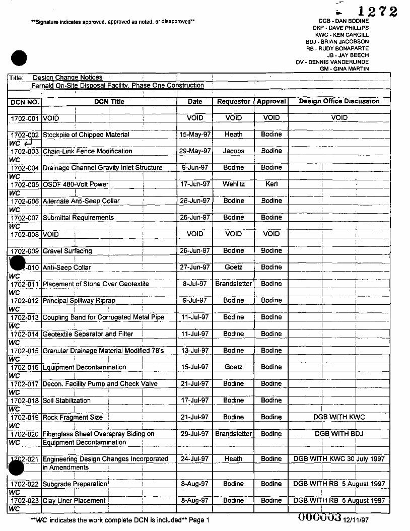
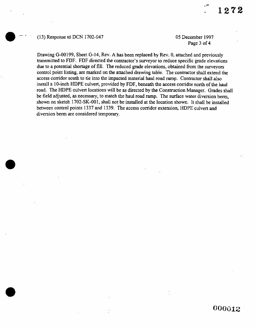
(1 3) Response to DCN 1702-047 --. - . 05 December 1997 Page 3 of 4
Drawing G-00199, Sheet G-14, Rev. A has been replaced by Rev. 0, attached and previously transmitted to FDF. FDF directed the contractor’s surveyor to reduce specific grade elevations due to a potential shortage of fill. The reduced grade elevations, obtained from the surveyors control point listing, are marked on the attached drawing table. The contractor shall extend the access corridor south to tie into the impacted material haul road ramp. Contractor shall also install a 1 0-inch HDPE culvert, provided by FDF, beneath the access corridor north of the haul road. The HDPE culvert locations will be as directed by the Construction Manager. Grades shall be field adjusted, as necessary, to match the haul road ramp. The surface water diversion berm, shown on sketch 1702-SK-001, shall not be installed at the location shown. It shall be installed between control points 1337 and 1339. The access corridor extension, HDPE culvert and diversion berm are considered temporary.
._..--.
-. _- --
1 M I
.. i . . . . . . . . .f . .
.- . I
I i
I /
1
1
1 I i ! 1
I I
I
!
1 I I I

1272 REQUEST FOR CURIFICATIONOF INFORMATION/ DESIGN CHANGE NOTICE-
RCI - DCN ACCEPTANCE
aRIGINAL 000014

a
0
REQUEST FOR CLARIFICATIONOF INFORMATION/ DESIGN CHANGE NOTICE-
RCI - DCN ACCEPTANCE
ORIGINAL

raA REQUEST FOR CLARIFICATION OF INFORMATION DESIGN CHANGE NOTICE - ( I ) W P / WONO.:
1702 (2) SK: NO.:
597
. 1702-013R I I ) DCN NO.:
/7uz - 4 4Y t4) RESPONSIBLE DISCIPLCNE: EO M u C m O T H E R O
(9) (XIRCI - MQURY O U S Q D SCREENING BY PROJECT ENGINEER (9) 2 DCN-JUsT[FICATION, EXISTING CONDITION & REQUEsTEDlPROPosED CHANGE
Paragraph 3.01 .A.I of Technical Specification Section 02772 states that surface upon which the GCL is to be placed shall be relatively smooth, fm, and not contain ruts greater than %-inch. Petro Environmental is requesting that this requirement be altered to allow ruts up to a maximum depth of I+/- %-inches.
(4A) RC-E: Surface Ruts for Placement of GCL
13) RESPONSE FOR RCl, IS A DCN REQ'D U N O - (14) FOR DCN: C APPROVED =PROVED AS NOTED jpblSAPPROyul
(7)DOCUMENTSAFFECTED
OSDF, Phase I Construction Documents - - - - - - - - - - - - - - - - - - - - - - - - - - - - - - - - - - - - - - - - - - - , - - - - - - - - - - - - - -
RCl - DCN ACCEPTANCE DATE: (20) CHARGE NO. FOR CADD SERVICES TO INCORPORATE
(7) DOCUMENT NOS.
Section 02772-3.0 1 .A. 1

. ..
(1 3) Response to RCI 1702-0 13R 29 October 1997 Page 2 of 2
It is an industry standard to prepare a firm unyielding subgrade to permit installation of the geosynthetics over the subgrade without causing rutting or deformation under the weight of the installation equipment. The subgrade shall also be free of standing water and maintained in a clean smooth condition.
The project specification was written to comply With manufacturers recommendations. Ignoring or increasing the allowable rutting size to 1 1/2 inch is not good engineering practice and not a solution to excessive rutting. Additional drying time and use of equipment to deploy that will reduce the excessive rutting should be used. Reasonable interpretation of the specifications is being applied in the field.
Daniel Bodine

. REQUEST FOR CLARIFICATION OF INFORMATION / DESIGN CHANGE NOTICE - (2) sc No.: (I)WP/ WONO.:
1702 597
On Site Disposal Facility Phase I 1 RESPONSIBLE DISCIPLINE: (4A) RCIIDCN-: En Mu C m O T H E R 0 Preparation of Trial Seams of HDPE Liner
(7) DOC- AFFECTED I (7) DOCUMENTNOS.
(9) BRCI - INQUIRY ~ U S Q D SCREENING BY PROJECT ENGINEER
(5)Pg I 0 I (6)DATE
( I 1) RCI NO.:
( I I ) DCN NO.:
11117/9
1702-0 19R
/ 702- 044 (7)REV. I (8) OTHER
(9) DCN-JUSI1FICATlON, EXISTING CONDITION & REQUESTEDPROPOSED CHANGE
(IO)@QUEST R: COMPANY: DATE: J. Richard dhairbaurn Petro Environmental Technologies, Lnc. 1 1/17/97
Paragraph 3.02.H of Technical Specification Section 02770 states that prior to actual seaming of the HDPE liner, trial seams must be prepared that we at least 15-fl. long by 1-fl . wide (after seaming). Petro Environmental is requesting, on behalf of Environmental Design & Construction, Inc., that the 15-ft. length be reduced to 5-A. in length.
( 12) FCE I PE Q. d .
I
DATE: - TlON APPROVAL.
&r?L.cL / g / C / . l r w ( 15) DESIGN 0 (20) CHARGE NO. FOR CADD SERWCES TO INCORPORATE
/y/&
l(13) RESPONSE FOR RCI, IS A DCN REQ'D n N O L L L ] Y E S (14) FOR D C N @ A P & ~ D -ROVED AS NOTED ,IDISAPPROVED
O W C E GRADE: (17

REQUEST FOR CLARIFICATION OF INFORMATION / DESIGN CHANGE NOTICE - fI)WP/ WONO.: 10) SK: NO.: I(S)F'g I 0 I l(6) DATE
I 702 I 597 C TITLE: On Site Disposal Facility Phase I
, RESPONSIBLE DISCIPLINE: 1MA) RCVDCN/ITILE:
I ll/l7/9' (I I) RCI NO.:
(1 1) DCN NO.: 1702-0 19R
PreparationvFfiial Seams of HDPE Liner
- (9) ~ R C I - MQLJIRY U U S Q D SCREENING BY PROJECT ENGINEER (9) - DCN-JUSTIFICATION, EXISTING CONDITION &
REQUESTEDIPROPOSED CHANGE
Paragraph 3.02.H of Technical Specification Section 02770 states that prior to actual seaming of the HDPE liner, mal seams must be prepared that p e at least 15-A. long by 1-ft. wide (after seaming). Petro Environmental is requesting, on behalf of Environmental Design & Construction, lnc., that the 154. length be reduced to 5-A. in length.
n 10)i@JJEST R: C6MPANY: DATE: (12) FCE / PE
1. Richard Jhairbaum Petro Environmental Technologies, Inc. 11/17/97 Q. c . // // /
13) RESPONSE FOR RCI. IS A DCN REQ'D U N O mYES (14) FOR DCN&AP&~ED @PROVED AS NOTED =DISAPPROVED
RCI - DCN ACCEPTANCE TION APPROVAL: DATE: (20) CHARGE NO. FOR CADD SERVICES TO INCORPORATE
DATE
15) DESIGN 0
16) FDF PE ACCEPTANCE & ERlFlCATION THAT ALL REQUIRED REVIEW ARE COMPLETE: (DCN ONLY)

(1)WP I WO NO.: (2) SIC No.: 1702 597
On Site Disposal Facility Phase 1 PONSIELE DISCIPLINE: IrsA) RC-E: En M U C ( x I O T H E R 0 I . Cold Weather Placement of Granular Drainage Material I
(5)Pg I 0 I (6)DATE
(1 I ) RCI NO.:
( I I ) DCN NO.:
I onon
1702-014R
I (7) DOCUMEKTS AFFECTED I (7)DOCUMENTNOS. I (7)REV. I ( 8 ) OTHER I I I
DATE:
/64J-w
(9) HRCI - INQUIRY [ ~ U S Q D SCREENING BY PROJEIX ENGINEER
,
(20) CHARGE NO FOR CADD SERWCES TO INCORPORATE
- (9) - DCN-JUsTzLlCATlON. EXISTING CONDITION & REQUEsrrrVPROPOSED CHANGE
Paragraph 3.05.C of Technical Specification Section 02714 states that placement of granular mainage material may not occur at ambient temperatures below 40" F or above 104" F unless authorized in writing by the Construction Manager. Petro Environmental is requesting that this particular specification requirement be waived. Tbe HDPE liner material was tested for Low Temperature Brittleness to a maximum temperature of -76" F (-60" C) and recorded passing results. This data was submitted in Supplier Submittal No. 056. Rev. 1; Document No. PET-O64C, Rev. 1. Low temperatures of this extreme nature are not anticipated at any time during the placement of the granular drainage material upon the geosynthetics. Regarding the geotextile material, a 1 0 - 0 ~ cushion andor a 1 6 - 0 ~ top supplemental cushion will be placed atop the HDPE geomembrane prior to placement of the granular drainage material. At no time will the equipment placing the stone operate directly on the geotextile material. Additionally, the equipment used during this aspect of the project shall consist of a low ground pressure machine, therefore, the ambient temperature of the underlying geosynthetics is not an essential factor to the placement of the granular drainage material.
IJ. Richkd Schairbaum Petro Environmental Technologies. Inc. 10/30/971 /
I( 13) RESPONSE FOR RCI, IS A DCN REQ'D (14) FOR DCN: ,E APPROVED ~ A P P R O M D AS NOTED -I 1 DISAPPROVED
t
I REQUEST FOR CLARIFICATION OF INFORMATION / DESIGN CHANGE NOTIdF- - rc
(I)WPI WONO.: (2) SIC NO.: 1702 597
On Site Disposal Facility Phase I
E O M U C m O T H E R U RESPONSIBLE DISCIPLINE: (4A) RCyDCNmnE:
Cold Weather P1a-t of Granular Drainage Material
(7) DOCUMENTS AFFECTED I (7)DOCUMENTNOS.
( I I ) RCI NO.:
( I I ) DCN NO.: 1702-014R
/ 782- 0+3 (7)REV. I ( 8 ) OTHER
(9) ~ R C I - INQUIRY OUSQD SCREENING BY PROJECT ENGINEER (9) 5 DCN-JUSTIFICATION. EXSTING CONDITION &
b REQUESTEDlPROPOSED CHANGE
Paragraph 3.05.C of Technical Specification Section 02714 states that placement of granular drainage material may not occur at ambient temperatures below 40" F or above 104" F unless authorized in writing by the Construction Manager. Petro Environmental is requesting that this particular specification requirement be waived. The HDPE liner material was tested for Low Temperature Brittleness to a maximum temperature of -76" F (-60' C) and recorded passing results. This data was submitted in Supplier Submittal No. 056. Rev. 1; Document No. PET-O64C, Rev. 1. Low temperatures of this ememe nature are not anticipated at any time during the placement of the granular drainage material upon the geosynthetics. Regarding the geotextile material, a 1 0 s z cushion andor a 16-ot top supplemental cushion will be placed atop the HDPE geomembrane prior to placement of the granular drainage material. At no time will the equipment placing the stone operate directly on the geotextile material. Additionally, the equipment used during this aspect of the project shall - -
of a low ground pressure machine, therefore, the ambient temperature of the q d e r / q t y m e ~ @ c s is not an essential factor to lacement of the granular dminage material. I. Ph
DATE: (12) FCE / PE DATE ntal Technologies, Inc. 10/30/97 n- f U/?O/f7
I(l3) RESPONSE FOR RCI, IS A DCN REQ'D (14) FOR IXN: 3 APPROVED ~ ~ P P R O V E D AS NOTED -JDISAPPROVED

REQUEST FOR CLARIFICATION OF INFORMATION / DESIGN CHANGE NOTICE -
I S ) D E S I G N T V F Z A A L DATE
/tf&-9+
6.-
4 97A 7
r"" hIc COMPANY:
13)RESPONSE: FOR RCI, IS A DCN REO'MuNOKYES
(20)CHARGE NO. FOR CAD0 SERVlCES TO INCORPORATE
N ! I - t / t I
I6)FDF PE ACCEPTANCE 8 MRlfl

REQUEST FOR CLARIFICATION OF INFORMATION / DESIGN CHANGE NOTICE -
mD0CUMENTS A m C T E D (8)OTHER
COMPANY: / * A 7 - 13)RESPONSE: FOR RCI, IS A DCN REQD7ONOaYES FOR DCMO APPROVED-D AS NOTEDODISAP/PROMD
/
RCI - DCN ACCEPTANCE I S)DESIGNTGA/A/ljAW DATE (20)CHARGE NO. FOR CADD SERVlCES TO INCORPORATE
/P&++ 16)FDF PE ACCEPTANCE 8 VERlFl S ARE COMPLETE: ( E N ONLY) DATl ’ERFORMANCE GRADE (17 Lr
DATE (21)WORK COMPLETED (SIGNOR BY FCE OR PE) ‘ DATt
rF-4259 (10/01/96)
3 C _ _ _ . _ _ . . _ . . . -. . 7 - c. .. . . ., ’ ’. . . . . ,
. L.- _... .- - - 8
4

‘.a ‘. ‘\
.-
os
REQUEST FOR CLARIFICA”l0NOF INFORMATION/ DESIGN CHANGE NOTICE-
~ G I N A L 080024 \

I 597 I 1 11519 ( I I) RCI NO.:
(4A) RCyDcNmTLE: (I I) DCN NO.: 0 46 vatu- e g Time Duration
(9) ~ R C I - INQUIRY O U S Q D sc G Y PROJECT ENGINEER % (9) 0 DCN-NSTIRCATION. EXISTING CONDITION & REWESTEDlPROPoSED CHANGE
I Paragraph 3.02.1.2 of Technical a02770 states that nondestructive seam continuity testing with a vacuum box shall be conducted for a time period of not Petro Environmental, on behalf of Ground Safe, is requesting . that this time period be reduced to 15 seconds. I
\ I
G O 0 0 2 5 FS-F4259 (10/01/96)
c
P '%
i I
//
I (6) DATE
8 8 ) I 116197 (I)W / wo No.: (%PI I WQ
I 702 597
On Site Disposal Facility Phw I ) RESPONSIBLE DISCIPLINE: (4A) RCVDCNIITTLE: ( I I) DCN No.: -
I E n MU Cm O T H E R O Alternative Mahod for Seaming Nonwoven Geotextiles I 7 6 2 4 3 9
(9) W R C l - INQUIRY OUSQD SCREpIING BY PR- ENGINEER (9) 1 DCN-JUSlEKATION. EMFIING CONDITION & -0KSEDCHANGE
Paragraph 3.02.A of Technical Specifidon Section 02714 states that &e variw types of geatextiles shall k continuously overlapped a minimum of &inches using a "single prayer" scam, and are to be sewed using Stitch Type401. Petro Environmental is requesting a DCN to the sewing procedure to pennit the use of a GT-200 Wedge Welder designed for all oollwovc~ georcxtile materials of any weight Attached is a letter h m the geotcxtilc manufachlrer, TNS Advanced Products, stating that this type of welding procedure is an acceptable method for bonding the geotcxtile together. Additionally attached is documentatioo on the Wedge Welder, as provided by the manufacturer, Novaweld.
DATE ental Technologies, hc. I//,? /.I7
ECDC CONTROLLED cow NO

%
127 .2 t REQUEST FOR CLARIFICATION OF INFORMATION / DESIGN CHANGE NOTKE - , ( 6 ) DATE
8 f 1 I 1/6/91 - (1)WPIWONO 0, sx: No. (5)Pg 1 *
I702 597
(9) ~ R C I - INQUIRY OUSQD SCREENING BY PROJECT ENGINEER (9) 1 DCN-JUSTIFICATION, EXISTING CONDmON & REQUEsrnrPROPosED CHANGE
Paragraph 3.02.A of Technical Specification Section 02714 States that the various types of geotextiles shall be continuously overlapped a minimum of binches using a "single prayer" ~eam, and are to be sewed using Stitch Type 401. Petro Environmental is requesting a to the sewing procedure to permit the use of a GT-200 Wedge Welder designed for all nonwoven geotextile materials of any weight. Attached is a letter from the geotextile manufacturer, TNS Advanced Roducts, Stating that this type of welding procedure is an acceptable method for bonding the geotextile together. Additionally attached is documentation on the Wedge Welder, as provided by the manufacturer, Novaweld.
On Site Disposal Facility Phase I
E D him C m O W R D
(4A) RCUDCWlTLE i) RESPONSIBLE DISCIPLINE Alternative Method for Seaming Nonwoven Geotextiles
(7) DOCUMENTS A F F E C E D I (7)iXKXhlENTNOS I
L . -.-
J . COMPANY: DATE
mental Technologies, Inc. M/-7 / f 7
( I 1 ) DCN NO - f 782-03?
(7)REV I (8) OTHER I
DATE: (20) CHARGE NO. FOR CADD SERVICES TO INCORPORATE
( 16) FDF PE ACCEPTANCE & VERIFICATION THAT ALL REQUIRED REVIEW ARE COMPLETE. (LXN ONLY) DATE:

- - - _ _ - - _. ( 13) Response to DCN 1702-039 11 November 1997
Page 2 of 2
RCI 1702-01 8R has been changed to DCN 1702-039 and is approved as noted below.
Add Part 3.02.D to Specification Section 02714.
D. When approved in writing by the Construction Manager and the geotextile manufacturer an alternate to sewing filter, cushion, and supplemental cushion nonwovern geotextiles is heat seaming using the Novaweld GT-200 Wedge Welder. Heat seaming shall be in accordance with equipment manufacturers requirements. If “burn out” occurs, the burned out area shall be covered with sufficient overlap as specified and seamed. For these repairs, a GT-I OOA hand held welder may be used. If in the opinion of the Construction Manager a large number of repairs is occurring the Construction Manager may direct the installer to return to sewing in accordance with specifications

3. 1
TNS MILLSENGINEERED SYNTHEI'IC PRODUCTS, INC. 59 15 Hammersmth Road Stone Mountain SA 30087 Phone: 770/564-1857 F m 770664- 18 I8
November 4,1997
Mr. Rick Schairbarrm Petro Environmental Inc. Fernald, OH
Fax: 5131648-34G7
Dear Rick
This letter is in regard to the Fluor Daniel Femaid Site- OSDF Phase 1 project. H a t seaming gee0:eXtilc utilizing the Novaweld device is an acceptable method for bonding 'INS nonwoven geotextiles. TNS only recommends this method for nonwoven geatextiles Utili& as protection for a geomembranc.
If you have any further questions, please fel frct to contact me.
Sincerely,
&I*- Richard J. F& TNS/Engaeertd Synthetic Products: Inc.

-- 1 2 7 % EXCLUSIVE BPR TECHNOLOGY 8
The GT=200 Wedge Welder Universal welder for ALL nonwoven geotextile mataials of AhY weight
FAST- over 30 feet per minute with 100% MARV seam strength (ASTM D4884-96)
Capable of seam welding all weights of nonwoven geotextiles, T-joints, GCLs, geonets, and geocomposites Replaces sewing machines, thereby elirxunating broken and lost needles I M A I ~ W N N C E - F R E E - no moving parts, no jams BPR process with alignment wheel assures minimum overlap, weld speed, high seam s m g t h resulting in instaliation savings of up to 30O0/0
Smart controls with current senson provide up to the second cartridge heating status
Easy to use, walk-behind
Internet website access for custoner support
W Comparison of Field Seaming Rates A* ~ u b h h c d m CcoadUd Plbria b o n -&t/Nm 1496
The GT-200features an ergonomic &sign promoting ease of use, increased productivity, and rcduced training time, job turnaround and Ooeratl job costs. No set-up costs M addititma1 supplies arv uecdcd.
ORIGINATORS OF BPR WEDGE WELUINC

Simpledesign Nojrms M a i n t a ~ n ce-frte
I
SPECIFICATIONS
Product Dimeneims: f Shipping Dimensions: Electrical Specificahons: Mechanical Speoifications: Height 48' (1.2m) Lengtb 52" (1.3~1) Power (factory Wnfigured): Wedge 2.25' (Oo06m) Width 32' (0.8m) Length 17" (0.4m) Depth 12' (C.3m) 22oVAcn 3Amgs, Wedge material is a Weight 35 Ibs (18kg) Weigm 60 Ibs (27kg) 66oWatb (m) non.corrosive metal allay
. m
l lOVAC, BAmps, 660 Watts (W) W& 34' ( o m )
Watbw PID Temperature Controller
. M
NOVAWELD PRODUCl' LlNE GT-lWA Hand-held wedge welder, ew, s b n m k ,
brush and usen manual CT-200 Semi-sutamahc wedge WJdCr for geotedu,
usem m u s t ilMrwticmal video, caixyhg caseoptional
nunual,=J*-optional
manual, carry@ case optional
GT-W Automtic lightweight wedge welder. users
GT-500 Automatic wedge/hot air wdda, users
GT-200 can be w e d lo themullyfwc OY
seam weld polypropylene, polyester and other nonwoven geotextiles offovr ot mom ounces per square yord. 7he GT-200 complcments the NOVAWLD family of wedge welding products for the installation of posynthefic materials including the GT-100 hand-held w d p welder for geotextile and g e m h n e materials, the GT-300 lightweight, automatic wedge welder and the GT-500 awtomafic wedgelhot air wtlder forgeonunbtanes.
~~~ ~
ORIGIhiATORS OF BPR WEDGE WELDING
2
NOVAWLD UC l2W Race Street, Unit L-104 NortheLnr\, CO 80241.USA 3m-4524372 Fax3u3452-2133 N(p:/ lmrw.acmwcldnom

..- ..... ........... ... .- . . ............. _.....__._._._._r_..._. _." ......_ " ._._,_...____ .---. ......-... ._...-.-.-.. --.-...--....- ..... ".".".._..." .... .- ....
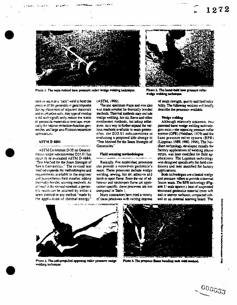
Alternate seaming methods for nonuoven geokxtiles Revisions to ASTM 0 4884 hme exponded the methodologias avaibble to 8ngin-E and instollen oddlng thermally bonded seomlng fnethods.
. . . ... ...................... ....-. ........ _" ................... ._ ....._.........__._.__....._....._.._... ........ - ............ ..-- .. .- ...................
a -=-wmctboddoaks ..-.... _... - ....-....- "_._.__ ...... ".- ........... Basically. five tscpbiitbec processes
CL? provide 9 nonworcn gectextik's scam. These procerses k l p d e wedge we!ding. rarinp. hot dr, ; rd! ive a d torch or o p flame. Si= h e usc ofad- hesim and !orch/npcn f l u x ;rc eppli- carion-spttific. h e pm!m ;ur not comFirrj !a Table 1 .
Many comadm tmvc aied a veriely of k s e pnxeswa wirh bmng degrees

............ -... .... . .... ...... ........-...._e......__.._ . ..-. - .......... .. ...
Y a
!

--
fi eld production!
pi.), Geotexck field seams at
30 to 50 feet per minute ... without lost or broken needles
Call now to order 303 452 0872
Fuc; 303 452 2733 Made in USA
R.K. Frobel & Associates

- - L 1 s 4
I REQUEST FOR CLARIFICATION OF INFORMATION / DESIGN CHANGE NOTICE -
. 8 ) CONSTRUCTION CONCURRENCE:
REQUISITION REQUIRED: n Y E S n N O (19) .
( 5 ) Pg 1 0 I ( 6 ) DATE (1)WP / WO NO.: (2) s/C NO.: 11!5/9: 1702 597
(21)WORK COMPLETED: (SIGNOFF BY FCE OR PE) DATE:
. _ _ ( I I ) RCI NO.:
On Site Disposal Facility Phase I 1 RESPONSIBLE DISCIPLINE: (4A) RCUDCNmTLE: ( I I ) DCN NO.: EO MU c m OTHER^ / v i a - 0 9 Vacuum Testing Time Duration I I I
(8) OTHER 17) DOCUMENTS AFFECTED I (7) DOCUMENTNOS. I (7) REV. I
(9) ~ R C I - INQUIRY O U S Q D SCREENING BY PROJECT ENGINEER (9) 1 DCN-JUSTIFICATION. EXISTING CONDITION & REQUESTEDPROPOSED CHANGE
Paragraph Z.02.1.2 of Technical Specification Section 02770 states that non-destructive seam continuity testing with a vacuum box shall be conducted for a time period of not less than 20 seconds. Petro Environmental, on behalf of Ground Safe, is requesting that this time period be reduced to 15 seconds.
COMPANY: DATE:I(l2) FCE I PE DATE . RLhard dhairbaum Petro Environmental Technologies, Inc. 11/5/971
13) RESPONSE FOR RCI, IS A DCN REQD U N O @S (14) FOR DCN: 2 APPROVED &PROVED AS NOTED =DISAPPROVED
RCI - DCN ACCEPTANCE DATE: (20) CHARGE NO. FOR CADD SERVICES TO INCORPORATE
DATE:
/??.%%- ?7 QUIRED REVIEW ARE COMPLETE: (DCN ONLY)
I I
nnnn- .::6 FS-F-4259 (10/01/96)

1702 597 I 1 01 I 3.N
. .
TITLE: I( I I) RCI NO.: On Site Disposal Facility Phase 1 I702-009R
(4) RESPONSIBLE DISCIPLWE: ( 4 4 RCVDCN TITLE: ( I I) DCN NO.: LDSnCS Anchor Trench Detail I7Q2-037
Allow both the LDS and LCS liner system synthetics to be placed in a common anchor mch. Tbe anchor trench would k -mad to the lines and grades &s indicated for the LDS Anchor Trench originally desiped. 'Ibe propoxd installatipn sequence is as follows:
1. Excavate common anchor trench to lines and grades required for- 5 Cco- ddy / A c y / - 0 7 -
the common anchor much as specified

1 2 7 2
On Site Disposal Facility Phve 1 (4) RESPONSIBLE DISCIPLINE. (4A) RCVDCN TITLE:
E n M u C m m R n LDSnCS Anchor Trench Detail
REQUEST FOR CLARIFICATION OF INFORMATION / DESJGN CHANGE NOTICE - (2) SX: NO.
I702 597 I( I I ) RCI NO
~~~~~R (1I)DCN NO.
/ 7 4 d - 0 3 7
DATE:
/6dd- 77 (20) CHARGE NO. FOR CADD SERVICES TO INCORPORATE
(9) ~ R C I - INQUIRY ~ U S Q D SCREENING BY PROJECT ENGMEER (9) DCN-JUS’TIFICATION. EXlSTTNG CONDITION & REQUESTEDlPROPoSED CHANGE
Allow both the LDS and LCS liner system synthetics to be placed in a common anchor trench. The anchor trench would be consmcted to the lines and grades as indicated for the LDS Anchor Trench originally designed. The proposed installation sequence is as follows:
1. Excavate common anchor trench to lines and grades required f o r e 5 e c o t , t/”y 2. Place t h e m s y n t h e t i c materials in the anchor trench 3 & l G & b a a a n chor trench to temporarily balla@&’&tbetics
/,fi 19-
4. Place LDS Drainage L- - /PJ’
c- IO) REQUESTOR COMPANY- DATE (12) FCE I PE
Iteven C. Brandstetter Petro Environmental Technologies, Inc. 10/13/97
13) RESPONSE FOR RCI, IS A DCN REQ’D I
U N O H k S (14) FOR DCN cj APPROVED W V E D AS NOTED L1 DISAPPROVED
RFORMANCE GRADE: (17) fc CONSTDUCnON CONCURRENCE: /7 A DATE: l(2 1 )
I I FS-F4259 ( IO/O IM)
WORK COMPLFIFD: W ? / 9
(SIGNOFF BY FCE ORPE 7 - DATE:

( 13) Response to DCN 1702-037 16 October 1997 Page 2 of 1
Shown below is an Alternative Anchor Trench Detail that may be used.in installing the Primary and Secondary Liner System when using a single trench excavation option. The construction sequence shall protect the liner system from damage due to weather or construction conditions. The Construction Sequence shall include the follouing:
1. Excavate Minimum 6 fi. Wide Trench per Specification Section 022 15
2. Remove Any Rock or Stones that may Damage Liner System in Preparation for Subgrade Inspection and Approval by Liner Installer.
Install Secondary Liner System per Requirements of Specification Sections 02714,02770 and 02772. Backfill and Compact Clay Liner Material in Area Designated as ”A” in the Detail Below per Specification Section 0,- 7715. part 3.03.D Ending with a Prepared Subgrade Surface for the Primary Liner System.
- 3.
4. Maintain Trench Dewatering and Backfill Density and Moisture Condition per Specification Section 02215, Parts 3.02 and 3.03.
5 . Inspect, Repair if Required and Obtain Approval of Subgrade for Primary Liner System Immediately Prior to Installation. Install Liner System per Requirements of Specification Sections 02714,02770 and 02772. Backfill Area Designated as “B” in the Detail below per Specification Section 02215, Part 3.03.D.
ALTERNATlVE ANCHOR TRENCH DETAIL

I ... _- .__ . .
...
.. - ....... .
. i t '
-.. .. - . . . . . . . I .
I
I . . . . . . . .
. I
I
I
---- ..A- ..-. -- . - . . . . . . . . . . . . . . . . . . . . -I-- ...... . .
TOT& P.82 (E80040

P c
b lg'7 2 GEOSYNTEC CONSULTANTS Page .I of-

DETAIL LINER SYSTEM ANCHOR TRENCH (NOTE 8) SCALE: 1” = 4’ YPEF F96X4538
c - 1272
44A)RCVDCN TITLE: .
Liner Penetration Boxes
REQUEST FOR CLARIFICATION OF INFORMATION / DESIGN CHANGE NOnCE -
(11)DCN NO.:
1702436
IWONO.. 1702 )SICNO.: FSC- 597
(9)ORCI - INQUIRY 0 USQD SCREENING BY PROJECT ENGINEER
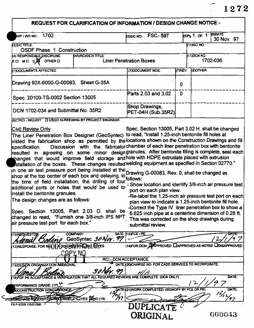
Civil Review Only The Liner Penetration Box Designer (GeoSyntS) to read, 'Install 1.25-inch bentonite fill holes at visted the fabrication shop as permitted by thelocations shown on the Construction Drawings and fill specification. Discussion with the fabrimtorchamber of each liner penetration box with bentonite resuked in agreeing on some minor designgranutes. After bentonite filling is complete, seal eacb
Spec. Section 13005, Part 3.02 H. shall be changed
. I o I IDrawing 90X-6000-Eo0083, Sheet G-35A
one air test pressure port being installed at theDradng G-00083, Rev. o, shall be changed as at the top center of each box and delaying, tofollows:
of field installation, the drilling of four - Show ports or holes that would be used to port on and identrfy 3/8-inc., air pressure test
each plan view. -Relabel the 1.25-inch air pressure test port on each plan view to indicate a 1.25-inch bentonite fill hole.
bentonite granules. he design changes are as follows:
-Correct the Type IV liner penetration box to show a shall be 6.625 inch pipe at a centerline dimension of 0.28 ft.
submittal review.
Spec- Section 13005, Part 2-03
air pressure test port for each box." hanged to read, 'Furnish one 3/8-inch IPS NPT. This was correctd on the shop drawings during t
IOIReQUESTOR: 4 COMPANY:
ORIGINAL

L (3)SC m: I(11)RCI NO.
(4) RESPONSI ISCIPUNE: (4A)RCUDCN TITLE: (1 1)DCN NO.: OSDF Phase 1 Construction
E O M u c r o r n E R m Liner Penetration Boxes 1702-036 I I
(7)ooCUMENTS AFFECTED OOOCUMENT Nos. (7)REV. (8)OTHER
0 ECDC C O R ~ T R ~ ~ i 1 - Drawing 90X-6000-(3-00083, Sheet G-35A
.
- in one air test pressure port being installed at theDrawing G-00083, Rev. o, hop at the top center of each box and delaying, tofollows:
dditional ports or holes that would be used to portoneachplanview~
be changed as
time of field installation, the drilling of four - Show location and identrfy 3/8-inch air pressure test
-Re-label the 1.25-inch air pressure test port on eact plan view to indicate a 1.25-inch bentonite fill hole.
the bentonite granules. e design changes are as follows:
- - - a z t V L L L ---------------------------------------------------- ----c---- mT0--- Parts 2.03 and 3.02 0
!--- .3
Shop Drawings, 'L QT Spec. 201 00-TS-0002 Section 13005
DCN 1702-034 and Submittal No. 35R2
------------------------------------------------------------~~-~--~-----:
PET-04H (Sub.35W)
Civil Review Onlv Spec. Section 13005, Part 3.02 H. shall be changed The Liner Penetration Box Designer (GeoSyntec) to read, 'Install 1.25-inch bentonite fill holes at visted the fabrication shop as permitted by thelocations shown on the Construction Drawings and fill specification. Discussion with the fabricatorchamber of each liner penetration box with bentonite resulted in agreeing on Some minor designgranules. After bentonite filling is complete, seal eact
(9)ORCI - INQUIRY 0 USQD SCREENING BY PROJECT ENGINEER
-Correct the Type IV liner penetration box to show a be 6.625 inch pipe at a centerline dimension of 0.28 ft.
submittal review.
Spec. Section 13005i Part 2-03 D*
air pressure test port for each box." hanged to read, 'Furnish one 3/8-inch IPS NPT. mis was on the shop drawings during t

I REQUEST FOR CLARlFfCATfON OF INFORMATION / DESIGN CHANGE NOTICE
P W ~ > O / t 3.0% I I I 9)ORCI - INQUIRY 0 USQD SCREENING BY PROJECT ENGINEER ( 9 ) ~ W S T l F I C O N . U [ I S T I N G CONOmON REOUESTEOPROPOSED
CHANGE
. /woNo.: 5 - 0 3 5 Z S C N O . : FSC597
)sx: n n ~ : OSDF - Phase I Construction
hange vertical and homontal control of Impacted Material Haul RoadlCell Access Road to that shown on new Drawing G I 4 (ar?achd hereto), whrch shall be added to
e Contract Documents.
ORIGINAL
!

REQUEST FOR CLARIFICATION OF INFORMATION / DESIGN CHANGE NOTICE I 1 )WP I WO NO.: 1702 - 0 3 5 (Z)SIC NO.: FSC 597
. U -uC CONTROLLED
COPY NO.
Change vertical and horizontal control of Impacted Material Haul RoadlCell Access Road to that shown on new Drawing G-14 (attached hereto), which shall be added to the Contract Documents.
DATE: /& ?/9 7
(WFOR DCN:%PROVED&&JPROVED AS NOTED ODISAPPROVEC
ORIGINAL
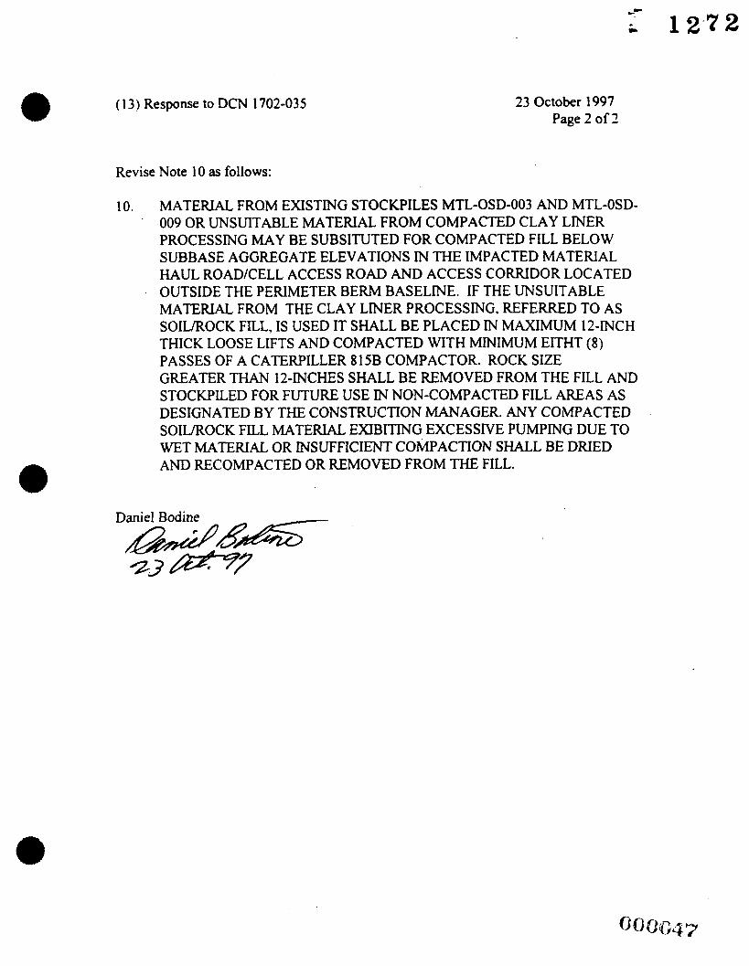
( 13) Response to DCN 1702-035 23 October 1997 Page 2 of 2
Revise Note 10 as follows:
IO. MATERIAL FROM EXISTING STOCKPILES MTL-OSD-003 AND MTL-OSD- 009 OR UNSUITABLE MATERIAL FROM COMPACTED CLAY LINER PROCESSING MAY BE SUBSITUTED FOR COMPACTED FILL BELOW SUBBASE AGGREGATE ELEVATIONS M THE IMPACTED MATERIAL HAUL ROAD/CELL ACCESS ROAD AND ACCESS CORRIDOR LOCATED OUTSIDE THE PERIMETER BERM BASELINE. IF THE UNSUITABLE MATERIAL FROM THE CLAY LINER PROCESSING, REFERRED TO AS
THICK LOOSE LIFTS AND COMPACTED WITH MINIMUM EITHT (8) PASSES OF A CATERPILLER 815B COMPACTOR. ROCK SIZE
SOILROCK FILL, IS USED IT SHALL BE PLACED IN MAXIMUM 12-INCH
GREATER THAN 12-INCHES SHALL BE REMOVED FROM THE FILL AND STOCKPILED FOR FUTURE USE IN NON-COMPACTED FILL AREAS AS DESIGNATED BY THE CONSTRUCTION MANAGER. ANY COMPACTED SOILROCK FILL MATERIAL EXIBITING EXCESSIVE PUMPING DUE TO WET MATERIAL OR INSUFFICIENT COMPACTION SHALL BE DRIED AND RECOMPACTED OR REMOVED FROM THE FILL.

REQUEST FOR CLARIFICATION OF INFORMATION / DESIGN CHANGE NOTICE.
) e d 2 & o / , 3.08 I I I I)ORCI. INQUIRY 0 USQD SCREENING BY PROJECT ENGINEER (9)plbCNJUSTIFICATlON,~lS~NG CONDITION REQUESTEDlPROPOSEC
CHANGE
>hange vertical and horizontal control of Impacted Material iaul Road/Cell Access Road to that shown on new hawing G-14 (attached hereto), which shall be added to he Contract Documents.
ECDC CONTROLLED COPY NO.
DATE: lGh ?/. 7
D AS NOTED ODISAPPROMC
RCI - DCN ACCEPTANCE GE NO. FOR CADD SERVICES TO INCORPORATE:
16)FDF PEACCEPTAN0€& MRlFlCATlON THAT ALL REQUIRED RMEWS ARE COMPLETE- ~ DATE:
’ERFORMANCE GRADE: ( 1 7 ) r S 6422/9 7 DATE: (21)WORK COMPLETED: (SIGNOFF BY FCE OR PE) DATE:
5-F-425Y (1 0101 196) v
ORIGINAL

-- C 1 2 1 2
(1 3) Response to DCN 1702-035 23 October 1997 Page 2 of 2
Revise Note 10 as follows:
10. MATERIAL FROM EXISTING STOCKPILES MTL-OSD-003 AND MTL-OSD- 009 OR UNSUITABLE MATERLAL FROM COMPACTED CLAY LINER PROCESSING MAY BE SUBSITUTED FOR COMPACTED FILL BELOW SUBBASE AGGREGATE ELEVATIONS IN W E IMPACTED MATERIAL HAUL ROADKELL ACCESS ROAD AND ACCESS CORRIDOR LOCATED OUTSIDE THE PERIMETER BERM BASELINE. IF THE UNSUITABLE MATERLAL FROM THE CLAY LINER PROCESSING, REFERRED TO AS
THICK LOOSE LIFTS AND COMPACTED WITH MINIMUM EITHT (8) PASSES OF A CATERPILLER 815B COMPACTOR. ROCK SIZE
SOILROCK FILL, IS USED IT SHALL BE PLACED IN MAXIMUM 12-INCH
GREATER THAN 12-INCHES SHALL BE REMOVED FROM THE FILL AND STOCKPILED FOR FUTURE USE IN NON-COMPACTED FILL AREAS AS DESIGNATED BY THE CONSTRUCTION MANAGER. ANY COMPACTED SOWROCK FILL MATERIAL EXIBITING EXCESSIVE PUMPING DUE TO WET MATERIAL OR INSUFFICIENT COMPACTION SHALL BE DRIED AND RECOMPACTED OR REMOVED FROM THE FILL.
Daniel Bodine

i 1272
FAX COVER SHEET
- Io:
Firm:

REQUEST FOR CLARIFICATION OF INFORMATION I DESIGN CHANGE NOTICE i 1)WP I WO NO.: 1702 - 0 3 5 (2WC NO.: FSC 597 (5)Pg 1 OF (6)DATE 6 OC: s i
3)s1c TITLE: OSDF - Phase I Construction ~(11%%$ ' (4) RESPONSIB DISCIPLINE: (4A)RCIID CN TITLE: (1 1 )DCN NO.:
/7c 2 - 0 3 s I - E l 3 MI3 C OTHER0 Impacted Material Haul Road/Cell Access Road Jt Construction Drawing IG-58 1 2 1
I (7)DOCUMENT NOS. I(~)REv. OTHER 7)DOCUMENTS AFFECTED
190X-6000-G-00074 I I
I
9)ORCI - INQUIRY 0 USQD SCREENING BY PROJECT ENGINEER (9)l3DCN-JUSTIFICATlON.€XlSTlNG CONDITION REQUESTEDlPROPOSED CHANGE
Change vertical and horizontal control of Impacted Material Haul Road/Cell Access Road to that shown on new Drawing G-14 (attached hereto), which shall be added to the Contract Documents.
/ A
(12)FCE I PE DATE: -/ /k/&
(I~)RES~ONS+ RCI. IS A DCN REQ'D? ONONES ( I ~ F O R DCN:,B$PPROVED~APPROVED AS NOTED CIDISAPPROVED
RCI - DCN ACCEPTANCE F T E NO. FOR CADD SERVICES TO INCORPORATE:
REQUIRED REVIEWS ARE COMPLETE: (DCN ONLY) DATE:
PERFORMANCE GRADE: (17)-
(1 8)CONSTRUCTION CONCURRENCE: DATE: I(21)WORK COMPLETED: (SIGNOFF BY FCE OR PE) DATE:
PURCHASE REQUISITION REQUIRED: U Y E S U N O (19) FS-F-4259 l10/01/961

( 1 3) Response to DCN 1702-035 23 October 1997 Page 2 o f 2
Revise Note 10 as follows:
IO. MATERWL FROM EXISTING STOCKPILES MTL-OSD-003 AND MTL-OSD- 009 OR UNSUITABLE MATERIAL FROM COMP.4CTED CLAY LINER PROCESSING MAY BE SUBSITUTED FOR COMPACTED FILL BELOW SUBBASE AGGREGATE ELEVATIONS IN THE IMP-ACTED MATERIAL HAUL ROADKELL ACCESS ROAD AND ACCESS CORRIDOR LOCATED OUTSIDE THE PERIMETER BERM BASELNE. IF THE UNSUITABLE MATERIAL FROM THE CLAY LINER PROCESSING. REFERRED TO .AS SOILROCK FILL. IS USED IT SHALL BE PLACED IN M-LXMUM 12-INCH THICK LOOSE LIFTS AND COMPACTED WITH MNIMUiLI EITHT (8) PASSES OF A CATEWILLER 815B COMPACTOR. ROCK SIZE GREATER THAN 12-INCHES SHALL BE REMOVED FROM THE FILL AND STOCKPILED FOR FUTURE USE IN NON-COh4PACTED FILL .4R€AS AS DESIGNATED BY THE CONSTRUCTION MANAGER. AiiY COMPACTED SOILROCK FILL MATERIAL EXIBITING EXCESSIVE PUMPING DUE TO WET MATERIAL OR INSUFFICIENT COMPACTION SHALL BE DRIED AND RECOMPACTED OR REMOVED FROM THE FILL.
Daniel Bodine

- - - . . - - . e - . , _ _ . * _ . . . _ - m \*-, , d--.?; a . & b . J v ~ . - . 2 8 . n ~ - b ~ , \ - . ~ , b i , - -wo . - I . . - - a . *
E. OR OTHER SHEETING APPROVED BY THE CONSmUCnON MANAGE2. 'EIGHT TEV?ORARY PLASTIC COVER WITH SANDBAGS, OR EQUIVALENT, TO PREVENT FR Oh' W I dD.
CONTRACTOR
I I
:TO ilALL GRADE WEST SIDE OF WEST DRAINAGE CHANNEL UPWARD A T A Of@,J: 1-VERTICAL SLOPE FROM CHANNEL CENTERLINE UNTIL SLOPE DAYLIGHTS AT
RIAL HAUL R O A D / C E L ~ A C C E S S
I I I I I I
,RY CULVE2TS SHALL BE INSTALLED TO LIMIT OF IMPACTED MATERIAL H A U L ROAG IENTS AND AT A MINIMUM SLOPE OF 1 PERCENT.
I I I I I I I
E l DESCRIPTION I DES. BY
50 25 lo I I
DR. BY CHK. BY I R W . BY I APP. BY
SCALE I N FEET
I GEo SYNTEC
- \aD STATES DEPARTMENT OF ENERGY 4Lu ENVIRONMENTAL MANAGEMENT PROJECT
KgiEg FLUOR DANIEL FERNALD
GQ0166-03 GEOSYNTEC DOCUMENT NO.:
SITE DISPOSAL FACILITY PHASE I CONSTRUCTION
PACTED
Y NOT BE ISSUED TENDER OR
UNLESS SEALED.
MATERIAL HAUL ROAD GRADING PLAN
FDF PROJECT NO.: 201 00
1 FDF SUBCONTRACT NO.:
CONSULTANTS 1 F97-A669
E
F

( 13) Response to DCX 1702-015 21 October 1997 Page 2 o f 2
Revise Xots 10 as follows:
10. bI.ATEFU.AL FROhI EXISTING STOCKPILES SITL-OSD-003 .AXD bITL-OSD- 009 OR LNSUIT.ULE &LATERIAL FROM CO;L[P.ACTED CL.AY LNER
SUBBASE AGGREGXTE ELEVATIONS IX THE IMP.ACTED MATERI.AL HAUL ROADICELL .ACCESS ROAD AND ACCESS C O W D O R LOC-ATED OUTSIDE THE PERIXIETER BERM BASELKE. IF THE L?;SUIT.ABLE iLIXTEFU.AL FROM THE CL.AY LlXER PROCESSIYG. REFEREED TO .AS
THICK LOOSE LIFTS .ASD COMP.ACTED WITH MIYI;LIU;LI EITHT (S) P.4SSES OF A CXTERPILLER S 15B COMPXCTOR. ROCK SIZE
PROCESSING MAY BE SLYBS.ITUTED FOR COb1P.ACTED FILL BELOlV
SOIL,‘ROCK FILL, IS CSED IT SH-ALL BE PL-ACED l3 hI.LXML31 12-lXCH
GRE-ATER THXV 12-h-CHES SHALL BE REMOVED FRObI THE FILL .AND STOCKPILED FOR FCTURE L;SE I3 NON-COhIP.ACTED FILL .I\REXS -4s DESIGNATED BY THE CONSTRUCTION MANAGER. ANY CObIP.4CTED SOILROCK FILL bLATERWL EXIBITIIU’G EXCESSIVE PUMPING DUE TO WET hLI-\TERLAL OR INSUFFICIENT COMPACTION SH.UL BE DRIED AND RECOMPACTED OR REMOVED FROM THE FILL.
Daniel Bodine

J L r r , . . I . . _.. - - .*;A - ,-.A _c_ - x x 0 1 3 . 3 0 61 5 . 5 9 61 5 . 4 2 6 1 8 . 1 7 61 6 . 4 1 6 1 8 . 1 7 611 . 5 6 6 1 5 . 0 0 61 6 . 41 6 0 0 . 0 0 6 1 5 . 4 2 599 . oo 5 9 8 . 0 0 6 1 8 . 1 7
48281 2 . 9 2 48281 1 . 4 2 4 8 2 8 2 8 . 4 2 48281 3 . 3 9 482778 .a i
482722 . a 4 4 a 2 7 a o . 9 3
481 7 8 7 . 0 4
481 762 2 5
482781 . 3 i
402781 . 3 9
4 0 2 7 7 9 . 2 0
4 0 2 0 2 8 . 0 3
401 7 4 3 . 2 7
I 3 3 U b 3 0 . 3 3 1 350969.70 1 3 5 0 9 0 7 . 6 5
1351 01 9 . 0 4 1 3 5 0 8 0 7 . 9 6 1350771 . 7 4 1 3 5 0 8 4 6 . 0 3 1 3 5 0 9 8 7 . 0 4
1351 01 9 . 6 4 1 3 5 0 7 3 7 . 7 3 1 3 5 0 7 5 6 . 9 8
1 350808.35
1 3 5 0 7 2 8 . 7 6
1 35081 4 . 3 5
1362 1 3 6 3 1 3 6 4 1 3 6 5 1366 1 3 6 7
1369 1 3 7 0 1371 1372 1 3 7 3 1374 1 3 7 5
1 3 6 8
EXISTING LEACHATE TRANS! I SSION SYSTEhl AND HORIZONTAL MONITORING Fg Y A @ R WITH COVER SLAB P .---- .__ --
DRAINAGE CHANNEL GRAVITY INLET SlRUC' AND CULVERT (GIS)
- .-.__ . -.. .... _ - _ _ ..... ..--.- DRAINAGE FLOW DIRECTION - 501 O+ CONSTRUCTION CONTROL POINT
, . --. 0.. 1 ...I
!
EXISTING TREES AND SHRUBS -2- -------- ______D 0' TEMPORARY - --
O:, .e
ACCESS CORRIDOR OR REROUTED NORTH ENTRANCE ROAD
.I IMPACTED MATERIAL HAUL ROAD (NOTE 4)
CELL DESIGNATION
TIE TO EXISTING TGL SYSTEM
6"/10" DECON FA C I LI TY FORCEMAI N NOTES:
TOPOGRAPHIC MAP BASED ON 1992 SITE FLYOVER AND SUPPLEMENTAL AS-BI OF EXISTING RAILYARD AND WEST OF THE CENTERLINE FOR THE WEST 25-YE
1.
CHANNEL.
ELEVATIONS ARE I N FEET ABOVE SEA LEVEL DATUM. NATIONAL GEODETIC VERTICAL DATUM [NGVD].)
GRID COORDINATE SYSTEM CORRESPONDS TO STATE PLANAR NORTH AMERICA OHIO SOUTH.
CONTOURS WITHIN THE SHADED REGION ON THE IMPACTED MATERIAL HAUL F OF BASE AGGREGATE.
(NOTE: "SEA LEVEL DA 2.
3.
4.
SUBGRADE ELEVATIONS CORRESPOND TO TOP OF PREPARED SUBGRADE, INCLl COMPACTED FILL CONSTRUCTION CONTROL POINTS FOR SUBGRADE ARE PROV
5.
G-34, G-5B, AND G-5C.
DIMENSION SHOWN FOR IMPACTED RUNOFF CATCHMENT AREA IS MEASURED C PERIMETER BERM BASELINE TO CREST OF GRANULAR PROTECTIVE LAYER.
6. - . . - . - - . ._ ...... - ,,._ -
FENCE GATE ........ ... .- . :"+Id

1 L I ' /;CELL ACCESS RAMP IlkT IMPACTED RUNOFF
! ISCATCHMENT AREA ,-\
i i ; ! j . : , I :
:i ' i % . \
IMPACTED MATE~IAL \ HAUL I~OAD/CELL?.
ACCESS??OAD '.. (NOTES 4 AND io) ' \ \ ': A \
... . .... - ......... ..........
. . . . . . . . . . . . . . ... :.. : . . .
_..- .- b.' \ .TEMP.oRAR;.. __--_____.____I___
........... ................... ............ .............. cu ~ ~ r m - r - c ~ ~ n .. . . . . .
. . . . . ......
..........
.-,.
. .

'REQUEST FOR CLARIFICATION OF INFORMATION I DESIGN CHANGE NOTICE - I WO NO.: 0) x No.: (5) P I OF
1702 5 9 l I( I I ) RCI NO.:
V
(9) W R C I - MQUrRY I U S Q D SCREENING BY PROIECT ENGINEER r (9) '7 DCN-JUSTIFICATION, EXISTING CONDITION & V R O P O S E D CHANGE
The referenced technical specification section requires that each completed liner pcaewtion box be pressure tested at IS psi prior to shipment. Plastek Werks, the fabricator of the penerration boxes, has provided documentation (see artached) requesting that the air pressure test be perm.itted to k conducted at a tcst pressure of 10.8 psi. We believe drat this is a safer test pressure and will still demonmatt the integrity of all weldments 011 the liner penetration boxes. Please review and rrspond as appropriate.
ECD@ CONTROLLED CQPY NO.
RCI - DCN ACCEPTANCE C - O l l
ATE: (20) CHARGE NO. FOR CADD SERVICES TO INCORPORATE
N / i P/zw?f (IS) D E S S J r
(16) FDF PE ACCEPTANCE & VERIFlCATlON THAT ALL REQUlRED REVIEWS ARE COMpm:
Ab mv) DATE

REQUEST FOR CLARIFICATION OF INFORMATION / DESIGN CHANGE NOTICE - 1 (2) S/C NO.: (5)P I O F 7
1(1 I ) RCI NO.: I702 597
etration Boxes
- (9) ~ R C I - INQUIRY ~ U S Q D SCREENMG BY PROJECT ENGINEER (9) -I DCN-JUSTIFICATION, EXISTlNG CONDITION &
REQUESTEDlPROPoSED CHANGE
me referenced technical specification section requires that each completed liner penetration box be pressure tested at I5 psi prior to shipment. Plastek Werks. the fabricator of the penetration boxes, has provided documentation (see attached) requesting that the air pressure test be permitted to be conducted at a test pressure of 10.8 psi. We believe that this is a safer test pressure and will still demonstrat the integrity of all weldments on the liner penetration boxes. Please review and respond as appropriate.
@ D e
I -
( 10) REQUESTER: COMPANY:
J. Richard Schairbaum Petro Environmental Technologies, Inc. / ‘
I(l3) RESPONSE FOR RCI, IS A DCN REQ‘D U N O (14) FOR DCN: h R o W D , @ ’ P R O M D AS NOTED 3 DISAPPROVED
I I
FS-F4259 (10/01/96)
ORIGINAL. .

While no flexible elworneric a d s M being wd, ASTM D 3219-89 will demonstrate the integrity of all weldmenti on tbs linn pcactration boxes. Thh Is a s l t a teat pmsurc mcthod, and agdn the liner penetrdon boxu nccd to be tested mare conscmtlvely since they are not pipe and can not rely on hoop 8 - N . MI internal tcst prcsouru will be 10.8 pi for the liner penetrudon boxes.

bcn- i3w-03q
3

dpI oa212
looIoI

U R R Y 8

September 29,1997
Mt. Dm Momw GROUND SAFE, INC.
btano l l~ , OA 30538 2091 CIUy Connectoor
Dear Mt. Monow:
For your revtew. please %nd enclosed our submfttals for air trge on bu lh pnevrtion boxra

( 13) Response to RCI 1702-005R 1 October 1997 DCN 1702-034
This RCI has been changed to a DCN. Documentation and justification has been provided that can be used in providing a specification change. Make the following changes to Section 13005 Parts 1.03.A.8 and 2.OS.B.
Add Part 1.03.A.8 ASTM D3212-89. Standard Specification for Joints for Drain and Sewer Plastic Pipe Using Flexible Elastomeric Seals.
Change the first three sentences of Part 2.OS.B. to read as follows:
Pressure test each completed liner penetration box in general accordance with ASTM D 3212, except that the air pressure shall be maintained for 30 minutes. Perform the test prior to shipping and at an air pressure of 10.8 psi injected through the air pressure port. Monitor the air pressure and apply soapy solution to all welds to facilitate detection of leaks.
Please note that air pressure testing of the liner box chamber is also required by specifications and drawings. After approved air testing is completed the air chamber shall be filled with bentonite power or bentonite granules. The specification and drawing currently requires using a bentonite slurry. Revise Drawing G-00083 Rev. 0 and Specification Section 13005 Parts 2.06 and 3.02.H as follows:
Eliminate Part 2.06.B. Renumber remaining parts. For Part 3.02.H replace the word “sluny” with “powder or granules”. Change Note 4 on Drawing G-00083 to read: “Liner penetration boxes shall be tested in the field after installation. Air pressure test chamber shall be backfilled with bentonite powder or granules after air pressure testing and seaming of geomembrane to boxes is completed. Plug shall be sealed with HDPE extrudate after backfilling with bentonite.”
Daniel Bodine
7 x n -

e
4) RESPONSI DISCIPLINE: (4A)RCVDCN TITLE: k0 M O C E OTHER0 Tempoty HDPE Culverts
4
4
4 c
:ll)DCN NO.:
1702-033
~~ ~ ~
REQUEST FOR CLARIFICATION OF INFORMATION / DESIGN CHANGE NOTICE -
_____-------------------------------------------------------------------
: l )WIWONO. : 1702 2)SC NO.: FSC- 597
7)DOCUMENTS AFFECTED I (7)DOCUMENT NOS. REV. J(B)OTHER
As authorized by FDF the following design :hanges to Drawing G-00074 Rev. 2 have been nade.
belete the Temporary HDPE Culvert and remporary Culvert No. 4 from the Phase 1 Project. lrainage within the cell, after the conclusion of the Dhase 1 project, will be contained and handled, as iecessary, by FDF.
COMPANY: DATE:
GeoSyntec /f 7 NREQ'D? ON0 OYES' ' ( 1 4 1 ~ 0 ~ DCNNAPPROVED OAPPROVED AS NOTED O'DISAPPROVEO
L
RCI - DCN ACCEPTANCE NO. FOR CADD SERWCES TO INCORPORATE:
c I6)FDF PE ACCEPTANCE 8 VERIFICATION THAT ALL R E Q M D R&lEWS p(RE COMPLEIE: W N ONLn

5 a 2 7 2
(1)WPIWONO 1702 ZWNO FSC-597
I 3 W Tl-I-LE 11)RCI NO
i4) RESPONSI DISCIPLINE 44A)RCVDCN TlTLE (1 1)DCN NO E O M U C E OTHER0 Tempory HDPE Culverts 1702-033
ODOCUMENTS AFFECTED ODOCUMENT NOS (BOTHER
OSDF Phase 1 Construction
Drawing 90X-6000-G-00074, Sheet G-5B 2 ________________-___----------------------------------------------------
Civil Review Only
G rJ L
made. COP) As authorized by FDF the following design
changes to Drawing G-00074 Rev. 2 have been CONTK!.JI~A~. -
elete the Temporary HDPE Culvert and emporary Culvert No. 4 from the Phase 1 Project.
Drainage within the cell, after the conclusion of the Phase 1 project, will be contained and handled, as f necessary, by FDF.
NO.
- ‘”$ 4
COMPANY: DATE: e GeoSyntec W&$F .- - (10)R EST0 (12’FCE’PE
( 3 SPONSE: FOR RCI, IS A DCN REQ‘D? O N 0 DYES‘ ’ ( 1 4 1 ~ 0 ~ DCNRAPPROVED OAPPROVED AS NOTED O’DISAPPROVED
(1 p P C N IECTAR - COMPANY. W E - k12)FCE I PE DATE:
- I - - - --r/ = / I - . T&/f 7 ( 1 4 1 ~ 0 ~ DCNRAPPROVED OAPPROVED AS NOTED O’DISAPPROVED

(1)WP I WO NO 1702
(3)SC TlTLE (1 1)RCI NO
is) RESPONSI LE DISCIPLINE. (4A)RCVDCN TITLE. (1l)DCN NO E O M O C& OTHER0 Pipe Embedment Fill Detail 1702-032
(7)DOCUMENTS AFFECTED (7)WCUMEMNOS OREV (8)OTHER
OSDF Phase 1 Construction
Details 41 and42
Sections B, C and D
Drawing 90X-6000-G-00087, Sheet GdOA and Sections A 8 B 0
0 Drawing 90X-6000-GO0082, Sheet G-24A
_____________-__---------------------------------------------------------
_________________--_----------------------------------------------------- 9 & F I & m O d zo/a!l-rs-m2 3 m o d o m 0
(9)ORCI - INQUIRY 0 USQD SCREENING BY PROJECT ENGINEER
As authorized by FDF the following design changes to Drawing G-00082 have been made. Change Sections B, C, and D to extend the pipe
A verbal request by the contractor to place 1 lift ofembedment fill to 72 1 inch over the top of the pipe embedment material over the top of HDPEcontainment pipes where pipe embedment fill is pipes was received. As authorized by FDF theprovided.
llowing design changes to Drawing G-00087As authorized by FDF the following design changes tc
Civil Review Only
-. - COMPANY: : (12)FCE I PE - GeoSyntec 19- -
RRCI, ISADCN REQW ON0 OYES ' ' ' (I~FOR DCN: B~PROVED OAPPROVED AS NOTEBODI&PROVED
Change Section B and Details 41 and 42 to extendmade. the pipe embedment fill to 75 1 inch over the top ofAdd the following sentences at the end of Part the solid pipe. Change Section A and Detail 41 to show the soil-top Of Pipe to a depth O f 7 5 1 inch. Compact the bentonite plug extending minimum 12 inches over embedment fill with a m i n h ~ m Of 4 Passes of a the top of the pipe, but in any case at least 6 inchesvibratov Plate COmPador." into the trench backfill.
3.03.B.4.'Continue placing embedment fill above the
Change 5 pounds per square inch to 10 pounds per square inch in Part 3.03.A.4.
L
ECDC CONTROLLED

c
i 1272
(3)SC TITLE (1 1)RCI NO
OSDF Phase 1 Construction
(9)ORCI - INQUIRY I3 USQD SCREENING BY PROJECT ENGINEER
As authorized by FDF the following design changes tc Drawing G-00082 have been made. Change Sections B, C, and D to extend the pipe
A verbal request by the contractor to place 1 lift ofembedment fill to 72 1 inch over the top of the pipe embedment material over the top of HDPEcontainment pipes where pipe embedment fill is pipes was received. As authorized by FDF theprovided.
Civil Review Only
Pipe Embedment Fill Detail 1. ' 1702-032 I F"M0 -3 OTHER0
.
I I (7)DOCUMENTS AFFECTED I (7)DOCUMEM NOS. PIREV. J(B)OTHER
Change Section B and Details 41 and 42 to extendmade. the pipe embedment fill to 72 1 inch over the top ofAdd the following sentences at the end of Part the sdid pipe. . . Change Section A and Detail 41 to show the soil-top of Pipe to a depth of 72 1 inch. Compact the bentonite plug extending minimum 12 inches overembedment fill with a minimum of 4 passes of a the top of the pipe, but in any case at least 6 inchesvibratow plate compactor-" into the trench backfill.
3.03.B.4."Continue placing embedment fill above the.
Change 5 pounds per square inch to 10 pounds per square inch in Part 3.03.A.4.
COMPANY:
( 1 4 1 ~ 0 ~ DCN: WPROVED OAPPROVED AS NOTE~OOISA~PROVEO
DATE: (2O)CHARGE NO. FOR CADD SERVICES TO INCORPORATE:
DATE: /7w 77
(16)Fm PE ACCEPTANCE 8 VERIFICATION THAT ALL #WIRED REVIEWS ARE COMPLETE: (DCN ONLY)

I REQUEST FOR CLARIFICATION OF INFORMATION / DESIGN CHANGE NOTICE -
{3)SIC TITLE:
4) RESPONSI DISCIPLINE: (4A)RCVDCN TITLE: L O M U 4 OTHER0
OSDF Phase 1 Construction
Clay Liner Stabilization-Cell Slopes
IWONO.: 1702 ~ W N O . : FSC- 597 5)Pg 1 OF 1 6)DATE 1 6 S e ~ t 97
(1 1)RCI NO.:
{ l l )DCN NO: 1 702-03 1
(7)DOCUMENTS AFFECTED I ODOCUMENT NOS. k7)REv. J(8)OTHER
Specification 201 00-TS-0002 Section 02225 Part 3.03.C, 3.03.1
and 3.03.K 0
lifts with a thickness of 7 to 8 inches." COMPANY:
N REQ'D? O N 0 D Y E S ' GeoSyntec (14)FOR DCN: M-OVED ON-
Civil Review Only Change Part 3.03.1. by adding the following sentencc after the existing third sentence.
Due to safety considerations and the generaluIf the soil stabilizer cannot be used on cell slopes the difficulty of using the Soil stabilizer On Cell SlOpeSsu&ing lift shall be scarified prior to placing the an alternate Procedure for scarifying the subgradenext lift using a disc, the tracking back and forth of a
~ G I N A I

cr p.
(3WC m (11)RCI NO
4) RESPONSI DISCIPLINE (4A)RCVDCN lTK€ (1 1)DCN NO
L O M U OTHER0 Clay Liner Stabilization-Cell Slopes 1702-03 1
(7)DOCUMENTS AFFECTED I (7)DOCUMENT NOS PREV I(8)OTHER
OSDF Phase 1 Construction
1272
Specification 201 00-TS-0002 Section 02225 Part 3.03.C, 3.03.1
and 3.03.K 0
Civil Review Only Change Part 3.03.1. by adding the following sentenu after the existing third sentence.
Due to safety considerations and the generaluIf the soil stabilizer cannot be used on cell slopes the difficulty of Using the Soil stabilizer O n Cell SlOpeSsu-ding lift shall be scarified prior to placing the an atternate Procedure for sanfying the subgradenext lift using a disc, the tracking back and forth of a

REQUEST FOR CLARIFICATION OF INFORMATION I DESIGN CHANGE NOTICE -
3% TITLE:
4) RESPONS DISCIPLINE: (4A)RCVDCN TITLE: EO M U C OTHER0 Liner Box Detail-Type IV
OSDF Phase 1 Construction
Jf
IWONO.: 1702 2)SC NO.: FSC- 597
(11)RCI NO.:
(11)DCN NO.:
1702-030
lrawing 90X-6000-G-00083 Sheet 25A Detail 24 0
I I I
9)ORCI - INQUIRY 0 USQD SCREENING BY PROJECT ENGINEER
3vil Review Only
TlON APPROVAL DATE
A dimensional error has been identied on Drawing G-00083, Detail 24. Change the following:
b Front Elevation: Replace 0.45’ with 0.28’ Right Elevation: Replace 10.75” with 6.625”
(2O)CHARGE NO FOR CAM) SERVICES TO INCORPORATE -- - - -- - - - _ _ _ _
/u/4
The Type IV Liner Penetration Box is intended to connect to the Nominal 6-inch Redundant LCS pipe and not the 10-inch pipe.
COMPANY: GeoS yntec
13)RESPONSE: FOR RCI. Is A DCN REQ’D? U N O
ECDC CONTROLLED COPY NO.,

REQUEST FOR CLARIFICATION OF INFORMATION / DESIGN CHANGE NOTICE - )wp I wo NO.. 1702 2- NO.: FSC- 597
)SC TITLE.
) RESPONS L DISCIPLINE: 0 M O 8 OTHER0 Liner Box Detail-Type IV 1702-030
)DOCUMENTS AFFECTED I (7)DOCUMENT NOS. ImREV. I(8)OTHER
(1 1)RCI NO .
OSDF Phase 1 Construction I(4A)RCVDCN T l l U . (1 1)DCN NO.:
Shet25A .
lrawing 90X-6000-G-00083 Detail 24 0
I I
IORCI - INQUIRY 0 USQD SCREENING BY PROJECT ENGINEER I
:ivil Review Only
A dimensional error has been identified on Drawing G-00083, Detail 24. Change the following:
Front Elevation: Replace 0.45' with 0.28' Right Elevation: Replace 10.75" with 6.625"
The Type IV Liner Penetration Box is intended to connect. to the Nominal 6-inch Redundant LCS .
3ipe and not the 10-inch pipe.
0ATE:kZO)CHARGE NO. FOR CADD SERVICES TO INCORPORATE:
- . . . CE 8 MRlFlCATJON THAT ALLREQUIRED Rf3lEWS ARE COMPLETE: (DCN ONLY) DATE.
_I.. -...-- "
-
DATE QCnRMNCE GRADE (17)- f
UCTION CONCyqRENCE A A , DATE:kZl)WORK COMPLETED (SIGNOFF BY FCE OR PE)

- ~~
'REQUEST FOR CLARIFICATION OF INFORMATION I DESIGN CHANGE NOTICE - L
OSDF Phase 1 Construction 4) E S P O N S I ~ DISCIPLINE '4A)RCVDCN TITLE :I3 M U C OTHER0 Survey Grid Spacing Clarification
I
I)WPIWONO.: 1702 2)yc NO.: FSC- 597 10 Sept 97
(11)DCN NO
1702-029
3 w c TITLE: k11)RCI NO.:
~
Spec. 20100-TS-0002, Section 021 00 Part 3.05.B.2 I o I I I I
9)URCI - INQUIRY 0 US00 SCREENING BY PROJECT ENGINEER
3vil Review Only
The reference Specification Section 021 00 Part if field 3.05.8.2 requires clarification. Change B.2 to read
The specification states that spacings identified are minimum required. Additional points may be reqirel
3s follows: " on slopes greater than 10 percent, a square grid
spaced not wider than 50 f t shall be used, but in any case, a line at the crest and toe of the slope shall be taken. If the slope distance is greater than 50 ft a midpoint slope survey point is required. "
COMPANY: +E: (12)FCE I PE DATE: GeoSyntec &,&9f) - -4 -
13)RESPONSE: FOR RCI. IS A DCN REQ'D? U N O R Y E S ' (I~FOR DCN)+~PROVED OAPPROVED AS NOTED QDI~APPROMC
L
RCI - DCN ACCEPTANCE DATE: (2O)CHARGE NO. FOR CADD SERVlCES TO INCORPORATE:
/q./A N THAT A L L m Q U I m REVIEWS ARk COMPLEIE: (DCN ONLY)

(3)SC TlTLE
(4) RESPONSI E DISCIPLINE: (4A)RCUDCN TITLE: (11)DCNNO € 0 M O C B OTHER0 Survey Grid Spacing Clarification 1702-029
(7)DOCUMENTS AFFECTED (7)DOCUMENT NOS. (7)REV. (&OTHER
OSDF Phase 1 Construction
Spec. 20100-TS-0002, Section 02100 Part 3.05.B.2 0 ________---------------------------------------------------------------- -
I I I
(9)ORCI - INQUIRY 0 USQD SCREENING BY PROJECT ENGINEER
The specification states that spacings identified are minimum required. Additional points may be reqired if field conditions warrent.
ICivil Review Only . The reference Specification Section 02100 Part 3.05.6.2 requires clarification. Change B.2 to read as follows: " on slopes greater than 10 percent, a square grid
spaced not wider than 50 ft shall be used, but in any case, a line at the crest and toe of the slope shall be taken. If the slope distance is greater than 50 ft a midpoint slope survey point is required. "
I COMPANY: >E: (12)FCE I PE DATE: &&@ GeoSyntec flu 7 1- /
(13)RESPONSE. FOR RCI. IS A DCN REQ'D? U N O DYES ' (WFOR D C N ~ P R O V E D OAIJPROVED AS NOTED ODISAPPROVED
(20)CHARGE NO. FOR CADD SERVICES TO INCORPORATE:
CE 8 VERIFICATION THAT W R a u i m RMEWS ARE COMPLETE: (DCN ONLY) DATE:

REQUEST FOR CLARIFICATION OF INFORMATION / DESIGN CHANGE NOTICE - (5)- /OF / (6 DATE
1 '702 (2)S/C NO.: 9 7 139-02-47 )WP / WO NO.:
(1 1)RCI NO.:
(1 1)DCN NO.:
[3)s/c TITLE: OJn= P H J J J 5 1 tf-.N5WL//c D D !
i7cJz - C L 6 [S) RESPONSIBLE DISCIPLINE: (4A)=I/=N TITLE: 3 m A / L / Z-EQ && L2 L?lA/A # 7 ~ rse/AL A L . ~ L ~ A , s ~ T EO M U OTHER0
(7)DOCUMENTS AFFECTED I (?)DOCUMENTNOS. I (7)REV.I (8)OTHER
13)RESPONSE: FOR RCI, IS A DCN REQ'MONOnYES ( ~ ~ ) F O R DCN@PROVEDOAPPROVED AS NOTEDO DISAPPROVED
RCI - DCN ACCEPTANCE DATE: (20)CHARGE NO. FOR CAD0 SERVlCES TO INCORPORATE:
- Y
16)FDF PE ACCEPTANCE VERIFICATON THAT AU RE~UIRED R ~ E W S ARE COMPLETE: (DCN ONLY) DATE
ORIGINAJ 0000'94

~
REQUEST FOR CLARIFICATION OF 1idFCR:;IIATION / DESIGN CHANGE NOTICE -
.’I 9 ,-< ;Y 9, ; - ‘.. i I , . , . I’. I ;-?. :..,a ;-. :.-&> i- :./ !>,I \‘-, t
I”r.ln\i .. ~ ; : ) f ’ t ?<.! !.,.> f’ ! ; *.: \+!
, .- ,:.e3 ’7 .- -, ,
. ,;=:4 I, . . .. . . ... :!I
RCI %CN A C C E ~ ~ A N C E DATE: (2O)CHARGE NO. FOR CADD SERVICES TO INCORPORATE
S ARE COMPLETE: (DCN ONLY) DAT - ’ERFORMANCE GRADE: ( 1 7 E - 2 -
/ -
DATE: (21)WORK COMPLETED: (SIGNOFF BY FCE OR PE) DATi
I

IWONO.: 1702 )=NO.: FSC- 597
(3)% TmLE OSDF Phase 1 Construction
(4A)RCVDCN TITLE. Wood Cellulose Fiber Mulch
(1 1)RCI NO
(11)DCN NO
1702-027
minor change in the requirements for wood cellulose fiber mulch is being made to permit use of ther acceptable products available. Change the pecification limit for Particle Length from 0.375
h (maximum) to 0.775 inch (maximum). s (7)DOCUMEMS AFFECTED
ERFORMANCE GRADE:
(7)DOCUMENT NOS VREV I(8)OTHER

m- 12.42
. , OSDF Phase 1 Construction
(4A)RCVDCN TITLE: Wood Cellulose Fiber Mulch
REQUEST FOR CLARIFICATION OF INFORMATION / DESIGN CHANGE NOTICE - {1)W I WO NO.: 1702 P)S/CNO.: FSC- 597
1(3EJc TITLE: 11 1)RCI NO.:
(1 1)DCN NO.:
1702-027
(7)DOClJMENTS AFFECTED (7)DOCUMENT NOS. (7)RN.
Spec. 201 00-TS-0002, Section 02930, Part 2.01 8.3 0
(8)OTHER
Civil Review Only
A minor change in the requirements for wood cellulose fiber mulch is being made to permit use of other acceptable products available. Change the
DATE:
ECDC CONTROLL~L COPY NO.

i 4
4
I
REQUEST FOR CLARIFICATION OF INFORMATION / DESIGN CHANGE NOTICE - (I)WIWONO: 1702 )SICNO: FSC-597
. .
OSDFPhase 1 Constnrction :4A)RcMcN TITLE: (11)DCN NO.:
Subgrade Control Points-Cell One 1702-026
Drawing No. 90X-6000-GOOO73 I SheetG-5A
I
F~cATIoN.wsnrs CON- LI RE ‘g)F ~ o e o s E D c w \ N G E
9)ORCI - INQUIRY 0 USUD SCREENING BY PROJECT ENGINEER
Civil Review Only
4dditional Subgrade Construction Control Poi& are attached for Cell One. Add the points to the Table on Drawing GO0073, Rev. 1. Additional ;uwe data is also provided in this DCN. Points 1082, 1083, 1141 and 1142 on the Drawing Pian and Table have been eliminated and replaced with Ioints 10006, 10003, 10010 and lOOO9, pespectively.
DATE: V%T/V>
ROVEDAS NOTED OD~SAPPROVED
ECDC CONTROLLED CQPY NO.
:, :..$ -.:;q
RCI - DCN ACCEPTANCE
ORIGINAL

REQUEST FOR CLARIFICATION OF INFORMATION I DESIGN CHANGE NOTICE - I)WPIWONO.: 1702 )SICNO.: FSC- 597
3)SIC TITLE: (11)RCI NO.:
4) RESPONSI LE.DISCIPLINE: (4A)RCVDCN TITLE: (1 1)DCN NO.: OSDF Phase 1 Construction
i0 M U C OTHER0 Subgrade Control Points-Cell One 1702-026
(7)ooCUMEM NOS. O W . (8)OTHER h
7)DOCUMENTS AFFECTED
lrawing No. 90X-6000-G-00073 Sheet G-5A 1 ._--__--_---------------------------------------------------------------
._________--------------------------------------------------------------
3)ORCI - INQUIRY 0 USQD SCREENING BY PROJECT ENGINEER (9)~N-JUSTlFICATlON,EXlSTlNG CONDITION & REQUESTEDPROPOSED CHANGE
3vil Review Only
4dditional Subgrade Construction Control Points Bre attached for Cell One. Add the points to the rable on Drawing G-00073, Rev. 1. Additional :urve data is also provided in this DCN. Points 1082, 1083, 1141 and 1142 on the Drawing Plan md Table have been eliminated and replaced with Ioints 10006, 10003, 10010 and 10009, espectivel y.
COMPANY: DATE: (1 2)FCE I PE DATE. GeoSyntec 2 7& 7
I3)RESPONSE: FOR RCI. IS A DCN REQ'D? O N 0 OYES (i4)FoR DCN+&EGROMD AS NOTED C I D ~ ~ P R O ~ O
ECDC CONTROLLED COPY NO.
RCI - DCN ACCEPTANCE
ORIGINAL

t -
8 8 x 3
0
.A
2 / 3 n
I'
/n 0
3 B \1
*.
E J h) ..
Y f
4 J J W 4
!!
c

A n 9Ow)'oO' R = 92.2062' T - 922062' L * 144.8372'-
A - 9000~00~ R = 79.6815' - T = 79.6615' l- L = 125.1631'
? 3
I
1 1
I
n I
I
I
I
I
1 IoOcS .

A - ~ ~ ' 0 0 ' R = 92.2062'
-t * 92.2062' L a 144.0372'
a = 9 0 ~ ~ 0 0 ' 'R = 79.6813' 1 - 79.6813' L - 125.1631'
t
I
I
I
I
\

a GEOSYNTEC CONSULTANTS
1100 Lake Heam Drive NE, Suite 200
,Telephone: (404) 705-9500 Teleftx: (404) 705-2000
A-- 30342-1523 USA
FAX COVER SHEET
To:
Firm: GeoSvntec Consultants
Fax No.: seed Dial 12
From: Gina Ma rtin
Project No.: j3QO166-4.1
David Bonnett I JeDh McMichen
Cover Page Plus 1 pages following
Sent by: Gina Marh 'n Date: 8nm 7 Time: 11:4s AM
MESSAGE:
David / Jeph,
Attached are the additional control points for cell 1 subgrade. If you have any questions
or difficulties reading the numbers, please call either John Ash or myself.
Thanks,
Gina Martin
CorpofaEcmcc: (407 )99~00 Walnut crrdr, CA WIC~; (510) 943-3034 Boca FL oflice: (407) 995-0900 Huntingron Bca4 CA W i (714)843-6866 Col~mbb, MD Om=: (410)715-1400 Austiq lX Office: (512) 4514003
Gcomaimic~ and Enviroamcnmi Laboratoy: (404) 7OS-9500 NZraerialrT&gL.borstorly: (401)99549W. -0. IL M c e : (3 12) 6584500

W
06 x 9 9 - s i f
9
0 0 9,
a- .*--
z i g 8 c (YR e (n(b h d) 0 (y m e C n g O b Qd)o m-33 0 0 0 0 0 0 0 0 0 - c c - - c - c --cy 0 0 0 0 0 0 0 0 0 0 0 0 0 0 0 0 0 0 0 .- .- .- -- -- - - - - - " 1 ' 0 0 0 0 0 0 8 0 0 0 0 0 0 0 0 0 0 0 0 0
1 I-
L\ f ' I
TOT% P.82 G O 0 0 6 4

- 1 IO0 Lakc Hcyn ihw. N E., Sj i tc 200 1272 - -- Allanra Gcorgla 30342 M GeoSyntec Consultants TcI. (404) 705-9500 F~rr (404) 70s-9400
FAX COVER SHEET
TO: ?m GD,kJ€ -
F A X NO: 6 3 > 6 r s - 3 y / ( - / - - FIRM:
FROM:
PROJEm NO: n / L 6 - Cover Page Plus 2- pEyesfollowing
Sent by: /$57 Time:- z;m I
Message:
orpornre Omcr: N.W. 53rd SW . S u b 650 6 Raton, FloriL 33487 USA
del. (407) 995.0900 Fax (407) 9950925

2
-e;
I? ,= -T! !&; a - IC I '- ' --
supply company P.O. BOX 7401 00 ATLANTA,GA 30374-01 OC]
Serving industry since 1901
(404) 34-1
AtW& Georgia, USA
P.O. Box 740100 Atlanta, GA 305149100 U.SA
etANT-moN I
MAILADmREbb I

- I
JUL-17-1997 14: 15 GEOSYNTEC W
EACH
;18.18
"B 18.18 65.78 EACH
. 9.35 sm.35
lic tor
imicai ilmost * blue. ini re- mold- i. One a1 1 OICt -piece itulas. anuai EACH f60.68 129.55
hi1 I G
Is I elar. com-
.glass.
ices a i a r ~ c -
p.h tear .ires in
:EAC .o 5 , low
'.I68 01 x s t n g .ier re- uring olerial ninale c. 3nd iisned ! side. 24'' Ig.
ISlVE EACH 4-up $8.40
8.22 10.55 12.73 15.13 17.24 21.38 36.51
ideal retory elting I con.
CH
2*
3R
- . . . . . . ..... . . . . . . . . . . . . . . . . ........ - .... . . - L k I
i !
GPO-3 Fiber Glass Sheets, Angles, and Channells Flame Retardant e Hlgh Arc Reriatanso 0 UL Recognlred ORsdColor ; Flbor glass relnlorce~ potyester (GPO-3) eomblnos goad elecirtcal lnrulatlon wlih mechanlul strength a d Our@bUlty. Crack rests-
rant. plus easy lo machtno and punch. Flame retsrdant grad. meeting NEMA speclflutlonr (Or C-3 la Ut. Rocognltd.
Sheet
Thick. 'A?- . . . . . . 'A,- 'h7"
!b' . .
GPO-3 Fiber Glass Sheets sizes r T x 12'. l f x 2 4 - . and 24-x36' am available. To order. spoclfy No. e
n . 8549K11 ..... $27.67 8549K31 ........ $1.66 vl ............... 8549K15 .... 98220 ..8549K12 ...... 34.36 699K32 . . . . . 2.88 '2- ......... ..85d9K16 .. 112.92
36' x 72' Other Sire Sheets 1-2 NO. NET EACH NO. NETISO. n. Thick. NO.
8549K13 . . . . 44.30 8549133 ..... 3.65 ,+:!;I. .:. ....... 8 5 4 i ~ i 7 ... raj.jj 8549K14 .... 60.04 8549K34 ........ 6.83 ......... 8549K18 .... 178.08
S/bA
ind sheet size.
Other Slxe Sheets No. NETISO. FT. 8549K35 ...... S5.W 8549K36 ... 8.S8 8W9K37 ... 9.76 8549K38 . . 11.75
GPO-3 Fibe; Glass Angles and Channels Excellent lor applications requiring cRemical resistance. IaBJl for use as beams. columns. braces. and supports. All molded construction
Furnkhed longlna as listed.
ANGLES CHANNELS Leg x Log Thlck. Lgth. No. NET EACH Width Helght Thlck. Lgth. No. NETEACH 2' m . 2 . . . . . . . . ...!'I ................... SO'................... 8522K41 ...... $25.87 2':~' .............. 1'. 57- .............. 8523KS 1 . ...$ 1&)S 2" * 4.v,.- '4" .................. 80'................... 8522K42 ...... 28.28 8-fn l'............. 2... . . . 60" ............. 8523K52 ...... 47.69
. . . . . . ................. .................. ..... ........... 76- 8523K53 38.39 ..0523K54 . 43.41
1%" * 2Vm" .'/tu" 76' 8522K43 27.43 3Ww" 2%;.
2- . 3':"' . . . . . . . "' IU' .................. 76- .................. 8522K45 ..... 49.04 644" . . . . . . . . . . 1 5 " .......... ..,d*~" ............ 76- .......... 8523K55 ...... 37.66
2%' . 3 . . . . . . . . . . . ...I I**.. ............... 8 0 ................. 8522K67 ...... 47.67 6%' ............. 2%' ........ .'/ a'. . . . . . . ..... 80' ............ ..8S23K57 ... 61.19
........... ..... lh- * 6" . . . . . . . . . ..JAa" .................. 76' .................. 8522U44 . . . . . 49.04 4 % ~ ..... r ................ % q- ............ 7 K .......
2 * 2- . . . . . . . . . . . . ',i- . . . . . . . . . . ..BO- .................. 8522K46 ...... 32-54 6%- .......... ly'.............. Yid' . . . . 82" ........ 85231(5 8 .... 59.26
I Fiber ailass Reinforced Sbructurat Shapes -1 0 Corroslon Aeslstant I 0 Hlgn Strength
Nonconductive 0 Llghtwelght
Featuring a high strength-to-welght ratio. these shapes weigh 80% Iesa than steel end 33% less than slumlnum. They.re made of liber glass reinlorced polyester and c3n be fabricated by mos1 con. ventionel methods. You can also loin Inese shapes by bonalng. bolt-
and riveting. ainlenenCe4rQe struclural shapes are ideal lor use as beams. cob
umn3. braces. trusses. ~laltormb. railings. supports. base and floor plares. dividers. and tu rn ducts. Excotlent lor corrosive enviran- menti. electrical appl~caiions. textile manufacturing. water and sew- age tfealmenl. cleaning an0 cooling sysiems. plus more. The color Is olive green except r040, which are white. EOUAL LEG ANQLES
S-Ft. Lengths 10-Ft. Length6 x Log x Thlck. Na. NETEACH WO. N6TEACH p 9 1" .' '*$*. 8642KSl $8.33 6642K21 ................ ....... ..... $13.60
l'/?'' * l'.'," * '.Y ............. 8542K82. ..... 18.93 8502K52.. .. 29.17 2" * ?" * a I" . . . . . . . . . . . . 8562K56 ..... .19.58 8502U25 ..... 34.31 3- 4 3" . EA'' . . . . . . 26.88 8542U26 ..... 47.80 3" A 3' x %* ............ 4210 8542K53 ..... 7S.a 4- 4- . 'I.* . . . . . . . . . . . . 32.86 6S42U27 .... 58.47 4' * 4' Irb- ................ 8502K58 ...... 49.13 8542K28 ..... 90.42 8' 6- l/2* .................... :.8542KB4 ....... 95.15 W2KS4 ..... 173.20 SHALLOW CHANNELS
A 6 C No. NETEACH No. NETEACH .......... 8 5 ~ 9 ~ 6 1 ....... ~0.14 8 5 2 ~ ~ 2 1 ..... sis.15
~ S Z Q U tu...... 18.86 ~ S ~ Q K 22..... ~0.46 8529K83 ....... 24.25 8519K23.. . 43.19
8" ......... 15'.- .......... 'i.' .......... 8528K66 ....... 36.98 8529K25 66.24 6" ........... 2"/1li" ...... ~/n- ........... 852WK88 ...... 80.13 8529K26 ..... 124.38
Dlmenslonr 5-FL Lengths 10-Ft. Longtha
....
TUBES OD Thkk. No. NEt%CH No. NETEACH 1' .................. '1.- .................. 8535U71 ..... $1238 )515K2l ... .S18.70 1%" ............... ................. 8S3!iK7Z2..... 10.20 W 5 K a,.... 27.71 z.. . . . . . %' 8535K73 ..... 37.76 0535K23
Wall SFt. Len tht 1 0 4 . Lengths
Recycled High Density Polyethy Wood-graln. weathered rodwood color bwrdr can bo urea
outdoors and indoors as Ioncing. docking. Boorlnp. sound and WrWlc barderr. and fer other appllcatlons. 7% are not tor use as structural members such as load bearing w a x . deck lreming. and tloor joists. You can cut and drill the board6 with standara woodworking. tools. The boaras, are made from reprocewxl HDPE from milk canons an4 similar contamem.
124oot and IO-tool lenglhr arm avalfrble in cmwr and whlta colorr. P1e.m SDeclfy NO. 8508U999, dlmenrionr, length, and colot when ordonng.
RODS S P L Lmnpllc8
No. NETL\CH Oiometer %". ................................ . 8 5 4 3 W ....... $223 %em ................................. 8543K28 ....... 2.34 %' ........................................ ..BW3KS9 ....... 2.34 %e* .................................. OW3K47.. 3.29 W.......... ............................. 6543K49 ....... 4.04 '/:" .................................. .8543K61 ....... 6.20 5)- .................................... 8643U53 ...... 9.H >/4-. ................... ..... 0543KSS ....... 12.32
.... . ~ W ~ I C S ? ...... .2 1.45
snEms 4 c x 48'
?Rick. NO. N E f b C H ................ .U37K33... . .$7 2.90 ................. 8537K35 ..... 1 2 U 4 ................. 8537K37 ..... 20258
%'. ......................................... 8537K36.. .. .24*1.48
4ene (HDPE) Boards SOLO IN LENGTHS
Thick. Width No. NETEACH '. ............... 2.h' ............... e.nii ........ 8s.m
'/r'...............2'.-............... .a17 ........ 7.87
w.. ............. 5 %-.. ........... ..8soBK2l ....... .a.w
1Wt. Longthr No. NETEACH 8543a31 ....... $3.56 ~W3U33 ....... 3.14 W K 2 1 . . . . . . 3.74 8543K35 . . . . . 5.26
8 W 1 w ....... 10.11 W3K37. . ..... 15.30 8543K26 ....... 16.95 W 3 K 2 8 . .... 32.40
8 5 4 3 ~ 2 2 ....... 8.45
ob" x 90" No. NETEACH 6537U13 ..$137.81 8537KlS.. 238.85
8637KlQ ... 46W.10 OSWKI~ ... 393.35

i ' - nzx2 -- .
REQUEST FOR CLARIFICATION OF INFORMAnON / DESIQN CHANGE NOnCE -

ORIGINAL

REQUEST FOR CLARIFICATION OF INFORMATION I DESIGN CHANGE NOTICE - 6)DATE l lAug 97
(1)WPIWONO 1702
b S J C TITLE
I I 1
(9)0DCKJUSTIFICATION,EXISTING CONDITION & REQUESTEDPROPOSED CHANGE
(9)ORCI - INQUIRY 0 USQD SCREENING BY PROJECT ENGINEER
OSDF Phase 1 Construction (4A)RCVDCN TITLE: (1l)DCN NO..
Riprap Protection Width 1702-024
Civil Review Only
The width for the Riprap Type C Protection for the Sedimentation Basin Outlet (248-inch) Culverts was not identified on the drawings. Add the
-
ECDC CC)NT%ILLEC COPY NG

REQUEST FOR CLARIFICATION OF INFORMATION / DESIGN CHANGE NOTICE - (1)WPIWONO 1702 (2)S/C NO FSC- 597 (5)Pg 1 OF 1 (6)DAE
(3)s/C TITLE (11)RCINO
(4) RESPONSI E DISCIPLINE (4A)RCVDCN TITLE (11)DCNNO ED M U C& OTHER0 Riprap Protection Width 1702-024
(7)DOCUMENTS AFFECTED (7)DOCUMENT NOS (7)REV (8)OTHER
1 1Aug 97
OSDF Phase 1 Construction
- I I
(13)RESPONSE: FOR RCI. IS A DCN REQ'D? O N O B Y E S (I~FOR DCN:KWPROMD OAPPROVED AS NOTE^ ODI~PROVEO
he width for the Riprap Type C Protection for the Basin Outlet (248-inch) Culverts
on the drawings. Add the llowing beneath the words, Type C Ripap Outlet rotection, on Section B, Drawing G-00089, Sheet
16' Wide Centered At Culvert Outlet Area
RCI - DCN ACCEPTANCE DATE: (2O)CHARGE NO. FOR CAD0 SERVICES TO INCORPORATE:
DATE: 97
QUIRED REvlEWS ARE COMPLE3E: (DCN ONLY) (16)FDF PE ACCEPTANCE 8 V E R I F I W l l O C T All.@!
4u&4f

REQUEST FOR CLARIFICATION OF INFORMATION / DESIGN CHANGE NOTICE - 1 )WP I wo NO.: 1 702 2)SC NO.: FSC- 597
(3)SC TITLE: I(l1)RCI NO.:
4) RESPONSIBLE DISCIPLINE: (4A)RCVDCN TITLE: (1 1)DCN NO.: L O M O C,@ OTHER0 Clay Liner Placement 1702-023
OSDF Phase 1 Construction
equipment, place the clay liner material in loose lifts with a thickness of 7 to 8 inches, except for the first lift over subgrade. The first liff over subgrade shall be nominal 10-inch loose thickness. "
I I )DOCUMENTS AFFECTED 1 ODOCUMENT NOS. I(7)REV. I(6)OTHER
(14)FOR O W P P R O M D OWPROVED AS N&D h b i b m = D ECDC GUNTROLLED
COPY NO.
RCI -QCN ACCEPTANCE \ - - -
11 S)DESW ORGAFUi3llQNW?E?ROVAL. DATE.kZO)CW\RGE NO FOR CAD0 SERVICES TO INCORPORATE:
(16)FDF PE ACCEPTANCE 8 VERIFICATION THAT ALL uQUlRED REVIEWS A& COMPLETE: (DCN ONLY) ~ / DATE:
I' ,

(1)WP I WO NO 1702 2)slC NO. FSC- 597 5)Pg 1 OF 1 (6)oAE
(J)S/C TITLE (1 1)RCI NO
'4) RESPONSIBLE DJSCIPLINE 44A)RCVDCN TITLE (1 1)DCN NO
E O MU C& OTHER0 Clay Liner Placement 1702-023
(7)DOCUMENTS AFFECTED (?)DOCUMENT NOS V ) R N (8)OTHER
8 Aug 97
OSDF Phase 1 Construction
Specification 201 00-TS-0002 Section 02225 Pad 3.03 .~ . 0
Petro Earthwork Plan, Submittal No. 11 PET-01 3 3 ____________________-------------------------------------------_----_-_-
I I
(9)ORCI - INQUIRY 0 USQD SCREENING BY PROJECT ENGINEER (9)OoCN-JUSTIFICATlON.EXISTING CONDITION 8 REQUESTEDPROPOSED CHANGE
The change in loose lift thickness for the initial lift ove d pivil Review Only
using the Caterpillar 8158, or equivalent quipment, place the clay liner material in loose lifts ith a thickness of 7 to 8 inches, except for the first over subgrade. The first lift over subgrade shall
be nominal 10-inch loose thickness. "
12)FCEIPE
RCI - DCN ACCEPTANCE i APPROVAL: DATE: (2O)CHARGE NO. FOR CADD SERVlCES TO INCORPORATE:
DATE: 91
il6)FDF PE ACCEPTANCE 8 VERIFICATION THAT ALL =WIRED REVIEWS ARE COMPLETE. (DCN ONLY) .

REQUEST FOR CLARIFICATION OF INFORMATION / DESIGN CHANGE NOTICE - 1)WP I WO NO.: 1702 ~)s/c NO.: FSC- 597
OSDF Phase 1 Construction (4A)RCVDCN TITLE:
Subgrade Preparation
I I I
3WC TITLE: J(11)RCI NO.:
(1 1)DCN NO.:
1702-022
7)DOCUMENTS AFFECTED I (7)DOCUMENT NOS. PREV. (8)OTHER
I I I
9)ORCI - INQUIRY 0 USQD SCREENING BY PROJECT ENGINEER (9)OoCN-JUSTIFICATlON.U(ISTING CONDITION 8 REQUESTEDPROPOSED CHANGE
3vil Review Only
2hange Specification Section, Section 02200, Part 5.07.B by replacing the third sentence with "Except
r roads and access corridors, soils shall not ibit pumping or develop ruts of two inches or
ore in depth. Minor rutting, defined as less than !-inches in depth, shall be :overed with suitable soil, as
COMPANY: (12)FCE I PE 10)REQ TOR: &&& &&->I GeoSvntec 10)REQ TOR: COMPANY: (12)FCE I PE DATE: &&& 8- GeoSyntec 13)RESPONSE: FOR RCI. IS A DCN REQ'D? O N 0 DYES ( 1 4 1 ~ 0 ~ DCN:&%PPROVED OA~PROVED AS NOTED ~DISAPPROVEU 13)RESPONSE: FOR RCI. IS A
ORIGINAL.

Civil Review Only
Change Specification Section, Section 02200, Part 3.07.6 by replacing the third sentence with "Except or roads and access corridors, soils shall not
@:,hibit pumping or develop ruts of two inches or more in depth. Minor rutting, defined as less than 2-inches in depth, shall be covered with suitable soil, as
ADCN REQD? U N O OES (14)FOR D C N : 4 i
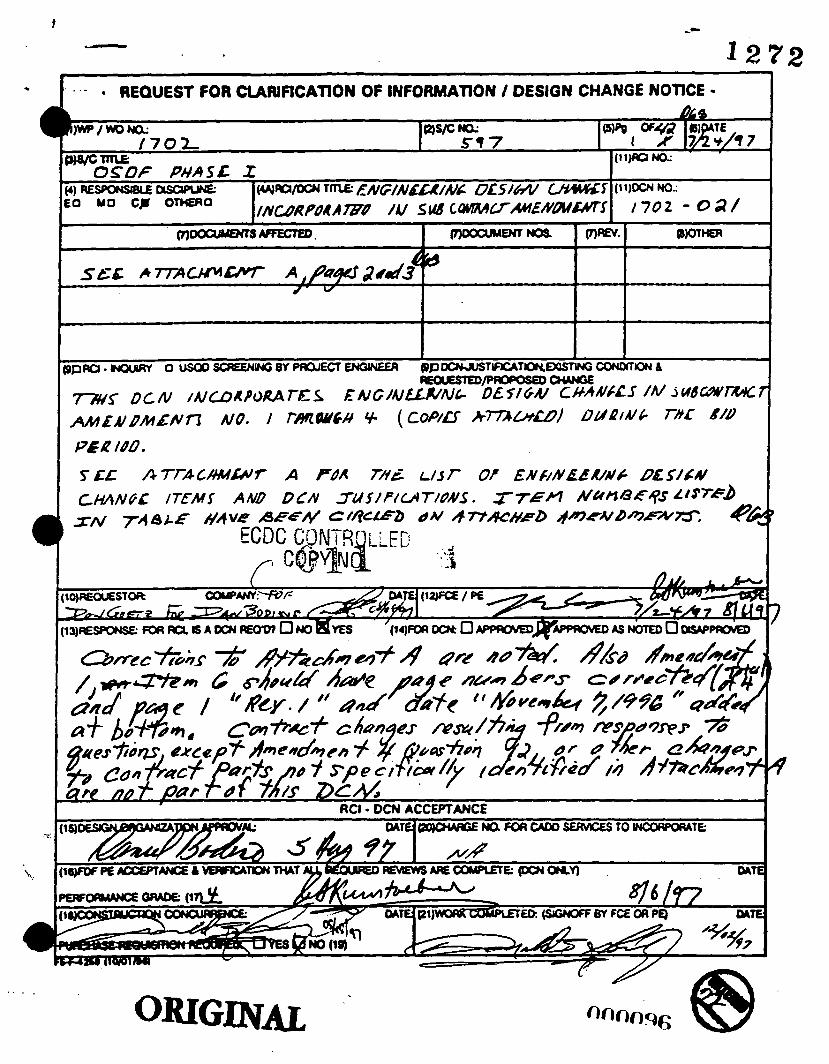
a . . .
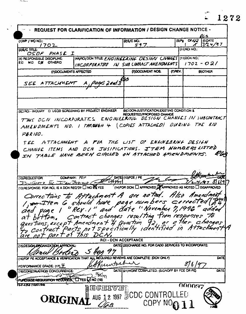
I
I I

or
N x F

c r r c C
I
!!
C
d
z C A * Q
0 9)
C
0
.-
3
5 k G
.- C
t
cy r- b cy 0 C 0 m 0 'c 0 Q)
v)
.- c
.-
a
C C m ..
F
c 0 N

I -
1 ~ L N D M ~ N T . ? ~ ~ ~ I F I C A T I O N NO 2. EFFECTWE O A n OWE 11) N O V W M R 7. 1886
I AMENDMENT OF SOLlClTATlON/MODlFlCATlON OF SUBCONTRACT I
1 *AGE 1 OK 2
5 N*ME ANO A ~ O R E S S OF SUBCONTRICTOR 1Nmr.rrrnr .cowrn.rr8ro.rd a@ C00.l
6. AMENDMENT OF S O U C I I A T W NO.
F97P272290 PROSPECTIVE OFFERORS 7. MOOVIUTIon OF WUICOWTMCT
NO.
REFER TO THE ATTACHED PAGES COR COMPLETE D n A l L S OF THE ADMP(DMDCI NO. 1
DATE
1 1/7/36 OATE
118. SU8CONTRACTOWOFFEROR 11C. DATE W E D
1 1/07/96
' - I 1X. DATE

Page 2 of 2 - FSC 597
ON-SITE DISPOSAL FACILITY - PHASE I Amendment Number 1
November 7, 1996
1 . Reference Part 4 - Special Terms and Conditions for Construction - Attachment No. 1.
Davis Bacon Wage Decision No 960034, Modification No. 7, and Replace in its entirety with Davis Bacon Wage Decision No. OH960034 Modification No 8, Dated October 18, 1996.
Reference Part 6 - Statement of Work, Rev. 0 dated October 21, 1996, replace in its entirety with the attached Rev.. 1 dated November 7, 1996..
2.
3. Reference part 6 - Statement of Work - Exhibit A - Subcontrrct Schedule, Rev. 0 dated October 21, 1996, replace in its entirety with the attached Rev. 1 dated November 7, 1996. b
4. Reference Pan 6 - Statement of Work - Exhibit 9 - Pay Item Descriptions, Rev. 8 dated October 21, 1996, replace in its entirety with the attached Rev. 1 dated November 7, 1996.
5. Reference Part 6 - Statement of Work - Exhibit f - Construction SUbcOnttaCtOr Termrnation Checklist, omitted from original proposal package. Insert the attached.
Reference Part 7 - Technical Drawings & Specificatiom, Pages 1 of 4 through 4 of 4, Rev.0 dated October 21, 1996, replace in its entirety with Pages 1 of 4 through 4 of 4, Rev. 1 dated November 7, 1996.
Reference Pan 7 - Technical Drawings & Specifications, Rev.0 section 3.0.A Reference Plan, 1 of 3, Rev. 0, and 75A
the attached drawings 75A Plan, 2 of 3, Rev. 1.
8 . Reference Pan 7 - Technical Drawings & Specifications, add the attached information ( fly ash spec, . . . . . . drawings, etc.
Reference Part 7 - Technical Drawings & Specifications, Section 1.0 - Construction Drawings. The following are additions/deletions to be incorporated in the referenced drawings: - I.
000181

- 0 The following is a general summary of the changes on the revised drawings Of sections that ut pan of this Amendment.
Drawing I Rev. Description
1 ) 90X-6000-G-00072 0 Grid Location. B-5: Relocate 'Construction Administration Area (Notc 12)'Shadow from drawing 90X-6000-G-00tZ, Rev. 0 , Grid Location B-5 to Grid hation C-5 (Approximately N479.200; E-1, 350, 400).
Add Note stating that Benchmarks OSDF-1, OSDF-2 and OSDF-3 shown on Benchmarks Table shall be installed by others.
2) 90X-6000-G-00075 0 Show utilization of existing fence along the west perimeter of OSDF Phase I Pmj&
Move west boundary of 'Sedimentation Basin' on drawing 90Xdooo-G-00075, Rev. O., grid location D-2, to the ea# 25' fect to Fdt Wge of existing fence line.
3) 90X-6000-G90075 0 Grid Isation All. Delete Shadowed Coordinate N482'ooo;
4) 90X-6000-G-00082 0 Change 'Future CeU 3. to read 'Future Cell' in the Kcond sentence of Note 2.
5) Section 02100 - Surveying a. In article 1.01. A. 1; Delete 'and permanent benchmarks'
b. Delete Article 3.04.

.-
- PART 7 - TECHNICAL
DRAWINGS AND SPECIFICATION
1 .O 2.0
Constructton Drawings . . . . , . . . . . . , . . . . . . . . . . . . . . . . . . . . . . . . . . . . . . 1 Specifications . . . . . . . . . . . . . . . . . . . . . . . . . . . . . . . . . . . . . . . . . . . . . . . . 2 A. Technical Specifications . . . . . . . . . . . . . . . . . . . . . . . . . . . . . . . . . . . . 2 8. Work Plans . . . . . . . . . . . . . . . . . . . . . . . . . . ... . . . . . . . . . . . . . . . . . 3 C. Construction Technical Specifications . . . . . . . . . . . . . . . . . . . . . . . . . . 3 Reference Information , . . . . . . . . . . . . . . . . . . . . . . . . . . . . . . . . . . . . . . . . . 3 A. Reference Drawings . . . . . . . . . . . . . . . . . . . . . . . . . . . . . . . . . . . . . . . 3 8. Reference Work Plans . . . . . . . . . . . . . . . . . . . . . . . . . . . . . . . . . . . . . . 5
3.0
NlENDHENT NO. 1

PART 7,
TECHNICAL DRAWINGS AND SPECiFICATIONS SUBCONTRACT NUMBER FSC 597 ON-SITE DISPOSAL FACILITY
1 .O CONSTRUCTION DRAWINGS
The following drawings show work t o be performed on this Subcontract:
m General Title Sheet Legend and Symbols
Civil
Site Development Plan Subgrade Grading Plan I Subgrade Grading Plan II Subgrade Grading Plan ill Cell Outlet Grading Plans OSDF Sections Cell Perimeter Details I
Rev. 1
Cell Perimeter Details I I Liner System Detads I Liner System Details I1 Liner System Details 111 Liner System Details IV Stormwater Management System Details I Stormwater Management System Details I1 Equipment Decontamination Facility Details I Equipment Decontamination Facility Details II Horizontal Monitoring Well Misc. Details Sedimentation Basin Details
Sheet Rev. FERMCO Na. m , Prawina &
X 1A 0 9OX-6000-X-00070 X 28 0 9OX-6000-X-00071
G-2A 0 90X-6000-G100072 G-SA 1 $. 9OX-6000-G-00073 G-5B .z 8( 90X-6000-G-00074 &tfW2'
G-5C 0 9OX-6OOO-G-00075 G-9A 0 90X-6000-G-00076 G l 5 A 2 Q 90X-6000-G-00077 *z G-20A 0 90X-6000-G-00078 G-21 A G-22A G-23A G-24A G-25A G-30A G-31 A G-37A G-37B G 4 A G 4 1 A
0
l a 2P
0 0 0 0 0 0 0 0
90X-6000-G-00079 +I= 90X-6000-G-00080 h*
90X-6000-G-08 1 a z &%f
90X-6000-G-00082 90X-6000-G-00083 90X-6000-G-00084 90X-6000-G-00085 90X-6000-G100086 90X-6000-G-00090 90X-6000-G-00087 90X-6000-G-00089
Swctura l Chain Link Fence F 5 A 0 90X-6000+-00088
0 0 0 3.04 November 7,1996
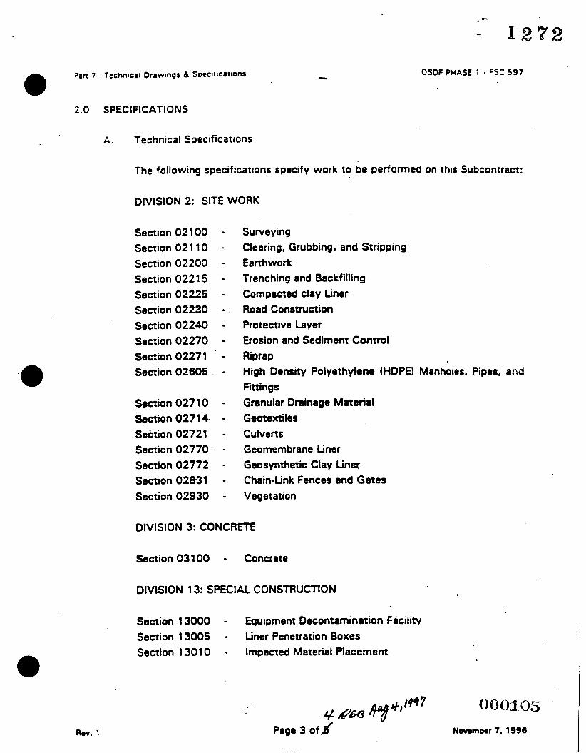
OSOF PHASE 1 - F f C 597
2.0 S PEClFlC ATlONS
A. Technical Specifications
The following specifications specify work to be performed on this Subcontract:
DIVISION 2: SITE WORK
Section 02 1 00 Section 021 10 Section 02200 Section 022 1 5 Section 02225 Section 02230 Section 02240 Section 02270 Section 02271 '
Section 02605
Section 027 1 0 Section 0271 4. Sektion 02721 Section 02770 Section 02772 Section 02831 Section 02930
Surveying Clearing, Grubbing, and Stripping Earthwork Trenching and Backfilling Compacted clay Liner Road Consauction Protective Layer Gosion and Sediment Control Riprap High Density Polyethylene (HDPD Manholes, Pipes, ard Fittings Granular Drainage Materid Gootextiles C u I v e rt s Geomembrane Liner Geosynthetic Clay Liner Chain-Link Fences and Gates Vegetation
DIVISION 3: CONCRETE
Section 031 00 - Concrete
DIVISION 13: SPECIAL CONSTRUCTION
Section 1 3000 - Equipment Decontamination Facility Section 13005 - Liner Penetration Boxes Section 1 301 0 - Impacted Material Placement
Rev. 1 Page 3 off Novrmbar 7. 1996

Pan 7 . Technic81 Drawings & Soectticroons OSDF PHASE 1 - FSC 597
B. Work Plans
I PI= Rev. G, October 1996 Surfac r-W a t er M an a g g - t o
( D R A m
Ma- Rev. G., October 1996 (DRAFT)
m s Plan. Rev. G, October 1996 (DRAFT)
C. Construction Technical Specifications,.
The following are Construction Technical Specifications referenced in other subcontract sections.
ms ppro Subcontract Submittal Requirements 1 0/2 1 /96 Subcontractor Safe Work Plan Format Requirements 1012 1 /96 Subcontractor Fire Extinguisher Inspection 1 0/2 1 /96 Subcontractor Ladder Inspection 1 012 1 /96 Subcontractor Ponable Structures 10121 196
3.0 REFERENCE INFORMATION
The following is reference information showing data relative to this Subcontract for use by the subcontractor:
.
A. Reference Drawings
Sheet Rev. FERMCO N a , 4 L P I
Facility Plot Plan x-3 G SOX-6000-X-00003
Site Plan x 4 G 90X-6000-X-OooO4 Brown TillGray Till Interface Contour Map X-10 G 9OX-6000-X-OOOOS . Gray Til Isopach Map x-1 1 G 9OX-6000-X-000 1 0
Surface Geology Map x-12 G 9OX-6000-X-00011 Geologic Section A-A X-13 G 9OX-6OOO-X-OoO 1 2
be3 : %ea€ is bCd ? y e 5 t ~ ~ v t d A&- / Md mm11-06 1497 4 636s &?'I
Rav 1 Page 4 of,# MENWENT NO. 1 Novunbrr 7,1996

c
- 1272
F97P272290 7. MODIFICATION OF SUBCONTRACT
I 6 AMENDMENT OF SOLICITATION/MODIFICATlON OF SUBCONTRACT
1 1 /22/96 DATE
1. AMENDMENTIMODIFICATION NO. Two It) I
11A. NAME AND T m E OF SGNER [Type 01 pmd
I
2. EFFECTIVE DATE N O V W 22. 1996 I
12A. F u n d Enwmmmtd Ratorbon Mrugmnt Cap.
A. D. Sablosky Contract Administrator
I
4. ISSUED BY: Fluor Danniel Femdd P.O. Box 538704 Cincinnati, OH 45253-8704
5 NAME AND ADDRESS OF SUBCOWfRACTOR I N m . . o r t o o u n y . ~ . d Op DATE 0. bh4ENwm OF S O L m r A ~ NO.
118 SUBCONTRACTOWOFFEROR
(*naruUre o l ~ ~ # d n r s d ro upn)
PROSPECTIVE OFFERORS
12C. DATE SIGNED
1 1 /22/96
1 l C . DATE W E D
NO.
8 . THIS ITEM ONLY APPLIES TO AMENDMENTS OF SOLICITATIONS
9. THIS ITEM APPLIES ONLY TO MODlFlCATlONS OF SUBCONTRACTSIORDERS. IT MODIFIES THE SUBC0MRACTK)RDER NO. AS DESCRIBED IN ITEM 10.
A. THIS UNILATERAL MODlflCATlON IS ISSUED PURSUANT TO: ISprirV .urhodvl. M E CHANGES SET FORTH N ITEM 10 ARE MADE IN THE SUBCONTRACT IDENTIFIED M ITEM 7
8. THE ABOVE NUMBERED CoNTRAcflORoER IS MODIFIED TO REFLECT W E ADMNISfRATNE CHANGES S R FORTH N
C THIS B t U W MODIFICATION IS ENTERED N T O RlrcsUAHT TO A U W O R W OF:
D OTHER t.Sm&y?ypo oinDOk%rarpnmd&riM
E. IMPORTANI: CONTRACTOR 0 i not. 0 i r- to s h thh doawnant md r . h m ma to th. otclrn.
10.
10. DESCRIPTION OF AMENDMENTMODIFICATION
REFER TO THE ATTACHED PAGES FOR COMPLRE DnAlLS OF THE ADMENDMENT NO. 2
0001.07

SOLICITATION NO. F97P272290
SUBCONTRACT NO. FSC 597
ON SITE DISPOSAL FACILITY (OSDF) PHASE I
AMENDMENT NO. 2
November 22,1996
1. Refer to Part 1, Offer Section, Section 1, Form FS-F-798, 'Solicitation, Offer, and Award", Item 13, and delete reference to quantity of offers. Refer to Instruction to Offerors for instructions regarding quantity and organization of offers; change proposal due date to December 12, 1996.
.
'2. Refer to Part 1, Offer Section, and add Form FS-F-4625, Agreement to Subcontract Terms and Conditions / General Provisions, dated 4/23/96.
3. Refer to Part 1, Offer Section, Section 2, Form FSF4107 M528, Representations, Certifications, ' and Other $tat%im'erW of Biddetsr I OffekWWted 7/19/95 and:- ' *sb - - *
A e f e r to Page 3 and delete hem 118 'Organization Conflict of Interest - Disclosure or Representation' in its entirety.
/= Refer to Page 4 and delete Item 12, 'Walsh-Healey Public Contracts Act Representation in its entirety.
4. Refer to Part 1, Offer Section, Section 4, 'Instructions to Offerors', dated October 24, 1996 and replace with 'Instructions to Offerors,' attached. Changes are highlighted. A
5. Refer to Psrt 4, Speaal Terms and Conditions for Construction OSDF Phase 1, ERRATA '- Sheet dated October 24, 1996 and replace with Special Terms and Conditions for
Construction OSDF Phase 1, ERRATA Sheet dated November 20, 1996.
,6. Refer to Part 5, Project Labor Agreement, Section 4, FERMCO Memorandum No. M:ADM:(IR):94-0198 dated May 24, 1994 and include page 1 of 2 which was previously omitted.
7 . /
Refer to Part 6, Statement of Work, Section 2.13 Contract Line hem 2, and replace with the following in its entirity:
"2.13 CONTRACT LINE ITEM 2
A. Contract tine Item 2 shall include cost for performing excavation, stockpile, haul and clay fill (herein after called additional excavation and clay fill) of an estimated not to exceed 5,000 in-place cubic yards (ICY) which is in addition to the scope of work specified or shown on the
.construction drawings. This cost shall be included in the base subcontract proposal price which will be listed as a per unit price pay OOc)108
Page 2 of 16

c
c 1 2 1 2
SOLICITATION NO. F97P272290 SUBCONTRACT NO. FSC 597 ON SITE DISPOSAL FACILITY (OSDF) PHASE 1 AMENDMENT NO. 2
item on the Pay hem Descriptions. This excavation and clay fill shall be performed as directed by the Construction Manager.
B. Payment for this estimated not to exceed excavation and clay fill shall be based on the Unit Price set forth in the Solidtation, Offer and Award Form (FS-F-798). This unit price for estimated excavation and clay fill per in-place cubic yard includes but is not limited t o labor, equipment, material, supervision, safety, quality control, submittals, taxes, insurance, bond, overhead and profit.
C. The Subcontractor shall include, as pert of the monthly invoice, the in-place cubic yards (ICY) of the additional excavation and clay fill during that billing period established by field surveys. Copies of the field surveys shall be included with the invoice. The billing shall be against contract line item 2 in the Pay hem Schedule.'
Refer t o Part 6, Statement of Work, Section 2.14.H.1 add the following : 0 8 . 4
'Response time is limited t o 30 minutes to the site and 30 minutes after leaving the site.'
2. Refer t o Part 6 , Statement of Work, Exhibit A - Construction Schedule, Rev. 1 dated November 7, 1996, replace in its entirety with Rev. 2, dated November 22, 1998.
10. Refer t o Part 6, Statement of Wok, Exhibit B - Pay Item Descriptions, Pay Item 7.0, Pay Item Heading 'Cell 1 and intercell berm LINER". Delete the Detailed Pay Item Description in its entirety and replace with:
"Items under this Pay Item include the liner for Cell 1 and the liner for the intercell berm between Cell 1 & 2 induding the tie-in of the various layers of Cell 1 and the intercell berm between Cell 1 & 2 t o the limits shown on the Construction Drawings.'
/
11. Refer t o Part 6, Statement of Work, Exhibit E, Documentation Requirements Form, delete in its entirety and replace with Rev. 1, dated November 22, 1996.
@ Refer to Part 7, Technical Specifications & Drawings, Construction Drawings, and replace:
me Sheet E E L Subgrade Grading Plan I G-5A Rev. 0
Rev. 0 OSDF Sections G-15A Rev. 0 / . Subgrade Grading Plan I1 G-5B

SOLICITATION NO. F97P272290 SUBCONTRACT NO. FSC 597 ON SITE DISPOSAL FACILITY (OSDF) PHASE 1 AMENDMENT NO. 2
Liner System Details I Liner System Details II
G-22A Rev. 0 G-23A Rev. 0
With the following drawings:
Sheet kL G-5A Rev. 1
IU Subgrade Grading Plan I Subgrade Grading Plan II G-50 Rev. 2 OSDF Sections G-15A Rev. 2 Liner System Details I G-22A Rev. 1 Liner System Details II G-23A .. - ~ Rev. 2
f
@ Refer to Part 7, Technical Specifications, Specification Section 02770, Table 02770-1, Tensile Properties (each Direction):
1) Change the specified value for Force Per Unit Width at Yield t o 8 minimum --. . .- . . . - ~ -- - .. - - - - . .
of 160 Ibhn per ASTM D 638.
2) Change the speafied value for Tensile Strength (force per unit width at break) t o a minimum of 100 lbhn per ASTM D 638.
14. Refer to Part 7, Technical Drawings and Specifications, Section 2.0.C - Construction Technical Specifications:
Subcontractor Fire Extinguisher Inspection Rocedure, Rev. 0, dated October 21, 1996, delete Attachments A and 6 in their entirety, replace with Attachments A and B, dated November 22, 1996;
Subcontractor bdder Inspection, dated October 21, 1996, delete Attachments A and B in their entirety, replace with Attachments A and 6 , dated November 22, 1996;
Subcontractor Portable Structures, add Attachments 1 through 4 which are referenced in this Construction Technical Specification but were not included in the proposal package.
15. Refer to Part 8 , Safety & Health and Training Requirements:
Table of Contents, Page 4, Section E - Attachments, change the description of Attachment 1 to read ‘Deleted”;
Section 2.0 General Safety and Health Provisions, delete subparagraph 2.3 in its entirety;
i
Page 4 of 16

SOLICITATION NO. F97P272290 SUBCONTRACT NO. FSC 597 ON SITE DISPOSAL FACILITY (OSDF) PHASE 1 AMENDMENT r r n rl NU. L
ttem Descriptions in Exhibit 8 of Part 6, Statement of Work.
Response:
7. Question:
Response:
8 . Question:
Response:
The Pay Item Schedule referenced in Part 1, Instructions to Offers, 10.0 Price Proposal, B was not provided in the solicitation. The requirement is for the Offeror to gemerate a Pay hem Schedule similar to the Pay Item Descriptions in Exhibit B of Part 6, Statement of Work. A form is provided for the convenience of the Offeror with this Amendment No. 2.
Reference Part 1, Instructions of Offeron, 10.0 Price Proposal, Items A.2 and 8: Please verify that Contract Line hem 2, 5,000 cubic yards of excavation, b not induded in the b y hem Descriptions of Exhibit to Part 6, Scope of Work, and, therefore, is not to be included in the Pay Item Schedule to be generated by the Offeror.
Refer to Amendment No. f dated November 7, 1996 for 8 revised Exhibit B and the description of Contract Line Item 2. The Pay hem Descriptions illustrate the minimum activities that must be included in a Pay hem Schedule and Pay hem Schedule Invoice. The Subcontractor may indude items .dditional to those liaad.
0
Refer to Reference Part 6, Statement of Work 2.13 Contract Line Item 2: provides for additional payment for 5,000 cubic yards of additional excavation and fdl on a unit price basis. However, the contract does not contain a variation in quantity clause. Therefore, it is arguable that amounts above 5,000 cubic yards could be subject to modification or a daim under this contract. The Special Conditions also limit the amount of overhead and profit that can be applied to modifications. Please clarify how payment for any required quantities above bid stated quantities will be made under the contract.
Amendment 2, Part 6, Statement of Work, Paragraph 2.13 for clarification. Contract tine Item 2 is a per unit price for an esrimated 5,000 cubic yards of excavation and backfill below the design subgrade. This estimated amount is a not to exceed amount; there is no representation that this amount or any amount of excavation and backfill below the design subgrade will be necessary, simply that it is anticipated. Hence, a variation in quantity clause would not be appropriate to this application. Amounts above 5,000 cubic yards would constitute a change order; an equitable adjustment for the changed work would be executed in accordance with the applicable General Provisions and Special Terms and Conditions.
Page 7 of 16

SOLICITATION NO. F97P272290 SUBCONTRACT NO. FSC 597 ON SITE DISPOSAL FACILITY (OSDF) PHASE 1 AMENDMENT NO. 2
9. Question: Rofersnce Part 6, StM8mant of Work, 2.14 Dust Control: requires after hours dust uppression and appsars to limit the amount payable to $50,000. Please clarify whether or not this 850,OoO is, in fact, intended as a Cap on the total amount payable or whether it will be modified upward in the event of greater th8n expected requirements for the activity. What exactly is the 550,000 dust suppression allowance intended to cover? What hapmns when the offeror over/underruns this amount?
Response: This dust suppression allowance is to cover the expense of bringing someone to the project site to suppress dust when unusual circumstance (IE. High wind and excessive dry heat) cause a previously secure soil surfacs to generate dust. In the event that after hours dust suppression exceeds $50,000 the contract will be modified in accordance with the applicable General Provisions and Special Terms and Conditions. Refer to Amendment 1, Part 6, Statement of Work, for a further explanation
. regarding what the dust suppression allowance is intended to cover. . .
10. Question: The solicitation contains option items which will be evaluated in determining the lowest total evaluated price. In this regard, the evaluation criteria indicate that either option 2 (8) or 2 (b) will be selected depending on which is the most 'advantageous' to the government. The evaluation criteria do not indicate how this advantage will be determined by Fluor Daniel Fernald. It is likewise not clear whether all offerors who submit will be evaluated using the same combination of options 2 (a) or 2 (b). Please darify whether or not ell offerors will be evaluated based on the same selection of options 2 (a) or 2 (b), of whether or not different combinations of options will be applied to different contractors.
Response: All offerors will be evaluated based upon the same combination of either Option 2A or 28.
11. Question: Reference Part 6, Statement of Work, Exhibit 6, Pay Item Description, 4.01, Leachate Conveyance System: the operation and maintenance of the Leachate Conveyance System is required by Part 1, Instruction to Offerors, 10.0 B, to be priced for the contract period. Please clarify how the price should be presented: Le., for the base contract period or should any extension be considered through potential options which extend the contract period.
Response: Refer to Amendment 2, Part 6, Statemant of Work, for amended project schedule. AU costs associated with schedule emmion that is not pan of the specific scope of work of Option 1 or Option 3 will ba included in the proposed cost for Option Pa and Option 2b. Option 1 does not have any schedule extension related to it.
000112 B Page 8 of 16

- 1 2 7 2
SOLICITATION NO. F97P272290 SUBCONTRACT NO. FSC 597 ON SITE DISPOSAL FACILITY (OSDF) PHASE 1 AMENDMENT NO. 2
Section E - Attachments, delete Attachment 1 in its entirety.
15. Refer to Part 9, Quality Assurance Requirements, Quality Requirements, Paragraph 2.3 on Page 2 of 5, and change Paragraph 2.3 to read:
"Describe the qualifications of the Subcontractor's Quality Inspector."
The following clarifications have been requested:
1.
2.
3.
Question: Reference Part 1, Instruction to Offerors, 0.0 Technical Proposal, page 8 of 16, Section 2, Technical Approach and Scftedule: Please clarify and expand upon the requested information/content of the offeror's technical approach. a
The format to be utiiized is for the Reliminary Safe Work Pian is included in the Subcontractor Safe Work Plan Format Requirements located in Part 7 (Volume Ill of the Solicitation .
_ -
Response:
Question: Reference Part 1, Subcontracting Plan: A SB/D subcontracting Plan is required for this contract, but no minimum SB/D requirement is identified. Please verify that no minimum goals are expected and that the SBID Subcontracting Plan is not part of the award evaluation.
Response: There.rre no specified minimum goals. Rather the Subcontracting Plan . must reflect a reasonable and good faith effort to subcontract to small
businesses, small disadvantaged business, and small women owned businesses. The Subcontracting Plan will be reviewed for sufficiency but will not be competitively evaluated. Failure to provide a sufficient Subcontract Plan may be grounds for a determination of non- responsiveness.
Question: Reference Part 1, Instructions to Offerors, 9.0 Technical Proposal, page 8 of 16, C. Project Team Roles and Responsibilities: requires offerors to "specify all significant lower tier subcontractors by name and address." Typically, agreements are not finalized with lower tier subcontractors until aher project award. Further, this contractor often allows other qualified bidders an opportunity to bid portions of lower tier subcontractor work after project award. Will Fluor Daniel Fernald accept changes to our named lower tier subcontractors after project a.ward?
Response: See Amendment 2 Pan 1, Instructions to Offerors; and, Part 4, Special
Page 5 of 16 .. .- .

- SOLICITATION NO. F97P272290 SUBCONTRACT NO. FSC 597 ON SITE DISPOSAL FACILITY (OSDF) PHASE 1 AMENDMENT NO. 2
Terms and Conditions Errata Sheet for clarification.
4. Question: Reference Pan 3, General Terms and Conditions, clause a.32, Indemnity: requires the subcontractor to broadly indemnify Fluor Daniel Fernald, FERMCO, and the government regardless of the comparative negligence of Fluor Daniel Femald, FERMCO or government employees or others. This is an extremely one-sided indemnity. It is also noted that in accordance with the Statement of Work at page 2 of 18, the construction site for this activity will have a public road running through it, which will continue to remain open to traffic during a substantial portion of the construction period. This certrinly increases the risk of accidents which could trigger this broad liability. Page 10 of 18 of the Statement of Work also states that Fluor Daniel Fernald will be responsible for all monitoring on the project. Given the fact that the subcontractor will not have complete control of the project, would FJuo; Daniel Farnald consider negotiating an indemnity which would be fairer with the subcontractor?
Response: Fluor Daniel Fernald will not consider negotiating this clause.
5. Question: Reference Part 4, Special Terms of Conditions, SC-29, Performance of Work by the Subcontractor: requires subcontractor to perform 55 percent of the work at the site. Please clarify how this determination will be made. If the determination is made on a project revenue basis, how will the purchase of materials and rental of equipment be considered? If the subcontractor is directly overseeing the labor of others (i.e., often equipment suppliers can provide equipment operators), how will this be considered? If site activities are supervised and managed by the subcontractor, what would be the requirement for work to be considered performed by others?
Response: Performance of work by the Subcontractor will be calculated and tracked by on a total cost basis. Purchases of material and rental of equipment will be "credited" to that tier of Subcontractor which executes the direct purchase or rental. If operators are supplied with rented equipment, the Subcontractor will be "credited" that dollar amount only if the rental agreement is a unit price agreement for equipment and there is no scope of work included in the rental agreement. The Subcontract shall provide documentation of this relationship upon request.
-
6. Question: Reference Part 1, Instructions to Offerors, 10.0 Price Proposal, B: Please verify that Pay Item Schedule was not provided in the solicitation and that t h e Offeror must generate a Pay Item Schedule similar to the Pay
000114 Page 6 of 16
@ SOLICITATION NO. F97P272290 SUBCONTRACT NO. FSC 597 ON SITE DISPOSAL FACILITY (OSDF) PHASE 1 AMENDMENT NO. 2
12. Question: Fluor Daniel Fernald is not required to exercise any of the options until October 15, 1997, in accordance with the special condition clause added by an errata sheet. Please clarify whether or not the exercise of these options is dependent upon funding or what other future events.
.
Response: Fluor Daniel Fernald is not required to exercise any options. If Fluor Daniel Fernald executes any individual or group of options, it will do so on or before October 15, 1997. Exercise of options is at the sole discretion of Fluor Daniel Fernald and will be exercised only if it is in the best interests of the Department of Energy and Fluor Daniel Fernald, funding and other factors being considered.
13. Question: Will Fluor Daniel Fernald provide Offerorr with quantity takesffs as determined by their Engineer?
b
.. Response: No.
14. Question: Reference Part 6, Statement of Work, 4.0 Interfaces and Restraints, 4.1 : Please clarify the extent of escorting required for deliveries to the project work site.
Response: Drivers delivering materials to the work site will not be required to complete training as defined in Part 8 provided a trained subcontractor esam is maintained at all times. Drivers without proper training will not enter any Radiological controlled area.
Drivers exiting their vehicles will wear the following safety equipment:
.
- Safety glasses with rigid shields or goggles (safety glasses
Hard hat (only ANSI Z89.1 listed)
Any additional PPE as required by escort
ANSI 287.1 listed)
Sturdy leather work boots - - Brightly colored safety vest -
Escorts will brief drivers of any hazards around a delivery vehicle.
15. Question: Will alternate work schedules be permitted, Le., four days of 10 hours a day, scheduled overtime, scheduled weekends, etc.?
Response: Refer to Part 6, Paragraph 7 for OSOF Project work hours. Alternate work schedules in excess of these hours will be considered i f requested and at least four days in advance. Work after dark will not be permitted.
Page 9 of 16

SOLICITATION NO. F979272290 SUBCONTRACT NO. FSC 597 ON SITE DISPOSAL FACILITY (OSDF) PHASE 1 AMENDMENT NO. 2
Scheduled overtime excluding split shifts will be permitted. Weekend work excluding Sundays will be permitted. Fluor Daniel Fernald reserves the right to back charge the Subcontractor for costs incurred to support schedule acceleration due to Subcontractor deficiency.
16.
17.
10.
19.
20.
21.
Question:
Response:
Question :
Responm:
Question:
Response:
Question:
Response:
Question:
Response:
Question:
r '
3 '
Refer to section 02270-16 Table 02270-1 No. 2 of Mechanical Propenies: tensile strength, has a 'typo", the specified value listed is 300 I bh . This is for smooth HDPE sheet, textured HOPE sheet is lower. NSC's value is 184 Ibhn. Can this please be clarified.
Refer to this Amsndwknt 2 for revision to Table 02270-1.
Reference drawing G37A - is the reference to creosote correct? s
YO&
Will the successful offeror be responsible to screen materials obtained from on-site sources to meet the material specifications?
The subcontractor shall be responsible for selection of the method and removal of the oversized material larger than *- in the construction of the compacted clay liner.
Reference 13010.3. 3.01 A: Will radioactive material be encountered in on-site borrow areas?
Work m the &e borrow areas b not included in this contract. Fill and material for the compacted clay liner shall be obtained for the cell excavations included in this contract.
Is the cost for the construction of the cell perimeter berm to be the entire berm even including that portion which abuts cell 2? If so, how do we build the berm without excavating Cell 27 Or is some portion of the perimeter berm to be included with cell 27 If SO, where on the drawings is this shown?
Refer to Drawings G5B, Rev. 2 and G-l5A, Rev. 2, included in this Amendment No. 2 for construction boundaries.
Please provide the offerers a cross section of the north entrance road.
Existing north entrance road cross section consists of 6 inches of asphaltic concrete pavement over 6 inches crushed rock base course.
Page 10 of 16

c - 1272
0 SOLICITATION NO. F97P272290 SUBCONTRACT NO. FSC 597 ON SITE DISPOSAL FACILITY (OSDF) PHASE 1 AMENDMENT NO. 2
22.
23.
@ 24.
25.
26.
27.
Question:
Response:
Question:
Response:
Question:
Response:
Question:
Response:
Question:
Response:
Question:
Reference 021 10-4, 3.05 B: refers to section 13010 for methods of disposal on site of clear and grub materials. Please clarify the final disposition of these materials.
Final disposition of deared material shall be in a separate stockpile in the Subcontractor's work area in accordance with the approved Subcontractor's Work Area Plan (Specification Section 021 10, 3.03E). Final disposition of grubbed material shall be in the On-Site Disposal Facility (OSDF) by others.
Reference 13010-5, 3.06 A: Who is the "CQC Consultant"?
The CQC Consultant is GeoSyntec Consultants, Inc., who is under contract t o Fluor Daniel Fernald t o perform this function. Note that the Subcontractor shall maintain its own full time QA Representative.
Is the material stockpiled in the IMPACTED material stockpiles (East and West) considered "select' material? .
. *
Reference Drawing 9OX-6OOO-9-OOO77, sheet No. 15A; select impacted material shall be obtained from the east and west impacted material stockpiles.
Does the material in the East and West IMPACTED stockpile area meet gradations for Impacted granular or Impacted non granular? Define IMPACTED.
These stockpiles are acceptable for use as the protective layer and select material layers induded into OSDF - Phase I for the non-granular impacted material. However, material larger than the material specified in Specification Section 02240 shall be removed. Impacted Material shall be as defined in the Impacted Material Placement Plan located in Part 7 of the solicitation.
a. b.
Where is the OSDF BORROW area for clay? Section 02225-3 item 2;OlE ... when will Bentonite be used?
a.
b.
As specified in the Section 02225, material for the clay liner shall be obtained from the OSDF excavation. The bentonite shall be used to fill perforations in the clay liner created by CQC testing.
Cells 1 and 2 are cut and fill. Does the cut material meet the 3" - spec.?
Page 11 of 16

....
SOLJCITATJON NO. F97P272290 SUBCONTRACT NO. FSC 597 ON SITE DISPOSAL FACILITY (OSDF) PHASE 1 AMENDMENT NO. 2
Response:
28. Question:
Response:
29. Question:
Response:
30. Question:
Response:
31. Question:
Response:
:L(PQO118
Material excavated from Cells 1 and 2 contains rock fragments larger than 3 inches. Rock fragment larger than 3 inches in fill material and larger than 2 inched for the compacted clay liner material shall be removed from the excavated material as specified in sections 02200 and 02225 respectively.
a.
b. C. What are BATTERY limits? d. Section 02110-4.305B refers to section 13010. Where is this
Where will the dearing and grubbing material be disposed of after stockpiling? What drawing shows limits of clearing and grubbing?
section?
a. Disposition of dearing and grubbing material stockpile shall be by other subcontract. - - - - a _ .
b. Clearing and grubbing limits shall be as noted on the construction Drawing 90X-6000-G-00073, sheet 9-5A.
c. The battery limits are shown on the construction drawings defines . the boundary of the entire OSDF project.
d. Section 13010 b induded in Volume II of the subcontract documents.
Ref. drawing G-5A legend item 2 notes "subgrade elevation (feet)". Is the outside of the Cell berms, as shown on this drawing considered final grade?
Elevations shown on the construction drawing G-5A are the subgrade elevation unless otherwise noted. Refer to Drawings G-20A and G-21A. Cell Perimeter Details I and Cell Perimeter Details II, respectively, which show the location of subgrade elevations and finished grade elevations beyond the limit of the perimeter berm.
Ref. Drawing G-23A detail 15/6 shows Temporary Protection (4" wide H " thick treated plywood sheets or equivalent) if i ts temporary, when does it get removed?
These plywood sheets get removed by others during construction for the cell 2 liner.
Ref. drawing G-58 are the elevation shown in the cells the bottom of clay?
Yes.
Page 12 of 16

0 SOLICITATION NO. F97P272290 SUBCONTRACT NO. FSC 597 ON SITE DISPOSAL FACILITY (OSDF) PHASE 1 AMENDMENT NO. 2
32.
33.
@ 34.
35.
36.
Quest ion:
Response:
Question:
Response:
Question:
Response:
Question :
Response:
Question:
Response:
Ref. drawing G-31A plan - Show Drainage Channel Gravity Inlet Structure & Culve rt... Drawing G-15A BIG-SA and C/G-5B shows this by others?
The gravity drainage inlet structures (GIs) and culverts shown on Drawing G-SA, G-5B. and G-31A are part of the surface-water management system and part of this subcontract. The leachate transmission system manholes shown south of each GIS shall be constructed by others. HDPE piping from OSDF - Phase I Subcontract shall be tied into piping at the leachate transmission system manholes as shown on the construction Drawing G-l5A, Sections 8 and C.
Page 1 of 4 PART 7 Technical Spec. drawing. and specs indicated Chain Link Fence as drawing G-SA...verses actual drawing number of S-5A (structural).
This has been corrected in the Amendment No. 1.
Please provide Electrical Specifications for work described in Part 6, Statement of Work :
- Section 2.2.8, Extended Uti/itks ...- - Section 2.6.A. Construction of the Equipment Decontamination fad*, including ...- Pow=.
Refer to Drawings G-37A and G-376 for electrical scope of work related to Equipment Decontamination Facility.
Drawing G-5A detail (WG-15a shows subgrade elevations but detail (B) on G-15a shows finished.grade. Which is correct?
Detail B on Drawing G-15A shows subgrade elevation and finished grade for the liner system, protective layer and select impacted material layer in cell 1 and the intercell berm between cell 1 and cell 2. Drawings G- 5A and G-56 show subgrade elevations only. For clarity purposes finished grade elevations are not shown in Drawings G-5A and G-5B.
G-15a shows B/L PERIMETER BERM at the HIGH POINT on the berm and sloping inward toward the cell but ... Drawing 22-A details show BIL PERIMETER BERM at the LOW POINT of the berm and slopes away from the cell. Which is correct?
The baseline of the perimeter berm is the high point of the berm sloping inward on the construction drawings G-15A and G-22A. For clarity the
Page 13 of 16

SOLICITATION NO. F97P272290 SUBCONTRACT NO. FSC 597 ON SITE DISPOSAL FACILITY (OSDF) PHASE 1
. AMENDMENT NO. 2
protective clay liner is shown only on the construction drawing G-22A.
37. Question: Reference Part 9, Quality Assurance Requirements, paragraph 2.3. Subcontractor is required to have Quality Inspector certified by National Institute for Certification pf Engineering Technologies for installation inspection of Geosynthetic Materials. The Construction Quality Assurance Plan, also in Part 9, states on page 4-8 that the CQC Consultant organization shall provide a Field Monitor with the same certification. In lieu of the fact that Fluor Daniel Fernald will already have a certified CQA Inspector, can the requirement to the Subcontractor be waived?
Response:
38. Question:
Refer to Amendment 2 for revision of paragraph 2.3.
May the two (2) 48' culverts be installed prior to June 2? If so, must w i allow 7 days after removing asphalt for RAD surveying prior to removing base course of road?
Response: No, the two (2) 48' culverts cannot be installed prior to June 2.
39. Question: Please define the radiologically controlled areas (RCA's).
Reponse: There are no radiologically controlled areas anticipated for this scope of work. Reference Part 6 Statement of Work, Section 4.9 for additional information.
40. Question: Is it the intent of the specification to obtain all the day liner material from on-site? If so, will it be a change of conditions if the clay liner must be obtained from off-site or require processing?
Response: . As specified in Section 02225, material for clay liner shall be obtained from the OSDF excavation. Processing of clay shall be done in accordance with Section 02225.
41. Question: Must the material excavated from Cell 1 be stockpiled in the contractor's work area? Can it be stockpiled at future cell areas (cells 2 or 3)? Same for the Cleared & Grubbed chippings.
Response: The material excavated from Cell 1 must be stockpiled in the subcontractor's work area. It cannot be stockpiled at future cell areas. Same for the Cleared & Grubbed chippings. Refer to Drawings G-56 amd G-5C. ,
Page 14 Qf 16

0 SOLICITATION NO. F97P272290 SUBCONTRACT NO. FSC 597 ON SITE DISPOSAL FACILITY (OSDF) PHASE 1 AMENDMENT NO. 2
42. Question: Where should the material excavated from Cell 2 be stockpiled?
Response: Refer to Drawings G-5B amd G-5C.
43. Question: Define the limits of the drain tile removal Le . Cell 1, Cell 2, whole facility?)
Response: Limits of the drain tile removal are the same as the physical limits for the base contract and for option 1 respectively.
44. Question: Are the other underground utilities shown on sheets SKG04394 11-16 part of the drain tile removal?
Reponse: Yes. 0
45. Question:
Response:
Is the Cell 2 drain tile removal part of base contract or Cell 2 option?
Drain tile removal within the excavation limits of the base scope of work is part of the base contract. Drain tile remove within the excavation limits of option 1 scope of work is part of option 1.
46. Question: Is it the intent of the specification to mix bentonite with on site soils to obtain 10' permeability if necessary?
Response: No.
47. Question: May the CQC Consultant begin conformance testing on clay liner prior t o excavation and stockpiling?
The CQC Consultant will begin conformance testing on c lah liner simultaneous with these activities.
Response:
48. Question: Is the construction of Sediment Basin 1A pan of this contract?'
Reponse: Construction of the Sediment Basin east of the North Entrance Road for Area 1A is part of this subcontract.
49. Question: Can the Existing North Entrance Road be used for hauling?
Response: Access and traffic control must be maintained as outlined in Part 6, SOW, Section 2.38. Existing North Entrance Road be used for hauling construction material only: it cannot be used for impacted material.
Page.15 of 16

SOLICITATION NO, F97P272290 SUBCONTRACT NO. FSC 597 ON SITE DISPOSAL FACILITY (OSDF) PHASE 1 AMENDMENT NO. 2
50.
51.
52.
53.
54.
Question :
Response:
Question:
Response:
Question:
Response:
Question:
Response:
Question :
Response:
Define the limits of fence removal.
As shown on Drawing G-5A, G-SB, and G-5C.
Shall the decon facility be manned by subcontractor full time? Will anyone other than subcontractor be using decon facility?
Only the subcontractor be using decontamination facility until turn over to Fluor Daniel Fernald.
What is the proposed haul route for the hpact8d material stockpile to the landfill cell? What are the decon and RAD survey requirements?
The haul route from the impacted material stockpiie to the cell will bt proposed by the subcontractor as part of tho reqphments of Technical Specification Section 13010 - Impacted Material Rawment. There are no radiological decontamination requirements because material from the stockpile be below minimum levels fot radiological contamination. Dust suppression and road cleaning from hauling operations will still be required.
a Is it the subcontractor's responsibiMy to remove the. silt from the sediment basidditches prior t o completion of project? If so, where shall the silt be placed?
the subcontractor shall maintain the sediment basins and ditches in accordance with the Surface Water Management and Erosion Control Plan located in Part 7 of this solicitation. Any silt that is removed will be placed in the impacted material stockpile.
Would it be acceptable to submit with our proposal a summary and table of contents for Subcontractor's Corporate Health & Safety Plan instead of the entire document?
The solicitation requirement is to submit the information requested in Part 8, Environmental Health and Safety, and Training Requirements, Section B, Requirements for the Subcontractor's Safety and Health (S&H) Program, Paragraphs 1.2. 1.3, 1.4, 1.5, and 1.7 of this solicitation. Refer to Instructions to Offerors.
0 Page 16 of 16

1 2 1 2
1. AMENDMENT/MODIFICATlON NO. 2. EFFECTIVE DATE THREE 13) NOVEMBER 27. 1996
l 6 AMENDMENT OF SOLlClTATlONlMODlFlCATION OF SUBCONTRACT
3. PAGE 1 OF 6
5. NAME AND ADDRESS OF SUBCONTRACTOR lN8me.rawtcwnW.snt8.~ &io 6. AMENDMENT OF SOUCmATlON NO. codel .
PROSPECTIVE OFFERORS
DATE
F97P272290 11/27/96
9 1 B. SuBCONTRACTORlOFFEROR
I I
8. THIS ITEM ONLY APPLIES TO AMENDMENTS OF SOLICITATIONS
12C. DATE 11C. DATE SIGNED 12%. ~
-
9. THIS ITEM APPLIES ONLY TO MODIFICATIONS OF SUBCONTRACTS/ORDERS. IT MODIFIES THE SUBCONTRACTlORDER NO. AS DESCRIBED IN ITEM 10.
A. THIS UNILATERAL MODIFICATION IS ISSUED PURSUANT TO: THE SUBCONTRACT IDENTIFIED IN ITEM 7
8. THE ABOVE NUMBERED CONTRAcT/DRMFI IS MOD- TO REFLECT THE ADMINISTRATIVE CHANGES SET FORTH IN ITEM 10.
UthOfWI. THE CHANGES SET FORTH IN ITEM 10 ARE MADE IN
C. THIS BILATERAL MOOAlCATlON IS ENTERED INTO PURSUANT TO AUTHORIP( OF:
0 OTHER (i%oafv wp. of modAiuoln mi .ur)ramy)
E IMPORTANT CONTRACTOR 3 IS m. 0 I# reawed to ugn t l u bocunwnt and return copas to the isswng office. I
10 DESCRIPTION OF AMENDMENT/MOOIFICATIOON
REFER TO THE ATTACHED PAGES FOR COMPLfTE DUAILS OF THE ADMENDMENT NO. 3
Except as powded herein. 811 terms and conditions of the document 6 or 7 . remain U n c b w d r d in full force and effect.
1 1 A. NAME AND TITLE OF SIGNER I T y p 01 pnnn 12A. FLUOR DANIEL FERNALD
I A. D. Sablosky
(Sgnerirre of parson euthorized to sign,
SIGNED
1 1 /27/96 6merur I I

SOLICITATION NO. F97P272290
SUBCONTRACT NO. FSC 597
ON SITE DISPOSAL FACILITY (OSDF) PHASE I
AMENDMENT NO. 3
November 27, 1996
1. Refer t o Part 1 ,"Instructions to Offerors", Section 3.0, Proposal Submittal, and:
Change "December 6, 1996" to read "December 12, 1996"
This change is t o insure that proposal due date in "Instructions t o Offerors" is the same as established in Amendment 2 on the Form FS-F-798, "Solicitation, Offer, and Award" Form. b
I<.._
~ .-- . - - - \ * - -- - -.
a THE FOLLOWING QUESTIONS HAVE BEEN ASKED
1. Question: Is it the subcontractor's responsibility t o strip wooded area topsoil only, ell other topsoil t o be stripped by others?
Response: - 6 inch top soil within the limit of Area 1A as shown on Reference Drawings 75X-5500-6-00235, 00439, 00440, and 00441 will be stripped by others. Top soil outside the limits of Area 1A shall be stripped and stock piled by the OSDF Phase I Subcontractor as specified in Specification Section 021 10.
2. Question: What do the four (4) solid diagonal lines on Sheet G-24A8 Detail A, t w o (2) feet from the supplemental geotextile limits @ the LCS and LDS layer and corridor transitions represent?
Response: The four (4) solid diagonal lines on Sheet G-24A, Detail A, are the limits of the LDS and LCS drainage corridor materials.
3. Question: May subcontractor use a simultaneous butt fused dual containment HDPE pipe system instead of a staggered welded system?
Response: Simultaneous butt fused dual Containment HDPE pipe system shall not be acceptable. Subcontractor shall butt-fuse carrier pipe and containment pipe individually. Pipe joints do not have to be staggered.
.. . . , ;, i. '
Page 2 of 6

SOLICITATION NO. F97P272290 SUBCONTRACT NO. FSC 597 ON SITE DISPOSAL FACILITY (OSDF) PHASE I AMENDMENT NO. 3
4.
5.
6.
* 7.
8 .
9.
10.
Question:
Response:
Question:
Response:
Question:
Response:
Question:
Response:
Question:
Response:
Question:
Response:
Question:
Response:
Please clarify the Type, SDR and perforations (if any) for the HDPE temporary culverts.
HDPE pipe for temporary culvert shall be corrugated HDPE pipe, SPlROLlTE 1000, Class 40 or approve equal.
How far does the 6" perforated pipe go once it passes through the liner penetration box on the LCS and LDS line? Is it capped? .
As shown on the construction Drawing 90X-6000-G-00082, sheet G- 24A, the 6" perforated pipe begins at the first joint (shown as 6" electrofusion coupler - typical) inside the cell after passing through the pipe penetration box goes up t o the beginning of the drainage corridor. All perforated pipes ate capped at their end inside the cell.
Is there a rain flap between Cell 1 and Cell 27
Yes - .
Do all subcontractor employees who work on site need t o be U.S. citizens?
Yes. - . --
Will low ground pressure vehicles (Le. no more than 4.5 psi) be allowed on the GCL?
No.
What is the length and width of the impacted runoff catchment area?
As shown on the construction drawings G-15A and G-22A, minimum dimensions are 110 f t plus cell slope in the north-south direction and 250 f t in the east-west direction.
Are Subcontractor personnel required t o have the 30. hour OSHA Outreach Training? If yes, Plans State Training will be provided by Fluor Daniel Fernald. Is the expense covered by Fluor Daniel Fernald or the Subcontractor?
Refer t o Pan 8 - Safety & Health and Training Requirements, Section C, 1 . l 1. The field supervision (positions as listed) for the prime
Page 3 of 6

SOLICITATION NO. F97P272290 SUBCONTRACT NO. FSC 597 ON SITE DISPOSAL FACILITY IOSDF) PHASE I AMENDMENT NO. 3
11 .
12.
13.
Question:
Response:
Question:
Response:
Question:
Response:
Question:
A.
Response:
D
- \
contractor or any lower tier subcontractors must complete. this training. The training will be provided by Fluor Daniel Fernald at no cost to the subcontractorb). Any expense for personnel attending the training is the responsibility of the subcontractor(s1.
When pipe penetration boxes are fabricated, should fabricator weld the 10" pipe stub into outlet, will this be done in the field?
The 10 inch containment pipe at the pipe penetration box shall be shop fabricated and not welded in the field.
Specifications require grinding (02770-9, 3.02E) 20 minutes prior to welding. This is fairly restrictive.
Existing specifications are adequate, necessary and remain unchanged. ,,t
R E Table 02770-1, Environmental Stress Crack, ASTM 05397500 hrs is a ambitious. We recommend 300 hrs, even though we typically test for 200 hrs.
0
e RE: GCL Specifications
- The frequency of 1/100,000 square feet is very excessive but it can be done. I would suggest this be indicated as single point analysis at one particular shear stress as otherwise we will need to perform three points every 100,000 square feet. If this is a cap testing would be best under the lower normal load of 5 psi and if a liner the higher normal load 45 psi, however, as indicated in Section 2.01 Products, part E.2.f - direct shear test duplicates - a load of 20 psi (middle of the road) may be desired. -
r T- - Section 2.01 Products, pan E.2.1 - direct shear test duplicates - there appears to be a typographical error as they indicate that duplicate tests should be performed at "20 points per square inch". I would interpret this to mean "20 pounds per
Page 4 of 6 0

- 1272
0 SOLICITATION NO. F97P272290 SUBCONTRACT NO. FSC 597 ON SITE DISPOSAL FACILITY (OSDF) PHASE I AMENDMENT NO. 3
square inch" but this should be clarified. While obtaining a clarification, the residual issue could be investigated a little bit further as well.
Response: Specification section 02772, paragraph 2.01 E.f, should read "pounds per square inch" instead of "points per square inch".
C. w o v m - The nonwoven geotextile of the Bentofix and likely any other needle punched GCL will not exhibit the mechanical propenies specified. Prior t o incorporation into the final GCL product, the nonwoven is a very loosely needled product with a grab tensile strength on the order of 20 Ibs. The propenies specified appear t o be those of a production nonwoven geotextile - not a component of a needle punched GCL.
Response: It is not the intention of the specifications t o limit GCL to only one type of geotextile. More information will be forthcoming in a later amendment. - .' ..
0 1 5. Question: RE: Attachment 10, part 8 of Volume 1. Subcontract training and
. . -
medical schedule locations. What training applies t o GCL Installers.
Response: Attachment 10 of Part 8 - Safety 81 Health and Training Requirements lists the times and weekdays that various training is offered by Fluor Daniel Fernald. Proposers must refer t o all sections of Part 8 including Section D - Project Specific Health & Safety Requirements Matrix t o detem.ine applicable training. Attachment 10 is for scheduling purposes after award.
When will the temporary leachate line "by others" be completed? 16. Question:
Response: The temporary leachate line (from manhole 3 t o the lift station) will be installed by June 30, 1997. The Leachate Conveyance System is anticipated t o be operational between July 1, 1997 and July 31, 1997.
17. Question: In which pay item should the cost of the cell access road be included? What is the length of the cell access road and will it have t o be removed at the completion of this project?
The cost of the cell access road should be in Pay Item 3.03. The' length of the cell access road is as determined by the subcontractor -
Response:

SOLICITATION NO. F97P272290 SUBCONTRACT NO. FSC 597 ON SITE DISPOSAL FACILITY (OSDF) PHASE I AMENDMENT NO. 3
reference note 17 on drawing G-56. The cell access road is to remain after the completion of this project.
18. Question: Is the cost of supplying and installing the supplemental geotextile over the protective layer to be included in the cost of options 2A and 2B?
Response: The supplemental geotextile is beneath the protective layer and is part of the base contract.
19. Question: Is the topsoil, as well as the trees, from the area to be cleared and grubbed to be disposed in the area labeled "Subcontractor Work Area? Will this topsoil be checked by radiation technicians in a similar manner t o the topsoil in the Cell 1 and Cell 2 areas prior to this project? Will it be treated as 'impacted soil'?
Response: The topsoil, as well as the trees, from the area to be cleared and h ,
grubbed are to be stockpiled (disposed of) in the area labeled 'Subcontractor Work Area'. The topsoil wlll'b-checked by Radiological Technicians prior to this project. This topsoil will not be treated as impacted material.
b
END OF AMENDMENT NO. 3
Page 6 of 6

I c-
5. NAME AN0 ADDRESS OF SUBCONTRACTOR ~ . S W W t . ~ W . S ? W 8 . 8 d rip
I AMENDMENT OF SOLlClTATlON/MODIFICATION OF SUBCONTRACT
6. AMENDMENT OF SOLICITATION NO. OAT€
I I I
1 1 A. NAME AND TITLE OF SIGNER cryPC 01 mn
I. AMENDMENT/MODlFlCATlON NO. FOUR (41
12A. FLUOR DANIEL F E R N U
I 2. EFFECTIVE DATE Omcomb., 6.1996
SUBCONTRACTORIOFFEROR
( 5 9 n S t U m of person eufhonzud KO ugnl
I J
12C. DATE SIGNED
12/06/96
11C. DATE SIGNED
Cud81
PROSPECTIVE OFFERORS F97P272290 I 10/24/96
7. MODIFCATKMI OF SUBCONtRACT NO. DATE I I 8 . THIS ITEM ONLY APPLIES TO AMENDMENTS OF SOLICITATIONS
~-
9. THIS ITEM APPLIES ONLY TO MODIFICATIONS OF SUBCONTRACTS/ORDERS. IT MODIFIES THE SUBCONTRACT/ORDER NO. AS DESCRIBED IN ITEM 10.
A. THIS UNILATERAL MODIFICATION 1s ISSUED PURSUANT TO (SpIciCy m. THE CHANGES SET FORTH IN ITEM 1 0 ARE MADE IN THE SUBCONTRACT IDENTIFIED IN ITEM 7.
B THE ABOVE NUMBERED CONTRACTIORDER IS MODPfEO TO REFLECT THE ADWlSWT'WE CHANGES SET FORTH IN ITEM 10.
C THIS BILATERAL MODlFlCATlW IS ENTERED N T O RJRSUANT TO AVrnORrrY OF:
D OTHER (Specify ryp. of moawiucim rd rulhomy)
E IMPORTANT CONTRACTOR iJ I8 not. 0 u r # u r d to mgn tt1~8 docunwm a d r a m twos to the I 8 8 U q office
1 0 DESCRIPTION OF AMENOMENT/MODlFlCATlON
REFER TO THE AlTACHED PAGES FOR COMPLETE DETAILS OF THE AMENDMENT NO. 4
I A. D. Sablosky I Contract Administrator

SOLICITATION NO. F97P272290
SUBCONTRACT NO. FSC 597
ON SITE DISPOSAL FACILITY (OSDF) PHASE I
AMENDMENT NO. 4
December 6, 1996
1. Refer t o Pan 1, Offer Section, Section 4, "Instructions t o Offerors", Paragraph 17.0, Pre-Award Survey, and add the following:
"G. L To be considered responsible, an offeror and its lower tier subcontractors must be able t o demonstrate to the satisfaction of Fluor Daniel Fernald that it has a record of safe construction performance as demonstrated by a current workers compensation insurance experience modification rate (EMR) of Jess than or equal t o 1.05; or the trend for the past three years is downward and none of the past three years had an EMR greater than 1.25; or for subcontractors that are too small, too new or self-insured, has an OSHA recordable incident rate of less than or equal t o 12 injuries and illnesses per 200,000man hours for the past calendar year. For lower tier subcontractors who are not known during . the Pre-Award Survey; OSDF Subconmctor.rnust be able.80 demonarate*. after award of the OSDF Subcontract that its lower tier subcontractors meet the above safety criteria."
*-.
2. Refer to Part 6, "Statement of Work",,Paragraph 4.9, and:
2. - delete last sentence T h i s paragraph does not apply t o the placement of selected impacted material ."
b. Add the following: v
"Impacted material included in Options 2A and 28 shall be soil from the impacted material stockpiles and/or flyash from the active flyash pile. It is not anticipated that the handling and placement of the impacted material will require training beyond the requirements specified in Pan 8, 'Environmental Health and Safety, and Training Requirements'. ,,
3. Refer to Part 6, "Statement of Work", and add Paragraph 4.1 1 as follows:
"4.1 1 A temporary access road will be constructed by others from the existing North Entrance Road to the east boundary of the FEMP Process Area. The purpose of the road will be to allow site access for other subcontractors t o the FEMP Process Area. The temporary access road will be completed by April 30, 1997. This road will be located just north of the Sedimentation Basin that is part of the scope of work for the OSDF Phase I Subcontract. The following is provided for the coordination purposes of the OSDF Phase I Subcontractor.
Reference Attachment 1 (Partial Plan, Construction Drawing 90X-6000-G- 0075, Sheet No. G-5C) to Amendment NO. 4. The temporary access road will
/
o~(a13(-J ' 2 b
Page 2 of 9

SOLICITATION NO. F97P272290 SUBCONTRACT NO. FSC 597 ON SITE DISPOSAL FACILITY (OSDF) PHASE I AMENDMENT NO. 4
a be isolated from the OSDF Subcontractor's Work Area by fencing along the north and south edges of the road. This fencing shall be installed and maintained by others. Cleaning and dust control of the temporary access road will be by others.
Installation and maintenance of temporary fencing, gates, or signage along the existing North Entrance Road as required for construction shall be the responsibility of the OSDF Phase I Subcontractor. North and south bound traffic on the existing North Entrance Road will have the right of way. The requirements in Part 6 - Statement of Work pertaining t o Existing North Entrance Road access, crossing existing roads that are in use, traffic control, and vehicular traffic on existing roads apply."
Refer to Volume II, Part 7, Technical Specification and Drawings", Specification Section 02230, "Road, Construction', Paragraph 2.01 .B. and change t o read:
"6. Furnish subbase material and base material consisting of crushed rock or angular soil free of organic matter or other deleterious materials, which meets the requirements of Item 304.02 8nd 703.04 of the Ohio DOT Specifications."
d
0 Refer t o Volume II, Part 7, Technical Specification and Drawings", Specification Section 02770, "Geomembrane Liner", Table 02770-1 and change Note 2 to read:
"2. Time-to-failure at a tensile stress of 30 percent of the tensile yield strength.'
/-
Note: This changes a response included in Amendment No. 3.
Refer to Volume I I , Part 7, "Technical Specification and Drawings", Specification Section 02772, "Geosynthetic Clay Liner", Paragraph 1.04 A.3, and insert the following subparagraphs:
'4. Manufacturer's requirements for any geotextile component of the geosynthetic clay liner. At a minimum, mass per unit area, grab strength, and grab elongation are to be required.
5. Certification that manufacturer's requirements for geotextile components are met."
Renumber existing subparagraphs "4." and "5." to be '6." and "7." respectively.
Note: This changes a response included in Amendment No. 3.
Refer to Volume II, Pan 7, 'Technical Specification and Drawings", Specification, <; ~
Page 3 of 9 08 0-1.3 8

SOLICITATION NO. F97P272290 SUBCONTRACT NO. FSC 597 ON SITE DISPOSAL FACILITY (OSDF) PHASE I AMENDMENT NO. 4
Section 02772, 'Geosynthetic Clay Liner", Paragraph 2.01 , 'Geosythetic Clay Liner D.", and:
- change subparagraph 6. t o read:
'6. Geotextile backings are woven and nonwoven materials, manufactured with polypropylene or polyester material, and conforming t o the manufacturer's requirements.'
- Delete subparagraph '8."
- Renumber existing subparagraph "9." to '8.'.
Note: This changes a response included in Amendment No. 3.
Refer to Volume II, Part 7, "Technical Specification and Drawings", Specification Section 02772, 'Geosynthetic Clay Liner", Paragraph 2.02, Manufacturing Quality Control'.- Chanw subparagraph B t o read: ... -
._
I - 1 .-. - ~ - .
o 'B. Perform manufacturing quality control test to demonstrate that geosynthetic clay liner properties conform t o the stated requirements. Note, the hydraulic conductivity and direct shear may be performed by either the subcontractor or the manufacturer.
Procedure Freauenc y
bentonite content ASTM D 5261 1 /40,000 ft'
bentonite moisture content . ASTMD4643 1 /100,000 ft'
bentonite free swell ASTM D 5890 1 /I 00,000 f t 2
grab strength ASTM D 4632 1 /40,000 ft'
grab elongation ASTM D 4632 1 /40,000 ft'
bentonite hydraulic conductivity GRI-GCL2 1 /100,000 ft'
direct shear ASTM D 5321 * 1/1OO,OOOft'"
Note: This changes a response included in Amendment No. 3.
Refer to Volume II, Part 7, "Technical Specification and Drawings", Specification Section 02772, "Geosynthetic Clay Liner", Table 02772-1, "Required Geosynthetic Clay Liner Propeny Values", and:
Delete the header "Woven Geotextile" and all property entries thereunder.
Delete the header "Nonwoven Geotextile" and all property entries thereunder. OQ(P132
I ..c 8 -
i Page 4 of 9

SOLICITATION NO. F97P272290 SUBCONTRACT NO. FSC 597 ON SITE DISPOSAL FACILITY (OSDF) PHASE I AMENDMENT NO. 4
Change Note 2 t o read: "Not used".
. Note: This changes a response included in Amendment No. 3.
Refer t o Construction Drawing 90X-6000-G-0075, Sheet NO. G 5 C , Rev. 0, dated October 14, 1996 and incorporate the following changes which are required t o accommodate the construction of the temporary access road:
a. Move subgrade control points 1372, 1373, 1375, 1376, 1378, 1379, 1380, 138 1 and 1382 by ten feet south.
b. Change subgrade control point 1377 to N-481, 134; E-l350,670.
1 1 . Refer t o Amendment No. 3, Question No .9, and change t o read:
"Question:
Response:
What is the length and width of the impacted runoff catchment area?
As shown on Construction Drawings G-15A and G-22A, minimum dimensions are 1 10 ft plus cell slope in the east-west direction and 250 h in the north-south direction."
a
THE FOLLOWING QUESTIONS HAVE BEEN ASKED
1. Question: Section A on Drawing Gl5A shows an intercell berm between cells A and 8. Where is this berm shown on Drawing G-SA?
Response: Construction Drawing G-5A shows the subgrade plan for the liner and the intercell berm and intentionally does not show the intercell berm t o add greater clarity t o the subgrade plan. Construction Drawing G-15A shows the liner and intercell berm construction.
2. Question: What is the drain tile material and size?
Response: Existing underground drain tiles are 10 inch clay pipes.
3. Question: May clearing and grubbing begin prior to Chain Link Fence and sediment basins being 100% complete?
Response: Clearing and grubbing may begin prior to the completion of the chain link fence. Clearing and grubbing of the area west of the North Entrance Road may begin prior to completion of the sedimentation pond.
4. Question: D. Table 02772-1 Nonwoven Geotextile - The nonwoven geotextile of
Page 5 of 9
SOLICITATION NO. F97P272290 SUBCONTRACT NO. FSC 597 ON SITE DISPOSAL FACILITY (OSDFI PHASE I AMENDMENT NO. 4
needle punched GCL will not exhibit the mechanical propenies specified. Prior t o incorporation into the final GCL product, the nonwoven is a very loosely needled product with a grab tensile strength on the order of 20 Ibs. The propenies specified appear t o be those of a production nonwoven geotextile - not a component of a needle punched GCL.
Response:, See changes to Specification Section 02772 in this Amendment No. 4.
5. Question: Will areas of permanent vegetation require topsoil respreading?
Response: No.
6 . Question: Subbase aggregate material is required at the Impacted Material Haul Road, Access Corridor, and Cell Access Road. Provide a specification for this material.
7.
a -
Response: -.Refer to changes in Specification Section 02230 Paragraph 2.1.8, in this Amendment No. 4..
Question: Provide the southerly limit (Grid Coordinate 0; dimension) for placement a of the 2 foot Select Impacted Material layer.
Response: Refer to Construction Drawings G-15A and G-22A and revise as follows:
“Limits of the Select Impacted Material layer in OSDF Cell I shall be as follows: A. North Slope- top of perimeter berm elevation E. East Slope- top of perimeter berm elevation C. West Slope- top of perimeter berm elevation except at the impacted runoff catchment area. D. South slope- 5 feet north of the intersection of the 2% base slope and 4 to 1 intercell berm slope, except at the impacted runoff catchment area.“
8 . Question: Provide either grid coordinate or location for the tie-in t o the potable water supply.
Response: Grid coordinate for potable water supply is as shown on Construction Drawing G-2A.
9. Question: Will the utility lines along the North Entrance Road be de-engerized or otherwise shut off by FDF prior to their abandonment?
Yes, the utility lines along the North Entrance Road will be de-engerized or otherwise shut off by FDF prior to their abandonment.
Response:
Page 6 of 9 1 ,

SOLICITATION NO. F97P272290 SUBCONTRACT NO. FSC 597 ON SITE DISPOSAL FACILITY (OSDF) PHASE I AMENDMENT NO. 4
a 10. Question: Will haul road speeds within the grading limits for scrapers / off-road
trucks be limited to 10 MPH?
Response: Haul road speeds within the grading limits for scrapers / off-road trucks will be limited to 10 MPH.
11 : Question: Referencing Option 2A, Pay Item Description 10.01, will the flyash be used as protective cover in the catchment area and on top of the intercell berm and beyond into Cell 2, Le., the entire layer?
Response: Protective layer in the impacted runoff catchment area shall be granular material as specified in Section 02710. Limits of the impacted runoff catchment area shall ve as shown on the Construction Drawing G-22A and G-23A. Limits of the select impacted material layer are defined in question 90 above.
Question: Pay Item Descriptions 10.0 and 1 1 .O indicate a one foot "Protective layer" followed by a two foot protective layer of impacted material. A' total of three feet in thickness.
Drawing 15A shows a one foot "Protective Layer" followed by a three foot layer of impacted material. A total of four feet in thickness. Please clarify.
Response: The Pay Item Description and Sections 2.1 1 and 2.1 2 of Part 6 are correct and control.
13. Question: SPR 12-9 and SPR 12-10 are reference in Part 8 of the solicitation. . Please provide.
Response: SPR 12-9 and SPR 12-1 0 are included in this amendment.
14. Question: Would FDF supply a Pay Item Description with columns for placing price as a convenience to offerors in submitting a Pay Item Schedule.
Response: A Pay Item Description with columns for placing price is attached as a convenience t o offerors in submitting a Pay Item Schedule.
15. Question: Drawing G-31 A, Note 9 states in part: "Type D Rip Rap shall be placed to the Nonh/South limits as shown in Detail 31 and t o the East/ West limits shown in Section B." Please clarify the limits shown in Section B.
Response: Refer to construction drawing G-31A Note 9, Line 3: East - West limits of the riprap at the gravity inlet structure IGIS) shall be as shown on section A instead of section 6. Riprap slope east of the gravity inlet
008135 Page 7 of 9
SOLICITATION NO. F97P272290 SUBCONTRACT NO. FSC 597 ON SITE DISPOSAL FACILITY (OSDF) PHASE I AMENDMENT NO. 4
16.
17.
18.
Question:
Response:
Question:
Response:
Quest ion:
Response:
structure shall be 3 horizontal t o 1 vertical. The south limit of riprap at the GIS shall be the limit of manhole cover slab grading. The north limit of riprap at GIS shall be 20 feet north of control point 8'07 and 8'08.
The construction phase drainage channel as shown in detail 28 shall begin from the control point 1 162 (refer t o construction drawing G-5A) and shall continue south t o GIS 5 as shown on construction drawing G- 5B.
Add the following notes for control points on drawing G-05A: ' Control Point No. 1302 - begin East drainage channel.
Control Point No. 1303 - begin North drainage channel. + Control Point No. 11 86 - end North drainage channel and daylight at existing grade.
Control Point No. 11 93 - begin West drainage channel.
Please clarify type-of Rip Rap to-be used.
Riprap in this subcontract shall be Type D except in the sedimentation basins. which shall use Type C riprap. Riprap shown on sheet G-30A shall be type D. Riprap shown on sheet G 4 1 s shall be type C.
Drawing G-5C and Sections A and 8 on Drawing G-41A detail the Sedimentation Basin Principal Spillway and Drainage Culverts. The extent of the Rip Rap (width) cannot be determined from the drawings. Please clarify.
The riprap outlet protection at the Principal Spillway outlet shall be 9 feet wide at the pipe outlet and 23 feet wide at the southern end of the riprap apron. The length of the riprap apron shall be 35 feet as shown in Section A, Drawing G-41A.
Exhibit A, Construction Schedule, Amendment No. 2, calls for Contract Duration of 265 calender days. Based upon a March 1 1, 1997 Notice to Proceed, the completion date would be December 1, 1997. Options would extend the completion date to December 31, 1997. However, the milestone for placement of impacted materials 2A and 28 would necessitate that these options were completed by December 15, 1997 and November 26, 1997 respectively. Please clarify.
Fluor Daniel Fernald's planning schedule for the Base Contract duration (265 calendar days) includes a period of time for demobilization and contract closeout that does not involve field work. Based on demobilization and contract closeout, field work would complete in
Page 8 of 9

something less than 265 calendar days. Therefore, 265 calendar days from N.T.P. is correct and represents total Base Contract completion (without any options).
The milestones for Option 2A and 28 (61 and 42 calendar days aher October 15, 1997 respectively) are activity completion milestones for those specific options, not contract completion milestones. The period of time after those completion milestones (the 295 calendar days from Notice to Proceed less the completion milestone dates) may 8 k O include time for demobilization and contract closeout that is not related to Option 2A or 28 field work.
.
.. ..
Based on Fluor Daniel Fernald's planning schedules, the milestone completion of Option 2B could possibly have a date that would precede the Base Contract Completion date, depending upon the amount of time for demobilization and contract closeout that is included. The durations and completions milestones as issued in Amendment 2 are correct. It is the Offeror's responsibility to submit a schedule that satisfies the listed durations for contract or milestone completion.
END OF AMENDMENT NO. 4
Page 9 of 9
(300137
3

I .
i r
1 . . .
1
t
1 .
fED$EN TATION . . B i $ I N 1 I
3, i 1 ' 1 : ! \ '.
i i li

1 REQUEST FOR CLARIFICATION OF INFORMATION / DESIGN CHANGE NOTICE - I WO NO.:
I702 s97 ( 5 ) p I of I (6)DATE
7:29f!

1. REQUEST FOR CLARIFICATION OF INFORMATION / DESIGN CHANGE NOTICE - I WO NO.: (2) SIC NO.:
1702 597 7R91
I I I I
(9) ~ R C I - ~ Q U I R Y ~ U S Q D SCREENING BY PROJECT ENGMEER (9) Ix/ DCN-JUSTIFICATION. EXISTING CONDITION & REQUESTEDlPROPOSED CHANGE
Referenced GeoSyntec document specifies the fiberglass sheet overspray siding to be 318" cormgated fiberglass sheets, 36" x 72". This exact specification cannot be purchased, therefore, we propose to purchase 26" x 144" cormgated fiberglass sheets. These sheets will be cut in half in order to meet the length requirement of 72". Specification 13000, Para. 3.018 shall be changed from reading "18 2 2 inche on center" to "12 f 2 inches on center." We believe the intent of the specification to be in limiting the overspray from the equipment being decontaminated, and we further believe this change will not in any way diminish the effectiveness of the overspray wall.
c/o/w F c d { U oA/LY
RCI - DCN ACCEPTANCE
000148

._ c
ib 1 2 x 2
. ...
. .* . .
C.
D.
E.
F.
G.
2.02
A.
B.
2.03
A.
2.04 ?
A.
- _.
FEMP OSDF PHI-SPEC-REV 0 F a d & bmmr Deconmmnwon . .
The equipma decontamination facility sump pump casing, suction flange and discharge flange shall be carbon steel. The pump impellcrshall.be bronze.
The equipment decontamination facility sump pump shall function to a maximum operating temperam of 150°F.
The equipment decontamination facility sump pump shall be Multiquip, Inc. ST-2005T, or equal.
The equipment decontamination facility sump pump shall be equipped with a 50-ft long submersible cord.
Install the equipment decontamination facility sump pump, discharge valve, piping* and wiring in accordance with manufacturer's inslmctions and as detailed on the Construction Drawings.
EQUIPMENT DECONTAMINATION FACILlTY VALVES
The equipment decontamination facility check valve shall be a 1% hch flanged polyvinyl chloride (PVC) swing check valve with ethylene propylene diene (EPDM) seats rated at 30°F to 120"F, 150 psig mounted in the pump discharge piping at the connection to the dual contained piping.
The equipment decontamination facility gate valve shall be a 1 1/2-inch flanged PVC gate valve with EPDM seals, polypropylene plug, rated at 30°F to 120"F, 150 psig mounted in the pump discharge piping downstream of the check valve.
EQUIPMENT DECONTAMINATION FACIXJIY DISCHARGE PIPING
The equipment decontamination facility discharge piping shall be a 1 'A inch leakproof Type 316 flexible stainless steel covered hose with liquid tight fittings to mate with flanged equipment as shown on the Construction Drawings.
EQUIPMENT DECONTAMINATION FACILITY WIND/OVERSP&iY SHIELD
shown on the Construuion Drawings# 3 .-- I 4 l W .
B. Provide pressure-treated boards for use as wood nailers and support posts as shown on the Constrimion Drawings.
13000-3 'd

1 ’- 2.10
A.
2.11
A.
2.12
A.
EQUIPMENT DECONTAMINATION FACILITY GRAVEL
Gravel used below the facility mad bed and in the facility sump shall meet the material requirements for drainage corridor gravel in Section 02710.
FLANGE GASKETS
Furnish low torque type flange gaskets in accordance with ASTM F 477.
WATER LINE
Water line shall be minimum 2-inch diameter Schedule 40 PVC.
PART 3 EXECUTION
A.
C.
D.
E.
3.02
A.
FEMP OSDF PHI-SPEC-REV 0 on IKXX): Embmcnt Dccanramination Faciliw
INSTALLATION
Install mechanical materials included in this Section in compliance with the manufacturer’s wrimn installation instructions.
Anach wind/ovcrspray shield to nailers at 18 &2 inches on center.
Install geotextile cushion and sacrificial geotextile cushion in accordance with Section02714. Construction quality requirements shall be in accordance with Section 02714.
Install geomernbrane in accordance with Section 02770. requirements shall be in accordance with Section 02770.
Construction quality
Excavate trench for water line to a minimum depth of 3 feet. BacHll wnch with trench spoils and compact in lifts no greater than 12 inches with hand operated compactor.
TESTING AND STARTUP
Testing and startup of mechanical components shall be in accordance with manufacturer’s written insuuctions.
GE390G21.1tF963U253.SPE i
1300@5 96.10.11

(1)WP I WO NO 1702 FSC- 597
(3)SC TlTLE (11)RCI NO
(4) RESPONSI LE DISCIPLINE (4A)RCVDCN TlTLE (11)DCN NO
E O M U C OTHER0 Rock Fragment Sue 1702-01 9
(7)DOCUMENTS AFFECTED
OSDF Phase 1 Construction
I (7)DOCUMENT NOS OREV 8)OTHER
k I I I I
I I I
I I I
(9)ORCI - INQUIRY 0 USQD SCREENING BY PROJECT ENGINEER (9)OoCNJUSTIFICATlON.U(ISTING CONDITION 8 REQUESTEDPROPOSED CHANGE
Rewrite Specification Section, 02200, Part 3.08.0 as follows:

c 1272
REQUEST FOR CLARIFICATION OF INFORMATION 1 DESIGN CHANGE NOTICE - b ~)s/c NO.: FSC- 597 5 ) g 1 OF 1 ks)DATE
21 Julv 97 I)WPIWONO.: 1702
I I I
))ORCI - INQUIRY 0 USQD SCREENING BY PROJECT ENGINEER (9)CloCNJUSTIFICAllON.U(ISTING CONDITION 8 REQUESEDIPROPOSED CHANGE
2vil Review Onlv Rewrite Specification Section, 02200, Part 3.08.D aa follows:
lhange Specification Section, Section 02200, Part
ot allow rock fragments larger than 5 inches for larger than 5 inches for loose lifts with a thickness of
I inch Irfts. ” maximum rock particle size shall be 3 inches, unless otherwise directed to be smaller by the Construction Manager
B by replacing the second sentence DO Remove rock Particles with a maxhlUm dimension
lominal 8 inch loose lifts and 3 inches for nominal 821 inches. For loose lifts of421 inches the
COMPANY: (12)FCE I PE GeoSyntec // ..
I3)RESPONSE. FOR RCI. IS A DC FOR DCN:~~APPR

- REQUEST FOR CLARIFICATION OF INFORMATION / DESIGN CHANGE NOTICE -
(2) SC NO.: 1702 597
(5) P I (6) DATE
7!17'!
On Site Disposal Facility Phase I (4) RESPONSIBLE DISCIPLINE: (4A) RCYDCN lTTE: . En M U C m OTHERn Soil Stabilization
(9) ~ R C I - INQUIRY UUWD SCREENING BY PROECT ~ G I N E E R (9) 'z DCN-IIIST1LlCATION. WslTNG CONDITION & REQUESTED/PROPOSED CHANGE
Civil Review Only Pennit ux of Hamm Ram 550 Soil Stabilizer with water spray bar attachment The rotors for both the Raco 550 and 250 Models an the same specifications and dimensions. Attached are technical specifications for each model. nG su
- (1I)DCNNO.:
1702-018
DATE: (20) CHARGE NO. FOR CADD SERVICES TO rNC0RpofuTE
#& DATE
97 (16) FDF PE ACCEPTANCE & VERlFlCAnON THAT ALL R E Q p S A R E C O M P L R E : (DcNoNLy)

. 1 2 7 2 c
r REQUEST FOR CLARIFICATION OF INFORMATION / DESIGN CHANGE NOTICE - (1)WP I WO-No.: (2) Y C NO.:
I702 597 ( I 1 ) RCI NO.: TITLE: - On Site Disposal Facility Phase I
(4) RESPONSIBLE DISCIPLINE: (4A) RCVDCN ( 1 1) DCN NO.: ED M u C m O W R n Soil Stabilization 1702-0 18
(9) DRCI - INQUIRY U U S Q D SCREENING BY PROJECT ENGINEER (9) 5 DCN-JUSTIFICATION. EXISTING CONDITION k REQUESTEDPROPOSED CHANGE
Civil Review Only Permit use of Hamm Raco 550 Soil Stabilizer with water spray bar attachment. The rotors for both the Raco 550 and 250 Models are the same specifications and dimensions. Attached are technical specifications for each model. % *cI n- A 6 0 *NL F q &+e0 4-A r&7& 4HJ,ce~~J;y w.+4
rJIt C r m I;/ O-'C 7 % ~ c, flWf/+ lid &&p&&> o/Ce47%; .
PERFORMANCE GRADE: (17) 4
. -

(1 3) Response to DCN 1702-0 18 25 July 1997 Page 2 of 2
Review of the attached technical data indicates that the R4CO Model 550 Soil Stabilizer is essentially a more powerful, 4 wheel drive, air conditioned stabilizer with a slight larger range of options, made by the same manufacturer. Therefore, the Model 550 is judged functionally equivalent to the RACO Model 250 Soil Stabilizer and in accordance with project specifications and design criteria.
Daniel Bodine, P.E., Resident Engineer

P. ai
..! . July 11. I997
. .. ... -...

. ..
0
.. Y s 8 c .1 0 B
n*co uo

-.-. SOIL STABILIZER ASPHALTRECYCLER 0
RACO 550
High engine performance with optimum air filter cleaner
Conversion into recycler only by exchange of toolr or by changing the rotor
&wheel drive and &wheel steering
Working posslbllity in both dlrectlons
Great maniablllty
Rotor doors hydraulically adjustable di8connectable
Rotor revolution adJustabIe and infinitely variable independently of soil irregularity
Operatlng depth max. 520 rnm
High performance through an electronic regulatlon system
Rapidly exchangeable spador and point teeth
Low repair costs
Rotor and mixer chamber made of abrtalon proof special dwl
Rotor drlve by 2 hydrostatic motor&
Cutting r n g k automatically adjustable
Adlustable cutting angle independenl of machlne position
Spring suspended double driving stand

-.e.-
SOIL STABILIZER a ASPHALT RECYCLER RACO 250
High engine p d o m n a wlth Fan hmvy duty air f i b
Rear whad wing
owaiding artlcuktsd tram.
Rear U r n with adjustable track
Rotor depth control
Rotor d h by 2 hydrostatic rnoton
Rotor and mlxer chambr macle of a m o n proof ap0ci.l steel
Mixer chamber rear door hydaulically adjustable
Infinitely variable rotor spctd
Oporating depth rnax. 20 inch (500 mm)
Eruy and quick change of teeth and point,
Low -pair costs
bmklng SYSblTl8
ConverJon into asphalt ncyder only by change of too13
. =B7


I
I I
)DOCUMEMS AFFECTED I ODOCUMENT NOS. PIREV. J(B)OTHER
(1)WP I WO NO.: 1702 )src No.: FSC- 597
(3)SC m:
(4) RESPONSI L DISCIPLINE: (4A)RCVDCN rmE: (11)DCN NO.: E O M O C g OTHER0
OSDF Phase 1 Construction
Decontaimination. Facilrty Pump and Check Valve 1 702-0 17
I I I (9)ORCI - INQUIRY 0 USQD SCREENING BY PROJECT ENGINEER ( 9 ) ~ ~ U S T I F I C A T l O N , ~ l S ~ N G CONDITION 8
REQUESTEDlPROPOSED CHANGE
The Decontamination Faciltty sump pump specified Change Specification Section 13000, Part 2.01 .C tc is Multiquip, Inc. Model ST-2005T, or equal. The read "The equipment decontamination faciltty sum[ pump proposed in Submittal No. 48 is Model ST- pump casing, suction flange and discharge flange 2005T. The proposed pump impeller is fabricated shall be cast iron. The pump impeller shall be hi- from hi-chrome iron and the pump housing, suction chrome iron or stainless steel.
COMPANY: GeoSyn tec
ECDC CONTROLLEE m P Y <.J NO
(12)FCE / PE DATE / e -we-/ 7, ' 7 - 7 / /* , -
ONGINAL GO0153 @

~
REQUEST FOR CLARIFICATION OF INFORMATION I DESIGN CHANGE NOTICE - )WP I wo NO. 1702 (2)SIC NO.: FSC- 597 (5)Pg 1 OF 1
)SIC TITLE I(1l)RCI NO 21 July 97
COMPANY GeoSyntec
OSDF Phase 1 Construction (4A)RCUDCN TITLE: (1 1)DCN NO.:
Decontaimination Facility Pump and Check Valve 1702-017
(1 2)FCE I PE DATE -. * ?.--> -1_ "/a'- -
)DOCUMENTS AFFECTED
Specification 201 00-TS-0002 Section1 3000
)URCI - INQUIRY 0 USQD SCREENING BY PROJECT ENGINEER
')DOCUMENT NOS. I(7)REV. I(8)OTHER
- I I
&N-JUSTIFICATION,EXlSTING CONDITION & .QUESTEDIPROPOSED CHANGE
RCI - DCN ACCEPTANCE DATE: (2O)CHARGE NO. FOR CADD SERVICES TO INCORPORATE:
DATE: 97
THAT@ R V R E D REVIEWS ARE COMPLETE: (DCN ONLY) - PERFORMANCE GRADE: ( 1 7 ) l ---- /
( 15)DESpUpRGANI~TIO~PPROVAL: DATE:I(ZO)CHARGE NO. FOR CADD SERVICES TO INCORPORATE:
DATE: - (16jFDF PE ACCEPTANCE 8 VERIFICAnON THAT@ R V R E D REVIEWS ARE COMPLETE: (DCN ONLY)
PERFORMANCE GRADE: ( 1 7 ) l ---- /
DATE: (2l)WORK COMPLETED: (SIGNOFF BY FCE OR PE) DATE:
FS-F-4259 l10/01/96)
._ L . . .
QRIGINAL

( 1 ) ~ I wo NO.: 1702 2 ) s ~ : NO.: FSC- 597
(3WC TITLE: (1 1)RCI NO.:
(4) RESPONSI LE DISCIPLINE: :4A)RCUDCN rmE: (1 1)DCN NO.:
E O M O Cj& OTHER0 Equipment Decontamination Faciltty 1702-01 6
OSDF Phase 1 Construction
1 I
)DOCUMENTS AFFECTED I (7)DOCUMENT NOS. REV. OTHER
90X-6000-G-00086 Sheet G-37A Detail 32 & Section B 0
(9)ORCI - INQUIRY 0 USQD SCREENING BY PROJECT ENGINEER (9)~oCKJUSTIFlCATlON,EXlSTING CONDITION 8 REQUESTEDPROPOSED CHANGE Civil Review Only
FDF 07/16/97 Y: DATE: TE. !/ - 8’ /w /” 4 7
(12)FCEIPE
The temporary Gravtty Line (WO 1700) has been he existing 60x40 portion of the decon facility ismoved 50-4 north per DCN 1700-047. This will not oriented exactly north south. The control points locate the
701 1 and 7012 are correct. point for the faciltty discharge piping (Control Point 701 0) 504 closer to the faciltty. The bottom of pipe elevation at the tie-in point shall be approximately 589.0 ft. As-buitt the tie-in and record the as-buitt coordinates and elevation
ECCiC CONTROLLED
I . &
D REVIEWS ARE COMPUTE: (DCN ONLY) DATE:
OREGINAL

I REQUEST FOR CLARIFICATION OF INFORMATION / DESIGN CHANGE NOTICE - - 1)W I I V U IVW.. I I W L
I I
3)SIC TITLE: (1 1)RCI NO.:
OSDF Phase 1 Construction (4A)RCIlDCN TITLE: (11)DCN NO.:
OTHER 0 Equipment Decontamination Facility 1702-01 6 I I
7)DOCUMENTS AFFECTED (7)DOCUMENT NOS. (7)REV. (6)OTHER I I
Detail 32 & 90X-6000-G-00086 Sheet G-37A Section B 0
3)ORCI - INQUIRY O USQD SCREENING BY PROJECT ENGINEER (9)0DCN-JUSTIFICATION.EXISTING CONDITION 8 REQUESTEDlPROPOSED CHANGE ;ivil Review Only
External dimension shown on drawing 90X-6000- 5-00086 is 60 ft east to west along the north side. :ontrol points 7011 to 7012 shows this dimension o be 61-ft 8-in. Please provide correct control
ints and /or dimensions.
PATE 3 8- G o e i a s;/&/Kj 7
13)RESPONSE FOR R NOTED ODISAPPROVED
The temporary Gravity Line (WO 1700) has been
locate the tie-in point for the facility discharge piping (Control Point 701 0) 5 0 4 closer to the facility. The bottom of pipe elevation at the tie-in point shall be approximately 589.0 fl. As-built the tie-in and record
The existing 60x40 portion of the decon facility is moved 50-fl north per DCN lot oriented exactly north south. The control points 701 1 and 7012 are correct.
700-047. This will
,a ?
as-built coordinates and elevation
RCt - DCN ACCEPTANCE (2O)CHARGE NO. FOR CADD SERVICES TO INCORPORATE:
116)FDF PE ACCEPTANCE 8 VERIFICATION THAT ALL REQUmD REVIEWS ARE COMPLETE: (DCN ONLY)
DERFORMANCE GRADE: ( 1 7 ) c -/ .
DATE:
DATE: (21)WORK COMPLETED: (SIGNOFF BY FCE OR PE) DATE:
-4259 (10/01/96)

REQUEST FOR CLARIFICATION OF INFORMTION / DESIGN CHANGE NOTICE - I)WP I wo NO.: 1702 2)Sc NO.: FSC- 597 r
1 I I ( 3 ) s TITLE: (1 1)RCI NO.:
(4) RESPONSI~DISCIPLINE: (4A)RCVDCN TILE: (1 1)DCN NO.: E O M O C OTHER0 Granular Drainage Material-Modifed 78's 1702-01 5
. - OSDF Phase 1 Construction
I I I (9)DRCI - INQUIRY USQD SCREENING BY PROJECT ENGINEER (9)aeCKJUSTlFICATloN.WSTlNG CONDrnON 8
REQUESTEDPROPOSED CHANGE
Civil Review Only. The gradation requirements for Change the Total Percent Passing for the 1/2 in the granular drainage material for the leachate sieve to 85 to 100. collection system and leachate detection system drainage layers and the granular protective Cover at This minor change will not affect performance of the the impacted Runoff Catchment Area has been respective drainage layers.
1 Part2.01.B 1 Specification 201 00-TS-0002 Section 0271 0
I I
DOCUMEMS AFFECTED I ODOCUMENT NOS. p. IWOTHER
DATE - 1 y / 2 9 / 5 7
AS NOT~D ODI~APPROVU)

. . ,wP wo NO.: 1702 (2)SIC NO.: FSC- 597 (5)Pg 1 OF 1 13 July 97
DATE.
9-757797 PPROVED AS NOY~ED ODI~APPROVED
(3)SIC TITLE:
(4) RESPONSI E DISCIPLINE: EO M O C OTHER0 Granular Drainage Material-Modifed 78's
OSDF Phase 1 Construction (4A)RCImCN TITLE: k
QNGINAI
(1 1)RCI NO.:
(1 1)DCN NO : 1702-015
(300158 @
(7)DOCUMENT NOS. (7)REV. (7)DOCUMENTS AFFECTED (8)OTHER
.9- 5 Specification 201 00-TS-0002 Section 0271 0 Part 2.01 .B row r:'& ; L> - . _.- - h i - t i L'I-, .
y,--v-+----- ______________-___--------------------------------------- - +%F
(Lox%- - - --: - __________________-------------------------------------
(9)ORCI - INQUIRY 0 USQD SCREENING BY PROJECT ENGINEER (9)DBCN-JUSTIFICATION.EXISTING CONDITION 8 REQUESTEDPROPOSED CHANGE
Civil Review Only. The gradation requirements for Change the Total Percent Passing for the 1/2 in the granular drainage material for the leachate sieve to 85 to 100. collection system and leachate detection system drainage layers and the granular Protective Cover at This minor change will not affect performance of the

REQUEST FOR CLARIFICATION OF INFORMATION / DESIGN CHANGE NOTICE - 1 )WP I wo NO.: 1 702 )SICNO.: FSC- 597 r
I I I
(3)s/c m :11)RCI NO
(4) RESPONSI L DISCIPLINE (4A)RCVDCN TITLE (1l)DCN NO
E O M U a OTHER0
OSDF Phase 1 Construction
Geotextile Separator and Filter 1 702-01 4
REQUEST FOR CLARIFICATION OF INFORMATION / DESIGN CHANGE NOTICE - 1 )WP I wo NO.: 1 702 )SICNO.: FSC- 597 r
Civil Review Only. This DCN supersedes DCN The Geotextile Fitter for the Sedimentation Basin ONLY may also be pinned with minimum 8-inch TH
The specification, Part 3.02.C, requires the Pins. If pins are used, the minimum overlap shall be 12-inches. Add sentence to Part 3.02.A as follows: " Exception to this is the Sedimentation Basin filter which may be spot sewn or pinned with
1702-008 which has been voided.
Geotextile Separator to be spot sewn. An alternate thod of holding down the fabric is pinning the ric with minimum 8-inch Tee Pins at spacing of
Note that the Cell Access Road is not
the following two sentences to Part 3.02.C . Pinning with minimum 8-inch Tee Pins is approved in-lieu of spot sewing for the Sedimentation Basin and Access Corridor ONLY. Pinning intervals shall
overlap is maintained.
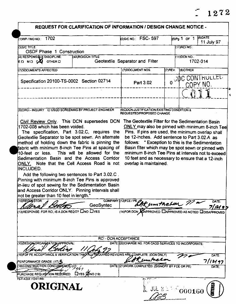
(3)SIC TITLE (1l)RCINO
(4) RESPONSI L DISCIPLINE (4A)RCIIDCN TITLE (1 1)DCN NO E O M U OTHER0 Geotextile Separator and Filter 1 702-0 14
(7)DOCUMENTS AFFECTED (7)DOCUMENT NOS (7)REV (8)OTHER
OSDF Phase 1 Construction
.J)C CON4 hULLtL1 COPY NO. Specification 201 00-TS-0002 Section 02714 Part 3.02 0
Civil Review Only. This DCN supersedes DCN 1702-008 which has been voided.
The specification, Part 3.02.C requires the Geotextile Separator to be spot sewn. An alternate method of holding down the fabric is pinning the
bric with minimum 8-inch Tee Pins at spacing of -feet or less. This will be allowed for the
Sedimentation Basin and the Access Corridor ONLY. Note that the Cell Access Road is not INCLUDED.
Add the following two sentences to Part 3.02.C . Pinning with minimum 8-inch Tee Pins is approved in-lieu of spot sewing for the Sedimentation Basin and Access Corridor ONLY. Pinning intervals shall
DATE:
The Geotextile Filter for the Sedimentation Basin ONLY may also be pinned with minimum 8-inch Tel Pins. If pins are used, the minimum overlap shall be 12-inches. Add sentence to Part 3.02.A as follows: " Exception to this is the Sedimentation Basin filter which may be spot sewn or pinned with minimum 8-inch Tee Pins at intervals not to exceec 10 feet and as necessary to ensure that a 12-inch overlap is maintained.
(2O)CHARGE NO FOR CADD SERVICES TO INCORPORATE.
not be greater than 10 feet in length." DATE:
(13)RESPONSE: FOR RCI, IS A DCN REQ'D? U N O D Y E S AS NOTED ODISAPPROVED
DATE
RCI - DCN ACCEPTANCE
(21)WORK COMPLETED (SIGNOFF BY FCE OR PE) OAT€
p '---: /-' . ,. . .
FS-F-4259 110/01/96)
ORIGINAL

(3)sIC m: (11)RCI NO.:
(4) RESfWNSl LE DISCIPLINE: (4A)RCVDCN TITLE: (11)DCN NO.: E O M U C# OTHER0
(7)DOCUMENTS AFFECTED ODOCUMENT NOS. W. (@OTHER
dW11
OSDF Phase 1 Construction
Coupling Band For Cormgated Metal Pipe 1702-01 3
\ '
I I (9)ORCI - INQUIRY 0 USQD SCREENING BY PROJECT ENGINEER (9)UDCN-JUSTIFICATlON,EXlSTlNG CONDITION 8
REQUESTEDPROPOSED CHANGE
Civil Review Only.
G-00089 Details 47 and 49 show 24-inch wide bands. Since all CMP on the project are part of temporary structures, the use of standard 12-inch wide coupling bands will be approved.
Comgations" will be removed..
Drawing changes will be as follows:
&..7..7 COMPANY GeoSyntec
Detail 47 - Coupling band shown will be redrawn he corrugated metal pipe (CMP) and at 12-inches wide centered Over the pipe joint
to the site by the contractor is produced
DATE (1 Z)FCE I PE

I REQUEST FOR CLARIFICATION OF INFORMATION / DESIGN CHANGE NOTICE - 2% NO.: FSC- 597 s)Pg 1 OF 1 wp I wo NO.. 1702 (6)DAE
11 Julv 97 I I I (3)S/C TITLE (11)RCI NO
(4) RESPONSI LE DISCIPLINE. (4A)RCVDCN TITLE ;11 )DCN NO
E O M O & OTHER0
(7)DOCUMENTS AFFECTED (7)DOCUMENT NOS CI)REV @)OTHER
OSDF Phase 1 Construction
Coupling Band For Corrugated Metal Pipe 1 702-0 1 3
Drawing 90X-6000-G-00089 Sheet G41A Details 47 and 49 0 LDC CONI ~ u L L L - ----_-__-------------------------------------------- - - -- - - - Tsop\rmff.- - - -
Civil Review Only. Drawing changes will be as follows:
Detail 47 - Coupling band shown will be redrawn
Detail 49 - Coupling band shown will be redrawn at 12-inches wide centered over the pipe joint. The stated 24-inches wide will be changed to 12-inches and the wording ” with 9 Cormgations” will be removed..
he corrugated metal pipe (CMP) supplied and at 12-inches wide centered over the pipe joint livered to the site by the contractor is produced
om Hel- Cor Pipe which has helical corrugations.
e pipe ends have been rerolled to accept andard 12-inch wide coupling bands. Drawing -00089 Details 47 and 49 show 24-inch wide nds. Since all CMP on the project are part of
andard 12-inch

( 3 ) s ~ n u
(4) RESPONSI E DISCIPLINE (~AIRCVDCN n u E O M O C 3 OTHER0
OSDF Phase 1 Construction
Principal Spillway Riprap
(1 1)RCI NO
(1l)DCNNO
1702-01 2
c RCI - DCN ACCEPTANCE
Drawing G41A SubmittalNo. 20 Section A 0 ________-_--_-_---------------------------------------------------------~
(9)ORCI - INQUIRY 0 USQD SCREENING BY PROJECT ENGINEER (9)UoCNJUSTIFICATlON.MlSTlNG CONDITION 8 REQUESTEDPROPOSED CHANGE
The location of the Sedimentation Basin has been This change is intended to extend the riprap to moved east . This move resulted in the Principal the existing ditch. West of the spillway centerline Spillway pipe discharge points being located farther the length of the spillway will be less than 60 feet
QRIGINAL
the completed spillway to extend to the ditch.
Drawing G-00089 Section A shall be revised by the spillway based on field surveys.
between the two CMPs. The width of the riprap at bottom ofthe riprap. the pipe discharge end and at the 60-foot point at the ditch shall be 15 feet and 23 feet, respectively.
As-buitt drawings shall document the extent of
changing the 35 feet to 6o feet at the centerline The geotextile shall extend beneath the sides and
Drawing G41A in Submittal No. 20 is a copy of Drawing G-00089.
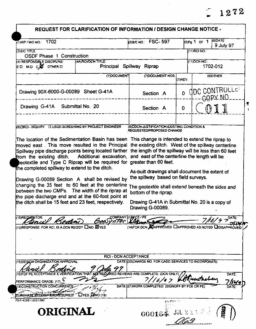
(3)SIC TITLE (11)RCINO
OSDF Phase 1 Construction 4) RESPONSI E DISCIPLINE (4A)RCYDCN TITLE (1 1)DCN NO
LO MU C p OTHER0 Principal Spillway Riprap 1702-012
~)DOCUMENI' (7)DOCUMENT NOS (8)OMER ( 7 ) R N
Drawing G41A SubmittalNo. 20 Section A O c o n _______------------------------------------------------------ _ _ _ _ _ _ _ _ _ _
(9)ORCI - INQUIRY 0 USQD SCREENING BY PROJECT ENGINEER (9)ODCNJUSTIFICATION,U(ISTING CONDITION 8 REQUESTEDPROPOSED CHANGE
The location of the Sedimentation Basin has been This change is intended to extend the riprap to moved east . This move resulted in the Principal the existing ditch. West of the spillway centerline Spillway pipe discharge points being located farther the length of the spillway will be less than 60 feet rom the existing ditch.
he completed spillway to extend to the ditch.
Drawing G-00089 Section A shall be revised by
between the two CMPs. The width of the riprap at bottom ofthe riprap. the pipe discharge end and at the 60-foot point at the ditch shall be 15 feet and 23 feet, respectively.
Additional excavation, and east of the centerline the length will be eotextile and Type C Riprap will be required for greater than 60 feet.
As-buitt drawings shall document the extent of the spillway based on field surveys.
changing the 35 feet to 6o feet at the centerline The geotextile shall extend beneath the sides and
Drawing E41A in Submittal No. 20 is a copy of Drawing G-00089. *
DATE:
(14)FOR DCN:)&PdVED OAPPROVED AS NOTED oDISAPPk6VEY

WO NO.: 1702
(2) sc No.. s97 7/88
(9) O R C l - INQUIRY n U S Q D SCREENING BY PROJECT ENGINEER (9) DCN-RISTIRCATION. EXKlTNG CONDmON & REQUESCEIYPROPOSEDCHANQ
On Site Disposal Facility Phase 1 4) RESPONSIBLE MSCIPLINE: (4A) RCVDCN TITLE:
E O M U Cm O T H E R 0 Placement of Stone Ova Geotcxtilc
lefmnced specification does not allow equipment to be driven d k d y on geotextk We believe that the m m t of the SpecifiCatiOa h to hit trafEc and potential damage to the cell liner system. We propose that the specifidon be r e d to rllow the geotextik sepanta abric, found under gravel toadways, to be placed and pinned. Gravel trucks would then %ilptc” sprrad the material over the fakic, an ndustry accepted standard practice. Trucks shall tailgate in a straight lint to elhninMe potentid rutting caused by sharp turns. Rutting of ubgrade should not be a concern, as the embankment has ban placed and compacted in compliance witb project spcciiicatiom. No natcrial shall be placed on wet subgrade. where excessive rutting would occur. Due to the thm lift of the gravel surface, we feel that (43 D the best way to provide for a quality finizhed product without damaging the geotextile.
- (I I) DCN No.:
17O2-OIl
RCI - DCN A m A N C E IS ) DESIGN ORGANIZATION APPROVAL: DAEI(20) CHARGE NO. FOR CAM) SERVICES TO INcoRpoRATE

(1)WP I WO NO.: (2) SC NO.:
1702 597
On Site Disposal Facility Phase I I - 14) RESPONSIBLE DISCIPLINE: I(4A) RCllDcN TITLE: 1(11)DCNNO.:
7/8/91
. . . . I En M U Ca O T H E R 0 I Placement of Stone Over Geotextile 1. 1702-011
Referenced specification does not allow equipment to be driven directly on geotextile. We believe that the intent of the specification is to limit mfic and potential damage to the cell liner system. We propose that the specification be revised to allow the geotextile separator fabric, found under gravel roadways, to be placed and pinned. Gravel trucks would then "tailgate" spread the material over the fabric, an indusuy accepted standard practice. Trucks shall tailgate in a straight line to eliminate potential rulting caused by sharp turns. Rutting of subgrade should not be a concern, as the embankment has been placed and compacted in compliance with project specifications. No material shall be placed on wet subgrade, where excessive rutting would occur. Due to the thin lift of the gravel surface, we feel that (4") is the best way to provide for a quality finished product without damaging the geotehle.
l(13) RESPONSE FOR RCI. IS A DCN REQP ~ N O ~ Y E S (14) FOR DCN- c A P P R ~ , & W P R O V E D AS NOTED o DISAPPROVED
RCI - DCN ACCEPTANCE ( I 5) DESIGN ORGANIZATION APPROVAL DATE: (20) CHARGE NO. FOR CADD SERVICES TO INCORPORATE
(16) FDF PE ACCEPTANCE & VERIFICATION THAT
PERFORMANCE GRADE (17) 4 DATE -
I
n - r - -- - - - 1.' - -. I: ' J : ,. -- I;,

Page2 of 2
DCN NO. 1702-0 1 1
(13) RESPONSE
DCN No. 1702-014 approved the use of minimum 8-inch Tee Pins for use in placing Geotextile Separator fabric. Sedimentation Basin and Access Corridor (NOTE: Cell Access Road NOT INCLUDED) will be approved under the following conditions.
The use of the "tailgate" spreading of stone over the Separator fabric for the
1. Subgrade/fill proofrolled or compacted as specified, graded and sealed such that rutting under truck traffic will not occur. QC to monitor full time.
2. Roll out Separator fabric, make taut and pin as necessary. QC to monitor full time.
3. Grade stone and perform minimum thickness measurements. Add additional stone if necessary.
Specification Section 02714 Part 3.05.E shall be revised by adding the following sentence.
Tailgate spreading over the geotextile of road stone may be used for the Sedimentation Basin gravel road and the Access Conidor under conditions approved in writing by the Construction Manager. Note that the Cell Access Road is NOT INCLUDED for this alternate placement procedure.

I 1
I REQUEST FOR CLARIFICATION OF INFORMATION / DESIGN CHANGE NOTICE - I
RCI - DCN ACCEPTANCE DATE^ CHARGE NO. FOR CADD SEFMCES TO INCORPORATE:
ORIGINAL

REQUEST FOR CLARIFICATION OF INFORMATION / DESIGN CHANGE NOTICE - I
I I I
(9p RCI - INQUIRY 0 USQD SCREENING BY PROJECT ENGINEER ( 9 ~ S T m C A T l O N . W S T l N G CONDITION 8 RE UESTED/PROPOSED CHANGE d#E: & L / I L mtflr’b G!AfL)/.
B
RCI - DCN ACCEPTANCE DATE: (2O)CHARGE NO. FOR CADD SERVICES TO INCORPORATE
(16)FDF PE ACCEPTANCE 6 VERlFlCATlON ’THAT AU REOUlRED REVlEWS
I 1 ’
ORIGIN&
3

TO
.. . - -. . .. . , . . . - . . .. .

r ..
TO
v21 .2
n

-- Id
H . SFNIROhklEMAL I NF ORWT I ON'
I. PROTECTXON AND PRECAUTIONS
1. TWUSPORfAT10% AND OSHA LABEL INFORMATION

C' ".
TO
- 221 .t
BREWER COTE QuAury MAINTENANCE PRODUCtS

REQUEST FOR CLARIFICATION OF INFORMATION / DESIGN CHANGE NOTICE - / 9 0 q l)WP I WO NO.:
3)SC TITLE:
4) RESPONSI DISCIPLINE: (4A)RCIIDCN TITLE: LO M O C Y O T H E R O
7)DOCUMENTS AFFECTED p)DOCUMENT NOS. I(7)REV. k8)OTHER
(11)RCI NO.:
(11)DCN NO.: OSDF- PHAY! 1 C~~NSTHHC T/on/
G~AFEZ P&RFAC/rvG 1702 -m P
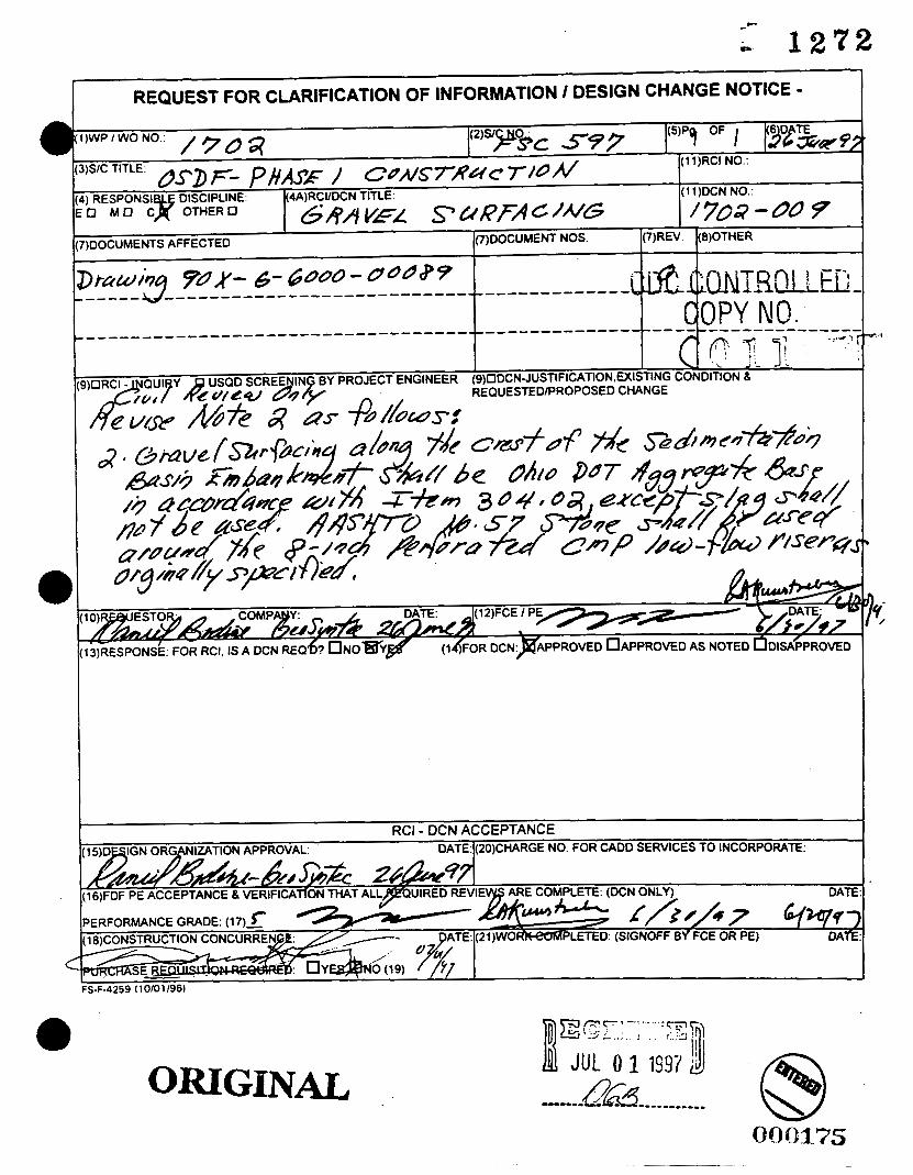
c
D 1272
a
a
C
a
REQUEST FOR CLARIFICATION OF INFORMATION I DESIGN CHANGE NOTICE -
ORIGIN&

*-
-* 1 2 1 2 REQUEST FOR CLARIFICATION OF INFORMATION / DESIGN CHANGE NOTICE -

~
REQUEST FOR CLARIFICATION OF INFORMATION / DESIGN CHANGE NOTICE -

-.
REQUEST FOR CLARIFICATION OF INFORMATION / DESIGN CHANGE NOTICE - 6 DATE
- YP9/OF / b Twe 97 ' 7 , \ D P I un .
DCN NO.:
I
)ORCI - INQUIRY 0 USQD SCREENING BY PROJECT ENGINEER (9)DCN-JUSTIFICATION.U(ISTING CONDITION 8 REQUESTEDPROPOSED CHANGE
DAT ' &?@& W & 6 h E Q D ~ C I N O DYES FOR DCN: PPROVED OAPPROVED AS NOTEDTIDISAFPROMD
ORIGINAL

L -iREQl,JESTFOR CLARIFICATION OF INFORMATION / DESIGN CHANGE NOTICE - 6 DATE
(5)pg PF 4 gi&* 9; (2)SIC NO
(11)RCI NO /7a4 1 )WP I wo,,rlo
3)s/c OSDF- p#4SZo 1 CdNs'7'Uc 7/i /y 4) RESPONSIBLE DISCIPLINE (4A)RCIIDCN TITLE (1 1)DCN NO :O M U OTHER0 ALTEHNVPF AW/-SFFP Cobof 1 7dg - 0 06 7)DOCUMENTS AFFECTED ((7)DOCUMENT NOS )(7)REV I(8)OTHER
RCI - DCN ACCEPTANCE L: DATE: (2O)CHARGE NO. FOR CADD SERVICES TO INCORPORATE:
26 S&P?7 DATE l6)FDF PE ACCEPTANCE 8 VERIFICATION THAT ALL REQUIRED REVIEWS ARE COMPLETE:
'ERFORMANCE GRADE: ( 1 7 ) z .- DATE -RK COMPLETED: (SIGNOFF BY FCE OR PE)
S-F-4259 ~101011961

DIAPHIUCtl
CONTECH CONSTRUCTION PRODUCTS, INC. COPY LIST PRICES
DATA ON DIAPHRACH
I I T T I I
A-
1. Cormgated htd rhall con[om to curmat AsFn S p u :
Allmrlaun 8744 Steel k444
2. Stml 01- to be f u l l y bituainous coated .OS lncb ChlCk.
3. iap ktue8n tw halt 8eetlonr should be aullrcd at tior of installation.
silo t p lugs lor COMeetlca.
'ClV 25 ne
c.e. I
0 .C . I t. 20
-- h g . No. 103195 Rev. 1 1 / 1 5 / 5 5
DIA - 2 .0 - . 10/1/90

REQUEST FOR CLARIFICATION OF INFORMATION / DESIGN CHANGE NOTICE - I P)Pa OF (6)DATE
s v 7 0 / 1-17-9 @S/C NO.: /76
. * I(l1)RCI NO.: -
- 1 2 1 2 I-'
- - - - c-- I t(4) RESPONSIBLE DISCIPLINE: I(1l)DCN NO.:
(7)DOCUMENTS AFFECTED (8)OTHER I
9% XSA m- r/-S RCI - DCN ACCEPTANCE ZDESIGN ORGANIZATION APPROVAL DATE4 (2O)CHARGE NO. FOR CAOO SERVICES TO INCORPORATE
ORIGINAL

CDC CONTROLLEL COPY NO.
LETE (DCN ONLY)
. . . . . , ,
ORIGINAL
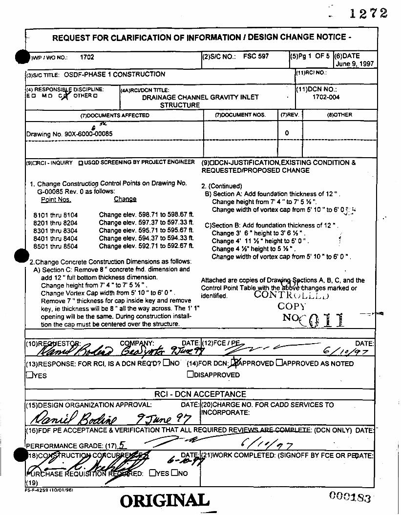
)WP I WO NO.: 1702 (2)S/C NO.: FSC 597
(1 5)DESIGN ORGANIZATION APPROVAL: DATE:
M d H & 7rw 97
I I -. . - - -
(1 1)RCI NO.: SIC TITLE: OSDF-PHASE 1 CONSTRUCTION
:o M O c . O T H E R O DRAINAGE CHANNEL GRAVlN INLET 1702-004 0 ) RESPONSI DISCIPLINE: ( U ) R C w N TITLE: (1 1)DCN NO.:
(20)CHARGE NO. FOR CAD0 SERVICES TO INCORPORATE:
I STRUCTURE I (7100CUMENTS AFFECTED I (7)WCUMENTNOS. 1V)REV. 1 (8)OTHER
0 6 -
-------- .------------------, hawing No. 90X-6000-00085 ----------------------------------------
))CWCI - INaulRY uSaD SCREENING BY PROJECT ENGINEER (9)ODCNJUSTlFlCATlON,WlSTlNG CONDITION 8 REQUESTEDlPROPOSED CHANGE
1. Change ConstructioJ Control Points on Drawing No. 2. (Continued) 8) Section A: Add foundation thickness of 12 . G-00085 Rev. 0 as follows:
Chanae Change height from 7' 4 to 7' 5 W 'I. Point Nos, Change width of vortex cap from 5' 10 " to 6' 0 ?. k
8101 thru 8104 Change elev. 598.71 to 598.67 R. u . .- 8201 thru 8204 Change elev- 597*37 to 597.33 '* C)Section B: Add foundation thickness of 12 I' . 8301 thru 8304 Change dev. 595.71 to 595.67 R. Change 31 6 11 height to 31 6 H em . 8401 thru 8404 Change elev. 594.37 to 594.33 R Change 41 n height to 51 n . 3
Change elev. 592.71 to 592.67 R
2.Change Concrete Construction Dimensions as follows: A) Section C: Remove 8 " concrete fnd. dimension and
Change H" height to n . Change width of vortex cap from 5' 10 " to 6 0 " .
8501 thru 8504
tions A, B, C, and the thanges marked or
Attached are copies of Dra Control Point Table with the identified.
add 12 " full bottom thickness dimension. Change height from 7' 4 " to 7' 5 % " . Change Vortex Cap width from 5' 10 " to 6 0 I' . Remove 7 " thickness for cap inside key and remove key, ie thickness will be 8 " all the way across. The 1' 1" opening will be the same. During construction install- tion the cap must be centered over the structure.
CON T K ,J I., i, L , I COPY
--I -
DATE:
1(1 ~IRESPONSE: FOR RCI, IS A DCN ~ E Q ~ D ? UNO (I~FOR D C N ~ P P R O V E D DIPPROVED AS NOTED
Q

I a
I
vi z 0 c 4 V 0 -I
K 0 L
c W W I in
in
I c z 0 z 4
L-
L
2 W W VI
vi z 0 I- O W Ln -J J
CI
U z K
W
n a
LI
a n
5 z 0 a. fn c 8 a a 3 "'
P 8 >
I
t z U
-

C
I .I
J / - 0
-1
1'-1
l'-ll"
I I I I
! I I I
i I
t
i I I
I
i
I
I . *
L
4" (TYP)-
- - I -I / CONSTRUCTmN CONTROL
sd t
I
4
0
b
.
' Q
D
t .
4
&
b a b 8
TRENCH BACKFILL
7
F NLET RISER
/ f i

.
'k, - 0 # ANEL GRAVITY INLET STRUCTURE AND CULVERT

ANTI-VORTEX DEVICE
6" DRAINAGE ORIFICE (TYP)
TRENCH BACKFILL
/ CONSTRUCTION CONTROL POIN
PIP[ EMBEDMENT FILL (NO-
. - : C ; I
- ~
POINT NO. 8101 I
8102 ' 8103 I 81 0 4 8105 I 9106 i 8107 I 8108 I 31 09 8110 1 8201 8202 , 8 2 0 :
I
dNEL GRAVITY INLET STRUCTURE AND' CULVERT a

.- 12?% GEOSYNTEC CONSULTANTS Page / of

-F C 1 2 7 2 GEOSYNTEC CONSULTANTS P a g e 2 L o f -
Date: I I R o d 8 P Date: P I 061 *Reviewed by: Y Y m m D D
Written by:
Client: F B F b j e c t : ~ S B F /ZZf YY urn DD
Rojes&epd-Uo.& @ 4 L66 Task No.: S */

9
U J f i 4 ) o l O c c u m ~ I n ( D ~ 4 ) Q , O c ~ n ~ u , I D r - O D ~ o oooocooooooooocoooooooooc m Rn 0 n -t -t d e e t d d d d In In In 5) In rl) In In U) In O D ~ W Q Q O D O D O D O D Q Q Q W Q Q W W O D Q Q W W Q ~ Q
s >
I - cJ n ID r- w Q, o - c y r) r cn 0 0 0 0 0 0 0 0 0 c 0 0 0 0 0 0 0 0 0 c 0 0 0 0 0 c c c c c c c c c c N N c y N c y N N N N N ~ r ) ~ ~ l r ) W a34) 4) 4) (D Q Q (0QODQ OD O D W W Q W a3 OD WOD Q a l W
(D IC OD Q, o - cy n e
0 0 r) 0 z 0 I- u W Ln
Z 0 i= a
c
-
0 LL 0 W a Ln
I I-
3 W 0 z c3 LT 0 0 0
z W
-.I J
I v, v, W
c.
CI
- a
a - m
a
a z 0
v, I- W -I z W 0 U z a Q > t > U a c3
I
m a
H
vi Z 0 I- U 0
I
9 2 [r
I- w W I v, v)
I I-
z 0 z J
W W m
-
a a
vi z 0 i= 0 W v, -I -I U z E U W a 4 I- O z 0 4 v) c E 0 a 3 v)
H
a
a
2 E
I I- Z
P - a
i 0 i= 0 W v)
v)
I I-
z
c.
CI
5 0 I v)
t 0 Z W [1:
cn
0 I z U I cn
a
3
9 0 Z 4 m 4:

c
I 2 9 2
L
DZAINAGE CHANNEL CULVERT GRAVITY INLET STFZUCTURE
6 ’8 ‘‘ t 1
I
-1
1’-1”
1’-11”
4” (TYP)-
i ! I
!
i
i - -
I -I r CONSTRUCTIION CONTROL / POINT (TYP) (
TRENCH BACKFILL (NOTE 4)
r INLET
7 **
RISER
EMBEDMENT FILL

- :t.@lNEL GRAVITY INLET STRUCTURE AND CULVERT
G DRAINAGE CHANNEL
GRAVITY INLET SWJCTURE 5'-3"
7 '-
1'-1
!
ANTI-VORTEX DEVICE +,: .tr i I - ' I
SUBGRADE
! \PIPE 'EMBEDMENT FILL (NOTE 4)
A \ SECTION - DRAINAGE CHANNEL GRAVITY INLET STRUCTURE ANC I (NOTE 1)
SCALE: 1" = 2'
I 7

1
81 01 81 0 2 81 03 81 0 4 81 0 5 31 06 81 0 7 81 0 8 5109 . 81 10 8201 8202 8203
1 "c: POINT NO.
4 4 4 4 4 4 4 4 4 4
4 4 -
W L GRAVITY INLET STRUCTURE AND CULVERT 0

13" T A U A N I ORFICE HOLE VORTEX OPENING
6" OIA. HOLE IN TOP
6" DiA. ORflCE HOLE
13" TALL ANT VORTEX OPENING
6" DIA. ORFICE HOLE
CONCRETE: 4500 PSI Q 28 DAYS. REINFORCED PER
ASTM C-478 SPECS. JO1NTS SEALED W/ CONSEAL SEALANT.
- 3'4" I
3' DIA. GRAVITY INLET STRUCTURE PETRO ENVIRONMENTAL / FERNALD PLANT)

I U

c


I 7-
I
. I('a!!w=

1 2 9 2 4
CDC CONTROLLED
COPY
. . ' .I . .. , :.:.:; I
I


MAY. - 2 8 ' 971MON) I I :35 TEL:3648
TEL:SI3 648 5767 P. 031

APPENDIX U:
NON-CONFORMANCE REPORTS (NCR)
Leachate Conveyance System OSDF Phase I
Leachate Conveyance System

LEACHATE CONVEYANCE SYSTEM - NONCONFORMANCE REPORTS I NCR NUMBER
1700-001
1700-002
1700-003
1700-004
1700-005
1700-006
1700-007
1700-008
1700-009
1700-01 0
DATE
7-J u 1-97
10-Jul-97
7-Sep-97
7-Sep-97 -
!8-Sep-9;
!3-Sep-9i
I9-Sep-9;
2-Oct-97
15-Oct-97
ORIGINATOR
H.E. Meekins
Rob Peddicord
Rob Peddicord
Rob Peddicord
Rob Peddicord
Rob Peddicord
Randy Livingston
Ned Meekins
Rob Peddicord
ASSESSMENT ACTIVITY
Conformance Testing
Construction Quality Control
Construction Quality Control
Construction Quality Control
Construction Quality Control
Construction Quality Control
Construction Activity
CQC OnSite Lab Testing
Construction Q.C
NONCONFORMANCE
Improper Soil Classification
Compaction of materials over dual containment pipe.
lifts of pipe embedment fill were not wet to saturation, therefore the lifts were not flooded.
Temporary cleanout was placed with the cleanout lateral facing in the opposite direction of the designed flow.
The specified couplings were not used for electrofusion.
Welding during precipitative conditions
In the process of electrofusing a coupling to the 8-inch pipe, a fault" was indicated by the processor 45 seconds prior to the completion of the 500 second cycle.
Test results for the bulk sample obtained from stockpile of No. 304 aggregate base material for grain-size analysis failed to meet the requirements of specs.
Wise Construction pipefitters performed an extrusion weld on the ends of an electrofusion coupling that previously faulted twice. Recommend subject to hydrostatic pressure test as specified in DCN No. 33.
*Updated Weekly' Page 1

FIGURE 5
- -- GeoSyntec Consultants
NONCONFORMANCE SUMMARY LOG
800205 97.05.22

FIGURE 1 - I272
GeoSyn tec Consultants Page 1 of2
'" NONCONFORMANCE TYPE: Construction Nonconfomance (4 Material Deviarion ( )
I NONCONFORMANCE (Fully describe as it relates IO requiremenu Use supplemental shcels as required):
I ' PROPOSED COMPLETION DATE: DATE FORRARDED TO APPROVAL AUTHORITY:
(5 J u r . / ? 9 7 /I Jury/P97
808204;
GQO166-01IF9710027.CDA 97.05.22

FIGURE 2
&&Bd
GeoSyntec Consultants CONSTRUCTION NONCONFORMANCE REPORT
L ' F j
Page 2 of2
Reject ( ) h. EVALUATION OF PROPOSED CORRECnVE ACI1ON: Comments( )
RIFIEpS SIGNATURE: /7
/ / ' M R O V A L AUTHORITY SIGNATURE: ,&- gJ 'I CONTINUATI@d FROM BLOCI; -:
'' DATE:
&47 '' DATE CLOSED:
7 / 4 7 7
GQOI 66-01/F9710027.CDA

APPROXIMATE MINIMUM w?. OF SAMPLE (PASONG NO. 10 SIEVE)
SAND
115 . . . . . . . . . . . .
flNE GRAIN I 65
SIEVE ANALYSIS
SIEVE NO.
3 ? *J-
. . . .
1% RETAJNED
6 Y - 6 297.3
2 *J-
2 0 . y
X RETAINED
/ . 0 / . 6 3 . J-
e) . . _ . .
. . b $
X flNER
/ o o . . . . . . .
. . . . . . . . .
. .
.utL J W L . . . . . . . . . . . . .
. . . . . . . .
. QA ID: p'(0 PROSECT
WE ClFlCATlONS
. . .
. . . .
. . Wd. . .
. . . . .
mNER 1 0 0

\
hi (Y t a z c VI a c
.. 0 z W J a s v,
2 r 3
3' a z 2: &I L
J J \ i
ct Y,
L U
> L) \I .. w
i 1 I I I 1 I I 1 I
I I I 1 1 T r 1 - 1 - 1 I
c
0
c
0 c
8 c
Q 8 c
L
0 (Y

AlTERBERG LIMITS TEST (ASTM D 4318)
WT. OF TARE (9roms)
(grams)
(grams 1 (grams)
. . . . . . . . . . . . . . . . . . . . . . . . . . . . . . . . . . . . . . . . . . . . . WT. OF YYET SOIL k TARE . . . . . . . . . . . . . . . . . . . . . . . . . . . . . . . . . . . . . . . .
. . . . . . . . . . . . . . . . . . . . . . . . . . . . . . . . . . . . . . . . . . . . . WT. OF WATER = 9-C . . . . . . . . . . . . . . . . . . . . . . . . . . . . . . . . . .
1 WT. OF DRY SOIL C-A (grams) . . . . . . . . . . . . . . . . . . . . . . . . . . . . . . . . . . . . . . . . . . . .
k 3 U R E CONTENT = (D/E)XlOO (%)
NUMBER o f BLOWS . . . . . . . . . . . . . . . . . . . . . . . . . . . . . . . . . . . . . . . . . . . . .
PROJECT: ON-SITE DISPOSAL FACILITY (OSDF)
sL* 6 6
r3.0 /;r
. . . . . . . . . . . . . . . . . . . . . . . . . . . . . . . .
. . *:. 3..
. . . . . . . . . . . . . . . . . . . . . . . . . . . . . . .
LIQUID LIMIT DETERMINATION
TARE NO. . . . . . . . . . . . . . . . . . . . . . . . . . . . . . . . . . . . . . . . . . . . .
. . . . . . . . . . . . . . . . . . . . . . . . . . . . . . . .
. . . . . . . . . . . . . . . . . . .
A
B C
D
E
F
. . . . .
. . . . .
. . . . .
. . . . .
. . . .
TARE NO. . . . . . . . . . . . . . . . . . . . . . . . . . . . . . . . . . . . . . . . . .
WT. OF TARE (g'oms)
WT. OF WET SOIL k TARE (grams)
WT. OF DRY SOIL k TARE (groms)
(grams)
. . . . . . . . . . . . . . . . . . . . . . . . . . . . . . . . . . . . . . . . . . . .
. . . . . . . . . . . . . . . . . . . . . . . . . . . . . . . . . . . . . . . . . . . . . . . . . . . . . . .
. . . . . . . . . . . . . . . . . . . . . . . . . . . . . . . . . . . . . . . . . . . . . . . . . . . . .
WT. OF WATER = 8-C . . . . . . . . . . . . . . . . . . . . . . . . . . . . . . . . .
N
/ - 7 2 s - a 3s * 2 ? 36 - c =3. . . . .
. . . . . . . . . . . . . . . . . . . . . . . . . . . . . .
. . . . . . . . . . . . . . . . . . . .
. . . . . . . . . . . . . . . . . . . . . . . . . . . . .
. . . . . . . . . . . . . . . . . . . . . . . . . . . . . .
I
DRYlNC TARE NO.
. . . . . . . . . . . . . . . . . . . . . . . . . . .
. . . . .
. . . . . . . . . . . . . . . . . . . . . . . . . . . . .
OA ID:
1 -6 2 e . e
. . @ : . ? (+ :.
. . .?? .??. . .
. .3.:.?6. ....
. .e .G. . . . .
wt ' 3 2
. . . . . . . . . . . . . . .
. . . . . . . . . . . . . . .
. . . . . . . . . . . . . . .
/ . %
d g . Y 9
w. :.c3.. . . . 34 * P) 9.- 0 3
.E.: .?.!. . . . . 0 . 3 '
2 s
. . . . . . . . . . . . . .
. . . . . . . . . . . . . .
. . . . . . . . . . . . . .
. . . . . . . . . . . . . .
. . . . . . . . . . . . .
,
. . . . . . . . . . . . . . . . . . . . . . . . . . . . . . . . 2 a . E / -7- . . . . . . . . . . . . . . . . . .
'"0 15 20 25 30 40 50 60
NO. OF BLOWS (N)
CURING TARE NO.
/ -C
PLASTIC LIMIT DETERMINATION
@ E , 1 W T . OF DRY SOIL - C-A . . . . . . . . . . . . . . . . . . . . . (groms) 1 /w . . . . . . . . . . . . . . . . .
2 . 1
2 & * 2 + . . . . . . . . . . . . . .
. . . . . . . . . . . .
3.9:. fll.. . . .
. .!.:?.!.. . .
. . . 7:. 3. . . .
3 8 . . . . . . . . . . . . . .
QA I D : P C O

CONSTRUCTION NONCONFORMANCE REPORT ' TlT&E/ORGANIZATI?N ' NCR NUMBER ' DATE DISCOVERED
' o ~ ~ T % & & ~ ~d --z&ZGT / &t._&&2 l-loo- 00-L
' HOLD TAG ' RESPONSIBLE ORGANIZATIONPROJECT ASSESSMENT ACTIVITY I
' PROPOSED COMPLETION DATE: '* D A l E FORWARDED 1'0 APPROVAL AUTHORITY:
04EQ21l GQO166-0I/FO7 10027.CDA 97.05.22

FIGURE 2
GeoSyntec Consultants Page 2 of2
CONSTRUCTION NONCONFORMANCE REPORT
'* EVALUATION OF PROPOSED CORRECTIVE ACTION Reject ( ) Comments( )
APPROVAL AUTHORITY SIGNATURE.
ho. whar when. where):
ooc212 97.05.22
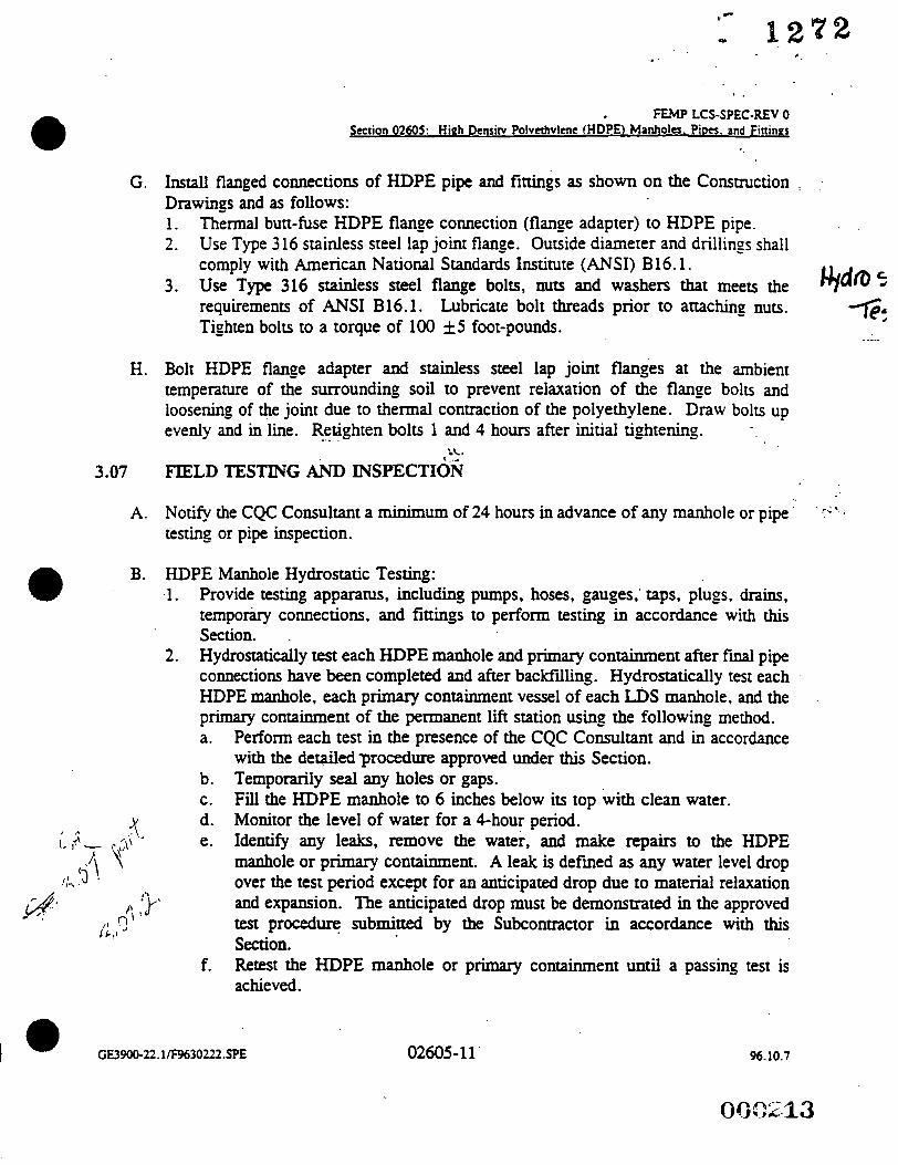
G.
H.
3.07
A.
B.
'. .. ' 6 .
FEMP LCS-SPEC-REV 0 Section 02605: High Denriw Polvethvlcne l H D P n Manholes. P i m . and Fittings
Install flanged connections of HDPE pipe and fittings as shown on the Construction Drawings and as follows: 1. Thermal butt-fuse HDPE flange connection (flange adapter) to HDPE pipe. 2. Use Type 316 stainless steel lap joint flange. Outside diameter and drillings shall
comply with American National Standards Institute (ANSI) B16.1. 3. Use Type 316 stainless steel flange bolts, nuts and washers that meets the
requirements of ANSI B16.1. Lubricate bolt threads prior to attaching nuts. Tighten bolts to a torque of 100 f5 foot-pounds.
Bolt HDPE flange adapter and stainless steel lap joint flanges at the ambient temperature of the surrounding soil to prevent relaxation of the flange bolrs and loosening of the joint due to thermal contraction of the polyethylene. Draw bolts up evenly and in line. Retighten L. bolts 1 and 4 hours after initial tightening.
LL 8
FIELD TESTING AND INSPECTION
Notify the CQC Consultant a minimum of 24 hours in advance of any manhole or pipe testing or pipe inspection.
HDPE Manhole Hydrostatic Testing: 1. Provide testing apparatus, including pumps, hoses, gauges, taps, plugs, drains,
temporary connections, and fittings to perform testing in accordance with this Section. . Hydrostatically test each HDPE manhole and primary containment after finai pipe connections have been completed and after backfilling. Hydrostatically test each HDPE manhole, each primaty containment vessel of each LDS manhole, and the pnmary containment of the permanent lift station using the following method. a. Perform each test in the presence of the CQC Consultant and in accordance
with the detailedprocedure approved under this Section. b. Temporarily seal any holes or gaps. c. Fill the HDPE manhole to 6 inches below its top with clean water. d. Monitor the level of water for a 4-hour period. e. Identify any leaks, remove the water, and make repairs to the HDPE
manhole or primary containment. A leak is defined as any water level drop over the test period except for an anticipated drop due to material relaxation
2.
/\ 'p and expansion. The anucipated drop must be demonstrated in the approved test procedure submitted by the Subcontractor in accordance with this Section. Retest the HDPE manhole or primary containment until a passing test is achieved.
it.? f.
02605-11' 96.10.7

C hr%* 3
FEMP LCS-SPEC-REV 0
After completion of the test, remove temporary seals, pump the HDPE manhole or primary containment dry, and dispose of test water.
[ ()$$ C. HDPE Pipe and Fittings Hydrostatic Testing: - .-' 1.
: I
2.
Provide testing apparatus, including pumps, hoses, gauges, taps, plugs. drains, temporary connections, and fittings to perfom testing in accordance with this Section. HDPE pipe hydrostatic testing: f& b.
C.
d.
e.
f. g - h.
1.
Pressure test all installed HDPE solid wall, carrier, and containment pipe prior to placing fdl over the pipes. Perform tests in the presence of the CQC Consultant and in accordance with the detailed test procedure submitted by the Subcontractor in accordance with this Section. Test HDPE solid wall and carrier pipe at % psi internal pressure for gravity pipe systems and at&$ internal pressure for force main system. Test pipes in accordance with ASME B31.9 5937.1 through 9937.3. Test HDPE containment pipe at 15 psi internal pressure. Test containment pipe in accordance with ASME B31.9 9937.1 through 9937.3. Test pipes at the required internal pressure for a minimum of one hour after the pressure in the pipe has stabilized. The test duration does not include the initial expansion phase after the pipe is first pressurized. The duration of the expansion phase shall be as recommended by the Manufacturer. Identify any leaks, remove the water, and make repairs to the pipe. Retest the pipe until acceptance criteria are achieved in accordance with the approved procedures for testing prior to placing bacldill over the pipe. Test gauges shall be calibrated within one year of date of test. Calibration shall be uaceable to ~ t i 0 ~ 1 or industry standards where possible. Acceptance criteria for hydrostatic testing is zero leakage for the stabilized pressure for the minimum duration of the=
D. Subcontractor may substitute air testing in lieu of hydrostatic testing if authorized in writing by the Construction Manager. Submit detailed work plan for review and approval by the Construction Manager.
E. HDPE Pipe Inspection 1 . Inspect fusion joints for evidence of excess or insufficient bead size,
conramination, offset, or any other evidence of inadequate joining. The surface of the HDPE pipe shall be dean at the time of inspection. Wipe or wash the HDPE pipe surface if Surface contamination inhibits inspection. Repair any pipe sections where greater than 4 percent pipe diameter deflection from vertical is observed.
2.
a GE3900-22.llF9630222.SPE 02605- 12 96.10.7
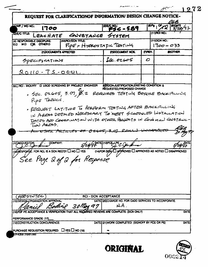
1
(cq&33Yd?E'rs ) 5)OESIG RGANltATlON APPROVAL
RCI - DCN ACCEPTANCE DATE: (ZO)CHARGE NO. FOR CAM) SERVlCES TO INCORPORATE:
d.A . i6)FW PEACCEmANCE 6 ~ T l O N T l U T A U RE&ffED F I N l E w s A R E c o M p L E T E : ( D c N ~ ~
WoRMAN(;E GRAM: ( 1 I I , IB)CONSTRUCTK)N CONCURRENCE:
DATE
DATE: (21)wocu< CoMPlEfED: (SIGNOFF BY FCE OR PE) DATE
UACHASERHXIlSmONRMUlRED . OYESONOIlQ~ -

Page 2 of 2 DCN NO. 1700-033
LEACHATE CONVEYANCE SYSTEM Pipe Hydrostatic Testing
(1 3) RESPONSE
Technical Specification Section 2605 Part 3.07 shall be changed as follows:
ArticIe C.2.a Add sentences "At pipe locations documented and approved in writing by the Construction hlanager the Subcontractor may, at his own risk, pressure test pipe after placing fill over the pipes. Locations of all joints. fittings. etc., shall be documented before backfilling. The test procedure shall be as specified, except the test duration shall be minimum 3 hours. 'I
Article C.2.c. Replace "120 psi 'I with I' 50 psi '* and 'I I30 psi internal pressure for I' with 'I 95 psi internal pressure for the LCS 'I. Add sentence 'I Test pressures for other pipe systems shall be in accordance with ASME €33 1.9 937.3.4 and as otherwise specified. I'
All other Articles of Section 02605 Part 3.07 remain unchanged.
The approval of pipe locations to be tested after backfilling should be evaluated on a case by case basis and where a defulite need to delay testing has been established. When properly prepared, the subcontractor can complete testing rather quickly and efficiently and even during weather conditions when backfrlling may not be suitable.

INTEROFFICE MEMORANDUM
To: Jim Jenkins, MS64
Location: Fernaid
From: Rick McGuire, MS64-
Location: Fernald
Extension: 648-5347
Date: August 4, 1997
Reference: NIA
FD Femald #: M : S W P( 0 S D F) : 9 7-00 3 5
Client: DOE DE-AC24-920R21972
Subject: LEACHATE CONVEYANCE SYSTEM - AUTHORIZATION TO BACKFILL LCS PIPING BEFORE TESTING
C: File Record Storage Copy 106.4.34.3 Mike Godber, MS64 Bill Zebick, MS64 Dan Bodine (GeoSyntec), MS38 Mary Jo Cleveland (Village Building Services), MS44 EDC 201 10-1700/OSDF File Station
DCN No. 1700-033 allows the subcontractor (Village Building Services), at their own risk, to pressure test pipe after placing fill over the pipes, at locations documented and approved, in writing, by the Construction Manager. This memorandum approves the placement of fill over the 4"/8" leachate conveyance system piping at the following locations:
b From approximately Sta. 7 + 40 shown on Drawing No. 92X-5900-6-00266, Rev. 1 to cleanout manhole COMH #11
b From cleanout manholes COMH #11 to COMH #12
This authorization is contingent upon conformance to the following requirements of DCN No. 1700-033:
b The test procedure shall be as specified in Specification Section 02605, Part 3.07, except that the test duration shall be minimum 3 hours.
b Locations of all joints, fittings, etc., shall be documented (on the contractor's as-built drawings) before backfilling.
If you have any question, please call me at Extension 5347.
RLM:rlm

FIGURE 1
-- GeoSyntec Consultants Page 1 of2
CONSTRUCTION NONCONFORMANCE REPORT * DATE DISCOVERED - TITLElORGANIZATION ' NCRNUMBER
~ 7 0 0 -003 07 *@ N U 7 HOLD TAG
' o%$?p&l~d ' -;r4dmcm/6k$dZ ' RESPONSIBLE ORGANIZ.-\TION/PROJECT. I " ASSESShlENT ACTlVIlY:
I I ' REQUIREMENTS (Idenrili. requirement from documenr [e..,.. CQA plan. specificarion. drawing. etc.]):
~ d n m J 5&&% 09.315- 3,03.c
/ " NONCONFORMANCE TYPE: Construction Nonconformance (bf Material Deviarion ( )
' RESPONSIBLE MANAGERS SIGNATURE: b / . I APPROVAL AUTHOWIY: " PROPOSED COMPLFTION DATE: '' DATE FORWARDED TO
GQO166-OI/F9710027.CD.4 97.05.22

FIGURE 2 f 1272 --
1B-
Geosyntec Consultants
CONSTRUCTION NONCONFORMANCE REPORT
Page 2 of 2
VERIFIERS SIGNATURE '' DATE
WA Nsr
000218
GQO166-OIIF9710027.CDA 97.05.22

FIGURE 1
-
GeoSyntec Consultants Page I o f2
CONSTRUCTION NONCONFOFOIANCE REPORT TITLUORGANIZATION ’ NCR NUMBER. D..\TE DISCOVERED
I too - 0 4 07 *&/clq7 ’ RESPONSIBLE ORGANEATIONPROJECT I ” ASSESSMENT A C n V I m HOLD TAG
” RESPONSIBLE MANAGER (NAMEI TITLE. ORGANIZATION):
GQO166-OIiF9710027.CDA
000219 97.05.22

FIGURE 2
H A m E a
GeoSyntec Consultants
CONSTRUCTION NONCONFORMANCE REPORT
Page 1 of 2
I
I" EVALUATION OF PROPOSED CORRECnVE ACTION: Accept (y Reject ( ) Comments( )
" APPROVAL AUTHORITY SIGNATURE DATE -'
Q ! X 4 - 27-57 - VERIFICATION OF CORRECT1
VERIFIERS SIGNATURE DATE ''
M 2 9 r n f W 7 DATE CLOSED
L
CONTINUATION FROM BLOCK -

CONSTRUCTION NONCONFORMANCE REPORT ' ONGINATO - llTLE/ORGANIZATION ' NCR NUMBER. ' D.4TE DISCOVERED
16 5 & f W 7 ' RESPONSIBLE ORGANIZATION/PROJECT 1 " ASSESSMENT ACTIVITY. ' HOLD TAG
QL I I
' REQUIREMENTS (Identie requirement from document 1e.g.. CQA plan. specification. dnwing. etc.]):
g5 7&%l(Pl 5jW$CQ&-
1 ". N O N C O N F O W C E TYPE: Consuuction Nonconformance (d Material Deviation ( )
' RESPONSIBLE MANAGER (NAME, TITLE. ORGANIZATION):
I ' /
ATURE: PROPOSED COMPLEllON DATE: tb DATE FORWARDED TO APPROVAL AUTHORITY:
/ 7 Js-&e H V 7 ,- - - 'I 0 ! g s $2.21
97.05.22 GQOl66-0 I/F9710027.CDA
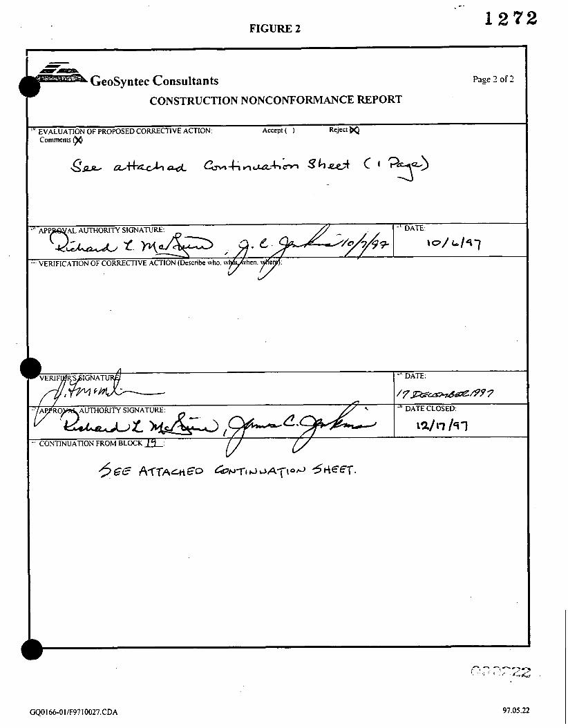
FIGURE 2 1 2 1 2
-- GeoSyntec Consultants Page 2 of 2
CONSTRUCTION NONCONFORMANCE REPORT
.4L AUTHORlN SIGNATURE: DATE: - 9. M . . "pge iERlFlCATION OF CORRECTIVE ACTION (Describe who.
r - h
A DATE CLOSED
\2/17 /SI :ONTINUATION FROM BLOCK &
91.05.22

Response to NCR 1700-005 Dated 16 Sept. and FDF Construction Evaluation Comments e Apparently, the subcontractor’s field personnel were unaware of FDE’s instruction to follow DCN 1700-058, as verified by VBS’s statements and the actions by VBS in the field. DCN 1700-058 requires a specific procedure for compacting by flooding and that procedure was not initiated by VBS or FDF at this location. The GeoSyntec Site Manager and Resident Engineer were notified of the field actions on the date of the occurrence and did not note any attempt to initiate a flooding procedure per the DCN. Density measurements were not performed, because the flooding procedure was not initiated and the pipe embedment fill was immediately covered with clay. VBS field supervisor stated that they were directed to do so by FDF and Rick McGuire confirmed the action when contacted from the field. The non-conformance was warranted.
Since FDF construction approved the construction area under question, FDF (Engineering, Management, QA etc.) should decide if they want to investigate the pipe embedment fill in-place density to determine, if, after confinement and placement and compaction of clay cover fill, the in-place density meets the requirements of the DCN. The minimum density requirement, determined per DCN 1700-058, is 108.1 lbs/ft3. If test pits are used a minimum of 3 test pits are recommended.
Jeph McMichen d& 9 v L Site QC Manage
Daniel Bodine v Q & H e Resident Engineer

RESPONSE TO CONSTRUCTION NONCONFORMANCE REPORT NO. 1700-005
19. EVALUATION OF PROPOSED CORRECTIVE ACTION (CONTINUATION SHEET) 0
FDF disputes several of the items described in Section 11 (Nonconformance) of this Construction Nonconformance Report (1 700-005). The subcontractor was instructed that he could follow the requirements of DCN No. 1700-058 and flood the pipe bedding material as called for on the DCN. This decision was not made to "speed up the process, before it rained" as stated in the nonconformance report, but was made because FDF Industrial Hygiene did not have enough working carbon monoxide (CO) monitors t o support the use of a vibratory plate compactor in all the areas that the Subcontractor was working a t the time.
DCN 1700-058 calls for the water levels in the trench t o be visually verified by CQC personnel (GeoSyntec) and for the fill t o be inspected and the dry density measured by the CQC personnel. The nonconformance report does state why this was not done, prior t o placement of clay. The Subcontractor was not instructed by Construction Management t o place clay material prior t o inspection and testing as implied in the nonconformance report. The nonconformance report does not state whether any density measurements were performed t o determine i f the density requirements defined in Paragraph 8.h of the attachment t o DCN No. 1700-058 were met. In the absence of such a test, Construction does not believe that a nonconformance is warranted.
Construction believes that the density of the bedding is at least as good .as that required by DCN No. 1700-058. I f the CQC Engineer must validate the density, it is recommended that test pits be excavated at random locations in the affected area.

27. Continuation from Block 19:
1211 7/97
Subsequent to this NCR and initial responses by FDF and the CQC Consultant, GeoSyntec, pressure testing of the 6-inch gravity line near Sta. 31 + 55 was performed. A test plug became lodged in the pipe and required excavation for removal.
At the time of excavation, FDF Engineering and Construction personnel (J. Jenkins and R. McGuire) viewed the excavation and backfill and have concluded that it meets the intent of the specification and is satisfactory. The temporary gravity line in this area has been backfilled for approximately three months and there appears to be no evidence of ground subsidence or settlement. The 1 O-inch containment pipe and 6-inch carrier pipe have also passed pressure testing. The carrier pipe has been photographed and, again, there appears to be no evidence of settlement (see attached photographs). FDF therefore believes the pipe embedment is satisfactory, no additional work is necessary, and the temporary gravity line is "acceptable "as- is."
12/17 k7-l R. L. McGuire - FDF Construction
000225

./ FIGURE 1 I
I 24 s C ~ ~ m C I 9 9 7
c
L 1272
APPROVAL AUTHORITY:
2s SGIprrrhOdlL99'1
GeoSyntec Consultants
CONSTRUCTION NONCONFORMANCE REPORT ' NCR NUMBER DATE DISCOVERED
1700 - 00L w-ss-+7 ' HOLD TAG
' "V&,*J - ZJZZ~6m$& ' RESPONSIBLE ORGANIZATIONPROJECT I " ASSESSMENT ACII.VITY
'' NONCONFORMANCE TYPE. Consuucoon Nonconformance Matcnal Deviation ( )
000226 v
GQO 166-Ol/F9710027.CDA 97.05.22

Comments on Non-conformance \TOO - 0 a b \& Use of PE 2406 Electrofusion couplings raises two design questions- relative to their acceptable use. One is compatibility with PE 3408 pipe and the second is design properties of the coupling. Coupling manufacturer, Central Plastics, has confinned that their couplings are compatible with a whole range of polyethylene materials from a low end of the medium density ( PE 2406) range to a high end of the high density (PE3408) range. See attached manufacturer literature obtained from their technical department.
The second concern is the hydrostatic design pressure rating. The PE 2406 standard ratings are less than those for PE 3408, the specified grade. However, the couplings are designed to have a safe operating pressure of atleast 125 psi and have been tested without failure at higher pressures and 'temperatures. The safe operating pressure is approximately twice the operating pressure for the SDR 26 pipe being used (64 psi) and 2 1/2 times the specified test pressure for the gravity pipe systems (DCN No. 1700-033). As always, the pipe and fitting is subject to a hydrostatic pressure test before acceptance. Attached is manufacturers documentation on safe operating pressure obtained from ,their installation procedures manual.
000227

c
I272
i
I.
t P 0
i 3 m m .. : 8 0) E
w k
h Q M .a 3 L
m 1 6 w
f

c-
- Hours to Failure lntemal Prevuru
1oOO + 130 PSI 275 PSI 2500 -
I Temperature I 176°F (80°C) 68OF (20°C)
*
. . I '
. .
~~
- r P S x 34IPS 30 5 30 1 .o 10 #123 1 1 013 1 IPS x 1 CTS 30 5 30 1 .o 10 #123 11 013 TAPPING TEES: 1 114 x 1 45 10 30 1 .o 10 #12/3 11013 2 x 1 90 10 30 1 .o 10 # l a 3 #I a13
Performance: Central Electrofusion Fittings typically achieve the following perforrnan&st results.
7 2
Saddle Impact: Falling Weight 10 Ib. from 7 ft.
Safe Operating Temperature: - 10°F to 12OOF (-23OC to 49°C) Safe Operating Pressure: 125 PSI Compliance With Standards: Central Electrofusion Fittings meet the re- quirements of ASTM F1055.
Electrical Requirements and Cooling Times
Extension time In time in m l l n g KVA Breaker card &a
seconds minutes time minimum 25 R. 50 tt.
COUPLINGS: ?
1J2 CTS 20 5 30 1 .o 10 #12M 11 OM 112 IPS 20 5 30 1 .o 10 #12f3 11 on 3 4 IPS 25 5 30 1 .o 10 #l2n 11013 1 CTS 25 5 30 1 .o 10 #l2/3 10 1 IPS 40 5 30 1 .o 10 #l2M 10 1 114 IPS 45 10 30 1 .s 10 #12M #lo13
Fining Fusion Clamped Total Generator
1 2IPS 45 10 '30 2.5 20 #lo13 1 ~~
3 IPS 90 10 30 2.5 20 #l OM 1 8/3 4 IPS 1 20 10 4s 2.5 20 #lo13 # 8 / 3
6 IPS 500 15 1 hour 2.5 20 #lo13 1 813 REDUCERS: 314 x 112 ms 20 5 30 1 .o 10 #la3 11 013 1 IPS x 112 CTS 25 5 30 1 .o 10 # l a 3 10
I 1 IPS x 1/2 IPS 30 5 30 1 .o 10 #1 2/3 11013 I
1 3 x 1 90 10 30 1 .o 10 # l a 3 rY21O13 I ~~ ~ ~~~
4 x 1 90 10 30 1 .o 10 1123 11013 6 x 1 90 10 30 1 .o 10 #12/3 Cy1 013 VOLTAGES: 90 Volt Minimum 150 Volt Maximum FREQUENCY: 45 to 75 Hertz INVERTERS: Yes.
WARNING. A.C. current only. 0.C. current can result In damage Io procassor

FIGURE 1 12’12
GeoSy n tec Consul tan ts Page 1 of2
CONSTRUCTION NONCONFORMANCE REPORT -’ TITLUORGANIZATION: ’. NCR NUMBER: ‘..DATE DISCOVERED:
a3 5e@*7 ‘. HOLD TAG:
‘ o?8To&md ’ ~ & ~ V K I @ C /G~$%i \7- -007 ’ RESPONSIBLE ORGANlZATlONlPROJECT: I ” ASSESSMENT ACTIVIlY:
I I
“ REQUIREMENTS (Identify requirement from document [e+ CQA plan. specification. dmving ctc.]):
’’ NONCONFORMANCE TYPE: Construction Nonconformance Material Deviation ( )
‘’ RESPONSIBLE MANAGER (NAME. TITLE. ORGANIZATION):
GQO 166-0 IF9710027.CDA 97.05.12

- FIGURE 1
- --n
GeoSyntec Consultants Cont.
GQO166-011F9710027.CDA 97.09.24

Mary Jo Cleveland Village Bidding Services 73 11 Vine Street Cincinnati, Ohio 45216
This letter addresses the ability to fuse Driscopipe during times of extreme humidity. As long as there is n o precipitation OT water on the pipe at the fnsion point, the pipe can be fused Please contact me at 871-9512 if you have any questions or comments. Thank you.
Scott Hoff Regional Sales Manager

FIGURE 1 1 2 7 2
- 5 CONSTRUCTION NONCONFORILI.&YCE REPORT
- D.4TE DISCOVERED: 19 _ccpTzNBGIL\w I ' ORIGINATOR: TITLUORGANIZATION: .' NCR NULIBER:
L 1 3 / 4 6 S T O d m , u 4 h ] /&-Os- pku \ 1 0 0 - 0 ~
' RESPONSIBLE ORGANIZ.4TIONIPROJECT: 1 " ASSESSMENT .umvin.: I ' HOLD T . G .
" NONCONFO~WAVCE TYPE: Consuuction Nonconformance ifi IMaterial Deviation ( )
GQO 166-0 1 E 9 7 10027.CDA

FIGURE 2 - 1272
(I
4
CONSTRUCTION NONCONFORMANCE REPORT
EV.ALUATION OF PROPOSED CORRECTIVE .-\CTION: Accept gU R W w r 8- S)L7/97 Comments td
' CONTINUATION FROM BLOCK -:
I
. GQO 166-0 I/F97 10027.CDA
phn-64 , ";.
97.05.22

CENTRAL PLASTICS COMPANY
FAC3IMfLE NO: (405) 273-5993
GROUP 11 11, 111
FROM; \ r \ r c - + m I
TOTAL NUMBER or PACES + (INCLUDING THIS COVER LETTER)
,

. . - . . . . . . . . . . . . .
. . . . . - , . .
, . . . . . . . . .
. . . . . . . . . .._ ..... ..p ..' I . . . . . . . . . . . . . . . . . . . . . . . . .
. . . . . . . . . . . . . . . . . , . . . _
. . . . .
.......... .._.- ... ..-..r ......... .. . . . . . .
.'.' - . - . - .
. . . . . . . . .' ' . /
. . . . . . . . . . .; . . . . . . . .
. . . ~I . 1. ' . :. .,. I -
. . . . . . . . . . ..:, -
..*I .... I . . . . . . . . . . . . . . . . . . . . . .
, . . . .
. . . . . . . . . . . . . . . . . . . . . . . . . . ..... ... . . . . . . . . . . . . . . . ...- .- . . . . . . . . . . . . . . . . . .
.._-_--_ / . . . .
. .
. . . . . . . . . . . . . . . . . .
f .
. . . . . . .
. . . .
. .
. .
. . . .

. . . . . . . . . . . . . . . . . . . . . . . . . . . . . . . . . . . . . . . . . . . . . . . . . . . .
e . :::..:. I.. : .. I ;. . e:- : : . - . . . . . . :
Redwrs. 3 4 - x IC' ClI
I" x In' el< l " x In" 1' r( 3/4-
I - x i- CIS 1- 8 I l/4- cas
1- % I 1'4'
Cuvplingr: 1 . T CIS of IPS
314- 1 - et4
I ' I II4-
I In- 2 - 3 - 4 - 6" X ' IO" 12"
Branch SJdJlcs: 2 - x 1- 3- x 3' 4" I 2' 6 - v 2' x- x 2"
6' x 4' 4- x 4-
. . . .
~~
LO 25 30 30 ?U 3 0 J!
20 30 2 5 4 5 0 s 00 4 5 I no 200 SO0 so0 730 ooa
120 I21 I 2 U I20 I Of)
I IO 50
. . - . . . . . . . . . . . . . .
. . . . . . . . . . . . .
. . . . . . . . . . . . . . . .
. . . . . . .
. . . . .. . . . . . . C _.. - . .... . . . . . . . . . . . . . . . . . . . . . . . . . . _.-.. ....... . .
. ..... - . _ . . . . . . . . . . . . . . . . . . . . . . . . . "... .-.-%*.:.: . . . . . . . . . . . . . . . . . . . . _ . . . . .
. . . . . . . . - . . - ..-., . . . . . . . . .
.... . . . . . . . . . . . . . . . . . . . . . . . . . . . .
.. . . : . : . ' . . . : . . . .
. . . . . . . . . . . . . ....... . . . . . . .;... . . . .
. . . . . . . * ...... . . . . . . . . . . . . . . . . 'f' :- . . - . . . . .
. . a: . . . .
. . . . . . . . . . . . . . . . . . . . . . . . .
. . . . ' .
(Side 2) Egecrtve Date (4/2996)
120 I20 I211 I20 I20 I10 I ne
I O I O IO 10 IO i n Ij
. , . ,
30 30 30 30 30 IO 30
30 30 30 30 30 30 30
-~~~
30 30 30 30 30 30 30 3 5 4 5 4 5 4 5 60 60
JU Jb 30 30 30 30 4 5
. . . --.. ...... _--. . . . . . . . e: . :. .
. . . . . . . . . . . _.' . . . . . . . . . .
. . . . . . - . . . . . . . . . . . . . . . . . . . . . . . . . . . . . . . .............. ......... ... . . . . . . . . . . . . . . . . . . . . . . . . . . . . . . . . . . . . . . . . . .
.:... ::* . . . -
. . . . . . . . . . . . . . . . . . . . . . . . . . . . . . . . .
. . .

FIGURE 1 1 2 1 2
GeoSyntec Consultants CONSTRUCTION NONCONFORMANCE REPORT I
Page I of2
SPONSIBLE MANAGERS SIGNATURE: I' PROPOSED COMPLmON DATE: '* DATE FORWARDED TO APPROVAL AUTHORIIY:
I OF lA
GQO166-OIE9710027.CDA 97.05.73

[[)[I -- GEOSYNTEC CONSULTANTS FERMAL& LOCATION: FERNALD, OHIO PROJECT NO: Go0166 TASK NO.: 04.1
DESCRIPTION: L C 5 uM.rcrrRu VI r34
MATERIAL TYPE: -
DATE: L day=month --. year
SAMPLE NO.: \ /SA-ot 8 * 3 4 UT& R p + F
SAND FINE GRAIN APPROXIMATE MINIMUM W. OF SAMPLE (PASSING NO. 10 SIEVE) 115 65
. . . . . . . . . . . . . . . . . . . . . . . . . . . . . . . . . . . . . . . . . . . . . . . . . . . . . . . . . . . . . . . . . . . . . . . . . . . . . . . . . . . . . . . . . . . . . . . TARE NO. K
WT. OF TARE (grams) /,v 4!.. q/w -. ' , /6l r-,
\ W T . OF DRY SAMPLE (grams) r . '-3 ; : -
WT. OF DRY SAMPLE PLUS TARE (grams) \ '3 eel '/ .-
. . . . . . . . . . . . . . . . . . . . . . . . . . . . . . . . . . . . . . . . . . . . . . . . . . .c. , 9 . .
(grams)
SIEVE ANALYSIS'
DIAMETER SIEVE NO. I (mm)
BEFORE WASH I 7 I AFTER WASH
c . . . .
Z FINER w b
. . . . . . . . . . . . . . . . . .
PROJECT SPECIflCAllONS
, , . . . . . . . . . . . . . . . .
I c c3 . . . . . . . . . . . . . . . . . . . . . . .
. . . . . 7L7 3w
. . . . . . 3.. ? . . .
I T I N E R = 100 - 1 Z RETAINED
.w - . I . 00 . . . . .
5040 . . . . . . . . . . . . . . . . . . . . . m , 3 7 5 3 . . . . . . .
. . . m ! , 6 . . . .
9. I!d . . . . 3 ... y . . . .
. . . . . =/.9 #.5. . . .
. . . . . 7. s , . r . . . .
. . . . . !I-. ! .G . . .
74Kw7qfii
c
. .
. . . . . .
2 8%
... I.!.'& . .
. . . . . Q.b.0.
. . . . . . . 0.130.. .
0.1-
. . . . . . . O!O.?S.
. . . . . . . . . . . . . . . . . . .
. . . . . . . . . . . . . . . . . . .
. . . . . . . . . . . . . . .
. . . . . . . . . . . . . . . . . . . . . .
*. .h. . . .*. 5- 5 . . . . . . . . : .s
. .
. . .4,-3.3. . . . . . .
. . . . . . . . . . . . . . . . . . . . . . . . . .
OA ID: JG
. . . . . . . S . 8 . . . . . . . . . .
. . . . . . . . . . . . . . . . . . .
%u ,----
.Q. -13 . . . . . . . . . . . . . . . . . . . . . . . . . . . . . . . . . . . . . .
. . . . . . . . . . . . . . . . . . . . . . . . . . . . . . . . . . . . . .
*opoiT. 369*6&.
. . . . . .
? . . . 5.2: 5 . 1. . . . . . . . . . . . . . . .
. . . . . . 'J 91.5 .+*. . . .3o+ 9.. . . .

LOCATION: FERNALD, OHIO PROJECT NO: GQ0'66 TASK NO.: 04*'
DESCRIPTION: LC5 CorJSrpU- 104 DATE: .k. day= month l%k year MATERIAL TYPE: +f304 AGfL . %A5E SAMPLE NO.: VRA -01
SOIL SAMPLE SIZE
f
. . . . . . . . . . . . . . . . . . . . . . . . . . . . . . . . . . . . . . . . . . . . . TARE NO. . .....h!.
. . . . . . . . . . . . . . . . . . . . . . . . . . . . . . . . . . . . . . . . . WT. OF DRY SAMPLE PLUS TARE . . . . . . . . .!.7.'.k.4..
BEFORE WASH
WT. OF TAR 101. . . . . . . . . . . . . . . . . . . . . . . . . . . . . . . . . . . . . . . . . . . . . . . . . . . . . . . . WT. OF DRY SAMPLE (gram4 I bl4-d
APPROXIMATE MINIMUM WT. OF SAMPLE (PASSING NO. 10 S I f M )
AFTER WASH
. . . . . . . . . . . . . . . . . . . . . . . . . . . . . . . . . . . . . . . . . . . .
. . . . . . . . . . . . . . . . . . . . . . . . . . . . . . . . . . . . . . . . . . . .
. . . . . . . . . . . . . . . . . . . . . . . . . . . . . . . . .
4
SAND
115 . . . . . .
X RETAINED
FINE GRAIN
65
* PROJfCT SPEClFlCATlONS X FINER
I - - d.! .d.. . . . . . . . . . . . . . . . : . . . . . . . . . . . . .
35.6 . . . . . . . . . . . . . . . . . . 1 7;yW
SIEVE ANALYSIS
9.. . . . . 5-5-
SIEVE NO.
. . . s. .@.. .!:/... I . ,s:L.#.?. . . . . . . . . . . .
75.?.. . . .
. .
. . . . . . . . .I.?,. 1.. . . . . .
316 .l:. . . . . . . . . . . . . . . . . . . . . . . . . . . . . .
. _ . . . . . . .l .I! 6 . . . . . . . .9.-r.3.3.. . . . . .
%FINER = 1007
. . . . . . . . . . . . . . . . . . . . . . . . . . . . . . . . .
. . . . . . . . . . . . . . . . . . . . . . . . . . . . . . . . .
. . . z5 .0 . . . . .
. . 1 ?P . . . .
12:s' 515. 4.6 21 3b
. - .'.!e..: . . , . . . O M ? . . . . . . . . 0 ! 3 O . . . .
. . . . . . ? ?!?. . . . .
. . . . . .0.*.935..
. . . . . . . . . . . . .
/a
. . . . . . . . . . . . . . . . . . . . . . . . . . . . . . . . . . . . . .I. . . . . . . . . . . . . . . . . . .
. . . . . . . . . . . . . . . . .
,
17. RETAINED
. . . . . . . . . . . . . . . . . . . + . . !?POT. 3 . d : e t '
3 . . . . . . . . .
d.?! 5 5 7 '1, (3
, -%*F .SI . . L. Z!C.<. .c. . .
. . . . . . . ' 3 ';..a,. .r. -9 5 *,3 . . . . . . . . . . . . . . .
- _ . . . . . . .
. . . . . . . . . . . . . . . . . .
-. Corn 9ty. WIT
TO .e. R=-Y
. . . . . . . . .
QA ID: 7'
J c 22- /cc . . J.. . . , d . . .I,. . . . . . . . . . . . . . . . . I . . . .?O.-!.??. ....
- - '/ I', b . . . . . . . . . . . . . . . . . . .5L. .7. . . . . . . . . . . . . . . . . . . . . . .
. . * , .t c- ,I. -<, . 3 . . . . . . . . . . . . . . . . . . . . . . . 1 L? LL 7 4 . . . 3 ?Lo . . . .
. . . . . . . !, : .a,+. 2.7 C .l fi*:k. . . . . . . . . . .Q. 7'. 3. . . . . . . - I
. . . . . . . . . . . . . . . . . . . . . . . . . . . . . . . . . . . . . . . . . . . . . . . . . . . . . . . .
. . . O . D O T .3.04*. .z . .'i2QU! -. . . .e:. . . . . . . . . . . . .
4 5 . . .VRQ8.-4zt I . . . . . . . . . . . . . . . . . . . . . . . . . . . . . . . . . . . . . . P t . . . . . . . . . . . I

FIGURE 1 1272
- sa GeoSyntec Consultants P3ge I of2
CONSTRUCTION NONCONFORNLWCE REPORT ‘ ORIGI TOR TITLUORGANIZ.4TION ’ NCR NUMBER - DATE DISCOVERED
1700 -a\o I H 0 L D T . G
Ak 7 ~ % & g / G & k % . RESPONSIBLE ORGANlZ4TION/PROJECT I ” 4SSESShlENT ACTlV177
I qxcificarion. dnuing. etc 1)
I
P / ! J 9 4 Ldy5-
I” N O N C O N F O k W C E TYPE Construcoon Noncontomancc ( H Marenal Deviation ( )
’’ RESPONSIBLE MANAGER (NAME. TITLE. ORGANIZATION):
V GQO166-OIIF9710027.CDA
000241 97.05.22

FIGURE 1
- 1--
GeoSyn tec Consultants CONSTRUCTION NONCONFORMANCE REPORT
' I CONTINUATION OF NONCONFORMANCE NCR NUMBER - 01-
Cont.
DATE:
OOG.249 97.09.24

FIGURE 1
CONSTRUCTION NONCONFORMANCE REPORT " CONTINUATION OF NONCONFORMANCE NCR NUMBER n& - 010
DATE
3RI= AToTP& GQOI66-0lIF97 10077.CDA
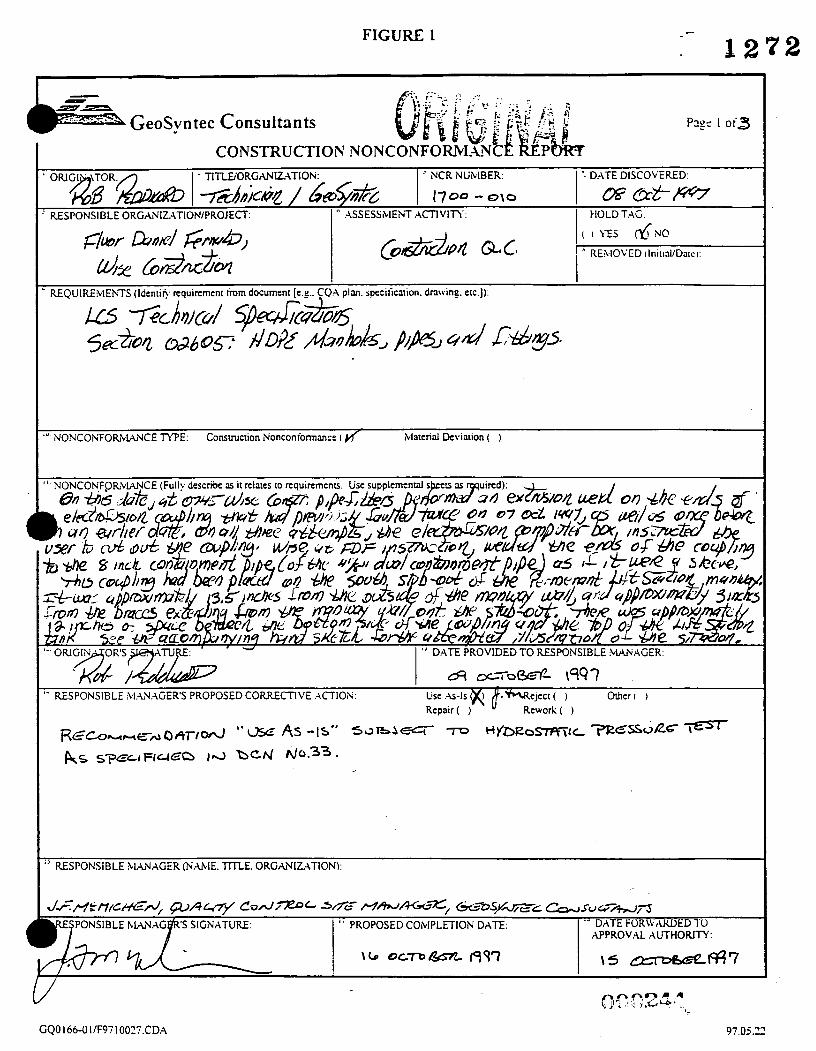
FIGURE 1 :- 1272
- TITLEiORGcV.(IL4TIOlu ' NCR NUMBER D4TE DISCOLERED
1700 - 010 1 HOLDTAG RESPONSIBLE ORCiANIZ4TIONIPROJECT I ASSESSMEM ,Amvin
I" NONCOI\;FOIL\MNCE TYFJE: Construction Noncontormmc: I K lLlatcriai Deviation ( )
'' RESPONSIBLE hlAWGER (lu'rL1IE. TITLE. ORGrLUIZATIONk
GQO166-01IF97100~7.CD~ 97.05.22

Phase I

Sheet1
NCR NUMBER DATE ORIGINATOR ASSESSMENT ACTIVITY
1 2 1 2
NONCONFORMANCE
I OSDF- PHASE ONE FIELD NONCONFORMANCE REPORTS 1
1702-001
1702-002
1702-003
1702-004
1702-005
1702-006
1702-007
1702-008
1702-009
1702-01 0
1 5-JuI-97
- 1 8-JuI-97
25-Au~-9
23-Aug-9
!5-AUg-97
1 -0ct-97
21 -0ct-97
1 O-Nov-Si
29-Nov-9i
Brian Erisman
~ ~~
Brian Erisman
Kirk Wills
Brian Erisman
Bill Nagel
Kirk Wills
Ned Meekins
Rob Peddicord
Ned Meekins
Earthwork: Compacted Fill
Earthwork: Compacted Fill
CQC
Earthwork: Compacted Fill
CQC
CQC
QC Laboratory Testing
Construction QC
Construction QC
Rock Fragments > 3-inches vere observed during fill operate
Due to a change in material, further testing needed to be
completed.
Removing visible rock particles
Rock in excess of 5-inches remained in fill material as fill
placement continued.
Compaction of area not yet approved for compaction.
Clay liner material was placed prior to conformace testing
being completed
A discrepancy in the grain-size test results between the quarry
saple and on-site stockpile
Geosynthetic clay liner material was placed which was
not approved by GeoSyntec
6-inch containment pipe oetween LCSILDS-01 manholes and liner penetration boxes for cell 1 was tested with incorrect
psi air pressure.
'Updated weekly* Page 1
n n n,n A A .&
12/16/97

FIGURE 5
- -- e GeoSyntec Consultants
NONCONFORMANCE SUMMARY LOG .
~ ~~~
Date Proposed Correction
Action Verified
Date Corrective
Action Approved
Date Proposed Corrective
Action Approved
NCR Number
to Approval Discovered Description Authority
NA -
7 n n n n a
97.05.22 GQO 16&01/F97 10027.CDA
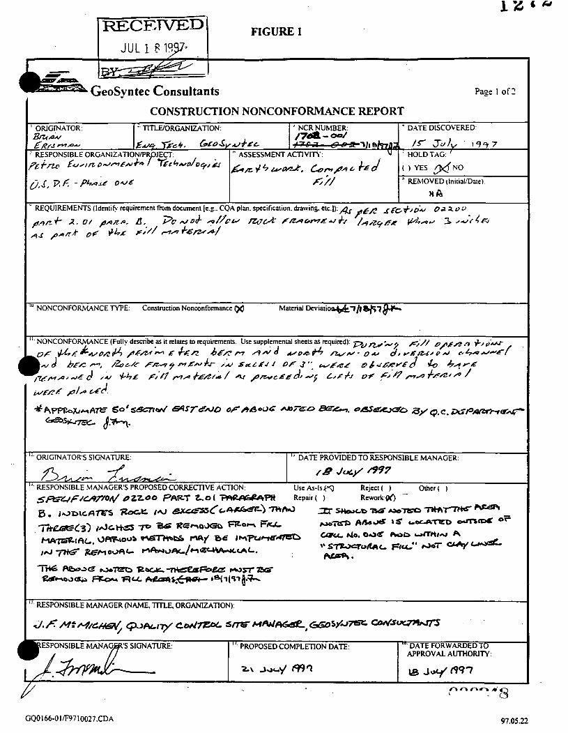
FIGURE 1
GeoSyntec Consultants Pape I of 2
'" NONCONFORMANCE TYPE: Construction Nonconformance 00 Material Dcviario+&7/# SB7 $*
l 7 PROPOSED COMPLETION DATE: '' DATE FORWARDED TO APPROVAL AUTHORITY:
a\ J&q r99q \a J o y 6 9 7 n n n r - . m ' - 8
GQO166-01/F9710027.CDA 97.05.22

1272 FIGURE 2
GeoSyntec Consultants Page 2 of 2
CONSTRUCTION NONCONFORMANCE REPORT
-' VERIFIERS SIGNATURE: I DATE:
? APPROVAL AUTHORITY SIGNATURE: DATE CLOSED:
I , ' CONTNUATION FROM BLOCK -:
GQO166-0IIF9710027.CDA
000249
97.05.22

. I . . .
FDF ONSITE DISPOSAL FACILITY (PHASE I) PROJECT -
Subcontract No. FSC 597 Petro Environmental Technologies, Inc.
NONCONFORMANCE REPORT FORM NOTICE OF NONCONFORMANCE
To: (Contractor/Subcontractor) Nonconfomiance Notice No.: - 00 1
Petro Environmental Technologies, Inc.
1 2 7 2
Date: July 21. 1997
Time: 5:OOPM
CONTRACTOR: Your attention is directed .to the following occurrence of nonconformance:
Location & Feature of Work Cell I - construction of perimeter berms
Description of Problem (Include contract specificatiodpladdrawing or FDF reference):
Paragraph: 02200-3.08.D: “Remove rock particles with a maximum dimension larger than 3-inches”. During con- struction of the perimeter berms, rock particles larger than 3-inches are remaining within the fill material between successive lifts and are not being removed prior to compaction.
Probable Cause of Problem:
:*e are simply too many rocks and not enough laborers and/or mechanical devices abailable to remove rocks Jger than 3-inches in diameter. Additionally, soil material is being placed faster than the laborers can remove the
rocks and whiIe they leave to empty the rocks collected, more soil is placed by articulating trucks and scrapers and the laborers simply can’t get back quickly enough or remove the rocks fast enough. There is also no mechanical means to remove‘the rocks other than via the laborers, therefore, the rocks become buried in successive lifis.
How and When Problem Was Located (Include estimate of how long the problem has existed):
GeoSyntec issued Petro Environmental a Construction Nonconformance Report (OR) on July 18, 1997, indicat- ing the problem was initially discovered on July 15, 1997. In response to the CNR, Petro Environmental’s QC Manager reviewed berm construction activities on July 21, 1997, and based upon an observation of the work being performed, it was deemed necessary to issue another Notice of Nonconformance to Petro Environmental.
Suggested Corrective Action:
It is recommended that mechanical means be employed to remove large rocks and/or additional laborers be utilized to remove the rocks. Simply placing more laborers in the field to remove rocks, will alone, not resolve the prob- lem, in addition to posing a d e t y hazard while working around the heavy equipment. Therefore, employing me- chanical means to resolve the problem will be necessary. Additionally, it may be necessary to suspend work on this phase of the construction until mechanical means sufficient to properly resolve the problem can be employed.
e t e d Method to Prevent Future Similar Problems:
H T R O dnce mechanical means and/or the use of additional laborers are employed, this should eiiminate the
CPQbOZSO L.

Contractor Action Taken: ,
The QC Manager has issued copies of this Notice of Nonconformance to the Project Manager, Steve Brandstetter, e General Superintendent, Dave Williams, in order to address the situation and to assist in arranging a SUC- 1 solution to the problem.
FDF Rep/CQC Rep Comments:
Receipt Acknowledged: Date: Time: 6 **I54 +-
3 / 5 4 & r d L & & / c -ld Steven C. BranGetter JVRich#d Schairbaum Project Manager, Petro Environmental Tech. Inc. Petro Environmental Technologies, Inc.
ction Manager CQC Consultant Field Monitor clor Daniel Fernald GeoSyntec, Inc.
F:\CUR-JOBS\WC7-024\QUALCTRL\NONCNFRERhlS.OO 1

FIGURE 1 1 2 7 2
GeoSyntec Consultants
~~
Papc I of 2
’” NONCONFORMANCE W E : Construction Nonconformance material Deviation ( )
PROPOSED COMPLETION DATE. DATE FORWARDED TO APPROVAL AUTHORITY:
I t8 J o y f W 7 -/m7
GQO166-OIIF9710027.CDA 97.05.22

FIGURE 2 1 2 7 2
GeoSyntec Consultants Page 2 of 2
&‘ DATE:
! APPROVAL AUTHORITY SIGNATURE: \ \ -
97.05.22

'" NONCONFORMANCE W E : Construction Nonconformance 6) Material Deviation ( )
' RESPONSIBLE MANAGER (NAME. TITLE. ORGANIZATION):

FIGURE 2 1272
-
GeoSyntec Consultants P3ge 2 of 2
CONSTRUCTION NONCONFORMANCE REPORT
APPROVAL AUTHORIT( SIGNATURE -‘ DATE
’ CONTINUATION FROM BLOCK -.
GQ0166-0 In97 10027.CDA 97.05.22

FIGURE 1 1 2 7 2
’‘ NONCONFORMANCE W E : Consrmcuon Nonconformance Material Deviation ( )
2 5 A ~ s T lPQ7 e*-- ‘ RESPONSIBLE MANAGERS PROPOSED CORRECnVE ACTION: use &-IS ( ) Reject( )
’’ RESPONSIBLE MANAGER (NAME. TITLE. ORGANIZATION):
PROPOSED COMPLETION DATE: DATE FORWARDED TO APPROVAL AUTHORITY:
26 &GOST 1997 25 bar 847 I
r \ c l c x # - ’ Ocsa ?da&-
GQO166-OIIF9710027.CDA 97.05.22

FIGURE 2
GeoSyntec Consultants Page 2 of 1
CONSTRUCTION NONCONFORMANCE REPORT
>' APPROVAL AUTHORITY SIGN\
n n -- VERIFICATION OF CORRECTIVE ACTION (Describe who. what when. whcrc):
- ' VERIFIERS SIGNATU
/ / I Ez/z7/47 +h7 I /
-' DATE CLOSED
v
97.05.22

FIGURE 1 E G E Z W E b t r o z iw
GeoSyntec Consultants ~ I o o . o - - - - - ~ ~ ~ ~ ~ ~ ~ o ~ o ~ . o . Page I of+3 -7
CONSTRUCTION NONCONFOMMVCE REPORT &*
'". NONCONFORMANCE TYPE: Consuuction Nonconformance (4 Material Deviation ( )
" PROPOSED COMPLETION DATE: DATE FORWARDED TO APPROVAL A U T H O W :
GQO166-0llF9710027.CDA 97.05.22

FIGURE 2 I 2 1 2
GeoSyntec Consultants CONSTRUCTION NONCONFORMANCE REPORT
EVALUATION OF PROPOSED CORRECnVE ACTION: 06 Reject ( )
APPROVAL AUTHORITY SIGNATURE: -' DATE: e., - VERIFICATION OF CORRECTIVE ACllON (Describe who. what when. where):
GQO166-OI/F9710027.CDA 97.05.22

1272 GEOSYNTEC CONSULTANTS P a g e L o f 3

- -72 FIGURE 1 L k
GeoSyntec Consultants CONSTRUCTION NONCONFORMANCE REPORT
I I ' REQUIREMENTS (Identie requirement from document [e+. CQA plan. specification. &wing e~c.]):
'. NONCONFOiLLlANCE (Fully describe as it relata to requirements. Use supplemental sheets aS required):
" RESPONSIBLE MANAGER (NAME. TITLE. ORGANIZATION):
v GQO166-OIIF9710027.CDA
- 97.05.22

FIGURE 1
Geosyntec Consultants Page 1 of2
CONSTRUCTION NONCONFORMANCE REPORT ' ORIGINATOR. I TlTLEIORGANIZATION. I ' NCR NUMBER. I - D.4E DISCOVERED
I 1 - REQUIREMENTS (Idcnfifv rcquiment from document [e.&. CQA plan. specificaoon. drawing eu.]).
7 6 G f C ~ l u ~ 4 m F I U n o 4 ~ D Y 02310 p u r zIol -- 7w-rJ 17oz-r5
Material Deviation PQ NONCONFORMANCE W E : Construction Nonconformance ( )
n IJ DATE PROVIDED TO RESPONSIBLE MANAGER.
21 h s - 1993- '- REJPONS~BLE MANAGER'S PROPOSED CORREC~VE ACTION. use As-Is go Reject ( ) mer( )
Repair( j Rework( )
Refer attached sheet
SPONSIBLE I' PROPOSED COMPLmON DATE: '* DATE FORWARDED TO APPROVAL AUTHORITY:
GQO166-OI/F9710027.CDA 97.0522

- - _.e
EVALUATION OF PROPOSED CORRECnVE ACIION: AfctV( ) Reject ( )
Comments ( )
APPROVAL AUTHORITY SIGNATURE: DATE:
- VERIFIERS SIGNATURE
' APPROVAL AUTHORIN SIGNATURE
CONTINUATION FROM BLOCK -
DATE: 4 zb DATE CLOSED:
. . . . . . . GQO 166-0 I F97 1 OOP7.CDA 97.05.22

FIGURE 1
- --n
GeoSvntec Consultants - CONSTRUCTION NONCONFORMANCE REPORT
" CONTINUATION OF NONCONFORMANCE NCR NUMBER NCk 17'2- 007
)RIGINATOR SIGNATURE: DATE: Ob O C 7 97
,n n noK.'? L7; e)
GQO166-OIIF9710027.CDA 91.09.24

FIGURE 2 1 2 1 2 I - I - - GeoSyntec Consultants Page 1 of 2
CONSTRUCTION NONCONFORMAiiCE REPORT
’- EVALUATION OF PROPOSED CORRECnVE ACTION: Acccpcm Rcjm ( ) Comments 6 )
-- VERIFICATION OF CORRECTIVE ACTION (Describe who. whar when. where):
I n
DATE CLOSED
---
97.05.22

FIGURE 1
II-r - GeoSyntec Consultants Cont.
CONSTRUCTION NONCONFORMANCE REPORT 14. CONTINLJATION OF NCR No. 1702408 RESPONSIBLE MANAGER'S PROPOSED CORRECTIVE ACnON:
1 2 1 2
The above noted material, No. 78 aggregate, was supplied by Highland Stone. The material was specifically graded for the OSDE project as No. 78 is not commonly produced in the general area. Initially GeoSyntec obtained samples (GDM 06 through GDM 10) fion stockpiles at the quany site. Results of the grain-size distribution tests met specification and DCN requirements as did hydraulic conductivity and carbonate content. The material was again sampled h m ''on site" stockpiles. Results of grain-size distribution test! GDM 13 through GDM 18 excluding GDM 15 did not meet specification requirements. An additional hydraulic conductivity test, GDN 14, met specification requirements. The discrepancy in grain-size test results appears to be due to a combination of loading, transporting off loading and stockpiling on site resulting in segregation of the material. It should also be noted that samples are only obtainable from the stockpile face. Based on the above findings no adverse affects are anticipated in the use of the material for its intended purpose.
GQO166-011F9710027.CDA 91. I 1 .OS

FIGURE Z - 1272 - - P GeoSyntec Consultants P3gt 2 o f ’ :
CONSTRUCT103 SONCOi\iFORM.UCE REPORT
.- VERIFIC.4TlO?i OF CORRECTIVE .ACTlO;\i (Describe who. w n a ~ when. wiiere,:
HA
VERIFIERS SIGNATURE: /c/A
-- DATE:
d A
FiA -’ DATE CLOSED:
I
-‘ CONTINUATION FROM BLOCK -.

FIGURE 1
& GeoSyn tec Consultants Page 1 of::
CONSTRUCTION NONCONFORiiLhYCE REPORT ' ORI AT0 - TITI&ORGANILATION ' NCR NUMBER * DATE DISCOVERED
' RESPONSIBLE ORGANIZ.ATION/PROJECT 1 H 0 L D T . G
I I * REQUIREMENTS (Identie requirement tiom document [e.:.. CQA plan. specificxion. dnwing. crc.]):
1 '" NOKCONFORhUNCE TYPE: Consmction Noncontonnancc (d ~Matcrid Deviation ( )
A430&V&6 49 r , c c . , m W B ? z ~ a7- '' RESPONSIBLE W A G E R @-ME, TITLE. ORGANIZATION):
'- DATE FORWARDED TO APPROVAL AUTHORITY
l 7 PROPOSED COklPLETION D A E .
/3 /r/ouergrR /997 /t N'dasw3l& A43
(500267 ' GQO166-OI/F9710027.CDA 97.05.11

FIGURE 2
I - I s z AESEZZL GeoSyntec Consultants Page 2 of2
CONSTRUCTION NONCONFORMAiCE REPORT
'* EVALUATION OF PROPOSED CORRECTIVE ACTION Accept Q, Reject( ) Comments ( )
' COMMUATION FROM BLOCK -'
GQO166-OI/F9710027.CDA 97.05.12

. . .
n. f

J

FIGURE I i272
I GeoSyn tec Consultants Page I oi:
' NONCONFORivWCE (Fully dacribc Y it relates to requirements. Use supplemental s h e a Y required):
m a 7 \ 97.05.12

FIGURE 2
GeoSyntec Consultants Page 1 of2
CONSTRUCTION NONCONFORh.IANCE REPORT
-- GQO166-OI/F9710027.CDA 97.05.22