Embed Size (px)
Citation preview
Page 1
MI002751
SENECA s.r.l.
Via Austria, 26 – 35127 – PADOVA – ITALY
Tel. +39.049.8705355 – 8705359 Fax. +39.049.8706287
Web site: www.seneca.it
Technical assistance: [email protected] (IT), [email protected] (Other)
Commercial reference: [email protected] (IT), [email protected] (Other)
This document is property of SENECA srl. Duplication and reproduction of its are forbidden (though partial), if notauthorized. Contents of present documentation refers to products and technologies described in it. Though we strive forreach perfection continually, all technical data contained in this document may be modified or added due to technical andcommercial needs; it’s impossible eliminate mismatches and discordances completely. Contents of presentdocumentation is anyhow subjected to periodical revision. If you have any questions don’t hesitate to contact ourstructure or to write us to e-mail addresses as above mentioned.
USER MANUAL
ZC-SG

USER MANUAL – ZC-SG
2
Seneca Z-PC Line module: ZC-SGThe ZC-SG module allows to manage the load cell signals and to process the weight value, withtwo types of communication: CANopen protocol, ModBUS protocol (RS232 serial).
General characteristicsHardware
Sampling frequency settable from 12,53 Hz to 151,71 Hz. 1500 VAC isolation amongst inputs, power supply and CAN interface. Protection against ESD discharge up to 4 kV. Adjustable rejection at 50 and 60Hz. Strain gauge directly powered by the instrument. Ratiometric measurement. Simplified power supply and serial bus wiring by means of the bus housed in the DIN rail. 1 to 64mV/V sensitivity, settable by software for real/integer values.
Software
Load cell calibration with known weight Load cell calibration is not necessary if the load cell sensibility is known. Configurable digital I/O. Stable weight indication via digital output / Modbus register / PDO Remote writing of the tare in volatile and/or non volatile memory through digital input / CAN
commands. Led Indications: Power Supply, CAN communication, MODBUS-RTU communication, Inputs
fault. Alarm generated when programmable threshold is exceeded. Measurement stabilization through a programmable number of samples, ±30000 points
hysteresis activable.
Communication
CAN Interface with CANopen protocol: up to 1 Mbps speed. CANopen Baud rate and Node ID configurability by DIP-switches or software. Nodeguarding or heartbeat RS232 Serial Communication with MODBUS-RTU protocol Complete configurability through specific software downloadable in the website www.seneca.it.

USER MANUAL – ZC-SG
3
FeaturesINPUTType 6-wires or 4-wires differential measurement inputFull scale ±5 mV ..±320 mVError Calibration: 0.01% of the full scale value
Linearity: 0.01% of the full scale valueThermal drift: 25 ppm/°C
STRAIN GAUGE CHARACTERISTICSPower supply voltage 5 Vdc
Minimum inpedance 87 Ω equivalent, eventually derived by a parallel of load cells (forexample four 350 Ω cells)
Sensitivity From ± 1 mV/V to ± 64 mV/VTerminals 4 or 6DIGITAL INPUT OR OUTPUTDigital input opto-isolated
Max voltage: 30 V
Digital output opto-isolated
Max current: 50 mAMax voltage: 30 V
CONVERSION/ACCURACY SPECIFICATIONSADC 24 bitThermal drift 25 ppm/°CSampling frequency Settable from 12.35 to 151.71 HzInterference rejection Settable both at 50 and 60 Hz
CONNECTIONSRemovable terminals Removable 3-way screw terminals, 5.08 mm pitchIDC10 rear connector CAN interface and power supply (for DIN rail)Stereophonic frontaljack
3.5 mm for RS232 connection (COM)
POWER SUPPLYSupply voltage 10 – 40 Vdc or 19 – 28 Vac ( 50Hz - 60Hz)Powerconsumption
Max: 2 W

USER MANUAL – ZC-SG
4
NOTE: “0x” means an exadecimal number interpretation.
CANOpen features
TECHNICAL DATABaud rate 20, 50, 125, 250, 500, 800, 1000 kbpsTypical refresh time 20 msSensibility supported From ±1 mV/V to ±64 mV/V
CANOpen TECHNICAL DATA
NMTSlaveNode guarding, heartbeat
Node ID HW switch or softwareNumber of PDO 2 TXPDO modes Event triggered, Sync (cyclic), Sync (acyclic)PDO mapping VariablePDO linking supportedNumber of SDO 1 serverError message yesSupported application Cia 301 v4.02Layer Cia 401 v2.01
CANOpen TPDOs transmission type supported
Object Value 0x180x Sub 2 TRANSMISSION TYPE0 Synchronous - acyclic
From 1 to 240 Synchronous - cyclic255 Asynchronous

USER MANUAL – ZC-SG
5
CANOpen PDOs mapping
OBJECTS FOR DEFAULT MAPPING
PDO NR COB-IDMAPPEDOBJECTS INDEX SUBINDEX
TPDO2 0x40000280+
NodeId
Measure float 0x6403 1
ADC 16 bit 0x6401 2
TPDO3 0x40000380+
NodeId
Measure integer 0x6401 1
STATUS 0x2120 0
Note that TPDO COB-ID must start with 0x4.
CANOpen emergency message
The Emergency message is composed by:
2 bytes of EEC (Emergency error code)
1 bytes of ER (Error register)
Max of 4 bytes of MEF (Manufacturer error filled)
For EEC code 0xFF10, the emergency message is:
EMERGENCY MESSAGEBYTE 0 BYTE 1 BYTE 2 BYTE 3 BYTE 4
0xFF10 0x81 MEF
With this MEF:
MEF (Manufacturer-specific Error Field) for EEC 0xFF10BIT DESCRIPTION
15..6 NA5 Generic communication with input error4 CRC communication with input error3 EEPROM error2 Over weight error1 Weight float < 00 Stable weight

USER MANUAL – ZC-SG
6
For a “timeout command” or “error command”, the emergency message is:
EMERGENCY MESSAGEBYTE 0 BYTE 1 BYTE 2 BYTE 3 BYTE 4
0xFF11 0x81 Object 0x2103
For “CPU ERROR” the Emergency message will be:
EMERGENCY MESSAGEBYTE 0 BYTE 1 BYTE 2 BYTE 3 BYTE 4
0xFF20 0x81 Object 0x1002
EECCODE DESCRIPTION0x0000 No error0x1000 Generic error0x4201 CPU temperature over HOT STOP ERROR0x4202 CPU temperature over HOT STOP0x4203 CPU temperature under COLD ERROR0x8110 Communication Can Overrun0x8120 Error passive0x8130 Life Guard error0x8140 Recovered from bus off0xFF10 General input channels error0xFF11 Command for input channel error0xFF20 CPU error
ERBIT 7 BIT 6 BIT 5 BIT 4 BIT 3 BIT 2 BIT 1 BIT 0
Generic 0 Voltage temperature communication 0 0 Manufacture
Where bit equal to “0” means “no error”.
Object 0x1002: manufacturer status register
Object 0x1002 is the CPU status.
OBJECT 1002BIT DESCRIPTION
31..3 NA2 Communication with input error1 NA0 EEPROM CRC error

USER MANUAL – ZC-SG
7
Object 0x1006: communication window lenght
OBJECT 1006MIN VAL [ms] MAX VAL [ms]
10 10000
Object 0x1007: synchronous window lenght
OBJECT 1007MIN VAL [ms] MAX VAL [ms]
2 2000
CANOpen manufacturer specific profile
If dip-switches are in “from memory” mode, the node address is selectable by Object 0x2001.
NODE ADDRESS (Object 0x2001)Object value Description
0..127 Node address
If dip-switches are in “from memory” mode, the baud rate is selectable by Object 0x2002.
BAUDRATE (Object 0x2002)Object value Description
1 20 kbit/s2 50 kbit/s3 125 kbit/s4 250 kbit/s5 500 kbit/s6 800 kbit/s7 1 Mbit/s
Object 0x2030 can be used to monitor the CPU temperature.
CPU TEMPERATURE (Object 0x2030)Subindex Description
1 Actual temperature [°C/10]2 Temperature for HOT STOP ERROR [°C/10] 95.0°C3 Temperature for HOT ERROR [°C/10] 90.0°C4 Temperature for COLD ERROR [°C/10] -25.0°C
The HOT STOP temperature sends in pre-operational the station.

USER MANUAL – ZC-SG
8
The HOT ERROR and the COLD ERROR temperature sends the Emergency Object.
The Object is Read Only.
Digital out logic
Digital out logic=0 the digital output it is normally opened.
Digital out logic=1 the digital output it is normally closed.
Object 0x2104: Execute
The object sends command to the CPU: the supported commands are:
Object 0x2104COMMAND CODE DESCRIPTION
0xC2FA Tare acquisition ready to be saved in EEPROM(allowed also in RUN)
0xC60C Full scale/known weight acquisition ready to besaved in EEPROM (allowed also in RUN)
0xC1BA Tare acquisition (on RAM) (allowed also in RUN)0xD180 Full scale acquisition (on RAM) (allowed also in
RUN)0xBAB0 Save new values on EEPROM (allowed also in RUN)
Object 0x2105: Execute result
The object is used to know the command execution result (only for special commands).
Object 0x2107: Configuration register 1
The object is used to setup the measure and the digital input/output.
CONFIGURATION REGISTER 1 (Object 0x2107)SUBINDEX Description
1 Sample number2 Mode3 Cell sensibility4 Digital out logic5 Digital out mode6 Digital IN or OUT selection
Sample NR
The sample number it is the number of sample that enters into the measure. Higher valuesimplies lower response speed but more stability.

USER MANUAL – ZC-SG
9
Mode
The station can be configured in two modes:
Mode=1: a known weight must be used to calibrate the system on site.
Mode=0: no need to use a known weight to calibrate the system, the station will use the factorycalibration values.
Cell sensibility
The object sets the cell mV/V sensibility:
0=±1 mV/V
1=±2 mV/V
2=±4 mV/V
3=±8 mV/V
4=±16 mV/V
5=±32 mV/V
6=±64 mV/V
7=from object 0x2108 sub1
Digital out logic
Defines the operation that will cause the switch to ON or OFF for the digital output.
DIGITAL OUT LOGICValue Description
0 The output is normally opened1 The output is normally closed

USER MANUAL – ZC-SG
10
Digital out mode
Defines the operation that will cause the switch to ON or OFF for the digital output.
DIGITAL OUT MODEValue Description
0 The gross weight exceeds the full scale1 The weight is stable and the net weight exceeds the
threshold set2 The weight it is stable
Digital in or out selection
The station can be configured with a digital input or a digital output:
- if IN or OUT selection=1: digital output enable/digital input disabled
- if IN or OUT selection=0: digital input enable/digital output disabled
Object 0x2108: configuration register 2
The object is used to setup the system measure.
CONFIGURATION REGISTER 2Subindex Description
1 Sense ratio2 Cell full scale3 Known weight value4 Not used5 Not used6 Threshold value7 Delta weight8 Delta time9 ADC speed
10 Resolution in number of points
Sense ratio
Sets the sense ratio for the strain gauge used in [mV/V] (floating point 32 bit format).
Cell full scale
If mode 1 is selected (object 0x2107) sets the full scale of the strain gauge in technical units ofweight (kg, pounds,etc…) (Floating point 32 bit format).
Known weight value
If mode 1 is selected (object 0x2107) sets the value of the weight used for the calibration intechnical units (kg, pounds, etc) (Floating point 32 bit format).

USER MANUAL – ZC-SG
11
Value for Maximum integer
Sets for what net weight (object 0x6403) the integer net value (object 0x6401 subindex 1) risethe +30000 value. (floating point 32 bit format).
Value for Minimum integer
Sets for what net weight (object 0x6403) the integer net value (object 0x6401 subindex 1) risethe zero value. (floating point 32 bit format).
Threshold value
If the net weight exceeds the threshold value set and the weight is stable, the digital output (ifsubindex digital out mode=1) is closed or opened (depending subindex digital output logic)(floating point 32 bit format).
Delta weight
Weight variation in technical units accepted for the condition of “stable weight” (floating point 32bit format)
Delta time
Time in units of 100 ms used with delta weight to establish whether or not the weight is stable[s/10].
ADC speed
The ADC speed and the frequency rejection can be customized by the table:
ADC CONFIGURATIONValue Sampling frequency [Hz] 50 Hz rejection 60 Hz rejection
27 151.71 NO NO55 74.46 NO NO82 49.95 YES YES
109 37.59 NO YES155 50.57 NO NO183 24.82 YES NO210 16.65 YES YES237 12.53 NO YES
Hysteresis
The hysteresis can be used to stabilize the input value. If the hysteresis is activated theresolution is limited to ±30000 points. If hysteresis is disabled, the resolution available is the full24 bit ADC.
0x00=hysteresis disabled
0x80=hysteresis enabled

USER MANUAL – ZC-SG
12
Object 0x2120: status
The status object contains important information about the state of the measure and the station.
STATUSBit Description
15..7 NA6 Net weight > threshold5 Generic communication with input channel error4 CRC communication with input channel error3 EEPROM error2 Over weight error1 Negative measure0 Stable weight condition
DIP-SWITCH configuration
BAUD-RATE (Dip-Switches: SW1)1 2 3 Meaning
Only Baud-Rate is acquired from memory(EEPROM)20 kbps50 kbps125 kbps250 kbps500 kbps800 kbps1 Mbps
ADDRESS (Dip-Switches: SW1)4 5 6 7 8 9 10 Meaning
Only address is acquired from memory(EEPROM)Address=1Address=2Address=3Address=4Address=5
X X X X X X X ……………………………Address=127

USER MANUAL – ZC-SG
13
CANOpen LED description
SERVICE (DIAGNOSTIC) LED DESCRIPTIONLED LED status MeaningRUN Blinking light Pre-operational mode
Single flash Stop modeON Operational mode
ERROR Single flash At least one error counter has reached or exceed the warninglevel
Double flash Guard eventTriple flash The SYNC has not received within the configurated
communication cycle timeout periodON The CAN controller is bus offOFF No error
FAIL Blinking Data receiving from RS232/overweight errorON Communication error with input channel
POWER ON Power supply
Object for analog data
Object 0x6401 contains the 16 bit (signed) values for the weight and the unsigned 16 bit ADCvalue.
16 BIT INTEGER INPUT (Object 0x6401)Subindex Description
1 Net value signed2 ADC value
Integer net value
Integer net value (signed): integer approximation of the floating point value.
ADC value
The ADC value scaled into 16 bit (unsigned) value.
Where if ADC = 0x8000 means 0 mV on input.
If ADC = 0xFFFF means max positive mV on input.
If ADC = 0 means max negative mV on input.

USER MANUAL – ZC-SG
14
Object 0x6403 32 bit float input value
Object 0x6403 contains the net weight in technical unit in agreement with the known weightobject (floating point 32 bit format).
Cell calibration procedure for mode=1 (calibration with a knownweight)
1) Set the right mV/V sensibility on object 0x2107 subindex 3
2) Save the new value by sending the command 0xBAB0 on object 0x2104 subindex 0
3) Send the Reset command by sending command 0xABAC on object 0x2104 subindex 0
4) Put the Tare on the cell
5) Get the Tare value by sending the command 0xC2FA on object 0x2104 subindex 0
6) Enter the known weight value in technical units (kg, pounds, etc) on object 0x2108 subindex3
7) Put the known weight value on the cell
8) Get the known weight by sending the command 0xC60C on object 0x2104 subindex 0
9) Save the new values by sending the command 0xBAB0 on object 0x2104 subindex 0
10) Wait 5 seconds and Switch OFF and then ON the ZC-SG
Cell calibration procedure for mode=0 (calibration without aknown weight)
1) Set the value 7 on object 0x2107 subindex 3 (use object 2108 for sense ratio)
2) Set the right mV/V sensibility on object 0x2108 subindex1 in floating point value
3) Save the new values by sending the command 0xBAB0 on object 0x2104 subindex 0
4) Send the Reset command by sending command 0xABAC on object 0x2104 subindex 0
5) Put the Tare on the cell
6) Get the Tare value by sending the command 0xC2FA on object 0x2104 subindex 0
7) Save the new values by sending the command 0xBAB0 on object 0x2104 subindex 0
8) Wait 5 seconds and Switch OFF and then ON the ZC-SG

USER MANUAL – ZC-SG
15
CANOpen functional diagram
For integer values

USER MANUAL – ZC-SG
16
CANOpen Object dictionary
COMMUNICATION PROFILE AREAINDEX SUB
INDEXNAME DESCRIPTION TYPE ACCESS DEFAULT
0x1000 0 Device type Profile 401=0x191 UNSIGNED 32 RO 0x000401910x1001 0 Error register Error register (DS401) UNSIGNED 8 RO 00x1002 0 Station status Status register UNSIGNED 32 RO 00x1005 0 SYNC COB-ID The device consumes
the SYNC messageUNSIGNED 32 RW 0x00000080
0x1006 0 Comm. windowlenght
Sync interval [us] UNSIGNED 32 RW 0
0x1007 0 Synchronouswindow lenght
The window [us] forthe PDO transmissionafter the SYNC
UNSIGNED 32 RW 0
0x1008 0 ManufacturerDevice name
Device name VISIBLESTRING
RO “ZC-SG”
0x1009 0 ManufacturerHW version
Hardware version VISIBLESTRING
RO “SC000000”
0x100A 0 ManufacturerSW version
Software version VISIBLESTRING
RO “SW001160”
0x100C 0 Guard Time [ms] UNSIGNED 16 RW 00x100D 0 Life time factor Max delay between
two guardingtelegrams=Guard_Time ·Life_Time_Factor
UNSIGNED 8 RW 0
0x1010
0 Storeparameters/number ofmapped object
Max subindex number UNSIGNED 8 RO 5
1 Save allparameters
Store not volatileparameters (write inASCII “save” for storeprocess MSB0x65766173 LSB)
UNSIGNED 32 RW 1
2 Savecommunicationparameters
Store not volatileparameters (write inASCII “save” for storeprocess MSB0x65766173 LSB)
UNSIGNED 32 RW 1
3 Save applicationparameters
Store not volatileparameters (write inASCII “save” for storeprocess MSB0x65766173 LSB)
UNSIGNED 32 RW 1
4 Savemanufacturerparameters
Store not volatileparameters (write inASCII “save” for storeprocess MSB0x65766173 LSB)
UNSIGNED 32 RW 1
5 Save channelparameters
Store not volatileparameters (write inASCII “save” for storeprocess MSB0x65766173 LSB)
UNSIGNED 32 RW 1

USER MANUAL – ZC-SG
17
0x1011 0 Restore default/number ofmapped object
Max subindex number UNSIGNED 8 RO 5
1 Restore allparameters
Restore not volatileparameters (write inASCII “load” for storeprocess MSB0x64616F6C LSB)
UNSIGNED 32 RW 0
2 Restorecommunicationparameters
Restore not volatileparameters (write inASCII “load” for storeprocess MSB0x64616F6C LSB)
UNSIGNED 32 RW 0
3 Restoreapplicationparameters
Restore not volatileparameters (write inASCII “load” for storeprocess MSB0x64616F6C LSB)
UNSIGNED 32 RW 0
4 SaveManufacturerparameters
Restore not volatileparameters (write inASCII “load” for storeprocess MSB0x64616F6C LSB)
UNSIGNED 32 RW 0
5 Restore slaveparameters
Restore not volatileparameters (write inASCII “load” for storeprocess MSB0x64616F6C LSB)
UNSIGNED 32 RW 0
0x1014 0 COB-IDemergencyObject
UNSIGNED 32 RO $NODEID+0x80
0x1017 0 Heartbeatproducer time
Time (ms)0x0000=there is notheartbeat service
UNSIGNED 16 RW 0
0x1018 0 Identity object Max subindex number UNSIGNED 8 RO 41 Vendor ID Seneca srl UNSIGNED 32 RO 0x000002492 Product code ZC-SG Machine ID
CodeUNSIGNED 32 RO 0x0000001F
3 Revisionnumber
UNSIGNED 32 RO
4 Serial number UNSIGNED 32 RO0x1200 0 1st SDO port/
number ofmapped object
Max subindex number UNSIGNED 8 RO 2
1 COB-ID SDOClient-> Server
COB-ID of receiveSDO
UNSIGNED 32 RO $NODEID+0x600
2 COB-ID SDOServer-> Client
COB-ID of transmitSDO
UNSIGNED 32 RO $NODEID+0x580
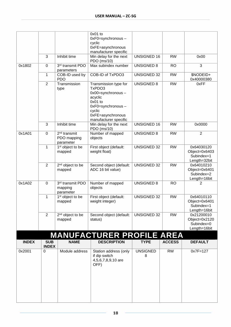
0x1801 0 2nd transmitPDOparameters
Number of mappedobjects
UNSIGNED 8 RO 3
1 COB-ID used byPDO
COB-ID of TxPDO2 UNSIGNED 32 RW $NODEID+0x40000280
2 Transmissiontype
Transmission type forTxPDO20x00=synchronous –acyclic
UNSIGNED 8 RW 0xFF
USER MANUAL – ZC-SG
18
0x01 to0xF0=synchronous –cyclic0xFE=asynchronousmanufacturer specific
3 Inhibit time Min delay for the nextPDO (ms/10)
UNSIGNED 16 RW 0x00
0x1802 0 3rd transmit PDOparameters
Max subindex number UNSIGNED 8 RO 3
1 COB-ID used byPDO
COB-ID of TxPDO3 UNSIGNED 32 RW $NODEID+0x40000380
2 Transmissiontype
Transmission type forTxPDO30x00=synchronous –acyclic0x01 to0xF0=synchronous –cyclic0xFE=asynchronousmanufacturer specific
UNSIGNED 8 RW 0xFF
3 Inhibit time Min delay for the nextPDO (ms/10)
UNSIGNED 16 RW 0x0000
0x1A01 0 2nd transmitPDO mappingparameter
Number of mappedobjects
UNSIGNED 8 RW 2
1 1st object to bemapped
First object (default:weight float)
UNSIGNED 32 RW 0x64030120Object=0x6403
Subindex=1Length=32bit
2 2nd object to bemapped
Second object (default:ADC 16 bit value)
UNSIGNED 32 RW 0x64010210Object=0x6401
Subindex=2Length=16bit
0x1A02 0 3rd transmit PDOmappingparameter
Number of mappedobjects
UNSIGNED 8 RO 2
1 1st object to bemapped
First object (default:weight integer)
UNSIGNED 32 RW 0x64010110Object=0x6401
Subindex=1Length=16bit
2 2nd object to bemapped
Second object (default:status)
UNSIGNED 32 RW 0x21200010Object=0x2120
Subindex=0Length=16bit
MANUFACTURER PROFILE AREAINDEX SUB
INDEXNAME DESCRIPTION TYPE ACCESS DEFAULT
0x2001 0 Module address Station address (onlyif dip switch4,5,6,7,8,9,10 areOFF)
UNSIGNED8
RW 0x7F=127

USER MANUAL – ZC-SG
19
0x2002 0 Baudrate Station Baudrate(only if dip switch1,2,3 are OFF)1=20kbps2=50kbps3=125kbps4=250kbps5=500kbps6=800kbps7=1Mbps
UNSIGNED8
RW 0x01
0x2003 0 Firmwarerelease
UNSIGNED16
RO 1122
0x2030 0 Devicetemperature/number ofparameters
Max subindexnumber
UNSIGNED8
RO 4
1 Internaltemperature
Station internaltemperature[°C/10]
INTEGER16
RO 0
2 Hi Hitemperature
Critical hottemperature (alloperations stop)[°C/10]
INTEGER 16 RO 950
3 Hitemperature
Warning for toohot temperature[°C/10]
INTEGER 16 RO 900
4 Lowtemperature
Critical lowtemperature (alloperations stop)[°C/10]
INTEGER 16 RO -250
0x2104 0 Execute Supportedcommands:0xC2FA=tareacquisition (ready forEEPROM saving)0xC60C=full scaleacquisition (ready forEEPROM saving)0xC1BA=tareacquisition (RAM)0xD180=full scaleacquisition (RAM)0xBAB0=save valuesin EEPROM
UNSIGNED16
RW 0
0x2105 Execute result 0=command done1=commandexecuted with error
UNSIGNED16
RW 0
0x2107 0 SETUP 1channel
Number ofparameters
UNSIGNED8
RO 6
1 SET1: samplenumber
Number ofsamples for f i ltercalculation[1..100]
UNSIGNED8
RW 100
2 SET1: mode 0=use the factorycalibration1=use a knownweight
UNSIGNED8
RW 1

USER MANUAL – ZC-SG
20
3 SET1: cellsensibil ity
0=±1 mV/V1=±2 mV/V2=±4 mV/V3=±8 mV/V4=±16 mV/V5=±32 mV/V6=±64 mV/V7= from object0x2108 sub1
UNSIGNED8
RW 1
4 SET1: digital outlogic
0=the output isnormally open1=the output isnormally closed
UNSIGNED8
RW 0
5 SET1: digital outoperation mode
0=the output isswitched when thegross_weight >full_scale1=the output inswitched when theweight is stable andthe net weight >threshold2=the output isswitched when theweight is stable
UNSIGNED8
RW 0
6 SET1: digital inor out mode
0=digital input mode1=digital outputmode
UNSIGNED8
RW 0
0x2108 0 SETUPChannel
Number ofparameters
UNSIGNED8
RO 10
1 SET2: senseratio
Cell sense ratio inmV/V measure
REAL 32 RW 2.0
2 SET2: cell fullscale
REAL 32 RW 10000.0
3 SET2: knownweight
Known weight [kg,g, etc…]
REAL 32 RW 10000.0
4 SET2: not used REAL 32 RO 10000.05 SET2: not
usedREAL 32 RO 0.0
6 SET2:threshold
REAL 32 RW 5000.0
7 SET2: Deltaweight
Weight variationfor the stablecondit ion
REAL 32 RW 1.0
8 SET2: Deltatime
The variationused for thestable condit ionDelta time ·100 ms
UNSIGNED16
RW 1
9 SET2: ADCspeed
27=151.71 Hz55=74.46 Hz82=49.95 Hz109=37.59 Hz155=50.57 Hz183=24.82 Hz210=16.65 Hz237=12.53 Hz
UNSIGNED8
RW 82
10 SET2: 30000pointshysteresis
0x00=fullresolution0x80=30000 pointsresolution
UNSIGNED8
RW 0x80

USER MANUAL – ZC-SG
21
0x2120 0 Channelstatus
Status object UNSIGNED16
RO
0x2125 0 Fault action UNSIGNED16
RW 0x8000
0x2160 0 Fault value Number ofparameters
UNSIGNED8
RO 0x01
1 Fault value REAL 32 RW 850.0
STANDARD DEVICE PROFILE AREAINDEX SUB
INDEXNAME DESCRIPTION TYPE ACCESS DEFAULT
0x6401 0 16 bit input Number of input UNSIGNED8
RO 2
1 Weightinteger
Weight in integerformat
INTEGER16
RO
2 ADC value(scaled to 16 bit)
ADC scaled value UNSIGNED16
RO
0x6403 0 Float input Number of input UNSIGNED8
RO 1
1 Weight real Weight in realformat
REAL 32 RO
0x6423 0 Globalinterruptenable
0=disableasynchronousTxPDO1=enableasynchronousTxPDO
BOOLEAN RW 0
0x6424 0 Analogueinterruptupper limit 16bit
Number upper value16 bit
UNSIGNED8
RO 1
1 Analogueinterruptupper limit 16bit
INTEGER16
RW 0
0x6425 0 Analogueinterruptlower limit 16bit
Number lower value16 bit
UNSIGNED8
RO 1
1 Analogueinterruptlower limit 16bit
INTEGER16
RW 0
0x6426 0 Analogueinterrupt deltalimit 16 bit
Number delta limitvalue 16 bit
UNSIGNED8
RO 1
1 Analogueinterrupt deltalimit 16 bit
INTEGER16
RW 0
0x6429 0 Analogueinterruptupper limitf loat
Number upper valuefloat
UNSIGNED8
RO 1
1 Analogueinterruptupper limitf loat
REAL 32 RW 0

USER MANUAL – ZC-SG
22
0x642A 0 Analogueinterruptlower limitf loat
Number lower valuefloat
UNSIGNED8
RO 1
1 Analogueinterruptlower limitf loat
REAL 32 RW 0
0x642B 0 Analogueinterrupt deltalimit f loat
Number delta limitvalue float
UNSIGNED8
RO 1
1 Analogueinterrupt deltalimit f loat
REAL 32 RW 0
Easy-SETUPTo configure the Seneca Z-PC Line modules, it is possible to use Easy-SETUP software, free-downloadable from the www.seneca.it; the configuration can be performed by RS232 or RS485bus communication.


