Embed Size (px)
Citation preview

ICD16/32
User’s Guide
03/24/07 Revision 4v2
ICD16/32 USER’S GUIDEREV4.2
2
TABLE OF CONTENTS ACKNOWLEDGMENT.....................................................................................................3 MANUAL USAGE...............................................................................................................3 Introduction..........................................................................................................................4
About ICD16/32 Cable Assembly (Kit PN 901618) ...........................................................4 About USB Multilink CPU16/3xx Cable (Kit PN 903517)..................................................5 Background Debug Mode (BDM).......................................................................................5
P&E ICD Software Installation...........................................................................................5 System Requirements..........................................................................................................6 Operating System................................................................................................................6 Computer ...........................................................................................................................6 Installing P&E ICD16 Software...........................................................................................6 Installing ICD32 Software.................................................................................................10
Directory Structure ............................................................................................................11 Creating a Common Directory Structure............................................................................11 Loading Centrilift Software onto a target............................................................................12
Connecting to your target. .................................................................................................13 Parallel Port Programmer ..................................................................................................13 USB Port Programmer......................................................................................................14 Alternate Power for the target............................................................................................15
Parallel Port Programmer ..............................................................................................15 USB Programmer .........................................................................................................16
Running the ICD Software ................................................................................................17 The Connection Manager..................................................................................................17 ICD 16/32 application.......................................................................................................19
Vortex GCS – Fixed Speed Controller..........................................................................21 Electrospeed GCS – Variable Speed Controller ............................................................23 GDI - Graphic Display Interface....................................................................................26 ICM – Integrated Communication Module.....................................................................29 EIO – Expansion Input/Output module And CIM ..........................................................30 RDCM – Remote Data Communication Module............................................................31
Centrilift Utility Programs .................................................................................................32 Setpoint Utility..................................................................................................................32
Setup ...........................................................................................................................32 Saving Setpoints.........................................................................................................33 Restoring Setpoints....................................................................................................36
Hardware Troubles ............................................................................................................38 PC & Software Troubles....................................................................................................38 Table of Figures .................................................................................................................40
ICD16/32 USER’S GUIDEREV4.2
3
ACKNOWLEDGMENT The information in this manual has been checked carefully to be accurate; however, Centrilift Control Technologies assumes no responsibility for possible inaccuracies or omissions. The methodology and/or specification contained within are subject to change without notice. Microsoft and MS-DOS are registered trademarks and Windows, Windows 95 Windows 98 are trademarks of Microsoft Corporation. IBM is a registered trademark and IBM PC, XT are trademarks of International Business Machines Corporation. ICD Interface Cable for CPU16 and CPU32 is the product of P&E Microcomputer Systems Inc., P.O. Box 2044, Woburn, MA. 01888-0044. TEL: (617) 353-9205 USB Multi Link cable for CPU16 and CPU32 is the product of P&E Microcomputer Systems Inc., P.O. Box 2044, Woburn, MA. 01888-0044. TEL: (617) 353-9205 MANUAL USAGE This manual is to be read in its entirety, and all precautions are to be observed. If there are concerns or questions in regards to the content, contact Centrilift Control Technologies at either the Claremore, Oklahoma, or Leduc, Alberta, facility. The use of this manual is intended for qualified Centrilift personnel and those authorized by Centrilift to load software or reload software on Centrilift equipment. If done incorrectly, it can cause damage to equipment. This manual outlines the procedure and equipment necessary for loading software and reloading software into the GCS line of products; however, P&E’s ICD cable interface and the related software are also capable of debugging. Debugging can be a useful tool to troubleshoot a faulty device. This manual will not cover debugging. The user can contact P&E Microcomputer Systems at the address provided above for more information on debugging.
There may be lethal voltages present on or around the equipment you will be loading the software on. All precautions must be taken to ensure safe installation of software. Make note of and follow all local electrical and safety standards of operation prior to the commencement of loading
software.

ICD16/32 USER’S GUIDEREV4.2
4
Introduction About ICD16/32 Cable Assembly (Kit PN 901618) The ICD16/32 Cable Assembly can be used to load software on the all the Centrilift products with a Background Debug Mode (BDM) connector. The Centrilift products that have the BDM connector are; Vortex GCS-Fixed Speed Controller (FSC), Electrospeed GCS-Variable Speed Controller (VSC), Graphic Display Interface (GDI), Integrated Communication Module (ICM), GCS-Expansion Input/Output module (EIO). The various components that make up the ICD16/32 are: 1. The main software loading assembly which includes the P&E ICD Interface, and a 5 volt DC
power supply, with built-in cables to connect between the target1 and a computer. 2. A 120 volt AC to 9 volt DC adapter that plugs into a standard 120 volts 60 hertz wall
socket. 3. A 25 pin extension cable for the standard IBM personal computer parallel port. Figure 1 graphically illustrates the various components of the ICD16/32 and the way they are inter-connected.2
Figure 1 ICD16/32 Cable Assembly
1 The word “target” refers to the GCS line of products. 2 Note that the 120-volt to 9-volt adapter is omitted from the illustration.
ICD16/32 USER’S GUIDEREV4.2
5
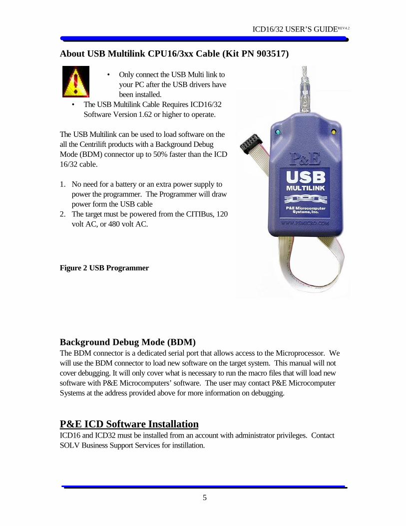
About USB Multilink CPU16/3xx Cable (Kit PN 903517)
• Only connect the USB Multi link to your PC after the USB drivers have been installed.
• The USB Multilink Cable Requires ICD16/32 Software Version 1.62 or higher to operate.
The USB Multilink can be used to load software on the all the Centrilift products with a Background Debug Mode (BDM) connector up to 50% faster than the ICD 16/32 cable. 1. No need for a battery or an extra power supply to
power the programmer. The Programmer will draw power form the USB cable
2. The target must be powered from the CITIBus, 120 volt AC, or 480 volt AC.
Figure 2 USB Programmer
Background Debug Mode (BDM) The BDM connector is a dedicated serial port that allows access to the Microprocessor. We will use the BDM connector to load new software on the target system. This manual will not cover debugging. It will only cover what is necessary to run the macro files that will load new software with P&E Microcomputers’ software. The user may contact P&E Microcomputer Systems at the address provided above for more information on debugging. P&E ICD Software Installation ICD16 and ICD32 must be installed from an account with administrator privileges. Contact SOLV Business Support Services for instillation.
ICD16/32 USER’S GUIDEREV4.2
6
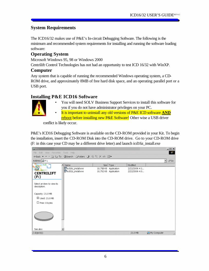
System Requirements The ICD16/32 makes use of P&E’s In-circuit Debugging Software. The following is the minimum and recommended system requirements for installing and running the software loading software: Operating System Microsoft Windows 95, 98 or Windows 2000 Centrilift Control Technologies has not had an opportunity to test ICD 16/32 with WinXP. Computer Any system that is capable of running the recommended Windows operating system, a CD-ROM drive, and approximately 8MB of free hard disk space, and an operating parallel port or a USB port. Installing P&E ICD16 Software
• You will need SOLV Business Support Services to install this software for you if you do not have administrator privileges on your PC.
• It is important to uninstall any old versions of P&E ICD software AND reboot before installing new P&E Software! Other wise a USB driver
conflict is likely occur. P&E’s ICD16 Debugging Software is available on the CD-ROM provided in your Kit. To begin the installation, insert the CD-ROM Disk into the CD-ROM drive. Go to your CD-ROM drive (F: in this case your CD may be a different drive letter) and launch icd16z_install.exe
ICD16/32 USER’S GUIDEREV4.2
7
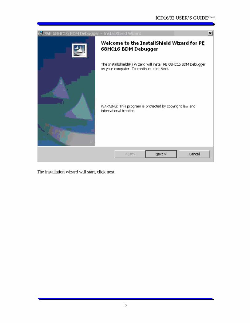
The installation wizard will start, click next.
ICD16/32 USER’S GUIDEREV4.2
8
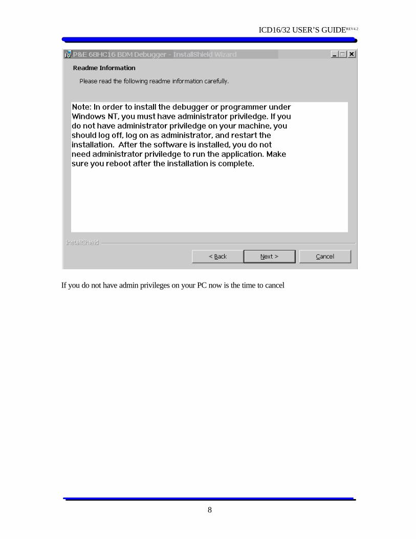
If you do not have admin privileges on your PC now is the time to cancel
ICD16/32 USER’S GUIDEREV4.2
9
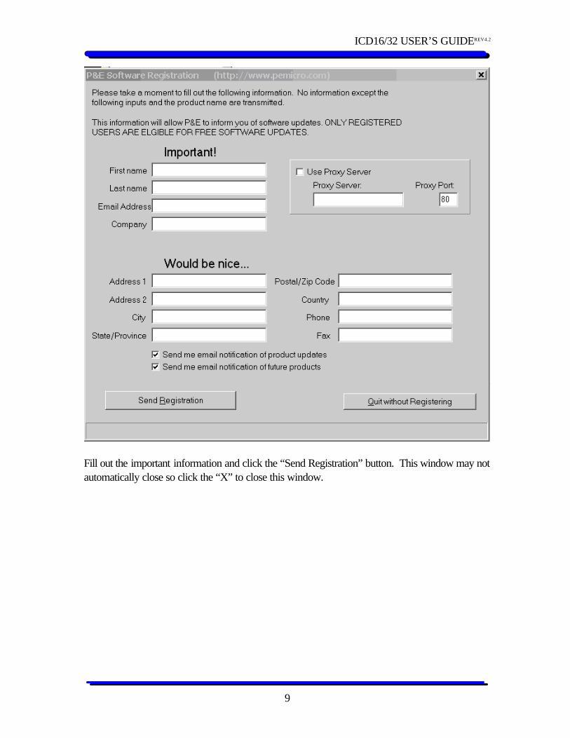
Fill out the important information and click the “Send Registration” button. This window may not automatically close so click the “X” to close this window.
ICD16/32 USER’S GUIDEREV4.2
10
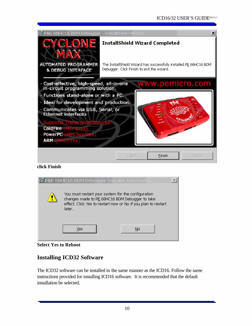
click Finish
Select Yes to Reboot Installing ICD32 Software The ICD32 software can be installed in the same manner as the ICD16. Follow the same instructions provided for installing ICD16 software. It is recommended that the default installation be selected.
ICD16/32 USER’S GUIDEREV4.2
11
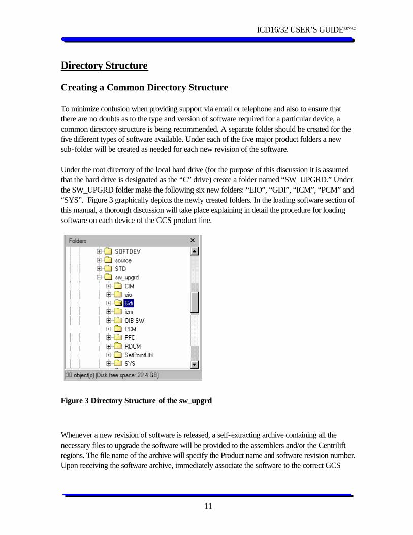
Directory Structure Creating a Common Directory Structure To minimize confusion when providing support via email or telephone and also to ensure that there are no doubts as to the type and version of software required for a particular device, a common directory structure is being recommended. A separate folder should be created for the five different types of software available. Under each of the five major product folders a new sub-folder will be created as needed for each new revision of the software. Under the root directory of the local hard drive (for the purpose of this discussion it is assumed that the hard drive is designated as the “C” drive) create a folder named “SW_UPGRD.” Under the SW_UPGRD folder make the following six new folders: “EIO”, “GDI”, “ICM”, “PCM” and “SYS”. Figure 3 graphically depicts the newly created folders. In the loading software section of this manual, a thorough discussion will take place explaining in detail the procedure for loading software on each device of the GCS product line.
Figure 3 Directory Structure of the sw_upgrd
Whenever a new revision of software is released, a self-extracting archive containing all the necessary files to upgrade the software will be provided to the assemblers and/or the Centrilift regions. The file name of the archive will specify the Product name and software revision number. Upon receiving the software archive, immediately associate the software to the correct GCS
ICD16/32 USER’S GUIDEREV4.2
12
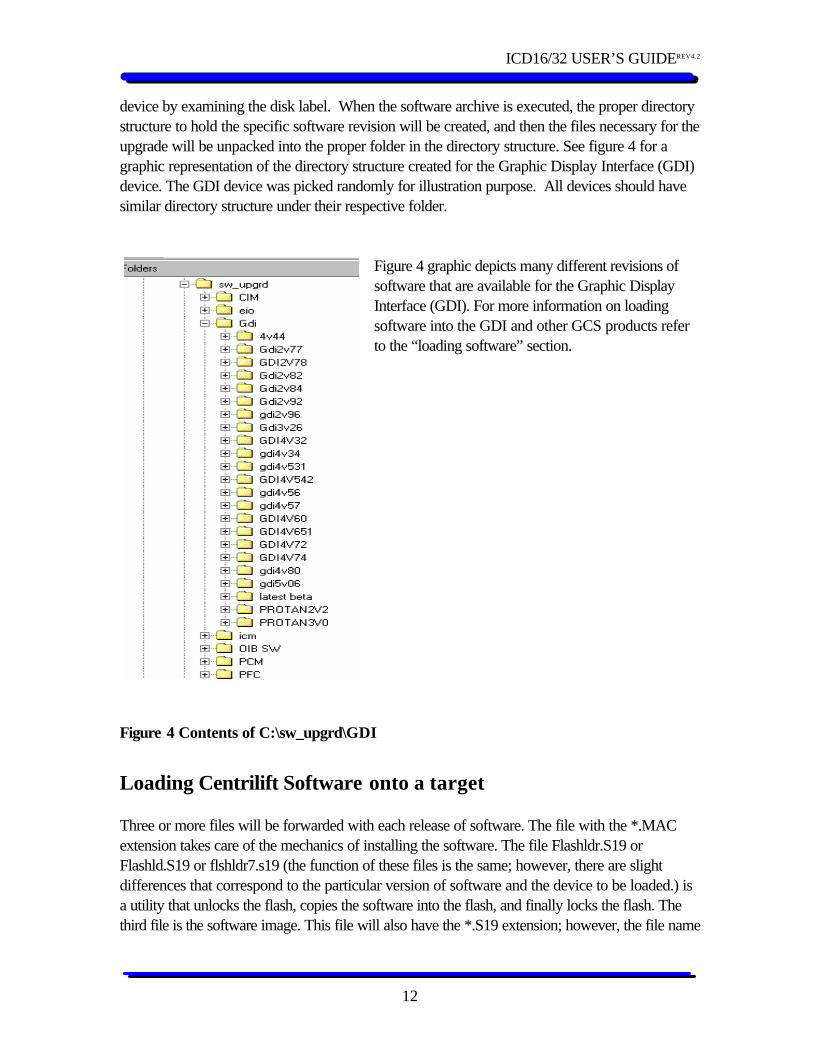
device by examining the disk label. When the software archive is executed, the proper directory structure to hold the specific software revision will be created, and then the files necessary for the upgrade will be unpacked into the proper folder in the directory structure. See figure 4 for a graphic representation of the directory structure created for the Graphic Display Interface (GDI) device. The GDI device was picked randomly for illustration purpose. All devices should have similar directory structure under their respective folder.
Figure 4 graphic depicts many different revisions of software that are available for the Graphic Display Interface (GDI). For more information on loading software into the GDI and other GCS products refer to the “loading software” section.
Figure 4 Contents of C:\sw_upgrd\GDI
Loading Centrilift Software onto a target Three or more files will be forwarded with each release of software. The file with the *.MAC extension takes care of the mechanics of installing the software. The file Flashldr.S19 or Flashld.S19 or flshldr7.s19 (the function of these files is the same; however, there are slight differences that correspond to the particular version of software and the device to be loaded.) is a utility that unlocks the flash, copies the software into the flash, and finally locks the flash. The third file is the software image. This file will also have the *.S19 extension; however, the file name
ICD16/32 USER’S GUIDEREV4.2
13
will be dependent on the device that this software is intended for and the revision number. The current software version for all Centrilift products are kept on Centriview in Engineering Specification CES148. The convention used to name the different types of software with the associated revision number is as follows: 1. GCS EIO: The software for this device is named “EIOXvXX.s19”, where XvXX will
indicate the revision number. Some examples of the release versions are: EIO1v08.S19, EIO1v22.S19, etc.
2. Vortex GCS FSC: The software for this device is named “SYSXvXX.S19”, where XvXX will indicate the revision number. Some examples of the release versions are: SYS5v40.S19, SYS5v98.S19, etc.
3. Electrospeed GCS VSC: This device has two different types of micro-controllers and requires two different types of software. The sixteen bit micro-controller (CPU16) works on the same software as the Vortex GCS; therefore, the naming convention and the revision number should be the same as described above for the Vortex GCS. The software for the 32 bit micro-controller (CPU32) is named as “PCMXXRX.S19”, where XrXX is the revision number. Some examples are: PCM5R30.S19, PCM7r06.S19, etc.
4. GDI: For this device the naming convention is GDIXvXX.S19, where XvXX is the revision number. Some examples are: Gdi2v74.S19, Gdi3V26.S19, etc.
5. ICM: The software for this device is named ICM_X, where X is a letter designating the revision of the software. Some examples are: Icm_a.S19, Icm_b.S19, etc.
Connecting to your target. Parallel Port Programmer Connect the 25 pin side of the programmer assembly to the shielded parallel extension cable. The other end of this cable is then connected to the computer, which has the P&E ICD application installed on it. The second step in setting up the hardware is to supply input power to the 5 volt DC power supply. There are three different supply choices available. The first choice is to use the 120 volt AC to 9 volt DC adapter. The second choice is the 9 volt vehicle lighter adapter; both these devices plug into the “9 Volt input” of the 5 volt power supply, and the slide switch of the power supply is placed on the “External” position. The final method for powering the 5 volt power supply is via a 9 volt battery that is installed in a small compartment at the back of the main ICD assembly. If the battery option is used, place the slid switch on the “Battery” position. To conserve the battery, it is recommended that the slide switch be returned to the “External” position whenever the ICD16/32 is not being used or the battery will get run down.

ICD16/32 USER’S GUIDEREV4.2
14
USB Port Programmer Caution: Do not connect the USB programmer to your PC until you have installed version 1.62 or higher of the P&E ICD Software.
Connect the USB cable and programmer to your PC. Note: If you are using a USB Hub the Hub must be capable of providing up to 500mA per port. The blue LED on the programmer will light when the programmer establishes communication with the PC’s USB port. Plug ribbon cable into your Target. Power up your Target. The yellow LED will light when the programmer detects power on your target.
Figure 5 Parallel port Connection Diagram
ICD16/32 USER’S GUIDEREV4.2
15
Figure 6 USB connection Diagram
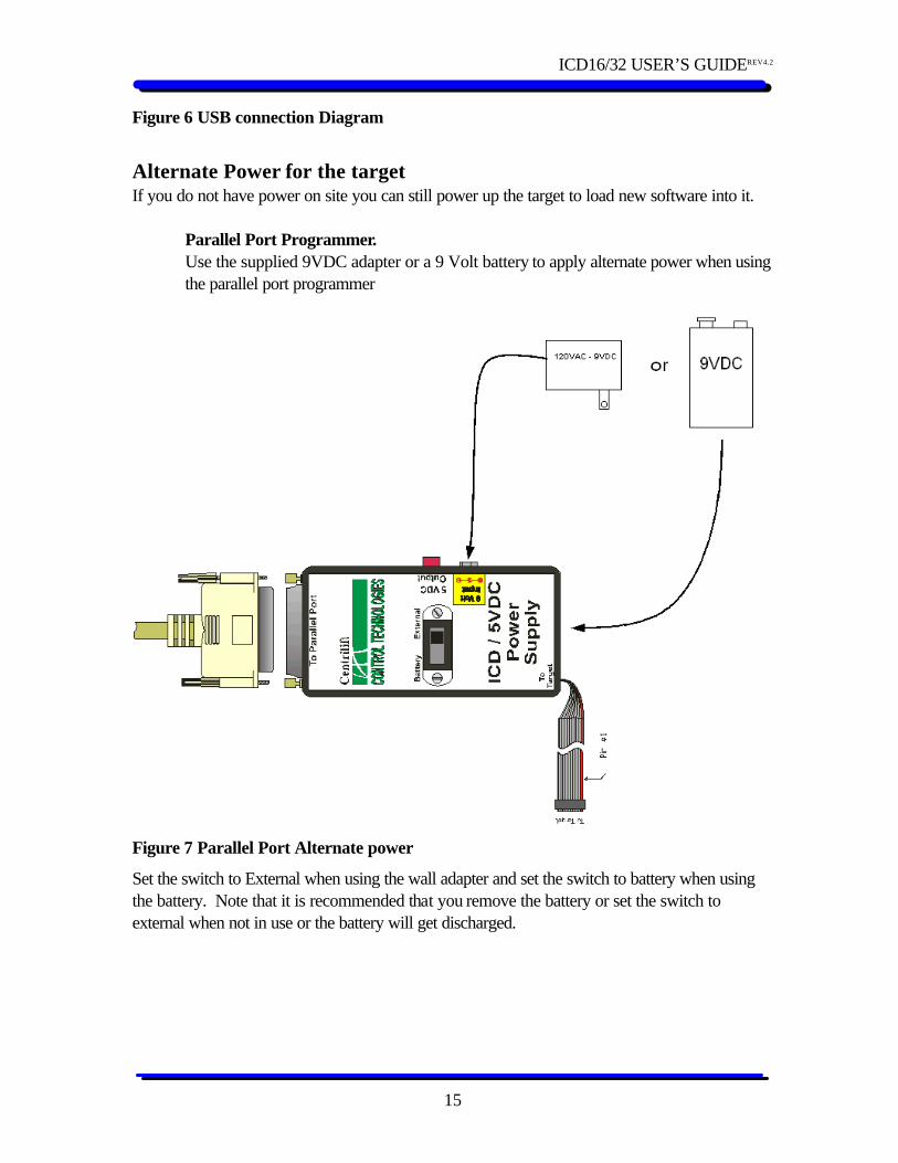
Alternate Power for the target If you do not have power on site you can still power up the target to load new software into it.
Parallel Port Programmer. Use the supplied 9VDC adapter or a 9 Volt battery to apply alternate power when using the parallel port programmer
Figure 7 Parallel Port Alternate power
Set the switch to External when using the wall adapter and set the switch to battery when using the battery. Note that it is recommended that you remove the battery or set the switch to external when not in use or the battery will get discharged.
ICD16/32 USER’S GUIDEREV4.2
16
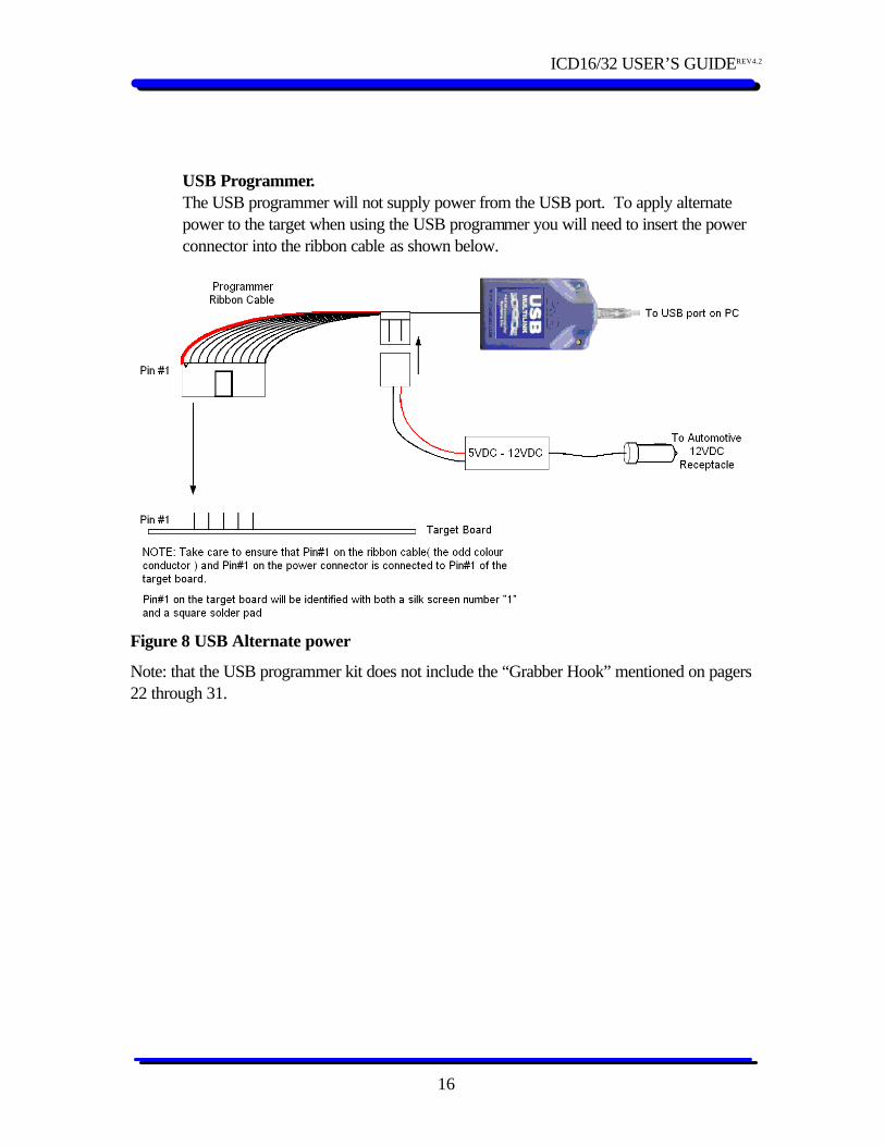
USB Programmer. The USB programmer will not supply power from the USB port. To apply alternate power to the target when using the USB programmer you will need to insert the power connector into the ribbon cable as shown below.
Figure 8 USB Alternate power
Note: that the USB programmer kit does not include the “Grabber Hook” mentioned on pagers 22 through 31.
ICD16/32 USER’S GUIDEREV4.2
17
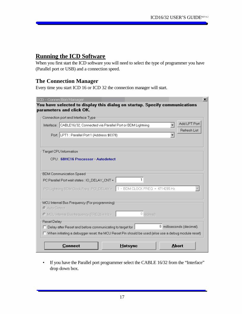
Running the ICD Software When you first start the ICD software you will need to select the type of programmer you have (Parallel port or USB) and a connection speed. The Connection Manager Every time you start ICD 16 or ICD 32 the connection manager will start.
• If you have the Parallel port programmer select the CABLE 16/32 from the “Interface”
drop down box.
ICD16/32 USER’S GUIDEREV4.2
18
• Select the lowest “IO_DELAY_CNT” number that you can connect with your target typically 1
• The connection manager will remember the settings so you should only have to set it up once.
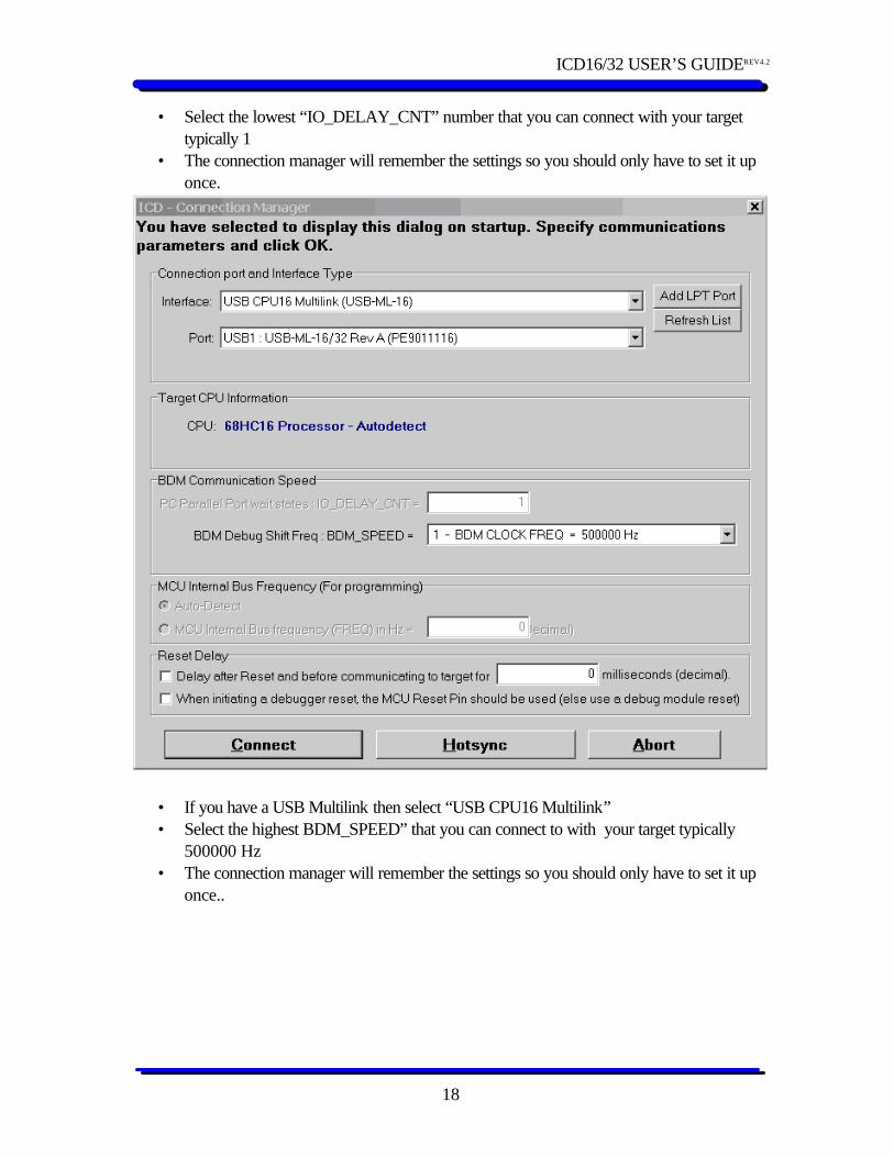
• If you have a USB Multilink then select “USB CPU16 Multilink” • Select the highest BDM_SPEED” that you can connect to with your target typically
500000 Hz • The connection manager will remember the settings so you should only have to set it up
once..
ICD16/32 USER’S GUIDEREV4.2
19
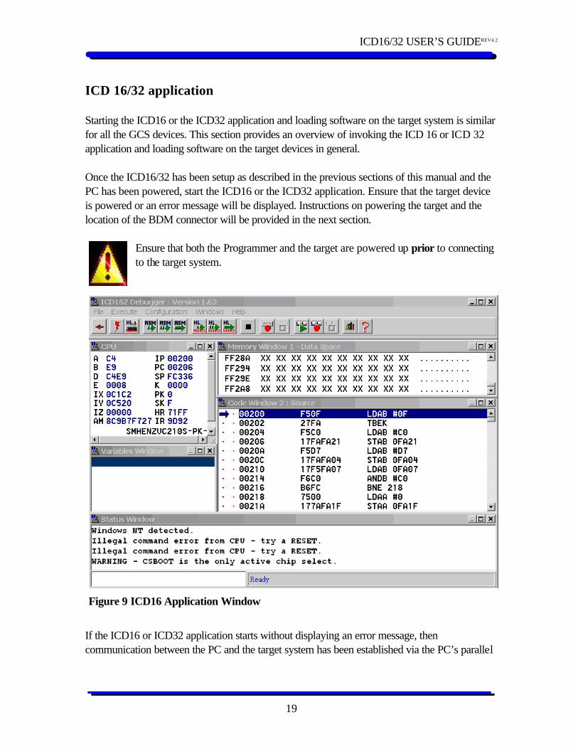
ICD 16/32 application Starting the ICD16 or the ICD32 application and loading software on the target system is similar for all the GCS devices. This section provides an overview of invoking the ICD 16 or ICD 32 application and loading software on the target devices in general. Once the ICD16/32 has been setup as described in the previous sections of this manual and the PC has been powered, start the ICD16 or the ICD32 application. Ensure that the target device is powered or an error message will be displayed. Instructions on powering the target and the location of the BDM connector will be provided in the next section.
Ensure that both the Programmer and the target are powered up prior to connecting to the target system.
If the ICD16 or ICD32 application starts without displaying an error message, then communication between the PC and the target system has been established via the PC’s parallel
Figure 9 ICD16 Application Window
ICD16/32 USER’S GUIDEREV4.2
20
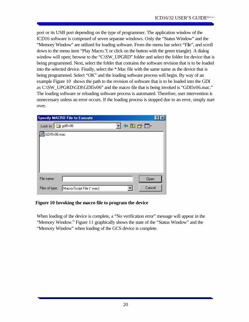
port or its USB port depending on the type of programmer. The application window of the ICD16 software is composed of seven separate windows. Only the “Status Window” and the “Memory Window” are utilized for loading software. From the menu bar select “File”, and scroll down to the menu item “Play Macro.”( or click on the button with the green triangle) A dialog window will open; browse to the “C:\SW_UPGRD” folder and select the folder for device that is being programmed. Next, select the folder that contains the software revision that is to be loaded into the selected device. Finally, select the *.Mac file with the same name as the device that is being programmed. Select “OK” and the loading software process will begin. By way of an example Figure 10 shows the path to the revision of software that is to be loaded into the GDI as C:\SW_UPGRD\GDI\GDI5v06” and the macro file that is being invoked is “GDI5v06.mac.” The loading software or reloading software process is automated. Therefore, user intervention is unnecessary unless an error occurs. If the loading process is stopped due to an error, simply start over.
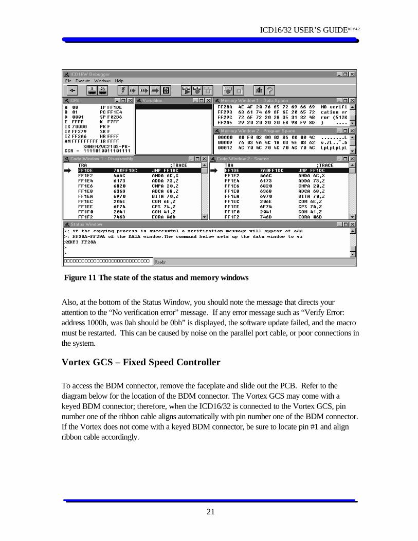
When loading of the device is complete, a “No verification error” message will appear in the “Memory Window.” Figure 11 graphically shows the state of the “Status Window” and the “Memory Window” when loading of the GCS device is complete.
Figure 10 Invoking the macro file to program the device
ICD16/32 USER’S GUIDEREV4.2
21
Also, at the bottom of the Status Window, you should note the message that directs your attention to the “No verification error” message. If any error message such as “Verify Error: address 1000h, was 0ah should be 0bh” is displayed, the software update failed, and the macro must be restarted. This can be caused by noise on the parallel port cable, or poor connections in the system.
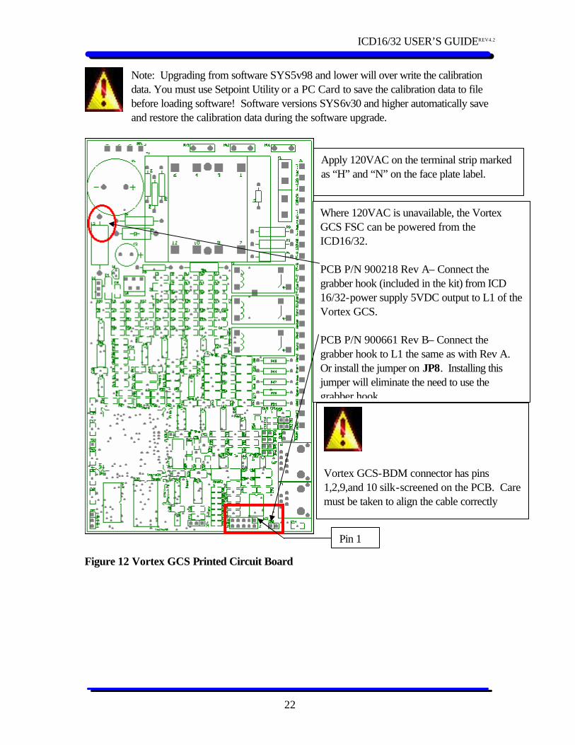
Vortex GCS – Fixed Speed Controller To access the BDM connector, remove the faceplate and slide out the PCB. Refer to the diagram below for the location of the BDM connector. The Vortex GCS may come with a keyed BDM connector; therefore, when the ICD16/32 is connected to the Vortex GCS, pin number one of the ribbon cable aligns automatically with pin number one of the BDM connector. If the Vortex does not come with a keyed BDM connector, be sure to locate pin #1 and align ribbon cable accordingly.
Figure 11 The state of the status and memory windows
ICD16/32 USER’S GUIDEREV4.2
22
Note: Upgrading from software SYS5v98 and lower will over write the calibration data. You must use Setpoint Utility or a PC Card to save the calibration data to file before loading software! Software versions SYS6v30 and higher automatically save and restore the calibration data during the software upgrade.
Figure 12 Vortex GCS Printed Circuit Board
Where 120VAC is unavailable, the Vortex GCS FSC can be powered from the ICD16/32. PCB P/N 900218 Rev A– Connect the grabber hook (included in the kit) from ICD 16/32-power supply 5VDC output to L1 of the Vortex GCS. PCB P/N 900661 Rev B– Connect the grabber hook to L1 the same as with Rev A. Or install the jumper on JP8. Installing this jumper will eliminate the need to use the grabber hook
Apply 120VAC on the terminal strip marked as “H” and “N” on the face plate label.
Vortex GCS-BDM connector has pins 1,2,9,and 10 silk-screened on the PCB. Care must be taken to align the cable correctly
Pin 1

ICD16/32 USER’S GUIDEREV4.2
23
Electrospeed GCS – Variable Speed Controller Power up the drive to load the software. In cases where 480VAC, 120VAC, or 24VDC is not available, the ICD16/32 may be used to power the System control board. But the USB programmer may not.
Note! Note: Upgrading from software SYS5v98 and lower will over write the calibration data. You must use Setpoint Utility or a PC Card to save the calibration data to file before loading software! Software versions SYS6v30 and higher automatically save and restore the calibration data during the software upgrade.
The System Control Board in the GCS Drive has two BDM connectors. J7 - The BDM connector on the left-hand side (center of board) is for the CPU16 that is used to load System Control ( SYSXvXX) software using the ICD16 program. J6 - The BDM connector on the right-hand side is for the CPU32 that is used to load Power Conversion Module (PCMXrXX ) software using the ICD32 program.
ICD16/32 USER’S GUIDEREV4.2
24
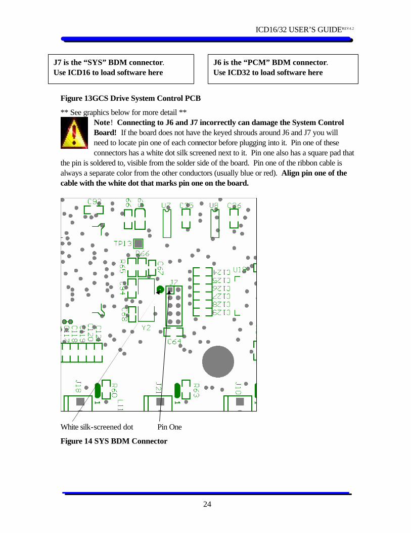
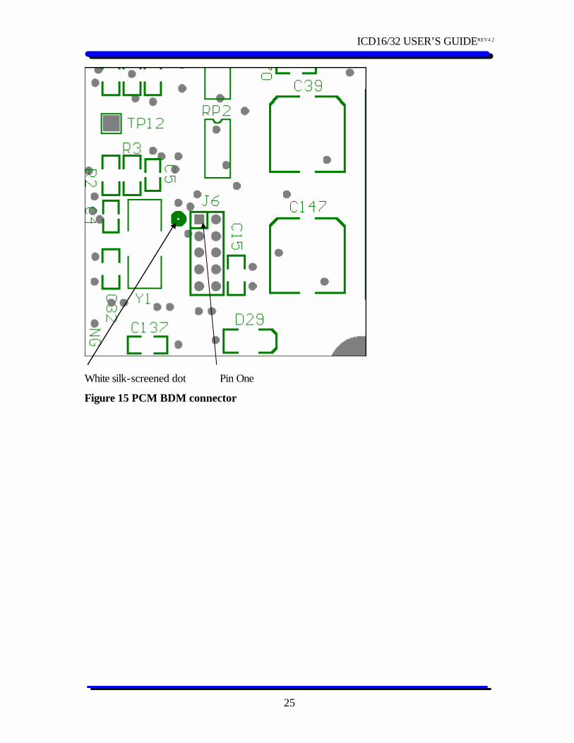
Figure 13GCS Drive System Control PCB
** See graphics below for more detail ** Note! Connecting to J6 and J7 incorrectly can damage the System Control Board! If the board does not have the keyed shrouds around J6 and J7 you will need to locate pin one of each connector before plugging into it. Pin one of these connectors has a white dot silk screened next to it. Pin one also has a square pad that
the pin is soldered to, visible from the solder side of the board. Pin one of the ribbon cable is always a separate color from the other conductors (usually blue or red). Align pin one of the cable with the white dot that marks pin one on the board.
White silk-screened dot Pin One
Figure 14 SYS BDM Connector
J7 is the “SYS” BDM connector. Use ICD16 to load software here
J6 is the “PCM” BDM connector. Use ICD32 to load software here
ICD16/32 USER’S GUIDEREV4.2
25
White silk-screened dot Pin One
Figure 15 PCM BDM connector
ICD16/32 USER’S GUIDEREV4.2
26
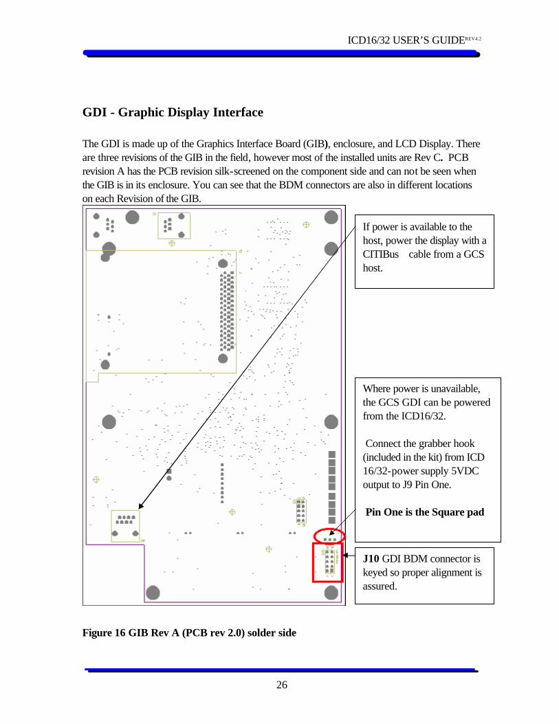
GDI - Graphic Display Interface The GDI is made up of the Graphics Interface Board (GIB), enclosure, and LCD Display. There are three revisions of the GIB in the field, however most of the installed units are Rev C. PCB revision A has the PCB revision silk-screened on the component side and can not be seen when the GIB is in its enclosure. You can see that the BDM connectors are also in different locations on each Revision of the GIB.
Figure 16 GIB Rev A (PCB rev 2.0) solder side
J10 GDI BDM connector is keyed so proper alignment is assured.
Where power is unavailable, the GCS GDI can be powered from the ICD16/32. Connect the grabber hook (included in the kit) from ICD 16/32-power supply 5VDC output to J9 Pin One. Pin One is the Square pad
If power is available to the host, power the display with a CITIBuscable from a GCS host.
ICD16/32 USER’S GUIDEREV4.2
27
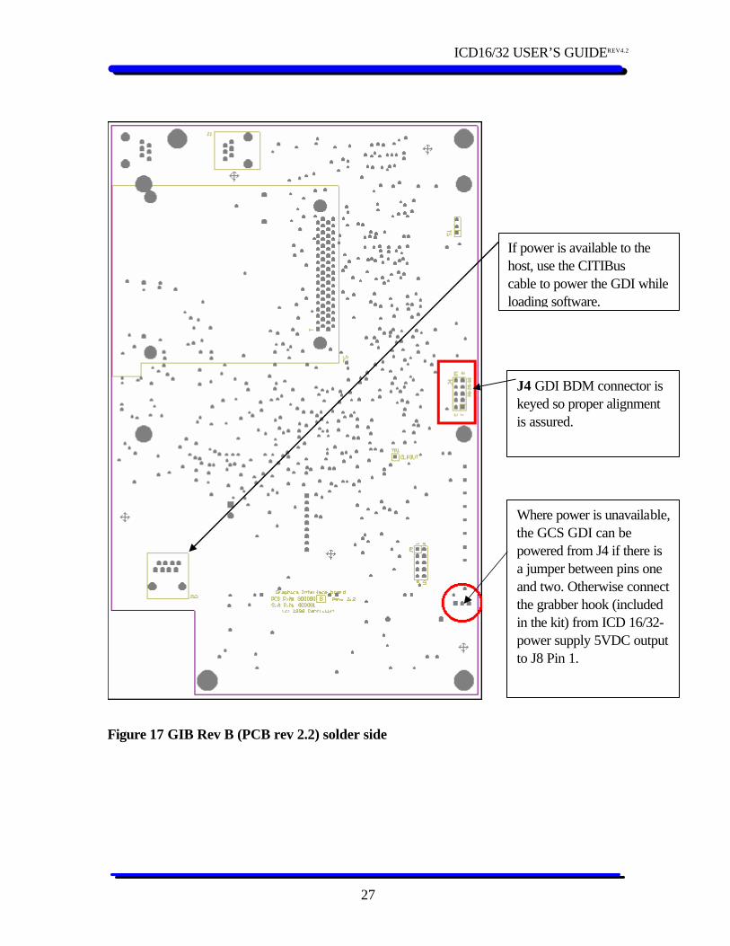
Figure 17 GIB Rev B (PCB rev 2.2) solder side
J4 GDI BDM connector is keyed so proper alignment is assured.
Where power is unavailable, the GCS GDI can be powered from J4 if there is a jumper between pins one and two. Otherwise connect the grabber hook (included in the kit) from ICD 16/32-power supply 5VDC output to J8 Pin 1.
If power is available to the host, use the CITIBus cable to power the GDI while loading software.
ICD16/32 USER’S GUIDEREV4.2
28
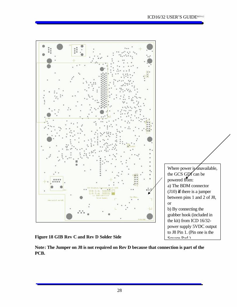
Figure 18 GIB Rev C and Rev D Solder Side
Note: The Jumper on J8 is not required on Rev D because that connection is part of the PCB.
Where power is unavailable, the GCS GDI can be powered from: a) The BDM connector (J10) if there is a jumper between pins 1 and 2 of J8, or b) By connecting the grabber hook (included in the kit) from ICD 16/32-power supply 5VDC output to J8 Pin 1. (Pin one is the Square Pad )

ICD16/32 USER’S GUIDEREV4.2
29
If you have trouble programming a GIB with out a host. Connect the grabber hook to the square pad ( pin 1 ) of J8.
ICM – Integrated Communication Module The Integrated Communication Module (ICM) consists of two separate printed circuit boards (PCBs) connected together by a flat cable. To access the BDM connector, remove the face plate and slide out both PCBs. Lay the PCBs end to end and refer to the diagram below for the location of the BDM connector. The ICM comes with a keyed BDM connector; therefore, when the ICD16/32 cable assembly is connected to the ICM, pin number one of the ribbon cable aligns automatically with pin number one of the ICM BDM connector.
Note: Loading software on the ICM with Software versions earlier than ICM-E will over write the calibration data. You must use ICM Reload Utility to save the calibration data to file before loading Software! For ICM-E Software and later the ICM macro file will preserve the Calibration Data automatically.
Figure 19 ICM-CPU PCB BDM connector
Where 120VAC is not available the ICM can be powered from the ICD16/32. Connect the grabber hook (included in the kit) from ICD 16/32-power supply 5VDC output to L1 of the ICM
Apply a 120VAC on the terminal strip marked as “H” and “N” on the face plate label.
ICD16/32 USER’S GUIDEREV4.2
30
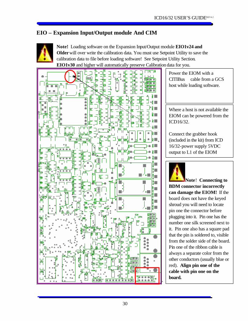
EIO – Expansion Input/Output module And CIM
Note! Loading software on the Expansion Input/Output module EIO1v24 and Older will over write the calibration data. You must use Setpoint Utility to save the calibration data to file before loading software! See Setpoint Utility Section. EIO1v30 and higher will automatically preserve Calibration data for you.
`
Note! Connecting to BDM connector incorrectly can damage the EIOM! If the board does not have the keyed shroud you will need to locate pin one the connector before plugging into it. Pin one has the number one silk screened next to it. Pin one also has a square pad that the pin is soldered to, visible from the solder side of the board. Pin one of the ribbon cable is always a separate color from the other conductors (usually blue or red). Align pin one of the cable with pin one on the board.
Where a host is not available the EIOM can be powered from the ICD16/32. Connect the grabber hook (included in the kit) from ICD 16/32-power supply 5VDC output to L1 of the EIOM
Power the EIOM with a CITIBus cable from a GCS host while loading software.
ICD16/32 USER’S GUIDEREV4.2
31
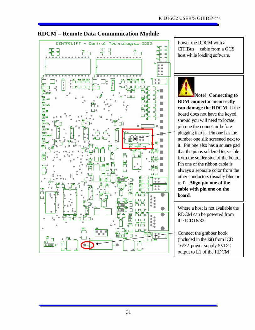
RDCM – Remote Data Communication Module
Note! Connecting to BDM connector incorrectly can damage the RDCM If the board does not have the keyed shroud you will need to locate pin one the connector before plugging into it. Pin one has the number one silk screened next to it. Pin one also has a square pad that the pin is soldered to, visible from the solder side of the board. Pin one of the ribbon cable is always a separate color from the other conductors (usually blue or red). Align pin one of the cable with pin one on the board.
Where a host is not available the RDCM can be powered from the ICD16/32. Connect the grabber hook (included in the kit) from ICD 16/32-power supply 5VDC output to L1 of the RDCM
Power the RDCM with a CITIBus cable from a GCS host while loading software.

ICD16/32 USER’S GUIDEREV4.2
32
Centrilift Utility Programs Setpoint Utility Setpoint Utility is a software tool used to preserve the calibration and configuration data on a GCS Host. This application will allow you to save the calibration data to a file on your PC. After saving the calibration data to a file you can load new software on the target with the ICD16/32, and then restore the saved calibration data from the file you saved with Setpoint Utility.
Setup 1. Connect a GCS to Computer cable from the serial port of your PC to the RS-232 port of
the GCS. 2. Run Setpoint Utility. (Double click on SetpointUtilityXvXXX.exe. Where XvXXX is the
version number of the utility.) 3. The utility will automatically try to communicate with a GCS host device using the same
parameters as the most recent attempt. If those parameters have changed, tyr to click on the command box labeled "Search". The utility will try all the different Comm ports and baud rates until it gets a reply from a GCS Host.
• If the utility can not find the Host it will display an error message in the Diagnostic
box at the bottom of the window. If this happens: • Check the communications settings on the GDI. The communications settings are
found under SCADA and Security, one window to the right. • Fill in the proper Baud rate, Modbus Address, and the Comm port on the PC that
you connected the GCS to Computer cable to. • Click on the search button. • If the utility still cannot connect with the Host try another version of Setpoint Utility.
ICD16/32 USER’S GUIDEREV4.2
33
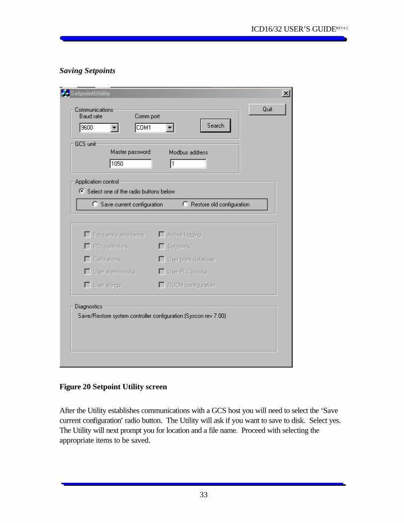
Saving Setpoints
Figure 20 Setpoint Utility screen
After the Utility establishes communications with a GCS host you will need to select the ‘Save current configuration’ radio button. The Utility will ask if you want to save to disk. Select yes. The Utility will next prompt you for location and a file name. Proceed with selecting the appropriate items to be saved.
ICD16/32 USER’S GUIDEREV4.2
34
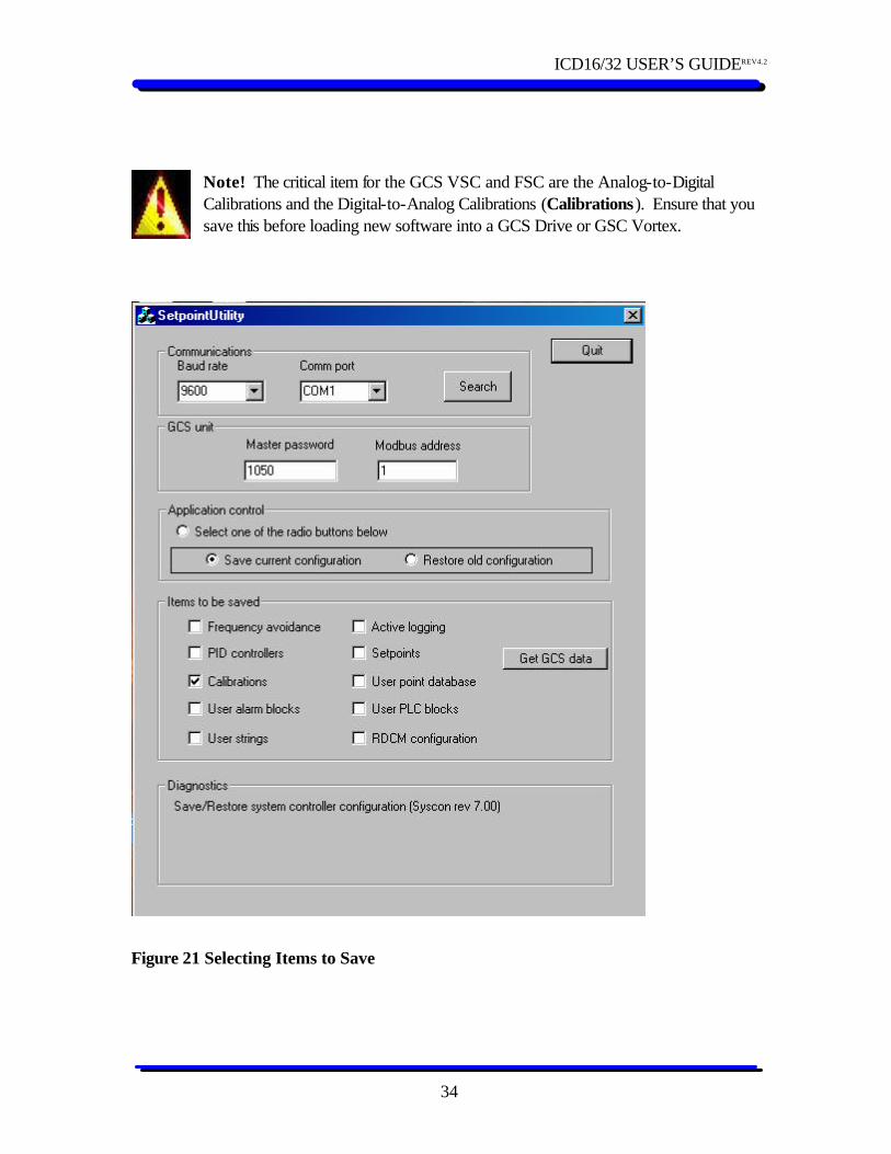
Note! The critical item for the GCS VSC and FSC are the Analog-to-Digital Calibrations and the Digital-to-Analog Calibrations (Calibrations). Ensure that you save this before loading new software into a GCS Drive or GSC Vortex.
Figure 21 Selecting Items to Save
ICD16/32 USER’S GUIDEREV4.2
35
Click the check boxes next to the items you need to save. ü Frequency avoidance – Check this if you wish to save any frequency avoidance settings that
differ from factory default. ü PID controllers – Check this, if you wish to save your settings that control the output
frequency from an Analog input, that are different from factory default. ü Calibration – Analog to Digital and Digital to Analog Calibration. Check this if you are
about to load Software on a GCS Drive, Vortex GCS, or a GCS-EIO module. ü Active Logging – Check this if you wish to preserve any active logging set up that is different
from factory default. ü User PLC Block – Check this if you wish to save any User PLC programs that is different
form Factory Default. ü User Point Database – If you saved User PLC Blocks you will need to save the database
too. ü Setpoints – Check this to save all the configuration and alarm setpoints that are different from
factory default. After the Utility has retrieved the data from the target you will need to tell the Utility to save the data to the file you designated earlier.
You must click the “Write data to disk” button to save the data to a File on your PC.
==Load software on the target with the ICD program and the BDM. ==
ICD16/32 USER’S GUIDEREV4.2
36
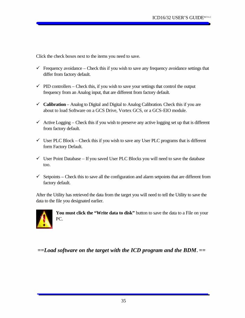
Restoring Setpoints Use the most recent version of setpoint utility to restore setpoints to the target. Connect to the target and start Setpoint Utility as described above. After establishing communication with the target you will see the screen below. • Click on ‘Restore old Configuration’. • Browse to the file you saved the old configuration in. • The Utility will grey out any check boxes if the file does not contain data about those
parameters.
ICD16/32 USER’S GUIDEREV4.2
37
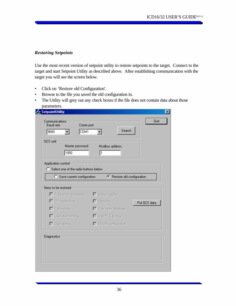
Figure 22 Restoring Items
• Click on the Check boxes that you want to restore, in this case- Calibrations. See screen below.
Figure 23 Selecting Items to Restore
*You must click the “Put GCS data” to write the data to the target. *Ensure “Scada&Security&System \System \Enable Cal” is set to No after loading new software and setpoints into the System Control Module (16bit micro on the GCS Drive and Vortex GCS).
ICD16/32 USER’S GUIDEREV4.2
38
Hardware Troubles
1. The hardware component of the Parallel port programming kit needs to be powered from a 9V DC source, either a battery or a wall adapter. If no power is supplied to the GCS programming hardware, communication errors with the GCS circuit board will occur.
2. The parallel cable connecting the PC parallel port and the BDM cable MUST be
IEEE1284 compliant. If the cable is not marked with the IEEE1284 text, then it is not compliant. All the parallel port cables supplied in the kits are IEEE1824 compliant.
3. The Programmer, the port that the programmer is plugged into, or the target may be
damaged. Try a programmer that you know works. Try a known good target, and finally try another PC. If you find that another programmer works on your PC then your programmer is likely damaged contact Centrilift Controls Technology for replacement parts. If a programmer works on another PC but not on your PC check “PC Troubles” below.
PC & Software Troubles
1. It works but it sure is slow! See the “Connection Manager” section on pages 14 and 15 for details about setting the connection speed.
2. We have noted instances where the Parallel port or the USB port on a PC could ‘lock
up’ or ‘freeze up’ after cables or peripherals are plugged in while the PC is running. If the P&E software has a problem connected to the GCS circuit board or has errors while updating software try rebooting the PC with all equipment connected.
3. Installation problem: The software from P&E requires administrator access in Windows
2000 during installation to properly install some low level system drivers. If the user who installs the software on the PC does not have admin rights, the software installation will appear to complete properly without any error messages, however the essential drivers will not be installed. After this, the P&E software will appear to function properly and execute upgrade macros. After the macro indicates the software update is complete, it will likely indicate a verify error and in actual fact no information will be written to the GCS board. Have SOLV install the software for you.

ICD16/32 USER’S GUIDEREV4.2
39
4. Some external peripherals that utilize the Parallel port on computer systems (e.g.: external parallel port CD-Rom, printer, scanner or Zip Drive) may install drivers that interfere with the drivers installed by the P&E software. It may be necessary to add a second parallel port or uninstall the peripheral drivers IF it is necessary to run the P&E software. Multi-function printers from HP and possibly other vendors have special programs that monitor printer activity on the parallel port. These programs must be turned off or disabled to prevent problems.
5. Also beware that some laptops, in particular some of the IBM Thinkpads, do not
implement a standard parallel port even though they claim they do. If you encounter this problem on a laptop and have access to a desktop machine, it is best to try the experiment on the desktop in order to rule out other issues.
6. The BIOS settings for the Parallel port should be one of the following: SPP, Normal,
Standard, Output Only, Unidirectional, AT. Try to avoid ECP, EPP or PS/2 Bi-directional.
7. In windows XP/2000, the parallel port dialog checkbox entitled "Enable Legacy Plug
and Play" should be checked. This setting is located in the Control Panel-->System-->Hardware->Device Manager->Ports->Printer Port (LPTX) dialog. You must reboot for this setting to take effect.
8. In Windows XP, make sure to turn off the parallel port plug and play scanning "feature".
This feature of windows XP will interrupt parallel port communications between the PC and P&E's interface cable. This will yield what looks like sporadic communications. The auto scan "feature" may be turned off for the parallel port by downloading and running a WINXP registry patch. Contact Centrilift Controls Technology for the patch.
9. A USB driver conflict occurs if the file [windows]\system32\peusbwd1.dll is version
7.0.0. This file should be version 6.2.2. The file was mistakenly upgraded in some releases. P&E's latest driver download will resolve this issue by restoring the proper version of the file -- simply install it and reboot. If you're still having issues, you should manually delete the file [windows]\system32\peusbwd1.dll, and reinstall the drivers. If the problem persists, you should download/run the "driver test" utility below. Be sure to check the "generate output" checkbox, then open a support request and post the output driver_information.txt, which will reside in the same directory as the driver test executable. Contact Centrilift Control Technologies for the files.
ICD16/32 USER’S GUIDEREV4.2
40
Table of Figures Figure 1 ICD16/32 Cable Assembly........................................................................................4 Figure 2 USB Programmer......................................................................................................5 Figure 3 Directory Structure of the sw_upgrd.........................................................................11 Figure 4 Contents of C:\sw_upgrd\GDI .................................................................................12 Figure 5 Parallel port Connection Diagram.............................................................................14 Figure 6 USB connection Diagram.........................................................................................15 Figure 7 Parallel Port Alternate power...................................................................................15 Figure 8 USB Alternate power..............................................................................................16 Figure 9 ICD16 Application Window....................................................................................19 Figure 10 Invoking the macro file to program the device.........................................................20 Figure 11 The state of the status and memory windows..........................................................21 Figure 12 Vortex GCS Printed Circuit Board.........................................................................22 Figure 13GCS Drive System Control PCB............................................................................24 Figure 14 SYS BDM Connector ...........................................................................................24 Figure 15 PCM BDM connector...........................................................................................25 Figure 16 GIB Rev A (PCB rev 2.0) solder side....................................................................26 Figure 17 GIB Rev B (PCB rev 2.2) solder side....................................................................27 Figure 18 GIB Rev C and Rev D Solder Side........................................................................28 Figure 19 ICM-CPU PCB....................................................................................................29 Figure 20 Setpoint Utility screen............................................................................................33 Figure 21 Selecting Items to Save..........................................................................................34 Figure 22 Restoring Items......................................................................................................37 Figure 23 Selecting Items to Restore......................................................................................37