Embed Size (px)
Citation preview

Struct Multidisc Optim (2013) 48:395–409DOI 10.1007/s00158-013-0892-y
INDUSTRIAL APPLICATION
Using an artificial bee colony algorithm for the optimalplacement of viscous dampers in planar building frames
M. Sonmez · E. Aydin · T. Karabork
Received: 13 June 2012 / Revised: 19 December 2012 / Accepted: 8 January 2013 / Published online: 21 February 2013© Springer-Verlag Berlin Heidelberg 2013
Abstract In this study, an Artificial Bee Colony Algorithm(ABCA) is used to obtain the optimal size and location ofviscous dampers in planar buildings to reduce the damageto the frame systems during an earthquake. The transferfunction amplitude of the top displacement and the elasticbase shear force evaluated at the first natural circular fre-quency of structures are chosen as objective functions. Thedamper coefficients of the added viscous dampers are takeninto consideration as design variables in a planar buildingframe. Transfer function amplitude of the top displacementand the amplitude of the elastic base shear force at the fun-damental natural frequency are minimized under an activeconstraint on sum of the damper coefficients of the addeddampers. According to two specified objective functions,an optimization algorithm based on the ABCA is proposed.The proposed method is verified by a gradient-based algo-rithm; steepest direction search algorithm (SDSA). Theproposed ABCA and the SDSA are applied to find theoptimal damper distribution for a nine-storey planar build-ing then the optimal damper allocation obtained from theABCA is investigated to rehabilitate models of irregularplanar buildings. The validity of the proposed method wasdemonstrated through a time history analysis of the optimaldamper designs, which were determined based on the fre-quency domain using the ABCA. The numerical results of
M. Sonmez · T. KaraborkDepartment of Civil Engineering, Faculty of Engineering,Aksaray University, 68100 Aksaray, Turkey
E. Aydin (�)Department of Civil Engineering, Faculty of Engineering,Nigde University, 51240 Nigde, Turkeye-mail: [email protected]
the proposed optimal damper design method show that theuse of the ABCA can be a practical and powerful tool todetermine the optimal damper allocation in planar buildingstructures.
Keywords Optimal dampers · Artificial bee colonyalgorithm · Passive dampers · Structural optimization
1 Introduction
During an earthquake a large amount of energy throughground motion is imparted to structures. In the basic con-cept of conventional inelastic design, structural membersshould absorb or dissipate these transmitted ground motionsby inelastic cycling deformation however, the structures arenot supposed to suffer a major collapse. In order to reduceinelastic energy dissipation demand on the framing systemof structures, passive energy dissipation devices are usedin new structures as well as the rehabilitation of ageing ordeficient structures. The use of energy dissipation systemsreduces damage to the frame systems. A number of passiveenergy dissipating systems such as the yielding of metals,frictional sliding and phase transformation in metals, defor-mation of visco-elastic fluids and solids, and fluid orificingare commercially available or under development (Symanset al. 2008).
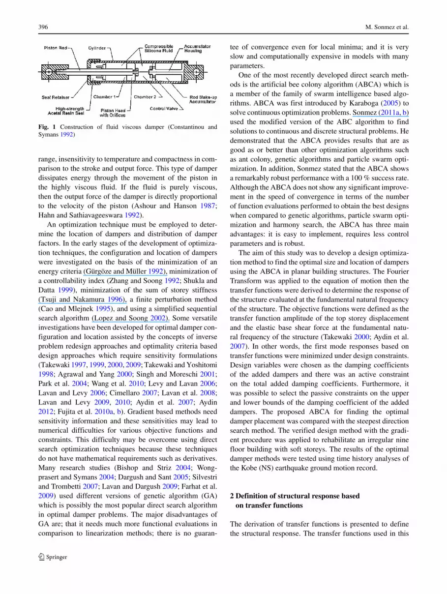
A fluid viscous damper, which is one of the passivedamper devices, consists of cylindrical piston immersed in aviscous fluid. This type of damper, widely used in aerospaceand military applications, has recently been adapted forbuilding applications as shown in Fig. 1 (Constantinou andSymans 1992). The characteristics of these devices are thelinear viscous response achieved over a broad frequency
396 M. Sonmez et al.
Fig. 1 Construction of fluid viscous damper (Constantinou andSymans 1992)
range, insensitivity to temperature and compactness in com-parison to the stroke and output force. This type of damperdissipates energy through the movement of the piston inthe highly viscous fluid. If the fluid is purely viscous,then the output force of the damper is directly proportionalto the velocity of the piston (Ashour and Hanson 1987;Hahn and Sathiavageeswara 1992).
An optimization technique must be employed to deter-mine the location of dampers and distribution of damperfactors. In the early stages of the development of optimiza-tion techniques, the configuration and location of damperswere investigated on the basis of the minimization of anenergy criteria (Gurgoze and Muller 1992), minimization ofa controllability index (Zhang and Soong 1992; Shukla andDatta 1999), minimization of the sum of storey stiffness(Tsuji and Nakamura 1996), a finite perturbation method(Cao and Mlejnek 1995), and using a simplified sequentialsearch algorithm (Lopez and Soong 2002). Some versatileinvestigations have been developed for optimal damper con-figuration and location assisted by the concepts of inverseproblem redesign approaches and optimality criteria baseddesign approaches which require sensitivity formulations(Takewaki 1997, 1999, 2000, 2009; Takewaki and Yoshitomi1998; Agrawal and Yang 2000; Singh and Moreschi 2001;Park et al. 2004; Wang et al. 2010; Levy and Lavan 2006;Lavan and Levy 2006; Cimellaro 2007; Lavan et al. 2008;Lavan and Levy 2009, 2010; Aydin et al. 2007; Aydin2012; Fujita et al. 2010a, b). Gradient based methods needsensitivity information and these sensitivities may lead tonumerical difficulties for various objective functions andconstraints. This difficulty may be overcome using directsearch optimization techniques because these techniquesdo not have mathematical requirements such as derivatives.Many research studies (Bishop and Striz 2004; Wong-prasert and Symans 2004; Dargush and Sant 2005; Silvestriand Trombetti 2007; Lavan and Dargush 2009; Farhat et al.2009) used different versions of genetic algorithm (GA)which is possibly the most popular direct search algorithmin optimal damper problems. The major disadvantages ofGA are; that it needs much more functional evaluations incomparison to linearization methods; there is no guaran-
tee of convergence even for local minima; and it is veryslow and computationally expensive in models with manyparameters.
One of the most recently developed direct search meth-ods is the artificial bee colony algorithm (ABCA) which isa member of the family of swarm intelligence based algo-rithms. ABCA was first introduced by Karaboga (2005) tosolve continuous optimization problems. Sonmez (2011a, b)used the modified version of the ABC algorithm to findsolutions to continuous and discrete structural problems. Hedemonstrated that the ABCA provides results that are asgood as or better than other optimization algorithms suchas ant colony, genetic algorithms and particle swarm opti-mization. In addition, Sonmez stated that the ABCA showsa remarkably robust performance with a 100 % success rate.Although the ABCA does not show any significant improve-ment in the speed of convergence in terms of the numberof function evaluations performed to obtain the best designswhen compared to genetic algorithms, particle swarm opti-mization and harmony search, the ABCA has three mainadvantages: it is easy to implement, requires less controlparameters and is robust.
The aim of this study was to develop a design optimiza-tion method to find the optimal size and location of dampersusing the ABCA in planar building structures. The FourierTransform was applied to the equation of motion then thetransfer functions were derived to determine the response ofthe structure evaluated at the fundamental natural frequencyof the structure. The objective functions were defined as thetransfer function amplitude of the top storey displacementand the elastic base shear force at the fundamental natu-ral frequency of the structure (Takewaki 2000; Aydin et al.2007). In other words, the first mode responses based ontransfer functions were minimized under design constraints.Design variables were chosen as the damping coefficientsof the added dampers and there was an active constrainton the total added damping coefficients. Furthermore, itwas possible to select the passive constraints on the upperand lower bounds of the damping coefficient of the addeddampers. The proposed ABCA for finding the optimaldamper placement was compared with the steepest directionsearch method. The verified design method with the gradi-ent procedure was applied to rehabilitate an irregular ninefloor building with soft storeys. The results of the optimaldamper methods were tested using time history analyses ofthe Kobe (NS) earthquake ground motion record.
2 Definition of structural response basedon transfer functions
The derivation of transfer functions is presented to definethe structural response. The transfer functions used in this

Using an artificial bee colony algorithm for the optimal placement of viscous dampers in planar building frames 397
1st storey
ith storey
Nth storey cN
ci
c1
Fig. 2 N-Storey moment frame planar steel building with local coor-dinate systems
study were those of Takewaki (2000). An N-storey frameplanar building as shown in Fig. 2 was the model for thedesign of the placement of the added dampers. The FourierTransform was applied to the equation of motion and thestructural response was defined at the fundamental naturalfrequency of the structure in the studies mentioned above.The transfer function vector of the displacements evaluatedfrom the fundamental natural frequency of the structure waspresented by Takewaki (2000) as follows:
U (ω1) = −A−1Mr (1)
where M denotes the mass matrix, r is the influence vectorin terms of the direction of the base acceleration. The matrixA is given as
A = K + iω1 (C + Cad) − ω21M (2)
where K , C, Cad and ω1 represent the global stiffnessmatrix, structural damping matrix, added damping matrixand the first natural circular frequency of the structure, and idenotes
√−1. If the transfer function vector of the displace-ments, given in (1), is multiplied by the stiffness matrix,the transfer function vector of elastic forces can be defined(Aydin et al. 2007) as:
F (ω1) = −KA−1Mr (3)
3 Description of the optimal damper problem
In the damper optimization methods, some of the objec-tive functions are top displacements, maximum inter-storeydrifts, the sum of interstorey drifts (Takewaki 2000), base
shear (Aydin et al. 2007), a defined damage index basedon energy (Lavan and Levy 2005), absolute acceleration(Cimellaro 2007), overturning moments, a defined damageindex, and combinations of some structural performancefunctions. Various objective functions can be used in orderto solve an optimal damper problem and the importanceof various cost functions can increase for different typesof structures. While a decrease in displacements or inter-storey drifts is important for a displacement-based design,some internal forces and accelerations can be important fora forced-based design. In other words, a defined structuraldamage index or an energy index may be important for dif-ferent structures. In this respect, a slight variation of theobjective function to solve an optimal damper problem alsochanges the results of the damper design.
In this study, the optimal damper problems were based onminimizing the top displacement and the elastic base shearresponse of the structure. The mathematical statement of thedamper design optimization in the context of this paper is asfollows:
Minimize f (Cad) = f (c1, c2, c3, . . . , cN) (4)
Taking into account the inequality constraints on theupper and lower bounds of the damping coefficients of eachadded damper gives the following:
0 ≤ ci ≤ ci (i = 1, 2, . . . , N) (5)
where ci is the upper bound of the damping coefficient ofthe damper in the ith storey and an equality constraint onthe sum of the added dampers is written as:
∑N
i=1ci = C (6)
where C is the sum of the damping coefficients of the addeddampers.
3.1 Minimization of top displacement
The first optimization problem based upon the minimiza-tion of the norm of the top displacement transfer function isexpressed as follows:
f1 (Cad) = ∣
∣Ut (ci)∣
∣ (i = 1, 2, ..., N) Minimize (7)
where∣
∣Ut (ci)∣
∣ corresponds to the transfer function ampli-tude of the top displacement evaluated at the undampedfundamental natural frequency, which is in vector U (ω1).This objective function is equal to the sum of the transferfunction amplitudes of the inter-storey drifts evaluated at theundamped fundamental natural frequency (Takewaki 2000).

398 M. Sonmez et al.
3.2 Minimization of elastic base shear
The second optimization problem based on the minimiza-tion of the norm of the elastic base shear transfer function isexpressed as follows:
Minimize f2 (Cad) = |Vb(ci)| (i = 1, 2 , ..., N) (8)
where,
|Vb(ci)| = |F1(ci)| + |F2(ci)| + . . . + |FN(ci)| (9)
where |Fi | is the transfer function amplitude of the ith storeyelastic force evaluated at the undamped fundamental natu-ral frequency, which is in vector F (ω1). This performancefunction was proposed by Aydin et al. (2007).
4 The artificial bee colony algorithm (ABCA)
4.1 Bee behaviour in nature
Nature inspired algorithms based on the social behaviour ofcertain insects can solve many complex optimization prob-lems. These insects live together in their nest and divideup work tasks such as foraging, nest building and guard-ing the colony. Each member of the colony performs theirtasks by interacting or communicating in a direct or indirectmanner in their local environment (Bonabeau et al. 1999;Kennedy et al. 2001). Like other social insects, honeybeesare only able to survive as a member of a community knownas a colony. A bee colony contains three types of bees;a queen bee, which is a fertile female, thousands of ster-ile female worker bees and a few thousand drones, whichare fertile males. The task of queen is to mate with thedrones, lay eggs and start new colonies. All the other tasksassociated with colony life such as; building the honey-comb and storing food, cleaning cells, feeding the queenand drones, and guarding the entrance are performed bythe female workers. When the female workers are aboutthree weeks old, they cease performing most tasks withinthe hive and become foragers for the rest of their lives.The forager honeybees search for promising flower nectarfrom different food sources in multiple directions up to 12kilometres from the hive, but they mostly fly within a three-kilometre radius (Honey Bee Biology 2010). Von Frisch(1967) discovered that when honeybees find a food sourcethey advertise their findings by performing a “round dance”or a “waggle dance” based on the distance of the food sourcefrom the hive. The round dance gives the information thatthe discovered food source is in the vicinity of the hive andthe waggle dance informs the other bees that the food sourceis situated more than 100 m from the hive. The directionand duration of dances are closely correlated to the direction
Fig. 3 Waggle dances for different food sources (Honey Bee Biology2010)
and distance of the patch of flowers. The longer the dura-tion of the dance, the better the food source quality. Hence,a bee indicating a high quality food source has a greaterprobability of being selected by other bees as it dances forlonger (Karaboga and Basturk 2008). Figure 3 depicts onehive, three food sources and the waggle dance performedby the bees that discovered these food sources (Lemmenset al. 2007). All the forager bees will find food sources ofdifferent quantities during their trip. Hence, after unload-ing the nectar, each bee can follow one of three options:(a) abandon the food source and search for another promis-ing flower patch, (b) continue to forage at the food sourcewithout recruiting their nest mates, or (c) perform the oneof the bee dances to recruit nest mates before returning tothe food source. The option selected is based on the quan-tity of food of the nectar source found by the individual bee.If a bee finds a nectar source that is above a certain limit,she follows option (c). If the nectar source is average, thebee goes to forage at the food source without recruiting nestmates (option b). Otherwise, the bee continues to search forpromising nectar sources (option a). The main goal of thebees is to locate the most abundant nectar source (Karabogaand Basturk 2008).
4.2 ABCA for damper design
In the ABCA, the food sources and their nectar quantityrepresent possible solutions to a given optimization prob-lem. The location of the food source corresponds to the
Using an artificial bee colony algorithm for the optimal placement of viscous dampers in planar building frames 399
design variables Cad(c1, c2, . . . ., cN). In the first step of theABCA, all the forager bees (BN) leave the hive to search forpromising flower patches. The location of a food source, s,can be determined as:
scnewj = clow
j + γ(
cupj − clow
j
)
(10)
clowj ≤ cj ≤ c
upj j = 1, 2, . . . , N (11)
where γ is a random number between 0 and 1. clowj and c
upj
are the lower and upper bounds of the j th design variable asin (11), respectively.
After the forager bees return to the hive with a certainamount of nectar (fh), determined using (7) or (8), the firsthalf of the bees (SN) which found the best food sourcesbecome “employed bees.” The remainder of the bees (calledunemployed or onlooker bees) watch the dancing bees todecide one of which employed bee they will follow. Theunemployed bees select a food source according to a prob-ability proportional to the amount of nectar to be found atthat food source (Von Frisch 1967). The probability Ps forsource s is calculated in the following way:
Ps = 1/sfh(Cad)∑SN
j=1 1/sfh(Cad)(12)
Each food source has only one employed bee; that is,the number of food sources is equal to the number ofemployed bees. The number of unemployed bees that willfly to a food source depends upon the amount of nectar at thesource. The unemployed bees choose a food source accord-ing to the quantity of the nectar. More unemployed bees willchoose to visit an abundant nectar source while fewer or nounemployed bees will choose the food source having lessnectar.
After an employed bee has recruited unemployed bees, ifany, she leaves the hive to find a better food source (calledcandidate food sources) in the neighbourhood of the pre-vious food sources discovered by her and other employedbees. This means that the ABC algorithm uses the pre-vious food source
(
scold
)
to search for a candidate foodsource (sc
new). Numerically, the location of a candidatefood source, s, is determined as:
scnewj = sc
oldj + φ
(
scoldj − kc
oldj
)
(13)
where φ is a random number between −1 and 1. scnewj is an
updated design variable. The left hand subscripts representthe solution number (food source, s = 1, 2, . . . , SN) whilethe right hand script denotes the design variable number(k = 1, 2, . . . , SN). k is a randomly chosen integer numberbut cannot be equal to s. sc
oldj that plays an important role
in the ABC convergence behaviour since it is used to controlthe exploration abilities of the bees. It directly influences
the location of the new food source, which is based on theprevious location of other food sources. If the quantity offood in the new location is better than old one, the new posi-tion becomes the food source; otherwise, the old location ismaintained as the best food source.
As mentioned above, the ABC algorithm is iterative. Ifthere is no improvement in the amount of nectar from a foodsource after a predefined iteration (LIMIT), this food sourceis discarded by its employed bee and this bee becomes a‘scout bee’, one of the colony’s explorers. Primarily con-cerned with finding any kind of nectar source and not havingany guidance as to where to look for food these scouts mayaccidentally discover rich, entirely unknown food sourcesand then they become an employed bee. A new locationfound by a scout bee is calculated using (10).
In general the ABC algorithm uses three control param-eters i) the number of worker bees (BN) which leave thehive to search for promising flower patches, ii) a prede-fined iteration number (LIMIT) if there is no improvementin the amount of nectar from a food source after this num-ber and iii) the maximum iteration number for searchingfor food (MCN). Unlike a genetic algorithm, the ABC algo-rithm does not require external parameters such as crossoverand mutation rate.
4.3 Proposed ABCA for optimal damper design
The procedure for the placement of added dampers in aplanar building frame is given as follows;
Step 1. Set the total number of Bees (BN), maximumnumber of cycles (MNC), the predetermined limitvalue (LIMIT) and number of design variables (D).Generally, BN may be set to 10 × D. MNC isdetermined after a few runs of the problem. Thepredetermined limit value is set to zero for optimaldamper problems.
Step 2. Generate a random initial bee colony. Each designvariable corresponding to the location of a bee inthe solution space is generated between the per-missible lowest and highest damper value, whichis constructed using following equation:
scnewj = clow
j + γ(
cupj − clow
j
)
s = 1, 2, 3, ..SN j = 1, 2, .., N
where clowj is set to zero. The total amount of added
damper coefficient(
∑nj=1 cj
)
must be equal to
C for each bee. If it is not equal, the cj’s must berearranged based on the following expression:
cj =∑n
j=1 cj
C∗ cj

400 M. Sonmez et al.
Step 3. Read the input data to construct the structure thencalculate the global stiffness matrix (K), and thestructural damping matrix (C). Then calculate theadded damping matrix (Cad) and the first naturalcircular frequency of the structure (ω1) for all bees(BN). The transfer function amplitude of the struc-tural response (fh) may be calculated based on theselected objective function. For example; when itis required that the top displacement is minimized,the transfer function vector of the displacementsevaluated from the fundamental natural frequencyof the structure U(ω1) is calculated. Then the cor-responding top displacement U t (ω1), which holdsthe objective function value, is selected from thedisplacement transfer vector. The sort bees basein the objective function value is in ascendingform. This means that the lowest objective func-tion value is placed in the first row of colonybecause the lowest value represents the minimumdisplacement.
Step 4. Select the best half of the sorted bees (SN) fromthe candidate food sources (BN). The bees associ-ated with the best locations then become employedbees. The remainder of the sorted bee becomeunemployed bees.
Step 5. Set cycle=1;Step 6. Loop over each food source (s = 1, 2, . . ., SN)
6.1 Determine the number of unemployed beeswhich visit the food location i based on theprobability Ps using (12).
6.2 Produce new solutions for an employed beeand any existing unemployed bees, using(13).
6.3 Construct Cad matrices using new solutionsthen calculate the transfer function ampli-tude of the structural response (fh) for theemployed and unemployed bees.
6.4 Select the best food level, which means thatminimum displacement value around foodsource i. If the quantity of food in the oneof the new location is greater than the oldone, then the new position becomes the foodsource; otherwise, old location is maintainedas a food source.
Step 7. cycle = cycle + 1Step 8. If the cycle is less than MNC or there is no
improvement in the quantity of the food source ina certain cycle, go to step 6. Otherwise, stop theprocedure.
It is noteworthy that the proposed ABCA given above hassome deviations from the original ABC algorithm proposed
by Karaboga and Basturk (2008). The first deviation isthat the original algorithm selects the half of the beesas “employed bees” and generates solutions for theseemployed bees. On the other hand, the ABCA generates BNsolutions initially and chooses best half of bees as the ini-tial solutions. Bees visiting the best food locations will be“employed bees” for these food locations and the rest of thebees become “onlookers”. The second deviation is that inthe original algorithm every employed bee constructs solu-tions in their neighbourhood and moves these locations ifthey have better fitness, then unemployed bees constructsolutions in the neighbourhoods of the employed bees theyfollowed. On the other hand, in ABCA employed bees andany existing onlooker bees visit the food locations found bythe employed bees together. One of bees finding the best fit-ness in the neighbourhood will be an employed bee in thenext cycle. By doing so, the greedy selection process is per-formed once in each cycle. The other deviation is that theemployed bee associated with the best solution is never ascout bee even if even if there is no improvement in thenectar after the LIMIT number of cycles.
5 Comparison of the SDSA and ABCA methods
The paper presents the investigation of a new optimiza-tion technique (ABCA) for the optimal placement of addeddampers in planar building frames. This section describesthe verification with the gradient based method (SDSA) ofthe proposed ABCA. A nine-storey steel planar buildingmodel was chosen for the comparison. The objective func-tions defined in Sections 3.1 and 3.2 were minimized todetermine the optimal damper design using both methods.
The steepest direction search algorithm used for the ver-ification may be similar to the steepest descent method.However, while the conventional steepest descent methoduses the gradient vector of objective function itself as thedirection and does not use any optimality criteria. The steep-est direction search algorithm takes full advantage of thederived optimality criteria, and does not adopt the gradi-ent vector as the direction. It guarantees the satisfactionof the optimality criteria (Takewaki 1999). It is a simpleand effective method to find the optimal damper placementhowever, this optimality criteria method needs the first andsecond order sensitivity formulations of the objective func-tions. When the base shear transfer function was selected asan objective function in the tall building, some convergenceproblems have been reported (Cimellaro 2007) for gradient-based solutions. The reason for this behaviour is that thegradient of objective function for base shear is generallyaffected by a change in scale of damping coefficient thatcan generate convergence problems. In the case when thereare changes in the objective functions and constraints, the

Using an artificial bee colony algorithm for the optimal placement of viscous dampers in planar building frames 401
Dampers
Fig. 4 Nine-storey steel planar building model
derivation of new sensitivity formulations is required andsome convergence problems can be exposed because of thecomplex objective functions and constraints. The proposedartificial bee colony algorithm is an iterative method and itdoes not require any gradient formulation and its derivation.Moreover, when the final values of both objective functionsare compared with the last value of the objective func-tion of the gradient based method, the proposed algorithmgives a good performance. When seen from this perspective,the proposed method is a simple tool for finding optimaldamper design.
5.1 Example 1
A nine-storey steel planar building was selected as the struc-tural model as shown in Fig. 4. Each storey was 4 m highand the span of each bay was 8 m. Young’s Modulus was2.06×105 MPa in the columns and beams. The shear defor-mation of the structural elements was not taken into account.The properties of the structural elements are presented inTable 1. The undamped fundamental natural frequency ofthe model structure was computed as 5.239 rad/s. The crit-ical damping ratio of the steel structure model was taken tobe ξ = 0.02 in the undamped first natural frequency. Thetotal damper capacity (C) was considered to be 2.646 ×10⁷ Ns/m and the added damping for each step is given as
�C = C/m in the gradient based damper design. The num-ber of design steps was 2000. The constraints on the upperbounds of the damping coefficients of the added damperswere assumed to be inactive.
Firstly, the optimal damper placements for both theminimization of the top displacement and the base shearwere determined using SDSA. Different distributions of thedampers were determined for the two performance func-tions as shown in Fig. 5a and b. The total damper capacitywas distributed over the 2nd, 3rd and 4th storeys in thetop displacement minimization as shown in Fig. 5a and itwas spread over the 1st, 2nd, 3rd, 4th, 5th, 6th, 7th and8th storeys in the base shear minimization as shown inFig. 5b. The optimal design histories of the dampers forthe two objective functions in terms of the transfer func-tion amplitudes of the top displacement and the base shearare presented in Fig. 6a and b. Each optimal damper designminimizes its objective functions. The first order sensitivi-ties of both objective functions are plotted in Fig. 7a and b.The convergences of the optimal design process were satis-fied in all storeys for the top displacement optimization andthe base shear optimization. When the dampers were con-centrated on the storeys where the interstorey drifts werelarge, the amplitude of the top displacement was effectivelyreduced. When the dampers were placed to minimize thebase shear, the damping coefficient of the added damperswas progressively reduced from the upper to the lowerstoreys, thus drastically reducing the base shear response.
In order to make the comparison, the proposed ABCAto determine the optimal damper placement without usingany gradient information was applied to a nine storey planarbuilding frame as shown in Fig. 4. The design histories ofthe damper for the two objectives are shown in Fig. 8a and bfor the ABCA. Due to the random numbers, more than onerun of the algorithm should be performed to assess the ran-dom number effects therefore, ten independent runs wereperformed and the minimum (best), the maximum (worst)and the average of the objective functions are shown inFig. 8a and b. It is significant that when the top displace-ment was used as an objective function, the convergencewas observed after approximately 50 cycles; on the otherhand, when the base shear was the objective function, at
Table 1 The properties of the structural members
Storey level Beams Columns Lumped mass (kg) Mass moment of inertia (kg m2)
A(m2) I(m4) A(m2) I(m4) Interior Exterior Interior Exterior
(10−4) (10−5) (10−4) (10−5) node (103) node (103) node (105) node (105)
1–3 756 383 756 383 51.2 25.6 5.46 1.71
4–6 683 353 683 353 51.2 25.6 5.46 1.71
7–9 365 205 365 205 51.2 25.6 5.46 1.71

402 M. Sonmez et al.
Fig. 5 Variation of the dampingcoefficient of the dampers for;a objective function as topdisplacement (Takewaki 2000)b objective function as baseshear (Aydin et al. 2007)
least 100 cycles were required before convergence occurred.Hence, the maximum number of cycles (MNC) was set to150 for all cases. Furthermore, for all cases, the number offoraging bees in a colony was assumed to be 10 times thedesign variables.
Table 2 presents the optimal damper designs for theSSDA and ABCA showing that the dampers for SDSA weredistributed on the 2nd, 3rd and 4th storeys in the top dis-placement minimization and the dampers for the ABCAwere placed predominantly on the 2nd, 3rd and 4th storeysin the top displacement minimization. The ABCA involvesthe selection of random numbers; therefore, for each opti-mization problem the operation was performed ten timesand the best and the worst results were selected as shown inTable 2. In order to develop a more practical solution, the
insignificantly damping coefficient of the dampers placedon the 1st, 5th, 6th, 7th, 8th and 9th storeys in the top dis-placement minimization and on the 9th in the base shearminimization can be considered to be zero. Table 2 showsan acceptable compatibility of the results of the two opti-mization methods. Furthermore, it can be seen that the pro-posed ABCA method, which does not require any gradientinformation, is effective in finding the optimal size andlocation of the added dampers.
The penultimate and last lines of Table 2 show respec-tively; the transfer function amplitude of the top displace-ment (f1) and the transfer function amplitude of the baseshear (f2) evaluated from the fundamental natural frequencyof the structure. The results of the objective functions basedon both top displacement minimization and base shear
Fig. 6 Variation of the transferfunction amplitude for;a top displacement minimizationb the base shear forceminimization

Using an artificial bee colony algorithm for the optimal placement of viscous dampers in planar building frames 403
Fig. 7 Variation of the first order derivatives with respect to designvariables (a) Top displacement minimization (Takewaki 2000) (b) baseshear minimization (Aydin et al. 2007)
minimization show that both the best and the worst damperdesigns determined using the ABCA considerably decreasethe structural response.
5.2 Example 2
The proposed ABCA method to find the optimal damperallocation was verified by a gradient base method (SDSA).The proposed damper design methods were carried out onthree irregular planar building models as shown in Fig. 9a–c.The model structure used for the verification in example 1was modified by adding diagonal bars. The cross sectionarea of each diagonal brace was assumed to be 0.23607 m2.Diagonal bars were fixed to the first three storeys in accor-dance with the 123 bracing model as shown in Fig. 9a, to the4th, 5th and 6th storeys in the 456 bracing model as shownin Fig. 9b, to the 7th, 8th and 9th storeys in the 789 bracingmodel as shown in Fig. 9c. The objective of the applica-tion of the added diagonal bars was to satisfy a stiffness
Fig. 8 Design history of optimal damper problem using ABCA(a) Top displacement minimization (b) Base shear minimization
irregularity in the planar building model. Then, to rehabili-tate these irregular models with dampers the optimal damperplacement was estimated with the ABCA. The effects of thevariations in the position of the stiff storeys were investi-gated in the optimal damper design. Figure 10 shows thevariation of the objective functions with respect to the num-ber of cycles in all bracing models. When the ABCA wasperformed to optimally place the added dampers, randomnumbers were used, for this reason; the ABC algorithm wasrun at least ten times. As shown in Fig. 10, the worst, thebest and the average performance values obtained from theABCA were chosen to demonstrate that the convergencecriteria were satisfied.
The undamped fundamental natural circular frequencyof the nine-storey building with 123 bracing (ω1) was esti-mated to be 6.7869 rad/s. As shown in Fig. 11a, damperswere added, optimally, to the 5th, 6th, 7th and 8th storeys forthe top displacement minimization in a nine-storey structurewith 123 bracing. Figure 11b shows the damper placementfor the base shear minimization in the same model wherethe dampers were distributed in decreasing quantity fromthe 4th storey to the upper storeys.

404 M. Sonmez et al.
Table 2 Comparison of the results of the optimal damper designs based on the ABCA and SDSA methods
Top displacement minimization (ABCA) Top displacement Base shear minimization (ABCA) Base shear mini-
Best Worst Averageminimization (SDSA)
Best Worst Averagemization (SDSA)
Design variables (N.s/m) (106)
c1 0 0.001946892 0.00021652 0 7.662480 7.448999 7.561073 7.69986
c2 9.157840 9.126909 9.144104 9.4691 4.386893 4.276341 4.327206 4.40559
c3 7.986149 7.746879 7.962118 7.56606 3.846087 3.802888 3.815662 3.86316
c4 9.315985 9.494948 9.344019 9.42483 3.370017 3.380883 3.371617 3.37365
c5 0 0.08746408 0.0090627 0 2.896398 2.951489 2.937905 2.88414
c6 0.00000024 0.00040702 0.000098397 0 2.315834 2.428893 2.381949 2.30202
c7 0.00001952 0.00002841 0.000197792 0 1.371787 1.477884 1.422009 1.34946
c8 0.00000585 0.000053550 0.000031318 0 0.610388 0.6913998 0.6421767 0.58212
c9 0 0.00000462 0.000003421 0 0.000105 0.0008092 0.00029245 0
Objective functions
f1 0.158221 0.158241 0.158223 0.158541 – – –
f2 (106) – – – 4.268842 4.271124 4.269907 4.273416
The undamped fundamental natural circular frequencyof the nine-storey building with 456 bracing (ω1) wasestimated to be 6.4732 rad/s. Dampers were added predom-inantly to the 2nd, 7th, and 8th storeys for top displacementminimization in the nine-storey structure with 456 bracingas shown in Fig. 11c. Figure 11d shows that for the damperplacement for the base shear minimization in the 456bracing model the dampers were distributed in decreasing
quantity from the 1st to 4th storey and the less quantity ofdamping coefficients are also placed on the 7th, 8th and 9thstoreys.
The undamped fundamental natural circular frequency ofnine-storey building with 789 bracing (ω1) was estimatedto be 5.5845 rad/s. As shown in Fig. 11e, added dampersfor top displacement minimization in nine-storey structurewith 456 bracing were focused on 2nd, 3rd, and 4th storeys
Fig. 9 Nine-storey steel planarbuilding frame with a 123bracing model b 456 bracingmodel c 789 bracing model
(b)(a)
(c)
Dampers
Stiff Storeys
Dampers
Stiff Storeys
Dampers
Stiff Storeys

Using an artificial bee colony algorithm for the optimal placement of viscous dampers in planar building frames 405
Fig. 10 Design history of optimal damper problem in case of ABCAfor; a Top displacement optimization with 123 bracing model b Topdisplacement optimization with 456 bracing model c Top displacement
optimization with 789 bracing model d Base shear optimization with123 bracing model e Base shear optimization with 456 bracing modelf Base shear optimization with 789 bracing model
where the interstorey drifts is large. The damper allocationfor the base shear minimization in the 456 bracing model ispresented in Fig. 11f showing that the dampers were locatedin decreasing quantity from the 1st to 6th storey.
5.3 Earthquake response analysis
The seismic response of the 9-storey structure to theKobe earthquake motion records is shown in Fig. 12. Theresponses before and after the insertion of the optimal vis-
cous dampers using the ABCA was computed by direct timeintegration of the model structure.
Figure 13a shows the comparison of the optimal damperdesign based on top storey displacement, the optimaldamper design based on the base shear and for the designwithout dampers. The maximum top storey displacementin both the top displacement optimization and base shearoptimization decreased by about 17.33 % and 14.78 %respectively according to whether dampers were applied ornot (Fig. 13a). The reduction in the maximum base shear

406 M. Sonmez et al.
Fig. 11 Optimal and uniform damper designs for; a top displace-ment minimization with 123 bracing model b base shear minimizationwith 123 bracing model c top displacement minimization with 456
bracing model d base shear minimization with 456 bracing model etop displacement minimization with 789 bracing model f base shearminimization with 789 bracing model

Using an artificial bee colony algorithm for the optimal placement of viscous dampers in planar building frames 407
Fig. 12 Kobe earthquake ground motion acceleration record (NS)
response of the model structure without bracing was approx-imately 27 % whereas, in the damper design based on topdisplacement minimization, it decreased by approximately28 % in case of the damper design based on the base shear,as shown in Fig. 14.
Fig. 14 Maximum base shear response of 9-storey planar buildingframe
The maximum displacements on the storey level areshown in Fig. 13b–d for the 123, 456 and 789 bracings. Ascan be seen there was a similar displacement response fromthe braced storeys in the three stiff storeys. Furthermore,
Fig. 13 Maximum storeydisplacement of the 9-storeyplanar building frame (a)without bracing model (b) 123bracing model (c) 456 bracingmodel (d) 789 bracing model

408 M. Sonmez et al.
comparisons of the optimal damper design for the top dis-placement and base shear in terms of the top displacementsin the 123, 456 and 789 bracing models reveal that the opti-mal damper design for top displacement was more effectivethan the optimal damper design for the base shear. Themaximum bases shear response of the model structures arepresented in Fig. 14 this shows that the base shear perfor-mance of the added damper models based on the base shearwas more effective than the damper models based on the topdisplacement. Each of the optimal damper design satisfiedits own objective. The optimal dampers designs obtained infrequency domain using the ABCA were tested by time his-tory analysis using the Kobe (NS) earthquake accelerationdata and the time history analyses showed that the opti-mal damper designs performed well under the Kobe (NS)earthquake conditions.
6 Conclusions
The ABCA has proved to be a useful design method for theplacement of viscous dampers in a planar building frame.In order to discover the optimal damper placement, an opti-mization problem defined by transfer functions evaluatedthe fundamental natural circular frequency of the structurewas solved by the proposed ABCA without using gradientinformation. The optimal damper coefficients of the addeddampers and the response of the top displacement and baseshear of the structure determined by ABCA were comparedwith the results of the SDSA gradient based algorithm. Inaddition, after the optimal damper designs based on twoobjective functions obtained were tested by the time his-tory analyses the ABCA was shown to perform well. Thismethod is very practical and highly effective in determin-ing the optimal placement of the added dampers. It wasobserved that the use of the ABCA may be a simple wayof solving the problem of optimal damper distribution. Ifan alternative performance function is required to regulatethe seismic response of multi-storey shear buildings, theproposed ABCA can be modified for a new function.
References
Agrawal AK, Yang JN (2000) Design passive energy dissipationsystems based on LQR methods. J Intell Mater Syst Struct10(20):933–944
Ashour SA, Hanson RD (1987) Elastic response of buildings withsupplemental damping. Technical Report UMCE:87–1
Aydin E, Boduroglu MH, Guney D (2007) Optimal damper distribu-tion for seismic rehabilitation of planar building structures. EngStruct 29:176–185
Aydin E (2012) Optimal damper placement based on base moment insteel building frames. J Constr Steel Res 79:216–225
Bishop JA, Striz AG (2004) On using genetic algorithms for opti-mum damper placement in space trusses. Struct Multidisc Optim28:136–145
Bonabeau E, Dorigo M, Theraulaz G (1999) Swarm intelligence:from natural to artificial systems. Oxford University Press,New York, NY
Cao X, Mlejnek HP (1995) Computational prediction and redesign forvisco-elastically damped structures. Comput Methods Appl MechEng 125:1–16
Cimellaro GP (2007) Simultaneous stiffness-damping optimizationof structures with respect to acceleration displacement and baseshear. Eng Struct 29:2853–2870
Constantinou MC, Symans MD (1992) Experimental and analyticalinvestigation of seismic response of structures with supplemen-tal fluid viscous dampers. Technical Report NCEER-92-0032.National Center for Earthquake Engineering Research, Buffalo,New York
Dargush GF, Sant RS (2005) Evolutionary aseismic design and retrofitof structures with passive energy dissipation. Earthq Eng StructDyn 34(13):1601–1626
Farhat F, Nakamura S, Takahashi K (2009) Application of geneticalgorithm to optimization of buckling restrained braces for seismicupgrading of existing structures. Comput Struct 87:110–119
Fujita K, Moustafa A, Takewaki I (2010a) Optimal placement of visco-elastic dampers and supporting members under variable criticalexcitations. Earthq Struct 1:43–67
Fujita K, Yamamoto K, Takewaki I (2010b) An evolutionary algo-rithm for optimal damper placement to minimize interstorey-drift transfer function in shear building. Earthq Struct 1(3):289–306
Gurgoze M, Muller PC (1992) Optimum position of dampers in multibody systems. J Sound Vib 158(3):517–530
Hahn GD, Sathiavageeswara KR (1992) Effects of added-damperdistribution on the seismic response of building. Comput Struct43(5):941–950
Honey Bee Biology (2010) Honey Bee Information. http://honeybee.tamu.edu. Texas A&M University, Accessed 2 June 2010
Karaboga F (2005) An idea based on honeybee swarm for numericaloptimization. Technical Report. Erciyes University, Turkey
Karaboga D, Basturk B (2008) On the performance of Artificial BeeColony (ABC). Appl Soft Comput 8:687–697
Kennedy J, Eberhart RC, Shi Y (2001) Swarm intelligence. MorganKaufmann Publishers, San Francisco, CA
Lavan O, Levy R (2005) Optimal design of supplemental viscousdampers for irregular shear frames in the presence of the yielding.Earthq Eng Struct Dyn 34:889–907
Lavan O, Levy R (2006) Optimal peripheral drift control of 3dIrregular framed structures using supplemental viscous dampers.J Earthqu Eng 10(6):903–923
Lavan O, Levy R (2009) Simple iterative use of Lyapunov’s solu-tion for the linear optimal design of passive devices in framedstructures. J Earthqu Eng 13(5):650–666
Lavan O, Dargush GF (2009) Multi-objective optimal seismicretrofitting of structures. J Earthqu Eng 13:758–790
Lavan O, Levy R (2010) Performance based optimal seismicretrofitting of yielding plane frames using added viscous damping.Earthq Struct 1(3):307–326
Lavan O, Cimellaro GP, Reinhorn AM (2008) Noniterative optimiza-tion procedure for seismic weakening and damping of inelasticstructures. J Struct Eng ASCE 134(10):1638–1648
Lemmens N, Jong S, Tuyls K, Nowe A (2007) A bee algorithmfor multi-agent systems: recruitment and navigation combined.AAMAS, Honolulu, Hawaii USA
Levy R, Lavan O (2006) Fully stressed design of passive controllersin framed structures for seismic loadings. Struct Multidisc Optim32(6):485–489

Using an artificial bee colony algorithm for the optimal placement of viscous dampers in planar building frames 409
Lopez GD, Soong TT (2002) Efficiency of a simple approach todamper allocation in MDOF structures. J Struct Control 9:19–30
Park JH, Kim J, Min KW (2004) Optimal design of added viscoelasticdampers and supporting braces. Earthq Eng Struct Dyn 33:465–484
Shukla AK, Datta TK (1999) Optimal use of viscoelastic dampers inbuilding frames for seismic force. J Struct Eng 125(4):401–409
Silvestri S, Trombetti T (2007) Physical and numerical approachesfor the optimal insertion of seismic viscous dampers in shear-typestructures. J Earthqu Eng 11(5):787–828
Singh MP, Moreschi LM (2001) Optimum seismic response controlwith dampers. Earthq Eng Struct Dyn 30:553–572
Sonmez M (2011a) Artificial bee colony algorithm for optimization oftruss structures. Appl Soft Comput 11(2):2406–2418
Sonmez M (2011b) Discrete optimum design of truss structuresusing artificial bee colony algorithm. Struct Multidisc Optim43:85–97
Symans MD, Charney FA, Whittaker A, Constantinou MC, KircherCA, Hohson MW, McNamara RJ (2008) Energy dissipation sys-tems for seismic applications: current practice and recent develop-ments. J Struct Eng ASCE 134(1):3–21
Takewaki I (1997) Efficient redesign of damped structural systemsfor target transfer functions. Comput Methods Appl Mech Eng147:275–286
Takewaki I (1999) Non-monotonic optimal damper placement viasteepest direction search. Earthq Eng Struct Dyn 28:655–670
Takewaki I (2000) Optimum damper placement for planar buildingframes using transfer functions. Struct Multidisc Optim 20:280–287
Takewaki I (2009) Building control with passive dampers: Optimalperformance-based design for earthquakes. Wiley (Asia),Singapore
Takewaki I, Yoshitomi S (1998) Effects of support stiffnesses on opti-mal damper placement for a planar building frame. Struct Des TallBuild 7:323–336
Tsuji M, Nakamura T (1996) Optimum viscous dampers for stiffnessdesign of shear buildings. Struct Des Tall Build 5:217–234
Von Frisch K (1967) Dance language and orientation of bees. HarvardUniversity Press, Cambridge, Massachusetts
Wang H, Li AQ, Jiao CK, Spencer BF (2010) Damper placementfor seismic control of super-long-span suspension bridges basedon the first-order optimization method. Sci China Tech Sci53(7):2008–2014
Wongprasert N, Symans MD (2004) Application of a genetic algo-rithm for optimal damper distribution within the nonlinear seismicbenchmark building. J Eng Mech 130(4):401–406
Zhang RH, Soong TT (1992) Seismic design of visco–elastic dampersfor structural applications. Struct Eng ASCE 118(5):1375–1392


