Embed Size (px)
Citation preview

This article appeared in a journal published by Elsevier. The attachedcopy is furnished to the author for internal non-commercial researchand education use, including for instruction at the authors institution
and sharing with colleagues.
Other uses, including reproduction and distribution, or selling orlicensing copies, or posting to personal, institutional or third party
websites are prohibited.
In most cases authors are permitted to post their version of thearticle (e.g. in Word or Tex form) to their personal website orinstitutional repository. Authors requiring further information
regarding Elsevier’s archiving and manuscript policies areencouraged to visit:
http://www.elsevier.com/authorsrights
Author's personal copy
Utilization of carbon dioxide from coal-based power plants as a heattransfer fluid for electricity generation in enhanced geothermalsystems (EGS)
Arun Ram Mohan a, Uday Turaga b, Vishakha Shembekar c, Derek Elsworth a,Sarma V. Pisupati a,*a John and Willie Leone Family Department of Energy and Mineral Engineering and EMS Energy Institute, The Pennsylvania State University, 110 HoslerBuilding, University Park, PA 16802, USAbADI Analytics LLC, 14511 Old Katy Road, Suite 374, Houston, TX, USAcOmkar Scientific Solutions LLC, 3133 Buffalo Speedway Apt 1309, Houston, TX, USA
a r t i c l e i n f o
Article history:Received 12 November 2012Received in revised form19 March 2013Accepted 16 May 2013Available online 9 July 2013
Keywords:Carbon dioxide sequestrationIGCCEnhanced geothermal systemsElectricityOrganic Rankine cycle
a b s t r a c t
The feasibility of using carbon dioxide (CO2) as a heat transfer fluid by organic Rankine cycle (ORC) inenhanced geothermal systems (EGS) in arid regions is explored in this paper. As CO2 is available forsequestration at high pressures from an Integrated Gasification Combined Cycle (IGCC) plant, this idea isexamined by pairing an IGCC plant with an EGS plant to facilitate both the simultaneous extraction ofgeothermal heat and sequestration of CO2 as well as power generation from EGS. The ORC portion of EGSwas modeled by ASPEN Plus version 7.3. Four different working fluids were chosen for the ORC portion ofthe EGS to absorb the geothermal energy from the CO2 in a binary heat exchanger. The power generatedfrom the EGS and the lowest possible temperature at which CO2 can be discharged from the binary heatexchanger was evaluated for each working fluid. The addition of a preheater provides an opportunity toadd a second cycle so that both CO2 and the working fluid can be discharged at the lowest possibletemperature. In all cases, the thermal energy recovered from the EGS reservoir is substantially higherthan that required to compress the CO2 stream from the IGCC for sequestration.
� 2013 Elsevier Ltd. All rights reserved.
1. Introduction
Recoverable geothermal energy is available in low permeabilitysedimentary rocks and basement formations with low porosity.At a depth of 6.5 km from the surface, the thermal reserve is of theorder of 1.1 � 106 EJ [1]. Assessment of enhanced geothermal sys-tems (EGS) for commercial utilization of geothermal heat showstremendous potential for electricity generation [2]. The conven-tional engineering and technology used to access oil and gas can beadapted for the extraction of geothermal energy provided it iscapable of accommodating temperatures greater than 250 �C.Stimulation of the low permeability rocks comprising thegeothermal reservoir is necessary as native permeabilities aretypically in the micro-Darcy range. This is accomplished by hy-draulic fracturing or hydraulic shearing to create and expand thereservoir, elevate fluid flow-through rates and increase the heat
transfer area of the reservoir. This facilitates the extraction ofgeothermal heat by creating a network of fractures that connectsthe injectionwells with the productionwells. In case of geothermalreservoirs with sufficient native permeability, techniques likewater-flooding used for oil recovery are utilized for the extractionof geothermal heat [3]. Rock temperature in excess of 200 �C ispreferable for the production of electricity from the resulting highenthalpy geothermal fluid [3]. The thermal energy is recoveredfrom the reservoir by pumping the heat transfer fluid through theinjection well deep into the subsurface and by recovering the hotfluid at the production well [4]. Modeling results show thatapproximately 40% of the thermal energy can be recovered from astimulated reservoir of volume approximately 0.1 km3. Themagnitude of the stimulated volume (0.1 km3) considered for thesesubsequent calculations, for a range of fracture spacing, perme-ability and well arrangements, is well below that achieved in thefield. This improves the chances of recoveringmore thermal energyfrom the geothermal reservoirs [5].
The deepest geothermal well so far drilled in the United States isapproximately 2.8 km and less than 100 geothermal wells are
* Corresponding author. Fax: þ1 814 865 3248.E-mail addresses: [email protected], [email protected] (S.V. Pisupati).
Contents lists available at SciVerse ScienceDirect
Energy
journal homepage: www.elsevier .com/locate/energy
0360-5442/$ e see front matter � 2013 Elsevier Ltd. All rights reserved.http://dx.doi.org/10.1016/j.energy.2013.05.047
Energy 57 (2013) 505e512
Author's personal copy
drilled so far [3]. These wells are considered as shallow hydro-thermal wells where the thermal gradient may be as high as 50 �C/km [3]. There are three advanced wellbore drilling technologiesthat will have potential applications in the construction andexploration of geothermal wells. Deep inside thewells, the pressureof the fluid (oil or gas) occupying the pores of the rock and thedensity of the rocks increase with depth. To avoid the blow out ofthese fluids from the well during the drilling process, the density ofthe drilling fluid has to be heavy enough to suppress the pressur-ized fluids within the pores of the rock and not light enough tofracture the rocks. In a certain range of depths, there is a narrowmargin for the density of the drilling fluids within which the wellscan be drilled safely. The drilling is done in stages where thediameter is largest at the top and smallest at the bottom of the well[6]. The reduction in diameter can be minimized by the expandabletubular casing process invented by Shell Oil, where an expandabledevice whose outer diameter is larger than the inner diameter ofthe casing is hydraulically pressurized to increase the outer diam-eter of the tube by 20% without compromising the strength of thetube [7e9]. The reliability of the process is yet to be proven ingeothermal wells even though it has a potential to reduce thedrilling cost of the wells. Another technique referred to as drillingwith casing is also promising as it uses fewer and longer casingsreducing the cost of well formation. These technologies have thepotential to reduce the cost of the well formation by as high as $ 3million per well [3].
Around 11.2 GWe of electricity is generated worldwide fromgeothermal energy [10]. As the temperature of the working fluidutilizing geothermal heat energy is much lower than that used inthe combustion of fossil fuels, the Carnot efficiency of electricitygeneration fromORC is also lower.Whenwater is used as aworkingfluid, the energy available for power generation from a supercriticalfluid is significantly larger than in hydrothermal water at 200 �C.Utilization efficiency, defined as the ratio of actual power generatedto the maximum possible power output, is between 25% and 50%for the current geothermal systems used in power generation [3].When water is used as a geothermal fluid, the installed capital costfor power generation is approximately $2.3/MWe for thegeothermal fluid temperature of 100 �C and $1.5/MWe when thegeothermal fluid temperature is 200 �C [11]. The cycle thermal ef-ficiency is estimated to be 22% at a resource temperature of 300 �Cand 14% at a geothermal source temperature of 200 �C [12].
When water is used as a geothermal fluid for the extraction ofgeothermal heat energy, depending upon the available thermalenergy in the geothermal fluid, there are four configurationspossible for the conversion of geothermal energy into electricity.They are dry steam plants, single flash steam plants, double flashsteam plants and binary steam plants. In dry steam plants, waterinjected into the geothermal well is recovered through the pro-duction well as dry steam. The production fluid will also containnon-condensable gases that typically account for 2% to 10% by wt ofsteam [13]. A cyclone separator removes all the rock debris and dustparticles entrained in the steam. Expansion of the dry steamthrough an impulse/reaction type turbine produces power. Asopposed to direct contact type condenser, a surface-type condenseris used for the condensation of steam so that the non-condensablegases can be treated for the removal of hydrogen sulfide [12]. As air-cooled condensers are uneconomical for small power plants, water-cooled condensers are used to condense the geothermal fluid. It iscooled in a cross-flow or counter-flow cooling tower and circulatedback into the injection well to form a closed loop. The Geysers innorthern California is an example where dry steam plant is used forthe conversion of geothermal energy into electricity [12,13].
Predominantly, the geothermal fluid leaving the productionwellis a two phase mixture. The steam quality, indexed by the weight
percentage of the steam in the mixture, is determined by thereservoir fluid conditions, well dimensions and well head pressure.The well head pressure is typically 0.5e1.0 MPa. In a single flashsteam plant, the two phasemixture is fed to the cylindrical pressurevessel cyclone separator to separate the primary high pressuresteam from the water. The high pressure steam is fed to the turbinefor power generation. The hot water is circulated through heatexchangers for direct heat applications. In a double flash steamplant, the high pressure hot water is flashed through a control valvefor the generation of steam that is subsequently expanded in a lowpressure steam turbine for the generation of additional power. Theamount of liquid wasted without the utilization of geothermal heatis 30 times more in a single flash power plant compared to that in adry steam power plant [13]. The amount of power generated by adouble flash power plant is 20%e30% greater than that recoveredfrom a single flash power plant [13].
Binary cycle plants use an organic Rankine cycle (ORC) wherethe geothermal heat is transferred from the geothermal fluid (waterin most cases) to a working fluid. The direct contact between thegeothermal fluid and the turbine, a feature typical in both singleand double flash cycles, is avoided and prevent damage to theturbine vanes caused by small particles and non-condensablegases. Extensive studies have been conducted on the propertiesof working fluid that are suitable for the organic Rankine cycle [14e29]. The working fluids used in the ORC can typically be R134a forgeothermal fluid temperatures as low as 100 �C [14,15]. Forgeothermal fluid temperatures greater than 200 �C, isobutane,isopentane, and a combination of mixture of fluids can be used[14,18].
2. Approach to the utilization of carbon dioxide for theextraction of geothermal heat
In arid regions, for example in the southwest part of the UnitedStates where subsurface temperatures are elevated, it is not feasibleto use water as a geothermal heat transfer fluid due to its scarcity.An alternative geothermal heat transfer fluid that is cheap andabundant is necessary for the absorption of geothermal heat inthese regions. In the year 2010, the total amount of CO2 emittedfrom the energy and the industry sector in the United States is 5.6gigatons [30]. Almost 34% of the total amount of CO2 is emittedfrom coal combustion for electricity generation and coal utilizationin the industrial sector [30]. Capture and sequestration of CO2emitted from power plants is necessary to mitigate climate change[31]. The objective of the paper is to explore the possibility of uti-lizing carbon dioxide as an alternative geothermal fluid for theextraction of geothermal heat in arid regions and to simultaneouslysequester CO2.
Air-blown combustion, oxycoal combustion and gasification arethe three coal-based technologies that can be utilized for powergeneration [32e34]. The CO2 stream produced from oxycoal com-bustion is concentrated compared to that obtained from air-blowncombustion maximizing the storage space if CO2 is sequestered.However, oxy-combustion requires that the supply air is pre-separated in the upstream portion of the boiler with attendantparasitic loads [33]. In both cases, compression of CO2 to highpressures is necessary before sequestration. Post combustion car-bon capture is suitable for air-blown and oxycoal combustion [32].In Integrated gasification combined cycle (IGCC), the concentratedstream of carbon dioxide is separated from the synthesis gas bypre-combustion carbon capture methods at high pressures suitablefor sequestration. Pre-combustion carbon capture is more costeffective compared to post combustion carbon capture [35]. Thehigher efficiency of power generation for IGCC (42% based on HHV)[32,35] combined with the economic method of separation of CO2
A. Ram Mohan et al. / Energy 57 (2013) 505e512506
Author's personal copy
makes this process an attractive option over the other two forpairing with the enhanced geothermal systems (EGS).
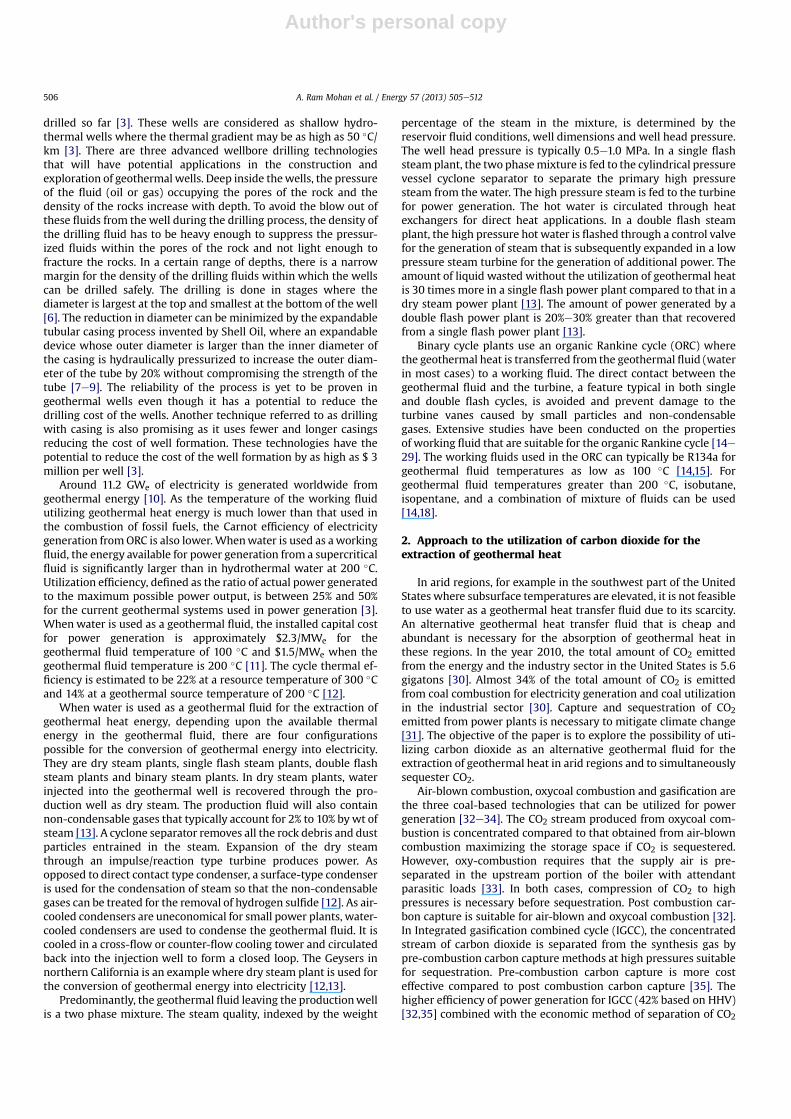
Fig. 1 shows the schematic representation of pairing an inte-grated gasification combined cycle (IGCC) plant with binaryenhanced geothermal systems. CO2 formed during the gasificationand the subsequent water gas shift reaction process is separated athigh pressures by pre-combustion carbon capture methods in anintegrated gasification combined cycle (IGCC) plant so that it isready for sequestration. The carbon dioxide ready to be sequesteredis fed into the injection well for the absorption of geothermal heatenergy. Short-circuiting flow of CO2 from the injection well to theproduction well may result in rapid but incomplete thermaldrawdown in the reservoir [36]. So the carbon dioxide is injected ina series of wells to attain a distributed sweep of fluid. The limitedpermeability of these reservoirs means that multiple injectionwells and production wells are required to provide sufficientthroughput in the reservoir. A portion of the injected CO2 is lost infractures in the rocks and this loss contributes to the sequesteredinventory. The remainder of the CO2 circulates through the reser-voir and is the agent that removes the heat. The geothermal heat istransferred from the CO2 to a working fluid in a heat exchanger andthis working fluid passes through the organic Rankine cycle (ORC)for power generation. This power generated is in addition to thatobtained from IGCC through the gas turbine and steam turbine. TheIGCC plant is sized such that it produces sufficient CO2 tocompensate for the sequestration losses adjacent to the reservoir.This symbiotic pairing of CO2-EGS with IGCC reduces both the us-age of water in arid regions while simultaneously extracting heatfrom the reservoir and sequestering CO2 in the subsurface.
3. Assumptions used in this study
The total amount of CO2 injected into the geothermal well is680 kg/s at a pressure of 15 MPa and at a temperature of 60 �C. Inorder to avoid premature depletion of the reservoir and limited bythe anticipated low permeability of the stimulated reservoir [36],this flow is distributed equally among 10 injection wells so that68 kg/s of CO2 is injected into each well. 10% of the total CO2injected into the wells escapes through the fractures and contrib-utes to the sequestered mass. The depth of the injection well andthe production well are each assumed to be 6 km. The thermal
gradient in the geothermal well is assumed to be 50 �C/km. Thepressure drop of CO2 from the injection well through the reservoirto the production well is assumed to be 3 MPa. The remaining CO2carries the geothermal heat and leaves the production well at atemperature of 300 �C and 12 MPa. It transfers the geothermal heatenergy to the working fluid in the ORC through a binary shell andtube heat exchanger. The CO2 lost to the geothermal reservoirduring the sequestration process is compensated from a 315 MWeIGCC plant using Pittsburgh no 8 coal. The ultimate analysis ofPittsburgh no 8 coal on a dry basis is given in Table 1 [37]. Assumingan efficiency of 42% HHV for the IGCC plant, based on the proximateanalysis, ultimate analysis and the calorific value [37], the totalamount of CO2 produced from the 315 MWe IGCC plant amounts to68 kg/s. The summary of the calculations is shown in Table 2.
4. Modeling approach for the organic Rankine cycle in EGS
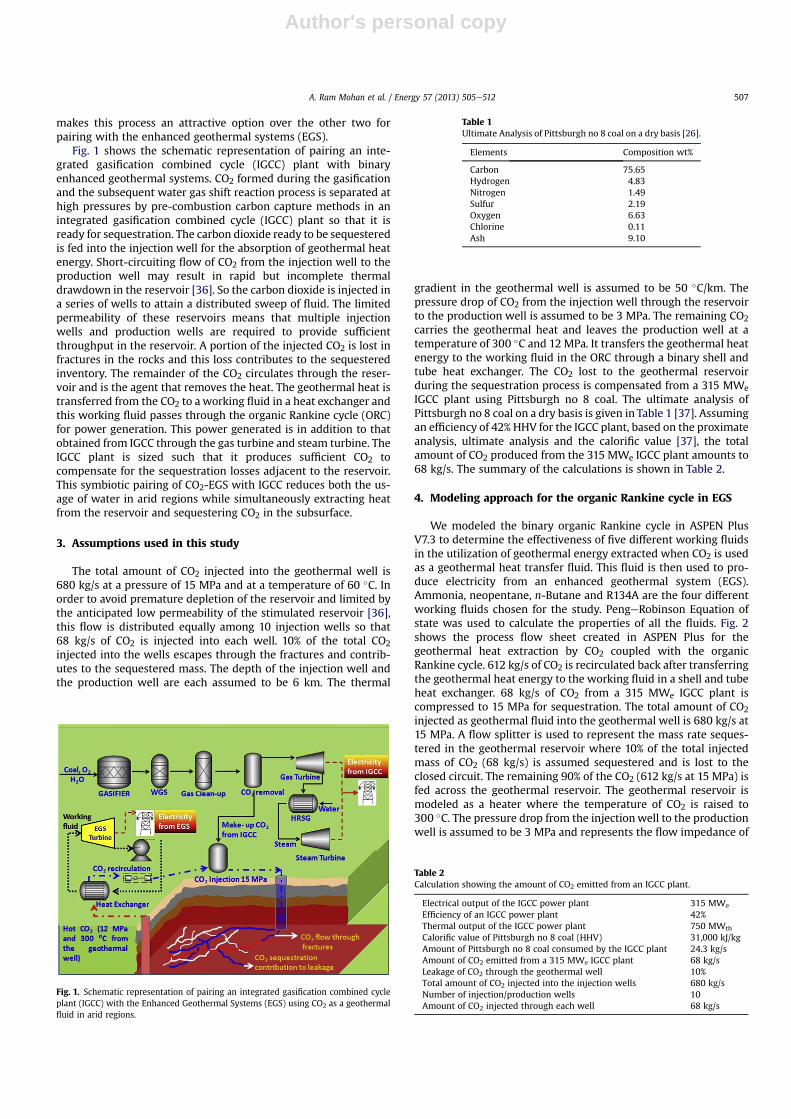
We modeled the binary organic Rankine cycle in ASPEN PlusV7.3 to determine the effectiveness of five different working fluidsin the utilization of geothermal energy extracted when CO2 is usedas a geothermal heat transfer fluid. This fluid is then used to pro-duce electricity from an enhanced geothermal system (EGS).Ammonia, neopentane, n-Butane and R134A are the four differentworking fluids chosen for the study. PengeRobinson Equation ofstate was used to calculate the properties of all the fluids. Fig. 2shows the process flow sheet created in ASPEN Plus for thegeothermal heat extraction by CO2 coupled with the organicRankine cycle. 612 kg/s of CO2 is recirculated back after transferringthe geothermal heat energy to the working fluid in a shell and tubeheat exchanger. 68 kg/s of CO2 from a 315 MWe IGCC plant iscompressed to 15 MPa for sequestration. The total amount of CO2injected as geothermal fluid into the geothermal well is 680 kg/s at15 MPa. A flow splitter is used to represent the mass rate seques-tered in the geothermal reservoir where 10% of the total injectedmass of CO2 (68 kg/s) is assumed sequestered and is lost to theclosed circuit. The remaining 90% of the CO2 (612 kg/s at 15 MPa) isfed across the geothermal reservoir. The geothermal reservoir ismodeled as a heater where the temperature of CO2 is raised to300 �C. The pressure drop from the injectionwell to the productionwell is assumed to be 3 MPa and represents the flow impedance of
Fig. 1. Schematic representation of pairing an integrated gasification combined cycleplant (IGCC) with the Enhanced Geothermal Systems (EGS) using CO2 as a geothermalfluid in arid regions.
Table 1Ultimate Analysis of Pittsburgh no 8 coal on a dry basis [26].
Elements Composition wt%
Carbon 75.65Hydrogen 4.83Nitrogen 1.49Sulfur 2.19Oxygen 6.63Chlorine 0.11Ash 9.10
Table 2Calculation showing the amount of CO2 emitted from an IGCC plant.
Electrical output of the IGCC power plant 315 MWe
Efficiency of an IGCC power plant 42%Thermal output of the IGCC power plant 750 MWth
Calorific value of Pittsburgh no 8 coal (HHV) 31,000 kJ/kgAmount of Pittsburgh no 8 coal consumed by the IGCC plant 24.3 kg/sAmount of CO2 emitted from a 315 MWe IGCC plant 68 kg/sLeakage of CO2 through the geothermal well 10%Total amount of CO2 injected into the injection wells 680 kg/sNumber of injection/production wells 10Amount of CO2 injected through each well 68 kg/s
A. Ram Mohan et al. / Energy 57 (2013) 505e512 507
Author's personal copy
the reservoir. The geothermal fluid (CO2) is discharged from theheater (proxy geothermal reservoir) at 12 MPa and 300 �C. It entersthe heat exchanger which is modeled by a MHEATX model inASPEN PLUS. The geothermal heat is transferred from CO2 to theworking fluid. The CO2 is recompressed to 15 MPa and circulatedback to the flow splitter inlet. CO2 lost in the sequestration processis compensated by the output from the IGCC plant (68 kg/s) so thata constant inlet flow rate of 680 kg/s can be maintained at the inletof the flow splitter.
In the first part of the study, a preheater was not used in theORC. The working fluid is chosen to be in liquid state. It is com-pressed to high pressure with a pump. In the absence of the pre-heater, it directly enters the binary heat exchanger to absorb thegeothermal heat from the CO2. The fluid passes completely to thevapor phase and the expansion of this fluid in the turbine to at-mospheric pressure produces electricity. The vapor at atmosphericpressure is fed to the condenser to change phase from vapor toliquid. The cold liquid at atmospheric pressure is recirculated backinto the pump. The power generated in this cycle was studied as afunction of the five different working fluids when the temperatureof the geothermal fluid at the heat exchanger inlet was 300 �C. Thelowest possible temperature at which CO2 can be discharged fromthe heat exchanger was also studied. In the second part of the study,a preheater was used. The hot working fluid in the vapor phaseleaving the turbine outlet enters the preheater to heat the cold buthigh pressure liquid leaving the pump before it enters the binaryheat exchanger to absorb the geothermal heat from the CO2. Theeffect of the preheater in reducing the amount of energy wasted incondensation was studied for both neopentane and n-Butane.There are three constraints used in the modeling of the organicRankine cycle. These are that: (i) there should not be any
temperature crossover either in the binary heat exchanger or thepreheater between the hot and the cold fluid, in other words, thetemperature of the hot fluid is always greater than the temperatureof the cold fluid from one end to the other end of the heatexchanger (ii) that the working fluid should completely be in thevapor phase at the turbine inlet, and, (iii) that the working fluidshould completely be in the vapor phase during expansion in theturbine or at the turbine outlet. The inlet conditions used for theworking fluid are shown in Tables 3e6. These conditions are chosento meet all the modeling constraints.
5. Error analysis
Based on the assumptions in Table 2, the ORC for the workingfluids was modeled under specific conditions in ASPEN Plus. Theresults are reproducible under the same conditions. Therefore, er-ror analysis is impertinent in this study.
6. Results and discussion
In the ORC, the pressure of the working fluid and its mass flowrate are the input conditions that determine the power output. Thespecific heat capacity and the thermodynamic properties of theworking fluid determine the amount of power generated from theORC for a certain amount of heat input. The amount of powergenerated, efficiency of power generation and the CO2 exit tem-perature are shown in Tables 3e6 for ammonia n-Butane, neo-pentane and R134A respectively. The first law efficiency is definedas the ratio of net power output generated in the ORC to thegeothermal heat energy absorbed by the working fluid from CO2 inthe binary heat exchanger.
Fig. 2. Process modeling of organic Rankine cycle for producing electricity by EGS using CO2 as a geothermal fluid.
Table 3Power output from EGS and efficiency of power generation from EGS for ammonia.
Mass flow rate of working fluid ammonia ¼ 100 kg/s
Working fluid pressure (MPa) Power generated (MWe) Exit CO2 temperature (�C) Ammonia temperature inheat exchanger
h %
Tin, �C Tout, �C
0.5 27.3 60 �35 293 12.71.0 36.4 60 �35 296 16.92.5 39.9 70 �35 238 20.33.0 44.9 65 �35 275 21.84.0 49 62 �35 295 23.2
A. Ram Mohan et al. / Energy 57 (2013) 505e512508
Author's personal copy
h ¼ WTurbine �WPump
½Geothermal energy absorbed by the working fluid� (1)
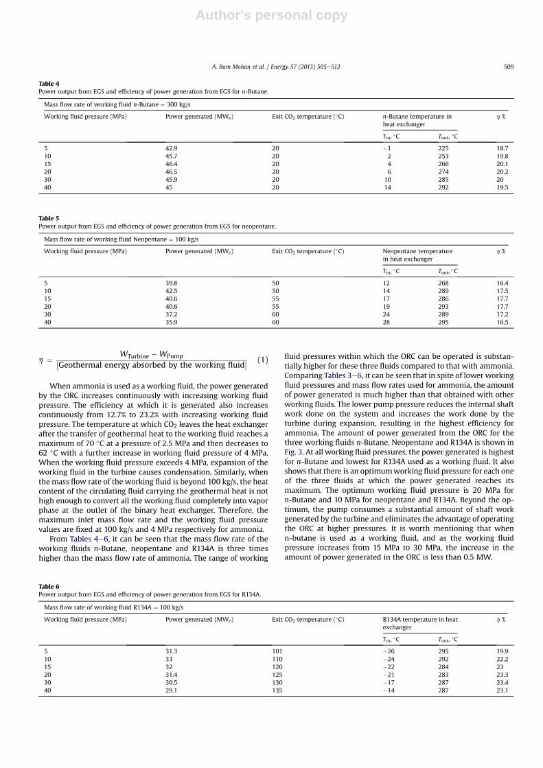
When ammonia is used as a working fluid, the power generatedby the ORC increases continuously with increasing working fluidpressure. The efficiency at which it is generated also increasescontinuously from 12.7% to 23.2% with increasing working fluidpressure. The temperature at which CO2 leaves the heat exchangerafter the transfer of geothermal heat to the working fluid reaches amaximum of 70 �C at a pressure of 2.5 MPa and then decreases to62 �C with a further increase in working fluid pressure of 4 MPa.When the working fluid pressure exceeds 4 MPa, expansion of theworking fluid in the turbine causes condensation. Similarly, whenthe mass flow rate of the working fluid is beyond 100 kg/s, the heatcontent of the circulating fluid carrying the geothermal heat is nothigh enough to convert all the working fluid completely into vaporphase at the outlet of the binary heat exchanger. Therefore, themaximum inlet mass flow rate and the working fluid pressurevalues are fixed at 100 kg/s and 4 MPa respectively for ammonia.
From Tables 4e6, it can be seen that the mass flow rate of theworking fluids n-Butane, neopentane and R134A is three timeshigher than the mass flow rate of ammonia. The range of working
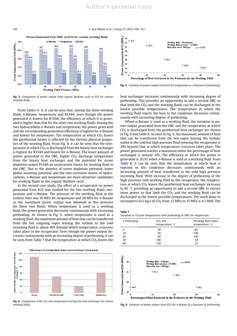
fluid pressures within which the ORC can be operated is substan-tially higher for these three fluids compared to that with ammonia.Comparing Tables 3e6, it can be seen that in spite of lower workingfluid pressures and mass flow rates used for ammonia, the amountof power generated is much higher than that obtained with otherworking fluids. The lower pump pressure reduces the internal shaftwork done on the system and increases the work done by theturbine during expansion, resulting in the highest efficiency forammonia. The amount of power generated from the ORC for thethree working fluids n-Butane, Neopentane and R134A is shown inFig. 3. At all working fluid pressures, the power generated is highestfor n-Butane and lowest for R134A used as a working fluid. It alsoshows that there is an optimumworking fluid pressure for each oneof the three fluids at which the power generated reaches itsmaximum. The optimum working fluid pressure is 20 MPa forn-Butane and 10 MPa for neopentane and R134A. Beyond the op-timum, the pump consumes a substantial amount of shaft workgenerated by the turbine and eliminates the advantage of operatingthe ORC at higher pressures. It is worth mentioning that whenn-butane is used as a working fluid, and as the working fluidpressure increases from 15 MPa to 30 MPa, the increase in theamount of power generated in the ORC is less than 0.5 MW.
Table 5Power output from EGS and efficiency of power generation from EGS for neopentane.
Mass flow rate of working fluid Neopentane ¼ 100 kg/s
Working fluid pressure (MPa) Power generated (MWe) Exit CO2 temperature (�C) Neopentane temperaturein heat exchanger
h %
Tin, �C Tout, �C
5 39.8 50 12 268 16.410 42.5 50 14 289 17.515 40.6 55 17 286 17.720 40.6 55 19 293 17.730 37.2 60 24 289 17.240 35.9 60 28 295 16.5
Table 4Power output from EGS and efficiency of power generation from EGS for n-Butane.
Mass flow rate of working fluid n-Butane ¼ 300 kg/s
Working fluid pressure (MPa) Power generated (MWe) Exit CO2 temperature (�C) n-Butane temperature inheat exchanger
h %
Tin, �C Tout, �C
5 42.9 20 �1 225 18.710 45.7 20 2 253 19.815 46.4 20 4 266 20.120 46.5 20 6 274 20.230 45.9 20 10 285 2040 45 20 14 292 19.5
Table 6Power output from EGS and efficiency of power generation from EGS for R134A.
Mass flow rate of working fluid R134A ¼ 100 kg/s
Working fluid pressure (MPa) Power generated (MWe) Exit CO2 temperature (�C) R134A temperature in heatexchanger
h %
Tin, �C Tout, �C
5 31.3 101 �26 295 19.910 33 110 �24 292 22.215 32 120 �22 284 2320 31.4 125 �21 283 23.330 30.5 130 �17 287 23.440 29.1 135 �14 287 23.1
A. Ram Mohan et al. / Energy 57 (2013) 505e512 509
Author's personal copy
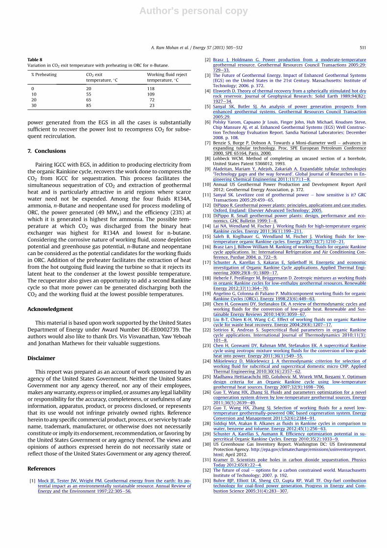
From Tables 4e6, it can be seen that, among the three workingfluids n-Butane, neopentane and R134A, even though the powergenerated is lowest for R134A, the efficiency at which it is gener-ated is higher than that for the other twoworking fluids. Among thetwo hydrocarbons n-Butane and neopentane, the power generatedand the corresponding generation efficiency is highest for n-Butaneand lowest for neopentane. The temperature at which CO2 leavesthe geothermal heater is affected by the thermo-physical proper-ties of the working fluid. From Fig. 4, it can be seen that the tem-perature at which CO2 is discharged from the binary heat exchangeris highest for R134A and lowest for n-Butane. The lower amount ofpower generated in the ORC, higher CO2 discharge temperaturefrom the binary heat exchanger and the potential for ozonedepletion makes R134A an unattractive choice for working fluid inthe ORC. Due to the absence of ozone depletion potential, lowerglobal warming potential and the non-corrosive nature of hydro-carbons, n-Butane and neopentane are more attractive candidatesfor working fluids in the organic Rankine cycle.
In the second case study, the effect of a recuperator on powergenerated from EGS was studied for the two working fluids neo-pentane and n-Butane. The pressure of the working fluid at theturbine inlet was 10 MPa for neopentane and 20 MPa for n-Butaneas the maximum power output was obtained at this pressurefor these two fluids. When neopentane is used as a workingfluid, the power generated decreases continuously with increasingpreheating. As shown in Fig. 5, when neopentane is used as aworking fluid, themaximum amount of heat that can be transferredfrom the hot outgoing vapor leaving the turbine to the coldincoming fluid is about 40% beyond which temperature crossovertakes place in the recuperator. Even though the power output de-creases continuouslywith an increasing degree of preheating, it canbe seen from Table 7 that the temperature at which CO2 leaves the
heat exchanger increases continuously with increasing degree ofpreheating. This provides an opportunity to add a second ORC sothat both the CO2 and the working fluids can be discharged at thelowest possible temperatures. The temperature at which theworking fluid rejects the heat to the condenser decreases contin-uously with increasing degree of preheating.
When n-Butane is used as a working fluid, the variation in po-wer output generated from the ORC and the temperature at whichCO2 is discharged from the geothermal heat exchanger are shownin Fig. 6 and Table 8. As seen in Fig. 6, the maximum amount of heatthat can be transferred from the hot vapor leaving the turbineoutlet to the cold but high pressure fluid entering the recuperator is30% beyond that at which temperature crossover takes place. Thepower generated reaches a maximumwhen the percentage of heatexchanged is around 10%. The efficiency at which the power isgenerated is 20.5% when n-Butane is used as a working fluid. FromTable 8, it can be seen that the temperature at which heat isrejected to the condenser decreases continuously with anincreasing amount of heat transferred to the cold high pressureincoming fluid. With increase in the degree of preheating of thehigh pressure cold working fluid in the recuperator, the tempera-ture at which CO2 leaves the geothermal heat exchanger increasesto 85 �C providing an opportunity to add a second ORC to extractmore power so that both the CO2 and the working fluid can bedischarged at the lowest possible temperatures. The work done torecompress 612 kg/s of CO2 from 12 MPa to 15 MPa is 4.3 MW. The
Fig. 3. Comparison of power output from organic Rankine cycle in EGS for variousworking fluids.
Fig. 4. Comparison of the CO2 exit temperature leaving the heat exchanger for variousworking fluids.
Fig. 5. Variation of power output from EGS for neopentane as a function of preheating.
Table 7Variation in CO2exit temperature with preheating in ORC for neopentane.
% Preheating CO2 exittemperature, �C
Working fluid rejecttemperature, �C
0 50 18310 60 14820 80 10030 100 6240 120 25
Fig. 6. Variation of power output from EGS for n-Butane as a function of preheating.
A. Ram Mohan et al. / Energy 57 (2013) 505e512510
Author's personal copy
power generated from the EGS in all the cases is substantiallysufficient to recover the power lost to recompress CO2 for subse-quent recirculation.
7. Conclusions
Pairing IGCC with EGS, in addition to producing electricity fromthe organic Rainkine cycle, recovers the work done to compress theCO2 from IGCC for sequestration. This process facilitates thesimultaneous sequestration of CO2 and extraction of geothermalheat and is particularly attractive in arid regions where scarcewater need not be expended. Among the four fluids R134A,ammonia, n-Butane and neopentane used for process modeling ofORC, the power generated (49 MWe) and the efficiency (23%) atwhich it is generated is highest for ammonia. The possible tem-perature at which CO2 was discharged from the binary heatexchanger was highest for R134A and lowest for n-butane.Considering the corrosive nature of working fluid, ozone depletionpotential and greenhouse gas potential, n-Butane and neopentanecan be considered as the potential candidates for the working fluidsin ORC. Addition of the preheater facilitates the extraction of heatfrom the hot outgoing fluid leaving the turbine so that it rejects itslatent heat to the condenser at the lowest possible temperature.The recuperator also gives an opportunity to add a second Rankinecycle so that more power can be generated discharging both theCO2 and the working fluid at the lowest possible temperatures.
Acknowledgment
This material is based uponwork supported by the United StatesDepartment of Energy under Award Number DE-EE0002739. Theauthors would also like to thank Drs. Vis Visvanathan, Yaw Yeboahand Jonathan Mathews for their valuable suggestions.
Disclaimer
This report was prepared as an account of work sponsored by anagency of the United States Government. Neither the United StatesGovernment nor any agency thereof, nor any of their employees,makes anywarranty, express or implied, or assumes any legal liabilityor responsibility for the accuracy, completeness, or usefulness of anyinformation, apparatus, product, or process disclosed, or representsthat its use would not infringe privately owned rights. Referenceherein toanyspecific commercialproduct, process, or serviceby tradename, trademark, manufacturer, or otherwise does not necessarilyconstitute or imply its endorsement, recommendation, or favoring bythe United States Government or any agency thereof. The views andopinions of authors expressed herein do not necessarily state orreflect those of the United States Government or any agency thereof.
References
[1] Mock JE, Tester JW, Wright PM. Geothermal energy from the earth: Its po-tential impact as an environmentally sustainable resource. Annual Review ofEnergy and the Environment 1997;22:305e56.
[2] Brasz J, Holdmann G. Power production from a moderate-temperaturegeothermal resource. Geothermal Resources Council Transactions 2005;29:729e33.
[3] The Future of Geothermal Energy. Impact of Enhanced Geothermal Systems(EGS) on the United States in the 21st Century. Massachusetts: Institute ofTechnology; 2006. p. 372.
[4] Elsworth D. Theory of thermal recovery from a spherically stimulated hot dryrock reservoir. Journal of Geophysical Research: Solid Earth 1989;94(B2):1927e34.
[5] Sanyal SK, Butler SJ. An analysis of power generation prospects fromenhanced geothermal systems. Geothermal Resources Council Transaction2005;29.
[6] Polsky Yarom, Capuano Jr Louis, Finger John, Huh Michael, Knudsen Steve,Chip Mansure AJ, et al. Enhanced Geothermal Systems (EGS) Well Construc-tion Technology Evaluation Report. Sandia National Laboratories; December2008. p. 108.
[7] Benzie S, Burge P, Dobson A. Towards a Moni-diameter well e advances inexpanding tubular technology. Proc. SPE European Petroleum Conference2000, SPE 65164, Paris, 2000.
[8] Lohbeck WCM. Method of completing an uncased section of a borehole,United States Patent 5366012, 1993.
[9] Aladeitan, Mariam Y, Adejoh, Zakariah A. Expandable tubular technologies‘Technology gaps and the way forward’. Global Journal of Researches in En-gineering Chemical Engineering 2011;11(7):1e8.
[10] Annual US Geothermal Power Production and Development Report April2012; Geothermal Energy Association, p. 372.
[11] Sanyal SK. Levelizee cost of geothermal power e how sensitive is it? GRCTransactions 2005;29:459e65.
[12] DiPippo R. Geothermal power plants: principles, applications and case studies.Oxford, England: Elsevier Advanced Technology; 2005.
[13] DiPippo R. Small geothermal power plants: design, performance and eco-nomics. GHC Bulletin 1999:1e8.
[14] Lai NA, Wendland M, Fischer J. Working fluids for high-temperature organicRankine cycles. Energy 2011;36(1):199e211.
[15] Saleh B, Koglbauer G, Wendland M, Fischer J. Working fluids for low-temperature organic Rankine cycles. Energy 2007;32(7):1210e21.
[16] Brasz Lars J, Bilbow William M. Ranking of working fluids for organic Rankinecycle applications. In: International Refrigeration and Air Conditioning Con-ference, Purdue 2004. p. 722e9.
[17] Schuster A, Karellas S, Kakaras E, Spliethoff H. Energetic and economicinvestigation of Organic Rankine Cycle applications. Applied Thermal Engi-neering 2009;29(8e9):1809e17.
[18] Heberle F, Preißinger M, Brüggemann D. Zeotropic mixtures as working fluidsin organic Rankine cycles for low-enthalpy geothermal resources. RenewableEnergy 2012;37(1):364e70.
[19] Angelino G, Colonna di Paliano P. Multicomponent working fluids for organicRankine Cycles (ORCs). Energy 1998;23(6):449e63.
[20] Chen H, Goswami DY, Stefanakos EK. A review of thermodynamic cycles andworking fluids for the conversion of low-grade heat. Renewable and Sus-tainable Energy Reviews 2010;14(9):3059e67.
[21] Liu B-T, Chien K-H, Wang C-C. Effect of working fluids on organic Rankinecycle for waste heat recovery. Energy 2004;29(8):1207e17.
[22] Sotirios K, Andreas S. Supercritical fluid parameters in organic Rankinecycle applications. International Journal of Thermodynamics 2010;11(3):101e8.
[23] Chen H, Goswami DY, Rahman MM, Stefanakos EK. A supercritical Rankinecycle using zeotropic mixture working fluids for the conversion of low-gradeheat into power. Energy 2011;36(1):549e55.
[24] Mikielewicz D, Mikielewicz J. A thermodynamic criterion for selection ofworking fluid for subcritical and supercritical domestic micro CHP. AppliedThermal Engineering 2010;30(16):2357e62.
[25] Madhawa Hettiarachchi HD, Golubovic M, Worek WM, Ikegami Y. Optimumdesign criteria for an Organic Rankine cycle using low-temperaturegeothermal heat sources. Energy 2007;32(9):1698e706.
[26] Guo T, Wang HX, Zhang SJ. Fluids and parameters optimization for a novelcogeneration system driven by low-temperature geothermal sources. Energy2011;36(5):2639e49.
[27] Guo T, Wang HX, Zhang SJ. Selection of working fluids for a novel low-temperature geothermally-powered ORC based cogeneration system. EnergyConversion and Management 2011;52(6):2384e91.
[28] Siddiqi MA, Atakan B. Alkanes as fluids in Rankine cycles in comparison towater, benzene and toluene. Energy 2012;45(1):256e63.
[29] Schuster A, Karellas S, Aumann R. Efficiency optimization potential in su-percritical Organic Rankine Cycles. Energy 2010;35(2):1033e9.
[30] US Greenhouse Gas Inventory Report. Washington DC: US EnvironmentalProtection Agency. http://epa.gov/climatechange/emissions/usinventoryreport.html; April 2012.
[31] Kramer D. Scientists poke holes in carbon dioxide sequestration. PhysicsToday 2012;65(8):22e4.
[32] The future of coal e options for a carbon constrained world. MassachusettsInstitute of Technology; 2007. p. 192.
[33] Buhre BJP, Elliott LK, Sheng CD, Gupta RP, Wall TF. Oxy-fuel combustiontechnology for coal-fired power generation. Progress in Energy and Com-bustion Science 2005;31(4):283e307.
Table 8Variation in CO2 exit temperature with preheating in ORC for n-Butane.
% Preheating CO2 exittemperature, �C
Working fluid rejecttemperature, �C
0 20 11810 55 10920 65 7230 85 23
A. Ram Mohan et al. / Energy 57 (2013) 505e512 511

Author's personal copy
[34] Longwell JP, Rubin ES, Wilson J. Coal: energy for the future. Progress in Energyand Combustion Science 1995;21(4):269e360.
[35] Figueroa JD, Fout T, Plasynski S, McIlvried H, Srivastava RD. Advances inCO2 capture technologydThe U.S. Department of Energy’s Carbon Seques-tration Program. International Journal of Greenhouse Gas Control 2008;2(1):9e20.
[36] Elsworth D. A comparative evaluation of the parallel flow and sphericalreservoir models of HDR geothermal systems. Journal of Volcanology andGeothermal Research 1990;44:283e93.
[37] Kabe T, Ishihara A, Qian EW, Sutrisna IP, Kabe Y. Studies in surface science andcatalysis. Coal and coal-related compounds. Structure, Reactivity and CatalyticReactions 2004;150.
A. Ram Mohan et al. / Energy 57 (2013) 505e512512


