Embed Size (px)
Citation preview
Cryogenic Millimeter-wave VPMs
Variable-delay Polarization Modulators for Cryogenic Millimeter-waveApplications
D.T. Chuss,1, a) J.R. Eimer,2 D.J. Fixsen,1 J. Hinderks,1 A.J. Kogut,1 J. Lazear,1 P. Mirel,1 E. Switzer,1 G.M.Voellmer,1 and E.J. Wollack11)NASA Goddard Space Flight Center, Greenbelt, MD 207712)Department of Physics and Astronomy, The Johns Hopkins University, Baltimore,MD
(Dated: 10 March 2014)
We describe the design, construction, and initial validation of the variable-delay polarization modulator(VPM) designed for the PIPER cosmic microwave background polarimeter. The VPM modulates betweenlinear and circular polarization by introducing a phase delay between orthogonal linear polarizations. EachVPM has a diameter of 39 cm and is designed to operate in a cryogenic environment (1.5 K). We describe themechanical design and performance of the kinematic double-blade flexure and drive mechanism along withthe construction of the high precision wire grid polarizers.
PACS numbers: 42,95,98Keywords: astronomical polarimetry, instrumentation, cosmic microwave background
I. INTRODUCTION
A Variable-delay Polarization Modulator (VPM)changes the state of polarization of electromagnetic ra-diation via the introduction of a variable phase delaybetween two orthogonal polarization components.1 Thisleads to a transfer function in which an output Stokesparameter U ′ defined at a 45◦ angle with respect to thepolarization separation basis (defined by the VPM grid)is modulated according to
U ′ = U cosφ+ V sinφ, (1)
where (Q, U , V ) are the input Stokes parameters. Notethat Q, the Stokes parameter defined by the differencebetween the two polarizations that are separated by theVPM, is unmodulated.
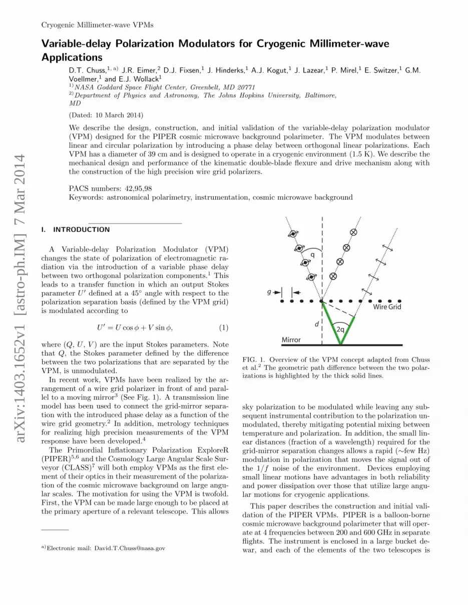
In recent work, VPMs have been realized by the ar-rangement of a wire grid polarizer in front of and paral-lel to a moving mirror3 (See Fig. 1). A transmission linemodel has been used to connect the grid-mirror separa-tion with the introduced phase delay as a function of thewire grid geometry.2 In addition, metrology techniquesfor realizing high precision measurements of the VPMresponse have been developed.4
The Primordial Inflationary Polarization ExploreR(PIPER)5,6 and the Cosmology Large Angular Scale Sur-veyor (CLASS)7 will both employ VPMs as the first ele-ment of their optics in their measurement of the polariza-tion of the cosmic microwave background on large angu-lar scales. The motivation for using the VPM is twofold.First, the VPM can be made large enough to be placed atthe primary aperture of a relevant telescope. This allows
a)Electronic mail: [email protected]
Wire Grid
Mirror
q
d2q
g
FIG. 1. Overview of the VPM concept adapted from Chusset al.2 The geometric path difference between the two polar-izations is highlighted by the thick solid lines.
sky polarization to be modulated while leaving any sub-sequent instrumental contribution to the polarization un-modulated, thereby mitigating potential mixing betweentemperature and polarization. In addition, the small lin-ear distances (fraction of a wavelength) required for thegrid-mirror separation changes allows a rapid (∼few Hz)modulation in polarization that moves the signal out ofthe 1/f noise of the environment. Devices employingsmall linear motions have advantages in both reliabilityand power dissipation over those that utilize large angu-lar motions for cryogenic applications.
This paper describes the construction and initial vali-dation of the PIPER VPMs. PIPER is a balloon-bornecosmic microwave background polarimeter that will oper-ate at 4 frequencies between 200 and 600 GHz in separateflights. The instrument is enclosed in a large bucket de-war, and each of the elements of the two telescopes is
arX
iv:1
403.
1652
v1 [
astr
o-ph
.IM
] 7
Mar
201
4

Cryogenic Millimeter-wave VPMs 2
Drive Shaft
Mirror
WireGrid
Double-BladeFlexure
RotaryFlexure
Mechanical Ground
FIG. 2. The operation of the VPM drive mechanism is shown.A warm motor turns an eccentric that is attached to a driveshaft. The drive shaft turns a cold rotary flexure that inturn pushes and pulls on one side of a kinematic double-bladeflexure that maintains the parallelism of the mirror over thethrow. A symmetric pair of rotary flexures (not shown) cou-ples to an additional shaft that is 180◦ out of phase with thefirst. These rotary flexures move counterweights to passivelycompensate the motion of the mirror.
cooled to 1.5 K by a combination of evaporating liquidhelium and superfluid pumps.8 Cooling the telescope re-duces background radiation and mitigates the couplingto variable grid emission.11 The emissivity is further re-duced by the increased conductance of the metallic coat-ings on both the wires and the mirror.
The details of the optical design9 and detectors10 forPIPER are described in other papers. This work focuseson the design, construction and validation of the VPMs.
II. DESIGN OF THE MECHANICAL ASSEMBLY
A schematic of the VPM is shown in Figure 2. The1.5 K mirror is actuated by a warm (ambient tempera-ture) motor that couples to the cold mechanism througha driveshaft. All parts of the mechanism that operate at1.5 K are constructed from stainless steel to ensure ther-momechanical stability and matching of the coefficientof thermal expansion. This includes the mirror which isconstructed from stainless steel honeycomb. The mirrorfaceplate is lapped flat, and then gold is deposited ontothe mirror to increase the conductivity of the surface. Aphoto of the VPM drive mechanism is shown in Figure 3.
Drive Shaft
Warm Motor Rotary Flexures Double-Blade Flexure
Mirror
Grid mounts
Capacitive DistanceSensor (1 of 3)
FIG. 3. Photograph of the PIPER VPM assembly.
To ensure transport of the mirror is parallel, we haveutilized a kinematic double-blade flexure similar to thoseused in the prototype Hertz VPM.12 This mechanismconstrains all degrees of freedom except for the direc-tion of motion. The PIPER flexure is constructed outof stainless steel using wire-EDM and is larger than theHertz flexure to permit the maximum throw required, 1mm. This is set by the longest wavelength modulated,λ = 1.5 mm (200 GHz). The parallelism requirement ofthe flexure is 5 arc seconds over the 1 mm throw to ensurethat the phase is well-defined at the shortest operatingwavelength, 0.5 mm (600 GHz).
The drive is powered by a motor operating at ambienttemperature. The motor is attached to an eccentric; thatin turn couples to two concentric stainless steel liftersthat are actuated 180◦ out of phase. These lifters con-nect to two sets of rotary flexures on the cold end of thedevice. A single central rotary flexure couples the centralshaft to the double-blade flexure to move the mirror. Apair of outer rotary flexures couple to a pair of counterweights to provide a first-order passive compensation forthe mirror motion. This reduces vibrations that can in-duce microphonic response in the system.
Because the eccentric determines the limits of the mir-ror movement, the operational mode of the VPM can bechanged simply by replacing the eccentric to achieve thedesired throw. This allows a straightforwards means tooperate at different observational frequency bands. ForPIPER, the throw will be reconfigured between flights toaccommodate the range of planned observing frequencybands.
III. GRID FABRICATION
One of the most challenging aspects of the VPM is theconstruction of the polarizing grids. The grids must holda flatness tolerance of <10 µm RMS over a clear apertureof 39 cm.9 In addition, it is important to maintain highuniformity of the spacing of the wires that comprise thegrid to achieve high polarization diplexing efficiency.
One historical approach for fabricating free-standingwire grid polarizers is to wind them directly onto a

Cryogenic Millimeter-wave VPMs 3
frame.13,14 In this technique, wire spacing control is diffi-cult because the wires are unconstrained along the frame.They can roll or slide out of position under minimal dis-placement forces because the wire tension, and thus thestatic friction holding them in place on the frame, is lowduring winding to avoid wire breakage. In addition, thistechnique requires a single spool of wire to be used dur-ing fabrication with no tolerance to wire breakage. Analternative to this technique that mitigates these issuesis to wrap the wires on a cylinder that has been precutwith regularly spaced alignment teeth, and then trans-fer the wires to their final frame.15 The latter techniquehas been extended to make prototype 50 cm diameterpolarizers.16
Here we describe significant enhancements to this tech-nique that have led to improved wire uniformity and sur-vivability at cryogenic temperatures. Free-standing wiregrid polarizers have an advantage over comparable de-posited membrane structures in that they do not use di-electric material as a substrate due to a degradation ofthe capacitive (perpendicular) mode and maximum op-erating frequency for a given feature size.17 However, his-torically, the performance of free-standing wire grid po-larizers has been limited due to wire spacing variability.The grid manufacturing process presented here greatlyimproves the uniformity of grid wires and can thereforegreatly enhance the capability of polarizers operating atwavelengths between 1 cm and 60 µm.
The process of grid fabrication is illustrated in Fig-ure 4, and additional diagrams are included in the Ap-pendix for clarity. The 40 µm copper-plated tungstenwire (36 µm diameter W wire; 0.13 µm Ni strike; 1.3-2.5µm Cu plating)18 is wrapped onto a mandrel using a 5-axis CNC mill. In contrast to previous versions of thistechnique,15,16 the mandrel itself is smooth, with groovescut only in two wire retainer bars that are recessed intothe mandrel. These grooves serve as guides to set thewire spacing. The precision of the milling machine usedfor the wrapping is sufficient that the entire mandrel neednot be grooved to maintain the 1 wire per groove criterionon the wire retainer bars. This realization reduces riskto the wire coatings that can become damaged by metalburrs during the winding and unwrapping processes.
To cut the grooves for the wires, we used a rotatingend mill oriented at 45◦ with respect to the rotation axisof the mandrel. We use a straight flute tungsten carbidetipped 1/2
′′diameter end mill in a climb cut at 2,500
RPM on the spindle, with the mandrel rotating at 2.7RPM. This combination of tool speeds and feeds leavesa burr-free groove in the soft copper retaining bar.
Once the wire is wrapped, the wire is fastened to thewire retainer bars. Previous efforts have used epoxy;however, because of the large size and cryogenic operat-ing environment of the PIPER grids, we have developeda technique for soldering the wires to the bars. The wireretainer bars are attached to the mandrel using thermallyinsulating stand-offs. This enables adequate thermal iso-lation to allow the solder to flow on the wire retainer bars
ThermalIsolators
Mandrel
Cu-platedW wire
Wire RetainerBars
CartridgeHeater
HeatedFixturePlate
Springs ScrewsStainless Steel Grid Frame
Mandrel
Solder Gap
Solder
Wires Cut
Wire Cross-sections
Wire Retainer Bar Grooves
FIG. 4. The process for constructing the large cryogenicwire grid. (top) The wire is wrapped around a mandrel us-ing a CNC mill. (middle) The wires are soldered to a pairof grooved wire retainer bars and cut. Heat is supplied tothe wire retainer bars via an integrated cartridge heater dur-ing this process. The wire retainer bars are thermally iso-lated from the rest of the mandrel. (bottom) The wires arethen transferred to the grid frame, attached via screws withsprings.
without heating the mandrel. A cartridge heater withinthe fixture plate heats the plate and the wire retainer barsto soldering temperature. No additional heat is added.We use 2% flux core silver solder for high strength. Thegrooves in the wire retainer bars that constrain the wirespacing are divided into two parts by a channel cut per-pendicular to the wire direction. This “solder gap” keepsthe solder away from the clear aperture and keeps theaperture side of the grooves free of solder. This allowsthe wires to seat in each grove when tensioned as is ex-plained below.
The wires are then cut at the top-dead-center loca-tion between the retainer bars and then removed fromthe mandrel. The retaining bars, with wires attached,are mounted to the stainless steel grid frame usingscrew-adjustable helical spring tensioners (See bottom ofFig. 4.) The springs maintain the tension on the wires

Cryogenic Millimeter-wave VPMs 4
FIG. 5. The final cryogenically-compatible polarizing grid isshown. The dimensions of the grid are 41.7×40 cm2.
despite the mismatch in coefficient of thermal contractionupon cooling due to the dissimilar materials of the gridand grid frame. In addition, upon tensioning, the wiresare pulled deeper into the unsoldered part of the retainerbar grooves. This ensures maximum control over wirespacing. Additional diagrams of the mandrel and theframe are shown in Figures 9 and 10 in the Appendix.
The tension is set to be 0.7 N (130 MPa) on each wire,or approximately 25% of the breaking strength of thetungsten wire. This is implemented by measuring thespring constants and setting the compression distance.This leads to a resonant frequency of 190 Hz, before ap-plication of a grid flattener (see below). Application ofthe grid flattener will increase the resonant frequency.
An image of the final grid is shown in Figure 5. Toaid in clarification, we provide a list of key innova-tions in this fabrication process that separate it from itspredecessors.15,16
• The grooves have been cut on the retainer bar only.This is sufficient for precise wrapping and does notdamage the optical parts of the wires as they areplaced into and removed from grooves with burrs.
• The wire-guide grooves are cut using an end milloriented at 45◦ to the mandrel axis to producehighly regular and burr-free cuts.
• The wires are soldered to the retainer bars for cryo-genic compatibility. An in situ soldering techniquehas been developed to do this.
• The interface between the retainer bars and thegrid frame is designed to pull the wires deeper intothe grooves that ultimately define the spacing uni-formity.
• The entire wire retainer bar is attached to the gridframe, so the wires are put into their position-defining grooves once and never removed. Springsare used in this attachment to meter the tensionand to compensate CTE mismatch upon cooling.
FIG. 6. A micrograph of a section of the wires is shown witha millimeter scale for comparison. The spacing of the wires is117.0 ± 5.7µm.
IV. VALIDATION
A. Uniformity of Wire Spacing
The wire spacing has been measured using a STIL S.A.CHR 150 confocal spectrometer.19 In this configuration,the grid was placed on the X-Y stage of a milling machine,and the vertical distance to the grid wires was measuredas a function of horizontal position. The average spacingof the wires was found to be 117.0±5.7µm. A micrographof the wires in Figure 6 shows the wire uniformity.
B. Flatness and Parallelism
The grid-mirror separation is measured at three placesnear the edge of the mirror, evenly spaced in angle 120◦
from each other. Capacitance sensors20 are mounted tothe frame and measure the distance between the sen-sor and the back of the mirror with better than 0.5 µmprecision using a standard calibration curve. Figure 7shows the tilt of the mirror as a function of time for afew modulation cycles (top) and mirror displacement for10 minutes of data (bottom). The tilt was calculatedusing the displacement data from the three capacitancesensors. The deviation from parallelism is ∼ ±2.5 arcseconds. This corresponds to a maximum tilt of about7 µm across the 30 cm illuminated aperture of PIPER.At 270 µm, this is 0.5% of the wavelength, and so theinduced phase error is small.
To define the plane of the wires, we implement a “gridflattener,” a polished ring pressed lightly against thewires. This technique of separating the tensioning com-ponent from the plane definition has been implementedin previous work.3,16 The grid flatness with the currentgrid flattener is ±8.7µm RMS as measured with the con-focal spectrometer.

Cryogenic Millimeter-wave VPMs 5
0.0 0.5 1.0 1.5 2.0
Time (s)
3
2
1
0
1
2
3Tilt
(arc
seco
nds)
FIG. 7. (Top) The mirror tilt is shown as a function oftime. Here the cam is driven at a frequency of 1.4 Hz usinga test motor. Several periods of the motion are shown toillustrate the jitter. (Bottom) The tilt is shown as a functionof the mirror displacement a for 10 minutes of data. At eachpoint, the mirror displacement is determined by averaging thereadings from the three capacitance sensors.
C. Cryogenic Compatibility
A test grid was constructed by wrapping the central 15cm of the PIPER grid frame at the full 41.7 cm length.This sample was cycled to 77 K ten times and did notfail. In addition, the flexure mechanism and drive trainwere cooled to 4 K in a liquid helium dewar and remainedfully operable.
The VPM mirrors are constructed of stainless steelhoneycomb that is internally held together using a braz-ing process developed by Bodycote.21 The face sheet usedfor the mirror was 1.5 mm material which will be lapped(to a flatness of <5 µm) and vapor deposited with 2.5 µmof gold. We tested this construction for thermal surviv-ability by thermally cycling the mirror 10 times to liquid
4 6 8 10 12 14−1
−0.8
−0.6
−0.4
−0.2
0
0.2
0.4
0.6
0.8
1
4π d/λ
Pola
rizat
ion
Sign
al [−
]
FIG. 8. The polarization transfer function of a sample gridin a test VPM is shown. The data points are polarizationmeasurements as a function of phase from 76-117 GHz. Themeasurement is consistent with unit efficiency to the accuracyof the measurement. The red curve is a transmission linemodel2 evaluated for the measured grid parameters.
nitrogen (77 K) temperature. We found no change inthe flatness; however, the precision surface (lapped andvapor deposited) has not yet been applied.
D. Grid Polarization Efficiency
We have made initial measurements of the grid effi-ciency using a quasioptical testbed coupled to a VectorNetwork Analyzer (VNA). We have transferred a sampleof a test grid to a 15 cm diameter circular frame andmounted it to a small VPM. Measurements of the po-larization transfer function were made from 76-117 GHz.The data analysis is identical to that for previously pub-lished results.22 Figure 8 shows the single frequency po-larization transfer function from 76-117 GHz. For eachgrid-mirror separation, a polarization spectrum is ob-tained. Each point in Figure 8 is the mean of 100 datapoints (1.36 GHz bandwidth.) Data from 9 grid-mirrorseparations are included in the plot.
For reference, we have superposed the transmissionline model for a VPM from Chuss et al.2 evaluated us-ing the mean wavelength over the band (3.15 mm) andthe PIPER wire diameter (40 µm.) The resistive cir-cuit element has been calculated using the conductivityof copper. The measured grid efficiency is greater than99%. This measurement is limited by the uncertainty inthe VNA absolute calibration.
V. SUMMARY
We have designed, constructed, and validated a cryo-genic variable-delay polarization modulator (VPM) forthe PIPER suborbital cosmic microwave background po-

Cryogenic Millimeter-wave VPMs 6
larimeter. The achieved specifications for the VPM areshown in Table I.
Property Value UnitsMaximum mirror throw 1.0 mmMirror tilt at maximum throw 5 arc secondsClear aperture 39 cmWire diameter 40 µmWire separation 117.0 µmWire separation error 5.7 µmGrid flatness 8.7 µmMin. wire resonance 190 HzPolarization Efficiency > 99 %
TABLE I. The parameters of the VPM for PIPER.
ACKNOWLEDGEMENTS
We thank Alyssa Barlis, Adam Blake, Matheus Teix-eira, and Vien Ha for work in the initial testing of thefabrication process and Paul Cursey for machining sup-port. In addition, we would like to thank Mike Jacksonfor modeling and finite element analysis for the flexureand drive system. This work was funded by a NASAAPRA suborbital grant.
1D. T. Chuss, E. J. Wollack, S. H. Moseley, and G. Novak, “Inter-ferometric polarization control,” Applied Optics 45, 5107–5117(2006).
2D. Chuss, E. Wollack, R. Henry, H. Hui, A. Juarez, M. Kre-jny, H. Moseley, and G. Novak, “Properties of a variable-delaypolarization modulator,” Applied Optics 51, 197–208 (2012).
3M. Krejny, D. Chuss, C. Drouet d’Aubigny, D. Golish, M. Houde,H. Hui, C. Kulesa, R. F. Loewenstein, S. H. Moseley, G. Novak,G. Voellmer, C. Walker, and E. Wollack, “The Hertz/VPM po-larimeter: Design and first light observations,” Applied Optics47 (2008), 0803.3759.
4J. R. Eimer, C. L. Bennett, D. T. Chuss, and E. J. Wollack,“Note: Vector reflectometry in a beam waveguide,” Review ofScientific Instruments 82, 086101 (2011), arXiv:1107.2453 [astro-ph.IM].
5D. T. Chuss, P. A. R. Ade, D. J. Benford, C. L. Bennett,J. L. Dotson, J. R. Eimer, D. J. Fixsen, M. Halpern, G. Hilton,J. Hinderks, G. Hinshaw, K. Irwin, M. L. Jackson, M. A. Jah,N. Jethava, C. Jhabvala, A. J. Kogut, L. Lowe, N. McCullagh,T. Miller, P. Mirel, S. H. Moseley, S. Rodriguez, K. Rostem,E. Sharp, J. G. Staguhn, C. E. Tucker, G. M. Voellmer, E. J.Wollack, and L. Zeng, “The Primordial Inflation PolarizationExplorer (PIPER),” in Society of Photo-Optical InstrumentationEngineers (SPIE) Conference Series, Society of Photo-OpticalInstrumentation Engineers (SPIE) Conference Series, Vol. 7741(2010).
6A. Kogut, P. A. R. Ade, D. Benford, C. L. Bennett, D. T. Chuss,J. L. Dotson, J. R. Eimer, D. J. Fixsen, M. Halpern, G. Hilton,J. Hinderks, G. F. Hinshaw, K. Irwin, C. Jhabvala, B. Johnson,J. Lazear, L. Lowe, T. Miller, P. Mirel, S. H. Moseley, S. Ro-driguez, E. Sharp, J. G. Staguhn, C. E. Tucker, A. Weston,and E. J. Wollack, “The Primordial Inflation Polarization Ex-plorer (PIPER),” in Society of Photo-Optical InstrumentationEngineers (SPIE) Conference Series, Society of Photo-OpticalInstrumentation Engineers (SPIE) Conference Series, Vol. 8452(2012).
7J. R. Eimer, C. L. Bennett, D. T. Chuss, T. Marriage, E. J. Wol-lack, and L. Zeng, “The cosmology large angular scale surveyor
(CLASS): 40 GHz optical design,” in Society of Photo-OpticalInstrumentation Engineers (SPIE) Conference Series, Societyof Photo-Optical Instrumentation Engineers (SPIE) ConferenceSeries, Vol. 8452 (2012) arXiv:1211.0041 [astro-ph.IM].
8J. Singal, D. J. Fixsen, A. Kogut, S. Levin, M. Limon, P. Lubin,P. Mirel, M. Seiffert, T. Villela, E. Wollack, and C. A. Wuensche,“The ARCADE 2 Instrument,” The Astrophysical Journal 730,138 (2011), arXiv:0901.0546 [astro-ph.IM].
9J. R. Eimer, P. A. R. Ade, D. J. Benford, C. L. Bennett, D. T.Chuss, D. J. Fixsen, A. J. Kogut, P. Mirel, C. E. Tucker, G. M.Voellmer, and E. J. Wollack, “The Primordial Inflation Polar-ization Explorer (PIPER): optical design,” in Society of Photo-Optical Instrumentation Engineers (SPIE) Conference Series,Society of Photo-Optical Instrumentation Engineers (SPIE) Con-ference Series, Vol. 7733 (2010).
10D. J. Benford, D. T. Chuss, G. C. Hilton, K. D. Irwin, N. S.Jethava, C. A. Jhabvala, A. J. Kogut, T. M. Miller, P. Mirel,S. H. Moseley, K. Rostem, E. H. Sharp, J. G. Staguhn, G. M.Stiehl, G. M. Voellmer, and E. J. Wollack, “5,120 supercon-ducting bolometers for the PIPER balloon-borne CMB polariza-tion experiment,” in Society of Photo-Optical InstrumentationEngineers (SPIE) Conference Series, Society of Photo-OpticalInstrumentation Engineers (SPIE) Conference Series, Vol. 7741(2010).
11N. Miller, D. T. Chuss, E. Wollack, and T. Marriage, “Applica-tion of a variable-delay polarization modulator to cmb measure-ments,” in preparation (2014).
12G. M. Voellmer, D. T. Chuss, M. Jackson, M. Krejny, S. H. Mose-ley, G. Novak, and E. J. Wollack, “A kinematic flexure-basedmechanism for precise parallel motion for the Hertz variable-delay polarization modulator (VPM),” in Optomechanical Tech-nologies for Astronomy. Edited by Atad-Ettedgui, Eli; Antebi,Joseph; Lemke, Dietrich. Proceedings of the SPIE, Volume 6273,pp. 62733P (2006)., Presented at the Society of Photo-OpticalInstrumentation Engineers (SPIE) Conference, Vol. 6273 (2006).
13W. Chambers, T. Parker, and A. Costly, Infrared and MillimeterWaves, Vol. 16 (Academic Press, 1986) pp. 77–107.
14J. Lahtinen and M. Halilikainen, “Fabrication and characteriza-tion of large free-standing polarizer grids for millimeter waves,”IJIMW 20, 3 (1999).
15G. Novak, J. L. Sundwall, and R. J. Pernic, “Far infrared po-larizing grids for use at cryogenic temperatures,” Applied Optics28, 3425–3427 (1989).
16G. M. Voellmer, C. Bennett, D. T. Chuss, J. Eimer, H. Hui,S. H. Moseley, G. Novak, E. J. Wollack, and L. Zeng, “A largefree-standing wire grid for microwave variable-delay polariza-tion modulation,” in Society of Photo-Optical InstrumentationEngineers (SPIE) Conference Series, Society of Photo-OpticalInstrumentation Engineers (SPIE) Conference Series, Vol. 7014(2008).
17L. Whitborn and R. Compton, “Equivalent-circuit formulas formetal grid reflectors at a dielectric boundary,” 24, 217–220(1985).
18 California Fine Wire, P.O. Box 446, Grover Beach, CA 93483-0446, www.calfinewire.com.
19 Sciences et Techniques Industrielles de la Lumiere (STIL), 595,rue Pierre Berthier, Domaine de Saint Hilaire, 13855 Aix enProvence Cedex 3, France.
20 KLA-Tencor, 80 Wilson Way, Westwood, MA 01090-1806, model4810 demodulator, model 2810-CR Probe.
21 Bodycote Aeorspace Defense and Energy, 710 Burns Street,Cincinnati, OH 45204.
22D. T. Chuss, E. J. Wollack, G. Pisano, S. Ackiss, K. U-Yen, andM. W. Ng, “A translational polarization rotator,” Applied Optics51, 6824 (2012).

Cryogenic Millimeter-wave VPMs 7
APPENDIX: DIAGRAMS OF MANDREL AND GRIDFRAMES
40
cm
A A
R7.4 cm
SECTION A-A
CartridgeHeater
Heated Fixture plate
Wire retainer barsMandrel
FIG. 9. The mandrel for winding the grids is shown. Thewire is wrapped around a mandrel using a CNC mill. Thewires are soldered to a pair of grooved wire retainer bars andcut. The wires are then transferred to the grid frame, at-tached via screws with springs.

Cryogenic Millimeter-wave VPMs 8
40
cm
41.7 cm
A A
B
SECTION A-A
DETAIL B SCALE 1 : 1
Wires soldered to copper bar
Wires rest, unsoldered,in teeth cut into copper bar
Compensator bar locates wires on tension spring axis and sets wire bar angleTension Bolt
Bushings
Tension Spring
Tungsten wires,copper plated
FIG. 10. Two views of the grid are shown (top and middle)along with a detail drawing of the attachment of the wireretainer bars (bottom).