Embed Size (px)
Citation preview

Viscoelasticity of multi-layer textile reinforced polymercomposites used in soccer balls
D. S. Price Æ R. Jones Æ A. R. Harland ÆV. V. Silberschmidt
Received: 6 December 2007 / Accepted: 1 February 2008 / Published online: 28 February 2008
� Springer Science+Business Media, LLC 2008
Abstract This paper gives details of a comprehensive
dynamic mechanical analysis (DMA) material character-
isation activity for all constituent layers of two modern-day
thermoformed soccer balls. The resulting material data were
used to define a series of viscoelastic finite element (FE)
models of each ball design which incorporated the through-
thickness composite material properties, including an inter-
nal latex bladder, woven fabric-based carcass and polymer
based outer panels. The developed FE modelling method-
ology was found to accurately describe the viscoelastic
kinetic energy loss characteristics apparent throughout a
soccer ball impact at velocities which are typical of those
experienced throughout play. The models have been vali-
dated by means of experimental impact testing under
dynamic loading conditions. It was found that the visco-
elastic material properties of the outer panels significantly
affected ball impact characteristics, with outer panel mate-
rials exhibiting higher levels of viscous damping resulting in
higher losses of kinetic energy.
Introduction
The spaghetti analogy used to describe the molecular
structure of rubber-like materials [1] defines their inherent
viscoelastic properties linked to relative motions of large
molecules in the process of deformation. If exposed to
constant stress (i.e. creep conditions), rubbers can experi-
ence flow, and when subjected to constant strain, will
experience non-zero levels of stress. Both phenomena are
rate-relaxation and time-dependent viscoelastic effects.
Similarly, the complex entanglement of long-chained mol-
ecules also gives rise to difficulties with respect to
realignment and intermolecular friction throughout rapid
straining and so resulting in strain-rate sensitivity and sig-
nificant stiffening effects when the material is subjected to
high strain rates [2]. The measurement of material visco-
elasticity is crucial for the determination of material
properties under both quasi-static and dynamic events, such
as impact. The modern-day soccer ball is an example of a
hollow pressurised structure which undergoes multiple
impacts, approximately 2,000 impacts per game, and should
be designed to withstand these loads whilst exhibiting high
levels of performance consistency and uniformity. To
engineer soccer balls effectively equipment manufacturers
need to understand the mechanical impact characteristics of
balls under dynamic loading conditions that are represen-
tative of play. This paper details the development of an
advanced viscoelastic FE model of the soccer ball validated
by a comprehensive dynamic test programme. This is to
enable kinetic energy loss impact properties to be charac-
terised by experimentally determined material parameters as
opposed to using an external damping co-efficient to tune
the model to enable agreement with impact test data. This
study therefore provides the first steps in developing a pre-
dictive modelling capacity enabling a greater understanding
of the effects of material selection on impact characteristics.
Soccer ball material mechanics
Kinetic energy loss
The impact characteristics of sport balls have been inves-
tigated by a number of authors covering a wide number of
D. S. Price (&) � R. Jones � A. R. Harland � V. V. Silberschmidt
Sports Technology Research Group, Wolfson School
of Mechanical and Manufacturing Engineering, Loughborough
University, Leicestershire LE11 3TU, UK
e-mail: [email protected]
123
J Mater Sci (2008) 43:2833–2843
DOI 10.1007/s10853-008-2526-0

sports, which employ both hollow pressurised deformable
balls such as soccer and tennis [3], and solid deformable
balls such as cricket and baseball [4]. A solid ball contains
material occupying the entire internal volume of the sphere;
a hollow ball is constructed from a spherical shell with a
specific wall thickness. Two main types of mechanical
models—rigid and deformable—are used for different types
of balls in various approaches. Mechanical models of rigid
solid and hollow balls of the same diameter differ only in
their dynamic parameters due to variations in the distribu-
tion of mass. Deformable hollow balls—in contrast to solid
ones—can be additionally stiffened by internal pressure.
This can be achieved either by means of ball inflation, i.e. in
soccer balls, by introducing air into the cavity using a pump
device, or in the case of tennis balls by carrying out a
controlled reaction, which produces gas inside the spherical
shell throughout the manufacturing stages. The effects of
internal ball pressure on impact characteristics have been
investigated by a number of authors. Armstrong et al. [5]
revealed that an increase in pressure caused a stiffer global
ball response therefore resulting in higher values of
co-efficient of restitution (COR)—the ratio of rebound to
inbound velocity, which provides a measurable dynamic
metric for the quantification of kinetic energy loss. The air
that is used to pressurise the soccer ball obeys the ideal gas
law, which is expressed as
~p ¼ q ~RT ¼ pþ pA; ð1Þ
where ~p is absolute (total) pressure, ~R is the gas constant, T
is the current temperature in Kelvin, p is gauge pressure, pA
is atmospheric pressure and q is fluid density.
Bridge [6] quantified the adiabatic increase in pressure
due to volumetric changes of the ball throughout impact
and likened its effect to that of a spring with minimal
damping. Hubbard and Stronge [7] found that the effects of
internal air pressure become significantly reduced with the
increase in the shell’s stiffness as apparent in table tennis
balls. It was found that COR for soccer balls has a stronger
dependence on ball construction than on its internal pres-
sure [8].
The fundamental metrics in the analysis of sports ball
impacts include the impact contact time, deformation and
COR. It has been shown that COR is dependent upon the
global ball stiffness, which in turn depends on both mate-
rial stiffness and internal pressure [5–7]. The effects of
kinetic energy loss made evident through COR manifest
themselves through a number of mechanisms. These
include: the energy used in the formation and damping of
post impact surface waves and modes of vibration [9, 10],
plastic deformation [11] and, most significantly, visco-
elastic material behaviour [12, 13].
The use of FE models for ball impact modelling has
been undertaken previously by Asai et al. [14], Hocknell,
[15], Mase and Kersten [16] and Cordingley [17]. Asai
et al. developed an FE model of a foot and calf assembly
and soccer impact scenario. The model was validated
through high speed video (HSV) analysis of maximum
velocity instep kicks performed by a number of male
soccer players. Details of the soccer ball materials were
not provided. Hocknell developed an FE model of the
golf club head/ball impact which was validated through
the determination of club head mode shapes measured
through the combined use of laser vibrometry and elec-
tronic speckle pattern interferometry (ESPI). Mase and
Kersten describe the use of a dynamic mechanical ana-
lyser (DMA) to ascertain viscoelastic properties of golf
ball materials as input for FE studies. The golf ball
construction in the studys of both Hocknell and Mase and
Kersten is based on a two-piece ball with a large poly-
butadiene core surrounded by an ethylene ionomer cover.
Cordingley developed an FE model of a tennis ball val-
idated though normal and oblique impact testing. The ball
construction of the tennis ball considered in this study
consists of a rubber compound consisting of a mixture of
natural rubber, reinforcing fillers, clay, zinc oxide, sulphur
and accelerators for the curative system. The outer cloth
covering consists of a mixture of natural and synthetic
wool-based yarn.
Hocknell, Asai et al. and Cordingley prescribed stiffness
proportional damping which is in the form of
rd ¼ bDel _e; ð2Þ
where rd is a damping stress, b is stiffness-proportional
Rayleigh damping co-efficient, Del is an elastic modulus in
the material’s strain-free state and _e is a strain rate.
Stiffness proportional damping, b, and mass propor-
tional damping, a, are related to one another by Rayleigh
damping which is the fraction of critical damping ni in the
form:
ni ¼a
2xiþ bxi
2; ð3Þ
where for a given mode, i, a is mass-proportional Rayleigh
damping and b is stiffness-proportional Rayleigh damping,
and xi is the frequency at the mode of interest.
Equation 3 does not describe a viscoelastic material; it is
used to introduce damping linked to the effects of the
stiffness and mass. a-Damping introduces forces caused by
the absolute velocities of the model and simulates the
structure moving through viscous ‘‘ether’’ (a permeating
still fluid so that any motion of any point in the model
causes damping) [18]. a-Damping is most effectively used
to damp out the low frequency response of the system.
b-Damping provides resistive damping stresses at each
point within the model that are proportional to the material
stiffness and strain rate in accordance with Eq. 2.
2834 J Mater Sci (2008) 43:2833–2843
123

The main problem with applying damping co-efficients
is that they cannot be physically determined directly and
are often used in numerical simulations as a fitting
parameter to enable model agreement with experimental
results. To develop accurate soccer ball FE models there is
a distinct need to determine viscoelastic material properties
experimentally to enable direct input into the model to
allow for sufficient modelling accuracy to depict kinetic
energy loss characteristics.
Theory of linear viscoelasticity
The molecular structure of rubber-like materials results in
their specific response to external forces that is between an
elastic solid that obeys Hooke’s law, and a viscous liquid
that obeys Newton’s law. Therefore, as with other mate-
rials of biological origin [19] rubber-like materials exhibit
material viscoelasticity. The basic constitutive equation for
linear viscoelasticity for a sample of rubber-like material
undergoing simple shear is:
sðtÞ ¼Z t
�1Gðt � sÞ _cðsÞds; ð4Þ
where s(t) is a shear stress as a function of time, G(t) is a
relaxation modulus, _c is a shear strain rate. The integration is
carried out over preceding time steps s, up to the current time t.
The frequency-dependent version of the stress relaxation
modulus is the complex modulus, which has greater rele-
vance to a soccer ball impact since it represents material
viscoelasticity under dynamic conditions. The complex
modulus is determined through the application of sinusoi-
dally varying strain as shown in Fig. 1.
The complex modulus G* has two components:
G� ¼ G0 þ iG00; ð5Þ
a storage modulus G0, which contributes to the stress that is
in phase with the imposed strain (Fig. 1a), and a loss
modulus G00, which contributes to the stress that is 90� out
of phase with the imposed strain (Fig. 1b). G0 specifies the
energy stored in the specimen due to the applied strain and
G00 specifies the dissipation of energy as heat [20].
The magnitude of both loss and storage moduli deter-
mine the magnitude of the phase difference d between the
total stress and the imposed strain, as shown in Fig. 1d. The
phase difference d indicates the extent of material’s vis-
cosity, with d = 0� and d = 90� being equivalent to
perfectly elastic and perfectly viscous materials, respec-
tively. A further parameter is the loss factor g, which
provides a measure of material’s damping and is defined as:
g ¼ G00
G0¼ tan d; ð6Þ
Figure 2 gives details of two characteristic responses of
G0, G00 and tan d with frequency for a typical styrene
butadiene rubber. At low frequencies G0 can be considered
fairly constant, however G00 increases with an increase in
frequency at a greater rate than G0. This can be explained by
specific features of the molecular microstructure. At low
frequency slowly moving polymer chain segments can
change their configurations in accordance with the induced
strain, resulting in G0[ G00. At higher frequencies, however,
Fig. 1 Cyclic stress strain
diagrams for (a) elastic, (b)
viscous and (c) viscoelastic
materials, (d) complex modulus
diagram for viscoelastic
material
J Mater Sci (2008) 43:2833–2843 2835
123

there is less time for configuration changes resulting in
considerable part of deformation energy being dissipated as
heat, due to the increased friction generated at entanglement
sites. This results in G00[ G0 and a higher level of the loss
factor, which increases with increasing frequency [21], as
shown in Fig. 2. It should also be noted that Fig. 2 only
represents one class of material. The shape of the curves
shown in Fig. 2 depends upon the chemical nature of the
material, and some rubbery materials and foams do not
experience an increase in G0, G00 and g with frequency.
Measurement of viscoelastic properties
The techniques involved in the measurement of G0, G00 and
g are dependent upon the frequency range of interest
[22–25], and generally there are five methods of mea-
surement including: creep and stress relaxation, torsion
pendulum, forced vibration non-resonance, resonance and
wave propagation methods. The dynamic mechanical
analysis (DMA) is a forced vibration technique that allows
for the measurement of viscoelastic behaviour in the fre-
quency range 0.1–1,000 Hz, and typically involves the
simultaneous application of strain and the measurement of
total stress as described by Read and Dean [26]. Given the
contact time for a soccer ball impact with an inbound
velocity ranging from 7 to 31 ms-1 lasts between 7 and
10 ms, it is necessary to measure viscoelastic properties at
a range of frequencies. This makes DMA a suitable tech-
nique to determine viscoelastic properties of a soccer ball
material.
Soccer ball construction
Two modern ball construction types, ball A and B (Fig. 3),
were considered in this study, and their exact material details
Fig. 2 Plot of log G0, log G00 and tan d against angular frequency for
a typical viscoelastic material adapted from Mark et al. [15]
Fig. 3 (a) Ball A and (b) ball B
construction details
2836 J Mater Sci (2008) 43:2833–2843
123
are regarded as the industrial partner’s proprietary. Both
balls utilise a machine-stitched 12-panel dodecahedron
underling carcass, with thermally bonded multi-layer com-
posite outer panels, pressurised by an internal natural rubber
latex bladder. The carcass material consists of two polyester
yarn-based plain-woven fabric layers bonded together by
natural rubber latex glue. The outer panel designs are based
on a foam and outer layer arrangement. The outer layer in
ball A consists of an Ethylene-propylene-diene-monomer
(EPDM) foam, a woven fabric layer, and a thermoplastic
polyurethane (TPU) outer layer bonded together by natural
rubber latex. Ball B consist of a polyurethane (PU) foam and
a TPU outer skin layer only.
DMA tests
Experimentation system
A TA Instruments 2890 DMA system was used to determine
viscoelastic properties of the individual constituent material
layers, the outer layer and the complete composite material
as defined in Fig. 3 for ball types A and B. Measurements of
storage and loss moduli were carried out at a frequency
range of 0.1—100 Hz. Although this range does not cover
oscillations with higher frequencies during the impact, the
major losses are linked with lower ones which are covered
by measurement range used throughout this study. Tensile
DMA testing was implemented for all constituent material
layers. The material test specimens extracted from ball
types A and B were 40 mm 9 5 mm in length and width,
with the thickness being equal to the layer thickness,
ranging from approximately 0.5 to 3 mm. All tests were
conducted at ambient room temperature, 23 �C, and due to
the maximum allowable force amplitude of the machine
being 18 N, a displacement amplitude of 20 lm was used.
The effects of material orientation were also considered in
specimens that contained fabric with the tensile test pieces
being tested along the yarn direction (0�) and along the bias
direction (45�). Figures 4–6 summarise details of DMA test
results; data for storage modulus, loss modulus and loss
factor are presented with respect to frequency, with each
curve showing an average of two specimens.
Results
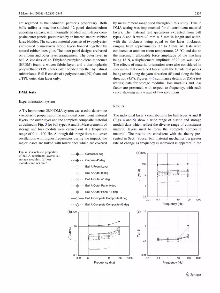
The individual layer’s contributions for ball types A and B
(Figs. 4 and 5) show a wide range of elastic and storage
moduli data which reflect the diverse range of constituent
material layers used to form the complete composite
material. The results are consistent with the theory pre-
sented in Sect. ‘Soccer ball material mechanics’: a greater
rate of change as frequency is increased is apparent in the
0.01
0.1
1
10
0.1
1
10
100
0.01 0.1 1 10 100 1000 0.01 0.1 1 10 100 1000
0.01 0.1 1 10 100 10000.1
1
10
100
1000Carcass 0 deg
Carcass 45 deg
Ball A Foam Layer
Ball A Outer 0 deg
Ball A Outer 45 deg
Ball A Outer Panel 0 deg
Ball A Outer Panel 45 deg
Ball A Complete Composite 0 deg
Ball A Complete Composite 45 deg
E’’ (
MP
a)
E’ (
MP
a)
Frequency (Hz)
Tan
δ
Frequency (Hz)
Frequency (Hz)
(a)
(b) (c)
Fig. 4 Viscoelastic properties
of ball A constituent layers: (a)
storage modulus, (b) loss
modulus and (c) tan d
J Mater Sci (2008) 43:2833–2843 2837
123

loss modulus when compared to the storage one. It was also
shown in Sect. ‘Soccer ball material mechanics’ that tan dincreases with frequency; this feature is confirmed for the
studied materials. It was found that the foam layer exhib-
ited higher levels of material damping (Fig. 5b) than the
other constituent layers, which is consistent with a notion
of foam materials being conventionally developed to have
good vibration isolation and damping characteristics.
From analysis of data for 0� in Figs. 4 and 5 it follows
that irrespective of the higher levels of damping associated
with the outer panel and foam layers, the complete com-
posite material demonstrates similar tan d to that of the
carcass material. This provides evidence that the carcass
layer when strained at 0� dominates the damping properties
of the entire composite material. A similar trend is
observed for the storage modulus for the carcass strained at
0�, which is significantly stiffer than all other constituent
materials. This indicates the significant effects of material
anisotropy to be significant, which was also found in a
previous study by Price [27]. It is also shown that the
complete composite material exhibits damping properties
that are different to that of the carcass strained at 45�,
indicating the effect of other constituent materials on the
deformation behaviour along the bias.
Figure 6 compares viscoelastic material data for the outer
panel material for both ball types and demonstrates that ball B
exhibits higher levels of material viscoelasticity than ball A.
The DMA study revealed that materials used for ball
construction behave in a viscoelastic manner, indicated by
variations of storage and loss moduli, and tan d with
0.01
0.1
1
10
0.1
1
10
100
0.01 0.1 1 10 100 1000 0.01 0.1 1 10 100 1000
0.01 0.1 1 10 100 10000.1
1
10
100
1000
E’’
(M
Pa)
Frequency (Hz)
Tan
δ
Frequency (Hz)
Frequency (Hz)
Carcass 0 deg
Carcass 45 deg
Ball B Foam Layer
Ball B Outer
Ball B Outer Panel
Ball B Complete Composite 0 deg
Ball B Complete Composite 45 deg
(c) (b)
(a)
E’ (
MP
a)
Fig. 5 Viscoelastic properties
of ball B constituent layers: (a)
storage modulus, (b) loss
modulus and (c) tan d
Ball B Outer Panel
Ball A Outer Panel 0 deg
Ball A Outer Panel 45 deg
0.01
0.1
1
0.01 0.1 1 10 100 1000
Tan
δ
Frequency (Hz)
Fig. 6 Damping properties of ball A and B outer panel materials
2838 J Mater Sci (2008) 43:2833–2843
123

frequency. The results have also revealed an anisotropic
viscous behaviour in the form of direction-dependent
material damping properties. The main finding of the DMA
testing indicates significantly higher levels of material
damping associated with the outer panel material in ball B,
when compared to ball A.
Implementation of DMA data into finite element
simulations
FE numerical simulations were implemented with the use
of the Abaqus EXPLICIT software package. Material vis-
coelasticity was introduced into the software by utilising
Eq. 4 and by using a dimensionless relaxation modulus
g(t), as opposed to G(t). This is carried out by the formation
of a Prony series by the software, which is based upon
exponential functions describing the stress relaxation
modulus g(t). Significantly easier integration of Eq. 4
allows for adequate definition of material viscoelasticity.
The software makes use of Fourier transform to allow
storage and loss moduli data to be converted into a Prony
series [28]. This is achieved by supplying real and imagi-
nary parts of the Fourier transform of the non-dimensional
shear relaxation function g*(x) alongside their respective
frequencies as follows:
Re½g�ðxÞ� ¼ G00=G1; ð7Þ
Im½g�ðx�Þ� ¼ 1� G0=G1; ð8Þ
where G? is the long-term shear modulus, which was
derived from the quasi-static tensile tests.
As all materials used in the ball are considered isotropic,
their Poison’s ratio m, shear and elastic moduli are related
by
G ¼ E
2ð1þ mÞ : ð9Þ
It follows that:
Re½g�ðxÞ� ¼ G00=G1 ¼ E00=E1; ð10Þ
Im½g�ðx�Þ� ¼ 1� G0=G1 ¼ 1� E0=E1; ð11Þ
Therefore the necessary data were derived from the
elastic modulus based DMA data. This in turn enabled the
formation of the Prony series and to characterise the
viscoelastic material properties of the soccer ball materials.
The DMA data were used to characterise the viscoelastic
material properties of three soccer ball FE models, as
shown in Fig. 7. Each model utilised linear-interpolation
composite shell elements to allow a through-thickness
composite structure of the panels to be sufficiently mod-
elled. This modelling methodology was in part adopted due
to the success seen in previous studies concerning com-
putational modelling of fabric materials, [29]–[32].
Pressurisation of each model was permitted through an
integral layer of hydrostatic fluid elements, which share the
nodes of the structural shell elements. The fluid elements
were coupled with a cavity reference node, which pos-
sessed a single degree of freedom to represent the pressure
of the cavity. A mass flow rate was applied to the cavity
reference node, which simulated the flow of a pneumatic
compressible fluid within the cavity, to represent the air
within the bladder and allow for pressurisation. The
pneumatic fluid behaves like an ideal gas as detailed in
Eq. 1 and allows the uniform increase in cavity pressure
throughout impact to be properly modelled. Based on
previous studies as detailed in Sect. ‘Kinetic energy loss’
the air was assumed to act as a spring with minimal
damping, and the effects of outer panel materials were
considered to be more significant. FE model 1 is a basic
Fig. 7 (a) FE model 1 and (b)
FE models 2 and 3
J Mater Sci (2008) 43:2833–2843 2839
123

model of the ball type A with the ball structure based on an
icosahedron allowing for a uniform arrangement of trian-
gular shell elements to be adopted. FE models 2 and 3 are
advanced FE models of ball types A and B and include an
accurate representation of the respective outer panel
designs as detailed in Fig. 7.
The material stiffness characteristics of ball types A and
B were determined through a series of quasi-static uniaxial
tensile tests using a standard tensile test machine. These
were performed on dumbbell specimens of the constituent
layers, outer panels and complete composite material lay-
ers conforming to BS 903 Part A2 [33]. A hyperelastic
reduced polynomial strain energy potential equation was
calibrated against the material data, through a least squares
fit procedure. This procedure was carried out by the FE
software and allowed for the characterisation of the ball
materials.
FE model validation
A series of impact tests were carried out on ball types A
and B to enable FE model validation. Each impact was
carried out using a bespoke 2-wheel ball launch device,
which introduced the ball between two counter-rotating
rollers launching it at the required velocity onto a steel
plate 2 m away. These tests included impacting five balls
of each type, five impacts for each ball along the direction
orthogonal to the plane of the steel plate which acted as a
target. Impacts occurred at inbound velocities of 9 (rep-
resentative of a standard drop test), 14, 22 and 32 ms-1.
Ball motion and impact were recorded using a Photron
Fastcam—Ultima APX 120 K HSV camera operating at
10,000 frames per second, which was remotely triggered
to initiate the storage of images into a microprocessor
linked to a laptop through a firewire connection. Each
audio video interleave (AVI) file was imported into Image
Pro Plus (IPP), a 2D image analysis software package,
which allowed for the determination of impact contact
time, longitudinal and tangential deformation, velocity
and COR.
Implementation of FE ball models
The DMA data for the bladder and complete composite
material were used to characterise material properties for
FE model 1, the basic FE model for ball type A. In
numerical simulations the ball model was impacted against
a rigid surface that was constrained with regard to all
degrees of freedom. Numerical simulations were per-
formed for four levels of the inbound speed, used in
experiments. Figure 8 provides data for COR, deformation
and contact time.
4
5
6
7
8
9
0 5 10 15 20 25 30 35
0
10
20
30
40
50
60
70
80
0 5 10 15 20 25 30 350.5
0.6
0.7
0.8
0.9
1
0 5 10 15 20 25 30 35
Ball A FE model 1
(a)
(b)
(c)
RO
C
)m
m(noi ta
mrof eDla nidut ig no L
)sm(
emi
TtcatnoC
Inbound Velocity (m/s)
Inbound Velocity (m/s)
Inbound Velocity (m/s)
Fig. 8 Impact data for ball type
A—experiment results and
numerical simulation data for
model 1: (a) COR, (b) contact
time, (c) longitudinal
deformation
2840 J Mater Sci (2008) 43:2833–2843
123

The agreement reached between experimental and
model COR data as featured in Fig. 8a is within 2% of
experimental averages. It should also be noted that the
hyperelastic material model used to define the elastic
response in FE model 1 was based upon tensile testing
carried out at low deformation rates (1,000 mm/min).
However agreement is also apparent between the experi-
mental and numerical results for the contact time and
deformation as detailed in Fig. 8b and c. This indicates that
the viscoelastic material model includes the effects of
strain-rate sensitivity—as detailed in Sect. ‘Theory of lin-
ear viscoelasticity’—that for a given material results in a
stiffer response at high strain rates. The viscoelastic
material model accounts for these effects by formulating
the material response based on the experimental data on the
increase of the storage modulus with frequency presented
in Sect. ‘DMA tests’.
DMA data for the bladder, carcass and respective outer
panels for ball types A and B were used to define the
viscoelastic behaviour of FE ball models 2 and 3. In sim-
ulations each ball model was impacted against a rigid
surface at the four prescribed velocities.
As shown in Fig. 9a there are clear differences in both
the levels of COR, and the relationship between COR and
inbound velocity between both ball types. Ball type A
gives higher levels of COR, indicating lower levels of
kinetic energy loss throughout impact, when compared to
ball type B. The COR data detailed in Fig. 9a give agree-
ment between FE model 2 and the averaged experimental
results for ball type A to be within 1.2% for ball type B it is
within 3%. The developed viscoelastic FE models predict
COR levels as a function of the disparate material damping
properties of both ball types, with good agreement with
experimental data. The difference in the decline of COR
with the inbound velocity for two balls is reproduced by the
models. This indicates the importance of the outer panel
material used within the new generation ball types as a
principal energy loss mechanism.
Figure 9b and c give details of dependences of contact
time and longitudinal deformation on the impact velocity
and reveals differences between both ball types. Ball type A
is characterised by lower contact times, and lower levels of
deformation than ball type B indicating a stiffer response.
These trends are properly reflected by the models; however
there is a slight underestimation of the contact time for FE
model 2 and ball type A resulting in a 10% difference
between model and experimental results. Figure 10 vividly
demonstrates that FE simulations adequately reproduce
deformation processes for ball type B during it interaction
with the target observed in experiments.
Figure 11 gives details of stress levels developed within
the outer panels of FE model 3 which is compared against
an earlier version of the model that incorporated a
b-damping co-efficient. The viscoelastic version of FE
model 3 exhibits greater levels of outer panel stress for the
same inbound velocity. This can be linked to the strain—
rate sensitivity in the material model (see Sect. ‘Theory of
linear viscoelasticity’). The FE models of soccer balls
developed in this study were found to adequately replicate
the deformation and kinetic energy loss characteristics
exhibited by thermoformed ball designs used in elite
competition.
Ball A FE Model 2 Ball B FE Model 3
4
5
6
7
8
9
10
11
)sm(
emi
TtcatnoC
Inbound Velocity (m/s)
0.6
0.65
0.7
0.75
0.8
0.85
0.9
Inbound Velocity (m/s)
RO
C
0
10
20
30
40
50
60
70
80
90
0 5 10 15 20 25 30 35
0 5 10 15 20 25 30 35
0 5 10 15 20 25 30 35
)m
m(noita
mrofeDlanidutignoL
Inbound Velocity (m/s)
(a)
(b)
(c)
Fig. 9 Experimental and numerical results following: impacts of ball
types A and B. (a) COR, (b) contact time and (c) longitudinal
deformation
J Mater Sci (2008) 43:2833–2843 2841
123

Conclusions
This paper demonstrates that DMA tests on constituent
materials can produce data to characterise material visco-
elasticity of the composite balls and, hence, to enable
accurate estimation of the kinetic energy loss exhibited by
soccer balls under impact loading. This has been demon-
strated for a range of FE models based on direct
introduction of several material layers. Experimental
results demonstrated a wide range of damping properties of
layers with high levels of damping for foam materials when
compared to the other constituent layers. This study also
revealed anisotropic material viscoelasticity, with greater
levels of damping found in testing fabric-based materials
along the material bias, as compared to along their yarn
directions.
The use of viscoelastic material data obtained with
DMA has revealed the relationship between viscoelasticity
of the outer panel material and COR magnitudes charac-
teristics, and has allowed the model to differentiate
between outer panels that have high tan d levels and,
subsequently, low COR magnitudes (i.e. ball type A). This
study has indicated COR to be strongly influenced by
material damping and has presented an experimental means
of its quantification. It has been shown that the use of DMA
data accounts for the effects of strain-rate sensitivity by
including the storage modulus data, which were experi-
mentally found to increase with frequency. This study has
provided a framework to estimate the kinetic energy loss
linked with material viscoelasticity making a basis for an
improved understanding of the dynamic properties of
soccer balls.
Acknowledgements The authors would like to acknowledge
EPSRC, adidas and Abaqus for their support for this project.
References
1. Treloar LG (1949) The physics of rubber elasticity. Oxford
University Press, London
2. Baumann JT (1998) A theory of the elastomer stress–strain curve,
In: Proceedings of the meeting of the rubber Division American
Chemical Society, Nashville, Tennessee, September 1998, p 1
3. Brody H (1990) Phys Teach 28:407
4. Adair RK (1994) The physics of baseball. Harper Collins, New
York
5. Armstrong CW, Levendusky TA, Eck JS, Spyropoulos P, Kugler
L (1988) Influence of inflation pressure and ball wetness on the
impact characteristics of two types of soccer ball, science and
football: Proceedings of the first World Congress of Science and
Football. In: Reilly T (ed) E & FN Spon, London, p 394
6. Bridge NJ (1998) Phys Educ 33(3):174
Fig. 10 Impact data for ball B
and respective FE model at the
moment of maximum
longitudinal contraction
Fig. 11 Effect of strain-rate sensitivity on stresses in outer panel (a)
viscoelastic FE model 3 (b) artificially damped FE model 3
2842 J Mater Sci (2008) 43:2833–2843
123

7. Hubbard M, Stronge WJ (2001) Sports Eng 4:49
8. Holmes G, Bell MJ (1985) J Sports Turf Res Inst 61:32
9. Bayman BF (1976) Am J Phys 44(7):671
10. Bridge NJ (1998) Phys Educ 33(4):236
11. Falcon E, Laroche C, Fauve S, Coste C (1998) Eur Phys J B 3:45
12. Hendee SP, Greenwald RM, Crisco JJ (1998) J Appl Biomech
14:390
13. Calvit HH (1967) Int J Solids Struct 3:951
14. Asai T, Carre MJ, Akatsuka T, Haake SJ (2002) Sports Eng 5:183
15. Hocknell A (1998) Computational and experimental analysis of
elastic deformation in impact. PhD Thesis, Loughborough Uni-
versity, Loughborough, UK
16. Mase T, Kersten AM (2004) Experimental evaluation of a 3-D
hyperelastic rate dependant golf ball constitutive model. In:
Hubbard M, Mehta RD, Pallis JM (eds) The engineering of sport
5, vol 2, p 238
17. Cordingley L (2002) Advanced modelling of hollow sports ball
impacts. PhD Thesis, Loughborough University, Loughborough,
UK
18. Abaqus (2003) Abaqus Version 6.4 users manual volume I:
introduction, spatial modelling, execution and output. Abaqus
INC
19. Amada S, Lakes RS (1997) J Mater Sci 32:2693
20. Ferry JD (1980) Viscoelastic properties of polymers. John Wiley
and Sons, Chichester
21. Mark JE, Erman B, Eirich FR (1994) Science and technology of
rubber. Academic Press, London
22. Oyadiji SO (2004) How to analyse the static and dynamic
response of viscoelastic components. NAFEMS, Bireniehill,
Glasgow
23. Wojtowicki JL, Jaouen L, Panneton R (2004) Rev Sci Instrum
75(8):2569
24. Deverge M, Jaouen L (2004) A review of experimental methods
for the elastic and damping characteristics of acoustical porous
materials, Proceedings of the 33rd international congress and
exposition on noise control engineering (inter-noise 2004), Pra-
gue, Czech Republic, August 2004, p 1 [CD-ROM]
25. Lagakos N, Jarzynski J, Cole JH, Bucaro JA (1986) J Appl Phys
59(12):4017
26. Read BE, Dean GD (1978) The determination of dynamic
properties of polymers and composites. Adam Hilger Ltd., Bristol
27. Price DS, Harland AR, Jones R (2006) Mater Sci Eng A 420:100
28. Abaqus (2003) Abaqus version 6.4 users manual vol III: mate-
rials. Abaqus INC
29. Xue P, Xiongqi P, Cao J (2003) Compos Pt A Appl Sci Manuf
34:183
30. Dong L, Lekakou C, Bader MG (2000) Compos Pt A Appl Sci
Manuf 31:639
31. Cavallaro PV, Johnson EJ, Sadegh AM (2003) Compos Struct
61:375
32. Tan P, Tong L, Steven GP (1997) Compos Pt A Appl Sci Manuf
28A:903
33. BS 903-A2 (1995) Physical testing of rubber—part A2: methods
for determining tensile stress–strain properties
J Mater Sci (2008) 43:2833–2843 2843
123