Embed Size (px)
Citation preview

fluid sensors and diagnostic
systems
bus, identification
and control systems
position sensors
and objectrecognitionw
ww
.ifm
.co
m
Innovations 2012
2
*Some offered information is available country-specific.
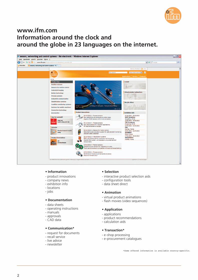
www.ifm.comInformation around the clock andaround the globe in 23 languages on the internet.
• Information- product innovations- company news- exhibition info- locations- jobs
• Documentation- data sheets- operating instructions- manuals- approvals- CAD data
• Communication*- request for documents- recall service- live advice- newsletter
• Selection- interactive product selection aids- configuration tools- data sheet direct
• Animation- virtual product animations- flash movies (video sequences)
• Application- applications- product recommendations- calculation aids
• Transaction*- e-shop processing- e-procurement catalogues
3
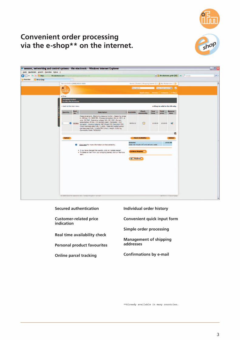
Convenient order processingvia the e-shop** on the internet.
Secured authentication
Customer-related priceindication
Real time availability check
Personal product favourites
Online parcel tracking
Individual order history
Convenient quick input form
Simple order processing
Management of shippingaddresses
Confirmations by e-mail
**Already available in many countries.
4
Position sensors andobject recognition
... maximum protection in hazardous areas
... safe detection of metal
Inductive sensors
Magnetic sensors, cylinder sensors
... now in full-metal housing
Touch sensors
... capacitive touch sensors for installation on walls
... PMD distance sensor O1D now insensitive to extraneous light
... OG-Cube as AC version
Photoelectric sensors
Flow sensors
... measurement of liquids up to 180 °C
... space-saving ATEX control monitor with wire-break alarm
... compressed air meter with display and totalizer function
... modular flow monitoring for field applications
... temperature transmitter with 4...20 mA and IO-Link 1.1
... for fast temperature changes
... hygienic Pt100 sensors with 4-wire connection
... head transmitter – the past; temperature plug – the future
Temperature sensors
... PN7 pressure sensor with communication interface IO-Link 1.1
... 2-wire pressure sensor, display, parameter setting via IO-Link
Pressure sensors
Fluid sensorsand diagnostic systems
... new level sensor, ignores foam and build up
... improved performance, now also with IO-Link
... diagnostic system: oil moisture and temperature sensor
Level sensors
Object recognition
... the vision sensor – optical object inspection
... fast diagnostic electronics detects machine crash
Diagnostic systems
6 - 7
8 - 9
10 - 11
12 - 13
14 - 15
16 - 17
26 - 27
28 - 29
30 - 31
32 - 33
38 - 39
40 - 41
42 - 43
44 - 45
(04.2012)
(11.2011)
34 - 35
36 - 37
20 - 21
22 - 23
24 - 25
18 - 19
(11.2011)
(04.2012)
(04.2012)
(04.2012)
(04.2012)
(04.2012)
(11.2011)
(11.2011)
(04.2012)
(11.2011)
(11.2011)
(11.2011)
(04.2012)
(04.2012)
(11.2011)
(04.2012)
(11.2011) 46 - 47
(04.2012)
(11.2011)
5
... AS-i gateways with ultra short transfer times
... AS-i safety made easy
Bus system AS-Interface
... standstill safely detected
Evaluation systems
Bus systems
... RFID with Profibus-DP
RF-identification systems
... dialogue module PMD360 NG for mobile vehicles
Control systems for mobile vehicles
Identification systems
Control systems
For further technical data please go to: www.ifm.com
Evaluation systems,power supplies
Connection technology Connection technology
... Y connection cable M12 for hygienic and wet areas
... Y connection cable M12 for factory automation
48 - 49
58 - 59
60 - 61
(04.2012)
(11.2011)
(11.2011)
(11.2011)
(04.2012)
(04.2012)
(04.2012)
50 - 51
52 - 53
54 - 55
56 - 57

6
Inductive sensors for ATEX 3D(zone 22) and 3G (zone 2).
EU-wide explosion protectionThe ATEX directive 94/9/EC (ATEX) sets out detailed rulesfor explosion prevention.This sensor family passed a very demanding test series ofartificial ageing, 4 joules impact test and subsequentprotection rating test. The result: the sensor housings aredesigned to ensure that, even in the toughest conditionsthey will not become an ignition source in explosive dustsor gaseous atmospheres. This guarantees maximum pro-tection in hazardous areas.
Only safe with the matching connectionifm ecolink series connectors also comply with the strictrequirements of the standard and are therefore allowedfor use in hazardous areas of the categories 2D, 3D and3G.
product news
The 4 joules impact test guarantees highmechanical stability of the housing.
Full metal sensors as threaded M12, M18and M30 types.
M12 connector ecolink for ATEXcategories 2D / 3D / 3G.
High vibration and shock resistance.
Maximum protection inhazardous areas.
Posi
tio
n s
enso
rs a
nd
ob
ject
rec
og
nit
ion
bus,identification
and control systems
fluid sensors and diagnostic
systems
position sensors
and objectrecognition
7
04.2012
Type Sensingrange[mm]
Ambienttemperature
[°C]
f
[Hz]
CategoryHousing material Orderno.
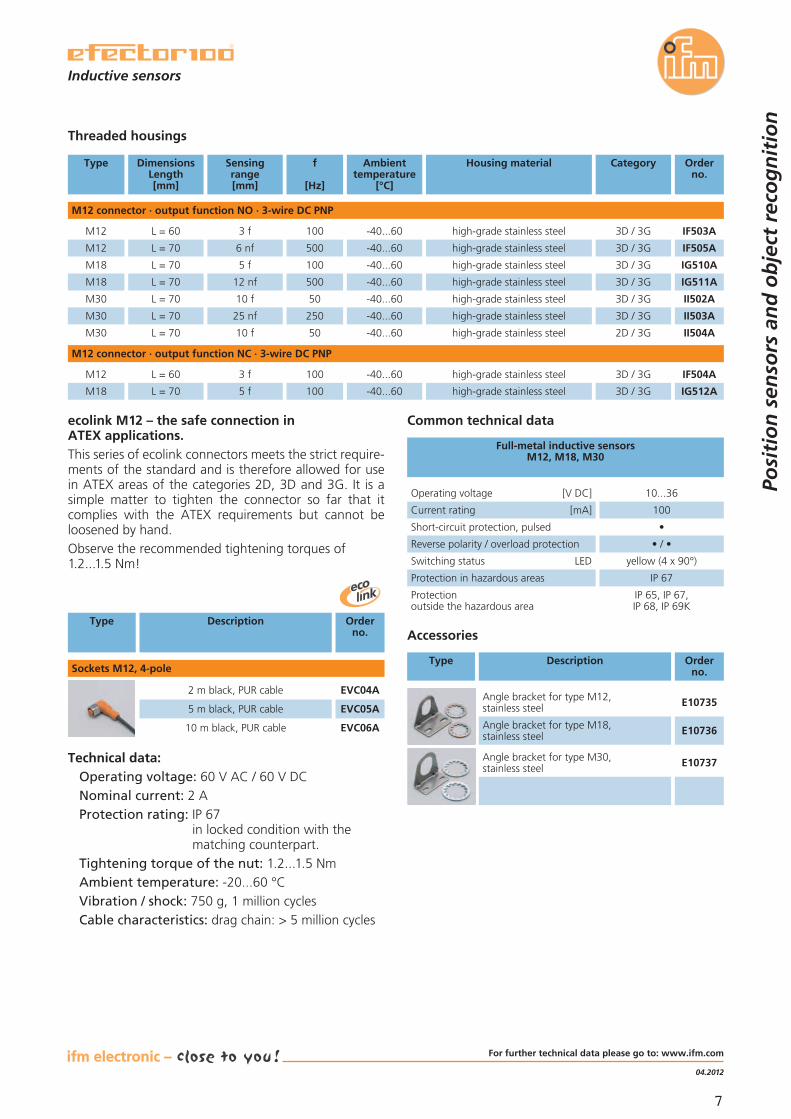
M12 connector · output function NO · 3-wire DC PNP
M12 3 f -40...60100 3D / 3Ghigh-grade stainless steel IF503A
M12
DimensionsLength[mm]
L = 60
L = 70 6 nf -40...60500 3D / 3Ghigh-grade stainless steel IF505A
M18 L = 70 5 f -40...60100 3D / 3Ghigh-grade stainless steel IG510A
M18 L = 70 12 nf -40...60500 3D / 3Ghigh-grade stainless steel IG511A
M30 L = 70 10 f -40...6050 3D / 3Ghigh-grade stainless steel II502A
M30 L = 70 25 nf -40...60250 3D / 3Ghigh-grade stainless steel II503A
Threaded housings
M12 connector · output function NC · 3-wire DC PNP
M12 3 f -40...60100 3D / 3Ghigh-grade stainless steel IF504A
M18
L = 60
L = 70 5 f -40...60100 3D / 3Ghigh-grade stainless steel IG512A
M30 10 f -40...6050 2D / 3Ghigh-grade stainless steel II504AL = 70
Operating voltage [V DC] 10...36
Current rating [mA] 100
Short-circuit protection, pulsed •
Reverse polarity / overload protection • / •
Switching status LED yellow (4 x 90°)
Protection in hazardous areas IP 67
Protectionoutside the hazardous area
IP 65, IP 67,IP 68, IP 69K
Full-metal inductive sensorsM12, M18, M30
Common technical data
Type Description Orderno.
Accessories
Angle bracket for type M30,stainless steel E10737
Angle bracket for type M12,stainless steel E10735
Angle bracket for type M18,stainless steel E10736
Technical data:Operating voltage: 60 V AC / 60 V DCNominal current: 2 AProtection rating: IP 67
in locked condition with thematching counterpart.
Tightening torque of the nut: 1.2...1.5 NmAmbient temperature: -20...60 °CVibration / shock: 750 g, 1 million cyclesCable characteristics: drag chain: > 5 million cycles
Type Description Orderno.
2 m black, PUR cable EVC04A
5 m black, PUR cable EVC05A
10 m black, PUR cable EVC06A
Sockets M12, 4-pole
ecolink M12 – the safe connection inATEX applications.This series of ecolink connectors meets the strict require-ments of the standard and is therefore allowed for usein ATEX areas of the categories 2D, 3D and 3G. It is asimple matter to tighten the connector so far that itcomplies with the ATEX requirements but cannot beloosened by hand.Observe the recommended tightening torques of1.2...1.5 Nm!
Inductive sensors
Posi
tio
n s
enso
rs a
nd
ob
ject
rec
og
nit
ion
For further technical data please go to: www.ifm.com

8
Safe state is reached whendamped.
ApplicationsThe safety function of the sensor allows the user to solvesome applications easier than before. If there is no metal inthe sensor field, the outputs are enabled. If there is metalin the sensor field, the outputs are safely switched off.
Example crane bridge monitoringA fail-safe sensor monitors the position of the crane onthe rail. So far the sensor was damped across the wholetravel; the sensor was undamped only at the stop posi-tions. This new fail-safe sensor allows mounting of onlyone damping element each at the beginning and theend of the crane bridge which saves material and moun-ting cost.
Fail-safe inductive sensor withoutmagnetic or coded target.
2 OSSD outputs for connection to a safetyrelay or safety PLC.
Diagnosis of different operating statesvia LED indication.
Easy integration in the machine due toflush mounting.
Certified to ISO 13849-1 PL d,IEC 61508 SIL 2 and IEC 62061 SIL cl2.
Safe detection of metal.
Posi
tio
n s
enso
rs a
nd
ob
ject
rec
og
nit
ion
bus,identification
and control systems
fluid sensors and diagnostic
systems
position sensors
and objectrecognition
product news
9
11.2011
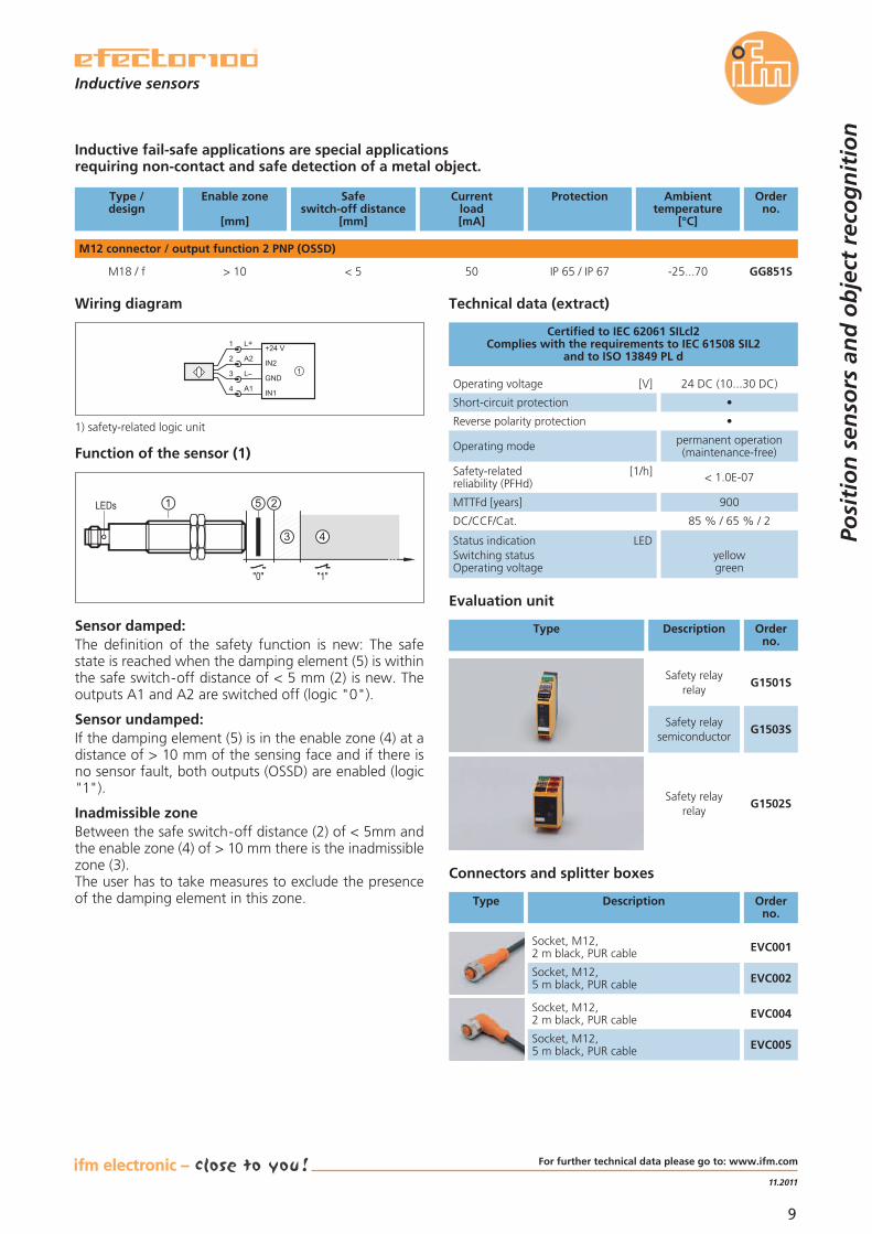
Technical data (extract)
Operating voltage [V] 24 DC (10...30 DC)
Short-circuit protection •
Reverse polarity protection •
Operating mode permanent operation(maintenance-free)
Safety-related [1/h]reliability (PFHd) < 1.0E-07
Status indication LEDSwitching statusOperating voltage
yellowgreen
Certified to IEC 62061 SILcl2Complies with the requirements to IEC 61508 SIL2
and to ISO 13849 PL d
Inductive fail-safe applications are special applicationsrequiring non-contact and safe detection of a metal object.
M12 connector / output function 2 PNP (OSSD)
Type /design
Enable zone
[mm]
ProtectionCurrentload[mA]
Safeswitch-off distance
[mm]
Ambienttemperature
[°C]
Orderno.
M18 / f 50> 10 GG851SIP 65 / IP 67< 5 -25...70
Connectors and splitter boxes
Type Description Orderno.
Socket, M12,2 m black, PUR cable EVC001
Socket, M12,5 m black, PUR cable EVC002
Socket, M12,2 m black, PUR cable EVC004
Socket, M12,5 m black, PUR cable EVC005
Sensor damped:The definition of the safety function is new: The safestate is reached when the damping element (5) is withinthe safe switch-off distance of < 5 mm (2) is new. Theoutputs A1 and A2 are switched off (logic "0").
Sensor undamped:If the damping element (5) is in the enable zone (4) at adistance of > 10 mm of the sensing face and if there isno sensor fault, both outputs (OSSD) are enabled (logic"1").
Inadmissible zoneBetween the safe switch-off distance (2) of < 5mm andthe enable zone (4) of > 10 mm there is the inadmissiblezone (3).The user has to take measures to exclude the presenceof the damping element in this zone.
Evaluation unit
Type Description Orderno.
G1501SSafety relay
relay
G1503SSafety relay
semiconductor
G1502SSafety relay
relay
3
1
4
2
L+
L
A1
A2+24 V
IN2
GND
IN1
1
Wiring diagram
1) safety-related logic unit
"0"
LEDs
"1"
21
3 4
5
Function of the sensor (1)
MTTFd [years] 900
DC/CCF/Cat. 85 % / 65 % / 2
Inductive sensors
Posi
tio
n s
enso
rs a
nd
ob
ject
rec
og
nit
ion
For further technical data please go to: www.ifm.com
10
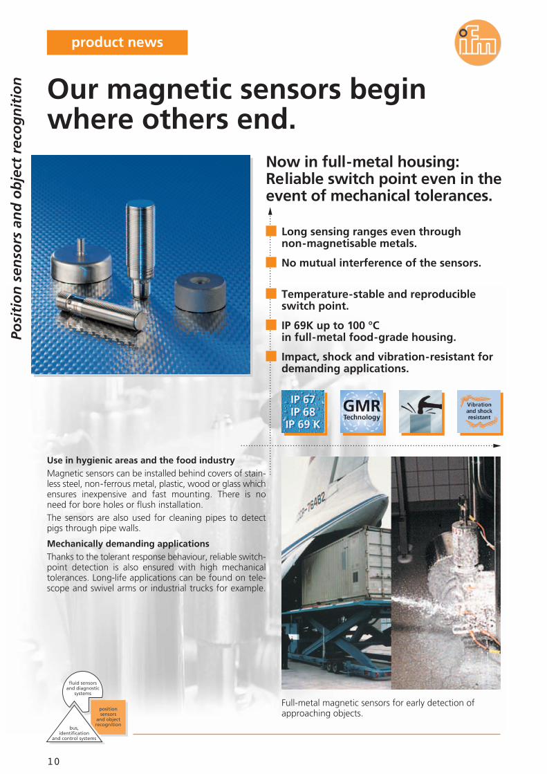
Now in full-metal housing:Reliable switch point even in theevent of mechanical tolerances.
Full-metal magnetic sensors for early detection ofapproaching objects.
Use in hygienic areas and the food industryMagnetic sensors can be installed behind covers of stain-less steel, non-ferrous metal, plastic, wood or glass whichensures inexpensive and fast mounting. There is noneed for bore holes or flush installation.The sensors are also used for cleaning pipes to detectpigs through pipe walls.
Mechanically demanding applicationsThanks to the tolerant response behaviour, reliable switch-point detection is also ensured with high mechanicaltolerances. Long-life applications can be found on tele-scope and swivel arms or industrial trucks for example.
Long sensing ranges even throughnon-magnetisable metals.
No mutual interference of the sensors.
Temperature-stable and reproducibleswitch point.
IP 69K up to 100 °Cin full-metal food-grade housing.
Impact, shock and vibration-resistant fordemanding applications.
Our magnetic sensors beginwhere others end.
Posi
tio
n s
enso
rs a
nd
ob
ject
rec
og
nit
ion
bus,identification
and control systems
fluid sensors and diagnostic
systems
position sensors
and objectrecognition
product news
11
11.2011
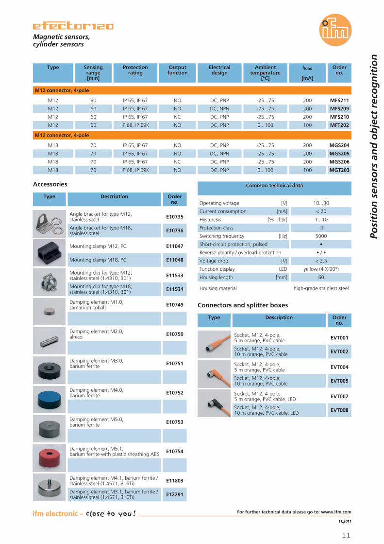
Type Protectionrating
Electricaldesign
Iload
[mA]
Ambienttemperature
[°C]
Orderno.
M12 connector, 4-pole
M12
Sensingrange[mm]
60 IP 65, IP 67 DC, PNP 200-25...75 MFS211
Outputfunction
NO
M12 60 IP 65, IP 67 DC, NPN 200-25...75 MFS209NO
M12 60 IP 65, IP 67 DC, PNP 200-25...75 MFS210NC
M12 60 IP 68, IP 69K DC, PNP 1000...100 MFT202NO
M12 connector, 4-pole
M18 70 IP 65, IP 67 DC, PNP 200-25...75 MGS204NO
M18 70 IP 65, IP 67 DC, NPN 200-25...75 MGS205NO
M18 70 IP 65, IP 67 DC, PNP 200-25...75 MGS206NC
M18 70 IP 68, IP 69K DC, PNP 1000...100 MGT203NO
Operating voltage [V] 10...30
Current consumption [mA] < 20
Protection class III
Switching frequency [Hz] 5000
Short-circuit protection, pulsed •
Reverse polarity / overload protection • / •
Voltage drop [V] < 2.5
Function display LED yellow (4 X 90°)
Housing length [mm] 60
Housing material high-grade stainless steel
Hysteresis [% of Sr] 1...10
Common technical dataAccessories
Type Description Orderno.
Mounting clip for type M12,stainless steel (1.4310, 301) E11533
Mounting clip for type M18,stainless steel (1.4310, 301) E11534
Damping element M1.0,samarium cobalt E10749
Damping element M2.0,alnico E10750
Damping element M3.0,barium ferrite E10751
Damping element M4.0,barium ferrite E10752
Damping element M5.0,barium ferrite E10753
Damping element M5.1,barium ferrite with plastic sheathing ABS E10754
Damping element M4.1, barium ferrite /stainless steel (1.4571, 316Ti) E11803
Damping element M3.1, barium ferrite /stainless steel (1.4571, 316Ti) E12291
Connectors and splitter boxes
Type Description Orderno.
Socket, M12, 4-pole,5 m orange, PVC cable EVT001
Socket, M12, 4-pole,10 m orange, PVC cable EVT002
Socket, M12, 4-pole,5 m orange, PVC cable EVT004
Socket, M12, 4-pole,10 m orange, PVC cable EVT005
Socket, M12, 4-pole,5 m orange, PVC cable, LED EVT007
Socket, M12, 4-pole,10 m orange, PVC cable, LED EVT008
Angle bracket for type M12,stainless steel E10735
Angle bracket for type M18,stainless steel E10736
Mounting clamp M12, PC E11047
Mounting clamp M18, PC E11048
Magnetic sensors,cylinder sensors
Posi
tio
n s
enso
rs a
nd
ob
ject
rec
og
nit
ion
For further technical data please go to: www.ifm.com
12
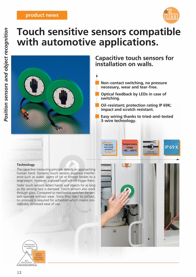
Capacitive touch sensors forinstallation on walls.
TechnologyThe capacitive measuring principle detects an approachinghuman hand. Dynamic touch sensors suppress interfer-ence such as water, layers of ice or foreign bodies to alarge extent. However, a gloved hand will still trigger them.Static touch sensors detect hands and objects for as longas the sensing face is damped. Touch sensors also workthrough glass. Compared to mechanical switches the sen-sors operate without wear. Since they react to contact,no pressure is required for activation which means con-siderably increased ease of use.
Non-contact switching, no pressurenecessary, wear and tear-free.
Optical feedback by LEDs in case ofswitching.
Oil-resistant; protection rating IP 69K;impact and scratch resistant.
Easy wiring thanks to tried-and-tested3-wire technology.
Touch sensitive sensors compatiblewith automotive applications.
Posi
tio
n s
enso
rs a
nd
ob
ject
rec
og
nit
ion
bus,identification
and control systems
fluid sensors and diagnostic
systems
position sensors
and objectrecognition
product news

13
04.2012
Operating voltage [V DC] 24 (12...36)
Current rating [mA] 500
Current consumption [mA] 30
Ambient temperature [°C] -40...85
Protection (front) IP 69K
Common technical data
Touch sensors
Connectors and splitter boxes
Type Description Orderno.
M8 socket,2 m black, PUR cable EVC150
M8 socket,5 m black, PUR cable EVC151
M8 socket,2 m black, PUR cable EVC153
M8 socket,5 m black, PUR cable EVC154
Other symbols as well as colours of the outer ring on request.
The products
Description Orderno.
Touch sensor, mounting on the wall,2 m PUR cable KT5001
Touch sensor, mounting on the wall,0.3 m PUR cable with M8 plug KT5002
Dimensions
10060,2 10
60°
38
120°
4,3
Mounting optionsThree common M4 cylinder head bolts or tappingscrews of Ø 3.9 mm diameter are required to mountthe sensor on a wall.LEDs as optical feedback signal that the sensor has beenactivated.
ApplicationsIndustry: Here, sensors are used as start / stop buttonson machines.Mobile applications: The sensors can be used as buttonson mobile vehicles and trailers. Furthermore they canbe used as stop buttons or door openers. Designs forhandicapped people with Braille are possible.
Type
Applications:Mobile area such as a start /stop button on mobile vehicles and semi-trailers,industrial applications.
Posi
tio
n s
enso
rs a
nd
ob
ject
rec
og
nit
ion
Dynamic evaluation principle · DC PNP
Touch sensor, mounting on the wall,0.3 m PUR cable with M8 plug KT5007
Dynamic evaluation principle · DC NPN
Touch sensor, mounting on the wall,2 m PUR cable KT5005
Touch sensor, mounting on the wall,0.3 m PUR cable with M8 plug KT5006
Static evaluation principle · DC PNP
For further technical data please go to: www.ifm.com

14
Object detection of gear parts
No interference caused by extraneous lightThe new generation of the popular O1D sensors with theinnovative on-chip time-of-flight measurement systembased on PMD technology (Photonic Mixer Device) oper-ates reliably with extraneous light of up to 100,000 lux.This exceeds the values of standard optical sensors manytimes over and corresponds to the light conditions on abright summer day with direct sunlight.These sensors can be used in workshops where daylighthits the sensor or target from above. Even reflectiveobjects such as metal surfaces are reliably detected orreflective strips on high-vis vests reliably suppressed.
PMD distance sensors O1Dnow insensitive to extraneouslight up to 100,000 lux.
Optical distance detection with a range ofup to 10 m.
2 switching outputs; one output can beconfigured as analogue output.
Scalable detection range andwindow function.
Can be used in applications needingbackground suppression.
Extensive range of fixing components.
Optical distance sensors withsun protection factor.
Posi
tio
n s
enso
rs a
nd
ob
ject
rec
og
nit
ion
bus,identification
and control systems
fluid sensors and diagnostic
systems
position sensors
and objectrecognition
product news
15
04.2012
Further technical data
TypeO1D
Accessories
Type Description Orderno.
Mounting set for clamp mounting,Ø 12 mm / stainless steel E2D101
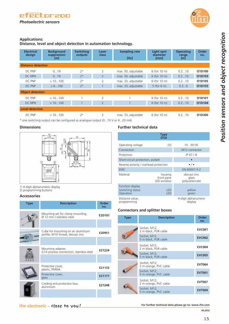
Applications:Distance, level and object detection in automation technology.
Distance detection
Electricaldesign
Backgroundsuppression
[m]
Switchingoutputs
Laserclass
Sampling rate
[Hz]
Light spotdiameter
[mm]
Operatingrange
[m]
Orderno.
DC PNP 0...19 2* 2 max. 50, adjustable 6 (for 10 m) 0.2...10 O1D100
DC NPN 0...19 2* 2 max. 50, adjustable 6 (for 10 m) 0.2...10 O1D103
DC PNP > 10...100 2* 2 max. 33, adjustable 6 (for 10 m) 0.2...10 O1D105
DC PNP > 6...100 2* 1 max. 33, adjustable 5 (for 6 m) 0.3...6 O1D155
Operating voltage [V] 10...30 DC
Connection M12 connector
Protection IP 67 / III
Short-circuit protection, pulsed •
Reverse polarity / overload protection • / •
EMC EN 60947-5-2
Material housingfront pane
LED window
diecast zincglass
polycarbonate
Function displaySwitching status LEDOperation LED
yellowgreen
Distance value,programming
4-digit alphanumericdisplay
52
1 2
30
45
2520
4,5
6
4559
42
M12x1
30
Dimensions
1) 4-digit alphanumeric display2) programming buttons
Connectors and splitter boxes
Type Description Orderno.
Socket, M12,2 m black, PUR cable EVC001
Socket, M12,5 m black, PUR cable EVC002
Socket, M12,2 m black, PUR cable EVC004
Socket, M12,5 m black, PUR cable EVC005
Cube for mounting on an aluminiumprofile, M10 thread, diecast zinc E20951
Mounting adapter,G1A process connection, stainless steel E21224
Protective cover,plastic, PMMA E21133
Protective cover,glass E21171
Cooling and protection box,aluminium E21248
Socket, M12,2 m orange, PVC cable EVT064
Socket, M12,5 m orange, PVC cable EVT001
Socket, M12,2 m orange, PVC cable EVT067
Socket, M12,5 m orange, PVC cable EVT004
Object detection
DC PNP > 10...100 1 2 1 6 (for 10 m) 0.2...10 O1D101
DC NPN > 10...100 1 2 1 6 (for 10 m) 0.2...10 O1D104
Level detection
DC PNP > 10...100 2* 2 max. 33, adjustable 6 (for 10 m) 0.2...10 O1D300
* one switching output can be configured as analogue output (0...10 V or 4...20 mA)
Photoelectric sensors
Posi
tio
n s
enso
rs a
nd
ob
ject
rec
og
nit
ion
For further technical data please go to: www.ifm.com

16
2-wire photoelectric sensorin metal housing with M18thread.
New version in 2-wire ACThe newly developed 2-wire output stage with a leakagecurrent of only 1.7 mA allows for the sensor also to beused in alternating current networks.
Robust metal housingThis sensor is optimised for use in harsh industrial environ-ments. The powerful technology together with the smallhousing design provides more flexibility for machine build-ing.
High optical performanceThanks to the minimal drift when detecting light or darkobjects, the sensor achieves long ranges as well as a verygood repeatability.
Voltage supply 20...250 V AC in2-wire technology.
Small, compact and robust:a high performance sensor.
Through-beam, retro-reflective and diffusereflection sensors (background suppression).
Fixed ranges for quick set-up.
Universal mounting and large selection offixing accessories.
OG-Cube as AC version.
Posi
tio
n s
enso
rs a
nd
ob
ject
rec
og
nit
ion
bus,identification
and control systems
fluid sensors and diagnostic
systems
position sensors
and objectrecognition
product news
17
04.2012
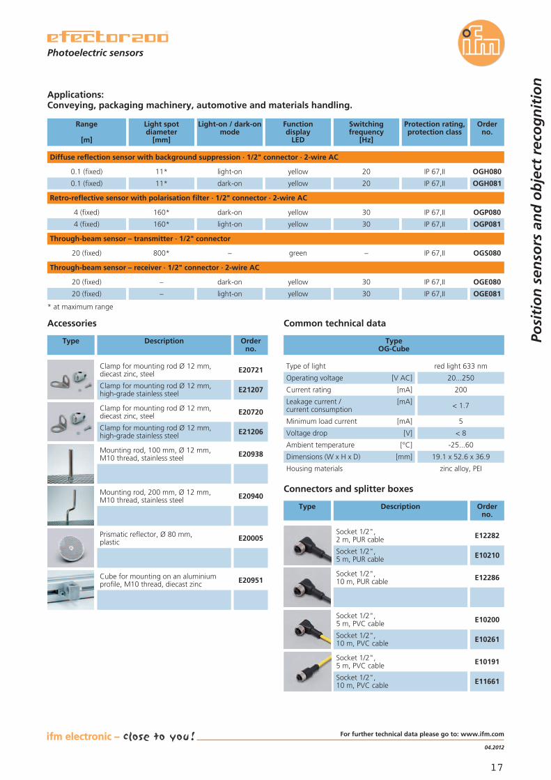
Applications:Conveying, packaging machinery, automotive and materials handling.
Diffuse reflection sensor with background suppression · 1/2" connector · 2-wire AC
TypeOG-Cube
Light spotdiameter
[mm]
Light-on / dark-onmode
Functiondisplay
LED
Orderno.
11* OGH080
Range
[m]
0.1 (fixed) light-on yellow
800* OGS080
–
20 (fixed)
20 (fixed)
–
dark-on
green
yellow OGE080
Operating voltage [V AC] 20...250
Type of light red light 633 nm
Current rating [mA] 200
Voltage drop [V] < 8
Ambient temperature [°C] -25...60
Minimum load current [mA] 5
Leakage current / [mA]current consumption < 1.7
Dimensions (W x H x D) [mm] 19.1 x 52.6 x 36.9
Accessories
Type Description Orderno.
Mounting rod, 100 mm, Ø 12 mm,M10 thread, stainless steel E20938
Mounting rod, 200 mm, Ø 12 mm,M10 thread, stainless steel E20940
Common technical data
Housing materials zinc alloy, PEI
Switchingfrequency
[Hz]
20
11* OGH0810.1 (fixed) dark-on yellow 20
–
30
Protection rating,protection class
IP 67,II
IP 67,II
IP 67,II
IP 67,II
–20 (fixed) light-on yellow OGE08130 IP 67,II
Through-beam sensor – transmitter · 1/2" connector
Through-beam sensor – receiver · 1/2" connector · 2-wire AC
Prismatic reflector, Ø 80 mm,plastic E20005
Cube for mounting on an aluminiumprofile, M10 thread, diecast zinc E20951
Connectors and splitter boxes
Type Description Orderno.
Socket 1/2",2 m, PUR cable E12282
Socket 1/2",5 m, PUR cable E10210
Socket 1/2",10 m, PUR cable E12286
Socket 1/2",5 m, PVC cable E10200
Socket 1/2",10 m, PVC cable E10261
Socket 1/2",5 m, PVC cable E10191
Socket 1/2",10 m, PVC cable E11661
Retro-reflective sensor with polarisation filter · 1/2" connector · 2-wire AC
160* OGP0804 (fixed) dark-on yellow 30
160* OGP0814 (fixed) light-on yellow 30
IP 67,II
IP 67,II
* at maximum range
Photoelectric sensors
Posi
tio
n s
enso
rs a
nd
ob
ject
rec
og
nit
ion
Clamp for mounting rod Ø 12 mm,diecast zinc, steel E20721
Clamp for mounting rod Ø 12 mm,high-grade stainless steel E21207
Clamp for mounting rod Ø 12 mm,diecast zinc, steel E20720
Clamp for mounting rod Ø 12 mm,high-grade stainless steel E21206
For further technical data please go to: www.ifm.com

18
The vision sensor checks if the chocolate mould isempty before it is refilled.
Optical object inspectionfor packaging, manufacturingand quality control.
Stand-alone unitwith integrated lighting and evaluation in a robust,industrially compatible IP 67 housing for use in the tem-perature range of -10...60 °C.
User-friendly parameter settingAll parameters can be set conveniently via a menu-guidedparameter setting software.
Object recognitionThe blob analysis used determines the selected character-istics of objects. They allow to check the presence, size,position or completeness of the objects.
Ethernet process interfacesThe Ethernet interface also provides remote maintenancewith storage of error images and evaluation data, an up-date option for the sensors as well as the process imagefor the connection of programmable logic controllers.
Posi
tio
n s
enso
rs a
nd
ob
ject
rec
og
nit
ion
bus,identification
and control systems
fluid sensors and diagnostic
systems
position sensors
and objectrecognition
Stand-alone unit with integratedillumination.
For inspection tasks with variablefeatures.
Compact and robust design.
User-friendly parameter setting.
Integrated Ethernet process interfaces(TCP/IP, Ethernet IP).
Vision sensor takes a closer lookat your production.
product news
19
04.2012
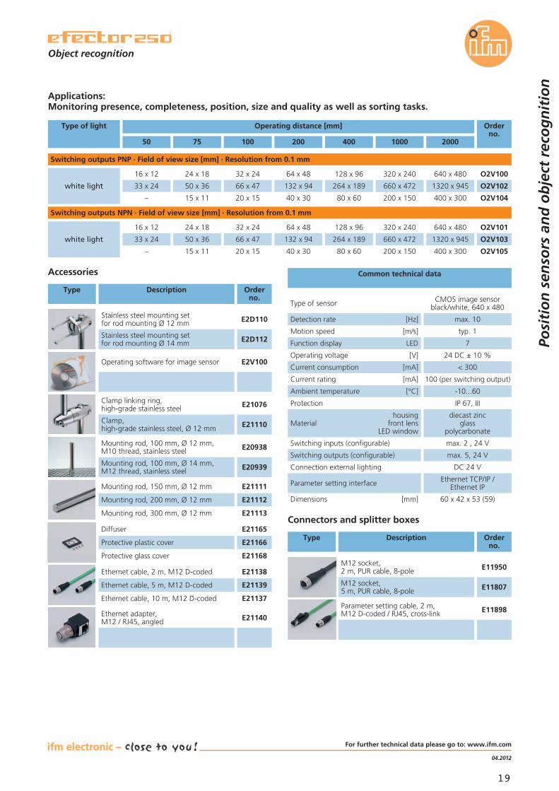
Applications:Monitoring presence, completeness, position, size and quality as well as sorting tasks.
Switching outputs PNP · Field of view size [mm] · Resolution from 0.1 mm
Common technical data
Operating voltage [V] 24 DC ± 10 %
Detection rate [Hz] max. 10
Type of sensor CMOS image sensorblack/white, 640 x 480
Motion speed [m/s] typ. 1
Function display LED 7
Current rating [mA] 100 (per switching output)
Current consumption [mA] < 300
Ambient temperature [°C] -10...60
Protection IP 67, III
housingMaterial front lens
LED window
diecast zincglass
polycarbonate
Switching inputs (configurable) max. 2 , 24 V
Switching outputs (configurable) max. 5, 24 V
Connection external lighting DC 24 V
Parameter setting interface Ethernet TCP/IP /Ethernet IP
Dimensions [mm] 60 x 42 x 53 (59)
Connectors and splitter boxes
Type Description Orderno.
M12 socket,2 m, PUR cable, 8-pole E11950
M12 socket,5 m, PUR cable, 8-pole E11807
Parameter setting cable, 2 m,M12 D-coded / RJ45, cross-link E11898
Accessories
Type Description Orderno.
Operating software for image sensor E2V100
Object recognition
Posi
tio
n s
enso
rs a
nd
ob
ject
rec
og
nit
ion
Stainless steel mounting setfor rod mounting Ø 12 mm E2D110
Stainless steel mounting setfor rod mounting Ø 14 mm E2D112
Clamp linking ring,high-grade stainless steel E21076
E21110Clamp,high-grade stainless steel, Ø 12 mm
Mounting rod, 150 mm, Ø 12 mm E21111
Mounting rod, 200 mm, Ø 12 mm E21112
Mounting rod, 300 mm, Ø 12 mm E21113
Diffuser
Protective plastic cover
Protective glass cover
Mounting rod, 100 mm, Ø 12 mm,M10 thread, stainless steel E20938
Mounting rod, 100 mm, Ø 14 mm,M12 thread, stainless steel E20939
Ethernet cable, 2 m, M12 D-coded E21138
Ethernet cable, 5 m, M12 D-coded E21139
Ethernet cable, 10 m, M12 D-coded E21137
Ethernet adapter,M12 / RJ45, angled E21140
E21165
E21166
E21168
50 75 100 200 400 1000 2000
Operating distance [mm] Orderno.
O2V100
O2V102
O2V104
Switching outputs NPN · Field of view size [mm] · Resolution from 0.1 mm
O2V101
O2V103
O2V105
Type of light
white light
white light
16 x 12
33 x 24
24 x 18
50 x 36
32 x 24
66 x 47
64 x 48
132 x 94
128 x 96
264 x 189
320 x 240
660 x 472
640 x 480
1320 x 945
– 15 x 11 20 x 15 40 x 30 80 x 60 200 x 150 400 x 300
16 x 12
33 x 24
24 x 18
50 x 36
32 x 24
66 x 47
64 x 48
132 x 94
128 x 96
264 x 189
320 x 240
660 x 472
640 x 480
1320 x 945
– 15 x 11 20 x 15 40 x 30 80 x 60 200 x 150 400 x 300
For further technical data please go to: www.ifm.com
20
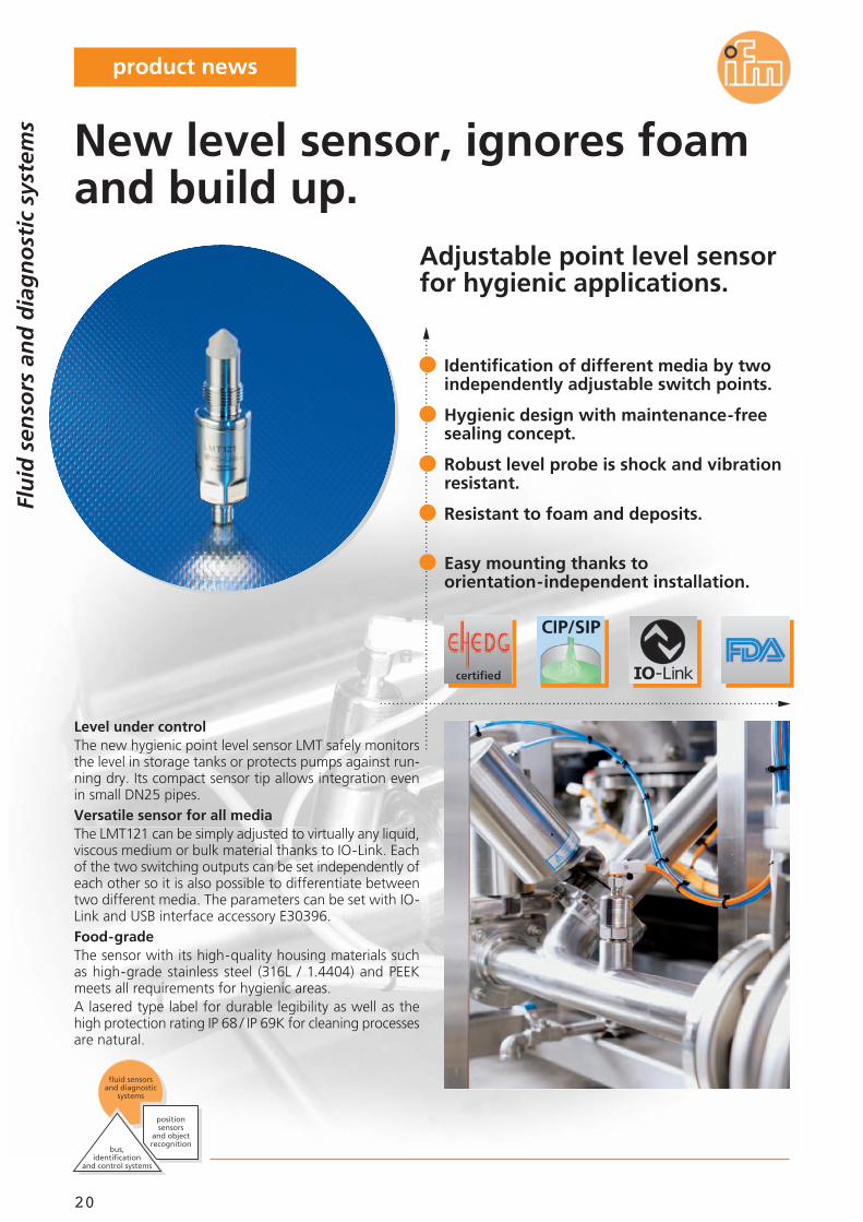
Adjustable point level sensorfor hygienic applications.
Level under controlThe new hygienic point level sensor LMT safely monitorsthe level in storage tanks or protects pumps against run-ning dry. Its compact sensor tip allows integration evenin small DN25 pipes.Versatile sensor for all mediaThe LMT121 can be simply adjusted to virtually any liquid,viscous medium or bulk material thanks to IO-Link. Eachof the two switching outputs can be set independently ofeach other so it is also possible to differentiate betweentwo different media. The parameters can be set with IO-Link and USB interface accessory E30396.Food-gradeThe sensor with its high-quality housing materials suchas high-grade stainless steel (316L / 1.4404) and PEEKmeets all requirements for hygienic areas.A lasered type label for durable legibility as well as thehigh protection rating IP 68 / IP 69K for cleaning processesare natural.
Identification of different media by twoindependently adjustable switch points.
Hygienic design with maintenance-freesealing concept.
Robust level probe is shock and vibrationresistant.
Resistant to foam and deposits.
Easy mounting thanks toorientation-independent installation.
New level sensor, ignores foamand build up.
Flu
id s
enso
rs a
nd
dia
gn
ost
ic s
yste
ms
bus,identification
and control systems
fluid sensors and diagnostic
systems
position sensors
and objectrecognition
product news
21
04.2012
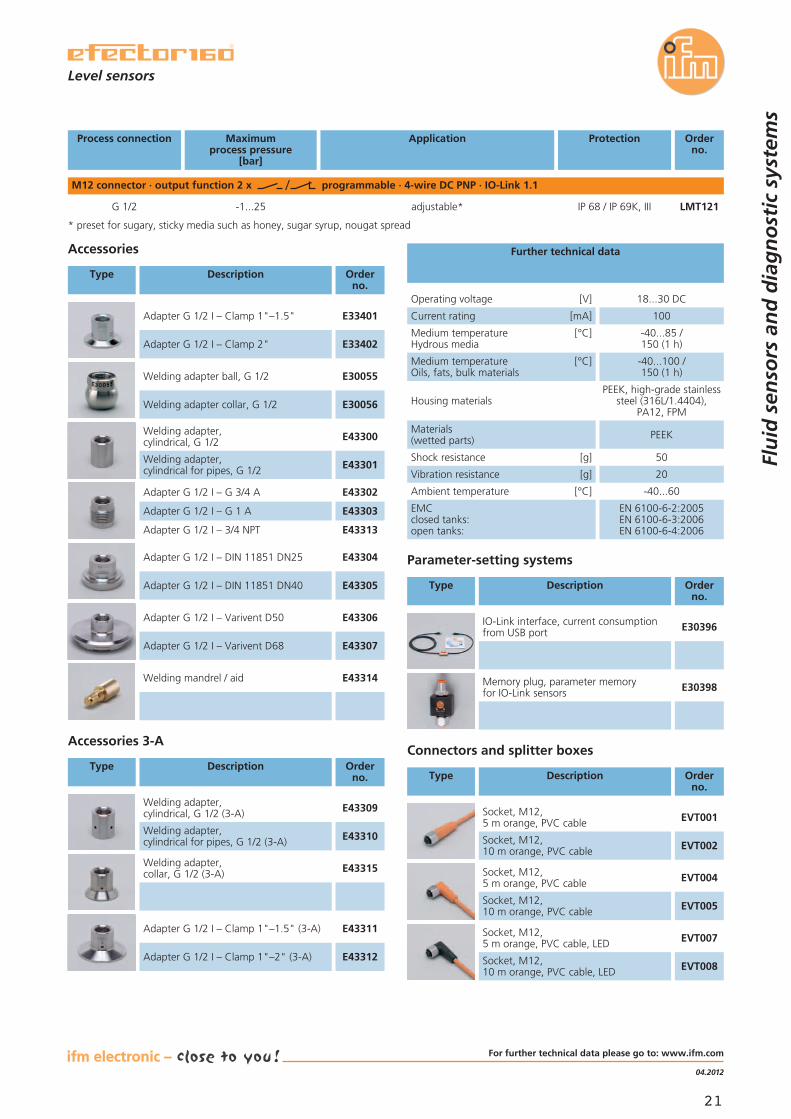
Process connection Maximumprocess pressure
[bar]
Application Protection Orderno.
M12 connector · output function 2 x programmable · 4-wire DC PNP · IO-Link 1.1
* preset for sugary, sticky media such as honey, sugar syrup, nougat spread
Level sensors
Flu
id s
enso
rs a
nd
dia
gn
ost
ic s
yste
ms
Accessories
Type Description Orderno.
Adapter G 1/2 I – Clamp 1"–1.5" E33401
Adapter G 1/2 I – Clamp 2" E33402
Welding adapter ball, G 1/2 E30055
Welding adapter collar, G 1/2 E30056
Welding adapter,cylindrical, G 1/2 E43300
Welding adapter,cylindrical for pipes, G 1/2 E43301
Adapter G 1/2 I – G 3/4 A E43302
Adapter G 1/2 I – G 1 A E43303
Adapter G 1/2 I – DIN 11851 DN25 E43304
Adapter G 1/2 I – DIN 11851 DN40 E43305
Adapter G 1/2 I – Varivent D50 E43306
Adapter G 1/2 I – Varivent D68 E43307
Welding mandrel / aid E43314
Welding adapter,cylindrical, G 1/2 (3-A) E43309
Welding adapter,cylindrical for pipes, G 1/2 (3-A) E43310
Adapter G 1/2 I – Clamp 1"–1.5" (3-A) E43311
Adapter G 1/2 I – Clamp 1"–2" (3-A) E43312
Accessories 3-A
Type Description Orderno.
Medium temperature [°C]Hydrous media
-40...85 /150 (1 h)
Medium temperature [°C]Oils, fats, bulk materials
-40...100 /150 (1 h)
Housing materialsPEEK, high-grade stainless
steel (316L/1.4404),PA12, FPM
Materials(wetted parts) PEEK
Shock resistance [g] 50
Vibration resistance [g] 20
Ambient temperature [°C] -40...60
EMCclosed tanks:open tanks:
EN 6100-6-2:2005EN 6100-6-3:2006EN 6100-6-4:2006
Operating voltage [V] 18...30 DC
Current rating [mA] 100
Further technical data
Connectors and splitter boxes
Type Description Orderno.
Socket, M12,5 m orange, PVC cable EVT001
Socket, M12,10 m orange, PVC cable EVT002
Socket, M12,5 m orange, PVC cable EVT004
Socket, M12,10 m orange, PVC cable EVT005
Socket, M12,5 m orange, PVC cable, LED EVT007
Socket, M12,10 m orange, PVC cable, LED EVT008
G 1/2 -1...25 adjustable* IP 68 / IP 69K, III LMT121
Welding adapter,collar, G 1/2 (3-A) E43315
Adapter G 1/2 I – 3/4 NPT E43313
Parameter-setting systems
Type Description Orderno.
IO-Link interface, current consumptionfrom USB port E30396
Memory plug, parameter memoryfor IO-Link sensors E30398
For further technical data please go to: www.ifm.com
22
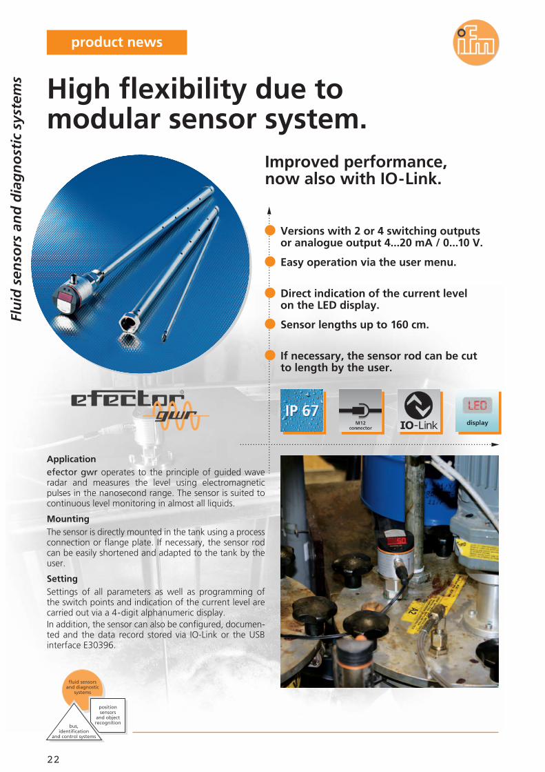
Applicationefector gwr operates to the principle of guided waveradar and measures the level using electromagnetic pulses in the nanosecond range. The sensor is suited tocontinuous level moni to r ing in almost all liquids.
MountingThe sensor is directly mounted in the tank using a processconnection or flange plate. If necessary, the sensor rodcan be easily shortened and adapted to the tank by theuser.
SettingSettings of all parameters as well as programming ofthe switch points and indication of the current level arecarried out via a 4-digit alphanumeric display.In addition, the sensor can also be configured, documen-ted and the data record stored via IO-Link or the USBinterface E30396.
Flu
id s
enso
rs a
nd
dia
gn
ost
ic s
yste
ms
bus,identification
and control systems
fluid sensors and diagnostic
systems
position sensors
and objectrecognition
Improved performance,now also with IO-Link.
Versions with 2 or 4 switching outputsor analogue output 4...20 mA / 0...10 V.
Easy operation via the user menu.
Direct indication of the current levelon the LED display.
Sensor lengths up to 160 cm.
If necessary, the sensor rod can be cutto length by the user.
High flexibility due tomodular sensor system.
product news
23
04.2012
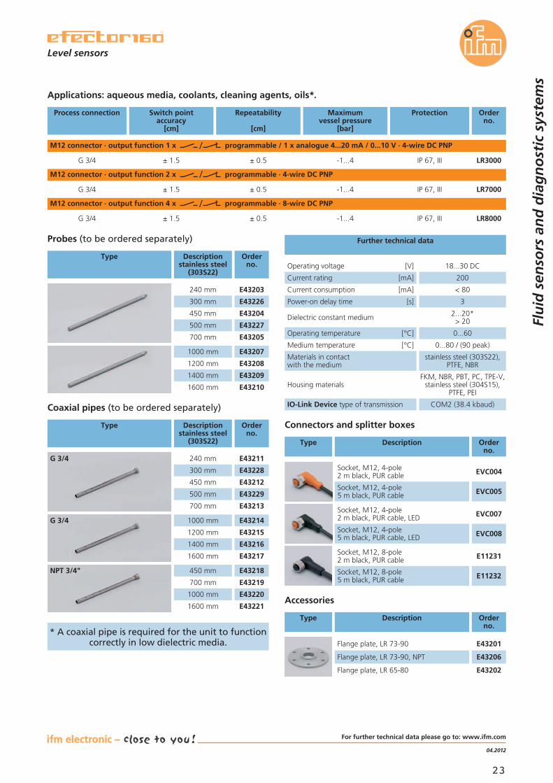
Applications: aqueous media, coolants, cleaning agents, oils*.
Accessories
Type Description Orderno.
Connectors and splitter boxes
Type Description Orderno.
Current consumption [mA] < 80
Dielectric constant medium 2...20*> 20
Operating temperature [°C] 0...60
Medium temperature [°C] 0...80 / (90 peak)
Materials in contactwith the medium
stainless steel (303S22),PTFE, NBR
Housing materialsFKM, NBR, PBT, PC, TPE-V,
stainless steel (304S15),PTFE, PEI
Power-on delay time [s] 3
Operating voltage [V] 18...30 DC
Current rating [mA] 200
Further technical data
Socket, M12, 4-pole2 m black, PUR cable
Socket, M12, 4-pole5 m black, PUR cable
Socket, M12, 4-pole2 m black, PUR cable, LED
Socket, M12, 4-pole5 m black, PUR cable, LED
Level sensors
Flu
id s
enso
rs a
nd
dia
gn
ost
ic s
yste
ms
EVC004
EVC005
EVC007
EVC008
Process connection Switch pointaccuracy
[cm]
Repeatability
[cm]
Maximumvessel pressure
[bar]
Protection Orderno.
M12 connector · output function 2 x programmable · 4-wire DC PNP
M12 connector · output function 4 x programmable · 8-wire DC PNP
G 3/4 ± 1.5 ± 0.5 -1...4 IP 67, III LR7000
Socket, M12, 8-pole2 m black, PUR cable E11231
Socket, M12, 8-pole5 m black, PUR cable E11232
G 3/4 ± 1.5 ± 0.5 -1...4 IP 67, III LR8000
M12 connector · output function 1 x programmable / 1 x analogue 4...20 mA / 0...10 V · 4-wire DC PNP
G 3/4 ± 1.5 ± 0.5 -1...4 IP 67, III LR3000
* A coaxial pipe is required for the unit to functioncorrectly in low dielectric media. Flange plate, LR 73-90 E43201
Flange plate, LR 73-90, NPT E43206
Flange plate, LR 65-80 E43202
Probes (to be ordered separately)
Type Descriptionstainless steel
(303S22)
Orderno.
E43203240 mm
E43204450 mm
E43226300 mm
E43205700 mm
E43227500 mm
E432071000 mm
E432081200 mm
E432091400 mm
E432101600 mm
Coaxial pipes (to be ordered separately)
Type Descriptionstainless steel
(303S22)
Orderno.
IO-Link Device type of transmission COM2 (38.4 kbaud)
E43211240 mm
E43212450 mm
E43213700 mm
E432141000 mm
E432151200 mm
E432161400 mm
E432171600 mm
E43218450 mm
E43228300 mm
E43219700 mm
E43229500 mm
E432201000 mm
E432211600 mm
G 3/4
G 3/4
NPT 3/4"
For further technical data please go to: www.ifm.com
24
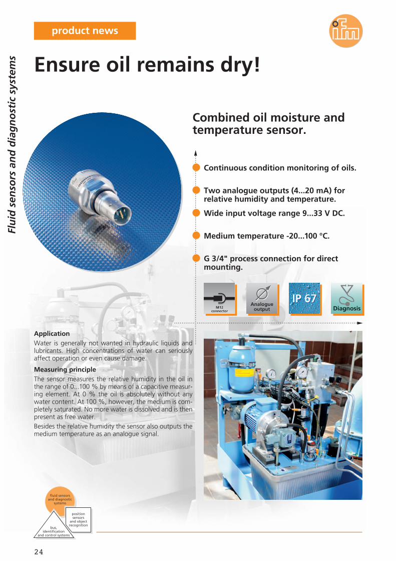
Combined oil moisture andtemperature sensor.
ApplicationWater is generally not wanted in hydraulic liquids andlubricants. High concentrations of water can seriouslyaffect operation or even cause damage.
Measuring principleThe sensor measures the relative humidity in the oil inthe range of 0...100 % by means of a capacitive measur-ing element. At 0 % the oil is absolutely without anywater content. At 100 %, however, the medium is com-pletely saturated. No more water is dissolved and is thenpresent as free water.Besides the relative humidity the sensor also outputs themedium temperature as an analogue signal.
Continuous condition monitoring of oils.
Two analogue outputs (4...20 mA) forrelative humidity and temperature.
Wide input voltage range 9...33 V DC.
Medium temperature -20...100 °C.
G 3/4" process connection for directmounting.
Ensure oil remains dry!
Flu
id s
enso
rs a
nd
dia
gn
ost
ic s
yste
ms
bus,identification
and control systems
fluid sensors and diagnostic
systems
position sensors
and objectrecognition
product news
25
11.2011
Wiring diagram
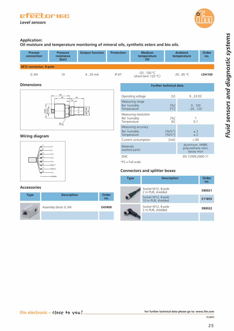
Application:Oil moisture and temperature monitoring of mineral oils, synthetic esters and bio oils.
Processconnection
Pressureresistance
[bar]
Output function Protection Mediumtemperature
Oil
Ambienttemperature
Orderno.
M12 connector, 8-pole
G 3/4 10 4...20 mA IP 67 -20...85 °C-20...100 °C(short-term 120 °C) LDH100
Accessories
Type Description Orderno.
Assembly block G 3/4 E43400
Connectors and splitter boxes
Type Description Orderno.
Measuring resolutionRel. humidity [%]Temperature [K]
10.1
Current consumption [mA] < 60
Materials(wetted parts)
aluminium, HNBR,polyurethane resin,
epoxy resin
EMC EN 13309:2000-11
Measuring accuracyRel. humidity [%FS*]Temperature [%FS*]
± 3± 2
Operating voltage [V] 9...33 DC
Measuring rangeRel. humidity [%]Temperature [°C]
0...100-20...120
Further technical data
screen
L+
L
Out 1
Out 2
1
8
7
6
3
4
5
2
n.c.
n.c.
n.c.
n.c.
Socket M12, 8-pole2 m PUR, shielded E80021
Socket M12, 8-pole10 m PUR, shielded E11855
Socket M12, 8-pole2 m PUR, shielded E80022
Dimensions
32
42M12x1
21,6
5444 43
14
G4
3
*FS = Full scale
Flu
id s
enso
rs a
nd
dia
gn
ost
ic s
yste
ms
Level sensors
For further technical data please go to: www.ifm.com
26
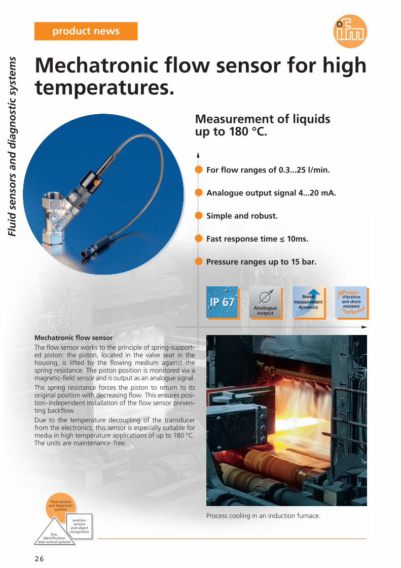
Measurement of liquidsup to 180 °C.
Process cooling in an induction furnace.
Mechatronic flow sensorThe flow sensor works to the principle of spring-support-ed piston: the piston, located in the valve seat in thehousing, is lifted by the flowing medium against thespring resistance. The piston position is monitored via amagnetic-field sensor and is output as an analogue signal.The spring resistance forces the piston to return to itsoriginal position with decreasing flow. This ensures posi-tion-independent installation of the flow sensor preven-ting backflow.Due to the temperature decoupling of the transducerfrom the electronics, this sensor is especially suitable formedia in high temperature applications of up to 180 °C.The units are maintenance-free.
For flow ranges of 0.3...25 l/min.
Analogue output signal 4...20 mA.
Simple and robust.
Fast response time ≤ 10ms.
Pressure ranges up to 15 bar.
Mechatronic flow sensor for hightemperatures.
Flu
id s
enso
rs a
nd
dia
gn
ost
ic s
yste
ms
bus,identification
and control systems
fluid sensors and diagnostic
systems
position sensors
and objectrecognition
product news
27
04.2012
Common technical data
Operating voltage [V] 24 DC (-15 % / + 10 %)
Short-circuit protection •
Materials in contactwith the medium
stainless steel 304/1.4301;nickel-plated brass;
PPS;O-ring: FPM
Ambient temperature [°C] 0...60
Response time [s] < 0.01
Current consumption [mA] < 30
Reverse polarity / overload protection • / •
TypeSBT, SBM
Dimensions
3565
M12x1
M12x1
1376,5
13
Rp
43
Rp
43
L+
L
1
3
2
Wiring
SBT633
Processconnection
Mediumtemperature
[°C]
Accuracy
[% of the final value]
Pressureresistance
[bar]
Orderno.
Connection cable 0.3 m with M12 connector · analogue function mode 4...20 mA
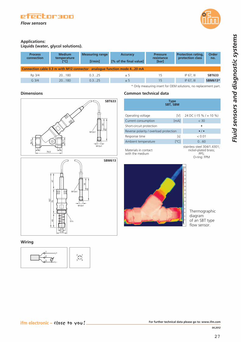
Rp 3/4 20...180 ± 5 15 SBT633
Protection rating,protection class
IP 67, III
G 3/4 20...180
Measuring range
[l/min]
0.3...25
0.3...25 ± 5 15 SBM613*IP 67, III
Applications:Liquids (water, glycol solutions).
* Only measuring insert for OEM solutions, no replacement part.35
65
M12x1
M12x1
20
4070
47157
30
G 43
SBM613
43
2 1
Thermographicdiagramof an SBT typeflow sensor.
Flu
id s
enso
rs a
nd
dia
gn
ost
ic s
yste
ms
Flow sensors
For further technical data please go to: www.ifm.com
28
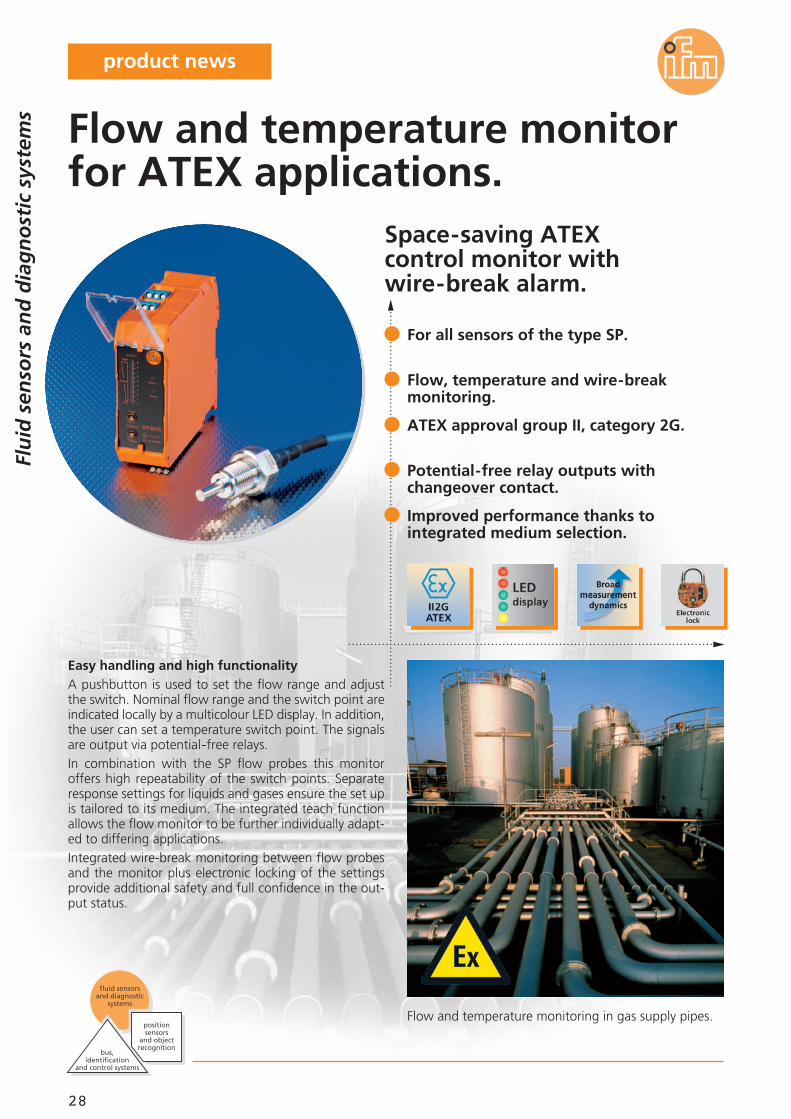
Space-saving ATEXcontrol monitor withwire-break alarm.
Flow and temperature monitoring in gas supply pipes.
Easy handling and high functionalityA pushbutton is used to set the flow range and adjustthe switch. Nominal flow range and the switch point areindicated locally by a multicolour LED display. In addition,the user can set a temperature switch point. The signalsare output via potential-free relays.In combination with the SP flow probes this monitoroffers high repeatability of the switch points. Separateresponse settings for liquids and gases ensure the set upis tailored to its medium. The integrated teach functionallows the flow monitor to be further individually adapt-ed to differing applications.Integrated wire-break monitoring between flow probesand the monitor plus electronic locking of the settingsprovide additional safety and full confidence in the out-put status.
For all sensors of the type SP.
Flow, temperature and wire-breakmonitoring.
ATEX approval group II, category 2G.
Potential-free relay outputs withchangeover contact.
Improved performance thanks tointegrated medium selection.
Flow and temperature monitorfor ATEX applications.
Flu
id s
enso
rs a
nd
dia
gn
ost
ic s
yste
ms
bus,identification
and control systems
fluid sensors and diagnostic
systems
position sensors
and objectrecognition
product news
29
04.2012
Temperature gradient [K/min] 30
Medium temperature [°C] -20...70
Protection IP 65 / IP 67
Materials in contactwith the medium
high-grade stainless steel(316L/1.4404)
Housing materials high-grade stainless steel(316L/1.4404)
Marking of the unit II 2G Ex ia IIC T4 Gb
Response time [s] 1...10
Approvals ZELM 11 ATEX 0467IECEx ZLM 11.0005
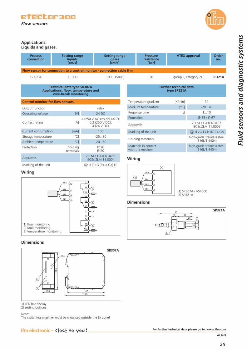
Further technical datatype SP321A
Dimensions
G2
1
9515 45
20
27
7,7
2
7
8
9BK
BU
BN
WH
Wiring
SP321A
Processconnection
Setting rangeliquids[cm/s]
Pressureresistance
[bar]
Orderno.
Flow sensor for connection to a control monitor · connection cable 6 m
G 1/2 A 3...300 30 SP321A
ATEX approval
group II, category 2G
Setting rangegases[cm/s]
100...15000
Applications:Liquids and gases.
107113,6
35,2
104,5
LEDs
SR307A
1) SR307A / VS40002) SP321A
22
23
24
28
29
30
31
3234
35
36
2
7
8
9BK
BU
BN
WH
1
2
3
L
L+
Wiring
Dimensions
Output function relay
Operating voltage [V] 24 DC
Current consumption [mA] 100
Storage temperature [°C] -25...80
Ambient temperature [°C] -20...60
Protection housingterminals
IP 20IP 20
Marking of the unit II (1) G [Ex ia Ga] IIC
Contact rating [A]4 (250 V AC cos phi >0.7);
0.2 (250 V DC);4 (24 V DC)
Approvals ZELM 11 ATEX 0466IECEx ZLM 11.0004
Technical data type SR307AApplications: flow, temperature and
wire-break monitoring
Control monitor for flow sensors
1) flow monitoring2) fault monitoring3) temperature monitoring
1) LED bar display2) setting buttons
Note:The switching amplifier must be mounted outside the Ex zone!
Flu
id s
enso
rs a
nd
dia
gn
ost
ic s
yste
ms
Flow sensors
For further technical data please go to: www.ifm.com

30
Compressed air meter withdisplay and totalizer function.
Argon consumption measurement in a laser welding system.
Calorimetric measuring principleThe compressed air meter detects the standard volumeflow directly (according to ISO 2533 and DIN 1343). Thismakes corrections, in case of temperature or pressurefluctuations, unnecessary. The high measurement dy-namics of the system enable the reliable detection of evenminute quantities, e.g. leakage. High accuracy and repeat-ability are ensured by the integration of the measure-ment sensor’s key elements into a defined pipe length.
Measuring compressed air consumption inair supply linesWe offer additional compressed air sensors for largermeasuring ranges on request, especially for supply andair supply lines.As an option compressed air sensors with exchangeableelectronics, allowing subsequent calibration under oper-ating pressure, can also be used.
Measurement to ISO 2533 and DIN 1343possible.
For compressed air in industrial use,argon, carbon dioxide, nitrogen.
Large measuring range up to 700 Nm3/h.Larger measuring ranges on request.
Fast response time and high responsesensitivity.
Volumetric flow quantity, flow velocityand temperature indication.
To prevent your money fromdissolving into thin air.
Flu
id s
enso
rs a
nd
dia
gn
ost
ic s
yste
ms
bus,identification
and control systems
fluid sensors and diagnostic
systems
position sensors
and objectrecognition
product news
31
11.2011
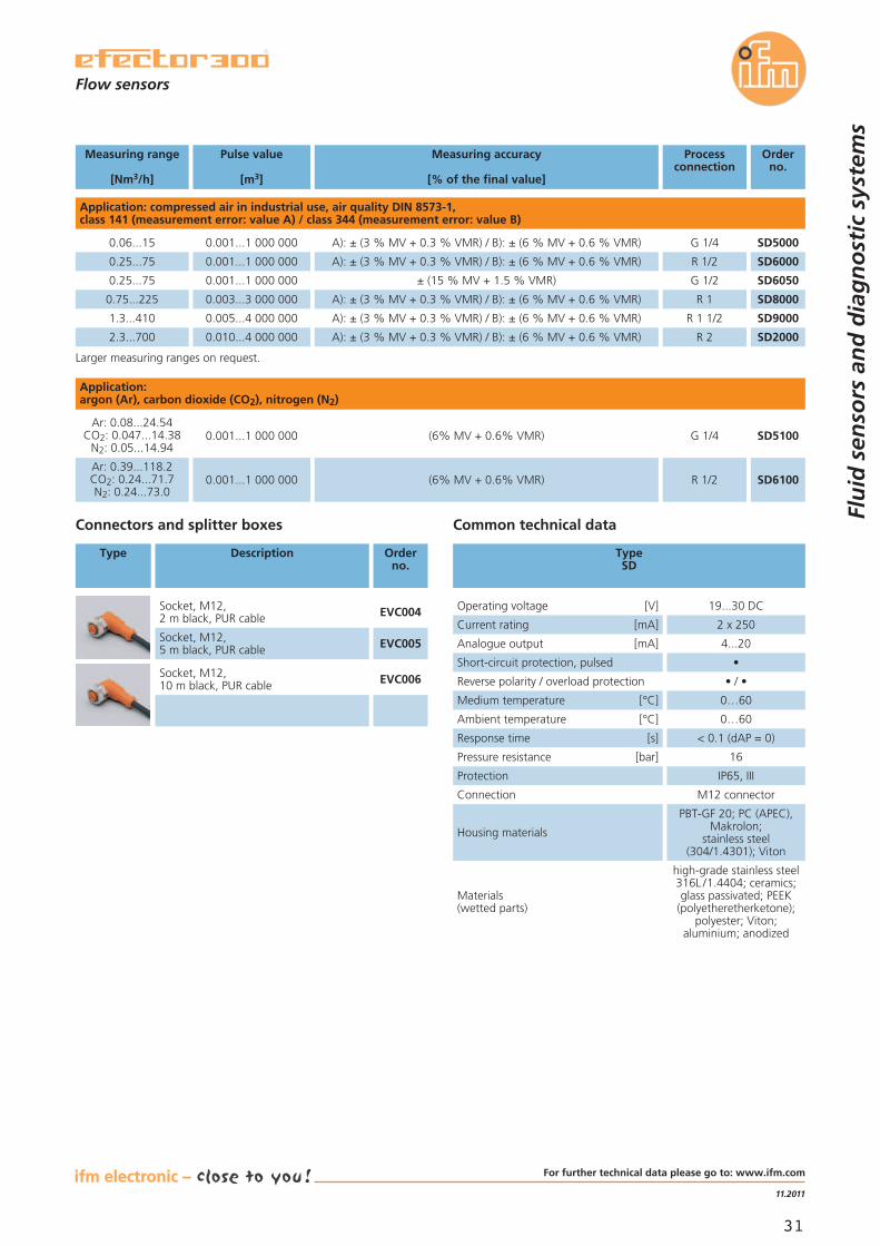
Measuring range
[Nm3/h]
Pulse value
[m3]
Measuring accuracy
[% of the final value]
Processconnection
Orderno.
Application: compressed air in industrial use, air quality DIN 8573-1,class 141 (measurement error: value A) / class 344 (measurement error: value B)
0.06...15 0.001...1 000 000 A): ± (3 % MV + 0.3 % VMR) / B): ± (6 % MV + 0.6 % VMR) G 1/4 SD5000
0.25...75 0.001...1 000 000 A): ± (3 % MV + 0.3 % VMR) / B): ± (6 % MV + 0.6 % VMR) R 1/2 SD6000
0.25...75 0.001...1 000 000 ± (15 % MV + 1.5 % VMR) G 1/2 SD6050
0.75...225 0.003...3 000 000 A): ± (3 % MV + 0.3 % VMR) / B): ± (6 % MV + 0.6 % VMR) R 1 SD8000
1.3...410 0.005...4 000 000 A): ± (3 % MV + 0.3 % VMR) / B): ± (6 % MV + 0.6 % VMR) R 1 1/2 SD9000
2.3...700 0.010...4 000 000 A): ± (3 % MV + 0.3 % VMR) / B): ± (6 % MV + 0.6 % VMR) R 2 SD2000
Common technical data
Operating voltage [V] 19...30 DC
Analogue output [mA] 4...20
Housing materials
PBT-GF 20; PC (APEC),Makrolon;
stainless steel(304/1.4301); Viton
Materials(wetted parts)
high-grade stainless steel316L /1.4404; ceramics;glass passivated; PEEK
(polyetheretherketone);polyester; Viton;
aluminium; anodized
Medium temperature [°C] 0…60
Ambient temperature [°C] 0…60
Response time [s] < 0.1 (dAP = 0)
Pressure resistance [bar] 16
Protection IP65, III
Connection M12 connector
Short-circuit protection, pulsed •
Current rating [mA] 2 x 250
TypeSD
Connectors and splitter boxes
Type Description Orderno.
Socket, M12,2 m black, PUR cable EVC004
Socket, M12,5 m black, PUR cable EVC005
Socket, M12,10 m black, PUR cable EVC006
Larger measuring ranges on request.
Reverse polarity / overload protection • / •
Application:argon (Ar), carbon dioxide (CO2), nitrogen (N2)
Ar: 0.08...24.54CO2: 0.047...14.38
N2: 0.05...14.940.001...1 000 000 (6% MV + 0.6% VMR) G 1/4 SD5100
Ar: 0.39...118.2CO2: 0.24...71.7N2: 0.24...73.0
0.001...1 000 000 (6% MV + 0.6% VMR) R 1/2 SD6100
Flu
id s
enso
rs a
nd
dia
gn
ost
ic s
yste
ms
Flow sensors
For further technical data please go to: www.ifm.com

32
Flu
id s
enso
rs a
nd
dia
gn
ost
ic s
yste
ms
bus,identification
and control systems
fluid sensors and diagnostic
systems
position sensors
and objectrecognition
On-site control monitorfor the flexible connection offlow sensors.
Flow monitoring in a return pipe witha large nominal width.
High flexibilityStandardised M12 connections are used to connect con-trol monitor and sensor as well as the supply. This allowsthe use of an evaluation and display unit in differentapplications, e.g. for different immersion depths and awide range of aggressive liquids.
Easy handling and high functionalityAdjustment to the flow and setting of the switch pointsare carried out by pressing a pushbutton. Flow and switchpoint are indicated by a multicolour LED display. High re-peatability of the switch points offers an optimum choicefor use.Electronic locking of the settings and factory reset of theparameters provide additional safety.
For the connection of sensors withdifferent immersion depths.
For sensors made of ceramics,high-grade stainless steel and titanium.
Teach button allows easy scalingof the measuring range.
Flow and switch point are indicatedby LEDs directly on the unit.
Available in DC and AC versions.
Modular flow monitoring forfield applications.
product news
33
11.2011
Flow sensors
Flu
id s
enso
rs a
nd
dia
gn
ost
ic s
yste
ms
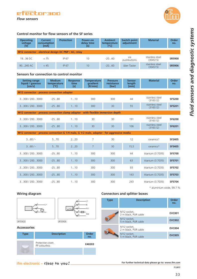
Operatingvoltage
[V]
Currentconsumption
[mA]
Protection Power-ondelay time
[s]
Ambienttemperature
[°C]
Orderno.
M12 connector · electrical design DC PNP / AC, relay
19...36 DC < 75 IP 67 10 -20...60
Switch pointadjustment
viapushbuttons
Material
stainless steel(304S15) SR5900
Accessories
Type Description Orderno.
Protective cover,PP colourless E40203
Connectors and splitter boxes
Type Description Orderno.
Control monitor for flow sensors of the SF series
* aluminium oxide, 99.7 %
Setting rangeliquid / gaseous
[cm/s]
Mediumtemperature
[°C]
Responsetime[s]
Temperaturegradient[K/min]
Pressureresistance
[bar]
Orderno.
M12 connector · process connection adapter
3...300 / 200...3000 -25...80 1...10 300 300
Sensorlength[mm]
44
Material
stainless steel(316S12) SF5200
3...300 / 200...3000 -25...80 1...10 300 30 55 stainless steel(316S12) SF5201
M12 connector · process connection clamp adapter · with flexible immersion depth
3...300 / 200...3000 -25...80 1...10 30 30 191 stainless steel(316S12) SF6200
M12 connector · process connection G 1/4 male, G 1/2 male, adapter · for aggressive media
3...60 / - 5...70 2...20 7 30 12 ceramics* SF2405
3...60 / - 5...70 2...20 7 30 15,5 ceramics* SF3405
3...300 / 200...3000 -25...80 1...10 300 300 44 titanium (3.7035) SF5700
Sensors for connection to control monitor
M12 socket,2 m black, PUR cable EVC001
M12 socket,5 m black, PUR cable EVC002
M12 socket,2 m black, PUR cable EVC004
M12 socket,5 m black, PUR cable EVC005
Wiring diagram
90...240 AC < 45 IP 67 10 -20...60 über Taster stainless steel(304S15) SR5906
L+
L
1
4
3
1
3
4
2
5
n.c.
L1
N
Out
SR5900 SR5906
3...300 / 200...3000 -25...80 1...10 30 30 106 stainless steel(316S12) SF6201
3...300 / 200...3000 -25...80 1...10 300 300 63 titanium (3.7035) SF5701
3...300 / 200...3000 -25...80 1...10 300 300 93 titanium (3.7035) SF5702
3...300 / 200...3000 -25...80 1...10 300 300 143 titanium (3.7035) SF5703
3...300 / 200...3000 -25...80 1...10 300 300 243 titanium (3.7035) SF5704
For further technical data please go to: www.ifm.com

34
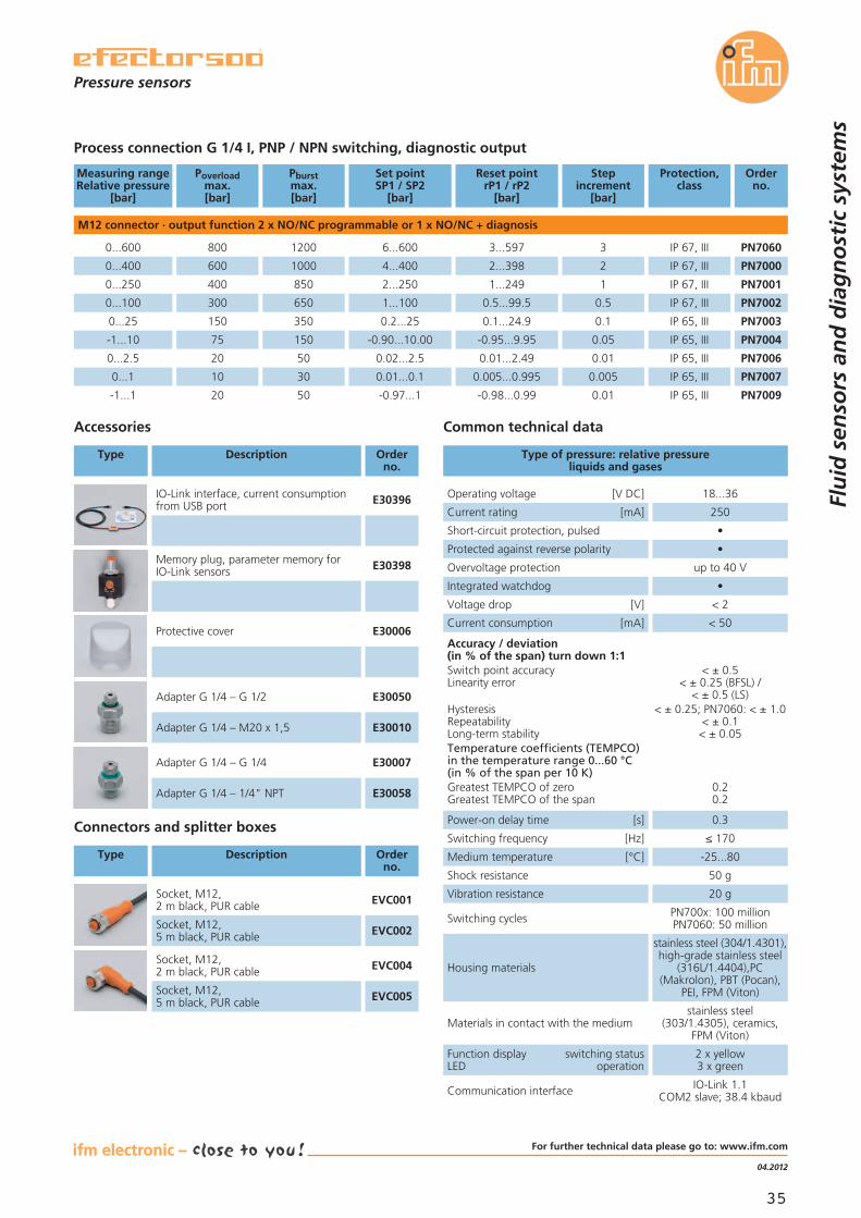
PN7 pressure sensorwith communication interfaceIO-Link 1.1.
PN7 pressure sensors in hydraulic and pneumatic lines
Parameter setting, diagnosis and trans-mission of process values via IO-Link.
High switch point accuracy andswitching frequency.
Ceramic measuring cell for more than100 million switching operations.
Dual independent switching outputs orswitching and diagnostic output.
Different versions with pressure rangesbetween -1...600 bar.
Pressure sensor with choice ofswitch points or analogue values.
Flu
id s
enso
rs a
nd
dia
gn
ost
ic s
yste
ms
bus,identification
and control systems
fluid sensors and diagnostic
systems
position sensors
and objectrecognition
PN7 pressure sensor upgraded with IO-LinkIO-Link is a simple, point-to-point, communication pro-tocol between an IO-Link enabled device, such as a sen-sor or actuator, and an IO-Link master.
IO-Link advantagesThe IO-Link circuit allows the process measurement data,parameters and diagnostic information to be transmittedusing the standard connection cable. For example, thepressure measurement can be transferred as a digital valuedirectly to the PLC. The measurement is more accurate,free from conversion errors.IO-Link masters can also store the set up parameters oftheir sensors. If the original sensor is damaged, then theIO-Link master will recognise its "blank" replacement andautomatically download the stored set up into the newlyconnected sensor, saving time and avoiding errors.
product news
35
04.2012
M12 connector · output function 2 x NO/NC programmable or 1 x NO/NC + diagnosis
0...600 PN7060
0...400 PN7000
0...250
800
600
400
1200
1000
850
6...600
4...400
2...250 PN7001
Accessories
Type Description Orderno.
Protective cover E30006
Adapter G 1/4 – G 1/2 E30050
Adapter G 1/4 – M20 x 1,5 E30010
Adapter G 1/4 – G 1/4 E30007
Adapter G 1/4 – 1/4" NPT E30058
Process connection G 1/4 I, PNP / NPN switching, diagnostic output
Measuring rangeRelative pressure
[bar]
Orderno.
Poverloadmax.[bar]
Pburstmax.[bar]
Set pointSP1 / SP2
[bar]
3...597
2...398
1...249
0...100 PN7002
0...25 PN7003
-1...10
300
150
75
650
350
150
1...100
0.2...25
-0.90...10.00 PN7004
0.5...99.5
0.1...24.9
-0.95...9.95
Reset pointrP1 / rP2
[bar]
3
2
1
0.5
0.1
0.05
0...2.5 PN7006
0...1
20
10
50
30
0.02...2.5
0.01...0.1 PN7007
0.01...2.49
0.005...0.995
0.01
0.005
Protection,class
IP 67, III
IP 67, III
IP 67, III
IP 67, III
IP 65, III
IP 65, III
IP 65, III
IP 65, III
-1...1 20 50 -0.97...1 PN7009-0.98...0.99 0.01 IP 65, III
Stepincrement
[bar]
Operating voltage [V DC] 18...36
Current rating [mA] 250
Current consumption [mA] < 50
Accuracy / deviation(in % of the span) turn down 1:1Switch point accuracyLinearity error
HysteresisRepeatabilityLong-term stabilityTemperature coefficients (TEMPCO)in the temperature range 0...60 °C(in % of the span per 10 K)Greatest TEMPCO of zeroGreatest TEMPCO of the span
< ± 0.5< ± 0.25 (BFSL) /
< ± 0.5 (LS)< ± 0.25; PN7060: < ± 1.0
< ± 0.1< ± 0.05
0.20.2
Type of pressure: relative pressureliquids and gases
Common technical data
Medium temperature [°C] -25...80
Housing materials
stainless steel (304/1.4301),high-grade stainless steel
(316L/1.4404),PC(Makrolon), PBT (Pocan),
PEI, FPM (Viton)
Materials in contact with the mediumstainless steel
(303/1.4305), ceramics,FPM (Viton)
Function display switching statusLED operation
2 x yellow3 x green
Communication interface IO-Link 1.1COM2 slave; 38.4 kbaud
Power-on delay time [s] 0.3
Switching frequency [Hz] ≤ 170
Shock resistance 50 g
Vibration resistance 20 g
Switching cycles PN700x: 100 millionPN7060: 50 million
Connectors and splitter boxes
Short-circuit protection, pulsed •
Protected against reverse polarity •
Overvoltage protection up to 40 V
Integrated watchdog •
Voltage drop [V] < 2
IO-Link interface, current consumptionfrom USB port E30396
Memory plug, parameter memory forIO-Link sensors E30398
Socket, M12,2 m black, PUR cable EVC001
Socket, M12,5 m black, PUR cable EVC002
Socket, M12,2 m black, PUR cable EVC004
Socket, M12,5 m black, PUR cable EVC005
Type Description Orderno.
Pressure sensors
Flu
id s
enso
rs a
nd
dia
gn
ost
ic s
yste
ms
For further technical data please go to: www.ifm.com
36
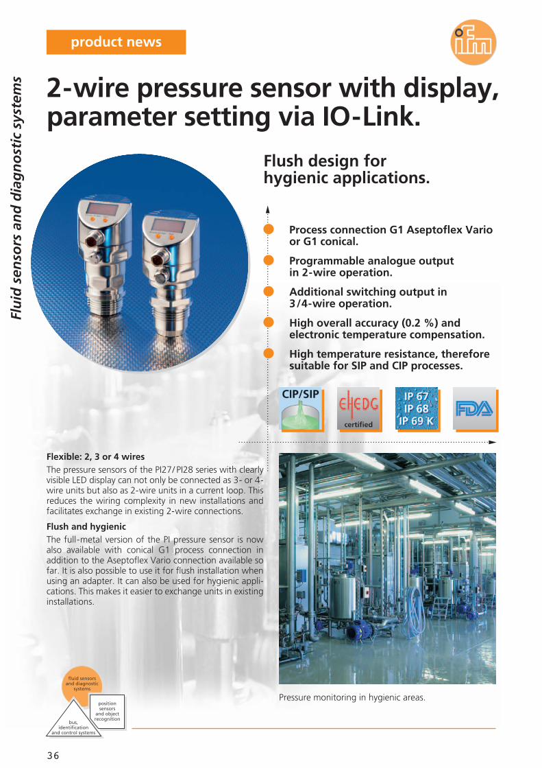
Flush design forhygienic applications.
Pressure monitoring in hygienic areas.
Flexible: 2, 3 or 4 wiresThe pressure sensors of the PI27/ PI28 series with clearlyvisible LED display can not only be connected as 3- or 4-wire units but also as 2-wire units in a current loop. Thisreduces the wiring complexity in new installations andfacilitates exchange in existing 2-wire connections.
Flush and hygienicThe full-metal version of the PI pressure sensor is nowalso available with conical G1 process connection inaddition to the Aseptoflex Vario connection available sofar. It is also possible to use it for flush installation whenusing an adapter. It can also be used for hygienic appli-cations. This makes it easier to exchange units in existinginstallations.
Process connection G1 Aseptoflex Varioor G1 conical.
Programmable analogue outputin 2-wire operation.
Additional switching output in3/4-wire operation.
High overall accuracy (0.2 %) andelectronic temperature compensation.
High temperature resistance, thereforesuitable for SIP and CIP processes.
2-wire pressure sensor with display,parameter setting via IO-Link.
Flu
id s
enso
rs a
nd
dia
gn
ost
ic s
yste
ms
bus,identification
and control systems
fluid sensors and diagnostic
systems
position sensors
and objectrecognition
product news
37
11.2011
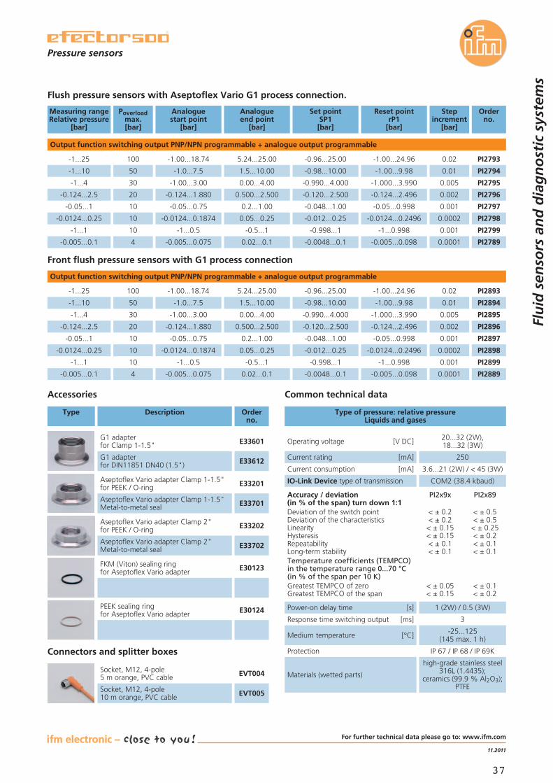
Flush pressure sensors with Aseptoflex Vario G1 process connection.
Measuring rangeRelative pressure
[bar]
Orderno.
Poverloadmax.[bar]
Analoguestart point
[bar]
Analogueend point
[bar]
Set pointSP1[bar]
Reset pointrP1
[bar]
Stepincrement
[bar]
Pressure sensors
Flu
id s
enso
rs a
nd
dia
gn
ost
ic s
yste
ms
Output function switching output PNP/NPN programmable + analogue output programmable
-1...25 PI2793
-1...10 PI2794
-1...4
100
50
30
-1.00...18.74
-1.0...7.5
-1.00...3.00
5.24...25.00
1.5...10.00
0.00...4.00 PI2795
Accessories
Type Description Orderno.
Aseptoflex Vario adapter Clamp 1-1.5"for PEEK / O-ring E33201
Aseptoflex Vario adapter Clamp 1-1.5"Metal-to-metal seal E33701
G1 adapterfor Clamp 1-1.5" E33601
G1 adapterfor DIN11851 DN40 (1.5") E33612
Aseptoflex Vario adapter Clamp 2"for PEEK / O-ring E33202
Aseptoflex Vario adapter Clamp 2"Metal-to-metal seal E33702
FKM (Viton) sealing ringfor Aseptoflex Vario adapter E30123
PEEK sealing ringfor Aseptoflex Vario adapter E30124
-0.96...25.00
-0.98...10.00
-0.990...4.000
-0.124...2.5 PI2796
-0.05...1 PI2797
-0.0124...0.25
20
10
10
-0.124...1.880
-0.05...0.75
-0.0124...0.1874
0.500...2.500
0.2...1.00
0.05...0.25 PI2798
-0.120...2.500
-0.048...1.00
-0.012...0.25
-1.00...24.96
-1.00...9.98
-1.000...3.990
-0.124...2.496
-0.05...0.998
-0.0124...0.2496
-1...1 PI2799
-0.005...0.1
10
4
-1...0.5
-0.005...0.075
-0.5...1
0.02...0.1 PI2789
-0.998...1
-0.0048...0.1
-1...0.998
-0.005...0.098
0.02
0.01
0.005
0.002
0.001
0.0002
0.001
0.0001
Operating voltage [V DC] 20...32 (2W),18...32 (3W)
Current rating [mA] 250
Current consumption [mA] 3.6...21 (2W) / < 45 (3W)
IO-Link Device type of transmission COM2 (38.4 kbaud)
Accuracy / deviation(in % of the span) turn down 1:1Deviation of the switch pointDeviation of the characteristicsLinearityHysteresisRepeatabilityLong-term stabilityTemperature coefficients (TEMPCO)in the temperature range 0...70 °C(in % of the span per 10 K)Greatest TEMPCO of zeroGreatest TEMPCO of the span
PI2x9x
< ± 0.2< ± 0.2< ± 0.15< ± 0.15< ± 0.1< ± 0.1
< ± 0.05< ± 0.15
PI2x89
< ± 0.5< ± 0.5< ± 0.25< ± 0.2< ± 0.1< ± 0.1
< ± 0.1< ± 0.2
Type of pressure: relative pressureLiquids and gases
Common technical data
Medium temperature [°C] -25...125(145 max. 1 h)
Materials (wetted parts)
high-grade stainless steel316L (1.4435);
ceramics (99.9 % Al2O3);PTFE
Power-on delay time [s] 1 (2W) / 0.5 (3W)
Response time switching output [ms] 3
Protection IP 67 / IP 68 / IP 69KConnectors and splitter boxes
Socket, M12, 4-pole5 m orange, PVC cable EVT004
Socket, M12, 4-pole10 m orange, PVC cable EVT005
Output function switching output PNP/NPN programmable + analogue output programmable
PI2893
PI2894
PI2895
PI2896
PI2897
PI2898
PI2899
PI2889
Front flush pressure sensors with G1 process connection
-1...25
-1...10
-1...4
100
50
30
-1.00...18.74
-1.0...7.5
-1.00...3.00
5.24...25.00
1.5...10.00
0.00...4.00
-0.96...25.00
-0.98...10.00
-0.990...4.000
-0.124...2.5
-0.05...1
-0.0124...0.25
20
10
10
-0.124...1.880
-0.05...0.75
-0.0124...0.1874
0.500...2.500
0.2...1.00
0.05...0.25
-0.120...2.500
-0.048...1.00
-0.012...0.25
-1.00...24.96
-1.00...9.98
-1.000...3.990
-0.124...2.496
-0.05...0.998
-0.0124...0.2496
-1...1
-0.005...0.1
10
4
-1...0.5
-0.005...0.075
-0.5...1
0.02...0.1
-0.998...1
-0.0048...0.1
-1...0.998
-0.005...0.098
0.02
0.01
0.005
0.002
0.001
0.0002
0.001
0.0001
For further technical data please go to: www.ifm.com
38
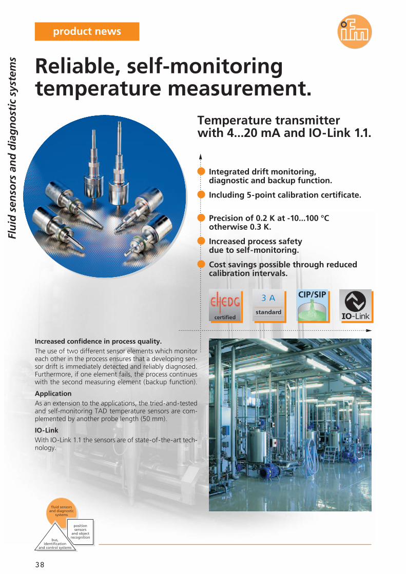
Temperature transmitterwith 4...20 mA and IO-Link 1.1.
Increased confidence in process quality.The use of two different sensor elements which monitoreach other in the process ensures that a developing sen-sor drift is immediately detected and reliably diagnosed.Furthermore, if one element fails, the process continueswith the second measuring element (backup function).
ApplicationAs an extension to the applications, the tried-and-testedand self-monitoring TAD temperature sensors are com-plemented by another probe length (50 mm).
IO-LinkWith IO-Link 1.1 the sensors are of state-of-the-art tech-nology.
Flu
id s
enso
rs a
nd
dia
gn
ost
ic s
yste
ms
bus,identification
and control systems
fluid sensors and diagnostic
systems
position sensors
and objectrecognition
Integrated drift monitoring,diagnostic and backup function.
Including 5-point calibration certificate.
Precision of 0.2 K at -10...100 °Cotherwise 0.3 K.
Increased process safetydue to self-monitoring.
Cost savings possible through reducedcalibration intervals.
Reliable, self-monitoringtemperature measurement.
product news
39
04.2012
Accessories
Type Description Orderno.
Other technical data
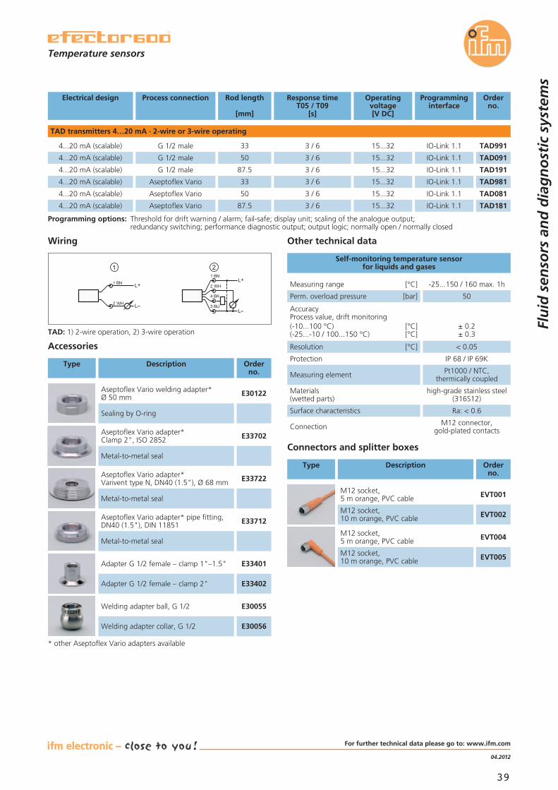
Measuring range [°C] -25...150 / 160 max. 1h
AccuracyProcess value, drift monitoring(-10...100 °C) [°C](-25...-10 / 100...150 °C) [°C]
± 0.2± 0.3
Materials(wetted parts)
high-grade stainless steel(316S12)
Surface characteristics Ra: < 0.6
Connection M12 connector,gold-plated contacts
Perm. overload pressure [bar] 50
Self-monitoring temperature sensorfor liquids and gases
Connectors and splitter boxes
Type Description Orderno.
M12 socket,5 m orange, PVC cable EVT001
M12 socket,10 m orange, PVC cable EVT002
M12 socket,5 m orange, PVC cable EVT004
M12 socket,10 m orange, PVC cable EVT005
Resolution [°C] < 0.05
Measuring element Pt1000 / NTC,thermically coupled
Electrical design Orderno.
Process connection Rod length
[mm]
Response timeT05 / T09
[s]
Programminginterface
TAD transmitters 4…20 mA · 2-wire or 3-wire operating
4...20 mA (scalable)
4...20 mA (scalable)
Operatingvoltage[V DC]
4...20 mA (scalable)
4...20 mA (scalable)
Programming options: Threshold for drift warning / alarm; fail-safe; display unit; scaling of the analogue output;redundancy switching; performance diagnostic output; output logic; normally open / normally closed
Adapter G 1/2 female – clamp 1"–1.5" E33401
Adapter G 1/2 female – clamp 2" E33402
Welding adapter ball, G 1/2 E30055
Welding adapter collar, G 1/2 E30056
Temperature sensors
Flu
id s
enso
rs a
nd
dia
gn
ost
ic s
yste
ms
* other Aseptoflex Vario adapters available
TAD981Aseptoflex Vario 33 15...32 IO-Link 1.1
TAD081Aseptoflex Vario 50 15...32 IO-Link 1.1
G 1/2 male 33 15...32 IO-Link 1.1
TAD091G 1/2 male 50
3 / 6
3 / 6
3 / 6
3 / 6 15...32 IO-Link 1.1
Wiring
2
L+
L
1
L+
L3 BU
4 BK
2 WH
1 BN
2 WH
1 BN
TAD: 1) 2-wire operation, 2) 3-wire operation
Protection IP 68 / IP 69K
Aseptoflex Vario welding adapter*Ø 50 mm E30122
Sealing by O-ring
Aseptoflex Vario adapter*Clamp 2", ISO 2852 E33702
Metal-to-metal seal
Aseptoflex Vario adapter*Varivent type N, DN40 (1.5"), Ø 68 mm E33722
Metal-to-metal seal
Aseptoflex Vario adapter* pipe fitting,DN40 (1.5"), DIN 11851 E33712
Metal-to-metal seal
TAD1814...20 mA (scalable) Aseptoflex Vario 87.5 15...32 IO-Link 1.13 / 6
4...20 mA (scalable) G 1/2 male 87.5 3 / 6 15...32 IO-Link 1.1 TAD191
TAD991
For further technical data please go to: www.ifm.com
40
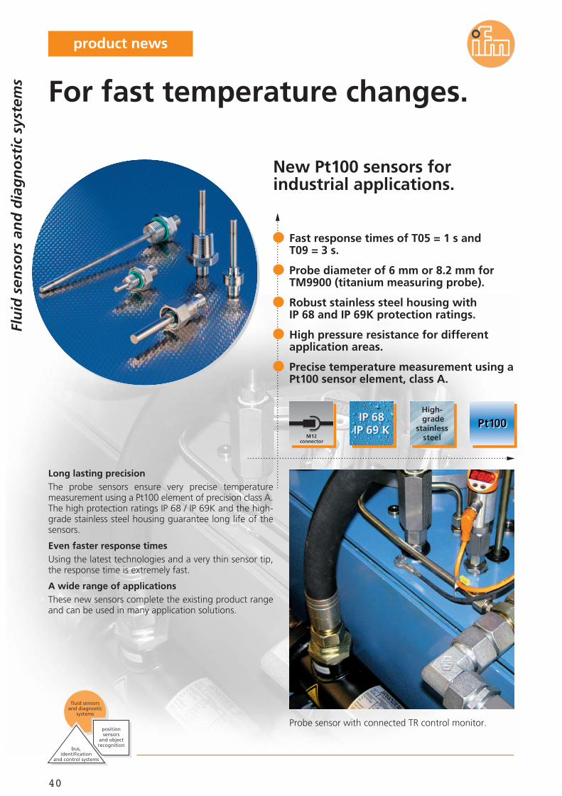
New Pt100 sensors forindustrial applications.
Probe sensor with connected TR control monitor.
Long lasting precisionThe probe sensors ensure very precise temperaturemeasurement using a Pt100 element of precision class A.The high protection ratings IP 68 / IP 69K and the high-grade stainless steel housing guarantee long life of thesensors.
Even faster response timesUsing the latest technologies and a very thin sensor tip,the response time is extremely fast.
A wide range of applicationsThese new sensors complete the existing product rangeand can be used in many application solutions.
Fast response times of T05 = 1 s andT09 = 3 s.
Probe diameter of 6 mm or 8.2 mm forTM9900 (titanium measuring probe).
Robust stainless steel housing withIP 68 and IP 69K protection ratings.
High pressure resistance for differentapplication areas.
Precise temperature measurement using aPt100 sensor element, class A.
For fast temperature changes.
Flu
id s
enso
rs a
nd
dia
gn
ost
ic s
yste
ms
bus,identification
and control systems
fluid sensors and diagnostic
systems
position sensors
and objectrecognition
product news
41
11.2011
Control monitor
Description Orderno.
Control monitor,1 x analogue output, 1 x PNP/NPN TR2432
Control monitor,2 x PNP/NPN TR7432
Measured signal converter,Pt100 / Pt1000 in 4...20 mA, scaling 0...100 °C TP3237
Connectors and splitter boxes
Type Description Orderno.
Socket, M12,2 m black, PUR cable EVC004
Socket, M12,5 m black, PUR cable EVC005
M12 jumper2 m black, PUR cable EVC013
M12 jumper5 m black, PUR cable EVC014
Accessories
Type Description Orderno.
Mounting set, connection of TT sensorsto TR, stainless steel (303 / 1.4305) E30017
Clamp fitting G 1/2, 6/8/10 mm,stainless steel (303 / 1.4305), FPM (Viton) E30018
Clamp fitting 1/2" NPT, 6/8/10 mm,stainless steel (303 / 1.4305); FPM (Viton) E30025
Progressive ring fitting G 1/2, 6 mm, high-grade stainless steel (316Ti / 1.4571) E30047
Progressive ring fitting 1/2" NPT, 6 mm,high-grade stainless steel (316Ti / 1.4571) E30049
Progressive ring fitting G 1/4, 6 mm, high-grade stainless steel (316Ti / 1.4571) E33431
Welding adapter, 24.7 mm, clamp adapter,high-grade stainless steel (316L / 1.4404) E30108
Adapter G 1/2 for TM9900,Titanium E40114
Adapter G 1/4 for TM9900,Titanium E40115
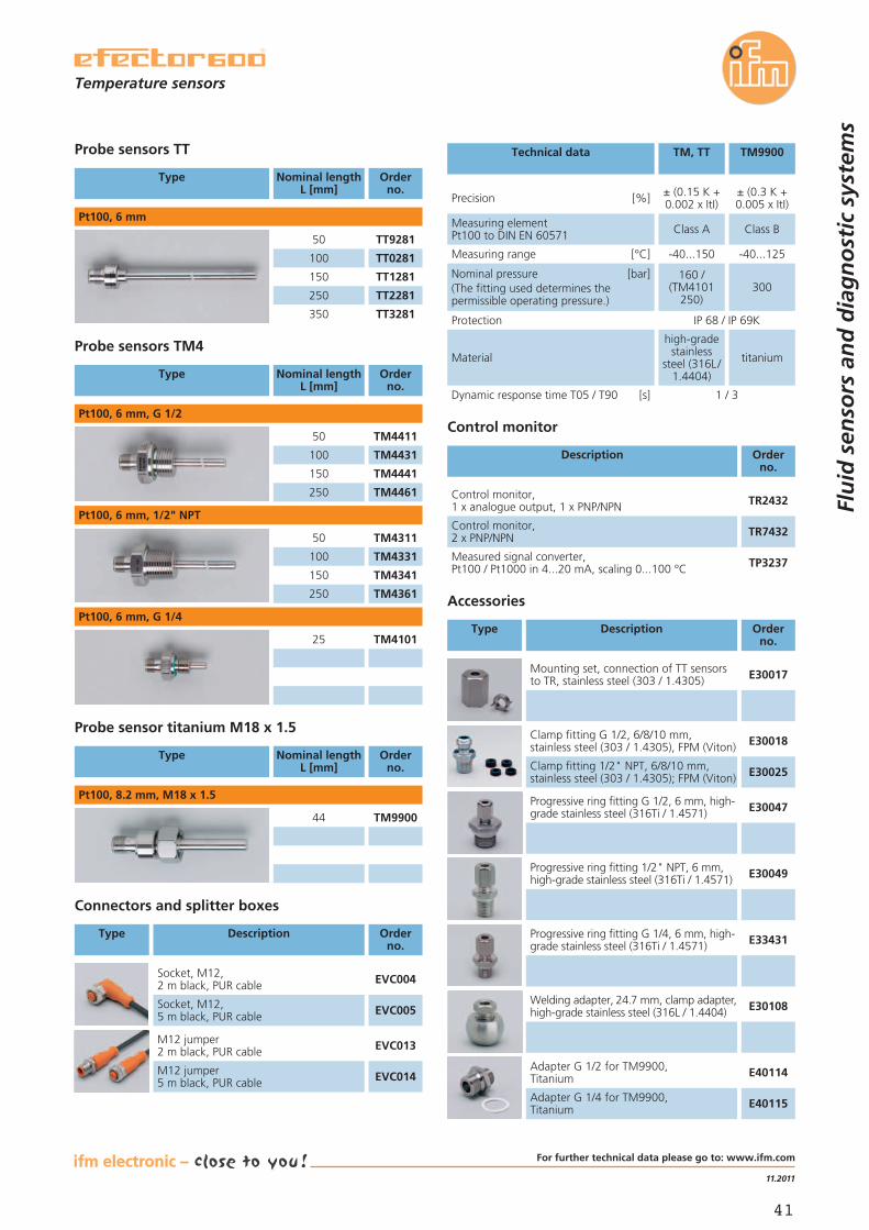
Nominal pressure [bar](The fitting used determines thepermissible operating pressure.)
160 /(TM4101
250)300
Protection IP 68 / IP 69K
Material
high-gradestainless
steel (316L/1.4404)
titanium
Dynamic response time T05 / T90 [s] 1 / 3
Measuring range [°C] -40...150 -40...125
Precision [%] ± (0.15 K +0.002 x ItI)
± (0.3 K +0.005 x ItI)
Measuring elementPt100 to DIN EN 60571 Class A Class B
Technical dataProbe sensors TT
Type Nominal lengthL [mm]
Orderno.
Pt100, 6 mm
Probe sensors TM4
Type Nominal lengthL [mm]
Orderno.
TM441150
TM4431100
TM4441150
TM4461250
Pt100, 6 mm, G 1/2
TM431150
TM4331100
TM4341150
TM4361250
Pt100, 6 mm, 1/2" NPT
TT928150
TT0281100
TT1281150
TT2281250
TT3281350
Probe sensor titanium M18 x 1.5
Type Nominal lengthL [mm]
Orderno.
Pt100, 8.2 mm, M18 x 1.5
TM990044
TM, TT TM9900
Temperature sensors
Flu
id s
enso
rs a
nd
dia
gn
ost
ic s
yste
ms
TM410125
Pt100, 6 mm, G 1/4
For further technical data please go to: www.ifm.com
42
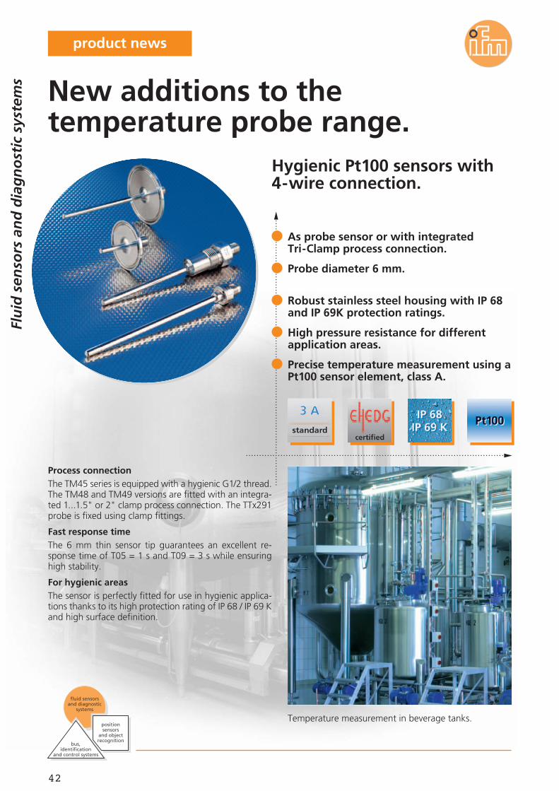
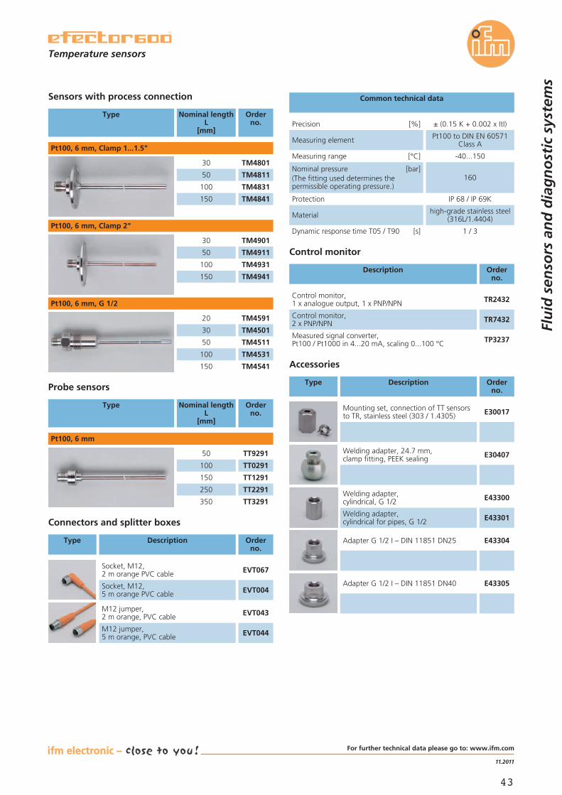
Hygienic Pt100 sensors with4-wire connection.
Temperature measurement in beverage tanks.
Process connectionThe TM45 series is equipped with a hygienic G1/2 thread.The TM48 and TM49 versions are fitted with an integra-ted 1...1.5" or 2" clamp process connection. The TTx291probe is fixed using clamp fittings.
Fast response timeThe 6 mm thin sensor tip guarantees an excellent re-sponse time of T05 = 1 s and T09 = 3 s while ensuringhigh stability.
For hygienic areasThe sensor is perfectly fitted for use in hygienic applica-tions thanks to its high protection rating of IP 68 / IP 69 Kand high surface definition.
As probe sensor or with integratedTri-Clamp process connection.
Probe diameter 6 mm.
Robust stainless steel housing with IP 68and IP 69K protection ratings.
High pressure resistance for differentapplication areas.
Precise temperature measurement using aPt100 sensor element, class A.
New additions to thetemperature probe range.
Flu
id s
enso
rs a
nd
dia
gn
ost
ic s
yste
ms
bus,identification
and control systems
fluid sensors and diagnostic
systems
position sensors
and objectrecognition
product news
43
11.2011
Control monitor
Description Orderno.
Control monitor,1 x analogue output, 1 x PNP/NPN TR2432
Control monitor,2 x PNP/NPN TR7432
Measured signal converter,Pt100 / Pt1000 in 4...20 mA, scaling 0...100 °C TP3237
Connectors and splitter boxes
Type Description Orderno.
Socket, M12,2 m orange PVC cable EVT067
Socket, M12,5 m orange PVC cable EVT004
M12 jumper,2 m orange, PVC cable EVT043
M12 jumper,5 m orange, PVC cable EVT044
Accessories
Type Description Orderno.
Mounting set, connection of TT sensorsto TR, stainless steel (303 / 1.4305) E30017
Welding adapter, 24.7 mm,clamp fitting, PEEK sealing E30407
Nominal pressure [bar](The fitting used determines thepermissible operating pressure.)
160
Protection IP 68 / IP 69K
Material high-grade stainless steel(316L/1.4404)
Dynamic response time T05 / T90 [s] 1 / 3
Measuring range [°C] -40...150
Precision [%] ± (0.15 K + 0.002 x ItI)
Measuring element Pt100 to DIN EN 60571Class A
Common technical dataSensors with process connection
Type Nominal lengthL
[mm]
Orderno.
TM480130
TM481150
TM4831100
TM4841150
Pt100, 6 mm, Clamp 1...1.5"
TM490130
TM491150
TM4931100
TM4941150
Pt100, 6 mm, Clamp 2"
Probe sensors
Type Nominal lengthL
[mm]
Orderno.
TT929150
TT0291100
TT1291150
TT2291250
TT3291350
Pt100, 6 mm
Temperature sensors
Flu
id s
enso
rs a
nd
dia
gn
ost
ic s
yste
ms
TM459120
TM450130
TM451150
TM4531100
TM4541150
Pt100, 6 mm, G 1/2
Welding adapter,cylindrical, G 1/2 E43300
Welding adapter,cylindrical for pipes, G 1/2 E43301
Adapter G 1/2 I – DIN 11851 DN25 E43304
Adapter G 1/2 I – DIN 11851 DN40 E43305
For further technical data please go to: www.ifm.com
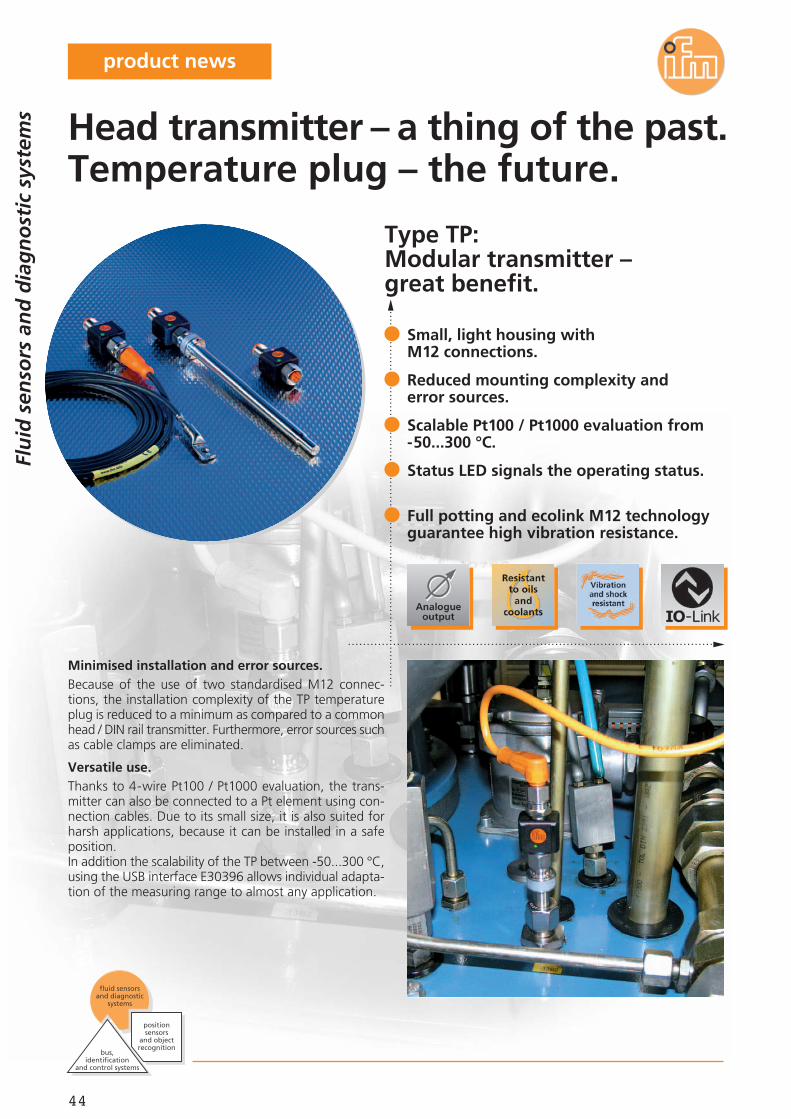
44
Type TP:Modular transmitter –great benefit.
Minimised installation and error sources.Because of the use of two standardised M12 connec-tions, the installation complexity of the TP temperatureplug is reduced to a minimum as compared to a commonhead / DIN rail transmitter. Furthermore, error sources suchas cable clamps are eliminated.
Versatile use.Thanks to 4-wire Pt100 / Pt1000 evaluation, the trans-mitter can also be connected to a Pt element using con-nection cables. Due to its small size, it is also suited forharsh applications, because it can be installed in a safeposition.In addition the scalability of the TP between -50...300 °C,using the USB interface E30396 allows individual adapta-tion of the measuring range to almost any application.
Small, light housing withM12 connections.
Reduced mounting complexity anderror sources.
Scalable Pt100 / Pt1000 evaluation from-50...300 °C.
Status LED signals the operating status.
Full potting and ecolink M12 technologyguarantee high vibration resistance.
Head transmitter – a thing of the past.Temperature plug – the future.
Flu
id s
enso
rs a
nd
dia
gn
ost
ic s
yste
ms
bus,identification
and control systems
fluid sensors and diagnostic
systems
position sensors
and objectrecognition
product news
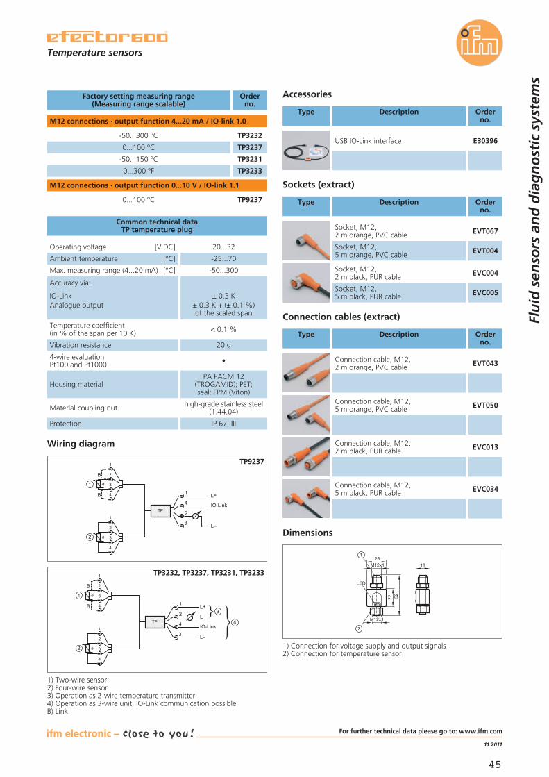
45
11.2011
Factory setting measuring range(Measuring range scalable)
Orderno.
M12 connections · output function 4...20 mA / IO-link 1.0
Sockets (extract)
Type Description Orderno.
Socket, M12,2 m orange, PVC cable EVT067
Socket, M12,5 m orange, PVC cable EVT004
Socket, M12,2 m black, PUR cable EVC004
Socket, M12,5 m black, PUR cable EVC005
Operating voltage [V DC] 20...32
Ambient temperature [°C] -25...70
Max. measuring range (4...20 mA) [°C] -50...300
4-wire evaluationPt100 and Pt1000 •
Housing materialPA PACM 12
(TROGAMID); PET;seal: FPM (Viton)
Material coupling nut high-grade stainless steel(1.44.04)
Protection IP 67, III
Accuracy via:
IO-LinkAnalogue output
± 0.3 K± 0.3 K + (± 0.1 %)of the scaled span
Temperature coefficient(in % of the span per 10 K) < 0.1 %
Common technical dataTP temperature plug
Connection cables (extract)
Type Description Orderno.
Connection cable, M12,2 m orange, PVC cable EVT043
Connection cable, M12,5 m orange, PVC cable EVT050
Connection cable, M12,2 m black, PUR cable EVC013
Connection cable, M12,5 m black, PUR cable EVC034
USB IO-Link interface E30396
Accessories
Type Description Orderno.
Temperature sensors
Flu
id s
enso
rs a
nd
dia
gn
ost
ic s
yste
ms
Vibration resistance 20 g
Dimensions
Wiring diagram
1) Connection for voltage supply and output signals2) Connection for temperature sensor
18M12x1
M12x1
25
LED
22 52
2
1) Two-wire sensor2) Four-wire sensor3) Operation as 2-wire temperature transmitter4) Operation as 3-wire unit, IO-Link communication possibleB) Link
TP3232
TP3237
-50...300 °C
0...100 °C
TP3231-50...150 °C
TP32330...300 °F
M12 connections · output function 0...10 V / IO-link 1.1
TP92370...100 °C
4
1
3
2
L+
L
IO-Link
1
2
3
4
1
2
1
2
3
4
B
B
TP
4
1
3
2L+
L
L
IO-Link1
2
3
4
1
2
3
4
1
2
3
4
B
B
TP
TP9237
TP3232, TP3237, TP3231, TP3233
For further technical data please go to: www.ifm.com
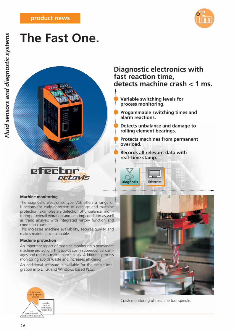
46
Diagnostic electronics withfast reaction time,detects machine crash < 1 ms.
Crash monitoring of machine tool spindle.
Machine monitoringThe diagnostic electronics type VSE offers a range offunctions for early detection of damage and machineprotection. Examples are detection of unbalance, moni-toring of overall vibration and bearing condition as wellas trend analysis with integrated history function andcondition counters.This increases machine availability, secures quality andmakes maintenance planable.
Machine protectionAn important aspect of machine monitoring is permanentmachine protection. This avoids costly subsequential dam-ages and reduces maintenance costs. Additional processmonitoring avoids waste and increases efficiency.An additional software is available for the simple inte-gration into Linux and Windows based PLCs.
Variable switching levels forprocess monitoring.
Progammable switching times andalarm reactions.
Detects unbalance and damage torolling element bearings.
Protects machines from permanentoverload.
Records all relevant data withreal-time stamp.
The Fast One.
Flu
id s
enso
rs a
nd
dia
gn
ost
ic s
yste
ms
bus,identification
and control systems
fluid sensors and diagnostic
systems
position sensors
and objectrecognition
product news
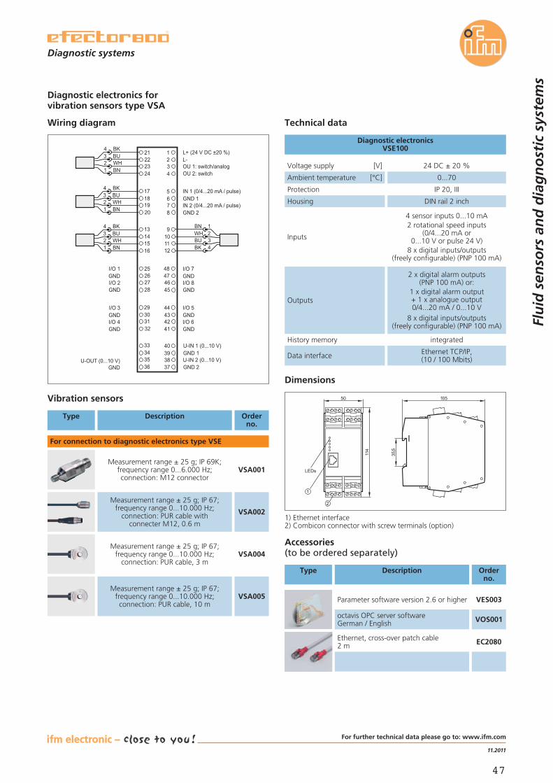
47
11.2011
Technical data
Voltage supply [V] 24 DC ± 20 %
Protection IP 20, III
Ambient temperature [°C] 0...70
Housing DIN rail 2 inch
Diagnostic electronicsVSE100
Dimensions
50
114
LEDs
2
1
10535,5
Diagnostic electronics forvibration sensors type VSA
Wiring diagram
L+ (24 V DC ±20 %)
1817
2019
1413
1615
2221
2423
65
87
21
43
109
1211
L-OU 1: switch/analog OU 2: switch
IN 1 (0/4...20 mA / pulse)GND 1IN 2 (0/4...20 mA / pulse)GND 2
1234
BNWHBUBK
4321
BKBUWHBN
I/O 7
3029
3231
3433
3635
2625
2827
4344
4142
4748
4546
3940
3738
GNDI/O 8GND
I/O 5GNDI/O 6GND
I/O 1GNDI/O 2GND
I/O 3GNDI/O 4GND
U-OUT (0...10 V)GND
U-IN 1 (0...10 V)GND 1U-IN 2 (0...10 V)GND 2
1234
BNWHBUBK
1234
BNWHBUBK
Data interface Ethernet TCP/IP,(10 / 100 Mbits)
History memory integrated
1) Ethernet interface2) Combicon connector with screw terminals (option)
Accessories(to be ordered separately)
Type Description Orderno.
Parameter software version 2.6 or higher VES003
octavis OPC server softwareGerman / English VOS001
Ethernet, cross-over patch cable2 m EC2080
Inputs
4 sensor inputs 0...10 mA2 rotational speed inputs
(0/4...20 mA or0...10 V or pulse 24 V)
8 x digital inputs/outputs(freely configurable) (PNP 100 mA)
Outputs
2 x digital alarm outputs(PNP 100 mA) or:
1 x digital alarm output+ 1 x analogue output0/4...20 mA / 0...10 V
8 x digital inputs/outputs(freely configurable) (PNP 100 mA)
Orderno.
Vibration sensors
For connection to diagnostic electronics type VSE
VSA001Measurement range ± 25 g; IP 69K;
frequency range 0...6.000 Hz;connection: M12 connector
VSA002
Measurement range ± 25 g; IP 67;frequency range 0...10.000 Hz;
connection: PUR cable withconnecter M12, 0.6 m
VSA004Measurement range ± 25 g; IP 67;
frequency range 0...10.000 Hz;connection: PUR cable, 3 m
VSA005Measurement range ± 25 g; IP 67;
frequency range 0...10.000 Hz;connection: PUR cable, 10 m
Type Description
Flu
id s
enso
rs a
nd
dia
gn
ost
ic s
yste
ms
Diagnostic systems
For further technical data please go to: www.ifm.com
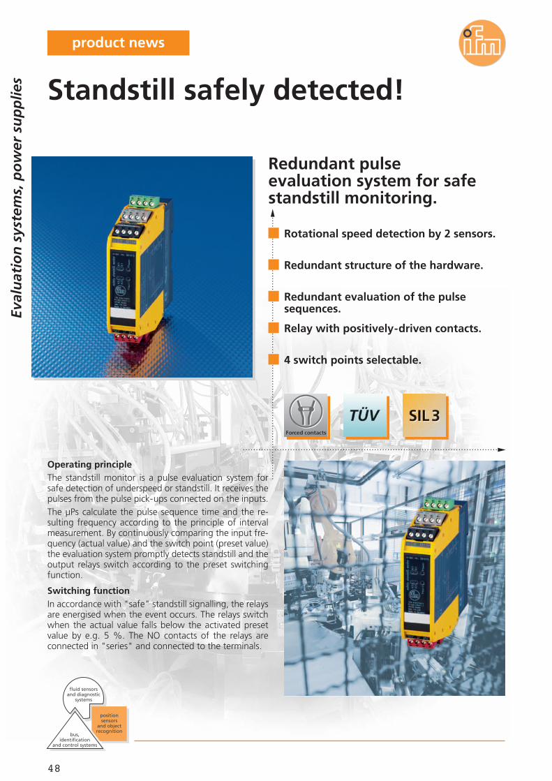
48
Redundant pulseevaluation system for safestandstill monitoring.
Operating principleThe standstill monitor is a pulse evaluation system forsafe detection of underspeed or standstill. It receives thepulses from the pulse pick-ups connected on the inputs.The μPs calculate the pulse sequence time and the re-sulting frequency according to the principle of intervalmeasurement. By continuously comparing the input fre-quency (actual value) and the switch point (preset value)the evaluation system promptly detects standstill and theoutput relays switch according to the preset switchingfunction.
Switching functionIn accordance with "safe" standstill signalling, the relaysare energised when the event occurs. The relays switchwhen the actual value falls below the activated presetvalue by e.g. 5 %. The NO contacts of the relays areconnected in "series" and connected to the terminals.
Eval
uat
ion
sys
tem
s, p
ow
er s
up
plie
s
Rotational speed detection by 2 sensors.
Redundant structure of the hardware.
Redundant evaluation of the pulsesequences.
Relay with positively-driven contacts.
4 switch points selectable.
Standstill safely detected!
bus,identification
and control systems
fluid sensors and diagnostic
systems
position sensors
and objectrecognition
product news
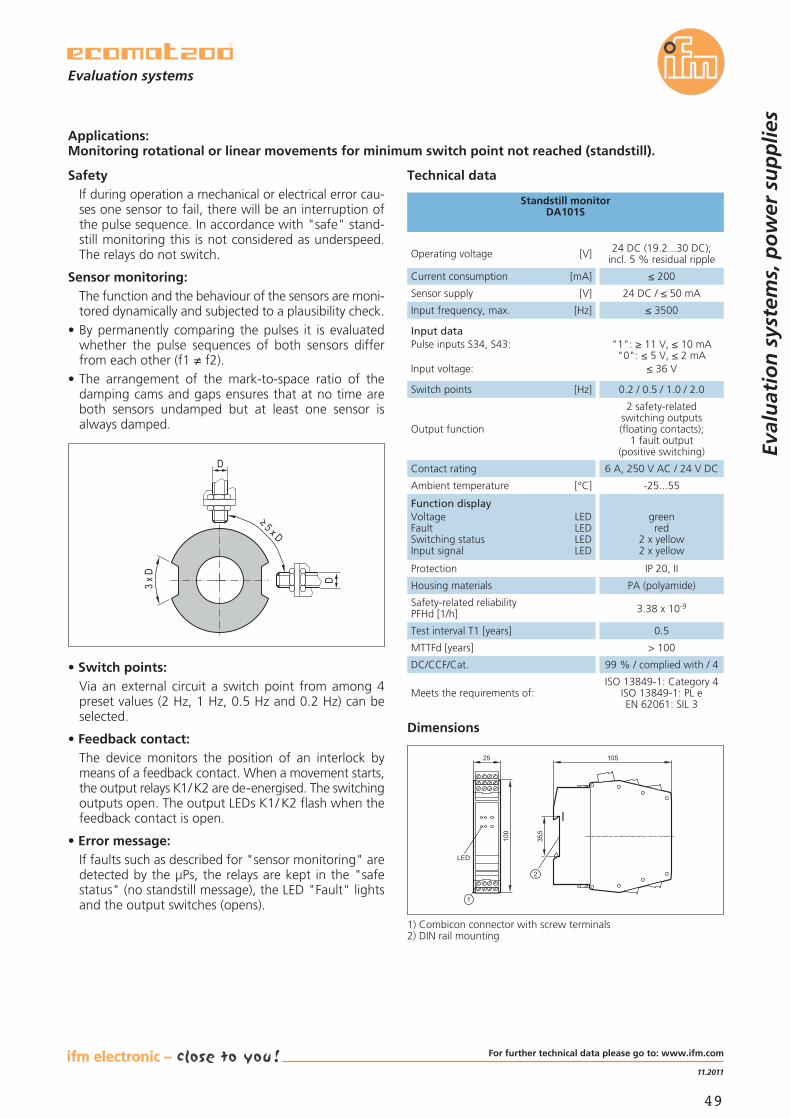
49
11.2011
Applications:Monitoring rotational or linear movements for minimum switch point not reached (standstill).
Eval
uat
ion
sys
tem
s, p
ow
er s
up
plie
s
Evaluation systems
Operating voltage [V] 24 DC (19.2...30 DC);incl. 5 % residual ripple
Sensor supply [V] 24 DC / ≤ 50 mA
Input frequency, max. [Hz] ≤ 3500
Current consumption [mA] ≤ 200
Switch points [Hz] 0.2 / 0.5 / 1.0 / 2.0
Input dataPulse inputs S34, S43:
Input voltage:
"1": ≥ 11 V, ≤ 10 mA"0": ≤ 5 V, ≤ 2 mA
≤ 36 V
Output function
2 safety-relatedswitching outputs(floating contacts);
1 fault output(positive switching)
Contact rating 6 A, 250 V AC / 24 V DC
Ambient temperature [°C] -25...55
Function displayVoltage LEDFault LEDSwitching status LEDInput signal LED
greenred
2 x yellow2 x yellow
Protection IP 20, II
Housing materials PA (polyamide)
Safety-related reliabilityPFHd [1/h] 3.38 x 10⁻⁹
Test interval T1 [years] 0.5
MTTFd [years] > 100
DC/CCF/Cat. 99 % / complied with / 4
Standstill monitorDA101S
Dimensions
25
100
LED
35,5
105
1) Combicon connector with screw terminals2) DIN rail mounting
Technical dataSafetyIf during operation a mechanical or electrical error cau-ses one sensor to fail, there will be an interruption ofthe pulse sequence. In accordance with "safe" stand-still monitoring this is not considered as underspeed.The relays do not switch.
Sensor monitoring:The function and the behaviour of the sensors are moni-tored dynamically and subjected to a plausibility check.
• By permanently comparing the pulses it is evaluatedwhether the pulse sequences of both sensors differfrom each other (f1 ≠ f2).
• The arrangement of the mark-to-space ratio of thedamping cams and gaps ensures that at no time areboth sensors undamped but at least one sensor isalways damped.
• Switch points:Via an external circuit a switch point from among 4preset values (2 Hz, 1 Hz, 0.5 Hz and 0.2 Hz) can beselected.
• Feedback contact:The device monitors the position of an interlock bymeans of a feedback contact. When a movement starts,the output relays K1/ K2 are de-energised. The switchingoutputs open. The output LEDs K1/ K2 flash when thefeedback contact is open.
• Error message:If faults such as described for "sensor monitoring" aredetected by the μPs, the relays are kept in the "safestatus" (no standstill message), the LED "Fault" lightsand the output switches (opens).
≥ 5 x D
D
D
3 x D
Meets the requirements of:ISO 13849-1: Category 4
ISO 13849-1: PL eEN 62061: SIL 3
For further technical data please go to: www.ifm.com

50
ecolink –a new dimension in connection technology.
For hygienic and wet areasin the food industry.
ecolink M12 for demanding applications.Most applications require special solutions. Only high-quality materials, safe production processes and fault-less mounting lead to success in the long run.The integrated end stop protects the O-ring againstdestruction caused by tightening the nut too much.Mounting and removal are carried out without tools.The asymmetrically acting vibration protection holds thenut tight in its position, guaranteeing an optimum andpermanent seal.High-quality materials especially adapted to the applica-tion and intensive monitoring during and after produc-tion guarantee maximum quality standards.
Co
nn
ecti
on
tec
hn
olo
gy
bus,identification
and control systems
position sensors
and objectrecognition
fluid sensors and diagnostic
systems
Connection technology meets the M12standard (EN 61076).
Optimum sealing even when mountedwithout tools.
The mechanical end stop protects
the O-ring against destruction.
Nut secured against shock/vibration due tosaw tooth contoured vibration protection.
LEDs clearly visible even in cases of highlight exposure.
ecolink M12 – the secure connectioneven in difficult applications.
product news
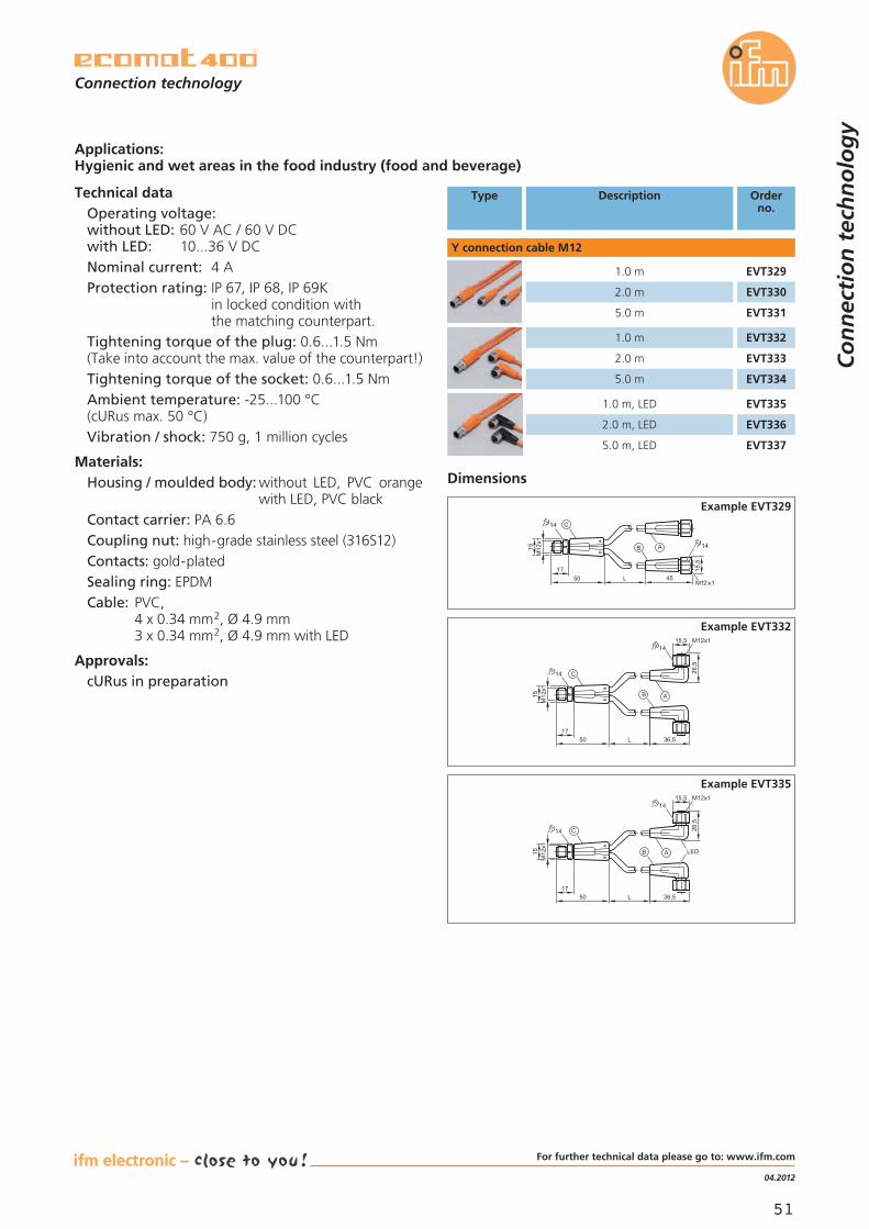
51
04.2012
Technical dataOperating voltage:without LED: 60 V AC / 60 V DCwith LED: 10...36 V DCNominal current: 4 AProtection rating: IP 67, IP 68, IP 69K
in locked condition withthe matching counterpart.
Tightening torque of the plug: 0.6...1.5 Nm(Take into account the max. value of the counterpart!)Tightening torque of the socket: 0.6...1.5 NmAmbient temperature: -25...100 °C(cURus max. 50 °C)Vibration / shock: 750 g, 1 million cycles
Materials:Housing / moulded body: without LED, PVC orange
with LED, PVC blackContact carrier: PA 6.6Coupling nut: high-grade stainless steel (316S12)Contacts: gold-platedSealing ring: EPDMCable: PVC,
4 x 0.34 mm2, Ø 4.9 mm3 x 0.34 mm2, Ø 4.9 mm with LED
Approvals:cURus in preparation
Co
nn
ecti
on
tec
hn
olo
gy
Connection technology
Applications:Hygienic and wet areas in the food industry (food and beverage)
Type Description Orderno.
Dimensions
L5017
M12x1
15
15,5
45
14
M12x1
14
B A
C
Example EVT329
L5017
M12x1
15
36,5
15,5
26,5
14M12x1
14
B A
C
Example EVT332
L5017
M12x1
15
36,5
15,5
26,5
14M12x1
14
LEDB A
C
Example EVT335
1.0 m
2.0 m
5.0 m
1.0 m
2.0 m
5.0 m
1.0 m, LED
2.0 m, LED
5.0 m, LED
EVT329
EVT330
EVT331
EVT335
EVT336
EVT337
EVT332
EVT333
EVT334
Y connection cable M12
For further technical data please go to: www.ifm.com

52
ecolink –a new dimension in connection technology.
From factory automation tomachine tool industry.
ecolink M12 for demanding applications.Most applications require special solutions. Only high-quality materials, safe production processes and fault-less mounting lead to success in the long run.The integrated end stop protects the O-ring againstdestruction caused by tightening the nut too much.Mounting and removal are carried out without tools.The asymmetrically acting vibration protection holds thenut tight in its position, guaranteeing an optimum andpermanent seal.High-quality materials especially adapted to the applica-tion and intensive monitoring during and after produc-tion guarantee maximum quality standards.
Co
nn
ecti
on
tec
hn
olo
gy
bus,identification
and control systems
position sensors
and objectrecognition
fluid sensors and diagnostic
systems
Connection technology meets the M12standard (EN 61076).
Optimum sealing even when mountedwithout tools.
The mechanical end stop protects
the O-ring against destruction.
Nut secured against shock/vibration due tosaw tooth contoured vibration protection.
LEDs clearly visible even in cases of highlight exposure.
ecolink M12 – the secure connectioneven in difficult applications.
product news
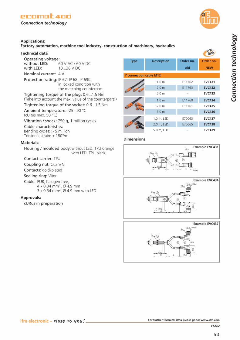
53
04.2012
Technical dataOperating voltage:without LED: 60 V AC / 60 V DCwith LED: 10...36 V DCNominal current: 4 AProtection rating: IP 67, IP 68, IP 69K
in locked condition withthe matching counterpart.
Tightening torque of the plug: 0.6...1.5 Nm(Take into account the max. value of the counterpart!)Tightening torque of the socket: 0.6...1.5 NmAmbient temperature: -25...90 °C(cURus max. 50 °C)Vibration / shock: 750 g, 1 million cyclesCable characteristics:Bending cycles: > 5 millionTorsional strain: ± 180°/m
Materials:Housing / moulded body: without LED, TPU orange
with LED, TPU blackContact carrier: TPUCoupling nut: CuZn/NiContacts: gold-platedSealing ring: VitonCable: PUR, halogen-free,
4 x 0.34 mm2, Ø 4.9 mm3 x 0.34 mm2, Ø 4.9 mm with LED
Approvals:cURus in preparation
Co
nn
ecti
on
tec
hn
olo
gy
Connection technology
Applications:Factory automation, machine tool industry, construction of machinery, hydraulics
Type Description Order no.
NEW
Order no.
old
Dimensions
Example EVC431
Example EVC434
Example EVC437
Y connection cable M12
1.0 m EVC431
2.0 m EVC432
5.0 m EVC433
E11762
E11763
–
1.0 m EVC434
2.0 m EVC435
5.0 m EVC436
E11760
E11761
–
1.0 m, LED EVC437
2.0 m, LED EVC438
5.0 m, LED EVC439
E70063
E70065
–
L5017
M12x1
15
14
45
15,5
M12x1
14
B A
C
4,2
L5017
M12x1
15
14
36,5
26,5
1415,5 M12x1
B A
C
4,2
L5017
M12x1
15
14
36,5
26,5
1415,5 M12x1
LEDB A
C
4,2
For further technical data please go to: www.ifm.com

54
AS-i gateways withultra short transfer times.
The bus at a glanceThe new ifm gateways are the fast connection from AS-ito Profibus or Profinet. Thanks to a colour display andweb interface, the status of all AS-i slaves is recognizableat a single glance.The quick set-up menu and intuitive handling facilitateinstallation and diagnosis. In addition, the web interfaceallows full remote access.
Three types of voltage supplyThe flexible voltage supply ensures a low-cost integrationinto your application. The units can be operated via AS-ipower supplies, DC power supplies, or a combination ofboth. It is also allowed to supply several AS-i networksvia a single power supply.
Colour display for clear diagnosisand set-up.
AS-i double address recognition.
Earth fault monitor.
Profinet switch with 2 ports and certifica-tion according to Conformance Class B.
Profibus DP interface with certifiedDPV0 and DPV1 functionality.
Third-generation communicator.
Bu
s sy
stem
s
bus,identification
and control systems
fluid sensors and diagnostic
systems
position sensors
and objectrecognition
product news

55
04.2012
The products
Description Orderno.
AS-i Profinet gateway1 AS-i master with M4 profile AC1401
AS-i Profinet gateway2 AS-i masters with M4 profile AC1402
AS-i data decoupling,can be mounted on AS-i Profinet gateway AC1250
Functions
• Pluggable data decouplingVia the optional data decoupling AC1250, the gatewayand the connected AS-i slaves can be powered by onepower supply. A single voltage source can hereby supplyseveral gateways and their AS-i networks.Power supplies with a voltage of 30 V (DC or AS-i)allow any possible AS-i structure at full cable length.The use of a 24 V power supply offers the advantageof AS-i power24: For AS-i networks of up to 50 m theintroduction of the bus system AS-interface will becomeeven more cost-efficient.
• Transfer of AS-i dataPLC user programs of existing plant can be changed tothe new AS-i gateways of the third generation withoutany changes to the I /O addresses.
Advantages and customer benefits
Communication interfaces:
Profinet:Profinet Class BProfinet switch 2 ports integrated
Profibus:Profibus DPV0 and DPV1 functionality
AS-Interface:1 and 2 AS-i masters pursuant to M4 profile
Configuration interface:Ethernet with integrated web interface
Connections:AS-i and auxiliary supply: plug-in terminals(supplied with the unit)Profinet 2 x RJ45Profibus D-Sub 9Configuration interface RJ45
Visualisation:1.8" colour displayLEDs for unit and fieldbus status
Housing:Robust metal housing:aluminium powder-coated; steel sheet galvanised
Ambient temperature:Operating temperature 0...60 °CStorage temperature -20...70 °C
Bu
s sy
stem
s
Bus system AS-interface
AS-i Profibus gateway1 AS-i master with M4 profile AC1411
AS-i Profibus gateway2 AS-i masters with M4 profile AC1412
Dimensions
106,293
135,5
128,2
AC1401 / AC1402
128,2
45 62,865,5 AC1250
106,293
135,5
128,2
AC1411 / AC1412
1) Sub-D (9 poles)
For further technical data please go to: www.ifm.com

56
System overview with safety-related components.
host (PLC)
standardmodule
standard PLCstandard AS-i master
I3
I1
I2
I4
safetymonitor safe
inputmodule
e-stop
standardswitch
AS-i safety monitorallows parameter setting viaUSB interface.
IntroductionThe new AS-i safety monitor processes up to four safeinputs or eight standard inputs /outputs locally and upto 31 safe slaves in the AS-i system. The AS-i safetymonitor is equipped with a USB interface and a chip cardfor an easy exchange of units.The user-friendly configuration and diagnostic softwareASIMON V3.0 G2 enables clear and quick assignmentand logical combination of the safety-related bus com-ponents in the tried-and-tested function block represen-tation under Windows.
4 safe inputs or8 standard inputs/outputs locally.
2 safe electronic outputs locally,6 triggerable outputs in the field.
USB 2.0 interface for clear configurationand diagnosis using the PC.
Saving of data on chip card for an easyexchange of units.
Certification to EN 62061/ SIL3,IEC 61508 / SIL3 and EN ISO13849-1/PLe.
AS-i safety made easy.
Safety at Work
Bu
s sy
stem
s
bus,identification
and control systems
fluid sensors and diagnostic
systems
position sensors
and objectrecognition
product news
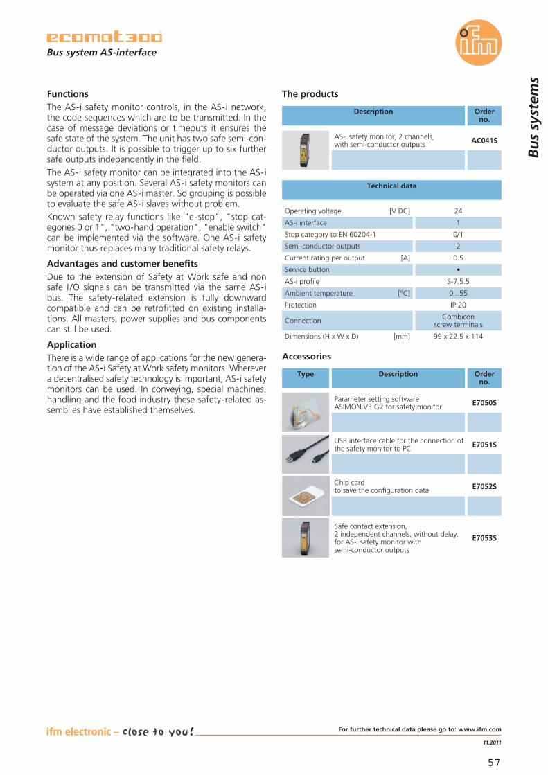
57
11.2011
The products
Description Orderno.
FunctionsThe AS-i safety monitor controls, in the AS-i network,the code sequences which are to be transmitted. In thecase of message deviations or timeouts it ensures thesafe state of the system. The unit has two safe semi-con-ductor outputs. It is possible to trigger up to six furthersafe outputs independently in the field.The AS-i safety monitor can be integrated into the AS-isystem at any position. Several AS-i safety monitors canbe operated via one AS-i master. So grouping is possibleto evaluate the safe AS-i slaves without problem.Known safety relay functions like "e-stop", "stop cat-egories 0 or 1", "two-hand operation", "enable switch"can be implemented via the software. One AS-i safetymonitor thus replaces many traditional safety relays.
Advantages and customer benefitsDue to the extension of Safety at Work safe and nonsafe I /O signals can be transmitted via the same AS-ibus. The safety-related extension is fully downwardcompatible and can be retrofitted on existing installa-tions. All masters, power supplies and bus componentscan still be used.
ApplicationThere is a wide range of applications for the new genera-tion of the AS-i Safety at Work safety monitors. Wherevera decentralised safety technology is important, AS-i safetymonitors can be used. In conveying, special machines,handling and the food industry these safety-related as-semblies have established themselves.
Operating voltage [V DC] 24
AS-i interface 1
Semi-conductor outputs 2
Current rating per output [A] 0.5
Service button •
AS-i profile S-7.5.5
Ambient temperature [°C] 0...55
Protection IP 20
Connection Combiconscrew terminals
Dimensions (H x W x D) [mm] 99 x 22.5 x 114
Stop category to EN 60204-1 0/1
Technical data
Accessories
Type Description Orderno.
Parameter setting softwareASIMON V3 G2 for safety monitor E7050S
USB interface cable for the connection ofthe safety monitor to PC E7051S
Chip cardto save the configuration data E7052S
AS-i safety monitor, 2 channels,with semi-conductor outputs AC041S
Bu
s sy
stem
s
Bus system AS-interface
E7053S
Safe contact extension,2 independent channels, without delay,for AS-i safety monitor withsemi-conductor outputs
For further technical data please go to: www.ifm.com

58
Flexible RFID system withevaluation unit, antennas andtransponders.
The new RFID evaluation unit with integrated Profi-bus-DP interface and web server can be used in produc-tion to mark tools, for quality assurance such as monitor-ing production steps, in conveying and in automationtechnology. Easy to use – flexible parameter setting –you can solve any identification task.The antenna concept guarantees easy and fast con-nection of the LF and HF RFID antennas to the evalu-ation unit by means of M12 connectors from 0.3...20 mfrom ifm electronic.The production range of the transponders includesnot only LF transponders with up to 2 Kbit-memory butalso HF transponders with 16 Kbits as FRAM versionwhich can be rewritten an unlimited number of times.
RFID evaluation unit with Profibus-DPand web server.
Evaluation unit with 4 antennaconnections or digital I /Os.
Read/write antennas in industriallycompatible housing.
Antennas and transponders from a fewbits to Kbytes.
Protection rating IP 67 meets the require-ments for harsh environments.
RFID with Profibus-DP forproduction and conveying.
bus,identification
and control systems
fluid sensors and diagnostic
systems
position sensors
and objectrecognition
Iden
tifi
cati
on
sys
tem
s
product news
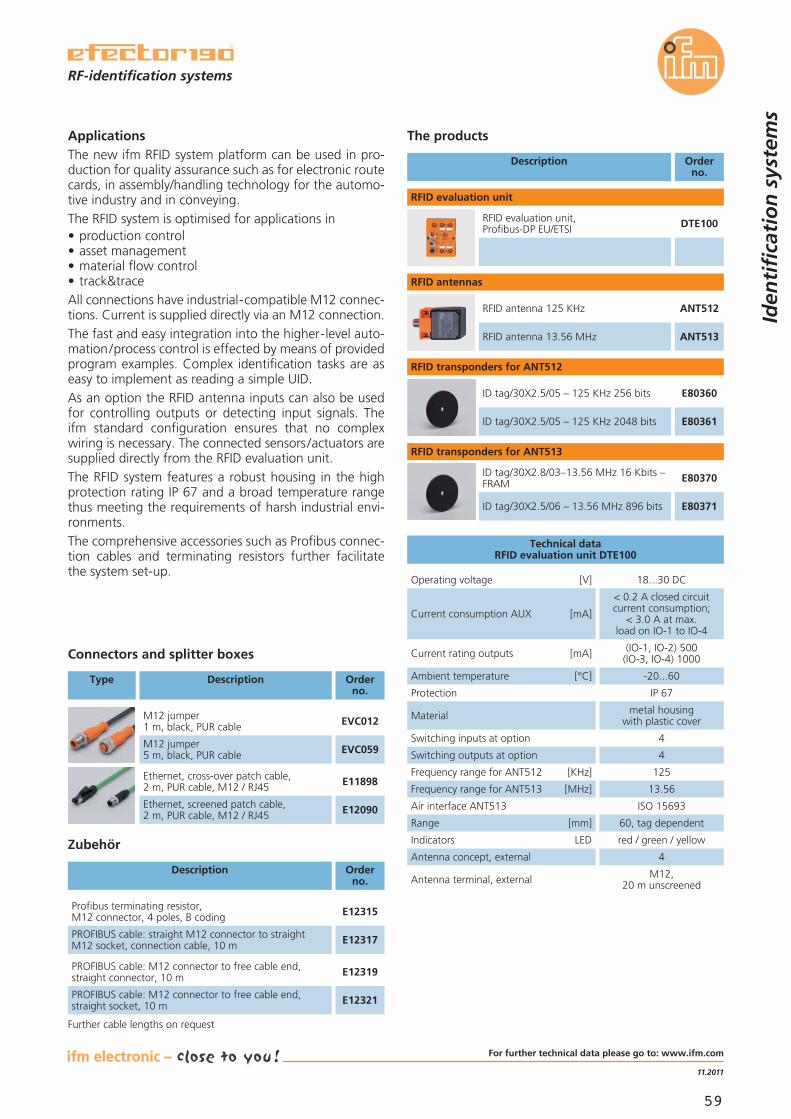
59
11.2011
ApplicationsThe new ifm RFID system platform can be used in pro-duction for quality assurance such as for electronic routecards, in assembly/handling technology for the automo-tive industry and in conveying.The RFID system is optimised for applications in• production control• asset management• material flow control• track&traceAll connections have industrial-compatible M12 connec-tions. Current is supplied directly via an M12 connection.The fast and easy integration into the higher-level auto-mation/process control is effected by means of providedprogram examples. Complex identification tasks are aseasy to implement as reading a simple UID.As an option the RFID antenna inputs can also be usedfor controlling outputs or detecting input signals. Theifm standard configuration ensures that no complexwiring is necessary. The connected sensors /actuators aresupplied directly from the RFID evaluation unit.The RFID system features a robust housing in the highprotection rating IP 67 and a broad temperature rangethus meeting the requirements of harsh industrial envi-ronments.The comprehensive accessories such as Profibus connec-tion cables and terminating resistors further facilitatethe system set-up.
Technical dataRFID evaluation unit DTE100
Operating voltage [V] 18...30 DC
Current rating outputs [mA] (IO-1, IO-2) 500(IO-3, IO-4) 1000
Current consumption AUX [mA]
< 0.2 A closed circuitcurrent consumption;
< 3.0 A at max.load on IO-1 to IO-4
Ambient temperature [°C] -20...60
Protection IP 67
Material metal housingwith plastic cover
Switching inputs at option 4
Switching outputs at option 4
Frequency range for ANT512 [KHz] 125
Frequency range for ANT513 [MHz] 13.56
Air interface ANT513 ISO 15693
Range [mm] 60, tag dependent
Indicators LED red / green / yellow
Antenna concept, external 4
Antenna terminal, external M12,20 m unscreened
Description Orderno.
DTE100RFID evaluation unit,Profibus-DP EU/ETSI
ANT512RFID antenna 125 KHz
ANT513RFID antenna 13.56 MHz
E80360ID tag/30X2.5/05 – 125 KHz 256 bits
E80361ID tag/30X2.5/05 – 125 KHz 2048 bits
E80370ID tag/30X2.8/03–13.56 MHz 16 Kbits –FRAM
E80371ID tag/30X2.5/06 – 13.56 MHz 896 bits
RFID evaluation unit
RFID antennas
The products
RFID transponders for ANT512
RFID transponders for ANT513
Connectors and splitter boxes
Type Description Orderno.
M12 jumper1 m, black, PUR cable EVC012
M12 jumper5 m, black, PUR cable EVC059
Ethernet, cross-over patch cable,2 m, PUR cable, M12 / RJ45 E11898
Ethernet, screened patch cable,2 m, PUR cable, M12 / RJ45 E12090
RF-identification systems
Iden
tifi
cati
on
sys
tem
s
Zubehör
Description Orderno.
Profibus terminating resistor,M12 connector, 4 poles, B coding E12315
PROFIBUS cable: straight M12 connector to straightM12 socket, connection cable, 10 m E12317
PROFIBUS cable: M12 connector to free cable end,straight connector, 10 m E12319
PROFIBUS cable: M12 connector to free cable end,straight socket, 10 m E12321
Further cable lengths on request
For further technical data please go to: www.ifm.com

60
7.0" TFT colour displaywith a resolutionof 800 x 480 pixels.
PDM360 NG dialogue moduleIn almost any mobile machinery a powerful process anddialogue unit is needed for machine operation and forindication of system messages.With its high-resolution graphic display, the powerful32-bit controller and the flexible programming accordingto IEC 61131-3, the PDM360 NG is such a user interface.Its robust housing with protection rating IP 67 enablesmounting inside or outside the cabin. It has been designedfor surface and panel mounting.Up to four CAN interfaces, Ethernet and USB togetherwith the Linux operating system form a universal plat-form for networking and communication with othervehicle components.
Backlit function keys withtactile feedback.
Optional encoder with pushbutton orscroll key.
Internal mass storage, USB interface,interfaces for analogue cameras.
Up to 4 CAN interfaces with CANopenand SAE J1939 protocol.
Programmable to IEC 61131-3 withCoDeSys 2.3.
Dialogue module PDM360 NGfor mobile vehicles.
Co
ntr
ol s
yste
ms
bus,identification
and control systems
fluid sensors and diagnostic
systems
position sensors
and objectrecognition
product news

61
04.2012
Description Orderno.
Dialogue module PDM360 NG with encoder CR1080
Dialogue module PDM360 NG with rocker switch CR1081
Mounting frame for panel mounting EC2110
USB adapter cable, M12 / RJ45 socket, 1.5 m EC2099
Ethernet, cross-over patch cable, 2 m, PUR cable,M12 connector / RJ45 connector E11898
Socket, M12, 2 m black, PUR cable EVC001
Socket, M12, 5 m black, PUR cable EVC002
Programming software CoDeSys, German version CP9006
Programming software CoDeSys, English version CP9008
Technical data
Dialogue modules PDM360 NGCR1080, CR1081, CR1083
Products
Housing closed,diecast aluminium
Device connection 1 x M12 connector6 x M12 socket
Protection IP 65, IP 67
Operating voltage [V DC] 10...32
Functions and advantages
• High-resolution displayProtected by a scratch-resistant glass pane, the moderndisplay, which can even be read in sunlight, provides aresolution of 800 x 480 pixels with an aspect ratio of15:9. Images and graphics can be shown with a colourdepth of up to 18 bits.
• Mechanical structureThe PDM360 NG has a fully sealed diecast aluminiumhousing with protection rating IP 67. The integratedM12 connectors provide all important connections forsupply, inputs /outputs and communication. It can beused as surface mount devices using the tried-and-tested RAM® mount system or can be mounted in awall. The service lid on the back allows the exchangeof the battery for the real-time clock as well as accessto the USB 2.0 service interface.
• The powerful electronicsThe integrated 32-bit controller and the operatingsystem Embedded Linux are the basis for the visualisa-tion of the high-resolution graphics, the processing ofthe application program and the unit functions. Dueto its universal software structure Embedded Linuxfurthermore provides many possibilities as regards com-munication and networking with other systems andnetworks.
• Programming to IEC 61131-3The CoDeSys software enables a clear and easy crea-tion of the application software for the user. Functionlibraries are available for the special functions of thedisplay.The graphic elements are created and animated via theintegrated visualisation.
• The communication interfacesThe PDM360 NG is equipped with up to four CANinterfaces to ISO 11898. These interfaces are forexample used to exchange data with the connectedcontroller, the de-centralised input/output modules orthe engine controller. For this purpose the interfacessupport the CANopen and the J1939 protocol amongothers. The integrated USB 2.0 interfaces provide easydata exchange with modern storage media.The Ethernet interface cannot only be used for pro-gramming but also for communication with other net-work participants.
Applications:• Complex construction machines• Agricultural machines• Municipal vehicles
Current consumption [mA] ≤ 300
Temperature range operation [°C]storage [°C]
-30...65-30...80
Display7" TFT LCD display800 x 480 pixels
18-bit colour depth
Indication RGB LED
Processor MPC5121/ PPC, 400 MHz
Data memory Flash / SRAM [MB] 128 / 128
Internal mass storage [GB](only CR1080 / CR1081) 1
Operating elements pushbuttonsCR1080 (backlit) encoder
91
Operating elements pushbuttonsCR1081 (backlit) rocker switch
91
Inputs (digital / analogue) 1
Inputs with special functions:Internal temperature sensorsPhotoelectric sensor
11
Outputs (digital) 1
Interfaces CR1080, CR10814 x CAN
1 x Ethernet 100 Mbits2 x USB 2.0
Interfaces CR1083
2 x CAN1 x Ethernet 100 Mbits
2 x USB 2.02 x analogue camera
Supports CAN protocols CANopen (DS 301 V4)SAE J 1939
Programming software CoDeSys V2.3
Standards and tests(extract)
CE,e1 (RL 2009/19/EC),
BN 411 002
Control systemsfor mobile vehicles
Co
ntr
ol s
yste
ms
Dialogue module PDM360 NG with 8 function keys CR1083
Operating elements pushbuttonsCR1083 (backlit) 8
For further technical data please go to: www.ifm.com

visit our website:
www.ifm.com
Position sensorsand object recognitionInductive sensorsCapacitive sensorsMagnetic sensors,cylinder sensorsSafety technologyValve sensorsPhotoelectric sensorsObject recognitionEncodersEvaluation systems,power suppliesConnection technology
Fluid sensorsand diagnostic systemsLevel sensorsFlow sensorsPressure sensorsTemperature sensorsDiagnostic systemsEvaluation systems,power suppliesConnection technology
Bus systemsBus system AS-InterfacePower suppliesConnection technology
Identification systemsMulticode reading systemsRF-identification systemsPower suppliesConnection technology
Control systemsControl systemsfor mobile vehiclesConnection technology
Overview ifm product range:
ifm article no. 7511468 · Printed in Germany on non-chlorine bleached paper.We reserve the right to make technical alterations without prior notice. · 04.2012
Cert no. IMO-COC-027827


