Embed Size (px)
Citation preview

Nuclear Instruments and Methods in Physics Research A259 (1987) 143-149North-Holland, Amsterdam
143
WAVE GUIDING BY A WIGGLING FEL BEAM
'" R.H. PANTELL, E. FONTANA and J. FEINSTEINElectrical Engineering Department, Stanford University, Stanford, CA 94305, USA
The electron beam in an FEL acts in a manner so as to guide the electromagnetic wave. This is a consequence of the beam-waveinteraction, which produces a wavevector of the combined mode giving and exponential decay in field amplitude transverse to thedirection of propagation. Prior studies have assumed a smooth boundary between beam and vacuum, and in this paper the wigglingmotion of the beam is incorporated into the analysis. It is found that when the ratio of the wiggle amplitude to the beam thickness islarge, the FEL gain is reduced and the guiding becomes weaker.
1. Introduction
Several authors have analysed the guiding of an electromagnetic wave in an FEL under the conditionsshown in fig. 1 [1,2]. A cylindrical beam with a smooth boundary is assumed, supporting a linearlypolarized (LP) mode. The electric field Ex is given by
Ex=Eo Jo(qr)
,~
Jo( qa) ,r:S,a
=EKo(pr)0 Ko(pa) ,
r 2: a,
(1)
where a is the beam radius, Eo is a constant, Jo is the Bessel function of first kind and zero order, and Kois the Bessel function for imaginary argument. The boundary condition is [3]
(2)
giving a relationship between p and q. Another relationship is obtained from the FEL interaction betweenthe beam and wave [1]:
(3)
where
F= 2Ielpo!W;:(I+~)ea6moY' ,
(4)
and I e I is the,magnitude of electron charge, k = 2'TT /11., A is the wavelength, Po is the dc charge density in
., x
2a-}-zFig. 1. The smooth boundary approximation (SBA) for determining the wave guiding effect of the electron beam in an FEL.
0168-9002/87/$03.50 © Elsevier Science Publishers B.V.(North-Holland Physics Publishing Division)
IV. BEAM GUIDING THEORY
144 R.H. Pantell et al. / Wave guiding by a wiggling FEL beam
the beam, µ. is the medium permeability, mo is the electron rest mass, aw is the wiggler parameter, and yis the ratio of particle energy to its rest energy.
The simultaneous solution of eqs. (2) and (3) gives the transverse wavevectors inside and outside thebeam, from which the FEL gain and transverse wave dimension may be determined.
If a dielectric guide is substituted for the electron beam, eq. (3) is replaced with
(5)
where n is the dielectric constant of the guide. A comparison between eqs. (3) and (5) indicates that theelectron beam presents an effective dielectric constant to the beam, ne, with a value given by
(6)
For typical FEL parameters, ne -1 - 10-7_10-8.
The usual dielectric fiber waveguide has an (n - 1) value in the range 10-2_10-3, which suggests thatbeam guiding in an FEL is extremely weak. In particular, a slight bending of the guide should producesignificant radiation loss, and any change in the direction of the surface normal will cause the wave withinthe guide to exceed the critical angle for total internal reflection. For example, with n - 1 = 10-8 and awave spot size of 500 µ.m, there is significant radiation loss for a bend with a radius of curvature :S, 25 km.
For these reasons, one would expect the wiggling motion of the electron beam in an FEL to causedramatic changes in the wave guiding. However, there are ameliorating effects in that the direction of thewavefronts in a wiggling beam are constant (tending to reduce radiation loss), whereas the wavefrontchanges direction when a guide with fixed dielectric is bent. In addition, radiation emitted by one portionof a wiggling beam is not necessarily lost, since it may pass through another portion of the periodicparticle trajectory. It is difficult, therefore, to predict the consequences of the wiggling motion withoutperforming a detailed analysis.
2. Incorporating the wiggling motion of the electron beam into the boundary condition
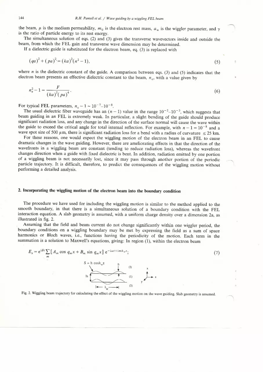
The procedure we have used for including the wiggling motion is similar to the method applied to thesmooth boundary, in that there is a simultaneous solution of a boundary condition with the FELinteraction equation. A slab geometry is assumed, with a uniform charge density over a dimension 2a, asillustrated in fig. 2.
Assuming that the field and beam current do not change significantly within one wiggler period, theboundary conditions on a wiggling boundary may be met by expressing the field as a sum of spaceharmonics or Bloch waves, i.e., functions having the periodicity of the motion. Each term in thesummation is a solution to Maxwell's equations, giving: In region (1), within the electron beam
E = eif3z'\' [A cos q x + B sin q x] e-iwt+imkwz.x L...Jm m rn m ,m
(7)
S = h coskwz h
\ . +2a c=:'-----.-/~ (1)
~. ~'C7
I-)..w~
Fig. 2. Wiggling beam trajectory for calculating the effect of the wiggling motion on the wave guiding. Slab geometry is assumed.
'2)
J-zy
(3)

R.H. Pantell et al. / Wave guiding by a wiggling FEL beam 145
In region (2), outside the beam
E = eif3z'\' C e-Pmx e-iwt+imkwz.x ~ m ,
m
(8)
where m is an integer, and
q; + k; :::::k2 = (~ f for m"" 0,
km = f3 + mkw,
< and
The other field components, Ez and Hy, are obtainable from Maxwell's equations. For m"" 0,
Pm:::::[2mkwk ]1/2::::: - iqm' (9)
The phase velocity in the z-direction for m < 0 is > c, the velocity of light, and these waves radiate in thetransverse direction. The direction of radiation, q _ m' is given by
(10)
For m> 0, the space harmonics are slow waves and do not radiate.The boundary condition at x = a + S(z) is
nxilE=O, n X ilH= 0, (11)
where ilE and ilH are the changes in electric and magnetic fields, respectively, across the boundary, andn, the normal to the boundary, is in the direction of the vector (1,0, -as/az). Eq. (11) gives
ilHy ( x = a + S) = 0,
asilEzCx = a + S) = - ~ilExCx = a + s),
(12)
(13)
Using the symmetry of the electron beam, namely that
z ~ z + AW/2' x~ -x (14)
is a symmetry transformation, it is not necessary to write boundary conditions at x = - a + S. Rather, eq.(14) gives the result
for m even,
for m odd.
The substitution of the series expansions for the fields into eqs. (12) and (13), followed by Besselfunction expansions for sinusoidal functions with sinusoid arguments and an application of harmonicbalance, yields a set ,of simultaneous, linear, homogeneous equations for the coefficients Am' Bm and em.
For example, "this procedure applied to eq. (12) yields
(15)
IV. BEAM GUIDING THEORY

146 R.H. Pantell et al. / Wave guiding by a wiggling FEL beam
where, as shown in fig. 2, h is the wiggle amplitude. A relationship is obtained between qo and Po, the -\transverse wavevectors within and outside the beam, respectively, for the fundamental mode, by equatingto zero a determinant formed from the coefficients of Am' Bm and em. If ±M are the highest spaceharmonics retained in the solution, then it is necessary to find the roots of a determinant with2(2M + 1) X 2(2M + 1) elements. This equation replaces the counterpart of eq. (2) for the smoothboundary approximation (SBA) in the slab geometry.
If the wiggle amplitude h is zero, the boundary condition for slab geometry is
(16)
For small wiggle amplitude, such that
(or, equivalently, a~« 0.125), (17)
the boundary condition resulting from the determinantal equation may be approximated by
(18)
It is seen from eq. (18) that the effect of the wiggle becomes more pronounced as the ratio h/a increases, aconclusion that is supported by the more exact analysis presented in a later section.
3. FEL interaction for a wiggling beam
To solve for FEL gain and optical wave dimension, an additional equation is required, relating Po andqo, to replace eq. (3) for the SBA. This relationship may be obtained by following the procedure originallydescribed by Pierce [4], obtaining a simultaneous solution of Maxwell's equations, a continuity equation,and a force equation. Using this approach, the FEL interaction equation for a wiggling beam is found tobe
(19)
where (Ex)m=O and (Ex)m=2 are the x-components of electric field for the m = 0 and m = 2 spaceharmonics, respectively. A comparison between eqs. (19) and (3) shows that the difference between theSBA and the wiggling beam result is the presence of (Ex)m=2'
One expects the (Ex)m=O term to appear in the FEL interaction because the fundamental mode, i.e.m = 0, satisfies a synchronism condition with the electron beam in which an electron slips one opticalperiod in the wave per wiggler period. A consequence of the synchronism is that at a cumulative exchangeoccurs between the particles and the m = 0 term. The m = 2 field is a slow wave which is also synchronousby having the electron advance one optical period per wiggler period. Therefore, this term also enters intoeq. (19). The field (Ex)m=2 is of order h2 in the wiggle amplitude, so to first order in h eqs. (3) and (19)are identical.
In eq. (19), (Ex)m=O and (Ex)m=2 have different x dependencies. Therefore, to obtain a relationshipbetween Po and qo a dot product if formed between (Ex)m=O and (Ex)m=2, giving
rlAw ja+s(z) (E) (E )* = dx jdz x m=2 x m 0F 0 -a+S(z)
(qoa)2 + (poa)2 = ( a )4 1- lAw dzja+s(z) I Ex I~=o dz .Po 0 -a+S(z)
(20)

R.H. Pantell et at. / Wave guiding by a wiggling FEL beam 147
The simultaneous solution of eq. (20) with the determinantal equation obtained from the wigglingboundary provides unique values for qo and Po, from which FEL gain and the transverse wave dimensioncan be determined. Power P in the wave varies with distance as
(21)where the exponential gain factor a is
a = - iIm(p~/k),Im( ) = imaginary part of ( ),
and the field varies with x outside the beam as e-Pox, so that Re(po) gives the exponential falloff of thewave.
(22)
4. Results
For the SBA there are multiple roots for poa, only one of which is acceptable. The location of theseroots, for the parameters listed in the figure, are shown in fig. 3 by an asterisk. To have exponential growthin the z-direction and decay in the positive x-direction, it is necessary that the root lie in the fourthquadrant. In addition, to satisfy the requirement
Ref d v E .J * < 0, (23)
where J is the current density in the electron beam, the root must lie within an angle of 450 to theabscissa. The condition expressed by eq. (23) is that the wave extracts energy from the electron beam. In
~ .... fig. 3, the cross hatched area shows the region of acceptability for a root. For the SBA, a root that lies inthe fourth quadrant also lies within the acceptable region. Allowing for a finite wiggle amplitude alters thelocation of the acceptable root in the complex plane, thereby altering gain and transverse wave dimension.The migration of the acceptable root from the SBA (h = 0) location to h = 50 µ.m (which is the value of hcorresponding to synchronism) is shown by a dashed line.
.8
A =2590AAw=10cmY=2000a=5µ.a (SBA)=2m-1
210 x Im(poa)
.3A = 2590 AAw = !Oem 1.2
Y = 2000
ka = 5 µm2
-.3 -.2 -.110 x Re(poa)\' \ V \ \0
-.1 ~\ \ \\h~50µm-.2
-.3
1.0r----,
o
ISmall Wiggle
Amplitude Solution
.6
.4
.2
Fig. 3. The values for poa for the parameters listed in thefigure are designated by asterisks for the smooth boundaryapproximation. Acceptable roots lie in the fourth quadrantwi thin an angle of 45 0 to the abscissa (as shown by the ruledarea). The motion of the acceptable root allowing for thewiggling motion is shown as a dashed line. For the givenparameters, the synchronism condition gives a wiggle ampli-
tude h = 50 ,urn.
20 30h (microns)
Fig. 4. A plot of the gain reduction factor ~ that results fromwiggling motion vs wiggle amplitude h. Convergence of thesolution as the number of space harmonics is increased isillustrated by the different curves. For the parameters listed inthe figure, synchronism requires that h = 50 ,urn, which meansthat space harmonics having - 3 :S m :S 3 should be included
in the analysis.
10 40 50
IV. BEAM GUIDING THEORY

148 R.H. Pantell et at. I Wave guiding by a wiggling FEL beam
.8
>- ~2590AAw ~10 emy ~2000
7R
6~ A ~2590AA ~10 emY~2000
:l a(SBA)~06 m-l ~
a(SBA)~1.0 m-l -
3f- a(SBA)~2.0 ~
\\2
o 10 20 30 40 50 10 20
.6/
a(SBA)~0.6 ml j?a(SBA)~1.0 m-l j /a(SBA)~2.0 m-l -
.4
.2
o 30 40 50h/a
Fig. 5. Gain reduction factor ~ vs hia for selected values ofgain.
h/a
Fig. 6. Ratio R of transverse wave dimension with and withoutincluding the wiggling motion, respectively, as a function
of hla_
A gain reduction factor, ~, the ratio of the FEL gain including the wiggling motion to the gain for theSBA, has been calculated for a UV and an IR free electron laser. For the UV case, y = 2000, 11.=2590 Aand Aw = 10 cm, giving (from the synchronism condition) a wiggle amplitude h equal to 50 µ.m. For theIR FEL, y = 100, 11.=10 µ.m and Aw = 8 cm, giving h = 220 µ.m. In each of these cases the beamdimension a, and the gain constant a, where a is the gain calculated for the SBA, were allowed to vary.(Varying a is equivalent to varying the parameter F in eq. (4), or, equivalently, varying the beam currentdensity.) It was found that the results for the IR laser were almost identical to the results for the UV case,in both gain reduction and wave size, so only the UV material is presented.
Fig. 4, a plot of ~ vs h, shows the convergence of the solution for the UV FEL with increasing h asmore space harmonics are included. Since h = 50 µ.m is the wiggle amplitude consistent with the chosen \parameters, it is seen from this figure that it is necessary to include M = ± 3 space harmonics (correspond-ing to a 14 X 14 determinant) to obtain an accurate solution.
Fig. 5 illustrates gain reduction ~ as a function of hia for selected values of gain for the UV laser. Gainis reduced from the smooth boundary approximation, although the effect becomes large only when thewiggle amplitude is large compared to the beam dimension. Another interesting feature shown in fig. 5 isthat gain reduction due to wiggling motion becomes more severe as gain increases. At very large values ofhia and a the FEL gain falls to zero.
Fig. 6 is a plot of the ratio R of the transverse dimension of the wave for the wiggling amplitudesolution to the SBA. The dimension is defined as the x-coordinate for which the power decreases to e -1 ofits x = 0 value. Again, the wiggling beam effect is more pronounced as hia and a increase, with almost anorder of magnitude increase in wave dimension for large values of these parameters.
5. Discussion
The inclusion of the wiggling motion of the electron beam into the wave guiding problem introducesspace harmonics. For m < 0 the phase velocity of the waves exceeds the velocity of light in vacuum,resulting in radiation. The m = 2 space harmonic is a slow wave in synchronism with the beam.
Adding the wiggling motion decreases gain and increases transverse dimension, although these effectsare significant only for large values of hia. Hence, for most wiggler designs the smooth boundaryapproximation is appropriate. This is somewhat surprising result, since even small values of hia give awave direction that exceeds the critical angle for total internal reflection at the beam boundary over almostthe entire wiggler period. However, the wave energy is not lost since it again passes through the beamfurther downstream with very little phase slippage.
(\

R.H. Pantell et at. I Wave guiding by a wiggling FEL beam 149
The reduction in gain that does occur at large values of hia results from increased radiation loss andfrom an increase in transverse wave dimension. Fig. 6 indicates that most of the reduction is attributableto the latter.
Acknowledgement
This work was supported by the U.S. Department of Energy under contract No. DE-FG 03-84-ER-13275.
References
[1] G.T. Moore, Opt. Comm. 52 (1984) 46.[2] E.T. Sharlemann, A.M. Sessler and l.S. Wartele, Phys. Rev. Lett. 54 (1985) 1925.[3] A.H. Cherin, An Introduction to Optical Fibers (McGraw-Hill, New York, 1983).[4] l.R. Pierce, Traveling-Wave Tubes (Van Nostrand, New York, 1950).
IV. BEAM GUIDING THEORY


