Embed Size (px)
Citation preview
ARTICLE IN PRESS
0029-8018/$ - se
doi:10.1016/j.oc
�CorrespondiE-mail addre
nsubram@safat
Ocean Engineering 34 (2007) 327–336
www.elsevier.com/locate/oceaneng
Wave runup on a concentric twin perforated circular cylinder
K. Vijayalakshmia,�, S. Neelamanib, R. Sundaravadivelua, K. Muralia
aOcean Engineering Department, Indian Institute of Technology Madras, Chennai 600036, IndiabCoastal Engineering and Air Pollution Dept, Environmental and Urban Development Division, Kuwait Institute for Scientific Research,
P.O. Box 24885, 13109, Safat, Kuwait
Received 25 February 2005; accepted 23 November 2005
Available online 9 May 2006
Abstract
The regular wave interaction with a twin concentric porous circular cylinder system consisting of an inner impermeable cylinder and an
outer perforated cylinder was studied through physical model and numerical model studies. The experiments were carried out on the twin
concentric cylinder model in a wave flume to study the wave runup and rundown at the leading and trailing edges of the perforated
cylinder. It was found that the maximum wave runup on the perforated cylinder is almost same as the incident wave height. The
experimental results were used to develop the predictive formulae for the wave runup and rundown on the perforated cylinder, which can
be easily used for design applications. The wave runup profiles around the perforated cylinder for different values of ka and porosities
were studied numerically using Green’s Identity Method. The results of the numerical study are presented and compared with the
experimental measurements.
r 2006 Elsevier Ltd. All rights reserved.
Keywords: Perforated cylinder; Wave runup; Porous effect parameter
1. Introduction
The wave interaction with porous structures is beingstudied with great importance in recent years. The waveloads and runup on the structures can be reducedconsiderably by perforating the structure. In the presentstudy the wave runup on a perforated circular cylinderencircling an impermeable cylinder of a sea water intakewell is studied. An extensive experimental study was carriedout to investigate the interaction of regular waves with sucha concentric cylinder system for different porosities of theouter cylinder. The diameter of the outer cylinder is takento be about 10 times that of the inner cylinder. In thispaper, the influence of porosity on wave runup on theperforated outer cylinder is highlighted. Predictive for-mulae developed to compute the wave runup on theperforated outer cylinder are also presented. The numericalmethod of solution for wave runup is also discussed.
e front matter r 2006 Elsevier Ltd. All rights reserved.
eaneng.2005.11.021
ng author.
sses: [email protected] (K. Vijayalakshmi),
.kisr.edu.kw (S. Neelamani).
Many researchers have carried out experimental andnumerical studies to investigate the wave interaction withporous structures like porous plates/walls, slotted walls,perforated wall caisson type breakwaters, etc. The experi-mental investigations on concentric cylinder systems, withthe outer perforated cylinder being of circular cross-section, are not reported in the literature. However, a veryfew numerical studies are available for this type ofconfiguration (Kenny et al., 1976; Wang and Ren, 1994;Darwiche et al., 1994; Williams and Li, 1998). Theseinvestigations mainly focussed at deepwater conditions.Neelamani et al. (2000) reported experimental studies on aconcentric cylinder system, with the outer cylinder being ofsquare cross-section. They carried out the experiments tostudy the water surface fluctuations in and around aperforated square caisson of size of 0.4� 0.4m encircling avertical cylinder of diameter 0.15m. Darwiche et al. (1994)investigated the wave interaction with a vertical cylinderencircled by a semi-porous circular caisson using eigen-function expansion method. Williams and Li (1998)extended the numerical procedure of Darwiche et al. (1994)to an interior cylinder mounted on a large storage tank.Teng et al. (2004) solved numerically the three-dimensional
ARTICLE IN PRESS
Table 1
Details of input parameters considered for regular waves
Parameter Range
Water depth (d) 0.70 m
Wave height (H) 0.05–0.3m (increment: 0.05m)
Wave period (T) 1.0–3.0 s (increment: 0.20 s)
K. Vijayalakshmi et al. / Ocean Engineering 34 (2007) 327–336328
problem of obliquely incident waves with an infinitenumber of perforated caissons using eigenfunction expan-sion method. Most of the theoretical investigations in thefield of wave-porous structure interaction are based on thetheory of Sollitt and Cross (1972).
2. Experimental study
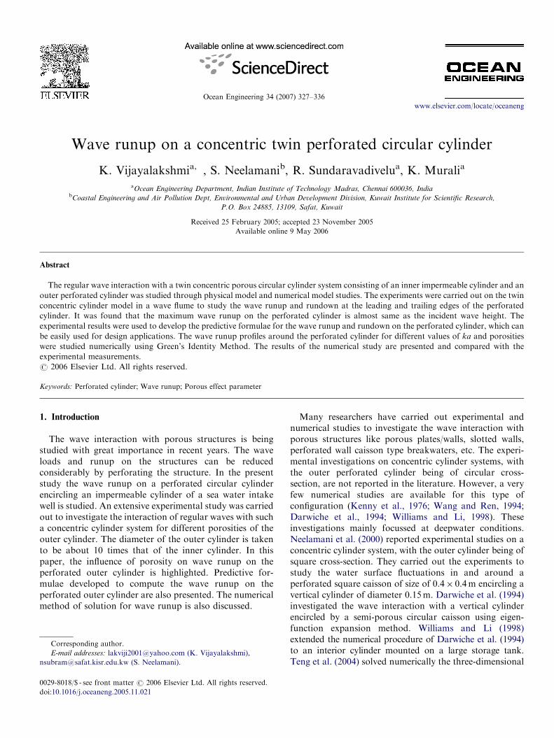
The experimental investigations were carried out in a 30mlong and 2.0m wide shallow water wave flume in theDepartment of Ocean Engineering, Indian Institute ofTechnology Madras, Chennai, India. Fig. 1 shows theexperimental set-up of the model of twin concentric cylindersystem as used in a seawater intake well in the wave flume.For the present investigation, wave runups and rundownswere measured at two locations at the leading and the trailingedges of the perforated cylinder (Fig. 1). The incident waveheight (H) was measured at the centre of the model positionwithout the model in the wave flume. The input parametersconsidered under regular waves are given in Table 1.
The inner cylinder is of diameter 0.05m and the outercylinder is of diameter 0.50m. The porosity of the cylinderwall was obtained by making holes of approximately32mm diameter uniformly on the outer cylindrical surface.The porosity is the fraction of area of openings on thecylinder surface. The porosity of the outer cylinder isvaried approximately from 5% to 20%.
3. Numerical study
In the present work, the interaction of water waves with aporous cylinder is investigated numerically using Green’sidentity method. The body boundary condition along theporous surface is developed on the basis of the formulationof Sollitt and Cross (1972) and the porous wall effectparameter, Gp, specified by Yu (1995) for a thin verticalbarrier extending to the seabed has been adopted. With the
Waveabsorber
2 m
Inner cylinder(0.05 m dia)
4
Perforated cylinder(0.50 m dia)
30m
Waveabsorber
Force balance (six c
SWL
0.7m
1.7m
4
Fig. 1. Experim
Gp included, the body boundary condition on the porouscylinder can be written as given by Eq. (1). Suitable values off and Ca are assumed in the numerical model. Based on aleast-square fit between the measured and numericallycomputed forces, the resistance and added mass coefficientshave been obtained for each porosity and wave height. Themain contribution of the numerical work has been to be ableto specify the ranges of the resistance coefficient for porouswall effect for various porosity and wave height ranges.
qfs
qr
����ð�Þ
¼ �qf0
qr� ikGp fþs � f�s
� �; �d � z � 0; r ¼ a,
(1)
GP ¼P
Rkt, (2)
R ¼ f � i 1þ Ca
ð1� PÞ
P
� �, (3)
where P is the porosity of the structure, R is thedimensionless porous impedance, t is the thickness of theporous wall, k is the wave number (2p/L) and f and Ca arethe non-dimensional resistance coefficient and added masscoefficient, respectively.Helmholtz equation along with the boundary conditions
is a boundary value problem. The boundary value problemis solved numerically within the framework of the lineartheory using the Green’s identity method following Murali(1996). The integration domain is basically the contour of
10 m
2
Wave maker
Flume bedomponent)
2
ental set-up.
ARTICLE IN PRESSK. Vijayalakshmi et al. / Ocean Engineering 34 (2007) 327–336 329
the body geometry. This contour is then discretised into anumber of small segments, and the velocity potential isassumed to be constant on each one. The porous bodyboundary condition is applied at the centre of each segment,which leads to a system of linear algebraic equations.Application of Green’s second identity to f and g* yields thefollowing integral equation in discrete form:
2fðiÞs þXN1
j¼1jai
fjðþÞs
qg�ðj; iÞ
qnj
dsj þXN1þN2
j¼N1þ1
jai
fjð�Þs
qg�ðj; iÞ
qnj
dsj
¼XN1
j¼1
g�ðj; iÞ �qf0
qnj
þ ikGpðfþs � f�s Þ
� �dsj
þXN1þN2
j¼N1þ1
g�ðj; iÞ �qf0
qnj
� ikGpðfþs � f�s Þ
� �dsj ð4Þ
(Rup
) 2/H
Dc/L=0.3230
0.2
0.4
0.6
0.8
1
Dc/L
Dc/L=0.1460
0.2
0.4
0.6
0.8
1
D
Dc/L=0.0960
0.2
0.4
0.6
0.8
1
Dc/L=0
Poro
Dc/L=0.073
0
0.2
0.4
0.6
0.8
1
0 10 15 20
D
0 55
Fig. 2. Influence of porosity on
where N1 and N2 are the equal number of segments alongthe outer and inner contours of the porous caisson and dsj isthe length of the jth segment. The Green’s function g*(j, i)used is Hankel function of first kind and zeroth order thatsatisfies the Helmholtz equation and all the boundaryconditions except the body boundary condition. For avertical wave source,
g�ðj; iÞ ¼ �ipH10ðkrÞ (5)
in which r is the distance from the observation point i to anypoint on the body contour. The body contour is twoconcentric circles of radii b and b–t where t is the thicknessof the porous caisson wall. In order to obtain acceptableresults, the cross-section contour is divided with sufficientelements on each circle for the porous cylinder. The unknownpotentials at the centre of the segments are obtained by solvingthe above simultaneous equations Eq. (4) using any standard
=0.230
c/L=0.124
.087
Dc/L=0.178
Dc/L=0.108
Dc/L=0.079
H/d=0.064-0.070H/d=0.131-0.142H/d=0.195-0.214H/d=0.228-0.284H/d=0.310-0.357H/d=0.380-0.426
sity (P %)
c/L=0.067
10 15 20
wave runup ratio (Rup)2/H.
ARTICLE IN PRESSK. Vijayalakshmi et al. / Ocean Engineering 34 (2007) 327–336330
matrix inversion procedure. The variables such as pressure,force and water surface fluctuations are obtained from thesepotentials. The total potential is given by f ¼ f0 þ fs. Thewave runup on the cylinder can be estimated as
Ru ¼H
2f�� ��. (6)
4. Results and discussion
4.1. Experimental results
4.1.1. Influence of porosity on runup and rundown ratios in
front and rear faces of the perforated cylinder
It is required to estimate the wave runup (Rup) andrundown (Rdown) on the perforated cylinder in order to
(Rup
) 4/H
Dc/L=0.323
0
0.2
0.4
0.6
0.8
1Dc/L=0.
Dc/L=0.1460
0.2
0.4
0.6
0.8
1
Dc/L
Dc/L=0.0960
0.2
0.4
0.6
0.8
1
Dc/L=
Poro
Dc/L=0.0730
0.2
0.4
0.6
0.8
1
0 5 10 15 20
Dc/L
0 5
Fig. 3. Influence of porosity on
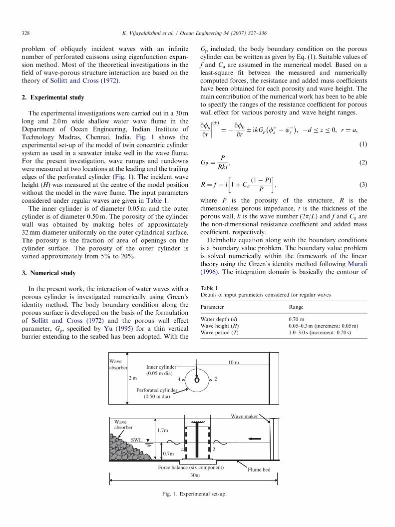
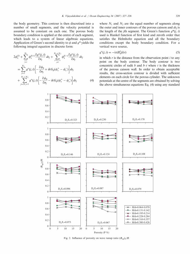
decide the minimum deck clearance for a seawater intakestructure. In this section, the influence of porosity on waverunup on the perforated cylinder for a wide range ofhydrodynamic conditions is presented. To measure thewave runup and rundown on the perforated cylinder, twowave probes were kept very close to the perforated cylinderat about 2 cm away from the front and rear faces of theouter cylinder. The runup and rundown on the outercylinder are presented as runup ratio (Rup/H) and run-down ratio (Rdown/H). The runup ratio at a location isdefined, as the ratio of measured runup to the measuredincident wave height. The rundown ratio at a location isdefined, as the ratio of measured rundown to the measuredincident wave height.The influence of porosity of the outer cylinder on wave
runup ratio in front of the cylinder at location 2 and rear ofthe cylinder at location 4 is illustrated in Figs. 2 and 3
230
=0.124
0.087
Dc/L=0.178
Dc/L=0.108
Dc/L=0.079
sity (P %)
=0.067
10 15 20
H/d=0.064-0.070H/d=0.131-0.142H/d=0.195-0.214H/d=0.228-0.284H/d=0.310-0.357H/d=0.380-0.426
wave runup ratio (Rup)4/H
ARTICLE IN PRESSK. Vijayalakshmi et al. / Ocean Engineering 34 (2007) 327–336 331
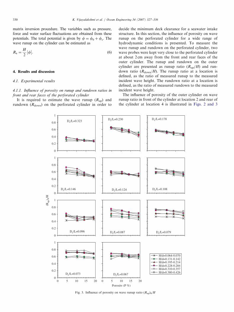
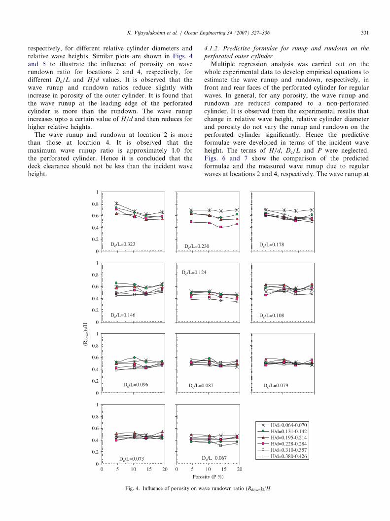
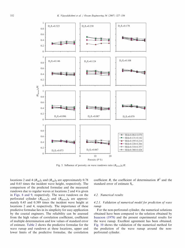
respectively, for different relative cylinder diameters andrelative wave heights. Similar plots are shown in Figs. 4and 5 to illustrate the influence of porosity on waverundown ratio for locations 2 and 4, respectively, fordifferent Dc/L and H/d values. It is observed that thewave runup and rundown ratios reduce slightly withincrease in porosity of the outer cylinder. It is found thatthe wave runup at the leading edge of the perforatedcylinder is more than the rundown. The wave runupincreases upto a certain value of H/d and then reduces forhigher relative heights.
The wave runup and rundown at location 2 is morethan those at location 4. It is observed that themaximum wave runup ratio is approximately 1.0 forthe perforated cylinder. Hence it is concluded that thedeck clearance should not be less than the incident waveheight.
(Rdo
wn)
2/H
Dc/L=0.3230
0.2
0.4
0.6
0.8
1
Dc/L=0.2
Dc/L=0.1460
0.2
0.4
0.6
0.8
1
Dc/L=0.12
Dc/L=0.096
0
0.2
0.4
0.6
0.8
1
Dc/L=0
Poros
Dc/L=0.0730
0.2
0.4
0.6
0.8
1
0 5 10 15 20
D
0 5
Fig. 4. Influence of porosity on wa
4.1.2. Predictive formulae for runup and rundown on the
perforated outer cylinder
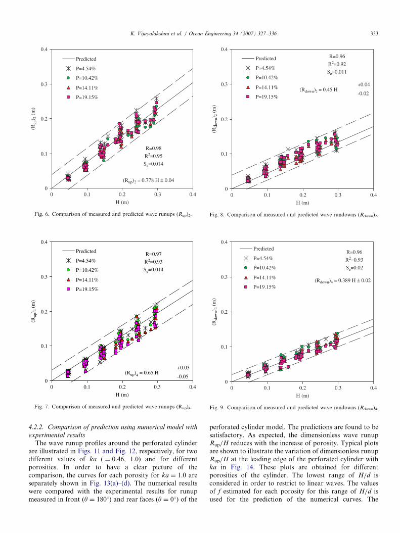
Multiple regression analysis was carried out on thewhole experimental data to develop empirical equations toestimate the wave runup and rundown, respectively, infront and rear faces of the perforated cylinder for regularwaves. In general, for any porosity, the wave runup andrundown are reduced compared to a non-perforatedcylinder. It is observed from the experimental results thatchange in relative wave height, relative cylinder diameterand porosity do not vary the runup and rundown on theperforated cylinder significantly. Hence the predictiveformulae were developed in terms of the incident waveheight. The terms of H/d, Dc/L and P were neglected.Figs. 6 and 7 show the comparison of the predictedformulae and the measured wave runup due to regularwaves at locations 2 and 4, respectively. The wave runup at
30
4
.087
Dc/L=0.178
Dc/L=0.108
Dc/L=0.079
ity (P %)
c/L=0.067
10 15 20
H/d=0.064-0.070H/d=0.131-0.142H/d=0.195-0.214H/d=0.228-0.284H/d=0.310-0.357H/d=0.380-0.426
ve rundown ratio (Rdown)2/H.
ARTICLE IN PRESS
(Rdo
wn)
4/H
Dc/L=0.323
0
0.2
0.4
0.6
0.8
1Dc/L=0.230
Dc/L=0.146
0
0.2
0.4
0.6
0.8
1
Dc/L=0.124
Dc/L=0.0960
0.2
0.4
0.6
0.8
1
Dc/L=0.087
Dc/L=0.178
Dc/L=0.108
Dc/L=0.079
Porosity (P %)
Dc/L=0.0730
0.2
0.4
0.6
0.8
1
Dc/L=0.067
0 10 20
H/d=0.064-0.070H/d=0.131-0.142H/d=0.195-0.214H/d=0.228-0.284H/d=0.310-0.357H/d=0.380-0.426
Fig. 5. Influence of porosity on wave rundown ratio (Rdown)4/H.
K. Vijayalakshmi et al. / Ocean Engineering 34 (2007) 327–336332
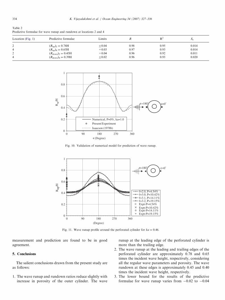
locations 2 and 4 (Rup)2 and (Rup)4 are approximately 0.78and 0.65 times the incident wave height, respectively. Thecomparison of the predicted formulae and the measuredrundown due to regular waves at locations 2 and 4 is givenin Figs. 8 and 9, respectively. The wave rundown on theperforated cylinder (Rdown)2 and (Rdown)4 are approxi-mately 0.45 and 0.389 times the incident wave height atlocations 2 and 4, respectively. The importance of thesepredictive formulae lies in its simplicity for easy applicationby the coastal engineers. The reliability can be assessedfrom the high values of correlation coefficient, coefficientof multiple determination and low values of standard errorof estimate. Table 2 shows the predictive formulae for thewave runup and rundown at these locations, upper andlower limits of the predictive formulae, the correlation
coefficient R, the coefficient of determination R2 and thestandard error of estimate Se.
4.2. Numerical results
4.2.1. Validation of numerical model for prediction of wave
runup
For the non-perforated cylinder, the numerical solutionsobtained have been compared to the solution obtained byIsaacson (1978) and the present experimental results forthe wave runup. Excellent agreement has been obtained.Fig. 10 shows the validation of the numerical method forthe prediction of the wave runup around the non-perforated cylinder.
ARTICLE IN PRESS
0
0.1
0.2
0.3
0.4
0 0.1 0.2 0.3 0.4
H (m)
(Rup
) 2 (
m)
Predicted
P=4.54%
P=10.42%
P=14.11%
P=19.15%
(Rup)2 = 0.778 H ± 0.04
R=0.98
R2=0.95
Se=0.014
Fig. 6. Comparison of measured and predicted wave runups (Rup)2.
-0.05(Rup)4 = 0.65 H
+0.03
R=0.97
R2=0.93
Se=0.014
0
0.1
0.2
0.3
0.4
0 0.1 0.2 0.3 0.4
H (m)
(Rup
) 4 (
m)
Predicted
P=4.54%
P=10.42%
P=14.11%
P=19.15%
Fig. 7. Comparison of measured and predicted wave runups (Rup)4.
0
0.1
0.2
0.3
0.4
0 0.1 0.2 0.3 0.4
H (m)
(Rdo
wn)
2 (m
)
Predicted
P=4.54%
P=10.42%
P=14.11%
P=19.15%-0.02
(Rdown)2 = 0.45 H+0.04
R=0.96
R2=0.92
Se=0.011
Fig. 8. Comparison of measured and predicted wave rundowns (Rdown)2.
0
0.1
0.2
0.3
0.4
0 0.1 0.2 0.3 0.4
H (m)
(Rdo
wn)
4 (m
)
Predicted
P=4.54%
P=10.42%
P=14.11%
P=19.15%(Rdown)4 = 0.389 H ± 0.02
R=0.96
R2=0.93
Se=0.02
Fig. 9. Comparison of measured and predicted wave rundowns (Rdown)4.
K. Vijayalakshmi et al. / Ocean Engineering 34 (2007) 327–336 333
4.2.2. Comparison of prediction using numerical model with
experimental results
The wave runup profiles around the perforated cylinderare illustrated in Figs. 11 and Fig. 12, respectively, for twodifferent values of ka ( ¼ 0.46, 1.0) and for differentporosities. In order to have a clear picture of thecomparison, the curves for each porosity for ka ¼ 1:0 areseparately shown in Fig. 13(a)–(d). The numerical resultswere compared with the experimental results for runupmeasured in front (y ¼ 1801) and rear faces (y ¼ 01) of the
perforated cylinder model. The predictions are found to besatisfactory. As expected, the dimensionless wave runupRup/H reduces with the increase of porosity. Typical plotsare shown to illustrate the variation of dimensionless runupRup/H at the leading edge of the perforated cylinder withka in Fig. 14. These plots are obtained for differentporosities of the cylinder. The lowest range of H/d isconsidered in order to restrict to linear waves. The valuesof f estimated for each porosity for this range of H/d isused for the prediction of the numerical curves. The
ARTICLE IN PRESS
Table 2
Predictive formulae for wave runup and rundown at locations 2 and 4
Location (Fig. 1) Predictive formulae Limits R R2 Se
2 (Rup)2 ¼ 0.78H 70.04 0.98 0.95 0.014
4 (Rup)4 ¼ 0.65H +0.03 0.97 0.93 0.014
2 (Rdown)2 ¼ 0.45H +0.04 0.96 0.92 0.011
4 (Rdown)4 ¼ 0.39H 70.02 0.96 0.93 0.020
0
0.2
0.4
0.6
0.8
1
0 90 180 270 360
Numerical, P=0%, ka=1.0Present Experiment
Isaacson (1978b)
(Degree)
Rup
/H
=180° =0°∋ ∋
∋
Fig. 10. Validation of numerical model for prediction of wave runup.
0
0.2
0.4
0.6
0.8
1
0 90 180 270 360
f=2.0, P=4.54%f=3.0, P=10.42%f=3.1, P=14.11%f=3.2, P=19.15%Expt-P=4.54%Expt-P=10.42%Expt-P=14.11%Expt-P=19.15%
=180° =0°
(Degree)
Rup
/H
∋ ∋
Fig. 11. Wave runup profile around the perforated cylinder for ka ¼ 0.46.
K. Vijayalakshmi et al. / Ocean Engineering 34 (2007) 327–336334
measurement and prediction are found to be in goodagreement.
5. Conclusions
The salient conclusions drawn from the present study areas follows:
1.
The wave runup and rundown ratios reduce slightly withincrease in porosity of the outer cylinder. The waverunup at the leading edge of the perforated cylinder ismore than the trailing edge.
2.
The wave runup at the leading and trailing edges of theperforated cylinder are approximately 0.78 and 0.65times the incident wave height, respectively, consideringall the regular wave parameters and porosity. The waverundown at these edges is approximately 0.45 and 0.40times the incident wave height, respectively.3.
The lower bound for the results of the predictiveformulae for wave runup varies from �0.02 to �0.04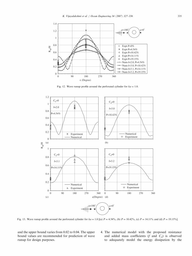
ARTICLE IN PRESS
0
0.2
0.4
0.6
0.8
1
1.2
1.4
0 90 180 270 360
Expt-P=0%Expt-P=4.54%Expt-P=10.42%Expt-P=14.11%Expt-P=19.15%Num-f=2.0, P=4.54%Num-f=3.0, P=10.42%Num-f=3.1, P=14.11%Num-f=3.2, P=19.15%
(Degree)
Rup
/H
=180° =0°∋∋
∋
Fig. 12. Wave runup profile around the perforated cylinder for ka ¼ 1.0.
(Degree)
Rup
/H
Ca=0
f=3.2
P=19.15%
0 90 180 270 360
NumericalExperiment
Ca=0
f=3.0
P=10.42%
NumericalExperiment
(b)
(d)
Ca=0
f=2.0
P=4.54%
0
0.2
0.4
0.6
0.8
1
1.2
ExperimentNumerical
Ca=0
f=3.1
P=14.11%
0
0.2
0.4
0.6
0.8
1
0 90 180 270 360
NumericalExperiment
(a)
(c) ∋
=180° =0°∋ ∋
Fig. 13. Wave runup profile around the perforated cylinder for ka ¼ 1.0 [(a) P ¼ 4.54%, (b) P ¼ 10.42%, (c) P ¼ 14.11% and (d) P ¼ 19.15%].
K. Vijayalakshmi et al. / Ocean Engineering 34 (2007) 327–336 335
and the upper bound varies from 0.02 to 0.04. The upperbound values are recommended for prediction of waverunup for design purposes.
4.
The numerical model with the proposed resistanceand added mass coefficients (f and Ca) is observedto adequately model the energy dissipation by the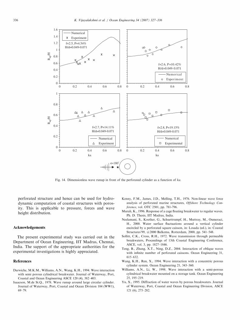
ARTICLE IN PRESS
=180°∋ka
Rup
/HR
up/H
f=2.5, P=4.54%H/d=0.049-0.071
0
0.2
0.4
0.6
0.8
1
1.2
1.4
1.6
0 0.2 0.4 0.6 0.8
Numerical
Experiment
f=2.6, P=10.42%H/d=0.049-0.071
0 0.2 0.4 0.6 0.8
Numer ical
Exper imen t
f=2.7, P=14.11%H/d=0.049-0.071
0
0.2
0.4
0.6
0.8
1
0 0.2 0.4 0.6 0.8
Numerical
Experiment
f=2.8, P=19.15%H/d=0.049-0.071
0 0.2 0.4 0.6 0.8
Numerical
Experimental
ka
Fig. 14. Dimensionless wave runup in front of the perforated cylinder as a function of ka.
K. Vijayalakshmi et al. / Ocean Engineering 34 (2007) 327–336336
perforated structure and hence can be used for hydro-dynamic computation of coastal structures with poros-ity. This is applicable to pressure, forces and waveheight distribution.
Acknowledgements
The present experimental study was carried out in theDepartment of Ocean Engineering, IIT Madras, Chennai,India. The support of the appropriate authorities for theexperimental investigations is highly appreciated.
References
Darwiche, M.K.M., Williams, A.N., Wang, K.H., 1994. Wave interaction
with semi porous cylindrical breakwater. Journal of Waterway, Port,
Coastal and Ocean Engineering ASCE 120 (4), 382–403.
Isaacson, M.de St.Q., 1978. Wave runup around large circular cylinder.
Journal of Waterway, Port, Coastal and Ocean Division 104 (WW1),
69–79.
Kenny, F.M., James, J.D., Melling, T.H., 1976. Non-linear wave force
analysis of perforated marine structures, Offshore Technology Con-
ference, vol. OTC 2501, pp. 781-796.
Murali, K., 1996. Response of a cage floating breakwater to regular waves.
Ph. D. Thesis, IIT Madras, India.
Neelamani, S., Koether, G., Schuettrumpf, H., Muttray, M., Oumeraci,
H., 2000. Water surface fluctuations around a vertical cylinder
encircled by a perforated square caisson, in: Losada (ed.), in: Coastal
Structures’99, @2000 Balkema, Rotterdam, 2000, pp. 541–548.
Sollitt, C.K., Cross, R.H., 1972. Wave transmission through permeable
breakwaters, Proceedings of 13th Coastal Engineering Conference,
ASCE, vol. 3, pp. 1827–1846.
Teng, B., Zhang, X.T., Ning, D.Z., 2004. Interaction of oblique waves
with infinite number of perforated caissons. Ocean Engineering 31,
615–632.
Wang, K.H., Ren, X., 1994. Wave interaction with a concentric porous
cylinder system. Ocean Engineering 21, 343–360.
Williams, A.N., Li, W., 1998. Wave interaction with a semi-porous
cylindrical breakwater mounted on a storage tank. Ocean Engineering
25, 195–219.
Yu, X., 1995. Diffraction of water waves by porous breakwaters. Journal
of Waterway, Port, Coastal and Ocean Engineering Division, ASCE
121 (6), 275–282.


