Embed Size (px)
Citation preview
BMD
WATER BOOSTER PUMPING' STATION WB170
BEAUDESERT ROAD PARKINSON TECHNOLOGY PARK
ELECTRICAL SWITCHBOARD
OPERATION AND MAINTENANCE MANUAL
Developed by:
J & P RICHARDSON INDUSTRIES CAMPBELL AVENUE
WACOL QLD 4076
ABN 23 001 952 325 ACN 001 952 325
Ph. (07) 3271 2911 Fax. (07) 3271 3623
WB170 Beaudesert Rd Water Booster Parkinson Technology Park Electrical Switchboard OM Manual
Q-Pulse Id TMS1107 Active 10/12/2014 Page 1 of 271
CONTENTS
1.0 INTRODUCTION
1.1 Operating Instructions
2.0 DESCRIPTION OF OPERATION
2.1 Mode Selection 2.2 Manual Control 2.3 Automatic Control
3.0 PUMPS
4.0 VALVES
5.0 TEST SHEETS
6.0 FLOWMETER
7.0 ELECTRICAL EQUIPMENT TECHNICAL INFORMATION
8.0 SWITCHBOARD WORKS TEST RESULTS
WB170 Beaudesert Rd Water Booster Parkinson Technology Park Electrical Switchboard OM Manual
Q-Pulse Id TMS1107 Active 10/12/2014 Page 2 of 271

I
9
I
e
s
I INDEX A4
Ref.No.35026 made in china
WB170 Beaudesert Rd Water Booster Parkinson Technology Park Electrical Switchboard OM Manual
Q-Pulse Id TMS1107 Active 10/12/2014 Page 3 of 271

GP ID
11111111111111111111111111' it
fl
WB170 Beaudesert Rd Water Booster Parkinson Technology Park Electrical Switchboard OM Manual
Q-Pulse Id TMS1107 Active 10/12/2014 Page 4 of 271
J & P Richardson Industries Ply Ltd
1.0 INTRODUCTION
These operating instructions cover the WB170 Beaudesert Road Water Booster pumping station electrical equipment supplied by J & P Richardson Industries Pty Ltd in September 2008.
1.1 Operating Instructions
Normal operation of the pumping station is in the automatic mode with control by means of a Master Programmable Logic Controller (PLC)/Radio Telemetry Unit (RTU) which receives level signals from the Level Measurement System in the wet well/Electronic Level Relays/Float Switches.
Manual operation control of the station is available by means of selector switches on the motor control switchboard.
File: 11.1pr_Server/docsilsched/Masters.doc Revision 0 Date: 25 May 2001
WB170 Beaudesert Rd Water Booster Parkinson Technology Park Electrical Switchboard OM Manual
Q-Pulse Id TMS1107 Active 10/12/2014 Page 5 of 271
SI 4ID II 411,
Iiiiiii3i)iiiicIA)iligli1ijilijciiiititoliftit;
2. Description of
Operation
WB170 Beaudesert Rd Water Booster Parkinson Technology Park Electrical Switchboard OM Manual
Q-Pulse Id TMS1107 Active 10/12/2014 Page 6 of 271

ID ID ID MI ID ID
1 1 1 1 1 1 1 1 1 1 1 1) 1 1 1 1 1 1 1 1 1 1 1 1 1
WB170 Beaudesert Rd Water Booster Parkinson Technology Park Electrical Switchboard OM Manual
Q-Pulse Id TMS1107 Active 10/12/2014 Page 7 of 271
J & P Richardson Industries Ply Ltd
2.0 DESCRIPTION OF OPERATION
2.1 Mode Selection
The station can be operated either automatically or manually with mode selection being made by means of the mode selector switches mounted on each pump section of the switchboard. These selector switches are designated with the following mode selections AUTO-OFF-MAN.
2.2 Manual Control
Each pumping unit can be run in manual control from the motor control centre by: -
a). Selecting the "MAN" setting on the "MODE SELECTOR SWITCHES" as described in Clause 2.1.
b). Starting by "START" pushbutton. c). Stopping by "STOP" pushbutton.
N.B. DO NOT LEAVE IN MANUAL WHILE STATION UNATTENDED
2.3 Automatic Control
For automatic control of the station: -
a). The "MODE SELECTOR SWITCHES" on the switchboard should be in the "AUTO" position.
b). The "DUTY SELECTOR SWITCH" should be set to provide the desired pump operation sequence. The "DUTY SELECTOR SWITCH" is marked:-
1-2 2-1
The pumps should be alternated at regular intervals to ensure that each pump unit has a reasonably equal running time. The total running hours of each pump unit is displayed on the hourmeter located on each pump section of the switchboard.
c). The automatic Duty Selection is done via the PLC software. Refer PLC SOFTWARE Section for details. The total running hours of each pump unit is displayed on the hourmeter located on each pump section of the switchboard.
d). The automatic starting, and stopping of the pumps is controlled by signals from Master PLC.
For NORMAL OPERATION, each of the pump selector switches should have "AUTO" mode selected.
In the AUTOMATIC mode the selected Duty Pump unit will start automatically as preset by the level in the wet well. In the event of the duty pump not being capable of supplying enough flow to continue draining the wet well and the well level rises to a second preset level, then the Standby Pump unit will automatically start, to provide additional pumping. The supplementary pump unit also takes over for the respective pump duty on the occurrence of one the Duty Pump unit failing.
File: Npr_Server/docs/lsched/Masters.doc Revision 0 Date: 25 May 2001
WB170 Beaudesert Rd Water Booster Parkinson Technology Park Electrical Switchboard OM Manual
Q-Pulse Id TMS1107 Active 10/12/2014 Page 8 of 271

ID MI
101111111Millcuclictokilluccoluij
(1 3. Pumps
WB170 Beaudesert Rd Water Booster Parkinson Technology Park Electrical Switchboard OM Manual
Q-Pulse Id TMS1107 Active 10/12/2014 Page 9 of 271

41. ap in
Iiiiiiiiiiiiiiiiiiiiiiiiij
di 410 al WB170 Beaudesert Rd Water Booster Parkinson Technology Park Electrical Switchboard OM Manual
Q-Pulse Id TMS1107 Active 10/12/2014 Page 10 of 271
J & P Richardson Industries Pty Ltd
3.0 PUMPS
SUPPLIER: FLOWSERVE HYDRO-TITAN
Ph: (07) 3277 9511 Fax: (07) 3277 0783
MODEL: 150x125-315 18.5kW
File: //Jpr_Server/docs/lscheci/Masters.doc Revision 0 Date: 25 May 2001
WB170 Beaudesert Rd Water Booster Parkinson Technology Park Electrical Switchboard OM Manual
Q-Pulse Id TMS1107 Active 10/12/2014 Page 11 of 271
HYDRO-TITAN
Installation, Operating and Maintenance Manual
Thompsons Kelly&Lewis
WB170 Beaudesert Rd Water Booster Parkinson Technology Park Electrical Switchboard OM Manual
Q-Pulse Id TMS1107 Active 10/12/2014 Page 12 of 271
HYDRO-TITAN TM
BACK PULL-OUT PUMP INSTRUCTIONS FOR INSTALLING AND
OPERATING
CUSTOMER RECORD DATA
Size
Serial Number
When ordering spare parts for your Hydro-Titan pump, always quote the pump size and serial number indicated above. We suggest you keep this booklet in a safe and easy to obtain place for future reference.
These instructions are prepared as a guide to the correct procedures and, provided they are followed, will result in trouble- free operation of your centrifugal pump.
These instructions do not cover driver or associated equipment, and for information on these items we recommend the manufacturer or distributor be consulted direct for maintenance and/or repair instructions.
For performance characteristics and maximum speed consult your Hydro-Titan pump distributor or TKL.
INDEX
A. INSTALLATION (1) Foundation (2) Piping (3) Alignment - Direct Coupled (4) Alignment - Belt Drive (5) Gland Sealing
B. START-UP (1) Priming (2) Start-Up (3) Gland (4) Mechanical Seal (5) Special Liquids
C. TROUBLE SHOOTING (1) No Discharge (2) Low Discharge (3) Lack of Pressure (4) Absorbs Too Much Power (5) Noisy Operation (6) Vibration (7) Pump Runs Hot
D. SERVICING
E. DISMANTLING (1) Spacer Coupling (2) Rotating Assembly (3) Casing (4) Mechanical Seal
A. INSTALLATION
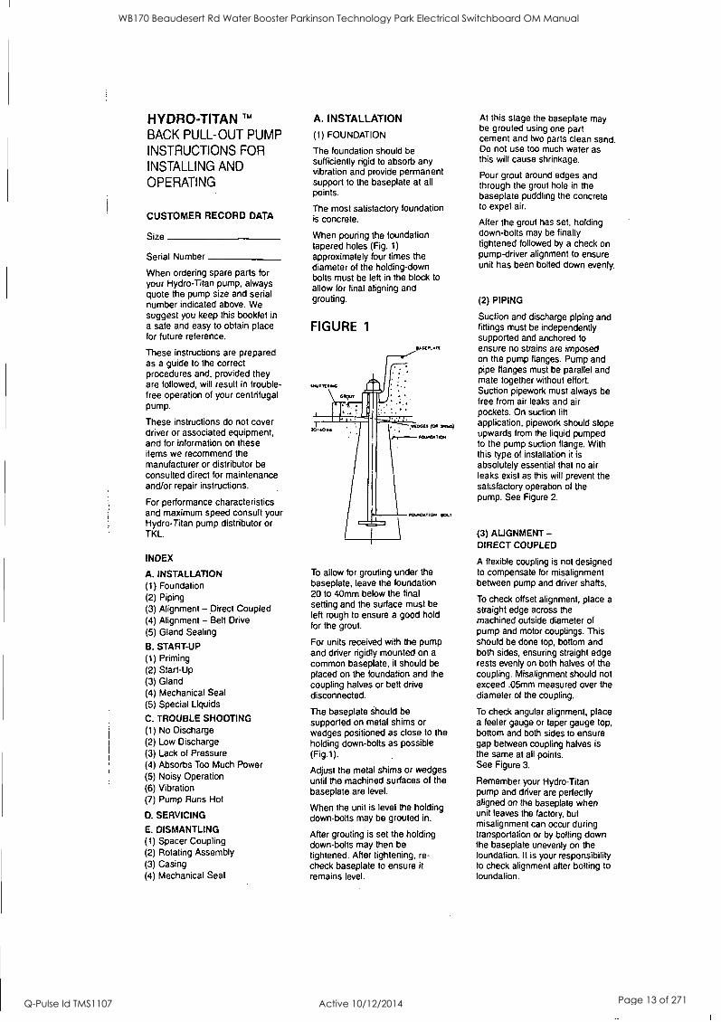
(1) FOUNDATION
The foundation should be sufficiently rigid to absorb any vibration and provide permanent support to the baseplate at all points.
The most satisfactory foundation is concrete.
When pouring the foundation tapered holes (Fig. 1)
approximately four times the diameter of the holding-down bolts must be left in the block to allow for final aligning and grouting.
FIGURE 1
MOO treiNG
ARPLAIII
10.0,a1C01
=1. rOvICATION (,t..
To allow for grouting under the baseplate, leave the foundation 20 to 40mm below the final setting and the surface must be left rough to ensure a good hold for the grout.
For units received with the pump and driver rigidly mounted on a
common baseplate, it should be placed on the foundation and the coupling halves or belt drive disconnected.
The baseplate should be supported on metal shims or wedges positioned as close to the holding down-bolts as possible (Fig.1).
Adjust the metal shims or wedges until the machined surfaces of the baseplate are level.
When the unit is level the holding down-bolts may be grouted in.
After grouting is set the holding down-bolts may then be tightened. After tightening, re- check baseplate to ensure it remains level.
At this stage the baseplate may be grouted using one part cement and two parts clean sand. Do not use too much water as this will cause shrinkage.
Pour grout around edges and through the grout hole in the baseplate puddling the concrete to expel air.
After the grout has set, holding down-bolts may be finally tightened followed by a check on pump-driver alignment to ensure unit has been bolted down evenly.
(2) PIPING
Suction and discharge piping and fittings must be independently supported and anchored to ensure no strains are imposed on the pump flanges. Pump and pipe flanges must be parallel and mate together without effort. Suction pipework must always be free from air leaks and air pockets. On suction lift application, pipework should slope upwards from the liquid pumped to the pump suction flange. With this type of installation it is absolutely essential that no air leaks exist as this will prevent the satisfactory operation of the pump. See Figure 2.
(3) ALIGNMENT - DIRECT COUPLED
A flexible coupling is not designed to compensate for misalignment between pump and driver shafts.
To check offset alignment, place a straight edge across the machined outside diameter of pump and motor couplings. This should be done top, bottom and both sides, ensuring straight edge rests evenly on both halves of the coupling. Misalignment should not exceed .05mm measured over the diameter of the coupling.
To check angular alignment, place a feeler gauge or taper gauge top, bottom and both sides to ensure gap between coupling halves is the same at all points. See Figure 3.
Remember your Hydro-Titan pump and driver are perfectly aligned on the baseplate when unit leaves the factory, but misalignment can occur during transportation or by bolting down the baseplate unevenly on the foundation. It is your responsibility to check alignment after bolting to foundation.
WB170 Beaudesert Rd Water Booster Parkinson Technology Park Electrical Switchboard OM Manual
Q-Pulse Id TMS1107 Active 10/12/2014 Page 13 of 271
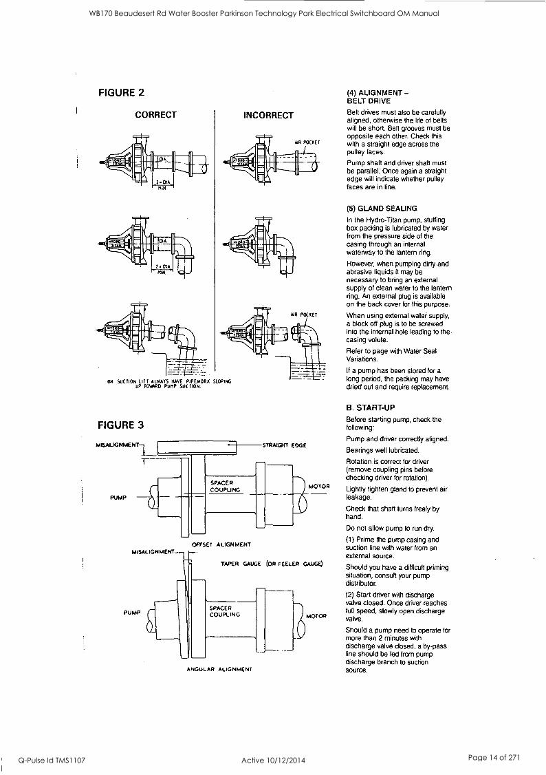
FIGURE 2
CORRECT INCORRECT
AIR POCKET
ON SUCTION LIFT ALWAYS HAVE PIPEWORK SLOPING UP TOW*RO PUMP SUCTION.
FIGURE 3
MISALIGNMENT
PUMP - SPACER COUPLING
STRAIGHT EDGE
MOTOR
OFFSET ALIGNMENT
PUMP
TAPER GAUGE (OR FEELER GAUGE)
SPACER COUPLING
ANGULAR ALIGNMENT
"--MOTOR
(4) ALIGNMENT - BELT DRIVE
Belt drives must also be carefully aligned, otherwise the life of belts will be short. Belt grooves must be opposite each other. Check this with a straight edge across the pulley faces.
Pump shaft and driver shaft must be parallel. Once again a straight edge will indicate whether pulley faces are in line.
(5) GLAND SEALING
In the Hydro-Titan pump, stuffing box packing is lubricated by water from the pressure side of the casing through an internal waterway to the lantern ring.
However, when pumping dirty.and abrasive liquids it may be necessary to bring an external supply of clean water to the lantern ring. An external plug is available on the back cover for this purpose.
When using external water supply, a block off plug is to be screwed into the internal hole leading to the, casing volute.
Refer to page with Water Seal Variations.
If a pump has been stored for a long period, the packing may have dried out and require replacement.
B. START-UP
Before starting pump, check the following:
Pump and driver correctly aligned.
Bearings well lubricated.
Rotation is correct for driver (remove coupling pins before checking driver for rotation).
Lightly tighten gland to prevent air leakage.
Check that shaft turns freely by hand.
Do not allow pump to run dry.
(1) Prime the pump casing and suction line with water from an external source.
Should you have a difficult priming situation, consult your pump distributor.
(2) Start driver with discharge valve closed. Once driver reaches full speed, slowly open discharge valve.
Should a pump need to operate for more than 2 minutes with discharge valve closed, a by-pass line should be led from pump discharge branch to suction source.
WB170 Beaudesert Rd Water Booster Parkinson Technology Park Electrical Switchboard OM Manual
Q-Pulse Id TMS1107 Active 10/12/2014 Page 14 of 271
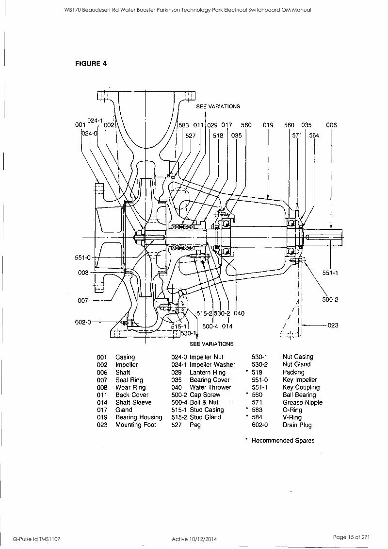
FIGURE 4
SEE VARIATIONS
024 -1002 002
024-0 583 011
527
029 017 560 019 560 035 006
518 035 571 584
551 0
008
007
551-1
602-0
001 002 006 007 008 011 014 017 019 023
515-1 - 1530-1
SEE VARIATIONS
Casing Impeller Shaft Seal Ring Wear Ring Back Cover Shaft Sleeve Gland Bearing Housing Mounting Foot
515-2 530-2 040
500-4 011 4
024-0 Impeller Nut 024-1 Impeller Washer 029 Lantern Ring 035 Bearing Cover 040 Water Thrower 500-2 Cap Screw 500-4 Bolt & Nut 515-1 Stud Casing 515-2 Stud Gland 527 Peg
530-1 530-2 518 551-0 551-1
* 560 571 583 584 602-0
A 500-2
I I.
/ 11. 023
Nut Casing Nut Gland Packing Key Impeller Key Coupling Ball Bearing Grease Nipple 0-Ring V-Ring Drain Plug
* Recommended Spares
WB170 Beaudesert Rd Water Booster Parkinson Technology Park Electrical Switchboard OM Manual
Q-Pulse Id TMS1107 Active 10/12/2014 Page 15 of 271
(3) Adjust gland until a slow but consistent drip of water leaks past the gland packing. Do not be in a
hurry to adjust stuffing box leakage, as this may take some time to settle in.
In the event of excessive leakage, do not tighten gland nuts more than one flat at a time.
If there is no leakage from the stuffing box, do not back off gland nuts while the pump is running as this will allow the whole set of rings to move away from the bottom of the box. The best procedure is to stop the pump and allow the pacicing to cool before restarting.
(4) Pumps with mechanical seals should operate without visible leakage.
(5) If pumping hot or special liquids, consult TKL for recommendation.
C. TROUBLE SHOOTING
(1) No discharge Not primed. Speed too low. Discharge head too high. Suction lift too high. Blockage. Incorrect rotation. Suction leaks.
(2) Low Discharge Air Leaks. Speed low. Suction lift too high. Discharge head too high. Blockage.
(3) Lack of Pressure Speed low. Air leaks. Discharge head too high. Blockage.
(4) Absorbs too much Power Speed too high. Total head too low. Misalignment. Stuffing box too tight.
(5) Pump Noisy Worn bearings. Misalignment. Bent shaft. Suction lift too high.
(6) Vibration Impeller blockage. Misalignment. Worn Bearings. Bent Shaft.
(7) Pump Runs Hot Gland too tight. Pump not discharging. Dry bearings. Bearing temperature should not exceed 45° above ambient.
D. SERVICING
Before servicing the Hydro-Titan pump, isolate the driver to prevent accidental starting.
Servicing should be carried out at least once a year and does not require dismantling of the pump.
Remove setscrews holding bearing covers Item 035 Fig. 4, and slide cover along shaft. This will enable you to force by hand fresh grease into the ball bearings, at the same time... pushing the old grease out of the bearing into the bearing housing well. Over-greasing causes heating. Do no fill grease space more than two-thirds full.
Recommended Grease types: SUPPLIER DESIGNATION British Petroleum BP Energrease
LS2 SKF SKF LGMT 2
Esso Beacon 2
Mobil Mobilux 2
Shell Alvania R2 Ampol Liplex EP2
While above lubricants are recommended, equivalents may be substituted where necessary.
At the same time, inspect the stuffing box. If it is leaking badly and requires attention, proceed as follows:
Close discharge valve.
Remove gland nuts.
Gland is in halves, and by unbolting the two halves the whole gland may be removed.
With a packing extractor, remove packing plus lantern ring. Please note that there are two turns of packing behind the lantern ring.
Repack in same sequence. As supplied, the Hydro-Titan pump is fitted with pre-formed packing and it is only necessary to insert the correct number of turns. If using continuous packing, the ends should be cut off square leaving a gap of 3- 5mm. This joint should be staggered as each turn is inserted.
Make sure lantern ring is
located in line with water seal hole.
E. DISMANTLING
(1) SPACER COUPLING - FIG. 5
The first step in dismantling the pump is to remove the coupling spacer. Once this is done, all rotating parts of the pump can be removed for attention on the bench without disturbing casing, pipework or driver.
Isolate driver.
Close suction and discharge valve.
Remove coupling guard.
Undo coupling pin nuts Item 4,
and remove coupling pins Item 5.
Remove motor half setscrew Item 7.
Coupling spacer may now be removed. Renew coupling rubbers Item 6
before reassembly
(2) ROTATING ASSEMBLY
With the coupling spacer removed, there is sufficient space to remove the back pull-out component.
Remove casing stud nuts Fig. 4 Item 530-1 and carefully pull the rotating element out of the casing. On larger pumps, lifting tackle will be required.
Casing '0' ring Item 583 should be renewed when reassembling.
With the rotating assembly on the bench, further dismantling may be carried out as follows:
Remove impeller nut and washer Item 024-0 & 024-1.
Remove split gland Item 017.
Remove outboard end bearing cover Item 035.
Remove impeller Item 002.
Shaft and bearings may now be removed from coupling end of pump, driving gently with a piece of wood if necessary.
To replace bearings, first remove pump half coupling Fig. 5 Item 1,
using a standard wheel puller. Bearings may now be removed. If
bearings are in good condition, flush with motor spirit or solvent, grease immediately, and replace on shaft. Complete cleanliness is essential when servicing ball bearings and will result in longer bearing life.
Re-assemble in reverse order, checking the following:
If worn, both dust and splash seals Fig. 4 Item 584 should be replaced.
After complete dismantling, gland packing should be renewed. See Servicing Section D.
Inspect shaft in area of stuffing box. If badly worn, fit new shaft or machine to take shaft sleeve, Fig. 4 Item 006.
Inspect impeller hubs for wear. If badly worn or out of round machine true in lathe and fit impeller sealing rings Fig. 4
WB170 Beaudesert Rd Water Booster Parkinson Technology Park Electrical Switchboard OM Manual
Q-Pulse Id TMS1107 Active 10/12/2014 Page 16 of 271
FIGURE 5
PUMP HALF
O
_a_114.111m
MOTOR HALF
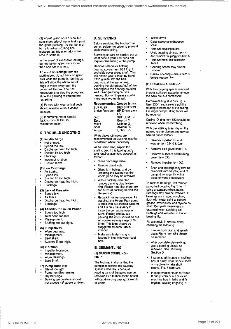
1 Pump half coupling 2 Spacer 3 Motor half coupling 4 Coupling nuts
FIGURE 6
3mm
5 Coupling pins *6 Coupling rubbers
7 Motor half setscrews
Recommended Spares
Impeller Running Clearance (mm) - LLI m ,.._ a c, Li. LL
50 50
32 32
160 200
0,20 to 0,27 _
c) - Lu m a cc L.L.
50 65 65 80 80
32 40 40 50 50
250 250 315 250 315
100 100 100
80 65 65
160 200 250
0,23 to 0,31
100 65 315 Back 0,20 to 0,27 Front 0,23 to 0,31
125 125 125 125 125 125 125
80 80 80 80
100 100 100
200 250 315 400 250 315 400
0,23 to 0,31
150 150 150 150 200 200 200 200 200
125 125 125 125 150 150 150 200 200
250 315 400 500 315 400 500 400 500
0,27 to 0,36 c., _ w
250 250 400 0,32 to 0,42
Item 008, machined in their bore to suit impeller hubs. For each size Hydro-Titan impeller running clearances are given in Fig. 6.
(3) CASING
The casing has remained coupled to the pipework and will normally only require cleaning internally.
However, if the running clearances are excessive and the casing shows wear in this area, it may be desirable to remove the casing and machine to take casing sealing rings Fig. 4 Item 007.
(4) MECHANICAL SEALS
If your Hydro-Titan pump is fitted with a mechanical seal, details will be seen on Fig. 7.
The faces on mechanical seals are easily broken and dismantling should be carried out with care.
The following procedure should be adopted:
With rotating element on the workbench, remove impeller.
Remove nuts and slide seal plate, Fig. 7 Item 6, along shaft. The stationary seal ring will back off with the seal plate.
Remove hex. head capscrews that hold bearing housing to
back cover Item 011.
Back cover Fig. 4 Item 011 may now be removed from impeller end of shaft, exposing rotating seal components which may be removed from the shaft by undoing grub screw. Fig. 7 Item 2.
Seal should be cleaned and sealing faces examined. Faces should be flat and free from scratches or pitting. If the seal is in
good condition it may be cleaned with Hydrocarbon and replaced and grub screw tightened on shaft to maintain dimension "A" Fig. 7.
The utmost cleanliness should be
observed when servicing mechanical seals.
Re-assembly should be carried out in reverse order.
WB170 Beaudesert Rd Water Booster Parkinson Technology Park Electrical Switchboard OM Manual
Q-Pulse Id TMS1107 Active 10/12/2014 Page 17 of 271
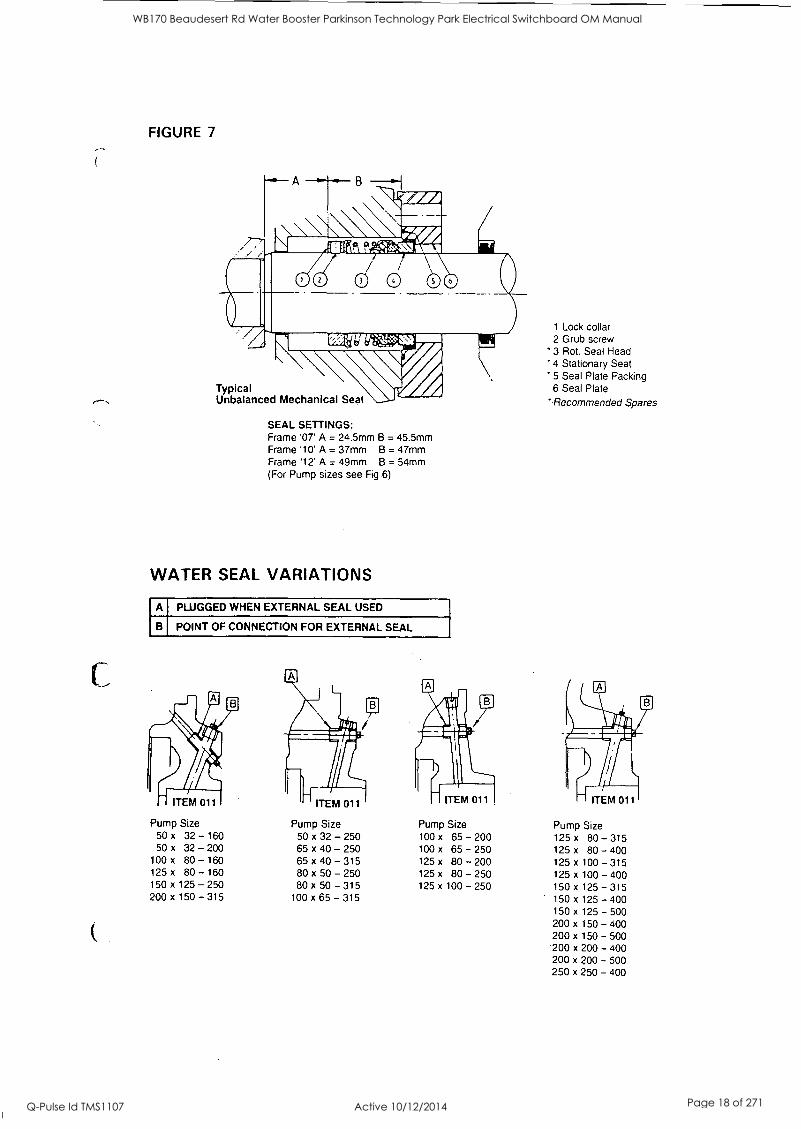
FIGURE 7
A - B
IIII4Var#2
611111111K Wistalmu
Typical Unbalanced Mechanical Seal
SEAL SETTINGS: Frame '07' A = 24.5mm B = 45.5mm Frame '10' A = 37mm B = 47mm Frame '12' A = 49mm B = 54mm (For Pump sizes see Fig 6)
WATER SEAL VARIATIONS
A PLUGGED WHEN EXTERNAL SEAL USED
B POINT OF CONNECTION FOR EXTERNAL SEAL
ITEM 011
1 Lock collar 2 Grub screw
' 3 Rot, Seal Head 4 Stationary Seat
*5 Seal Plate Packing 6 Seal Plate
"Recommended Spares
ITEM 011 ITEM 011
Pump Size Pump Size Pump Size Pump Size 50 x 32 - 160 50 x 32 - 250 100 x 65 - 200 125x 80 - 315 50 x 32 - 200 65 x 40 - 250 100 x 65 - 250 125 x 80 - 400
100 x 80 - 160 65 x 40 - 315 125 x 80 - 200 125 x 100 - 315 125 x 80 - 160 80 x 50 - 250 125 x 80 - 250 125 x 100 - 400 150 x 125 - 250 80 x 50 - 315 125 x 100 - 250 150x 125 - 315 200 x 150 - 315 100 x 65 - 315 150 x 125 - 400
150 x 125 - 500 200 x 150 - 400 200 x 150 - 500 200 x 200 - 400 200 x 200 - 500 250 x 250 - 400
WB170 Beaudesert Rd Water Booster Parkinson Technology Park Electrical Switchboard OM Manual
Q-Pulse Id TMS1107 Active 10/12/2014 Page 18 of 271
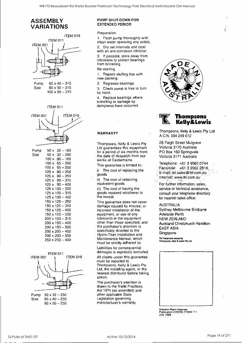
ASSEMBLY VARIATIONS
ITEM 019 ITEM 011
ITEM 001
Pump 65 x 40 - 315 Size 80 x 50 - 315
100 x 65 - 315
ITEM 011
ITEM 001 ITEM 019
Pump Size
50 x 32 - 160 50 x 32 - 200
100 x 80 - 160 100 x 65 - 200 100 x
125 x
125 x 125 x
125 x
125 x
125 x
125 x
150 x
150 x 150 x
65 - 250 80 - 200 80 - 250 80 - 315 80 - 400
100 - 250 100 - 315 100 - 400 125 - 250 125 - 315 125 - 400
150 x 125 - 500 200 x 150 - 315 200 x 150 - 400 200 x 150 - 500 200 x 200 - 400 200 x 200 - 500 250 x 250 - 400
ITEM 011 ITEM 001 ITEM 019
Pump 50 x 32 - 250 Size 65 x 40 - 250
80 x 50 - 250
PUMP SHUT-DOWN FOR EXTENDED PERIOD
Preparation
1. Flush pump thoroughly with clean water removing any solids.
2. Dry out internals and coat with an anti-corrosion inhibitor. 3. If possible, store away from vibrations to protect bearings from brinelling. Re-starting
1. Repack stuffing box with new packing.
2. Regrease bearings.
3. Check pump is free to turn by hand.
4. Replace bearings where brinelling or damage by dampness have occurred.
WARRANTY
Thompsons, Kelly & Lewis Pty Ltd guarantees this equipment for a period of six months from the date of despatch from our works at Castlemaine.
This guarantee is limited to:
i) The cost of replacing the goods.
ii) The cost of obtaining equivalent goods.
iii) The cost of having the goods repaired whichever is the lowest.
This guarantee does not cover damage caused by misuse, or incorrect installation of the equipment, or use of any lubricants in the equipment other than those specified; and the purchaser's attention is specifically directed to the Hydro-Titan Installation and Maintenance Manual, which must be strictly adhered to.
Liabilities for consequential damages is expressly excluded.
All claims under this guarantee must be reported to Thompsons, Kelly & Lewis Pty Ltd, the installing agent, or the nearest distributor before taking action.
The purchaser's attention is drawn to the Trade Practices Act 1974 (as amended) and other applicable State Legislation governing manufacturer's warranty.
Thompsons Kelly&Lewis
Thompsons, Kelly & Lewis Pty Ltd A.C.N. 004 249 012
26 Faigh Street Mulgrave Victoria 3170 Australia PO Box 160 Springvale Victoria 3171 Australia
Telephone: +61 3 9562 0744 Facsimile: +61 3 9562 2816
Internet: www.tkl.com.au
For further information, sales, service or technical assistance, consult your telephone directory for nearest sales office:
AUSTRALIA Sydney Melbourne Brisbane Adelaide Perth NEW ZEALAND Auckland Christchurch Hamilton EAST ASIA Singapore TM-Trademark owned by Thompsans, Keay & Leafs Ply Ltd
Alteration Rights Reserved Publication HYDRO-TITAN/ 7.1 July 1999
WB170 Beaudesert Rd Water Booster Parkinson Technology Park Electrical Switchboard OM Manual
Q-Pulse Id TMS1107 Active 10/12/2014 Page 19 of 271
lgiv/ Thompsons Keilly&Lewis
HYDRO-TITAN - 3.1 May 1997
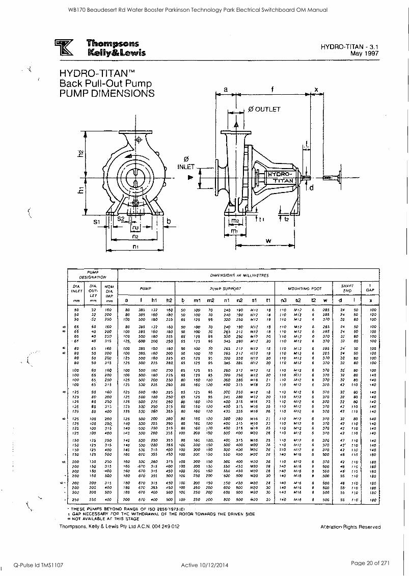
HYDRO-TITAN' Back Pull-Out Pump PUMP DIMENSIONS
0
Go
75
n2
n,
0 INLET
to.
w
PUMP DESIGNATION
DIMENSIONS IN MILLIMETRES
044 INLET
mm
DM OUT- LET mm
NOM. DIA Imp. mm
PUMP PUMP SUPPORT MOUNTING FOOT SHAFT END
1
GAP
a I hl h2 b ml m2 nt n2 81 ti n3 s2 t2 w d I x
50 32 760 80 385 132 160 50 100 70 240 790 M72 18 :10 M72 6 285 24 50 100 50 32 200 80 385 160 180 50 100 70 240 190 M72 16 170 Mil 6 285 24 50 100 50 '32 250 100 500 780 225. 65 725 95. 320 250 A4I2 78 770 M12 6 370 32 80 100
65 50 160 80 385 132 160 150 100 70 240 190 M12 18 110 MI? 6 285 24 50 100 65 40 200 100 385 160 180 50 100 ip 265 212 A412 r8 170 6412 6 .285 24 50 700 65 40 250 100 500 180 225 65 725 95 320 250 A512 20 .170 Mr2 6 370 32 80 100
.65 40 315 125, 500 200 250 65 125 95 315 280 M12 .20 770 4/12 6 370 32 80 100
80 65 160 100 385 750 180 50 100 70 265 212 MI? 18 ITO Ml? 6 285 24 50 700 80 50 200 100 385, '760 200. 5C 100 70 265 212 4/72 18 110 6472 6 285 24 50 700 80 50 250 125 500 180 225 65 425 95 320 250 641.2 20 110 M12 6 370 32 80 700 80 50 315 125 500 225 280 65 125 95 315 280 M12 20 110 M12 6 320. 32 80 700
100 SO 160 100 500 160 200 65 125 95 250 272 M72 75 170 M72 6 370 32 80 100 100 65 200 100 500 180 225 65 125 95 320 250 M72 20 770 4412 6 370 32. 80 140 100 65 250 125 500 200 250 80 760 120 350 280 6416 24 170 A 4!2 5 370 32 80 140 700 65 315 t25 530 225 280 80 160 120 400 315 We 23 17.0 6412 6 370. 42 770 740
725 80 760 725 500 180 ,225 65 725 95 320 250 4412 78 110 6412 6 370 32 80 740 125 80 200 125 500 '780 250' 65 125 95 345 280 M12 20 110 M12 6 370 32 80 140 725 80 250 725 500 225 280 80, 160 10 400 375 641.6 23 110 M12 6 370 32 BD 740 725 60 315 125. 53.0 250 375 80 160 720 400 315 641,6 25 710 M12 6 370 42 170 740 t25 80 400 125 530 280 355 80 160 120 435 355 M16 26 170 M72 6 370 42 710 140
725 100 200 125 500 200 280 80 160 720 360 280 M7.6 2; 170 M72 6 370 32 80 140 125 700 250. 140 530 225 280 80 760 120 400 375 M76 23 170 M72 6 370 42 110 140 125 100 315 740 .530 .250 315 80 760 J20 400 315 1476 25 170 M72 6 370 42 110 140 125 700 400 140 530 280 355 700 200 750 500 400 6420 26 170 6412 6 370 42 770 740
150 125 250 140 530 250 355 80 160 720: 400 375 M76. 25 710 M72 6 370 42 770 140 750 125 375 140 530 280 355 700 200 1.50 500 400 6420. 26 710 6412 6 370 42' 710 740 750 125 400 140 530 3/5 400 700 200 750 500 400 A420' 26 710 6472 6 370 42, 170 740 150 725 500 160 670 355 450 700 200 ;50 550 850 M20 28 740 MI6 6 500 48 710 780
200 '750 250 160 530 .280 375 700 200 750 500 400 M20 26 770 M12 6 370 42 710 780 200 150 375 760 .670 315 400 700 200 150 550 450 M20 28 140 M t 6 8 500 48 770 180 200 150 .400 160 670 315 450 100 200 150 550 450 1420 28 .140 6416 8 500 48. 710 180 200 750 500 760 670 355 500 70C 250 200 '600 500 M20 30 r40 6476 8 500 55 710 780
200 200 315 180 670 375 450 100 200 150 550 450 M20 28 740 M76 8 500 48 710 180 200 200 400 780 670 355 450 100 250 200 600 500 M20 30 740 M76 8 500 55. 770 180 200 200 500 780 670 400 500 100. 250 200 600 500 M1420 30 '140 M76 8 500 55 1;0 780
250 250 400 200 670 400 500 700 250 200 500 500 1420 30 740 MIS 8 500 55 170 180
THESE PUMPS. BEYOND RANGE OF ISO 2858.1975 1E).
GAP NECESSARY FOR THE WITHDRAWAL OF THE ROTOR TOWARDS THE DRIVEN SIDE NOT AVAILABLE AT THIS STAGE
Thompsons, Kelly & Lewis Pty Ltd A.C.N. 004 249 012 Alteration Rights Reserved
WB170 Beaudesert Rd Water Booster Parkinson Technology Park Electrical Switchboard OM Manual
Q-Pulse Id TMS1107 Active 10/12/2014 Page 20 of 271
Thompsons Kelly&Lewis
HYDRO-TITAN" - 4.1 June 1992
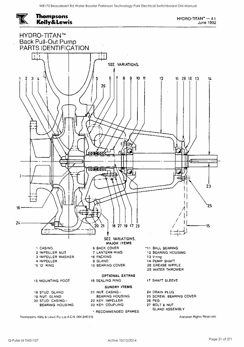
HYDRO-TITAN TM
Back Pull-Out Pump PARTS IDENTIFICATION
SEE VARIATIONS-
8 9 10 11 12 11 28 10 13 14
1 CASING 2 IMPELLER NUT 3 IMPELLER WASHER 4 IMPELLER
*5 '0' RING
15 MOUNTING FOOT
18 STUD: GLAND 19 NUT: GLAND 20 STUD: CASING-
BEARING HOUSING
SEE VARIATIONS. MAJOR ITEMS
6 BACK COVER 7 LANTERN RING
8 PACKING 9 GLAND
10 BEARING COVER
OPTIONAL EXTRAS
16 SEALING RING
SUNDRY ITEMS
21 NUT: CASING- BEARING HOUSING
22 KEY: IMPELLER 23 KEY: COUPLING
RECOMMENDED SPARES
Therndsons. Kelly 8. Lewis Pty Ltd A.C.N. 004 249 012
11 BALL BEARING 12 BEARING HOUSING 13 V-ring 14 PUMP SHAFT 28 GREASE NIPPLE 29 WATER THROWER
17 SHAFT SLEEVE
24 DRAIN PLUG 25 SCREW: BEARING COVER 26 PEG 27 BOLT & NUT
GLAND ASSEMBLY
Alteration Rights Reserved
WB170 Beaudesert Rd Water Booster Parkinson Technology Park Electrical Switchboard OM Manual
Q-Pulse Id TMS1107 Active 10/12/2014 Page 21 of 271

el
i[OIIIIIIIII1111111111111111111111111111111110
4. Valves
WB170 Beaudesert Rd Water Booster Parkinson Technology Park Electrical Switchboard OM Manual
Q-Pulse Id TMS1107 Active 10/12/2014 Page 22 of 271

ID di
0
Iiiiiiiiiiiiiiiiitui11111
WB170 Beaudesert Rd Water Booster Parkinson Technology Park Electrical Switchboard OM Manual
Q-Pulse Id TMS1107 Active 10/12/2014 Page 23 of 271
J & P Richardson Industries Ply Ltd
4.0 VALVES
SUPPLIER: TYCO WATER
Ph: (07) 3866 7670 Fax: (07) 3260 2142
MODEL: 0150 REFLUX VALVE
SUPPLIER: TYCO WATER
Ph: (07) 3866 7670 Fax: (07) 3260 2142
MODEL: 0150 M.S. SLUICE VALVE
File: inpr_Server/docs/!sched/Masters.doc Revision 0 Date: 25 May 2001
WB170 Beaudesert Rd Water Booster Parkinson Technology Park Electrical Switchboard OM Manual
Q-Pulse Id TMS1107 Active 10/12/2014 Page 24 of 271
tax Flow Control
e
Features
Ductile Iron body and cover for high strength and impact resistance
Ductile Iron components are fusion coated with Rilsan Nylon 11 for long life corrosion protection
Full bore design for minimum head loss
No debris pockets
Disc held in open position by positive pressure to avoid fluctuations
Free acting and counterweight versions available. Interchangeable in the field
Limit switch fit out available.
Free acting version features EPDM encapsulated gunmetal disc with pressure activated lip seal and fully flexible rubber hinge
Counterweight version features EPDM encapsulated gunmetal disc with pressure activated lip seal and solid stainless steel shaft
Counterweight utilises separate shaft located in the cover to enable rapid closing and lessen fluctuations
Adjustable counterweight can be mounted on either side of the valve
Integral body seat for maintenance free operation
Integral cast feet for safe and easy storage
Counterweight shaft seals are 0- Ring type to ensure leak free operation
Isolated fasteners for corrosion protection Slotted holes on top of inlet flange to facilitate bolt insertion when connecting to adjacent valves
A.B.N. 75 087 415 745
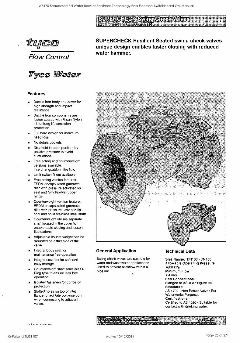
SUPERCHECK Resilient Seated swing check valves unique design enables faster closing with reduced water hammer.
General Application
Swing check valves are suitable for water and wastewater applications. Used to prevent backflow within a pipeline.
Technical Data
Size Range: DN100 - DN150 Allowable Operating Pressure: 1600 kPa Minimum Flow: 1.4 m/s End Connections: Flanged to AS 4087 Figure B5 Standards: AS 4794 - Non-Return Valves For Waterworks Purposes Certifications: Certified to AS 4020 - Suitable for contact with drinking water.
Copyright by Tyco InternationaHltd. chan e roduct des, ns and ectficahons without notice. Tyco Water reserves the.° htto
TWSCV/03/04
WB170 Beaudesert Rd Water Booster Parkinson Technology Park Electrical Switchboard OM Manual
Q-Pulse Id TMS1107 Active 10/12/2014 Page 25 of 271
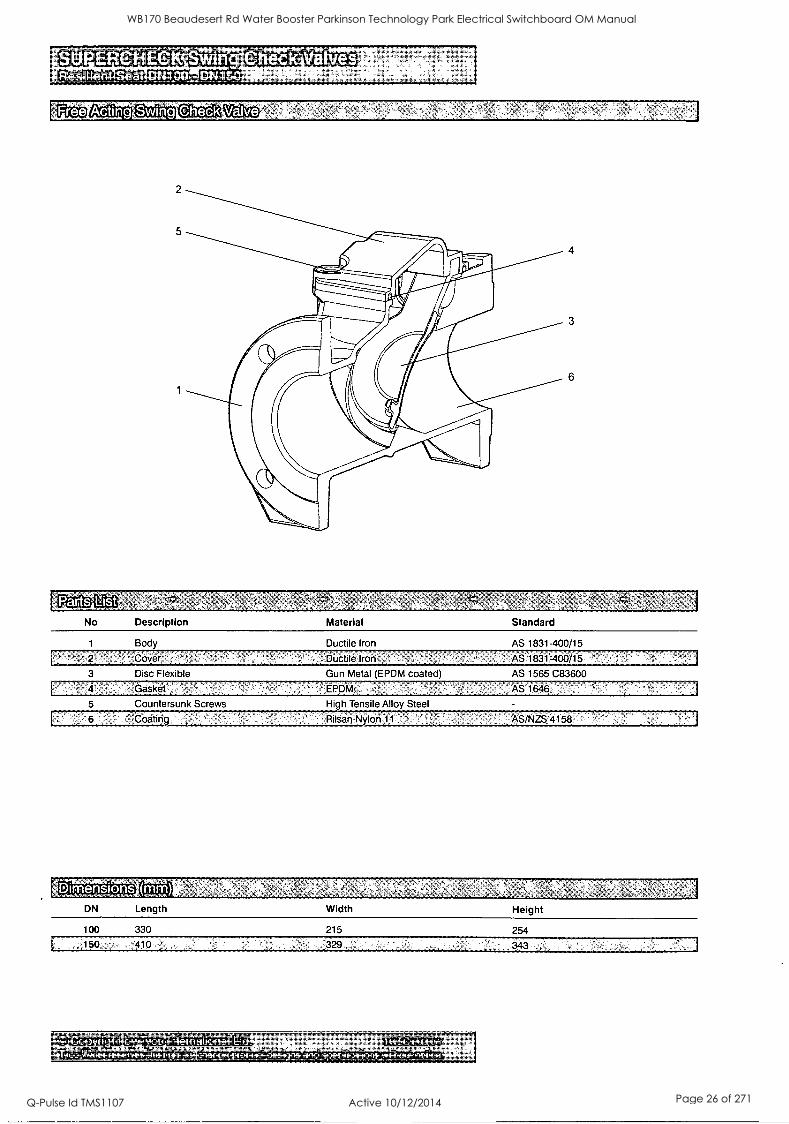
No Description Material Standard
1 Body Ductile Iron AS 1831-400/15
Disc Flexible Gun Metal (EPDM coated) AS 1565 C83600
Countersunk Screws
Coating
High Tensile Alloy Steel
'Rilsan Nylon11 AS/NZS 4158
Dimensions DN Length Width Height
100 330 215 254
150 410 329
0 ee e
I I .
WB170 Beaudesert Rd Water Booster Parkinson Technology Park Electrical Switchboard OM Manual
Q-Pulse Id TMS1107 Active 10/12/2014 Page 26 of 271
counterweight Swing pieckyalve
10
4
14
Partt Ltist
11/12
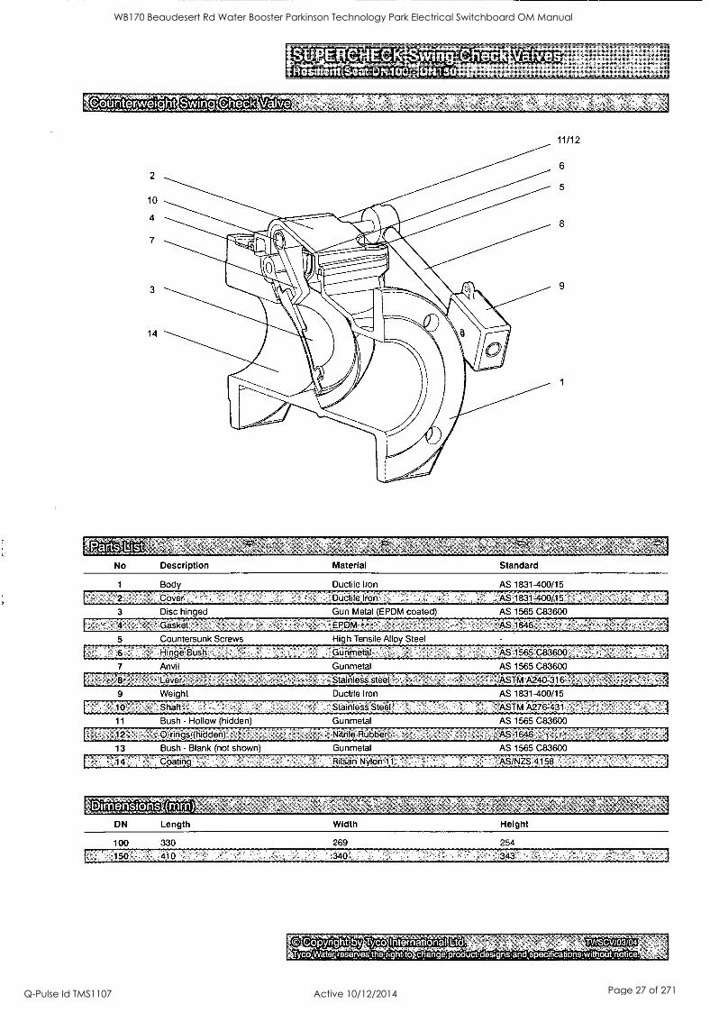
No
1
Description
Body
Material Standard
Ductile Iron AS 1831-400/15
Ductilealron AS .183l 400/15:
3 Disc hinged
Gesket
5 Countersunk Screws
Hinge Bush
7 Anvil
8 Lever
Weight
10 Shaft
Gun Metal (EPDM coated) AS 1565 C83600
High Tensile Alloy Steel
Gunmetal
Gunmetal
,:Staiiiless"steel
Ductile Iron
StainleSs Steel!
11 Bush - Hollow (hidden Gunmetal
AS 1565 C83600
AS 1565 C83600
ASTM.A240-316
AS 1831-400/15
'''ASTM A276:431
AS 1565 C83600
13 Bush - Blank (not shown)
Nitrile Rubber
Gunmetal AS 1565 C83600
14 1 Coating Rilsan Nylon 11 'ASIN2S 4158'
IDimensions DN Length Width Height
100 330 269 254
Copyright by Tyco International TWSCV/03/04
Tycopaterreservesihejright,to change,product;designsandspecificahonsmithouknotice.
WB170 Beaudesert Rd Water Booster Parkinson Technology Park Electrical Switchboard OM Manual
Q-Pulse Id TMS1107 Active 10/12/2014 Page 27 of 271
SUPERVIEeK Swing DN100- DN150
idal SpaCi ing
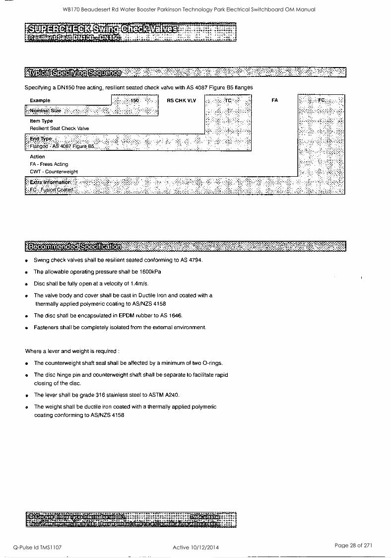
Specifying a DN150 free acting, resilient seated check valve with AS 4087 Figure B5 flanges
Example
Nominal Size
150
Item Type
Resilient Seat Check Valve
RS CHK VLV
End Type
Flanged - AS 4087 Figure, B5
TC
Action FA - Frees Acting
CWT - Counterweight
FA
Extra Information FC Co'ated
FC,
- 0 0 Specification
Swing check valves shall be resilient seated conforming to AS 4794.
The allowable operating pressure shall be 1600kPa
Disc shall be fully open at a velocity of 1.4m/s.
The valve body and cover shall be cast in Ductile Iron and coated with a
thermally applied polymeric coating to AS/NZS 4158
The disc shall be encapsulated in EPDM rubber to AS 1646.
Fasteners shall be completely isolated from the external environment.
Where a lever and weight is required :
The counterweight shaft seal shall be affected by a minimum of two 0-rings.
The disc hinge pin and counterweight shaft shall be separate to facilitate rapid
closing of the disc.
The lever shall be grade 316 stainless steel to ASTM A240.
The weight shall be ductile iron coated with a thermally applied polymeric
coating conforming to AS/NZS 4158
0 International Ltd. s -
TWSCV/03104
WB170 Beaudesert Rd Water Booster Parkinson Technology Park Electrical Switchboard OM Manual
Q-Pulse Id TMS1107 Active 10/12/2014 Page 28 of 271
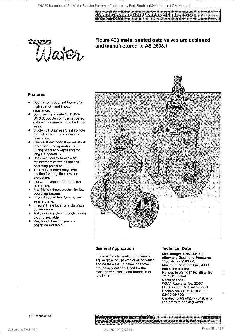
Features
Ductile Iron body and bonnet for high strength and impact resistance. Solid gunmetal gate for DN80- DN200, ductile iron fusion coated gate with gunmetal rings for larger sizes. Grade 431 Stainless Steel spindle for high strength and corrosion resistance. Gunmetal dezincification resistant top casting incorporating dual 0-ring seals and wiper ring for long life operation. Back seal facility to allow for replacement of seals under full operating pressure. Thermally bonded polymeric coating for long life corrosion protection. Isolated fasteners for corrosion protection. Anti-friction thrust washer for low operating torques. Integral cast in feet for safe and easy storage. Integral lifting lugs for installation convenience. Anticlockwise closing or clockwise closing available. Key, handwheel or gearbox operation available.
A.B.N. 75 087 415 745
. :I, 0 *II'
to - 00 -
Figure 400 metal seated gate valves are designed and manufactured to AS 2638.1
General Application
Figure 400 metal seated gate valves are suitable for use with drinking water and waste water, in below or above ground applications. Used for the isolation of sections and branches in
pipelines.
- .
Technical Data Size Range: DN80-DN900 Allowable Operating Pressure: 1600 kPa or 3500 kPa Maximum Temperature: 40°C End Connections: Flanged to AS 4087 Fig B5 or B6 TYTON® Socket Certifications: WSAA Appraisal No. 02/07 ISC AS 2638 Certified Product License No. PRD/R61/0412/2 (DN80-DN750) Certified to AS 4020 - suitable for contact with drinking water.
G t . yK
WB170 Beaudesert Rd Water Booster Parkinson Technology Park Electrical Switchboard OM Manual
Q-Pulse Id TMS1107 Active 10/12/2014 Page 29 of 271
15
14
9
12
10
1
18
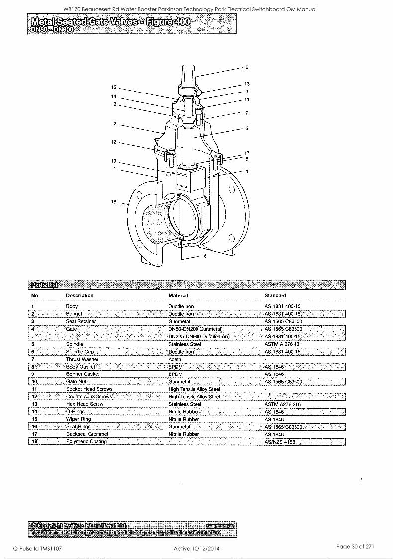
No
1
Description
Body
Material
Ductile Iron
3 Seal Retainer
Ductile Iron
Gunmetal
5
6.
7
Spindle
Spindle Cap
Thrust Washer
DN80-DN200 Gunmetal
DN225-DN906:Duatile,fron:.:
Stainless Steel
:.Ductile Irdn
Acetal
f, 8 Botldiikef 9 Bonnet Gasket
EPDM
EPDM
Standard
AS 1831 400-15
ASS 1831,400-15
AS 1565 C83600
AS 1565 C83600
AS1861 466-15
ASTM A 276 431
AS 1831 400 -15.
AS 1646
AS 1646 i
10' Gate,Nut Gunmetal. AS 1565 C83600
11 Socket Head Screws High Tensile Alloy Steel
12: counter'sbnk ScieWs: HigKlerisile Alloy Steel
13 Hex Head Screw Stainless Steel ASTM A276 316
14, ' 0-Rings
15 Wiper Ring
16
17 Backseal Grommet
18 Polymeric Coating
Nitrile Rubber
Nitrile Rubber
Gunmetal
Nitrile Rubber
AS 1646
AS 1646
.,;,As;1565.083600
AS 1646
AS/NZS .4158
WB170 Beaudesert Rd Water Booster Parkinson Technology Park Electrical Switchboard OM Manual
Q-Pulse Id TMS1107 Active 10/12/2014 Page 30 of 271
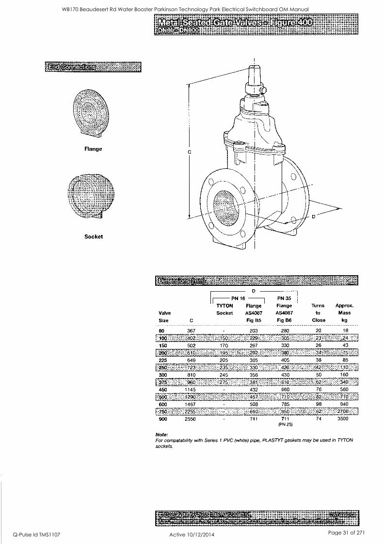
0
Flange
Socket
Dimensions
Valve
Size C
80 367
7I00 ' 402
150 502
200 610
225 649 ,
250 723
300 810
17375 ; 960
450 1145
1290:
600 1467
[fig: .-: 2255
900 2550
ID -7 PN 35 PN 16
MON Flange Flange Turns Approx.
Socket AS4087 AS4087 to Mass
Fig B5 Fig B6 Close kg
203 280 20 18
'150 . 170
____-__... 229 ... _
267
' :. ' 305_
330
23
26 43
.195
205
292
305
380
405
34
38
75
85
235
245
' 275
330 .........
356
:: 420 ........:
430
42
50
.
;
..... 1.10
160
381
432
... . ..
,': 610
660
62
76
: .. : 340
560
:..47 ..:,:71P 82 710 .:...,..
508 785
711 711 (PN 25)
74 3500
Note: For compatability with Series 1 PVC (white) pipe, PLASTYT gaskets may be used in TYTON sockets.
( i ) S - S .
WB170 Beaudesert Rd Water Booster Parkinson Technology Park Electrical Switchboard OM Manual
Q-Pulse Id TMS1107 Active 10/12/2014 Page 31 of 271
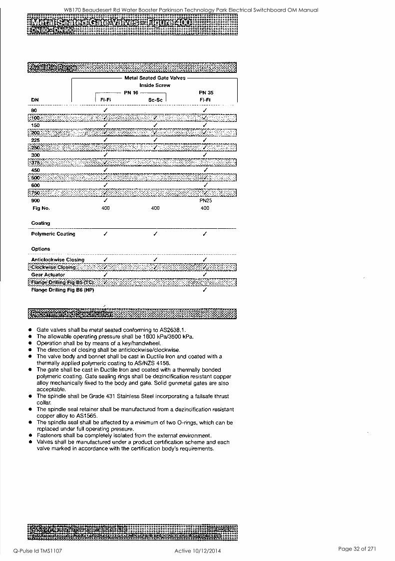
DN Fl-Fl
80
Metal Seated Gate Valves
Inside Screw PN 16 PN 35
Sc-Sc I Fl-Fl
300
375
450
600
750
900
Fig No.
Coating
400 400
PN25
400
Polymeric Coating
Options
Anticlockwise Closing .Clockwise Closing Gear Actuator Flange Fig B5 (TC)
Flange Drilling Fig B6 (HP)
- Specification
Gate valves shall be metal seated conforming to AS2638.1. The allowable operating pressure shall be 1600 kPa/3500 kPa. Operation shall be by means of a key/handwheel. The direction of closing shall be anticlockwise/clockwise. The valve body and bonnet shall be cast in Ductile Iron and coated with a thermally applied polymeric coating to AS/NZS 4158. The gate shall be cast in Ductile Iron and coated with a thermally bonded polymeric coating. Gate sealing rings shall be dezincification resistant copper alloy mechanically fixed to the body and gate. Solid gunmetal gates are also acceptable. The spindle shall be Grade 431 Stainless Steel incorporating a failsafe thrust collar. The spindle seal retainer shall be manufactured from a dezincification resistant copper alloy to AS1565. The spindle seal shall be affected by a minimum of two 0-rings, which can be replaced under full operating pressure. Fasteners shall be completely isolated from the external environment. Valves shall be manufactured under a product certification scheme and each valve marked in accordance with the certification body's requirements.
WB170 Beaudesert Rd Water Booster Parkinson Technology Park Electrical Switchboard OM Manual
Q-Pulse Id TMS1107 Active 10/12/2014 Page 32 of 271

MO ID II
5. Test Sheets
WB170 Beaudesert Rd Water Booster Parkinson Technology Park Electrical Switchboard OM Manual
Q-Pulse Id TMS1107 Active 10/12/2014 Page 33 of 271

I.
Ililliiiiiiiiiiiilliiiiill
ID II. I.
.
WB170 Beaudesert Rd Water Booster Parkinson Technology Park Electrical Switchboard OM Manual
Q-Pulse Id TMS1107 Active 10/12/2014 Page 34 of 271

J & P Richardson Industries Pry Ltd
5.0 TEST SHEETS
File: / /Jpr _Server /docs /!sched/Masters.doc Revision 0 Date: 25 May 2001
WB170 Beaudesert Rd Water Booster Parkinson Technology Park Electrical Switchboard OM Manual
Q-Pulse Id TMS1107 Active 10/12/2014 Page 35 of 271
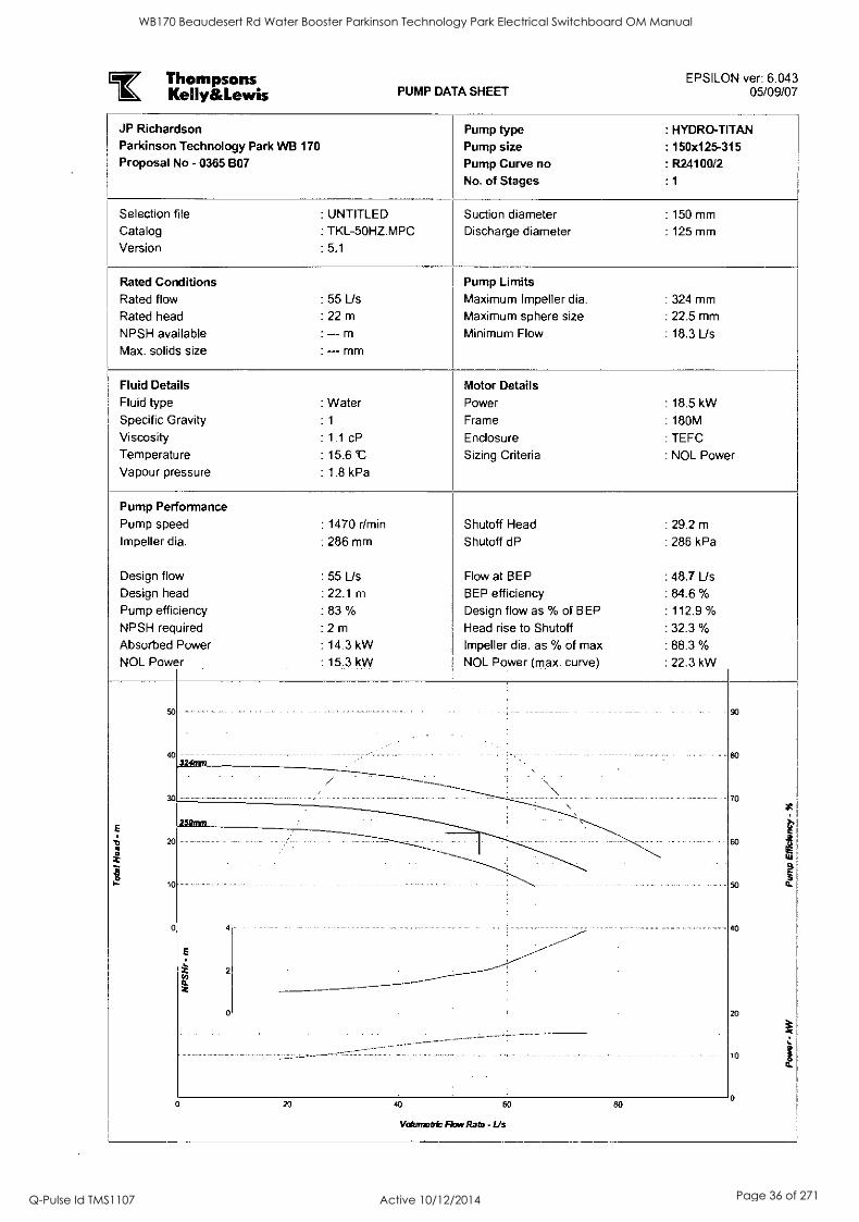
Thompsons Keily&Lewis PUMP DATA SHEET
EPSILON ver: 6.043 05/09/07
JP Richardson Parkinson Technology Park VVB 170
Proposal No - 0365 B07
Pump type Pump size Pump Curve no No. of Stages
: HYDRO-TITAN
: 150x125-315
: R24100/2
: 1
Selection file : UNTITLED Suction diameter : 150 mm
Catalog : TKL-50HZ.MPC Discharge diameter : 125 mm
Version : 5.1
Rated Conditions Pump Limits Rated flow : 55 Us Maxi
.
mum Impeller dia. : 324 mm
Rated head : 22 m Maximum sphere size : 22.5 mm
NPSH available
Max. solids size
: - m
: -- mm
Minimum Flow : 18.3 Us
Fluid Details Motor Details Fluid type : Water Power : 18.5 kW Specific Gravity : 1 Frame : 180M
Viscosity : 1.1 cP Enclosure : TEFC Temperature : 15.6 t Sizing Criteria : NOL Power Vapour pressure : 1.8 kPa
Pump Performance Pump speed : 1470 r/min Shutoff Head : 29.2 m
Impeller dia. : 286 mm Shutoff dP : 286 kPa
Design flow : 55 Us Flow at BEP : 48.7 Us Design head : 22.1 m BEP efficiency : 84.6 %
Pump efficiency : 83 % Design flow as % of BEP : 112.9 %
NPSH required : 2 m Head rise to Shutoff : 32.3 %
Absorbed Power : 14.3 kW Impeller dia. as % of max : 88.3 % NOL Power : 15.3 kW NOL Power (max. curve) : 22.3 kW
so 324entn
70
E 259nrn
20
- 10 so
1 w 9.
a
0 40
-------
2 cf) O. 2 _
0 20
o
t
o 20 40 60 80
Volumetric Flow Rate - Lls
WB170 Beaudesert Rd Water Booster Parkinson Technology Park Electrical Switchboard OM Manual
Q-Pulse Id TMS1107 Active 10/12/2014 Page 36 of 271

II el
110111119[1111111111.111111111111111111111119111111J
6. Flowmeter
WB170 Beaudesert Rd Water Booster Parkinson Technology Park Electrical Switchboard OM Manual
Q-Pulse Id TMS1107 Active 10/12/2014 Page 37 of 271

GI ID 41111 la
IIII111111minum111111
WB170 Beaudesert Rd Water Booster Parkinson Technology Park Electrical Switchboard OM Manual
Q-Pulse Id TMS1107 Active 10/12/2014 Page 38 of 271

J & P Richardson Industries Pty Ltd
6.0 FLOWMETER
File: 11.1pr_Server/docs/lsched/Masters.doc Revision 0 Date: 25 May 2001
WB170 Beaudesert Rd Water Booster Parkinson Technology Park Electrical Switchboard OM Manual
Q-Pulse Id TMS1107 Active 10/12/2014 Page 39 of 271

Fullstand Druck ua Durchfluss
0 ° Ar Temperatur FlOssigkeits- Registrierung Systeme Services
analyse Komponenten
Brief Operating Instructions
Pro line Promag 10 Electromagnetic Flow Measuring System
KA032D/06/en/01.08 71067518
Solutions
These Brief Operating Instructions are not intended to replace the Operating Instructions provided in the scope of supply. Detailed information is provided in the Operating Instructions and the additional documentation on the CD-ROM supplied.
The complete device documentation consists of:
These Brief Operating Instructions Depending on the device version: - Operating Instructions and the Description of Device Functions - Approvals and safety certificates - Special safety instructions in accordance with the approvals for
the device (e.g. explosion protection, pressure equipment directive etc.)
- Additional device-specific information
Endress+Hauser People for Process Automation
WB170 Beaudesert Rd Water Booster Parkinson Technology Park Electrical Switchboard OM Manual
Q-Pulse Id TMS1107 Active 10/12/2014 Page 40 of 271

Table of contents Pro line Promag 10
Table of contents
1 Safety instructions 3 1.1 Designated use 3
1.2 Installation, commissioning and operation 3
1.3 Operational safety 3
1.4 Safety conventions 4
2 Installation 5
2.1 Transporting to the measuring point 5
2.2 Installation conditions 6
2.3 Installing the Promag W sensor 11
2.4 Installing the Promag P sensor 12
2.5 Tightening torques for Promag W and Promag P 14
2.6 Installing the Promag H sensor 20
2.7 Installing the transmitter housing 21
2.8 Post-installation check 23
3 Wiring 24 3.1 Connecting the various housing types 25
3.2 Connecting the remote version connecting cable 26
3.3 Potential equalization 29
3.4 Degree of protection 30
3.5 Post-connection check 30
4 Commissioning 31 4.1 Switching on the measuring device 31
4.2 Operation 32
4.3 Navigating within the function matrix 33
4.4 Device functions to be configured during commissioning 34
4.5 Troubleshooting 35
2 Endress+Hauser
WB170 Beaudesert Rd Water Booster Parkinson Technology Park Electrical Switchboard OM Manual
Q-Pulse Id TMS1107 Active 10/12/2014 Page 41 of 271
Pro line Promag 10 Safety instructions
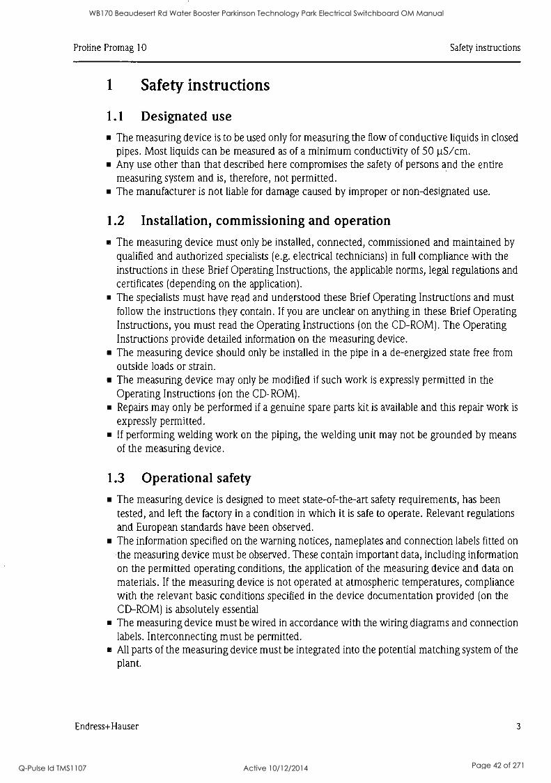
1 Safety instructions
1.1 Designated use
The measuring device is to be used only for measuring the flow of conductive liquids in closed pipes. Most liquids can be measured as of a minimum conductivity of 50 µS /cm. Any use other than that described here compromises the safety of persons and the entire measuring system and is, therefore, not permitted. The manufacturer is not liable for damage caused by improper or non-designated use.
1.2 Installation, commissioning and operation
The measuring device must only be installed, connected, commissioned and maintained by qualified and authorized specialists (e.g. electrical technicians) in full compliance with the instructions in these Brief Operating Instructions, the applicable norms, legal regulations and certificates (depending on the application). The specialists must have read and understood these Brief Operating Instructions and must follow the instructions they contain. If you are unclear on anything in these Brief Operating Instructions, you must read the Operating Instructions (on the CD-ROM). The Operating Instructions provide detailed information on the measuring device.
II The measuring device should only be installed in the pipe in a de-energized state free from outside loads or strain. The measuring device may only be modified if such work is expressly permitted in the Operating Instructions (on the CD-ROM). Repairs may only be performed if a genuine spare parts kit is available and this repair work is
expressly permitted. If performing welding work on the piping, the welding unit may not be grounded by means of the measuring device.
1.3 Operational safety
The measuring device is designed to meet state-of-the-art safety requirements, has been tested, and left the factory in a condition in which it is safe to operate. Relevant regulations and European standards have been observed. The information specified on the warning notices, nameplates and connection labels fitted on the measuring device must be observed. These contain important data, including information on the permitted operating conditions, the application of the measuring device and data on
materials. If the measuring device is not operated at atmospheric temperatures, compliance with the relevant basic conditions specified in the device documentation provided (on the CD-ROM) is absolutely essential The measuring device must be wired in accordance with the wiring diagrams and connection labels. Interconnecting must be permitted. All parts of the measuring device must be integrated into the potential matching system of the plant.
Endress+Hauser 3
WB170 Beaudesert Rd Water Booster Parkinson Technology Park Electrical Switchboard OM Manual
Q-Pulse Id TMS1107 Active 10/12/2014 Page 42 of 271
Safety instructions Pro line Promag 10
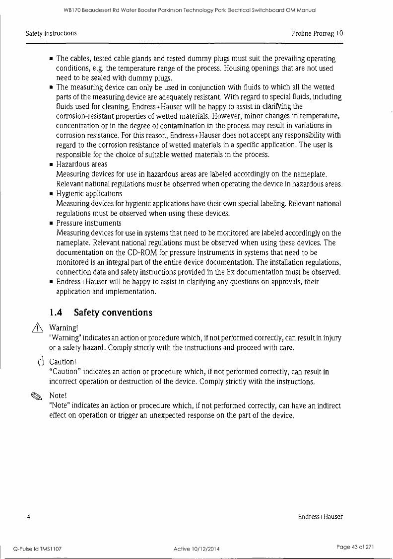
The cables, tested cable glands and tested dummy plugs must suit the prevailing operating conditions, e.g. the temperature range of the process. Housing openings that are not used need to be sealed with dummy plugs. The measuring device can only be used in conjunction with fluids to which all the wetted parts of the measuring device are adequately resistant. With regard to special fluids, including fluids used for cleaning, Endress+Hauser will be happy to assist in clarifying the corrosion-resistant properties of wetted materials. However, minor changes in temperature, concentration or in the degree of contamination in the process may result in variations in
corrosion resistance. For this reason, Endress+Hauser does not accept any responsibility with regard to the corrosion resistance of wetted materials in a specific application. The user is
responsible for the choice of suitable wetted materials in the process. Hazardous areas Measuring devices for use in hazardous areas are labeled accordingly on the nameplate. Relevant national regulations must be observed when operating the device in hazardous areas. Hygienic applications Measuring devices for hygienic applications have their own special labeling. Relevant national regulations must be observed when using these devices. Pressure instruments Measuring devices for use in systems that need to be monitored are labeled accordingly on the nameplate. Relevant national regulations must be observed when using these devices. The documentation on the CD-ROM for pressure instruments in systems that need to be
monitored is an integral part of the entire device documentation. The installation regulations, connection data and safety instructions provided in the Ex documentation must be observed. Endress+Hauser will be happy to assist in clarifying any questions on approvals, their application and implementation.
1.4 Safety conventions
,A Warning! "Warning" indicates an action or procedure which, if not performed correctly, can result in injury or a safety hazard. Comply strictly with the instructions and proceed with care.
Caution! "Caution" indicates an action or procedure which, if not performed correctly, can result in incorrect operation or destruction of the device. Comply strictly with the instructions.
Note! "Note" indicates an action or procedure which, if not performed correctly, can have an indirect effect on operation or trigger an unexpected response on the part of the device.
O
4 Endress+Hauser
WB170 Beaudesert Rd Water Booster Parkinson Technology Park Electrical Switchboard OM Manual
Q-Pulse Id TMS1107 Active 10/12/2014 Page 43 of 271
Pro line Promag 10 Installation
2 Installation
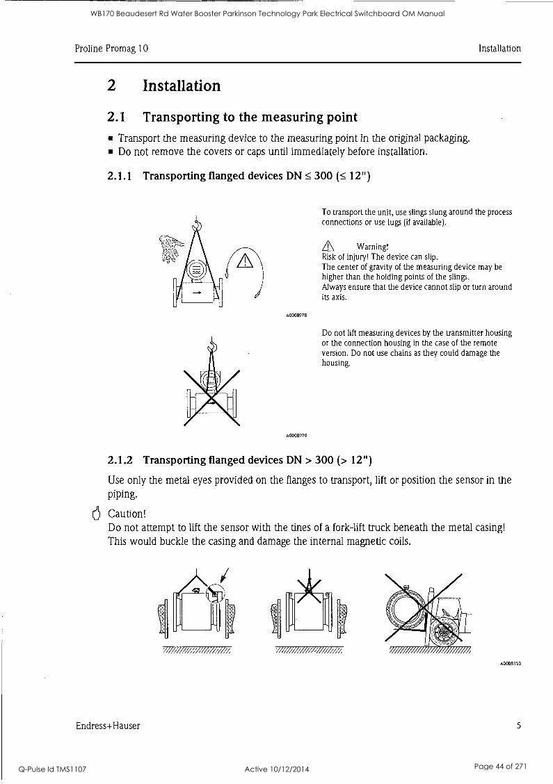
2.1 Transporting to the measuring point Transport the measuring device to the measuring point in the original packaging. Do not remove the covers or caps until immediately before installation.
2.1.1 Transporting flanged devices DN 5 300 12")
A0008978
A0008979
To transport the unit, use slings slung around the process connections or use lugs (if available).
Warning! Risk of injury! The device can slip. The center of gravity of the measuring device may be higher than the holding points of the slings. Always ensure that the device cannot slip or turn around its axis.
Do not lift measuring devices by the transmitter housing or the connection housing in the case of the remote version. Do not use chains as they could damage the housing.
2.1.2 Transporting flanged devices DN > 300 (> 12")
Use only the metal eyes provided on the flanges to transport, lift or position the sensor in the piping.
6 Caution! Do not attempt to lift the sensor with the tines of a fork-lift truck beneath the metal casing!
This would buckle the casing and damage the internal magnetic coils.
/ // ////////, A0008153
Endress+Hauser 5
WB170 Beaudesert Rd Water Booster Parkinson Technology Park Electrical Switchboard OM Manual
Q-Pulse Id TMS1107 Active 10/12/2014 Page 44 of 271
Installation Pro line Promag 10
2.2 Installation conditions
2.2.1 Dimensions
For the dimensions of the measuring device, see the associated Technical Information on the CD-ROM.
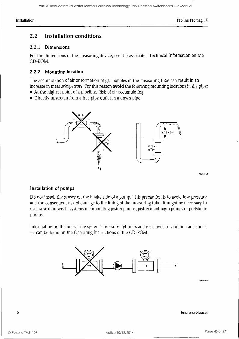
2.2.2 Mounting location
The accumulation of air or formation of gas bubbles in the measuring tube can result in an increase in measuring errors. For this reason avoid the following mounting locations in the pipe:
At the highest point of a pipeline. Risk of air accumulating! Directly upstream from a free pipe outlet in a down pipe.
A0008154
Installation of pumps
Do not install the sensor on the intake side of a pump. This precaution is to avoid low pressure and the consequent risk of damage to the lining of the measuring tube. It might be necessary to
use pulse dampers in systems incorporating piston pumps, piston diaphragm pumps or peristaltic pumps.
Information on the measuring system's pressure tightness and resistance to vibration and shock ---> can be found in the Operating Instructions of the CD-ROM.
A0003203
6 Endress+Hauser
WB170 Beaudesert Rd Water Booster Parkinson Technology Park Electrical Switchboard OM Manual
Q-Pulse Id TMS1107 Active 10/12/2014 Page 45 of 271
Pro line Promag 10 Installation
a
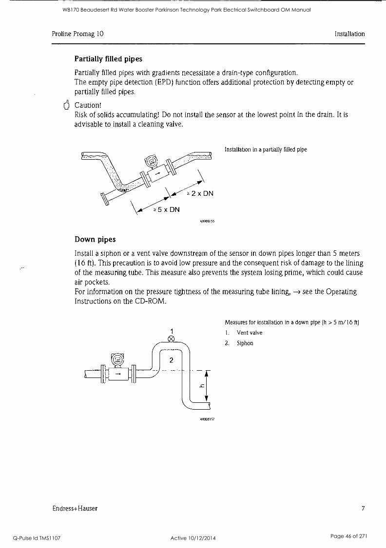
Partially filled pipes
Partially filled pipes with gradients necessitate a drain-type configuration. The empty pipe detection (EPD) function offers additional protection by detecting empty or partially filled pipes.
Caution! Risk of solids accumulating! Do not install the sensor at the lowest point in the drain. It is
advisable to install a cleaning valve.
"NooM11., , 2 x DN
\A-CDN A0008155
Installation in a partially filled pipe
Down pipes
Install a siphon or a vent valve downstream of the sensor in down pipes longer than 5 meters (16 ft). This precaution is to avoid low pressure and the consequent risk of damage to the lining of the measuring tube. This measure also prevents the system losing prime, which could cause air pockets. For information on the pressure tightness of the measuring tube lining, --> see the Operating Instructions on the CD-ROM.
A0008157
Measures for installation in a down pipe (h > 5 m/16 ft)
1. Vent valve
2. Siphon
Endress+Hauser 7
WB170 Beaudesert Rd Water Booster Parkinson Technology Park Electrical Switchboard OM Manual
Q-Pulse Id TMS1107 Active 10/12/2014 Page 46 of 271
Installation Pro line Promag 10
6
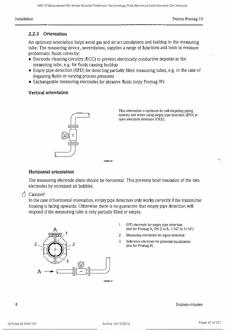
2.2.3 Orientation
An optimum orientation helps avoid gas and air accumulations and buildup in the measuring tube. The measuring device, nevertheless, supplies a range of functions and tools to measure problematic fluids correctly:
Electrode cleaning circuitry (ECC) to prevent electrically conductive deposits in the measuring tube, e.g. for fluids causing buildup Empty pipe detection (EPD) for detecting partially filled measuring tubes, e.g. in the case of
degassing fluids or varying process pressures Exchangeable measuring electrodes for abrasive fluids (only Promag W)
Vertical orientation
A0008158
Horizontal orientation
This orientation is optimum for self-emptying piping systems and when using empty pipe detection (EPD) or open electrode detection (OED).
The measuring electrode plane should be horizontal. This prevents brief insulation of the two electrodes by entrained air bubbles.
Caution! In the case of horizontal orientation, empty pipe detection only works correctly if the transmitter housing is facing upwards. Otherwise there is no guarantee that empty pipe detection will
respond if the measuring tube is only partially filled or empty.
2
A0008159
1. EPD electrode for empty pipe detection (not for Promag H, DN 2 to 8, 1/12" to 5/16").
2. Measuring electrodes for signal detection
3. Reference electrode for potential equalization (not for Promag H)
8 Endress+Hauser
WB170 Beaudesert Rd Water Booster Parkinson Technology Park Electrical Switchboard OM Manual
Q-Pulse Id TMS1107 Active 10/12/2014 Page 47 of 271
Pro line Promag 10 Installation
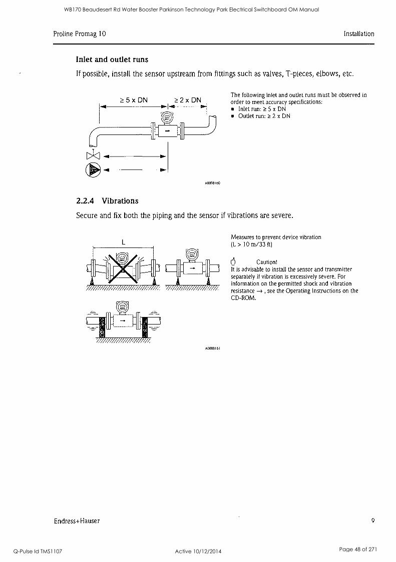
Inlet and outlet runs
If possible, install the sensor upstream from fittings such as valves, T-pieces, elbows, etc.
5 x DN 2 x DN
A0008160
2.2.4 Vibrations
The following inlet and outlet runs must be observed in order to meet accuracy specifications:
Inlet run: 5 x DN Outlet run: 2 x DN
Secure and fix both the piping and the sensor if vibrations are severe.
A000816I
Measures to prevent device vibration (L > 10 m/33 ft)
6 Caution! It is advisable to install the sensor and transmitter separately if vibration is excessively severe. For information on the permitted shock and vibration resistance -) , see the Operating Instructions on the CD-ROM.
Endress+Hauser 9
WB170 Beaudesert Rd Water Booster Parkinson Technology Park Electrical Switchboard OM Manual
Q-Pulse Id TMS1107 Active 10/12/2014 Page 48 of 271
Installation Pro line Promag 10
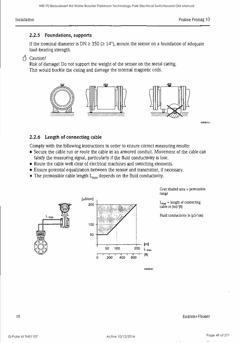
2.2.5 Foundations, supports
If the nominal diameter is DN 350 14"), mount the sensor on a foundation of adequate load-bearing strength.
6 Caution! Risk of damage! Do not support the weight of the sensor on the metal casing. This would buckle the casing and damage the internal magnetic coils.
'300000°
'://r1/ /2/////2/
A0008163
2.2.6 Length of connecting cable
Comply with the following instructions in order to ensure correct measuring results: Secure the cable run or route the cable in an armored conduit. Movement of the cable can falsify the measuring signal, particularly if the fluid conductivity is low. Route the cable well clear of electrical machines and switching elements. Ensure potential equalization between the sensor and transmitter, if necessary. The permissible cable length Lim, depends on the fluid conductivity.
10
[µS /cm]
200 -
100
50
50 100
I I I 1
0 200 400
[m] 200 L max
' '
600
A0008981
Gray shaded area = permissible range
Lmax = length of connecting cable in [m] /]ft]
Fluid conductivity in [µS /cm]
Endress+Hauser
WB170 Beaudesert Rd Water Booster Parkinson Technology Park Electrical Switchboard OM Manual
Q-Pulse Id TMS1107 Active 10/12/2014 Page 49 of 271
Pro line Promag 10 Installation
a
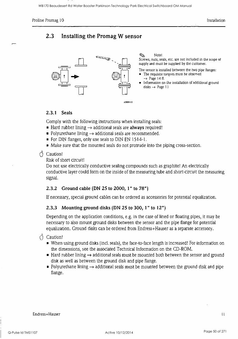
2.3 Installing the Promag W sensor
2.3.1 Seals
a0008105
Note! Screws, nuts, seals, etc. are not included in the scope of supply and must be supplied by the customer.
The sensor is installed between the two pipe flanges: The requisite torques must be observed
Page 14 ff.
Information on the installation of additional ground disks -) Page 11
Comply with the following instructions when installing seals: Hard rubber lining additional seals are always required! Polyurethane lining additional seals are recommended. For DIN flanges, only use seals to DIN EN 1514-1. Make sure that the mounted seals do not protrude into the piping cross-section.
Caution! Risk of short circuit! Do not use electrically conductive sealing compounds such as graphite! An electrically conductive layer could form on the inside of the measuring tube and short-circuit the measuring signal.
2.3.2 Ground cable (DN 25 to 2000, 1" to 78")
If necessary, special ground cables can be ordered as accessories for potential equalization.
2.3.3 Mounting ground disks (DN 25 to 300, 1" to 12")
Depending on the application conditions, e.g. in the case of lined or floating pipes, it may be necessary to also mount ground disks between the sensor and the pipe flange for potential equalization. Ground disks can be ordered from Endress+Hauser as a separate accessory.
Caution! When using ground disks (incl. seals), the face-to-face length is increased! For information on the dimensions, see the associated Technical Information on the CD-ROM. Hard rubber lining -> additional seals must be mounted both between the sensor and ground disk as well as between the ground disk and pipe flange. Polyurethane lining -* additional seals must be mounted between the ground disk and pipe flange.
Endress+ Hauser 11
WB170 Beaudesert Rd Water Booster Parkinson Technology Park Electrical Switchboard OM Manual
Q-Pulse Id TMS1107 Active 10/12/2014 Page 50 of 271
Installation Pro line Promag 10
A0008167
1. Place the ground disk and the additional seals between the measuring device flange and pipe flange (see graphic).
2. Insert the screws through the flange bores. Tighten the nuts so that they are still loose.
3. Now rotate the ground disk as shown in the graphic until the handle strikes the screws. This correctly centers the ground disk automatically.
4. Tighten the screws to the required torque -> Page 14
5. Wire the ground disks in accordance with the grounding concept of the plant.
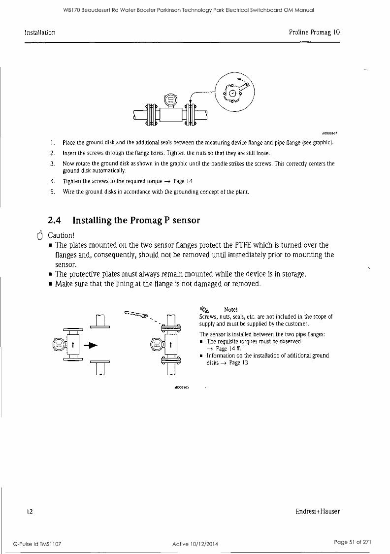
2.4 Installing the Promag P sensor Caution!
The plates mounted on the two sensor flanges protect the PTFE which is turned over the flanges and, consequently, should not be removed until immediately prior to mounting the sensor. The protective plates must always remain mounted while the device is in storage. Make sure that the lining at the flange is not damaged or removed.
a 0008165
Ckb, Note! Screws, nuts, seals, etc. are not included in the scope of
supply and must be supplied by the customer.
The sensor is installed between the two pipe flanges: The requisite torques must be observed -> Page 14 ff.
Information on the installation of additional ground disks -> Page 13
12 Endress+Hauser
WB170 Beaudesert Rd Water Booster Parkinson Technology Park Electrical Switchboard OM Manual
Q-Pulse Id TMS1107 Active 10/12/2014 Page 51 of 271
Pro line Promag 10 Installation
a
a
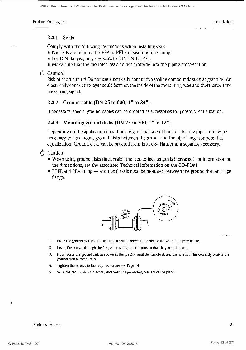
2.4.1 Seals
Comply with the following instructions when installing seals: No seals are required for PFA or PFTE measuring tube lining. For DIN flanges, only use seals to DIN EN 1514-1. Make sure that the mounted seals do not protrude into the piping cross-section.
Caution! Risk of short circuit! Do not use electrically conductive sealing compounds such as graphite! An electrically conductive layer could form on the inside of the measuring tube and short-circuit the measuring signal.
2.4.2 Ground cable (DN 25 to 600, 1" to 24")
If necessary, special ground cables can be ordered as accessories for potential equalization.
2.4.3 Mounting ground disks (DN 25 to 300, 1" to 12")
Depending on the application conditions, e.g. in the case of lined or floating pipes, it may be necessary to also mount ground disks between the sensor and the pipe flange for potential equalization. Ground disks can be ordered from Endress+Hauser as a separate accessory.
Caution! When using ground disks (incl. seals), the face-to-face length is increased! For information on the dimensions, see the associated Technical Information on the CD-ROM. PTFE and PFA lining additional seals must be mounted between the ground disk and pipe flange.
A0008167
1. Place the ground disk and the additional seal(s) between the device flange and the pipe flange.
2. Insert the screws through the flange bores. Tighten the nuts so that they are still loose.
3. Now rotate the ground disk as shown in the graphic until the handle strikes the screws. This correctly centers the ground disk automatically.
4. Tighten the screws to the required torque -4 Page 14
5. Wire the ground disks in accordance with the grounding concept of the plant.
Endress+Hauser 13
WB170 Beaudesert Rd Water Booster Parkinson Technology Park Electrical Switchboard OM Manual
Q-Pulse Id TMS1107 Active 10/12/2014 Page 52 of 271
Installation Proline Promag 10
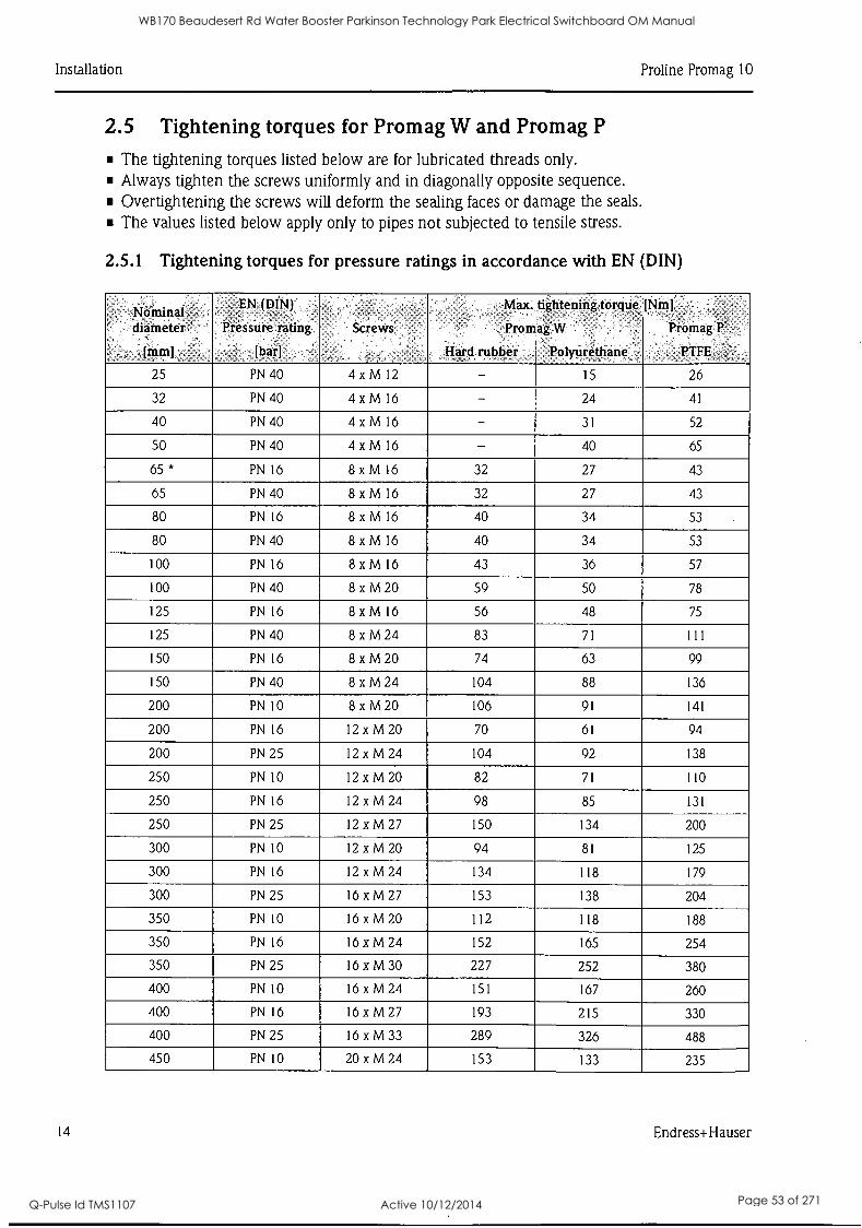
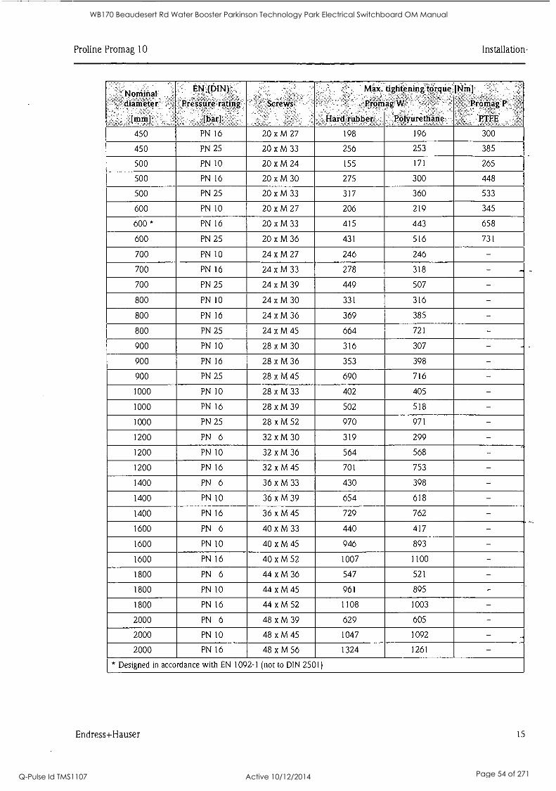
2.5 Tightening torques for Promag W and Promag P
The tightening torques listed below are for lubricated threads only. Always tighten the screws uniformly and in diagonally opposite sequence. Overtightening the screws will deform the sealing faces or damage the seals. The values listed below apply only to pipes not subjected to tensile stress.
2.5.1 Tightening torques for pressure ratings in accordance with EN (DIN)
..
Nominal ,
diameter
[mm]
.
,
EN (DIN)
Pressure rating
[bar]
Screws
Max.
Promag
Hard rubber
tightening torque
W
,Polyurethane
[Nm]
Promag P
PTFE
25 PN 40 4 xM 12 - 15 26
32 PN 40 4 xM 16 - 24 41
40 PN 40 4 xM 16 - 31 52
50 PN 40 4 xM 16 - 40 65
65 * PN 16 8 x M 16 32 27 43
65 PN 40 8 x M 16 32 27 43
80 PN 16 8 x M 16 40 34 53
80 PN 40 8 x M 16 40 34 53
100 PN 16 8 x M 16 43 36 57
100 PN 40 8 x M 20 59 50 78
125 PN 16 8 xM 16 56 48 75
125 PN 40 8 xM 24 83 71 111
150 PN 16 8 x M 20 74 63 99
150 PN 40 8 xM 24 104 88 136
200 PN 10 8 xM 20 106 91 141
200 PN 16 12 xM 20 70 61 94
200 PN 25 12 xM 24 104 92 138
250 PN 10 12 xM 20 82 71 110
250 PN 16 12 xM 24 98 85 131
250 PN 25 12 xM 27 150 134 200
300 PN 10 12 x M 20 94 81 125
300 PN 16 12 xM 24 134 118 179
300 PN 25 16 xM 27 153 138 204
350 PN 10 16 xM 20 112 118 188
350 PN 16 16 xM 24 152 165 254
350 PN 25 16 xM 30 227 252 380
400 PN 10 16 xM 24 151 167 260
400 PN 16 16 xM 27 193 215 330
400 PN 25 16 xM 33 289 326 488
450 PN 10 20 xM 24 153 133 235
14 Endress+Hauser
WB170 Beaudesert Rd Water Booster Parkinson Technology Park Electrical Switchboard OM Manual
Q-Pulse Id TMS1107 Active 10/12/2014 Page 53 of 271
Proline Promag 10 Installation,
Nominal diameter
[mm]
EN :(151.N),
,Pressure rating,
[bar],
Screwsa
Max.
Promag
Hard rubber
tightening`torque:[Nin]
W ,
'Polyurethane
. Promag P;
PTFE
450 PN 16 20 xM27 198 196 300
450 PN 25 20 xM33 256 253 385
500 PN 10 20 xM24 155 171 265
500 PN 16 20 xM30 275 300 448
500 PN 25 20 xM33 317 360 533
600 PN 10 20 xM27 206 219 345
600* PN 16 20 xM33 415 443 658
600 PN 25 20 xM36 431 516 731
700 PN 10 24 xM27 246 246 - 700 PN 16 24 xM33 278 318 - - 700 PN 25 24 xM39 449 507 - 800 PN 10 24xM30 331 316 - 800 PN 16 24 xM36 369 385 - 800 PN 25 24 xM45 664 721 - 900 PN 10 28 xM30 316 307 - 900 PN 16 28 xM36 353 398 - 900 PN 25 28 xM45 690 716 - 1000 PN 10 28 xM33 402 405 - 1000 PN 16 28 xM39 502 518 - 1000 PN 25 28 xM52 970 971 - 1200 PN 6 32 xM30 319 299 - 1200 PN 10 32 x M 36 564 568 - 1200 PN 16 32 xM 45 701 753 - 1400 PN 6 36 xM 33 430 398 - 1400 PN 10 36 xM39 654 618 - 1400 PN 16 36 xM 45 729 762 - 1600 PN 6 40 xM33 440 417 - 1600 PN 10 40 xM45 946 893 - 1600 PN 16 40 xM52 1007 1100 - 1800 PN 6 44 xM36 547 521 - 1800 PN 10 44 xM45 961 895 - 1800 PN 16 44 xM52 1108 1003 - 2000 PN 6 48 xM39 629 605 - 2000 PN 10 48 xM45 1047 1092 - .
2000 PN 16 48 xM56 1324 1261 - * Designed in accordance with EN 1092-1 (not to DIN 2501)
Endress+Hauser 15
WB170 Beaudesert Rd Water Booster Parkinson Technology Park Electrical Switchboard OM Manual
Q-Pulse Id TMS1107 Active 10/12/2014 Page 54 of 271
Installation Proline Promag 10
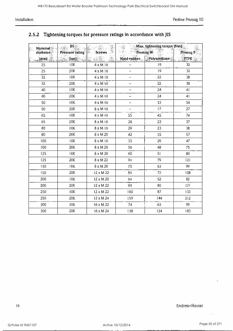
2.5.2 Tightening torques for pressure ratings in accordance with JIS
NOminal chaMeter, -
(Mini
JIS
Pressure rating
[bar]
.Screlks
Max.
Promag
Hard.ruhher
tightening torque-
W
; Polyurethane
(Nmj
PromagP,
PTFE .
25 10K 4 xMl6 - 19 32
25 20K 4 xMl6 - 19 32
32 10K 4 xMl6 - 22 38
32 20K 4 xMl6 - 22 38
40 10K 4 xMl6 - 24 41
40 20K 4 xMl6 - 24 41
50 10K 4 xMl6 - 33 54
50 20K 8 xMl6 - 17 27
65 10K 4 xMl6 55 45 74
65 20K 8 xMl6 28 23 37
80 10K 8 xM 16 29 23 38
80 20K 8 xM20 42 35 57
100 10K 8 xM 16 35 29 47
100 20K 8 xM20 56 48 75
125 10K 8 xM20 60 51 80
125 20K 8 xM22 91 79 121
150 10K 8 xM20 75 63 99
150 20K 12 xM22 81 72 108
200 10K 12 xM20 61 52 82
200 20K 12 xM22 91 80 121
250 10K 12 xM22 100 87 133
250 20K 12 xM24 159 144 212
300 10K 16 xM22 74 63 99
300 20K 16 xM24 138 124 183
16 Endress+Hauser
WB170 Beaudesert Rd Water Booster Parkinson Technology Park Electrical Switchboard OM Manual
Q-Pulse Id TMS1107 Active 10/12/2014 Page 55 of 271
Proline Promag 10 Installation
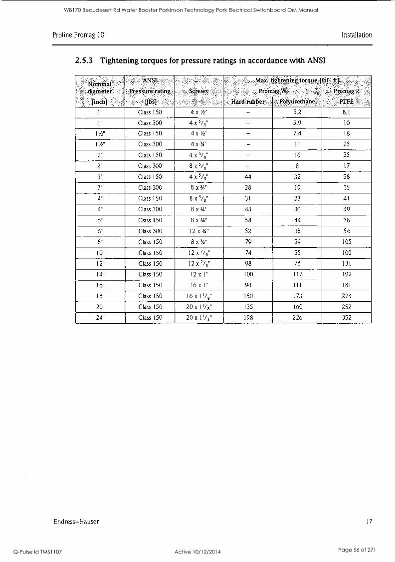
2.5.3 Tightening torques for pressure ratings in accordance with ANSI
Nominal ,
'._ diameter
[inch]
, ANSI`
Pressure rating '
[ibs]
Screws
, Max,tightening
Promag,W,
Hard rubber ,
torque,' _
-rolyurethanei
bf ft] .
. _
,Promag P
PTFE -
1" Class 150 4 x 1/2" - 5.2 8.1
1" Class 300 4 x 5/8" - 5.9 10
11/2" Class 150 4 x 1/2" - 7.4 18
11/2" Class 300 4 x 3/4" - 11 25
2" Class 150 4 x 5/8" - 16 35
2" Class 300 8 x 5/8" - 8 17
3" Class 150 4 x 5/8" 44 32 58
3" Class 300 8 x 3/4" 28 19 35
4" Class 150 8 x 5/8" 31 23 41
4" Class 300 8 x 3/4" 43 30 49
6" Class 150 8 x 3/4" 58 44 78
6" Class 300 12 x 3/4" 52 38 54
8" Class 150 8 x 3/4" 79 59 105
10" Class 150 12 x 7/8" 74 55 100
12" Class 150 12 x 7/8" 98 76 131
14" Class 150 12 x 1" 100 117 192
16" Class 150 16 x I" 94 1 I 1 181
18" Class 150 16 x 0/8" 150 173 274
20" Class 150 20 x 1'/8" 135 160 252
24" Class 150 20 x 11/4" 198 226 352
Endress+Hauser 17
WB170 Beaudesert Rd Water Booster Parkinson Technology Park Electrical Switchboard OM Manual
Q-Pulse Id TMS1107 Active 10/12/2014 Page 56 of 271
Installation Proline Promag 10
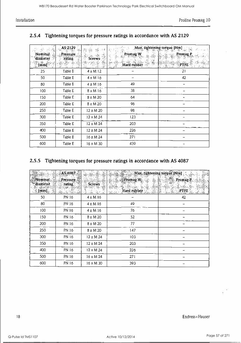
2.5.4 Tightening torques for pressure ratings in accordance with AS 2129
Nominal diameter
Imin1
AS 2129
Pressure rating Screws
Max. tightening
Promag W
Hard rubber
torque [Nin]
Promag P,
PTFE
25 Table E 4xM12 - 21
50 Table E 4 x M 16 - 42
80 Table E 4 x M 16 49 - 100 Table E 8 x M 16 38 - 150 Table E 8 x M 20 64 - 200 Table E 8 x M 20 96 - 250 Table E 12 xM20 98 - 300 Table E 12 xM 24 123 - 350 Table E 12 xM24 203 - 400 Table E 12 xM24 226 - 500 Table E 16 xM24 271 - 600 Table E 16 xM30 439 -
2.5.5 Tightening torques for pressure ratings in accordance with AS 4087
Nominal y
4"° diameter
mmj
AS 4087 '
Pressure ,"- rating Screws
Max. tightening
,,Promag W
',Hard rubber
torqiie. [Nmj
- '777'- , Promag P
PTFE
50 PN 16 4 x M 16 - 42
80 PN 16 4 x M 16 49 - 100 PN 16 4 x M 16 76 - 150 PN 16 8 x M 20 52 - 200 PN 16 8 x M 20 77 - 250 PN 16 8xM20 147 - 300 PN 16 12 x M 24 103 - 350 PN 16 12 xM24 203 - 400 PN 16 12 xM24 226 - 500 PN 16 16 xM24 271 - 600 PN 16 16 x M 30 393 -
18 Endress+Hauser
WB170 Beaudesert Rd Water Booster Parkinson Technology Park Electrical Switchboard OM Manual
Q-Pulse Id TMS1107 Active 10/12/2014 Page 57 of 271
Proline Promag 10 Installation
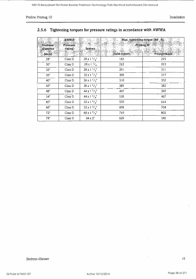
2.5.6 Tightening torques for pressure ratings in accordance with AWWA
Nominal diameter
[inch]
AWWA" Pressure
rating Screws
.Max. tightening
Promag .
Hard' rubber
torquellbf ft]..
W:
-- Polyurethane ,
28" Class D 28 x 1 '/4" 182 215
30" Class D 28 x 1 '/, 212 223
32" Class D 28 x 1 I /2" 291 311
36" Class D 32 x 1 1/2" 309 317
40" Class D 36 x 1 '/2" 310 352
42" Class D 36 x 1 Y2" 389 382
48" Class D 44 x 1 I/2" 407 392
54" Class D 44 x 1 3/4" 538 467
60" Class D 52 x 1 3/4" 559 614
66" Class D 52 x 1 3/4" 698 704
72" Class D 60 x 1 3/4" 719 802
78" Class D 64 x 2" 629 580
Endress+Hauser 19
WB170 Beaudesert Rd Water Booster Parkinson Technology Park Electrical Switchboard OM Manual
Q-Pulse Id TMS1107 Active 10/12/2014 Page 58 of 271

Installation Pro line Promag 10
a
a
a
2.6 Installing the Promag H sensor Depending on the order specifications, the sensor is supplied with or without ready-mounted process connections. Mounted process connections are fixed to the sensor with 4 hexagonal-headed bolts.
Caution! Depending on the application and length of the pipe, the sensor may have to be supported or
additionally secured. The sensor must be secured if using plastic process connections. An
appropriate wall mounting kit can be ordered separately from Endress+Hauser as an accessory.
2.6.1 Seals
When mounting the process connections, make sure that the seals in question are free from dirt and centered correctly.
Caution! The screws must be securely tightened in the case of metal process connections. Together with the sensor, the process connection forms a metal connection that ensures defined seal compression. The seals should be replaced periodically depending on the application, particularly if molded seals are used (aseptic version)! The intervals between seal replacement depend on the frequency of the cleaning cycles and the fluid and cleaning temperatures. Replacement seals can be ordered as an accessory.
2.6.2 Welding the sensor into the pipe (weld nipples)
Caution! Risk of destroying the electronics! Make sure that the welding system is not grounded via the sensor or transmitter.
a. Secure the sensor with a few welding points in the pipe. A welding jig suitable for this purpose can be ordered separately as an accessory.
b. Release the screws on the process connection flange and remove the sensor, including the seal, from the pipe.
c. Weld the process connection into the pipe.
d. Mount the sensor back into the pipe. In doing so, make sure the seals are clean and correctly positioned.
Note! When welding is performed correctly with thin-walled pipes carrying food, the seal is not damaged by the heat even when it is mounted. It is recommended, however, to disassemble the sensor and seal. For the disassembly work, it must be possible to open the pipe approx. 8 mm (0.31 in) in total.
20 Endress+Hauser
WB170 Beaudesert Rd Water Booster Parkinson Technology Park Electrical Switchboard OM Manual
Q-Pulse Id TMS1107 Active 10/12/2014 Page 59 of 271
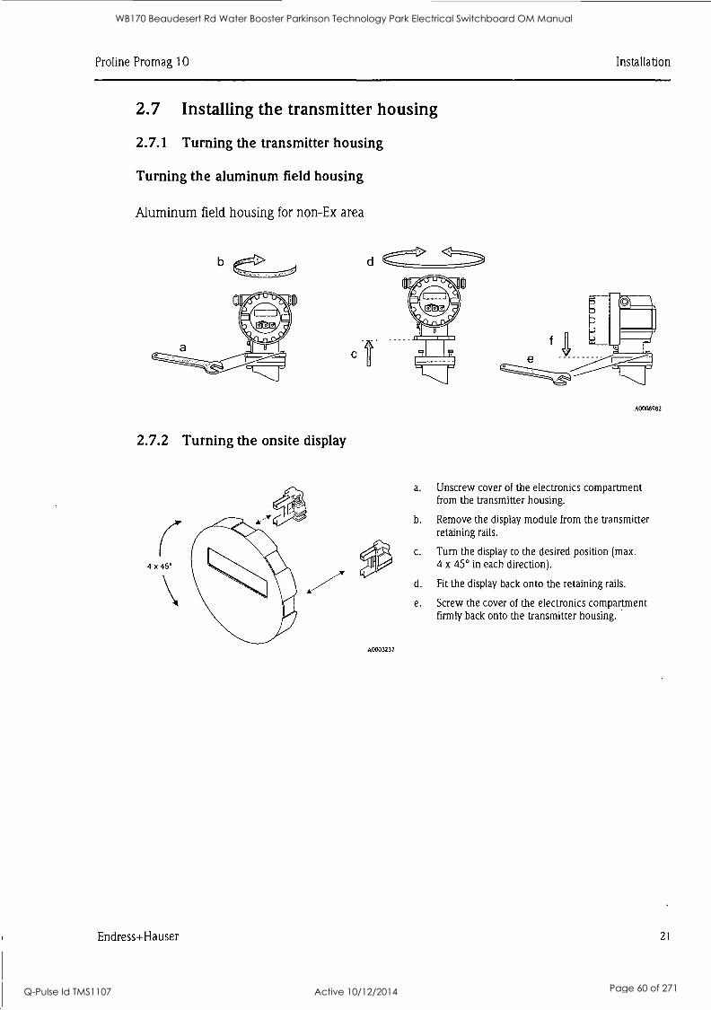
Pro line Promag 10 Installation
2.7 Installing the transmitter housing
2.7.1 Turning the transmitter housing
Turning the aluminum field housing
Aluminum field housing for non-Ex area
b
2.7.2 Turning the onsite display
4 x 45°
d
A C
A0003237
A0008982
a. Unscrew cover of the electronics compartment from the transmitter housing.
b. Remove the display module from the transmitter retaining rails.
c. Turn the display to the desired position (max. 4 x 45° in each direction).
d. Fit the display back onto the retaining rails.
e. Screw the cover of the electronics compartment firmly back onto the transmitter housing.
Endress+Hauser 21
WB170 Beaudesert Rd Water Booster Parkinson Technology Park Electrical Switchboard OM Manual
Q-Pulse Id TMS1107 Active 10/12/2014 Page 60 of 271
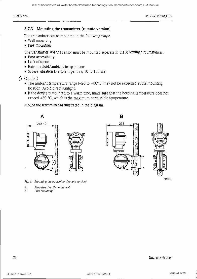
Installation Pro line Promag 10
6
2.7.3 Mounting the transmitter (remote version)
The transmitter can be mounted in the following ways: Wall mounting Pipe mounting
The transmitter and the sensor must be mounted separate in the following circumstances: Poor accessibility Lack of space Extreme fluid/ambient temperatures Severe vibration (>2 g/2 h per day; 10 to 100 Hz)
Caution! The ambient temperature range (-20 to +60°C) may not be exceeded at the mounting location. Avoid direct sunlight. If the device is mounted to a warm pipe, make sure that the housing temperature does not exceed +60 °C, which is the maximum permissible temperature.
Mount the transmitter as illustrated in the diagram.
A
Fig. 1: Mounting the transmitter (remote version)
A Mounted directly on the wall B Pipe mounting
B
A0003216
22 Endress+Hauser
WB170 Beaudesert Rd Water Booster Parkinson Technology Park Electrical Switchboard OM Manual
Q-Pulse Id TMS1107 Active 10/12/2014 Page 61 of 271

Pro line Promag 10 Installation
2.8 Post-installation check
Is the measuring device damaged (visual inspection)? Does the device correspond to specifications at the measuring point, including process temperature and pressure, ambient temperature, minimum fluid conductivity, measuring range, etc.? Does the arrow on the sensor nameplate match the actual direction of flow through the pipe? Is the position of the measuring electrode plane correct? Is the position of the empty pipe detection electrode correct? Were all screws tightened to the specified torques when the sensor was installed? Were the correct seals used (type, material, installation)? Are the measuring point number and labeling correct (visual inspection)? Were the inlet and outlet runs respected? - Inlet run 5 x DN
- Outlet run 2 x DN
Is the measuring device protected against moisture and direct sunlight? Is the sensor adequately protected against vibration (attachment, support)? Acceleration up to 2 g by analogy with IEC 600 68-2-8
Endress+Hauser 23
WB170 Beaudesert Rd Water Booster Parkinson Technology Park Electrical Switchboard OM Manual
Q-Pulse Id TMS1107 Active 10/12/2014 Page 62 of 271
Wiring Pro line Promag 10
3 Wiring /!\ Warning!
Risk of electric shock! Components carry dangerous voltages. Never mount or wire the measuring device while it is connected to the power supply. Before connecting the power supply, check the safety equipment. Route the power supply and signal cables so they are securely seated. Seal the cable entries and covers tight.
Caution! Risk of damaging the electronic components!
Connect the power supply in accordance with the connection data on the nameplate. Connect the signal cable in accordance with the connection data in the Operating Instructions or the Ex documentation on the CD-ROM.
a
a
a
In addition, for the remote version:
Caution! Risk of damaging the electronic components!
Only connect sensors and transmitters with the same serial number. Observe the cable specifications of the connecting cable -> Operating Instructions on the CD-ROM.
Note! Install the connecting cable securely to prevent movement.
In addition, for measuring devices with fieldbus communication:
Caution! Risk of damaging the electronic components!
Observe the cable specification of the fieldbus cable -> Operating Instructions on the CD-ROM. Keep the stripped and twisted lengths of cable shield as short as possible. Screen and ground the signal lines --> Operating Instructions on the CD-ROM. When using in systems without potential equalization -> Operating Instructions on the CD-ROM.
In addition, for Ex-certified measuring devices:
Warning! When wiring Ex-certified measuring devices, all the safety instructions, wiring diagrams, technical information etc. of the related Ex documentation must be observed Ex documentation on the CD-ROM.
24 Endress+Hauser
WB170 Beaudesert Rd Water Booster Parkinson Technology Park Electrical Switchboard OM Manual
Q-Pulse Id TMS1107 Active 10/12/2014 Page 63 of 271
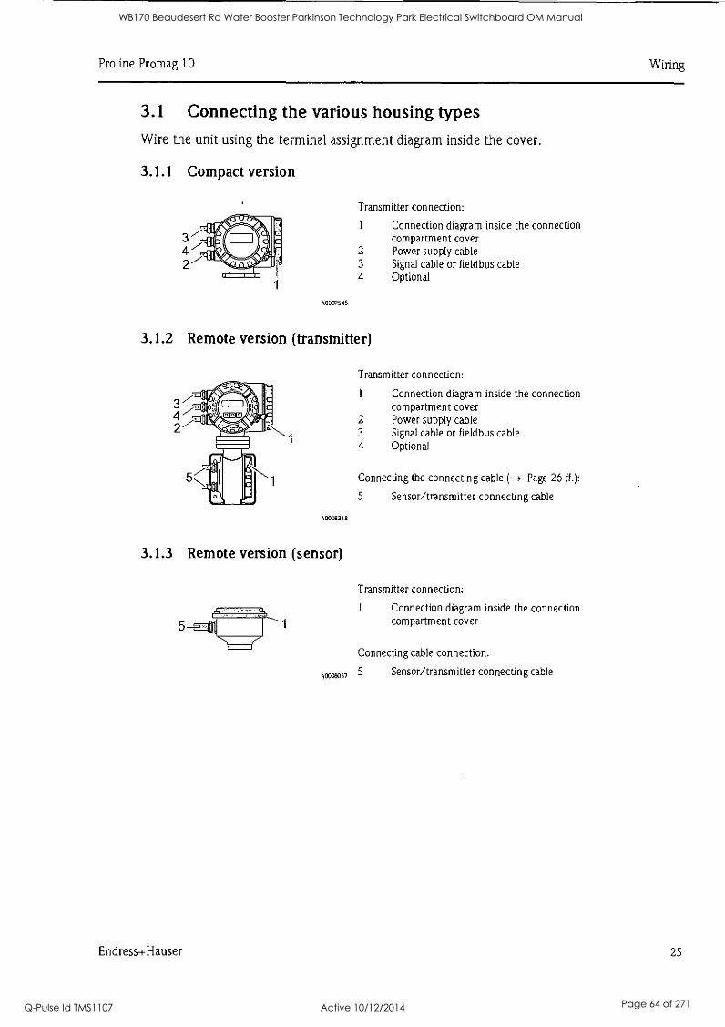
Pro line Promag 10 Wiring
3.1 Connecting the various housing types Wire the unit using the terminal assignment diagram inside the cover.
3.1.1 Compact version
A0007545
Transmitter connection:
1 Connection diagram inside the connection compartment cover
2 Power supply cable 3 Signal cable or fieldbus cable 4 Optional
3.1.2 Remote version (transmitter)
A0008218
3.1.3 Remote version (sensor)
Transmitter connection:
1 Connection diagram inside the connection compartment cover
2 Power supply cable 3 Signal cable or fieldbus cable 4 Optional
Connecting the connecting cable (-> Page 26 ff.):
5 Sensor/transmitter connecting cable
Transmitter connection:
1 Connection diagram inside the connection compartment cover
Connecting cable connection:
A0008037 5 Sensor/transmitter connecting cable
Endress+Hauser 25
WB170 Beaudesert Rd Water Booster Parkinson Technology Park Electrical Switchboard OM Manual
Q-Pulse Id TMS1107 Active 10/12/2014 Page 64 of 271
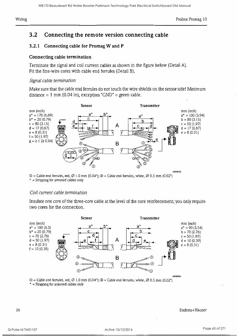
Wiring Pro line Promag 10
3.2 Connecting the remote version connecting cable
3.2.1 Connecting cable for Promag W and P
Connecting cable termination
Terminate the signal and coil current cables as shown in the figure below (Detail A).
Fit the fine-wire cores with cable end ferrules (Detail B).
Signal cable termination
Make sure that the cable end ferrules do not touch the wire shields on the sensor side! Minimum distance = 1 mm (0.04 in), exception "GND" = green cable.
mm (inch) a* = 170 (6.69) b* = 20 (0.79) c = 80 (3.15) d = 17 (0.67) e = 8 (0.31) f = 50 (1.97) g = ?_ 1 (.?_ 0.04)
Sensor
A
B
Transmitter
a0008983
0 = Cable end ferrules, red, 0 1.0 mm (0.041; = Cable end ferrules, white, 0 0.5 mm (0.02") * = Stripping for armored cables only
Coil current cable termination
mm (inch) a* = 100 (3.94) b = 80 (3.15) c 50 (1.97) d = 17 (0.67) e = 8 (0.31)
Insulate one core of the three-core cable at the level of the core reinforcement; you only require two cores for the connection.
mm (inch) a* = 160 (6.3) b* = 20 (0.79) c = 70 (2.76) d = 50 (1.97) e = 8 (0.31)
= 10 (0.39)
O
0
A
B
Transmitter
a0008984
O = Cable end ferrules, red, 0 1.0 mm (0.04"); = Cable end ferrules, white, 0 0.5 mm (0.02") * = Stripping for armored cables only
mm (inch) a* = 90 (3.54) b = 70 (2.76) c = 50 (1.97) d = 10 (0.39) e = 8 (0.31)
26 Endress+Hauser
WB170 Beaudesert Rd Water Booster Parkinson Technology Park Electrical Switchboard OM Manual
Q-Pulse Id TMS1107 Active 10/12/2014 Page 65 of 271
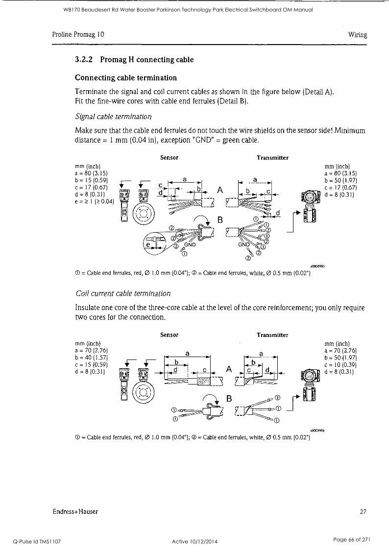
Pro line Promag 10 Wiring
3.2.2 Promag H connecting cable
Connecting cable termination
Terminate the signal and coil current cables as shown in the figure below (Detail A).
Fit the fine-wire cores with cable end ferrules (Detail B).
Signal cable termination
Make sure that the cable end ferrules do not touch the wire shields on the sensor side! Minimum distance = 1 mm (0.04 in), exception "CND" = green cable.
mm (inch) a = 80 (3.15) b = 15 (0.59) c = 17 (0.67) d = 8 (0.31) e = 1 0.04)
Sensor
A
7--- ____ L____. ---,:__.-
----- --,_
10:1'1..d n, B -cr.C)
_
GND GND o ®
0 © 0
Transmitter
a0008985
@ = Cable end ferrules, red, 0 1.0 mm (0.04"); 0 = Cable end ferrules, white, 0 0.5 mm (0.02")
Coil current cable termination
mm (inch) a = 80 (3.15) b = 50 (1.97) c = 17 (0.67) d = 8 (0.31)
Insulate one core of the three-core cable at the level of the core reinforcement; you only require two cores for the connection.
mm (inch) a = 70 (2.76) b = 40 (1.57) c = 15 (0.59) d = 8 (0.31)
Sensor Transmitter
60008986
O = Cable end ferrules, red, 0 1.0 mm (0.04"); 0 = Cable end ferrules, white, 0 0.5 mm (0.02")
mm (inch) a = 70 (2.76) b = 50 (1.97)
= 10 (0.39) d = 8 (0.31)
Endress+Hauser 27
WB170 Beaudesert Rd Water Booster Parkinson Technology Park Electrical Switchboard OM Manual
Q-Pulse Id TMS1107 Active 10/12/2014 Page 66 of 271
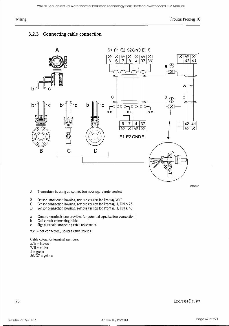
Wiring Pro line Promag 10
3.2.3 Connecting cable connection
A
b
D
S1 El E2 S2GNDE S
I ler AL M7 36
RIMOSP 6 8 4
n.c.
.111
41110
VAL 111r41 a 42 41
©0 4 11101101t
El E2GNDE
A Transmitter housing on connection housing, remote version
B Sensor connection housing, remote version for Promag W/P C Sensor connection housing, remote version for Promag H, DN 25 D Sensor connection housing, remote version for Promag H, DN 40
a Ground terminals (are provided for potential equalization connection) b Coil circuit connecting cable c Signal circuit connecting cable (electrodes)
n.c. = not connected, isolated cable shields
Cable colors for terminal numbers: 5/6 = brown 7/8 = white 4 = green 36/37 = yellow
n.c.
a -v #I t 1 42 41
A0008987
28 Endress+Hauser
WB170 Beaudesert Rd Water Booster Parkinson Technology Park Electrical Switchboard OM Manual
Q-Pulse Id TMS1107 Active 10/12/2014 Page 67 of 271
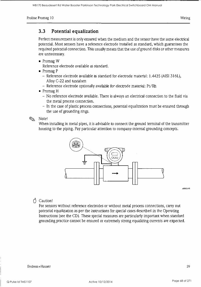
Pro line Promag 10 Wiring
3.3 Potential equalization Perfect measurement is only ensured when the medium and the sensor have the same electrical potential. Most sensors have a reference electrode installed as standard, which guarantees the required potential connection. This usually means that the use of ground disks or other measures are unnecessary.
Promag W Reference electrode available as standard. Promag P
- Reference electrode available as standard for electrode material: 1.4435 (AISI 316L), Alloy C-22 and tantalum
- Reference electrode optionally available for electrode material: Pt/Rh Promag H
- No reference electrode available. There is always an electrical connection to the fluid via the metal process connection.
- In the case of plastic process connections, potential equalization must be ensured through the use of grounding rings.
Note! When installing in metal pipes, it is advisable to connect the ground terminal of the transmitter housing to the piping. Pay particular attention to company-internal grounding concepts.
4a'
000
A0003195
6 Caution! For sensors without reference electrodes or without metal process connections, carry out potential equalization as per the instructions for special cases described in the Operating Instructions (see the CD). These special measures are particularly important when standard grounding practice cannot be ensured or extremely strong equalizing currents are expected.
Endress+Hauser 29
WB170 Beaudesert Rd Water Booster Parkinson Technology Park Electrical Switchboard OM Manual
Q-Pulse Id TMS1107 Active 10/12/2014 Page 68 of 271

Wiring Pro line Promag 10
3.4 Degree of protection The devices meet all the requirements for IP 67.
After mounting in the field or service work, the following points have to be observed to ensure that IP 67 protection is retained:
Install the measuring device in such a way that the cable entries do not point upwards. Do not remove the seal from the cable entry. Remove all unused cable entries and plug them with suitable drain plugs.
A0007549
A0007550
3.5 Post-connection check
Tighten the cable entries correctly.
The cables must loop down before they enter the cable entries ("water trap").
Are cables or the device damaged (visual inspection)? Does the supply voltage match the information on the nameplate? Do the cables used comply with the necessary specifications? Do the mounted cables have adequate strain relief and are they routed securely? Is the cable type route completely isolated? Without loops and crossovers? Are all screw terminals firmly tightened? Have all the measures for grounding and potential equalization been correctly implemented? Are all cable entries installed, firmly tightened and correctly sealed? Cable routed as a "water trap" in loops? Are all the housing covers installed and securely tightened?
In addition, for measuring devices with fieldbus communication: Are all the connecting components (T-boxes, junction boxes, connectors, etc.) connected with each other correctly? Has each fieldbus segment been terminated at both ends with a bus terminator? Has the max. length of the fieldbus cable been observed in accordance with the specifications? Has the max. length of the spurs been observed in accordance with the specifications? Is the fieldbus cable fully shielded and correctly grounded?
30 Endress+Hauser
WB170 Beaudesert Rd Water Booster Parkinson Technology Park Electrical Switchboard OM Manual
Q-Pulse Id TMS1107 Active 10/12/2014 Page 69 of 271
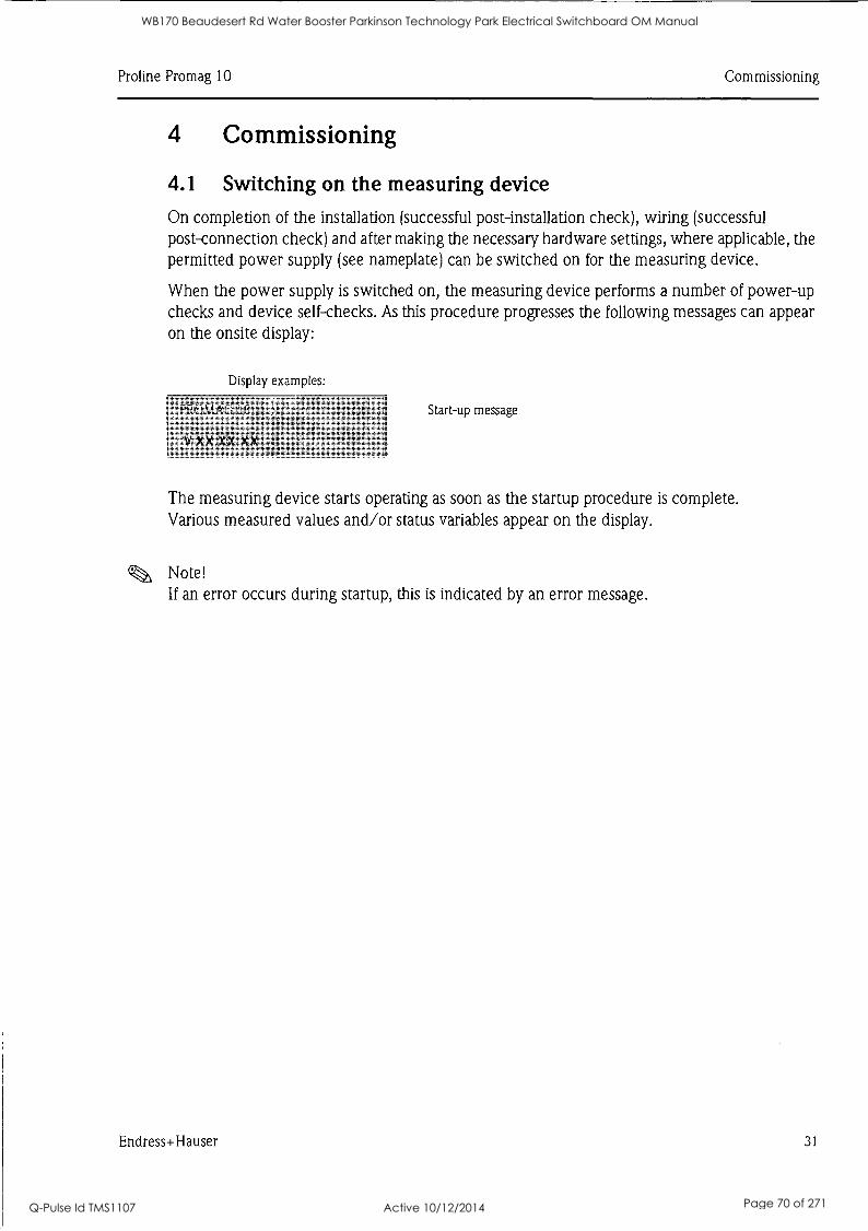
Pro line Promag 10 Commissioning
4 Commissioning
4.1 Switching on the measuring device
On completion of the installation (successful post-installation check), wiring (successful post-connection check) and after making the necessary hardware settings, where applicable, the permitted power supply (see nameplate) can be switched on for the measuring device.
When the power supply is switched on, the measuring device performs a number of power-up checks and device self-checks. As this procedure progresses the following messages can appear on the onsite display:
Display examples:
PROMAG 16
V XX.XX.XX '
Start-up message
The measuring device starts operating as soon as the startup procedure is complete. Various measured values and/or status variables appear on the display.
Note! If an error occurs during startup, this is indicated by an error message.
Endress+Hauser 31
WB170 Beaudesert Rd Water Booster Parkinson Technology Park Electrical Switchboard OM Manual
Q-Pulse Id TMS1107 Active 10/12/2014 Page 70 of 271
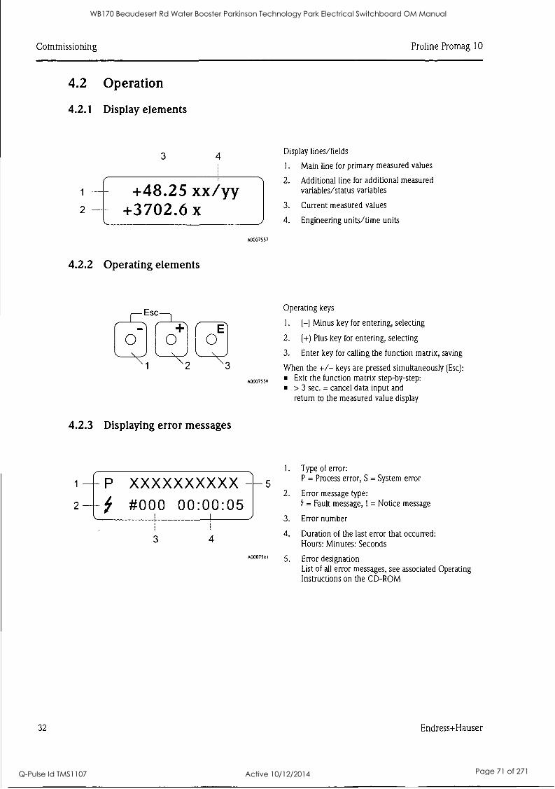
Commissioning Pro line Promag 10
4.2 Operation
4.2.1 Display elements
3 4
+48.25 xx/yy +3702.6 x
Display lines/fields
1. Main line for primary measured values
2. Additional line for additional measured variables/status variables
3. Current measured values
4. Engineering units/time units
A0007557
4.2.2 Operating elements
Esc , Operating keys
1. (-) Minus key for entering, selecting
0 0 0 2. (+) Plus key for entering, selecting
2
3. Enter key for calling the function matrix, saving
When the +/- keys are pressed simultaneously (Esc): \ji \I \I3 A0007559 Exit the function matrix step-by-step:
> 3 sec. = cancel data input and return to the measured value display
4.2.3 Displaying error messages
I. Type of error:
P XXXXXXXXXX P = Process error, S = System error 1 5
2. Error message type:
#000 00:00:05 = Fault message, ! = Notice message
3. Error number
3 4 4. Duration of the last error that occurred:
Hours: Minutes: Seconds
A0007561 5. Error designation List of all error messages, see associated Operating Instructions on the CD-ROM
32 Endress+Hauser
WB170 Beaudesert Rd Water Booster Parkinson Technology Park Electrical Switchboard OM Manual
Q-Pulse Id TMS1107 Active 10/12/2014 Page 71 of 271
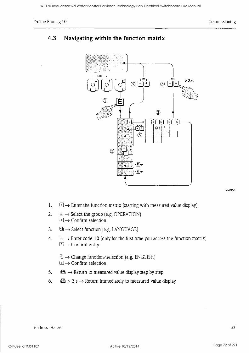
Pro line Promag 10 Commissioning
4.3 Navigating within the function matrix
O
A0007562
1. --> Enter the function matrix (starting with measured value display)
2. -> Select the group (e.g. OPERATION) E Confirm selection
3. ra -> Select function (e.g. LANGUAGE)
4. -> Enter code 10 (only for the first time you access the function matrix) E Confirm entry
-> Change function/selection (e.g. ENGLISH)
CI ---> Confirm selection
5. 6S -> Return to measured value display step by step
6. ffi > 3 s -> Return immediately to measured value display
Endress+Hauser 33
WB170 Beaudesert Rd Water Booster Parkinson Technology Park Electrical Switchboard OM Manual
Q-Pulse Id TMS1107 Active 10/12/2014 Page 72 of 271
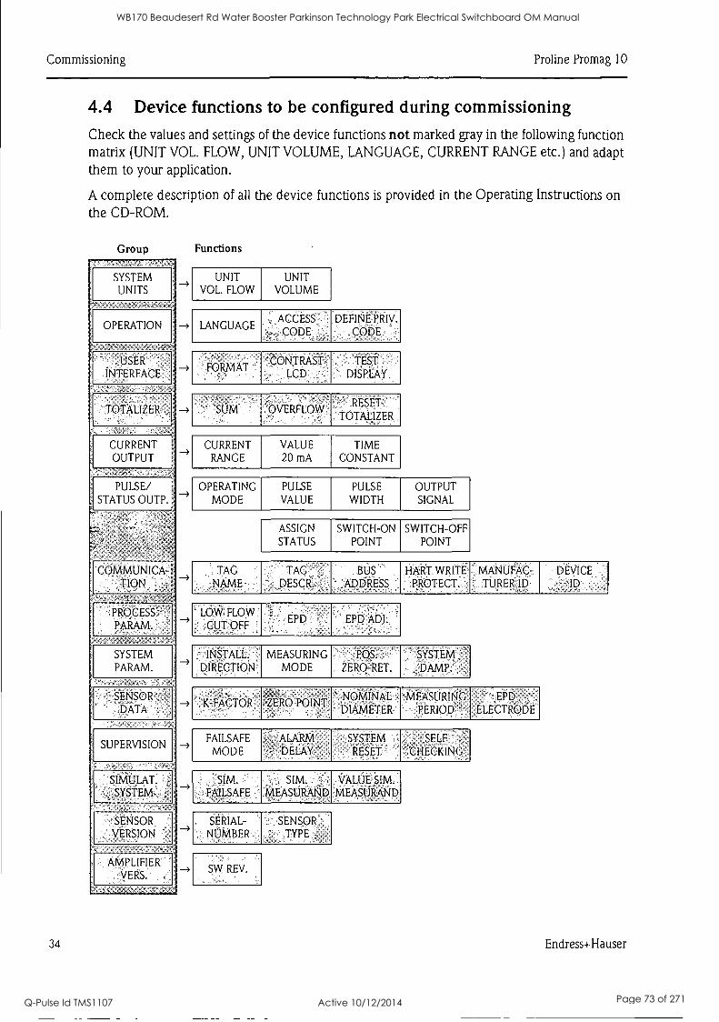
Commissioning Proline Promag 10
4.4 Device functions to be configured during commissioning
Check the values and settings of the device functions not marked gray in the following function matrix (UNIT VOL. FLOW, UNIT VOLUME, LANGUAGE, CURRENT RANGE etc.) and adapt them to your application.
A complete description of all the device functions is provided in the Operating Instructions on the CD-ROM.
Group Functions
SYSTEM UNITS
OPERATION
.USER INTERFACE
TOTALIZER
CURRENT OUTPUT
PULSE/ STATUS OUTP.
COMMUNICA- TION
PROCESS. PARAM.
SYSTEM PARAM.
SENSOR DATA -
SUPERVISION
SIMULAT. SYSTEM'
SENSOR VERSION
AMPLIFIER vERS.
UNIT VOL. FLOW
UNIT VOLUME
, ACCESS CODE
DEFINE'PRIV. CODE
FORMAT , CONTRAST
' LCD
TEST DISPLAY
SUM OVERFLOW RESET
TOTALIZER
CURRENT VALUE TIME RANGE 20 mA CONSTANT
OPERATING PULSE PULSE OUTPUT MODE VALUE WIDTH SIGNAL
ASSIGN SWITCH-ON SWITCH-OFF STATUS POINT POINT
TAG ' TAG BUS HART. WRITE MANUFAC- DEVICE NAME ' DESCR. ADDRESS PROTECT. . TORER: ID Jp
LOW, FLOW
, ,CUT OFF , t r:
PD EPD ADJ:
INSTALL. MEASURING POS. SYSTEM DIRECTION MODE ZERO-RET. DAMP.
K-FACTOR ZERO POINT NOMINAL DIAMETER
MEASURING PERIOD
EPD ELECTRODE
FAILSAFE
MODE ALARM DELAY
SYSTEM RESET
SELF CHECKING
SIM. Sim: - VALUE- sm., FAILSAFE ';MEASURAND MEASURAND
SERIAL- NUMBER
SENSOR TYPE
SW REV.
34 Endress+Hauser
WB170 Beaudesert Rd Water Booster Parkinson Technology Park Electrical Switchboard OM Manual
Q-Pulse Id TMS1107 Active 10/12/2014 Page 73 of 271

Pro line Promag 10 Commissioning
4.5 Troubleshooting
A complete description of all the error messages is provided in the Operating Instructions on the CD-ROM.
Note! The output signals (e.g. pulse, frequency) of the measuring device must correspond to the higher-order controller.
Endress+Hauser 35
WB170 Beaudesert Rd Water Booster Parkinson Technology Park Electrical Switchboard OM Manual
Q-Pulse Id TMS1107 Active 10/12/2014 Page 74 of 271

www.endress.com/worldwide
Endress+Hauser People for Process Automation
KA032D/06/en/01.08 71067518 FM+SGML 6.0
WB170 Beaudesert Rd Water Booster Parkinson Technology Park Electrical Switchboard OM Manual
Q-Pulse Id TMS1107 Active 10/12/2014 Page 75 of 271
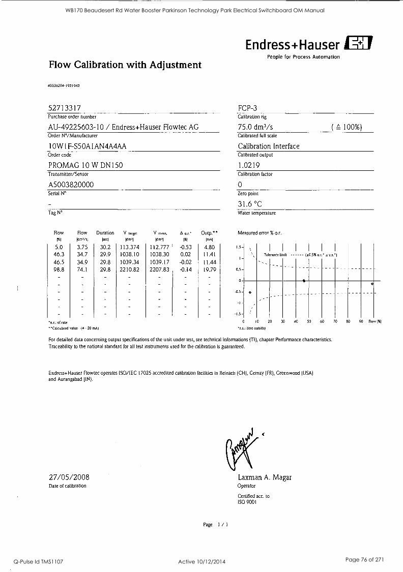
Endress+Hauser
Flow Calibration with Adjustment
40036294-1921942
52713317 FCP-3
People for Process Automation
Purchase order number Calibration rig
AU-49225603-10 / Endress+Hauser Flowtec AG 75.0 dm3/s ( 100%) Order N°/Manufacturer Calibrated full scale
10W1F-S50A1AN4A4AA Calibration Interface Order code Calibrated output
PROMAG 10 W DN150 1.0219 Transmitter/Sensor Calibration factor
A5003820000 0 Serial N° Zero point
31.6 °C Tag N° Water temperature
Flow Flow
1%1 WO/s/
5.0 46.3
46.5 98.8
3.75 34.7 34.9 74.1
Duration lsec1
30.2 29.9
29.8 29.8
*as.: of rate
'Calculated value (4 -20 mAl
V target V meas. A or.' Outp. ** Id m'l 1%1 1mAl
113.374 1038.10
1039.34 2210.82
112.777 1038.30 1039.17 2207.83
-0.53 0.02
-0.02 -0.14
4.80 11.41
11.44 19.79
Measured error % o.r.
1.5 -
0.5 -
0
Tolerance limb (±0.5% or.' ± z.s.1
---
-as-
-1-
0 --- --- ---
0 10 20 30 40 50 60 70 80 90 Flo v 1%1
*z.s.: Zero stability
For detailed data concerning output specifications of the unit under test, see technical informations (TI), chapter Performance characteristics. Traceability to the national standard for all test instruments used for the calibration is guaranteed.
Endress+Hauser Flowtec operates ISO/IEC 17025 accredited calibration facilities in Reinach (CH), Cernay (FR), Greenwood (USA)
and Aurangabad (IN).
27/05/2008 Date of calibration
Page 1 / 1
Laxman A. Magar Operator
Certified acc. to ISO 9001
WB170 Beaudesert Rd Water Booster Parkinson Technology Park Electrical Switchboard OM Manual
Q-Pulse Id TMS1107 Active 10/12/2014 Page 76 of 271
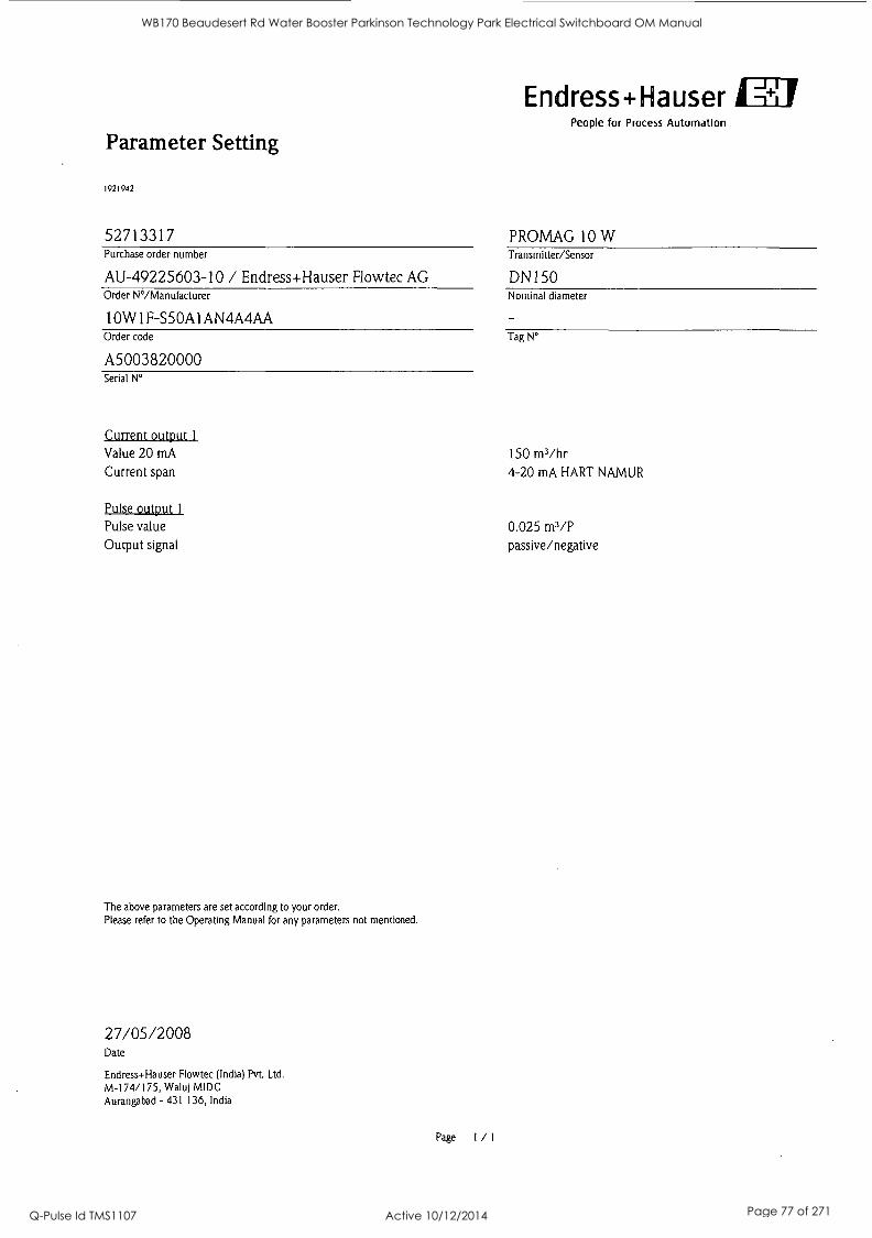
Endress+Ha user People for Process Automation
Parameter Setting
1921942
52713317 PROMAG 10 W Purchase order number Transmitter/Sensor
AU-49225603-10 / Endress+Hauser Flowtec AG DN150 Order N°/Manufacturer Nominal diameter
10W1F-S50A1AN4A4AA Order code
A5003820000 Serial N°
Current output 1
Value 20 mA
Current span
Tag N°
150 m3/hr 4-20 mA HART NAMUR
Pulse output 1
Pulse value 0.025 m3/P Output signal passive/negative
The above parameters are set according to your order. Please refer to the Operating Manual for any parameters not mentioned.
27/05/2008 Date
Endress+Hauser Flowtec (India) Pvt. Ltd.
M-174/175, Waluj MIDC Aurangabad - 431 136, India
Page I / I
WB170 Beaudesert Rd Water Booster Parkinson Technology Park Electrical Switchboard OM Manual
Q-Pulse Id TMS1107 Active 10/12/2014 Page 77 of 271

ID
7. Electrical Equip. Technical Inform
WB170 Beaudesert Rd Water Booster Parkinson Technology Park Electrical Switchboard OM Manual
Q-Pulse Id TMS1107 Active 10/12/2014 Page 78 of 271

GI ID IR ID ID
1 1 1 1 1 1 1 1 1 1 1 1 1 1 1 1 1 1 1 1 1 1 1 1 1 1
WB170 Beaudesert Rd Water Booster Parkinson Technology Park Electrical Switchboard OM Manual
Q-Pulse Id TMS1107 Active 10/12/2014 Page 79 of 271

J & P Richardson Industries Pty Ltd
7.0 ELECTRICAL EQUIPMENT TECHNICAL INFORMATION
File: //.1pr_Server/docs/lsched/Masters.doc Revision 0 Date: 25 May 2001
WB170 Beaudesert Rd Water Booster Parkinson Technology Park Electrical Switchboard OM Manual
Q-Pulse Id TMS1107 Active 10/12/2014 Page 80 of 271
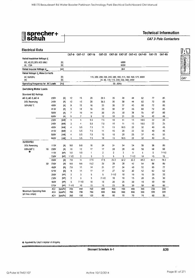
sprecher+ Technical Information
I schuh I CA7 3-Pole Contactors
Electrical Data
Rated Insulation Voltage U,
IEC, AS,BS,SEV, VDE 0660
UL, CSA
CA7-9 CA7-12 CA7-16 CA7-23 CA7-30 CA7-37 CA7-43 CA7-60
690V
600V
CA7-72 CA7-85
- 0
0 Rated Impulse Voltage U,,,,,, (kV] 8kV
Rated Voltage 1/ -Main Contacts
AC 50/60Hz
DC
115, 200, 208, 230, 240, 380, 400, 415, 460, 500,
24, 48, 110, 115, 220, 230, 300, 440V
575, 690V CA7
Operating Frequency for AC Loads [Hz) 50...60Hz
Switching Motor Loads
Standard IEC Ratings
AC-2, AC-3, AC-4 230V [A] 12 15 20 26.5 35 38 44 62 72 85
DOL Reversing 240V [A] 12 15 20 26.5 35 38 44 62 72 85
50Hz/60' C 400V [A] 9 12 16 23 30 37 43 60 72 85
415V [A] 9 12 16 23 30 37 43 60 72 85
500V [A] 7 10 14 20 25 30 38 55 67 80
690V [A] 5 7 9 12 18 21 25 34 42 49
230V [kW] 3 4 5.5 7.5 10 11 13 18.5 22 25
240V [kW] 3 4 5.5 7.5 10 11 13 18.5 22 25
400V [kW] 4 5.5 7.5 11 15 18.5 22 32 40 45
415V [kW] 4 5.5 7.5 11 15 20 22 32 40 45
500V [kW] 4 5.5 7.5 13 15 20 25 37 45 55
690V [kW] 4 5.5 7.5 10 15 18.5 22 32 40 45
UL/CSA/IEC
DOL Reversing 115V [A] 9.8 9.8 16 24 24 34 34 56 56 80
60Hz/60' C 10 230V [A] 10 12 17 17 28 28 40 50 68 68
0 115V [HP] 1/2 1/2 1 2 2 3 3 5 5 7-1/2
230V [HP] 11/2 2 3 3 5 5 7-1/2 10 15 15
200V [A] 7.8 11 17.5 17.5 25.3 32.2 32.2 48.3 62.1 78.2
30 230V [A) 6.8 9.6 15.2 22 28 28 42 54 68 80
460V [A] 7.6 11 14 21 27 34 40 52 65 77
575V [A] 9 11 17 17 27 32 32 52 62 62
200V [HP] 2 3 5 5 7-1/2 10 10 15 20 25
230V [HP] 2 3 5 7-1/2 10 10 15 20 25 30
460V [HP] 5 7-1/2 10 15 20 25 30 40 50 60
575V [HP] 7-1/2 10 15 15 25 30 30 50 60 60
AC2 [ops/hr] 450 450 450 400 400 400 400 300 250 200 Maximum Operating Rate AC3 (at max. amps)
AC4
[ops/hr]
[ops/hr]
700
200
700
150
700
120
600 600 600 600
80 80 70 70
500
70
500
60
500
50
0 Approved by Lloyd's register of shipping.
Discount Schedule A-1 A39
WB170 Beaudesert Rd Water Booster Parkinson Technology Park Electrical Switchboard OM Manual
Q-Pulse Id TMS1107 Active 10/12/2014 Page 81 of 271
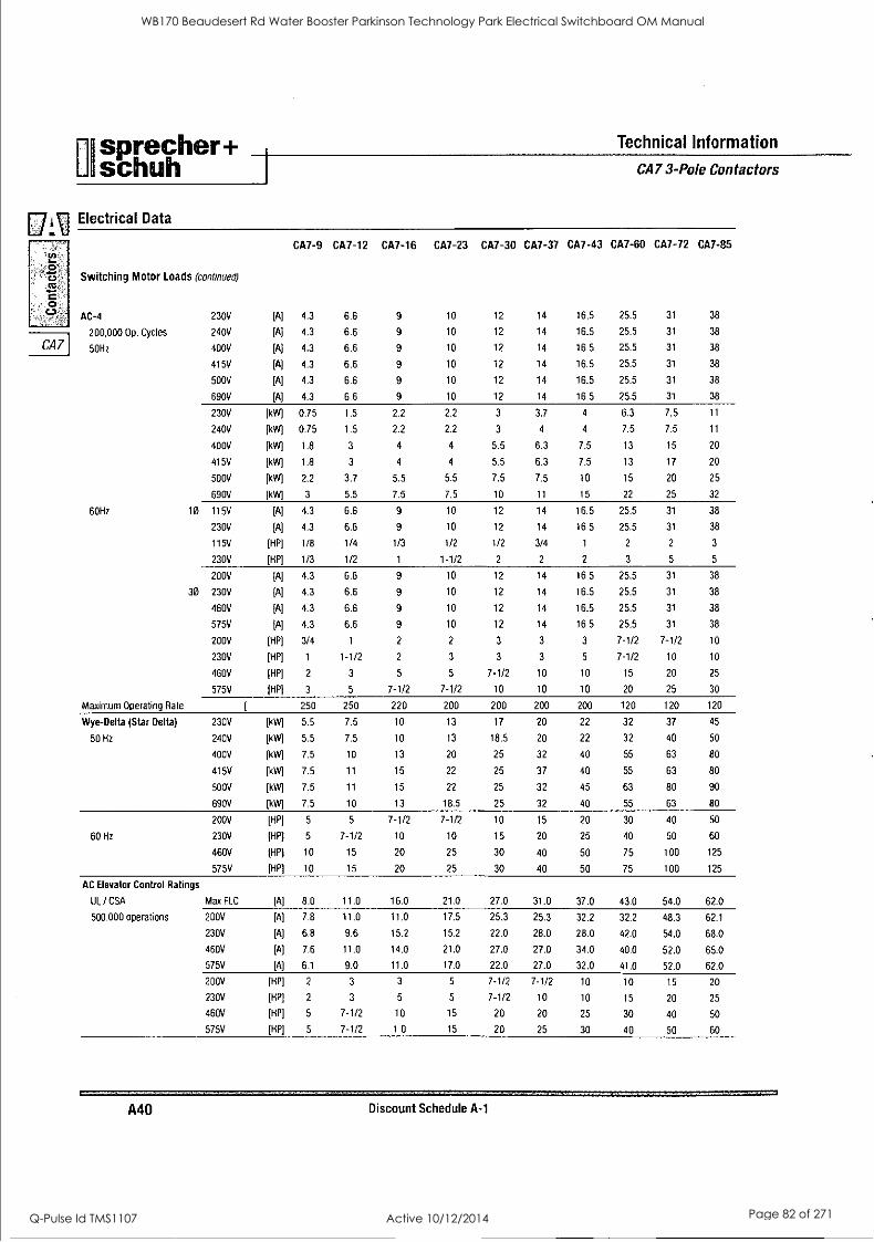
i sprecher+ schuh
Technical Information
CA7 3-Pole Contactors
1:7 ] Electrical Data
a..
CA7-9 CA7-12 CA7-16 CA7-23 CA7-30 CA7-37 CA7-43 CA7-60 CA7-72 CA7-85
0 4-0
CC
0
Switching Motor Loads (continued)
AC-4 230V [A] 4.3 6.6 9 10 12 14 16.5 25.5 31 38
200,000 Op. Cycles 240V [A] 4.3 6.6 9 10 12 14 16.5 25.5 31 38
CA7 50Hz 400V [A] 4.3 6.6 9 10 12 14 16.5 25.5 31 38
415V [A] 4.3 6.6 9 10 12 14 16.5 25.5 31 38
500V [A] 4.3 6.6 9 10 12 14 16.5 25.5 31 38
690V [A] 4.3 6.6 9 10 12 14 16.5 25.5 31 38
230V [kW] 0.75 1.5 2.2 2.2 3 3.7 4 6.3 7.5 11
240V [kW] 0.75 1.5 2.2 2.2 3 4 4 7.5 7.5 11
400V [kW] 1.8 3 4 4 5.5 6.3 7.5 13 15 20
415V [kW] 1.8 3 4 4 5.5 6.3 7.5 13 17 20
500V [kW] 2.2 3.7 5.5 5.5 7.5 7.5 10 15 20 25
690V [kW] 3 5.5 7.5 7.5 10 11 15 22 25 32
60Hz 10 115V [A] 4.3 6.6 9 10 12 14 16.5 25.5 31 38
230V [A] 4.3 6.6 9 10 12 14 16.5 25.5 31 38
115V [HP] 1/8 1/4 1/3 1/2 1/2 3/4 1 2 2 3
230V [HP] 1/3 1/2 1 1-1/2 2 2 2 3 5 5
200V [A] 4.3 6.6 9 10 12 14 16.5 25.5 31 38
30 230V [A] 4.3 6.6 9 10 12 14 16.5 25.5 31 38
460V [A] 4.3 6.6 9 10 12 14 16.5 25.5 31 38
575V [A] 4.3 6.6 9 10 12 14 16.5 25.5 31 38
200V [HP] 3/4 1 2 2 3 3 3 7-1/2 7-1/2 10
230V [HP] 1 1-1/2 2 3 3 3 5 7-1/2 10 10
460V [HP] 2 3 5 5 7-1/2 10 10 15 20 25
575V [HP] 3 5 7-1/2 7-1/2 10 10 10 20 25 30
Maximum Operating Rate [ 250 250 220 200 200 200 200 120 120 120
Wye-Delta (Star Delta) 230V [kW] 5.5 7.5 10 13 17 20 22 32 37 45
50 Hz 240V [kW] 5.5 7.5 10 13 18.5 20 22 32 40 50
400V [kW] 7.5 10 13 20 25 32 40 55 63 80
415V [kW] 7.5 11 15 22 25 37 40 55 63 80
500V [kW] 7.5 11 15 22 25 32 45 63 80 90
690V il<Wl 7.5 10 13 18.5 25 32 40 55 63 80
200V [HP] 5 5 7-1/2 7-1/2 10 15 20 30 40 50
60 Hz 230V [HP] 5 7-1/2 10 10 15 20 25 40 50 60
460V [HP] 10 15 20 25 30 40 50 75 100 125
575V [HP] 10 15 20 25 30 40 50 75 100 125
AC Elevator Control Ratings
UL / CSA Max FLC [A] 8.0 11.0 16.0 21.0 27.0 31.0 37.0 43.0 54.0 62.0
500.000 operations 200V [A] 7.8 11.0 11.0 17.5 25.3 25.3 32.2 32.2 48.3 62.1
230V [A] 6.8 9.6 15.2 15.2 22.0 28.0 28.0 42.0 54.0 68.0
460V [A] 7.6 11.0 14.0 21.0 27.0 27.0 34.0 40.0 52.0 65.0
575V [A] 6.1 9.0 11.0 17.0 22.0 27.0 32.0 41.0 52.0 62.0
200V [HP] 2 3 3 5 7-1/2 7-1/2 10 10 15 20
230V [HP] 2 3 5 5 7-1/2 10 10 15 20 25
460V [HP] 5 7-1/2 10 15 20 20 25 30 40 50
575V [HP] 5 7-1/2 1 0 15 20 25 30 40 50 60
A40 Discount Schedule A-1
WB170 Beaudesert Rd Water Booster Parkinson Technology Park Electrical Switchboard OM Manual
Q-Pulse Id TMS1107 Active 10/12/2014 Page 82 of 271
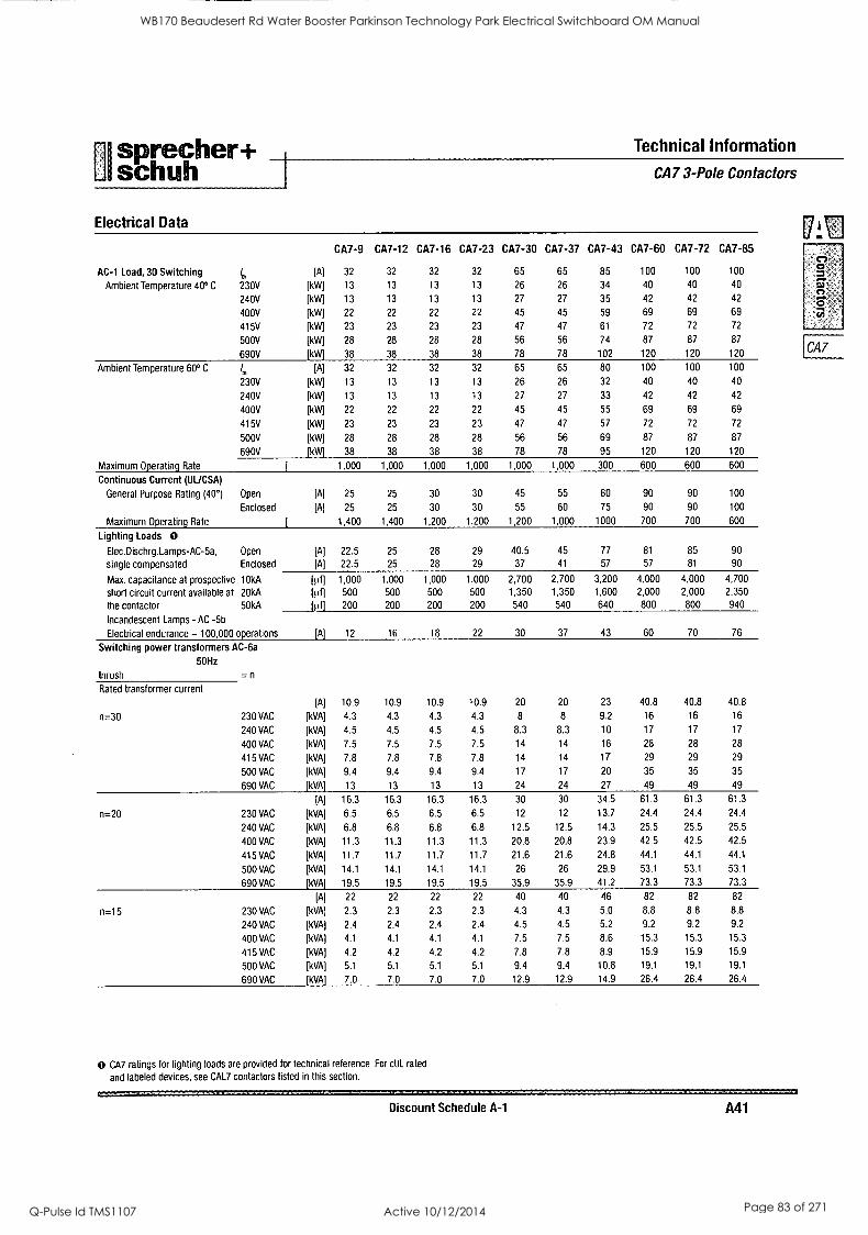
[11
sprecher+ schuh
Technical Information
Electrical Data
CA7 3-Pole Contactors
CA7-9 CA7-12 CA7-16 CA7-23 CA7-30 CA7-37 CA7-43 CA7-60 CA7-72 CA7-85 C,
AC-1 Load, 30 Switching lu, [A] 32 32 32 32 65 65 85 100 100 100
Ambient Temperature 40° C 230V
240V
[kW]
[kW]
13
13
13
13
13
13
13
13
26
27
26
27
34
35
40
42
40
42
40
42 C` ca
400V [kW] 22 22 22 22 45 45 59 69 69 69
415V [kW] 23 23 23 23 47 47 61 72 72 72
500V
690V
[kW]
[kW]
28
38
28
38
28
38
28
38
56
78
56
78
74
102
87
120
87
120
87
120 CA7
Ambient Temperature 60° C I,,
230V
[A]
[kW]
32
13
32
13
32
13
32
13
65
26
65
26
80
32
100
40
100
40
100
40
240V [kW] 13 13 13 13 27 27 33 42 42 42
400V [kW] 22 22 22 22 45 45 55 69 69 69
415V [kW] 23 23 23 23 47 47 57 72 72 72
500V [kW] 28 28 28 28 56 56 69 87 87 87
690V [kW] 38 38 38 38 78 78 95 120 120 120
Maximum Operating Rate [ 1.000 1,000 1,000 1,000 1,000 1,000 300 600 600 600
Continuous Current (UUCSA)
General Purpose Rating (40°1 Open [A] 25 25 30 30 45 55 60 90 90 100
Enclosed [A] 25 25 30 30 55 60 75 90 90 100
Maximum Operating Rate [ 1,400 1,400 1,200 1,200 1,200 1,000 1000 700 700 600
Lighting Loads 0 Elec.Dischrglamps-AC-5a, Open [A] 22.5 25 28 29 40.5 45 77 81 85 90
single compensated Enclosed [A] 22.5 25 28 29 37 41 57 57 81 90
Max. capacitance at prospective 10kA [0] 1,000 1,000 1,000 1,000 2,700 2,700 3,200 4,000 4,000 4,700
short circuit current available at 20kA [ut] 500 500 500 500 1,350 1,350 1,600 2,000 2,000 2.350
the contactor 50kA 200 200 200 200 540 540 640 800 800 940
Incandescent Lamps - AC -5b
_Ilif] Electrical endurance - 100,000 operations [A] 12 16 18 22 30 37 43 60 70 76
Switching power transformers AC-6a
50Hz
Inrush = n
Rated transformer current
[A] 10.9 10.9 10.9 10.9 20 20 23 40.8 40.8 40.8
n=30 230 VAC [kVA] 4.3 4.3 4.3 4.3 8 8 9.2 16 16 16
240 VAC [kVA] 4.5 4.5 4.5 4.5 8.3 8.3 10 17 17 17
400 VAC [kVA] 7.5 7.5 7.5 7.5 14 14 16 28 28 28
415 VAC [kVA] 7.8 7.8 7.8 7.8 14 14 17 29 29 29
500 VAC [kVA] 9.4 9.4 9.4 9.4 17 17 20 35 35 35
690 VAC [kVA] 13 13 13 13 24 24 27 49 49 49
[A] 16.3 16.3 16.3 16.3 30 30 34.5 61.3 61.3 61.3
n=20 230 VAC [kVA] 6.5 6.5 6.5 6.5 12 12 13.7 24.4 24.4 24.4
240 VAC [kVA] 6.8 6.8 6.8 6.8 12.5 12.5 14.3 25.5 25.5 25.5
400 VAC [kVA] 11.3 11.3 11.3 11.3 20.8 20.8 23.9 42.5 42.5 42.5
415 VAC [kVA] 11.7 11.7 11.7 11.7 21.6 21.6 24.8 44.1 44.1 44.1
500 VAC [kVA] 14.1 14.1 14.1 14.1 26 26 29.9 53.1 53.1 53.1
690 VAC [kVA] 19.5 19.5 19.5 19.5 35.9 35.9 41.2 73.3 73.3 73.3
[A] 22 22 22 22 40 40 46 82 82 82
n=15 230 VAC [kVA] 2.3 2.3 2.3 2.3 4.3 4.3 5.0 8.8 8.8 8.8
240 VAC [kVA] 2.4 2.4 2.4 2.4 4.5 4.5 5.2 9.2 9.2 9.2
400 VAC [kVA] 4.1 4.1 4.1 4.1 7.5 7.5 8.6 15.3 15.3 15.3
415 VAC [kVA] 4.2 4.2 4.2 4.2 7.8 7.8 8.9 15.9 15.9 15.9
500 VAC (kVA] 5.1 5.1 5.1 5.1 9.4 9.4 10.8 19.1 19.1 19.1
690 VAC [kVA] 7.0 7.0 7.0 7.0 12.9 12.9 14.9 26.4 26.4 26.4
0 CA7 ratings for lighting loads are provided for technical reference. For cUL rated
and labeled devices, see CAL7 contactors listed in this section.
Discount Schedule A-1 A41
WB170 Beaudesert Rd Water Booster Parkinson Technology Park Electrical Switchboard OM Manual
Q-Pulse Id TMS1107 Active 10/12/2014 Page 83 of 271
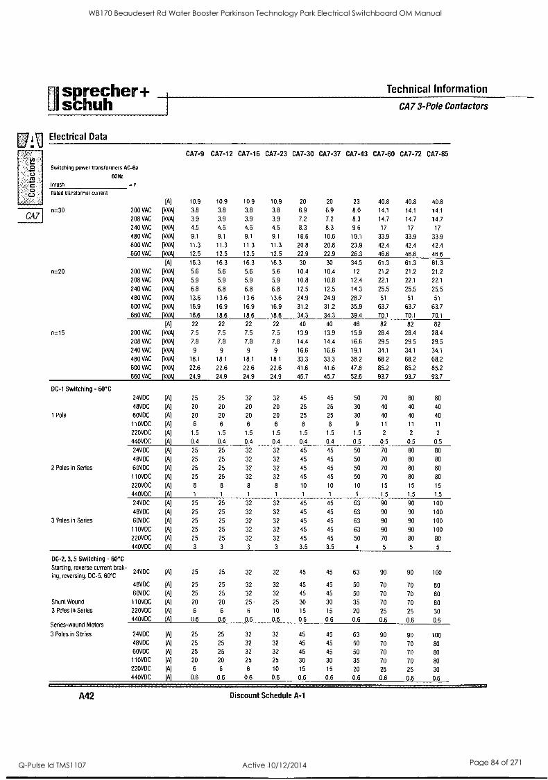
Isprecher+ schuh
Technical Information
CA7 3-Pole Contactors
oElectrical Data
o`cn
O
CA7
CA7-9 CA7-12 CA7-16 CA7-23 CA7-30 CA7-37 CA7-43 CA7-60 CA7-72 CA7-85
Switching power transformers AC-6a
60Hz
Inrush
Rated transformer current
n=30
n=20
n=15
DC-1 Switching - 60°C
1 Pole
2 Poles in Series
3 Poles in Series
DC-2, 3, 5 Switching - 60°C
Starting, reverse current brak- ing, reversing. DC-5. 60°C
Shunt Wound
3 Poles in Series
Series-wound Motors
3 Poles in Series
A42
=n
[A] 10.9 10.9 10.9 10.9 20 20 23 40.8 40.8 40.8
200 VAC [kVA] 3.8 3.8 3.8 3.8 6.9 6.9 8.0 14.1 14.1 14.1
208 VAC [kVA] 3.9 3.9 3.9 3.9 7.2 7.2 8.3 14.7 14.7 14.7
240 VAC [kVA] 4.5 4.5 4.5 4.5 8.3 8.3 9.6 17 17 17
480 VAC [kVA] 9.1 9.1 9.1 9.1 16.6 16.6 19.1 33.9 33.9 33.9
600 VAC [kVA] 11.3 11.3 11.3 11.3 20.8 20.8 23.9 42.4 42.4 42.4
660 VAC [kVA] 12.5 12.5 12.5 12.5 22.9 22.9 26.3 46.6 46.6 46.6
[A] 16.3 16.3 16.3 16.3 30 30 34.5 61.3 61.3 61.3
200 VAC [kVA] 5.6 5.6 5.6 5.6 10.4 10.4 12 21.2 21.2 21.2
208 VAC [kVA] 5.9 5.9 5.9 5.9 10.8 10.8 12.4 22.1 22.1 22.1
240 VAC [kVA] 6.8 6.8 6.8 6.8 12.5 12.5 14.3 25.5 25.5 25.5
480 VAC [kVA] 13.6 13.6 13.6 13.6 24.9 24.9 28.7 51 51 51
600 VAC [kVA] 16.9 16.9 16.9 16.9 31.2 31.2 35.9 63.7 63.7 63.7
660 VAC [kVA] 18.6 18.6 18.6 18.6 34.3 34.3 39.4 70.1 70.1 70.1
[A] 22 22 22 22 40 40 46 82 82 82
200 VAC [kVA] 7.5 7.5 7.5 7.5 13.9 13.9 15.9 28.4 28.4 28.4
208 VAC [kVA] 7.8 7.8 7.8 7.8 14.4 14.4 16.6 29.5 29.5 29.5
240 VAC [kVA] 9 9 9 9 16.6 16.6 19.1 34.1 34.1 34.1
480 VAC [kVA] 18.1 18.1 18.1 18.1 33.3 33.3 38.2 68.2 68.2 68.2
600 VAC [kVA] 22.6 22.6 22.6 22.6 41.6 41.6 47.8 85.2 85.2 85.2
660 VAC [kVA] 24.9 24.9 24.9 24.9 45.7 45.7 52.6 93.7 93.7 93.7
24VDC [A] 25 25 32 32 45 45 50 70 80 80
48VDC [A] 20 20 20 20 25 25 30 40 40 40
60VDC [A] 20 20 20 20 25 25 30 40 40 40
110VDC [A] 6 6 6 6 8 8 9 11 11 11
220VDC [A] 1.5 1.5 1.5 1.5 1.5 1.5 1.5 2 2 2
440VDC [A] 0.4 0.4 0.4 0.4 0.4 0.4 0.5 0.5 0.5 0.5
24VDC [A] 25 25 32 32 45 45 50 70 80 80
48VDC [A] 25 25 32 32 45 45 50 70 80 80
60VDC [A] 25 25 32 32 45 45 50 70 80 80
110VDC [A] 25 25 32 32 45 45 50 70 80 80
220VDC [A] 8 8 8 8 10 10 10 15 15 15
440VDC [A] 1 1 1 1 1 1 1 1.5 1.5 1.5
24VDC [A] 25 25 32 32 45 45 63 90 90 100
48VDC [A] 25 25 32 32 45 45 63 90 90 100
60VDC [A] 25 25 32 32 45 45 63 90 90 100
110VDC [A] 25 25 32 32 45 45 63 90 90 100
220VDC [A] 25 25 32 32 45 45 50 70 80 80
440VDC [A] 3 3 3 3 3.5 3.5 4 5 5 5
24VDC [A] 25 25 32 32 45 45 63 90 90 100
48VDC [A] 25 25 32 32 45 45 50 70 70 80
60VDC [A] 25 25 32 32 45 45 50 70 70 80
110VDC [A] 20 20 25 - 25 30 30 35 70 70 80
220VDC [A] 6 6 6 10 15 15 20 25 25 30 440VDC [A] 0.6 0.6 0.6 0.6 0.6 0.6 0.6 0.6 0.6 0.6
24VDC [A] 25 25 32 32 45 45 63 90 90 100
48VDC [A] 25 25 32 32 45 45 50 70 70 80
60VDC [A] 25 25 32 32 45 45 50 70 70 80 110VDC [A] 20 20 25 25 30 30 35 70 70 80
220VDC [A] 6 6 6 10 15 15 20 25 25 30
440VDC [A] 0.6 0.6 0.6 0.6 0.6 0.6 0.6 0.6 0.6 0.6
Discount Schedule A-1
WB170 Beaudesert Rd Water Booster Parkinson Technology Park Electrical Switchboard OM Manual
Q-Pulse Id TMS1107 Active 10/12/2014 Page 84 of 271
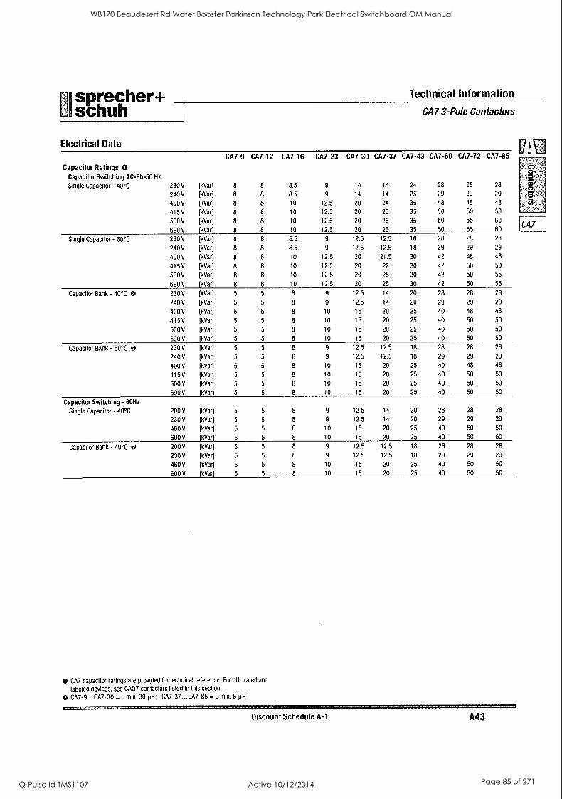
sprecher+ schuh
Technical Information
Electrical Data
CA7 3-Pole Contactors
CA7-9 CA7-12 CA7-16 CA7-23 CA7-30 CA7-37 CA7-43 CA7-60 CA7-72 CA7-85
Capacitor Ratings 0 Capacitor Switching AC-6b-50 Hz
C, o - = si Single Capacitor - 40°C 230 V [kVar] 8 8 8.5 9 14 14 24 28 28 28 o
240 V [kVar) 8 8 8.5 9 14 14 25 29 29 29
400 V [kVar) 8 8 10 12.5 20 24 35 48 48 48
415 V [kVar) 8 8 10 12.5 20 25 35 50 50 50
500 V [kVal 8 8 10 12.5 20 25 35 50 55 60 CA7
690 V [kVar] 8 8 10 12.5 20 25 35 50 55 60
Single Capacitor - 60°C 230 V [kVarl 8 8 8.5 9 12.5 12.5 18 28 28 28
240 V [kVar] 8 8 8.5 9 12.5 12.5 18 29 29 29
400 V [kVar) 8 8 10 12.5 20 21.5 30 42 48 48
415 V [kVar) 8 8 10 12.5 20 22 30 42 50 50
500 V [kVar] 8 8 10 12.5 20 25 30 42 50 55
690 V [kVar] 8 8 10 12.5 20 25 30 42 50 55
Capacitor Bank - 40°C 0 230 V [kVar] 5 5 8 9 12.5 14 20 28 28 28
240 V [kVar] 5 5 8 9 12.5 14 20 29 29 29
400 V IkVarj 5 5 8 10 15 20 25 40 48 48
415 V [kVar) 5 5 8 10 15 20 25 40 50 50
500 V [kVar] 5 5 8 10 15 20 25 40 50 50
690 V [kVar] 5 5 8 10 15 20 25 40 50 50
Capacitor Bank - 60°C 0 230 V [kVar] 5 5 8 9 12.5 12.5 18 28 28 28
240 V [kVar] 5 5 8 9 12.5 12.5 18 29 29 29
400 V [kVar] 5 5 8 10 15 20 25 40 48 48
415 V [kVar] 5 5 8 10 15 20 25 40 50 50
500 V [kVar] 5 5 8 10 15 20 25 40 50 50
690 V [kVar] 5 5 8 10 15 20 25 40 50 50
Capacitor Switching - 60Hz
Single Capacitor - 40°C 200 V [kVar] 5 5 8 9 12.5 14 20 28 28 28
230 V [kVar] 5 5 8 9 12.5 14 20 29 29 29
460 V (kVar] 5 5 8 10 15 20 25 40 50 50
600 V [kVar] 5 5 8 10 15 20 25 40 50 60
Capacitor Bank - 40°C 200 V [kVar] 5 5 8 9 12.5 12.5 18 28 28 28
230 V [kVar) 5 5 8 9 12.5 12.5 18 29 29 29
460 V [kVar) 5 5 8 10 15 20 25 40 50 50
600 V [kVar] 5 5 8 10 15 20 25 40 50 50
0 CA7 capacitor ratings are provided for technical reference. For cUL rated and
labeled devices. see CAO7 contactors listed in this section.
0 CA7-9 ...CA7-30 = L min. 30 pH; CA7-37...CA7-85 = L min. 6 pH
Discount Schedule A-1 A43
WB170 Beaudesert Rd Water Booster Parkinson Technology Park Electrical Switchboard OM Manual
Q-Pulse Id TMS1107 Active 10/12/2014 Page 85 of 271
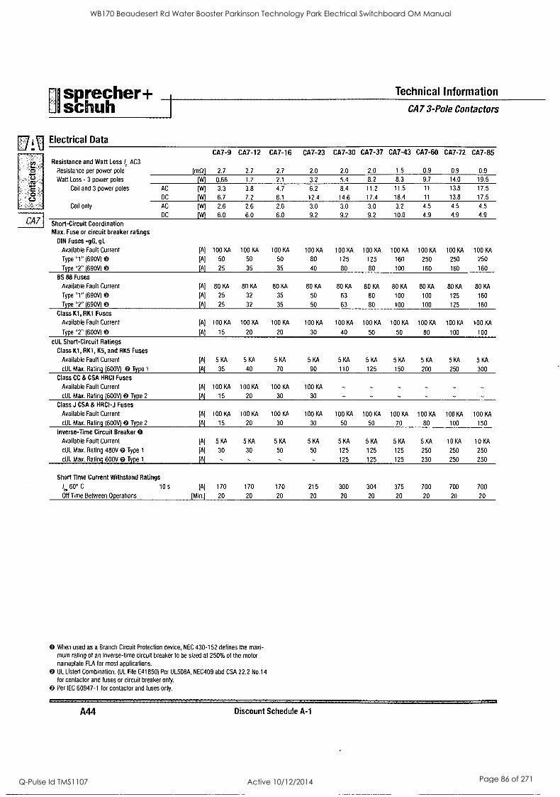
1
sprecher+ schuh
Technical Information
CA7 3-Pole Contactors
,g Electrical Data CA7-9 CA7-12 CA7-16 CA7-23 CA7-30 CA7-37 CA7-43 CA7-60 CA7-72 CA7-85
Resistance and Watt Loss I. AC3
Resistance per power pole [mQ] 2.7 2.7 2.7 2.0 2.0 2.0 1.5 0.9 0.9 0.9
Watt Loss - 3 power poles [W] 0.66 1.2 2.1 3.2 5.4 8.2 8.3 9.7 14.0 19.5
Coil and 3 power poles AC
DC
[W]
[W]
3.3
6.7
3.8
7.2
4.7
8.1
6.2
12.4
8.4
14.6
11.2
17.4
11.5
18.4
11
11
13.8
13.8
17.5
17.5
Coil only AC
DC
[W]
[W]
2.6
6.0
2.6
6.0
2.6
6.0
3.0
9.2
3.0
9.2
3.0
9.2
3.2
10.0
4.5
4.9
4.5
4.9
4.5
4.9
Short-Circuit Coordination Max. Fuse or circuit breaker ratings
DIN Fuses -gG, gL
Available Fault Current [A] 100 KA 100 KA 100 KA 100 KA 100 KA 100 KA 100 KA 100 KA 100 KA 100 KA
Type "1" (690V) 0 [A] 50 50 50 80 125 125 160 250 250 250
Type "2" (690V) 0 [A] 25 35 35 40 80 80 100 160 160 160
BS 88 Fuses
Available Fault Current [A] 80 KA 80 KA 80 KA 80 KA 80 KA 80 KA 80 KA 80 KA 80 KA 80 KA
Type "1" (690V) 0 [A] 25 32 35 50 63 80 100 100 125 160
Type "2" (690V) 0 [A] 25 32 35 50 63 80 100 100 125 160
Class Kl, RK1 Fuses
Available Fault Current [A] 10010 100 KA 100 KA 100 KA 100 KA 100 KA 100 KA 100 KA 100 KA 100 KA
Type "2" (600V) @ [A] 15 20 20 30 40 50 50 80 100 100
cUL Short-Circuit Ratings Class Kl, RK1, K5, and RK5 Fuses
Available Fault Current [A] 5 KA 5 KA 5 KA 5 KA 5 KA 5 KA 5 KA 5 KA 5 KA 5 KA
cUL Max. Rating (600V) 49 Type 1 [A] 35 40 70 90 110 125 150 200 250 300
Class CC & CSA HRCI Fuses
Available Fault Current [A] 100 KA 100 KA 100 KA 100 KA
cUL Max. Rating (600V) 0 Type 2 [A] 15 20 30 30
Class J CSA & HRCI-J Fuses
Available Fault Current [A] 100 KA 100 KA 100 KA 100 KA 100 KA 100 KA 100 KA 100 KA 100 KA 100 KA
cUL Max. Rating (6001) 0 Type 2 [A] 15 20 30 30 50 50 70 80 100 150
Inverse-Time Circuit Breaker 0 Available Fault Current [A] 5 KA 5 KA 5 KA 5 KA 5 KA 5 KA 5 KA 5KA 10 KA 10 KA
cUL Max. Rating 4813V 0 Type 1 [A] 30 30 50 50 125 125 125 250 250 250
cUL Max. Rating 600V 0 Type 1 [A] - - - - 125 125 125 250 250 250
Short Time Current Withstand Ratings
lc", 60° C 10 s [A] 170 170 170 215 300 304 375 700 700 700
Off Time Between Operations [MM.] 20 20 20 20 20 20 20 20 20 20
O When used as a Branch Circuit Protection device, NEC 430-152 defines the maxi- mum rating of an Inverse-time circuit breaker to be sized at 250% of the motor nameplate FLA for most applications. UL Listed Combination. (UL File E41850) Per UL508A, NEC409 abd CSA 22.2 No.14
for contactor and fuses or circuit breaker only.
Per IEC 60947-1 for contactor and fuses only.
A44 Discount Schedule A-1
WB170 Beaudesert Rd Water Booster Parkinson Technology Park Electrical Switchboard OM Manual
Q-Pulse Id TMS1107 Active 10/12/2014 Page 86 of 271
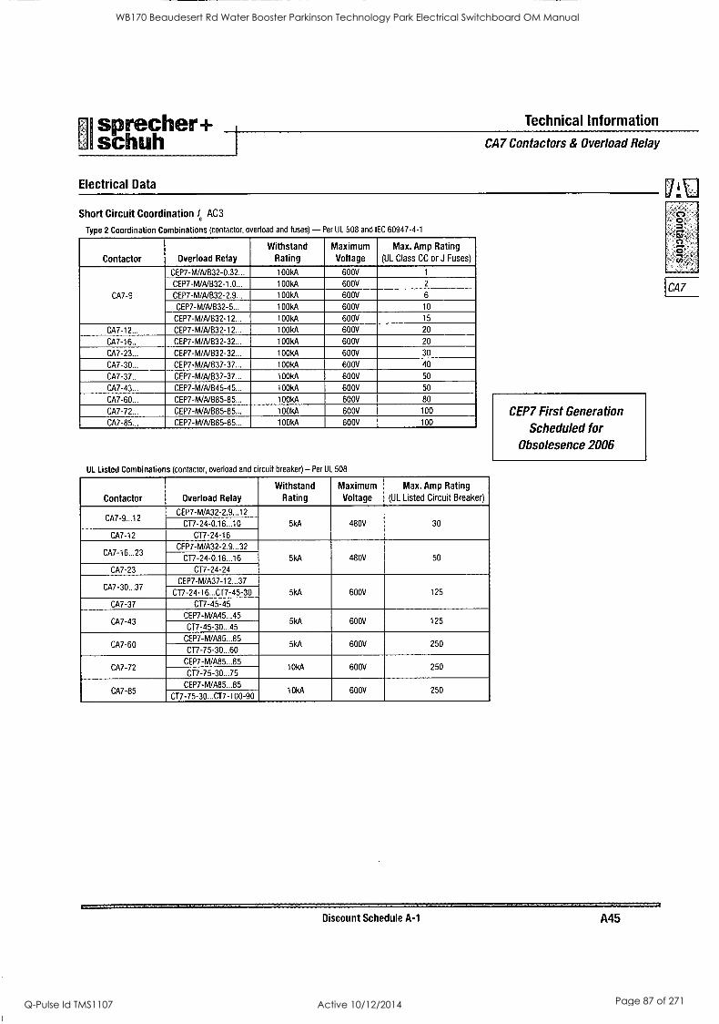
sprecher+ schuh
Technical Information
Electrical Data
CA7 Contactors & Overload Relay
Short Circuit Coordination /e AC3
Type 2 Coordination Combinations (contactor, overload and fuses) - Per UL 508 and IEC 60947-4-1
Contactor Overload Relay
Withstand Rating
Maximum Voltage
Max. Amp Rating
(UL Class CC or J Fuses)
CA7-9
CEP7-M/A/B32-0.32... 100kA 600V 1
CEP7-M/A/B32-1.0... 100kA 600V 2
CEP7-M/A/B32-2.9... 100kA 600V 6
CEP7-WA/B32-5... 100kA 600V 10
CEP7-M/A/B32-12... 100kA 600V 15
CA7-12... CEP7-M/NB32-12... 100kA 600V 20
CA7-16... CEP7-M/A/B32-32... 1001(A 600V 20
CA7-23... CEP7-M/A/B32-32... 100kA 600V 30
CA7-30... CEP7-WA/B37-37... 100kA 600V 40
CA7-37... CEP7-WA/B37-37... 1001(A 600V 50
CA7-43... CEP7-M/A/B45-45... 1001(A 600V 50
CA7-60... CEP7-M/A/B85-85... 100kA 600V 80
CA7-72... CEP7-M/A/B85-85... 100kA 600V 100
CA7-85... CEP7-M/A/B85-85... 100kA 600V 100
UL Listed Combinations (contactor, overload and circuit breaker) - Per UL 508
Contactor Overload Relay
Withstand Rating
Maximum Voltage
Max. Amp Rating
(UL Listed Circuit Breaker)
CA7-9...12 CEP7-M/A32-2.9...12
5kA 480V 30 C17-24-0.16...10
CA7-12 CT7-24-16
CA7-16...23 CEP7-M/A32-2.9...32
5kA 480V 50 CT7-24-0.16...16
CA7-23 CT7-24-24
CA7-30...37 CEP7-M/A37-12...37
5kA 600V 125 CT7-24-16...CT7-45-30
CA7-37 CT7-45-45
CA7-43 CEP7-M/A45...45
5kA 600V 125 CT7-45-30...45
CA7-60 CEP7-M/A85...85
5kA 600V 250 CT7-75-30...60
CA7-72 CEP7-WA85...85
10kA 600V 250 CT7-75-30...75
CA7-85 CEP7- M/A85...85
10I(A 600V 250 CT7-75-30...CT7-100-90
CEP7 First Generation
Scheduled for Obsolesence 2006
Discount Schedule A-1 A45
CA7
WB170 Beaudesert Rd Water Booster Parkinson Technology Park Electrical Switchboard OM Manual
Q-Pulse Id TMS1107 Active 10/12/2014 Page 87 of 271
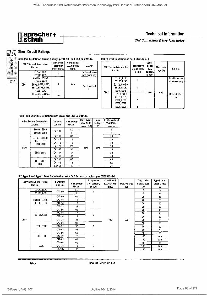
pI sprecher+ Technical Information
schuh 1 CA7 Contactors & Overload Relay
[7, i \ Short Circuit Ratings
0 cs as
4.10.
0 C.)
CA7
CEP7 Second Generation Cat. No.
Max. avail- able fault
current (kA)
Conditional S.C. current,
lq (kA) S.C.P.D.
CEP7
ED1AB, EEAB
ED1BB, EEBB 1
600
Suitable for use
with fuses only
ED1CB, ED1DB.
ED1EB, EECB,
EEDB, EEEB, EEED,
EEFD, EEPB, EERB,
EESB, EETD
5 Not restricted
to
EEEE, EEFE. EEGE.
EEUE 10
High Fault Short Circuit Ratings per UL508 and CSA 22.2 No.14
IEC Short Circuit Ratings per EN60947-4-1
CEP7 Second Generation
No
Prospective S.C. current ,
Ir (kA)
Condi- tional
S.C.
current, lq jkA)
Max. . lt- age (V)
S.C.P.D.
CEP7
ED1AB, EEAB
ED1BB, EEAB 1
100 690
Suitable for use
with fuses only
ED1CB, ED1DB.
EECB,EEDB,
EEPB. EERB
1
Not restricted
to
ED1 EB, EEEB,
EEED, EEFD,
EEEE, EEFE.
EESB, EETD
3
EEGE, EEUE 5
CEP7 Second Generation
Cat No.
Contactor Cat No.
Max. starter FLC (A)
Max. avail- able fault
current (kA)
Max.
voltage (V)
UL Class J and
CSA HRCI -J fuse (A)
CEP7
ED1AB, EEAB CA7-09
0 5 .
100 600
3
ED1BB,EEBB 1 6
ED1CB, ED1DB,
ED1EB, EEEB,
EECB,EEDB
CA7-09 09 20
CA7-12 12 20
CA7-16 16 30
CA7-23 23 30
EEED, EEFD
CA7-30 30 50
CA7-37 37 50
CA7-43 43 70
EEEE, EEFE
EEGE
CA7-60 60 80
CA7-72 72 100
CA7-85 85 150
IEC Type 1 and Type II Fuse Coordination with CA7 Series contactors per EN60947-4-1
CEP7 Second Generation
Cat No.
Contactor Cat No.
Max. starter FLC (A)
Prospective S.C. current,
Ir (kA)
Conditional S.C. current,
lq (kA)
Max. voltage
(V)
Type I with Class J fuse
(A)
Type II with Class J fuse
(A)
CEP7
ED1AB, EEAB CA7-09
0.5 1
100 600
3 3
ED1BB,EEBB 1 6 6
ED1CB, ED1DB,
EECB,EEDB
CA7-09 09
1
20 15
CA7-12 12 20 20
CA7-16 16 30 30
CA7-23 23 30 30
ED1EB, EEEB
CA7-09 09
3
20 15
CA7-12 12 20 20
CA7-16 16 30 30
CA7-23 23 30 30
EEED, EEFD
CA7-30 30
3
50 50
CA7-37 37 50 50
CA7-43 43 70 70
EEEE, EEFE
CA7-60 60
3
80 80 CA7-72 72 100 100 CA7-85 85 150 150
EEGE
CA7-60 60
5
80 80 CA7-72 72 100 100 CA7-85 85 150 150
A46 Discount Schedule A-1
WB170 Beaudesert Rd Water Booster Parkinson Technology Park Electrical Switchboard OM Manual
Q-Pulse Id TMS1107 Active 10/12/2014 Page 88 of 271
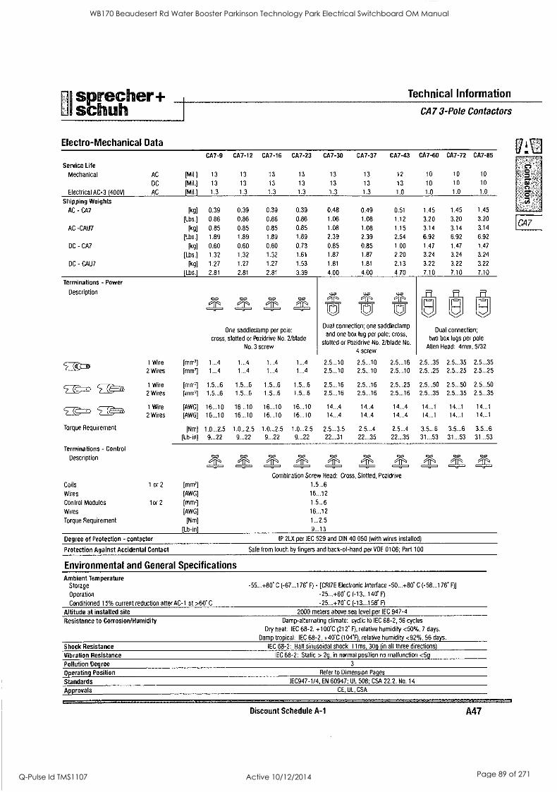
I
sprecher+ Technical Information
schuh Electro-Mechanical Data
CA7 3-Pole Contactors
Service Life
Mechanical
Electrical AC-3 (400V)
Shipping Weights
AC - CA7
AC -CAU7
DC - CA7
DC - CAU7
AC
DC
AC
Terminations - Power
Description
[Mill [Mil.]
[Mil.]
CA7-9
13
13
1.3
CA7-12
13
13
1.3
CA7-16
13
13
1.3
CA7-23
13
13
1.3
[kg] 0.39 0.39 0.39 0.39
[Lbs.] 0.86 0.86 0.86 0.86
[kg] 0.85 0.85 0.85 0.85
[Lbs.] 1.89 1.89 1.89 1.89
[kg] 0.60 0.60 0.60 0.73
[Lbs.] 1.32 1.32 1.32 1.61
[kg] 1.27 1.27 1.27 1.53
(Lbs.] 2.81 2.81 2.81 3.39
One saddleclamp per pole:
cross, slotted or Pozidrive No. 2/blade
No. 3 screw
1 Wire [mm'] 1...4 1...4
2 Wires [mm'] 1...4 1...4
1 Wire [mal 1.5...6 1.5...6
2 Wires [mm'] 1.5...6 1.5...6
1 Wire [AWG] 16...10 16...10
2 Wires [AWG] 16...10 16...10
Torque Requirement Requirement [Nm] 1.0...2.5 1.0...2.5
[Lb-in] 9...22 9...22
Terminations - Control
Description
Coils 1 or 2 [mm']
Wires [AWG]
Control Modules 1 or 2 [mmil
Wires [AWG]
Torque Requirement [Nm]
[Lb-in]
Degree of Protection - contactor
CA7-30 CA7-37 CA7-43 CA7-60 CA7-72 CA7-85
13
13
1.3
13
13
1.3
0.48 0.49
1.06 1.08
1.08 1.08
2.39 2.39
0.85 0.85
1.87 1.87
1.81 1.81
4.00 4.00
12 10
13 10
1.0 1.0
0.51 1.45
1.12 3.20
1.15 3.14
2.54 6.92
1.00 1.47
2.20 3.24
2.13 3.22
4.70 7.10
Dual connection; one saddleclamp
and one box lug per pole; cross,
slotted or Pozidrive No. 2/blade No.
4 screw
B
10
10
1.0
10
10
1.0
1.45 1.45
3.20 3.20
3.14 3.14
6.92 6.92
1.47 1.47
3.24 3.24
3.22 3.22
7.10 7.10
Dual connection;
two box lugs per pole
Allen Head: 4mm, 5/32
1...4 1...4 2.5...10 2.5...10 2.5...16 2.5...35 2.5...35 2.5...35 1...4 1...4 2.5...10 2.5...10 2.5...10 2.5...25 2.5...25 2.5...25
1.5...6 1.5...6 2.5...16 2.5...16 2.5...25 2.5...50 2.5...50 2.5...50 1.5...6 1.5...6 2.5...16 2.5...16 2.5...16 2.5...35 2.5...35 2.5...35
16...10 16...10 14...4 14..4 14...4 14...1 14...1 14...1
16...10 16...10 14...4 14..4 14...4 14...1 14...1 14...1
1.0...2.5 1.0...2.5 2.5...3.5 2.5...4 2.5...4 3.5...6 3.5...6 3.5...6
9...22 9...22 22...31 22...35 22...35 31...53 31...53 31...53
MMMZZ. Z. M Combination Screw Head: Cross, Slotted, Pozidrive
1.5...6
16...12
1.5...6
16...12
1...2.5
9...13
IP 2LX per IEC 529 and DIN 40 050 (with wires installed)
Protection Against Accidental Contact Safe from touch by fingers and back-of-hand per VDE 0106; Part 100
Environmental and General Specifications Ambient Temperature
Storage
Operation
Conditioned 15% current reduction after AC-1 at >60" C
Altitude at installed site Resistance to Corrosion/Humidity
Shock Resistance
Vibration Resistance
Pollution Degree
Operating Position
Standards
Approvals
-55...+80" C (-67...176' F) - [CRI7E Electronic Interface -50...+80' C (- 58...176' F)]
-25...+60" C (-13...140' F)
-25...+70' C (-13...158' F)
2000 meters above sea level per IEC 947-4
Damp-alternating climate: cyclic to IEC 68-2, 56 cycles
Dry heat: IEC 68-2, +100'C (212* F), relative humidity <50%, 7 days.
Damp tropical: IEC 68 -2, +40"C (104'F), relative humidity <92%, 56 days.
IEC 68-2: Half sinusoidal shock 11 ms, 30g (in all three directions)
IEC 68-2: Static > 2g, in normal position no malfunction <5g
3
Refer to Dimension Pages
IEC947-1/4, EN 60947; UL 508; CSA 22.2, No. 14
CE, UL, CSA
Discount Schedule A-1 A47
.t\l
0'
CA7
WB170 Beaudesert Rd Water Booster Parkinson Technology Park Electrical Switchboard OM Manual
Q-Pulse Id TMS1107 Active 10/12/2014 Page 89 of 271
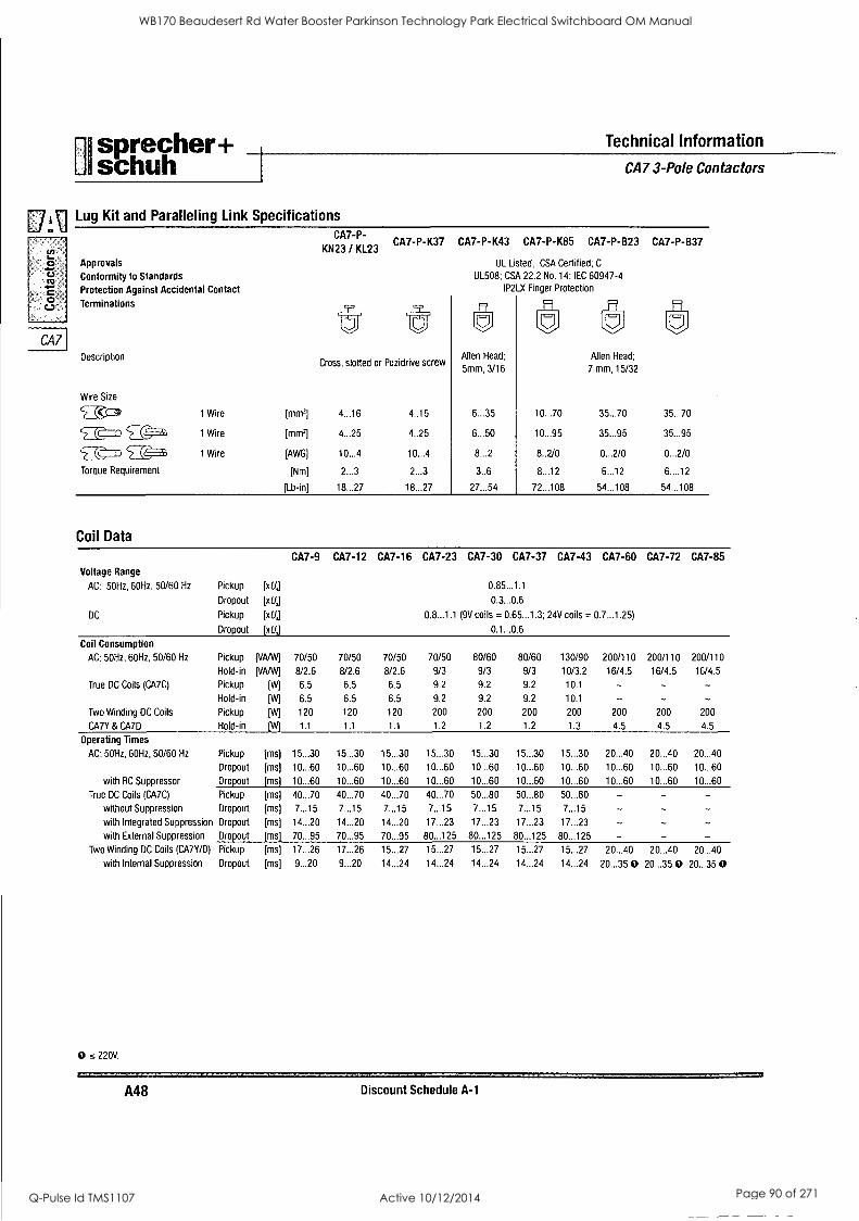
isprecher+ Technical Information
I schuh I CA7 3-Pole Contactors
r7 V1 Lug Kit and Paralleling Link Specifications U CA7-P-
KN23 / KL23 U)
Ca L.
Approvals
vs ti Conformity to Standards
c, Protection Against Accidental Contact o
c.) Terminations
CA7 Description
CA7-P-K37 CA7-P-K43 CA7-P-K85 CA7-P-B23 CA7-P-B37
Cross, slotted or Pozidrive screw
Wire Size
5 ( 1 Wire [mma 4...16 4..16
5 (<7-7) $--(as, 1 Wire [mnfj 4...25 4..25
`? ?_ _.( 1 Wire [AWG] 10...4 10...4
Torque Requirement [Nm] 2...3 2...3
[Lb-in] 18...27 18...27
Coil Data
UL Listed: CSA Certified; C
UL508; CSA 22.2 No. 14; IEC 60947-4 1P21.)( Finger Protection
Allen Head:
5mm, 3/16
ff1
7)
Allen Head;
7 mm, 15/32
6...35 10..70 35...70 35...70
6 . 50 10...95 35...95 35...95
8...2 8..2/0 0...2/0 0...2/0
3..6 8...12 6...12 6....12
27...54 72...108 54...108 54...108
Voltage Range
AC: 50Hz, 60Hz, 50/60 Hz
DC
Pickup
Dropout
Pickup
Dropout
[xU,]
[xL/J
[xU,]
[x11,1
CA7-9 CA7-12 CA7-16 CA7-23 CA7-30 CA7-37 CA7-43 CA7-60
0.85...1.1
0.3...0.6
0,8_1.1 (9V coils = 0.65...1.3; 24V coils = 0.7...1.25)
0.1...0.6
CA7-72 CA7-85
Coil Consumption
AC: 50Hz, 60Hz, 50/60 Hz Pickup [VA/W] 70/50 70/50 70/50 70/50 80/60 80/60 130/90 200/110 200/110 200/110
Hold-in [VANV] 8/2.6 8/2.6 8/2.6 9/3 9/3 9/3 10/3.2 16/4.5 16/4.5 16/4.5
True DC Coils (CA7C) Pickup [W] 6.5 6.5 6.5 9.2 9.2 9.2 10.1 - - - Hold -in [W] 6.5 6.5 6.5 9.2 9.2 9.2 10.1 - - -
Two Winding DC Coils Pickup [W] 120 120 120 200 200 200 200 200 200 200
CA7Y & CA7D Hold-in [W] 1.1 1.1 1.1 1.2 1.2 1.2 1.3 4.5 4.5 4.5
Operating Times
AC: 5011z, 60Hz, 50/60 Hz Pickup [ms] 15...30 15...30 15...30 15...30 15...30 15...30 15...30 20...40 20...40 20...40
Dropout [ms] 10...60 10...60 10...60 10...60 10...60 10...60 10...60 10...60 10...60 10...60
with RC Suppressor Dropout [ms] 10...60 10...60 10...60 10...60 10...60 10...60 10...60 10...60 10...60 10...60
True DC Coils (CA7C) Pickup [ms] 40...70 40...70 40...70 40...70 50...80 50...80 50...80 - - - without Suppression Dropout [ms] 7...15 7...15 7...15 7...15 7...15 7...15 7...15 - - with Integrated Suppression Dropout [ms] 14...20 14...20 14...20 17...23 17...23 17...23 17...23
with External Suppression Dropout [ms] 70...95 70...95 70...95 80...125 80...125 80...125 80...125 - - - Two Winding DC Coils (CA7Y/D) Pickup [ms] 17...26 17...26 15...27 15...27 15...27 15...27 15...27 20...40 20...40 20...40
with Internal Suppression Dropout [ms] 9...20 9...20 14...24 14...24 14...24 14...24 14...24 20...35 0 20...35 0 20...35 0
0 s 220V.
A48 Discount Schedule A-1
WB170 Beaudesert Rd Water Booster Parkinson Technology Park Electrical Switchboard OM Manual
Q-Pulse Id TMS1107 Active 10/12/2014 Page 90 of 271
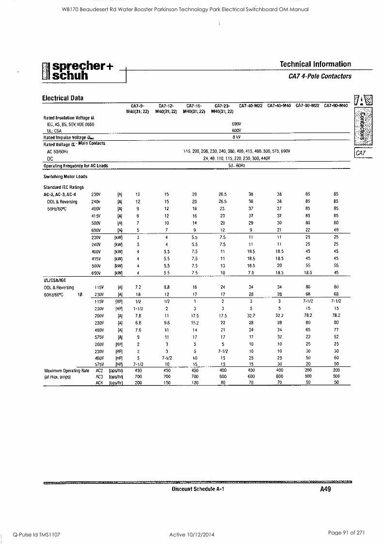
Ui sprecher + Technical Information
schuh 1 CA7 4-Pole Contactors
Electrical Data [7'
CA7-9- M40(31; 22)
CA7-12- M40(31; 22)
CA7-16- CA7-23- CA7-40-M22 CA7-40-M40
M40(31; 22) M40(31; 22)
CA7-90-M22 CA7-90-M40
Rated Insulation Voltage lA
IEC, AS, BS, SEV, VDE 0660 690V
UL; CSA 600V o'
Rated Impulse Voltage L 8 kV
Rated Voltage U." Main Contacts
AC 50/60Hz 115, 200, 208, 230, 240, 380, 400, 415, 460, 500, 575, 690V CA7 DC 24. 48, 110. 115, 220, 230, 300, 440V
Operating Frequency for AC Loads 50...60Hz
Switching Motor Loads
Standard IEC Ratings
AC-2, AC-3, AC-4 230V [A] 12 15 20 26.5 38 38 85 85
DOL & Reversing 240v [A] 12 15 20 26.5 38 38 85 85
50Hz/60°C 400V [A] 9 12 16 23. 37 37 85 85
415V [A] 9 12 16 23 37 37 85 85
500V [Aj 7 10 14 20 29 30 80 80
690V [A] 5 7 9 12 9 21 22 49
230V [kW] 3 4 5.5 7.5 11 11 25 25
240V [kW] 3 4 5.5 7.5 11 11 25 25
400V [kW] 4 5.5 7.5 11 18.5 18.5 45 45
415V [kW] 4 5.5 7.5 11 18.5 18.5 45 45
500V [kW] 4 5.5 7.5 13 18.5 20 55 55
690V [kW] 4 5.5 7.5 10 7.5 18.5 18.5 45
UUCSA/IEC
DOL & Reversing 115V [A] 7.2 9.8 16 24 34 34 80 80
60Hz/60°C 10 230V [A] 18 12 17 17 28 28 68 68
115V [HP] 1/2 1/2 1 2 3 3 7-1/2 7-1/2
230V [HP] 1-1/2 2 3 3 5 5 15 15
200V [A] 7.8 11 17.5 17.5 32.2 32.2 78.2 78.2
230V [A] 6.8 9.6 15.2 22 28 28 80 80
460V [A] 7.6 11 14 21 34 34 65 77
575V [A] 9 11 17 17 17 32 22 52
200V [HP] 2 3 5 5 10 10 25 25
230V [HP] 2 3 5 7-1/2 10 10 30 30
460V [HP] 5 7-1/2 10 15 25 25 50 60
575V [HP] 7-1/2 10 15 15 15 30 20 50
Maximum Operating Rate AC2 [ops/hr] 450 450 450 400 400 400 200 200
(at max. amps) AC3 [ops/hr] 700 700 700 600 600 600 500 500
AC4 rops/hrl 200 150 120 80 70 70 50 50
Discount Schedule A-1 A49
WB170 Beaudesert Rd Water Booster Parkinson Technology Park Electrical Switchboard OM Manual
Q-Pulse Id TMS1107 Active 10/12/2014 Page 91 of 271
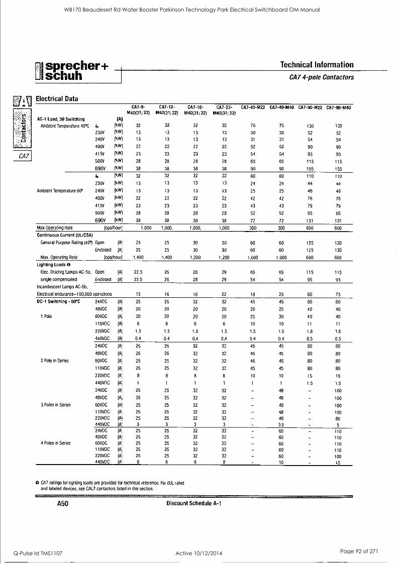
CA7
sprecher+ Technical Information
schuh I CA7 4-pole Contactors
Electrical Data CA7-9-
M40(31; 22) CA7-12-
M40(31; 22)
CA7-16- M40(31; 22)
CA7-23- M40(31; 22)
CA7-40-M22 CA7-40-M40 CA7-90-M22 CA7-90-M40
AC-1 Load, 30 Switching [A]
Ambient Temperature 40°C I.,
230V
[kW]
]kW]
32
13
32
13
32
13
32
13
75
30
75
30
130
52
130
52
240V [kW] 13 13 13 13 31 31 54 54
400V [kW] 22 22 22 22 52 52 90 90
415V [kW] 23 23 23 23 54 54 93 93
500V [kW] 28 28 28 28 65 65 113 113
690V [kW] 38 38 38 38 90 90 155 155
lie (kW] 32 32 32 32 60 60 110 110
230V [kW] 13 13 13 13 24 24 44 44
Ambient Temperature 60° 240V [kW] 13 13 13 13 25 25 46 46
400V (kW) 22 22 22 22 42 42 76 76
415V (kW) 23 23 23 23 43 43 79 79
500V [kW] 28 28 28 28 52 52 95 95
690V [kW] 38 38 38 38 72 72 131 131
Max Operating Rate [ops/hour] 1,000 1,000, 1,000, 1,000 300 300 600 600
Continuous Current (1.1L/CSA)
General Purpose Rating (40°) Open [A] 25 25 30 30 60 60 125 130
Enclosed [A] 25 25 30 30 60 60 125 130
Max. Operating Rate [ops/hour] 1,400 1,400 1,200 1,200 1,000 1.000 600 600
Lighting Loads 0 Elec. Dischrglamps-AC-5a, Open [A] 22.5 25 28 29 65 65 115 115
single compensated Enclosed [A] 22.5 25 28 29 54 54 95 95
Incandescent Lamps AC-5b,
Electrical endurance-100,000 operations 12 16 18 22 18 25 60 75
DC-1 Switching - 60°C 24VDC [A] 25 25 32 32 45 45 80 80
48VDC [A] 20 20 20 20 25 25 40 40
1 Pole 60VDC [A] 20 20 20 20 25 30 40 40
110VDC [A] 6 6 6 6 10 10 11 11
220VDC [A] 1.5 1.5 1.5 1.5 1.5 1.5 1.8 1.8
440VDC [A] 0.4 0.4 0.4 0.4 0.4 0.4 0.5 0.5
24VDC [A] 25 25 32 32 45 45 80 80
48VDC [A] 25 25 32 32 45 45 80 80
2 Pole in Series 60VDC [A] 25 25 32 32 45 45 80 80
110VDC [A] 25 25 32 32 45 45 80 80
220VDC [A] 8 8 8 8 10 10 15 15
440VDC [A] 1 1 1 1 1 1 1.5 1.5
24VDC [A] 25 25 32 32 48 - 100
48VDC [A] 25 25 32 32 48 100
3 Poles in Series 60VDC [A] 25 25 32 32 48 - 100
110VDC [A] 25 25 32 32 48 100
220VDC [A] 25 25 32 32 48 80 440VDC [A] 3 3 3 3 3.5 - 5
24VDC [A] 25 25 32 32 60 - 110 48VDC [A] 25 25 32 32 60 - 110
4 Poles in Series 60VDC [A] 25 25 32 32 60 - 110 110VDC [A] 25 25 32 32 60 - 110 220VDC [A] 25 25 32 32 60 - 100 440VDC [A] 8 8 8 8 10 - 15
0 CA7 ratings for lighting loads are provided for technical reference. For cUL rated
and labeled devices, see CAL7 contactors listed in this section.
A50 Discount Schedule A-1
WB170 Beaudesert Rd Water Booster Parkinson Technology Park Electrical Switchboard OM Manual
Q-Pulse Id TMS1107 Active 10/12/2014 Page 92 of 271
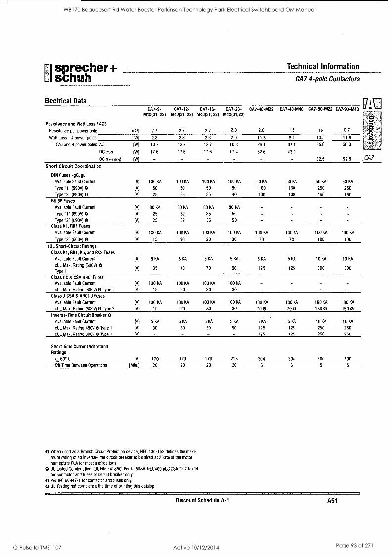
sprecher+ Technical Information
schuh 1 CA7 4-pole Contactors
Electrical Data
Resistance and Watt Loss 4AC3
Resistance per power pole
Watt Loss - 4 power poles
Coil and 4 power poles AC
DC (true)
DC (2 winding)
CA7-9- CA7-12- CA7-16- M40(31; 22) M40(31; 22) M40(31; 22)
2.7 2.7 2.7
2.8 2.8 2.8
13.7 13.7 13.7
17.6 17.6 17.6
- - - Short Circuit Coordination
DIN Fuses -gG, gL
Available Fault Current [A] 100 KA 100 KA 100 KA
Type "1" (690V) 0 [A] 50 50 50
Type "2" (690V) 0 [A] 25 35 35
BS 88 Fuses
Available Fault Current [A] 80 KA 80 KA 80 M Type "1" (690V) 0 [A] 25 32 35
Type "2" (690V) 0 [A] 25 32 35
Class K1, RK1 Fuses
Available Fault Current [A] 100 KA 100 KA 100 KA
Type "2" (600V)49 [A] 15 20 20
cUL Short-Circuit Ratings
Class K1, RK1, K5, and RK5 Fuses
Available Fault Current [A] 5 KA 5 KA 5 KA
cUL Max. Rating (600V) 0 [A] 35 40 70
Type 1
Class CC & CSA HRCI Fuses
Available Fault Current [A] 100 KA 100 KA 100 KA
cUL Max. Rating (600V) 0 Type 2 [A] 15 20 30
Class J CSA & HRCI-J Fuses
Available Fault Current [A] 100 KA 100 KA 100 KA
cUL Max. Rating (600V) 0 Type 2 [A] 15 20 30
Inverse-Time Circuit Breaker 0 Available Fault Current [A] 5 KA 5 KA 5 KA
cUL Max. Rating 480V 0 Type 1 [A] 30 30 50
cUL Max. Rating 600V 49 Type 1 [A] - -
Short Time Current Withstand Ratings
60° C [A] 170 170 170
Off Time Between Operations [Min.] 20 20 20
0 When used as a Branch Circuit Protection device, NEC 430-152 defines the maxi-
mum rating of an Inverse-time circuit breaker to be sized at 250% of the motor
nameplate FLA for most applications.
UL Listed Combination. (UL File E41850) Per UL508A, NEC409 abd CSA 22.2 No.14
for contactor and fuses or circuit breaker only.
O Per IEC 60947-1 for contactor and fuses only.
O UL Testing not complete a the time of printing this catalog.
CA7-23- CA7-40-M22 CA7-40-M40 CA7-90-M22 CA7-90-M40 ° M40(31;22)
- 0-
2.0 2.0 1.5 0.8 0.7
2.0 11.3 8.4 13.5 11.8 ST) '
10.8 26.1 37.4 36.0 56.3 :,.(,)°`..
17.4 32.6 43.9 - - - 32.5 52.8 CA7
100 KA 50 KA 50 KA 50 KA 50 KA
80 160 160 250 250
40 100 100 160 160
80 KA - 50 - - - 50 - -
100 KA 100 KA 100 KA 100 KA 100 KA
30 70 70 100 100
5 KA 5 KA 5 KA 10 KA 10 KA
90 125 125 300 300
100 KA
30
100 KA 100 KA 100 KA 100 KA 100 KA
30 70 0 70 0 150 0 150 0 .
5 KA 5 KA 5 KA 10 KA 10 KA
50 125 125 250 250
- 125 125 250 250
215 304 304 700 700
20 5 5 5 5
Discount Schedule A-1 A51
WB170 Beaudesert Rd Water Booster Parkinson Technology Park Electrical Switchboard OM Manual
Q-Pulse Id TMS1107 Active 10/12/2014 Page 93 of 271
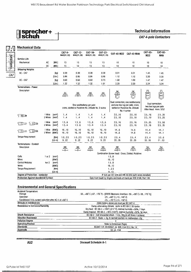
sprecher+ Technical Information
schuh CA7 4-pole Contactors
[MI Mechanical Data
L. 0 4-0 cU CU
0
CA7
Service Life
Mechanical
Shipping Weights
AC - CA7
DC - CA7
Terminations - Power
AC [Mil.]
DC [Mil.]
CA7-9- M40(31; 22)
13
13
CA7-12- M40(31; 22)
13
13
CA7-16- M40(31; 22)
13
13
CA7-23- M40(31; 22)
13
13
CA7-40-M22
10
10
CA7-40-M40
10
10
CA7-90- M22
10
10
CA7-90- M40
10
10
[kg] 0.39 0.39 0.39 0.39 0.51 0.51 1.45 1.45
[Lbs.] 0.86 0.86 0.86 0.86 1.12 1.12 3.20 3.20
[kg] 0.60 0.60 0.60 0.73 1.00 1.00 1.47 1.47
[Lbs.] 1.32 1.32 1.32 1.61 2.20 2.20 3.24 3.24
Description
5 (('a 1 Wire [mm2
2 Wires [mml
1 Wire [mm2]
2 Wires [mm2]
1 Wire [AWG]
2 Wires [AWG]
[Nm]
[Lb-in]
Dual connection;
two box lugs per pole
Allen Head: 4mm, 5/32
2.5...16 2.5...35
2.5...10 2.5...25
2.5...25 2.5...50
2.5...16 2.5...35
14...4 14...1
14...4 14...1
2.5...4 3.5...6
22...35 31...53
Dual connection; one saddleclamp
and one box lug per pole; cross,
slotted or Pozidrive No. 2/blade
No. 4 screw
2.5...10 2.5...10 2.5...10 2.5...10
2.5...16 2.5...16 2.5...16 2.5...16
14...6 14..6
14...6 14..6
2.5...4 2.5...4
22...35 22...35
One saddleclamp per pole:
cross, slotted or Pozidrive No. 2/blade No. 3 screw
1...4 1...4 1...4 1...4
1...4 1...4 1...4 1...4
1.5...6 1.5...6 1.5...6 1.5...6
1.5...6 1.5...6 1.5...6 1.5...6
16...10 16...10 16...10 16...10 16...10 16...10 16...10 16...10
1.0...2.5 1.0...2.5 1.0...2.5 1.0...2.5
9...22 9...22 9...22 9...22
( -n
`EgEEz
Torque Requirement
Terminations - Control
Description
Coils
Wires
Control Modules
Wires
Torque Requirement
1 or 2 [mml [AWG]
1or 2 [mml [AWG]
[Nm]
[Lb-inj
Combination Screw Head: Cross, Slotted, Pozidrive
1.5...6
16...12
1.5...6
16...12
1...2.5
9...13
Degree of Protection - contactor IP 2LX per IEC 529 and DIN 40 050 (with wires installed)
Protection Against Accidental Contact Safe from touch by fingers and back-of-hand per VDE 0106; Part 100
Environmental and General Specifications Ambient Temperature
Storage
Operation
Conditioned 15% current reduction after AC-1 at >60' C
Altitude at installed site Resistance to Corrosion/Humidity
Shock Resistance Vibration Resistance
Pollution Degree
Operating Position
Standards
Approvals
-55...+80' C (-67...176' F) - [CRI7E Electronic Interface -50...+80' C (-58...176' F)]
-25...+60' C (-13...140' F)
-25...+70' C (-13...158' F)
2000 meters above sea level per IEC 947-4
Damp-alternating climate: cyclic to IEC 68-2, 56 cycles
Dry heat: IEC 68-2. +100'C (212' F), relative humidity <50%, 7 days. Damp tropical: IEC 68-2, +40'C (104'F), relative humidity <92%, 56 days.
IEC 68-2: Half sinusoidal shock 11ms, 30g (in all three directions)
IEC 68-2: Static > 2g, in normal position no malfunction <5g 3
Refer to Dimension Pages
IEC947-1/4, EN 60947; UL 508; CSA 22.2, No. 14
CE. UL, CSA
A52 Discount Schedule A-1
WB170 Beaudesert Rd Water Booster Parkinson Technology Park Electrical Switchboard OM Manual
Q-Pulse Id TMS1107 Active 10/12/2014 Page 94 of 271
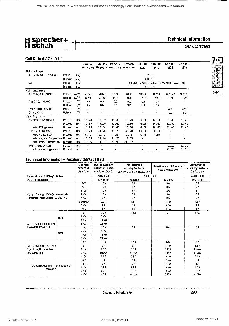
I
sprecher+ schuh
Technical Information
CA7 Contactors
Coil Data (CA7 4-Pole)
Voltage Range
CA7-9- M40(31; 22)
CA7-12- M40(31; 22)
CA7-16- M40(31; 22)
CA7-23- CA7-40- CA7-40- CA7-90- CA7 -90- M40(31; 22) M22 M40 M22 M40
O
AC: 50Hz, 60Hz, 50/60 Hz Pickup [xUs] 0.85...1.1
Dropout [xt/J 0.3...0.6
DC Pickup [x U] 0.8...1.1 (9V coils = 0.65...1.3; 24V coils = 0.7...1.25)
Dropout [xUs] 0.1...0.6
Coil Consumption
AC: 50Hz, 60Hz, 50/60 Hz Pickup [VA/W] 70/50 70/50 70/50 70/50 130/90 130/90 400/240 400/240 CA7
Hold-in [VA/W] 8/2.6 8/2.6 8/2.6 9/3 12/3.6 12/3.6 24/9 24/9
True DC Coils (CA7C) Pickup [W] 6.5 6.5 6.5 9.2 10.1 10.1 - - Hold -in [W] 6.5 6.5 6.5 9.2 10.1 10.1 - -
Two Winding DC Coils Pickup [W] - - - - - - 325 325
CA7Y & CA7D Hold-in [W] - - - - 5.5 5.5
Operating Times
AC: 50Hz, 60Hz. 50/60 Hz Pickup [ms] 15...30 15...30 15...30 15...30 15...30 15...30 20...30 20...30
Dropout [ms] 10...60 10...60 10..,60 10...60 10...60 10...60 20...40 20...40
with RC Suppressor Dropout [ms] 10...60 10...60 10..,60 10...60 10...60 10...60 20...40 20...40
True DC Coils (CA7C) Pickup [ms] 40...70 40...70 40...70 40...70 50...80 50...80 - - without Suppression Dropout [ms] 7...15 7...15 7...15 7...15 7...15 7...15
with Integrated Suppression Dropout [ms] 14...20 14...20 14,..20 17...23 - - - with External Suppression Dropout [ms] 70...95 70...95 70...95 80...125 - - - -
Two Winding DC Coils Pickup [ms] - - - - 15...20 20...25
with Internal Suppression Dropout [ms] - - - - - 20...25 20...25
Technical Information - Auxiliary Contact Data
Mounted Standard Auxiliary
Built-in Auxiliary Contacts in Contac- for CA7-9...CA7-23
Front Mounted Auxiliary Contacts
CA7-PV, CS7-PV, CZE/A7, CV7
Front Mounted Bifurcated Auxiliary Contacts
Side Mounted Auxiliary Contacts
CA-PA, CM7
Electrical Contact Ratings - NEMA A600, P600 A600, 0600 A600, 0600
Min. Contact Rating 17V, 10 mA 17V, 5 mA 5V, 3 mA 17V, 10 mA
24V 10A 6A 3A 6A 48V 10A 6A 3A 6A 120V 10A 6A 3A 6A
Contact Ratings - IEC AC-15 (solenoids,
contactors) rated voltage IEC 60947-5-1
240V
400V
10A
6 A
5 A
3 A
3 A
2 A
5 A
3 A
480V/500V 2.5 A 1.6 A 1.2 A 1.6 A
600V 1 A 1 A 0.7 A 1 A
690V 1 A i A 0.7 A 1 A
Ith 20A 10A 10A 10A
40 °C 230V
400V
8 kW
14 kW
AC-12 (Control of resistive 690V 24 kW
loads) IEC 60947-5-1
60 °C
1,,
230V
400V
20 A
8 kW
14 kW
6 A 6 A 6 A
690V 24 kW
24V 12A 12A 6A 6A
DC-12 Switching DC Loads 48V 9 A 9 A 3.2 A 3.2 A
Vs< 1 ms, Resistive Loads 110V 3.5 A 3.5 A 0.45 A 0.45 A
IEC 60947-5-1 220V 0.55 A 0.55 A 0.18 A 0.18 A
440V 0.2A 0.2A 0.1 A 0.1 A
24V 5A 5A 2.5A 5A
DC-13 IEC 60947-5-1, Solenoids and
contactors
48V
110V
3 A
1.2 A
3 A
1.2 A
1.5 A
0.6 A
3 A
1.2 A
220V 0.6A 0.6A 0.3A 0.6A
440V 0.3A 0.15A 0.15A 0.15A
Discount Schedule A-1 A53
WB170 Beaudesert Rd Water Booster Parkinson Technology Park Electrical Switchboard OM Manual
Q-Pulse Id TMS1107 Active 10/12/2014 Page 95 of 271
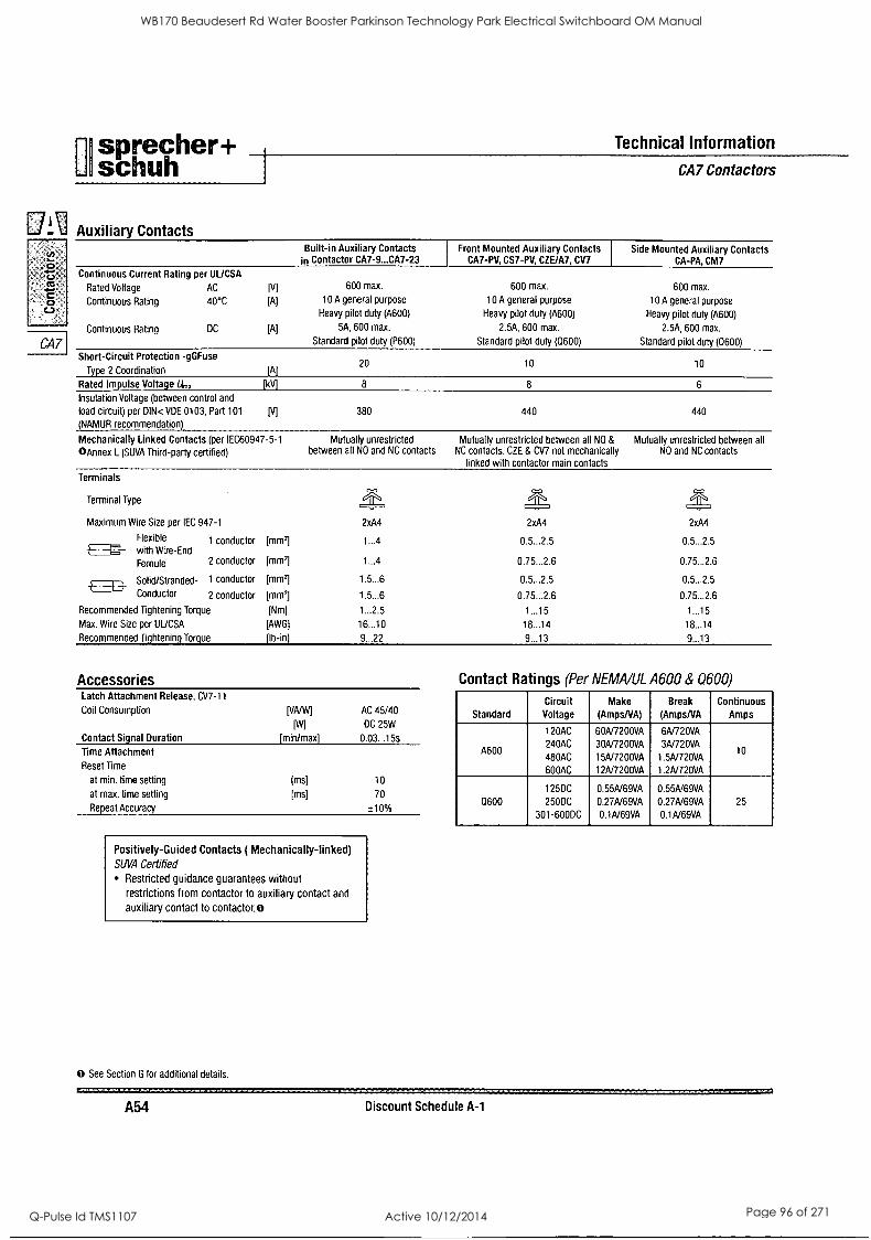
sprecher+ Technical Information
schuh
3 0111 .._ Auxiliary Contacts
CA7
Built-in Auxiliary Contacts in Contactor CA7-9...CA7-23
Continuous Current Rating per UUCSA
Rated Voltage AC
Continuous Rating 40°C
Continuous Rating
[A)
DC [A)
600 max.
10 A general purpose
Heavy pilot duty (A600)
5A, 600 max.
Standard pilot duty (P600)
Front Mounted Auxiliary Contacts CA7-PV, CS7-PV, CZE/A7, CV7
600 max.
10 A general purpose
Heavy pilot duty (A600)
2.5A, 600 max.
Standard pilot duty (0600)
CA7 Contactors
Side Mounted Auxiliary Contacts CA-PA, CM7
600 max.
10 A general purpose
Heavy pilot duty (A600)
2.5A, 600 max.
Standard pilot duty (0600)
Short-Circuit Protection -gGFuse
Type 2 Coordination
Rated Impulse Voltage U., Insulation Voltage (between control and
load circuit) per DIN< VDE 0103, Part 101
(NAMUR recommendation)
Mechanically Linked Contacts (per IEC60947-5-1
()Annex L (SUVA Third-party certified)
LA] 20 10 10
8 8 6
IV] 380 440 440
Mutually unrestricted between all NO and NC contacts
Mutually unrestricted between all NO & Mutually unrestricted between all NC contacts. CZE & CV7 not mechanically NO and NC contacts
linked with contactor main contacts
Terminals
Terminal Type
Maximum Wire Size per IEC 947-1 2xA4 2xA4 2xA4
Flexible 1 conductor
with Wire-End [mm'] 1...4 0.5...2.5 0.5...2.5
Fernule 2 conductor [mm,] 1...4 0.75...2.6 0.75...2.6
Solid /Stranded- 1 conductor [mm2] 1.5...6 0.5...2.5 0.5...2.5
Conductor 2 conductor [mm'] 1.5...6 0.75...2.6 0.75...2.6
Recommended Tightening Torque [Nm] 1...2.5 1...15 1...15
Max. Wire Size per UUCSA [AWG] 16...10 18...14 18...14
Recommended Tightening Torque [lb -inj 9...22 9...13 9...13
Accessories Latch Attachment Release, CV7-11
Coil Consumption
Contact Signal Duration
Time Attachment
Reset Time
at min. time setting
at max. time setting
Repeat Accuracy
PAM [W1
[min/max]
AC 45/40
DC 25W
0.03...15s
(ins]
Ems)
10
70
± 10%
Positively-Guided Contacts ( Mechanically-linked) SUVA Certified
Restricted guidance guarantees without restrictions from contactor to auxiliary contact and
auxiliary contact to contactor.0
0 See Section G for additional details.
Contact Ratings (Per NEMA/UL A600 & 0600)
Standard Circuit
Voltage Make
(AmpsNA) Break
(AmpsNA Continuous
Amps
A600
120AC
240AC
480AC
600AC
60A/7200VA
30A/7200VA
15A/7200VA
12A/7200VA
6A/720VA
3A/720VA
1.5A/720VA
1.2A/720VA
10
0600 125DC
250DC
301-600DC
0.55A/69VA
0.27A/69VA
0.1A/69VA
0.55A/69VA
0.27A/69VA
0.1A/69VA
25
A54 Discount Schedule A-1
WB170 Beaudesert Rd Water Booster Parkinson Technology Park Electrical Switchboard OM Manual
Q-Pulse Id TMS1107 Active 10/12/2014 Page 96 of 271
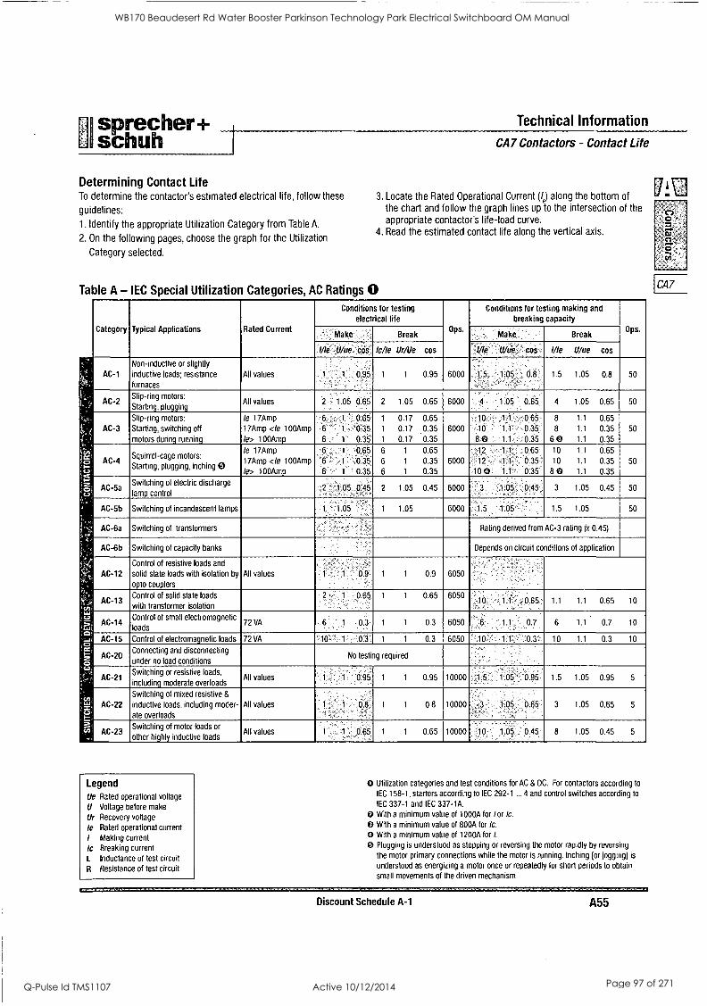
sprecher+ Technical Information
schuh CA7 Contactors - Contact Life
Determining Contact Life To determine the contactor's estimated electrical life, follow these
guidelines:
1. Identify the appropriate Utilization Category from Table A.
2. On the following pages, choose the graph for the Utilization
Category selected.
3. Locate the Rated Operational Current (/e) along the bottom of the chart and follow the graph lines up to the intersection of the appropriate contactor's life-load curve.
4. Read the estimated contact life along the vertical axis.
Table A - IEC Special Utilization Categories, AC Ratings 0
Category Typical Applications Rated Current
Conditions for testing electrical life
Ops .
Conditions for testing making and
breaking capacity Ops.
Make. :. Break ' Make., ' Break ,
1/le. ;Ulue_ cos. Ic/le Ur/Ue cos : I/le Uke cos, I/le U/ue cos
AC-1
Non-inductive or slightly
inductive loads; resistance furnaces
All values 1' 0.95 1 1 0.95 6000 ,
.,.
5 1,05 cf.s,. , --,
1.5 1.05 0.8 50
AC-2 Slip-ring motors:
Starting, plugging All values 2 - 1.05 0.65 2 1.05 0.65 6000
. ,...., ,
.1.05 0.65: 4 1.05 0.65 50
AC-3
, Slip-ring motors:
Starting, switching off
motors during running
le 17Amp
17Amp <le 100Amp
Ie> 100Amp
048 6 1 0.35
6 1 0.35
1 0.17 0.65
1 0.17 0.35
1 0.17 0.35
6000
. 10 1. 0.65: -10 .1.1. 9.35: .8.0 1.1 0.35
8 1.1 0.65
8 1.1 0.35
6 0 1.1 0.35
50
irc) .:5, c., IS =.
, ,::,,
, fJ
AC-4 Squirrel-cage motors:
Starting, plugging, inching
le 17Amp
17Amp <le 100Amp
le> 100Amp
0:65,
1 0.38 1 0.35
6 1 0.65
6 1 0.35
6 1 0.35
6000
..12 ,,1 1. 0.65"
12 - 1 1: 0:35
X- -10 0 1 0.35'
10 1.1 0.65
10 1.1 0.35
8 0 1.1 0.35
50
AC-5a lamp control
Switching of electric discharge 2 1 05 0,45 2 1.05 0A5 6000 ::1:05 0:45,, 3 1.05 0.45 50
AC-5b Switching of incandescent lamps 1 1 05 1 1.05 6000. 1.5 .1:05'. 1.5 1.05 50
AC-6a Switching of transformers Rating derived from AC-3 rating (x 0.45)
AC-6b Switching of capacity banks Depends on circuit conditions of application
AC-12
Control of resistive loads and
solid state loads with isolation by
opto couplers
All values 1 1 0 9 1 1 0.9 6050
AC-13 Control of solid state loads
with transformer isolation
1 0.65 1 1 0.65 6050 - - -
.10'. -.1.1.. 0.65_, 1.1 1.1 0.65 10
c_a
'.. AC-14 5 Control of small electromagnetic loads
72 VA
.
0.3 1 1 0.3 6050 G .1.1 0.7 6 1.1 0.7 10
cp ' -it ,'- 22.
2 '
AC-15 Control of electromagnetic loads 72 VA 10 1 ..0.3:. 1 1 0.3 6050 1 0.3: 10 1.1 0.3 10
AC-20 Connecting and disconnecting
under no load conditions No testing required
AC-21 Switching or resistive loads,
including moderate overloads All values
,-,
1 0.95 1 1 0.95 10000 .1 5 . .1.05 . 0.95. 1.5 1.05 0.95 5
cn, I" ' AC-22 x" c., =
Switching of mixed resistive &
inductive loads, including moder-
ate overloads
All values 1 0.8: 1 1 0.8 10000 1.05. 0 65 3 1.05 0.65 5
3. 41) AC-23
..,
Switching of motor loads or
other highly inductive loads All values 1 1 0.65 1 1 0.65 10000 10 1.05. 0.45 - 8 1.05 0.45 5
Legend Ue Rated operational voltage
U Voltage before make
Ur Recovery voltage
be Rated operational current
I Making current
Ic Breaking current
1. Inductance of test circuit
R Resistance of test circuit
O Utilization categories and test conditions for AC & DC. For contactors according to
IEC 158-1, starters according to IEC 292-1 ... 4 and control switches according to
IEC 337-1 and IEC 337-1A. With a minimum value of 1000A for /or lc.
0 With a minimum value of 800A for Ic.
0 With a minimum value of 1200A for I.
0 Plugging is understood as stopping or reversing the motor rapidly by reversing
the motor primary connections while the motor is running. Inching [or jogging] is
understood as energizing a motor once or repeatedly for short periods to obtain
small movements of the driven mechanism.
Discount Schedule A-1 A55
CA7
WB170 Beaudesert Rd Water Booster Parkinson Technology Park Electrical Switchboard OM Manual
Q-Pulse Id TMS1107 Active 10/12/2014 Page 97 of 271
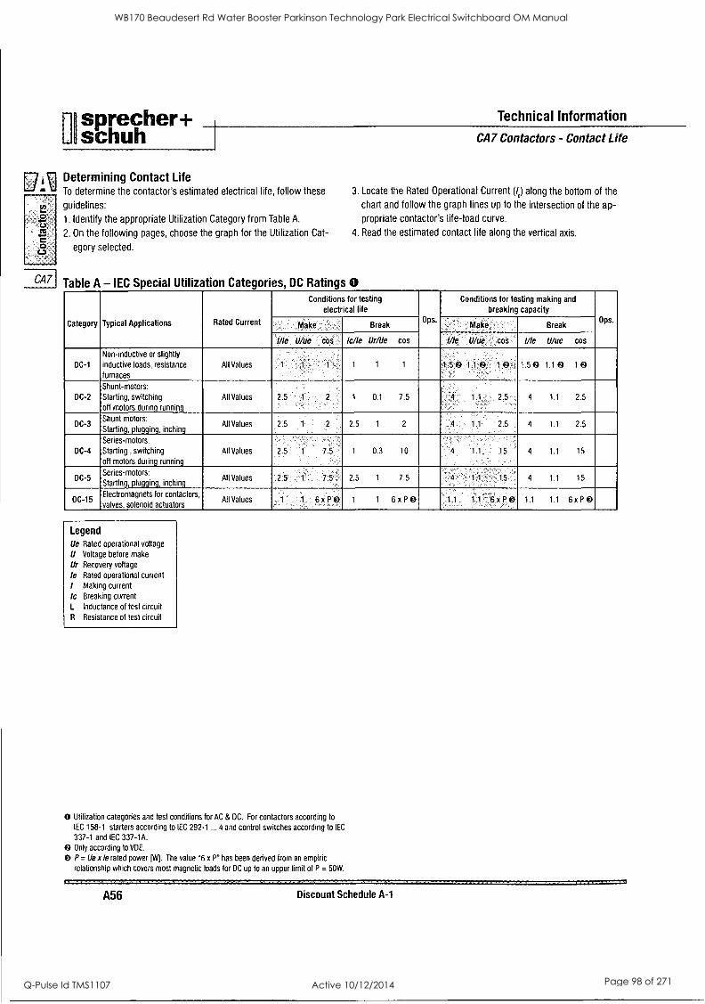
sprecher+ Technical Information
schuh CA7 Contactors - Contact Life
0 C6
,
.0
0
Determining Contact Life To determine the contactor's estimated electrical life, follow these
guidelines:
1. Identify the appropriate Utilization Category from Table A.
2. On the following pages, choose the graph for the Utilization Cat-
egory selected.
3. Locate the Rated Operational Current (/d along the bottom of the
chart and follow the graph lines up to the intersection of the ap-
propriate contactor's life-load curve.
4. Read the estimated contact life along the vertical axis.
CA7 Table A - IEC Special Utilization Categories, DC Ratings 0
Category Typical Applications Rated Current
Conditions for testing electrical life
Ups.
Conditions for testing making and
breaking capacity Ops. tilke ' Break ' . Make Break
I/le U/ue cos lc/le Ur/Ue cos /// U/ue cos 1/le Ulue cos
DC-1
Non-inductive or slightly
inductive loads, resistance
furnaces
All Values 1 1 1 1 1 1 1:5 0 1.1 0 1 0 ..
1.5 0 1.1 0 10
DC-2
Shunt-motors: Starting, switching off motors during running
All Values 2.5 T 2 1 0.1 7.5 1.1.:... 2.5.. 4 1.1 2.5
DC-3 Shunt motors:
Starting, plugging, inching All Values 2:5 1. 2,5 1 2 1.1 2.5 , 4 1.1 2.5
DC-4
Series-motors:
Starting , switching
off motors during running
All Values 2.5 ' 1 7.5 1 0.3 10 1 15 ' 4 1.1 15
DC-5 Series-motors: Starting, plugging, inching
All Values : 2.5 5 . . 2.5 1 7.5 4 11 15 4 1.1 15
DC-15 Electromagnets for contactors,
valves, solenoid actuators All Values 1 1. 6.x po 1 1 6 xP 0 , 11 11 - 6 x P0 1.1 1.1 6x P
Legend Ue Rated operational voltage
U Voltage before make
Ur Recovery voltage
le Rated operational current
/ Making current
lc Breaking current L Inductance of test circuit
R Resistance of test circuit
0 Utilization categories and test conditions for AC & DC. For contactors according to
IEC 158-1, starters according to IEC 292-1 ... 4 and control switches according to IEC
337-1 and (EC 337-1A.
0 Only according to VDE.
P= Ue x le rated power K. The value "6 x P" has been derived from an empiric
relationship which covers most magnetic loads for DC up to an upper limit of P = 50W.
A56 Discount Schedule A-1
WB170 Beaudesert Rd Water Booster Parkinson Technology Park Electrical Switchboard OM Manual
Q-Pulse Id TMS1107 Active 10/12/2014 Page 98 of 271
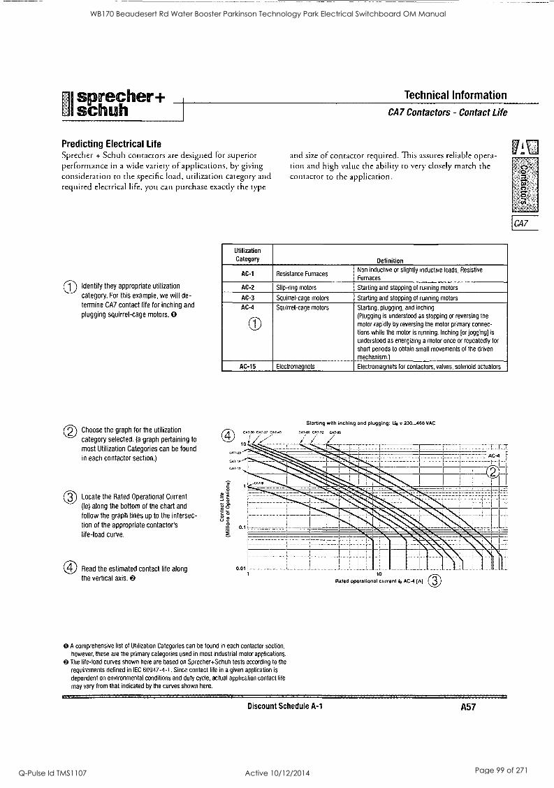
sprecher + Technical Information
UI schuh CA7 Contactors - Contact Life
Predicting Electrical Life Sprecher + Schuh contactors are designed for superior performance in a wide variety of applications, by giving consideration to the specific load, utilization category arid required electrical life, you can purchase exactly the type
(--1) Identify they appropriate utilization
category. For this example, we will de-
termine CA7 contact life for inching and
plugging squirrel-cage motors. 0
and size of contactor required. This assures reliable opera- tion and high value the ability to very closely match the contactor to the application.
Utilization Category Definition
AC-1 Resistance Furnaces Non inductive or slightly inductive loads, Resistive
Furnaces
AC-2 Slip-ring motors Starting and stopping of running motors
AC-3 Squirrel-cage motors Starting and stopping of running motors
AC-4
Lis',..._
Squirrel-cage motors Starting, plugging, and inching
(Plugging is understood as stopping or reversing the
motor rapidly by reversing the motor primary connec-
tions while the motor is running. Inching [or jogging] is
understood as energizing a motor once or repeatedly for
short periods to obtain small movements of the driven
mechanism.)
AC-15 Electromagnets Electromagnets for contactors, valves, solenoid actuators
© Choose the graph for the utilization
category selected. (a graph pertaining to
most Utilization Categories can be found
in each contactor section.)
Locate the Rated Operational Current
(le) along the bottom of the chart and
follow the graph lines up to the intersec-
tion of the appropriate contactor's
life-load curve.
Read the estimated contact life along
the vertical axis.
Starting with inching and plugging; tie = 230...460 VAC
CAJ CA772 CA785
11 a g
= 2
0 A comprehensive list of Utilization Categories can be found in each contactor section,
however, these are the primary categories used in most industrial motor applications. The life-load curves shown here are based on Sprecher+Schuh tests according to the
requirements defined in IEC 60947-4-1. Since contact life in a given application is
dependent on environmental conditions and duty cycle, actual application contact life
may vary from that indicated by the curves shown here.
10
Rated operational current le AC-4 (Al (3)
Discount Schedule A-1 A57
CA7
WB170 Beaudesert Rd Water Booster Parkinson Technology Park Electrical Switchboard OM Manual
Q-Pulse Id TMS1107 Active 10/12/2014 Page 99 of 271
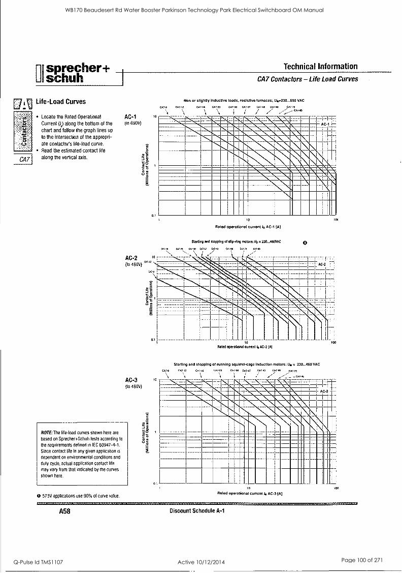
F1 sprecher+ Li schuh CA7
Technical Information
Contactors - Life Load Curves
TU Life-Load Curves
e
03
0 C.3
CA7
Locate the Rated Operational
Current (le) along the bottom of the
chart and follow the graph lines up
to the intersection of the appropri-
ate contactors life-load curve.
Read the estimated contact life
along the vertical axis.
AC-1 (to 690V)
0
Uo "6 0
(a
10
0.1
CA7.9 CA7,2
Non or slightly Inductive loads, resistive furnaces; Ue.230...690 VAC
CA7-03 CA7-23 CA730 CA7-37
r \
CA7-43 C4740 CA7.72
, 1-- -11 .b6..
INS=911. 'VMISMNZOIL. 114 NM241 n lat.
wli ' Il
10
Rated operational current le AC-1 [A]
Starting and stopping of slip-ring motors; Ue = 230...460VAC
CV -IA 07.23 CAI 061.37 07-43 CA7-60 01.72 01.$5
0
tot-
AC-3 (lo 460V)
NOTE: The life-load curves shown here are
based on Sprecher+Schuh tests according to
the requirements defined in IEC 60947-4-1.
Since contact life in any given application is
dependent on environmental conditions and
duty cycle, actual application contact life
may vary from that indicated by the curves
shown here.
0 575V applications use 90% of curve value.
10
Rated operational curve t ie AC 2 [A]
Starting and stopping of running squirrel-cage induction motors; Ue = 230...460 VAC
CA7.0 007.12 CA, 6
0.1
047.23 CA -40 Cm." 001 -43 00740 0074,
r
1-0%1A AC-3
U
10
Rated operationa current to AC-3 [A]
A58 Discount Schedule A-1
WB170 Beaudesert Rd Water Booster Parkinson Technology Park Electrical Switchboard OM Manual
Q-Pulse Id TMS1107 Active 10/12/2014 Page 100 of 271
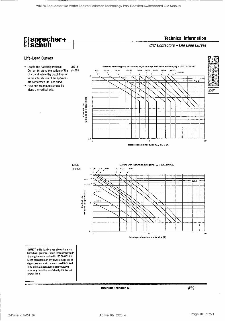
sprecher+ Technical Information
I schuh I CA7 Contactors - Life Load Curves
Life-Load Curves
Locate the Rated Operational
Current (e) along the bottom of the
chart and follow the graph lines up
to the intersection of the appropri-
ate contactor's life-load curve.
Read the estimated contact life
along the vertical axis.
AC-3 Starting and stopping of running squirrel-cage induction motors; Lie = 500...575V AC
(to 575)
AC-4 (to 69011)
NOTE: The life-load curves shown here are
based on Sprecher+Schuh tests according to
the requirements defined in IEC 60947-4-1.
Since contact life in any given application is
dependent on environmental conditions and
duty cycle, actual application contact life
may vary from that indicated by the curves
shown here.
0, C 2
411C! 2), to
c o o a/ (.7
10
0,1
CA7-9 CA7-12 CA7.16 CA7.23 CM-30 CA7-37 CA7-43 CA7-60 CA7.72 _,-CA7-85
AC-3
CA7
10
Rated operational current /e AC-3 [A]
Starting with inching and plugging; Ue = 230...690VAC
ca/-42 Cfy-91
100
10
Rated operational current le AC-4 [A]
100
Discount Schedule A-1 A59
WB170 Beaudesert Rd Water Booster Parkinson Technology Park Electrical Switchboard OM Manual
Q-Pulse Id TMS1107 Active 10/12/2014 Page 101 of 271
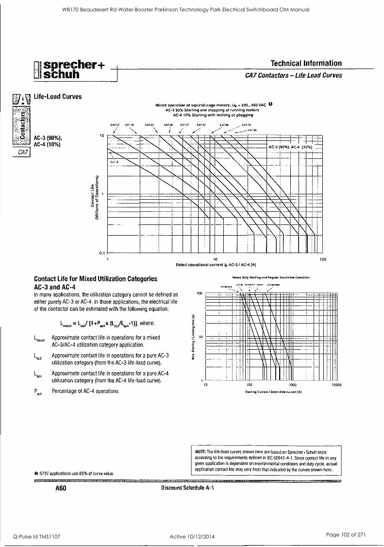
I sprecher+ Technical Information
schuh I CA7 Contactors - Life Load Curves
DAi Life-Load Curves
0.
O rJ
CA7
AC-3 (90%), AC-4 (10%)
Mixed operation of squirrel-cage motors; Ue = 230...460 VAC 0 AC-3 90% Starting and stopping of running motors
AC-4 10% Starting with inching or plugging
CA7 -12 CA7 16 CA7.23 CA7-30, CA7 37 CA7-13 CA7-60 CA7 72
CA7-85
10
0.1
AC-3 (90%), AC-4 (10%)
witreak.mqk NEIIMAISik
10
Rated operational current ie AC-3 / AC-4 (A]
Contact Life for Mixed Utilization Categories AC-3 and AC-4 In many applications, the utilization category cannot be defined as
either purely AC-3 or AC-4. In those applications, the electrical life
of the contactor can be estimated with the following equation:
Lmixed = Lad [1+13,4x (1.3/L444 1)]. where:
Lmixed Approximate contact life in operations for a mixed
AC-3/AC-4 utilization category application.
Lan Approximate contact life in operations for a pure AC-3
utilization category (from the AC-3 life-load curve).
L1,4 Approximate contact life in operations for a pure AC-4
utilization category (from the AC-4 life-load curve).
Paca Percentage of AC-4 operations
0 575V applications use 85% of curve value.
100
Heavy Duty Starting and Regular Short-time Operation
CA740.37 C4740.72.1 CAT4/12/16 \
100
MIIMMA 1111MINNIMMIIIIINMIM rr4rukiayakz=iglrr....== IMIIMME111111111111111=111111111111=1111111111111111011
MM111111111M1=11111111111111111111111111111EMMI
1 MininirnMINMIUMMIL'Es MUM
10 100 1000
Starting Current / Short-time current (A)
0000
NOTE: The life-load curves shown here are based on Sprecher+Schuh tests according to the requirements defined in IEC 60947-4-1. Since contact life in any
given application is dependent on environmental conditions and duty cycle, actual application contact life may vary from that indicated by the curves shown here.
A60 Discount Schedule A-1
WB170 Beaudesert Rd Water Booster Parkinson Technology Park Electrical Switchboard OM Manual
Q-Pulse Id TMS1107 Active 10/12/2014 Page 102 of 271
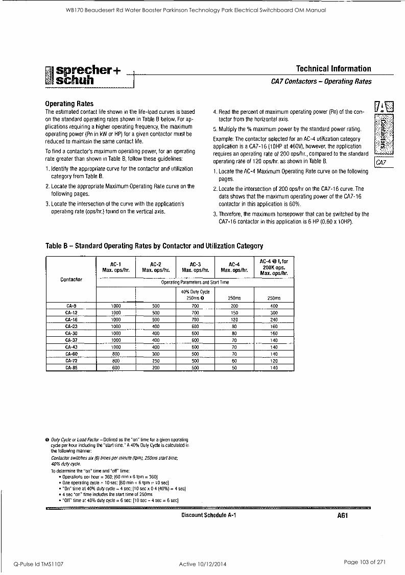
sprecher+ Technical Information
L schuh 1 CA7 Contactors - Operating Rates
Operating Rates The estimated contact life shown in the life-load curves is based
on the standard operating rates shown in Table B below. For ap-
plications requiring a higher operating frequency, the maximum
operating power (Pn in kW or HP) for a given contactor must be
reduced to maintain the same contact life.
To find a contactor's maximum operating power, for an operating
rate greater than shown in Table B, follow these guidelines:
1. Identify the appropriate curve for the contactor and utilization
category from Table B.
2. Locate the appropriate Maximum Operating Rate curve on the
following pages.
3. Locate the intersection of the curve with the application's operating rate (ops/hr.) found on the vertical axis.
4. Read the percent of maximum operating power (Pn) of the con-
tactor from the horizontal axis.
5. Multiply the % maximum power by the standard power rating.
Example: The contactor selected for an AC-4 utilization category
application is a CA7-16 (10HP at 460V), however, the application
requires an operating rate of 200 ops/hr., compared to the standard
operating rate of 120 ops/hr. as shown in Table B.
1. Locate the AC-4 Maximum Operating Rate curve on the following
pages.
2. Locate the intersection of 200 ops/hr on the CA7-16 curve. The
data shows that the maximum operating power of the CA7-16
contactor in this application is 60%.
3. Therefore, the maximum horsepower that can be switched by the
CA7-16 contactor in this application is 6 HP (0.60 x 10HP).
Table B - Standard Operating Rates by Contactor and Utilization Category
Contactor
AC-1 Max. ops/hr.
AC-2 Max. ops/hr.
AC-3 Max. ops/hr.
AC-4 Max. ops/hr.
@I AC -4 le for 200K ops.
Max. ops/hr.
Operating Parameters and Start Time
40% Duty Cycle
250ms 0 250ms 250ms
CA-9 1000 500 700 200 400
CA-12 1000 500 700 150 300
CA-16 1000 500 700 120 240
CA-23 1000 400 600 80 160
CA-30 1000 400 600 80 160
CA-37 1000 400 600 70 140
CA-43 1000 400 600 70 140
CA-60 800 300 500 70 140
CA-72 800 250 500 60 120
CA-85 600 200 500 50 140
0 Duty Cycle or Load Factor -Defined as the "on" time for a given operating
cycle per hour including the "start time." A 40% Duty Cycle is calculated in
the following manner:
Contactor switches six (6) times per minute (tpm), 250ms start time;
40% duty cycle.
To determine the "on" time and "off" time: Operations per hour = 360; [60 min x 6 tpm = 360]
One operating cycle = 10 sec; [60 min ÷ 6 tpm = 10 sec]
"On" time at 40% duty cycle = 4 sec; [10 sec x 0.4 (40%) = 4 sec]
4 sec "on" time includes the start time of 250ms
"Off" time at 40% duty cycle = 6 sec; DO sec -4 sec = 6 sec]
Discount Schedule A-1 A61
[PO 0 -S
WB170 Beaudesert Rd Water Booster Parkinson Technology Park Electrical Switchboard OM Manual
Q-Pulse Id TMS1107 Active 10/12/2014 Page 103 of 271
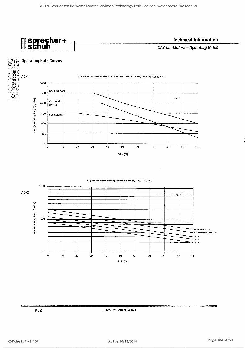
sprecher+ Technical Information
schuh I CA7 Contactors - Operating Rates
1-7 1-1 Operating Rate Curves U
0 AC-1
CO
c.,
CA7
AC-2
3000
2500
2000
1500
1000
500
Non or slightly inductive loads, resistance furnaces; Ue = 230...690 VAC
3
0
0
10000
1000
100
10 20 30 40 50 60 70 80 90 100
P/Pn [%]
Slip-ring motors: starting. switching off; Ue = 230...460 VAC
0 10 20 30 40 50
P/Pn [%1
60 70 80 90
CA7V,7. INCA7,4
CA7.,N0A7 N0CA7.37CA74]
C, 00
047.72
CA7 46
100
A62 Discount Schedule A-1
WB170 Beaudesert Rd Water Booster Parkinson Technology Park Electrical Switchboard OM Manual
Q-Pulse Id TMS1107 Active 10/12/2014 Page 104 of 271
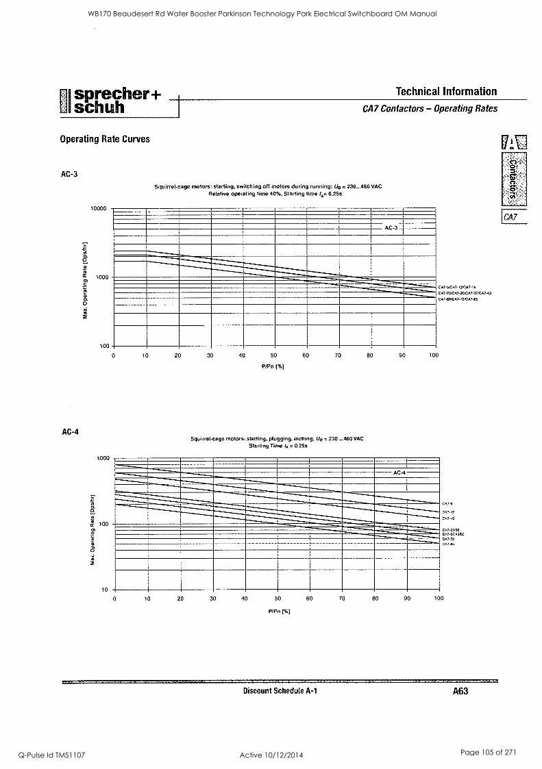
sprecher+ I schuh
Operating Rate Curves
AC-3
AC-4
10000
1000
Technical Information
CA7 Contactors - Operating Rates
Squirrel-cage motors: starting, switching off motors during running; U8 = 230...460 VAC Relative operating time 40%, Starting time IA= 0.25s
AC 3
100
0
CA7 VCA7 12/CA7,6
CA7-23:CA7-30/CA7-37:CA7-43
CA760/CA7-72,CA725
10 20 30 40 50 60 70 80 90 100
P/Pn (%)
Squirrel-cage motors: starting, plugging, inching; U8 = 230 ...460 VAC
Starting Time 4, = 0.25$
CA7 23,20 CA7-37:43,60
CA7-72
CA7-85
Discount Schedule A-1 A63
ova
CA7
WB170 Beaudesert Rd Water Booster Parkinson Technology Park Electrical Switchboard OM Manual
Q-Pulse Id TMS1107 Active 10/12/2014 Page 105 of 271
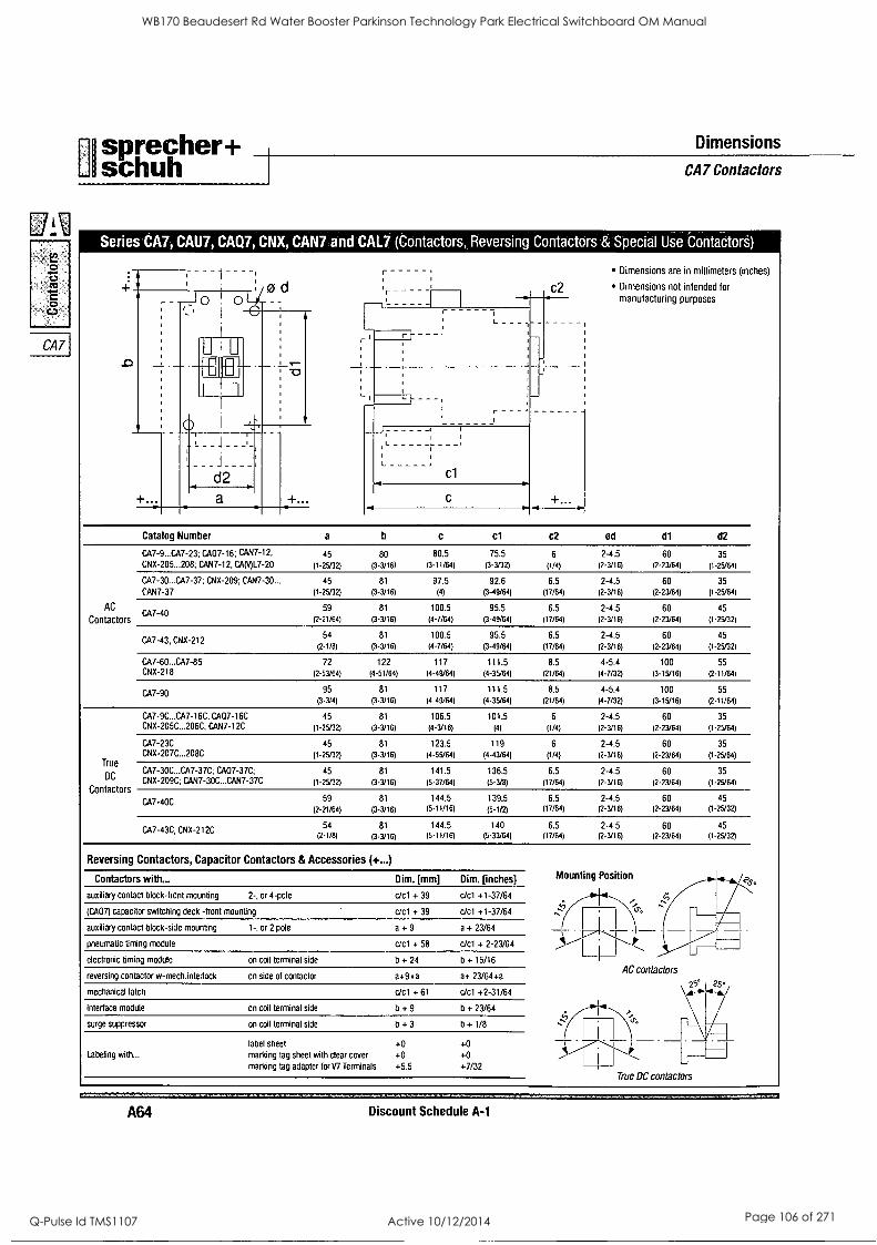
CA7
sprecher+ Dimensions
schuh I CA7 Contactors
Series CA7, CAU7, I CAQ7 CNX, CANTand CAL7 (Contactors, Reversing Contactors & Special Use Contactors)
Dimensions are in millimeters (inches) 1 '
:-
' , ,, Dimensions not intended for
- - ._ 0 . 0 - manufacturing purposes
',- ' :
-1
,
,
I
, firm
+...
0
,
L _ _ 4 ___,_,
d2
1
,
c1
a c
Catalog Number a b c cl c2 od dl d2
CA7-9...CA7-23; CA07-16; CAN7-12, 45 80 80.5 75.5 6 2-4.5 60 35
CNX-205...208; CAN7-12, CA(147-20 (1-25/32) (3-3/16) (3-11/64) (3-3/32) (1/4) (2-3/16) (2-23/64) (1-25/64)
CA7-30...CA7-37; CNX-209; CAN7-30... 45 81 97.5 92.6 6.5 2-4.5 60 35
CAN7-37 (1-25/32) (3-3/16) (4) (3-49/64) (17/64) (2-3/16) (2-23/64) (1-25/64)
AC CA7
59 81 100.5 95.5 6.5 2-4.5 60 45 -40
Contactors (2-21/64) (3-3/16) (4-7/64) (3-49/64) (17/64) (2-3/16) (2-23/64) (1-25/32)
54 81 100.5 95.5 6.5 2-4.5 60 45 CA7-43, CNX-212
(2-1/8) (3-3/16) (4-7/64) (3-49/64) (17/64) (2-3/16) (2-23/64) (1-25/32)
CA7-60...CA7-85 72 122 117 111.5 8.5 4-5.4 100 55 CNX-218 (2-53/64) (4-51/64) (4-49/64) (4-35/64) (21/64) (4-7/32) (3-15/16) (2-11/64)
CA7-90 95 81 117 111.5 8.5 4-5.4 100 55
(3-3/4) (3-3/16) (4-49/64) (4-35/64) (21/64) (4-7/32) (3-15/16) (2-11/64)
CA7-9C...CA7-16C, CA07-16C 45 81 106.5 101.5 6 2-4.5 60 35 CNX-205C...206C; CAN7-12C (1-25/32) (3-3/16) (4-3/16) (4) (1/4) (2-3/16) (2-23/64) (1-25/64)
CA7-23C 45 81 123.5 119 6 2-4.5 60 35 CNX-207C...208C (1-25/32) (3-3/16) (4-55/64) (4-43/64) (1/4) (2-3/16) (2-23/64) (1-25/64) - - True CA7-30C...CA7-37C: CA07-37C; 45 81 141.5 136.5 6.5 2-4.5 60 35
DC CNX-209C; CAN7-30C...CAN7-37C (1-25/32) (3-3/16) (5-37/64) (5-3/8) (17/64) (2-3/16) (2-23/64) (1-25/64) Contactors
CA7-40C 59 81 144.5 139.5 6.5 2-4.5 60 45
(2-21/64) (3-3/16) (5-11/16) (5-1/2) (17/64) (2-3/16) (2-23/64) (1-25/32)
54 81 144.5 140 6.5 2-4.5 60 45 CA7-430 CNX-212C (2-1/8) (3-3/16) (5-11/16) (5-33/64) (17/64) (2-3/16) (2-23/64) (1-25/32)
Reversing Contactors, Capacitor Contactors & Accessories (+...)
Contactors with... Dim. [mm] Dim. [inches] Mounting Position
ii41
.
auxiliary contact block-front mounting 2-, or 4-pole c/c1 + 39 c/c1 +1-37/64
(CA07) capacitor switching deck -front mounting c/c1 + 39 c/c1 +1-37/64
I .
I
auxiliary contact block-side mounting 1-, or 2 pole a + 9 a + 23/64 T. - _ _ _
pneumatic timing module c/c1 + 58 c/c1 + 2-23/64 i . . - - - - - 7-'-----...1 , LI_1
electronic timing module on coil terminal side b + 24 b + 15/16
reversing contactor w-mechinterlock on side of contactor a+9+a a+ 23/64+a AC contactors
95° mechanical latch c/c1 + 61 c/c1 +2-31/64 \ --s-4.-&,/
25°
=1
interface module on coil terminal side b + 9 b + 23/64
surge suppressor on coil terminal side b + 3 b + 1/8
label sheet +0 +0 13,..-- Labeling with... marking tag sheet with clear cover +0 +0
-----,y-
1----r marking tag adapter for V7 Terminals +5.5 +7/32 True DC contactors
AM Discount Schedule A-1
WB170 Beaudesert Rd Water Booster Parkinson Technology Park Electrical Switchboard OM Manual
Q-Pulse Id TMS1107 Active 10/12/2014 Page 106 of 271
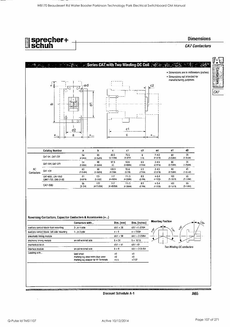
01 sprecher+ schuh
Dimensions
,Series CA7'with Two Winding,DC Coil
CA7 Contactors
Dimensions are in millimeters (inches)
Dimensions not intended for
manufacturing purposes :
-I: , 1 '
: Ø d , c2 I _ o o
,
- _
+.
-
r
.
1 I
0 I -4-,
MEI
+.
d2 cl
a c ___r. ...r......
Catalog Number a b c cl c2 ad di d2
CA7-9Y...CA7-23Y 54 90 80.5 75.5 6 2-4.5 60 35
(2-9/64) (3-35/64) (3-11/64) (3-3/32) (1/4) (2-3/16) (2-23/64) (1- 25/64)
CA7-30Y, CA7-37Y 54 90 97.5 92.6 6.5 2-4.5 60 35
(2-9/64) (3-35/64) (4) (3-49/64) (17/64) (2-3/16) (2-23/64) (1- 25/64)
AC CA7-43Y
63 90 100.5 95.6 6.5 2-4.5 60 45
Contactors (2-31/64) (3-35764) (4-7/64) (3-7/8) (17/64) (2-3/16) (2-23/64) (1- 25,32)
CA7-600...CA7-85D 81 131 117 111.5 8.5 4-5.4 100 55
CAN7-72D, CNX-218D (3-3/16) (5-5/32) (4- 49/64) (4-35/64) (21/6.4) (4-7/32) (3-15/16) (2-11/64)
95 122 117 111.5 8.5 4-5.4 100 55 CA7-90D (3-3/4) (4-51/64) (4-49/64) (4-35/64) (21/64) (4-7/32) (3-15/16) (2-11/64)
Reversing Contactors, Capacitor Contactors & Accessories (+...)
Contactors with... Dim. [mm] Dim. [inches] Mounting Position -
auxiliary contact block-front mounting 2-, or 4-pole c/c1 + 39 c/c1 +1-37/64 0-4
auxiliary contact block- left side mounting 1-, or 2 pole a + 9 a + 23/64
pneumatic timing module c/c1 + 58 c/c1 + 2-23/64 1 ii _....----r---.1,_" 1
Ill. electronic timing module on coil terminal side b + 24 b + 15/16 L__I_I b mechanical latch c/c1 + 61 c/c1 +61
interface module on coil terminal side b + 9 c/cl + 2-31/64 Two Winding DC contactors
Labeling with... label sheet +0 +0
marking tag sheet with clear cover +0 +0 marking tag adapter for W Terminals +5.5 +7/32
Discount Schedule A-1 A65
oja
en-
CA7
WB170 Beaudesert Rd Water Booster Parkinson Technology Park Electrical Switchboard OM Manual
Q-Pulse Id TMS1107 Active 10/12/2014 Page 107 of 271
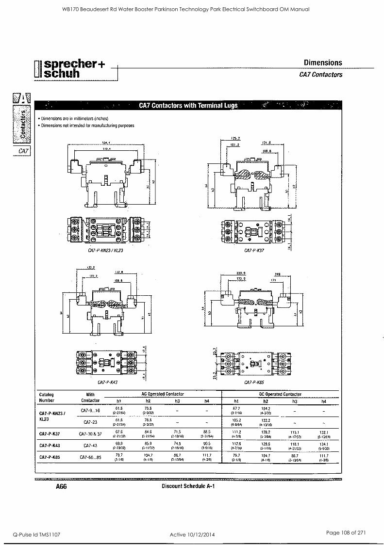
Cn
0
CCS
0
CA7
Ul sprecher+ Dimensions
schuh I CA7 Contactors
CA7 Contactors with Termiiial
Dimensions are in millimeters (inches)
Dimensions not intended for manufacturing purposes
CA7-P-KN23 / KL23
125.2
!I:o _....0 oi
* to 0 - oil CA7-P-K37
CA7-P-K85
Catalog
Number With AC Operated Contactor DC Operated Contactor
Contactor hi h2 h3 h4 ht h2 h3 h4
CA7-9...16 61.6 78.6 87.2 104.2 - -
CA7-P-KN23 / (2-27/64) (3-3/32) (3-7/16) (4-3/32)
KL23 CA7-23
61.6 (2-27/64)
78.6 (3-3/32) - 105.2
(4-9/64)
122.2 (4-13/16) - -
CA7-P-K37 CA7-30 & 37 67.6 84.6 71.5 88.5 111.2 128.2 115.1 132.1
(2-21/32) (3-21/64) (2-13/16) (3-31/64) (4-3/8) (5-3/64) (4-17/32) (5-13/64)
69.0 85.0 74.5 90.5 112.6 128.6 118.1 134.1 CA7-P-K43 CA7-43 (2-23/32) (3-11/32) (2-15/16) (3-9/16) (4-7/16) (5-1/16) (4-21/32) (5-9/32)
79.7 104.7 86.7 111.7 79.7 104.7 86.7 111.7 CA7-P-K85 CA7-60...85 (3-1/8) (4 -1 /8) (3-13/64) (4-3/8) (3-1/8) (4-1/8) (3-13/64) (4-3/8)
A66 Discount Schedule A-1
WB170 Beaudesert Rd Water Booster Parkinson Technology Park Electrical Switchboard OM Manual
Q-Pulse Id TMS1107 Active 10/12/2014 Page 108 of 271
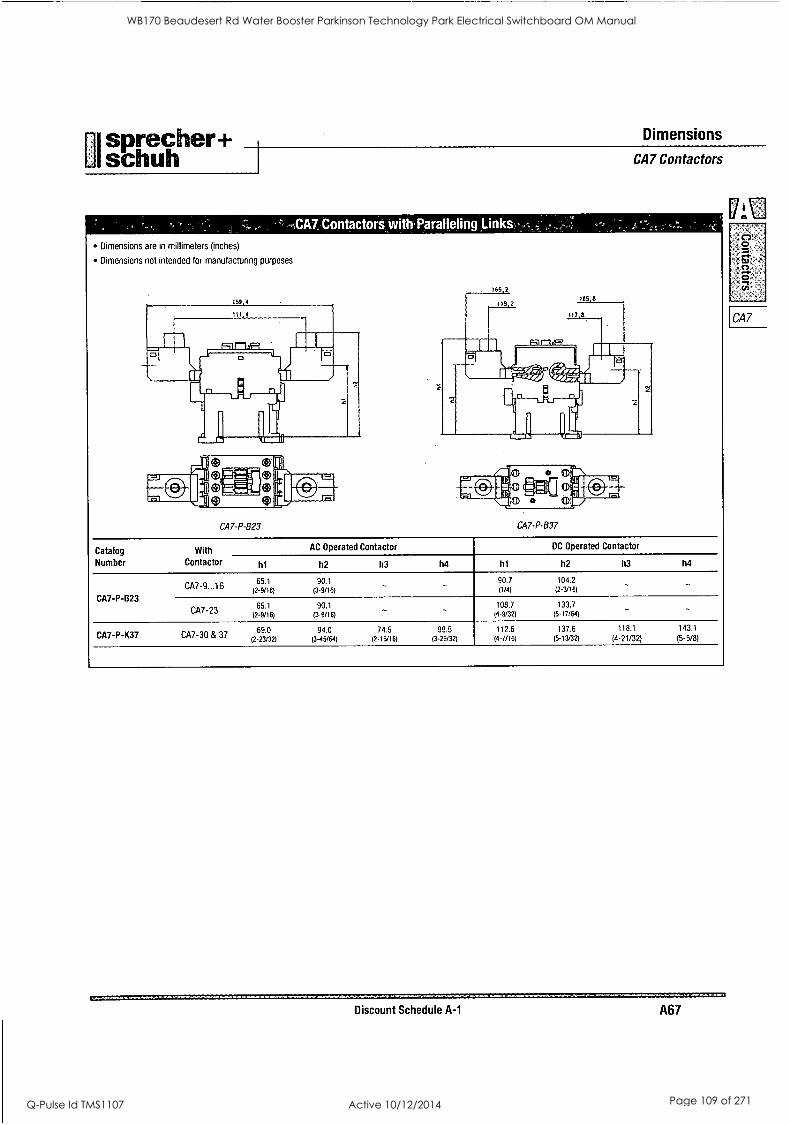
sprecher+ Dimensions
UIschuh I CA7 Contactors
ontactors,with Paralleling Links
Dimensions are in millimeters (inches)
Dimensions not intended for manufacturing purposes
CA7-P-B23 CA7-P-B37
Catalog With Number Contactor
AC Operated Contactor DC Operated Contactor
CA7-P-B23
CA7-9...16
CA7-23
CA7-P-K37 CA7-30 & 37
111 h2
65.1 90.1
(2-9/16) (3.9/16)
65.1 90.1 (2-9/16) (3-9/16)
69.0 94.0 12-23/321 (3-45/64)
h3 h4 ht h2 h3 h4
90.7 (1/4)
104.2 (2-3/16)
108.7 133.7 (4-9/32) (5-17/64)
74.5 99.5 112.6 137.6 118.1 143.1
(2-15/16) (3-29/32) (4-7/16) (5-13/32) (4-21/32) (5-5/8)
Discount Schedule A-1 A67
WB170 Beaudesert Rd Water Booster Parkinson Technology Park Electrical Switchboard OM Manual
Q-Pulse Id TMS1107 Active 10/12/2014 Page 109 of 271
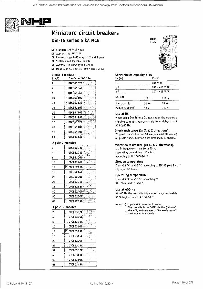
Miniature circuit breakers Din-T6 series 6 kA MCB
CI Standards AS/NZS 4898
D Approval No. N17481
CI Current range 2-63 Amps 1, 2 and 3 pole
Sealable and lockable handle
Cl Available in curve type C and D
Mounts on CD chassis (250 A and 355 A)
1 pole 1 module In (A) C - Curve 5-10 In
2
4
6
10
13
16
20
25
32
40
50
63
DTCB6102C
DTCB6104C
urct6lok
'DTCB6110C
DTCB6113C
DCB6116C
,DTCB6120C
DTCB6125C
iDTCB6132C
DTCB6140C
DTCB6150C, -
DTCB6163C
2 pole 2 modules
2
4
6
10
13
16
20
25
32
40
50
63
3 pole 3
2
4
6
10
13
16
20
25
32
40
50
63
DTC136202C
DTCB6204C
-DTCB6206C
DTCB6210C
DTCB6213C
DTCB6216C
DTC136220C
DTCB6225C
DTCB6232C
DTCB6240C
DTCB6250C
'DTC86263C
modules
DTCB6302C
DTCB6304C
DTCB6306C
DTCB6310C
DTCB6313C
DTCB6316C
DTCB6320C
DTCB6325C
DTCB6332C
DTCB6340C
DTCB6350C
DTCB6363C
ui
DTCB6
1 pole
Short circuit capacity 6 kA In (A) 2 - 63
1P
2P
3P
DC use
Short circuit
Max.voltage (DC)
1P
20 kA
48 V
240 V AC
240 - 415 V AC
240 - 415 V AC
2 P')
25 kA
110 V
Use at DC
When using Din-T6 in a DC application the magnetic
tripping current is approximately 40 % higher than in
AC 50/60 Hz.
Shock resistance (In X, Y, Z directions). 20 g with shock duration 10 ms (minimum 18 shocks).
40 g with shock duration 5 ms (minimum 18 shocks).
Vibration resistance (In X, Y, Z directions). 3 g in frequency range 10 to 55 Hz
(operating time at least 30 min).
According to IEC 60068-2-6.
Storage temperature From -55 °C to +55 °C, according to IEC 88 part 2 - 1
(duration 96 hours).
Operating temperature From -25 °C to +55 °C, according to
VDE 0664 parts 1 and 2.
Use at 400 Hz
At 400 Hz the magnetic trip current is approximately
50 % higher than in AC 50/60 Hz.
Notes: ') 2 pole MCB connected in series.
The line side is the "OFF" (bottom) side of the MCB, and connects to CD chassis tee-offs. Available on indent only.
WB170 Beaudesert Rd Water Booster Parkinson Technology Park Electrical Switchboard OM Manual
Q-Pulse Id TMS1107 Active 10/12/2014 Page 110 of 271

aInnovatory in Proteedom Technology TERASAK1
Din-T MCBs Technical data Characteristics according to BS EN 60898
Miniature Circuit Breakers are intended for the protection of Rated short-circuit breaking capacity (Icn) wiring installations against both overloads and short-circuits in Is the value of the short-circuit that the MCB is capable of domestic or commercial wiring installations where operation is withstanding in the following test of sequence of operations: possible by uninstructed people 0-t-CO.
Tripping characteristic curves
Magnetic release
An electromagnet with plunger ensures instantaneous tripping in
the event of short-circuit. The NHP Din-T range has 3 different types, following the current for instantaneous release: types B, C
and D curve.
Icn Test Tripping Applications (A) current time
B 3 x In 0.1<t<45 s (In<32 A) Only for resistive loads eg:
5 x In 0.1<t<90 s (In>32 A) electrical heating water heater
t<0.1 s stoves.
C 5 x In 0.1<t<15 s (In<32 A) Usual loads such as:
10 x In 0.1<t<30 s (In>32 A) lighting socket outlets
t<0.1 s small motors
D 10 x In 0.1<t<4 5(**) (In<32 A) Control and protection of
20 x In 0.1<t<8 s (In>32 A) circuits having important transient inrush currents
t<0.1 s (large motors)
Thermal release
The release is initiated by a bimetal strip in the event of overload. The standard defines the range of releases for specific overload values. Reference ambient temperature is 30 °C.
Test Tripping current time
1.13 x In t ? 1 h (In < 63 A)
t ? 2 h (In > 63 A)
1.45 x In t < 1 h (In < 63 A) t < 2 h (In > 63 A)
2.55 x In 1 s < t < 60 s (In < 32 A)
1 s < t < 120 s (In >32 A)
After the test the MCB is capable, without maintenance, to withstand a dielectric strength test at a test voltage of 900 V.
Moreover, the MCB shall be capable of tripping when loaded
with 2.8 In within the time corresponding to 2.55 In but greater than 0.1s.
Service short-circuit breaking capacity (Ics) Is the value of the short-circuit that the MCB is capable of withstanding in the following test of sequence of operations: 0-t-CO-t-CO.
After the test the MCB is capable, without maintenance, to withstand a dielectric strength test at a test voltage of 1500 V.
Moreover, the MCB shall not trip at a current of 0.96 In. The MCB
shall trip within lh when current is 1.6 In.
0 - Represents an opening operation
C - Represents a closing operation followed by an
automatic opening.
t - Represents the time interval between two successive
short-circuit operations: 3 minutes.
The relation between the rated short-circuit capacity (Icn) and the rated service short-circuit breaking capacity (Ics) shall be as follows:
Icn (A) Ics (A)
< 6000 6000
> 6000 < 10000
0.75 Icn min. 6000
> 10000 0.75 Icn min. 7500
In both sequences all MCBs are tested for emission of ionized gases during short-circuit (grid distance), in a safety distance between two MCBs of 35 mm when devices are installed in two different rows in the enclosure. This performance allows the use of any NHP/Terasaki enclosure.
WB170 Beaudesert Rd Water Booster Parkinson Technology Park Electrical Switchboard OM Manual
Q-Pulse Id TMS1107 Active 10/12/2014 Page 111 of 271
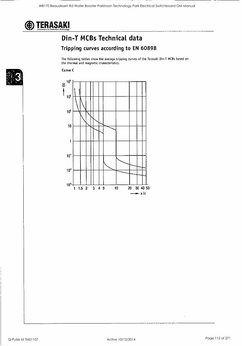
aInnovator., in Protection rethnoloR TERASAK1
Din-T MCBs Technical data
Tripping curves according to EN 60898
The following tables show the average tripping curves of the Terasaki Din-T MCBs based on
the thermal and magnetic characteristics.
Curve C
04
110'
102
10
1
104
104
104 1 1 5 2 3 4 5 10 20 30 40 50
x In
WB170 Beaudesert Rd Water Booster Parkinson Technology Park Electrical Switchboard OM Manual
Q-Pulse Id TMS1107 Active 10/12/2014 Page 112 of 271
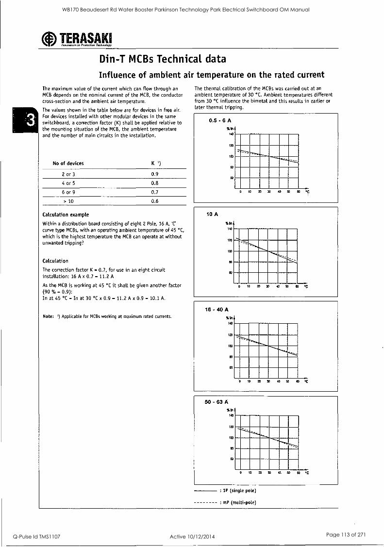
aInnovators in Protection Technoloxy TERASAKI
Din-T MCBs Technical data
Influence of ambient air temperature on the rated current
The maximum value of the current which can flow through an
MCB depends on the nominal current of the MCB, the conductor cross-section and the ambient air temperature.
The values shown in the table below are for devices in free air. For devices installed with other modular devices in the same
switchboard, a correction factor (K) shall be applied relative to the mounting situation of the MCB, the ambient temperature and the number of main circuits in the installation.
No of devices K ')
2 or 3 0.9
4 or 5 0.8
6 or 9 0.7
> 10 0.6
Calculation example
Within a distribution board consisting of eight 2 Pole, 16 A, 'C'
curve type MCBs, with an operating ambient temperature of 45 °C,
which is the highest temperature the MCB can operate at without unwanted tripping?
Calculation
The correction factor K - 0.7, for use in an eight circuit installation: 16 A x 0.7 - 11.2 A
As the MCB is working at 45 °C it shall be given another factor (90 0/0= 0.9): In at 45 °C = In at 30 °C x 0.9 = 11.2 A x 0.9 - 10.1 A.
Note: ') Applicable for MCBs working at maximum rated currents.
The thermal calibration of the MCBs was carried out at an
ambient temperature of 30 °C. Ambient temperatures different from 30 °C influence the bimetal and this results in earlier or later thermal tripping.
0.5 - 6 A
icin 140
120
- ICO
- - - - _
80
60
0 ID 20 30 40 50 60 ..0
10 A
% In
1443
i2D
ICO
60
60
0 la 20 30 40 50 eo %
16 - 40 A
1.ta I
140
120
1CO
CO
60
0 10 20 90 40 SO e0 7.-C
50 - 63 A
%In 140
120
103
03
eo
0 10 20 30 W. 50 So °C
:1P (single pole)
: mP (multi -pole)
WB170 Beaudesert Rd Water Booster Parkinson Technology Park Electrical Switchboard OM Manual
Q-Pulse Id TMS1107 Active 10/12/2014 Page 113 of 271
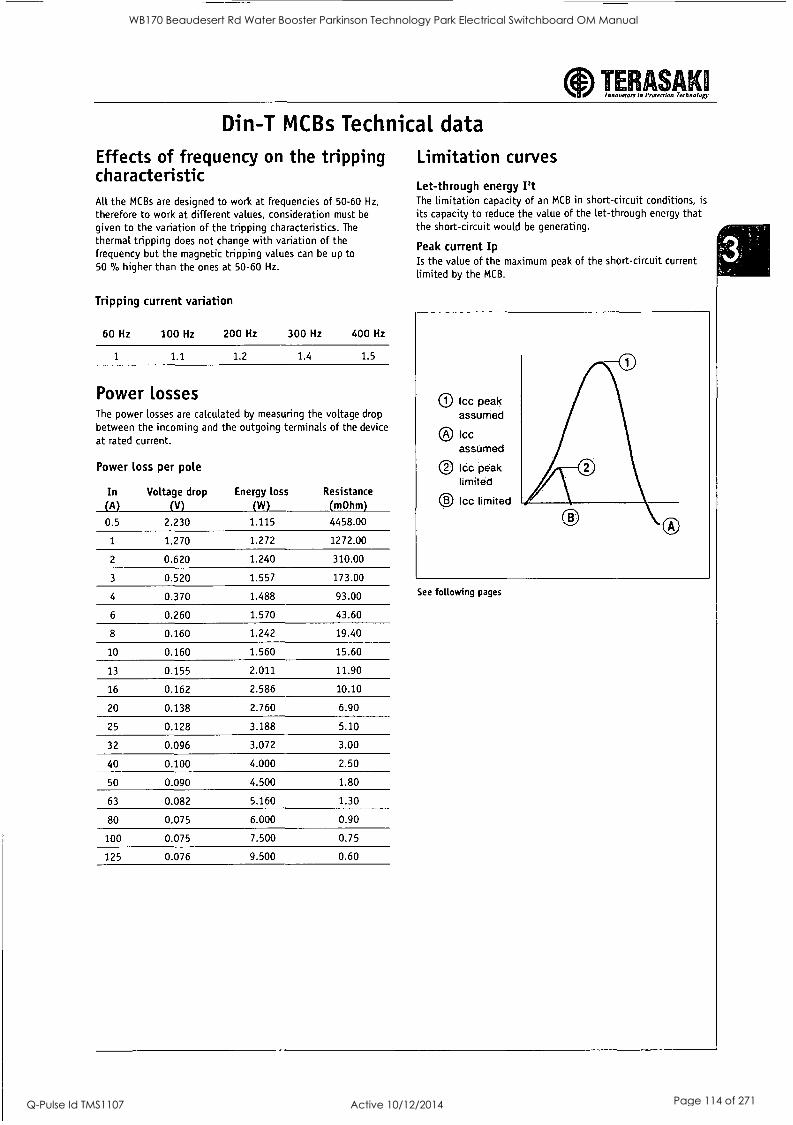
aInnorworx in Protecrion Technology TERASAKI
Din-T MCBs Technical data
Effects of frequency on the tripping characteristic All the MCBs are designed to work at frequencies of 50-60 Hz,
therefore to work at different values, consideration must be
given to the variation of the tripping characteristics. The
thermal tripping does not change with variation of the frequency but the magnetic tripping values can be up to 50 0/0 higher than the ones at 50-60 Hz.
Tripping current variation
60 Hz 100 Hz 200 Hz 300 Hz 400 Hz
1 1.4 1.5
Power losses The power losses are calculated by measuring the voltage drop between the incoming and the outgoing terminals of the device at rated current.
Power loss per pole
In (A)
Voltage drop (V)
2.230
Energy loss
(W) 1.115
Resistance (m0hm)
4458.00 0.5
1 1.270 1.272 1272.00
2 0.620 1.240 310.00
3 0.520 1.557 173.00
4 0.370 1.488 93.00
6 0.260 1.570 43.60
8 0.160 1.242 19.40
10 0.160 1.560 15.60
13 0.155 2.011 11.90
16 0.162 2.586 10.10
20 0.138 2.760 6.90
25 0.128 3.188 5.10
32 0.096 3.072 3.00
40 0.100 4.000 2.50
50 0.090 4.500 1.80
63 0.082 5.160 1.30
80 0.075 6.000 0.90
100 0.075 7.500 0.75
125 0.076 9.500 0.60
Limitation curves
Let-through energy Pt The limitation capacity of an MCB in short-circuit conditions, is its capacity to reduce the value of the let-through energy that the short-circuit would be generating.
Peak current Ip Is the value of the maximum peak of the short-circuit current limited by the MCB.
O I= peak assumed
0 Icc assumed
® !Cc peak limited
Icc limited
See following pages
WB170 Beaudesert Rd Water Booster Parkinson Technology Park Electrical Switchboard OM Manual
Q-Pulse Id TMS1107 Active 10/12/2014 Page 114 of 271
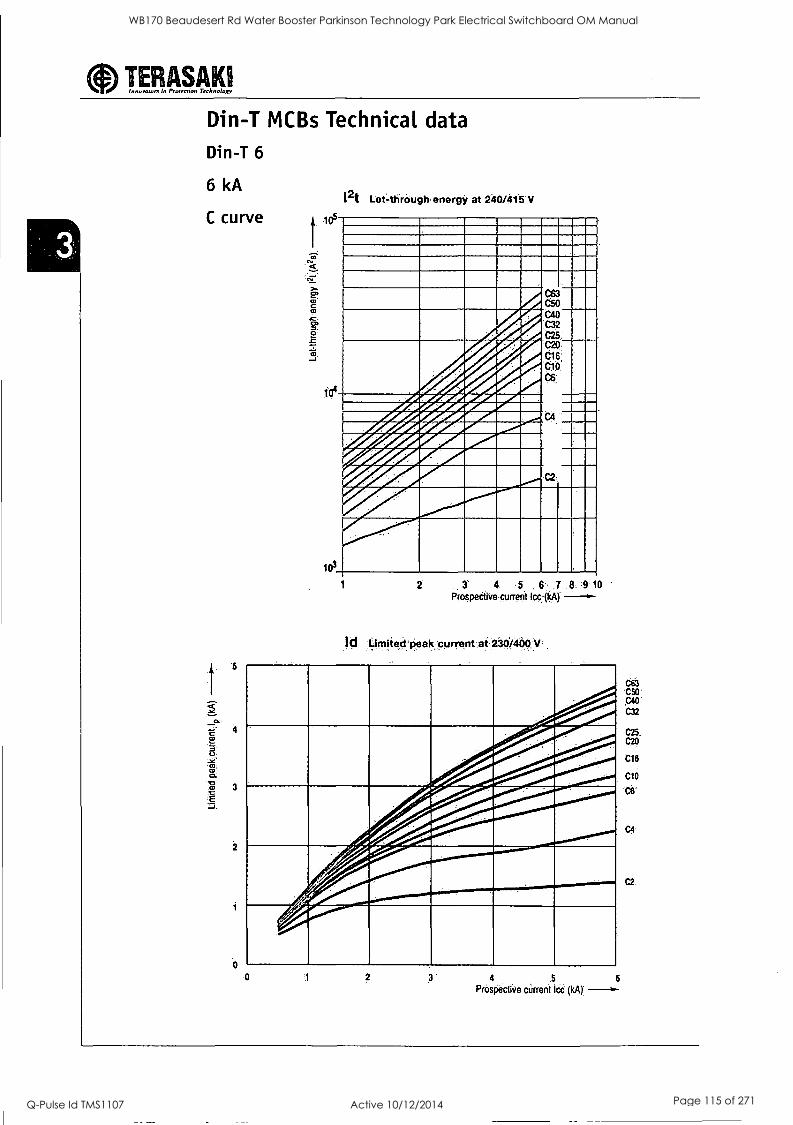
0 Innorotorw in Protection Technology TERASAKI
Din-T MCBs Technical data Din-T 6
6 kA i2t
C curve 105
C
U
cu
.70
E
Let4tireugtr energy at 240/415 V
A 1 ee c50033 C50 C40 C32 C25 C20. C16:, C10 c6
1 2 '3' 4 ,5 ,7 8. :9 10
Prospective current Icc (kA) --§--
Id icirtiiterii,eakcurrent at280%400,y'
4 5
Prospectivecarreet let (kA),
6
WB170 Beaudesert Rd Water Booster Parkinson Technology Park Electrical Switchboard OM Manual
Q-Pulse Id TMS1107 Active 10/12/2014 Page 115 of 271
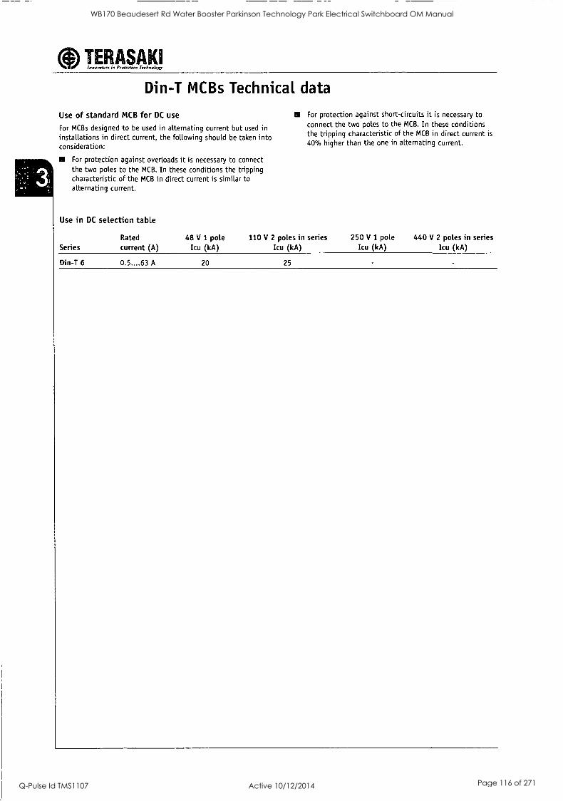
aInnovators in Protection Talmo lop' TERASAK1
Din-T MCBs Technical data
Use of standard MCB for DC use
For MCBs designed to be used in alternating current but used in installations in direct current, the following should be taken into consideration:
For protection against overloads it is necessary to connect the two poles to the MCB. In these conditions the tripping characteristic of the MCB in direct current is similar to alternating current.
Use in DC selection table
Series Rated current (A)
Din-T 6 0.5....63 A
48 V 1 pole Icu (kA)
20
MI For protection against short-circuits it is necessary to connect the two poles to the MCB. In these conditions the tripping characteristic of the MCB in direct current is
40% higher than the one in alternating current.
110 V 2 poles in series Icu (kA)
250 V I pole Icu (kA)
440 V 2 poles in series Icu (kA)
25
WB170 Beaudesert Rd Water Booster Parkinson Technology Park Electrical Switchboard OM Manual
Q-Pulse Id TMS1107 Active 10/12/2014 Page 116 of 271

ODInnovators In Protection Technology TERASAKI
Din-T MCBs Technical data
Text for specifiers
MCB Series Din-T 6
According to EN 60898 standard
For DIN rail mounting according to DIN EN 50022; EN 50022; future EN 60715; IEC 60715 (top hat rail 35 mm)
II Grid distance 35 mm
Working ambient temperature from -25 °C up to +50 °C
Approved by CEBEC, VDE, KEMA, IMQ.
1 pole is a module of 18 mm wide
Nominal rated currents are:
0.5/1/2/3/4/6/10/13/16/20/25/32/40/50/63 A
Ail Tripping characteristics: B,C,D (B curve Din-T 10 only).
Number of poles: 1 P, 1 P+N, 2 P, 3 P, 3 P+N, 4P
The short-circuit breaking capacity is: 6/10k A, energy
limiting class 3
Terminal capacity from 1 up to 35 mm2 rigid wire or 1.5 up
to 25 mm' flexible wire.
Screw head suitable for flat or Pozidrive screwdriver
Can be connected by means of both pin or fork busbars
The toggle can be sealed in the ON or OFF position
Rapid closing
EI Both incoming and outgoing terminals have a protection degree of IP 20 and they are sealable
NI Isolator function thanks to Red/Green printing on the toggle.
1111 Maximum voltage between two phases; 440 V-
Maximum voltage for utilisation in DC current: 48 V 1 P and
110 V 2 P
Two position rail clip
Mechanical shock resistance 40 g (direction x, y, z)
minimum 18 shocks 5 ms half-sinusoidal acc. to IEC 60068-2-27
Vibration resistance: 3 g (direction x, y, z) minimum
30 min. according to IEC 60068-2-6
Extensions can be added on both left or right hand side
Auxiliary contact
4r. Shunt trip
Undervoltage release
- Motor operator
Panelboard switch
Add-on RCD can be coupled.
WB170 Beaudesert Rd Water Booster Parkinson Technology Park Electrical Switchboard OM Manual
Q-Pulse Id TMS1107 Active 10/12/2014 Page 117 of 271
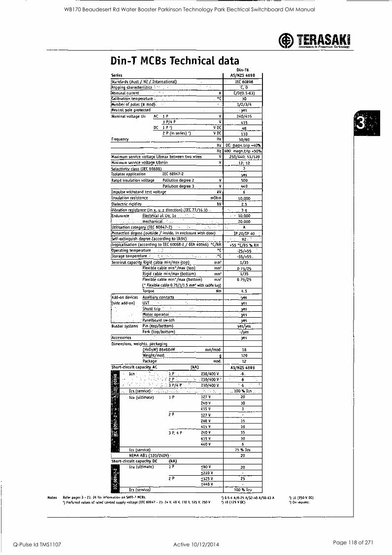
aInnovators in Prow-don Technology TERASAK1
Din-T MCBs Technical data Din-T6
Series AS/NZS 4898
Standards (Aust / NZ / International) IEC 60898 .
iTripping characteristics ',.', C, D
(Nominal current . A C/D(0.5-63) ;Calibration temperature , °C 30
,Number of poles (8 mod). 1/2/3/4 Neutral pole protected yes
Nominal
Frequency
voltage Un AC 1 P V 240/415 3 P/4 P V 415
DC 1 P') V DC 48 2 P (in series) ') V DC 110
Hz 50/60 Hz DC: magn.trip +40%
Hz 400: magn.trip +50%
Maximum service voltage Ubmax between two wires V 250/440; 53/120 Minimum service voltage Ubmin V 12; 12
Selectivity class (IEC 60898) 3
Isolator application IEC 60947-2 yes
Rated insulation voltage Pollution degree 2 V 500
Pollution degree 3 V 440
Impulse withstand test voltage kV 6
Insulation resistance m0hm 10 000
Dielectric rigidity kV 2.5
Vibration resistance (in x,,y,'z direction) (IEC-77/16.3) 3 g
tEndurance
k
.ElectriOal at Un, In ,' 10,000 . . .: : . , mechanical.: , 20,000
;Utilisation category (IEC 60947-2)
iProtectioli degree.(obttide/ inside, inenClosure.with door) IP 20/IP 40 ,
Self-extinguish degree :(according to UL94) V2 -
1Tropicalisation'(according to IEC 60068-2 / DIN 40046) °C/PH +55 °C/95 % RH '
;Operating temperatUre ' ' v : : °C. -25/+55
Storage temperature - , C. -55/+55, Terminal capacity Rigid cable min/max (top) mm' 1/35
flexible cable min /max (top) mm' 0.75/25 Rigid cable min/max (bottom) mm' 1/35 flexible cable min /max (bottom) mm'
( Flexible cable 0.75/1/1.5 me with cable lug)
0.75/25
Torque Nm 4.5
(Add -on
(side i -
l '
devices Auxiliary'contacts eyes
add-on) - UVT yes
Shunt trip.' yes
' Motor operator ' yes
- Panelboard switch yes
Busbar systems Pin (top/bottom) yes/yes Fork (top/bottom) -/yes
!Accessories , yes
Dimensions, weights, packaging
(HxDxW) 86x68xW mm/mod 18
Weight/mod. g 120
Package mod. 12
Short-circuit capacity AC (kA) AS/NZS 4898
Icn 1 P'.. 230/400 V -6, ..
: ' 2 P : . , 230/400 V.-
. 3 P/4.P: 230/400 V ' 6
Ics (service) - ,:,. .;100 % Icn .. .
ps
Icu (ultimate) 1 P 127 V 20
240V 10
415V 3
2P 127V -
240 V 15
415 V 10
3 P, 4 P 240 V 15
415V 10
440 V 6
Ics (service) 75 % Icu
NEMA AB1 (120/240V) , 20
Short-circuit capacity DC (kA)
lV
2;
i.,
Icu (ultimate) 1 P <60 V 20
<220 V -
2P <125V 25
<440 V
Ics (service) 100 % Icu
Notes Refer pages 3 - 23, 24 for information on SAFE-T MCBs. ' 0.5-4 A/6-25 A/32-40 A/50-63 A
') Preferred values of rated control supply voltage (IEC 60947 - 2): 24 V, 48 V, 110 V, 125 V, 250 V ') 30 (125 V DC)
`) 10 (250 V DC)
') On request.
WB170 Beaudesert Rd Water Booster Parkinson Technology Park Electrical Switchboard OM Manual
Q-Pulse Id TMS1107 Active 10/12/2014 Page 118 of 271
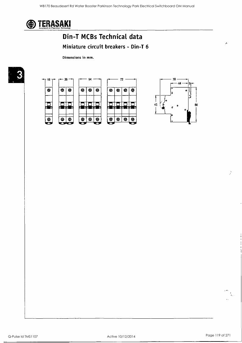
TERASAKI Innowours in Prom -don Technoloxy
Din-T MCBs Technical data
Miniature circuit breakers - Din-T 6
Dimensions in mm.
118 TafT"--1 0 0
0 0 111C11,--1111=1"
72
11111.111111111 Id no NI MI SY ad Isi
0 0 ICIFF---111C10
WB170 Beaudesert Rd Water Booster Parkinson Technology Park Electrical Switchboard OM Manual
Q-Pulse Id TMS1107 Active 10/12/2014 Page 119 of 271
AC 1/ 40V
CA4 1,10A -." ' ,.'2 5A ' r 1 Sileaccess .., CAl 0 I -., 20A , 7 514 : Side access , CA1OB .-:-.." 20A : 7 514 , 20A
-10A' 2 5A --.: Rear access s CA20 !- - 25A .. ' I IkW", Side access 6A20/3 ; ,, 25A', I IkW '25A i
CM-I , Dry circuit switching-. , Side access - CADInFor toy Voliage/Cutrent swactuni Side access C26 i '-', 32A' 15kW ' i 32A _______.,-___ - ,
CG4-1 Dry circuit switching'. Rear access - CA.012" see cat ion for specificatins Side access C32 ':j` ' 40A : - ^22kW 1- 50A
008 ". . - 20A ''''' i 7 514 . ' Rear: access C42 '63A ., 30kW- .63A'
...' " . " * 1 ' . ^ ' ' '
1 1 1 . - 11 S . 0 1 17' 1 11 : .1.1 .t
' " . 1
. 1 . 1. 1 1:. 11 I 1 ' : 1 1: 1 Y . . . . . -. e .
1 1 1 11 11 1.- . ..' . I, -,...S.," *:,°
1 1. t 1111 1' . .11 / 1 1 , 1 1 1 1 t 1
1 1' 1 't 11 1
Ac-21A AC2 415V '
C43 i '63A - 30kW - 1 63A `C315 1 . 315A , .- i .13214 , 315.1
C80' ' 100A1 s 45kWr 1 ;;115A'
CI25 150A 7,5kW - 1 150A ., .
i
' L400 : - 450A 132kW - 500A
L600 ,; 500A 13214 ;800A'
L80014 630A 7132kW', -1100A
WB170 Beaudesert Rd Water Booster Parkinson Technology Park Electrical Switchboard OM Manual
Q-Pulse Id TMS1107 Active 10/12/2014 Page 120 of 271
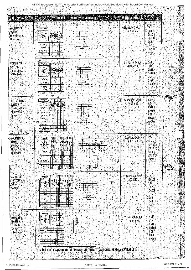
f*, t"' _
` APPLICATIONS iSWITCHIIEVELOPMENVIVIRING:ENAGRAMr 143"2 . J R . & A N t v 5 , 4--
Three phase
Three wire
VOLTMETER
SWITCH
Three. phase
TeNeiitral
VOLTMETER
SWITCH,
PliSse'to.,Pha se
And Phase
To Neutral
':;VOLTMETER
'`AMMETER
'SWITCH
Thielphase Four Wire
AMMETER '
SWITCH
11.4(e' ,.Current
AMMETik.
SWITCH
Three C.F. :
0 it
OFF R W
MINIM n EMI a II
1 7 S
.110{ 71.
A.;
u-
ivw
OFF P.N.
3-3N
1-
. 17 t9
III 1 7
warlamumminismini 111E291/11131111111MEN1111111111 11111=11111111111111111111NP111111
1111111111111141111111111
INEENVIIIIIE111111110001111 111111111111111111111111111111
Illf8E6111131111111111111111111 OP 111111111111111111111111111111kiii
ifirn 1311 17 II .
'. . 11/1,1 EICOMENIIII II 81111111111111411
INIMIIIIIIIIIMIP IIIPIIIIIIEIIIIIII I MIIIIMMINIIIIIIIIIP111111111111111 11=1111111111111111N11111111PI PIP! 111111101111111111111111111111111111441114
1111111111111111111111110111111111111N111111
1111111011111M11410111104111111111 M111111111111111111i11.1MINIMIll I
S 9.1,
4, 0!,
' W
6 1 I 10.17
°F l' 11111111.1111.1 I PINIIIIIIIIIIM
R 11111111141111111 I MIN 'NMI 111111111111411 IIP IMMO i 1111111111114111111
1111111111111111
I 1
-1 1 1 1' T'
e'6 e
'17 S
1111111111111117.06 111111111 1111111111111111741=111
^
ROERING;DETAILS;,_n
.: Standard Switch .(..,114
A004 -625 CG4
CAlpp
CG8,
C-A20
,CA20B ,1
Standard, Switch
A005-G24
Standa,rd,SWitch
A007-625.
Standard Switch
A033-600
:Standatd Switch '
AOS8:622
Standard Switch
A048-624
MANY WO STANDARD OR SPECIAL CIRCLNTARY.WITCRES:READILY AVAILABLE
CA4
CG4
CA10 .
CA108
CG8
'CA20
. CA208
CA4
CG4
CA10
CA100
CG8
CA20'
CA2013
CA4'
C04.
CAIO
CAIOB
. CG8
CA20
.".2013
CA10'
6A108
C08
CAM'
CA208
26,
C32
'C43
C80
CA4
CG4
CA10
, 'CA1013
CG8
CA20
CA208
WB170 Beaudesert Rd Water Booster Parkinson Technology Park Electrical Switchboard OM Manual
Q-Pulse Id TMS1107 Active 10/12/2014 Page 121 of 271
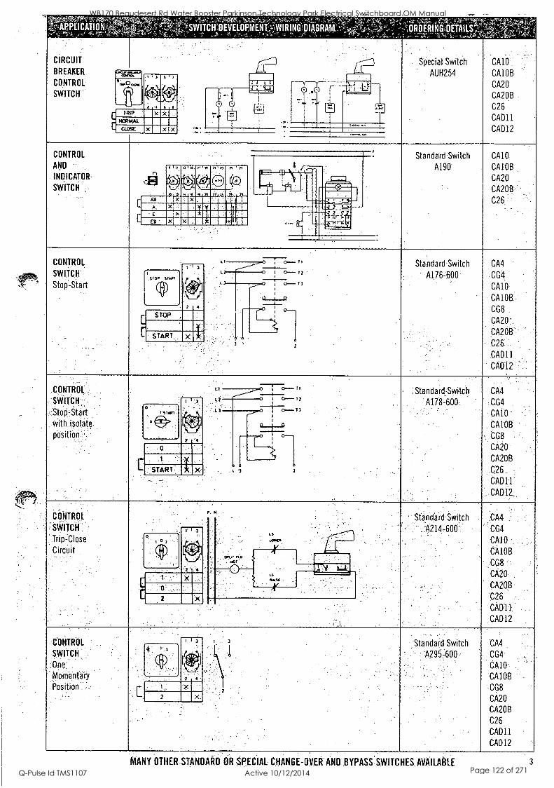
;;YP,.--;"
....'ORDERING,DETAILS"- SWITCH'DEVELOPMENT411RINGIIIAGRAM,,%
CIRCUIT
BREAKER
CONTROL
SWITCH
tear =two,
cuau
TRIP
' ,C %it
Special Switch
AUH254
CA10
CA10B
CA20
CA20B
C26
CAD11
CAD12
CONTROL
AND
INDICATOR
SWITCH
IS fl
0 mamsliii ansimmus.
111111111=11111M111111111111M
1111E1111112111110111113111M0
Standard Switch
A190
CA10
CA10B
CA20
CA2013
C26
CONTROL
SWITCH
Stop-Start OP S Olt
(9)
L
C
II 3
t"
2 4
STOP
START.
Standard Switch
- A176-600
CM
CG4
CA10
CA10B
CG8
CA20'
CA20B
C26
CAD11
CAD12
CONTROL:
SWITCH
with isolate.
positibn
st1
Standard-Switch
A178--600
CA4
CG4
CA10
CA10B
CG8
CA20
CA20B
C26
CAD11
CADIZ
CONTROL
SWITCH
Trip-Close
Circuit
- Standard Switch
" A214-600
"
CA4
CG4
CA10
CA10B
CG8
CA20
CA20B
C26
CAD11
CAD12
COITR01.
SWITCH:
Morrientaijf
Position
4 : '
2
:Standard Switch
-A2957600-
CA4
CG4
CA10
CA10B
CG8
CA20
CA20B
C26
CAD11
CAD12
MANY OTHER-STANDARD OR SPECIAL CHANGE-OVER AND BYPASS SWITCHES AVAILABLE 3
WB170 Beaudesert Rd Water Booster Parkinson Technology Park Electrical Switchboard OM Manual
Q-Pulse Id TMS1107 Active 10/12/2014 Page 122 of 271
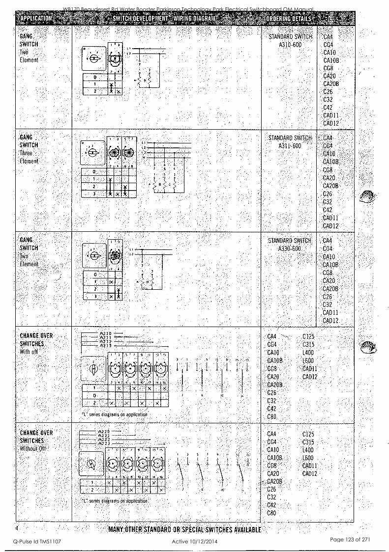
APPLICATIONS
GANG
SWITCH
Two
Element
GANG
SWITCH
Three
Element
ITCH:DEVELOPMENT:i1WIRINGIIIAGRAM?; ORDERING DETAILS';;
STANDARD SWITCH
A310-600
101
2
CA4
CG4
.CA10
CA10B
CG8
CA20
CA20B
C26
C32
C42
CAD11
CAD12
1 3 STANDARD SWITCH
A311600
2 4 6 6
o,
2
x
CA4
'CG4
CA10
CA10B
CG8
CA20
CA208
C26
C32
C42.
CAD11
CAD12
GANG
SWITCH
Element
STANDARD SWITCH
A330-600
CA4
CG4
CA10 CA10B"
CG8
CA20
CA20B
C26
C32
CAD11
CAD12
CHANGE. OVER
SWITCHES.
With oft
A210 A711
--A212 . . -A2I3 1 17 9 II '3 15
10i ' 9
x
2 x x x
I: series diagrams o r al pireatio
CA4 C125
CG4 C3'15
"CA10 1.400
CA10B L600
'CG8 CAD11
CA20 CAD12
CA20B
C26'
C32
C42
C80
CHANGE OVER
SWITCHES
WithOut Ott
A? 20 'A22,1 A222
- A223
"1' series diigrams on anplicat
CA4 C125
CG4 C315
CA10 L400
CA10B L600
CG8 CAD11
CA20 CAD12
CA20B
,C26
C32
C42
C80
MANY OTHER STANDARD OR SPECIAL SWITCHES AVAILABLE
WB170 Beaudesert Rd Water Booster Parkinson Technology Park Electrical Switchboard OM Manual
Q-Pulse Id TMS1107 Active 10/12/2014 Page 123 of 271
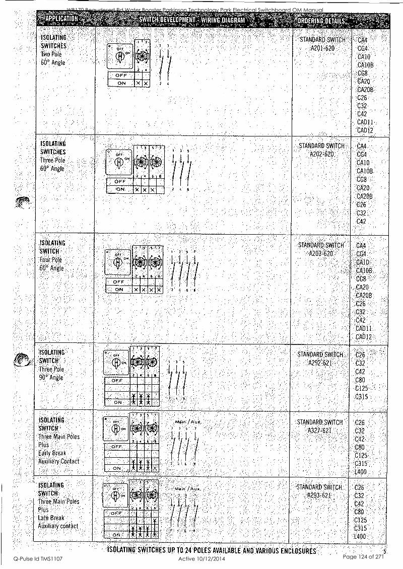
PPLICATIO WITCHDEVELOPMENTWIRING,DIAGRAM RDERINGOETAILS
-ISOLATING'
SWITCHES
Two Pole
60° Angle
'STANDARD SWITCH', ("Al
,A201620 CG4
CA10
CA108
CG8
CA20
' CA2013:,
C26
C32
C42
CADft: CADi2
ISOLATING
SWITCHES
Three Pole,
60° Angle
OFF ON ;
Orr ON
:.4
X X
1 1 3 5 -1 7
d '4
OFF
N
6
X ><
STANDARD SWITCH
'A202 -620' CA4
CG4'
;CA10
CA108
CG8
CA20
CA2QB
C26
C32
C42
ISOLATING
SWITCH
Four Pole
.60` Angle
'ISOLATING
SWITCH
',Three Pole
90° Angle"
ISOLATING
SWITCH '
Three,Main PrileS
Plus
Early Break
Auxiliary Contact.
ISOLATING
SWITCH
Three Main Poles
ORJS
Late Break
Auxiliary contact
, OFF
ON
OFF ON
1 1 3' 5 I 1,
4,A IV 2 4 6 e'
X X X
Utr
Qp014 zmr
J 1
'OFF
ON
tviwt /Aux.
6
STANDARD SWITCH
-A203-620,
STANDARD SWITCH
A292=621' '
STANDARD, SWITCH
A327-621
SIANDARD"SWITCH
,A293 -621
CA4
CG4
CA1013
CG8
CA20
CA20B
C26
C32
642
CAD11:
CAD12
C26
C32
C42
C80
C125
C315
C26
C32
C12
C80
C125
C315
1.400
C26
,C32 -
C42
C80
, C125
C315
"L400
ISOLATINO'SWITCHES UP T0 24POLES AVAILABLE AND.VARIOUS ENCL0SURES
WB170 Beaudesert Rd Water Booster Parkinson Technology Park Electrical Switchboard OM Manual
Q-Pulse Id TMS1107 Active 10/12/2014 Page 124 of 271
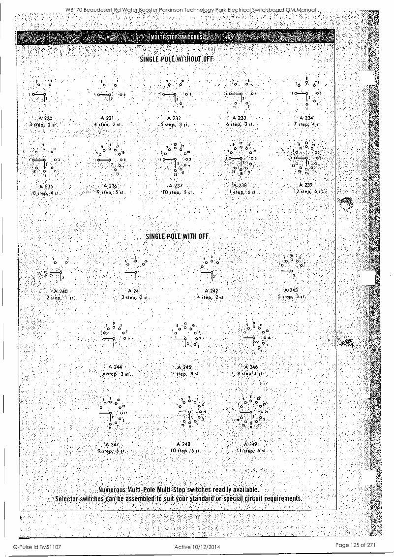
''SINGLE POLEWITHOUT,OFF
A 230 3 step, 2 st.
-A231 A-232 4 step, 2 sr.. 5 step, 3 it.
A 233. 6 step; 3 st.
. A 236 step,:5
A 237 . 0 step, 5 st.
A 238 . A 239
11 step, 6 %I. 12.step, 6 st.
SINGLE POLE WITH OFF
A.241 3:step, 2 st..
A 242- ' 4 Step, 2 st.
5 9 3
0 0
o'
-12 A 243
5 step, 3 st.
5 9
3
0 0 0
0-7
0 It
A 244
6-step 3 st. A.245
7 step, 4 st. 'A 246
8 step 4 st .
. '0 0 5 9 13 5 13 o
9
0
1 ° 0 o" 0 O'
0 0 " 617
2 0
--9 o o
7 ts;12 ° 3
0 r o 0
0 - 7 550 07
11 7
A 247 9,step, 5 st
A 248 '10 step 5st.
A 249
fl.step, 6st.
Numerous Multi -Pole Multi-Step switches readily available.
Selector; switches can be assembled to suit:your standard or speCial circuit requirements.
WB170 Beaudesert Rd Water Booster Parkinson Technology Park Electrical Switchboard OM Manual
Q-Pulse Id TMS1107 Active 10/12/2014 Page 125 of 271
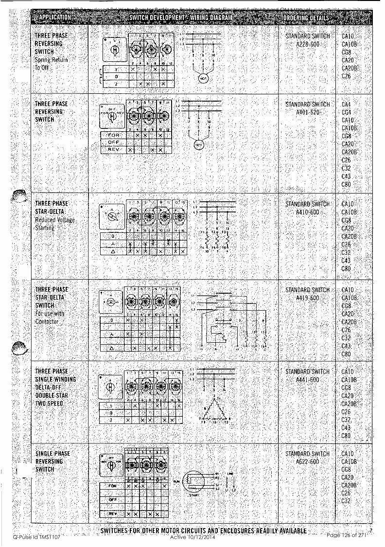
?Irg ,7140" -- ' , '1APPLICATION,
:r.;--,;Likree,-., A.--,... -,..,,,,%,,,,:,;.','"
THREE PHASE -, , .
REVERSING
SWIT:CH. '
Spririg Return
1b-Off- ,
"' - 10- 'y'rkt4p4.135:IssioLei,41,iWASICrANNIAVW0Spegrat , ' - .,,,,
. - - - 0 ASWITCHMEVELOPMENT&WIRING',01AGRAM - -- r ' '''' ...% `1..;;...-4.5,,," '',..,?..1k- 4- 4,*4f r''''', ,c. ._*&L'N`rriQ"'..i,:skA.I.,X,url.-7 ',. - , -
"
- Xr-treetvig4irgMCAr" ,, ORDERINGIIETAILSt 44,44t,V2W1;,Zr.fr".9M, .?;'$''`i
F ' - ,
.,,,,t` t . !-.1.' 1.-.;-gi,no
STANDARD SWITCH ,
- -A228-600
,
' '
, '
CA10
CA10B.
CG8 .,
CA20
CA2013', ..
- C26 , ,
S 7 's I 11 '
,
4:,'' * .),
' ). - , .
- ' ?
Filf 4, 40
T ,
,J,
2
,..
, ,,.
,
9 , '
?
111/111113111 `" x .
o . II .
, 111110102 x .
"THREE' PHASE-
REVERSING ' '
SWITCH . ,
.
,
,
STANDARD SWTCH
A401-620
-
.
,, ' '
. ,
C-A4
CG4
6 A10
C100(3, ,
CA20
CA2013', ' *
C26 -
C32.
C4-3
C80 ,.
igli ,iir,
' II
r et: ft
.. 1 ,
4: , .'1. r -. -"(tp " 6.1511kN ter: 4.,
t i
''' 3
,
7
9
-
-.... FOR X., X ' .
1 1 1 1 1 1 ' CI) ,
.
REV ' X , X -
.
. ,
.
,
'
HREE PHASE ' -
STAR-DELTA.
Reduced VoltagO,
Starting . i
, .. '
.
,
. . , .
STANDARD SWITCH
A410-600,.
' ,' ,
' , . '
,
' CA10-,
CA10B
c08 CA20
CA013 ' .C32,
C'43 ' '
C80,-
'7, 9,, '
' ":\''' ''' C..",:a efiS ' 20I: eta .
.
Tc '
.
5 , lc ',, ,
6 13 , T2 T3
,, ,
TS 16 ' 10 ' 7'
,
2 4 '6 .6 10 ,1 'I I:
CI ' .'1'' ',. : i'''' -' "- ! ' -
A X X
A X * X' .
.
. , . .
.
THREE PHASE
' STAR DELTA
' SWITCH
For use with ' ,,
ContPctor
,
STANDARD SWITCH ,-
A419=600
.. .
, . . ,
-
'
,
, . ,
CA10"
CA10B
. CG8.
CA20.;
CA2,0B - '
I 3 5 1 :,
`,. f
1
AIN
..3 IS.
101 d
'2
=4:4 OPd ] ----1--. 13
: -
.
a IC .b
0 ,,
'
X,
- )(MU El
.
'
=MIA .
A ' X 111111111111111 - -II ' - 11111111111111 .'
A . .
THREE PHASE .
S,ING,LEVINOING
"LIELTA-,OFF',
DOUBLE STAR
' TWO SPEED . :
, -
.
-
' STANDARD SWITCH - ' :. A441-6,00 '
: , '
.
.
.
, ,
CA10
CA10B
CG8
CA20 - CA2OB
C43
C80
, . ,
- I) 1\1!)...
, 9 11
L 1
- ''' 9 , ,
' i' 1). - .:.
"
1. 2
L31 , A f-4 <11"i)-
93 fit, [:...e.1
.
,11,.. t--. 4/ 1.
, .
. .
4 . . " ,
1 3 T 2 3
IMMEMEI ,. k x .
x x .
,
,, - .
,
, , ' , .,, ,- .
.
.
SINGLE PHASE
REVERSING
SWITCH
. ,
'
,
. . . . . .,..
... .
STANDARD SWITCH
A622-600 '
. . ' .
, ,
,
' CA10 ''
CA10B
CG8
CA20 - CA208
'C32:
.
111111111111M111111111111111111191 9919991199.99zuw,
-
, ,
.
.
. ,
'
.
.v-c- ;e: , (0)1'..
ask 1:3:::41
74., ig.`1 114,
r , tO yip , ',
. '
,
cr , Lea ' -
' s iner114.0.1354 FOR ' ' '
si ' x x x 11:1
MOE 11111111
II _ '
S2 ,11 11 , ' -
.
, . .
. .
.
'SWITCHES;FOR OTHER MOTOR CIRCUITS AND ENCLOSURES READILY AVAILABLE , ,, 1
WB170 Beaudesert Rd Water Booster Parkinson Technology Park Electrical Switchboard OM Manual
Q-Pulse Id TMS1107 Active 10/12/2014 Page 126 of 271
lvy Duty Motion:
f'
1
,,,=
'--"i*.k n! ' VI,
. 4r- ' fY
N
.1 " ; , 44. ..'x'. .
1
-- r'''re 4., . ' InsillatediEnclosures' ..,
u.
The enclosed.is,only,a,selectionof an extensive range of our switches.and optional eirTr:::i a.,,, ,- Due-to design development requireinentsspecifications'maizalter without-notice 5.% , - , ,
SYDNEY..., : ,- -.... , , ,- MELBOURNE ,.,,- ,`, - . , ,, - BRISBANE ADELAIDE
37§ l_lierficial Rtiiil, , ",,,,':';', '14`Brpnscliiii'Stre'ef , ,:.- , -, , ' , , 22 81170kkitreet:;;!;-. , ;`-, : !:-` i',9/1780f802 SOuittio4d
:- .' ;;Ifishfield, N S lk2131% - ',' ";-p Bayswater VIC 3153 ; , .,;/. Bowen Hills, (lid 4006,, .. -, :, ; zi. Clindere:S k 5037
.5 TEL (02)..9107,7333/4;',,); -., ', ' ,JEL: (03) 9720,8777, -,. ' i, ' '.,; TEL (07)3252-8844,,;,,- ; , ,' , .-,,7EL (08) 83711443 .. f -
FAX. (02) 0092,- , ': ,;- :--, , FAX. ,(03)97200760 - e, - * '. FAX- (D7)3252 1407 '" FAX '108i Ole's/eau-M:1**0 corn au ':'1,' : *, :.,salesv,icgausteait31:ccirti:ail ' ' '' ' '. " ' ; '2 ' ' - ' '-' 8111 09Cil
WB170 Beaudesert Rd Water Booster Parkinson Technology Park Electrical Switchboard OM Manual
Q-Pulse Id TMS1107 Active 10/12/2014 Page 127 of 271
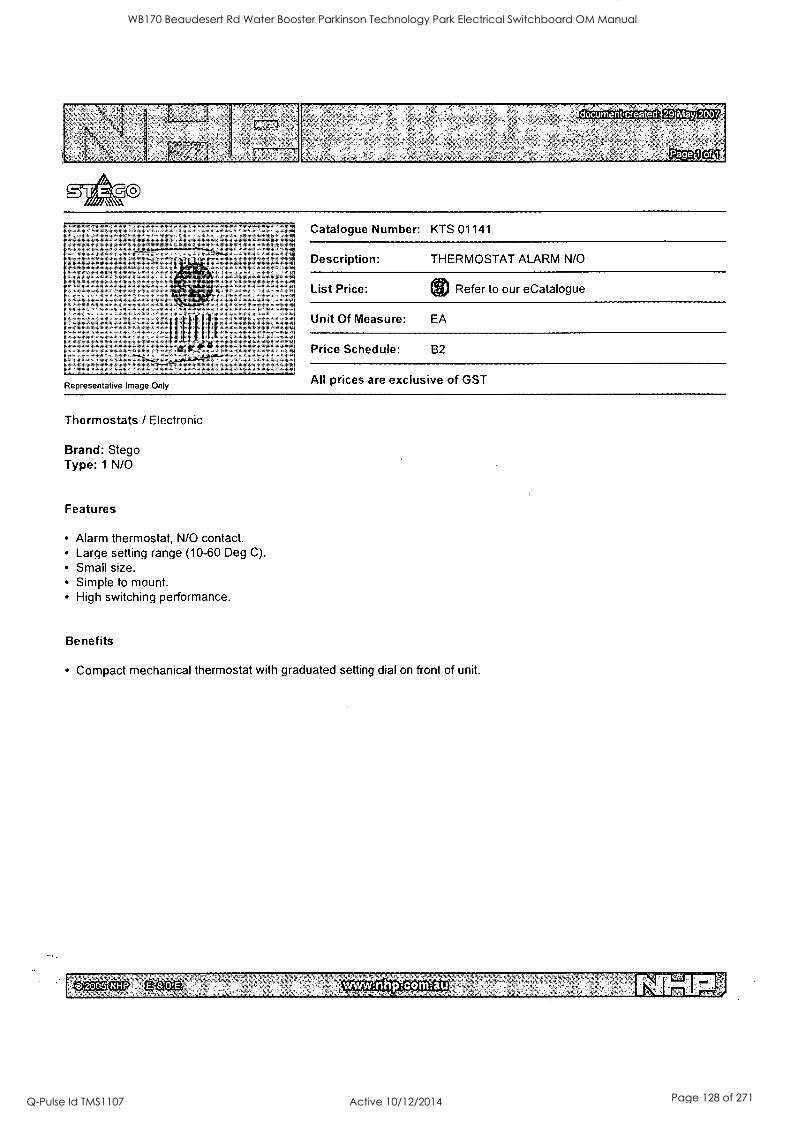
document, created: 291May 2007
Representative Image Only
Catalogue Number: KTS 01141
Description: THERMOSTAT ALARM N/O
List Price: 8 Refer to our eCatalogue
Unit Of Measure: EA
Price Schedule: B2
All prices are exclusive of GST
Thermostats / Electronic
Brand: Stego Type: 1 N/O
Features
Alarm thermostat, N/O contact. Large setting range (10-60 Deg C). Small size. Simple to mount. High switching performance.
Benefits
Compact mechanical thermostat with graduated setting dial on front of unit.
0.2005 NHO. Nei
WB170 Beaudesert Rd Water Booster Parkinson Technology Park Electrical Switchboard OM Manual
Q-Pulse Id TMS1107 Active 10/12/2014 Page 128 of 271
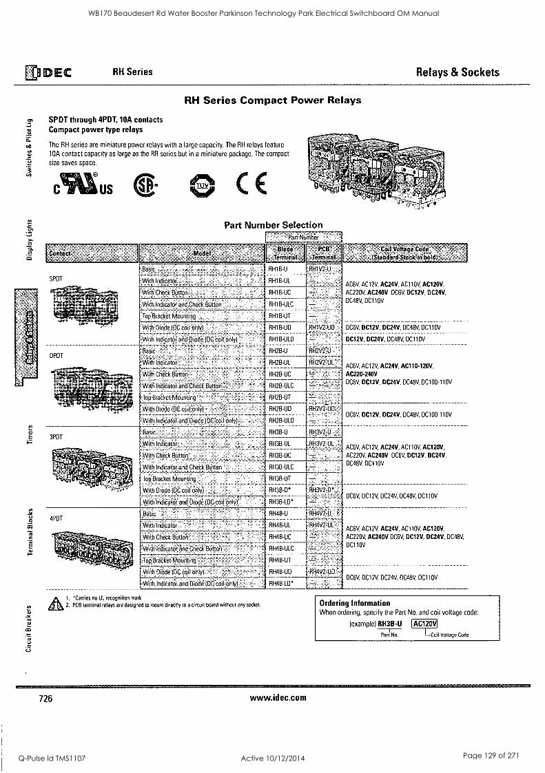
EDIEDEC RH Series Relays & Sockets
RH Series Compact Power Relays
SPDT through 4PDT, 10A contacts Compact power type relays
The RH series are miniature power relays with a large capacity. The RH relays feature
10A contact capacity as large as the RR series but in a miniature package. The compact
size saves space.
Contact
RC,
Model
Part Number Selection Pan Nuniber -
SPDT
DPDT
-Blade Terminal
I Basic RH1B-U RH1V2-U __
( With Indicator RH1B-UL - AC6V AC12V AC24V AC110y, AC120V,
With Check Button RH1B-UC AC220V AC240V DC6V, DC12V, DC24V,
RH1B-ULC DC48V DC110V
il With Indicator and Check Button -_... _ ..
%.* Top`Bracket Mounting RH1B-UT
With Diode (DC coil only) _ RH1B-UD .RH1V2U6. DC6V, DC12V, DC24V, DC48V, DC110y , . _
With Indicator and Diode (DC coil only)" - - DC12V, DC24V, DC48V, DC110V RH1 ...
Basic ,' . RH2B-U ' RH2V2--U <
F With Indicator . . RH2B-UL RH2V2,UL AC6V, AC12V, AC24V, AC110-120V,
-With Check Button ' , . RH2B-UC - . AC220-240V
DC48VDC100-110V - ..i. With Indicator and Check Button -,' - RH2B-UL . ,-2-11
DC6V, DC12V, DC24V,
Top Bracket Mounting - - --- RH2B-UT
Coil Vottege Code
(Standard StoCk:fri bold)
3PDT
With Diode (DC coil only) F_,` RH2B-UD
With Indicator and Diode IDC coilOnly) j RH2B-ULD
Basic RH3B-U
With Indicator RH3B-UL
[With Check Button- RH3B-UC
With Indicator and Check Button - RH3B-ULC
Top Bracket Mounting
With Diode IDC coil Only) .
With Indicator and Diode (DC coil only)
4PDT
` 4,4
RH3B-UT
RH3B-D"
RH3B-LD"
1-13V2-Ut
DC6V, DC12V, DC24V, DC48V, DC100-110V
AC6V, AC12V, AC24V, AC110y, AC120V,
AC220V, AC240V DC6V, DC12V, DC24V,
DC48V, DC110V
RH3V2-D*, DC6V, DC12V, DC24V, DC48V, DC110V
Basic , RH4B-U RH4V2-U -
With Indicator RH4B-UL RH4V2-UL
With Check Button- ' RH4B-UC
With Indicator and Check Button
Top Bracket Mounting -
With Diode (DC coil only) - '
With Indicator and Diode (DC coil-only) ' RH4B-LD`
carries no UL recognition mark.
2. PCB terminal relays are designed to mount directly to a circuit board without any socket.
RH4B-ULC
RH4B-UT
RH4B-UD RH4V2-UD
AC6V, AC12V, AC24V, AC110V, AC120V,
AC220V, AC240V DC6V, DC12V, DC24V, DC48V,
DC110V
DC6V, DC12V, DC24V, DC48V, DC110V
Ordering Information When ordering, specify the Part No. and coil voltage code:
(example) RH3B-U I AC120V
Part No. 1-Coil Voltage Code
726 www.idec.com
WB170 Beaudesert Rd Water Booster Parkinson Technology Park Electrical Switchboard OM Manual
Q-Pulse Id TMS1107 Active 10/12/2014 Page 129 of 271
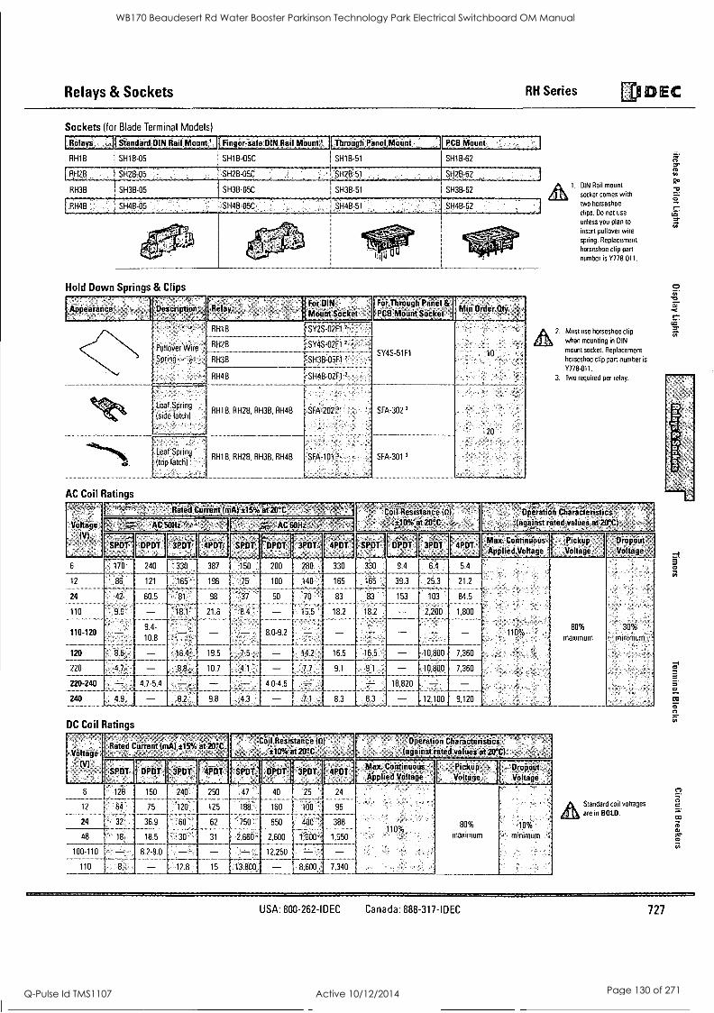
Relays & Sockets RH Series EDI DEC
Sockets (for Blade Terminal Models)
Belayi Steriderd,DIN Rail, Mount;':.. finger4afe 13114 Rail Milunt4 LThroirgli;Ren4Meiint PCB Minim;
SH18-62 RH1B SH18-05 SH18-05C I SH1B -51
4
[ R. 51-128-a5 SH28 05C " SH2B-51 SHZB -62 I: I I
RH3B SH3B-05 SH3B-05C 1 SH3B-51 SH3B-62
RH4B . SH4B-05 .SH48-05C ,
I SH4B- I , 51 4B- SH62 ...
- I
cf
iitici a.
.
Hold Down Springs & Clips
Appearance Deucriptran' Fin' DIN Mount Socket
For Through Panel t PCB Mount Slicker
. g Order
n*, "d" "'"er ""
Pullover Wire
Spring -,-,
,
RH1B __ _ _-_ RH2B
SY2S-02F1 2
___- -------- - SY4S-02F1 2.,
SY4S-51F1 10 RI-13B ISH3B-05F1 2
RH4B SH4B-02F1 2
Leaf Spring
(side latch) R H 18, RH26, RH38, RH4B SFA-202 ' SFA-302 3
20 0. . .
Leaf Sprtng '
.(top latch(' RH18, RH2B, RH3B, RH48 SFA-101 3 SFA-301 3
AC Coil Ratings
Coil Resistance (0)
:Voltage ,` AC 50Hil'P" 11% >1-1.7, AC 60Hz ±10% at 213°Q
(V)
6
12
24
110
110-120
120 86
220 4.7
220-240 - 240 4.9
-SPOT DPDT 3PDT 4PDT; SPDT DPDT 3PDT' 4PDT -SPDT DPOT 3PDT, 4PDT-
170 240 f 330
86 121 165 196
42 605 Br 98
96 181 216 84
1 387 150 200 280 330 330 9 4 64 1 5 4
75 1 100 140 165 165 39 3 _ -
70
155
83 83 153
182 182- - 8 0-9 2
16.4 19.5 7 5
8 10.7 4 1
4.7-5.4
165
253 21 2
103 845
2,200 1 800
16 5 10,800 7,360
1 - 1- 10,800 7,360 9.1
4.0-4.6 -- 71 8.3
DC Coil Ratings
Coil Resistance (0)
Voltage L Rated Current (nA)±15°A at 20°C II
t10% at ZO°C
(1.9 SPOT DPDT- 3PDT 4PDT- SPi3T, DPDT 3PDT 4PDT
18,820
al. DIN Rail mount
socket comes with two horseshoe
clips. Do not use
unless you plan to
insert pullover wire spring. Replacement
horseshoe clip part
number is Y778-011.
2. Most use horseshoe clip when mounting in DIN
mount socket. Replacement
horseshoe clip part number is
Y778-011.
3. Two required per relay.
'Operation Criaracieristics lagitiust rated values at 20°C)
-max -colimiubus ,Appliedyoltiige
,Pickup Voltage
" Dropout Voltage:
80% 30%
maximum minimum
6 128
12 64
24 32
48 18
100-110
110
150 240
75 120
369 60
18.5 -.30
12,100 9,120
Operafon Characteristics (against rated values at 20°C)
no 47
125 1
62 -750
2,660
40
160
650
2,600
388
1,550
7,340
8.2 -9.0 12,250
Max Continnous Pickup Applied Voltage Voltage
110% 80%
maximum
Droliont '
Voltage
10% minimum
Standard coil voltages
are in BOLD.
USA: 800-262-IDEC Canada: 888-317-IDEC 727
WB170 Beaudesert Rd Water Booster Parkinson Technology Park Electrical Switchboard OM Manual
Q-Pulse Id TMS1107 Active 10/12/2014 Page 130 of 271
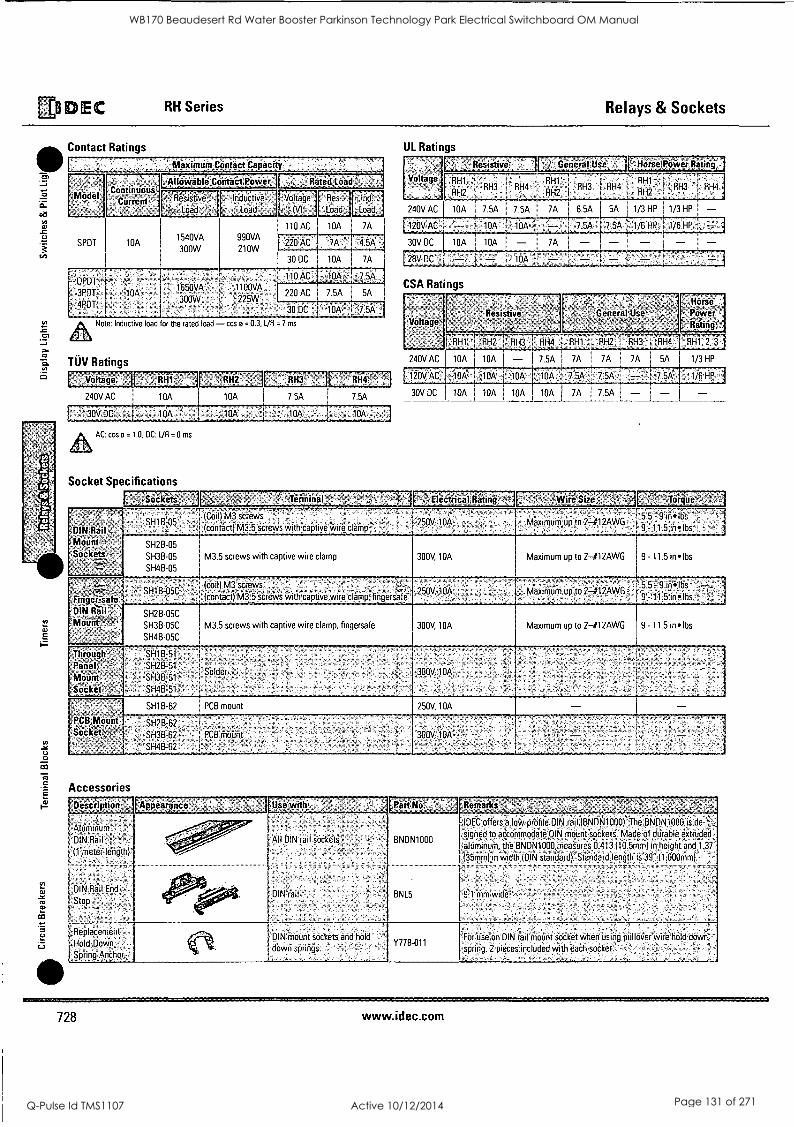
,General Use 1
DEC RH Series Relays & Sockets
rn
a.
ca
a>
c.)
Cr
TUV Ratings
Contact Ratings
Model
SPDT
Continuous Current
10A
.:Maximum Contact Capacity -
411Owidile!ceiitaiiPoiver °
ResistiVe
Load
1540VA
300W
InduCtive
Load-
990VA
210W
DPDT 1650VA ' 1100VA -
3POT 10A 300W '- 225W
4PDT
Note
Fated,Lead.-
,Voltage Res - Ind
(V) - Load Load
110 AC I 10A I 7A
30 DC I 10A
110 AC I, 10A
220 AC 75A
7A
Inductive load for the rated load - cos o = 0.3, L/0 = 7 ms
Voltage
240V AC
391/. DC
10A
10A
10A 7 5A
10k
RH4
AC cos o = 1 0 DC UR = 0 ms
Socket Specifications
SO Cieeti?-
E 67.
DIN Rail Monnt- SOciets -
'finier;Safe 'DIN Bill"
Through t: Panel Mount Socket
PCB Mount .Secket,
SH1B-05 -
SH2B-05
SH3B-05
SH4B-05
- ^
SH1a=05C
SH2B-05C
SH3B-05C
SH4B 05C
SH1B:51
SH2B:51
SH3B-51
SH4B-51
SH1B-62
1-
UL Ratings
Horie PM,ver Rating
'''''5'9u 11111 RH3 ' RH4 "1 : RH3 [ RH4 RH2 1 RH2 -- tlhl - ,.;
RH2
RH3 RH4.1
1/3 HP [1/3 HP - .:1/6 HP 1/6 HP
240V AC 10A 7.5A I 7 5A 1 7A I 6.5A 1 5A
:i 0.yAc : I, 10A. .I :10A 7.5A: I 7,54.k.:
30V DC 10A 10A 7A - - 28V,DC 10A
CSA Ratings
Voltage; .
240V AC
120V AC
30V DC
Resistive General Use
RH1' TiTri7R-17135--FRH4 RH1 RH2 RH3 ;RH4 RH1 2, 3 .1
10A I 10A - 7.5A 7A 7A 7A I 5A 1/3 HP
10A: I '1 OA I 10A 7:5A
Florae.,
Power -flitting;
" 1 /6-1P
10A 10A I 10A 10A 2A I 7.5A -
Terminal INire Size,
(CoillM3 screws ' _ s. - -
150V, 10A (contact) M3 5 screws with captive wire clamp * 1 L
M3 5 screws with captive wire clamp
(cod) M3 'screws
(COntaet) M35`screWs with captive wire clamp, fingerSsa'f
M3 5 screws with captive wire clamp, fingersafe
Solder
i
PCB mount
SH2B;62 1
-SH3B-62'' PCB Mount
SH4B-62 -
300V 10A
250V, 10A
300V, 10A
250V, 10A
300V;10A
- inlbs Maximum up to 241 '2AWO
5 5
i 9 - 11 5 inelbs
Maximum up to 2-412AWG
MaxibitIm up to
9 - 11 5 mlbs
5-- 9 in'ilbss 9'111 5 inlbs--
Maximum up to 2-412AWG 19 -11 5 in lbs
Accessories
[Description
Aluminum
DIN Rail
11 meter length)
DIN Rail End
Stop
Appearince Use with
All DIN rail sockets -
DIN rail
[Part No
BNDN1000
BNL5
Remarks'
IDEC offers a low-prbfile DIN rail (BNDN1000){ The BNDN1000 is de- -.,
signed to accommodate DIN mount sockets Made of durable extruded
aluminum, the BNDN1000 measures ti 413116 5rrirri) in height and 1 37 -
(35mm) in width WIN standard) Standard length is 39" (1,000mm)
91 mm wide- -
Replacement Hold -Down-
Spring Anchor,
DIN mount sockets and hold
down springs - Y778-011
For use on DIN rail mount socket when using pullover wire hold &min
. spring 2 pieces included with each socket
728 www.idec.com
WB170 Beaudesert Rd Water Booster Parkinson Technology Park Electrical Switchboard OM Manual
Q-Pulse Id TMS1107 Active 10/12/2014 Page 131 of 271
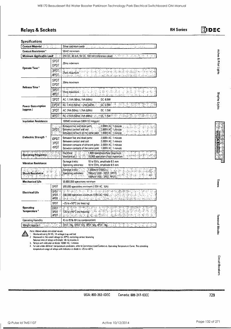
Relays & Sockets RH Series DIDEC
Specifications
Contact Material Silver cadmium oxide
Contact Resistance' 50m0 maximum
I MiniiiiMmAppliCable Load' 24VDC, 30 MA. 5V DC, 100 rnA (reference value)
Operate Time I
SPDT
DPDT 20ms maximum
3PDT.".
4PDT 25ms maximum
Release Time 2
SPDT
DPDT 20ms maximum
... . .
3PDT .
4PDT
.
25ms maximum '
Power Consumption (approx.)
SPDT AC: 1.1VA (50Hz), 1VA (60Hz) DC: 0.8W
DPDT AC: .114VA (50Hz); 1.2VA (60Hz) DC: 09W
3PDT AC: 2VA (50Hz), 1.7VA (60Hz) DC: 1.5W
1'4P.DT.... : AC:,2.5VA160Hzi, 2VA (60HZ):. DC 1 5W . .,, _........___ Insulation Resistance
........ 100M0 minimum (500V DC meggei)
Dielectric Strength I
.. ...
:SPDT:.. - ... '
Between live and dead parts: :.2,000V.AC, 1 minute :.
Between contact and coil: : 1 2,000V AC;1.MinOte '
Betweeiicoeitacts of the same pole: 1,000v AC:1 minute
DPDT
3PDT
4PDT
Between live and dead parts: 2,000V AC, 1 minute
Between contact and coil: 2,000V AC, 1 minute
Between contacts of different poles: 2,000V AC, 1 minute
Between contacts of the same pole: 1,000V AC, 1 minute
Operating Frequency Electrical.: 1;800 operations /hour maximum
Mechanical 18,600 operations /hour maximum
Vibration Resistance Damage limits: 10 to 55Hz, amplitude 0.5 mm
Operating extremes: 10 to 55Hz. amplitude 0.5 mm
Shock Resistance ..Damage.limifs: .. .1;o00m/s2.. (100G) 7...."-
: - i. . .... . .
-SPOT, .
,Opeipting extremes: 200m/s2. (206 - SPOT, DPOT) .. ., ... . :..: ,
100ni/s7.110G -.3POT.APDT)
Mechanical Life
Electrical Life
DPDT
50,000,000 operations minimum
500,000 operations minimum (120V AC, 10A)
f:.SPDT
:3PDT ..: 4PDT .
,200,000 operations minimum )120V AC, 10A)
. . ' Operating Temperature'
SPDT -25 to +50°C (no freezing)
DPDT
3PDT
4PDT
-
-25 to +40 °C (no freezing)
Operating Humidity 45 to 85% RH (no condensation) - yypigntpppr9.)
,- . .. ... . .. ... .
SPOT: 24g OPDT.:37g.3f0T:51.1g,4POT' 74
Note: Above values are initial values.
1. Measured using 5V DC, 1A voltage drop method
2. Measured at the rated voltage (at 20°C), excluding contact bouncing
Release time of relays with diode: 40 ms maximum
3. Relays with indicator or diode: 1000V AC, 1 minute 4. For use under different temperature conditions, refer to Continuous Load Current vs. Operating Temperature Curve. The operating
temperature range of relays with indicator or diode is -25 to +40°C.
a
USA: 800-262-IDEC Canada: 888-317-IDEC 729
WB170 Beaudesert Rd Water Booster Parkinson Technology Park Electrical Switchboard OM Manual
Q-Pulse Id TMS1107 Active 10/12/2014 Page 132 of 271
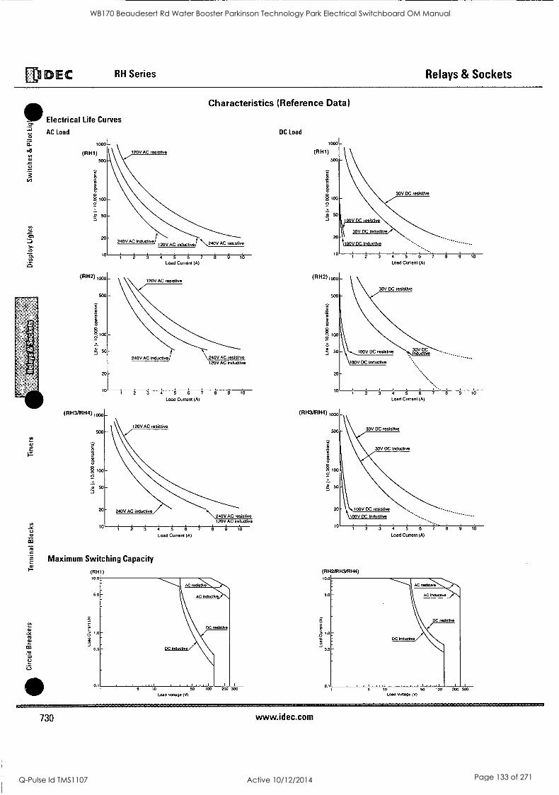
Di EC RH Series Relays & Sockets
Electrical Life Curves
AC Load
loon
ea
OJ
at E F-
(RH1) 500
0
a
§ 100
50 LI
20
10
(RH2) woo
500
.4
a
100
50
20
10
(RH3/RH4)1
20
120V AC resistive
240V AC inductive, 120V AC inductive
Characteristics (Reference Data)
\240V AC resistive
A A 4 A A + 8 A
Load Current (A)
120V AC resistive
240V AC inductive 240V AC resistive 120VAC inductive
i A 4 A A 7 8 61 Load Current (A)
120V AC resistive
240V AC inductive \240V AC resistive
120V AC inductive
2 3 4 5 6 4 . i i 10
Load Current (A)
Maximum Switching Capacity
(RH1) 10.0_
5
AC resistiii
AC inductive
DC resistive
DC inductive
5 i0 SO 100 I i 1,1,1 1 .011.11.1
Load Voltage (V)
DC Load
30V DC resistive
2 3 4 5 6 7 8 9 1
Load Current (A)
(RH2),000
500
Ra
30V DC resistive
10
(RH3/RH4) 1000
100y DC resistive 30V DC IrMUctive
2 3 4 5 6 7 8 9 1
Load Current (A)
30V DC resistive
30V DC inductive
20 100V DC resistive.
\100V DC Inductive
10 2 A 4 A A 7 8 9 10
Load Current (A)
DC inductive
1 1 1 1 1 1 1 1 1 1
to so 100 20o x Load Voltage (V)
730 www.idec.com
WB170 Beaudesert Rd Water Booster Parkinson Technology Park Electrical Switchboard OM Manual
Q-Pulse Id TMS1107 Active 10/12/2014 Page 133 of 271
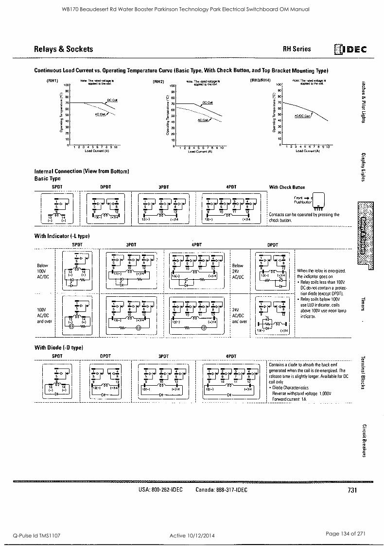
Relays &Sockets RH Series .DEC
Continuous Load Current vs. Operating Temperature Curve (Basic Type, With Check Button, and Top Bracket Mounting Type)
(RH1) 100
90
Eig
5 70
a 60 ; 2 40
0 30
O zo
In
Note: The rated voltage is applied to the coil.
DC Coil
AC Col
1 2 3 4 5 6 7 8 9 10
(RH2) 100
90
:(3. 60
e 70
0 60
50
2' 4°
3° O 20
10
0
Note: The rated voltage is applied to the coil.
DC Coil
AC Cdl
1 2 3 4 5 6 7 8 9 10 Load Current (A) Load Current (A)
Internal Connection (View from Bottom) Basic Type
SPDT DPDT 3PDT
(RH3/RH4) Note: The rated voltage is applied to the coil. 100
90
80
5 70
9 60
5° EP 40
. 3° 0 20
10
0
AC/DC Coil
1 2 3 4 5 6 7 8 9 10
Load Current (A)
4PDT With Check Button
1004 (-)
______ t -n . i'''. 9 1 9 12 .
I L_134_1 _
6 941 113(-) (,)14 J
9 10 11 12
Front Pushbutton
/fir' ' Contacts can be operated by pressing the
13(-) (*)14 j check button.
With Indicator ( -L type)
SPDT 3PDT 4PDT DPDT
...-1> ...-> -1> 5
12 Below
10 11 1
.1 24V
Below
100V
AC/DC i
13 14 (-I 01
.
1
5
' I
13(-) (t):14
I When the relay is energized,
1 the indicator goes on.
1 Relay coils less thane 00V
I DC do not contain a otec-
tion diode (except DPDTL
, Relay coils below 100V
.. AC/DC ago
L_ -aikP- lm
. .
- - - -- - _
[ z
' 5 6 7
I
I 24V 9 10 11 12
I AC/DC I
100V
AC/DC I
and over I
11111111511
D , D = 8 9 10 12
1
5
**4.
I use LED indicator, coils
above 100V use neon lamp 12
indicator.
71114 and over
i
'
111(-) (a)l 4 i
M I @ i
With Diode (-D type)
SPDT 3PDT 4PDT
4 EEF EE?
1 Contains a diode to absorb the back emf
I generated when the coil is de-energized. The
13(-) (+)14
8 5 6
13(-) Diode Characteristics
coil only.
release time is slightly longer. Available for DC
10 12 9 10 11 12
Reverse withstand voltage: 1.000V
Forward current: 1A
O
0
=.1 3
3
USA: 800-262-IDEC Canada: 888-317-IDEC 731
WB170 Beaudesert Rd Water Booster Parkinson Technology Park Electrical Switchboard OM Manual
Q-Pulse Id TMS1107 Active 10/12/2014 Page 134 of 271
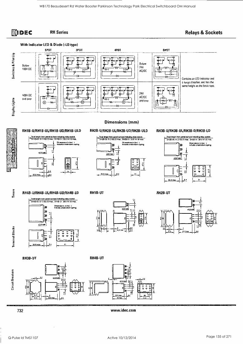
DEC RH Series Relays & Sockets
a) to to ty
.43
With Indicator LED & Diode (-LD type)
Below 100V DC
100V DC
and over
SPDT
5
3PDT 4PDT
1)7 9 10
DPDT
Below
24V
AC/DC
24V
AC/DC
and over
Contains an LED indicator and
a surge absorber, and has the
same height as the basic type.
Dimensions (mm)
RH1B-U/RH1B-UL/RH1B-UD/RH1B-ULD RH2B-U/RH2B-UL/RH2B-UD/RH2B-ULD RH3B-U/RH3B-UL/RH3B-D/RH3B-LD
Told length from panel surlace including relay socket SH18.05: 61.5 (63.5) max., SH1151: 39.6 (41.6) max.
Dimensions in the ( )
include a hold-down spring.
14 _.,.
Total length from panel surface including relay socket Sli2B-05: 61.5 (63.5) max., SH2B-51: 39.6 (41.6) max.
Dimensions in the ( )
include a hold-down spring.
35.6 max. 6.4
RH4B-U/RH4B-UL/RH4B-UD/RH4B-LD RH1B-UT
Told length from panel sun ace including relay socket SH48-05: 61.5 (63.5) max.. SH48-51. 39.6 (41.6) max.
RH3B-UT
Dimensions in the ( )
include a hold-down spring.
-r -r -r
41
21
RH4B-UT
Total length from panel surface including relay socket
SH3B-05: 61.5 (63.5) max SH3B-51: 39.6 (41.6) max.
Dimensions in the ( )
include a hold-down spring.
RH2B-UT
31
732 www.idec.com
WB170 Beaudesert Rd Water Booster Parkinson Technology Park Electrical Switchboard OM Manual
Q-Pulse Id TMS1107 Active 10/12/2014 Page 135 of 271
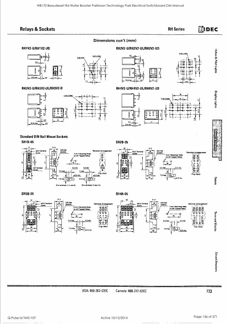
Relays & Sockets RH Series ED DEC
RH1V2-U/RH1V2-UD
55
111
RH3V2-U/RH3V2-UL/RH3V2-D
Dimensions con't (mm)
3-02.4 holes
Standard DIN Rail Mount Sockets
SH1B-05
1.43 5 TOIIIIi1101
31.5
RH2V2-U/RH2V2-UL/RH2V2-UD
21
RH4V2-U/RH4V2-UL/RH4V2-UD
13-o2. Wes
SH2B-05
31.5
SH3B-05
32
M3.5 Tenrinal
(For terminals 1. 5. and 9)
31.5
DIN RI (BNDN)
2.04.2 Mounting Holes (or M4 Tapped Holes)
-0
(For terminals 13 and 14)
1 36 1
4.4 mar. 4 5.5 min.
7.911101. 03.9 *10.
Terminal Arrangement
:41 -11)
T
jeliter (Top Mew)
31.5
Terminal AnangemeM
131,
r,-9 `i
a).
(Top View)
DIN Flab
(BNDN) Terminal Arrangement
2-04.2 Mounting H o h m I - .---.0 .. 7 (or M4 Tapped Holes) 1 T T Ti\ i------. . --.
4.4.0.0. i 1 L. 5.5 min. l4ii IA' F.7
7 ......
114.51 7.9 max.
t I 1 (Top Yew)
CO
,S7* ,-, jJ
ID
IC
10
a ID
USA: 800-262-IDEC Canada: 888-317-IDEC 733
WB170 Beaudesert Rd Water Booster Parkinson Technology Park Electrical Switchboard OM Manual
Q-Pulse Id TMS1107 Active 10/12/2014 Page 136 of 271
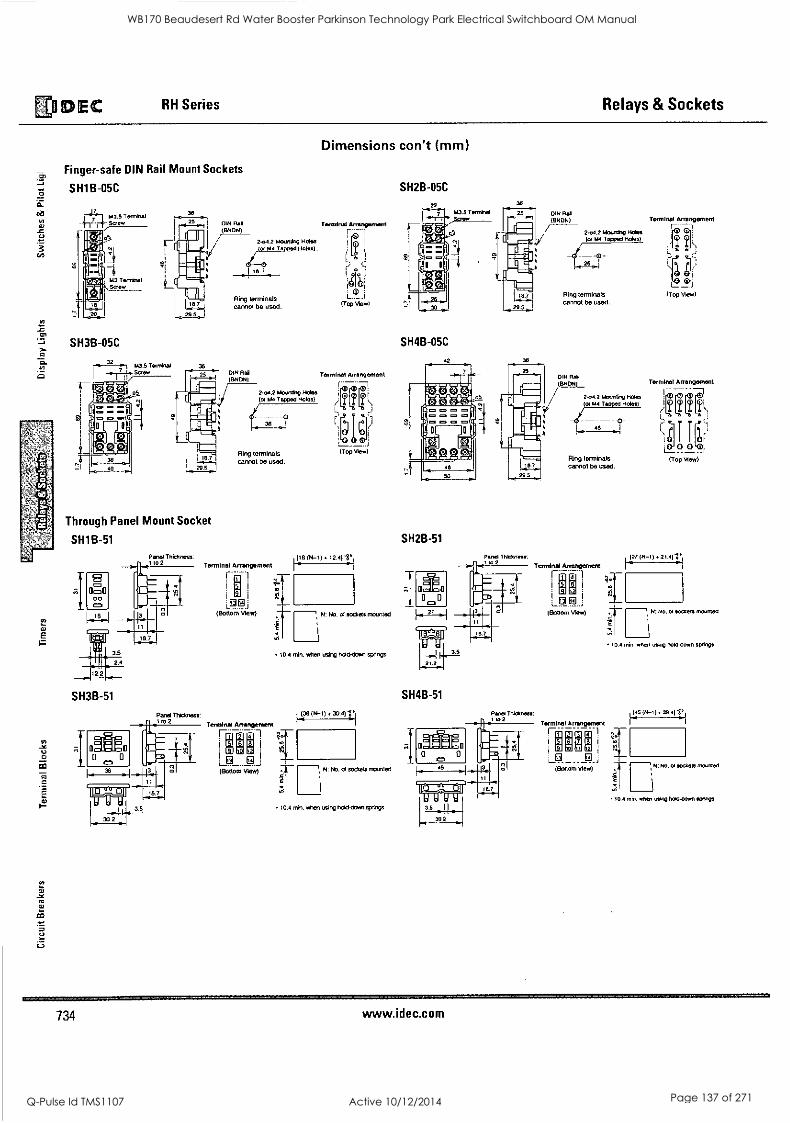
E0 DEC RH Series Relays & Sockets
Yt
..=
E
Finger-safe DIN Rail Mount Sockets
SH1B-05C
30
SH3B-05C
32 1.43.5 Terminal 36
-a-ii-ra7,Screw
05 Imo
27.r1
1M111
18.7
.14
cannot be used. Ring terminals
- - -0
2.4.2 Mounting Holes (or M4 Tapped Holes)
2-04.21140001109 Helen
ior P00 100004 1101001
'8 I -r
Ring terminals cannol be used.
Through Panel Mount Socket
SH1 B-51
SH3B-51
Terminal Arrangement
11
3 I
I I
gig LJ (Bottom View)
Terminal Arrangement
i- 6 021 F9. i j (Bottom View)
Dimensions con't (mm)
Terminal Arrangement
I. 131
I -8 C
IZDtlr
(Top View)
Terminal Arrangement
ci
(Top View)
(N-1). 12.4)
5.
N: No. 01 sockets mounted
10.4 min. when using hold-down springs
1.138 (14-1) 30.41;
N: No. 01 $ecksts mounted
10.4 min. when using hold-clown springs
SH2B-05C
22 -11 M3.5 Terminal
SH4B-05C
36
25
30
DIN Rail (BNDN)
SH2B-51
Panel Thickness:
2.4.2 Mounling Holes lor M4 Tapped Hal)
Ring terminals cannot be used.
DIN Rae ,(BNON)
2-04.2 Mounting Holes (or M4 Tapped Holes)
- - - 48 ..1
Ring terminals cannol be used.
Terminal Arrangement
Terminal Arrangement
TO
(Top View)
Terminal Arrangement
Bt- I
iS 1 1 1r' : 1) _ 1
(Top View)
21.2
SH4B-51
3.5
39.2
(Bottom View)
Terminal Arrenge
0 Mrt
I
iaIJWri M
(Bottom View)
10.4 min. when using hold-down springs
1,[45 (N-1). 39.4) ti
10.4 min. when ming hold-down springs
734 www.idec.com
WB170 Beaudesert Rd Water Booster Parkinson Technology Park Electrical Switchboard OM Manual
Q-Pulse Id TMS1107 Active 10/12/2014 Page 137 of 271
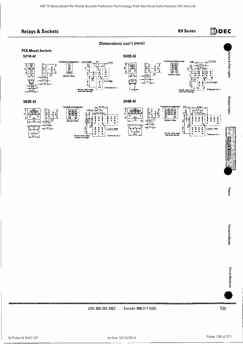
Relays & Sockets RH Series 13)} DEC
PCB Mount Sockets
SH1B-62
SH3B-62
Terminal Arrangement 3,32.4 Mies 6.8
FL-1 i Li r; (Bottom View) *Nt e*
i 43- \ 2.02110188
Dimensions con't (mm)
I 18 nen.
. 0.4
c7;
36 nem when using hold-down seems
Terminal Arrangement
" ..9i
(Bott.T.r.Tiew)
0 (Toieranee 110.1)
SH2B-62
SH4B-62
Terminal ArrangerneM
Fa- Ei I
,
I
n F... ,
.1Q_ El: (Bottom View)
2.85 21.5 min.
34 min. when using hold-down springs
Terminal Arrangement 885 05 min E El a 1
FENT 7; iiTht;Ii
(8on., view) 3
36 mln. when using hold-down smings
(704eranne 00.1) 36 min. when using hold-down springs
+ 411
: 8-02.4110185
4P1 (Tolerance ±0.1)
t t + +
1+02+ mem
+ + + (Tam.. 00.1)
9 01
USA: 800-262-IDEC Canada: 888-317-IDEC 735
WB170 Beaudesert Rd Water Booster Parkinson Technology Park Electrical Switchboard OM Manual
Q-Pulse Id TMS1107 Active 10/12/2014 Page 138 of 271
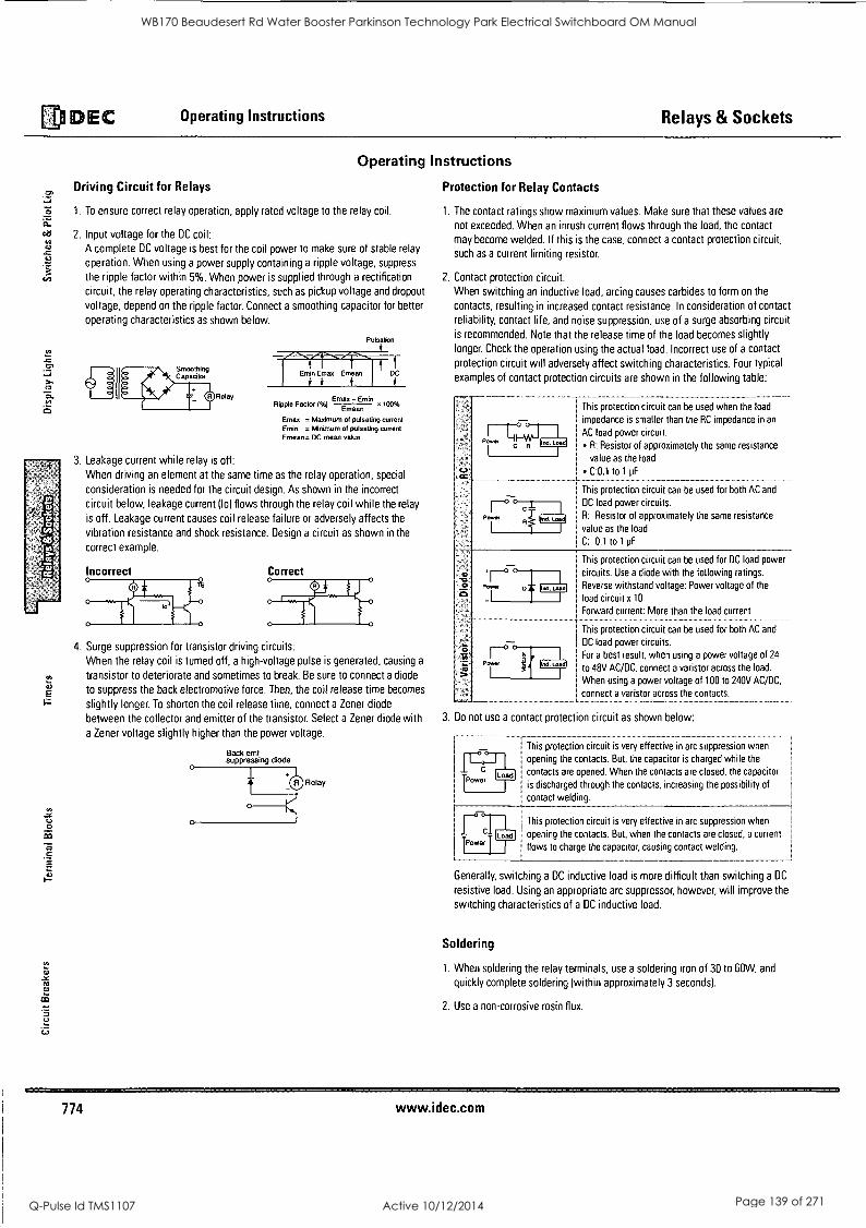
al DEC Operating Instructions Relays & Sockets
ci
10
Operating Instructions
Protection for Relay Contacts
1. The contact ratings show maximum values. Make sure that these values are
not exceeded. When an inrush current flows through the load, the contact
may become welded. If this is the case, connect a contact protection circuit,
such as a current limiting resistor.
2. Contact protection circuit: When switching an inductive load, arcing causes carbides to form on the
contacts, resulting in increased contact resistance. In consideration of contact
reliability, contact life, and noise suppression, use of a surge absorbing circuit is recommended. Note that the release time of the load becomes slightly longer. Check the operation using the actual load. Incorrect use of a contact
protection circuit will adversely affect switching characteristics. Four typical
examples of contact protection circuits are shown in the following table:
Driving Circuit for Relays
1. To ensure correct relay operation, apply rated voltage to the relay coil.
2. Input voltage for the DC coil:
A complete DC voltage is best for the coil power to make sure of stable relay
operation. When using a power supply containing a ripple voltage, suppress
the ripple factor within 5%, When power is supplied through a rectification
circuit, the relay operating characteristics, such as pickup voltage and dropout
voltage, depend on the ripple factor. Connect a smoothing capacitor for better
operating characteristics as shown below.
a Relay
Pulsation
Ripple Factor (%) Erntrno-.Enrnin x 100%
Emax = Maximum of pulsating current Ernie = Minimum of pulsating current Emean= DC mean value
3. Leakage current while relay is off:
When driving an element at the same time as the relay operation, special
consideration is needed for the circuit design. As shown in the incorrect
circuit below, leakage current (lo) flows through the relay coil while the relay
is off. Leakage current causes coil release failure or adversely affects the
vibration resistance and shock resistance. Design a circuit as shown in the
correct example.
Incorrect Correct
4. Surge suppression for transistor driving circuits:
When the relay coil is turned off, a high-voltage pulse is generated, causing a
transistor to deteriorate and sometimes to break. Be sure to connect a diode
to suppress the back electromotive force. Then, the coil release time becomes
slightly longer. To shorten the coil release time, connect a Zener diode
between the collector and emitter of the transistor. Select a Zener diode with
a Zener voltage slightly higher than the power voltage.
Back emf suppressing diode
Relay
I This protection circuit can be used when the load
impedance is smaller than the RC impedance in an
AC load power circuit.
R: Resistor of approximately the same resistance
value as the load
I C:0.1 to 1 pF
I This protection circuit can be used for both AC and
DC load power circuits.
R: Resistor of approximately the same resistance
value as the load
C: 0.1 to 1 pF
This protection circuit can be used for DC load power
circuits. Use a diode with the following ratings.
Reverse withstand voltage: Power voltage of the
load circuit x 10
Forward current: More than the load current
This protection circuit can be used for both AC and
DC load power circuits.
For a best result, when using a power voltage of 24
to 48V AC/DC. connect a varistor across the load.
When using a power voltage of 100 to 240V AC/DC.
connect a varistor across the contacts.
3. Do not use a contact protection circuit as shown below:
This protection circuit is very effective in arc suppression when
opening the contacts. But, the capacitor is charged while the
contacts are opened. When the contacts are closed, the capacitor
is discharged through the contacts, increasing the possibility of
contact welding.
This protection circuit is very effective in arc suppression when
opening the contacts. But, when the contacts are closed, a current Power
flows to charge the capacitor, causing contact welding.
Generally, switching a DC inductive load is more difficult than switching a DC
resistive load. Using an appropriate arc suppressor, however, will improve the
switching characteristics of a DC inductive load.
Soldering
1. When soldering the relay terminals, use a soldering iron of 30 to 60W, and
quickly complete soldering (within approximately 3 seconds).
2. Use a non-corrosive rosin flux.
774 www.idec.com
WB170 Beaudesert Rd Water Booster Parkinson Technology Park Electrical Switchboard OM Manual
Q-Pulse Id TMS1107 Active 10/12/2014 Page 139 of 271
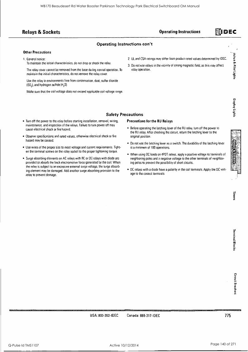
Relays & Sockets Operating Instructions Di DEC
Operating Instructions con't
Other Precautions
1. General notice:
To maintain the initial characteristics, do not drop or shock the relay.
The relay cover cannot be removed from the base during normal operation. To
maintain the initial characteristics, do not remove the relay cover.
Use the relay in environments free from condensation, dust, sulfur dioxide
(SO2), and hydrogen sulfide (FI,S.
Make sure that the coil voltage does not exceed applicable coil voltage range.
2. UL and CSA ratings may differ from product rated values determined by !DEC.
3. Do not use relays in the vicinity of strong magnetic field, as this may affect relay operation.
Safety Precautions
Turn off the power to the relay before starting installation, removal, wiring,
maintenance, and inspection of the relays. Failure to turn power off may
cause electrical shock or fire hazard.
Observe specifications and rated values, otherwise electrical shock or fire
hazard may be caused.
Use wires of the proper size to meet voltage and current requirements. Tight-
en the terminal screws on the relay socket to the proper tightening torque.
Surge absorbing elements on AC relays with RC or DC relays with diode are
provided to absorb the back electromotive force generated by the coil. When
the relay is subject to an excessive external surge voltage, the surge absorb-
ing element may be damaged. Add another surge absorbing provision to the
relay to prevent damage.
Precautions for the RU Relays
Before operating the latching lever of the RU relay, turn off the power to
the RU relay. After checking the circuit, return the latching lever to the
original position.
Do not use the latching lever as a switch. The durability of the latching lever
is a minimum of 100 operations.
When using DC loads on 4PDT relays, apply a positive voltage to terminals of
neighboring poles and a negative voltage to the other terminals of neighbor-
ing poles to prevent the possibility of short circuits.
DC relays with a diode have a polarity in the coil terminals. Apply the DC volt-
age to the correct terminals.
a
3
USA: 800-262-IDEC Canada: 888-317-IDEC 775
WB170 Beaudesert Rd Water Booster Parkinson Technology Park Electrical Switchboard OM Manual
Q-Pulse Id TMS1107 Active 10/12/2014 Page 140 of 271
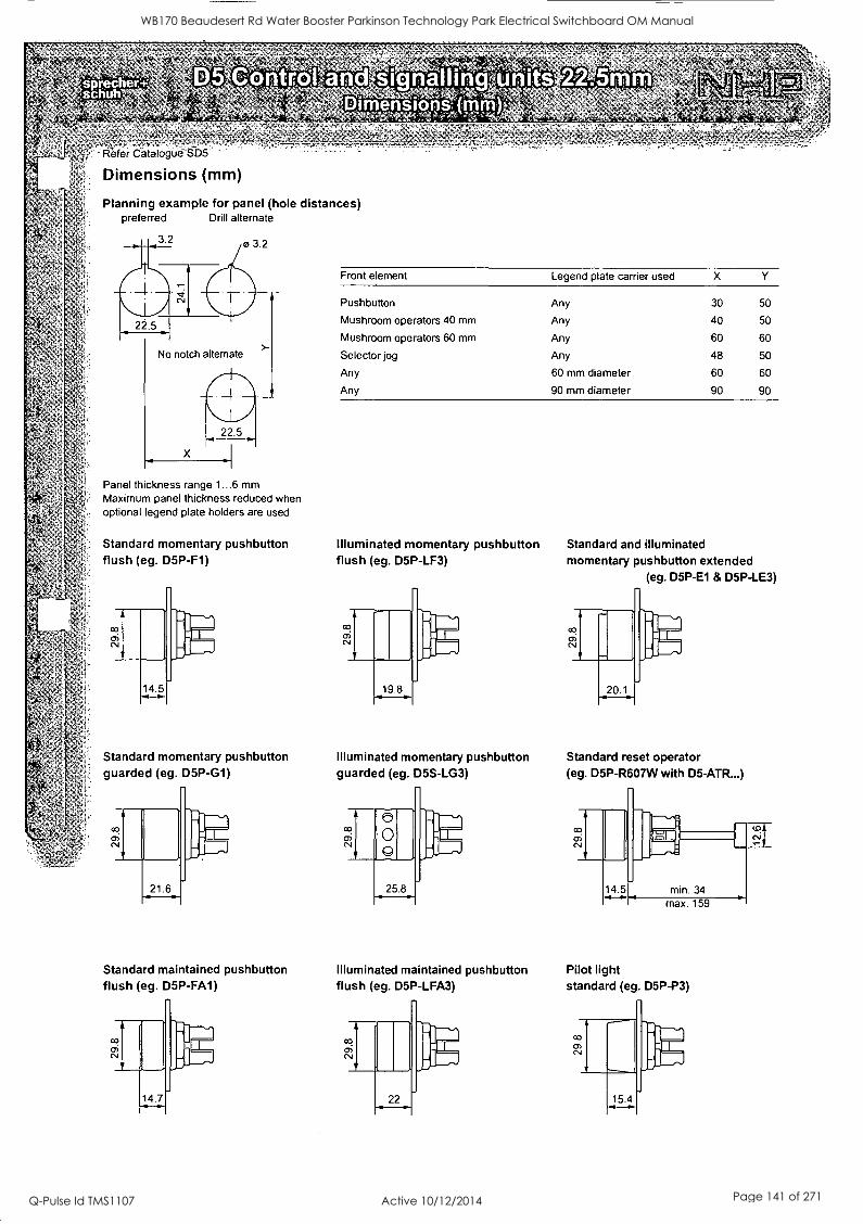
225mm
Wefer Catalogue-SD5
Dimensions (mm)
Planning example for panel (hole distances) preferred Drill alternate
1 3 2
- 032
J 22 5
No notch alternate
X
>-
Panel thickness range 1...6 mm Maximum panel thickness reduced when optional legend plate holders are used
Front element Legend plate carrier used X
Pushbutton Any 30 50
Mushroom operators 40 mm Any 40 50
Mushroom operators 60 mm Any 60 60
Selector jog Any 48 50
Any 60 mm diameter 60 60
Any 90 mm diameter 90 90
Standard momentary pushbutton Illuminated momentary pushbutton flush (eg. D5P-F1)
Standard momentary pushbutton guarded (eg. D5P-G1)
Standard maintained pushbutton flush (eg. D5P-FA1)
flush (eg. D5P-LF3)
Standard and illuminated momentary pushbutton extended
(eg. D5P-E1 & D5P-LE3)
Illuminated momentary pushbutton Standard reset operator guarded (eg. D5S-LG3) (eg. D5P-R607W with D5-ATR...)
14.5 min. 34
Illuminated maintained pushbutton Pilot light flush (eg. D5P-LFA3)
max. 159
standard (eg. D5P-P3)
WB170 Beaudesert Rd Water Booster Parkinson Technology Park Electrical Switchboard OM Manual
Q-Pulse Id TMS1107 Active 10/12/2014 Page 141 of 271
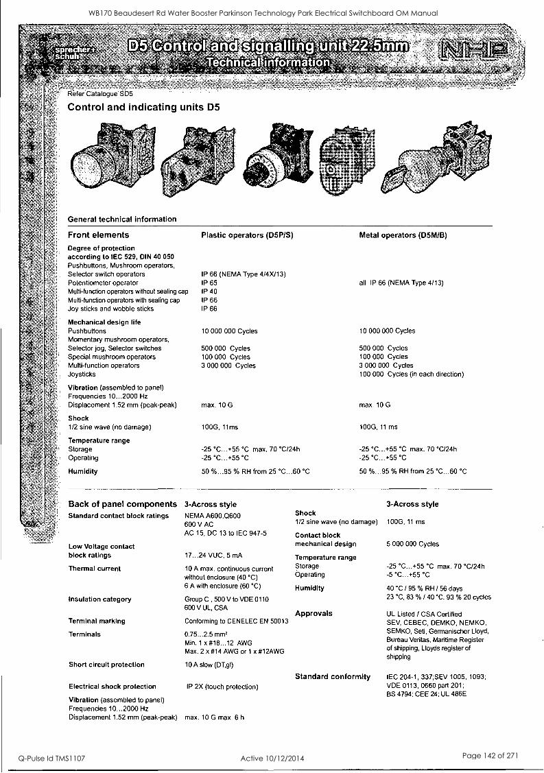
Refer Catalogue SD5
Control and indicating units D5
General technical information
Front elements Degree of protection according to IEC 529, DIN 40 050 Pushbuttons, Mushroom operators, Selector switch operators Potentiometer operator Multi-function operators without sealing cap
Multi-function operators with sealing cap
Joy sticks and wobble sticks
Mechanical design life Pushbuttons Momentary mushroom operators, Selector jog, Selector switches Special mushroom operators Multi-function operators Joysticks
Vibration (assembled to panel) Frequencies 10...2000 Hz
Displacement 1.52 mm (peak-peak)
Shock 1/2 sine wave (no damage)
Temperature range Storage Operating
Humidity
Plastic operators (D5P/S)
IP 66 (NEMA Type 4/4X/13) IP 65 IP 40 IP 66 IP 66
10 000 000 Cycles
500 000 Cycles 100 000 Cycles 3 000 000 Cycles
max. 10 G
100G, 11rns
-25 °C...+55 °C max. 70 °C/24h -25 °C...+55 °C
50 %...95 °A) RH from 25 °C...60 °C
Metal operators (D5M/B)
all IP 66 (NEMA Type 4/13)
10 000 000 Cycles
500 000 Cycles 100 000 Cycles 3 000 000 Cycles 100 000 Cycles (in each direction)
max. 10 G
100G, 11 ms
-25 °C...+55 °C max. 70 °C/24h -25 °C...+55 °C
50 %...95 % RH from 25 °C...60 °C
Back of panel components 3-Across style 3-Across style Standard contact block ratings NEMA A600,Q600 Shock
600 V AC 1/2 sine wave (no damage) 100G, 11 ms
AC 15, DC 13 to IEC 947-5 Contact block
Low Voltage contact mechanical design 5 000 000 Cycles
block ratings 17...24 VUC, 5 mA Temperature range
Thermal current 10 A max. continuous current Storage -25 °C...+55 °C max. 70 °C/24h
without enclosure (40 °C) Operating -5 °C...+55 °C
6 A with enclosure (60 °C) Humidity 40 °C / 95 % RH /56 days
Insulation category Group C , 500 V to VDE 0110 23 °C, 83 % / 40 °C, 93 % 20 cycles
600 V UL, CSA Approvals UL Listed / CSA Certified
Terminal marking
Terminals
Conforming to CENELEC EN 50013
0.75...2.5 mm' Min. 1 x #18...12 AWG Max. 2 x #14 AWG or 1 x #12AWG
SEV, CEBEC, DEMKO, NEMKO, SEMKO, Seti, Germanischer Lloyd, Bureau Veritas, Maritime Register of shipping, Lloyds register of shipping
Short circuit protection 10 A slow (DT,gl)
Standard conformity IEC 204-1, 337;SEV 1005, 1093;
Electrical shock protection IP 2X (touch protection) VDE 0113, 0660 part 201; BS 4794; CEE 24; UL 486E
Vibration (assembled to panel) Frequencies 10...2000 Hz Displacement 1.52 mm (peak-peak) max. 10 G max. 6 h
WB170 Beaudesert Rd Water Booster Parkinson Technology Park Electrical Switchboard OM Manual
Q-Pulse Id TMS1107 Active 10/12/2014 Page 142 of 271
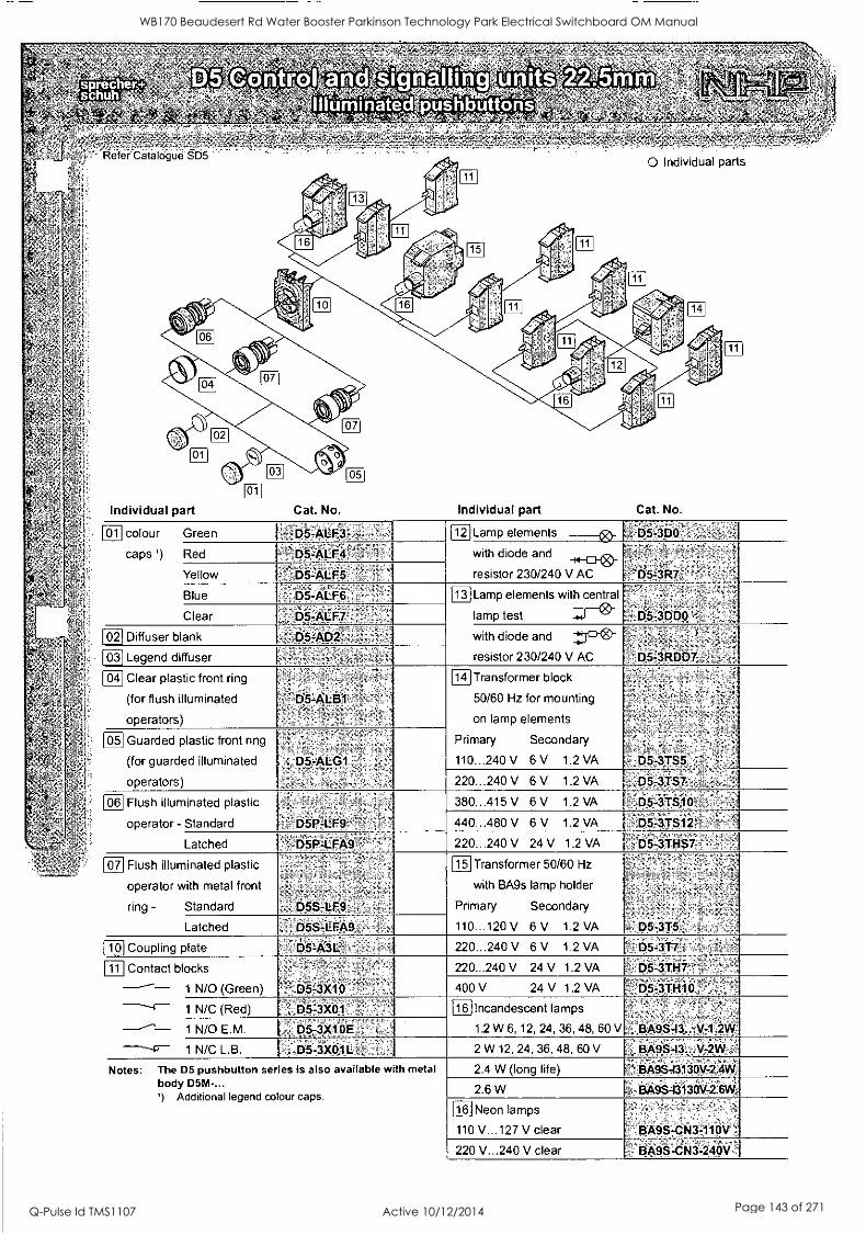
0 0 0 .; ..,-,,,
,,,' ,,= , . e -3 -
0
1061
1131
16
110
Individual part Cat. No.
116
1151
Individual part
0 Individual parts
Cat. No.
1141
colour
caps ) Red
Green
Yellow ,05-ALF5
12. Lamp elements
with diode and
resistor 230/240 V AC
D5-3P0
Blue
Clear
b5-ALF5
7-,D5-ALF7
Diffuser blank D5.AD2,- -
Legend diffuser
13 Lamp elements with central
lamp test
with diode and
resistor 230/240 V AC
D5-3DDO ', ,
'D5:3R667,..;`:
Clear plastic front ring
(for flush illuminated
operators)
65-ALB1'-
Guarded plastic front ring
(for guarded illuminated
operators)
' D5-ALG1
14] Transformer block
50/60 Hz for mounting
on lamp elements
Primary Secondary
110...240V 6V 1.2 VA 65-3TS5
220...240 V 6 V 1.2 VA
Flush illuminated plastic
operator - Standard
380...415 V 6V 1.2 VA - I
440...480 V 6V 1.2 VA
Latched ..D5F-LFA9' 220...240 V 24 V 1.2 VA ;D513THS7
Flush illuminated plastic
operator with metal front
ring - Standard _ D5S-LF9
Latched D5S-LFA9
115 Transformer 50/60 Hz
with BA9s lamp holder
Primary Secondary
110...120V 6V 1.2 VA D5J3T5.
101 Coupling plate :D5-A3L - 220...240 V 6 V 1.2 VA D5-3T7 :
Contact blocks - 1 N/O (Green) .D5=3X10
220...240 V 24 V 1.2 VA 'D5-3TH7
400V 24V 1.2 VA
1 N/C (Red) D5-3X01 ---- 1 N/O E.M. D5-3k1OE
16 Incandescent lamps
1.2W 6, 12, 24, 36, 48, 60 V
1 N/C L.B. D5-3X01L 2W 12, 24, 36, 48, 60 V
Notes: The D5 pushbutton series is also available with metal body D5M-... ') Additional legend colour caps.
2.4 W (long life)
2.6 W
1161 Neon lamps
110 V...127 V clear
220 V...240 V clear
`;65-3TH10'
BA9S-13..-.V=1 2W
BA9S-13.:.V:-2W
SA9S-13130V:24W1
BA9S-131301-2:0W5
1 BA9S-CN3-11-0V '
EiA9S-CN3-2400
WB170 Beaudesert Rd Water Booster Parkinson Technology Park Electrical Switchboard OM Manual
Q-Pulse Id TMS1107 Active 10/12/2014 Page 143 of 271
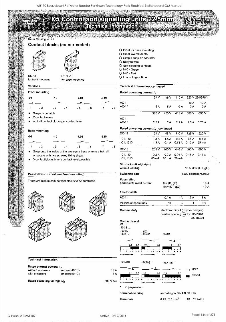
22.5mm
Refer Catalogue'SD5
Contact blocks (colour coded)
D5-3X D5-3BX for front mounting for base mounting
O Front or base mounting O Small overall depth O Simple snap-on contacts O Easy to wire O Self-cleaning contacts O N/O - Green O N/C - Red
O Low voltage - Blue
Versions Technical information, continued
Front mounting Rated operating current /e
-01 -10 -L01 -E10
. 1 . 2 . 3 . 4 . 5 . 6 . 7 . 8
Snap-on on latch
2 contact levels
up to 3 contact blocks per contact level
Base mounting
-01 -10 -L01 -E10
. 1 .2 .3 4 .5 6 .7 .8
Snap onto the inside of the enclosure base or onto a hat rail,
or secure with two screwed fixing straps
3 contact blocks in one contact level possible
Possibilities to combine (Front mounting)
There are maximum 6 contact blocks to be combined
Technical information
Rated thermal current /th without enclosure (ambient 40 °C) with enclosure (ambient 60 °C)
10 A 6A
Rated operating voltage Ue 690 V AC
24 V 48 V 110 V 220 V 230/240 V
AC-1 AC-15 8A 8A 6 A
10 A 3A
10 A 3A
380 V 400 V 415 V 500 V 690 V
AC-1 AC-15 2.5A 2A 2.2A 1.5A 0.75A
Rated operating current /e continued
DC-13 24 V 48V 110V 125V 220 V
-01, -10 -01, -E10
3 A 1.3 A
1.5 A
0.4 A 0.2 A
0.13 A 0.6 A
0.13 A 0.1 A
65 mA
DC-13 250 V 400 V 440 V 500 V 600 V
-01, -10 -01, -E10
0.3 A 65 mA
0.2 A 26 mA
0.04 A 26 mA
0.15 A 0.13 A
Short-circuit withstand without welding
Switching rate
Fuse rating permissible rated current
Electrical life
fast (D, gF) slow (DT, gG)
10 A slow (DT, gG)
6000 operations/hour
16A 10A
AC-11 0.1A 1A 2A 3A
millions of operations 10 3 1 0.5
Contact duty
Contact travel D5-...
800 E-...
-3X10 -3BX10 -36X01
-3X01
electronic circuit (H-type- bridges)
positive opening for: D5-3X01 D5-3BX01
-3X01L
3.3 5.7 1.05 5.7 3.1 5.7 111 IP 1 2 3 4 5 6 0 1 2 3 4
1...1=1 0 1 2 3 4 5 6
mm MIT -I. 10/11
3BX01L -3X10E -3BX10E
3.1 5.7 1.1 5.7 1.1 5.7
11111 FRIPPIR FIRER! 0 1 2 3 4 5 6 0 1 2 3 4 5 6 0 1 2 3 4 5 6
TM mm -Ow in preparation
Terminal marking
Terminals
TT
O open
closed
according to DIN EN 50 013
0.75 ..2.5 mm2 18...12 AWG
WB170 Beaudesert Rd Water Booster Parkinson Technology Park Electrical Switchboard OM Manual
Q-Pulse Id TMS1107 Active 10/12/2014 Page 144 of 271
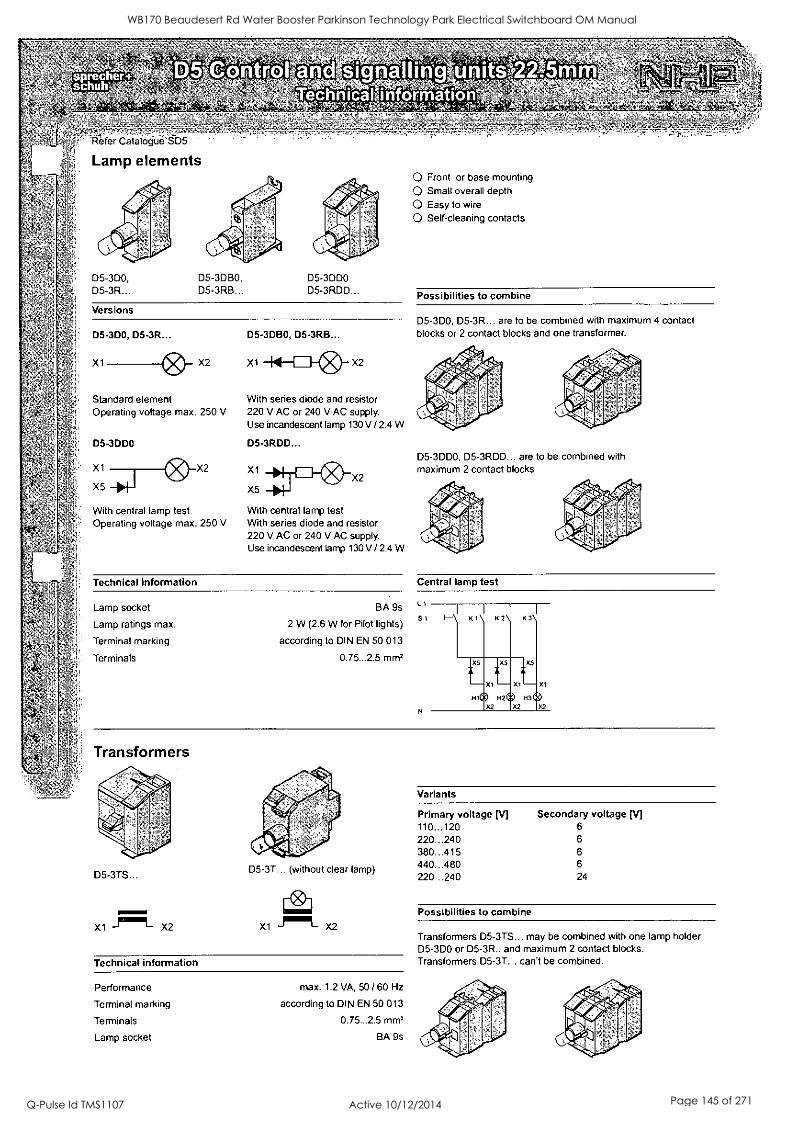
Refer Catalogue SD5
Lamp elements
D5 -3D0, D5-3R
D5-3DBO, D5-3RB
D5-3DDO D5-3RDD
Versions
D5-3D0, D5-3R... D5-3DBO, D5-3RB...
X1 X2 X1 --141I-11 X2
Standard element Operating voltage max. 250 V
D5-3DDO
X1
X5
X2
With central lamp test Operating voltage max. 250 V
With series diode and resistor 220 V AC or 240 V AC supply. Use incandescent lamp 130 V / 2.4 W
D5-3RDD...
X1
X5 X2
With central lamp test With series diode and resistor 220 V AC or 240 V AC supply. Use incandescent lamp 130 V / 2.4 W
Technical information
Lamp socket BA 9s
Lamp ratings max. 2 W (2.6 W for Pilot lights)
Terminal marking according to DIN EN 50 013
Terminals 0.75...2.5 mmz
O Front or base mounting
O Small overall depth
O Easy to wire
O Self-cleaning contacts
Possibilities to combine
D5-3D0, D5-3R are to be combined with maximum 4 contact blocks or 2 contact blocks and one transformer.
D5-3DD0, D5-3RDD... are to be combined with maximum 2 contact blocks
Central lamp test
Li
S1 K1 K2 K3
Hi Qi
L X5
X1
Transformers
D5-3TS...
X1 111m.9 X2
D5-3T... (without clear lamp)
X1 "Imi X2
Technical information
Performance
Terminal marking
Terminals
Lamp socket
max. 1.2 VA, 50 / 60 Hz
according to DIN EN 50 013
0.75...2.5 mm2
BA 9s
Variants
Primary voltage [V] Secondary voltage [V] 110...120 6
220...240 6
380...415 6
440...480 6
220...240 24
Possibilities to combine
Transformers D5-3TS... may be combined with one lamp holder D5-3D0 or D5-3R.. and maximum 2 contact blocks. Transformers D5-3T... can't be combined.
WB170 Beaudesert Rd Water Booster Parkinson Technology Park Electrical Switchboard OM Manual
Q-Pulse Id TMS1107 Active 10/12/2014 Page 145 of 271

A MEM
E E
88 mm
63 mm
45 mm
0001110110,00000000
144 mm
Detailed specifications for ERICO's TRANSIENT DISCRIMINATING FILTER, TDF-10A SERIES
Applications 'itning transients and surges are a major cause of expensive electronic ipment failure and business disruption. Damage may result in loss of
;omputers, data commmunications, loss of revenue, and loss of profits. the new Transient Discriminating FilterTM family of TVSS devices offer ;conomical and reliable protection from power transients with the conven- ence of easy installation on 35mm DIN rail mountings.
the TDF series has been specifically designed for process control applica- ions to protect the switched mode power supply units on devices such as 'LC controllers, SCADA systems and motor controllers. Units are avail- ible for 3A, 10A and 20A loads and in a range of clamping voltages ncluding 30V, 150V, 275V. The range is intended for use in conjunction with ERICO's Universal Transient Barrier UTB's to provide a coordinated approach to protection of both the power and data control circuits.
the TDF is a series connected single phase surge filter providing an aggregate surge capacity of 50kA (8/201.1s) - 201cA L-N & L-G and 101cA
1-G. The space efficient low pass filter, provides some 65dB of attenua- ion to voltage transients. Not only does this reduce the residual let hrough voltage, but it helps further reduce the steep rates of rise of volt- age and current providing superior protection for sensitive electronic ;quipment.
Features Compact design fits into most distribution boards and motor control centres
High efficiency filtering - ideal for the protection of switched mode power supplies from large dv/dt and di/dt transients
Three modes of protection L-N, L-G, N-G
35mm DIN rail mount - DIN 43 880 profile matches common MCB's
LED indication and opto-isolated output for remote status monitoring
Transient Discriminating Technology ensures safe operation during abnormal over-voltage events
UL1449 Edition 2 recognized
Large 501cA surge capacity provides a
high level of protection and long operational life
5 year limited warranty
CO®
WB170 Beaudesert Rd Water Booster Parkinson Technology Park Electrical Switchboard OM Manual
Q-Pulse Id TMS1107 Active 10/12/2014 Page 146 of 271
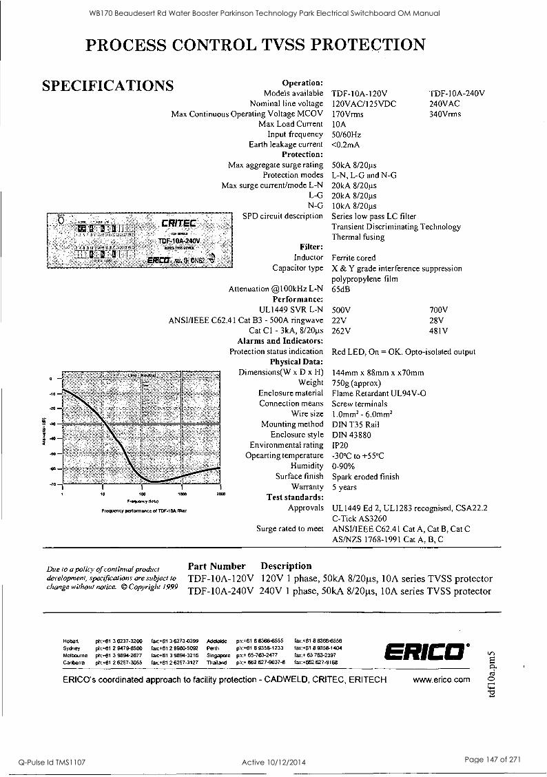
PROCESS CONTROL TVSS PROTECTION
SPECIFICATIONS Operation: Models available
Nominal line voltage Max Continuous Operating Voltage MCOV
Max Load Current Input frequency
Earth leakage current Protection:
Max aggregate surge rating Protection modes
Max surge current/mode L-N L-G N-G
SPD circuit description
+,=1141INNIcill
r.? ,4 e 1 to 3 ?it 93 4i:::: 4.:62s,?:
-LALE:1111_,._
TDF- 1OA -240V
rx ER11:17 six. at ON62
t Filter:
Inductor Capacitor type
Attenuation @100kHz L-N Performance:
UL1449 SVR L-N ANSUIEEE C62.41 Cat B3 - 500A ringwave
Cat Cl - 3kA, 8/20us Alarms and Indicators:
Protection status indication Physical Data:
Dimensions(W x D x H) Weight
Enclosure material Connection means
Wire size Mounting method
Enclosure style Environmental rating
Opearting temperature Humidity
Surface finish Warranty
Test standards: Approvals Frequency performance of TDF-10A fitter
Surge rated to meet
TDF-10A-I 20V 120VAC/125VDC 170Vrms 10A 50/60Hz <0.2mA
TDF-10A-240V 240VAC 340Vrrns
50kA 8/20us L-N, L-G and N-G 20kA 8/20us 20kA 8/2011s
10kA 8/20p Series low pass LC filter Transient Discriminating Technology Thermal fusing
Ferrite cored X & Y grade interference suppression polypropylene film 65dB
500V 22V 262V
700V 28V 481V
Red LED, On = OK. Opto-isolated output
144mm x 88mm x x7Omm 750g (approx) Flame Retardant UL94V -O Screw terminals 1.0mm2 - 6.0mm2 DIN T35 Rail DIN 43880 IP20 -30°C to +55°C 0-90% Spark eroded finish 5 years
UL1449 Ed 2, UL1283 recognised, CSA22.2 C-Tick AS3260 ANSUIEEE C62.41 Cat A, Cat B, Cat C AS/NZS 1768-1991 Cat A, B, C
Due to a policy of continual product development, specifications are subject to change without notice. © Copyright 1999
Part Number Description TDF-10A-120V 120V 1 phase, 50kA 8/20p.s, 10A series TVSS protector TDF-10A-240V 240V 1 phase, 50kA 8/20ps, 10A series TVSS protector
Hobart
Sydney Melbourne
Canberra
ph:+61 3 6237-3200 ph:+61 2 9479-8500
ph:+61 3 9894-2677 ph:+61 2 6257-3055
tatc+61 3 6273-0399
fatc+61 2 9980-5092
fax+61 3 9894-3216 fax+61 2 6257-3127
Adelaide p:+61 8 8366-6555 Perth ph:+61 8 9358-1233
Singapore ph:* 65-763-2477
Thailand pir+ 662 627-9037-8
fax:+61 8 8366-6556 fax:.61 8 9358-1404 fax:* 65 763-2397 fax:+662 627-9168
ERICEI° ERICO's coordinated approach to facility protection - CADWELD, CRITEC, ERITECH www.erico.com
WB170 Beaudesert Rd Water Booster Parkinson Technology Park Electrical Switchboard OM Manual
Q-Pulse Id TMS1107 Active 10/12/2014 Page 147 of 271

v.
00000000
72 mm
E E 0 r-
88 mm
63 mm
45 mm
I I
-
Detailed Specifications for ERICO's TDS-DINLINE SURGE DIVERTER TDS180-4S
Applications Lightning transients and surges are a major cause of expensive electronic equip- ment failure and business disruption. Damage may result in loss of computers, data and communications, loss of revenue, and loss of profits. The new TDS- DINLINE family of surge diverters and filters offer economical and reliable protection from power transients in even the most strenuous applications.
Transient Discriminating Technology (TDS) introduces the first quantum leap in transient suppression technology for mains powered equipment. It offers a new
level of safety and reliability, yet retains optimum protection levels critical for electronic equipment. TDS is an active frequency based device that discriminates between the slower mains voltages and the higher speed transients. When transient frequencies are detected the patented TDS "Quick-Switch" technology "switches in" robust protection devices to limit the transient to safe levels. The frequency discrimination circuit controlling the TDS "Quick-Switch" ensures that
the device is virtually immune to the effects of the 50/60Hz sustained over- voltages, allowing fault voltages of up to 480Vrms without degradation, and
providing over-voltage robustness in excess of the demanding new and emerging standards.
TDS technology is essential for any site where abnormal over-voltages can occur or where the possible catastrophic failure of traditional technologies due to over- voltage events can not be tolerated.
The TDS180-4S unit provides this technology in a single mode shunt-only, 72mm width module. Its unique design allows it to be configured for Ph-N or Ph-E or N-E applications.
Rated to a surge capacity of 80kA (8/20p), internally 1601cA of surge material is
provided for additional robustness and to provide long service life. The unit is
designed for sites with a medium risk of transients or for secondary protection applications. For the protection of high exposure sites or critical equipment higher surge rated TDS DINLINE units, or TDS MOVTECTM should be in- stalled.
Features Robust against abnormal over-voltage
UL1449 Edition 2 compliant
Single phase primary protection for medium exposure sites or secondary protection applications
Single mode protection, configurable to Ph-N, Ph-E or N-E protection
35mm DIN rail mount, DIN 43 880
profile matches common MCBs
72mm width compact design fits into most switch and distribution boards
Electronic status indicator ideal for poorly illuminated locations
Long Service life
Optional retrofittable TDS Alarm Relay for remote alarms
CO®
WB170 Beaudesert Rd Water Booster Parkinson Technology Park Electrical Switchboard OM Manual
Q-Pulse Id TMS1107 Active 10/12/2014 Page 148 of 271
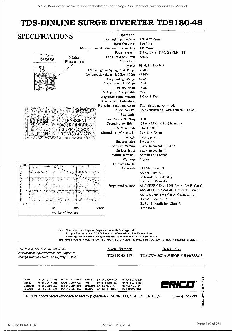
TDS-DINLINE SURGE DIVERTER TDS180-4S SPECIFICATIONS Operation:
Nominal input voltage 220 -277 Vrms
Input frequency 50/60 Hz
Max. permissible abnormal over-voltage 480 Vrms
Power systems TN-C, TN-S, TN-C-S (MEN), IT Status Earth leakage current <2mA
Elect onics Protection: Modes Ph-N, Ph-E or N-E
Let through voltage @ 3kA 8/20gs <720V
Let through voltage @ 20kA 8/20gs <910V
Surge rating 8/20ps 80kA
Surge rating 10 /350µs 16kA
Energy rating 38401
MultipulseTM capability Yes
Aggregate surge material 160kA 8/20ps
Alarms and Indicators: Protection status indication Two, electronic. On = OK
Alarm contacts User configurable, with optional TDS-AR
Physicals:
Environmental rating IP20
Operating conditions -35 to +55°C, 0-90% humidity
Enclosure style DIN 43880
Dimensions (W x D x H) 72 x 88 x 70mm
Weight 350g (approx.)
Encapsulation Shockguard
Enclosure material Flame Retardent UL94V-0
Surface finish Spark eroded finish
Wiring terminals Accepts up to 6mm2
Warranty 5 years
Test standards: Approvals UL1449 Edition 2
AS 3260, IEC 950
Certificate of suitability,
Electricity Regulator
Surge rated to meet ANSI/IEEE C62.41-1991 Cat A, Cat B, Cat C.
ANSI/IEEE C62.45 -1987 Life cycle testing.
AS/NZS 1768-1991 Cat A, Cat.B, Cat C.
BS 6651:1992 Cat A, Cat B.
IEC801-5 Installation Class 5.
IEC 61643-1
Cr
Ss
T1 T2
2 4,8 810121416i
L_L_ Tin ALARM
ERICCT
TRANSIENT -
DISCRIMINATING SUPPRESSOR TDS180-4S-277
10
1 20 1000
Number of Impulses
10000
Note: Other operating voltages and frequencies are available on application. For specifications on other DINLINE products, refer to relevant Specifications Sheet.
Exceeding nominal operating voltage while transient events occur may affect product life. TDS, MULTIPULSE, PROLINE, CRITEC, MOVTEC, DINLINE and SURGE REDUCTION FILTER are trademarks of ERICO.
Due to a policy of continual product development, specifications are subject to change without notice. © Copyright 1998
Model Number Description
TDS180-4S-277 TDS 277V 80KA SURGE SUPPRESSOR
Hobart ph:+61 3 6237-3200 fac+61 3
Sydney ph:+61 2 9479-8500 fac+61 2
Melbourne ph:+61 3 9894-2677 faic+61 3
Canberra ph:+61 2 6257-3055 fa+61 2
6273-0399 Adelaide ph: +61 8 8366-6555 fax:+61 8 8366-6556 9980-5092 Perth ph:+61 8 9358-1233 fax:+61 8 9358-1404 9894-3216 Singapore ph:+ 65-763-2477 fax:. 65 763-2397 6257-3127 Thailand ph:+ 662 627-9037-8 fax:+662 627-9168
ERICO° ERICO's coordinated approach to facility protection - CADWELD, CRITEC, ERITECH www.erico.com
WB170 Beaudesert Rd Water Booster Parkinson Technology Park Electrical Switchboard OM Manual
Q-Pulse Id TMS1107 Active 10/12/2014 Page 149 of 271
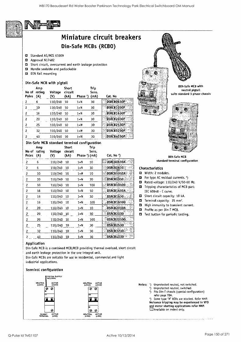
Miniature circuit breakers Din-Safe MCBs (RCBO)
El Standard AS/NZS 61009
O Approval N17482
O Short circuit, overcurrent and earth leakage protection O Handle sealable and padlockable
DIN Rail mounting
Din-Safe MCB with pigtail Amp
No of rating Poles (Al
Short Voltage circuit
V kA
Trip Sens.
Phase ' mA Cat. No
2 6 110/240 10 1+N 30 -DSRCB0630R .
2 10 110/240 10 1+N 30 DSitCB1030P
2 16 110/240 10 1+N 30 OSRCB1630P
2 20 110/240 10 1+N 30 DSRCB2030P
2 25 110/240 10 1+N 30 -DSRC82530P I
2 32 110/240 10 1+N 30 ' DSRCB3230P.
2 40 110/240 10 1+N 30 DSRCB403OR '
Din-Safe MCB standard terminal configuration Amp
No of rating Poles (A)
Voltage (V)
Short Trip circuit Sens. (kA) Phase 2) (mA) Cat. No')
2 6 110/240 10 1+N 10 a DSRCB0610A
2 6 110/240 10 14-N 30 DSReB0630
2 10 110/240 10 1+N 10 - DSRC81010A
2 10 110/240 10 1+N 30 DSRCB1030
2 10 110/240 10 1+N 100 DSRCB10100 .
2 16 110/240 10 1+N 10 DSRCB1610A
2 16 110/240 10 1+N 30 DSRCB1630
2 16 110/240 10 1+N 100 DSRCB16100'
2 20 110/240 10 1+N 10 DSRCB2010A
2 20 110/240 10 1+N 30 -
, .
DSRCB2030
2 20 110/240 10 1+N 100 DSRCB20100
2 25 110/240 10 1+N 30 DSRCB2530
2 32 110/240 10 1+N 30 DSRCB3230 c
2 40 110/240 10 1+N 30 - DSRCB4030
Application Din-Safe MCB is a combined MCB/RCD providing thermal overload, short circuit
and earth leakage protection in the one integral unit. Din-Safe MCBs are suitable for use in residential, commercial and light industrial applications.
Terminal configuration
NEUTRAL (LOAD)
N
PIGTAIL SUPPLY NEUTRAL
ACTIVE (LOAD)
CI"
DUMMY ACTIVE TERMINAL (LINE)
NEUTRAL ACTIVE (LOAD) (LOAD)
0
Jia N
0 0 NEUTRAL ACTIVE
(LINE) (LINE)
DIN-Safe MCB with neutral pigtail
suits standard 3 phase chassis
DIN-Safe MCB
standard terminal configuration
Characteristics O Width: 2 modules.
For type AC residual currents.
O Rated voltage: 110/240 V/50-60 Hz.
O Tripping characteristics of MCB part:
IEC 60848 - C curve.
O Short circuit capacity: 10 kA.
O Terminal capacity: 25 mm2.
O High immunity to transient current.
O Profile as per Din-T MCB.
Test button for periodic testing.
Notes: ') Unprotected neutral, not switched. 2) Unprotected neutral, switched. ') Fits Din-T chassis (special configuration)
refer page TBA.
`) Some type "A" RCDs are stocked. Refer NHP.
Nuisance tripping may be experienced in VFD
and motor starting applications refer NHP.
Available on indent only.
WB170 Beaudesert Rd Water Booster Parkinson Technology Park Electrical Switchboard OM Manual
Q-Pulse Id TMS1107 Active 10/12/2014 Page 150 of 271
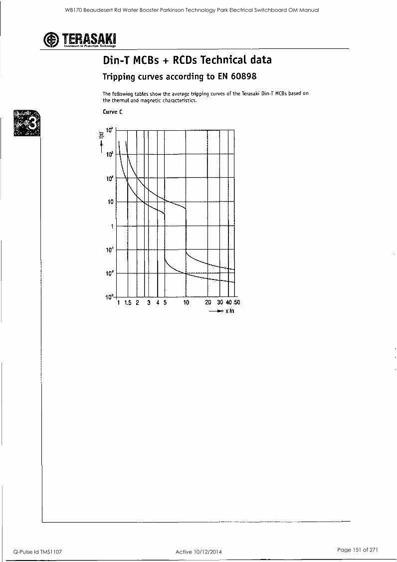
aInnovators in Protection Technology TERASAKI
Din-T MCBs + RCDs Technical data
Tripping curves according to EN 60898
The following tables show the average tripping curves of the Terasaki Din-T MCBs based on
the thermal and magnetic characteristics.
Curve C
041
los
102
10
10'
104
10' 1 1 5 2 3 4 5 10 20 30 40.50
x In
WB170 Beaudesert Rd Water Booster Parkinson Technology Park Electrical Switchboard OM Manual
Q-Pulse Id TMS1107 Active 10/12/2014 Page 151 of 271
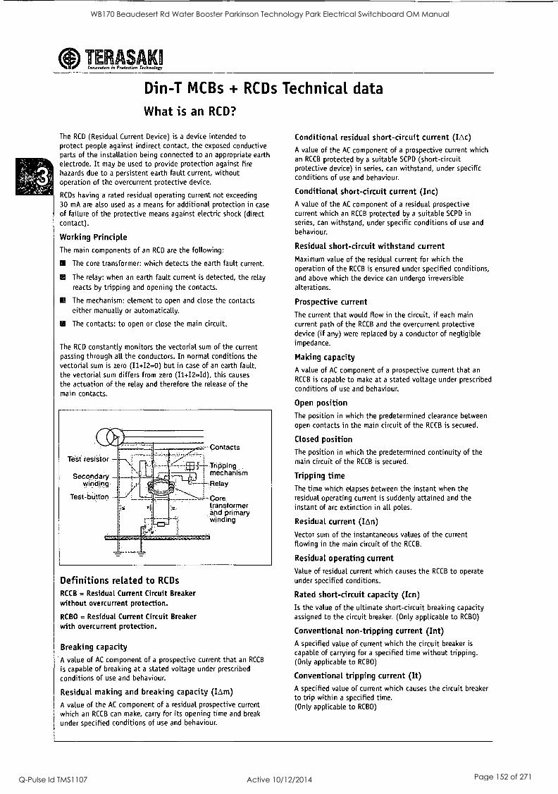
TE ASAK innovators in Protection Technology
Din-T MCBs + RCDs Technical data
What is an RCD?
The RCD (Residual Current Device) is a device intended to protect people against indirect contact, the exposed conductive parts of the installation being connected to an appropriate earth electrode. It may be used to provide protection against fire hazards due to a persistent earth fault current, without operation of the overcurrent protective device.
RCDs having a rated residual operating current not exceeding 30 mA are also used as a means for additional protection in case
of failure of the protective means against electric shock (direct contact).
Working Principle
The main components of an RCD are the following:
NI The core transformer: which detects the earth fault current.
ES The relay: when an earth fault current is detected, the relay
reacts by tripping and opening the contacts.
IS The mechanism: element to open and close the contacts either manually or automatically.
ES The contacts: to open or close the main circuit.
The RCD constantly monitors the vectorial sum of the current passing through all the conductors. In normal conditions the vectorial sum is zero (11+12=0) but in case of an earth fault, the vectorial sum differs from zero (I142-Id), this causes
the actuation of the relay and therefore the release of the main contacts.
Tett resistor -
Secondary - winding-
Test- button -
Contacts
4- Tr i ppi ng i mechanism
Core transformer and priMary winding
Definitions related to RCDs
RCCB = Residual Current Circuit Breaker without overcurrent protection.
RCBO = Residual Current Circuit Breaker with overcurrent protection.
Breaking capacity
A value of AC component of a prospective current that an RCCB
is capable of breaking at a stated voltage under prescribed
conditions of use and behaviour.
Residual making and breaking capacity (IAm)
A value of the AC component of a residual prospective current which an RCCB can make, carry for its opening time and break
under specified conditions of use and behaviour.
Conditional residual short-circuit current (IAc) A value of the AC component of a prospective current which an RCCB protected by a suitable SCPO (short-circuit protective device) in series, can withstand, under specific conditions of use and behaviour.
Conditional short-circuit current (Inc) A value of the AC component of a residual prospective current which an RCCB protected by a suitable SCPD in series, can withstand, under specific conditions of use and
behaviour.
Residual short-circuit withstand current
Maximum value of the residual current for which the operation of the RCCB is ensured under specified conditions, and above which the device can undergo irreversible alterations.
Prospective current
The current that would flow in the circuit, if each main current path of the RCCB and the overcurrent protective device (if any) were replaced by a conductor of negligible impedance.
Making capacity
A value of AC component of a prospective current that an
RCCB is capable to make at a stated voltage under prescribed conditions of use and behaviour.
Open position The position in which the predetermined clearance between open contacts in the main circuit of the RCCB is secured.
Closed position
The position in which the predetermined continuity of the main circuit of the RCCB is secured.
Tripping time The time which elapses between the instant when the residual operating current is suddenly attained and the instant of arc extinction in all poles.
Residual current (ILA)
Vector sum of the instantaneous values of the current flowing in the main circuit of the RCCB.
Residual operating current
Value of residual current which causes the RCCB to operate under specified conditions.
Rated short-circuit capacity (Icn)
Is the value of the ultimate short-circuit breaking capacity assigned to the circuit breaker. (Only applicable to RCBO)
Conventional non-tripping current (Int) A specified value of current which the circuit breaker is
capable of carrying for a specified time without tripping. (Only applicable to RCBO)
Conventional tripping current (It) A specified value of current which causes the circuit breaker to trip within a specified time. (Only applicable to RCBO)
WB170 Beaudesert Rd Water Booster Parkinson Technology Park Electrical Switchboard OM Manual
Q-Pulse Id TMS1107 Active 10/12/2014 Page 152 of 271
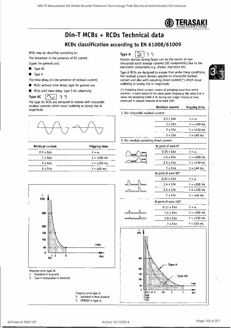
TERASAKII Innovators In Protertion Technology
Din-T MCBs + RCDs Technical data
RCDs classification according to EN 61008/61009 RCDs may be classified according to:
The behaviour in the presence of DC current
(types for general use).
E Type AC
Type A
The time-delay (in the presence of residual current)
RCDs without time delay: type for general use
RCDs with time delay: type S for selectivity
Type AC (\, 1) 2)
The type AC RCDs are designed to release with sinusoidal residual currents which occur suddenly or slowly rise in magnitude.
Residual current
0.5 x IAn
1 x IAn
2 x 'An
5 x IAn
Tripping time
t =
t = <300 ms
t = <150 ms
t = <40 ms
Tripping curve type AC
') Standard in Australia ') Type A acceptable in Australia
Tripping curve type A
') Standard in New Zealand
`) DSRCBH is type A.
Type A 3) 4)
Certain devices during faults can be the source of non-
sinusoidal earth leakage currents (DC components) due to the electronic components e.g. diodes, thyristors etc.
Type A RCDs are designed to ensure that under these conditions the residual current devices operate on sinusoidal residual current and also with pulsating direct current(*) which occur suddenly or slowly rise in magnitude.
() Pulsating direct current: current of pulsating wave form which assumes, in each period of the rated power frequency, the value 0 or a
value not exceeding 0.006 A DC during one single interval of time, expressed in angular measure of at least 150°.
Residual current Tripping time
1. For sinusoidal residual current
0.5 x IAn
1 x IAn
2 x IAn
5 x IAn
t =oo
t = <300 ms
t = <150 ms
t <40 ms
2. For residual pulsating direct current
At point of wave 0°
0.35 x IAn
1.4 x IAn
2.8 x IAn
7 x IAn
At point of wave 90°
0.25 x IAn
1.4 x IAn
2.8 x IAn
7 x IAn
At point of wave 135°
0.11 x IAn
1.4 x IAn
2.8 x IAn
7 x IAn
t =oo
t = <300 ms
t = <150 ms
t = <40 ms
t = co
t = <300 ms
t = <150 ms
t = <40 ms
t = ao
t = <300 ms
t = <150 ms
t = <40 ms
330
200
150
100
-1-r-
40 4
.51 1.4 2'
0.35 1025
-041
- Type A
Type AC
i rot+.
7
WB170 Beaudesert Rd Water Booster Parkinson Technology Park Electrical Switchboard OM Manual
Q-Pulse Id TMS1107 Active 10/12/2014 Page 153 of 271
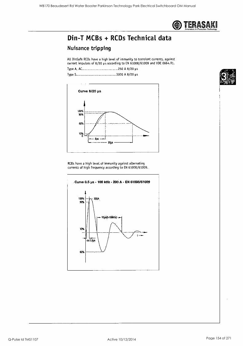
aInnovators in Protection Technolo TERASAK1
Din-T MCBs + RCDs Technical data
Nuisance tripping
All Din Safe RCDs have a high level of immunity to transient currents, against current impulses of 8/20 ps according to EN 61008/61009 and VDE 0664.T1.
Type A, AC 250 A 8/20 ps
Type S 3000 A 8/20 ps
RCDs have a high level of immunity against alternating currents of high frequency according to EN 61008/61009.
Curve 0.5 ps - 100 kHz - 200 A - 61008/61009
WB170 Beaudesert Rd Water Booster Parkinson Technology Park Electrical Switchboard OM Manual
Q-Pulse Id TMS1107 Active 10/12/2014 Page 154 of 271
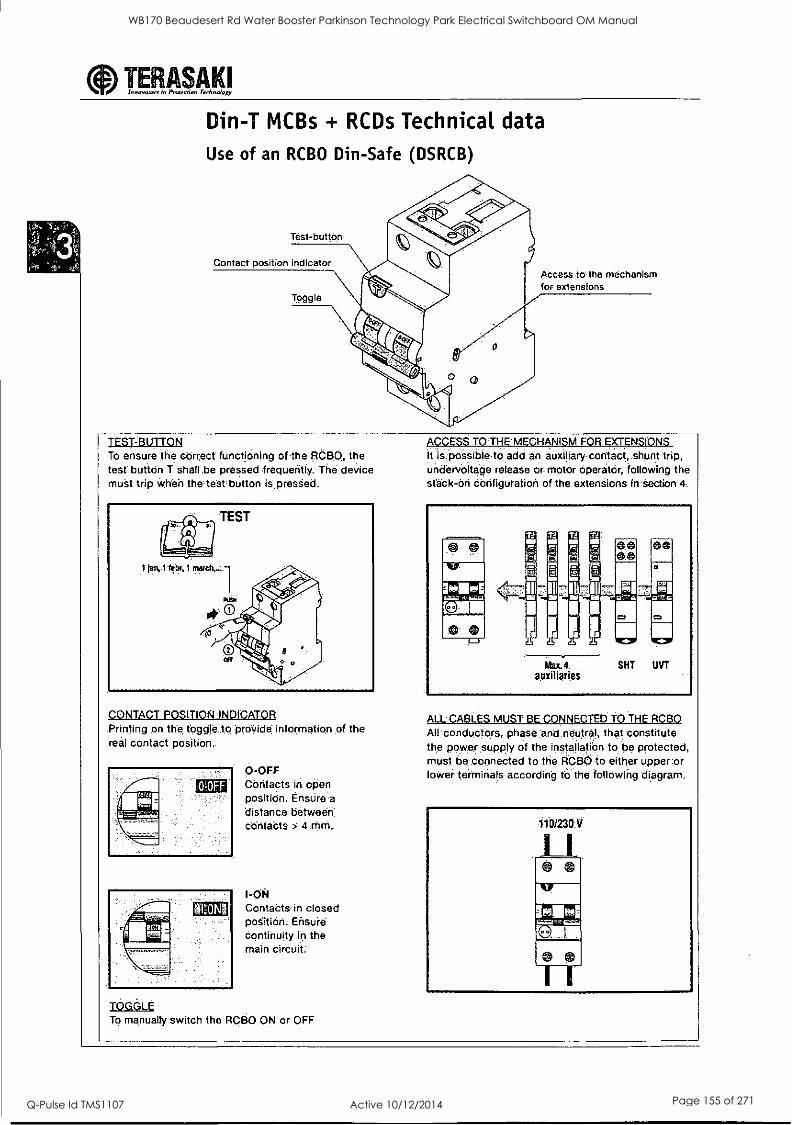
aInnovators in Protection Technology TERASAKI
Din-T MCBs + RCDs Technical data
Use of an RCBO Din-Safe (DSRCB)
Test-button
Contact position Indicator Abcess to the mechanism for extensions
TEST-BUTTON To ensure the correct functiOning of the RCBO, the test button T shall be pressed frequently. The device must trip When the test button is presSed.
CONTACT POSITION INDICATOR Printing on the toggle to provide information of the real contact position.
Contacts' in open position. EnsUre a
distance between contacts > 4 MM.
I-061 ContaCts in closed poSition. Ensure continuity in the main circuit
TOGGLE To manually switch the RCBO ON or OFF
ACCESS TOTHEMECHANISM FOR EXTENSIONS itfis possible add an auxiliary contact, shunt trip, undervoltage release or.. motor Operator; following the Stack-On configuration of the extensions in 'Section 4:
ALLCABLES MUST BE CONNECTED TO THE RCBO All conductors, phase; nd neutral, that constitute the power supply of the installatiOn to be protected, must be.connected to the RCBO to either upper or lower terminals according to the following diagram.
110/230Y
1 1
0 0
WB170 Beaudesert Rd Water Booster Parkinson Technology Park Electrical Switchboard OM Manual
Q-Pulse Id TMS1107 Active 10/12/2014 Page 155 of 271
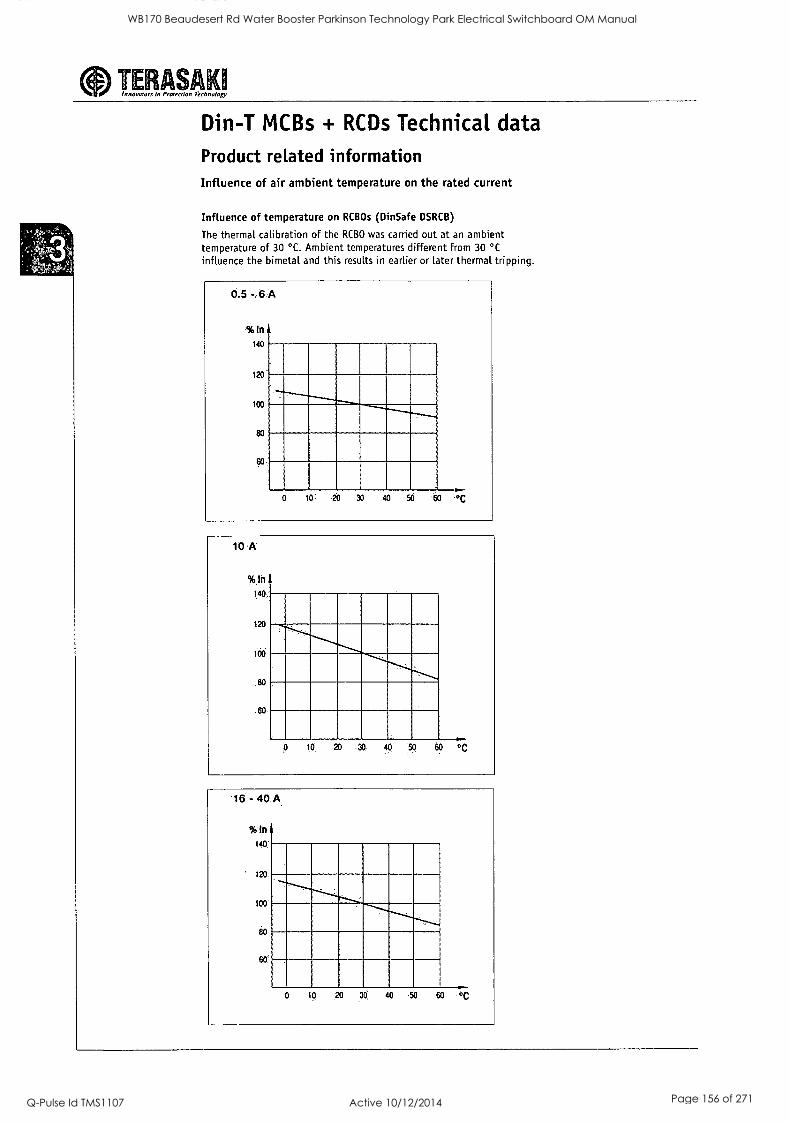
aInnovutom in Protection Technology TE ASAK
Din-T MCBs + RCDs Technical data
Product related information Influence of air ambient temperature on the rated current
Influence of temperature on RCBOs (Din Safe DSRCB)
The thermal calibration of the RCBO was carried out at an ambient temperature of 30 °C. Ambient temperatures different from 30 °C
influence the bimetal and this results in earlier or later thermal tripping.
0.5 - 6 A
%In 140
120
loo
so
iol 20 30 40 50 -60 °C
WB170 Beaudesert Rd Water Booster Parkinson Technology Park Electrical Switchboard OM Manual
Q-Pulse Id TMS1107 Active 10/12/2014 Page 156 of 271
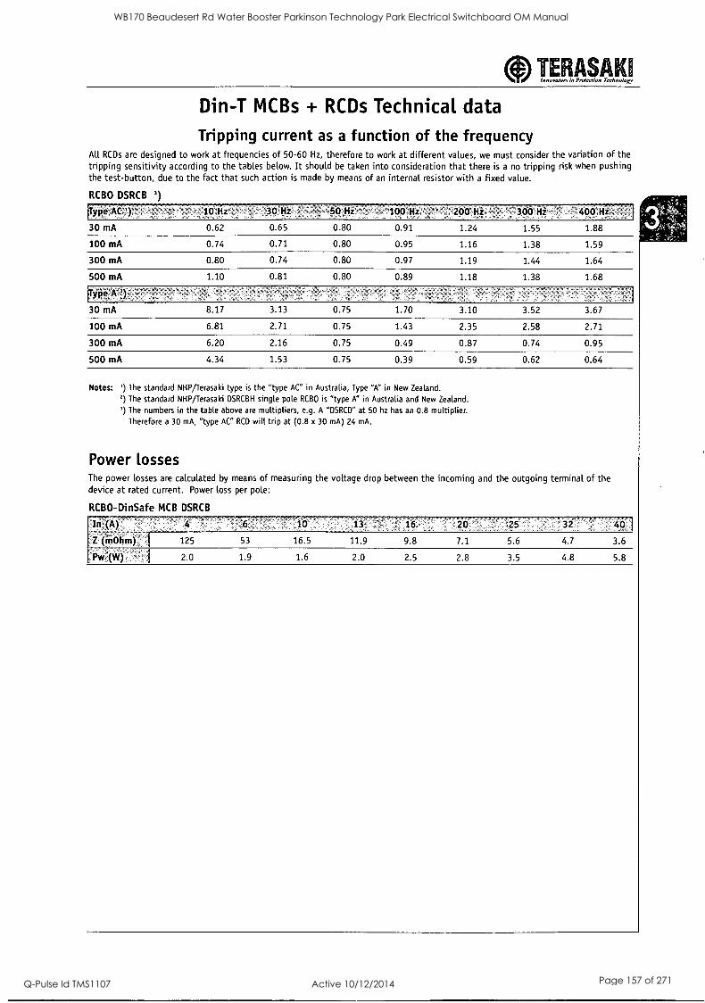
aInnovaton in Prufection Technoloxy TERASAKII
Din-T MCBs + RCDs Technical data Tripping current as a function of the frequency
All RCDs are designed to work at frequencies of 50-60 Hz, therefore to work at different values, we must consider the variation of the tripping sensitivity according to the tables below. It should be taken into consideration that there is a no tripping risk when pushing the test-button, due to the fact that such action is made by means of an internal resistor with a fixed value.
RCBO DSRCB 3)
iTirpe At .'10:itz' 30:41i! ;.`.li:: 50 Iii: ...: ;!'100Hi 200 Hi::E : :300'H 400:11i
30 mA 0.62 0.65 0.80 0.91 1.24 1.55 1.88
100 mA 0.74 0.71 0.80 0.95 1.16 1.38 1.59
300 mA 0.80 0.74 0.80 0.97 1.19 1.44 1.64
500 mA 1.10 0.81 0.80 0.89 1.18 1.38 1.68
1.00AET:
30 mA 8.17 3.13 0.75 1.70 3.10 3.52 3.67
100 mA 6.81 2.71 0.75 1.43 2.35 2.58 2.71
300 mA 6.20 2.16 0.75 0.49 0.87 0.74 0.95
500 mA 4.34 1.53 0.75 0.39 0.59 0.62 0.64
Notes: ') The standard NHP/Terasaki type is the "type AC" in Australia, Type "A" in New Zealand.
') The standard NHP/Terasaki DSRCBH single pole RCBO is "type A" in Australia and New Zealand.
') The numbers in the table above are multipliers, e.g. A "DSRCD" at 50 hz has an 0.8 multiplier. Therefore a 30 mA, "type AC" RCD will trip at (0.8 x 30 mA) 24 mA.
Power losses The power losses are calculated by means of measuring the voltage drop between the incoming and the outgoing terminal of the device at rated current. Power loss per pole:
RCBO-DinSafe MCB DSRCB
In (A) 4 0 13 20 32 O
Z (iiiohm) 1 125 53 16.5 11.9 9.8 7.1 5.6 4.7 3.6
I^ PW (W) I 20 1.9 1.6 2.0 2.5 2.8 3.5 4.8 5.8
WB170 Beaudesert Rd Water Booster Parkinson Technology Park Electrical Switchboard OM Manual
Q-Pulse Id TMS1107 Active 10/12/2014 Page 157 of 271
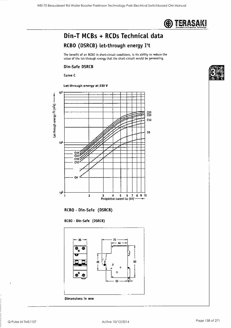
aInnovators in Protection Technology TESL SAKI
t ^
c
0
Din-T MCBs + RCDs Technical data
RCBO (DSRCB) let-through energy Pt
The benefit of an RCBO in short-circuit conditions, is its ability to reduce the value of the let-through energy that the short-circuit would be generating.
Din-Safe DSRCB
Curve C
Let-through energy at 230 V
lors
104
C40 C25 C16 C10
wrArAfAIAL.-- Avessrommommr-
.z..corcimutsaww. .4*A21111111/411P2
./4111111/21IMIE
Per
3 4 5 5 7 .8.:9 10
Pro'epectiVe current Icc (kA)
RCBO - Din-Safe (DSRCB)
RCBO - Din-Safe (DSRCB)
ON
%If
45
70
59
89
Dimensions in mm
C32 C20
C13
WB170 Beaudesert Rd Water Booster Parkinson Technology Park Electrical Switchboard OM Manual
Q-Pulse Id TMS1107 Active 10/12/2014 Page 158 of 271
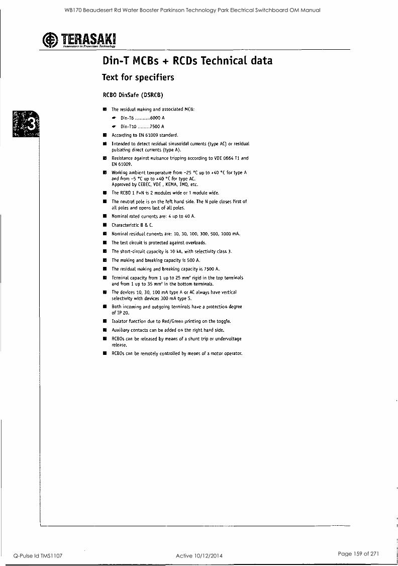
aInnovators in Protection Technology TERASAKII
Din-T MCBs + RCDs Technical data
Text for specifiers
RCBO Din Safe (DSRCB)
The residual making and associated MCB:
Din-T6 6000 A
4r Din-T10 7500 A
According to EN 61009 standard.
Intended to detect residual sinusoidal currents (type AC) or residual
pulsating direct currents (type A).
Resistance against nuisance tripping according to VDE 0664 T1 and
EN 61009.
Working ambient temperature from -25 °C up to +40 °C for type A
and from -5 °C up to +40 °C for type AC.
Approved by CEBEC, VDE KEMA, IMQ, etc.
The RCBO 1 P+N is 2 modules wide or 1 module wide.
The neutral pole is on the left hand side. The N pole closes first of all poles and opens last of all poles.
Nominal rated currents are: 4 up to 40 A.
Characteristic B & C.
Nominal residual currents are: 10, 30, 100, 300, 500, 1000 mA.
The test circuit is protected against overloads.
III The short-circuit capacity is 10 kA, with selectivity class 3.
The making and breaking capacity is 500 A.
The residual making and breaking capacity is 7500 A.
Terminal capacity from 1 up to 25 mm' rigid in the top terminals and from 1 up to 35 mm' in the bottom terminals.
The devices 10, 30, 100 mA type A or AC always have vertical selectivity with devices 300 mA type S.
Both incoming and outgoing terminals have a protection degree
of IP 20.
Isolator function due to Red/Green printing on the toggle.
Auxiliary contacts can be added on the right hand side.
RCBOs can be released by means of a shunt trip or undervoltage release.
RCBOs can be remotely controlled by means of a motor operator.
WB170 Beaudesert Rd Water Booster Parkinson Technology Park Electrical Switchboard OM Manual
Q-Pulse Id TMS1107 Active 10/12/2014 Page 159 of 271
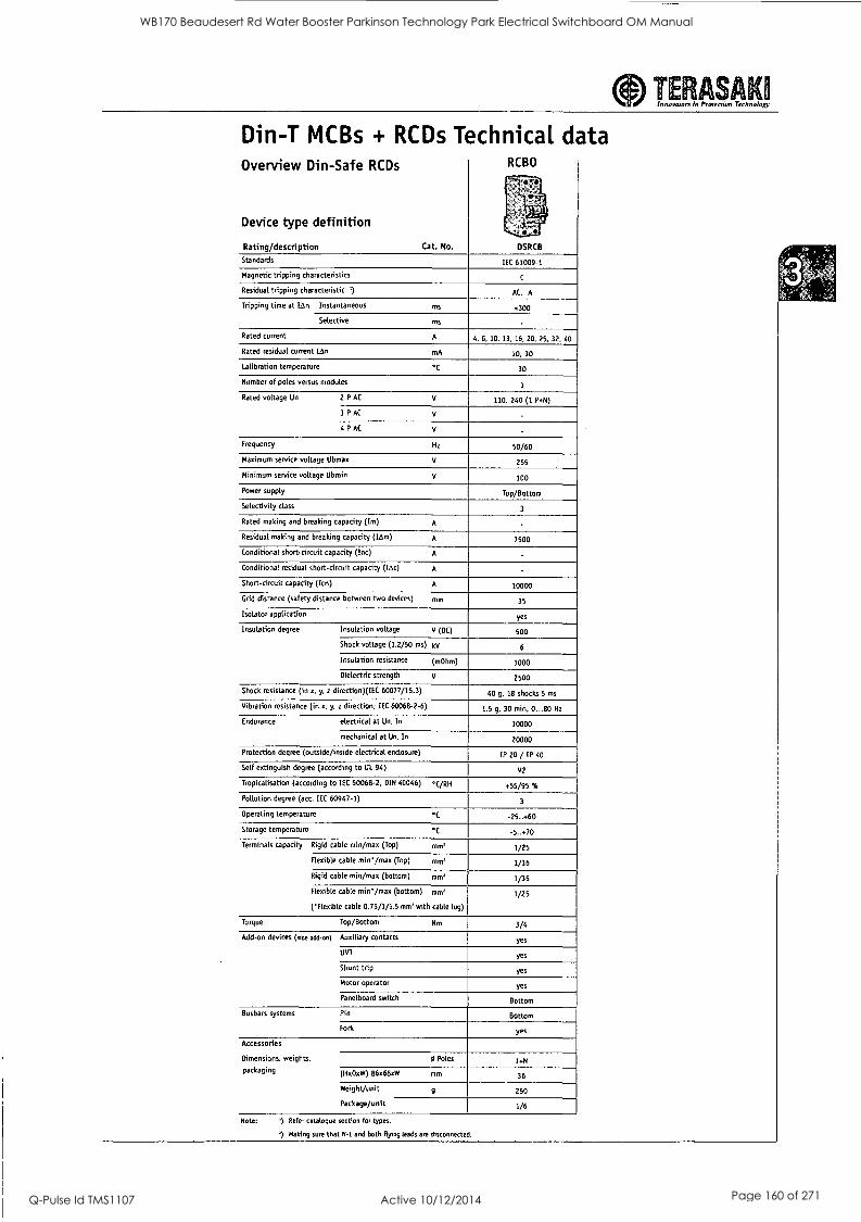
TERASA 1 Innainnora in Pinection Thalmann:),
Din-T MCBs + RCDs Technical data Overview Din-Safe RCDs
Device type definition
Rating/description Cat. No.
KUSU
I.
DSRCB
Standards IEC 61009-1
Magnetic tripping characteristics C
Residual tripping characteristic ') AC, A
Tripping time at k1n Instantaneous ms <300
Selective ms -
Rated current A 4, 6, 10, 13, 16, 20, 25, 32, 40
Rated residual current [An mA 10, 30
Calibration temperature °C 30
Number of poles versus modules 1
Rated voltage Un 2 P AC V 110. 240 (1 P.N)
3 P AC V
4 P AC V
Frequency Hz 50/60
Maximum service voltage Ubmax V 255
Minimum service voltage Ubmin V 100
Power supply Top/Bottom
Selectivity class 3
Rated making and breaking capacity (Im) A
Residual making and breaking capacity (Lem) A 7500
Conditional short-circuit capacity (Inc) A
Conditional residual short-circuit capacity (tAr) A .
Short-circuit capacity (Ico) A 10000
Grid distance (safety distance between two devices) mm 35
Isolator application yes
Insulation degree Insulation voltage V (DC) 500
Shock voltage (1.2/50 ms) kV 6
Insulation resistance (mOhm) 1000
Dielectric strength V 2500
Shock resistance (in x, y, z direction)(IEC 60077/16.3) 40 g, 18 shocks 5 ms
Vibration resistance (in x, y, z direction; IEC 60068-2-6) 1.5 g, 30 min, 0...80 Hz
Endurance electrical at Un. In 10000
mechanical at Un, In 20000
Protection degree (outside/inside electrical enclosure) IP 20 / IP 40
Self extinguish degree (according to UL 94) V2
Tropicalisation (according to IEC 60068-2, DIN 40046) °C/RH .55/95 9.,
Pollution degree (ace IEC 60947-1) 3
Operating temperature °C -25...60
Storage temperature °C -5..40 Terminals capacity Rigid cable min/max (Top) mm' 1/25
Flexible cable min' /max (Top) rpm, 1/16
Rigid cable min/max (bottom) mm' 1/35
Flexible cable min'/max (bottom) mm'
('Flexible cable 0.75/1/1.5 mm' with cable lug)
1/25
Torque Top/Bottom Nm 3/4
Add-on devices (side add-on) Auxiliary contacts yes
UVT yes
Shunt trip yes
Motor operator yes
Panelboard switch Bottom
Busbars systems Pin Bottom
Folk yes
Accessories
Dimensions, weights, 6 Poles 1+N
packaging (HxDxW) 86x68xW mm 36
Weight/unit g 250
Package/unit 1/6
Note: .) Refer catalogue section for types.
') Making sure that and both flying leads am disconnected.
WB170 Beaudesert Rd Water Booster Parkinson Technology Park Electrical Switchboard OM Manual
Q-Pulse Id TMS1107 Active 10/12/2014 Page 160 of 271
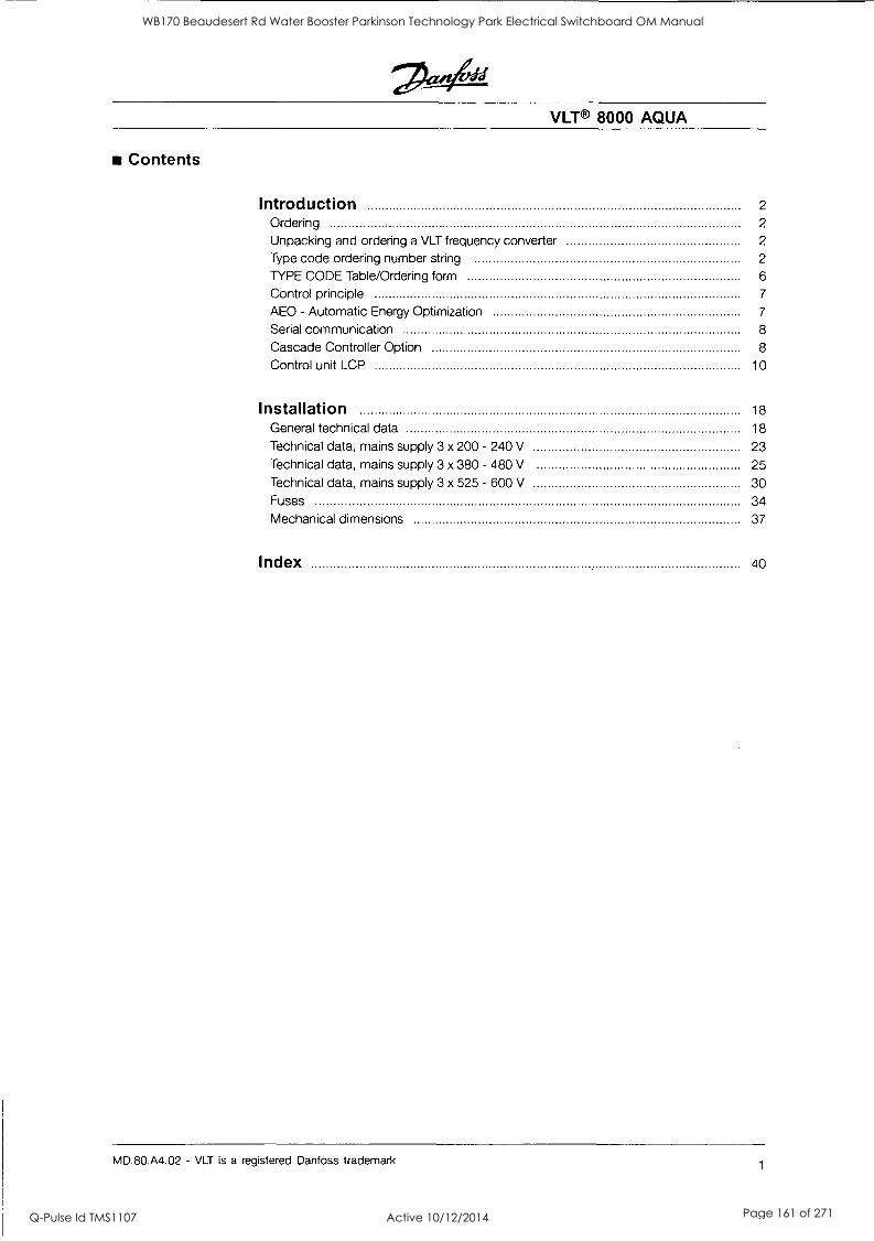
VLT® 8000 AQUA
Contents
Introduction 2
Ordering 2
Unpacking and ordering a VLT frequency converter 2
Type code ordering number string 2
TYPE CODE Table/Ordering form 6
Control principle 7
AEO - Automatic Energy Optimization 7
Serial communication 8
Cascade Controller Option 8
Control unit LCP 10
Installation 18
General technical data 18
Technical data, mains supply 3 x 200 - 240 V 23 Technical data, mains supply 3 x 380 - 480 V 25
Technical data, mains supply 3 x 525 - 600 V 30 Fuses 34
Mechanical dimensions 37
Index 40
MD.80.A4.02 - VLT is a registered Danfoss trademark 1
WB170 Beaudesert Rd Water Booster Parkinson Technology Park Electrical Switchboard OM Manual
Q-Pulse Id TMS1107 Active 10/12/2014 Page 161 of 271
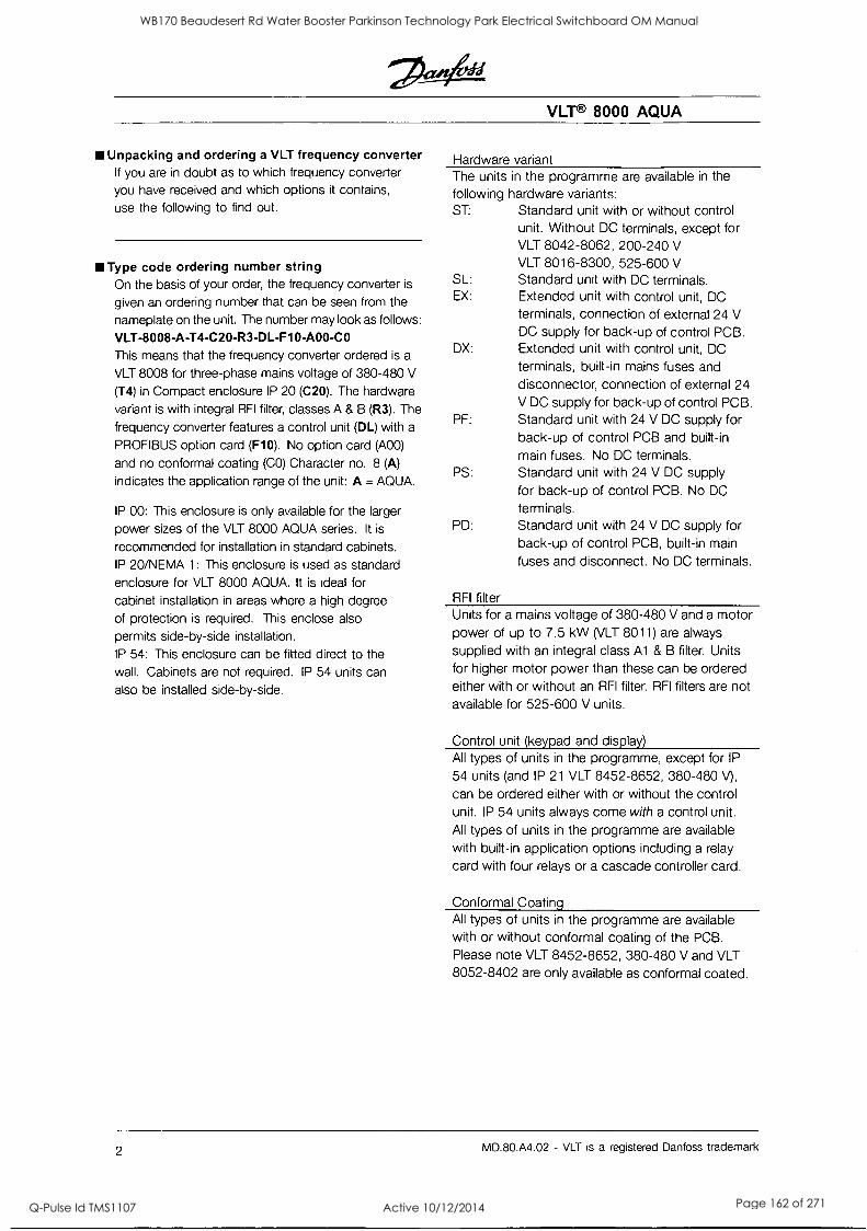
VLT® 8000 AQUA
III Unpacking and ordering a VLT frequency converter If you are in doubt as to which frequency converter
you have received and which options it contains,
use the following to find out.
Type code ordering number string On the basis of your order, the frequency converter is
given an ordering number that can be seen from the
nameplate on the unit. The number may look as follows:
VLT-8008-A-T4-C20-R3-DL-F10-A00-CO This means that the frequency converter ordered is a
VLT 8008 for three-phase mains voltage of 380-480 V
(T4) in Compact enclosure IP 20 (C20). The hardware
variant is with integral RFI filter, classes A & B (R3). The
frequency converter features a control unit (DL) with a
PROFIBUS option card (F10). No option card (A00)
and no conformal coating (CO) Character no. 8 (A)
indicates the application range of the unit: A = AQUA.
IP 00: This enclosure is only available for the larger
power sizes of the VLT 8000 AQUA series. It is
recommended for installation in standard cabinets. IP 20/NEMA 1: This enclosure is used as standard enclosure for VLT 8000 AQUA. It is ideal for
cabinet installation in areas where a high degree
of protection is required. This enclose also
permits side-by-side installation.
IP 54: This enclosure can be fitted direct to the wall. Cabinets are not required. IP 54 units can
also be installed side-by-side.
Hardware variant The units in the programme are available in the
following hardware variants: ST: Standard unit with or without control
unit. Without DC terminals, except for VLT 8042-8062, 200-240 V
VLT 8016-8300, 525-600 V SL: Standard unit with DC terminals. EX: Extended unit with control unit, DC
terminals, connection of external 24 V DC supply for back-up of control PCB.
DX: Extended unit with control unit, DC
terminals, built-in mains fuses and disconnector, connection of external 24 V DC supply for back-up of control PCB.
PF: Standard unit with 24 V DC supply for back-up of control PCB and built-in
main fuses. No DC terminals. PS: Standard unit with 24 V DC supply
for back-up of control PCB. No DC
terminals. PD: Standard unit with 24 V DC supply for
back-up of control PCB, built-in main fuses and disconnect. No DC terminals.
RFI filter Units for a mains voltage of 380-480 V and a motor power of up to 7.5 kW (VLT 8011) are always supplied with an integral class Al & B filter. Units for higher motor power than these can be ordered either with or without an RFI filter. RFI filters are not available for 525-600 V units.
Control unit (keypad and display) All types of units in the programme, except for IP
54 units (and IP 21 VLT 8452-8652, 380-480 V),
can be ordered either with or without the control unit. IP 54 units always come with a control unit. All types of units in the programme are available
with built-in application options including a relay
card with four relays or a cascade controller card.
Conformal Coating All types of units in the programme are available with or without conformal coating of the PCB. Please note VLT 8452-8652, 380-480 V and VLT 8052-8402 are only available as conformal coated.
2 MD.80.A4.02 - VLT is a registered Danfoss trademark
WB170 Beaudesert Rd Water Booster Parkinson Technology Park Electrical Switchboard OM Manual
Q-Pulse Id TMS1107 Active 10/12/2014 Page 162 of 271
VLT® 8000 AQUA
200-240 V
Typecode
Position in string
T2
9-10
COO
11-13
C20
11-13
CN1
11-13
C54
11-13
ST
14-15
SL
14-15
RO
16-17
R1
16-17
R3
16-17 4.0 kW/5.0 HP 8006 X X X X X X
5.5 kW/7.5 HP 8008 X X X X X X
7.5 kW/10 HP 8011 X X X X X X
11 kW/15 HP 8016 X X X X X X
15 kW/20 HP 8022 X X X X X X
18.5 kW/25 HP 8027 X X X X X X
22 kW/30 HP 8032 X X X X X X
30 kW/40 HP 8042 X X X X X X
37 kW/50 HP 8052 X X X X X X
45 kW/60 HP 8062 X X X X X X
380-480 V
Typecode
Position in string
T4
9-10
COO
11-13
C20
11-13
CN1
11-13
C54
11-13
ST
14-15
SL
14-15
EX
14-15
DX
14-15
PS
14-15
PD
14-15
PF
14-15
RO
16-17
R1
16-17
R3
16-17 4.0 kW/5.0 HP 8006 X X X X X
5.5 kW/7.5 HP 8008 X X X X X
7.5 kW/10 HP 8011 X X X X X
11 kW/15 HP 8016 X X X X X X X
15 kW/20 HP 8022 X X X X X X X
18.5 kW/25 HP 8027 X X X X X X X
22 kW/30 HP 8032 X X X X X X X
30 kW/40 HP 8042 X X X X X X X
37 kW/50 HP 8052 X X X X X X X
45 kW/60 HP 8062 X X X X X X X
55 kW/75 HP 8072 X X X X X X X
75 kW/100 HP 8102 X X X X X X X
90 kW/125 HP 8122 X X X X X X X
110 kW/150 HP 8152 X X X X X X X X X X X
132 kW/200 HP 8202 X X X X X X X X X X X
160 kW/250 HP 8252 X X X X X X X X X X X
200 kW/300 HP 8302 X X X X X X X X X X X
250 kW/350 HP 8352 X X X X X X X X X X X
315 kW/450 HP 8452 X X X X X X X X X X X
355 kW/500 HP 8502 X X X X X X X X X X X
400 kW/550 HP 8602 X X X X X X X X X X X
450 kW/600 HP 8652 X X X X X X X X X X X
Voltage
T2: 200-240 VAC
T4: 380-480 VAC
Enclosure
COO: Compact IP 00
C20: Compact IP 20
CN1: Compact NEMA 1
C54: Compact IP 54
I NB!: NEMA 1 exceeds IP 20
Hardware variant
ST: Standard
SL: Standard with DC terminals
EX: Extended with 24 V supply and DC terminals
DX: Extended with 24 V supply, DC terminals, disconnect and fuse
PS: Standard with 24 V supply
PD: Standard with 24 V supply, fuse and disconnect
PF: Standard with 24 V supply and fuse
RFI filter
RO: Without filter
R1: Class Al filter
R3: Class Al and B filter
MD.80.A4.02 - VLT is a registered Danfoss trademark 3
t.
WB170 Beaudesert Rd Water Booster Parkinson Technology Park Electrical Switchboard OM Manual
Q-Pulse Id TMS1107 Active 10/12/2014 Page 163 of 271
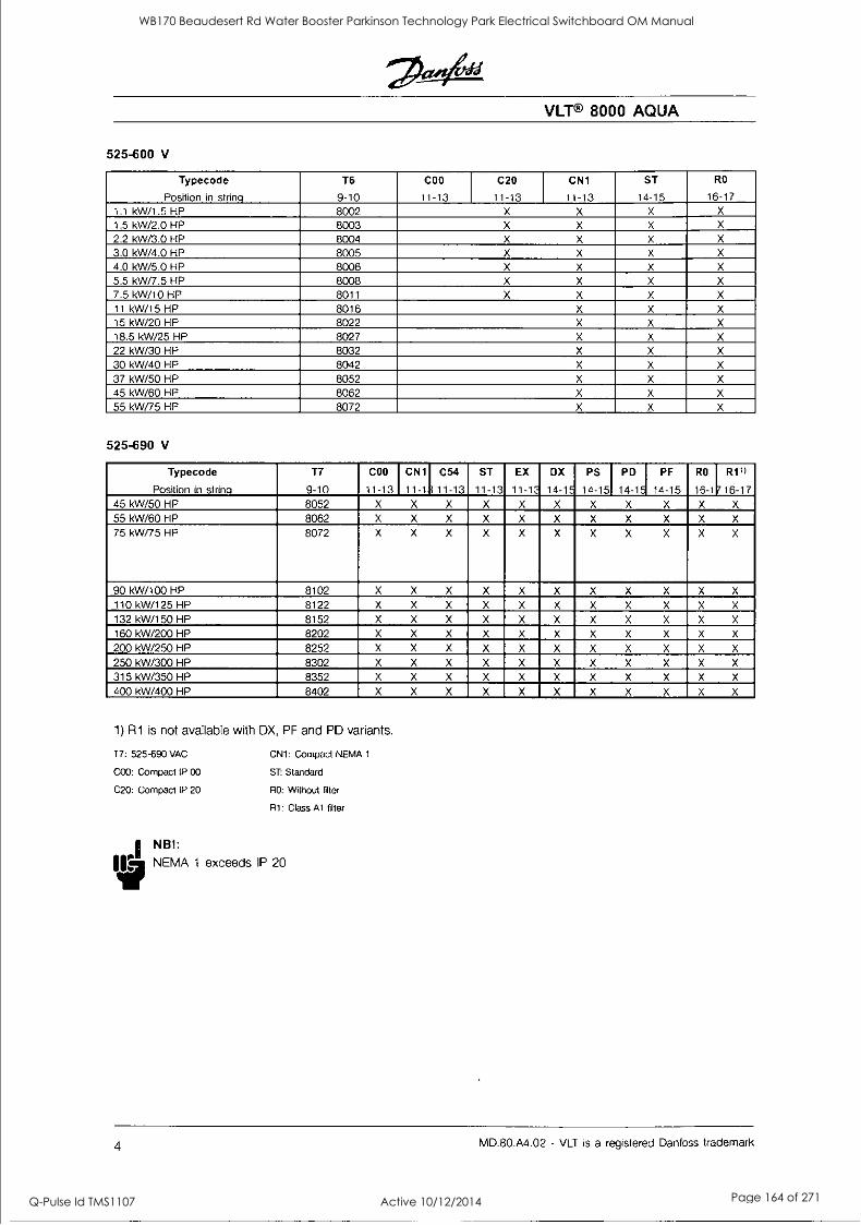
VLT® 8000 AQUA
525-600 V
Typecode
Position in string
T6
9-10
COO
11-13
C20
11-13
CN1
11-13
ST
14-15
RO
16-17 1.1 kW/1.5 HP 8002 X X X X
1.5 kW/2.0 HP 8003 X X X X
2.2 kW/3.0 HP 8004 X X X X
3.0 kW/4.0 HP 8005 X X X X
4.0 kW/5.0 HP 8006 X X X X
5.5 kW/7.5 HP 8008 X X X X
7.5 kW/10 HP 8011 X X X X
11 kW/15 HP 8016 X X X
15 kW/20 HP 8022 X X X
18.5 kW/25 HP 8027 X X X
22 kW/30 HP 8032 X X X
30 kW/40 HP 8042 X X X
37 kW/50 HP 8052 X X X
45 kW/60 HP 8062 X X X
55 kW/75 HP 8072 X X X
525-690 V
Typecode
Position in string
T7
9-10
COO
11-13
CN1
11- 11811
13 C54
-13
ST
11-13
EX
11-13
DX
14-15
PS
14-15
PD
14-15
PF
14-15
RO
16- 111716
17 R11)
-17 45 kW/50 HP 8052 X X X X X X X X X X X
55 kW/60 HP 8062 X X X X X X X X X X X
75 kW/75 HP 8072 X X X X X X X X X X X
90 kW/100 HP 8102 X X X X X X X X X X X
110 kW/125 HP 8122 X X X X X X X X X X X
132 kW/150 HP 8152 X X X X X X X X X X X
160 kW/200 HP 8202 X X X X X X X X X X X
200 kW/250 HP 8252 X X X X X X X X X X X
250 kW/300 HP 8302 X X X X X X X X X X X
315 kW/350 HP 8352 X X X X X X X X X X X
400 kW/400 HP 8402 X X X X X X X X X X X
1) R1 is not available with DX, PF and PD variants.
17: 525-690 VAC
COO: Compact IP 00
C20: Compact IP 20
CN1: Compact NEMA 1
ST: Standard
RO: Without filter
R1: Class Al filter
N B ! :
NEMA 1 exceeds IP 20
4 MD.80.A4.02 - VLT is a registered Danfoss trademark
WB170 Beaudesert Rd Water Booster Parkinson Technology Park Electrical Switchboard OM Manual
Q-Pulse Id TMS1107 Active 10/12/2014 Page 164 of 271
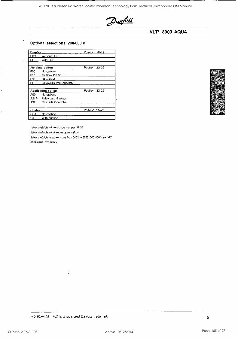
VLT® 8000 AQUA
Optional selections, 200-600 V
Display Position: 18-19 DO1) Without LCP DL With LCP
Fieldbus option Position: 20-22 FOO No options F10 Profibus DP V1
F30 DeviceNet F40 LonWorks free topology
Application option Position: 23-25 A00 No options A312) Relay card 4 relays A32 Cascade Controller
Coating Position: 26-27 CO3) No coating C1 With coating
it Not available with enclosure compact IP 54
2) Not available with fieldbus options (Fxx)
3) Not available for power sizes from 8452 to 8652, 380-480 V and VLT
8052-8402, 525-690 V
MD.80.A4.02 - VLT is a registered Danfoss trademark 5
WB170 Beaudesert Rd Water Booster Parkinson Technology Park Electrical Switchboard OM Manual
Q-Pulse Id TMS1107 Active 10/12/2014 Page 165 of 271
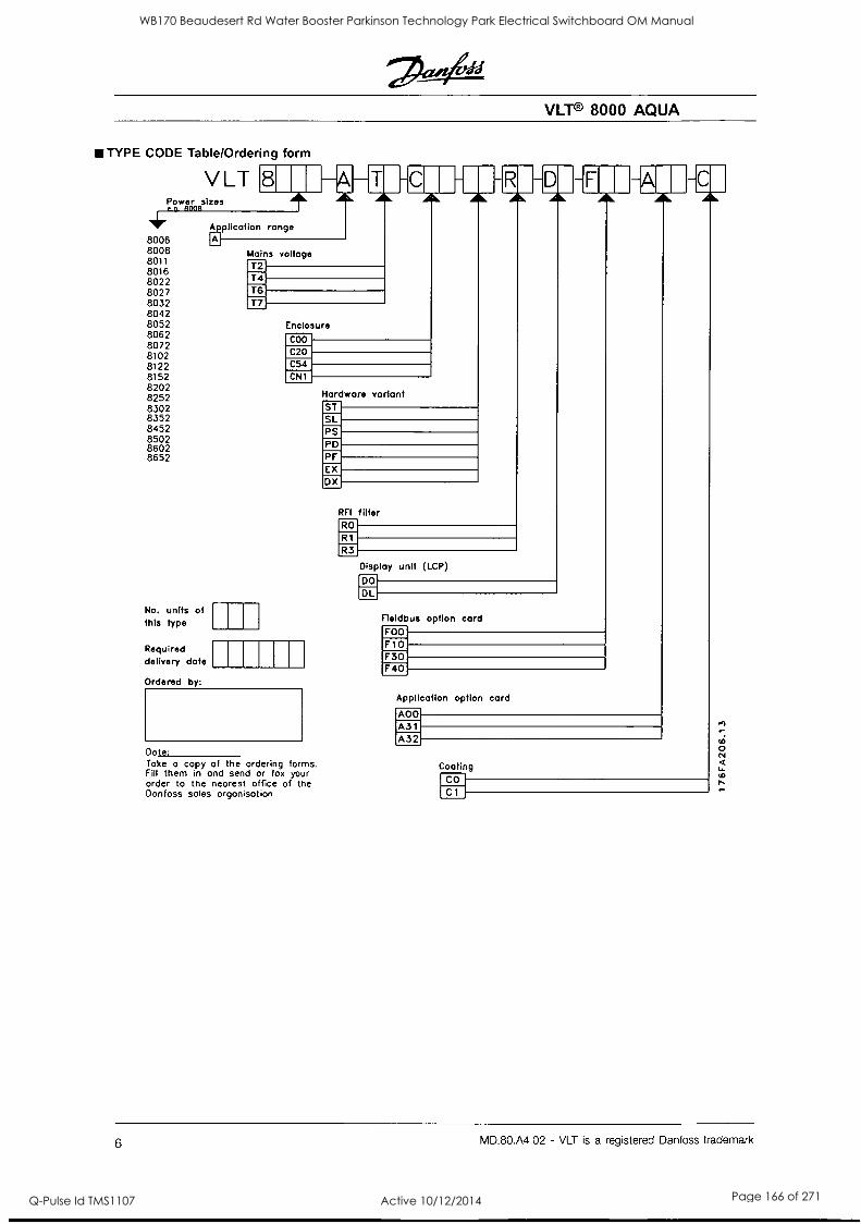
VLT® 8000 AQUA
TYPE CODE Table/Ordering form
V LT 8
8006 range
8008 8011 8016 8022 8027 8032 8042 8052 8062 8072 8102 8122 8152 CN1
8202 8252 8302 8352 8452 8502 8602 8652
Power sizes r p. BOOR
Mains voltage T2 T4 T6 T7
Enclosure
COO
C20 C54
No. units of this type
Required delivery date
Ordered by:
Dote: Take a copy of the ordering forms. Fill them in and send or fox your order to the nearest office of the Danfoss soles organisation
Hardware vorlant ST SL PS PD PF EX DX
RFI filter RO
R1
R3
-R -D -
Display unit (LCP)
DO
DL
Fleldbus option card FOO
F
F10 F30 F40
Application option card
A00 A31 A32
-14:-IcAl, I
Coating CO
C1
6 MD.80.A4.02 - VLT is a registered Danfoss trademark
WB170 Beaudesert Rd Water Booster Parkinson Technology Park Electrical Switchboard OM Manual
Q-Pulse Id TMS1107 Active 10/12/2014 Page 166 of 271
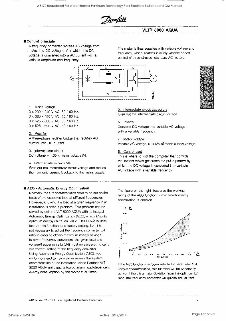
VLT® 8000 AQUA
Control principle A frequency converter rectifies AC voltage from mains into DC voltage, after which this DC
voltage is converted into a AC current with a
variable amplitude and frequency.
The motor is thus supplied with variable voltage and frequency, which enables infinitely variable speed
control of three-phased, standard AC motors.
1. Mains voltage
3 x 200 - 240 V AC, 50 / 60 Hz.
3 x 380 - 480 V AC, 50 / 60 Hz.
3 x 525 - 600 V AC, 50 / 60 Hz.
3 x 525 - 690 V AC, 50 / 60 Hz.
2 3 4
6
5
7
8
2. Rectifier
A three-phase rectifier bridge that rectifies AC
current into DC current.
3. Intermediate circuit DC voltage = 1.35 x mains voltage [\/].
4. Intermediate circuit coils Even out the intermediate circuit voltage and reduce
the harmonic current feedback to the mains supply.
5. Intermediate circuit capacitors
Even out the intermediate circuit voltage.
6. Inverter
Converts DC voltage into variable AC voltage
with a variable frequency.
7. Motor voltage Variable AC voltage, 0-100% of mains supply voltage.
8. Control card
This is where to find the computer that controls the inverter which generates the pulse pattern by which the DC voltage is converted into variable
AC voltage with a variable frequency.
AEO - Automatic Energy Optimization Normally, the U/f characteristics have to be set on the
basis of the expected load at different frequencies.
However, knowing the load at a given frequency in an
installation is often a problem. This problem can be
solved by using a VLT 8000 AQUA with its integral
Automatic Energy Optimization (AEO), which ensures
optimum energy utilization. All VLT 8000 AQUA units
feature this function as a factory setting, i.e. it is
not necessary to adjust the frequency converter U/f
ratio in order to obtain maximum energy savings.
In other frequency converters, the given load and
voltage/frequency ratio (U/f) must be assessed to carry
out correct setting of the frequency converter.
Using Automatic Energy Optimization (AEO), you
no longer need to calculate or assess the system
characteristics of the installation, since Danfoss VLT
8000 AQUA units guarantee optimum, load-dependent energy consumption by the motor at all times.
The figure on the right illustrates the working
range of the AEO function, within which energy
optimization is enabled.
2
0 2
72.
A
1.00
0.75
0.50
0.25
1. 0.1 0.2 0.3 0.4 0.5 0.5 0.7 0.6 0.9 1.0 VC.
Frequency
If the AEO function has been selected in parameter 101,
Torque characteristics, this function will be constantly active. If there is a major deviation from the optimum U/f
ratio, the frequency converter will quickly adjust itself.
MD.80.A4.02 - VLT is a registered Danfoss trademark 7
WB170 Beaudesert Rd Water Booster Parkinson Technology Park Electrical Switchboard OM Manual
Q-Pulse Id TMS1107 Active 10/12/2014 Page 167 of 271
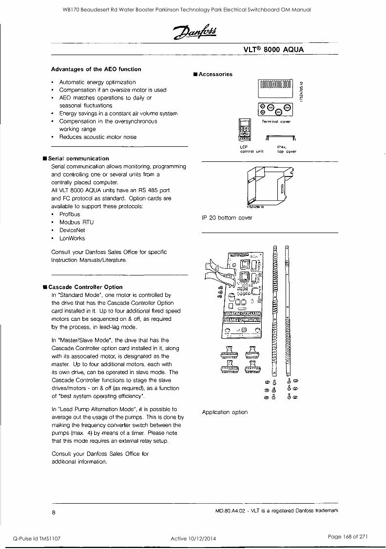
VLT® 8000 AQUA
Advantages of the AEO function
Automatic energy optimization Compensation if an oversize motor is used
AEO matches operations to daily or
seasonal fluctuations Energy savings in a constant air volume system Compensation in the oversynchronous working range Reduces acoustic motor noise
Serial communication Serial communication allows monitoring, programming
and controlling one or several units from a
centrally placed computer.
All VLT 8000 AQUA units have an RS 485 port
and FC protocol as standard. Option cards are
available to support these protocols: Profibus
Modbus RTU
DeviceNet
Lon Works
Consult your Danfoss Sales Office for specific
Instruction Manuals/Literature.
III Cascade Controller Option In "Standard Mode", one motor is controlled by
the drive that has the Cascade Controller Option
card installed in it. Up to four additional fixed speed
motors can be sequenced on & off, as required
by the process, in lead-lag mode.
In "Master/Slave Mode", the drive that has the
Cascade Controller option card installed in it, along
with its associated motor, is designated as the
master. Up to four additional motors, each with
its own drive, can be operated in slave mode. The
Cascade Controller functions to stage the slave
drives/motors - on & off (as required), as a function
of "best system operating efficiency".
In "Lead Pump Alternation Mode", it is possible to
average out the usage of the pumps. This is done by
making the frequency converter switch between the pumps (max. 4) by means of a timer. Please note
that this mode requires an external relay setup.
Consult your Danfoss Sales Office for additional information.
Accessories
000000000000110
Terminol cover
LCP control unit
A a IP4x, top cover
175ZA296.10
IP 20 bottom cover
D
c",
Application option
C§) 8 80 08 " (§,8 8c)
8 MD.80.A4.02 - VLT is a registered Danfoss trademark
WB170 Beaudesert Rd Water Booster Parkinson Technology Park Electrical Switchboard OM Manual
Q-Pulse Id TMS1107 Active 10/12/2014 Page 168 of 271
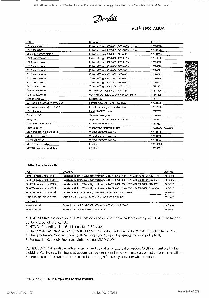
VLT® 8000 AQUA
Type Description Order no.
IP 4x top cover IP )/ Option, VLT type 8006-8011 380-480 V compact 175Z0928
IP 4 x top cover 1) Option, VLT type 8002-8011 525-600 V compact 175Z0928
NEMA 12 bonding plate 2) Option, VLT type 8006-8011 380-480 V 175H4195
IP 20 terminal cover Option, VLT type 8006-8022 200-240 V 175Z4622
IP 20 terminal cover Option, VLT type 8027-8032 200-240 V 17524623
IP 20 terminal cover Option, VLT type 8016-8042 380-480 V 175Z4622
IP 20 terminal cover Option, VLT type 8016-8042 525-600 V 175Z4622,
IP 20 terminal cover Option, VLT type 8052-8072 380-480 V 175Z4623
IP 20 terminal cover Option, VLT type 8102-8122 380-480 V 175Z4280
IP 20 terminal cover Option, VLT type 8052-8072 525-600 V 175Z4623
IP 20 bottom cover Option, VLT type 8042-8062 200-240 V 176F1800
Terminal adaptor kit VLT type 8042-8062 200-240 V, IP 54 176F1808
Terminal adaptor kit VLT type 8042-8062 200-240 V, IP 00/NEMA 1 176F1805
Control panel LCP Separate LCP 175Z7804
LCP remote-mounting kit IP 00 & 203/ Remote-mounting kit, incl. 3 m cable 175Z0850
LCP remote-mounting kit IP 54 4/ Remote-mounting kit, incl. 3 m cable 175Z7802
LCP blind cover for all IP00/1P20 drives 175Z7806
Cable for LCP Separate cable (3 m) 175Z0929_
Relay card Application card with four relay outputs 175Z3691
Cascade controller card With conformal coating 175Z3692
Profibus option Without/with conformal coating 175Z3685/175Z3686
Lon Works option, Free topology Without conformal coating 176F0225
Modbus RTU option Without conformal coating 175Z3362
Device Net option Without conformal coating 176F0224
MCT 10 Set-up software CD-Rom 13081000
MCT 31 Harmonic calculation CD-Rom 13081031
Rittal Installation Kit
Type Description Order No.
Rittal TS8 enclosure for IP005) Installation kit for 1800mm high enclosure, VLT8152-8202, 380-480V; VLT8052-8202, 525-690V 176F1824
Rittal TS8 enclosure for IP005) Installation kit for 2000mm high enclosure, VLT8152-8202, 380-480V; VLT8052-8202, 525-690V 176F1826
Rittal TS8 enclosure for IP005) Installation kit for 1800mm high enclosure, VLT8252-8352, 380-480V; VLT8252-8402, 525-690V 176F1823
Rittal TS8 enclosure for IP005) Installation kit for 2000mm high enclosure, VLT8252-8352, 380-480V; VLT8252-8402, 525-690V 176F1825
Rittal TS8 enclosure for IP005) Installation kit for 2000mm high enclosure, VLT8452-8652, 380-480V 176F1850
Floor stand for IP21 and IP54
enclosures/
Option, VLT8152-8352, 380-480V; VLT 8052-8402, 525-690V 176F1827
Mains shield kit Protection kit, VLT 8152-8352, 380-480 V; VLT 8052, 525-600 V 176F0799
Mains shield kit Protection kit, VLT 8452-8652, 380-480 V 176F1851
1) IP 4x/NEMA 1 top cover is for IP 20 units only and only horizontal surfaces comply with IP 4x. The kit also
contains a bonding plate (UL).
2) NEMA 12 bonding plate (UL) is only for IP 54 units.
3) The remote-mounting kit is only for IP 00 and IP 20 units. Enclosure of the remote-mounting kit is IP 65. 4) The remote-mounting kit is only for IP 54 units. Enclosure of the remote-mounting kit is IP 65.
5) For details: See High Power Installation Guide, MI.90.JX.YY.
VLT 8000 AQUA is available with an integral fieldbus option or application option. Ordering numbers for the individual VLT types with integrated options can be seen from the relevant manuals or instructions. In addition, the ordering number system can be used for ordering a frequency converter with an option.
MD.80.A4.02 - VLT is a registered Danfoss trademark 9
WB170 Beaudesert Rd Water Booster Parkinson Technology Park Electrical Switchboard OM Manual
Q-Pulse Id TMS1107 Active 10/12/2014 Page 169 of 271
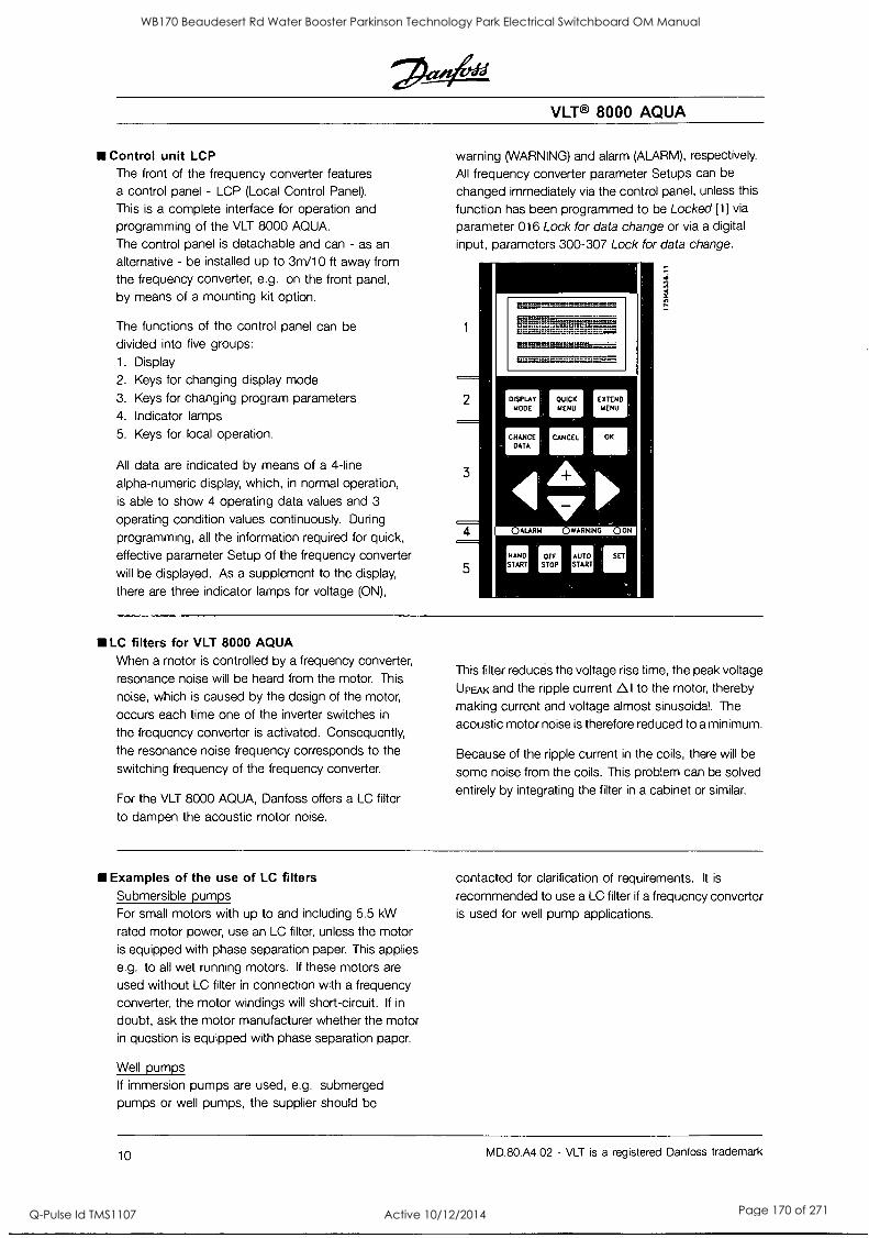
VLT® 8000 AQUA
Control unit LCP The front of the frequency converter features a control panel - LCP (Local Control Panel).
This is a complete interface for operation and programming of the VLT 8000 AQUA.
The control panel is detachable and can - as an
alternative - be installed up to 3m/10 ft away from
the frequency converter, e.g. on the front panel,
by means of a mounting kit option.
The functions of the control panel can be
divided into five groups:
1. Display
2. Keys for changing display mode
3. Keys for changing program parameters
4. Indicator lamps
5. Keys for local operation.
All data are indicated by means of a 4-line
alpha-numeric display, which, in normal operation,
is able to show 4 operating data values and 3
operating condition values continuously. During
programming, all the information required for quick,
effective parameter Setup of the frequency converter
will be displayed. As a supplement to the display,
there are three indicator lamps for voltage (ON),
warning (WARNING) and alarm (ALARM), respectively.
All frequency converter parameter Setups can be
changed immediately via the control panel, unless this
function has been programmed to be Locked [1] via
parameter 016 Lock for data change or via a digital
input, parameters 300-307 Lock for data change.
LC filters for VLT 8000 AQUA When a motor is controlled by a frequency converter,
resonance noise will be heard from the motor. This
noise, which is caused by the design of the motor,
occurs each time one of the inverter switches in
the frequency converter is activated. Consequently,
the resonance noise frequency corresponds to the
switching frequency of the frequency converter.
For the VLT 8000 AQUA, Danfoss offers a LC filter
to dampen the acoustic motor noise.
This filter reduces the voltage rise time, the peak voltage
UPEAk and the ripple current 0I to the motor, thereby
making current and voltage almost sinusoidal. The
acoustic motor noise is therefore reduced to a minimum.
Because of the ripple current in the coils, there will be
some noise from the coils. This problem can be solved
entirely by integrating the filter in a cabinet or similar.
Examples of the use of LC filters Submersible pumps For small motors with up to and including 5.5 kW
rated motor power, use an LC filter, unless the motor is equipped with phase separation paper. This applies
e.g. to all wet running motors. If these motors are
used without LC filter in connection with a frequency converter, the motor windings will short-circuit. If in
doubt, ask the motor manufacturer whether the motor in question is equipped with phase separation paper.
Well pumps If immersion pumps are used, e.g. submerged pumps or well pumps, the supplier should be
contacted for clarification of requirements. It is
recommended to use a LC filter if a frequency converter is used for well pump applications.
10 MD.80.A4.02 - VLT is a registered Danfoss trademark
WB170 Beaudesert Rd Water Booster Parkinson Technology Park Electrical Switchboard OM Manual
Q-Pulse Id TMS1107 Active 10/12/2014 Page 170 of 271
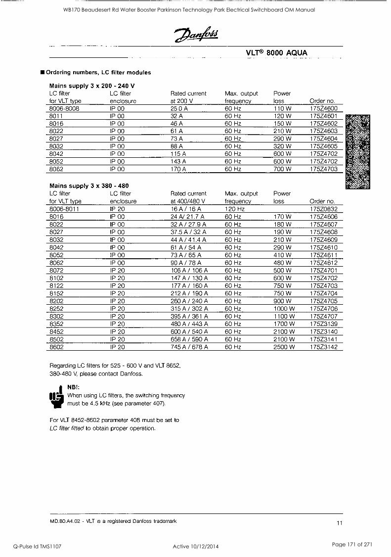
VLT® 8000 AQUA
Ordering numbers, LC filter modules
Mains supply 3 x 200 - 240 V LC filter for VLT type
LC filter enclosure
Rated current at 200 V
Max. output frequency
Power loss Order no.
8006-8008 IP 00 25.0 A 60 Hz 110 W 175Z4600 8011 IP 00 32 A 60 Hz 120 W 175Z4601 8016 IP 00 46 A 60 Hz 150 W 175Z4602 8022 IP 00 61 A 60 Hz 210 W 175Z4603 8027 IP 00 73 A 60 Hz 290 W 175Z4604 8032 IP 00 88 A 60 Hz 320 W 175Z4605 8042 IP 00 115 A 60 Hz 600 W 175Z4702 8052 IP 00 143 A 60 Hz 600 W 175Z4702 8062 IP 00 170 A 60 Hz 700 W 175Z4703
Mains supply 3 x 380 - 480 LC filter LC filter for VLT type enclosure
Rated current at 400/480 V
Max. output frequency
Power loss Order no.
8006-8011 IP 20 16A/16A 120 Hz 175Z0832 8016 IP 00 24 A/ 21.7 A 60 Hz 170 W 175Z4606 8022 IP 00 32A/27.9A 60 Hz 180 W 175Z4607 8027 IP 00 37.5A/32A 60 Hz 190 W 175Z4608 8032 IP 00 44A/41.4A 60 Hz 210 W 175Z4609 8042 IP 00 61 A / 54 A 60 Hz 290 W 175Z4610 8052 IP 00 73A/65 A 60 Hz 410 W 175Z4611 8062 IP 00 90A/78 A 60 Hz 480 W 175Z4612 8072 IP 20 106A/ 106 A 60 Hz 500 W 175Z4701 8102 IP 20 147A/ 130 A 60 Hz 600 W 175Z4702 8122 IP 20 177A/160A 60 Hz 750 W 175Z4703 8152 IP 20 212A/ 190 A 60 Hz 750 W 175Z4704 8202 IP 20 260 A / 240 A 60 Hz 900 W 175Z4705 8252 IP 20 315 A / 302 A 60 Hz 1000 W 175Z4706 8302 IP 20 395 A / 361 A 60 Hz 1100 W 175Z4707 8352 IP 20 480 A / 443 A 60 Hz 1700 W 175Z3139 8452 IP 20 600 A / 540 A 60 Hz 2100 W 175Z3140 8502 IP 20 658 A / 590 A 60 Hz 2100 W 175Z3141 8602 IP 20 745 A / 678 A 60 Hz 2500 W 175Z3142
Regarding LC filters for 525 - 600 V and VLT 8652,
380-480 V, please contact Danfoss.
NB!:
14 When using LC filters, the switching frequency
must be 4.5 kHz (see parameter 407).
For VLT 8452-8602 parameter 408 must be set to
LC filter fitted to obtain proper operation.
MD.80.A4.02 - VLT is a registered Danfoss trademark 11
WB170 Beaudesert Rd Water Booster Parkinson Technology Park Electrical Switchboard OM Manual
Q-Pulse Id TMS1107 Active 10/12/2014 Page 171 of 271
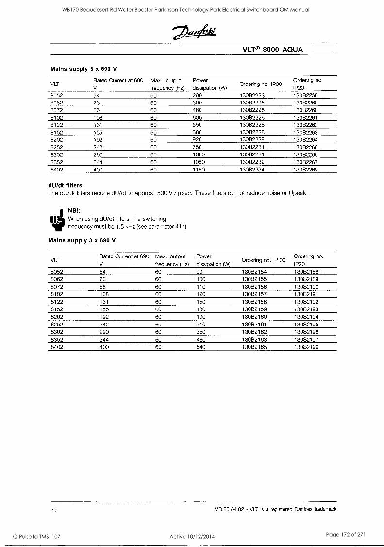
VLT® 8000 AQUA
Mains supply 3 x 690 V
VLT Rated Current at 690
V
Max. output frequency (Hz)
Power
dissipation (W) Ordering no. POD
Ordering no.
IP20
8052 54 60 290 130B2223 130B2258 8062 73 60 390 130B2225 130B2260
8072 86 60 480 130B2225 130B2260 8102 108 60 600 130B2226 130B2261
8122 131 60 550 130B2228 130B2263 8152 155 60 680 130B2228 130B2263 8202 192 60 920 130B2229 130B2264
8252 242 60 750 130B2231 130B2266
8302 290 60 1000 130B2231 130B2266
8352 344 60 1050 130B2232 130B2267
8402 400 60 1150 130B2234 130B2269
dU/dt filters The dU/dt filters reduce dU/dt to approx. 500 V /1.tsec. These filters do not reduce noise or Upeak.
I NB!:
110 When using dU/dt filters, the switching frequency must be 1.5 kHz (see parameter 411)
Mains supply 3 x 690 V
VLT Rated Current at 690
V
Max. output
frequency (Hz)
Power
dissipation (W) Ordering no. IP 00
Ordering no.
IP20
8052 54 60 90 130B2154 13082188 8062 73 60 100 130B2155 130B2189
8072 86 60 110 130B2156 13082190 8102 108 60 120 130B2157 13082191
8122 131 60 150 130B2158 13082192 8152 155 60 180 130B2159 130B2193 8202 192 60 190 130B2160 13082194 8252 242 60 210 13082161 13082195
8302 290 60 350 130B2162 130B2196
8352 344 60 480 13082163 13082197
8402 400 60 540 13082165 13082199
12 MD.80.A4.02 - VLT is a registered Danfoss trademark
WB170 Beaudesert Rd Water Booster Parkinson Technology Park Electrical Switchboard OM Manual
Q-Pulse Id TMS1107 Active 10/12/2014 Page 172 of 271
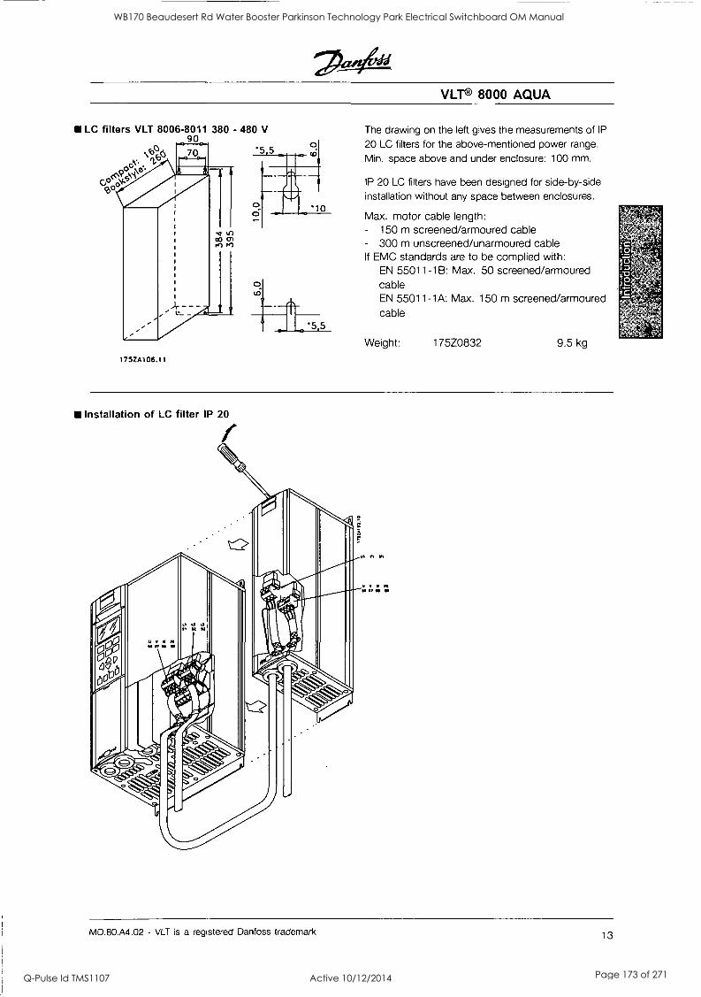
VLT® 8000 AQUA
LC filters VLT 8006-8011 380 - 480 V 90
6f3A 70 5 5
Cp e41\e'.
175ZA106.11
The drawing on the left gives the measurements of IP
20 LC filters for the above-mentioned power range.
Min. space above and under enclosure: 100 mm.
IP 20 LC filters have been designed for side-by-side installation without any space between enclosures.
Max. motor cable length: - 150 m screened/armoured cable - 300 m unscreened/unarmoured cable If EMC standards are to be complied with:
EN 55011-1B: Max. 50 screened/armoured cable EN 55011-1A: Max. 150 m screened/armoured cable
Weight: 175Z0832 9.5 kg
Installation of LC filter IP 20 I
MD.80.A4.02 - VLT is a registered Danfoss trademark 13
WB170 Beaudesert Rd Water Booster Parkinson Technology Park Electrical Switchboard OM Manual
Q-Pulse Id TMS1107 Active 10/12/2014 Page 173 of 271
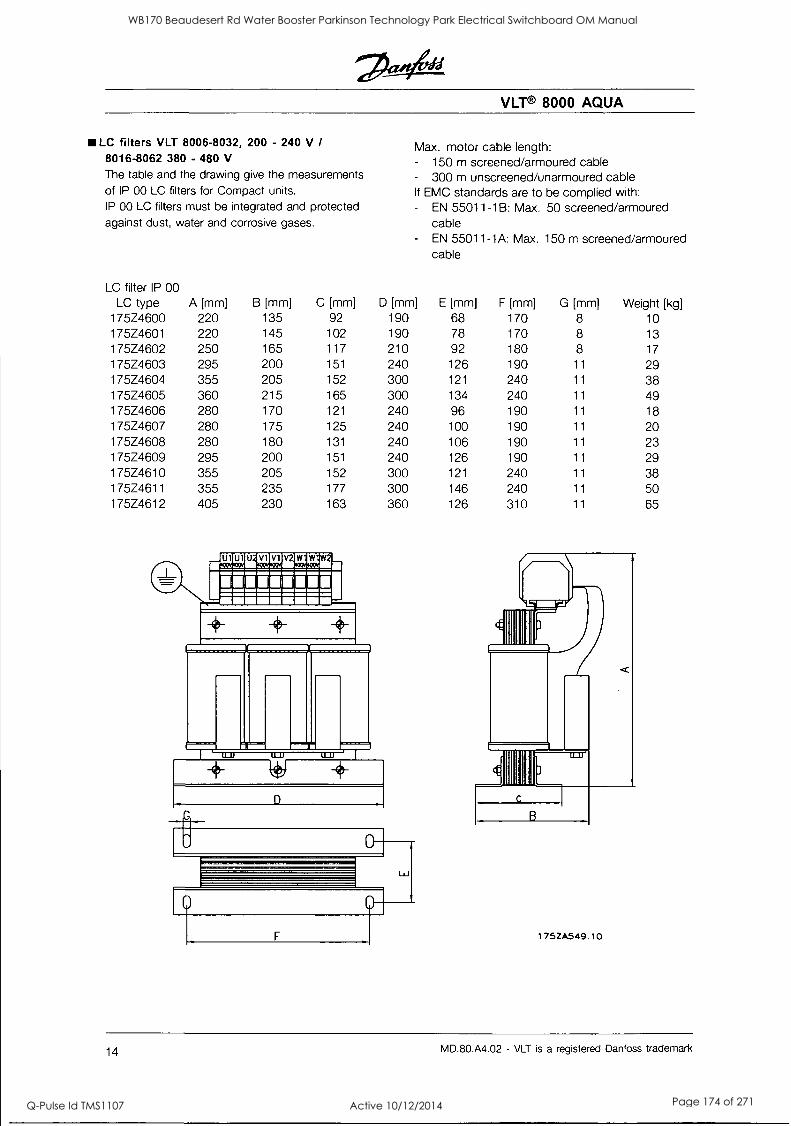
VLT 8000 AQUA
LC filters VLT 8006-8032, 200 - 240 V / 8016-8062 380 - 480 V The table and the drawing give the measurements of IP 00 LC filters for Compact units. IP 00 LC filters must be integrated and protected
against dust, water and corrosive gases.
Max. motor cable length: - 150 m screened/armoured cable - 300 m unscreened/unarmoured cable If EMC standards are to be complied with: - EN 55011-1B: Max. 50 screened/armoured
cable - EN 55011-1A: Max. 150 m screened/armoured
cable
LC filter IP 00 LC type A [mm] B [mm] C [mm] D [mm] E [mm] F [mm] G [mm] Weight [kg]
175Z4600 220 135 92 190 68 170 8 10 175Z4601 220 145 102 190 78 170 8 13
175Z4602 250 165 117 210 92 180 8 17
175Z4603 295 200 151 240 126 190 11 29 175Z4604 355 205 152 300 121 240 11 38 175Z4605 360 215 165 300 134 240 11 49 175Z4606 280 170 121 240 96 190 11 18 175Z4607 280 175 125 240 100 190 11 20 175Z4608 280 180 131 240 106 190 11 23 175Z4609 295 200 151 240 126 190 11 29 175Z4610 355 205 152 300 121 240 11 38 175Z4611 355 235 177 300 146 240 11 50 175Z4612 405 230 163 360 126 310 11 65
LJ
F
B
175ZA549.10
14 MD.80.A4.02 - VLT is a registered Danfoss trademark
WB170 Beaudesert Rd Water Booster Parkinson Technology Park Electrical Switchboard OM Manual
Q-Pulse Id TMS1107 Active 10/12/2014 Page 174 of 271
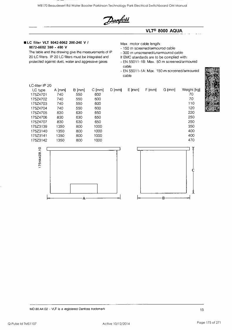
VLT® 8000 AQUA
LC filter VLT 8042-8062 200-240 V /
8072-8602 380 - 480 V
The table and the drawing give the measurements of IP
20 LC filters. IP 20 LC filters must be integrated and
protected against dust, water and aggressive gases.
LC-filter IP 20 LC type
175Z4701 175Z4702 175Z4703 175Z4704 175Z4705 175Z4706 175Z4707 175Z3139 175Z3140 175Z3141 175Z3142
A [mm] B [mm] C [mm]
Max. motor cable length: - 150 m screened/armoured cable - 300 m unscreened/unarmoured cable If EMC standards are to be complied with: - EN 55011-1B: Max. 50 m screened/armoured
cable - EN 55011-1A: Max. 150 m screened/armoured
cable
D [mm] E [mm] F [mm] G [mm] Weight [kg]
740 550 600 70 740 550 600 70 740 550 600 110
740 550 600 120
830 630 650 220 830 630 650 250 830 630 650 250 1350 800 1000 350 1350 800 1000 400 1350 800 1000 400 1350 800 1000 470
I I
L. A
I
B -I
C
I
MD.80.A4.02 - VLT is a registered Danfoss trademark 15
WB170 Beaudesert Rd Water Booster Parkinson Technology Park Electrical Switchboard OM Manual
Q-Pulse Id TMS1107 Active 10/12/2014 Page 175 of 271
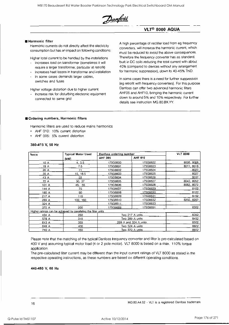
VLT® 8000 AQUA
Harmonic filter Harmonic currents do not directly affect the electricity
consumption but has an impact on following conditions:
Higher total current to be handled by the installations
Increases load on transformer (sometimes it will
require a larger transformer, particular at retrofit)
- Increases heat losses in transformer and installation
In some cases demands larger cables,
switches and fuses
Higher voltage distortion due to higher current
- Increase risk for disturbing electronic equipment
connected to same grid
A high percentage of rectifier load from eg frequency
converters, will increase the harmonic current, which
must be reduced to avoid the above consequences.
Therefore the frequency converter has as standard,
built in DC coils reducing the total current with about
40% (compared to devices without any arrangement
for harmonic suppression), down to 40-45% ThiD.
In some cases there is a need for further suppression (eg retrofit with frequency converters). For this purpose
Danfoss can offer two advanced harmonic filters
AHF05 and AHF10, bringing the harmonic current down to around 5% and 10% respectively. For further
details see instruction MG.80.BX.YY.
Ordering numbers, Harmonic filters
Harmonic filters are used to reduce mains harmonics AHF 010: 10% current distortion
AHF 005: 5% current distortion
380-415 V, 50 Hz
IAHF,N Typical Motor Used
fkIN1
Danfoss ordering number VLT 8000
AHF 005 AHF 010
10 A 4, 5.5 17506600 175G6622 8006, 8008 19 A 7.5 17506601 17506623 8011, 8016
26 A 11 17506602 17506624 8022
35 A 15, 18.5 17506603 17506625 8027
43 A 22 175G6604 17506626 8032
72 A 30, 37 17506605 17506627 8042, 8052 101 A 45. 55 17506606 17506628 8062, 8072 144 A 75 17506607 17506629 8102
180 A 90 17506608 17506630 8122
217 A 110 17506609 17506631 8152
289 A 132, 160 175G6610 17506632 8202, 8252
324 A 175G6611 17506633 370 A 200 17506688 17506691 8302
Higher ratings can be achieved by paralleling the filter units
434 A 250 Two 217 A units 8352
578 A 315 Two 289 A units 8452
613 A 355 289 A and 324 A units 8502
648 A 400 Two 324 A units 8602 740 A 450 Two 370 A units 8652
Please note that the matching of the typical Danfoss frequency converter and filter is pre-calculated based on
400 V and assuming typical motor load (4 or 2 pole motor). VLT 8000 is based on a max. 110% torque application. The pre-calculated filter current may be different than the input current ratings of VLT 8000 as stated in the respective operating instructions, as these numbers are based on different operating conditions.
440-480 V, 60 Hz
16 MD.80.A4.02 - VLT is a registered Danfoss trademark
WB170 Beaudesert Rd Water Booster Parkinson Technology Park Electrical Switchboard OM Manual
Q-Pulse Id TMS1107 Active 10/12/2014 Page 176 of 271
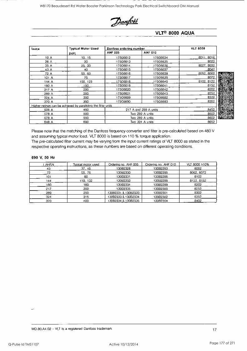
VLT® 8000 AQUA
IAHF,N Typical Motor Used
fHP1
Danfoss ordering number VLT 8000 AHF 005 AHF 010
19 A 10, 15 175G6612 175G6634 8011, 8016 26 A 20 175G6613 17506635 8022 35 A 25, 30 175G6614 175G6636 8027, 8032 43 A 40 17506615 17506637 8042 72 A 50, 60 175G6616 17506638 8052, 8062
101 A 75 17506617 17506639 8072 144 A 100, 125 175G6618 17506640 8102, 8122
180 A 150 175G6619 17506641 8152 217 A 200 175G6620 17506642 8202
289 A 250 175G6621 17506643 8252
324 A 300 17506689 17506692 8302
370 A 350 175G6690 17506693 8352 Higher ratings can be achieved by paralleling the filter units
506 A 450 217 A and 289 A units 8452 578 A 500 Two 289 A units 8502
578 A 550 Two 289 A units 8602
648 A 600 Two 324 A units 8652
Please note that the matching of the Danfoss frequency converter and filter is pre-calculated based on 480 V
and assuming typical motor load. VLT 8000 is based on 110 % torque application. The pre-calculated filter current may be varying from the input current ratings of VLT 8000 as stated in the
respective operating instructions, as these numbers are based on different operating conditions.
690 V, 50 Hz
I AHF,N Typical motor used Ordering no. AHF 005 Ordering no. AHF 010 VLT 8000 110%
43 37, 45 130B2328 13062293 8052 72 55, 75 13082330 13082295 8062, 8072 101 90 13082331 130B2296 8102 144 110, 132 13082333 130B2298 8122, 8152
180 160 13082334 13082299 8202 217 200 13082335 130B2300 8252 289 250 13082331 & 13082333 13082301 8302 324 315 13082333 &13082334 130B2302 8352 370 400 13082334 &13082335 13082304 8402
MD.80.A4.02 - VLT is a registered Danfoss trademark 17
WB170 Beaudesert Rd Water Booster Parkinson Technology Park Electrical Switchboard OM Manual
Q-Pulse Id TMS1107 Active 10/12/2014 Page 177 of 271
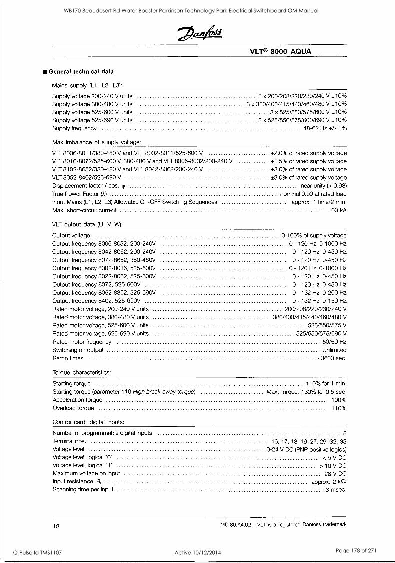
VLT® 8000 AQUA
General technical data
Mains supply (L1, L2, L3):
Supply voltage 200-240 V units 3 x 200/208/220/230/240 V ±10%
Supply voltage 380-480 V units 3 x 380/400/415/440/460/480 V ±10%
Supply voltage 525-600 V units 3 x 525/550/575/600 V ±10%
Supply voltage 525-690 V units 3 x 525/550/575/600/690 V ±10% Supply frequency 48-62 Hz +/- 1%
Max imbalance of supply voltage:
VLT 8006-8011/380-480 V and VLT 8002-8011/525-600 V ±2.0% of rated supply voltage VLT 8016-8072/525-600 V, 380-480 V and VLT 8006-8032/200-240 V ±1.5% of rated supply voltage VLT 8102-8652/380-480 V and VLT 8042-8062/200-240 V ±3.0% of rated supply voltage VLT 8052-8402/525-690 V ±3.0% of rated supply voltage Displacement factor / cos. cp near unity (> 0.98)
True Power Factor (X) nominal 0.90 at rated load
Input Mains (L1, L2, L3) Allowable On-OFF Switching Sequences approx. 1 time/2 min.
Max. short-circuit current 100 kA
VLT output data (U, V, \A/):
Output voltage 0-100% of supply voltage
Output frequency 8006-8032, 200-240V 0 - 120 Hz, 0-1000 Hz
Output frequency 8042-8062, 200-240V 0 - 120 Hz, 0-450 Hz
Output frequency 8072-8652, 380-460V 0 - 120 Hz, 0-450 Hz
Output frequency 8002-8016, 525-600V 0 - 120 Hz, 0-1000 Hz
Output frequency 8022-8062, 525-600V 0 - 120 Hz, 0-450 Hz
Output frequency 8072, 525-600V 0 - 120 Hz, 0-450 Hz
Output frequency 8052-8352, 525-690V 0 - 132 Hz, 0-200 Hz
Output frequency 8402, 525-690V 0 - 132 Hz, 0-150 Hz
Rated motor voltage, 200-240 V units 200/208/220/230/240 V
Rated motor voltage, 380-480 V units 380/400/415/440/460/480 V
Rated motor voltage, 525-600 V units 525/550/575 V
Rated motor voltage, 525-690 V units 525/550/575/690 V
Rated motor frequency 50/60 Hz
Switching on output Unlimited
Ramp times 1- 3600 sec.
Torque characteristics:
Starting torque 110% for 1 min.
Starting torque (parameter 110 High break-away torque) Max. torque: 130% for 0.5 sec. Acceleration torque 100% Overload torque 110%
Control card, digital inputs:
Number of programmable digital inputs 8
Terminal nos. 16, 17, 18, 19, 27, 29, 32, 33 Voltage level 0-24 V DC (PNP positive logics) Voltage level, logical "0" < 5 V DC Voltage level, logical "1" > 10 V DC
Maximum voltage on input 28 V DC
Input resistance, R1 approx. 2 I<C2
Scanning time per input 3 msec.
18 MD.80.A4.02 - VLT is a registered Danfoss trademark
WB170 Beaudesert Rd Water Booster Parkinson Technology Park Electrical Switchboard OM Manual
Q-Pulse Id TMS1107 Active 10/12/2014 Page 178 of 271
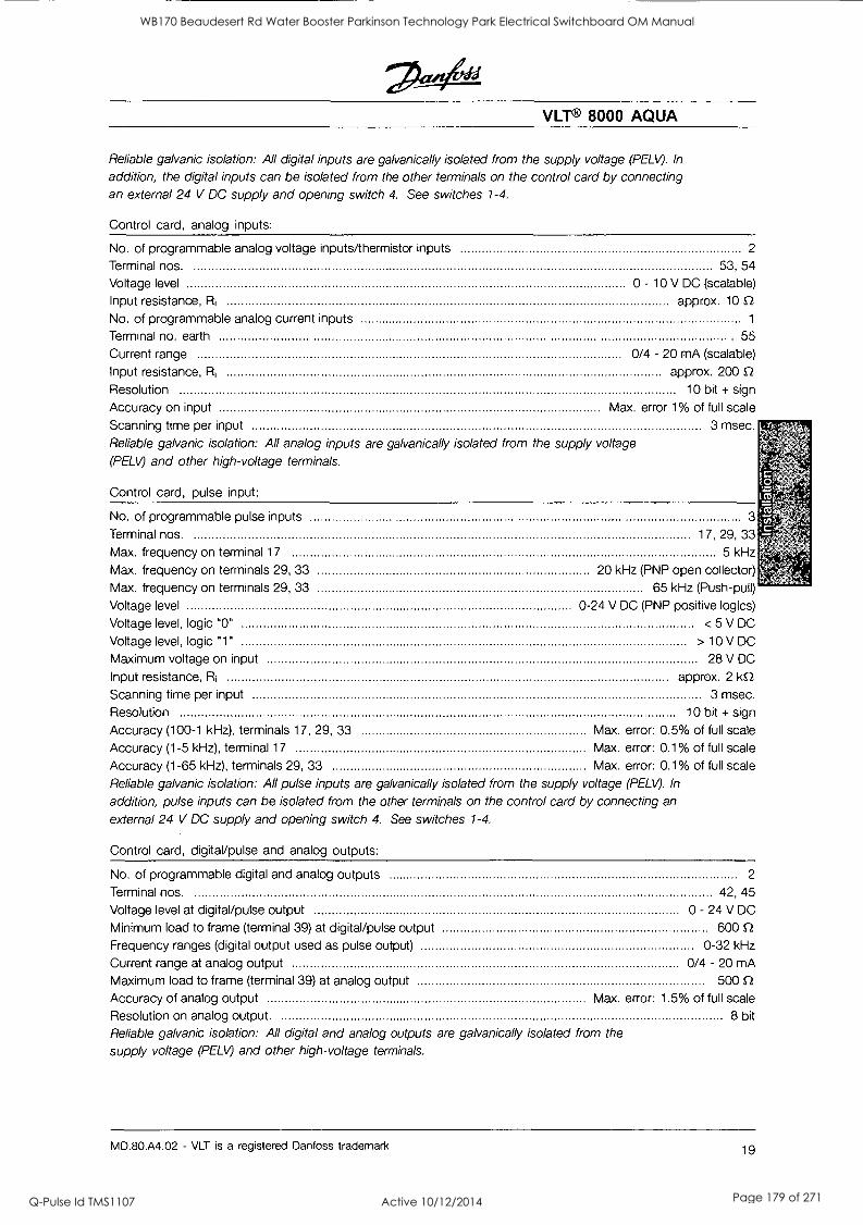
VLT® 8000 AQUA
Reliable galvanic isolation: All digital inputs are galvanically isolated from the supply voltage (PELV). In
addition, the digital inputs can be isolated from the other terminals on the control card by connecting an external 24 V DC supply and opening switch 4. See switches 1-4.
Control card, analog inputs:
No. of programmable analog voltage inputs/thermistor inputs 2
Terminal nos. 53, 54
Voltage level 0 - 10 V DC (scalable)
Input resistance, Ri approx. 10 Q No. of programmable analog current inputs 1
Terminal no. earth 55
Current range 0/4 - 20 mA (scalable)
Input resistance, R1 approx. 200 0,
Resolution 10 bit + sign
Accuracy on input Max. error 1% of full scale
Scanning time per input 3 msec.
Reliable galvanic isolation: All analog inputs are galvanically isolated from the supply voltage
(PELV) and other high-voltage terminals.
Control card, pulse input:
No. of programmable pulse inputs 3
Terminal nos. 17, 29, 33
Max. frequency on terminal 17 5 kHz
Max. frequency on terminals 29, 33 20 kHz (PNP open collector)
Max. frequency on terminals 29, 33 65 kHz (Push-pull)
Voltage level 0-24 V DC (PNP positive logics)
Voltage level, logic "0" < 5 V DC
Voltage level, logic "1" > 10 V DC
Maximum voltage on input 28 V DC
Input resistance, Ri approx. 2162 Scanning time per input 3 msec.
Resolution 10 bit + sign
Accuracy (100-1 kHz), terminals 17, 29, 33 Max. error: 0.5% of full scale
Accuracy (1-5 kHz), terminal 17 Max. error: 0.1% of full scale
Accuracy (1-65 kHz), terminals 29, 33 Max. error: 0.1% of full scale
Reliable galvanic isolation: All pulse inputs are galvanically isolated from the supply voltage (PELF). In
addition, pulse inputs can be isolated from the other terminals on the control card by connecting an
external 24 V DC supply and opening switch 4. See switches 1-4.
Control card, digital/pulse and analog outputs:
No. of programmable digital and analog outputs 2
Terminal nos. 42, 45
Voltage level at digital/pulse output 0 - 24 V DC
Minimum load to frame (terminal 39) at digital/pulse output 600 Q Frequency ranges (digital output used as pulse output) 0-32 kHz
Current range at analog output 0/4 - 20 mA
Maximum load to frame (terminal 39) at analog output 500 Q
Accuracy of analog output Max. error: 1.5% of full scale
Resolution on analog output. 8 bit
Reliable galvanic isolation: All digital and analog outputs are galvanically isolated from the
supply voltage (PELT/) and other high-voltage terminals.
MD.80.A4.02 - VLT is a registered Danfoss trademark 19
WB170 Beaudesert Rd Water Booster Parkinson Technology Park Electrical Switchboard OM Manual
Q-Pulse Id TMS1107 Active 10/12/2014 Page 179 of 271
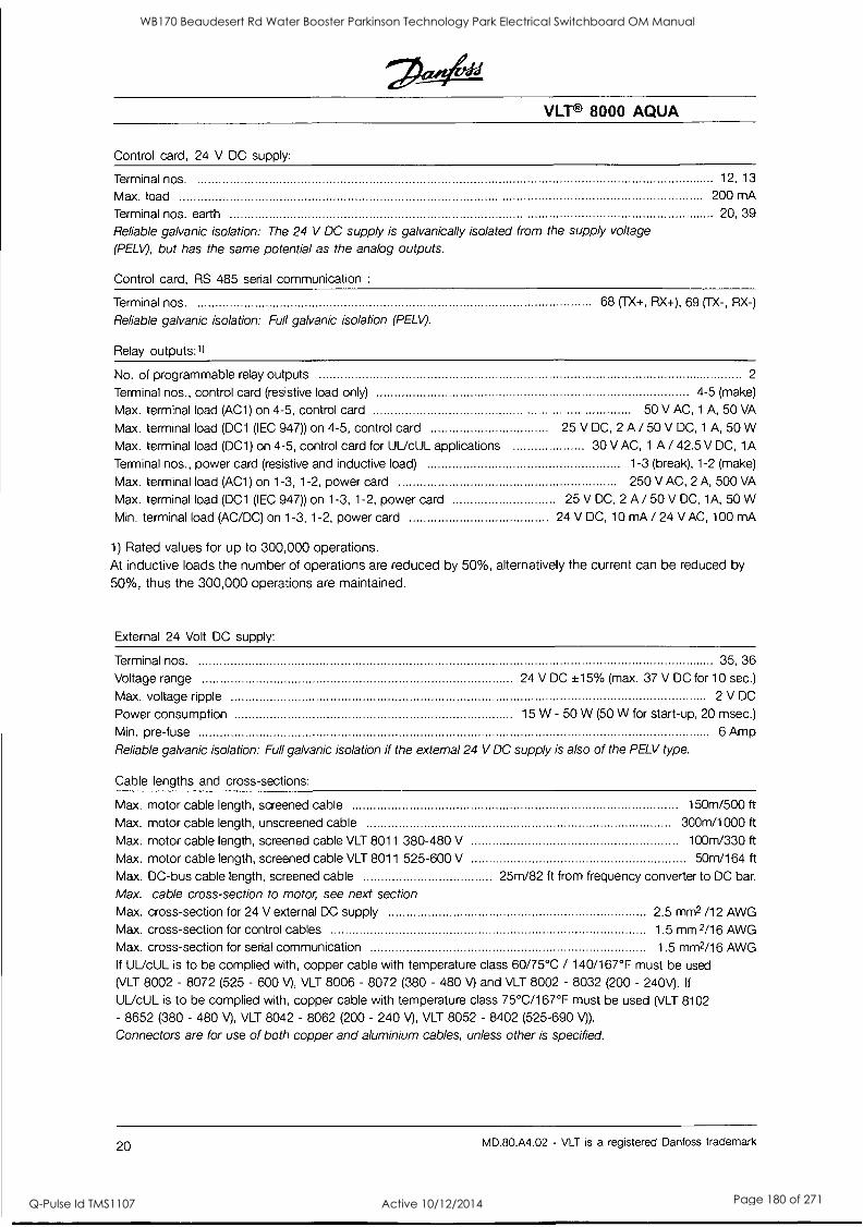
VLT® 8000 AQUA
Control card, 24 V DC supply:
Terminal nos. 12, 13
Max. load 200 mA
Terminal nos. earth 20, 39
Reliable galvanic isolation: The 24 V DC supply is galvanically isolated from the supply voltage
(PELV), but has the same potential as the analog outputs.
Control card, RS 485 serial communication :
Terminal nos.
Reliable galvanic isolation: Full galvanic isolation (PELV).
Relay outputs:1l
68 (TX+, RX+), 69 (TX-, RX-)
No. of programmable relay outputs 2
Terminal nos., control card (resistive load only) 4-5 (make)
Max. terminal load (AC1) on 4-5, control card 50 V AC, 1 A, 50 VA
Max. terminal load (DC1 (IEC 947)) on 4-5, control card 25 V DC, 2 A / 50 V DC, 1 A, 50 W
Max. terminal load (DC1) on 4-5, control card for UUcUL applications 30 V AC, 1 A / 42.5 V DC, 1A
Terminal nos., power card (resistive and inductive load) 1-3 (break), 1-2 (make)
Max. terminal load (AC1) on 1-3, 1-2, power card 250 V AC, 2 A, 500 VA
Max. terminal load (DC1 (IEC 947)) on 1-3, 1-2, power card 25 V DC, 2 A / 50 V DC, 1A, 50 W
Min. terminal load (AC/DC) on 1-3, 1-2, power card 24 V DC, 10 mA / 24 V AC, 100 mA
1) Rated values for up to 300,000 operations. At inductive loads the number of operations are reduced by 50%, alternatively the current can be reduced by
50%, thus the 300,000 operations are maintained.
External 24 Volt DC supply:
Terminal nos. 35, 36
Voltage range 24 V DC +15% (max. 37 V DC for 10 sec.)
Max. voltage ripple 2 V DC
Power consumption 15 W - 50 W (50 W for start-up, 20 msec.)
Min. pre-fuse 6 Amp
Reliable galvanic isolation: Full galvanic isolation if the external 24 V DC supply is also of the PELV type.
Cable lengths and cross-sections:
Max. motor cable length, screened cable 150m/500 ft
Max. motor cable length, unscreened cable 300m/1000 ft
Max. motor cable length, screened cable VLT 8011 380-480 V 100m/330 ft
Max. motor cable length, screened cable VLT 8011 525-600 V 50m/164 ft Max. DC-bus cable length, screened cable 25m/82 ft from frequency converter to DC bar.
Max. cable cross-section to motor, see next section Max. cross-section for 24 V external DC supply
Max. cross-section for control cables
Max. cross-section for serial communication
If UL/cUL is to be complied with, copper cable with temperature class 60/75°C / (VLT 8002 - 8072 (525 - 600 A, VLT 8006 - 8072 (380 - 480 V) and VLT 8002 -
UUcUL is to be complied with, copper cable with temperature class 75°C/167°F
2.5 mm2 /12 AWG
1.5 mm2/16 AWG
1.5 mm2/16 AWG 140/167°F must be used
8032 (200 - 240V). If
must be used (VLT 8102
- 8652 (380 - 480 V), VLT 8042 - 8062 (200 - 240 V), VLT 8052 - 8402 (525-690 V)).
Connectors are for use of both copper and aluminium cables, unless other is specified.
20 MD.80.A4.02 - VLT is a registered Danfoss trademark
WB170 Beaudesert Rd Water Booster Parkinson Technology Park Electrical Switchboard OM Manual
Q-Pulse Id TMS1107 Active 10/12/2014 Page 180 of 271
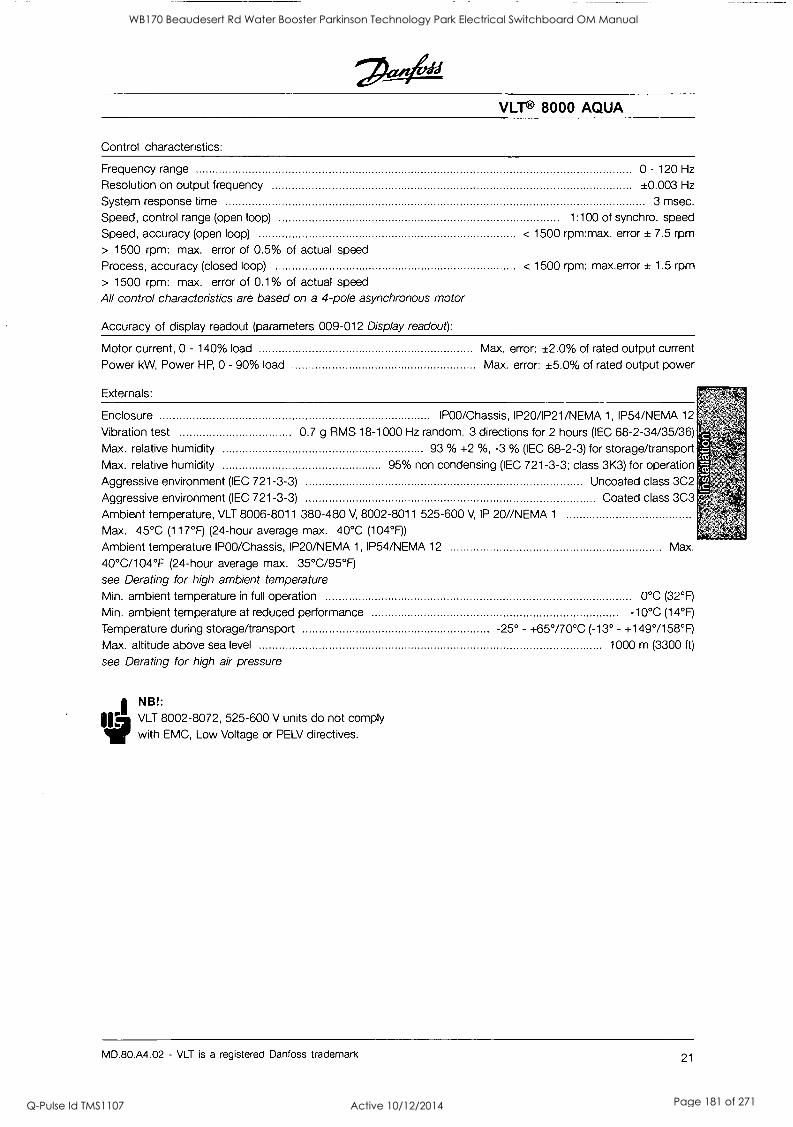
VLT® 8000 AQUA
Control characteristics:
Frequency range 0 - 120 Hz
Resolution on output frequency ±0.003 Hz
System response time 3 msec.
Speed, control range (open loop) 1:100 of synchro. speed
Speed, accuracy (open loop) < 1500 rpm:max. error ± 7.5 rpm
> 1500 rpm: max. error of 0.5% of actual speed
Process, accuracy (closed loop) < 1500 rpm: max.error ± 1.5 rpm
> 1500 rpm: max. error of 0.1% of actual speed
All control characteristics are based on a 4-pole asynchronous motor
Accuracy of display readout (parameters 009-012 Display readout):
Motor current, 0 - 140% load
Power kW, Power HP, 0 - 90% load
Externals:
Max. error: ±2.0% of rated output current Max. error: ±5.0% of rated output power
Enclosure IPOO/Chassis, IP20/1P21/NEMA 1, IP54/NEMA 12
Vibration test 0.7 g RMS 18-1000 Hz random. 3 directions for 2 hours (IEC 68-2-34/35/36) Max. relative humidity 93 % +2 %, -3 % (IEC 68-2-3) for storage/transport Max. relative humidity 95% non condensing (IEC 721-3-3; class 3K3) for operation
Aggressive environment (IEC 721-3-3) Uncoated class 3C2
Aggressive environment (IEC 721-3-3) Coated class 3C3
Ambient temperature, VLT 8006-8011 380-480 V, 8002-8011 525-600 V, IP 20//NEMA 1
Max. 45°C (117°F) (24-hour average max. 40°C (104°F))
Ambient temperature IPOO/Chassis, IP20 /NEMA 1, IP54/NEMA 12 Max.
40°C/104°F (24-hour average max. 35°C/95°F) see Derating for high ambient temperature Min. ambient temperature in full operation 0°C (32°F)
Min. ambient temperature at reduced performance -10°C (14°F)
Temperature during storage/transport -25° - +65°/70°C (-13° - +149°/158°F) Max. altitude above sea level 1000 m (3300 ft)
see Derating for high air pressure
I N B ! :
1114
VLT 8002-8072, 525-600 V units do not comply with EMC, Low Voltage or PELV directives.
MD.80.A4.02 - VLT is a registered Danfoss trademark 21
WB170 Beaudesert Rd Water Booster Parkinson Technology Park Electrical Switchboard OM Manual
Q-Pulse Id TMS1107 Active 10/12/2014 Page 181 of 271
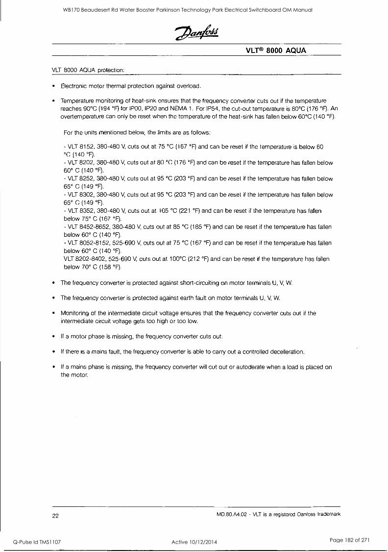
VLT® 8000 AQUA
VLT 8000 AQUA protection:
Electronic motor thermal protection against overload.
Temperature monitoring of heat-sink ensures that the frequency converter cuts out if the temperature reaches 90°C (194 °F) for {POO, IP20 and NEMA 1. For IP54, the cut-out temperature is 80°C (176 °F). An
overtemperature can only be reset when the temperature of the heat-sink has fallen below 60°C (140 °F).
For the units mentioned below, the limits are as follows:
- VLT 8152, 380-480 V, cuts out at 75 °C (167 °F) and can be reset if the temperature is below 60 °C (140 °F).
- VLT 8202, 380-480 V, cuts out at 80 °C (176 °F) and can be reset if the temperature has fallen below 60° C (140 °F).
- VLT 8252, 380-480 V, cuts out at 95 °C (203 °F) and can be reset if the temperature has fallen below 65° C (149 °F).
- VLT 8302, 380-480 V, cuts out at 95 °C (203 °F) and can be reset if the temperature has fallen below 65° C (149 °F).
- VLT 8352, 380-480 V, cuts out at 105 °C (221 °F) and can be reset if the temperature has fallen
below 75° C (167 °F).
- VLT 8452-8652, 380-480 V, cuts out at 85 °C (185 °F) and can be reset if the temperature has fallen below 60° C (140 °F).
- VLT 8052-8152, 525-690 V, cuts out at 75 °C (167 °F) and can be reset if the temperature has fallen
below 60° C (140 °F).
VLT 8202-8402, 525-690 V, cuts out at 100°C (212 °F) and can be reset if the temperature has fallen
below 70° C (158 °F).
The frequency converter is protected against short-circuiting on motor terminals U, V, W.
The frequency converter is protected against earth fault on motor terminals U, V, W.
Monitoring of the intermediate circuit voltage ensures that the frequency converter cuts out if the intermediate circuit voltage gets too high or too low.
If a motor phase is missing, the frequency converter cuts out.
If there is a mains fault, the frequency converter is able to carry out a controlled decelleration.
If a mains phase is missing, the frequency converter will cut out or autoderate when a load is placed on the motor.
22 MD.80.A4.02 - VLT is a registered Danfoss trademark
WB170 Beaudesert Rd Water Booster Parkinson Technology Park Electrical Switchboard OM Manual
Q-Pulse Id TMS1107 Active 10/12/2014 Page 182 of 271
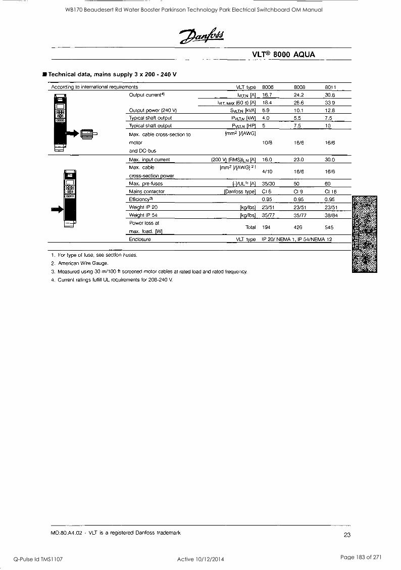
VLT® 8000 AQUA
Technical data, mains supply 3 x 200 - 240 V
According to international requirements
Output current4)
Output power (240 V)
Typical shaft output
Typical shaft output
Max. cable cross-section to
motor
and DC-bus
VLT type
[A]
MAX (60 s) [A]
Svcris) [kVA]
PVLT,N [kW]
PVLT,N [HP]
[mm2 HAWG]
Max. input current
Max. cable
cross-section power
Max. pre-fuses
Mains contactor
Efficiency3)
Weight IP 20
Weight IP 54
Power loss at
max. load. [W]
(200 V) (RMS)IL,N [A]
[mm2 ] /IAWG1 2)
(-1/UL1) [A]
[ Danfoss type]
[kg/Ibs]
[kg/lbs]
Total
8006 8008 8011
16.7 24.2 30.8
18.4 26.6 33.9
6.9 10.1 12.8
4.0 5.5 7.5
5 7.5 10
10/8 16/6 16/6
16.0 23.0 30.0
4/10 16/6 16/6
35/30 50 60
CI 6 CI 9 CI 16
0.95 0.95 0.95
23/51 23/51 23/51
35/77 35/77 38/84
194 426 545
Enclosure VLT type IP 20/ NEMA 1, IP 54/NEMA 12
1. For type of fuse, see section Fuses.
2. American Wire Gauge.
3. Measured using 30 m/100 ft screened motor cables at rated load and rated frequency.
4. Current ratings fulfill UL requirements for 208-240 V.
MD.80.A4.02 - VLT is a registered Danfoss trademark 23
WB170 Beaudesert Rd Water Booster Parkinson Technology Park Electrical Switchboard OM Manual
Q-Pulse Id TMS1107 Active 10/12/2014 Page 183 of 271
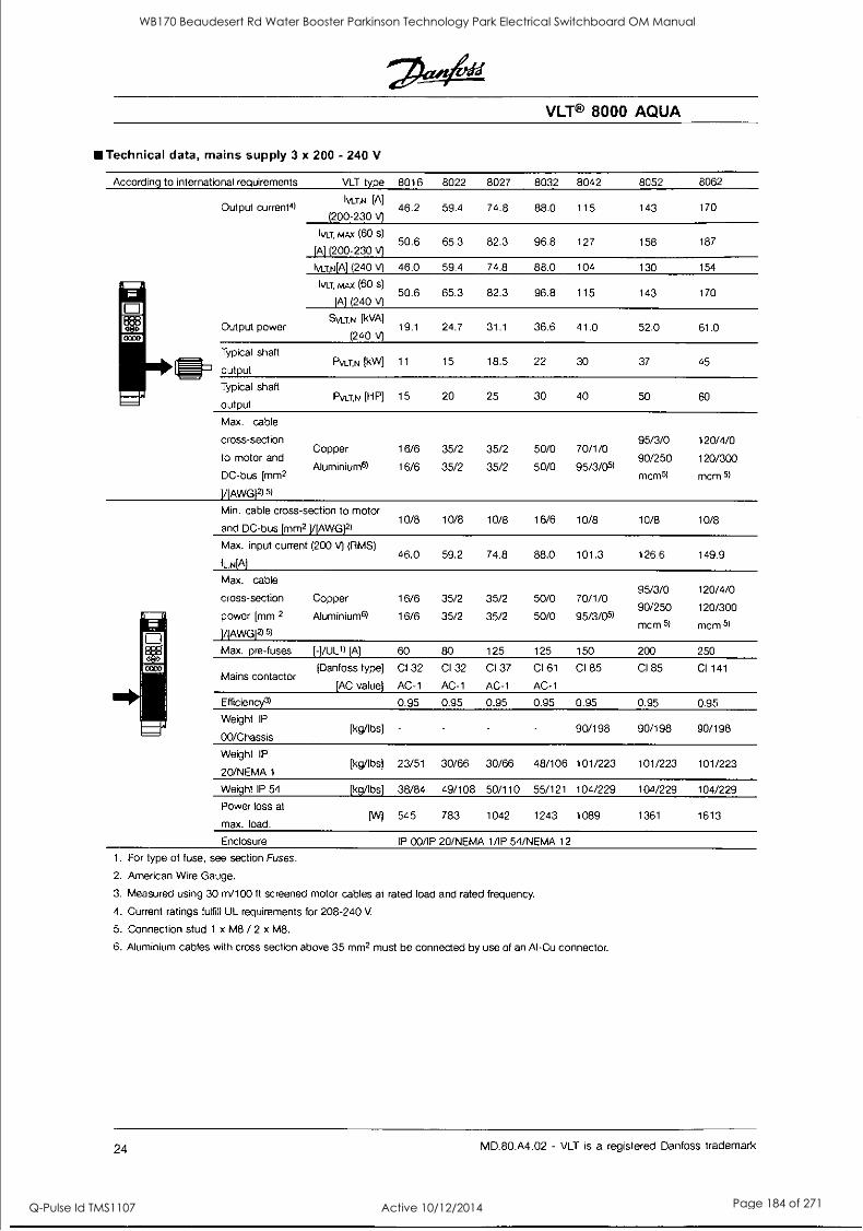
Technical data, mains supply 3 x 200 - 240 V
According to international requirements
Output current4)
Output power
Typical shaft
WI output
Typical shaft
output
VLT type
IvaN [A]
(200-230 V)
IVLT, MAX (60 s)
[A] (200-230 A Ivu,N[A] (240 V)
lvt3, mAx (60 s)
[A] (240 V)
SVLT,N [kVA)
(240 V)
PVLT,N [kW]
PVLT,N [HP]
Max. cable
cross-section Copper
to motor and Aluminium6)
DC-bus [mm2
HAWG12) 5)
Min. cable cross-section to motor
and DC-bus [mm2 ]/[AWG]2)
Max. input current (200 V) (RMS)
IL,N[A]
Max. cable
cross-section Copper
power [mm 2 Aluminium6)
M AWG]2)
Max. pre-fuses [-]/UL1) [A]
[Danfoss type] Mains contactor
[AC value]
Efficiency3l
Weight IP
00/Chassis [kg/lbs]
Weight IP [kg/lbs]
20/NEMA 1
Weight IP 54 [kg/lbs]
Power loss at [W]
max. load.
VLT® 8000 AQUA
8016 8022 8027 8032 8042 8052 8062
46.2 59.4 74.8 88.0 115 143 170
50.6 65.3 82.3 96.8 127 158 187
46.0 59.4 74.8 88.0 104 130 154
50.6 65.3 82.3 96.8 115 143 170
19.1 24.7 31.1 36.6 41.0 52.0 61.0
11 15 18.5 22 30 37 45
15 20 25 30 40 50 60
16/6
16/6
35/2
35/2
35/2
35/2
50/0
50/0
70/1/0
95/3/051
95/3/0
90/250
mcm5)
120/4/0
120/300
mcm 5)
10/8 10/8 10/8 16/6 10/8 10/8 10/8
46.0 59.2 74.8 88.0 101.3 126.6 149.9
16/6
16/6
35/2
35/2
35/2
35/2
50/0
50/0
70/1/0
95/3/051
95/3/0
90/250
mcm
120/4/0
120/300
mcm 5)
60 80 125 125 150 200 250
CI 32
AC-1
CI 32
AC-1
CI 37
AC-1
CI 61
AC-1
CI 85 CI 85 CI 141
0.95 0.95 0.95 0.95 0.95 0.95 0.95
90/198 90/198 90/198
23/51 30/66 30/66 48/106 101/223 101/223 101/223
38/84 49/108 50/110 55/121 104/229 104/229 104/229
545 783 1042 1243 1089 1361 1613
Enclosure IP 00/IP 20/NEMA 1/IP 54/NEMA 12
1. For type of fuse, see section Fuses.
2. American Wire Gauge.
3. Measured using 30 m/100 ft screened motor cables at rated load and rated frequency.
4. Current ratings fulfill UL requirements for 208-240 V
5. Connection stud 1 x M8 / 2 x M8.
6. Aluminium cables with cross section above 35 mm2 must be connected by use of an Al-Cu connector.
24 MD.80.A4.02 - VLT is a registered Danfoss trademark
WB170 Beaudesert Rd Water Booster Parkinson Technology Park Electrical Switchboard OM Manual
Q-Pulse Id TMS1107 Active 10/12/2014 Page 184 of 271
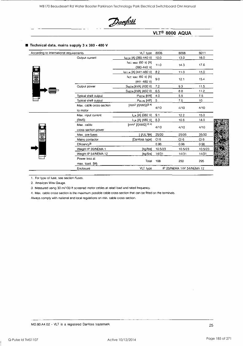
VLT® 8000 AQUA
Technical data, mains supply 3 x 380 - 480 V
According to international requirements
Output current
Output power
Typical shaft output
Typical shaft output
Max. cable cross-section
to motor
Max. input current
(RMS)
Max. cable
cross-section power
Max. pre-fuses
Mains contactor
Efficiency3)
Weight IP 20/NEMA 1
Weight IP 54/NEMA 12
Power loss at
max. load. [W]
Enclosure
VLT type 8006 8008 8011
IVLT,N [A] (380-440 V) 10.0 13.0 16.0
Ivcr, NtA.x (60 s) [A]
(380-440.V) 11.0 14.3 17.6
N [A] (441-480 V) 8.2 11.0 14.0
mAx (60 s) [A]
(441-480 V) 9.0 12.1 15.4
SVLT,N [kVA] (400 V) 7.2 9.3 11.5
SvLT,N [kVA] (460 V) 6.5 8.8 11.2
PVLT,N (kW] 4.0 5.5 7.5
PVLT,N [HP] 5 7.5 10
[mm2 ]/[AWG]2) 4) 4/10 4/10 4/10
IL,N [A] (380 V) 9.1 12.2 15.0
11_,N [A] (480 V) 8.3 10.6 14.0
[mm2 ]/[AWG] 2) 4) 4/10 4/10 4/10
[-]/ULft[A] 25/20 25/25 35/30
[Danfoss type] CI 6 CI 6 CI 6
0.96 0.96 0.96
[kg/lbs] 10.5/23 10.5/23 10.5/23
[kg/lbs] 14/31 14/31 14/31
Total 198 250 295
VLT type IP 20/NEMA 1/IP 54/NEMA 12
1. For type of fuse, see section Fuses.
2. American Wire Gauge.
3. Measured using 30 m/100 ft screened motor cables at rated load and rated frequency.
4. Max. cable cross section is the maximum possible cable cross section that can be fitted on the terminals.
Always comply with national and local regulations on min. cable cross-section.
MD.80.A4.02 - VLT is a registered Danfoss trademark 25
WB170 Beaudesert Rd Water Booster Parkinson Technology Park Electrical Switchboard OM Manual
Q-Pulse Id TMS1107 Active 10/12/2014 Page 185 of 271
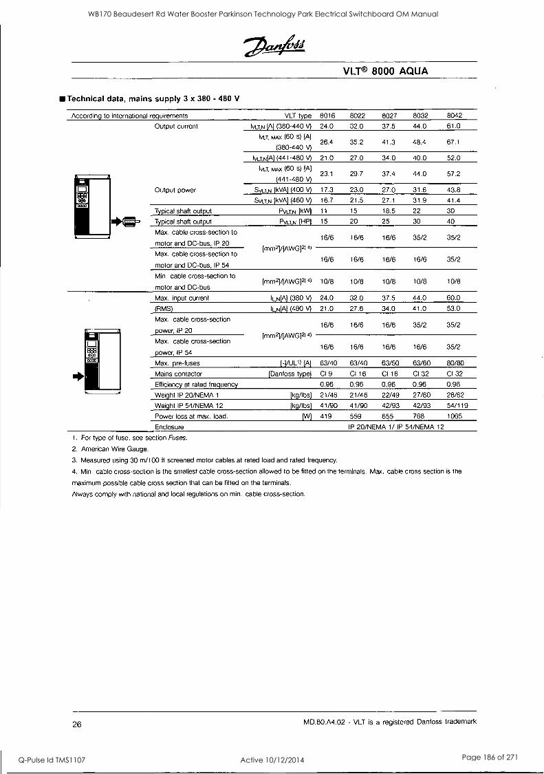
Technical data, mains supply 3 x 380 - 480 V
According to international requirements
Output current
w OS13
ED 0030
Output power
Typical shaft output I= Typical shaft output
Max. cable cross-section to
motor and DC-bus, IP 20
Max. cable cross-section to
motor and DC-bus, IP 54
Min. cable cross-section to
motor and DC-bus
Max. input current
(RMS)
Max. cable cross-section
power, IP 20
Max. cable cross-section
power, IP 54
Max. pre-fuses
Mains contactor
Efficiency at rated frequency
Weight IP 20/NEMA 1
Weight IP 54/NEMA 12
Power loss at max. load.
Enclosure
VLT type
IvaN [A] (380-440 V)
Ivur, NtAx (60 s) [A]
(380-440 V)
IvaN[A] (441-480 V)
Ivor, mAx (60 s) [A]
(441-480 V)
SVLTN [kVA] (400 V)
SVLTN [kVA] (460 V)
PVLT,N [kW]
PVLT,N [HP]
[MM2] /[AWG12) 4)
Ernm211[AWG]2)
IL,N[A] (380 V)
ILN[A] (480 V)
[MM2] /[AWGF) 4)
[-]/UL1) [A]
[Danfoss type]
[kg/lbs]
[kg/lbs]
VLT® 8000 AQUA
8016 8022 8027 8032 8042
24.0 32.0 37.5 44.0 61.0
26.4 35.2 41.3 48.4 67.1
21.0 27.0 34.0 40.0 52.0
23.1 29.7 37.4 44.0 57.2
17.3 23.0 27.0 31.6 43.8
16.7 21.5 27.1 31.9 41.4
11 15 18.5 22 30
15 20 25 30 40
16/6 16/6 16/6 35/2 35/2
16/6 16/6 16/6 16/6 35/2
10/8 10/8 10/8 10/8 10/8
24.0 32.0 37.5 44.0 60.0
21.0 27.6 34.0 41.0 53.0
16/6 16/6 16/6 35/2 35/2
16/6 16/6 16/6 16/6 35/2
63/40 63/40 63/50 63/60 80/80
Cl 9 CI 16 CI 16 CI 32 CI 32
0.96 0.96 0.96 0.96 0.96
21/46 21/46 22/49 27/60 28/62
41/90 41/90 42/93 42/93 54/119
419 559 655 768 1065
IP 20/NEMA 1/ IP 54/NEMA 12
1. For type of fuse, see section Fuses.
2. American Wire Gauge.
3. Measured using 30 m/100 ft screened motor cables at rated load and rated frequency.
4. Min. cable cross-section is the smallest cable cross-section allowed to be fitted on the terminals. Max. cable cross section is the
maximum possible cable cross section that can be fitted on the terminals.
Always comply with national and local regulations on min. cable cross-section.
26 MD.80.A4.02 - VLT is a registered Danfoss trademark
WB170 Beaudesert Rd Water Booster Parkinson Technology Park Electrical Switchboard OM Manual
Q-Pulse Id TMS1107 Active 10/12/2014 Page 186 of 271
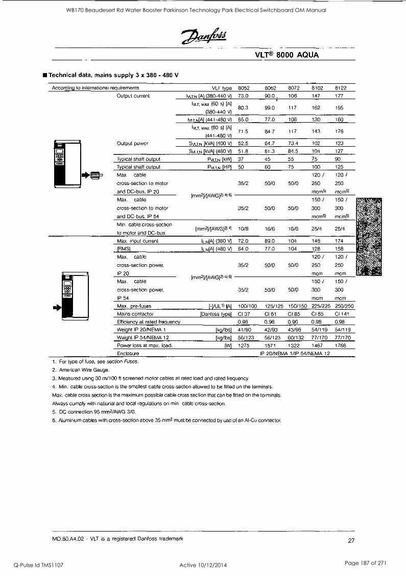
Technical data, mains supply 3 x 380 - 480 V
According to international requirements
Output current
Output power
Typical shaft output
Typical shaft output
IltMW Max. cable
cross-section to motor
and DC-bus, IP 20
Max. cable
cross-section to motor
and DC-bus, IP 54
Min. cable cross-section
to motor and DC-bus
Max. input current
(RMS)
Max. cable
cross-section power,
IP 20
Max. cable
cross-section power,
IP 54
Max. pre-fuses
Mains contactor
Efficiency at rated frequency
Weight IP 20/NEMA 1
Weight IP 54/NEMA 12
Power loss at max. load.
Enclosure
VLT® 8000 AQUA
VLT type 8052 8062 8072 8102 8122
IVLT,N [A] (380-440 V) 73.0 90.0 106 147 177
tytAx (60 s) [A]
(380-440 V) 80.3 99.0 117 162 195
Ivi_T,N[A] (441-480 V) 65.0 77.0 106 130 160
Ivur, mAx (60 s) [A]
(441-480 V) 71.5 84.7 117 143 176
SyLT,N [kVA] (400 V) 52.5 64.7 73.4 102 123
Svur,rsi [kVA' (460 V) 51.8 61.3 84.5 104 127
PVLTN [kW] 37 45 55 75 90
PVLT.N [HP] 50 60 75 100 125
EMM2YEAWGi2) 4) 61
35/2 50/0 50/0
120 /
250
mcm5)
120 /
250
mcm5)
35/2 50/0 50/0
150/ 300
mcm5)
150/ 300
mcm5)
[mm2] /[AWG12) 4) 10/8 16/6 16/6 25/4 25/4
IL N[A] (380 V) 72.0 89.0 104 145 174
IL,N[A] (480 V) 64.0 77.0 104 128 158
VTIM2HAWG12) 4) 6)
35/2 50/0 50/0
120 / 250
mcm
120 / 250
mcm
35/2 50/0 50/0
150 / 300
mcm
150 /
300
mcm
[- ] /UL') [A] 100/100 125/125 150/150 225/225 250/250
[ Danfoss type] CI 37 CI 61 C I 85 CI 85 CI 141
0.96 0.96 0.96 0.98 0.98
[kg/lbs] 41/90 42/93 43/96 54/119 54/119
[kg/lbs] 56/123 56/123 60/132 77/170 77/170
[W] 1275 1571 1322 1467 1766
IP 20/NEMA 1/IP 54/NEMA 12
1. For type of fuse, see section Fuses.
2. American Wire Gauge.
3. Measured using 30 m/100 ft screened motor cables at rated load and rated frequency.
4. Min. cable cross-section is the smallest cable cross-section allowed to be fitted on the terminals.
Max. cable cross section is the maximum possible cable cross section that can be fitted on the terminals.
Always comply with national and local regulations on min. cable cross-section.
5. DC connection 95 mm2/AWG 3/0.
6. Aluminium cables with cross-section above 35 mm2 must be connected by use of an Al-Cu connector.
MD.80.A4.02 - VLT is a registered Danfoss trademark 27
WB170 Beaudesert Rd Water Booster Parkinson Technology Park Electrical Switchboard OM Manual
Q-Pulse Id TMS1107 Active 10/12/2014 Page 187 of 271
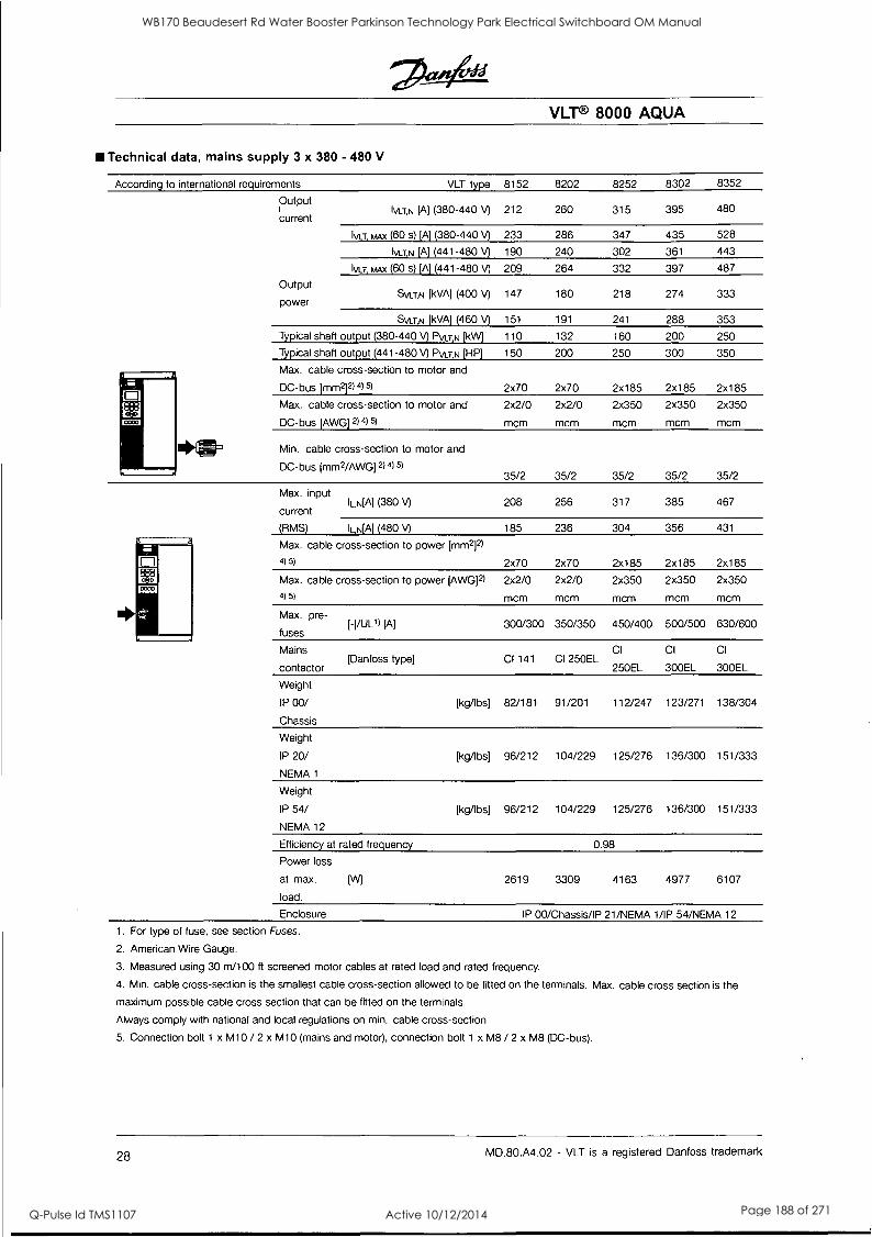
COM
VLT® 8000 AQUA
Technical data, mains supply 3 x 380 - 480 V
According to international requirements
Output
current
st.W.
VLT type
IVLT,N [A] (380-440 A
Ku, tom (60 s) [A] (380-440 V)
IvaN [A] (441-480 V)
Ivor, NtAx (60 s) (A] (441-480 V)
Output SVIZN [kVA] (400 V)
power
SVCrp [kVA] (460 V)
Typical shaft output (380-440 V) Pwr,N [kW]
Typical shaft output (441-480 V) PVLI,N [HP]
Max. cable cross-section to motor and
DC-bus [MM2]2) 4) 5)
Max. cable cross-section to motor and
DC-bus [AWG] 2) 4) 5)
Min. cable cross-section to motor and
DC-bus [MM2/AWG] 2) 4) 5)
Max. input IL,N[A] (380 V)
current
(RMS) ILN[Al (480 V)
Max. cable cross-section to power [mm2]2)
4) 5)
Max. cable cross-section to power (AWG12)
4) 5)
Max. pre-
fuses [-]/UL1) [A]
Mains [Danfoss type]
contactor
Weight
IP 00/
Chassis
Weight
IP 20/
NEMA 1
Weight
IP 54/
NEMA 12
Efficiency at rated frequency
Power loss
at max.
load.
8152 8202 8252 8302 8352
212 260 315 395 480
233 286 347 435 528
190 240 302 361 443
209 264 332 397 487
147 180 218 274 333
151 191 241 288 353
110 132 160 200 250
150 200 250 300 350
2x70 2x70 2x185 2x185 2x185
2x2/0 2x2/0 2x350 2x350 2x350
mcm mcm mcm mcm mcm
35/2 35/2 35/2 35/2 35/2
208 256 317 385 467
185 236 304 356 431
2x70 2x70 2x185 2x185 2x185
2x2/0 2x2/0 2x350 2x350 2x350
mcm mcm mcm mcm mcm
300/300 350/350 450/400 500/500 630/600
CI 141 CI 250EL CI
250EL
CI
300EL
CI
300EL
[kg/lbs] 82/181 91/201 112/247 123/271 138/304
[kg/lbs] 96/212 104/229 125/276 136/300 151/333
[kg/lbs] 96/212 104/229 125/276 136/300 151/333
0.98
2619 3309 4163 4977 6107
Enclosure IP 00/Chassis/IP 21/NEMA 1/IP 54/NEMA 12
1. For type of fuse, see section Fuses.
2. American Wire Gauge.
3. Measured using 30 m/100 ft screened motor cables at rated load and rated frequency.
4. Min. cable cross-section is the smallest cable cross-section allowed to be fitted on the terminals. Max cable cross section is the
maximum possible cable cross section that can be fitted on the terminals.
Always comply with national and local regulations on min. cable cross-section.
5. Connection bolt 1 x M10 / 2 x M10 (mains and motor), connection bolt 1 x M8 / 2 x M8 (DC-bus).
28 MD.80.A4.02 - VLT is a registered Danfoss trademark
WB170 Beaudesert Rd Water Booster Parkinson Technology Park Electrical Switchboard OM Manual
Q-Pulse Id TMS1107 Active 10/12/2014 Page 188 of 271
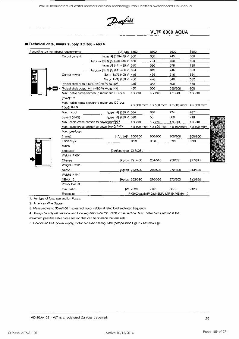
Technical data, mains supply 3 x 380 - 480 V
According to international requirements
0033
VLT type
Output current IVLT,N [A] (380-440 V)
Ivur, MAX (60 s) [A] (380-440 \/)
IvaN [A] (441-480 V)
mAx (60 s) [A] (441-480 V)
Output power Svcr.N [kVA) (400 V)
SVULN [kVA) (480 V)
Typical shaft output (380-440 V) Pvcrki [kW]
41J Typical shaft output (441-480 A PvaN [HP]
Max. cable cross-section to motor and DC-bus
[mm2] 4) 5)
Max. cable cross-section to motor and DC-bus
[AWG] 4) 51
Max. input
current (RMS)
Max. cable cross
Max. cable cross
-section to power [MM2]4)
-section to power (AWG]2) 415)
luytAx [A] (380 V)
IL,K4Ax [A] (480 V)
8452
600
660
540
594
416
430
315
450
4 x 240
584
526
4 x 240
4 x 500 mcm
VLT® 8000 AQUA
8502
658
724
590
649
456
470
355
500
4 x 240
648
581
4 x 240
4 x 500 mcm
8602 8652
745 800
820 800
678 730
746 803
516 554
540 582
400 450
550/600 600
4 x 240 4 x 240
4 x 500 mcm 4 x 500 mcm 4 x 500 mcm 4 x 500 mcm
734
668
4 x 240
4 x 500 mcm
787
718
4 x 240
4 x 500 mcm
Max. pre-fuses
(mains)
Efficiency3)
Mains
contactor
[-]/UL [A]1 1 700/700 900/900 900/900 900/900
0.98 0.98 0.98 0.98
[Danfoss type] CI 300EL
Weight IP 00/
Chassis
Weight IP 20/
NEMA 1
Weight IP 54/
NEMA 12
Power loss at
max. load
Enclosure
[kg/lbs] 221/488
[kg/lbs] 263/580
[kg/lbs] 263/580
234/516
270/596
270/596
236/521
272/600
272/600
277/611
313/690
313/690
[W] 7630 7701 8879 9428
IP 00/Chassis/IP 21/NEMA 1/IP 54/NEMA 12
1. For type of fuse, see section Fuses.
2. American Wire Gauge.
3. Measured using 30 m/100 ft screened motor cables at rated load and rated frequency.
4. Always comply with national and local regulations on min. cable cross-section. Max. cable cross section is the
maximum possible cable cross section that can be fitted on the terminals.
5. Connection bolt, power supply, motor and load sharing: M10 (compression lug), 2 x M8 (box lug)
MD.80.A4.02 - VLT is a registered Danfoss trademark 29
WB170 Beaudesert Rd Water Booster Parkinson Technology Park Electrical Switchboard OM Manual
Q-Pulse Id TMS1107 Active 10/12/2014 Page 189 of 271
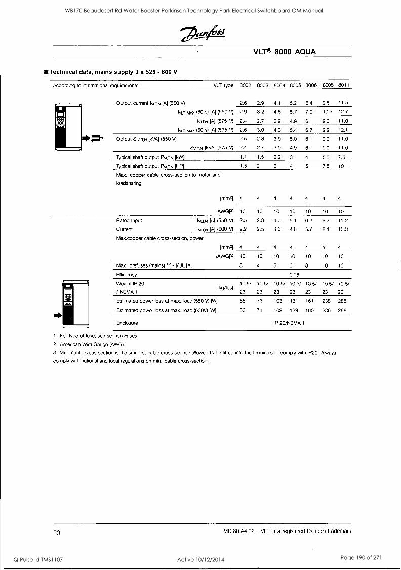
Technical data, mains supply 3 x 525 - 600 V
According to international requirements
COCO
EA DODO
Output current IvaN [A] (550 V) 2.6 2.9 4.1 5.2 6.4 9.5 11.5
Iva Max (60 s) [A] (550 V) 2.9 3.2 4.5 5.7 7.0 10.5 12.7
IVCEN [A] (575 V) 2.4 2.7 3.9 4.9 6.1 9.0 11.0
IN/LT, MM (60 s) [A] (575 V) 2.6 3.0 4.3 5.4 6.7 9.9 12.1
*I= Output S V1J,N [kVA] (550 V) 2.5 2.8 3.9 5.0 6.1 9.0 11.0
SvurN [kVA] (575 \/) 2.4 2.7 3.9 4.9 6.1 9.0 11.0
Typical shaft output PATN [kW] 1.1 1.5 2.2 3 4 5.5 7.5
Typical shaft output PVLTN [HP] 1.5 2 3 4 5 7.5 10
Max. copper cable cross-section to motor and
loadsharing
[AWG]2) 10 10 10 10 10 10 10
Rated Input IVLT,N [A] (550 V) 2.5 2.8 4.0 5.1 6.2 9.2 11.2
Current I VI.T.11 [A] (600 V) 2.2 2.5 3.6 4.6 5.7 8.4 10.3
Max.copper cable cross-section, power
[mm2] 4 4 4 4 4 4 4
[AWG]Z) 10 10 10 10 10 10 10
Max. prefuses (mains) 14 -1/UL [A] 3 4 5 6 8 10 15
Efficiency 0.96
Weight IP 20
/ NEMA 1
VLT® 8000 AQUA
VLT type 8002 8003 8004 8005 8006 8008 8011
[mm2] 4 4 4 4 4 4 4
10.5/ 10.5/ 10.5/ 10.5/ 10.5/ 10.5/ 10.5/ [kg/lbs]
23 23 23 23 23 23 23
Estimated power loss at max. load (550 V) [W] 65 73 103 131 161 238 288
Estimated power loss at max. load (600V) [W] 63 71 102 129 160 236 288
Enclosure IP 20/NEMA 1
1. For type of fuse, see section Fuses.
2. American Wire Gauge (AWG).
3. Min. cable cross-section is the smallest cable cross-section allowed to be fitted into the terminals to comply with IP20. Always
comply with national and local regulations on min. cable cross-section.
30 MD.80.A4.02 - VLT is a registered Danfoss trademark
WB170 Beaudesert Rd Water Booster Parkinson Technology Park Electrical Switchboard OM Manual
Q-Pulse Id TMS1107 Active 10/12/2014 Page 190 of 271
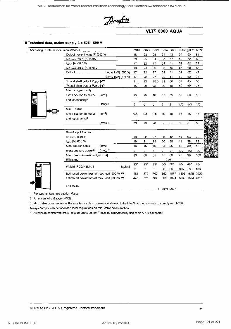
VLT® 8000 AQUA
III Technical data, mains supply 3 x 525 - 600 V
According to international requirements
Output current 1\43,N [A) (550 V)
Iva, MAX (60 s) [A] (550V)
IVIZN [A] (575 V)
IvUl", MAX (60 s) [A] (575 V)
Output
Typical shaft output PVLT,N [kW)
Typical shaft output PVI.TN [HP]
SVU,N [kVA] (550 V)
SVLT,N [kVA) (575 V)
Max. copper cable
cross-section to motor [mm2]
and loadsharing4l
[AWG]21
Min. cable
cross-section to motor [mm2]
and loadsharing3)
[AWG]21
Rated Input Current
I vurNEA] (550 V)
Ivur.N[A] (600 V)
Max copper cable [mm2]
cross section, power4l [AWG]
Max. prefuses (mains)141/UL (A)
Efficiency
Weight IP 20/NEMA 1 [kg/lbs]
Estimated power loss at max. load (550 V) [W]
Estimated power loss at max. load (600 V) [W]
8016 8022 8027 8032 8042
18 23 28 34 43
20 25 31 37 47
17 22 27 32 41
19 24 30 35 45
17 22 27 32 41
17 22 27 32 41
11 15 18.5 22 30
15 20 25 30 40
16 16 16 35 35
6 6 6 2 2
0.5 0.5 0.5 10 10
20 20 20 8 8
18 22 27 33 42
16 21 25 30 38
16 16 16 35 35
6 6 6 2 2
20 30 35 45 60
0.96
23/
51
23/
51
23/
51
30/ 30/
66 66
451
446
576
576
702
707
852 1077
838 1074
8052 8062 8072
54 65 81
59 72 89
52 62 77
57 68 85
51 62 .77
52 62 77
37 45 55
50 60 75
50 50 50
1/0 1/0 1/0
16 16 16
6 6 6
53 63 79
49 38 72
50 50 50
1/0 1/0 1/0
75 90 100
48/ 48/ 48/
106 106 106
1353 1628 2029
1362 1624 2016
Enclosure IP 20/NEMA 1
1. For type of fuse, see section Fuses.
2. American Wire Gauge (AWG).
3. Min. cable cross-section is the smallest cable cross-section allowed to be fitted into the terminals to comply with IP 20.
Always comply with national and local regulations on min. cable cross-section.
4. Aluminium cables with cross-section above 35 mm2 must be connected by use of an Al-Cu connector.
MD.80.A4.02 - VLT is a registered Danfoss trademark 31
WB170 Beaudesert Rd Water Booster Parkinson Technology Park Electrical Switchboard OM Manual
Q-Pulse Id TMS1107 Active 10/12/2014 Page 191 of 271
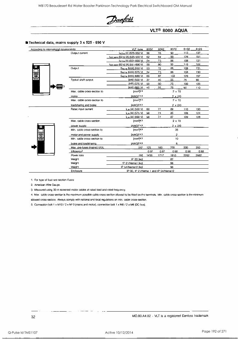
Technical data, mains supply 3 x 525 - 690 V
According to international requirements
Output current
Output
Typical shaft output
Max. cable cross-section to
motor
Max. cable cross-section to
loadsharinq and brake
Rated input current
Max. cable cross-section
power supply
Min. cable cross-section to
motor and power supply
Min. cable cross-section to
brake and loadsharinq
Max. pre-fuses (mains) ( -(/UL
EfficiencY3
Power loss
Weight
Weight
Weight
VLT® 8000 AQUA
VLT type 8052 8062 8072 8102 8122
kil TN IA1 (525-550 V) 56 76 90 113 137
Iv, T MAX (60 s) IA1(525-550 V) 62 84 99 124 151
KM TN (Al (551-690 V) 54 73 86 108 131
MT kw (60 s) (Al (551-690 V) 59 80 95 119 144
SV1 TN (kVA) (550 V) 53 72 86 108 131
SyrrN (kVA) (575 V) 54 73 86 108 130
S \A TN (kVA) (690 V) 65 87 103 129 157
(kW) (550 V) 37 45 55 75 90
(HP) (575 V) 50 60 75 100 125
(kWl (690 V) 45 55 75 90 110
(mm2]4.5
(AWG12.4.5
2 x 70
2 x 2/0
(mm2]4.5
(AWG12.4.5
2 x 70
2 x 2/0
k N (Al (550 V) 60 77 89 110 130
ILN (A) (575 V) 58 74 85 106 124
ILN (Al (690 V) 58 77 87 109 128
(mm2]4.5
lAWG12.4.5
2 x 70
2 x 2/0
(mm2]4.5
IAWG12.4.5
35
2
(mm2]4.5
lAWG12A5
10
8
(Al1 125 160 200 200 250
0.97 0.97 0.98 0.98 0.98
1W) 1458 1717 1913 2262 2662
IP 00 (kg) 82
IP 21/Nema1 [kill 96
IP 54/Nemal 2 (kg) 96
Enclosure IP 00 IP 21/Nema 1 and IP 54/Nemal2
1. For type of fuse see section Fuses
2. American Wire Gauge.
3. Measured using 30 m screened motor cables at rated load and rated frequency.
4. Max. cable cross-section is the maximum possible cable cross-section allowed to be fitted on the terminals. Min. cable cross-section is the minimum
allowed cross-section. Always comply with national and local regulations on min. cable cross-section.
5. Connection bolt 1 x M10 / 2 x M10 (mains and motor), connection bolt 1 x M8 / 2 x M8 (DC -bus).
32 MD.80.A4.02 - VLT is a registered Danfoss trademark
WB170 Beaudesert Rd Water Booster Parkinson Technology Park Electrical Switchboard OM Manual
Q-Pulse Id TMS1107 Active 10/12/2014 Page 192 of 271
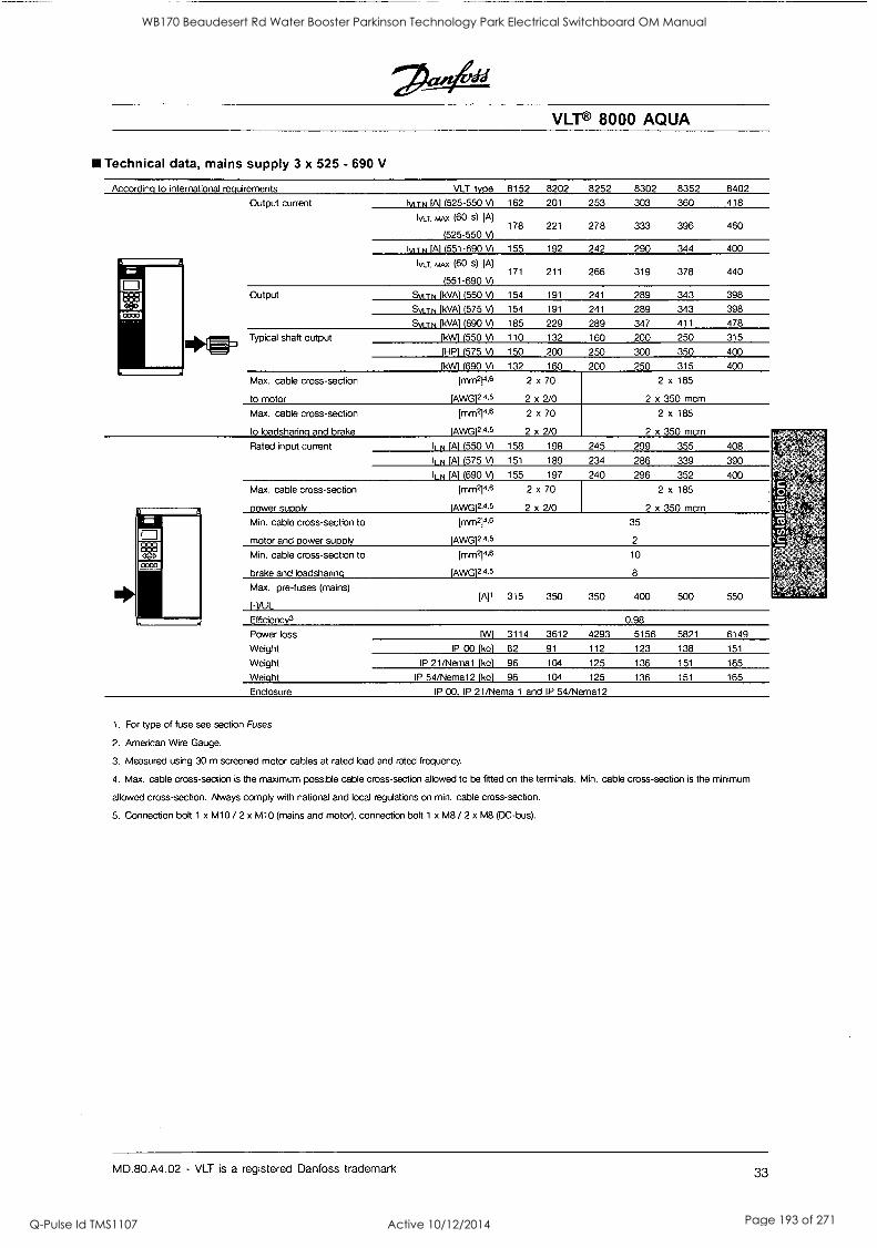
VLT® 8000 AQUA
Technical data, mains supply 3 x 525 - 690 V
According to international requirements
Output current
Output
Typical shaft output
Max. cable cross-section
to motor
Max. cable cross-section
to loadsharinq and brake
Rated input current
Max. cable cross-section
Power supply
Min. cable cross-section to
motor and power supply
Min. cable cross-section to
brake and loadsharinq
Max. pre-fuses (mains)
I-1/UL
Efficiency3
Power loss PM
Weight IP 00 [kg]
Weight IP 21/Nema1 [kg)
Weight IP 54/Nema12 [kql
Enclosure IP 00, IP 21/Nema 1 and IP 54/Nema12
VLT type
T N [Al (525-550 V)
is&T, MAX (60 s) [A)
(525-550 v)
lyrrN [Al (551-690 V)
Ivo-. MAX (60 s) (A)
(551-690 V)
Svi TN fkVA1 (550 V)
Syi T N IkVA1 (575 V)
SVI TN IkVAI (690 V)
[kW' (550 V)
[HP[ (575 V)
IkW1 (690 V) [mm214.6
lAWG12.4.5
[mm2rie
(AWG12.4.5
l N [Al (550 A l N (575 V)
ILN (690 A Lrnm214.6
[AwG12.4.5
imm2y1,6
lAWG12.4.5
imm94,6
(AWG12.4.5
8152 8202 8252 8302 8352 8402
162 201 253 303 360 418
178 221 278 333 396 460
155 192 242 290 344 400
171 211 266 319 378 440
154 191 241 289 343 398
154 191 241 289 343 398
185 229 289 347 411 478
110 132 160 200 250 315
150 200 250 300 350 400
132 160 200 250 315 400
2 x 70
2 x 2/0
2 x 185
2 x 350 mcm
2 x 70
2 x 2/0
2 x 185
2 x 350 mcm
158 198 245 299 355 408
151 189 234 286 339 390
155 197 240 296 352 400
2 x 70
2 x 2/0
2 x 185
2 x 350 mcm
35
2
10
8
315 350 350 400 500 550
0,98
3114 3612 4293 5156 5821 6149
82 91 112 123 138 151
96 104 125 136 151 165
96 104 125 136 151 165
1. For type of fuse see section Fuses
2. American Wire Gauge.
3. Measured using 30 m screened motor cables at rated load and rated frequency.
4. Max. cable cross-section is the maximum possible cable cross-section allowed to be fitted on the terminals. Min. cable cross-section is the minimum
allowed cross-section. Always comply with national and local regulations on min. cable cross-section.
5. Connection bolt 1 x M10 / 2 x M10 (mains and motor), connection bolt 1 x M8 / 2 x M8 (DC-bus).
MD.80.A4.02 - VLT is a registered Danfoss trademark 33
WB170 Beaudesert Rd Water Booster Parkinson Technology Park Electrical Switchboard OM Manual
Q-Pulse Id TMS1107 Active 10/12/2014 Page 193 of 271
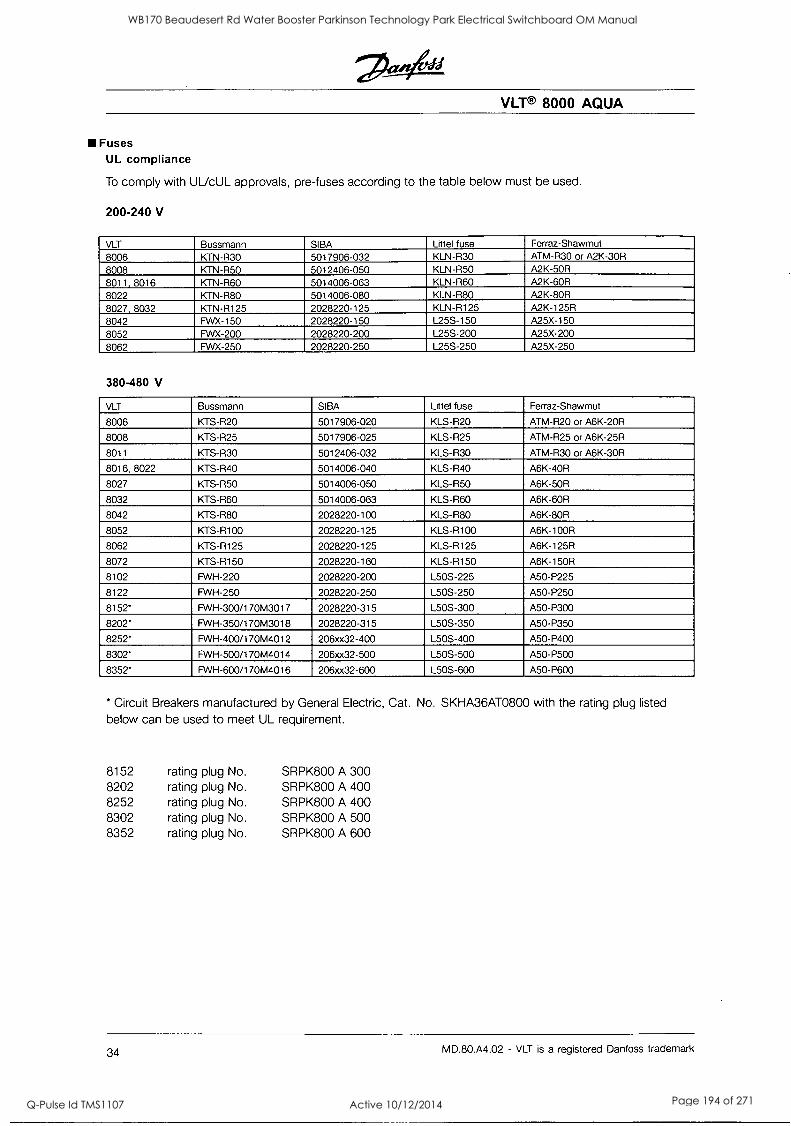
VLT® 8000 AQUA
Fuses UL compliance
To comply with ULicUL approvals, pre-fuses according to the table below must be used.
200-240 V
VLT Bussmann SIBA Littel fuse Ferraz-Shawmut
8006 KTN-R30 5017906-032 KLN-R30 _
ATM-R30 or A2K-30R 8008 KTN-R50 5012406-050 KLN-R50 A2K-50R 8011, 8016 KTN-R60 5014006-063 KLN-R60 A2K-60R 8022 KTN-R80 5014006-080 KLN-R80 A2K-80R
8027, 8032 KTN-R125 2028220-125 KLN-R125 A2K-125R
8042 FWX-150 2028220-150 1_25S-150 A25X-150
8052 FWX-200 2028220-200 L25S-200 A25X-200
8062 FWX-250 2028220-250 L25S-250 A25X-250
380-480 V
VLT Bussmann SIBA Littel fuse Ferraz-Shawmut
8006 KTS-R20 5017906-020 KLS-R20 ATM-R20 or A6K-20R
8008 KTS-R25 5017906-025 KLS-R25 ATM-R25 or A6K-25R
8011 KTS-R30 5012406-032 KLS-R30 ATM-R30 or A6K-30R
8016, 8022 KTS-R40 5014006-040 KLS-R40 A6K-40R
8027 KTS-R50 5014006-050 KLS-R50 A6K-50R
8032 KTS-R60 5014006-063 KLS-R60 A6K-60R
8042 KTS-R80 2028220-100 KLS-R80 A6K-80R
8052 KTS-R100 2028220-125 KLS-R100 A6K-100R
8062 KTS-R125 2028220-125 KLS-R125 A6K-125R
8072 KTS-R150 2028220-160 KLS-R150 A6K-150R
8102 FWH-220 2028220-200 L50S-225 A50-P225
8122 FWH-250 2028220-250 L50S-250 A50-P250
8152* FWH-300/170M3017 2028220-315 L50S-300 A50-P300
8202* FWH-350/170M3018 2028220-315 L50S-350 A50-P350
8252' FWH-400/170M4012 206xx32-400 L50S-400 A50-P400
8302' FWH-500/170M4014 206xx32-500 L50S-500 A50-P500
8352* FWH-600/170M4016 206xx32-600 L50S-600 A50-P600
* Circuit Breakers manufactured by General Electric, Cat. No. SKHA36AT0800 with the rating plug listed
below can be used to meet UL requirement.
8152 rating plug No. SRPK800 A 300 8202 rating plug No. SRPK800 A 400 8252 rating plug No. SRPK800 A 400 8302 rating plug No. SRPK800 A 500 8352 rating plug No. SRPK800 A 600
34 MD.80.A4.02 - VLT is a registered Danfoss trademark
WB170 Beaudesert Rd Water Booster Parkinson Technology Park Electrical Switchboard OM Manual
Q-Pulse Id TMS1107 Active 10/12/2014 Page 194 of 271
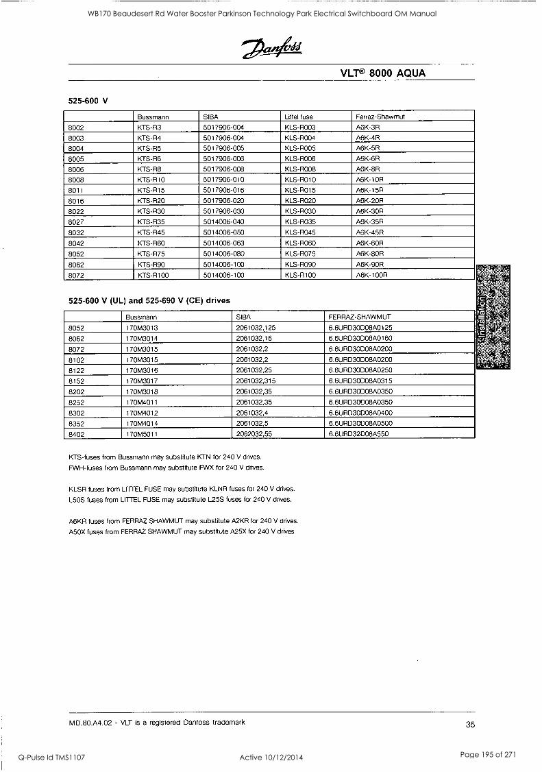
VLT® 8000 AQUA
525-600 V
Bussmann SIBA Littel fuse Ferraz-Shawmut
8002 KTS-R3 5017906-004 KLS-R003 A6K-3R
8003 KTS-R4 5017906-004 KLS-R004 A6K-4R
8004 KTS-R5 5017906-005 KLS-R005 A6K-5R
8005 KTS-R6 5017906-006 KLS-R006 A6K-6R
8006 KTS-R8 5017906-008 KLS-R008 A6K-8R
8008 KTS-R10 5017906-010 KLS-R010 A6K-10R
8011 KTS-R15 5017906-016 KLS-R015 A6K-15R
8016 KTS-R20 5017906-020 KLS-R020 A6K-201R
8022 KTS-R30 5017906-030 KLS-R030 A6K-30R
8027 KTS-R35 5014006-040 KLS-R035 A6K-351R
8032 KTS-R45 5014006-050 KLS-R045 A6K-451R
8042 KTS-R60 5014006-063 KLS-R060 A6K-60R
8052 KTS-R75 5014006-080 KLS-R075 A6K-80R
8062 KTS-R90 5014006-100 KLS-R090 A6K-90R
8072 KTS-R100 5014006-100 KLS-R100 A6K-100R
525-600 V (UL) and 525-690 V (CE) drives
Bussmann SIBA FERRAZ-SHAWMUT
8052 170M3013 2061032,125 6.6URD3ODO8A0125
8062 170M3014 2061032,16 6.6URD3ODO8A0160
8072 170M3015 2061032,2 6.6URD3ODO8A0200
8102 170M3015 2061032,2 6.6URD3ODO8A0200
8122 170M3016 2061032,25 6.6URD30D08A0250
8152 170M3017 2061032,315 6.6URD3ODO8A0315
8202 170M3018 2061032,35 6.6URD30D08A0350
8252 170M4011 2061032,35 6.6URD30008A0350
8302 170M4012 2061032,4 6.6URD30008A0400
8352 170M4014 2061032,5 6.6URD30008A0500
8402 170M5011 2062032,55 6.6URD32D08A550
KTS-fuses from Bussmann may substitute KTN for 240 V drives.
FWH-fuses from Bussmann may substitute FWX for 240 V drives.
KLSR fuses from LITTEL FUSE may substitute KLNR fuses for 240 V drives.
L5OS fuses from LITTEL FUSE may substitute L255 fuses for 240 V drives.
A6KR fuses from FERRAZ SHAWMUT may substitute A2KR for 240 V drives.
A5OX fuses from FERRAZ SHAWMUT may substitute A25X for 240 V drives.
MD.80.A4.02 - VLT is a registered Danfoss trademark 35
WB170 Beaudesert Rd Water Booster Parkinson Technology Park Electrical Switchboard OM Manual
Q-Pulse Id TMS1107 Active 10/12/2014 Page 195 of 271
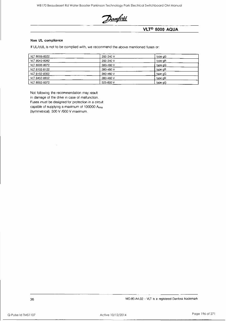
VLT® 8000 AQUA
Non UL compliance
If UUcUL is not to be complied with, we recommend the above mentioned fuses or:
VLT 8006-8032 200-240 V type gG
VLT 8042-8062 200-240 V type gR
VLT 8006-8072 380-480 V type gG
VLT 8102-8122 380-480 V type gR
VLT 8152-8352 380-480 V type gG
VLT 8452-8652 380-480 V type gR
VLT 8002-8072 525-600 V type gG
Not following the recommendation may result
in damage of the drive in case of malfunction.
Fuses must be designed for protection in a circuit
capable of supplying a maximum of 100000 Arms
(symmetrical), 500 V /600 V maximum.
36 MD.80.A4.02 - VLT is a registered Danfoss trademark
WB170 Beaudesert Rd Water Booster Parkinson Technology Park Electrical Switchboard OM Manual
Q-Pulse Id TMS1107 Active 10/12/2014 Page 196 of 271
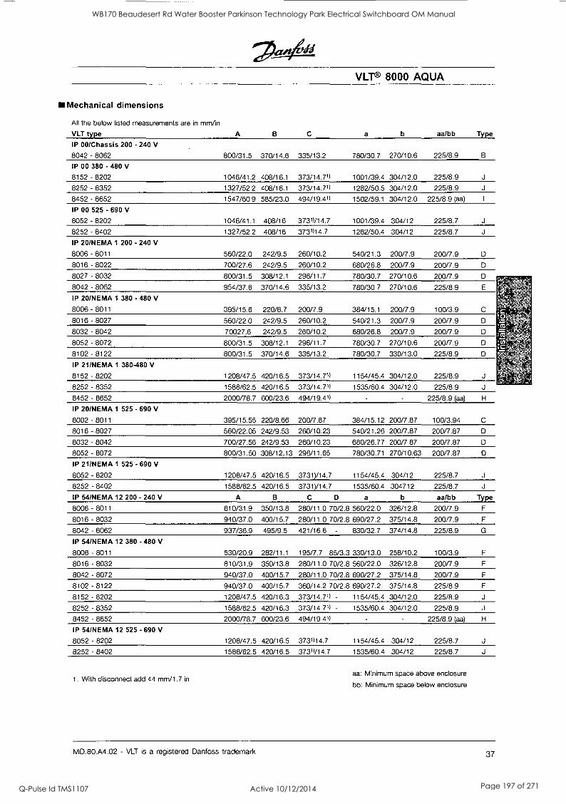
VLT® 8000 AQUA
Mechanical dimensions
All the below listed measurements are in mm/in
VLT type A B C a b aa/bb Type
IP 00/Chassis 200 - 240 V
8042 - 8062 800/31.5 370/14.6 335/13.2 780/30.7 270/10.6 225/8.9 B
IP 00 380 - 480 V
8152 - 8202 1046/41.2 408/16.1 373/14.71) 1001/39.4 304/12.0 225/8.9 J
8252 - 8352 1327/52.2 408/16.1 373/14.71) 1282/50.5 304/12.0 225/8.9 J
8452 - 8652 1547/60.9 585/23.0 494/19.41) 1502/59.1 304/12.0 225/8.9 (aa) I
IP 00 525 - 690 V
8052 - 8202 1046/41.1 408/16 37311/14.7 1001/39.4 304/12 225/8.7 J
8252 - 8402 1327/52.2 408/16 3731114.7 1282/50.4 304/12 225/8.7 J
IP 20/NEMA 1 200
8006 - 8011
- 240 V
560/22.0 242/9.5 260/10.2 540/21.3 200/7.9 200/7.9
8016 - 8022 700/27.6 242/9.5 260/10.2 680/26.8 200/7.9 200/7.9 nnn n
01_141 - Olh0C OUL1/ 0 1 .0 0l.10/ IL. I LUC), 11.7 1 OV10V. 1 Z 1 LW I V .C1 Ll..11.11 1 L;
8042 - 8062 954/37.6 370/14.6 335/13.2 780/30.7 270/10.6 225/8.9 E
.
c -
IP 20/NEMA 1 380
8006 - 8011
- 480 V
395/15.6 220/8.7 200/7.9 384/15.1 200/7.9 100/3.9 C
8016 - 8027 560/22.0 242/9.5 260/10.2 540/21.3 200/7.9 200/7.9
8032 - 8042 70027.6 242/9.5 260/10.2 680/26.8 200/7.9 200/7.9 D "t";
8052 - 8072 800/31.5 308/12.1 296/11.7 780/30.7 270/10.6 200/7.9 Dot 8102 - 8122 800/31.5 370/14.6 335/13.2 780/30.7 330/13.0 225/8.9 D
IP 21/NEMA 1 380-480 V
8152 - 8202 1208/47.5 420/16.5 373/14.71) 1154/45.4 304/12.0 225/8.9 J
8452 - 8652 2000/78.7 600/23.6 494/19.41) 225/8.9 (aa) H
IP 20/NEMA 1 525 - 690 V
8002 - 8011 395/15.55 220/8.66 200/7.87 384/15.12 200/7.87 100/3.94 C
8016 - 8027 560/22.05 242/9.53 260/10.23 540/21.26 200/7.87 200/7.87 D
8032 - 8042 700/27.56 242/9.53 260/10.23 680/26.77 200/7.87 200/7.87 D
8052 - 8072 800/31.50 308/12.13 296/11.65 780/30.71 270/10.63 200/7.87
IP 21/NEMA 1 525 - 690 V
8052 - 8202 1208/47.5 420/16.5 3731)/14.7 1154/45.4 304/12 225/8.7 J
8252 - 8402 1588/62.5 420/16.5 3731)/14.7 1535/60.4 304712 225/8.7 J
IP 54/NEMA 12 200 - 240 V A B C D a b aa/bb Type
8006 - 8011 810/31.9 350/13.8 280/11.0 70/2.8 560/22.0 326/12.8 200/7.9 F
8016 - 8032 940/37.0 400/15.7 280/11.0 70/2.8 690/27.2 375/14.8 200/7.9 F
8042 - 8062 937/36.9 495/9.5 421/16.6 - 830/32.7 374/14.8 225/8.9 G
IP 54/NEMA 12 380 - 480 V
8006 - 8011 530/20.9 282/11.1 195/7.7 85/3.3 330/13.0 258/10.2 100/3.9 F
8016 - 8032 810/31.9 350/13.8 280/11.0 70/2.8 560/22.0 326/12.8 200/7.9 F
8042 - 8072 940/37.0 400/15.7 280/11.0 70/2.8 690/27.2 375/14.8 200/7.9 F
8102 - 8122 940/37.0 400/15.7 360/14.2 70/2.8 690/27.2 375/14.8 225/8.9 F
8152 - 8202 1208/47.5 420/16.3 373/14.71) - 1154/45.4 304/12.0 225/8.9 J
8252 - 8352 1588/62.5 420/16.3 373/14.71) - 1535/60.4 304/12.0 225/8.9 J
8452 - 8652 2000/78.7 600/23.6 494/19.41) - 225/8.9 (aa) H
IP 54/NEMA 12 525 - 690 V
8052 - 8202 1208/47.5 420/16.5 3731)14.7 1154/45.4 304/12 225/8.7 J
8252 - 8402 1588/62.5 420/16.5 3731)/14.7 1535/60.4 304/12 225/8.7 J
1. With disconnect add 44 mm/1.7 in aa: Minimum space above enclosure
bb: Minimum space below enclosure
MD.80.A4.02 - VLT is a registered Danfoss trademark 37
WB170 Beaudesert Rd Water Booster Parkinson Technology Park Electrical Switchboard OM Manual
Q-Pulse Id TMS1107 Active 10/12/2014 Page 197 of 271
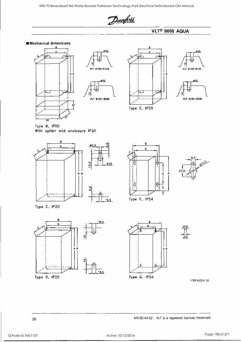
VLT® 8000 AQUA
Mechanical dimensions B
Al
81
VLT 8100-8125
VLT 8150-8300
Type B, IPOO
With option and enclosure IP20
Type C, IP20
5
Type D, IP20 '8 5
Type E, IP20
Type F, IP54
Type G, IP54
VLT 8100-8125
VLT 8150-8300
016
176FA224.10
38 MD.80.A4.02 - VLT is a registered Danfoss trademark
WB170 Beaudesert Rd Water Booster Parkinson Technology Park Electrical Switchboard OM Manual
Q-Pulse Id TMS1107 Active 10/12/2014 Page 198 of 271
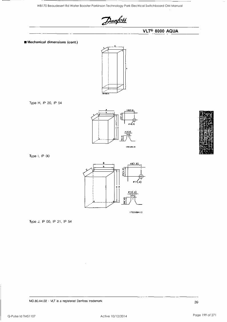
VLT® 8000 AQUA
Mechanical dimensions (cont.)
IIIF26.10
Type H, IP 20, IP 54
Type I, IP 00
I 76FA2134.10
1752A894.12
Type J, IP 00, IP 21, IP 54
MD.80.A4.02 - VLT is a registered Danfoss trademark 39
WB170 Beaudesert Rd Water Booster Parkinson Technology Park Electrical Switchboard OM Manual
Q-Pulse Id TMS1107 Active 10/12/2014 Page 199 of 271
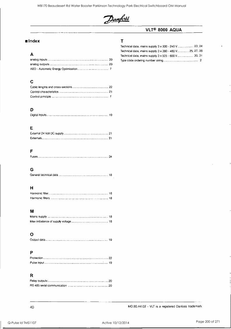
VLT® 8000 AQUA
Index Technical data, mains supply 3 x 200 - 240 V 23, 24
Technical data, mains supply 3 x 380 - 480 V 25, 27, 28
A Technical data, mains supply 3 x 525 - 600 V 30, 31
analog inputs 20 Type code ordering number string 2
analog outputs 20
AEO - Automatic Energy Optimization 7
C Cable lengths and cross-sections 22
Control characteristics 21
Control principle 7
D Digital inputs 19
E External 24 Volt DC supply 21
Externals 21
F
Fuses 34
G General technical data 18
H
Harmonic fitter 16
Harmonic fitters 18
M
Mains supply 18
Max imbalance of supply voltage 18
0 Output data 19
P Protection 22
Pulse input 19
R Relay outputs. 20
RS 485 serial communication 20
40 MD.80.A4.02 - VLT is a registered Danfoss trademark
WB170 Beaudesert Rd Water Booster Parkinson Technology Park Electrical Switchboard OM Manual
Q-Pulse Id TMS1107 Active 10/12/2014 Page 200 of 271
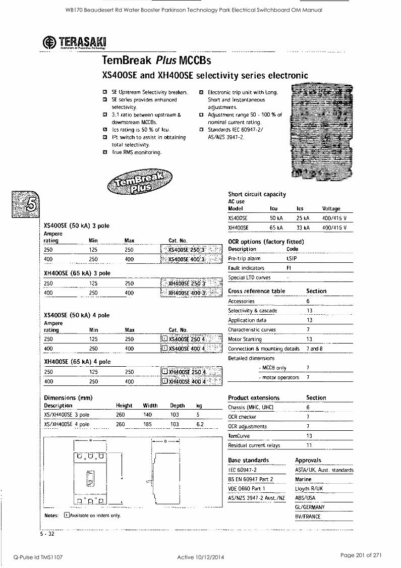
aInnevatoe, 1. Prwersion Trchnolav TERASAK
TemBreak Plus MCCBs
XS400SE and XH400SE selectivity series electronic
MI
SE Upstream Selectivity breakers.
SE series provides enhanced
selectivity.
Electronic trip unit with Long,
Short and Instantaneous
adjustments. 0 3:1 ratio between upstream &
downstream MCCBs.
0 Adjustment range 50 - 100 % of nominal current rating.
Ics rating is 50 % of Icu. 0 Standards IEC 60947-2/ 12t switch to assist in obtaining total selectivity.
AS/NZS 3947-2.
0 True RMS monitoring.
XS400SE (50 kA) 3 pole Ampere
I rating Min Max Cat. No.
250 125 250 - _
XS400SE-2503
1 400 250 400 XS400SE 4003,
XH400SE (65 kA) 3 pole
250 125 250 XH400SE 250 3
400 250 400 XH400SE '400 3
XS400SE (50 kA) 4 pole Ampere rating Min Max Cat. No.
250 125 250 XS4005E 250 4
400 250 400 XS400SE 400 4
XH400SE (65 kA) 4 pole
250 125 250 XH400SE 250 4
400 250 400 XH400SE 400 4
Dimensions (mm) Description Height Width Depth kg
XS/XH400SE 3 pole 260 140 103 5
XS/XH400SE 4 pole 260 185 103 6.2
d
° P ° P
Short circuit capacity AC use Model Icu Ics Voltage
XS400SE 50 kA 25 kA 400/415 V
XH400SE 65 kA 33 kA 400/415 V
OCR options (factory fitted) Description Code
Pre-trip alarm LSIP
Fault indicators Fl
Special LTD curves
Cross reference table Section
Accessories 6
Selectivity & cascade
Application data
13
13
Characteristic curves 7
Motor Starting 13
Connection & mounting details 7 and 8
Detailed dimensions
- MCCB only 7
- motor operators 7
Product extensions
Chassis (MHC, UHC)
OCR checker
Section
6
7
OCR adjustments
TemCurve
Residual current relays
Base standards
IEC 60947-2
BS EN 60947 Part 2
VDE 0660 Part 1
7
13
11
Approvals
ASTA/UK, Aust. standards
Marine
Lloyds R/UK
AS/NZS 3947-2 Aust./NZ ABS/USA
GL/GERMANY
Notes: MiAvailableonindentonly. BV/FRANCE
5 -32
WB170 Beaudesert Rd Water Booster Parkinson Technology Park Electrical Switchboard OM Manual
Q-Pulse Id TMS1107 Active 10/12/2014 Page 201 of 271
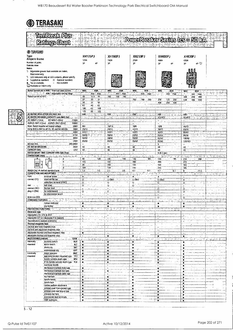
0 Innorolon In Protection Tecknolopy TERASAKI
TemBreak Ratings
(4) TERASAla
Type Ampere frame Number of poles
Outside view
Notes:
') Adjustable ground fault available on indent,
fitted externally.
') LED indicators only or LED contacts, please specify.
Supplied as standard. 0 Optional standard.
Yes or available. - Not available
CI Available on indent only
Rated current (A):In Nominaliated current
ASR - t_qustaol., sed-vj ralge -. Rated or ert at 43 C
AC RATED. INSULATION VOLTAGE DM. .
AC RATED BREAKING (kA)
tiC 609472 (icu) IE,C 60947-2(lcs1 DOV
AS/N2S 3847-2 Hal AS/N /S 3947-211es] 1000V
Note: Rated lmpu:se wow:to voltam! tNJV Uimp (kV) is 8kV all XS, X! aid Xi( MCCITs
4605
240:: without Ina 240-69011
DC RATED BREAKING 250V
CAPACT I Y (kA) 125V
1
RATED SHORT TIME CURRENT RMS (kAl flew)
.0IMENSIONS (mm)
X11125PJ XH160PJ XH400PJ XH250PJ XH630PJ
3P 4P 3P
250A
I 3P 41,
63p 30A
4P r72
125A : 160A 50A I 400A
:NRC
20 12.5 20 160
2 20 32
50 32 SO
63 40 62
100 63 100
125 80 125.. 690 - 690
Weight (kg) marked standard type
'CONNECTION AND MOUNTINGS
front terminal screw
connect (I CI attached flat bar
soldedess terminal (PWC)
rear. , bolt stud
connect (RC) fiat bar stud
plug-in (PM) for switchboard
,for distribution hoard
craw-out ;DOI - STANDARD l LAIURES
contact in(liCaif. .
914
25,13
250 125 250 1 630
400 250 4IX)
;5/7 5
23/i
I ICU /ICS I .ICU /ICS
18:9 819 45:23
. 42:15 33/15 65/33 4/171 95:43
. ............ 65/5 :I 85/5C
65'50 100/50
85/50 8%150 125/153
42a I
.50:59 50-50
IWO
40
43
42;21
50:50
sof so
85:50
40
40
,47P1
65;:i15 . .
65/50
a 90
l!
120 '05 143 +x0 185 143
"65 760 250
103 133 103
124 145 ;5 2 25 41 G 47
. 40
40
(0.3 sec)
40
40
6:
7:0 213
:03
145
9
280
:15
hlar)
trip button `PROTECTIVE FUNCTIONS'
Electronic type" Adjustable LTD. STD & INS I
Adjustable GET-or Adjustable PTA (opus-) j Trip indicators (option) (contacts)
Thermal-magnetic type
thermal and fixed magnetic trips
[ thermal and adjustable magnetic trios
adjustable thermal and fixed magnaic nips
I adjustable thermal and magnetic trips
ACCESSORILS (option)
Internally .loll: diary 5m;:.11
mounted alrI r I switch
snuill LAP)
undervottage trip Externally motor operator
CODE'
AUX
ALT
SHI..
UVT
MOT
mounted operating breaker mounted :ype TFJ
handle variable depth type XEIT
IP 65 handle variable depth roc ILK
extension handle
mechanical interlock front typc
mechanical interlock mar type
mechanical interlock cable type
key interlock
handle holder
handle lock
captive padlock adectimelt terminal cover l'ont ctxtiwcl type
terrnhal cover reepug-in type
interpole barriers
accessories lead terminals
- OCR s:Ialing.kit ,
5 -12
:
e
:
WB170 Beaudesert Rd Water Booster Parkinson Technology Park Electrical Switchboard OM Manual
Q-Pulse Id TMS1107 Active 10/12/2014 Page 202 of 271
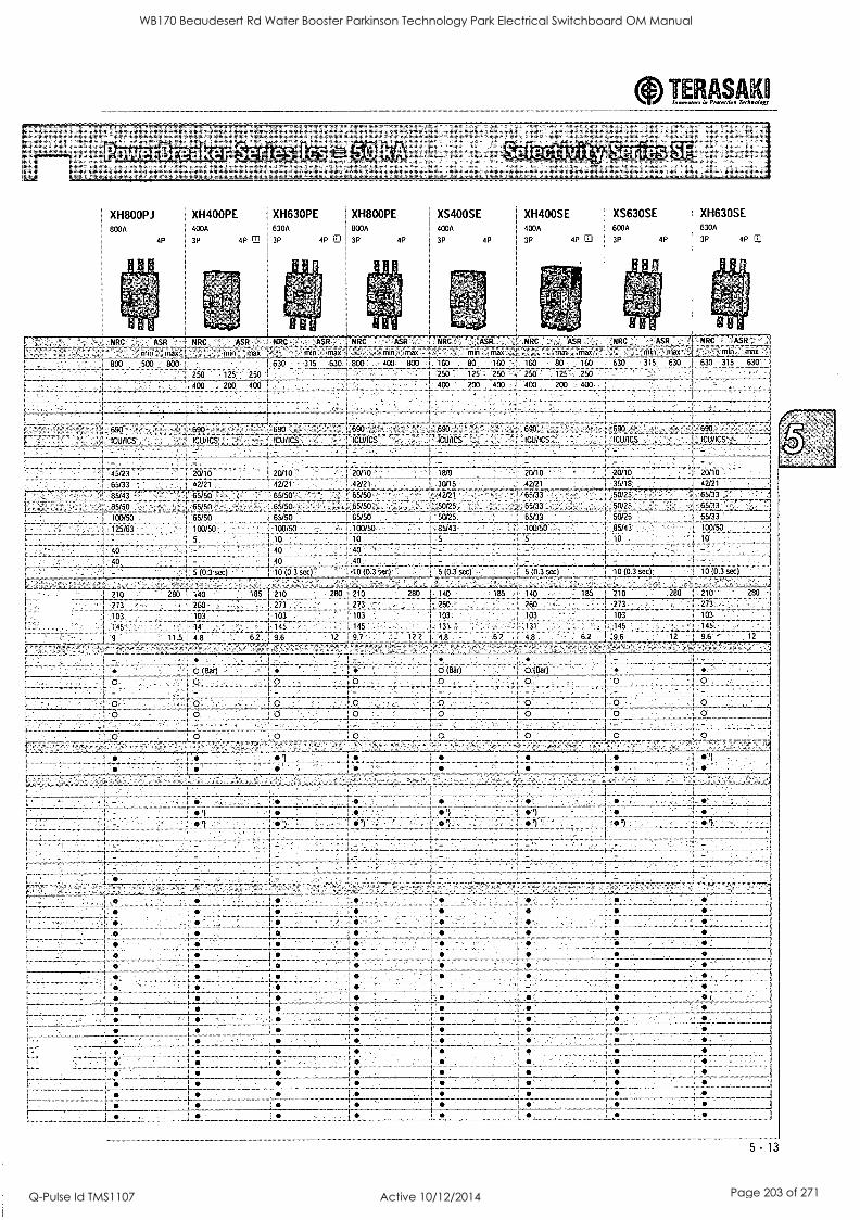
aInsurraren Le Preeerriam Technology TERASAK
XH800PJ 800A
4P
XH400PE XH630PE IXH800PE 400A 630A 1 800A
3P 4P nJ 3P 4P El 1 3P
XS400SE XH400SE 400A 4005
4P i
3P 4P 3P 4P ID
XS630SE XH630SE 6005 630A
3P 4P 3P 4P ED
NRC ASR NRC ASR NRC ASR NRC ' ASR NRC NRC NRC AS
nax Mg I 11 n r_rnax min max
800 500 800 630 315 630 800 4(9/ 800 160 80 160 160 80 1 30 315 530
250 125 '250
NRC ASV, :11FI Max
30 3:5 630
!CIVICS
-- 690 690 '1 7- --r- -v. .i90. .
. .- , .
680 - 690 ' 1C.11/16S ;albs - 1C1;11CS ICU /ICS _ iduics icuRsT: - --
. -
43/23 20/10 1.'20/10 2610 . -
65/33 I 42/21 I- 42/21
2- 11/10
42/21 r 30/15
! 18/9 - 231:0
35/18
' grg6 - f .6.SiSii rt ; i .65/50 .; ... i '65/50; ! '65/50 l'. 42/21
s 65/33' ' 6F:33
- 42/21
BSA 3 65/50 : 65/50 .
17166- -/b 7 7 -- 7 Tsisci . i 65/50 . :1 65/50
...: 50/25
.! 50/25. .. , , 15/33 ,TIST.6.7777--- tiii,) 1.lowso ... :.lowso
s : 10 le
40 - 40 40
5 ,,0 3 ,..e:j ': 0 (0.314:cj : '.:0 (03 'Al :
.,0/75
50/25._
50/25
85/43
10 5
65/33 -65/33
100 /50
5 /3 3 sec)
210 las 1 210 200 ! 210 780 1 140
7;3 730 1 273
133 103 103
.273
105
; 260
-C3 ; 14 145 14n
12 97 122 48 9 115 48 62, 96
o (Bar) (Bar)
O
0
10 I33 secl
210 7!01 210
700 273
103 103 ;03
13' 143 145,
67 48 62 96 12 96 17
--
- 1 1-- ^i 46
I
-
i _
I
:
'xi
:
5 -
WB170 Beaudesert Rd Water Booster Parkinson Technology Park Electrical Switchboard OM Manual
Q-Pulse Id TMS1107 Active 10/12/2014 Page 203 of 271
TERASAK1 Section 7 Innevaion Pram-don Tech,. logy
MCCB operational characteristics & dimensions Page
Thermal - magnetic MCCB characteristics Time / current characteristics thermal - magnetic MCCBs
Electronic MCCB characteristics - settings PTA - Pre-trip alarm option GF - Ground fault / 4th CT option LED trip indication options Time / current characteristics electronic MCCBs
OCR checker for electronic MCCBs
Tem Curve selectivity software MCCB dimensions with and without motors fitted AC Watts loss - 3 pole MCCBs
7 - 2 to 7 - 4
7 - 5 to 7 - 10 7 - 11 to 7 - 14 7 - 15 to 7 - 19 7 - 16 to 7 - 19 7 - 18 to 7 - 19 7 - 20 to 7 - 22
7 - 23 7 - 24
7 - 25 to 7 - 50 7 - 51
7 - 1
WB170 Beaudesert Rd Water Booster Parkinson Technology Park Electrical Switchboard OM Manual
Q-Pulse Id TMS1107 Active 10/12/2014 Page 204 of 271
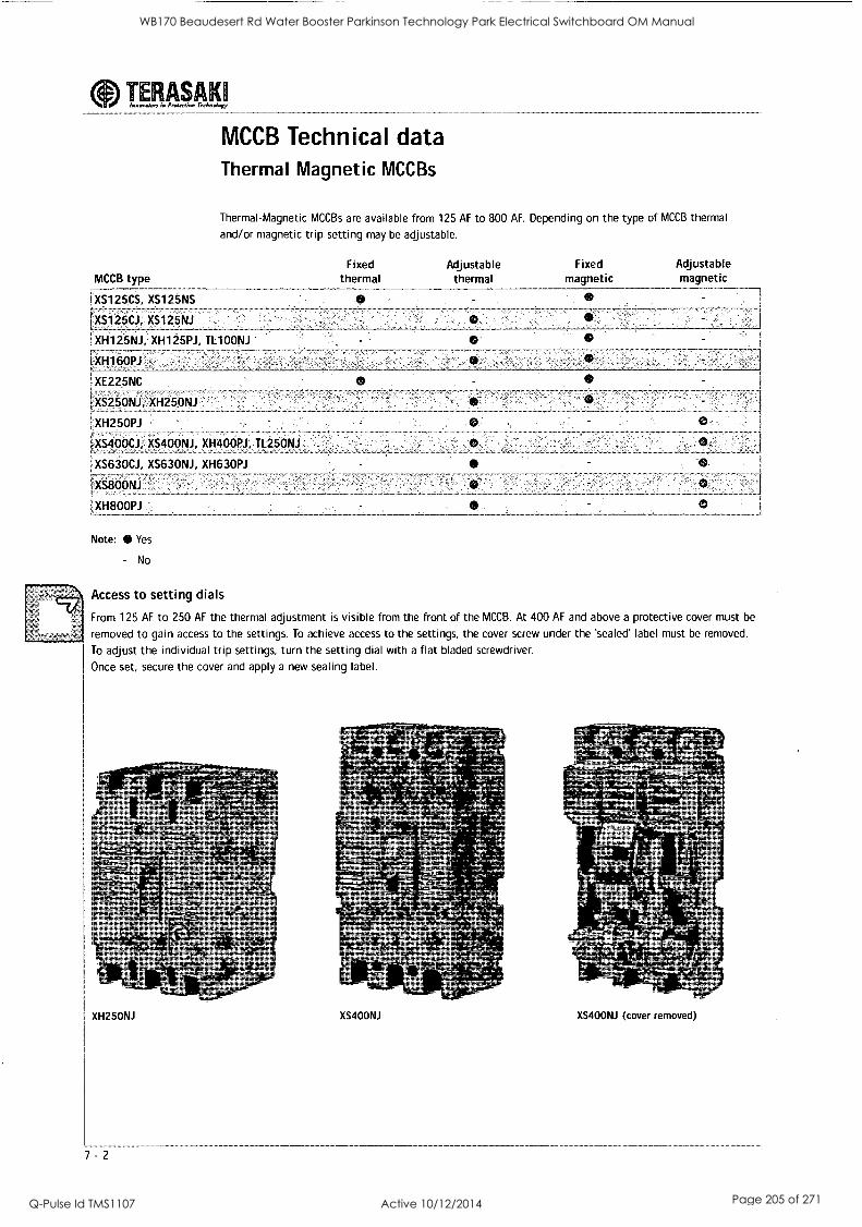
TERASAK1 Innovalem G Prolerrina Terchnoluzy
MCCB type
XS125CS, XS125NS
LXS125CJ, XS125N1
1XH125NJ, XH125PJ, TL100N1
1X1-1160P1
MCCB Technical data Thermal Magnetic MCCBs
Thermal-Magnetic MCCBs are available from 125 AF to 800 AF. Depending on the type of MCCB thermal
and/or magnetic trip setting may be adjustable.
Fixed thermal
0
Adjustable thermal
Fixed magnetic
0..
0
Adjustable magnetic
XE225NC
0
XS25ONJ; XH25ONJ
XH250PJ
XS400CJ, XS400NJ, XH40013J, TL250N1
XS630CJ, XS63ONJ, XH630PJ
XS8OONJ
XH800P1
Note: Yes
- No
0
Access to setting dials
From 125 AF to 250 AF the thermal adjustment is visible from the front of the MCCB. At 400 AF and above a protective cover must be
removed to gain access to the settings. To achieve access to the settings, the cover screw under the 'sealed' label must be removed.
To adjust the individual trip settings, turn the setting dial with a flat bladed screwdriver.
Once set, secure the cover and apply a new sealing label.
.1;
XH25ONJ
7 - 2
XS400NJ XS400NJ (cover removed)
WB170 Beaudesert Rd Water Booster Parkinson Technology Park Electrical Switchboard OM Manual
Q-Pulse Id TMS1107 Active 10/12/2014 Page 205 of 271
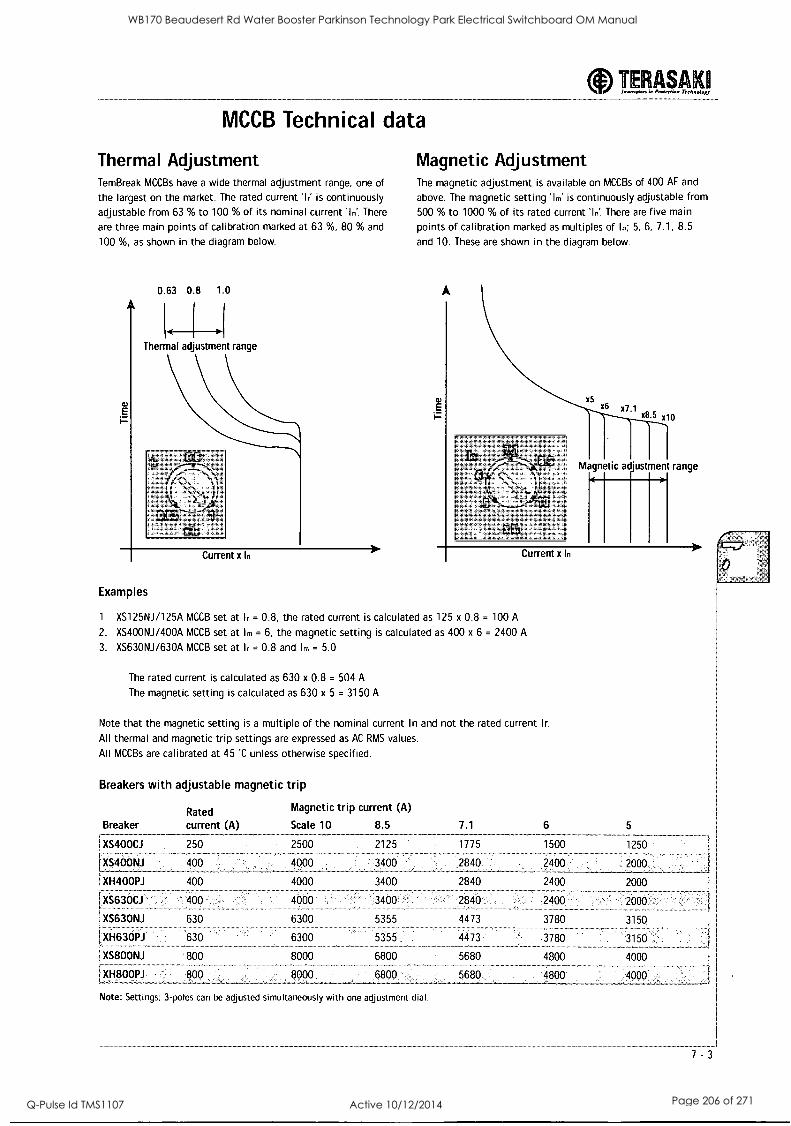
MCCB Technical data
Thermal Adjustment TemBreak MCCBs have a wide thermal adjustment range, one of
the largest on the market. The rated current 'Ir' is continuously
adjustable from 63 % to 100 % of its nominal current in'. There
are three main points of calibration marked at 63 %, 80 % and
100 %, as shown in the diagram below.
0.63 0.8 1.0
Thermal adjustment range
Examples
Current x In
TERASAK Inner...Ion in Pr ...wino Technalogy
Magnetic Adjustment The magnetic adjustment is available on MCCBs of 400 AF and
above. The magnetic setting 'Im' is continuously adjustable from
500 % to 1000 % of its rated current 'In. There are five main
points of calibration marked as multiples of In; 5, 6, 7.1, 8.5
and 10. These are shown in the diagram below.
Magnetic adjustment range
1. XS125NJ/125A MCCB set at Ir = 0.8, the rated current is calculated as 125 x 0.8 = 100 A
2. XS400NJ/400A MCCB set at Im = 6, the magnetic setting is calculated as 400 x 6 = 2400 A
3. XS63ONJ/630A MCCB set at Ir = 0.8 and Im = 5.0
The rated current is calculated as 630 x 0.8 = 504 A
The magnetic setting is calculated as 630 x 5 = 3150 A
Note that the magnetic setting is a multiple of the nominal current In and not the rated current Ir.
All thermal and magnetic trip settings are expressed as AC RMS values.
All MCCBs are calibrated at 45 'C unless otherwise specified.
Breakers with adjustable magnetic trip
Rated Magnetic trip current (A)
Breaker current (A) Scale 10 8.5
XS400CJ 250 2500 2125
IXS400NJ 400 4000 3400
XH400PJ 400
XS630CJ
XS63ONJ
X/1630PJ
XS800NJ
XE18001)J
4000
400
630
800
800
4000
6300
6300
8000
7.1 6 5
1775 1500 1250
2840 2400 2000
2840
2840
4473
4473
6800
2400
2400
3780
3780
4800
2000
2000
3150
3150
4000
4000
Note: Settings; 3-poles can be adjusted simultaneously with one adjustment dial.
--,
7 - 3
WB170 Beaudesert Rd Water Booster Parkinson Technology Park Electrical Switchboard OM Manual
Q-Pulse Id TMS1107 Active 10/12/2014 Page 206 of 271
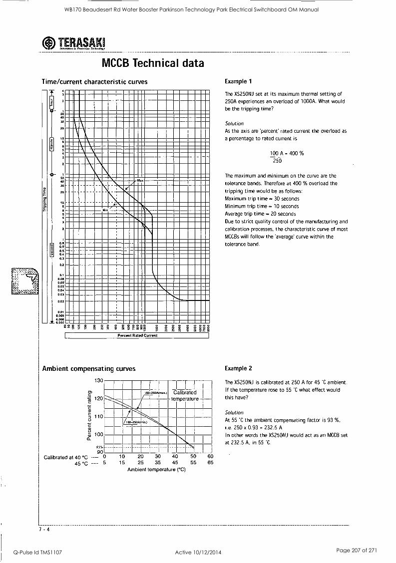
aInnen... in Proirviow Trekno log TERASAK1
MCCB Technical data
Time/current characteristic curves
3
2
50 40 30
20
10
4
3
2
50 40 30
20
10 8
5 4
3
2
1
0.8 06 0.5 0.4 0.3
0.2
0.1 0.08 0.06 0.05 0.04 003
0.02
0.01 0.008 000E 0 005
z Ma
Mln
22E E2EEEEEEEI Hill Percent Rated Current
Example 1
The XS25ONJ set at its maximum thermal setting of
250A experiences an overload of 1000A. What would
be the tripping time?
Solution
As the axis are 'percent' rated current the overload as
a percentage to rated current is
100 A = 400 %
250
The maximum and minimum on the curve are the
tolerance bands. Therefore at 400 % overload the
tripping time would be as follows:
Maximum trip time - 30 seconds
Minimum trip time - 10 seconds
Average trip time - 20 seconds
Due to strict quality control of the manufacturing and
calibration processes, the characteristic curve of most
MCCBs will follow the 'average' curve within the
tolerance band.
Ambient compensating curves Example 2
130
0)
cf,2' 120
110
C cu
4, 100
93%
90 Calibrated at 40 °C - 0
45 °C - 5
I I 1
60-250A mu.) Calibrated temperature
160-250A(min.)
10 20 30 40 50 15 25 35 45 55
Ambient temperature (°C)
60 65
The XS25ONJ is calibrated at 250 A for 45 'C ambient.
If the temperature rose to 55 'C what effect would
this have?
Solution
At 55 'C the ambient compensating factor is 93 %,
i.e. 250 x 0.93 = 232.5 A
In other words the XS25ONJ would act as an MCCB set
at 232.5 A, in 55 'C.
WB170 Beaudesert Rd Water Booster Parkinson Technology Park Electrical Switchboard OM Manual
Q-Pulse Id TMS1107 Active 10/12/2014 Page 207 of 271
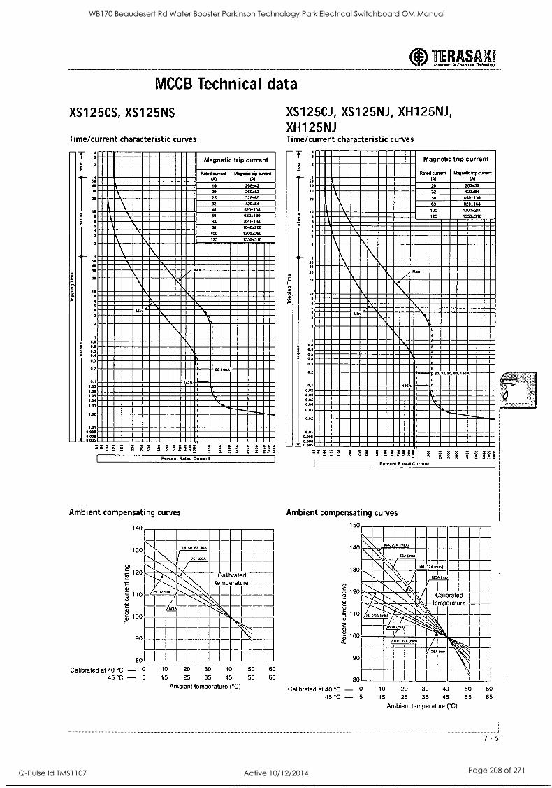
MCCB Technical data
XS125CS, XS125NS
Time/current characteristic curves
I 3
2
sa 40 30
20
to
8
6 5 4
3
2
1
50 ao 30
20
10 8
6
5 4
3
2
1
0.8 06 0.5 0.4 0.3
02
0 1
0.08 0 MI
I Magnetic trip current
Rated current Wpm& trip wawa (A) (A)
I 56 208.42 I 20 260.52 I 25 325165
32 I
420.84 40 520:104
I 50 650s130 i 8202164
1040.208 1
63 1 ao
100 1300.260 125 1550.310
Max
Min
1
1
I
3
,
1 20-100A
1
, au
I
:
0.05 D.04
0.03
0.02
1
1
1
I
0.01 Ace
l 000wS
I
III it. +,If Percent Rated Current
Ambient compensating curves
140
130
120
110
1-6) 100 a-
90
80
Calibrated at 40 °C - 0 45 °C - 5
16. 50. 63 BOA
20. 1000 I I
1
Calibrated temperature
25. 32.50A
25A
10 20 30 40 50 60
15 25 35 45 55 65
TERASAK1 Inwevalortl. Prrsteetiew Trelmoloo
XS125CJ, XS125NJ, XH125NJ, XH125NJ Time/current characteristic curves
4 3
2
1 50 ao 30
20
10 a
6 5
3
2
1
SO 40
20
10 6
8 5 4
3
2
1
0.8 0.5
0.5 0.4 0.3
0.2
01 0.05 Doe
Magnetic trip current
Rated current (A)
Magnetic trip coma (A)
260.52 20 32
50
420.84 650.130
63 820:164 100 1300.260 125 1550.310
IM=11111111111111111111MMEMI
Nk1111111111 l l hik.30
Alin
11 1 111
1
'
I
1 1
f 20,32,50,83,
'
100A
I250
1-
1,
0.05 0.04
0.03
1
0.02 1
0.01
1
1
008 008 I
005
2 2 ? ',:.1 F 3 3 3 & 3 33331 3 lif ff 111, Percent Rated Current
Ambient compensating curves
150
140
130
rn 120
92
;- 110 0
100
90
80
H 1 1
50A. 20A OW) I I
1 1 130 (m."
I 1
1 .00.324 In..)
1 \T I
125A 11111/ 0
I 1
I 1
I A Calibrated
50 20A (min)
\-- temperature
I
63A 1.in) ' \ I
00. 32A Wm) 1
)
I
11 11 1 1 I
1 11 1 11 Ambient temperature (°C) Calibrated at 40 °C - 0 10 20 30 40 50 60
45 °C - 5 15 25 35 45 55 65
Ambient temperature (°C)
7 - 5
WB170 Beaudesert Rd Water Booster Parkinson Technology Park Electrical Switchboard OM Manual
Q-Pulse Id TMS1107 Active 10/12/2014 Page 208 of 271
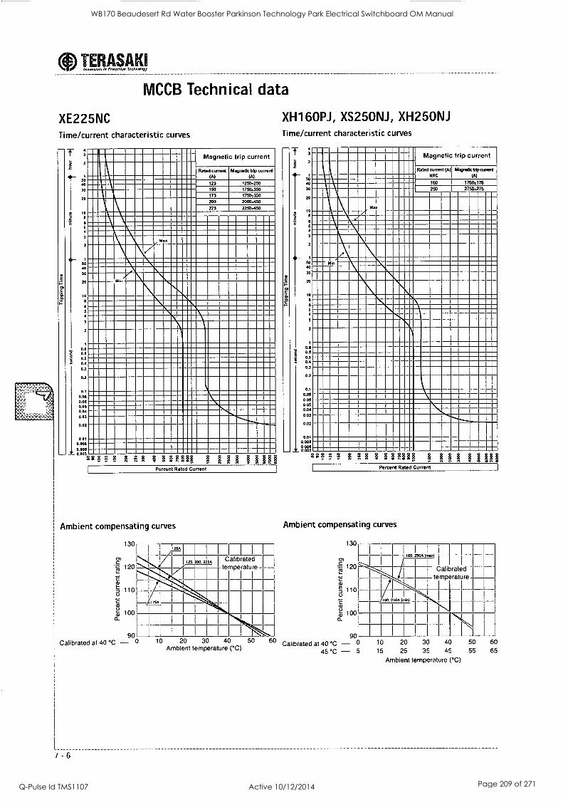
aInnovator, irt Pnwertion Technolor TERASAKI
MCCB Technical data
XE225NC Time/current characteristic curves
E
T 2
50 40
30
20
4. 10 8
8 5 4
2
1
50 40
30
20
1
0.8 0.6 0.5 0.4
0.3
0.2
0.1
0.08 0.00 0.05 0.04 0.03
0.02
Magnetic trip current
Rated canard (A)
125
150
175
200
Magnetic trip current (A)
1250:250 1750:350
1750:350
20001450
225 2250:450
z
Min
0.01 0.008
0.006 0.005 " ERR &F, ERRE&
Percent Rated Current
Ambient compensating curves
130
Calibrated 125. 200. 2254
temperature-.
Calibrated at 40 °C
7 - 6
110
cu
i,5) 100
_900
I I
I I
10 20 30 40 50 Ambient temperature (°C)
XH160PJ, XS25ONJ, XH25ONJ Time/current characteristic curves
2
2
so ao 30
20
10
2
1
50 40
30
20
to
6 5
3
2
1
0.8 06 0.5 0.4 0.3
0.2
0.1
0.08 0.06 0.05 0.04
0.03
0.02
0.01 0.006 0 006 0.005
Magnetic trip current
Rated current (A NRC
Max
Min
160
250
fftwetictdpcummt (A)
1760:176 2750:275
sgRil R ERR &R Percent Rated Current
Ambient compensating curves
130
I 120
z 2.)
'5 110
a)
a-: 100 0_
90
160. 250A Mmx)
Calibrated A temperature
I/I 7 I I _ 160. 250A nnin)
1 1 1
I I 1
I
Calibrated at 40 °C - 0 10 20 30 40 50 60
45 °C - 5 15 25 35 45 55 65
Ambient temperature (°C)
WB170 Beaudesert Rd Water Booster Parkinson Technology Park Electrical Switchboard OM Manual
Q-Pulse Id TMS1107 Active 10/12/2014 Page 209 of 271
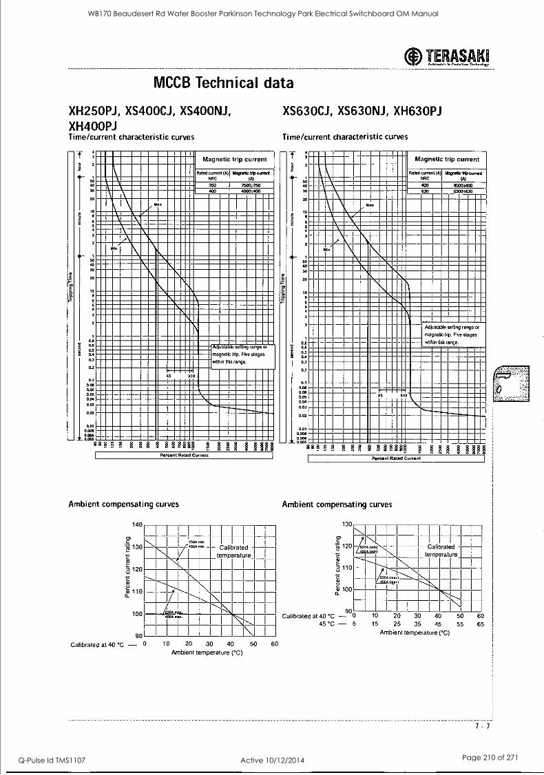
MCCB Technical data
XH250PJ, XS400CJ, XS400NJ, XH400PJ Time/current characteristic curves
T 2
so ao 30
20
10
6
4
3
2
50 40 30
20
1:
6
3
2
1
0.8 06 0.5 0.4 0.3
0.2
0.1
0.08 0.06 0.05 0.04
0.03
0.02
Magnetic trip current
Rated current (A)
NRC
250 400
Magnetic hip current (A)
25003250 40003400
z Ma
PAM
Adjustasle setting range or
magnetic trip. Five stages
within this range.
XS x10
0.01 0.006 0.000
.0°62 F § F,n;1 g gig II gig Percent Rated Current
Ambient compensating curves
140
Er'
.7",72 130
120
100
90
250A II ill. i rn.n. temperature
11 Calibrated
1
4005 ,g.,,,,.
Calibrated at 40 °C - 0 10 20 30 40 50
Ambient temperature (°C)
60
TERASAKI Innen...am In Prorenion Technology
XS630CJ, XS63ONJ, XH630PJ
Time/current characteristic curves
T Magnetic trip current
Rated current (A) Magnetic hip current NRC (A)
4000±400 63C0-.0330
a
6
5 4
3
2
50 40
so
10 6
4
3
o.a 0.6 0.5 0.4
0.3
0.2
0.1 0.08 0.06 0.05 0.04
0.03
0.02
0.01 0.008 0.006 0 005
Adjustable setting range or
magnetic tnp. Five stages
within this range.
g F F. F ?. F.?, ? 1st 1 Percent Rated Current
Ambient compensating curves
130
C "rg 120
a2..
0= 110
2 0_ ro 100
90 Calibrated at 40 °C -
45 °C - 5
I I
I - 630A (rnin) ri -- I temperature
Calibrated I
630 (max)
I
10 20 30 40 50 60 15 25 35 45 55 65
Ambient temperature (°C)
7 - 7
WB170 Beaudesert Rd Water Booster Parkinson Technology Park Electrical Switchboard OM Manual
Q-Pulse Id TMS1107 Active 10/12/2014 Page 210 of 271
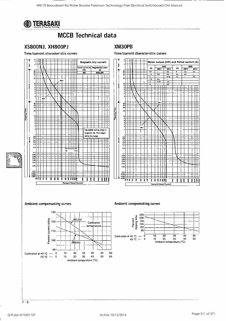
aInnovator,- in Protection Technology TERASAK1
MCCB Technical data
XS800NJ, XH800PJ Time/current characteristic curves
E
1
T
1
50 40
30
20
1:
5 4
3
2
50 40
30
20
10
6 5
2
1
0.0 08 0.5 0.4 0.3
0.2
01 0.00 0.08 0.05 0.04 0.03
0.02
0.01 0.008
A..2.011 9a a? 3 $ 3 $ 3.333 3 1131
Magnetic trip current
Rated current (A)
NRC Magnetic tdp canard
800 8030±800
4I
Min z
Adjustable setting range or
magnetic trip. Five stages
within this range
05 X10
Percent Rated Current
Ambient compensating curves
130
rn :7.: 120
110
a)
12 100 0_
90
Calibrated at 40 °C - 0
45 °C - 5
8000 On.)
I I I
Calibrated temperature
1300A Wi)
1 1 1 1 1
7 - 8
10 20 30 40 50 60
15 25 35 45 55 65
Ambient temperature (°C)
XM3OPB Time/current characteristic curves
T 3
50 40
30
20
10 8
6
5
2
1
SO
40
30
20
10 8
5 4
3
2
1
0.8 0.0 03 0.4
0.3
0.2
0.1
0.00 0.00 0.05 0.04
0.03
0.02
0.01 0.008
Motor output (kW) and Rated current (A)
(A) OM) (kW)
V
0.2
V V
1.5 3.7 0.7
1 4 0.2 0.4 10 2.2 - 53
2.6 - 0.75
5 - 2.2
Mad
/ Min.
..........._ ............._.._.
0.006 0.005
928 1 F2 3 9 . 3 3 3 3 3333 3 3 3 3 a 3 333
Percent Rated Current
Ambient compensating curves
250 E 200
a./ cs, 150 ya 125 cL a 100
- 90
Calibrated at 40 °C - 0 10 20 30 40 50
45 °C - 5 15 25 35 45 55 Ambient temperature (°C)
WB170 Beaudesert Rd Water Booster Parkinson Technology Park Electrical Switchboard OM Manual
Q-Pulse Id TMS1107 Active 10/12/2014 Page 211 of 271
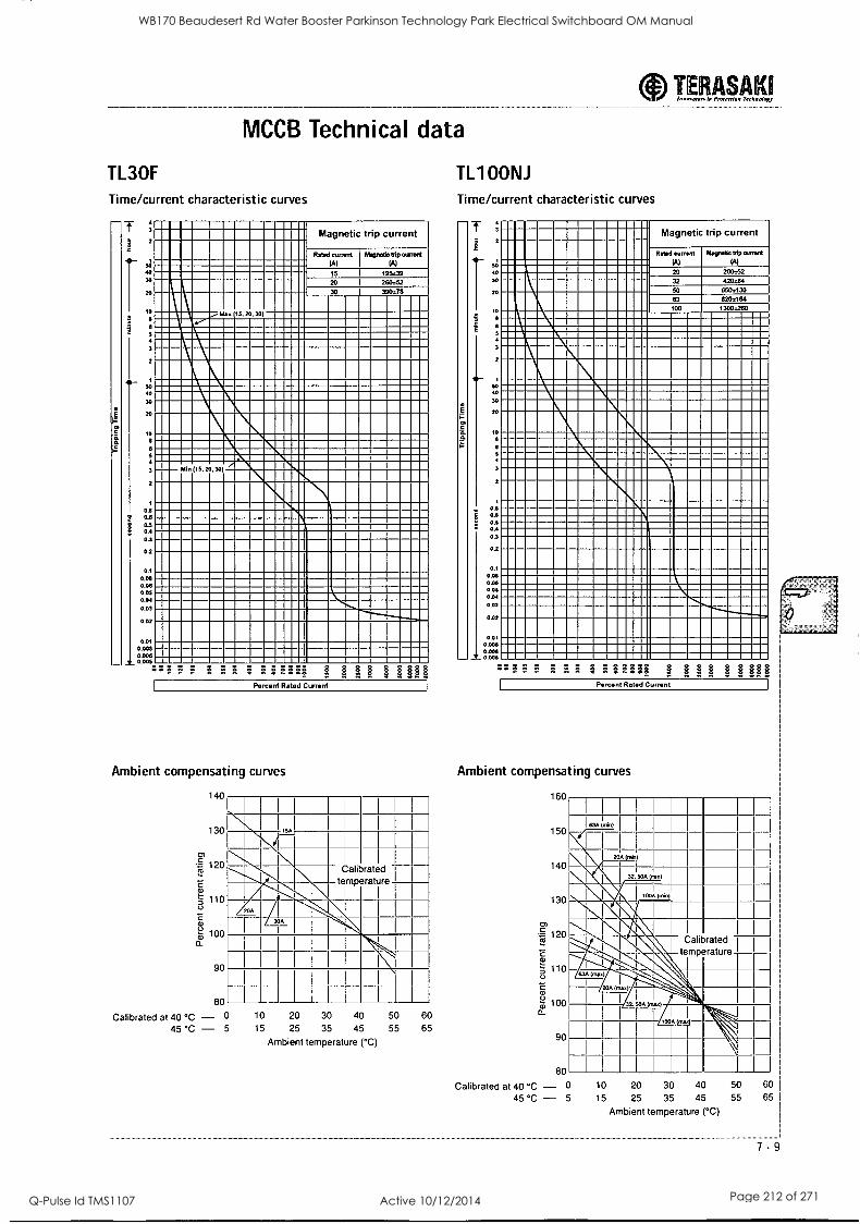
MCCB Technical data
TL3OF
Time/current characteristic curves
2
41-
40
40
30
20
10
4
3
2
46- 40 30
20
10
6 5
3
2
1
0.8 06 0.5 0.4
0.3
0.2
01 0.06 0.06 0.05 0.04
0.03
0.02
0.01 0.008 0 ON 0 005
F 3 8 33 3 33E333 3 3 3 3333
Magnetic trip current
111
Rated current (A)
Mare/kelp current (Al
15 195.39 20 260=52
Max 15,20, 30)
30 390578
ti
Min (15, 20,30 Minh.
Percent Rated Current
Ambient compensating curves
140
130
120
5 110 0
a )
100 a-
90
80
I I
m I I
I I
Calibrated L
temperature
304
Calibrated at 40 °C - 0 10 20 30 40 50
45 °C - 5 15 25 35 45 55
Ambient temperature (°C)
60 65
TL1 OONJ
Time/current characteristic curves
E
I 2
50 40 30
20
10.
5
3
2
so 4o
30
20
10
3
2
1
0.6 06 0.5 0.4
0.3
0.2
01 0.04 0 06 0.05 0.04 0 03
0.02
0.01 0.006 0.006 0.005
FL" Fa L F, 333333 31118 8188
TERASAKI Innovator. In Protection Technology ----___---
Magnetic trip current
Rated current
(A)
20
32
50
63
100
Magnetic trip =Wed (Al
260.52 420.64 650.130 820=164 1300..260
Percent Rated Currant
Ambient compensating curves
cr,
160
150
140
130
120
0)
5 110
y 100 a-
90
80
634 0060
I
20A (mini
32. 504 (min)
1004 (mini
16..
etemp rature Calibrated
63A (rnax)
I I 32.504 (Ix Ailliiill' \ IIII 10°0(1) IIIII II I I II Il
Calibrated at 40 °C - 0 10 20 30 40
45 °C - 5 15 25 35 45
Ambient temperature (°C)
50 55
60
65 I
7-9
WB170 Beaudesert Rd Water Booster Parkinson Technology Park Electrical Switchboard OM Manual
Q-Pulse Id TMS1107 Active 10/12/2014 Page 212 of 271
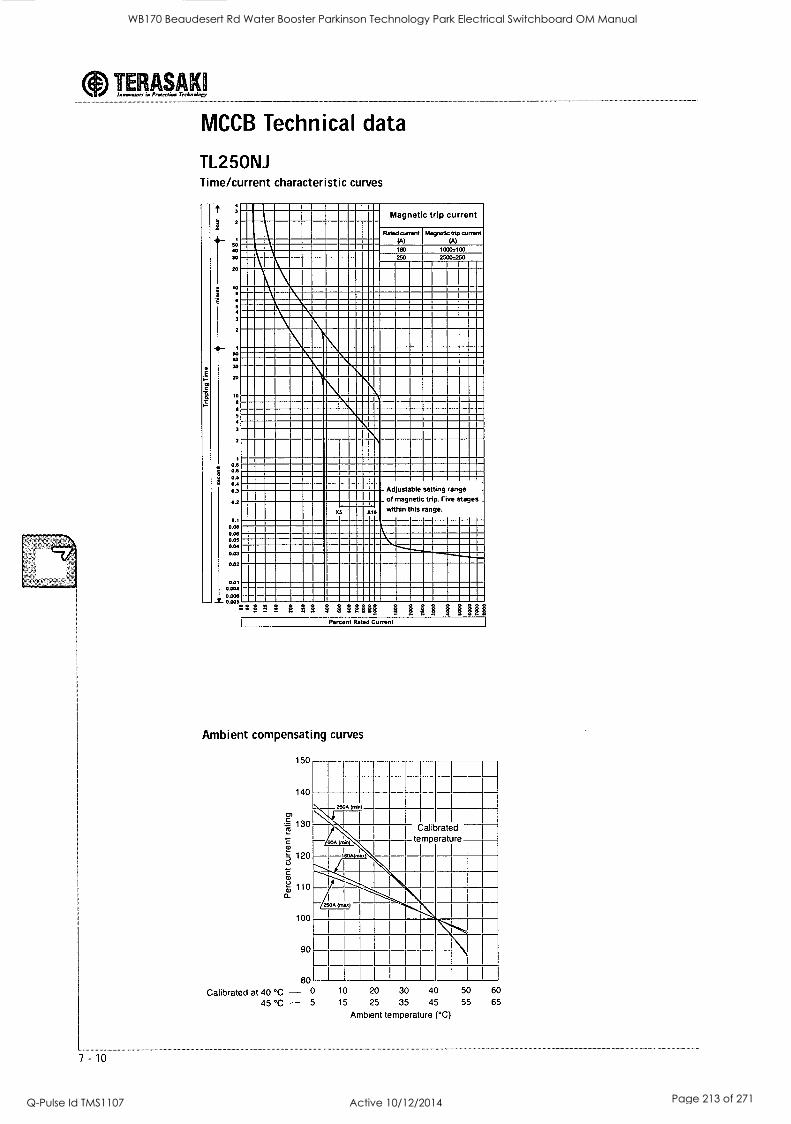
MCCB Technical data
TL25ONJ Time/current characteristic curves
E
t
450
30
Ai- 1
50 40 30
20
10
08 03 0.4 0.3
0.2
0.1 0.08 0.08 0.05 0.04
0.03
002
001 0.004
111111111111111 ii
niesr-miumelm---1-111
11.111111111111101
1111111311E1 Ad ustabie setting range
within 7ngthneUiscrattingpe..Five
stages
62 x10
Magnetic trip current
Rated current Magnetk bip current
(A) (A) 160 100021130
250 2500o250
0.008 030 H a 888
Percen Rated Current
Ambient compensating curves
150
140
130
5 120
C
t - , ) 1 1 0 a_
100
90
80
Calibrated at 40 °C - 0
45 °C - 5
I
I
I I
2500 (min)
1 I
Calibrated
600 (0.01 temperature
I
l
*--- 25 001.40
I I
I I I
I I I
I I
I I
10 20 30 40 50 60
15 25 35 45 55 65
Ambient temperature (°C)
WB170 Beaudesert Rd Water Booster Parkinson Technology Park Electrical Switchboard OM Manual
Q-Pulse Id TMS1107 Active 10/12/2014 Page 213 of 271
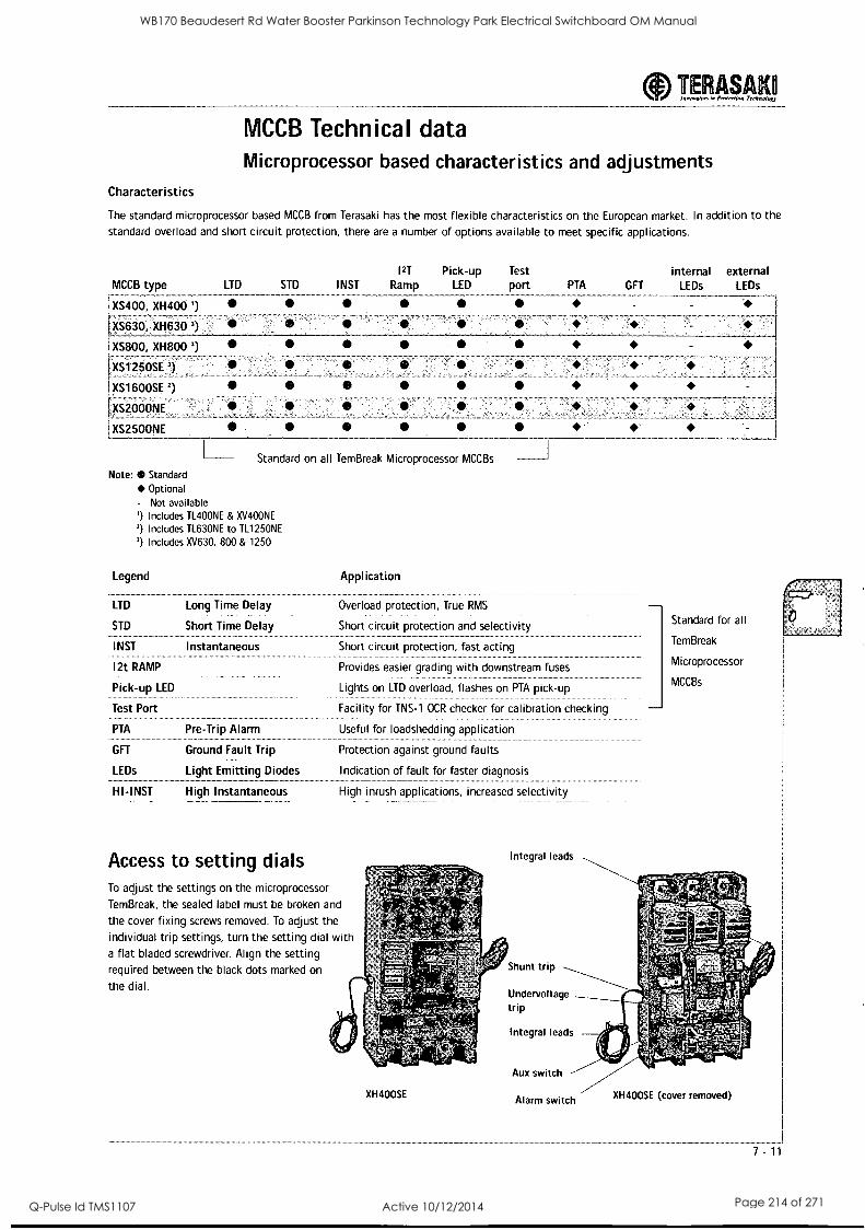
TERASAK Innorelon in Inxerriem Trehnoloo
MCCB Technical data Microprocessor based characteristics and adjustments
Characteristics
The standard microprocessor based MCCB from Terasaki has the most flexible characteristics on the European market. In addition to the standard overload and short circuit protection, there are a number of options available to meet specific applications.
MCCB type LTD
XS400, XH400 ')
XS630, XH630
i XS800, XH800 3)
XS1250SE ')
XS1600SE 2)
XS2000NE
XS2500NE
STD INST
I2T Pick-up Test Ramp LED port PTA GFT
internal LEDs
external LEDs
Standard on all TemBreak Microprocessor MCCBs
Note: *Standard Optional
- Not available ') Includes TL400NE & XV400NE
2) Includes TL630NE to TL1250NE
') Includes XV630, 800 & 1250
Legend
LTD
STD
INST
12t RAMP
Pick-up LED
Test Port
PTA
GFT
LEDs
HI-INST
Long Time Delay
Short Time Delay
Instantaneous
Pre-Trip Alarm
Ground Fault Trip
Light Emitting Diodes
High Instantaneous
Application
Overload protection, True RMS
Short circuit protection and selectivity
Short circuit protection, fast acting
Provides easier grading with downstream fuses
Lights on LTD overload, flashes on PTA pick-up
Facility for TNS-1 OCR checker for calibration checking
Useful for loadshedding application
Protection against ground faults
Indication of fault for faster diagnosis
High inrush applications, increased selectivity
Standard for all
TemBreak
Microprocessor
MCCBs
Access to setting dials To adjust the settings on the microprocessor
TemBreak, the sealed label must be broken and
the cover fixing screws removed. To adjust the
individual trip settings, turn the setting dial with a flat bladed screwdriver. Align the setting required between the black dots marked on
the dial.
XH400SE
Integral leads
Shunt trip
Undervoltage trip
Integral leads
Aux switch
Alarm switch XH400SE (cover removed)
7 -11
WB170 Beaudesert Rd Water Booster Parkinson Technology Park Electrical Switchboard OM Manual
Q-Pulse Id TMS1107 Active 10/12/2014 Page 214 of 271
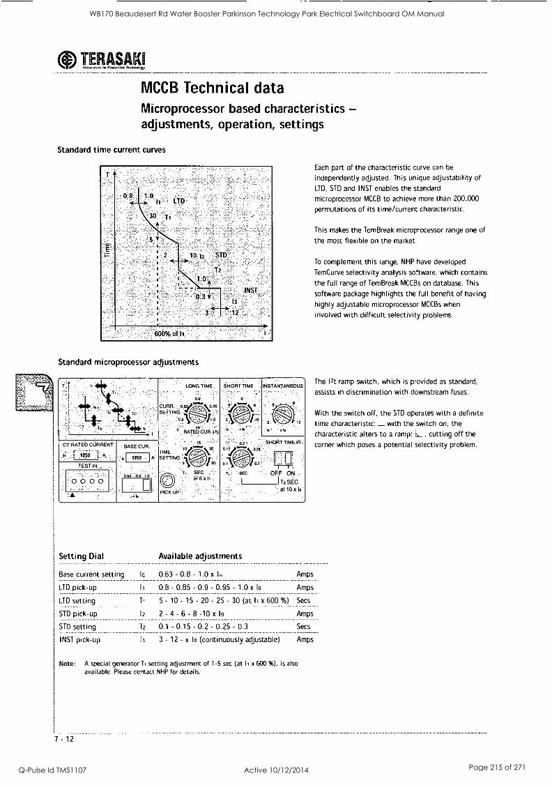
TERASAK Innovator., in Protection Technology
MCCB Technical data Microprocessor based characteristics - adjustments, operation, settings
Standard time current curves
08 10 4 _>. 11 LTD
30 Ti
2 10 12 STD"
T2
1 0
0'3 1' 13
3<- 12
INST
600% of 11
Standard microprocessor adjustments
SHORT TIME INSTANTANEOUS
2\
CT. RATED CURRENT
1250 .
TEST I
0 0.0 0
BASE CUR.
1250
0.63 -o.e 1.o
x. 6
. SHORT TIME VI- 0.15
OFF ON
11-2 SEC arlOxIo
Setting Dial
Base current setting
LTD pick-up
LTD setting
STD pick-up
STD setting
INST pick-up
Available adjustments
to 0.63 - 0.8 - 1.0 x In
0.8 - 0.85 - 0.9 - 0.95 - 1.0 x to
5 10 - 15 - 20 - 25 - 30 (at 13 x 600 %)
12 2 - 4 - 6 - 8 -10 x lo
T2 0.1 - 0.15 - 0.2 - 0.25 - 0.3
Amps
Amps
Secs
Amps
Secs
13 3 - 12 - x lo (continuously adjustable) Amps
Note: A special generator T1 setting adjustment of 1-5 sec (at Ii x 600 %), is also
available. Please contact NHP for details.
7 -12
Each part of the characteristic curve can be
independently adjusted. This unique adjustability of
LTD, STD and INST enables the standard
microprocessor MCCB to achieve more than 200,000
permutations of its time/current characteristic.
This makes the TemBreak microprocessor range one of
the most flexible on the market.
To complement this range, NHP have developed
TemCurve selectivity analysis software, which contains
the full range of TemBreak MCCBs on database. This
software package highlights the full benefit of having
highly adjustable microprocessor MCCBs when
involved with difficult selectivity problems.
The 12t ramp switch, which is provided as standard,
assists in discrimination with downstream fuses.
With the switch off, the STD operates with a definite time characteristic: L_ with the switch on, the
characteristic alters to a ramp: L , cutting off the
corner which poses a potential selectivity problem.
WB170 Beaudesert Rd Water Booster Parkinson Technology Park Electrical Switchboard OM Manual
Q-Pulse Id TMS1107 Active 10/12/2014 Page 215 of 271
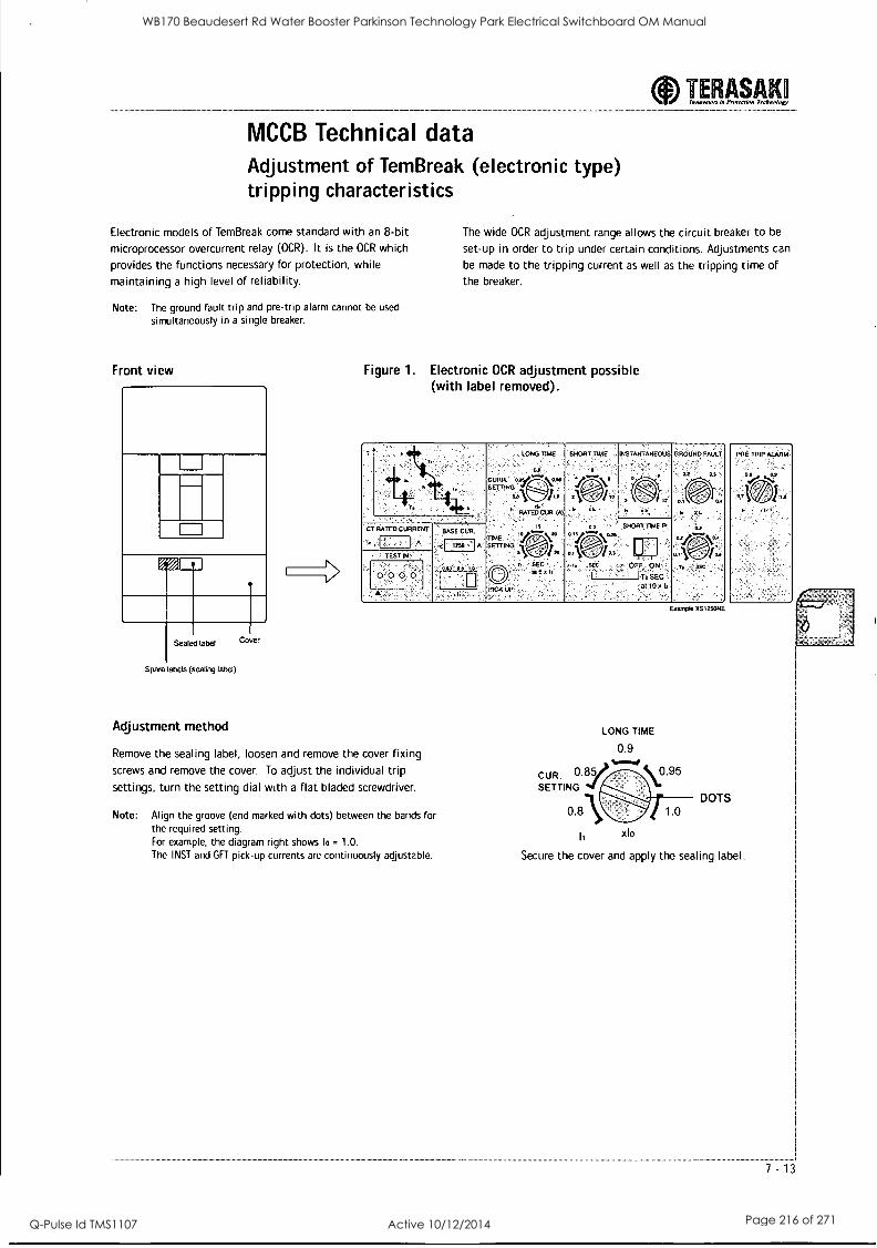
MCCB Technical data Adjustment of TemBreak (electronic type) tripping characteristics
Electronic models of TemBreak come standard with an 8-bit microprocessor overcurrent relay (OCR). It is the OCR which
provides the functions necessary for protection, while
maintaining a high level of reliability.
Note: The ground fault trip and pre-trip alarm cannot be used
simultaneously in a single breaker.
Front view
IlD
Sealed label
Spare labels (sealing label)
Cover
TERASAKO Innovators in Pnnertion Technology
The wide OCR adjustment range allows the circuit breaker to be
set-up in order to trip under certain conditions. Adjustments can
be made to the tripping current as well as the tripping time of the breaker.
Figure 1. Electronic OCR adjustment possible (with label removed).
T LONG TIME
CURB. $ETI1N I
L RATEDCUR. W.
TIME ` SETTING ,
9,
,,
SHORT TIME
3 \ '
INSTANTANEOUS
E;) I tz
. .
GROUND FAULT
P,1
1 T, SEC
PRE TRIP MAMA:
SNORT
OFF
.
TIME
ON
I Tx SEC
El CT RATED CURRENT BASE CUR.
: A tl 1I50 A
. TEST
'0.0: 02 0 ....,
,,.
al 10x b
Adjustment method
Remove the sealing label, loosen and remove the cover fixing
screws and remove the cover. To adjust the individual trip settings, turn the setting dial with a flat bladed screwdriver.
Note: Align the groove (end marked with dots) between the bands for the required setting. For example, the diagram right shows lo = 1.0. The INST and GFT pick-up currents are continuously adjustable.
E.:10m4s XS1ZSANE
LONG TIME
0.9
CUR. 0.82/7' V95 SETTING
li xlo
DOTS
Secure the cover and apply the sealing label.
WB170 Beaudesert Rd Water Booster Parkinson Technology Park Electrical Switchboard OM Manual
Q-Pulse Id TMS1107 Active 10/12/2014 Page 216 of 271
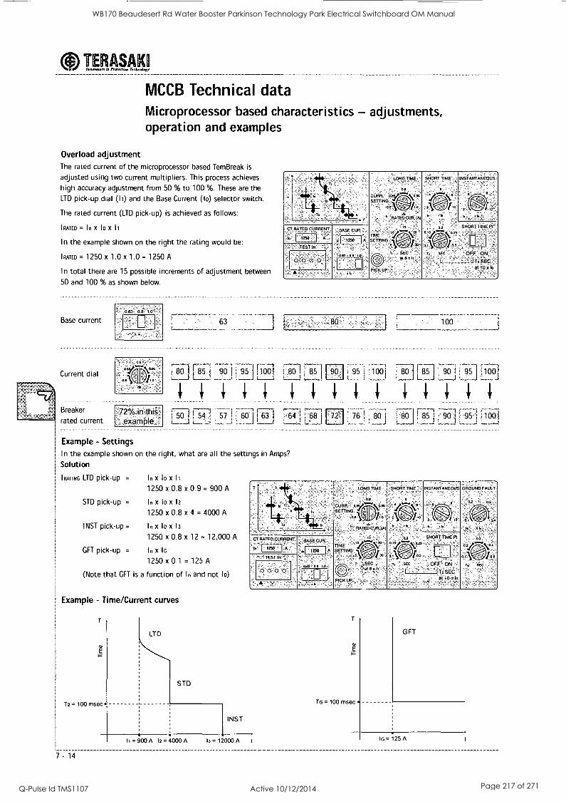
TERASAKH Innovator. in PFOIrCriel Technology
MCCB Technical data Microprocessor based characteristics - adjustments, operation and examples
Overload adjustment The rated current of the microprocessor based TemBreak is
adjusted using two current multipliers. This process achieves
high accuracy adjustment from 50 % to 100 %. These are the
LTD pick-up dial (11) and the Base Current (lo) selector switch.
The rated current (LTD pick-up) is achieved as follows:
!RATED = 1 n X 10 X 11
In the example shown on the right the rating would be:
I RATED = 1250 x 1.0 x 1.0 = 1250 A
In total there are 15 possible increments of adjustment between
50 and 100 % as shown below.
Base current
Current dial
= Breaker
rated current
"063 06 1 0' .
:..example
63
T I
. RATED CURRENT,
A 1,25.1 TEST IN
0-0 0 0
..:BASE CUR.
Ic "9'
043 00'1.0
LONG TIME
0.9 -
CORR: °eV."'" on SETrIOOG
oe
hj 'RATE[4CUR:(A)
TIME ' SETRNG
PICK UP
3, SEC 016011
8-01 5. 7901 551 ;,10(1) 117.8371
7-1
[50 1 54 1 571 60
85 0 i 95 100
100
90 '1 951 1560
100
r85 1
Example - Settings In the example shown on the right, what are all the settings in Amps?
Solution
(RATING LTD pick-up = In x 10 X 11
1250 x 0.8 x 0.9 = 900 A
STD pick-up = In x 10 x 12
1250 x 0.8 x 4 = 4000 A
INST pick-up = In x 10 X 13
1250 x 0.8 x 12 = 12,000 A
GFT pick-up = In x lo
1250 x 0.1 = 125 A
(Note that GFT is a function of In and not lo)
Example - Time/Current curves
T2 = 100 msec
7 -14
LTD
STD
INST
,
T. N
LONG TIME
0.0
CsURR.N00.94,47,\0.94
DA VIIIIINI 0
' 1i f3ATEgCUFL IA)
. TIME
vo SETTING 1
, , 1, X
r -SEC
O ,818101
PICK Up ,
SNORT TIME
4
:1 ' ' ''
INSTANTANEOUS
9
3 MT 6, II.
GROUND FAULT
oz oa
' 0 0.1 0.4
I. Y4
0.3
°2437N4 (A .-v.),,ba
h SEC
oa SNORT TIME Pt
o 1.y.... 024 CT RATED. CURRENT BASE CUR
-,, 1250 A o :, /LI
TEST IN
14 ^ SEC OFF ON -
I I TT SEC 0' 0% 0 0 0.43 0 $ 10 ,
Al 10 519
.6.
11 = 900 A 12 = 4000 A 13= 12000 A I
T
E'
To = 100 msec
GFT
lo = 125 A
WB170 Beaudesert Rd Water Booster Parkinson Technology Park Electrical Switchboard OM Manual
Q-Pulse Id TMS1107 Active 10/12/2014 Page 217 of 271
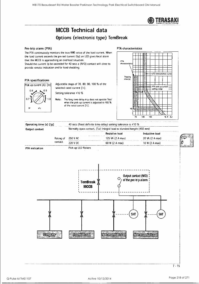
TERASAM Innovalon In Protectinn Technology
MCCB Technical data Options (electronic type) TemBreak
Pre-trip alarm (PTA)
The PTA continuously monitors the true RMS value of the load current. When
the load current exceeds the pre-set current (Ip) an LED gives local alarm
that the MCCB is approaching an overload situation.
Should the current Ip be exceeded for 40 secs a (N/0) contact will close to
provide remote indication and/or load shedding.
PTA specifications
Pick up current (A): [Ip]
IP X11
Operating time (s) [Ip]
Output contact
Adjustable steps of 70, 80, 90, 100 % of the
selected rated current [Ii].
Setting tolerance ±10 %
Note: The long time-delay trip does not operate 'first' when the pick-up current is adjusted to 100 %
of the rated current [11].
PTA characteristics
PTA characteristics
time in )
40
MEM 111111
1111 IMMEMlial=MINEMNIMIN MNIIMIEMIIMMMIMIMMI ....imm......m.
11111E2LTD characteristic curve
IIIIEMIEIMMIMIMME= 11111111--- I"IIIMirli'M 11119111111111111
ligNridIZMINN IIIIIIMME
PTA pick-up current setting range
IN=.1
1101161MM==11110=111MI IMILIMIMENTIMM== Ell:::== .711WINEM III En 70 100 150 % X (I,)
40 secs (fixed definite time-delay) setting tolerance is ±10 %
Normally open contact, (1a) Integral lead is standard length (450 mm)
Inductive load
20 VA (2 A max
10 W (2 A max)
Rating of 250 V AC
contact 220 V DC
PTA indication Pick-up LED flickers
TemBreak MCCB
Output contact (N/O)
C: of the pre-trip alarm
Computer Essential Load -essential -essential
WB170 Beaudesert Rd Water Booster Parkinson Technology Park Electrical Switchboard OM Manual
Q-Pulse Id TMS1107 Active 10/12/2014 Page 218 of 271

IMAM MCCB Technical data Adjustment of TemBreak electronic type OCR
with ground fault
Ground fault trip The GFT pick-up current is continuously adjustable from 10 % to 40 % of the rated CT current.
Notes: The ground fault trip and pre-trip alarm cannot be used simultaneously in a single breaker.
XS400SE, XH400SE are not available with ground fault function. When a three pole breaker is used in a 3 phase, 4 wire system,
a separate CT is required for the neutral line. (refer NHP).
GFT specifications
Pick-up current (A): [IG] 0.2 0.3
0.1 0.4
IG X lc+
Time-delay (S): [TG]
0.3
0.1 \ - ' i0.8
TG SEC
4th CT for GFT
Rating (A) Type
2500 UX0Y0007A
:2000 - UX0Y0006A
1600 UX0Y0005A
UX0Y0004A
1000 UX0Y0003A
800 UX0Y0002A
630 UX0Y0001A
Continuously adjustable from 10 to 40 % of the rated CT
current (let) setting tolerance is ± 15 %
The GFT has a definite time-delay characteristic and is
adjustable in steps of 0.1, 0.2, 0.3, 0.4, 0.8 s. Total clearing
time is +50 ms and resettable time is -20 ms for the preset
time delay.
Tripping time (s)
0.8
GFT characteristics 0.1
F N
Dimensions (mm)
1./ GFT pick-up current setting range
10 40 Vox (Ici)
- 0--
Rating (A) A B C D E F H CH M N
!2500-1000 140 110 50 10 80 85 145 75 85 35
.800-630 105 100 40 8 50 75 110 57 50 20
7 -16
WB170 Beaudesert Rd Water Booster Parkinson Technology Park Electrical Switchboard OM Manual
Q-Pulse Id TMS1107 Active 10/12/2014 Page 219 of 271
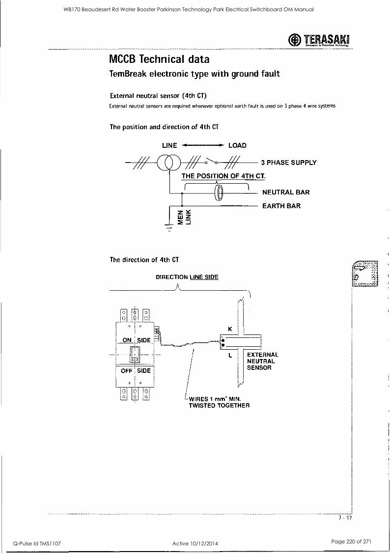
TERASAKII lAwnwaor. M pretertion Terhwolog
MCCB Technical data Tem Break electronic type with ground fault
External neutral sensor (4th CT)
External neutral sensors are required whenever optional earth fault is used on 3 phase 4 wire systems
The position and direction of 4th CT
LINE LOAD
3 PHASE SUPPLY
THE POSITION OF 4TH CT.
The direction of 4th CT
DIRECTION LINE SIDE
A
^ _L_ o m o 0 0 ," 0
c I c
ONE SIDE
ml
OFF : SIDE
° 1 °
jo o
11
-WIRES 1 me MIN. TWISTED TOGETHER
NEUTRAL BAR
EARTH BAR
L EXTERNAL NEUTRAL SENSOR
WB170 Beaudesert Rd Water Booster Parkinson Technology Park Electrical Switchboard OM Manual
Q-Pulse Id TMS1107 Active 10/12/2014 Page 220 of 271
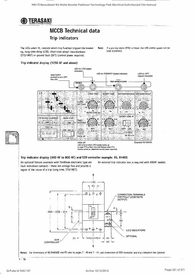
aInnotwom in Pr %version Technology TERASAKO
MCCB Technical data Trip indicators
The LEDs when lit, indicate which trip function tripped the breaker
eg, long-time-delay (LTD), short-time delay/ instantaneous
(STD/INST) or ground fault (GFT) (control power required).
Trip indicator display (1250 AF and above)
reset button pushed to turn OFF the LED
LED for LTD tripped indication
Note: If a pre-trip alarm (PTA) is fitted, the LED control power can be
used (common).
LED for STD/INST tripped indication
TRIP INDICATORS
LED for OFT tripped indication
11
T.
LONG TIME
CURR oty 0 95
SETTING 0 8 1
GT RATED CURRENT
,In ) 1250 , A
,TEST IN
0 0 0 0
BASE CUR '
A.
063 09 10
h RATED CUR (A)
' 15
TIME, to Arti..\2o
SETTING st\r4 T, SEC
at6x11'
PICK UP
SHORT TIME INSTANTANEOUS
t, xb
02 o 1.4,"".
011 Tz SE
to xb
SHORT TIME 12t
0 25
03
OFF ON
112 SEC all° x lo
GROUND'FAULT
0.2
of
to X I.
03
04
PICK UP LED turns on when LTD function picks up. In case PTA is fitted, this LED flickers when PTA function picks up. (seperate control power required).
Trip indicator display (400 AF to 800 AF) and OCR controller example: XS, XH400
An optional feature available with TemBreak electronic type are
fault indication contacts - these are voltage free and provide a
signal of the cause of a trip (long time, STD/INST).
260 228 - 214
Example XS1250SE
An external trip indicator box is required with 400AF models.
140
, I
(t.
r ON
IOFT
- OCR
21
CONTROLLER
L- 145 145-"
RSV O
.4 gm(
al74145 CAA/ na,
44
45
CONNECTION TERMINALS FOR FAULT (CONTACTS / OUTPUT)
4
8° \ \- LED INDICATORS
\_ OPTIONAL
Notes: For dimensions of XS/XH800SE and PE refer to pages 7 - 40 and 7 - 41, add dimensions of OCR controller and trip indication box (above).
7 -18
WB170 Beaudesert Rd Water Booster Parkinson Technology Park Electrical Switchboard OM Manual
Q-Pulse Id TMS1107 Active 10/12/2014 Page 221 of 271
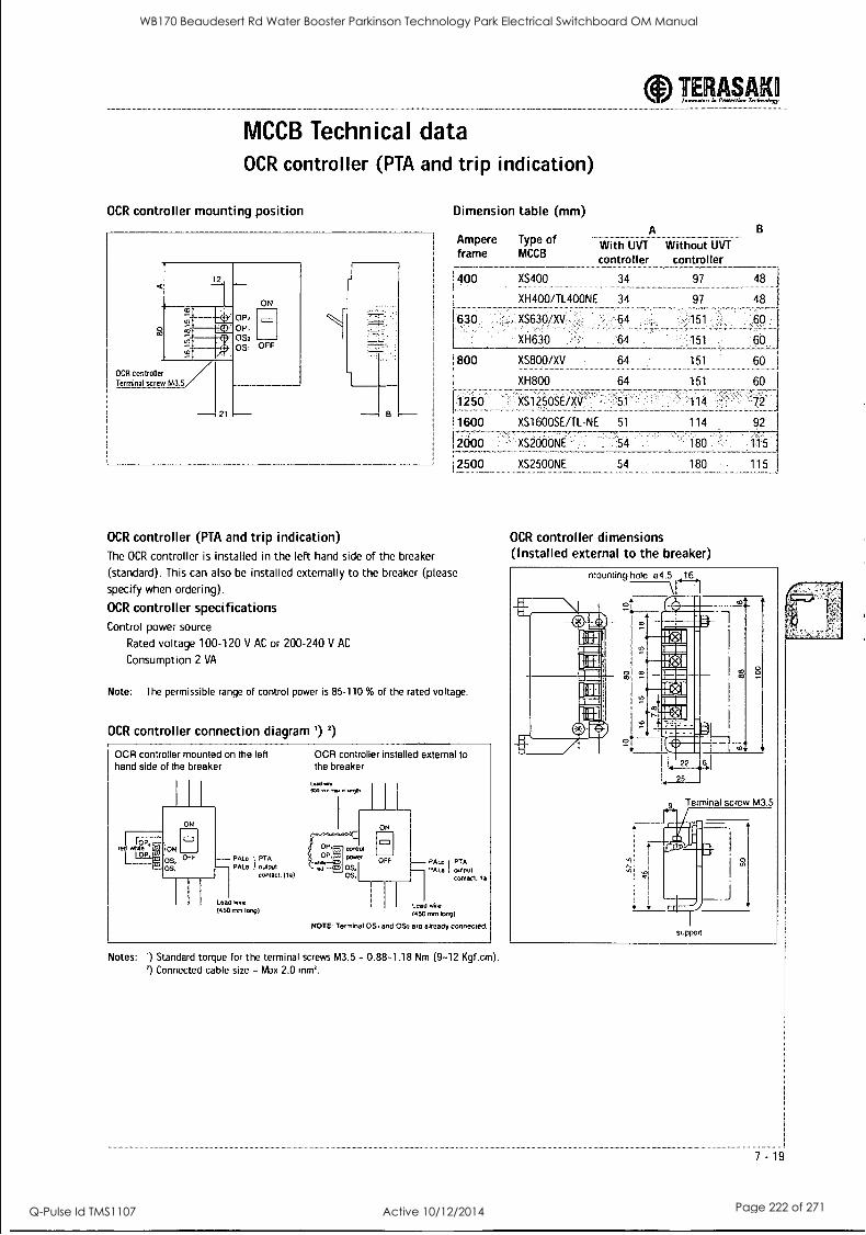
MCCB Technical data OCR controller (PTA and trip indication)
OCR controller mounting position Dimension table (mm)
OP2 OP, OSa os, OFF
OCR controller Terminal screw M3.5
21 B
Ampere frame
;400
1 ;
030
1800
;
Type of MCCB
A
With UVT
controller
XS400 34
XH400/TL400NE 34
XS630 /XVI 64
XH630 64
XS800/XV 64
XH800 64
[71256 ., xs1250sEixv ,
TERM= Inwormari r Pngerdow, Terknolexy
B
Without UVT
controller
1600 XS1600SE/TL-NE 51
12000
2500
OCR controller (PTA and trip indication) The OCR controller is installed in the left hand side of the breaker
(standard). This can also be installed externally to the breaker (please
specify when ordering).
OCR controller specifications Control power source
Rated voltage 100-120 V AC or 200-240 V AC
Consumption 2 VA
Note: The permissible range of control power is 85-110 % of the rated voltage.
OCR controller connection diagram ') 2)
OCR controller mounted on the left OCR controller installed external to hand side of the breaker the breaker
ON
niate 10N
1°P on, OFF
OS,
Laid *rt. coo wo., 6-ye,
1 I
- PALO - PALO PTA
! output contact, (I a) '"
P, coma
OS OS,
Lead Wire
(450 nn long)
ON
OFF PALc PTA wiper contact la
Lead wire 450 mm long)
NOTE: Terminal OS, and 0S2 are already connected.
Notes: ') Standard torque for the terminal screws M3.5 - 0.88-1.18 Nm (9-12 Kgf.cm). 2) Connected cable size - Max 2.0 mm2.
97 48
97 48
151 60
151
151
151
114
114
60
60
XS2000NE 54 180 115
XS2500NE 54 180
OCR controller dimensions (Installed external to the breaker)
115
7 -19
WB170 Beaudesert Rd Water Booster Parkinson Technology Park Electrical Switchboard OM Manual
Q-Pulse Id TMS1107 Active 10/12/2014 Page 222 of 271
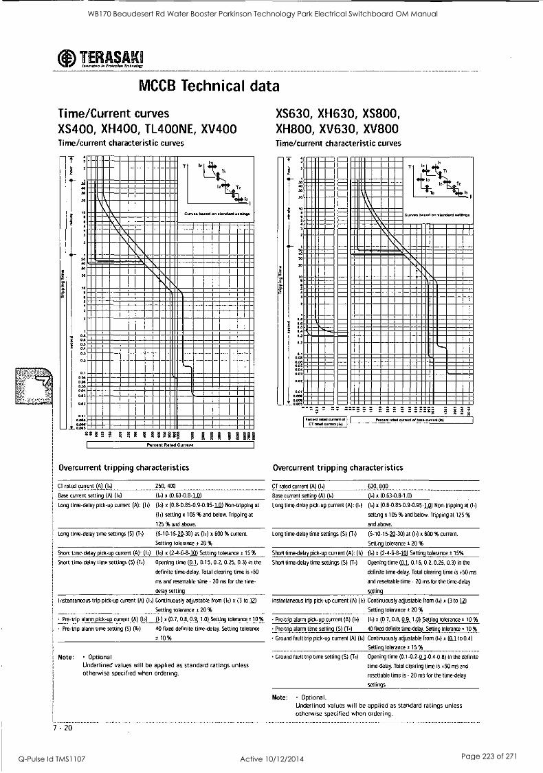
alosowlers la Preen-lion Trchneiew TERASAKO
MCCB Technical data
Time/Current curves XS400, XH400, TL400NE, XV400 Time/current characteristic curves
t I
2.
1
to
2
it- 1
50 40
SO
20
10
3
2
0.6 0.6 03 0.4
0.3
0.2
0.1
0.08 0.06 0355 0.04 003
002
005 0.006 0.006 0.005
P. 7.; 8 R r 8 8 13E3E1
Curves beset, on standard setttnos
Percent Rated Current
Overcurrent tripping characteristics
CT rated current (A) (10 250, 400
Base current setting (A) (I0) (lo) x (0.63-0.8-1k
Long time-delay pick-up current (A): (14 (10) x (0.8-0.85-0.9-0.95-1k Non-tripping at
(Ii) setting x 105 % and below. Tripping at
125 % and above.
Long time-delay time settings (S) (TO (5-10-15-24 -30) at (10 x 600 % current.
Setting tolerance a 20 %
Short time-delay pick-up current (A): (14 (10) x (2-4-6-8-n) Setting tolerance a 15 %
Short time-delay time settings (5) (Tz) Opening time al, 0.15, 0.2, 0.25. 0.3) in the
definite time-delay. Total clearing time is +50
ms and resettable time - 20 ms for the time-
delay setting
Instantaneous trip pick-up current (A) (13) Continuously adjustable from (10) x (3 to 12)
Setting tolerance ± 20 %
Pre-trip alarm pick-up current (A) (I.) x (0.7, 0.8, 0.9, 1.0) Setting tolerance ± 10 %
Pre-trip alarm time setting (S) (To) 40 fixed definite time-delay. Setting tolerance
± 10 %
Note: Optional. Underlined values will be applied as standard ratings unless otherwise specified when ordering.
7-20
XS630, XH630, XS800, XH800, XV630, XV800 Time/current characteristic curves
T
S
2
30
5.
10
a.
10
2
Os
° 00.6
0.;0
0.2
0.1 008 0.00 0.05 0.04 OD3
0.02
OA, 0.001 0001 -'- 0.005
Curves based en standard settings
111111111111111111 1M= 1111=11=11M1 11111 11111=11=M BEN= 1.1
11.1
01111I 1MIMII MM.= BM I___
=1=.1
ggg gg n. ° ° n. n.8o lig Percent retell cerrent of
CT rated current (In) Pe cent rated current el base Cliff nt ill
Overcurrent tripping characteristics
CT rated current (A) (I.) 630, 800
Base current setting (A) (14 (14 x (0.63-0.8-1.0)
Long time-delay pick-up current (A): (h) (I.) x (0.8-0.85-0.9-0.95-1a Non-tripping at (h)
setting x 105 % and below. Tripping at 125 %
and above.
Long time-delay time settings (S) (T4 (5-10-15-20-30) at (14 x 600 % current.
Setting tolerance ± 20 %
Short time-delay pick-up current (A): (12) (14 x (2-4-6-8-1()) Setting tolerance a 15%
Short time-delay time settings (S) (Tr) Opening time (0.1 0.15, 0.2, 0.25, 0.3) in the
definite time-delay. Total clearing time is +50 ms
and resettable time - 20 ms for the time-delay
setting
Instantaneous trip pick-up current (A) (13) Continuously adjustable from (14 x (3 to 12)
Setting tolerance ± 20 %
Pre-trip alarm pick-up current (A) (I.)
Pre-trip alarm time setting (S) (To)
Ground fault trip pick-up current (A) (I.)
Ground fault trip time setting (S) (T.)
(14 x (0.7, 0.8, 03, 1.0) Setting tolerance: 10 %
40 fixed definite time-delay. Setting tolerance ± 10 %
Continuously adjustable from (14 x (01 to 0.4)
Setting tolerance ± 15 %
Opening time (0.1-0.2-a3-0.4-0.8) in the definite
time-delay. Total clearing time is +50 ms and
resettable time is - 20 ms for the time-delay
settings
Note: Optional. Underlined values will be applied as standard ratings unless otherwise specified when ordering.
WB170 Beaudesert Rd Water Booster Parkinson Technology Park Electrical Switchboard OM Manual
Q-Pulse Id TMS1107 Active 10/12/2014 Page 223 of 271
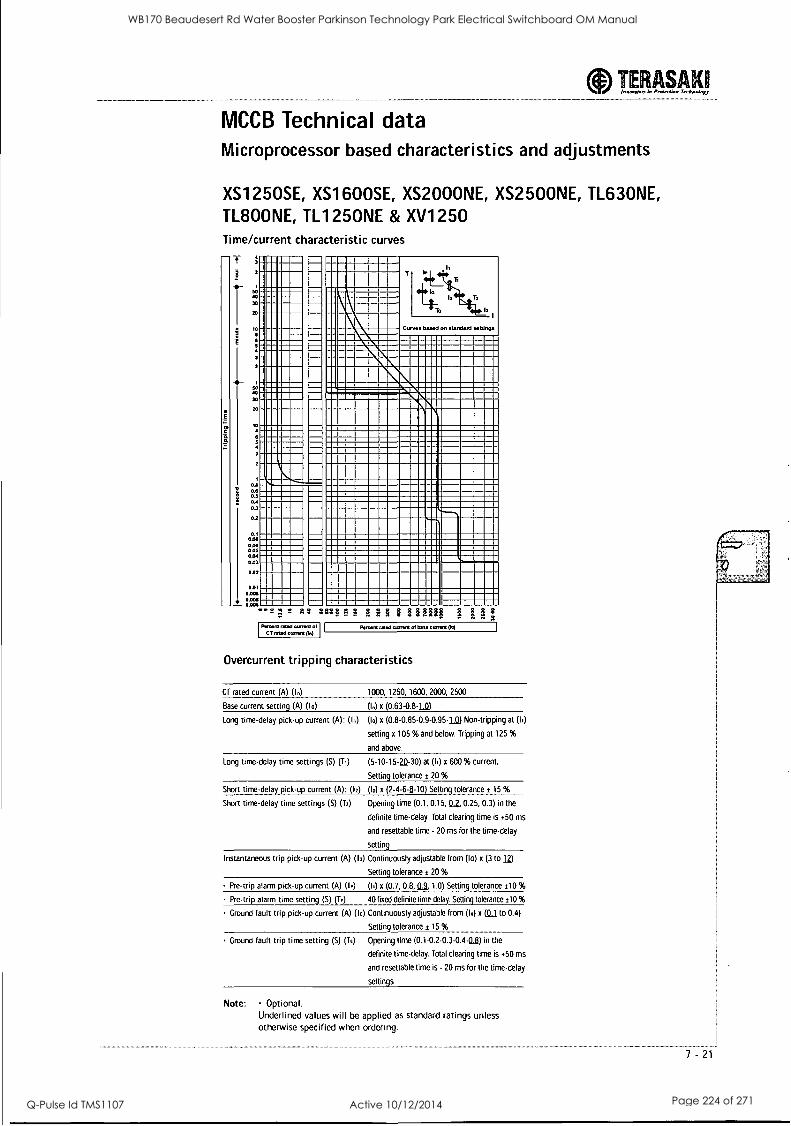
TERASAKII hmaursin Preget-lion Tcc*s.4nyy
MCCB Technical data Microprocessor based characteristics and adjustments
XS1250SE, XS1600SE, XS2000NE, XS2500NE, TL630NE, TL800NE, TL1250NE & XV1250 Time/current characteristic curves
a
T
20
10
xi
0.11
0.4
0.4 0.3
0.2
0.1
0m
005 0.04 Ott.
0.02
0.01 0.0011
0.0011 0.005
Curves tuned on standar! settings
1111MM - ..ti_- Una WI
MM MI
111 111
MUM= I VIM
Pootere rated anent of CT tilted current gni
' F. ill I `4
Peiatnt sled clirrerd 01 base arr. (to)
Overcurrent tripping characteristics
CT rated current (A) (I.) 1000, 1250, 1600, 2000, 2500
Base current setting (A) (10) (In) x
Long time-delay pick-up current (A): (Id (10) x (0.8-0.85-0.9-0.95-LW Non-tripping at (I,)
setting x 105 % and below. Tripping at 125 %
and above.
Long time-delay time settings (S) (Ti) (5-10-15.2D-30) at (Id x 600 % current.
Setting tolerance t 20 %
Short time-delay pick-up current (A): (12) (10) x (2.4-6-6-10) Setting tolerance t 15 %
Short time-delay time settings (S) (To) Opening time (0.1, 0.15, 02 0.25, 0.3) in the
definite time-delay. Total clearing time is +50 ms
and resettable time - 20 ms for the time-delay
setting
Instantaneous trip pick-up current (A) (13) Continuously adjustable from (lo) x (3 to )2)
Setting tolerance t 20 %
Pre-trip alarm pick-up current (A) (1r) (Id x (0.7, 0.8, 03, 1.0) Settine tolerance ±10 %
Pre-trip alarm time setting (S) (Tr) 40 fixed definite time-delay. Setting tolerance t10 %
Ground fault trip pick-up current (A) (lc) Continuously adjustable from (I.) x ((1,1 to 0.4)
Setting tolerance t 15 %
Ground fault trip time setting (S) (To) Opening time (0.1-0.2-0.3-0.4-0,3) in the
definite time-delay. Total clearing time is +50 ms
and resettable time is - 20 ms for the time-delay
settings
Note: Optional. Underlined values will be applied as standard ratings unless otherwise specified when ordering.
7 -21
WB170 Beaudesert Rd Water Booster Parkinson Technology Park Electrical Switchboard OM Manual
Q-Pulse Id TMS1107 Active 10/12/2014 Page 224 of 271
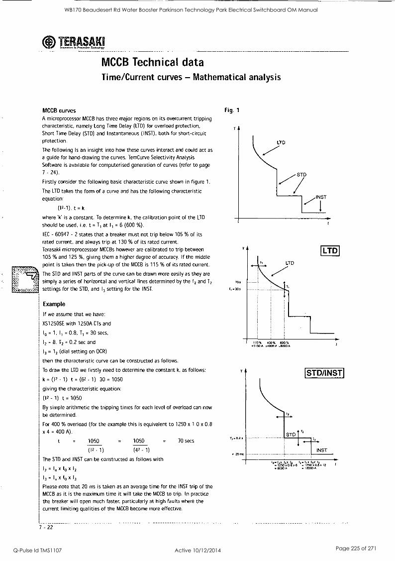
TEPAPAY
MCCB Technical data Time/Current curves - Mathematical analysis
MCCB curves A microprocessor MCCB has three major regions on its overcurrent tripping characteristic, namely Long Time Delay (LTD) for overload protection,
Short Time Delay (STD) and Instantaneous (INST), both for short-circuit protection.
The following is an insight into how these curves interact and could act as
a guide for hand-drawing the curves. Tem Curve Selectivity Analysis
Software is available for computerised generation of curves (refer to page
7 - 24).
Firstly consider the following basic characteristic curve shown in figure 1.
The LTD takes the form of a curve and has the following characteristic
equation:
(12-1). t = k
where 'k' is a constant. To determine k, the calibration point of the LTD
should be used, i.e. t = T1 at 11 = 6 (600 %).
IEC - 60947 - 2 states that a breaker must not trip below 105 % of its
rated current, and always trip at 130 % of its rated current.
Terasaki microprocesssor MCCBs however are calibrated to trip between
105 % and 125 %, giving them a higher degree of accuracy. If the middle
point is taken then the pick-up of the MCCB is 115 % of its rated current.
The STD and INST parts of the curve can be drawn more easily as they are
simply a series of horizontal and vertical lines determined by the 12 and T2
settings for the STD, and 13 setting for the INST.
Example
If we assume that we have:
XS125OSE with 1250A CTs and
10 = 1, I, = 0.8, T1 = 30 secs,
12 = 8, T2 = 0.2 sec and
13 = 12 (dial setting on OCR)
then the characteristic curve can be constructed as follows.
To draw the LTD we firstly need to determine the constant k, as follows:
k = (12 - 1) t = (62 - 1) 30 = 1050
giving the characteristic equation:
(12 - 1) t = 1050
By simple arithmetic the tripping times for each level of overload can now
be determined.
For 400 % overload (for the example this is equivalent to 1250 x 1.0 x 0.8
x 4 = 400 A).
1050 = 1050 = 70 secs
(12 - 1) (42 - 1)
The STD and INST can be constructed as follows with
12 =1 x 10 x 12
13 = In X 10 X 13
Please note that 20 ms is taken as an average time for the INST trip of the
MCCB as it is the maximum time it will take the MCCB to trip. In practice
the breaker will open much faster, particularly at high faults where the
current limiting qualities of the MCCB become more effective.
7 -22
Fig. 1
T
LTD
STD
704
1,30s
LTD
LTD
72- 0.2 s
* 20 ms
115% 400% 600% =1150A =4000A =60004
STD/INST
STD
INST
1"250°A.Ig X 8 '':12'50°A.I4 Z
= 80004 = 12000 A
WB170 Beaudesert Rd Water Booster Parkinson Technology Park Electrical Switchboard OM Manual
Q-Pulse Id TMS1107 Active 10/12/2014 Page 225 of 271
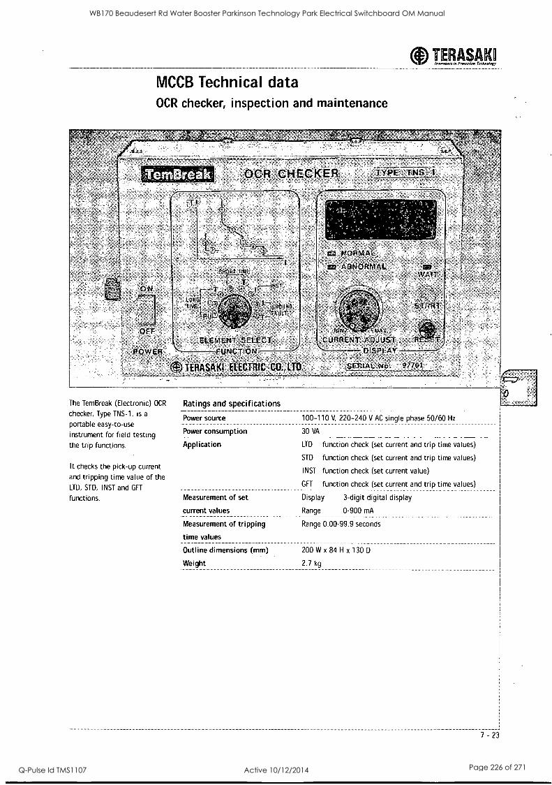
TERASAKO Inninwari in Pinierrimt Techniximt
MCCB Technical data OCR checker, inspection and maintenance
-OCR ,setiReicglt
14
,EIL;Erar-f4ELEG-t,,, Ails.101:644'
TERASPiKt ELECTFE 111D
The TemBreak (Electronic) OCR
checker, Type TNS-1, is a
portable easy-to-use
instrument for field testing the trip functions.
It checks the pick-up current
and tripping time value of the LTD, STD, INST and GFT
functions.
ift!.44,
'CO A R
Ratings and specifications
Power source
Power consumption
Application
Measurement of set
current values
Measurement of tripping
time values
Outline dimensions (mm)
Weight
100-110 V. 220-240 V AC single phase 50/60 Hz
30 VA
LTD
STD
INST
GFT
function check (set current and trip time values)
function check (set current and trip time values)
function check (set current value)
function check (set current and trip time values)
Display
Range
3-digit digital display
0-900 mA
Range 0.00-99.9 seconds
200 W x 84 H x 130 D
2.7 kg
WB170 Beaudesert Rd Water Booster Parkinson Technology Park Electrical Switchboard OM Manual
Q-Pulse Id TMS1107 Active 10/12/2014 Page 226 of 271
Our:Objective is to'provide yoU,.with the tools
necessarY,to.ensure your time is managed as
effectyely and efficientlyas possible 4
.TeniCurve has been'developed Wholly:by NHP,for.--
the AU-straliari market,,bUt will alSo be used
within,the Terasaki orgamsation-throughout`the-
world,
, Circuit breaker,Selection and set-up can be a,
laborious-;andztime-consuming task NHP has .
ensured that TerriCuve,4'0, for "WindoWSTu'98,,,
2000; NT-and XP is now'even simpler td, operate::
Hence; accurate results"Can,beigained:in`ra,
matter of minutes
The datatiase`With TeiiiCiirVe'h-ardS
characteristiC curves for all Terasakr devices:-
presently-available from NHP In addition fa
this, the extensive 'database of non-Terasaki,,
devices allowsyou to,produce accurate grading
from theqi.arisformers.pr,imarr side'to'theTpoint191
final distribution
'High;_quality prints -canbe outpuf;inaUdifig the A;
characteristic curves for each chosen device::: -
° -
-as well as a complete list -of:device settings
WB170 Beaudesert Rd Water Booster Parkinson Technology Park Electrical Switchboard OM Manual
Q-Pulse Id TMS1107 Active 10/12/2014 Page 227 of 271
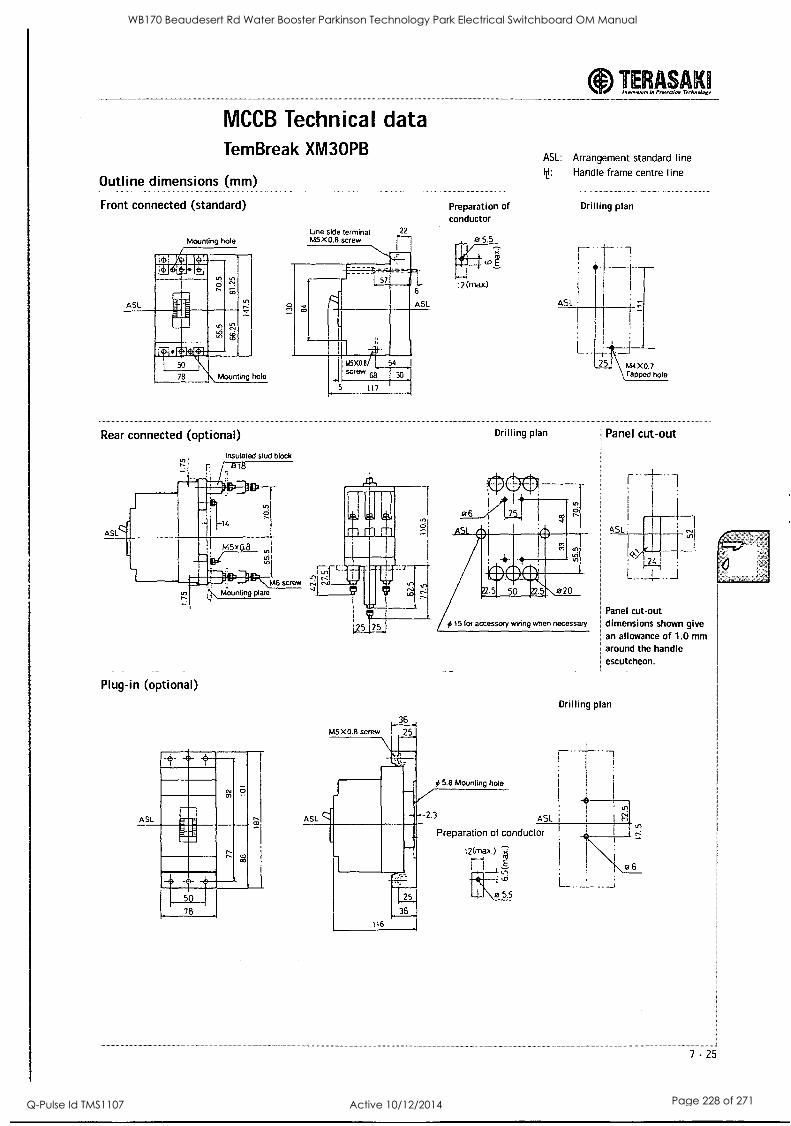
MCCB Technical data Tem Break XM3OPB
Outline dimensions (mm)
Front connected (standard)
ASL
Mounting hole
Mounting hole
Rear connected (optional)
0 et,
Insulated stud block
Line side terminal M5 X0.8 screw
22
L. 6
ASL
115X0.8 l 54 screw
5 117
Preparation of conductor
12 frnia.x)
TERASAK Inninnoort in Protection Teeltwoly7
ASL: Arrangement standard line y: Handle frame centre line
Drilling plan
Drilling plan
Plug-in (optional)
ASL
CIE= .- III if
ill= 78
# 15 for accessory wiring when necessary
# 5.8 Mounting hole
2.3 ASL
Preparation of conductor
E
1"d
la 5.5
25.4 114X0.7 \ Tapped hole
Panel cut-out
ASL -1 : /-2, :
.
L._ I ..__I
.
Panel cut-out dimensions shown give an allowance of 1.0 mm around the handle escutcheon.
L
Drilling plan
7 -25
WB170 Beaudesert Rd Water Booster Parkinson Technology Park Electrical Switchboard OM Manual
Q-Pulse Id TMS1107 Active 10/12/2014 Page 228 of 271
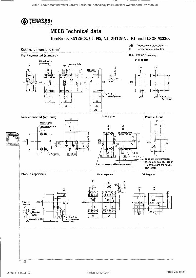
aInnovainrs in Prisierria. Technology TERASAKI
MCCB Technical data TemBreak XS125CS, CJ, NS, NJ, XH125NJ, Pi and TL3OF MCCBs
Outline dimensions (mm)
Front connected (standard)
Interpole barter (remcwable)
3P IP
651.
141
'
4P Mounting hole
sq. 1.. 90
120
Rear connected (optional)
ASL._
Mounting plate
hsulated stud dock
--f
:2!
11M,
Plug-in (optional)
0
MEt screw -
ASL
MB screw
ASL: Arrangement standard line
y: Handle frame centre line
Note: XS125NS 1 pole only
Drilling plan
,ii 3P 4P ?
It It
14t9 rt--- 1---,d-.1 -1---f-
(rnx) I I 1
j ASL
1 1 - `.21
L*' N M4 x 07
127 6 Mounting screw
L 79
Drilling plan
3P 4P
111
\ M4 x 0.7
Tapped hole
Panel cut-out LP
I 3P
I it
15
/ 5 15 Q15 lor accessory wiring when necessary
Mounting block
Notzt. x 0:7 Tapped hole Panel cut-out dimensions
shown give an allowance of 1.0 mm around the handle escutcheon.
3P
Drilling plan
4P
WB170 Beaudesert Rd Water Booster Parkinson Technology Park Electrical Switchboard OM Manual
Q-Pulse Id TMS1107 Active 10/12/2014 Page 229 of 271
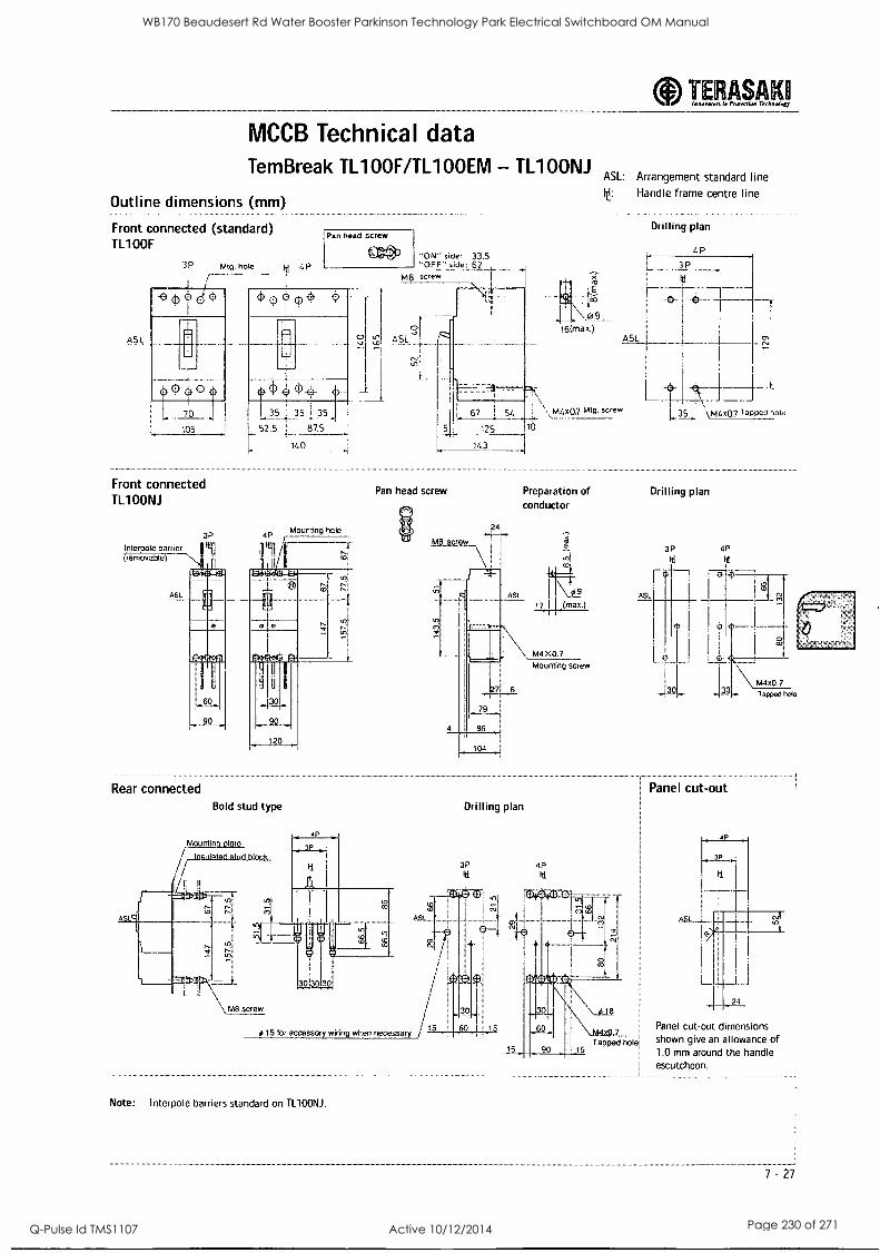
MCCB Technical data Tem Break TL100F/TL100EM - TL1OONJ
Outline dimensions (mm)
Front connected (standard) TL100F
AS1.
id 4P
1Pan head screw
C3*3 ON" side: 33.5 'OFF' side: 62_
M8 screw
ASL: Arrangement standard line It: Handle frame centre line
<') e0
.
70
105
Front connected TL100N1
Inter le barrier (removable)
Drilling plan
L.P
I 3P
I 10
1----bd
ASL
52.5 87.5
14 0
67 54 M4x07 mtg. screw
143
35 35 35
là
Mounting hole 3P 4P ,
Rear connected
90
Bold stud type
Moun in
rbasidated stud block
Pan head screw
is 15 for accessory wiring when necessary
Note: Interpole barriers standard on TL100NJ.
Preparation of conductor
104
M4X0.7 Mounting screw
Le. I \ L35 I M4x0.7 TaPPeO hole
Drilling plan
ASL
4P
30
0 CD
M4x0.7 Tapped hole
Drilling plan
Panel cut-out
3P 4P Itt
Panel cut-out shown give
dimensions an allowance of
1.0 mm around the handle escutcheon.
7 - 27
WB170 Beaudesert Rd Water Booster Parkinson Technology Park Electrical Switchboard OM Manual
Q-Pulse Id TMS1107 Active 10/12/2014 Page 230 of 271
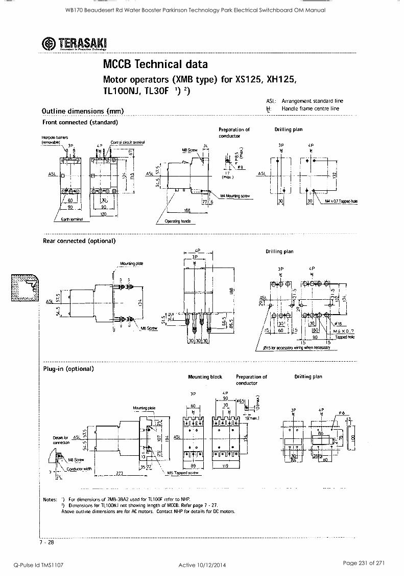
TERASAKQ innovator% in gnomic". Technology -_
MCCB Technical data Motor operators (XMB type) for XS125, XH125, TL1OONJ, TL3OF 1) 2)
Outline dimensions (mm)
Front connected (standard)
Interpoie barriers
(removable) 3P, 4?
Control circuit terminal
11
/ Earth teminal
Rear connected (optional)
AS
Plug-in (optional)
Mounting plate
i fl
Detads la AS' connection
M6 Screw
\_ Conductor wicllb
ASL LI,
Preparation of conductor
ASL: Arrangement standard line
le: Handle frame centre line
Drilling plan
24 3P 4P MB Screw ''''' M M --
rr M4 Mounting
(max.) 17 r-1
[
A SI
14-'-- .--44*---1 4.1.\ 09
...
27 6
.L ..J
30 j AM x 0.7 Tapped hole
186
/Operatiig Fondle
LrIT".4"
Fi
M8 Screw
Mounting plate
223 lo -
Mounting block
3P
ASL
41
89
M5 Tapped screw
Drilling plan
3P 4P
Po
L291141_60 1'.5
1 (so,\\\ , I .1 I
L 90 Tapped hole
/ 015 tor accessory wiring when necessary 5 15
Preparation of conductor
4P 90 065 30
LtflifULI
119
Notes: ') For dimensions of 7MB-3BA2 used for TL100F refer to NHP.
2) Dimensions for TL1OONJ not showing length of MCCB. Refer page 7 - 27.
Above outline dimensions are for AC motors. Contact NHP for details for DC motors.
7 -28
Drilling plan
WB170 Beaudesert Rd Water Booster Parkinson Technology Park Electrical Switchboard OM Manual
Q-Pulse Id TMS1107 Active 10/12/2014 Page 231 of 271
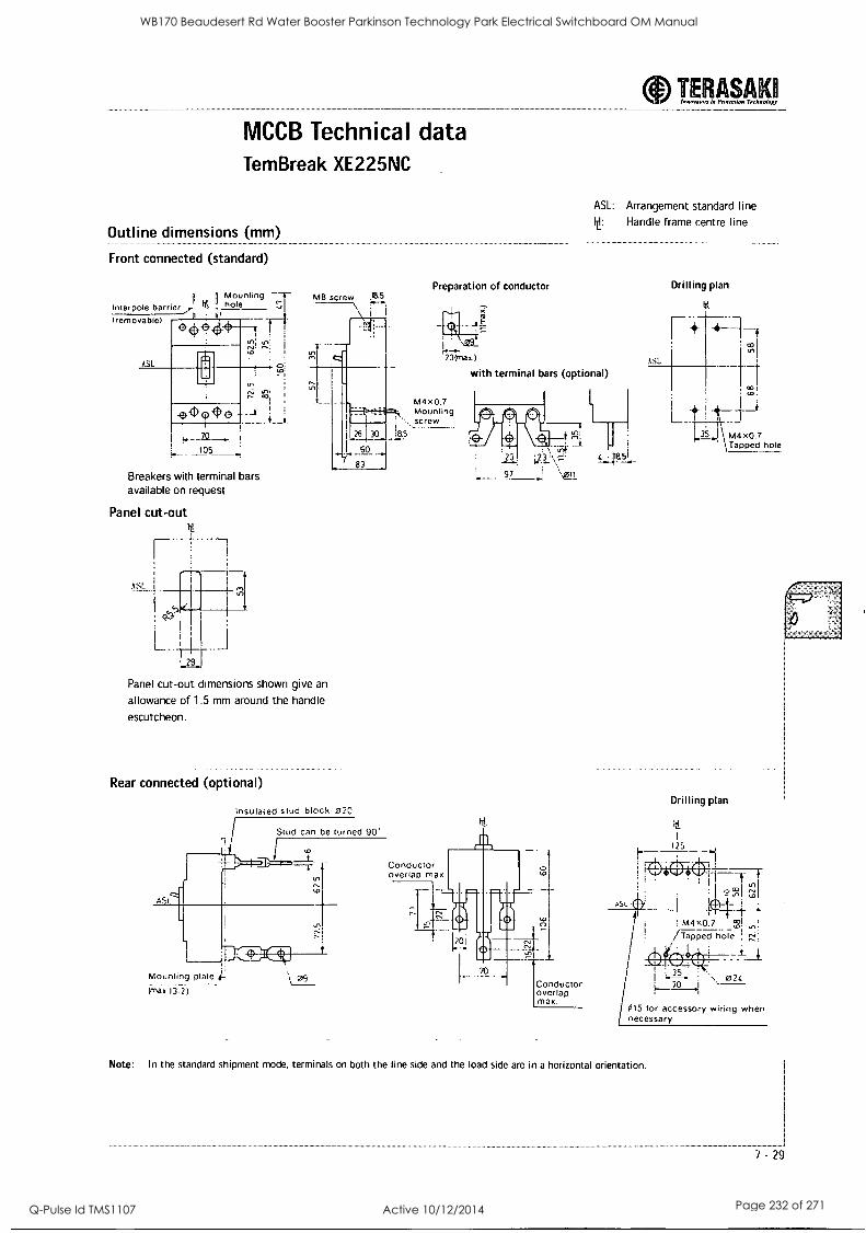
6 he f ItIVIIII3 in goner:inn Technology TERASAXO
MCCB Technical data Tem Break XE225NC
Outline dimensions (mm)
Front connected (standard)
Interpole barrier". P. II
(removable)
ASL
Mounting - hole
ASL: Arrangement standard line t: Handle frame centre line
Preparation of conductor
NO_
23(max.)
with terminal bars (optional)
'A!
23 '1.23
97 1 \gyl
_105_ Breakers with terminal bars available on request
Panel cut-out
LI 29.1.
Panel cut-out dimensions shown give an
allowance of 1.5 mm around the handle
escutcheon.
Rear connected (optional)
ASI
Insulated stud block Z20
Stud can be turned 90'
I I Conductor overlap max
LO
Mounting plate d-
(max.13. 2)
I
Conductor overlap max.
Drilling plan
lt
r+ ASL
+-1 CO
.0 I
M4x0.7 Tapped hole
Drilling plan
4- -- M4 x0.7 ,cg!
Tapped hare
/ i ,--3L . \ 024 ..._,2161
415 for accessory wiring when necessary
ii-
Note: In the standard shipment mode, terminals on both the line side and the load side are in a horizontal orientation.
"""
7 -29
WB170 Beaudesert Rd Water Booster Parkinson Technology Park Electrical Switchboard OM Manual
Q-Pulse Id TMS1107 Active 10/12/2014 Page 232 of 271
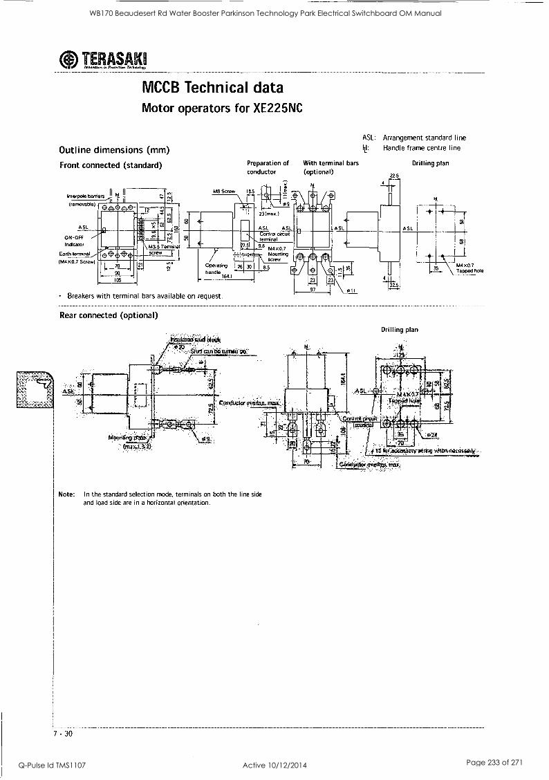
aInnovator. in Proierrion Technology TERASAKH
MCCB Technical data Motor operators for XE225NC
Outline dimensions (mm)
Front connected (standard)
11 Interpol(' banters
(removable)
ASL
ON-OFf Indicator
Earth terminal
(M4 X0.7 Screw)
Preparation of With terminal bars conductor (optional)
--r It
ASL: Arrangement standard line
M: Handle frame centre line
Drilling plan
M8 Screw 18.5
22.5
4 T'
11 It
rt
M3.5 Terminal screw
gar Operating handle
164.1
Breakers with terminal bars available on request.
Rear connected (optional)
23 (max.)
ASL ASL Control circuit terminal 9.6 M4x0 7
Mounting screw
26 30 8.5
A SL
M4 X0.7 Tapped hole
Drilling plan
Note: In the standard selection mode, terminals on both the line side
and load side are in a horizontal orientation.
7 -30
WB170 Beaudesert Rd Water Booster Parkinson Technology Park Electrical Switchboard OM Manual
Q-Pulse Id TMS1107 Active 10/12/2014 Page 233 of 271
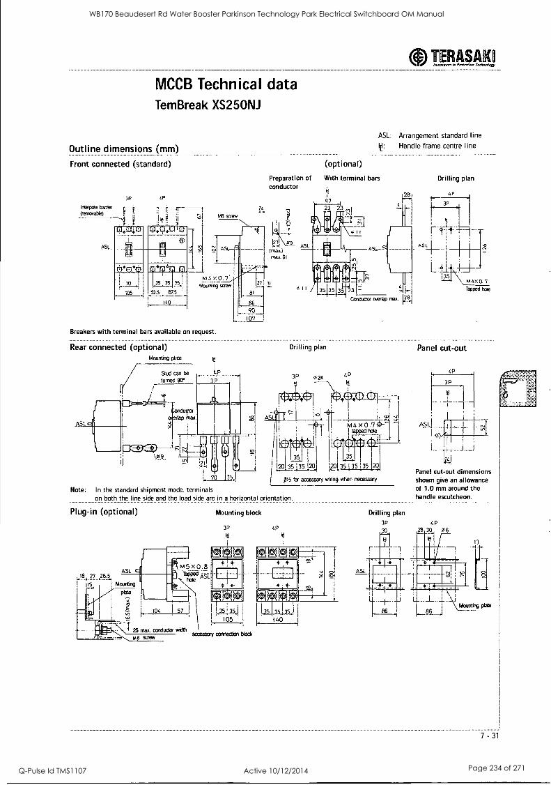
MCCB Technical data TemBreak XS25ONJ
Outline dimensions (mm)
Front connected (standard)
Preparation of conductor
24
123i \_09 ASL
;max.) max. 61
m 2, X 0 . 7 IFS
LE78 1
86
:0 Mounting screw
Breakers with terminal bars available on request.
Rear connected (optional) Mounting plate
Stud can be
turned 90° 3P
107 1
TEERASAK Inter...tart Ix Preen-dam Tec4nology
ASL: Arrangement standard line
le: Handle frame centre line
(optional)
With terminal bars
97
Drilling plan
ducts ap ;flax
H
70
Note: In the standard shipment mode, terminals on both the line side and the load side are in a horizontal orientation.
Plug-in (optional) Mounting block
CP
Id
ASL
Drilling plan
3P
30
Drilling plan
AP
3p
AS
111-'
31 5
L6:1
Weed hale
Panel cut-out
ASL
Panel cut-out dimensions shown give an allowance of 1.0 mm around the handle escutcheon.
4P
L
7 -31
WB170 Beaudesert Rd Water Booster Parkinson Technology Park Electrical Switchboard OM Manual
Q-Pulse Id TMS1107 Active 10/12/2014 Page 234 of 271
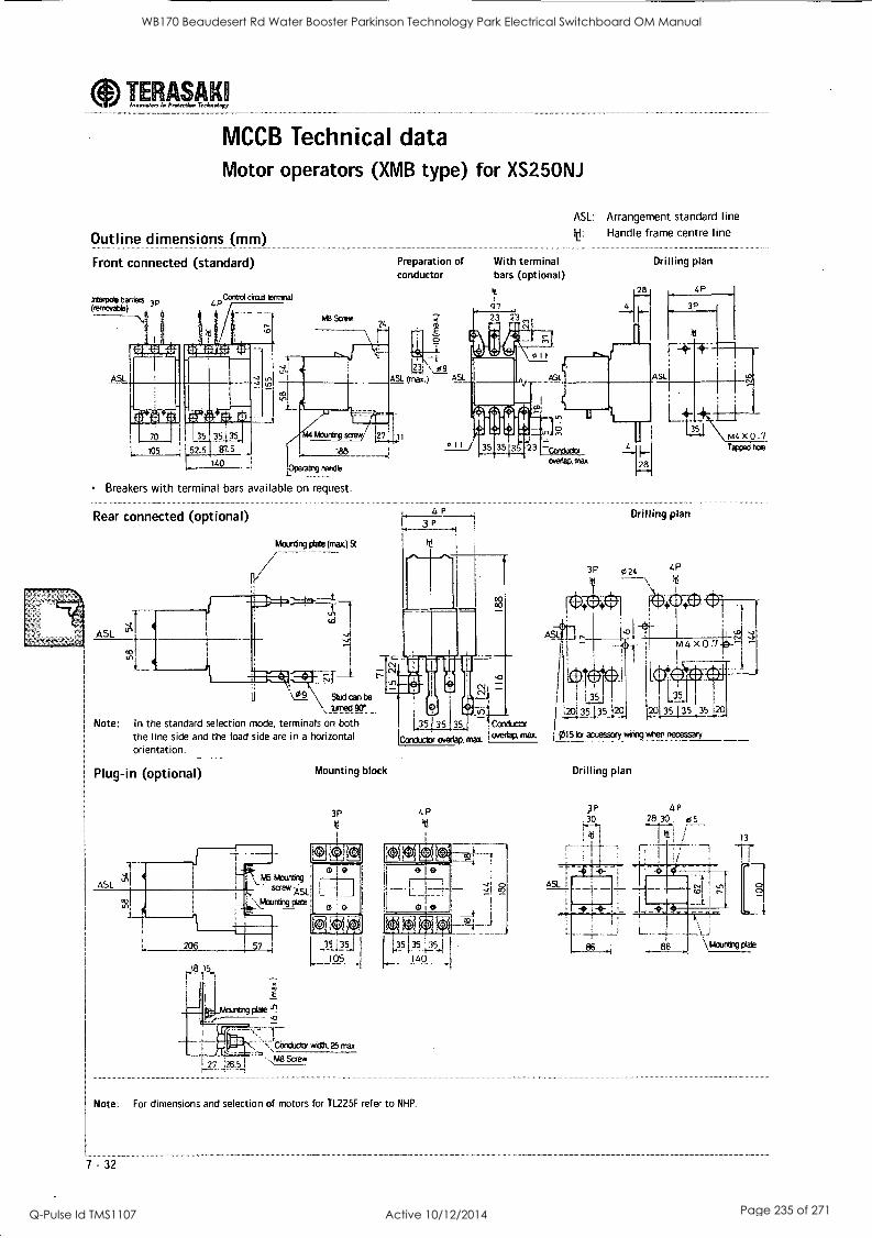
TERASAM Innovate, in Prarction Terhnoloxy
MCCB Technical data Motor operators (XMB type) for XS25ONJ
Outline dimensions (mm)
Front connected (standard)
Mambo* berries 3p Offerable)
ASL
4P Contrd &wit genrilal
_ .
105 52.5 Es7. 5
140
-41
tr,
Me Scree 24
Preparation of conductor
With terminal bars (optional)
cr7
ASL: Arrangement standard line
Handle frame centre line
Drilling plan
Atuntiv =my
188
operaing handle
Breakers with terminal bars available on request.
Rear connected (optional)
Marring cLate (mm051
11
4p 3P
ii'Vgs.9_ Stud can te , turned 90°
Note: In the standard selection mode, terminals on both the line side and the load side are in a horizontal orientation.
Plug-in (optional) Mounting block
3P
35 35 35 Conduptor
Conductor overlap. max. 1 GierL311 max
4P lj
.1 1 I7-L_ :II 2 el i
- 4-J g, .
1.-3-51-.I-A-1 140
Note: For dimensions and selection of motors for TL225F refer to NHP.
7 - 32
Drilling plan
iM I 1.35
I .20i 35_135_1_20 20135 135 35 120
Idit 5 la accessory gsirigg %hen necessary
Drilling plan
P 4P 30 2830. 66
WB170 Beaudesert Rd Water Booster Parkinson Technology Park Electrical Switchboard OM Manual
Q-Pulse Id TMS1107 Active 10/12/2014 Page 235 of 271
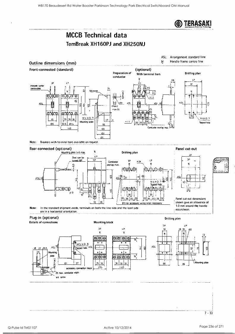
MCCB Technical data Tem Break XH160PJ and XH25ONJ
Outline dimensions (mm)
Front-connected (standard) Preparation of conductor
(optional) With terminal bars
97 23 213
TERASAKI Innov.on in Protertion TerlopoIngy ------------------
ASL: Arrangement standard line
Handle frame centre line
28
i40
Note: Breakers with terminal bars available on request.
Rear-connected (optional) Mounting plate 1 =5 max.
r,/
ASL
Stud can be
turned 90°
\ 0 9
IN Drilling plan 4 P
3 P -1 3P "I 1
Conductor
1
i overlap max, hi
o_24 4P
RI);
k44x0.7 4) 11 Tapped hole_
I
, 70 !35
t ot)all I I I !
' I Os! 20135135 j20 20135 35135 20
015 lor accessory wiring when necessary
Note: In the standard shipment mode, terminals on both the line side and the load side are in a horizontal orientation.
Plug-in (optional) Details of connections
ASL
Mounting
plate
121 57 fxs'
accessory connection block
*:-.22..,,.1.11.25 max. conductor width
M8 screw
Mounting block
A51-
Drilling plan
4P
3P
Ft-VT--
ASL
4-- 35
1
Panel cut-out
4P
3P
Cl
\ MAX° '7
Tapped hole
ASL .
I
I I
v";
L2'
Panel cut-out dimensions shown give an allowance of 1.0 mm around the handle escutcheon.
Drilling plan
7 -33
WB170 Beaudesert Rd Water Booster Parkinson Technology Park Electrical Switchboard OM Manual
Q-Pulse Id TMS1107 Active 10/12/2014 Page 236 of 271
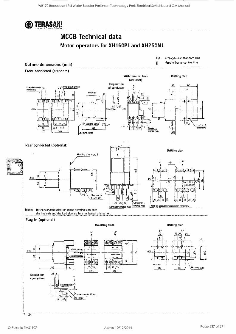
eInnovators in Protection Teehnniagy TERASAKI
MCCB Technical data Motor operators for XH160PJ and XH25ONJ
Outline dimensions (mm)
Front connected (standard)
Inteepole barriers 3 p (rernovate)
ASL
Coned cicuitterrnitai 4P
r
(I. Id / M8 Screw
21.
With terminal bars
(optional) Preparation of conductor
-4 7-r
23 \ qg ASL (max.)
r 30 .41
90 105
Rear connected (optional)
ASL
)1(44 Wenn screw.
188
Operating handb
Mouneng *4 (may.) 5t
ax
127 11
can be \ turned 90'
Note: In the standard selection mode, terminals on both the line side and the load side are in a horizontal orientation.
47 2.3 23
r,
ASL: Arrangement standard line
It: Handle frame centre line
Drilling plan
28 LP
ASL
-I,
23 1-Conductor overtao mat
05- 35 i 35.:4 Conductor .
Conduct( overlap, max. clvertaP, max
Plug-in (optional)
3P
Mounting block
42
Details for connection
7 - 34
Mounting plate 4?
wOM. 25 max
t ts48 Screw 2 Z5 ,.5 1
28
Drilling plan
3P 024 4P
It \ It I . ;
LLSt-t 1 .121 ''':r
'
-1611 - ii m4x0.7.6_-; -i i Taxed hde
tpl. 05.1 -
! I 1 35 I
1 1 - ! 20 35 135 120135 1 35 352O
I015 tor accessory wiring when necessary
514 X 0.7 Tapped hole
Drilling plan
WB170 Beaudesert Rd Water Booster Parkinson Technology Park Electrical Switchboard OM Manual
Q-Pulse Id TMS1107 Active 10/12/2014 Page 237 of 271
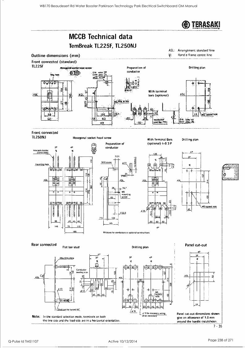
aIwnwyesors 4 Prato/pa TerAnelorr TERASAKEI
MCCB Technical data TemBreak TL225F, TL25ONJ
Outline dimensions (mm) Front connected (standard) TL225F to.in=rx.s#, Wink
DU
I -
Preparation of conductor
With terminal bars (optional)
Front connected TL25ONJ
Interpole barrio( (removable)
3P 4P
Hexagonal socket head screw
Preparation of conductor
ASL: Arrangement standard line le: Handle frame centre line
Drilling plan
IXE
4111
[ ED;rd.kir; 1-2:0=41
,aviixo. frvw.; .,
With Terminal Bars Drilling plan (optional) t=8 3 P
Rear connected Flat bar stud
ASL
Mounting plate
Conductor overiap.max.
i% Values for conductors or optional terminal bars
L 4P
3P
hl
I .
I / d /Stud van be turned 90
Drilling plan
3P 4P
id
4P
Note: In the standard selection mode, terminals on both the line side and the load side are in a horizontal orientation.
90i 33
4 36 I 415 for accessory wiring
when necessary
Panel cut-out
4P
3P
hole
r
Panel cut-out dimensions shown
give an allowance of 1.0 mm
around the handle escutcheon.
7 -35
WB170 Beaudesert Rd Water Booster Parkinson Technology Park Electrical Switchboard OM Manual
Q-Pulse Id TMS1107 Active 10/12/2014 Page 238 of 271
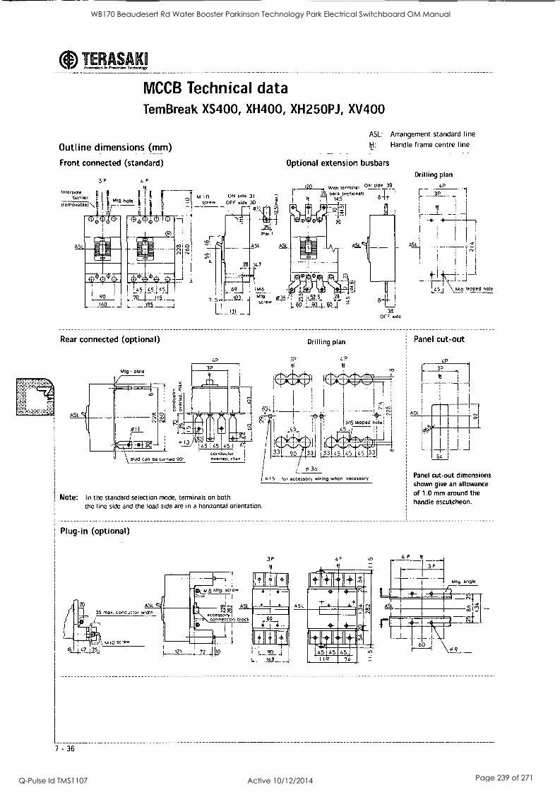
TERASAK In In:reran,. Terknalary
MCCB Technical data Tem Break XS400, XH400, XH250PJ, XV400
Outline dimensions (mm)
Front connected (standard)
M I 0 ON side.31 _screw OFF side 30
all
ASL: Arrangement standard line
y: Handle frame centre line
Optional extension busbars Drilling plan
terminal ON side 120 4P
F3P it bars 7, 14.5
Ast,
! h L
tapped hole
Rear connected (optional)
"9' plate
69
7.5e,
L.
jilt' lira' its te,
't116 rr a. IS
Ms CC! ° 4 I IL52-.-5N
§9
Drilling plan
3P Ill
41111.41Ariih IW 111W
I
ASL i
0 er{i
I , firr...,,g....ki I
I
331, 90 133J 33 LS 1GS 45 133 / 1
1
I / Inib tpr accessory wiring when necessary
stud can tte In nee 90'
4? It!
1'4)-
38 OFF side
Panel cut-out
.
4P
h 3P
IN
---1
1------1-"'
1 ASL
Note: In the standard selection mode, terminals on both the line side and the load side are in a horizontal orientation.
Plug-in (optional)
Panel cut-out dimensions shown give an allowance of 1.0 mm around the handle escutcheon.
36
WB170 Beaudesert Rd Water Booster Parkinson Technology Park Electrical Switchboard OM Manual
Q-Pulse Id TMS1107 Active 10/12/2014 Page 239 of 271
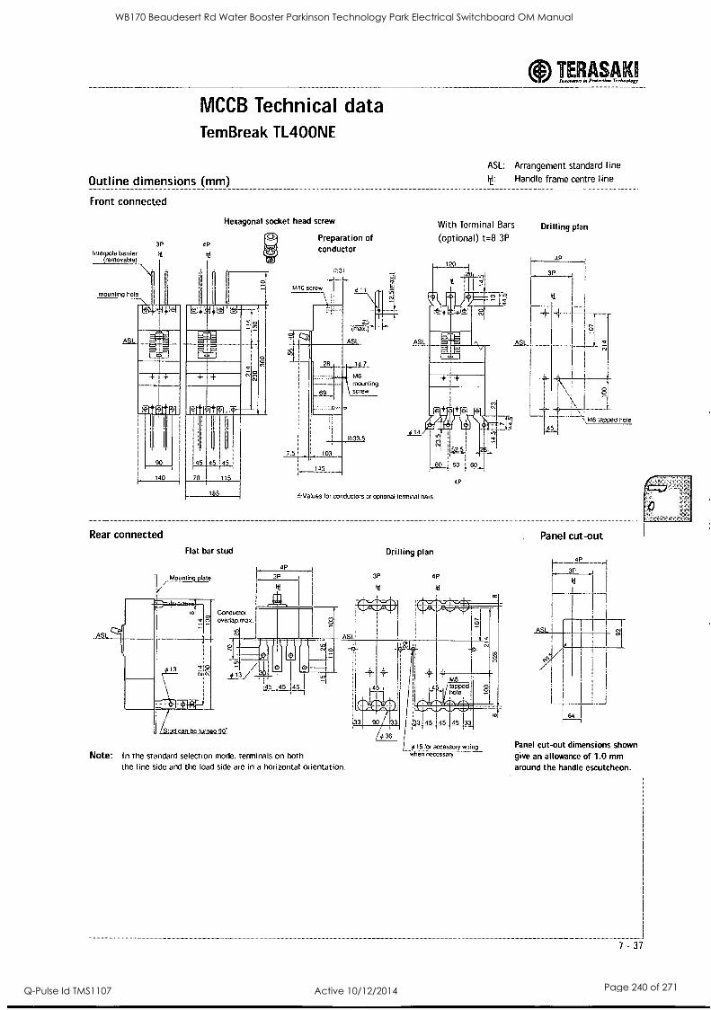
MCCB Technical data Tem Break TL400NE
Outline dimensions (mm)
Front connected
Interpole barrier (removable)
3P
ht
4P
Hexagonal socket head screw
Preparation of conductor
ASL: Arrangement standard line
It: Handle frame centre line
With Terminal Bars
(optional) t=8 3P
Drilling plan
4P
3P
MS mounting screw
VA6 tapped hole
Rear connected
ASL
Flat bar stud
Mounting plate
Conductor eIn ovenap.max
4p
it: Values for conductors or optional terminal bars
3P
J, Stud can be turned 90
5 145
3P
ht
Drilling plan
4P
it[
Note: In the standard selection mode, terminals on both the line side and the load side are in a horizontal orientation.
ys 15 for accessory wiring when necessary
hi
ASL
cy%
..j
Panel cut-out dimensions shown give an allowance of 1.0 mm around the handle escutcheon.
-_ 7 -37
WB170 Beaudesert Rd Water Booster Parkinson Technology Park Electrical Switchboard OM Manual
Q-Pulse Id TMS1107 Active 10/12/2014 Page 240 of 271
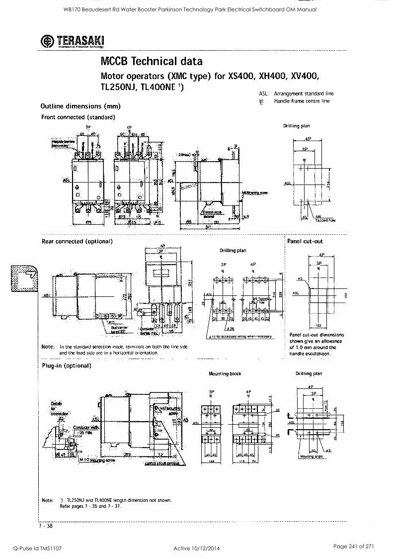
TERASAKI lonovolorx Provettion Technology
MCCB Technical data Motor operators (XMC type) for XS400, XH400, XV400, TL25ONJ, TL400NE 1)
Outline dimensions (mm)
Front connected (standard)
..""
Rear connected (optional) Drilling plan
3P
it
ASL: Arrangement standard line
I: Handle frame centre line
Drilling plan
Panel cut-out
4 P .. _3P Iti
R3
ASL z
Note: In the standard selection mode, terminals on both the line side
and the load side are in a horizontal orientation.
I Plug-in (optional)
777 ,comiitr*div f as fro
Mounting block
Panel cut-out dimensions shown give an allowance of 1.0 mm around the handle escutcheon.
Drilling plan
3P
Note: ) TL25ONJ and TL400NE length dimension not shown. Refer pages 7 - 35 and 7 - 37.
WB170 Beaudesert Rd Water Booster Parkinson Technology Park Electrical Switchboard OM Manual
Q-Pulse Id TMS1107 Active 10/12/2014 Page 241 of 271
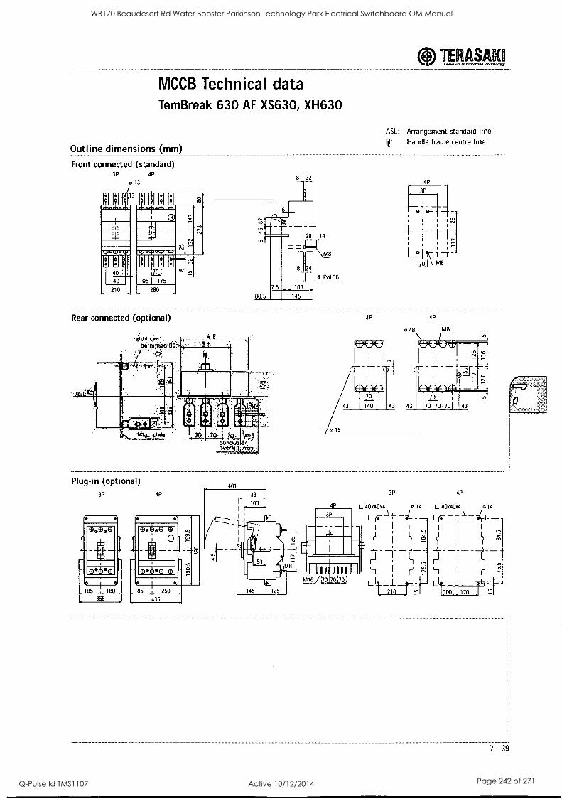
MCCB Technical data TemBreak 630 AF XS630, XH630
Outline dimensions (mm)
Front connected (standard) 3P 4P
013 8 32
Rear connected (optional)
ASL: Arrangement standard line
lt Handle frame centre line
4P
3P
I t- t
L \ M8
Plug-in (optional) 3P 4P
401
3P 4P
4P L 40x40x4 e 14 L 40x40x4 0 14
100 F170
7 -39
WB170 Beaudesert Rd Water Booster Parkinson Technology Park Electrical Switchboard OM Manual
Q-Pulse Id TMS1107 Active 10/12/2014 Page 242 of 271
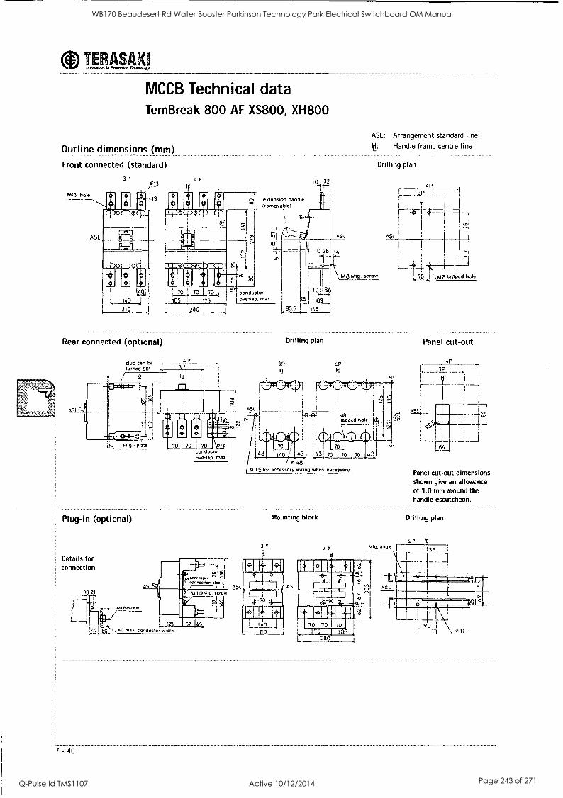
TERASAKI lonorwors I., Protecrion Technology
MCCB Technical data Tem Break 800 AF XS800, XH800
Outline dimensions (mm)
Front connected (standard)
Mtg. hole
31' 013
4P
extension handle (removable)
10 32 -41-4
t$igi :107k.1 '42 conductor
140 I 105 ! 175 I overlap. Max.
210 280
Rear connected (optional)
stud can be turned 90'
41'
ao.5
to I 36
145
3P
Drilling plan
ASL: Arrangement standard line
10: Handle frame centre line
Drilling plan
4P 3P
ASt. ASL L'21
I I
I
L,70, j \mg tapped hole M8 Mtg. screw
4P
Panel cut-out
I.. Mtg plate
Plug-in (optional
Details for connection
7 - 40
184
70 L70 13
conductor overlap. max.
"1= , acCesSOry
i
CO nection bloc k ASL
Mkt=IL M loM141g. screw
121 62 45 40 max. conductor width
1 48
15 for accessory wiring when necessary
Mounting block
Panel cut-out dimensions shown give an allowance of 1.0 mm around the handle escutcheon.
Drilling plan
WB170 Beaudesert Rd Water Booster Parkinson Technology Park Electrical Switchboard OM Manual
Q-Pulse Id TMS1107 Active 10/12/2014 Page 243 of 271
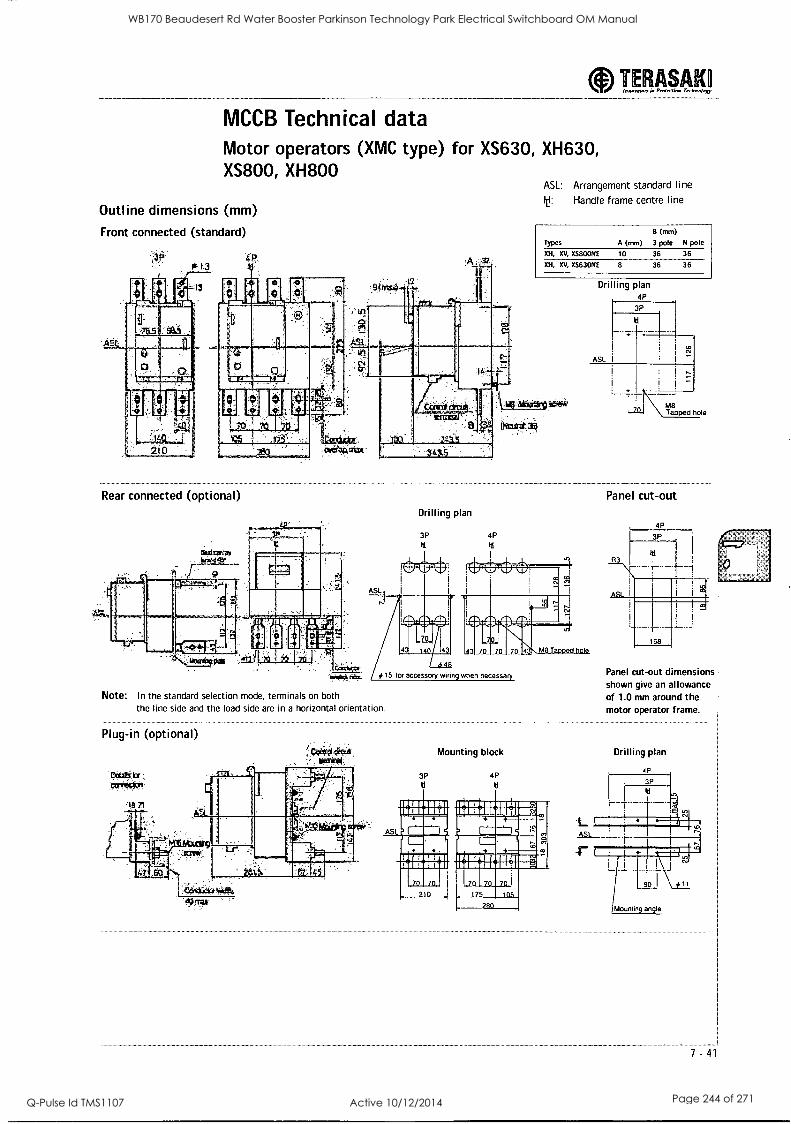
TERASAKO Innovator< in Pnnenlon TechnoIngy
MCCB Technical data Motor operators (XMC type) for XS630, XH630, XS800, XH800
Outline dimensions (mm)
Front connected (standard)
Of V3
ASL: Arrangement standard line t Handle frame centre line
Types
OH, XV, XS800NE
B (mm)
A (mm) 3 pole N pole
10 36 36
XH, XV, XS630NE 8 36 36
Rear connected (optional)
Ia .0 0
ASL
Drilling plan
3P 4P
Itt
1113P.
0--114-1 H
*15 for accessory wirin
as Mr
Drilling plan 4P
3P
ASL
M8 Tapped hole
Panel cut-out
3 70 70 70
when necessary
Note: In the standard selection mode, terminals on both the line side and the load side are in a horizontal orientation.
Plug-in (optional)
ASL
Panel cut-out dimensions shown give an allowance of 1.0 mm around the motor operator frame.
3P tl
Mounting block
4P
tl
Drilling plan
0 _175 2Rn /Mourning angle
-41
WB170 Beaudesert Rd Water Booster Parkinson Technology Park Electrical Switchboard OM Manual
Q-Pulse Id TMS1107 Active 10/12/2014 Page 244 of 271
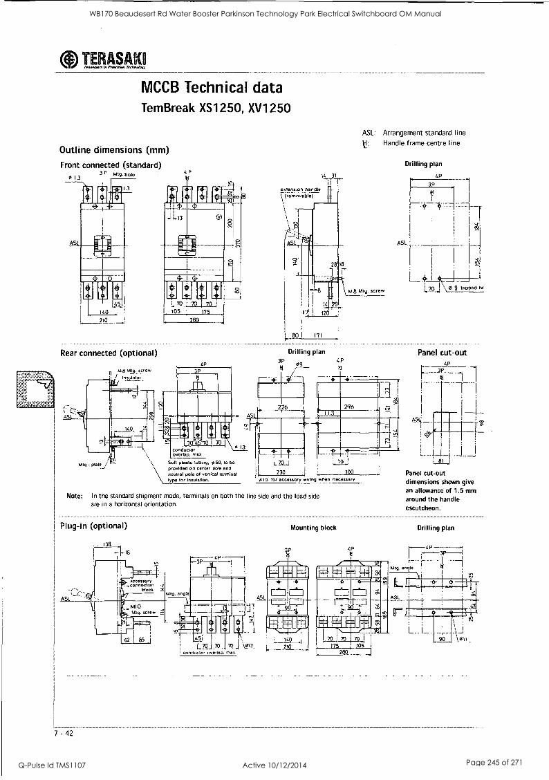
a....J...., la Prow lion Tremolo*, TERASAKQ
MCCB Technical data Tem Break XS1250, XV1250
Outline dimensions (mm)
Front connected (standard) 3 r Mtg. hobo
1
913
Rear connected (optional)
4 P
ASL: Arrangement standard line t Handle frame centre line
Drilling plan
4P
3P
'5
A51
4P
Drilling plan
ill
3P 4 P
L3-
Panel cut-out
70 70 conductor overlap, max
Soft plastic tubing, 050, to be provided on center Dole and
\neutral pole of vertical terminal type for Insulation.
59 13
I 70 .;
L 1
230 300
015 for accessory wiring when necessary
Note: In the standard shipment mode, terminals on both the line side and the load side are in a horizontal orientation.
Plug-in (optional)
ASL
. 138
accessory u Connection -2
block
r
3P
Mounting block
Panel cut out dimensions shown give an allowance of 1.5 mm around the handle escutcheon.
Drilling plan
P
Mtg. angle
!
it i
ASL
hAl 0 Mtg. screw ?I
7 -42
L 85 j 45j
70.1 0\113. L 210 Conduct, overlap. max.
140
WB170 Beaudesert Rd Water Booster Parkinson Technology Park Electrical Switchboard OM Manual
Q-Pulse Id TMS1107 Active 10/12/2014 Page 245 of 271
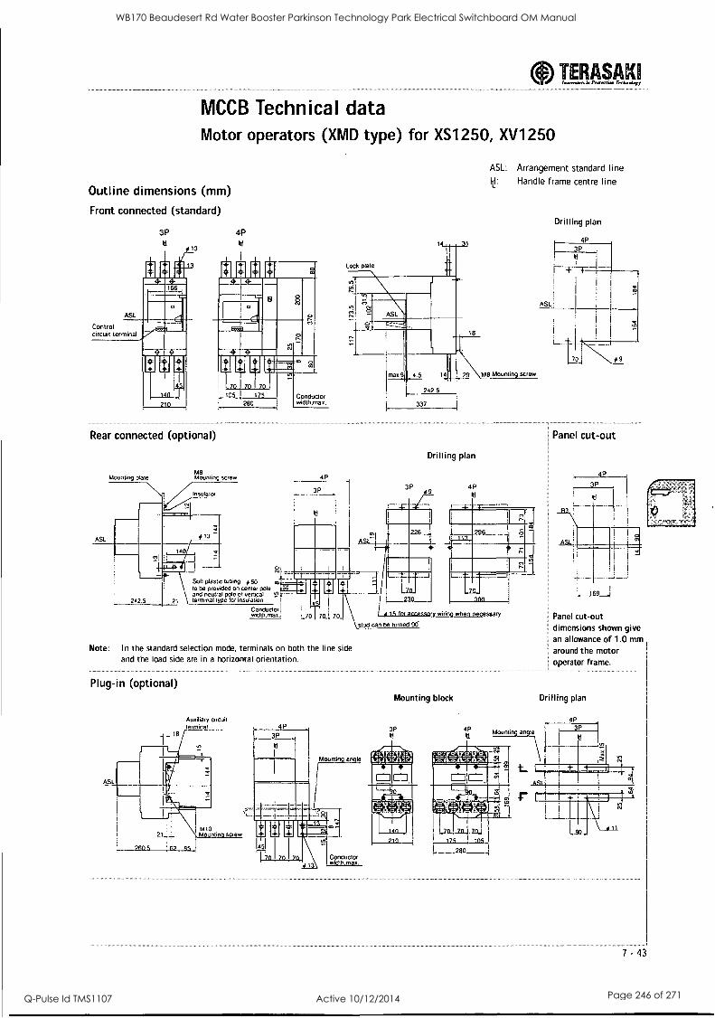
MCCB Technical data Motor operators (XMD type) for XS1250, XV1250
Outline dimensions (mm)
Front connected (standard)
ASL
Control circuit terminal
3P
13
4P tl
TERASAK hlwavoon 4 Preferr4. Trchn.lart
ASL: Arrangement standard line Handle frame centre line
Drilling plan
Rear connected (optional)
ASL
Mounting plate M8 Mounting screw
Drilling plan
4P
Panel cut-out
4
3P
Solt plasbc tubing # 50 no
to be provided on center pole and neutral pole of verbcal _
242.5 21 terminal type for insulation
Conductor width.max.
Note: In the standard selection mode, terminals on both the line side and the load side are in a horizontal orientation.
Plug-in (optional)
Auxiliary circuit terminal__ 4P
_ _ la r
Mounting block
Panel cut-out dimensions shown give an allowance of 1.0 mm around the motor operator frame.
Drilling plan
3P
Mounting angle
ASL
M10 Mountin screw
Conductor width max.
7.43
WB170 Beaudesert Rd Water Booster Parkinson Technology Park Electrical Switchboard OM Manual
Q-Pulse Id TMS1107 Active 10/12/2014 Page 246 of 271
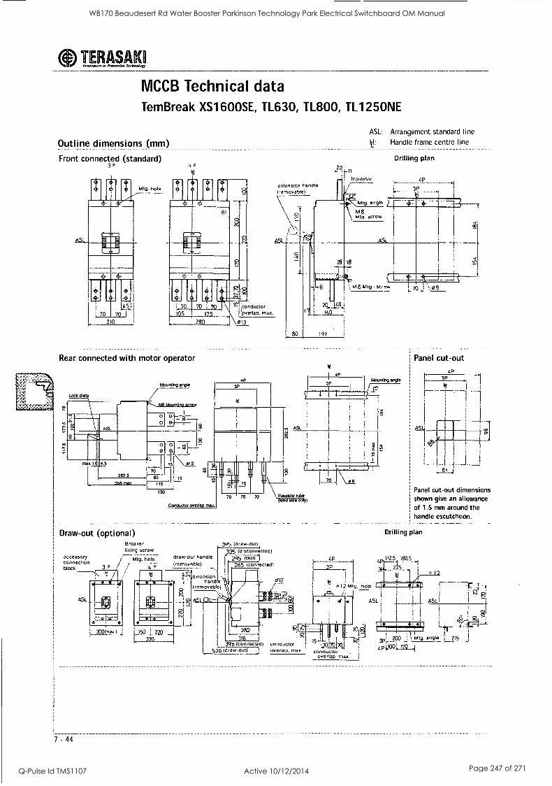
aInnovoion in I...rain Technology TERASAKI
MCCB Technical data Tem Break XS1600SE, TL630, TL800, TL1250NE
Outline dimensions (mm)
Front connected (standard) 3P
Mtg. hole
P 20. It
Insulator extension handle (removable)
ASL: Arrangement standard line
Handle frame centre line
Drilling plan
r<f- Mtg. angle
MB Mtg. screw
I_ 3P
111111111 --I :conductor l'pvertay. max.
2 \0l3
Rear connected with motor operator
191
v 4P
3P
1 - '1
,., mg Mtg screw gf -
Panel cut-out
Mounting angle
r?
Draw-out (optional)
accessory connection block
ASL
7 - 44
Breaker fixing screw
Mtg hole draw-our handle .
/ (rrtmovnble)
It extension hand e
(removable)
395 (draw-Out)
325 (dIsconnocted) 295 (testl
265 (connected1
012
L.P
hole
ASL
a
Panel cut-out dimensions shown give an allowance of 1.5 mm around the handle escutcheon.
Drilling plan
112.5 182.5 4P
3000,m.) L5031 2A) 282
315 I 396 (connected)
526 (drawout)
RT- RI
conductor !
overlap, max
j t2Q17°
conductor overlap, max.
111 re., i I i
I
L 215 200 I Mtg.
L. 1 CRINIMC211t311
GPIXO 170
WB170 Beaudesert Rd Water Booster Parkinson Technology Park Electrical Switchboard OM Manual
Q-Pulse Id TMS1107 Active 10/12/2014 Page 247 of 271
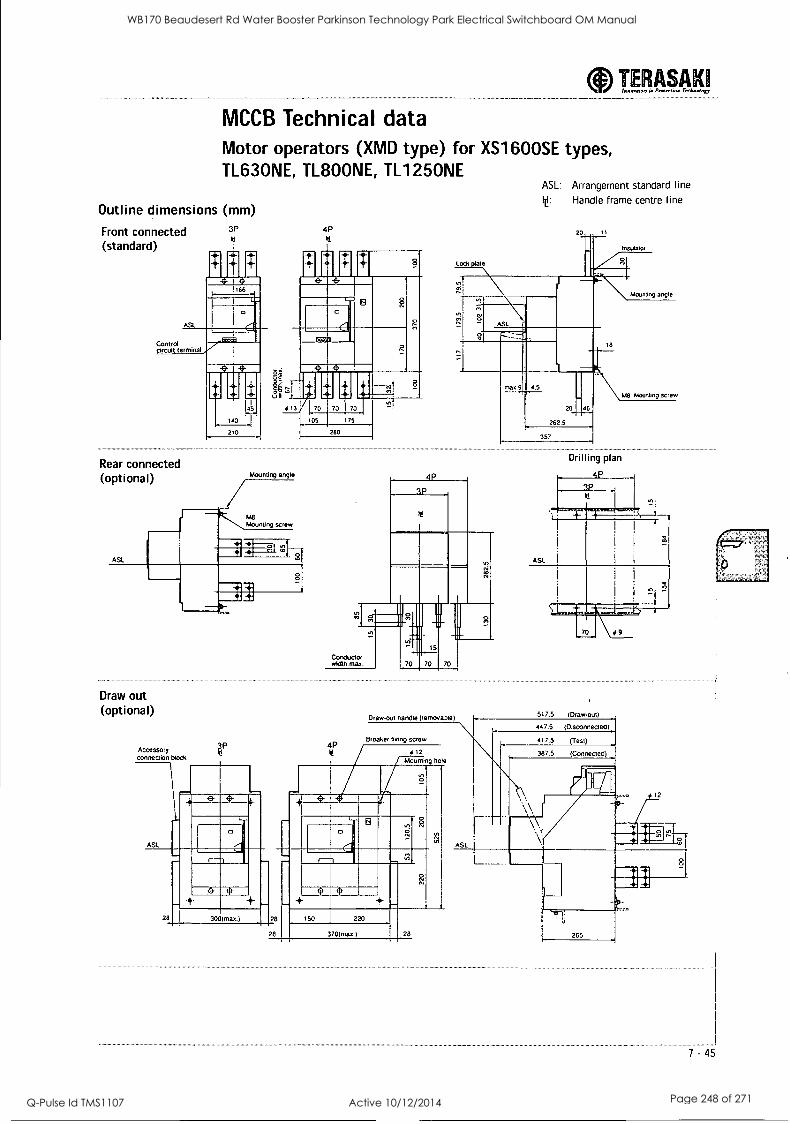
MCCB Technical data Motor operators (XMD type) for XS1600SE types, TL630NE, TL800NE, TL1250NE
Outline dimensions (mm)
Front connected (standard)
ASL
Control circuit terminal
Rear connected (optional)
ASL
3P
0.5 %I
13
Mounting angle
MO Mounting screw
4P
280
Draw out (optional)
Lock Diate
TERASAKII IN.Men u Preleview Terkstaing
ASL: Arrangement standard line
lid: Handle frame centre line
20
Insulator
ASL
II II
Conductor wictlh.max
n Ill 11
max.9 4.5
20
262.5
357
46
Mounting angle
M8 Mounting screw
Drilling plan
Accessory connection b10Ck
4P
Draw-out handle (rernova0le)
Breaker fixing screw
12
Mounting hole
28
28
150 220
370(.8.4 28
7 -45
WB170 Beaudesert Rd Water Booster Parkinson Technology Park Electrical Switchboard OM Manual
Q-Pulse Id TMS1107 Active 10/12/2014 Page 248 of 271
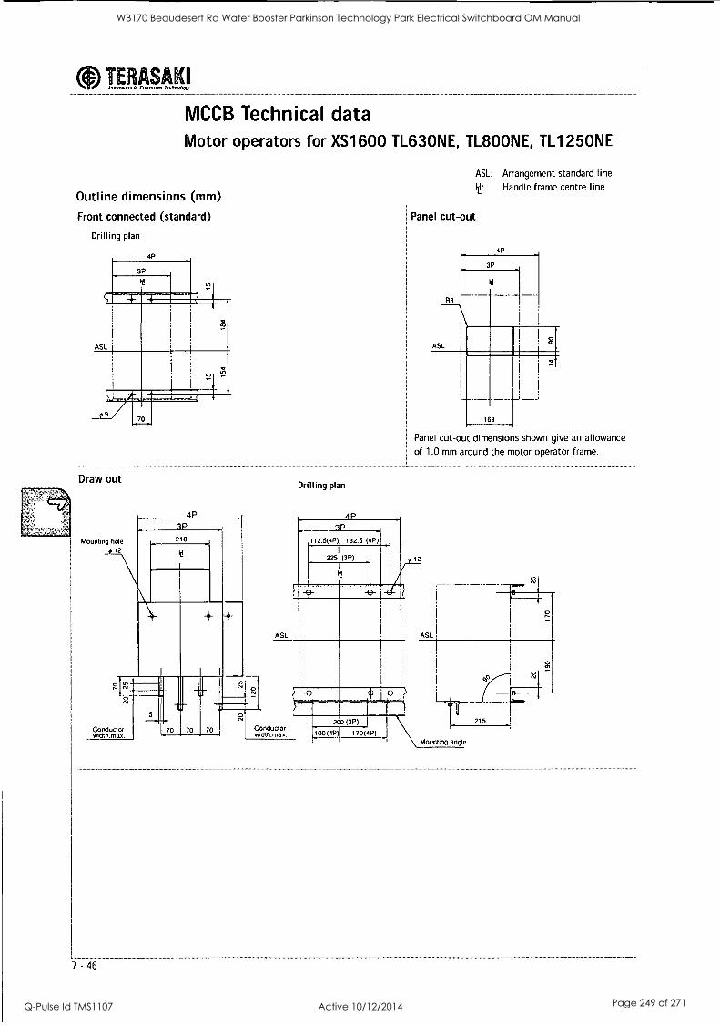
YE;' ASAK6
MCCB Technical data Motor operators for XS1600 TL630NE, TL800NE, TL1250NE
Outline dimensions (mm)
Front connected (standard)
Drilling plan
Draw out
Mounting hole #12
4P
ASL: Arrangement standard line t Handle frame centre line
Panel cut-out
Drilling plan
Panel cut-out dimensions shown give an allowance
of 1.0 mm around the motor operator frame.
12
ASL
0 0.
Conductor weltri,max. 1
70 70 Conductor width max.
200 (3P)
100(4P) 170(4P) Mounting angle
WB170 Beaudesert Rd Water Booster Parkinson Technology Park Electrical Switchboard OM Manual
Q-Pulse Id TMS1107 Active 10/12/2014 Page 249 of 271
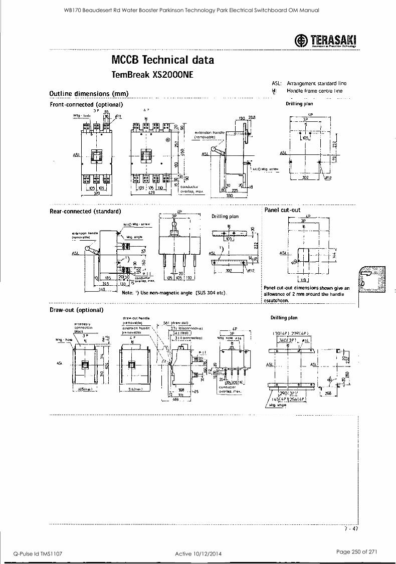
MCCB Technical data Tem Break XS2000NE
Outline dimensions (mm)
Front-connected (optional) 4 P
TERASAKI Iea,eej.,e La Preterriew Technology --_-_--_---
ASL: Arrangement standard line t Handle frame centre line
Drilling plan
Rear-connected (standard)
extenvon handle (removable) A, Mtg. angle
M 10 M19 screw
4P
,i- 20
[ I I I
conductor L105 1 105 1104
i .,.. Overilfp. rt.,
40 Note: ') Use non-magnetic angle (SUS 304 etc).
Drilling plan
14i1E:4-1 1) f 1 ASL
Panel cut-out
I I r- - -i- - -1
LL 302
Draw-out (optional) draw-out handle (removable) 56i (draw-out)
extension handle ,
s
371 (nisconnectod) (removable!
I
r 34 1 Pesti
311 (con.necteo)
\ \ P
4P 1 3P
Mtg. nom 014 I
Oil
308 3 ri
L__ .666...
L. oct106litcj
overlap, max.
Panel cut-out dimensions shown give an allowance of 2 mm around the handle escutcheon.
Drilling plan
170(4P) 779(48)
1_3/6381 014i I/
ASLI
! 4S7 _911
268
7 - 47
WB170 Beaudesert Rd Water Booster Parkinson Technology Park Electrical Switchboard OM Manual
Q-Pulse Id TMS1107 Active 10/12/2014 Page 250 of 271
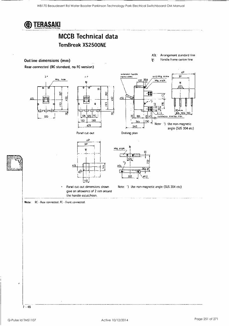
TERASAK Innovator. in Protection Ter/mato,.
MCCB Technical data Tem Break XS2500NE
Outline dimensions (mm)
Rear-connected (RC standard, no FC version)
3P P
Iti
-e ; TN)
C)
105 105 110
60 269
429
Panel cut-out
Panel cut-out dimensions shown
give an allowance of 2 mm around
the handle escutcheon.
Note: RC - Rear connected, FC - Front connected.
7 -48
ASL: Arrangement standard line
It Handle frame centre line
extension handle (removable) MW Mtg. screw
130 Mtg. angle
///
GP
3P
ASL
10
245
340
Drilling plan
20 conductor overlap,
Note: ') Use non-magnetic
angle (SUS 304 etc)
Note: 1) Use non-magnetic angle (SUS 304 etc)
WB170 Beaudesert Rd Water Booster Parkinson Technology Park Electrical Switchboard OM Manual
Q-Pulse Id TMS1107 Active 10/12/2014 Page 251 of 271
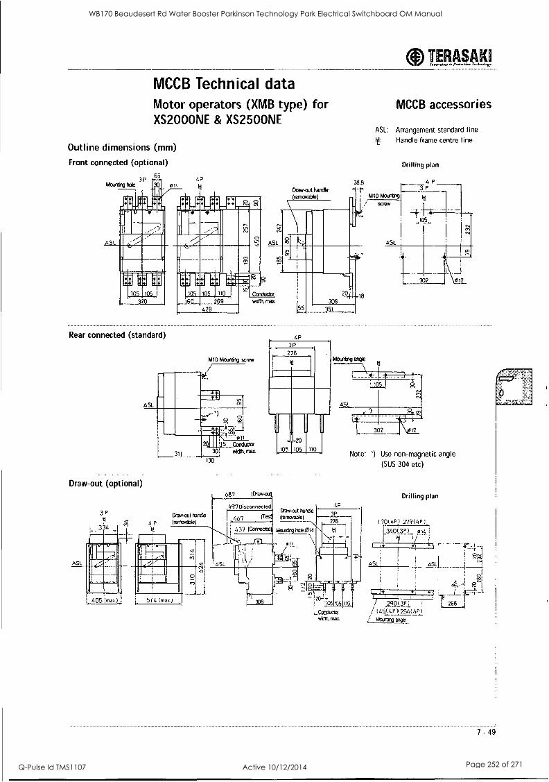
aInnovnlon in Prageerion Technology TERASAKI
MCCB Technical data Motor operators (XMB type) for XS2000NE & XS2500NE
Outline dimensions (mm)
Front connected (optional)
65 3P
Mounting
jL 111
MEM WIMP
Rear connected (standard)
Draw-out (optional)
ASL
3?
334
4? It' Draw-out handle
(removable)
28.8
MCCB accessories
ASL: Arrangement standard line
Ii!: Handle frame centre line
Drilling plan
ASL
429
width. max.
MID Mounting screw
Drawbul handle
(removable)
405 (ma()
P")
514 (mu.)
55 351
4P
3P
276
687 (Draw-o( l
4SL
497 Disconnected
46
437 (Careled
- -20
105 1105 110
Draw-out handle (removable)
Mourding hot 014
RE
elI
-Cce
to
!105
_Conduct( win,. max.
Note: Use non-magnetic angle
(SUS 304 etc)
Drilling plan 4P
ASL
14 I I I
/ I 454! 2S: 4? 2,
Mounting angt.
268 I
7 - 49
WB170 Beaudesert Rd Water Booster Parkinson Technology Park Electrical Switchboard OM Manual
Q-Pulse Id TMS1107 Active 10/12/2014 Page 252 of 271
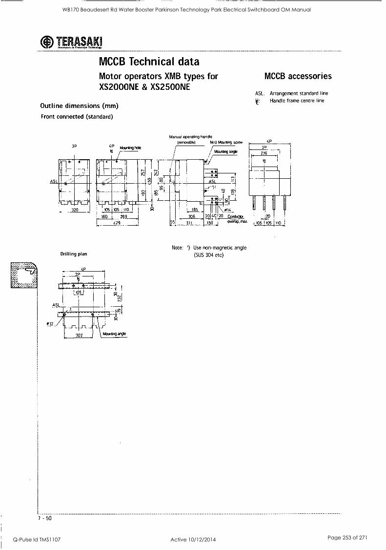
aInnovator, la Pm...lion Techwo logy TERASAKI
MCCB Technical data Motor operators XMB types for XS2000NE & XS2500NE
Outline dimensions (mm)
Front connected (standard)
3P
Manual operating handle
4P (rerncwoble) M10 Mounting screw
M
Mount^9. angle oulting hole
It1
/ ./
Drilling plan
105 105 110 .1,
160 269 1
429
7 - 50
\ 0)4
306 20140 20 Conductor '20 311 150 °verlaP. mat 05 1105 1110
MCCB accessories
ASL: Arrangement standard line
le: Handle frame centre line
4P
i
3P
276
III
Note: 1) Use non-magnetic angle
(SUS 304 etc)
WB170 Beaudesert Rd Water Booster Parkinson Technology Park Electrical Switchboard OM Manual
Q-Pulse Id TMS1107 Active 10/12/2014 Page 253 of 271
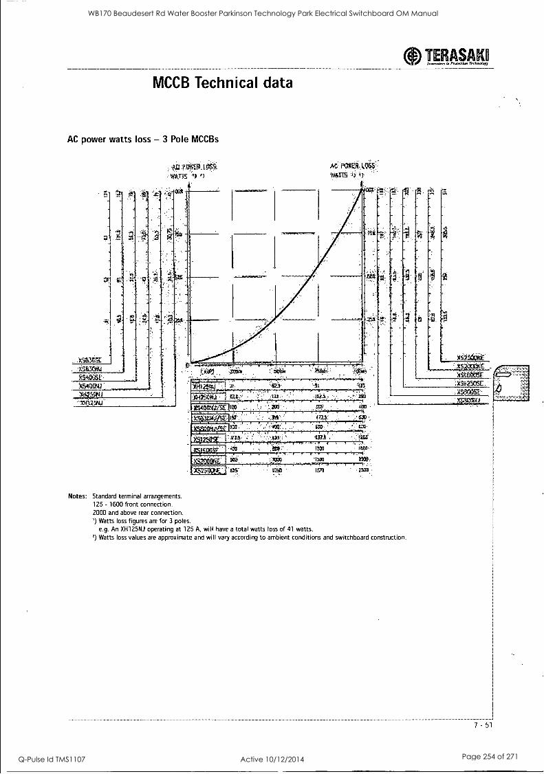
aInnomom in PIWITI4111 Technology TERASAKII
MCCB Technical data
AC power watts loss -3 Pole MCCBs
Notes: Standard terminal arrangements. 125 - 1600 front connection. 2000 and above rear connection. ') Watts loss figures are for 3 poles.
e.g. An XH125NJ operating at 125 A, will have a total watts loss of 41 watts. 2) Watts loss values are approximate and will vary according to ambient conditions and switchboard construction.
7 -51
WB170 Beaudesert Rd Water Booster Parkinson Technology Park Electrical Switchboard OM Manual
Q-Pulse Id TMS1107 Active 10/12/2014 Page 254 of 271
'44;4
' r,"). ,
. 404-44,4\
0 ' 0 ' ' . 0 0 0 -. , .-- - v%4'... +:,-li -4 ...`';-- ., . - . . ' *, .: en,,;('1 O* 7.'4
0 0 0 0 0 0 4,-
0 0 " . " 0 . 0
0 . - I .° '
;7-A4n jk.41 PoWerGad
4...,' t - , , T. - a
0 ' " S 0 S a
a, ' ^ x'. ,'
f, 414;4,
S 0 0 0
° 42 ^
0 0 .5. 0 0 0 0 " 5
0 0
- o .
. . 0
,- rel_la-tatr..,?4, wt.; ,arre,,,Otrol',4actirre.
A 11:4-_ ,,,A4Arta4.,,,,ASA1 , 7, ' _
surris..141.... (-ardor:4i .
- " "
,160.oloo 0.44,
' 44tliga .00,000
0 0 0
V-, 4
kda'' - 14,
2"'TRaYlr'r:Ca. 1
So; 44ar161;";-7P:' 7-C,";:tiltOTIAf;itiql 4440
we 11, ,
- .
.,
. 5 4 4 ,
'. - , 4,, .1- . . e
5 - - .
teriegerrieue 42° .N4: t 4/ 1£0' of. 44A 4
.44 000- "*44 li14.-4A44 40404 ".44,1A
"4*.r..4-1.10Y1,44 teigia6,4
5 , -
"i,..0" . . t, ,, ) ..
. - . " .11.. IS I. . Of. II
. 9 - . . - -
- I-
I
.42
d k
*
4 A CS' 5- - es ' .1
. - . - 5 . ° 94`1'4.' <4 ; sg
. subrnains,cable
- '
I
. 0 . 5.5 4' -"1..r\-7:41,-.. . :
- :, 4
0
Automauc-final
0 0
00 00 .0 determineS * 0 .
- "*"F's ,,4, , , o - 5
0C 0 o . 0. powerful
00 includes
harmonic
software, including
000 0
a - -'2" 4.,,e,
5 - -1',Y,,''./: ,.30°.4 ..! fr.:. ' --r ' '"'. , - ' -. . i ,-4% ..,-4
4 .,
''''' ' '24,. .- 7,4 '-'4' ''.4Y - . "-,-.4', - --t---- ,-,...., r'' . - - -
- ` 116 - . -.-i'", 7,...,'.. ,.;,-?.., -12,',,,-,,, - : ;,,,,-1,k,::: ;,t,4,,';'',':-,,,
D -
, : . ..., breakers:
Note PowerCad is a product of PowerCad Software Pty Ltd. Purchases of this software can be obtained from PowerCad www.powercad corn au
, Generator gizing '4.-0
. ° ' .
* 0 D
0 00
-
WB170 Beaudesert Rd Water Booster Parkinson Technology Park Electrical Switchboard OM Manual
Q-Pulse Id TMS1107 Active 10/12/2014 Page 255 of 271

ID 10
8. Switchboard Works Test Results
WB170 Beaudesert Rd Water Booster Parkinson Technology Park Electrical Switchboard OM Manual
Q-Pulse Id TMS1107 Active 10/12/2014 Page 256 of 271

4. 11) 411) al di
i
WB170 Beaudesert Rd Water Booster Parkinson Technology Park Electrical Switchboard OM Manual
Q-Pulse Id TMS1107 Active 10/12/2014 Page 257 of 271

J & P Richardson Industries Pty Ltd
8.0 SWITCHBOARD WORKS TEST RESULTS
File: / /Jpr _Server /docs /!sched/Masters.doc Revision 0 Date: 25 May 2001
WB170 Beaudesert Rd Water Booster Parkinson Technology Park Electrical Switchboard OM Manual
Q-Pulse Id TMS1107 Active 10/12/2014 Page 258 of 271
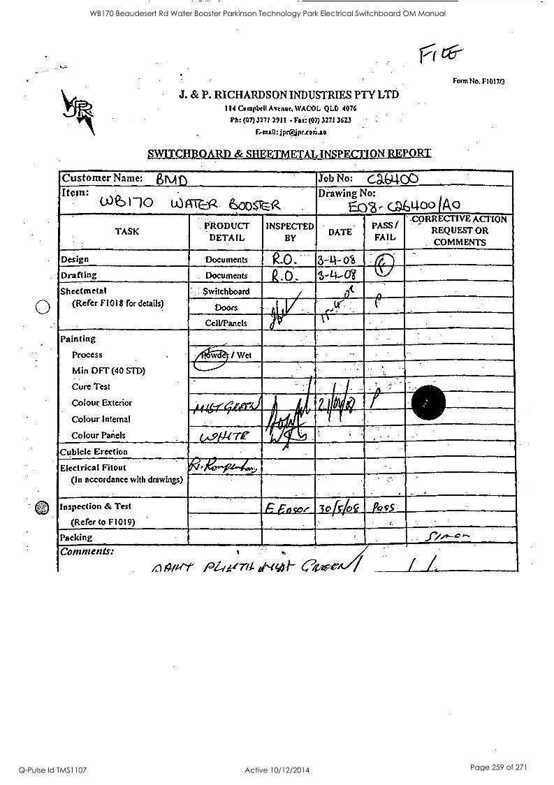
J. & P. RICHARDSON INDUSTRIES PTY LTD 111 Campbell Avenue, %VACOL QLD 4076
Pb: (07)3271 2911 - Fax: (07) 3271 3623
&MAI!: jpra p
SWITCHBOARD
Form No. F101713
Customer Name: giv 1) Job No: cac,400 Item:
03i23 no L.k) -Area 600sTER Drawing No:
E02,, co%14001A0
TASK PRODUCT
. DETAIL INSPECTED
BY DATE
PASS / FAIL
coRRECTIVE ACTION REQUEST OR COMMENTS
Design Documents R.0 .. 3-14- 0/1 ...
Drafting Documents 0 _ 5 LiCtii'
Sheetmetal (Refer F1018 for details)
Switchboard dt Doors
r
CeIVPanels Mal -
Painting
Process
Min DFT (40 STD)
Cure Test
Colour Exterior
Colour Internal
Colour Panels
w / Wet - '
IFITfilifillillil 1111311'
.
- -re . .
Cubicle Erection
Electrical Fitout (In accordance with drawings) --
Inspection & Test
(Refer to F1019) . . 'QS
r
Packing ' ...,....c. ....
Comments: I . Z11;7/1-e'r PZ-14-i77L 1,1^-10 I- Cgiire I /
WB170 Beaudesert Rd Water Booster Parkinson Technology Park Electrical Switchboard OM Manual
Q-Pulse Id TMS1107 Active 10/12/2014 Page 259 of 271
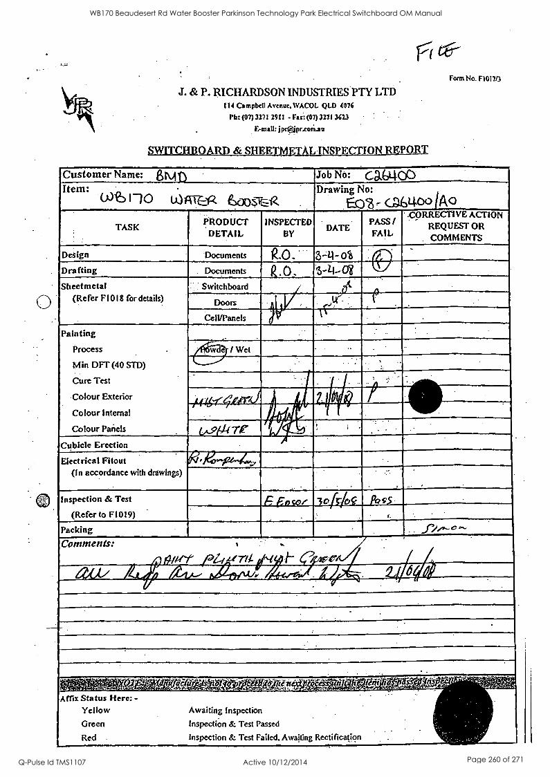
J. & P. RICHARDSON INDUSTRIES PTY LTD 114 Campbell Avenue. WACOL QLD 4076
Ph: (07)3271 2911 - Fax: (07) 3271 3623
jprapr.coM.au
Form No. F1017/3
Customer Name: aim t Job No: CD,WOC) Item:
10 LO ATE 00s-rEA -
Drawing No:
E(:), (LOO JA
TASK PRODUCT
DETAIL INSPECTED
BY DATE
PASS / FAIL
coRRECTIVE ACTION REQUEST OR COMMENTS
Design Documents R.O. . 3-4- Ot Drafting Documents k 0 3-1-1,0$
Sheetmetal (Refer FIO I 8 for details)
Switchboard dt- -
Doors . . .
CeIVPanels TC
Painting
Process .
Min DFT (40 STD)
Cure Test
Colour Exterior
Colour Internal
Colour Panels
/ Wet - - -
_
- .
.
,i I, /
Sa
lin cA-914-re 1,, 4t , . .. .
Cubicle Erection
Electrical Fitout (In accordance with drawings)
tk ,kr-pe-14.
.,
-
Inspection & Test
(Refer to F1019) 5 Foca, 3oHo Poss
1 i
,
Packing S
Comments: A # <Pt
,
1
Z-1 rti ,,,./ ;
.
1 4, . 4 1 IP I I APPLIMPVIMPA19111,-.17117
- .
. .
, .
'A.0,1-'541-ggi,VA.e.:4..' ..itei , - --g., , ' ' ..,,,! VP ., ' g..7 .= :.-1'.1 . .....- _ . ."-j .4 ik:44-?1,
Rectification .
- '..: '
.
Affix Status Here: - Yellow Awaiting Inspection
Green Inspection & Test Passed
Red Inspection & Test Failed, Awaiting
WB170 Beaudesert Rd Water Booster Parkinson Technology Park Electrical Switchboard OM Manual
Q-Pulse Id TMS1107 Active 10/12/2014 Page 260 of 271
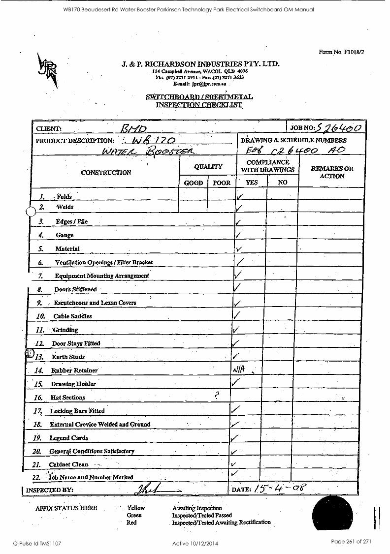
J. & P. RICIIARDSON INDUSTRIES PTY. LTD. 114 Campbell Avenue, WACOL QLD 4076
Ph: (07) 3271 2911 - Fax: (07) 3271 3623 E-mail: jpr®Jpr.com.au.
RWIT(ITBOARD / STOIETMETAT, INSPECTION CI 1FrELIST.
Form No. F1018/2
CLIENT: Etib PRODUCT DESCRIPTION: A/4! 0
(41/7-7FX.: Reepcfr,F,4_
CONSTRUCTION
400 DRAWING & SCHEDULE NUMBERS
®o
REMARKS OR ACTION
NO
2. Welds
i3,
Edges / File
Gauge
V
Equipment Mounting Arrangement
Doors Stiffened
Escutcheons and Lexan Covers
10. Cable Saddles r
11. Grinding
12. Door Stays Fitted
13. Earth Studs
14. Rubber Retainer
15. Drawing Holder
16. Hat Sections
17. Locking Bars Fitted
18. External Crevice Welded and Ground
19. Legend Cards
20. Gener4l Conditions Satisfactory
21. Cabinet Clean
22. db Name and ,Number Marked
I INSPECTED Br_ cfr/61-.. AFFIX STATUS HERE Yellow Awaiting Iiispeation
Green Inspected/Tested Passed Red InspectecVrested Awaiting Rectification.
WB170 Beaudesert Rd Water Booster Parkinson Technology Park Electrical Switchboard OM Manual
Q-Pulse Id TMS1107 Active 10/12/2014 Page 261 of 271
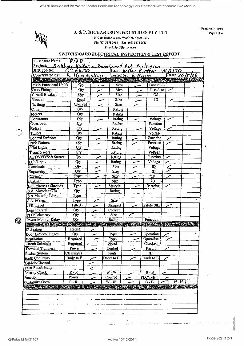
J. & P. RICHARDSON INDUSTRIES PTY LTD 114 Campbell Avenue, WACOL QLD 4076
Ph: (07) 3271 2911 - Fax: (07) 3271 3623
E-mail: jpr®jpr.com.au
SWITCHBOARD ELECTRICAL INSPECTION & TEST REPORT
Customer Name: Pro ect: JPR Job No:
Constructed b :
Form No. F1019/8
Page 1 of 6
Item: Date: y0
Main Functional Unit/s
Fuse Fittings Circuit Breakers
Neutral Earthing C.Ts Meters Contactors Overloads Rela s
Qty
Q!
QV Reqd
Checked
Qty Qty
Size Size Size Size.
Size Rating Ratin
Rating Ratin
Volta :e Function
Timers Control Switches
Push Buttons Pilot Lights Transformers ATT/VFD/Soft Starter DC Supply Terminals
Volta :e Vol
Function
Engraving
Busbars Escutcheons / Shrouds
SA. Metering CTs
SA Metering Links S.A. Meters 1PR Label Le end Card PLC/re.lemettY Power Monitor Rela fr-fiAtitt IP Sealing Door Latches/Hinges Ventilation Circuit Schedule Terminal Ti htness
Busbar S stem
Earth Continui
Qty QV Qty Qty. Qty
Type Type Type
Qty Type Type Fitted -
Rating Rating Rating Size Size Size Siie
Material
Correct Size
Ra
Rating
Qy Required Required Power
Bod .to E Doors to E
Operation Operation Checked Result
ID
Panels to E
Cubicle Cleaned
Paint Finish Intact Polarity Check
Function Continuity Check
R -R Power. R -R
W - W Control W - W
B - B
PLC/Telem B - B
WB170 Beaudesert Rd Water Booster Parkinson Technology Park Electrical Switchboard OM Manual
Q-Pulse Id TMS1107 Active 10/12/2014 Page 262 of 271
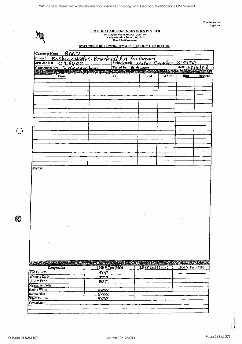
J. & P. RICHARDSON INDUSTRIES PTY LTD 114 Campbell Avenue. WACOL QLD 4076
Pb: (07) 3271 2911 - Fax: (07) 3271 3623
E -mail: Jprapr.comau
SWITCHBOARD CONTINUITY & INSULATION TEST REPORT
Form No. FI019/9 Page 6 of 6
Customer Name:
Project: JPR Job No:
Constructed b: 4 . 4, 4
C*% A77: From
p,,4 Pi.c irwx-or) Switchboard: I -
Date: 2.
Ft' ti t T '',..7Z71777.
Red White Blue Neutral
Sketch:
Designation Red to Earth
White to Earth
Blue to Earth
Neutral to Earth Red to Whitc Red to Blue White to Blue
Comments:
'7r7q14. 4P-XV;g05.-i . .
1000 V Test
co:90
TOP
TOO
2.5 kV Test lmin 1000 V Test (Mn)
WB170 Beaudesert Rd Water Booster Parkinson Technology Park Electrical Switchboard OM Manual
Q-Pulse Id TMS1107 Active 10/12/2014 Page 263 of 271
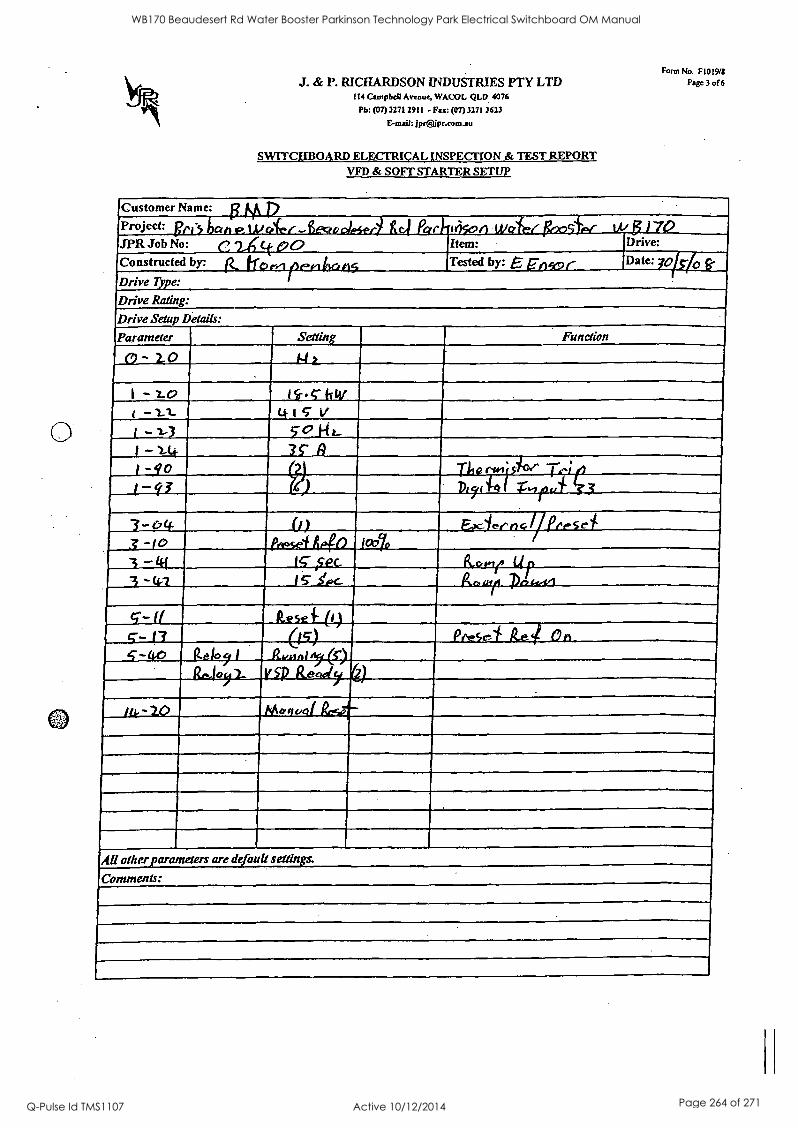
J. & P. RICHARDSON INDUSTRIES PTY LTD 114 Campbell Avenue, WACOL QLD 4076
Ph: (07) 327l 2911 - Fax: (07)3271 3623
E-mail: jprOpr.com.au
SWITCHBOARD ELECTRICAL INSPECTION & TEST REPORT VFD & SOFT STARTER SETUP
Form No. F1019/8 Page 3 of 6
Customer Name:
Project:
Drive Type:
Drive Rating:
Drive Setup Details:
vt LI/ der JPR Job No: C:2ACt pQ Constructed by: 6, fics,,,,,Iree,
a1 a. . Item:
, I -
Tested by: E _rim 0 r 0
Drive:
Date: 7015/0
Parameter
- zo
-L0 4
-Z1- 1 -1-3 -
/ -go
e7
3 a
-41
-ft 5 -13
Setting Function
141
4tc V 5-0 r
rwisioe ;
Iff fer r -0)
le&sel 446 too 0
lc ISEC.
1S- Ypc_
Facies' y)* I I PPeSei
11.0 is u r Any
kese T (I)
V SP Gal Peese-
Monvej
All otherparanteters are default settings.
Comments:
WB170 Beaudesert Rd Water Booster Parkinson Technology Park Electrical Switchboard OM Manual
Q-Pulse Id TMS1107 Active 10/12/2014 Page 264 of 271
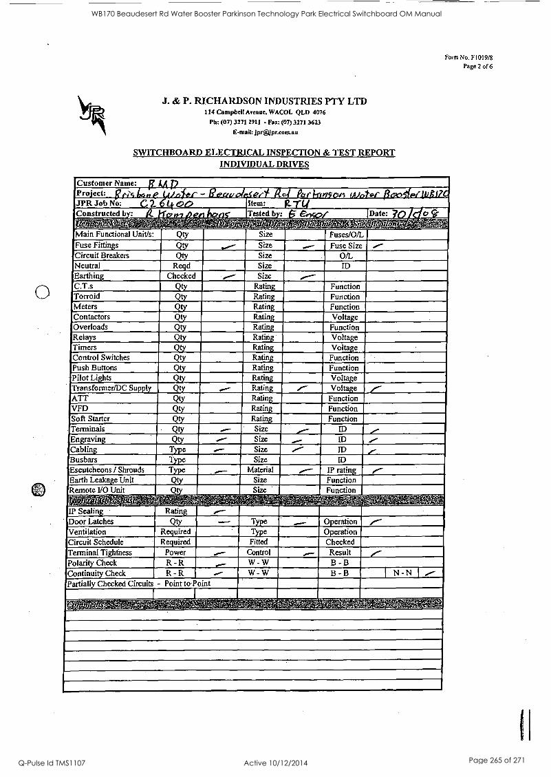
Pro'ect: t tio
' II I
1
I I
e
1 1'
fiffflieMPIAIM Item:
4,14. lifTM I I N rieektozZ,-MM-.wc 0,41,182 :YAW iYg:fkgrP7;17i--.__f-'-43,7',..,.S'i
I I if A a Tested b : Date:
Qty
MEI"MINIMI =32. R d
Checked ""'-'
Size
Size Size Size Size
Fuses/O/L Fuse Size
OIL ID
I
i4
11
.1
I I I
I I [t(1,--Viffer00.077-
S MOM MB= MIME = IM =I MO= MORI II1== IOW= =UM ""
Ratin Ratin Ratin Ratin Ratin Ratin Ratin Ratin Ratin Ratin Ratin
Function Function Function Volta e Function Volta e
Volta :e Function Function Vol e
Vol e ME31. MOM
I EMIE Ratin Ratin Ratin
Function Function Function
MWMI Size ID M311 "" Size ID
11151M Size ID
MEM Size ID
WPM ..01- Material IP ratin Size Function Size Function
.r7.7;7
c I .4
Power R -R R -R
Fitted Control
W - W
W - W
..0 Checked Result B - B
B -B
P. ..- .` 4 '4
N -N
WB170 Beaudesert Rd Water Booster Parkinson Technology Park Electrical Switchboard OM Manual
Q-Pulse Id TMS1107 Active 10/12/2014 Page 265 of 271
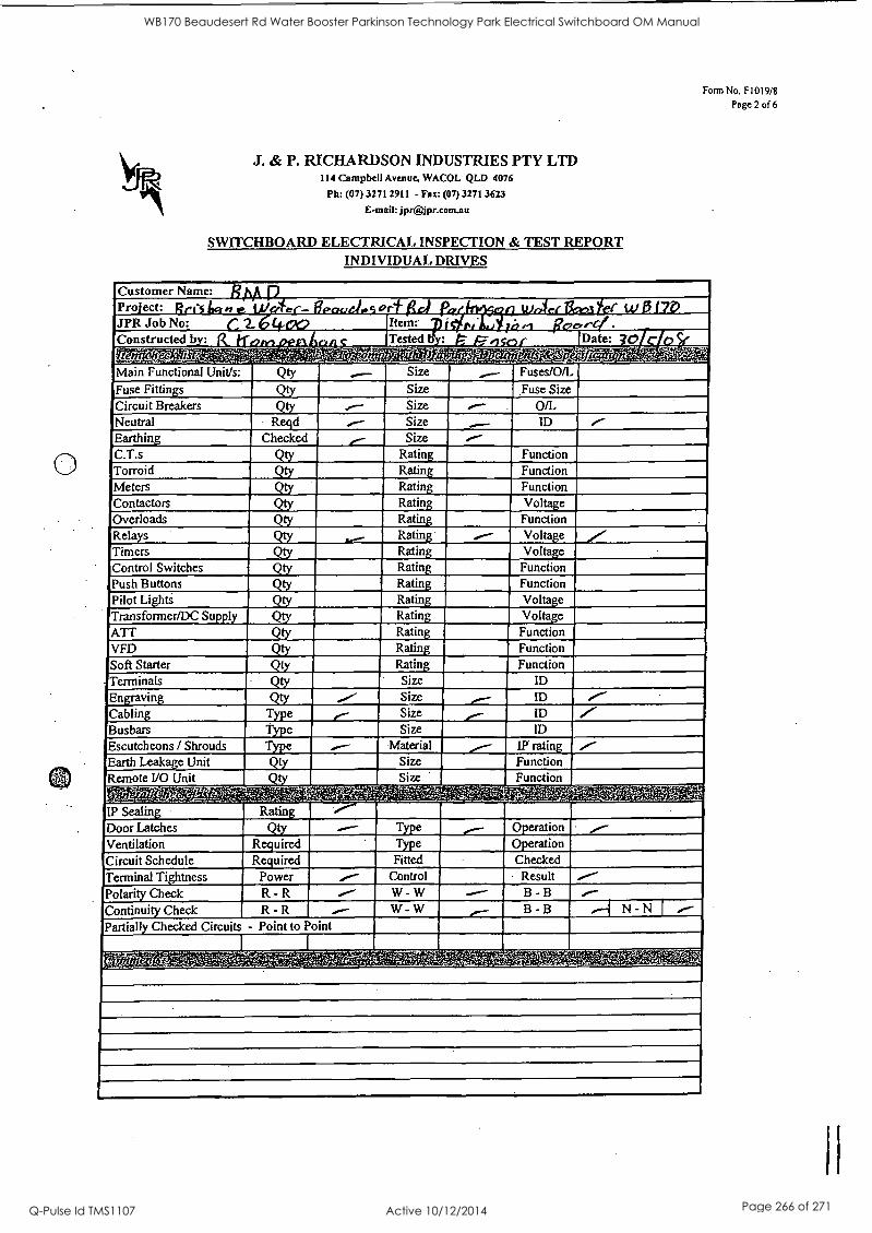
-a 4
I IP I I
; I
I I I'
I I 400 - ' s El.1.. 1
CIEMFM,Mc rr.
if .0
21IA ae` "" ;912 e
Tested bqjl7,, r
a
I I I
O.'
II
Qty Im31. mum R d
Checked
MIME
Size
Size Size Size Size
Ratin Ratin Ratin Ratin Ratin Ratin Ratin Ratin Ratin Ratin Ratin Ratin Ratin Ratin Size Size Size Size
Material
Fuses/O/L Fuse Size
0/L ID
Function Function Function Vol c Function
Function Function
Function Function Function
ID ID ID ID
I
MAIM P51 01-011g5V
Date: ?O
Power R - R R - R
Control W - W W - W
Result B - B
B - B N - N
WB170 Beaudesert Rd Water Booster Parkinson Technology Park Electrical Switchboard OM Manual
Q-Pulse Id TMS1107 Active 10/12/2014 Page 266 of 271
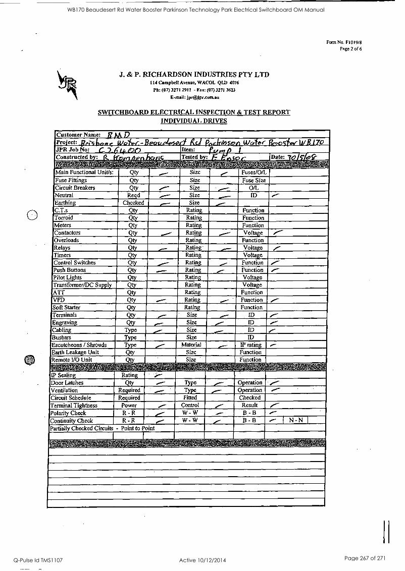
; 5 '
. I 1 5
I I
I I I' I
Pro'ect: ; I
.WPFSITMERPPP.0 4.1M174 0 . ..1117XTMEWAIIM, (I MEW /
i I s . I 4.../* 1,1 lif MEM Tested b :
di-4i,eii-1' M A - - 'W_ ' - ' '-',-k L' ','.04',Np'51pi-l4, ), - I V.,._1 t Z IpiTI? j Y Al i t ro- '' g'r-e"-: - i , -2,'-Pk-
u.
I I I
:
I
''I
Qty MM. /NMI
R d Checked
41.1
= Power R - R R - R
MIME
Size
Size Size Size Size
Ratin Ratin Ratin Ratin Ratin Ratin Ratin Ratin Ratin Ratin Ratin Ratin Ratin Ratin Size Size Size Size
Material Size Size
IIPME
Fuses/O/L Fuse Size
0/L ID
Function Function Function Vole
Function
Function Function Vol e Volt. e
Function Function Function
ID ID ID ID
Function Function
Fitted Control W - W
W - W
Checked Result B - B
B - B N - N
WB170 Beaudesert Rd Water Booster Parkinson Technology Park Electrical Switchboard OM Manual
Q-Pulse Id TMS1107 Active 10/12/2014 Page 267 of 271
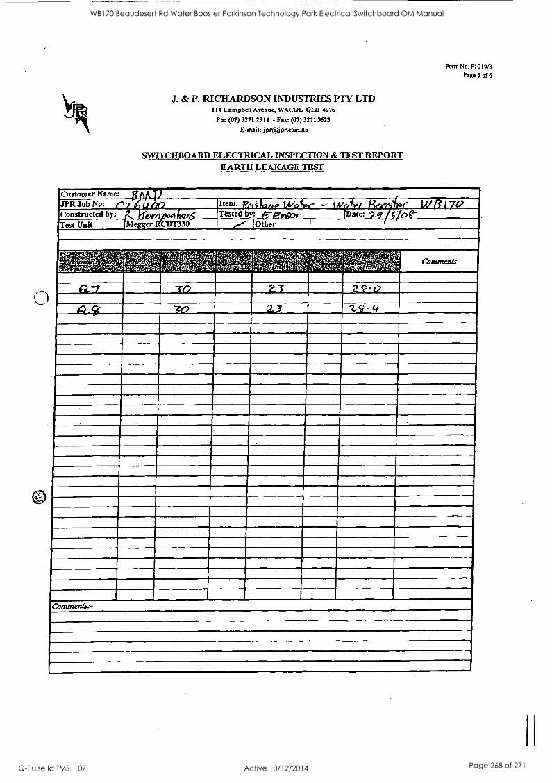
0
J. & P. RICHARDSON INDUSTRIES PTY LTD 114 Campbell Avenue, WACOL 4:211) 4076
Ph: (07) 3271 2911 - Fax: (07) 3271 3623
E-mail: jpr(a4pr.com.au
SWITCHBOARD ELECTRICAL INSPECTION & TEST REPORT EARTH LEAKAGE TEST
Form No. F1019/8
Page 5 of 6
Customer Name: ; I L p JPR Job No: C7_ 4 Co Item: pp IN lie/- W ji 17° 'Constructed by: It 116,0,707:41 016 Tested by: 6-E-iticor (Date: 2.gy riot Test Unit iblegger R1CDT330 (Other
MMC
WB170 Beaudesert Rd Water Booster Parkinson Technology Park Electrical Switchboard OM Manual
Q-Pulse Id TMS1107 Active 10/12/2014 Page 268 of 271
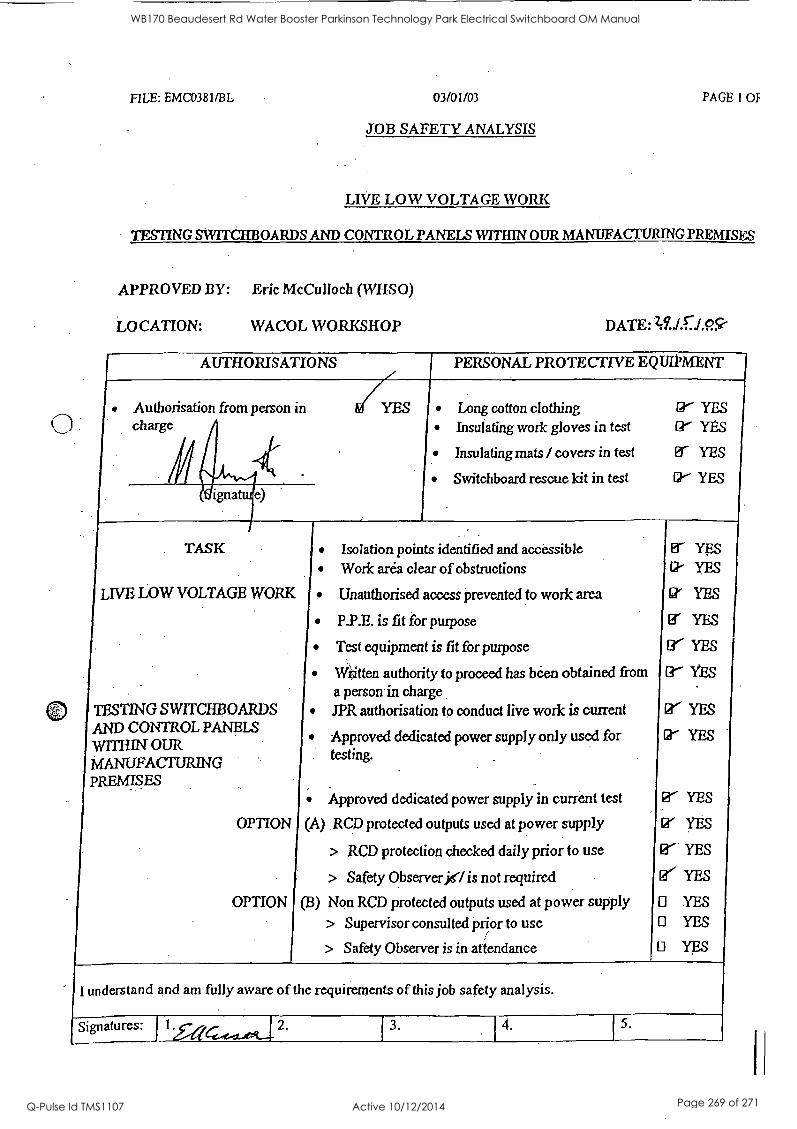
FILE: EMC0381/13L 03/01/03 PAGE 1 OF
JOB SAFETY ANALYSIS
LIVE LOW VOLTAGE WORK
TESTING SWITCHBOARDS AND CONTROL PANELS WITHIN OUR MANUFACTURING PREMISES
APPROVED BY: Eric McCulloch (WHSO)
LOCATION: WACOL WORKSHOP DATE: 28../.0.C:Sr
AUTHORISATIONS
Authorisation from person in charge
PERSONAL PROTECTIVE EQUIPMENT
YES
Switchboard rescue kit in test I' Insulating mats / covers in test
Insulating work gloves in test Long cotton clothing
I YES
Er YES
rrct" yYEE.
TASK Isolation points identified and accessible er YES
Work area clear of obstructions Ck YES
LIVE LOW VOLTAGE WORK Unauthorised access prevented to work area 0/ YES
TESTING SWITCHBOARDS AND CONTROL PANELS WITHIN OUR MANUFACTURING PREMISES
P.P.E. is fit for purpose
Test equipment is fit for purpose
Er YES
(r. YES
Written authority to proceed has been obtained from tr- YES
a person in charge JPR authorisation to conduct live work is current PC YES
Approved dedicated power supply only used for g' YES
testing.
Approved dedicated power supply in current test 0' YES
OPTION (A) .RCD protected outputs used at power supply 0' YES
> RCD protection checked daily prior to use 0' YES
> Safety Observer jel is not required e YES
OPTION (B) Non RCD protected outputs used at power supply YES
> Supervisor consulted prior to use YES
> Safety Observer is in attendance YES
I understand and am fully aware of the requirements of this job safety analysis.
Signatures:
WB170 Beaudesert Rd Water Booster Parkinson Technology Park Electrical Switchboard OM Manual
Q-Pulse Id TMS1107 Active 10/12/2014 Page 269 of 271
WB170 Beaudesert Rd Water Booster Parkinson Technology Park Electrical Switchboard OM Manual
Q-Pulse Id TMS1107 Active 10/12/2014 Page 270 of 271
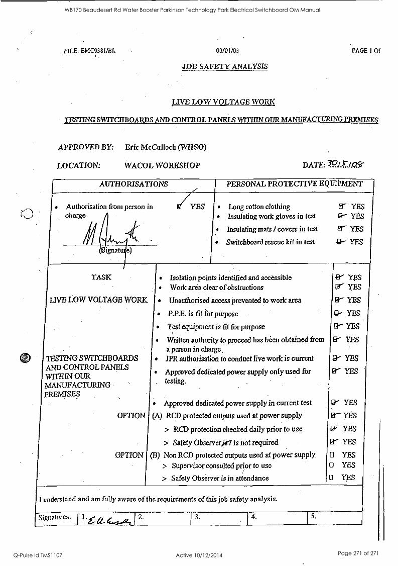
FILE: EMC0381/BL 03/01/03 PAGE 1 OF
JOB SAFETY ANALYSIS
LIVE LOW VOLTAGE WORK
TESTING SWITCHBOARDS AND CONTROL PANELS WITHIN OUR MANUFACTURING PREMISES
APPROVED BY: Eric McCulloch (WHSO)
LOCATION: WACOL WORKSHOP DATE: wi.riosi
AUTHORISATIONS
Authorisation from person in YES charge
ignat
TASK
LIVE LOW VOLTAGE WORK
(1) TESTING SWITCHBOARDS AND CONTROL PANELS WITHIN OUR MANUFACTURING PREMISES
OPTION
OPTION
PERSONAL PROTECTIVE EQUIPMENT
Long cotton clothing er YES
Insulating work gloves in test (g- YES
Insulating mats / covers in test td' YES
Switchboard rescue kit in test YES
Isolation points identified and accessible Work area clear of obstructions
Unauthorised access prevented to work area
P.P.E. is fit for purpose
Test equipment is fit for purpose
Witten authority to proceed has been obtained from a person in charge JPR authorisation to conduct live work is current
Approved dedicated power supply only used for testing.
Approved dedicated power supply in current test
(A) RCD protected outputs used at power supply
> RCD protection checked daily prior to use
> Safety Observer,ie is not required
(B) Non RCD protected outputs used at power supply > Supervisor consulted prior to use
> Safety Observer is in attendance
fir YES lit" YES
Er YES
a- YES
[I-- YES
EY YES
g- YES
Er YES
cr YES
0- YES
0- YES
0' YES
O YES O YES
0 YES
I understand and am fully aware of the requirements of this job safety analysis.
Signatures:
WB170 Beaudesert Rd Water Booster Parkinson Technology Park Electrical Switchboard OM Manual
Q-Pulse Id TMS1107 Active 10/12/2014 Page 271 of 271