Embed Size (px)
Citation preview

© 2013 AIRCOM International Ltd
AIRCOM LTE Webinar Series:
What affects LTE Cell throughput

2 © 2013 AIRCOM International Ltd
About the Presenters
Graham Whyley – Lead Technical Trainer
AIRCOM Technical Master Trainer since 2005
Currently responsible for all LTE training course creation and delivery
Over 20 years of training experience at companies including British Telecom and Fujitsu
Contact us at [email protected]
Adam Moore – Learning & Development Manager
With AIRCOM since 2006
Member of CIPD

3 © 2013 AIRCOM International Ltd
About AIRCOM
Founded in 1995
14 offices worldwide
Over 150 LTE customers
Acquired Symena in 2012
Products deployed in 159 countries
Comprehensive Tool and technology training portfolio
Network
Advise
Audit
Plan
Optimise
Manage
AIRCOM is the leading provider of mobile network planning, optimisation and management software and consultancy services.
TEOCO offer very complimentary assurance an optimisation solutions as well as an excellent analytics portfolio.
Significantly stronger combined offering for customers
Find out more at www.aircominternational.com

4 © 2013 AIRCOM International Ltd
LTE PORTFOLIO
ACCREDITATION
COURSESA202 AIRCOM Accredited
LTE Planning and
Optimisation Engineer
(5 days inc exam)

5 © 2013 AIRCOM International Ltd
Agenda-What affects LTE Cell throughput
Maximizing the data rate and spectral efficiency are the main targets in LTE cellular systems.
Transport Block Size
Codewords
LTE UE categories
What effects Cell throughput

6 © 2013 AIRCOM International Ltd
What affects Cell throughput
L1/L2
IP
UDP
GTP-U
eNode B
L1
MAC
RLC
PDCP
Relay
L1
MAC
RLC
PDCP
UE
IP
Application
TCP/UDP
DATA
DATA
DATA
DATA
DATA
DATA

7 © 2013 AIRCOM International Ltd
User Plane
Application Application Application Rate
TCP overhead UDP
Real Time Non Real Time
TCP overhead UDP
Real Time Non Real Time
IP overhead IP overhead
RLC layer will concatenate or segment the data coming from PDCP layer into correct block size
RLC
PDCP
overhead RLC
PDCP
overhead
8 © 2013 AIRCOM International Ltd
WHAT IS A TRANSPORT BLOCK
RLC HEADER
RLC HEADER
RLC
MAC MAC HEADER
TRANSPORT BLOCK
RLC
MAC
IP TCP /UDP

9 © 2013 AIRCOM International Ltd
User Plane
Application Application Application Rate
TCP overhead UDP
Real Time Non Real Time
TCP overhead UDP
Real Time Non Real Time
IP overhead IP overhead
RLC
PDCP
overhead RLC
PDCP
overhead
L1
MAC
UE
overhead
overhead L1
MAC
UE
overhead
overhead
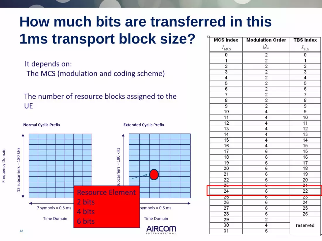
MAC layer selects the modulation and coding scheme configures the physical layer
QPSK 2 bits
16QAM 4 bits
64QAM 6bits
Different coding Rates

10 © 2013 AIRCOM International Ltd
LTE UE categories Normal Cyclic Prefix
7 symbols = 0.5 ms
Freq
uen
cy D
om
ain
12
su
bca
rrie
rs =
18
0 k
Hz
Time Domain
Resource Element 2 bits 4 bits 6 bits

11 © 2013 AIRCOM International Ltd
Now how many bits are
transferred in this 1ms
transport block size?
Modulation and coding scheme (MCS): The MCS index (0…31) is used by the base station to signal to the terminal the modulation and coding scheme to use for receiving or transmitting a certain transport block. Each MCS index stands for a certain modulation order and transport block size index

12 © 2013 AIRCOM International Ltd
RRC Connection Reconfiguration
Message
Since the size of transport block is not fixed
MCS Index
|UE ID/RNTI Type |C-RNTI | |Subframe Number |2 | |UE ID/RNTI Value |'8627'H || |Transport Block Indicator |single TB info | |Modulation Order DL 1 |QAM64 | |New Data Indicator DL 1 |new data | |Redundancy Version DL 1 |0 | |Reserved |0 | |Modulation Scheme Index DL |24 |
RRC Connection Reconfiguration Message Modulation Scheme Index DL 24
13 © 2013 AIRCOM International Ltd
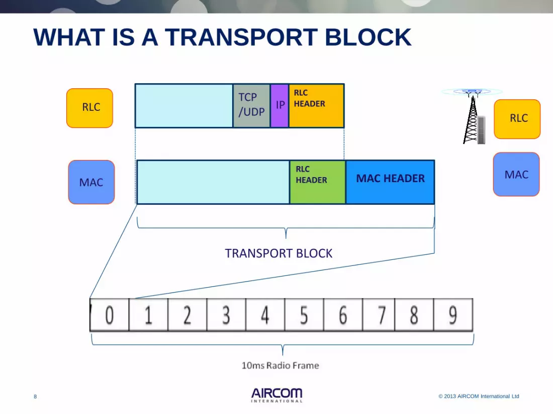
How much bits are transferred in this
1ms transport block size?
It depends on: The MCS (modulation and coding scheme)
The number of resource blocks assigned to the UE
Normal Cyclic Prefix
7 symbols = 0.5 ms
Freq
uen
cy D
om
ain
12
su
bca
rrie
rs =
18
0 k
Hz
Time Domain
Extended Cyclic Prefix
6 symbols = 0.5 ms
12
su
bca
rrie
rs =
18
0 k
Hz
Time Domain
Resource Element 2 bits 4 bits 6 bits

14 © 2013 AIRCOM International Ltd
Transport Block Size Tables Look-up table is referenced by the TBS Index and the number of
allocated Resource Blocks
RRC Connection Reconfiguration Message Modulation Scheme Index DL 24

15 © 2013 AIRCOM International Ltd
POLL eNB assigns MCS index 12 and 2 resource blocks (RBs). What is the transport block size? 1. 56 2. 144 3. 616 4. 376 5. 440

16 © 2013 AIRCOM International Ltd
POLL eNB assigns MCS index 12 and 2 resource blocks (RBs). What is the transport block size? 1. 56 2. 144 3. 616 4. 376 5. 440

17 © 2013 AIRCOM International Ltd
Table 7.1.7.2.1-1 Look-up table is referenced by the TBS Index and the number of
allocated Resource Blocks

18 © 2013 AIRCOM International Ltd
What affects LTE Cell throughput

19 © 2013 AIRCOM International Ltd
Coding Rate
20 © 2013 AIRCOM International Ltd
Coding rate
L1
MAC overhead
overhead L1
MAC overhead
overhead
MAC layer selects the modulation and coding scheme configures the physical layer
Code rate: The code rate is defined as the ratio between the transport block size and the total number of physical layer bits per subframe that are available for transmission of that transport block. The code rate is an indication for the redundancy that has been added due to the channel coding process

21 © 2013 AIRCOM International Ltd
CQI
Modulation Efficiency Actual coding rate
Required SINR
1 QPSK 0.1523 0.07618 -4.46
2 QPSK 0.2344 0.11719 -3.75
3 QPSK 0.3770 0.18848 -2.55
4 QPSK 0.6016 308/1024 -1.15
5 QPSK 0.8770 449/1024 1.75
6 QPSK 1.1758 602/1024 3.65
7 16QAM 1.4766 378/1024 5.2
8 16QAM 1.9141 490/1024 6.1
9 16QAM 2.4063 616/1024 7.55
10 64QAM 2.7305 466/1024 10.85
11 64QAM 3.3223 567/1024 11.55
12 64QAM 3.9023 666/1024 12.75
13 64QAM 4.5234 772/1024 14.55
14 64QAM 5.1152 873/1024 18.15
15 64QAM 5.5547 948/1024 19.25
The coding rate indicates
how many real data bits
are present out of 1024
while the efficiency
provides the number of
information bits per
modulation symbol.
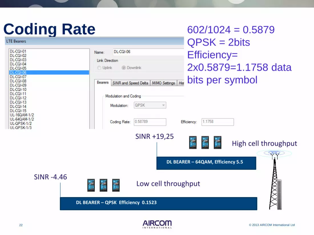
602/1024 = 0.5879
QPSK = 2bits
Efficiency=
2x0.5879=1.1758 data
bits per symbol
Coding Rate
22 © 2013 AIRCOM International Ltd
Coding Rate
602/1024 = 0.5879
QPSK = 2bits
Efficiency=
2x0.5879=1.1758 data
bits per symbol
DL BEARER – 64QAM, Efficiency 5.5
SINR +19,25 High cell throughput
DL BEARER – QPSK Efficiency 0.1523
SINR -4.46 Low cell throughput

23 © 2013 AIRCOM International Ltd
Coding Rate

24 © 2013 AIRCOM International Ltd
CQI
Modulation Efficiency Actual
coding rate Required
SINR
1 QPSK 0.1523 0.07618 -4.46
2 QPSK 0.2344 0.11719 -3.75
3 QPSK 0.3770 0.18848 -2.55
4 QPSK 0.6016 308/1024 -1.15
5 QPSK 0.8770 449/1024 1.75
6 QPSK 1.1758 602/1024 3.65
7 16QAM 1.4766 378/1024 5.2
8 16QAM 1.9141 490/1024 6.1
9 16QAM 2.4063 616/1024 7.55
10 64QAM 2.7305 466/1024 10.85
11 64QAM 3.3223 567/1024 11.55
12 64QAM 3.9023 666/1024 12.75
13 64QAM 4.5234 772/1024 14.55
14 64QAM 5.1152 873/1024 18.15
15 64QAM 5.5547 948/1024 19.25
Coding Rate
CQI = 15
Terminal Density
High throughput
25 © 2013 AIRCOM International Ltd
Code word
L1
MAC overhead
overhead
TRANSPORT BLOCK
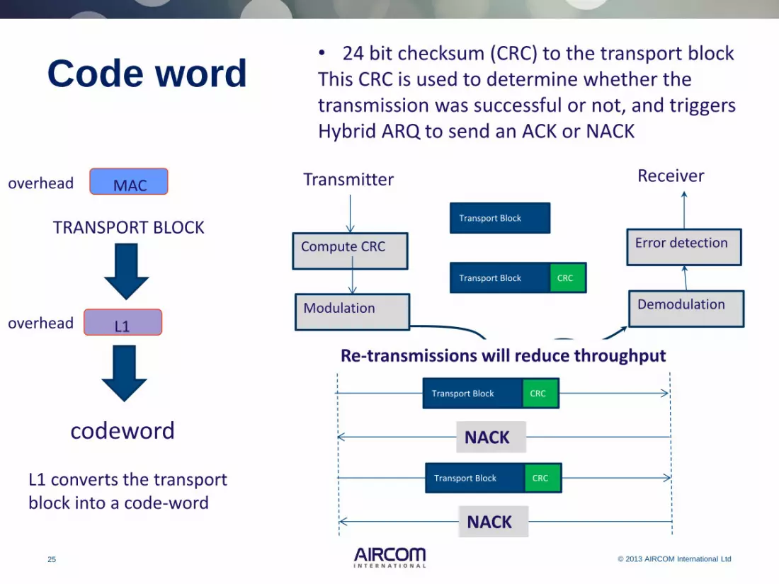
• 24 bit checksum (CRC) to the transport block This CRC is used to determine whether the transmission was successful or not, and triggers Hybrid ARQ to send an ACK or NACK
codeword
Transmitter
Transport Block
Transport Block CRC
Compute CRC
Modulation
Receiver
Error detection
Demodulation
Transport Block CRC
NACK
Transport Block CRC
NACK
L1 converts the transport block into a code-word
Re-transmissions will reduce throughput

26 © 2013 AIRCOM International Ltd
Adaptive re-transmission If the base station receives the data with errors Two ways for it to respond
1. The base station can trigger a non adaptive re-transmission by sending the mobile a negative acknowledgement on the PHICH. The mobile then re-transmits the data with the same parameters that it used first time around.
2. Alternatively, the base station can trigger an adaptive re-transmission by explicitly sending the mobile another scheduling grant. It can do this to change the parameters that the mobile uses for the re-transmission, such as the resource block allocation or the modulation scheme.
Scheduling grant maximum number of re-transmissions without receiving a positive response
Change parameters like uplink modulation scheme
QPSK for noisy channels

27 © 2013 AIRCOM International Ltd
Code word If the transport block is too small, it is padded up to 40 bits If the Transport Block is too big, it is divided into smaller pieces, each of which gets an additional 24 bit CRC A codeword, then, is essentially a transport block with error protection. Note that a UE may be configured to receive one or two transport blocks (and hence one or two codewords) in a single transmission interval Maximum of 2 codewords used to limit signalling requirement (CQI reporting, HARQ acknowledgements, resource allocations)
L1
MAC
TRANSPORT BLOCK
codeword
L1
MAC
TRANSPORT BLOCK
codeword

28 © 2013 AIRCOM International Ltd
Codeword
• Maximum of 2 codewords used to limit signalling requirement (CQI reporting, HARQ acknowledgements, resource allocations)
• Transmit diversity provides the fallback when only a codeword is transferred
The number of layers is always less than or equal to the number of antenna ports (transmit antennas).
Layer 1
Layer 2 Codeword 1

29 © 2013 AIRCOM International Ltd
Transmit Diversity
Transmit diversity requires multiple antenna elements at the transmitter, and one or more antenna elements at the receiver
3GPP has specified transmit diversity schemes based upon using either 2 or 4 antenna elements at the transmitter
Transmit diversity transfers a single code word during each 1 ms subframe
Modulated
Codeword
Layer 1
Layer 2
Layer mapping for 2 layers Modulated
Codeword Layer 3
Layer 4
Layer mapping for 4 layers
Layer 1
Layer 2

30 © 2013 AIRCOM International Ltd
4 Layers
Codewords Layers Mapping
2 4 The first codeword is split (odd/even) between the first two layers , the second codeword is split between the second two layers. Each codeword same length
Layer 1
Layer 2
Layer 3
Layer 4
4 layers – 2 codewords
Codeword 1
Codeword 2
Note that the number of layers is always less than or equal to the number of antenna ports (transmit antennas). The number of layers used in any particular transmission depends (at least in part) on the Rank Indication (RI) feedback from the UE

31 © 2013 AIRCOM International Ltd
MIMO
MIMO can transfer either 1 or 2 code words during each 1 ms sub-frame
CQI reporting, link adaptation and HARQ run independently for each code word
Resource Allocation Type (0 or 1)
Resource Block Assignment
TPC Command for PUCCH
HARQ Process Number
Modulation and Coding Scheme
New Data Indicator
Redundancy Version
Modulation and Coding Scheme
New Data Indicator
Redundancy Version
Precoding Information
Transport Block 1 information
Transport Block 2 information
DCI Format 2
The scheduling commands for downlink transmissions are more complicated, and are handled in Release 8 by DCI formats 1 to 1D and 2 to 2A

32 © 2013 AIRCOM International Ltd
Cell throughput
CQI = 1
CQI = 15
10Mhz
Maximizing the data rate and spectral efficiency are the main targets in LTE cellular systems.
CQI
Modulation Efficiency Actual
coding rate Required
SINR
1 QPSK 0.1523 0.07618 -4.46
2 QPSK 0.2344 0.11719 -3.75
3 QPSK 0.3770 0.18848 -2.55
4 QPSK 0.6016 308/1024 -1.15
5 QPSK 0.8770 449/1024 1.75
6 QPSK 1.1758 602/1024 3.65
7 16QAM 1.4766 378/1024 5.2
8 16QAM 1.9141 490/1024 6.1
9 16QAM 2.4063 616/1024 7.55
10 64QAM 2.7305 466/1024 10.85
11 64QAM 3.3223 567/1024 11.55
12 64QAM 3.9023 666/1024 12.75
13 64QAM 4.5234 772/1024 14.55
14 64QAM 5.1152 873/1024 18.15
15 64QAM 5.5547 948/1024 19.25

33 © 2013 AIRCOM International Ltd
Spectral efficiency
Evolved
Node B
(eNB)
modulation and coding scheme
64QAM 6bits/Hz
64QAM 6bits/Hz
64QAM 6bits/Hz
64QAM 6bits/Hz
A 64 QAM the spectral efficiency cannot exceed N = 6 (bit/s)/Hz If a forward error correction (FEC) code with code rate 1/2 is added, meaning that the encoder input bit rate is one half the encoder output rate, the spectral efficiency is 50% of the modulation efficiency
Different Coding Rates (Bit/s)/Hz per cell It is a measure of the quantity of users or services that can be simultaneously supported by a limited radio frequency bandwidth
Efficiency 5.5547
Efficiency 5.1152
Efficiency 4.5234
Efficiency 3.9023

34 © 2013 AIRCOM International Ltd
Maximum data rate for CQI bearer 1 Assumptions: 10 Mz Bandwidth Normal Prefix Coding rate 0.07618 MIMO 1x1
Bandwidth (MHz)
1.4 3 5 10 15 20
# of RBs
6 15 25 50 75 100
Subcarriers 72 180 300 600 900 1200 Normal Cyclic Prefix
7 symbols = 0.5 ms
Freq
uen
cy D
om
ain
12
su
bca
rrie
rs =
18
0 k
Hz
Time Domain
CQI bearer 1
All 50 PRB
MIMO 1x1
35 © 2013 AIRCOM International Ltd
0 1 2 3 19
One Sub-frame = 1 mS
10 ms
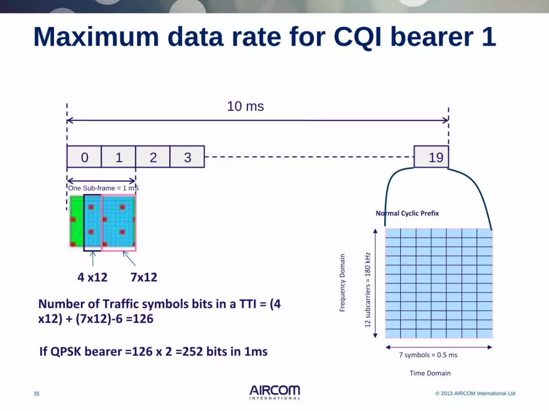
Number of Traffic symbols bits in a TTI = (4 x12) + (7x12)-6 =126
If QPSK bearer =126 x 2 =252 bits in 1ms
Maximum data rate for CQI bearer 1
4 x12 7x12
Normal Cyclic Prefix
7 symbols = 0.5 ms
Freq
uen
cy D
om
ain
12
su
bca
rrie
rs =
18
0 k
Hz
Time Domain

36 © 2013 AIRCOM International Ltd
0 1 2 3 19
One Sub-frame = 1 mS
10 ms
Number of Traffic symbols bits in a TTI = (4 x12) + (7x12)-6 =126
If QPSK bearer =126 x 2 =252 bits in 1ms
In 1
0 M
hz
you
hav
e 5
0 P
RB
in 1
mS
Maximum data rate for CQI bearer 1
In one TTI (1mS)you have 50 x 252 bits = 12600 bits per 1mS

37 © 2013 AIRCOM International Ltd
0 1 2 3 19
One Sub-frame = 1 mS
10 ms Number of Traffic symbols bits in a TTI = (4 x12) + (7x12)-6 =126
If QPSK bearer =126 x 2 =252 bits in 1ms
In 1
0 M
hz
you
hav
e 5
0 P
RB
in 1
mS
Maximum data rate for CQI bearer 1
In one TTI (1mS)you have 50 x 252 bits = 12600 bits per 1mS
Coding Rate 12600 bits x 0.07618=959.104 bits in 1ms
Bits per second =959.104 x 1000= 959104 kb/s =0.975 Mb/s in 10Mhz

38 © 2013 AIRCOM International Ltd
What have we not taken into account?

39 © 2013 AIRCOM International Ltd
Each Bearer has a maximum data rate
Antenna 1
1 ms
12 s
ub-c
arr
iers
Bits per second =959.104 x 1000= 959104 kb/s =0.975 Mb/s in 10Mhz
With
ou
t M
IMO
CQI 15
CQI 1
Low throughput
High throughput
With
ou
t M
IMO

40 © 2013 AIRCOM International Ltd
Bearers W
ith
ou
t M
IMO

41 © 2013 AIRCOM International Ltd
Physical Overhead W
ith
ou
t M
IMO
Antenna 1 Antenna 2
42 © 2013 AIRCOM International Ltd
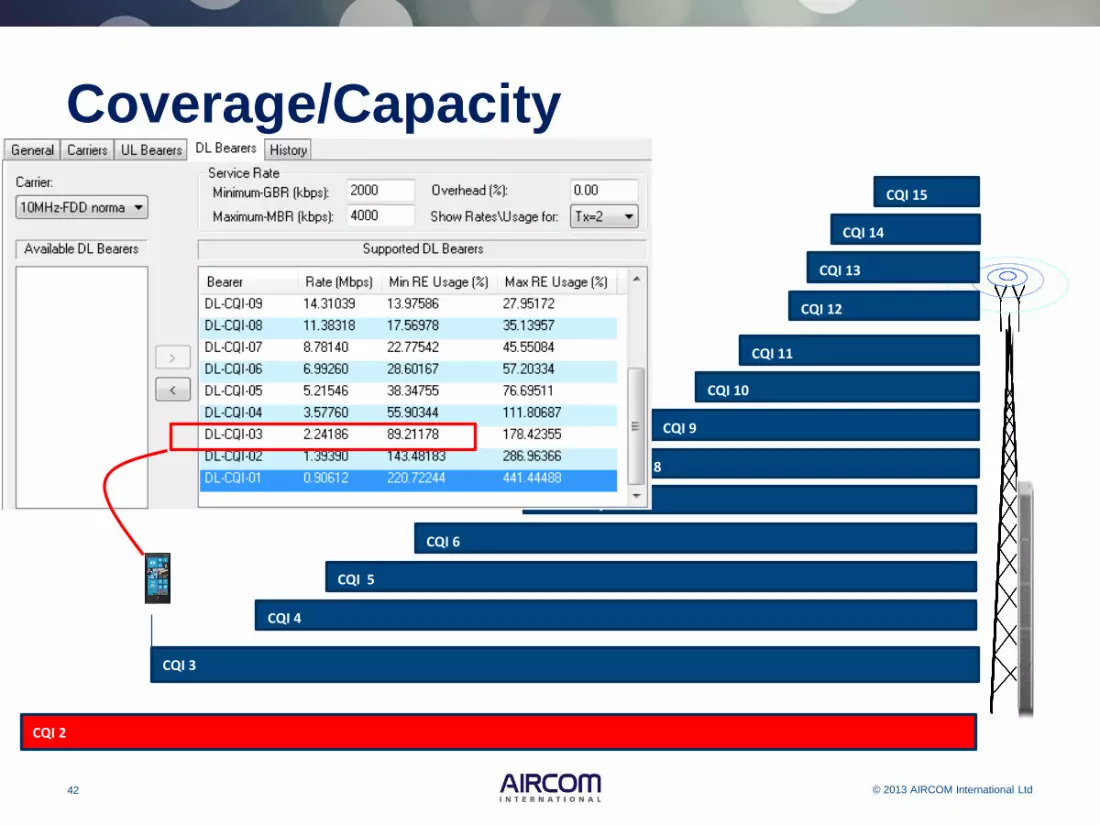
Coverage/Capacity
CQI 1
CQI 15
CQI 14
CQI 13
CQI 12
CQI 11
CQI 10
CQI 9
CQI 8
CQI 7
CQI 6
CQI 5
CQI 4
CQI 1 CQI 3
CQI 2

43 © 2013 AIRCOM International Ltd
Summary Cell throughput is dependant on: • Modulation and coding scheme (MCS) (0…31)
and Transport block size • Bandwidth • Normal / Extended Prefix • Transmission modes TX diversity, Su-MIMO etc. • LTE UE categories
CQI
(MCS) (0…31)
Normal Cyclic Prefix
7 symbols = 0.5 ms
Freq
uen
cy D
om
ain
12
su
bca
rrie
rs =
18
0 k
Hz
Time Domain

44 © 2013 AIRCOM International Ltd
Next Topic
Comparison between GSM, UMTS & LTE

45 © 2013 AIRCOM International Ltd
In Closing
Thank you for attending
Webinars webpage – keep up to date and register to receive email alerts on new webinars http://www.aircominternational.com/Webinars.aspx