Embed Size (px)
Citation preview


Section 1
INTRODUCTION
by L. Deschamps
Today, the technical, economic, and ope~ational qualities of polymer-insulated
cables are leading to their ever increasing use in electric power transmission and
distributionnetwOrks. The use of new materials, the·implernentation of new
manufacturing techniques, improved knowledge of the electric, thermal and
thermomechanicalbehavior of polymer insulations, and new operational requirements
for cables are factors producing a rapid evolution of this technology. Good
management of a power system requires a goodknowledge of degradationand aging
mechanisms of this systemito optimize its design, choice, and operating conditions.
JICABLE is thushappy to contribute to the organization of this workshop, "Cable
89", on the aging of polymer insulated cables. JICABLE has set itself the task of
providing a "platforrll" for exchanges between researchworkers, physicists, chemists
and other scientists, and manufacturers and users of cables for all voltage levels.
Besides successfulJICABLE conferences in 1984 and 1987 (ea.ch with 600 participants
from 40 countries), three workshops have covered three topical problems: HT 84,
"Behavior in Overload Gonditions"; HI 87, "Behavior in High Electric Fields"; and
F 87 "Fire Behavior". This present workshop, "Gable 89", organized jointly by the
Electric Power Research Institute,.the Gana.dian Electric Association and JIGABLE
will coyer the importantproblems of cable aging,
Gonnectionsbetween JICABLE, GIGRE, GIRED, and IEEE permit a concerted organization
and avoids wasteful competition and duplication of effort. Formed in France by the
Societe des Electriciens et des Electroniciens, JIGABLE is presently broadening its
scope, and, with its new status, will have its next confeÏ"ence between 2-8 March,
1991 in. Europe.
l warmly thank EPRI and CEA for their essential parts in the organization of "Cable
89". l wish tOthank more 'par t Lcul.arl.y Ralph Samm of EPRI, general chairman of the
workshop, who had the delicate mission of organizing "Gable 89".. Finally, l would
like to thank all the participants at this meeting for their contributions and
active participation. l wish great success to our efforts. Thank you very much.
1-1

R E P 0 R T SUMMARYSUBJECTS Underground transmission construction 1 Underground distribution 1
Underground cables
TOPICS Cable insulationAging (materials)Transmission cables
Distribution cablesExtruded cablesDielectric materials
EPRI EL·7090s
AUDIENCE R&D managers 1 Engineering/design technical staff
Proceedings: JICABLE 1EPRII CEA Workshop"Cable 89"The Aging of Extruded Dielectric Cab les
Service experience data on solid-dielectric power distribution cables show that significant numbers of cab les exhibit a shorterthan-desired lifetime. Although lessdata exist on transmissionclass cables, the aging parameters, with the exception of moisture, should be similar. A recent workshop addressed means ofimproving both distribution- and transmission-class cable lifetimeand performance reliability at a reasonable cost.
OBJECTIVE To improve understanding of aging phenomena associated with extrudeddielectric cables.
APPROACH The Cable 89 workshop-cosponsored by EPRI, the Canadian ElectricAssociation, and JICABLE of France-was held November 2-3, 1989, inSaint Petersburg Beach, Florida. More than 60 representatives of universities, research organizations, and electric utilities as weil as manufacturersof insulating polymers and power cables attended the workshop. Expertpresentations focused on Iife predictions of aging, materials, cables andaccessories, accelerated aging, diagnostics, and service experience. Threeworking groups discussed materials aging and diagnostics, cable/accessoryaging and diagnostics, and service experience with accelerated aging.
KEY POINTS The workshop initiated an important dialogue between cable users, cabledesigners, and dielectrics experts. Workshop attendees agreed on thefollowing:
• The potential benefits and limitations of diagnostics for materials agingrequire greater clarification because of the wide variety of disciplinesrepresented in the cable insulation community. More interdisciplinary communication is needed.
• Accelerated testing on cable specimens should be limited to a reasonabletime limit of two years maximum.
• No satisfactory accelerated aging procedure for cables has beendeveloped.
Electric Power Research Institute

• Imperfections are a major source of failures in cables.
EPRI PERSPECTIVE This workshop aided in outlining resolutions of problems associatedwith the aging ofextruded dielectric cables. The overall workshop consensus was that improved diagnostic and accelerated aging tests thatduplicate real-world situations will more accurately aid, in estimatingcable life and evaluating enhanced manufacturing techniques. Futureinternational collaborations to discuss ongoing efforts in these areasare planned. Related EPRI reports address dielectric diagnostic techniques (reports EL-6207·and EL-7076).
PROJECT RP7898-98EPRI Project Manager: Ralph W. SammElectrical Systems DivisionContractors: Broadhurst Consulting; KELTEK
For further information on EPRI research programs, caliEPRI Technical Information Specialists (415) 855-2411.

Proceedings: JICABLE1EPRIICEA Workshop"Cable 89"
The Aging ofExtruded Dtelectrlc Cables
EL-7090Research Project 7898-98
Proceedinçs, December 1990
Saint Petersburg Beach, FloridaNovember 2-3, 1989
Prepared by
BROADHURST CONSULTING116 Ridge Road
Box 163Washington Grove, Maryland 20880
Principal Author/EditorM. G. Broadhurst
KELTEKPost Office Box 57
1310 North Eighth Street, Number 10Montpelier. Idaho 83254
Principal InvestigatorE. F. Kelley
Prépared for
Electric Power Research Institute3412. Hillview Avenue
Palo Alto, California 94304
EPRI Project ManagerR. W. Samm
Underground TransmissionProgramElectrical Systems Division

ORDERING INFORMATION
Requests for copies of this report should be directed to Research Reports Center(RRC), Box 50490, Palo Alto, CA 94303, (415) 965-4081. There is no charge for reportsrequested by EPRI member utilities and affiliates, U.S. utility associations, U.S. governmentagencies (federal, state, and local), media, and foreign organizations with which EPRI hasan information exchange agreement. On request, RRC will send a catalog of EPRI reports.
Electric Power Research Institute and EPRI are registered service marks of Electric Power Research Institute, Inc.
Copyright © 1990 Electric Power Research Institute, Inc. Ali rights reserved.
NOTICEThis report was prepared by the organization(s)"named below as an account of work sponsored by the ElectricPower Research Institute, Inc. (EPRI). Neither EPRI, members of EPRI, the organization(s) named below, nor anyperson acting on behalf of any of them: (a) makes any warranty, express or implied, with respect to the use of anyinformation, apparatus, method, or process disclosed in this report or that such use may not infringe privatelyowned rights; or (b) assumes any liabilities with respecttothe use of, or for damages resulting from the use of,any information, apparatus, method, or process disclosed in this report.
Prepared byBroadhurst ConsultingWashington Grave, MarylandandKELTEKMontpelier, Idaho

ABSTRACT
This report presents .the proceedings of the workshop "Cable 89" on The Aging of
ExtrudedDielectric Cables. The workshop was·held in.St. Petersburg Beach, Florida,
on November 2-3,1989. The sponsoring organizations are the Electric Power Research
Institute (US), the Canadian Electric Association and JICABLE (France).
Attendance at the workshop was by invitation only, and attendees included 60
representatives of universities, research organizations, .electric utilities, and
manufacturers of insulating polymers and power cables, from ten countries. The
workshop was created as a forumf.orworld experts ro relate and compare their
service experiences, theoretical, fundamental and experimental stl.ldies, and test
results on the topic of aging of solid dielectric cables. The overall topic
included materials aging, cable and accessories aging, diagnostic tests, accelerated
aging and service experiences and conditions. The first half day of the workshop
featured six overview presentations by interna.tional experts. These presentations
and the brief discussionsthatfollowed each presentation are included in this
report. The second half day waS devoted to discussions within three separate
working groups dealing with the. three topic areas: materials, cables, and
acceleratedtests. Reports from thethree working groups were given on. the third
half day, and are included in this report with the genera.l discussions that followed
each one. Detailedquestionnaires were mailed to participants in advance, tofocus
attention on areas ofprimary concern. The data from these questionnaires made a
foundation for.the working group discusSions and the general discussions on the last
day of the workshop. Participants had an opportunity to present brief formaI
presentations during the workinggroup sessions. The content of these were
incorporated intothe working group reports. They were .also madeavailable, as
separate written documents, to the participants at the meeting. Theseworkshop
discussions were :recorded, transcribed and edited and included in the proceedings.
Conclusions (representing an informaI consensus of the attendees) are also included
in the report.
Key words: Extruded dielectric cables, electrical aging, electrical insulation,
electric power cables, ac<::elerated tests, distributioncables.
Hi

CONTENTS
Section
1
2
3
4
5
6
INTRODUCTION
WORKSHOP DESIGN
SYNOPSIS OF PROBLEMS AND CONCULSIONS
General-Transmission and Distribution Cables
WORKING GROUP REPORTS
Materials Aging and Diagnostics
Cable / Accessory Aging and Diagnostics
Accelerated Aging - Service Experience
General discussion of Working Group Reports
OVERVIEW PRESENTATIONS WITH DISCUSSIONS
Aging - Life Predictions by T. Dakin
Aging of Solid Electrical Insulations by R. Eichhorn
Cables / Accessory Aging by L. Deschamps
Influence of Insulation Morphology on the AcceleratedAging of Cables by J-P. Crine
Diagnostic Tests for Solid Dielectric Cables by W. Boone
Cable Service Experience by D. Mintz
PERSPECTIVE OF THE SECRETARY
1-1
2-1
3-1
3-3
4a-l
4a-l
4b-l
4c-l
4d-l
5a-l
5a-l
5b-l
5c-l
5d-l
5e-l
5f-l
6-1
APPENDIX A
APPENDIX B
APPENDIX C
APPENDIX D
APPENDIX E
APPENDIX F
ATTENDANCE LIST
WORKSHOP OFFICIALS
FINAL PROGRAM
INTRODUCTION
DETAILED REPORT ON MATERIALS WORKING GROUP
ACRONYMS AND ABBREVIATIONS
v
A-l
B-l
C-l
D-I
E-I
F-l

Figure
5b-l
5b-2
5b-3
5b-4
5b-5
5b-6
5c-l
5c-2
5c-3
5c-4
5c-5
5c-6
5c-7
5c-8
5c-9
5c-10
5c-ll
5c-12
5c-13
5c-14
5c-15
5c-16
5c-17
5c-18
5c-19
ILLUSTRATIONS
Electrical insulating materials for use in cables
Peroxide crosslinking of polyethylene ta make XLPE
Chemical structures and polymerization reactions
Two variations of polymers crosslinked with a silane and water
The oxidation process in a polymer
A partiallywater-filled void in a polymer showing gas trapped
Litetimefor thermal agingof XLPE at various temperatures
Va.riation of mechanical properties of XLPE with time at 100°C
Variation of mechanical properties of XLPE with time at 110°C
Variation of mechariical properties of XLPE with time at 135°C
Variation of dielectric 16ss tangent of XLPE with time at 135°C
Dielectric loss tangent of XLPE with time at 135°C
Cross section of a cable containing a variety of defects
Plot of the life curve given by Eq. 5c~3
Failure rate as a function of dielectric aging time
Lite durations versus testing voltage of 20-kV cables with water
A test bar for mechanicaltesting of insulation
Plot of stress vs. time for mechanical testing of cable insulation
Modulus of four types of PE as a function of temperature
Springmodel for dimensional changes in PE
Small-load thermal mechanical and differential mechanical data
Two designs for relieving thermomechanical stresses in cables
XLPE insulated cab les for EDF distribution networks
Qüantityof HN 33_S_23 cable, terminations arid joints in service
Failure rates for HN S 23 (3-core) cable and accessories
vii
Page
5b-2
5b-2
5b-3
5b~4
5b-6
5b-7
5c-2
5c-3
5c-3
5c-4
5c-4
5c-5
5c-6
5c-7
5c-7
5c-8
5c-9
5c-9
5c-10
5c-ll
5c-ll
5c-12
5c-13
5c-15
5c-16

Figure
5c-20
5c-21
5e-1
5e-2
5e-3
5e-4
5f-1
5f-2
5f-3
Data on EDF service experience with extruded insulation cables
Data on EDF operating experience with extruded insulation cables
The 63% breakdown field vs. size of largest water trees
Threshold voltage from impulse breakdown vs. dc prestressing
Breakdown strength of XLPE cable vs. dc leakage current
Breakdown strength of XLPE cable vs. loss tangent
Age profiles of European XLPE cables (1985)
Failure rate as a function of year of installation
XLPE cable failure rate versus average cable age
viii
Page
5c-17
5c-18
5e-3
5e-3
5e-4
5e-4
5f-4
5f-7
5f-8

Table
4b-1
5c-1
5f-1
5f-2
5f-3
5f-2
TABLES
Factors affecting wet and dry aging
Comparison of an XLPE cable with a paper cable
1986 cable failure rates per year
Qûantities of installed plant used for failure rate statistics
Examples where small parts give large percentages of failures
XLPE cable failure rates by voltage class
ix
Pa~e
4b-2
5c-14
5f-2
5f-3
5f-5
5f-6
Section 2
WORKSHOP DESIGN
This workshop, "GABLE 89", was scheduled just prior to the November, 1989 IGG
meeting in St. Petersburg Beach, Florida, for the convenience of those attending
both meetings. The central topic of the workshop is "The Aging of Extruded
Dielectric Gables". Attendance at the workshop was by invitation only, and
attenders included 60 representatives of universities, research organizations,
electric utilities, and manufacturers of insulating polymers and power cables, from
ten countries. The attendance list is presented in Appendix A, and those having
official duties related to the workshop are listed in Appendix B.
The three organizations sponsoring this workshop are JIGABLE (France), the Electric
Power Research Institute (US), and the Ganadian Electric Association. The workshop
was created as a forum for world experts to relate and compare their service
experiences, theoretical, fundamental and experimental studies, and test results on
the topic of aging of solid dielectric cables. The overall topic included materials
aging, cable and accessories aging, diagnostic tests, accelerated ag~ng and service
experiences and conditions.
The first half day of the workshop featured six overview presentations by
internationally renowned experts. Brief discussions followed each presentation.
The second half day was devoted to discussions within three separate working groups
dealing with the three topic areas: materials, cables, and accelerated tests.
Reports from the three working groups were given on the third half day, followed by
lively discussions among aIl participants. The program of the meeting is presented
in Appendix G.
Detailed questionnaires were mailed to participants in advance. These served to
focus attention on areas of primary concern. The data from these questionnaires
made a foundation for the working group discussions and the general discussions on
the last day of the workshop. Participants had an opportunity to present brief
formalpresentations.during.the working group sessions. The content of these were
incorporated into the working group reports. They were also made available, as
separate written documents, to the participants at the meeting.
2-1

These workshop discussions were recorded, transcribed and edited for inclusion in
the proceedings. The edited discussions are not presentedin chronological order
but rather are groupedunder several topics, for ease in reading the discussions and
seeing the basis for the conclusions that follow each topic group. These
conclusions,along with conclusions from the six overview presentations and the
three working-group reports are included in Section 3 of this report.
2-2

Section 3
SYNOPSIS OF PROBLEMS AND CONCLUSIONS
Improving cable lifetime and performance reliability at a reasonable costis a
major goal of the organizations sponsoring andparticipating in this workshop.
Service experiencedata.on solid-dielectric power distribution cables (~ 35 kV) show
that significant numbers of cableshaveless than the desired·lifetime of 30 years.
Large riumbers of premature cable failures (greater than 5 failures/year/100 mi of
cable) are costly and inconvenient. And yet,prediçtivetests to better estimate
cable lifetime often fall short of their purpose. Furthermore, various options for
incorporating new cecbrïo Iogy Lritïo the manufacture and inS.tallati()n oIthe next
generation of cable systems present toinsulation and cablemakers andto their
customers, the utitities, the problem of which of the new "improvements" to adopt.
Eitherthe polymer insulating materials, cable construction or installation
prâ-cticesare usually blamed forcableperformanc~problems. Steady, ongoing
improvements are being made in all of theseareas, but there is a long time-lag
betweentheimplementation of new cable technology and the accumulation of
sufficient service data to· evaluate new cables. Forexample, D.· Mintz showed that
service experience in North America was much worse than that in Europe. Attendees
generally discounted the relevance of those data tothe newest generation of cables,
which use tree-resistant polymers, cleaner materials and, in sorne cases,
manufacturingprecautions to excludè water from.the cables. The introduction of
transmission cables (~69 kV) also is too recent to allow much service experience.
To overcome this time-lag and better evaluate current cables, accelerated aging
techniques are used toestimate long-time service performlince with short-time tests.
White attendees agreed that. present.acceleratedagingmethods were necessary, they
tended to distrust the results of these tests, and leaned toward lIIinimizing the
severity .of accelerating cond:i.tionsandmaximizing testtimes. Even the most
important E)xtrapolation techniqueslike Arrhenius temperature·behavior andWeibull
failure statistics were sometimes criticized in the discussions. The goal of
evaluating eventual cable performance with a short-time test seems yet to be
realized.
3-1

Workshop organizers took care to distinguish between transmission and distribution
cables and between the effects of wet and dry environments during aging. The
insulation in transmission cables (as compared to distribution cables) may be a
bettergrade, is usually extrùded to greater wall thicknesses and is usually dry
cured ratherthan wet cured. Insulation in the two types of cable are cooled at
different rates and hence probably to different morphologies. The insulation is
operated at different stresses for the two types of cable. Transmission cables are
protected bya metallic moisture barrier, while distribution cables, in gel1eral, are
not. Thus, in service, insulation in transmission cables ages in a dry environment,
while the insulation in distribution cab les is usually exposed to ambient ground
moisture. While wet aging is not considered relevant to transmission cabl$s, dry
aging is sometimes considered relevant to thermal overload conditions in
distribution cables where elevated temperatures may drive out moisture.from the
insulation. Because transmission cable technology is newer than distribution cable
technology, the service experience with transmission cables is more limited than
that with distribution cables, and workshop discussions were mostly about
distribution cables.
Attendees seemed relatively comfortable with present methods of testing full reels
of cable fQllowing manufacture. These tests eliminate large defects (beca4se they
cause the cable to fail) and condition small defects by annealingthem and reducing
volatiles. Attendees expressed little confidence in present in-ground diagnostic
tests to predict the remaining life of distribution cables. The extent to which
such a test would affect decisions about cable replacement was questioned~
Attendees generally favored tests to evaluate new materials and material
modifications for comparison with older materials. AGBD and oxidation resistance
were highly regarded partly because of their close connections to service
requirements. Less favored were measurements of properties like morphology and
space charge that had less apparent relevance to service requirements. The
popularity of newer measurements on materials presumably suffered from a lâck of
familiarity throughout the cable community.
A summary of conclusions from the overview presentations, working group reports and
general discussions is given below. These conclusions should not be viewed as
"truth" as they do not represent the result of a critical scientific proce:;s of data
analysis. They are merely opinions expressed during the workshop discussions,
presentations and surveys. At best, they represent the general understanding among
the attendees about the current general knowledgeand practice in cable technology.
3-2
We group these conclusions according to their applicability to distribution cables,
or transmission cables or both.
GENERAL - TRANSMISSION AND DISTRIBUTION CABLES
• The potential benefits and limitations ofdiagno;tics for materialsaging require greater clarification especially because of the widevariety of disciplines represented in the cable insulation community.Ways to communicate better between disciplines are needed.
• Accelerated testing on cable specimens should be limited to two yearsas a reasonable practical time limit.
• There is no satisfactory accelerated aging procedure for cables.
• Imperfections are a major source of failures in cables.
• The factory test procedures commonly used to deal with imperfectionsare effective.
• Breakdown strength increases slightly with insulation density fot agiven material.
• The effects of morphology on cable performance under normal operatingconditions are not widely understood or agreed upon.
• Antioxidant concentrations in the insulation of cables withcoextruded screens are changed because of migration of antioxidantsbetween the insulation and screen.
• Oxidation is retarded by screens, jackets and antioxidants.
• Increased power factor of a cable is a strong indication of sorneproblem with the cable.
• Power factor measurements in the field are not sensitive enough todetect many problems in cables.
• Surge damage is best avoided by use of adequate protection devic~s
and correct installation procedures.
• Metal sheaths provide the best protection against water but addasignificant fraction to the cost of a cable.
• Weibull statistics are mathematically correct and experimentallyvalid under carefully controlled conditions.
• In many practical applications data donot fall on a straight-lirieWeibull plot presumably due to changing external conditions oruncontrolled parameters.
• Past experience has shown that improvement in one property with a newor modified material always goes with a loss in sorne other property.
• The intrinsic strength of PE and XLPE is probably > 1000 kV/mm.
3-3

DISTRIBUTION CABLES,
• During accelerated aging with load cycling, the order of propertyloss for dry aging is oxidation resistance, elongation and AGBD, andfor wetconditions the order is AGBD, oxidation resistance andelongation. This observation can be considered a guide toappropriate tests.
• Water treeing is the most significant aging factor in MV cableswithout water barriers. Any method to reduce water influxisbeneficial.
• Residual moisture in cable insulation produées bow-tie trees that donot cause problems at operating stresses during dry aging.
• An improved standard accelerated aging test is needed to evaluate wetaging in both insulations and semiconducting materials.
• Bow-tie trees sometimes grow to the extent of causing breakdown.Many breakdowns occur without any apparent connection with bow-tietrees.
• Present diagnostic tests g~v~ng rema~n~ng cable life often do notaffect replacement decisions because of lack of confidence in thetest.
• Ions affect tiee growth during wet aging but have little effectduring accelerated dry aging.
• 30 years is normally considered an adequate cable lifetime.
• About 5 failuresjyearjlOO mi of cable is considered by many tosignify the end of a cables practical life.
• Tree-retardant materials show significantly reduced tree growth inaccelerated tests compared to XLPE.
• A continuous supply of liquid water is necessary before tree growthbecomes significant.
• Liquid water in cables under voltage stress is a major source offailure in polyethylene-based insulation.
• The use of polyethylene-based jackets and semiconducting layers andcare to exclude the ingressof water during manufacture andinstallation significantly reduce water related damage in cableswithout metallic barriers.
• Water-tree-retardant materials have significantly better performancein accelerated wet aging tests than does ordinary XLPE.
• Indications are that service performance of TR materials will bebetter than ordinary XLPE.
• Gareful cost and performance analysis 1s needed to evaluatetherelative merits of new materials and structures such as metal sheathsand TR polymers.
3-4

• It is sometime difficult to distinguish between changes in a materialdue to external conditions (like ingress of water from thesurroundings) and aging (like the growth of largetrees).
• Three stages in the life of a cable are: Early failures (defectelimination - failure rate decreases with time} , maturity (failurerate constant), and aging (oxidation or sorne other deteriorationbegins - failure rate increases with time).
• No single effective diagnostic test to predict remaining life of wetaged polymers is presently foreseen.
• Experience with numerous availablediagnostics for wet aging ispresently too limited for practical use.
TRANSMISSION CABLES
• In dry HV cables, inorganic and metallicimpurities are the worstcontaminants.
• The ratio of factory test voltage to service voltage commonlygecreases with increase in service voltage because of practicalproblems ofapplying high voltages.
• Increasing the field in HV cables beyond their design stress is notrecommended without a careful analysis of cost and performance.
• The Arrhenius equation has been suggested as usefuL for extrapolatingthermal aging results to long times.
3-5

Section 4a
WORKING GROUP REPORT - MATERIALS AGING AND DIAGNOSTICS
B. Bernstein, Chairman
The objectives of this group were 1) to understand materials behavior (life
prediction and açcelerated aging behavior) in order eventually to understand cable
behavior, and 2) to examine the significance of diagnostic techniques. Discussions
included dry and wet aging and we occasionally included cable. results and problems
along with materials. We summarized the questionnaire results (18 respondents for
dry conditions and 19 for wet) , had prepared presentations, had a general discussion
and then returned to the questionnaire to see what suggested changes the attendees
felt strongly about.
For dry aging, important factors included field, time, contamination in the semicon
and insulation", voids, cavities, and the semicon-insulation interface. For wet
aging, external water, field, time, contamination, voids and cavities were also
ranked high in importance. For diagnostic techniques, methods for measuring
contaminants - conventional optical microscopy and dielectric strength were the
highest ranking. For test geometry, respondents preferred coaxial geometry with
semiconducting electrodes for wet aging, and parallel geometry with semiconducting
electrodes for dry aging. There was no strong consensus in favor of the EFI test.
ACBD and time to breakdown were the most favored assessment methods. Analytical
techniques ranked high as a group, but different people preferred different
techniques. Respondents split on the importance of morphological changes, and
diffusion of components was considered an important factor. Everyone thought there
were good tests for evaluation of retardant additives, but differed on what those
tests are.
NESTE and Siemens presented data on a new tree retardant material. Andras Farkas
talked about laboratory testing. Schroth talked about cable testing. Conventional
EFI tests show the new material has good resistance to both bow tie and vented water
trees. Dr. Dalle talked about new diagnostic techniques for dry and wet aging,
particularly space-charge measurements using shock waves. Dr. Favrie discussed
migration of additives from the semiconductor layer into the insulation of cables.
Dr. Fallou made suggestions on the use of the controversial tanS test, and
4a-l

measurements of gas evolution undèr stress. (The problem of differentiatin.gtrapped
gases fromthose due to decomposition was noted.) Dr. Mayoux d~scussed dry aging
using partial-discharge methods .andchemicalchanges in the channel waHs. He
focused on the effects of ions on aging. Dr. Barlow discussed secondary
recrystaHization in polyethylene and resultant microvoids thatcan grow t()
potentially harmful sizes. Dr. Braun discussed x-ray-induced partial discharges as
a way to increase the sensitivity tosmaU voids.
One change from the survey results was the suggestion that Concurrent stres~es
should be considered. Ranking of survey results did not change~ Unfamiliarity with
certain techniques phat have provided extensive results seemsevident. We<concluded
that more effort should he made to conununicate these resultsto the geneiaFcable
community. We differentiated between temperature cycling andtemperature gradient
which sorne attendees considered an important parameter.
The highest ranking diagnosti.c techniques are old onesfroIil the 1970's
contaminants, visual inspection and dielectric strength. A newillethod like
chemiluminescence is so sensitive that interpretation is difficult. Measurements of
density are also promising. Optical and electron microscopy are Of knownvalue.
FTIR was one of the highest ranking techniques in spite ofsensitivitylimits.
Proton-induced.x-ray emission and ion chromatographyare worth attention, and
dielectric strength is an important method. We·concluded that not enough
information was available to the industry to use many of the new materials
measurement tnethods. Dr. Boone's tree length results relating tree.lengths to
breakdown strength suggested that s Irni.Lar' urrsucces s fu I" studies in this c()l.lntl:"Y
should be reexamined.
For wet·accelerated aging Ac:BD is the first property to disappe<irand oxidation
resistance is the second. Physical properties de grade later. Fordryaccelerated
aging, the first property to degrade is oxidation resistance. Only afterwards are
there changes in elongation. ACBD stl:"ength is lost last. For wet aging, electrical
measuremerrt s: seem appropriate. For dry aging other properties may change before the
electrical properties. Tt has been suggested that TR additivesmay affectthese
observations, but they canbe a guide to the selection of the most appropriate aging
tests.
4a-2

Section 4b
WORKING GROUP REPORT - CABLE/ACCESSORY AGING AND DIAGNOSTICS
L.Deschamps, Chairman
This working group included 15 participants from Europe, Japan, the lJS.andCanada.
Topies included PE, XLPE and EPR, MV « 5 kV/rnrn) , HV (5 to 10 kV/DlJ!l) and EHV
(> 10 kV/rnrn) cables, and wet and dry conditions. A surnrnaryof theanswers to the
questionnaires about the main factors affecting the lifetime of cables and
accessories and the most important diagnostic tests aregiven in Table 4b~1.
Water treeing is the most significant aging factor in MV cables without water
barriers. Any method used toredtlceinflux of water intothe insulation is
beneficial. ThEldegree of moisture protection is a matter of economics. Cables
withmetal sheaths can costup to twice as much aS equivalent cab les without metal
sheaths. Tree retardant additives can significantly reduce tree growth in the
presence of water. 45% of MY cable in the US is presently made with tree-retardant
compounds. Incre.asing the insulationwall thickness, using expanding tapesunder
the jacket to block longitudinal flowof water and.the use of solid conductors are
examples of water reduction methods, the use of which is an econonïic problenï.
In Japan, MV cables (6 to 33 kV) are not waterproofed, and lead foil is being
considered for 22 to 33 kV cables. 69 to 500 kV HV cableswill be waterproofed in
the future. In Europe MV cablesarenot waterproofed except in France, and EHV
cables are. In France, MV, HV and EHV cables are waterproofed. In the US many
utilities are changing philosophy from lowest initial cost to longer service life
andease of replacement, for exampleTRXLPE insulation and PE jackets. For HV
cables no failures attributable to water trees have been reported exceptwhen there
was accidentaI flow of water into the cable. This suggests that intrinsic water in
the insulation does not reduce the expected life of a cable.
It is difficult to dissociate the waterproblem from theproblem ofcontaminants,
both in the insulation and at the interface between the insulation and
semiconducting layer. Paper fiber contaminants with moisture initiate water trees
and resultin a lower breakdown strength even with low electric fields. In dry HV
cable metallicimpurities are the worst, especially in the maximum field region and
4b-l

Table 4b-l
FACTORS AFFECTING WET AND DRY AGING OF CABLES AND ACCESSORY AGINGAND DIAGNOSTIC TESTS RATED FROM THE QUESTIONNAIRE
Score is indicated by the bar lengths
under wet conditions
cable characleristics
~gk1g of occessories
accessory characteristics
Compotibility of moterlols J-~;clc,;;;sign----J-Type-;; moterio\- - r
Adhesion_ ===.-JVolto~rotin~~
applied constralnts
induced effects
4b-2
under dry conditionscable charocteristics
Field .Jremperoture====.-J - -
remperoture cyeling J-Freq;t;cT--J-- Externolstroin JInduced effects
Partial disehorges J-Shrinkbocl;"--J ------Oxidotion =_J
Diagnostic test

especially when the particles are not imbedded and produce partial discharges and
breakdown. Particles greater than 30 ~m to 40 ~min low density PE and 100 ~m in
XLPE are to be avoided. Interface contaminants involve roughness (want better than
30 ~m or 100 ~m smoothness as above) and quality of carbon black. Emission shields
do not produce-as much improvement with the latest generation of semiconducting
materials as with older semiconducting materials, probably because they are cleaner.
Maximum overload temperatures dependon the mechanical properties of the insulation,
and appear to be 105°C for XLPE [this value is used in Europe and Japan, while 130°C
is used in North America] and slightly higher for EPR cables, and 80°C and 90°C for
low and high density PE, respectively. Creep can occur in XLPE and EPR above 90°C.
Residual deformation occurs if pressure remains during a cooling transient, and is
relatively small in EPR. Choice of screen and bedding materials and careful
installation practices can alleviate damage, and increase the maximum overload
temperature to 130°C. Accessory aging problems involve material compatibility, for
example the filler in the silicone grease used to connect accessories. HV cables do
not show aging when external influences such as water are avoided.
Diagnostic tests apply to wet conditions only. CIGRE tests are summarized by W.
Boone in Section Se of this report. The practical use of tanS and conduction
current tests are not clear. Partial-discharge tests do not detect water tree
degradation until just prior to breakdown, but they can detect cavities and
electrical trees.
4b-3

Section 4c
WORKING GROUP REPORT - ACCELERATED AGING AND SERVICE EXPERIENCE
J. D~nsley, Chairman
The objectives of thisworking group were to:
• shareknowledge on accelerated aging by discussing mechanisms ofaging. under"dryu and "wet" conditions,eyaluatingthe roles ofvarious stresses, and discussing diagnostic techniques,
• tabulate a:fange of stresses for accelerated·agingtests underdryand wét conditions, and
• discuss normal and abnormal service experience.
Questions to be answered to reach these objectives are:
• How do particular stresses affect aging?
• What are the mechanisms of aging·overa wide range of stresses?
• What synergistic effects occur between stresses?
•
DRY AGING
What are the limitations of present accelerated aging tests to screenmaterials and to guarantee a minimum cable life of 30 years for bothwet and dry conditions?
The results of the workshop questionnaireshowed general agreement on the importance
of: E, t,contaminants, cavities, partial discharges, interfaces, conn~ctors and
test geom~try. There was less agreement about r~sidual moisture (the long term
effects of bow-tie trees), temperature (maximum temperature, thermal aging),
temperature cycling (thermomechanical.effects and morphology changes), frequency
(usefulness of accelerated aging), residual and externalmechanical strain (void
formation, .: cracking and. loss of adhesion), antioxidants (chemical reaction control),
residual and dissolved gases (void formation and deterioration) and space charge
(high fieldeffects).
The following salient points resulted from the discussion:
• To det~ct gross imperfections during manufacture, a cable shouldbesampled over a year and subjected to ACBD testing.
4c-l

• The Weibull plot of the results gives useful information.
• Residual moisture produces bow tie treesand these should not be aproblem at operating stresses.
• The French long term test was described in detail, using standardsHN-33-S-52, -51 and -54 for single core cables up to 100 kV, 245 kVand 420 kV respectively. For 100 kV cables, a length of 100 m withindoor and outdoor terminations and 4 joints are aged for 6000 h (250days). Termination flashover precludes ACBD testing. With an agingvoltage of 1.73Vo' 167 cycles at 100°C and 83 cycles at 105°C wereapplied as 8 h on and 16 h off per cycle. The 100°C and 105°C testsapply to XLPE. A 2.2Vo acceptance test is described for 5 220 kVcables and for 400 kV cables, 1.91Vo for 10 hours and 1.74Vo for onehour is described. Weibull statistics were used to estimate themaximum number of breakdowns (5 in 30 km) to give a maximum faultlevel of 0.2 faults/l00 km (3-phase) per year.
• Cables removed from service after 14 years (63 and 225-kV LDPEtransmission cab les) had small bow-tie trees and impulse and ACBDexceeded new cable specifications. IR, UV and DSC tests gave nounusual results.
• Italian practice is to test each core length of cable at 3Vo for0.5 h and to test fini shed cable at 2Vo' However long term tests attoo high a stress can produce ionization in microvoids.
• The effect of 10 kV/mm aging on XLPE morphology showed no significantchanges. Thermal gradients did change the structure of the lamellae.Mechanical stress is known to affect recrystallization. SAXS andWAXS seemed not to be effective in this study.
WET AGING
The workshop questionnaire showed general agreement on the importance of E, t, water
ions, contaminants in the semiconductor layer, cavities, connectors and test
geometry (uniform and coaxial with SC electrodes). There was less agreement on
temperature (conflicting data), morphology (importance of), residual andexternal
mechanical strain (how much does it effect tree growth?), frequency (extent of
usefulness). Discussions of these points included:
• Morphology may influence the way trees propagate independent ofdetailed mechanism.
• While large tensile strain will promote treeing, normal values ofstrain are no real problem.
• A new standard test is needed to evaluate new materials (bothinsulations and semiconducting materials).
• The EFI test uses semiconducting electrodes (1 metal electrode andsalt solution as the high voltage electrode), 15 kV/mm, cyclictemperature. At 3, 8, and 16 weeks diagnostic tree counts and ACBDtests are done. The interface as weIl as the insulation and
4c-2

semiconductor are tested. Comparing this test with a standard defecttest (needlejplane) was proposed.
• Water trees in insulated wire with a square conductor (nosemiconducting shield) are similar to those in full sized cables.Tests on full-sized cables should be made over a range of conditionsto avoid misleading information about materials. These conditionsinclude E and T. Ions are important. Time to breakdown tests werepreferred. Tests by CIGRE and AEIC seemed to give similar materialsevaluations even though they used significantly different testconditions.
• Accelerated aging test that relates to service experience is stillneeded.
A range of test conditions suggested for cables is: E = 2 kVjmm - S kVjmm,
f = 50 Hz - 60 Hz, TM = SocC, SOcC, TC room temperature to the melting
temperature, ion composition should be controlled, t = time to breakdown with a
limit of two years.
Suggested diagnostic tests on cables are: time to breakdown, AC step tests (after 2
years), visual observations, water content. Tests needing further study include
TSC, space charge measurements, conduction current, low frequency (0.1 Hz), tan6,
and repeated surges.
Good collection and analysis of service failures are needed to pinpoint problems and
guide design of valid accelerated tests. The service data is of low probability
events (less-than 0.1%), which is much lower than the 63% levels for laboratory
tests.
4c-3
Section 4d
SUMMARY OF GENERAL DISCUSSION FOLLOWING WORKINGGROUP REPORTS
ACCELERATED AGING
E. Brancato: John Densley, you l'laid tests and field results don'tagree. Could we
predict lifetime with an equation that comhines Arrhenius temperature dependence
with.E- n field dependence including the temperature dependence of n itself?
J. Densley: Under dry conditions maybe. l don't think the aging models that you
suggest apply towet conditions. For example, n forwater treed insulation is
around 4;underdry conditionsit is from 9 to 20, and failures are almost
independerttof temperature on slab .materials in the laboratory. However, l don't
want to infer that there is no hopefor prediction in the labo W. Boone: John
Densley, as the required test duration is, in general, much shorter for dry aging
than for wet aging, by choosingthesame duration fOr both tests, the conditions for
your recommendedaccelerated aging tests are less severe for wet than for dry aging.
Whynot. compen$ate by increasing frequency fOr wet aging? J. Densley: Our
objection to high freqllencyaging is the high cost of equipment for testing cables.
I·like the use of high frequency for wet and dry, but the consensus of. our group was
to not include high frequencytests. W. B.oone: Why use the same.two year timefor
both tests, was it Just for practical reasons? J . Densley: I think so , It can
take moî"ethart. a year for some aging phenomenato becomeapparent. Two years·is a
compromise W.Boone: Do you agree that your recommended dry aging test is more
"accelerating" thanthe wet aging test? J. Densley: No, theparameters for dry
aging are not intended to be more accelerating. R. Samm: l propose the wet and dry
tests are equally severe. In the dry case you have eliminated the most severe
ccmMtion, the water. With too severe conditions<onerisksdoingextra, artificial
damage. C. Katz: J. Densley why are AC breakdown tests preferred over impulse BD
tests.- isit due to lack of impulse BD equipment? You said·teststo·BD were
preferred and then l'laid ACBD should be used after·a two year limit. WhyAC a.nd why
two years? J. Densley: AC tests were preferred because they are more convenient.
We thought one year aging was not long enough for someof the rtewer materials, but
we needed an upper limit. D. Silver: It was pretty unanimous. Two years was a
reasonable.compromise. J. Tanaka: How would we best test a newmaterial to l'lee if
ft wouldmakebetter insulation thal1 existingml.iterials? B. Bernstein: We don't
have good answer to that. But for wet tests: dielectric testing, peripheral
4d-l

tests, 2 years wet aging. For dry tests: oxidation resistance, thermal aging.
J-M. Braun: l would add non-destructive tests to measure the condition and
remaining life of a cable containing Tanaka's new material.
• Accelerated testing on a specimen should be limited to two years ~$ areasonable practical time limit.
• There is no satisfactory accelerated aging procedure.
BOW-TIE TREES & BREAKDOWN
J-P. Crine: Has anyone seen a cable break down due to bow-tie trees? S. Verne:
Yes, we've seen breakdown originating from bow-tie trees. The likelihood of this
happening increases with increasing size and densityofbow-tie tree~. A bow-tie
tree always grows towards a neighboring defect, which may be in the bulk or ~t the
surface of the insulation. Connecting to a surface defect transforms a bow-tie into
a vented tree. N. Srinivas: We have seen large bow-tie trees near the failed
region in 175-mil XLPE cable. There are not a lot of small trees but big on~s grown
from very small sized contaminants. This cable had a wet conductorwhen it went in
and when it came out. D. Mintz: l found large bow-tie trees in 5-kV cables and
their size related to the defect thatthey grew from. Bow-tie trees do not hecome
larger as the insulation thickness increases, so l don't believe that the bow-tie
trees would be significant inlarger cables (25 kV or 35 kV). In about 40% of
failed cables samples l looked at, l did not see large sizes or numbers of water
trees that could be implicated in the failure.
• Bow-tie trees sometimes grow to the extent of causing breakdown. Asignificant number of breakdowns occur without any apparentconnection with bow-tie trees.
CABLE TESTS FOR DEFECT DETECTION AND DEFECT CONDITIONING
D. Silver: ACBD should be at the top of the list for both wet and dry aging.
Oxidation is not enough to cause significant changes in the physical charac~eristics
of XLPE in cables even after 30 years in service. Imperfections are the main thing.
1) Production samples should be selected periodically over a period of a year and
ACBD tested. 2) The data evaluated with a Weibull plot - essentially a straight
line for XLPE insulation. The position of the plot and the. slope gives a good
assessment of imperfections. In addition, we need a full reel voltage test to
eliminate gross imperfections. The US tests at 200 V/mil, (much helow the 15kV/rnm
or 20 kV/rnm used in France). l suggest we increase the full-reel voltage te$t ab ove
200 V/mil. In the US, we use four times Vo for 15 kV cables and 3.25Vo for over
35 kV cables. It disturbs me that as we go up in operating voltage, we continually
drop the ratio of test voltageto operating voltage. What is the justification for
4d-2

this? B. Bernstein: 1) this chart assumes no imperfections. We were concerned
with material aging, not cable defects. S. Banati: We treat polymer cables like
paper cables and l see now there is a big difference. What tests should we do to
get good polymer cables? L. Deschamps: In France we test at 2.2Vo and check
Weibull parameters to generate a breakdown if there are big defects and condition
the small defects to eliminate the early failures. l do not know the best ratio of
test stress to operating stress. W. Boone: IEC has almost decided to increase the
routine test for medium voltage cables to 3Vo' The Netherlandsis considering 5Vofor 10 kV and 3Vo for 30 kV. This is done mainlyto eliminate defects, and will
not change the life of the cable. E. Favrie: For400-kV cables, we have a test,
440 kV for 10h and after 24 h, 400 kV for one hour to check that the 440 kV did not
damage the cable. Wethink there is threshold voltage. If there is no problem
during the routine high level test, there will be no problem in service. J. Moran:
Testing 225 kV and 400 kV cables is increasingly expensive and complex as tèst
voltage goesup. l see a trend around the world to substitute hours for kilovolts
as a compromise at extremely high voltages.
• Imperfections are a major source of failures in cables.
• The test procedures commonly used to deal with imperfections seemadequate.
• The ratio of test voltage to service voltage commonly decreases withincrease in service voltage because of practical problems of applyinghigh voltages.
CABLE TESTS OF REMAINING LIFE.
S. Grzybowski: We still need ways to use the test results to say how good a cable
is. l suggest we need a standard reference material, and low frequency AC tests at
0.1 Hz. J. Moran: l certainly concur that ac breakdown strength is the most
dominant indicator of residual life. Perhaps we need sorne practical version of the
30- to 35-yr-old concept of a very-Iow-frequency ac test to be conducted in the
field. N. Srinivas: Jim Moran's question: does what we study here mean anything
about the life of the cable in the field. We are looking for at least a 30-year
life. We ignore failures in the firstfive years, but the main life of the rest of
the cables should be at least 30 years. J-P. Crine: l repeat J-M. Braun'squestion:
How can we evaluate the condition and age of a cable without removing it from the
ground? F. Garcia: An operating' cable is undergoing a continuous withstand test
merely by being alive. That's a good test of performance. If utilities have a
black box to tell when a cable might fail, l don't think they're goingto change
that cable until it actually fails. I suggest that' s a perfectly valid way of doing
things. The first failure you ignore - the second failure requires a decision and
4d-3

data from the black box might help withthat decision. D. Mintz: Northeast
Utilities used such a replace-as-it-fails typeprogram (with HMWPE) , unsuccessfully
- failure rates continued to increase. Only a few utilities would go around and
replace cables if they could have a black box that told them which ones to choose.
W. Boone: A large utility in our country decided to replace cables to avoid
unannounced failures. It just depends on how dependent a utility is on certain
connections. Theysometimes must do more than just waitand see. N. Srinivas: Do
you have a diagnostic tool to tell the life of the cable? W. Boone: The GIGRE
characterization tests (BD of pieces of cable from the field and inspection for
trees), together with practicalexperience, are considered a diagnostic tool.
C. Katz: An alternative to replacement is to dry the cable by passing dry gas or
dielectric fluid through it. A nurnber of utilities are prolonging service life of
cables this way.
• A diagnostic test g~v~ng remaining cable life wouldoften not affectreplacement decisions.
INGREASED STRESS IN HV GABLES
L. Deschamps: For high voltage cable it is not possible to see the aging, suggesting
possible use of higher stresses. G. Matey: We don'tsee changes in XLPE at higher
stresses but we do not know about the effect of higher stress on the semicon or at
the interface, or the effect of impulses and high frequency currents. We must be
cautious before recornrnending higher gradients. L. Deschamps: Also the non
distributed energy 10ss should be considered. And if we increase the field in a
cable that is in service, we will change the rate of failure. and can'textrapolate
the Weibull statistics for that cable. For this reason l am not in favor of
increasingthe field in high voltage cable without caution and carefulevaluation of
the economics.
• Increasing the field in highvoltage cables is not recornrnended beforea careful analysis of cost and performance.
IONS
B. Bernstein: Ions migrating from the semicons during wet aging alsoaffect tree
growth (Katz and coworkers in 1973 or 1974). From EPRI report EL5757. ions did not
cause decreased BD strength during dry aging. The importance of ions differs
greatly between wetand dry aging. C. Katz: The moisture (and not the ions)
reduces the dielectric strength.
4d-4

• Ions affect tree growth during wet aging but have no effect on dryaging.
MORPHOLOGY
J-P. Crine: Concerning a critical field in XLPE, l have shown that microcavities
start at a relatively low temperature and at a field on the order of 15 kV/mm to
20 kV/mm, and these microcavities are the first step in aging that leads to
breakdown. l doubt that we could operate XLPE cables for long above about 20 kV/mm.
l showed that EPR is better than XLPE in the above respect. J. Densley: Mr. Favrie
discussed a 400-kV cable subjected to 27 kV/null (aboveCrine's proposed 20 kV/mm
critical field) for 7,700 hwithout detectable change.
• Breakdown strength increases with density for a given materiaL.
• Morphology and its effect on cable performance is not widelyunderstood.
OXIDATION RESISTANCE
S. Verne: Oxidation resistance measured oninsulation for medium voltage cables is
misleading. Such insulation is fully stabilized. With coextruded screens, the
antioxidant disappears from the insulation into the screen, but screens do protect
the insulation from oxidation. Our measurements on cables with coextruded screens
show oxidation resistance remains throughout the lifetime of cable. B. Bernstein:
Excellent point. Data from the thermal overload project show that both screens and
jackets slow down oxidation in XLPE. Oxidation resistance is going to berelated
primarilyto how muchantioxidant remains after the extrusion process.
• Antioxidant diffuses from the insulation into coextruded screens.
• Oxidation is inhibited by screens, jackets and antioxidants.
POWER FACTOR
D. Silver: If the power factor increases from 0.01 for XLPE or 0.05 for TRXLPE, to
greater than 0.1, it indicates extensive water treeing. [unknown]: You can't do a
power factor in the field because XLPE, EPR, and paper cables are all connected to
the same feeder. You could take a piece of cable to the lab, but it will not show
the field condition. J. Moran: Power factor is sensitive to wide variations in
conductor and insulation shield resistivity.
• Increased power factor is a strong indication of impending breakdownin a cable.
4d-5
Could
be
• Power factor is not sensitive enough to detectmany problems in acable.
SERVICE LIFE OF CABLES
J. Moran: Like M. Brancato, Iwant to extend laboratory aging to cable life.
someone define service life? D. Mintz: 3 to 7 failuresj100 mijyearseems to
when most people think of replacement. l think a cable should give less than
1 failurej100 mijyr after 10 to 15 years of service. M. Mashikian: l perceive from
the discussions many islands of knowledge, but not the bridges that connect these
islands, and tell us how much this cable has aged or how much more life it has. Can
we bring this information together? J .. Densley: Exchanging ideas between
disciplines in a forum like this workshop is the first steptoward bridging these
islands.
• 30 years is normally considered an adequate lifetime.
• About 5 failuresjyearj100 m of cable is normally considered end oflife.
SURGES
J-M. Braun: Aren't surges important in the life of water treed cables and in
accelerated tests? J. Densley: That was discussed briefly at the end of our
session and did not get in the summary. We think better protection by utilities
will lessen the impact of surges. Surges were discussed as a diagnostic tool.
S. Harper: In EPRI sponsored work, we showed a definite decrease in life for cables
in accelerated AEle type tests using three times voltage and surges as low as 40 kV.
• Surge damage is best avoided by installing adequate protectiondevices.
TREES ANb TREE RETARDANT POLYMERS
N. Srinivas: Treeing and semiconductor migration seem more important to me than
ACBD on the list of important influences for materials. B. Bernstein: l'm sure ac
breakdown is related to treeing in wet aging. ,M. Broadhurst: Is it correct that ten
years ago treeing might have been an important factor onyour list and now tree
resistant polymers have reduced that problem? Should a materials scientist now
focus on oxidation resistance and breakdown strength to make the next improvement in
4d-6

cablematerials? B. Bernstein: Ibere are data (paper by CTL at the 1989 T&D
Conference) showing that one of the newer tree retardant XLPE's doesn't tree, but
still undergoes reduction of breakdown strength. Forconventional XLPE there should
be a relationship between treeing and breakdown strength. For discussion purposes,
we now have adopted Silver's suggestion to put breakdown strength on the top for
both wet and dry aging. The dry aging items are for thermally induced accelerated
aging and we need to study it more. We need materials peoples input, and more
information on the relationship that you described. We must distinguish between
oxidation resistance and the presence of oxidation. C. Katz: We showed that most
tree resistant polymers did show at least small trees after aging. A. Mendelsohn:
ICC updates show data on tree retardant XLPE that is significantly better than
.ordinary XLPE at a comparable service age (8 years). L. Deschamps: What kind of
tests did you use to compare the materials? A. Mendelsohn: Field service
statistics, and various accelerated aging tests. That data can be made available.
D. Mintz: Eight years age for the first pieceof TRXLPE is too soon to know much
about its service performance. The average age of TRXLPE cables is only a couple of
years, and we should have virtually no failure data yet. C. Katz: We conducted
acceleratedlaboratory tests 2.5 years ago, with cables made recently. AlI tests
started at the same time, under the same conditions, using the same water, wall
thicknessesand conductor sizes. We saw at least 50% improvementwith TRXLPE over
XLPE. We conservatively estimate the accelerated age was equivalent to at least 10
service years. R. Schroth: If we do accelerated cable tests on both TRXLPE and
XLPE, and we know 20-years' service data for XLPE and how to extrapolate the
accelerateddata for XLPE; we can extrapolate the TRXLPE the same way to tell if the
TRXLPE gives better results in service. B. Bernstein: Dielectric losses are higher
in sorne TRpolymers. Dr. Schroth, how high are the losses in cables made with the
new material you talked about yesterday? R. Schroth: We use an additive that does
not affect tanS. Cable losses will be the same as XLPE. G. Matey: The losses are
well below AEIC's specifications. J. Chan: For low-voltage and medium voltage
cables, conductor losses are significantly higher than dielectric losses. For
extra-high-voltage cables, the dielectric losses become significant. Oil-paper has
a 0.25% power factor and polyethylene, < 0.1%, so you should be concerned about
paper cables if you are concerned about losses. J-P. Crine: The IEEE Electrical
Insulation Symposium will have a special session on water treeing in Toronto next
summer. l invite you as the Technical Program Chairman.
• Tree retardant materials show significantly reducedtree growth inaccelerated tests compared to XLPE.
• Continuous supply of liquid water is necessary before tree growthbecomes significant.
4d-7

WATER IN CABLES
D. Silver: Why didn/t the questionnaire returns mentioninternalwater? Water:j.n
the conductor is perhaps the most important factor in watertreeing. B. Bernste:J.n:
External water was listed under wet agingand ranked high in.importance. It wa.sn/t
listed in the dry aging. [unknown]: External water means externalto the
insulation, be it in the conductor or outside the cable, internai water means
the insulation. R. Eichhorn: Dr. Deschamps, the Jackets youpointed out as becçmi.ng
more popular in the US, but they are PE and not PVC. L. Deschamps: The US is
shifting attention from lowest cost to longest service life and ease of replacement
For medium voltage polymeric cable, it's clear waterhas badéffeds; Wehaveto
opUmize the cable technologyregarding particles, interfaces, new materials Ce.g.
tree resistent), solid conductors, and sealed conductorsystems to avoidpropagation
of water between the semiconducting layer and the jacket The US is evolving the
technology. C. Katz: Permeation of moisture reducesthe br~akdown·strength. We
can remove the moisture from the insulation and restore the electric strepgth to
80% - 90%. J. Chan: What isthecriticalmoisture for treeingand bre.akq.()wp,
100 ppm, 50 ppm,O ppm? D. Silver: A steam cured cable has about 2000 ppm of
water. If you don't add waterto the conductor or on theoutside, youd<>n't gétany
significant development or propagation ofwater trees. Bow-tie trees can develop
from the residual moisture during the factory fullreel voltage test. B. Bernstein:
If you accept dielectrophoresis as the mechanism for moisture migration tothe high
stress site,then the question doesn't have a practical answet:'because in service
you have years for the moisture to migrate, and local concentrations aremuch
different than overall concentrations of moisture. B.Eichhorn: l remember tha.t
Sletbak and Botne in a 1977 paper reported that 70% relative humidity was necessary
to grow bow-tie trees (not vénted trees) in cable insulation. a.Ma.te)': Breakdown
cornes from a continuous supply of water, rather than anyfixed moisture levelill the
insulation. J-P. Crine The water could be local orbulk. Therecouldbe 100%
waterin a small 'Void. Is the state of the water important? we only knowthat we
need water in an electric field toget water trees. B. Bernstein: Are you
suggesting that the water's role is to move the ions? J-P.Crine: No. J. Châfi;
We have done experiments withdry-cured and steam-curedcables. Steam-cured cables
have 6,000 ppm moisture because of themicrovoids. Dry~curedcable lias 200ppm
300 ppm. Yet, trees grow as much in dry-cured cables as in steam-cured cables. l
think that hygroscopic contiamfriatres :concentrate the moisture· tohigh·. concentration
while we measure only the average moisture. S. Verne: We test.edparticularly pure
thermoplastic PE with a solubility of 150 ppm of water. It behavedno better than
various kinds of less pure XLPE. We immersed it in water and applied a voltage. We
dè tiec t ed treeing and the water illcreased to 1000 ppm; Broadhurst: water
4d-8

is so important, l think a fundamental study of the factors affecting the degree
that polymers t.aké up water wouldbe useful. Fluoropolymers take upvery little
water. Gould we make an economical polymer that was its own water barrier? How
much extra in insulation costs would it be worth to have a waterproof polymer?
L. Deschamps: For 40-year cable life we have to avoid water.
metallic sheaths in France, on high and medium voltage cables.
That' s why we use
The question of
insulation cost involves a complete analysis inc1uding investments, replacement etc.
to optimize the system. l have. made estimates of cost for increased life using tree
retardant polymers. (For utilities, treesare notthe problem, cable life is the
problem.) W. Boone : The statement that if you requirea 40~year. life, you should
avoid water,goes too far. Aswith cars, the risk of failure generallydecreases
with the priee of the car. Butnobodywill recommend a Rolls Royceasthe only way
to avoid problems. A metal enclosure adds substantially to the costs of the cable.
l am not surethis increase incosts is really necessary, Sorne cables lie inwater
for 15 to 20years without trees or failures. L. Deschamps: From the datashown
yesterday, the rate of failùre of medium voltage cable installed without protection
againstwater increases rapidly with·time. W•. Boone: L am saying that new tree
retardant materials are being developed and tested and not all the data are
available yet, but this solution couldbecome a very interesting alternative to the
m.etalenclosure, particularlyfrom an economic point: of view. D. Silver: The
statisticson XLPE are for 20-year-old cables without effective water exclusion. A
Japanese pàper showed that a 15°G - 20 0G temperature gradient impedes the ingress of
water. Witha PE jacket, no water in the conductor, and tree retardants, we should
beable t.o get 40-year life withoutdoublingthe cost of thecableby adding a
metallic moisture barrier. Wealready have conventional XLPEcables in service now
for 27 years. J. Moran: The cost of a lead sheath or laminar barrier does not
double the cost of the cable. It is more like 5%- 10%. D. Silver: At the IGG
Meeting, lead foil laminate was reported to add 100% to the cost of a 1/0 AWG
aluminum 35 kV cable and 50% to the cost of a 1000 kV/mil a luminum35 kV cable. For
more expensive transmission cables the lead sheath willadd a lowerpercentage.
Liquid water in cables is a major source offailure in XLPE.
•
•
•
PE jackets, semiconductinglayers and care to exc1ude the ingress ofwater during manufacture and installationsignificantly reduce waterrelated damage.
Watertree retardant materials have significantly better performancein accelerated wet aging tests than does ordinary polyethylene-basedinsulation.
Indications are that service performance of TR materials wi1lbebetterthan ordinary polyethylene-based insulation.
4d-9

• Metal sheaths add a significant fraction to the cost of a cable.
• Careful cost and performance analysis is needed to evaluate therelative merits of new materials and structures such as metal sheathsand TR polymers.
WEIBULL STATISTICS
B. Eichhorn: We should reevaluate the use of Weibull statistics because the very
early failures of concern in the field rarely lie on the Weibull line determined
from most of the data. J-P. Crine: l support Eichhorn's view that one never sees
data in a straight line on a Weibull plot. Shouldn't we abandon Weibull statistics
in favor of something else to predict cable lifetime? J. Densley: Sorne data lie on
very good straightlines on Weibull plots. These data are being used successfully
by the Japanese and French to successfully design cables. Maybe slope changes
indicate a need to control parameters better. L. Deschamps: Use of the Weibull law
requires a very well defined material without changes by external influence. A
rnetal sheath around the cable avoids modification of the rnaterial. In France we use
this law for pure PE material with good correlation between tests on materials,
tests on cables and failure rates. If you change the population it won't work.
S. Verne: In many cases early failures do not lie on the Weibull line. We have the
resistance of the material 1) under general conditions and 2) with concentrated
stresses (as are found near defects). Concentrated stress effects tend not to show
up in Weibull statistics because of their infrequent occurrence in test samples.
J. Chan: We did a 10-yr or 15-yr analysis of breakdown failures using Weibull
statistics to de termine the 63% lifetime of the cable. A 15-kV cable had a lifetime
of around 12 years. Doubling that lifetime still doesn't give 30 years.
• Weibull statistics are mathematically correct and experimentallyvalid under controlled conditions.
• In many practical applications data do not fall on a straight lineWeibull plot.
• It is sometime difficult to distinguish between changes in a materialdue to changing conditions (like ingress of water) and aging (likethe presence of large trees).
SUMMARY BY WORKING GROUP CHAIRMEN
R. Samm: Has anybody come here and changed their mind? Have we just reinforced our
attitudes and opinions? Should we do this again in a year or two? l call on the
working group chairman for final comments.
4d-10

B. Bernstein
1) EPRl has a number of projects thatwe haven't mentioned. Two major projects are
designed to compare service aging and lab aging. l hope as a res~lt of this
workshop we will have a project on dry aging. 2) Ongoing projects at Georgia Power
and Detroit Edison are showing that we can't definitively relate ac breakdown
strength to aging especially with applied transients. l now think we need a better
summary of potential benefits and limitations of newer diagnostics. We need better
communications between technical disciplines in this area, both for materials and
cable evaluation. We may be able to use different diagnostic approaches for
different wet and dry agings. We need to distinguish between 1) manufacturing
imperfections appropriately diagnosed by applying high withstand stresses and 2)
aging-induced imperfections in the insulation that were the focusof my working
group. We need better clarification of the whole subject of morphology. We need to
clarify apparent differences between the European results as described by L.
Deschamps and US results that l know about. l think there is a problem with thermal
overload and morphology. There is some merit to both 90·C and 130·C maximum thermal
overload temperature, but some valid questions need answers if one talks about
105·C. We should examine Dr. Boone's longest tree determination, and seek to relate
it to dielectric strength and power factor. The AElC accelerated test procedure
makes dry-cured cable look like steam-cured cable. We must carefully define how
XLPE has been laboratory aged before interpreting dry-cured cable data. We must
also be careful that accelerated aging tests do not make a material look better than
it will prove to be in the real world. l'm aware that for conventional URD
construction, 15-kV, 175~mil-wall, standard shield wall thicknesses, that the film
f~~l barrier increases the cost by 50% to 100% in the US, butmy understanding is
that there is room for improvement here. l thank my secretary, John Tanaka, for his
excellent job as secretary of my working group.
John Densley
l think this has been worthwhile, and l hope JlCABLE, EPRl and CEAwill fund another
workshop. lt's good for experts from different continents with different
philosophies on aging and on testing to exchange and communicate ideas. lt. is
essential in order for us to advance the stateof the art. For conclusions, l think
that we definitely need an accelerated aging test to evaluate the large numbers of
new insulations and semicons and combinations. l think some possible diagnostic
techniques were rated lowin the questionnaire because of lack of knowledge rather
than lack of merit. For example, space charge measurements have developed greatly
in recent years and should be very seriously considered for both wet and dry
insulation systems. We need a good system to collect failure statistics, to help
4d-ll

develop accelerated aging tests. Agood in-situ diagnostic test is needèd. Harry
Orton did an excellent job as my secretary. He made my job a lot easierlast night
and l just wish tothank him.
L. Deschamps
Lwish alsoto thank my secretary, Pierre DeJean. l think this .kind ofexchange is
very fruitfuL We obtained,these two days, a lot of information on theaging of
cables. One objective of our work was to answer the question: Is our. present
knowledge sufficient tooptimize cables in terms of long lUe, reductiOllofcosts
and good reliabili ty? 1) For medium voltage cables under wet conditions, we have
seen someutilities go to water-tightsystems. Todaythere are newdevelopmentsin
the insulation, interfaces and watertree retardantmater.ials, and newtechnology
for voids control and inhibition of water penetration. These developments have a
cost and the decision a.s to whether or not tousewater tight shea.thswill depend on
which is the Inost economic system with good reliability. Todo this eva.luation, we
need more functional standards. 2) For very-high-voltage cables, we havegood
procedures toeliminate earlyfailure~. Because these cablesshow· noproperty
changes in service we are considering increasing the operatingstress. Wehave
discussed possible problems with this action,like generation of new tiefects.
Increasing the stress on VHV cables is too important a. .decision for ourworking
group. Once more, l thank Ralph Samm very much for theorganizing of this workshop.
R.· Samm
Some experiences which were not entirely pleasurable are significant in that you can
say, '1 wasthereand l survived.' Oneexample is therecent earthquake. It
not a pleasure, butat least l do have the unique distinction ofsaying l wasthere
and l survived. l believe this has been a very fruitfuland beneficial workshop and
l think you've all had the pleasure of being here. Notonly that, Ithinlçyouhave
the distinction of being able to say that last night you had ·the toughest duck ever
served, and you survived!
l would like to thank Mr. Bernstein, Dr. Densley, Mr. Deschamps, Dr. Broadhurst,
Dr. Kelley and Ms. Farrell for all they've done for the workshop and above aU ,1
would like to thank you, the attendees and the workers for allyour suggestions,
help and hard work. We intend to send each of you a copy of the proceedings in the
first quarter of next year. Andwithout further ado,thank you.
4d-12

Section Sa
AGING - LIFE PREDICTIONS
by.T. DAKIN
Dr. Dakin died on April 1, .1990, athis home in Florida. Histechnical contributions tounderstanding the nature andbehavior of electrical insulation have been outstanding andguide much of the work of those who followed him. We arefortunate ta. have had his leadership in this field, and willmisshisparticipation. An obituary can befoutld in ElectricalInsulation Magazine
Dr -: Dakin reportedon his extensive experience with aging tests and Ld.fe : time
prediction. He pointedoutthe importance toWestinghouse.of lifetimeprediction to
assure customer confidence and maintain a reputation oLquality. He discussed three
different areas: long term outdoor environrnentaltestirig, accelè.rated Lndoor salt
fogtestingand thermaLtesting.
Outdoor tests were conductedby exposing insulators to outdoor environrnents attest
sites in different parts of the country. Data gatheredoutside the Westinghouse
laboratory, where sarnple condition and aging events could be continuallyrnonitored,
were especiallyimportant in .: obtaining experience .with the service performance of
insulators. Thesetests were done on bushings, pot heads, disconnect switches and
similar components, made of·cast epoxy and polyester. There was no good way found
to èxtrapolatethe environrnental resultsat short times to longer times
For partiaL discharges, the arcing that occurred intermittently outdoors c0\11d be
made to occur continuously in an indoor salt-fog chamber. Thesalt-fogtesting
showed how weil a component would withstand the erosive effects of arcing on the
material surface. No organic materialwould survive continuous surface arcing.
Organics thatcarbonized underarcing conditions were not used as insulators. Other
materials etched at various rates. The solution to the arcing problem was to design
the components toavoid arcing. Such tests were performed on films of materials
used for capacitor dielectrics. (Westinghouse did not make cables. Capacitor and
cable dielectrics share similar problems.)
Thermal life tests were done by measuring lifetime at several relatively high
temperatures and ex.trapolatingto longer lifetimes at Low~r temperatures using the
Sa-l

Arrhenius equation. These extrapolations were successfully done and the method was
used with confidence world wide.
DISCUSSIONS
E. Brancato: Are thermal aging extrapolations under control because we know their
basis in chemical laws? T.D.: Yes, they are pretty reliable. E.B.: Is salt-fog
testing reasonably reliable? T.D.: Yeso E.B.: But how to accelerate voltage
aging is still in question? T.D.: Yeso But we can accelerate partial discharge
and tracking tests. E.B.: Apart ~from partial discharges and tracking, are there
other mechanisms of voltage aging (in the laboratory)? T.D.: Yes. For dc stress,
one gets electrolysis. DC stress is important in capacitors. J. Tanaka: The
Arrhenius equation can be derived from physical mechanisms. Does it still apply if
the system is not at thermal equilibrium? And have you applied statistical methods
to partial discharge aging tests? T.D.: For engineering, l think the statistical
approach is alright, but as a scientist, l want to know something about the
mechanism and its rate of change with temperature and time. M. Broadhurst: For
salt-fog tests, does the total number of arcs or the total current in arcing
determine the lifetime? T.D.: 1t's the total amount of arcing, provided the
mechanism does not change. M. Broadhurst: Did you use numbers and actually test
it? T.D.: We were doing this sort of thing. It's simple because the leakage
current is usually low, and could determine how much arcing we had on insulators
outdoors and also in salt·fog tests. N. Srinivas: l agree we partially understand
aging in electrical equipment in general, but mechanisms.in cables are not
understood.
Sa-2

Section Sb
AGING OFSOLID ELECTRICAL INSULATIONS
by R. EICHHORN
One of the earliest accounts of the in.stal1ationof ùnderground cable which l have
heard, was presented by Earl Hazen after he had retiied from Simplex and become the
Eastern Editor of T & D Magazine. He attributes the story to Theodore O. Rudd,
Chairman of the Kerite Company, who recounted it during a review of the first
century of cable making in the United States. "The first telegraph lines between
Philadelphia and Baltimore were laid in 1846. One ofthem consisted of a single
iron wire and the specifications directed that the wire be insulated with taro In
conformance with the specification, aworkman was hired ta carry a bucket of tar,
slung to his side and with the aid of a monster sponge to tar the wire. The foreman
reported that the worker got as far as Wilmington, Del.when the tar proved too much
for him. He went to sleep and never woke. We buried him there. After that the
record ceases, history does not record the fate of that particular cable."
An incomplete list of the dielectrics which have been used for the electrical
insulation.of power and communicationcables is presented in the Figure Sb-1. The
firstten materials listedareby no means al1 replaced by newer ones in commercial
practice. Sorne are still used in certain applications where they have special
advantages. This situation illustrates the fact that there is no one material which
is best for ail electrical insulation applications. Each has advantages which are
unique and fit it for certain uses,
The material with the best overall combination of physical, chemical and electrical
properties is pure thermoplastic polyethylene. With polyethylene as a starting
point many other materials areadapted, eachby emphasizing or exaggerating one of
polyethylenes properties. Thus many other polyolefins, polar and nonpolar
copolymers, blends and filled materials have been developed each with one or
possibly two advantages over polyethylene and ail others. This is seen by the
disappearance of polyethylene as a power cable insulation. However it is extremely
important to understand that this game of formulation is really based upon
compromise. To emphasize or improve any one property of the basic polymer always
requires sacrifice ofothers. The greater the improvement, the greater the
Sb-l

TARGUTTA PERCHA, BALATA 1881
BITUMINFABRICS PLAIN, WAX, OIL, fil Ja~k.t
RUBBER ALWAYS THE UNIVERSAL GOAL
NEOPRENEPVC GERMANY 1927
POLVISOBUTYLENEBUTVL RUBBERCHLOROPRENE 1931
POLVTHENE 1933,REPLACED PVC ABOUT 1980
1934 • 1936 800 NEW OI!GANICS fOR INSULATIONS
EPR, EPDM
XLPE
SILICONE RUBBER 1945
CHLOROSULFONATED PE 1950
TR XLPE 1979
SILANECROSSLINKED POLVOLEFINS(HOHCURE)
LLDPEFLEXOMERS p. 0.88 • 0.915
Figure 5b-l. Electrical insulatingmaterials for use in cables.
sacrifice. For example, even the chemical crosslinking of polyethylene, shawn in
Figure 5b-2, which is a minor change, decreases the eleètrical breakdown strength
and increases dissipation factor. Greater changes such ascopolymerization or
introduction of polarity can improve flexibility and the ability to hold fillers but
these changes result in more serious degradation of physical, chemical and
. O· 1 1:/",\ /}.--~-- + ~ A cr-O-O-r"""U' ---
---A/V'v--- + 2O~-O'-
o
0 ' 011_.~-- + ~ «-OH + ~ C-C.H3
· .. 0 1+ --J'V"V"V--- + ~ c -CH2 + HDU
--- _~-.::;:::;;_-- XLPE
Figure 5b-2. Peroxide crosslinkingof polyethylene to make XLPE.
5b-2

electricalproperties, forexample elongation, toughness, oxidation resistance,
chemical stability, eleCtricàlbreakdown strength, impulse strength and dielectric
lQsses.
In recent yearsthepàce of improvement in insulations has increased.substantially
and new materials are appearing at an increasing rate. This is partially due to
observations ofearly failures in sorne direct buried cables mademany years ago
beforethe importance of purity, jackets, smooth interfaces, strand fillers, and
treeresistance wereappreCiated. In fairness however, it must be remembered that
there are many cables insulatedwiththermoplast:icpolyethylene still in service
after twenty or more years and most of the early failures can be tracedto certain
makers and certain yearsof manufacture. In Europe, wherethe same materials were
used but qualitywas more important than price, the experience with early
polyethylenes wasvery good. In France the shift to crosslinked polyethylene is
only recently underway and other European.countries use crosslinked polyethylene but
not because. of dissatisfaction with the thermoplastic material. A similar situation
existed with ethylene-propylene insulations when they were new. The occurrence of
failures due to voids andcavities limited application for many years and caused the
first high-yoltage EPR insulatedcable tested at Waltz.Mill toblow up. The
A ~caf ... - - - CHl.- tH~- CHL- CHz- CUz.- - -
..t x.. 'I)P() , c""'''''... .,..plc... 4••"",-;".. L" 'J() ft.
CHL= CHl, +CHz: CH .~1
C"~2.n+1
CH,; -{CH1 - .CHf ct:\z. ,CHa pAOp~ ..e
titiS BlITtHf. all"NCN
CHz.= CHz. + lA
l'lib" oN
t,H" OCTf.Nf, 8RAIICH
--... - - - CH2-CHl.-{CHz. - CM 1- CHz. - - -,o1c- 0
1
CH!
------ - - -- CHl.-CHz.-(CHz.- qHr-CHz.----c=O
1
o1
C1HS
Figure 5b-3. Chemical structures and polymerizationreactions of a fewcommon resins that are important .t;opolymer insulatedpower cables.
5b-3

discovery thatsurface treatment is required to make the severalcomponent~
compatible was the improvement which made these materials practical and commercial.
Figure 5b-3 shows the structures in approximate schematicform of a few cOmmon
resins which are not new but perhapsnot familiar. The first shows polymethylene or
an unbranched section of a polyethylene molecule. Conventional polyethylen~ made in
a high pressure and high temperature reactor contains manybranches of varying
lengths on the backbone chain. High density polyethylene madewith any of several
catalysts has the unbranched structure shown. The second structure is typ~cal of
EPR where the methyl branches appear randomly along the chain. The new materials
called LLDPE are of the second type and are available from two suppliers, ~CC and
DOW although the twomaterials are prepared by quite different methods. Flexomers
are a new class of materials which can be made with any of the side chains shown or
combinations. The range of properties in these materials is extensive. The last
two structures show polar copolymers which are not new but are often used as the
base for semiconductive shield materials. They are not too good for insulation
ETHYLENE SILANE COPOLYMER (SJ.IJt:lK)
"" Hoti
(CH"aCH1) + CHl = Cl-I'~i.-(O'HJ) ~
-(CHI - CH1 - ~H - CHz. - CHz)- :t.:.- ~i.~OC"'5)J
~CHz. -CH - CH&.T1
-Si.-1o1
-Si.-
-(CHz.- CH - CH~T
~CHz.- CH - CHI.)1
- Si. OH1
SilANE GRAFT COPalYMER (SIOPLAS)
pe + CHt,: CH'~ltOC:H')J + 2001t~
-(CHI ~H Cftz.)
CHz.1CHz.
HOM 1- -s\."",
o,-5':
1<rHz.CH,.
{CHz.-è-H-CHz.r
Figure 5b-4. Two variations of polymers thatare crosslinked with a silane and water.
5b-4

because their polarity renders them electrically lossy and susceptible to oxidation.
A new class of polymers which has been accepted in Europe are crosslinked by use of
a silane and water. The formation of two variations is shown in Figure Sb-4. The
first is a silane copolymer in which the vinyl silane becomes part of the main
chain; the second is a silane graft copolymer in which the vinyl silane grafts to
the main chain as a branch. The differences between these materials is that while
the latter crosslinks more rapidly it has a limited shelf life. It can crosslink
before use if unreacted peroxide and silane remain. Another technique called
Monosil is a process for charging polyethylene, silane, peroxide and catalyst to a
special extruder and making a Sioplas in one step.
Papers on the aging of electrical insulations have not changed verymuch since the
one by Kiss, Doepken, Srinivas and Bernstein (1) which was presented at the
Symposium on Durability Of Macromolecular Materials in Miami in 1978. As Kiss, et
al. said in their paper "Aging and lifetime are terms based upon biological
analogies, and, though widely used, describe the investigated phenomena with limited
accuracy." Kelen suggested the term "endurance" which may be better. In either
case it is reasonable to assume that the lifetime of a cable commences when it is
put into service, first exposed to the conditions which will eventually lead to its
failure. Included among these conditions are the presence ofcontaminants, highly
divergent stresses, water and impulses and they are dueto imperfections in cable
construction, materials used, and the conditions of installation and operation.
Looking deeper into the phenomenon of aging, in search of mechanisms and
explanations, we find a common observation in recent work, that is either electrical
or water treeing, sometimes both. The response to this observation varies with the
background of the observer and sometimes with the amount of experience he has with
the problem. Responses following the observation of trees may be tabulated as
follows:
• After the observation of trees, count and measure the trees andattempt correlations with other variables.
• Since the mechanism of organic degradation is oxidation, measure itand attempt the correlation of oxidation with treeing.
• Consider first things first, measure and correlatefunctionalproperties with aging.
In the tree counts which are usually done, distributions of tree populations in
several size ranges for both vented and bow-tie trees are most common.
Considerably less time consuming are the estimation of average and maximum tree
Sb-S

RH -- 12· + H·Q.. + 02. ---... ROO·
ROOH ~ RO· + OH·
R.OO· + f<,'H .... R.OOH of- R:·R.O· of R' H -- ROH + RI.
OH· T ~H -- R'· + HOHR'· of- Oz. --+- 1<.'00 •ROOH -+- /20· ... OH·2 ROOH --+- RO· ... RDO· + HOH
, 1 H 1 1
- C - C -c - c -c -C-1 1 1 1 1 1
X,
Figure Sb-S. The oxidationproces s in a polymer.
sizes in a given specimen. Correlation is usually with the age of alaboratory
specimen or the service Hfe of a. real failed cable. Oxidatiort of long-chain
organic molecùles usually commences with an attack upona tertiary carbon and
abstraction of its H atom, as shownin Figure Sb-S. This can be done invarious
ways but the most common result is chain scission and it represents the first step
in degradation. After the first event the reaction has many varieties, liberates a
range of low molecular weight materials and is autocatalytic so that it accelerates
with time. However oxidation is not a rapid reaction in underground insulations
because the concentration of oxygen is limited and an antioxidant is always used ta
postpone its onset. A subject of real interest is the observation of visible or
ultraviolet light emission fromdielectrics under electrical stress. Papersby
Nitta C2.) OJ report emission of light f rom specimens during water-treegrawth.
This has been used, by Dakin (~) as weIl as Nitta, as evidence to suggest the
possibility of undetectably lowlevels of partial discharge , The emission of light
during water treeing fromexactly the same locations where thewater trees grow has
been reported by Tanaka CD et al., and they cons fde r electroluminescence or
chemiluminescence as weIl as partial discharge as a possible cause. Certainly
oxyluminescence has been shown to be a real effect in polyolefins. On the other
hand using more modern equipment, Densley et al. have triedunsuccessfullyto
observe light emission which could not be explained as an artifact of the

experimentaltechnique. A definitive experilllent which answers the question about
the origin of thelight would bemost helpful at this point in our investigations.
We needto knowwhether oxidation is required as a precursor towat~r tree.growth or
if it accompanies the tree growth.
Certainly wedoknowthat oxidationoccursonthe inside of thewater tree cavities
and channel.s . One of the first observat.Lons of water treeing was that water trees
could disappear visually after removal of the electric stress and water supply only
to reappear after>soaking in warm water for a few hours. This indicates that in
polyolefins t1:'le>original hydrophobie nature of the material haschangedor refilling
of small charmeLs would never bepossible. Themost likely explana.tion is ox Ldat.Lon
and this conclusion has been ana1ytically verified.
If aging of.insulations is considered in the. narrower context of high·voltage
cables, wè<firtd much less information a.\7ailable and our knowledgelfiore shallow.
Most high-voltage cables are protected against the ingress of water so that water
treeing is nota serious problem unless leaks occur at joints, connectors or the
sheath. If this occurs the probJ.em isserious since the operating s.tresses are
higherthan in distribution cables. It is ofinterest, however, that the first
application of PE, in the days ofrudilnentary, low-temperature. low-pressure
extruders,was for insulation of a short submarinecable.
TFigure Sb-G. A partiallywater-filled void in a!,olymer showing.gastrappedin thetip of the 'Void.
5b-7

Probably the most important problems which could lead to premature failures inhigh
voltage cables are the presence of contaminants, voids, protrusions from the semicon
shields into the insulation, high power factor and overloading. A partially gas
filled void is pictured in Figure 5b-6. The reasons are that at higher operating
stress, a stress enhancement due to contaminant or interface roughness could
generate more stress than in a medium voltage insulation. This could initiate
electrical trees which lead to failure more rapidly thanwater trees do. Aiso if
the power factor is high, tree-type failures can grow as a result of localized
overheating within the tree. Gas-filled voids are under greater stress than the
surrounding solid material and the breakdown strength is lower. Therefore,
discharging can commence when the Paschen conditions are fulfilled.
Aging of electrical insulations is not a simple subject. It has been studied for
years and hopefully the information which is discovered now is that which will lead
to understanding rather than just lead to more questions. In either case there is
much more work to be done before the ultimate insulation is produced and validated,
if in fact that is possible.
REFERENCES
L K. D. Kiss, H. D. Doepken, N. Srinivas, B. S. Bernstein, "Aging of PolyolefinElectrical Insulation," ACS Symposium Series, No. 95, 1978, pp.433-466.
2. Y. Nitta, S. Suzuki, Y. Takahashi, Y. Kawasaki, S. Tanaguchi, Y. Suzuki, "WaterTree Resistive Polymer Blend" IEEE Trans., Vol. EI-9, No. 3, 1974, p109.
3. T. Tanaka, T. Fukada, S. Suzukâ , Y. Nitta, H. Gotoh, K. Kubota, IEEE Trans.,Vol. PAS-93, No. 2, 1974, P 693.
4. T. Dakin "Rapporteur's Report - Session D - Treeing in Polyethylene," 1974Annual Report. Conference on Electrical Insulation and Dielectric Phenomena,National Academy of Sciences, Wash. D. C., 1975.
DISCUSSION
S. Verne: Thankyou for an excellent presentation. Your comprehensivelist of
materials did notinclude impregnated paper. Impregnated paper has proved
outstandingly successful, and oil-paper cables which have been in service for 50
yearsdo not need replacement. Thereis an analogy betweenthis historic experience
and filled polymer insulation called EPR. EPR cables mayperform very weIl and may
exceedPE in just one or two properties. You mentioned thatEPR cables blew up at
Waltz Mill, but there are many EPR cables in service which haven't blown up. R.E.:
l think EPR is a good practical dielectric. material with a few unique advantages
over PE. The thing l like about paper is there is no decrease in dielectric
5b-8

strength as the dielectric section increases. However this symposium was planned to
cover solid.dielectrics only. E. Favrie: l agree that impregnated paper gives good
service, but it is possible to obtain very good results with polymer insulated
cable. Itdepends on the quality of the material. It is now possible to have very
good material. Three other- important factors are: the design of the cable, and the
pr~ce~s for manufacturing the cable, and the environmental conditions of the cable.
In France, we find cables with a water barrier have given very good high-voltage
service for 27 years. C. Katz: l'd like to emphasize that Mr. Verne is correct
that paper cable has lasted in excess of 50 years. We tend to overlook that
polymerie cables are not protected from the environment. Once moisture is removed,
l'm quite sure that those cables will last significantly longer than we are
accustomed to these days.
5b-9

Section Sc
CABLES/ACCESSORIES
L.Deschamps
The dictionary defines aging as the action of growing old, the changes that happen
as tirne passes and the action of allowing or causing these changes. In this
workshop, weare concerned with materials, cables and cable structures. The three
most important materials are thermoplastic polyethylene, cross linked polyethylene
and ethylene propylenerubbers (EPRs). Cables aresubdivided into MV (;$; 5 kV/mm) ,
HV (5 kV/mm E < 10 kV/mm) andVHV and EHV (~ 10 kV). The cable structure of
primaryconcern is whether or not the cable is waterproof. Agingfactors can be
internaI or externat. InternaI factors include processirig conditions, insulation
morphology, type of semiconducting layer, moisture barriers, strand fill, adhesion,
interfaces, residual1:)yproducts, strains and moisture, contaminants in the
semiconductor and insulation, level and frequency of electrical stress, temperature,
temperature gradients, temperature cycling profile, oxidation and partial
discharges. External.factors includedamaged insulation and faulty joints,
mechanical aggression,waterpenetration, .contamination and local heating.
Aging mechanismsthat can work together or separatelyinclude thermal, dielectric,
mechanical and thermomechanicaland corrosion. Aging phenomena are complex and
require three types of tests. These are tests on materials, laboratory tests on
cable samples and long term full scale tests involving simultaneouseleêtrical,
thermalandmèchan1cal stresSes.
THERMALAGING
Thermalaging results fromoxidation of. the carbonchains whichmay induce an
increase indielectric los ses and a drop in mechanical characteristics. An
Arrhenius type law 'Ls usually âpplied to thermal agf.ng . Accordingto 1. E. C.
Publication 216, the lifetime L.at agivenabsolute temperature, T, 1s
Log L A + E/RT, (5c-1)
where A is a constant, R 8.314 J/rnolK is the perfect gasconstantandE is the
5c-l

experimental activation energy (100 kJ - no kJ). An example of the application of
this equation to XLPE aged at various temperatures and using a 20% decrease in the
initial elongation to break as the end of life criterion is shownin Figure Sc-l.
Lifetime deys
LgO1500
~2
1000
250
so 971 1
2.7552.703
_ 50 yeers
1201
2.545
135 150 -c1 ..
2.451 103
T
Figure Sc-l. Lifetime for thermal agingof XLPE at various temperatures. Thisdata gives A = 11.47, E/k = 5730 for theconstants in Eq. 5c-l.
Figures Sc-2 to 5c-4 show the effects of thermal aging on variations with time of
elongation to break and tensile modulus at 100oe, 110 0e and 13Soe and losstangent
at 13Soe. These data are presented for a variety of samples from different
manufacturers. It is apparent that there is a wide variation in the properties and
aging behavior of the materials tested. The complexityof the phenomena involved
reveals the difficulty of extrapolating the results obtained ata high temperature
to lower temperatures. However, the general behavior observed can be summarized in
terms of· four time zones of aging. In zone l, materials tests show the material is
improving, and we interpret this as the elimination of polar crosslinking residues.
During zone Il, the material is not changing due to high efficiency of the
antioxidant. During zone III the antioxidant provides only partial protection, and
the material starts to degrade. Finally, in zone IV, the antioxidant is fully
consumed and loss of desirable properties accelerates. These aging zones are
5c-2

42 84 a 7Test duratian in days
42 84Test duratian in days
Different manufactures8 __ H _
C_._ 1 __D__ J _0_E_ K __F _
21
Variation of tensile strength (%)
a
-75
-50
_25
_10021
Variation of elangatian at break('la)
a
_25
-50
_100 L..-J_-J.. ...l- '--' ____
a 7
Figure Sc-2. Variation of mechanical propertiesof XLPE with time at 100°C for a variety ofsamples from different manufacturers.
Voriation of tensile strength (%)
_25
Variation of elongation at breoWIe)
o
_25
_50
_75
~'- Jr \'- ------.-----·1." ~~
O~"-- 8
'-- ;.;=~---·0.:»: \ .. ~--....~/' - - E........ \ '>,-- .~. '"
---~ ,,~____ .. -, F
---. _ ---.o_·K----- C
_50Different monufactures8 __ H __C 1 __
D __ . J _. _E __· K __F _
al. 16aTest duretien in deys
_100o 14 42 84 16a
Test durotlon in doys
_100 L..-JL----i-__-'- ---l--l~
o 14 42
Figure Sc-3. Variation ofmechanical propertiesof XLPE with time at no°c for a variety ofsamples from different manufacturers.
Sc-3

Variatian af elangatlan at break (0/0) Variation oftensile strengh (0/0)
4221
o
-25
-50
-100 l-li....----J.__-L.. ---:l.....~
o 74221
a
-100 L-...L---J~__-l.L -1-___
o 7
Figure 5c-4. Variation of mechanical propertiesof XLPE with time ât 135°C for a variety ofsamples from different manufacturers •.
84 112 140Test duration in days
10'"tg li
20
1S
la
5
00 7 lI. 21 42 56
2S
40 Different manufactures8 __ H __
3S C......_ 1 __D __ J_._
30 E __ K __F _
45
Figure 5~-5. Variation of dielectriclosstangent of XLPE with time at 135°C fora varietyof samples from different manufacturers.
5c-4

30 ~--.,.+---+---+---+---i'--t- +-'---I
TI
CD
(ID
II
14 21
CD XLf'E withfiller@XLflE
Figure 5c-6. Dielectric loss tangent of XLPEwith time at 135°C, showing the four zones ofaging.
illustrated schematically in Figure 5c"5.
Long-duration aging tests permit the integration ofelectrical, the.rmal and
thermomechanical aging. The advantages of this kind of test are threefold. They
evaluate diverse installation and mounting constraints. They simultaneously test
the. cable andits accessories. Andthey check the performance of the cable and its
accessories under overload conditions in terms of both thermal and thermomechanical
performance. An example ofa set of test conditions for a long termaging test for
20-kVcables are the following. A 3S-m loop of cableis buried directly in the
ground, 80 cm deep. Twice the normal voltage (40 kV phase to phase) is applied for
5000 h and the temperature is cycled from 8 hheating to 16 h cooling. 125 of these
heat;ing cycles aredone with the conductor at 100°C and 85 are done with the
conductor at 120°C.
DIELECTRIC·AGING
The intrinsic dielectric strength of PE and XLPE isprobably-greater than.)
1000 kV/mm. Thisintrinsic strength is reducedby the presence of impurities, voids
and. water in the material. Sorne examples of such defects are shown in the schematic
cross section of cable in Figure 5c.-7.
Sc-S

al loose semi-eonductive screen,b] bubbles caused by gas-evolution in the conductive screen,cl cavitiesdue to shrinkage or gas·formation in insulation,dl defects in the core-screen,el inclusion of foreign particlesthat separate gases,fi projections or points on the semi-eonductive screen,gl splinters andhl fibers.
Figure Sc-7. Cross section of a cable containinga variety of identified defects of the type thatlower the breakdown strength of the cable.
The homogeneous nature of extruded insulation causes impurities to have a greater
influence in extruded cables than they have in cables with tape-type insulation. A
statistical approach has therefore been adopted for assessing the dielectric quality
of these materials. This approach is based on the following four assumptions, ail
of which have been confirmed experimentally. 1) Insulation protected by a water
tight sheath does not undergo any modification due to external influences
(particularly humidity) during the life of the cable. 2) Breakdown is a phenomena
characterized by a random variable in three dimensions: the time t to failure, the
electric stress and the volume of material submitted to the electric field. 3)
Breakdown originates in a very small domain of the insulation. This microscopie
rupture leads to failure through the entire thickness of insulation. 4) The law of
cumulated probability of failure, p(t), at time t, voltage V, and for cable length
L, follows the generalized Weibull law:
p(t) (Sc-2)
where a and b are the time and voltage scattering parameters respectively. For a
given probability of failure we obtain the following lifetime law:
(Sc-3)
Sc-6

where the larger the value of n the greater the lifetime. Eq. Sc-3 is shown
graphically in Figure Sc-B.
Log V Lite curve (Breakdown equiprobability)
Log t
Figure Sc-B. Plot of the life curve given by Eq.Sc-3.
A plot of failure rate .as a function of time is shown in Figure Sc-9. This Figure
shows three different regions of failure.
dF(t,E)-dt-
Failure rate =À (t, E) '" =kt D-1F(t,E)
Early foilures
0=1
Molurity Ageing
lime
Figure Sc-9. Failurerate as a function ofdielectric ageing time.
Sc-7

Trees play the major role indielectric aging. The two types of trees are
electrical and water trees, and the three stages in the development of trees are
incubation, propagation and breakdown.
Electrical trees propagate with a channel diameter of approximately 100 #, and
exhibit light emission due to partial discharges. Electricaltrees are bush type if
the local field is greater than 1000 kV/mm, and branched if the local field is less
than 1000 kV/mm. If the median f'Lel.d isgreater than 4 kV/mm, electrical trees grow
at about 10 #m/min, the partial discharges contain sorne hundreds of picocoulombs of
charge and breakdown occurs as soon as the tree connects the two electrodes. If the
median field is less than 4 kV/mm then the growth is not continuous, a few
picocoulombs of charge are contained in a partial discharge and breakdown occurs
sorne hours after the electrodes are connected by the tree.
Water trees incubate at impurities due to the high local fields. Incubation depends
on the quantity of water present. Water trees propagate by non interconnected
microvoids partially filled with water. Water tree shapes includebow-tie, tree and
bush shapes. They do not exhibit partial discharges, andthey propagate such that
their length is proportionai to sorne powe:(, n, of time. Usually n is between 0.2
and 0.5. The mechanisms of water treeing involve electromechanical forces,
diffusion of water and chemical action including oxidation. While water trees do
not lead automatically tobreakdown, they do lead to degradation of the insulation,
possibly due to partial discharges in the partially-water-filled voids. InHV
o Breokdowns of cobles with impurities)( Breakdawns af a "normal" cable
l( '- _"NOrmal" cable samples not yet broken1( xx"'" ••. @ Re-energized broken samples
•. ~....•.• ~ N 2S01( 0 x Gill x..xt::;.....
........4S 4S ....""-'0 .....-."
Voltage
2 Ua
5 Ua
3 Ua
Ua. L.:--__----.....;...----'---J..~--------__------L.::_-___103
Figure Sc-l0. Life durations versus testingvoltage of 20-kV cables, the conductors ofwhichare filled with water.
Sc-8

cables , bow"tie trees of 10 J.tm - 15 J.tm in size pose no danger to the operation of
the cable whiletrees growing sorne hundreds of J.tm from t1:;le in!>ulation/semiconductor
iriterface do pose danger. Figur~ 5c-10 shows the results of life tests on 20~kV
cables where theconductor is filled with water.
MECHANICAL AND THERMOMECHANICALAGEING
Mechanical tests are carried out on durnb-bell samples with a spacing between jaws of
50 mm, atatension rate of 2 mm/min for a time of 2 minutes. These conditions
correspond to nearly 100% elongation for the narrow part. The sample is thell held
stretched for 60 min. The modulus at 10% elongationequals tentimes the stress at
2 min. of test. Figure 5c~11 shows a test bar, and Figure 5c-12 shows the stress
31F
G============j
Figure 5c-11. A test bar for mechanical testingof insulation.
stress inMPa1_ Elongotion test
TI _Relaxation test
in min
Figure 5c-12. Plot of strreas versustime formechanical testing of cable insulation.
5c-9

versus time that one typically measures from the above test procedure. The modulus
as determinedfrom the mechanical test is plotted as a functionof temperat~re for
four different polyethylenes in Figure 5c~13 .
..Modulus" MPa_-,- --,-__.,.-_-,
100 b----~_,...-f-----_+---I--__J
10 1-------1----~ffi~'__+_-_lj
CD LOPE@ HOPEQ) Filled XLPE@ Non filled XLPE
120
Temperature 'oC)
90 105600.1 L-~_'---L_.L---'-_..L---'-_..l..-J--'---..J
20
Figure 5c~l3. The modulus of four types ofpolyethylene as a function of temperature.
When an XLPE~insulated cable is heated above the crystalline melting point ~f the
XLPE and then cooled back to ambient temperature, the XLPE will tend to cont:tact
par~llel to the cable length unless there is something to hinder such moveme~t. In
the radial direction, under the effect of temperature the material dilates, with an
increase in the dilation rate during melting of the crystallites. On the wb,ole,
when the material returns to ambient temperature, it has expanded. This situation
is illustrated schematically by aspring model in Figure 5c~14, and by therIl!al
mechanical analysis data in both the transverse and longitudinal directions in
Figure 5c~15.
The mechanical behavior of polyethylene is closely related to the crystallinity and
inorganic fillers (which affect the modulus) and to the crosslinking (which effects
the elasticity). During temperature -overages, low density PE retains its normal
characteristics at BOGe, and high density PE retains a significant part of its
5c~lO

Extrusion --...
Crystollinemelting< point
"'1 c
g .S!-'" VIC C._ D... 0
.J:. )(ln QJ
Crystallint mtltlng> point
1lo-Alo..
Figure Sc-14. Spring model showing howcrystallite melting affects the dimensionalchanges in polyethylene.
__~____ XLPE
l '.trcnsverscl
TMA----
roc120 ' ';0' ! 80 ! 50 ' 20
XLPE6L longitudinal
"'1 c
en .S!o ln-"'cC 0'C c.~ ~
" ,! " ,
3060 90 120
TOC, , ! ! , " ,!
110 80 50 20
Figure Sc-IS. Small-load thermal mechanical anddifferential mechanical data onXLPE from anextruded cable.
Sc-ll

modu1us at gODe. In the case of XLPE, fixing an over1oad temperature shou1dbe done
carefu11y because of significant modu1us 10ss near the crystalline me1t:ing
temperature of about 103 D e.
Thermomechanica1 stress can be determined by equating the therma1strain (the
coefficient of expansion, a, timesthe temperature change, da), to the modu1us of
e1asticity divided by the stress, S. The stress due to unre1ieved thermal strain is
then, aSd8. For polyethylene with a modulus of 30 MPa and a coefficient of
expansion of 0.0007, a temperature change of sODe produces a stress of about 1 MPa.
Two examples of cable systems designedto relieve thermomechanical stresses in
extruded cables are shown in Figure Sc-16.
Comp'ressible groo'ved shield
Cable cleats incoq~orating3P'ring~
Figure Sc-16. Two designs for relievingthermomechanical stresses in cables.
Sc-12

CABLES
Figure Sc-17 is a dra'wing of a l2/20-kVrated,XLPE cable.
7 6 5 4 3 2
9 B
L Circular stranded aluminium conduetor2_ Extruded semi-conduetingscreen3_ Cross-linked polyethylene insulation
C Extruded semi-conducting screen with grooves5.. Sealing product
6. MetaUic shied: aluminium tape,laid longitudinaly
end bonded ta the oversheath
7_ Thick pratective oversheath in polyvinylchloride
8_ Stranded aluminium conductor of the.earthing conductor
9. Earth.canductorlelld covering
Figure Sc-17. XLPE Insulated cablesof12/20-kVratedvoltage for EDF distribution networks.
A comparison of the performance of RN 33-S-23 cable to impregnated paper insulated
cable ls shown in Table Sc-l.
The remaining Figures and Tables give data on the performance of cables and
accessories in service in France. These are self explanatory and are presented
without further comment.
Sc-13

Table 5c-1
COMPARISON OFAXLPE CABLE WITH A PAPER CABLE
Impregnated paperinsulated cable(ancient cable).
XLPE insulated cableHN 33-S-23
Aluminum conductor crosssection.
Nominal current, buriedinstallation, winter.
Emergency overload current
Mass.
Relative costs
3x150 mm2 3x150 mm2
355 A 400 A(12.3 MVA) (13.8 MVA)
370 A 450 A(12.8 MVA) (15.6 MVA)
10 kg/m 4.75 kg/m
110% 100%
5c-14

HN 33_5_233core Length
45
40
35
30
25
20
15
10
5
79 80 81 82 83 84 85 86 87 88 89Vears
HN 33_5_23 (3core)Number of terminations in op'eration
400
350
300
250
200
150
100
50
~ ~ ~ ~ ~ ~ ~ ~ ~ ~ ~ ~
Years
HN 33_5_23 (3 core)Number of joints in op-eration
Figure Sc-lB. Quantity of RN 33 S 23 cable,terminations and joints in service by year .
. Sc-1S

HN 33_5_23 XLPE (3core)Failure rates
9 Rate per 100 km
8
7
6
5
4
3
2
Accessanes
078 79 80 81 82 83 84 85 86 87 88 89
Vears
HN33_ 5.,.23(3 core)Foilure rates Rer 1000 occessories
7 Rate per 1000accessories
6
5
4
3
2
Terminations
8283 84 85 86 87 88 89Vears
80 81oL-!-_.L.-:::::::C=:Z::=:::C=:=:::C=:===~::::::J
78 79
Figure Sc-19. Failure rates for HN S 23 (3 core)cable and accessories by year of service.
Sc-16

Main characteristics of HV and VHV sy'ntheticinsulated cables .used hl: EDF.
Rated voltage
36/63kV 52/90 kV 130/225 kV 230/400 kV
Conductor Nature Al cr Cu Alor·Cu Al or Cu Al or Cu
Cross sections 240 to 1600, 240 ta 1600 240 ta 1600 630and1200'mm 2
Insulobon Nature LOPE,HOPE,XLPE LOPE, HOPE,XLPE LOPE HOPE LOPE
Mali. voltage6 6 10 15gradient kV /m
Mali. tg li 8.10-' 8.10-' 8.10-' 3.10-'
Max. thermalresistivity 350 350 350 350°C.cm/W
Shortcll'cuit Single.phase 8 kA/Z.5s 10kA/2.5 s 31.5 kA/U5s 63kA/0.5scurrent
31.5kA/lscapobility Three phase 20kA!ls 20kA/ls 63kA!1s
Ellample of characteristics far1200 mm2 Alconductar:
Mali power transmission105 145 340capocity MVA 570
Weight perunit length16 18 20.5 24)cg/m
Umiting temperatures on canductorNature of insulotion
LOPE HOPE XLPE
Permanent service condition 70°C BO·C gooe
Overloadconditiall Booe 9O°C 100°CShort-circuit condition 1S0·C IS0°C 250·C
Totallength of Paper insulation Elltruded insulat ion Shore ofRated voltage threephcse circuits (% increase) (% increase) extruded insulation
on total tength
63kV 1050 km 550 km (-3%) 500 km (+7%) 47%
90kV 100 km 15 km(o%) 85 km (+8%) 85%(and 150 k'{)
225kV 480 km 250 km(O%) 230km(+7%) 48%
400 kV 21.5 km 15 km (0%) 6.5 kml+15%) 30%...
Insu loted co bles in service in E0P_Transmisslannetwarks (y,eor 1989)
Figure 5c-20. Data on EDF service experiencewith extruded insulation cables,
56-17

ReLiability
LOPE and HOPE
Cumulated probabiLity of faiLure
(t )0 (v ,bL
P(t) =1-e - 1; ~V;;J G
o» (V~b LF(t) =e -\tOI val 1;
a =Time scattering parameterb =Voltage scattenng porametern = -1/5lope lite curve
EDF 5TANDARDLOPE HOPE
HN 33 551 and HN 33554--- ---
225 kV a ~ 1 0.6 0.4and - -----
400 kV b - 12 8- --- ---cables n ~ 17.5 ~ 20 :;. 20
Total length* inservice Cumulated Mean internaifault rates
Total number in service length " year /100 km4" year(accessories 1 number"year / 100 occ x yecr
Cables 230 1560 0.06
Terminations 1878 9165 0.09
Joints 1156 5802 0.17
*3 phase links
E OF Op'erating~p'erience
130/225 kV Cables and accessoriesIntrinsic fault rates _Up to1989
Figure Sc-.21. Data on EDF operating experiencewith extruded insulation cables.
Sc-lB

DISCUSSION
D. Silver: Itis incorrect to say one must exclude water with a metallic sheath to
achieve long life. In the US we have 27 years service experience with XLPE cables,
including 2 to 2.5 million feet operating at69 kV and 0.35 million feet operating
at 138kV without a metal sheath and sorne without special efforts to exclude water
from theconductor. The failure rate is very low. With proper construction (no
significant contaminants, no water in the conductor, an overall jacket and tree
retardant insulation), l believe one can achieve a 40-year life without a metallic
sheath. The use of lead sheaths in Europe is a conservative approach. l've never
seen data that show a moisture barrier is needed for a cable to perform properly.
L.D.: All answers to the questionnaire were in favor of metal shields above 10 kV.
C. Katz: Was the XLPE data you showed on the Arrhenius plot for cables insulated
with XLPE or for the XLPE comp9und itself? And what is the effect on the data of
excluding the environment? L.D.: The data were for prototypes with metal foil
around the insulation at the beginning of our new technology. The materials used
for these data were evolving as you could see from the mechanicalperformance
curves. Those data are not for present technology. B. Bernstein: Thermal aging of
PE is more than just oxidation. It involves morphology changes, void size and
concentration, solubility and migration of antioxidants. This complexity of effects
bringsinto questio~ the meaning of the Arrhenius equation. Also l question the
conclusion of JICABLE 84 thatthe maximum overload should be 103°C. Published data
show phase separation occurs between 90°C and 105°C. This may not be a problem in
dry aging but is a potential problem in wet aging.
5c-19

Section 5d
INFLUENCE OF INSULATION MORPHQLOGY ON THE ACCELERATED AGING OF CABLES
by J-P. GRINE
pr. Crine presented experimental evidence for a relationship between breakdown
strength and morphology in PE and XLPE. Published data showed an increase in
breakdown stl"engtli with density for llM.WPE and both steam-cured and dry-cured XLPE,
with aIlthree ma.terials plotted on the same. curve. Other pubUshed data,
consistent with the ab ove , showed that impulse breakdown strength decreases with
amorphousthickness. Dr. Crine then showed neutron scattering data on deuterated PE
andboth small-angle and wide-angle x-ray scattering data on XLPE plaques. He
interpretedthese data as showing that there was a critlcal field around 15 kV/mm,
atwhichdiscontinuous changes occurred in the structure of PE. He noted the
similarityin his observations and reports that capacitance, loss and conduction
changes occur above 15 - 30 kV/mm.
From these observations he concluded: 1) AC"fields above a critical value ("'15
kV/mm) may induce defects in PE and XLPE agedat 22°C. 2) The maximum size of the
defects is relatedto the length of tlIeamorphous phase. 3) There are resultant
changes in electrical properties. 4) Above a critical field of 15-20 kV/mm, aging
beco11les irreversible.
DISCUSSION
T. Barlow: CouldXLPE byproducts bereacting at highfield (30 kV) but not at low
field? J~P.C.: Perhaps, but l doubt it. We dried these samples overnight in
vacuum at50 "C; S ..Grzybowski: Did you seemorphology. changes after thermal and
electricalaging? J,..M Braun: How does one get from a 50 Âdefect orvoidto cable
performance and life? J-P.C.: Good question. The initiation step is a few 50 Â
voids. Thesegrow in number and sizewith time to JLmsizes andpartlal discharges
start and.tévencual.Ly create a breakdown site. R. Elchhorn: When the small angle x
ray scattering curve indicates increasing spatial perfection is there any difference
in the Unewidth,any Line nàrrowing, in thex-ray diffractlonmain peaks? J-P.C.:
It is hard to see because the main peak is n()t weIl defined and the def'eê t s are so
small. Apublished reportby P. PhiUips of U. Tennessee us lng SAXSshows
5d-l

defects generated in insulation from cables of different ages. G. Matey: We have
doue silllilar work on French cables and see morphology changes. Gables aged 6,000
hours under service conditions show a rearrangement of the crystalline phase that
affects the lamellae. The cables operate at much lower fields than you have used.
and at these rated field levels you can rest assured that the cables willnot
breakdown.
5d-2

Section 5e
DIAGNOSTIC TESTS FOR SOLIDDIELECTRIC CABLES
by W. BOONE
INTRODUCTION
The purpose of diagnostic tests is not primarily to eliminate production or
installationdefects, but rather to identify and evaluate degradation phenomena by
applying certain specifie techniques, preferably of nori-destructive nature and
preferably performed "at site" and "on line" (1). It is important to distinguish
between: degradation under dry conditions and degradationunder wet conditions.
DEGRADATION UNDER DRY CONDITIONS (1)(1)
The first category comprises the following measurements which may give information
on the state of degradation:
• density
• oxidation content
• partial-discharge detection
• tanS
Density measurements can beused to check the crystallinity which may influence the
long-term electrical performance. The density of insulating material generally
increases with aging time.
Oxidation is an aging mechanism affecting mechanical properties. Antioxidants are
used to improve thermal stability. The oxidation content increases with aging time,
especially near the conductor shield.
Partial-discharge (PD) activity is generally associatedwith defects already
present in new cables or accessories. However non-detectable micro-discharge levels
may contribute to aging in the long term. PD detection at site, using switching
impulse voltage, is under consideration (~), although it is not very likely partial
discharge detection will soon become an important tool to identify degradation
processes.
5e-1

In general, the dissipation factor does not change significantly as a result of
degradationmechanisms under dry conditions and is therefore not to be recommended
as a method to judge cable aging.
At a recent CIGRE colloquium in Toronto (Sept. 1989) (J) it was concluded that, for
the time being, the extruded cable insulations do not appearto exhibit property
changes that can be measured easily or that can be said to be significant in terms
of cable life reduction when contaminations from external sources, e.q. water, are
excluded.
DEGRADATION UNDER WET CONDITIONS
The following list of relevant measurements or tests will be discussed:
• CIGRE-characterization test
• Dual polarity test
• Insulàtion resistance test
• tanS
• DC-dielectric relaxation test
• Partial discharge detection
• DC-withstand test
• L.F.-withstand test
• Oscillating wave test
The CIGRE-characterization test (~) comprises breakdown tests on pieces of cable,
taken from the circuit and subsequent visual inspections. The combination of data
(the ACBD value and the size of the largest tree) gives a reliable indication about
the quality of the cable in service and the related life expectancy (see
Figure Se-1). The 'bad' cables are located in the right hand part of the curve, the
'good' cables in the left hand part.
In the dualpolarity test (.§.) cable pieces are subjected to impulse breakdown, while
being pre-stressed with dc-voltageof opposite polarity. Thedegree of aging can be
related to a threshold voltage VthDC (see Figure Se-2).
The results of the insulation resistance test (dc-leakage current test and the dc
component measuring method in ac charging current) and the tanS test appear to be
related with the ACBD value and consequently with thedegree 'of aging (l) ClD
Se-2

80
• •
60
(A)
f breokdown during
service performance
o~__-"" -'-----'.L......;. ---l- ...J
o 60 80 100
lorgest water tree Imox (% of theinsulation thickness)
Figure Se-1. The 63% breakdoWn. field às afunction of the size of the largest watl9r tree.
(S) l"=-".....d...,,~""~(C)
Figure Se-2. (A) Diagram of circuit fordetermining threshold voltage. (B) Typicalvolt,gge transient. CG) Typical imp41se breakdownvoltage vs..•. dcprestressing voltage to establishthreshold voltage.
(see FiguresSe-3 andSe-4). The tanS measurement is also recommended ina 1981
IEEE Pàper <'2). to quantify the remaining H.fe . In (11) the dielectric relaxation
method is mentioned, measuring the dielechic relaxation after.dc. voltage
application
Se-3

0.1 1Leakage Current (J1 A)
\0 100
2
Figure 5e-3. The breakdown strength of XLPE power cables as afunction of dc leakage current.
0.01 0.05 0.\ 0.5
Tan 6 (96)
5 10
Figure 5e-4. The breakdown strength of XLPE power cables as afunction bf the loss tangent.
These tests, so far all suffering from a lack of practical experience, donot give
any specific details but can only provide broad information about the leve1 of
degradation. Besides the strong impression i.s given thatthe tests will only be
decisive if the level of degradation is already unacceptablyhigh.
5e-4

As the mechanism of water tree growth is not related to PD activity, PD detection
cannot be used for a diagnôstic purpose with respect to cables suffering from water
treeing.
Sorne authors (~)(1) report a much stronger reduction of dc-strength than ac-strength
for cables affected by water treeing. From that point of view a dc-withstand test
has diagnostic capabilities. However if a dc-breakdown occurs the combinatiort of a
travelling voltage wave and trapped space charge may be very dangerou~ (10}(12). The
lack of effect of dc-stressing on ac-strength is generally confirmed (~)(10)(11).
The low-frequency withstand test, extensively dealt with in (12) is proposed as a
diagnostic test, for long lengths of cable without therisks that have to be
accepted when de-voltage is applied.
The oscillating-wave test (13), in which the dc-eharged cable is discharged through
an inductance, developed as an after-laying test could be extended as a diagnostic
test foraged cables.
CONCLUSIONS
Effective diagnostic techniques are not likely to be expected soonfor cables aged
under dry conditions. For cables aged under wet conditions a variety of techniques
are mentioned in the literature but, most of them lack practical experience or
international acknowledgement and are consequently not of immediate practical use.
The CIGRE-characterization test is being widely applied and is certainly effective
but is still complicated. The dual polarity test needs more practical expetience,
but is also very complicated. Site tests that are nearly non-destructive, like the
insulation resistance test, the tanS test and the de dielectric relaxation test are
still not very convincing as appropriate diagnostic tests, aS long as no more
statistical data about practical applications can be shown. Considering withstand
voltage tests, the low-frequency test and the oscillating-wave test should need
further attention.
REFERENCES
1. "Dielectric Diagnostics of Electrical Equipment for ac-Applications."CIGRE 1990 paper for joint session 33/15.
2. Evaluation of Diagnostic Techniques for Cable Characterization.EPRI-report EL-6207, Feb. 1989.
3. "Consideration of Ageing Factors in Extruded Insulation Cables andAccessories." CIGRE WG 21-09, to be published in Electra.
5e~5

4. E. Lemke, R. RôdLng , W. Weissenberg.by PD measUremetlts at high voltages."
"On site testingof extruded power cablesCIGRE-symposium, Vienna, .5-8 May, 1987.
5. E, F. Steennis. Water Treeing, the Behavior of Water Trees in Extruded CableInsulation, Thesis Technical University Delft, .Juné 1989.
6, A,Dima,C, Katz, G, S. Eager, R.Eaton, "Characterization of the> DegreeCable Ageing by a Dual Polarity Br'eakdown Test Method." Jicable 1987.
7. H. Fukagawa, T. Okamoto, N. Hozumi,T.Shibata. "Developmentof methods toestimate the residual life of XLPEcables deteriorated by water trees."Jicable 1987.
8. T.Hirata, S. Fujigaki, K. Sugiyama, M. Inami, H. Takehana. "Diagnostic methodfor high voltage XLPE insulated cable in the field." Jicable 1987
9. G. Bahder, C. Katz, G-. S. Eager,E. Leber, S. M. Ghalmers, W.H.Mangrum. "Life Expectancyof Crosslinked Polyethylene Insulated15 to 35 kV." IEEE Trans Pas, Vol. 100, No. 4, ApriL1981.
10. H. Farelll,P. Soelberg, E. Illstad, J .Sletbak. "The Influence ..of a <dc TestVoltage on the ac Performance. of New and Old XLPE Cables." CIRED, .area 3, 1989.
Il. N. N. Srinivas, B. S. Bernstein, R. A. Decker. "Effects ofdc Testing on acBreakdown Strength of XLPE Insulated Cables Subjected to LaboratoryAcceleratedAgeing." IEEE/PES 1989, T&D conference, New Orleans, April 1989.
12. P , GtèSnefeld, R. V. Olshausen, F, Selle. "Fehler Erkennung undIsolationsgefahrdung bei der Prüfung Watertree-HaltigerVPE Kabel.mitSpannungenUnterschiedlicher Form." Elektrizitâtswirtschaft, VoL 84, 24Jun1985.
13. C. Aucourt, W. Boone, W. Kalkner,R. D.Naybour, Ombello. "Recommèridatiî.onsfor a New After Laying Testl-iethod for High Voltage Extruded Cable Systems." Tobe published at CIGRE 1990 for session 21.
DISCUSSION
D, Silver: l suggest the power factor test in the field or thelaboratory is
most significant non destructive diagnostic test. As power factor increases the
size and density of trees in the cable insulation are increasing. YouarenOt
seeing thelargertrees, but more smaller trees indicate higherprobabilityof there
being Laz'ge.r trees that will give b.rèakdown , W. B.: One mustbecareful. Only the
largest tree is of importance and l do not believe tanS-measurements .wÜl give this
kind of information. On the other hand dramatic changes in tanS-value may indicate
that something is wrong. 1t was suggested at the Toronto meeting of' C1GRE that
field tests which give rough indications and more detailed labOiatorytests are a
good combination, Statistical workshould be done to be. sure that this i5 really an
effective tool. C. Katz: Mr. Silver Ls only partially correct because dissipation
factor cannot be measured on one particular site, only. H's onlythetreethat
is important - it's also the moisture. Driedcable with trees gooddielectric
5e-6

strength. We have measured dissipation factor of long lengths of cable in the
laboratory andsee relatively small increases in tanS. It's difficult to
distinguish between tanSs of two cables which mayhave very different conditions.
This was published eight years ago in IEEE. B. Bernstein: Doepken and Srinivas
under EPRI contract showed it was very hard to relate power factor to residual
breakdown strength. J. Densley: The Japanese find they can relate the non
linearity in the GO-Hz current waveform to treeing. This was published in Power
Apparatus and Systems a couple of years ago and very good sensitivity to tree length
with this measurement technique was claimed. W.B.: G. Katz tried to show a
relation between tanS measurements at the time of observation and the critical
value, withthe intention ofgiving a rough indic~tion of remaining life.
5e-7

Section Sf
CABLE SERVICE EXPERIENCE
How weIl are distribution power cables performing?
by D. Mintz
This presentation is based on Canadian Electrical Association Project 117 D 29S,/
Surveyof experience with polymerie insulated power cable in underground service.
Resources for this work were drawn from EPRI, EEI, AEIC, NELPA, DEFU, UNIPEDE,
European utilities publishing in CIRED, American utilities contributing at ICC,
Canadian utilities participating in CEA survey.
For sorne utilities, the scene of a eus tomer without power due to a cable failure is
a rare occurrence; for others, it is aIl too frequent. The problems, that sorne
utilities have encountered, have prompted many groups to start gathering data on
service experience with polymerie power cables. The Canadian Electrical Association
sponsored such surveys in 1983 and 1987, and the majority of the material discussed
in this talk came out of the work for that project.
For the work on service experience to yield the results wanted, an international co
operative effort will be required. Many individuals and groups have supplied
information on their experience either directly to data gathering groups or through
published articles. l would like to thank those groups for allowing the general
community of utilities to share their findings. l believe that.the unprejudiced
transfer of information will result in the fastest solution to cable problems.
l would like to point out in particular the work of the DISCAB working group of
UNIPEDE (the Union of Producers and Distributors of Electricity in Europe), DEFU
(the Danish group), AEIC (the Association of Edison Illuminating Companies), NELPA
(the Northwest Light and Power Association), EEI (the Edison Electric Institute),
EPRI (the Electric Power Research Institute) and CEA (the Canadian Electrical
Association). In addition, l would like to thank those utilities in Europe, the
United States and Canada that gather and release information on the performance of
their underground systems.
Sf-l

WEAT DO WE WANT TO KNOW?
From the utility point of view, there are two main questions: How weil will the
cable perform, and what is the most cost-effective product thatcan be boughtand
installed? Utilities want to know iftheir cable system is performing asexpected
or if there are problems that need investigation. As weil as the performance of the
cable already installed, utilities areconcerned about choices for new
installations. Will the new product perform underservice conditions as expected?
Manufacturers would like to be able to produce a long-lasting, relatively
inexpensive cable which satisfies utility requirements. They have invested a
considerable amount of money in new or renovated facilities to improvetheir
product. New insulating materials and cable designs have been developed. Studies
of service performance will help identify the important factors in cable design and
will allow manufacturers to produce better, more competitive products.
One of the major research efforts is in the area of accelerated testing techniques.
In-service cable performance has shown that the techniques previously used are not
adequate. It will be the actual in-service experience that will confirm or refute
the predictions of the new or modified tests.
SERVICE EXPERIENCE - THE ULTlMATE TEST
The results of the cable's performance in-service is the ultimate test of the
cable's capabilities. It looks at the very long lengths of cable necessary to fully
examine not only the materials and design of the cable, but also manufacturing
Table5f-l
1986 CABLE FAILURE RATES PER YEAR
XLPE LDPE/HMPE
per 100 per 100 per 100 per 100 per 100 perl00conductor conductor circuit conductor conductor circuit
km miles km km miles km
Canada (CEA) 0.90 1.45 2.70
US (AEIC) 0.90 1.45 2.70 4.08 6.57 12.25
EUROPE (UNIPEDE) 0.12 0.19 0.37 1. 26 2.03 3.79
5f-2

qua lity control. In actual practice un.acceptabIe.faiI1.lre :rate.s (e.g.,
10fa1.l1ts/100km/yr) are a very low probability occurrence (0.06%) when considered
as<an experitnent on6m (20ft) samples. Becausein-service experience is gained
overnormal time and under a large variety of conditions, all aspects of the cabIe's
performance will be tested without the use of questionable accelerating factors or
fixedconditions. LastIy, service experience is the proving ground for a l l.: aspects
of the cable system, .including utilityhandling and installation practices whichcan
have a great effect on the ultimate performance of the cable.
The cable failure rates were taken from the 1987 CEA report, from the AEICpresenta
tiondescribed in the minutes of the November, 1987 ICCmeeting and from the
UNIPEDE-DISCAB paperpresented at CIRED 1989. These n1.ltnbers a.re.for the types of
insulations indicated, includingall voltage classes, cable constructions, ages, ·or
methods of installation. So-called "dig-in" failures have been excluded from the
data. The bold numbers in the Table indicates the statistic used by the group
gathering the data. This points up one of the difficulties in comparing data from
several sources.
The failure rate statistics were derived from the quantities of installed plant
showninTable 5f-2. These quantitiesare largeenough to.give a good definition to
average performance.
Table 5f-2
QUANTITIESOF.INSTA1...LED PLANT USEDFOR THE FAlLURERATE STATISTICS
Country
CanadaUSEurope
Conductorkm
25,000113,000249,000
Conductormiles
16,00070,000
155,000
Circuitkm
8,30038,00083,000
Thesetypes oLstatistics help define a.cceptable performance. In North America, the
Ilumbers for high molecular weight polyethylene (HMPE),would be considered unaccep
table by many, if not most utilities, and those cables would be involved in some
kindof replac:ementprogram Clearly, the cross-linkédpolyetb,ylene (XLPE) insu
lated cables are performing much better. Many oLthe utilitiesthat Ideal with in
Ontario find those kinds of failure rates (i.e., below ~ fault/100 km/yr)
acceptable
5f-3

DIFFICULTIES IN GATHERING AND INTERPRETING SERVICE PERFORMANCE DATA
Gathering an~ interpreting service performance information has man~ difficulties.
An obvious difficulty is the choice of statistical parameter touse. As seen
previously, the choice of measurement of "cable" length (kilometers, miles,
conductor or circuit length) can lead to confusion. In addition, cumulative failtire
rates have been used in place of yearly rates by many.researchers. Sirice most
people feel that cable age is a factor, age-weighted cumulative failure rates have
been proposed; however, they are not often used because of the difficulty in obtain
ing installed-plant age data.
A serious problem with service information is accuracy. Often the amount of cable
installed can only be guessed at, and field personnel, interested in réstoring the
power, do not always have the time to report cable failures. It is often difficult
to determine the cause of failure (1. e., determine "dig-in" type faults). In the
case of sorne insulation types or cable constructions there is not enough installed
plant to de termine accurate failure rates. Since utilities with severe cable
problems are more likely to keepaccurate failure records, it is possible that the
failure rates are biased.
Information on cable design, age, insulating material, method of installation are,
for the most part, not available.
100
90
80
:-700....
60la
'lJ.!!
~50
e
ë 40la
0:: France;;; 30ë1-
20
10
68 70 72 74 76 78 80 82 84 86Year
66
oL---JL...-.:--JI.....I--..!II:.:..o~:...J!=_--l_--'o......-..L_-L,..--L_-L._...J
62 64
Figure 5f-1. Age profiles of XLPE cahles (1985)
5f-4

To'ilhlstrate how these problems can effect the interpretation of the data, Figure
5f-1, taken·from (1), shows the age profiles of XLPE cables for·severalEuropean
countries as compared to Canada. It is easy to see that the Canadian experience is
based on older designs of cable with longer service times. This ~ay partially
explain the differences in overall cable failure rates betweenCanada and Europe.
WHAT WE HAVE LEARNED FROM THE CURRENT INFORMATION
Examination offailure rate data has givenusa perspective on average cable
performance and has helped to point out problem cables to both utilities and
manufacturers. The averagefailure rates giveutilities a standard bywhich they
can evaluate their own. systems.
PART OF SYSTEMCAN DOMINATE FAILURE RATE
Oneinteresting outcome of the study of cable system performance has been the
realizationthat a small part of a cable system canbe responsible for an overall
poor cable performance record. Memphis Light and Power had poor experience with a
cable made in the early 1970's thathad a larger proportion of failures than would
be expected from the proportion installed. Swedish utilities noticed a similar
effect with cables of an early graphite shield design. In the CEA work, the five
Canadian utilities shown in Table 5f-3 could define their installed plant and
failures well enough so that a comparison could be made.
Table 5f-3
EXAMPLES WHERE SMALL PARTS OF A SYSTEM GIVELARGE PERCENTAGES OF FAILURES
Location
OttawaSt. JohnNorth YorkBurlingtonWindsor
Percentage ofInstalled Plant
3%<1%<5%
5%22%
Percentage ofFailures
81%56%53%30%63%
Ottawa's failure rate goes from 4.4 tounder 0.9 faults/100 km/yr if the bad cable
is excluded. For the others, their failure rate is approximately halvedby
eliminating the problemcable.
5f-5

IDENTIFICATION OF POSSIBLE PROBLEM CABLE
Service experience has also helpedidentify sorne cable designs and materials that
are suspect. The failure rates that were shownpreviously, indicatethat the cables
insulated with high molecular weight polyethylene (US) or linear polyethylene
(Europe) do not have as good a service record as XLPE. In Canada and the US,
uncoated carbon-black-filled tapes have been shown to be very susceptible to water
treeing and premature failure. In addition, two voltage classes of cable (5·kV XLPE
in Canada and 30-kV XLPE in Europe) have been shown to be more at risk than others.
The data demonstrating this last result are shown in table5f-4. The data for the
5-kV and 15-kV cables cornes from Canadian utilities in the CEA survey. These high
failure rates are due to the old design (tape shields) and the age of the cable (up
to 20 yrs). For both years, the cables' average ages.were the samebut the 5-kV
cable had more than twice the failure rate. It may bethat, for relatively thin
walled designs susceptible to water treeing, wall thickness is more important than
increased stress (since the growth of·water trees from local stress enhancements
does not require a high average electric field).
Table Sf-4
XLPE CABLE FAILURE RATES BY VOLTAGE CLASS
Year
1985
1986
1985
1986
Voltage Failure rate / Length weightedClass 100 cond km/year average age (yrs)
5 kV 8.5 12.015 kV 3.8 12.4
5 kV 8.0 13.115 kV 3.5 13.1
10 kV 0.1220 kV 0.1030 kV 1.11
10 kV 0.0920 kV 0.1330 kV 0.84
On the otherhand,the European XLPE cable data (CIRED 1989) shows, that compared to
10-kV and 20-kV cable, 30-kV cable has a far worse performance record. This was
consistent for six years of data. Perhaps for larger wallthicknesses stress is
more important because the water trees must be longer (i. e -. , furtherfrom the
"stress enhancement") to affect performance.
5f-6

EVALUATION OF NEW DESIGNS AND INSTALLATIONPRACTICES
An important reasQnfor looking at service experience is theevaluationof cable
designs andpractices. Twogroups, who are tryingto look at these factors, are
NELPA and AEIC. Their results are still tenuous because of srnall sample sizes,
relatiyely newcablesandthe difficulty in obtainingcable age data. However, the
work of these groups shouldbe applauded becausetheir efforts will supply the type
of information needed in the future; The variation of failure rates withcable age
is a sought-after relation. Two attempts from the Canadian data are depicted in
Figures Sf-2 and 5f-3.
The data for absolute cable age are depictedin figure 5fc2. The data available for
this graph Were limited sothat the failure rates.used wereaveraged>over 5 years.
Theeffectofthepoor cable can be seen in the difference between the two North
York Hydro graphs. The increasewith age is obvious. Figure5f-3 is based on
length-weighted average cable age. Again the increase with age is evident. These
two graphs combine the performance of many designs and voltages of cables, and they
would not applyto today'scables. However, theyoffer somefeel·forthe average
performance of "older" designs.
North York(wlthout poor cable)
82-78 71-73 72-63 67-63(0-4) (5-9) (10~lq) (15-19)
YEAR INSTALLED (APPROX. ACE)
cpOttawa 1
(without poor cable)11111111111111
1,1
3.0
0 •.5
CI:-e~. 2 •.5
CI:wQ.
E
'"~ 2.0
CI:
~
wl.51-<CI:wCI::3 1.0
<u.
Figure 5f-2. •FaUurerateasafunction of year of installation.
Sf-7

6.0
:;;~, 5.0~
U><w
"c·h.q.oa....">-~ 3.0C>C>
~'3{l- Z.O.!i..0:
,,'...2~ 1,.0
0'---1_....1._-'-_-'-_-1-_.1.-_'---'_-'-_--'5 7 8 9 10 11 12 13 14 15
Length Welghted Average Cable Age (Years)
Figure 5f-J. XLPE cable failure rate versus average cable age.
SUMMARY
The results of examining service experience has helped define realistic cable
performance expectations and gives a method for reevaluatingfuture performance
expectations. In the future we would like to learn the following from service
experience:
• service life of cables
• evaluation of accelerated aging tests
• actual cost effectiveness of new cable designs
• confirmation of cable design improvements
• manufacturing process changes
• installation techniques
• and circuit designs.
Even though the difficulties in obtaining accurate service experience data are
significant, it is essential to continue the work withfurther detailed studies to
evaluate the large nurnber of new insulating compounds and cable designs. Itis only
through the concerted efforts of many groups of utilities and manufacturers that the
needed information will be obtained. It will be throughourefforts today that
5f-8

future erigineers will not have to say "We wish there were sorne in-service cable
performance data available."
REFERENCES
1. J.D. Mintz, Principal Investigator. "Survey of Experience with PolymerieInsulated Power Cable in Underground Service." Phase III, CEA proj ect117 D295, October 1987.
2. "International Cable Fault Statistics on Synthetically Insulated MV Cables",written by UNIPEDE DISCAB group, CIRED proceedings, 1989.
3. "The 1986 AEIC.Cable Engineering Section Cable Operations. Report" , AppendixV-B, IEEE Insulated Conductors Committee Minutes, November .1987.
DISCUSSION
W. Boone: In the Netherlands,they replace cable after a certain number of
failures. The rate of failure goes down as replacement rate goes up but the cost is
large. Have you considered differences in replacement in terms of differences in
failure rates reported by different countries? D.M.: The Americans are asked to
say how much cable (mostly high molecular weight) is removed from the ground when
they're reporting to AEIC. In Canada, cable replacement programs involve butyl
rubber which doesn't appear in the statistics. For XLPE, even failure rates of 20
are cheaper to repair than to replace - there is a lot of cable involved. Only
recently are there large-scale replacements (four to six million dollars). Yes
replacement is an important part, but l don't think it affects my data much at
present. S. Verne: Is the dramatic difference between European and North American
statistics due mainly to jacketed cables or to other factors? D.M.: l don't have
data on that. 1 suspect other factors. In Ontario Hydro sorne jacketed cables have
performed very badly. l don't think even better jackets are the final answer. In
the European data are French data with a true semi-impervious metal shield as well
as a jacket. And newness makes a difference. We have better design and
manufacturing quality now than 20 years ago. There are now cleaner materials,
bettershields,better controls on the lines - a lot of differences. Small
quantities can dominate your statistics. The high North American number may be
dominated by the older designs or poorer quality cables or one or two bad runs.
It's very difficult to be sure. J. Moran: This is a very excellent paper. The
missing element, and l'm sure it's due to politeness, in your paper is vintage and
manufacturers. Manufacturers have bad and good years as chateaus do with wines.
D.M.: l didn't put in manufacturers data because l can't get it. In the ÜS and
Canada cablemakers are spread all over and no one knows how much cable cornes from
which manufacturers. 1 could get the dollars spent but not the lengths of cable.
5f-9

It ismore thedifficulty than just politeness. T. Dakin: Is it possibleto
extract the effects of operating temperatures or loading levels from yourdata?
D.M.: For Ganadian and most other data the typicalload is less than half the rated
9Üoc load. Most people runcool systems. That's not true everywhere, but is
generally true of people who supplied data forthis survey. D. Silver: l believe
the most important reasons the European and North AInerican statistics aredifferent
are: 1) Until recently most US cables were single conductor and unjacketed while
European cables werethree phase, conductor jacketed cables; and 2) at the time the
cables for which we have data were manufactured and installed, there was much less
awareness of the significance of water in the conductor, and fewer precautions taken
to exclude it in the US than in Europe. l think overall jackets and water in the
conductor can explain the difference.
Sf-1Ü

Section 6
PERSPECTIVE OF THE SECRETARY
by M. Broadhurst
l was asked by the sponsors of this workshop to présent my views on "Gable '89" and
problems that .. the workshop addresses. Ido this f:l:'om my perspective as a polymer
physicist, andwithinthe framework of 30yearsof materials research experience,
p:rimarilya.t the National Bureau of Standards (now National Institut;e of Standards
and TechnolOgy) in the field of dielecttic properties of polymers.
The electricaltnsulationproblem is acomplex andvaried orle. Entire careers have
beenspent solving sorne problems and working on others. Progress hascomein
increments withno quick or easy solution to insulation failures in power cables.
The failure mechanisms arevaried and complex, and changing technology places new
demands on.the properties of existing materialsand creates new and modified
materialsto be evaluated as possible replacements for older ones.
with anycomplex phenomenon, our state of knowledge canbe divided roughlyinto
three categories.
1. First,there are established s.cientificprinciples that .can bedescribed and verified quantitatively by well controlled scientificexperiments.
2. Second, there is empirical knowledge gainedthrough extensiveexperimentation and years of field. experience ... Thisknowledge isoften the ba.sis for.current manufacturing practiceand engineeringimprovements in practical systems.
3. Third, there Ls a body of commonly quotedprinciples and heliefs.theseare often.qualitative,. loosely fOrIDulated and supported by.anumber of observations rather than well .• defined experiments. Thiscat;egory oflcnowledge·is often the source of new.hypotheses ofmaterial hehavioror creative leaps awayfrom theusual progressionoftechnical development.
:r found ft increased my appreciation and understanding of the. many topics addressed
du:ring Cable .' 89 to look at· the type of ..knowledge lnvolved. All three types of
knowledgeare useful, as l will tryto show with simple examples from the workshop.
6-1

The Arrhenius equation is an example of a weIl established scientific principle. It
is a weIl established relationship betweentime and temperature, and can be verified
in the laboratory for many physical and chemical processes. It is also used in
cable insulation aging studies where its applicability can not be rigorously
defended. Dr. Dakin and Dr. Deschamps discussed its usefulness forpaper-o~l
insulation that was structurally stable over the temperature range of testi;r:ig and
use (5a-l), and for elongation to break data for XLPE (5c-2). But, as pointed out
in the discussions, the equation does not work f~r many processes where int~rnal or
external conditions change over the ranges of temperatures and times that this
equation is used.
The idea that defects reduce cable performance illustrates a type ofknowledge that
came from years of experience. There have been many experiments and model
calculations about the deleterious effects of particles, voids, and protrusions into
the insulation. While one cannot test aIl situations involving defects in cables,
the conclusion tHat imperfections are a major source of failures in cables (4d-3)
successfully guides polymer and cable manufacturers to make better cables by
reducing the sizes and numbers of imperfections. This general knowledge apélut
imperfections also provides a rationale for over-voltage testing of finished cables.
A commonly quoted belief can be illustrated by the idea that partial discharges are
involved with water tree growth. Such discharges have never been observed. The
belief that they exist at levels too low to be detected with present équiplllent cornes
from our ideas about the most likely water treeing mechanisms. This belief suggests
that we need more sensitive PDmeasurements. If watertree related partial
discharges were found, they could form the basis of a new diagnostic test for water
tree detection.
With these simple examples, l have tried to show how three quite different 1;>ut
complimentary types of knowledge are involved in a complex research program, Each
type has advantages and disadvantage, and all threeare needed for a well balanced
research program. This perspective also makes clear the need for meetings like
"Cable '89" that gather together practitioners of all threetypes of knowledgeand
keep the field vital, nourished and up to date.
6-2

Appendix A
ATTENDEES
PARTICIPANTS AT CABLE 89 WORKSHOPNOVEMBER 2nd & 3rd, 1989
DON CeSAR HOTELST. PETERSBURG, FLORIDA
CANADA
Jean-Marie BraunOntario Hydro Research Labs800 Kipling AvenueToronto, OntarioCANADA M8Z SS4
John ChanSupervisorPhysical &Mech. Tests Lab.Canada Wire & Cable22 Commercial RoadToronto, Ont.CANADA M4G 1Z4
Dr. Jean-Pierre CrineIREQ1800 Montee Sainte-JulieVarennes, QuebecCANADA JOL 2PO
John DensleyPower Engineering SectionDivision of Electrical EngineersNational Research Council of CanadaBuilding M-SO, Montreal RoadOttawa, OntarioCANADA K1A OR8
Mr. Ronald FrankPirelli Cables Inc.42S St. LouisSaint-Jean-sur-RichelieuQuebec, CANADA J38 1Y6
Frank HintzeCanada Wire2S0Ferrand DriveDon Mills, OntarioCANADA
A-l
David MintzOntario Hydro Research Labs.800 Kipling AvenueToronto, OntarioCANADA M8Z 5S4
Harry OrtonPowertech Labs. Inc.12388 88th AvenueSurrey, BCCANADA V3W 7R7
Neil PlantPhillips CableKing Street WBrockville, OntarioCANADA K6V 5W4
Jacob RoizCanadian Electric Association1 Westmount SquareSuite SOOMontreal, QuebecCANADA 83Z 2P9
FRANCE
Jean BezilleLes Cables de Lyon4 quai de la Loire62225 Calais CedexFRANCE
Bernard DalleEDF - DER - CIMA1 avenue du General de Gaulle92141 Clamart CedexFRANCE

Pierre DeJeanManager of High Voltage CableFILERGIE19 avenue de la Paix-ParonB.P. 10689104 sens CedexFRANCE
Lucien DeschampsEDF - DER - ERMEL1 Avenue du General de Gaulle92141 Clamart CedexFRANCE
Michel ErambertACOMEUsinesDe Mortàin-Romagny60140 MortainFRANCE
Brigitte FallouLCIE33 avenue due general leciercb.p. No. 8 F92266 fontenay-aux-rosesCedexFRANCE
Eugene FavrieSILECB.P. No. 677877 Montereau CedexFRANCE
Mrs. Sylvie Le PeurianElectricite de FranceGECCT - Les RenardieresRoute de Sens77205 MORET SjLoingFRANCE
Christian MayouxUniversite Paul SabatierLaboratoire de Genie Electrique118, route de Narbonne31062 Toulouse CedexFRANCE
Sylvie MondinChercheur a l'Universite P. et M. CurieLaboratoire des Reacteurs ChimiquesEcole Nat. Superieure de Chimie de Paris11, rue Pierre et Marie Curie75231 Paris Cedex 05FRANCE
A-2
Alain ToureilleLaboratoire of Electro TechniqueScience UniversitePlace Bataillon 34060Montpelier, FRANCE
GERMANY
Mr. Reinhard SchrothManager, Power Cable Development Dept.SIEMENS A.G.SKT VF - BPostfach 140Berlin 13F.R.G.
Dott. Germano BerettaSpecial Cables CoordinatorPirelli Group Cable SectorViale Sarca, 20220126 Milano, ITALY
Shin lrieSenior EngineerFurukawa Electric America Inc.200 Westpark Drive Ste 190Peachtree City, GA 30269
Shigeki IsojimaChief Research AssociateEnergy Appàratus & SystemsR & D DepartmentOsaka Research LaboratoriesSumitomo Electric Industries, Ltd.1-1~3 Shimaya, KonohanaOsaka City, OsakaJAPAN
Mr. Hideji MutoThe Furukawa Elect. Co. Ltd.Chiba Research Lab.No. 6 Yawata-KaigandoriIchihara, Chibu, 290 JAPAN

NETHERLANDS
Willem BooneKEMAElectrotechResearch Dept.Postbus9035NL-6800 ET ArnehemNETHERLANDS
SWEDEN
Andras FarkasNESTE Polyeten A~
Skills Center Wire & CableS444/86Stenungsund,SWEDEN
SWITZERLAND
Gabriel MateyBPChemicals(Suisse)Il Rue de VeyrotBox 149CH 1217 MeyrinSWITZERLAND
Heinrich ZimmetmanKabelwerke·.Bl:'ugg AGBrugg Cable Products Ltd.Klosterzelgstraat 28CH-5200 BRUGGSWITZERLAND
UNITED KINGDOM
Dr. Dilip Das. GuptaUnivetsityofWales BangorSchool of Electronic Engineering ScienceDean StreetBangor, GwyneddWALES LL57 IUT
RobertD. RosevearPirelli.GeneralEngineering DepartmentLeigh Road -POB 6GB-Eastleigh~HANTS 805 5YEUNITED KINGDOM
Stefan VerneBICCl Ariel Way~ Wood.LaneGB -London W12 7SLENGLAND
A-3
UNITED STATES
Tony BarlowUSIChemicals11500 Northlake DriveP.O. Box 429550Cincinnati, Ohio 45249
Bruce BernsteinElectric Power Research Institute10th Floor1019 - 19th Street, NWWashington, D.G. 20036
Emanuel Brancato7370 HallmarkRoadClarksville, Mawland 21029
Dr. Martin BroadhurstConsultant116 Ridge Road, Box 16.3Washington Grove, MD 20880
Dr. Morton BrownDupont8pecialtyPolymers Wire & CableChestnut Run711Wilmington, .DE 19898
Dr.. Armin Brunil1gLectromechanical Design Co.13510 Glendundee DriveHerndon, VA 22071
Mike BuckweitzPirelli CableP.O. Box 1097GreenwoodSouthCarolina 29648
Paul·CinquemaniPirelli Cable710 Industrial DriveLexington, S.C. 29072
Dr. Thomas DakinConsulting Scientist,
Electrical Insulation2121 N. Ocean Boulevard Apt. 901RBoca Raton, Florida 33431
Dr. H. C. Doepken(Tony)Director of Research & DevelopmentCablec CorporationP.O. Box 391Yonkers, NY 10702
Joe Dudas1605 H. G. MoselyLongview, Texas 75604
Robert M. EichhornUnion Carbide CorporationP.O. Box 670Bound Brook, NJ 08805
Hussein A. EIBadalyManagerElectrical Systems ResearchConsolidated Edison Co. of NY, Inc.4 Irving Place (Room 1428)New York, NY 10003
Shirley F. FarrellEPRI3412 Hillview AvenuePalo Alto, CA 94304
Felipe G. GarciaEPRI EHV Laboratory223 Alexander StreetYonkers, NY 10701
Stan GrzybowskiDept. of Electrical EngineeringMississippi StateUniversityMississippi 39762
Richard H. HandwerkNESTE Chemicals Inc.303 George Street, Ste 103New Brunswick, NJ 08901
V. Stanley HarperManager, Projects SectionGeorgia Power Co.P.O. Box 4545Atlanta, GA 30302
Dr. Ben HwangBP Performance PolyrnersNewburg RoadP.O. Box 400Hackettstown, 'NJ 07840
Carlos KatzCable Technology LaboratoriesP.O. Box 707New Brunswick, NJ 08903
Edward F. KelleyP.O. Box 57Montpelier, ID 83254
A-4
Carl LandingerConductor Products, Inc.P.O. Box 430Scottsville, TX 75688
Fabrizio MarcianoPirelli Cable Corp.710 Industrial DriveLexington, South Carolina 29072
Dr. Matthew S. MashikianElectric Insulation Research CenterInstitute of Materials ScienceUniversity of Connecticut97 North Eagleville RoadStorrs, Connecticut 06269-3136
Dr. Alfred MendelsohnUnion Carbide Corp.P.O. Box 670Bound Brook, NJ 08805
Dr. Isaac MokedPresidentNESTE Chemicals, Inc.303 George Street, Ste 103New Brunswick, NJ 08901
James A. Moran, Jr.Nokia Engineering125 Wolf RoadAlbany, NY 12205
Professor Roger PorterPolyrner Sci~nce & Engineering Dept.University of MassachusettsAmherst, Massachusetts 01002
ThomasJ. RodenbaughElectric Power Research Institute3412 Hillview AvenuePalo Alto, CA 94304
Ralph W. SarnrnElectric Power Research Institute3412 Hillview AvenuePalo Alto, CA 94304
Dr. D. K. SharmaElectric Power Research Institute3412 Hillview AvenuePalo Alto, CA 94304
David A. Silver997 N. Collier Blvd.Marco Island, FL 33937

Robert SmithKerite Cable Co.49 Day StreetSeymour, CT 06483
Lawrence SpenadelExxon Chemical5200 Bayway DriveBaytown, TX 77522
Nagu SrinivasDetroit Edison Co.2000 2nd AvenueWSC H-84Detroit, Michigan 48226
Dr. John TanakaProfessor of ChemistryUniversity of ConnecticutStorrs, Connecticut 06268
LeonardWidemanHouston L & P Co.P.O. Box 1700 - Rm. 11145 Greenway PlazaHouston, TX 77001
A-5

AppendixB
WORKSHOP OFFICIALS
CHAIRMAN OF THE WORKSHOP: Ralph W. Samm (EPRI)
ADMINISTRATIVE OFFICE: Shirley Ferrel (EPRI)
TECHNICAL COORDINATORS:Lucien Deschamps (JICABLE)Bruce Bernstein (EPRI)Jopn Densley (CEA)
SPONSORING ORGANIZATIONS:
JICABLEEPRI (Electric Power Research Institute)CEA (Canadian Electric Association)
WORKING GROUP CHAIRMEN AND SECRETARIES:
Materials Aging and DiagnosticsBruce Bernstein,ChairmanJohn Ta~aka, Secretary
CâblejAccessoryAgingand Diagnostics'Lucien Deschamps, ChairmanBernard Dalle, >Secretary
Accelerated Aging - Service ExperienceJohn Densley, ChairmanHarry Orton, Secretary
OVERVIEW PRESENTERS:
AgingjLife Predictions - Torn Dakin (Consultant)Materials - Robert Eichorn (Union Carbide)Cables/Accessories "> Lucien Deschamps (EDF - DER - ERMEL)Accelerated Aging - Jean-Pierre Crine(IREC)Diagnostics - WillemBoone (KEMA)Service Experience - David Mintz (Ontario Hydro)
WORKSHOP SECRETARIES:
Martin Broadhurst (Consultant)Edward F. Kelley (Consultant)
B-l

Appendix C
JICABLE/EPRI/CEA Workshop "Cable 89"
FINAL PROGRAM
THURSDAYNovember 2nd
7:30 a.m. Registration & Continental Breakfast
8:30 a.m. Welcome
8:40 a.m. Overview Presentations with brief discussion:
Aging-Life PredictionsMaterialsCables/AccessoriesAccelerated AgingDiagnosticsService Experience
Noon Lunch
2:00 p.m. Three Working Groups:
T. DakinR. EichornL. DeschampsJ-P CrineW. BooneD. Mintz
Materials Aging and DiagnosticsCable/Accessory Aging and DiagnosticsAccelerated Aging-Service Experience
5:00 p.m. Adjourn
6:00 p.m. Reception
7:00 p.m. Dinner
FRIDAYNovember 3rd
8:00 a.m. Continental Breakfast
9:00 a.m. Working Group reports and final discussions
Noon Workshop summary and conclusion
1:00 p.m. Adjourn
C-l

Appendix D
QUESTIONAIRE

WORKSHOP "CABLE 89"Attachment #2
IntroductionA workshophas beenorganized prior to the November ICC meeting in St.Petersburg, Florida on November 2~3, 1989. The topic will be, "The Aging of
Extended Dielectric Cables" .
We wouldappreciate lt. if you would kindly participate in the workshop orsuggest someone in your organization equally expert in the subject.
The workshop will last one-and a half days and will corrsist of a hall day ofintroductory presentations on various aspects of cable aging. The remainingtime will be spent addressing concerns expressed in the results of a speciallyprepared questionnaire which is enclosed. Many of the questions are in tabularform to make it easier for the organizing chairman to analyze the data. Spacehas been left in each question for you to add your comments or parameters youconsider important and which have been omitted. For the purpose of theworkshop and the questionnaire, the stress levels are: MV (:5:5kV/mm), HV (5 to10kV/mm) and EHV (~1 OkV/mm). The data from the questionnaire will be thefocus of the discussion at the workshop sothat it is important that you fill itin and return it by September 1, 1989 to Ms. Shirley Farrell. It is intended todiscuss the more controversial points by forming groups of participants andthen have one session altogether to summarize Our findings.
D-l

= =igh=3 1 N F L U E N C E
MV HV EHV CO M·.. M.·E NTS
Residual Moisture
Field
Temperature
Temperature Gradient
Temperature Cycling
Frequency
Residual Strain
External Strain
Time
Partial Pischarges
Others (Please List)
Material Type...
Moorphology ...
Antioxidents
Additives
Dissolved Gases
Contaminants (Semicon) ...
Contaminants (Insulation)r
Voids/Cavities
Amber's
SC/lnsulation Interface
Space Charge Injection
Legénd: None =0LOIN 1 Med 2H
MaterialsAging 1. What factor influence the aging otmatëtlalë underdry conditions?
Your commentson those parameterswhich have a. medium or high influence would
What synergistic effects occur a.mong the vartous parameters?
Is any partlcular rnaterlal more or tess sensitive to any of the parameters?
D-2

2. What factors influence the aging or materials under wet conditions?
Le.WJod:None= 0Low = 1Med -2-High =3 1 N F L U E N···C E
EHV C 0 M.ME N TSMV HVResidual Moisture
Externa.! ,Water
Ions in Water
Fie.ld
Temperature
Temperature Gradient
Temperature Cycling
Frequency
Residual Strain
Externat Strain
Time
Partial Discharqes
Morphology..
Contaminants in Semicon
Contaminants in lnsulàtlon
DissolvedGases
Antioxidants
Additives
Cavities/Voids
Ambers
Please make. cornments.Are there. anysynergistic affects?Is thereany particularmaterial more OJ less sensitive toanyof the parameters?
D-3
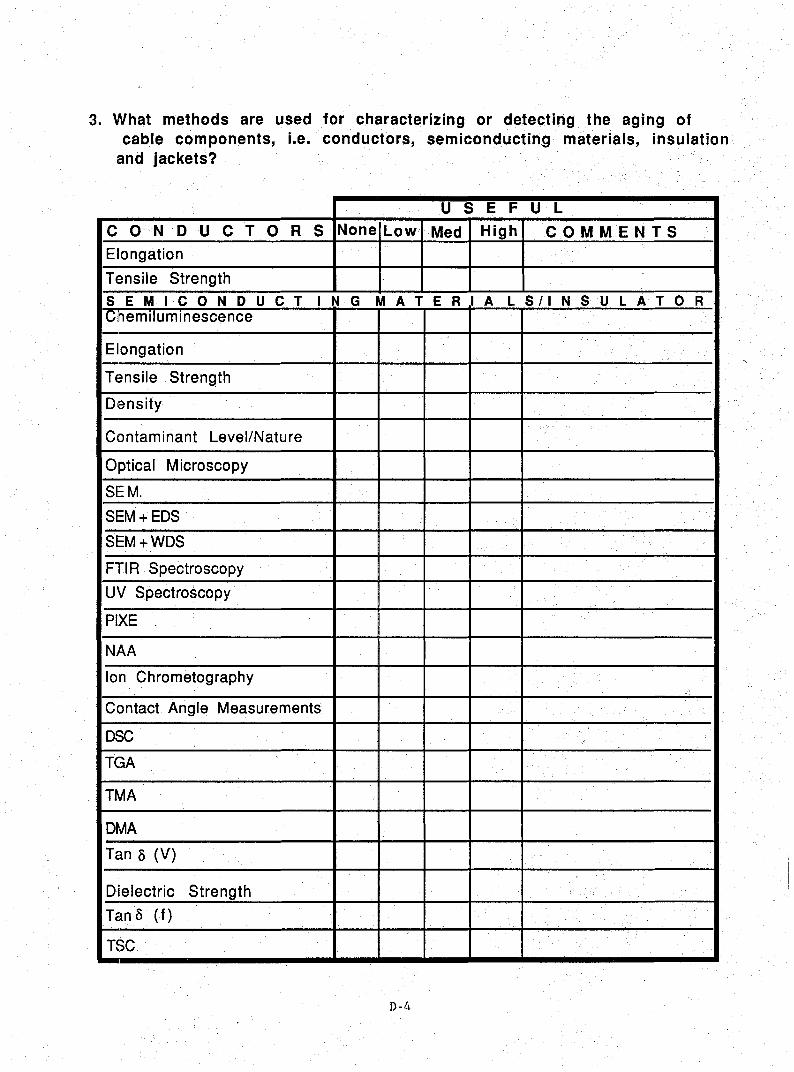
3. What methods are used for characterizing or detecting the aging ofcable components, i.e. conductors, semiconducting materials, insulation
and jackets?
U 5 E F U L
C ON o U C T 0 R 5 None Low Med High COMMENTSElongation
Tensile Strength
S E Mie 0 N D U C T 1 N G M A T E R 1 A L S / 1 N S' U LAT 0 RChemilummescence
Elongation
Tensile Strength
Density
Contaminant Level/Nature
Optical Microscopy
SEM.
SEM+EDS
SEM+WDS
FTIR Spectroscopy
UV Spectroscopy
PIXE~,
NAA
Ion Chrometography
Contact Angle Measurements
DSC
TGA
TMA
DMA
Tan 0 (V)
Dielectric Strength )
Tano (f)
TSC
D-4

4. What information on materlals is needed to understandaging?
5. What new techniques have been developed in the last five years and which will aid incharacterizing or detecting aging of materials?
6. What test geometricsdo vou consider togive the most realistic simulation of aging?
1= Least Effective 5 =Most Effective
W E T (L1QUID NATURE) 1 3 3 4 5
Needle/Plane Liquid Electrodes
Needle/Plane SC Electrodes
Uniform Field SC Electrodes
Uniform Field Liquid Electrodes
Scratched Surface Liquid Electrodes
Coaxial Geometry Liquid Electrodes
Coaxial Geometry SC Electrodes
D R YNeedle/Plane Metal Electrodes
Needle/Plane SC Electrodes
Uniform Field Metal Electrodes
Uniform Field SC Electrodes~
7.What parameters do you use to assess your materials after aging tests?
S E N S 1 T 1 V 1 T YNone Low Med High C OMM E NTS
ACBD Test
Time To 80 Test
Tan f!.
Impulse Voltage BD Test
OC Testing
Analytical Techniques(Please Soecifv)
D-S

8. Do morphological changes in the insulation/semicon occurduringaging which can significantly affect the life? Ifso, what are they(Wetand Dry Conditions)?
9. 15 diffusion of stabilizers (antitoxicolants and additives) and/orcontaminantsanimportantfactor in aging? If so, what effects can
occur? (Wet and Dry Conditions)
10. DO we have a good test to evaluate the retal"dantadditives (Waterand/orElectricTrees)?
D-6
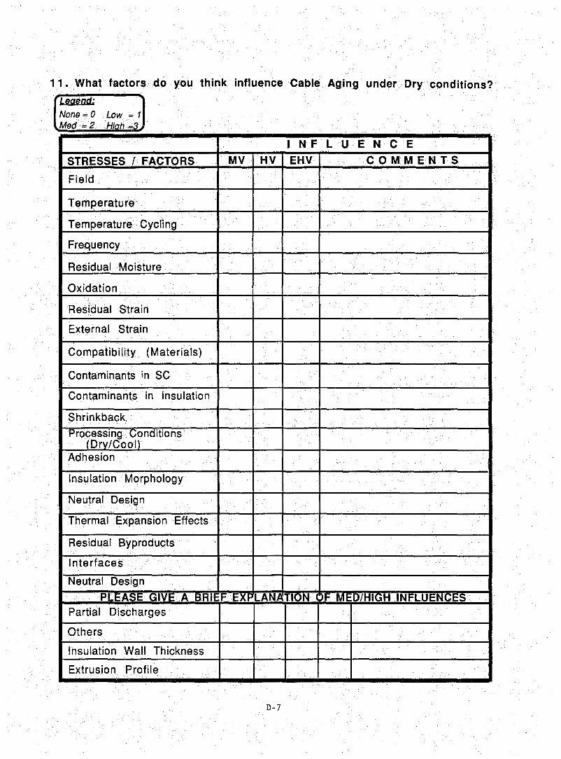
11 .What fact.or!~doyou thlnk influence Cable Aging underDryconditions?
Legend:.
None = 0 low, = 1Med=2 Hioh =3
1 NF L U E N C E
STRESSES/FACTORS MV HV EHV C 0 MM EiN TS
Field
Temperature
Temperature Cycling
Frequency
Residual Moisture
Oxidation
Residual Strain
External stratn
Oojnpatibifity (Materials)
Contaminants in SC
Contaminants in lnsulatlon
Shrinkback
Processing.Conditions(Drv/Ooot)
Adhesion
Insulation Morphology
Neutral Design
Thermal Expansion Effects
Residual Byproducts
Interfaces
Neutral Design
PLEASEG1VEA BAIEE EXPLAN~TION >F MED/HIGH INFLUENCESPartial Discharges
Others
Insulation Wall Thickness
Extrusion Profile
D-7
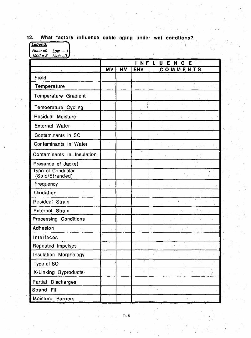
12. What factors influence cable aging under wet condtions?Legend:
None~O Low = 1Med=2 Hioh =3
1 NF L U E N C EMV HV EHV COMMENTS
Field
Temperature
Temperature Gradient
Temperature Cycling
Residual Moisture
External Water
Contaminants in SC
Contaminants in Water
Contaminants in Insulation
Presence of JacketType of Conductor(Sold/Stranded)
Frequency
Oxidation
Residual Strain ,
External Strain
Processing Conditions
Adhesion
Interfaces
Repeatedlmpulses
Insulation Morphology
Type of SC
X-Linking Byproducts
Partial Discharges
Strand Fil!
Moisture Barriers
D-8

13. Aging of Accessories
What factors influence aging of accessories?
Legend:
None=0Med=2
1 NF L U E N C EMV HV EHV COMMENTS
Field
Temperature
Temperature Cycling
Frequency
Compatibility of Materials
Adhesion
Residual Strain
External Strain
Thermal Expansion
Connector Design
Voltage Rating
Current Rating
Mechantcal Vibration
Partial Discharges
Type of Material
Please make comments about any Med/High Influence
D-9

14 a. lesting Aeeelerated Aging
What test parameters should be used to aeeelerated aging of cables?aeeessories?
ORY (EHV)
LEV E L SL 0 P E X L P E E P R
P A R A M E T E R SMin Max Min Max Min Max
Field (kV/m)
(Cèlcius)..•.....
Temperature ..
Cycling (Temperature)
Frequency Hz
Repeated Impulses....
Mechanical Strain
Time
DC Application
14b.WET (HV)
LEV E L5L 0 P E X L P E E P R ...
P A R A M E T E R SMin Max Min MaxMin Max
Field (kVlm)
Temperature (Celcius) .
Cycling (Temperature)
Frequency Hz
Repeated Impulses
Mechanical Strain
Time
DC Application
D-10

14c. WET (MV)
LEV E L S
P A R AM E T E R SL D P E X L P E E P R
Min Max Min Max Min Max
Field..
Temperature
Temperature Cycling• >
Frequency
Water Inside (Ves/No)
Water Outside (Ves/No)
DC Application
Types ofContaminants
Contaminants Concentration
Mechanical Strain
Impulses (Ves/No) [Repeated]
Time -
Water Nature
15.What methodsareused to .·analyze the data? CE.g. do vou use Wiebull, Log~normal
Statistics,.GMTF orOther?)
16. Wilat theoretical model of aging do vou use?
17. What additlonal tests should be performed on accessories?
18. Is there a national standard for aging tests under wet or dry conditions? If so, pleasename them.
D-ll

19. Diagnostic Tests
What tests do you use to assess the degree of aging after acceleratedaging tests or field aging?
Legenet:
None =0 Low = 1Med=2 Hi h =3
S E N S 1 T 1 V 1 T YT E S T MV HV EHV C 0 M M ·E N T S
AC Ramp BD Test
AC Step BD Test
AC Constant Stress Test
Impulse Voltage
DC BD Test
Tan ô (v)
Tan ô (f)
DC Leakage Current
Partial Discharqss
Low Frequency Testing
Oscillating Wave Testing
20. Do you conduct in situ tests to measure aging? If so, which ones?
21. What factory and installation tests do you conduct for transmissionclass cables (~138-kV)?
D-12

22. Service Experience
a. What is your experience of aging or servtee of cables?(Transmission and distribution [with and wlthout a moisture barrier».
b. What techniques are available to rejuvenate aged cables?
c. Have vou tried any? If so, what is your experience?
d. Is there an in-situ test to predict remaining life? (Dry or Wet Conditions)
e. What kind of research would Vou suggest?
f. Can vou relate cable failure to installation data of that cable?
0-13
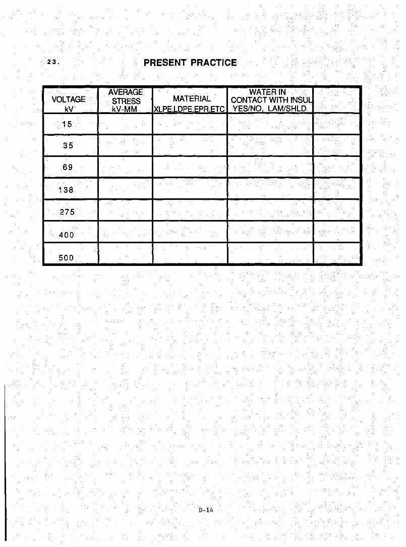
23. PRESENT PRACTICE
AVERAGE WATERJNVOLTAGE STRESS MATERIAL cor-nACT WITHINSUl
kV kV-MM XLPE LOPE EPR ETC YES/NO LAM/SHLO
15
35
69
138
275
400
500
D-14

Appendix E
WORKING GROUP ON MATERIALS - DETAILED REPORT
by JOHN TANAKA, SEGRETARY
The working group on Materials Aging and Diagnostics·met at 2:00pm under the
ch.airmanship.()~ Bruce Bernstein.
Bernstein fitstaskedfor the number of people who wished to give reports. About
four to fivepeople responded. Bernstein then outlined the rules to be followed.
Hepointed out that this working group<was to confine itself to materials since
cables wer~ being covered in a parallel working group At the start, the results of
tlle surveycovering materials would be reviewed. Then aftet the presentations and
discussion,it was hopedthat objectives could be formulated toward the close of the
session. With the procedures clarified, Bernstein went on the summarize the survey.
In order toderive a feeling as to what items people considered important, Bernstein
chose to countthe number of people who rated a particular item a "3" or highly
important. There were 18 responses tabulated for the dry condition (one was a
faulty xerox copy which could not be read) and 19 responses tabulated for the wet
condition. The separate items tmderthecategories ofaging, diagnostics, test
geometry,· aSsessment methods, and 1lI0rphology changes were shown with .t;henumber of
"3" responses for each sub-item.
Andras Farkas of NESTE reported on the lab testing of XLPE preparedwith their water
tree retardant. The uniform field approach usingthe GIGRE methodologyknown as
EFI/Eb wasused. The voltage stress was 15 kV/mmwithtemperature cycled 16 hours
at 90°C and 8hours at 7°G. The aging time was 3 and 8 weeks. There was a
significant difference (a factor of 1000) in the number of bow tie trees when the
water treeretardant sample was compared to a standard XLPE sample. When AG
breakdown was used, thewater tree retardant samples maintained a high breakdown
value whereas the breakdown values for the standard XLPE were found to degra4e. A
typical breakdown for the water treeretardant samples after 16 weeks was about
78 kV/mm whereas90%of.the standard XLPE samples had failed and those surviving had
dielectric strength of around 10 kV/mm. Finally, since electrical trees have been
reportedto grow from water trees and since electrical trees are more detrimental to
the health of a cable than water trees, a double needle test was used at 50% and 80%
E-l
relative humidity to grow electric trees. The inception voltage showed better
results for the tree retardant samples than for the standard XLPE.
Reinhard Schroth of Siemens reportedon the aging experiments on full sized cables
made with the same tree retardant material. The cables were made on a standard CV
line. The construction included an insulation shield, a copper wire screen and a
jacket. A ClGRE common test was run for 250 days. The results of the testing was
compared with a XLPE cable of the type which has had 20 years of service experience.
The bow tie tree count obtained by aging at 40°C for 1000, 2000, and 6000 hours was
about four orders of magnitude lower for the cable containing the tree retardant.
The number of vented trees in the tree retardant cable was about six times lower
than for the standard XLPE. The AC breakdown degraded with aging for the standard
XLPE but was not degraded as much with the tree retardant.
The cables were also tested using the AElC test protocol for 300 days. There was a
good correlation with the ClGRE test. The density and number of bow tie trees was
much less in the tree retardant cable. The AC breakdown voltage was more stable to
degradation with age for the tree retardant cable. lt was concluded on the basis of
comparison with the standard XLPE cable that the tree retardant cable will be long
lived.
Jean-Pierre Crine of lREQ asked which type of trees are more important, the water
trees or vented trees? Schroth said that he knew how to do the tests but was not as
certain about interpretations. However, without making a judgement on which is
important, it should be noted that both were reduced. Grine notedthat the AElG
results did not show the results for vented trees. He asked whether differences
were observed in the bow tie trees and vented trees. Schroth responded that the
data had been collected. The results were similar to the CIGRE common test. The
results of the GlGRE test should be considered to be representative.
Grine asked whether the tree retardant used was that developed by Siemens. Farkas
responded that the tree retardant represented the combined technologies of Siemens
and NESTE.
Bernstein asked whether the additive could be described as a partial discharge
suppressant. Schroth responded by observing that the tree retardant material was
highly dispersed in the polyethylene. The implication seemed to be that it was not
a partial discharge suppressant.
E-2

Emmanuel Brancato, consultant, observed that the ratios of values obtained for the
tree retàrdant cable and the water tree retardant cable were reported. He wondered
whether the ratio of cable life could be obtained from these other ratios. Schroth
felt .thatprojections of this type are not necessarily valid.
Bob Eichhorn of Union Carbide observed that the data were very interestingbut were
only the final points. He noted thàt none of the fundamentals were being reported.
For example, what is the system? How does it work? Without information of this
type, the results are commercial rather than scientific. Farkas responded that
there wasn'ttime in the schedule to discuss ail the fundamentals. Briefly, thè
water tree retardants are selected from a series of active compounds which inhibit
formation of hydroperoxides. The retardants suppressradical formation. In
standard polyethylene, radicals form more rapidly than can be reacted with the
antioxidànts present. The tree retardant is more effective than the usual
antioxidànt for preventing peroxide formation. The hydroperoxideinhibitor is part
of a copolymer system.
Ben Hwang of B.P. Performance Polymers askedwhether the jacket was removed in
testing. Schroth said yeso Bernard Dalle from EDF-DER-ClMA reported that insulated
cables have been studied for a long time in France for thermal, dielectric,
mechanical, and hydrolytic aging. These studies have shown that when hurnidity is
prevented from getting into a cable by use of a lead sheath, there is no water
treeing. However, EDF, the manufacturers, and materials suppliers have decided that
diagnostictools areneeded to study the effect of morphology of the insulation and
the interface between the semicon and insulation. To this end, the universities,
manufacturers, and suppliers are evaluating a number of diagnostic tests to be
applied to this problem. Work has been initiated, but the program is just coming to
the end of its first year, and results have not been achieved.
Dalle also described the pressure wave propagation method of determining space
charge in an insulating material. J. Lerwiner has developed this method and has
succeeded in measuringthespace charge in an intact cable insulation. Eugene
Favrie of SILEC has applied this method to a cable system. Semicons can contain 1%
zinc steàrate and larger. amounts of p~asticizers. Zinc stearate was found to
diffuse into the insulation and cause a large increase in the space charge. When
the .zinc stearate is eliminated from the semicon, the space charge did not increase
verymuch. Itwas postulated that the plasticizer facilitatedthe diffusion of zinc
steàrate into the insulation;
E-3

erine asked for the identity, of the supplier of the shield materialcorttainingthe
zinc stearate. Dalle did not know the supplier. Bernstein asked whether the main
point of the presentation was that the pressure pulse method was,a new d.iagnostic
tool. He noted, in any case, that it wasa diagnostic toOl nbton the list. erihe
noted that there was another important point inthat a component of theshield had
migrated into the insulation.
Brigitte Fallou of LeIE, France, noted that sometimes we look for something at a
place that is convenient rather than where the problem mightbe located. She rtoted
the change in the tanS of high density and low density polyethylene with temperature
and with aging. The unaged tanS vs. temperature curves are rather flat. After
aging, noticeable peaksform. Because ,of the shape of the cut:ve, the measuremertt
temperature is important. It was suggested that tanS was an index of aging proper
ties and probably could be correlated to other agingproperties such as elongatiOn
tobreak. Another example of ,a criterion for acceleratedaging as a functiOh Of
combined stresses wasthe time neededto reducethe breakdown voltage by 15%. The
temperature index available froIn thermal aging studieswas suggested asa means of
giving rankingto materials. The evolution of gases ,rtamely CO, C02' and H2 canbe
related to life for polyethylene terephthalate. Because short time tests areneeded
to project life data, diagnostic tests are important in measurihgthebeginrtings of
degradation. Christian Mayoux from Universite Paul Sabatier cornrnented thatthe
results of Ge analysis must,be used with care. He quoted resultsof hydrogen
evolution from XLPE under twodifferent conditions. The amount of hydrogeh
observed was quite differentfor the two experiments.
Roger Porter of' the University of Massachusetts, asked for a clarification. Henoted
that polyrners do not spontaneously decompose. He wondered how the gases originate.
Fallou said that high temperatures were not being used. The expe:riments were
suggested by the gas analysis from transformers. The degassing was from initial
decompositions (whichby inference was from electrical stress).
Torn Dakin, consultant, asked whetherhydrogen evolution parallels the gas
observed in transformers. Fallou responded that the gas evolution is a short term
test topredict changead.n longer term tests 'such as mechanicalproperties.
Bernstein asked whether the decompostion could be correlated to aging. Fàllou said
thatthe decornpositionwas a short term indication of aging. Porter pointedout
that the amorphous regimes in a polyrner can contain dissolved gases. He pointed out
that these might complicate the gas decomposition studies. Martin Broadhurst, of
E-4

the National. Instituteof Standards and Technology,said he had leatned a lot from
the EPRI and Union Garbide projects studying space charges. The space charges
induced ina polymer were found to evolve with time. The flow of these charges in
the. po'lymar, might be capable of carrying out chemistry. Bernstein c.ommented that
generalized changes were most easilym~asured. Gas evolution is a generalized
change. Failures, on the other hand, are site specific. Generalized changes may
not always reflect the changes at the failure site. Grine commented on the micro
cavity fo!,mation. Some tiny spots are evaporated. SOpHi! gases are probably formed.
What doesthis mean with respect tofailure time?
GhristianMayoux from.Universite Paul Sabatier described two experiments to study
the degra(iation of polymers by partiaL discharge. In the fitst experiment, Mayoux
creates a long channel (1 mm to 1.3 mm) in lowdensitypolyethyleneby molding a
wire in polyethylene and then extracting it Leavi.rrg the hollow channel. A flat
electrodeis pressed against one end of the channel. A wire electrode is inserted
from the other end of the channel leaving a gap between the point plane electrodes
of.l mm to 5.mm. A single pulse ofSS-JLs rise time and 200-JLs decay was imposed on
the gap in the channel. DiffeTent species were found to impinge on the surface of
the channels. The surface of the channels were changed. Someantioxidantsand
oligom~rsweTe found. Therewasgas evolved. Light emission spectroscopy was done.
The discharge occurs as in air until the ratio of the channel diameter to electrode
gap is lower than 0.20. The surface of the channel was studiedwith IR. Inthe
second experiment, an apparatus was constructed which contains ion and electron
guns., Thes.e sources allow formation of ions and electrons with energies of 20 eV to
300 eV and current densities of 0.25 JLAmm- 2 for ions and 0.50pA.mm- 2 for
electrons. A polyimide sample was exposed to these corona like ions and electrons.
Theelectrical characterizationaftertheion and electron bombardment was with
thermallystimulated current. These •twonoveL and interesting techniques are being
used to studythenature of partial discharge dMradation ofinsulating materials..
Bernstein asked whether the aging behavior or the life of the polymer was being
studied. Mayoux said. that the aging mechanism. was being studied, not life. Armin
Bruning of Lectr.omechanical. Design asked about the energyofthe dischargein the
êhannel.Mayoux said thatthis could be determined, but had not yet been done.
Argon ions of 25 eV, 45 eV, and 95 eVhad been used in the second experiment. Aiso
differences weTe foundbetween argon ions and nitrogen moleculeions.
Tony Barlow, >Quantum commentedon morphology and secondary crystallization. This
latter was defined as polymer chains forming lamellae and spherulites at tempera-
E-5

tures below the melting point in order to achieve a lower energyconfiguration than
that produced in the extrusion process. When microvoids are measured by·optical
spectroscopy, they are found to increase. This is ascribed to the secondary
crystallization. Because of the pseudo laminar flow during extrusion, it i~
expected that the center of the insulation wouldexhibit more secondarycrystalliza
tion than the portion near the surfaces. This is borne out by the data. Another
evidence that the polymer moleculesare undergoing movement during secondary
crystallization is the observation that when a slab of a virgin polymer and a slab
containing antioxidant are placed in contact, the antioxidant is found to migrate
from the antioxidant-containing slab into the virgin polymer. The next question is
whether the same effect is observed forcross-linked polyethylene. It has been
found that dry cured polyethylene do generate voids. These are about 2 ~m in size
with 47 voids/mm3 being observed. Since the XLPE was prepared witha similar
material and the same extrusion equipment, it would seem that the processing
condition has an effect on the microvoid population.
Bernstein asked whether microvoids of this type are significant. Barlow said yes,
they may coalesce and get larger. Bernstein asked what would happen to the
hypothetical cable which operates at temperatures no higher than 40-S0°C? Barlow
felt that microvoids would also grow in these cables. Porter suggested an alternate
hypothesis. He wondered if additives could phase separate and then diffuse away
leaving a void. Eichhorn observed that in steam cured cables the water phase
segregates and forms a halo. However, on the loss of water, the voids do not
necessarily remain. He also observed that, with sorne antioxidants, there is an
agglomeration. These remain and have been known to be the initiation point for
trees. These two observations are thus counter to Porter's alternate hypothesis.
John Tanaka, University of Connecticut, asked whether the halos which are often
observed tobe at the center of the insulation are related to the microvoid forma
tion? Barlow did not have an answer.
Jean-Marie Braun of Ontario Hydro described a technique which is being developed for
filled epoxy spacers used in switchgear. This is a diagnostic technique which can
probably be applied to cable insulation. Very small voids do not initiate dischar
ges in a consistent manner. In general, discharges are started by free electrons
generated by cosmic rays which are then accelerated in the field causing collisions
with the gas molecules present and generating secondary electronsand ions. Very
small voids are less apt to be hit by cosmic rays and insufficient electroIls are
created to enable discharges to initiate. The technique being developed for the
epoxy spacers is to irradiate the microvoid with X-rays. This createsa sufficient
E-G

number of electrons so that a true inception voltage is observed for microvoids.
The X-ray can be focussed to find the site of a microvoid. If the beam is irradiat
ing a microvoid, a partial discharge is detected. If the X-ray is turned off or
moved, the partial discharge ceases. If there are no.microvoids, no partial
discharge is detected. The technique has been shown to work by using a O.l-mm void
purposely put in an epoxy spacer.
Bernstein asked whether the X-ray would degrade polyethylene. Braun said that the
X-ray was tunable and that the energies could be adjusted to appropriate l~vels.
Eichhorn asked about the target. Braun believed that it was the Ka lines of
tungsten. Brancato asked about the inception voltage. Braun said that the incep
tion voltage was sufficient to give partial discharge in large voids. It was not so
high as to give a glow discharge.
At this point, Bernstein initiated the wrap-up for the session. The survey results
were put on the overhead and the audience was asked whether any of the par~meters
should be reevaluated. The first survey results to be discussed were the categories
under Aging.
Brancato noted that time was the most important parameter. There would be no aging
without time. Mayoux felt that field and time were related and should be yoked.
Hwang felt that external water and field needed to be combined. Neither stress by
itself would cause appreciable deterioration of the insulation. Bruning asked about
the effect of water in the field. Eichhorn noted that polyethylene saturates at
about 0.1% water. Wben there is a field present, more water enters the
polyethylene. This is due to the electrophoretic effect under either an AG or DG
field. The temperature rise and thermodynamics tend to counter this effect and will
push the water out. Joe Dudas, consultant, in response to the low score given
temperatUre gradient, said that he had a problem with this. Temperature and
temperature gradient are always a significant factor and they should go together.
Tony Doepkin, Gablec, commented that he agreed but that he had not given it a "3"
rating. Only "3" ratings were counted for the overhead being shown. Eichborn
commented that Densley had observed in accelerated life tests that room temperature
effects weregreater for polyethylene than high temperature effects. Eichborn said
that he had made the same observations. However, EPR shows opposite effects.
Bernstein wondered whether this was a temperature gradient effect.
Tom Rodenbaugh, EPRI, noted that for studies of semicon contamination, temperature
gradients would be needed. Bernstein commented that Phillips' work and Katz's work
E-7

showed that microvoids increased with temperature of thermal loadcycling treatment
and that there was a relationship between aging and breakdown; Fallou pointed out
that the magnitude of the temperature was important. Tests run in France show that
at certain elevated temperatures, new phenomena appeared. Thesewere not
necessarily real world phenomena. It is important to recognize the temperature of
the transition points.
Eichhorn asked about temperature cycling. This shouldbe added to the list.
Bernstein noted the low score for high frequency testing. Eichhorn thought it might
be important, but no other comments were made. Bernstein noted the lowscore for
morphology. Perhaps many people were not aware of the results of the work on
morphology. With the introduction of the subject of contamination, Hwangcommented
that he was surprised that it did not get more votes. Broadhurst wondered about
contamination and field enhancement. Should these be coupled? Eichhorn pointed out
that residual moisture does not belong in the wet environment testing. Barlow
concurred saying that since the sample was placed in water the residual moisture was
insignificant.
The next category to be discussed was Diagnosis Techniques. Bernstein observed that
the survey seemed to indicate that the diagnostic techniques for 1970 are adequate.
The lower significance placed on sorne of the more exotic techniques might be due to
unfamiliarity. Fallou asked whether the diagnostic methods listed were only for
materials. Bernstein said yeso Bernstein commented that chemiluminescence was so
sensitive, it was difficult to interpret the results. Work done under EPRI contract
seemed to indicate that for dry aging the most important aging parameter was
oxidation resistance which was followed by elongation to break and thenelectrical
properties (ACBD); For wet environments, the order was électrical properties,
oxidation, and then elongation.
Crine noted that density changes slowly over time due to increasedcrystallinity.
Tanaka pointed out that Sandia had found densitychanges a useful way tofollow
oxidation. Broadhurst noted that perhaps the modulus and yield properties of
polyethylene would change 10% for a 1% change indensity. Eichhorn observed that
Dse is an important tool for materials development. For example, the efféctiveness
of an antioxidant can be quickly evaluated. Micro IR and FTIR are useful. The
micro IR, in particular, enables a small spot to be analyzed. Porter asked about
the use of microscopy for determining the number and lengthof trees.
Willem Boone, KEMA, felt that the life ofa cable is correlated tothe size of the
E-8

trees. Doepkin responded that in a study of 7 or 8 HMWPE field aged cables, they
did not get a correlation of cable life with tree size. Doepkin felt that, in
general, it was difficult to get this type of correlation. Bernstein noted that TGA
and TMA were both rated low. He felt that this is as it should be. Porter agreed.
Bernstein wondered if anyone had looked at tano as a function of frequency. Was
there a possibility that as a diagnostic tool a frequency different from 60 Hz
should be used? Brancato felt that the results would be the same at different
frequencies.
Bernstein noted that dielectric strength had been used by Neste as their criteria of
a desirable material. Rodenbaugh asked Doepkin whether the tano obtained in the
laboratory correlated with field experience. Doepkin said that there was a correla
tion and that it was datum which an engineer needed to know. Hwang pointed out that
there was a Sumitomo paper in which voltage life had been determined by tests on a
plaque.
The discussion meeting was adjourned at 5:00 pm.
E-9

ACBDAEICAWGBDCEADSCEEDFEEIEHVEPDMEPREPRIFTIRHMPEHMWPEHVICCIECIEEEIRIREQLDPEMVNELPAPDPEPVCSAXSSCsemiconTRTRXLPETSCUNIPEDEUVVHVWAXSXLPE
Appendix F
ACRONYMS AND ABBREVIATIONS
- ac breakdown- Association of Edison Illuminating Companie~
- American wire gauge- breakdown- Canadian Electriêal Association- differential scanning calorimetry- field- Electricite de France .- Edison ElectricInstitute- extrahighyoltage ..•. .- ethylen~-propylene-diene monomer- eth~lene-propylene rubber- ElectricPower~esearch Institute- Forier transform infrared spectroscopy- high molecular weight polye~hylene
- high molecular weight polyethylene- highvoltage
Ins1.llating Coml.uctors Committee (of IEEE Power Engineering Society)- International Electrochemical Commission- Institute of Electrical and Electronics Engineers- infrared .- Institut de Recherche d'Hydro-Quebec- +ow-density polyethylene- m~di~voltage .- Northwest Light and Power Association- partial dischàrge- poly~thylene
- polyvinyl chloride- smaUangle x-ra.y spectroscopy- semi.cond\jcting material or layersem~conducting layer
- treeretardant- tree-retardant cross-linked polyethylene- thermally stimulated currents
Union of Producers and Distributors of Electricity in Europe- ultraviolet
very high voltage- wide angle x-ray spectroscopy- cross-linked polyethylene
F-l