Embed Size (px)
Citation preview

DOI 10.1140/epje/i2004-10041-1
Eur. Phys. J. E 15, 117–126 (2004) THE EUROPEAN
PHYSICAL JOURNAL E
Wrinkle formations in axi-symmetrically stretched membranes
J.-C. Geminarda, R. Bernal, and F. Melo
Departamento de Fısica Universidad de Santiago de Chile and Center for Advanced Interdisciplinary Research in Materials,CIMAT, Avenida Ecuador 3493 - Santiago, Chile
Received 26 May 2004 and Received in final form 10 August 2004 /Published online: 19 October 2004 – c© EDP Sciences / Societa Italiana di Fisica / Springer-Verlag 2004
Abstract. We study experimentally the main features of wrinkles that form in an initially stretched andflat elastic membrane when subjected to an axi-symmetric traction force at the center. The wavelength andamplitude of the wrinkle pattern are accurately characterized as the membrane tension and the tractionforced are varied. We show that wrinkles are the result of a supercritical instability and appear for a well-defined critical traction force that is a function of the membrane tension. Wrinkle length and amplitudeincrease as the traction force is increased further. By contrast, both quantities decrease as the membranetension is increased. Calculations based on symmetry arguments and elastic-energy minimization are ingood agreement with experiments and provide a simple way to investigate configurations that are difficultto access experimentally. Such problems include wrinkles in elastic nano-films on finite-thickness viscoussubstrates used in semiconductor technology or in cellular forces detection.
PACS. 46.32.+x Static buckling and instability – 87.19.St Movement and locomotion – 85.40.Ls Metal-lization, contacts, interconnects; device isolation
1 Introduction
Standing films, plates or membranes under longitudinalcompressive stress spontaneously buckle to allow for theexpansion of the film by bending out of the nominal filmplane. In such configurations, buckling produces wrinklesthat are perpendicular to the direction of applied compres-sion [1,2]. However, less intuitive buckling occurs when anelastic band stripe is subjected to large enough longitudi-nal stretching in its plane [3,4]; the film buckles to relaxthe in-plane strain incompatibility generated by the Pois-son effect. Hence, wrinkles accommodate themselves par-allel to the direction of the applied tension. In general, thebuckling wavelength is a compromise between the relax-ation of in-plane strain and the elastic stresses associatedwith bending. In practice, the constraint provided by anelastic substrate, to which most films are bounded, canprevent buckling whereas a viscous substrate allows it,but on a time scale set by the viscous flow [5,6].
Wrinkling in elastic films under stress is ubiquitousin nature. Among common systems exhibiting this phe-nomenon are our skin, textiles and more specifically thincoatings subjected to stresses mismatch [7,8]. Apart froma basic interest, wrinkled membranes have found un-expected applications recently. For instance, in modern
a Permanent address: Laboratoire de Physique, Ecole Nor-male Superieure de Lyon, 64, Allee d’Italie, 69364 Lyon cedex07, France; e-mail: [email protected]
technology, pre-wrinkled conductive films are proposed asstretchable electrical contacts required in large-area elec-tronics [9]. In medicine, surgery has always involved cut-ting, thickening contraction and in many cases wrinklingof the skin. Potential applications of wrinkle mechanics toimprove wound healing have been recently summarized byE. Cerda [10]. In turn, in cell biomechanics, wrinkled pat-terns produced by cells crawling onto elastic membranes(several nanometers thick), provided a useful tool to testliving-cells locomotion. With this method, the length ofthe wrinkles has been correlated to the force applied bythe cell cytoskeleton [11,12]. In this article, we presentexperimental as well as theoretical studies of the wrin-kles that form on an initially flat elastic membrane whensubjected to an axi-symmetric traction force. In our sys-tem such a force is applied over a central region havinga given radius by pulling symmetrically the membrane.With this configuration we intend to mimic, for instance,the pattern resulting from the homogeneous contractionof a nearly circular living cell when attached to an elas-tic film [13] or a circular wound as described recently byE. Cerda [10]. In addition to the central force, the mem-brane can be stretched radially to vary its tension. Ourresults show that the length of the wrinkles as well astheir amplitude increase as the traction force is increasedbeyond a well-defined critical value which is a function ofthe membrane tension. By contrast, both quantities de-crease as the initial membrane tension is increased. Weshow thus that wrinkles appear as a consequence of a

118 The European Physical Journal E
supercritical instability. Beyond the instability threshold,the number of nucleated wrinkles is nearly independent ofthe central force, varies very slowly with membrane ten-sion, and is a linear function of the size of the centralobject. In addition, if the tension vanishes, our results pre-dict that wrinkles develop in the whole membrane. Theseobservations challenge the validity of previous membraneforce measurements [12], due to living-cell traction, basedon the wrinkle length. We discuss under what conditionsthese measurements are reliable and we propose alterna-tive approaches. To account for our experimental results,we develop a theoretical approach, based on bending- andstretching-energy minimization, that capture well the fea-tures described above. Symmetry arguments allow us tosolve the complex membrane equations with simple nu-merical calculation.
Our article is organized as follows. Section 2 is de-voted to the description of the procedure used to deformthe membrane and to introduce the minimal ingredientsnecessary to explain why the membrane buckles. In ad-dition, by developing simple equilibrium forces considera-tions and by neglecting the bucking threshold, we recoverrecent experimental and theoretical results [10] obtainedin the limit of an infinitely thin and infinitely large mem-brane under stress. In our experiment, the displacementfield is characterized by tracking the position of small par-ticles randomly distributed on the surface membrane. Be-sides, the amplitude and the length of wrinkles are mea-sured with a simple procedure based on the deflection ofa lattice of equidistant parallel lines projected onto themembrane. Both methods are described in detail in theexperimental section. In Section 3, in addition to measure-ments of the length and the amplitude of wrinkles, we testthe number of wrinkles by varying the size of the pullingcircle, the pulling central force and the membrane ten-sion. In Section 4 we introduce the basis of our theoreticalmodel and we contrast it with our experimental results.For the sake of continuity the complete description of oursemi-analytical calculations is developed in the appendix.Finally, our main conclusions are presented in Section 5.
2 Problem geometry
2.1 Definitions
Aiming to mimic the contraction of a cell attached to astretched membrane, we consider the geometry sketched inFigure 1. The circular membrane is pulled toward the cen-ter along a circle (radius r0). We denote ur(r0) = −δ theimposed radial displacement. In order to account for theinitial stretching of the membrane, we impose the displace-ment ur(R) = β along the large outer radius, R. In thefollowing, we denote u(r, θ) the horizontal-displacementfield and ζ(r, θ) the out-of-plane displacement of the mem-brane. The general set of equations governing the equilib-rium shape of the membrane is given in the appendix.
R
r0
βδ
R*
σθθ
σθθ
Elastic membrane
Fig. 1. Sketch of the experimental configuration. The mainquantities defined in the text are indicated in the figure. Thedarker section, limited by R∗, indicates the membrane region,under azimuthal compression, where wrinkling might occur.
2.2 Axi-symmetrically stretched membrane
If the mechanical situation is stable with respect to thebuckling of the membrane (ζ = 0), taking into ac-count the imposed deformation, one shows easily that thehorizontal-displacement field reduces to ur, which obeys∆ur = 0. Taking into account the boundary conditions,one obtains
ur(r) =δr0 + βR
R2 − r20
r − δR+ βr0
R2 − r20
Rr0
r(1)
and the corresponding components of the stress tensor
σrr =E
1− σ2
×[
(1 + σ)δr0 + βR
R2 − r20
+ (1− σ)δR+ βr0
R2 − r20
Rr0
r2
]
, (2)
σθθ =E
1− σ2
×[
(1 + σ)δr0 + βR
R2 − r20
− (1− σ)δR+ βr0
R2 − r20
Rr0
r2
]
, (3)
σrθ = 0 . (4)
At this point, it is worth considering the case of amembrane stretched at the outer radius with the constanttension γ without any constraint along the inner circle.One can easily obtain from equation (2) that the resultingdisplacement β at the outer radius R satisfies
γ =E
1− σ
β
R. (5)
Note that the tension γ is then associated to the initialdisplacements β at the outer radius and −δ0 ≡ ur(r0) =βr0/R at the inner circle. Let us now impose an additionaldisplacement −δi along the inner circle so that δ = δi +δ0. Using equation (2), one can show that, in order tomaintain the equilibrium, one must pull the membrane

J.-C. Geminard et al.: Wrinkle formations in axi-symmetrically stretched membranes 119
along the inner radius with the tension τ ≡ σrr(r0) whichimplies
τ = E(1− σ)R2 + (1 + σ)r2
0
(1− σ2)(R2 − r20)
δir0
+γ
1 + σ. (6)
Thus, there exists a linear relation between the imposeddisplacement δi and τ , and the initial tension γ is propor-tional to β. In the following, we will improperly use the“tensions” β and δi (or δ) instead of γ and τ .
Let us now analyze the behavior of the orthoradialstress σθθ. Provided that δ > 0 and β > 0, the radialcomponent σrr > 0 (∀r), whereas σθθ changes in sign forthe radius
R∗ =
√
1− σ
1 + σ
δR+ βr0
δr0 + βRRr0 . (7)
The orthoradial stress σθθ > 0 for r > R∗. In this regionthe membrane is stretched in both the directions of ther- and θ-axis. By contrast, σθθ < 0 for r < R∗. In thisregion, the membrane is subjected to a compression alongthe θ-axis so that it is likely to buckle and to form wrinkleselongated along the r-axis. Let us now assume, in a crudeapproximation, that the buckling instability leads to theformation of n radial wrinkles. The threshold of the insta-bility at a distance r from the center can be approximatedby σtθθ ∝ En2h2/r2, where h denotes the thickness of themembrane. In the limit R → ∞ and r0δ À h2, one canguess that the membrane buckles as soon as σθθ < 0 sothat the length of the wrinkles is of the order of R∗. Inthat limit
R∗ = r0
√
τ − γ1+σ
γ. (8)
We recover here the result recently obtained by E.Cerda [10]. A good agreement was found between theoryand experiment. The main conclusion is that the lengthof the wrinkles increases with the imposed tension τ anddecreases when the initial tension of the membrane γ isincreased.
In addition, one can notice that, in the case of a mem-brane without any initial tension (β = 0), the radius
R∗ = R√
(1− σ)/(1 + σ) is smaller than the outer ra-dius R of the membrane (σ > 0, in usual practical cases)and does not depend on the displacement δi, imposed atthe center. In this case, one can expect the characteristicsof the wrinkles to be imposed mainly by the outer bound-ary, and, for instance, their length to be about the outerradius R.
Thus, when pulled at the center, the membrane is gen-erally submitted to an orthoradial compression in a region,r0 < r < R∗, in which wrinkles elongated along the r-axisare likely to form. The result obtained above (Eq. (8)), islimited to the case of very thin membranes (or to largeimposed displacements) and does not provide any infor-mation on the number of wrinkles n nor on the wrinkleprofile. In the following section, we describe the experi-mental realization of the proposed geometry and analyzethe characteristics of the membrane instability close to thethreshold of the instability.
Parallel-light
PMirror
Small-angle lighting
MaskFrame
Tension adjustment
Pump
Central tube
Membrane
Fig. 2. Experimental setup.
Fig. 3. Top view of the buckled membrane. Above a thresholddisplacement, radial wrinkles form around the central tube.One can clearly see them from above using the circular small-angle light source (12 wrinkles, r0 = 19 mm).
3 Experimental study
3.1 Experimental setup
The experimental setup consists of a horizontal circularframe that holds firmly a thin elastic membrane (Latex,thickness h = 0.2 mm) which is initially wedged betweentwo plexiglass rings without any significant tension. Theinitial tension of the membrane, γ, can be adjusted laterby pushing it down along a circle (R = 18.5 cm) by meansof a third L-shaped ring (Fig. 2).
One imposes the axi-symmetric radial displacement δialong a circle (radius r0) by sucking in the membrane ina vertical tube (PVC); the inner pressure, P , is decreasedwith the help of a manual pump. The top circular edgeof the tube is rounded and lubricated so as to allow themembrane to slide without any significant friction. A sim-ple radial in-plane displacement over the whole surface ofthe stretched membrane results from the imposed defor-mation.
The system is imaged from above, along the vertical,with the help of a high-resolution digital camera (NikonD1x). We use two different light sources; the membranecan be either lit from above by an annular array of LEDs,or from below by a parallel-light source. The upper lightsource (100 LEDs along a circle (radius 15 cm), 1 cmabove the upper surface of the membrane) provides a
120 The European Physical Journal E
x
y
20 mm
Shadow of the mask Brass particle
(a)
(b)
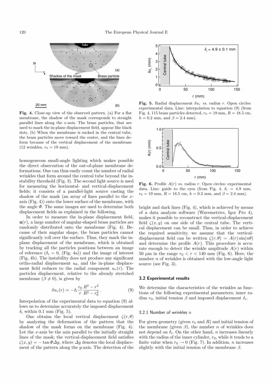
Fig. 4. Close-up view of the observed pattern. (a) For a flatmembrane, the shadow of the mask corresponds to straightparallel lines along the x-axis. The brass particles, that areused to mark the in-plane displacement field, appear like blackdots. (b) When the membrane is sucked in the central tube,the brass particles move toward the center, and the lines de-form because of the vertical displacement of the membrane(12 wrinkles, r0 = 19 mm).
homogeneous small-angle lighting which makes possiblethe direct observation of the out-of-plane membrane de-formations. One can thus easily count the number of radialwrinkles that form around the central tube beyond the in-stability threshold (Fig. 3). The second light source is usedfor measuring the horizontal- and vertical-displacementfields; it consists of a parallel-light source casting theshadow of the mask (an array of lines parallel to the x-axis (Fig. 4)) onto the lower surface of the membrane, withthe angle Φ. The same images are used to determine bothdisplacement fields as explained in the following.
In order to measure the in-plane displacement field,u(r), a large number of angular-shaped brass particles arerandomly distributed onto the membrane (Fig. 4). Be-cause of their angular shape, the brass particles cannotsignificantly roll over the surface. Thus, they mark the in-plane displacement of the membrane, which is obtainedby tracking all the particles positions between an imageof reference (δi = 0, (Fig. 4a)) and the image of interest(Fig. 4b). The instability does not produce any significantortho-radial displacement uθ, and the in-plane displace-ment field reduces to the radial component ur(r). Theparticles displacement, relative to the already stretchedmembrane (β 6= 0), is given by
δur(r) = −δir0
r
R2 − r2
R2 − r20
. (9)
Interpolation of the experimental data to equation (9) al-lows us to determine accurately the imposed displacementδi within 0.1 mm (Fig. 5).
One obtains the local vertical displacement ζ(r, θ)by analyzing the deformation of the pattern that theshadow of the mask forms on the membrane (Fig. 4).Let the x-axis be the axis parallel to the initially straightlines of the mask; the vertical-displacement field satisfiesζ(x, y) = − tanΦ∆y, where ∆y denotes the local displace-ment of the pattern along the y-axis. The detection of the
5
4
3
2
1
0
δur (
mm
)
150100500
r (mm)
Cen
tral t
ube
δi = 4.9 ± 0.1 mm
Fig. 5. Radial displacement δur vs. radius r. Open circles:experimental data. Line: interpolation to equation (9) (fromFig. 4, 115 brass particles detected, r0 = 19 mm, R = 18.5 cm,h = 0.2 mm, and β = 2.4 mm).
1.0
0.5
0.0
A(r
) (m
m)
150100500
r (mm)
Cen
tral t
ube
Fig. 6. Profile A(r) vs. radius r. Open circles: experimentaldata. Line: guide to the eyes (from Fig. 4, δi = 4.9 mm,r0 = 19 mm, R = 18.5 cm, h = 0.2 mm, and β = 2.4 mm).
bright and dark lines (Fig. 4), which is achieved by meansof a data analysis software (Wavemetrics, Igor Pro 4),makes it possible to reconstruct the vertical-displacementfield ζ(x, y) on one side of the central tube. The verti-cal displacement can be small. Thus, in order to achievethe required sensitivity, we assume that the vertical-displacement field can be written ζ(r, θ) = A(r) sin(nθ)and determine the profile A(r). This procedure is accu-rate enough to detect the wrinkle amplitude A(r) within50 µm in the range r0 < r < 140 mm (Fig. 6). Here, thenumber n of wrinkles is obtained with the low-angle lightsource (see Fig. 3).
3.2 Experimental results
We determine the characteristics of the wrinkles as func-tions of the following experimental parameters; inner ra-dius r0, initial tension β and imposed displacement δi.
3.2.1 Number of wrinkles n
For given geometry (given r0 and R) and initial tension ofthe membrane (given β), the number n of wrinkles doesnot depend on δi. On the other hand, n increases linearlywith the radius of the inner cylinder, r0, while it tends to afinite value when r0 → 0 (Fig. 7). In addition, n increasesslightly with the initial tension of the membrane β.

J.-C. Geminard et al.: Wrinkle formations in axi-symmetrically stretched membranes 121
25
20
15
10
5
0
n
16012080400
r0/h
β/h = 12β/h = 28
Fig. 7. Number n vs. radius r0. The number of wrinkles n in-creases linearly with the radius of the inner cylinder r0, whileit tends to a finite value in the limit r0 → 0 (typically 5). Inaddition, n increases with the initial tension of the membraneβ (R = 18.5 cm, h = 0.2 mm).
0.8
0.6
0.4
0.2
0.0
A m (
mm
)
86420
δi (mm)
20
15
10
5
0
L (mm
)
β = 2.4 mm, r0 = 19 mmβ = 2.4 mm, r0 = 31 mmβ = 5.6 mm, r0 = 31 mm
Fig. 8. Amplitude Am and length L vs. δ. Experimental mea-surements of the maximum amplitude Am and of the lengthL as functions of the imposed displacement δ. Full symbols:amplitude Am; open symbols: length L. Lines: interpolationof Am to Am =
√
K(δi − δc
i) and of L to L = Lc + ξδi. The
results correspond to two different radii r0 and two differentvalues of the initial tension β (R = 18.5 cm, h = 0.2 mm).
3.2.2 Amplitude Am and length L vs. displacement −δ
From the experimental profiles A(r) (Fig. 6), we deter-mine the maximum amplitude Am and the typical lengthL of the wrinkles, the latter defined to correspond to theinflexion point of the profile, d2A/dr2(L + r0) = 0. Thewrinkles appear beyond a critical displacement δci (Fig. 8);
the maximum amplitude Am satisfies Am =√
K(δi − δci )whereas, starting from the finite value Lc, the length Lincreases linearly with δi. However, L decreases when theradius r0 and the tension β are increased. The character-istics of the bifurcation will be discussed in details withthe help of the numerical results in Section 4.3.2.
3.3 Comments
Even providing accurate measurements of the wrinklescharacteristics, the experimental setup presents some limi-tations that deserve to be discussed at this point and that,in particular, justify the numerical analysis of the problempresented in Section 4.
The main limitation of the experimental setup con-sists of its inability to reach the limit β → 0. Indeed,
in this limit the weight of the membrane cannot be ne-glected anymore; experimentally, for small values of β, themembrane is not flat and the experimental setup fails toprovide reliable measurements. Another limitation comesfrom the friction between the membrane and the centralcylinder. We avoided this effect as much as possible but,at this point, we must prove that the characteristics ofthe wrinkles do not depend on the friction at this bound-ary. Finally, we cannot change easily the outer radius Rand the characteristics of the elastic membrane. We know,from the mathematical analysis, that the thickness h ofthe membrane is the length scale, and that the results canbe expressed in terms of h. In the same way, there is noneed to know the elastic constant of the material as thecharacteristics of the wrinkles are only governed by geo-metrical relations. By contrast, we do not know accuratelythe value of the Poisson coefficient which is likely to playan important role (see, for instance, Eq. (7)). Moreover,this coefficient cannot be changed easily.
In the next section, we present numerical results thatvalidate and extend our experimental findings.
4 Numerical study
4.1 Set of equations
Assuming that the membrane vertical deformation can bewritten in the form ζ(r, θ) = A(r) cos(nθ), we show (seeappendix) that the problem can be reduced to the follow-ing set of differential equations:
r2u0r
′′
+ ru0r
′ − u0r =
1
4r
[
n2(1 + σ)A2 − 2n2σrAA′
−(1− σ)r2A′2 − 2r3A′A′′
]
, (10)
(
r4A(4) + 2r3A(3))
h2 − r2A′′
[
(1 + 2n2)h2
+3(
σn2A2 + r2A′2)
+ 12r(
σu0r + ru0
r
′
)
]
+rA′
[
(1 + 2n2)h2 − 3n2A2 − 12r(
u0r + σru0
r
′
)
]
+n2A
[
(n2 − 4)h2 + 12r(
u0r + σru0
r
′
)
]
+3n4A3 + 3n2σr2AA′2 − 3σr3A′3 = 0 , (11)
where A(r) denotes the profile of the wrinkles along the r-axis and u0
r(r) the axi-symmetric part of the radial-displa-cement field. The solution to equations (10) and (11) canbe found, provided the boundary conditions u0
r(r0) = −δand u0
r(R) = β for the horizontal-displacement field u0r(r),
and A(r0) = 0, A(R) = 0, A′(r0) = 0, and A′(R) = 0 forthe radial profile A(r) of the wrinkles.
4.2 Numerical method
The coupled differential equations (10) and (11), associ-ated to the corresponding boundary conditions, are solved

122 The European Physical Journal E
50
40
30
20
10
0
n
200150100500
r0/h
β/h = 12.5
β/h = 37.5
β/h = 12
β/h = 28
Fig. 9. Number n vs. radius r0. Full symbols: numerical data.Open symbols: experimental results from Figure 7. The num-ber n of wrinkles depends linearly on the radius r0 of thecentral cylinder. The slope dn
dr0increases with the initial ten-
sion of the membrane β. The number n is found to tend to 2or 3 when r0 → 0 (δ/h = 50, R/h = 1000, and σ = 0.5).
numerically using a relaxation method. As the number ofwrinkles, n, is a parameter in these equations, we com-pute initially the solutions for different values of n. Fur-ther analysis of the energy as a function of n provides uswith the number n which minimizes the energy.
4.3 Numerical results
We compute the equilibrium shape of the membrane forvalues of the parameters similar to that of the experimen-tal situation. In a first step, we choose a value of the Pois-son coefficient, σ = 0.5. The numerical displacement fieldu0r and profile A(r) are similar to the experimental ones
presented in Figures 5 and 6 and are thus not reproducedin this section.
4.3.1 Number of wrinkles n
We compute the number of wrinkles, n, at equilibriumand observe that it depends only slightly on the imposeddisplacement δ. By contrast, n increases linearly with theradius r0 of the central cylinder (Fig. 9). In agreementwith the experimental results, n is found not to vanishwhen r0 → 0 and the slope dn
dr0increases with the ini-
tial tension of the membrane β. However, we note thatthe experimental value of n is always significantly smallerthan that predicted numerically. The discrepancy remainsunexplained but we note that, numerically, the energy dif-ference between configurations corresponding to differentvalues of n is small. In our experimental configuration,the membrane is likely to be frozen by the effect of dis-sipation before reaching the optimal number of wrinkles.We can guess that an increase in the number of wrinkleswould lead to enhanced dissipation as the deformation ofthe membrane would involve creation of more curvature.Thus, since we measured n for increasing values of thetension, the observed number of wrinkles is smaller thanthe predicted one. Nevertheless, we note in the numeri-cal results that the wrinkle profile A(r) does not dependsignificantly on n close to the energy minimum.
50
40
30
20
10
0
δc/
h
6040200
β/h
(a)
6
4
2
0
dL/d
δ
40200
β/h
(d)
50
40
30
20
10
0
Lc/
h
6040200
β/h
(b)
2.0
1.5
1.0
0.5
0.0
K/h
6040200
β/h
(c)
Fig. 10. Dimensionless δc, K, Lc, and dL/dδ vs. β. The lengthof the wrinkles remains small enough compared to the outer ra-dius for the system to be considered as infinite. Open symbols:numerical results (diamonds: r0/h = 50; circles: r0/h = 100;squares: r0/h = 150; triangles: r0/h = 200). Full symbols in(a): experimental data from Figure 8. (R/h = 1000, and σ =0.5.)
4.3.2 Instability threshold and bifurcation characteristics
Again in agreement with the experimental results, thewrinkles are found numerically to appear beyond a criticalvalue δc of the displacement δ which depends on the initialmembrane tension β (Fig. 10a). (In order to make compar-ison with the experiment easier, we report, in Fig. 10a, ex-perimental results from Fig. 8. The discrepancy is alwaysless than 20%, better than the accuracy in h.) The nu-merical results show that δc increases linearly with β andtends to a small but non-zero value (a few times the mem-brane thickness h) when β vanishes. The length Lc of thewrinkles at the threshold decreases with β but increaseswith r0 (Fig. 10b). In turn, above δc, the maximum ampli-
tude Am of the wrinkles increases like Am =√
K(δ − δc),where the factor K decreases (Fig. 10c) when the radiusr0 and the tension of the membrane β are increased. Thelength of the wrinkles increases with δ and the slope dL/dδdecreases drastically when the tension of the membrane isincreased. By contrast, we do not observe any apprecia-ble variation of dL/dδ when the radius r0 of the centralcylinder is changed (Fig. 10d).
In Figure 11, we illustrate the explicit dependence ofwrinkle amplitude and length on the main control param-eter δ. As pointed out above, the wrinkle amplitude fol-lows a robust square root law as a function of δ (see lowerpanel of Fig. 11). The result holds true even in the limitβ = 0. However, the wrinkle length dependence on thepulling force is complex, depending strongly of membranetension and the system size (see upper panel of Fig. 11).For small enough β, wrinkle length quickly saturates tothe dimension of the system; L tends asymptotically to

J.-C. Geminard et al.: Wrinkle formations in axi-symmetrically stretched membranes 123
500
400
300
200
100
0
L/h
β=0.00
β=0.01
β=0.05
(R-r0)/2h
6
4
2
0
A m/h
2520151050
δ/h
β/h = 12.5 β/h = 0.00β/h = 25.0 β/h = 0.05β/h = 37.5
Fig. 11. Length L and amplitude Am vs. δ. The maximumamplitude Am of the wrinkles scales like
√δ − δc whatever the
initial membrane tension β (bottom). The length L increaseslinearly with δ for large enough initial membrane tension β(β/h = 12.5, 25 and 37.5 (full circles, squares, and diamonds,top)). If β is small, departure from the linear law is observedclose to the threshold δc (β = 0, 0.01, and 0.05). When β = 0,the length L of the wrinkles is rapidly limited by the dimensionof the system. (R/h = 1000, r0/h = 50, and σ = 0.5.)
roughly (R − r0)/2h. At still small values of β, for whichthe system is large enough, we observe a nearly squareroot dependence of L on δ, corresponding to the regimereported recently in reference [10]. Notice that for smallβ and h nearly zero, δc is small and the square root de-pendence of L extends to smaller values of δ. However, asmembrane tension β is increased further, L starts increas-ing linearly with δ.
4.3.3 Poisson ratio effects
In this subsection we investigate how the results above aremodified when the Poisson ratio is varied. In Figure 12a,we show the wrinkle profile for several values of σ. One cannotice that for σ = 0 the wrinkles extend up to the outerboundary. However, the wrinkle length decreases as σ in-creases indicating that the Poisson effect opposes to buck-ling in this case. Thus, the main responsible of wrinkleformation is not the Poisson effect but instead a geometricazimuthal-contraction of the membrane due to the cylin-drical geometry. Indeed, an axi-symmetric circular sectionof the membrane is naturally compressed when pulled to-ward the center. In turn, the number of wrinkles n as afunction of σ is presented in Figure 12b. In Figure 12c, weshow the maximum amplitude Am and length L as func-tions of σ. L decreases linearly when σ is increased. Theamplitude Am is nearly constant.
20
15
10
5
0
n
10
8
6
4
2
0
A(r
)/h
σ = 0.00
σ = 0.25
σ = 0.50
8
6
4
2
0
Am/h
0.50.40.30.20.10.0σ
5
4
3
2
1
0
L/h
(×1
02)
Am/h
L/h
(a)
(b)
(c)
Fig. 12. Profiles A(r), and n, Am and L vs. σ. (a): Profile A(r)for σ = 0.00, 0.25 and 0.50. For σ = 0.00 the wrinkles extendup to the outer boundary, but they contract as σ increases.(b): Number of wrinkles n as a function of σ. (c): Maximumamplitude Am and length L as functions of σ. (r0/h = 50,R/h = 1000, δ/h = 50, and β/h = 12.5.)
5 Conclusions
In conclusion, to understand either the homogeneous con-traction of a nearly circular living cell when attached toan elastic film or a circular wound, we have study in de-tail the geometry of a wrinkled membrane arising fromaxi-symmetric traction forces. We have shown that thewrinkle amplitude varies as the square root of the trac-tion displacement, Am ∼
√δ − δc, beyond a well-defined
critical value δc, as in a supercritical instability. In turn,we show that wrinkle length increases linearly with trac-tion displacement. However, in the limit of an infinitelythin and infinitely large membrane, we predict that wrin-kle length goes like square root of tension, in agreementwith recent independent results [10].
On the other hand, the number of wrinkles n, dependsonly slightly on the imposed displacements δ and β butincreases linearly with the radius r0 of the central cylinder.At this stage one last question comes to mind and relatesto what really selects the width of wrinkles, the distancefrom the center to the border on which membrane pullingoccurs or simply its radius of curvature. To elucidate thisquestion, the inner cylinder is now replaced by a square(edge 52 mm) with rounded corners (radius of curvature12.7 mm). For a circle having the same radius of curvature,r0 = 12.7 mm, one would expect n = 12 (r0/h ' 60,Fig. 7). Note that the characteristics of the wrinkles aresimilar to those observed in Figure 3. However, we do notobserve any wrinkles in the flat parts of the inner frame,in agreement with the increase of δc with the radius ofcurvature of the boundary.
We now discuss some aspects of the technique intro-duced by Burton [12] to characterize membrane forces,produced by living cells, by measuring the wrinkle length.

124 The European Physical Journal E
Fig. 13. Top view of the buckled membrane. The inner cylin-der is replaced by a square (edge 52 mm) with rounded cor-ners (radius of curvature 12.7 mm). The characteristics of thewrinkles on the round corners are similar to those observed inFigure 3. No wrinkles appear in the flat parts. (R = 18.5 cm,β/h = 28 and h = 0.2 mm.)
First remark is that this method requires the wrinklelength to be defined and measured without any ambiguity.However, in experiments wrinkle length measurements areaffected by large uncertainties. Here, we suggest to takewrinkle length as the distance from the pulling object tothe inflexion point of the wrinkle profile. But, these mea-surements require precise knowledge of the wrinkle pro-file, information that is not currently available in suchsmall systems. The second remark is that if the tensionvanishes, our results predict that wrinkles develop in thewhole membrane. This observation challenges the validityof force measurements since wrinkle length is no longer afunction of the traction force. It might be argued that dueto the preparation method of elastic membranes, see ref-erence [12], there is always a membrane tension that lim-its the wrinkle length. However, to our knowledge, no in-dependent measurements of such membrane tension havebeen carried out. Indeed, we believe that in case of van-ishing membrane tension another mechanism controls thewrinkle length, for instance, gravity effects. In spite of thearguments above, if the wrinkle profile is available, thenwe suggest to measure the wrinkle maximum amplitudeinstead of the wrinkle length. This alternative methodhas more advantages. First, since the wrinkle amplitudeis rather insensitive to Poisson effects, it does not requirea precise knowledge of σ, a quantity which is hardly ac-cessible in very thin membranes. Second and more im-portant, beyond the instability threshold, wrinkle ampli-tude follows a robust square root law as a function of thepulling force. In contrast, wrinkle length dependence onthe pulling force is complex, depending strongly on themembrane tension (see Fig. 11). Thus, we conclude thatmore reliable measurements to characterize forces actingon membranes are obtained with the wrinkle maximumamplitude.
Finally, let us mention that our calculations performedby using a simple semi-analytical method are in goodagreement with experiments, providing a reliable tool toinvestigate configurations that are difficult to access ex-perimentally. For instance, wrinkles in nano elastic filmson finite-thickness viscous substrates used in semiconduc-tor technology or cellular forces detection as describedabove. For these cases, our method can be generalized toinclude, for instance, gravity effect and viscous substrate.
We are very grateful to Fernando Lund and Enrique Cerdafor many enlightening discussions and critical reading of themanuscript. This work was supported by Conicyt under Fon-dap Program No. 11980002. J.-C.G. thanks the Centre Na-tional de la Recherche Scientifique (France) for supporting theresearch of its members in foreign laboratories.
Appendix A.
In the present appendix, we show how the initial complexproblem of minimizing the elastic energy with respect tothe displacement fields u(r, θ) and ζ(r, θ) can be reducedto a set of two non-linear simple differential equations.
Set of general equations
Let us denote ζ(r, θ) the scalar vertical-displacement field,and ur(r, θ) and uθ(r, θ) the radial and ortho-radial com-ponents of the horizontal-displacement field u(r, θ).
The elastic energy per unit surface associated to thebending deformation can be written [14] as
EB =Eh3
24(
1− σ2)
×[
(
∆ζ)2
+ 2(1− σ)
×{(
1
r2
∂ζ
∂θ− 1
r
∂2ζ
∂r∂θ
)2
−(
∂2ζ
∂r2
)(
1
r
∂ζ
∂r+
1
r2
∂2ζ
∂θ2
)}]
(A.1)
with
∆ζ =∂2ζ
∂r2+
1
r
∂ζ
∂r+
1
r2
∂2ζ
∂θ2, (A.2)
while the elastic energy per unit surface associated to thestretching deformation is given by
ES =Eh
2(
1− σ2)
×[
(
urr + uθθ)2 + 2(1− σ)×
(
u2rθ − uθθurr
)
]
, (A.3)

J.-C. Geminard et al.: Wrinkle formations in axi-symmetrically stretched membranes 125
where urr, urθ and uθθ are the deformations:
urr =∂ur∂r
+1
2
(
∂ζ
∂r
)2
, (A.4)
uθθ =urr
+1
r
∂uθ∂θ
+1
2r2
(
∂ζ
∂θ
)2
, (A.5)
urθ =1
2
(
1
r
∂ur∂θ
+∂uθ∂r
)
− uθ2r
+1
2r
∂ζ
∂r
∂ζ
∂θ. (A.6)
We remind that the stress tensor relates to the deforma-tions according to
σrr =E
1− σ2(urr + σuθθ) , (A.7)
σθθ =E
1− σ2(σurr + uθθ) , (A.8)
σrθ =E
1 + σσurθ . (A.9)
The equilibrium shape of the membrane minimizes thetotal energy
∫ ∫
(ES+EB)rdrdθ with respect to the func-tions ζ(r, θ), ur(r, θ) and uθ(r, θ).
Buckling instability
Introduction
Let us now assume that the stretched membrane issubjected to an instability that leads to the forma-tion of n identical wrinkles elongated along the r-axis.Helped by the experimental results, we write the vertical-displacement field in the following form:
ζ(r, θ) = A(r) cos(nθ) (A.10)
and solve the general set of equations in order to deter-mine the number of wrinkles, n, and the profile, A(r),that minimize the total elastic energy. The main problemis to determine the relations between the vertical- andhorizontal-displacement fields ζ and u. We show, in thefollowing subsection, how the n-fold symmetry of the con-sidered situation helps in overcoming this difficulty.
Symmetries
One can easily convince oneself that the displacement urmust be equal on both sides of a crest line (for instance,the radial line θ = 0) whereas the displacement uθ mustchange in sign. Thus, ur and uθ can be written as
ur(r, θ) = u0r(r) + ur(r) cos(2nθ) , (A.11)
uθ(r, θ) = uθ(r) sin(2nθ) . (A.12)
The possible axi-symmetric deformation u0θ(r) is taken to
be zero as we do not impose any twist of the membrane(or differential rotation of the boundaries).
In the same way, the component σrθ of the stress ten-sor must be odd in θ, whereas σθr must be even in θ. Thestress tensor being symmetric, these two conditions im-pose σrθ = σθr = 0, and, from equation (A.9), urθ = 0.Then, replacing ζ, ur, and uθ by their expressions (A.10),(A.11), and (A.12) in equation (A.6) leads to
ru′θ − uθ − 2nur =1
2nAA′ . (A.13)
Moreover, σrr must be even and σθθ odd in θ, so thatthese functions can be written as
σrr(r, θ) = σ0rr(r) + σrr(r) cos(2nθ) , (A.14)
σθθ(r, θ) = σ0θθ(r) + σθθ(r) sin(2nθ) . (A.15)
Introducing the expressions (A.10), (A.11), and (A.12) inthe general relations (A.7) and (A.8), and using the rela-tions (A.14) and (A.15), one obtains the following impor-tant relations between the stress tensor and the displace-ment fields:
(1− σ2)σ0rr = u0
r
′
+ σu0r
r+
σn2
4r2A2 +
1
4A′2 , (A.16)
(1− σ2)σ0θθ = σu0
r
′
+u0r
r+
n2
4r2A2 +
σ
4A′2 , (A.17)
σrr = u′r+1
4A′2 = − 1
σ
(
2nuθr
+urr− n2
4r2A2
)
, (A.18)
σθθ = 0 . (A.19)
Note that equations (A.13) and (A.18) make it possibleto write the derivatives ur
′ and uθ′ as functions of ur and
uθ and of the derivatives of the amplitude A.
Minimization of the elastic energy
The equilibrium shape of the membrane minimizes thetotal elastic energy
∫ ∫
(ES +EB)rdrdθ. Thanks to equa-tions (A.13) and (A.18), the energy per unit area (ES +EB) can be rewritten as a function of ur(r) and uθ(r)without any occurence of their derivatives. Thus, the min-imization of the total energy with respect to these two
functions reduces to dr(ES+EB)dur
= 0 and dr(ES+EB)duθ
= 0and leads to the unique relation:
rur +n
2ruθ =
n2
4A2 . (A.20)
Introducing this last relation in ES (Eq. (A.3)) allows usto rewrite the total energy as a function of u0
r(r) and A(r)only.
The minimization of the total elastic energy with re-spect to u0
r(r) consists in writing
dr(ES + EB)
du0r
− d
dr
[
dr(ES + EB)
du0r
]
= 0 , (A.21)
that leads to equation (10) of Section 4.2. In the sameway, the minimization with respect to A(r) leads to equa-tion (11).

126 The European Physical Journal E
References
1. S.P. Timoshenko, J.M. Gere, Theory of Elastic Stability
(McGraw Hill, New York, 1988).2. See, for instance, B. Roman, A. Pocheau, Europhys. Lett.
46, 602 (1999); B. Audoly, B. Roman, A. Pocheau, Eur.Phys. J. B 27, 7 (2002)
3. E. Cerda, K. Ravi-Chandar, L. Mahadevan, Nature 419,579 (2002).
4. E. Cerda, L. Mahadevan, Phys. Rev. Lett. 90, 1 (2003).5. N. Sridhar, D.J. Srolovitz, Z. Suo, Appl. Phys. Lett. 75,
2482 (2001).6. H.Z. Yin, R. Huang, K.D. Hobart et al., J. Appl. Phys.
94, 6875 (2003).
7. See, for instance, K.D. Hobart, F.J. Kub, M. Fatemi, M.E.Twigg, P.E. Thompson, T.S. Kuan, C.K. Inoki, J. Elec-tron. Mater. 29, 897 (2000).
8. K.D. Hobart, 2001 International Conference on Alterna-
tive Substrate Technology, J. Electron. Mater. 30, 797(2001).
9. S.P. Lacour, S. Wagner, Z.Y. Huang et al., Appl. Phys.Lett. 82, 2404 (2003).
10. E. Cerda, Mechanics of scars, to be published in J.Biomech. (2004).
11. A.K. Harris, P. Wild, D. Stopak, Science 208, 177 (1980).12. K. Burton, D.L. Taylor, Nature 393, 150 (1998).13. R. Bernal, J.-Ch. Geminard, F. Melo, in preparation.14. L.D. Landau, E. M Lifchitz, Theory of Elasticity (Perga-
mon, New York, 1959).


