Embed Size (px)
Citation preview
1
ALNOR® ventilation systemsis a legally protected trademark and technical patent. All rights reserved.
ww
w.aln
or.co
m.p
l
Ducts SPR . . . . . . . . . . . . . . . . . . . . . . . 16
Bends BPL-90 . . . . . . . . . . . . . . . . . . . . 18 BP-90 . . . . . . . . . . . . . . . . . . . . . 19 BPN-90 . . . . . . . . . . . . . . . . . . . 20 BPNR-90 . . . . . . . . . . . . . . . . . . 21 BPKL/BPKFL-90 . . . . . . . . . . . . . 22
BPK, BPKF-90 . . . . . . . . . . . . . . 23 BSL-90 . . . . . . . . . . . . . . . . . . . . 24 BS-90 . . . . . . . . . . . . . . . . . . . . . 25 BSKL-90 . . . . . . . . . . . . . . . . . . . 26 BSK-90 . . . . . . . . . . . . . . . . . . . . 27 BSDL, BSD-90 . . . . . . . . . . . . . . 28 BPL, BP-60 . . . . . . . . . . . . . . . . . 29 BSL, BS-60. . . . . . . . . . . . . . . . . . 30 BSKL-60 . . . . . . . . . . . . . . . . . . . 31 BSK-60 . . . . . . . . . . . . . . . . . . . . 32 BPL-45 . . . . . . . . . . . . . . . . . . . . 33 BP-45 . . . . . . . . . . . . . . . . . . . . . 34 BPN-45 . . . . . . . . . . . . . . . . . . . 35 BPNR-45 . . . . . . . . . . . . . . . . . . 36 BPKL, BPKFL-45 . . . . . . . . . . . . . 37 BPK, BPKF-45 . . . . . . . . . . . . . . 38 BSL-45 . . . . . . . . . . . . . . . . . . . . 39 BS-45 . . . . . . . . . . . . . . . . . . . . . 40 BSKL-45 . . . . . . . . . . . . . . . . . . . 41 BSK-45 . . . . . . . . . . . . . . . . . . . . 42 BPL, BP-30. . . . . . . . . . . . . . . . . . 43 BSL, BS-30. . . . . . . . . . . . . . . . . . 44 BSKL-30. . . . . . . . . . . . . . . . . . . . 45 BSK-30. . . . . . . . . . . . . . . . . . . . . 46 BPL, BP-15 . . . . . . . . . . . . . . . . . . 47 BSL, BS-15 . . . . . . . . . . . . . . . . . . 48 BSKL-15 . . . . . . . . . . . . . . . . . . . . 49 BSK-15 . . . . . . . . . . . . . . . . . . . . . 50
Reducers RPCL . . . . . . . . . . . . . . . . . . . . . 51 RPC . . . . . . . . . . . . . . . . . . . . . . . 53 RPCN . . . . . . . . . . . . . . . . . . . . . . 55 RPCNR. . . . . . . . . . . . . . . . . . . . . 56
RPCFL . . . . . . . . . . . . . . . . . . . . 57 RPCF . . . . . . . . . . . . . . . . . . . . . 59 RPCL, RPCFL, RPC, RPCF . . . . . . 61 RSCLL, RSLL, RSCLFL, RSLFL . . . . 64 RSFC, RSFCF, RSFCL, RSFCFL . . . . . . . . 71
Collar SPL . . . . . . . . . . . . . . . . . . . . . . . 73saddles SP . . . . . . . . . . . . . . . . . . . . . . . . 75 SPSL . . . . . . . . . . . . . . . . . . . . . . 77 SPS . . . . . . . . . . . . . . . . . . . . . . . 80 SSCL, SSL, SSC, SS. . . . . . . . . . . . 83
SSCCB . . . . . . . . . . . . . . . . . . . . . 88 SSCCBL . . . . . . . . . . . . . . . . . . . 90 SSCFB . . . . . . . . . . . . . . . . . . . . 92 SSCFBL . . . . . . . . . . . . . . . . . . . . 93
Lateral SSCVL, SSCV-45 . . . . . . . . . . . . . 94collarsaddles
T-pieces TPCL, XPCL . . . . . . . . . . . . . . . . 95 TPC, XPC . . . . . . . . . . . . . . . . . . . 98 TPCL-CP-R, TPC-CP-R . . . . . . . . 101 TPC-CP-R-I, TPCL-CP-R-I . . . . . . 102
TSCL, TSL, XSCL, XSL, TSC, TS, XSC, XS . 103 TPCL, XPCL, TPC, XPC. . . . . . . . 109 COLL . . . . . . . . . . . . . . . . . . . . . 112 TSVL, TSV-45, XSVL, XSV-45 . . 113
Y-pieces YSVL-45 . . . . . . . . . . . . . . . . . . 117 YSV-45 . . . . . . . . . . . . . . . . . . . 118
Couplings NSL . . . . . . . . . . . . . . . . . . . . . 119 NS . . . . . . . . . . . . . . . . . . . . . . 120 SNSL . . . . . . . . . . . . . . . . . . . . 121 MSF . . . . . . . . . . . . . . . . . . . . . 123
SMSFL . . . . . . . . . . . . . . . . . . . . 124
Take-offs ILPRL . . . . . . . . . . . . . . . . . . . . 126 ILPR . . . . . . . . . . . . . . . . . . . . . . 127 ILSL . . . . . . . . . . . . . . . . . . . . . . 128 ILS . . . . . . . . . . . . . . . . . . . . . . . 129
ILSF . . . . . . . . . . . . . . . . . . . . . . 130
Take-offs ILSV-45 , ILSVL-45. . . . . . . . . . . 131
Angle ASV-45 . . . . . . . . . . . . . . . . . . . 132take-offswith mesh
Take-offs ILSN. . . . . . . . . . . . . . . . . . . . . . 133with mesh
Balancing ILA . . . . . . . . . . . . . . . . . . . . . . 134dampers ILA-K . . . . . . . . . . . . . . . . . . . . 135
End caps CSL . . . . . . . . . . . . . . . . . . . . . . 136 CS . . . . . . . . . . . . . . . . . . . . . . . 137 CP . . . . . . . . . . . . . . . . . . . . . . . 138 CPF . . . . . . . . . . . . . . . . . . . . . . 139
CSN . . . . . . . . . . . . . . . . . . . . . . 140
Product Type Page Product Type Page
Table of Contents – Product Catalogue 4.0.

2
ALNOR® ventilation systemsis a legally protected trademark and technical patent. All rights reserved.
ww
w.a
lno
r.co
m.p
l
Product Type Page Product Type Page
Offsets ODSOL, ODSO . . . . . . . . . . . . . 141
Collar with GALA. . . . . . . . . . . . . . . . . . . . . 142EPDM Gasket
Gaskets GASK. . . . . . . . . . . . . . . . . . . . . 143
Take-offs KILL . . . . . . . . . . . . . . . . . . . . . . 144with plate KIL . . . . . . . . . . . . . . . . . . . . . . . 145
Suspension CLRL-C. . . . . . . . . . . . . . . . . . . . 148rings CLRU . . . . . . . . . . . . . . . . . . . . . 149 CLR, CLRL . . . . . . . . . . . . . . . . . 150
Perforated PB . . . . . . . . . . . . . . . . . . . . . . . 151suspensionbands
Duct FAA, FAAL, FAAT . . . . . . . . . . . 152supports
Rectangular EQVS . . . . . . . . . . . . . . . . . . . . . 153duct EQRS . . . . . . . . . . . . . . . . . . . . . 154suspensions EQZS . . . . . . . . . . . . . . . . . . . . . 155
EQLS . . . . . . . . . . . . . . . . . . . . . 156 AMORT . . . . . . . . . . . . . . . . . . . 157
Mounting LDB . . . . . . . . . . . . . . . . . . . . . . 158 profile LDBST . . . . . . . . . . . . . . . . . . . . 159
Console W-LDB. . . . . . . . . . . . . . . . . . . . 160 WK-LDB. . . . . . . . . . . . . . . . . . . 161
Foots ST-P . . . . . . . . . . . . . . . . . . . . . . 162
Accessories LDB-BE . . . . . . . . . . . . . . . . . . . 163mounting LDB-BE . . . . . . . . . . . . . . . . . . . 164 for profile LDB-BTRA . . . . . . . . . . . . . . . . . 165 LDB-BAN. . . . . . . . . . . . . . . . . . 166
LDB-P-41-1 . . . . . . . . . . . . . . . . 167 LDB-P-41-2 . . . . . . . . . . . . . . . . 168 LDB-PC-41-3 . . . . . . . . . . . . . . . 169 LDB-PT-41-4 . . . . . . . . . . . . . . . 170 LDB-PK-41-5 . . . . . . . . . . . . . . . 171 LDB-PTRA-45-41-4. . . . . . . . . . 172 LDB-BE-41. . . . . . . . . . . . . . . . . 173 LDB-BTRA-41-3. . . . . . . . . . . . . 174 LDB-PBTR-41. . . . . . . . . . . . . . . 175 LDB-AN-TL-41-4 . . . . . . . . . . . . 176 LDB-B-O-CLAMP-21. . . . . . . . . 177 LDB-U-BCLAMP . . . . . . . . . . . . 178 LDB-W-BCLAMP. . . . . . . . . . . . 179 LDB-BAN-41 . . . . . . . . . . . . . . . 180 LDB-Z. . . . . . . . . . . . . . . . . . . . . 181 LDB-U . . . . . . . . . . . . . . . . . . . . 182 LDB-DCB-41-4 . . . . . . . . . . . . . 183 LDB-STP-AN-41-3 . . . . . . . . . . . 184 LDB-STP-41-4-TOP . . . . . . . . . . 185 LDB-STP-82-4-2 . . . . . . . . . . . . 186 LDB-CHTB-41-6-2. . . . . . . . . . . 187 LDB-EXT-U-21-4 . . . . . . . . . . . . 188 LDB-WP-41 . . . . . . . . . . . . . . . . 189 LDB-BAN-R2-41 . . . . . . . . . . . . 190 Z-LDB. . . . . . . . . . . . . . . . . . . . . 191 GPK . . . . . . . . . . . . . . . . . . . . . . 192
Channel nut SNP, SNL, SNKL. . . . . . . . . . . . . 193
Threaded rod PG . . . . . . . . . . . . . . . . . . . . . . . 194
Beam clamp B-CLB. . . . . . . . . . . . . . . . . . . . . 195
Anohor TK . . . . . . . . . . . . . . . . . . . . . . . 196screws TK-MO. . . . . . . . . . . . . . . . . . . . 197
Table of Contents – Product Catalogue
3
ALNOR® ventilation systemsis a legally protected trademark and technical patent. All rights reserved.
ww
w.aln
or.co
m.p
l
Product Type Page Product Type Page
Steel screws SRS . . . . . . . . . . . . . . . . . . . . . . 198 SRS . . . . . . . . . . . . . . . . . . . . . . 199 KROZ . . . . . . . . . . . . . . . . . . . . . 200
Steel nuts NKS . . . . . . . . . . . . . . . . . . . . . . 201 NZO. . . . . . . . . . . . . . . . . . . . . . 202
Steel washer PDS . . . . . . . . . . . . . . . . . . . . . . 203
G-Clamp KLQ . . . . . . . . . . . . . . . . . . . . . . 204
Slide duct PWQ . . . . . . . . . . . . . . . . . . . . . 205
Screws WGO . . . . . . . . . . . . . . . . . . . . . 206 WGO-KL-NK, WGO-KZ-NK, WGO-IB-NK . 207
Band clips TKS . . . . . . . . . . . . . . . . . . . . . . 208for flexible TKS-A . . . . . . . . . . . . . . . . . . . . 209ducts TKS-N . . . . . . . . . . . . . . . . . . . . 210 TKSE, TKSL . . . . . . . . . . . . . . . . 211
Sealing bands MSFK. . . . . . . . . . . . . . . . . . . . . 212
Side corners NQ. . . . . . . . . . . . . . . . . . . . . . . 215for rectangular NQ-SH. . . . . . . . . . . . . . . . . . . . 216ducts
Rectangular PQ . . . . . . . . . . . . . . . . . . . . . . . 217duct profile
Balancing AMT . . . . . . . . . . . . . . . . . . . . . 218tape
Turning vane PRQ . . . . . . . . . . . . . . . . . . . . . . 219guides for PRQ-R . . . . . . . . . . . . . . . . . . . . 220rectangular
ducts
Duct baffles WKK, WKK-OCY . . . . . . . . . . . . 221 RURA, WKD . . . . . . . . . . . . . . . 222 WKT . . . . . . . . . . . . . . . . . . . . . 223
Flanges FLS. . . . . . . . . . . . . . . . . . . . . . . 224
Screws WGO . . . . . . . . . . . . . . . . . . . . . 225
Net SIA. . . . . . . . . . . . . . . . . . . . . . . 226
Damper KIT-DSKS . . . . . . . . . . . . . . . . . 227mechanism KIT-DSKS-0, KIT-DSKS-1. . . . . . 228 KIT-DS. . . . . . . . . . . . . . . . . . . . 229
KIT-DS-H . . . . . . . . . . . . . . . . . . 230 KIT-DS-M . . . . . . . . . . . . . . . . . 231 KIT-DS-PVC . . . . . . . . . . . . . . . . 232 KIT-DS-PVC . . . . . . . . . . . . . . . . 233 KKS-2 . . . . . . . . . . . . . . . . . . . . 234
Rod PRET . . . . . . . . . . . . . . . . . . . . . 235drawn
Prefabricated CSQ-PREF, WSQ-PREF. . . . . . . . 236air CSQ-A-PREF, WSQ-A-PREF. . . . 237intake CSQ-K-PREF, WSQ-K-PREF . . . . 238elements
Prefabricated DSQW-PREF . . . . . . . . . . . . . . . 239multi-blade DSQW-A-PREF . . . . . . . . . . . . . 240damper DSQOW-A-PREF . . . . . . . . . . . . 244accessories
Table of Contents – Product Catalogue
4
ALNOR® ventilation systemsis a legally protected trademark and technical patent. All rights reserved.
ww
w.a
lno
r.co
m.p
lTable of Contents – Product Catalogue
Ventilation NI-AKB-70 . . . . . . . . . . . . . . . . 246ducts devices
Exhaust valves KW . . . . . . . . . . . . . . . . . . . . . 249 KWI . . . . . . . . . . . . . . . . . . . . . . 250 KW-S . . . . . . . . . . . . . . . . . . . . . 251
KWO . . . . . . . . . . . . . . . . . 252, 254 KW, KWI, KW-S . . . . . . . . . . . . 253
Supply air KN . . . . . . . . . . . . . . . . . . . . . . 255valves KNI . . . . . . . . . . . . . . . . . . 256, 260 KN-S . . . . . . . . . . . . . . . . . . . . . 257 KNT . . . . . . . . . . . . . . . . . . 258, 261
KN, KN-S . . . . . . . . . . . . . . . . . . 259
Mounting RMI . . . . . . . . . . . . . . . . . . . . . . 262frames RMLI . . . . . . . . . . . . . . . . . . . . . 263 RM. . . . . . . . . . . . . . . . . . . . . . . 264 RMDL . . . . . . . . . . . . . . . . . . . . 265
Rosettes ROZ-H . . . . . . . . . . . . . . . . . . . . 266 ROZ-P . . . . . . . . . . . . . . . . . . . . 267
Chrome-nickel KCN . . . . . . . . . . . . . . . . . . . . . 268ventilationcap supply
Plastic KPP . . . . . . . . . . . . . . . . . . . . . . 269air valve
Air Intake - UELA . . . . . . . . . . . . . . . . . . . . 270- Air Ejector UVLA . . . . . . . . . . . . . . . . . . . . 271 USLA . . . . . . . . . . . . . . . . . . . . . 272 USAV. . . . . . . . . . . . . . . . . . . . . 273
External USUA. . . . . . . . . . . . . . . . . . . . . 275flap valve USMS-P. . . . . . . . . . . . . . . . . . . 276 USMS . . . . . . . . . . . . . . . . . . . . 277
External USUF . . . . . . . . . . . . . . . . . . . . . 278Grille
Grilles USSE . . . . . . . . . . . . . . . . . . . . . 279
Connectors USSE-B1 . . . . . . . . . . . . . . . . . . 280 USSE-B2 . . . . . . . . . . . . . . . . . . 281 USSE-B3 . . . . . . . . . . . . . . . . . . 282 USAB. . . . . . . . . . . . . . . . . . . . . 283
Grilles ULMA . . . . . . . . . . . . . . . . . . . . 284
Round duct SGR . . . . . . . . . . . . . . . . . . . . . 285grills SGR-DA . . . . . . . . . . . . . . . . . . 287
Rectangular SHR . . . . . . . . . . . . . . . . . . . . . 288duct grills SHR-RM. . . . . . . . . . . . . . . . . . . 290
Square intake NCD-S . . . . . . . . . . . . . . . . . . . . 291diffusers PRK . . . . . . . . . . . . . . . . . . . . . . 293
Rectangular NKSD-C . . . . . . . . . . . . . . . . . . 294swirl cassette NKSD-CB. . . . . . . . . . . . . . . . . . 295diffusers NK-SWB. . . . . . . . . . . . . . . . . . . 296 NK-SWA . . . . . . . . . . . . . . . . . . 299
PRW. . . . . . . . . . . . . . . . . . . . . . 298 PRR . . . . . . . . . . . . . . . . . . . . . . 301
Round NCD-R . . . . . . . . . . . . . . . . . . . 302swirl cassette PRR-SD-R. . . . . . . . . . . . . . . . . . 304diffusers
Round intake NCD . . . . . . . . . . . . . . . . . . . . . 305diffuser PRO . . . . . . . . . . . . . . . . . . . . . . 308 PRR-CD . . . . . . . . . . . . . . . . . . . 309 RM-NCD . . . . . . . . . . . . . . . . . . 310
Long range KHA. . . . . . . . . . . . . . . . . . . . . . 311nozzle
Product Type Page Product Type Page
5
ALNOR® ventilation systemsis a legally protected trademark and technical patent. All rights reserved.
ww
w.aln
or.co
m.p
lTable of Contents – Product Catalogue
Round supply ACL . . . . . . . . . . . . . . . . . . . . . . 313diffusers ACP . . . . . . . . . . . . . . . . . . . . . . 315 ITG. . . . . . . . . . . . . . . . . . . . . . . 319 DKF . . . . . . . . . . . . . . . . . . . . . . 321
Square supply AKP . . . . . . . . . . . . . . . . . . . . . . 317diffusers
Wall air CSQ . . . . . . . . . . . . . . . . . . . . . . 323intake grill CSQ-A . . . . . . . . . . . . . . . . . . . . 324 CSQ-A . . . . . . . . . . . . . . . . . . . . 325
Wall exhaust WSQ . . . . . . . . . . . . . . . . . . . . . 326grille WSQ-A . . . . . . . . . . . . . . . . . . . 327 WSQ-A . . . . . . . . . . . . . . . . . . . 328
Flexible round AF-AL . . . . . . . . . . . . . . . . . . . . 331ducts AF-SN . . . . . . . . . . . . . . . . . . . . 332
AF-AL, AF-SN . . . . . . . . . . . . . . 333
Flexible duct ALAD-L . . . . . . . . . . . . . . . . . . . 335 ALAD-3 . . . . . . . . . . . . . . . . . . 336 ALAD-L,ALAD-3 . . . . . . . . . . . . 337 POAD. . . . . . . . . . . . . . . . . . . . . 347 PVC-A . . . . . . . . . . . . . . . . . . . . 351
COM-F . . . . . . . . . . . . . . . . . . . 352 PVC-R-DUCT, PVC-S-DUCT . . . 353
Insulated ALSD-L . . . . . . . . . . . . . . . . . . . 340flexible ducts ALSD-L PE . . . . . . . . . . . . . . . . . 341
ALSD-3 . . . . . . . . . . . . . . . . . . . 342 ALSDL-L. . . . . . . . . . . . . . . . . . . 343 ALSDL-PE-L . . . . . . . . . . . . . . . . 344 POD. . . . . . . . . . . . . . . . . . . . . . 348
Flexible ducts ALAD-HY-3 . . . . . . . . . . . . . . . . 338 ALAD-HY-L . . . . . . . . . . . . . . . . 339 ALID-HY-3. . . . . . . . . . . . . . . . . 349 ALID-HY-L . . . . . . . . . . . . . . . . . 350
Insulated SLVD-25/SLVD-50 . . . . . . . . . . . 354ventilation duct sleeve
Circular SIL . . . . . . . . . . . . . . . . . . . . . . . 358silencers SIBL . . . . . . . . . . . . . . . . . . . . . . 360 SIBOL. . . . . . . . . . . . . . . . . . . . . 362
Circular SIRL . . . . . . . . . . . . . . . . . . . . . . 365 silencers SIBRL . . . . . . . . . . . . . . . . . . . . . 367 SIBROL. . . . . . . . . . . . . . . . . . . . 369
Acoustic SQLL-25. . . . . . . . . . . . . . . . . . . 372silencers SQLL-50. . . . . . . . . . . . . . . . . . . 373 SQQL-30 . . . . . . . . . . . . . . . . . . 375 SQQL-B-30 . . . . . . . . . . . . . . . . 376
Attenuating BSIL . . . . . . . . . . . . . . . . . . . . . . 377bends
Flexible SLEFL . . . . . . . . . . . . . . . . . . . . . 379silencers SLEAL . . . . . . . . . . . . . . . . . . . . 381 SLESD . . . . . . . . . . . . . . . . . . . . 383
SLEAF . . . . . . . . . . . . . . . . . . . . 385
Noise silencer SLQ . . . . . . . . . . . . . . . . . . . . . . 386
Przepustnice DARL . . . . . . . . . . . . . . . . . . . . . 389regulacyjne DAR . . . . . . . . . . . . . . . . . . . . . . 390 DARH. . . . . . . . . . . . . . . . . . . . . 391 DARL, DAR, DARH . . . . . . . . . . 392
Regulating DASL . . . . . . . . . . . . . . . . . . . . . 395dampers DASL-CV . . . . . . . . . . . . . . . . . . 396 DAS . . . . . . . . . . . . . . . . . . . . . . 397 DAS-CV. . . . . . . . . . . . . . . . . . . 398
DAS-PVC . . . . . . . . . . . . . . . . . . 399 DASH. . . . . . . . . . . . . . . . . . . . . 400
Airtight DATL/DAT . . . . . . . . . . . . . . . . . 401shut-offdampers
Shut-off DAP-CV. . . . . . . . . . . . . . . . . . . 402dampers DAP-CV. . . . . . . . . . . . . . . . . . . 403
Non-return DAOSL. . . . . . . . . . . . . . . . . . . . 404dampers DAOS. . . . . . . . . . . . . . . . . . . . . 405
Product Type Page Product Type Page
6
ALNOR® ventilation systemsis a legally protected trademark and technical patent. All rights reserved.
ww
w.a
lno
r.co
m.p
l
Sealing TAL . . . . . . . . . . . . . . . . . . . . . 429tapes TALK . . . . . . . . . . . . . . . . . . . . . 430 TALE . . . . . . . . . . . . . . . . . . . . 431 TLV . . . . . . . . . . . . . . . . . . . . . . 432
DUCT . . . . . . . . . . . . . . . . . . . . 433 MET . . . . . . . . . . . . . . . . . . . . . 434 TAPV . . . . . . . . . . . . . . . . . . . . . 435
Self-adhesive GWS . . . . . . . . . . . . . . . . . . . . . 436nails
Welding nails GWZ . . . . . . . . . . . . . . . . . . . . 437 GWZ-PI . . . . . . . . . . . . . . . . . . . 438
Duct seal USZ, USZ-CE. . . . . . . . . . . . . . . 439
Acryl SIL-AKR. . . . . . . . . . . . . . . . . . . . . . . . . . . .440sealants
Sealants SIL-UNI..., SIL-DEK. . . . . . . . . . . 441
Foams PIA-MON. . . . . . . . . . . . . . . . . . 442
Firefighting SIL-PPOZ . . . . . . . . . . . . . . . . . . . . . . . . . .443silicones
Pumps PIS-POMP . . . . . . . . . . . . . . . . . 444
Sheet OCSP . . . . . . . . . . . . . . . . . . . . . 445elements ESLA . . . . . . . . . . . . . . . . . . . . . 446repair spray
Pressed BPKCL, BPKC 90°. . . . . . . . . . . . 449cleaning BPBKCL, BPBKC 90° . . . . . . . . . 450bend
Table of Contents – Product Catalogue
Sliding GKL/GK . . . . . . . . . . . . . . . . . . . 406 dampers
Alternating DATVTL . . . . . . . . . . . . . . . . . . . 407dampers DATASL . . . . . . . . . . . . . . . . . . . 409 DATATL . . . . . . . . . . . . . . . . . . . 410
Regulating DASML, DASM . . . . . . . . . . . . . 412dampersfor servomotor
Airtight DATML, DATM . . . . . . . . . . . . . 413dampers for servomotor
Alternating DATVTML . . . . . . . . . . . . . . . . . 414dampers DATATML . . . . . . . . . . . . . . . . . 415for servomotor
Iris damper GBL . . . . . . . . . . . . . . . . . . . . . 416 GBLM . . . . . . . . . . . . . . . . . . . 419
Steel DASQ, DASQL, DASQM, DASQML . . . . 420multi-blade damper
Rectangular DSQ. . . . . . . . . . . . . . . . . . . . . . 421single-bladedamper
Galvanised DSQW . . . . . . . . . . . . . . . . . . . . 422rectangularmulti-bladedamper
Aluminium DSQW-A . . . . . . . . . . . . . . . . . . 423rectangular DSQOW-A. . . . . . . . . . . . . . . . . 425multi-bladedamper
Product Type Page Product Type Page
7
ALNOR® ventilation systemsis a legally protected trademark and technical patent. All rights reserved.
ww
w.aln
or.co
m.p
l
Access doors IPR . . . . . . . . . . . . . . . . . . . . . . 451 IPR -RRD . . . . . . . . . . . . . . . . . . 452 IPFQ. . . . . . . . . . . . . . . . . . . . . . 453
IPFQ-RD. . . . . . . . . . . . . . . . . . . 454
Flanges FLT . . . . . . . . . . . . . . . . . . . . . . . 455
Clamps FLKT. . . . . . . . . . . . . . . . . . . . . . 456
End caps CPFH . . . . . . . . . . . . . . . . . . . . . 457 CSHL . . . . . . . . . . . . . . . . . . . . . 458 CPFH . . . . . . . . . . . . . . . . . . . . . 459
Roof lead-ins PD-B1 . . . . . . . . . . . . . . . . . . . . 462 PD-B2 . . . . . . . . . . . . . . . . . . . . 463 PD-B3 . . . . . . . . . . . . . . . . . . . . 464 TAGF . . . . . . . . . . . . . . . . . . . . . 465
Roof sleeves PD-EPDM-R. . . . . . . . . . . . . . . . 466 PD-EPDM-S. . . . . . . . . . . . . . . . 467 PD-EPDM-SO . . . . . . . . . . . . . . 468
Roof pillars COKD . . . . . . . . . . . . . . . . . . . . 469 CQKD . . . . . . . . . . . . . . . . . . . . 487
Roof ejectors WD-C1 . . . . . . . . . . . . . . . . . . . 470 WD-C2 . . . . . . . . . . . . . . . . . . . 471 WD-D . . . . . . . . . . . . . . . . . . . . 472 WD-E. . . . . . . . . . . . . . . . . . . . . 473 WD-G . . . . . . . . . . . . . . . . . . . . 474 WD-B. . . . . . . . . . . . . . . . . . . . . 475
Take-off band BSAVL-90, BSAV-90 . . . . . . . . . 476 BSILNL-135, BSILN-135 . . . . . . . 477
Roof air intake CD-C1 . . . . . . . . . . . . . . . . . . . . 478 CD-C2 . . . . . . . . . . . . . . . . . . . . 479
Ventilation RHA. . . . . . . . . . . . . . . . . . . . . . 480caps VHK . . . . . . . . . . . . . . . . . . . . . . 483
Product Type Page
Table of Contents – Product Catalogue
Roof ejectors HAN, HAF . . . . . . . . . . . . . . . . . 481
Roof lead-ins PDQ-AI . . . . . . . . . . . . . . . . . . . 485 PDQ-AII . . . . . . . . . . . . . . . . . . . 486
Roof CDQ-A. . . . . . . . . . . . . . . . . . . . 488air intake CDQ-B. . . . . . . . . . . . . . . . . . . . 489
Roof ejector WDQ-A . . . . . . . . . . . . . . . . . . 490 WDQ-B . . . . . . . . . . . . . . . . . . . 491 WDQ-E . . . . . . . . . . . . . . . . . . . 492
Air intake and BFQN-135 . . . . . . . . . . . . . . . . . 493exhaust bend
Heat and HRU-ERGO . . . . . . . . . . . . . . . . 496energy HRU-ERGO . . . . . . . . . . . . . . . . 499recovery HRU-CONTR . . . . . . . . . . . . . . . 501ventilators
Heat HRE-ERGO. . . . . . . . . . . . . . . . . 502exchangers HRE-ECCO. . . . . . . . . . . . . . . . . 503
Duct fans DV . . . . . . . . . . . . . . . . . . . . . . . 504
Servomotors TD-04, TD-06, TA-04, TA-06 . . . . . . . 506 TD-04 . . . . . . . . . . . . . . . . . . . . 507 TD-06 . . . . . . . . . . . . . . . . . . . . 508
TA-04, TA-06 . . . . . . . . . . . . . . 509 CM, LMC, LM, NM, SM, LF, NF, SF . . . . . 510 BELIMO. . . . . . . . . . . . . . . . . . . 511 CM24-L, 230-L . . . . . . . . . . . . . 512 LMC24A, 230A. . . . . . . . . . . . . 513 LM24A, 230A . . . . . . . . . . . . . . 514 NM24A, 230A. . . . . . . . . . . . . . 515 SM24, 230 . . . . . . . . . . . . . . . . 516 LF24, 230 . . . . . . . . . . . . . . . . . 517 NF24A, 230A . . . . . . . . . . . . . . 518 SF24A, 230A. . . . . . . . . . . . . . . 519
Product Type Page
8
ALNOR® ventilation systemsis a legally protected trademark and technical patent. All rights reserved.
Rou
nd
du
cts
and
fi t
tin
gs
Download WentyleDownload AlnorCAM
Buy via B2B
Filters UFI . . . . . . . . . . . . . . . . . . . . . . . 522 UFI-W . . . . . . . . . . . . . . . . . . . . 523 F-SRT . . . . . . . . . . . . . . . . . . . . . 524 FSBQL . . . . . . . . . . . . . . . . . . . . 526
FSBQ-I . . . . . . . . . . . . . . . . . . . 527 FSBQ-W. . . . . . . . . . . . . . . . . . . 528 FSCQ . . . . . . . . . . . . . . . . . . . . . 529 FSQ . . . . . . . . . . . . . . . . . . . . . . 530
Technical ARMAFLEX . . . . . . . . . . . . . . . . . . . . . . .532insulations
Rectangular QDN . . . . . . . . . . . . . . . . . . . . . 538ducts QD1. . . . . . . . . . . . . . . . . . . . . . 539
Rectangular QBF . . . . . . . . . . . . . . . . . . . . . . 540bends QBFR . . . . . . . . . . . . . . . . . . . . . 541
Rectangular QB . . . . . . . . . . . . . . . . . . . . . . . 542bends QBR . . . . . . . . . . . . . . . . . . . . . . 543 QBR1 . . . . . . . . . . . . . . . . . . . . . 544
Rectangular QPR2 . . . . . . . . . . . . . . . . . . . . . 545reducers PR7, PRL7 . . . . . . . . . . . . . . . . . 546 QPR6 . . . . . . . . . . . . . . . . . . . . . 547 PR1, PRL1 . . . . . . . . . . . . . . . . . 548
Rectangular QPR3 . . . . . . . . . . . . . . . . . . . . . 549setoffs QPR4 . . . . . . . . . . . . . . . . . . . . . 550
Rectangular TR . . . . . . . . . . . . . . . . . . . . . . . 551t-pieces TR1 . . . . . . . . . . . . . . . . . . . . . . 552and rectangular TR7 . . . . . . . . . . . . . . . . . . . . . . 553 crossing t-pieces TR8 . . . . . . . . . . . . . . . . . . . . . . 554
TR9 . . . . . . . . . . . . . . . . . . . . . . 555 CZ2 . . . . . . . . . . . . . . . . . . . . . . 556 TR2 . . . . . . . . . . . . . . . . . . . . . . 557 CZ1 . . . . . . . . . . . . . . . . . . . . . . 558 TR3 . . . . . . . . . . . . . . . . . . . . . . 559 TR5 . . . . . . . . . . . . . . . . . . . . . . 560 TR4 . . . . . . . . . . . . . . . . . . . . . . 561
Round duct TR6 . . . . . . . . . . . . . . . . . . . . . . 562take-off
End cap QES . . . . . . . . . . . . . . . . . . . . . . 563
Pre-insulated SPRI . . . . . . . . . . . . . . . . . . . . . . 567round ducts
Pre-insulated BSLI-90 . . . . . . . . . . . . . . . . . . . 568bends BSLI-60 . . . . . . . . . . . . . . . . . . . 569 BSLI-45 . . . . . . . . . . . . . . . . . . . 570 BSLI-30 . . . . . . . . . . . . . . . . . . . 571
BSLI-15 . . . . . . . . . . . . . . . . . . . 572
Pre-insulated RSCLLI . . . . . . . . . . . . . . . . . . . . 573reducers
Pre-insulated TPCLI . . . . . . . . . . . . . . . . . . . . . 577tee-pieces
Pre-insulated NSLI . . . . . . . . . . . . . . . . . . . . . . 580couplings MSFI . . . . . . . . . . . . . . . . . . . . . 581
Pre-insulated CPFI . . . . . . . . . . . . . . . . . . . . . . 582end caps CSLI . . . . . . . . . . . . . . . . . . . . . . 583
Pre-insulated DASLI. . . . . . . . . . . . . . . . . . . . . 584damper
Table of Contents – Product Catalogue
Product Type Page Product Type Page
9
ALNOR® ventilation systemsis a legally protected trademark and technical patent. All rights reserved.
Rou
nd
du
cts and
fi tting
sDownload Wentyle
Download AlnorCAMBuy via B2B
SPIRAL System® Round Ventilation Ducts and Fittings
We reserve the right to make changes in the dimensions and technical data products due to their continuous improvement.
11
ALNOR® ventilation systemsis a legally protected trademark and technical patent. All rights reserved.
Rou
nd
du
cts and
fi tting
sDownload Wentyle
Download AlnorCAMBuy via B2B
Benefits of Use Quick and easy installation Factory-installed gasket, with no loose components, ensuring proper adherence to the duct after joining.
With fittings fixed tightly, no risk of leakage. Environmentally friendly, no need for silicones, which con-tain toxic solvents that may penetrate the duct.
Installable in any weather conditions. Resistant to temperatures from -30°C to +100°C Supports negative pressures of up to 3000Pa Supports overpressures of up to 5000Pa Internal and external production control. Attractive design, so important when ducts run
uncovered
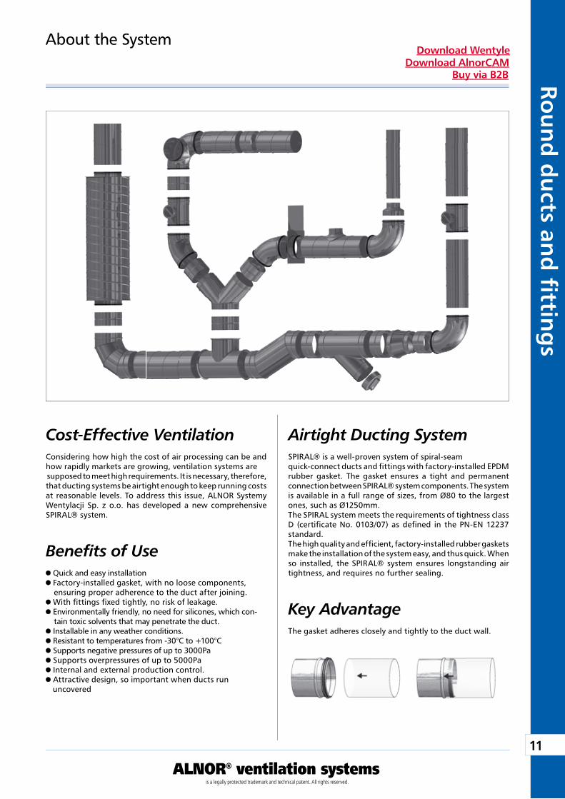
About the System
Cost-Effective VentilationConsidering how high the cost of air processing can be and how rapidly markets are growing, ventilation systems are supposed to meet high requirements. It is necessary, therefore, that ducting systems be airtight enough to keep running costs at reasonable levels. To address this issue, ALNOR Systemy Wentylacji Sp. z o.o. has developed a new comprehensive SPIRAL® system.
Airtight Ducting SystemSPIRAL® is a well-proven system of spiral-seam quick-connect ducts and fittings with factory-installed EPDM rubber gasket. The gasket ensures a tight and permanent connection between SPIRAL® system components. The system is available in a full range of sizes, from Ø80 to the largest ones, such as Ø1250mm.The SPIRAL system meets the requirements of tightness class D (certificate No. 0103/07) as defined in the PN-EN 12237 standard.The high quality and efficient, factory-installed rubber gaskets make the installation of the system easy, and thus quick. When so installed, the SPIRAL® system ensures longstanding air tightness, and requires no further sealing.
The gasket adheres closely and tightly to the duct wall.
Key Advantage
12
ALNOR® ventilation systemsis a legally protected trademark and technical patent. All rights reserved.
Rou
nd
du
cts
and
fi t
tin
gs
Download WentyleDownload AlnorCAM
Buy via B2B
0 5000,00
0,25
0,50
0,75
1,00
1,25
1000 1500 2000
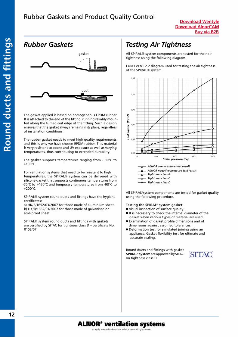
Rubber Gaskets and Product Quality Control
The gasket applied is based on homogeneous EPDM rubber. It is attached to the end of the fitting, running reliably moun-ted along the turned-out edge of the fitting. Such a design ensures that the gasket always remains in its place, regardless of installation conditions.
The rubber gasket needs to meet high quality requirements, and this is why we have chosen EPDM rubber. This material is very resistant to ozone and UV exposure as well as varying temperatures, thus contributing to extended durability.
The gasket supports temperatures ranging from - 30°C to +100°C.
For ventilation systems that need to be resistant to high temperatures, the SPIRAL® system can be delivered with silicone gasket that supports continuous temperatures from
-70°C to +150°C and temporary temperatures from -90°C to +200°C.
SPIRAL® system round ducts and fittings have the hygiene certificates:a) HK/B/1652/03/2007 for those made of aluminium sheetb) HK/B/1652/01/2007 for those made of galvanised or acid-proof sheet
SPIRAL® system round ducts and fittings with gaskets are certified by SITAC for tightness class D – certificate No. 0103/07
Testing Air TightnessRubber GasketsAll SPIRAL® system components are tested for their air tightness using the following diagram.
EURO VENT 2.2 diagram used for testing the air tightness of the SPIRAL® system.
All SPIRAL®system components are tested for gasket quality using the following procedure.
Testing the SPIRAL® system gasket: Visual inspection of surface quality. It is necessary to check the internal diameter of the gasket when various types of material are used.
Examination of gasket profile dimensions and of dimensions against assumed tolerances.
Deformation test for simulated joining using an appliance. Gasket flexibility test for ultimate and
accurate sealing.
gasket
duct
Leak
fac
tor
(l/s
m2)
Static pressure (Pa)
ALNOR overpressure test resultALNOR negative pressure test resultTightness class BTightness class CTightness class D
Round ducts and fittings with gasket SPIRAL® system are approved by SITAC on tightness class D.
13
ALNOR® ventilation systemsis a legally protected trademark and technical patent. All rights reserved.
Rou
nd
du
cts and
fi tting
sDownload Wentyle
Download AlnorCAMBuy via B2B
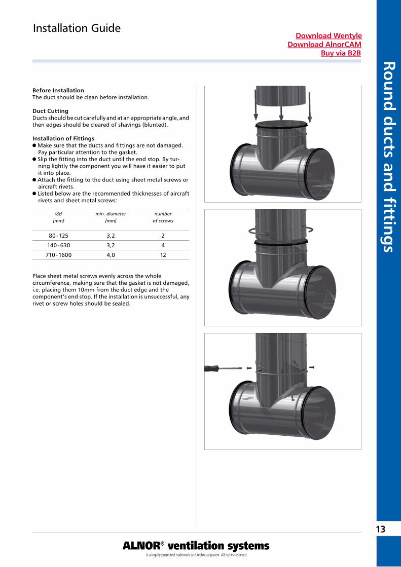
Installation Guide
Before InstallationThe duct should be clean before installation.
Duct CuttingDucts should be cut carefully and at an appropriate angle, and then edges should be cleared of shavings (blunted).
Installation of Fittings Make sure that the ducts and fittings are not damaged. Pay particular attention to the gasket.
Slip the fitting into the duct until the end stop. By tur-ning lightly the component you will have it easier to put it into place.
Attach the fitting to the duct using sheet metal screws or aircraft rivets.
Listed below are the recommended thicknesses of aircraft rivets and sheet metal screws:
Place sheet metal screws evenly across the whole circumference, making sure that the gasket is not damaged, i.e. placing them 10mm from the duct edge and the component’s end stop. If the installation is unsuccessful, any rivet or screw holes should be sealed.
d[mm]
min. diameter[mm]
numberof screws
80 - 125 3,2 2
140 - 630 3,2 4
710 - 1600 4,0 12
14
ALNOR® ventilation systemsis a legally protected trademark and technical patent. All rights reserved.
Rou
nd
du
cts
and
fi t
tin
gs
Download WentyleDownload AlnorCAM
Buy via B2B
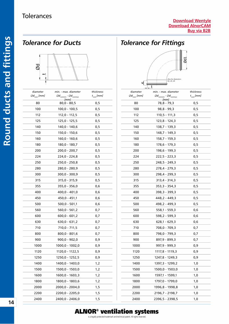
Tolerance for Ducts
Tolerances
Tolerance for Fittings
Also for diameters:d2, d3, d4
diameterdnom [mm]
min. - max. diameterdnommin - dnommax
[mm]
thicknesstnom [mm]
diameterdnom [mm]
min. - max. diameterdnommin - dnommax
[mm]
thicknesstnom [mm]
80 80,0 - 80,5 0,5
100 100,0 - 100,5 0,5
112 112,0 - 112,5 0,5
125 125,0 - 125,5 0,5
140 140,0 - 140,6 0,5
150 150,0 - 150,6 0,5
160 160,0 - 160,6 0,5
180 180,0 - 180,7 0,5
200 200,0 - 200,7 0,5
224 224,0 - 224,8 0,5
250 250,0 - 250,8 0,5
280 280,0 - 280,9 0,5
300 300,0 - 300,9 0,5
315 315,0 - 315,9 0,5
355 355,0 - 356,0 0,6
400 400,0 - 401,0 0,6
450 450,0 - 451,1 0,6
500 500,0 - 501,1 0,6
560 560,0 - 561,2 0,7
600 600,0 - 601,2 0,7
630 630,0 - 631,2 0,7
710 710,0 - 711,5 0,7
800 800,0 - 801,6 0,7
900 900,0 - 902,0 0,9
1000 1000,0 - 1002,0 0,9
1120 1120,0 - 1122,5 0,9
1250 1250,0 - 1252,5 0,9
1400 1400,0 - 1403,0 1,2
1500 1500,0 - 1503,0 1,2
1600 1600,0 - 1603,3 1,2
1800 1800,0 - 1803,6 1,2
2000 2000,0 - 2004,0 1,5
2200 2200,0 - 2205,0 1,5
2400 2400,0 - 2406,0 1,5
80 78,8 - 79,3 0,5
100 98,8 - 99,3 0,5
112 110,5 - 111,3 0,5
125 123,8 - 124,3 0,5
140 138,7 - 139,3 0,5
150 148,7 - 149,3 0,5
160 158,7 - 159,3 0,5
180 178,6 - 179,3 0,5
200 198,6 - 199,3 0,5
224 222,5 - 223,3 0,5
250 248,5 - 249,3 0,5
280 278,4 - 279,3 0,5
300 298,4 - 299,3 0,5
315 313,4 - 314,3 0,5
355 353,3 - 354,3 0,5
400 398,3 - 399,3 0,5
450 448,2 - 449,3 0,5
500 498,2 - 499,3 0,5
560 558,1 - 559,3 0,6
600 598,2 - 599,3 0,6
630 628,1 - 629,3 0,6
710 708,0 - 709,3 0,7
800 798,0 - 799,3 0,7
900 897,9 - 899,3 0,7
1000 997,9 - 999,3 0,9
1120 1117,8 - 1119,3 0,9
1250 1247,8 - 1249,3 0,9
1400 1397,3 - 1299,2 1,0
1500 1500,0 - 1503,0 1,0
1600 1597,1 - 1599,1 1,0
1800 1797,0 - 1799,0 1,0
2000 1996,8 - 1998,8 1,0
2200 2196,7 - 2198,7 1,0
2400 2396,5 - 2398,5 1,0
15
ALNOR® ventilation systemsis a legally protected trademark and technical patent. All rights reserved.
Rou
nd
du
cts and
fi tting
sDownload Wentyle
Download AlnorCAMBuy via B2B
L
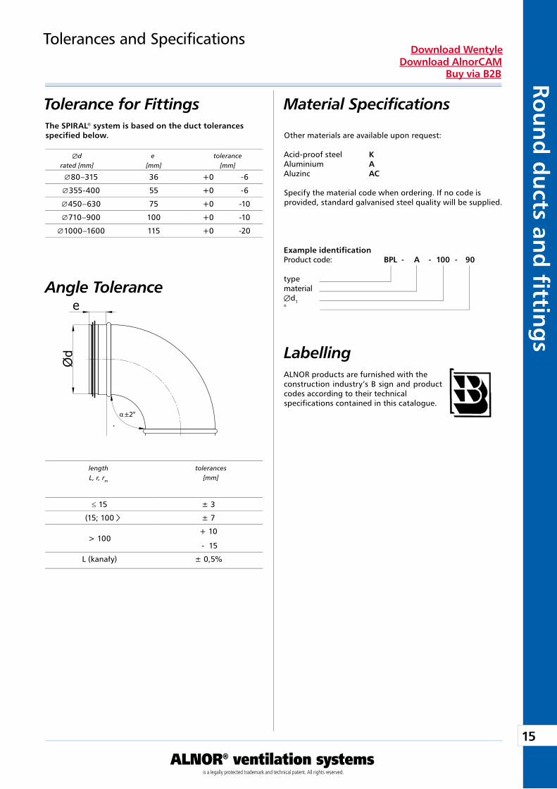
Angle Tolerance
Tolerances and Specifications
Material Specifications
Labelling
Other materials are available upon request:
Acid-proof steel KAluminium AAluzinc AC
Specify the material code when ordering. If no code is provided, standard galvanised steel quality will be supplied.
ALNOR products are furnished with the construction industry’s B sign and product codes according to their technical specifications contained in this catalogue.
Example identificationProduct code: BPL - A - 100 - 90
typematerialÆd1°
Tolerance for FittingsThe SPIRAL® system is based on the duct tolerances specified below.
Æd e tolerance rated [mm] [mm] [mm]
length tolerances L, r, rm [mm]
80–315 36 +0 -6
355-400 55 +0 -6
450–630 75 +0 -10
710–900 100 +0 -10
1000–1600 115 +0 -20
≤ 15 ± 3
(15; 100 ± 7
> 100+ 10
- 15
L (kanały) ± 0,5%
16
ALNOR® ventilation systemsis a legally protected trademark and technical patent. All rights reserved.
Rou
nd
du
cts
and
fi t
tin
gs
Download WentyleDownload AlnorCAM
Buy via B2B
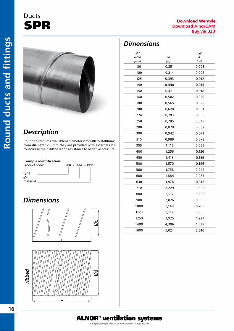
Ducts
SPRDimensions
Round spiral ducts available in diameters from 80 to 1600mm; from diameter 250mm they are provided with external ribs to increase their stiffness and resistance to negative pressure.
Dimensions
Example identificationProduct code: SPR - aaa - bbb
typeÆd1material
Description
Æd π d2
rated πd 4 [mm] [m] [m2]
ribb
ed
80 0,251 0,005
100 0,314 0,008
125 0,393 0,012
140 0,440 0,015
150 0,471 0,018
160 0,502 0,020
180 0,565 0,025
200 0,628 0,031
224 0,703 0,039
250 0,785 0,049
280 0,879 0,062
300 0,942 0,071
315 0,989 0,078
355 1,115 0,099
400 1,256 0,126
450 1,413 0,159
500 1,570 0,196
560 1,758 0,246
600 1,884 0,283
630 1,978 0,312
710 2,229 0,396
800 2,512 0,503
900 2,826 0,636
1000 3,140 0,785
1120 3,517 0,985
1250 3,925 1,227
1400 4,396 1,539
1600 5,024 2,010
17
ALNOR® ventilation systemsis a legally protected trademark and technical patent. All rights reserved.
Rou
nd
du
cts and
fi tting
sDownload Wentyle
Download AlnorCAMBuy via B2B
Dimensions
80
100
125
160
200
250
315
400
500
630
800
1000
1250
20
15
10
5
2
Pa/m
1
5
0.05
0.1
0.5
10
50
100
200
0.0210 50 100 500 1000 5000 10000 l/s
m3/h50 100 500 1000 5000 10000 50000
5
m/s
[Pa/m]
[l/s]
[m3/h]
[m/s]
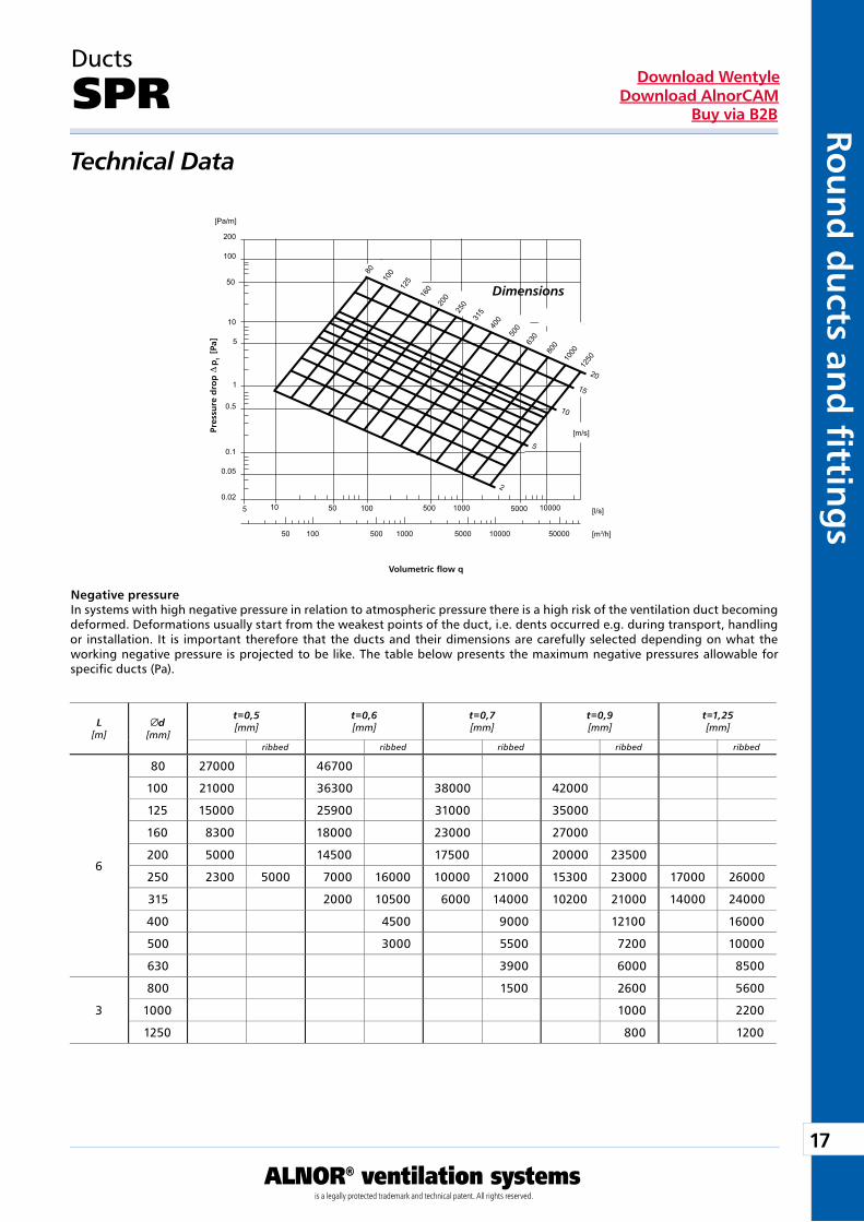
Technical Data
Negative pressureIn systems with high negative pressure in relation to atmospheric pressure there is a high risk of the ventilation duct becoming deformed. Deformations usually start from the weakest points of the duct, i.e. dents occurred e.g. during transport, handling or installation. It is important therefore that the ducts and their dimensions are carefully selected depending on what the working negative pressure is projected to be like. The table below presents the maximum negative pressures allowable for specific ducts (Pa).
Ducts
SPR
Volumetric fl ow q
Pre
ssu
re d
rop
D p
t [
Pa]
ribbed ribbed ribbed ribbed ribbed
L[m]
d[mm]
t=0,5[mm]
t=0,6[mm]
t=0,7[mm]
t=0,9[mm]
t=1,25[mm]
6
80 27000 46700
100 21000 36300 38000 42000
125 15000 25900 31000 35000
160 8300 18000 23000 27000
200 5000 14500 17500 20000 23500
250 2300 5000 7000 16000 10000 21000 15300 23000 17000 26000
315 2000 10500 6000 14000 10200 21000 14000 24000
400 4500 9000 12100 16000
500 3000 5500 7200 10000
630 3900 6000 8500
3
800 1500 2600 5600
1000 1000 2200
1250 800 1200
18
ALNOR® ventilation systemsis a legally protected trademark and technical patent. All rights reserved.
Rou
nd
du
cts
and
fi t
tin
gs
Download WentyleDownload AlnorCAM
Buy via B2B
rm » 1 x d1
Dimensions
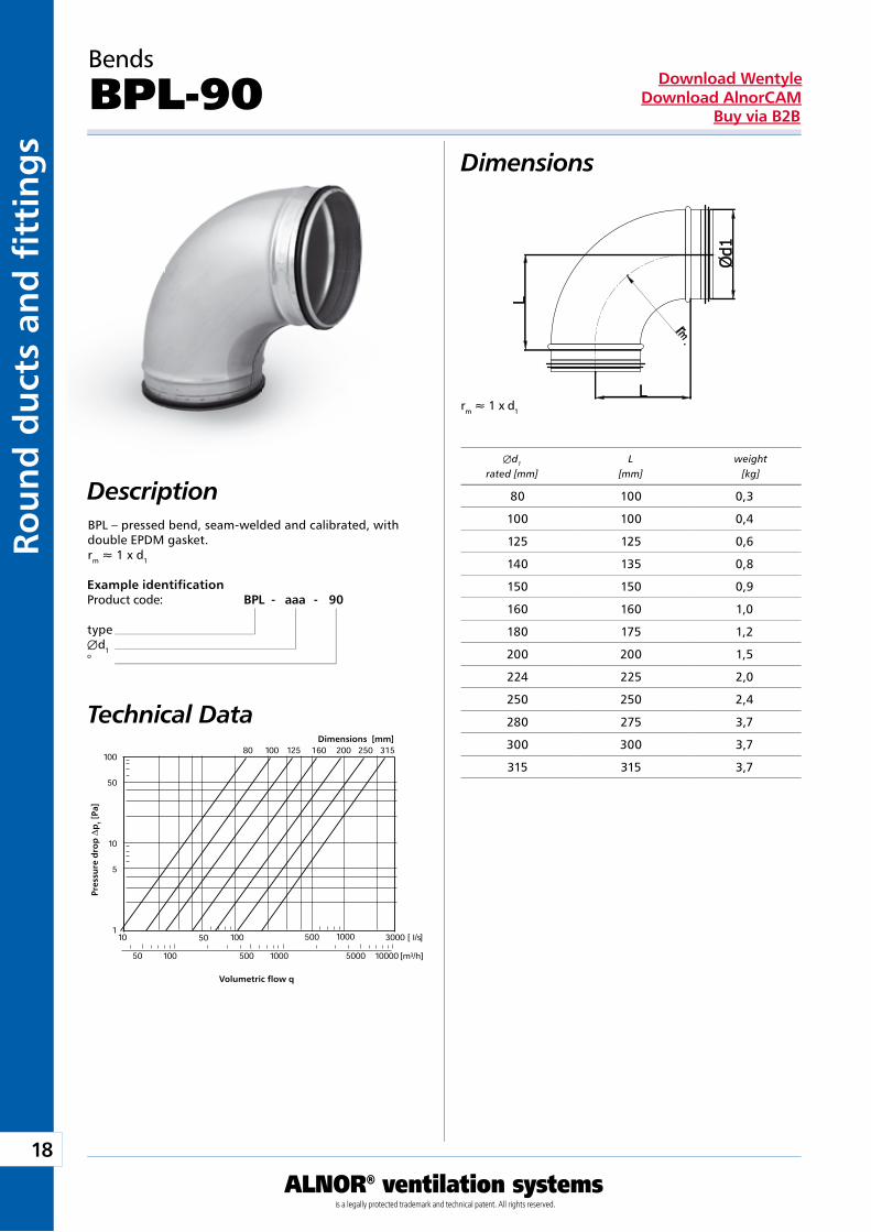
DescriptionBPL – pressed bend, seam-welded and calibrated, with double EPDM gasket.rm » 1 x d1
Technical Data
Example identificationProduct code: BPL - aaa - 90
typeÆd1°
Bends
BPL-90
Dimensions [mm]
Pre
ssu
re d
rop
Dp
t [P
a]
Volumetric flow q
Æd1 L weight rated [mm] [mm] [kg]
80 100 0,3
100 100 0,4
125 125 0,6
140 135 0,8
150 150 0,9
160 160 1,0
180 175 1,2
200 200 1,5
224 225 2,0
250 250 2,4
280 275 3,7
300 300 3,7
315 315 3,7
19
ALNOR® ventilation systemsis a legally protected trademark and technical patent. All rights reserved.
Rou
nd
du
cts and
fi tting
sDownload Wentyle
Download AlnorCAMBuy via B2B
rm » 1 x d1
Description
Dimensions
Technical Data
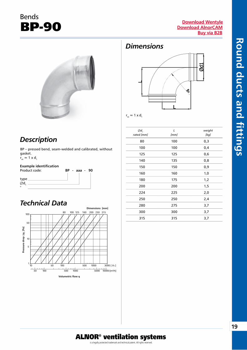
Example identificationProduct code: BP - aaa - 90
typeÆd1°
BP – pressed bend, seam-welded and calibrated, without gasket.rm » 1 x d1
Bends
BP-90
Dimensions [mm]
Pre
ssu
re d
rop
Dp
t [P
a]
Volumetric flow q
Æd1 L weight rated [mm] [mm] [kg]
80 100 0,3
100 100 0,4
125 125 0,6
140 135 0,8
150 150 0,9
160 160 1,0
180 175 1,2
200 200 1,5
224 225 2,0
250 250 2,4
280 275 3,7
300 300 3,7
315 315 3,7
20
ALNOR® ventilation systemsis a legally protected trademark and technical patent. All rights reserved.
Rou
nd
du
cts
and
fi t
tin
gs
Download WentyleDownload AlnorCAM
Buy via B2B
rm » 1 x d1
AB
Description
Dimensions
Technical Data
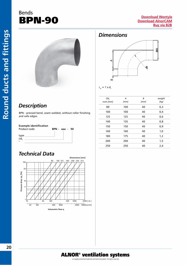
Example identificationProduct code: BPN - aaa - 90
typed1
°
Bends
BPN-90
Dimensions [mm]
Pre
ssu
re d
rop
Dp
t [P
a]
Volumetric flow q
d1
nom [mm]A
[mm]B
[mm]weight
[kg]
BPN - pressed bend, seam-welded, without roller finishing and safe edges.
80 100 40 0,3
100 100 40 0,4
125 125 40 0,6
140 135 40 0,8
150 150 40 0,9
160 160 40 1,0
180 175 40 1,2
200 200 40 1,5
250 250 40 2,4
21
ALNOR® ventilation systemsis a legally protected trademark and technical patent. All rights reserved.
Rou
nd
du
cts and
fi tting
sDownload Wentyle
Download AlnorCAMBuy via B2B
AB
rm » 1 x d1
Description
Dimensions
Technical Data
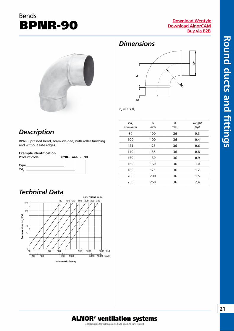
Example identificationProduct code: BPNR - aaa - 90
typed1
Bends
BPNR-90
Dimensions [mm]
Pre
ssu
re d
rop
Dp
t [P
a]
Volumetric flow q
d1
nom [mm]A
[mm]B
[mm]weight
[kg]
BPNR - pressed bend, seam-welded, with roller finishing and without safe edges.
80 100 36 0,3
100 100 36 0,4
125 125 36 0,6
140 135 36 0,8
150 150 36 0,9
160 160 36 1,0
180 175 36 1,2
200 200 36 1,5
250 250 36 2,4
22
ALNOR® ventilation systemsis a legally protected trademark and technical patent. All rights reserved.
Rou
nd
du
cts
and
fi t
tin
gs
Download WentyleDownload AlnorCAM
Buy via B2B
1
5
50
100 100
125
160
[l/s]
[m³/h]
10 50 100 500 1000
50 100 500 1000
80
rm » 0,6 x d1
Le
Le
rm » 0,6 x d1
Description
Dimensions
Technical Data
Bends
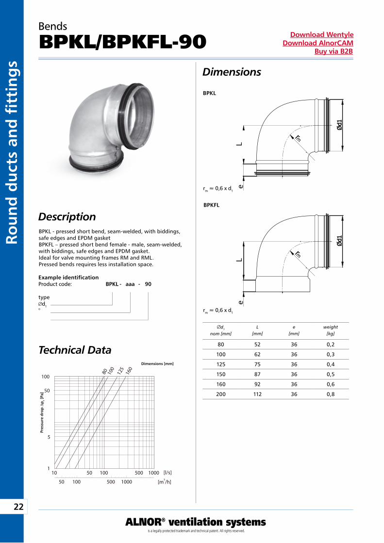
BPKL/BPKFL-90
d1
nom [mm]L
[mm]e
[mm]weight
[kg]
BPKL
BPKFL
Example identificationProduct code: BPKL - aaa - 90
typed1
°
BPKL - pressed short bend, seam-welded, with biddings, safe edges and EPDM gasketBPKFL – pressed short bend female - male, seam-welded, with biddings, safe edges and EPDM gasket.Ideal for valve mounting frames RM and RML.Pressed bends requires less installation space.
Dimensions [mm]
Pre
ssu
re d
rop
Dp
t [P
a]
80 52 36 0,2
100 62 36 0,3
125 75 36 0,4
150 87 36 0,5
160 92 36 0,6
200 112 36 0,8
23
ALNOR® ventilation systemsis a legally protected trademark and technical patent. All rights reserved.
Rou
nd
du
cts and
fi tting
sDownload Wentyle
Download AlnorCAMBuy via B2B
1
5
50
100 100
125
160
[l/s]
[m³/h]
10 50 100 500 1000
50 100 500 1000
80
rm » 0,6 x d1
Le
Le
rm » 0,6 x d1
Description
Dimensions
Technical Data
Example identificationProduct code: BPK - aaa - 90
typed1
°
Bends
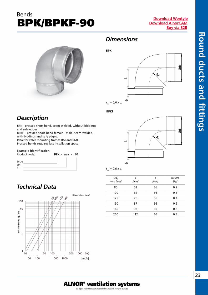
BPK/BPKF-90
d1
nom [mm]L
[mm]e
[mm]weight
[kg]
BPK
BPKF
BPK - pressed short bend, seam-welded, without biddings and safe edgesBPKF – pressed short bend female - male, seam-welded, with biddings and safe edges.Ideal for valve mounting frames RM and RML.Pressed bends requires less installation space.
Dimensions [mm]
Pre
ssu
re d
rop
Dp
t [P
a]
80 52 36 0,2
100 62 36 0,3
125 75 36 0,4
150 87 36 0,5
160 92 36 0,6
200 112 36 0,8
24
ALNOR® ventilation systemsis a legally protected trademark and technical patent. All rights reserved.
Rou
nd
du
cts
and
fi t
tin
gs
Download WentyleDownload AlnorCAM
Buy via B2B
rm » 1 x d1
Dimensions
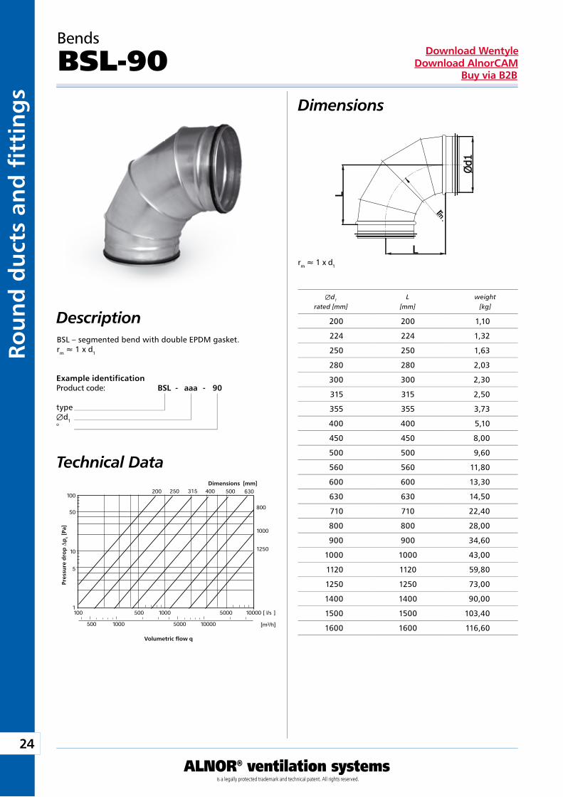
DescriptionBSL – segmented bend with double EPDM gasket.rm » 1 x d1
Technical Data
Example identificationProduct code: BSL - aaa - 90
typeÆd1°
Bends
BSL-90
Dimensions [mm]
Pre
ssu
re d
rop
Dp
t [P
a]
Volumetric flow q
Æd1 L weight rated [mm] [mm] [kg]
200 200 1,10
224 224 1,32
250 250 1,63
280 280 2,03
300 300 2,30
315 315 2,50
355 355 3,73
400 400 5,10
450 450 8,00
500 500 9,60
560 560 11,80
600 600 13,30
630 630 14,50
710 710 22,40
800 800 28,00
900 900 34,60
1000 1000 43,00
1120 1120 59,80
1250 1250 73,00
1400 1400 90,00
1500 1500 103,40
1600 1600 116,60
25
ALNOR® ventilation systemsis a legally protected trademark and technical patent. All rights reserved.
Rou
nd
du
cts and
fi tting
sDownload Wentyle
Download AlnorCAMBuy via B2B
rm » 1 x d1
Dimensions
Description
Technical Data
Example identificationProduct code: BS - aaa - 90
typeÆd1°
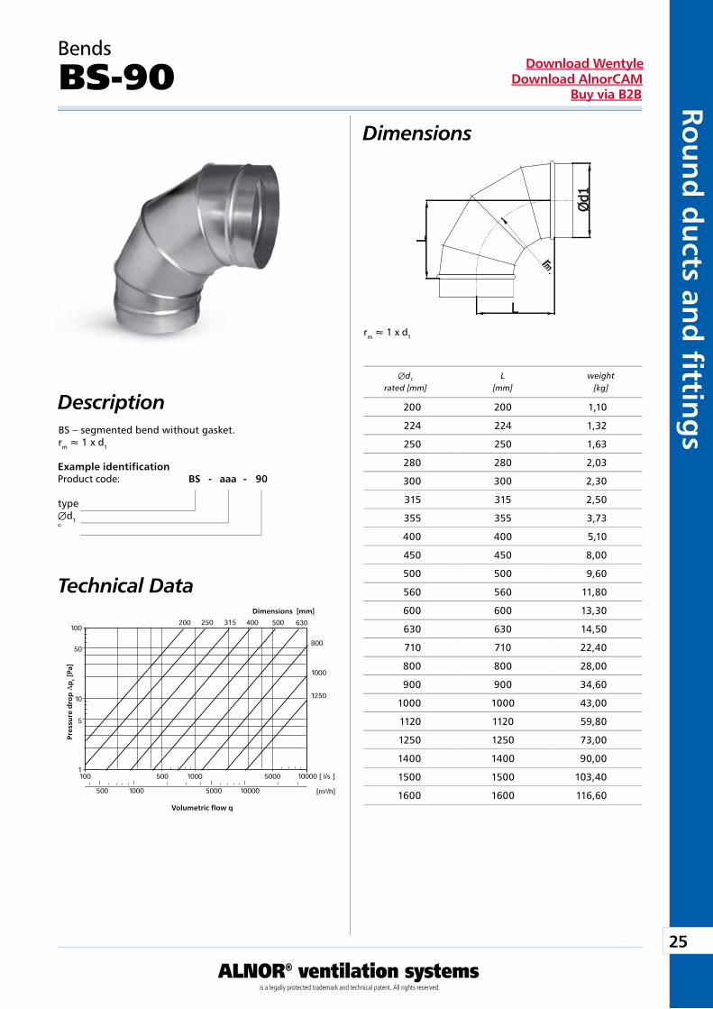
BS – segmented bend without gasket.rm » 1 x d1
Bends
BS-90
Dimensions [mm]
Pre
ssu
re d
rop
Dp
t [P
a]
Volumetric flow q
Æd1 L weight rated [mm] [mm] [kg]
200 200 1,10
224 224 1,32
250 250 1,63
280 280 2,03
300 300 2,30
315 315 2,50
355 355 3,73
400 400 5,10
450 450 8,00
500 500 9,60
560 560 11,80
600 600 13,30
630 630 14,50
710 710 22,40
800 800 28,00
900 900 34,60
1000 1000 43,00
1120 1120 59,80
1250 1250 73,00
1400 1400 90,00
1500 1500 103,40
1600 1600 116,60
26
ALNOR® ventilation systemsis a legally protected trademark and technical patent. All rights reserved.
Rou
nd
du
cts
and
fi t
tin
gs
Download WentyleDownload AlnorCAM
Buy via B2B
rm » 0,6 x d1
Dimensions
Description
Example identificationProduct code: BSKL - aaa - 90
typeÆd1°
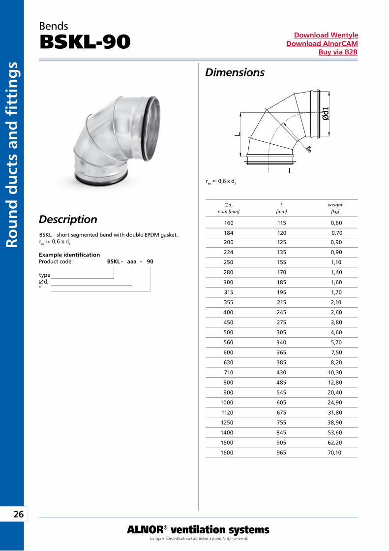
BSKL - short segmented bend with double EPDM gasket.rm » 0,6 x d1
Bends
BSKL-90
Æd1 L weight nom [mm] [mm] [kg]
200 125 0,90
224 135 0,90
250 155 1,10
280 170 1,40
300 185 1,60
315 195 1,70
355 215 2,10
400 245 2,60
450 275 3,80
500 305 4,60
560 340 5,70
600 365 7,50
630 385 8,20
710 430 10,30
800 485 12,80
900 545 20,40
1000 605 24,90
1120 675 31,80
1250 755 38,90
1400 845 53,60
1500 905 62,20
1600 965 70,10
160 115 0,60
184 120 0,70
27
ALNOR® ventilation systemsis a legally protected trademark and technical patent. All rights reserved.
Rou
nd
du
cts and
fi tting
sDownload Wentyle
Download AlnorCAMBuy via B2B
Description
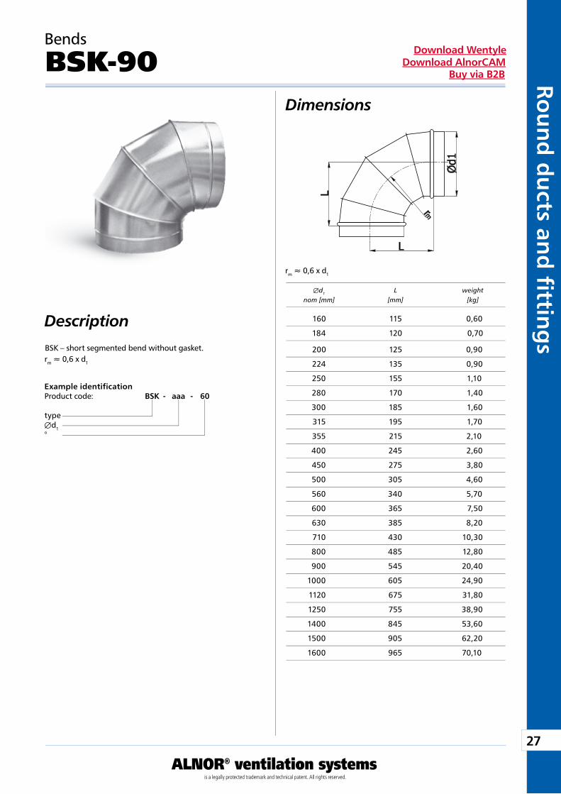
Example identificationProduct code: BSK - aaa - 60
typeÆd1°
Dimensions
Æd1 L weight nom [mm] [mm] [kg]
rm » 0,6 x d1
rm » 0,6 x d1
Bends
BSK-90
BSK – short segmented bend without gasket. 200 125 0,90
224 135 0,90
250 155 1,10
280 170 1,40
300 185 1,60
315 195 1,70
355 215 2,10
400 245 2,60
450 275 3,80
500 305 4,60
560 340 5,70
600 365 7,50
630 385 8,20
710 430 10,30
800 485 12,80
900 545 20,40
1000 605 24,90
1120 675 31,80
1250 755 38,90
1400 845 53,60
1500 905 62,20
1600 965 70,10
160 115 0,60
184 120 0,70
28
ALNOR® ventilation systemsis a legally protected trademark and technical patent. All rights reserved.
Rou
nd
du
cts
and
fi t
tin
gs
Download WentyleDownload AlnorCAM
Buy via B2B
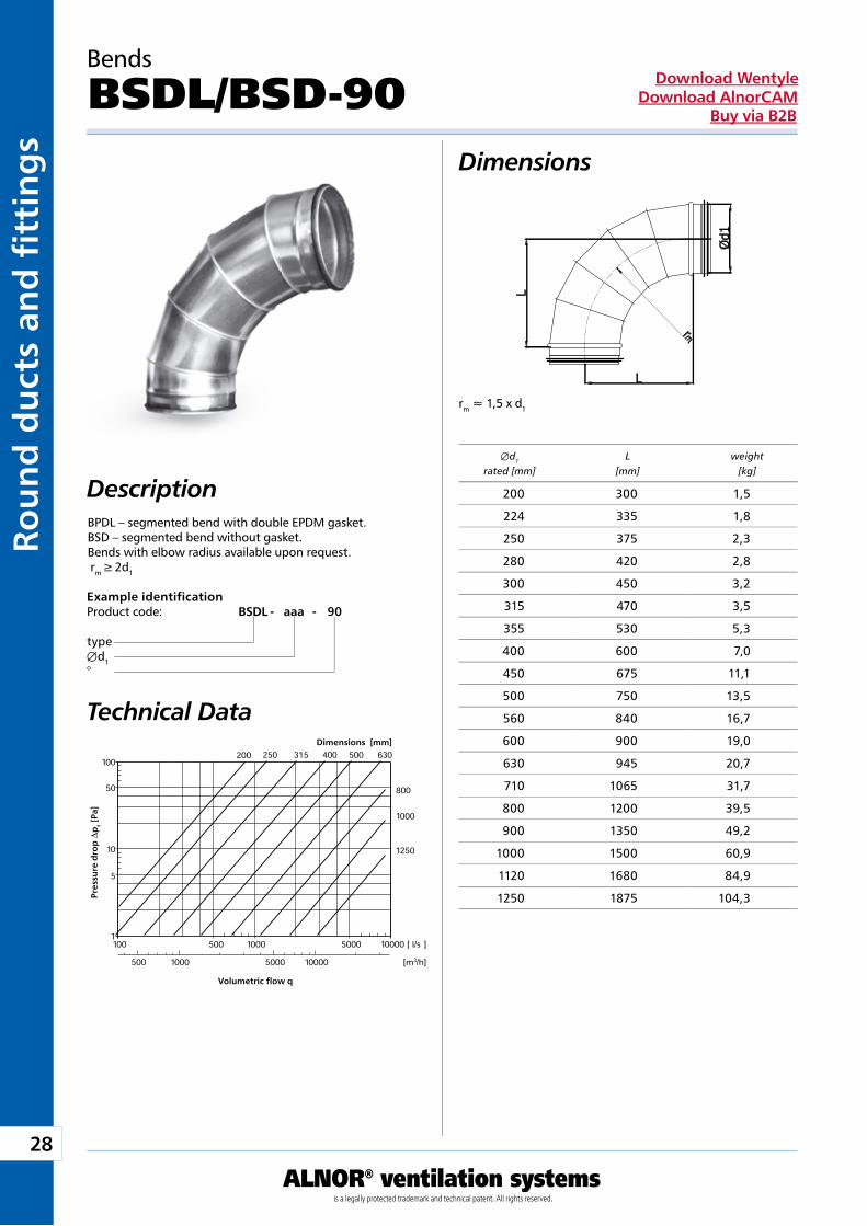
rm » 1,5 x d1
Dimensions
DescriptionBPDL – segmented bend with double EPDM gasket.BSD – segmented bend without gasket.Bends with elbow radius available upon request. rm ³ 2d1
Technical Data
Example identificationProduct code: BSDL - aaa - 90
typeÆd1°
Bends
BSDL/BSD-90
Dimensions [mm]
Pre
ssu
re d
rop
Dp
t [P
a]
Volumetric flow q
Æd1 L weight rated [mm] [mm] [kg]
200 300 1,5
224 335 1,8
250 375 2,3
280 420 2,8
300 450 3,2
315 470 3,5
355 530 5,3
400 600 7,0
450 675 11,1
500 750 13,5
560 840 16,7
600 900 19,0
630 945 20,7
710 1065 31,7
800 1200 39,5
900 1350 49,2
1000 1500 60,9
1120 1680 84,9
1250 1875 104,3
29
ALNOR® ventilation systemsis a legally protected trademark and technical patent. All rights reserved.
Rou
nd
du
cts and
fi tting
sDownload Wentyle
Download AlnorCAMBuy via B2B
rm » 1 x d1
Dimensions
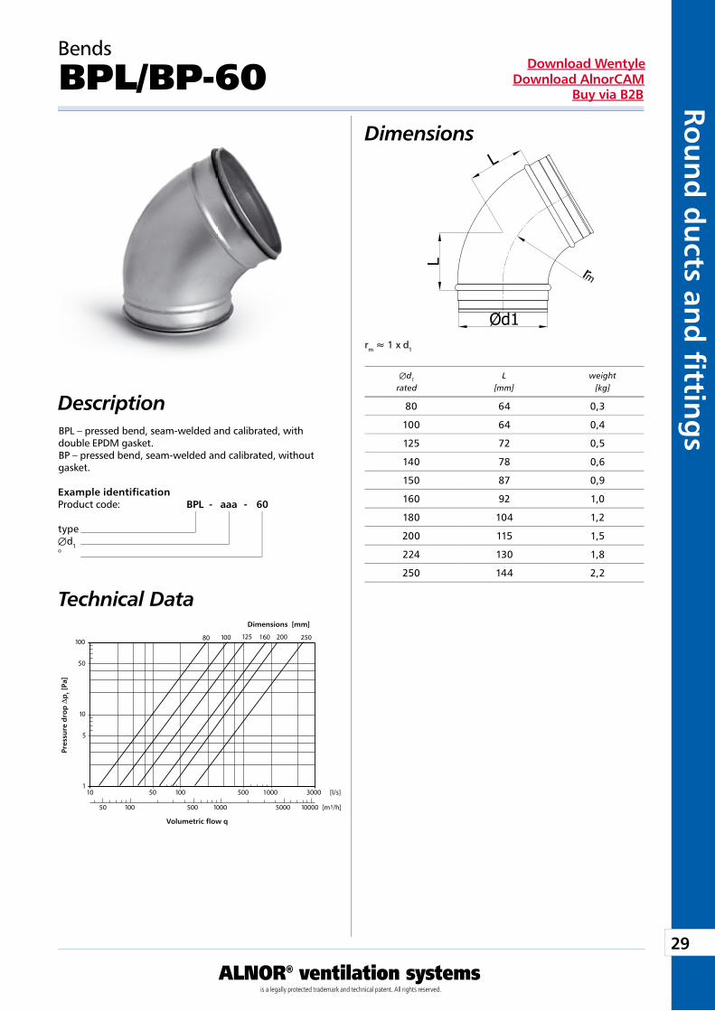
DescriptionBPL – pressed bend, seam-welded and calibrated, with double EPDM gasket.BP – pressed bend, seam-welded and calibrated, without gasket.
Technical Data
Example identificationProduct code: BPL - aaa - 60
typeÆd1°
Bends
BPL/BP-60
Dimensions [mm]
Pre
ssu
re d
rop
Dp
t [P
a]
Volumetric flow q
Æd1 L weight rated [mm] [kg]
80 64 0,3
100 64 0,4
125 72 0,5
140 78 0,6
150 87 0,9
160 92 1,0
180 104 1,2
200 115 1,5
224 130 1,8
250 144 2,2
30
ALNOR® ventilation systemsis a legally protected trademark and technical patent. All rights reserved.
Rou
nd
du
cts
and
fi t
tin
gs
Download WentyleDownload AlnorCAM
Buy via B2B
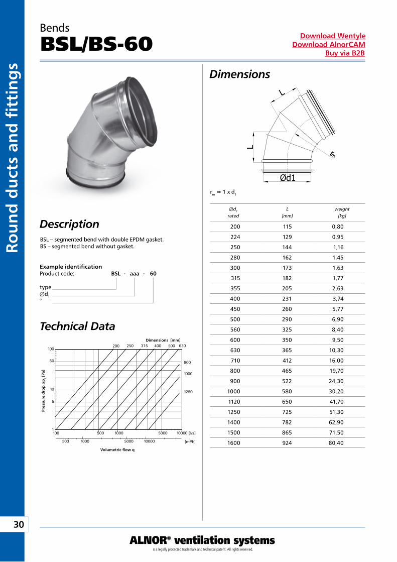
rm » 1 x d1
Bends
BSL/BS-60Dimensions
DescriptionBSL – segmented bend with double EPDM gasket.BS – segmented bend without gasket.
Technical Data
Example identificationProduct code: BSL - aaa - 60
typeÆd1°
Dimensions [mm]
Pre
ssu
re d
rop
Dp
t [P
a]
Volumetric flow q
Æd1 L weight rated [mm] [kg]
200 115 0,80
224 129 0,95
250 144 1,16
280 162 1,45
300 173 1,63
315 182 1,77
355 205 2,63
400 231 3,74
450 260 5,77
500 290 6,90
560 325 8,40
600 350 9,50
630 365 10,30
710 412 16,00
800 465 19,70
900 522 24,30
1000 580 30,20
1120 650 41,70
1250 725 51,30
1400 782 62,90
1500 865 71,50
1600 924 80,40
31
ALNOR® ventilation systemsis a legally protected trademark and technical patent. All rights reserved.
Rou
nd
du
cts and
fi tting
sDownload Wentyle
Download AlnorCAMBuy via B2B
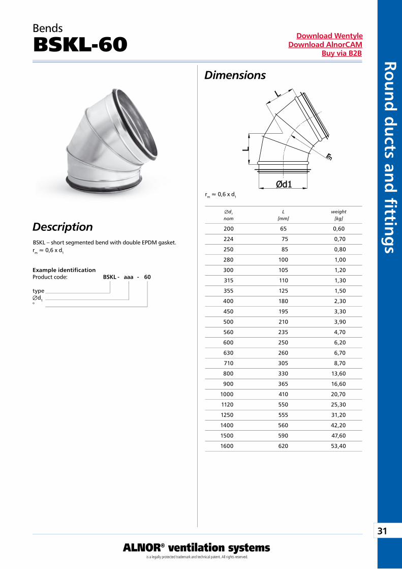
rm » 0,6 x d1
rm » 0,6 x d1
Bends
BSKL-60Dimensions
DescriptionBSKL – short segmented bend with double EPDM gasket.
Example identificationProduct code: BSKL - aaa - 60
typeÆd1°
Æd1 L weight nom [mm] [kg]
200 65 0,60
224 75 0,70
250 85 0,80
280 100 1,00
300 105 1,20
315 110 1,30
355 125 1,50
400 180 2,30
450 195 3,30
500 210 3,90
560 235 4,70
600 250 6,20
630 260 6,70
710 305 8,70
800 330 13,60
900 365 16,60
1000 410 20,70
1120 550 25,30
1250 555 31,20
1400 560 42,20
1500 590 47,60
1600 620 53,40
32
ALNOR® ventilation systemsis a legally protected trademark and technical patent. All rights reserved.
Rou
nd
du
cts
and
fi t
tin
gs
Download WentyleDownload AlnorCAM
Buy via B2B
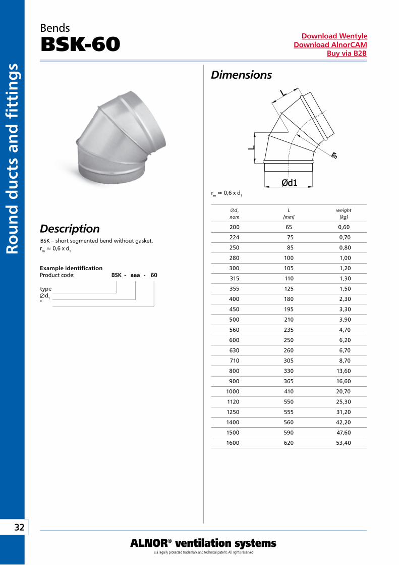
Dimensions
Description
Example identificationProduct code: BSK - aaa - 60
typeÆd1°
rm » 0,6 x d1
rm » 0,6 x d1
Bends
BSK-60
BSK – short segmented bend without gasket.
Æd1 L weight nom [mm] [kg]
200 65 0,60
224 75 0,70
250 85 0,80
280 100 1,00
300 105 1,20
315 110 1,30
355 125 1,50
400 180 2,30
450 195 3,30
500 210 3,90
560 235 4,70
600 250 6,20
630 260 6,70
710 305 8,70
800 330 13,60
900 365 16,60
1000 410 20,70
1120 550 25,30
1250 555 31,20
1400 560 42,20
1500 590 47,60
1600 620 53,40
33
ALNOR® ventilation systemsis a legally protected trademark and technical patent. All rights reserved.
Rou
nd
du
cts and
fi tting
sDownload Wentyle
Download AlnorCAMBuy via B2B
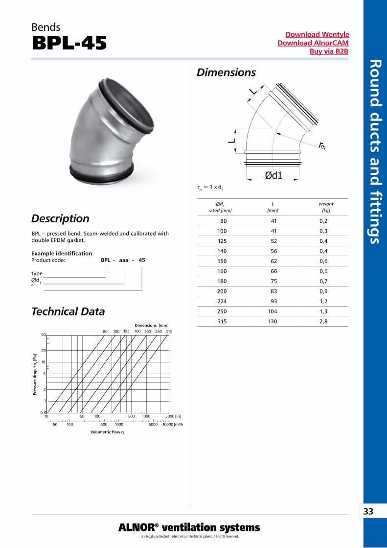
rm » 1 x d1
Bends
BPL-45Dimensions
DescriptionBPL – pressed bend. Seam-welded and calibrated with double EPDM gasket.
Technical Data
Example identificationProduct code: BPL - aaa - 45
typeÆd1°
Dimensions [mm]
Pre
ssu
re d
rop
Dp
t [P
a]
Volumetric flow q
Æd1 L weight rated [mm] [mm] [kg]
80 41 0,2
100 41 0,3
125 52 0,4
140 56 0,4
150 62 0,6
160 66 0,6
180 75 0,7
200 83 0,9
224 93 1,2
250 104 1,3
315 130 2,8
34
ALNOR® ventilation systemsis a legally protected trademark and technical patent. All rights reserved.
Rou
nd
du
cts
and
fi t
tin
gs
Download WentyleDownload AlnorCAM
Buy via B2B
rm » 1 x d1
Bends
BP-45Dimensions
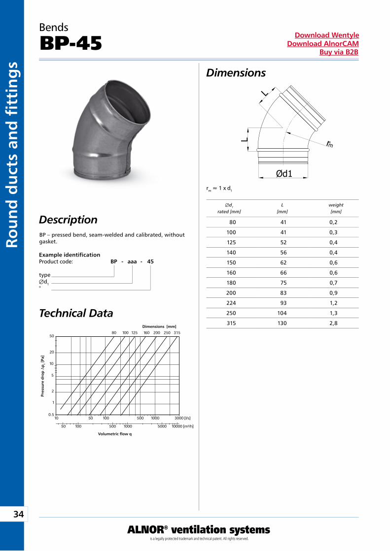
DescriptionBP – pressed bend, seam-welded and calibrated, without gasket.
Technical Data
Example identificationProduct code: BP - aaa - 45
typeÆd1°
Dimensions [mm]
Pre
ssu
re d
rop
Dp
t [P
a]
Volumetric flow q
Æd1 L weight rated [mm] [mm] [mm]
80 41 0,2
100 41 0,3
125 52 0,4
140 56 0,4
150 62 0,6
160 66 0,6
180 75 0,7
200 83 0,9
224 93 1,2
250 104 1,3
315 130 2,8
35
ALNOR® ventilation systemsis a legally protected trademark and technical patent. All rights reserved.
Rou
nd
du
cts and
fi tting
sDownload Wentyle
Download AlnorCAMBuy via B2B
rm » 1 x d1
A
B
Bends
BPN-45Dimensions
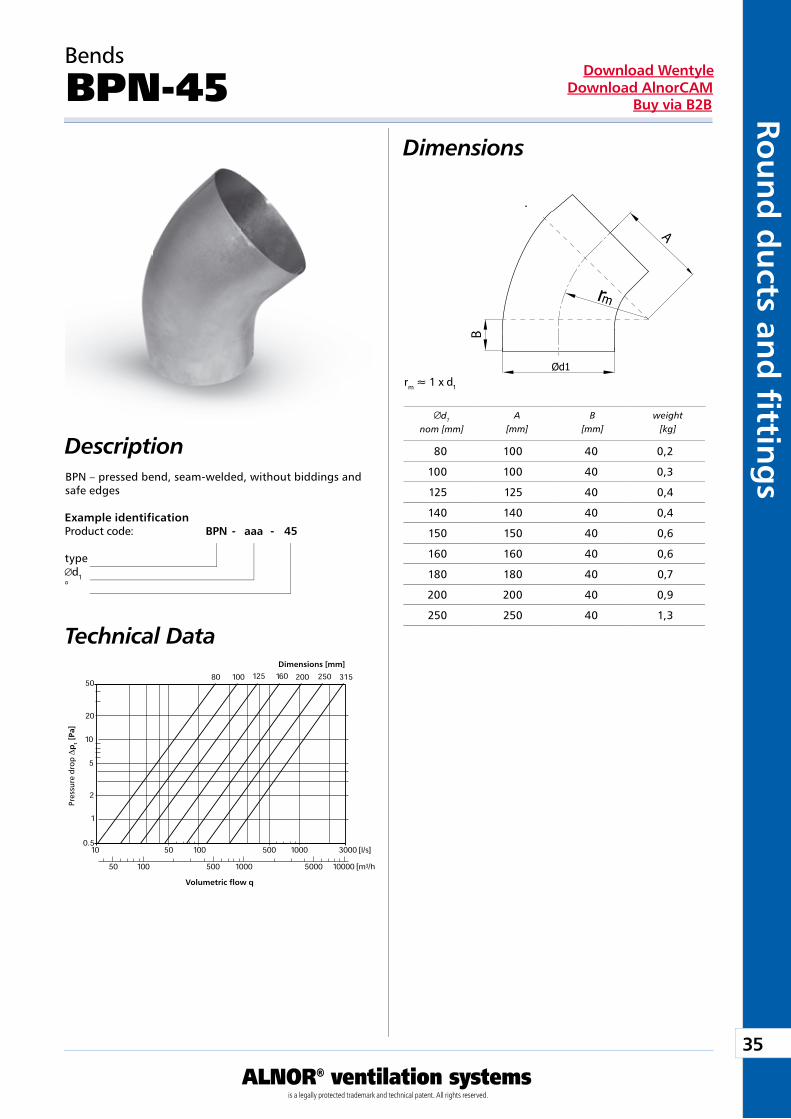
DescriptionBPN – pressed bend, seam-welded, without biddings and safe edges
Technical Data
Example identificationProduct code: BPN - aaa - 45
typed1
°
Dimensions [mm]
Pres
sure
dro
p D
pt
[Pa]
Volumetric flow q
d1
nom [mm]A
[mm]B
[mm]weight
[kg]
80 100 40 0,2
100 100 40 0,3
125 125 40 0,4
140 140 40 0,4
150 150 40 0,6
160 160 40 0,6
180 180 40 0,7
200 200 40 0,9
250 250 40 1,3
36
ALNOR® ventilation systemsis a legally protected trademark and technical patent. All rights reserved.
Rou
nd
du
cts
and
fi t
tin
gs
Download WentyleDownload AlnorCAM
Buy via B2B
rm » 1 x d1
A
B
Bends
BPNR-45Dimensions
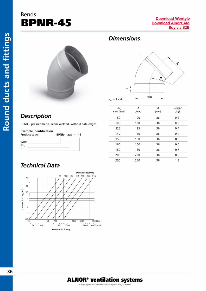
DescriptionBPNR – pressed bend, seam-welded, without safe edges
Technical Data
Example identificationProduct code: BPNR - aaa - 45
typed1
°
Dimensions [mm]
Pres
sure
dro
p D
pt
[Pa]
Volumetric flow q
d1
nom [mm]A
[mm]B
[mm]weight
[kg]
80 100 36 0,2
100 100 36 0,3
125 125 36 0,4
140 140 36 0,4
150 150 36 0,6
160 160 36 0,6
180 180 36 0,7
200 200 36 0,9
250 250 36 1,3
37
ALNOR® ventilation systemsis a legally protected trademark and technical patent. All rights reserved.
Rou
nd
du
cts and
fi tting
sDownload Wentyle
Download AlnorCAMBuy via B2B
rm » 0,6 x d1
L
eL
e
rm » 0,6 x d1
Bends
BPKL/BPKFL-45Dimensions
Description
Example identificationProduct code: BPKL - aaa - 45
typed1
°
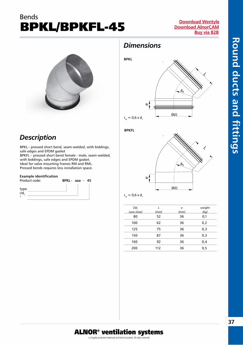
d1
nom [mm]L
[mm]e
[mm]weight
[kg]
BPKL
BPKFL
BPKL - pressed short bend, seam-welded, with biddings, safe edges and EPDM gasketBPKFL – pressed short bend female - male, seam-welded, with biddings, safe edges and EPDM gasket.Ideal for valve mounting frames RM and RML.Pressed bends requires less installation space.
80 52 36 0,1
100 62 36 0,2
125 75 36 0,3
150 87 36 0,3
160 92 36 0,4
200 112 36 0,5
38
ALNOR® ventilation systemsis a legally protected trademark and technical patent. All rights reserved.
Rou
nd
du
cts
and
fi t
tin
gs
Download WentyleDownload AlnorCAM
Buy via B2B
rm » 0,6 x d1
L
eL
e
rm » 0,6 x d1
Bends
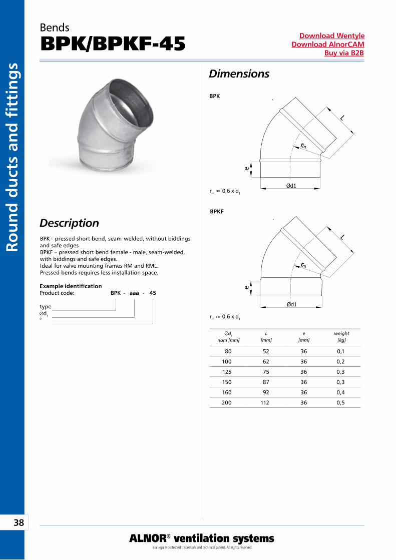
BPK/BPKF-45Dimensions
Description
Example identificationProduct code: BPK - aaa - 45
typed1
°
d1
nom [mm]L
[mm]e
[mm]weight
[kg]
BPK
BPKF
BPK - pressed short bend, seam-welded, without biddings and safe edgesBPKF – pressed short bend female - male, seam-welded, with biddings and safe edges.Ideal for valve mounting frames RM and RML.Pressed bends requires less installation space.
80 52 36 0,1
100 62 36 0,2
125 75 36 0,3
150 87 36 0,3
160 92 36 0,4
200 112 36 0,5
39
ALNOR® ventilation systemsis a legally protected trademark and technical patent. All rights reserved.
Rou
nd
du
cts and
fi tting
sDownload Wentyle
Download AlnorCAMBuy via B2B
rm » 1 x d1
Bends
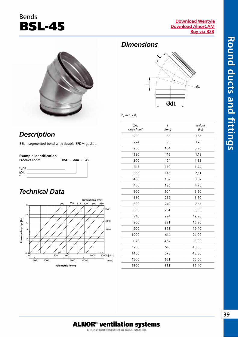
BSL-45Dimensions
DescriptionBSL – segmented bend with double EPDM gasket.
Technical Data
Example identificationProduct code: BSL - aaa - 45
typeÆd1°
Dimensions [mm]
Pre
ssu
re d
rop
Dp
t [P
a]
Volumetric flow q
Æd1 L weight rated [mm] [mm] [kg]
200 83 0,65
224 93 0,78
250 104 0,96
280 116 1,18
300 124 1,33
315 130 1,44
355 145 2,11
400 162 3,07
450 186 4,75
500 204 5,60
560 232 6,80
600 249 7,65
630 261 8,30
710 294 12,90
800 331 15,80
900 373 19,40
1000 414 24,00
1120 464 33,00
1250 518 40,00
1400 578 48,80
1500 621 55,60
1600 663 62,40
40
ALNOR® ventilation systemsis a legally protected trademark and technical patent. All rights reserved.
Rou
nd
du
cts
and
fi t
tin
gs
Download WentyleDownload AlnorCAM
Buy via B2B
rm » 1 x d1
Bends
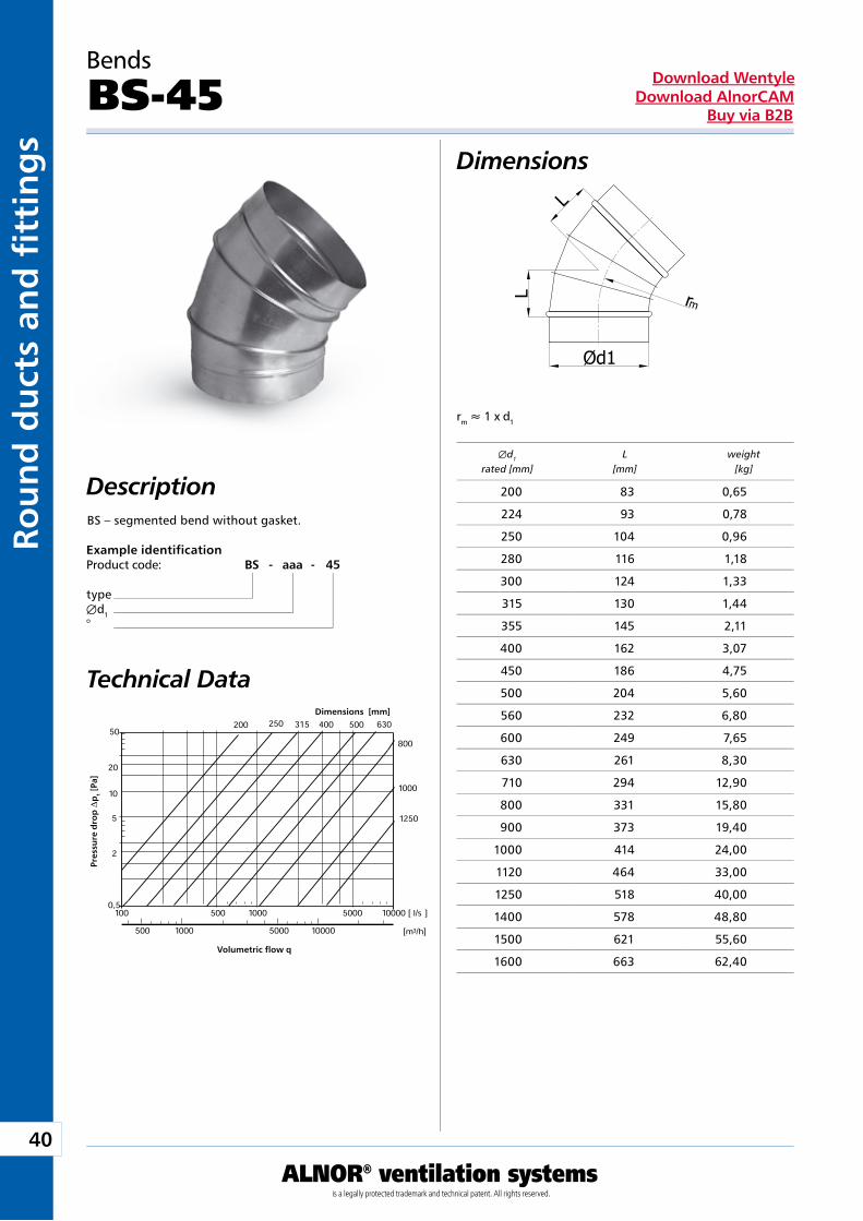
BS-45Dimensions
DescriptionBS – segmented bend without gasket.
Technical Data
Example identificationProduct code: BS - aaa - 45
typeÆd1°
Dimensions [mm]
Pre
ssu
re d
rop
Dp
t [P
a]
Volumetric flow q
Æd1 L weight rated [mm] [mm] [kg]
200 83 0,65
224 93 0,78
250 104 0,96
280 116 1,18
300 124 1,33
315 130 1,44
355 145 2,11
400 162 3,07
450 186 4,75
500 204 5,60
560 232 6,80
600 249 7,65
630 261 8,30
710 294 12,90
800 331 15,80
900 373 19,40
1000 414 24,00
1120 464 33,00
1250 518 40,00
1400 578 48,80
1500 621 55,60
1600 663 62,40
41
ALNOR® ventilation systemsis a legally protected trademark and technical patent. All rights reserved.
Rou
nd
du
cts and
fi tting
sDownload Wentyle
Download AlnorCAMBuy via B2B
rm » 0,6 x d1
rm » 0,6 x d1
Bends
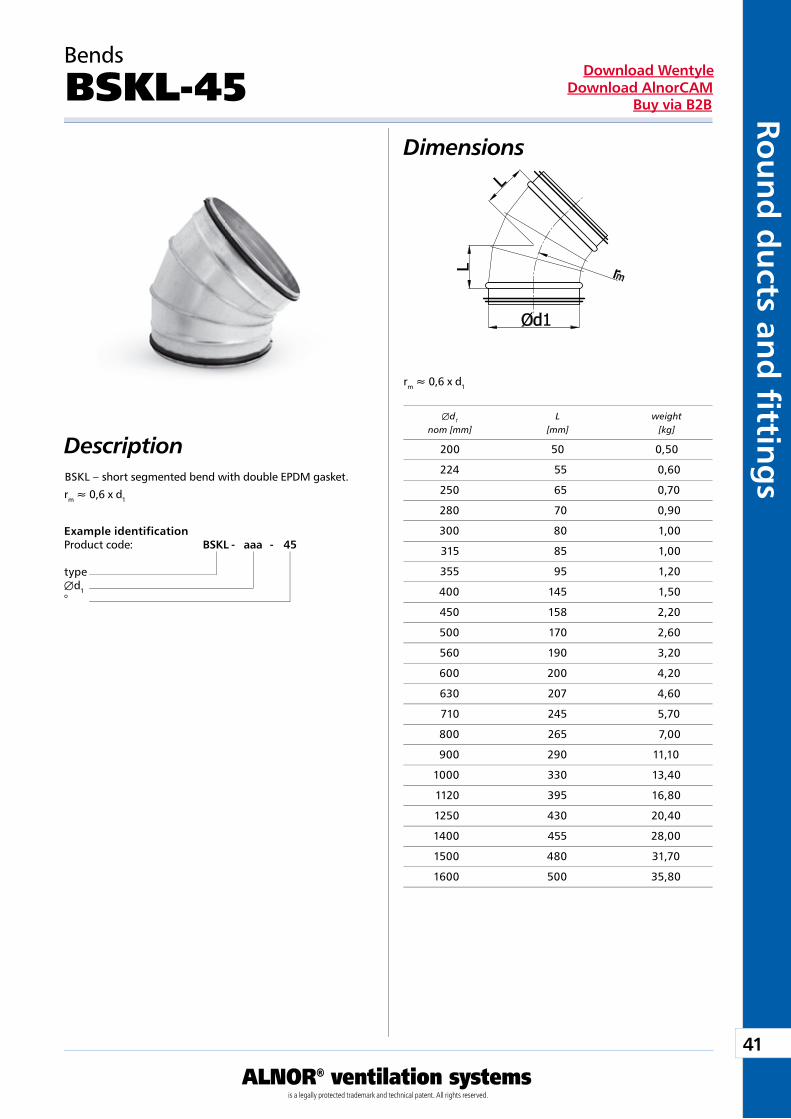
BSKL-45Dimensions
DescriptionBSKL – short segmented bend with double EPDM gasket.
Example identificationProduct code: BSKL - aaa - 45
typeÆd1°
Æd1 L weight nom [mm] [mm] [kg]
200 50 0,50
224 55 0,60
250 65 0,70
280 70 0,90
300 80 1,00
315 85 1,00
355 95 1,20
400 145 1,50
450 158 2,20
500 170 2,60
560 190 3,20
600 200 4,20
630 207 4,60
710 245 5,70
800 265 7,00
900 290 11,10
1000 330 13,40
1120 395 16,80
1250 430 20,40
1400 455 28,00
1500 480 31,70
1600 500 35,80
42
ALNOR® ventilation systemsis a legally protected trademark and technical patent. All rights reserved.
Rou
nd
du
cts
and
fi t
tin
gs
Download WentyleDownload AlnorCAM
Buy via B2B
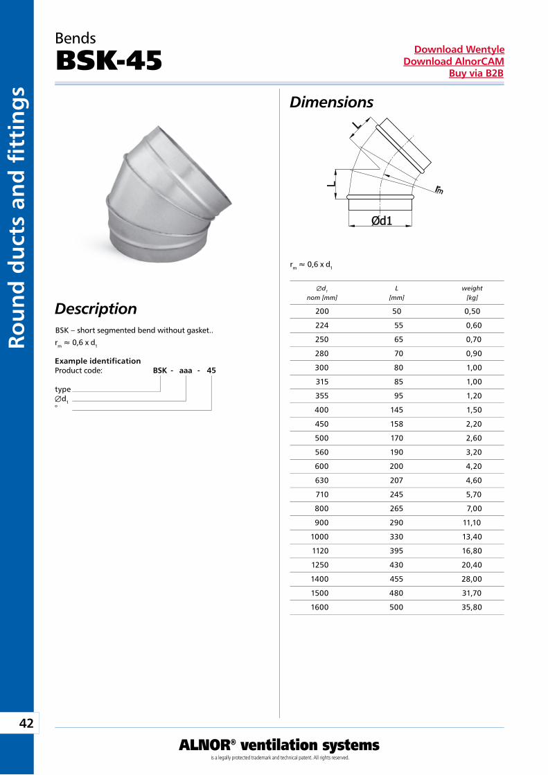
Example identificationProduct code: BSK - aaa - 45
typeÆd1°
BSK – short segmented bend without gasket..
Dimensions
Description
rm » 0,6 x d1
rm » 0,6 x d1
Bends
BSK-45
Æd1 L weight nom [mm] [mm] [kg]
200 50 0,50
224 55 0,60
250 65 0,70
280 70 0,90
300 80 1,00
315 85 1,00
355 95 1,20
400 145 1,50
450 158 2,20
500 170 2,60
560 190 3,20
600 200 4,20
630 207 4,60
710 245 5,70
800 265 7,00
900 290 11,10
1000 330 13,40
1120 395 16,80
1250 430 20,40
1400 455 28,00
1500 480 31,70
1600 500 35,80
43
ALNOR® ventilation systemsis a legally protected trademark and technical patent. All rights reserved.
Rou
nd
du
cts and
fi tting
sDownload Wentyle
Download AlnorCAMBuy via B2B
rm » 1 x d1
Bends
BPL/BP-30Dimensions
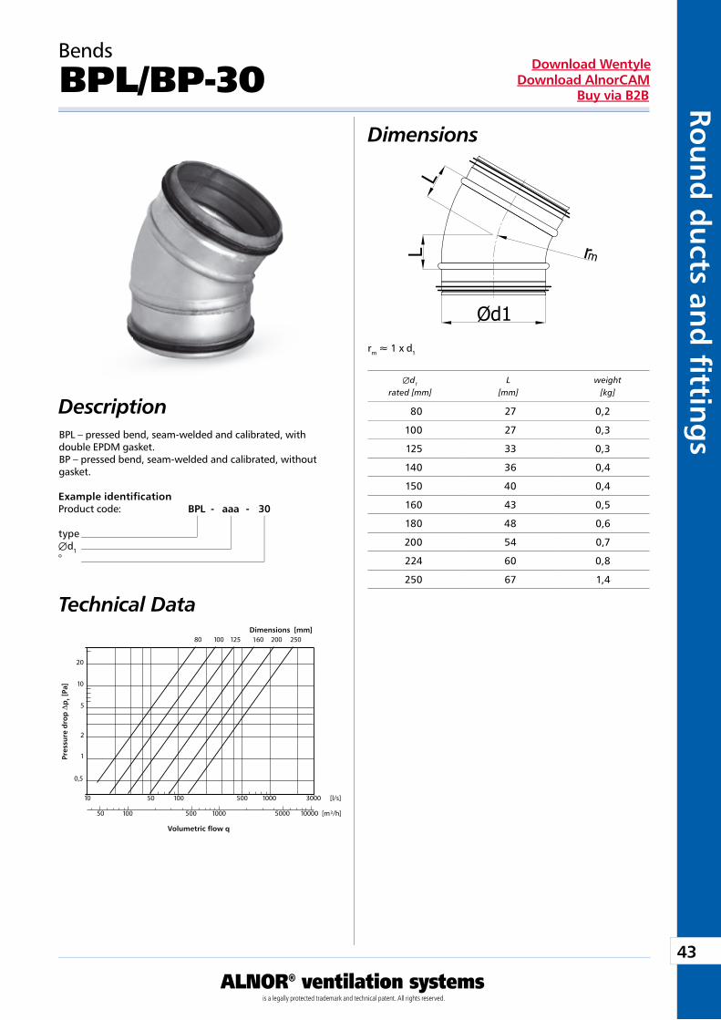
DescriptionBPL – pressed bend, seam-welded and calibrated, with double EPDM gasket.BP – pressed bend, seam-welded and calibrated, without gasket.
Technical Data
Example identificationProduct code: BPL - aaa - 30
typeÆd1°
Dimensions [mm]
Pre
ssu
re d
rop
Dp
t [P
a]
Volumetric flow q
Æd1 L weight rated [mm] [mm] [kg]
80 27 0,2
100 27 0,3
125 33 0,3
140 36 0,4
150 40 0,4
160 43 0,5
180 48 0,6
200 54 0,7
224 60 0,8
250 67 1,4
44
ALNOR® ventilation systemsis a legally protected trademark and technical patent. All rights reserved.
Rou
nd
du
cts
and
fi t
tin
gs
Download WentyleDownload AlnorCAM
Buy via B2B
rm » 1 x d1
Bends
BSL/BS-30Dimensions
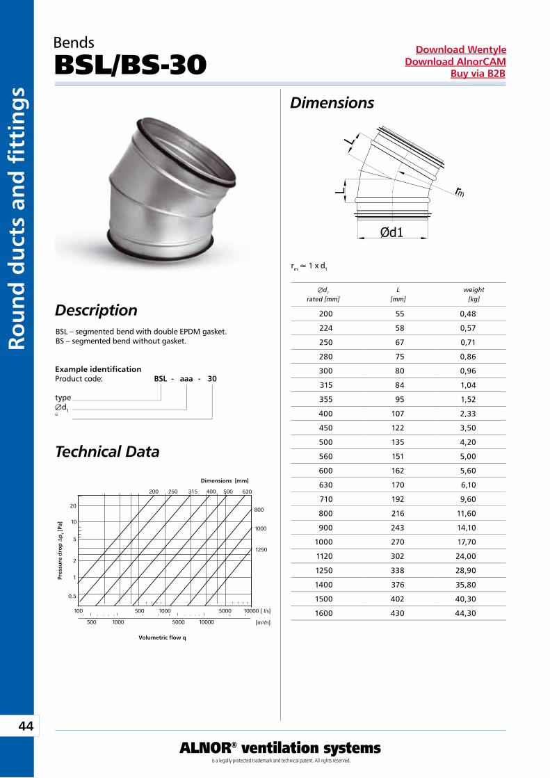
DescriptionBSL – segmented bend with double EPDM gasket.BS – segmented bend without gasket.
Technical Data
Example identificationProduct code: BSL - aaa - 30
typeÆd1°
Dimensions [mm]
Pre
ssu
re d
rop
Dp
t [P
a]
Volumetric flow q
Æd1 L weight rated [mm] [mm] [kg]
200 55 0,48
224 58 0,57
250 67 0,71
280 75 0,86
300 80 0,96
315 84 1,04
355 95 1,52
400 107 2,33
450 122 3,50
500 135 4,20
560 151 5,00
600 162 5,60
630 170 6,10
710 192 9,60
800 216 11,60
900 243 14,10
1000 270 17,70
1120 302 24,00
1250 338 28,90
1400 376 35,80
1500 402 40,30
1600 430 44,30
45
ALNOR® ventilation systemsis a legally protected trademark and technical patent. All rights reserved.
Rou
nd
du
cts and
fi tting
sDownload Wentyle
Download AlnorCAMBuy via B2B
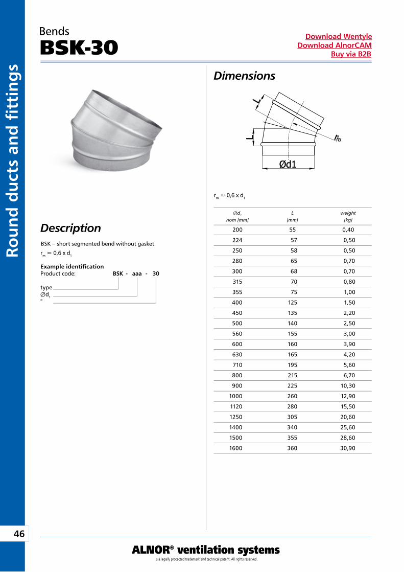
rm » 0,6 x d1
rm » 0,6 x d1
Bends
BSKL-30Dimensions
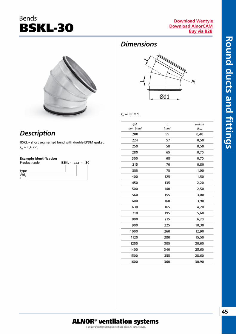
DescriptionBSK L – short segmented bend with double EPDM gasket.
Example identificationProduct code: BSKL - aaa - 30
typeÆd1°
Æd1 L weight nom [mm] [mm] [kg]
200 55 0,40
224 57 0,50
250 58 0,50
280 65 0,70
300 68 0,70
315 70 0,80
355 75 1,00
400 125 1,50
450 135 2,20
500 140 2,50
560 155 3,00
600 160 3,90
630 165 4,20
710 195 5,60
800 215 6,70
900 225 10,30
1000 260 12,90
1120 280 15,50
1250 305 20,60
1400 340 25,60
1500 355 28,60
1600 360 30,90
46
ALNOR® ventilation systemsis a legally protected trademark and technical patent. All rights reserved.
Rou
nd
du
cts
and
fi t
tin
gs
Download WentyleDownload AlnorCAM
Buy via B2B
Description
Example identificationProduct code: BSK - aaa - 30
typeÆd1°
BSK – short segmented bend without gasket.
Dimensions
rm » 0,6 x d1
Bends
BSK-30
Æd1 L weight nom [mm] [mm] [kg]
rm » 0,6 x d1
200 55 0,40
224 57 0,50
250 58 0,50
280 65 0,70
300 68 0,70
315 70 0,80
355 75 1,00
400 125 1,50
450 135 2,20
500 140 2,50
560 155 3,00
600 160 3,90
630 165 4,20
710 195 5,60
800 215 6,70
900 225 10,30
1000 260 12,90
1120 280 15,50
1250 305 20,60
1400 340 25,60
1500 355 28,60
1600 360 30,90
47
ALNOR® ventilation systemsis a legally protected trademark and technical patent. All rights reserved.
Rou
nd
du
cts and
fi tting
sDownload Wentyle
Download AlnorCAMBuy via B2B
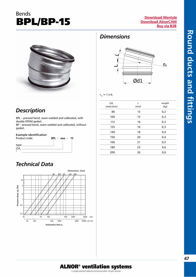
rm » 1 x d1
Bends
BPL/BP-15Dimensions
DescriptionBPL – pressed bend, seam-welded and calibrated, with double EPDM gasket.BP – pressed bend, seam-welded and calibrated, without gasket.
Technical Data
Example identificationProduct code: BPL - aaa - 15
typeÆd1°
Dimensions [mm]
Pre
ssu
re d
rop
Dp
t [P
a]
Volumetric flow q
Æd1 L weight rated [mm] [mm] [kg]
80 13 0,2
100 13 0,3
112 16 0,3
125 16 0,3
140 18 0,4
150 20 0,4
160 21 0,5
180 23 0,6
200 26 0,6
48
ALNOR® ventilation systemsis a legally protected trademark and technical patent. All rights reserved.
Rou
nd
du
cts
and
fi t
tin
gs
Download WentyleDownload AlnorCAM
Buy via B2B
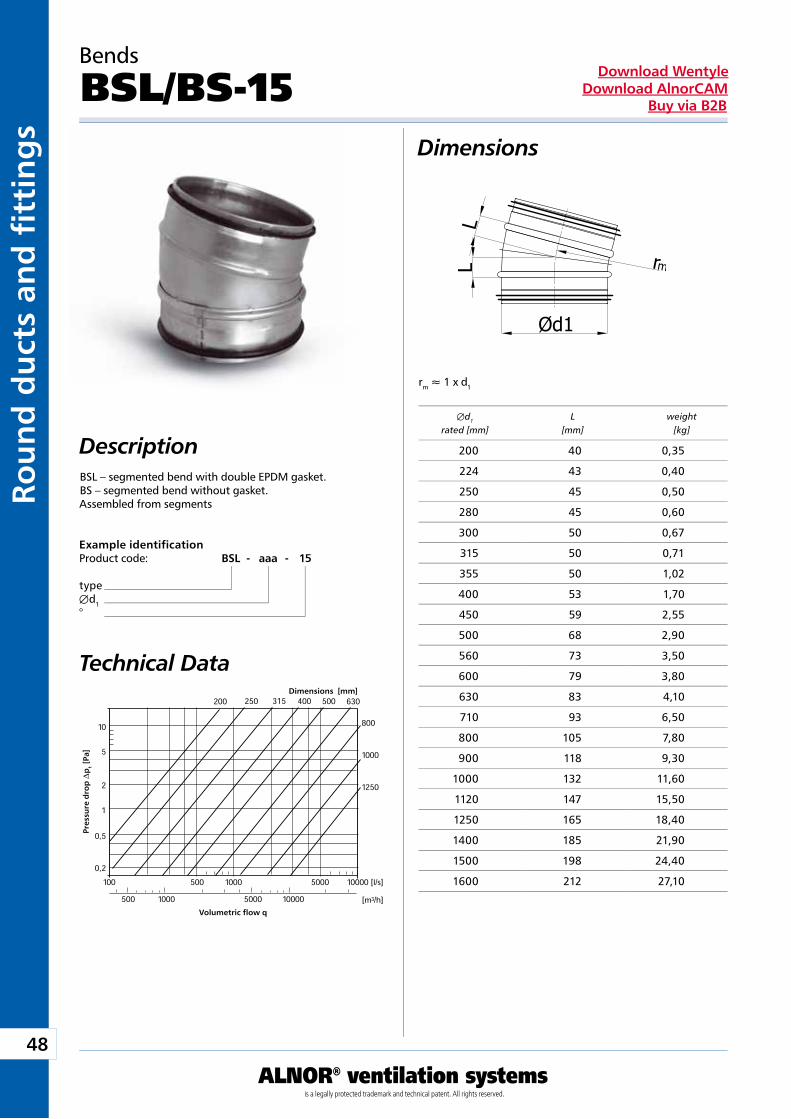
rm » 1 x d1
Bends
BSL/BS-15Dimensions
DescriptionBSL – segmented bend with double EPDM gasket.BS – segmented bend without gasket.Assembled from segments
Technical Data
Example identificationProduct code: BSL - aaa - 15
typeÆd1°
Dimensions [mm]
Pre
ssu
re d
rop
Dp
t [P
a]
Volumetric flow q
Æd1 L weight rated [mm] [mm] [kg]
200 40 0,35
224 43 0,40
250 45 0,50
280 45 0,60
300 50 0,67
315 50 0,71
355 50 1,02
400 53 1,70
450 59 2,55
500 68 2,90
560 73 3,50
600 79 3,80
630 83 4,10
710 93 6,50
800 105 7,80
900 118 9,30
1000 132 11,60
1120 147 15,50
1250 165 18,40
1400 185 21,90
1500 198 24,40
1600 212 27,10

49
ALNOR® ventilation systemsis a legally protected trademark and technical patent. All rights reserved.
Rou
nd
du
cts and
fi tting
sDownload Wentyle
Download AlnorCAMBuy via B2B
rm » 0,6 x d1
rm » 0,6 x d1
Bends
BSKL-15Dimensions
DescriptionBSKL – short segmented bend with double EPDM gasket.
Example identificationProduct code: BSKL - aaa - 15
typeÆd1°
Æd1 L weight nom [mm] [mm] [kg]
200 35 0,30
224 37 0,30
250 45 0,40
280 50 0,50
300 50 0,60
315 50 0,60
355 55 0,70
400 95 1,20
450 100 1,70
500 105 1,90
560 115 2,30
600 120 2,90
630 120 3,10
710 145 4,20
800 150 4,90
900 160 7,40
1000 185 9,20
1120 195 11,00
1250 205 12,80
1400 215 16,80
1500 225 18,60
1600 235 20,50
50
ALNOR® ventilation systemsis a legally protected trademark and technical patent. All rights reserved.
Rou
nd
du
cts
and
fi t
tin
gs
Download WentyleDownload AlnorCAM
Buy via B2B
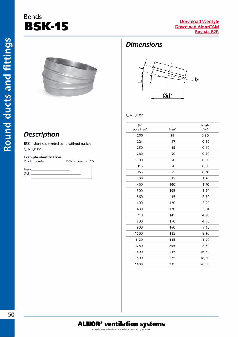
Description
Example identificationProduct code: BSK - aaa - 15
typeÆd1°
BSK – short segmented bend without gasket.
Dimensions
rm » 0,6 x d1
Bends
BSK-15
Æd1 L weight nom [mm] [mm] [kg]
rm » 0,6 x d1
200 35 0,30
224 37 0,30
250 45 0,40
280 50 0,50
300 50 0,60
315 50 0,60
355 55 0,70
400 95 1,20
450 100 1,70
500 105 1,90
560 115 2,30
600 120 2,90
630 120 3,10
710 145 4,20
800 150 4,90
900 160 7,40
1000 185 9,20
1120 195 11,00
1250 205 12,80
1400 215 16,80
1500 225 18,60
1600 235 20,50
51
ALNOR® ventilation systemsis a legally protected trademark and technical patent. All rights reserved.
Rou
nd
du
cts and
fi tting
sDownload Wentyle
Download AlnorCAMBuy via B2B
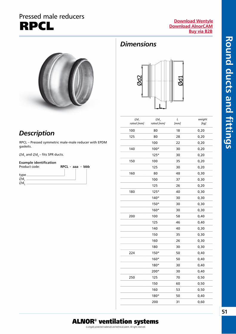
Pressed male reducers
RPCLDimensions
DescriptionRPCL – Pressed symmetric male-male reducer with EPDM gaskets.
Æd1 and Æd2 – fits SPR ducts.
Example identificationProduct code: RPCL - aaa - bbb
typeÆd1Æd2
Æd1 Æd2 L weight rated [mm] rated [mm] [mm] [kg]
100 80 18 0,20
125 80 28 0,20
100 22 0,20
140 100* 30 0,20
125* 30 0,20
150 100 35 0,20
125 30 0,20
160 80 48 0,30
100 37 0,30
125 26 0,20
180 125* 40 0,30
140* 30 0,30
150* 30 0,30
160* 30 0,30
200 100 58 0,40
125 46 0,40
140 40 0,30
150 35 0,30
160 26 0,30
180 30 0,30
224 150* 50 0,40
160* 50 0,40
180* 30 0,40
200* 30 0,40
250 125 70 0,50
150 60 0,50
160 53 0,50
180* 50 0,40
200 31 0,60
52
ALNOR® ventilation systemsis a legally protected trademark and technical patent. All rights reserved.
Rou
nd
du
cts
and
fi t
tin
gs
Download WentyleDownload AlnorCAM
Buy via B2B
* Fabricated, the remaining entirely pressed.
Pressed male reducers
RPCL
Æd1 Æd2 L weight rated [mm] rated [mm] [mm] [kg]
Æd1 Æd2 L weight rated [mm] rated [mm] [mm] [kg]
Dimensions
450* 80 2,60
500* 75 2,60
600 400* 130 3,10
450* 100 3,00
500* 70 2,70
560* 30 2,40
630 315* 160 3,20
400* 140 3,30
450* 120 3,30
500* 80 3,00
560* 75 2,90
600* 30 2,50
224* 50 0,50
280 160* 80 0,60
180* 70 0,60
200* 60 0,60
224* 40 0,60
300 200* 70 0,70
224* 60 0,70
250* 30 0,60
280* 30 0,70
315 160 88 0,80
180* 90 0,80
200 68 0,70
224* 60 0,70
250 43 0,70
280* 40 0,70
300* 38 0,70
355 200* 110 1,10
224* 90 1,00
250* 70 1,00
315* 30 0,90
400 200* 140 1,50
224* 120 1,40
250* 100 1,30
315* 60 1,30
355* 30 1,20
450 250* 140 2,00
280* 110 1,90
300* 100 1,90
315* 90 1,80
355* 60 1,70
400* 40 1,70
500 250* 128 2,20
300* 140 2,40
315* 120 2,20
355* 100 2,20
400* 70 2,10
450* 40 2,10
560 315* 170 2,90
355* 140 2,80
400* 110 2,70
53
ALNOR® ventilation systemsis a legally protected trademark and technical patent. All rights reserved.
Rou
nd
du
cts and
fi tting
sDownload Wentyle
Download AlnorCAMBuy via B2B
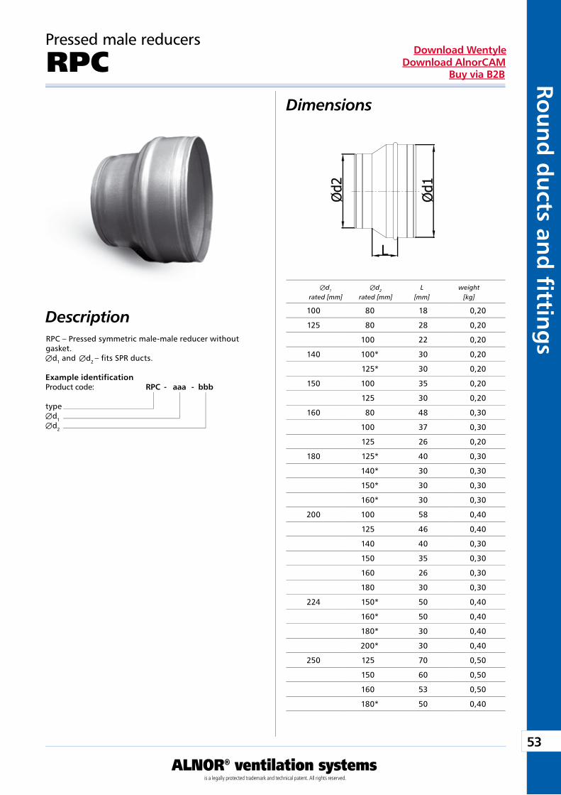
Pressed male reducers
RPCDimensions
DescriptionRPC – Pressed symmetric male-male reducer without gasket.Æd1 and Æd2 – fits SPR ducts.
Example identificationProduct code: RPC - aaa - bbb
typeÆd1Æd2
Æd1 Æd2 L weight rated [mm] rated [mm] [mm] [kg]
100 80 18 0,20
125 80 28 0,20
100 22 0,20
140 100* 30 0,20
125* 30 0,20
150 100 35 0,20
125 30 0,20
160 80 48 0,30
100 37 0,30
125 26 0,20
180 125* 40 0,30
140* 30 0,30
150* 30 0,30
160* 30 0,30
200 100 58 0,40
125 46 0,40
140 40 0,30
150 35 0,30
160 26 0,30
180 30 0,30
224 150* 50 0,40
160* 50 0,40
180* 30 0,40
200* 30 0,40
250 125 70 0,50
150 60 0,50
160 53 0,50
180* 50 0,40
54
ALNOR® ventilation systemsis a legally protected trademark and technical patent. All rights reserved.
Rou
nd
du
cts
and
fi t
tin
gs
Download WentyleDownload AlnorCAM
Buy via B2B
* Fabricated, the remaining entirely pressed.
Pressed male reducers
RPC
Æd1 Æd2 L weight rated [mm] rated [mm] [mm] [kg]
Æd1 Æd2 L weight rated [mm] rated [mm] [mm] [kg]
Dimensions
450* 80 2,60
500* 75 2,60
600 400* 130 3,10
450* 100 3,00
500* 70 2,70
560* 30 2,40
630 315* 160 3,20
400* 140 3,30
450* 120 3,30
500* 80 3,00
560* 75 2,90
600* 30 2,50
200 31 0,60
224* 50 0,50
280 160* 80 0,60
180* 70 0,60
200* 60 0,60
224* 40 0,60
300 200* 70 0,70
224* 60 0,70
250* 30 0,60
280* 30 0,70
315 160 88 0,80
180* 90 0,80
200 68 0,70
224* 60 0,70
250 43 0,70
280* 40 0,70
300* 38 0,70
355 200* 110 1,10
224* 90 1,00
250* 70 1,00
315* 30 0,90
400 200* 140 1,50
224* 120 1,40
250* 100 1,30
315* 60 1,30
355* 30 1,20
450 250* 140 2,00
280* 110 1,90
300* 100 1,90
315* 90 1,80
355* 60 1,70
400* 40 1,70
500 250* 128 2,20
300* 140 2,40
315* 120 2,20
355* 100 2,20
400* 70 2,10
450* 40 2,10
560 315* 170 2,90
355* 140 2,80
400* 110 2,70
55
ALNOR® ventilation systemsis a legally protected trademark and technical patent. All rights reserved.
Rou
nd
du
cts and
fi tting
sDownload Wentyle
Download AlnorCAMBuy via B2B
Pressed nipple reducers
RPCNDimensions
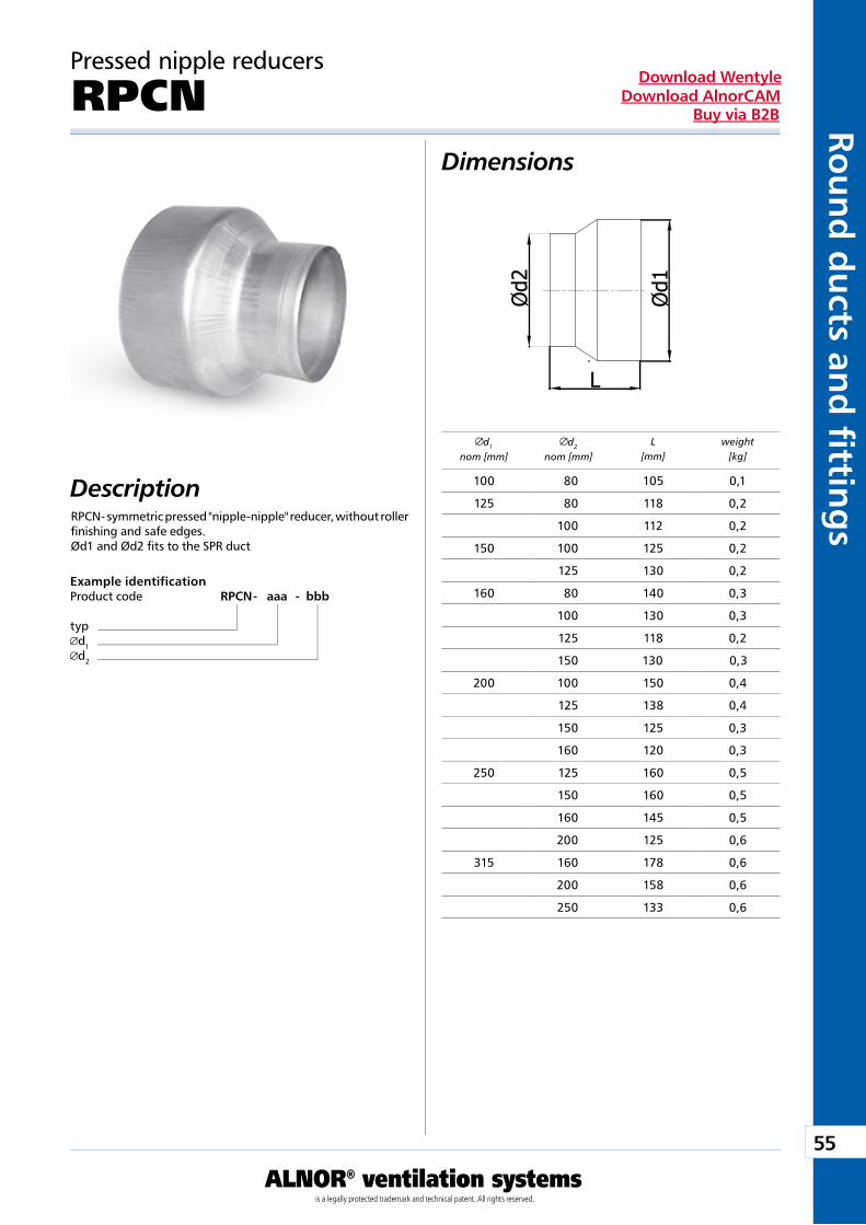
DescriptionRPCN- symmetric pressed "nipple-nipple" reducer, without roller finishing and safe edges. Ød1 and Ød2 fits to the SPR duct
Example identificationProduct code RPCN - aaa - bbb
typd1d2
d1
nom [mm]d2
nom [mm]L
[mm]weight
[kg]
100 80 105 0,1
125 80 118 0,2
100 112 0,2
150 100 125 0,2
125 130 0,2
160 80 140 0,3
100 130 0,3
125 118 0,2
150 130 0,3
200 100 150 0,4
125 138 0,4
150 125 0,3
160 120 0,3
250 125 160 0,5
150 160 0,5
160 145 0,5
200 125 0,6
315 160 178 0,6
200 158 0,6
250 133 0,6

56
ALNOR® ventilation systemsis a legally protected trademark and technical patent. All rights reserved.
Rou
nd
du
cts
and
fi t
tin
gs
Download WentyleDownload AlnorCAM
Buy via B2B
Pressed nipple reducers
RPCNRDimensions
DescriptionRPCNR - symmetric pressed "nipple-nipple" reducer, with roller finishing and whitout safe edges. Ød1 and Ød2 - fits to the SPR duct
Example identificationProduct code RPCN R - aaa - bbb
typd1d2
d1
nom [mm]d2
nom [mm]L
[mm]weight
[kg]
100 80 20 0,1
125 80 32 0,2
100 22 0,2
150 100 35 0,2
125 30 0,2
160 80 25 0,3
100 40 0,3
125 27 0,2
150 30 0,3
200 100 60 0,4
125 47 0,4
150 35 0,3
160 30 0,3
250 125 50 0,5
150 50 0,5
160 55 0,5
200 35 0,6
315 160 87 0,6
200 67 0,6
250 42 0,6
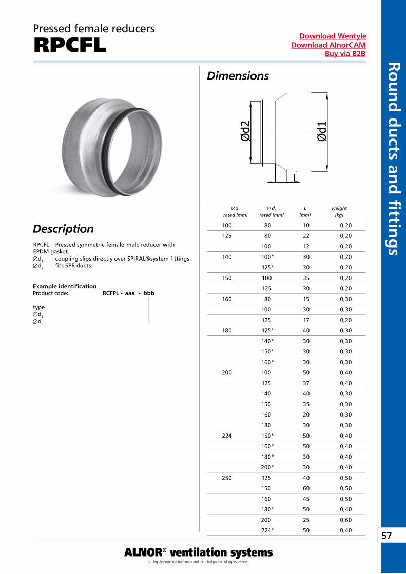
57
ALNOR® ventilation systemsis a legally protected trademark and technical patent. All rights reserved.
Rou
nd
du
cts and
fi tting
sDownload Wentyle
Download AlnorCAMBuy via B2B
Pressed female reducers
RPCFLDimensions
DescriptionRPCFL – Pressed symmetric female-male reducer with EPDM gasket.Æd1 – coupling slips directly over SPIRAL®system fittings. Æd2 – fits SPR ducts.
Example identificationProduct code: RCFPL - aaa - bbb
typeÆd1Æd2
Æd1 Æ�d2 L weight rated [mm] rated [mm] [mm] [kg]
100 80 10 0,20
125 80 22 0,20
100 12 0,20
140 100* 30 0,20
125* 30 0,20
150 100 35 0,20
125 30 0,20
160 80 15 0,30
100 30 0,30
125 17 0,20
180 125* 40 0,30
140* 30 0,30
150* 30 0,30
160* 30 0,30
200 100 50 0,40
125 37 0,40
140 40 0,30
150 35 0,30
160 20 0,30
180 30 0,30
224 150* 50 0,40
160* 50 0,40
180* 30 0,40
200* 30 0,40
250 125 40 0,50
150 60 0,50
160 45 0,50
180* 50 0,40
200 25 0,60
224* 50 0,40
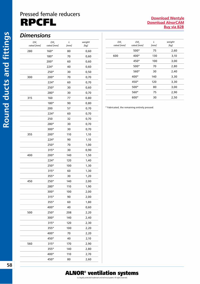
58
ALNOR® ventilation systemsis a legally protected trademark and technical patent. All rights reserved.
Rou
nd
du
cts
and
fi t
tin
gs
Download WentyleDownload AlnorCAM
Buy via B2B
Æd1 Æd2 L weight rated [mm] rated [mm] [mm] [kg]
Æd1 Æd2 L weight rated [mm] rated [mm] [mm] [kg]
* Fabricated, the remaining entirely pressed.
Pressed female reducers
RPCFLDimensions
500* 75 2,60
600 400* 130 3,10
450* 100 3,00
500* 70 2,80
560* 30 2,40
400* 140 3,30
450* 120 3,30
500* 80 3,00
560* 75 2,90
600* 30 2,50
280 160* 80 0,60
180* 70 0,60
200* 60 0,60
224* 40 0,60
250* 30 0,50
300 200* 70 0,70
224* 60 0,70
250* 30 0,60
280* 30 0,70
315 160 77 0,80
180* 90 0,80
200 57 0,70
224* 60 0,70
250 32 0,70
280* 30 0,70
300* 30 0,70
355 200* 110 1,10
224* 90 1,10
250* 70 1,00
315* 30 0,90
400 200* 140 1,50
224* 120 1,40
250* 100 1,30
315* 60 1,30
355* 30 1,20
450 250* 140 2,00
280* 110 1,90
300* 100 2,00
315* 90 2,00
355* 60 1,80
400* 40 0,60
500 250* 208 2,20
300* 140 2,40
315* 120 2,30
355* 100 2,20
400* 70 2,20
450* 40 2,10
560 315* 170 2,90
355* 140 2,80
400* 110 2,70
450* 80 2,60
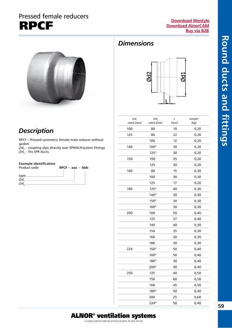
59
ALNOR® ventilation systemsis a legally protected trademark and technical patent. All rights reserved.
Rou
nd
du
cts and
fi tting
sDownload Wentyle
Download AlnorCAMBuy via B2B
Pressed female reducers
RPCFDimensions
DescriptionRPCF – Pressed symmetric female-male reducer without gasket.Æd1 – coupling slips directly over SPIRAL®system fittings. Æd2 – fits SPR ducts.
Example identificationProduct code: RPCF - aaa - bbb
typeÆd1Æd2
Æd1 Æd2 L weight rated [mm] rated [mm] [mm] [kg]
100 80 10 0,20
125 80 22 0,20
100 12 0,20
140 100* 30 0,20
125* 30 0,20
150 100 35 0,20
125 30 0,20
160 80 15 0,30
100 30 0,30
125 17 0,20
180 125* 40 0,30
140* 30 0,30
150* 30 0,30
160* 30 0,30
200 100 50 0,40
125 37 0,40
140 40 0,30
150 35 0,30
160 20 0,30
180 30 0,30
224 150* 50 0,40
160* 50 0,40
180* 30 0,40
200* 30 0,40
250 125 40 0,50
150 60 0,50
160 45 0,50
180* 50 0,40
200 25 0,60
224* 50 0,40
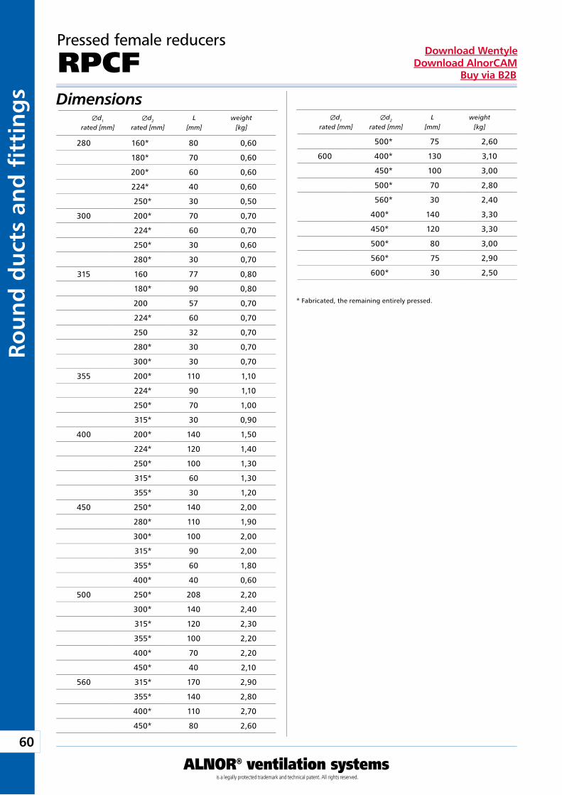
60
ALNOR® ventilation systemsis a legally protected trademark and technical patent. All rights reserved.
Rou
nd
du
cts
and
fi t
tin
gs
Download WentyleDownload AlnorCAM
Buy via B2B
Pressed female reducers
RPCF
Æd1 Æd2 L weight rated [mm] rated [mm] [mm] [kg]
Æd1 Æd2 L weight rated [mm] rated [mm] [mm] [kg]
* Fabricated, the remaining entirely pressed.
Dimensions
500* 75 2,60
600 400* 130 3,10
450* 100 3,00
500* 70 2,80
560* 30 2,40
400* 140 3,30
450* 120 3,30
500* 80 3,00
560* 75 2,90
600* 30 2,50
280 160* 80 0,60
180* 70 0,60
200* 60 0,60
224* 40 0,60
250* 30 0,50
300 200* 70 0,70
224* 60 0,70
250* 30 0,60
280* 30 0,70
315 160 77 0,80
180* 90 0,80
200 57 0,70
224* 60 0,70
250 32 0,70
280* 30 0,70
300* 30 0,70
355 200* 110 1,10
224* 90 1,10
250* 70 1,00
315* 30 0,90
400 200* 140 1,50
224* 120 1,40
250* 100 1,30
315* 60 1,30
355* 30 1,20
450 250* 140 2,00
280* 110 1,90
300* 100 2,00
315* 90 2,00
355* 60 1,80
400* 40 0,60
500 250* 208 2,20
300* 140 2,40
315* 120 2,30
355* 100 2,20
400* 70 2,20
450* 40 2,10
560 315* 170 2,90
355* 140 2,80
400* 110 2,70
450* 80 2,60
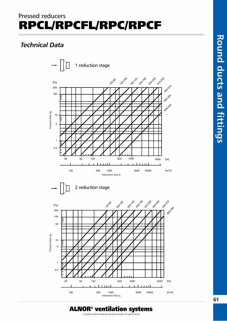
61
ALNOR® ventilation systemsis a legally protected trademark and technical patent. All rights reserved.
Rou
nd
du
cts and
fi tting
sDownload Wentyle
Download AlnorCAMBuy via B2B
5000
Pa
l/s
m3/h
20 50 100 500 1000
200
100
10
5
1
0,5
100 500 1000 5000 10000
630-
500
500-
400
400-
315
315-
250
250-
200
200-
160
160-
125
125-
100
100-
80[Pa]
[l/s]
[m3/h]
5000
Pa
l/s
m3/h
20 50 100 500 1000
200
100
50
10
5
1
0.5
100 500 1000 5000 10000
630-
40050
0-31
5
400-
250
315-
200
250-
160
200-
125
160-
100
125-
80
[Pa]
[l/s]
[m3/h]
Pressed reducers
RPCL/RPCFL/RPC/RPCFTechnical Data
Pre
ssur
e dr
op D
p t
1 reduction stage
Volumetric flow q
2 reduction stage
Pre
ssur
e dr
op D
p t
Volumetric flow q
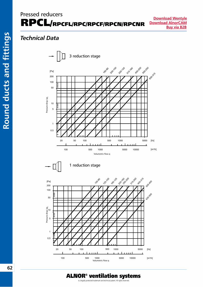
62
ALNOR® ventilation systemsis a legally protected trademark and technical patent. All rights reserved.
Rou
nd
du
cts
and
fi t
tin
gs
Download WentyleDownload AlnorCAM
Buy via B2B
5000
Pa
l/s
m3/h
20 50 100 500 1000
200
100
50
10
5
1
0,5
100 500 1000 5000 10000
630-5
00
500-4
00400-3
15
100-8
0
125-1
0016
0-125
200-1
6025
0-200
315-2
50
[Pa]
[l/s]
[m3/h]
5000 l/s
m3/h
20 50 100 500 1000
200
100
50
10
5
1
0.5
100 500 1000 5000 10000
Pa
630-
31550
0-25
0
400-
200
315-
160
200-
100
250-
125
160-
80
[Pa]
[l/s]
[m3/h]
Pressed reducers
RPCL/RPCFL/RPC/RPCF/RPCN/RPCNR
Technical Data P
ress
ure
drop
Dp t
3 reduction stage
Volumetric flow q
1 reduction stage
Pre
ssur
e dr
op D
p t
Volumetric flow q
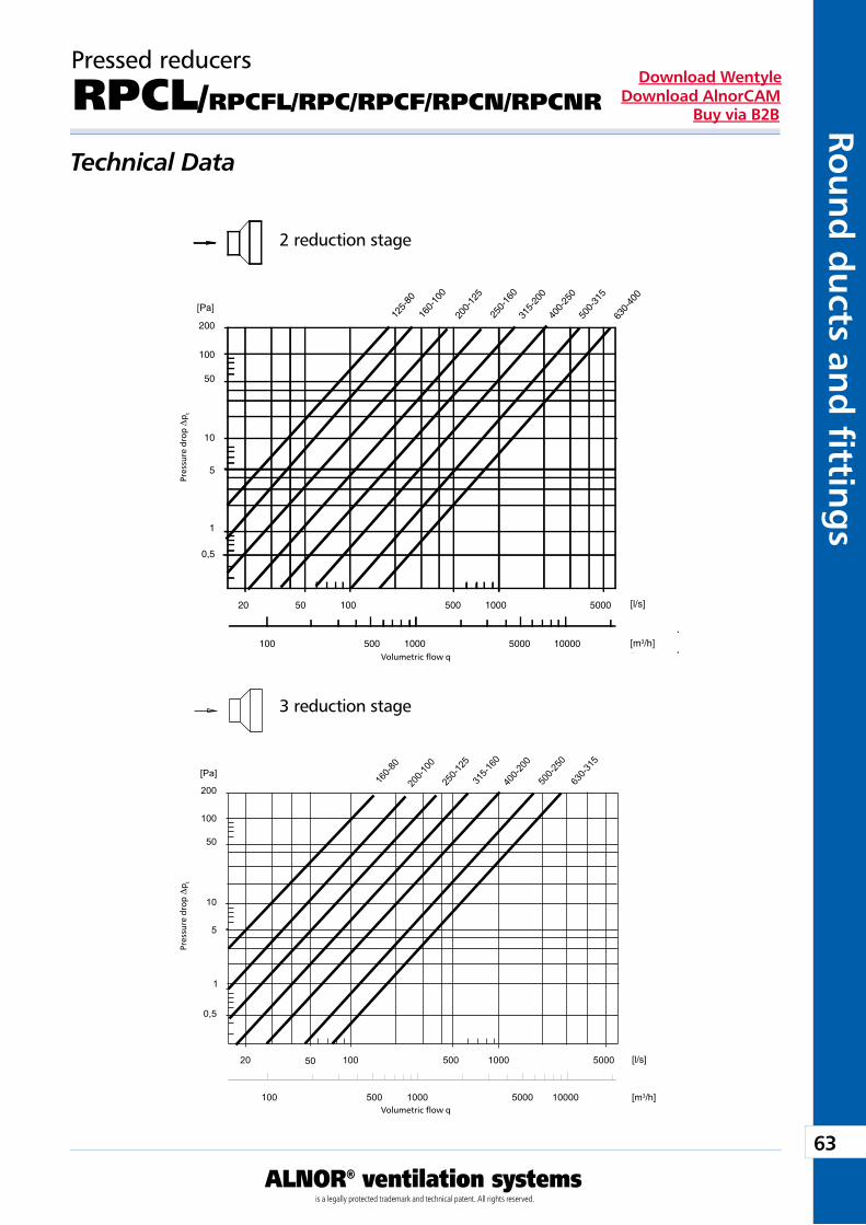
63
ALNOR® ventilation systemsis a legally protected trademark and technical patent. All rights reserved.
Rou
nd
du
cts and
fi tting
sDownload Wentyle
Download AlnorCAMBuy via B2B
1000050001000500100
0,5
1
5
10
50
100
200
10005001005020
m3/h
l/s
Pa
5000
500-
315
630-
400
400-
250
315-
200
250-
160
200-
125
160-
100
125-
80
[Pa]
[l/s]
[m3/h]
1000050001000500100
0,5
1
5
10
50
100
200
10005001005020
m3/h
l/s
Pa
5000
630-3
15
500-2
50
400-2
00
315-1
60
250-1
25
200-1
00
160-8
0
[Pa]
[l/s]
[m3/h]
Pressed reducers
RPCL/RPCFL/RPC/RPCF/RPCN/RPCNR
Technical Data P
ress
ure
drop
Dp t
2 reduction stage
Volumetric flow q
3 reduction stage
Pre
ssur
e dr
op D
p t
Volumetric flow q
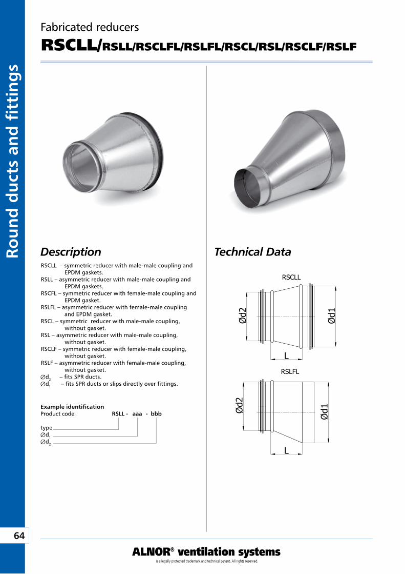
64
ALNOR® ventilation systemsis a legally protected trademark and technical patent. All rights reserved.
Rou
nd
du
cts
and
fi t
tin
gs
Download WentyleDownload AlnorCAM
Buy via B2B
Fabricated reducers
RSCLL/RSLL/RSCLFL/RSLFL/RSCL/RSL/RSCLF/RSLF
Technical DataDescriptionRSCLL – symmetric reducer with male-male coupling and
EPDM gaskets.RSLL – asymmetric reducer with male-male coupling and
EPDM gaskets.RSCFL – symmetric reducer with female-male coupling and
EPDM gasket.RSLFL – asymmetric reducer with female-male coupling
and EPDM gasket.RSCL – symmetric reducer with male-male coupling,
without gasket.RSL – asymmetric reducer with male-male coupling,
without gasket.RSCLF – symmetric reducer with female-male coupling,
without gasket.RSLF – asymmetric reducer with female-male coupling,
without gasket.Æd2 – fits SPR ducts.Æd1 – fits SPR ducts or slips directly over fittings.
Example identificationProduct code: RSLL - aaa - bbb
typeÆd1Æd2
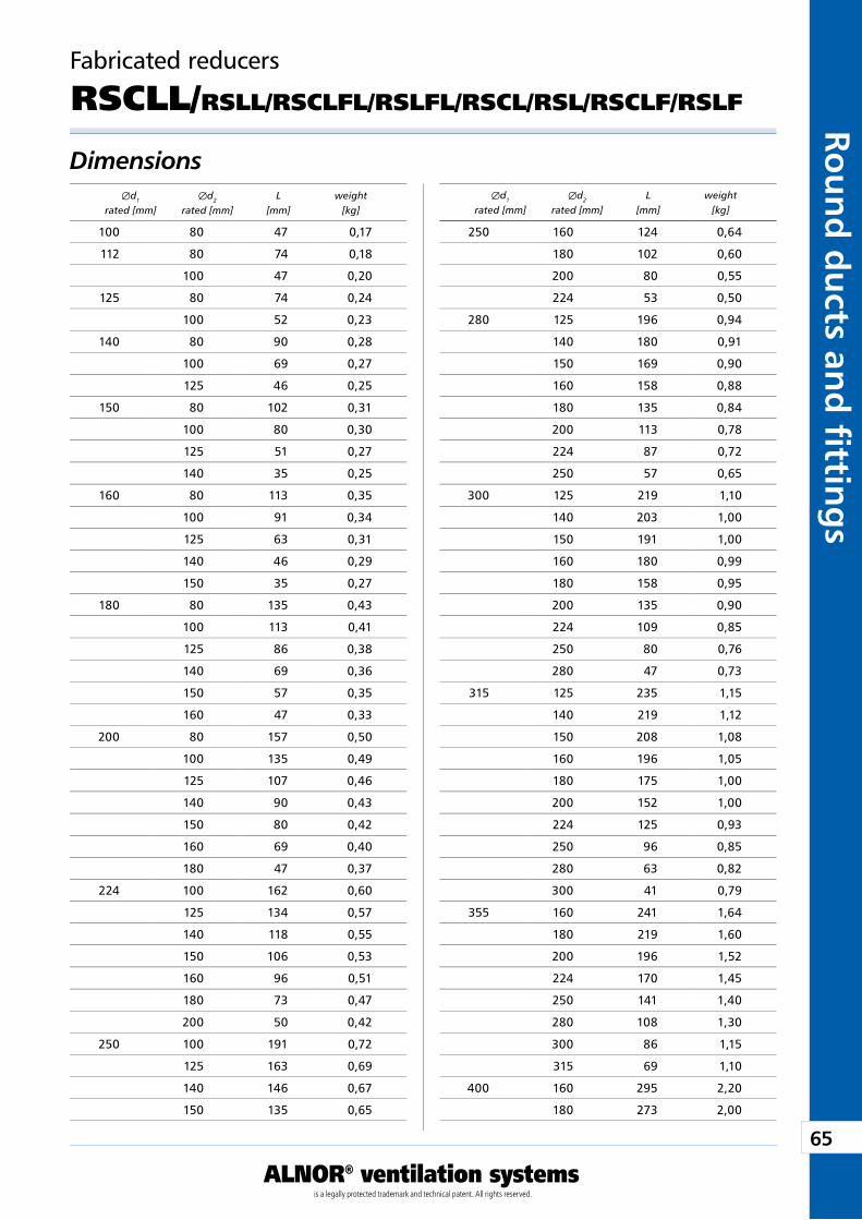
65
ALNOR® ventilation systemsis a legally protected trademark and technical patent. All rights reserved.
Rou
nd
du
cts and
fi tting
sDownload Wentyle
Download AlnorCAMBuy via B2B
Fabricated reducers
RSCLL/RSLL/RSCLFL/RSLFL/RSCL/RSL/RSCLF/RSLF
Dimensions Æd1 Æd2 L weight rated [mm] rated [mm] [mm] [kg]
Æd1 Æd2 L weight rated [mm] rated [mm] [mm] [kg]
250 160 124 0,64
180 102 0,60
200 80 0,55
224 53 0,50
280 125 196 0,94
140 180 0,91
150 169 0,90
160 158 0,88
180 135 0,84
200 113 0,78
224 87 0,72
250 57 0,65
300 125 219 1,10
140 203 1,00
150 191 1,00
160 180 0,99
180 158 0,95
200 135 0,90
224 109 0,85
250 80 0,76
280 47 0,73
315 125 235 1,15
140 219 1,12
150 208 1,08
160 196 1,05
180 175 1,00
200 152 1,00
224 125 0,93
250 96 0,85
280 63 0,82
300 41 0,79
355 160 241 1,64
180 219 1,60
200 196 1,52
224 170 1,45
250 141 1,40
280 108 1,30
300 86 1,15
315 69 1,10
400 160 295 2,20
180 273 2,00
100 80 47 0,17
112 80 74 0,18
100 47 0,20
125 80 74 0,24
100 52 0,23
140 80 90 0,28
100 69 0,27
125 46 0,25
150 80 102 0,31
100 80 0,30
125 51 0,27
140 35 0,25
160 80 113 0,35
100 91 0,34
125 63 0,31
140 46 0,29
150 35 0,27
180 80 135 0,43
100 113 0,41
125 86 0,38
140 69 0,36
150 57 0,35
160 47 0,33
200 80 157 0,50
100 135 0,49
125 107 0,46
140 90 0,43
150 80 0,42
160 69 0,40
180 47 0,37
224 100 162 0,60
125 134 0,57
140 118 0,55
150 106 0,53
160 96 0,51
180 73 0,47
200 50 0,42
250 100 191 0,72
125 163 0,69
140 146 0,67
150 135 0,65
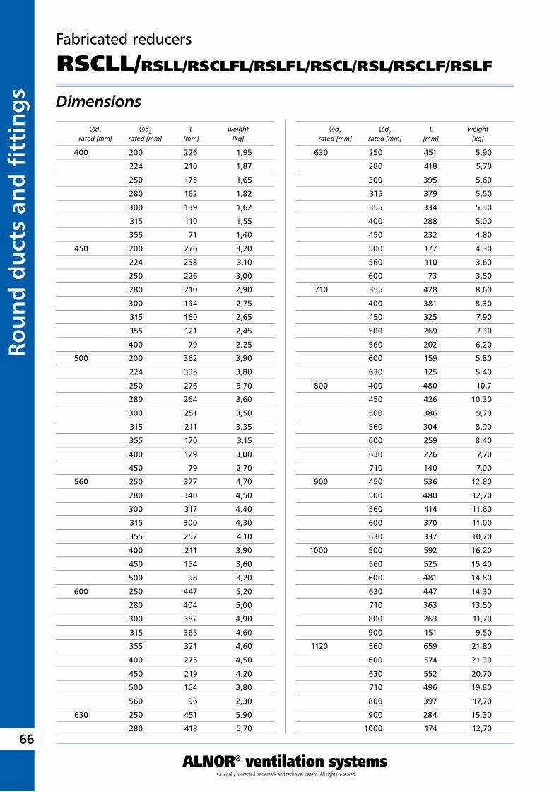
66
ALNOR® ventilation systemsis a legally protected trademark and technical patent. All rights reserved.
Rou
nd
du
cts
and
fi t
tin
gs
Download WentyleDownload AlnorCAM
Buy via B2B
Dimensions
Fabricated reducers
RSCLL/RSLL/RSCLFL/RSLFL/RSCL/RSL/RSCLF/RSLF
Æd1 Æd2 L weight rated [mm] rated [mm] [mm] [kg]
Æd1 Æd2 L weight rated [mm] rated [mm] [mm] [kg]
400 200 226 1,95
224 210 1,87
250 175 1,65
280 162 1,82
300 139 1,62
315 110 1,55
355 71 1,40
450 200 276 3,20
224 258 3,10
250 226 3,00
280 210 2,90
300 194 2,75
315 160 2,65
355 121 2,45
400 79 2,25
500 200 362 3,90
224 335 3,80
250 276 3,70
280 264 3,60
300 251 3,50
315 211 3,35
355 170 3,15
400 129 3,00
450 79 2,70
560 250 377 4,70
280 340 4,50
300 317 4,40
315 300 4,30
355 257 4,10
400 211 3,90
450 154 3,60
500 98 3,20
600 250 447 5,20
280 404 5,00
300 382 4,90
315 365 4,60
355 321 4,60
400 275 4,50
450 219 4,20
500 164 3,80
560 96 2,30
630 250 451 5,90
280 418 5,70
630 250 451 5,90
280 418 5,70
300 395 5,60
315 379 5,50
355 334 5,30
400 288 5,00
450 232 4,80
500 177 4,30
560 110 3,60
600 73 3,50
710 355 428 8,60
400 381 8,30
450 325 7,90
500 269 7,30
560 202 6,20
600 159 5,80
630 125 5,40
800 400 480 10,7
450 426 10,30
500 386 9,70
560 304 8,90
600 259 8,40
630 226 7,70
710 140 7,00
900 450 536 12,80
500 480 12,70
560 414 11,60
600 370 11,00
630 337 10,70
1000 500 592 16,20
560 525 15,40
600 481 14,80
630 447 14,30
710 363 13,50
800 263 11,70
900 151 9,50
1120 560 659 21,80
600 574 21,30
630 552 20,70
710 496 19,80
800 397 17,70
900 284 15,30
1000 174 12,70
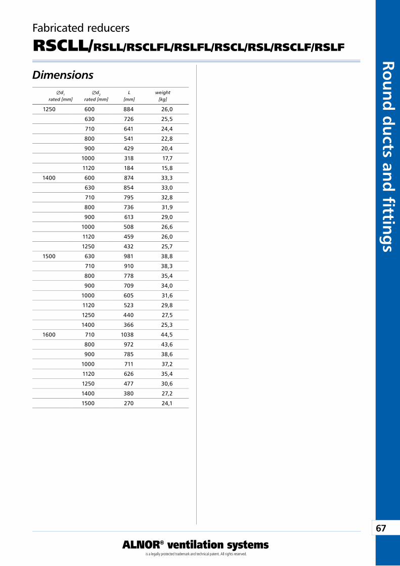
67
ALNOR® ventilation systemsis a legally protected trademark and technical patent. All rights reserved.
Rou
nd
du
cts and
fi tting
sDownload Wentyle
Download AlnorCAMBuy via B2B
Dimensions
Fabricated reducers
RSCLL/RSLL/RSCLFL/RSLFL/RSCL/RSL/RSCLF/RSLF
Æd1 Æd2 L weight rated [mm] rated [mm] [mm] [kg]
1250 600 884 26,0
630 726 25,5
710 641 24,4
800 541 22,8
900 429 20,4
1000 318 17,7
1120 184 15,8
1400 600 874 33,3
630 854 33,0
710 795 32,8
800 736 31,9
900 613 29,0
1000 508 26,6
1120 459 26,0
1250 432 25,7
1500 630 981 38,8
710 910 38,3
800 778 35,4
900 709 34,0
1000 605 31,6
1120 523 29,8
1250 440 27,5
1400 366 25,3
1600 710 1038 44,5
800 972 43,6
900 785 38,6
1000 711 37,2
1120 626 35,4
1250 477 30,6
1400 380 27,2
1500 270 24,1
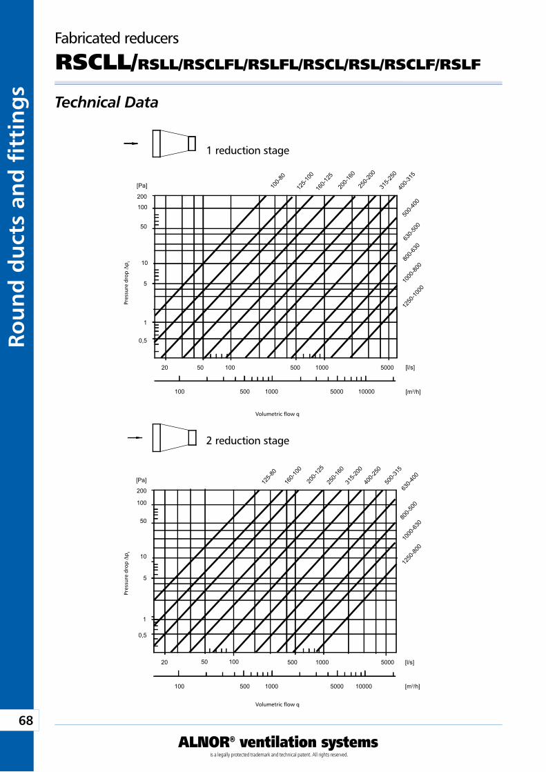
68
ALNOR® ventilation systemsis a legally protected trademark and technical patent. All rights reserved.
Rou
nd
du
cts
and
fi t
tin
gs
Download WentyleDownload AlnorCAM
Buy via B2B
5000
Pa
l/s
m3/h
20 50 100 500 1000
200
100
50
10
5
1
0,5
100 500 1000 5000 1000012
50-10
00
1000
-800
800-6
30
630-5
00
500-4
00
400-3
15
315-2
50
250-2
00
200-1
60
160-1
25
125-1
00
100-8
0
[Pa]
[l/s]
[m3/h]
5000
Pa
l/s
m3/h
20 50 100 500 1000
200
100
50
10
5
1
0,5
100 500 1000 5000 10000
500-3
15
400-2
50
315-2
00
250-1
60
200-1
25
160-1
00
125-8
0
1250
-800
1000
-630
800-5
00
630-4
00[Pa]
[l/s]
[m3/h]
Technical Data
Fabricated reducers
RSCLL/RSLL/RSCLFL/RSLFL/RSCL/RSL/RSCLF/RSLF
Pre
ssur
e dr
op D
p t
1 reduction stage
Volumetric flow q
Pre
ssur
e dr
op D
p t
2 reduction stage
Volumetric flow q
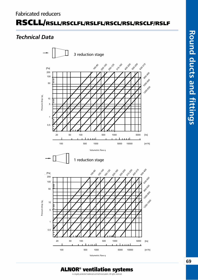
69
ALNOR® ventilation systemsis a legally protected trademark and technical patent. All rights reserved.
Rou
nd
du
cts and
fi tting
sDownload Wentyle
Download AlnorCAMBuy via B2B
5000
Pa
l/s
m3/h
20 50 100 500 1000
200
100
50
10
5
1
0,5
100 500 1000 5000 1000012
50-63
01000
-500
800-4
00
630-3
15
500-2
50
400-2
00
315-1
60
250-1
25
200-1
00
160-8
0
[Pa]
[l/s]
[m3/h]
5000
Pa
l/s
m3/h
20 50 100 500 1000
200
100
50
10
5
1
0,5
100 500 1000 5000 10000
800-
630
1250
-100
0
1000
-800
630-
500
500-
400
400-
315
315-
250
250-
200
100-
80
160-
125
125-
100
200-
160
[Pa]
[l/s]
[m3/h]
Technical Data
Fabricated reducers
RSCLL/RSLL/RSCLFL/RSLFL/RSCL/RSL/RSCLF/RSLF
Pre
ssur
e dr
op D
p t
3 reduction stage
Volumetric flow q
Pre
ssur
e dr
op D
p t
1 reduction stage
Volumetric flow q
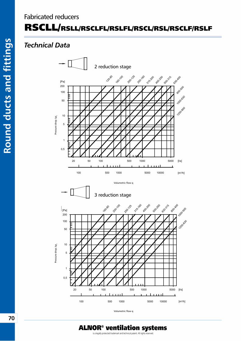
70
ALNOR® ventilation systemsis a legally protected trademark and technical patent. All rights reserved.
Rou
nd
du
cts
and
fi t
tin
gs
Download WentyleDownload AlnorCAM
Buy via B2B
5000
Pa
l/s
m3/h
20 50 100 500 1000
200
100
50
10
5
1
0,5
100 500 1000 5000 1000012
50-80
0
1000
-630
800-5
00
630-4
00
500-3
15
400-2
50
315-2
00
250-1
60
200-1
25
160-1
00
125-8
0
[Pa]
[l/s]
[m3/h]
5000
Pa
l/s
m3/h
20 50 100 500 1000
200
100
50
10
5
1
0,5
100 500 1000 5000 10000
1250
-630
1000
-500
800-4
00
630-3
15
500-2
50
400-2
00
315-1
60
250-1
25
200-1
00
160-8
0
[Pa]
[l/s]
[m3/h]
Technical Data
Fabricated reducers
RSCLL/RSLL/RSCLFL/RSLFL/RSCL/RSL/RSCLF/RSLF
Pre
ssur
e dr
op D
p t
2 reduction stage
Volumetric flow q
Pre
ssur
e dr
op D
p t
3 reduction stage
Volumetric flow q
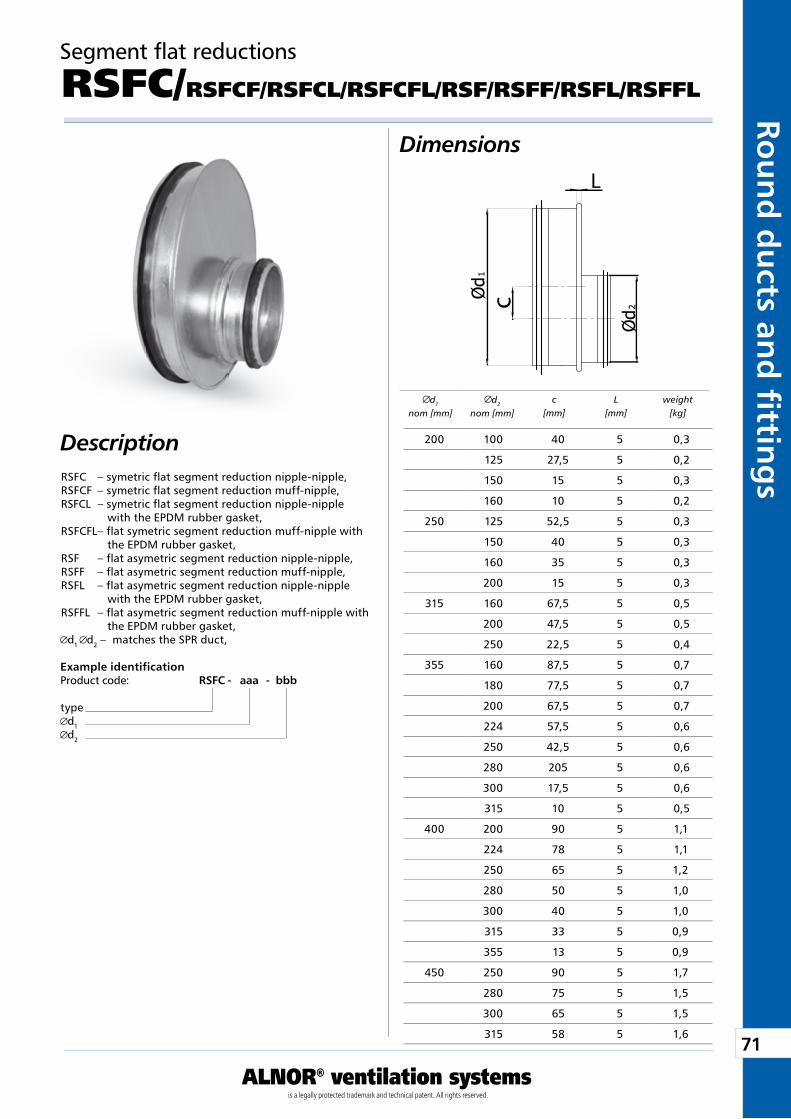
71
ALNOR® ventilation systemsis a legally protected trademark and technical patent. All rights reserved.
Rou
nd
du
cts and
fi tting
sDownload Wentyle
Download AlnorCAMBuy via B2B
c
L
Segment flat reductions
RSFC/RSFCF/RSFCL/RSFCFL/RSF/RSFF/RSFL/RSFFL
Dimensions
Description
Example identificationProduct code: RSFC - aaa - bbb
typed1d2
d1
nom [mm]d2
nom [mm]c
[mm]L
[mm]weight
[kg]
RSFC – symetric flat segment reduction nipple-nipple,RSFCF – symetric flat segment reduction muff-nipple,RSFCL – symetric flat segment reduction nipple-nipple
with the EPDM rubber gasket,RSFCFL – flat symetric segment reduction muff-nipple with
the EPDM rubber gasket,RSF – flat asymetric segment reduction nipple-nipple,RSFF – flat asymetric segment reduction muff-nipple,RSFL – flat asymetric segment reduction nipple-nipple
with the EPDM rubber gasket,RSFFL – flat asymetric segment reduction muff-nipple with
the EPDM rubber gasket,d1 d2 – matches the SPR duct,
200 100 40 5 0,3
125 27,5 5 0,2
150 15 5 0,3
160 10 5 0,2
250 125 52,5 5 0,3
150 40 5 0,3
160 35 5 0,3
200 15 5 0,3
315 160 67,5 5 0,5
200 47,5 5 0,5
250 22,5 5 0,4
355 160 87,5 5 0,7
180 77,5 5 0,7
200 67,5 5 0,7
224 57,5 5 0,6
250 42,5 5 0,6
280 205 5 0,6
300 17,5 5 0,6
315 10 5 0,5
400 200 90 5 1,1
224 78 5 1,1
250 65 5 1,2
280 50 5 1,0
300 40 5 1,0
315 33 5 0,9
355 13 5 0,9
450 250 90 5 1,7
280 75 5 1,5
300 65 5 1,5
315 58 5 1,6
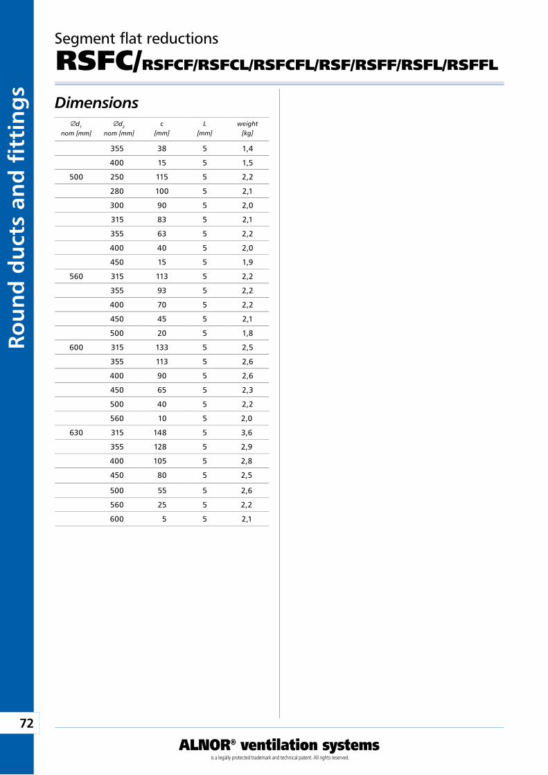
72
ALNOR® ventilation systemsis a legally protected trademark and technical patent. All rights reserved.
Rou
nd
du
cts
and
fi t
tin
gs
Download WentyleDownload AlnorCAM
Buy via B2B
Segment flat reductions
RSFC/RSFCF/RSFCL/RSFCFL/RSF/RSFF/RSFL/RSFFL
Dimensions d1
nom [mm]d2
nom [mm]c
[mm]L
[mm]weight
[kg]
355 38 5 1,4
400 15 5 1,5
500 250 115 5 2,2
280 100 5 2,1
300 90 5 2,0
315 83 5 2,1
355 63 5 2,2
400 40 5 2,0
450 15 5 1,9
560 315 113 5 2,2
355 93 5 2,2
400 70 5 2,2
450 45 5 2,1
500 20 5 1,8
600 315 133 5 2,5
355 113 5 2,6
400 90 5 2,6
450 65 5 2,3
500 40 5 2,2
560 10 5 2,0
630 315 148 5 3,6
355 128 5 2,9
400 105 5 2,8
450 80 5 2,5
500 55 5 2,6
560 25 5 2,2
600 5 5 2,1
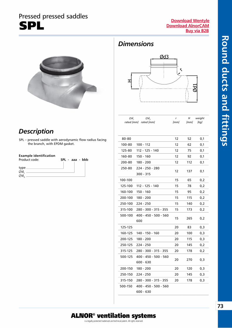
73
ALNOR® ventilation systemsis a legally protected trademark and technical patent. All rights reserved.
Rou
nd
du
cts and
fi tting
sDownload Wentyle
Download AlnorCAMBuy via B2B
Pressed pressed saddles
SPLDimensions
DescriptionSPL – pressed saddle with aerodynamic flow radius facing
the branch, with EPDM gasket.
Example identificationProduct code: SPL - aaa - bbb
typeÆd1Æd3
Æd1 Æd3 r H weight rated [mm] rated [mm] [mm] [mm] [kg]
80-80 12 52 0,1
100-80 100 - 112 12 62 0,1
125-80 112 - 125 - 140 12 75 0,1
160-80 150 - 160 12 92 0,1
200-80 180 - 200 12 112 0,1
250-80 224 - 250 - 280
300 - 31512 137 0,1
100-100 15 65 0,2
125-100 112 - 125 - 140 15 78 0,2
160-100 150 - 160 15 95 0,2
200-100 180 - 200 15 115 0,2
250-100 224 - 250 15 140 0,2
315-100 280 - 300 - 315 - 355 15 173 0,2
500-100 400 - 450 - 500 - 560
60015 265 0,2
125-125 20 83 0,3
160-125 140 - 150 - 160 20 100 0,3
200-125 180 - 200 20 115 0,3
250-125 224 - 250 20 145 0,2
315-125 280 - 300 - 315 - 355 20 178 0,2
500-125 400 - 450 - 500 - 560
600 - 63020 270 0,3
200-150 180 - 200 20 120 0,3
250-150 224 - 250 20 145 0,3
315-150 280 - 300 - 315 - 355 20 178 0,3
500-150 400 - 450 - 500 - 560
600 - 630
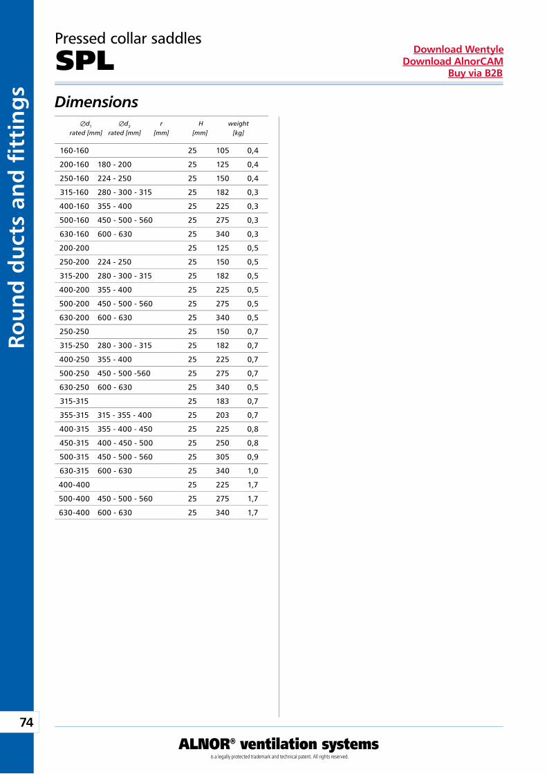
74
ALNOR® ventilation systemsis a legally protected trademark and technical patent. All rights reserved.
Rou
nd
du
cts
and
fi t
tin
gs
Download WentyleDownload AlnorCAM
Buy via B2B
Dimensions
Pressed collar saddles
SPL
Æd1 Æd3 r H weight rated [mm] rated [mm] [mm] [mm] [kg]
160-160 25 105 0,4
200-160 180 - 200 25 125 0,4
250-160 224 - 250 25 150 0,4
315-160 280 - 300 - 315 25 182 0,3
400-160 355 - 400 25 225 0,3
500-160 450 - 500 - 560 25 275 0,3
630-160 600 - 630 25 340 0,3
200-200 25 125 0,5
250-200 224 - 250 25 150 0,5
315-200 280 - 300 - 315 25 182 0,5
400-200 355 - 400 25 225 0,5
500-200 450 - 500 - 560 25 275 0,5
630-200 600 - 630 25 340 0,5
250-250 25 150 0,7
315-250 280 - 300 - 315 25 182 0,7
400-250 355 - 400 25 225 0,7
500-250 450 - 500 -560 25 275 0,7
630-250 600 - 630 25 340 0,5
315-315 25 183 0,7
355-315 315 - 355 - 400 25 203 0,7
400-315 355 - 400 - 450 25 225 0,8
450-315 400 - 450 - 500 25 250 0,8
500-315 450 - 500 - 560 25 305 0,9
630-315 600 - 630 25 340 1,0
400-400 25 225 1,7
500-400 450 - 500 - 560 25 275 1,7
630-400 600 - 630 25 340 1,7
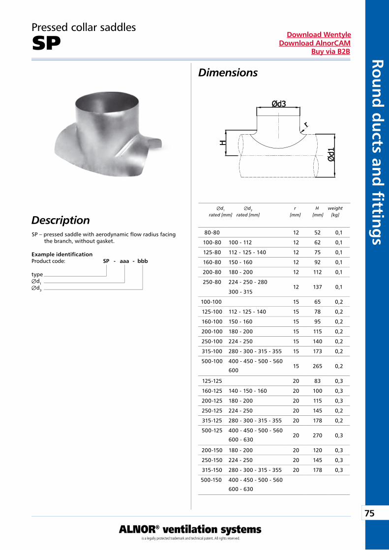
75
ALNOR® ventilation systemsis a legally protected trademark and technical patent. All rights reserved.
Rou
nd
du
cts and
fi tting
sDownload Wentyle
Download AlnorCAMBuy via B2B
Pressed collar saddles
SPDimensions
DescriptionSP – pressed saddle with aerodynamic flow radius facing
the branch, without gasket.
Example identificationProduct code: SP - aaa - bbb
typeÆd1Æd3
Æd1 Æd3 r H weight rated [mm] rated [mm] [mm] [mm] [kg]
80-80 12 52 0,1
100-80 100 - 112 12 62 0,1
125-80 112 - 125 - 140 12 75 0,1
160-80 150 - 160 12 92 0,1
200-80 180 - 200 12 112 0,1
250-80 224 - 250 - 280
300 - 31512 137 0,1
100-100 15 65 0,2
125-100 112 - 125 - 140 15 78 0,2
160-100 150 - 160 15 95 0,2
200-100 180 - 200 15 115 0,2
250-100 224 - 250 15 140 0,2
315-100 280 - 300 - 315 - 355 15 173 0,2
500-100 400 - 450 - 500 - 560
60015 265 0,2
125-125 20 83 0,3
160-125 140 - 150 - 160 20 100 0,3
200-125 180 - 200 20 115 0,3
250-125 224 - 250 20 145 0,2
315-125 280 - 300 - 315 - 355 20 178 0,2
500-125 400 - 450 - 500 - 560
600 - 63020 270 0,3
200-150 180 - 200 20 120 0,3
250-150 224 - 250 20 145 0,3
315-150 280 - 300 - 315 - 355 20 178 0,3
500-150 400 - 450 - 500 - 560
600 - 630
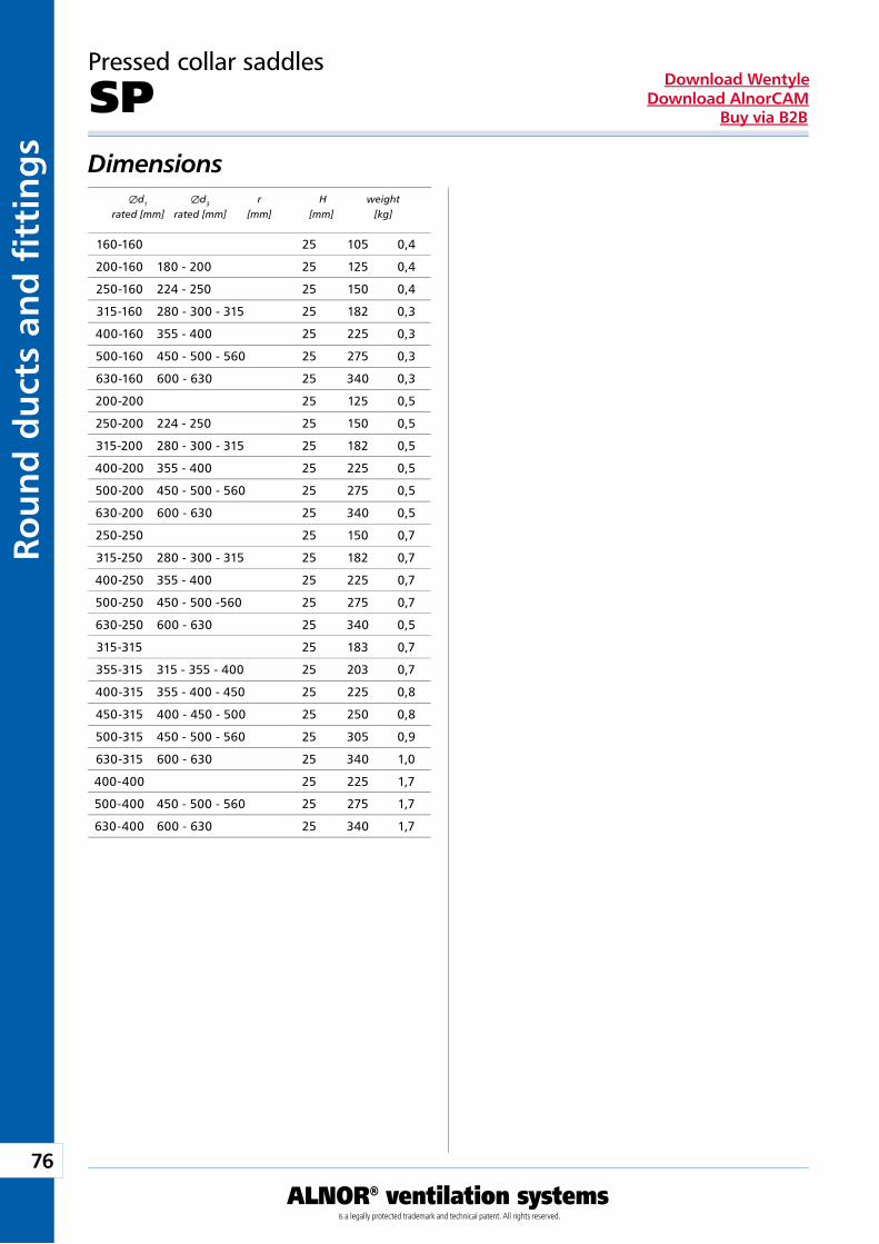
76
ALNOR® ventilation systemsis a legally protected trademark and technical patent. All rights reserved.
Rou
nd
du
cts
and
fi t
tin
gs
Download WentyleDownload AlnorCAM
Buy via B2B
Pressed collar saddles
SPDimensions Æd1 Æd3 r H weight rated [mm] rated [mm] [mm] [mm] [kg]
160-160 25 105 0,4
200-160 180 - 200 25 125 0,4
250-160 224 - 250 25 150 0,4
315-160 280 - 300 - 315 25 182 0,3
400-160 355 - 400 25 225 0,3
500-160 450 - 500 - 560 25 275 0,3
630-160 600 - 630 25 340 0,3
200-200 25 125 0,5
250-200 224 - 250 25 150 0,5
315-200 280 - 300 - 315 25 182 0,5
400-200 355 - 400 25 225 0,5
500-200 450 - 500 - 560 25 275 0,5
630-200 600 - 630 25 340 0,5
250-250 25 150 0,7
315-250 280 - 300 - 315 25 182 0,7
400-250 355 - 400 25 225 0,7
500-250 450 - 500 -560 25 275 0,7
630-250 600 - 630 25 340 0,5
315-315 25 183 0,7
355-315 315 - 355 - 400 25 203 0,7
400-315 355 - 400 - 450 25 225 0,8
450-315 400 - 450 - 500 25 250 0,8
500-315 450 - 500 - 560 25 305 0,9
630-315 600 - 630 25 340 1,0
400-400 25 225 1,7
500-400 450 - 500 - 560 25 275 1,7
630-400 600 - 630 25 340 1,7
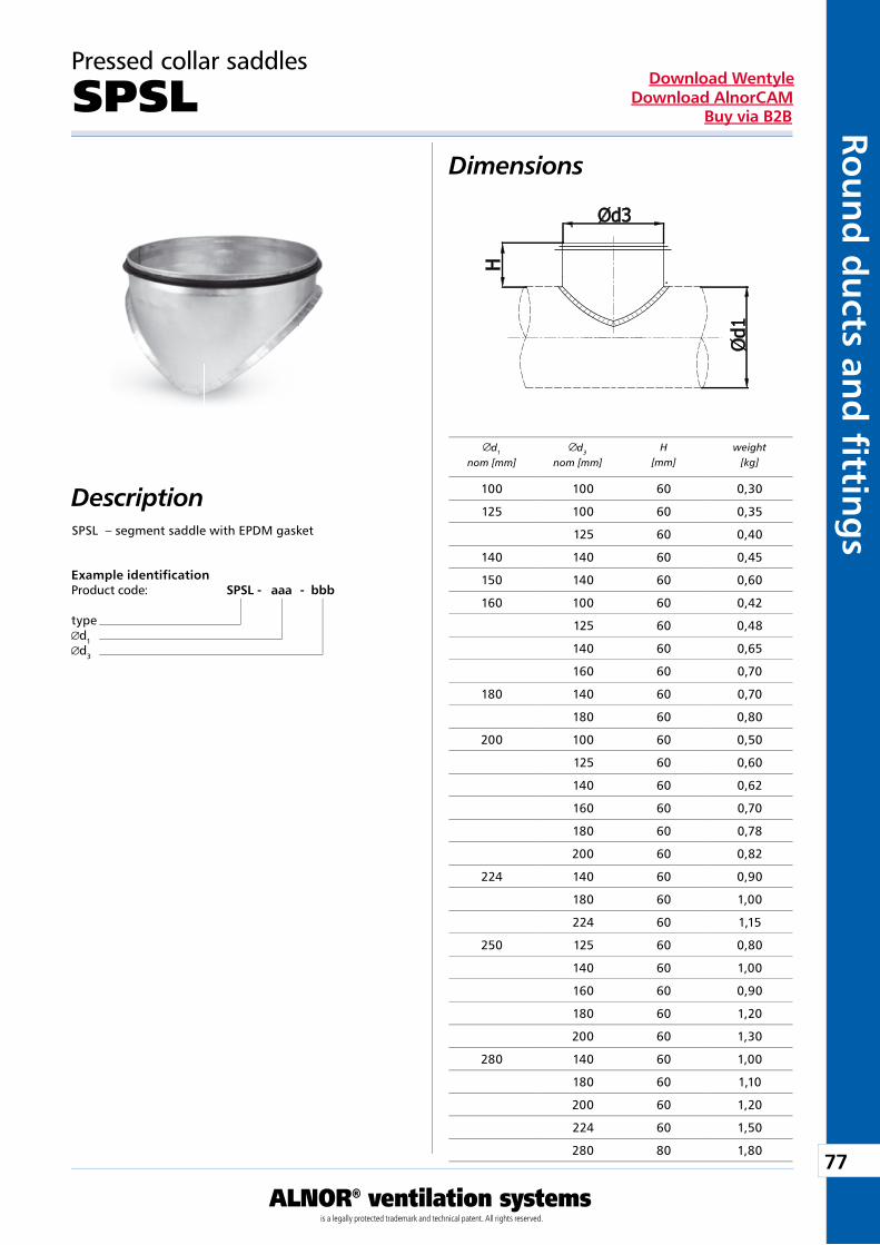
77
ALNOR® ventilation systemsis a legally protected trademark and technical patent. All rights reserved.
Rou
nd
du
cts and
fi tting
sDownload Wentyle
Download AlnorCAMBuy via B2B
Pressed collar saddles
SPSLDimensions
DescriptionSPSL – segment saddle with EPDM gasket
Example identificationProduct code: SPSL - aaa - bbb
typed1d3
d1
nom [mm]d3
nom [mm]H
[mm]weight
[kg]
100 100 60 0,30
125 100 60 0,35
125 60 0,40
140 140 60 0,45
150 140 60 0,60
160 100 60 0,42
125 60 0,48
140 60 0,65
160 60 0,70
180 140 60 0,70
180 60 0,80
200 100 60 0,50
125 60 0,60
140 60 0,62
160 60 0,70
180 60 0,78
200 60 0,82
224 140 60 0,90
180 60 1,00
224 60 1,15
250 125 60 0,80
140 60 1,00
160 60 0,90
180 60 1,20
200 60 1,30
280 140 60 1,00
180 60 1,10
200 60 1,20
224 60 1,50
280 80 1,80
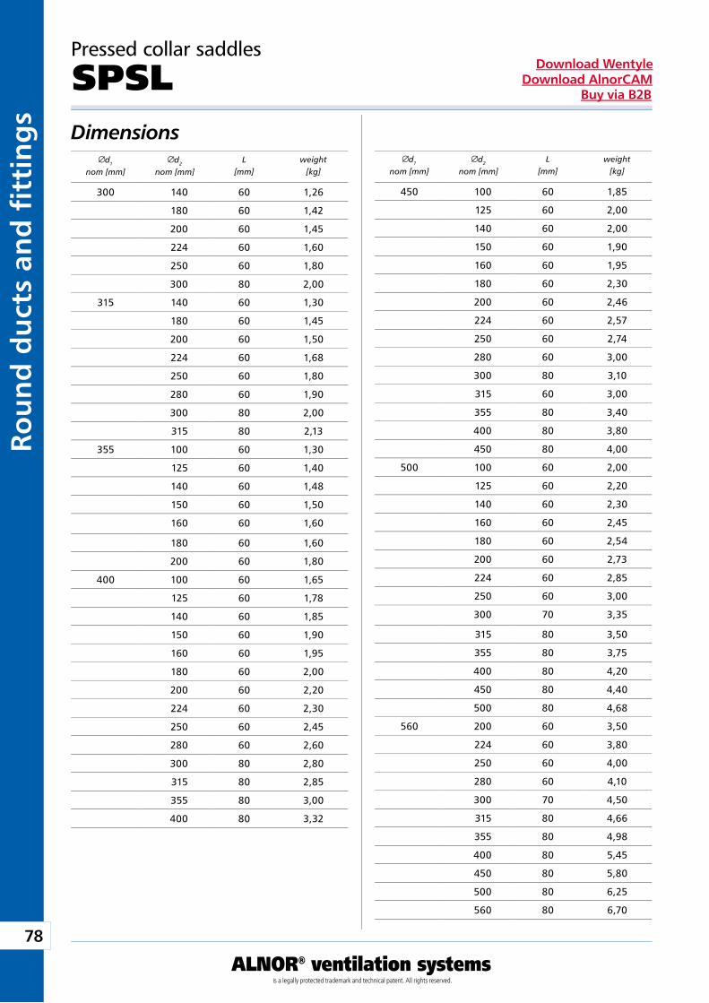
78
ALNOR® ventilation systemsis a legally protected trademark and technical patent. All rights reserved.
Rou
nd
du
cts
and
fi t
tin
gs
Download WentyleDownload AlnorCAM
Buy via B2B
Dimensionsd1
nom [mm]d2
nom [mm]L
[mm]weight
[kg]
Pressed collar saddles
SPSL
d1
nom [mm]d2
nom [mm]L
[mm]weight
[kg]
300 140 60 1,26
180 60 1,42
200 60 1,45
224 60 1,60
250 60 1,80
300 80 2,00
315 140 60 1,30
180 60 1,45
200 60 1,50
224 60 1,68
250 60 1,80
280 60 1,90
300 80 2,00
315 80 2,13
355 100 60 1,30
125 60 1,40
140 60 1,48
150 60 1,50
160 60 1,60
180 60 1,60
200 60 1,80
400 100 60 1,65
125 60 1,78
140 60 1,85
150 60 1,90
160 60 1,95
180 60 2,00
200 60 2,20
224 60 2,30
250 60 2,45
280 60 2,60
300 80 2,80
315 80 2,85
355 80 3,00
400 80 3,32
450 100 60 1,85
125 60 2,00
140 60 2,00
150 60 1,90
160 60 1,95
180 60 2,30
200 60 2,46
224 60 2,57
250 60 2,74
280 60 3,00
300 80 3,10
315 60 3,00
355 80 3,40
400 80 3,80
450 80 4,00
500 100 60 2,00
125 60 2,20
140 60 2,30
160 60 2,45
180 60 2,54
200 60 2,73
224 60 2,85
250 60 3,00
300 70 3,35
315 80 3,50
355 80 3,75
400 80 4,20
450 80 4,40
500 80 4,68
560 200 60 3,50
224 60 3,80
250 60 4,00
280 60 4,10
300 70 4,50
315 80 4,66
355 80 4,98
400 80 5,45
450 80 5,80
500 80 6,25
560 80 6,70
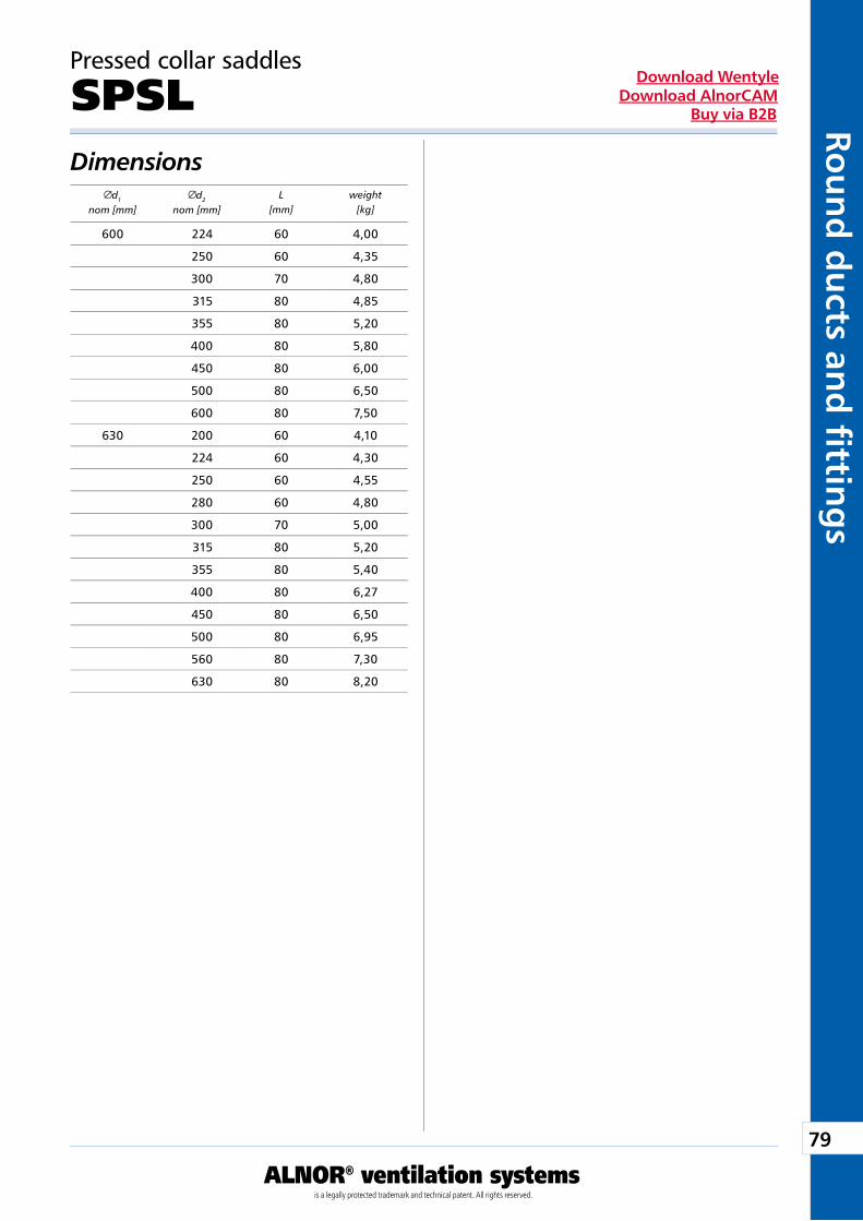
79
ALNOR® ventilation systemsis a legally protected trademark and technical patent. All rights reserved.
Rou
nd
du
cts and
fi tting
sDownload Wentyle
Download AlnorCAMBuy via B2B
Dimensionsd1
nom [mm]d2
nom [mm]L
[mm]weight
[kg]
Pressed collar saddles
SPSL
600 224 60 4,00
250 60 4,35
300 70 4,80
315 80 4,85
355 80 5,20
400 80 5,80
450 80 6,00
500 80 6,50
600 80 7,50
630 200 60 4,10
224 60 4,30
250 60 4,55
280 60 4,80
300 70 5,00
315 80 5,20
355 80 5,40
400 80 6,27
450 80 6,50
500 80 6,95
560 80 7,30
630 80 8,20
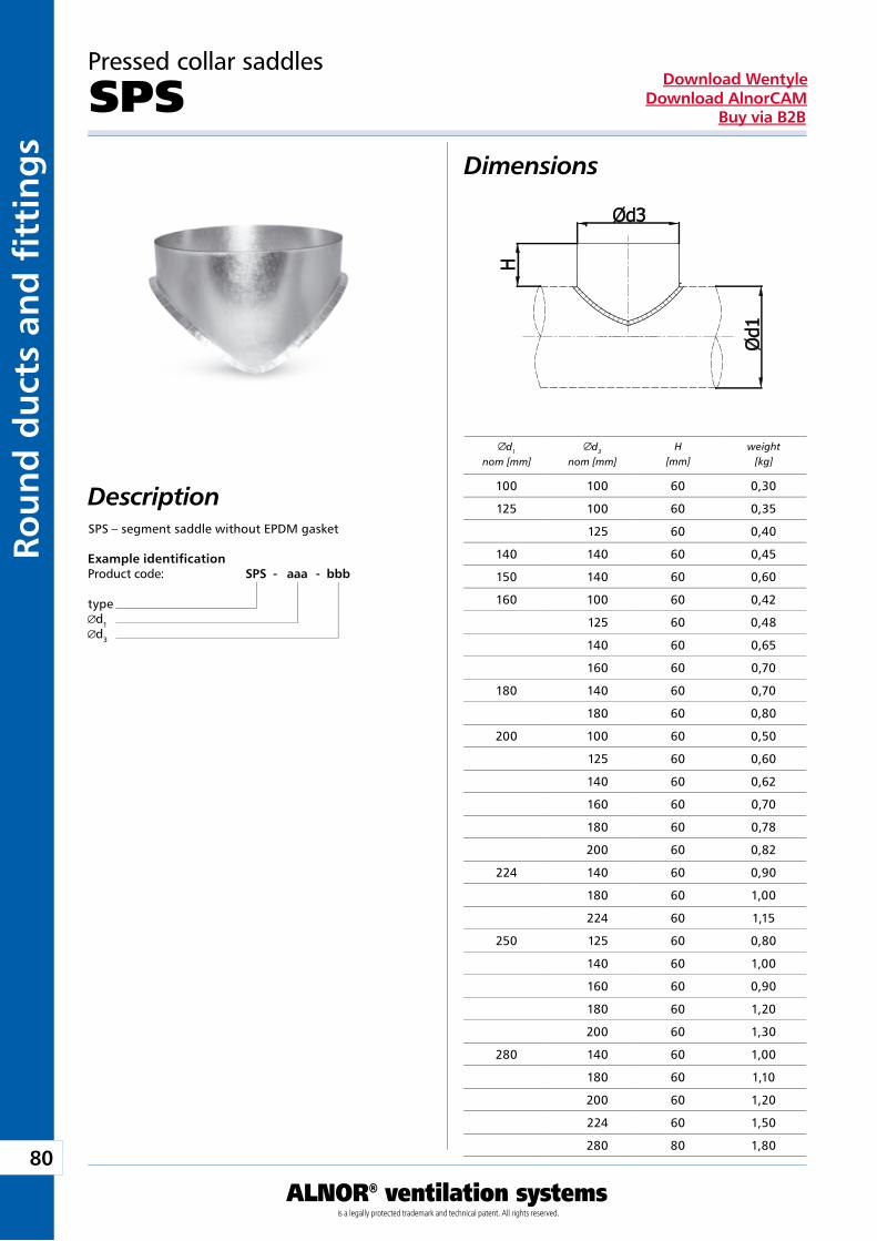
80
ALNOR® ventilation systemsis a legally protected trademark and technical patent. All rights reserved.
Rou
nd
du
cts
and
fi t
tin
gs
Download WentyleDownload AlnorCAM
Buy via B2B
Pressed collar saddles
SPSDimensions
DescriptionSPS – segment saddle without EPDM gasket
Example identificationProduct code: SPS - aaa - bbb
typed1d3
d1
nom [mm]d3
nom [mm]H
[mm]weight
[kg]
100 100 60 0,30
125 100 60 0,35
125 60 0,40
140 140 60 0,45
150 140 60 0,60
160 100 60 0,42
125 60 0,48
140 60 0,65
160 60 0,70
180 140 60 0,70
180 60 0,80
200 100 60 0,50
125 60 0,60
140 60 0,62
160 60 0,70
180 60 0,78
200 60 0,82
224 140 60 0,90
180 60 1,00
224 60 1,15
250 125 60 0,80
140 60 1,00
160 60 0,90
180 60 1,20
200 60 1,30
280 140 60 1,00
180 60 1,10
200 60 1,20
224 60 1,50
280 80 1,80
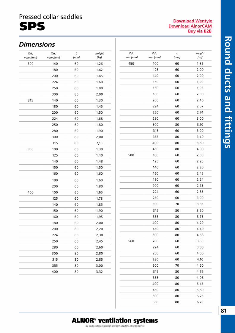
81
ALNOR® ventilation systemsis a legally protected trademark and technical patent. All rights reserved.
Rou
nd
du
cts and
fi tting
sDownload Wentyle
Download AlnorCAMBuy via B2B
Dimensionsd1
nom [mm]d2
nom [mm]L
[mm]weight
[kg]
Pressed collar saddles
SPS
d1
nom [mm]d2
nom [mm]L
[mm]weight
[kg]
300 140 60 1,26
180 60 1,42
200 60 1,45
224 60 1,60
250 60 1,80
300 80 2,00
315 140 60 1,30
180 60 1,45
200 60 1,50
224 60 1,68
250 60 1,80
280 60 1,90
300 80 2,00
315 80 2,13
355 100 60 1,30
125 60 1,40
140 60 1,48
150 60 1,50
160 60 1,60
180 60 1,60
200 60 1,80
400 100 60 1,65
125 60 1,78
140 60 1,85
150 60 1,90
160 60 1,95
180 60 2,00
200 60 2,20
224 60 2,30
250 60 2,45
280 60 2,60
300 80 2,80
315 80 2,85
355 80 3,00
400 80 3,32
450 100 60 1,85
125 60 2,00
140 60 2,00
150 60 1,90
160 60 1,95
180 60 2,30
200 60 2,46
224 60 2,57
250 60 2,74
280 60 3,00
300 80 3,10
315 60 3,00
355 80 3,40
400 80 3,80
450 80 4,00
500 100 60 2,00
125 60 2,20
140 60 2,30
160 60 2,45
180 60 2,54
200 60 2,73
224 60 2,85
250 60 3,00
300 70 3,35
315 80 3,50
355 80 3,75
400 80 4,20
450 80 4,40
500 80 4,68
560 200 60 3,50
224 60 3,80
250 60 4,00
280 60 4,10
300 70 4,50
315 80 4,66
355 80 4,98
400 80 5,45
450 80 5,80
500 80 6,25
560 80 6,70
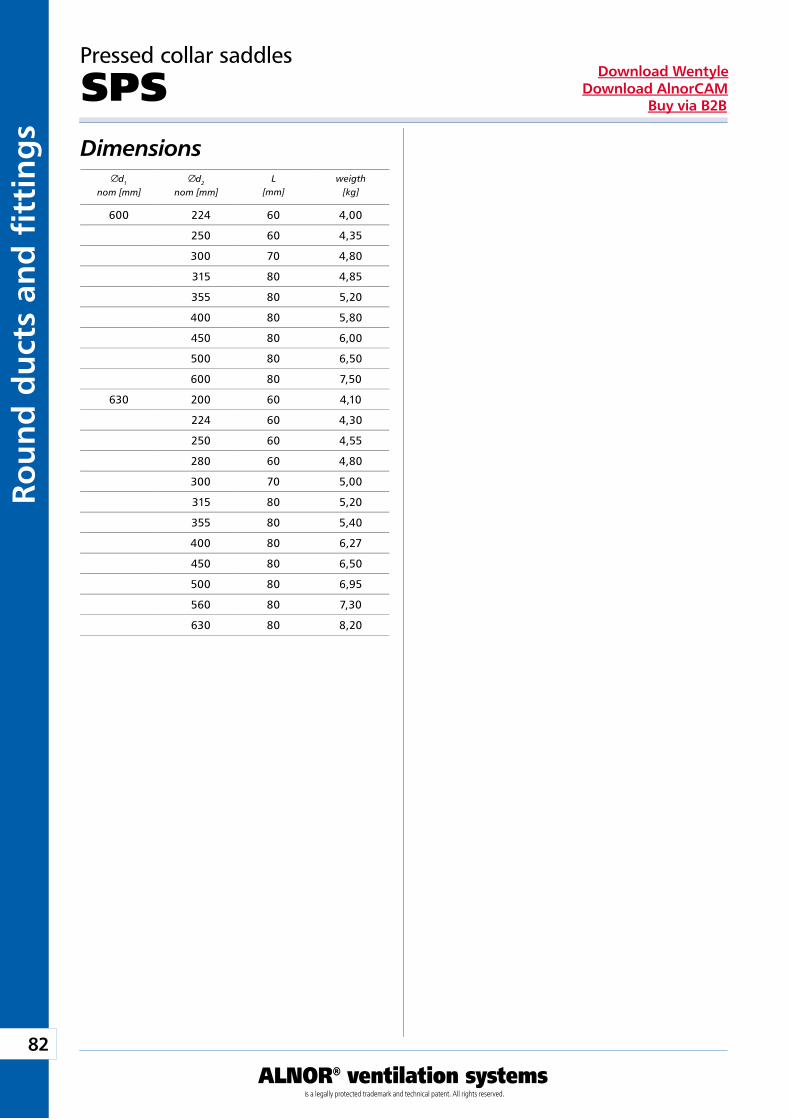
82
ALNOR® ventilation systemsis a legally protected trademark and technical patent. All rights reserved.
Rou
nd
du
cts
and
fi t
tin
gs
Download WentyleDownload AlnorCAM
Buy via B2B
Dimensionsd1
nom [mm]d2
nom [mm]L
[mm]weigth
[kg]
Pressed collar saddles
SPS
600 224 60 4,00
250 60 4,35
300 70 4,80
315 80 4,85
355 80 5,20
400 80 5,80
450 80 6,00
500 80 6,50
600 80 7,50
630 200 60 4,10
224 60 4,30
250 60 4,55
280 60 4,80
300 70 5,00
315 80 5,20
355 80 5,40
400 80 6,27
450 80 6,50
500 80 6,95
560 80 7,30
630 80 8,20
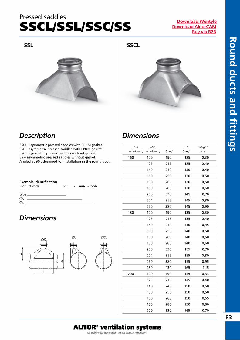
83
ALNOR® ventilation systemsis a legally protected trademark and technical patent. All rights reserved.
Rou
nd
du
cts and
fi tting
sDownload Wentyle
Download AlnorCAMBuy via B2B
Pressed saddles
SSCL/SSL/SSC/SS
Dimensions DescriptionSSCL – symmetric pressed saddles with EPDM gasket.SSL – asymmetric pressed saddles with EPDM gasket.SSC – symmetric pressed saddles without gasket.SS – asymmetric pressed saddles without gasket.Angled at 90°, designed for installation in the round duct.
Example identificationProduct code: SSL - aaa - bbb
typeÆdÆd2
Dimensions
SSL SSCL
Æd Æd3 L H weight rated [mm] rated [mm] [mm] [mm] [kg]
160 100 190 125 0,30
125 215 125 0,40
140 240 130 0,40
150 250 130 0,50
160 260 130 0,50
180 280 130 0,60
200 330 145 0,70
224 355 145 0,80
250 380 145 0,90
180 100 190 135 0,30
125 215 135 0,40
140 240 140 0,45
150 250 140 0,50
160 260 140 0,50
180 280 140 0,60
200 330 155 0,70
224 355 155 0,80
250 380 155 0,95
280 430 165 1,15
200 100 190 145 0,33
125 215 145 0,40
140 240 150 0,50
150 250 150 0,50
160 260 150 0,55
180 280 150 0,60
200 330 165 0,70

84
ALNOR® ventilation systemsis a legally protected trademark and technical patent. All rights reserved.
Rou
nd
du
cts
and
fi t
tin
gs
Download WentyleDownload AlnorCAM
Buy via B2B
Dimensions
Pressed saddles
SSCL/SSL/SSC/SS
Æd Æd3 L H weight rated [mm] rated [mm] [mm] [mm] [kg]
Æd Æd3 L H weight rated [mm] rated [mm] [mm] [mm] [kg]
200 224 355 165 0,80
250 380 165 1,00
280 430 175 1,20
300 450 175 1,25
315 465 175 1,30
224 100 190 160 0,35
125 215 160 0,40
140 240 165 0,50
150 250 165 0,50
160 260 165 0,65
180 280 165 0,70
200 330 180 0,80
224 355 180 0,85
250 380 180 1,00
280 430 190 1,20
300 450 190 1,30
315 465 190 1,40
355 525 200 2,00
250 100 190 170 0,35
125 215 170 0,40
140 240 175 0,50
150 250 175 0,50
160 260 175 0,60
180 280 175 0,65
200 330 190 0,80
224 355 190 0,90
250 380 190 1,00
280 430 200 1,20
300 450 200 1,30
315 465 200 1,35
355 525 210 2,00
400 570 210 2,40
280 100 190 185 0,40
125 215 185 0,40
140 240 190 0,50
150 250 190 0,55
160 260 190 0,60
180 280 190 0,75
200 330 205 0,80
224 355 205 0,90
250 380 205 1,00
280 280 430 215 1,30
300 450 215 1,30
315 465 215 1,40
355 525 225 2,00
400 570 225 2,40
450 620 225 3,40
300 100 190 195 0,40
125 215 195 0,45
140 240 200 0,50
150 250 200 0,55
160 260 200 0,60
180 280 200 0,65
200 330 215 0,80
224 355 215 0,90
250 380 215 1,10
280 430 225 1,25
300 450 225 1,40
315 465 225 1,40
355 525 235 2,10
400 570 235 2,50
450 620 235 3,50
315 100 190 205 0,40
125 215 205 0,50
140 240 210 0,55
150 250 210 0,60
160 260 210 0,60
180 280 210 0,70
200 330 225 0,85
224 355 225 0,95
250 380 225 1,10
280 430 235 1,30
300 450 235 1,40
315 465 235 1,50
355 525 245 2,10
400 570 245 2,50
450 620 245 3,60
500 680 250 4,10
355 100 190 225 0,40
125 215 225 0,50
140 240 230 0,55
150 250 230 0,60
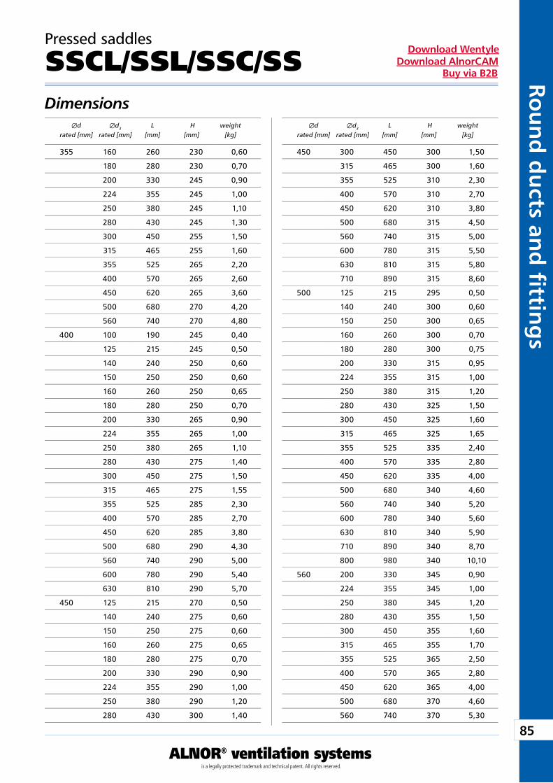
85
ALNOR® ventilation systemsis a legally protected trademark and technical patent. All rights reserved.
Rou
nd
du
cts and
fi tting
sDownload Wentyle
Download AlnorCAMBuy via B2B
Pressed saddles
SSCL/SSL/SSC/SSDimensions Æd Æd3 L H weight rated [mm] rated [mm] [mm] [mm] [kg]
Æd Æd3 L H weight rated [mm] rated [mm] [mm] [mm] [kg]
450 300 450 300 1,50
315 465 300 1,60
355 525 310 2,30
400 570 310 2,70
450 620 310 3,80
500 680 315 4,50
560 740 315 5,00
600 780 315 5,50
630 810 315 5,80
710 890 315 8,60
500 125 215 295 0,50
140 240 300 0,60
150 250 300 0,65
160 260 300 0,70
180 280 300 0,75
200 330 315 0,95
224 355 315 1,00
250 380 315 1,20
280 430 325 1,50
300 450 325 1,60
315 465 325 1,65
355 525 335 2,40
400 570 335 2,80
450 620 335 4,00
500 680 340 4,60
560 740 340 5,20
600 780 340 5,60
630 810 340 5,90
710 890 340 8,70
800 980 340 10,10
560 200 330 345 0,90
224 355 345 1,00
250 380 345 1,20
280 430 355 1,50
300 450 355 1,60
315 465 355 1,70
355 525 365 2,50
400 570 365 2,80
450 620 365 4,00
500 680 370 4,60
560 740 370 5,30
355 160 260 230 0,60
180 280 230 0,70
200 330 245 0,90
224 355 245 1,00
250 380 245 1,10
280 430 245 1,30
300 450 255 1,50
315 465 255 1,60
355 525 265 2,20
400 570 265 2,60
450 620 265 3,60
500 680 270 4,20
560 740 270 4,80
400 100 190 245 0,40
125 215 245 0,50
140 240 250 0,60
150 250 250 0,60
160 260 250 0,65
180 280 250 0,70
200 330 265 0,90
224 355 265 1,00
250 380 265 1,10
280 430 275 1,40
300 450 275 1,50
315 465 275 1,55
355 525 285 2,30
400 570 285 2,70
450 620 285 3,80
500 680 290 4,30
560 740 290 5,00
600 780 290 5,40
630 810 290 5,70
450 125 215 270 0,50
140 240 275 0,60
150 250 275 0,60
160 260 275 0,65
180 280 275 0,70
200 330 290 0,90
224 355 290 1,00
250 380 290 1,20
280 430 300 1,40
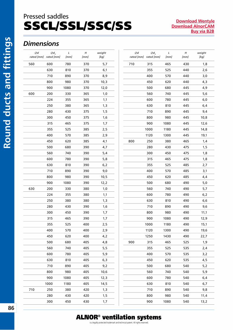
86
ALNOR® ventilation systemsis a legally protected trademark and technical patent. All rights reserved.
Rou
nd
du
cts
and
fi t
tin
gs
Download WentyleDownload AlnorCAM
Buy via B2B
Dimensions
Pressed saddles
SSCL/SSL/SSC/SS
Æd Æd3 L H weight rated [mm] rated [mm] [mm] [mm] [kg]
Æd Æd3 L H weight rated [mm] rated [mm] [mm] [mm] [kg]
560 600 780 370 5,7
630 810 370 6,1
710 890 370 8,9
800 980 370 10,3
900 1080 370 12,0
600 200 330 365 1,0
224 355 365 1,1
250 380 365 1,3
280 430 375 1,5
300 450 375 1,6
315 465 375 1,7
355 525 385 2,5
400 570 385 2,9
450 620 385 4,1
500 680 390 4,7
560 740 390 5,4
600 780 390 5,8
630 810 390 6,2
710 890 390 9,0
800 980 390 10,5
900 1080 390 12,2
630 200 330 380 1,0
224 355 380 1,1
250 380 380 1,3
280 430 390 1,6
300 450 390 1,7
315 465 390 1,7
355 525 400 2,5
400 570 400 2,9
450 620 400 4,2
500 680 405 4,8
560 740 405 5,5
600 780 405 5,9
630 810 405 6,3
710 890 405 9,2
800 980 405 10,6
900 1080 405 12,3
1000 1180 405 14,5
710 250 380 420 1,3
280 430 420 1,5
300 450 430 1,7
710 315 465 430 1,8
355 525 440 2,6
400 570 440 3,0
450 620 440 4,3
500 680 445 4,9
560 740 445 5,6
600 780 445 6,0
630 810 445 6,4
710 890 445 9,4
800 980 445 10,8
900 1080 445 12,6
1000 1180 445 14,8
1120 1300 445 19,1
800 250 380 465 1,4
280 430 475 1,5
300 450 475 1,8
315 465 475 1,8
355 525 485 2,7
400 570 485 3,1
450 620 485 4,4
500 680 490 5,0
560 740 490 5,7
600 780 490 6,2
630 810 490 6,6
710 890 490 9,6
800 980 490 11,1
900 1080 490 12,9
1000 1180 490 15,1
1120 1300 490 19,6
1250 1430 490 22,7
900 315 465 525 1,9
355 525 535 2,4
400 570 535 3,2
450 620 535 4,5
500 680 540 5,2
560 740 540 5,9
600 780 540 6,4
630 810 540 6,7
710 890 540 9,8
800 980 540 11,4
900 1080 540 13,2
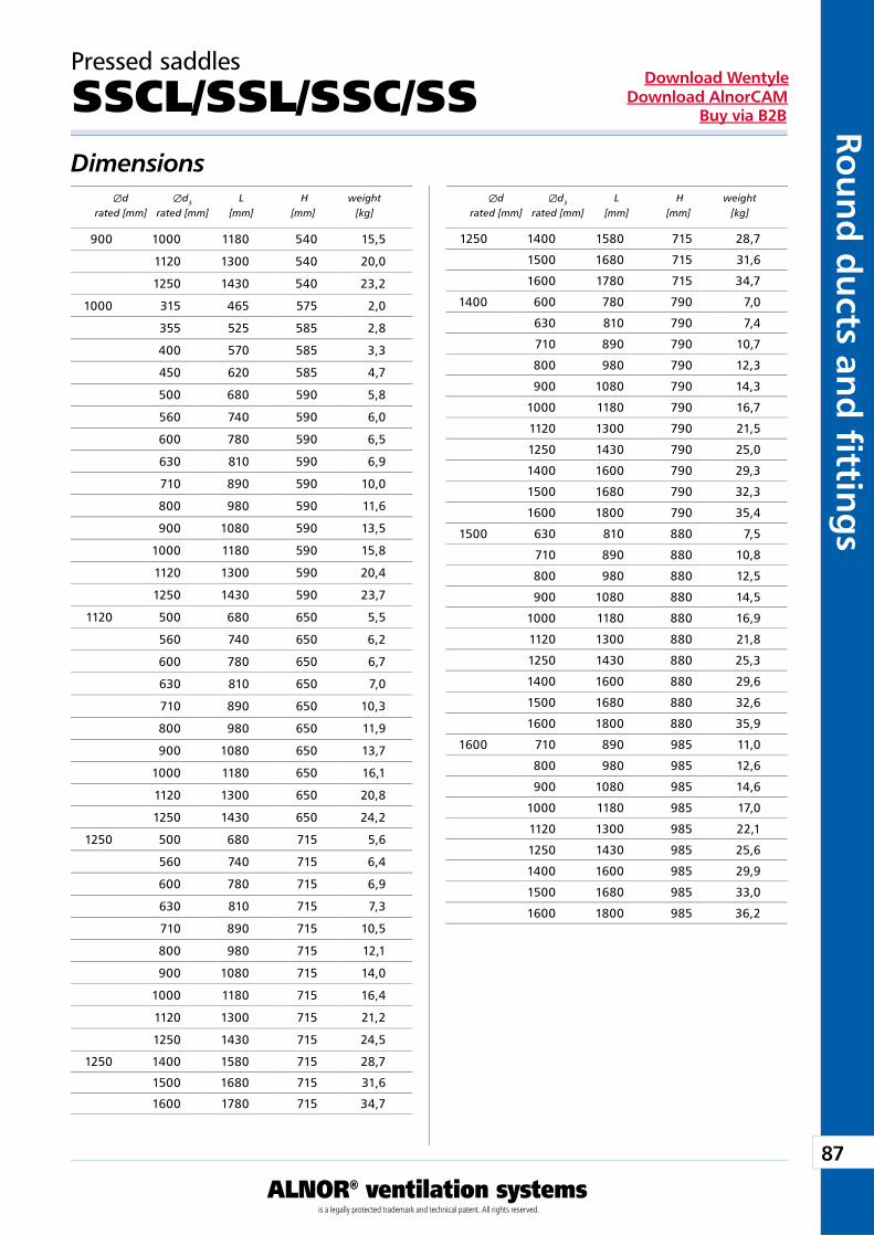
87
ALNOR® ventilation systemsis a legally protected trademark and technical patent. All rights reserved.
Rou
nd
du
cts and
fi tting
sDownload Wentyle
Download AlnorCAMBuy via B2B
Pressed saddles
SSCL/SSL/SSC/SSDimensions Æd Æd3 L H weight rated [mm] rated [mm] [mm] [mm] [kg]
Æd Æd3 L H weight rated [mm] rated [mm] [mm] [mm] [kg]
900 1000 1180 540 15,5
1120 1300 540 20,0
1250 1430 540 23,2
1000 315 465 575 2,0
355 525 585 2,8
400 570 585 3,3
450 620 585 4,7
500 680 590 5,8
560 740 590 6,0
600 780 590 6,5
630 810 590 6,9
710 890 590 10,0
800 980 590 11,6
900 1080 590 13,5
1000 1180 590 15,8
1120 1300 590 20,4
1250 1430 590 23,7
1120 500 680 650 5,5
560 740 650 6,2
600 780 650 6,7
630 810 650 7,0
710 890 650 10,3
800 980 650 11,9
900 1080 650 13,7
1000 1180 650 16,1
1120 1300 650 20,8
1250 1430 650 24,2
1250 500 680 715 5,6
560 740 715 6,4
600 780 715 6,9
630 810 715 7,3
710 890 715 10,5
800 980 715 12,1
900 1080 715 14,0
1000 1180 715 16,4
1120 1300 715 21,2
1250 1430 715 24,5
1250 1400 1580 715 28,7
1500 1680 715 31,6
1600 1780 715 34,7
1250 1400 1580 715 28,7
1500 1680 715 31,6
1600 1780 715 34,7
1400 600 780 790 7,0
630 810 790 7,4
710 890 790 10,7
800 980 790 12,3
900 1080 790 14,3
1000 1180 790 16,7
1120 1300 790 21,5
1250 1430 790 25,0
1400 1600 790 29,3
1500 1680 790 32,3
1600 1800 790 35,4
1500 630 810 880 7,5
710 890 880 10,8
800 980 880 12,5
900 1080 880 14,5
1000 1180 880 16,9
1120 1300 880 21,8
1250 1430 880 25,3
1400 1600 880 29,6
1500 1680 880 32,6
1600 1800 880 35,9
1600 710 890 985 11,0
800 980 985 12,6
900 1080 985 14,6
1000 1180 985 17,0
1120 1300 985 22,1
1250 1430 985 25,6
1400 1600 985 29,9
1500 1680 985 33,0
1600 1800 985 36,2
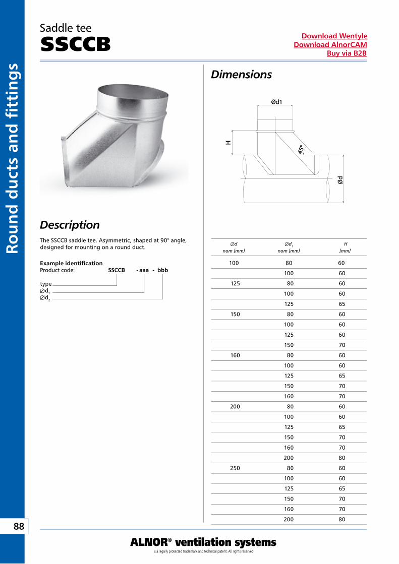
88
ALNOR® ventilation systemsis a legally protected trademark and technical patent. All rights reserved.
Rou
nd
du
cts
and
fi t
tin
gs
Download WentyleDownload AlnorCAM
Buy via B2B
Saddle tee
SSCCB
The SSCCB saddle tee. Asymmetric, shaped at 90° angle, designed for mounting on a round duct.
Æd Æd1 H nom [mm] nom [mm] [mm]
Example identificationProduct code: SSCCB - aaa - bbb
typeÆd1Æd2
Dimensions
Description
100 80 60
100 60
125 80 60
100 60
125 65
150 80 60
100 60
125 60
150 70
160 80 60
100 60
125 65
150 70
160 70
200 80 60
100 60
125 65
150 70
160 70
200 80
250 80 60
100 60
125 65
150 70
160 70
200 80
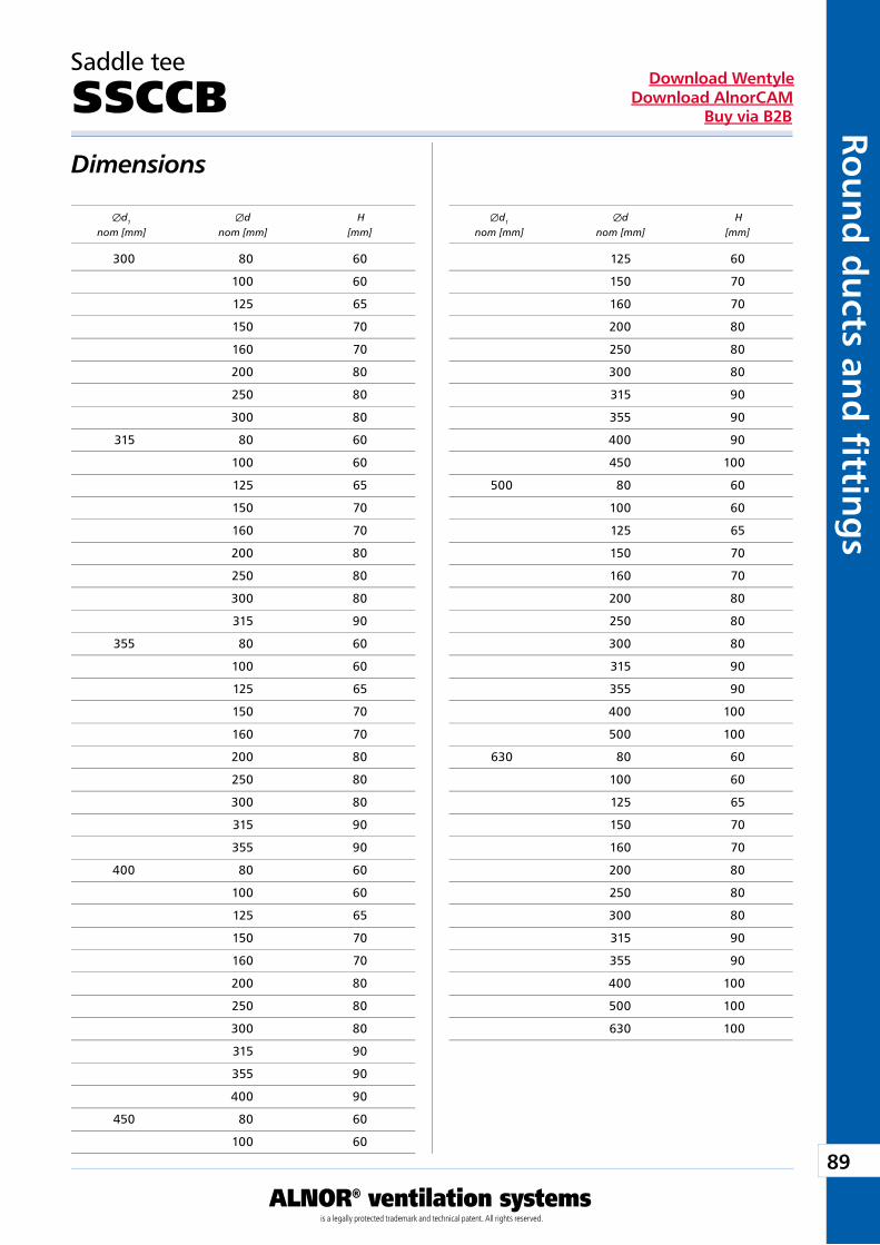
89
ALNOR® ventilation systemsis a legally protected trademark and technical patent. All rights reserved.
Rou
nd
du
cts and
fi tting
sDownload Wentyle
Download AlnorCAMBuy via B2B
Saddle tee
SSCCB
Æd1 Æd H nom [mm] nom [mm] [mm]
Dimensions
Æd1 Æd H nom [mm] nom [mm] [mm]
300 80 60
100 60
125 65
150 70
160 70
200 80
250 80
300 80
315 80 60
100 60
125 65
150 70
160 70
200 80
250 80
300 80
315 90
355 80 60
100 60
125 65
150 70
160 70
200 80
250 80
300 80
315 90
355 90
400 80 60
100 60
125 65
150 70
160 70
200 80
250 80
300 80
315 90
355 90
400 90
450 80 60
100 60
125 60
150 70
160 70
200 80
250 80
300 80
315 90
355 90
400 90
450 100
500 80 60
100 60
125 65
150 70
160 70
200 80
250 80
300 80
315 90
355 90
400 100
500 100
630 80 60
100 60
125 65
150 70
160 70
200 80
250 80
300 80
315 90
355 90
400 100
500 100
630 100
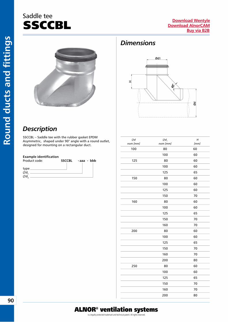
90
ALNOR® ventilation systemsis a legally protected trademark and technical patent. All rights reserved.
Rou
nd
du
cts
and
fi t
tin
gs
Download WentyleDownload AlnorCAM
Buy via B2B
Æd Æd1 H nom [mm] nom [mm] [mm]
Saddle tee
SSCCBL
SSCCBL – Saddle tee with the rubber gasket EPDMAsymmetric, shaped under 90° angle with a round outlet,designed for mounting on a rectangular duct.
Example identificationProduct code: SSCCBL - aaa - bbb
typeÆd1Æd2
Dimensions
Description
100 80 60
100 60
125 80 60
100 60
125 65
150 80 60
100 60
125 60
150 70
160 80 60
100 60
125 65
150 70
160 70
200 80 60
100 60
125 65
150 70
160 70
200 80
250 80 60
100 60
125 65
150 70
160 70
200 80
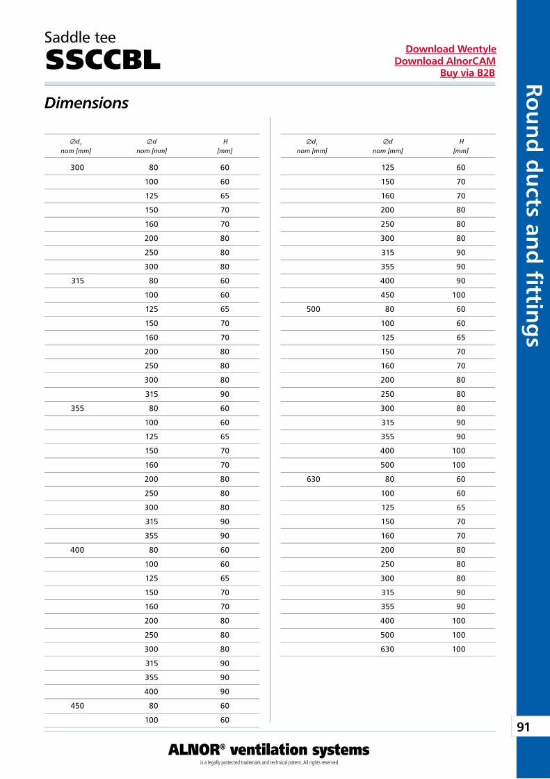
91
ALNOR® ventilation systemsis a legally protected trademark and technical patent. All rights reserved.
Rou
nd
du
cts and
fi tting
sDownload Wentyle
Download AlnorCAMBuy via B2B
Dimensions
Saddle tee
SSCCBL
Æd1 Æd H nom [mm] nom [mm] [mm]
Æd1 Æd H nom [mm] nom [mm] [mm]
300 80 60
100 60
125 65
150 70
160 70
200 80
250 80
300 80
315 80 60
100 60
125 65
150 70
160 70
200 80
250 80
300 80
315 90
355 80 60
100 60
125 65
150 70
160 70
200 80
250 80
300 80
315 90
355 90
400 80 60
100 60
125 65
150 70
160 70
200 80
250 80
300 80
315 90
355 90
400 90
450 80 60
100 60
125 60
150 70
160 70
200 80
250 80
300 80
315 90
355 90
400 90
450 100
500 80 60
100 60
125 65
150 70
160 70
200 80
250 80
300 80
315 90
355 90
400 100
500 100
630 80 60
100 60
125 65
150 70
160 70
200 80
250 80
300 80
315 90
355 90
400 100
500 100
630 100
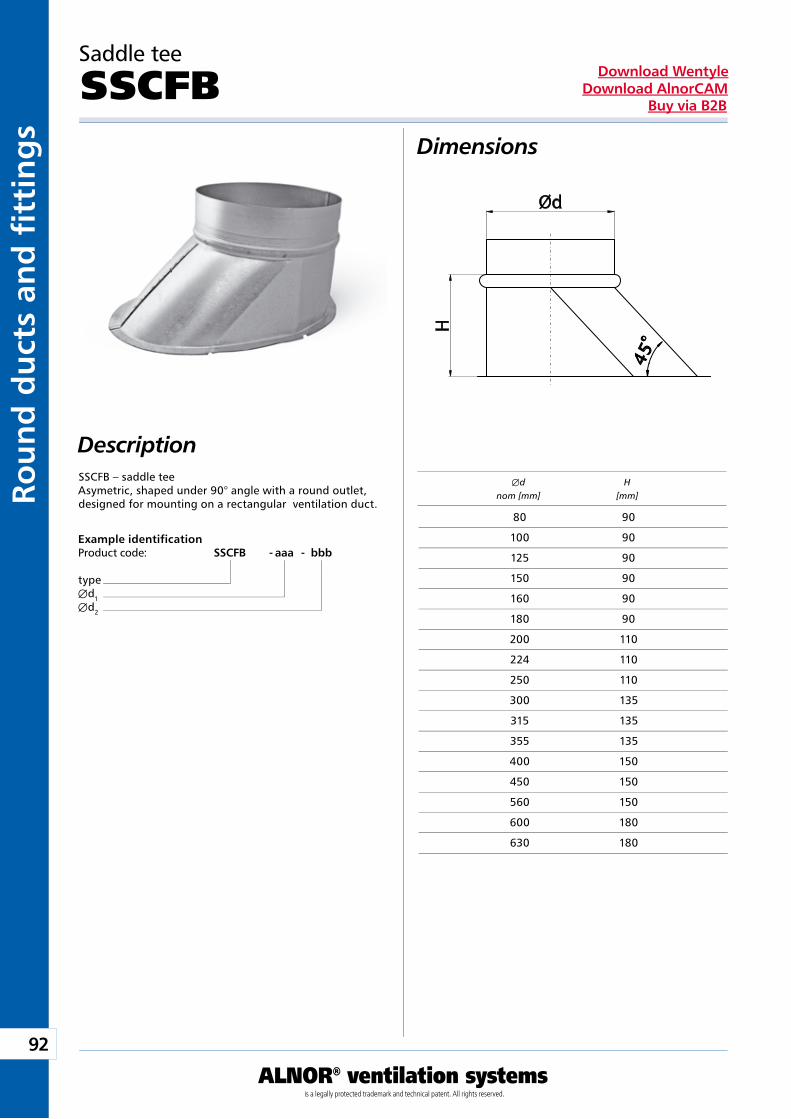
92
ALNOR® ventilation systemsis a legally protected trademark and technical patent. All rights reserved.
Rou
nd
du
cts
and
fi t
tin
gs
Download WentyleDownload AlnorCAM
Buy via B2B
Saddle tee
SSCFBDimensions
Description
Example identificationProduct code: SSCFB - aaa - bbb
typeÆd1Æd2
SSCFB – saddle teeAsymetric, shaped under 90° angle with a round outlet,designed for mounting on a rectangular ventilation duct.
Æd H nom [mm] [mm]
80 90
100 90
125 90
150 90
160 90
180 90
200 110
224 110
250 110
300 135
315 135
355 135
400 150
450 150
560 150
600 180
630 180
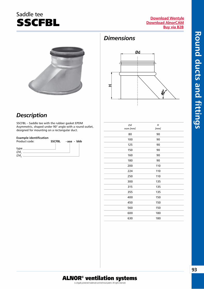
93
ALNOR® ventilation systemsis a legally protected trademark and technical patent. All rights reserved.
Rou
nd
du
cts and
fi tting
sDownload Wentyle
Download AlnorCAMBuy via B2B
Saddle tee
SSCFBLDimensions
Description
Example identificationProduct code: SSCFBL - aaa - bbb
typeÆd1Æd2
SSCFBL – Saddle tee with the rubber gasket EPDMAsymmetric, shaped under 90° angle with a round outlet, designed for mounting on a rectangular duct.
Æd H nom [mm] [mm]
80 90
100 90
125 90
150 90
160 90
180 90
200 110
224 110
250 110
300 135
315 135
355 135
400 150
450 150
560 150
600 180
630 180
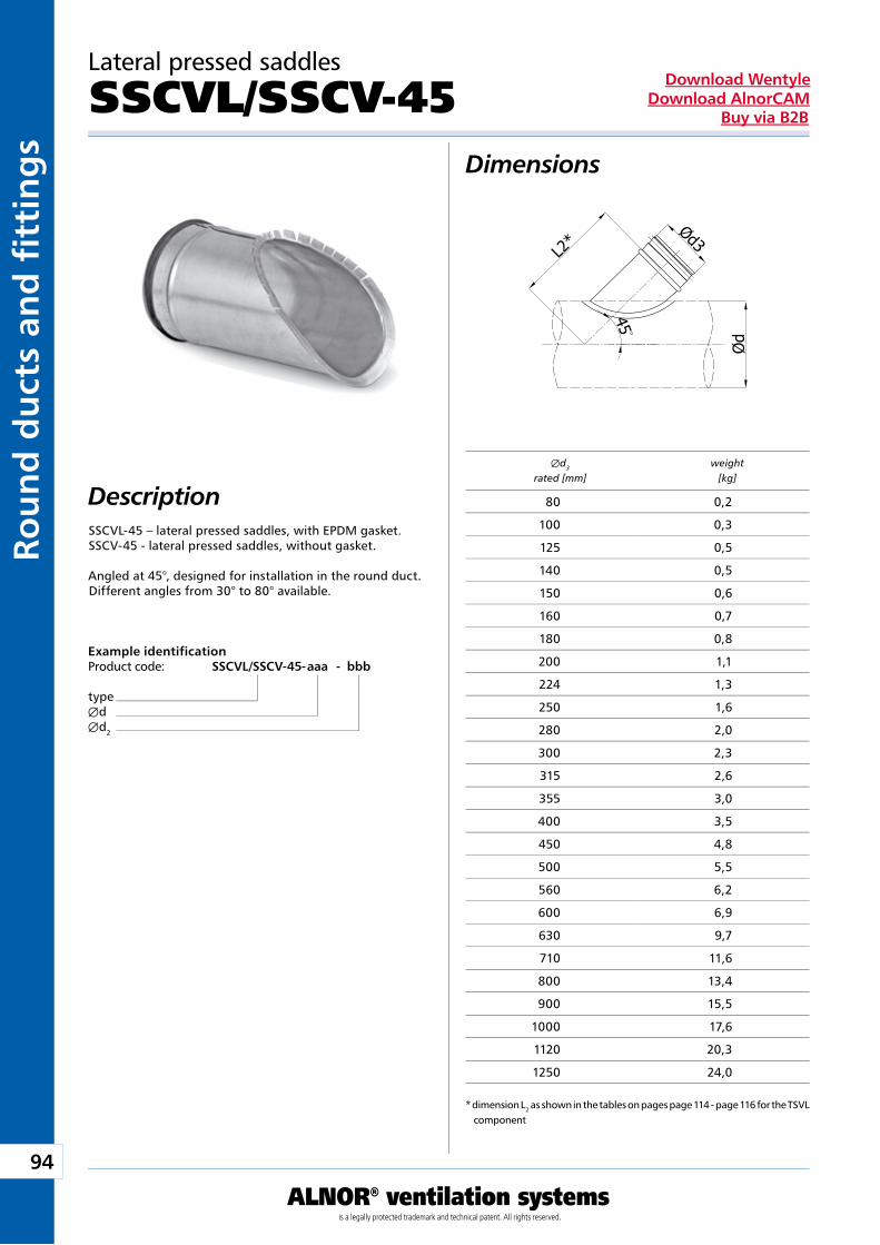
94
ALNOR® ventilation systemsis a legally protected trademark and technical patent. All rights reserved.
Rou
nd
du
cts
and
fi t
tin
gs
Download WentyleDownload AlnorCAM
Buy via B2B
3o
Lateral pressed saddles
SSCVL/SSCV-45Dimensions
DescriptionSSCVL-45 – lateral pressed saddles, with EPDM gasket.SSCV-45 - lateral pressed saddles, without gasket.
Angled at 45°, designed for installation in the round duct.Different angles from 30° to 80° available.
Example identificationProduct code: SSCVL/SSCV-45 - aaa - bbb
typeÆdÆd2
* dimension L2 as shown in the tables on pages page 114 - page 116 for the TSVL component
Æd3 weight rated [mm] [kg]
80 0,2
100 0,3
125 0,5
140 0,5
150 0,6
160 0,7
180 0,8
200 1,1
224 1,3
250 1,6
280 2,0
300 2,3
315 2,6
355 3,0
400 3,5
450 4,8
500 5,5
560 6,2
600 6,9
630 9,7
710 11,6
800 13,4
900 15,5
1000 17,6
1120 20,3
1250 24,0
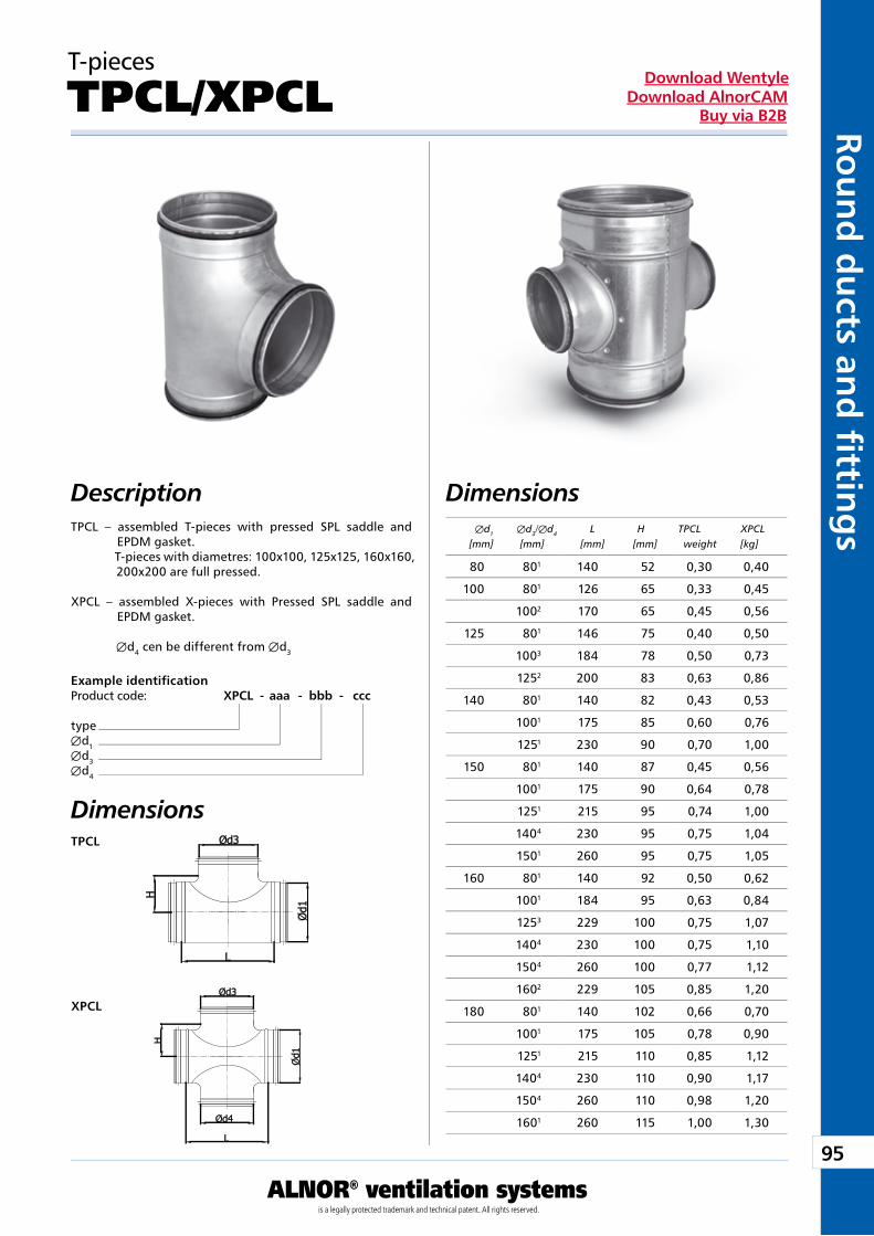
95
ALNOR® ventilation systemsis a legally protected trademark and technical patent. All rights reserved.
Rou
nd
du
cts and
fi tting
sDownload Wentyle
Download AlnorCAMBuy via B2B
TPCL
XPCL
T-pieces
TPCL/XPCL
DescriptionTPCL – assembled T-pieces with pressed SPL saddle and
EPDM gasket. T-pieces with diametres: 100x100, 125x125, 160x160,
200x200 are full pressed.
XPCL – assembled X-pieces with Pressed SPL saddle and EPDM gasket.
Æd4 cen be different from Æd3
Example identificationProduct code: XPCL - aaa - bbb - ccc
typeÆd1Æd3Æd4
Dimensions
Dimensions Æd1 Æd3/Æd4 L H TPCL XPCL [mm] [mm] [mm] [mm] weight [kg]
80 801 140 52 0,30 0,40
100 801 126 65 0,33 0,45
1002 170 65 0,45 0,56
125 801 146 75 0,40 0,50
1003 184 78 0,50 0,73
1252 200 83 0,63 0,86
140 801 140 82 0,43 0,53
1001 175 85 0,60 0,76
1251 230 90 0,70 1,00
150 801 140 87 0,45 0,56
1001 175 90 0,64 0,78
1251 215 95 0,74 1,00
1404 230 95 0,75 1,04
1501 260 95 0,75 1,05
160 801 140 92 0,50 0,62
1001 184 95 0,63 0,84
1253 229 100 0,75 1,07
1404 230 100 0,75 1,10
1504 260 100 0,77 1,12
1602 229 105 0,85 1,20
180 801 140 102 0,66 0,70
1001 175 105 0,78 0,90
1251 215 110 0,85 1,12
1404 230 110 0,90 1,17
1504 260 110 0,98 1,20
1601 260 115 1,00 1,30
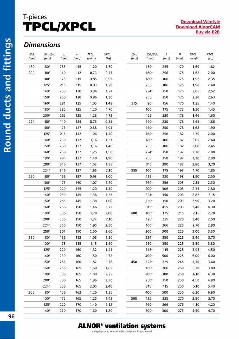
96
ALNOR® ventilation systemsis a legally protected trademark and technical patent. All rights reserved.
Rou
nd
du
cts
and
fi t
tin
gs
Download WentyleDownload AlnorCAM
Buy via B2B
Dimensions
T-pieces
TPCL/XPCL
Æd1 Æd3/Æd4 L H TPCL XPCL [mm] [mm] [mm] [mm] weight [kg]
Æd1 Æd3/Æd4 L H TPCL XPCL [mm] [mm] [mm] [mm] weight [kg]
180 1804 285 115 1,20 1,50
200 801 140 112 0,73 0,75
1001 175 115 0,85 0,95
1253 215 115 0,93 1,20
1404 230 120 0,94 1,27
1503 260 120 0,96 1,30
1603 281 125 1,05 1,48
1804 285 125 1,20 1,70
2002 265 125 1,28 1,73
224 801 140 124 0,75 0,85
1001 175 127 0,88 1,03
1251 215 132 1,06 1,30
1404 230 132 1,16 1,37
1504 260 132 1,16 1,40
1601 260 137 1,25 1,50
1804 285 137 1,40 1,90
2001 346 137 1,53 1,95
2244 346 137 1,65 2,10
250 801 156 137 0,93 1,00
1001 175 140 1,07 1,20
1251 220 145 1,20 1,30
1404 230 145 1,38 1,55
1504 255 145 1,38 1,60
1603 256 150 1,46 1,75
1804 306 150 1,70 2,00
2001 306 150 1,72 2,10
2244 350 150 1,95 2,30
2501 307 150 2,00 2,60
280 804 156 152 1,05 1,20
1004 175 155 1,15 1,40
1251 220 160 1,32 1,43
1404 230 160 1,50 1,72
1504 255 160 1,52 1,78
1604 256 165 1,60 1,85
1804 306 165 1,80 2,25
2001 306 165 1,86 2,30
2244 350 165 2,05 2,40
300 804 156 162 1,20 1,35
1004 175 165 1,25 1,42
1251 220 170 1,40 1,52
1404 230 170 1,60 1,80
1504 255 170 1,60 1,82
1604 256 175 1,62 2,00
1804 306 175 1,96 2,35
2001 306 175 1,98 2,40
2244 350 175 2,05 2,52
2501 350 175 2,20 2,63
315 804 156 170 1,25 1,40
1004 175 173 1,30 1,45
1251 220 178 1,46 1,60
1404 230 178 1,65 1,86
1504 250 178 1,68 1,90
1604 256 182 1,70 2,00
1804 306 182 2,05 2,40
2001 306 182 2,08 2,45
2244 350 182 2,20 2,80
2501 350 182 2,30 2,90
3151 390 182 2,80 3,70
355 1004 175 193 1,70 1,85
1254 220 198 1,90 2,00
1604 256 203 2,15 2,30
2004 306 203 2,55 2,80
2244 350 203 2,82 3,15
2504 350 203 2,90 3,20
3154 455 203 3,40 4,30
400 1004 175 215 2,15 2,20
1254 225 220 2,40 2,50
1604 266 225 2,70 2,90
2004 300 225 3,00 3,30
2244 350 225 3,40 3,70
2504 350 225 3,50 3,80
3154 415 225 3,95 4,50
4004 500 225 5,00 6,00
450 1254 225 245 3,30 3,40
1604 266 250 3,70 3,80
2004 300 250 4,10 4,30
2504 350 250 4,50 4,90
3154 415 250 6,10 5,40
4004 500 250 6,20 6,90
500 1254 225 270 3,80 3,70
1604 266 275 4,10 4,20
2004 300 275 4,50 4,70
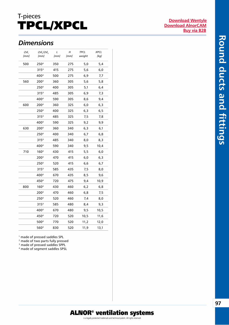
97
ALNOR® ventilation systemsis a legally protected trademark and technical patent. All rights reserved.
Rou
nd
du
cts and
fi tting
sDownload Wentyle
Download AlnorCAMBuy via B2B
Dimensions
T-pieces
TPCL/XPCL
Æd1 Æd3/Æd4 L H TPCL XPCL [mm] [mm] [mm] [mm] weight [kg]
1 made of pressed saddles SPL2 made of two parts fully pressed3 made of pressed saddles SPPL4 made of segment saddles SPSL
500 2504 350 275 5,0 5,4
3154 415 275 5,6 6,0
4004 500 275 6,9 7,7
560 2004 360 305 5,6 5,8
2504 400 305 5,1 6,4
3154 485 305 6,9 7,3
4004 590 305 8,6 9,4
600 2004 360 325 6,0 6,3
2504 400 325 6,3 6,5
3154 485 325 7,5 7,8
4004 590 325 9,2 9,9
630 2004 360 340 6,3 6,1
2504 400 340 6,7 6,8
3154 485 340 8,0 8,3
4004 590 340 9,5 10,4
710 1604 430 415 5,5 6,0
2004 470 415 6,0 6,3
2504 520 415 6,6 6,7
3154 585 435 7,5 8,0
4004 670 435 8,5 9,6
4504 720 475 9,4 10,9
800 1604 430 460 6,2 6,8
2004 470 460 6,8 7,5
2504 520 460 7,4 8,0
3154 585 480 8,4 9,3
4004 670 480 9,5 10,5
4504 720 520 10,5 11,6
5004 770 520 11,2 12,0
5604 830 520 11,9 13,1
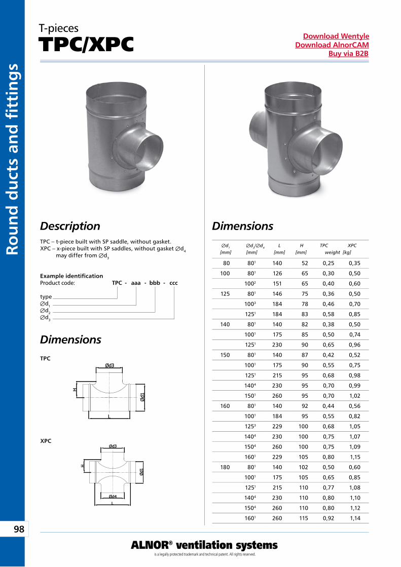
98
ALNOR® ventilation systemsis a legally protected trademark and technical patent. All rights reserved.
Rou
nd
du
cts
and
fi t
tin
gs
Download WentyleDownload AlnorCAM
Buy via B2B
TPC
XPC
T-pieces
TPC/XPC
Dimensions DescriptionTPC – t-piece built with SP saddle, without gasket.XPC – x-piece built with SP saddles, without gasket Æd4
may differ from Æd3
Example identificationProduct code: TPC - aaa - bbb - ccc
typeÆd1Æd2Æd3
Dimensions
Æd1 Æd3/Æd4 L H TPC XPC [mm] [mm] [mm] [mm] weight [kg]
80 801 140 52 0,25 0,35
100 801 126 65 0,30 0,50
1002 151 65 0,40 0,60
125 801 146 75 0,36 0,50
1003 184 78 0,46 0,70
1251 184 83 0,58 0,85
140 801 140 82 0,38 0,50
1001 175 85 0,50 0,74
1251 230 90 0,65 0,96
150 801 140 87 0,42 0,52
1001 175 90 0,55 0,75
1251 215 95 0,68 0,98
1404 230 95 0,70 0,99
1501 260 95 0,70 1,02
160 801 140 92 0,44 0,56
1001 184 95 0,55 0,82
1253 229 100 0,68 1,05
1404 230 100 0,75 1,07
1504 260 100 0,75 1,09
1601 229 105 0,80 1,15
180 801 140 102 0,50 0,60
1001 175 105 0,65 0,85
1251 215 110 0,77 1,08
1404 230 110 0,80 1,10
1504 260 110 0,80 1,12
1601 260 115 0,92 1,14
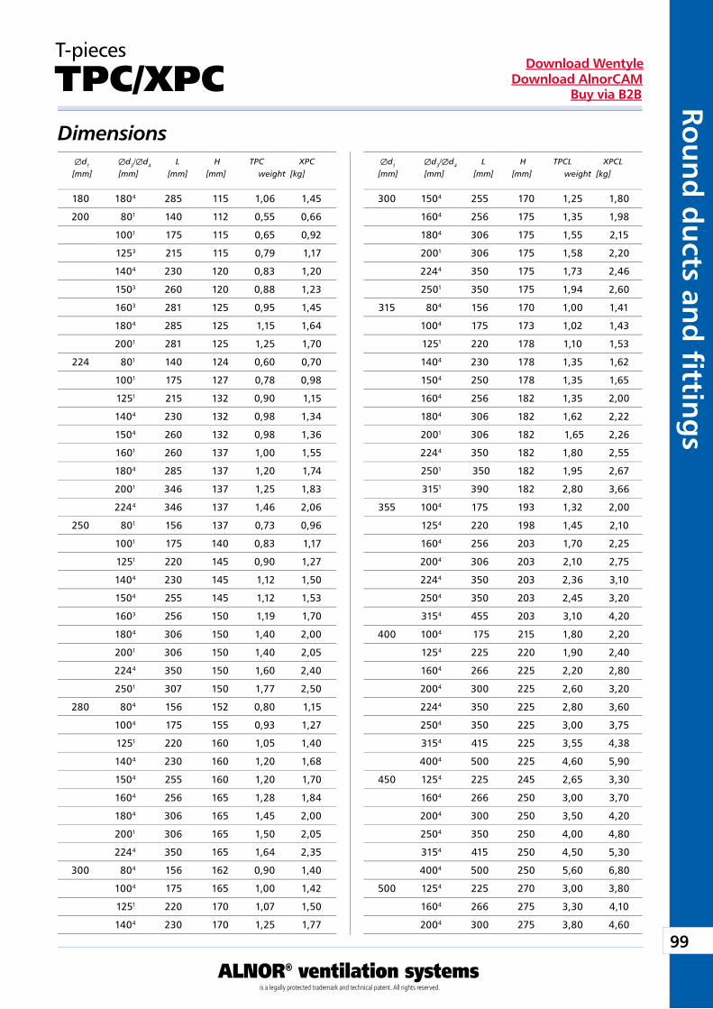
99
ALNOR® ventilation systemsis a legally protected trademark and technical patent. All rights reserved.
Rou
nd
du
cts and
fi tting
sDownload Wentyle
Download AlnorCAMBuy via B2B
T-pieces
TPC/XPCDimensions Æd1 Æd3/Æd4 L H TPC XPC [mm] [mm] [mm] [mm] weight [kg]
Æd1 Æd3/Æd4 L H TPCL XPCL [mm] [mm] [mm] [mm] weight [kg]
180 1804 285 115 1,06 1,45
200 801 140 112 0,55 0,66
1001 175 115 0,65 0,92
1253 215 115 0,79 1,17
1404 230 120 0,83 1,20
1503 260 120 0,88 1,23
1603 281 125 0,95 1,45
1804 285 125 1,15 1,64
2001 281 125 1,25 1,70
224 801 140 124 0,60 0,70
1001 175 127 0,78 0,98
1251 215 132 0,90 1,15
1404 230 132 0,98 1,34
1504 260 132 0,98 1,36
1601 260 137 1,00 1,55
1804 285 137 1,20 1,74
2001 346 137 1,25 1,83
2244 346 137 1,46 2,06
250 801 156 137 0,73 0,96
1001 175 140 0,83 1,17
1251 220 145 0,90 1,27
1404 230 145 1,12 1,50
1504 255 145 1,12 1,53
1603 256 150 1,19 1,70
1804 306 150 1,40 2,00
2001 306 150 1,40 2,05
2244 350 150 1,60 2,40
2501 307 150 1,77 2,50
280 804 156 152 0,80 1,15
1004 175 155 0,93 1,27
1251 220 160 1,05 1,40
1404 230 160 1,20 1,68
1504 255 160 1,20 1,70
1604 256 165 1,28 1,84
1804 306 165 1,45 2,00
2001 306 165 1,50 2,05
2244 350 165 1,64 2,35
300 804 156 162 0,90 1,40
1004 175 165 1,00 1,42
1251 220 170 1,07 1,50
1404 230 170 1,25 1,77
300 1504 255 170 1,25 1,80
1604 256 175 1,35 1,98
1804 306 175 1,55 2,15
2001 306 175 1,58 2,20
2244 350 175 1,73 2,46
2501 350 175 1,94 2,60
315 804 156 170 1,00 1,41
1004 175 173 1,02 1,43
1251 220 178 1,10 1,53
1404 230 178 1,35 1,62
1504 250 178 1,35 1,65
1604 256 182 1,35 2,00
1804 306 182 1,62 2,22
2001 306 182 1,65 2,26
2244 350 182 1,80 2,55
2501 350 182 1,95 2,67
3151 390 182 2,80 3,66
355 1004 175 193 1,32 2,00
1254 220 198 1,45 2,10
1604 256 203 1,70 2,25
2004 306 203 2,10 2,75
2244 350 203 2,36 3,10
2504 350 203 2,45 3,20
3154 455 203 3,10 4,20
400 1004 175 215 1,80 2,20
1254 225 220 1,90 2,40
1604 266 225 2,20 2,80
2004 300 225 2,60 3,20
2244 350 225 2,80 3,60
2504 350 225 3,00 3,75
3154 415 225 3,55 4,38
4004 500 225 4,60 5,90
450 1254 225 245 2,65 3,30
1604 266 250 3,00 3,70
2004 300 250 3,50 4,20
2504 350 250 4,00 4,80
3154 415 250 4,50 5,30
4004 500 250 5,60 6,80
500 1254 225 270 3,00 3,80
1604 266 275 3,30 4,10
2004 300 275 3,80 4,60
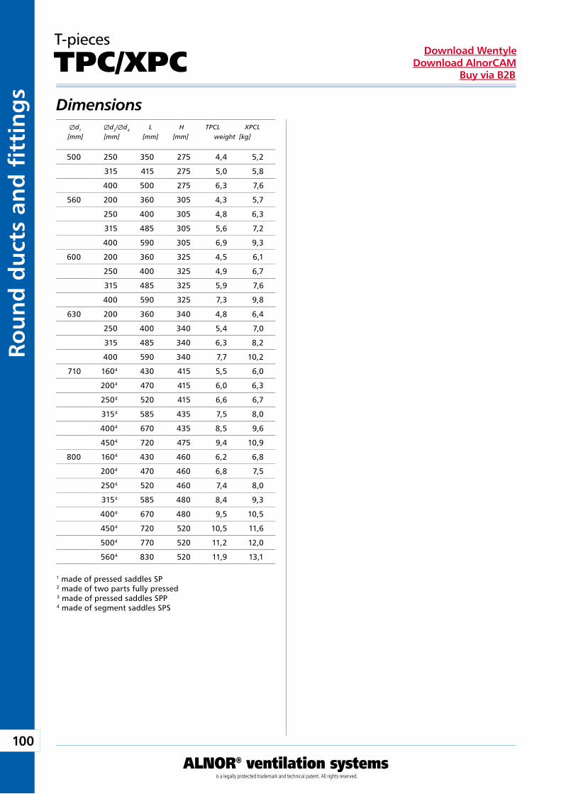
100
ALNOR® ventilation systemsis a legally protected trademark and technical patent. All rights reserved.
Rou
nd
du
cts
and
fi t
tin
gs
Download WentyleDownload AlnorCAM
Buy via B2B
T-pieces
TPC/XPCDimensions Æd1 Æd3/Æd4 L H TPCL XPCL [mm] [mm] [mm] [mm] weight [kg]
1 made of pressed saddles SP2 made of two parts fully pressed3 made of pressed saddles SPP4 made of segment saddles SPS
500 250 350 275 4,4 5,2
315 415 275 5,0 5,8
400 500 275 6,3 7,6
560 200 360 305 4,3 5,7
250 400 305 4,8 6,3
315 485 305 5,6 7,2
400 590 305 6,9 9,3
600 200 360 325 4,5 6,1
250 400 325 4,9 6,7
315 485 325 5,9 7,6
400 590 325 7,3 9,8
630 200 360 340 4,8 6,4
250 400 340 5,4 7,0
315 485 340 6,3 8,2
400 590 340 7,7 10,2
710 1604 430 415 5,5 6,0
2004 470 415 6,0 6,3
2504 520 415 6,6 6,7
3154 585 435 7,5 8,0
4004 670 435 8,5 9,6
4504 720 475 9,4 10,9
800 1604 430 460 6,2 6,8
2004 470 460 6,8 7,5
2504 520 460 7,4 8,0
3154 585 480 8,4 9,3
4004 670 480 9,5 10,5
4504 720 520 10,5 11,6
5004 770 520 11,2 12,0
5604 830 520 11,9 13,1
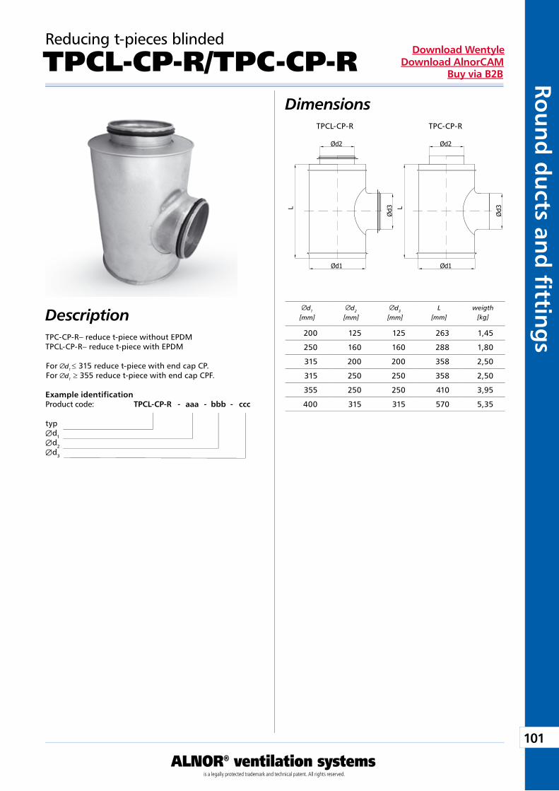
101
ALNOR® ventilation systemsis a legally protected trademark and technical patent. All rights reserved.
Rou
nd
du
cts and
fi tting
sDownload Wentyle
Download AlnorCAMBuy via B2B
Ød3L
Ød2
Ød1
Ød3L
Ød2
Ød1
Reducing t-pieces blinded
TPCL-CP-R/TPC-CP-RDimensions
Description
Example identificationProduct code: TPCL-CP-R - aaa - bbb - ccc
typÆd1Æd2Æd3
d1
[mm]d2
[mm]d3
[mm]L
[mm]weigth
[kg]
TPCL-CP-R TPC-CP-R
TPC-CP-R– reduce t-piece without EPDMTPCL-CP-R– reduce t-piece with EPDM
For d1 ≤ 315 reduce t-piece with end cap CP.For d1 ≥ 355 reduce t-piece with end cap CPF.
200 125 125 263 1,45
250 160 160 288 1,80
315 200 200 358 2,50
315 250 250 358 2,50
355 250 250 410 3,95
400 315 315 570 5,35
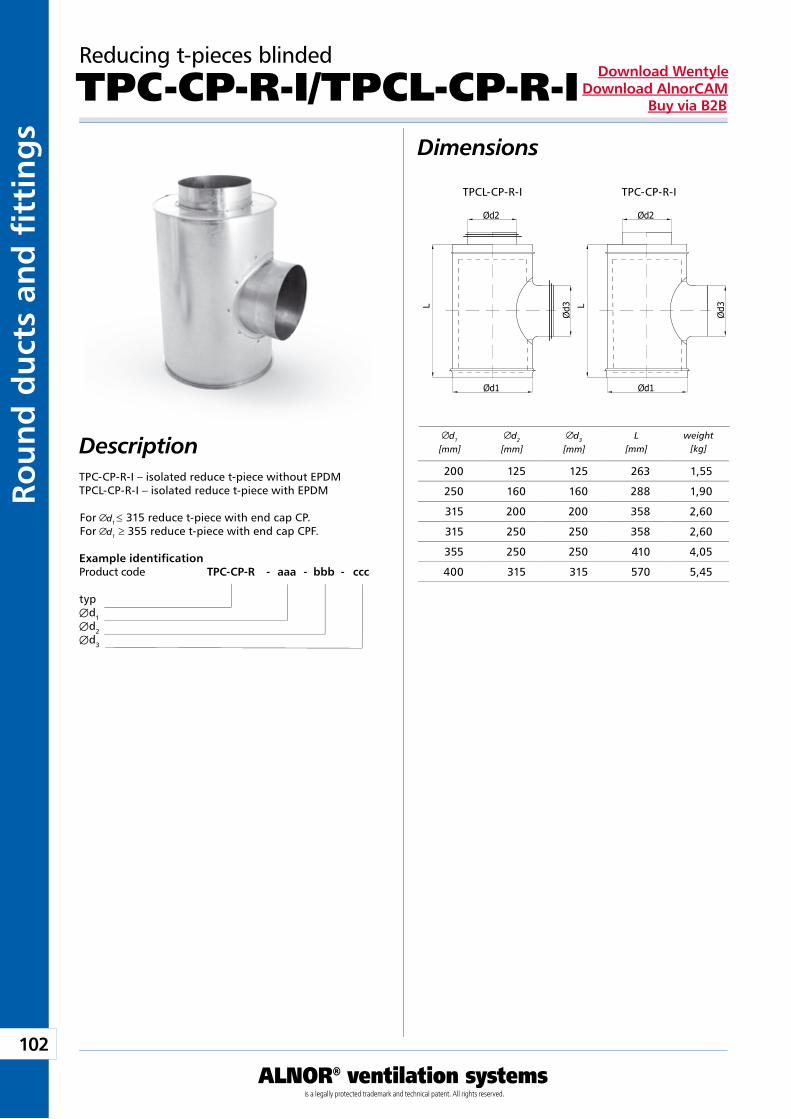
102
ALNOR® ventilation systemsis a legally protected trademark and technical patent. All rights reserved.
Rou
nd
du
cts
and
fi t
tin
gs
Download WentyleDownload AlnorCAM
Buy via B2B
Ød3L
Ød2
Ød1
Ød3L
Ød2
Ød1
Reducing t-pieces blinded
TPC-CP-R-I/TPCL-CP-R-IDimensions
Description
Example identificationProduct code TPC-CP-R - aaa - bbb - ccc
typÆd1Æd2Æd3
d1
[mm]d2
[mm]d3
[mm]L
[mm]weight
[kg]
TPCL-CP-R-I TPC-CP-R-I
TPC-CP-R-I – isolated reduce t-piece without EPDMTPCL-CP-R-I – isolated reduce t-piece with EPDM
For d1 ≤ 315 reduce t-piece with end cap CP.For d1 ≥ 355 reduce t-piece with end cap CPF.
200 125 125 263 1,55
250 160 160 288 1,90
315 200 200 358 2,60
315 250 250 358 2,60
355 250 250 410 4,05
400 315 315 570 5,45
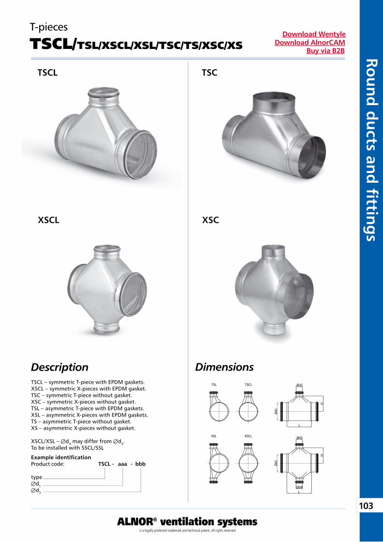
103
ALNOR® ventilation systemsis a legally protected trademark and technical patent. All rights reserved.
Rou
nd
du
cts and
fi tting
sDownload Wentyle
Download AlnorCAMBuy via B2B
T-pieces
TSCL/TSL/XSCL/XSL/TSC/TS/XSC/XS
DescriptionTSCL – symmetric T-piece with EPDM gaskets.XSCL – symmetric X-pieces with EPDM gasket.TSC – symmetric T-piece without gasket.XSC – symmetric X-pieces without gasket.TSL – asymmetric T-piece with EPDM gaskets.XSL – asymmetric X-pieces with EPDM gaskets.TS – asymmetric T-piece without gasket.XS – asymmetric X-pieces without gasket.
XSCL/XSL – Æd4 may differ from Æd3.To be installed with SSCL/SSL
Example identificationProduct code: TSCL - aaa - bbb
typeÆd1Æd3
Dimensions
TSCL TSC
XSCL XSC
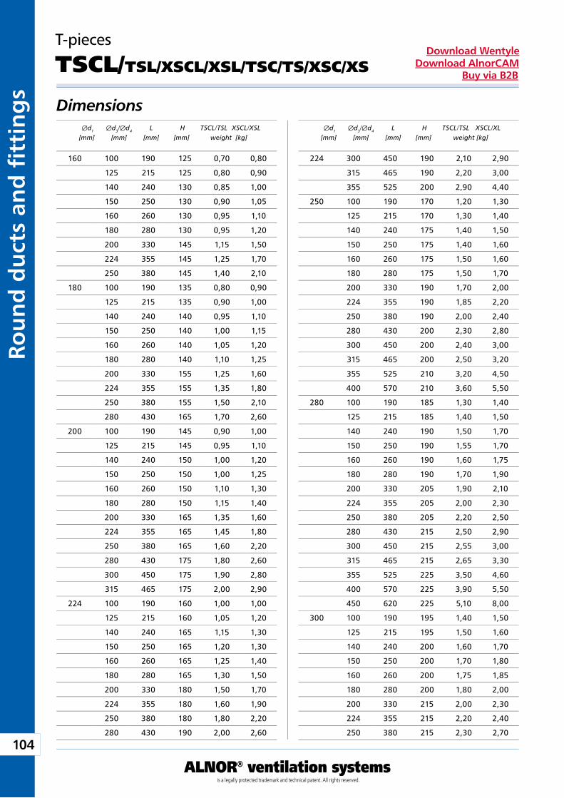
104
ALNOR® ventilation systemsis a legally protected trademark and technical patent. All rights reserved.
Rou
nd
du
cts
and
fi t
tin
gs
Download WentyleDownload AlnorCAM
Buy via B2B
T-pieces
TSCL/TSL/XSCL/XSL/TSC/TS/XSC/XS
Dimensions Æd1 Æd3/Æd4 L H TSCL/TSL XSCL/XSL [mm] [mm] [mm] [mm] weight [kg]
Æd1 Æd3/Æd4 L H TSCL/TSL XSCL/XL [mm] [mm] [mm] [mm] weight [kg]
160 100 190 125 0,70 0,80
125 215 125 0,80 0,90
140 240 130 0,85 1,00
150 250 130 0,90 1,05
160 260 130 0,95 1,10
180 280 130 0,95 1,20
200 330 145 1,15 1,50
224 355 145 1,25 1,70
250 380 145 1,40 2,10
180 100 190 135 0,80 0,90
125 215 135 0,90 1,00
140 240 140 0,95 1,10
150 250 140 1,00 1,15
160 260 140 1,05 1,20
180 280 140 1,10 1,25
200 330 155 1,25 1,60
224 355 155 1,35 1,80
250 380 155 1,50 2,10
280 430 165 1,70 2,60
200 100 190 145 0,90 1,00
125 215 145 0,95 1,10
140 240 150 1,00 1,20
150 250 150 1,00 1,25
160 260 150 1,10 1,30
180 280 150 1,15 1,40
200 330 165 1,35 1,60
224 355 165 1,45 1,80
250 380 165 1,60 2,20
280 430 175 1,80 2,60
300 450 175 1,90 2,80
315 465 175 2,00 2,90
224 100 190 160 1,00 1,00
125 215 160 1,05 1,20
140 240 165 1,15 1,30
150 250 165 1,20 1,30
160 260 165 1,25 1,40
180 280 165 1,30 1,50
200 330 180 1,50 1,70
224 355 180 1,60 1,90
250 380 180 1,80 2,20
280 430 190 2,00 2,60
224 300 450 190 2,10 2,90
315 465 190 2,20 3,00
355 525 200 2,90 4,40
250 100 190 170 1,20 1,30
125 215 170 1,30 1,40
140 240 175 1,40 1,50
150 250 175 1,40 1,60
160 260 175 1,50 1,60
180 280 175 1,50 1,70
200 330 190 1,70 2,00
224 355 190 1,85 2,20
250 380 190 2,00 2,40
280 430 200 2,30 2,80
300 450 200 2,40 3,00
315 465 200 2,50 3,20
355 525 210 3,20 4,50
400 570 210 3,60 5,50
280 100 190 185 1,30 1,40
125 215 185 1,40 1,50
140 240 190 1,50 1,70
150 250 190 1,55 1,70
160 260 190 1,60 1,75
180 280 190 1,70 1,90
200 330 205 1,90 2,10
224 355 205 2,00 2,30
250 380 205 2,20 2,50
280 430 215 2,50 2,90
300 450 215 2,55 3,00
315 465 215 2,65 3,30
355 525 225 3,50 4,60
400 570 225 3,90 5,50
450 620 225 5,10 8,00
300 100 190 195 1,40 1,50
125 215 195 1,50 1,60
140 240 200 1,60 1,70
150 250 200 1,70 1,80
160 260 200 1,75 1,85
180 280 200 1,80 2,00
200 330 215 2,00 2,30
224 355 215 2,20 2,40
250 380 215 2,30 2,70
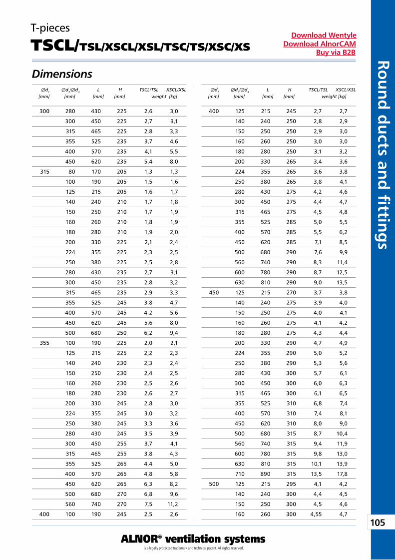
105
ALNOR® ventilation systemsis a legally protected trademark and technical patent. All rights reserved.
Rou
nd
du
cts and
fi tting
sDownload Wentyle
Download AlnorCAMBuy via B2B
T-pieces
TSCL/TSL/XSCL/XSL/TSC/TS/XSC/XS
Dimensions Æd1 Æd3/Æd4 L H TSCL/TSL XSCL/XSL [mm] [mm] [mm] [mm] weight [kg]
Æd1 Æd3/Æd4 L H TSCL/TSL XSCL/XSL [mm] [mm] [mm] [mm] weight [kg]
300 280 430 225 2,6 3,0
300 450 225 2,7 3,1
315 465 225 2,8 3,3
355 525 235 3,7 4,6
400 570 235 4,1 5,5
450 620 235 5,4 8,0
315 80 170 205 1,3 1,3
100 190 205 1,5 1,6
125 215 205 1,6 1,7
140 240 210 1,7 1,8
150 250 210 1,7 1,9
160 260 210 1,8 1,9
180 280 210 1,9 2,0
200 330 225 2,1 2,4
224 355 225 2,3 2,5
250 380 225 2,5 2,8
280 430 235 2,7 3,1
300 450 235 2,8 3,2
315 465 235 2,9 3,3
355 525 245 3,8 4,7
400 570 245 4,2 5,6
450 620 245 5,6 8,0
500 680 250 6,2 9,4
355 100 190 225 2,0 2,1
125 215 225 2,2 2,3
140 240 230 2,3 2,4
150 250 230 2,4 2,5
160 260 230 2,5 2,6
180 280 230 2,6 2,7
200 330 245 2,8 3,0
224 355 245 3,0 3,2
250 380 245 3,3 3,6
280 430 245 3,5 3,9
300 450 255 3,7 4,1
315 465 255 3,8 4,3
355 525 265 4,4 5,0
400 570 265 4,8 5,8
450 620 265 6,3 8,2
500 680 270 6,8 9,6
560 740 270 7,5 11,2
400 100 190 245 2,5 2,6
400 125 215 245 2,7 2,7
140 240 250 2,8 2,9
150 250 250 2,9 3,0
160 260 250 3,0 3,0
180 280 250 3,1 3,2
200 330 265 3,4 3,6
224 355 265 3,6 3,8
250 380 265 3,8 4,1
280 430 275 4,2 4,6
300 450 275 4,4 4,7
315 465 275 4,5 4,8
355 525 285 5,0 5,5
400 570 285 5,5 6,2
450 620 285 7,1 8,5
500 680 290 7,6 9,9
560 740 290 8,3 11,4
600 780 290 8,7 12,5
630 810 290 9,0 13,5
450 125 215 270 3,7 3,8
140 240 275 3,9 4,0
150 250 275 4,0 4,1
160 260 275 4,1 4,2
180 280 275 4,3 4,4
200 330 290 4,7 4,9
224 355 290 5,0 5,2
250 380 290 5,3 5,6
280 430 300 5,7 6,1
300 450 300 6,0 6,3
315 465 300 6,1 6,5
355 525 310 6,8 7,4
400 570 310 7,4 8,1
450 620 310 8,0 9,0
500 680 315 8,7 10,4
560 740 315 9,4 11,9
600 780 315 9,8 13,0
630 810 315 10,1 13,9
710 890 315 13,5 17,8
500 125 215 295 4,1 4,2
140 240 300 4,4 4,5
150 250 300 4,5 4,6
160 260 300 4,55 4,7
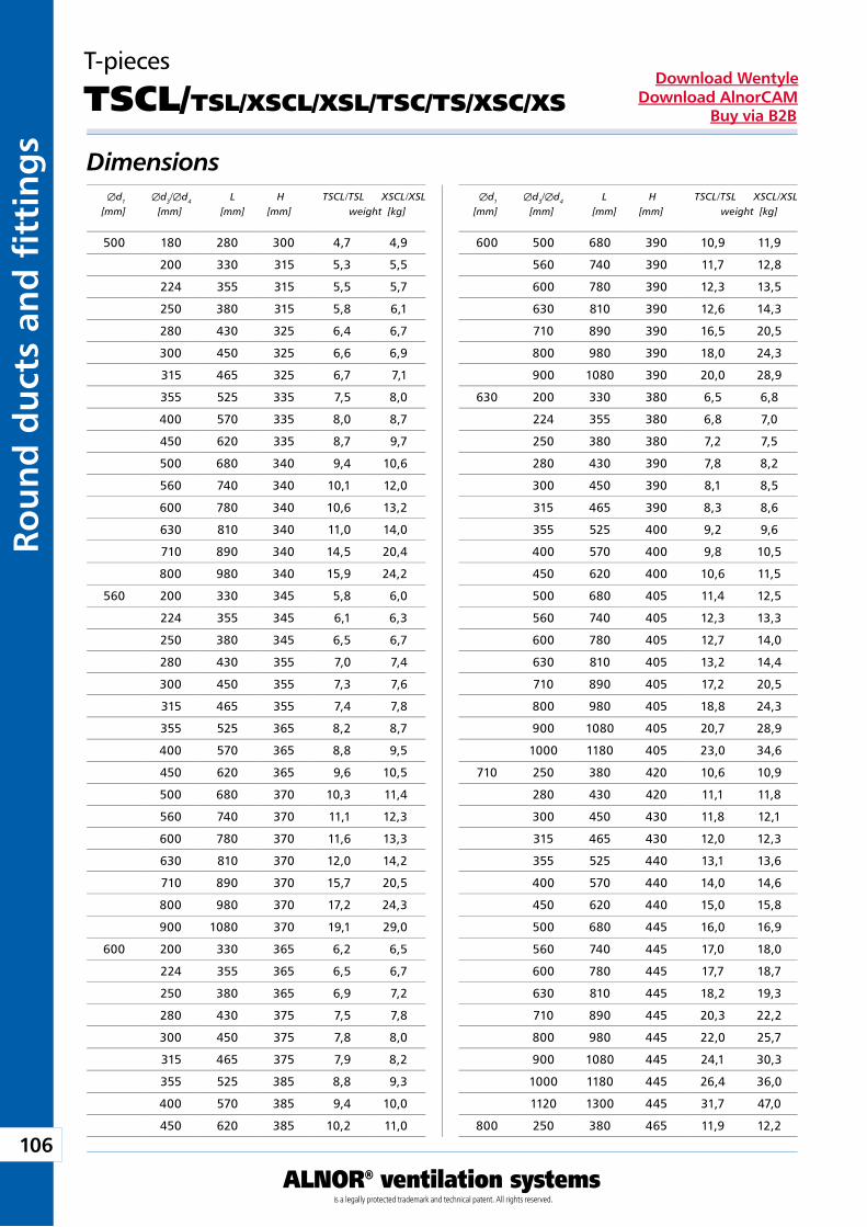
106
ALNOR® ventilation systemsis a legally protected trademark and technical patent. All rights reserved.
Rou
nd
du
cts
and
fi t
tin
gs
Download WentyleDownload AlnorCAM
Buy via B2B
T-pieces
TSCL/TSL/XSCL/XSL/TSC/TS/XSC/XS
Dimensions Æd1 Æd3/Æd4 L H TSCL/TSL XSCL/XSL [mm] [mm] [mm] [mm] weight [kg]
Æd1 Æd3/Æd4 L H TSCL/TSL XSCL/XSL [mm] [mm] [mm] [mm] weight [kg]
500 180 280 300 4,7 4,9
200 330 315 5,3 5,5
224 355 315 5,5 5,7
250 380 315 5,8 6,1
280 430 325 6,4 6,7
300 450 325 6,6 6,9
315 465 325 6,7 7,1
355 525 335 7,5 8,0
400 570 335 8,0 8,7
450 620 335 8,7 9,7
500 680 340 9,4 10,6
560 740 340 10,1 12,0
600 780 340 10,6 13,2
630 810 340 11,0 14,0
710 890 340 14,5 20,4
800 980 340 15,9 24,2
560 200 330 345 5,8 6,0
224 355 345 6,1 6,3
250 380 345 6,5 6,7
280 430 355 7,0 7,4
300 450 355 7,3 7,6
315 465 355 7,4 7,8
355 525 365 8,2 8,7
400 570 365 8,8 9,5
450 620 365 9,6 10,5
500 680 370 10,3 11,4
560 740 370 11,1 12,3
600 780 370 11,6 13,3
630 810 370 12,0 14,2
710 890 370 15,7 20,5
800 980 370 17,2 24,3
900 1080 370 19,1 29,0
600 200 330 365 6,2 6,5
224 355 365 6,5 6,7
250 380 365 6,9 7,2
280 430 375 7,5 7,8
300 450 375 7,8 8,0
315 465 375 7,9 8,2
355 525 385 8,8 9,3
400 570 385 9,4 10,0
450 620 385 10,2 11,0
600 500 680 390 10,9 11,9
560 740 390 11,7 12,8
600 780 390 12,3 13,5
630 810 390 12,6 14,3
710 890 390 16,5 20,5
800 980 390 18,0 24,3
900 1080 390 20,0 28,9
630 200 330 380 6,5 6,8
224 355 380 6,8 7,0
250 380 380 7,2 7,5
280 430 390 7,8 8,2
300 450 390 8,1 8,5
315 465 390 8,3 8,6
355 525 400 9,2 9,6
400 570 400 9,8 10,5
450 620 400 10,6 11,5
500 680 405 11,4 12,5
560 740 405 12,3 13,3
600 780 405 12,7 14,0
630 810 405 13,2 14,4
710 890 405 17,2 20,5
800 980 405 18,8 24,3
900 1080 405 20,7 28,9
1000 1180 405 23,0 34,6
710 250 380 420 10,6 10,9
280 430 420 11,1 11,8
300 450 430 11,8 12,1
315 465 430 12,0 12,3
355 525 440 13,1 13,6
400 570 440 14,0 14,6
450 620 440 15,0 15,8
500 680 445 16,0 16,9
560 740 445 17,0 18,0
600 780 445 17,7 18,7
630 810 445 18,2 19,3
710 890 445 20,3 22,2
800 980 445 22,0 25,7
900 1080 445 24,1 30,3
1000 1180 445 26,4 36,0
1120 1300 445 31,7 47,0
800 250 380 465 11,9 12,2
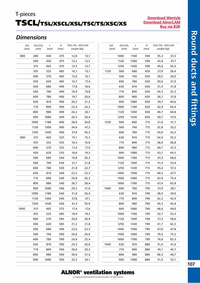
107
ALNOR® ventilation systemsis a legally protected trademark and technical patent. All rights reserved.
Rou
nd
du
cts and
fi tting
sDownload Wentyle
Download AlnorCAMBuy via B2B
T-pieces
TSCL/TSL/XSCL/XSL/TSC/TS/XSC/XS
Dimensions Æd1 Æd3/Æd4 L H TSCL/TSL XSCL/XSL [mm] [mm] [mm] [mm] weight [kg]
Æd1 Æd3/Æd4 L H TSCL/TSL XSCL/XSL -[mm] [mm] [mm] [mm] weight [kg]
800 280 430 475 12,8 13,1
300 450 475 13,2 13,5
315 465 475 13,5 13,7
355 525 485 14,7 15,1
400 570 485 15,6 16,1
450 620 485 16,7 17,4
500 680 490 17,8 18,6
560 740 490 18,9 19,8
600 780 490 19,7 20,6
630 810 490 20,2 21,2
710 890 490 22,4 24,2
800 980 490 24,2 26,1
900 1080 490 26,5 30,4
1000 1180 490 28,9 36,0
1120 1300 490 34,6 47,2
1250 1430 490 37,9 56,2
900 315 465 525 15,1 15,3
355 525 535 16,4 16,8
400 570 535 17,4 17,9
450 620 535 18,6 19,3
500 680 540 19,8 20,3
560 740 540 21,1 21,8
600 780 540 21,8 22,7
630 810 540 22,5 23,3
710 890 540 24,8 26,3
800 980 540 26,7 28,4
900 1080 540 29,2 31,0
1000 1180 540 31,8 36,4
1120 1300 540 37,8 47,1
1250 1430 540 41,4 55,9
1000 315 465 575 17,4 17,6
355 525 585 18,9 19,2
400 570 585 20,0 20,4
450 620 585 21,2 21,8
500 680 590 22,6 23,3
560 740 590 24,0 24,6
600 780 590 24,8 25,4
630 810 590 25,5 26,0
710 890 590 28,0 29,3
800 980 590 30,0 31,4
900 1080 590 32,5 34,1
1000 1180 590 35,3 37,3
1120 1300 590 41,8 47,7
1250 1430 590 45,6 56,4
1120 500 680 650 27,9 28,4
560 740 650 29,5 30,0
600 780 650 30,6 31,0
630 810 650 31,4 31,8
710 890 650 34,3 35,3
800 980 650 36,7 37,8
900 1080 650 39,7 40,6
1000 1180 650 42,9 44,4
1120 1300 650 46,7 48,8
1250 1430 650 50,7 57,0
1250 500 680 715 31,0 31,7
560 740 715 32,8 33,2
600 780 715 34,0 34,3
630 810 715 34,9 35,2
710 890 715 38,0 38,8
800 980 715 40,7 41,5
900 1080 715 43,7 44,5
1000 1180 715 47,3 48,6
1120 1300 715 51,4 53,0
1250 1430 715 55,6 57,3
1400 1580 715 60,5 67,7
1500 1680 715 63,9 75,4
1600 1780 715 67,4 83,8
1400 600 780 790 37,9 38,1
630 810 790 38,9 39,0
710 890 790 42,2 42,9
800 980 790 45,3 45,8
900 1080 790 48,6 49,0
1000 1180 790 52,7 53,3
1120 1300 790 57,2 58,0
1250 1430 790 61,7 62,5
1400 1580 790 67,0 67,8
1500 1680 790 70,5 75,2
1600 1780 790 74,0 83,3
1500 630 810 880 41,6 41,6
710 890 880 45,1 45,7
800 980 880 48,3 48,7
900 1080 880 51,9 52,1
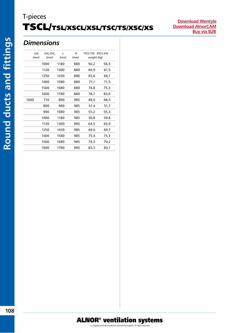
108
ALNOR® ventilation systemsis a legally protected trademark and technical patent. All rights reserved.
Rou
nd
du
cts
and
fi t
tin
gs
Download WentyleDownload AlnorCAM
Buy via B2B
T-pieces
TSCL/TSL/XSCL/XSL/TSC/TS/XSC/XS
Dimensions Æd1 Æd3/Æd4 L H TSCL/TSL XSCL/XSL [mm] [mm] [mm] [mm] weight [kg]
1000 1180 880 56,2 56,5
1120 1300 880 60,9 61,5
1250 1430 880 65,6 66,1
1400 1580 880 71,1 71,5
1500 1680 880 74,8 75,3
1600 1780 880 78,7 83,0
1600 710 890 985 48,0 48,5
800 980 985 51,4 51,7
900 1080 985 55,2 55,3
1000 1180 985 59,8 59,8
1120 1300 985 64,5 65,0
1250 1430 985 69,6 69,7
1400 1580 985 75,4 75,3
1500 1680 985 79,3 79,2
1600 1780 985 83,3 83,1
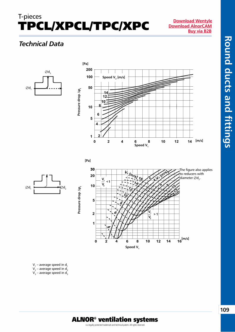
109
ALNOR® ventilation systemsis a legally protected trademark and technical patent. All rights reserved.
Rou
nd
du
cts and
fi tting
sDownload Wentyle
Download AlnorCAMBuy via B2B
30
1
0 2 4 6 8 10 12 14 16
2
5
10
20
30
10
8
6
4
V2 [m/s] 16 4 V2 [m/s]
2
6 8 1012
1214
200
100
50
10
5
12 4 6 8 10 12 140
1412
108
6
2
4
Æd1
Æd3
[Pa]
[m/s]
Æd1 Æd2
[Pa]
[m/s]
V1
V2
<1
V1
V2
> 1
T-pieces
TPCL/XPCL/TPC/XPCTechnical Data
Pre
ssur
e d
rop
Dp
t
Speed V1
Speed V3 [m/s] P
ress
ure
dro
p D
pt
Speed V1
V1 – average speed in d1V2 – average speed in d2V3 – average speed in d3
The figure also applies to reducers with diameter Æd2.
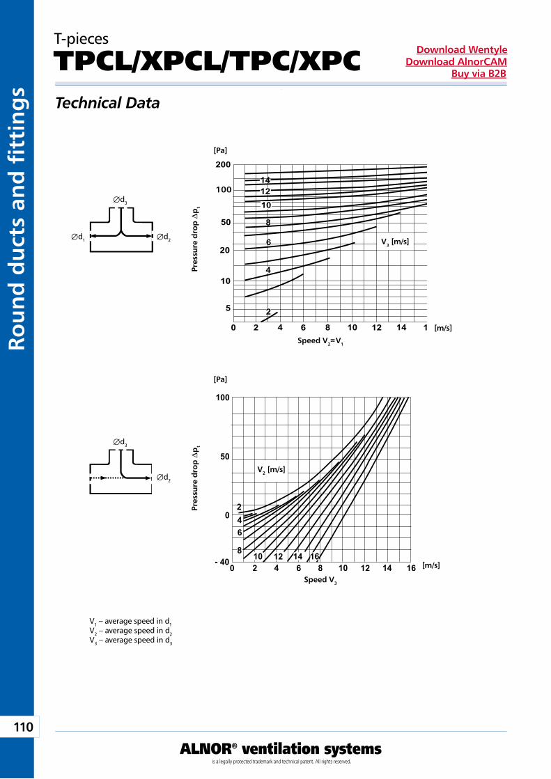
110
ALNOR® ventilation systemsis a legally protected trademark and technical patent. All rights reserved.
Rou
nd
du
cts
and
fi t
tin
gs
Download WentyleDownload AlnorCAM
Buy via B2B
- 40
0
50
100
0 2 4 6 8 10 12 14 16
246
810 12 14 16
5
10
50
200
0 2 4 6 8 10 12 14 16
100
20
141210
8
6
4
2
Æd1
Æd3
Æd2
[Pa]
[m/s]
V3 [m/s]
[Pa]
[m/s]
V2 [m/s]
Æd3
Æd2
T-pieces
TPCL/XPCL/TPC/XPCTechnical Data
V1 – average speed in d1V2 – average speed in d2V3 – average speed in d3
Pre
ssur
e d
rop
Dp
t
Speed V2= V1
Pre
ssur
e d
rop
Dp
t
Speed V3
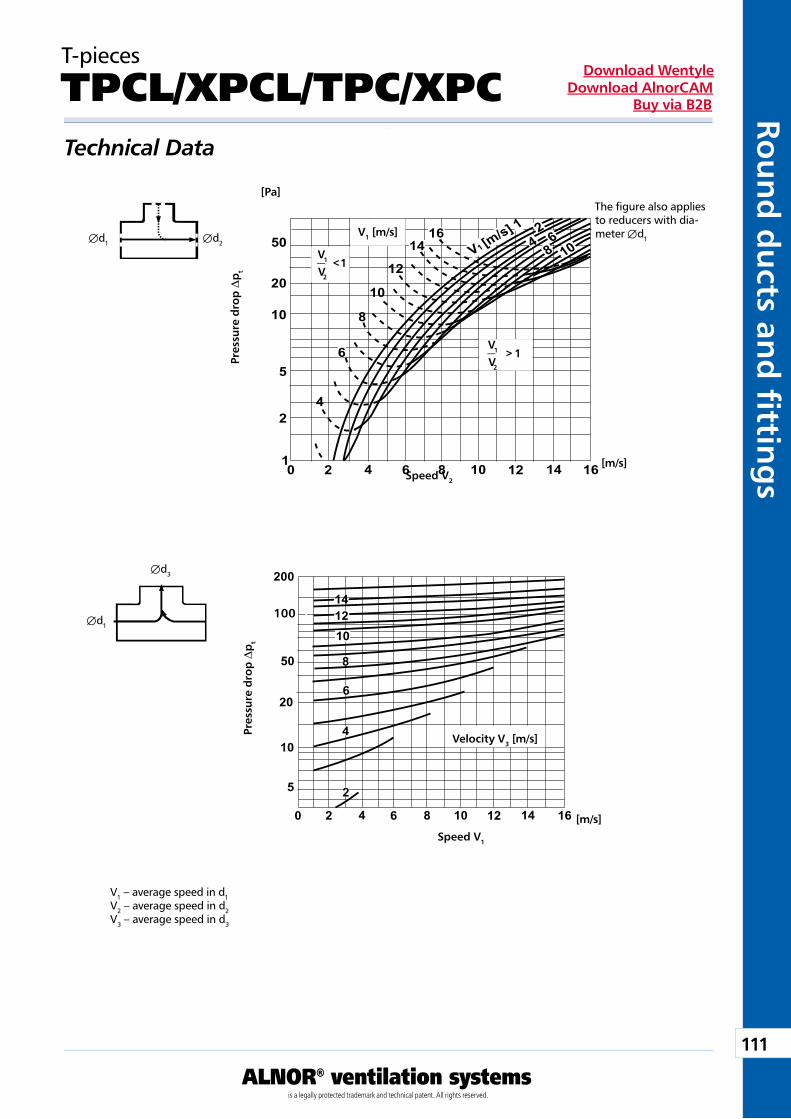
111
ALNOR® ventilation systemsis a legally protected trademark and technical patent. All rights reserved.
Rou
nd
du
cts and
fi tting
sDownload Wentyle
Download AlnorCAMBuy via B2B
5
10
50
200
0 2 4 6 8 10 12 14 16
100
20
141210
8
6
4
2
42
0 2 4 6 8 10 12 14 16
5
10
20
50
1
12
10
8
1614 V1 [m
/s] 14 6
8 10
6
2
Æd1
Æd3
Æd1 Æd2
[Pa]
[m/s]
[m/s]
Velocity V3 [m/s]
V1
V2
<1
V1
V2
> 1
V1 [m/s]
T-pieces
TPCL/XPCL/TPC/XPCTechnical Data
V1 – average speed in d1V2 – average speed in d2V3 – average speed in d3
Pre
ssur
e d
rop
Dp
t
Speed V2
Pre
ssur
e d
rop
Dp
t
Speed V1
The figure also applies to reducers with dia-meter Æd1
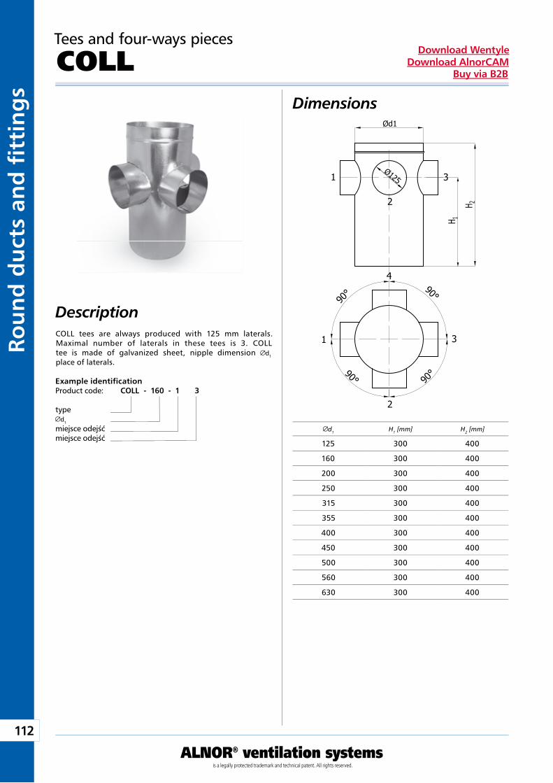
112
ALNOR® ventilation systemsis a legally protected trademark and technical patent. All rights reserved.
Rou
nd
du
cts
and
fi t
tin
gs
Download WentyleDownload AlnorCAM
Buy via B2B
Tees and four-ways pieces
COLL Dimensions
DescriptionCOLL tees are always produced with 125 mm laterals. Maximal number of laterals in these tees is 3. COLL tee is made of galvanized sheet, nipple dimension d1 place of laterals.
Example identificationProduct code: COLL - 160 - 1 3
typed1
miejsce odejśćmiejsce odejść
Ød1
Ø1251
2
3
1 3
2
H
H
1
2
4
90° 90°
90°
90°
d1 H1 [mm] H2 [mm]
125 300 400
160 300 400
200 300 400
250 300 400
315 300 400
355 300 400
400 300 400
450 300 400
500 300 400
560 300 400
630 300 400
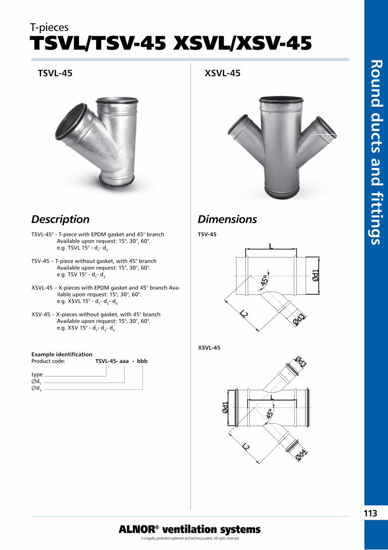
113
ALNOR® ventilation systemsis a legally protected trademark and technical patent. All rights reserved.
Rou
nd
du
cts and
fi tting
sDownload Wentyle
Download AlnorCAMBuy via B2B
TSV-45
XSVL-45
T-pieces
TSVL/TSV-45 XSVL/XSV-45
DescriptionTSVL-45° - T-piece with EPDM gasket and 45° branch
Available upon request: 15°, 30°, 60°. e.g. TSVL 15° - d1- d3
TSV-45 – T-piece without gasket, with 45° branchAvailable upon request: 15°, 30°, 60°.e.g. TSV 15° - d1- d3
XSVL-45 – X-pieces with EPDM gasket and 45° branch Ava-ilable upon request: 15°, 30°, 60°.e.g. XSVL 15° - d1- d3- d4
XSV-45 – X-pieces without gasket, with 45° branchAvailable upon request: 15°, 30°, 60°. e.g. XSV 15° - d1- d3- d4
Example identificationProduct code: TSVL-45 - aaa - bbb
typeÆd1Æd3
Dimensions
TSVL-45 XSVL-45
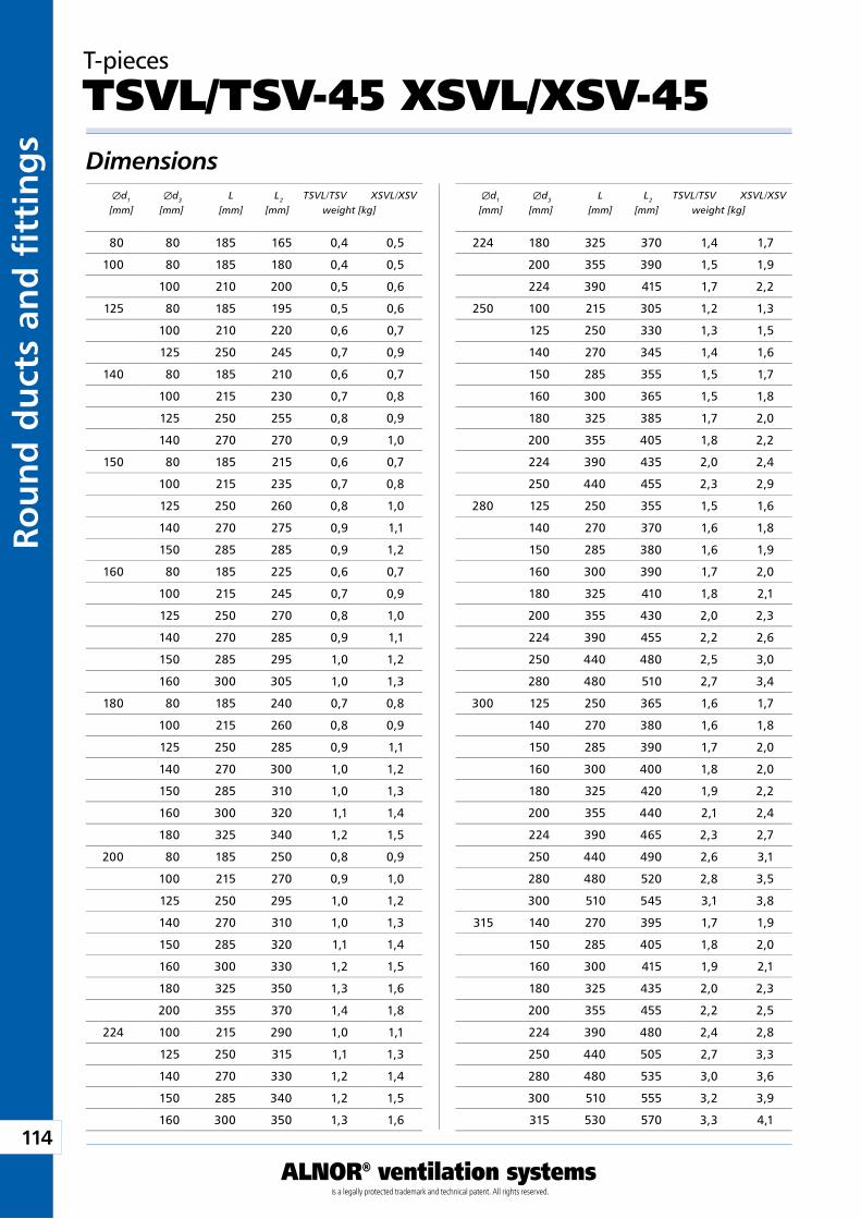
114
ALNOR® ventilation systemsis a legally protected trademark and technical patent. All rights reserved.
Rou
nd
du
cts
and
fi t
tin
gs
Download WentyleDownload AlnorCAM
Buy via B2B
T-pieces
TSVL/TSV-45 XSVL/XSV-45Dimensions Æd1 Æd3 L L2 TSVL/TSV XSVL/XSV [mm] [mm] [mm] [mm] weight [kg]
Æd1 Æd3 L L2 TSVL/TSV XSVL/XSV [mm] [mm] [mm] [mm] weight [kg]
80 80 185 165 0,4 0,5
100 80 185 180 0,4 0,5
100 210 200 0,5 0,6
125 80 185 195 0,5 0,6
100 210 220 0,6 0,7
125 250 245 0,7 0,9
140 80 185 210 0,6 0,7
100 215 230 0,7 0,8
125 250 255 0,8 0,9
140 270 270 0,9 1,0
150 80 185 215 0,6 0,7
100 215 235 0,7 0,8
125 250 260 0,8 1,0
140 270 275 0,9 1,1
150 285 285 0,9 1,2
160 80 185 225 0,6 0,7
100 215 245 0,7 0,9
125 250 270 0,8 1,0
140 270 285 0,9 1,1
150 285 295 1,0 1,2
160 300 305 1,0 1,3
180 80 185 240 0,7 0,8
100 215 260 0,8 0,9
125 250 285 0,9 1,1
140 270 300 1,0 1,2
150 285 310 1,0 1,3
160 300 320 1,1 1,4
180 325 340 1,2 1,5
200 80 185 250 0,8 0,9
100 215 270 0,9 1,0
125 250 295 1,0 1,2
140 270 310 1,0 1,3
150 285 320 1,1 1,4
160 300 330 1,2 1,5
180 325 350 1,3 1,6
200 355 370 1,4 1,8
224 100 215 290 1,0 1,1
125 250 315 1,1 1,3
140 270 330 1,2 1,4
150 285 340 1,2 1,5
160 300 350 1,3 1,6
224 180 325 370 1,4 1,7
200 355 390 1,5 1,9
224 390 415 1,7 2,2
250 100 215 305 1,2 1,3
125 250 330 1,3 1,5
140 270 345 1,4 1,6
150 285 355 1,5 1,7
160 300 365 1,5 1,8
180 325 385 1,7 2,0
200 355 405 1,8 2,2
224 390 435 2,0 2,4
250 440 455 2,3 2,9
280 125 250 355 1,5 1,6
140 270 370 1,6 1,8
150 285 380 1,6 1,9
160 300 390 1,7 2,0
180 325 410 1,8 2,1
200 355 430 2,0 2,3
224 390 455 2,2 2,6
250 440 480 2,5 3,0
280 480 510 2,7 3,4
300 125 250 365 1,6 1,7
140 270 380 1,6 1,8
150 285 390 1,7 2,0
160 300 400 1,8 2,0
180 325 420 1,9 2,2
200 355 440 2,1 2,4
224 390 465 2,3 2,7
250 440 490 2,6 3,1
280 480 520 2,8 3,5
300 510 545 3,1 3,8
315 140 270 395 1,7 1,9
150 285 405 1,8 2,0
160 300 415 1,9 2,1
180 325 435 2,0 2,3
200 355 455 2,2 2,5
224 390 480 2,4 2,8
250 440 505 2,7 3,3
280 480 535 3,0 3,6
300 510 555 3,2 3,9
315 530 570 3,3 4,1
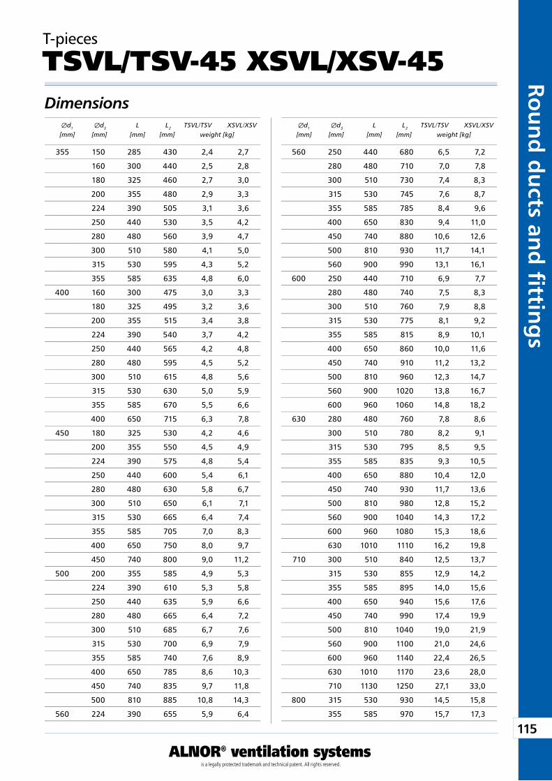
115
ALNOR® ventilation systemsis a legally protected trademark and technical patent. All rights reserved.
Rou
nd
du
cts and
fi tting
sDownload Wentyle
Download AlnorCAMBuy via B2B
T-pieces
TSVL/TSV-45 XSVL/XSV-45Dimensions Æd1 Æd3 L L2 TSVL/TSV XSVL/XSV [mm] [mm] [mm] [mm] weight [kg]
Æd1 Æd3 L L2 TSVL/TSV XSVL/XSV [mm] [mm] [mm] [mm] weight [kg]
355 150 285 430 2,4 2,7
160 300 440 2,5 2,8
180 325 460 2,7 3,0
200 355 480 2,9 3,3
224 390 505 3,1 3,6
250 440 530 3,5 4,2
280 480 560 3,9 4,7
300 510 580 4,1 5,0
315 530 595 4,3 5,2
355 585 635 4,8 6,0
400 160 300 475 3,0 3,3
180 325 495 3,2 3,6
200 355 515 3,4 3,8
224 390 540 3,7 4,2
250 440 565 4,2 4,8
280 480 595 4,5 5,2
300 510 615 4,8 5,6
315 530 630 5,0 5,9
355 585 670 5,5 6,6
400 650 715 6,3 7,8
450 180 325 530 4,2 4,6
200 355 550 4,5 4,9
224 390 575 4,8 5,4
250 440 600 5,4 6,1
280 480 630 5,8 6,7
300 510 650 6,1 7,1
315 530 665 6,4 7,4
355 585 705 7,0 8,3
400 650 750 8,0 9,7
450 740 800 9,0 11,2
500 200 355 585 4,9 5,3
224 390 610 5,3 5,8
250 440 635 5,9 6,6
280 480 665 6,4 7,2
300 510 685 6,7 7,6
315 530 700 6,9 7,9
355 585 740 7,6 8,9
400 650 785 8,6 10,3
450 740 835 9,7 11,8
500 810 885 10,8 14,3
560 224 390 655 5,9 6,4
560 250 440 680 6,5 7,2
280 480 710 7,0 7,8
300 510 730 7,4 8,3
315 530 745 7,6 8,7
355 585 785 8,4 9,6
400 650 830 9,4 11,0
450 740 880 10,6 12,6
500 810 930 11,7 14,1
560 900 990 13,1 16,1
600 250 440 710 6,9 7,7
280 480 740 7,5 8,3
300 510 760 7,9 8,8
315 530 775 8,1 9,2
355 585 815 8,9 10,1
400 650 860 10,0 11,6
450 740 910 11,2 13,2
500 810 960 12,3 14,7
560 900 1020 13,8 16,7
600 960 1060 14,8 18,2
630 280 480 760 7,8 8,6
300 510 780 8,2 9,1
315 530 795 8,5 9,5
355 585 835 9,3 10,5
400 650 880 10,4 12,0
450 740 930 11,7 13,6
500 810 980 12,8 15,2
560 900 1040 14,3 17,2
600 960 1080 15,3 18,6
630 1010 1110 16,2 19,8
710 300 510 840 12,5 13,7
315 530 855 12,9 14,2
355 585 895 14,0 15,6
400 650 940 15,6 17,6
450 740 990 17,4 19,9
500 810 1040 19,0 21,9
560 900 1100 21,0 24,6
600 960 1140 22,4 26,5
630 1010 1170 23,6 28,0
710 1130 1250 27,1 33,0
800 315 530 930 14,5 15,8
355 585 970 15,7 17,3
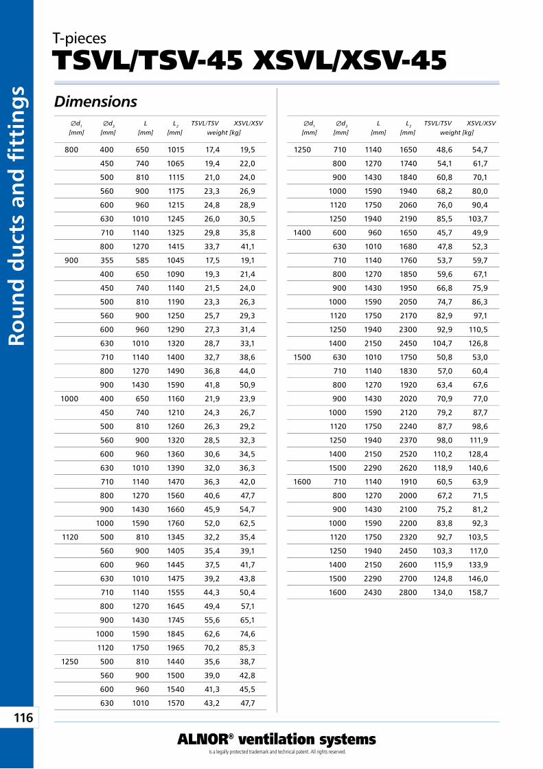
116
ALNOR® ventilation systemsis a legally protected trademark and technical patent. All rights reserved.
Rou
nd
du
cts
and
fi t
tin
gs
Download WentyleDownload AlnorCAM
Buy via B2B
T-pieces
TSVL/TSV-45 XSVL/XSV-45Dimensions Æd1 Æd3 L L2 TSVL/TSV XSVL/XSV [mm] [mm] [mm] [mm] weight [kg]
Æd1 Æd3 L L2 TSVL/TSV XSVL/XSV [mm] [mm] [mm] [mm] weight [kg]
800 400 650 1015 17,4 19,5
450 740 1065 19,4 22,0
500 810 1115 21,0 24,0
560 900 1175 23,3 26,9
600 960 1215 24,8 28,9
630 1010 1245 26,0 30,5
710 1140 1325 29,8 35,8
800 1270 1415 33,7 41,1
900 355 585 1045 17,5 19,1
400 650 1090 19,3 21,4
450 740 1140 21,5 24,0
500 810 1190 23,3 26,3
560 900 1250 25,7 29,3
600 960 1290 27,3 31,4
630 1010 1320 28,7 33,1
710 1140 1400 32,7 38,6
800 1270 1490 36,8 44,0
900 1430 1590 41,8 50,9
1000 400 650 1160 21,9 23,9
450 740 1210 24,3 26,7
500 810 1260 26,3 29,2
560 900 1320 28,5 32,3
600 960 1360 30,6 34,5
630 1010 1390 32,0 36,3
710 1140 1470 36,3 42,0
800 1270 1560 40,6 47,7
900 1430 1660 45,9 54,7
1000 1590 1760 52,0 62,5
1120 500 810 1345 32,2 35,4
560 900 1405 35,4 39,1
600 960 1445 37,5 41,7
630 1010 1475 39,2 43,8
710 1140 1555 44,3 50,4
800 1270 1645 49,4 57,1
900 1430 1745 55,6 65,1
1000 1590 1845 62,6 74,6
1120 1750 1965 70,2 85,3
1250 500 810 1440 35,6 38,7
560 900 1500 39,0 42,8
600 960 1540 41,3 45,5
630 1010 1570 43,2 47,7
1250 710 1140 1650 48,6 54,7
800 1270 1740 54,1 61,7
900 1430 1840 60,8 70,1
1000 1590 1940 68,2 80,0
1120 1750 2060 76,0 90,4
1250 1940 2190 85,5 103,7
1400 600 960 1650 45,7 49,9
630 1010 1680 47,8 52,3
710 1140 1760 53,7 59,7
800 1270 1850 59,6 67,1
900 1430 1950 66,8 75,9
1000 1590 2050 74,7 86,3
1120 1750 2170 82,9 97,1
1250 1940 2300 92,9 110,5
1400 2150 2450 104,7 126,8
1500 630 1010 1750 50,8 53,0
710 1140 1830 57,0 60,4
800 1270 1920 63,4 67,6
900 1430 2020 70,9 77,0
1000 1590 2120 79,2 87,7
1120 1750 2240 87,7 98,6
1250 1940 2370 98,0 111,9
1400 2150 2520 110,2 128,4
1500 2290 2620 118,9 140,6
1600 710 1140 1910 60,5 63,9
800 1270 2000 67,2 71,5
900 1430 2100 75,2 81,2
1000 1590 2200 83,8 92,3
1120 1750 2320 92,7 103,5
1250 1940 2450 103,3 117,0
1400 2150 2600 115,9 133,9
1500 2290 2700 124,8 146,0
1600 2430 2800 134,0 158,7
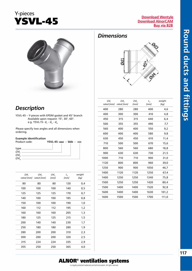
117
ALNOR® ventilation systemsis a legally protected trademark and technical patent. All rights reserved.
Rou
nd
du
cts and
fi tting
sDownload Wentyle
Download AlnorCAMBuy via B2B
Y-pieces
YSVL-45Dimensions
DescriptionYSVL-45 – Y-pieces with EPDM gasket and 45° branch
Available upon request: 15°, 30°, 60°.e.g. YSVL-15- d1 - d3 - d4
Please specify two angles and all dimensions when ordering.
Example identificationProduct code: YSVL-45 - aaa - bbb - ccc
typeÆd1Æd3Æd4
Æd1 Æd3 Æd4 L2 weight rated [mm] rated [mm] [mm] [mm] [kg]
Æd1 Æd3 Æd4 L2 weight rated [mm] rated [mm] [mm] [mm] [kg]
400 280 280 400 4,6
400 300 300 410 4,8
450 315 315 440 6,4
500 355 355 490 7,7
560 400 400 550 9,2
600 400 400 580 9,8
630 450 450 610 11,4
710 500 500 670 15,6
800 560 560 680 18,8
900 630 630 730 21,5
1000 710 710 900 31,0
1120 800 800 960 39,0
1250 900 900 1050 46,7
1400 1120 1120 1250 67,4
1400 1250 1250 1340 75,8
1500 1250 1250 1420 80,4
1500 1400 1400 1520 92,8
1600 1400 1400 1630 101,2
1600 1500 1500 1700 111,0
80 80 80 120 0,4
100 100 100 140 0,5
125 125 125 170 0,7
140 100 100 185 0,8
150 100 100 190 1,0
160 112 112 195 1,2
160 160 160 205 1,3
180 125 125 215 1,5
200 140 140 230 1,7
250 180 180 280 1,9
280 200 200 310 2,3
300 200 200 320 2,5
315 224 224 335 2,9
355 250 250 365 4,0
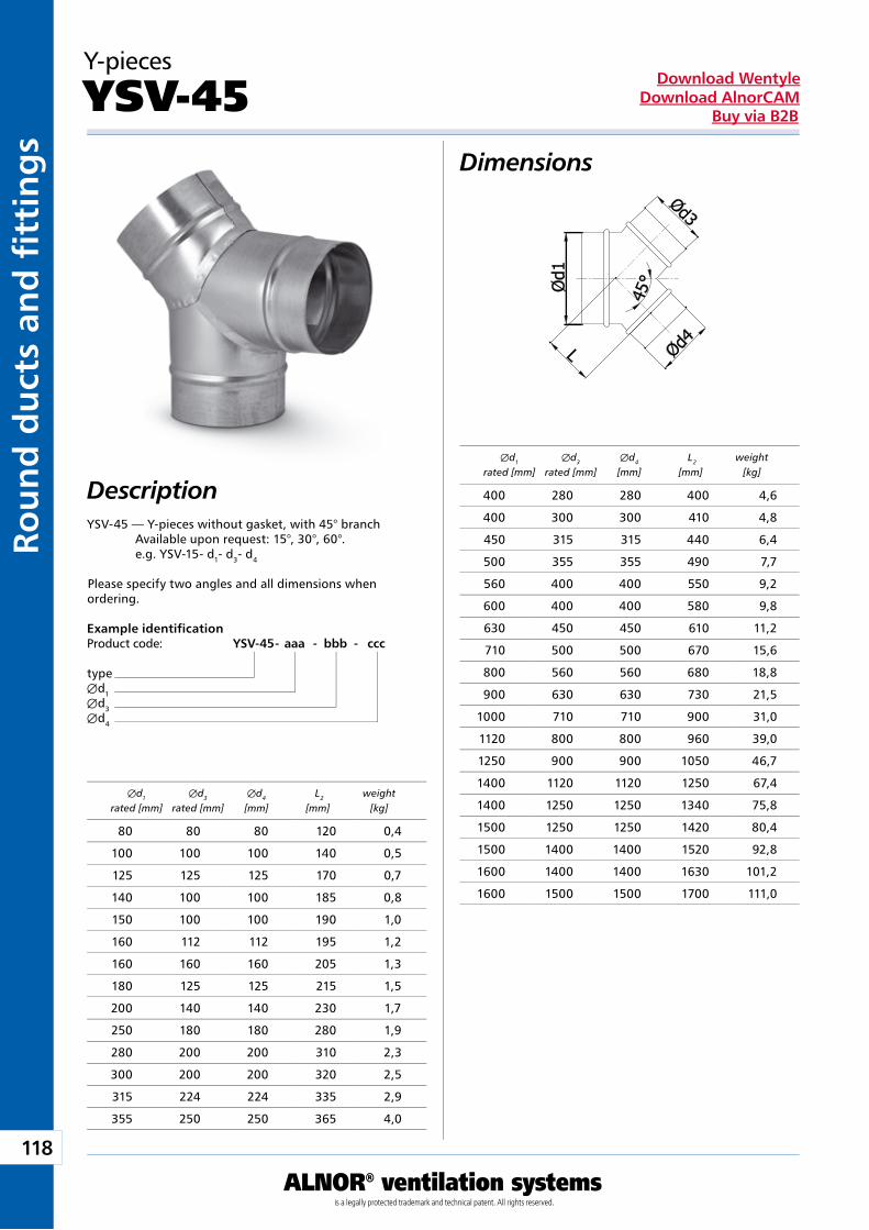
118
ALNOR® ventilation systemsis a legally protected trademark and technical patent. All rights reserved.
Rou
nd
du
cts
and
fi t
tin
gs
Download WentyleDownload AlnorCAM
Buy via B2B
Y-pieces
YSV-45Dimensions
DescriptionYSV-45 — Y-pieces without gasket, with 45° branch
Available upon request: 15°, 30°, 60°. e.g. YSV-15- d1- d3- d4
Please specify two angles and all dimensions when ordering.
Example identificationProduct code: YSV-45 - aaa - bbb - ccc
typeÆd1Æd3Æd4
Æd1 Æd3 Æd4 L2 weight rated [mm] rated [mm] [mm] [mm] [kg]
Æd1 Æd3 Æd4 L2 weight rated [mm] rated [mm] [mm] [mm] [kg]
400 280 280 400 4,6
400 300 300 410 4,8
450 315 315 440 6,4
500 355 355 490 7,7
560 400 400 550 9,2
600 400 400 580 9,8
630 450 450 610 11,2
710 500 500 670 15,6
800 560 560 680 18,8
900 630 630 730 21,5
1000 710 710 900 31,0
1120 800 800 960 39,0
1250 900 900 1050 46,7
1400 1120 1120 1250 67,4
1400 1250 1250 1340 75,8
1500 1250 1250 1420 80,4
1500 1400 1400 1520 92,8
1600 1400 1400 1630 101,2
1600 1500 1500 1700 111,0
80 80 80 120 0,4
100 100 100 140 0,5
125 125 125 170 0,7
140 100 100 185 0,8
150 100 100 190 1,0
160 112 112 195 1,2
160 160 160 205 1,3
180 125 125 215 1,5
200 140 140 230 1,7
250 180 180 280 1,9
280 200 200 310 2,3
300 200 200 320 2,5
315 224 224 335 2,9
355 250 250 365 4,0
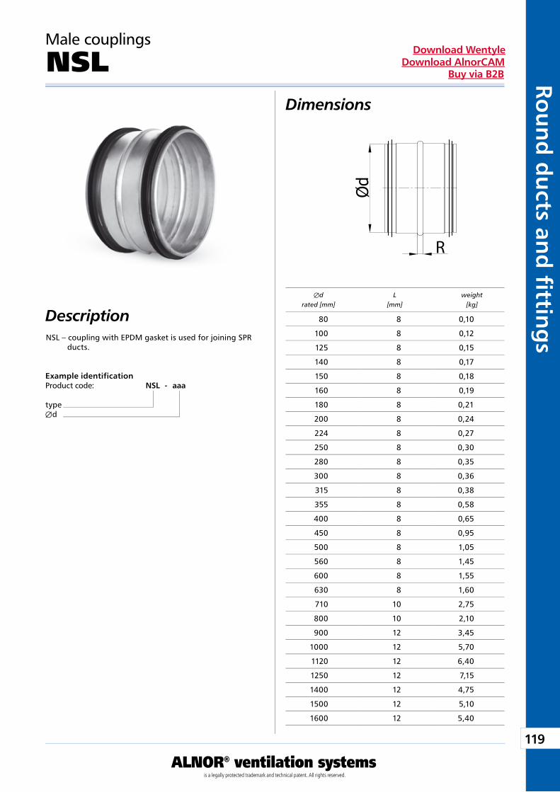
119
ALNOR® ventilation systemsis a legally protected trademark and technical patent. All rights reserved.
Rou
nd
du
cts and
fi tting
sDownload Wentyle
Download AlnorCAMBuy via B2B
R
Male couplings
NSL
Description
Dimensions
NSL – coupling with EPDM gasket is used for joining SPR ducts.
Example identificationProduct code: NSL - aaa
typeÆd
Æd L weight rated [mm] [mm] [kg]
80 8 0,10
100 8 0,12
125 8 0,15
140 8 0,17
150 8 0,18
160 8 0,19
180 8 0,21
200 8 0,24
224 8 0,27
250 8 0,30
280 8 0,35
300 8 0,36
315 8 0,38
355 8 0,58
400 8 0,65
450 8 0,95
500 8 1,05
560 8 1,45
600 8 1,55
630 8 1,60
710 10 2,75
800 10 2,10
900 12 3,45
1000 12 5,70
1120 12 6,40
1250 12 7,15
1400 12 4,75
1500 12 5,10
1600 12 5,40
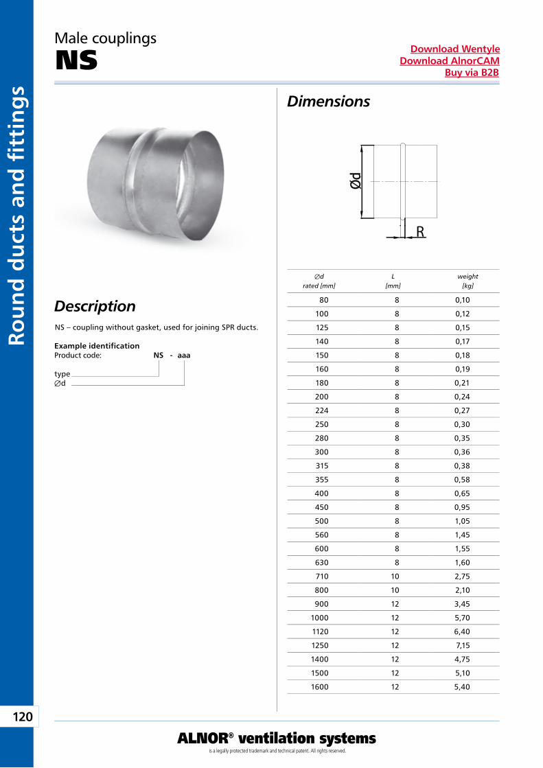
120
ALNOR® ventilation systemsis a legally protected trademark and technical patent. All rights reserved.
Rou
nd
du
cts
and
fi t
tin
gs
Download WentyleDownload AlnorCAM
Buy via B2B
R
Male couplings
NS
Description
Dimensions
NS – coupling without gasket, used for joining SPR ducts.
Example identificationProduct code: NS - aaa
typeÆd
Æd L weight rated [mm] [mm] [kg]
80 8 0,10
100 8 0,12
125 8 0,15
140 8 0,17
150 8 0,18
160 8 0,19
180 8 0,21
200 8 0,24
224 8 0,27
250 8 0,30
280 8 0,35
300 8 0,36
315 8 0,38
355 8 0,58
400 8 0,65
450 8 0,95
500 8 1,05
560 8 1,45
600 8 1,55
630 8 1,60
710 10 2,75
800 10 2,10
900 12 3,45
1000 12 5,70
1120 12 6,40
1250 12 7,15
1400 12 4,75
1500 12 5,10
1600 12 5,40
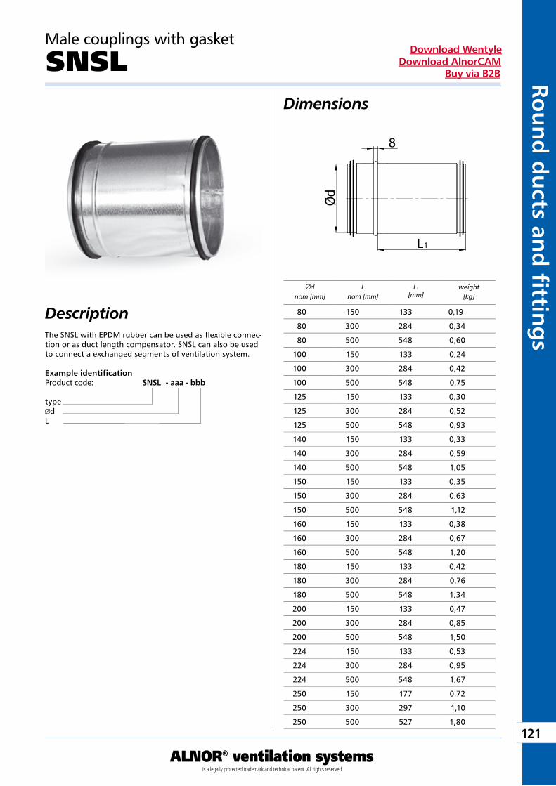
121
ALNOR® ventilation systemsis a legally protected trademark and technical patent. All rights reserved.
Rou
nd
du
cts and
fi tting
sDownload Wentyle
Download AlnorCAMBuy via B2B
L
8
1
Male couplings with gasket
SNSL
Description
Dimensions
The SNSL with EPDM rubber can be used as flexible connec-tion or as duct length compensator. SNSL can also be used to connect a exchanged segments of ventilation system.
dnom [mm]
Lnom [mm]
L1
[mm]weight
[kg]
Example identificationProduct code: SNSL - aaa - bbb
typed
L
80 150 133 0,19
80 300 284 0,34
80 500 548 0,60
100 150 133 0,24
100 300 284 0,42
100 500 548 0,75
125 150 133 0,30
125 300 284 0,52
125 500 548 0,93
140 150 133 0,33
140 300 284 0,59
140 500 548 1,05
150 150 133 0,35
150 300 284 0,63
150 500 548 1,12
160 150 133 0,38
160 300 284 0,67
160 500 548 1,20
180 150 133 0,42
180 300 284 0,76
180 500 548 1,34
200 150 133 0,47
200 300 284 0,85
200 500 548 1,50
224 150 133 0,53
224 300 284 0,95
224 500 548 1,67
250 150 177 0,72
250 300 297 1,10
250 500 527 1,80
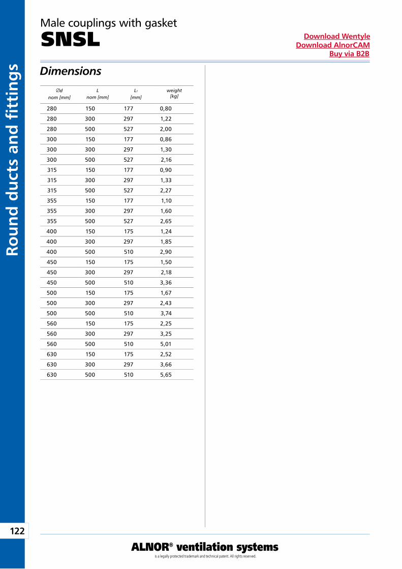
122
ALNOR® ventilation systemsis a legally protected trademark and technical patent. All rights reserved.
Rou
nd
du
cts
and
fi t
tin
gs
Download WentyleDownload AlnorCAM
Buy via B2B
Male couplings with gasket
SNSLDimensions
dnom [mm]
Lnom [mm]
L1
[mm]weight
[kg]
280 150 177 0,80
280 300 297 1,22
280 500 527 2,00
300 150 177 0,86
300 300 297 1,30
300 500 527 2,16
315 150 177 0,90
315 300 297 1,33
315 500 527 2,27
355 150 177 1,10
355 300 297 1,60
355 500 527 2,65
400 150 175 1,24
400 300 297 1,85
400 500 510 2,90
450 150 175 1,50
450 300 297 2,18
450 500 510 3,36
500 150 175 1,67
500 300 297 2,43
500 500 510 3,74
560 150 175 2,25
560 300 297 3,25
560 500 510 5,01
630 150 175 2,52
630 300 297 3,66
630 500 510 5,65
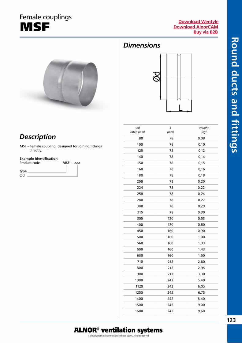
123
ALNOR® ventilation systemsis a legally protected trademark and technical patent. All rights reserved.
Rou
nd
du
cts and
fi tting
sDownload Wentyle
Download AlnorCAMBuy via B2B
Female couplings
MSF
Description
Dimensions
MSF – female coupling, designed for joining fittings directly.
Example identificationProduct code: MSF - aaa
typeÆd
Æd L weight rated [mm] [mm] [kg]
80 78 0,08
100 78 0,10
125 78 0,12
140 78 0,14
150 78 0,15
160 78 0,16
180 78 0,18
200 78 0,20
224 78 0,22
250 78 0,24
280 78 0,27
300 78 0,29
315 78 0,30
355 120 0,53
400 120 0,60
450 160 0,90
500 160 1,00
560 160 1,33
600 160 1,43
630 160 1,50
710 212 2,60
800 212 2,95
900 212 3,30
1000 242 5,40
1120 242 6,05
1250 242 6,75
1400 242 8,40
1500 242 9,00
1600 242 9,60
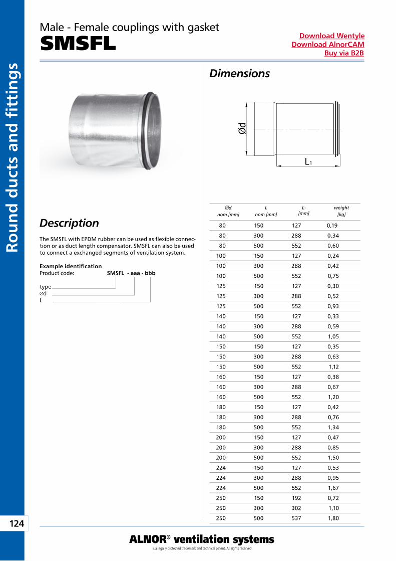
124
ALNOR® ventilation systemsis a legally protected trademark and technical patent. All rights reserved.
Rou
nd
du
cts
and
fi t
tin
gs
Download WentyleDownload AlnorCAM
Buy via B2B
L1
Male - Female couplings with gasket
SMSFL
Description
Dimensions
Example identificationProduct code: SMSFL - aaa - bbb
typed
L
The SMSFL with EPDM rubber can be used as flexible connec-tion or as duct length compensator. SMSFL can also be used to connect a exchanged segments of ventilation system.
dnom [mm]
Lnom [mm]
L1
[mm]weight
[kg]
80 150 127 0,19
80 300 288 0,34
80 500 552 0,60
100 150 127 0,24
100 300 288 0,42
100 500 552 0,75
125 150 127 0,30
125 300 288 0,52
125 500 552 0,93
140 150 127 0,33
140 300 288 0,59
140 500 552 1,05
150 150 127 0,35
150 300 288 0,63
150 500 552 1,12
160 150 127 0,38
160 300 288 0,67
160 500 552 1,20
180 150 127 0,42
180 300 288 0,76
180 500 552 1,34
200 150 127 0,47
200 300 288 0,85
200 500 552 1,50
224 150 127 0,53
224 300 288 0,95
224 500 552 1,67
250 150 192 0,72
250 300 302 1,10
250 500 537 1,80
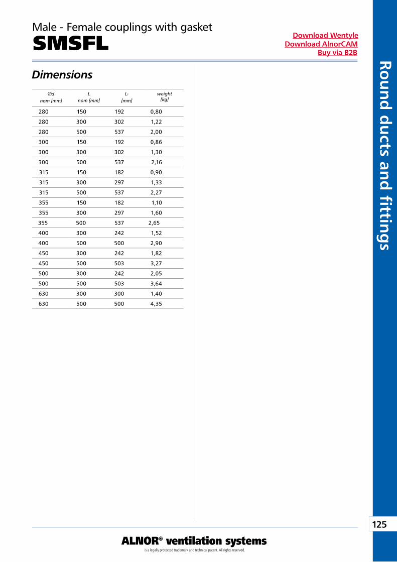
125
ALNOR® ventilation systemsis a legally protected trademark and technical patent. All rights reserved.
Rou
nd
du
cts and
fi tting
sDownload Wentyle
Download AlnorCAMBuy via B2B
Male - Female couplings with gasket
SMSFLDimensions
dnom [mm]
Lnom [mm]
L1
[mm]weight
[kg]
280 150 192 0,80
280 300 302 1,22
280 500 537 2,00
300 150 192 0,86
300 300 302 1,30
300 500 537 2,16
315 150 182 0,90
315 300 297 1,33
315 500 537 2,27
355 150 182 1,10
355 300 297 1,60
355 500 537 2,65
400 300 242 1,52
400 500 500 2,90
450 300 242 1,82
450 500 503 3,27
500 300 242 2,05
500 500 503 3,64
630 300 300 1,40
630 500 500 4,35
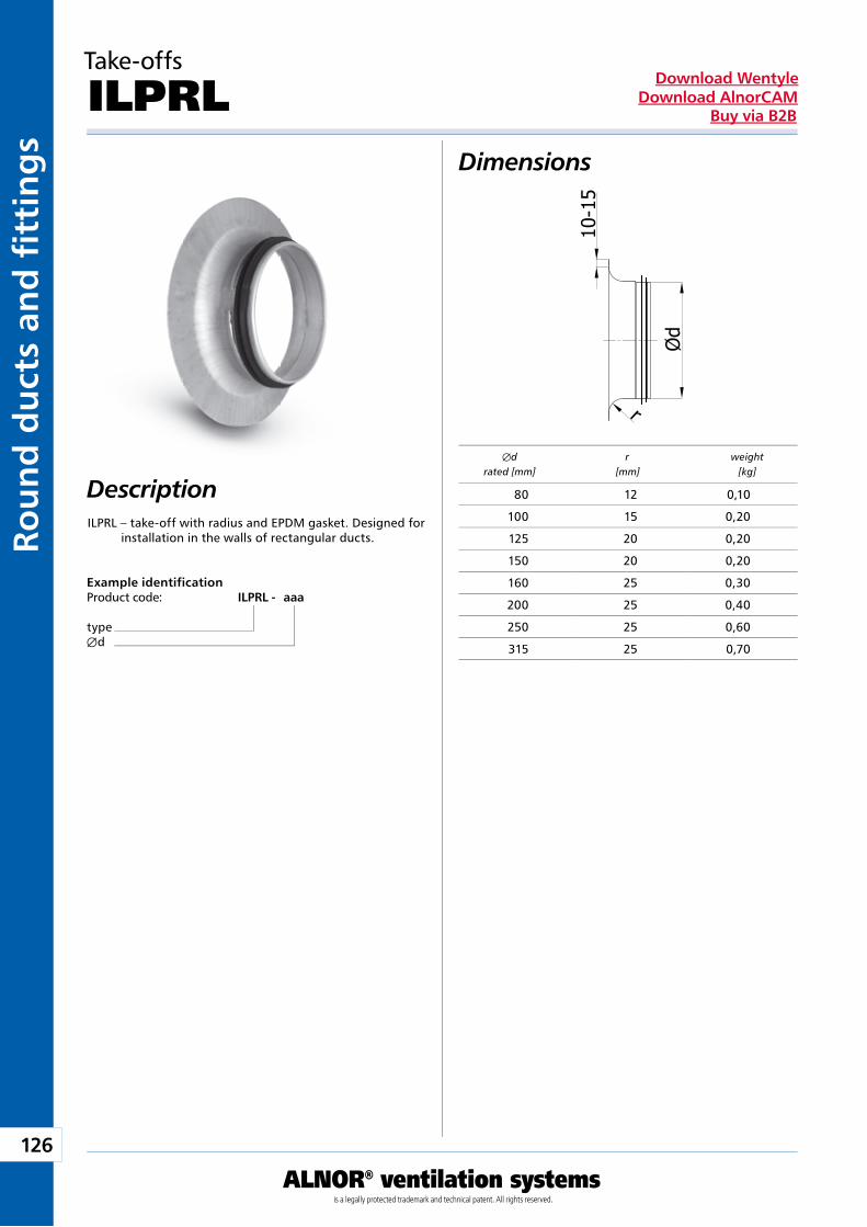
126
ALNOR® ventilation systemsis a legally protected trademark and technical patent. All rights reserved.
Rou
nd
du
cts
and
fi t
tin
gs
Download WentyleDownload AlnorCAM
Buy via B2B
Take-offs
ILPRL
Description
Dimensions
ILPRL – take-off with radius and EPDM gasket. Designed for installation in the walls of rectangular ducts.
Example identificationProduct code: ILPRL - aaa
typeÆd
Æd r weight rated [mm] [mm] [kg]
80 12 0,10
100 15 0,20
125 20 0,20
150 20 0,20
160 25 0,30
200 25 0,40
250 25 0,60
315 25 0,70
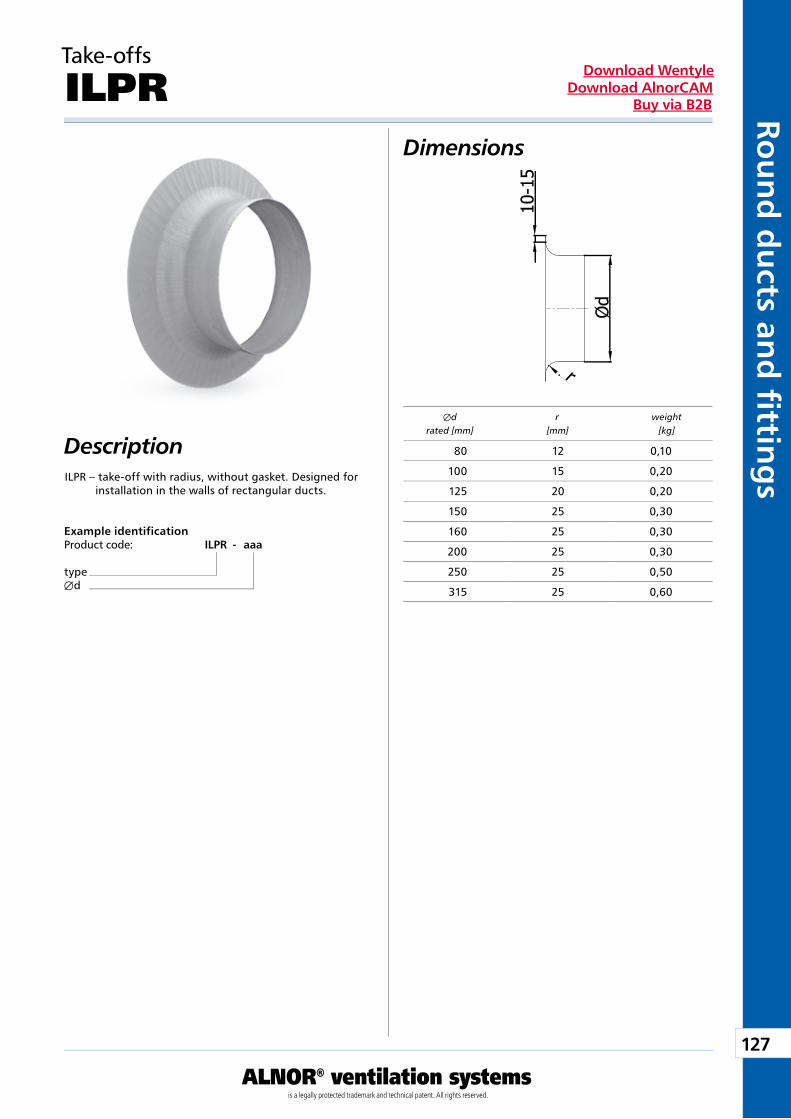
127
ALNOR® ventilation systemsis a legally protected trademark and technical patent. All rights reserved.
Rou
nd
du
cts and
fi tting
sDownload Wentyle
Download AlnorCAMBuy via B2B
Take-offs
ILPR
Description
Dimensions
ILPR – take-off with radius, without gasket. Designed for installation in the walls of rectangular ducts.
Example identificationProduct code: ILPR - aaa
typeÆd
Æd r weight rated [mm] [mm] [kg]
80 12 0,10
100 15 0,20
125 20 0,20
150 25 0,30
160 25 0,30
200 25 0,30
250 25 0,50
315 25 0,60
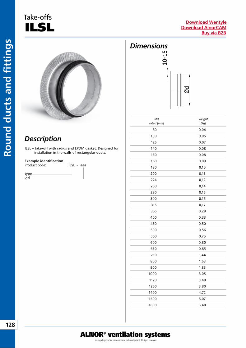
128
ALNOR® ventilation systemsis a legally protected trademark and technical patent. All rights reserved.
Rou
nd
du
cts
and
fi t
tin
gs
Download WentyleDownload AlnorCAM
Buy via B2B
Take-offs
ILSL
Description
Dimensions
ILSL – take-off with radius and EPDM gasket. Designed for installation in the walls of rectangular ducts.
Example identificationProduct code: ILSL - aaa
typeÆd
Æd weight rated [mm] [kg]
80 0,04
100 0,05
125 0,07
140 0,08
150 0,08
160 0,09
180 0,10
200 0,11
224 0,12
250 0,14
280 0,15
300 0,16
315 0,17
355 0,29
400 0,33
450 0,50
500 0,56
560 0,75
600 0,80
630 0,85
710 1,44
800 1,63
900 1,83
1000 3,05
1120 3,40
1250 3,80
1400 4,72
1500 5,07
1600 5,40
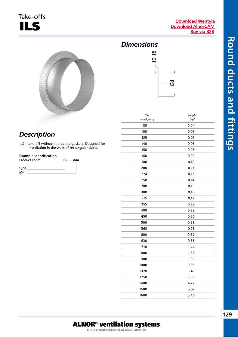
129
ALNOR® ventilation systemsis a legally protected trademark and technical patent. All rights reserved.
Rou
nd
du
cts and
fi tting
sDownload Wentyle
Download AlnorCAMBuy via B2B
Take-offs
ILS
Description
Dimensions
ILS – take-off without radius and gaskets. Designed for installation in the walls of rectangular ducts.
Example identificationProduct code: ILS - aaa
typeÆd
Æd weight rated [mm] [kg]
80 0,04
100 0,05
125 0,07
140 0,08
150 0,08
160 0,09
180 0,10
200 0,11
224 0,12
250 0,14
280 0,15
300 0,16
315 0,17
355 0,29
400 0,33
450 0,50
500 0,56
560 0,75
600 0,80
630 0,85
710 1,44
800 1,63
900 1,83
1000 3,05
1120 3,40
1250 3,80
1400 4,72
1500 5,07
1600 5,40
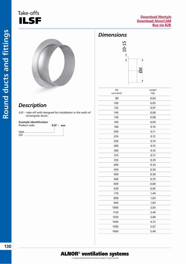
130
ALNOR® ventilation systemsis a legally protected trademark and technical patent. All rights reserved.
Rou
nd
du
cts
and
fi t
tin
gs
Download WentyleDownload AlnorCAM
Buy via B2B
Dimensions
ILSF – take-off with designed for installation in the walls of rectangular ducts.
Example identificationProduct code: ILSF - aaa
typeÆd
Take-offs
ILSF
Description
dnom [mm]
weight[kg]
80 0,04
100 0,05
125 0,07
140 0,08
150 0,08
160 0,09
180 0,10
200 0,11
224 0,12
250 0,14
280 0,15
300 0,16
315 0,17
355 0,29
400 0,33
450 0,50
500 0,56
560 0,75
600 0,80
630 0,85
710 1,44
800 1,63
900 1,83
1000 3,05
1120 3,40
1250 3,80
1400 4,72
1500 5,07
1600 5,40
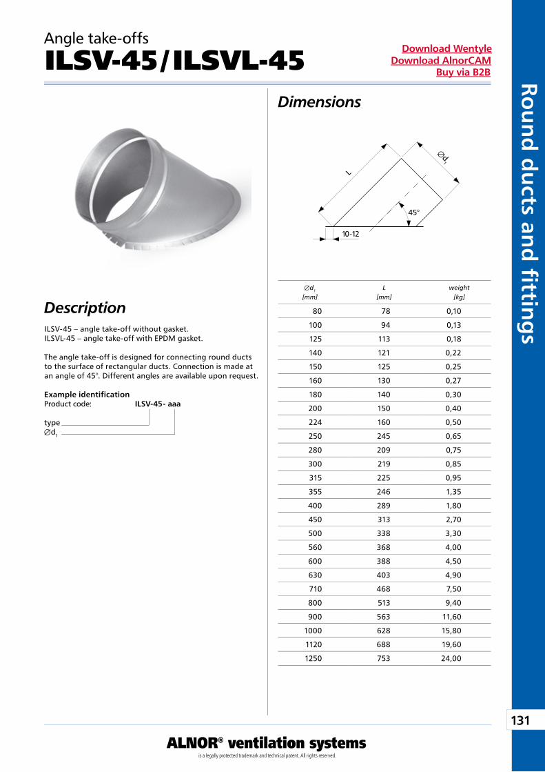
131
ALNOR® ventilation systemsis a legally protected trademark and technical patent. All rights reserved.
Rou
nd
du
cts and
fi tting
sDownload Wentyle
Download AlnorCAMBuy via B2B
Æd1
L
10-12
45°
Angle take-offs
ILSV-45 / ILSVL-45
Description
Dimensions
ILSV-45 – angle take-off without gasket.ILSVL-45 – angle take-off with EPDM gasket.
The angle take-off is designed for connecting round ducts to the surface of rectangular ducts. Connection is made at an angle of 45°. Different angles are available upon request.
Example identificationProduct code: ILSV-45 - aaa
typeÆd1
Æd1 L weight [mm] [mm] [kg]
80 78 0,10
100 94 0,13
125 113 0,18
140 121 0,22
150 125 0,25
160 130 0,27
180 140 0,30
200 150 0,40
224 160 0,50
250 245 0,65
280 209 0,75
300 219 0,85
315 225 0,95
355 246 1,35
400 289 1,80
450 313 2,70
500 338 3,30
560 368 4,00
600 388 4,50
630 403 4,90
710 468 7,50
800 513 9,40
900 563 11,60
1000 628 15,80
1120 688 19,60
1250 753 24,00
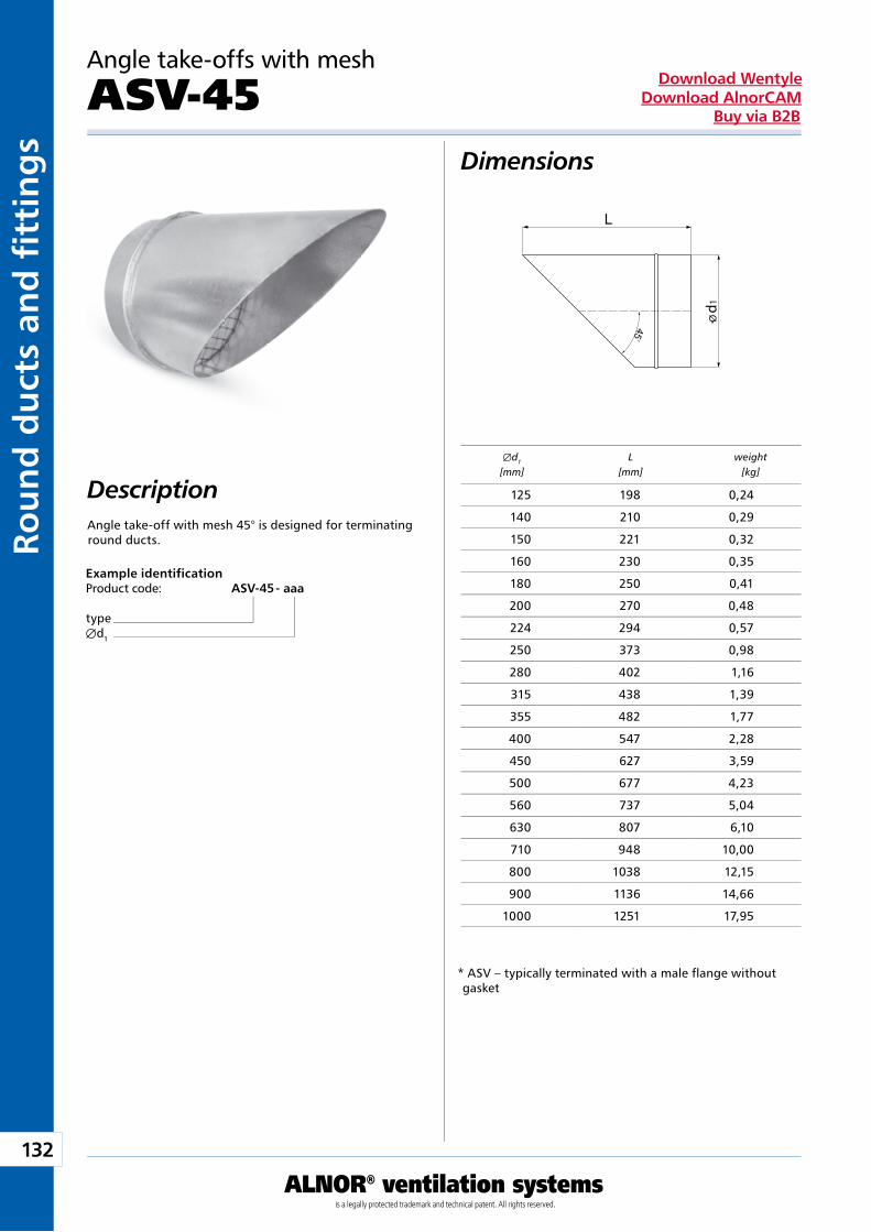
132
ALNOR® ventilation systemsis a legally protected trademark and technical patent. All rights reserved.
Rou
nd
du
cts
and
fi t
tin
gs
Download WentyleDownload AlnorCAM
Buy via B2B
d 1
Angle take-offs with mesh
ASV-45
Description
Dimensions
Angle take-off with mesh 45° is designed for terminating round ducts.
Example identificationProduct code: ASV-45 - aaa
typeÆd1
* ASV – typically terminated with a male flange without gasket
Æd1 L weight [mm] [mm] [kg]
125 198 0,24
140 210 0,29
150 221 0,32
160 230 0,35
180 250 0,41
200 270 0,48
224 294 0,57
250 373 0,98
280 402 1,16
315 438 1,39
355 482 1,77
400 547 2,28
450 627 3,59
500 677 4,23
560 737 5,04
630 807 6,10
710 948 10,00
800 1038 12,15
900 1136 14,66
1000 1251 17,95
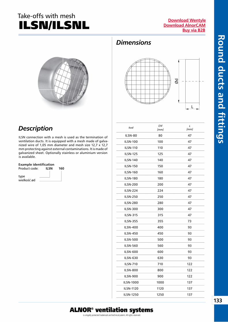
133
ALNOR® ventilation systemsis a legally protected trademark and technical patent. All rights reserved.
Rou
nd
du
cts and
fi tting
sDownload Wentyle
Download AlnorCAMBuy via B2B
Take-offs with mesh
ILSN/ILSNLDimensions
DescriptionILSN connection with a mesh is used as the termination of ventilation ducts. It is equipped with a mesh made of galva-nized wire of 1,05 mm diameter and mesh size 12,7 x 12,7 mm protecting against external contaminations. It is made of galvanized sheet. Optionally stainless or aluminium version is available.
Example identificationProduct code: ILSN 160
typewielkość ød
L
Ød
kodÆd
[mm] L
[mm]
ILSN-80 80 47
ILSN-100 100 47
ILSN-110 110 47
ILSN-125 125 47
ILSN-140 140 47
ILSN-150 150 47
ILSN-160 160 47
ILSN-180 180 47
ILSN-200 200 47
ILSN-224 224 47
ILSN-250 250 47
ILSN-280 280 47
ILSN-300 300 47
ILSN-315 315 47
ILSN-355 355 73
ILSN-400 400 93
ILSN-450 450 93
ILSN-500 500 93
ILSN-560 560 93
ILSN-600 600 93
ILSN-630 630 93
ILSN-710 710 122
ILSN-800 800 122
ILSN-900 900 122
ILSN-1000 1000 137
ILSN-1120 1120 137
ILSN-1250 1250 137
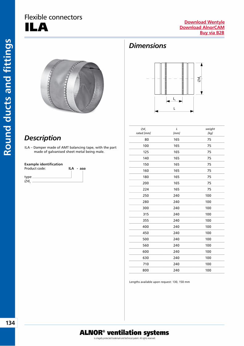
134
ALNOR® ventilation systemsis a legally protected trademark and technical patent. All rights reserved.
Rou
nd
du
cts
and
fi t
tin
gs
Download WentyleDownload AlnorCAM
Buy via B2B
L1
L
Æd 1
Flexible connectors
ILA
Description
Dimensions
ILA – Damper made of AMT balancing tape, with the part made of galvanised sheet metal being male.
Example identificationProduct code: ILA - aaa
typeÆd1
Lengths available upon request: 130, 150 mm
Æd1 L weight rated [mm] [mm] [kg]
80 165 75
100 165 75
125 165 75
140 165 75
150 165 75
160 165 75
180 165 75
200 165 75
224 165 75
250 240 100
280 240 100
300 240 100
315 240 100
355 240 100
400 240 100
450 240 100
500 240 100
560 240 100
600 240 100
630 240 100
710 240 100
800 240 100
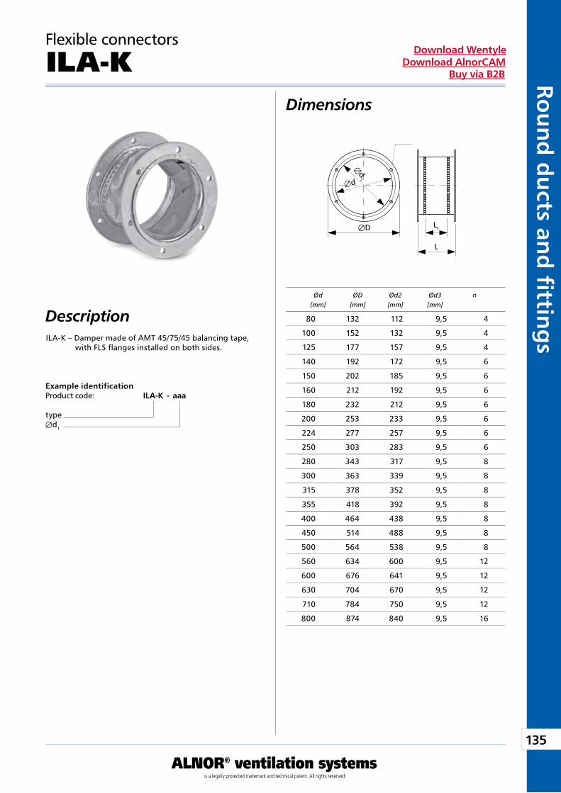
135
ALNOR® ventilation systemsis a legally protected trademark and technical patent. All rights reserved.
Rou
nd
du
cts and
fi tting
sDownload Wentyle
Download AlnorCAMBuy via B2B
L1
L
Æd1
Æd
ÆD
Flexible connectors
ILA-K
Description
Dimensions
ILA-K – Damper made of AMT 45/75/45 balancing tape, with FLS flanges installed on both sides.
Example identificationProduct code: ILA-K - aaa
typeÆd1
Ød ØD Ød2 Ød3 n [mm] [mm] [mm] [mm]
80 132 112 9,5 4
100 152 132 9,5 4
125 177 157 9,5 4
140 192 172 9,5 6
150 202 185 9,5 6
160 212 192 9,5 6
180 232 212 9,5 6
200 253 233 9,5 6
224 277 257 9,5 6
250 303 283 9,5 6
280 343 317 9,5 8
300 363 339 9,5 8
315 378 352 9,5 8
355 418 392 9,5 8
400 464 438 9,5 8
450 514 488 9,5 8
500 564 538 9,5 8
560 634 600 9,5 12
600 676 641 9,5 12
630 704 670 9,5 12
710 784 750 9,5 12
800 874 840 9,5 16
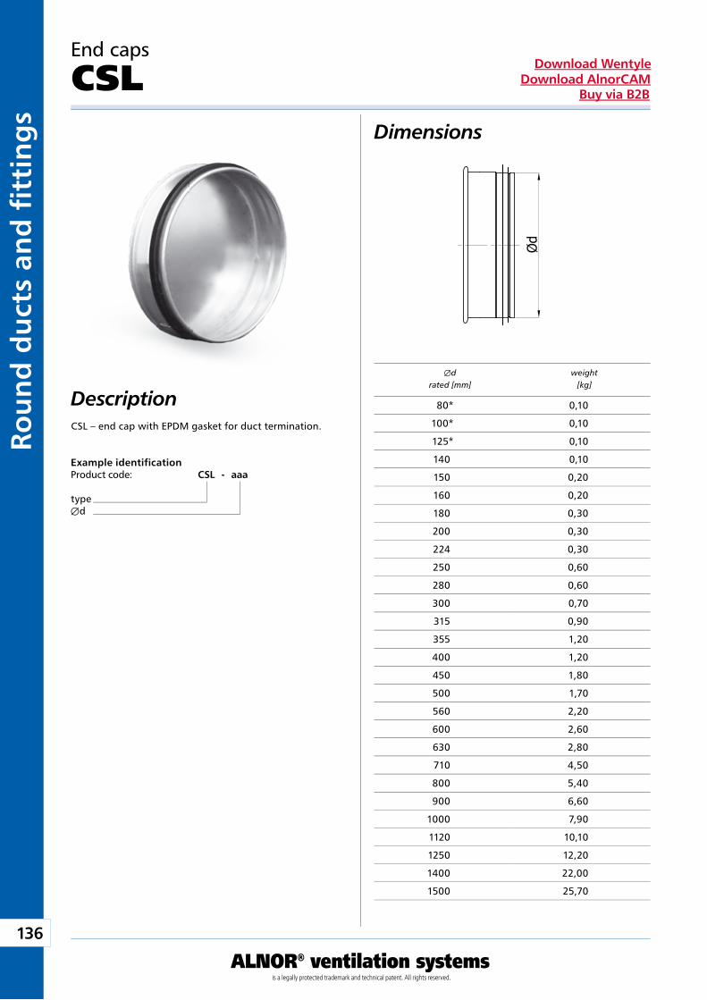
136
ALNOR® ventilation systemsis a legally protected trademark and technical patent. All rights reserved.
Rou
nd
du
cts
and
fi t
tin
gs
Download WentyleDownload AlnorCAM
Buy via B2B
End caps
CSL
Description
Dimensions
CSL – end cap with EPDM gasket for duct termination.
Example identificationProduct code: CSL - aaa
typeÆd
Æd weight rated [mm] [kg]
80* 0,10
100* 0,10
125* 0,10
140 0,10
150 0,20
160 0,20
180 0,30
200 0,30
224 0,30
250 0,60
280 0,60
300 0,70
315 0,90
355 1,20
400 1,20
450 1,80
500 1,70
560 2,20
600 2,60
630 2,80
710 4,50
800 5,40
900 6,60
1000 7,90
1120 10,10
1250 12,20
1400 22,00
1500 25,70
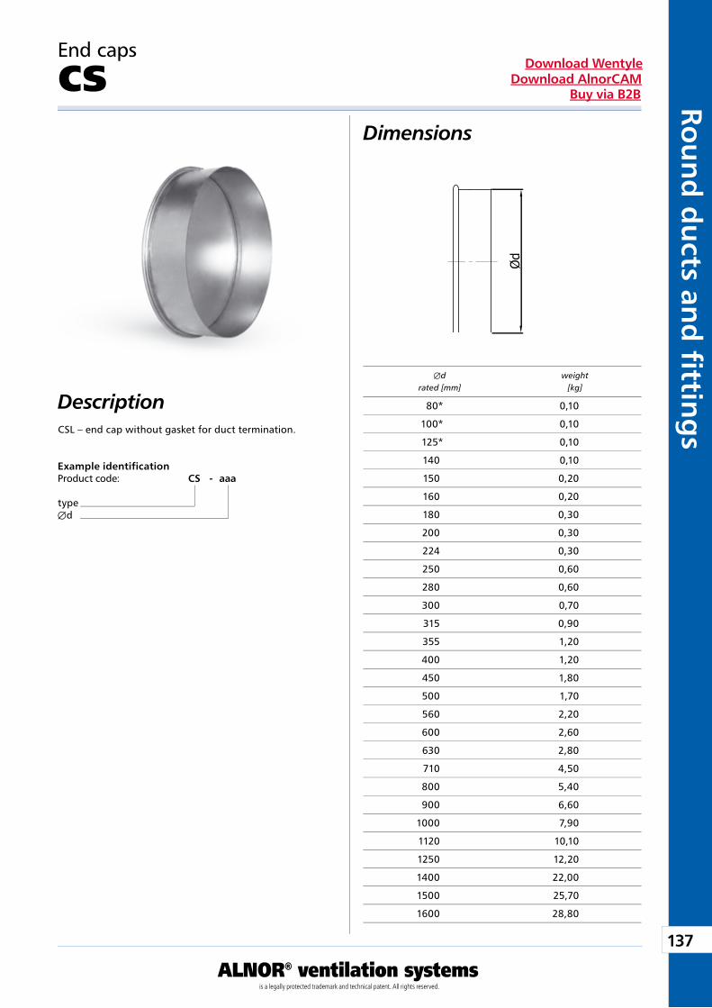
137
ALNOR® ventilation systemsis a legally protected trademark and technical patent. All rights reserved.
Rou
nd
du
cts and
fi tting
sDownload Wentyle
Download AlnorCAMBuy via B2B
End caps
CS
Description
Dimensions
CSL – end cap without gasket for duct termination.
Example identificationProduct code: CS - aaa
typeÆd
Æd weight rated [mm] [kg]
80* 0,10
100* 0,10
125* 0,10
140 0,10
150 0,20
160 0,20
180 0,30
200 0,30
224 0,30
250 0,60
280 0,60
300 0,70
315 0,90
355 1,20
400 1,20
450 1,80
500 1,70
560 2,20
600 2,60
630 2,80
710 4,50
800 5,40
900 6,60
1000 7,90
1120 10,10
1250 12,20
1400 22,00
1500 25,70
1600 28,80
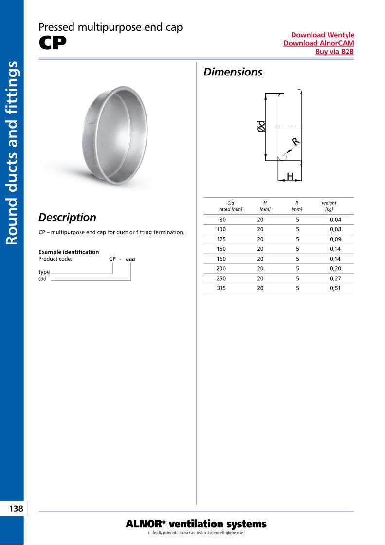
138
ALNOR® ventilation systemsis a legally protected trademark and technical patent. All rights reserved.
Rou
nd
du
cts
and
fi t
tin
gs
Download WentyleDownload AlnorCAM
Buy via B2B
Pressed multipurpose end cap
CP
Description
Dimensions
CP – multipurpose end cap for duct or fitting termination.
Example identificationProduct code: CP - aaa
typeÆd
Æd H R weight rated [mm] [mm] [mm] [kg]
80 20 5 0,04
100 20 5 0,08
125 20 5 0,09
150 20 5 0,14
160 20 5 0,14
200 20 5 0,20
250 20 5 0,27
315 20 5 0,51
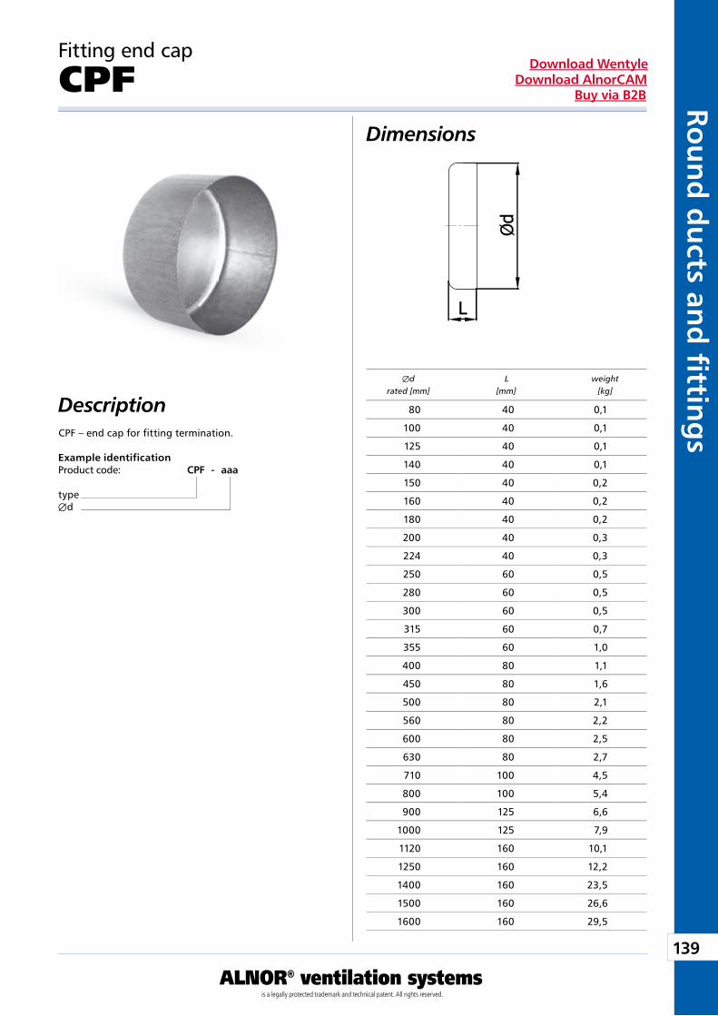
139
ALNOR® ventilation systemsis a legally protected trademark and technical patent. All rights reserved.
Rou
nd
du
cts and
fi tting
sDownload Wentyle
Download AlnorCAMBuy via B2B
Fitting end cap
CPF
Description
Dimensions
CPF – end cap for fitting termination.
Example identificationProduct code: CPF - aaa
typeÆd
Æd L weight rated [mm] [mm] [kg]
80 40 0,1
100 40 0,1
125 40 0,1
140 40 0,1
150 40 0,2
160 40 0,2
180 40 0,2
200 40 0,3
224 40 0,3
250 60 0,5
280 60 0,5
300 60 0,5
315 60 0,7
355 60 1,0
400 80 1,1
450 80 1,6
500 80 2,1
560 80 2,2
600 80 2,5
630 80 2,7
710 100 4,5
800 100 5,4
900 125 6,6
1000 125 7,9
1120 160 10,1
1250 160 12,2
1400 160 23,5
1500 160 26,6
1600 160 29,5
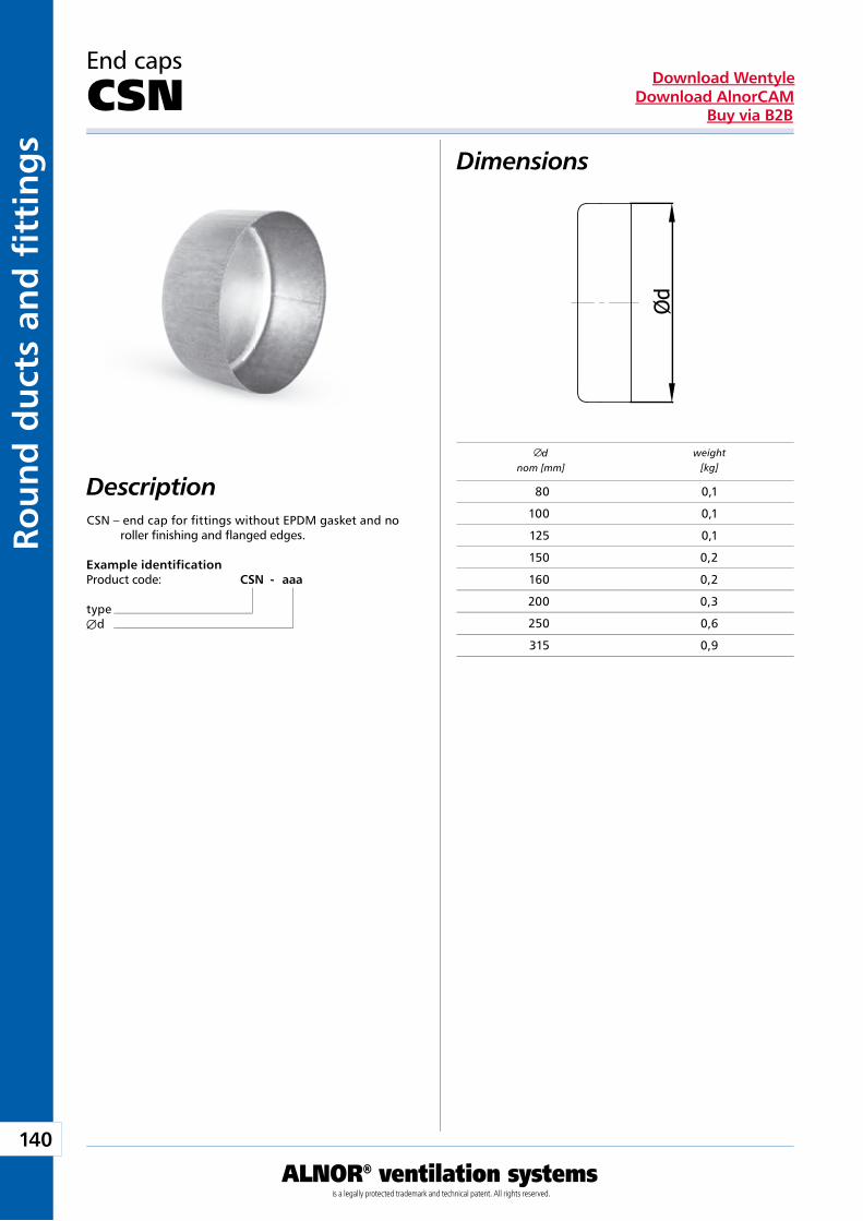
140
ALNOR® ventilation systemsis a legally protected trademark and technical patent. All rights reserved.
Rou
nd
du
cts
and
fi t
tin
gs
Download WentyleDownload AlnorCAM
Buy via B2B
Example identificationProduct code: CSN - aaa
typeÆd
End caps
CSN
Description
Dimensions
CSN – end cap for fittings without EPDM gasket and no roller finishing and flanged edges.
dnom [mm]
weight[kg]
80 0,1
100 0,1
125 0,1
150 0,2
160 0,2
200 0,3
250 0,6
315 0,9
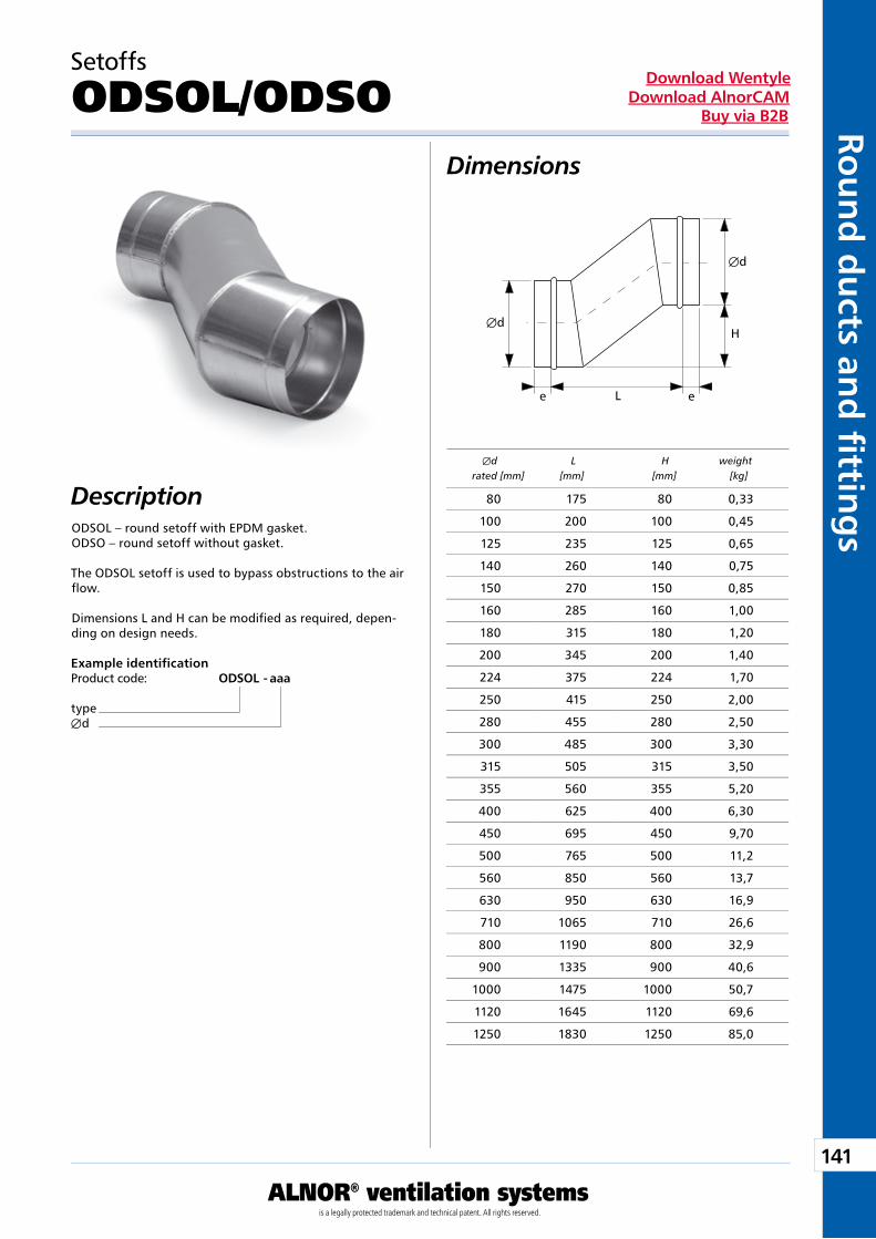
141
ALNOR® ventilation systemsis a legally protected trademark and technical patent. All rights reserved.
Rou
nd
du
cts and
fi tting
sDownload Wentyle
Download AlnorCAMBuy via B2B
Setoffs
ODSOL/ODSODimensions
DescriptionODSOL – round setoff with EPDM gasket.ODSO – round setoff without gasket.
The ODSOL setoff is used to bypass obstructions to the air flow.
Dimensions L and H can be modified as required, depen-ding on design needs.
Example identificationProduct code: ODSOL - aaa
typeÆd
Æd L H weight rated [mm] [mm] [mm] [kg]
Æd
e eL
Æd
H
80 175 80 0,33
100 200 100 0,45
125 235 125 0,65
140 260 140 0,75
150 270 150 0,85
160 285 160 1,00
180 315 180 1,20
200 345 200 1,40
224 375 224 1,70
250 415 250 2,00
280 455 280 2,50
300 485 300 3,30
315 505 315 3,50
355 560 355 5,20
400 625 400 6,30
450 695 450 9,70
500 765 500 11,2
560 850 560 13,7
630 950 630 16,9
710 1065 710 26,6
800 1190 800 32,9
900 1335 900 40,6
1000 1475 1000 50,7
1120 1645 1120 69,6
1250 1830 1250 85,0
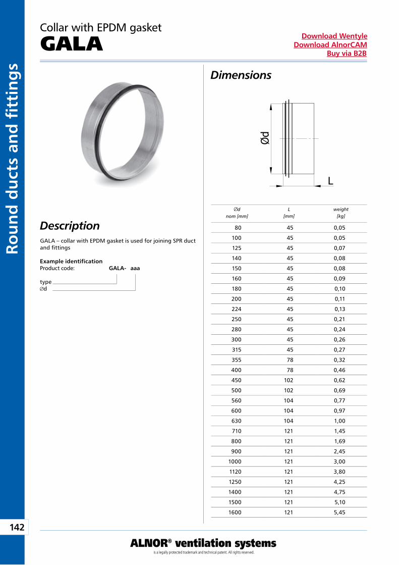
142
ALNOR® ventilation systemsis a legally protected trademark and technical patent. All rights reserved.
Rou
nd
du
cts
and
fi t
tin
gs
Download WentyleDownload AlnorCAM
Buy via B2B
Example identificationProduct code: GALA - aaa
typed
Collar with EPDM gasket
GALA
GALA – collar with EPDM gasket is used for joining SPR ductand fittings
dnom [mm]
L[mm]
weight[kg]
Dimensions
Description 80 45 0,05
100 45 0,05
125 45 0,07
140 45 0,08
150 45 0,08
160 45 0,09
180 45 0,10
200 45 0,11
224 45 0,13
250 45 0,21
280 45 0,24
300 45 0,26
315 45 0,27
355 78 0,32
400 78 0,46
450 102 0,62
500 102 0,69
560 104 0,77
600 104 0,97
630 104 1,00
710 121 1,45
800 121 1,69
900 121 2,45
1000 121 3,00
1120 121 3,80
1250 121 4,25
1400 121 4,75
1500 121 5,10
1600 121 5,45
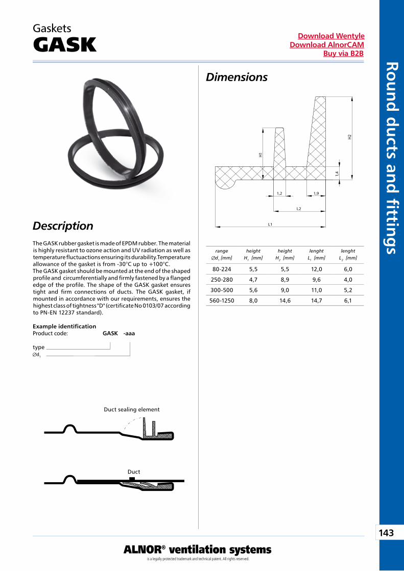
143
ALNOR® ventilation systemsis a legally protected trademark and technical patent. All rights reserved.
Rou
nd
du
cts and
fi tting
sDownload Wentyle
Download AlnorCAMBuy via B2B
Gaskets
GASK
The GASK rubber gasket is made of EPDM rubber. The material is highly resistant to ozone action and UV radiation as well as temperature fluctuactions ensuring its durability.Temperature allowance of the gasket is from -30°C up to +100°C.The GASK gasket should be mounted at the end of the shaped profile and circumferentially and firmly fastened by a flanged edge of the profile. The shape of the GASK gasket ensures tight and firm connections of ducts. The GASK gasket, if mounted in accordance with our requirements, ensures the highest class of tightness "D" (certificate No 0103/07 according to PN-EN 12237 standard).
Example identificationProduct code: GASK -aaa
typed1
Description
Dimensions
1,2
H2
1,9
L1
L2
1,4
H1
ranged1 [mm]
heightH1 [mm]
heightH2 [mm]
lenghtL1 [mm]
lenghtL2 [mm]
Duct sealing element
Duct
80-224 5,5 5,5 12,0 6,0
250-280 4,7 8,9 9,6 4,0
300-500 5,6 9,0 11,0 5,2
560-1250 8,0 14,6 14,7 6,1
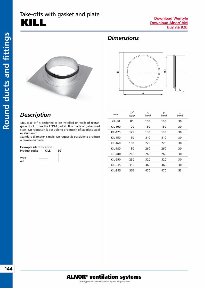
144
ALNOR® ventilation systemsis a legally protected trademark and technical patent. All rights reserved.
Rou
nd
du
cts
and
fi t
tin
gs
Download WentyleDownload AlnorCAM
Buy via B2B
Take-offs with gasket and plate
KILLDimensions
DescriptionKILL take-off is designed to be installed on walls of rectan-gular duct. It has the EPDM gasket. It is made of galvanized steel. On request it is possible to produce it of stainless steel or aluminum.Standard diameter is male. On request is possible to produce a female diameter.
Example identificationProduct code: KILL 160
typeød
L
Ød
A
Bcode
Æd [mm]
A[mm]
B[mm]
L[mm]
KIL-80 80 160 160 30
KIL-100 100 160 160 30
KIL-125 125 180 180 30
KIL-150 150 210 210 30
KIL-160 160 220 220 30
KIL-180 180 260 260 30
KIL-200 200 260 260 30
KIL-250 250 320 320 30
KIL-315 315 360 360 30
KIL-355 355 470 470 53
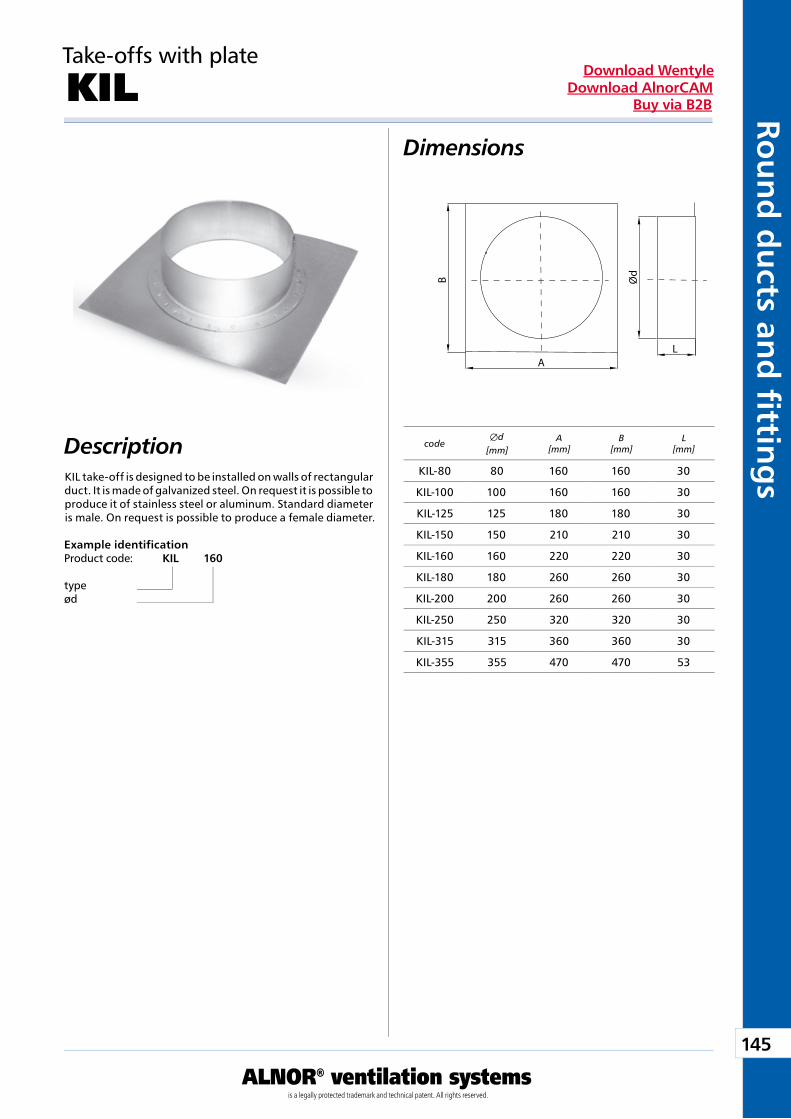
145
ALNOR® ventilation systemsis a legally protected trademark and technical patent. All rights reserved.
Rou
nd
du
cts and
fi tting
sDownload Wentyle
Download AlnorCAMBuy via B2B
Take-offs with plate
KILDimensions
DescriptionKIL take-off is designed to be installed on walls of rectangular duct. It is made of galvanized steel. On request it is possible to produce it of stainless steel or aluminum. Standard diameter is male. On request is possible to produce a female diameter.
Example identificationProduct code: KIL 160
typeød
L
Ød
A
Bcode
Æd [mm]
A[mm]
B[mm]
L[mm]
KIL-80 80 160 160 30
KIL-100 100 160 160 30
KIL-125 125 180 180 30
KIL-150 150 210 210 30
KIL-160 160 220 220 30
KIL-180 180 260 260 30
KIL-200 200 260 260 30
KIL-250 250 320 320 30
KIL-315 315 360 360 30
KIL-355 355 470 470 53
Ventilation Accessories
We reserve the right to make changes in the dimensions and technical data products due to their continuous improvement
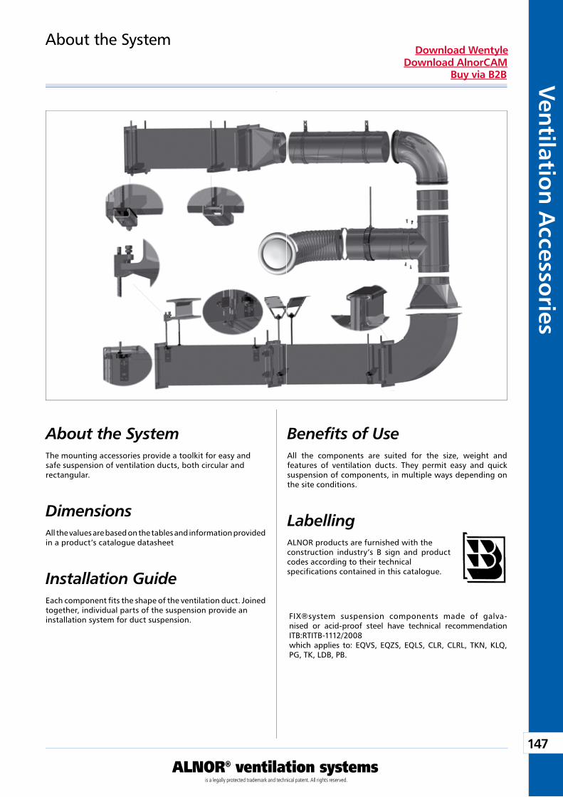
147
ALNOR® ventilation systemsis a legally protected trademark and technical patent. All rights reserved.
Ven
tilation
Accesso
riesDownload Wentyle
Download AlnorCAMBuy via B2B
About the System Benefits of UseThe mounting accessories provide a toolkit for easy and safe suspension of ventilation ducts, both circular and rectangular.
Dimensions All the values are based on the tables and information provided in a product’s catalogue datasheet
All the components are suited for the size, weight and features of ventilation ducts. They permit easy and quick suspension of components, in multiple ways depending on the site conditions.
About the System
LabellingALNOR products are furnished with the construction industry’s B sign and product codes according to their technical specifications contained in this catalogue.Installation Guide
Each component fits the shape of the ventilation duct. Joined together, individual parts of the suspension provide an installation system for duct suspension. FIX®system suspension components made of galva-
nised or acid-proof steel have technical recommendation ITB:RTITB-1112/2008 which applies to: EQVS, EQZS, EQLS, CLR, CLRL, TKN, KLQ, PG, TK, LDB, PB.
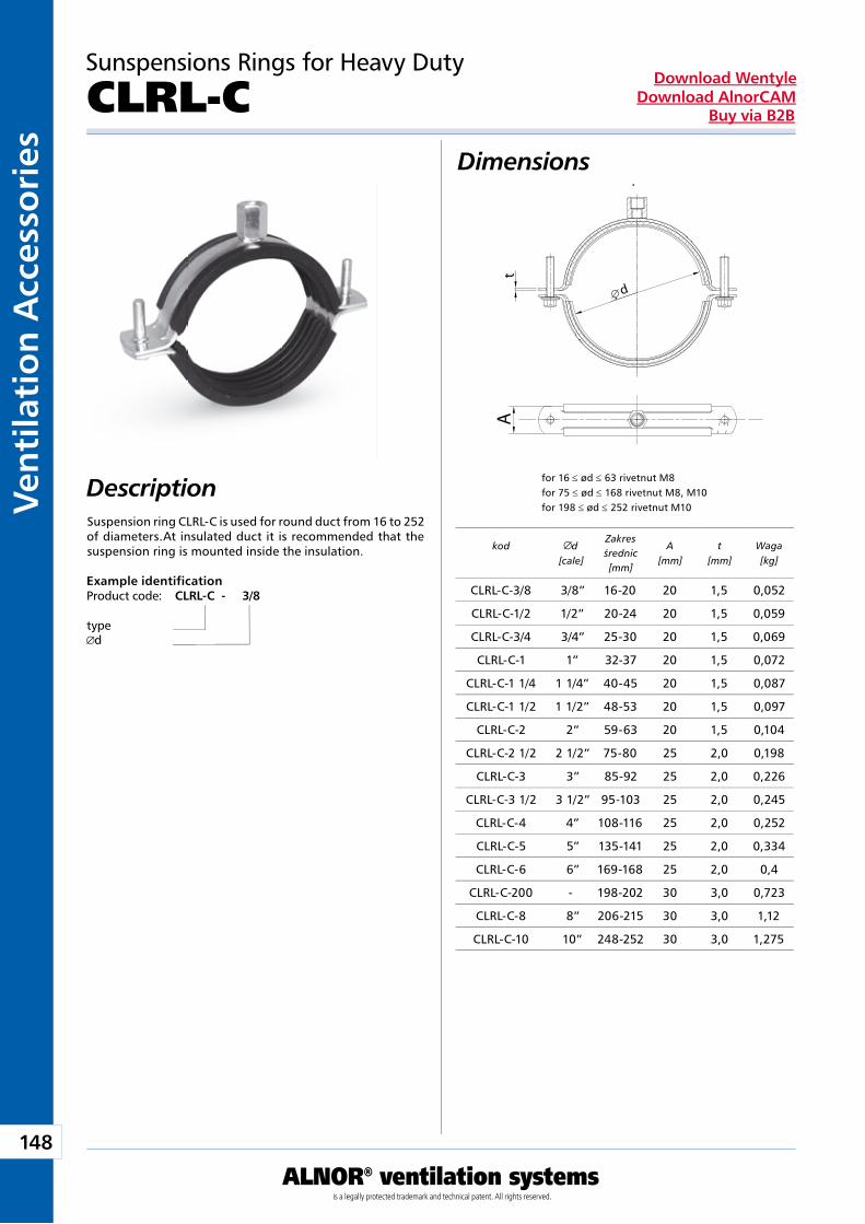
148
ALNOR® ventilation systemsis a legally protected trademark and technical patent. All rights reserved.
Ven
tila
tio
n A
cces
sori
esDownload Wentyle
Download AlnorCAMBuy via B2B
d
tA
dla 16 ≤ ød ≤ 63 nitonakrętka M8 dla 75 ≤ ød ≤ 168 nitonakrętka M8, M10 dla 198 ≤ ød ≤ 252 nitonakrętka M10
Suspension ring CLRL-C is used for round duct from 16 to 252 of diameters.At insulated duct it is recommended that the suspension ring is mounted inside the insulation.
for 16 ≤ ød ≤ 63 rivetnut M8for 75 ≤ ød ≤ 168 rivetnut M8, M10for 198 ≤ ød ≤ 252 rivetnut M10
Sunspensions Rings for Heavy Duty
CLRL-CDimensions
Description
Example identificationProduct code: CLRL-C - 3/8
typed
kod d[cale]
Zakres średnic[mm]
A[mm]
t[mm]
Waga[kg]
CLRL-C-3/8 3/8” 16-20 20 1,5 0,052
CLRL-C-1/2 1/2” 20-24 20 1,5 0,059
CLRL-C-3/4 3/4” 25-30 20 1,5 0,069
CLRL-C-1 1” 32-37 20 1,5 0,072
CLRL-C-1 1/4 1 1/4” 40-45 20 1,5 0,087
CLRL-C-1 1/2 1 1/2” 48-53 20 1,5 0,097
CLRL-C-2 2” 59-63 20 1,5 0,104
CLRL-C-2 1/2 2 1/2” 75-80 25 2,0 0,198
CLRL-C-3 3” 85-92 25 2,0 0,226
CLRL-C-3 1/2 3 1/2” 95-103 25 2,0 0,245
CLRL-C-4 4” 108-116 25 2,0 0,252
CLRL-C-5 5” 135-141 25 2,0 0,334
CLRL-C-6 6” 169-168 25 2,0 0,4
CLRL-C-200 - 198-202 30 3,0 0,723
CLRL-C-8 8” 206-215 30 3,0 1,12
CLRL-C-10 10” 248-252 30 3,0 1,275
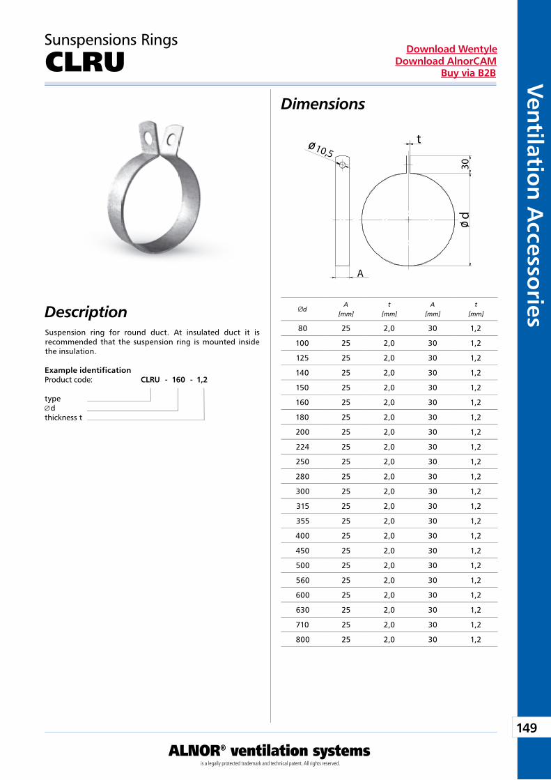
149
ALNOR® ventilation systemsis a legally protected trademark and technical patent. All rights reserved.
Ven
tilation
Accesso
riesDownload Wentyle
Download AlnorCAMBuy via B2B
A
10,5t
d30
ø
ø
Sunspensions Rings
CLRU
DescriptionSuspension ring for round duct. At insulated duct it is recommended that the suspension ring is mounted inside the insulation.
Example identificationProduct code: CLRU - 160 - 1,2
type d
thickness t
Dimensions
dA
[mm]t
[mm]A
[mm]t
[mm]
80 25 2,0 30 1,2
100 25 2,0 30 1,2
125 25 2,0 30 1,2
140 25 2,0 30 1,2
150 25 2,0 30 1,2
160 25 2,0 30 1,2
180 25 2,0 30 1,2
200 25 2,0 30 1,2
224 25 2,0 30 1,2
250 25 2,0 30 1,2
280 25 2,0 30 1,2
300 25 2,0 30 1,2
315 25 2,0 30 1,2
355 25 2,0 30 1,2
400 25 2,0 30 1,2
450 25 2,0 30 1,2
500 25 2,0 30 1,2
560 25 2,0 30 1,2
600 25 2,0 30 1,2
630 25 2,0 30 1,2
710 25 2,0 30 1,2
800 25 2,0 30 1,2
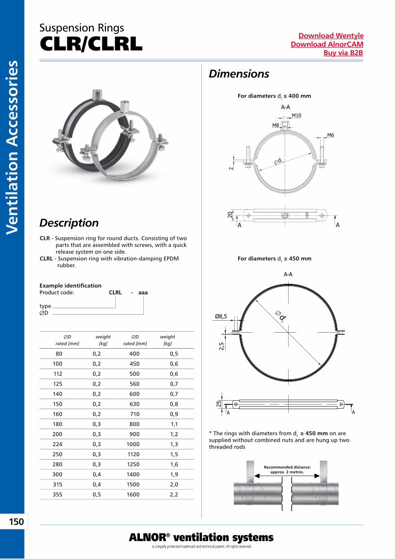
150
ALNOR® ventilation systemsis a legally protected trademark and technical patent. All rights reserved.
Ven
tila
tio
n A
cces
sori
esDownload Wentyle
Download AlnorCAMBuy via B2B
d1
d1
Dimensions
Description
Suspension Rings
CLR/CLRL
CLR - Suspension ring for round ducts. Consisting of two parts that are assembled with screws, with a quick release system on one side. CLRL - Suspension ring with vibration-damping EPDM rubber.
Example identificationProduct code: CLRL - aaa
typeÆD
* The rings with diameters from d1 ≥ 450 mm on are supplied without combined nuts and are hung up two threaded rods
ÆD weight ÆD weight rated [mm] [kg] rated [mm] [kg]
Recommended distance: approx. 2 metres.
For diameters d1 ≥ 450 mm
For diameters d1 ≤ 400 mm
80 0,2 400 0,5
100 0,2 450 0,6
112 0,2 500 0,6
125 0,2 560 0,7
140 0,2 600 0,7
150 0,2 630 0,8
160 0,2 710 0,9
180 0,3 800 1,1
200 0,3 900 1,2
224 0,3 1000 1,3
250 0,3 1120 1,5
280 0,3 1250 1,6
300 0,4 1400 1,9
315 0,4 1500 2,0
355 0,5 1600 2,2

151
ALNOR® ventilation systemsis a legally protected trademark and technical patent. All rights reserved.
Ven
tilation
Accesso
riesDownload Wentyle
Download AlnorCAMBuy via B2B
Description
Suspension Bands
PB
The PB perforated suspension band is used for the suspension of circular and oval ventilation ducts. It is used in systems where smooth height adjustment is required or suspension rings cannot be employed.
Example identificationProduct code: PB17-06
type
Dimensions
type A L [mm] [mb]
PB 17-06 17 25 0,6
PB 17-06-10 17 10 0,6
PB 19-06 19 25 0,6
PB 25-08 25 25 0,8
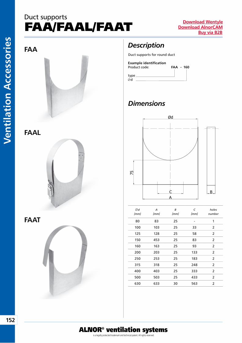
152
ALNOR® ventilation systemsis a legally protected trademark and technical patent. All rights reserved.
Ven
tila
tio
n A
cces
sori
esDownload Wentyle
Download AlnorCAMBuy via B2B
B
Ød
75
AC
Duct supports
FAA/FAAL/FAATDescriptionDuct supports for round duct
Example identificationProduct code: FAA - 160
type d
Dimensions
FAA
FAAL
FAAT
d[mm]
A[mm]
B[mm]
C[mm]
holes number
80 83 25 - 1
100 103 25 33 2
125 128 25 58 2
150 453 25 83 2
160 163 25 93 2
200 203 25 133 2
250 253 25 183 2
315 318 25 248 2
400 403 25 333 2
500 503 25 433 2
630 633 30 563 2
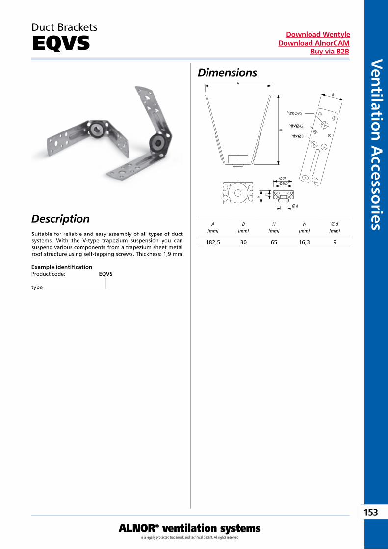
153
ALNOR® ventilation systemsis a legally protected trademark and technical patent. All rights reserved.
Ven
tilation
Accesso
riesDownload Wentyle
Download AlnorCAMBuy via B2B
Ø10,6
x
x
x
Duct Brackets
EQVSDimensions
DescriptionSuitable for reliable and easy assembly of all types of duct systems. With the V-type trapezium suspension you can suspend various components from a trapezium sheet metal roof structure using self-tapping screws. Thickness: 1,9 mm.
Example identificationProduct code: EQVS
type
holes
holes
holes
A[mm]
B[mm]
H[mm]
h[mm]
d[mm]
182,5 30 65 16,3 9
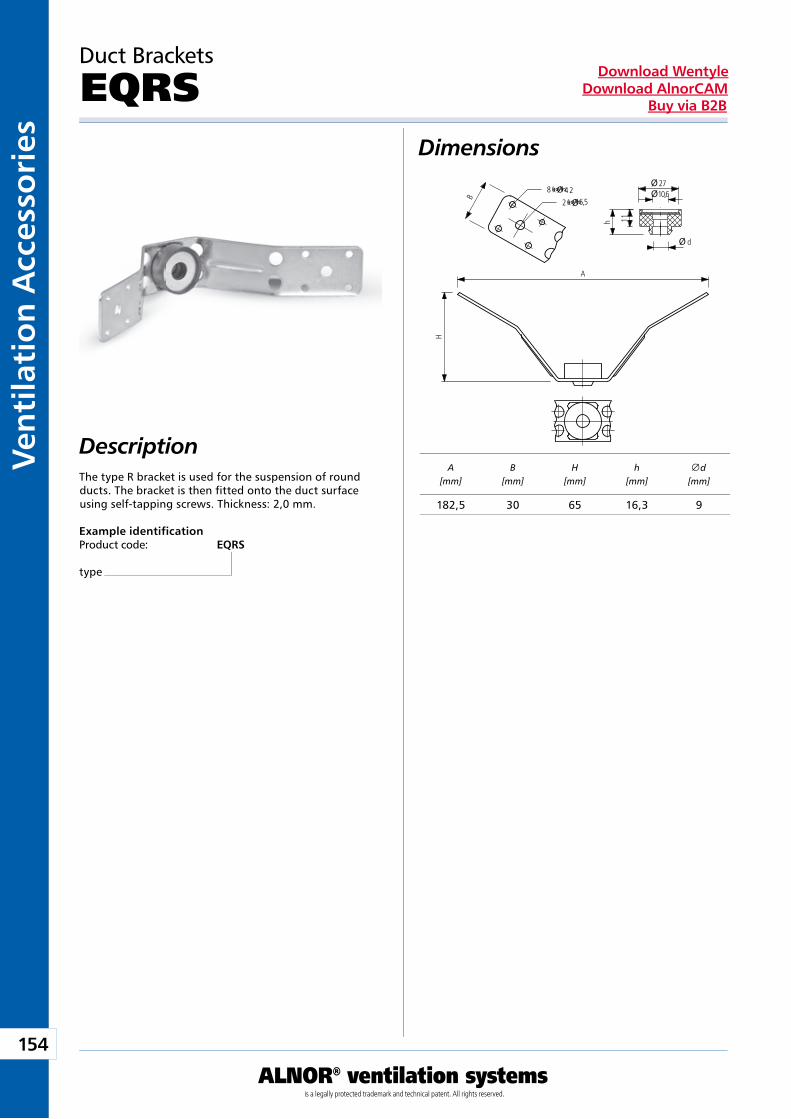
154
ALNOR® ventilation systemsis a legally protected trademark and technical patent. All rights reserved.
Ven
tila
tio
n A
cces
sori
esDownload Wentyle
Download AlnorCAMBuy via B2B
x
x
Description
Duct Brackets
EQRS
The type R bracket is used for the suspension of round ducts. The bracket is then fitted onto the duct surface using self-tapping screws. Thickness: 2,0 mm.
Example identificationProduct code: EQRS
type
Dimensions
holes
holes
A[mm]
B[mm]
H[mm]
h[mm]
d[mm]
182,5 30 65 16,3 9
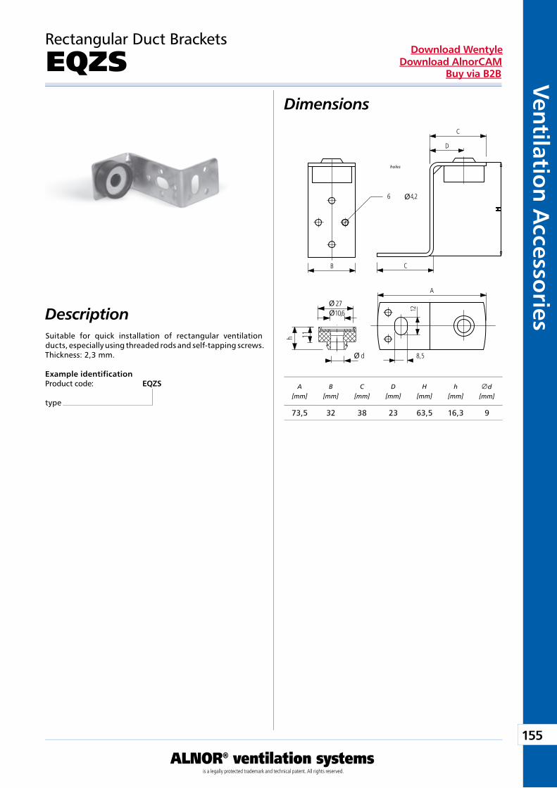
155
ALNOR® ventilation systemsis a legally protected trademark and technical patent. All rights reserved.
Ven
tilation
Accesso
riesDownload Wentyle
Download AlnorCAMBuy via B2B
Rectangular Duct Brackets
EQZSDimensions
DescriptionSuitable for quick installation of rectangular ventilation ducts, especially using threaded rods and self-tapping screws. Thickness: 2,3 mm.
Example identificationProduct code: EQZS
type
holes
A[mm]
B[mm]
C[mm]
D[mm]
H[mm]
h[mm]
d[mm]
73,5 32 38 23 63,5 16,3 9
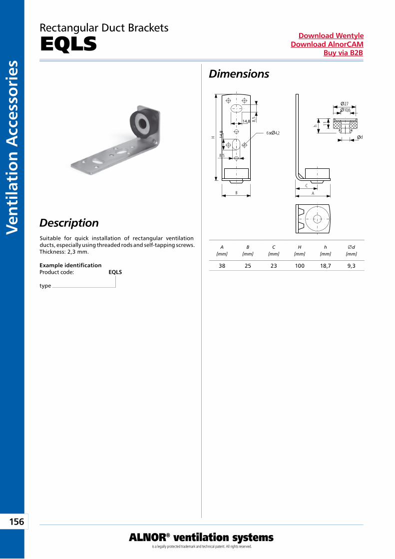
156
ALNOR® ventilation systemsis a legally protected trademark and technical patent. All rights reserved.
Ven
tila
tio
n A
cces
sori
esDownload Wentyle
Download AlnorCAMBuy via B2B
ØØ
ØxØ
14,8
14,8
Rectangular Duct Brackets
EQLSDimensions
DescriptionSuitable for quick installation of rectangular ventilation ducts, especially using threaded rods and self-tapping screws. Thickness: 2,3 mm.
Example identificationProduct code: EQLS
type
A[mm]
B[mm]
C[mm]
H[mm]
h[mm]
d[mm]
38 25 23 100 18,7 9,3
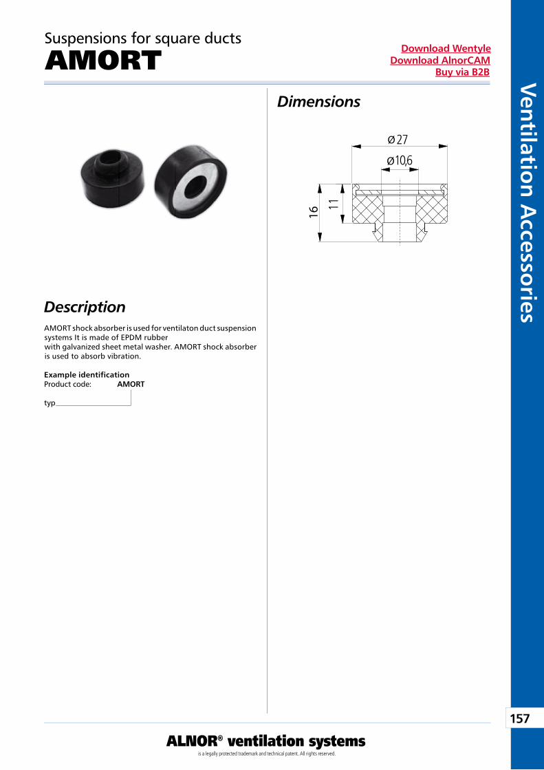
157
ALNOR® ventilation systemsis a legally protected trademark and technical patent. All rights reserved.
Ven
tilation
Accesso
riesDownload Wentyle
Download AlnorCAMBuy via B2B
Ø10,6
16
Suspensions for square ducts
AMORTDimensions
DescriptionAMORT shock absorber is used for ventilaton duct suspension systems It is made of EPDM rubber with galvanized sheet metal washer. AMORT shock absorber is used to absorb vibration.
Example identificationProduct code: AMORT
typ
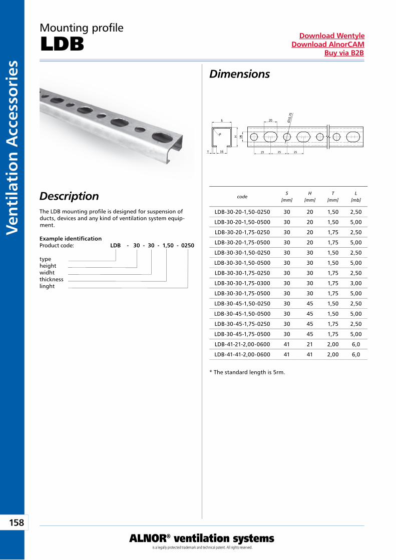
158
ALNOR® ventilation systemsis a legally protected trademark and technical patent. All rights reserved.
Ven
tila
tio
n A
cces
sori
esDownload Wentyle
Download AlnorCAMBuy via B2B
S
25 25 25
Mounting profile
LDB
The LDB mounting profile is designed for suspension of ducts, devices and any kind of ventilation system equip-ment.
Dimensions
Description
Example identificationProduct code: LDB - 30 - 30 - 1,50 - 0250
typeheightwidhtthicknesslinght
codeS
[mm]H
[mm]T
[mm]L
[mb]
* The standard length is 5rm.
LDB-30-20-1,50-0250 30 20 1,50 2,50
LDB-30-20-1,50-0500 30 20 1,50 5,00
LDB-30-20-1,75-0250 30 20 1,75 2,50
LDB-30-20-1,75-0500 30 20 1,75 5,00
LDB-30-30-1,50-0250 30 30 1,50 2,50
LDB-30-30-1,50-0500 30 30 1,50 5,00
LDB-30-30-1,75-0250 30 30 1,75 2,50
LDB-30-30-1,75-0300 30 30 1,75 3,00
LDB-30-30-1,75-0500 30 30 1,75 5,00
LDB-30-45-1,50-0250 30 45 1,50 2,50
LDB-30-45-1,50-0500 30 45 1,50 5,00
LDB-30-45-1,75-0250 30 45 1,75 2,50
LDB-30-45-1,75-0500 30 45 1,75 5,00
LDB-41-21-2,00-0600 41 21 2,00 6,0
LDB-41-41-2,00-0600 41 41 2,00 6,0
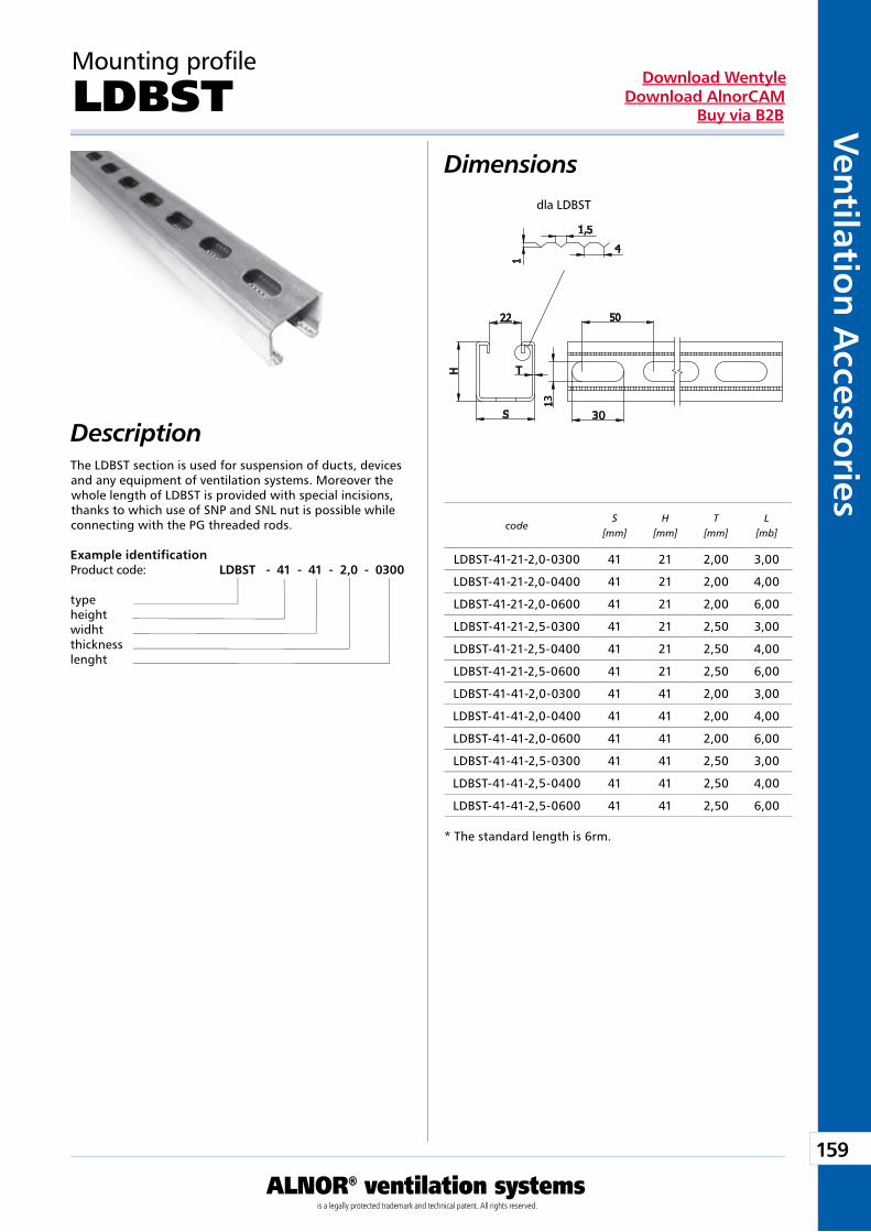
159
ALNOR® ventilation systemsis a legally protected trademark and technical patent. All rights reserved.
Ven
tilation
Accesso
riesDownload Wentyle
Download AlnorCAMBuy via B2B
T
0
3
Mounting profile
LDBST
The LDBST section is used for suspension of ducts, devices and any equipment of ventilation systems. Moreover the whole length of LDBST is provided with special incisions, thanks to which use of SNP and SNL nut is possible while connecting with the PG threaded rods.
Dimensions
Description
Example identificationProduct code: LDBST - 41 - 41 - 2,0 - 0300
typeheightwidhtthicknesslenght
code
* The standard length is 6rm.
dla LDBST
S[mm]
H[mm]
T[mm]
L[mb]
LDBST-41-21-2,0-0300 41 21 2,00 3,00
LDBST-41-21-2,0-0400 41 21 2,00 4,00
LDBST-41-21-2,0-0600 41 21 2,00 6,00
LDBST-41-21-2,5-0300 41 21 2,50 3,00
LDBST-41-21-2,5-0400 41 21 2,50 4,00
LDBST-41-21-2,5-0600 41 21 2,50 6,00
LDBST-41-41-2,0-0300 41 41 2,00 3,00
LDBST-41-41-2,0-0400 41 41 2,00 4,00
LDBST-41-41-2,0-0600 41 41 2,00 6,00
LDBST-41-41-2,5-0300 41 41 2,50 3,00
LDBST-41-41-2,5-0400 41 41 2,50 4,00
LDBST-41-41-2,5-0600 41 41 2,50 6,00
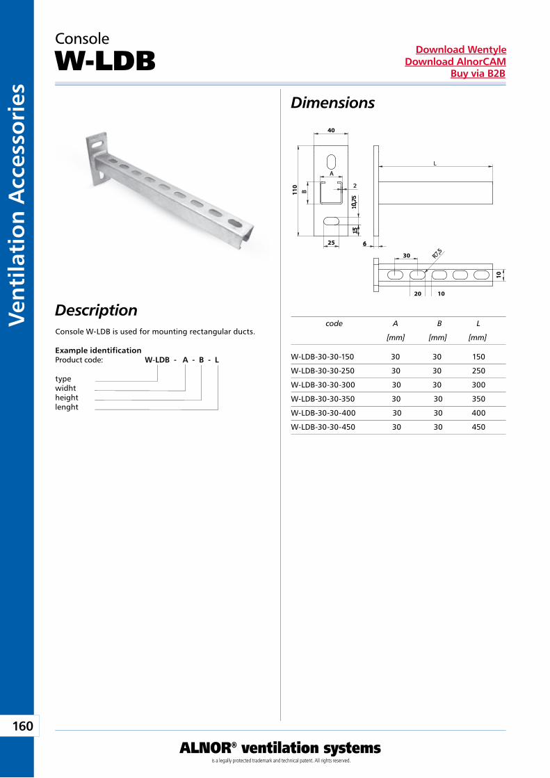
160
ALNOR® ventilation systemsis a legally protected trademark and technical patent. All rights reserved.
Ven
tila
tio
n A
cces
sori
esDownload Wentyle
Download AlnorCAMBuy via B2B
Description
Console
W-LDB
Console W-LDB is used for mounting rectangular ducts.
Dimensions
Example identificationProduct code: W-LDB - A - B - L
typewidhtheightlenght
code A B L
[mm] [mm] [mm]
25
10
30
40
110
20 10
W-LDB-30-30-150 30 30 150
W-LDB-30-30-250 30 30 250
W-LDB-30-30-300 30 30 300
W-LDB-30-30-350 30 30 350
W-LDB-30-30-400 30 30 400
W-LDB-30-30-450 30 30 450
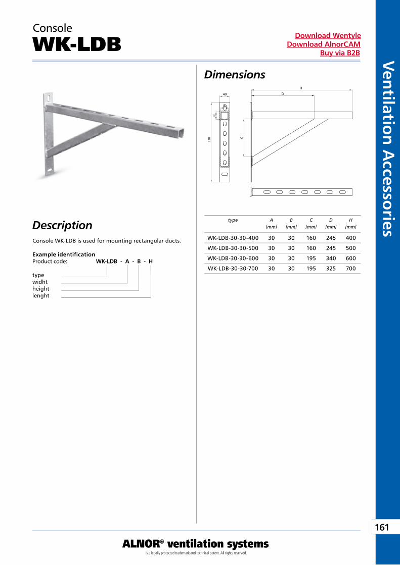
161
ALNOR® ventilation systemsis a legally protected trademark and technical patent. All rights reserved.
Ven
tilation
Accesso
riesDownload Wentyle
Download AlnorCAMBuy via B2B
type A[mm]
B[mm]
C[mm]
D[mm]
H[mm]Description
Console
WK-LDB
Console WK-LDB is used for mounting rectangular ducts.
Dimensions
Example identificationProduct code: WK-LDB - A - B - H
typewidhtheightlenght
A
B
40
330 C
D
H
WK-LDB-30-30-400 30 30 160 245 400
WK-LDB-30-30-500 30 30 160 245 500
WK-LDB-30-30-600 30 30 195 340 600
WK-LDB-30-30-700 30 30 195 325 700
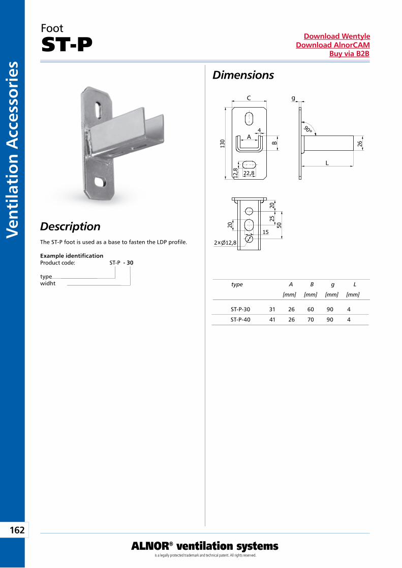
162
ALNOR® ventilation systemsis a legally protected trademark and technical patent. All rights reserved.
Ven
tila
tio
n A
cces
sori
esDownload Wentyle
Download AlnorCAMBuy via B2B
Dimensions
Description
Foot
ST-P
The ST-P foot is used as a base to fasten the LDP profile.
Example identificationProduct code: ST-P - 30
typewidht type A B g L
[mm] [mm] [mm] [mm]
x
g
L
A
B
C
ST-P-30 31 26 60 90 4
ST-P-40 41 26 70 90 4
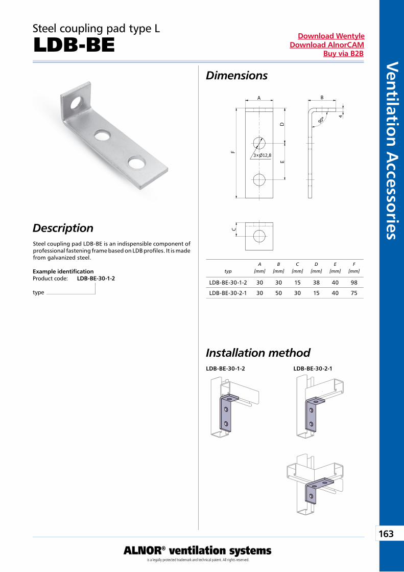
163
ALNOR® ventilation systemsis a legally protected trademark and technical patent. All rights reserved.
Ven
tilation
Accesso
riesDownload Wentyle
Download AlnorCAMBuy via B2B
x
B
C
A
DE
FDescriptionSteel coupling pad LDB-BE is an indispensible component of professional fastening frame based on LDB profiles. It is made from galvanized steel.
Example identificationProduct code: LDB-BE-30-1-2
type
typA
[mm]B
[mm]C
[mm]D
[mm]E
[mm]F
[mm]
Steel coupling pad type L
LDB-BEDimensions
Installation methodLDB-BE-30-1-2 LDB-BE-30-2-1
LDB-BE-30-1-2 30 30 15 38 40 98
LDB-BE-30-2-1 30 50 30 15 40 75
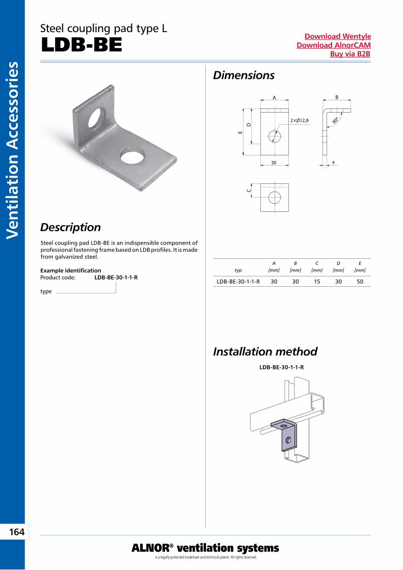
164
ALNOR® ventilation systemsis a legally protected trademark and technical patent. All rights reserved.
Ven
tila
tio
n A
cces
sori
esDownload Wentyle
Download AlnorCAMBuy via B2B
x
BA
C
E
D
Description
Example identificationProduct code: LDB-BE-30-1-1-R
type
Steel coupling pad LDB-BE is an indispensible component of professional fastening frame based on LDB profiles. It is made from galvanized steel.
typA
[mm]B
[mm]C
[mm]D
[mm]E
[mm]
Steel coupling pad type L
LDB-BEDimensions
Installation methodLDB-BE-30-1-1-R
LDB-BE-30-1-1-R 30 30 15 30 50
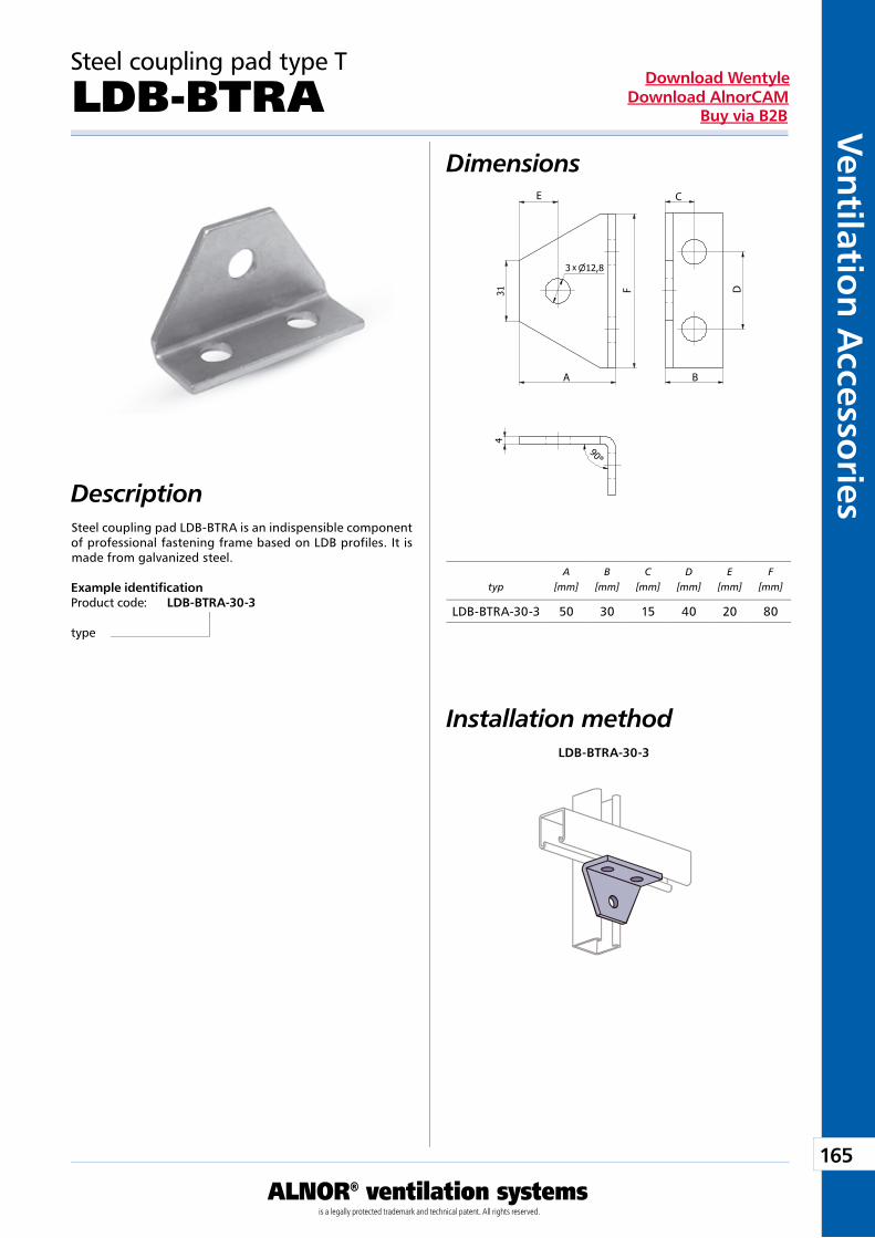
165
ALNOR® ventilation systemsis a legally protected trademark and technical patent. All rights reserved.
Ven
tilation
Accesso
riesDownload Wentyle
Download AlnorCAMBuy via B2B
x
C
F D
E
A B
DescriptionSteel coupling pad LDB-BTRA is an indispensible component of professional fastening frame based on LDB profiles. It is made from galvanized steel.
Example identificationProduct code: LDB-BTRA-30-3
type
typA
[mm]B
[mm]C
[mm]D
[mm]E
[mm]F
[mm]
Steel coupling pad type T
LDB-BTRADimensions
Installation methodLDB-BTRA-30-3
LDB-BTRA-30-3 50 30 15 40 20 80
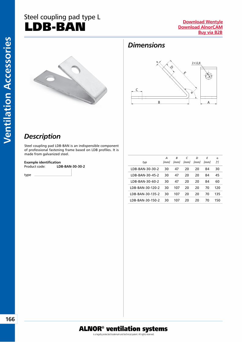
166
ALNOR® ventilation systemsis a legally protected trademark and technical patent. All rights reserved.
Ven
tila
tio
n A
cces
sori
esDownload Wentyle
Download AlnorCAMBuy via B2B
x
α
AB
C
D
E
Description
Example identificationProduct code: LDB-BAN-30-30-2
type
Steel coupling pad LDB-BAN is an indispensible component of professional fastening frame based on LDB profiles. It is made from galvanized steel.
typA
[mm]B
[mm]C
[mm]D
[mm]E
[mm]α[o]
Steel coupling pad type L
LDB-BANDimensions
LDB-BAN-30-30-2 30 47 20 20 84 30
LDB-BAN-30-45-2 30 47 20 20 84 45
LDB-BAN-30-60-2 30 47 20 20 84 60
LDB-BAN-30-120-2 30 107 20 20 70 120
LDB-BAN-30-135-2 30 107 20 20 70 135
LDB-BAN-30-150-2 30 107 20 20 70 150
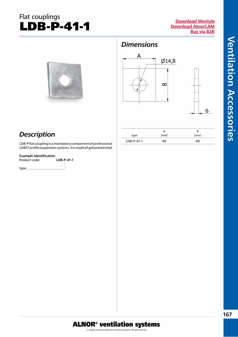
167
ALNOR® ventilation systemsis a legally protected trademark and technical patent. All rights reserved.
Ven
tilation
Accesso
riesDownload Wentyle
Download AlnorCAMBuy via B2B
A
B
6
4
typeA
[mm]B
[mm]DescriptionLDB-P flat coupling is a mandatory component of professional LDBST profile suspension systems. It is made of galvanized steel
Flat couplings
LDB-P-41-1
Example identificationProduct code: LDB-P-41-1
type
Dimensions
LDB-P-41-1 40 40
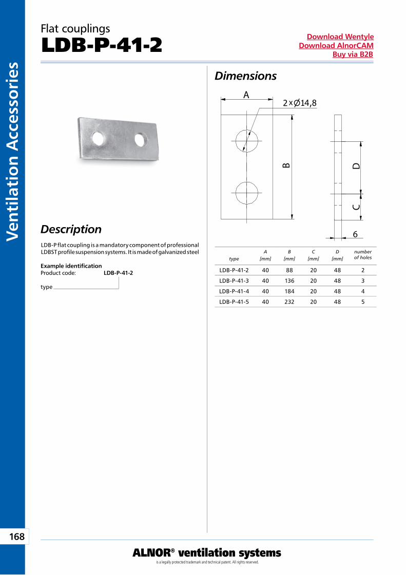
168
ALNOR® ventilation systemsis a legally protected trademark and technical patent. All rights reserved.
Ven
tila
tio
n A
cces
sori
esDownload Wentyle
Download AlnorCAMBuy via B2B
xA
B
6
CD
4
typeA
[mm]B
[mm]C
[mm]D
[mm]number of holes
Description
Flat couplings
LDB-P-41-2
Example identificationProduct code: LDB-P-41-2
type
Dimensions
LDB-P flat coupling is a mandatory component of professional LDBST profile suspension systems. It is made of galvanized steel
LDB-P-41-2 40 88 20 48 2
LDB-P-41-3 40 136 20 48 3
LDB-P-41-4 40 184 20 48 4
LDB-P-41-5 40 232 20 48 5
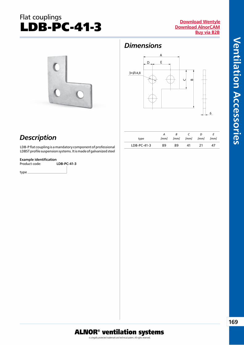
169
ALNOR® ventilation systemsis a legally protected trademark and technical patent. All rights reserved.
Ven
tilation
Accesso
riesDownload Wentyle
Download AlnorCAMBuy via B2B
x
A
C
3
D
B
E
4
6
typeA
[mm]B
[mm]C
[mm]D
[mm]E
[mm]
Flat couplings
LDB-PC-41-3Dimensions
Description
Example identificationProduct code: LDB-PC-41-3
type
LDB-P flat coupling is a mandatory component of professional LDBST profile suspension systems. It is made of galvanized steel
LDB-PC-41-3 89 89 41 21 47
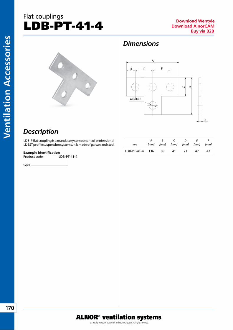
170
ALNOR® ventilation systemsis a legally protected trademark and technical patent. All rights reserved.
Ven
tila
tio
n A
cces
sori
esDownload Wentyle
Download AlnorCAMBuy via B2B
C B
x4
D
A
FE
4
6
typeA
[mm]B
[mm]C
[mm]D
[mm]E
[mm]F
[mm]
Flat couplings
LDB-PT-41-4Dimensions
Description
Example identificationProduct code: LDB-PT-41-4
type
LDB-P flat coupling is a mandatory component of professional LDBST profile suspension systems. It is made of galvanized steel
LDB-PT-41-4 136 89 41 21 47 47
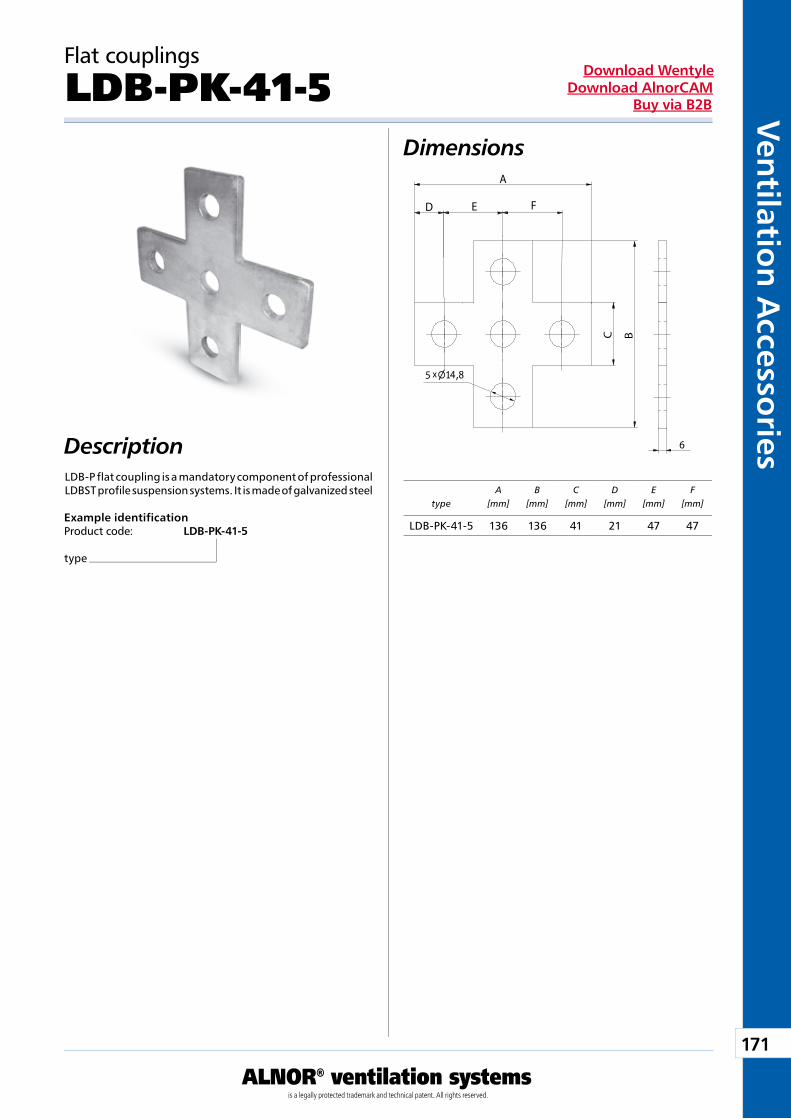
171
ALNOR® ventilation systemsis a legally protected trademark and technical patent. All rights reserved.
Ven
tilation
Accesso
riesDownload Wentyle
Download AlnorCAMBuy via B2B
C B
x
D
A
FE
5 4
6
typeA
[mm]B
[mm]C
[mm]D
[mm]E
[mm]F
[mm]
Flat couplings
LDB-PK-41-5Dimensions
Description
Example identificationProduct code: LDB-PK-41-5
type
LDB-P flat coupling is a mandatory component of professional LDBST profile suspension systems. It is made of galvanized steel
LDB-PK-41-5 136 136 41 21 47 47
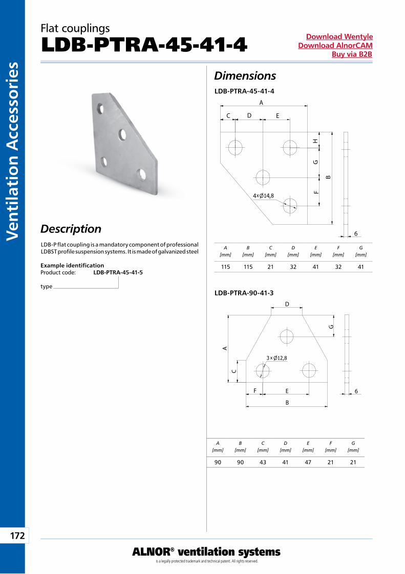
172
ALNOR® ventilation systemsis a legally protected trademark and technical patent. All rights reserved.
Ven
tila
tio
n A
cces
sori
esDownload Wentyle
Download AlnorCAMBuy via B2B
C D
A
B
x4
G
6
4
E
FH
B
G
A
x
D
C
EF 6
A[mm]
B[mm]
C[mm]
D[mm]
E[mm]
F[mm]
G[mm]
A[mm]
B[mm]
C[mm]
D[mm]
E[mm]
F[mm]
G[mm]
Flat couplings
LDB-PTRA-45-41-4Dimensions
Description
Example identificationProduct code: LDB-PTRA-45-41-5
type
LDB-P flat coupling is a mandatory component of professional LDBST profile suspension systems. It is made of galvanized steel
LDB-PTRA-45-41-4
LDB-PTRA-90-41-3
115 115 21 32 41 32 41
90 90 43 41 47 21 21
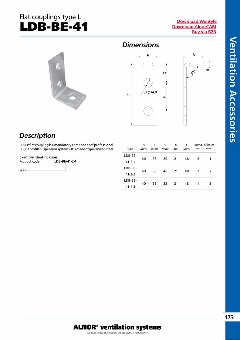
173
ALNOR® ventilation systemsis a legally protected trademark and technical patent. All rights reserved.
Ven
tilation
Accesso
riesDownload Wentyle
Download AlnorCAMBuy via B2B
x
B
F
A
DEC
6
4
A[mm]
B[mm]
C[mm]
D[mm]
E[mm]
F[mm]
G[mm]
A[mm]
B[mm]
C[mm]
D[mm]
E[mm]
F[mm]
G[mm]
typeA
[mm]B
[mm]C
[mm]D
[mm]E
[mm]numb. of holes vert. horiz.
Flat couplings type L
LDB-BE-41Dimensions
Description
Example identificationProduct code: LDB-BE-41-2-1
type
LDB-P flat coupling is a mandatory component of professional LDBST profile suspension systems. It is made of galvanized steel
115 115 21 32 41 32 41
90 90 43 41 47 21 21
LDB-BE-
41-2-140 56 89 21 48 2 1
LDB-BE-
41-2-240 89 48 21 48 2 2
LDB-BE-
41-1-340 53 23 21 48 1 3
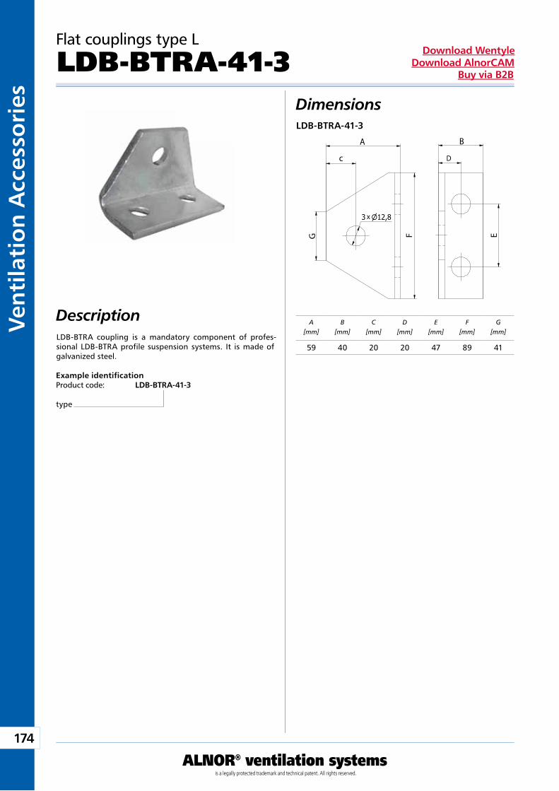
174
ALNOR® ventilation systemsis a legally protected trademark and technical patent. All rights reserved.
Ven
tila
tio
n A
cces
sori
esDownload Wentyle
Download AlnorCAMBuy via B2B
x
D
F E
c
A B
G6
A[mm]
B[mm]
C[mm]
D[mm]
E[mm]
F[mm]
G[mm]
Flat couplings type L
LDB-BTRA-41-3Dimensions
Description
Example identificationProduct code: LDB-BTRA-41-3
type
LDB-BTRA coupling is a mandatory component of profes-sional LDB-BTRA profile suspension systems. It is made of galvanized steel.
LDB-BTRA-41-3
59 40 20 20 47 89 41
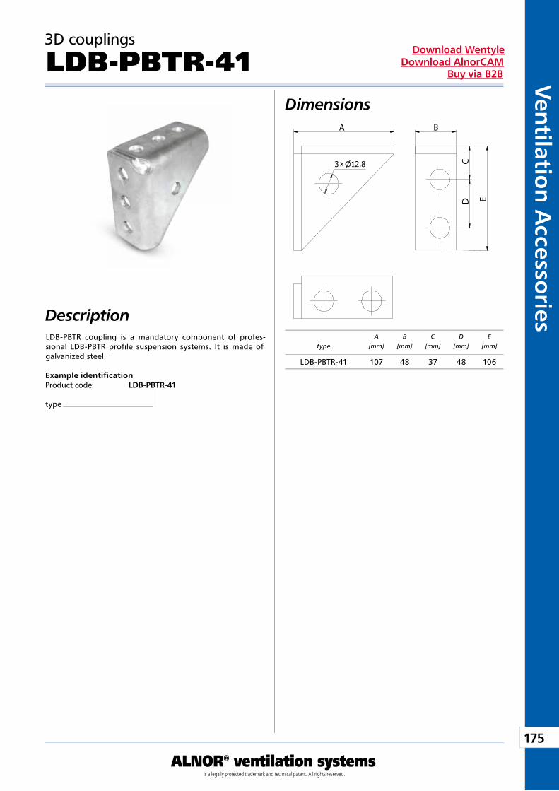
175
ALNOR® ventilation systemsis a legally protected trademark and technical patent. All rights reserved.
Ven
tilation
Accesso
riesDownload Wentyle
Download AlnorCAMBuy via B2B
C
A
x
B
D E
typeA
[mm]B
[mm]C
[mm]D
[mm]E
[mm]
3D couplings
LDB-PBTR-41Dimensions
Description
Example identificationProduct code: LDB-PBTR-41
type
LDB-PBTR coupling is a mandatory component of profes-sional LDB-PBTR profile suspension systems. It is made of galvanized steel.
LDB-PBTR-41 107 48 37 48 106
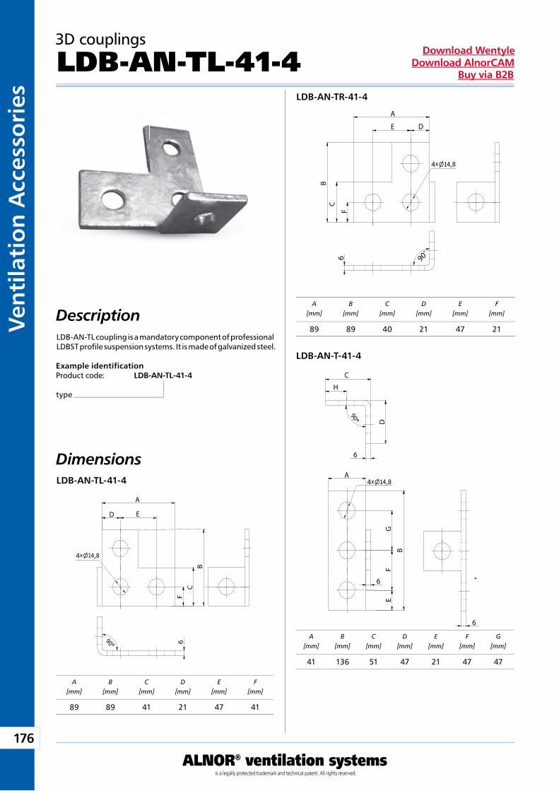
176
ALNOR® ventilation systemsis a legally protected trademark and technical patent. All rights reserved.
Ven
tila
tio
n A
cces
sori
esDownload Wentyle
Download AlnorCAMBuy via B2B
CB
A
D E
x4 4
F6
A
DE
C
B
x4 4
F6 90
o
A
B
DC
x4 4
6
6
EF
GH
6
A[mm]
B[mm]
C[mm]
D[mm]
E[mm]
F[mm]
A[mm]
B[mm]
C[mm]
D[mm]
E[mm]
F[mm]
A[mm]
B[mm]
C[mm]
D[mm]
E[mm]
F[mm]
G[mm]
3D couplings
LDB-AN-TL-41-4
Dimensions
Description
Example identificationProduct code: LDB-AN-TL-41-4
type
LDB-AN-TL coupling is a mandatory component of professional LDBST profile suspension systems. It is made of galvanized steel.
LDB-AN-TL-41-4
LDB-AN-TR-41-4
LDB-AN-T-41-4
89 89 41 21 47 41
89 89 40 21 47 21
41 136 51 47 21 47 47
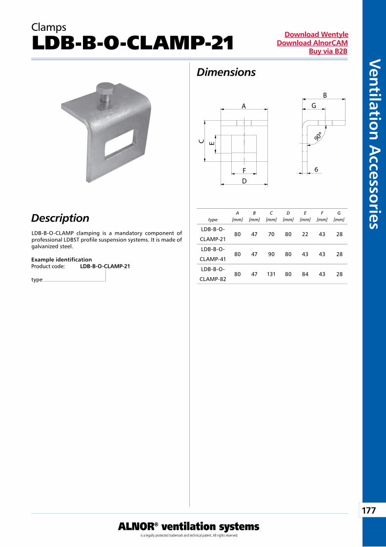
177
ALNOR® ventilation systemsis a legally protected trademark and technical patent. All rights reserved.
Ven
tilation
Accesso
riesDownload Wentyle
Download AlnorCAMBuy via B2B
BA
C E
F 6
D
G
M10
typeA
[mm]B
[mm]C
[mm]D
[mm]E
[mm]F
[mm]G
[mm]
Clamps
LDB-B-O-CLAMP-21Dimensions
Description
Example identificationProduct code: LDB-B-O-CLAMP-21
type
LDB-B-O-CLAMP clamping is a mandatory component of professional LDBST profile suspension systems. It is made of galvanized steel.
LDB-B-O-
CLAMP-2180 47 70 80 22 43 28
LDB-B-O-
CLAMP-4180 47 90 80 43 43 28
LDB-B-O-
CLAMP-8280 47 131 80 84 43 28
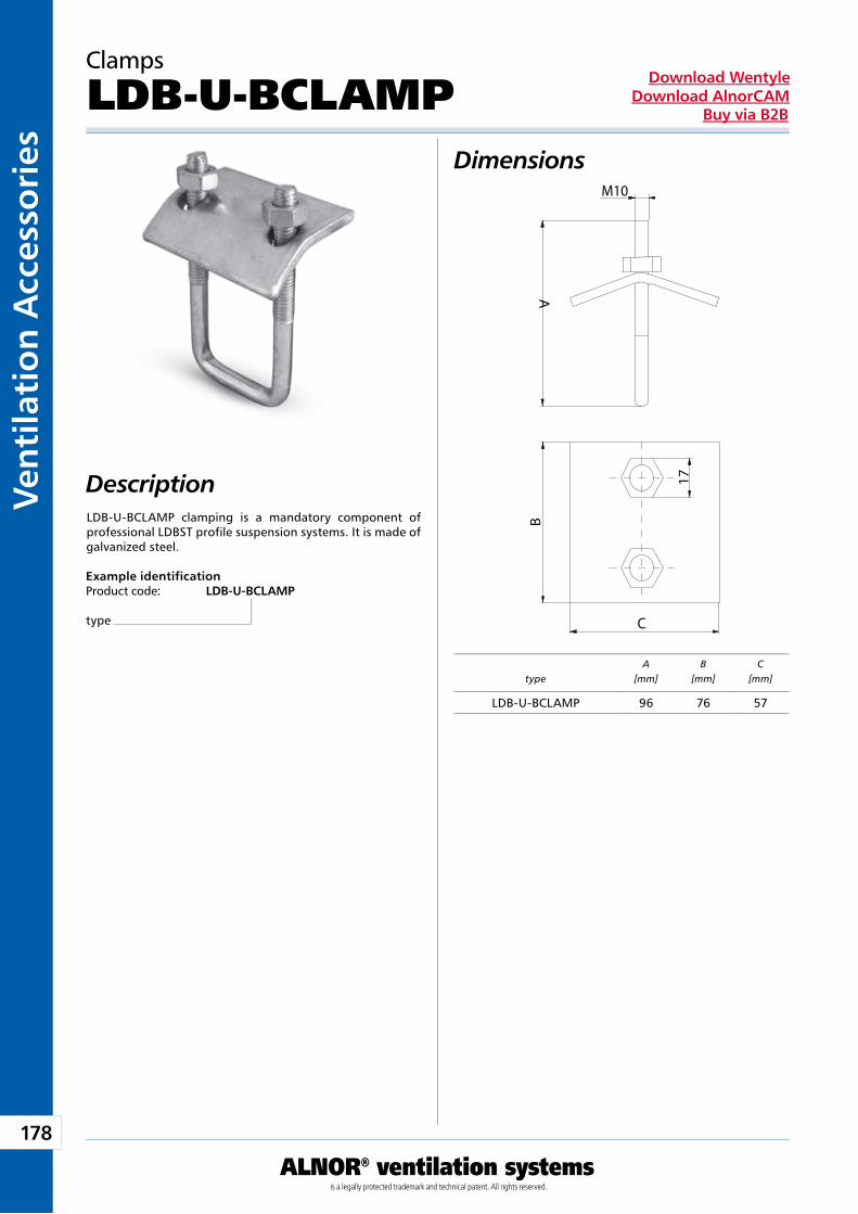
178
ALNOR® ventilation systemsis a legally protected trademark and technical patent. All rights reserved.
Ven
tila
tio
n A
cces
sori
esDownload Wentyle
Download AlnorCAMBuy via B2B
M10
A
B
C
17type
A[mm]
B[mm]
C[mm]
Clamps
LDB-U-BCLAMPDimensions
Description
Example identificationProduct code: LDB-U-BCLAMP
type
LDB-U-BCLAMP clamping is a mandatory component of professional LDBST profile suspension systems. It is made of galvanized steel.
LDB-U-BCLAMP 96 76 57
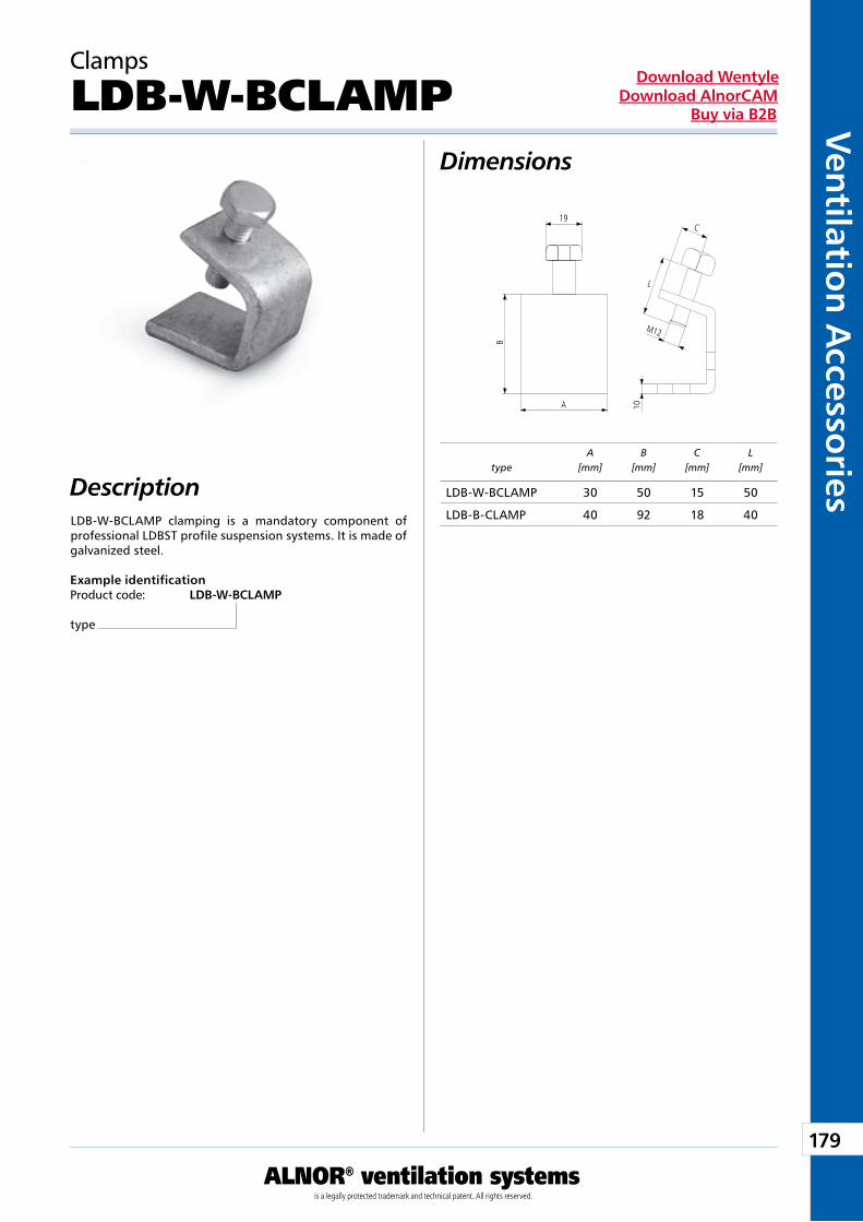
179
ALNOR® ventilation systemsis a legally protected trademark and technical patent. All rights reserved.
Ven
tilation
Accesso
riesDownload Wentyle
Download AlnorCAMBuy via B2B
A
L
M12
C
B
10
19
typeA
[mm]B
[mm]C
[mm]L
[mm]
Clamps
LDB-W-BCLAMPDimensions
Description
Example identificationProduct code: LDB-W-BCLAMP
type
LDB-W-BCLAMP clamping is a mandatory component of professional LDBST profile suspension systems. It is made of galvanized steel.
LDB-W-BCLAMP 30 50 15 50
LDB-B-CLAMP 40 92 18 40
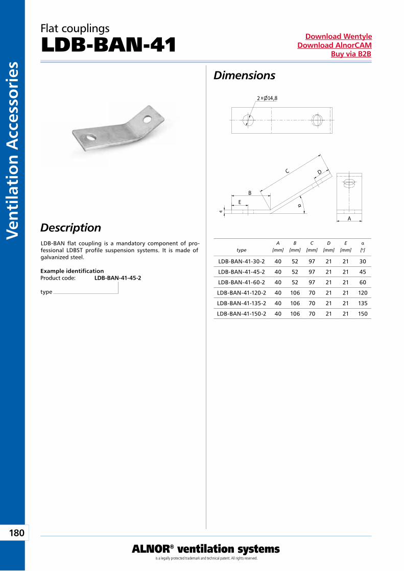
180
ALNOR® ventilation systemsis a legally protected trademark and technical patent. All rights reserved.
Ven
tila
tio
n A
cces
sori
esDownload Wentyle
Download AlnorCAMBuy via B2B
α x2 4
E
A
B
C D
typeA
[mm]B
[mm]C
[mm]D
[mm]E
[mm]α[o]
Flat couplings
LDB-BAN-41Dimensions
Description
Example identificationProduct code: LDB-BAN-41-45-2
type
LDB-BAN flat coupling is a mandatory component of pro-fessional LDBST profile suspension systems. It is made of galvanized steel.
LDB-BAN-41-30-2 40 52 97 21 21 30
LDB-BAN-41-45-2 40 52 97 21 21 45
LDB-BAN-41-60-2 40 52 97 21 21 60
LDB-BAN-41-120-2 40 106 70 21 21 120
LDB-BAN-41-135-2 40 106 70 21 21 135
LDB-BAN-41-150-2 40 106 70 21 21 150
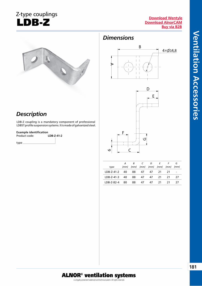
181
ALNOR® ventilation systemsis a legally protected trademark and technical patent. All rights reserved.
Ven
tilation
Accesso
riesDownload Wentyle
Download AlnorCAMBuy via B2B
xB
A
4
6
F
E
D
CG
4
typeA
[mm]B
[mm]C
[mm]D
[mm]E
[mm]F
[mm] G[mm]
Z-type couplings
LDB-ZDimensions
Description
Example identificationProduct code: LDB-Z-41-2
type
LDB-Z coupling is a mandatory component of professional LDBST profile suspension systems. It is made of galvanized steel.
LDB-Z-41-2 40 88 47 47 21 21 -
LDB-Z-41-3 40 88 47 47 21 21 27
LDB-Z-82-4 80 88 47 47 21 21 27
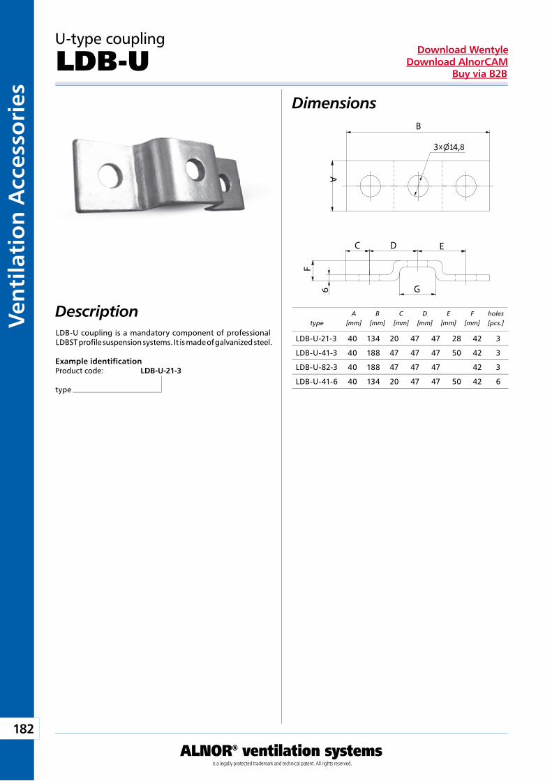
182
ALNOR® ventilation systemsis a legally protected trademark and technical patent. All rights reserved.
Ven
tila
tio
n A
cces
sori
esDownload Wentyle
Download AlnorCAMBuy via B2B
B
A
x3 4
6
C
F
D E
G
typeA
[mm]B
[mm]C
[mm]D
[mm]E
[mm]F
[mm]holes [pcs.]
U-type coupling
LDB-UDimensions
Description
Example identificationProduct code: LDB-U-21-3
type
LDB-U coupling is a mandatory component of professional LDBST profile suspension systems. It is made of galvanized steel. LDB-U-21-3 40 134 20 47 47 28 42 3
LDB-U-41-3 40 188 47 47 47 50 42 3
LDB-U-82-3 40 188 47 47 47 42 3
LDB-U-41-6 40 134 20 47 47 50 42 6
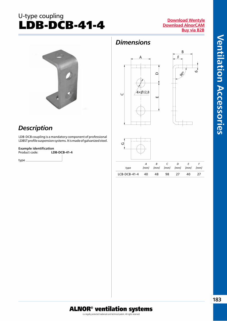
183
ALNOR® ventilation systemsis a legally protected trademark and technical patent. All rights reserved.
Ven
tilation
Accesso
riesDownload Wentyle
Download AlnorCAMBuy via B2B
x
B
G
A
DE
C
F
6
4
typeA
[mm]B
[mm]C
[mm]D
[mm]E
[mm]F
[mm]
U-type coupling
LDB-DCB-41-4Dimensions
Description
Example identificationProduct code: LDB-DCB-41-4
type
LDB-DCB coupling is a mandatory component of professional LDBST profile suspension systems. It is made of galvanized steel.
LCB-DCB-41-4 40 48 98 27 40 27
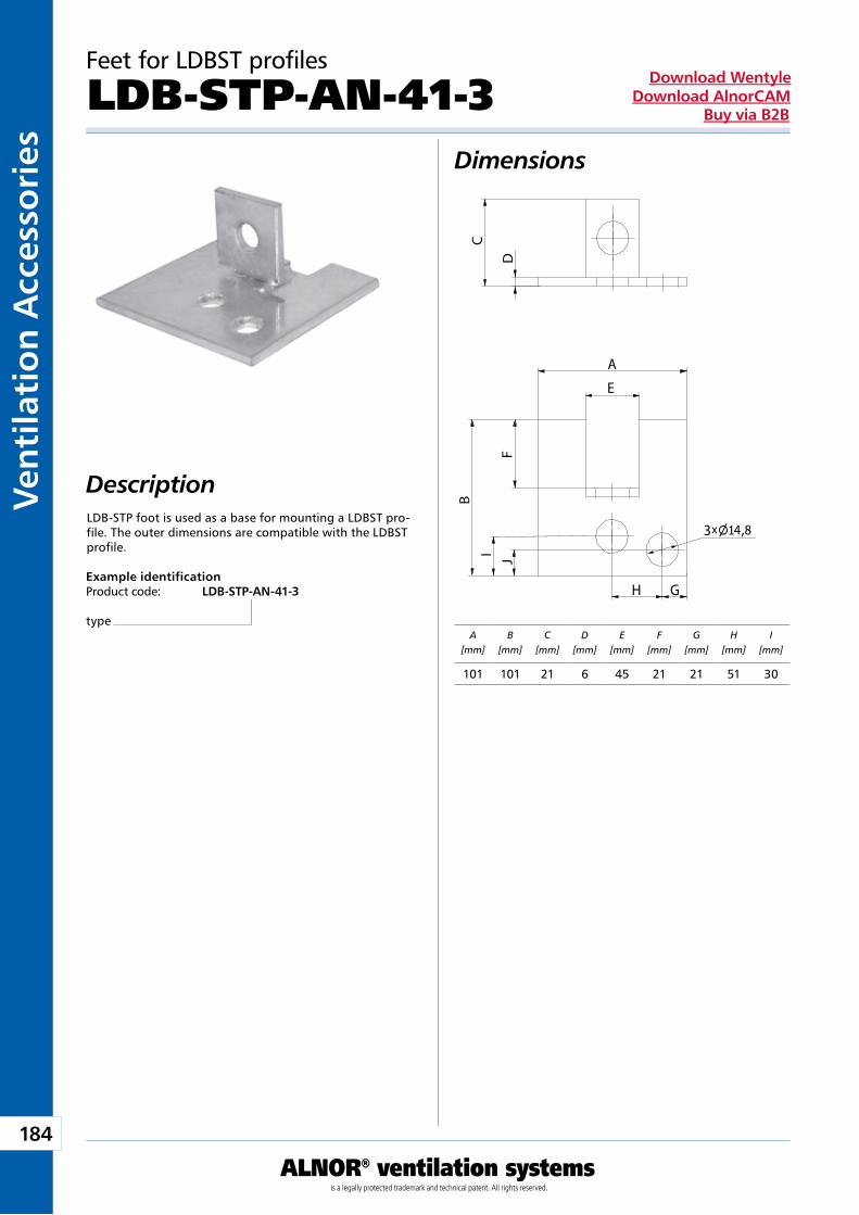
184
ALNOR® ventilation systemsis a legally protected trademark and technical patent. All rights reserved.
Ven
tila
tio
n A
cces
sori
esDownload Wentyle
Download AlnorCAMBuy via B2B
E
B
A
C
DF
x3 4
GH
I J
A[mm]
B[mm]
C[mm]
D[mm]
E[mm]
F[mm]
G[mm]
H[mm]
I[mm]
Feet for LDBST profiles
LDB-STP-AN-41-3Dimensions
Description
Example identificationProduct code: LDB-STP-AN-41-3
type
LDB-STP foot is used as a base for mounting a LDBST pro-file. The outer dimensions are compatible with the LDBST profile.
101 101 21 6 45 21 21 51 30
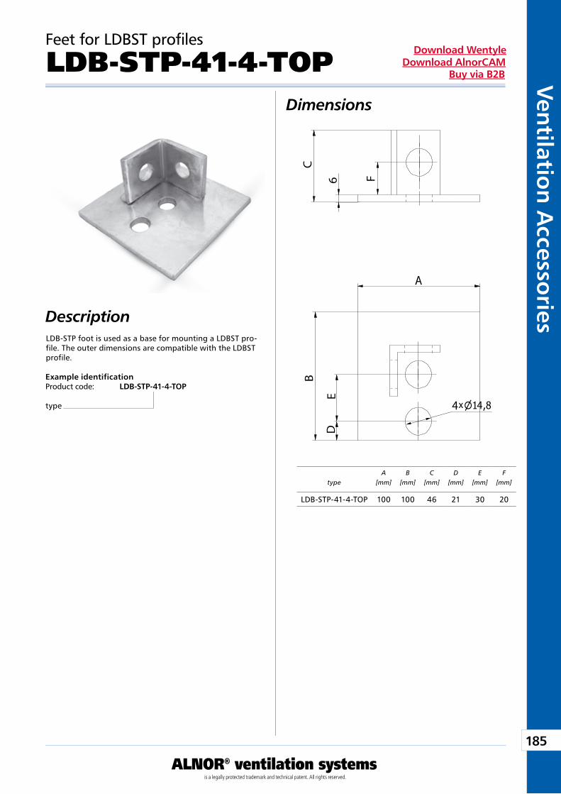
185
ALNOR® ventilation systemsis a legally protected trademark and technical patent. All rights reserved.
Ven
tilation
Accesso
riesDownload Wentyle
Download AlnorCAMBuy via B2B
B
A
C
6
x4 4
DE
F
typeA
[mm]B
[mm]C
[mm]D
[mm]E
[mm]F
[mm]
Feet for LDBST profiles
LDB-STP-41-4-TOPDimensions
Description
Example identificationProduct code: LDB-STP-41-4-TOP
type
LDB-STP foot is used as a base for mounting a LDBST pro-file. The outer dimensions are compatible with the LDBST profile.
LDB-STP-41-4-TOP 100 100 46 21 30 20
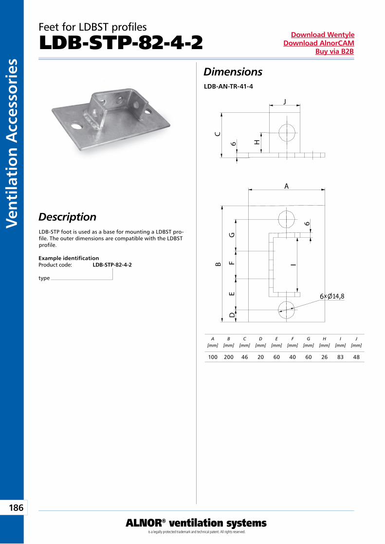
186
ALNOR® ventilation systemsis a legally protected trademark and technical patent. All rights reserved.
Ven
tila
tio
n A
cces
sori
esDownload Wentyle
Download AlnorCAMBuy via B2B
B
A
C
6 H
x6 4
DE
FG
6
I
J
A[mm]
B[mm]
C[mm]
D[mm]
E[mm]
F[mm]
G[mm]
H[mm]
I[mm]
J[mm]
Feet for LDBST profiles
LDB-STP-82-4-2Dimensions
Description
Example identificationProduct code: LDB-STP-82-4-2
type
LDB-STP foot is used as a base for mounting a LDBST pro-file. The outer dimensions are compatible with the LDBST profile.
LDB-AN-TR-41-4
100 200 46 20 60 40 60 26 83 48
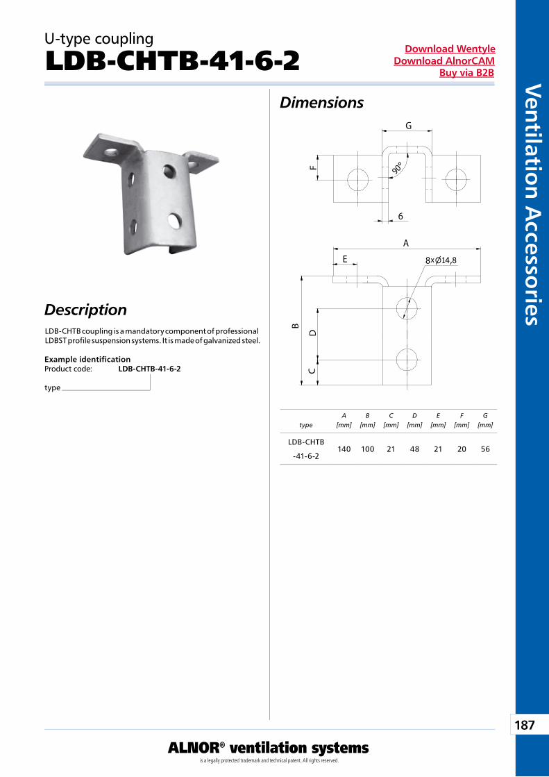
187
ALNOR® ventilation systemsis a legally protected trademark and technical patent. All rights reserved.
Ven
tilation
Accesso
riesDownload Wentyle
Download AlnorCAMBuy via B2B
A
G
F
B
6
x8 4
CD
E
typeA
[mm]B
[mm]C
[mm]D
[mm]E
[mm]F
[mm]G
[mm]
A[mm]
B[mm]
C[mm]
D[mm]
E[mm]
F[mm]
G[mm]
H[mm]
I[mm]
J[mm]
U-type coupling
LDB-CHTB-41-6-2Dimensions
Description
Example identificationProduct code: LDB-CHTB-41-6-2
type
LDB-CHTB coupling is a mandatory component of professional LDBST profile suspension systems. It is made of galvanized steel.
100 200 46 20 60 40 60 26 83 48
LDB-CHTB
-41-6-2140 100 21 48 21 20 56
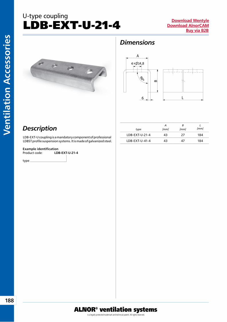
188
ALNOR® ventilation systemsis a legally protected trademark and technical patent. All rights reserved.
Ven
tila
tio
n A
cces
sori
esDownload Wentyle
Download AlnorCAMBuy via B2B
L
B
A
6
x4 4
typeA
[mm]B
[mm]L
[mm]
U-type coupling
LDB-EXT-U-21-4Dimensions
Description
Example identificationProduct code: LDB-EXT-U-21-4
type
LDB-EXT-U coupling is a mandatory component of professional LDBST profile suspension systems. It is made of galvanized steel.
LDB-EXT-U-21-4 43 27 184
LDB-EXT-U-41-4 43 47 184
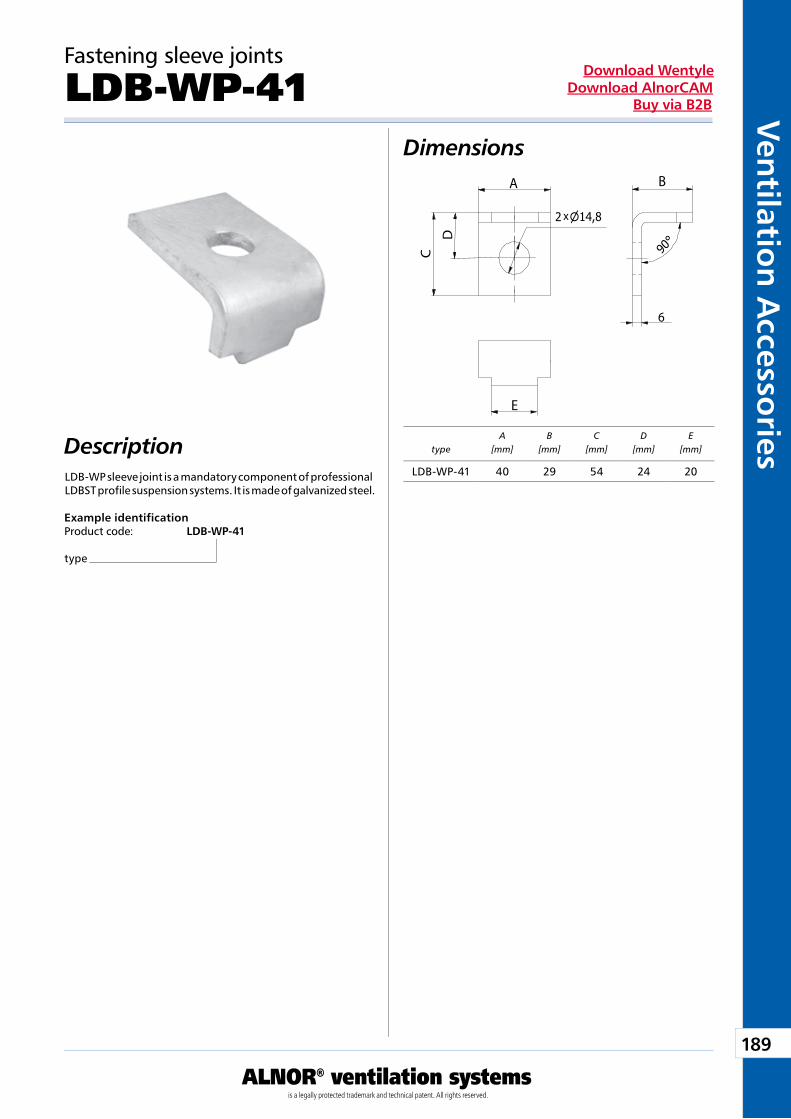
189
ALNOR® ventilation systemsis a legally protected trademark and technical patent. All rights reserved.
Ven
tilation
Accesso
riesDownload Wentyle
Download AlnorCAMBuy via B2B
x
BA
C
D
6
4
E
typeA
[mm]B
[mm]C
[mm]D
[mm]E
[mm]
Fastening sleeve joints
LDB-WP-41Dimensions
Description
Example identificationProduct code: LDB-WP-41
type
LDB-WP sleeve joint is a mandatory component of professional LDBST profile suspension systems. It is made of galvanized steel.
LDB-WP-41 40 29 54 24 20
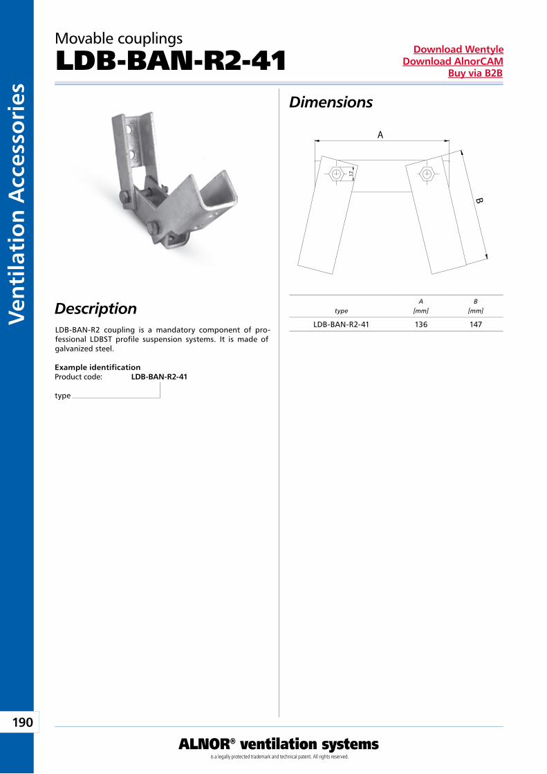
190
ALNOR® ventilation systemsis a legally protected trademark and technical patent. All rights reserved.
Ven
tila
tio
n A
cces
sori
esDownload Wentyle
Download AlnorCAMBuy via B2B
17
A
B
typeA
[mm]B
[mm]
Movable couplings
LDB-BAN-R2-41Dimensions
Description
Example identificationProduct code: LDB-BAN-R2-41
type
LDB-BAN-R2 coupling is a mandatory component of pro-fessional LDBST profile suspension systems. It is made of galvanized steel.
LDB-BAN-R2-41 136 147
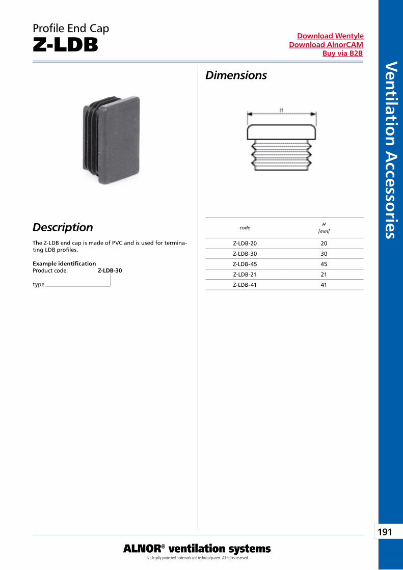
191
ALNOR® ventilation systemsis a legally protected trademark and technical patent. All rights reserved.
Ven
tilation
Accesso
riesDownload Wentyle
Download AlnorCAMBuy via B2B
Description
Profile End Cap
Z-LDB
The Z-LDB end cap is made of PVC and is used for termina-ting LDB profiles.
Example identificationProduct code: Z-LDB-30
type
Dimensions
codeH
[mm]
Z-LDB-20 20
Z-LDB-30 30
Z-LDB-45 45
Z-LDB-21 21
Z-LDB-41 41
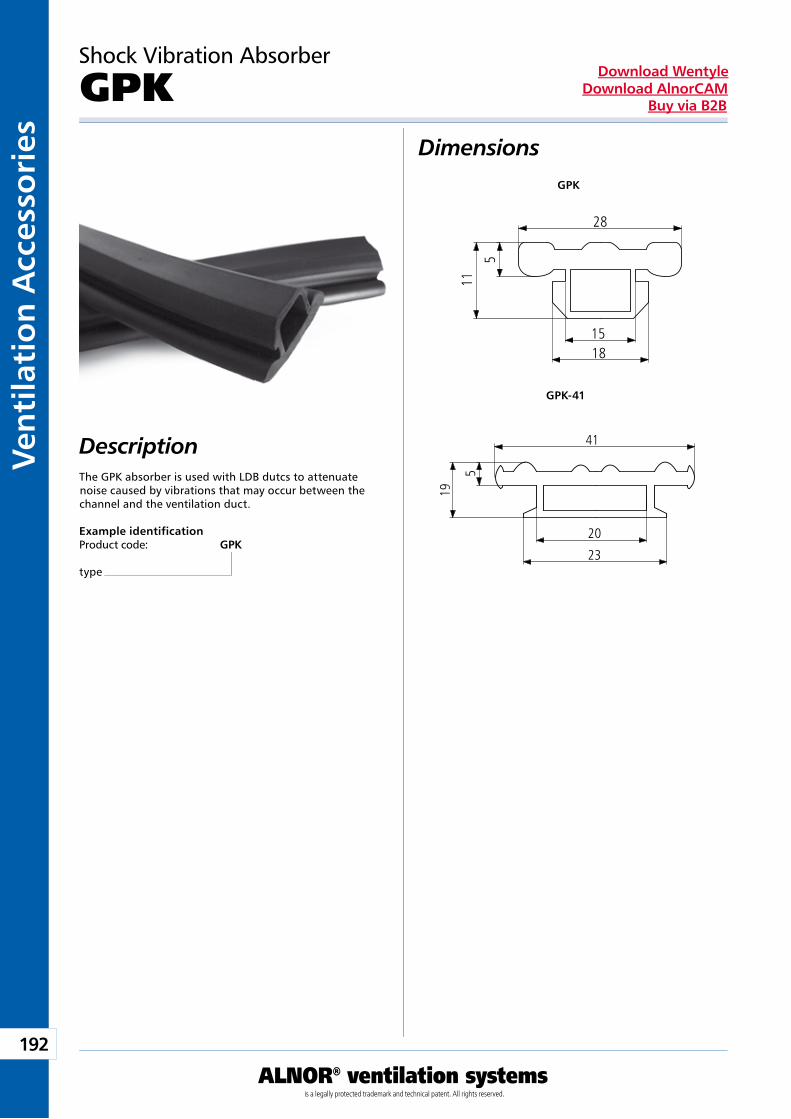
192
ALNOR® ventilation systemsis a legally protected trademark and technical patent. All rights reserved.
Ven
tila
tio
n A
cces
sori
esDownload Wentyle
Download AlnorCAMBuy via B2B
28
5
1518
11
41
5
20
23
19Description
Shock Vibration Absorber
GPK
The GPK absorber is used with LDB dutcs to attenuate noise caused by vibrations that may occur between the channel and the ventilation duct.
Example identificationProduct code: GPK
type
Dimensions
GPK-41
GPK
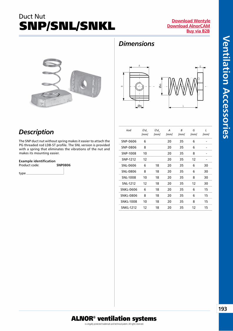
193
ALNOR® ventilation systemsis a legally protected trademark and technical patent. All rights reserved.
Ven
tilation
Accesso
riesDownload Wentyle
Download AlnorCAMBuy via B2B
d
d1
2
Description
Duct Nut
SNP/SNL/SNKL
The SNP duct nut without spring makes it easier to attach the PG threaded rod LDB-ST profile. The SNL version is provided with a spring that eliminates the vibrations of the nut and makes its mounting easier.
Example identificationProduct code: SNP0806
type
Dimensions
kod
d1
[mm] d2
[mm]A
[mm]B
[mm]G
[mm]L
[mm]
SNP-0606 6 20 35 6 -
SNP-0806 8 20 35 6 -
SNP-1008 10 20 35 8 -
SNP-1212 12 20 35 12 -
SNL-0606 6 18 20 35 6 30
SNL-0806 8 18 20 35 6 30
SNL-1008 10 18 20 35 8 30
SNL-1212 12 18 20 35 12 30
SNKL-0606 6 18 20 35 6 15
SNKL-0806 8 18 20 35 6 15
SNKL-1008 10 18 20 35 8 15
SNKL-1212 12 18 20 35 12 15
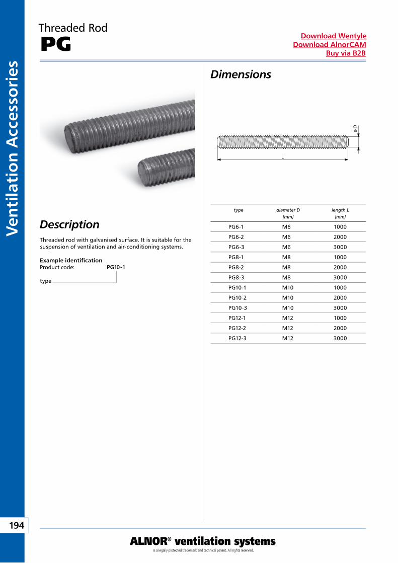
194
ALNOR® ventilation systemsis a legally protected trademark and technical patent. All rights reserved.
Ven
tila
tio
n A
cces
sori
esDownload Wentyle
Download AlnorCAMBuy via B2B
D
L
Ø
Threaded Rod
PGDimensions
DescriptionThreaded rod with galvanised surface. It is suitable for the suspension of ventilation and air-conditioning systems.
Example identificationProduct code: PG10 - 1
type
type diameter D length L [mm] [mm]
PG6-1 M6 1000
PG6-2 M6 2000
PG6-3 M6 3000
PG8-1 M8 1000
PG8-2 M8 2000
PG8-3 M8 3000
PG10-1 M10 1000
PG10-2 M10 2000
PG10-3 M10 3000
PG12-1 M12 1000
PG12-2 M12 2000
PG12-3 M12 3000
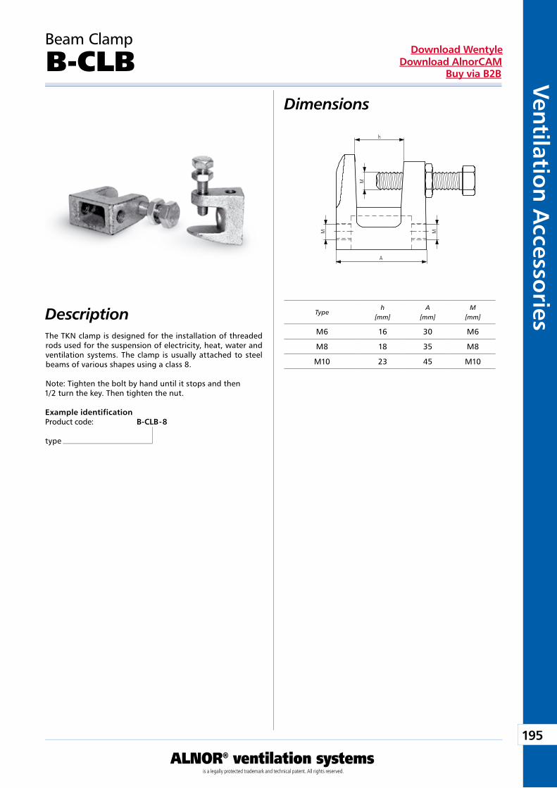
195
ALNOR® ventilation systemsis a legally protected trademark and technical patent. All rights reserved.
Ven
tilation
Accesso
riesDownload Wentyle
Download AlnorCAMBuy via B2B
M
h
A
MM
Beam Clamp
B-CLBDimensions
DescriptionThe TKN clamp is designed for the installation of threaded rods used for the suspension of electricity, heat, water and ventilation systems. The clamp is usually attached to steel beams of various shapes using a class 8.
Note: Tighten the bolt by hand until it stops and then1/2 turn the key. Then tighten the nut.
Example identificationProduct code: B-CLB - 8
type
Typeh
[mm]A
[mm]M
[mm]
M6 16 30 M6
M8 18 35 M8
M10 23 45 M10
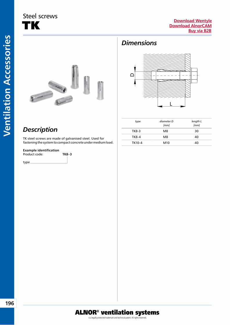
196
ALNOR® ventilation systemsis a legally protected trademark and technical patent. All rights reserved.
Ven
tila
tio
n A
cces
sori
esDownload Wentyle
Download AlnorCAMBuy via B2B
L
D
Steel screws
TKDimensions
DescriptionTK steel screws are made of galvanised steel. Used for fastening the system to compact concrete under medium load.
Example identificationProduct code: TK8 - 3
type
type diameter D length L [mm] [mm]
TK8-3 M8 30
TK8-4 M8 40
TK10-4 M10 40
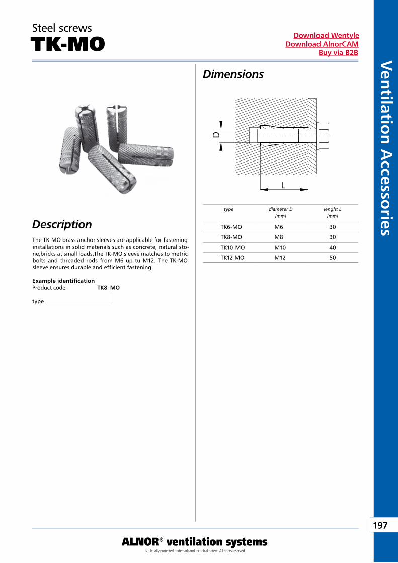
197
ALNOR® ventilation systemsis a legally protected trademark and technical patent. All rights reserved.
Ven
tilation
Accesso
riesDownload Wentyle
Download AlnorCAMBuy via B2B
L
D Description
Dimensions
Steel screws
TK-MO
The TK-MO brass anchor sleeves are applicable for fastening installations in solid materials such as concrete, natural sto-ne,bricks at small loads.The TK-MO sleeve matches to metric bolts and threaded rods from M6 up tu M12. The TK-MO sleeve ensures durable and efficient fastening.
Example identificationProduct code: TK8 - MO
type
type diameter D[mm]
lenght L[mm]
TK6-MO M6 30
TK8-MO M8 30
TK10-MO M10 40
TK12-MO M12 50
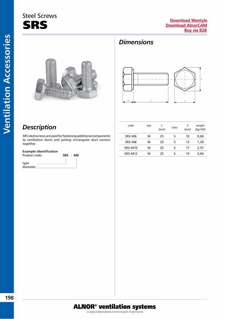
198
ALNOR® ventilation systemsis a legally protected trademark and technical patent. All rights reserved.
Ven
tila
tio
n A
cces
sori
esDownload Wentyle
Download AlnorCAMBuy via B2B
e
SK L
Steel Screws
SRSDimensions
DescriptionSRS steel screws are used for fastening additional components to ventilation ducts and joining rectangular duct corners together.
Example identificationProduct code: SRS - M8
typediameter
code
size L[mm]
classS
[mm]weight[kg/100]
SRS-M6 M 25 5 10 0,66
SRS-M8 M 25 5 13 1,39
SRS-M10 M 25 5 17 2,57
SRS-M12 M 25 5 19 3,66
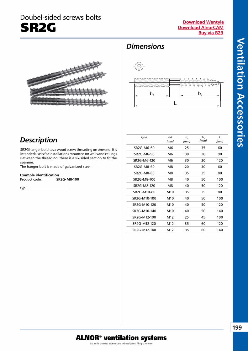
199
ALNOR® ventilation systemsis a legally protected trademark and technical patent. All rights reserved.
Ven
tilation
Accesso
riesDownload Wentyle
Download AlnorCAMBuy via B2B
b b1 2
Doubel-sided screws bolts
SR2GDimensions
DescriptionSR2G hanger bolt has a wood screw threading on one end. It’s intended use is for installations mounted on walls and ceilings. Between the threading, there is a six-sided section to fit the spanner. The hanger bolt is made of galvanized steel.
Example identificationProduct code: SR2G- M8-100
typ
type ød[mm]
b1
[mm]b2
[mm]L
[mm]
SR2G-M6-60 M6 25 35 60
SR2G-M6-90 M6 30 30 90
SR2G-M6-120 M6 30 30 120
SR2G-M8-60 M8 20 30 60
SR2G-M8-80 M8 35 35 80
SR2G-M8-100 M8 40 50 100
SR2G-M8-120 M8 40 50 120
SR2G-M10-80 M10 35 35 80
SR2G-M10-100 M10 40 50 100
SR2G-M10-120 M10 40 50 120
SR2G-M10-140 M10 40 50 140
SR2G-M12-100 M12 25 45 100
SR2G-M12-120 M12 35 60 120
SR2G-M12-140 M12 35 60 140
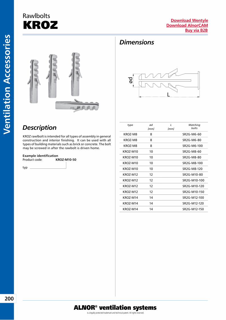
200
ALNOR® ventilation systemsis a legally protected trademark and technical patent. All rights reserved.
Ven
tila
tio
n A
cces
sori
esDownload Wentyle
Download AlnorCAMBuy via B2B
L
ød
Rawlbolts
KROZDimensions
DescriptionKROZ rawlbolt is intended for all types of assembly in general construction and interior finishing. It can be used with all types of building materials such as brick or concrete. The bolt may be screwed in after the rawbolt is driven home.
Example identificationProduct code: KROZ-M10-50
typ
type ød[mm]
L[mm]
Matching bolts
KROZ-M8 8 SR2G-M6-60
KROZ-M8 8 SR2G-M6-80
KROZ-M8 8 SR2G-M6-100
KROZ-M10 10 SR2G-M8-60
KROZ-M10 10 SR2G-M8-80
KROZ-M10 10 SR2G-M8-100
KROZ-M10 10 SR2G-M8-120
KROZ-M12 12 SR2G-M10-80
KROZ-M12 12 SR2G-M10-100
KROZ-M12 12 SR2G-M10-120
KROZ-M12 12 SR2G-M10-150
KROZ-M14 14 SR2G-M12-100
KROZ-M14 14 SR2G-M12-120
KROZ-M14 14 SR2G-M12-150
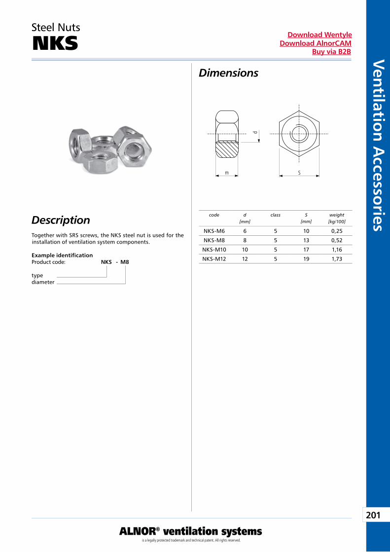
201
ALNOR® ventilation systemsis a legally protected trademark and technical patent. All rights reserved.
Ven
tilation
Accesso
riesDownload Wentyle
Download AlnorCAMBuy via B2B
Sm
d
Steel Nuts
NKSDimensions
DescriptionTogether with SRS screws, the NKS steel nut is used for the installation of ventilation system components.
Example identificationProduct code: NKS - M8
typediameter
code d[mm]
class S[mm]
weight[kg/100]
NKS-M6 6 5 10 0,25
NKS-M8 8 5 13 0,52
NKS-M10 10 5 17 1,16
NKS-M12 12 5 19 1,73
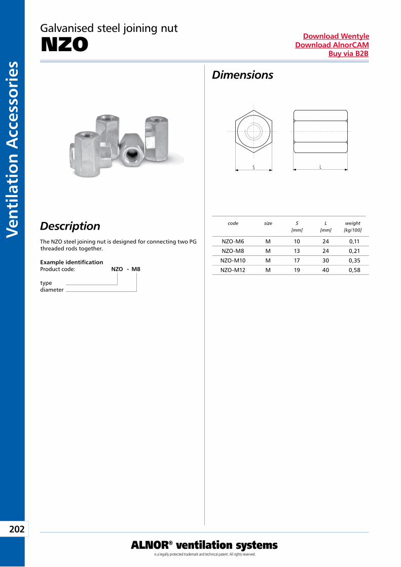
202
ALNOR® ventilation systemsis a legally protected trademark and technical patent. All rights reserved.
Ven
tila
tio
n A
cces
sori
esDownload Wentyle
Download AlnorCAMBuy via B2B
S L
Galvanised steel joining nut
NZODimensions
DescriptionThe NZO steel joining nut is designed for connecting two PG threaded rods together.
Example identificationProduct code: NZO - M8
typediameter
code
size S[mm]
L[mm]
weight[kg/100]
NZO-M6 M 10 24 0,11
NZO-M8 M 13 24 0,21
NZO-M10 M 17 30 0,35
NZO-M12 M 19 40 0,58
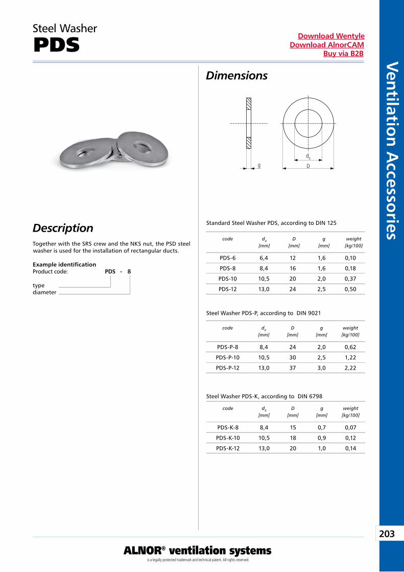
203
ALNOR® ventilation systemsis a legally protected trademark and technical patent. All rights reserved.
Ven
tilation
Accesso
riesDownload Wentyle
Download AlnorCAMBuy via B2B
g D
d0
Steel Washer
PDSDimensions
DescriptionTogether with the SRS crew and the NKS nut, the PSD steel washer is used for the installation of rectangular ducts.
Example identificationProduct code: PDS - 8
typediameter
Standard Steel Washer PDS, according to DIN 125
Steel Washer PDS-P, according to DIN 9021
code
d0
[mm]D
[mm]g
[mm]weight[kg/100]
Steel Washer PDS-K, according to DIN 6798
PDS-6 6,4 12 1,6 0,10
PDS-8 8,4 16 1,6 0,18
PDS-10 10,5 20 2,0 0,37
PDS-12 13,0 24 2,5 0,50
code
d0
[mm]D
[mm]g
[mm]weight[kg/100]
PDS-P-8 8,4 24 2,0 0,62
PDS-P-10 10,5 30 2,5 1,22
PDS-P-12 13,0 37 3,0 2,22
code
d0
[mm]D
[mm]g
[mm]weight[kg/100]
PDS-K-8 8,4 15 0,7 0,07
PDS-K-10 10,5 18 0,9 0,12
PDS-K-12 13,0 20 1,0 0,14
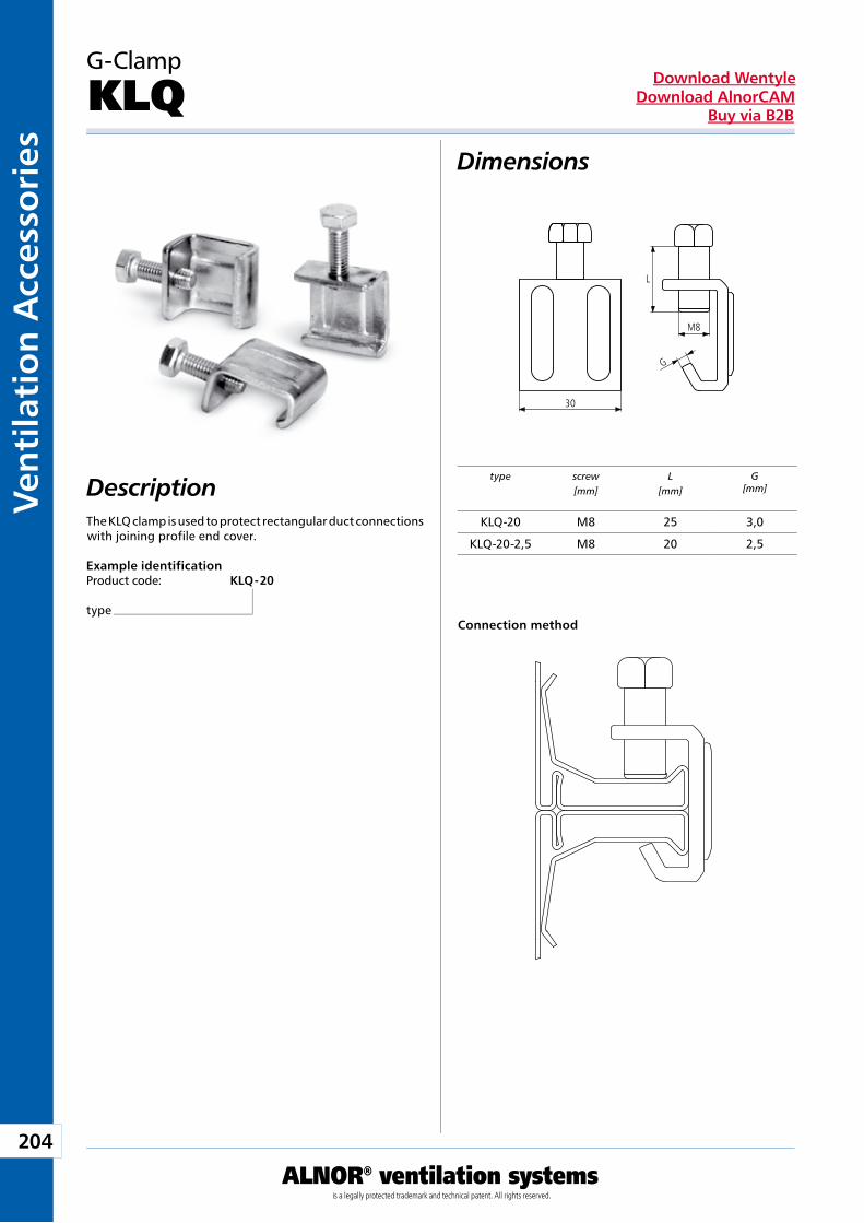
204
ALNOR® ventilation systemsis a legally protected trademark and technical patent. All rights reserved.
Ven
tila
tio
n A
cces
sori
esDownload Wentyle
Download AlnorCAMBuy via B2B
30
L
M8
G
G-Clamp
KLQDimensions
DescriptionThe KLQ clamp is used to protect rectangular duct connections with joining profile end cover.
Example identificationProduct code: KLQ - 20
typeConnection method
type screw[mm]
L[mm]
G[mm]
KLQ-20 M8 25 3,0
KLQ-20-2,5 M8 20 2,5
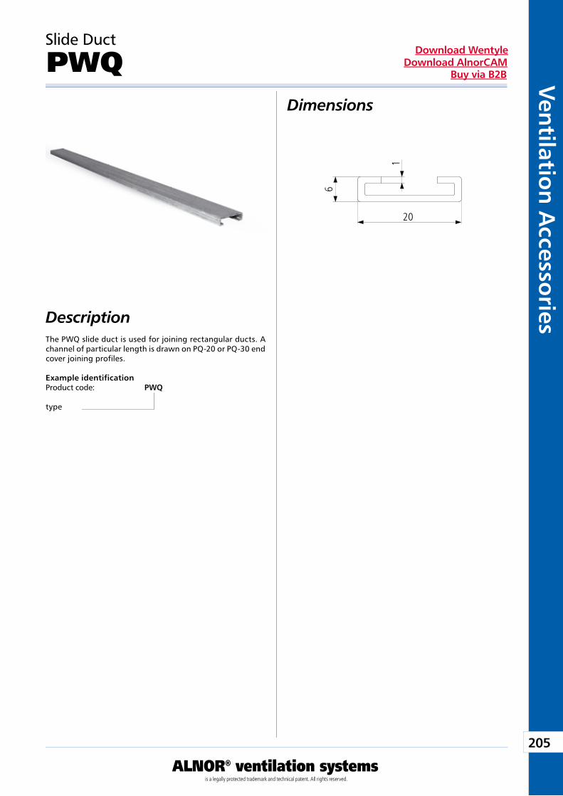
205
ALNOR® ventilation systemsis a legally protected trademark and technical patent. All rights reserved.
Ven
tilation
Accesso
riesDownload Wentyle
Download AlnorCAMBuy via B2B
20
6
1
Slide Duct
PWQDimensions
DescriptionThe PWQ slide duct is used for joining rectangular ducts. A channel of particular length is drawn on PQ-20 or PQ-30 end cover joining profiles.
Example identificationProduct code: PWQ
type
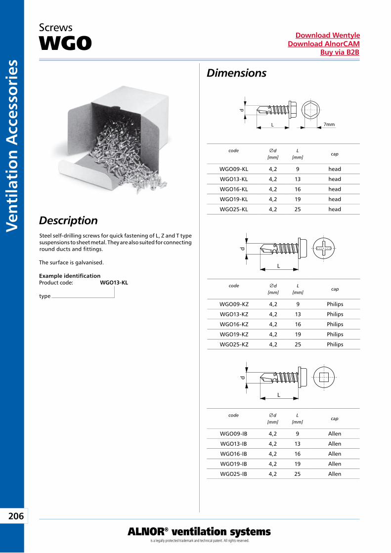
206
ALNOR® ventilation systemsis a legally protected trademark and technical patent. All rights reserved.
Ven
tila
tio
n A
cces
sori
esDownload Wentyle
Download AlnorCAMBuy via B2B
d
L 7mm
d
L
d
L
Dimensions
Description
Screws
WGO
Steel self-drilling screws for quick fastening of L, Z and T type suspensions to sheet metal. They are also suited for connecting round ducts and fittings.
The surface is galvanised.
Example identificationProduct code: WGO13-KL
type
code
cap
head
head
head
head
head
code
cap
Philips
Philips
Philips
Philips
Philips
code
cap
Allen
Allen
Allen
Allen
Allen
d
[mm]L
[mm]
WGO09-KL 4,2 9
WGO13-KL 4,2 13
WGO16-KL 4,2 16
WGO19-KL 4,2 19
WGO25-KL 4,2 25
d
[mm]L
[mm]
WGO09-KZ 4,2 9
WGO13-KZ 4,2 13
WGO16-KZ 4,2 16
WGO19-KZ 4,2 19
WGO25-KZ 4,2 25
d[mm]
L[mm]
WGO09-IB 4,2 9
WGO13-IB 4,2 13
WGO16-IB 4,2 16
WGO19-IB 4,2 19
WGO25-IB 4,2 25
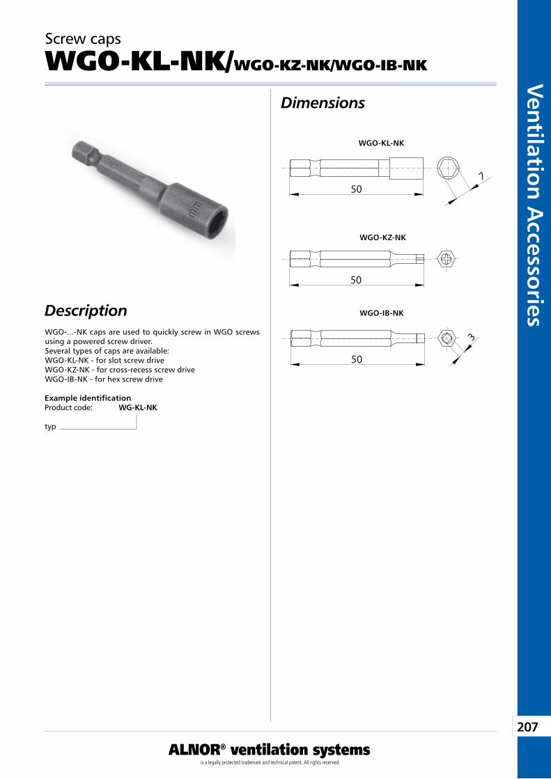
207
ALNOR® ventilation systemsis a legally protected trademark and technical patent. All rights reserved.
Ven
tilation
Accesso
riesDownload Wentyle
Download AlnorCAMBuy via B2B
50
50
3
7
50
WGO-KL-NK
WGO-KZ-NK
WGO-IB-NK
Screw caps
WGO-KL-NK/WGO-KZ-NK/WGO-IB-NK
Dimensions
DescriptionWGO-...-NK caps are used to quickly screw in WGO screws using a powered screw driver. Several types of caps are available: WGO-KL-NK - for slot screw drive WGO-KZ-NK - for cross-recess screw drive WGO-IB-NK - for hex screw drive
Example identificationProduct code: WG-KL-NK
typ
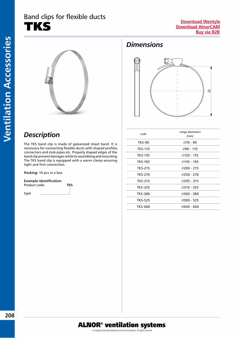
208
ALNOR® ventilation systemsis a legally protected trademark and technical patent. All rights reserved.
Ven
tila
tio
n A
cces
sori
esDownload Wentyle
Download AlnorCAMBuy via B2B
D
Band clips for flexible ducts
TKS
DescriptionThe TKS band clip is made of galvanized sheet band. It is necessary for connecting flexible ducts with shaped profiles, connectors and stub pipes etc. Properly shaped edges of the band clip prevent damages while its assembling and mounting. The TKS band clip is equipped with a worm clamp ensuring tight and firm connection.
Packing: 10 pcs in a box
Example identificationProduct code: TKS
type
Dimensions
coderange diameters
[mm]
TKS-90 70 - 90
TKS-110 90 - 110
TKS-135 120 - 135
TKS-165 145 - 165
TKS-215 200 - 215
TKS-270 250 - 270
TKS-315 295 - 315
TKS-325 310 - 325
TKS-380 360 - 380
TKS-525 500 - 525
TKS-660 640 - 660
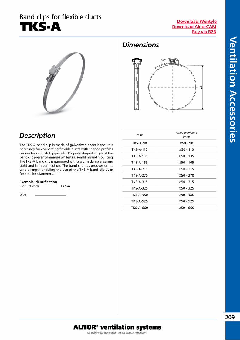
209
ALNOR® ventilation systemsis a legally protected trademark and technical patent. All rights reserved.
Ven
tilation
Accesso
riesDownload Wentyle
Download AlnorCAMBuy via B2B
D
Band clips for flexible ducts
TKS-A
Description
Example identificationProduct code: TKS-A
type
Dimensions
The TKS-A band clip is made of galvanized sheet band. It is necessary for connecting flexible ducts with shaped profiles, connectors and stub pipes etc. Properly shaped edges of the band clip prevent damages while its assembling and mounting. The TKS-A band clip is equipped with a worm clamp ensuring tight and firm connection. The band clip has grooves on its whole length enabling the use of the TKS-A band clip even for smaller diameters.
coderange diameters
[mm]
TKS-A-90 50 - 90
TKS-A-110 50 - 110
TKS-A-135 50 - 135
TKS-A-165 50 - 165
TKS-A-215 50 - 215
TKS-A-270 50 - 270
TKS-A-315 50 - 315
TKS-A-325 50 - 325
TKS-A-380 50 - 380
TKS-A-525 50 - 525
TKS-A-660 50 - 660
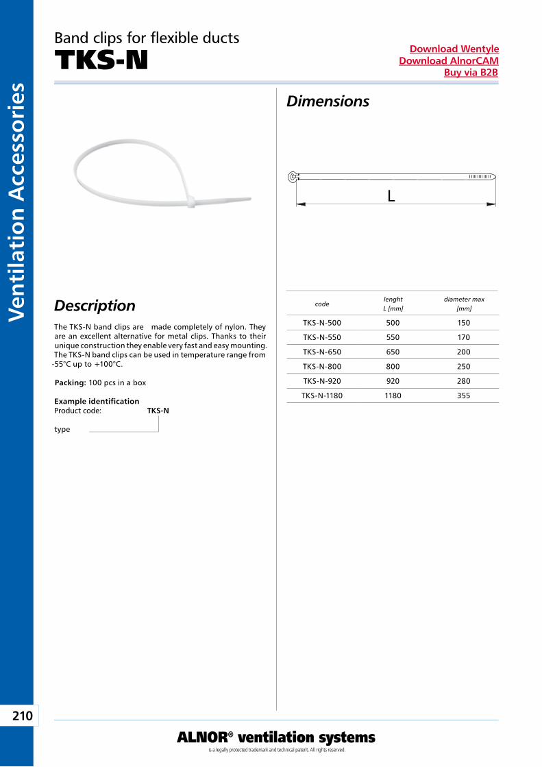
210
ALNOR® ventilation systemsis a legally protected trademark and technical patent. All rights reserved.
Ven
tila
tio
n A
cces
sori
esDownload Wentyle
Download AlnorCAMBuy via B2B
L
Band clips for flexible ducts
TKS-N
DescriptionThe TKS-N band clips are made completely of nylon. They are an excellent alternative for metal clips. Thanks to their unique construction they enable very fast and easy mounting. The TKS-N band clips can be used in temperature range from
-55°C up to +100°C.
Packing: 100 pcs in a box
Example identificationProduct code: TKS-N
type
Dimensions
codelenghtL [mm]
diameter max[mm]
TKS-N-500 500 150
TKS-N-550 550 170
TKS-N-650 650 200
TKS-N-800 800 250
TKS-N-920 920 280
TKS-N-1180 1180 355
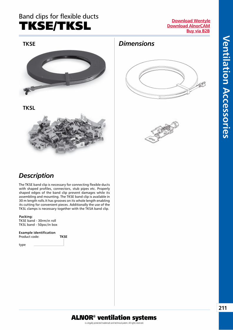
211
ALNOR® ventilation systemsis a legally protected trademark and technical patent. All rights reserved.
Ven
tilation
Accesso
riesDownload Wentyle
Download AlnorCAMBuy via B2B
Band clips for flexible ducts
TKSE/TKSLTKSE
TKSL
DescriptionThe TKSE band clip is necessary for connecting flexible ducts with shaped profiles, connectors, stub pipes etc. Properly shaped edges of the band clip prevent damages while its assembling and mounting. The TKSE band clip is available in 30 m length rolls.It has grooves on its whole length enabling its cutting for convenient pieces. Additionally the use of the TKSL clamps is necessary together with the TKSA band clip.
Packing: TKSE band - 30rm/in rollTKSL band - 50psc/in box
Example identificationProduct code: TKSE
type
Dimensions
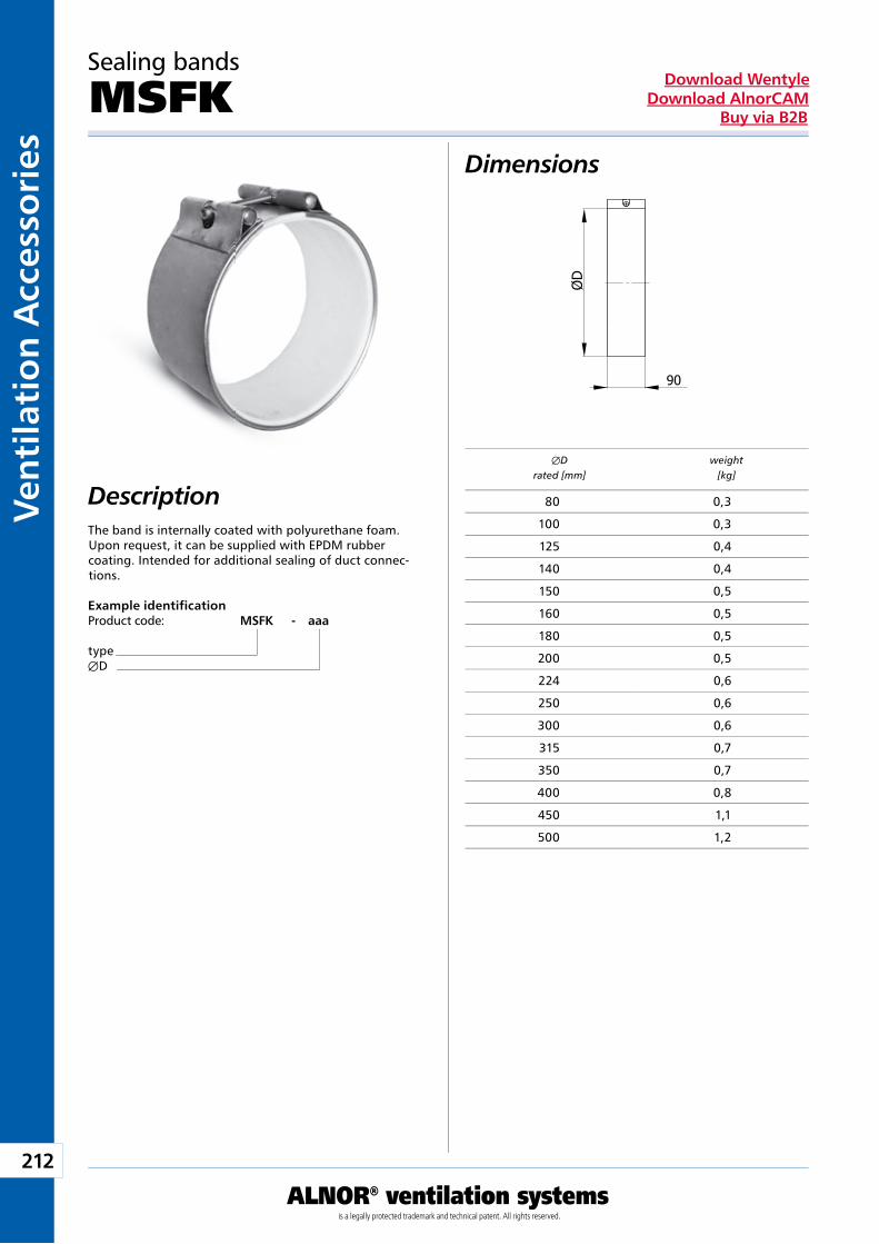
212
ALNOR® ventilation systemsis a legally protected trademark and technical patent. All rights reserved.
Ven
tila
tio
n A
cces
sori
esDownload Wentyle
Download AlnorCAMBuy via B2B
Dimensions
Description
Sealing bands
MSFK
The band is internally coated with polyurethane foam. Upon request, it can be supplied with EPDM rubber coating. Intended for additional sealing of duct connec-tions.
Example identificationProduct code: MSFK - aaa
typeÆD
ÆD weight rated [mm] [kg]
80 0,3
100 0,3
125 0,4
140 0,4
150 0,5
160 0,5
180 0,5
200 0,5
224 0,6
250 0,6
300 0,6
315 0,7
350 0,7
400 0,8
450 1,1
500 1,2
Prefabricated Ducts
Producent zastrzega sobie prawo do dokonywania zmian w wymiarach i danych technicznych produktów ze względu na ciągłe ich doskonalenie
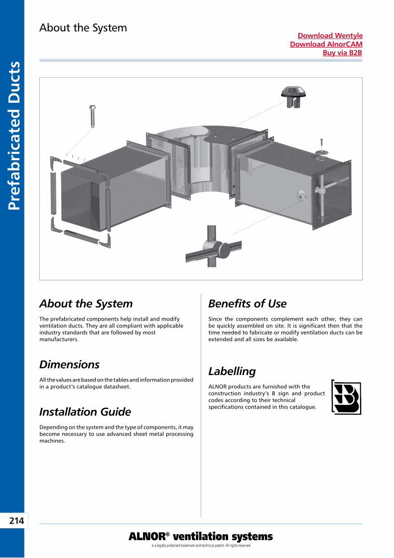
214
ALNOR® ventilation systemsis a legally protected trademark and technical patent. All rights reserved.
Pref
abri
cate
d D
uct
sDownload Wentyle
Download AlnorCAMBuy via B2B
About the System
About the SystemThe prefabricated components help install and modify ventilation ducts. They are all compliant with applicable industry standards that are followed by most manufacturers.
Dimensions All the values are based on the tables and information provided in a product’s catalogue datasheet.
Installation GuideDepending on the system and the type of components, it may become necessary to use advanced sheet metal processing machines.
Benefits of UseSince the components complement each other, they can be quickly assembled on site. It is significant then that the time needed to fabricate or modify ventilation ducts can be extended and all sizes be available.
LabellingALNOR products are furnished with the construction industry’s B sign and product codes according to their technical specifications contained in this catalogue.
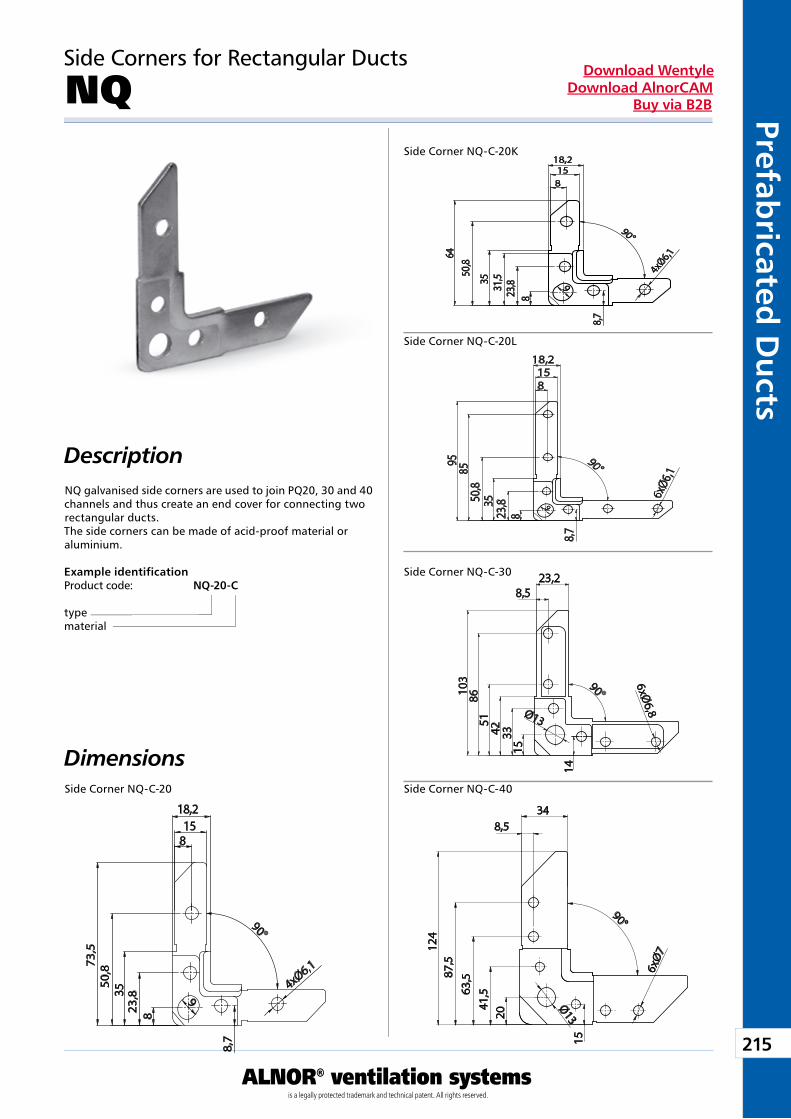
215
ALNOR® ventilation systemsis a legally protected trademark and technical patent. All rights reserved.
Prefabricated
Du
ctsDownload Wentyle
Download AlnorCAMBuy via B2B
Dimensions
Description
Side Corners for Rectangular Ducts
NQ
NQ galvanised side corners are used to join PQ20, 30 and 40channels and thus create an end cover for connecting tworectangular ducts.The side corners can be made of acid-proof material oraluminium.
Example identificationProduct code: NQ-20-C
typematerial
Side Corner NQ-C-20 Side Corner NQ-C-40
Side Corner NQ-C-20K
Side Corner NQ-C-20L
Side Corner NQ-C-30
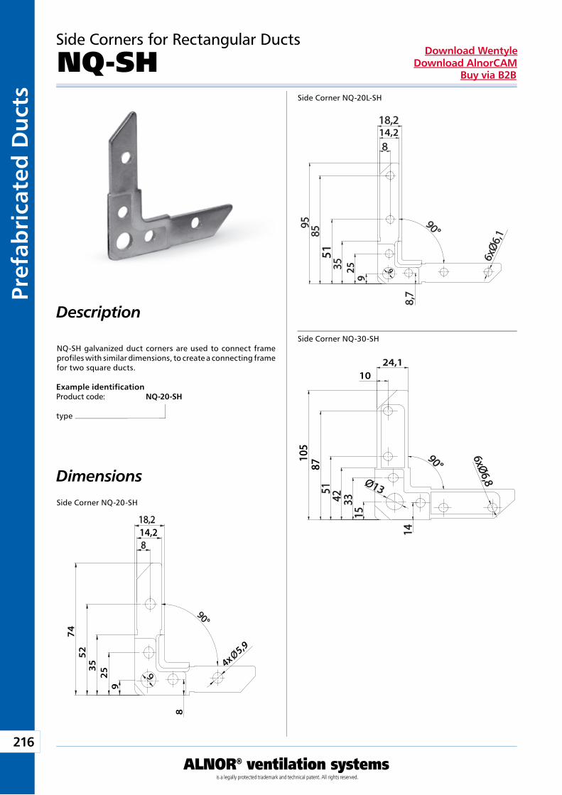
216
ALNOR® ventilation systemsis a legally protected trademark and technical patent. All rights reserved.
Pref
abri
cate
d D
uct
sDownload Wentyle
Download AlnorCAMBuy via B2B
Side Corners for Rectangular Ducts
NQ-SH
NQ-SH galvanized duct corners are used to connect frame profiles with similar dimensions, to create a connecting frame for two square ducts.
Example identificationProduct code: NQ-20-SH
type
Side Corner NQ-20-SH
Description
Side Corner NQ-20L-SH
Dimensions
Side Corner NQ-30-SH
14,2
4x 5,9
7452
3525
9
8
14,2
51
259
24,110
105
87
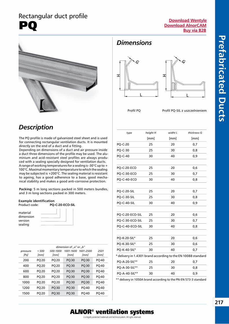
217
ALNOR® ventilation systemsis a legally protected trademark and technical patent. All rights reserved.
Prefabricated
Du
ctsDownload Wentyle
Download AlnorCAMBuy via B2B
Description
Dimensions
Rectangular duct profile
PQ
The PQ profile is made of galvanized steel sheet and is used for connecting rectangular ventilation ducts. It is mounted directly on the end of a duct and a fitting. Depending on dimensions of a duct and air pressure inside a duct three dimensions of the profile may be used. The alu-minium and acid-resistant steel profiles are always produ-ced with a sealing specially designed for ventilation ducts.A range of working temperatures for a sealing is -30°C up to + 100°C. Maximal momentary temperature to which the sealing may be subjected is +200°C. The sealing material is resistant to ageing, has a good adherence to a base, good mecha-nical stability and makes a good anti-corrosive protection.
Packing: 5 m long sections packed in 500 meters bundles, and 3 m long sections packed in 300 meters.
Example identificationProduct code: PQ-C-20-ECO-SIL
materialdimensionversionsealing
type height H widht L thickness G
[mm] [mm] [mm]
dimension of „a” or „b”pressure
[Pa]< 500[mm]
500-1000[mm]
1001-1600[mm]
1601-2500[mm]
2501[mm]
Profil PQ Profil PQ-SIL z uszczelnieniem
PQ-C-20 25 20 0,7
PQ-C-30 25 30 0,8
PQ-C-40 30 40 0,9
PQ-C-20-ECO 25 20 0,6
PQ-C-30-ECO 25 30 0,7
PQ-C-40-ECO 30 40 0,8
PQ-C-20-SIL 25 20 0,7
PQ-C-30-SIL 25 30 0,8
PQ-C-40-SIL 30 40 0,9
PQ-C-20-ECO-SIL 25 20 0,6
PQ-C-30-ECO-SIL 25 30 0,7
PQ-C-40-ECO-SIL 30 40 0,8
PQ-K-20-SIL* 25 20 0,6
PQ-K-30-SIL* 25 30 0,6
PQ-K-40-SIL* 30 40 0,7
200 PQ 20 PQ 20 PQ 30 PQ 30 PQ 40
400 PQ 20 PQ 20 PQ 30 PQ 30 PQ 40
600 PQ 20 PQ 20 PQ 30 PQ 30 PQ 40
800 PQ 20 PQ 20 PQ 30 PQ 30 PQ 40
1000 PQ 20 PQ 20 PQ 30 PQ 30 PQ 40
1200 PQ 20 PQ 30 PQ 30 PQ 40 PQ 40
1500 PQ 20 PQ 30 PQ 30 PQ 40 PQ 40
* delivery in 1.4301 brand according to the EN 10088 standard
PQ-A-20-SIL** 25 20 0,7
PQ-A-30-SIL** 25 30 0,8
PQ-A-40-SIL** 30 40 0,9
** delivery in 1050A brand according to the PN-EN 573-3 standard
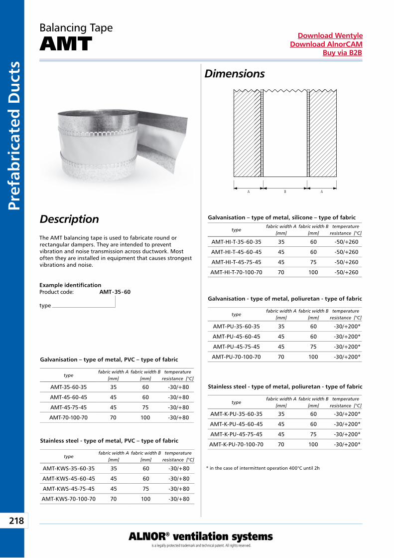
218
ALNOR® ventilation systemsis a legally protected trademark and technical patent. All rights reserved.
Pref
abri
cate
d D
uct
sDownload Wentyle
Download AlnorCAMBuy via B2B
Balancing Tape
AMT
The AMT balancing tape is used to fabricate round or rectangular dampers. They are intended to prevent vibration and noise transmission across ductwork. Most often they are installed in equipment that causes strongest vibrations and noise.
Example identificationProduct code: AMT - 35 - 60
type
Description
Dimensions
Galvanisation – type of metal, silicone – type of fabric
typefabric width A
[mm]fabric width B
[mm]temperature
resistance [°C]
Galvanisation – type of metal, PVC – type of fabric
typefabric width A
[mm]fabric width B
[mm]temperature
resistance [°C]
Stainless steel - type of metal, PVC – type of fabric
typefabric width A
[mm]fabric width B
[mm]temperature
resistance [°C]
Galvanisation - type of metal, poliuretan - type of fabric
typefabric width A
[mm]fabric width B
[mm]temperature
resistance [°C]
Stainless steel - type of metal, poliuretan - type of fabric
typefabric width A
[mm]fabric width B
[mm]temperature
resistance [°C]
* in the case of intermittent operation 400°C until 2h
A B A
AMT-HI-T-35-60-35 35 60 -50/+260
AMT-HI-T-45-60-45 45 60 -50/+260
AMT-HI-T-45-75-45 45 75 -50/+260
AMT-HI-T-70-100-70 70 100 -50/+260
AMT-35-60-35 35 60 -30/+80
AMT-45-60-45 45 60 -30/+80
AMT-45-75-45 45 75 -30/+80
AMT-70-100-70 70 100 -30/+80
AMT-KWS-35-60-35 35 60 -30/+80
AMT-KWS-45-60-45 45 60 -30/+80
AMT-KWS-45-75-45 45 75 -30/+80
AMT-KWS-70-100-70 70 100 -30/+80
AMT-PU-35-60-35 35 60 -30/+200*
AMT-PU-45-60-45 45 60 -30/+200*
AMT-PU-45-75-45 45 75 -30/+200*
AMT-PU-70-100-70 70 100 -30/+200*
AMT-K-PU-35-60-35 35 60 -30/+200*
AMT-K-PU-45-60-45 45 60 -30/+200*
AMT-K-PU-45-75-45 45 75 -30/+200*
AMT-K-PU-70-100-70 70 100 -30/+200*
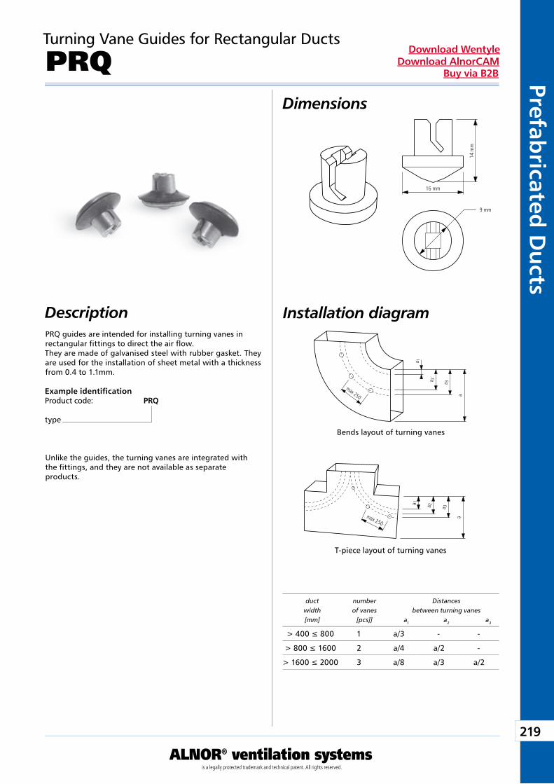
219
ALNOR® ventilation systemsis a legally protected trademark and technical patent. All rights reserved.
Prefabricated
Du
ctsDownload Wentyle
Download AlnorCAMBuy via B2B
Turning Vane Guides for Rectangular Ducts
PRQDimensions
DescriptionPRQ guides are intended for installing turning vanes in rectangular fittings to direct the air flow.They are made of galvanised steel with rubber gasket. They are used for the installation of sheet metal with a thickness from 0.4 to 1.1mm.
Example identificationProduct code: PRQ
type
Unlike the guides, the turning vanes are integrated with the fittings, and they are not available as separate products.
Installation diagram
T-piece layout of turning vanes
duct number Distances width of vanes between turning vanes [mm] [pcs]] a1 a2 a3
Bends layout of turning vanes
max 250
a 1
a 2 a 3
a
max 250
a 1 a 2 a 3
a
max 250a 1
a 2 a 3
a
max 250
a 1 a 2 a 3
a
9 mm
14 m
m
16 mm
> 400 £ 800 1 a/3 - -
> 800 £ 1600 2 a/4 a/2 -
> 1600 £ 2000 3 a/8 a/3 a/2
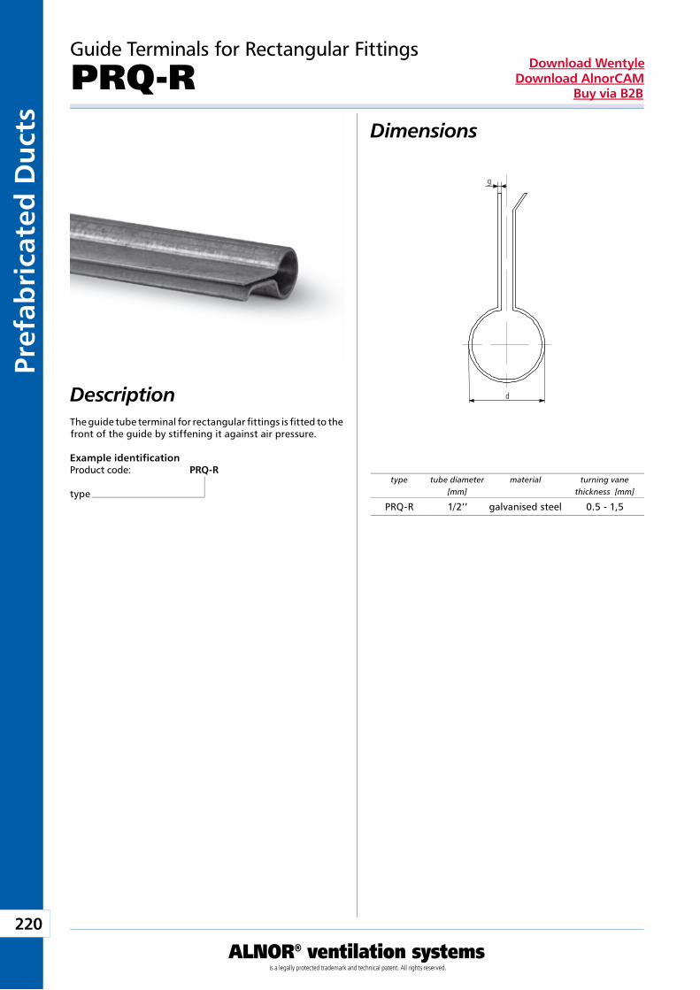
220
ALNOR® ventilation systemsis a legally protected trademark and technical patent. All rights reserved.
Pref
abri
cate
d D
uct
sDownload Wentyle
Download AlnorCAMBuy via B2B
Guide Terminals for Rectangular Fittings
PRQ-R
DescriptionThe guide tube terminal for rectangular fittings is fitted to the front of the guide by stiffening it against air pressure.
Example identificationProduct code: PRQ-R
type
Dimensions
type tube diameter [mm]
material turning vane thickness [mm]
PRQ-R 1/2’’ galvanised steel 0.5 - 1,5
d
g
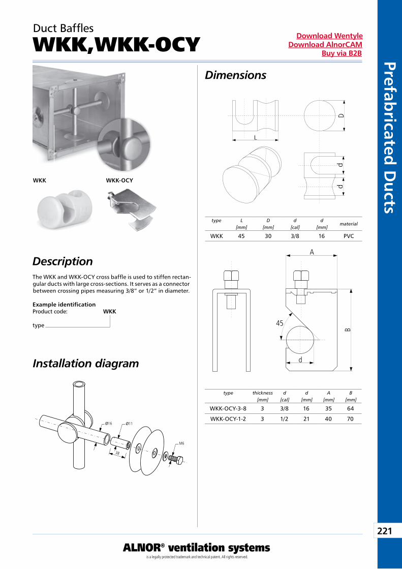
221
ALNOR® ventilation systemsis a legally protected trademark and technical patent. All rights reserved.
Prefabricated
Du
ctsDownload Wentyle
Download AlnorCAMBuy via B2B
Example identificationProduct code: WKK
type
Duct Baffles
WKK,WKK-OCYDimensions
DescriptionThe WKK and WKK-OCY cross baffle is used to stiffen rectan-gular ducts with large cross-sections. It serves as a connector between crossing pipes measuring 3/8” or 1/2” in diameter.
Installation diagram
type L[mm]
D[mm]
d[cal]
d[mm]
material
WKK
type thickness[mm]
d[cal]
d[mm]
A[mm]
B[mm]
WKK-OCY
dd
L
DB
45
d
A
WKK 45 30 3/8 16 PVC
WKK-OCY-3-8 3 3/8 16 35 64
WKK-OCY-1-2 3 1/2 21 40 70
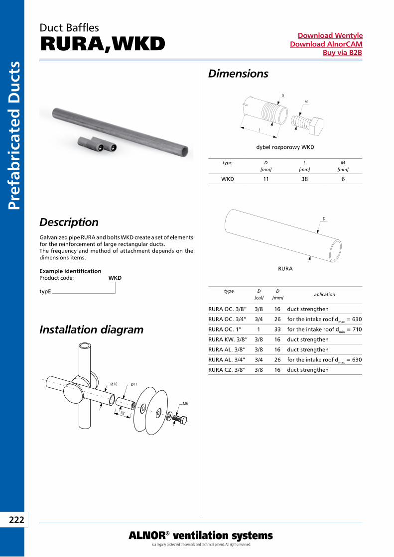
222
ALNOR® ventilation systemsis a legally protected trademark and technical patent. All rights reserved.
Pref
abri
cate
d D
uct
sDownload Wentyle
Download AlnorCAMBuy via B2B
Duct Baffles
RURA,WKDDimensions
DescriptionGalvanized pipe RURA and bolts WKD create a set of elements for the reinforcement of large rectangular ducts.The frequency and method of attachment depends on the dimensions items.
Example identificationProduct code: WKD
typE
Installation diagram
RURA
dybel rozporowy WKD
type D[cal]
D[mm]
aplication
type D[mm]
L[mm]
M[mm]
L
DM
D
WKD 11 38 6
RURA OC. 3/8” 3/8 16 duct strengthen
RURA OC. 3/4” 3/4 26 for the intake roof dmax = 630
RURA OC. 1” 1 33 for the intake roof dmin = 710
RURA KW. 3/8” 3/8 16 duct strengthen
RURA AL. 3/8” 3/8 16 duct strengthen
RURA AL. 3/4” 3/4 26 for the intake roof dmax = 630
RURA CZ. 3/8” 3/8 16 duct strengthen
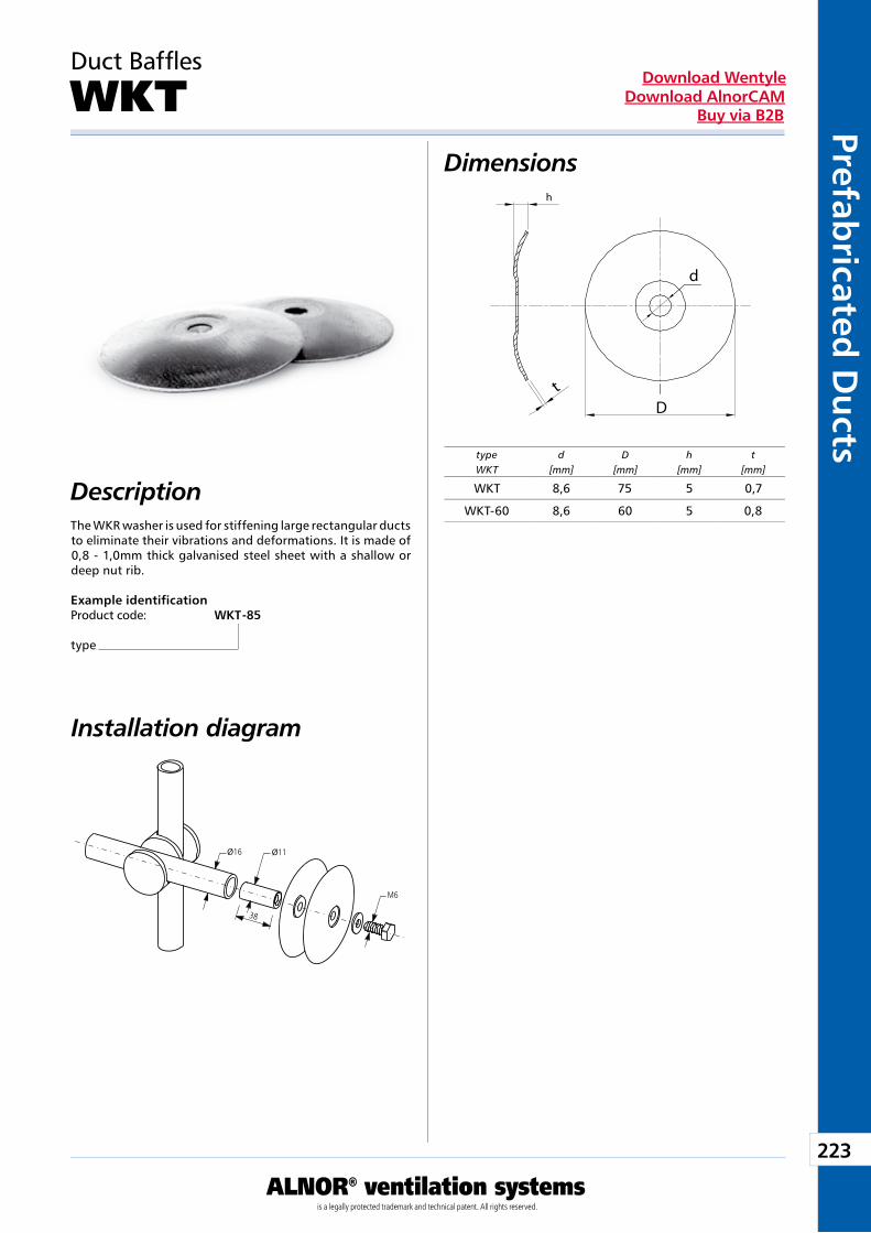
223
ALNOR® ventilation systemsis a legally protected trademark and technical patent. All rights reserved.
Prefabricated
Du
ctsDownload Wentyle
Download AlnorCAMBuy via B2B
Duct Baffles
WKTDimensions
DescriptionThe WKR washer is used for stiffening large rectangular ducts to eliminate their vibrations and deformations. It is made of 0,8 - 1,0mm thick galvanised steel sheet with a shallow or deep nut rib.
Example identificationProduct code: WKT -85
type
Installation diagram
typeWKT
d[mm]
D[mm]
h[mm]
t[mm]
D
d
t
h
WKT 8,6 75 5 0,7
WKT-60 8,6 60 5 0,8
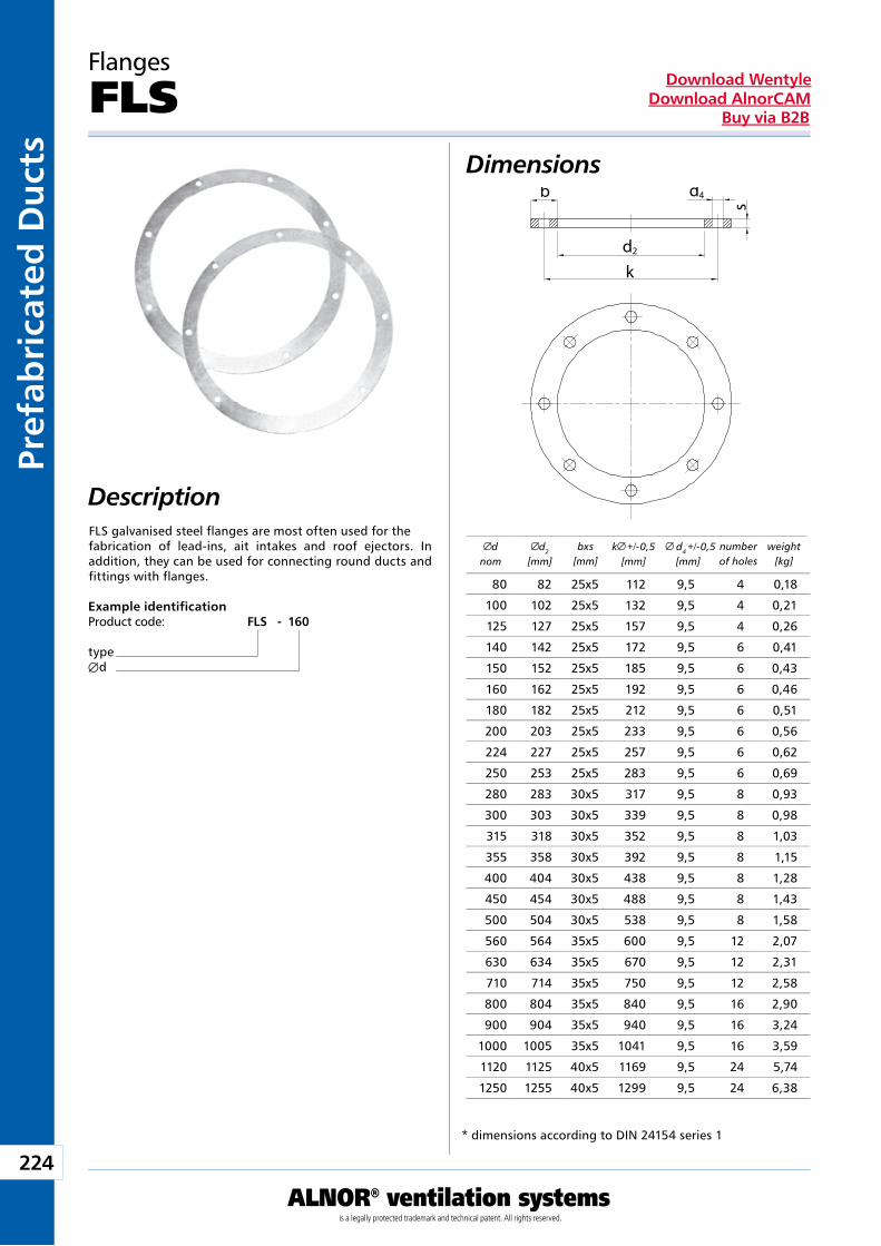
224
ALNOR® ventilation systemsis a legally protected trademark and technical patent. All rights reserved.
Pref
abri
cate
d D
uct
sDownload Wentyle
Download AlnorCAMBuy via B2B
FLS galvanised steel flanges are most often used for the fabrication of lead-ins, ait intakes and roof ejectors. In addition, they can be used for connecting round ducts and fittings with flanges.
Flanges
FLS
Example identificationProduct code: FLS - 160
typeÆd
Dimensions
Description
* dimensions according to DIN 24154 series 1
dnom
d2
[mm]bxs
[mm]k +/-0,5
[mm] d4 +/-0,5[mm]
number of holes
weight [kg]
b d4
s
d2
k
80 82 25x5 112 9,5 4 0,18
100 102 25x5 132 9,5 4 0,21
125 127 25x5 157 9,5 4 0,26
140 142 25x5 172 9,5 6 0,41
150 152 25x5 185 9,5 6 0,43
160 162 25x5 192 9,5 6 0,46
180 182 25x5 212 9,5 6 0,51
200 203 25x5 233 9,5 6 0,56
224 227 25x5 257 9,5 6 0,62
250 253 25x5 283 9,5 6 0,69
280 283 30x5 317 9,5 8 0,93
300 303 30x5 339 9,5 8 0,98
315 318 30x5 352 9,5 8 1,03
355 358 30x5 392 9,5 8 1,15
400 404 30x5 438 9,5 8 1,28
450 454 30x5 488 9,5 8 1,43
500 504 30x5 538 9,5 8 1,58
560 564 35x5 600 9,5 12 2,07
630 634 35x5 670 9,5 12 2,31
710 714 35x5 750 9,5 12 2,58
800 804 35x5 840 9,5 16 2,90
900 904 35x5 940 9,5 16 3,24
1000 1005 35x5 1041 9,5 16 3,59
1120 1125 40x5 1169 9,5 24 5,74
1250 1255 40x5 1299 9,5 24 6,38
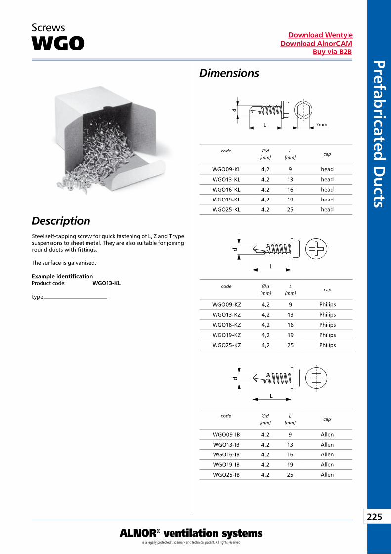
225
ALNOR® ventilation systemsis a legally protected trademark and technical patent. All rights reserved.
Prefabricated
Du
ctsDownload Wentyle
Download AlnorCAMBuy via B2B
Dimensions
Description
Screws
WGO
Steel self-tapping screw for quick fastening of L, Z and T type suspensions to sheet metal. They are also suitable for joining round ducts with fittings.
The surface is galvanised.
Example identificationProduct code: WGO13-KL
type
code
cap
head
head
head
head
head
code
cap
Philips
Philips
Philips
Philips
Philips
code
cap
Allen
Allen
Allen
Allen
Allen
d
L 7mm
d
L
d
L
d
[mm]L
[mm]
WGO09-KL 4,2 9
WGO13-KL 4,2 13
WGO16-KL 4,2 16
WGO19-KL 4,2 19
WGO25-KL 4,2 25
d
[mm]L
[mm]
WGO09-KZ 4,2 9
WGO13-KZ 4,2 13
WGO16-KZ 4,2 16
WGO19-KZ 4,2 19
WGO25-KZ 4,2 25
d[mm]
L[mm]
WGO09-IB 4,2 9
WGO13-IB 4,2 13
WGO16-IB 4,2 16
WGO19-IB 4,2 19
WGO25-IB 4,2 25
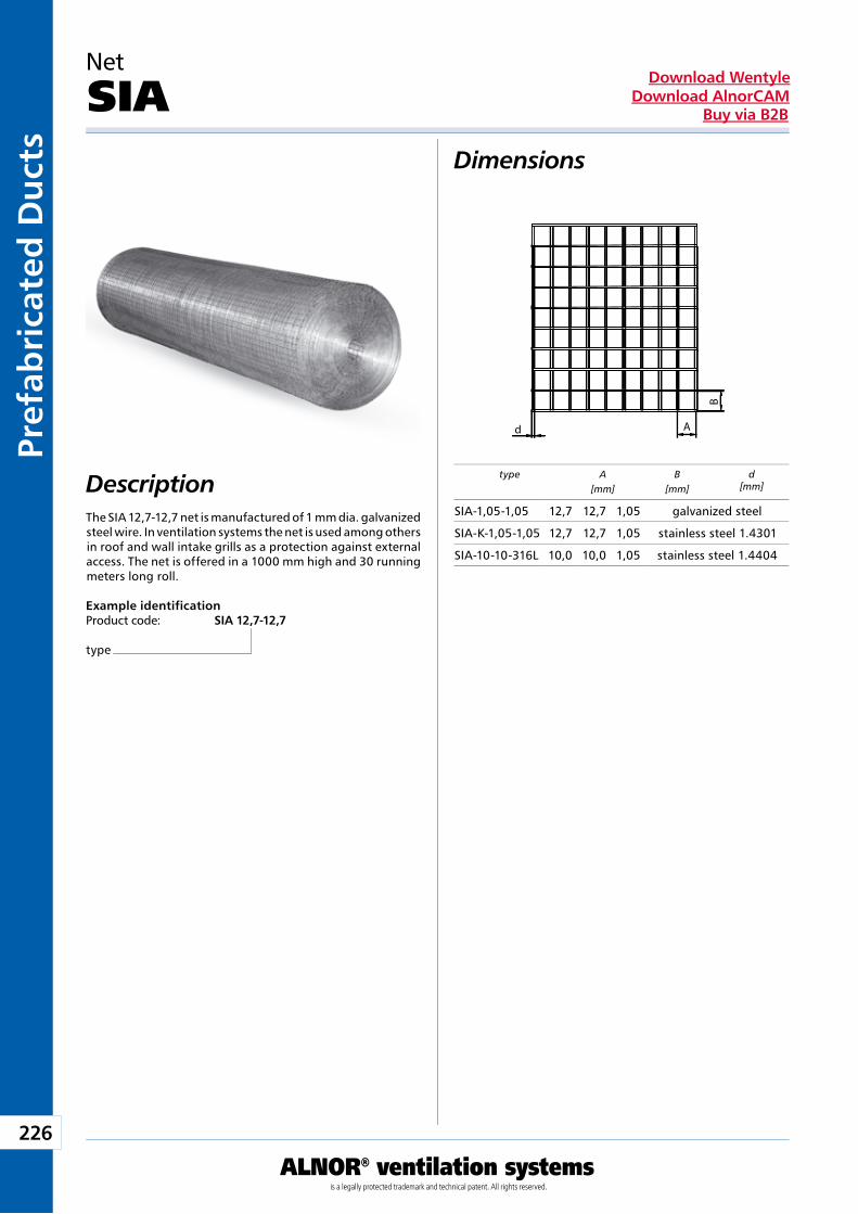
226
ALNOR® ventilation systemsis a legally protected trademark and technical patent. All rights reserved.
Pref
abri
cate
d D
uct
sDownload Wentyle
Download AlnorCAMBuy via B2B
Dimensions
Description
Net
SIA
The SIA 12,7-12,7 net is manufactured of 1 mm dia. galvanized steel wire. In ventilation systems the net is used among others in roof and wall intake grills as a protection against external access. The net is offered in a 1000 mm high and 30 running meters long roll.
Example identificationProduct code: SIA 12,7-12,7
type
type A[mm]
B[mm]
d[mm]
A
B
d
SIA-1,05-1,05 12,7 12,7 1,05 galvanized steel
SIA-K-1,05-1,05 12,7 12,7 1,05 stainless steel 1.4301
SIA-10-10-316L 10,0 10,0 1,05 stainless steel 1.4404
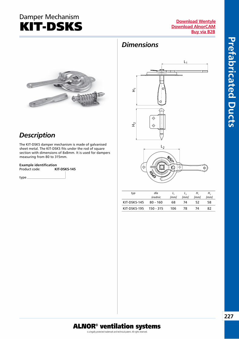
227
ALNOR® ventilation systemsis a legally protected trademark and technical patent. All rights reserved.
Prefabricated
Du
ctsDownload Wentyle
Download AlnorCAMBuy via B2B
Damper Mechanism
KIT-DSKSDimensions
DescriptionThe KIT-DSKS damper mechanism is made of galvanised sheet metal. The KIT-DSKS fits under the rod of square section with dimensions of 8x8mm. It is used for dampers measuring from 80 to 315mm.
Example identificationProduct code: KIT-DSKS-145
type
typ dlaśrednic
L1
[mm]L2
[mm]H1
[mm]H2
[mm]
L
H1
H2
1
L2
KIT-DSKS-145 80 - 160 68 74 52 58
KIT-DSKS-195 150 - 315 106 78 74 82
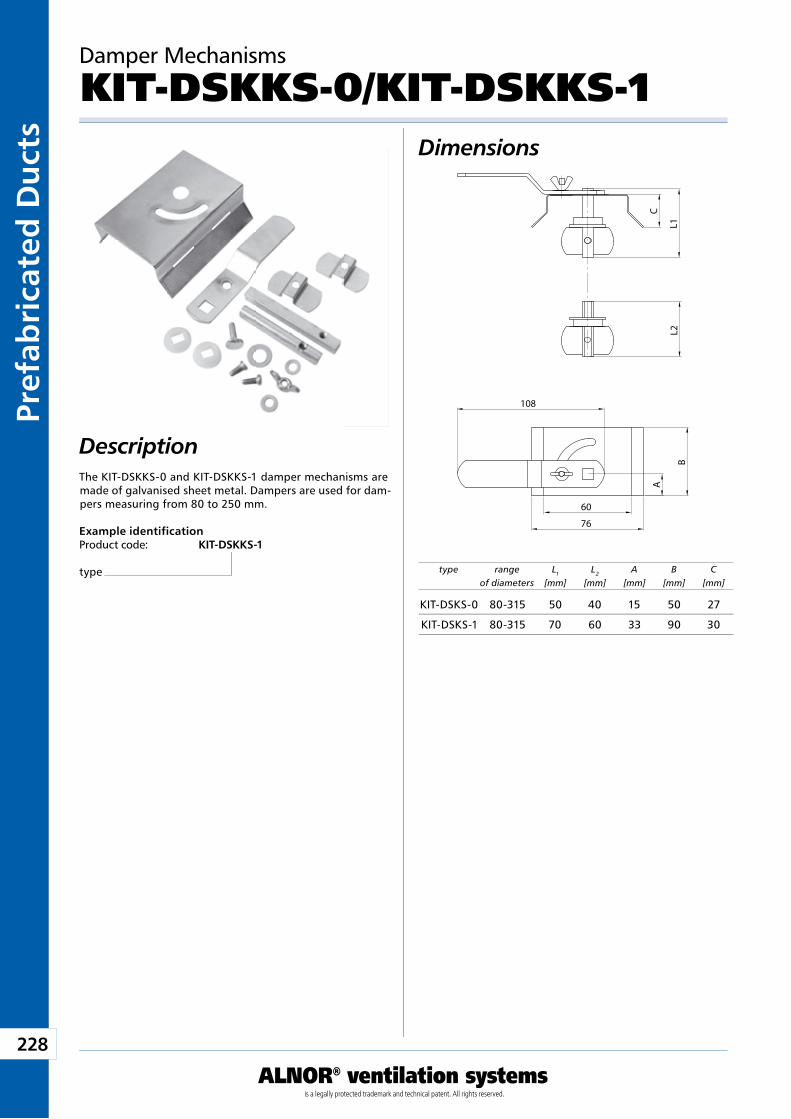
228
ALNOR® ventilation systemsis a legally protected trademark and technical patent. All rights reserved.
Pref
abri
cate
d D
uct
sDownload Wentyle
Download AlnorCAMBuy via B2B
Damper Mechanisms
KIT-DSKKS-0/KIT-DSKKS-1Dimensions
DescriptionThe KIT-DSKKS-0 and KIT-DSKKS-1 damper mechanisms are made of galvanised sheet metal. Dampers are used for dam-pers measuring from 80 to 250 mm.
Example identificationProduct code: KIT-DSKKS-1
type type rangeof diameters
L1
[mm]L2
[mm]A
[mm]B
[mm]C
[mm]
B
76
60
108
C
L1L2
A
KIT-DSKS-0 80-315 50 40 15 50 27
KIT-DSKS-1 80-315 70 60 33 90 30
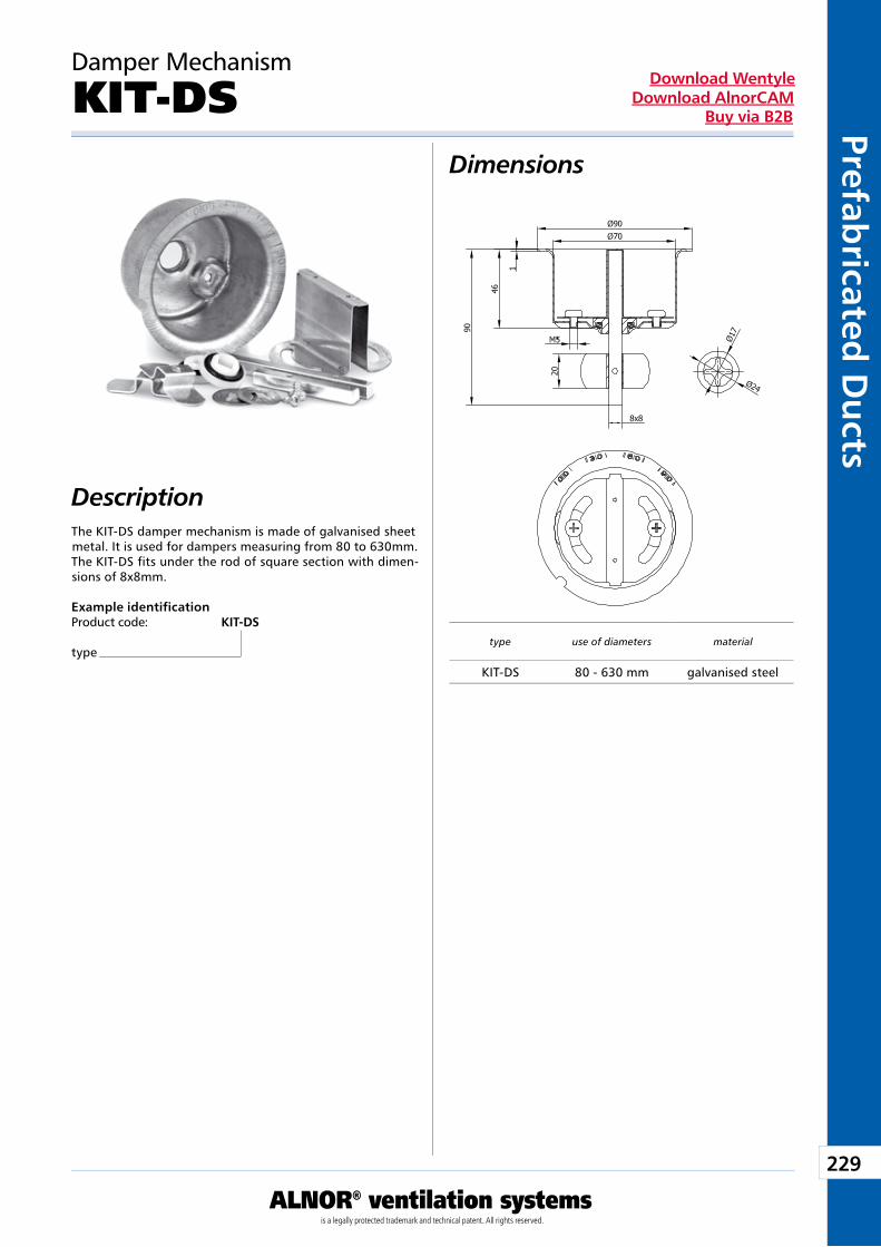
229
ALNOR® ventilation systemsis a legally protected trademark and technical patent. All rights reserved.
Prefabricated
Du
ctsDownload Wentyle
Download AlnorCAMBuy via B2B
Damper Mechanism
KIT-DSDimensions
DescriptionThe KIT-DS damper mechanism is made of galvanised sheet metal. It is used for dampers measuring from 80 to 630mm. The KIT-DS fits under the rod of square section with dimen-sions of 8x8mm.
Example identificationProduct code: KIT-DS
typetype use of diameters material
KIT-DS 80 - 630 mm galvanised steel
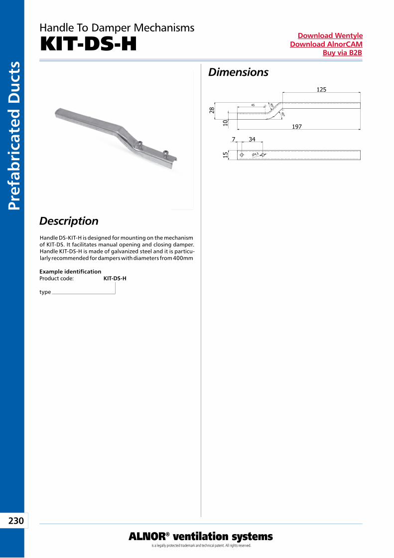
230
ALNOR® ventilation systemsis a legally protected trademark and technical patent. All rights reserved.
Pref
abri
cate
d D
uct
sDownload Wentyle
Download AlnorCAMBuy via B2B
Dimensions
Description
Example identificationProduct code: KIT-DS-H
type
Handle To Damper Mechanisms
KIT-DS-H
Handle DS-KIT-H is designed for mounting on the mechanism of KIT-DS. It facilitates manual opening and closing damper. Handle KIT-DS-H is made of galvanized steel and it is particu-larly recommended for dampers with diameters from 400mm
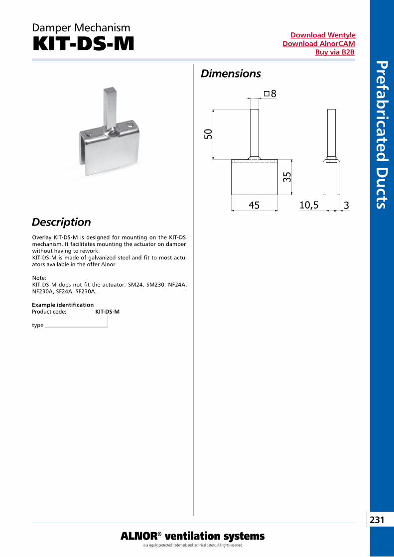
231
ALNOR® ventilation systemsis a legally protected trademark and technical patent. All rights reserved.
Prefabricated
Du
ctsDownload Wentyle
Download AlnorCAMBuy via B2B
Example identificationProduct code: KIT-DS-M
type
Damper Mechanism
KIT-DS-MDimensions
DescriptionOverlay KIT-DS-M is designed for mounting on the KIT-DS mechanism. It facilitates mounting the actuator on damper without having to rework.KIT-DS-M is made of galvanized steel and fit to most actu-ators available in the offer Alnor
Note:KIT-DS-M does not fit the actuator: SM24, SM230, NF24A, NF230A, SF24A, SF230A.
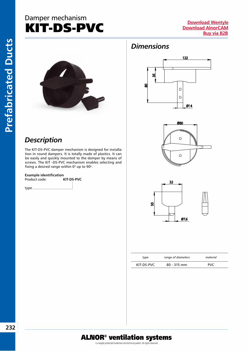
232
ALNOR® ventilation systemsis a legally protected trademark and technical patent. All rights reserved.
Pref
abri
cate
d D
uct
sDownload Wentyle
Download AlnorCAMBuy via B2B
Dimensions
Description
Damper mechanism
KIT-DS-PVC
The KIT-DS-PVC damper mechanism is designed for installa-tion in round dampers. It is totally made of plastics. It can be easily and quickly mounted to the damper by means of screws. The KIT -DS-PVC mechanism enables selecting and fixing a desired range within 0o up to 90o. Example identificationProduct code: KIT-DS-PVC
type
type range of diameters material
KIT-DS-PVC 80 - 315 mm PVC
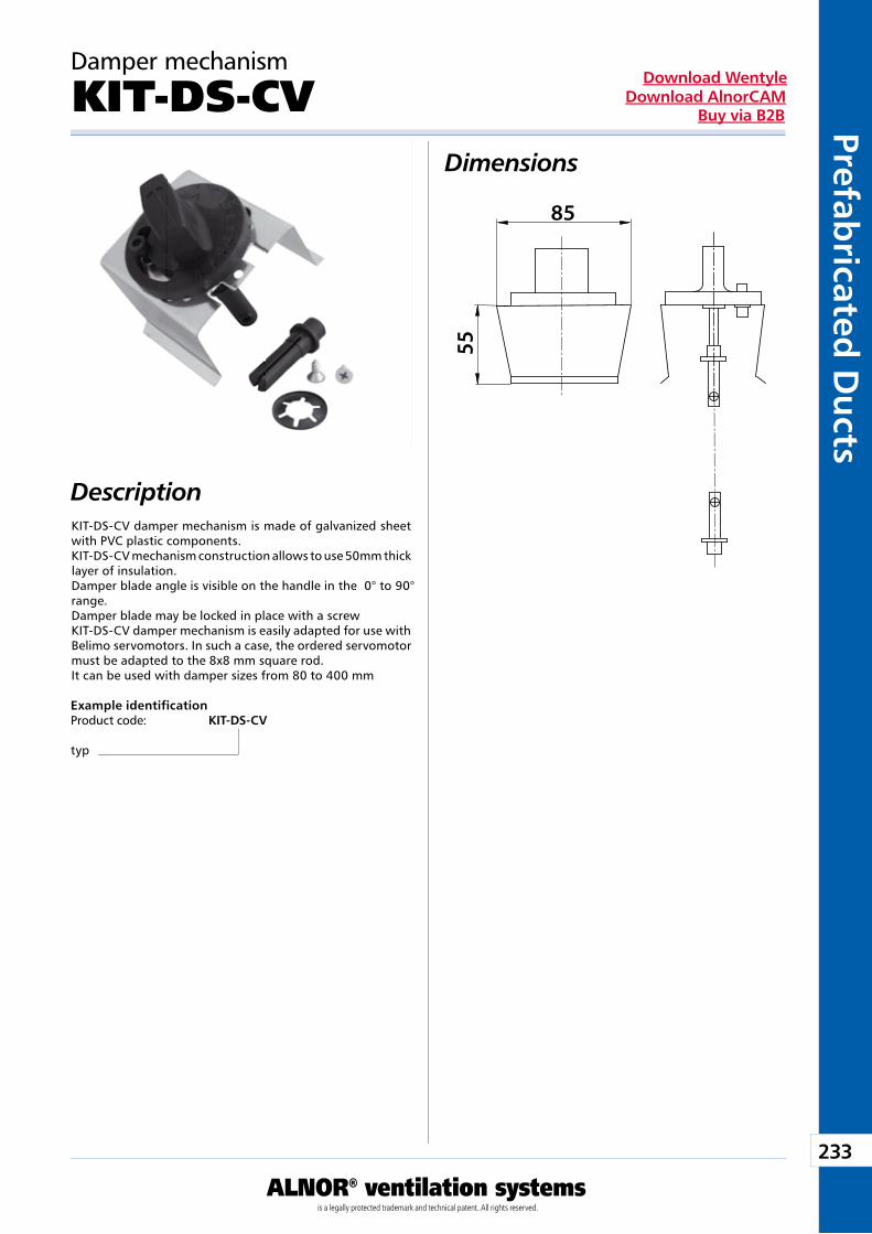
233
ALNOR® ventilation systemsis a legally protected trademark and technical patent. All rights reserved.
Prefabricated
Du
ctsDownload Wentyle
Download AlnorCAMBuy via B2B
Damper mechanism
KIT-DS-CVDimensions
DescriptionKIT-DS-CV damper mechanism is made of galvanized sheet with PVC plastic components. KIT-DS-CV mechanism construction allows to use 50mm thick layer of insulation. Damper blade angle is visible on the handle in the 0° to 90° range. Damper blade may be locked in place with a screw KIT-DS-CV damper mechanism is easily adapted for use with Belimo servomotors. In such a case, the ordered servomotor must be adapted to the 8x8 mm square rod. It can be used with damper sizes from 80 to 400 mm
Example identificationProduct code: KIT-DS-CV
typ
85
55
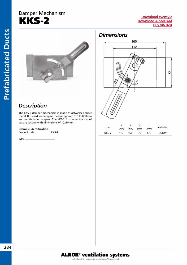
234
ALNOR® ventilation systemsis a legally protected trademark and technical patent. All rights reserved.
Pref
abri
cate
d D
uct
sDownload Wentyle
Download AlnorCAMBuy via B2B
Damper Mechanism
KKS-2Dimensions
DescriptionThe KKS-2 damper mechanism is made of galvanised sheet metal. It is used for dampers measuring from 315 to 800mm and multi-blade dampers. The KKS-2 fits under the rod of square section with dimensions of 10x10mm.
Example identificationProduct code: KKS-2
type
typeA
[mm]B
[mm]C
[mm]L
[mm]application
KKS-2 112 160 77 175 DSQW
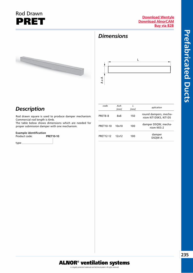
235
ALNOR® ventilation systemsis a legally protected trademark and technical patent. All rights reserved.
Prefabricated
Du
ctsDownload Wentyle
Download AlnorCAMBuy via B2B
Rod Drawn
PRETDimensions
DescriptionRod drawn square is used to produce damper mechanism. Commercial rod length is 6mb.The table below shows dimensions which are needed for proper submission damper with one mechanism.
Example identificationProduct code: PRET10-10
type
code AxA[mm]
L[mm]
aplication
A x
A
L
PRET8-8 8x8 150 round dampers, mecha-nism KIT-DSKS, KIT-DS
PRET10-10 10x10 100 damper DSQW, mecha-nism KKS-2
PRET12-12 12x12 100 damperDSQW-A
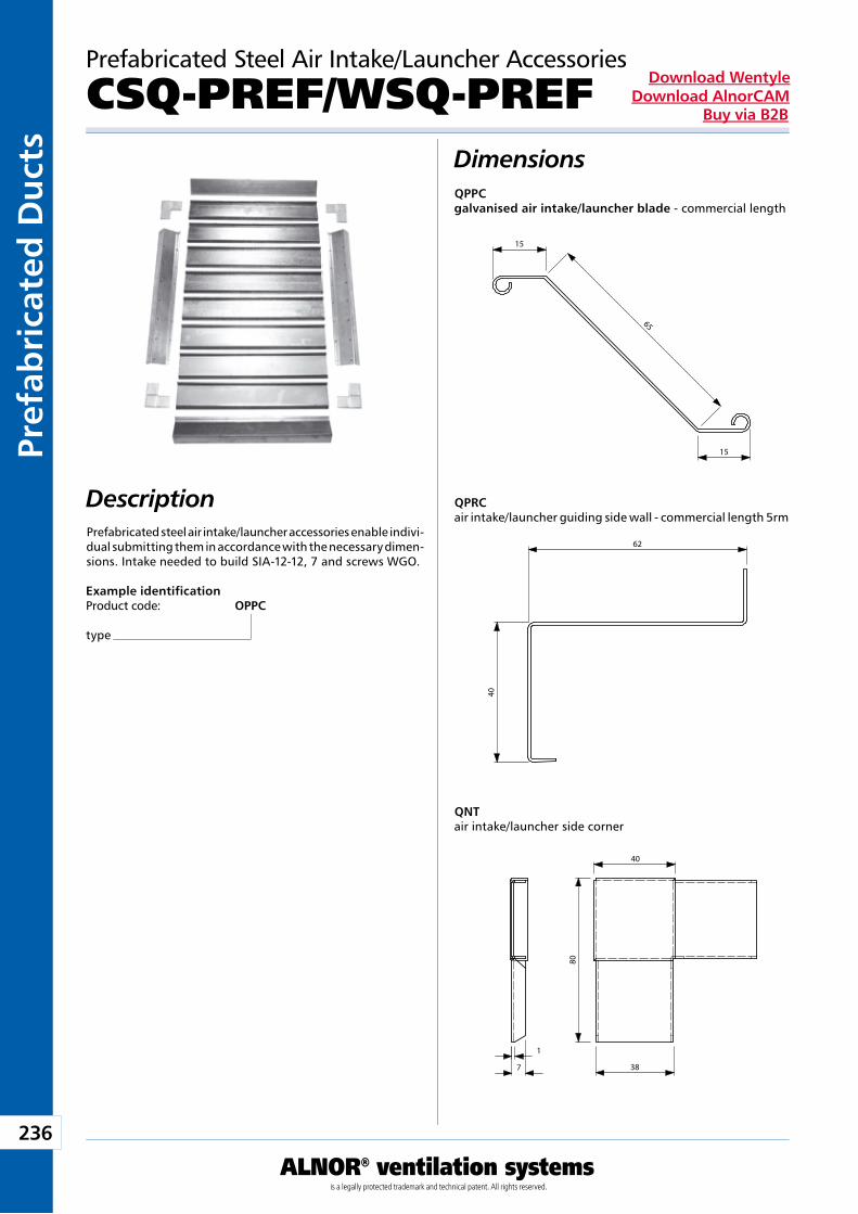
236
ALNOR® ventilation systemsis a legally protected trademark and technical patent. All rights reserved.
Pref
abri
cate
d D
uct
sDownload Wentyle
Download AlnorCAMBuy via B2B
Example identificationProduct code: OPPC
type
Prefabricated Steel Air Intake/Launcher Accessories
CSQ-PREF/WSQ-PREFDimensions
DescriptionPrefabricated steel air intake/launcher accessories enable indivi-dual submitting them in accordance with the necessary dimen-sions. Intake needed to build SIA-12-12, 7 and screws WGO.
QPPCgalvanised air intake/launcher blade - commercial length
QPRCair intake/launcher guiding side wall - commercial length 5rm
QNTair intake/launcher side corner
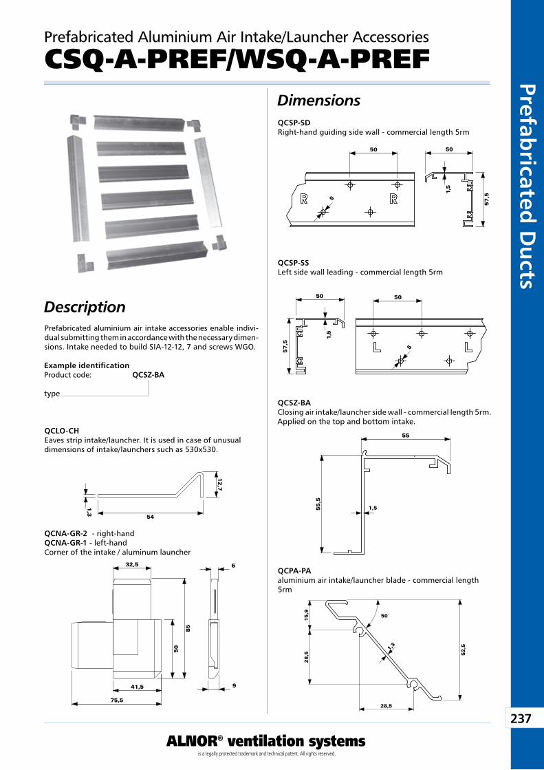
237
ALNOR® ventilation systemsis a legally protected trademark and technical patent. All rights reserved.
Prefabricated
Du
ctsDownload Wentyle
Download AlnorCAMBuy via B2B
Prefabricated Aluminium Air Intake/Launcher Accessories
CSQ-A-PREF/WSQ-A-PREFDimensions
Description
QCNA-GR-2 - right-handQCNA-GR-1 - left-handCorner of the intake / aluminum launcher
QCSZ-BAClosing air intake/launcher side wall - commercial length 5rm. Applied on the top and bottom intake.
QCSP-SSLeft side wall leading - commercial length 5rm
QCLO-CHEaves strip intake/launcher. It is used in case of unusual dimensions of intake/launchers such as 530x530.
QCSP-SDRight-hand guiding side wall - commercial length 5rm
QCPA-PAaluminium air intake/launcher blade - commercial length 5rm
Example identificationProduct code: QCSZ-BA
type
Prefabricated aluminium air intake accessories enable indivi-dual submitting them in accordance with the necessary dimen-sions. Intake needed to build SIA-12-12, 7 and screws WGO.
32,5
85
50
41,5
75,5
9
6
12
,7
54
1,3
1,5
55
55
,5
50
57
,5
1,5
50
�5
50
57
,5
1,5
50
�5
1,3
50°
52
,5
15
,92
8,5
28,5
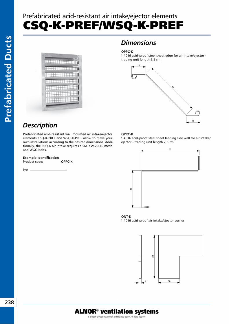
238
ALNOR® ventilation systemsis a legally protected trademark and technical patent. All rights reserved.
Pref
abri
cate
d D
uct
sDownload Wentyle
Download AlnorCAMBuy via B2B
Prefabricated acid-resistant air intake/ejector elements
CSQ-K-PREF/WSQ-K-PREFDimensions
DescriptionPrefabricated acid-resistant wall mounted air intake/ejector elements CSQ-K-PREF and WSQ-K-PREF allow to make your own installations according to the desired dimensions. Addi-tionally, the SCQ-K air intake requires a SIA-KW-20-10 mesh and WGO bolts.
Example identificationProduct code: QPPC-K
typ
QPPC-K1.4016 acid-proof steel sheet edge for air intake/ejector - trading unit length 2,5 rm
QPRC-K1.4016 acid-proof steel sheet leading side wall for air intake/ejector - trading unit length 2,5 rm
QNT-K1.4016 acid-proof air-intake/ejector corner
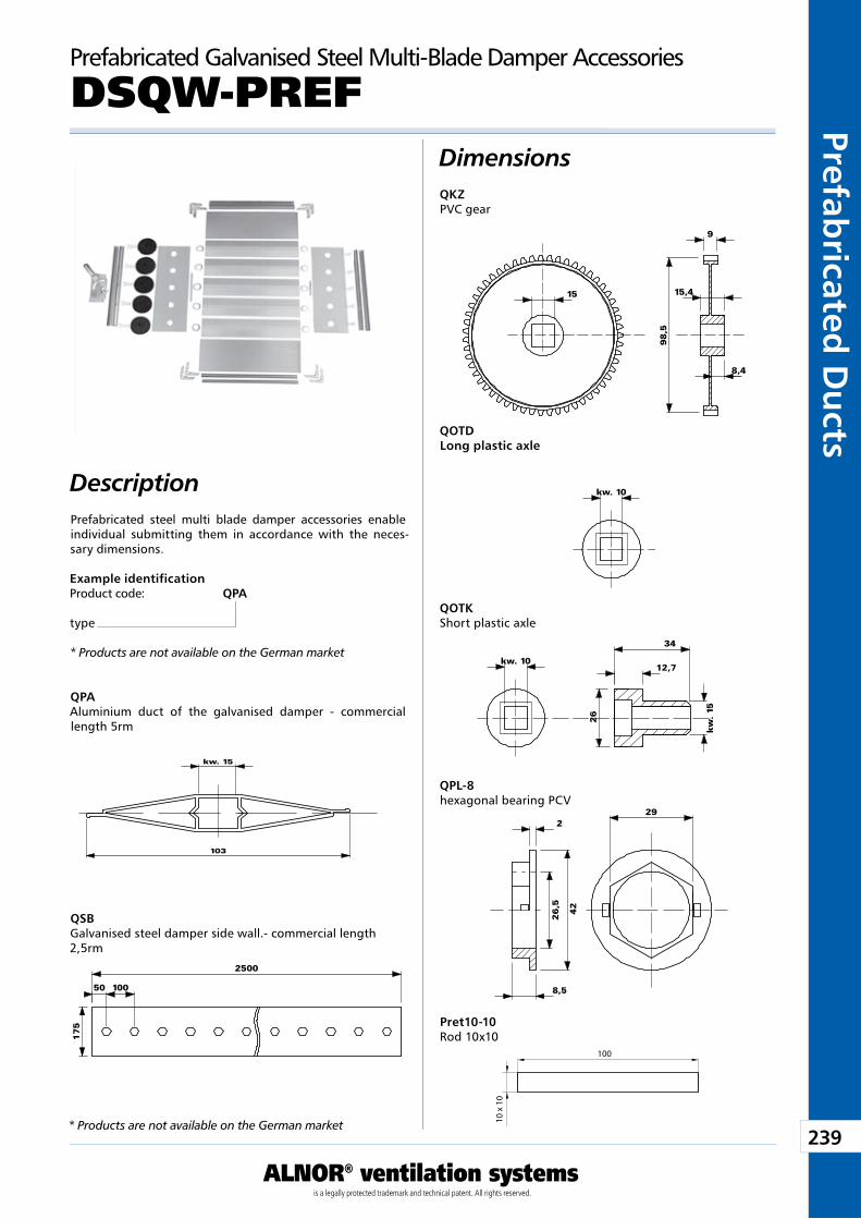
239
ALNOR® ventilation systemsis a legally protected trademark and technical patent. All rights reserved.
Prefabricated
Du
ctsDownload Wentyle
Download AlnorCAMBuy via B2B
Prefabricated Galvanised Steel Multi-Blade Damper Accessories
DSQW-PREFDimensions
DescriptionPrefabricated steel multi blade damper accessories enable individual submitting them in accordance with the neces-sary dimensions.
Example identificationProduct code: QPA
type
* Products are not available on the German market
QPAAluminium duct of the galvanised damper - commercial length 5rm
QSBGalvanised steel damper side wall.- commercial length 2,5rm
QKZPVC gear
QOTDLong plastic axle
QOTKShort plastic axle
QPL-8hexagonal bearing PCV
Pret10-10Rod 10x10
15
9
15,4
8,4
98
,5
kw. 106,7
50
�26
kw
. 15
kw. 1012,7
34
�26
kw
. 15
kw. 15
103
292
8,5
26
,5
�42
2500
17
5
50 100
10 x
10
100
* Products are not available on the German market
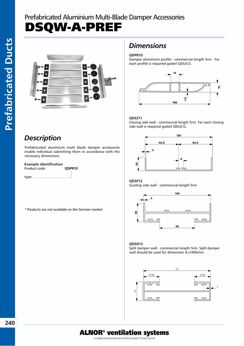
240
ALNOR® ventilation systemsis a legally protected trademark and technical patent. All rights reserved.
Pref
abri
cate
d D
uct
sDownload Wentyle
Download AlnorCAMBuy via B2B
Prefabricated Aluminium Multi-Blade Damper Accessories
DSQW-A-PREFDimensions
Description
Example identificationProduct code: QDPR10
type
QDPR10Damper aluminium profile - commercial length 5rm. For each profile is required gasket QDUŁ12.
QDSZ11Closing side wall - commercial length 5rm. For each closing side wall is required gasket QDUŁ12.
QDSP12Guiding side wall - commercial length 5rm
QDSD13Split damper wall - commercial length 5rm. Split damper wall should be used for dimension A≥1400mm.
Prefabricated aluminium multi blade damper accessories enable individual submitting them in accordance with the necessary dimensions.
12
108
15
1,5
125
29,98 29,98
35
2
125
2
65
35
125
62,5 62,5
9
2
25
* Products are not available on the German market
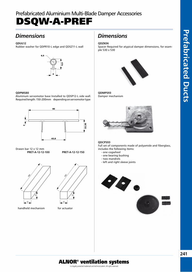
241
ALNOR® ventilation systemsis a legally protected trademark and technical patent. All rights reserved.
Prefabricated
Du
ctsDownload Wentyle
Download AlnorCAMBuy via B2B
Prefabricated Aluminium Multi-Blade Damper Accessories
DSQW-A-PREFDimensions Dimensions
QDZK06Spacer Required for atypical damper dimensions, for exam-ple 530 x 530
QDMPS93Damper mechanism
QDCPS93Full set of components made of polyamide and fiberglass, includes the following items:
- one cogwheel - one bearing bushing - two mandrels - left and right sleeve joints
QDUŁ12Rubber washer for QDPR10-L edge and QDSZ11-L wall
QDPMS80Aluminum servomotor base Installed to QDSP12-L side wall. Required length: 150-200mm depending on servomotor type
Drawn bar 12 x 12 mm PRET-A-12-12-100 PRET-A-12-12-150
pod mechanizm ręczny pod siłownik
90
3
22
,35
43,8
9,5
4
�6,5
1212
1212
100
150
handheld mechanism for actuator
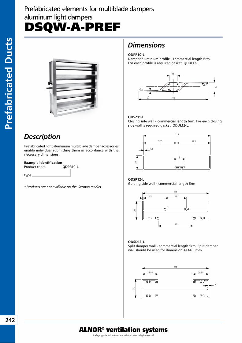
242
ALNOR® ventilation systemsis a legally protected trademark and technical patent. All rights reserved.
Pref
abri
cate
d D
uct
sDownload Wentyle
Download AlnorCAMBuy via B2B
DescriptionPrefabricated light aluminium multi blade damper accessories enable individual submitting them in accordance with the necessary dimensions.
Example identificationProduct code: QDPR10-L
type
DimensionsQDPR10-LDamper aluminium profile - commercial length 6rm.For each profile is required gasket QDUŁ12-L.
QDSZ11-LClosing side wall - commercial length 6rm. For each closing side wall is required gasket QDUŁ12-L.
QDSP12-LGuiding side wall - commercial length 6rm
QDSD13-LSplit damper wall - commercial length 5rm. Split damper wall should be used for dimension A≥1400mm.
Prefabricated elements for multiblade dampers aluminum light dampers
DSQW-A-PREF
12
108
15
1,5
115
24,98 24,98
35
2
115
1,5
65
30
40
115
57,5 57,5
9
1,5
20
* Products are not available on the German market
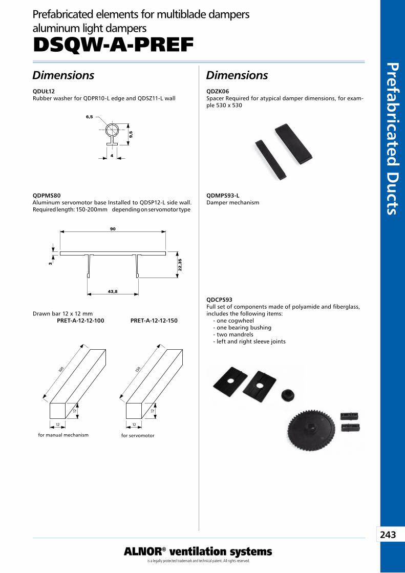
243
ALNOR® ventilation systemsis a legally protected trademark and technical patent. All rights reserved.
Prefabricated
Du
ctsDownload Wentyle
Download AlnorCAMBuy via B2B
Dimensions DimensionsQDZK06Spacer Required for atypical damper dimensions, for exam-ple 530 x 530
QDMPS93-LDamper mechanism
QDCPS93Full set of components made of polyamide and fiberglass, includes the following items:
- one cogwheel - one bearing bushing - two mandrels - left and right sleeve joints
QDUŁ12Rubber washer for QDPR10-L edge and QDSZ11-L wall
QDPMS80Aluminum servomotor base Installed to QDSP12-L side wall. Required length: 150-200mm depending on servomotor type
Drawn bar 12 x 12 mm PRET-A-12-12-100 PRET-A-12-12-150
for manual mechanism for servomotor
Prefabricated elements for multiblade dampers aluminum light dampers
DSQW-A-PREF
90
3
22
,35
43,8
9,5
4
�6,5
1212
1212
100
150
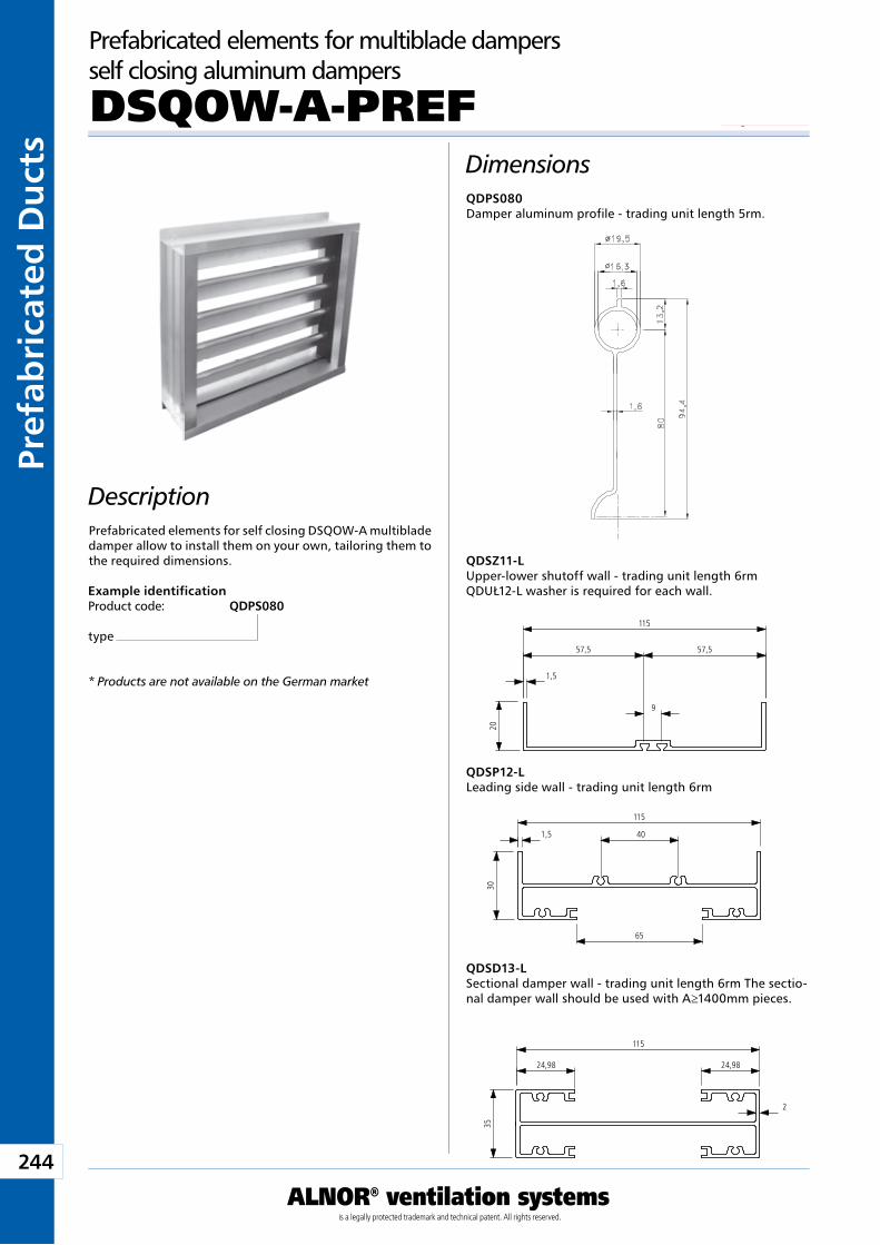
244
ALNOR® ventilation systemsis a legally protected trademark and technical patent. All rights reserved.
Pref
abri
cate
d D
uct
sDownload Wentyle
Download AlnorCAMBuy via B2B
Example identificationProduct code: QDPS080
type
* Products are not available on the German market
DescriptionPrefabricated elements for self closing DSQOW-A multiblade damper allow to install them on your own, tailoring them to the required dimensions.
Prefabricated elements for multiblade dampers self closing aluminum dampers
DSQOW-A-PREFDimensionsQDPS080 Damper aluminum profile - trading unit length 5rm.
QDSZ11-L Upper-lower shutoff wall - trading unit length 6rm QDUŁ12-L washer is required for each wall.
QDSP12-L Leading side wall - trading unit length 6rm
QDSD13-L Sectional damper wall - trading unit length 6rm The sectio-nal damper wall should be used with A≥1400mm pieces.
115
24,98 24,98
35
2
115
1,5
65
30
40
115
57,5 57,5
9
1,5
20
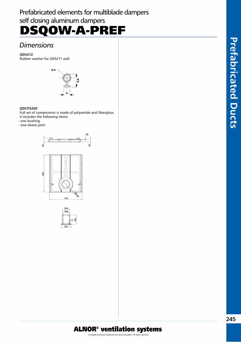
245
ALNOR® ventilation systemsis a legally protected trademark and technical patent. All rights reserved.
Prefabricated
Du
ctsDownload Wentyle
Download AlnorCAMBuy via B2B
Prefabricated elements for multiblade dampers self closing aluminum dampers
DSQOW-A-PREFDimensionsQDUŁ12 Rubber washer for QDSZ11 wall
QDCPS200 Full set of components is made of polyamide and fiberglass, it includes the following items:
- one bushing - one sleeve joint
9,5
4
�6,5
6,3
0,8
8,5
85,0
70,0
16,0
21,8
1,5 20,0
16,35
12,00
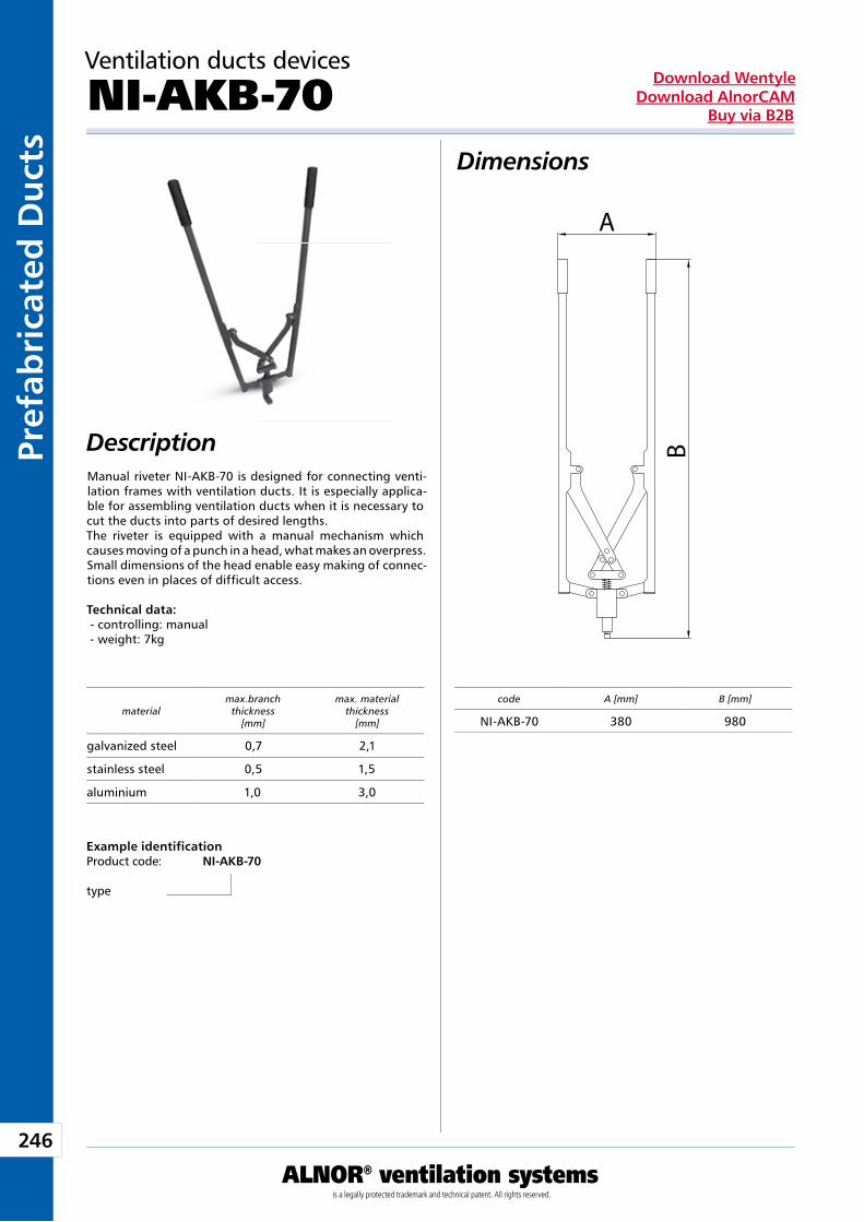
246
ALNOR® ventilation systemsis a legally protected trademark and technical patent. All rights reserved.
Pref
abri
cate
d D
uct
sDownload Wentyle
Download AlnorCAMBuy via B2B
Ventilation ducts devices
NI-AKB-70Dimensions
DescriptionManual riveter NI-AKB-70 is designed for connecting venti-lation frames with ventilation ducts. It is especially applica-ble for assembling ventilation ducts when it is necessary to cut the ducts into parts of desired lengths.The riveter is equipped with a manual mechanism which causes moving of a punch in a head, what makes an overpress. Small dimensions of the head enable easy making of connec-tions even in places of difficult access.
Technical data: - controlling: manual - weight: 7kg
Example identificationProduct code: NI-AKB-70
type
B
A
code A [mm] B [mm]
NI-AKB-70 380 980material
max.branch thickness
[mm]
max. materialthickness
[mm]
galvanized steel 0,7 2,1
stainless steel 0,5 1,5
aluminium 1,0 3,0
Ventilation Accessories
We reserve the right to make changes in the dimensions and technical data products due to their continuous improvement
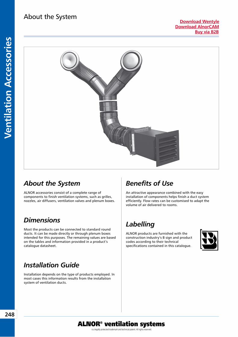
248
Vent
ilati
on A
cces
sori
es
ALNOR® ventilation systemsis a legally protected trademark and technical patent. All rights reserved.
Download WentyleDownload AlnorCAM
Buy via B2B
About the SystemALNOR accessories consist of a complete range of components to finish ventilation systems, such as grilles, nozzles, air diffusers, ventilation valves and plenum boxes.
Dimensions Most the products can be connected to standard round ducts. It can be made directly or through plenum boxes intended for this purposes. The remaining values are based on the tables and information provided in a product’s catalogue datasheet.
About the System
Installation GuideInstallation depends on the type of products employed. In most cases this information results from the installation system of ventilation ducts.
Benefits of UseAn attractive appearance combined with the easy installation of components helps finish a duct system efficiently. Flow rates can be customised to adapt the volume of air delivered to rooms.
LabellingALNOR products are furnished with the construction industry’s B sign and product codes according to their technical specifications contained in this catalogue.
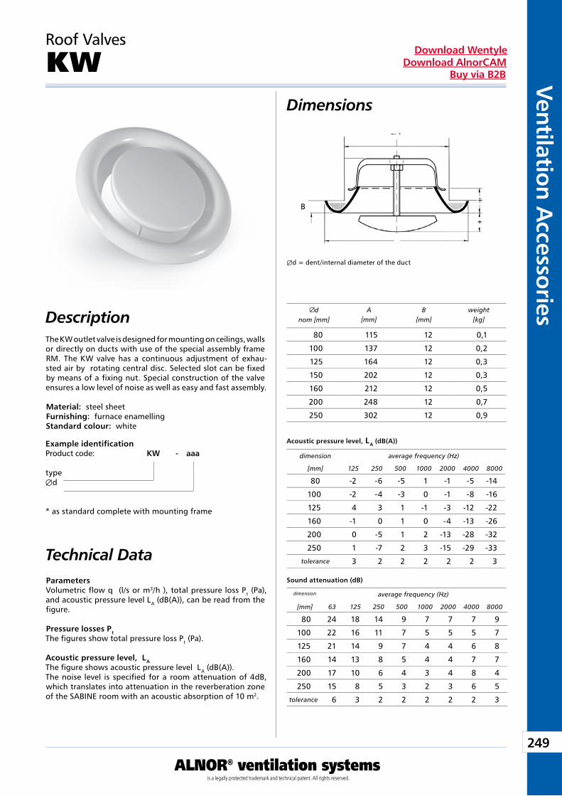
249
Ventilation Accessories
ALNOR® ventilation systemsis a legally protected trademark and technical patent. All rights reserved.
Download WentyleDownload AlnorCAM
Buy via B2B
Dimensions
Description
Roof Valves
KW
The KW outlet valve is designed for mounting on ceilings, walls or directly on ducts with use of the special assembly frame RM. The KW valve has a continuous adjustment of exhau-sted air by rotating central disc. Selected slot can be fixed by means of a fixing nut. Special construction of the valve ensures a low level of noise as well as easy and fast assembly.
Material: steel sheetFurnishing: furnace enamellingStandard colour: white
Example identificationProduct code: KW - aaa
typeÆd
* as standard complete with mounting frame
Parameters Volumetric flow q (l/s or m3/h ), total pressure loss Pt (Pa), and acoustic pressure level LA (dB(A)), can be read from the figure.
Pressure losses Pt The figures show total pressure loss Pt (Pa).
Acoustic pressure level, LA The figure shows acoustic pressure level LA (dB(A)).The noise level is specified for a room attenuation of 4dB, which translates into attenuation in the reverberation zone of the SABINE room with an acoustic absorption of 10 m2.
Æd = dent/internal diameter of the duct
dnom [mm]
A[mm]
B[mm]
weight[kg]
Acoustic pressure level, LA (dB(A))
Sound attenuation (dB)
dimension average frequency (Hz)
[mm] 125 250 500 1000 2000 4000 8000
dimension average frequency (Hz)
[mm] 63 125 250 500 1000 2000 4000 8000
Technical Data
Æd
A
B
80 115 12 0,1
100 137 12 0,2
125 164 12 0,3
150 202 12 0,3
160 212 12 0,5
200 248 12 0,7
250 302 12 0,9
80 -2 -6 -5 1 -1 -5 -14
100 -2 -4 -3 0 -1 -8 -16
125 4 3 1 -1 -3 -12 -22
160 -1 0 1 0 -4 -13 -26
200 0 -5 1 2 -13 -28 -32
250 1 -7 2 3 -15 -29 -33
tolerance 3 2 2 2 2 2 3
80 24 18 14 9 7 7 7 9
100 22 16 11 7 5 5 5 7
125 21 14 9 7 4 4 6 8
160 14 13 8 5 4 4 7 7
200 17 10 6 4 3 4 8 4
250 15 8 5 3 2 3 6 5
tolerance 6 3 2 2 2 2 2 3
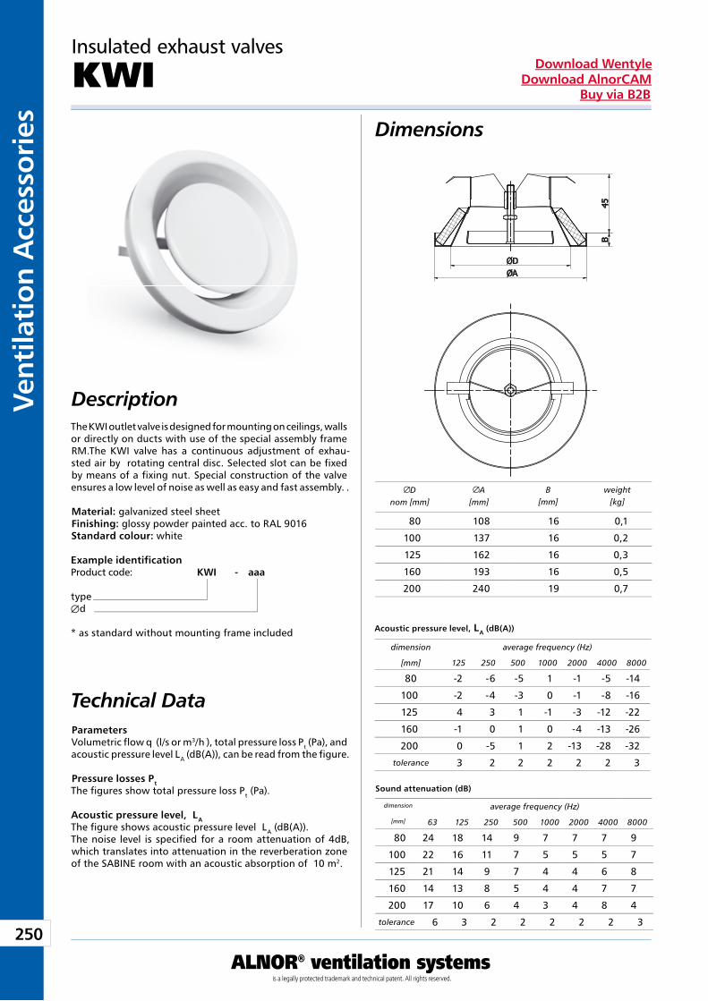
250
Vent
ilati
on A
cces
sori
es
ALNOR® ventilation systemsis a legally protected trademark and technical patent. All rights reserved.
Download WentyleDownload AlnorCAM
Buy via B2B
Example identificationProduct code: KWI - aaa
typeÆd
* as standard without mounting frame included
Description
Dimensions
Parameters Volumetric flow q (l/s or m3/h ), total pressure loss Pt (Pa), and acoustic pressure level LA (dB(A)), can be read from the figure.
Pressure losses Pt The figures show total pressure loss Pt (Pa).
Acoustic pressure level, LA The figure shows acoustic pressure level LA (dB(A)).The noise level is specified for a room attenuation of 4dB, which translates into attenuation in the reverberation zone of the SABINE room with an acoustic absorption of 10 m2.
Insulated exhaust valves
KWI
The KWI outlet valve is designed for mounting on ceilings, walls or directly on ducts with use of the special assembly frame RM.The KWI valve has a continuous adjustment of exhau-sted air by rotating central disc. Selected slot can be fixed by means of a fixing nut. Special construction of the valve ensures a low level of noise as well as easy and fast assembly. .
Material: galvanized steel sheetFinishing: glossy powder painted acc. to RAL 9016Standard colour: white
Technical Data
Acoustic pressure level, LA (dB(A))
Sound attenuation (dB)
Dnom [mm]
A[mm]
B[mm]
weight[kg]
dimension average frequency (Hz)
[mm] 125 250 500 1000 2000 4000 8000
dimension average frequency (Hz)
[mm] 63 125 250 500 1000 2000 4000 8000
80 108 16 0,1
100 137 16 0,2
125 162 16 0,3
160 193 16 0,5
200 240 19 0,7
80 -2 -6 -5 1 -1 -5 -14
100 -2 -4 -3 0 -1 -8 -16
125 4 3 1 -1 -3 -12 -22
160 -1 0 1 0 -4 -13 -26
200 0 -5 1 2 -13 -28 -32
tolerance 3 2 2 2 2 2 3
80 24 18 14 9 7 7 7 9
100 22 16 11 7 5 5 5 7
125 21 14 9 7 4 4 6 8
160 14 13 8 5 4 4 7 7
200 17 10 6 4 3 4 8 4
tolerance 6 3 2 2 2 2 2 3
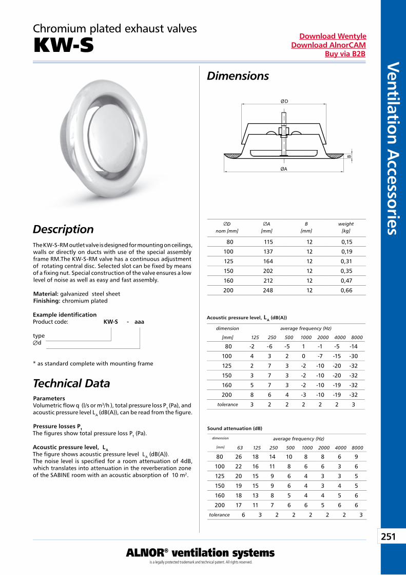
251
Ventilation Accessories
ALNOR® ventilation systemsis a legally protected trademark and technical patent. All rights reserved.
Download WentyleDownload AlnorCAM
Buy via B2B
Dimensions
Description
Example identificationProduct code: KW-S - aaa
typeÆd
* as standard complete with mounting frame
Technical DataParameters Volumetric flow q (l/s or m3/h ), total pressure loss Pt (Pa), and acoustic pressure level LA (dB(A)), can be read from the figure.
Pressure losses Pt The figures show total pressure loss Pt (Pa).
Acoustic pressure level, LA The figure shows acoustic pressure level LA (dB(A)).The noise level is specified for a room attenuation of 4dB, which translates into attenuation in the reverberation zone of the SABINE room with an acoustic absorption of 10 m2.
Chromium plated exhaust valves
KW-S
Dnom [mm]
A[mm]
B[mm]
weight[kg]
Acoustic pressure level, LA (dB(A))
Sound attenuation (dB)
dimension average frequency (Hz)
[mm] 125 250 500 1000 2000 4000 8000
dimension average frequency (Hz)
[mm] 63 125 250 500 1000 2000 4000 8000
The KW-S-RM outlet valve is designed for mounting on ceilings, walls or directly on ducts with use of the special assembly frame RM.The KW-S-RM valve has a continuous adjustment of rotating central disc. Selected slot can be fixed by means of a fixing nut. Special construction of the valve ensures a low level of noise as well as easy and fast assembly.
Material: galvanized steel sheet Finishing: chromium plated
80 115 12 0,15
100 137 12 0,19
125 164 12 0,31
150 202 12 0,35
160 212 12 0,47
200 248 12 0,66
80 -2 -6 -5 1 -1 -5 -14
100 4 3 2 0 -7 -15 -30
125 2 7 3 -2 -10 -20 -32
150 3 7 3 -2 -10 -20 -32
160 5 7 3 -2 -10 -19 -32
200 8 6 4 -3 -10 -19 -32
tolerance 3 2 2 2 2 2 3
80 26 18 14 10 8 8 6 9
100 22 16 11 8 6 6 3 6
125 20 15 9 6 4 3 3 5
150 19 15 9 6 4 3 4 5
160 18 13 8 5 4 4 5 6
200 17 11 7 6 6 5 6 6
tolerance 6 3 2 2 2 2 2 3
D
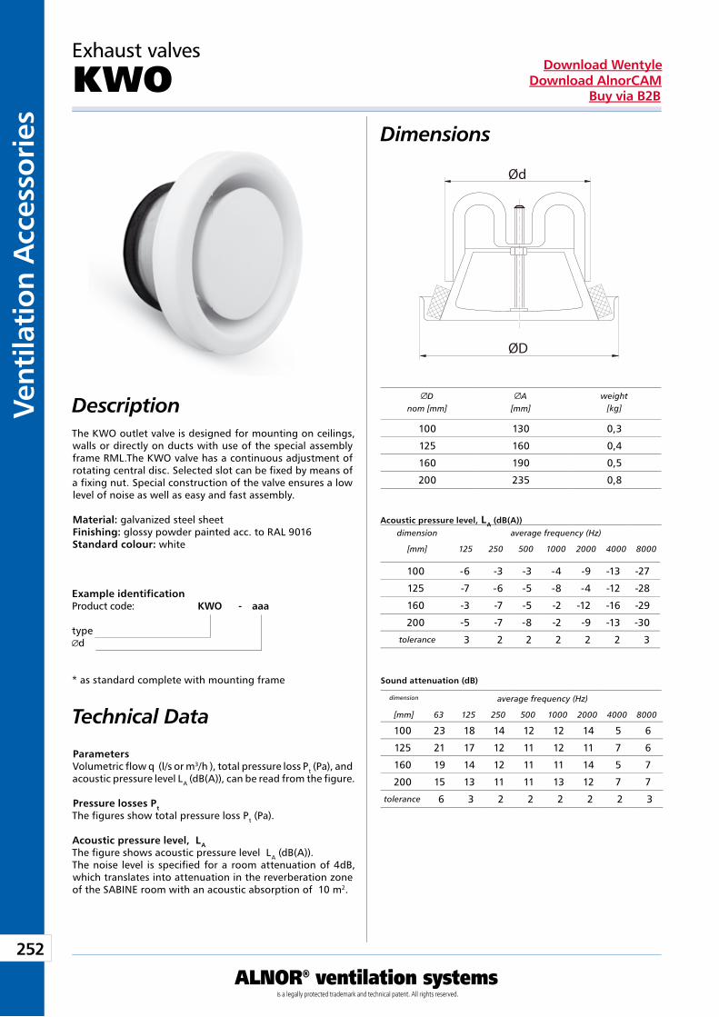
252
Vent
ilati
on A
cces
sori
es
ALNOR® ventilation systemsis a legally protected trademark and technical patent. All rights reserved.
Download WentyleDownload AlnorCAM
Buy via B2B
Parameters Volumetric flow q (l/s or m3/h ), total pressure loss Pt (Pa), and acoustic pressure level LA (dB(A)), can be read from the figure.
Pressure losses Pt The figures show total pressure loss Pt (Pa).
Acoustic pressure level, LA The figure shows acoustic pressure level LA (dB(A)).The noise level is specified for a room attenuation of 4dB, which translates into attenuation in the reverberation zone of the SABINE room with an acoustic absorption of 10 m2.
Dimensions
Description
Exhaust valves
KWO
The KWO outlet valve is designed for mounting on ceilings, walls or directly on ducts with use of the special assembly frame RML.The KWO valve has a continuous adjustment of rotating central disc. Selected slot can be fixed by means of a fixing nut. Special construction of the valve ensures a low level of noise as well as easy and fast assembly.
Material: galvanized steel sheetFinishing: glossy powder painted acc. to RAL 9016Standard colour: white
Example identificationProduct code: KWO - aaa
typed
* as standard complete with mounting frame
Technical Data
Acoustic pressure level, LA (dB(A))
Sound attenuation (dB)
Dnom [mm]
A[mm]
weight[kg]
dimension average frequency (Hz)
[mm] 125 250 500 1000 2000 4000 8000
dimension average frequency (Hz)
[mm] 63 125 250 500 1000 2000 4000 8000
100 130 0,3
125 160 0,4
160 190 0,5
200 235 0,8
100 -6 -3 -3 -4 -9 -13 -27
125 -7 -6 -5 -8 -4 -12 -28
160 -3 -7 -5 -2 -12 -16 -29
200 -5 -7 -8 -2 -9 -13 -30
tolerance 3 2 2 2 2 2 3
100 23 18 14 12 12 14 5 6
125 21 17 12 11 12 11 7 6
160 19 14 12 11 11 14 5 7
200 15 13 11 11 13 12 7 7
tolerance 6 3 2 2 2 2 2 3
ØD
Ød
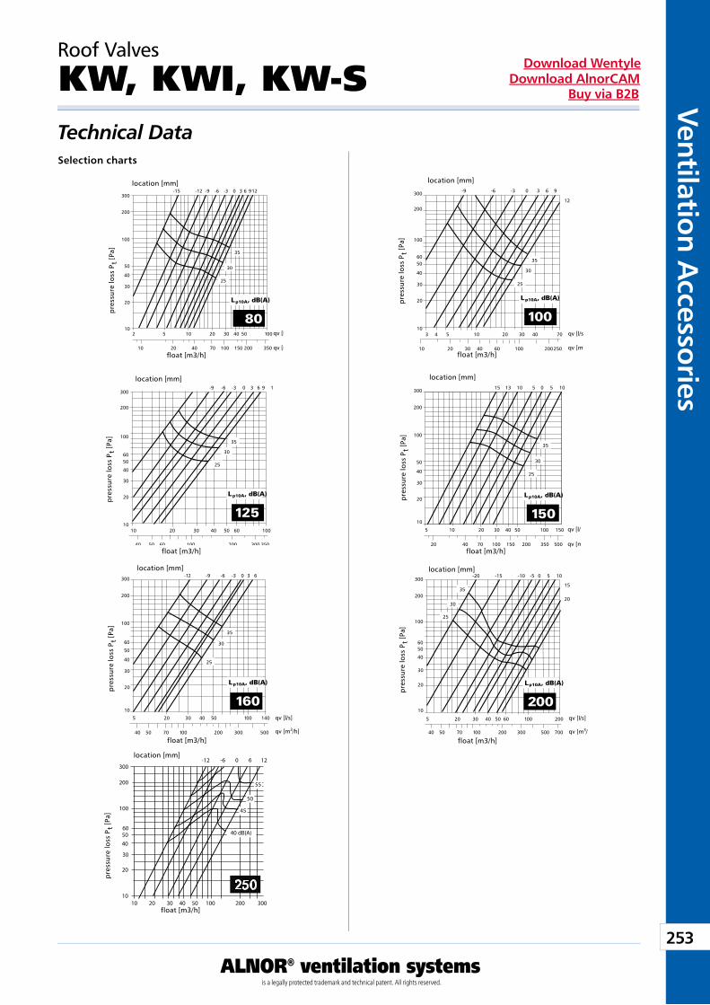
253
Ventilation Accessories
ALNOR® ventilation systemsis a legally protected trademark and technical patent. All rights reserved.
Download WentyleDownload AlnorCAM
Buy via B2B
Roof Valves
KW, KWI, KW-STechnical DataSelection charts
float [m3/h]
location [mm]
pre
ssur
e lo
ss P
t [P
a]
float [m3/h]
float [m3/h]
float [m3/h]
float [m3/h]
float [m3/h]
location [mm]
pre
ssur
e lo
ss P
t [P
a]
location [mm]
pre
ssur
e lo
ss P
t [P
a]
location [mm]
pre
ssur
e lo
ss P
t [P
a]
location [mm]
pre
ssur
e lo
ss P
t [P
a]
location [mm]
pre
ssur
e lo
ss P
t [P
a]
location [mm]
pre
ssur
e lo
ss P
t [P
a]
float [m3/h]
-12 -6 0 6 12
250
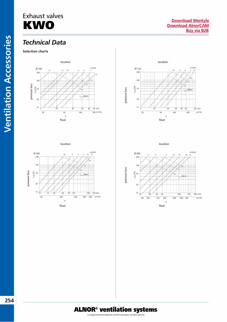
254
Vent
ilati
on A
cces
sori
es
ALNOR® ventilation systemsis a legally protected trademark and technical patent. All rights reserved.
Download WentyleDownload AlnorCAM
Buy via B2B
Exhaust valves
KWOTechnical DataSelection charts
float
location
stra
ta c
iśni
enia
Pt
[Pa]
float
location
stra
ta c
iśni
enia
Pt
[Pa]
float
location
stra
ta c
iśni
enia
Pt
[Pa]
float
location
stra
ta c
iśni
enia
Pt
[Pa]
pre
ssur
e lo
ccp
ress
ure
locc
pre
ssur
e lo
ccp
ress
ure
locc
2
3
7
9
10
11
14
15
16
10
20
50
100
5 10 20 50 [l/s]
∆ p
t [Pa
]
20
q
50 100 180 [m3/h]
Ø 100
200
30 40
a [mm]
30
35
40
-15 -12 -10 -5 0 5
10
L WA [dB(A)]
2
3
7
9
10
11
14
15
16
10
20
50
100
5 10 20 80 [l/s]
∆ p t [
Pa]
20
q
50 100 200 [m3/h]
Ø 125200
30 40 50
a [mm]
30
35
40
-10 -5 0 5 10
LWA [dB(A)]
2
3
7
9
10
11
14
15
16
10
20
50
100
10 15 20 130 [l/s]
∆ p
t [Pa
]
40
q
100 200 300 [m3/h]
Ø 160200
30 40 50
400
100
a [mm]
30
35
40
-10 -5 0 5 10 15
L WA [dB(A)]
2
3
4
5
7
8
9
11
13
15
10
20
50
100
20 30 40 150 [l/s]
∆ p t [
Pa]
80
q
150 200 300 [m3/h]
Ø 200200
50 100
400
200
100 500
a [mm]
30
35
40
-3 0 5 10 15 20 25
L WA [dB(A)]
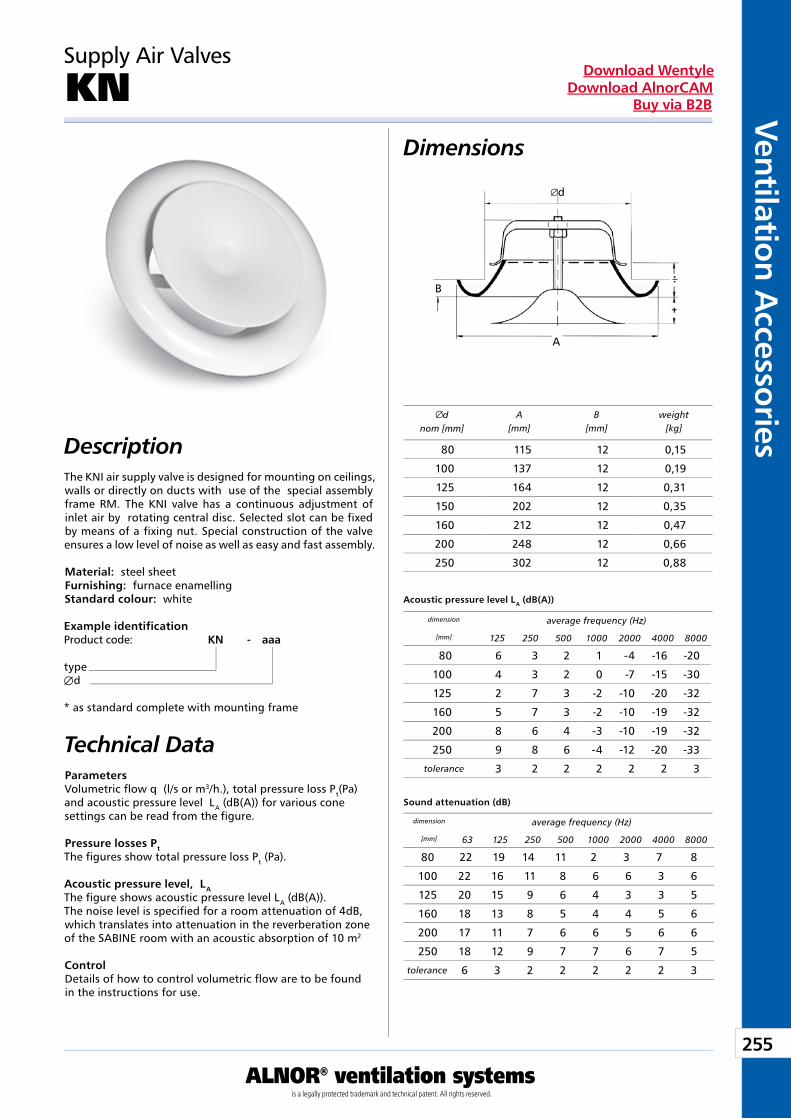
255
Ventilation Accessories
ALNOR® ventilation systemsis a legally protected trademark and technical patent. All rights reserved.
Download WentyleDownload AlnorCAM
Buy via B2B
Dimensions
Description
Supply Air Valves
KN
The KNI air supply valve is designed for mounting on ceilings, walls or directly on ducts with use of the special assembly frame RM. The KNI valve has a continuous adjustment of inlet air by rotating central disc. Selected slot can be fixed by means of a fixing nut. Special construction of the valve ensures a low level of noise as well as easy and fast assembly.
Material: steel sheetFurnishing: furnace enamellingStandard colour: white
Example identificationProduct code: KN - aaa
typeÆd
* as standard complete with mounting frame
Parameters Volumetric flow q (l/s or m3/h.), total pressure loss Pt(Pa) and acoustic pressure level LA (dB(A)) for various cone settings can be read from the figure.
Pressure losses Pt The figures show total pressure loss Pt (Pa).
Acoustic pressure level, LA The figure shows acoustic pressure level LA (dB(A)).The noise level is specified for a room attenuation of 4dB, which translates into attenuation in the reverberation zone of the SABINE room with an acoustic absorption of 10 m2
Control Details of how to control volumetric flow are to be found in the instructions for use.
dnom [mm]
A[mm]
B[mm]
weight[kg]
Acoustic pressure level LA (dB(A))
Sound attenuation (dB)
dimension average frequency (Hz)
[mm] 125 250 500 1000 2000 4000 8000
dimension average frequency (Hz)
[mm] 63 125 250 500 1000 2000 4000 8000
Technical Data
80 115 12 0,15
100 137 12 0,19
125 164 12 0,31
150 202 12 0,35
160 212 12 0,47
200 248 12 0,66
250 302 12 0,88
80 6 3 2 1 -4 -16 -20
100 4 3 2 0 -7 -15 -30
125 2 7 3 -2 -10 -20 -32
160 5 7 3 -2 -10 -19 -32
200 8 6 4 -3 -10 -19 -32
250 9 8 6 -4 -12 -20 -33
tolerance 3 2 2 2 2 2 3
80 22 19 14 11 2 3 7 8
100 22 16 11 8 6 6 3 6
125 20 15 9 6 4 3 3 5
160 18 13 8 5 4 4 5 6
200 17 11 7 6 6 5 6 6
250 18 12 9 7 7 6 7 5
tolerance 6 3 2 2 2 2 2 3
d
A
B
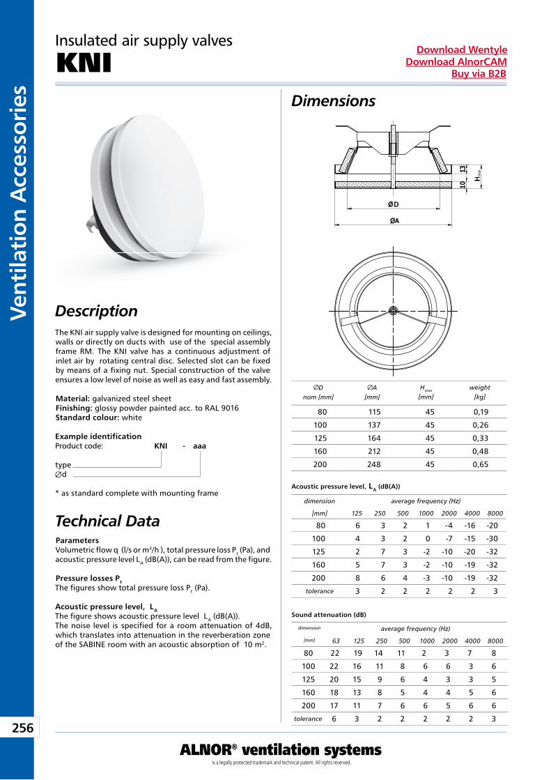
256
Vent
ilati
on A
cces
sori
es
ALNOR® ventilation systemsis a legally protected trademark and technical patent. All rights reserved.
Download WentyleDownload AlnorCAM
Buy via B2B
Dimensions
Description
Parameters Volumetric flow q (l/s or m3/h ), total pressure loss Pt (Pa), and acoustic pressure level LA (dB(A)), can be read from the figure.
Pressure losses Pt The figures show total pressure loss Pt (Pa).
Acoustic pressure level, LA The figure shows acoustic pressure level LA (dB(A)).The noise level is specified for a room attenuation of 4dB, which translates into attenuation in the reverberation zone of the SABINE room with an acoustic absorption of 10 m2.
Technical Data
Example identificationProduct code: KNI - aaa
typeÆd
* as standard complete with mounting frame
Insulated air supply valves
KNI
Dnom [mm]
A[mm]
Hmax
[mm]weight
[kg]
Acoustic pressure level, LA (dB(A))
Sound attenuation (dB)
dimension average frequency (Hz)
[mm] 125 250 500 1000 2000 4000 8000
dimension average frequency (Hz)
[mm] 63 125 250 500 1000 2000 4000 8000
The KNI air supply valve is designed for mounting on ceilings, walls or directly on ducts with use of the special assembly frame RM. The KNI valve has a continuous adjustment of inlet air by rotating central disc. Selected slot can be fixed by means of a fixing nut. Special construction of the valve ensures a low level of noise as well as easy and fast assembly.
Material: galvanized steel sheet Finishing: glossy powder painted acc. to RAL 9016 Standard colour: white
80 115 45 0,19
100 137 45 0,26
125 164 45 0,33
160 212 45 0,48
200 248 45 0,65
80 6 3 2 1 -4 -16 -20
100 4 3 2 0 -7 -15 -30
125 2 7 3 -2 -10 -20 -32
160 5 7 3 -2 -10 -19 -32
200 8 6 4 -3 -10 -19 -32
tolerance 3 2 2 2 2 2 3
80 22 19 14 11 2 3 7 8
100 22 16 11 8 6 6 3 6
125 20 15 9 6 4 3 3 5
160 18 13 8 5 4 4 5 6
200 17 11 7 6 6 5 6 6
tolerance 6 3 2 2 2 2 2 3
D
max
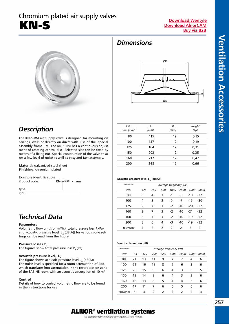
257
Ventilation Accessories
ALNOR® ventilation systemsis a legally protected trademark and technical patent. All rights reserved.
Download WentyleDownload AlnorCAM
Buy via B2B
Dimensions
Description
Example identificationProduct code: KN-S-RM - aaa
typeÆd
Parameters Volumetric flow q (l/s or m3/h.), total pressure loss Pt(Pa) and acoustic pressure level LA (dB(A)) for various cone set-tings can be read from the figure.
Pressure losses Pt The figures show total pressure loss Pt (Pa).
Acoustic pressure level, LA The figure shows acoustic pressure level LA (dB(A)).The noise level is specified for a room attenuation of 4dB, which translates into attenuation in the reverberation zone of the SABINE room with an acoustic absorption of 10 m2
Control Details of how to control volumetric flow are to be found in the instructions for use.
Chromium plated air supply valves
KN-S
Technical Data
Dnom [mm]
A[mm]
B[mm]
weight[kg]
Acoustic pressure level LA (dB(A))
Sound attenuation (dB)
dimension average frequency (Hz)
[mm] 125 250 500 1000 2000 4000 8000
dimension average frequency (Hz)
[mm] 63 125 250 500 1000 2000 4000 8000
The KN-S-RM air supply valve is designed for mounting on ceilings, walls or directly on ducts with use of the special assembly frame RM. The KN-S-RM has a continuous adjust-ment of rotating central disc. Selected slot can be fixed by means of a fixing nut. Special construction of the valve ensu-res a low level of noise as well as easy and fast assembly.
Material: galvanized steel sheetFinishing: chromium plated
80 115 12 0,15
100 137 12 0,19
125 164 12 0,31
150 202 12 0,35
160 212 12 0,47
200 248 12 0,66
80 6 4 3 -1 -5 -10 -27
100 4 3 2 0 -7 -15 -30
125 2 7 3 -2 -10 -20 -32
160 3 7 3 -2 -10 -21 -32
160 5 7 3 -2 -10 -19 -32
200 8 6 4 -3 -10 -19 -32
tolerance 3 2 2 2 2 2 3
80 21 13 11 9 7 7 4 6
100 22 16 11 8 6 6 3 6
125 20 15 9 6 4 3 3 5
150 19 14 8 6 4 3 3 6
160 18 13 8 5 4 4 5 6
200 17 11 7 6 6 5 6 6
tolerance 6 3 2 2 2 2 2 3
ØD
ØA
B
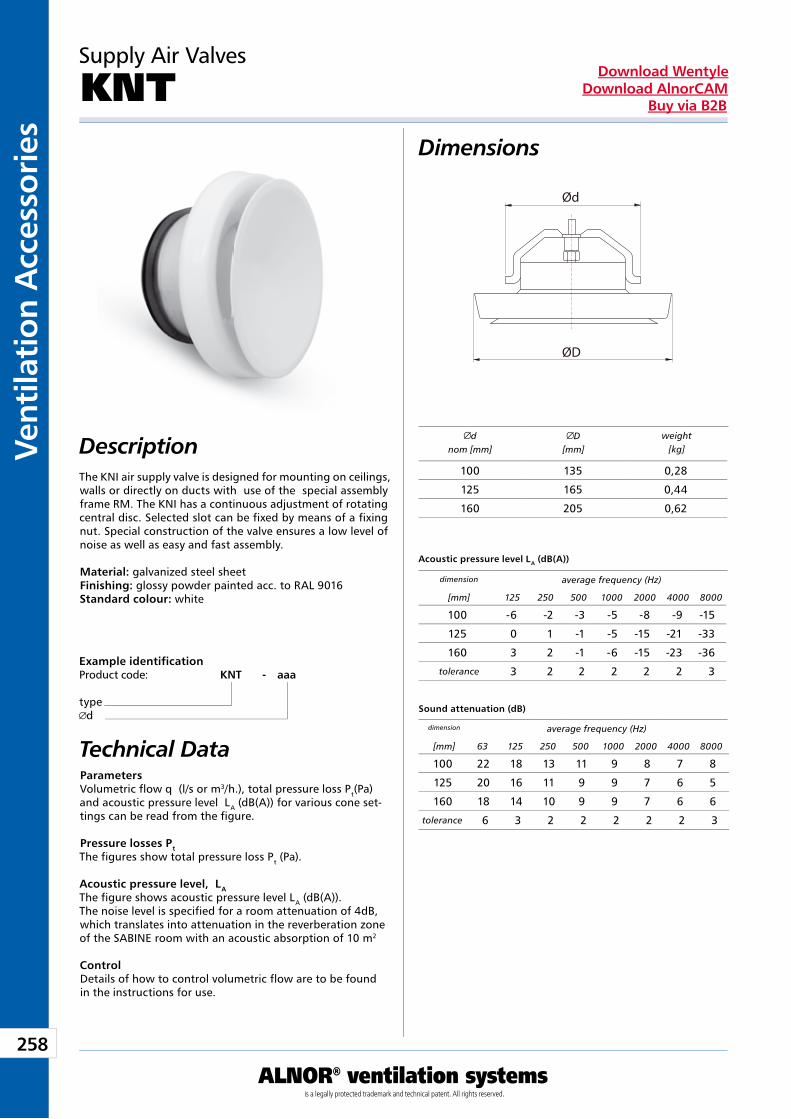
258
Vent
ilati
on A
cces
sori
es
ALNOR® ventilation systemsis a legally protected trademark and technical patent. All rights reserved.
Download WentyleDownload AlnorCAM
Buy via B2B
Parameters Volumetric flow q (l/s or m3/h.), total pressure loss Pt(Pa) and acoustic pressure level LA (dB(A)) for various cone set-tings can be read from the figure.
Pressure losses Pt The figures show total pressure loss Pt (Pa).
Acoustic pressure level, LA The figure shows acoustic pressure level LA (dB(A)).The noise level is specified for a room attenuation of 4dB, which translates into attenuation in the reverberation zone of the SABINE room with an acoustic absorption of 10 m2
Control Details of how to control volumetric flow are to be found in the instructions for use.
Dimensions
Description
Supply Air Valves
KNT
The KNI air supply valve is designed for mounting on ceilings, walls or directly on ducts with use of the special assembly frame RM. The KNI has a continuous adjustment of rotating central disc. Selected slot can be fixed by means of a fixing nut. Special construction of the valve ensures a low level of noise as well as easy and fast assembly.
Material: galvanized steel sheet Finishing: glossy powder painted acc. to RAL 9016Standard colour: white
Example identificationProduct code: KNT - aaa
typed
Technical Data
Acoustic pressure level LA (dB(A))
Sound attenuation (dB)
dimension average frequency (Hz)
[mm] 125 250 500 1000 2000 4000 8000
dimension average frequency (Hz)
[mm] 63 125 250 500 1000 2000 4000 8000
dnom [mm]
D[mm]
weight[kg]
100 -6 -2 -3 -5 -8 -9 -15
125 0 1 -1 -5 -15 -21 -33
160 3 2 -1 -6 -15 -23 -36
tolerance 3 2 2 2 2 2 3
100 22 18 13 11 9 8 7 8
125 20 16 11 9 9 7 6 5
160 18 14 10 9 9 7 6 6
tolerance 6 3 2 2 2 2 2 3
100 135 0,28
125 165 0,44
160 205 0,62
ØD
Ød
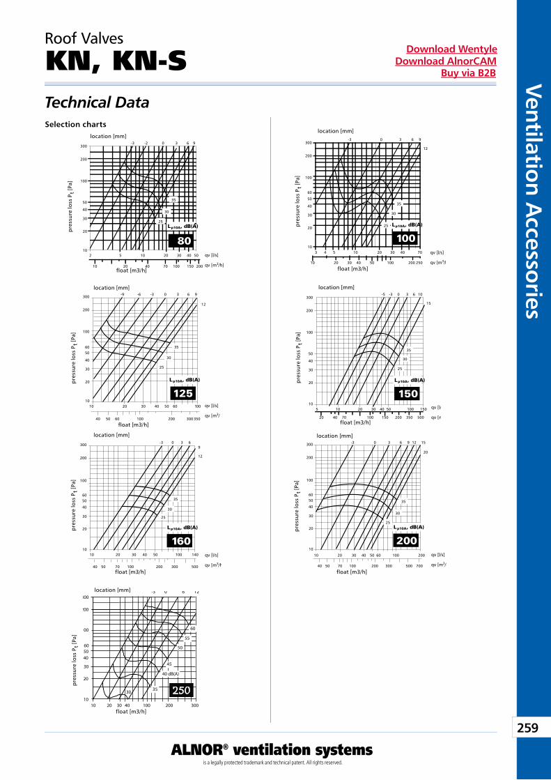
259
Ventilation Accessories
ALNOR® ventilation systemsis a legally protected trademark and technical patent. All rights reserved.
Download WentyleDownload AlnorCAM
Buy via B2B
Roof Valves
KN, KN-STechnical DataSelection charts
float [m3/h]
location [mm]
pre
ssur
e lo
ss P
t [P
a]
float [m3/h]
location [mm]
pre
ssur
e lo
ss P
t [P
a]
float [m3/h]
location [mm]
pre
ssur
e lo
ss P
t [P
a]
float [m3/h]
location [mm]
pre
ssur
e lo
ss P
t [P
a]
float [m3/h]
location [mm]
pre
ssur
e lo
ss P
t [P
a]
float [m3/h]
location [mm]
pre
ssur
e lo
ss P
t [P
a]
float [m3/h]
location [mm]
pre
ssur
e lo
ss P
t [P
a]
250
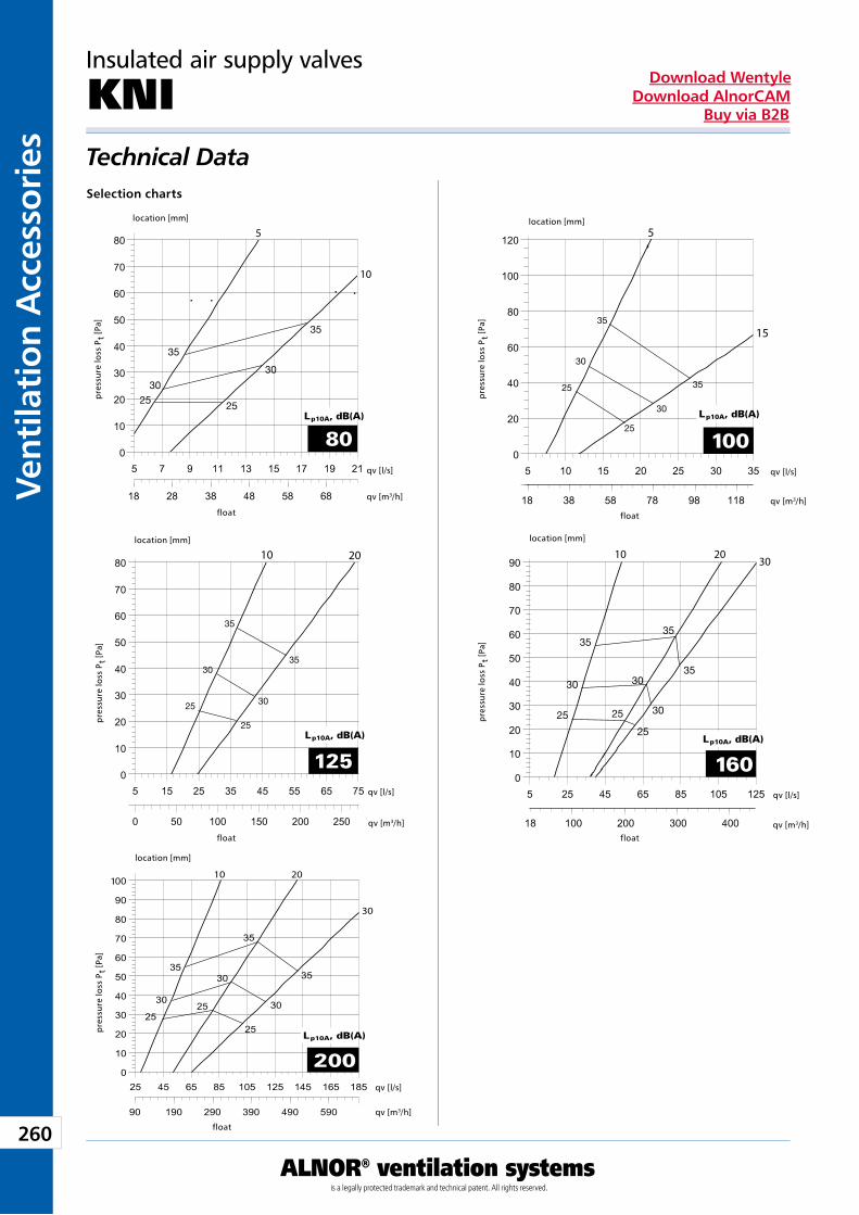
260
Vent
ilati
on A
cces
sori
es
ALNOR® ventilation systemsis a legally protected trademark and technical patent. All rights reserved.
Download WentyleDownload AlnorCAM
Buy via B2B
Technical DataSelection charts
float
location [mm]
pre
ssur
e lo
ss P
t [P
a]
float
location [mm]
pre
ssur
e lo
ss P
t [P
a]
float
location [mm]
pre
ssur
e lo
ss P
t [P
a]
float
location [mm]
pre
ssur
e lo
ss P
t [P
a]
float
location [mm]
pre
ssur
e lo
ss P
t [P
a]qv [l/s]
qv [m3/h]
qv [l/s]
qv [m3/h]
qv [l/s]
qv [m3/h]
qv [l/s]
qv [m3/h]
qv [l/s]
qv [m3/h]
10 20
110 20
30
5
15
5
10
10 2030
Insulated air supply valves
KNI
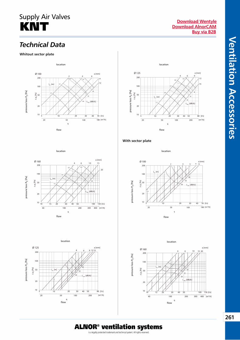
261
Ventilation Accessories
ALNOR® ventilation systemsis a legally protected trademark and technical patent. All rights reserved.
Download WentyleDownload AlnorCAM
Buy via B2B
Supply Air Valves
KNTTechnical DataWhitout sector plate
flow
location
pre
ssur
e lo
ss P
t [P
a]
flow
location
pre
ssur
e lo
ss P
t [P
a]
flow
location
pre
ssur
e lo
ss P
t [P
a]
flow
location
pre
ssur
e lo
ss P
t [P
a]
flow
location
pre
ssur
e lo
ss P
t [P
a]
flow
location
pre
ssur
e lo
ss P
t [P
a]
With sector plate
10
20
50
100
5 10 20 50 [l/s]
∆ p
t [Pa
]
20
q
50 100 180 [m3/h]
Ø 100200
30 40
L WA [dB(A)]
l0,2 [m]
a [mm]2 4 6
9
12
1,0
1,5
2,0 2,5
30
35
40
10
20
50
100
5 10 20 80 [l/s]
∆ p
t [Pa
]
20
q
50 100 200 [m3/h]
Ø 125
200
30 40 50
L WA [dB(A)]
l0,2 [m]
a [mm]4 6 9
12
15
1,5
2,0
2,5
3,03,5
30
35
40
10
20
50
100
5 10 20 50 [l/s]
∆ p
t [Pa
]
20
q
50 100 180 [m3/h]
Ø 100200
30 40
L WA [dB(A)]
l0,2 [m]
a [mm]2 4 6 9 12
30
35
40
1,5
1,0
2
3 4 5
10
20
50
100
10 15 20 130 [l/s]
∆ p
t [Pa
]
40
q
100 200 300 [m3/h]
Ø 160200
30 40 50
400
100
L WA [dB(A)]
l0,2 [m]
a [mm]
4 6 10 15
20
1,5
2,0
2,5 3,0
30
35
40
10
20
50
100
5 10 20 80 [l/s]
∆ p t [
Pa]
20
q
50 100 200 [m3/h]
Ø 125
200
30 40 50
L WA [dB(A)]
l0,2 [m]
a [mm]4 6 9 12 15
30
35
40
1,5
2
3
4
10
20
50
100
10 15 20 130 [l/s]
∆ p t [
Pa]
40
q
100 200 300 [m3/h]
Ø 160200
30 40 50
400
100
L WA [dB(A)]
l0,2 [m]
a [mm]
4 6 10 15 20
30
35
40
1,5
2
4 5
3
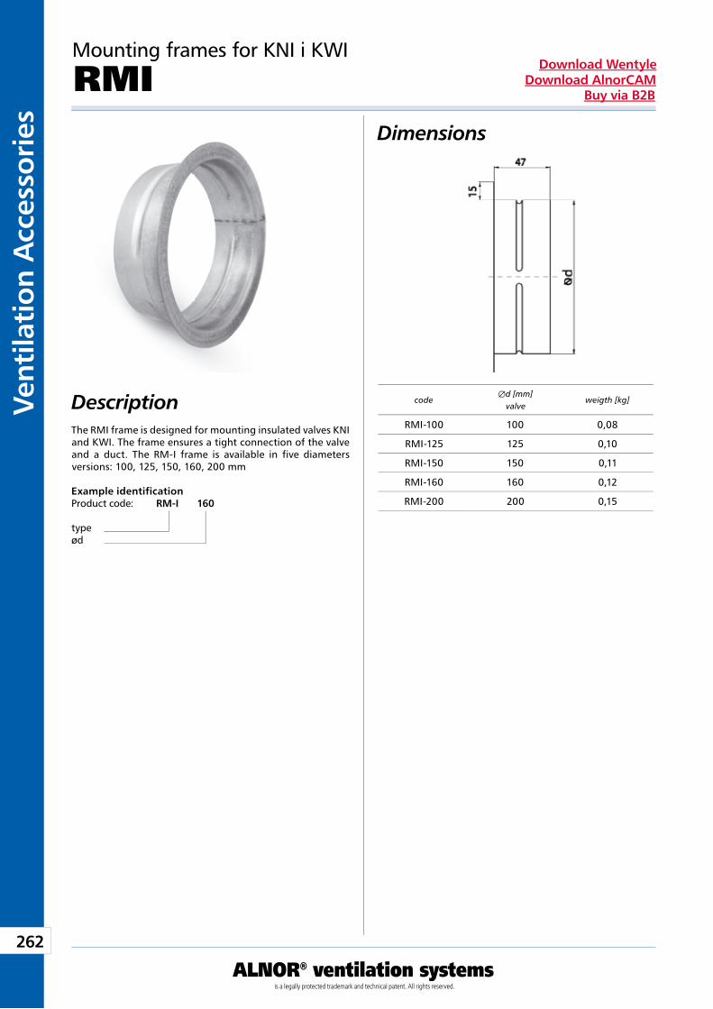
262
Vent
ilati
on A
cces
sori
es
ALNOR® ventilation systemsis a legally protected trademark and technical patent. All rights reserved.
Download WentyleDownload AlnorCAM
Buy via B2B
Mounting frames for KNI i KWI
RMI Dimensions
DescriptionThe RMI frame is designed for mounting insulated valves KNI and KWI. The frame ensures a tight connection of the valve and a duct. The RM-I frame is available in five diameters versions: 100, 125, 150, 160, 200 mm
Example identificationProduct code: RM-I 160
typeød
codeÆd [mm]
valveweigth [kg]
RMI-100 100 0,08
RMI-125 125 0,10
RMI-150 150 0,11
RMI-160 160 0,12
RMI-200 200 0,15
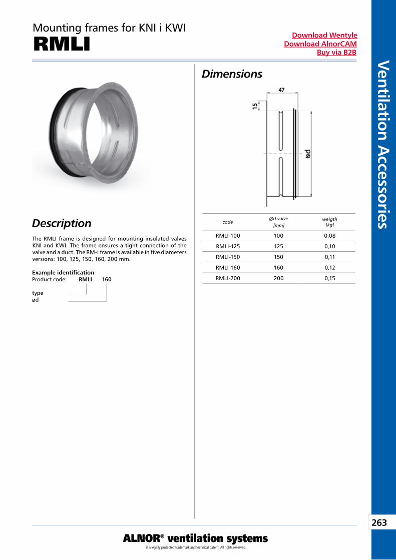
263
Ventilation Accessories
ALNOR® ventilation systemsis a legally protected trademark and technical patent. All rights reserved.
Download WentyleDownload AlnorCAM
Buy via B2B
Mounting frames for KNI i KWI
RMLIDimensions
DescriptionThe RMLI frame is designed for mounting insulated valves KNI and KWI. The frame ensures a tight connection of the valve and a duct. The RM-I frame is available in five diameters versions: 100, 125, 150, 160, 200 mm.
Example identificationProduct code: RMLI 160
typeød
codeÆd valve
[mm]weigth
[kg]
RMLI-100 100 0,08
RMLI-125 125 0,10
RMLI-150 150 0,11
RMLI-160 160 0,12
RMLI-200 200 0,15
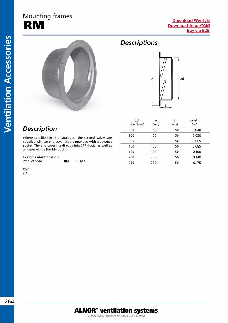
264
Vent
ilati
on A
cces
sori
es
ALNOR® ventilation systemsis a legally protected trademark and technical patent. All rights reserved.
Download WentyleDownload AlnorCAM
Buy via B2B
Descriptions
Description
Mounting frames
RM
Where specified in this catalogue, the control valves are supplied with an end cover that is provided with a bayonet socket. The end cover fits directly into SPR ducts, as well as all types of the flexible ducts.
Example identificationProduct code: RM - aaa
typeÆd
Æd A B weight rated [mm] [mm] [mm] [kg]
80 118 50 0,040
100 125 50 0,050
125 155 50 0,065
150 176 50 0,085
160 186 50 0,100
200 230 50 0,140
250 280 50 0,175
dA
B
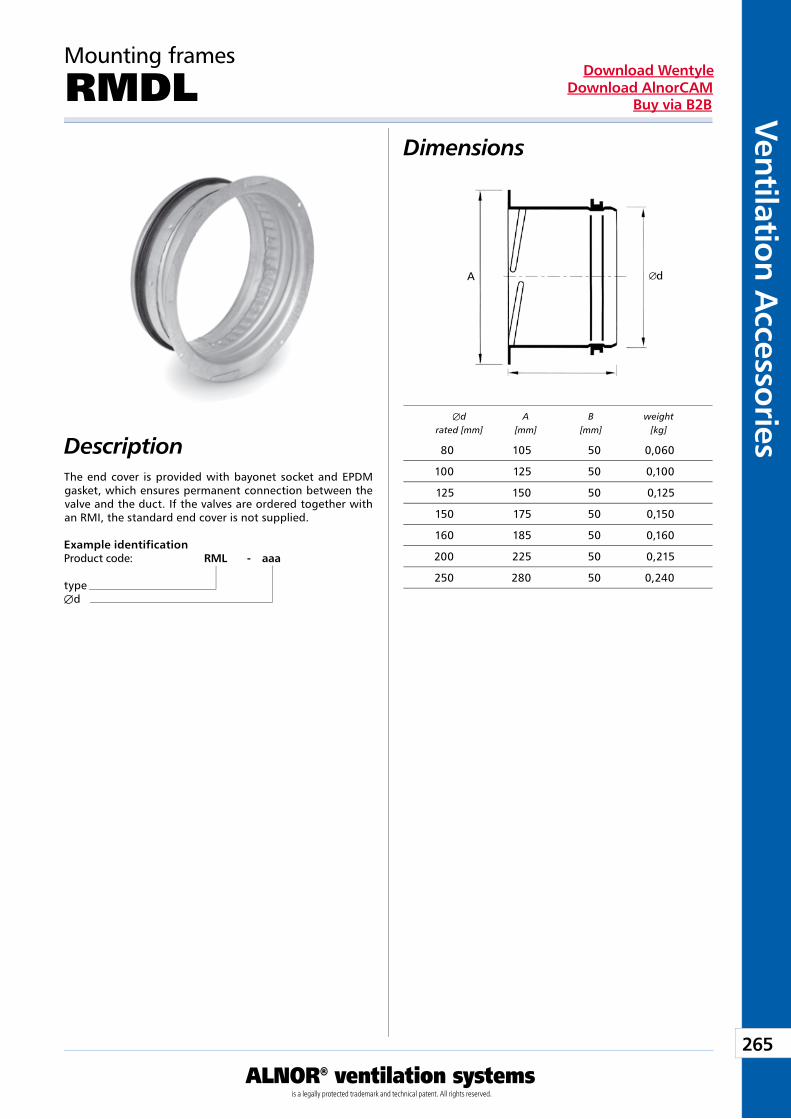
265
Ventilation Accessories
ALNOR® ventilation systemsis a legally protected trademark and technical patent. All rights reserved.
Download WentyleDownload AlnorCAM
Buy via B2B
Dimensions
Description
Mounting frames
RMDL
The end cover is provided with bayonet socket and EPDM gasket, which ensures permanent connection between the valve and the duct. If the valves are ordered together with an RMI, the standard end cover is not supplied.
Example identificationProduct code: RML - aaa
typeÆd
Æd A B weight rated [mm] [mm] [mm] [kg]
80 105 50 0,060
100 125 50 0,100
125 150 50 0,125
150 175 50 0,150
160 185 50 0,160
200 225 50 0,215
250 280 50 0,240
B
dA
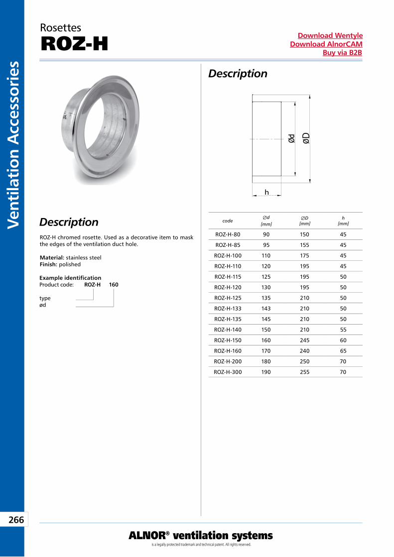
266
Vent
ilati
on A
cces
sori
es
ALNOR® ventilation systemsis a legally protected trademark and technical patent. All rights reserved.
Download WentyleDownload AlnorCAM
Buy via B2B
Rosettes
ROZ-HDescription
DescriptionROZ-H chromed rosette. Used as a decorative item to mask the edges of the ventilation duct hole. Material: stainless steel Finish: polished
Example identificationProduct code: ROZ-H 160
typeød
codeÆd
[mm] ÆD
[mm]h
[mm]
ROZ-H-80 90 150 45
ROZ-H-85 95 155 45
ROZ-H-100 110 175 45
ROZ-H-110 120 195 45
ROZ-H-115 125 195 50
ROZ-H-120 130 195 50
ROZ-H-125 135 210 50
ROZ-H-133 143 210 50
ROZ-H-135 145 210 50
ROZ-H-140 150 210 55
ROZ-H-150 160 245 60
ROZ-H-160 170 240 65
ROZ-H-200 180 250 70
ROZ-H-300 190 255 70
D
h
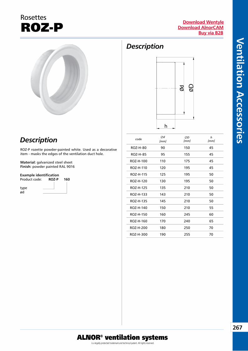
267
Ventilation Accessories
ALNOR® ventilation systemsis a legally protected trademark and technical patent. All rights reserved.
Download WentyleDownload AlnorCAM
Buy via B2B
Rosettes
ROZ-PDescription
DescriptionROZ-P rozette powder-painted white. Used as a decorative item - masks the edges of the ventilation duct hole. Material: galvanized steel sheet Finish: powder painted RAL 9016
Example identificationProduct code: ROZ-P 160
typeød
codeÆd
[mm] ÆD
[mm]h
[mm]
ROZ-H-80 90 150 45
ROZ-H-85 95 155 45
ROZ-H-100 110 175 45
ROZ-H-110 120 195 45
ROZ-H-115 125 195 50
ROZ-H-120 130 195 50
ROZ-H-125 135 210 50
ROZ-H-133 143 210 50
ROZ-H-135 145 210 50
ROZ-H-140 150 210 55
ROZ-H-150 160 245 60
ROZ-H-160 170 240 65
ROZ-H-200 180 250 70
ROZ-H-300 190 255 70
D
h
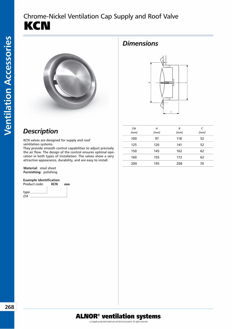
268
Vent
ilati
on A
cces
sori
es
ALNOR® ventilation systemsis a legally protected trademark and technical patent. All rights reserved.
Download WentyleDownload AlnorCAM
Buy via B2B
Chrome-Nickel Ventilation Cap Supply and Roof Valve
KCN Dimensions
DescriptionKCN valves are designed for supply and roof ventilation systems.They provide smooth control capabilities to adjust precisely the air flow. The design of the control ensures optimal ope-ration in both types of installation. The valves show a very attractive appearance, durability, and are easy to install.
Material: steel sheetFurnishing: polishing
Example identificationProduct code: KCN aaa
typeÆd
d[mm]
A[mm]
B[mm]
C[mm]
100 97 118 52
125 120 141 52
150 145 162 62
160 155 172 62
200 195 208 70
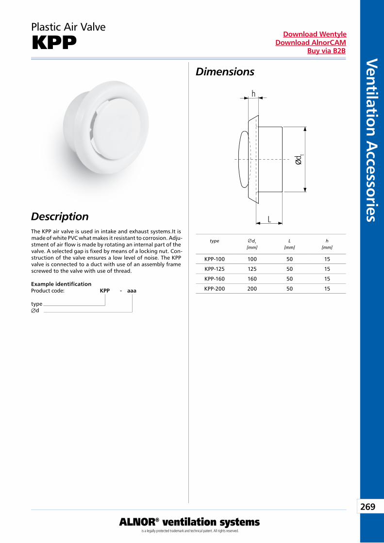
269
Ventilation Accessories
ALNOR® ventilation systemsis a legally protected trademark and technical patent. All rights reserved.
Download WentyleDownload AlnorCAM
Buy via B2B
Dimensions
Description
Plastic Air Valve
KPP
The KPP air valve is used in intake and exhaust systems.It is made of white PVC what makes it resistant to corrosion. Adju-stment of air flow is made by rotating an internal part of the valve. A selected gap is fixed by means of a locking nut. Con-struction of the valve ensures a low level of noise. The KPP valve is connected to a duct with use of an assembly frame screwed to the valve with use of thread.
Example identificationProduct code: KPP - aaa
typeÆd
type d1
[mm]L
[mm]h
[mm]
KPP-100 100 50 15
KPP-125 125 50 15
KPP-160 160 50 15
KPP-200 200 50 15
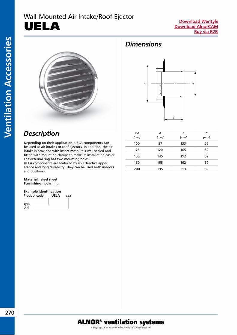
270
Vent
ilati
on A
cces
sori
es
ALNOR® ventilation systemsis a legally protected trademark and technical patent. All rights reserved.
Download WentyleDownload AlnorCAM
Buy via B2B
Wall-Mounted Air Intake/Roof Ejector
UELA Dimensions
DescriptionDepending on their application, UELA components can be used as air intakes or roof ejectors. In addition, the air intake is provided with insect mesh. It is well sealed and fitted with mounting clamps to make its installation easier. The external ring has two mounting holes.UELA components are featured by an attractive appe-arance and long durability. They can be used both indoors and outdoors.
Material: steel sheetFurnishing: polishing
Example identificationProduct code: UELA aaa
typeÆd
d[mm]
A[mm]
B[mm]
C[mm]
100 97 133 52
125 120 165 52
150 145 192 62
160 155 192 62
200 195 253 62
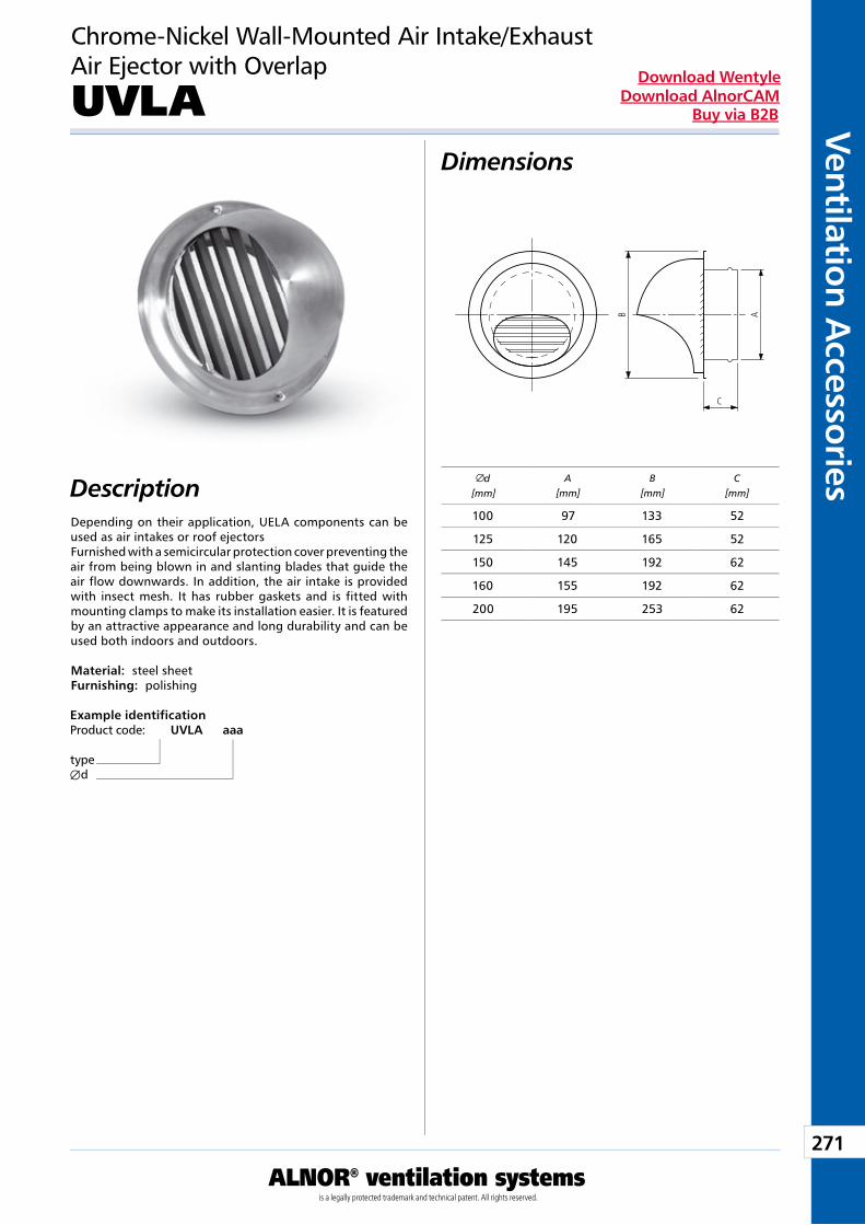
271
Ventilation Accessories
ALNOR® ventilation systemsis a legally protected trademark and technical patent. All rights reserved.
Download WentyleDownload AlnorCAM
Buy via B2B
Chrome-Nickel Wall-Mounted Air Intake/ExhaustAir Ejector with Overlap
UVLA Dimensions
DescriptionDepending on their application, UELA components can be used as air intakes or roof ejectorsFurnished with a semicircular protection cover preventing the air from being blown in and slanting blades that guide the air flow downwards. In addition, the air intake is provided with insect mesh. It has rubber gaskets and is fitted with mounting clamps to make its installation easier. It is featured by an attractive appearance and long durability and can be used both indoors and outdoors. Material: steel sheetFurnishing: polishing
Example identificationProduct code: UVLA aaa
typeÆd
d[mm]
A[mm]
B[mm]
C[mm]
100 97 133 52
125 120 165 52
150 145 192 62
160 155 192 62
200 195 253 62
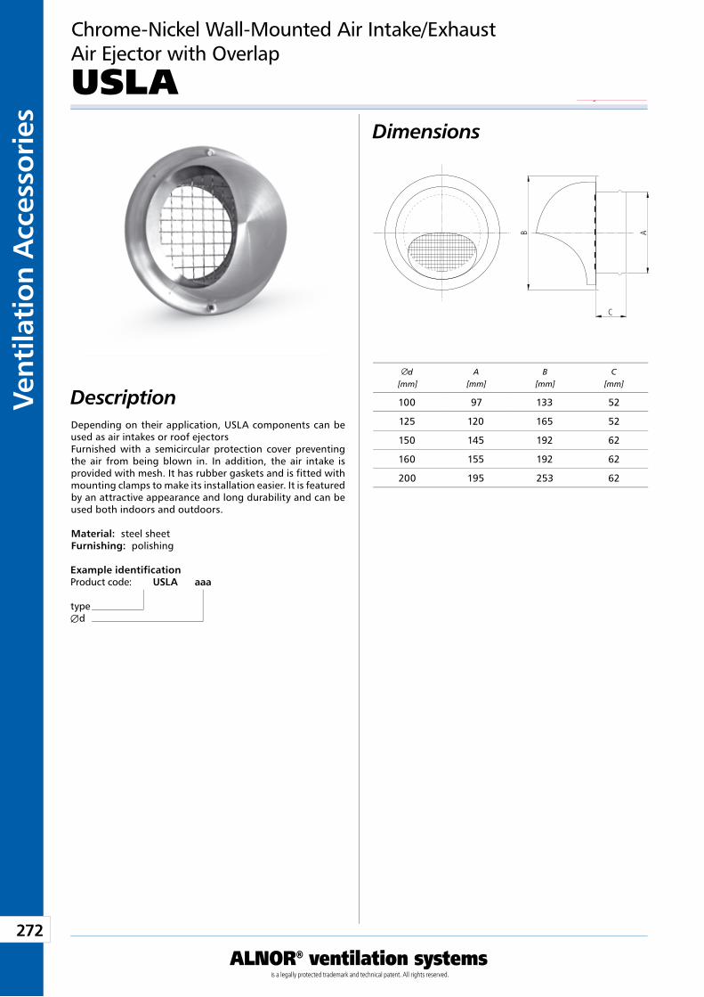
272
Vent
ilati
on A
cces
sori
es
ALNOR® ventilation systemsis a legally protected trademark and technical patent. All rights reserved.
Download WentyleDownload AlnorCAM
Buy via B2B
Chrome-Nickel Wall-Mounted Air Intake/ExhaustAir Ejector with Overlap
USLA Dimensions
Description
Example identificationProduct code: USLA aaa
typeÆd
Depending on their application, USLA components can be used as air intakes or roof ejectorsFurnished with a semicircular protection cover preventing the air from being blown in. In addition, the air intake is provided with mesh. It has rubber gaskets and is fitted with mounting clamps to make its installation easier. It is featured by an attractive appearance and long durability and can be used both indoors and outdoors. Material: steel sheetFurnishing: polishing
d[mm]
A[mm]
B[mm]
C[mm]
100 97 133 52
125 120 165 52
150 145 192 62
160 155 192 62
200 195 253 62
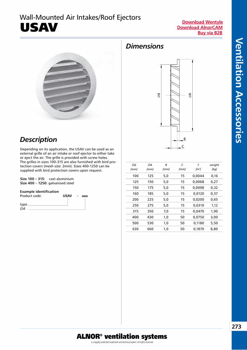
273
Ventilation Accessories
ALNOR® ventilation systemsis a legally protected trademark and technical patent. All rights reserved.
Download WentyleDownload AlnorCAM
Buy via B2B
Dimensions
Description
Wall-Mounted Air Intakes/Roof Ejectors
USAV
Depending on its application, the USAV can be used as an external grille of an air intake or roof ejector to either take or eject the air. The grille is provided with screw holes.The grilles in sizes 100-315 are also furnished with bird pro-tection covers (mesh size: 2mm). Sizes 400-1250 can be supplied with bird protection covers upon request.
Size 100 – 315: cast aluminiumSize 400 – 1250: galvanised steel
Example identificationProduct code: USAV - aaa
typeÆd
d[mm]
A[mm]
B[mm]
C[mm]
F[m2]
weight[kg]
100 125 5,0 15 0,0044 0,16
125 150 5,0 15 0,0068 0,27
150 175 5,0 15 0,0098 0,32
160 185 5,0 15 0,0120 0,37
200 225 5,0 15 0,0200 0,65
250 275 5,0 15 0,0310 1,12
315 350 7,0 15 0,0470 1,90
400 430 1,0 50 0,0750 3,00
500 530 1,0 50 0,1180 5,50
630 660 1,0 50 0,1870 8,80
B
C
d A
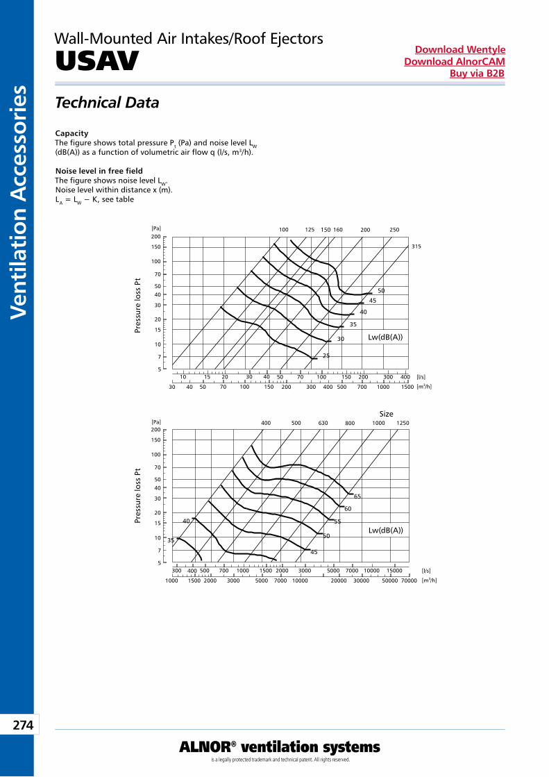
274
Vent
ilati
on A
cces
sori
es
ALNOR® ventilation systemsis a legally protected trademark and technical patent. All rights reserved.
Download WentyleDownload AlnorCAM
Buy via B2B
Technical Data
Wall-Mounted Air Intakes/Roof Ejectors
USAV
CapacityThe figure shows total pressure Pt (Pa) and noise level LW (dB(A)) as a function of volumetric air flow q (l/s, m3/h).
Noise level in free fieldThe figure shows noise level LW.Noise level within distance x (m).LA = LW − K, see table
Pres
sure
loss
Pt
Pres
sure
loss
Pt
Size
45
40
35
30
25
50
125100 160 200 250
315
200
150
100
70
5040
30
20
15
10
7
5
200
50
30 40 50
1510
70 100 150
20 30 40
300
100
400 500 700
15070
1000
200 300 400
1500
45
40
35
60
55
50
65
200
150
100
70
5040
30
20
15
10
7
5
500400 630 800 1000 1250
3000
1000
5000 7000
1500700
2000
500400
1500
300
1000 10000
2000
7000020000
3000 150005000 7000 10000
5000030000
[l/s]
[m3/h]
[l/s]
[m3/h]
[Pa]
[Pa]
150
Lw(dB(A))
Lw(dB(A))
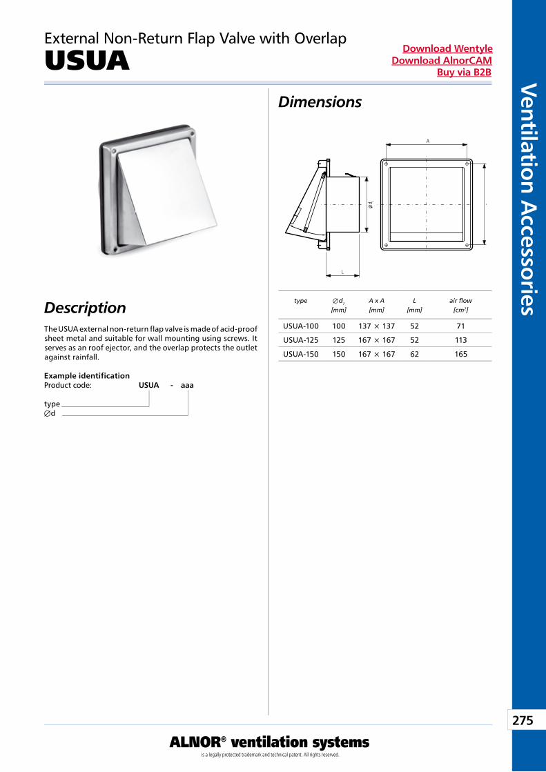
275
Ventilation Accessories
ALNOR® ventilation systemsis a legally protected trademark and technical patent. All rights reserved.
Download WentyleDownload AlnorCAM
Buy via B2B
Dimensions
Description
External Non-Return Flap Valve with Overlap
USUA
The USUA external non-return flap valve is made of acid-proof sheet metal and suitable for wall mounting using screws. It serves as an roof ejector, and the overlap protects the outlet against rainfall.
Example identificationProduct code: USUA - aaa
typeÆd
type Æ d1
[mm]A x A[mm]
L[mm]
air flow[cm2]
USUA-100 100 137 × 137 52 71
USUA-125 125 167 × 167 52 113
USUA-150 150 167 × 167 62 165
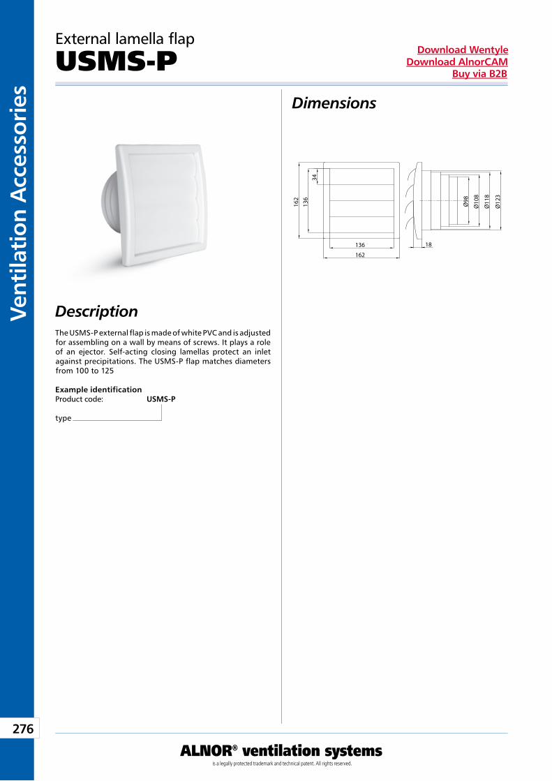
276
Vent
ilati
on A
cces
sori
es
ALNOR® ventilation systemsis a legally protected trademark and technical patent. All rights reserved.
Download WentyleDownload AlnorCAM
Buy via B2B
Dimensions
Description
External lamella flap
USMS-P
The USMS-P external flap is made of white PVC and is adjusted for assembling on a wall by means of screws. It plays a role of an ejector. Self-acting closing lamellas protect an inlet against precipitations. The USMS-P flap matches diameters from 100 to 125
Example identificationProduct code: USMS-P
type
162
162
136
136
34
Ø98
Ø10
8
Ø11
8
Ø12
3
18
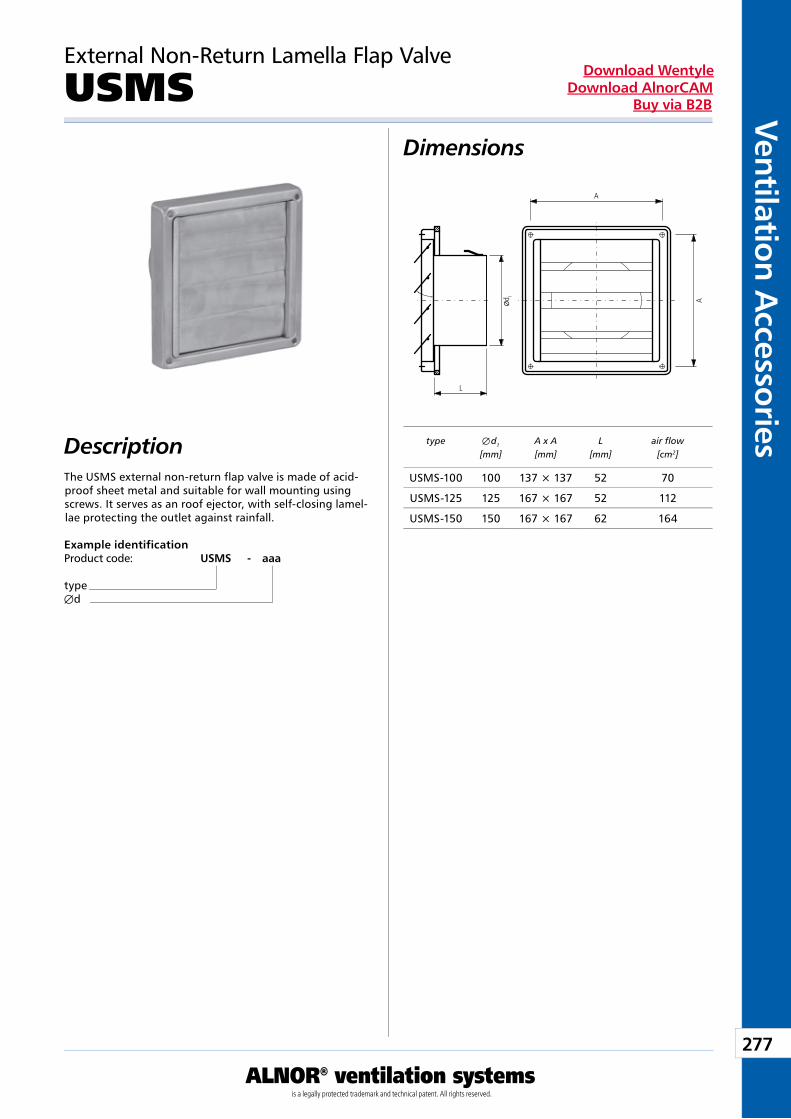
277
Ventilation Accessories
ALNOR® ventilation systemsis a legally protected trademark and technical patent. All rights reserved.
Download WentyleDownload AlnorCAM
Buy via B2B
Dimensions
Description
External Non-Return Lamella Flap Valve
USMS
The USMS external non-return flap valve is made of acid-proof sheet metal and suitable for wall mounting using screws. It serves as an roof ejector, with self-closing lamel-lae protecting the outlet against rainfall.
Example identificationProduct code: USMS - aaa
typeÆd
type Æ d1
[mm]A x A[mm]
L[mm]
air flow[cm2]
USMS-100 100 137 × 137 52 70
USMS-125 125 167 × 167 52 112
USMS-150 150 167 × 167 62 164
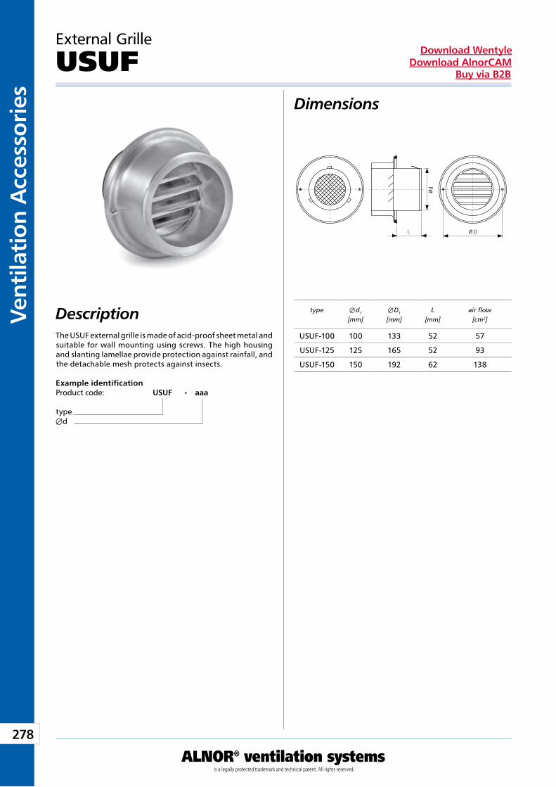
278
Vent
ilati
on A
cces
sori
es
ALNOR® ventilation systemsis a legally protected trademark and technical patent. All rights reserved.
Download WentyleDownload AlnorCAM
Buy via B2B
Dimensions
Description
External Grille
USUF
The USUF external grille is made of acid-proof sheet metal and suitable for wall mounting using screws. The high housing and slanting lamellae provide protection against rainfall, and the detachable mesh protects against insects.
Example identificationProduct code: USUF - aaa
typeÆd
type Æ d1
[mm]Æ D1
[mm]L
[mm]air flow
[cm2]
USUF-100 100 133 52 57
USUF-125 125 165 52 93
USUF-150 150 192 62 138
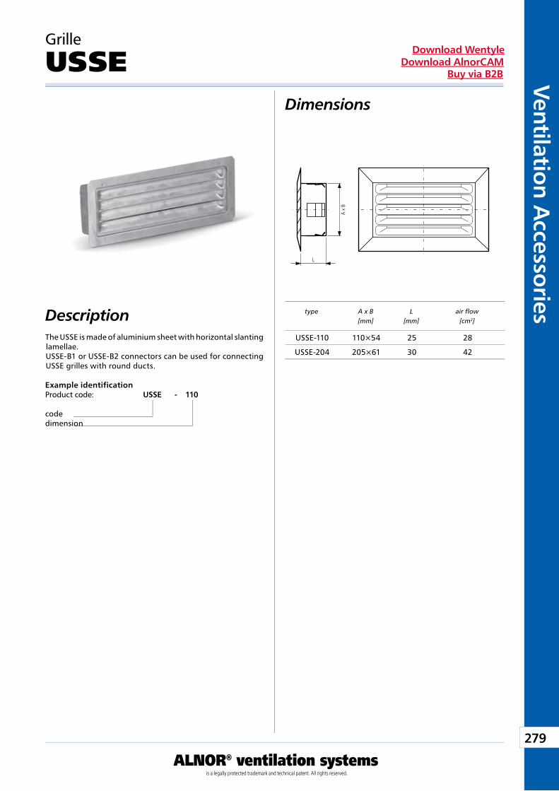
279
Ventilation Accessories
ALNOR® ventilation systemsis a legally protected trademark and technical patent. All rights reserved.
Download WentyleDownload AlnorCAM
Buy via B2B
Dimensions
Description
Grille
USSE
The USSE is made of aluminium sheet with horizontal slanting lamellae.USSE-B1 or USSE-B2 connectors can be used for connecting USSE grilles with round ducts.
Example identificationProduct code: USSE - 110
codedimension
type A x B[mm]
L[mm]
air flow[cm2]
USSE-110 110×54 25 28
USSE-204 205×61 30 42
L
A x
B
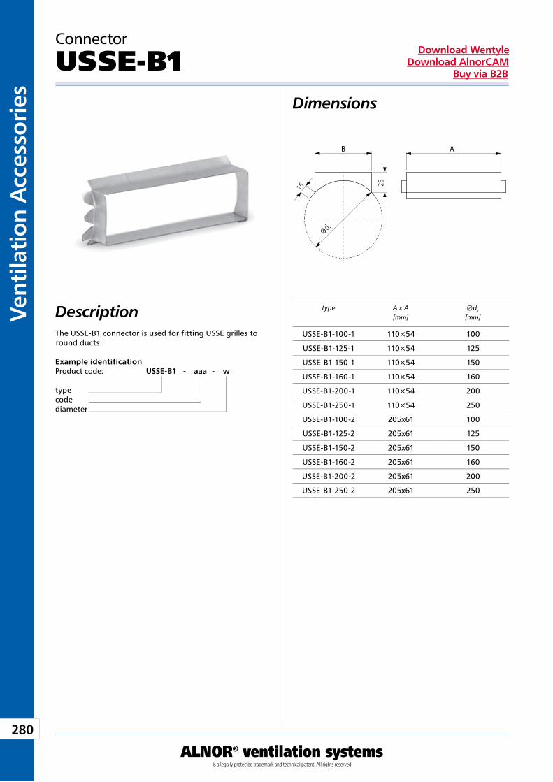
280
Vent
ilati
on A
cces
sori
es
ALNOR® ventilation systemsis a legally protected trademark and technical patent. All rights reserved.
Download WentyleDownload AlnorCAM
Buy via B2B
Dimensions
Description
Connector
USSE-B1
The USSE-B1 connector is used for fitting USSE grilles to round ducts.
Example identificationProduct code: USSE-B1 - aaa - w
typecodediameter
type A x A[mm]
Æ d1
[mm]
USSE-B1-100-1 110×54 100
USSE-B1-125-1 110×54 125
USSE-B1-150-1 110×54 150
USSE-B1-160-1 110×54 160
USSE-B1-200-1 110×54 200
USSE-B1-250-1 110×54 250
USSE-B1-100-2 205x61 100
USSE-B1-125-2 205x61 125
USSE-B1-150-2 205x61 150
USSE-B1-160-2 205x61 160
USSE-B1-200-2 205x61 200
USSE-B1-250-2 205x61 250
AB
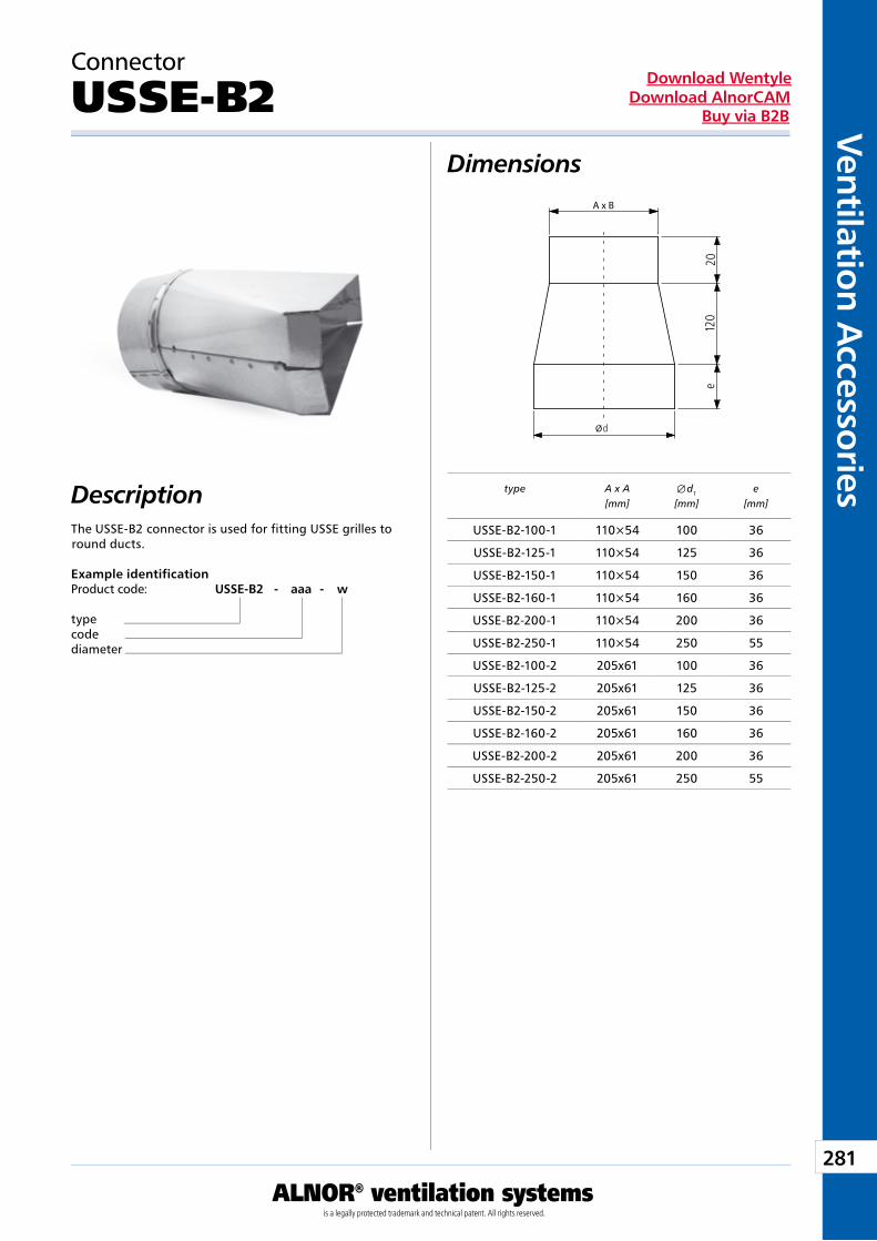
281
Ventilation Accessories
ALNOR® ventilation systemsis a legally protected trademark and technical patent. All rights reserved.
Download WentyleDownload AlnorCAM
Buy via B2B
Dimensions
Description
Connector
USSE-B2
The USSE-B2 connector is used for fitting USSE grilles to round ducts.
Example identificationProduct code: USSE-B2 - aaa - w
typecodediameter
type A x A[mm]
Æ d1
[mm]e
[mm]
USSE-B2-100-1 110×54 100 36
USSE-B2-125-1 110×54 125 36
USSE-B2-150-1 110×54 150 36
USSE-B2-160-1 110×54 160 36
USSE-B2-200-1 110×54 200 36
USSE-B2-250-1 110×54 250 55
USSE-B2-100-2 205x61 100 36
USSE-B2-125-2 205x61 125 36
USSE-B2-150-2 205x61 150 36
USSE-B2-160-2 205x61 160 36
USSE-B2-200-2 205x61 200 36
USSE-B2-250-2 205x61 250 55
A x B
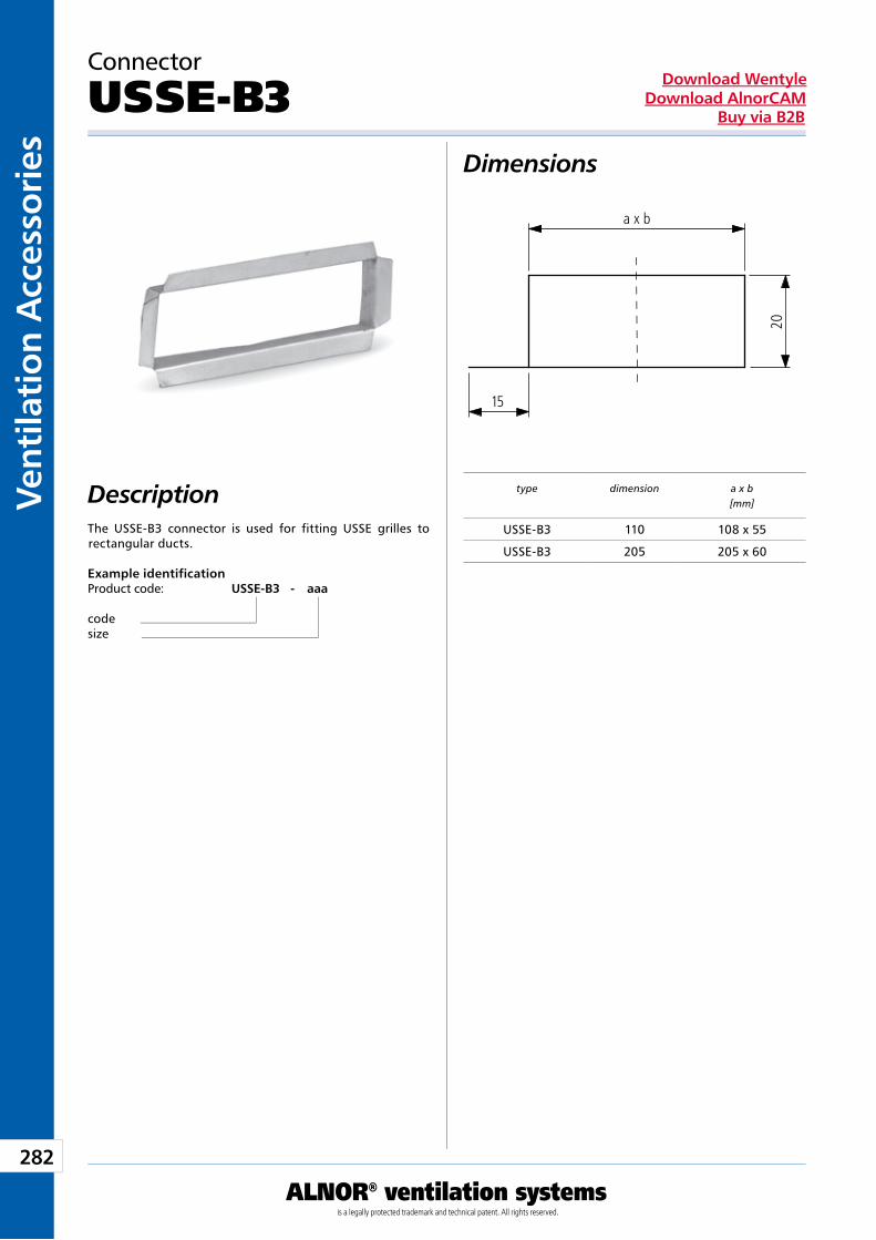
282
Vent
ilati
on A
cces
sori
es
ALNOR® ventilation systemsis a legally protected trademark and technical patent. All rights reserved.
Download WentyleDownload AlnorCAM
Buy via B2B
Dimensions
Description
Connector
USSE-B3
The USSE-B3 connector is used for fitting USSE grilles to rectangular ducts.
Example identificationProduct code: USSE-B3 - aaa
codesize
type dimension a x b[mm]
USSE-B3 110 108 x 55
USSE-B3 205 205 x 60
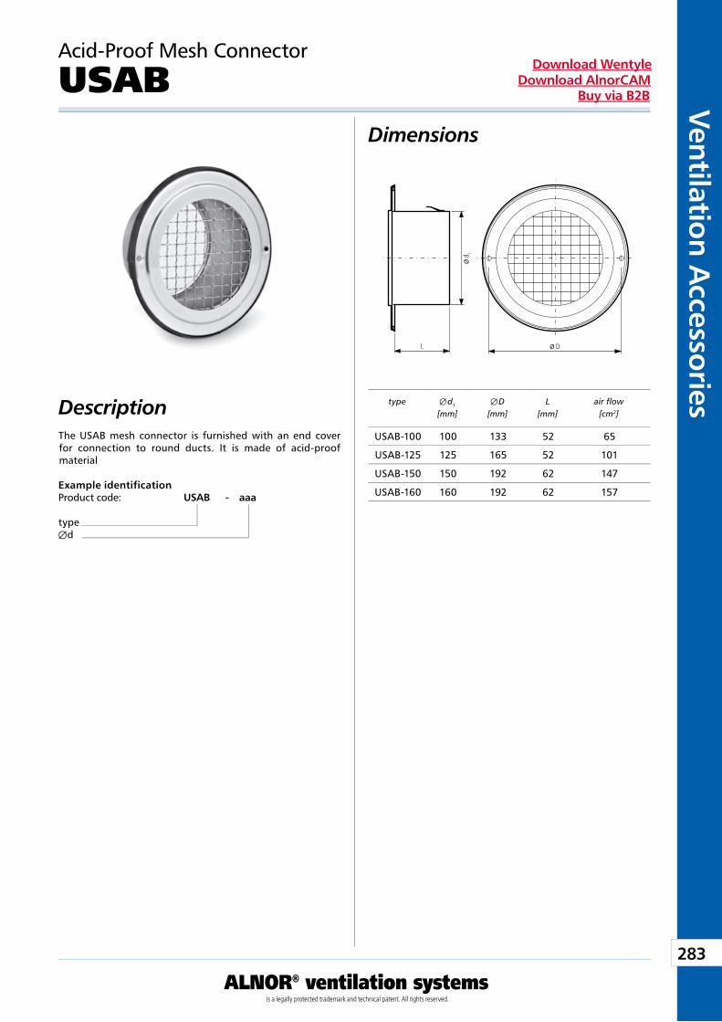
283
Ventilation Accessories
ALNOR® ventilation systemsis a legally protected trademark and technical patent. All rights reserved.
Download WentyleDownload AlnorCAM
Buy via B2B
Dimensions
Description
Acid-Proof Mesh Connector
USAB
The USAB mesh connector is furnished with an end cover for connection to round ducts. It is made of acid-proof material
Example identificationProduct code: USAB - aaa
typeÆd
type Æ d1
[mm]Æ D
[mm]L
[mm]air flow
[cm2]
USAB-100 100 133 52 65
USAB-125 125 165 52 101
USAB-150 150 192 62 147
USAB-160 160 192 62 157

284
Vent
ilati
on A
cces
sori
es
ALNOR® ventilation systemsis a legally protected trademark and technical patent. All rights reserved.
Download WentyleDownload AlnorCAM
Buy via B2B
Dimensions
Description
Grille
ULMA
The ULMA grille is aluminium cast. When connected to the duct, it is provided with a detachable mesh that enables its cleaning.
Example identificationProduct code: ULMA - aaaa
typeÆd
type Æ d1
[mm]Æ D
[mm]L
[mm]air flow
[cm2]
ULMA-100 100 140 52 45
ULMA-125 125 178 52 67
ULMA-150 150 178 62 115
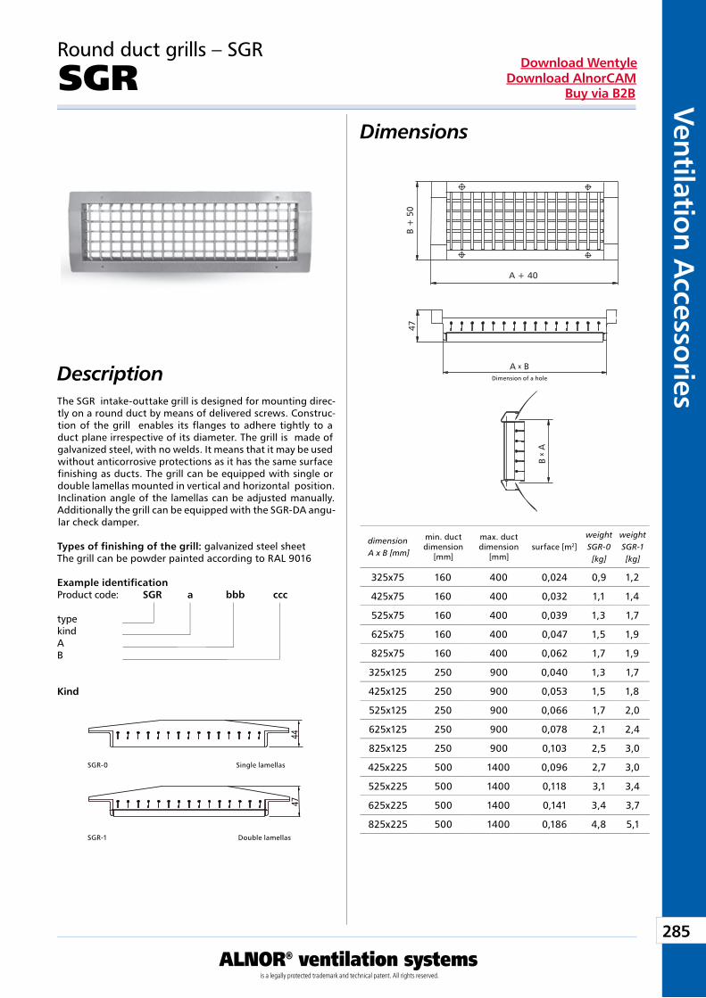
285
Ventilation Accessories
ALNOR® ventilation systemsis a legally protected trademark and technical patent. All rights reserved.
Download WentyleDownload AlnorCAM
Buy via B2B
Dimensions
Description
Round duct grills – SGR
SGR
The SGR intake-outtake grill is designed for mounting direc-tly on a round duct by means of delivered screws. Construc-tion of the grill enables its flanges to adhere tightly to a duct plane irrespective of its diameter. The grill is made of galvanized steel, with no welds. It means that it may be used without anticorrosive protections as it has the same surface finishing as ducts. The grill can be equipped with single or double lamellas mounted in vertical and horizontal position. Inclination angle of the lamellas can be adjusted manually. Additionally the grill can be equipped with the SGR-DA angu-lar check damper.
Types of finishing of the grill: galvanized steel sheetThe grill can be powder painted according to RAL 9016
Example identificationProduct code: SGR a bbb ccc
typekindAB
Kind
SGR-0 Single lamellas
SGR-1 Double lamellas
dimension A x B [mm]
min. duct dimension
[mm]
max. duct dimension
[mm]surface [m2]
weight SGR-0 [kg]
weight SGR-1 [kg]
325x75 160 400 0,024 0,9 1,2
425x75 160 400 0,032 1,1 1,4
525x75 160 400 0,039 1,3 1,7
625x75 160 400 0,047 1,5 1,9
825x75 160 400 0,062 1,7 1,9
325x125 250 900 0,040 1,3 1,7
425x125 250 900 0,053 1,5 1,8
525x125 250 900 0,066 1,7 2,0
625x125 250 900 0,078 2,1 2,4
825x125 250 900 0,103 2,5 3,0
425x225 500 1400 0,096 2,7 3,0
525x225 500 1400 0,118 3,1 3,4
625x225 500 1400 0,141 3,4 3,7
825x225 500 1400 0,186 4,8 5,1
A + 40
A BWymiary otworu
B +
50
47
B
A
x
x
Dimension of a hole
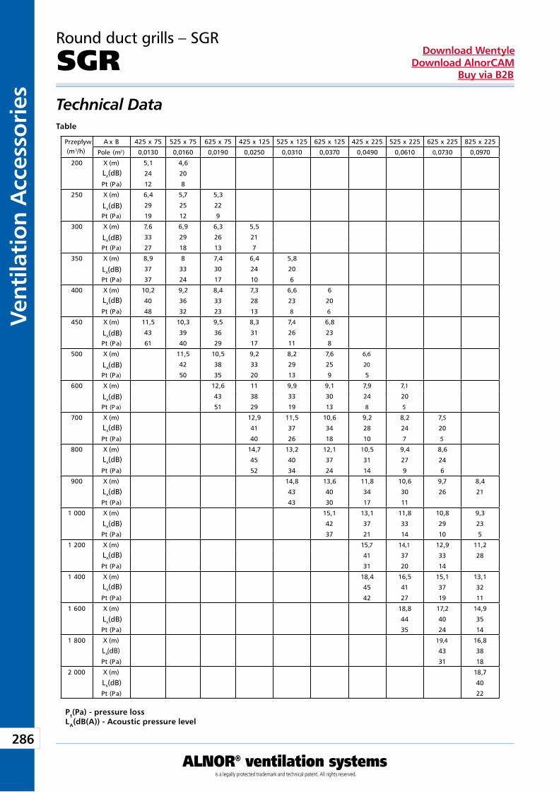
286
Vent
ilati
on A
cces
sori
es
ALNOR® ventilation systemsis a legally protected trademark and technical patent. All rights reserved.
Download WentyleDownload AlnorCAM
Buy via B2B
Technical DataTable
Pt(Pa) - pressure lossLA(dB(A)) - Acoustic pressure level
Round duct grills – SGR
SGR
selection char t
Przepływ(m3/h)
A x B 425 x 75 525 x 75 625 x 75 425 x 125 525 x 125 625 x 125 425 x 225 525 x 225 625 x 225 825 x 225
Pole (m2) 0,0130 0,0160 0,0190 0,0250 0,0310 0,0370 0,0490 0,0610 0,0730 0,0970
200 X (m) 5,1 4,6
24 20
Pt (Pa) 12 8
250 X (m) 6,4 5,7 5,3
29 25 22
Pt (Pa) 19 12 9
300 X (m) 7,6 6,9 6,3 5,5
33 29 26 21
Pt (Pa) 27 18 13 7
350 X (m) 8,9 8 7,4 6,4 5,8
37 33 30 24 20
Pt (Pa) 37 24 17 10 6
400 X (m) 10,2 9,2 8,4 7,3 6,6 6
40 36 33 28 23 20
Pt (Pa) 48 32 23 13 8 6
450 X (m) 11,5 10,3 9,5 8,3 7,4 6,8
43 39 36 31 26 23
Pt (Pa) 61 40 29 17 11 8
500 X (m) 11,5 10,5 9,2 8,2 7,6 6,6
42 38 33 29 25 20
Pt (Pa) 50 35 20 13 9 5
600 X (m) 12,6 11 9,9 9,1 7,9 7,1
43 38 33 30 24 20
Pt (P a) 51 29 19 13 8 5
700 X (m) 12,9 11,5 10,6 9,2 8,2 7,5
41 37 34 28 24 20
Pt (Pa) 40 26 18 10 7 5
800 X (m) 14,7 13,2 12,1 10,5 9,4 8,6
45 40 37 31 27 24
Pt (Pa) 52 34 24 14 9 6
900 X (m) 14,8 13,6 11,8 10,6 9,7 8,4
43 40 34 30 26 21
Pt (Pa) 43 30 17 11
1 000 X (m) 15,1 13,1 11,8 10,8 9,3
42 37 33 29 23
Pt (Pa) 37 21 14 10 5
1 200 X (m) 15,7 14,1 12,9 11,2
41 37 33 28
Pt (Pa) 31 20 14
1 400 X (m) 18,4 16,5 15,1 13,1
45 41 37 32
Pt (Pa) 42 27 19 11
1 600 X (m) 18,8 17,2 14,9
44 40 35
Pt (Pa) 35 24 14
1 800 X (m) 19,4 16,8
43 38
Pt (Pa) 31 18
2 000 X (m) 18,7
40
Pt (Pa) 22
L (dB)A
L (dB)A
L (dB)A
L (dB)A
L (dB)A
L (dB)A
L (dB)A
L (dB)A
L (dB)A
L (dB)A
L (dB)A
L (dB)A
L (dB)A
L (dB)A
L (dB)A
L (dB)A
L (dB)A
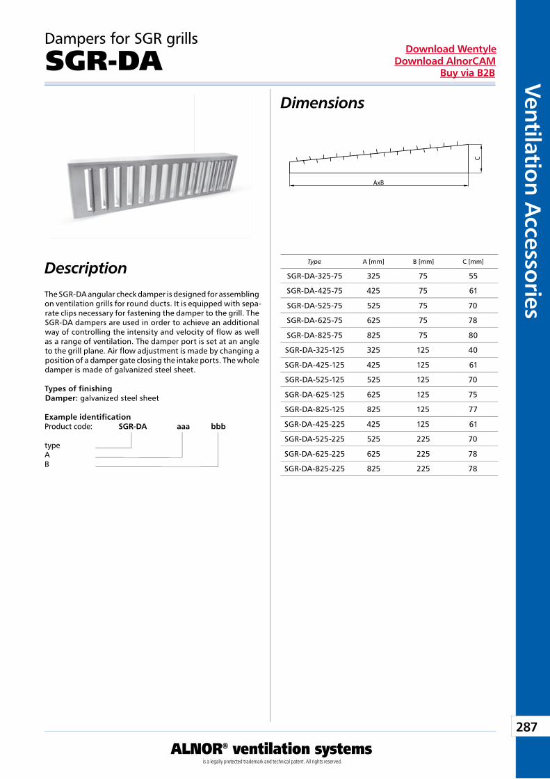
287
Ventilation Accessories
ALNOR® ventilation systemsis a legally protected trademark and technical patent. All rights reserved.
Download WentyleDownload AlnorCAM
Buy via B2B
Dimensions
Description
Dampers for SGR grills
SGR-DA
The SGR-DA angular check damper is designed for assembling on ventilation grills for round ducts. It is equipped with sepa-rate clips necessary for fastening the damper to the grill. The SGR-DA dampers are used in order to achieve an additional way of controlling the intensity and velocity of flow as well as a range of ventilation. The damper port is set at an angle to the grill plane. Air flow adjustment is made by changing a position of a damper gate closing the intake ports. The whole damper is made of galvanized steel sheet.
Types of finishingDamper: galvanized steel sheet
Example identificationProduct code: SGR-DA aaa bbb
typeAB
Type A [mm] B [mm] C [mm]
SGR-DA-325-75 325 75 55
SGR-DA-425-75 425 75 61
SGR-DA-525-75 525 75 70
SGR-DA-625-75 625 75 78
SGR-DA-825-75 825 75 80
SGR-DA-325-125 325 125 40
SGR-DA-425-125 425 125 61
SGR-DA-525-125 525 125 70
SGR-DA-625-125 625 125 75
SGR-DA-825-125 825 125 77
SGR-DA-425-225 425 125 61
SGR-DA-525-225 525 225 70
SGR-DA-625-225 625 225 78
SGR-DA-825-225 825 225 78
AxB
C
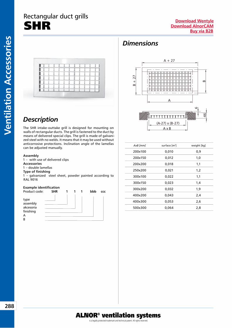
288
Vent
ilati
on A
cces
sori
es
ALNOR® ventilation systemsis a legally protected trademark and technical patent. All rights reserved.
Download WentyleDownload AlnorCAM
Buy via B2B
Dimensions
Description
Rectangular duct grills
SHR
The SHR intake-outtake grill is designed for mounting on walls of rectangular ducts. The grill is fastened to the duct by means of delivered special clips. The grill is made of galvani-zed steel with no welds. It means that it may be used without anticorrosive protections. Inclination angle of the lamellas can be adjusted manually.
Assembly1 – with use of delivered clipsAccessories 1 – double lamellasType of finishing1 – galvanized steel sheet, powder painted according to RAL 9016
Example identificationProduct code: SHR 1 1 1 bbb ccc
typeassemblyakcesoriafinishingAB
AxB [mm] surface [m2] weight [kg]
200x100 0,010 0,9
200x150 0,012 1,0
200x200 0,018 1,1
250x200 0,021 1,2
300x100 0,022 1,1
300x150 0,023 1,4
300x200 0,032 1,9
400x200 0,043 2,4
400x300 0,053 2,6
500x300 0,064 2,8
A
B +
27
B
A + 27
46
6
A x B(A-27) x (B-27)
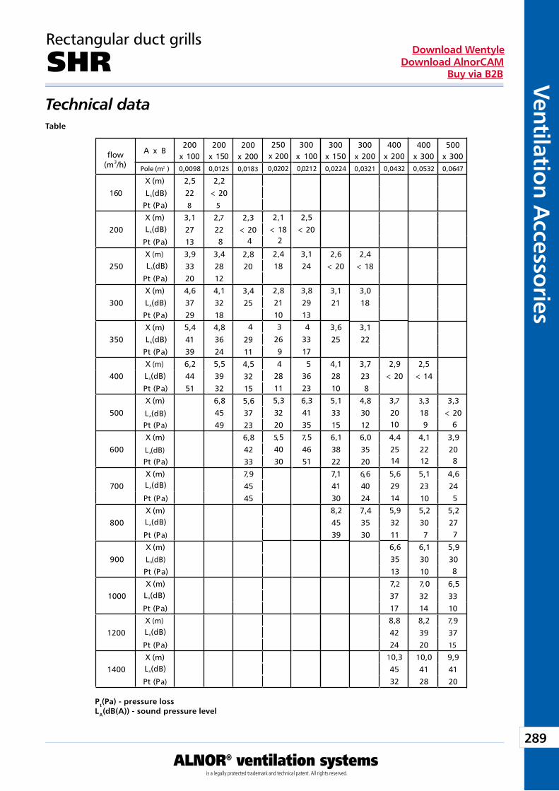
289
Ventilation Accessories
ALNOR® ventilation systemsis a legally protected trademark and technical patent. All rights reserved.
Download WentyleDownload AlnorCAM
Buy via B2B
Technical dataTable
Pt(Pa) - pressure lossLA(dB(A)) - sound pressure level
Rectangular duct grills
SHR
Przepływ
(m3/h)
A x B200
x 100200
x 150500
x 300Pole (m ) 0,0098 0,0125 0,0647
160X (m) 2,5 2,2L (dB) 22 < 20
Pt (Pa) 8 5
200X (m) 3,1 2,7
27 22Pt (Pa) 13
250X (m) 3,9 3,4
33 28Pt (Pa) 20 12
300X (m) 4,6 4,1
37 32Pt (Pa) 29 18
350X (m) 5,4 4,8
41 36Pt (Pa) 39 24
400X (m) 6,2 5,5
44 39Pt (Pa) 51 32
500X (m) 6,8 3,3
45 < 20Pt (Pa) 49
600X (m) 3,9
20Pt (Pa)
700X (m) 4,6
24Pt (Pa)
800X (m) 5,2
27Pt (Pa)
900X (m) 5,9
30Pt (Pa)
1000X (m) 6,5
33Pt (Pa) 10
1200X (m) 7,
37Pt (Pa) 15
1400X (m) 9,9
41Pt (Pa) 20
2
A
L (dB)A
L (dB)A
L (dB)A
L (dB)A
L (dB)A
L (dB)A
L (dB)A
L (dB)A
L (dB)A
L (dB)A
L (dB)A
L (dB)A
L (dB)A
200x 2000,0183
2,3< 20
2,820
3,425
4
29114,532155,637236,842337,94545
8
300x 150
400x 200
0,0224 0,0432
2,6< 20
3,121
3,625
4,1 2,928 < 20105,1 3,733 20156,1 4,438 25227,1 5,641 29308,2 5,945 3239 11
6,635137,
37178,84224
10,34532
300x 100
0212
2,5< 20
3,124
3,82913
3317
36236,341357,54651
4
5
300x 2000,0321
2,4< 18
3,018
3,122
3,7238
4,830126,035206,640247,43530
400x 3000,0532
2,5< 14
3,318
4,122
5,123
5,2307
6,130107,
32148,23920
10,04128
2 0
4
2502000202
2,1< 18
2,418
2,82110
269
28115,332205,54030
3
4
x
0,
2
10 9 6
14 12 8
14 10 5
7
9
8
0,
flow
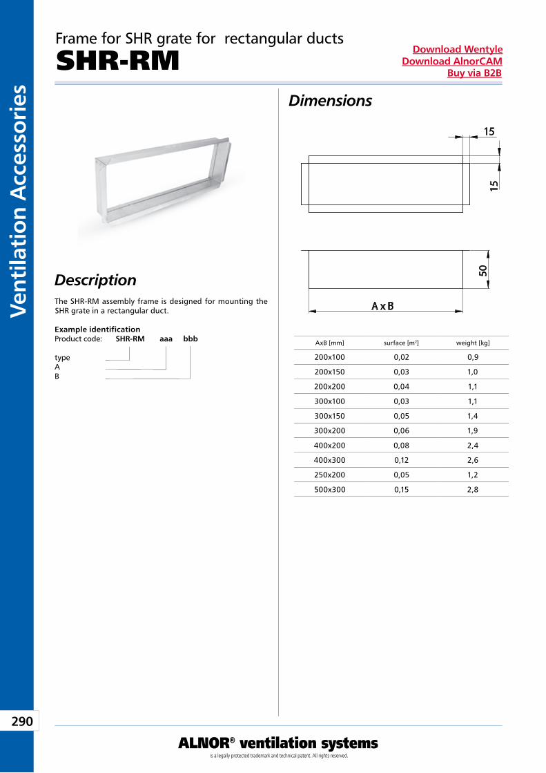
290
Vent
ilati
on A
cces
sori
es
ALNOR® ventilation systemsis a legally protected trademark and technical patent. All rights reserved.
Download WentyleDownload AlnorCAM
Buy via B2B
Dimensions
Description
Frame for SHR grate for rectangular ducts
SHR-RM
The SHR-RM assembly frame is designed for mounting the SHR grate in a rectangular duct.
Example identificationProduct code: SHR-RM aaa bbb
typeAB
AxB [mm] surface [m2] weight [kg]
200x100 0,02 0,9
200x150 0,03 1,0
200x200 0,04 1,1
300x100 0,03 1,1
300x150 0,05 1,4
300x200 0,06 1,9
400x200 0,08 2,4
400x300 0,12 2,6
250x200 0,05 1,2
500x300 0,15 2,8
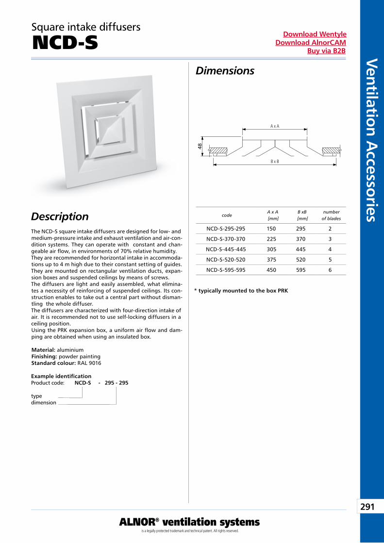
291
Ventilation Accessories
ALNOR® ventilation systemsis a legally protected trademark and technical patent. All rights reserved.
Download WentyleDownload AlnorCAM
Buy via B2B
Dimensions
Description
Square intake diffusers
NCD-S
The NCD-S square intake diffusers are designed for low- and medium-pressure intake and exhaust ventilation and air-con-dition systems. They can operate with constant and chan-geable air flow, in environments of 70% relative humidity.They are recommended for horizontal intake in accommoda-tions up to 4 m high due to their constant setting of guides. They are mounted on rectangular ventilation ducts, expan-sion boxes and suspended ceilings by means of screws.The diffusers are light and easily assembled, what elimina-tes a necessity of reinforcing of suspended ceilings. Its con-struction enables to take out a central part without disman-tling the whole diffuser.The diffusers are characterized with four-direction intake of air. It is recommended not to use self-locking diffusers in a ceiling position.Using the PRK expansion box, a uniform air flow and dam-ping are obtained when using an insulated box.
Material: aluminiumFinishing: powder paintingStandard colour: RAL 9016
Example identificationProduct code: NCD-S - 295 - 295
typedimension
codeA x A [mm]
B xB [mm]
numberof blades
* typically mounted to the box PRK
NCD-S-295-295 150 295 2
NCD-S-370-370 225 370 3
NCD-S-445-445 305 445 4
NCD-S-520-520 375 520 5
NCD-S-595-595 450 595 6
48
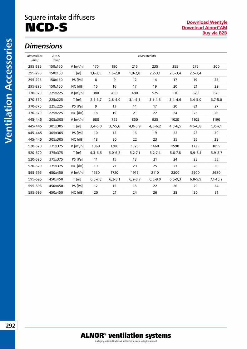
292
Vent
ilati
on A
cces
sori
es
ALNOR® ventilation systemsis a legally protected trademark and technical patent. All rights reserved.
Download WentyleDownload AlnorCAM
Buy via B2B
Square intake diffusers
NCD-S Dimensions
characteristicdimensions[mm]
A × A[mm]
295-295 150x150 V [m3/h] 170 190 215 235 255 275 300
295-295 150x150 T [m] 1,6-2,5 1,6-2,8 1,9-2,8 2,2-3,1 2,5-3,4 2,5-3,4
295-295 150x150 PS [Pa] 8 9 12 14 17 19 23
295-295 150x150 NC [dB] 15 16 17 19 20 21 22
370-370 225x225 V [m3/h] 380 430 480 525 570 620 670
370-370 225x225 T [m] 2,5-3,7 2,8-4,0 3,1-4,3 3,1-4,3 3,4-4,6 3,4-5,0 3,7-5,0
370-370 225x225 PS [Pa] 9 13 14 17 20 21 27
370-370 225x225 NC [dB] 18 19 21 22 24 25 26
445-445 305x305 V [m3/h] 680 765 850 935 1020 1105 1190
445-445 305x305 T [m] 3,4-5,0 3,7-5,6 4,0-5,9 4,3-6,2 4,3-6,5 4,6-6,8 5,0-7,1
445-445 305x305 PS [Pa] 10 12 16 19 22 23 30
445-445 305x305 NC [dB] 18 20 22 23 25 26 28
520-520 375x375 V [m3/h] 1060 1200 1325 1460 1590 1725 1855
520-520 375x375 T [m] 4,3-6,5 5,0-6,8 5,2-7,1 5,2-7,4 5,6-7,8 5,9-8,1 5,9-8,7
520-520 375x375 PS [Pa] 11 15 18 21 24 28 33
520-520 375x375 NC [dB] 19 21 23 25 27 28 30
595-595 450x450 V [m3/h] 1530 1720 1915 2110 2300 2500 2680
595-595 450x450 T [m] 6,5-7,8 6,2-8,1 6,2-8,7 6,5-9,0 6,5-9,3 6,8-9,9 7,1-10,2
595-595 450x450 PS [Pa] 12 15 18 22 26 29 34
595-595 450x450 NC [dB] 20 21 24 26 28 30 31
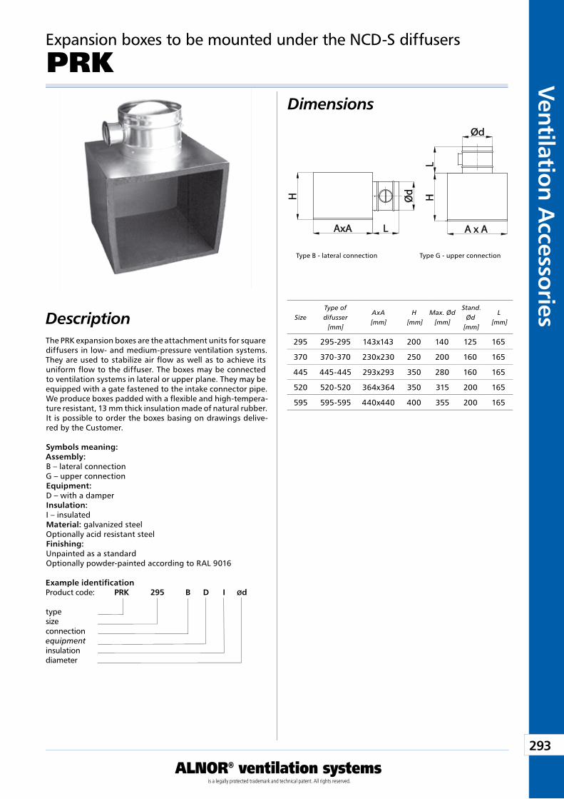
293
Ventilation Accessories
ALNOR® ventilation systemsis a legally protected trademark and technical patent. All rights reserved.
Download WentyleDownload AlnorCAM
Buy via B2B
Dimensions
Description
Expansion boxes to be mounted under the NCD-S diffusers
PRK
The PRK expansion boxes are the attachment units for square diffusers in low- and medium-pressure ventilation systems. They are used to stabilize air flow as well as to achieve its uniform flow to the diffuser. The boxes may be connected to ventilation systems in lateral or upper plane. They may be equipped with a gate fastened to the intake connector pipe. We produce boxes padded with a flexible and high-tempera-ture resistant, 13 mm thick insulation made of natural rubber. It is possible to order the boxes basing on drawings delive-red by the Customer.
Symbols meaning:Assembly:B – lateral connectionG – upper connectionEquipment:D – with a damperInsulation:I – insulatedMaterial: galvanized steelOptionally acid resistant steelFinishing:Unpainted as a standardOptionally powder-painted according to RAL 9016
Example identificationProduct code: PRK 295 B D I Ød
typesizeconnectionequipmentinsulationdiameter
Type B - lateral connection Type G - upper connection
SizeType of difusser
[mm]
AxA [mm]
H [mm]
Max. Ød [mm]
Stand. Ød
[mm]
L [mm]
295 295-295 143x143 200 140 125 165
370 370-370 230x230 250 200 160 165
445 445-445 293x293 350 280 160 165
520 520-520 364x364 350 315 200 165
595 595-595 440x440 400 355 200 165
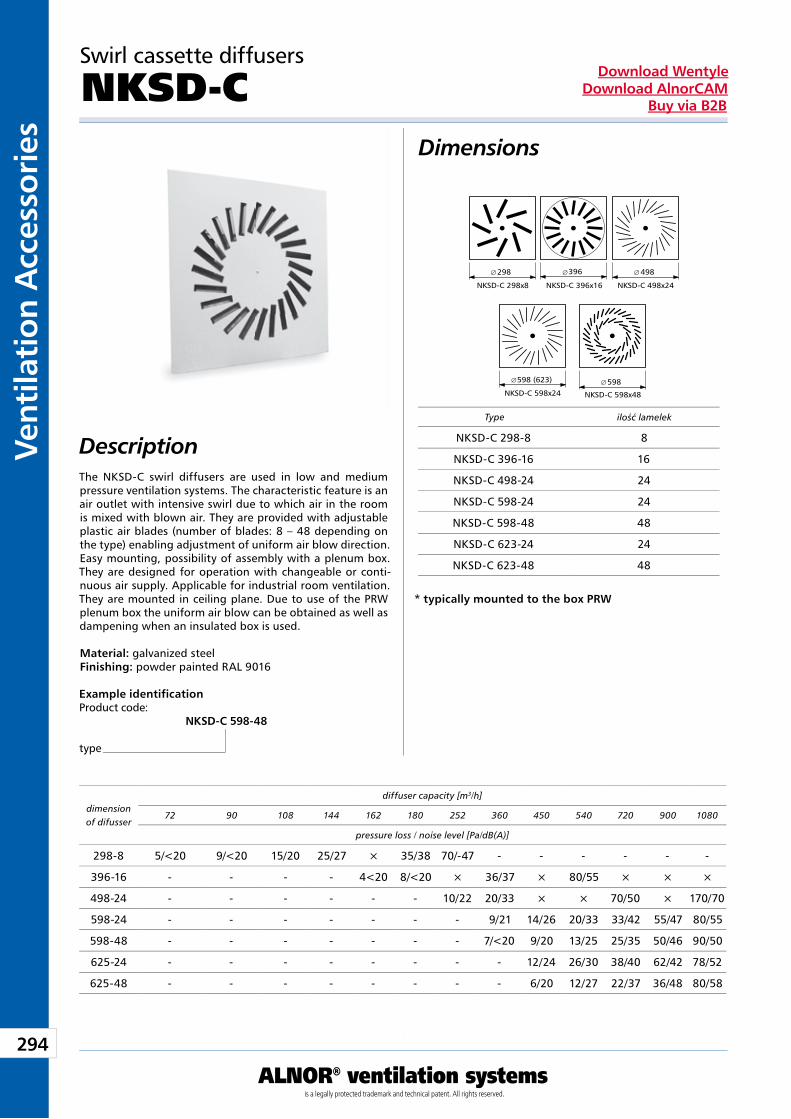
294
Vent
ilati
on A
cces
sori
es
ALNOR® ventilation systemsis a legally protected trademark and technical patent. All rights reserved.
Download WentyleDownload AlnorCAM
Buy via B2B
Dimensions
Description
dimensionof difusser
diffuser capacity [m3/h]
pressure loss / noise level [Pa/dB(A)]
Type
* typically mounted to the box PRW
ilość lamelek
NKSD-C 298-8 8
NKSD-C 396-16 16
NKSD-C 498-24 24
NKSD-C 598-24 24
NKSD-C 598-48 48
NKSD-C 623-24 24
NKSD-C 623-48 48
Swirl cassette diffusers
NKSD-C
The NKSD-C swirl diffusers are used in low and medium pressure ventilation systems. The characteristic feature is an air outlet with intensive swirl due to which air in the room is mixed with blown air. They are provided with adjustable plastic air blades (number of blades: 8 – 48 depending on the type) enabling adjustment of uniform air blow direction. Easy mounting, possibility of assembly with a plenum box. They are designed for operation with changeable or conti-nuous air supply. Applicable for industrial room ventilation. They are mounted in ceiling plane. Due to use of the PRW plenum box the uniform air blow can be obtained as well as dampening when an insulated box is used.
Material: galvanized steelFinishing: powder painted RAL 9016
Example identificationProduct code: NKSD-C 598-48
type
72 90 108 144 162 180 252 360 450 540 720 900 1080
298-8 5/<20 9/<20 15/20 25/27 × 35/38 70/-47 - - - - - -
396-16 - - - - 4<20 8/<20 × 36/37 × 80/55 × × ×
498-24 - - - - - - 10/22 20/33 × × 70/50 × 170/70
598-24 - - - - - - - 9/21 14/26 20/33 33/42 55/47 80/55
598-48 - - - - - - - 7/<20 9/20 13/25 25/35 50/46 90/50
625-24 - - - - - - - - 12/24 26/30 38/40 62/42 78/52
625-48 - - - - - - - - 6/20 12/27 22/37 36/48 80/58
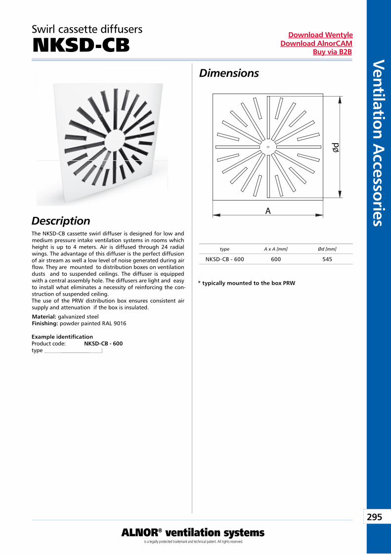
295
Ventilation Accessories
ALNOR® ventilation systemsis a legally protected trademark and technical patent. All rights reserved.
Download WentyleDownload AlnorCAM
Buy via B2B
Dimensions
Description
Swirl cassette diffusers
NKSD-CB
The NKSD-CB cassette swirl diffuser is designed for low and medium pressure intake ventilation systems in rooms which height is up to 4 meters. Air is diffused through 24 radial wings. The advantage of this diffuser is the perfect diffusion of air stream as well a low level of noise generated during air flow. They are mounted to distribution boxes on ventilation dusts and to suspended ceilings. The diffuser is equipped with a central assembly hole. The diffusers are light and easy to install what eliminates a necessity of reinforcing the con-struction of suspended ceiling.The use of the PRW distribution box ensures consistent air supply and attenuation if the box is insulated.
Material: galvanized steelFinishing: powder painted RAL 9016
Example identificationProduct code: NKSD-CB - 600type
type A x A [mm] Ød [mm]
NKSD-CB - 600 600 545
* typically mounted to the box PRW
A
dØ
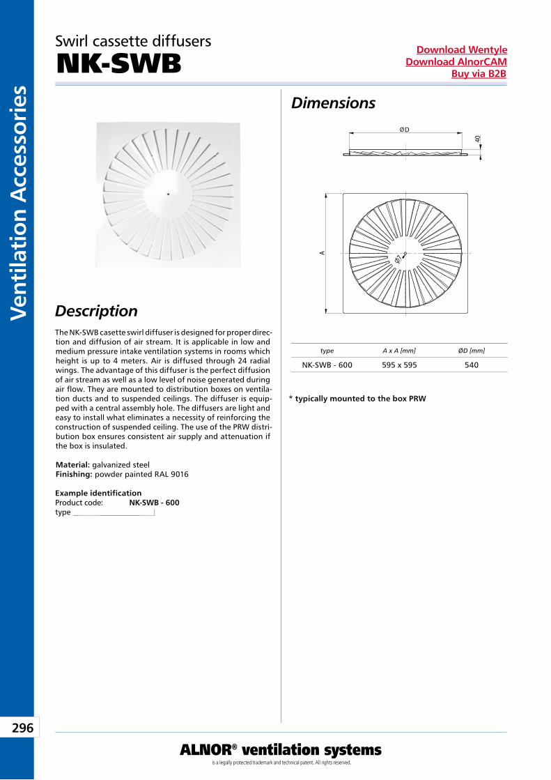
296
Vent
ilati
on A
cces
sori
es
ALNOR® ventilation systemsis a legally protected trademark and technical patent. All rights reserved.
Download WentyleDownload AlnorCAM
Buy via B2B
Dimensions
Description
Swirl cassette diffusers
NK-SWB
The NK-SWB casette swirl diffuser is designed for proper direc-tion and diffusion of air stream. It is applicable in low and medium pressure intake ventilation systems in rooms which height is up to 4 meters. Air is diffused through 24 radial wings. The advantage of this diffuser is the perfect diffusion of air stream as well as a low level of noise generated during air flow. They are mounted to distribution boxes on ventila-tion ducts and to suspended ceilings. The diffuser is equip-ped with a central assembly hole. The diffusers are light and easy to install what eliminates a necessity of reinforcing the construction of suspended ceiling. The use of the PRW distri-bution box ensures consistent air supply and attenuation if the box is insulated.
Material: galvanized steelFinishing: powder painted RAL 9016
Example identificationProduct code: NK-SWB - 600type
type A x A [mm] ØD [mm]
NK-SWB - 600 595 x 595 540
* typically mounted to the box PRW
D
A
40
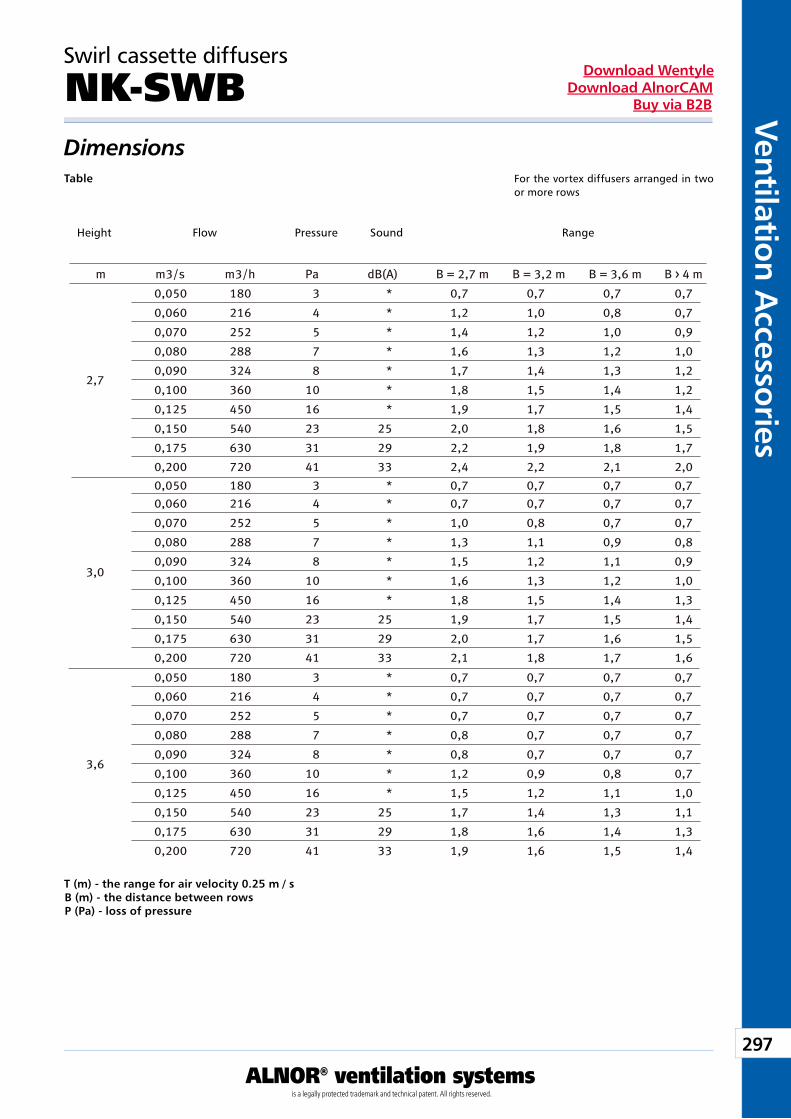
297
Ventilation Accessories
ALNOR® ventilation systemsis a legally protected trademark and technical patent. All rights reserved.
Download WentyleDownload AlnorCAM
Buy via B2B
Swirl cassette diffusers
NK-SWB DimensionsTable
T (m) - the range for air velocity 0.25 m / sB (m) - the distance between rowsP (Pa) - loss of pressure
Wysokość Przepływ Zasięg Ciśnienie Hałas
Dla dyfuzorów wirowychrozmieszczonych w dwóch lub więcej rzędach
For the vortex diffusers arranged in two or more rows
Height Flow Pressure Sound Range
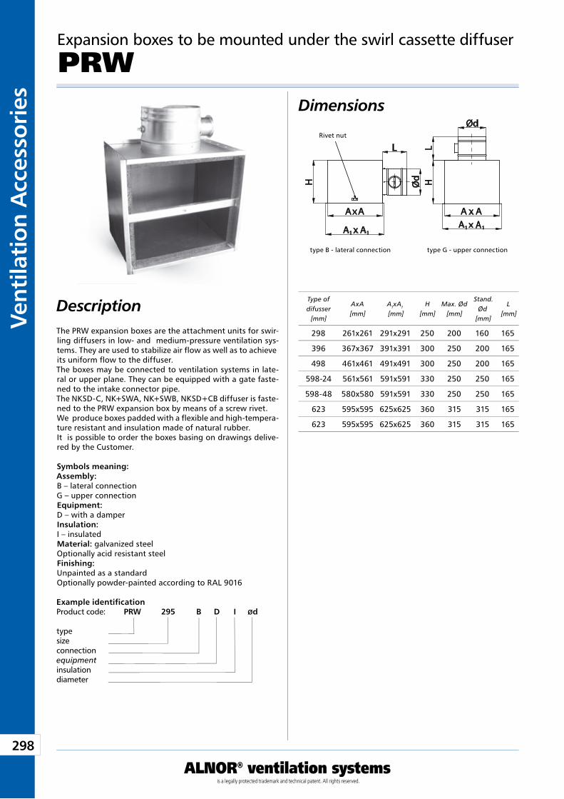
298
Vent
ilati
on A
cces
sori
es
ALNOR® ventilation systemsis a legally protected trademark and technical patent. All rights reserved.
Download WentyleDownload AlnorCAM
Buy via B2B
Dimensions
Description
Expansion boxes to be mounted under the swirl cassette diffuser
PRW
The PRW expansion boxes are the attachment units for swir-ling diffusers in low- and medium-pressure ventilation sys-tems. They are used to stabilize air flow as well as to achieve its uniform flow to the diffuser.The boxes may be connected to ventilation systems in late-ral or upper plane. They can be equipped with a gate faste-ned to the intake connector pipe.The NKSD-C, NK+SWA, NK+SWB, NKSD+CB diffuser is faste-ned to the PRW expansion box by means of a screw rivet.We produce boxes padded with a flexible and high-tempera-ture resistant and insulation made of natural rubber.It is possible to order the boxes basing on drawings delive-red by the Customer.
Symbols meaning:Assembly:B – lateral connectionG – upper connectionEquipment:D – with a damperInsulation:I – insulatedMaterial: galvanized steelOptionally acid resistant steelFinishing:Unpainted as a standardOptionally powder-painted according to RAL 9016
type B - lateral connection type G - upper connection
Rivet nut
Example identificationProduct code: PRW 295 B D I Ød
typesizeconnectionequipmentinsulationdiameter
Type of difusser
[mm]
AxA [mm]
A1xA1
[mm]H
[mm]Max. Ød
[mm]
Stand. Ød
[mm]
L [mm]
298 261x261 291x291 250 200 160 165
396 367x367 391x391 300 250 200 165
498 461x461 491x491 300 250 200 165
598-24 561x561 591x591 330 250 250 165
598-48 580x580 591x591 330 250 250 165
623 595x595 625x625 360 315 315 165
623 595x595 625x625 360 315 315 165
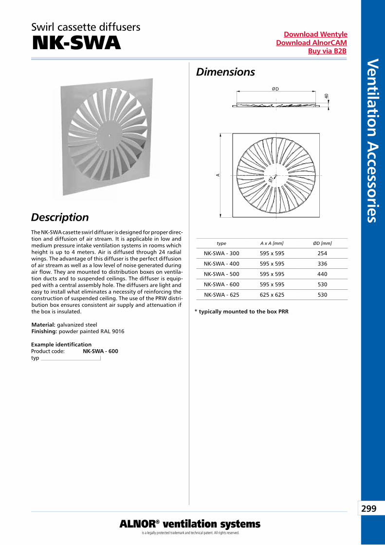
299
Ventilation Accessories
ALNOR® ventilation systemsis a legally protected trademark and technical patent. All rights reserved.
Download WentyleDownload AlnorCAM
Buy via B2B
Dimensions
Description
Swirl cassette diffusers
NK-SWA
The NK-SWA casette swirl diffuser is designed for proper direc-tion and diffusion of air stream. It is applicable in low and medium pressure intake ventilation systems in rooms which height is up to 4 meters. Air is diffused through 24 radial wings. The advantage of this diffuser is the perfect diffusion of air stream as well as a low level of noise generated during air flow. They are mounted to distribution boxes on ventila-tion ducts and to suspended ceilings. The diffuser is equip-ped with a central assembly hole. The diffusers are light and easy to install what eliminates a necessity of reinforcing the construction of suspended ceiling. The use of the PRW distri-bution box ensures consistent air supply and attenuation if the box is insulated.
Material: galvanized steelFinishing: powder painted RAL 9016
Example identificationProduct code: NK-SWA - 600typ
* typically mounted to the box PRR
type A x A [mm] ØD [mm]
NK-SWA - 300 595 x 595 254
NK-SWA - 400 595 x 595 336
NK-SWA - 500 595 x 595 440
NK-SWA - 600 595 x 595 530
NK-SWA - 625 625 x 625 530
D
A
40
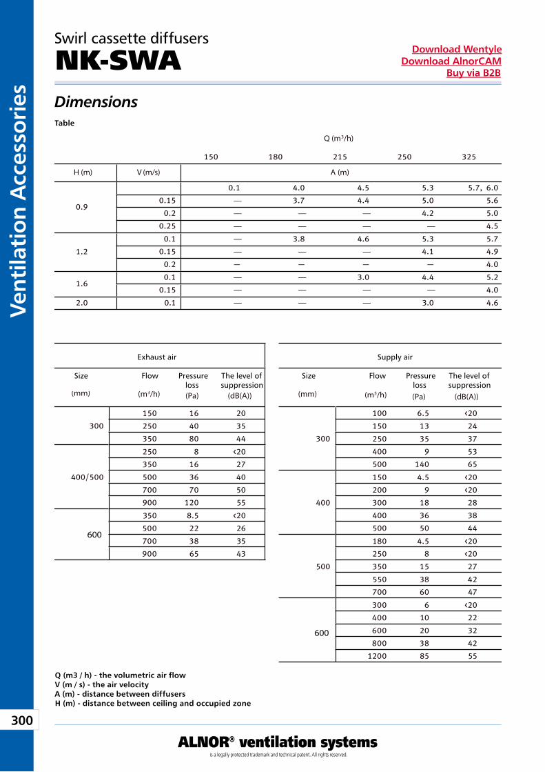
300
Vent
ilati
on A
cces
sori
es
ALNOR® ventilation systemsis a legally protected trademark and technical patent. All rights reserved.
Download WentyleDownload AlnorCAM
Buy via B2B
Swirl cassette diffusers
NK-SWADimensionsTable
Q (m3 / h) - the volumetric air flowV (m / s) - the air velocityA (m) - distance between diffusersH (m) - distance between ceiling and occupied zone
Wielkość(mm)
Przepływ(m /h)
Strataciśnienia
(Pa)
Poziomtłumienia(dB(A))
Q (m /h)
H (m) V (m/s) A (m)
—
— — —
— — — —
—
— — —
. .
— —
— — — —
— — —
600
600
Wywiew Nawiew
Wielkość(mm)
Przepływ(m /h)
Strataciśnienia
(Pa)
Poziomtłumienia(dB(A))
Size Flow Pressure The level of loss suppression
Size Flow Pressure The level of loss suppression
Exhaust air Supply air
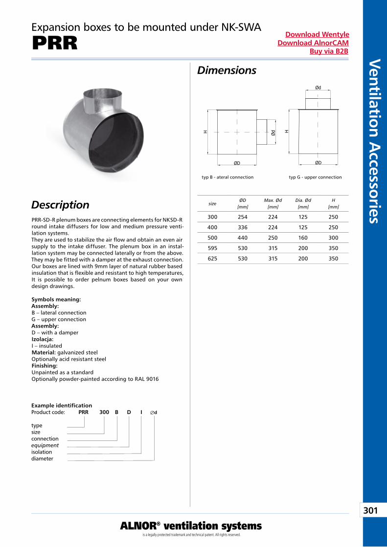
301
Ventilation Accessories
ALNOR® ventilation systemsis a legally protected trademark and technical patent. All rights reserved.
Download WentyleDownload AlnorCAM
Buy via B2B
Expansion boxes to be mounted under NK-SWA
PRRDimensions
DescriptionPRR-SD-R plenum boxes are connecting elements for NKSD-R round intake diffusers for low and medium pressure venti-lation systems. They are used to stabilize the air flow and obtain an even air supply to the intake diffuser. The plenum box in an instal-lation system may be connected laterally or from the above. They may be fitted with a damper at the exhaust connection. Our boxes are lined with 9mm layer of natural rubber based insulation that is flexible and resistant to high temperatures, It is possible to order pelnum boxes based on your own design drawings. Symbols meaning:Assembly:B – lateral connectionG – upper connectionAssembly:D – with a damperIzolacja:I – insulatedMaterial: galvanized steelOptionally acid resistant steelFinishing:Unpainted as a standardOptionally powder-painted according to RAL 9016
Example identificationProduct code: PRR 300 B D I Æd
typesizeconnectionequipmentisolationdiameter
typ B - ateral connection typ G - upper connection
sizeØD
[mm]Max. Ød
[mm]Dia. Ød[mm]
H[mm]
300 254 224 125 250
400 336 224 125 250
500 440 250 160 300
595 530 315 200 350
625 530 315 200 350
H
ØD
Ød H
ØD
Ød
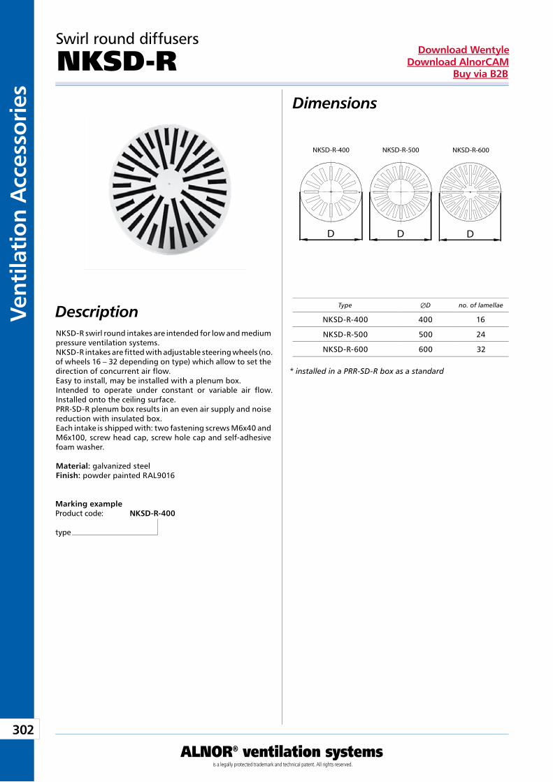
302
Vent
ilati
on A
cces
sori
es
ALNOR® ventilation systemsis a legally protected trademark and technical patent. All rights reserved.
Download WentyleDownload AlnorCAM
Buy via B2B
Swirl round diffusers
NKSD-R Dimensions
DescriptionNKSD-R swirl round intakes are intended for low and medium pressure ventilation systems. NKSD-R intakes are fitted with adjustable steering wheels (no. of wheels 16 – 32 depending on type) which allow to set the direction of concurrent air flow. Easy to install, may be installed with a plenum box. Intended to operate under constant or variable air flow. Installed onto the ceiling surface. PRR-SD-R plenum box results in an even air supply and noise reduction with insulated box. Each intake is shipped with: two fastening screws M6x40 and M6x100, screw head cap, screw hole cap and self-adhesive foam washer. Material: galvanized steel Finish: powder painted RAL9016
Marking example Product code: NKSD-R-400
type
* installed in a PRR-SD-R box as a standard
Type ÆD no. of lamellae
NKSD-R-400 400 16
NKSD-R-500 500 24
NKSD-R-600 600 32
D D D
NKSD-R-400 NKSD-R-500 NKSD-R-600
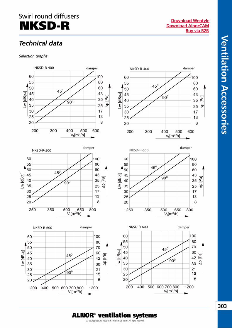
303
Ventilation Accessories
ALNOR® ventilation systemsis a legally protected trademark and technical patent. All rights reserved.
Download WentyleDownload AlnorCAM
Buy via B2B
Swirl round diffusers
NKSD-R Technical data
Selection graphs
przepustnica przepustnicaNKSD-R-400 NKSD-R-400
przepustnica przepustnicaNKSD-R-500 NKSD-R-500
przepustnic a
6
200 400 500 600 700 800 1200 200 400 500 600 700 800 1200
15213042
70
600/32 przepustnic a
615213042
70
600/32NKSD-R-600 NKSD-R-600
damper damper
damper
damperdamper
damper
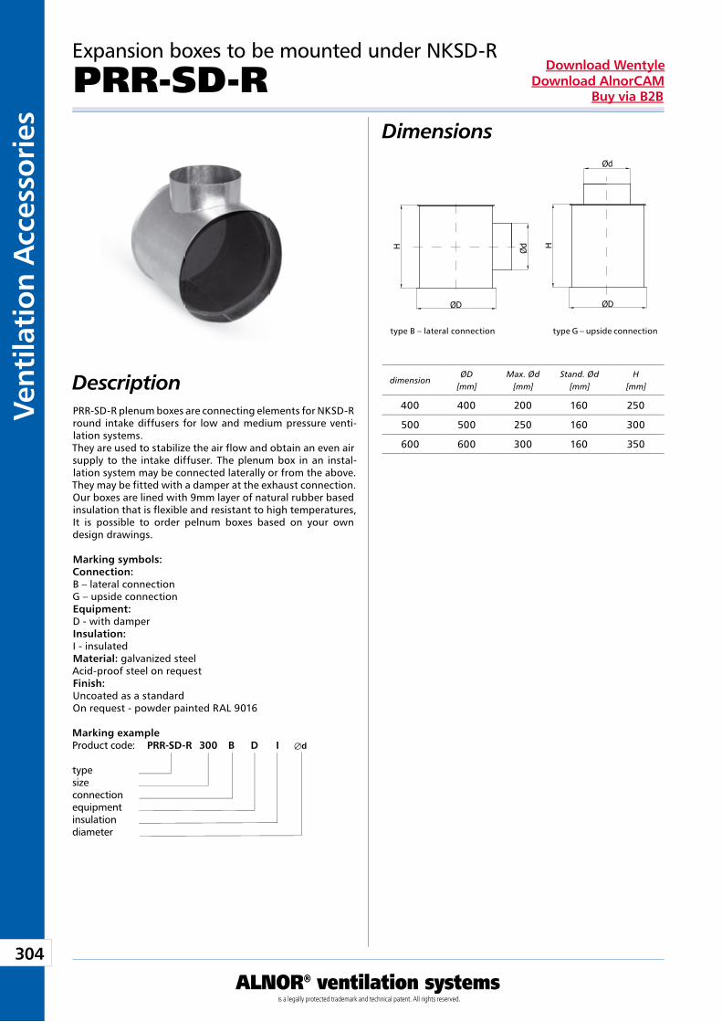
304
Vent
ilati
on A
cces
sori
es
ALNOR® ventilation systemsis a legally protected trademark and technical patent. All rights reserved.
Download WentyleDownload AlnorCAM
Buy via B2B
Expansion boxes to be mounted under NKSD-R
PRR-SD-RDimensions
DescriptionPRR-SD-R plenum boxes are connecting elements for NKSD-R round intake diffusers for low and medium pressure venti-lation systems. They are used to stabilize the air flow and obtain an even air supply to the intake diffuser. The plenum box in an instal-lation system may be connected laterally or from the above. They may be fitted with a damper at the exhaust connection. Our boxes are lined with 9mm layer of natural rubber based insulation that is flexible and resistant to high temperatures, It is possible to order pelnum boxes based on your own design drawings. Marking symbols: Connection: B – lateral connection G – upside connection Equipment: D - with damper Insulation: I - insulated Material: galvanized steel Acid-proof steel on request Finish: Uncoated as a standard On request - powder painted RAL 9016
type B – lateral connection type G – upside connection
Marking example Product code: PRR-SD-R 300 B D I Æd type size connection equipment insulation diameter
dimensionØD
[mm]Max. Ød
[mm]Stand. Ød
[mm]H
[mm]
400 400 200 160 250
500 500 250 160 300
600 600 300 160 350
H
ØD
Ød H
ØD
Ød
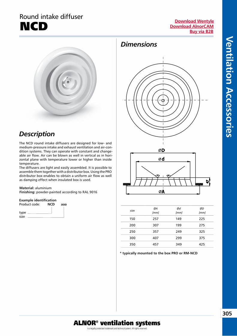
305
Ventilation Accessories
ALNOR® ventilation systemsis a legally protected trademark and technical patent. All rights reserved.
Download WentyleDownload AlnorCAM
Buy via B2B
Dimensions
Description
Round intake diffuser
NCD
The NCD round intake diffusers are designed for low- and medium-pressure intake and exhaust ventilation and air-con-dition systems. They can operate with constant and change-able air flow. Air can be blown as well in vertical as in hori-zontal plane with temperature lower or higher than inside temperature.The diffusers are light and easily assembled. It is possible to assemble them together with a distributor box. Using the PRO distributor box enables to obtain a uniform air flow as well as damping effect when insulated box is used.
Material: aluminiumFinishing: powder-painted according to RAL 9016
Example identificationProduct code: NCD aaa
typesize
* typically mounted to the box PRO or RM-NCD
sizeØA
[mm]Ød
[mm]ØD
[mm]
150 257 149 225
200 307 199 275
250 357 249 325
300 407 299 375
350 457 349 425
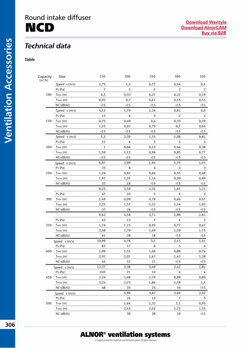
306
Vent
ilati
on A
cces
sori
es
ALNOR® ventilation systemsis a legally protected trademark and technical patent. All rights reserved.
Download WentyleDownload AlnorCAM
Buy via B2B
Round intake diffuser
NCD Technical data
Table
Wydajność(m /h)
Wielkość
Speed v (m/s)
Ps (Pa)
Tmin (m)
Tmax (m)
NC (dB(A))
Speed v (m/s)
Ps (Pa)
Tmin (m)
Tmax (m)
NC (dB(A))
Speed v (m/s)
Speed v (m/s)
Speed v (m/s)
Speed v (m/s)
Speed v (m/s)
Ps (Pa)
Tmin (m)
Tmax (m)
NC (dB(A))
Ps (Pa)
Tmin (m)
Tmax (m)
NC (dB(A))
Ps (Pa)
Tmin (m)
Tmax (m)
NC (dB(A))
Ps (Pa)
Tmin (m)
Tmax (m)
NC (dB(A))
Ps (Pa)
Tmin (m)
Tmax (m)
NC (dB(A))
Ps (Pa)
Tmin (m)
Tmax (m)
NC (dB(A))
Ps (Pa)
Tmin (m)
Tmax (m)
NC (dB(A))
Capacity Size
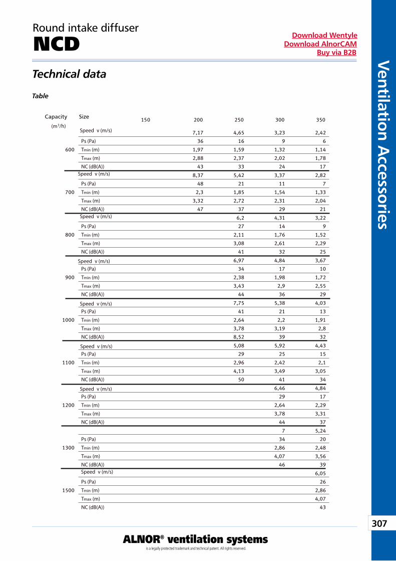
307
Ventilation Accessories
ALNOR® ventilation systemsis a legally protected trademark and technical patent. All rights reserved.
Download WentyleDownload AlnorCAM
Buy via B2B
Round intake diffuser
NCD Technical data
Table
Wydajność/h)
Wielkość
Ps (Pa)
Tmin (m)
Tmax (m)
NC (dB(A))
Ps (Pa)
Tmin (m)
Tmax (m)
NC (dB(A))
Ps (Pa)
Tmin (m)
Tmax (m)
NC (dB(A))
Ps (Pa)
Tmin (m)
Tmax (m)
NC (dB(A))
Ps (Pa)
Tmin (m)
Tmax (m)
NC (dB(A))
Ps (Pa)
Tmin (m)
Tmax (m)
NC (dB(A))
Ps (Pa)
Tmin (m)
Tmax (m)
NC (dB(A))
Ps (Pa)
Tmin (m)
Tmax (m)
NC (dB(A))
Ps (Pa)
Tmin (m)
Tmax (m)
NC (dB(A))
(mSpeed v (m/s)
Speed v (m/s)
Speed v (m/s)
Speed v (m/s)
Speed v (m/s)
Speed v (m/s)
Speed v (m/s)
Speed v (m/s)
Capacity Size
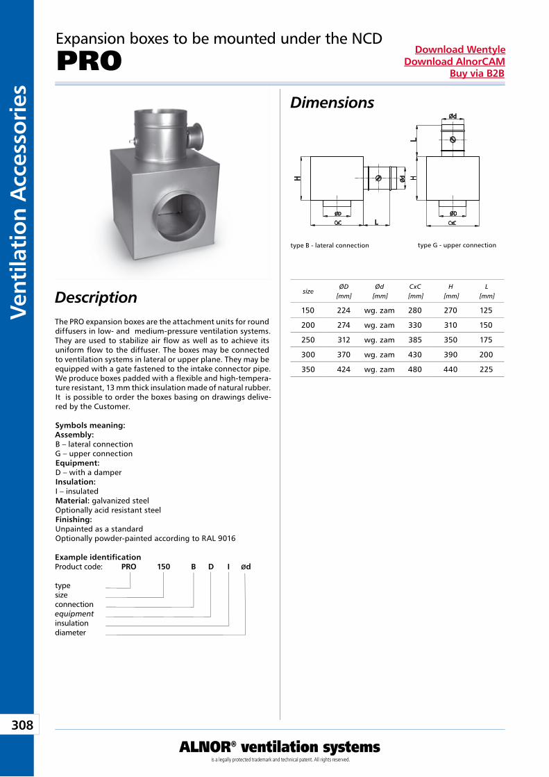
308
Vent
ilati
on A
cces
sori
es
ALNOR® ventilation systemsis a legally protected trademark and technical patent. All rights reserved.
Download WentyleDownload AlnorCAM
Buy via B2B
Dimensions
Description
Example identificationProduct code: PRO 150 B D I Ød
typesizeconnectionequipmentinsulationdiameter
Expansion boxes to be mounted under the NCD
PRO
The PRO expansion boxes are the attachment units for round diffusers in low- and medium-pressure ventilation systems. They are used to stabilize air flow as well as to achieve its uniform flow to the diffuser. The boxes may be connected to ventilation systems in lateral or upper plane. They may be equipped with a gate fastened to the intake connector pipe. We produce boxes padded with a flexible and high-tempera-ture resistant, 13 mm thick insulation made of natural rubber.It is possible to order the boxes basing on drawings delive-red by the Customer.
Symbols meaning:Assembly:B – lateral connectionG – upper connectionEquipment:D – with a damperInsulation:I – insulatedMaterial: galvanized steelOptionally acid resistant steelFinishing:Unpainted as a standardOptionally powder-painted according to RAL 9016
type B - lateral connection type G - upper connection
sizeØD
[mm]Ød
[mm]CxC
[mm]H
[mm]L
[mm]
150 224 wg. zam 280 270 125
200 274 wg. zam 330 310 150
250 312 wg. zam 385 350 175
300 370 wg. zam 430 390 200
350 424 wg. zam 480 440 225
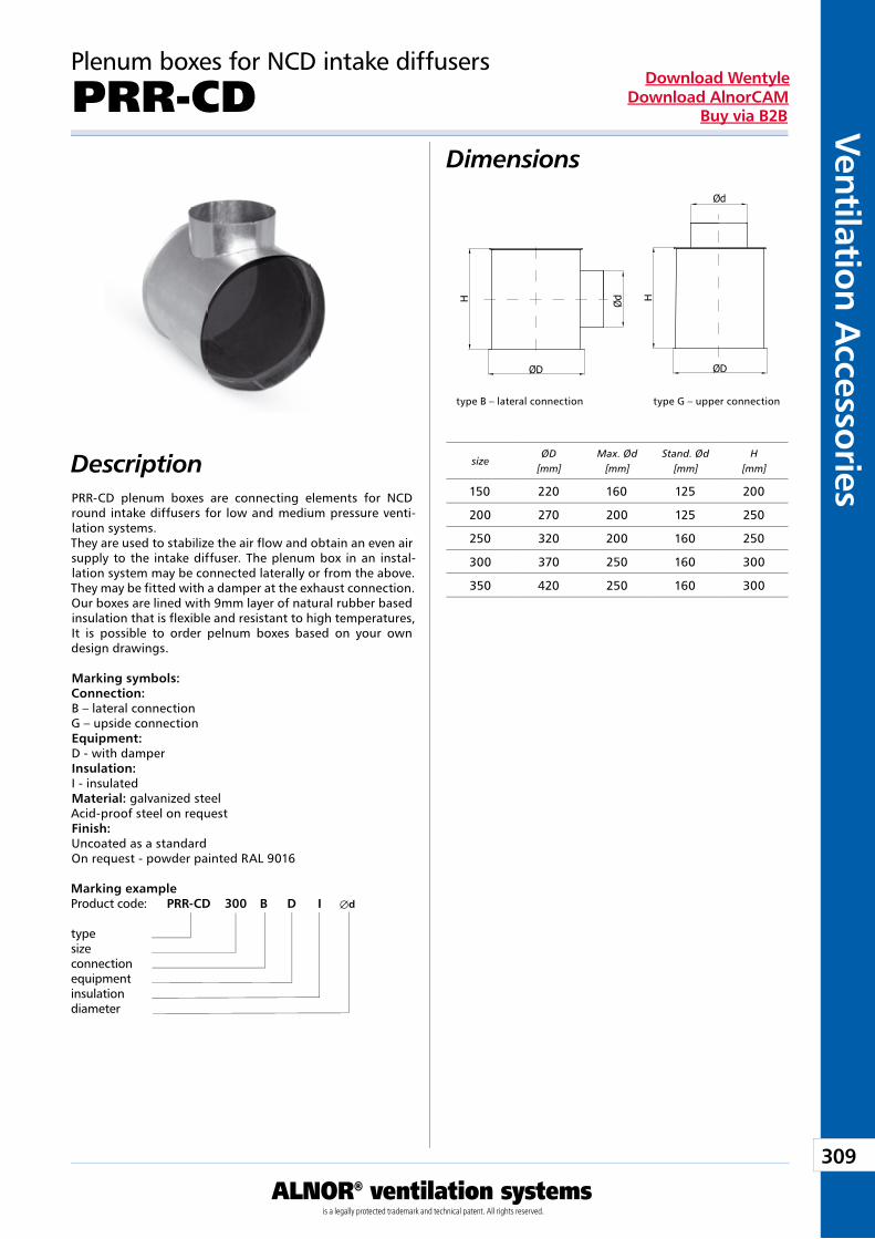
309
Ventilation Accessories
ALNOR® ventilation systemsis a legally protected trademark and technical patent. All rights reserved.
Download WentyleDownload AlnorCAM
Buy via B2B
Plenum boxes for NCD intake diffusers
PRR-CDDimensions
DescriptionPRR-CD plenum boxes are connecting elements for NCD round intake diffusers for low and medium pressure venti-lation systems. They are used to stabilize the air flow and obtain an even air supply to the intake diffuser. The plenum box in an instal-lation system may be connected laterally or from the above. They may be fitted with a damper at the exhaust connection. Our boxes are lined with 9mm layer of natural rubber based insulation that is flexible and resistant to high temperatures, It is possible to order pelnum boxes based on your own design drawings. Marking symbols: Connection: B – lateral connection G – upside connection Equipment: D - with damper Insulation: I - insulated Material: galvanized steel Acid-proof steel on request Finish: Uncoated as a standard On request - powder painted RAL 9016
Marking example Product code: PRR-CD 300 B D I Æd type size connection equipment insulation diameter
type B – lateral connection type G – upper connection
sizeØD
[mm]Max. Ød
[mm]Stand. Ød
[mm]H
[mm]
150 220 160 125 200
200 270 200 125 250
250 320 200 160 250
300 370 250 160 300
350 420 250 160 300
H
ØD
Ød H
ØD
Ød
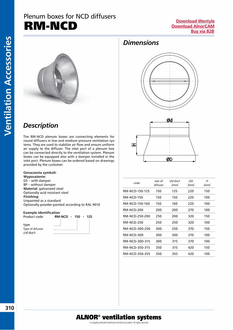
310
Vent
ilati
on A
cces
sori
es
ALNOR® ventilation systemsis a legally protected trademark and technical patent. All rights reserved.
Download WentyleDownload AlnorCAM
Buy via B2B
Dimensions
Description
Plenum boxes for NCD diffusers
RM-NCD
The RM-NCD plenum boxes are connecting elements for round diffusers in low and medium pressure ventilation sys-tems. They are used to stabilize air flow and ensure uniform air supply to the diffuser. The inlet port of a plenum box can be connected directly to the ventilation system. Plenum boxes can be equipped also with a damper installed in the inlet port. Plenum boxes can be ordered based on drawings provided by the customer.
Oznaczenia symboli:Wyposażenie:DS – with damperBP – without damperMaterial: galvanized steelOptionally acid resistant steelFinishing:Unpainted as a standardOptionally powder-painted according to RAL 9016
Example identificationProduct code: RM-NCD - 150 - 125
typeType of difusserÆd duct
codesize ofdifiuser
Æd duct [mm]
ÆD [mm]
H [mm]
RM-NCD-150-125 150 125 220 150
RM-NCD-150 150 150 220 100
RM-NCD-150-160 150 160 220 100
RM-NCD-200 200 200 270 100
RM-NCD-250-200 250 200 320 150
RM-NCD-250 250 250 320 100
RM-NCD-300-250 300 250 370 150
RM-NCD-300 300 300 370 100
RM-NCD-300-315 300 315 370 100
RM-NCD-350-315 350 315 420 150
RM-NCD-350-355 350 355 420 100
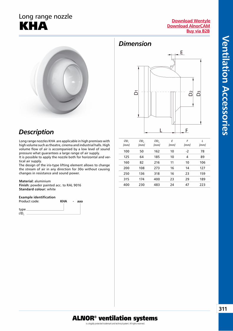
311
Ventilation Accessories
ALNOR® ventilation systemsis a legally protected trademark and technical patent. All rights reserved.
Download WentyleDownload AlnorCAM
Buy via B2B
Dimension
Description
Long range nozzle
KHA
Example identificationProduct code: KHA - aaa
typeD1
D1
[mm]D2
[mm]D3
[mm]E
[mm]F
[mm]L
[mm]Long range nozzles KHA are applicable in high premises with high volume such as theatre, cinema and industrial halls. High volume flow of air is accompanied by a low level of sound pressure what guarantees a large range of air supply.It is possible to apply the nozzle both for horizontal and ver-tical air supply.The design of the iris-type lifting element allows to change the stream of air in any direction for 30o without causing changes in resistance and sound power.
Material: aluminiumFinish: powder painted acc. to RAL 9016Standard colour: white
100 50 162 10 -2 78
125 64 185 10 4 89
160 82 216 11 10 106
200 108 273 16 14 127
250 136 318 16 23 159
315 174 400 23 29 189
400 230 483 24 47 223
D D
FL
E
D
1 2 3
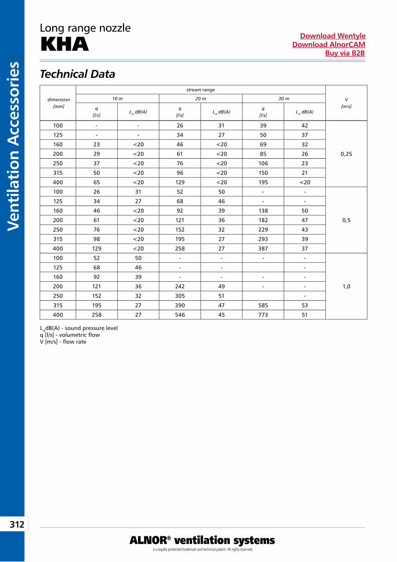
312
Vent
ilati
on A
cces
sori
es
ALNOR® ventilation systemsis a legally protected trademark and technical patent. All rights reserved.
Download WentyleDownload AlnorCAM
Buy via B2B
Long range nozzle
KHATechnical Data
LAdB(A) - sound pressure levelq [l/s] - volumetric flowV [m/s] - flow rate
dimension[mm]
stream range
V[m/s]
10 m 20 m 30 m
q[l/s]
LA dB(A)q
[l/s]LA dB(A)
q[l/s]
LA dB(A)
100 - - 26 31 39 42
0,25
125 - - 34 27 50 37
160 23 <20 46 <20 69 32
200 29 <20 61 <20 85 26
250 37 <20 76 <20 106 23
315 50 <20 96 <20 150 21
400 65 <20 129 <20 195 <20
100 26 31 52 50 - -
0,5
125 34 27 68 46 - -
160 46 <20 92 39 138 50
200 61 <20 121 36 182 47
250 76 <20 152 32 229 43
315 98 <20 195 27 293 39
400 129 <20 258 27 387 37
100 52 50 - - - -
1,0
125 68 46 - - -
160 92 39 - - - -
200 121 36 242 49 - -
250 152 32 305 51 -
315 195 27 390 47 585 53
400 258 27 546 45 773 51
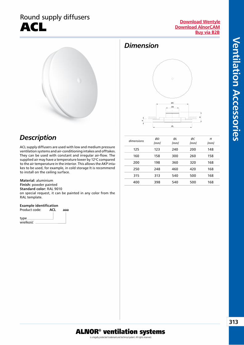
313
Ventilation Accessories
ALNOR® ventilation systemsis a legally protected trademark and technical patent. All rights reserved.
Download WentyleDownload AlnorCAM
Buy via B2B
Round supply diffusers
ACLDimension
DescriptionACL supply diffusers are used with low and medium pressure ventilation systems and air-conditioning intakes and offtakes. They can be used with constant and irregular air-flow. The supplied air may have a temperature lower by 12oC compared to the air temperature in the interior. This allows the AKP inta-kes to be used, for example, in cold storage It is recommend to install on the ceiling surface. Material: aluminium Finish: powder painted Standard color: RAL 9010 on special request, it can be painted in any color from the RAL template.
Example identificationProduct code: ACL aaa
typewielkość
dimensionsØD
[mm]ØL
[mm]ØC
[mm]H
[mm]
125 123 240 200 148
160 158 300 260 158
200 198 360 320 168
250 248 460 420 168
315 313 540 500 168
400 398 540 500 168
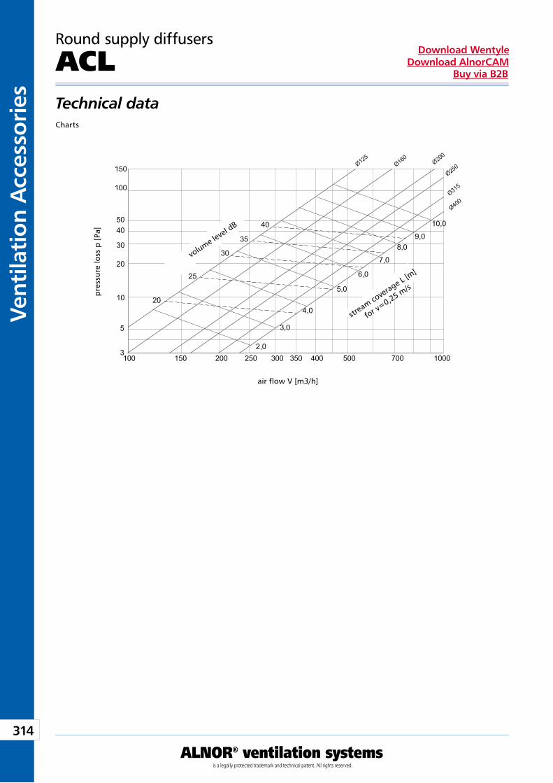
314
Vent
ilati
on A
cces
sori
es
ALNOR® ventilation systemsis a legally protected trademark and technical patent. All rights reserved.
Download WentyleDownload AlnorCAM
Buy via B2B
Round supply diffusers
ACLTechnical dataCharts
air flow V [m3/h]
volume level d
B
stream co
verage L [m
]
for v=0,25 m
/s
pre
ssur
e lo
ss p
[Pa]
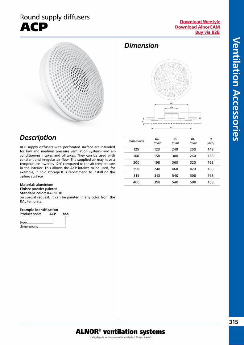
315
Ventilation Accessories
ALNOR® ventilation systemsis a legally protected trademark and technical patent. All rights reserved.
Download WentyleDownload AlnorCAM
Buy via B2B
Round supply diffusers
ACPDimension
DescriptionACP supply diffusers with perforated surface are intended for low and medium pressure ventilation systems and air-conditioning intakes and offtakes. They can be used with constant and irregular air-flow. The supplied air may have a temperature lower by 12oC compared to the air temperature in the interior. This allows the AKP intakes to be used, for example, in cold storage It is recommend to install on the ceiling surface. Material: aluminium Finish: powder painted Standard color: RAL 9010 on special request, it can be painted in any color from the RAL template.
Example identificationProduct code: ACP aaa
typedimensions
dimensionsØD
[mm]ØL
[mm]ØC
[mm]H
[mm]
125 123 240 200 148
160 158 300 260 158
200 198 360 320 168
250 248 460 420 168
315 313 540 500 168
400 398 540 500 168
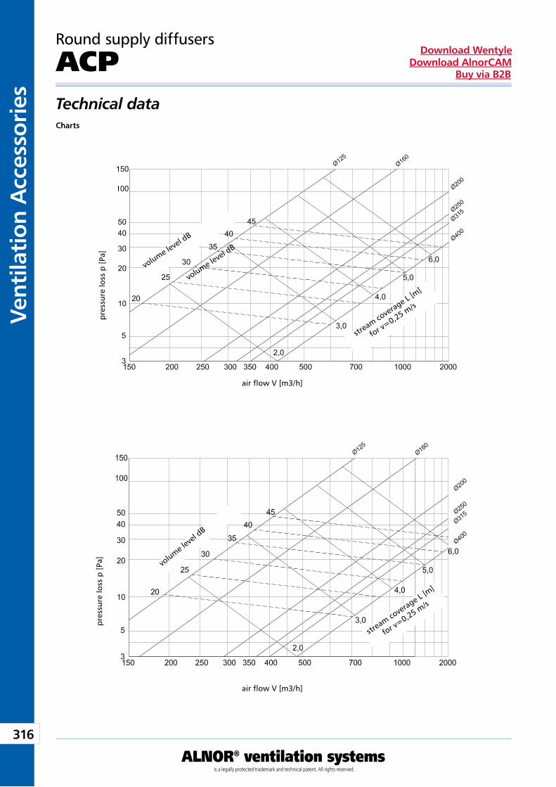
316
Vent
ilati
on A
cces
sori
es
ALNOR® ventilation systemsis a legally protected trademark and technical patent. All rights reserved.
Download WentyleDownload AlnorCAM
Buy via B2B
Round supply diffusers
ACPTechnical dataChartsCharts
air flow V [m3/h]
air flow V [m3/h]
volume level d
B
stream co
verage L [m
]
for v=0,25 m
/s
stream co
verage L [m
]
for v=0,25 m
/s
pre
ssur
e lo
ss p
[Pa]
pre
ssur
e lo
ss p
[Pa]
volume level d
B
volume l
evel
dB
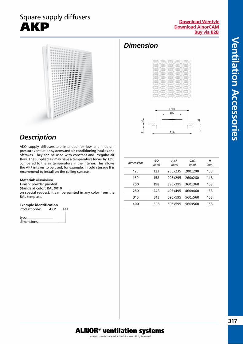
317
Ventilation Accessories
ALNOR® ventilation systemsis a legally protected trademark and technical patent. All rights reserved.
Download WentyleDownload AlnorCAM
Buy via B2B
Square supply diffusers
AKPDimension
DescriptionAKO supply diffusers are intended for low and medium pressure ventilation systems and air-conditioning intakes and offtakes. They can be used with constant and irregular air-flow. The supplied air may have a temperature lower by 12oC compared to the air temperature in the interior. This allows the AKP intakes to be used, for example, in cold storage It is recommend to install on the ceiling surface. Material: aluminium Finish: powder painted Standard color: RAL 9010 on special request, it can be painted in any color from the RAL template.
Example identificationProduct code: AKP aaa
typedimensions
dimensionsØD
[mm]AxA
[mm]CxC
[mm]H
[mm]
125 123 235x235 200x200 138
160 158 295x295 260x260 148
200 198 395x395 360x360 158
250 248 495x495 460x460 158
315 313 595x595 560x560 158
400 398 595x595 560x560 158
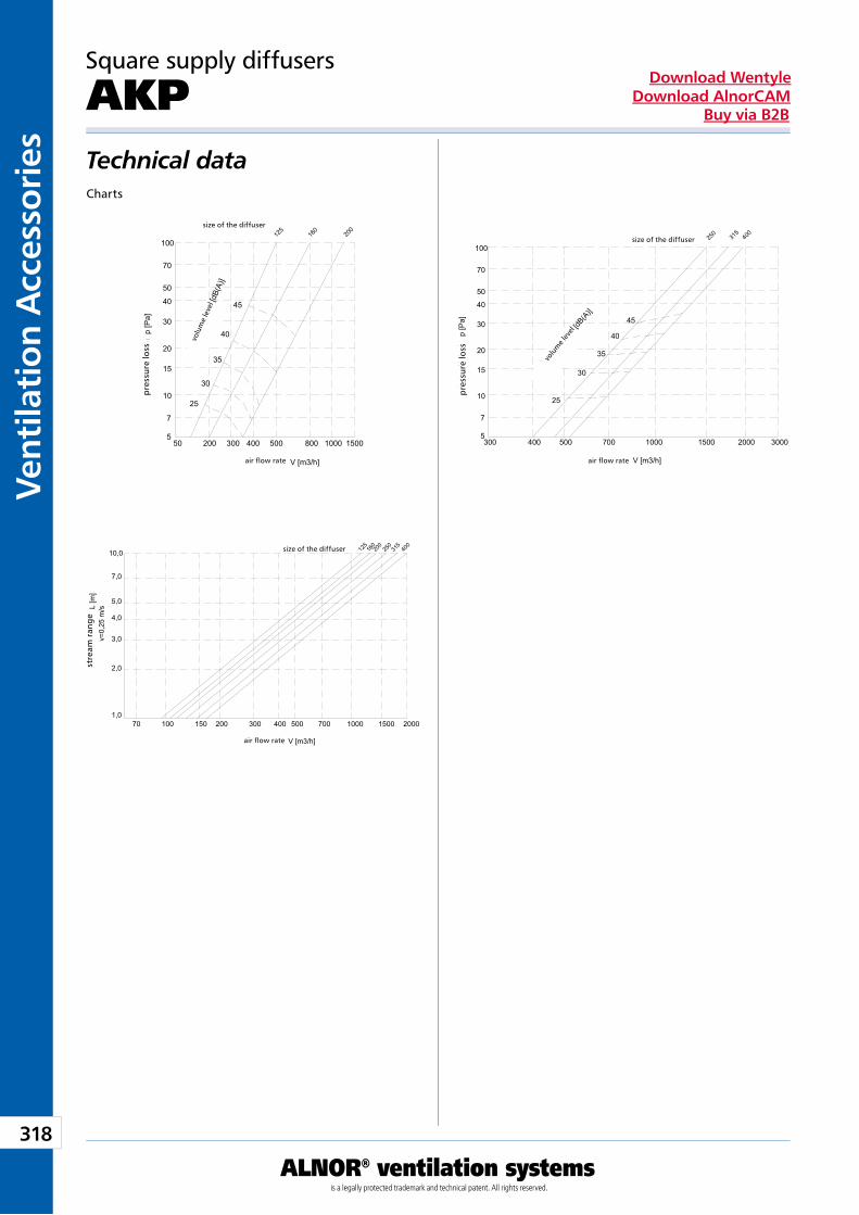
318
Vent
ilati
on A
cces
sori
es
ALNOR® ventilation systemsis a legally protected trademark and technical patent. All rights reserved.
Download WentyleDownload AlnorCAM
Buy via B2B
Square supply diffusers
AKPTechnical dataCharts
stre
am r
ang
e
pre
ssur
e lo
ss
pre
ssur
e lo
ss
air flow rate
air flow rate
size of the diffuser
size of the diffuser
size of the diffuser
air flow rate
volu
me
leve
l
volu
me
leve
l
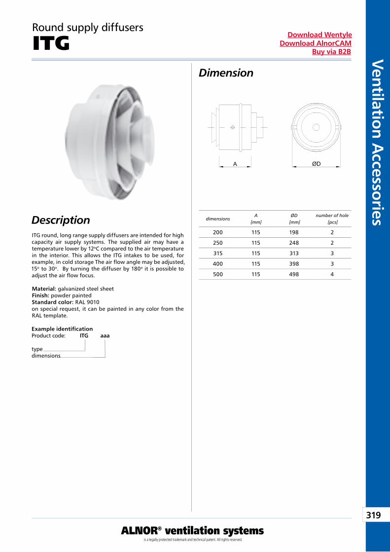
319
Ventilation Accessories
ALNOR® ventilation systemsis a legally protected trademark and technical patent. All rights reserved.
Download WentyleDownload AlnorCAM
Buy via B2B
Round supply diffusers
ITGDimension
DescriptionITG round, long range supply diffusers are intended for high capacity air supply systems. The supplied air may have a temperature lower by 12oC compared to the air temperature in the interior. This allows the ITG intakes to be used, for example, in cold storage The air flow angle may be adjusted, 15o to 30o. By turning the diffuser by 180o it is possible to adjust the air flow focus. Material: galvanized steel sheet Finish: powder painted Standard color: RAL 9010 on special request, it can be painted in any color from the RAL template.
Example identificationProduct code: ITG aaa
typedimensions
dimensionsA
[mm]ØD
[mm]number of hole
[pcs]
200 115 198 2
250 115 248 2
315 115 313 3
400 115 398 3
500 115 498 4
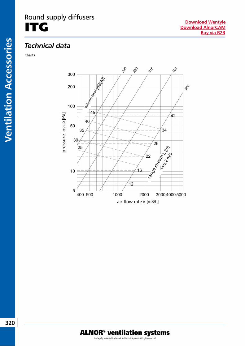
320
Vent
ilati
on A
cces
sori
es
ALNOR® ventilation systemsis a legally protected trademark and technical patent. All rights reserved.
Download WentyleDownload AlnorCAM
Buy via B2B
Round supply diffusers
ITGTechnical dataCharts
volu
me
leve
l
pres
sure
loss
air flow rate
rang
e st
ream
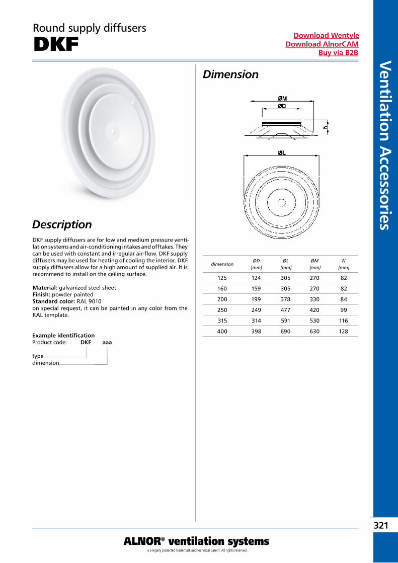
321
Ventilation Accessories
ALNOR® ventilation systemsis a legally protected trademark and technical patent. All rights reserved.
Download WentyleDownload AlnorCAM
Buy via B2B
Round supply diffusers
DKFDimension
DescriptionDKF supply diffusers are for low and medium pressure venti-lation systems and air-conditioning intakes and offtakes. They can be used with constant and irregular air-flow. DKF supply diffusers may be used for heating of cooling the interior. DKF supply diffusers allow for a high amount of supplied air. It is recommend to install on the ceiling surface. Material: galvanized steel sheet Finish: powder painted Standard color: RAL 9010 on special request, it can be painted in any color from the RAL template.
Example identificationProduct code: DKF aaa
typedimension
dimensionØD
[mm]ØL
[mm]ØM
[mm]N
[mm]
125 124 305 270 82
160 159 305 270 82
200 199 378 330 84
250 249 477 420 99
315 314 591 530 116
400 398 690 630 128
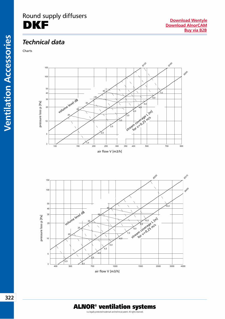
322
Vent
ilati
on A
cces
sori
es
ALNOR® ventilation systemsis a legally protected trademark and technical patent. All rights reserved.
Download WentyleDownload AlnorCAM
Buy via B2B
Round supply diffusers
DKFTechnical dataCharts
pre
ssur
e lo
ss p
[Pa]
pre
ssur
e lo
ss p
[Pa]
air flow V [m3/h]
air flow V [m3/h]
strea
m cover
age L
[m]
for v=0,25 m
/s
strea
m cover
age L
[m]
for v=0,25 m
/s
volume level d
B
volume level d
B
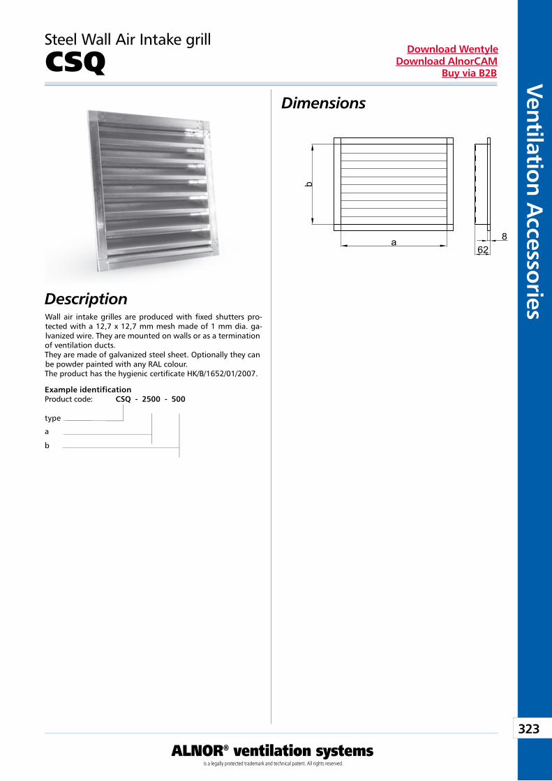
323
Ventilation Accessories
ALNOR® ventilation systemsis a legally protected trademark and technical patent. All rights reserved.
Download WentyleDownload AlnorCAM
Buy via B2B
Dimensions
Description
Steel Wall Air Intake grill
CSQ
Wall air intake grilles are produced with fixed shutters pro-tected with a 12,7 x 12,7 mm mesh made of 1 mm dia. ga-lvanized wire. They are mounted on walls or as a termination of ventilation ducts.They are made of galvanized steel sheet. Optionally they can be powder painted with any RAL colour.The product has the hygienic certificate HK/B/1652/01/2007.
Example identificationProduct code: CSQ - 2500 - 500
type
a
b
a
b
628
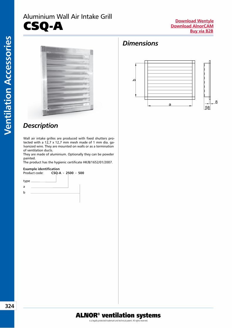
324
Vent
ilati
on A
cces
sori
es
ALNOR® ventilation systemsis a legally protected trademark and technical patent. All rights reserved.
Download WentyleDownload AlnorCAM
Buy via B2B
Dimensions
Description
a
b
588
Aluminium Wall Air Intake Grill
CSQ-A
Wall air intake grilles are produced with fixed shutters pro-tected with a 12,7 x 12,7 mm mesh made of 1 mm dia. ga-lvanized wire. They are mounted on walls or as a termination of ventilation ducts.They are made of aluminium. Optionally they can be powder painted.The product has the hygienic certificate HK/B/1652/01/2007.
Example identificationProduct code: CSQ-A - 2500 - 500
type
a
b
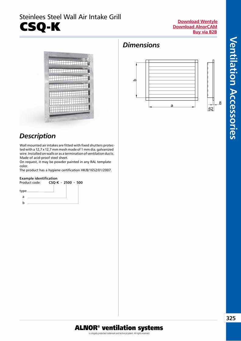
325
Ventilation Accessories
ALNOR® ventilation systemsis a legally protected trademark and technical patent. All rights reserved.
Download WentyleDownload AlnorCAM
Buy via B2B
Steinlees Steel Wall Air Intake Grill
CSQ-KDimensions
DescriptionWall mounted air intakes are fitted with fixed shutters protec-ted with a 12,7 x 12,7 mm mesh made of 1 mm dia. galvanized wire. Installed on walls or as a termination of ventilation ducts. Made of acid-proof steel sheet. On request, it may be powder painted in any RAL template color. The product has a hygiene certification HK/B/1652/01/2007.
Example identificationProduct code: CSQ-K - 2500 - 500
type
a b
a
b
628
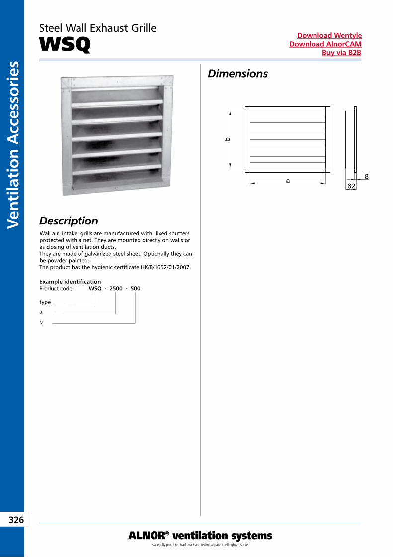
326
Vent
ilati
on A
cces
sori
es
ALNOR® ventilation systemsis a legally protected trademark and technical patent. All rights reserved.
Download WentyleDownload AlnorCAM
Buy via B2B
Dimensions
DescriptionWall air intake grills are manufactured with fixed shutters protected with a net. They are mounted directly on walls or as closing of ventilation ducts.They are made of galvanized steel sheet. Optionally they can be powder painted.The product has the hygienic certificate HK/B/1652/01/2007.
a
b
628
Steel Wall Exhaust Grille
WSQ
Example identificationProduct code: WSQ - 2500 - 500
type
a
b
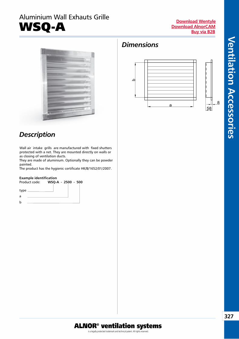
327
Ventilation Accessories
ALNOR® ventilation systemsis a legally protected trademark and technical patent. All rights reserved.
Download WentyleDownload AlnorCAM
Buy via B2B
Dimensions
Description
Aluminium Wall Exhauts Grille
WSQ-A
Wall air intake grills are manufactured with fixed shutters protected with a net. They are mounted directly on walls or as closing of ventilation ducts.They are made of aluminium. Optionally they can be powder painted.The product has the hygienic certificate HK/B/1652/01/2007.
a
b
588
Example identificationProduct code: WSQ-A - 2500 - 500
type
a
b
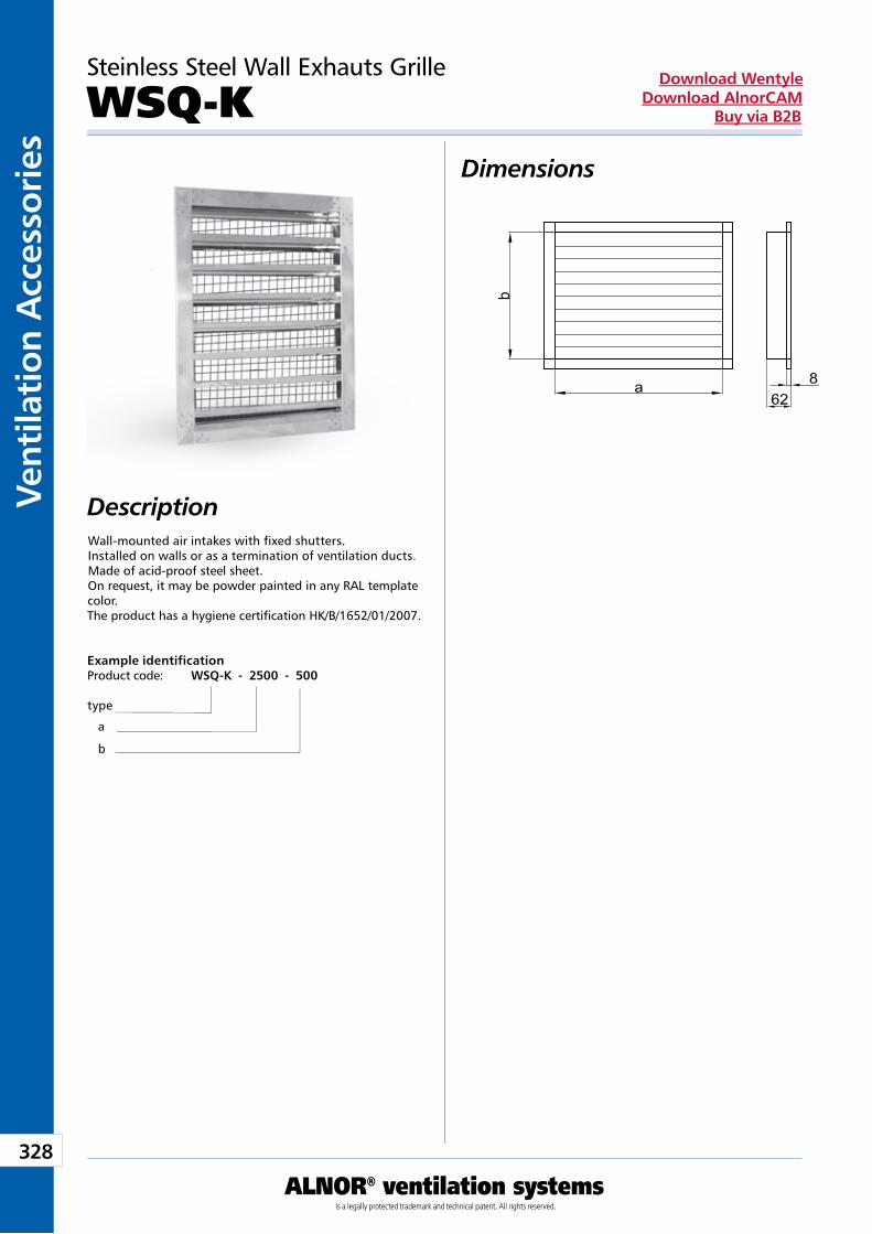
328
Vent
ilati
on A
cces
sori
es
ALNOR® ventilation systemsis a legally protected trademark and technical patent. All rights reserved.
Download WentyleDownload AlnorCAM
Buy via B2B
Steinless Steel Wall Exhauts Grille
WSQ-KDimensions
DescriptionWall-mounted air intakes with fixed shutters. Installed on walls or as a termination of ventilation ducts. Made of acid-proof steel sheet. On request, it may be powder painted in any RAL template color. The product has a hygiene certification HK/B/1652/01/2007.
Example identificationProduct code: WSQ-K - 2500 - 500
type
a b
a
b
628
FlexibleDucts
Producent zastrzega sobie prawo do dokonywania zmian w wymiarach i danych technicznych produktów ze względu na ciągłe ich doskonalenie
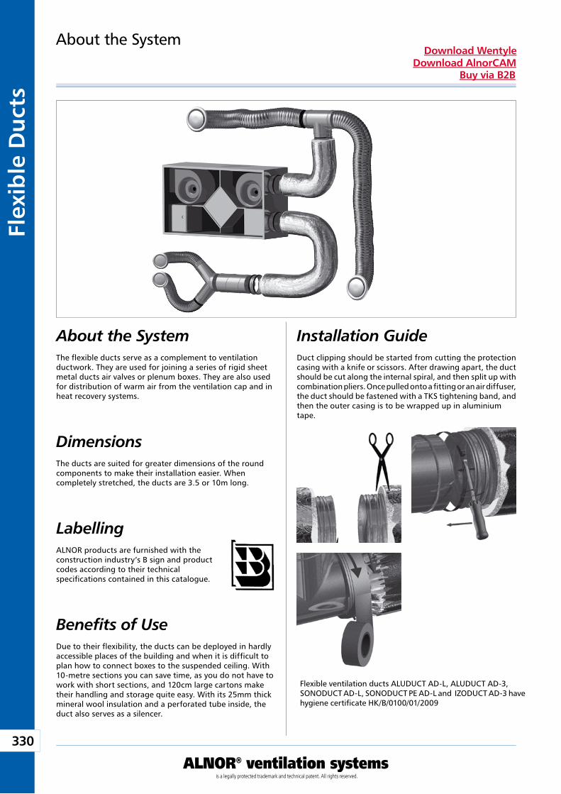
330
ALNOR® ventilation systemsis a legally protected trademark and technical patent. All rights reserved.
Flex
ible
Du
cts
Download WentyleDownload AlnorCAM
Buy via B2B
Installation GuideDuct clipping should be started from cutting the protection casing with a knife or scissors. After drawing apart, the duct should be cut along the internal spiral, and then split up with combination pliers. Once pulled onto a fitting or an air diffuser, the duct should be fastened with a TKS tightening band, and then the outer casing is to be wrapped up in aluminiumtape.
About the System
About the SystemThe flexible ducts serve as a complement to ventilation ductwork. They are used for joining a series of rigid sheet metal ducts air valves or plenum boxes. They are also used for distribution of warm air from the ventilation cap and in heat recovery systems.
Dimensions The ducts are suited for greater dimensions of the round components to make their installation easier. When completely stretched, the ducts are 3.5 or 10m long.
Benefits of UseDue to their flexibility, the ducts can be deployed in hardly accessible places of the building and when it is difficult to plan how to connect boxes to the suspended ceiling. With 10-metre sections you can save time, as you do not have to work with short sections, and 120cm large cartons make their handling and storage quite easy. With its 25mm thick mineral wool insulation and a perforated tube inside, the duct also serves as a silencer.
LabellingALNOR products are furnished with the construction industry’s B sign and product codes according to their technical specifications contained in this catalogue.
Flexible ventilation ducts ALUDUCT AD-L, ALUDUCT AD-3, SONODUCT AD-L, SONODUCT PE AD-L and IZODUCT AD-3 have hygiene certificate HK/B/0100/01/2009
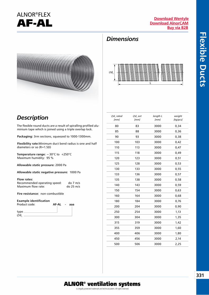
331
ALNOR® ventilation systemsis a legally protected trademark and technical patent. All rights reserved.
Flexible D
ucts
Download WentyleDownload AlnorCAM
Buy via B2B
d1
L
Dimensions
DescriptionThe flexible round ducts are a result of spiralling profiled alu-minium tape which is joined using a triple overlap lock.
Packaging: 3rm sections, squeezed to 1000-1300mm.
Flexibility rate:Minimum duct bend radius is one and half diameters or so (R=1.5D)
Temperature range: − 30°C to +250°CMaximum humidity: 95 %
Allowable static pressure: 2000 Pa
Allowable static negative pressure: 1000 Pa
Flow rates: Recommended operating speed: do 7 m/sMaximum flow rate: do 25 m/s
Fire resistance: non-combustible
ALNOR®FLEX
AF-AL
Example identificationProduct code: AF-AL - aaa
typeÆd1
Æd1 rated[mm]
Æd1 ext [mm]
length L[mm]
weight[kg/pcs]
80 83 3000 0,34
85 88 3000 0,36
90 93 3000 0,38
100 103 3000 0,42
110 113 3000 0,47
115 118 3000 0,49
120 123 3000 0,51
125 128 3000 0,53
130 133 3000 0,55
133 136 3000 0,57
135 138 3000 0,58
140 143 3000 0,59
150 154 3000 0,63
160 164 3000 0,68
180 184 3000 0,76
200 204 3000 0,90
250 254 3000 1,13
300 304 3000 1,35
315 319 3000 1,42
355 359 3000 1,60
400 406 3000 1,80
450 456 3000 2,14
500 506 3000 2,25
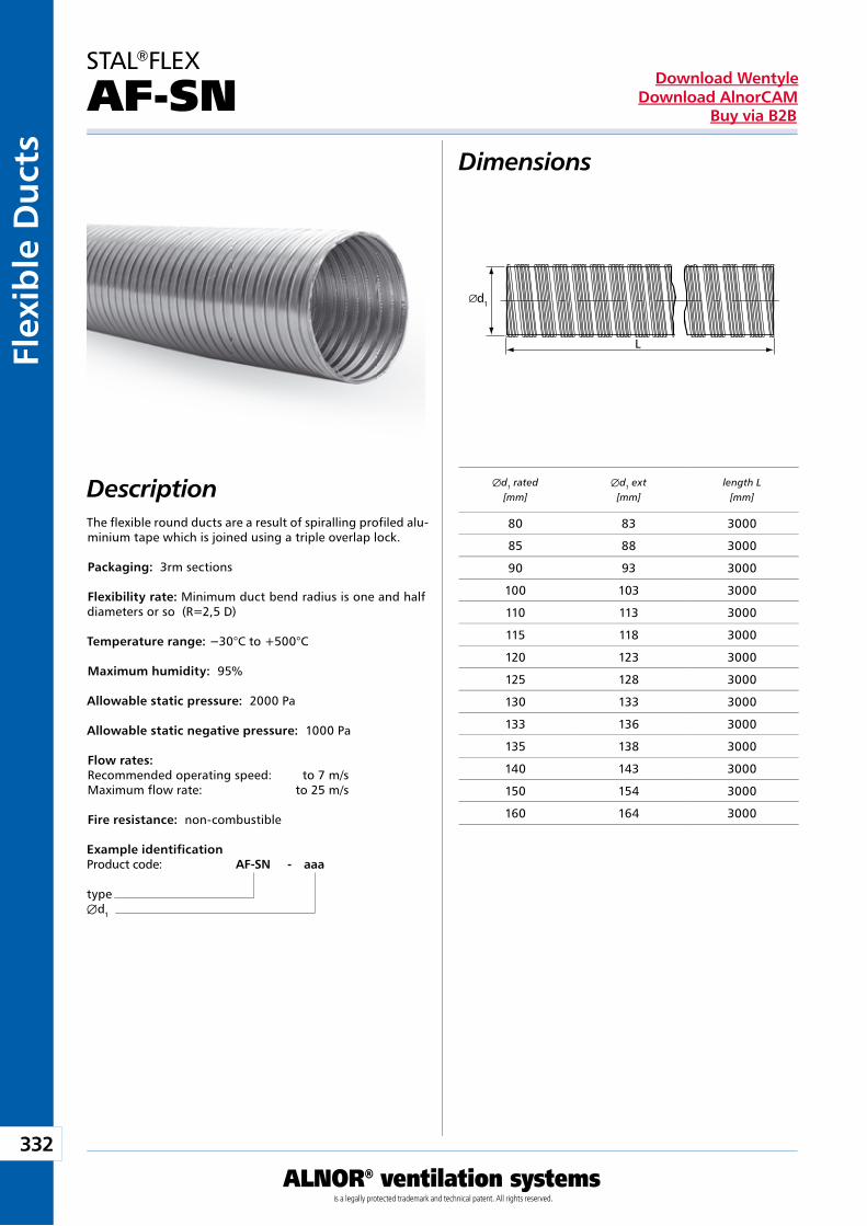
332
ALNOR® ventilation systemsis a legally protected trademark and technical patent. All rights reserved.
Flex
ible
Du
cts
Download WentyleDownload AlnorCAM
Buy via B2B
d1
L
Dimensions
DescriptionThe flexible round ducts are a result of spiralling profiled alu-minium tape which is joined using a triple overlap lock.
Packaging: 3rm sections
Flexibility rate: Minimum duct bend radius is one and half diameters or so (R=2,5 D)
Temperature range: −30°C to +500°C
Maximum humidity: 95%
Allowable static pressure: 2000 Pa
Allowable static negative pressure: 1000 Pa
Flow rates: Recommended operating speed: to 7 m/sMaximum flow rate: to 25 m/s
Fire resistance: non-combustible
STAL®FLEX
AF-SN
Example identificationProduct code: AF-SN - aaa
typeÆd1
Æd1 rated[mm]
Æd1 ext [mm]
length L[mm]
80 83 3000
85 88 3000
90 93 3000
100 103 3000
110 113 3000
115 118 3000
120 123 3000
125 128 3000
130 133 3000
133 136 3000
135 138 3000
140 143 3000
150 154 3000
160 164 3000
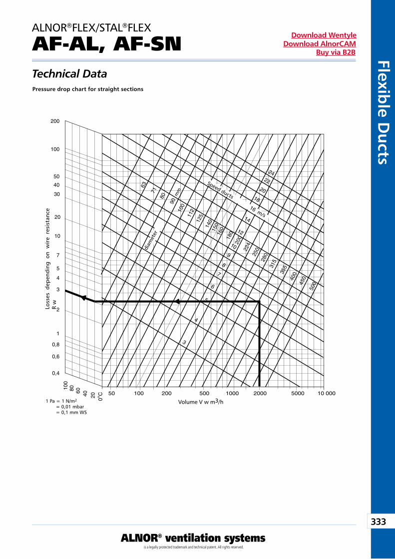
333
ALNOR® ventilation systemsis a legally protected trademark and technical patent. All rights reserved.
Flexible D
ucts
Download WentyleDownload AlnorCAM
Buy via B2B
Technical Data
ALNOR®FLEX/STAL®FLEX
AF-AL, AF-SN
Pressure drop chart for straight sections
Volume V w m3/h
diam
eter
Loss
es d
epen
ding
on
wir
e re
sist
ance
R
w
Speed ducts
m/s
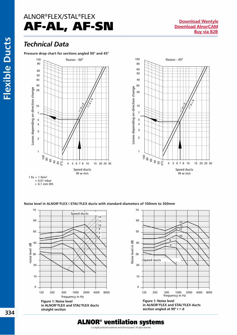
334
ALNOR® ventilation systemsis a legally protected trademark and technical patent. All rights reserved.
Flex
ible
Du
cts
Download WentyleDownload AlnorCAM
Buy via B2B
Technical Data
ALNOR®FLEX/STAL®FLEX
AF-AL, AF-SN
Noise level in ALNOR®FLEX i STAL®FLEX ducts with standard diameters of 100mm to 300mm
Pressure drop chart for sections angled 90° and 45°
Figure 1: Noise level in ALNOR®FLEX and STAL®FLEX ductsstraight section
Figure 1: Noise level in ALNOR®FLEX and STAL®FLEX ductssection angled at 90° r = d
Speed ductsW w m/s
flexion - 90° flexion - 45°
Speed ductsW w m/s
Loss
es d
epen
ding
on
dire
ctio
n ch
ange
Loss
es d
epen
ding
on
dire
ctio
n ch
ange
frequency in Hz
Speed ducts
Speed ducts
frequency in Hz
nois
e le
vel
dB
Noi
se le
vel i
n dB
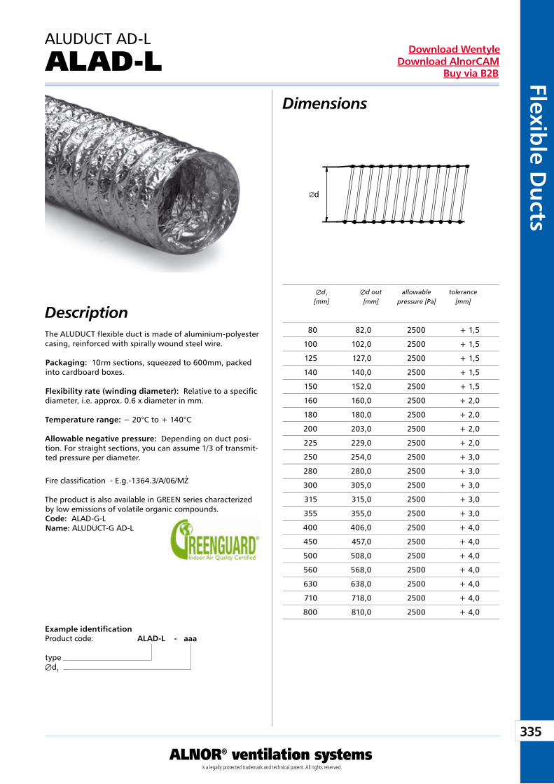
335
ALNOR® ventilation systemsis a legally protected trademark and technical patent. All rights reserved.
Flexible D
ucts
Download WentyleDownload AlnorCAM
Buy via B2B
d
Dimensions
DescriptionThe ALUDUCT flexible duct is made of aluminium-polyester casing, reinforced with spirally wound steel wire.
Packaging: 10rm sections, squeezed to 600mm, packed into cardboard boxes.
Flexibility rate (winding diameter): Relative to a specific diameter, i.e. approx. 0.6 x diameter in mm.
Temperature range: − 20°C to + 140°C
Allowable negative pressure: Depending on duct posi-tion. For straight sections, you can assume 1/3 of transmit-ted pressure per diameter.
Fire classifi cation - E.g.-1364.3/A/06/MŻ
The product is also available in GREEN series characterized by low emissions of volatile organic compounds.Code: ALAD-G-LName: ALUDUCT-G AD-L
Example identificationProduct code: ALAD-L - aaa
typeÆd1
ALUDUCT AD-L
ALAD-L
Æd1 Æd out allowable tolerance [mm] [mm] pressure [Pa] [mm]
80 82,0 2500 + 1,5
100 102,0 2500 + 1,5
125 127,0 2500 + 1,5
140 140,0 2500 + 1,5
150 152,0 2500 + 1,5
160 160,0 2500 + 2,0
180 180,0 2500 + 2,0
200 203,0 2500 + 2,0
225 229,0 2500 + 2,0
250 254,0 2500 + 3,0
280 280,0 2500 + 3,0
300 305,0 2500 + 3,0
315 315,0 2500 + 3,0
355 355,0 2500 + 3,0
400 406,0 2500 + 4,0
450 457,0 2500 + 4,0
500 508,0 2500 + 4,0
560 568,0 2500 + 4,0
630 638,0 2500 + 4,0
710 718,0 2500 + 4,0
800 810,0 2500 + 4,0
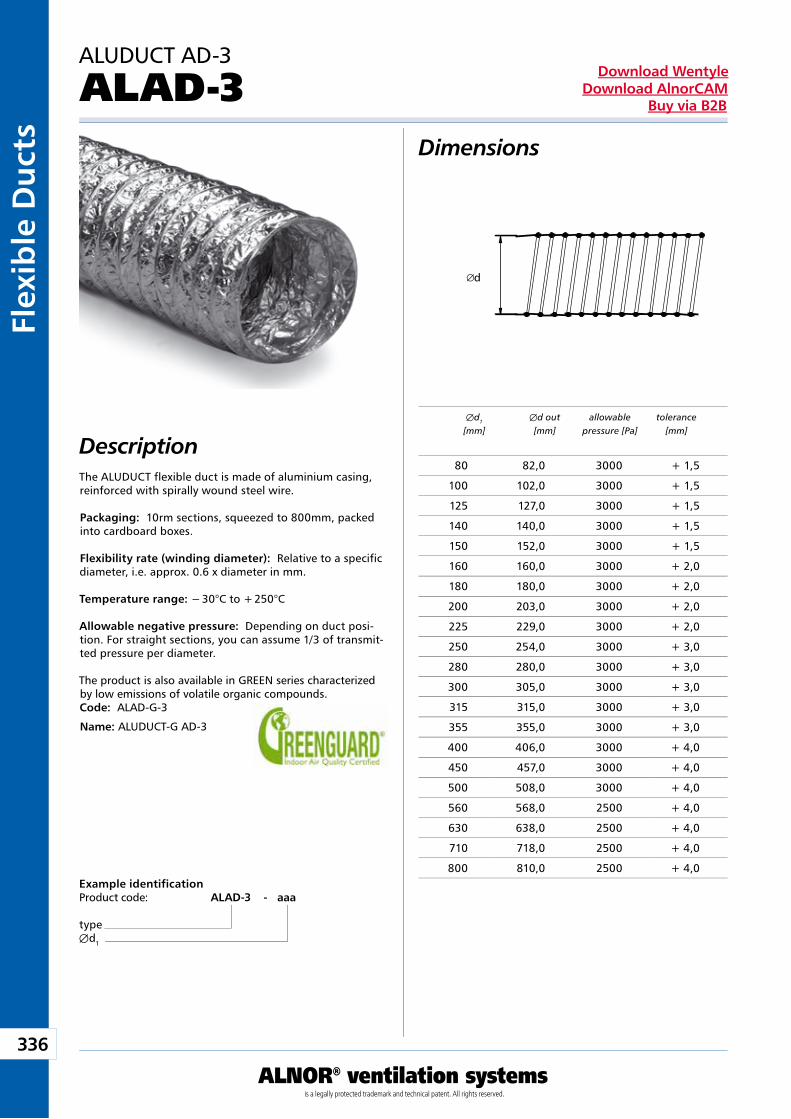
336
ALNOR® ventilation systemsis a legally protected trademark and technical patent. All rights reserved.
Flex
ible
Du
cts
Download WentyleDownload AlnorCAM
Buy via B2B
d
Dimensions
DescriptionThe ALUDUCT flexible duct is made of aluminium casing, reinforced with spirally wound steel wire.
Packaging: 10rm sections, squeezed to 800mm, packed into cardboard boxes.
Flexibility rate (winding diameter): Relative to a specific diameter, i.e. approx. 0.6 x diameter in mm.
Temperature range: − 30°C to + 250°C
Allowable negative pressure: Depending on duct posi-tion. For straight sections, you can assume 1/3 of transmit-ted pressure per diameter.
The product is also available in GREEN series characterized by low emissions of volatile organic compounds.Code: ALAD-G-3
Name: ALUDUCT-G AD-3
Example identificationProduct code: ALAD-3 - aaa
typeÆd1
ALUDUCT AD-3
ALAD-3
Æd1 Æd out allowable tolerance [mm] [mm] pressure [Pa] [mm]
80 82,0 3000 + 1,5
100 102,0 3000 + 1,5
125 127,0 3000 + 1,5
140 140,0 3000 + 1,5
150 152,0 3000 + 1,5
160 160,0 3000 + 2,0
180 180,0 3000 + 2,0
200 203,0 3000 + 2,0
225 229,0 3000 + 2,0
250 254,0 3000 + 3,0
280 280,0 3000 + 3,0
300 305,0 3000 + 3,0
315 315,0 3000 + 3,0
355 355,0 3000 + 3,0
400 406,0 3000 + 4,0
450 457,0 3000 + 4,0
500 508,0 3000 + 4,0
560 568,0 2500 + 4,0
630 638,0 2500 + 4,0
710 718,0 2500 + 4,0
800 810,0 2500 + 4,0
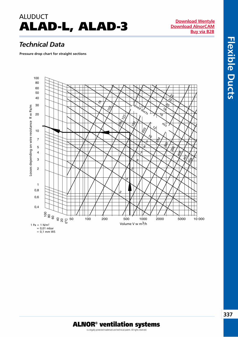
337
ALNOR® ventilation systemsis a legally protected trademark and technical patent. All rights reserved.
Flexible D
ucts
Download WentyleDownload AlnorCAM
Buy via B2B
Technical Data
ALUDUCT
ALAD-L, ALAD-3
Pressure drop chart for straight sections
Volume V w m3/h
Loss
es d
epen
ding
on
wire
res
ista
nce
R w
Pa/
m
Speed ducts
m/s
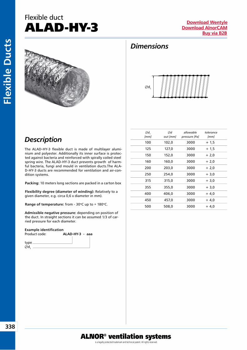
338
ALNOR® ventilation systemsis a legally protected trademark and technical patent. All rights reserved.
Flex
ible
Du
cts
Download WentyleDownload AlnorCAM
Buy via B2B
Æd1
Dimensions
Description
Example identificationProduct code: ALAD-HY-3 - aaa
typeÆd1
The ALAD-HY-3 flexible duct is made of multilayer alumi-nium and polyester. Additionally its inner surface is protec-ted against bacteria and reinforced with spirally coiled steel spring wire. The ALAD-HY-3 duct prevents growth of harm-ful bacteria, fungi and mould in ventilation ducts.The ALA-D-HY-3 ducts are recommended for ventilation and air-con-dition systems.
Packing: 10 meters long sections are packed in a carton box
Flexibility degree (diameter of winding): Relatively to a given diameter, e.g. circa 0,6 x diameter in mm).
Range of temperature: from - 30oC up to + 180oC.
Admissible negative pressure: depending on position of the duct. In straight sections it can be assumed 1/3 of car-ried pressure for each diameter.
Flexible duct
ALAD-HY-3
Æd1 Æd allowable tolerance [mm] out [mm] pressure [Pa] [mm]
100 102,0 3000 + 1,5
125 127,0 3000 + 1,5
150 152,0 3000 + 2,0
160 160,0 3000 + 2,0
200 203,0 3000 + 2,0
250 254,0 3000 + 3,0
315 315,0 3000 + 3,0
355 355,0 3000 + 3,0
400 406,0 3000 + 4,0
450 457,0 3000 + 4,0
500 508,0 3000 + 4,0
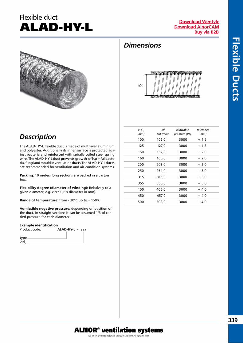
339
ALNOR® ventilation systemsis a legally protected trademark and technical patent. All rights reserved.
Flexible D
ucts
Download WentyleDownload AlnorCAM
Buy via B2B
Æd
Dimensions
Description
Example identificationProduct code: ALAD-HY-L - aaa
typeÆd1
The ALAD-HY-L flexible duct is made of multilayer aluminium and polyester. Additionally its inner surface is protected aga-inst bacteria and reinforced with spirally coiled steel spring wire. The ALAD-HY-L duct prevents growth of harmful bacte-ria, fungi and mould in ventilation ducts.The ALAD-HY-L ducts are recommended for ventilation and air-condition systems.
Packing: 10 meters long sections are packed in a carton box.
Flexibility degree (diameter of winding): Relatively to a given diameter, e.g. circa 0,6 x diameter in mm).
Range of temperature: from - 30oC up to + 150oC
Admissible negative pressure: depending on position of the duct. In straight sections it can be assumed 1/3 of car-ried pressure for each diameter.
Æd 1 Æd allowable tolerance [mm] out [mm] pressure [Pa] [mm]
Flexible duct
ALAD-HY-L
100 102,0 3000 + 1,5
125 127,0 3000 + 1,5
150 152,0 3000 + 2,0
160 160,0 3000 + 2,0
200 203,0 3000 + 2,0
250 254,0 3000 + 3,0
315 315,0 3000 + 3,0
355 355,0 3000 + 3,0
400 406,0 3000 + 4,0
450 457,0 3000 + 4,0
500 508,0 3000 + 4,0
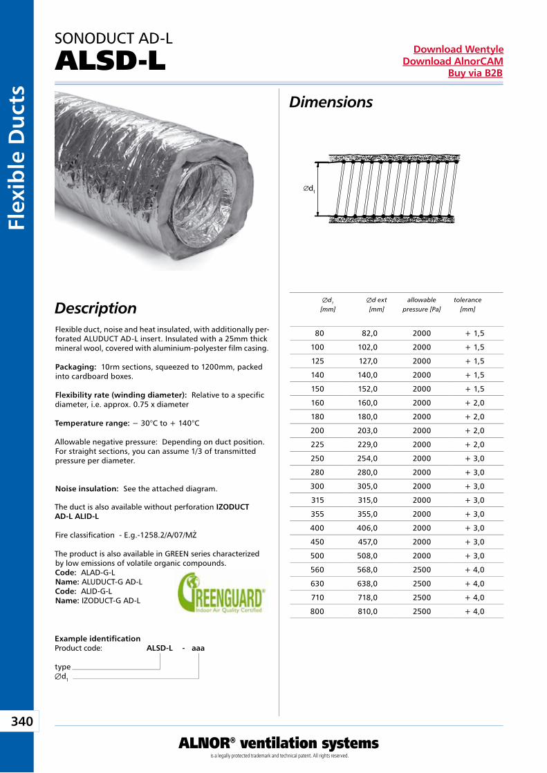
340
ALNOR® ventilation systemsis a legally protected trademark and technical patent. All rights reserved.
Flex
ible
Du
cts
Download WentyleDownload AlnorCAM
Buy via B2B
d1
Dimensions
Description
Example identificationProduct code: ALSD-L - aaa
typeÆd1
SONODUCT AD-L
ALSD-L
Flexible duct, noise and heat insulated, with additionally per-forated ALUDUCT AD-L insert. Insulated with a 25mm thick mineral wool, covered with aluminium-polyester film casing.
Packaging: 10rm sections, squeezed to 1200mm, packed into cardboard boxes.
Flexibility rate (winding diameter): Relative to a specific diameter, i.e. approx. 0.75 x diameter
Temperature range: − 30°C to + 140°C
Allowable negative pressure: Depending on duct position. For straight sections, you can assume 1/3 of transmitted pressure per diameter.
Noise insulation: See the attached diagram.
The duct is also available without perforation IZODUCT AD-L ALID-L
Fire classifi cation - E.g.-1258.2/A/07/MŻ
The product is also available in GREEN series characterized by low emissions of volatile organic compounds.Code: ALAD-G-LName: ALUDUCT-G AD-LCode: ALID-G-LName: IZODUCT-G AD-L
Æd1 Æd ext allowable tolerance [mm] [mm] pressure [Pa] [mm]
80 82,0 2000 + 1,5
100 102,0 2000 + 1,5
125 127,0 2000 + 1,5
140 140,0 2000 + 1,5
150 152,0 2000 + 1,5
160 160,0 2000 + 2,0
180 180,0 2000 + 2,0
200 203,0 2000 + 2,0
225 229,0 2000 + 2,0
250 254,0 2000 + 3,0
280 280,0 2000 + 3,0
300 305,0 2000 + 3,0
315 315,0 2000 + 3,0
355 355,0 2000 + 3,0
400 406,0 2000 + 3,0
450 457,0 2000 + 3,0
500 508,0 2000 + 3,0
560 568,0 2500 + 4,0
630 638,0 2500 + 4,0
710 718,0 2500 + 4,0
800 810,0 2500 + 4,0
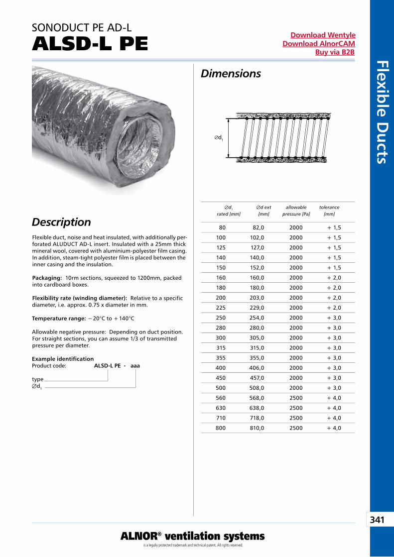
341
ALNOR® ventilation systemsis a legally protected trademark and technical patent. All rights reserved.
Flexible D
ucts
Download WentyleDownload AlnorCAM
Buy via B2B
d1
Dimensions
DescriptionFlexible duct, noise and heat insulated, with additionally per-forated ALUDUCT AD-L insert. Insulated with a 25mm thick mineral wool, covered with aluminium-polyester film casing. In addition, steam-tight polyester film is placed between the inner casing and the insulation.
Packaging: 10rm sections, squeezed to 1200mm, packed into cardboard boxes.
Flexibility rate (winding diameter): Relative to a specific diameter, i.e. approx. 0.75 x diameter in mm.
Temperature range: − 20°C to + 140°C
Allowable negative pressure: Depending on duct position. For straight sections, you can assume 1/3 of transmitted pressure per diameter.
Example identificationProduct code: ALSD-L PE - aaa
typeÆd1
SONODUCT PE AD-L
ALSD-L PE
Æd1 Æd ext allowable tolerance rated [mm] [mm] pressure [Pa] [mm]
80 82,0 2000 + 1,5
100 102,0 2000 + 1,5
125 127,0 2000 + 1,5
140 140,0 2000 + 1,5
150 152,0 2000 + 1,5
160 160,0 2000 + 2,0
180 180,0 2000 + 2,0
200 203,0 2000 + 2,0
225 229,0 2000 + 2,0
250 254,0 2000 + 3,0
280 280,0 2000 + 3,0
300 305,0 2000 + 3,0
315 315,0 2000 + 3,0
355 355,0 2000 + 3,0
400 406,0 2000 + 3,0
450 457,0 2000 + 3,0
500 508,0 2000 + 3,0
560 568,0 2500 + 4,0
630 638,0 2500 + 4,0
710 718,0 2500 + 4,0
800 810,0 2500 + 4,0
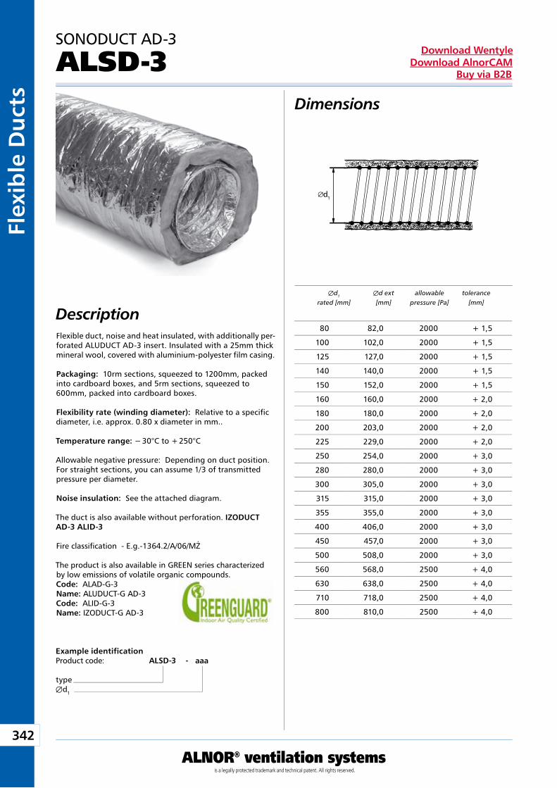
342
ALNOR® ventilation systemsis a legally protected trademark and technical patent. All rights reserved.
Flex
ible
Du
cts
Download WentyleDownload AlnorCAM
Buy via B2B
d1
Dimensions
DescriptionFlexible duct, noise and heat insulated, with additionally per-forated ALUDUCT AD-3 insert. Insulated with a 25mm thick mineral wool, covered with aluminium-polyester film casing.
Packaging: 10rm sections, squeezed to 1200mm, packed into cardboard boxes, and 5rm sections, squeezed to 600mm, packed into cardboard boxes.
Flexibility rate (winding diameter): Relative to a specific diameter, i.e. approx. 0.80 x diameter in mm..
Temperature range: − 30°C to + 250°C
Allowable negative pressure: Depending on duct position. For straight sections, you can assume 1/3 of transmitted pressure per diameter.
Noise insulation: See the attached diagram.
The duct is also available without perforation. IZODUCT AD-3 ALID-3
Fire classifi cation - E.g.-1364.2/A/06/MŻ
The product is also available in GREEN series characterized by low emissions of volatile organic compounds.Code: ALAD-G-3Name: ALUDUCT-G AD-3Code: ALID-G-3Name: IZODUCT-G AD-3
Example identificationProduct code: ALSD-3 - aaa
typeÆd1
SONODUCT AD-3
ALSD-3
Æd1 Æd ext allowable tolerance rated [mm] [mm] pressure [Pa] [mm]
80 82,0 2000 + 1,5
100 102,0 2000 + 1,5
125 127,0 2000 + 1,5
140 140,0 2000 + 1,5
150 152,0 2000 + 1,5
160 160,0 2000 + 2,0
180 180,0 2000 + 2,0
200 203,0 2000 + 2,0
225 229,0 2000 + 2,0
250 254,0 2000 + 3,0
280 280,0 2000 + 3,0
300 305,0 2000 + 3,0
315 315,0 2000 + 3,0
355 355,0 2000 + 3,0
400 406,0 2000 + 3,0
450 457,0 2000 + 3,0
500 508,0 2000 + 3,0
560 568,0 2500 + 4,0
630 638,0 2500 + 4,0
710 718,0 2500 + 4,0
800 810,0 2500 + 4,0
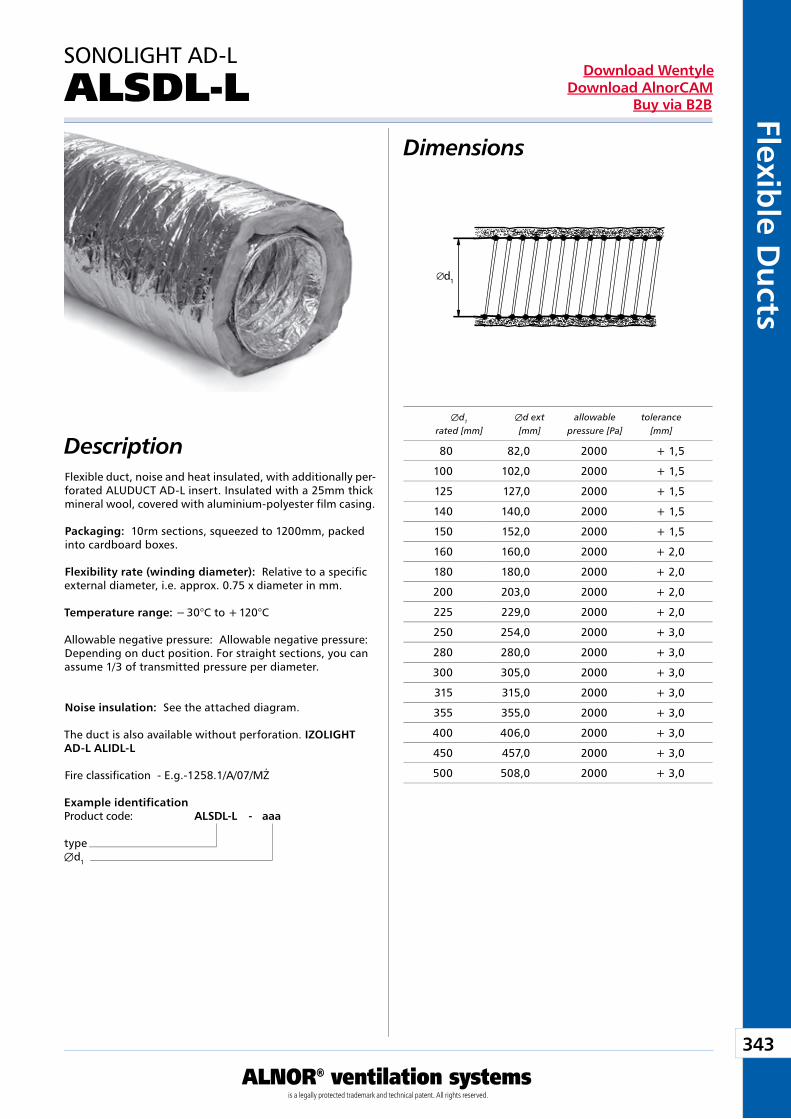
343
ALNOR® ventilation systemsis a legally protected trademark and technical patent. All rights reserved.
Flexible D
ucts
Download WentyleDownload AlnorCAM
Buy via B2B
d1
Dimensions
DescriptionFlexible duct, noise and heat insulated, with additionally per-forated ALUDUCT AD-L insert. Insulated with a 25mm thick mineral wool, covered with aluminium-polyester film casing.
Packaging: 10rm sections, squeezed to 1200mm, packed into cardboard boxes.
Flexibility rate (winding diameter): Relative to a specific external diameter, i.e. approx. 0.75 x diameter in mm.
Temperature range: − 30°C to + 120°C
Allowable negative pressure: Allowable negative pressure: Depending on duct position. For straight sections, you can assume 1/3 of transmitted pressure per diameter.
Noise insulation: See the attached diagram.
The duct is also available without perforation. IZOLIGHT AD-L ALIDL-L
Fire classifi cation - E.g.-1258.1/A/07/MŻ
Example identificationProduct code: ALSDL-L - aaa
typeÆd1
SONOLIGHT AD-L
ALSDL-L
Æd1 Æd ext allowable tolerance rated [mm] [mm] pressure [Pa] [mm]
80 82,0 2000 + 1,5
100 102,0 2000 + 1,5
125 127,0 2000 + 1,5
140 140,0 2000 + 1,5
150 152,0 2000 + 1,5
160 160,0 2000 + 2,0
180 180,0 2000 + 2,0
200 203,0 2000 + 2,0
225 229,0 2000 + 2,0
250 254,0 2000 + 3,0
280 280,0 2000 + 3,0
300 305,0 2000 + 3,0
315 315,0 2000 + 3,0
355 355,0 2000 + 3,0
400 406,0 2000 + 3,0
450 457,0 2000 + 3,0
500 508,0 2000 + 3,0
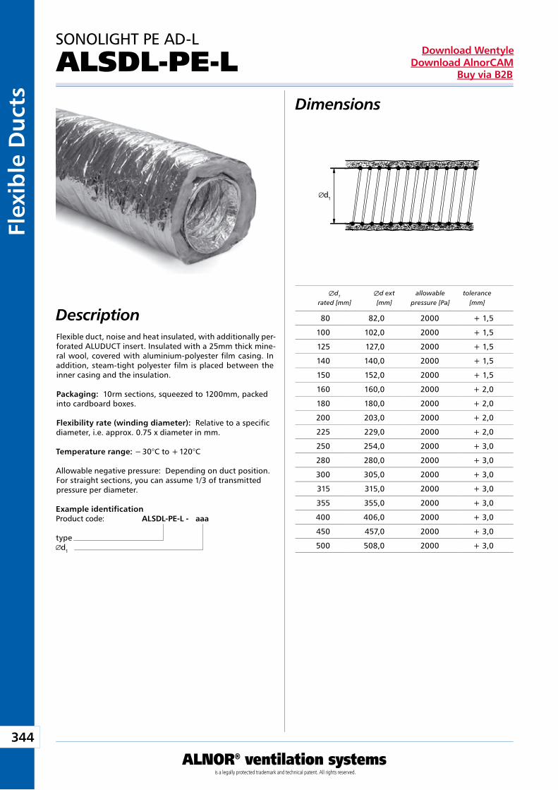
344
ALNOR® ventilation systemsis a legally protected trademark and technical patent. All rights reserved.
Flex
ible
Du
cts
Download WentyleDownload AlnorCAM
Buy via B2B
d1
Flexible duct, noise and heat insulated, with additionally per-forated ALUDUCT insert. Insulated with a 25mm thick mine-ral wool, covered with aluminium-polyester film casing. In addition, steam-tight polyester film is placed between the inner casing and the insulation.
Packaging: 10rm sections, squeezed to 1200mm, packed into cardboard boxes.
Flexibility rate (winding diameter): Relative to a specific diameter, i.e. approx. 0.75 x diameter in mm.
Temperature range: − 30°C to + 120°C
Allowable negative pressure: Depending on duct position. For straight sections, you can assume 1/3 of transmitted pressure per diameter.
Æd1 Æd ext allowable tolerance rated [mm] [mm] pressure [Pa] [mm]
Dimensions
Description
Example identificationProduct code: ALSDL-PE-L - aaa
typed1
SONOLIGHT PE AD-L
ALSDL-PE-L
80 82,0 2000 + 1,5
100 102,0 2000 + 1,5
125 127,0 2000 + 1,5
140 140,0 2000 + 1,5
150 152,0 2000 + 1,5
160 160,0 2000 + 2,0
180 180,0 2000 + 2,0
200 203,0 2000 + 2,0
225 229,0 2000 + 2,0
250 254,0 2000 + 3,0
280 280,0 2000 + 3,0
300 305,0 2000 + 3,0
315 315,0 2000 + 3,0
355 355,0 2000 + 3,0
400 406,0 2000 + 3,0
450 457,0 2000 + 3,0
500 508,0 2000 + 3,0
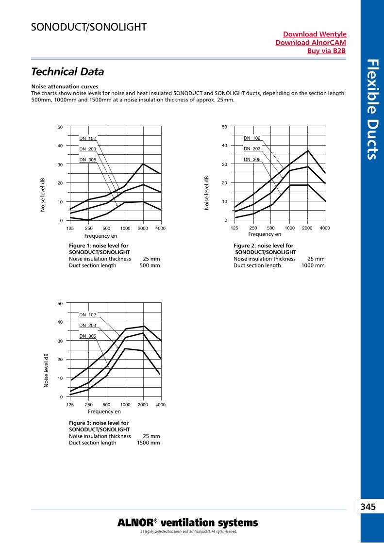
345
ALNOR® ventilation systemsis a legally protected trademark and technical patent. All rights reserved.
Flexible D
ucts
Download WentyleDownload AlnorCAM
Buy via B2B
Technical Data
SONODUCT/SONOLIGHT
Figure 1: noise level for SONODUCT/SONOLIGHT Noise insulation thickness 25 mm Duct section length 500 mm
Figure 2: noise level for SONODUCT/SONOLIGHTNoise insulation thickness 25 mm Duct section length 1000 mm
Figure 3: noise level for SONODUCT/SONOLIGHTNoise insulation thickness 25 mm Duct section length 1500 mm
Noise attenuation curvesThe charts show noise levels for noise and heat insulated SONODUCT and SONOLIGHT ducts, depending on the section length: 500mm, 1000mm and 1500mm at a noise insulation thickness of approx. 25mm.
Noi
se le
vel d
B
Frequency en
Noi
se le
vel d
B
Frequency en
Noi
se le
vel d
B
Frequency en
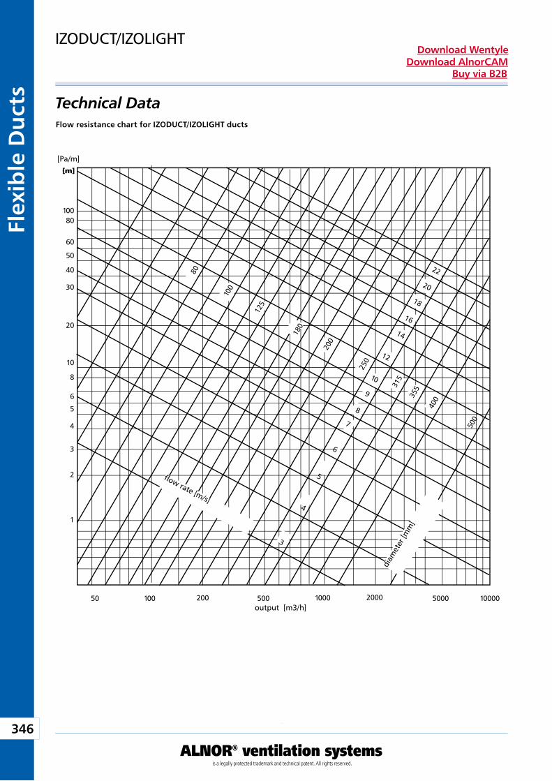
346
ALNOR® ventilation systemsis a legally protected trademark and technical patent. All rights reserved.
Flex
ible
Du
cts
Download WentyleDownload AlnorCAM
Buy via B2B
10080
60
50
40
30
20
10
8
6
5
4
3
2
1
50 100 200 500 1000 2000 5000 10000
• • • • • • • •[m]
3
4
5
6
7
8
9
10
80
100
125
180
200
250
315
355
400
500
12
14
16
18
20
22
Technical Data
IZODUCT/IZOLIGHT
Flow resistance chart for IZODUCT/IZOLIGHT ducts
[Pa/m]
output [m3/h]
flow rate [m/s]
diam
eter
[mm
]
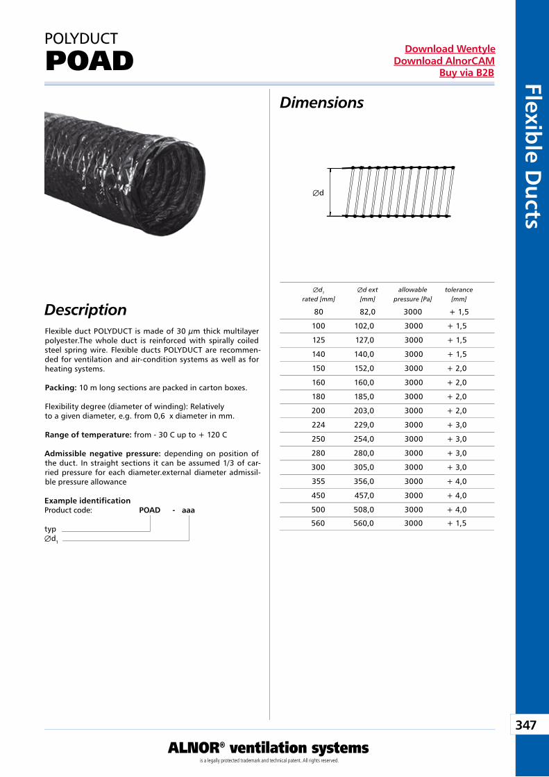
347
ALNOR® ventilation systemsis a legally protected trademark and technical patent. All rights reserved.
Flexible D
ucts
Download WentyleDownload AlnorCAM
Buy via B2B
Æd
Dimensions
Description Æd1 Æd ext allowable tolerance rated [mm] [mm] pressure [Pa] [mm]
Flexible duct POLYDUCT is made of 30 µm thick multilayer polyester.The whole duct is reinforced with spirally coiled steel spring wire. Flexible ducts POLYDUCT are recommen-ded for ventilation and air-condition systems as well as for heating systems.
Packing: 10 m long sections are packed in carton boxes.
Flexibility degree (diameter of winding): Relatively to a given diameter, e.g. from 0,6 x diameter in mm.
Range of temperature: from - 30 C up to + 120 C
Admissible negative pressure: depending on position of the duct. In straight sections it can be assumed 1/3 of car-ried pressure for each diameter.external diameter admissil-ble pressure allowance
Example identificationProduct code: POAD - aaa
typÆd1
POLYDUCT
POAD
80 82,0 3000 + 1,5
100 102,0 3000 + 1,5
125 127,0 3000 + 1,5
140 140,0 3000 + 1,5
150 152,0 3000 + 2,0
160 160,0 3000 + 2,0
180 185,0 3000 + 2,0
200 203,0 3000 + 2,0
224 229,0 3000 + 3,0
250 254,0 3000 + 3,0
280 280,0 3000 + 3,0
300 305,0 3000 + 3,0
355 356,0 3000 + 4,0
450 457,0 3000 + 4,0
500 508,0 3000 + 4,0
560 560,0 3000 + 1,5
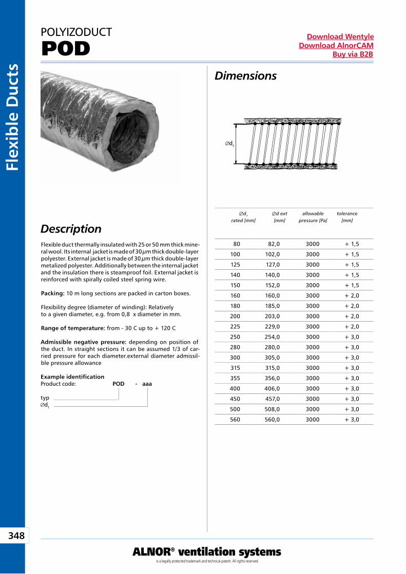
348
ALNOR® ventilation systemsis a legally protected trademark and technical patent. All rights reserved.
Flex
ible
Du
cts
Download WentyleDownload AlnorCAM
Buy via B2B
d1
Dimensions
Description Æd1 Æd ext allowable tolerance rated [mm] [mm] pressure [Pa] [mm]
Example identificationProduct code: POD - aaa
typd1
POLYIZODUCT
POD
Flexible duct thermally insulated with 25 or 50 mm thick mine-ral wool. Its internal jacket is made of 30 µm thick double-layer polyester. External jacket is made of 30 µm thick double-layer metalized polyester. Additionally between the internal jacket and the insulation there is steamproof foil. External jacket is reinforced with spirally coiled steel spring wire.
Packing: 10 m long sections are packed in carton boxes.
Flexibility degree (diameter of winding): Relatively to a given diameter, e.g. from 0,8 x diameter in mm.
Range of temperature: from - 30 C up to + 120 C
Admissible negative pressure: depending on position of the duct. In straight sections it can be assumed 1/3 of car-ried pressure for each diameter.external diameter admissil-ble pressure allowance
80 82,0 3000 + 1,5
100 102,0 3000 + 1,5
125 127,0 3000 + 1,5
140 140,0 3000 + 1,5
150 152,0 3000 + 1,5
160 160,0 3000 + 2,0
180 185,0 3000 + 2,0
200 203,0 3000 + 2,0
225 229,0 3000 + 2,0
250 254,0 3000 + 3,0
280 280,0 3000 + 3,0
300 305,0 3000 + 3,0
315 315,0 3000 + 3,0
355 356,0 3000 + 3,0
400 406,0 3000 + 3,0
450 457,0 3000 + 3,0
500 508,0 3000 + 3,0
560 560,0 3000 + 3,0
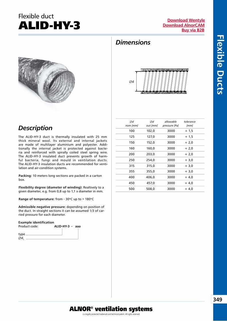
349
ALNOR® ventilation systemsis a legally protected trademark and technical patent. All rights reserved.
Flexible D
ucts
Download WentyleDownload AlnorCAM
Buy via B2B
Æd
Dimensions
Description
Example identificationProduct code: ALID-HY-3 - aaa
typeÆd1
The ALID-HY-3 duct is thermally insulated with 25 mm thick mineral wool. Its external and internal jackets are made of multilayer aluminium and polyester. Addi-tionally the internal jacket is protected against bacte-ria and reinforced with spirally coiled steel spring wire. The ALID-HY-3 insulated duct prevents growth of harm-ful bacteria, fungi and mould in ventilation ducts. The ALID-HY-3 insulation ducts are recommended for venti-lation and air-condition systems.
Packing: 10 meters long sections are packed in a carton box.
Flexibility degree (diameter of winding): Realtively to a given diameter, e.g. from 0,8 up to 1,1 x diameter in mm.
Range of temperature: from - 30oC up to + 180oC
Admissible negative pressure: depending on position of the duct. In straight sections it can be assumed 1/3 of car-ried pressure for each diameter.
Æd Æd allowable tolerance nom [mm] out [mm] pressure [Pa] [mm]
Flexible duct
ALID-HY-3
100 102,0 3000 + 1,5
125 127,0 3000 + 1,5
150 152,0 3000 + 2,0
160 160,0 3000 + 2,0
200 203,0 3000 + 2,0
250 254,0 3000 + 3,0
315 315,0 3000 + 3,0
355 355,0 3000 + 3,0
400 406,0 3000 + 4,0
450 457,0 3000 + 4,0
500 508,0 3000 + 4,0
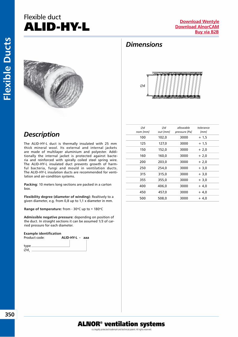
350
ALNOR® ventilation systemsis a legally protected trademark and technical patent. All rights reserved.
Flex
ible
Du
cts
Download WentyleDownload AlnorCAM
Buy via B2B
Æd
Dimensions
Description
Example identificationProduct code: ALID-HY-L - aaa
typeÆd1
The ALID-HY-L duct is thermally insulated with 25 mm thick mineral wool. Its external and internal jackets are made of multilayer aluminium and polyester. Addi-tionally the internal jacket is protected against bacte-ria and reinforced with spirally coiled steel spring wire. The ALID-HY-L insulated duct prevents growth of harm-ful bacteria, fungi and mould in ventilation ducts. The ALID-HY-L insulation ducts are recommended for venti-lation and air-condition systems.
Packing: 10 meters long sections are packed in a carton box.
Flexibility degree (diameter of winding): Realtively to a given diameter, e.g. from 0,8 up to 1,1 x diameter in mm.
Range of temperature: from - 30oC up to + 180oC
Admissible negative pressure: depending on position of the duct. In straight sections it can be assumed 1/3 of car-ried pressure for each diameter.
Æd Æd allowable tolerance nom [mm] out [mm] pressure [Pa] [mm]
Flexible duct
ALID-HY-L
100 102,0 3000 + 1,5
125 127,0 3000 + 1,5
150 152,0 3000 + 2,0
160 160,0 3000 + 2,0
200 203,0 3000 + 2,0
250 254,0 3000 + 3,0
315 315,0 3000 + 3,0
355 355,0 3000 + 3,0
400 406,0 3000 + 4,0
450 457,0 3000 + 4,0
500 508,0 3000 + 4,0
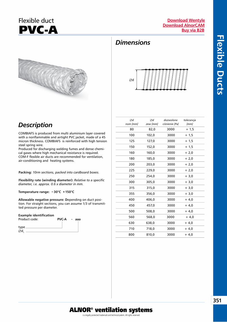
351
ALNOR® ventilation systemsis a legally protected trademark and technical patent. All rights reserved.
Flexible D
ucts
Download WentyleDownload AlnorCAM
Buy via B2B
Æd
Dimensions
DescriptionCOMBIAFS is produced from multi aluminium layer covered with a nonflammable and airtight PVC jacket, made of a 45 micron thickness. COMBIAFS is reinforced with high tension steel spring wire.Produced for discharging welding fumes and dense chemi-cal gases where high mechanical resistance is required.COM-F flexible air ducts are recommended for ventilation, air-conditioning and heating systems.
Packing: 10rm sections, packed into cardboard boxes.
Flexibility rate (winding diameter): Relative to a specificdiameter, i.e. approx. 0.6 x diameter in mm.
Temperature range: − 30°C + 150°C
Allowable negative pressure: Depending on duct posi-tion. For straight sections, you can assume 1/3 of transmit-ted pressure per diameter.
Example identificationProduct code: PVC-A - aaa
typeÆd1
Æd Æd dozwolone tolerancja nom [mm] zew [mm] ciśnienie [Pa] [mm]
Flexible duct
PVC-A
80 82,0 3000 + 1,5
100 102,0 3000 + 1,5
125 127,0 3000 + 1,5
150 152,0 3000 + 1,5
160 160,0 3000 + 2,0
180 185,0 3000 + 2,0
200 203,0 3000 + 2,0
225 229,0 3000 + 2,0
250 254,0 3000 + 3,0
300 305,0 3000 + 3,0
315 315,0 3000 + 3,0
355 356,0 3000 + 3,0
400 406,0 3000 + 4,0
450 457,0 3000 + 4,0
500 508,0 3000 + 4,0
560 568,0 3000 + 4,0
630 638,0 3000 + 4,0
710 718,0 3000 + 4,0
800 810,0 3000 + 4,0
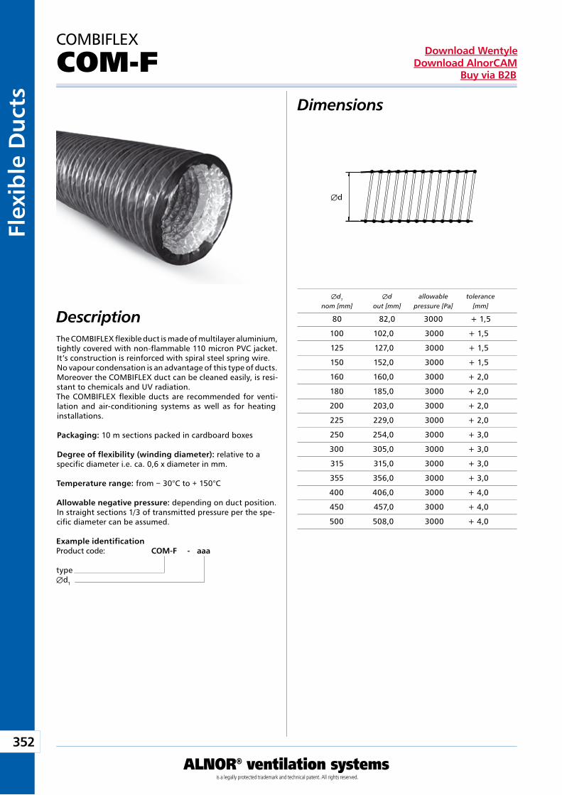
352
ALNOR® ventilation systemsis a legally protected trademark and technical patent. All rights reserved.
Flex
ible
Du
cts
Download WentyleDownload AlnorCAM
Buy via B2B
Æd
The COMBIFLEX flexible duct is made of multilayer aluminium, tightly covered with non-flammable 110 micron PVC jacket. It’s construction is reinforced with spiral steel spring wire. No vapour condensation is an advantage of this type of ducts. Moreover the COMBIFLEX duct can be cleaned easily, is resi-stant to chemicals and UV radiation. The COMBIFLEX flexible ducts are recommended for venti-lation and air-conditioning systems as well as for heating installations.
Packaging: 10 m sections packed in cardboard boxes
Degree of flexibility (winding diameter): relative to a specific diameter i.e. ca. 0,6 x diameter in mm.
Temperature range: from − 30°C to + 150°C
Allowable negative pressure: depending on duct position.In straight sections 1/3 of transmitted pressure per the spe-cific diameter can be assumed.
COMBIFLEX
COM-F
Æd1 Æd allowable tolerance nom [mm] out [mm] pressure [Pa] [mm]
80 82,0 3000 + 1,5
100 102,0 3000 + 1,5
125 127,0 3000 + 1,5
150 152,0 3000 + 1,5
160 160,0 3000 + 2,0
180 185,0 3000 + 2,0
200 203,0 3000 + 2,0
225 229,0 3000 + 2,0
250 254,0 3000 + 3,0
300 305,0 3000 + 3,0
315 315,0 3000 + 3,0
355 356,0 3000 + 3,0
400 406,0 3000 + 4,0
450 457,0 3000 + 4,0
500 508,0 3000 + 4,0
Dimensions
Description
Example identificationProduct code: COM-F - aaa
typeÆd1
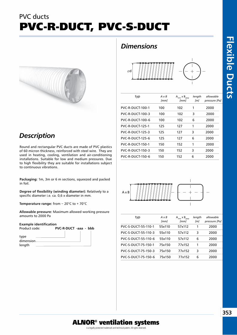
353
ALNOR® ventilation systemsis a legally protected trademark and technical patent. All rights reserved.
Flexible D
ucts
Download WentyleDownload AlnorCAM
Buy via B2B
Æd
A x B
Round and rectangular PVC ducts are made of PVC plastics of 60 micron thickness, reinforced with steel wire. They are used in heating, cooling, ventilation and air-conditioning installations. Suitable for low and medium pressures. Due to high flexibility they are suitable for installations subject to continuous vibrations.
Packaging: 1m, 3m or 6 m sections, squeezed and packed in foil.
Degree of flexibility (winding diameter): Relatively to a specific diameter i.e. ca. 0,6 x diameter in mm.
Temperature range: from − 20°C to + 70°C
Allowable pressure: Maximum allowed working pressure amounts to 2000 Pa
Example identificationProduct code: PVC-R-DUCT - aaa - bbb
typedimensionlength
PVC ducts
PVC-R-DUCT, PVC-S-DUCT
typ A x B Azew x Bzew length allowable [mm] [mm] [m] pressure [Pa]
PVC-S-DUCT-55-110-1 55x110 57x112 1 2000
PVC-S-DUCT-55-110-3 55x110 57x112 3 2000
PVC-S-DUCT-55-110-6 55x110 57x112 6 2000
PVC-S-DUCT-75-150-1 75x150 77x152 1 2000
PVC-S-DUCT-75-150-3 75x150 77x152 3 2000
PVC-S-DUCT-75-150-6 75x150 77x152 6 2000
PVC-R-DUCT-100-1 100 102 1 2000
PVC-R-DUCT-100-3 100 102 3 2000
PVC-R-DUCT-100-6 100 102 6 2000
PVC-R-DUCT-125-1 125 127 1 2000
PVC-R-DUCT-125-3 125 127 3 2000
PVC-R-DUCT-125-6 125 127 6 2000
PVC-R-DUCT-150-1 150 152 1 2000
PVC-R-DUCT-150-3 150 152 3 2000
PVC-R-DUCT-150-6 150 152 6 2000
typ A x B Azew x Bzew length allowable [mm] [mm] [m] pressure [Pa]
Dimensions
Description
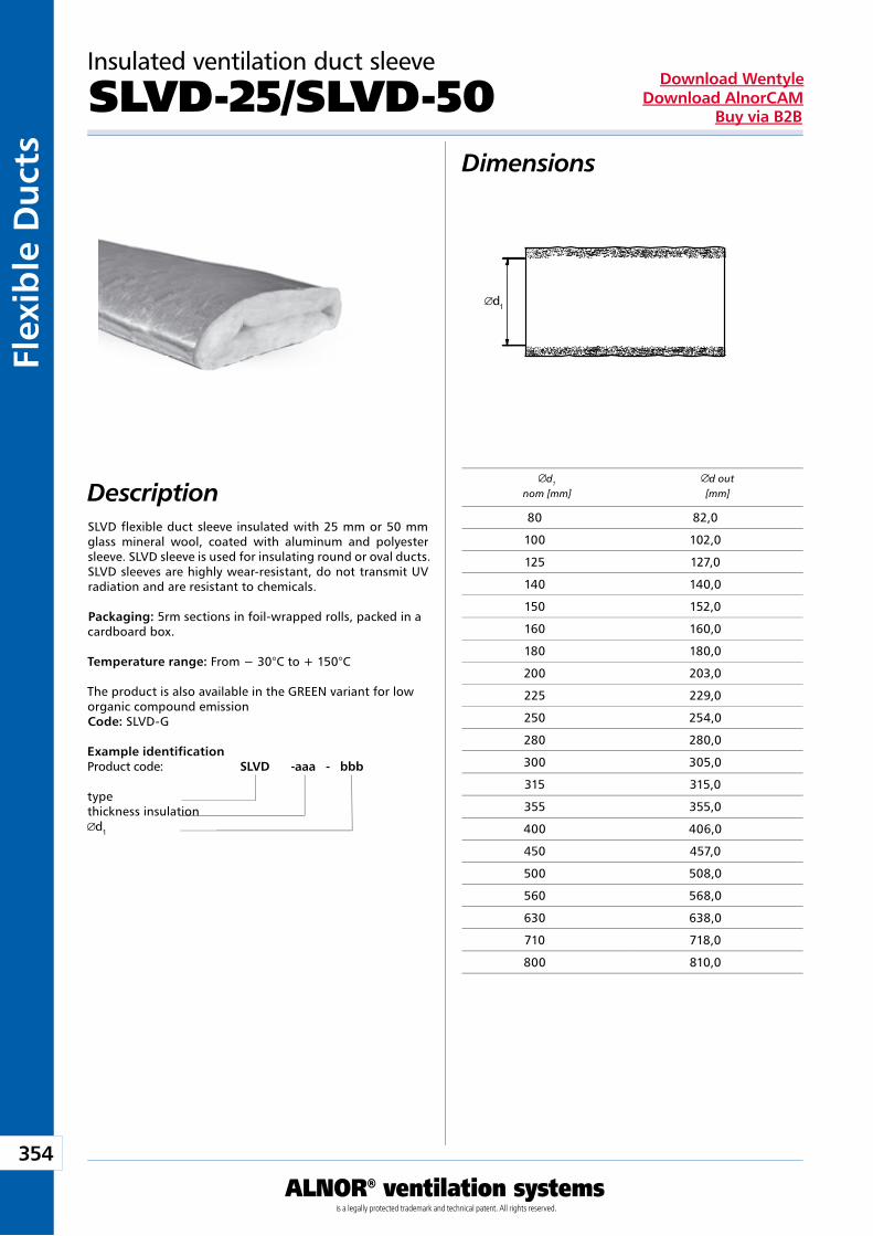
354
ALNOR® ventilation systemsis a legally protected trademark and technical patent. All rights reserved.
Flex
ible
Du
cts
Download WentyleDownload AlnorCAM
Buy via B2B
d1
Dimensions
Description
Insulated ventilation duct sleeve
SLVD-25/SLVD-50
SLVD flexible duct sleeve insulated with 25 mm or 50 mm glass mineral wool, coated with aluminum and polyester sleeve. SLVD sleeve is used for insulating round or oval ducts. SLVD sleeves are highly wear-resistant, do not transmit UV radiation and are resistant to chemicals. Packaging: 5rm sections in foil-wrapped rolls, packed in a cardboard box. Temperature range: From − 30°C to + 150°C The product is also available in the GREEN variant for low organic compound emission Code: SLVD-G
d1
nom [mm]d out
[mm]
Example identificationProduct code: SLVD - aaa - bbb
typethickness insulation
d1
80 82,0
100 102,0
125 127,0
140 140,0
150 152,0
160 160,0
180 180,0
200 203,0
225 229,0
250 254,0
280 280,0
300 305,0
315 315,0
355 355,0
400 406,0
450 457,0
500 508,0
560 568,0
630 638,0
710 718,0
800 810,0

Silencers
Producent zastrzega sobie prawo do dokonywania zmian w wymiarach i danych technicznych produktów ze względu na ciągłe ich doskonalenie
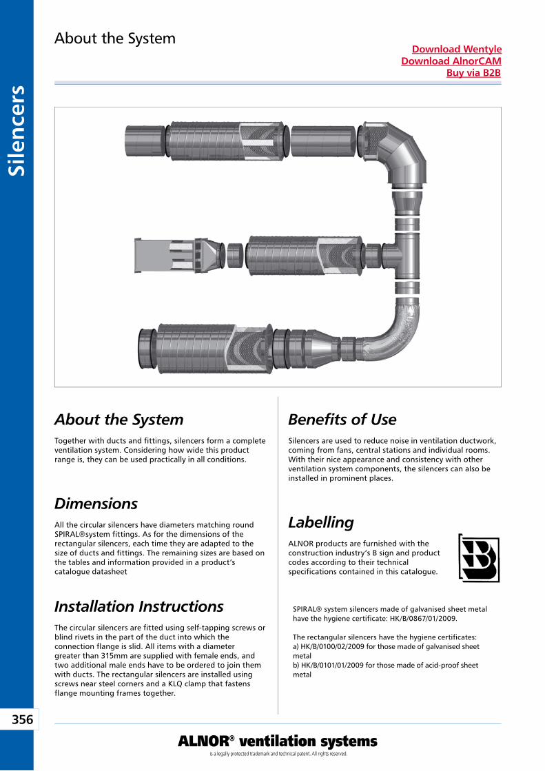
356
ALNOR® ventilation systemsis a legally protected trademark and technical patent. All rights reserved.
Sile
nce
rsDownload Wentyle
Download AlnorCAMBuy via B2B
Dimensions
About the System Benefits of UseTogether with ducts and fittings, silencers form a complete ventilation system. Considering how wide this product range is, they can be used practically in all conditions.
All the circular silencers have diameters matching round SPIRAL®system fittings. As for the dimensions of the rectangular silencers, each time they are adapted to the size of ducts and fittings. The remaining sizes are based on the tables and information provided in a product’s catalogue datasheet
Silencers are used to reduce noise in ventilation ductwork, coming from fans, central stations and individual rooms. With their nice appearance and consistency with other ventilation system components, the silencers can also be installed in prominent places.
About the System
Installation InstructionsThe circular silencers are fitted using self-tapping screws or blind rivets in the part of the duct into which the connection flange is slid. All items with a diameter greater than 315mm are supplied with female ends, and two additional male ends have to be ordered to join them with ducts. The rectangular silencers are installed using screws near steel corners and a KLQ clamp that fastens flange mounting frames together.
LabellingALNOR products are furnished with the construction industry’s B sign and product codes according to their technical specifications contained in this catalogue.
SPIRAL® system silencers made of galvanised sheet metal have the hygiene certificate: HK/B/0867/01/2009.
The rectangular silencers have the hygiene certificates:a) HK/B/0100/02/2009 for those made of galvanised sheet metalb) HK/B/0101/01/2009 for those made of acid-proof sheet metal
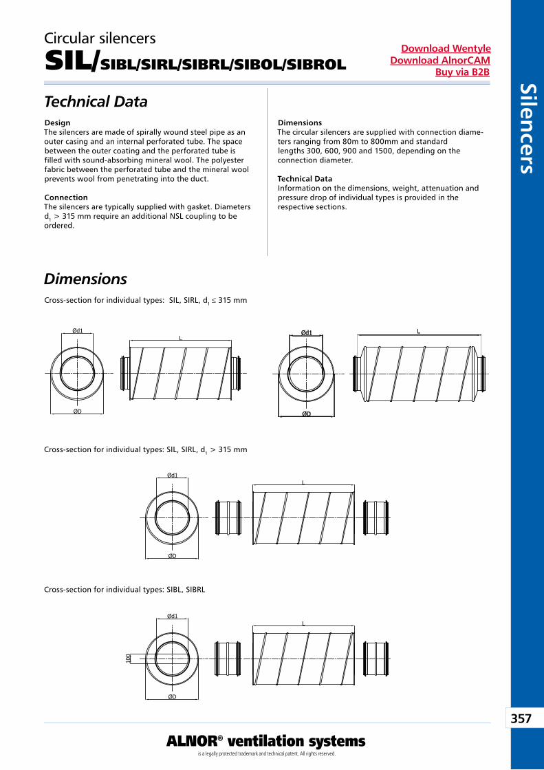
357
ALNOR® ventilation systemsis a legally protected trademark and technical patent. All rights reserved.
Silencers
Download WentyleDownload AlnorCAM
Buy via B2B
Circular silencers
SIL/SIBL/SIRL/SIBRL/SIBOL/SIBROL
Technical DataDesignThe silencers are made of spirally wound steel pipe as an outer casing and an internal perforated tube. The space between the outer coating and the perforated tube is filled with sound-absorbing mineral wool. The polyester fabric between the perforated tube and the mineral wool prevents wool from penetrating into the duct.
ConnectionThe silencers are typically supplied with gasket. Diameters d1 > 315 mm require an additional NSL coupling to be ordered.
DimensionsThe circular silencers are supplied with connection diame-ters ranging from 80m to 800mm and standard lengths 300, 600, 900 and 1500, depending on the connection diameter.
Technical DataInformation on the dimensions, weight, attenuation and pressure drop of individual types is provided in the respective sections.
Dimensions
Cross-section for individual types: SIBL, SIBRL
Cross-section for individual types: SIL, SIRL, d1 > 315 mm
Cross-section for individual types: SIL, SIRL, d1 ≤ 315 mm
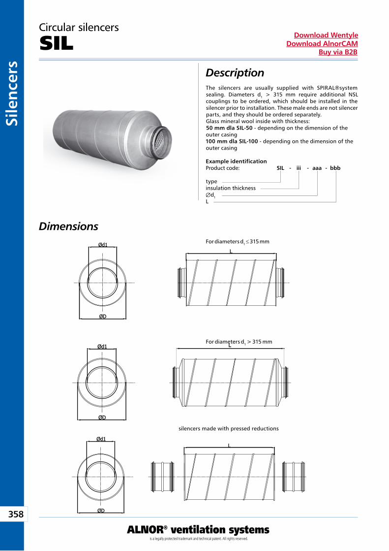
358
ALNOR® ventilation systemsis a legally protected trademark and technical patent. All rights reserved.
Sile
nce
rsDownload Wentyle
Download AlnorCAMBuy via B2B
Circular silencers
SILDescriptionThe silencers are usually supplied with SPIRAL®system sealing. Diameters d1 > 315 mm require additional NSL couplings to be ordered, which should be installed in the silencer prior to installation. These male ends are not silencer parts, and they should be ordered separately.Glass mineral wool inside with thickness:50 mm dla SIL-50 - depending on the dimension of the outer casing100 mm dla SIL-100 - depending on the dimension of the outer casing
Example identificationProduct code: SIL - iii - aaa - bbb
typeinsulation thickness Æd1L
Dimensions For diameters d1 ≤ 315 mm
For diameters d1 > 315 mm
silencers made with pressed reductions
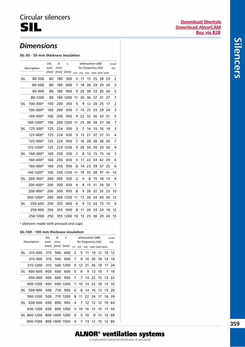
359
ALNOR® ventilation systemsis a legally protected trademark and technical patent. All rights reserved.
Silencers
Download WentyleDownload AlnorCAM
Buy via B2B
Circular silencers
SILDimensions SIL-50 - 50 mm thickness insulation
SIL-100 - 100 mm thickness insulation
Description
d1
nom [mm]
Dnom [mm]
L
[mm]
attenuation [dB]for frequency [Hz]
weight
[kg]
125 250 500 1000 2000 4000
Descriptiond1
nom [mm]
Dnom [mm]
L
[mm]
attenuation [dB]for frequency [Hz]
weight
[kg]
125 250 500 1000 2000 4000
* silencers made with pressed end cups
SIL 80-300 80 180 300 5 11 15 25 28 23 2
80-600 80 180 600 7 18 26 29 29 24 3
80-900 80 180 900 9 26 38 33 30 26 5
80-1200 80 180 1200 11 30 36 37 31 27 7
SIL 100-300* 100 200 350 5 9 12 20 25 17 2
100-600* 100 200 650 7 15 25 33 29 24 3
100-900* 100 200 950 9 22 32 36 33 31 5
100-1200* 100 200 1200 11 25 36 39 37 38 7
SIL 125-300* 125 224 350 3 7 14 19 16 19 3
125-600* 125 224 650 5 13 21 37 37 31 4
125-900* 125 224 950 7 16 28 38 38 35 7
125-1200* 125 224 1250 9 20 34 39 39 36 9
SIL 160-300* 160 250 350 2 8 12 15 15 14 3
160-600* 160 250 650 3 11 22 33 42 29 6
160-900* 160 250 950 8 14 23 39 37 25 8
160-1200* 160 250 1250 11 19 35 38 47 41 10
SIL 200-300* 200 300 350 2 4 8 15 18 13 4
200-600* 200 300 650 4 8 15 31 28 20 7
200-900* 200 300 950 8 9 20 32 35 23 10
200-1200* 200 300 1250 11 17 26 34 40 26 12
SIL 250-600 250 355 600 6 9 13 24 15 15 9
250-900 250 355 900 8 11 20 33 24 18 12
250-1200 250 355 1200 10 13 25 38 29 24 15
SIL 315-600 315 500 600 5 5 11 19 12 10 12
315-900 315 500 900 7 9 16 30 18 14 18
315-1200 315 500 1200 9 12 21 36 18 17 24
SIL 400-600 400 600 600 5 6 9 13 10 7 16
400-900 400 600 900 7 7 14 22 15 13 22
400-1200 400 600 1200 7 10 14 22 18 13 32
SIL 500-900 500 710 900 6 8 14 16 13 13 26
500-1200 500 710 1200 8 11 22 24 17 16 39
SIL 630-900 630 800 900 4 7 12 12 12 10 44
630-1200 630 800 1200 5 10 16 15 15 11 56
SIL 800-1200 800 1000 1200 4 5 10 9 15 12 69
800-1500 800 1000 1500 4 7 13 12 15 12 86
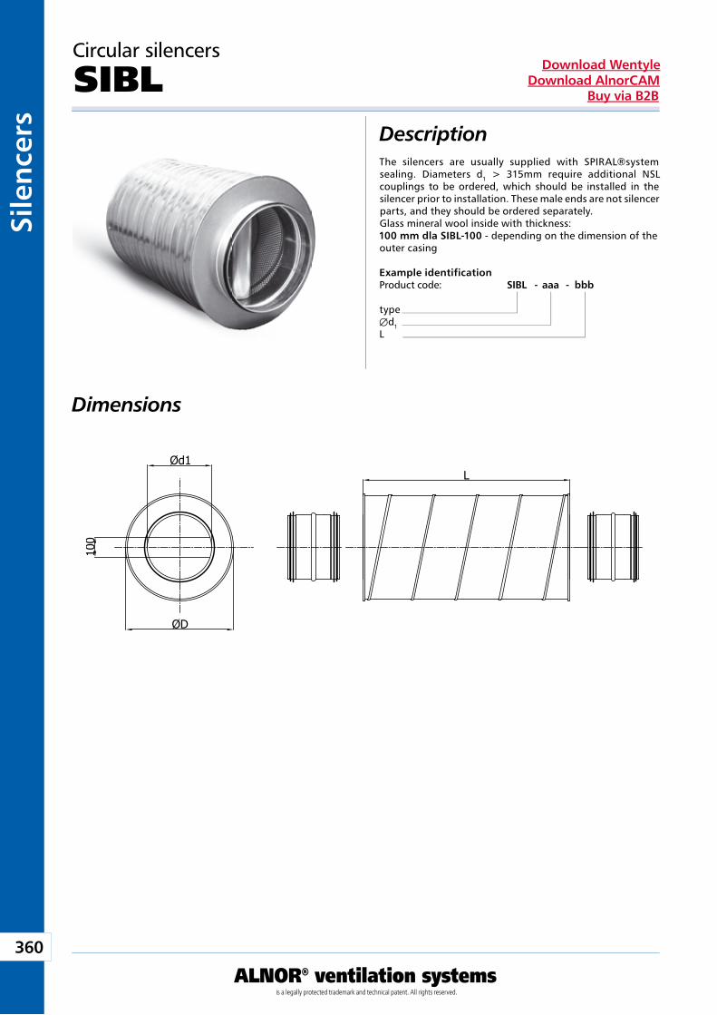
360
ALNOR® ventilation systemsis a legally protected trademark and technical patent. All rights reserved.
Sile
nce
rsDownload Wentyle
Download AlnorCAMBuy via B2B
Circular silencers
SIBLDescription
Dimensions
The silencers are usually supplied with SPIRAL®system sealing. Diameters d1 > 315mm require additional NSL couplings to be ordered, which should be installed in the silencer prior to installation. These male ends are not silencer parts, and they should be ordered separately.Glass mineral wool inside with thickness:100 mm dla SIBL-100 - depending on the dimension of the outer casing
Example identificationProduct code: SIBL - aaa - bbb
typeÆd1L
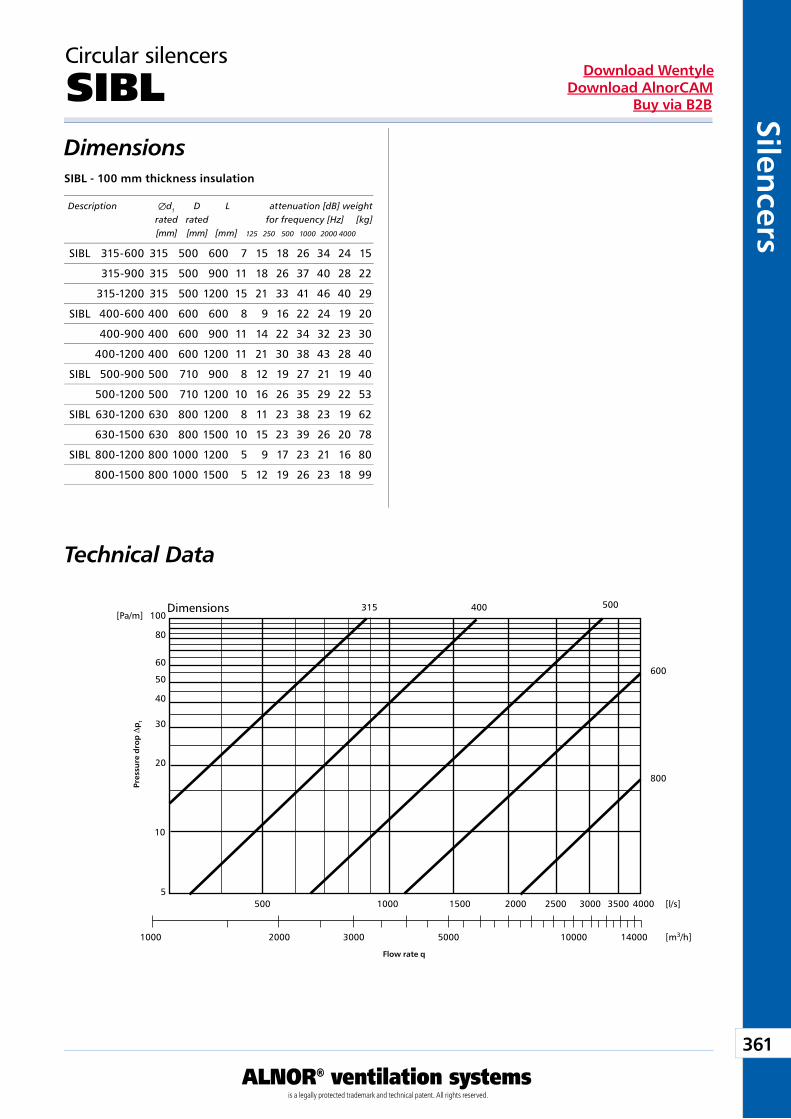
361
ALNOR® ventilation systemsis a legally protected trademark and technical patent. All rights reserved.
Silencers
Download WentyleDownload AlnorCAM
Buy via B2B
100[Pa/m]315 500
600
800
80
60
50
40
30
20
10
5
1000 2000
500 1000 1500 2000 2500 3000 3500 4000 [l/s]
[m3/h]3000 5000 10000 14000
400
Circular silencers
SIBLDimensions
Technical Data
SIBL - 100 mm thickness insulation
Pres
sure
dro
p D
pt
Flow rate q
Description Æd1 D L attenuation [dB] weight rated rated for frequency [Hz] [kg] [mm] [mm] [mm] 125 250 500 1000 2000 4000
Dimensions
SIBL 315-600 315 500 600 7 15 18 26 34 24 15
315-900 315 500 900 11 18 26 37 40 28 22
315-1200 315 500 1200 15 21 33 41 46 40 29
SIBL 400-600 400 600 600 8 9 16 22 24 19 20
400-900 400 600 900 11 14 22 34 32 23 30
400-1200 400 600 1200 11 21 30 38 43 28 40
SIBL 500-900 500 710 900 8 12 19 27 21 19 40
500-1200 500 710 1200 10 16 26 35 29 22 53
SIBL 630-1200 630 800 1200 8 11 23 38 23 19 62
630-1500 630 800 1500 10 15 23 39 26 20 78
SIBL 800-1200 800 1000 1200 5 9 17 23 21 16 80
800-1500 800 1000 1500 5 12 19 26 23 18 99
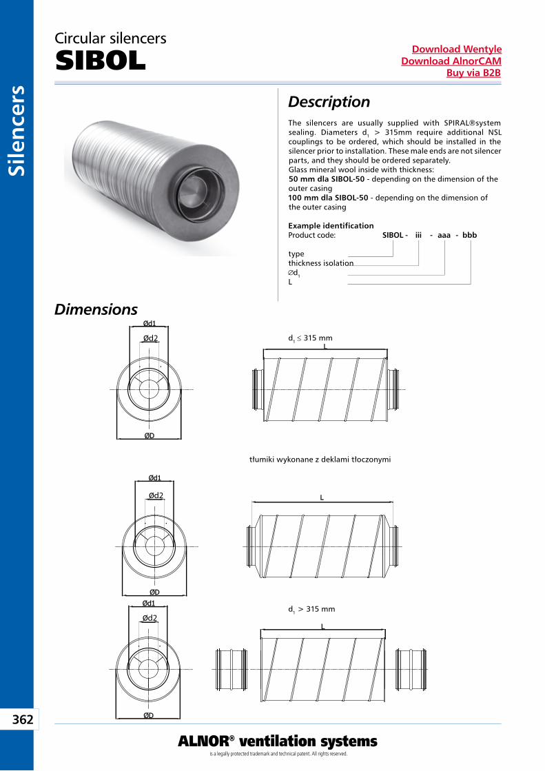
362
ALNOR® ventilation systemsis a legally protected trademark and technical patent. All rights reserved.
Sile
nce
rsDownload Wentyle
Download AlnorCAMBuy via B2B
d2
d2
d2
The silencers are usually supplied with SPIRAL®system sealing. Diameters d1 > 315mm require additional NSL couplings to be ordered, which should be installed in the silencer prior to installation. These male ends are not silencer parts, and they should be ordered separately.Glass mineral wool inside with thickness:50 mm dla SIBOL-50 - depending on the dimension of the outer casing100 mm dla SIBOL-50 - depending on the dimension of the outer casing
Circular silencers
SIBOLDescription
Example identificationProduct code: SIBOL - iii - aaa - bbb
typethickness isolation
d1L
Dimensions
d1 ≤ 315 mm
d1 > 315 mm
tłumiki wykonane z deklami tłoczonymi
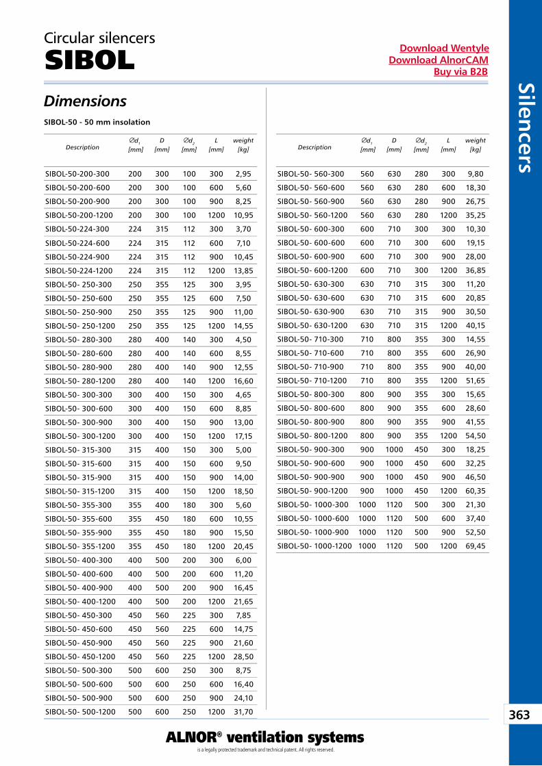
363
ALNOR® ventilation systemsis a legally protected trademark and technical patent. All rights reserved.
Silencers
Download WentyleDownload AlnorCAM
Buy via B2B
Circular silencers
SIBOLDimensionsSIBOL-50 - 50 mm insolation
Descriptiond1
[mm]D
[mm]d2
[mm]L
[mm]weight
[kg] Descriptiond1
[mm]D
[mm]d2
[mm]L
[mm]weight
[kg]
SIBOL-50-200-300 200 300 100 300 2,95
SIBOL-50-200-600 200 300 100 600 5,60
SIBOL-50-200-900 200 300 100 900 8,25
SIBOL-50-200-1200 200 300 100 1200 10,95
SIBOL-50-224-300 224 315 112 300 3,70
SIBOL-50-224-600 224 315 112 600 7,10
SIBOL-50-224-900 224 315 112 900 10,45
SIBOL-50-224-1200 224 315 112 1200 13,85
SIBOL-50- 250-300 250 355 125 300 3,95
SIBOL-50- 250-600 250 355 125 600 7,50
SIBOL-50- 250-900 250 355 125 900 11,00
SIBOL-50- 250-1200 250 355 125 1200 14,55
SIBOL-50- 280-300 280 400 140 300 4,50
SIBOL-50- 280-600 280 400 140 600 8,55
SIBOL-50- 280-900 280 400 140 900 12,55
SIBOL-50- 280-1200 280 400 140 1200 16,60
SIBOL-50- 300-300 300 400 150 300 4,65
SIBOL-50- 300-600 300 400 150 600 8,85
SIBOL-50- 300-900 300 400 150 900 13,00
SIBOL-50- 300-1200 300 400 150 1200 17,15
SIBOL-50- 315-300 315 400 150 300 5,00
SIBOL-50- 315-600 315 400 150 600 9,50
SIBOL-50- 315-900 315 400 150 900 14,00
SIBOL-50- 315-1200 315 400 150 1200 18,50
SIBOL-50- 355-300 355 400 180 300 5,60
SIBOL-50- 355-600 355 450 180 600 10,55
SIBOL-50- 355-900 355 450 180 900 15,50
SIBOL-50- 355-1200 355 450 180 1200 20,45
SIBOL-50- 400-300 400 500 200 300 6,00
SIBOL-50- 400-600 400 500 200 600 11,20
SIBOL-50- 400-900 400 500 200 900 16,45
SIBOL-50- 400-1200 400 500 200 1200 21,65
SIBOL-50- 450-300 450 560 225 300 7,85
SIBOL-50- 450-600 450 560 225 600 14,75
SIBOL-50- 450-900 450 560 225 900 21,60
SIBOL-50- 450-1200 450 560 225 1200 28,50
SIBOL-50- 500-300 500 600 250 300 8,75
SIBOL-50- 500-600 500 600 250 600 16,40
SIBOL-50- 500-900 500 600 250 900 24,10
SIBOL-50- 500-1200 500 600 250 1200 31,70
SIBOL-50- 560-300 560 630 280 300 9,80
SIBOL-50- 560-600 560 630 280 600 18,30
SIBOL-50- 560-900 560 630 280 900 26,75
SIBOL-50- 560-1200 560 630 280 1200 35,25
SIBOL-50- 600-300 600 710 300 300 10,30
SIBOL-50- 600-600 600 710 300 600 19,15
SIBOL-50- 600-900 600 710 300 900 28,00
SIBOL-50- 600-1200 600 710 300 1200 36,85
SIBOL-50- 630-300 630 710 315 300 11,20
SIBOL-50- 630-600 630 710 315 600 20,85
SIBOL-50- 630-900 630 710 315 900 30,50
SIBOL-50- 630-1200 630 710 315 1200 40,15
SIBOL-50- 710-300 710 800 355 300 14,55
SIBOL-50- 710-600 710 800 355 600 26,90
SIBOL-50- 710-900 710 800 355 900 40,00
SIBOL-50- 710-1200 710 800 355 1200 51,65
SIBOL-50- 800-300 800 900 355 300 15,65
SIBOL-50- 800-600 800 900 355 600 28,60
SIBOL-50- 800-900 800 900 355 900 41,55
SIBOL-50- 800-1200 800 900 355 1200 54,50
SIBOL-50- 900-300 900 1000 450 300 18,25
SIBOL-50- 900-600 900 1000 450 600 32,25
SIBOL-50- 900-900 900 1000 450 900 46,50
SIBOL-50- 900-1200 900 1000 450 1200 60,35
SIBOL-50- 1000-300 1000 1120 500 300 21,30
SIBOL-50- 1000-600 1000 1120 500 600 37,40
SIBOL-50- 1000-900 1000 1120 500 900 52,50
SIBOL-50- 1000-1200 1000 1120 500 1200 69,45
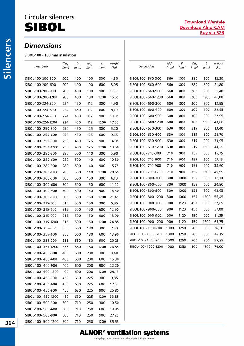
364
ALNOR® ventilation systemsis a legally protected trademark and technical patent. All rights reserved.
Sile
nce
rsDownload Wentyle
Download AlnorCAMBuy via B2B
Circular silencers
SIBOLDimensionsSIBOL-100 - 100 mm insulation
Descriptiond1
[mm]D
[mm]d2
[mm]L
[mm]weight
[kg] Descriptiond1
[mm]D
[mm]d2
[mm]L
[mm]weight
[kg]
SIBOL-100-200-300 200 400 100 300 4,30
SIBOL-100-200-600 200 400 100 600 8,05
SIBOL-100-200-900 200 400 100 900 11,80
SIBOL-100-200-1200 200 400 100 1200 15,55
SIBOL-100-224-300 224 450 112 300 4,90
SIBOL-100-224-600 224 450 112 600 9,10
SIBOL-100-224-900 224 450 112 900 13,35
SIBOL-100-224-1200 224 450 112 1200 17,55
SIBOL-100- 250-300 250 450 125 300 5,20
SIBOL-100- 250-600 250 450 125 600 9,65
SIBOL-100- 250-900 250 450 125 900 14,05
SIBOL-100- 250-1200 250 450 125 1200 18,50
SIBOL-100- 280-300 280 500 140 300 5,90
SIBOL-100- 280-600 280 500 140 600 10,80
SIBOL-100- 280-900 280 500 140 900 15,75
SIBOL-100- 280-1200 280 500 140 1200 20,65
SIBOL-100- 300-300 300 500 150 300 6,10
SIBOL-100- 300-600 300 500 150 600 11,20
SIBOL-100- 300-900 300 500 150 900 16,30
SIBOL-100- 300-1200 300 500 150 1200 21,45
SIBOL-100- 315-300 315 500 150 300 6,95
SIBOL-100- 315-600 315 500 150 600 12,90
SIBOL-100- 315-900 315 500 150 900 18,90
SIBOL-100- 315-1200 315 500 150 1200 24,85
SIBOL-100- 355-300 355 560 180 300 7,60
SIBOL-100- 355-600 355 560 180 600 13,90
SIBOL-100- 355-900 355 560 180 900 20,25
SIBOL-100- 355-1200 355 560 180 1200 26,55
SIBOL-100- 400-300 400 600 200 300 8,40
SIBOL-100- 400-600 400 600 200 600 15,30
SIBOL-100- 400-900 400 600 200 900 22,20
SIBOL-100- 400-1200 400 600 200 1200 29,15
SIBOL-100- 450-300 450 630 225 300 9,85
SIBOL-100- 450-600 450 630 225 600 17,85
SIBOL-100- 450-900 450 630 225 900 25,85
SIBOL-100- 450-1200 450 630 225 1200 33,85
SIBOL-100- 500-300 500 710 250 300 10,50
SIBOL-100- 500-600 500 710 250 600 18,85
SIBOL-100- 500-900 500 710 250 900 27,25
SIBOL-100- 500-1200 500 710 250 1200 35,55
SIBOL-100- 560-300 560 800 280 300 12,20
SIBOL-100- 560-600 560 800 280 600 21,80
SIBOL-100- 560-900 560 800 280 900 31,40
SIBOL-100- 560-1200 560 800 280 1200 41,00
SIBOL-100- 600-300 600 800 300 300 12,95
SIBOL-100- 600-600 600 800 300 600 22,95
SIBOL-100- 600-900 600 800 300 900 32,95
SIBOL-100- 600-1200 600 800 300 1200 43,00
SIBOL-100- 630-300 630 800 315 300 13,40
SIBOL-100- 630-600 630 800 315 600 23,70
SIBOL-100- 630-900 630 800 315 900 33,95
SIBOL-100- 630-1200 630 800 315 1200 44,25
SIBOL-100- 710-300 710 900 355 300 15,75
SIBOL-100- 710-600 710 900 355 600 27,15
SIBOL-100- 710-900 710 900 355 900 38,60
SIBOL-100- 710-1200 710 900 355 1200 49,95
SIBOL-100- 800-300 800 1000 355 300 18,10
SIBOL-100- 800-600 800 1000 355 600 30,90
SIBOL-100- 800-900 800 1000 355 900 43,65
SIBOL-100- 800-1200 800 1000 355 1200 56,45
SIBOL-100- 900-300 900 1120 450 300 22,65
SIBOL-100- 900-600 900 1120 450 600 37,00
SIBOL-100- 900-900 900 1120 450 900 51,35
SIBOL-100- 900-1200 900 1120 450 1200 65,75
SIBOL-100- 1000-300 1000 1250 500 300 26,30
SIBOL-100- 1000-600 1000 1250 500 600 42,15
SIBOL-100- 1000-900 1000 1250 500 900 55,85
SIBOL-100- 1000-1200 1000 1250 500 1200 74,00
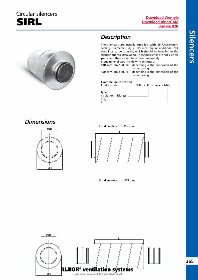
365
ALNOR® ventilation systemsis a legally protected trademark and technical patent. All rights reserved.
Silencers
Download WentyleDownload AlnorCAM
Buy via B2B
Circular silencers
SIRLDescription
Dimensions
The silencers are usually supplied with SPIRAL®system sealing. Diameters d1 > 315 mm require additional NSL couplings to be ordered, which should be installed in the silencer prior to installation. These male ends are not silencer parts, and they should be ordered separately.Stone mineral wool inside with thickness:100 mm dla SIRL-10 – depending o the dimension of the
outer casing.150 mm dla SIRL-15 – depending o the dimension of the
outer casing.
Example identificationProduct code: SIRL - iii - aaa - bbb
typeinsulation thickness Æd1L
For diameters d1 ≤ 315 mm
For diameters d1 > 315 mm
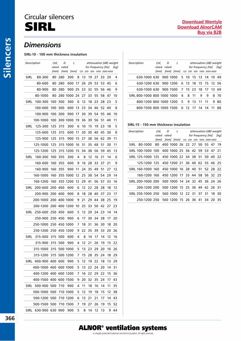
366
ALNOR® ventilation systemsis a legally protected trademark and technical patent. All rights reserved.
Sile
nce
rsDownload Wentyle
Download AlnorCAMBuy via B2B
Circular silencers
SIRLDimensions
SIRL-15 - 150 mm thickness insulation
SIRL-10 - 100 mm thickness insulation
Description Æd1 D L attenuation [dB] weight rated rated for frequency [Hz] [kg] [mm] [mm] [mm] 125 250 500 1000 2000 4000
Description Æd1 D L attenuation [dB] weight rated rated for frequency [Hz] [kg] [mm] [mm] [mm] 125 250 500 1000 2000 4000
Description Æd1 D L attenuation [dB] weight rated rated for frequency [Hz] [kg] [mm] [mm] [mm] 125 250 500 1000 2000 4000
SIRL 80-300 80 280 300 8 13 19 27 33 29 4
80-600 80 280 600 17 26 29 53 53 45 6
80-900 80 280 900 25 23 32 55 56 46 9
80-1000 80 280 1000 24 27 33 55 58 47 10
SIRL 100-300 100 300 300 6 12 18 23 28 23 5
100-600 100 300 600 13 23 34 46 52 40 8
100-900 100 300 900 17 30 39 54 55 46 10
100-1000 100 300 1000 19 36 39 56 51 40 11
SIRL 125-300 125 315 300 6 10 15 19 23 18 5
125-600 125 315 600 11 20 30 40 45 30 8
125-900 125 315 900 15 27 38 56 62 39 11
125-1000 125 315 1000 16 31 35 48 51 30 11
125-1200 125 315 1200 15 34 38 56 59 45 13
SIRL 160-300 160 355 300 4 8 12 16 21 14 6
160-600 160 355 600 9 16 28 33 37 21 9
160-900 160 355 900 11 24 35 49 51 27 12
160-1000 160 355 1000 12 25 38 54 54 29 14
160-1200 160 355 1200 12 29 41 56 57 33 16
SIRL 200-600 200 400 600 6 12 22 28 28 18 12
200-900 200 400 900 8 18 28 40 37 23 17
200-1000 200 400 1000 9 21 29 44 38 25 19
200-1200 200 400 1200 10 25 33 50 42 27 23
SIRL 250-600 250 450 600 5 12 20 24 23 14 14
250-900 250 450 900 6 17 30 34 28 17 20
250-1000 250 450 1000 7 18 31 36 30 18 20
250-1200 250 450 1200 9 22 35 39 33 20 26
SIRL 315-600 315 500 600 4 8 14 17 14 12 16
315-900 315 500 900 4 12 21 26 19 15 22
315-1000 315 500 1000 5 13 23 29 20 16 26
315-1200 315 500 1200 7 15 28 35 24 18 29
SIRL 400-900 400 600 900 5 12 19 22 18 13 29
400-1000 400 600 1000 5 13 22 24 20 14 31
400-1200 400 600 1200 7 16 22 29 22 15 36
400-1500 400 600 1500 9 20 32 35 24 17 43
SIRL 500-900 500 710 900 4 11 18 16 14 11 35
500-1000 500 710 1000 5 12 19 18 15 12 38
500-1200 500 710 1200 6 13 21 21 17 14 43
500-1500 500 710 1500 7 19 27 26 19 15 52
SIRL 630-900 630 900 900 5 8 14 12 13 9 44
630-1000 630 900 1000 5 10 15 13 14 10 49
630-1200 630 900 1200 6 13 18 15 15 12 56
630-1500 630 900 1500 7 15 23 18 17 13 69
SIRL 800-1000 800 1000 1000 4 8 11 9 9 8 70
800-1200 800 1000 1200 5 9 13 11 11 9 80
800-1500 800 1000 1500 6 12 17 14 14 11 88
SIRL 80-1000 80 400 1000 26 22 27 50 55 47 19
SIRL 100-1000 100 400 1000 25 36 42 59 53 47 21
SIRL 125-1000 125 450 1000 22 34 38 51 50 40 22
125-1200 125 450 1200 21 36 40 62 55 46 25
SIRL 160-1000 160 450 1000 16 28 40 51 52 28 22
160-1200 160 450 1200 17 33 44 58 56 32 25
SIRL 200-1000 200 500 1000 14 24 32 45 36 24 26
200-1200 200 500 1200 15 25 36 49 42 26 31
SIRL 250-1000 250 560 1000 12 22 31 37 31 18 30
250-1200 250 560 1200 15 26 36 41 34 20 35
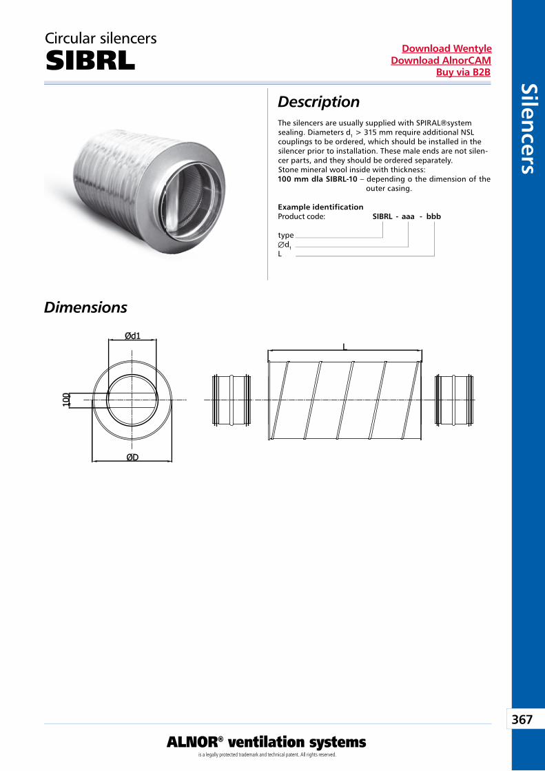
367
ALNOR® ventilation systemsis a legally protected trademark and technical patent. All rights reserved.
Silencers
Download WentyleDownload AlnorCAM
Buy via B2B
Circular silencers
SIBRLDescription
Dimensions
The silencers are usually supplied with SPIRAL®system sealing. Diameters d1 > 315 mm require additional NSL couplings to be ordered, which should be installed in the silencer prior to installation. These male ends are not silen-cer parts, and they should be ordered separately.Stone mineral wool inside with thickness:100 mm dla SIBRL-10 – depending o the dimension of the
outer casing.
Example identificationProduct code: SIBRL - aaa - bbb
typeÆd1L
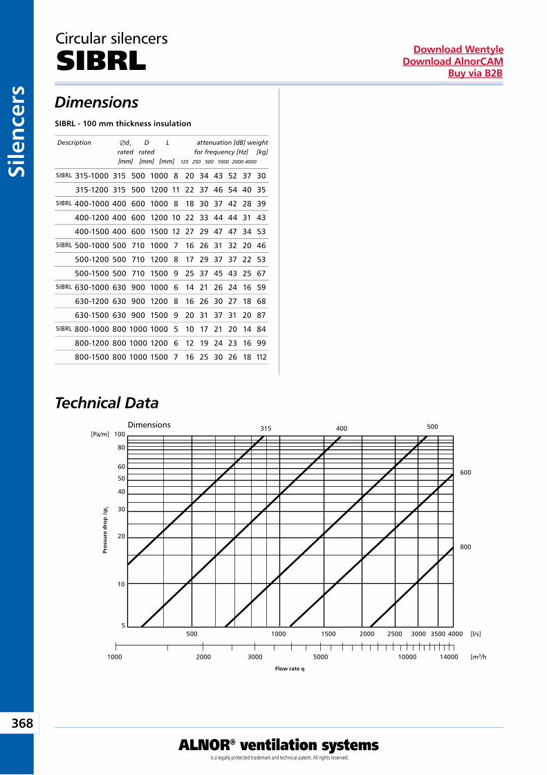
368
ALNOR® ventilation systemsis a legally protected trademark and technical patent. All rights reserved.
Sile
nce
rsDownload Wentyle
Download AlnorCAMBuy via B2B
100[Pa/m]315 500
600
800
80
60
50
40
30
20
10
5
1000 2000
500 1000 1500 2000 2500 3000 3500 4000 [l/s]
[m3/h]3000 5000 10000 14000
400
Circular silencers
SIBRLDimensions
Technical Data
SIBRL - 100 mm thickness insulation
Pres
sure
dro
p D
pt
Flow rate q
Description Æd1 D L attenuation [dB] weight rated rated for frequency [Hz] [kg] [mm] [mm] [mm] 125 250 500 1000 2000 4000
Dimensions
SIBRL 315-1000 315 500 1000 8 20 34 43 52 37 30
315-1200 315 500 1200 11 22 37 46 54 40 35
SIBRL 400-1000 400 600 1000 8 18 30 37 42 28 39
400-1200 400 600 1200 10 22 33 44 44 31 43
400-1500 400 600 1500 12 27 29 47 47 34 53
SIBRL 500-1000 500 710 1000 7 16 26 31 32 20 46
500-1200 500 710 1200 8 17 29 37 37 22 53
500-1500 500 710 1500 9 25 37 45 43 25 67
SIBRL 630-1000 630 900 1000 6 14 21 26 24 16 59
630-1200 630 900 1200 8 16 26 30 27 18 68
630-1500 630 900 1500 9 20 31 37 31 20 87
SIBRL 800-1000 800 1000 1000 5 10 17 21 20 14 84
800-1200 800 1000 1200 6 12 19 24 23 16 99
800-1500 800 1000 1500 7 16 25 30 26 18 112
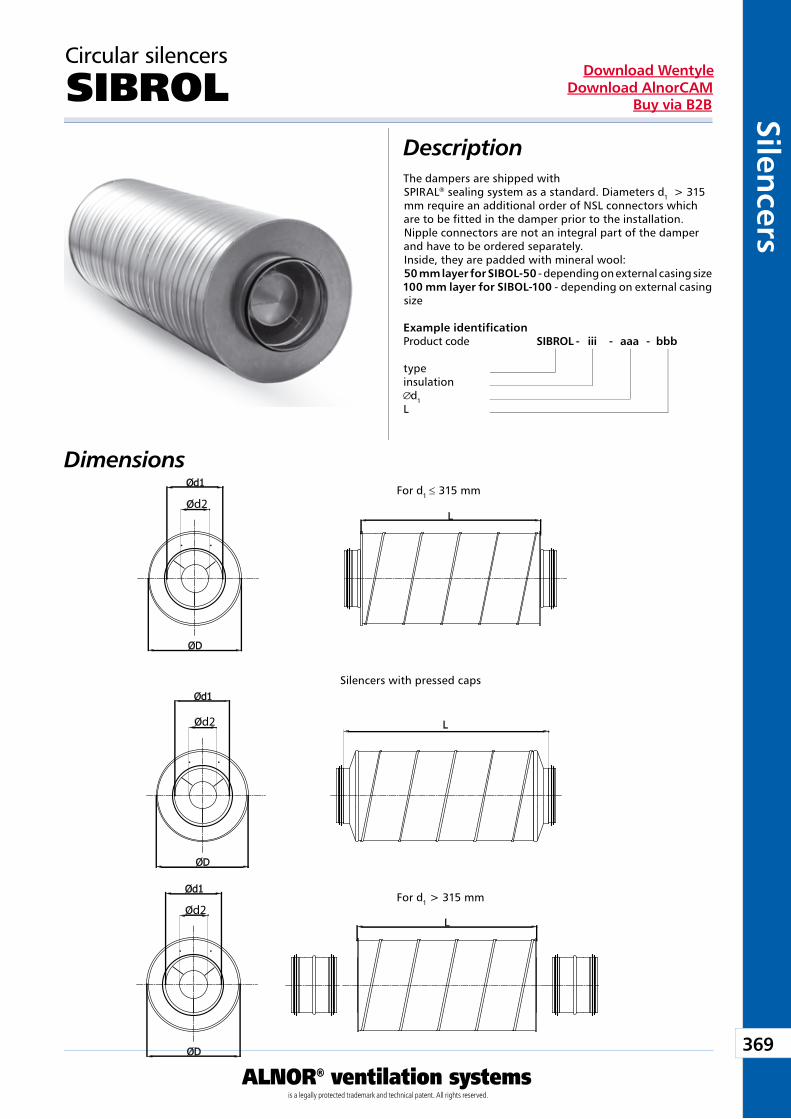
369
ALNOR® ventilation systemsis a legally protected trademark and technical patent. All rights reserved.
Silencers
Download WentyleDownload AlnorCAM
Buy via B2B
d2
d2
d2
Circular silencers
SIBROLDescription
Dimensions
The dampers are shipped with SPIRAL® sealing system as a standard. Diameters d1 > 315 mm require an additional order of NSL connectors which are to be fitted in the damper prior to the installation. Nipple connectors are not an integral part of the damper and have to be ordered separately. Inside, they are padded with mineral wool: 50 mm layer for SIBOL-50 - depending on external casing size 100 mm layer for SIBOL-100 - depending on external casing size
Example identificationProduct code SIBROL - iii - aaa - bbb
typeinsulation
d1L
For d1 ≤ 315 mm
For d1 > 315 mm
Silencers with pressed caps
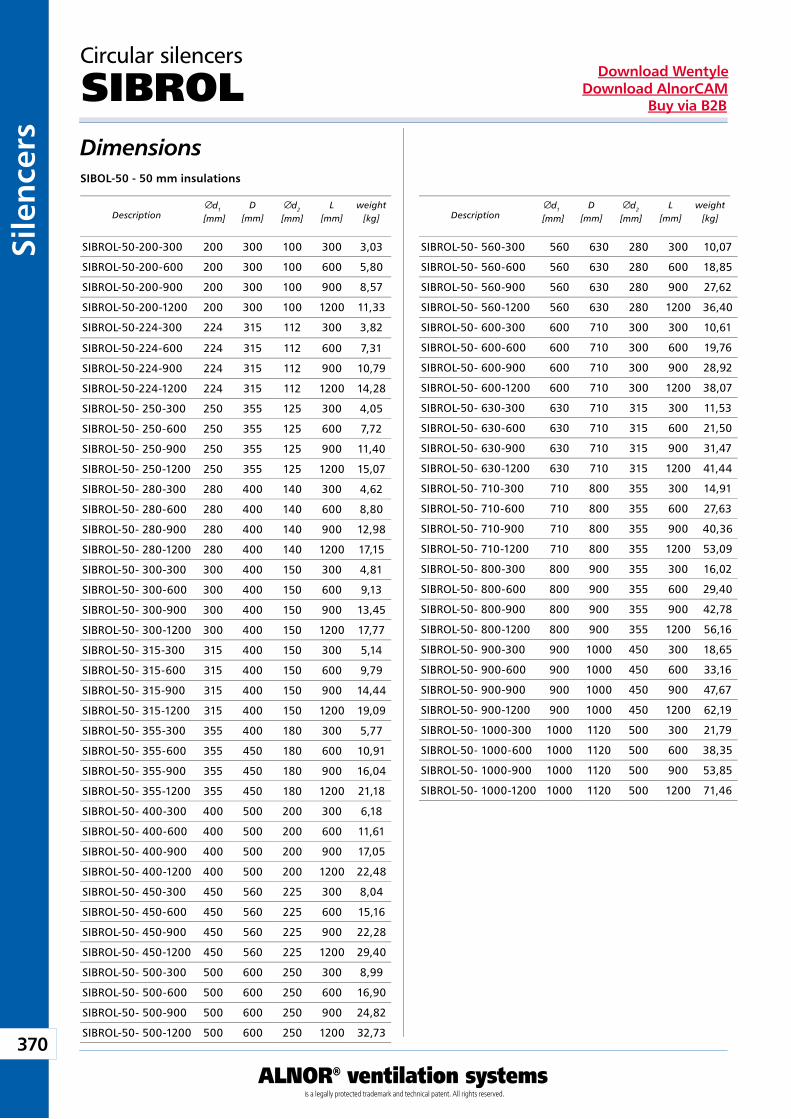
370
ALNOR® ventilation systemsis a legally protected trademark and technical patent. All rights reserved.
Sile
nce
rsDownload Wentyle
Download AlnorCAMBuy via B2B
Circular silencers
SIBROLDimensionsSIBOL-50 - 50 mm insulations
Descriptiond1
[mm]D
[mm]d2
[mm]L
[mm]weight
[kg] Descriptiond1
[mm]D
[mm]d2
[mm]L
[mm]weight
[kg]
SIBROL-50-200-300 200 300 100 300 3,03
SIBROL-50-200-600 200 300 100 600 5,80
SIBROL-50-200-900 200 300 100 900 8,57
SIBROL-50-200-1200 200 300 100 1200 11,33
SIBROL-50-224-300 224 315 112 300 3,82
SIBROL-50-224-600 224 315 112 600 7,31
SIBROL-50-224-900 224 315 112 900 10,79
SIBROL-50-224-1200 224 315 112 1200 14,28
SIBROL-50- 250-300 250 355 125 300 4,05
SIBROL-50- 250-600 250 355 125 600 7,72
SIBROL-50- 250-900 250 355 125 900 11,40
SIBROL-50- 250-1200 250 355 125 1200 15,07
SIBROL-50- 280-300 280 400 140 300 4,62
SIBROL-50- 280-600 280 400 140 600 8,80
SIBROL-50- 280-900 280 400 140 900 12,98
SIBROL-50- 280-1200 280 400 140 1200 17,15
SIBROL-50- 300-300 300 400 150 300 4,81
SIBROL-50- 300-600 300 400 150 600 9,13
SIBROL-50- 300-900 300 400 150 900 13,45
SIBROL-50- 300-1200 300 400 150 1200 17,77
SIBROL-50- 315-300 315 400 150 300 5,14
SIBROL-50- 315-600 315 400 150 600 9,79
SIBROL-50- 315-900 315 400 150 900 14,44
SIBROL-50- 315-1200 315 400 150 1200 19,09
SIBROL-50- 355-300 355 400 180 300 5,77
SIBROL-50- 355-600 355 450 180 600 10,91
SIBROL-50- 355-900 355 450 180 900 16,04
SIBROL-50- 355-1200 355 450 180 1200 21,18
SIBROL-50- 400-300 400 500 200 300 6,18
SIBROL-50- 400-600 400 500 200 600 11,61
SIBROL-50- 400-900 400 500 200 900 17,05
SIBROL-50- 400-1200 400 500 200 1200 22,48
SIBROL-50- 450-300 450 560 225 300 8,04
SIBROL-50- 450-600 450 560 225 600 15,16
SIBROL-50- 450-900 450 560 225 900 22,28
SIBROL-50- 450-1200 450 560 225 1200 29,40
SIBROL-50- 500-300 500 600 250 300 8,99
SIBROL-50- 500-600 500 600 250 600 16,90
SIBROL-50- 500-900 500 600 250 900 24,82
SIBROL-50- 500-1200 500 600 250 1200 32,73
SIBROL-50- 560-300 560 630 280 300 10,07
SIBROL-50- 560-600 560 630 280 600 18,85
SIBROL-50- 560-900 560 630 280 900 27,62
SIBROL-50- 560-1200 560 630 280 1200 36,40
SIBROL-50- 600-300 600 710 300 300 10,61
SIBROL-50- 600-600 600 710 300 600 19,76
SIBROL-50- 600-900 600 710 300 900 28,92
SIBROL-50- 600-1200 600 710 300 1200 38,07
SIBROL-50- 630-300 630 710 315 300 11,53
SIBROL-50- 630-600 630 710 315 600 21,50
SIBROL-50- 630-900 630 710 315 900 31,47
SIBROL-50- 630-1200 630 710 315 1200 41,44
SIBROL-50- 710-300 710 800 355 300 14,91
SIBROL-50- 710-600 710 800 355 600 27,63
SIBROL-50- 710-900 710 800 355 900 40,36
SIBROL-50- 710-1200 710 800 355 1200 53,09
SIBROL-50- 800-300 800 900 355 300 16,02
SIBROL-50- 800-600 800 900 355 600 29,40
SIBROL-50- 800-900 800 900 355 900 42,78
SIBROL-50- 800-1200 800 900 355 1200 56,16
SIBROL-50- 900-300 900 1000 450 300 18,65
SIBROL-50- 900-600 900 1000 450 600 33,16
SIBROL-50- 900-900 900 1000 450 900 47,67
SIBROL-50- 900-1200 900 1000 450 1200 62,19
SIBROL-50- 1000-300 1000 1120 500 300 21,79
SIBROL-50- 1000-600 1000 1120 500 600 38,35
SIBROL-50- 1000-900 1000 1120 500 900 53,85
SIBROL-50- 1000-1200 1000 1120 500 1200 71,46
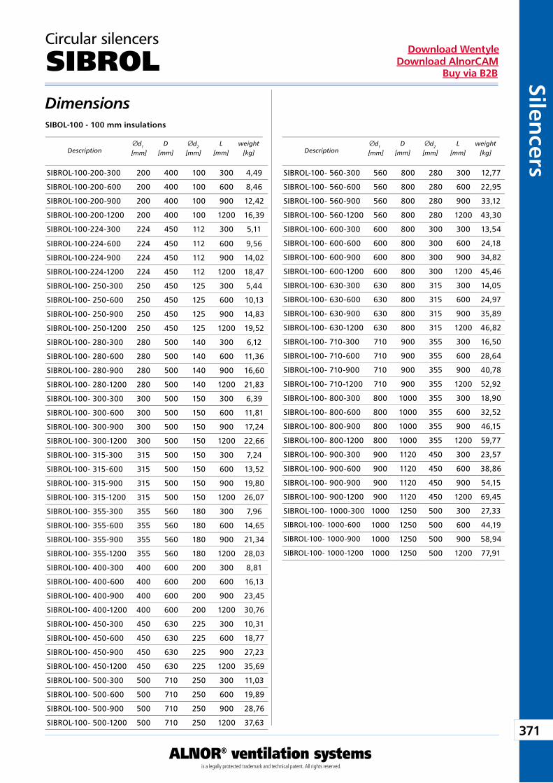
371
ALNOR® ventilation systemsis a legally protected trademark and technical patent. All rights reserved.
Silencers
Download WentyleDownload AlnorCAM
Buy via B2B
Circular silencers
SIBROLDimensionsSIBOL-100 - 100 mm insulations
Descriptiond1
[mm]D
[mm]d2
[mm]L
[mm]weight
[kg] Descriptiond1
[mm]D
[mm]d2
[mm]L
[mm]weight
[kg]
SIBROL-100-200-300 200 400 100 300 4,49
SIBROL-100-200-600 200 400 100 600 8,46
SIBROL-100-200-900 200 400 100 900 12,42
SIBROL-100-200-1200 200 400 100 1200 16,39
SIBROL-100-224-300 224 450 112 300 5,11
SIBROL-100-224-600 224 450 112 600 9,56
SIBROL-100-224-900 224 450 112 900 14,02
SIBROL-100-224-1200 224 450 112 1200 18,47
SIBROL-100- 250-300 250 450 125 300 5,44
SIBROL-100- 250-600 250 450 125 600 10,13
SIBROL-100- 250-900 250 450 125 900 14,83
SIBROL-100- 250-1200 250 450 125 1200 19,52
SIBROL-100- 280-300 280 500 140 300 6,12
SIBROL-100- 280-600 280 500 140 600 11,36
SIBROL-100- 280-900 280 500 140 900 16,60
SIBROL-100- 280-1200 280 500 140 1200 21,83
SIBROL-100- 300-300 300 500 150 300 6,39
SIBROL-100- 300-600 300 500 150 600 11,81
SIBROL-100- 300-900 300 500 150 900 17,24
SIBROL-100- 300-1200 300 500 150 1200 22,66
SIBROL-100- 315-300 315 500 150 300 7,24
SIBROL-100- 315-600 315 500 150 600 13,52
SIBROL-100- 315-900 315 500 150 900 19,80
SIBROL-100- 315-1200 315 500 150 1200 26,07
SIBROL-100- 355-300 355 560 180 300 7,96
SIBROL-100- 355-600 355 560 180 600 14,65
SIBROL-100- 355-900 355 560 180 900 21,34
SIBROL-100- 355-1200 355 560 180 1200 28,03
SIBROL-100- 400-300 400 600 200 300 8,81
SIBROL-100- 400-600 400 600 200 600 16,13
SIBROL-100- 400-900 400 600 200 900 23,45
SIBROL-100- 400-1200 400 600 200 1200 30,76
SIBROL-100- 450-300 450 630 225 300 10,31
SIBROL-100- 450-600 450 630 225 600 18,77
SIBROL-100- 450-900 450 630 225 900 27,23
SIBROL-100- 450-1200 450 630 225 1200 35,69
SIBROL-100- 500-300 500 710 250 300 11,03
SIBROL-100- 500-600 500 710 250 600 19,89
SIBROL-100- 500-900 500 710 250 900 28,76
SIBROL-100- 500-1200 500 710 250 1200 37,63
SIBROL-100- 560-300 560 800 280 300 12,77
SIBROL-100- 560-600 560 800 280 600 22,95
SIBROL-100- 560-900 560 800 280 900 33,12
SIBROL-100- 560-1200 560 800 280 1200 43,30
SIBROL-100- 600-300 600 800 300 300 13,54
SIBROL-100- 600-600 600 800 300 600 24,18
SIBROL-100- 600-900 600 800 300 900 34,82
SIBROL-100- 600-1200 600 800 300 1200 45,46
SIBROL-100- 630-300 630 800 315 300 14,05
SIBROL-100- 630-600 630 800 315 600 24,97
SIBROL-100- 630-900 630 800 315 900 35,89
SIBROL-100- 630-1200 630 800 315 1200 46,82
SIBROL-100- 710-300 710 900 355 300 16,50
SIBROL-100- 710-600 710 900 355 600 28,64
SIBROL-100- 710-900 710 900 355 900 40,78
SIBROL-100- 710-1200 710 900 355 1200 52,92
SIBROL-100- 800-300 800 1000 355 300 18,90
SIBROL-100- 800-600 800 1000 355 600 32,52
SIBROL-100- 800-900 800 1000 355 900 46,15
SIBROL-100- 800-1200 800 1000 355 1200 59,77
SIBROL-100- 900-300 900 1120 450 300 23,57
SIBROL-100- 900-600 900 1120 450 600 38,86
SIBROL-100- 900-900 900 1120 450 900 54,15
SIBROL-100- 900-1200 900 1120 450 1200 69,45
SIBROL-100- 1000-300 1000 1250 500 300 27,33
SIBROL-100- 1000-600 1000 1250 500 600 44,19
SIBROL-100- 1000-900 1000 1250 500 900 58,94
SIBROL-100- 1000-1200 1000 1250 500 1200 77,91
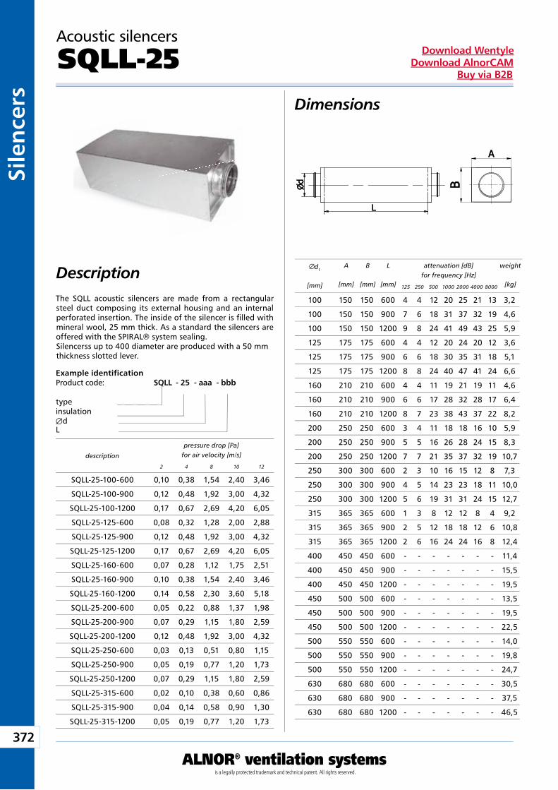
372
ALNOR® ventilation systemsis a legally protected trademark and technical patent. All rights reserved.
Sile
nce
rsDownload Wentyle
Download AlnorCAMBuy via B2B
Dimensions
Description d1
[mm]
A
[mm]
B
[mm]
L
[mm]
attenuation [dB]for frequency [Hz]
weight
[kg]125 250 500 1000 2000 4000 8000
description
pressure drop [Pa]for air velocity [m/s]
2 4 8 10 12
100 150 150 600 4 4 12 20 25 21 13 3,2
100 150 150 900 7 6 18 31 37 32 19 4,6
100 150 150 1200 9 8 24 41 49 43 25 5,9
125 175 175 600 4 4 12 20 24 20 12 3,6
125 175 175 900 6 6 18 30 35 31 18 5,1
125 175 175 1200 8 8 24 40 47 41 24 6,6
160 210 210 600 4 4 11 19 21 19 11 4,6
160 210 210 900 6 6 17 28 32 28 17 6,4
160 210 210 1200 8 7 23 38 43 37 22 8,2
200 250 250 600 3 4 11 18 18 16 10 5,9
200 250 250 900 5 5 16 26 28 24 15 8,3
200 250 250 1200 7 7 21 35 37 32 19 10,7
250 300 300 600 2 3 10 16 15 12 8 7,3
250 300 300 900 4 5 14 23 23 18 11 10,0
250 300 300 1200 5 6 19 31 31 24 15 12,7
315 365 365 600 1 3 8 12 12 8 4 9,2
315 365 365 900 2 5 12 18 18 12 6 10,8
315 365 365 1200 2 6 16 24 24 16 8 12,4
400 450 450 600 - - - - - - - 11,4
400 450 450 900 - - - - - - - 15,5
400 450 450 1200 - - - - - - - 19,5
450 500 500 600 - - - - - - - 13,5
450 500 500 900 - - - - - - - 19,5
450 500 500 1200 - - - - - - - 22,5
500 550 550 600 - - - - - - - 14,0
500 550 550 900 - - - - - - - 19,8
500 550 550 1200 - - - - - - - 24,7
630 680 680 600 - - - - - - - 30,5
630 680 680 900 - - - - - - - 37,5
630 680 680 1200 - - - - - - - 46,5
SQLL-25-100-600 0,10 0,38 1,54 2,40 3,46
SQLL-25-100-900 0,12 0,48 1,92 3,00 4,32
SQLL-25-100-1200 0,17 0,67 2,69 4,20 6,05
SQLL-25-125-600 0,08 0,32 1,28 2,00 2,88
SQLL-25-125-900 0,12 0,48 1,92 3,00 4,32
SQLL-25-125-1200 0,17 0,67 2,69 4,20 6,05
SQLL-25-160-600 0,07 0,28 1,12 1,75 2,51
SQLL-25-160-900 0,10 0,38 1,54 2,40 3,46
SQLL-25-160-1200 0,14 0,58 2,30 3,60 5,18
SQLL-25-200-600 0,05 0,22 0,88 1,37 1,98
SQLL-25-200-900 0,07 0,29 1,15 1,80 2,59
SQLL-25-200-1200 0,12 0,48 1,92 3,00 4,32
SQLL-25-250-600 0,03 0,13 0,51 0,80 1,15
SQLL-25-250-900 0,05 0,19 0,77 1,20 1,73
SQLL-25-250-1200 0,07 0,29 1,15 1,80 2,59
SQLL-25-315-600 0,02 0,10 0,38 0,60 0,86
SQLL-25-315-900 0,04 0,14 0,58 0,90 1,30
SQLL-25-315-1200 0,05 0,19 0,77 1,20 1,73
The SQLL acoustic silencers are made from a rectangular steel duct composing its external housing and an internal perforated insertion. The inside of the silencer is filled with mineral wool, 25 mm thick. As a standard the silencers are offered with the SPIRAL® system sealing.Silencerss up to 400 diameter are produced with a 50 mm thickness slotted lever.
Example identificationProduct code: SQLL - 25 - aaa - bbb
typeinsulationÆdL
Acoustic silencers
SQLL-25
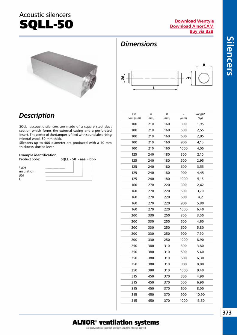
373
ALNOR® ventilation systemsis a legally protected trademark and technical patent. All rights reserved.
Silencers
Download WentyleDownload AlnorCAM
Buy via B2B
Description
Dimensions
SQLL accoustic silencers are made of a square steel duct section which forms the external casing and a perforated insert. The center of the damper is filled with sound absorbing mineral wool, 50 mm thick. Silencers up to 400 diameter are produced with a 50 mm thickness slotted lever.
Example identificationProduct code: SQLL - 50 - aaa - bbb
typeinsulationÆdL
Æd A B L weight nom [mm] [mm] [mm] [mm] [kg]
100 210 160 300 1,95
100 210 160 500 2,55
100 210 160 600 2,95
100 210 160 900 4,15
100 210 160 1000 4,55
125 240 180 300 2,10
125 240 180 500 2,95
125 240 180 600 3,55
125 240 180 900 4,45
125 240 180 1000 5,15
160 270 220 300 2,42
160 270 220 500 3,70
160 270 220 600 4,2
160 270 220 900 5,80
160 270 220 1000 6,40
200 330 250 300 3,50
200 330 250 500 4,60
200 330 250 600 5,80
200 330 250 900 7,90
200 330 250 1000 8,90
250 380 310 300 3,80
250 380 310 500 5,40
250 380 310 600 6,30
250 380 310 900 8,80
250 380 310 1000 9,40
315 450 370 300 4,90
315 450 370 500 6,90
315 450 370 600 8,00
315 450 370 900 10,90
315 450 370 1000 13,50
Acoustic silencers
SQLL-50
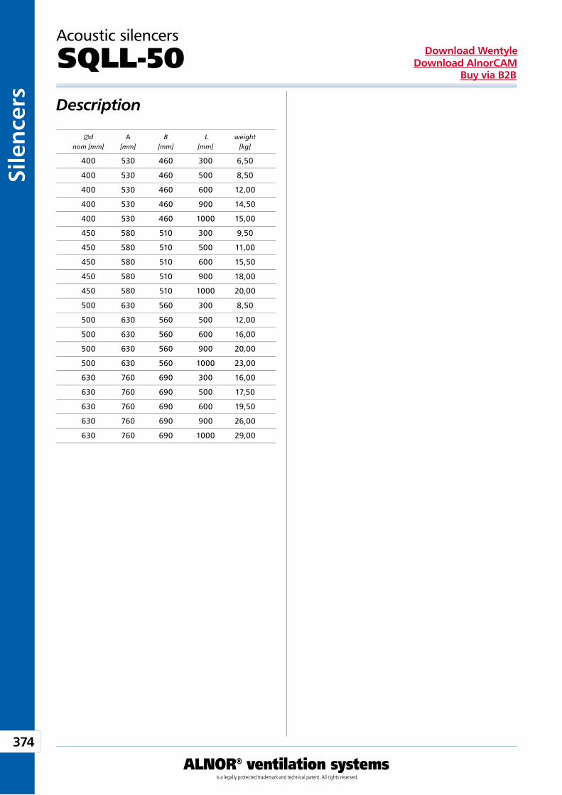
374
ALNOR® ventilation systemsis a legally protected trademark and technical patent. All rights reserved.
Sile
nce
rsDownload Wentyle
Download AlnorCAMBuy via B2B
Description
Æd A B L weight nom [mm] [mm] [mm] [mm] [kg]
400 530 460 300 6,50
400 530 460 500 8,50
400 530 460 600 12,00
400 530 460 900 14,50
400 530 460 1000 15,00
450 580 510 300 9,50
450 580 510 500 11,00
450 580 510 600 15,50
450 580 510 900 18,00
450 580 510 1000 20,00
500 630 560 300 8,50
500 630 560 500 12,00
500 630 560 600 16,00
500 630 560 900 20,00
500 630 560 1000 23,00
630 760 690 300 16,00
630 760 690 500 17,50
630 760 690 600 19,50
630 760 690 900 26,00
630 760 690 1000 29,00
Acoustic silencers
SQLL-50
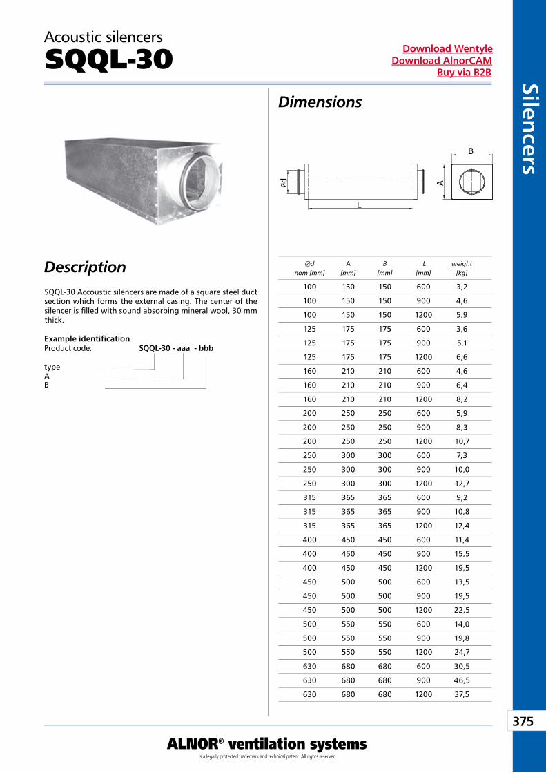
375
ALNOR® ventilation systemsis a legally protected trademark and technical patent. All rights reserved.
Silencers
Download WentyleDownload AlnorCAM
Buy via B2B
Description
Dimensions
SQQL-30 Accoustic silencers are made of a square steel duct section which forms the external casing. The center of the silencer is filled with sound absorbing mineral wool, 30 mm thick.
Example identificationProduct code: SQQL -30 - aaa - bbb
typeAB
B
A
L
Ø d
Æd A B L weight nom [mm] [mm] [mm] [mm] [kg]
100 150 150 600 3,2
100 150 150 900 4,6
100 150 150 1200 5,9
125 175 175 600 3,6
125 175 175 900 5,1
125 175 175 1200 6,6
160 210 210 600 4,6
160 210 210 900 6,4
160 210 210 1200 8,2
200 250 250 600 5,9
200 250 250 900 8,3
200 250 250 1200 10,7
250 300 300 600 7,3
250 300 300 900 10,0
250 300 300 1200 12,7
315 365 365 600 9,2
315 365 365 900 10,8
315 365 365 1200 12,4
400 450 450 600 11,4
400 450 450 900 15,5
400 450 450 1200 19,5
450 500 500 600 13,5
450 500 500 900 19,5
450 500 500 1200 22,5
500 550 550 600 14,0
500 550 550 900 19,8
500 550 550 1200 24,7
630 680 680 600 30,5
630 680 680 900 46,5
630 680 680 1200 37,5
Acoustic silencers
SQQL-30

376
ALNOR® ventilation systemsis a legally protected trademark and technical patent. All rights reserved.
Sile
nce
rsDownload Wentyle
Download AlnorCAMBuy via B2B
Description
Dimensions
SQQL-B-30 silencers are made of a square steel duct section which forms the external casing. SQQL-B-30 silencers have one side connection on one of the walls. The center of the silencer is filled with sound absorbing mineral wool, 30 mm thick.
B
A
L
Ø d
Example identificationProduct code: SQQL -B-30 - aaa - bbb
typeAB
Æd A B L weight nom [mm] [mm] [mm] [mm] [kg]
100 150 150 600 3,2
100 150 150 900 4,6
100 150 150 1200 5,9
125 175 175 600 3,6
125 175 175 900 5,1
125 175 175 1200 6,6
160 210 210 600 4,6
160 210 210 900 6,4
160 210 210 1200 8,2
200 250 250 600 5,9
200 250 250 900 8,3
200 250 250 1200 10,7
250 300 300 600 7,3
250 300 300 900 10,0
250 300 300 1200 12,7
315 365 365 600 9,2
315 365 365 900 10,8
315 365 365 1200 12,4
400 450 450 600 11,4
400 450 450 900 15,5
400 450 450 1200 19,5
450 500 500 600 13,5
450 500 500 900 19,5
450 500 500 1200 22,5
500 550 550 600 14,0
500 550 550 900 19,8
500 550 550 1200 24,7
630 680 680 600 30,5
630 680 680 900 46,5
630 680 680 1200 37,5
Acoustic silencers
SQQL-B-30
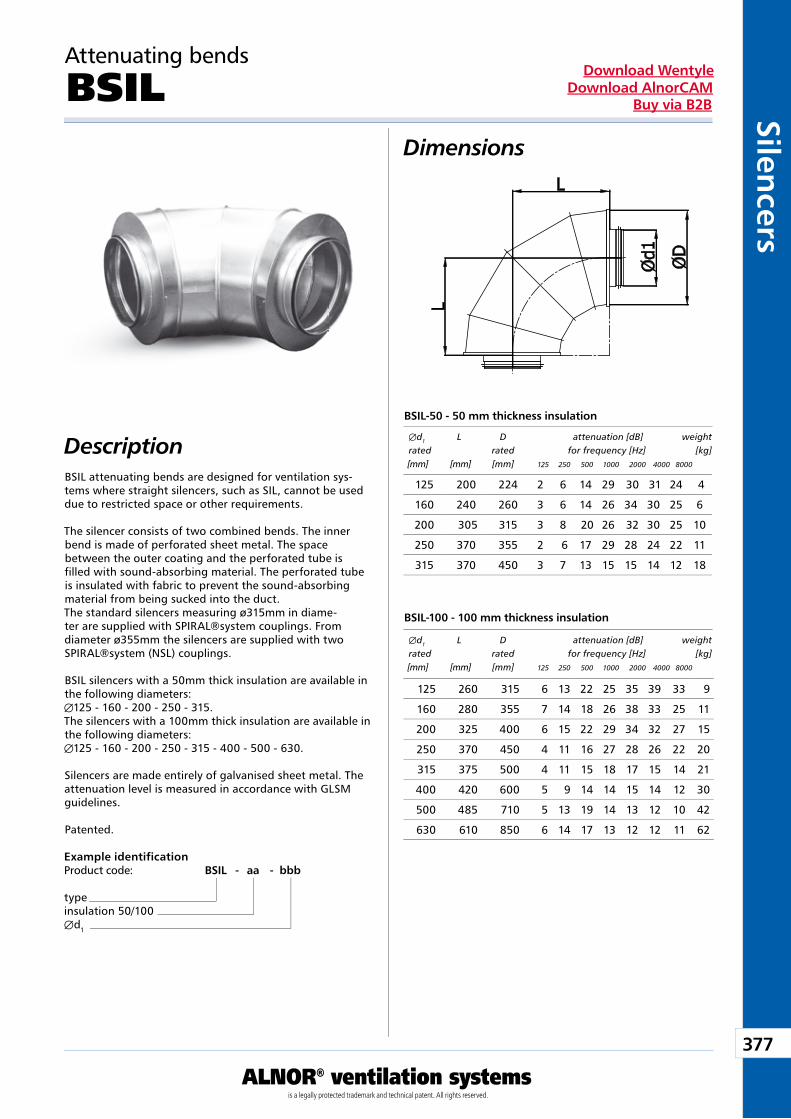
377
ALNOR® ventilation systemsis a legally protected trademark and technical patent. All rights reserved.
Silencers
Download WentyleDownload AlnorCAM
Buy via B2B
Attenuating bends
BSILDimensions
DescriptionBSIL attenuating bends are designed for ventilation sys-tems where straight silencers, such as SIL, cannot be used due to restricted space or other requirements.
The silencer consists of two combined bends. The inner bend is made of perforated sheet metal. The space between the outer coating and the perforated tube is filled with sound-absorbing material. The perforated tube is insulated with fabric to prevent the sound-absorbing material from being sucked into the duct.The standard silencers measuring ø315mm in diame-ter are supplied with SPIRAL®system couplings. From diameter ø355mm the silencers are supplied with two SPIRAL®system (NSL) couplings.
BSIL silencers with a 50mm thick insulation are available in the following diameters:Æ125 - 160 - 200 - 250 - 315.The silencers with a 100mm thick insulation are available in the following diameters:Æ125 - 160 - 200 - 250 - 315 - 400 - 500 - 630.
Silencers are made entirely of galvanised sheet metal. The attenuation level is measured in accordance with GLSM guidelines.
Patented.
Example identificationProduct code: BSIL - aa - bbb
typeinsulation 50/100Æd1
BSIL-50 - 50 mm thickness insulation
BSIL-100 - 100 mm thickness insulation
Æd1 L D attenuation [dB] weight rated rated for frequency [Hz] [kg] [mm] [mm] [mm] 125 250 500 1000 2000 4000 8000
Æd1 L D attenuation [dB] weight rated rated for frequency [Hz] [kg] [mm] [mm] [mm] 125 250 500 1000 2000 4000 8000
125 200 224 2 6 14 29 30 31 24 4
160 240 260 3 6 14 26 34 30 25 6
200 305 315 3 8 20 26 32 30 25 10
250 370 355 2 6 17 29 28 24 22 11
315 370 450 3 7 13 15 15 14 12 18
125 260 315 6 13 22 25 35 39 33 9
160 280 355 7 14 18 26 38 33 25 11
200 325 400 6 15 22 29 34 32 27 15
250 370 450 4 11 16 27 28 26 22 20
315 375 500 4 11 15 18 17 15 14 21
400 420 600 5 9 14 14 15 14 12 30
500 485 710 5 13 19 14 13 12 10 42
630 610 850 6 14 17 13 12 12 11 62
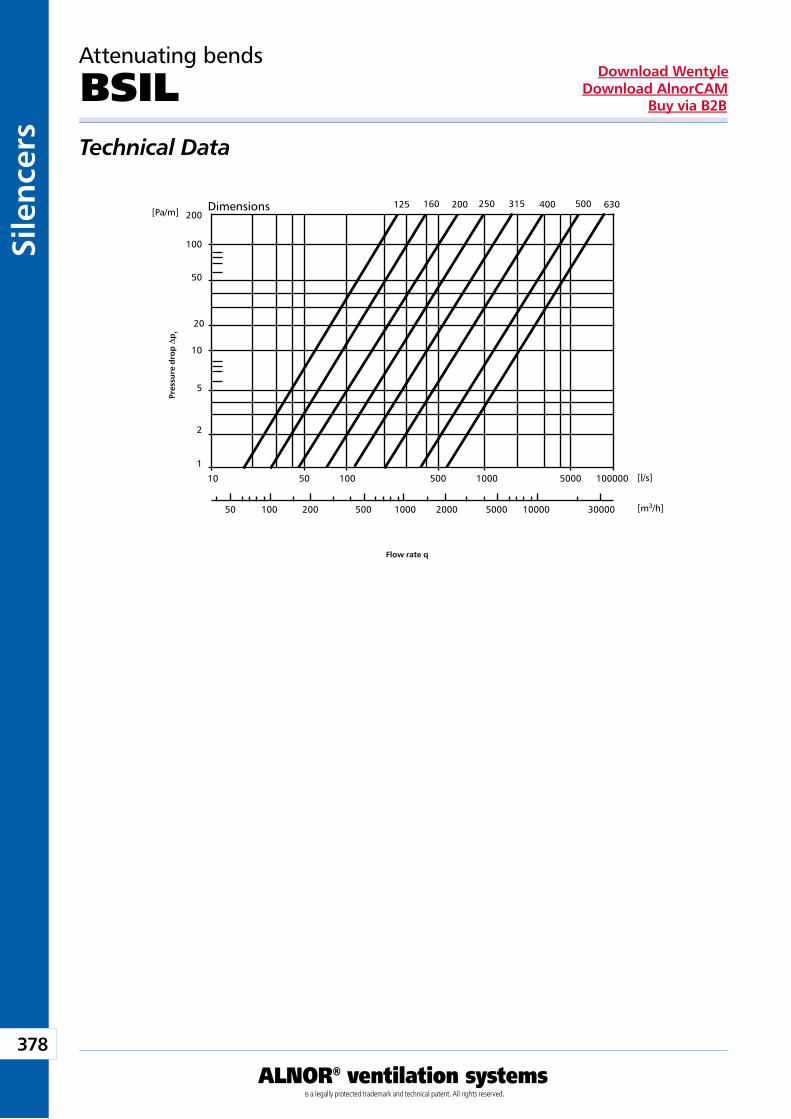
378
ALNOR® ventilation systemsis a legally protected trademark and technical patent. All rights reserved.
Sile
nce
rsDownload Wentyle
Download AlnorCAMBuy via B2B
[Pa/m]
[l/s]
[m3/h]
1
10
50 100 200 500 1000 2000 5000 10000 30000
50 100 500 1000 5000 100000
2
5
10
20
50
100
200125 160 200 250 315 400 500 630
Attenuating bends
BSILTechnical Data
Pres
sure
dro
p D
pt
Flow rate q
Dimensions
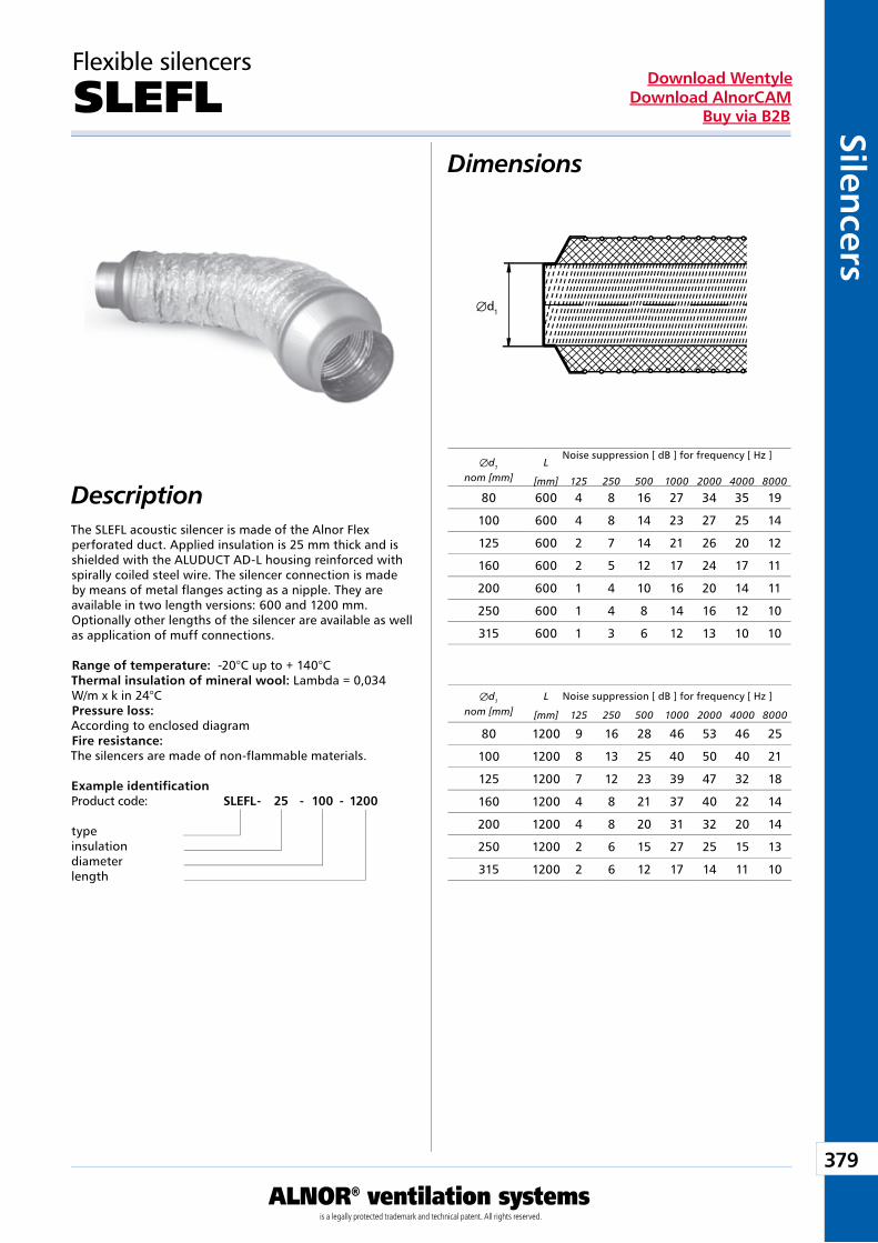
379
ALNOR® ventilation systemsis a legally protected trademark and technical patent. All rights reserved.
Silencers
Download WentyleDownload AlnorCAM
Buy via B2B
Æd1
Flexible silencers
SLEFL
The SLEFL acoustic silencer is made of the Alnor Flex perforated duct. Applied insulation is 25 mm thick and is shielded with the ALUDUCT AD-L housing reinforced with spirally coiled steel wire. The silencer connection is made by means of metal flanges acting as a nipple. They are available in two length versions: 600 and 1200 mm.Optionally other lengths of the silencer are available as well as application of muff connections.
Range of temperature: -20°C up to + 140°CThermal insulation of mineral wool: Lambda = 0,034 W/m x k in 24°CPressure loss:According to enclosed diagramFire resistance:The silencers are made of non-flammable materials.
Example identificationProduct code: SLEFL - 25 - 100 - 1200
typeinsulationdiameter length
Æd1
nom [mm]L
Noise suppression [ dB ] for frequency [ Hz ]
[mm] 125 250 500 1000 2000 4000 8000
Æd1
nom [mm]L Noise suppression [ dB ] for frequency [ Hz ]
[mm] 125 250 500 1000 2000 4000 8000
80 600 4 8 16 27 34 35 19
100 600 4 8 14 23 27 25 14
125 600 2 7 14 21 26 20 12
160 600 2 5 12 17 24 17 11
200 600 1 4 10 16 20 14 11
250 600 1 4 8 14 16 12 10
315 600 1 3 6 12 13 10 10
80 1200 9 16 28 46 53 46 25
100 1200 8 13 25 40 50 40 21
125 1200 7 12 23 39 47 32 18
160 1200 4 8 21 37 40 22 14
200 1200 4 8 20 31 32 20 14
250 1200 2 6 15 27 25 15 13
315 1200 2 6 12 17 14 11 10
Dimensions
Description
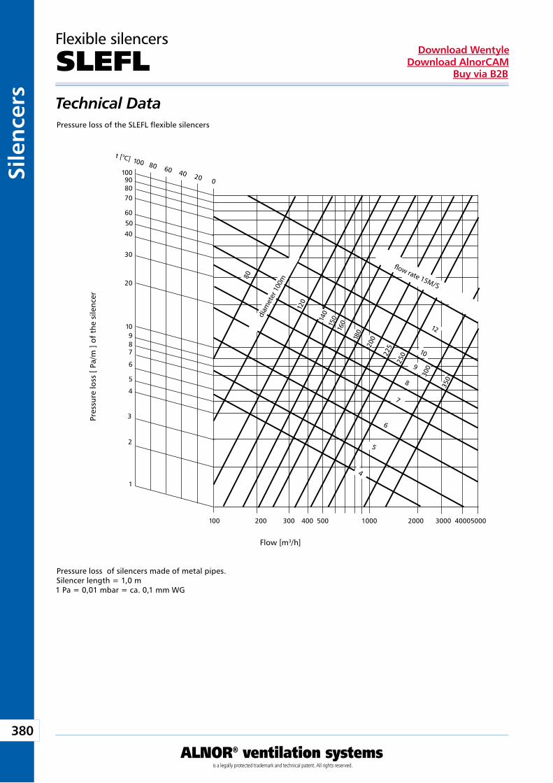
380
ALNOR® ventilation systemsis a legally protected trademark and technical patent. All rights reserved.
Sile
nce
rsDownload Wentyle
Download AlnorCAMBuy via B2B
100 200 300 400 500 1000 2000 3000 4000 5000
100 80 60 40 20 0
t [ oC]
100908070
60
50
40
30
20
10987
6
5
4
3
2
1
80
120
140
150
180
200
225
250
300
350
160 12
7
8
10
6
5
4
9
Flexible silencers
SLEFL
Pressure loss of the SLEFL flexible silencers
Pressure loss of silencers made of metal pipes.Silencer length = 1,0 m1 Pa = 0,01 mbar = ca. 0,1 mm WG
Pres
sure
loss
[ Pa
/m ]
of t
he s
ilenc
er
Flow [m3/h]
śred
nica
100
m
prędkość przepływu 15 m/sdiam
eter
100
m
� ow rate 15M/S
Technical Data
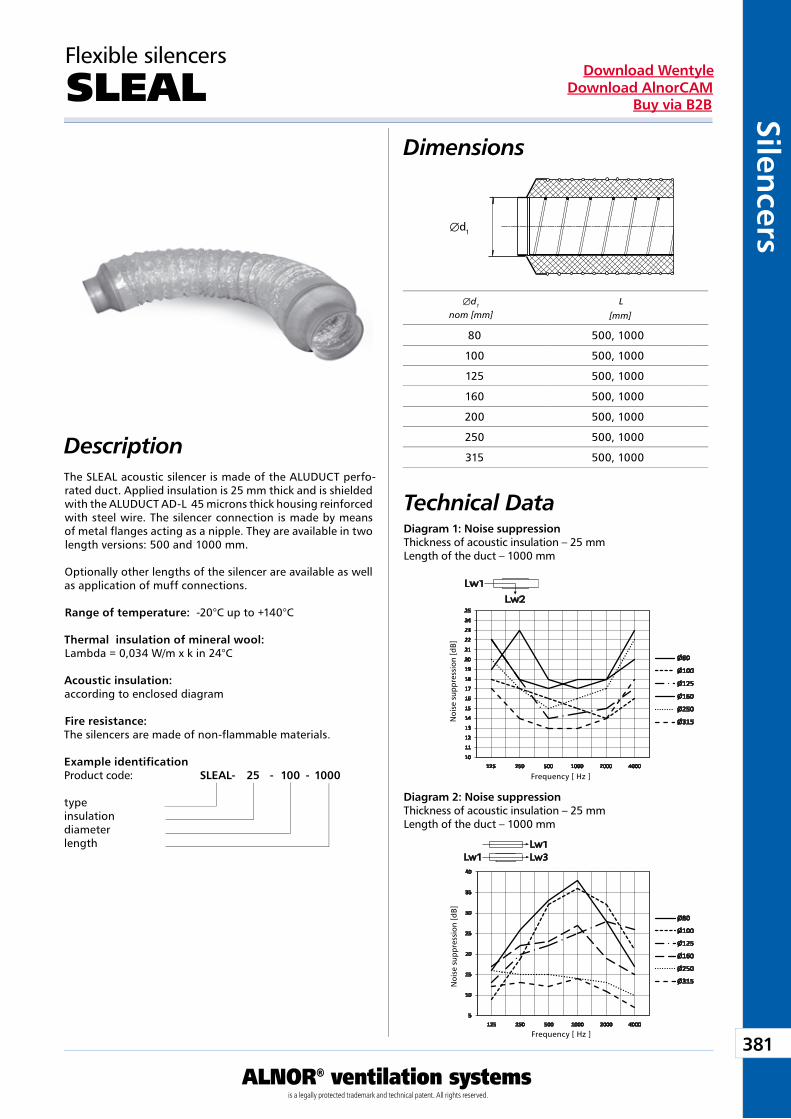
381
ALNOR® ventilation systemsis a legally protected trademark and technical patent. All rights reserved.
Silencers
Download WentyleDownload AlnorCAM
Buy via B2B
Æd1
Lw1
Lw2
Lw1 Lw3Lw1
[mm]
Flexible silencers
SLEAL
The SLEAL acoustic silencer is made of the ALUDUCT perfo-rated duct. Applied insulation is 25 mm thick and is shielded with the ALUDUCT AD-L 45 microns thick housing reinforced with steel wire. The silencer connection is made by means of metal flanges acting as a nipple. They are available in two length versions: 500 and 1000 mm.
Optionally other lengths of the silencer are available as well as application of muff connections.
Range of temperature: -20°C up to +140°C
Thermal insulation of mineral wool:Lambda = 0,034 W/m x k in 24°C
Acoustic insulation:according to enclosed diagram
Fire resistance:The silencers are made of non-flammable materials.
Frequency [ Hz ]
Noi
se s
uppr
essi
on [d
B]N
oise
sup
pres
sion
[dB]
Æd1
nom [mm]L
Diagram 1: Noise suppressionThickness of acoustic insulation – 25 mmLength of the duct – 1000 mm
Diagram 2: Noise suppressionThickness of acoustic insulation – 25 mmLength of the duct – 1000 mm
Frequency [ Hz ]
80 500, 1000
100 500, 1000
125 500, 1000
160 500, 1000
200 500, 1000
250 500, 1000
315 500, 1000
Example identificationProduct code: SLEAL - 25 - 100 - 1000
typeinsulationdiameter length
Dimensions
Description
Technical Data
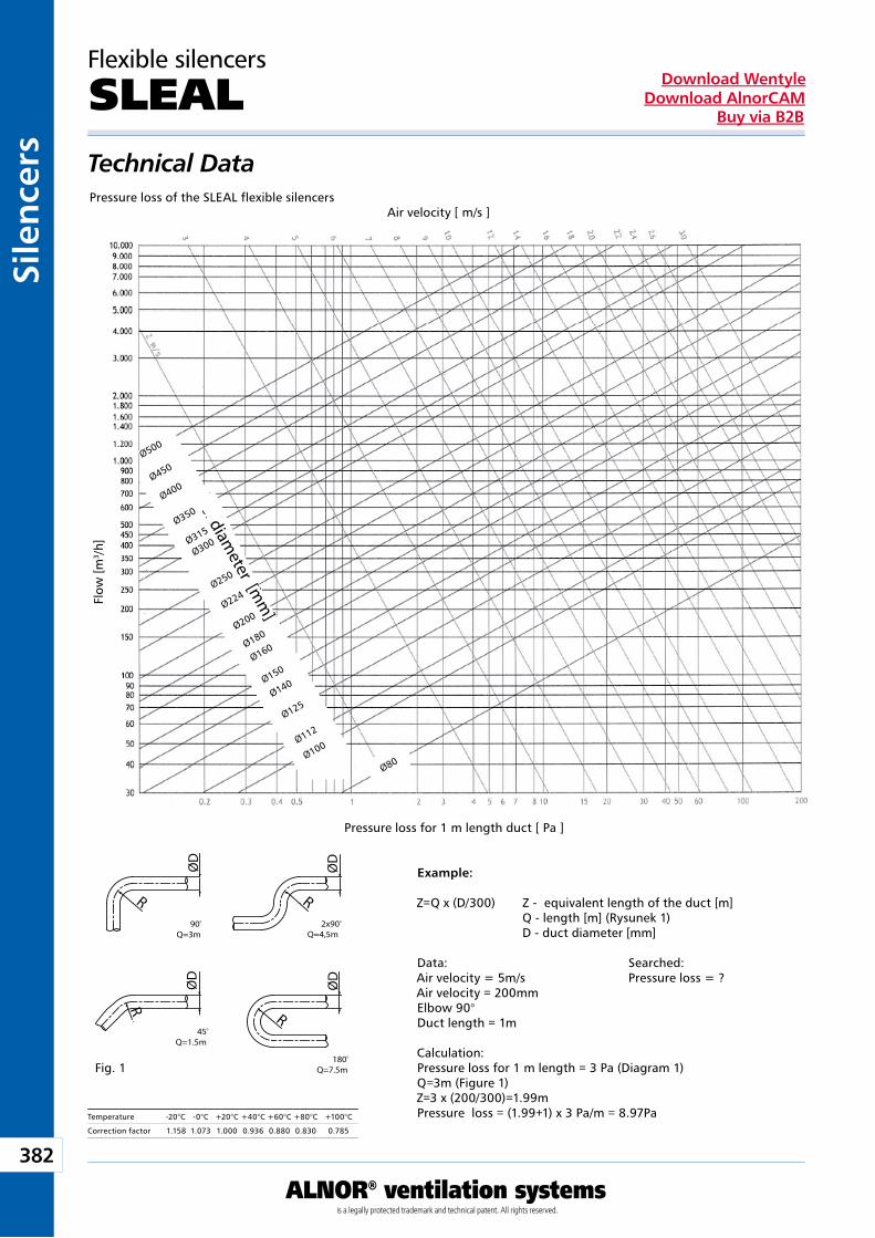
382
ALNOR® ventilation systemsis a legally protected trademark and technical patent. All rights reserved.
Sile
nce
rsDownload Wentyle
Download AlnorCAMBuy via B2B
średnica [mm
]
Ø500
Ø450
Ø400
Ø350
Ø315
Ø300
Ø250
Ø224
Ø200
Ø180
Ø160
Ø150
Ø140
Ø125
Ø112
Ø100
Ø80
R
ØD
R
ØD
R
ØD
R
ØD
90Q=3m
o 2x90Q=4,5m
o
180Q=7.5m
o
45Q=1.5m
o
Flow
[m3 /
h]
Pressure loss for 1 m length duct [ Pa ]
Air velocity [ m/s ]
Example:
Z=Q x (D/300) Z - equivalent length of the duct [m] Q - length [m] (Rysunek 1) D - duct diameter [mm]
Data: Searched:Air velocity = 5m/s Pressure loss = ?Air velocity = 200mmElbow 90°Duct length = 1m
Calculation:Pressure loss for 1 m length = 3 Pa (Diagram 1)Q=3m (Figure 1)Z=3 x (200/300)=1.99mPressure loss = (1.99+1) x 3 Pa/m = 8.97Pa
Fig. 1
Temperature -20°C -0°C +20°C +40°C +60°C +80°C +100°C
Correction factor 1.158 1.073 1.000 0.936 0.880 0.830 0.785
Flexible silencers
SLEAL
Pressure loss of the SLEAL flexible silencers
diameter [m
m]
Technical Data
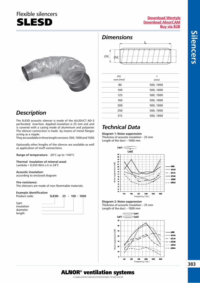
383
ALNOR® ventilation systemsis a legally protected trademark and technical patent. All rights reserved.
Silencers
Download WentyleDownload AlnorCAM
Buy via B2B
Æd1 Æd1
Lw1
Lw2
Lw1 Lw3Lw1
[mm]
Flexible silencers
SLESD
The SLESD acoustic silencer is made of the ALUDUCT AD-3 perforated insertion. Applied insulation is 25 mm sick and is covered with a casing made of aluminium and polyester. The silencer connection is made by means of metal flanges acting as a nipple.They are available in three length versions: 500, 1000 and 1500.
Optionally other lengths of the silencer are available as well as application of muff connections.
Range of temperature: -20°C up to +140°C
Thermal insulation of mineral wool:Lambda = 0,034 W/m x k in 24°C
Acoustic insulation:according to enclosed diagram
Fire resistance:The silencers are made of non-flammable materials.
Frequency [ Hz ]
Noi
se s
uppr
essi
on [d
B]N
oise
sup
pres
sion
[dB]
Æd1
nom [mm]L
Diagram 1: Noise suppressionThickness of acoustic insulation – 25 mmLength of the duct – 1000 mm
Diagram 2: Noise suppressionThickness of acoustic insulation – 25 mmLength of the duct – 1000 mm
Frequency [ Hz ]
80 500, 1000
100 500, 1000
125 500, 1000
160 500, 1000
200 500, 1000
250 500, 1000
315 500, 1000
Example identificationProduct code: SLESD- 25 - 100 - 1000
typeinsulationdiameter length
Dimensions
Description
Technical Data

384
ALNOR® ventilation systemsis a legally protected trademark and technical patent. All rights reserved.
Sile
nce
rsDownload Wentyle
Download AlnorCAMBuy via B2B
średnica [mm
]
Ø500
Ø450
Ø400
Ø350
Ø315
Ø300
Ø250
Ø224
Ø200
Ø180
Ø160
Ø150
Ø140
Ø125
Ø112
Ø100
Ø80
R
ØD
R
ØD
R
ØD
R
ØD
90Q=3m
o 2x90Q=4,5m
o
180Q=7.5m
o
45Q=1.5m
o
Flow
[m3 /
h]
Pressure loss for 1 m length duct [ Pa ]
Air velocity [ m/s ]
Example:
Z=Q x (D/300) Z - equivalent length of the duct [m] Q - length [m] (Rysunek 1) D - duct diameter [mm]
Data: Searched:Air velocity = 5m/s Pressure loss = ?Air velocity = 200mmElbow 90°Duct length = 1m
Calculation:Pressure loss for 1 m length = 3 Pa (Diagram 1)Q=3m (Figure 1)Z=3 x (200/300)=1.99mPressure loss = (1.99+1) x 3 Pa/m = 8.97Pa
Fig. 1
Temperature -20°C -0°C +20°C +40°C +60°C +80°C +100°C
Correction factor 1.158 1.073 1.000 0.936 0.880 0.830 0.785
Flexible silencers
SLESD
Pressure loss of the SLESD flexible silencers
diameter [m
m]
Technical Data
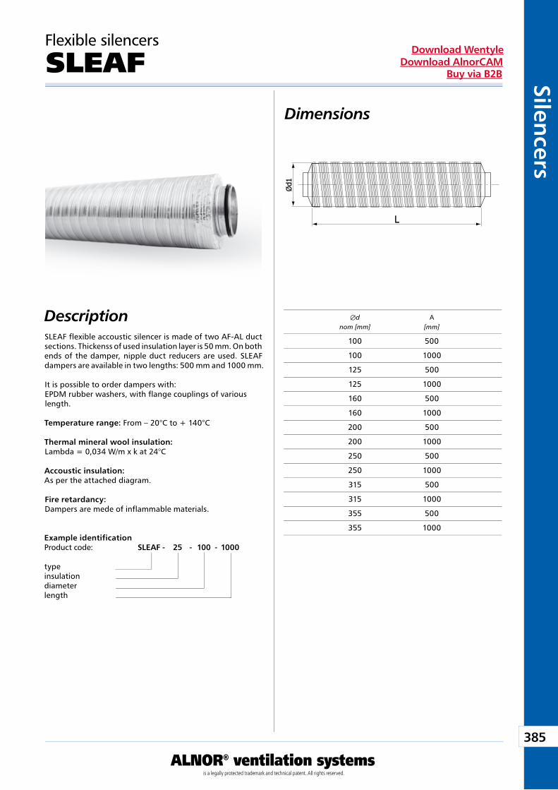
385
ALNOR® ventilation systemsis a legally protected trademark and technical patent. All rights reserved.
Silencers
Download WentyleDownload AlnorCAM
Buy via B2B
Flexible silencers
SLEAF
Dimensions
DescriptionSLEAF flexible accoustic silencer is made of two AF-AL duct sections. Thickenss of used insulation layer is 50 mm. On both ends of the damper, nipple duct reducers are used. SLEAF dampers are available in two lengths: 500 mm and 1000 mm. It is possible to order dampers with: EPDM rubber washers, with flange couplings of various length. Temperature range: From – 20°C to + 140°C Thermal mineral wool insulation: Lambda = 0,034 W/m x k at 24°C Accoustic insulation: As per the attached diagram. Fire retardancy: Dampers are mede of inflammable materials.
Example identificationProduct code: SLEAF - 25 - 100 - 1000
typeinsulationdiameter length
Æd A nom [mm] [mm]
100 500
100 1000
125 500
125 1000
160 500
160 1000
200 500
200 1000
250 500
250 1000
315 500
315 1000
355 500
355 1000
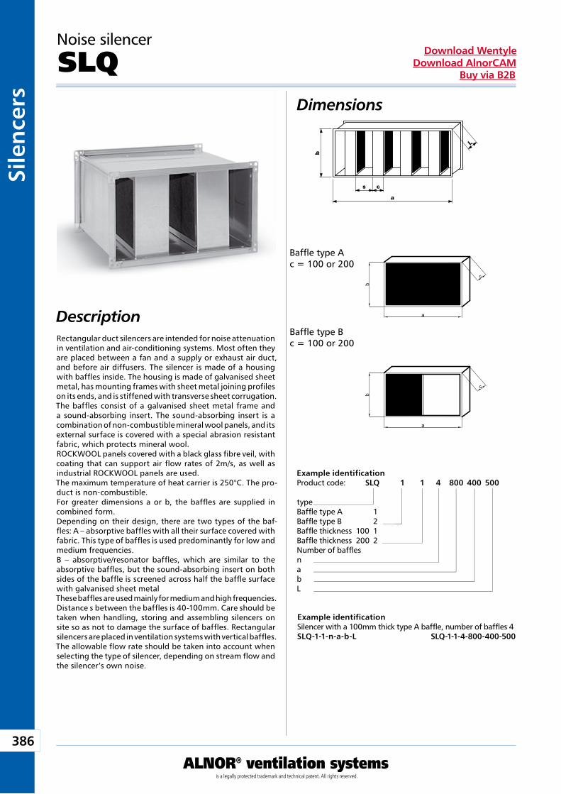
386
ALNOR® ventilation systemsis a legally protected trademark and technical patent. All rights reserved.
Sile
nce
rsDownload Wentyle
Download AlnorCAMBuy via B2B
L
b
a
s c
a
b
c
c
b
a
Noise silencer
SLQ Dimensions
DescriptionRectangular duct silencers are intended for noise attenuation in ventilation and air-conditioning systems. Most often they are placed between a fan and a supply or exhaust air duct, and before air diffusers. The silencer is made of a housing with baffles inside. The housing is made of galvanised sheet metal, has mounting frames with sheet metal joining profiles on its ends, and is stiffened with transverse sheet corrugation.The baffles consist of a galvanised sheet metal frame and a sound-absorbing insert. The sound-absorbing insert is a combination of non-combustible mineral wool panels, and its external surface is covered with a special abrasion resistant fabric, which protects mineral wool.ROCKWOOL panels covered with a black glass fibre veil, with coating that can support air flow rates of 2m/s, as well as industrial ROCKWOOL panels are used.The maximum temperature of heat carrier is 250°C. The pro-duct is non-combustible.For greater dimensions a or b, the baffles are supplied in combined form.Depending on their design, there are two types of the baf-fles: A – absorptive baffles with all their surface covered with fabric. This type of baffles is used predominantly for low and medium frequencies.B – absorptive/resonator baffles, which are similar to the absorptive baffles, but the sound-absorbing insert on both sides of the baffle is screened across half the baffle surface with galvanised sheet metal These baffles are used mainly for medium and high frequencies. Distance s between the baffles is 40-100mm. Care should be taken when handling, storing and assembling silencers on site so as not to damage the surface of baffles. Rectangular silencers are placed in ventilation systems with vertical baffles. The allowable flow rate should be taken into account when selecting the type of silencer, depending on stream flow and the silencer’s own noise.
Example identificationSilencer with a 100mm thick type A baffle, number of baffles 4SLQ-1-1-n-a-b-L SLQ-1-1-4-800-400-500
Example identificationProduct code: SLQ 1 1 4 800 400 500
typeBaffle type A 1Baffle type B 2Baffle thickness 100 1Baffle thickness 200 2Number of baffles nabL
Baffle type Ac = 100 or 200
Baffle type Bc = 100 or 200
Ventilationdampers
We reserve the right to make changes in the dimensions and technical data products due to their continuous improvement
388
ALNOR® ventilation systemsis a legally protected trademark and technical patent. All rights reserved.
Ven
tila
tio
n d
amp
ers
Download WentyleDownload AlnorCAM
Buy via B2B
Ventilation dampers
TECHNICAL INFORMATIONS
Dampers complete with ducts and profiles compose a complete system of ventilation duct elements.Thanks to their variety they are applicable almost in all conditions.
DimensionsAll round dampers are of diameters corresponding to dimen-sions of round set of the SPIRAL® profiles. In the case of rectangular ducts - their dimensions are each time adjusted to sizes of ducts and profiles. The remaining dimensions are based on tables and informations specified in a catalogue chart of each element.
Assembly instruction Round dampers are mounted by means of self-drilling screws or rivets in a part of a duct where a connecting flan-ge is inserted. Rectangular dampers are mounted at steel corners by means of screws and with use of the KLQ clamp clamping two flange frames. Servo-motors can be mounted as well on round as on rectangular dampers.
About a system
MarkingALNOR products are marked with the building mark and the product code corresponding to the technical specification included in this calalogue. SPI-RAL® system round dampers made of galvanized sheet have a hygienical certificate HK/B/0867/01/2009
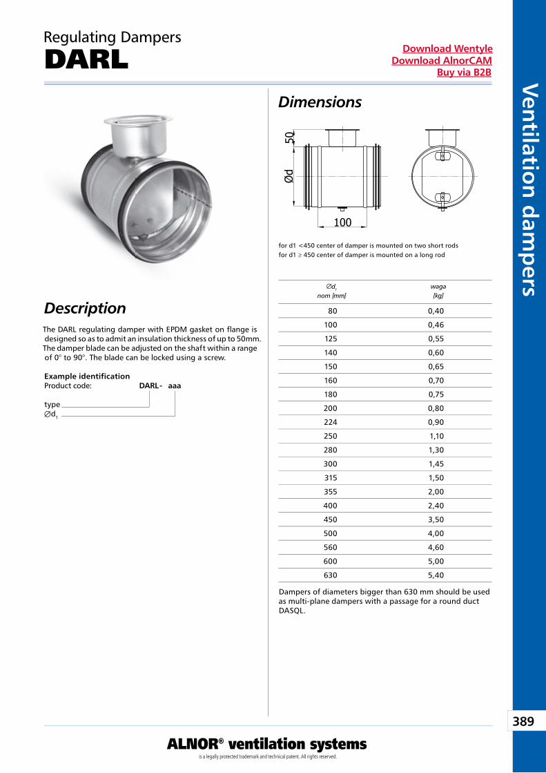
389
ALNOR® ventilation systemsis a legally protected trademark and technical patent. All rights reserved.
Ven
tilation
dam
pers
Download WentyleDownload AlnorCAM
Buy via B2B
d1
nom [mm]waga[kg]
Description
Dimensions
The DARL regulating damper with EPDM gasket on flange is designed so as to admit an insulation thickness of up to 50mm.The damper blade can be adjusted on the shaft within a range of 0° to 90°. The blade can be locked using a screw.
Example identificationProduct code: DARL - aaa
typeÆd1
Regulating Dampers
DARL
for d1 <450 center of damper is mounted on two short rodsfor d1 ≥ 450 center of damper is mounted on a long rod
Dampers of diameters bigger than 630 mm should be used as multi-plane dampers with a passage for a round duct DASQL.
80 0,40
100 0,46
125 0,55
140 0,60
150 0,65
160 0,70
180 0,75
200 0,80
224 0,90
250 1,10
280 1,30
300 1,45
315 1,50
355 2,00
400 2,40
450 3,50
500 4,00
560 4,60
600 5,00
630 5,40
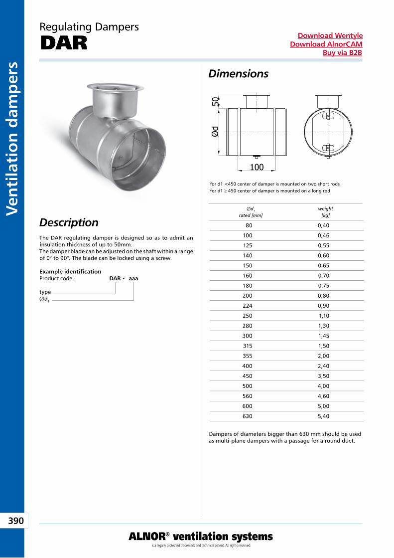
390
ALNOR® ventilation systemsis a legally protected trademark and technical patent. All rights reserved.
Ven
tila
tio
n d
amp
ers
Download WentyleDownload AlnorCAM
Buy via B2B
Description
Dimensions
The DAR regulating damper is designed so as to admit an insulation thickness of up to 50mm.The damper blade can be adjusted on the shaft within a range of 0° to 90°. The blade can be locked using a screw.
Example identificationProduct code: DAR - aaa
typeÆd1
Regulating Dampers
DAR
Æd1 weight rated [mm] [kg]
for d1 <450 center of damper is mounted on two short rodsfor d1 ≥ 450 center of damper is mounted on a long rod
80 0,40
100 0,46
125 0,55
140 0,60
150 0,65
160 0,70
180 0,75
200 0,80
224 0,90
250 1,10
280 1,30
300 1,45
315 1,50
355 2,00
400 2,40
450 3,50
500 4,00
560 4,60
600 5,00
630 5,40
Dampers of diameters bigger than 630 mm should be used as multi-plane dampers with a passage for a round duct.
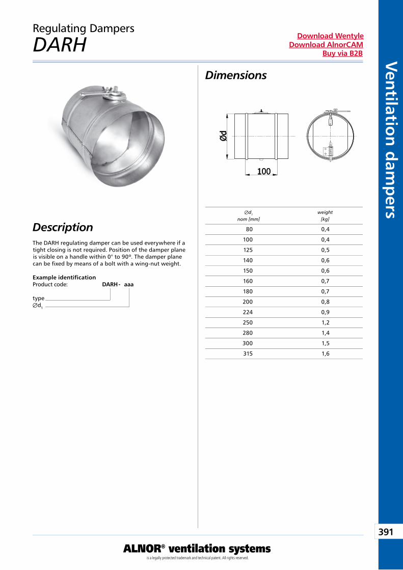
391
ALNOR® ventilation systemsis a legally protected trademark and technical patent. All rights reserved.
Ven
tilation
dam
pers
Download WentyleDownload AlnorCAM
Buy via B2B
Regulating Dampers
DARH
Description
Dimensions
The DARH regulating damper can be used everywhere if a tight closing is not required. Position of the damper plane is visible on a handle within 0° to 90º. The damper plane can be fixed by means of a bolt with a wing-nut weight.
Example identificationProduct code: DARH - aaa
typeÆd1
Æd1 weight nom [mm] [kg]
80 0,4
100 0,4
125 0,5
140 0,6
150 0,6
160 0,7
180 0,7
200 0,8
224 0,9
250 1,2
280 1,4
300 1,5
315 1,6
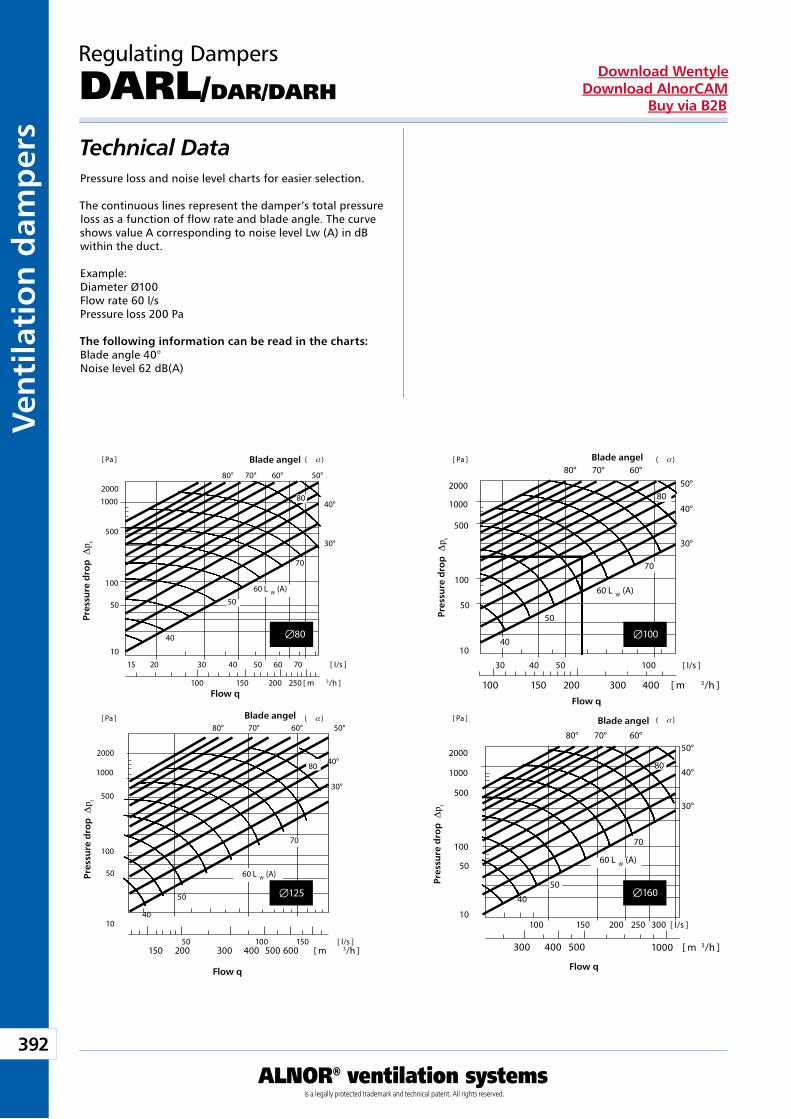
392
ALNOR® ventilation systemsis a legally protected trademark and technical patent. All rights reserved.
Ven
tila
tio
n d
amp
ers
Download WentyleDownload AlnorCAM
Buy via B2B
Æ100Æ80
Æ160Æ125
Technical DataPressure loss and noise level charts for easier selection.
The continuous lines represent the damper’s total pressure loss as a function of flow rate and blade angle. The curve shows value A corresponding to noise level Lw (A) in dB within the duct.
Example:Diameter Ø100 Flow rate 60 l/s Pressure loss 200 Pa
The following information can be read in the charts: Blade angle 40° Noise level 62 dB(A)
Regulating Dampers
DARL/DAR/DARH
Blade angel
Pre
ssu
re d
rop
Dp t
Flow q
Blade angel
Pre
ssu
re d
rop
Dp t
Flow q
Blade angel
Pre
ssu
re d
rop
Dp t
Flow q
Blade angel
Pre
ssu
re d
rop
Dp t
Flow q
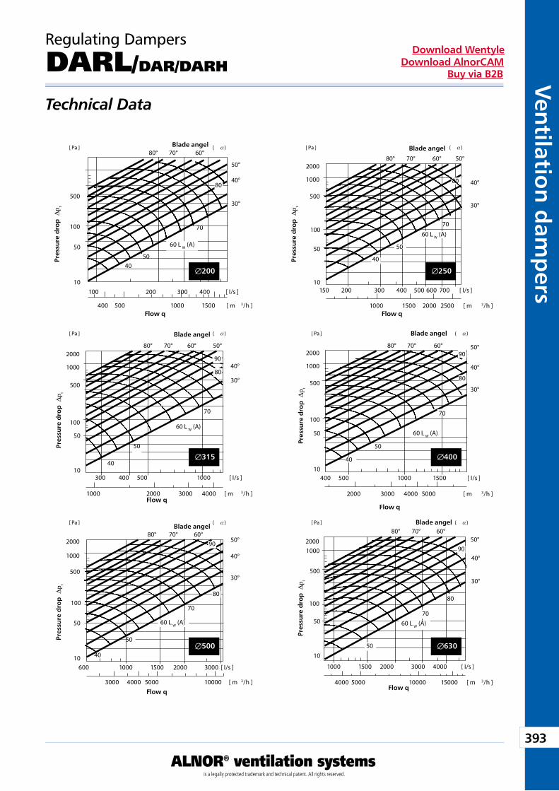
393
ALNOR® ventilation systemsis a legally protected trademark and technical patent. All rights reserved.
Ven
tilation
dam
pers
Download WentyleDownload AlnorCAM
Buy via B2B
Æ200 Æ250
Æ315
Æ500 Æ630
Æ400
Regulating Dampers
DARL/DAR/DARH
Technical Data
Blade angel
Pre
ssu
re d
rop
Dp t
Flow q
Blade angel
Pre
ssu
re d
rop
Dp t
Flow q
Blade angel
Pre
ssu
re d
rop
Dp t
Flow q
Blade angel
Pre
ssu
re d
rop
Dp t
Flow q
Blade angel
Pre
ssu
re d
rop
Dp t
Flow q
Blade angel
Pre
ssu
re d
rop
Dp t
Flow q
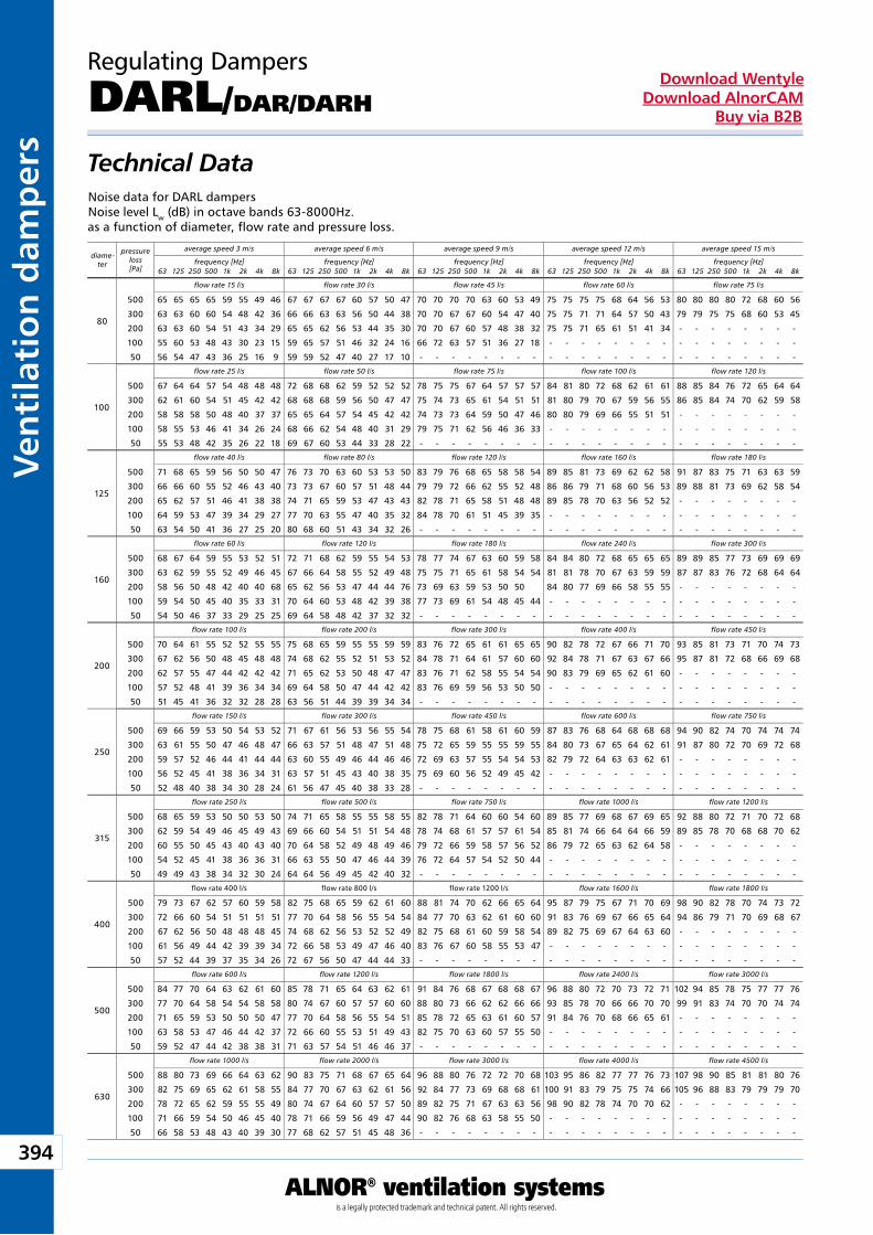
394
ALNOR® ventilation systemsis a legally protected trademark and technical patent. All rights reserved.
Ven
tila
tio
n d
amp
ers
Download WentyleDownload AlnorCAM
Buy via B2B
Regulating Dampers
DARL/DAR/DARH
Technical DataNoise data for DARL dampersNoise level Lw (dB) in octave bands 63-8000Hz.as a function of diameter, flow rate and pressure loss.
diame-ter
pressure loss[Pa]
average speed 3 m/s average speed 6 m/s average speed 9 m/s average speed 12 m/s average speed 15 m/s
frequency [Hz] frequency [Hz] frequency [Hz] frequency [Hz] frequency [Hz]63 125 250 500 1k 2k 4k 8k 63 125 250 500 1k 2k 4k 8k 63 125 250 500 1k 2k 4k 8k 63 125 250 500 1k 2k 4k 8k 63 125 250 500 1k 2k 4k 8k
flow rate 15 l/s flow rate 30 l/s flow rate 45 l/s flow rate 60 l/s flow rate 75 l/s
flow rate 25 l/s flow rate 50 l/s flow rate 75 l/s flow rate 100 l/s flow rate 120 l/s
flow rate 40 l/s flow rate 80 l/s flow rate 120 l/s flow rate 160 l/s flow rate 180 l/s
flow rate 60 l/s flow rate 120 l/s flow rate 180 l/s flow rate 240 l/s flow rate 300 l/s
flow rate 100 l/s flow rate 200 l/s flow rate 300 l/s flow rate 400 l/s flow rate 450 l/s
flow rate 150 l/s flow rate 300 l/s flow rate 450 l/s flow rate 600 l/s flow rate 750 l/s
flow rate 250 l/s flow rate 500 l/s flow rate 750 l/s flow rate 1000 l/s flow rate 1200 l/s
flow rate 400 l/s flow rate 800 l/s flow rate 1200 l/s flow rate 1600 l/s flow rate 1800 l/s
flow rate 600 l/s flow rate 1200 l/s flow rate 1800 l/s flow rate 2400 l/s flow rate 3000 l/s
flow rate 1000 l/s flow rate 2000 l/s flow rate 3000 l/s flow rate 4000 l/s flow rate 4500 l/s
80
500 65 65 65 65 59 55 49 46 67 67 67 67 60 57 50 47 70 70 70 70 63 60 53 49 75 75 75 75 68 64 56 53 80 80 80 80 72 68 60 56
300 63 63 60 60 54 48 42 36 66 66 63 63 56 50 44 38 70 70 67 67 60 54 47 40 75 75 71 71 64 57 50 43 79 79 75 75 68 60 53 45
200 63 63 60 54 51 43 34 29 65 65 62 56 53 44 35 30 70 70 67 60 57 48 38 32 75 75 71 65 61 51 41 34 - - - - - - - -
100 55 60 53 48 43 30 23 15 59 65 57 51 46 32 24 16 66 72 63 57 51 36 27 18 - - - - - - - - - - - - - - - -
50 56 54 47 43 36 25 16 9 59 59 52 47 40 27 17 10 - - - - - - - - - - - - - - - - - - - - - - - -
100
500 67 64 64 57 54 48 48 48 72 68 68 62 59 52 52 52 78 75 75 67 64 57 57 57 84 81 80 72 68 62 61 61 88 85 84 76 72 65 64 64
300 62 61 60 54 51 45 42 42 68 68 68 59 56 50 47 47 75 74 73 65 61 54 51 51 81 80 79 70 67 59 56 55 86 85 84 74 70 62 59 58
200 58 58 58 50 48 40 37 37 65 65 64 57 54 45 42 42 74 73 73 64 59 50 47 46 80 80 79 69 66 55 51 51 - - - - - - - -
100 58 55 53 46 41 34 26 24 68 66 62 54 48 40 31 29 79 75 71 62 56 46 36 33 - - - - - - - - - - - - - - - -
50 55 53 48 42 35 26 22 18 69 67 60 53 44 33 28 22 - - - - - - - - - - - - - - - - - - - - - - - -
125
500 71 68 65 59 56 50 50 47 76 73 70 63 60 53 53 50 83 79 76 68 65 58 58 54 89 85 81 73 69 62 62 58 91 87 83 75 71 63 63 59
300 66 66 60 55 52 46 43 40 73 73 67 60 57 51 48 44 79 79 72 66 62 55 52 48 86 86 79 71 68 60 56 53 89 88 81 73 69 62 58 54
200 65 62 57 51 46 41 38 38 74 71 65 59 53 47 43 43 82 78 71 65 58 51 48 48 89 85 78 70 63 56 52 52 - - - - - - - -
100 64 59 53 47 39 34 29 27 77 70 63 55 47 40 35 32 84 78 70 61 51 45 39 35 - - - - - - - - - - - - - - - -
50 63 54 50 41 36 27 25 20 80 68 60 51 43 34 32 26 - - - - - - - - - - - - - - - - - - - - - - - -
160
500 68 67 64 59 55 53 52 51 72 71 68 62 59 55 54 53 78 77 74 67 63 60 59 58 84 84 80 72 68 65 65 65 89 89 85 77 73 69 69 69
300 63 62 59 55 52 49 46 45 67 66 64 58 55 52 49 48 75 75 71 65 61 58 54 54 81 81 78 70 67 63 59 59 87 87 83 76 72 68 64 64
200 58 56 50 48 42 40 40 68 65 62 56 53 47 44 44 76 73 69 63 59 53 50 50 84 80 77 69 66 58 55 55 - - - - - - - -
100 59 54 50 45 40 35 33 31 70 64 60 53 48 42 39 38 77 73 69 61 54 48 45 44 - - - - - - - - - - - - - - - -
50 54 50 46 37 33 29 25 25 69 64 58 48 42 37 32 32 - - - - - - - - - - - - - - - - - - - - - - - -
200
500 70 64 61 55 52 52 55 55 75 68 65 59 55 55 59 59 83 76 72 65 61 61 65 65 90 82 78 72 67 66 71 70 93 85 81 73 71 70 74 73
300 67 62 56 50 48 45 48 48 74 68 62 55 52 51 53 52 84 78 71 64 61 57 60 60 92 84 78 71 67 63 67 66 95 87 81 72 68 66 69 68
200 62 57 55 47 44 42 42 42 71 65 62 53 50 48 47 47 83 76 71 62 58 55 54 54 90 83 79 69 65 62 61 60 - - - - - - - -
100 57 52 48 41 39 36 34 34 69 64 58 50 47 44 42 42 83 76 69 59 56 53 50 50 - - - - - - - - - - - - - - - -
50 51 45 41 36 32 32 28 28 63 56 51 44 39 39 34 34 - - - - - - - - - - - - - - - - - - - - - - - -
250
500 69 66 59 53 50 54 53 52 71 67 61 56 53 56 55 54 78 75 68 61 58 61 60 59 87 83 76 68 64 68 68 68 94 90 82 74 70 74 74 74
300 63 61 55 50 47 46 48 47 66 63 57 51 48 47 51 48 75 72 65 59 55 55 59 55 84 80 73 67 65 64 62 61 91 87 80 72 70 69 72 68
200 59 57 52 46 44 41 44 44 63 60 55 49 46 44 46 46 72 69 63 57 55 54 54 53 82 79 72 64 63 63 62 61 - - - - - - - -
100 56 52 45 41 38 36 34 31 63 57 51 45 43 40 38 35 75 69 60 56 52 49 45 42 - - - - - - - - - - - - - - - -
50 52 48 40 38 34 30 28 24 61 56 47 45 40 38 33 28 - - - - - - - - - - - - - - - - - - - - - - - -
315
500 68 65 59 53 50 50 53 50 74 71 65 58 55 55 58 55 82 78 71 64 60 60 54 60 89 85 77 69 68 67 69 65 92 88 80 72 71 70 72 68
300 62 59 54 49 46 45 49 43 69 66 60 54 51 51 54 48 78 74 68 61 57 57 61 54 85 81 74 66 64 64 66 59 89 85 78 70 68 68 70 62
200 60 55 50 45 43 40 43 40 70 64 58 52 49 48 49 46 79 72 66 59 58 57 56 52 86 79 72 65 63 62 64 58 - - - - - - - -
100 54 52 45 41 38 36 36 31 66 63 55 50 47 46 44 39 76 72 64 57 54 52 50 44 - - - - - - - - - - - - - - - -
50 49 49 43 38 34 32 30 24 64 64 56 49 45 42 40 32 - - - - - - - - - - - - - - - - - - - - - - - -
400
500 79 73 67 62 57 60 59 58 82 75 68 65 59 62 61 60 88 81 74 70 62 66 65 64 95 87 79 75 67 71 70 69 98 90 82 78 70 74 73 72
300 72 66 60 54 51 51 51 51 77 70 64 58 56 55 54 54 84 77 70 63 62 61 60 60 91 83 76 69 67 66 65 64 94 86 79 71 70 69 68 67
200 67 62 56 50 48 48 48 45 74 68 62 56 53 52 52 49 82 75 68 61 60 59 58 54 89 82 75 69 67 64 63 60 - - - - - - - -
100 61 56 49 44 42 39 39 34 72 66 58 53 49 47 46 40 83 76 67 60 58 55 53 47 - - - - - - - - - - - - - - - -
50 57 52 44 39 37 35 34 26 72 67 56 50 47 44 44 33 - - - - - - - - - - - - - - - - - - - - - - - -
500
500 84 77 70 64 63 62 61 60 85 78 71 65 64 63 62 61 91 84 76 68 67 68 68 67 96 88 80 72 70 73 72 71 102 94 85 78 75 77 77 76
300 77 70 64 58 54 54 58 58 80 74 67 60 57 57 60 60 88 80 73 66 62 62 66 66 93 85 78 70 66 66 70 70 99 91 83 74 70 70 74 74
200 71 65 59 53 50 50 50 47 77 70 64 58 56 55 54 51 85 78 72 65 63 61 60 57 91 84 76 70 68 66 65 61 - - - - - - - -
100 63 58 53 47 46 44 42 37 72 66 60 55 53 51 49 43 82 75 70 63 60 57 55 50 - - - - - - - - - - - - - - - -
50 59 52 47 44 42 38 38 31 71 63 57 54 51 46 46 37 - - - - - - - - - - - - - - - - - - - - - - - -
630
500 88 80 73 69 66 64 63 62 90 83 75 71 68 67 65 64 96 88 80 76 72 72 70 68 103 95 86 82 77 77 76 73 107 98 90 85 81 81 80 76
300 82 75 69 65 62 61 58 55 84 77 70 67 63 62 61 56 92 84 77 73 69 68 68 61 100 91 83 79 75 75 74 66 105 96 88 83 79 79 79 70
200 78 72 65 62 59 55 55 49 80 74 67 64 60 57 57 50 89 82 75 71 67 63 63 56 98 90 82 78 74 70 70 62 - - - - - - - -
100 71 66 59 54 50 46 45 40 78 71 66 59 56 49 47 44 90 82 76 68 63 58 55 50 - - - - - - - - - - - - - - - -
50 66 58 53 48 43 40 39 30 77 68 62 57 51 45 48 36 - - - - - - - - - - - - - - - - - - - - - - - -
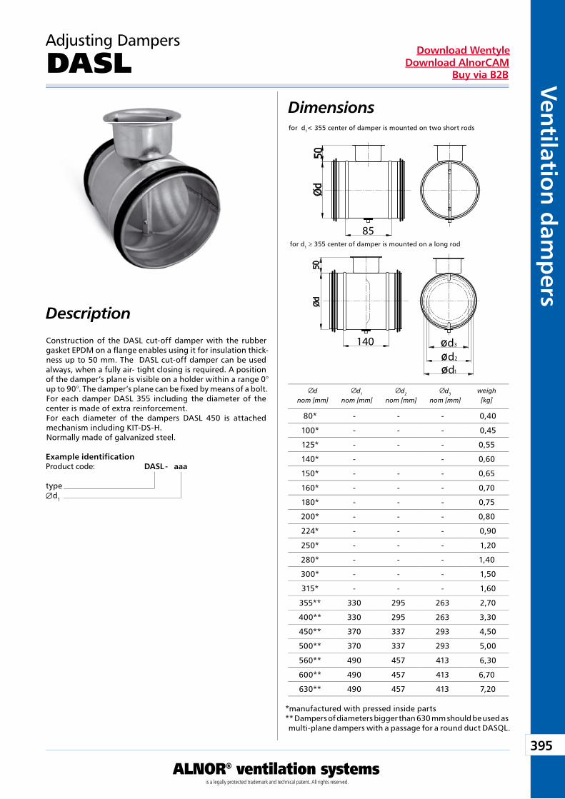
395
ALNOR® ventilation systemsis a legally protected trademark and technical patent. All rights reserved.
Ven
tilation
dam
pers
Download WentyleDownload AlnorCAM
Buy via B2B
85
dd
1
2
d3140
dnom [mm]
d1
nom [mm]d2
nom [mm]d3
nom [mm]weigh[kg]
Dimensions
Example identificationProduct code: DASL - aaa
typeÆd1
Adjusting Dampers
DASL
Description
for d1 ≥ 355 center of damper is mounted on a long rod
for d1< 355 center of damper is mounted on two short rods
Construction of the DASL cut-off damper with the rubber gasket EPDM on a flange enables using it for insulation thick-ness up to 50 mm. The DASL cut-off damper can be used always, when a fully air- tight closing is required. A position of the damper’s plane is visible on a holder within a range 0° up to 90°. The damper’s plane can be fixed by means of a bolt.For each damper DASL 355 including the diameter of the center is made of extra reinforcement.For each diameter of the dampers DASL 450 is attached mechanism including KIT-DS-H.Normally made of galvanized steel.
80* - - - 0,40
100* - - - 0,45
125* - - - 0,55
140* - - 0,60
150* - - - 0,65
160* - - - 0,70
180* - - - 0,75
200* - - - 0,80
224* - - - 0,90
250* - - - 1,20
280* - - - 1,40
300* - - - 1,50
315* - - - 1,60
355** 330 295 263 2,70
400** 330 295 263 3,30
450** 370 337 293 4,50
500** 370 337 293 5,00
560** 490 457 413 6,30
600** 490 457 413 6,70
630** 490 457 413 7,20
*manufactured with pressed inside parts** Dampers of diameters bigger than 630 mm should be used as multi-plane dampers with a passage for a round duct DASQL.
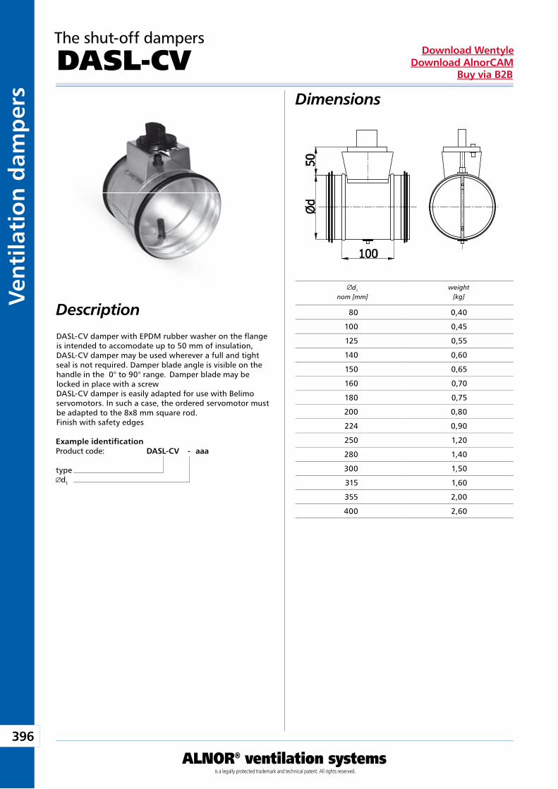
396
ALNOR® ventilation systemsis a legally protected trademark and technical patent. All rights reserved.
Ven
tila
tio
n d
amp
ers
Download WentyleDownload AlnorCAM
Buy via B2B
d1
nom [mm]weight
[kg]
The shut-off dampers
DASL-CV
Description
Dimensions
DASL-CV damper with EPDM rubber washer on the flange is intended to accomodate up to 50 mm of insulation, DASL-CV damper may be used wherever a full and tight seal is not required. Damper blade angle is visible on the handle in the 0° to 90° range. Damper blade may be locked in place with a screw DASL-CV damper is easily adapted for use with Belimo servomotors. In such a case, the ordered servomotor must be adapted to the 8x8 mm square rod. Finish with safety edges
Example identificationProduct code: DASL-CV - aaa
typed1
80 0,40
100 0,45
125 0,55
140 0,60
150 0,65
160 0,70
180 0,75
200 0,80
224 0,90
250 1,20
280 1,40
300 1,50
315 1,60
355 2,00
400 2,60
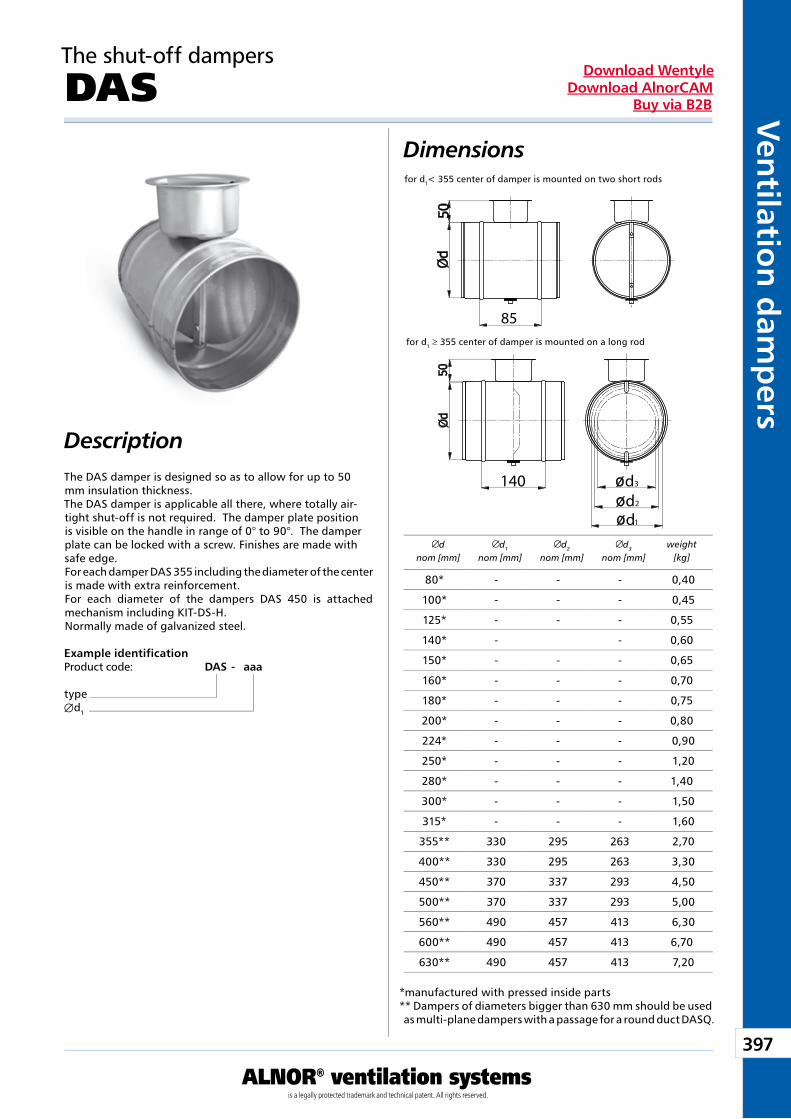
397
ALNOR® ventilation systemsis a legally protected trademark and technical patent. All rights reserved.
Ven
tilation
dam
pers
Download WentyleDownload AlnorCAM
Buy via B2B
85
dd
1
2
d3140
dnom [mm]
d1
nom [mm]d2
nom [mm]d3
nom [mm]weight
[kg]
Dimensions
Description
Example identificationProduct code: DAS - aaa
typeÆd1
for d1 ≥ 355 center of damper is mounted on a long rod
for d1< 355 center of damper is mounted on two short rods
The shut-off dampers
DAS
The DAS damper is designed so as to allow for up to 50 mm insulation thickness.The DAS damper is applicable all there, where totally air-tight shut-off is not required. The damper plate position is visible on the handle in range of 0° to 90°. The damper plate can be locked with a screw. Finishes are made with safe edge.For each damper DAS 355 including the diameter of the centeris made with extra reinforcement.For each diameter of the dampers DAS 450 is attached mechanism including KIT-DS-H.Normally made of galvanized steel.
*manufactured with pressed inside parts** Dampers of diameters bigger than 630 mm should be used as multi-plane dampers with a passage for a round duct DASQ.
80* - - - 0,40
100* - - - 0,45
125* - - - 0,55
140* - - 0,60
150* - - - 0,65
160* - - - 0,70
180* - - - 0,75
200* - - - 0,80
224* - - - 0,90
250* - - - 1,20
280* - - - 1,40
300* - - - 1,50
315* - - - 1,60
355** 330 295 263 2,70
400** 330 295 263 3,30
450** 370 337 293 4,50
500** 370 337 293 5,00
560** 490 457 413 6,30
600** 490 457 413 6,70
630** 490 457 413 7,20
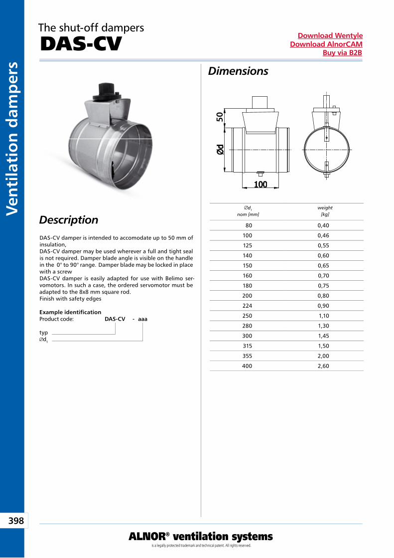
398
ALNOR® ventilation systemsis a legally protected trademark and technical patent. All rights reserved.
Ven
tila
tio
n d
amp
ers
Download WentyleDownload AlnorCAM
Buy via B2B
50d1
nom [mm]weight
[kg]
The shut-off dampers
DAS-CV
Description
Dimensions
DAS-CV damper is intended to accomodate up to 50 mm of insulation, DAS-CV damper may be used wherever a full and tight seal is not required. Damper blade angle is visible on the handle in the 0° to 90° range. Damper blade may be locked in place with a screw DAS-CV damper is easily adapted for use with Belimo ser-vomotors. In such a case, the ordered servomotor must be adapted to the 8x8 mm square rod. Finish with safety edges
Example identificationProduct code: DAS-CV - aaa
typd1
80 0,40
100 0,46
125 0,55
140 0,60
150 0,65
160 0,70
180 0,75
200 0,80
224 0,90
250 1,10
280 1,30
300 1,45
315 1,50
355 2,00
400 2,60
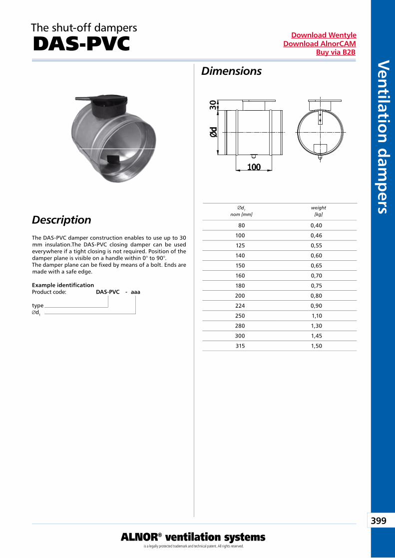
399
ALNOR® ventilation systemsis a legally protected trademark and technical patent. All rights reserved.
Ven
tilation
dam
pers
Download WentyleDownload AlnorCAM
Buy via B2B
30d1
nom [mm]weight
[kg]
The shut-off dampers
DAS-PVC
Description
Dimensions
The DAS-PVC damper construction enables to use up to 30 mm insulation.The DAS-PVC closing damper can be used everywhere if a tight closing is not required. Position of the damper plane is visible on a handle within 0° to 90°. The damper plane can be fixed by means of a bolt. Ends are made with a safe edge.
Example identificationProduct code: DAS-PVC - aaa
typed1
80 0,40
100 0,46
125 0,55
140 0,60
150 0,65
160 0,70
180 0,75
200 0,80
224 0,90
250 1,10
280 1,30
300 1,45
315 1,50
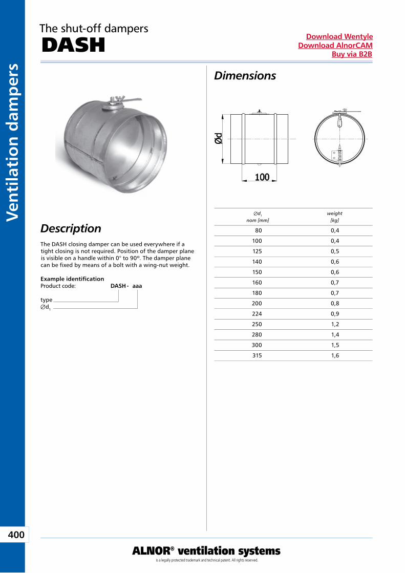
400
ALNOR® ventilation systemsis a legally protected trademark and technical patent. All rights reserved.
Ven
tila
tio
n d
amp
ers
Download WentyleDownload AlnorCAM
Buy via B2B
The shut-off dampers
DASH
Description
Dimensions
The DASH closing damper can be used everywhere if a tight closing is not required. Position of the damper plane is visible on a handle within 0° to 90º. The damper plane can be fixed by means of a bolt with a wing-nut weight.
Example identificationProduct code: DASH - aaa
typeÆd1
Æd1 weight nom [mm] [kg]
80 0,4
100 0,4
125 0,5
140 0,6
150 0,6
160 0,7
180 0,7
200 0,8
224 0,9
250 1,2
280 1,4
300 1,5
315 1,6
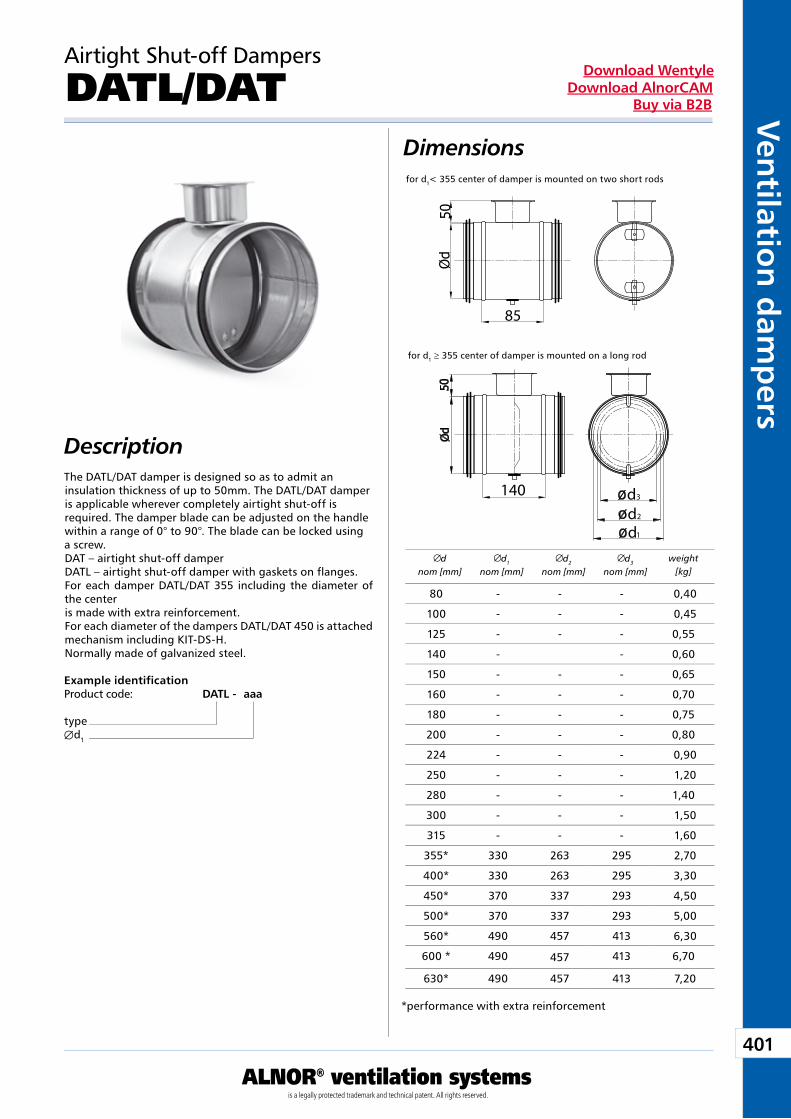
401
ALNOR® ventilation systemsis a legally protected trademark and technical patent. All rights reserved.
Ven
tilation
dam
pers
Download WentyleDownload AlnorCAM
Buy via B2B
85
dd
1
2
d3140
dnom [mm]
d1
nom [mm]d2
nom [mm]d3
nom [mm]weight
[kg]
Airtight Shut-off Dampers
DATL/DAT
Description
Dimensions
The DATL/DAT damper is designed so as to admit an insulation thickness of up to 50mm. The DATL/DAT damper is applicable wherever completely airtight shut-off is required. The damper blade can be adjusted on the handle within a range of 0° to 90°. The blade can be locked using a screw.DAT – airtight shut-off damperDATL – airtight shut-off damper with gaskets on flanges.For each damper DATL/DAT 355 including the diameter of the centeris made with extra reinforcement.For each diameter of the dampers DATL/DAT 450 is attached mechanism including KIT-DS-H.Normally made of galvanized steel.
Example identificationProduct code: DATL - aaa
typeÆd1
*performance with extra reinforcement
for d1 ≥ 355 center of damper is mounted on a long rod
for d1< 355 center of damper is mounted on two short rods
80 - - - 0,40
100 - - - 0,45
125 - - - 0,55
140 - - 0,60
150 - - - 0,65
160 - - - 0,70
180 - - - 0,75
200 - - - 0,80
224 - - - 0,90
250 - - - 1,20
280 - - - 1,40
300 - - - 1,50
315 - - - 1,60
355* 330 263 295 2,70
400* 330 263 295 3,30
450* 370 337 293 4,50
500* 370 337 293 5,00
560* 490 457 413 6,30
600 * 490 457 413 6,70
630* 490 457 413 7,20
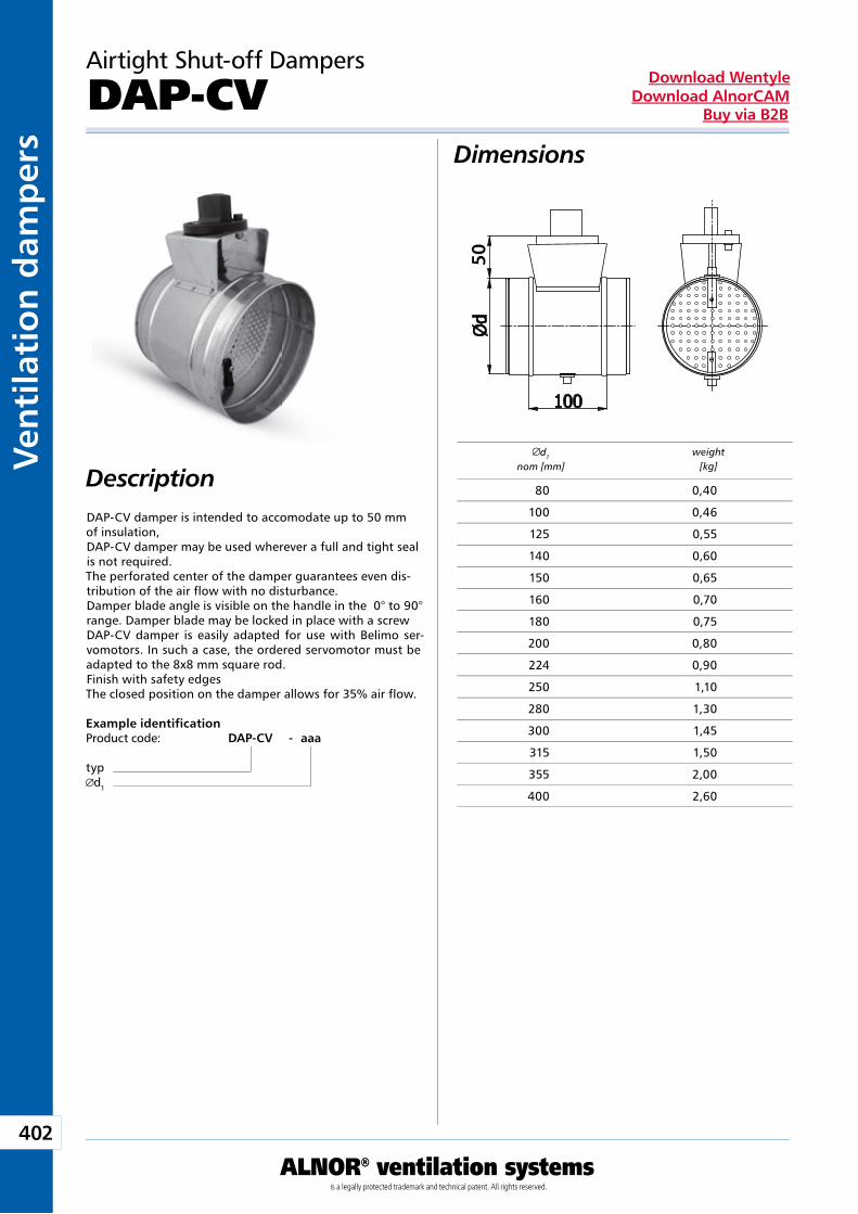
402
ALNOR® ventilation systemsis a legally protected trademark and technical patent. All rights reserved.
Ven
tila
tio
n d
amp
ers
Download WentyleDownload AlnorCAM
Buy via B2B
50d1
nom [mm]weight
[kg]
Airtight Shut-off Dampers
DAP-CV
Description
Dimensions
DAP-CV damper is intended to accomodate up to 50 mm of insulation, DAP-CV damper may be used wherever a full and tight seal is not required. The perforated center of the damper guarantees even dis-tribution of the air flow with no disturbance. Damper blade angle is visible on the handle in the 0° to 90° range. Damper blade may be locked in place with a screw DAP-CV damper is easily adapted for use with Belimo ser-vomotors. In such a case, the ordered servomotor must be adapted to the 8x8 mm square rod. Finish with safety edges The closed position on the damper allows for 35% air flow.
Example identificationProduct code: DAP-CV - aaa
typd1
80 0,40
100 0,46
125 0,55
140 0,60
150 0,65
160 0,70
180 0,75
200 0,80
224 0,90
250 1,10
280 1,30
300 1,45
315 1,50
355 2,00
400 2,60
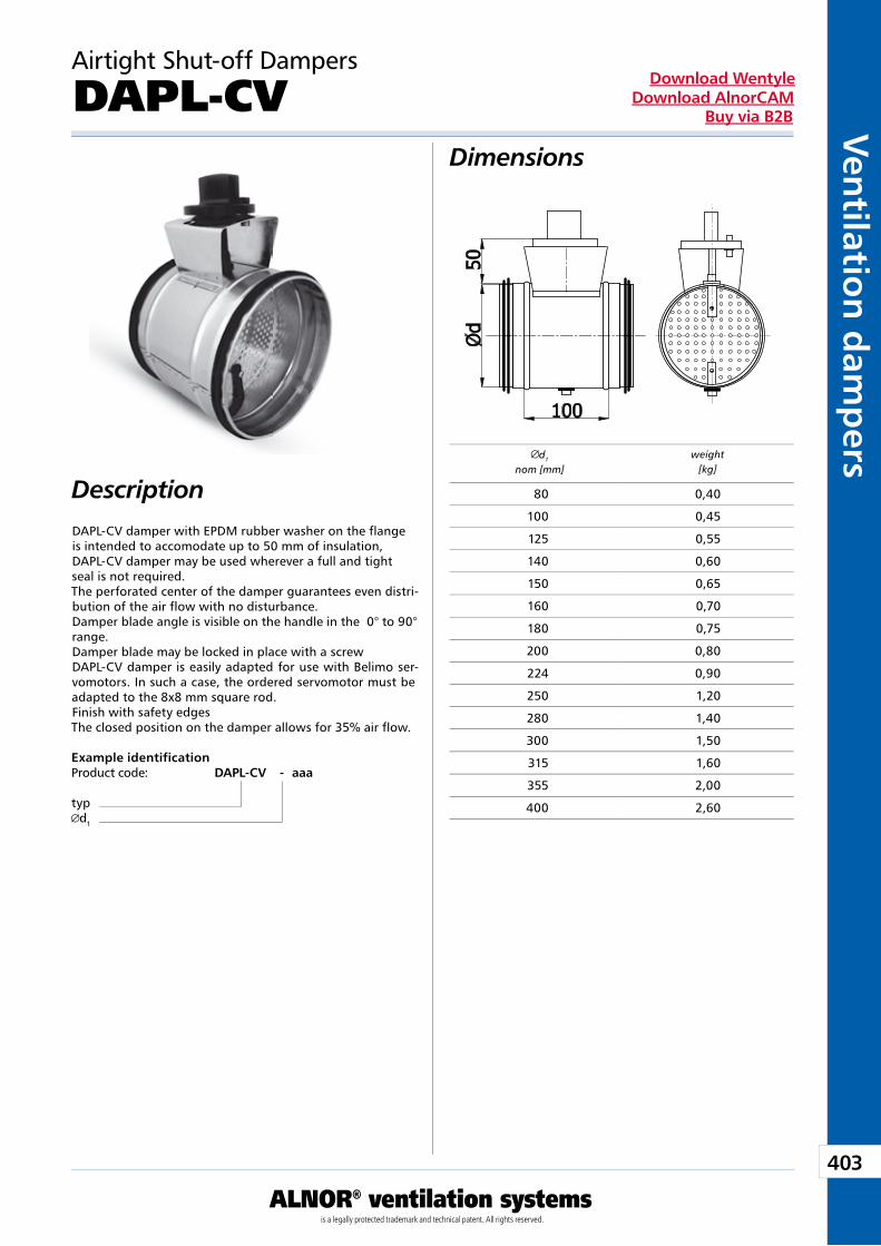
403
ALNOR® ventilation systemsis a legally protected trademark and technical patent. All rights reserved.
Ven
tilation
dam
pers
Download WentyleDownload AlnorCAM
Buy via B2B
d1
nom [mm]weight
[kg]
Airtight Shut-off Dampers
DAPL-CV
Description
Dimensions
DAPL-CV damper with EPDM rubber washer on the flange is intended to accomodate up to 50 mm of insulation, DAPL-CV damper may be used wherever a full and tight seal is not required. The perforated center of the damper guarantees even distri-bution of the air flow with no disturbance. Damper blade angle is visible on the handle in the 0° to 90° range. Damper blade may be locked in place with a screw DAPL-CV damper is easily adapted for use with Belimo ser-vomotors. In such a case, the ordered servomotor must be adapted to the 8x8 mm square rod. Finish with safety edges The closed position on the damper allows for 35% air flow.
Example identificationProduct code: DAPL-CV - aaa
typd1
80 0,40
100 0,45
125 0,55
140 0,60
150 0,65
160 0,70
180 0,75
200 0,80
224 0,90
250 1,20
280 1,40
300 1,50
315 1,60
355 2,00
400 2,60
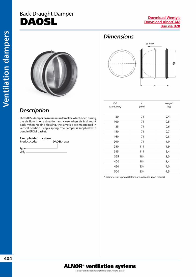
404
ALNOR® ventilation systemsis a legally protected trademark and technical patent. All rights reserved.
Ven
tila
tio
n d
amp
ers
Download WentyleDownload AlnorCAM
Buy via B2B
air flow
Back Draught Damper
DAOSL
Description
Dimensions
The DAOSL damper has aluminium lamellae which open during the air flow in one direction and close when air is draught back. When no air is flowing, the lamellae are maintained in vertical position using a spring. The damper is supplied with double EPDM gasket.
Example identificationProduct code: DAOSL - aaa
typeÆd1
Æd1 L weight rated [mm] [mm] [kg]
* diameters of up to ø560mm are available upon request
80 74 0,4
100 74 0,5
125 74 0,6
150 74 0,7
160 74 0,8
200 74 1,0
250 114 1,9
315 114 2,4
355 184 3,0
400 184 3,4
450 234 4,0
500 234 4,5
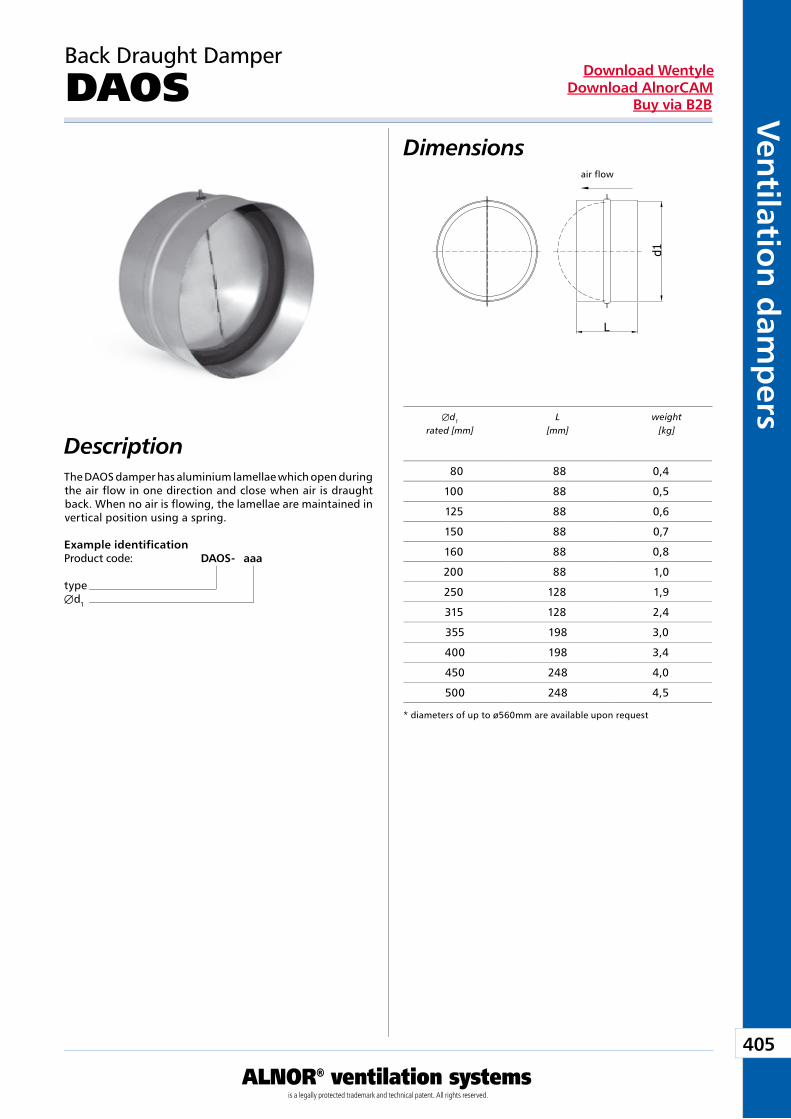
405
ALNOR® ventilation systemsis a legally protected trademark and technical patent. All rights reserved.
Ven
tilation
dam
pers
Download WentyleDownload AlnorCAM
Buy via B2B
Back Draught Damper
DAOS
Description
Dimensions
The DAOS damper has aluminium lamellae which open during the air flow in one direction and close when air is draught back. When no air is flowing, the lamellae are maintained in vertical position using a spring.
Example identificationProduct code: DAOS - aaa
typeÆd1
Æd1 L weight rated [mm] [mm] [kg]
* diameters of up to ø560mm are available upon request
air flow
80 88 0,4
100 88 0,5
125 88 0,6
150 88 0,7
160 88 0,8
200 88 1,0
250 128 1,9
315 128 2,4
355 198 3,0
400 198 3,4
450 248 4,0
500 248 4,5
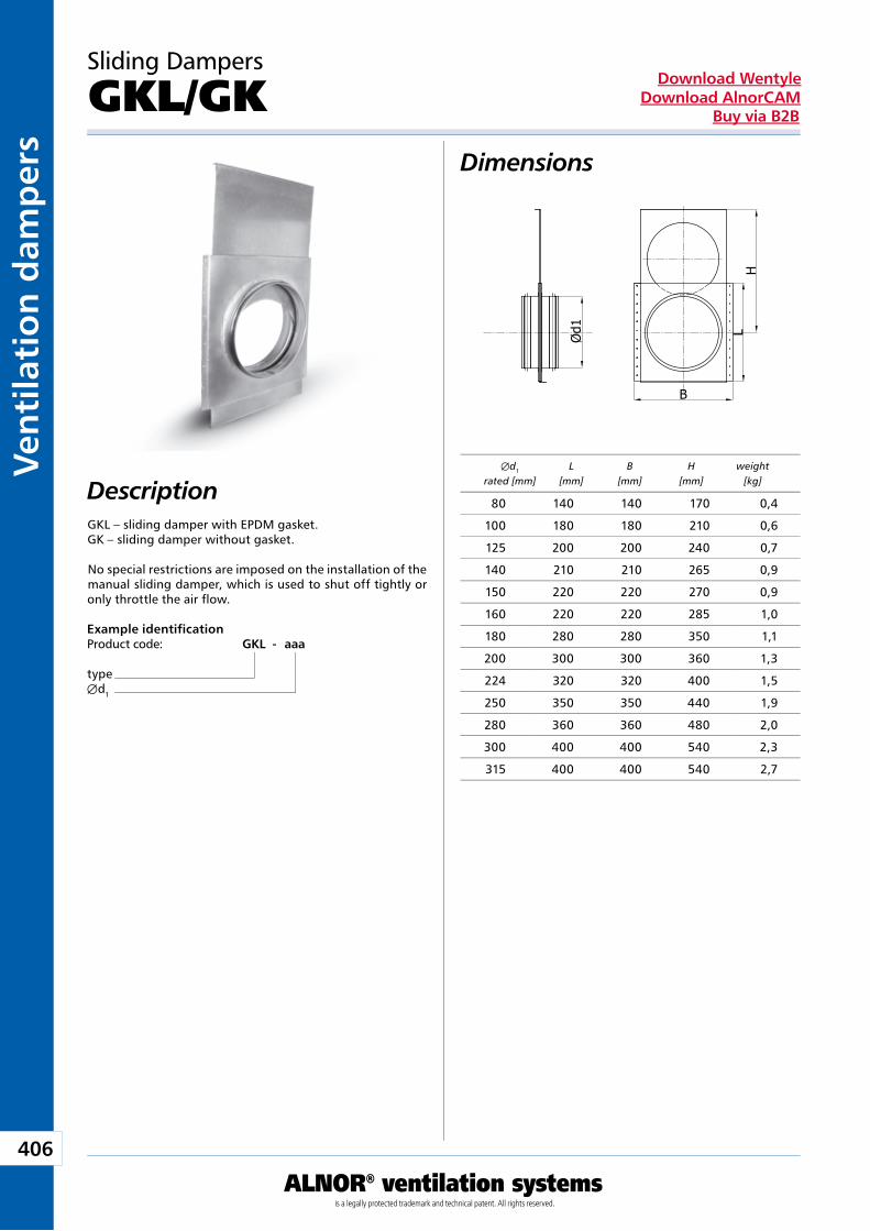
406
ALNOR® ventilation systemsis a legally protected trademark and technical patent. All rights reserved.
Ven
tila
tio
n d
amp
ers
Download WentyleDownload AlnorCAM
Buy via B2B
L
Sliding Dampers
GKL/GK
Description
Dimensions
GKL – sliding damper with EPDM gasket.GK – sliding damper without gasket.
No special restrictions are imposed on the installation of the manual sliding damper, which is used to shut off tightly or only throttle the air flow.
Example identificationProduct code: GKL - aaa
typeÆd1
Æd1 L B H weight rated [mm] [mm] [mm] [mm] [kg]
80 140 140 170 0,4
100 180 180 210 0,6
125 200 200 240 0,7
140 210 210 265 0,9
150 220 220 270 0,9
160 220 220 285 1,0
180 280 280 350 1,1
200 300 300 360 1,3
224 320 320 400 1,5
250 350 350 440 1,9
280 360 360 480 2,0
300 400 400 540 2,3
315 400 400 540 2,7
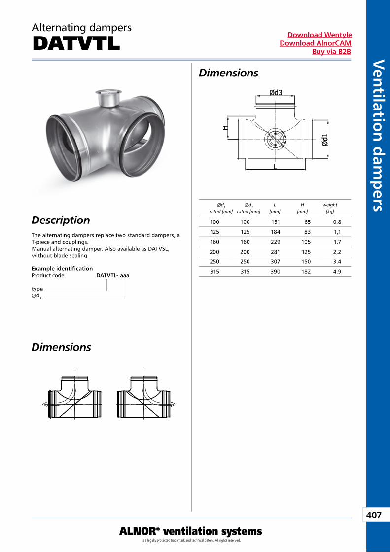
407
ALNOR® ventilation systemsis a legally protected trademark and technical patent. All rights reserved.
Ven
tilation
dam
pers
Download WentyleDownload AlnorCAM
Buy via B2B
Alternating dampers
DATVTL
Description
Dimensions
The alternating dampers replace two standard dampers, a T-piece and couplings.Manual alternating damper. Also available as DATVSL, without blade sealing.
Example identificationProduct code: DATVTL - aaa
typeÆd1
Dimensions
Æd1 Æd3 L H weight rated [mm] rated [mm] [mm] [mm] [kg]
100 100 151 65 0,8
125 125 184 83 1,1
160 160 229 105 1,7
200 200 281 125 2,2
250 250 307 150 3,4
315 315 390 182 4,9
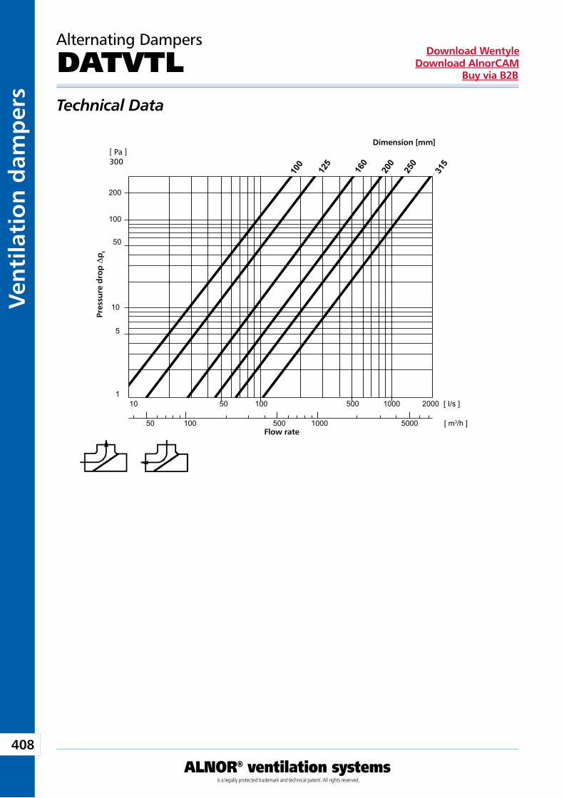
408
ALNOR® ventilation systemsis a legally protected trademark and technical patent. All rights reserved.
Ven
tila
tio
n d
amp
ers
Download WentyleDownload AlnorCAM
Buy via B2B
100
125
160
200
250
315
[ Pa ] 300
200
100
50
1
10
5
50 100 500 1000 5000 [ m3/h ]
10 50 100 500 1000 2000 [ I/s ]
Alternating Dampers
DATVTLTechnical Data
Dimension [mm]
Pre
ssur
e d
rop
Dp
t
Flow rate
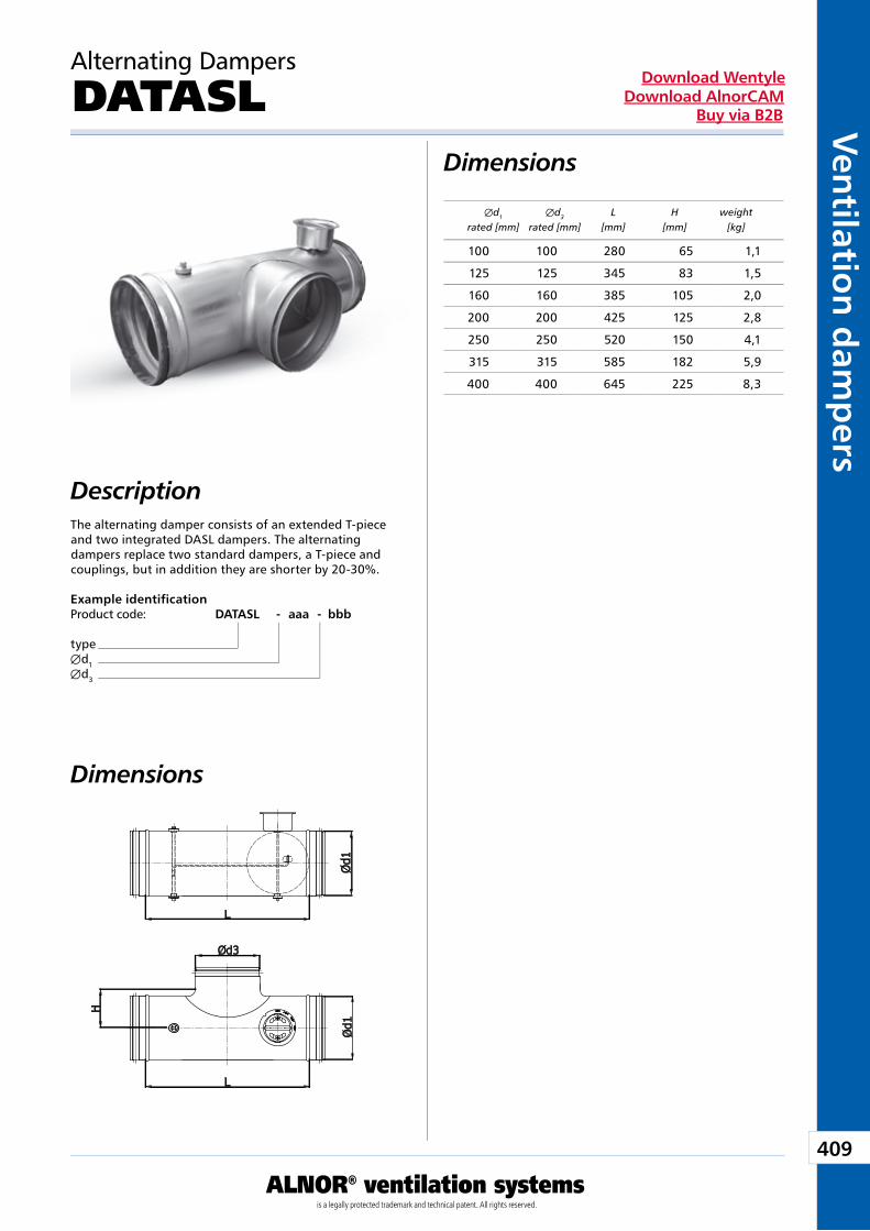
409
ALNOR® ventilation systemsis a legally protected trademark and technical patent. All rights reserved.
Ven
tilation
dam
pers
Download WentyleDownload AlnorCAM
Buy via B2B
Alternating Dampers
DATASL
Description
Dimensions
The alternating damper consists of an extended T-piece and two integrated DASL dampers. The alternating dampers replace two standard dampers, a T-piece and couplings, but in addition they are shorter by 20-30%.
Dimensions
Example identificationProduct code: DATASL - aaa - bbb
typeÆd1Æd3
Æd1 Æd3 L H weight rated [mm] rated [mm] [mm] [mm] [kg]
100 100 280 65 1,1
125 125 345 83 1,5
160 160 385 105 2,0
200 200 425 125 2,8
250 250 520 150 4,1
315 315 585 182 5,9
400 400 645 225 8,3
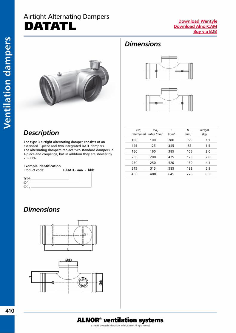
410
ALNOR® ventilation systemsis a legally protected trademark and technical patent. All rights reserved.
Ven
tila
tio
n d
amp
ers
Download WentyleDownload AlnorCAM
Buy via B2B
Airtight Alternating Dampers
DATATLDimensions
The type 3 airtight alternating damper consists of an extended T-piece and two integrated DATL dampers. The alternating dampers replace two standard dampers, a T-piece and couplings, but in addition they are shorter by 20-30%.
Dimensions
Example identificationProduct code: DATATL - aaa - bbb
typeÆd1Æd3
Description Æd1 Æd3 L H weight rated [mm] rated [mm] [mm] [mm] [kg]
100 100 280 65 1,1
125 125 345 83 1,5
160 160 385 105 2,0
200 200 425 125 2,8
250 250 520 150 4,1
315 315 585 182 5,9
400 400 645 225 8,3
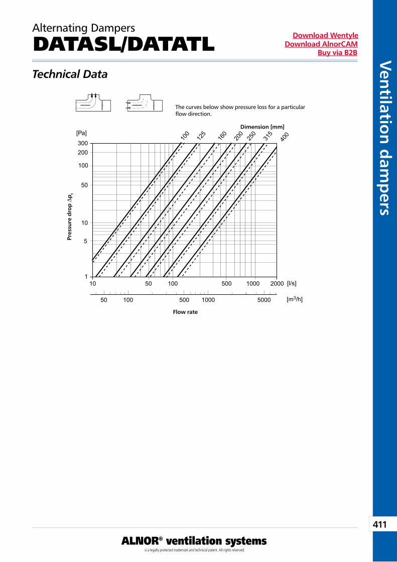
411
ALNOR® ventilation systemsis a legally protected trademark and technical patent. All rights reserved.
Ven
tilation
dam
pers
Download WentyleDownload AlnorCAM
Buy via B2B
[Pa]
300
100
200
50
10
5
110 50 100 500 1000 2000
50 100 500 1000 5000
100
125
160
200
250
315
400
[l/s]
[m3/h]
Alternating Dampers
DATASL/DATATLTechnical Data
The curves below show pressure loss for a particular flow direction.
Dimension [mm]
Pre
ssur
e d
rop
Dp
t
Flow rate
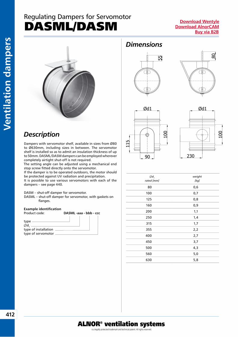
412
ALNOR® ventilation systemsis a legally protected trademark and technical patent. All rights reserved.
Ven
tila
tio
n d
amp
ers
Download WentyleDownload AlnorCAM
Buy via B2B
Regulating Dampers for Servomotor
DASML/DASMDimensions
DescriptionDampers with servomotor shelf, available in sizes from Ø80 to Ø630mm, including sizes in between. The servomotor shelf is installed so as to admit an insulation thickness of up to 50mm. DASML/DASM dampers can be employed wherever completely airtight shut-off is not required.The setting angle can be adjusted using a mechanical end stop screw fitted directly onto the servomotor.If the damper is to be operated outdoors, the motor should be protected against UV radiation and precipitation.It is possible to use various servomotors with each of the dampers – see page 440.
DASM – shut-off damper for servomotor.DASML – shut-off damper for servomotor, with gaskets on flanges.
Example identificationProduct code: DASML - aaa - bbb - ccc
typeÆd1type of installationtype of servomotor
Æd1 weight rated [mm] [kg]
80 0,6
100 0,7
125 0,8
160 0,9
200 1,1
250 1,4
315 1,7
355 2,2
400 2,7
450 3,7
500 4,3
560 5,0
630 5,8
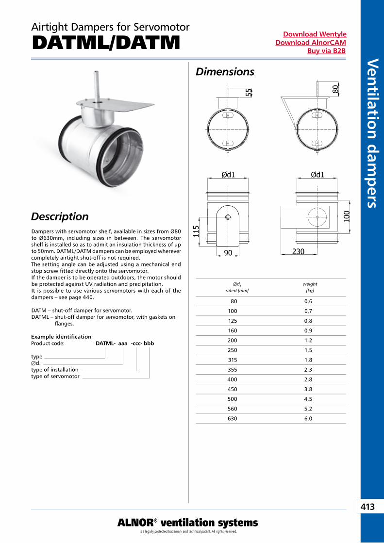
413
ALNOR® ventilation systemsis a legally protected trademark and technical patent. All rights reserved.
Ven
tilation
dam
pers
Download WentyleDownload AlnorCAM
Buy via B2B
Airtight Dampers for Servomotor
DATML/DATMDimensions
DescriptionDampers with servomotor shelf, available in sizes from Ø80 to Ø630mm, including sizes in between. The servomotor shelf is installed so as to admit an insulation thickness of up to 50mm. DATML/DATM dampers can be employed wherever completely airtight shut-off is not required.The setting angle can be adjusted using a mechanical end stop screw fitted directly onto the servomotor.If the damper is to be operated outdoors, the motor should be protected against UV radiation and precipitation.It is possible to use various servomotors with each of the dampers – see page 440.
DATM – shut-off damper for servomotor.DATML – shut-off damper for servomotor, with gaskets on flanges.
Æd1 weight rated [mm] [kg]
Example identificationProduct code: DATML - aaa - ccc- bbb
typeÆd1type of installationtype of servomotor
80 0,6
100 0,7
125 0,8
160 0,9
200 1,2
250 1,5
315 1,8
355 2,3
400 2,8
450 3,8
500 4,5
560 5,2
630 6,0
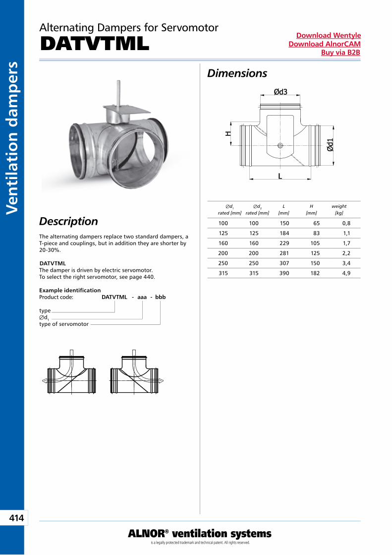
414
ALNOR® ventilation systemsis a legally protected trademark and technical patent. All rights reserved.
Ven
tila
tio
n d
amp
ers
Download WentyleDownload AlnorCAM
Buy via B2B
Alternating Dampers for Servomotor
DATVTMLDimensions
Example identificationProduct code: DATVTML - aaa - bbb
typeÆd1type of servomotor
DescriptionThe alternating dampers replace two standard dampers, a T-piece and couplings, but in addition they are shorter by 20-30%.
DATVTMLThe damper is driven by electric servomotor.To select the right servomotor, see page 440.
Æd1 Æd3 L H weight rated [mm] rated [mm] [mm] [mm] [kg]
100 100 150 65 0,8
125 125 184 83 1,1
160 160 229 105 1,7
200 200 281 125 2,2
250 250 307 150 3,4
315 315 390 182 4,9
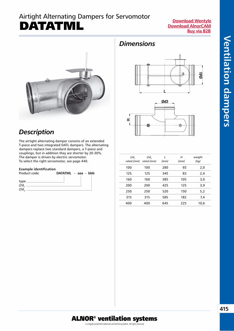
415
ALNOR® ventilation systemsis a legally protected trademark and technical patent. All rights reserved.
Ven
tilation
dam
pers
Download WentyleDownload AlnorCAM
Buy via B2B
Airtight Alternating Dampers for Servomotor
DATATMLDimensions
Example identificationProduct code: DATATML - aaa - bbb
typeÆd1Æd3
DescriptionThe airtight alternating damper consists of an extended T-piece and two integrated DATL dampers. The alternating dampers replace two standard dampers, a T-piece and couplings, but in addition they are shorter by 20-30%. The damper is driven by electric servomotor.To select the right servomotor, see page 440.
Æd1 Æd3 L H weight rated [mm] rated [mm] [mm] [mm] [kg]
100 100 280 65 2,0
125 125 345 83 2,4
160 160 385 105 3,0
200 200 425 125 3,9
250 250 520 150 5,2
315 315 585 182 7,4
400 400 645 225 10,6
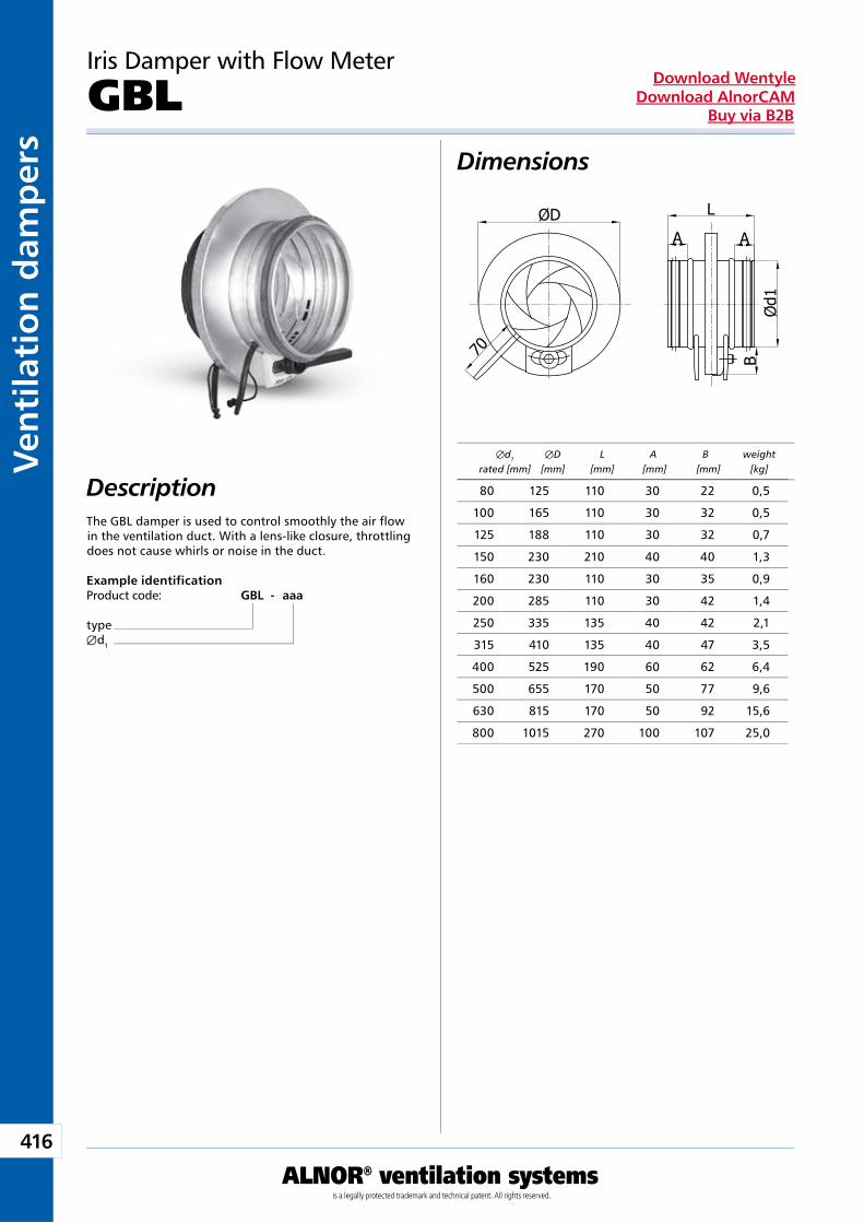
416
ALNOR® ventilation systemsis a legally protected trademark and technical patent. All rights reserved.
Ven
tila
tio
n d
amp
ers
Download WentyleDownload AlnorCAM
Buy via B2B
Iris Damper with Flow Meter
GBL
Description
Dimensions
The GBL damper is used to control smoothly the air flow in the ventilation duct. With a lens-like closure, throttling does not cause whirls or noise in the duct.
Example identificationProduct code: GBL - aaa
typeÆd1
Æd1 ÆD L A B weight rated [mm] [mm] [mm] [mm] [mm] [kg]
80 125 110 30 22 0,5
100 165 110 30 32 0,5
125 188 110 30 32 0,7
150 230 210 40 40 1,3
160 230 110 30 35 0,9
200 285 110 30 42 1,4
250 335 135 40 42 2,1
315 410 135 40 47 3,5
400 525 190 60 62 6,4
500 655 170 50 77 9,6
630 815 170 50 92 15,6
800 1015 270 100 107 25,0
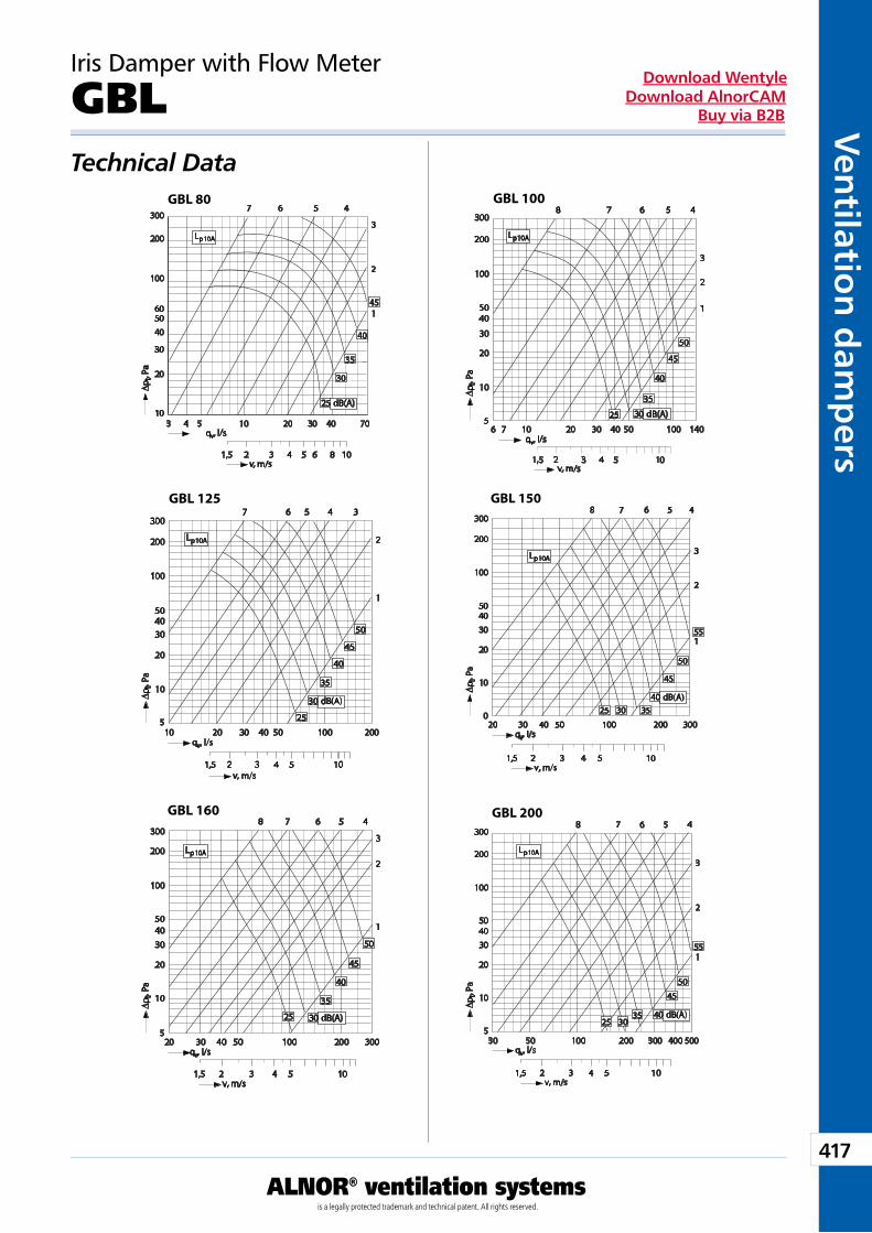
417
ALNOR® ventilation systemsis a legally protected trademark and technical patent. All rights reserved.
Ven
tilation
dam
pers
Download WentyleDownload AlnorCAM
Buy via B2B
GBL 80 GBL 100
GBL 125 GBL 150
GBL 160 GBL 200
Iris Damper with Flow Meter
GBLTechnical Data
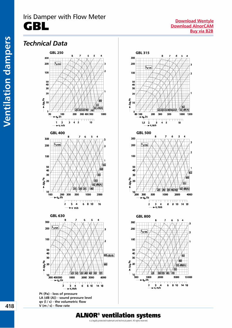
418
ALNOR® ventilation systemsis a legally protected trademark and technical patent. All rights reserved.
Ven
tila
tio
n d
amp
ers
Download WentyleDownload AlnorCAM
Buy via B2B
GBL 250 GBL 315
GBL 400 GBL 500
GBL 630 GBL 800
Iris Damper with Flow Meter
GBLTechnical Data
Pt (Pa) - loss of pressureLA (dB (A)) - sound pressure levelqv (l / s) - the volumetric fl owV (m / s) - fl ow rate
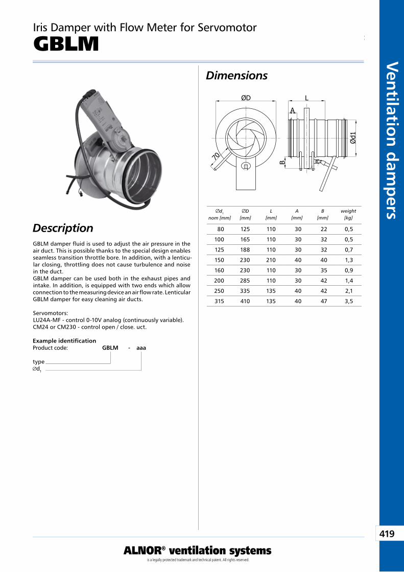
419
ALNOR® ventilation systemsis a legally protected trademark and technical patent. All rights reserved.
Ven
tilation
dam
pers
Download WentyleDownload AlnorCAM
Buy via B2B
d1
nom [mm]D
[mm]L
[mm]A
[mm]B
[mm]weight
[kg]
GBLM damper fluid is used to adjust the air pressure in the air duct. This is possible thanks to the special design enables seamless transition throttle bore. In addition, with a lenticu-lar closing, throttling does not cause turbulence and noise in the duct.GBLM damper can be used both in the exhaust pipes and intake. In addition, is equipped with two ends which allow connection to the measuring device an air flow rate. Lenticular GBLM damper for easy cleaning air ducts.
Servomotors:LU24A-MF - control 0-10V analog (continuously variable).CM24 or CM230 - control open / close. uct.
Description
Dimensions
Example identificationProduct code: GBLM - aaa
typed1
Iris Damper with Flow Meter for Servomotor
GBLM
80 125 110 30 22 0,5
100 165 110 30 32 0,5
125 188 110 30 32 0,7
150 230 210 40 40 1,3
160 230 110 30 35 0,9
200 285 110 30 42 1,4
250 335 135 40 42 2,1
315 410 135 40 47 3,5
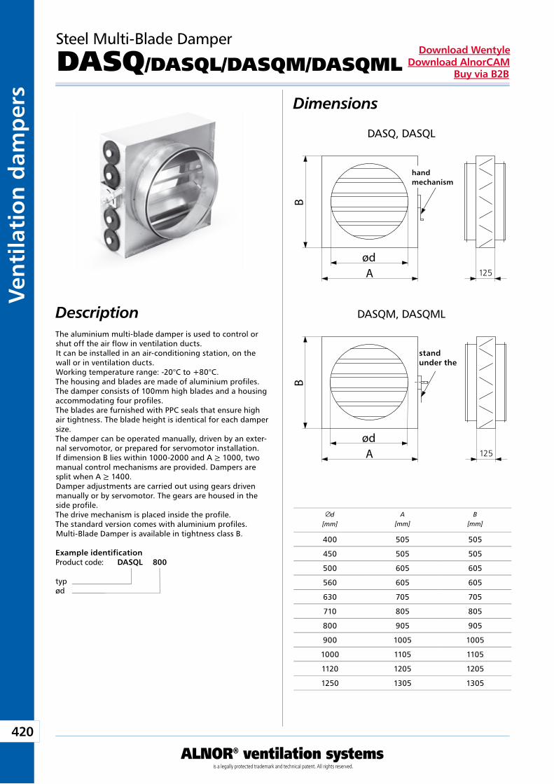
420
ALNOR® ventilation systemsis a legally protected trademark and technical patent. All rights reserved.
Ven
tila
tio
n d
amp
ers
Download WentyleDownload AlnorCAM
Buy via B2B
A
B
ød
Mechanizmręczny
A
B
ød
Podstawka pod siłownik
stand under the
Steel Multi-Blade Damper
DASQ/DASQL/DASQM/DASQML
Dimensions
DescriptionThe aluminium multi-blade damper is used to control or shut off the air flow in ventilation ducts.It can be installed in an air-conditioning station, on the wall or in ventilation ducts.Working temperature range: -20°C to +80°C. The housing and blades are made of aluminium profiles.The damper consists of 100mm high blades and a housing accommodating four profiles.The blades are furnished with PPC seals that ensure high air tightness. The blade height is identical for each damper size.The damper can be operated manually, driven by an exter-nal servomotor, or prepared for servomotor installation.If dimension B lies within 1000-2000 and A ≥ 1000, two manual control mechanisms are provided. Dampers are split when A ≥ 1400.Damper adjustments are carried out using gears driven manually or by servomotor. The gears are housed in the side profile.The drive mechanism is placed inside the profile.The standard version comes with aluminium profiles.Multi-Blade Damper is available in tightness class B.
hand mechanism
DASQ, DASQL
DASQM, DASQML
Example identificationProduct code: DASQL 800
typød
d[mm]
A[mm]
B[mm]
400 505 505
450 505 505
500 605 605
560 605 605
630 705 705
710 805 805
800 905 905
900 1005 1005
1000 1105 1105
1120 1205 1205
1250 1305 1305
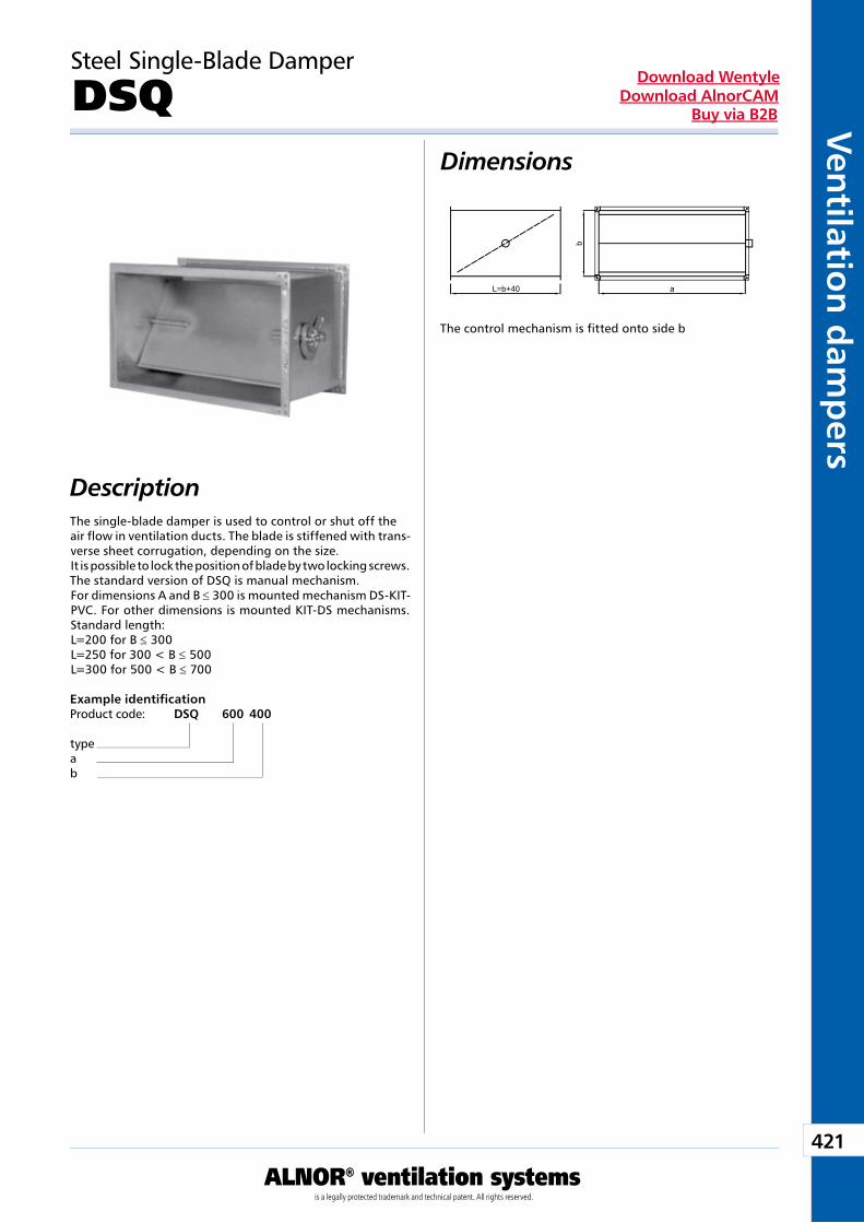
421
ALNOR® ventilation systemsis a legally protected trademark and technical patent. All rights reserved.
Ven
tilation
dam
pers
Download WentyleDownload AlnorCAM
Buy via B2B
b
aL=b+40
Steel Single-Blade Damper
DSQDimensions
Description
Example identificationProduct code: DSQ 600 400
typeab
The control mechanism is fitted onto side b
The single-blade damper is used to control or shut off theair flow in ventilation ducts. The blade is stiffened with trans-verse sheet corrugation, depending on the size.It is possible to lock the position of blade by two locking screws.The standard version of DSQ is manual mechanism.For dimensions A and B ≤ 300 is mounted mechanism DS-KIT-PVC. For other dimensions is mounted KIT-DS mechanisms.Standard length:L=200 for B ≤ 300L=250 for 300 < B ≤ 500L=300 for 500 < B ≤ 700
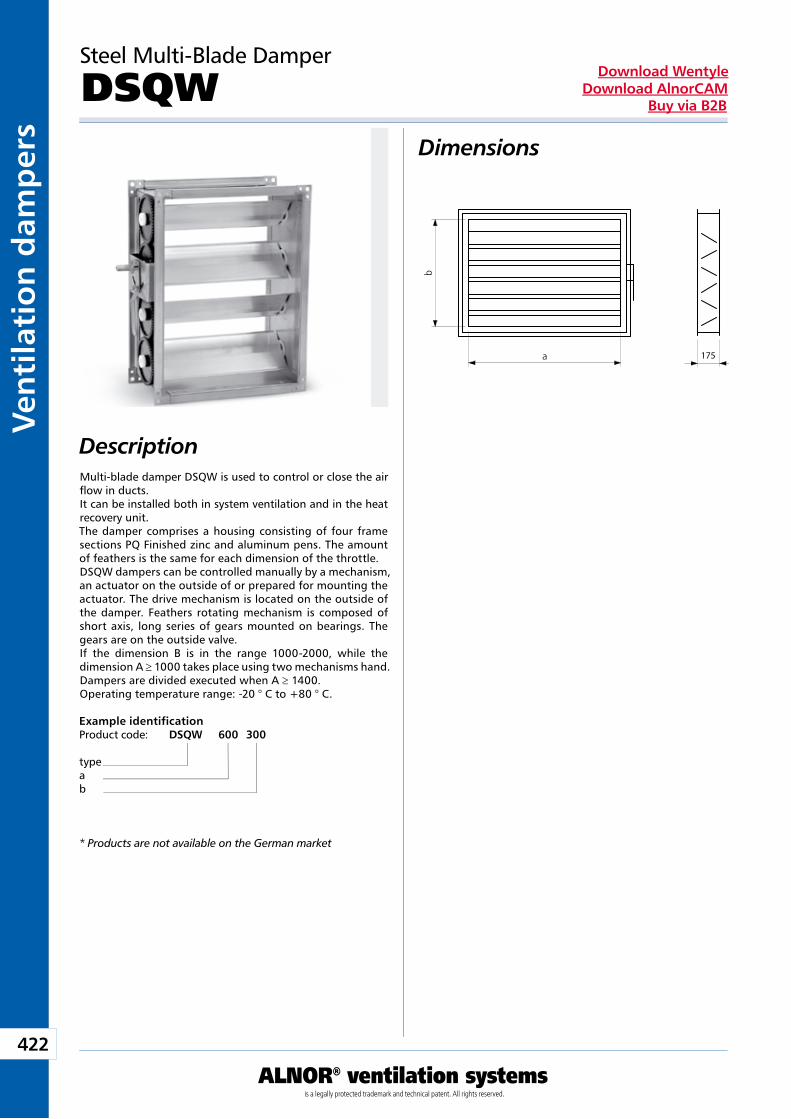
422
ALNOR® ventilation systemsis a legally protected trademark and technical patent. All rights reserved.
Ven
tila
tio
n d
amp
ers
Download WentyleDownload AlnorCAM
Buy via B2B
175
Steel Multi-Blade Damper
DSQWDimensions
Description
Example identificationProduct code: DSQW 600 300
typeab
* Products are not available on the German market
Multi-blade damper DSQW is used to control or close the air flow in ducts.It can be installed both in system ventilation and in the heat recovery unit.The damper comprises a housing consisting of four frame sections PQ Finished zinc and aluminum pens. The amount of feathers is the same for each dimension of the throttle.DSQW dampers can be controlled manually by a mechanism, an actuator on the outside of or prepared for mounting the actuator. The drive mechanism is located on the outside of the damper. Feathers rotating mechanism is composed of short axis, long series of gears mounted on bearings. The gears are on the outside valve.If the dimension B is in the range 1000-2000, while the dimension A ≥ 1000 takes place using two mechanisms hand. Dampers are divided executed when A ≥ 1400.Operating temperature range: -20 ° C to +80 ° C.
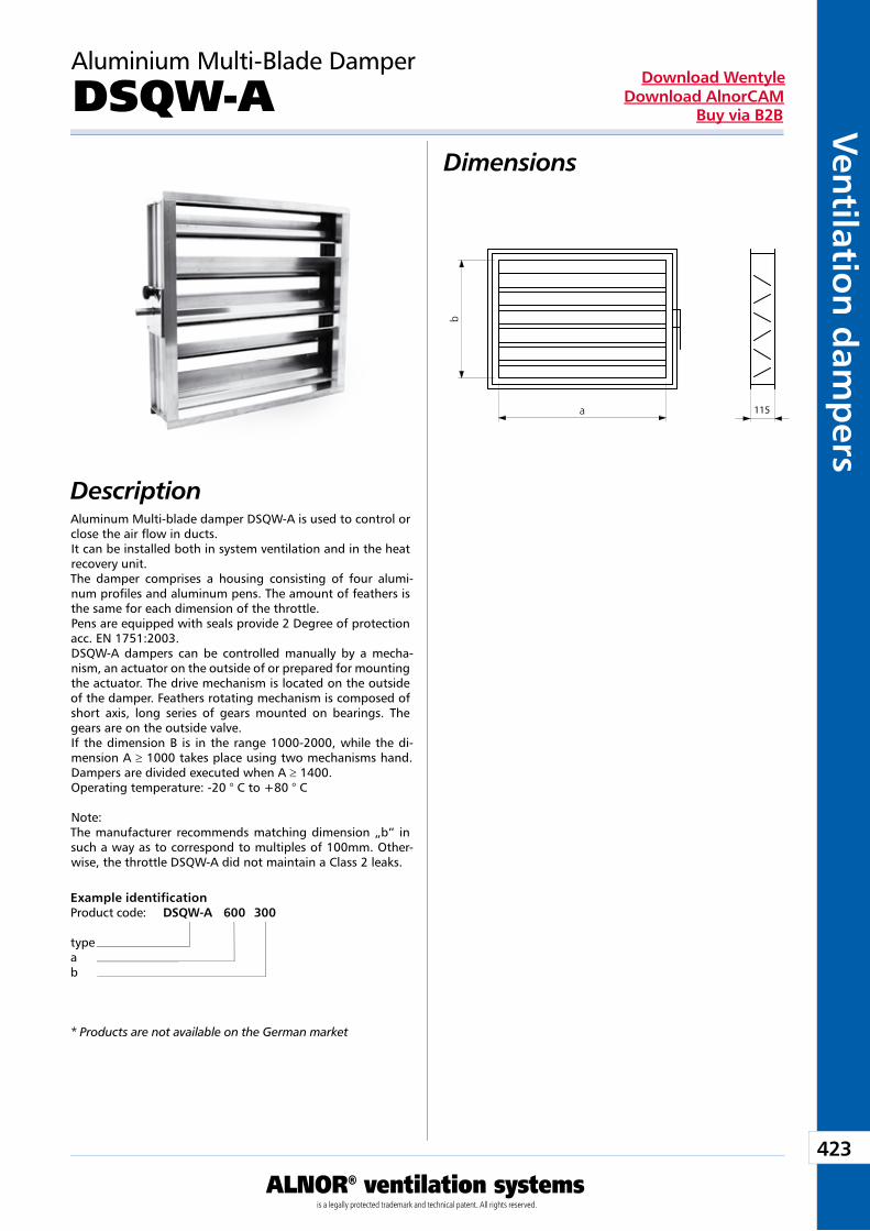
423
ALNOR® ventilation systemsis a legally protected trademark and technical patent. All rights reserved.
Ven
tilation
dam
pers
Download WentyleDownload AlnorCAM
Buy via B2B
115
Aluminium Multi-Blade Damper
DSQW-ADimensions
Description
Example identificationProduct code: DSQW-A 600 300
typeab
* Products are not available on the German market
Aluminum Multi-blade damper DSQW-A is used to control or close the air flow in ducts.It can be installed both in system ventilation and in the heat recovery unit.The damper comprises a housing consisting of four alumi-num profiles and aluminum pens. The amount of feathers is the same for each dimension of the throttle.Pens are equipped with seals provide 2 Degree of protection acc. EN 1751:2003.DSQW-A dampers can be controlled manually by a mecha-nism, an actuator on the outside of or prepared for mounting the actuator. The drive mechanism is located on the outside of the damper. Feathers rotating mechanism is composed of short axis, long series of gears mounted on bearings. The gears are on the outside valve.If the dimension B is in the range 1000-2000, while the di-mension A ≥ 1000 takes place using two mechanisms hand. Dampers are divided executed when A ≥ 1400.Operating temperature: -20 ° C to +80 ° C
Note:The manufacturer recommends matching dimension „b” in such a way as to correspond to multiples of 100mm. Other-wise, the throttle DSQW-A did not maintain a Class 2 leaks.
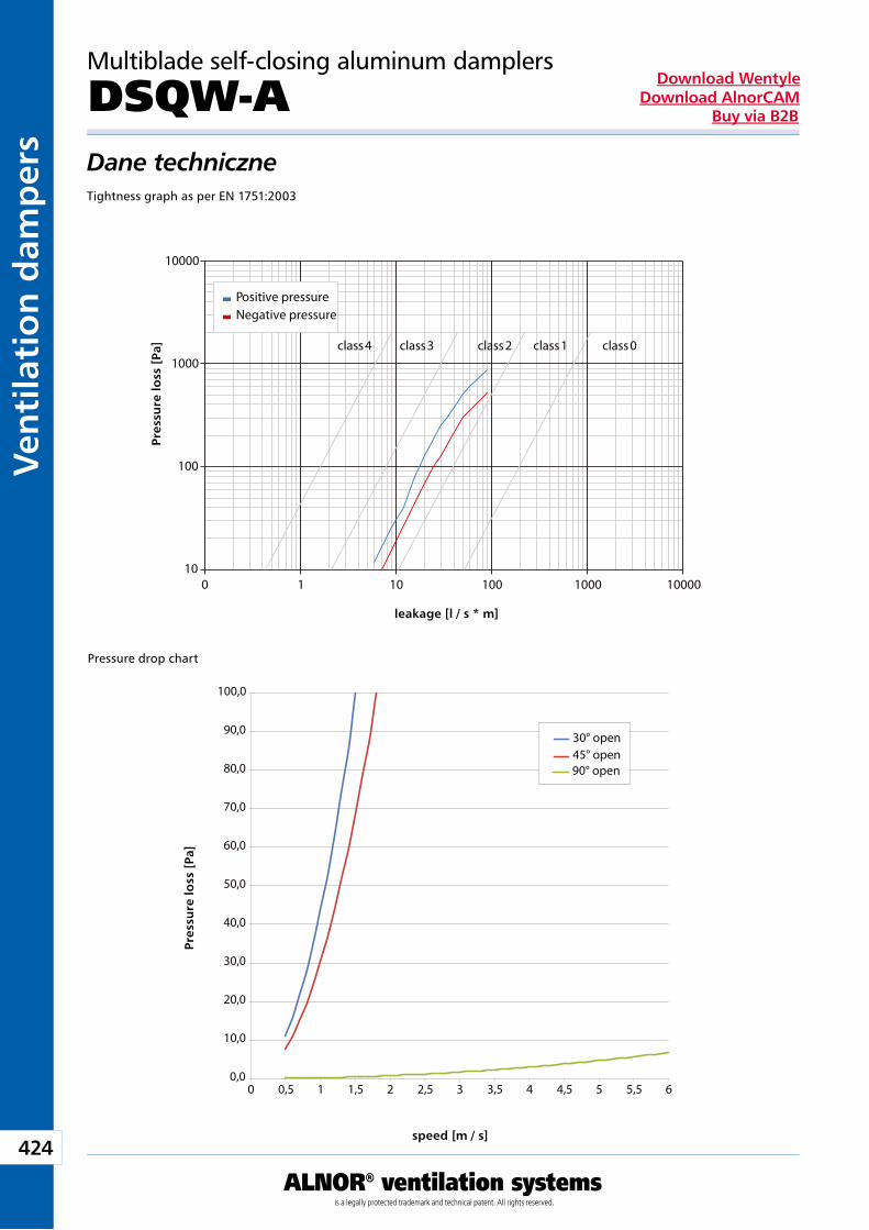
424
ALNOR® ventilation systemsis a legally protected trademark and technical patent. All rights reserved.
Ven
tila
tio
n d
amp
ers
Download WentyleDownload AlnorCAM
Buy via B2B
Positive pressureNegative pressure
10000
1000
100
100 1
class 0class 1class 2class 3class 4
10 100 1000 10000
2
stra
ty c
iśni
enia
[Pa]
nieszczelność [l/s*m ]
www
0,0
10,0
20,0
30,0
40,0
50,0
60,0
70,0
80,0
90,0
100,0
0 0,5 1 1,5 2 2,5 3 3,5 4 4,5 5 5,5 6
30° open45° open90° open
prędkość [m/s]
stra
ty c
iśni
enia
[Pa]
Multiblade self-closing aluminum damplers
DSQW-ADane techniczneTightness graph as per EN 1751:2003
Pressure drop chart
Pres
sure
loss
[Pa
]
Pres
sure
loss
[Pa
]
leakage [l / s * m]
speed [m / s]
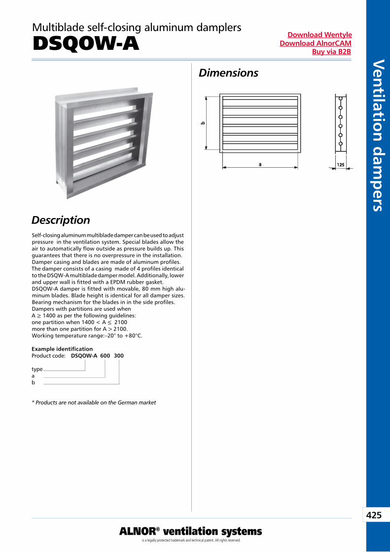
425
ALNOR® ventilation systemsis a legally protected trademark and technical patent. All rights reserved.
Ven
tilation
dam
pers
Download WentyleDownload AlnorCAM
Buy via B2B
Multiblade self-closing aluminum damplers
DSQOW-ADimensions
DescriptionSelf-closing aluminum multiblade damper can be used to adjust pressure in the ventilation system. Special blades allow the air to automatically flow outside as pressure builds up. This guarantees that there is no overpressure in the installation. Damper casing and blades are made of aluminum profiles. The damper consists of a casing made of 4 profiles identical to the DSQW-A multiblade damper model. Additionally, lower and upper wall is fitted with a EPDM rubber gasket. DSQOW-A damper is fitted with movable, 80 mm high alu-minum blades. Blade height is identical for all damper sizes. Bearing mechanism for the blades in in the side profiles. Dampers with partitions are used when A ≥ 1400 as per the following guidelines: one partition when 1400 < A ≤ 2100 more than one partition for A > 2100. Working temperature range:–20° to +80°C.
Example identificationProduct code: DSQOW-A 600 300
typeab
* Products are not available on the German market
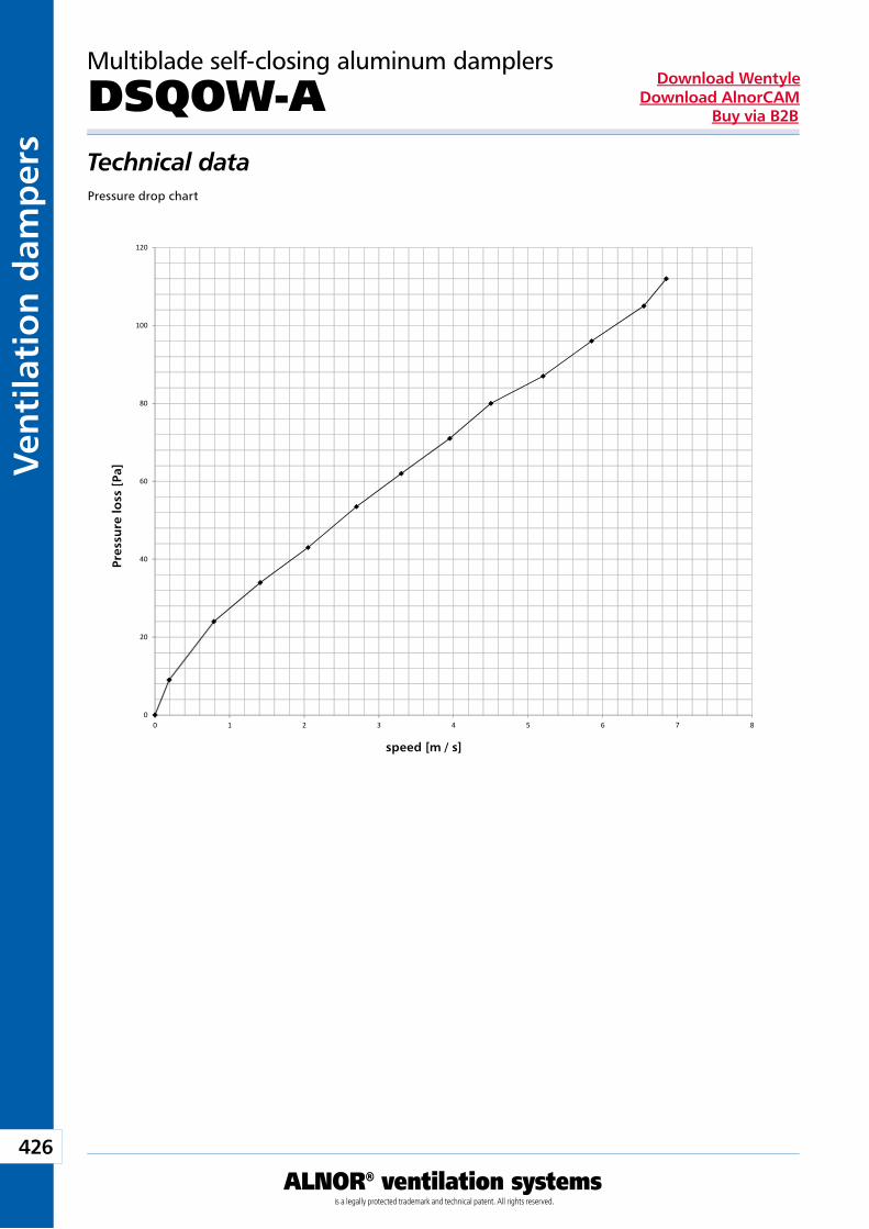
426
ALNOR® ventilation systemsis a legally protected trademark and technical patent. All rights reserved.
Ven
tila
tio
n d
amp
ers
Download WentyleDownload AlnorCAM
Buy via B2B
0
20
40
60
80
100
120
0 1 2 3 4 5 6 7 8
stra
ty c
iśni
enia
[Pa
]
prędkość [m/s]
Multiblade self-closing aluminum damplers
DSQOW-ATechnical dataPressure drop chart
Pres
sure
loss
[Pa
]
speed [m / s]
SealingProducts
We reserve the right to make changes in the dimensions and technical data products due to their continuous improvement
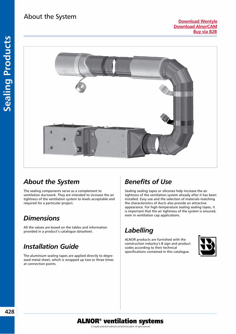
428
ALNOR® ventilation systemsis a legally protected trademark and technical patent. All rights reserved.
Seal
ing
Pro
du
cts
Download WentyleDownload AlnorCAM
Buy via B2B
About the SystemThe sealing components serve as a complement to ventilation ductwork. They are intended to increase the air tightness of the ventilation system to levels acceptable and required for a particular project.
Dimensions All the values are based on the tables and information provided in a product’s catalogue datasheet.
About the System
Installation GuideThe aluminium sealing tapes are applied directly to degre-ased metal sheet, which is wrapped up two or three times at connection points.
Benefits of UseSealing sealing tapes or silicones help increase the air tightness of the ventilation system already after it has been installed. Easy use and the selection of materials matching the characteristics of ducts also provide an attractive appearance. For high-temperature sealing sealing tapes, it is important that the air tightness of the system is ensured, even in ventilation cap applications.
LabellingALNOR products are furnished with the construction industry’s B sign and product codes according to their technical specifications contained in this catalogue.
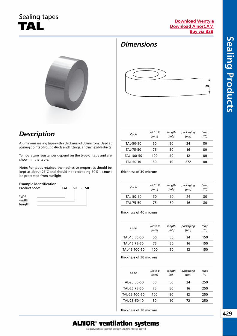
429
ALNOR® ventilation systemsis a legally protected trademark and technical patent. All rights reserved.
Sealing
Prod
ucts
Download WentyleDownload AlnorCAM
Buy via B2B
Dimensions
Description
Sealing tapes
TAL
Aluminium sealing tape with a thickness of 30 microns. Used at joining points of round ducts and fittings, and in flexible ducts.
Temperature resistances depend on the type of tape and are shown in the table.
Note: For tapes retained their adhesive properties should be kept at about 21°C and should not exceeding 50%. It must be protected from sunlight.
Example identificationProduct code: TAL 50 - 50
typewidthlength
Codewidth B
[mm]length[mb]
packaging[pcs]
temp[°C]
Codewidth B
[mm]length[mb]
packaging[pcs]
temp[°C]
Codewidth B
[mm]length[mb]
packaging[pcs]
temp[°C]
thickness of 30 microns
thickness of 30 microns
thickness of 30 microns
Codewidth B
[mm]length[mb]
packaging[pcs]
temp[°C]
thickness of 40 microns
TAL-50-50 50 50 24 80
TAL-75-50 75 50 16 80
TAL-100-50 100 50 12 80
TAL-50-10 50 10 272 80
TAL-15 50-50 50 50 24 150
TAL-15 75-50 75 50 16 150
TAL-15 100-50 100 50 12 150
TAL-25 50-50 50 50 24 250
TAL-25 75-50 75 50 16 250
TAL-25 100-50 100 50 12 250
TAL-25-50-10 50 10 72 250
TAL-50-50 50 50 24 80
TAL-75-50 75 50 16 80
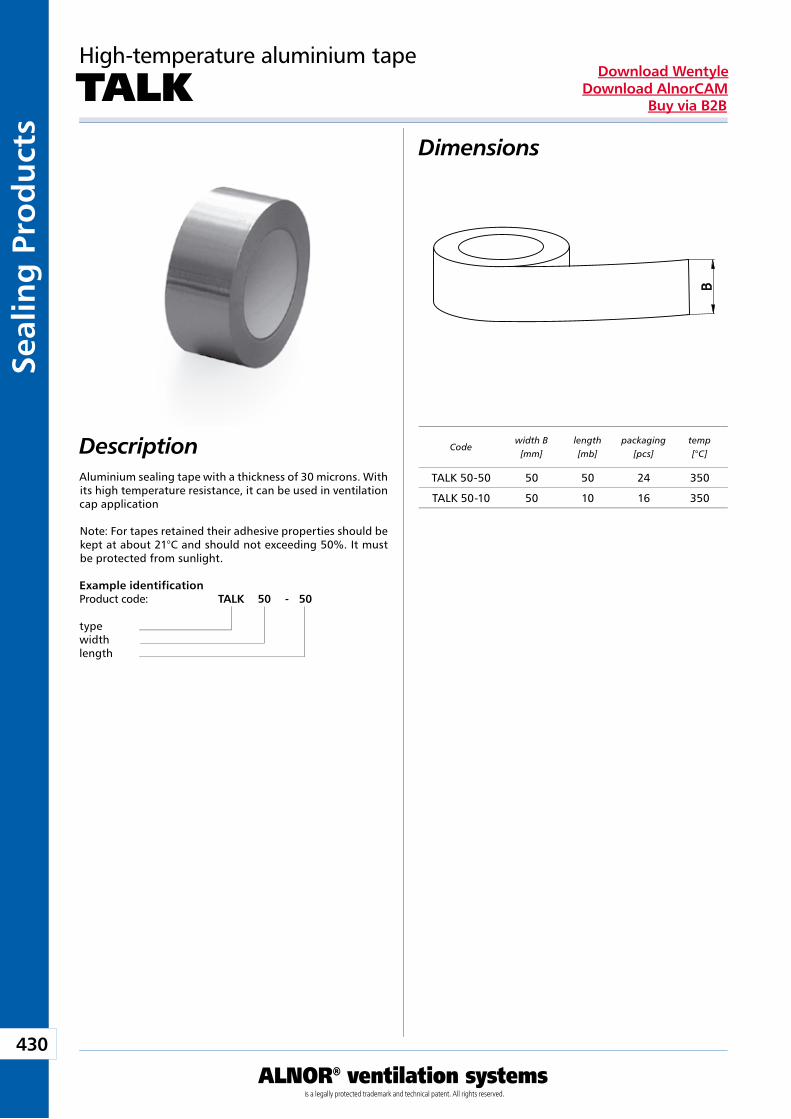
430
ALNOR® ventilation systemsis a legally protected trademark and technical patent. All rights reserved.
Seal
ing
Pro
du
cts
Download WentyleDownload AlnorCAM
Buy via B2B
Dimensions
Description
High-temperature aluminium tape
TALK
Aluminium sealing tape with a thickness of 30 microns. With its high temperature resistance, it can be used in ventilation cap application
Note: For tapes retained their adhesive properties should be kept at about 21°C and should not exceeding 50%. It must be protected from sunlight.
Example identificationProduct code: TALK 50 - 50
typewidthlength
Codewidth B
[mm]length[mb]
packaging[pcs]
temp[°C]
TALK 50-50 50 50 24 350
TALK 50-10 50 10 16 350
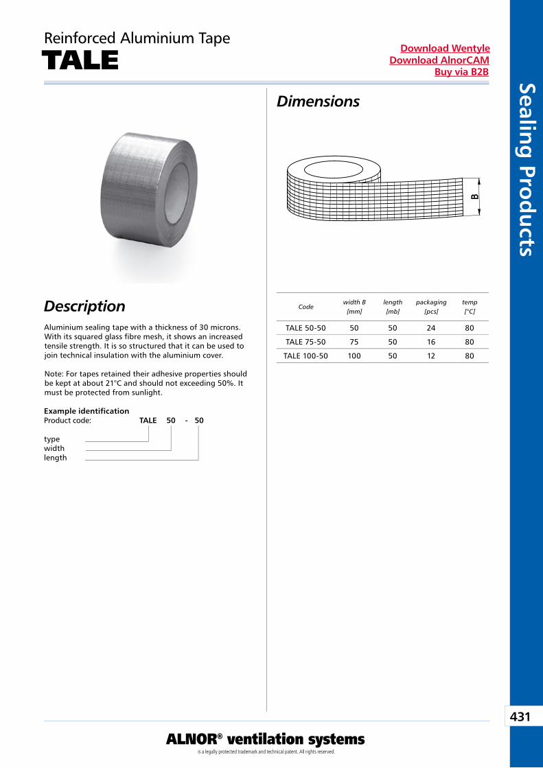
431
ALNOR® ventilation systemsis a legally protected trademark and technical patent. All rights reserved.
Sealing
Prod
ucts
Download WentyleDownload AlnorCAM
Buy via B2B
Dimensions
Description
Reinforced Aluminium Tape
TALE
Aluminium sealing tape with a thickness of 30 microns. With its squared glass fibre mesh, it shows an increased tensile strength. It is so structured that it can be used to join technical insulation with the aluminium cover.
Note: For tapes retained their adhesive properties should be kept at about 21°C and should not exceeding 50%. It must be protected from sunlight.
Example identificationProduct code: TALE 50 - 50
typewidthlength
Codewidth B
[mm]length[mb]
packaging[pcs]
temp[°C]
TALE 50-50 50 50 24 80
TALE 75-50 75 50 16 80
TALE 100-50 100 50 12 80
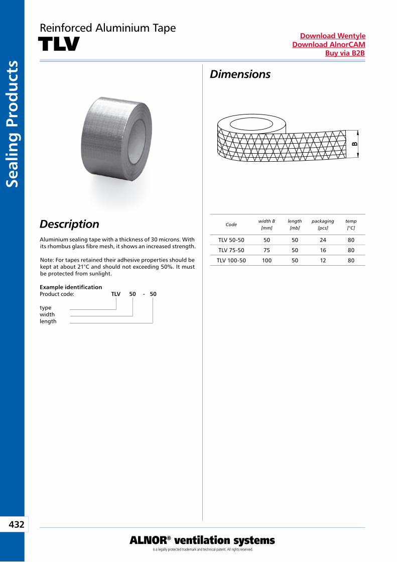
432
ALNOR® ventilation systemsis a legally protected trademark and technical patent. All rights reserved.
Seal
ing
Pro
du
cts
Download WentyleDownload AlnorCAM
Buy via B2B
Dimensions
Description
Reinforced Aluminium Tape
TLV
Aluminium sealing tape with a thickness of 30 microns. With its rhombus glass fibre mesh, it shows an increased strength.
Note: For tapes retained their adhesive properties should be kept at about 21°C and should not exceeding 50%. It must be protected from sunlight.
Example identificationProduct code: TLV 50 - 50
typewidthlength
Codewidth B
[mm]length[mb]
packaging[pcs]
temp[°C]
TLV 50-50 50 50 24 80
TLV 75-50 75 50 16 80
TLV 100-50 100 50 12 80
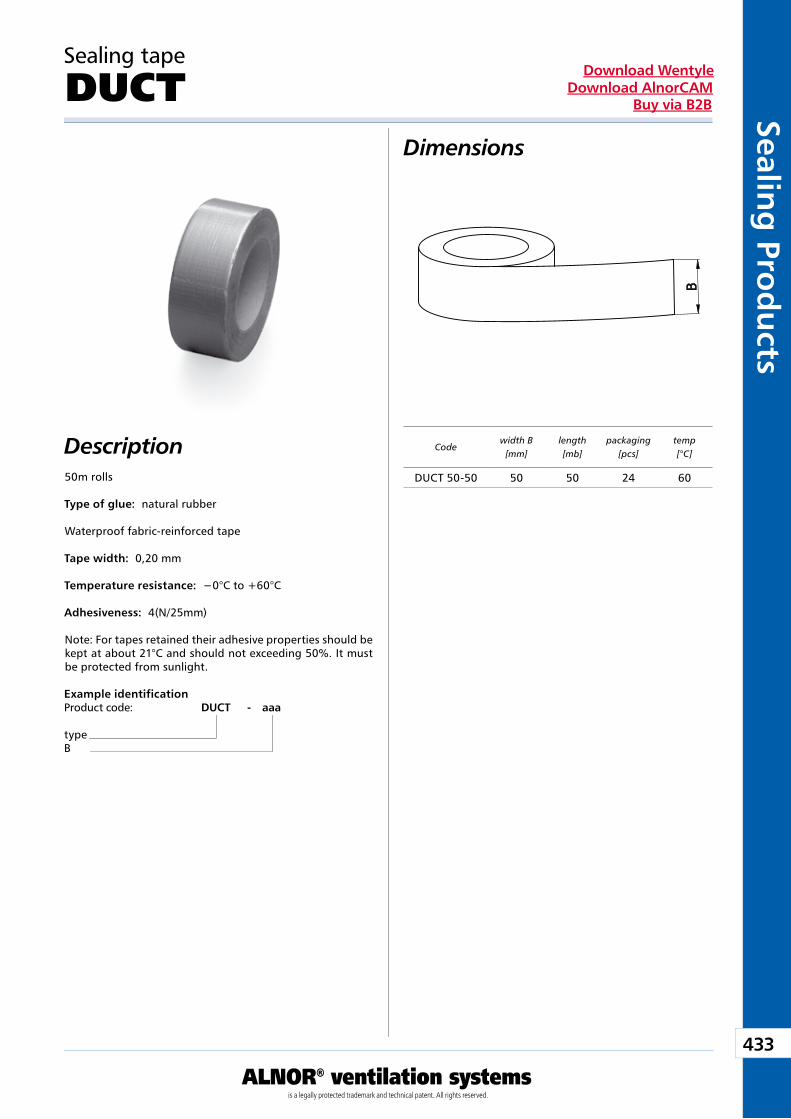
433
ALNOR® ventilation systemsis a legally protected trademark and technical patent. All rights reserved.
Sealing
Prod
ucts
Download WentyleDownload AlnorCAM
Buy via B2B
Dimensions
Description50m rolls
Type of glue: natural rubber
Waterproof fabric-reinforced tape
Tape width: 0,20 mm
Temperature resistance: −0°C to +60°C
Adhesiveness: 4(N/25mm)
Note: For tapes retained their adhesive properties should be kept at about 21°C and should not exceeding 50%. It must be protected from sunlight.
Sealing tape
DUCT
Example identificationProduct code: DUCT - aaa
typeB
Codewidth B
[mm]length[mb]
packaging[pcs]
temp[°C]
DUCT 50-50 50 50 24 60
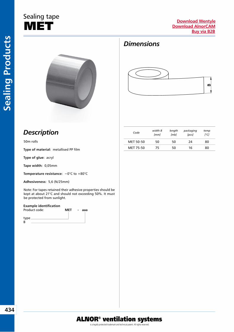
434
ALNOR® ventilation systemsis a legally protected trademark and technical patent. All rights reserved.
Seal
ing
Pro
du
cts
Download WentyleDownload AlnorCAM
Buy via B2B
Dimensions
Description50m rolls
Type of material: metallised PP film
Type of glue: acryl
Tape width: 0,05mm
Temperature resistance: −0°C to +80°C
Adhesiveness: 5,6 (N/25mm)
Note: For tapes retained their adhesive properties should be kept at about 21°C and should not exceeding 50%. It must be protected from sunlight.
Sealing tape
MET
Example identificationProduct code: MET - aaa
typeB
Codewidth B
[mm]length[mb]
packaging[pcs]
temp[°C]
MET 50-50 50 50 24 80
MET 75-50 75 50 16 80
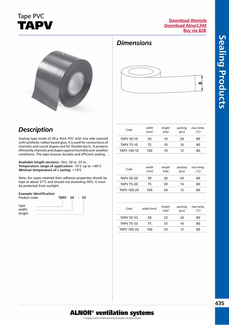
435
ALNOR® ventilation systemsis a legally protected trademark and technical patent. All rights reserved.
Sealing
Prod
ucts
Download WentyleDownload AlnorCAM
Buy via B2B
Dimensions
Description
Tape PVC
TAPV
Sealing tape made of 20 µ thick PVC with one side covered with synthetic rubber based glue. It is used for connections of channels and round shapes and for flexible ducts. It protects efficiently channels and shapes against humidity and weather conditions. The tape ensures durable and efficient sealing. .
Available length versions: 10m, 20 m, 33 m. Temperature range of application: -10°C up to +80°CMinimal temperature of c oating: +10°C
Note: For tapes retained their adhesive properties should be kept at about 21°C and should not exceeding 50%. It must be protected from sunlight.
Example identificationProduct code: TAPV 50 - 33
typewidhtlenght
Codewidht[mm]
lenght[mb]
packing[pcs]
max temp.[°C]
Codewidht [mm]
lenght[mb]
packing[pcs]
max temp.[°C]
Code widht [mm]lenght[mb]
packing[pcs]
max temp.[°C]
TAPV 50-10 50 10 24 80
TAPV 75-10 75 10 16 80
TAPV 100-10 100 10 12 80
TAPV 50-20 50 20 24 80
TAPV 75-20 75 20 16 80
TAPV 100-20 100 20 12 80
TAPV 50-33 50 33 24 80
TAPV 75-33 75 33 16 80
TAPV 100-33 100 33 12 80
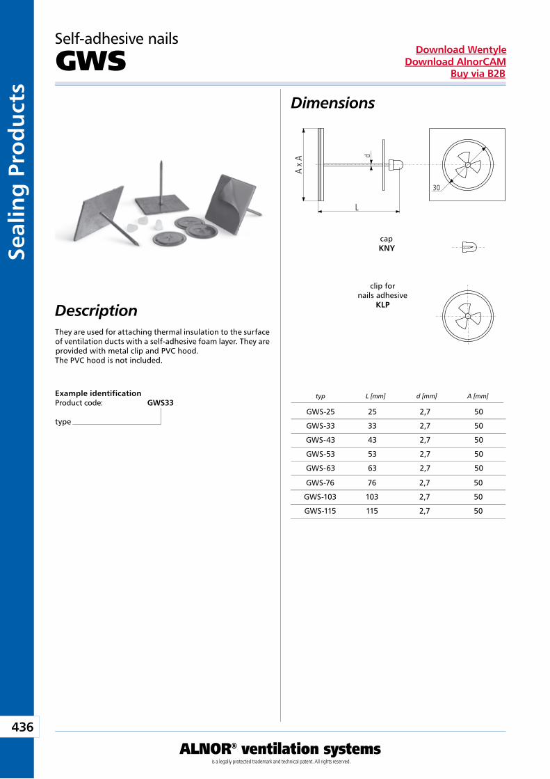
436
ALNOR® ventilation systemsis a legally protected trademark and technical patent. All rights reserved.
Seal
ing
Pro
du
cts
Download WentyleDownload AlnorCAM
Buy via B2B
Self-adhesive nails
GWSDimensions
DescriptionThey are used for attaching thermal insulation to the surface of ventilation ducts with a self-adhesive foam layer. They are provided with metal clip and PVC hood. The PVC hood is not included.
Example identificationProduct code: GWS33
type
typ L [mm] d [mm] A [mm]
d
30
A x
A
L
cap KNY
clip for nails adhesive
KLP
GWS-25 25 2,7 50
GWS-33 33 2,7 50
GWS-43 43 2,7 50
GWS-53 53 2,7 50
GWS-63 63 2,7 50
GWS-76 76 2,7 50
GWS-103 103 2,7 50
GWS-115 115 2,7 50
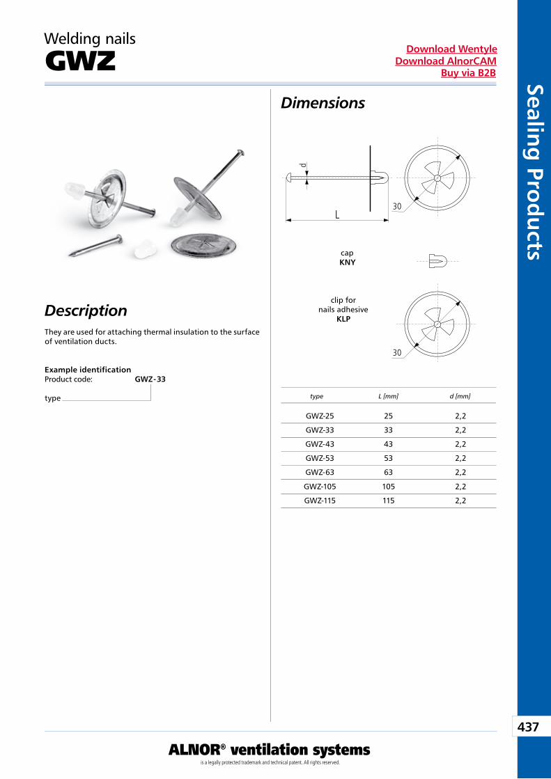
437
ALNOR® ventilation systemsis a legally protected trademark and technical patent. All rights reserved.
Sealing
Prod
ucts
Download WentyleDownload AlnorCAM
Buy via B2B
Welding nails
GWZDimensions
DescriptionThey are used for attaching thermal insulation to the surface of ventilation ducts.
Example identificationProduct code: GWZ - 33
type type L [mm] d [mm]
30
d
L
30
cap KNY
clip for nails adhesive
KLP
GWZ-25 25 2,2
GWZ-33 33 2,2
GWZ-43 43 2,2
GWZ-53 53 2,2
GWZ-63 63 2,2
GWZ-105 105 2,2
GWZ-115 115 2,2
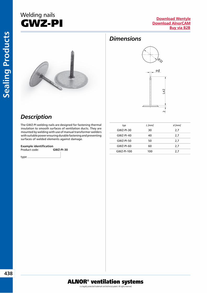
438
ALNOR® ventilation systemsis a legally protected trademark and technical patent. All rights reserved.
Seal
ing
Pro
du
cts
Download WentyleDownload AlnorCAM
Buy via B2B
Dimensions
Description
Welding nails
GWZ-PI
The GWZ-PI welding nails are designed for fastening thermal insulation to smooth surfaces of ventilation ducts. They are mounted by welding with use of manual transformer welders with suitable power ensuring durable fastening and preventing surfaces of welded elements against damage.
Example identificationProduct code: GWZ-PI -30
type
typ L [mm] d [mm]
d
GWZ-PI-30 30 2,7
GWZ-PI-40 40 2,7
GWZ-PI-50 50 2,7
GWZ-PI-60 60 2,7
GWZ-PI-100 100 2,7
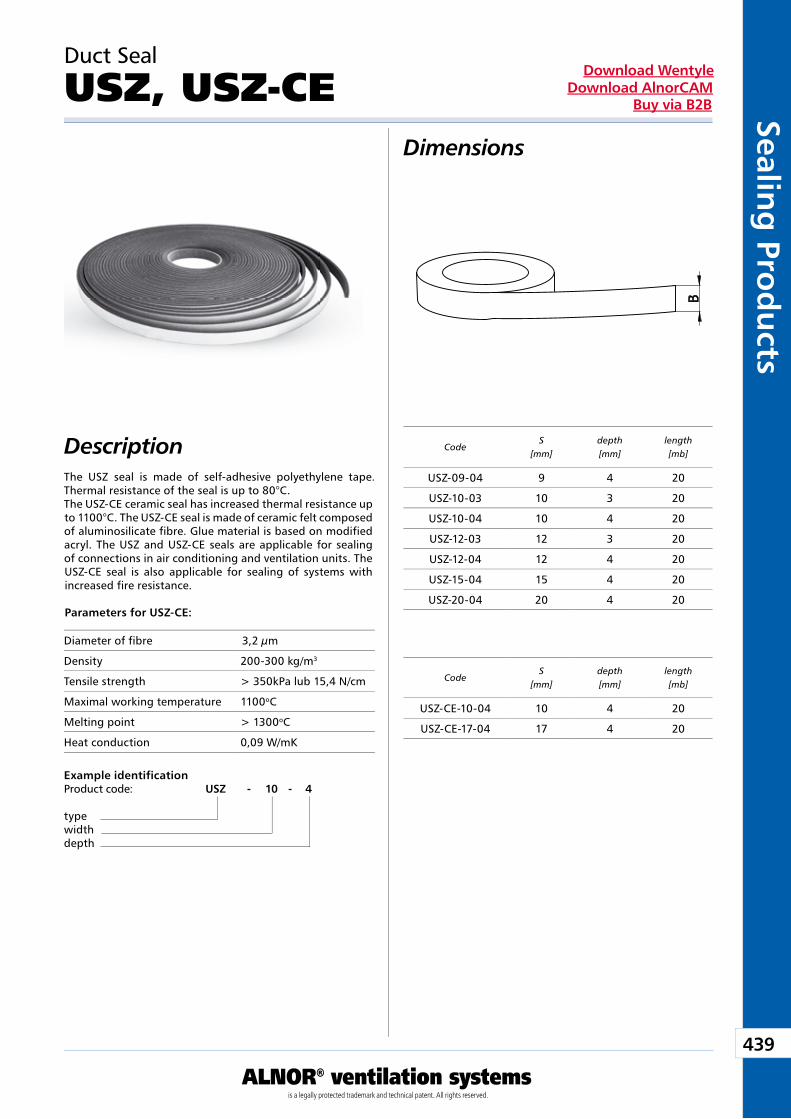
439
ALNOR® ventilation systemsis a legally protected trademark and technical patent. All rights reserved.
Sealing
Prod
ucts
Download WentyleDownload AlnorCAM
Buy via B2B
Dimensions
Description
Duct Seal
USZ, USZ-CE
Example identificationProduct code: USZ - 10 - 4
typewidthdepth
CodeS
[mm]depth[mm]
length[mb]
CodeS
[mm]depth[mm]
length[mb]
The USZ seal is made of self-adhesive polyethylene tape. Thermal resistance of the seal is up to 80°C. The USZ-CE ceramic seal has increased thermal resistance up to 1100°C. The USZ-CE seal is made of ceramic felt composed of aluminosilicate fibre. Glue material is based on modified acryl. The USZ and USZ-CE seals are applicable for sealing of connections in air conditioning and ventilation units. The USZ-CE seal is also applicable for sealing of systems with increased fire resistance.
Parameters for USZ-CE:
USZ-09-04 9 4 20
USZ-10-03 10 3 20
USZ-10-04 10 4 20
USZ-12-03 12 3 20
USZ-12-04 12 4 20
USZ-15-04 15 4 20
USZ-20-04 20 4 20
USZ-CE-10-04 10 4 20
USZ-CE-17-04 17 4 20
Diameter of fibre 3,2 µm
Density 200-300 kg/m3
Tensile strength > 350kPa lub 15,4 N/cm
Maximal working temperature 1100oC
Melting point > 1300oC
Heat conduction 0,09 W/mK
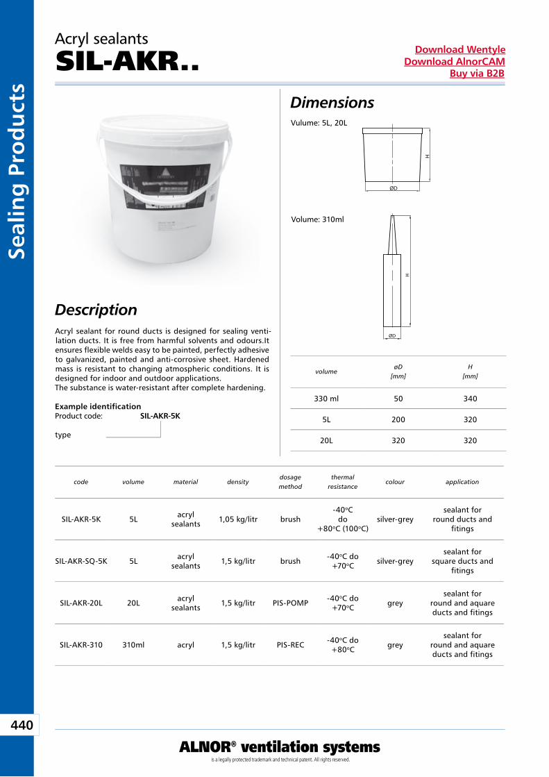
440
ALNOR® ventilation systemsis a legally protected trademark and technical patent. All rights reserved.
Seal
ing
Pro
du
cts
Download WentyleDownload AlnorCAM
Buy via B2B
DescriptionAcryl sealant for round ducts is designed for sealing venti-lation ducts. It is free from harmful solvents and odours.It ensures flexible welds easy to be painted, perfectly adhesive to galvanized, painted and anti-corrosive sheet. Hardened mass is resistant to changing atmospheric conditions. It is designed for indoor and outdoor applications.The substance is water-resistant after complete hardening.
Example identificationProduct code: SIL-AKR-5K
type
code volume material densitydosagemethod
thermalresistance
colour application
volumeøD
[mm]H
[mm]
ØD
H
ØD
H
Dimensions
Acryl sealants
SIL-AKR..
SIL-AKR-5K 5L acrylsealants 1,05 kg/litr brush
-40oCdo
+80oC (100oC)silver-grey
sealant forround ducts and
fitings
SIL-AKR-SQ-5K 5L acrylsealants 1,5 kg/litr brush -40oC do
+70oC silver-greysealant for
square ducts and fitings
SIL-AKR-20L 20L acrylsealants 1,5 kg/litr PIS-POMP -40oC do
+70oC greysealant for
round and aquare ducts and fitings
SIL-AKR-310 310ml acryl 1,5 kg/litr PIS-REC -40oC do +80oC grey
sealant forround and aquare ducts and fitings
330 ml 50 340
5L 200 320
20L 320 320
Vulume: 5L, 20L
Volume: 310ml
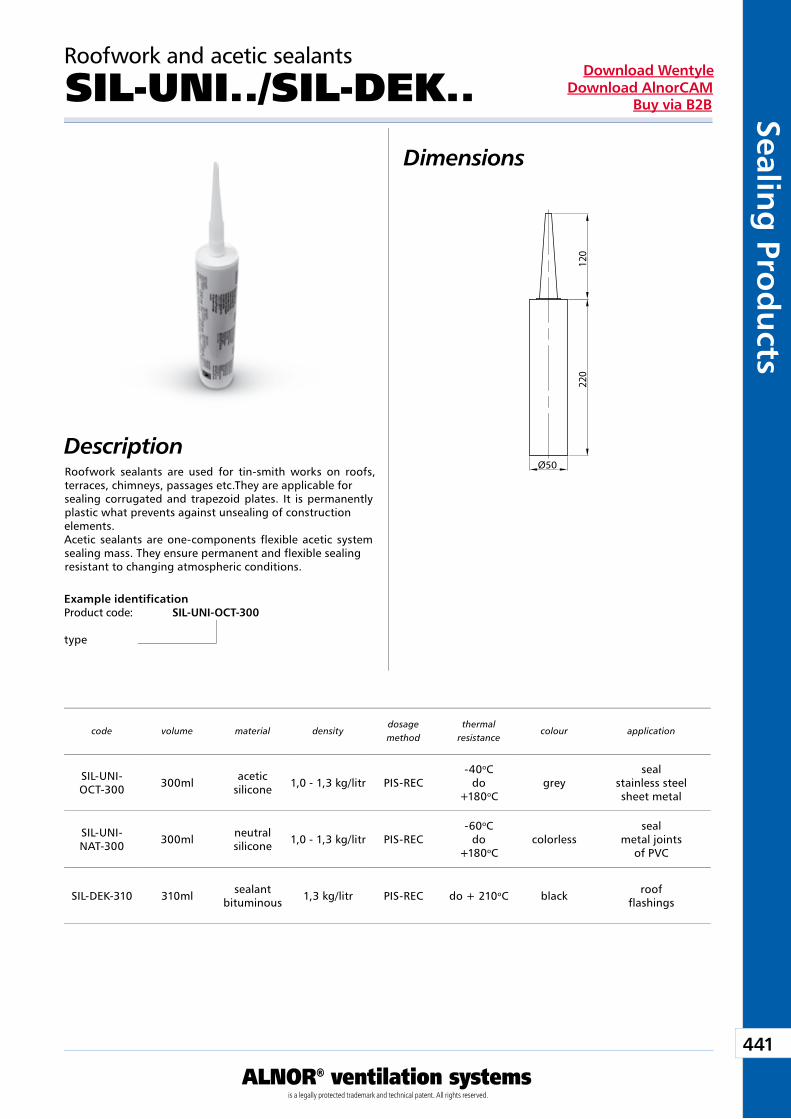
441
ALNOR® ventilation systemsis a legally protected trademark and technical patent. All rights reserved.
Sealing
Prod
ucts
Download WentyleDownload AlnorCAM
Buy via B2B
DescriptionRoofwork sealants are used for tin-smith works on roofs, terraces, chimneys, passages etc.They are applicable for sealing corrugated and trapezoid plates. It is permanently plastic what prevents against unsealing of construction elements.Acetic sealants are one-components flexible acetic system sealing mass. They ensure permanent and flexible sealing resistant to changing atmospheric conditions.
Example identificationProduct code: SIL-UNI-OCT-300
type
code volume material densitydosagemethod
thermalresistance
colour application
Ø50
220
120
Dimensions
Roofwork and acetic sealants
SIL-UNI../SIL-DEK..
SIL-UNI-OCT-300 300ml acetic
silicone 1,0 - 1,3 kg/litr PIS-REC-40oC
do+180oC
greyseal
stainless steelsheet metal
SIL-UNI-NAT-300 300ml neutral
silicone 1,0 - 1,3 kg/litr PIS-REC-60oC
do+180oC
colorlessseal
metal jointsof PVC
SIL-DEK-310 310ml sealantbituminous 1,3 kg/litr PIS-REC do + 210oC black roof
flashings
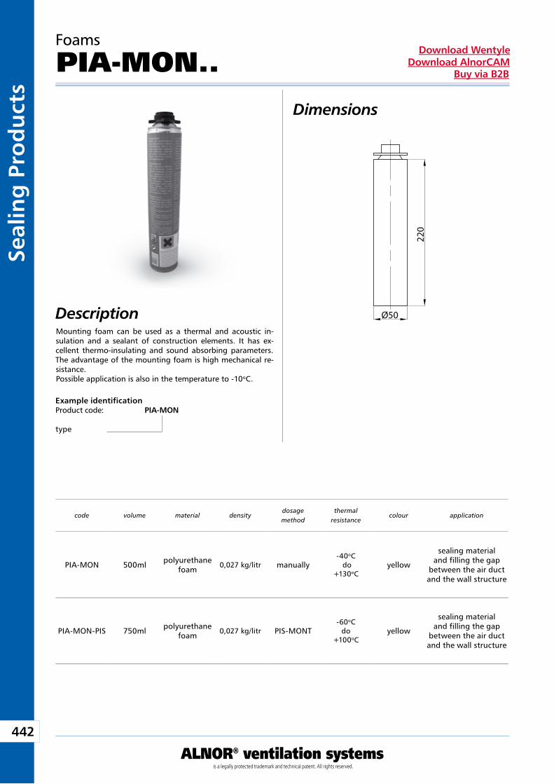
442
ALNOR® ventilation systemsis a legally protected trademark and technical patent. All rights reserved.
Seal
ing
Pro
du
cts
Download WentyleDownload AlnorCAM
Buy via B2B
DescriptionMounting foam can be used as a thermal and acoustic in-sulation and a sealant of construction elements. It has ex-cellent thermo-insulating and sound absorbing parameters. The advantage of the mounting foam is high mechanical re-sistance.Possible application is also in the temperature to -10oC.
Example identificationProduct code: PIA-MON
type
code volume material densitydosagemethod
thermalresistance
colour application
Ø50
220
Dimensions
Foams
PIA-MON..
PIA-MON 500ml polyurethane foam
0,027 kg/litr manually-40oC do
+130oCyellow
sealing material and filling the gap
between the air duct and the wall structure
PIA-MON-PIS 750ml polyurethane foam
0,027 kg/litr PIS-MONT-60oC
do+100oC
yellow
sealing material and filling the gap
between the air duct and the wall structure
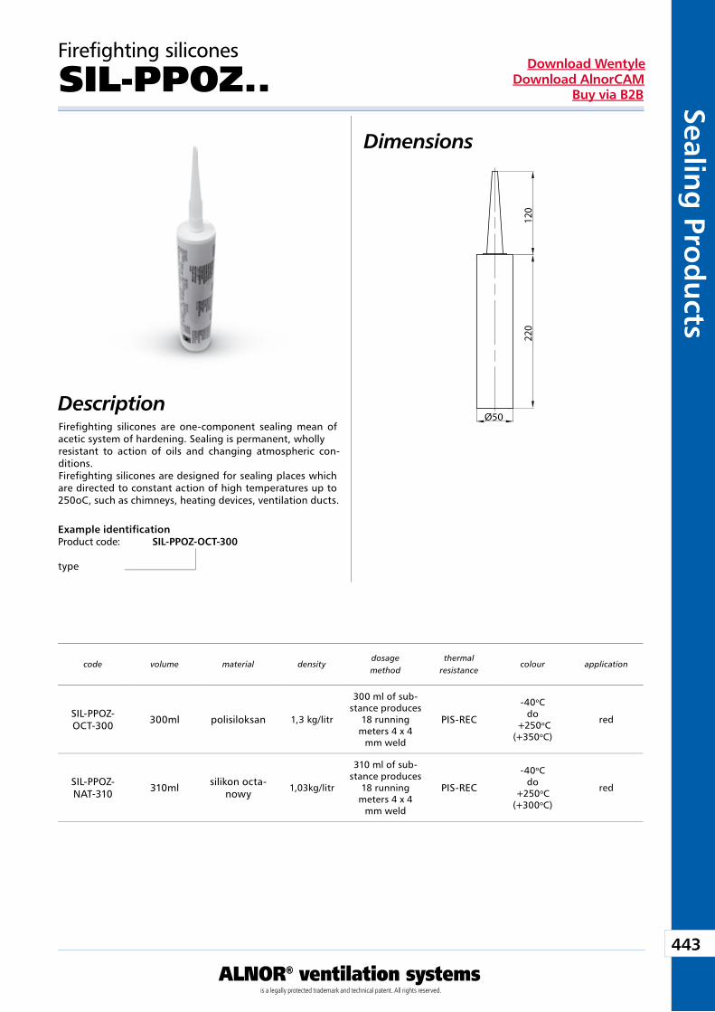
443
ALNOR® ventilation systemsis a legally protected trademark and technical patent. All rights reserved.
Sealing
Prod
ucts
Download WentyleDownload AlnorCAM
Buy via B2B
DescriptionFirefighting silicones are one-component sealing mean of acetic system of hardening. Sealing is permanent, wholly resistant to action of oils and changing atmospheric con-ditions.Firefighting silicones are designed for sealing places which are directed to constant action of high temperatures up to 250oC, such as chimneys, heating devices, ventilation ducts.
Example identificationProduct code: SIL-PPOZ-OCT-300
type
code volume material densitydosagemethod
thermalresistance
colour application
Ø50
220
120
Dimensions
Firefighting silicones
SIL-PPOZ..
SIL-PPOZ-OCT-300 300ml polisiloksan 1,3 kg/litr
300 ml of sub-stance produces
18 running meters 4 x 4
mm weld
PIS-REC
-40oC do
+250oC(+350oC)
red
SIL-PPOZ-NAT-310 310ml silikon octa-
nowy1,03kg/litr
310 ml of sub-stance produces
18 running meters 4 x 4
mm weld
PIS-REC
-40oC do
+250oC(+300oC)
red
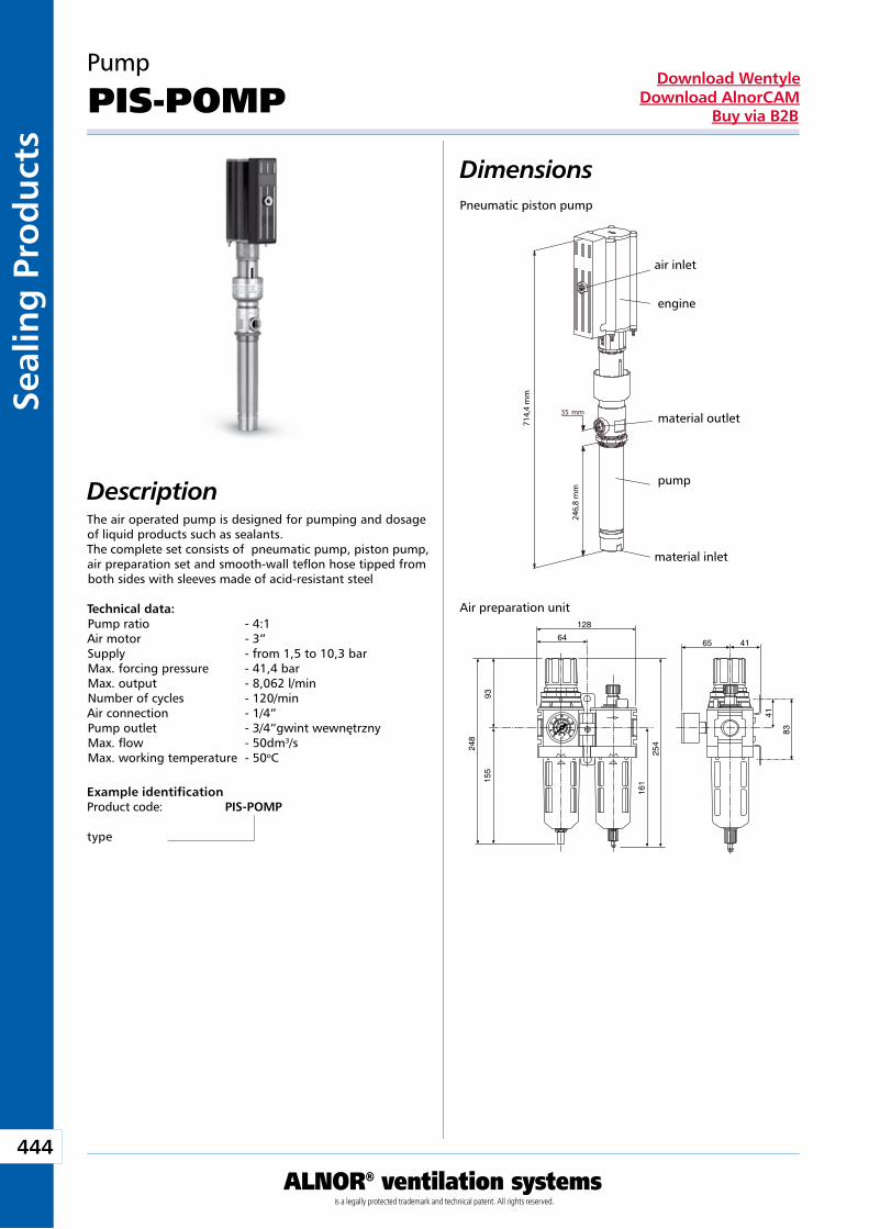
444
ALNOR® ventilation systemsis a legally protected trademark and technical patent. All rights reserved.
Seal
ing
Pro
du
cts
Download WentyleDownload AlnorCAM
Buy via B2B
DescriptionThe air operated pump is designed for pumping and dosage of liquid products such as sealants.The complete set consists of pneumatic pump, piston pump, air preparation set and smooth-wall teflon hose tipped from both sides with sleeves made of acid-resistant steel
Technical data:Pump ratio - 4:1Air motor - 3”Supply - from 1,5 to 10,3 barMax. forcing pressure - 41,4 barMax. output - 8,062 l/minNumber of cycles - 120/minAir connection - 1/4”Pump outlet - 3/4”gwint wewnętrznyMax. flow - 50dm3/sMax. working temperature - 50oC
Example identificationProduct code: PIS-POMP
type
Silnik
Wylot materiału
Pompa
Wlot powietrza
35 mm
Wlot materiału
714,
4 m
m
246,
8 m
m
Pneumatic piston pump
Air preparation unit128
64
248
155
161
6525
441
83
41
93
Dimensions
Pump
PIS-POMP
air inlet
engine
material outlet
pump
material inlet
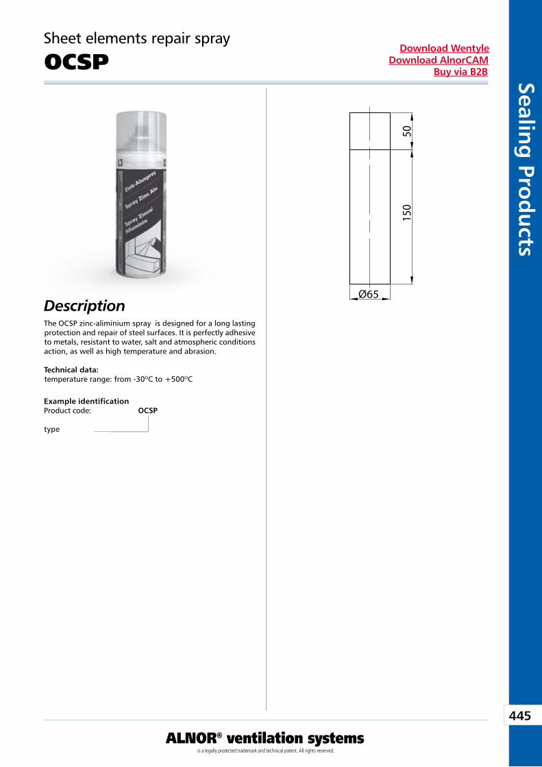
445
ALNOR® ventilation systemsis a legally protected trademark and technical patent. All rights reserved.
Sealing
Prod
ucts
Download WentyleDownload AlnorCAM
Buy via B2B
DescriptionThe OCSP zinc-aliminium spray is designed for a long lasting protection and repair of steel surfaces. It is perfectly adhesive to metals, resistant to water, salt and atmospheric conditions action, as well as high temperature and abrasion.
Technical data:temperature range: from -30OC to +500OC
Example identificationProduct code: OCSP
type
Ø65
150
50
Sheet elements repair spray
OCSP
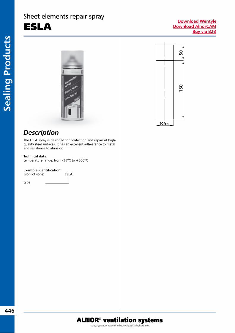
446
ALNOR® ventilation systemsis a legally protected trademark and technical patent. All rights reserved.
Seal
ing
Pro
du
cts
Download WentyleDownload AlnorCAM
Buy via B2B
DescriptionThe ESLA spray is designed for protection and repair of high-quality steel surfaces. It has an excellent adhearance to metal and resistance to abrasion
Technical data:temperature range: from -35OC to +500OC
Example identificationProduct code: ESLA
type
Ø65
150
50
Sheet elements repair spray
ESLA

Access Products
We reserve the right to make changes in the dimensions and technical data products due to their continuous improvement
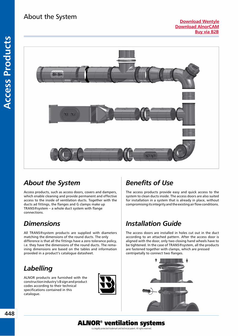
448
ALNOR® ventilation systemsis a legally protected trademark and technical patent. All rights reserved.
Acc
ess
Pro
du
cts
Download WentyleDownload AlnorCAM
Buy via B2B
Dimensions
About the SystemAccess products, such as access doors, covers and dampers, which enable cleaning and provide permanent and effective access to the inside of ventilation ducts. Together with the ducts ad fittings, the flanges and G clamps make up TRANS®system – a whole duct system with flangeconnections.
All TRANS®system products are supplied with diameters matching the dimensions of the round ducts. The only difference is that all the fittings have a zero tolerance policy, i.e. they have the dimensions of the round ducts. The rema-ining dimensions are based on the tables and information provided in a product’s catalogue datasheet.
About the System
Benefits of UseThe access products provide easy and quick access to the system to clean ducts inside. The access doors are also suited for installation in a system that is already in place, without compromising its integrity and the existing air flow conditions.
LabellingALNOR products are furnished with the construction industry’s B sign and product codes according to their technical specifications contained in this catalogue.
Installation GuideThe access doors are installed in holes cut out in the duct according to an attached pattern. After the access door is aligned with the door, only two closing hand wheels have to be tightened. In the case of TRANS®system, all the products are fastened together with clamps, which are pressed centripetally to connect two flanges.
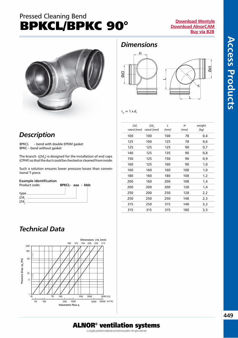
449
ALNOR® ventilation systemsis a legally protected trademark and technical patent. All rights reserved.
Access Pro
du
ctsDownload Wentyle
Download AlnorCAMBuy via B2B
Dimensions
Technical Data
BPKCL – bend with double EPDM gasket BPKC – bend without gasket
The branch (Æd3) is designed for the installation of end caps (CPHF) so that the duct could be checked or cleaned from inside.
Such a solution ensures lower pressure losses than conven-tional T-piece.
Example identificationProduct code: BPKCL - aaa - bbb
typeÆd1Æd2
Pressed Cleaning Bend
BPKCL/BPKC 90°
Æd1 Æd3 L H weight rated [mm] rated [mm] [mm] [mm] [kg]
Dimensions Æd1 [mm]
Pre
ssu
re d
rop
Dp
t [P
a]
Volumetric flow q
rm » 1 x d1
Description
50 100 500 1000 5000 10000
3000100050010050101
5
10
50
100
100 125 160 200 250 315
[l/s]
[m3/h]
200
100 100 100 78 0,4
125 100 125 78 0,6
125 125 125 90 0,7
140 125 135 90 0,8
150 125 150 90 0,9
160 125 160 90 1,0
160 160 160 108 1,0
180 160 180 108 1,2
200 160 200 108 1,4
200 200 200 128 1,4
250 200 250 128 2,2
250 250 250 148 2,3
315 250 315 148 3,3
315 315 315 180 3,3
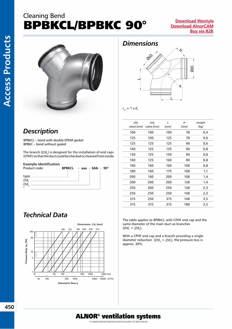
450
ALNOR® ventilation systemsis a legally protected trademark and technical patent. All rights reserved.
Acc
ess
Pro
du
cts
Download WentyleDownload AlnorCAM
Buy via B2B
Dimensions
DescriptionBPBKCL – bend with double EPDM gasket BPBKC – bend without gasket
The branch (Æd3) is designed for the installation of end caps (CPHF) so that the duct could be checked or cleaned from inside.
Technical DataThe table applies to BPBKCL with CPHF end cap and the same diameter of the main duct as branches (Æd1 = Æd3).
With a CPHF end cap and a branch providing a single diameter reduction (Æd3 < Æd1), the pressure loss is approx. 30%.
Example identificationProduct code: BPBKCL - aaa - bbb - 90°
typeÆd1Æd3°
Cleaning Bend
BPBKCL/BPBKC 90°
Dimensions Æd1 [mm]
Pre
ssu
re d
rop
Dp
t [P
a]
Volumetric flow q
Æd1 Æd3 L H weight rated [mm] rated [mm] [mm] [mm] [kg]
rm » 1 x d1
50 100 500 1000 5000 10000
3000100050010050101
5
10
50
100100 125 160 200 250 315
[l/s]
[m3/h]
100 100 100 78 0,4
125 100 125 78 0,6
125 125 125 90 0,6
140 125 135 90 0,8
150 125 150 90 0,8
160 125 160 90 0,8
160 160 160 108 0,8
180 160 175 108 1,1
200 160 200 108 1,4
200 200 200 128 1,4
250 200 250 128 2,3
250 250 250 148 2,3
315 250 315 148 3,5
315 315 315 180 3,5
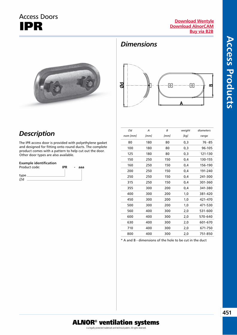
451
ALNOR® ventilation systemsis a legally protected trademark and technical patent. All rights reserved.
Access Pro
du
ctsDownload Wentyle
Download AlnorCAMBuy via B2B
Dimensions
Description
Access Doors
IPR
The IPR access door is provided with polyethylene gasket and designed for fitting onto round ducts. The complete product comes with a pattern to help cut out the door.Other door types are also available.
Example identificationProduct code: IPR - aaa
typeÆd
d A B weight diameters
nom [mm] [mm] [mm] [kg] range
* A and B - dimensions of the hole to be cut in the duct
80 180 80 0,3 76 -85
100 180 80 0,3 96-105
125 180 80 0,3 121-130
150 250 150 0,4 130-155
160 250 150 0,4 156-190
200 250 150 0,4 191-240
250 250 150 0,4 241-300
315 250 150 0,4 301-360
355 300 200 0,4 341-380
400 300 200 1,0 381-420
450 300 200 1,0 421-470
500 300 200 1,0 471-530
560 400 300 2,0 531-600
600 400 300 2,0 570-640
630 400 300 2,0 601-670
710 400 300 2,0 671-750
800 400 300 2,0 751-850
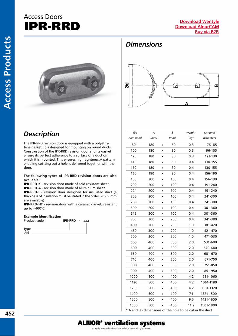
452
ALNOR® ventilation systemsis a legally protected trademark and technical patent. All rights reserved.
Acc
ess
Pro
du
cts
Download WentyleDownload AlnorCAM
Buy via B2B
Dimensions
Description
Example identificationProduct code: IPR-RRD - aaa
typeÆd
Access Doors
IPR-RRD
d A B weight range of
nom [mm] [mm] [mm] [kg] diameters
The IPR-RRD revision door is equipped with a polyethy-lene gasket. It is designed for mounting on round ducts. Construstion of the IPR-RRD revision door and its gasket ensure its perfect adherence to a surface of a duct on which it is mounted. This ensures high tightness.A pattern enabling cuttting out a hole is delivered together with the door.
The following types of IPR-RRD revision doors are also available: IPR-RRD-K - revision door made of acid resistant sheetIPR-RRD-A - revision door made of aluminium sheetIPR-RRD-I - revision door designed for insulated duct (a thickness of insulation must be stated in the order. 20 - 55mm are available)IPR-RRD-HT - revision door with a ceramic gasket, resistant up to +400°C
* A and B - dimensions of the hole to be cut in the duct
80 180 x 80 0,3 76 -85
100 180 x 80 0,3 96-105
125 180 x 80 0,3 121-130
140 180 x 80 0,4 130-155
150 180 x 80 0,4 130-155
160 180 x 80 0,4 156-190
180 200 x 100 0,4 156-190
200 200 x 100 0,4 191-240
224 200 x 100 0,4 191-240
250 200 x 100 0,4 241-300
280 200 x 100 0,4 241-300
300 200 x 100 0,4 301-360
315 200 x 100 0,4 301-360
355 300 x 200 0,4 341-380
400 300 x 200 1,0 381-420
450 300 x 200 1,0 421-470
500 300 x 200 1,0 471-530
560 400 x 300 2,0 531-600
600 400 x 300 2,0 570-640
630 400 x 300 2,0 601-670
710 400 x 300 2,0 671-750
800 400 x 300 2,0 751-850
900 400 x 300 2,0 851-950
1000 500 x 400 4,2 951-1060
1120 500 x 400 4,2 1061-1180
1250 500 x 400 4,2 1181-1320
1400 500 x 400 7,1 1321-1500
1500 500 x 400 9,5 1421-1600
1600 500 x 400 11,2 1501-1800
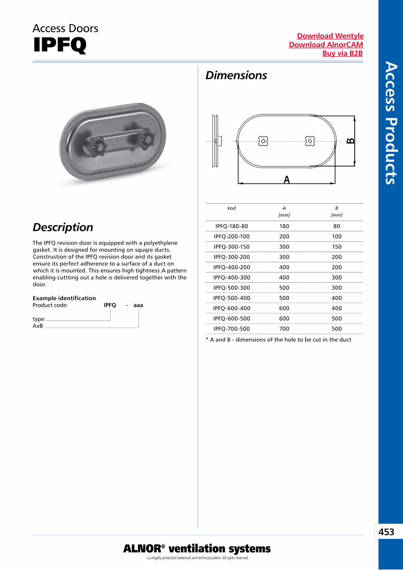
453
ALNOR® ventilation systemsis a legally protected trademark and technical patent. All rights reserved.
Access Pro
du
ctsDownload Wentyle
Download AlnorCAMBuy via B2B
Example identificationProduct code: IPFQ - aaa
typeAxB
Dimensions
Description
Access Doors
IPFQ
The IPFQ revision door is equipped with a polyethylene gasket. It is designed for mounting on squqre ducts. Construstion of the IPFQ revision door and its gasket ensure its perfect adherence to a surface of a duct on which it is mounted. This ensures high tightness.A pattern enabling cuttting out a hole is delivered together with the door.
kod A[mm]
B[mm]
* A and B - dimensions of the hole to be cut in the duct
IPFQ-180-80 180 80
IPFQ-200-100 200 100
IPFQ-300-150 300 150
IPFQ-300-200 300 200
IPFQ-400-200 400 200
IPFQ-400-300 400 300
IPFQ-500-300 500 300
IPFQ-500-400 500 400
IPFQ-600-400 600 400
IPFQ-600-500 600 500
IPFQ-700-500 700 500
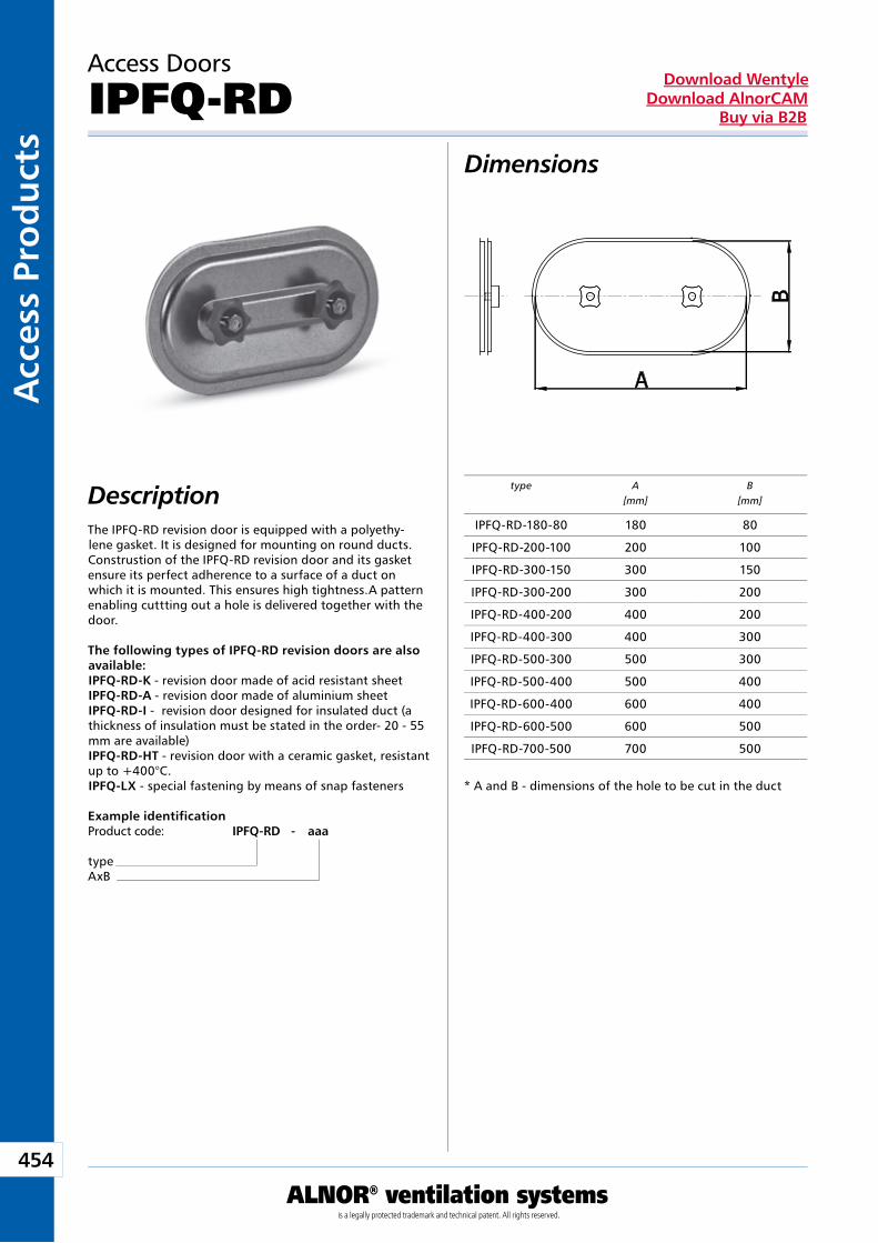
454
ALNOR® ventilation systemsis a legally protected trademark and technical patent. All rights reserved.
Acc
ess
Pro
du
cts
Download WentyleDownload AlnorCAM
Buy via B2B
Dimensions
Description
Example identificationProduct code: IPFQ-RD - aaa
typeAxB
Access Doors
IPFQ-RD
The IPFQ-RD revision door is equipped with a polyethy-lene gasket. It is designed for mounting on round ducts. Construstion of the IPFQ-RD revision door and its gasket ensure its perfect adherence to a surface of a duct on which it is mounted. This ensures high tightness.A pattern enabling cuttting out a hole is delivered together with the door.
The following types of IPFQ-RD revision doors are also available: IPFQ-RD-K - revision door made of acid resistant sheet IPFQ-RD-A - revision door made of aluminium sheetIPFQ-RD-I - revision door designed for insulated duct (a thickness of insulation must be stated in the order- 20 - 55 mm are available)IPFQ-RD-HT - revision door with a ceramic gasket, resistant up to +400°C.IPFQ-LX - special fastening by means of snap fasteners
type A[mm]
B[mm]
* A and B - dimensions of the hole to be cut in the duct
IPFQ-RD-180-80 180 80
IPFQ-RD-200-100 200 100
IPFQ-RD-300-150 300 150
IPFQ-RD-300-200 300 200
IPFQ-RD-400-200 400 200
IPFQ-RD-400-300 400 300
IPFQ-RD-500-300 500 300
IPFQ-RD-500-400 500 400
IPFQ-RD-600-400 600 400
IPFQ-RD-600-500 600 500
IPFQ-RD-700-500 700 500
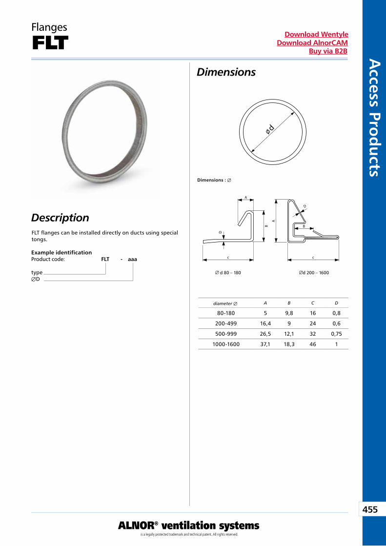
455
ALNOR® ventilation systemsis a legally protected trademark and technical patent. All rights reserved.
Access Pro
du
ctsDownload Wentyle
Download AlnorCAMBuy via B2B
Dimensions
Description
Flanges
FLT
FLT flanges can be installed directly on ducts using special tongs.
Example identificationProduct code: FLT - aaa
typeÆD
diameter Æ
Dimensions : Æ
d 80 – 180 d 200 – 1600
Ø d
A B C D
80-180 5 9,8 16 0,8
200-499 16,4 9 24 0,6
500-999 26,5 12,1 32 0,75
1000-1600 37,1 18,3 46 1
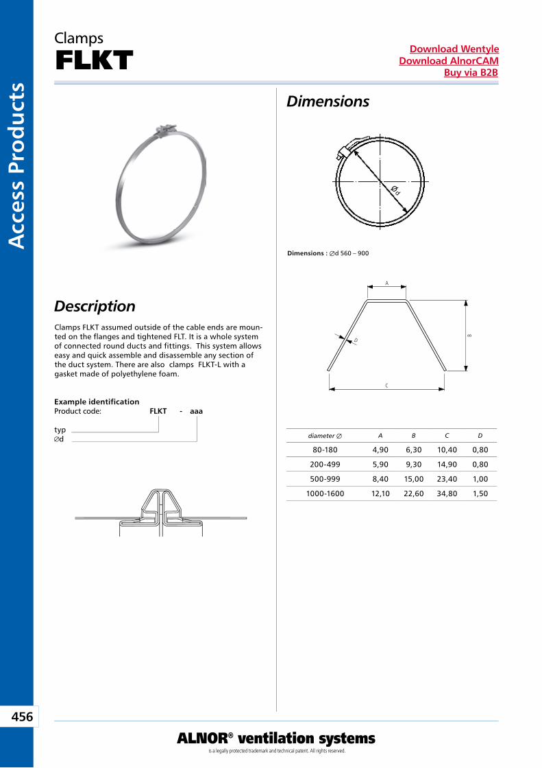
456
ALNOR® ventilation systemsis a legally protected trademark and technical patent. All rights reserved.
Acc
ess
Pro
du
cts
Download WentyleDownload AlnorCAM
Buy via B2B
Dimensions
Description
Clamps
FLKT
Dimensions : Æd 560 – 900
diameter Æ
Clamps FLKT assumed outside of the cable ends are moun-ted on the flanges and tightened FLT. It is a whole system of connected round ducts and fittings. This system allows easy and quick assemble and disassemble any section of the duct system. There are also clamps FLKT-L with a gasket made of polyethylene foam.
Example identificationProduct code: FLKT - aaa
typd
A
C
B
D
Ø d
A B C D
80-180 4,90 6,30 10,40 0,80
200-499 5,90 9,30 14,90 0,80
500-999 8,40 15,00 23,40 1,00
1000-1600 12,10 22,60 34,80 1,50
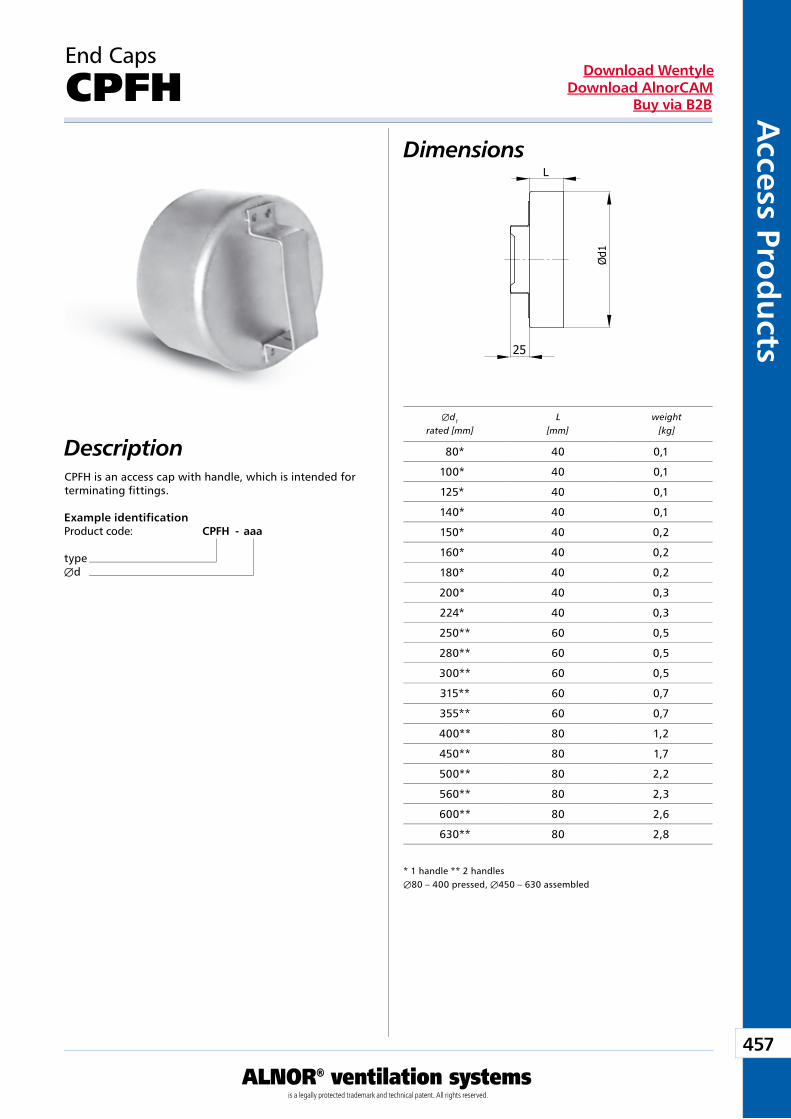
457
ALNOR® ventilation systemsis a legally protected trademark and technical patent. All rights reserved.
Access Pro
du
ctsDownload Wentyle
Download AlnorCAMBuy via B2B
End Caps
CPFH
DescriptionCPFH is an access cap with handle, which is intended for terminating fittings.
Example identificationProduct code: CPFH - aaa
typeÆd
Dimensions
* 1 handle ** 2 handlesÆ80 – 400 pressed, Æ450 – 630 assembled
Æd1 L weight rated [mm] [mm] [kg]
80* 40 0,1
100* 40 0,1
125* 40 0,1
140* 40 0,1
150* 40 0,2
160* 40 0,2
180* 40 0,2
200* 40 0,3
224* 40 0,3
250** 60 0,5
280** 60 0,5
300** 60 0,5
315** 60 0,7
355** 60 0,7
400** 80 1,2
450** 80 1,7
500** 80 2,2
560** 80 2,3
600** 80 2,6
630** 80 2,8
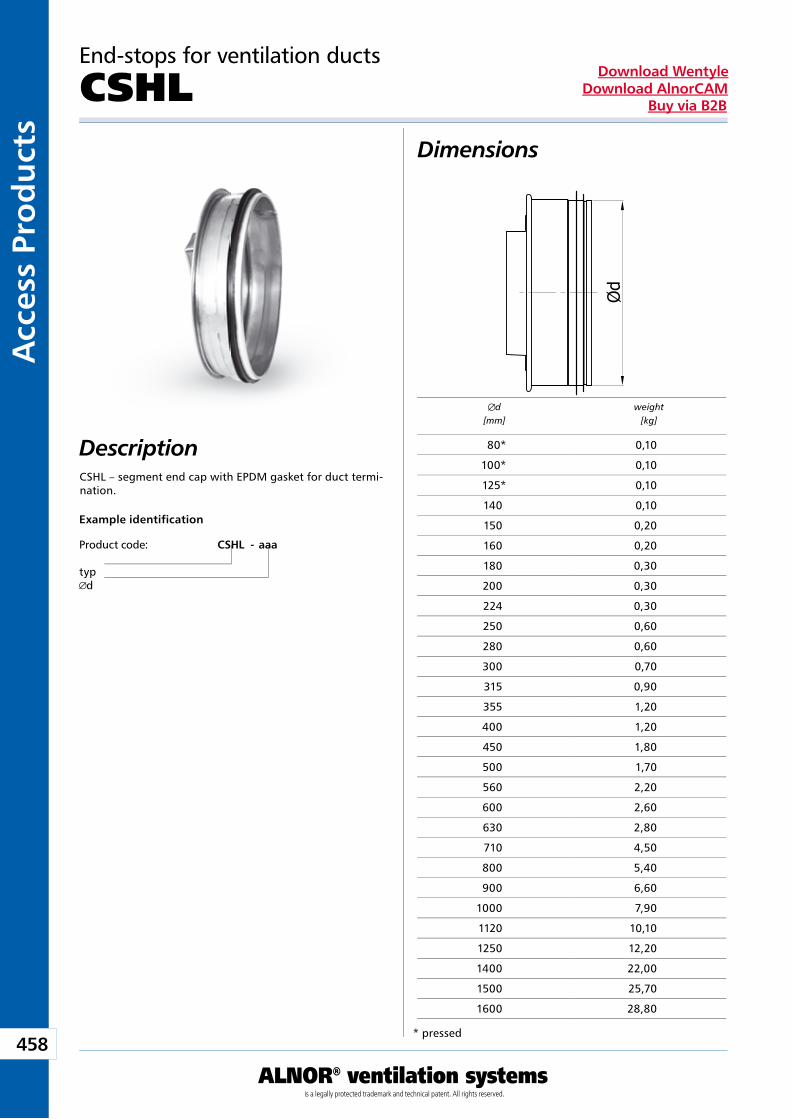
458
ALNOR® ventilation systemsis a legally protected trademark and technical patent. All rights reserved.
Acc
ess
Pro
du
cts
Download WentyleDownload AlnorCAM
Buy via B2B
Description
Dimensions
Example identification
Product code: CSHL - aaa
typd
End-stops for ventilation ducts
CSHL
CSHL – segment end cap with EPDM gasket for duct termi-nation.
d[mm]
weight[kg]
* pressed
80* 0,10
100* 0,10
125* 0,10
140 0,10
150 0,20
160 0,20
180 0,30
200 0,30
224 0,30
250 0,60
280 0,60
300 0,70
315 0,90
355 1,20
400 1,20
450 1,80
500 1,70
560 2,20
600 2,60
630 2,80
710 4,50
800 5,40
900 6,60
1000 7,90
1120 10,10
1250 12,20
1400 22,00
1500 25,70
1600 28,80
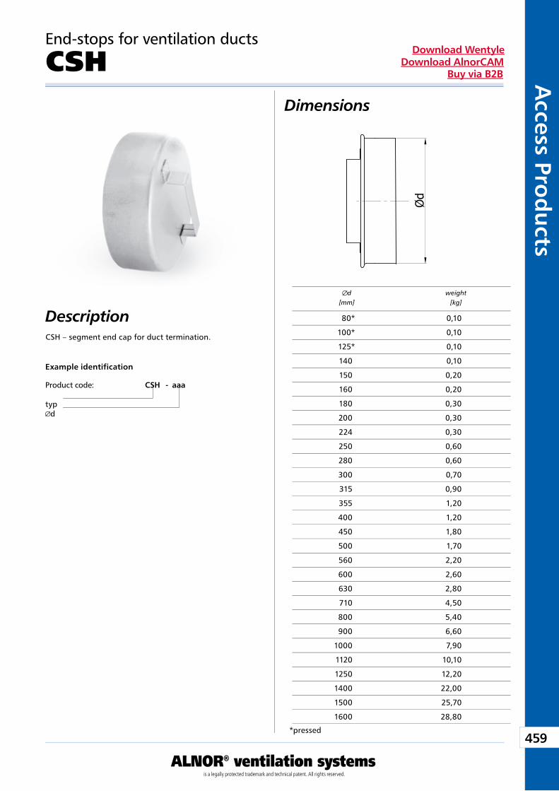
459
ALNOR® ventilation systemsis a legally protected trademark and technical patent. All rights reserved.
Access Pro
du
ctsDownload Wentyle
Download AlnorCAMBuy via B2B
Description
Dimensions
Example identification
Product code: CSH - aaa
typd
End-stops for ventilation ducts
CSH
CSH – segment end cap for duct termination.
d[mm]
weight[kg]
*pressed
80* 0,10
100* 0,10
125* 0,10
140 0,10
150 0,20
160 0,20
180 0,30
200 0,30
224 0,30
250 0,60
280 0,60
300 0,70
315 0,90
355 1,20
400 1,20
450 1,80
500 1,70
560 2,20
600 2,60
630 2,80
710 4,50
800 5,40
900 6,60
1000 7,90
1120 10,10
1250 12,20
1400 22,00
1500 25,70
1600 28,80
Roof Hoods
Producent zastrzega sobie prawo do dokonywania zmian w wymiarach i danych technicznych produktów ze względu na ciągłe ich doskonalenie
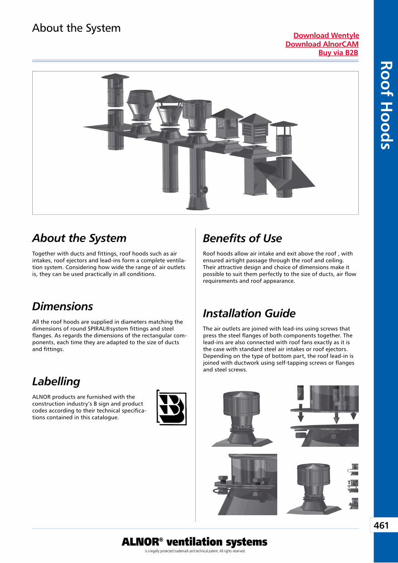
461
ALNOR® ventilation systemsis a legally protected trademark and technical patent. All rights reserved.
Roo
f Ho
od
sDownload Wentyle
Download AlnorCAMBuy via B2B
About the SystemTogether with ducts and fittings, roof hoods such as air intakes, roof ejectors and lead-ins form a complete ventila-tion system. Considering how wide the range of air outlets is, they can be used practically in all conditions.
Dimensions All the roof hoods are supplied in diameters matching the dimensions of round SPIRAL®system fittings and steel flanges. As regards the dimensions of the rectangular com-ponents, each time they are adapted to the size of ducts and fittings.
About the System
LabellingALNOR products are furnished with the construction industry’s B sign and product codes according to their technical specifica-tions contained in this catalogue.
Benefits of UseRoof hoods allow air intake and exit above the roof , with ensured airtight passage through the roof and ceiling. Their attractive design and choice of dimensions make it possible to suit them perfectly to the size of ducts, air flow requirements and roof appearance.
Installation GuideThe air outlets are joined with lead-ins using screws that press the steel flanges of both components together. The lead-ins are also connected with roof fans exactly as it is the case with standard steel air intakes or roof ejectors. Depending on the type of bottom part, the roof lead-in is joined with ductwork using self-tapping screws or flanges and steel screws.
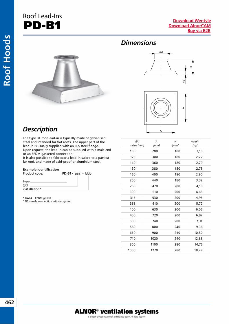
462
ALNOR® ventilation systemsis a legally protected trademark and technical patent. All rights reserved.
Roo
f H
oo
ds
Download WentyleDownload AlnorCAM
Buy via B2B
DescriptionThe type B1 roof lead-in is typically made of galvanised steel and intended for flat roofs. The upper part of the lead-in is usually supplied with an FLS steel flange.Upon request, the lead-in can be supplied with a male end or an EPDM gasketed connection.It is also possible to fabricate a lead-in suited to a particu-lar roof, and made of acid-proof or aluminium steel.
Roof Lead-Ins
PD-B1
Example identificationProduct code: PD-B1 - aaa - bbb
typeÆdinstallation*
* GALA – EPDM gasket* NS – male connection without gasket
Dimensions
Æd A H weight rated [mm] [mm] [mm] [kg]
100 280 180 2,10
125 300 180 2,22
140 360 180 2,79
150 380 180 2,78
160 400 180 2,90
200 440 180 3,32
250 470 200 4,10
300 510 200 4,68
315 530 200 4,93
355 610 200 5,72
400 630 200 6,06
450 720 200 6,97
500 740 200 7,31
560 800 240 9,36
630 900 240 10,80
710 1020 240 12,83
800 1100 280 14,76
1000 1270 280 18,29
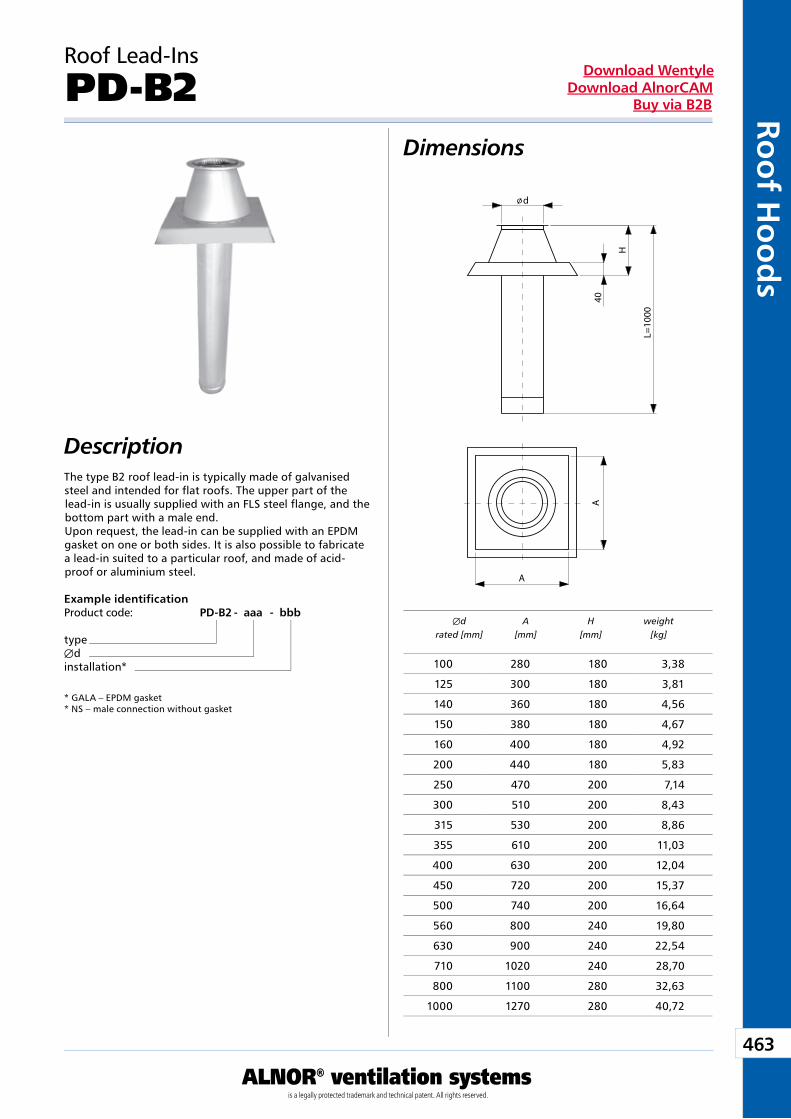
463
ALNOR® ventilation systemsis a legally protected trademark and technical patent. All rights reserved.
Roo
f Ho
od
sDownload Wentyle
Download AlnorCAMBuy via B2B
The type B2 roof lead-in is typically made of galvanised steel and intended for flat roofs. The upper part of the lead-in is usually supplied with an FLS steel flange, and the bottom part with a male end.Upon request, the lead-in can be supplied with an EPDM gasket on one or both sides. It is also possible to fabricate a lead-in suited to a particular roof, and made of acid-proof or aluminium steel.
Roof Lead-Ins
PD-B2
Example identificationProduct code: PD-B2 - aaa - bbb
typeÆdinstallation*
* GALA – EPDM gasket * NS – male connection without gasket
Dimensions
Description
Æd A H weight rated [mm] [mm] [mm] [kg]
100 280 180 3,38
125 300 180 3,81
140 360 180 4,56
150 380 180 4,67
160 400 180 4,92
200 440 180 5,83
250 470 200 7,14
300 510 200 8,43
315 530 200 8,86
355 610 200 11,03
400 630 200 12,04
450 720 200 15,37
500 740 200 16,64
560 800 240 19,80
630 900 240 22,54
710 1020 240 28,70
800 1100 280 32,63
1000 1270 280 40,72
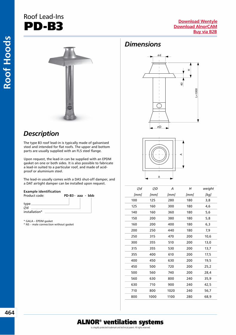
464
ALNOR® ventilation systemsis a legally protected trademark and technical patent. All rights reserved.
Roo
f H
oo
ds
Download WentyleDownload AlnorCAM
Buy via B2B
D
The type B3 roof lead-in is typically made of galvanised steel and intended for flat roofs. The upper and bottom parts are usually supplied with an FLS steel flange.
Upon request, the lead-in can be supplied with an EPDM gasket on one or both sides. It is also possible to fabricate a lead-in suited to a particular roof, and made of acid-proof or aluminium steel.
The lead-in usually comes with a DAS shut-off damper, and a DAT airtight damper can be installed upon request.
Roof Lead-Ins
PD-B3
Example identificationProduct code: PD-B3 - aaa - bbb
typeÆdinstallation*
* GALA – EPDM gasket * NS – male connection without gasket
Dimensions
Description
Æd ÆD A H weight
[mm] [mm] [mm] [mm] [kg]
100 125 280 180 3,8
125 160 300 180 4,6
140 160 360 180 5,6
150 200 380 180 5,8
160 200 400 180 6,3
200 250 440 180 7,9
250 315 470 200 10,6
300 355 510 200 13,0
315 355 530 200 13,7
355 400 610 200 17,5
400 450 630 200 19,5
450 500 720 200 25,2
500 560 740 200 28,4
560 630 800 240 35,9
630 710 900 240 42,5
710 800 1020 240 56,7
800 1000 1100 280 68,9
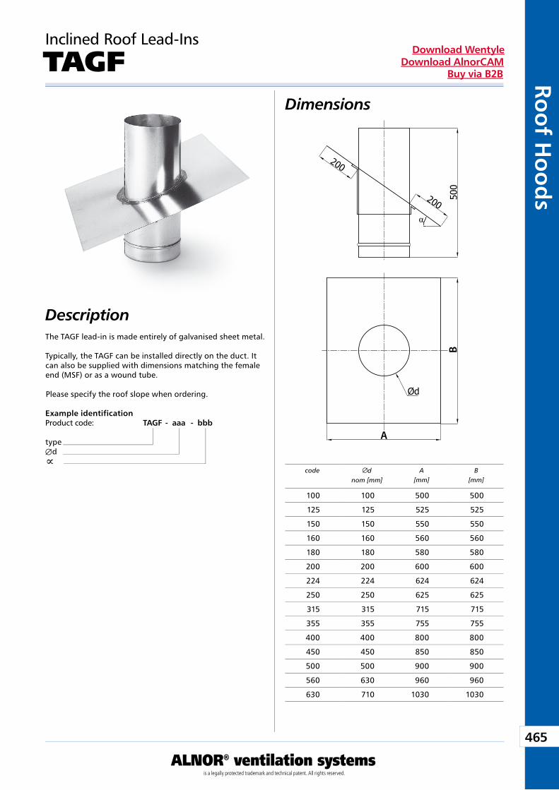
465
ALNOR® ventilation systemsis a legally protected trademark and technical patent. All rights reserved.
Roo
f Ho
od
sDownload Wentyle
Download AlnorCAMBuy via B2B
BA
Dimensions
Description
Inclined Roof Lead-Ins
TAGF
The TAGF lead-in is made entirely of galvanised sheet metal.
Typically, the TAGF can be installed directly on the duct. It can also be supplied with dimensions matching the female end (MSF) or as a wound tube.
Please specify the roof slope when ordering.
Example identificationProduct code: TAGF - aaa - bbb
typeÆdµ
code dnom [mm]
A[mm]
B[mm]
100 100 500 500
125 125 525 525
150 150 550 550
160 160 560 560
180 180 580 580
200 200 600 600
224 224 624 624
250 250 625 625
315 315 715 715
355 355 755 755
400 400 800 800
450 450 850 850
500 500 900 900
560 630 960 960
630 710 1030 1030
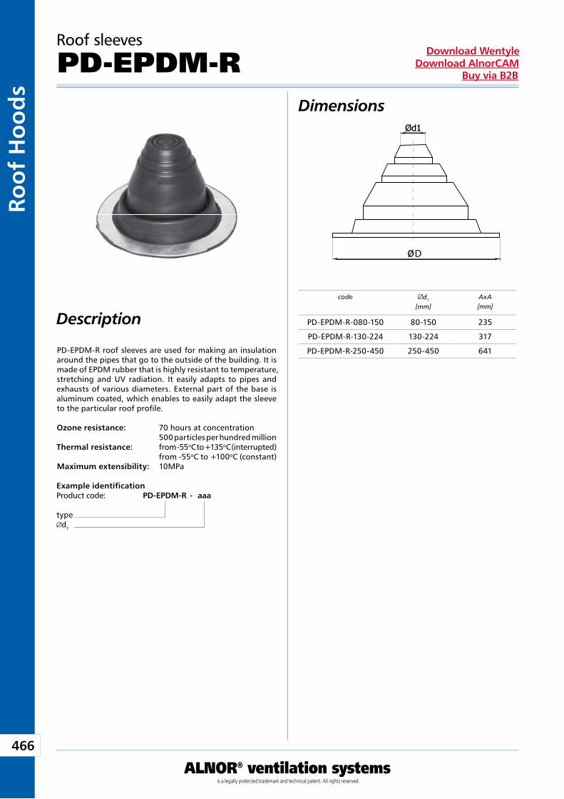
466
ALNOR® ventilation systemsis a legally protected trademark and technical patent. All rights reserved.
Roo
f H
oo
ds
Download WentyleDownload AlnorCAM
Buy via B2B
D
Roof sleeves
PD-EPDM-R
Description
Dimensions
PD-EPDM-R roof sleeves are used for making an insulation around the pipes that go to the outside of the building. It is made of EPDM rubber that is highly resistant to temperature, stretching and UV radiation. It easily adapts to pipes and exhausts of various diameters. External part of the base is aluminum coated, which enables to easily adapt the sleeve to the particular roof profile.
Ozone resistance: 70 hours at concentration 500 particles per hundred million Thermal resistance: from -55oC to +135oC (interrupted) from -55oC to +100oC (constant) Maximum extensibility: 10MPa
Example identificationProduct code: PD-EPDM-R - aaa
typed1
code d1
[mm]AxA[mm]
PD-EPDM-R-080-150 80-150 235
PD-EPDM-R-130-224 130-224 317
PD-EPDM-R-250-450 250-450 641
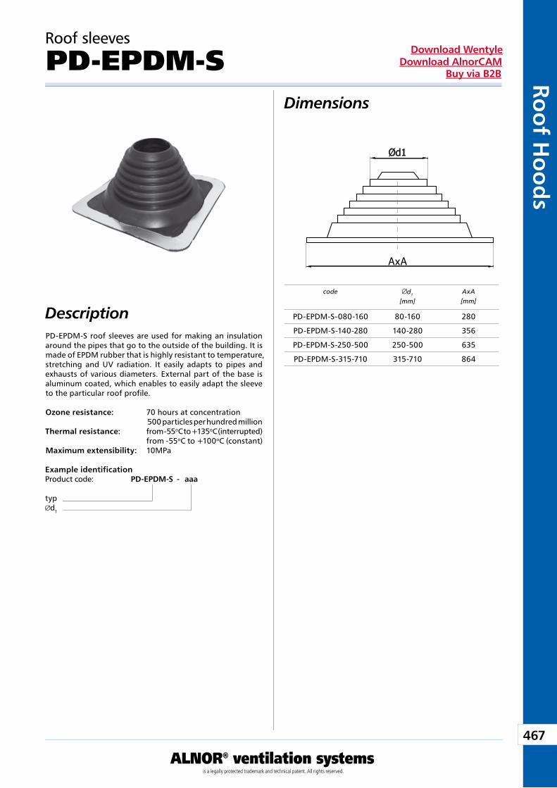
467
ALNOR® ventilation systemsis a legally protected trademark and technical patent. All rights reserved.
Roo
f Ho
od
sDownload Wentyle
Download AlnorCAMBuy via B2B
AxA
Roof sleeves
PD-EPDM-S
Description
Dimensions
Example identificationProduct code: PD-EPDM-S - aaa
typd1
code d1
[mm]AxA[mm]
PD-EPDM-S roof sleeves are used for making an insulation around the pipes that go to the outside of the building. It is made of EPDM rubber that is highly resistant to temperature, stretching and UV radiation. It easily adapts to pipes and exhausts of various diameters. External part of the base is aluminum coated, which enables to easily adapt the sleeve to the particular roof profile. Ozone resistance: 70 hours at concentration 500 particles per hundred million Thermal resistance: from -55oC to +135oC (interrupted) from -55oC to +100oC (constant) Maximum extensibility: 10MPa
PD-EPDM-S-080-160 80-160 280
PD-EPDM-S-140-280 140-280 356
PD-EPDM-S-250-500 250-500 635
PD-EPDM-S-315-710 315-710 864
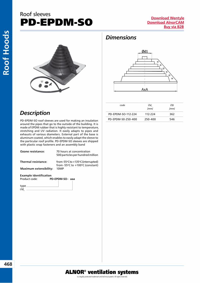
468
ALNOR® ventilation systemsis a legally protected trademark and technical patent. All rights reserved.
Roo
f H
oo
ds
Download WentyleDownload AlnorCAM
Buy via B2B
AxA
Roof sleeves
PD-EPDM-SO
Description
Dimensions
PD-EPDM-SO roof sleeves are used for making an insulation around the pipes that go to the outside of the building. It is made of EPDM rubber that is highly resistant to temperature, stretching and UV radiation. It easily adapts to pipes and exhausts of various diameters. External part of the base is aluminum coated, which enables to easily adapt the sleeve to the particular roof profile. PD-EPDM-SO sleeves are shipped with plastic snap fasteners and an assembly band Ozone resistance: 70 hours at concentration 500 particles per hundred million Thermal resistance: from -55oC to +135oC (interrupted) from -55oC to +100oC (constant) Maximum extensibility: 10MP
Example identificationProduct code: PD-EPDM-SO - aaa
typed1
code d1
[mm]D
[mm]
PD-EPDM-SO-112-224 112-224 362
PD-EPDM-S0-250-400 250-400 546
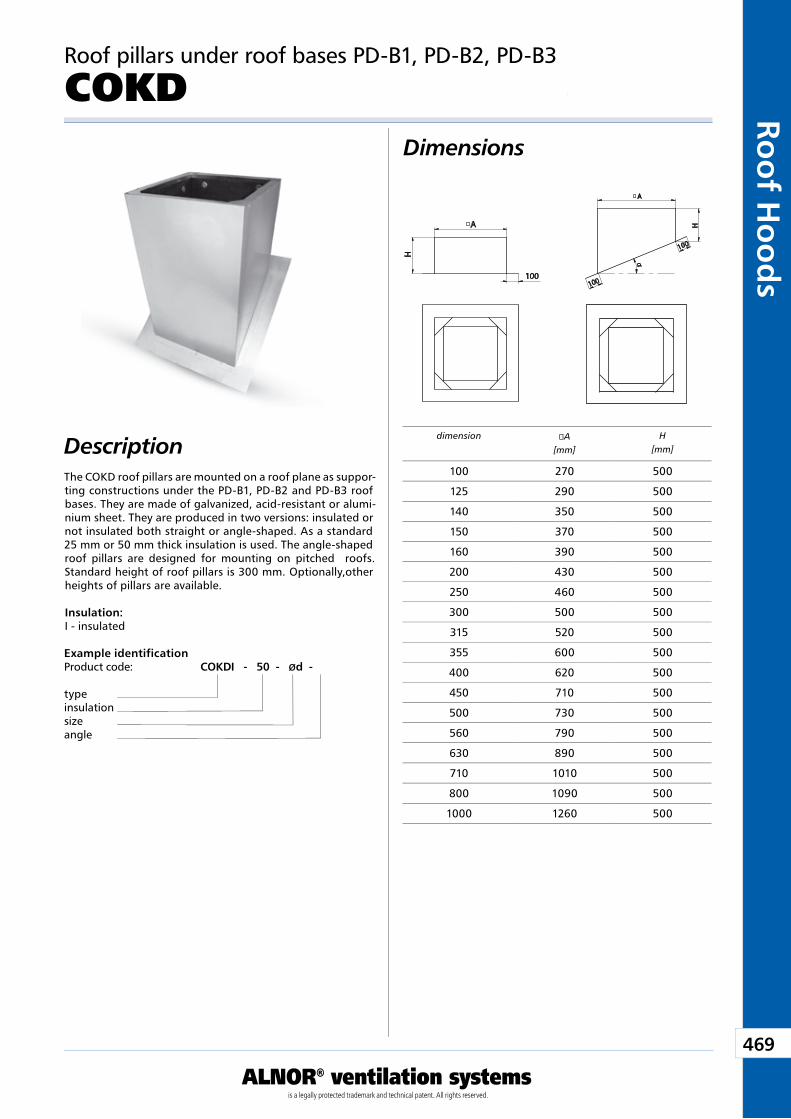
469
ALNOR® ventilation systemsis a legally protected trademark and technical patent. All rights reserved.
Roo
f Ho
od
sDownload Wentyle
Download AlnorCAMBuy via B2B
A
H
o
100
o A
H
100
100
α
Description
Dimensions
Roof pillars under roof bases PD-B1, PD-B2, PD-B3
COKD
The COKD roof pillars are mounted on a roof plane as suppor-ting constructions under the PD-B1, PD-B2 and PD-B3 roof bases. They are made of galvanized, acid-resistant or alumi-nium sheet. They are produced in two versions: insulated or not insulated both straight or angle-shaped. As a standard 25 mm or 50 mm thick insulation is used. The angle-shaped roof pillars are designed for mounting on pitched roofs. Standard height of roof pillars is 300 mm. Optionally,other heights of pillars are available.
Insulation: I - insulated
Example identificationProduct code: COKD I - 50 - Ød - �
typeinsulationsizeangle
dimension �A[mm]
H[mm]
100 270 500
125 290 500
140 350 500
150 370 500
160 390 500
200 430 500
250 460 500
300 500 500
315 520 500
355 600 500
400 620 500
450 710 500
500 730 500
560 790 500
630 890 500
710 1010 500
800 1090 500
1000 1260 500
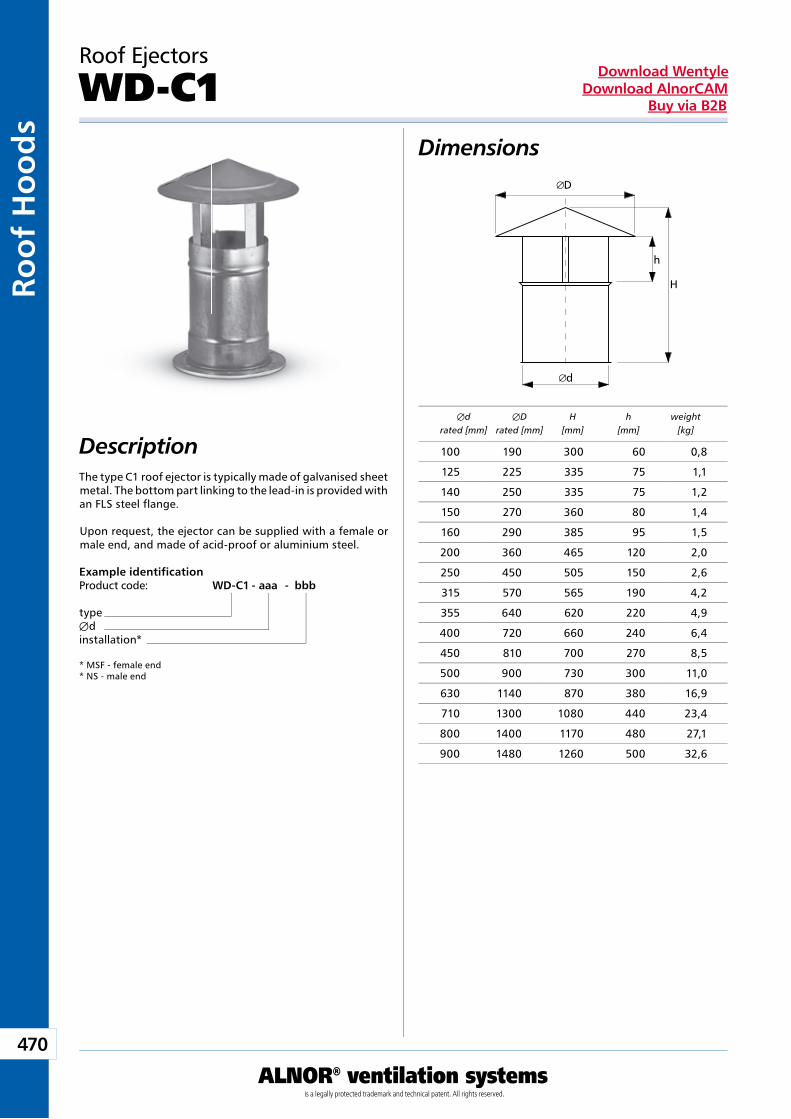
470
ALNOR® ventilation systemsis a legally protected trademark and technical patent. All rights reserved.
Roo
f H
oo
ds
Download WentyleDownload AlnorCAM
Buy via B2B
D
d
H
h
The type C1 roof ejector is typically made of galvanised sheet metal. The bottom part linking to the lead-in is provided with an FLS steel flange.
Upon request, the ejector can be supplied with a female or male end, and made of acid-proof or aluminium steel.
Roof Ejectors
WD-C1
Example identificationProduct code: WD-C1 - aaa - bbb
typeÆdinstallation* * MSF - female end* NS - male end
Dimensions
Description Æd ÆD H h weight rated [mm] rated [mm] [mm] [mm] [kg]
100 190 300 60 0,8
125 225 335 75 1,1
140 250 335 75 1,2
150 270 360 80 1,4
160 290 385 95 1,5
200 360 465 120 2,0
250 450 505 150 2,6
315 570 565 190 4,2
355 640 620 220 4,9
400 720 660 240 6,4
450 810 700 270 8,5
500 900 730 300 11,0
630 1140 870 380 16,9
710 1300 1080 440 23,4
800 1400 1170 480 27,1
900 1480 1260 500 32,6
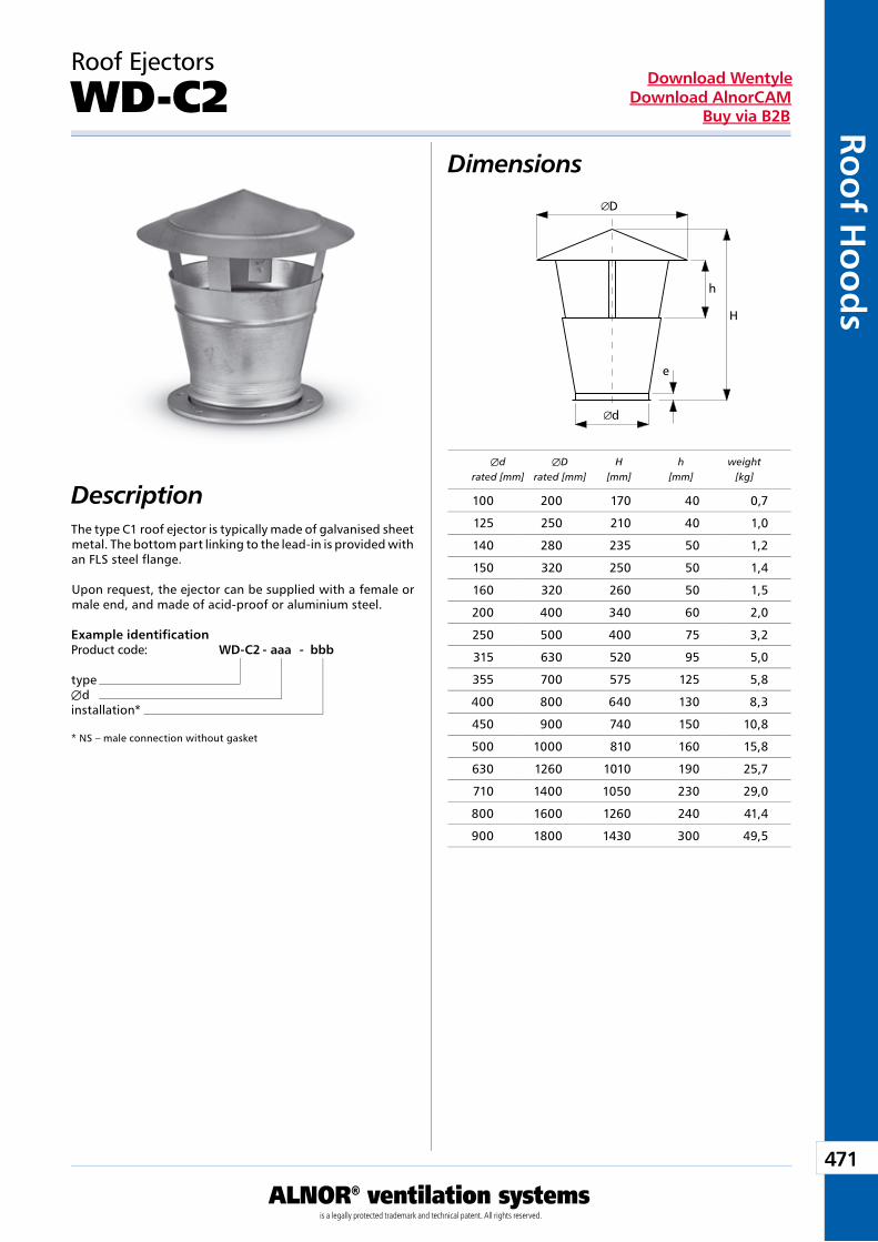
471
ALNOR® ventilation systemsis a legally protected trademark and technical patent. All rights reserved.
Roo
f Ho
od
sDownload Wentyle
Download AlnorCAMBuy via B2B
D
d
H
h
e
The type C1 roof ejector is typically made of galvanised sheet metal. The bottom part linking to the lead-in is provided with an FLS steel flange.
Upon request, the ejector can be supplied with a female or male end, and made of acid-proof or aluminium steel.
Roof Ejectors
WD-C2
Example identificationProduct code: WD-C2 - aaa - bbb
typeÆdinstallation* * NS – male connection without gasket
Dimensions
Description Æd ÆD H h weight rated [mm] rated [mm] [mm] [mm] [kg]
100 200 170 40 0,7
125 250 210 40 1,0
140 280 235 50 1,2
150 320 250 50 1,4
160 320 260 50 1,5
200 400 340 60 2,0
250 500 400 75 3,2
315 630 520 95 5,0
355 700 575 125 5,8
400 800 640 130 8,3
450 900 740 150 10,8
500 1000 810 160 15,8
630 1260 1010 190 25,7
710 1400 1050 230 29,0
800 1600 1260 240 41,4
900 1800 1430 300 49,5
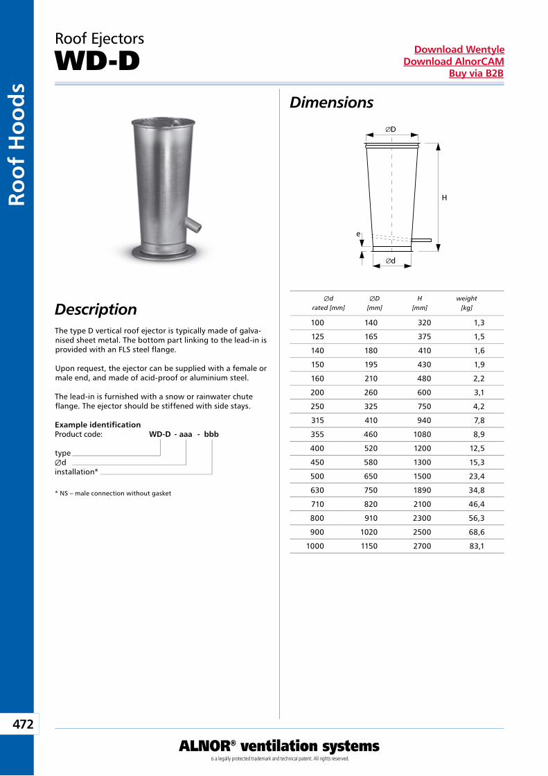
472
ALNOR® ventilation systemsis a legally protected trademark and technical patent. All rights reserved.
Roo
f H
oo
ds
Download WentyleDownload AlnorCAM
Buy via B2B
D
H
d
e
The type D vertical roof ejector is typically made of galva-nised sheet metal. The bottom part linking to the lead-in is provided with an FLS steel flange.
Upon request, the ejector can be supplied with a female or male end, and made of acid-proof or aluminium steel.
The lead-in is furnished with a snow or rainwater chute flange. The ejector should be stiffened with side stays.
Roof Ejectors
WD-D
Example identificationProduct code: WD-D - aaa - bbb
typeÆdinstallation*
* NS – male connection without gasket
Dimensions
Description Æd ÆD H weight rated [mm] [mm] [mm] [kg]
100 140 320 1,3
125 165 375 1,5
140 180 410 1,6
150 195 430 1,9
160 210 480 2,2
200 260 600 3,1
250 325 750 4,2
315 410 940 7,8
355 460 1080 8,9
400 520 1200 12,5
450 580 1300 15,3
500 650 1500 23,4
630 750 1890 34,8
710 820 2100 46,4
800 910 2300 56,3
900 1020 2500 68,6
1000 1150 2700 83,1
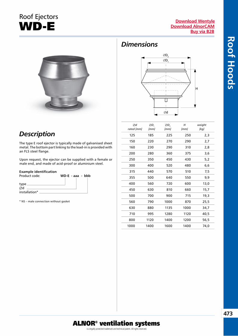
473
ALNOR® ventilation systemsis a legally protected trademark and technical patent. All rights reserved.
Roo
f Ho
od
sDownload Wentyle
Download AlnorCAMBuy via B2B
D2
d
H
D1
The type E roof ejector is typically made of galvanised sheet metal. The bottom part linking to the lead-in is provided with an FLS steel flange.
Upon request, the ejector can be supplied with a female or male end, and made of acid-proof or aluminium steel.
Roof Ejectors
WD-E
Example identificationProduct code: WD-E - aaa - bbb
typeÆdinstallation*
* NS – male connection without gasket
Dimensions
Description Æd ÆD1 ÆD2 H weight rated [mm] [mm] [mm] [mm] [kg]
125 185 225 250 2,3
150 220 270 290 2,7
160 230 290 310 2,8
200 280 360 375 3,6
250 350 450 430 5,2
300 400 520 480 6,6
315 440 570 510 7,5
355 500 640 550 9,9
400 560 720 600 13,0
450 630 810 660 15,7
500 700 900 715 19,3
560 790 1000 870 25,5
630 880 1135 1000 34,7
710 995 1280 1120 40,5
800 1120 1400 1200 56,5
1000 1400 1600 1400 74,0
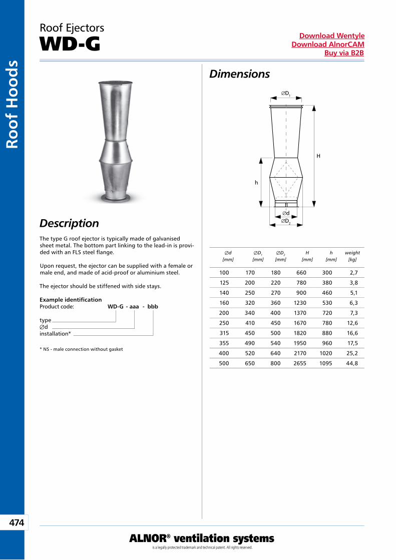
474
ALNOR® ventilation systemsis a legally protected trademark and technical patent. All rights reserved.
Roo
f H
oo
ds
Download WentyleDownload AlnorCAM
Buy via B2B
D1
H
d
h
D2
The type G roof ejector is typically made of galvanised sheet metal. The bottom part linking to the lead-in is provi-ded with an FLS steel flange.
Upon request, the ejector can be supplied with a female or male end, and made of acid-proof or aluminium steel.
The ejector should be stiffened with side stays.
Roof Ejectors
WD-G
Example identificationProduct code: WD-G - aaa - bbb
typeÆdinstallation*
* NS - male connection without gasket
Dimensions
Description
Æd ÆD1 ÆD2 H h weight [mm] [mm] [mm] [mm] [mm] [kg]
100 170 180 660 300 2,7
125 200 220 780 380 3,8
140 250 270 900 460 5,1
160 320 360 1230 530 6,3
200 340 400 1370 720 7,3
250 410 450 1670 780 12,6
315 450 500 1820 880 16,6
355 490 540 1950 960 17,5
400 520 640 2170 1020 25,2
500 650 800 2655 1095 44,8
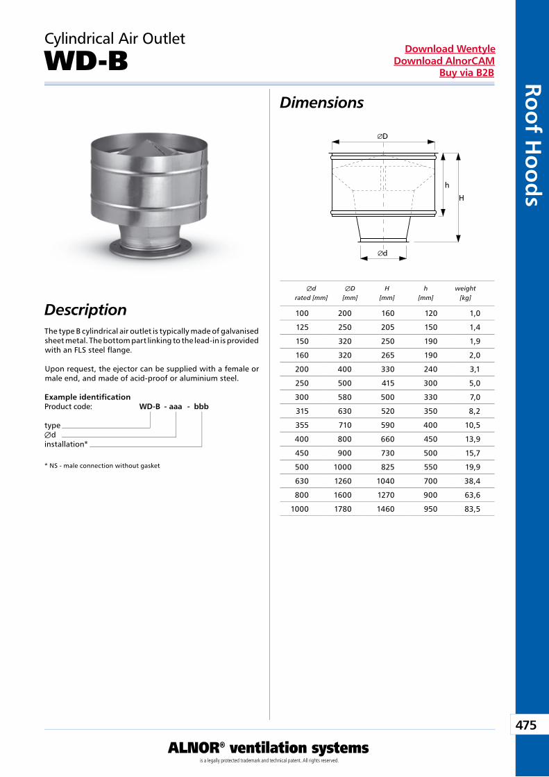
475
ALNOR® ventilation systemsis a legally protected trademark and technical patent. All rights reserved.
Roo
f Ho
od
sDownload Wentyle
Download AlnorCAMBuy via B2B
d
H
D
h
The type B cylindrical air outlet is typically made of galvanised sheet metal. The bottom part linking to the lead-in is provided with an FLS steel flange.
Upon request, the ejector can be supplied with a female or male end, and made of acid-proof or aluminium steel.
Cylindrical Air Outlet
WD-B
Example identificationProduct code: WD-B - aaa - bbb
typeÆdinstallation*
* NS - male connection without gasket
Dimensions
Description
Æd ÆD H h weight rated [mm] [mm] [mm] [mm] [kg]
100 200 160 120 1,0
125 250 205 150 1,4
150 320 250 190 1,9
160 320 265 190 2,0
200 400 330 240 3,1
250 500 415 300 5,0
300 580 500 330 7,0
315 630 520 350 8,2
355 710 590 400 10,5
400 800 660 450 13,9
450 900 730 500 15,7
500 1000 825 550 19,9
630 1260 1040 700 38,4
800 1600 1270 900 63,6
1000 1780 1460 950 83,5
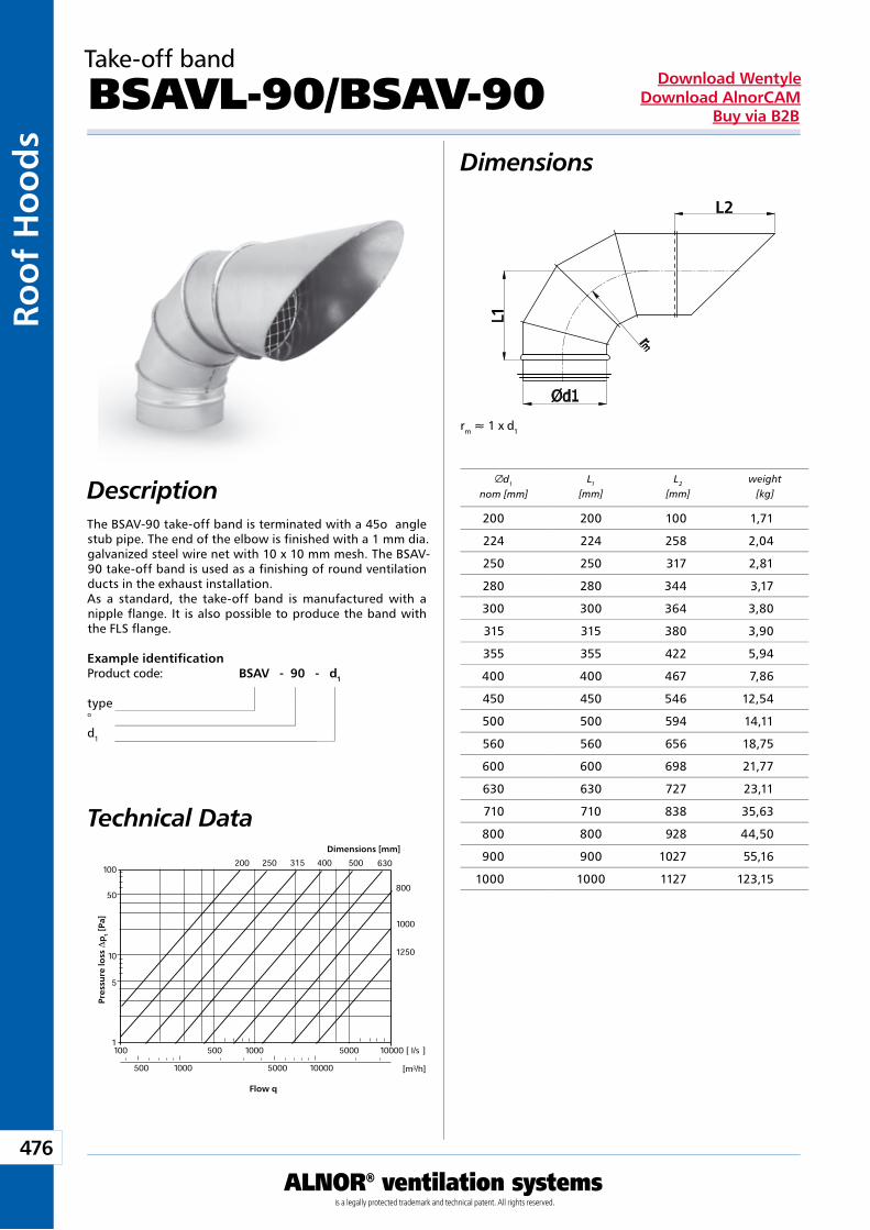
476
ALNOR® ventilation systemsis a legally protected trademark and technical patent. All rights reserved.
Roo
f H
oo
ds
Download WentyleDownload AlnorCAM
Buy via B2B
rm » 1 x d1
1
2
Dimensions
Description
Technical Data
Example identificationProduct code: BSAV - 90 - d1
type°d1
The BSAV-90 take-off band is terminated with a 45o angle stub pipe. The end of the elbow is finished with a 1 mm dia. galvanized steel wire net with 10 x 10 mm mesh. The BSAV-90 take-off band is used as a finishing of round ventilation ducts in the exhaust installation.As a standard, the take-off band is manufactured with a nipple flange. It is also possible to produce the band with the FLS flange.
Take-off band
BSAVL-90/BSAV-90
Dimensions [mm]
Pre
ssu
re lo
ss D
pt
[Pa]
Flow q
d1
nom [mm]L1
[mm]L2
[mm]weight
[kg]
200 200 100 1,71
224 224 258 2,04
250 250 317 2,81
280 280 344 3,17
300 300 364 3,80
315 315 380 3,90
355 355 422 5,94
400 400 467 7,86
450 450 546 12,54
500 500 594 14,11
560 560 656 18,75
600 600 698 21,77
630 630 727 23,11
710 710 838 35,63
800 800 928 44,50
900 900 1027 55,16
1000 1000 1127 123,15
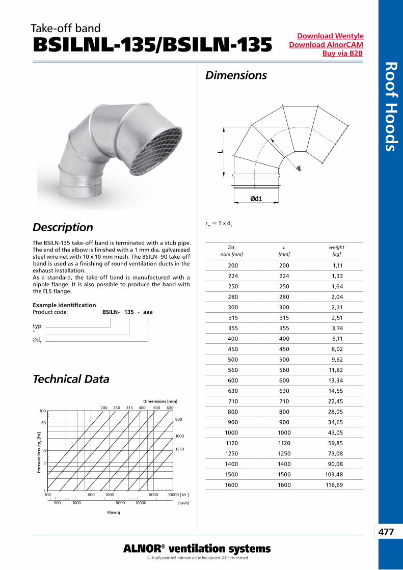
477
ALNOR® ventilation systemsis a legally protected trademark and technical patent. All rights reserved.
Roo
f Ho
od
sDownload Wentyle
Download AlnorCAMBuy via B2B
rm » 1 x d1
Dimensions
DescriptionThe BSILN-135 take-off band is terminated with a stub pipe. The end of the elbow is finished with a 1 mm dia. galvanized steel wire net with 10 x 10 mm mesh. The BSILN -90 take-off band is used as a finishing of round ventilation ducts in the exhaust installation.As a standard, the take-off band is manufactured with a nipple flange. It is also possible to produce the band with the FLS flange.
Take-off band
BSILNL-135/BSILN-135
Dimensions [mm]
Pre
ssu
re lo
ss D
pt
[Pa]
Flow q
d1
nom [mm]L
[mm]weight
[kg]
Technical Data
Example identificationProduct code: BSILN - 135 - aaa
typ°
d1
200 200 1,11
224 224 1,33
250 250 1,64
280 280 2,04
300 300 2,31
315 315 2,51
355 355 3,74
400 400 5,11
450 450 8,02
500 500 9,62
560 560 11,82
600 600 13,34
630 630 14,55
710 710 22,45
800 800 28,05
900 900 34,65
1000 1000 43,05
1120 1120 59,85
1250 1250 73,08
1400 1400 90,08
1500 1500 103,48
1600 1600 116,69
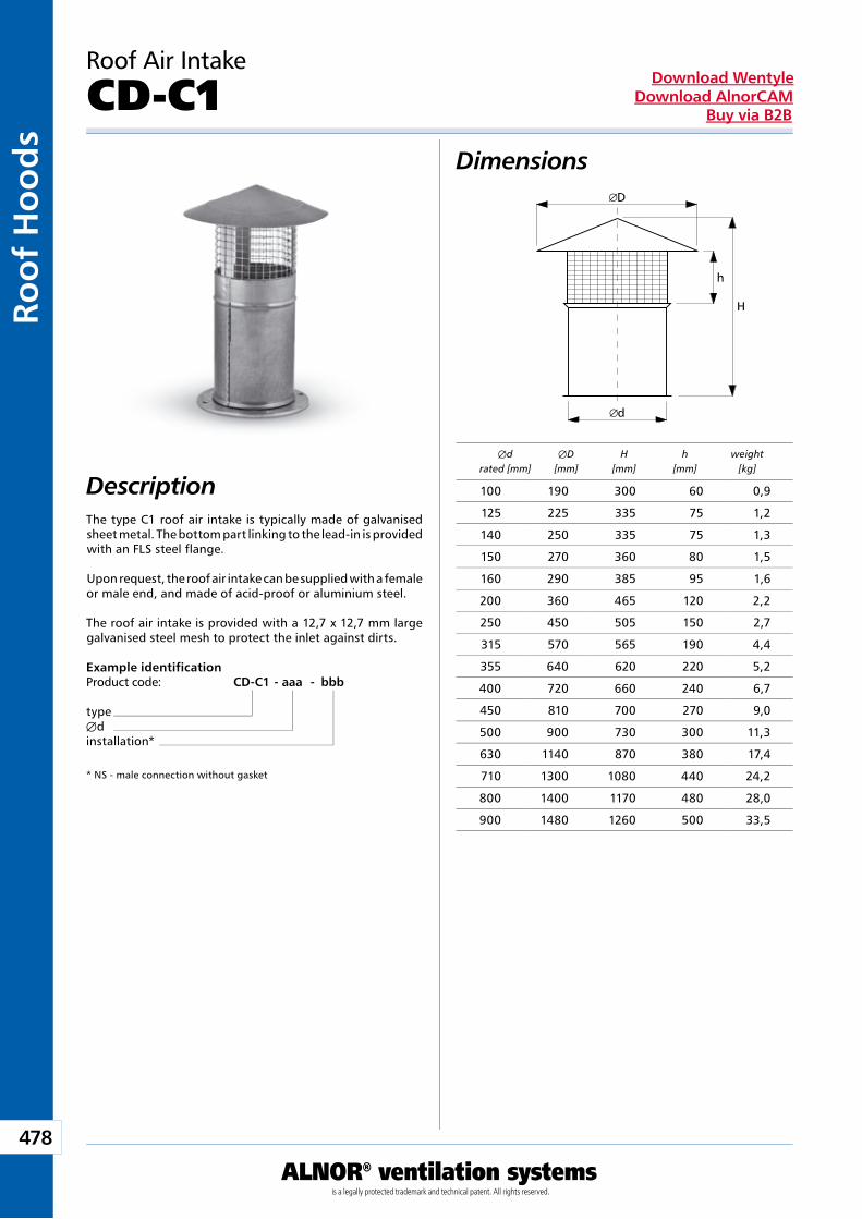
478
ALNOR® ventilation systemsis a legally protected trademark and technical patent. All rights reserved.
Roo
f H
oo
ds
Download WentyleDownload AlnorCAM
Buy via B2B
d
H
D
h
The type C1 roof air intake is typically made of galvanised sheet metal. The bottom part linking to the lead-in is provided with an FLS steel flange.
Upon request, the roof air intake can be supplied with a female or male end, and made of acid-proof or aluminium steel.
The roof air intake is provided with a 12,7 x 12,7 mm large galvanised steel mesh to protect the inlet against dirts.
Roof Air Intake
CD-C1
Example identificationProduct code: CD-C1 - aaa - bbb
typeÆdinstallation*
* NS - male connection without gasket
Dimensions
Description Æd ÆD H h weight rated [mm] [mm] [mm] [mm] [kg]
100 190 300 60 0,9
125 225 335 75 1,2
140 250 335 75 1,3
150 270 360 80 1,5
160 290 385 95 1,6
200 360 465 120 2,2
250 450 505 150 2,7
315 570 565 190 4,4
355 640 620 220 5,2
400 720 660 240 6,7
450 810 700 270 9,0
500 900 730 300 11,3
630 1140 870 380 17,4
710 1300 1080 440 24,2
800 1400 1170 480 28,0
900 1480 1260 500 33,5
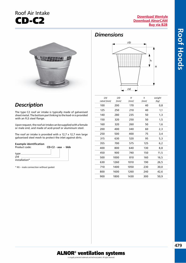
479
ALNOR® ventilation systemsis a legally protected trademark and technical patent. All rights reserved.
Roo
f Ho
od
sDownload Wentyle
Download AlnorCAMBuy via B2B
d
H
D
h
The type C2 roof air intake is typically made of galvanised sheet metal. The bottom part linking to the lead-in is provided with an FLS steel flange.
Upon request, the roof air intake can be supplied with a female or male end, and made of acid-proof or aluminium steel.
The roof air intake is provided with a 12,7 x 12,7 mm large galvanised steel mesh to protect the inlet against dirts.
Roof Air Intake
CD-C2
Example identificationProduct code: CD-C2 - aaa - bbb
typeÆdinstallation*
* NS – male connection without gasket
Dimensions
Description Æd ÆD H h weight rated [mm] [mm] [mm] [mm] [kg]
100 200 170 40 0,8
125 250 210 40 1,1
140 280 235 50 1,3
150 320 250 50 1,5
160 320 260 50 1,6
200 400 340 60 2,3
250 500 400 75 3,4
315 630 520 95 5,3
355 700 575 125 6,2
400 800 640 130 8,8
450 900 740 150 11,5
500 1000 810 160 16,5
630 1260 1010 190 26,5
710 1400 1050 230 30,0
800 1600 1260 240 42,6
900 1800 1430 300 50,9
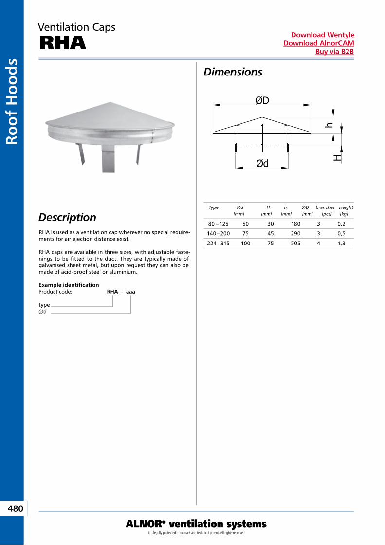
480
ALNOR® ventilation systemsis a legally protected trademark and technical patent. All rights reserved.
Roo
f H
oo
ds
Download WentyleDownload AlnorCAM
Buy via B2B
Dimensions
DescriptionRHA is used as a ventilation cap wherever no special require-ments for air ejection distance exist.
RHA caps are available in three sizes, with adjustable faste-nings to be fitted to the duct. They are typically made of galvanised sheet metal, but upon request they can also be made of acid-proof steel or aluminium.
Ventilation Caps
RHA
Example identificationProduct code: RHA - aaa
typeÆd
Type Æd H h ÆD branches weight [mm] [mm] [mm] {mm] [pcs] [kg]
80 – 125 50 30 180 3 0,2
140 – 200 75 45 290 3 0,5
224 – 315 100 75 505 4 1,3
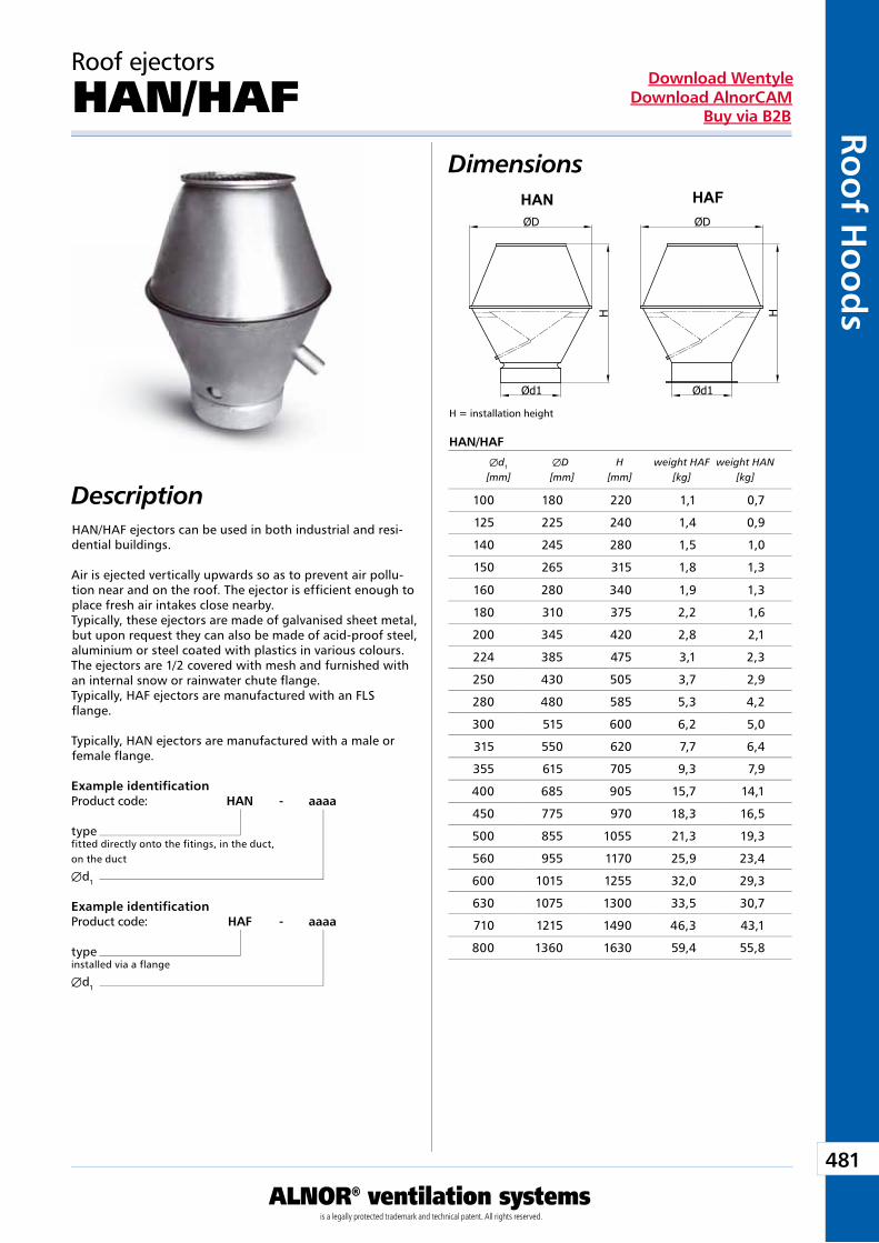
481
ALNOR® ventilation systemsis a legally protected trademark and technical patent. All rights reserved.
Roo
f Ho
od
sDownload Wentyle
Download AlnorCAMBuy via B2B
Dimensions
Description
Roof ejectors
HAN/HAF
HAN/HAF ejectors can be used in both industrial and resi-dential buildings.
Air is ejected vertically upwards so as to prevent air pollu-tion near and on the roof. The ejector is efficient enough to place fresh air intakes close nearby.Typically, these ejectors are made of galvanised sheet metal, but upon request they can also be made of acid-proof steel, aluminium or steel coated with plastics in various colours. The ejectors are 1/2 covered with mesh and furnished with an internal snow or rainwater chute flange.Typically, HAF ejectors are manufactured with an FLS flange.
Typically, HAN ejectors are manufactured with a male or female flange.
Example identificationProduct code: HAN - aaaa
typefitted directly onto the fitings, in the duct,on the duct
Æd1
Example identificationProduct code: HAF - aaaa
typeinstalled via a flange
Æd1
HAN/HAF
H = installation height
Æd1 ÆD H weight HAF weight HAN [mm] [mm] [mm] [kg] [kg]
100 180 220 1,1 0,7
125 225 240 1,4 0,9
140 245 280 1,5 1,0
150 265 315 1,8 1,3
160 280 340 1,9 1,3
180 310 375 2,2 1,6
200 345 420 2,8 2,1
224 385 475 3,1 2,3
250 430 505 3,7 2,9
280 480 585 5,3 4,2
300 515 600 6,2 5,0
315 550 620 7,7 6,4
355 615 705 9,3 7,9
400 685 905 15,7 14,1
450 775 970 18,3 16,5
500 855 1055 21,3 19,3
560 955 1170 25,9 23,4
600 1015 1255 32,0 29,3
630 1075 1300 33,5 30,7
710 1215 1490 46,3 43,1
800 1360 1630 59,4 55,8
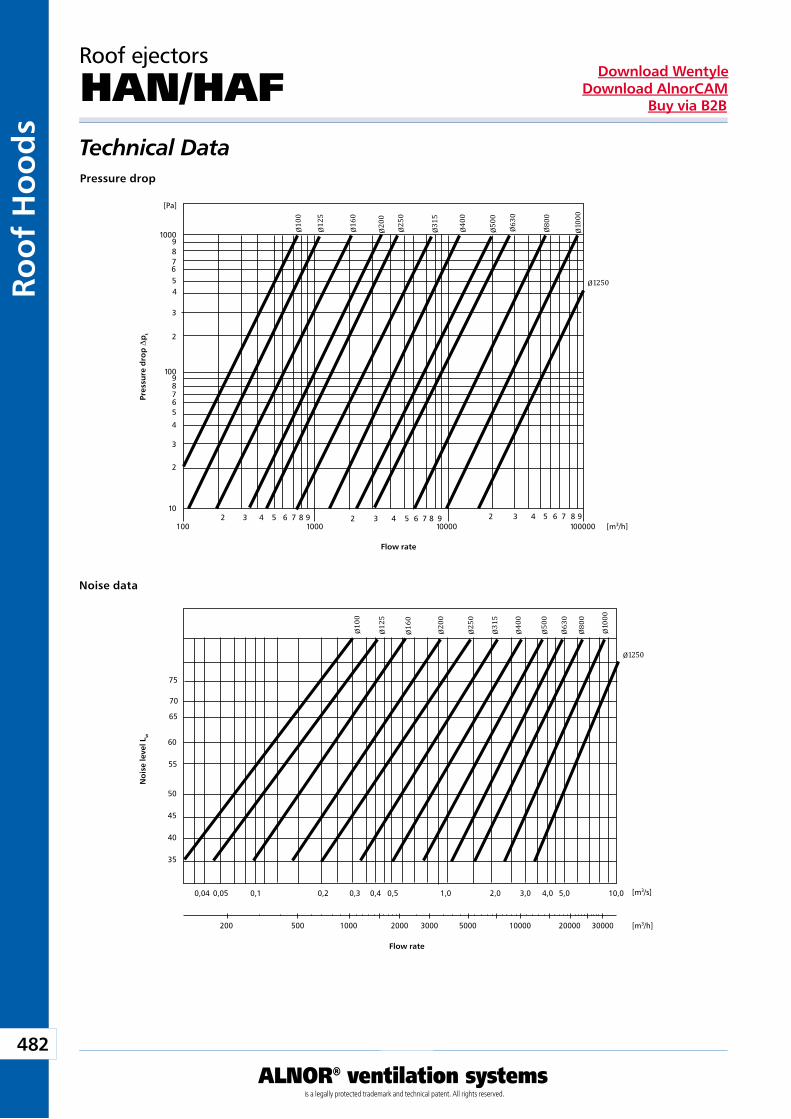
482
ALNOR® ventilation systemsis a legally protected trademark and technical patent. All rights reserved.
Roo
f H
oo
ds
Download WentyleDownload AlnorCAM
Buy via B2B
Ø100
Ø125
Ø160
Ø200
Ø250
Ø315
Ø400
Ø500
Ø630
Ø800
Ø1000
Ø1250
[m3/h]
[m3/s]
75
70
65
60
55
50
45
40
35
0,04 0,05 0,1 0,2 0,3 0,4 0,5 1,0 2,0 3,0 4,0 5,0 10,0
200 500 1000 2000 3000 5000 10000 20000 30000
Ø100
Ø125
Ø160
Ø200
Ø250
Ø315
Ø400
Ø500
Ø630
Ø800
Ø1000
Ø1250
[Pa]
1000987654
3
2
98765
4
3
2
10
100 1000 10000 100000
100
2 3 4 5 6 7 8 9 2 3 4 5 6 7 8 9 2 3 4 5 6 7 8 9[m3/h]
Technical Data
Roof ejectors
HAN/HAF
Flow rate
Flow rate
Pres
sure
dro
p D
pt
No
ise
leve
l Lw
Pressure drop
Noise data
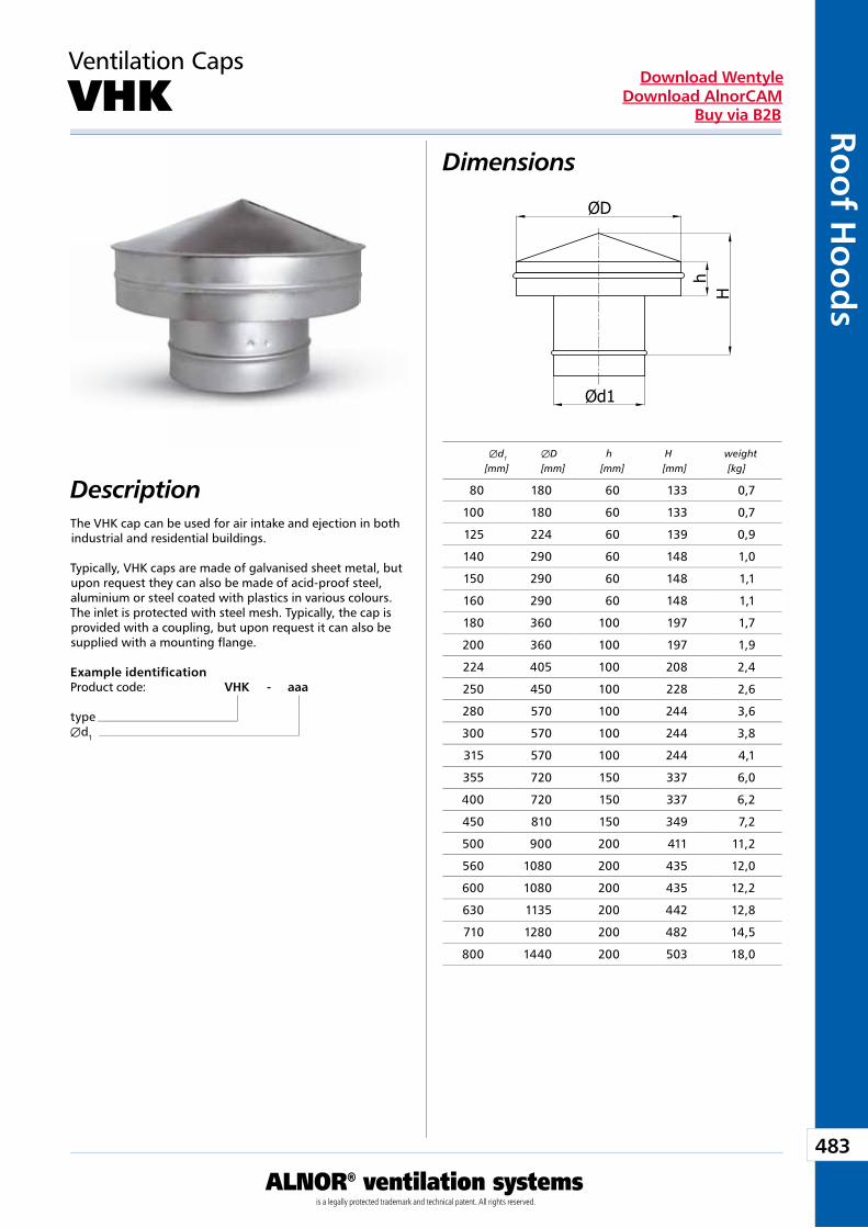
483
ALNOR® ventilation systemsis a legally protected trademark and technical patent. All rights reserved.
Roo
f Ho
od
sDownload Wentyle
Download AlnorCAMBuy via B2B
Ød1
ØD
Hh
Dimensions
Description
Ventilation Caps
VHK
The VHK cap can be used for air intake and ejection in both industrial and residential buildings.
Typically, VHK caps are made of galvanised sheet metal, but upon request they can also be made of acid-proof steel, aluminium or steel coated with plastics in various colours. The inlet is protected with steel mesh. Typically, the cap is provided with a coupling, but upon request it can also be supplied with a mounting flange.
Example identificationProduct code: VHK - aaa
typeÆd1
Æd1 ÆD h H weight [mm] [mm] [mm] [mm] [kg]
80 180 60 133 0,7
100 180 60 133 0,7
125 224 60 139 0,9
140 290 60 148 1,0
150 290 60 148 1,1
160 290 60 148 1,1
180 360 100 197 1,7
200 360 100 197 1,9
224 405 100 208 2,4
250 450 100 228 2,6
280 570 100 244 3,6
300 570 100 244 3,8
315 570 100 244 4,1
355 720 150 337 6,0
400 720 150 337 6,2
450 810 150 349 7,2
500 900 200 411 11,2
560 1080 200 435 12,0
600 1080 200 435 12,2
630 1135 200 442 12,8
710 1280 200 482 14,5
800 1440 200 503 18,0
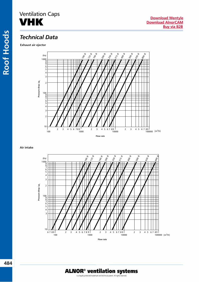
484
ALNOR® ventilation systemsis a legally protected trademark and technical patent. All rights reserved.
Roo
f H
oo
ds
Download WentyleDownload AlnorCAM
Buy via B2B
100098765
4
3
2
100987654
3
2
10
1002 3 4 5 6 7 8 9
10002 3 4 5 6 7 89
100002 3 4 5 6 7 89
100000
800Ø
630Ø
500Ø
400Ø
315Ø
250Ø
200Ø
160Ø
125Ø
100Ø(Pa)
[m3/h]
100
106 7 8 9 2 3 4 5 6 7 8 9
10002 3 4 5 6 7 8 9
100002 3 4 5 6 7 89
100000
800Ø
630Ø
500Ø
400Ø
315Ø
250Ø
200Ø
160Ø
125Ø
100Ø
1000987654
3
2
10098765
4
3
(Pa)
[m3/h]
Technical Data
Ventilation Caps
VHK
Exhaust air ejector
Air intake
Pres
sure
dro
p D
pt
Pres
sure
dro
p D
pt
Flow rate
Flow rate
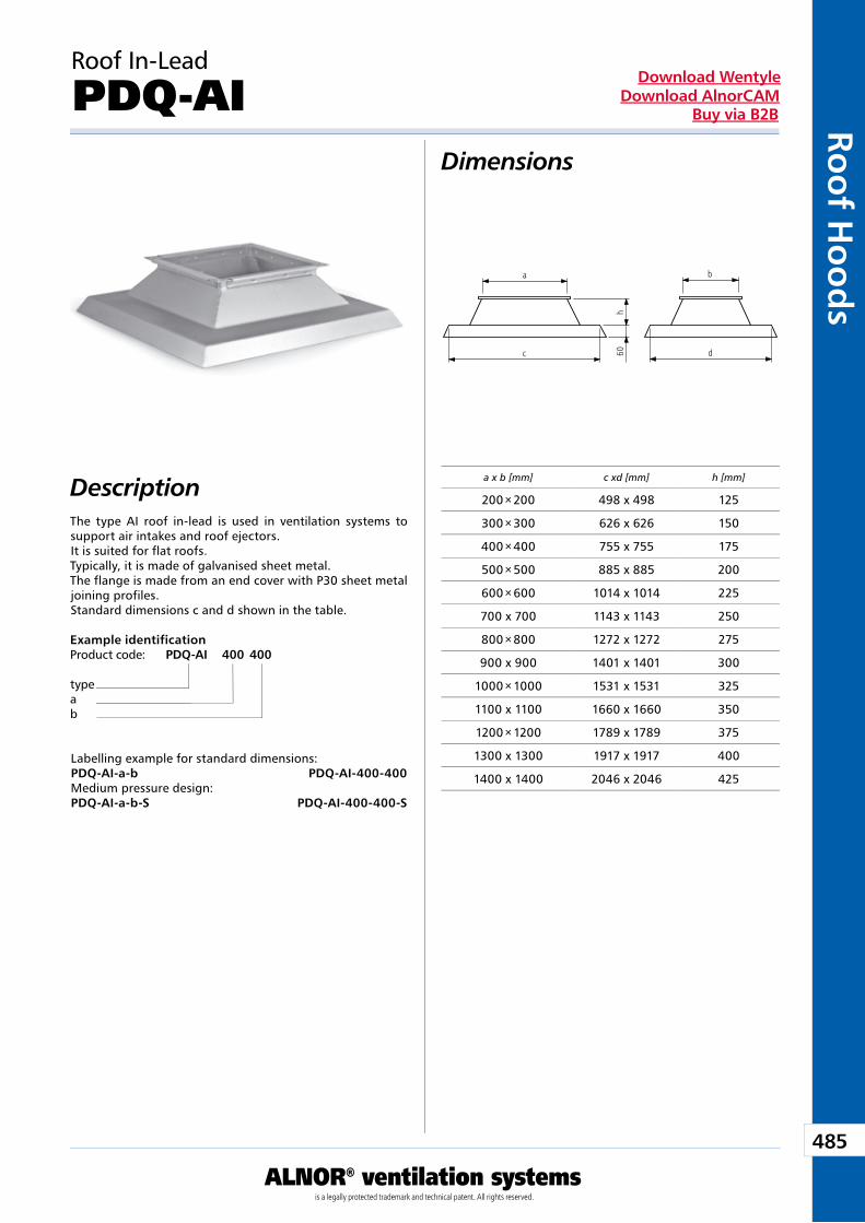
485
ALNOR® ventilation systemsis a legally protected trademark and technical patent. All rights reserved.
Roo
f Ho
od
sDownload Wentyle
Download AlnorCAMBuy via B2B
h60 d
b
c
a
Roof In-Lead
PDQ-AIDimensions
DescriptionThe type AI roof in-lead is used in ventilation systems to support air intakes and roof ejectors.It is suited for flat roofs.Typically, it is made of galvanised sheet metal.The flange is made from an end cover with P30 sheet metal joining profiles.Standard dimensions c and d shown in the table.
Labelling example for standard dimensions:PDQ-AI-a-b PDQ-AI-400-400Medium pressure design:PDQ-AI-a-b-S PDQ-AI-400-400-S
Example identificationProduct code: PDQ-AI 400 400
typeab
a x b [mm] c xd [mm] h [mm]
200 × 200 498 x 498 125
300 × 300 626 x 626 150
400 × 400 755 x 755 175
500 × 500 885 x 885 200
600 × 600 1014 x 1014 225
700 x 700 1143 x 1143 250
800 × 800 1272 x 1272 275
900 x 900 1401 x 1401 300
1000 × 1000 1531 x 1531 325
1100 x 1100 1660 x 1660 350
1200 × 1200 1789 x 1789 375
1300 x 1300 1917 x 1917 400
1400 x 1400 2046 x 2046 425
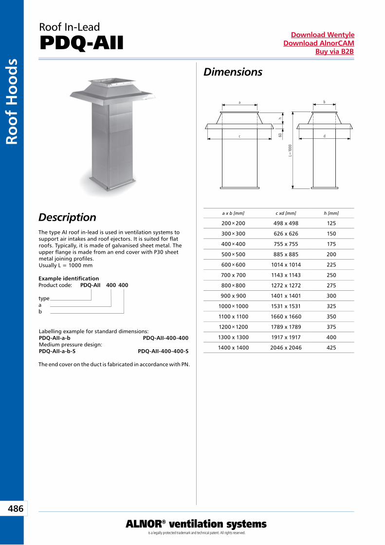
486
ALNOR® ventilation systemsis a legally protected trademark and technical patent. All rights reserved.
Roo
f H
oo
ds
Download WentyleDownload AlnorCAM
Buy via B2B
L=10
00
h60 d
b
c
a
Roof In-Lead
PDQ-AIIDimensions
DescriptionThe type AI roof in-lead is used in ventilation systems to support air intakes and roof ejectors. It is suited for flat roofs. Typically, it is made of galvanised sheet metal. The upper flange is made from an end cover with P30 sheet metal joining profiles.Usually L = 1000 mm
The end cover on the duct is fabricated in accordance with PN.
Labelling example for standard dimensions:PDQ-AII-a-b PDQ-AII-400-400Medium pressure design:PDQ-AII-a-b-S PDQ-AII-400-400-S
Example identificationProduct code: PDQ-AII 400 400
typeab
a x b [mm] c xd [mm] h [mm]
200 × 200 498 x 498 125
300 × 300 626 x 626 150
400 × 400 755 x 755 175
500 × 500 885 x 885 200
600 × 600 1014 x 1014 225
700 x 700 1143 x 1143 250
800 × 800 1272 x 1272 275
900 x 900 1401 x 1401 300
1000 × 1000 1531 x 1531 325
1100 x 1100 1660 x 1660 350
1200 × 1200 1789 x 1789 375
1300 x 1300 1917 x 1917 400
1400 x 1400 2046 x 2046 425
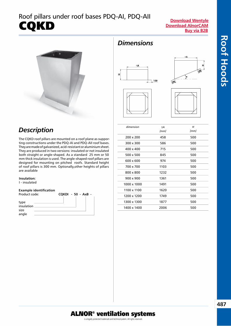
487
ALNOR® ventilation systemsis a legally protected trademark and technical patent. All rights reserved.
Roo
f Ho
od
sDownload Wentyle
Download AlnorCAMBuy via B2B
A
H
o
100
o A
H
100
100
αDimensions
Description
Roof pillars under roof bases PDQ-AI, PDQ-AII
CQKD
The CQKD roof pillars are mounted on a roof plane as suppor-ting constructions under the PDQ-AI and PDQ-AII roof bases. They are made of galvanized, acid-resistant or aluminium sheet.They are produced in two versions: insulated or not insulated both straight or angle-shaped. As a standard 25 mm or 50 mm thick insulation is used. The angle-shaped roof pillars are designed for mounting on pitched roofs. Standard height of roof pillars is 300 mm. Optionally,other heights of pillars are available
Insulation:I - insulated
Example identificationProduct code: CQKD I - 50 - AxB - �
typeinsulationsizeangle
dimension �A[mm]
H[mm]
200 x 200 458 500
300 x 300 586 500
400 x 400 715 500
500 x 500 845 500
600 x 600 974 500
700 x 700 1103 500
800 x 800 1232 500
900 x 900 1361 500
1000 x 1000 1491 500
1100 x 1100 1620 500
1200 x 1200 1749 500
1300 x 1300 1877 500
1400 x 1400 2006 500
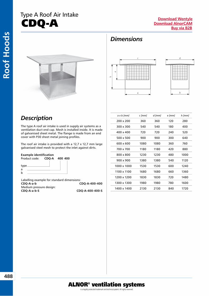
488
ALNOR® ventilation systemsis a legally protected trademark and technical patent. All rights reserved.
Roo
f H
oo
ds
Download WentyleDownload AlnorCAM
Buy via B2B
Type A Roof Air Intake
CDQ-A Dimensions
DescriptionThe type A roof air intake is used in supply air systems as a ventilation duct end cap. Mesh is installed inside. It is made of galvanised sheet metal. The flange is made from an end cover with P30 sheet metal joining profiles.
The roof air intake is provided with a 12,7 x 12,7 mm large galvanised steel mesh to protect the inlet against dirts.
Labelling example for standard dimensions:CDQ-A-a-b CDQ-A-400-400Medium pressure design:CDQ-A-a-b-S CDQ-A-400-400-S
Example identificationProduct code: CDQ-A 400 400
typeab
a x b [mm] c [mm] d [mm] e [mm] h [mm]
200 x 200 360 360 120 280
300 x 300 540 540 180 400
400 x 400 720 720 240 520
500 x 500 900 900 300 640
600 x 600 1080 1080 360 760
700 x 700 1180 1180 420 880
800 x 800 1230 1230 480 1000
900 x 900 1380 1380 540 1120
1000 x 1000 1530 1530 600 1240
1100 x 1100 1680 1680 660 1360
1200 x 1200 1830 1830 720 1480
1300 x 1300 1980 1980 780 1600
1400 x 1400 2130 2130 840 1720
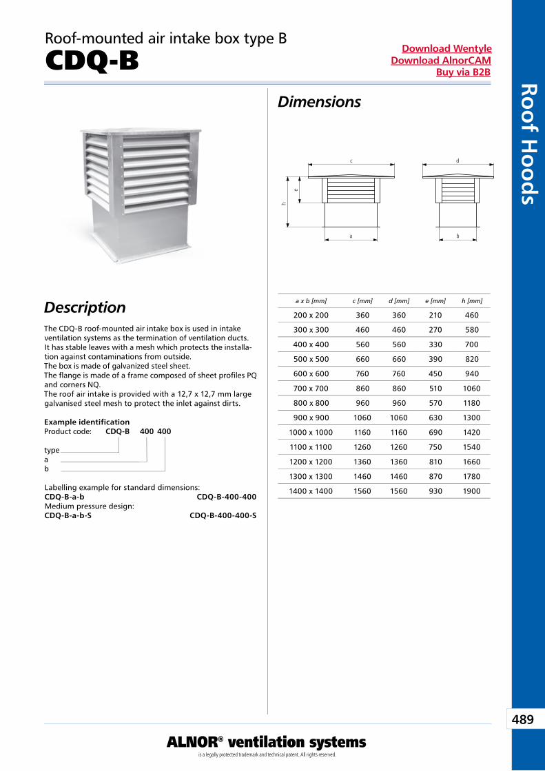
489
ALNOR® ventilation systemsis a legally protected trademark and technical patent. All rights reserved.
Roo
f Ho
od
sDownload Wentyle
Download AlnorCAMBuy via B2B
Dimensions
Description
Roof-mounted air intake box type B
CDQ-B
The CDQ-B roof-mounted air intake box is used in intake ventilation systems as the termination of ventilation ducts. It has stable leaves with a mesh which protects the installa-tion against contaminations from outside. The box is made of galvanized steel sheet. The flange is made of a frame composed of sheet profiles PQ and corners NQ. The roof air intake is provided with a 12,7 x 12,7 mm large galvanised steel mesh to protect the inlet against dirts.
Labelling example for standard dimensions:CDQ-B-a-b CDQ-B-400-400Medium pressure design:CDQ-B-a-b-S CDQ-B-400-400-S
Example identificationProduct code: CDQ-B 400 400
typeab
a x b [mm] c [mm] d [mm] e [mm] h [mm]
200 x 200 360 360 210 460
300 x 300 460 460 270 580
400 x 400 560 560 330 700
500 x 500 660 660 390 820
600 x 600 760 760 450 940
700 x 700 860 860 510 1060
800 x 800 960 960 570 1180
900 x 900 1060 1060 630 1300
1000 x 1000 1160 1160 690 1420
1100 x 1100 1260 1260 750 1540
1200 x 1200 1360 1360 810 1660
1300 x 1300 1460 1460 870 1780
1400 x 1400 1560 1560 930 1900
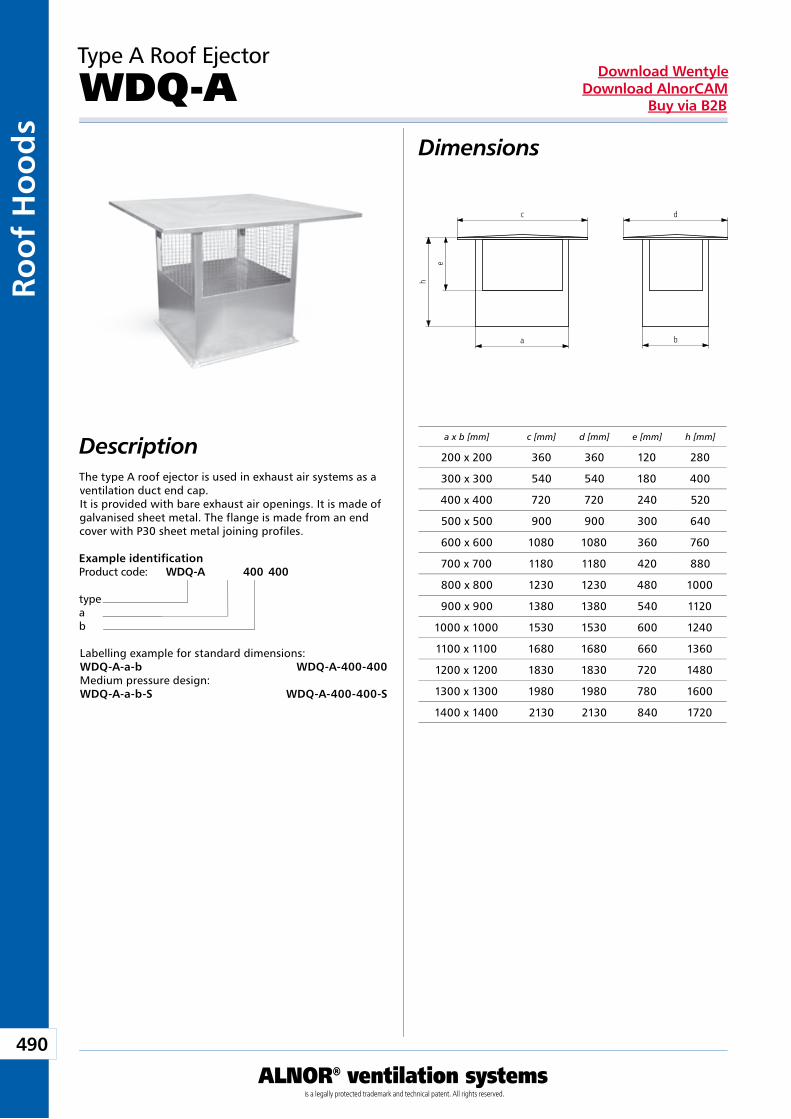
490
ALNOR® ventilation systemsis a legally protected trademark and technical patent. All rights reserved.
Roo
f H
oo
ds
Download WentyleDownload AlnorCAM
Buy via B2B
Type A Roof Ejector
WDQ-A Dimensions
DescriptionThe type A roof ejector is used in exhaust air systems as a ventilation duct end cap.It is provided with bare exhaust air openings. It is made of galvanised sheet metal. The flange is made from an end cover with P30 sheet metal joining profiles.
Labelling example for standard dimensions:WDQ-A-a-b WDQ-A-400-400Medium pressure design:WDQ-A-a-b-S WDQ-A-400-400-S
Example identificationProduct code: WDQ-A 400 400
typeab
a x b [mm] c [mm] d [mm] e [mm] h [mm]
200 x 200 360 360 120 280
300 x 300 540 540 180 400
400 x 400 720 720 240 520
500 x 500 900 900 300 640
600 x 600 1080 1080 360 760
700 x 700 1180 1180 420 880
800 x 800 1230 1230 480 1000
900 x 900 1380 1380 540 1120
1000 x 1000 1530 1530 600 1240
1100 x 1100 1680 1680 660 1360
1200 x 1200 1830 1830 720 1480
1300 x 1300 1980 1980 780 1600
1400 x 1400 2130 2130 840 1720
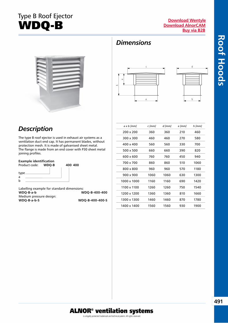
491
ALNOR® ventilation systemsis a legally protected trademark and technical patent. All rights reserved.
Roo
f Ho
od
sDownload Wentyle
Download AlnorCAMBuy via B2B
Type B Roof Ejector
WDQ-BDimensions
DescriptionThe type B roof ejector is used in exhaust air systems as a ventilation duct end cap. It has permanent blades, without protection mesh. It is made of galvanised sheet metal. The flange is made from an end cover with P30 sheet metal joining profiles.
Labelling example for standard dimensions:WDQ-B-a-b WDQ-B-400-400Medium pressure design:WDQ-B-a-b-S WDQ-B-400-400-S
Example identificationProduct code: WDQ-B 400 400
typeab
a x b [mm] c [mm] d [mm] e [mm] h [mm]
200 x 200 360 360 210 460
300 x 300 460 460 270 580
400 x 400 560 560 330 700
500 x 500 660 660 390 820
600 x 600 760 760 450 940
700 x 700 860 860 510 1060
800 x 800 960 960 570 1180
900 x 900 1060 1060 630 1300
1000 x 1000 1160 1160 690 1420
1100 x 1100 1260 1260 750 1540
1200 x 1200 1360 1360 810 1660
1300 x 1300 1460 1460 870 1780
1400 x 1400 1560 1560 930 1900
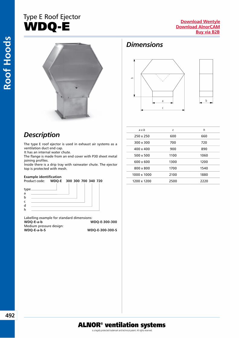
492
ALNOR® ventilation systemsis a legally protected trademark and technical patent. All rights reserved.
Roo
f H
oo
ds
Download WentyleDownload AlnorCAM
Buy via B2B
h
b
c
a
Type E Roof Ejector
WDQ-E Dimensions
DescriptionThe type E roof ejector is used in exhaust air systems as a ventilation duct end cap.It has an internal water chute.The flange is made from an end cover with P30 sheet metal joining profiles.Inside there is a drip tray with rainwater chute. The ejector top is protected with mesh.
Labelling example for standard dimensions:WDQ-E-a-b WDQ-E-300-300Medium pressure design:WDQ-E-a-b-S WDQ-E-300-300-S
Example identificationProduct code: WDQ-E 300 300 700 340 720
typeabcdh
a x b c h
250 x 250 600 660
300 x 300 700 720
400 x 400 900 890
500 x 500 1100 1060
600 x 600 1300 1200
800 x 800 1700 1540
1000 x 1000 2100 1880
1200 x 1200 2500 2220
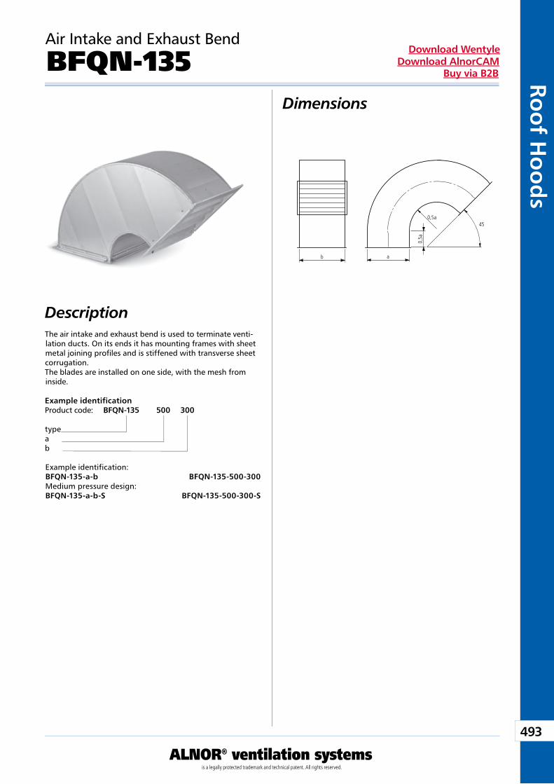
493
ALNOR® ventilation systemsis a legally protected trademark and technical patent. All rights reserved.
Roo
f Ho
od
sDownload Wentyle
Download AlnorCAMBuy via B2B
Air Intake and Exhaust Bend
BFQN-135Dimensions
DescriptionThe air intake and exhaust bend is used to terminate venti-lation ducts. On its ends it has mounting frames with sheet metal joining profiles and is stiffened with transverse sheet corrugation.The blades are installed on one side, with the mesh from inside.
Example identification:BFQN-135-a-b BFQN-135-500-300Medium pressure design:BFQN-135-a-b-S BFQN-135-500-300-S
Example identificationProduct code: BFQN-135 500 300
typeab

Auxiliary Equipment and Accessories
We reserve the right to make changes in the dimensions and technical data products due to their continuous improvement
495
Auxiliary Eq
uipm
ent and A
ccessories
ALNOR® ventilation systemsis a legally protected trademark and technical patent. All rights reserved.
Download WentyleDownload AlnorCAM
Buy via B2B
Devices
TECHNICAL INFORMATION
Devices are the completion of the ventilation duct elements system. Thanks to variety of elements they are applicable in almost all conditions.
DimensionsDimensions of all devices are adjusted to elements of the duct system and profiles or auxilliary elements. All sizes are based on tables and informations presented in a catalogue chart of the given element.
Assembly instructionsSuch devices as duct fans are mounted by means of self-drilling screws or rivets in a part of the duct into which a connecting flange is inserted. Each time servo-motors are mounted on a base at a damper mechanism by means of sel-f-drilling screws.
About the system
Benefits of the useDevices enable full making an account of possibilities of the ventilation system. They facilitate adjustment of air flow and its increasing by means of fans and servo-motors.
MarkingALNOR products are marked with the building mark and the product code corresponding to the technical specification included in this catalogue.
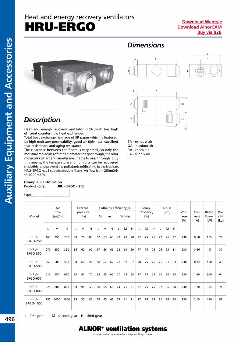
496
Aux
iliar
y Eq
uip
men
t an
d A
cces
sori
es
ALNOR® ventilation systemsis a legally protected trademark and technical patent. All rights reserved.
Download WentyleDownload AlnorCAM
Buy via B2B
B
A
I
E
D
C
MF
G
5
EA
OA
RA
SA
Heat and energy recovery ventilators
HRU-ERGODimensions
Description
Example identificationProduct code: HRU - ERGO - 250
type
Model
Airflow
[m3/h]
Externalpressure
[Pa]
Enthalpy Efficiency[%] Temp.Efficiency
[%]
Noise[dB] Volt-
age[V]
Cur-rent[A]
RatedPower
[W]
Weight[kg]
Summer Winter
L M H L M H L M H L M H L M H L M H
HRU-ERGO-250
165 250 250 30 70 85 67 63 63 73 70 70 77 75 75 22 26 27 230 0,50 105 29
HRU-ERGO-350
270 350 350 36 60 90 67 66 66 72 69 69 77 75 75 25 29 31 230 0,56 117 37
HRU-ERGO-500
360 500 500 30 60 100 68 62 62 72 67 67 78 75 75 25 31 33 230 0,72 150 43
HRU-ERGO-650
515 650 650 25 40 70 68 65 65 70 68 68 77 75 75 30 34 35 230 1,40 200 64
HRU-ERGO-800
625 800 800 60 98 120 68 65 65 74 71 71 77 75 75 32 36 38 230 1,70 355 71
HRU-ERGO-1000
780 1000 1000 25 35 85 68 65 65 74 71 71 77 75 75 31 36 38 230 2,10 440 83
L - first gear M - second gear H - third gear
Heat and energy recovery ventilator HRU-ERGO has high efficient counter flow heat exchanger.Total heat exchanger is made of ER paper which is featuredby high moisture permeability, good air tightness, excellent tear resistance, and aging resistance.The clearance between the fibers is very small, so only the moisture molecules of small diameter can go through, the odormolecules of larger diameter are unable to pass through it. By this means, the temperature and humidity can be recovered smoothly, and prevent the pollutants infiltrating to the fresh air.HRU-ERGO has 3 speeds, double filters. Airflow from 250m3/h to 1000m3/h.
EA - exhaust airOA - outdoor airRA - room airSA - supply air
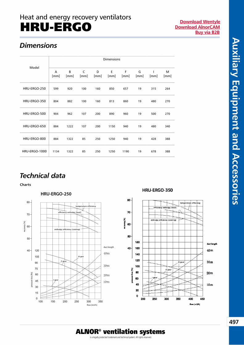
497
Auxiliary Eq
uipm
ent and A
ccessories
ALNOR® ventilation systemsis a legally protected trademark and technical patent. All rights reserved.
Download WentyleDownload AlnorCAM
Buy via B2B
HRU-ERGO-250
pres
sure
loss
[Pa]
�ow [m3/h]
duct length
reco
very
[%]
temperature efficiency
efficiency enthalpy (heat)
enthalpy efficiency (cooling)
II gear
III gear
I gear
Heat and energy recovery ventilators
HRU-ERGODimensions
Model
Dimensions
A[mm]
B[mm]
C[mm]
D[mm]
E[mm]
F[mm]
G[mm]
I[mm]
M[mm]
HRU-ERGO-250 599 920 100 160 850 657 19 315 264
HRU-ERGO-350 804 882 100 160 813 860 19 480 270
HRU-ERGO-500 904 962 107 200 890 960 19 500 270
HRU-ERGO-650 884 1222 107 200 1150 940 19 480 340
HRU-ERGO-800 884 1322 85 250 1250 940 19 428 388
HRU-ERGO-1000 1134 1322 85 250 1250 1190 19 678 388
Technical dataCharts
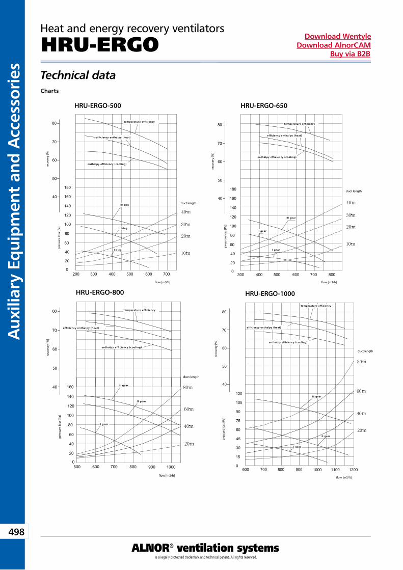
498
Aux
iliar
y Eq
uip
men
t an
d A
cces
sori
es
ALNOR® ventilation systemsis a legally protected trademark and technical patent. All rights reserved.
Download WentyleDownload AlnorCAM
Buy via B2B
HRU-ERGO-500
pres
sure
loss
[Pa]
duct length
reco
very
[%]
�ow [m3/h]
temperature efficiency
efficiency enthalpy (heat)
enthalpy efficiency (cooling)
II bieg
III bieg
I bieg
HRU-ERGO-650
pres
sure
loss
[Pa]
duct length
reco
very
[%]
�ow [m3/h]
temperature efficiency
efficiency enthalpy (heat)
enthalpy efficiency (cooling)
II gear
III gear
I gear
HRU-ERGO-800
pres
sure
loss
[Pa]
duct length
reco
very
[%]
�ow [m3/h]
temperature efficiency
efficiency enthalpy (heat)
enthalpy efficiency (cooling)
II gear
III gear
I gear
pres
sure
loss
[Pa]
duct length
reco
very
[%]
�ow [m3/h]
temperature efficiency
efficiency enthalpy (heat)
enthalpy efficiency (cooling)
II gear
III gear
I gear
HRU-ERGO-1000
Heat and energy recovery ventilators
HRU-ERGOTechnical dataCharts
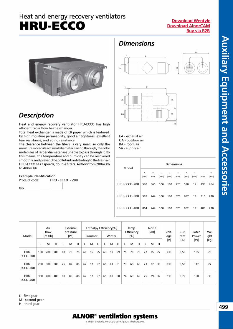
499
Auxiliary Eq
uipm
ent and A
ccessories
ALNOR® ventilation systemsis a legally protected trademark and technical patent. All rights reserved.
Download WentyleDownload AlnorCAM
Buy via B2B
B
A
I
E
D
C
MF
G
5
EA
OA
RA
SA
Heat and energy recovery ventilators
HRU-ECCODimensions
Description
Example identificationProduct code: HRU - ECCO - 200
typ
L - first gearM - second gearH - third gear
ModelDimensions
A
[mm]
B
[mm]
C
[mm]
D
[mm]
E
[mm]
F
[mm]
G
[mm]
I
[mm]
M
[mm]
HRU-ECCO-200 580 666 100 160 725 510 19 290 264
HRU-ECCO-300 599 744 100 160 675 657 19 315 270
HRU-ECCO-400 804 744 100 160 675 862 19 480 270
Model
Airflow
[m3/h]
Externalpressure
[Pa]
Enthalpy Efficiency[%] Temp.Efficiency
[%]
Noise[dB] Volt-
age[V]
Cur-rent[A]
RatedPower
[W]
Weight[kg]
Summer Winter
L M H L M H L M H L M H L M H L M H
HRU-ECCO-200
150 200 200 60 70 75 60 55 55 63 59 59 75 70 70 22 25 27 230 0,50 105 23
HRU-ECCO-300
250 300 300 75 82 85 62 57 57 65 61 61 73 68 68 23 27 30 230 0,56 117 27
HRU-ECCO-400
350 400 400 80 85 88 62 57 57 65 60 60 74 69 69 25 29 32 230 0,72 150 35
EA - exhaust airOA - outdoor airRA - room airSA - supply air
Heat and energy recovery ventilator HRU-ECCO has high efficient cross flow heat exchanger.Total heat exchanger is made of ER paper which is featuredby high moisture permeability, good air tightness, excellent tear resistance, and aging resistance.The clearance between the fibers is very small, so only the moisture molecules of small diameter can go through, the odormolecules of larger diameter are unable to pass through it. By this means, the temperature and humidity can be recovered smoothly, and prevent the pollutants infiltrating to the fresh air.HRU-ECCO has 3 speeds, double filters. Airflow from 200m3/h to 400m3/h.
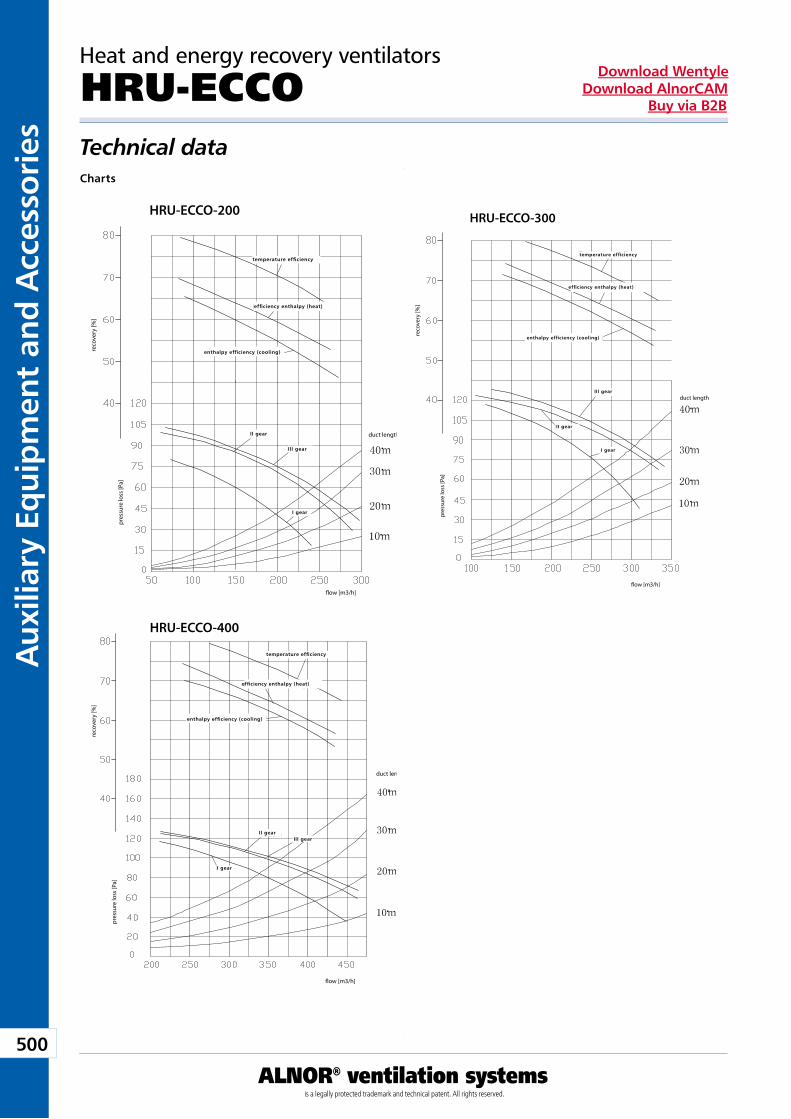
500
Aux
iliar
y Eq
uip
men
t an
d A
cces
sori
es
ALNOR® ventilation systemsis a legally protected trademark and technical patent. All rights reserved.
Download WentyleDownload AlnorCAM
Buy via B2B
HRU-ECCO-200
pres
sure
loss
[Pa]
�ow [m3/h]
duct length
reco
very
[%]
temperature efficiency
efficiency enthalpy (heat)
enthalpy efficiency (cooling)
II gear
III gear
I gear
HRU-ECCO-400
pres
sure
loss
[Pa]
�ow [m3/h]
duct length
reco
very
[%]
temperature efficiency
efficiency enthalpy (heat)
enthalpy efficiency (cooling)
II gearIII gear
I gear
HRU-ECCO-300
pres
sure
loss
[Pa]
reco
very
[%]
temperature efficiency
efficiency enthalpy (heat)
enthalpy efficiency (cooling)
II gear
III gear
I gear
duct length
�ow [m3/h]
Heat and energy recovery ventilators
HRU-ECCOTechnical dataCharts
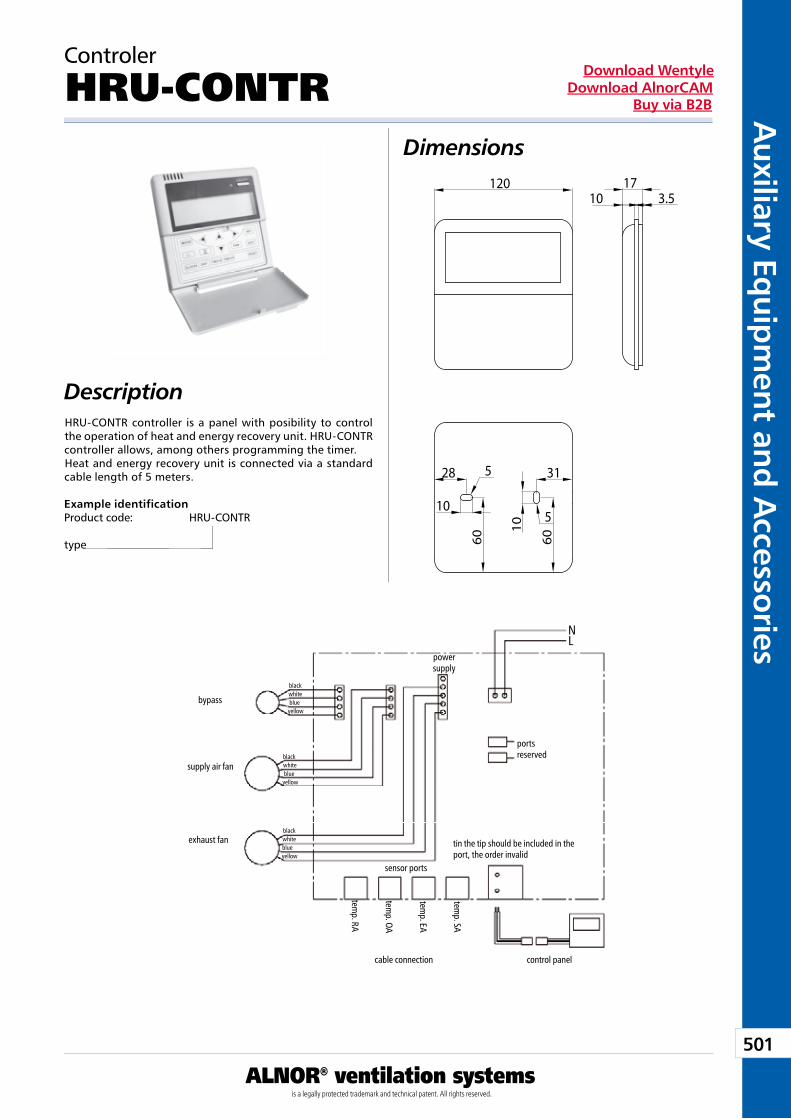
501
Auxiliary Eq
uipm
ent and A
ccessories
ALNOR® ventilation systemsis a legally protected trademark and technical patent. All rights reserved.
Download WentyleDownload AlnorCAM
Buy via B2B
120 1710 3.5
28
10
60 60
31
10 5
5
Controler
HRU-CONTRDimensions
DescriptionHRU-CONTR controller is a panel with posibility to control the operation of heat and energy recovery unit. HRU-CONTR controller allows, among others programming the timer. Heat and energy recovery unit is connected via a standard cable length of 5 meters.
Example identificationProduct code: HRU-CONTR
type
power supply
ports reserved
NL
tin the tip should be included in the port, the order invalid
sensor ports
exhaust fan
supply air fan
bypass
blackwhiteblueyellow
control panelcable connection
temp. RA
temp. OA
temp. EA
temp. SA
blackwhiteblueyellow
blackwhiteblueyellow
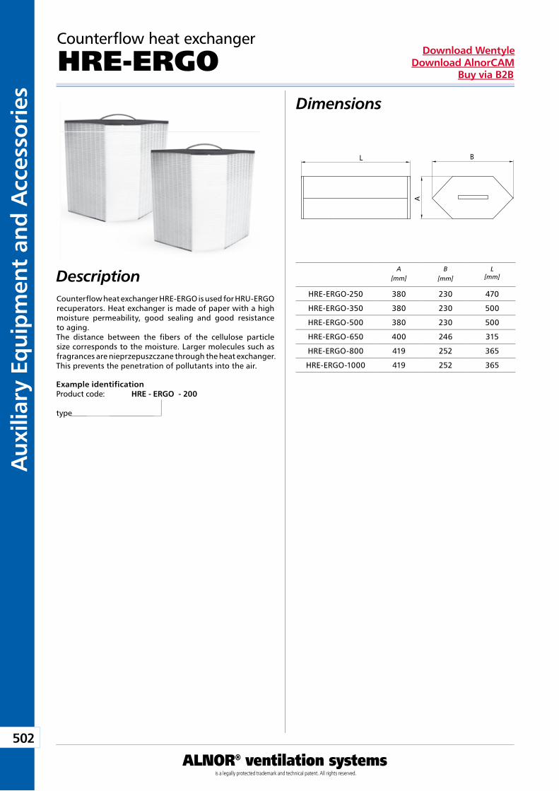
502
Aux
iliar
y Eq
uip
men
t an
d A
cces
sori
es
ALNOR® ventilation systemsis a legally protected trademark and technical patent. All rights reserved.
Download WentyleDownload AlnorCAM
Buy via B2B
L B
A
A[mm]
B[mm]
L[mm]
Counterflow heat exchanger
HRE-ERGODimensions
Description
Example identificationProduct code: HRE - ERGO - 200
type
Counterflow heat exchanger HRE-ERGO is used for HRU-ERGO recuperators. Heat exchanger is made of paper with a high moisture permeability, good sealing and good resistance to aging.The distance between the fibers of the cellulose particle size corresponds to the moisture. Larger molecules such as fragrances are nieprzepuszczane through the heat exchanger. This prevents the penetration of pollutants into the air.
HRE-ERGO-250 380 230 470
HRE-ERGO-350 380 230 500
HRE-ERGO-500 380 230 500
HRE-ERGO-650 400 246 315
HRE-ERGO-800 419 252 365
HRE-ERGO-1000 419 252 365
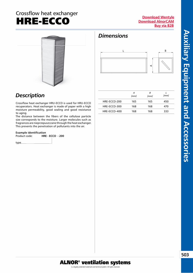
503
Auxiliary Eq
uipm
ent and A
ccessories
ALNOR® ventilation systemsis a legally protected trademark and technical patent. All rights reserved.
Download WentyleDownload AlnorCAM
Buy via B2B
L B
A
A[mm]
B[mm]
L[mm]
Crossflow heat exchanger
HRE-ECCODimensions
Description
Example identificationProduct code: HRE - ECCO - 200
type
Crossflow heat exchanger HRU-ECCO is used for HRU-ECCO recuperators. Heat exchanger is made of paper with a high moisture permeability, good sealing and good resistance to aging.The distance between the fibers of the cellulose particle size corresponds to the moisture. Larger molecules such as fragrances are nieprzepuszczane through the heat exchanger. This prevents the penetration of pollutants into the air.
HRE-ECCO-200 165 165 450
HRE-ECCO-300 168 168 470
HRE-ECCO-400 168 168 333
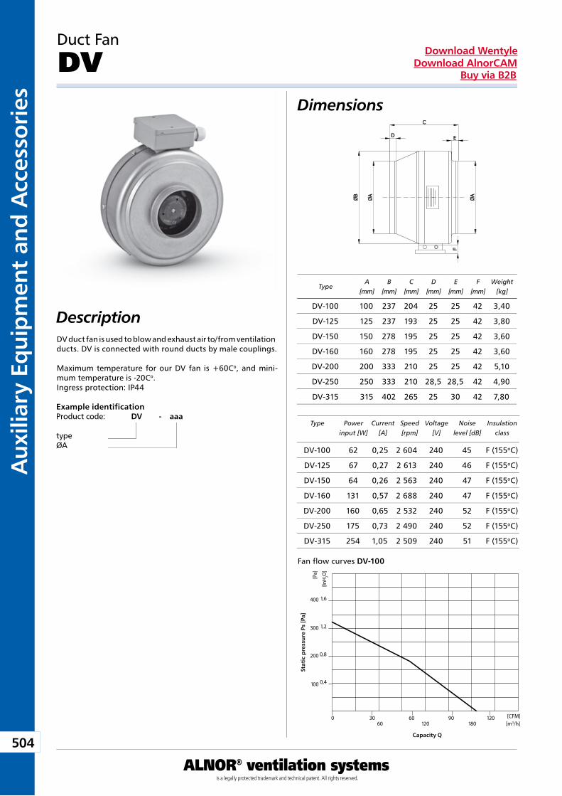
504
Aux
iliar
y Eq
uip
men
t an
d A
cces
sori
es
ALNOR® ventilation systemsis a legally protected trademark and technical patent. All rights reserved.
Download WentyleDownload AlnorCAM
Buy via B2B
Duct Fan
DV Dimensions
DescriptionDV duct fan is used to blow and exhaust air to/from ventilation ducts. DV is connected with round ducts by male couplings.
Maximum temperature for our DV fan is +60Co, and mini-mum temperature is -20Co.Ingress protection: IP44 Example identificationProduct code: DV - aaa
typeØA
TypeA
[mm]B
[mm]C
[mm]D
[mm]E
[mm]F
[mm]Weight
[kg]
Type Power input [W]
Current[A]
Speed [rpm]
Voltage[V]
Noiselevel [dB]
Insulation class
Stat
ic p
ress
ure
Ps
[Pa]
Capacity Q
Fan flow curves DV-100
0 30 60 90 12060 120 180
100
200
300
400
0,4
0,8
1,2
1,6
[CFM][m3/h]
[Pa]
[InH
2O]
DV-100 100 237 204 25 25 42 3,40
DV-125 125 237 193 25 25 42 3,80
DV-150 150 278 195 25 25 42 3,60
DV-160 160 278 195 25 25 42 3,60
DV-200 200 333 210 25 25 42 5,10
DV-250 250 333 210 28,5 28,5 42 4,90
DV-315 315 402 265 25 30 42 7,80
DV-100 62 0,25 2 604 240 45 F (155oC)
DV-125 67 0,27 2 613 240 46 F (155oC)
DV-150 64 0,26 2 563 240 47 F (155oC)
DV-160 131 0,57 2 688 240 47 F (155oC)
DV-200 160 0,65 2 532 240 52 F (155oC)
DV-250 175 0,73 2 490 240 52 F (155oC)
DV-315 254 1,05 2 509 240 51 F (155oC)
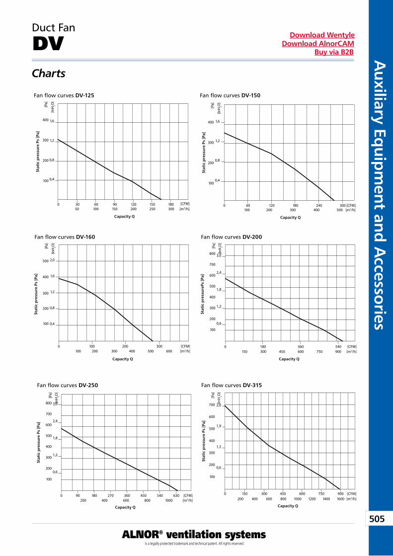
505
Auxiliary Eq
uipm
ent and A
ccessories
ALNOR® ventilation systemsis a legally protected trademark and technical patent. All rights reserved.
Download WentyleDownload AlnorCAM
Buy via B2B
Duct Fan
DV Charts
Stat
ic p
ress
ure
Ps
[Pa]
Capacity Q
Stat
ic p
ress
ure
Ps [
Pa]
Capacity Q
Stat
ic p
ress
ure
Ps
[Pa]
Capacity Q
Stat
ic p
ress
ure
Ps
[Pa]
Capacity Q
Stat
ic p
ress
ure
Ps
[Pa]
Capacity Q
Fan flow curves DV-250
Fan flow curves DV-200Fan flow curves DV-160
Fan flow curves DV-150Fan flow curves DV-125
Fan flow curves DV-315
Stat
ic p
ress
ure
Ps
[Pa]
Capacity Q
0 90 180 270 360 450 540 630
100
200
300
400
500
600
700
800
0,6
1,2
1,8
2,4
3,0
200 400 600 800 1000[CFM][m3/h]
[Pa]
[InH
2O]
0 180 360 540
100
200
300
400
500
600
700
800
0,6
1,2
1,8
2,4
3,0
150 300 450 600 750 900[CFM][m3/h]
[Pa]
[InH
2O]
0 100 200 300
100
200
300
400
500
0,4
0,8
1,2
1,6
2,0
100 200 300 400 500 600[CFM][m3/h]
[Pa]
[InH
2O]
0 60 120 180 240 300
100
200
300
400
0,4
0,8
1,2
1,6
100 200 300 400 500[CFM]
[m3/h][P
a]
[InH
2O]
0 30 60 90 120 150 180
100
200
300
400
0,4
0,8
1,2
1,6
50 100 150 200 250 300[CFM]
[m3/h]
[Pa]
[InH
2O]
0
700
600
500
400
300
200
100
0,6
1,3
1,9
2,6
150 300 450 600 750 9001600140012001000800600400200
[CFM][m3/h]
[Pa]
[InH
2O]
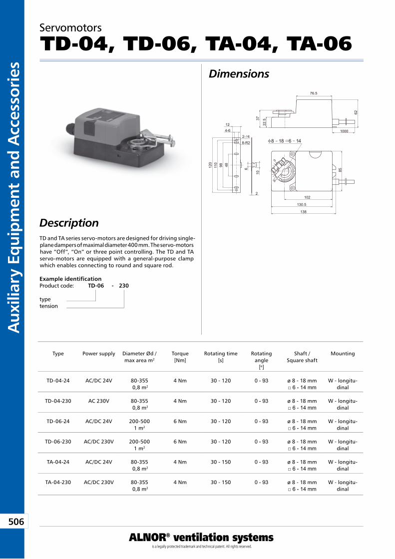
506
Aux
iliar
y Eq
uip
men
t an
d A
cces
sori
es
ALNOR® ventilation systemsis a legally protected trademark and technical patent. All rights reserved.
Download WentyleDownload AlnorCAM
Buy via B2B
Servomotors
TD-04, TD-06, TA-04, TA-06Dimensions
DescriptionTD and TA series servo-motors are designed for driving single-plane dampers of maximal diameter 400 mm. The servo-motors have “Off”, “On” or three point controlling. The TD and TA servo-motors are equipped with a general-purpose clamp which enables connecting to round and square rod.
Example identificationProduct code: TD-06 - 230
typetension
Type Power supply Diameter Ød / max area m2
Torque[Nm]
Rotating time[s]
Rotating angle
[o]
Shaft / Square shaft
Mounting
TD-04-24 AC/DC 24V 80-355 0,8 m2
4 Nm 30 - 120 0 - 93 ø 8 - 18 mm□ 6 - 14 mm
W - longitu-dinal
TD-04-230 AC 230V 80-355 0,8 m2
4 Nm 30 - 120 0 - 93 ø 8 - 18 mm□ 6 - 14 mm
W - longitu-dinal
TD-06-24 AC/DC 24V 200-5001 m2
6 Nm 30 - 120 0 - 93 ø 8 - 18 mm□ 6 - 14 mm
W - longitu-dinal
TD-06-230 AC/DC 230V 200-5001 m2
6 Nm 30 - 120 0 - 93 ø 8 - 18 mm□ 6 - 14 mm
W - longitu-dinal
TA-04-24 AC/DC 24V 80-355 0,8 m2
4 Nm 30 - 150 0 - 93 ø 8 - 18 mm□ 6 - 14 mm
W - longitu-dinal
TA-04-230 AC/DC 230V 80-355 0,8 m2
4 Nm 30 - 150 0 - 93 ø 8 - 18 mm□ 6 - 14 mm
W - longitu-dinal
76.5
22.5
62
37
1000
90
130.5
102
138
85
0
8 18 6 142- 4
8-R2
4-612
2
4898110
120
10
6
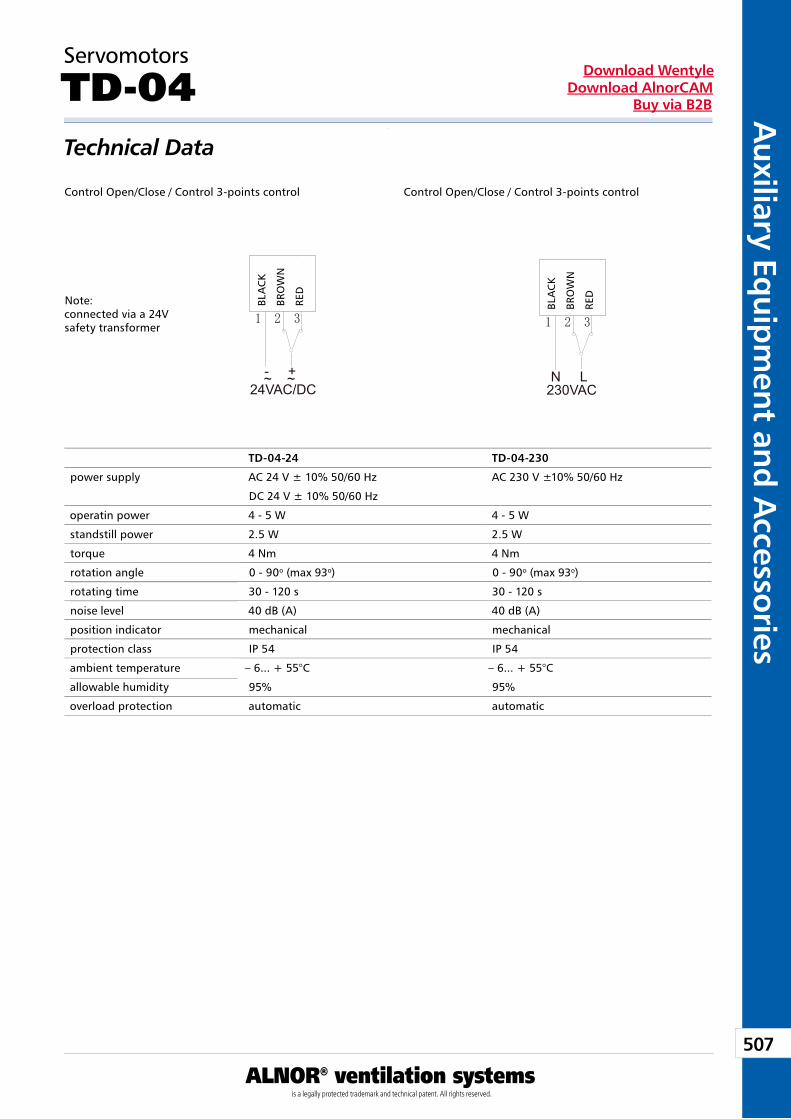
507
Auxiliary Eq
uipm
ent and A
ccessories
ALNOR® ventilation systemsis a legally protected trademark and technical patent. All rights reserved.
Download WentyleDownload AlnorCAM
Buy via B2B
24VAC/DC
CZAR
NYBR
ĄZOW
YCZ
ERWO
NY
- +~ ~
Servomotors
TD-04Technical Data
Note: connected via a 24V safety transformer
TD-04-24 TD-04-230
power supply AC 24 V ± 10% 50/60 Hz AC 230 V ±10% 50/60 Hz
DC 24 V ± 10% 50/60 Hz
operatin power 4 - 5 W 4 - 5 W
standstill power 2.5 W 2.5 W
torque 4 Nm 4 Nm
rotation angle 0 - 90o (max 93o) 0 - 90o (max 93o)
rotating time 30 - 120 s 30 - 120 s
noise level 40 dB (A) 40 dB (A)
position indicator mechanical mechanical
protection class IP 54 IP 54
ambient temperature – 6... + 55°C – 6... + 55°C
allowable humidity 95% 95%
overload protection automatic automatic
230VAC
CZAR
NYBR
ĄZOW
YCZ
ERWO
NY
N L
Control Open/Close / Control 3-points control Control Open/Close / Control 3-points control
BLA
CK
BRO
WN
RED
BLA
CK
BRO
WN
RED
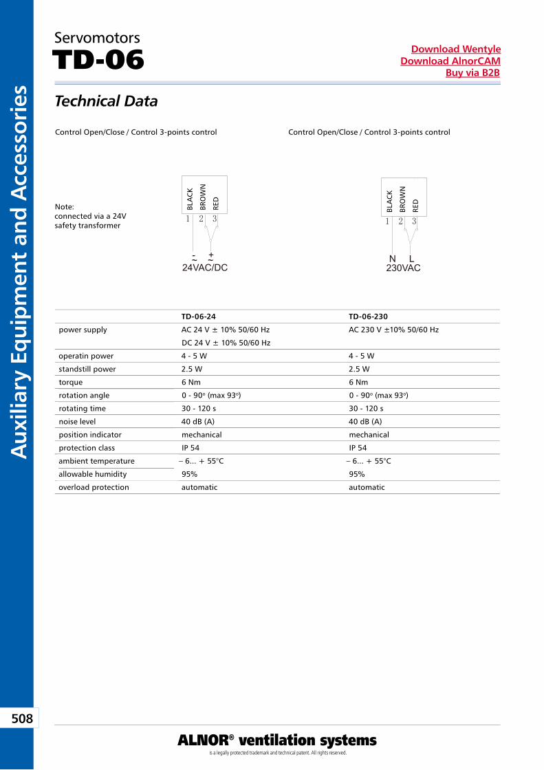
508
Aux
iliar
y Eq
uip
men
t an
d A
cces
sori
es
ALNOR® ventilation systemsis a legally protected trademark and technical patent. All rights reserved.
Download WentyleDownload AlnorCAM
Buy via B2B
Servomotors
TD-06Technical Data
TD-06-24 TD-06-230
power supply AC 24 V ± 10% 50/60 Hz AC 230 V ±10% 50/60 Hz
DC 24 V ± 10% 50/60 Hz
operatin power 4 - 5 W 4 - 5 W
standstill power 2.5 W 2.5 W
torque 6 Nm 6 Nm
rotation angle 0 - 90o (max 93o) 0 - 90o (max 93o)
rotating time 30 - 120 s 30 - 120 s
noise level 40 dB (A) 40 dB (A)
position indicator mechanical mechanical
protection class IP 54 IP 54
ambient temperature – 6... + 55°C – 6... + 55°C
allowable humidity 95% 95%
overload protection automatic automatic
24VAC/DC
CZAR
NYBR
ĄZOW
YCZ
ERWO
NY
- +~ ~
Note: connected via a 24V safety transformer
230VAC
CZAR
NYBR
ĄZOW
YCZ
ERWO
NY
N L
Control Open/Close / Control 3-points control Control Open/Close / Control 3-points control
BLA
CK
BRO
WN
RED
BLA
CK
BRO
WN
RED
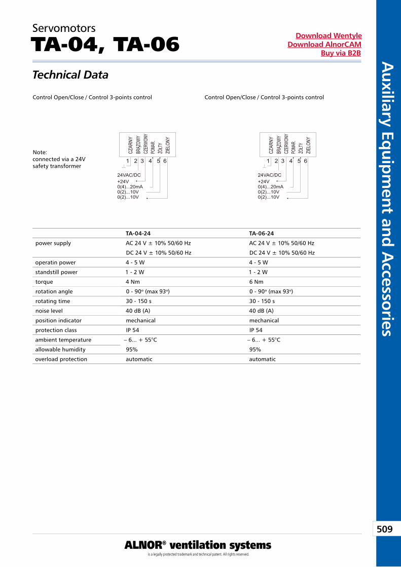
509
Auxiliary Eq
uipm
ent and A
ccessories
ALNOR® ventilation systemsis a legally protected trademark and technical patent. All rights reserved.
Download WentyleDownload AlnorCAM
Buy via B2B
Servomotors
TA-04, TA-06Technical Data
TA-04-24 TA-06-24
power supply AC 24 V ± 10% 50/60 Hz AC 24 V ± 10% 50/60 Hz
DC 24 V ± 10% 50/60 Hz DC 24 V ± 10% 50/60 Hz
operatin power 4 - 5 W 4 - 5 W
standstill power 1 - 2 W 1 - 2 W
torque 4 Nm 6 Nm
rotation angle 0 - 90o (max 93o) 0 - 90o (max 93o)
rotating time 30 - 150 s 30 - 150 s
noise level 40 dB (A) 40 dB (A)
position indicator mechanical mechanical
protection class IP 54 IP 54
ambient temperature – 6... + 55°C – 6... + 55°C
allowable humidity 95% 95%
overload protection automatic automatic
Note: connected via a 24V safety transformer
Control Open/Close / Control 3-points control Control Open/Close / Control 3-points control
1 2 3 4 5 6
AC/DC24V+24V0(4)...20mA0(2)...10V0(2)...10V
CZAR
NYBR
ĄZOW
YCZ
ERWO
NY
ŻÓŁTY
ZIEL
ONY
POMA
R.
1 2 3 4 5 6
AC/DC24V+24V0(4)...20mA0(2)...10V0(2)...10V
CZAR
NYBR
ĄZOW
YCZ
ERWO
NY
ŻÓŁTY
ZIEL
ONY
POMA
R.
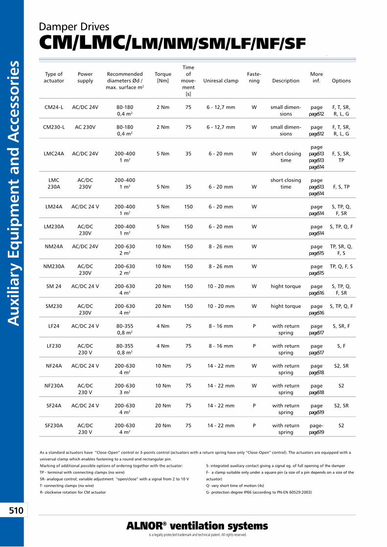
510
Aux
iliar
y Eq
uip
men
t an
d A
cces
sori
es
ALNOR® ventilation systemsis a legally protected trademark and technical patent. All rights reserved.
Download WentyleDownload AlnorCAM
Buy via B2B
Type ofactuator
Power supply
Recommended diameters Ød /
max. surface m2
Torque [Nm]
Time of
move-ment
[s]
Uniresal clampFaste-ning Description
More inf. Options
CM24-L AC/DC 24V 80-1800,4 m2
2 Nm 75 6 - 12,7 mm W small dimen-sions
page page 512
F, T, SR, R, L, G
CM230-L AC 230V 80-1800,4 m2
2 Nm 75 6 - 12,7 mm W small dimen-sions
page page 512
F, T, SR, R, L, G
LMC24A AC/DC 24V 200-4001 m2
5 Nm 35 6 - 20 mm W short closing time
page page 513 page 513 page 514
F, S, SR, TP
LMC 230A
AC/DC 230V
200-4001 m2 5 Nm 35 6 - 20 mm W
short closing time
page page 513 page 514
F, S, TP
LM24A AC/DC 24 V 200-4001 m2
5 Nm 150 6 - 20 mm W page page 514
S, TP, Q, F, SR
LM230A AC/DC 230V
200-4001 m2
5 Nm 150 6 - 20 mm W page page 514
S, TP, Q, F
NM24A AC/DC 24V 200-6302 m2
10 Nm 150 8 - 26 mm W pagepage 515
TP, SR, Q, F, S
NM230A AC/DC 230V
200-6302 m2
10 Nm 150 8 - 26 mm W pagepage 515
TP, Q, F, S
SM 24 AC/DC 24 V 200-6304 m2
20 Nm 150 10 - 20 mm W hight torque page page 516
S, TP, Q, F, SR
SM230 AC/DC 230V
200-6304 m2
20 Nm 150 10 - 20 mm W hight torque page page 516
S, TP, Q, F
LF24 AC/DC 24 V 80-3550,8 m2
4 Nm 75 8 - 16 mm P with return spring
page page 517
S, SR, F
LF230 AC/DC 230 V
80-3550,8 m2
4 Nm 75 8 - 16 mm P with return spring
page page 517
S, F
NF24A AC/DC 24 V 200-6304 m2
10 Nm 75 14 - 22 mm W with return spring
page page 518
S2, SR
NF230A AC/DC 230 V
200-6303 m2
10 Nm 75 14 - 22 mm W with return spring
page page 518
S2
SF24A AC/DC 24 V 200-6304 m2
20 Nm 75 14 - 22 mm P with return spring
page page 519
S2, SR
SF230A AC/DC 230 V
200-6304 m2
20 Nm 75 14 - 22 mm P with return spring
page-page 519
S2
As a standard actuators have “Close-Open” control or 3-points control (actuators with a return spring have only “Close-Open” control). The actuators are equipped with a
universal clamp which enables fastening to a round and rectangular pin.
Marking of additional possible options of ordering together with the actuator:
TP - terminal with connecting clamps (no wire)
SR- analogue control, variable adjustment “open/close” with a signal from 2 to 10 V
T- connecting clamps (no wire)
R- clockwise rotation for CM actuator
Damper Drives
CM/LMC/LM/NM/SM/LF/NF/SF
S- integrated auxiliary contact giving a signal eg. of full opening of the damper
F- a clamp suitable only under a square pin (a size of a pin depends on a size of the
actuator)
Q- very short time of motion (4s)
G- protection degree IP66 (according to PN-EN 60529:2003)
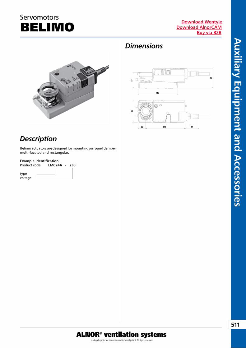
511
Auxiliary Eq
uipm
ent and A
ccessories
ALNOR® ventilation systemsis a legally protected trademark and technical patent. All rights reserved.
Download WentyleDownload AlnorCAM
Buy via B2B
Servomotors
BELIMO Dimensions
DescriptionBelimo actuators are designed for mounting on round damper multi-faceted and rectangular.
Example identificationProduct code: LMC24A - 230
typevoltage
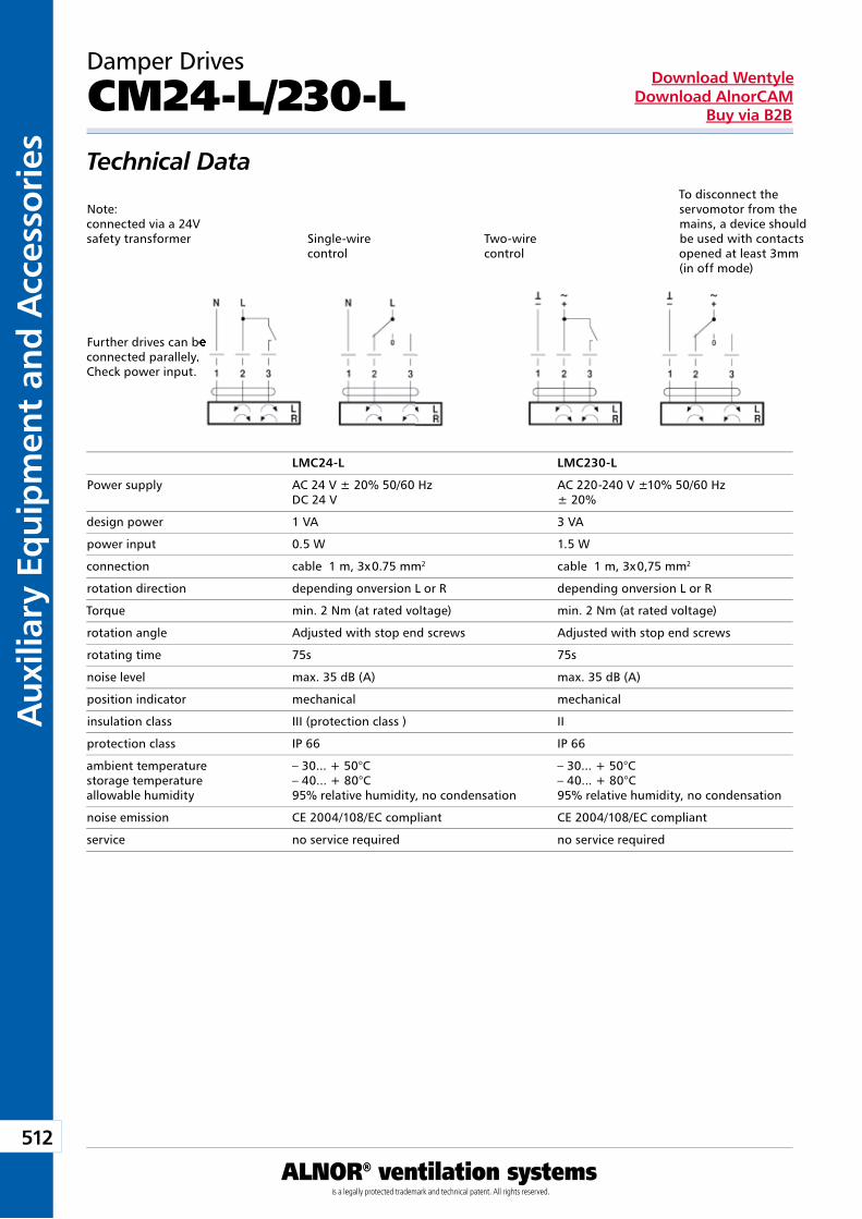
512
Aux
iliar
y Eq
uip
men
t an
d A
cces
sori
es
ALNOR® ventilation systemsis a legally protected trademark and technical patent. All rights reserved.
Download WentyleDownload AlnorCAM
Buy via B2B
Damper Drives
CM24-L/230-LTechnical Data
Note: connected via a 24V safety transformer
Further drives can be connected parallely. Check power input.
To disconnect the servomotor from the mains, a device should be used with contacts opened at least 3mm (in off mode)
LMC24-L LMC230-L
Power supply AC 24 V ± 20% 50/60 Hz AC 220-240 V ±10% 50/60 Hz DC 24 V ± 20%
design power 1 VA 3 VA
power input 0.5 W 1.5 W
connection cable 1 m, 3x 0.75 mm2 cable 1 m, 3x 0,75 mm2
rotation direction depending onversion L or R depending onversion L or R
Torque min. 2 Nm (at rated voltage) min. 2 Nm (at rated voltage)
rotation angle Adjusted with stop end screws Adjusted with stop end screws
rotating time 75s 75s
noise level max. 35 dB (A) max. 35 dB (A)
position indicator mechanical mechanical
insulation class III (protection class ) II
protection class IP 66 IP 66
ambient temperature – 30... + 50°C – 30... + 50°Cstorage temperature – 40... + 80°C – 40... + 80°Callowable humidity 95% relative humidity, no condensation 95% relative humidity, no condensation
noise emission CE 2004/108/EC compliant CE 2004/108/EC compliant
service no service required no service required
Single-wire control
Two-wire control
Further drives can be connected parallely.
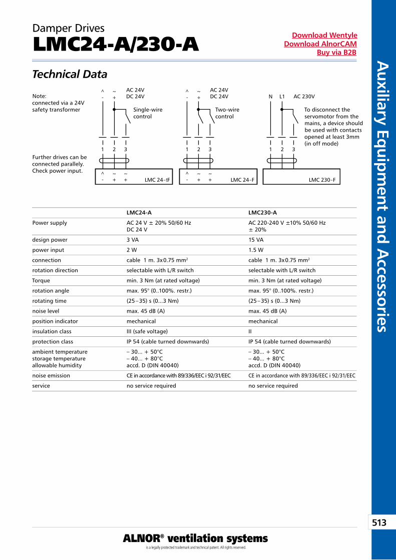
513
Auxiliary Eq
uipm
ent and A
ccessories
ALNOR® ventilation systemsis a legally protected trademark and technical patent. All rights reserved.
Download WentyleDownload AlnorCAM
Buy via B2B
Damper Drives
LMC24-A/230-ATechnical Data
Note: connected via a 24V safety transformer
Further drives can be connected parallely. Check power input.
To disconnect the servomotor from the mains, a device should be used with contacts opened at least 3mm (in off mode)
LMC24-A LMC230-A
Power supply AC 24 V ± 20% 50/60 Hz AC 220-240 V ±10% 50/60 Hz DC 24 V ± 20%
design power 3 VA 15 VA
power input 2 W 1.5 W
connection cable 1 m. 3x 0.75 mm2 cable 1 m. 3x 0.75 mm2
rotation direction selectable with L/R switch selectable with L/R switch
Torque min. 3 Nm (at rated voltage) min. 3 Nm (at rated voltage)
rotation angle max. 95° (0..100%. restr.) max. 95° (0..100%. restr.)
rotating time (25 – 35) s (0...3 Nm) (25 – 35) s (0...3 Nm)
noise level max. 45 dB (A) max. 45 dB (A)
position indicator mechanical mechanical
insulation class III (safe voltage) II
protection class IP 54 (cable turned downwards) IP 54 (cable turned downwards)
ambient temperature – 30... + 50°C – 30... + 50°Cstorage temperature – 40... + 80°C – 40... + 80°Callowable humidity accd. D (DIN 40040) accd. D (DIN 40040)
noise emission CE in accordance with 89/336/EEC i 92/31/EEC CE in accordance with 89/336/EEC i 92/31/EEC
service no service required no service required
Single-wire control
Two-wire control
1 2 3
LMC 24–tF LMC 24–F LMC 230–F
1 2 3 1 2
N L1
3
AC 24VDC 24V
AC 24VDC 24V
AC 230V
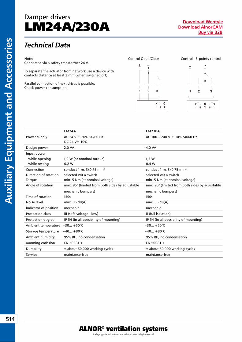
514
Aux
iliar
y Eq
uip
men
t an
d A
cces
sori
es
ALNOR® ventilation systemsis a legally protected trademark and technical patent. All rights reserved.
Download WentyleDownload AlnorCAM
Buy via B2B
Damper drivers
LM24A/230ATechnical Data
Note:Connected via a safety transformer 24 V.
To separate the actuator from network use a device with contacts distance at least 3 mm (when switched off).
Parallel connection of next drives is possible. Check power consumption.
LM24A LM230A
Power supply AC 24 V ± 20% 50/60 Hz AC 100... 240 V ± 10% 50/60 HzDC 24 V± 10%
Design power 2,0 VA 4,0 VA
Input power
while opening 1,0 W (at nominal torque) 1,5 Wwhile resting 0,2 W 0,4 W
Connection conduct 1 m, 3x0,75 mm2 conduct 1 m, 3x0,75 mm2
Direction of rotation selected wit a switch selected wit a switchTorque min. 5 Nm (at nominal voltage) min. 5 Nm (at nominal voltage)
Angle of rotation max. 95° (limited from both sides by adjustable
mechanic bumpers)
max. 95° (limited from both sides by adjustable
mechanic bumpers)
Time of rotation 150s 150s
Noise level max. 35 dB(A) max. 35 dB(A)
Indicator of position mechanic mechanic
Protection class III (safe voltage - low) II (full isolation)
Protection degree IP 54 (in all possibility of mounting) IP 54 (in all possibility of mounting)
Ambient temperature – 30... +50°C – 30... +50°C
Storage temperature – 40... +80°C – 40... +80°C
Ambient humidity 95% RH, no condensation 95% RH, no condensation
Jamming emission EN 50081-1 EN 50081-1
Durability » about 60,000 working cycles » about 60,000 working cycles
Service maintance-free maintance-free
Control Open/Close Control 3-points control
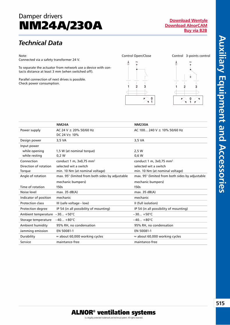
515
Auxiliary Eq
uipm
ent and A
ccessories
ALNOR® ventilation systemsis a legally protected trademark and technical patent. All rights reserved.
Download WentyleDownload AlnorCAM
Buy via B2B
Control Open/Close Control 3-points control
Damper drivers
NM24A/230ATechnical Data
Note:Connected via a safety transformer 24 V.
To separate the actuator from network use a device with con-tacts distance at least 3 mm (when switched off).
Parallel connection of next drives is possible. Check power consumption.
Control Open/Close Control 3-points control
NM24A NM230A
Power supply AC 24 V ± 20% 50/60 Hz AC 100... 240 V ± 10% 50/60 HzDC 24 V± 10%
Design power 3,5 VA 3,5 VA
Input power
while opening 1,5 W (at nominal torque) 2,5 Wwhile resting 0,2 W 0,6 W
Connection conduct 1 m, 3x0,75 mm2 conduct 1 m, 3x0,75 mm2
Direction of rotation selected wit a switch selected wit a switchTorque min. 10 Nm (at nominal voltage) min. 10 Nm (at nominal voltage)
Angle of rotation max. 95° (limited from both sides by adjustable
mechanic bumpers)
max. 95° (limited from both sides by adjustable
mechanic bumpers)
Time of rotation 150s 150s
Noise level max. 35 dB(A) max. 35 dB(A)
Indicator of position mechanic mechanic
Protection class III (safe voltage - low) II (full isolation)
Protection degree IP 54 (in all possibility of mounting) IP 54 (in all possibility of mounting)
Ambient temperature – 30... +50°C – 30... +50°C
Storage temperature – 40... +80°C – 40... +80°C
Ambient humidity 95% RH, no condensation 95% RH, no condensation
Jamming emission EN 50081-1 EN 50081-1
Durability » about 60,000 working cycles » about 60,000 working cycles
Service maintance-free maintance-free
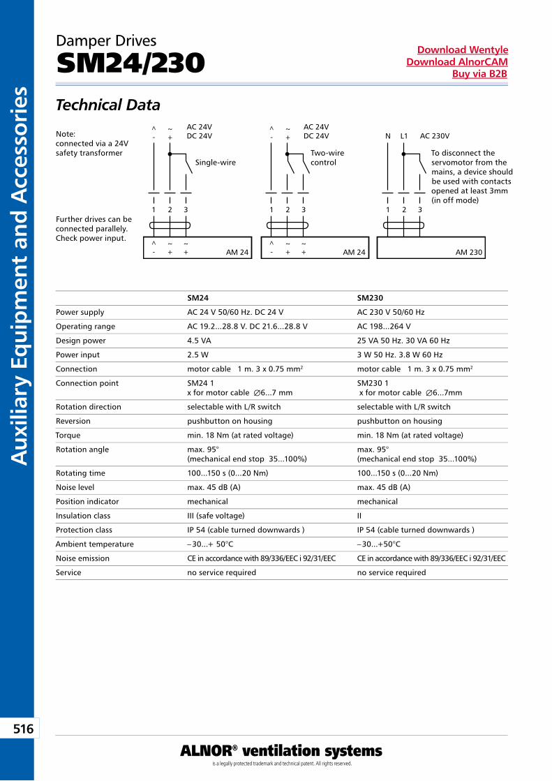
516
Aux
iliar
y Eq
uip
men
t an
d A
cces
sori
es
ALNOR® ventilation systemsis a legally protected trademark and technical patent. All rights reserved.
Download WentyleDownload AlnorCAM
Buy via B2B
Damper Drives
SM24/230Technical Data
Note: connected via a 24V safety transformer
Further drives can be connected parallely. Check power input.
To disconnect the servomotor from the mains, a device should be used with contacts opened at least 3mm (in off mode)
SM24 SM230
Power supply AC 24 V 50/60 Hz. DC 24 V AC 230 V 50/60 Hz
Operating range AC 19.2...28.8 V. DC 21.6...28.8 V AC 198...264 V
Design power 4.5 VA 25 VA 50 Hz. 30 VA 60 Hz
Power input 2.5 W 3 W 50 Hz. 3.8 W 60 Hz
Connection motor cable 1 m. 3 x 0.75 mm2 motor cable 1 m. 3 x 0.75 mm2
Connection point SM24 1 SM230 1 x for motor cable Æ6...7 mm x for motor cable Æ6...7mm
Rotation direction selectable with L/R switch selectable with L/R switch
Reversion pushbutton on housing pushbutton on housing
Torque min. 18 Nm (at rated voltage) min. 18 Nm (at rated voltage)
Rotation angle max. 95° max. 95° (mechanical end stop 35...100%) (mechanical end stop 35...100%)
Rotating time 100...150 s (0...20 Nm) 100...150 s (0...20 Nm)
Noise level max. 45 dB (A) max. 45 dB (A)
Position indicator mechanical mechanical
Insulation class III (safe voltage) II
Protection class IP 54 (cable turned downwards ) IP 54 (cable turned downwards )
Ambient temperature – 30...+ 50°C – 30...+50°C
Noise emission CE in accordance with 89/336/EEC i 92/31/EEC CE in accordance with 89/336/EEC i 92/31/EEC
Service no service required no service required
Single-wire Two-wire control
1 2 3
AM 24 AM 24 AM 230
1 2 3 1 2
N L1
3
AC 24VDC 24V
AC 24VDC 24V
AC 230V
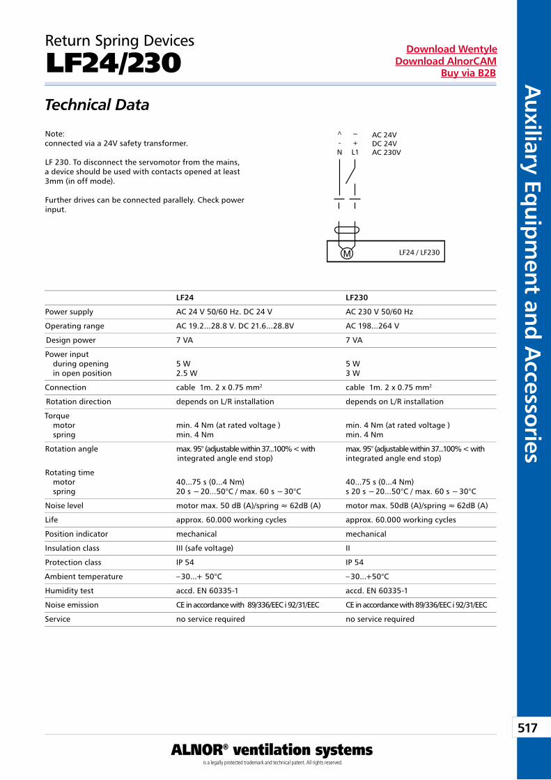
517
Auxiliary Eq
uipm
ent and A
ccessories
ALNOR® ventilation systemsis a legally protected trademark and technical patent. All rights reserved.
Download WentyleDownload AlnorCAM
Buy via B2B
Note: connected via a 24V safety transformer.
LF 230. To disconnect the servomotor from the mains, a device should be used with contacts opened at least 3mm (in off mode).
Further drives can be connected parallely. Check power input.
Return Spring Devices
LF24/230Technical Data
LF24 LF230
Power supply AC 24 V 50/60 Hz. DC 24 V AC 230 V 50/60 Hz
Operating range AC 19.2...28.8 V. DC 21.6...28.8V AC 198...264 V
Design power 7 VA 7 VA
Power input during opening 5 W 5 W in open position 2.5 W 3 W
Connection cable 1m. 2 x 0.75 mm2 cable 1m. 2 x 0.75 mm2
Rotation direction depends on L/R installation depends on L/R installation
Torque motor min. 4 Nm (at rated voltage ) min. 4 Nm (at rated voltage ) spring min. 4 Nm min. 4 Nm
Rotation angle max. 95° (adjustable within 37...100% < with max. 95° (adjustable within 37...100% < with integrated angle end stop) integrated angle end stop)
Rotating time motor 40...75 s (0...4 Nm) 40...75 s (0...4 Nm) spring 20 s − 20...50°C / max. 60 s − 30°C s 20 s − 20...50°C / max. 60 s − 30°C
Noise level motor max. 50 dB (A)/spring » 62dB (A) motor max. 50dB (A)/spring » 62dB (A)
Life approx. 60.000 working cycles approx. 60.000 working cycles
Position indicator mechanical mechanical
Insulation class III (safe voltage) II
Protection class IP 54 IP 54
Ambient temperature – 30...+ 50°C – 30...+50°C
Humidity test accd. EN 60335-1 accd. EN 60335-1
Noise emission CE in accordance with 89/336/EEC i 92/31/EEC CE in accordance with 89/336/EEC i 92/31/EEC
Service no service required no service required
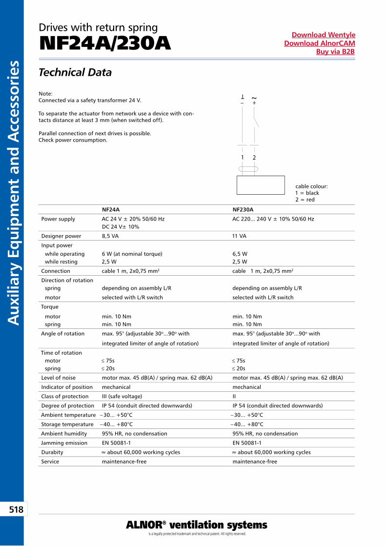
518
Aux
iliar
y Eq
uip
men
t an
d A
cces
sori
es
ALNOR® ventilation systemsis a legally protected trademark and technical patent. All rights reserved.
Download WentyleDownload AlnorCAM
Buy via B2B
Drives with return spring
NF24A/230ATechnical Data
Note:Connected via a safety transformer 24 V.
To separate the actuator from network use a device with con-tacts distance at least 3 mm (when switched off).
Parallel connection of next drives is possible. Check power consumption.
NF24A NF230A
Power supply AC 24 V ± 20% 50/60 Hz AC 220... 240 V ± 10% 50/60 HzDC 24 V± 10%
Designer power 8,5 VA 11 VA
Input power
while operating 6 W (at nominal torque) 6,5 Wwhile resting 2,5 W 2,5 W
Connection cable 1 m, 2x0,75 mm2 cable 1 m, 2x0,75 mm2
Direction of rotationspring depending on assembly L/R depending on assembly L/R
motor selected with L/R switch selected with L/R switch
Torque
motor min. 10 Nm min. 10 Nmspring min. 10 Nm min. 10 Nm
Angle of rotation max. 95° (adjustable 30o...90o with
integrated limiter of angle of rotation)
max. 95° (adjustable 30o...90o with
integrated limiter of angle of rotation)
Time of rotationmotor ≤ 75s ≤ 75sspring ≤ 20s ≤ 20s
Level of noise motor max. 45 dB(A) / spring max. 62 dB(A) motor max. 45 dB(A) / spring max. 62 dB(A)
Indicator of position mechanical mechanical
Class of protection III (safe voltage) II
Degree of protection IP 54 (conduit directed downwards) IP 54 (conduit directed downwards)
Ambient temperature – 30... +50°C – 30... +50°C
Storage temperature – 40... +80°C – 40... +80°C
Ambient humidity 95% HR, no condensation 95% HR, no condensation
Jamming emission EN 50081-1 EN 50081-1
Durabity » about 60,000 working cycles » about 60,000 working cycles
Service maintenance-free maintenance-free
cable colour: 1 = black2 = red
1 2
– +
T ~
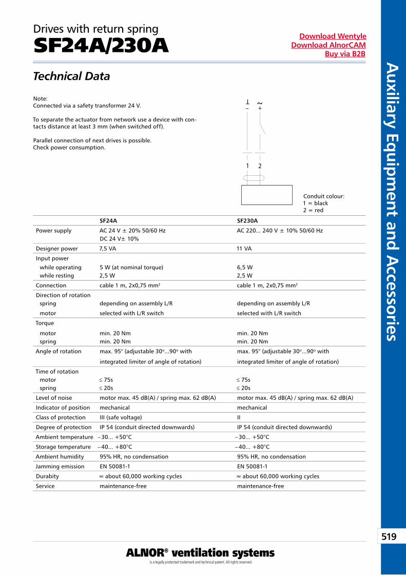
519
Auxiliary Eq
uipm
ent and A
ccessories
ALNOR® ventilation systemsis a legally protected trademark and technical patent. All rights reserved.
Download WentyleDownload AlnorCAM
Buy via B2B
Drives with return spring
SF24A/230ATechnical Data
Note:Connected via a safety transformer 24 V.
To separate the actuator from network use a device with con-tacts distance at least 3 mm (when switched off).
Parallel connection of next drives is possible. Check power consumption.
Conduit colour: 1 = black2 = red
SF24A SF230A
Power supply AC 24 V ± 20% 50/60 Hz AC 220... 240 V ± 10% 50/60 HzDC 24 V± 10%
Designer power 7,5 VA 11 VA
Input power
while operating 5 W (at nominal torque) 6,5 Wwhile resting 2,5 W 2,5 W
Connection cable 1 m, 2x0,75 mm2 cable 1 m, 2x0,75 mm2
Direction of rotationspring depending on assembly L/R depending on assembly L/R
motor selected with L/R switch selected with L/R switch
Torque
motor min. 20 Nm min. 20 Nmspring min. 20 Nm min. 20 Nm
Angle of rotation max. 95° (adjustable 30o...90o with
integrated limiter of angle of rotation)
max. 95° (adjustable 30o...90o with
integrated limiter of angle of rotation)
Time of rotationmotor ≤ 75s ≤ 75sspring ≤ 20s ≤ 20s
Level of noise motor max. 45 dB(A) / spring max. 62 dB(A) motor max. 45 dB(A) / spring max. 62 dB(A)
Indicator of position mechanical mechanical
Class of protection III (safe voltage) II
Degree of protection IP 54 (conduit directed downwards) IP 54 (conduit directed downwards)
Ambient temperature – 30... +50°C – 30... +50°C
Storage temperature – 40... +80°C – 40... +80°C
Ambient humidity 95% HR, no condensation 95% HR, no condensation
Jamming emission EN 50081-1 EN 50081-1
Durabity » about 60,000 working cycles » about 60,000 working cycles
Service maintenance-free maintenance-free
1 2
– +
T ~
Auxiliary Equipment and Accessories
We reserve the right to make changes in the dimensions and technical data products due to their continuous improvement
521
Auxiliary Eq
uipm
ent and A
ccessories
ALNOR® ventilation systemsis a legally protected trademark and technical patent. All rights reserved.
Download WentyleDownload AlnorCAM
Buy via B2B
Filters
TECHNICAL INFORMATION
Duct filters are the complement of the ventilation ducts system. Thanks to a wide choice they are applicable in almost all conditions.
DimensionsAll round filters have diameters or connections to plenum boxes correcponding to dimensions of a round set of the SPIRAL®system profiles. Dimensions of rectangular filters are adjusted each time to sizes of ducts and profiles. The reamining dimensions are based on tables and informations included in a catalogue chart of a given element.
Assembly instructionRound filters are mounted by means of self-drilling screws or rivets in a part of the ducts where a connecting flange is inserted. Recatngular filters are mounted at steel corners by means of screws or with the use of the KLQ clamp clamping two flange frames.
About the System
Benefits of the useFilters prevent contaminations to get into rooms and into the inside of ventilation system. Thanks to it the system pro-vides air of proper quality and increases durability of moun-ted devices. Easy replacement of round and rectangular fil-ter elements ensures comfortable use and service of assem-bled installation.
MarkingWyroby firmy ALNOR oznaczane są znakiem budowlanym, oraz kodem towaru zgodnym ze specyfikacją techniczną za-wartą w niniejszym katalogu.
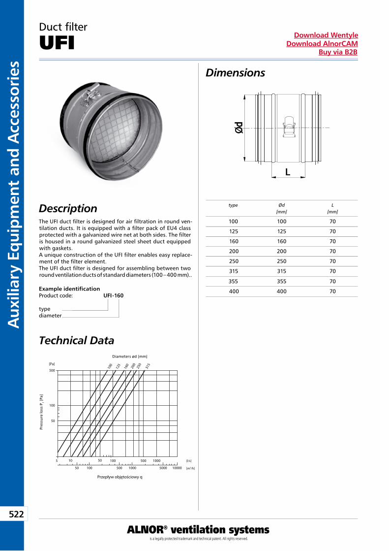
522
Aux
iliar
y Eq
uip
men
t an
d A
cces
sori
es
ALNOR® ventilation systemsis a legally protected trademark and technical patent. All rights reserved.
Download WentyleDownload AlnorCAM
Buy via B2B
Dimensions
Description
50
10
100
500 100
125
160
200
250
315
100 500 1000
100005000100050010050
[Pa]
Przepływ objętościowy q
[l/s]
[m3/h]
5 50
Spad
ek c
iśni
enia
P t
Wymiary Ød [mm]
Duct filter
UFI
Technical Data
The UFI duct filter is designed for air filtration in round ven-tilation ducts. It is equipped with a filter pack of EU4 class protected with a galvanized wire net at both sides. The filter is housed in a round galvanized steel sheet duct equipped with gaskets.A unique construction of the UFI filter enables easy replace-ment of the filter element.The UFI duct filter is designed for assembling between two round ventilation ducts of standard diameters (100 – 400 mm)..
Example identificationProduct code: UFI - 160
typediameter
type Ød L [mm] [mm]
Diameters ød [mm]
Pres
sure
loss
Pt [
Pa]
100 100 70
125 125 70
160 160 70
200 200 70
250 250 70
315 315 70
355 355 70
400 400 70
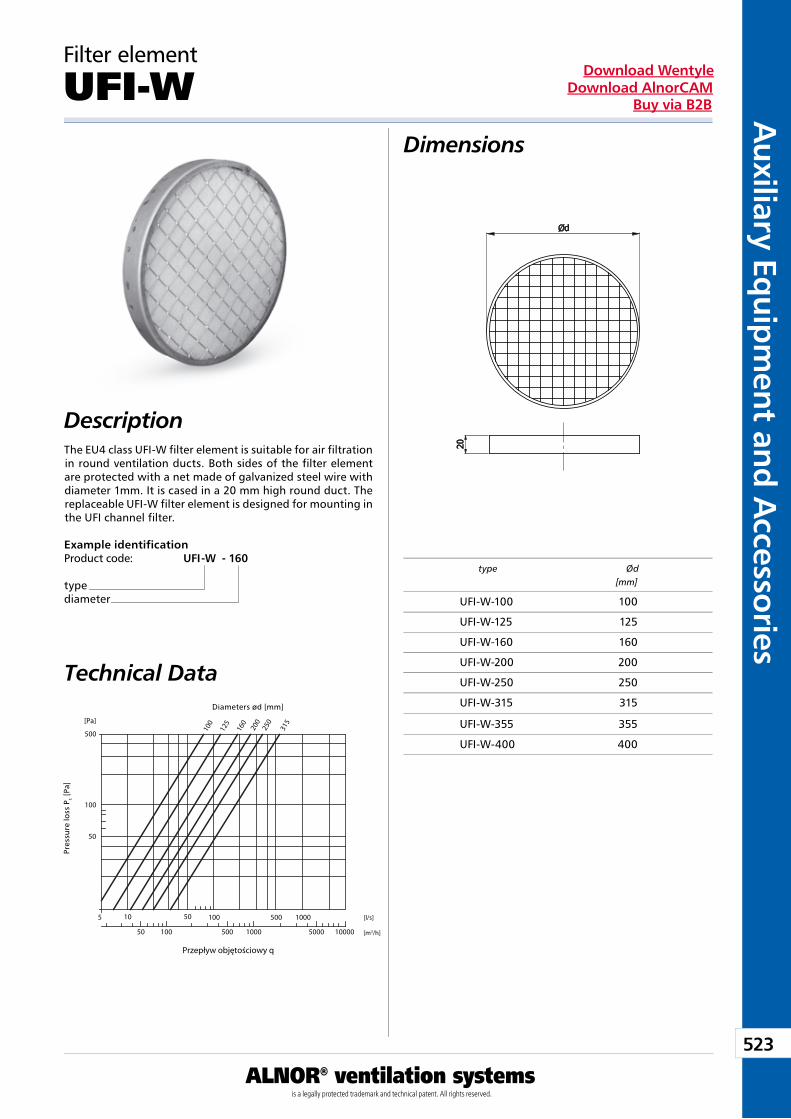
523
Auxiliary Eq
uipm
ent and A
ccessories
ALNOR® ventilation systemsis a legally protected trademark and technical patent. All rights reserved.
Download WentyleDownload AlnorCAM
Buy via B2B
Dimensions
Description
50
10
100
500 100
125
160
200
250
315
100 500 1000
100005000100050010050
[Pa]
Przepływ objętościowy q
[l/s]
[m3/h]
5 50
Spad
ek c
iśni
enia
P t
Wymiary Ød [mm]
Filter element
UFI-W
Technical Data
The EU4 class UFI-W filter element is suitable for air filtration in round ventilation ducts. Both sides of the filter element are protected with a net made of galvanized steel wire with diameter 1mm. It is cased in a 20 mm high round duct. The replaceable UFI-W filter element is designed for mounting in the UFI channel filter.
type Ød [mm]
Example identificationProduct code: UFI -W - 160
typediameter
Diameters ød [mm]
Pres
sure
loss
Pt [
Pa]
UFI-W-100 100
UFI-W-125 125
UFI-W-160 160
UFI-W-200 200
UFI-W-250 250
UFI-W-315 315
UFI-W-355 355
UFI-W-400 400
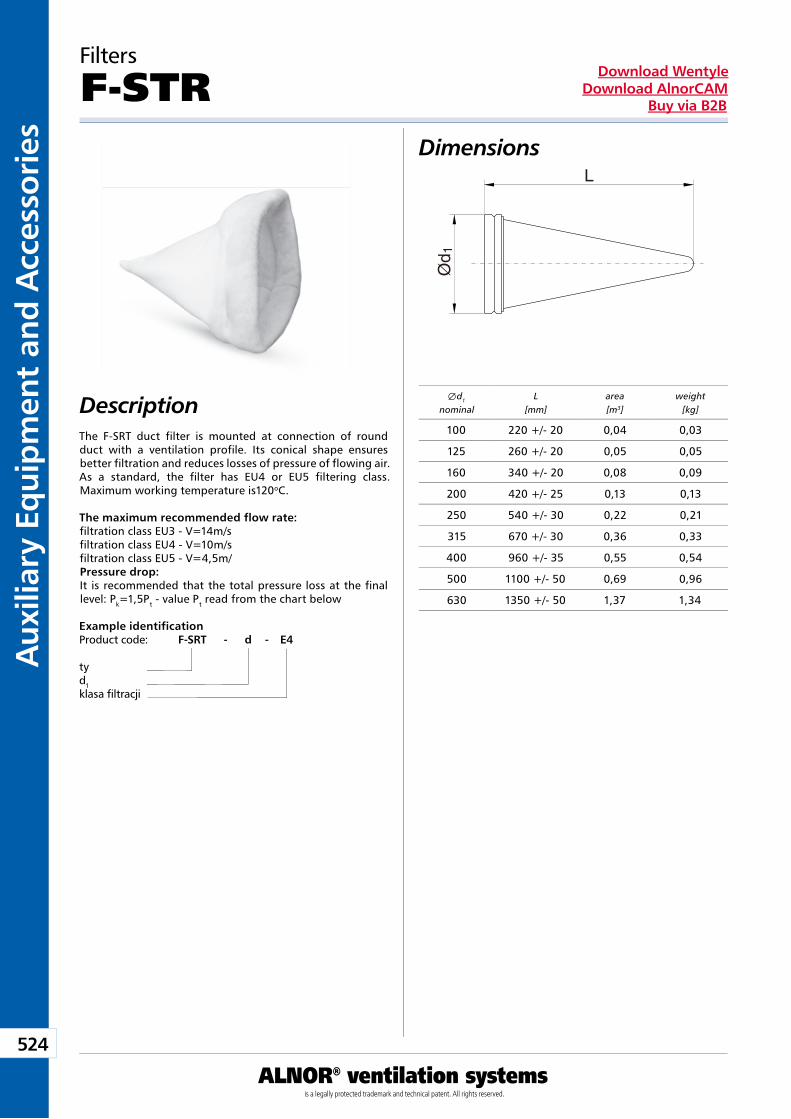
524
Aux
iliar
y Eq
uip
men
t an
d A
cces
sori
es
ALNOR® ventilation systemsis a legally protected trademark and technical patent. All rights reserved.
Download WentyleDownload AlnorCAM
Buy via B2B
Filters
F-STRDimensions
DescriptionThe F-SRT duct filter is mounted at connection of round duct with a ventilation profile. Its conical shape ensures better filtration and reduces losses of pressure of flowing air. As a standard, the filter has EU4 or EU5 filtering class. Maximum working temperature is120oC.
Example identificationProduct code: F-SRT - d - E4
tyd1klasa filtracji
d1
nominalL
[mm]area[m3]
weight[kg]
The maximum recommended flow rate:filtration class EU3 - V=14m/sfiltration class EU4 - V=10m/sfiltration class EU5 - V=4,5m/Pressure drop:It is recommended that the total pressure loss at the final level: Pk=1,5Pt - value Pt read from the chart below
L
Ød 1
100 220 +/- 20 0,04 0,03
125 260 +/- 20 0,05 0,05
160 340 +/- 20 0,08 0,09
200 420 +/- 25 0,13 0,13
250 540 +/- 30 0,22 0,21
315 670 +/- 30 0,36 0,33
400 960 +/- 35 0,55 0,54
500 1100 +/- 50 0,69 0,96
630 1350 +/- 50 1,37 1,34
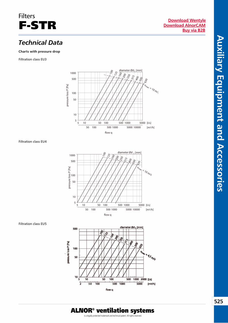
525
Auxiliary Eq
uipm
ent and A
ccessories
ALNOR® ventilation systemsis a legally protected trademark and technical patent. All rights reserved.
Download WentyleDownload AlnorCAM
Buy via B2B
Filtration class EU3
Filters
F-STR
Filtration class EU4
Filtration class EU5
Technical DataCharts with pressure drop
1000
500
5
50 100 500 1000 5000 10000
10 50 100
630
vmax = 10 m/s
500
400
315250
20016012510
0
500 1000 5000
100
50
5
10
diameter Ød1 [mm]
[l/s]
[m3/h]
�ow q
pr
essu
re lo
ss P
[Pa]
1000
500
5
50 100 500 1000 5000 10000
10 50 100
630
vmax = 10 m/s
500400315250
20016012510
0
500 1000 5000
100
50
5
10
diameter Ød 1 [mm]
[l/s]
[m3/h]
�ow q
pr
essu
re lo
ss P
[Pa]
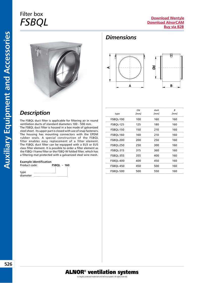
526
Aux
iliar
y Eq
uip
men
t an
d A
cces
sori
es
ALNOR® ventilation systemsis a legally protected trademark and technical patent. All rights reserved.
Download WentyleDownload AlnorCAM
Buy via B2B
Filter box
FSBQLDimensions
DescriptionThe FSBQL duct filter is applicable for filtering air in round ventilation ducts of standard diameters 100 - 500 mm. The FSBQL duct filter is housed in a box made of galvanized steel sheet . Its upper part is closed with use of snap fasteners. The housing has mounting connectors with the EPDM rubber seals. A special construction of the FSBQL filter enables easy replacement of a filter element. The FSBQL duct filter can be equipped with a EU3 or EU5 class filter element. It is possible to order a filter element as the FSBQ-I frame filter or the FSBQ-W folded filter, which has a filtering mat protected with a galvanized steel wire mesh.
Example identificationProduct code: FSBQL - 160
typediameter
typed
[mm]AxA[mm]
B[mm]
FSBQL-100 100 160 160
FSBQL-125 125 180 160
FSBQL-150 150 210 160
FSBQL-160 160 210 160
FSBQL-200 200 250 160
FSBQL-250 250 300 160
FSBQL-315 315 360 160
FSBQL-355 355 400 160
FSBQL-400 400 450 160
FSBQL-450 450 500 160
FSBQL-500 500 550 160
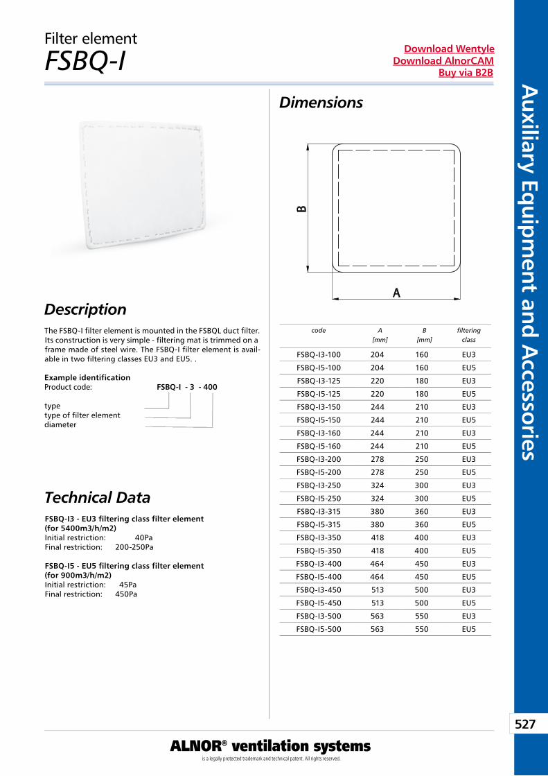
527
Auxiliary Eq
uipm
ent and A
ccessories
ALNOR® ventilation systemsis a legally protected trademark and technical patent. All rights reserved.
Download WentyleDownload AlnorCAM
Buy via B2B
Filter element
FSBQ-I
The FSBQ-I filter element is mounted in the FSBQL duct filter. Its construction is very simple - filtering mat is trimmed on a frame made of steel wire. The FSBQ-I filter element is avail-able in two filtering classes EU3 and EU5. .
FSBQ-I3 - EU3 filtering class filter element(for 5400m3/h/m2)Initial restriction: 40PaFinal restriction: 200-250Pa
FSBQ-I5 - EU5 filtering class filter element(for 900m3/h/m2) Initial restriction: 45PaFinal restriction: 450Pa
Example identificationProduct code: FSBQ-I - 3 - 400
typetype of filter element diameter
Technical Data
Dimensions
Descriptioncode A
[mm]B
[mm]filtering
class
FSBQ-I3-100 204 160 EU3
FSBQ-I5-100 204 160 EU5
FSBQ-I3-125 220 180 EU3
FSBQ-I5-125 220 180 EU5
FSBQ-I3-150 244 210 EU3
FSBQ-I5-150 244 210 EU5
FSBQ-I3-160 244 210 EU3
FSBQ-I5-160 244 210 EU5
FSBQ-I3-200 278 250 EU3
FSBQ-I5-200 278 250 EU5
FSBQ-I3-250 324 300 EU3
FSBQ-I5-250 324 300 EU5
FSBQ-I3-315 380 360 EU3
FSBQ-I5-315 380 360 EU5
FSBQ-I3-350 418 400 EU3
FSBQ-I5-350 418 400 EU5
FSBQ-I3-400 464 450 EU3
FSBQ-I5-400 464 450 EU5
FSBQ-I3-450 513 500 EU3
FSBQ-I5-450 513 500 EU5
FSBQ-I3-500 563 550 EU3
FSBQ-I5-500 563 550 EU5
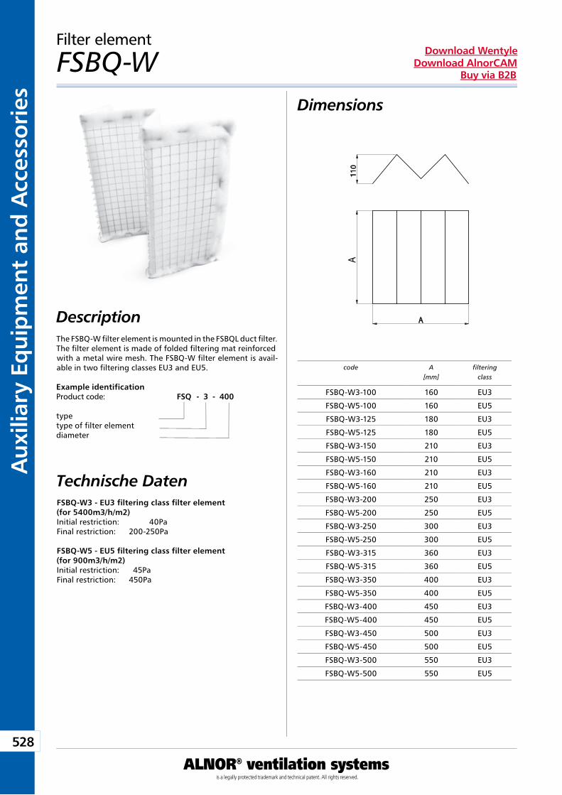
528
Aux
iliar
y Eq
uip
men
t an
d A
cces
sori
es
ALNOR® ventilation systemsis a legally protected trademark and technical patent. All rights reserved.
Download WentyleDownload AlnorCAM
Buy via B2B
A
Filter element
FSBQ-W
Technische Daten
The FSBQ-W filter element is mounted in the FSBQL duct filter. The filter element is made of folded filtering mat reinforced with a metal wire mesh. The FSBQ-W filter element is avail-able in two filtering classes EU3 and EU5.
Dimensions
Description
FSBQ-W3 - EU3 filtering class filter element(for 5400m3/h/m2)Initial restriction: 40PaFinal restriction: 200-250Pa
FSBQ-W5 - EU5 filtering class filter element(for 900m3/h/m2) Initial restriction: 45PaFinal restriction: 450Pa
Example identificationProduct code: FSQ - 3 - 400
typetype of filter element diameter
code A[mm]
filteringclass
FSBQ-W3-100 160 EU3
FSBQ-W5-100 160 EU5
FSBQ-W3-125 180 EU3
FSBQ-W5-125 180 EU5
FSBQ-W3-150 210 EU3
FSBQ-W5-150 210 EU5
FSBQ-W3-160 210 EU3
FSBQ-W5-160 210 EU5
FSBQ-W3-200 250 EU3
FSBQ-W5-200 250 EU5
FSBQ-W3-250 300 EU3
FSBQ-W5-250 300 EU5
FSBQ-W3-315 360 EU3
FSBQ-W5-315 360 EU5
FSBQ-W3-350 400 EU3
FSBQ-W5-350 400 EU5
FSBQ-W3-400 450 EU3
FSBQ-W5-400 450 EU5
FSBQ-W3-450 500 EU3
FSBQ-W5-450 500 EU5
FSBQ-W3-500 550 EU3
FSBQ-W5-500 550 EU5
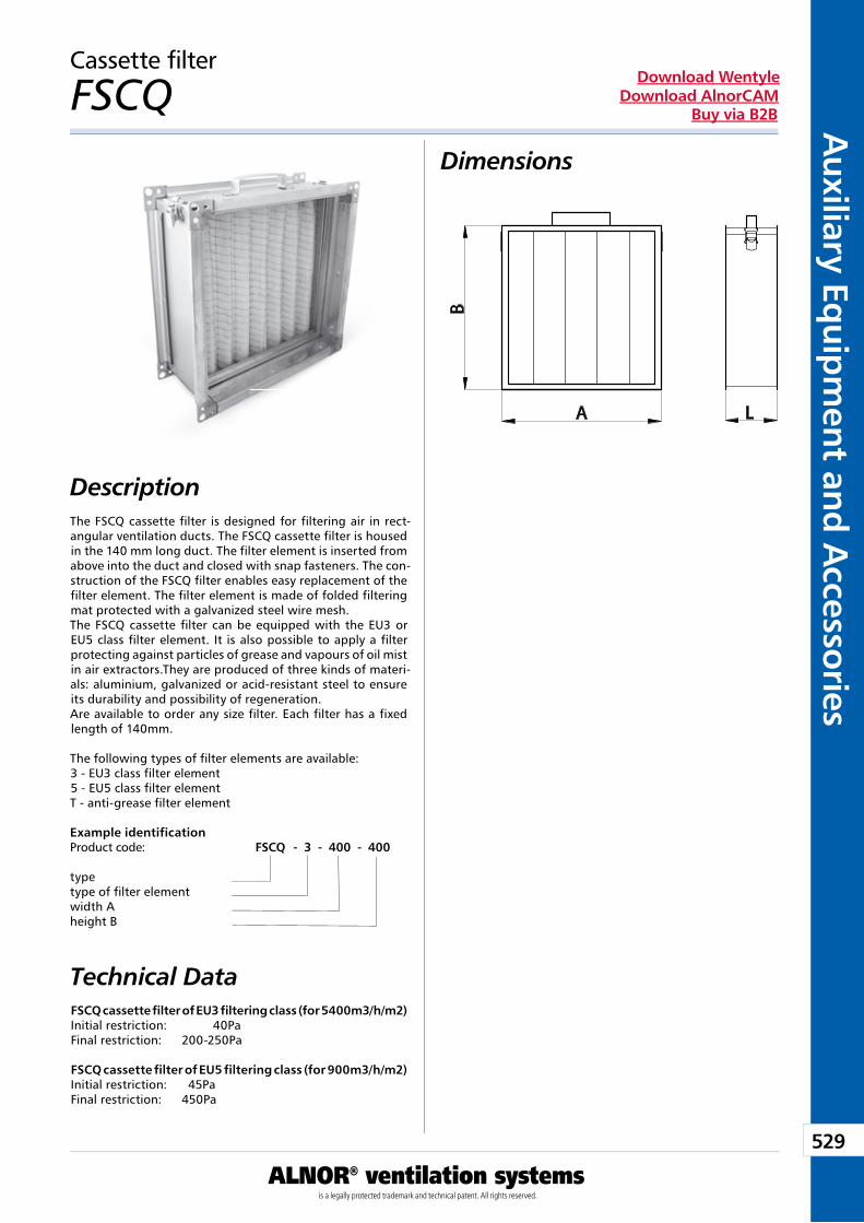
529
Auxiliary Eq
uipm
ent and A
ccessories
ALNOR® ventilation systemsis a legally protected trademark and technical patent. All rights reserved.
Download WentyleDownload AlnorCAM
Buy via B2B
Cassette filter
FSCQ
The FSCQ cassette filter is designed for filtering air in rect-angular ventilation ducts. The FSCQ cassette filter is housed in the 140 mm long duct. The filter element is inserted from above into the duct and closed with snap fasteners. The con-struction of the FSCQ filter enables easy replacement of the filter element. The filter element is made of folded filtering mat protected with a galvanized steel wire mesh.The FSCQ cassette filter can be equipped with the EU3 or EU5 class filter element. It is also possible to apply a filter protecting against particles of grease and vapours of oil mist in air extractors.They are produced of three kinds of materi-als: aluminium, galvanized or acid-resistant steel to ensure its durability and possibility of regeneration.Are available to order any size filter. Each filter has a fixed length of 140mm.
The following types of filter elements are available: 3 - EU3 class filter element 5 - EU5 class filter element T - anti-grease filter element
Example identificationProduct code: FSCQ - 3 - 400 - 400
typetype of filter element width Aheight B
Technical DataFSCQ cassette filter of EU3 filtering class (for 5400m3/h/m2)Initial restriction: 40PaFinal restriction: 200-250Pa
FSCQ cassette filter of EU5 filtering class (for 900m3/h/m2)Initial restriction: 45PaFinal restriction: 450Pa
Dimensions
Description
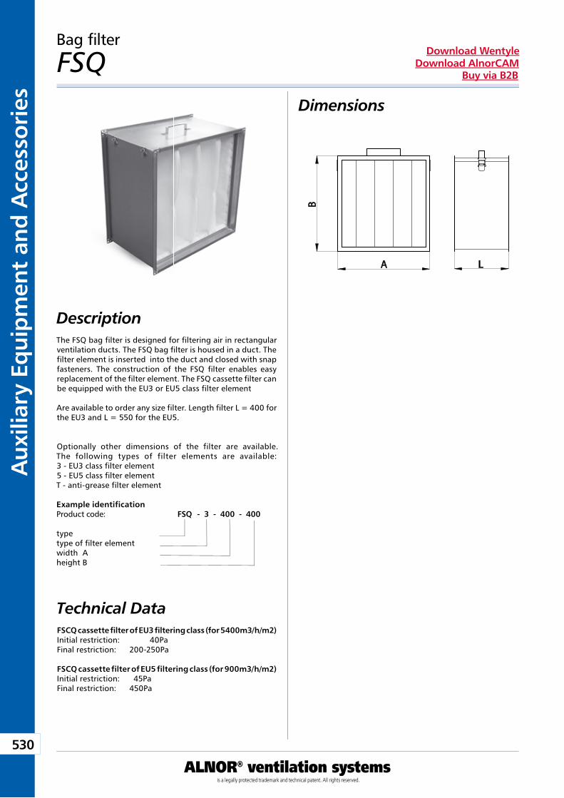
530
Aux
iliar
y Eq
uip
men
t an
d A
cces
sori
es
ALNOR® ventilation systemsis a legally protected trademark and technical patent. All rights reserved.
Download WentyleDownload AlnorCAM
Buy via B2B
Bag filter
FSQ
The FSQ bag filter is designed for filtering air in rectangular ventilation ducts. The FSQ bag filter is housed in a duct. The filter element is inserted into the duct and closed with snap fasteners. The construction of the FSQ filter enables easy replacement of the filter element. The FSQ cassette filter can be equipped with the EU3 or EU5 class filter element
Are available to order any size filter. Length filter L = 400 for the EU3 and L = 550 for the EU5.
Optionally other dimensions of the filter are available. The following types of filter elements are available: 3 - EU3 class filter element 5 - EU5 class filter element T - anti-grease filter element
Example identificationProduct code: FSQ - 3 - 400 - 400
typetype of filter element width Aheight B
Technical Data
Dimensions
Description
FSCQ cassette filter of EU3 filtering class (for 5400m3/h/m2)Initial restriction: 40PaFinal restriction: 200-250Pa
FSCQ cassette filter of EU5 filtering class (for 900m3/h/m2)Initial restriction: 45PaFinal restriction: 450Pa

Auxiliary Equipment and Accessories
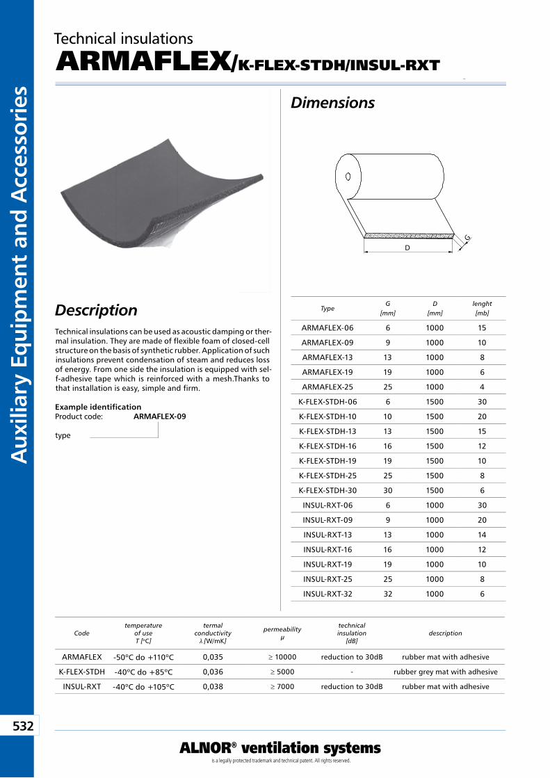
532
Aux
iliar
y Eq
uip
men
t an
d A
cces
sori
es
ALNOR® ventilation systemsis a legally protected trademark and technical patent. All rights reserved.
Download WentyleDownload AlnorCAM
Buy via B2B
Dimensions
DescriptionTechnical insulations can be used as acoustic damping or ther-mal insulation. They are made of flexible foam of closed-cell structure on the basis of synthetic rubber. Application of such insulations prevent condensation of steam and reduces loss of energy. From one side the insulation is equipped with sel-f-adhesive tape which is reinforced with a mesh.Thanks to that installation is easy, simple and firm.
Example identificationProduct code: ARMAFLEX-09
type
TypeG
[mm]D
[mm]lenght[mb]
Technical insulations
ARMAFLEX/K-FLEX-STDH/INSUL-RXT
Codetemperature
of useT [oC]
termal conductivity
λ [W/mK]
permeabilityµ
technicalinsulation
[dB]description
GD
ARMAFLEX-06 6 1000 15
ARMAFLEX-09 9 1000 10
ARMAFLEX-13 13 1000 8
ARMAFLEX-19 19 1000 6
ARMAFLEX-25 25 1000 4
K-FLEX-STDH-06 6 1500 30
K-FLEX-STDH-10 10 1500 20
K-FLEX-STDH-13 13 1500 15
K-FLEX-STDH-16 16 1500 12
K-FLEX-STDH-19 19 1500 10
K-FLEX-STDH-25 25 1500 8
K-FLEX-STDH-30 30 1500 6
INSUL-RXT-06 6 1000 30
INSUL-RXT-09 9 1000 20
INSUL-RXT-13 13 1000 14
INSUL-RXT-16 16 1000 12
INSUL-RXT-19 19 1000 10
INSUL-RXT-25 25 1000 8
INSUL-RXT-32 32 1000 6
ARMAFLEX -50oC do +110oC 0,035 ≥ 10000 reduction to 30dB rubber mat with adhesive
K-FLEX-STDH -40oC do +85oC 0,036 ≥ 5000 - rubber grey mat with adhesive
INSUL-RXT -40oC do +105oC 0,038 ≥ 7000 reduction to 30dB rubber mat with adhesive
Rectangular ducts and fittings
We reserve the right to make changes in the dimensions and technical data products due to their continuous improvement
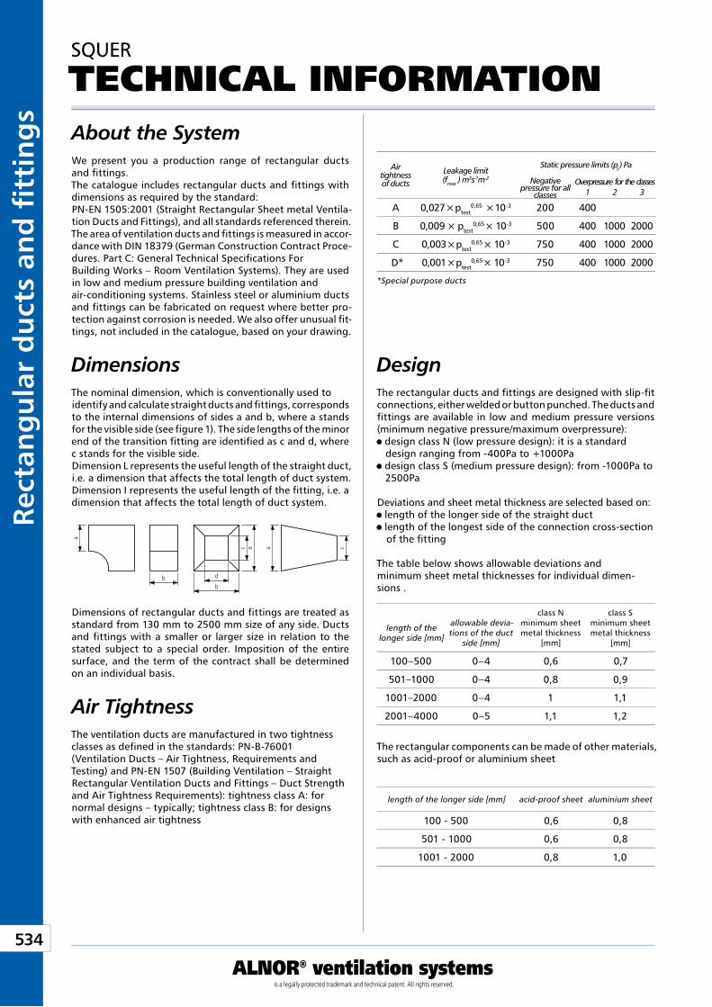
Kan
ały
i ksz
tałt
ki p
rost
oką
tne
534
ALNOR® ventilation systemsis a legally protected trademark and technical patent. All rights reserved.
Rect
ang
ula
r d
uct
s an
d fi
tti
ng
sDownload Wentyle
Download AlnorCAMBuy via B2B
SQUER
TECHNICAL INFORMATION
DesignThe rectangular ducts and fittings are designed with slip-fit connections, either welded or button punched. The ducts and fittings are available in low and medium pressure versions (minimum negative pressure/maximum overpressure): design class N (low pressure design): it is a standard design ranging from -400Pa to +1000Pa
design class S (medium pressure design): from -1000Pa to 2500Pa
Deviations and sheet metal thickness are selected based on: length of the longer side of the straight duct length of the longest side of the connection cross-section of the fitting
The table below shows allowable deviations and minimum sheet metal thicknesses for individual dimen-sions .
The rectangular components can be made of other materials, such as acid-proof or aluminium sheet
Air tightness of ducts
Leakage limit(fmax ) m3s-1m-2
Static pressure limits (ps) Pa
Negative pressure for all
classes
Overpressure for the classes1 2 3
*Special purpose ducts
length of the longer side [mm]
allowable devia-tions of the duct
side [mm]
class Nminimum sheet metal thickness
[mm]
class Sminimum sheet metal thickness
[mm]
length of the longer side [mm] acid-proof sheet aluminium sheet
About the System
Dimensions
We present you a production range of rectangular ducts and fittings.The catalogue includes rectangular ducts and fittings with dimensions as required by the standard:PN-EN 1505:2001 (Straight Rectangular Sheet metal Ventila-tion Ducts and Fittings), and all standards referenced therein.The area of ventilation ducts and fittings is measured in accor-dance with DIN 18379 (German Construction Contract Proce-dures. Part C: General Technical Specifications For Building Works – Room Ventilation Systems). They are used in low and medium pressure building ventilation and air-conditioning systems. Stainless steel or aluminium ducts and fittings can be fabricated on request where better pro-tection against corrosion is needed. We also offer unusual fit-tings, not included in the catalogue, based on your drawing.
The nominal dimension, which is conventionally used to identify and calculate straight ducts and fittings, corresponds to the internal dimensions of sides a and b, where a stands for the visible side (see figure 1). The side lengths of the minor end of the transition fitting are identified as c and d, where c stands for the visible side.Dimension L represents the useful length of the straight duct, i.e. a dimension that affects the total length of duct system.Dimension I represents the useful length of the fitting, i.e. a dimension that affects the total length of duct system.
The ventilation ducts are manufactured in two tightness classes as defined in the standards: PN-B-76001 (Ventilation Ducts – Air Tightness, Requirements and Testing) and PN-EN 1507 (Building Ventilation – Straight Rectangular Ventilation Ducts and Fittings – Duct Strength and Air Tightness Requirements): tightness class A: for normal designs – typically; tightness class B: for designs with enhanced air tightness
Air Tightness
Dimensions of rectangular ducts and fittings are treated as standard from 130 mm to 2500 mm size of any side. Ducts and fittings with a smaller or larger size in relation to the stated subject to a special order. Imposition of the entire surface, and the term of the contract shall be determined on an individual basis.
caac
a
b
db
100–500 0–4 0,6 0,7
501–1000 0–4 0,8 0,9
1001–2000 0–4 1 1,1
2001–4000 0–5 1,1 1,2
100 - 500 0,6 0,8
501 - 1000 0,6 0,8
1001 - 2000 0,8 1,0
A 0,027 × ptest0,65 × 10-3 200 400
B 0,009 × ptest0,65 × 10-3 500 400 1000 2000
C 0,003 × ptest0,65 × 10-3 750 400 1000 2000
D* 0,001 × ptest0,65 × 10-3 750 400 1000 2000
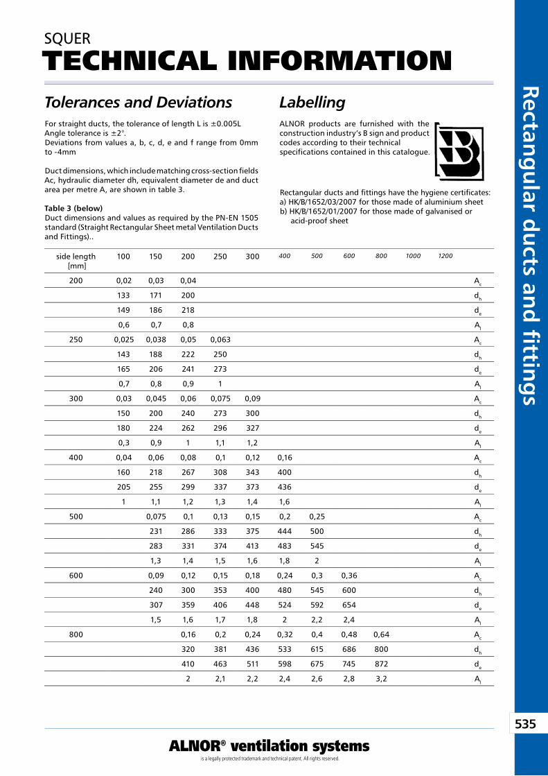
535
ALNOR® ventilation systemsis a legally protected trademark and technical patent. All rights reserved.
Rectang
ular d
ucts an
d fi ttin
gs
Download WentyleDownload AlnorCAM
Buy via B2B
Tolerances and Deviations
SQUER
TECHNICAL INFORMATION
For straight ducts, the tolerance of length L is ±0.005LAngle tolerance is ±2°.Deviations from values a, b, c, d, e and f range from 0mm to -4mm
Duct dimensions, which include matching cross-section fields Ac, hydraulic diameter dh, equivalent diameter de and duct area per metre A, are shown in table 3.
Table 3 (below)Duct dimensions and values as required by the PN-EN 1505 standard (Straight Rectangular Sheet metal Ventilation Ducts and Fittings)..
LabellingALNOR products are furnished with the construction industry’s B sign and product codes according to their technical specifications contained in this catalogue.
Rectangular ducts and fittings have the hygiene certificates:a) HK/B/1652/03/2007 for those made of aluminium sheetb) HK/B/1652/01/2007 for those made of galvanised or acid-proof sheet
side length [mm]
100 150 200 250 300 400 500 600 800 1000 1200
200 0,02 0,03 0,04 Ac
133 171 200 dh
149 186 218 de
0,6 0,7 0,8 Al
250 0,025 0,038 0,05 0,063 Ac
143 188 222 250 dh
165 206 241 273 de
0,7 0,8 0,9 1 Al
300 0,03 0,045 0,06 0,075 0,09 Ac
150 200 240 273 300 dh
180 224 262 296 327 de
0,3 0,9 1 1,1 1,2 Al
400 0,04 0,06 0,08 0,1 0,12 0,16 Ac
160 218 267 308 343 400 dh
205 255 299 337 373 436 de
1 1,1 1,2 1,3 1,4 1,6 Al
500 0,075 0,1 0,13 0,15 0,2 0,25 Ac
231 286 333 375 444 500 dh
283 331 374 413 483 545 de
1,3 1,4 1,5 1,6 1,8 2 Al
600 0,09 0,12 0,15 0,18 0,24 0,3 0,36 Ac
240 300 353 400 480 545 600 dh
307 359 406 448 524 592 654 de
1,5 1,6 1,7 1,8 2 2,2 2,4 Al
800 0,16 0,2 0,24 0,32 0,4 0,48 0,64 Ac
320 381 436 533 615 686 800 dh
410 463 511 598 675 745 872 de
2 2,1 2,2 2,4 2,6 2,8 3,2 Al
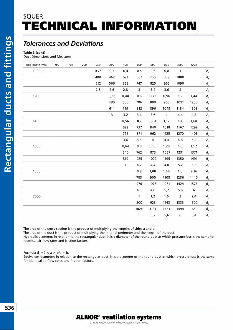
Kan
ały
i ksz
tałt
ki p
rost
oką
tne
536
ALNOR® ventilation systemsis a legally protected trademark and technical patent. All rights reserved.
Rect
ang
ula
r d
uct
s an
d fi
tti
ng
sDownload Wentyle
Download AlnorCAMBuy via B2B
Tolerances and Deviations
SQUER
TECHNICAL INFORMATION
Table 3 (cont) Duct Dimensions and Measures
The area of the cross-section is the product of multiplying the lengths of sides a and b.The area of the duct is the product of multiplying the internal perimeter and the length of the duct.Hydraulic diameter: in relation to the rectangular duct, it is a diameter of the round duct at which pressure loss is the same for identical air flow rates and friction factors.
Formula dh = 2 × a × b/a + b.Equivalent diameter: in relation to the rectangular duct, it is a diameter of the round duct at which pressure loss is the same for identical air flow rates and friction factors.
side length [mm] 100 150 200 250 300 400 500 600 800 1000 1200
1000 0,25 0,3 0,4 0,5 0,6 0,8 1 Ac
400 462 571 667 750 889 1000 dh
512 566 662 747 825 965 1090 de
2,5 2,6 2,8 3 3,2 3,6 4 Al
1200 0,36 0,48 0,6 0,72 0,96 1,2 1,44 Ac
480 600 706 800 960 1091 1200 dh
614 719 812 896 1049 1184 1308 de
3 3,2 3,4 3,6 4 4,4 4,8 Al
1400 0,56 0,7 0,84 1,12 1,4 1,68 Ac
622 737 840 1018 1167 1292 dh
771 871 962 1125 1270 1403 de
3,6 3,8 4 4,4 4,8 5,2 Al
1600 0,64 0,8 0,96 1,28 1,6 1,92 Ac
640 762 873 1067 1231 1371 dh
819 925 1022 1195 1350 1491 de
4 4,2 4,4 4,8 5,2 5,6 Al
1800 0,9 1,08 1,44 1,8 2,16 Ac
783 900 1108 1286 1440 dh
976 1078 1261 1424 1573 de
4,6 4,8 5,2 5,6 6 Al
2000 1 1,2 1,6 2 2,4 Ac
800 923 1143 1333 1500 dh
1024 1131 1323 1494 1650 de
5 5,2 5,6 6 6,4 Al
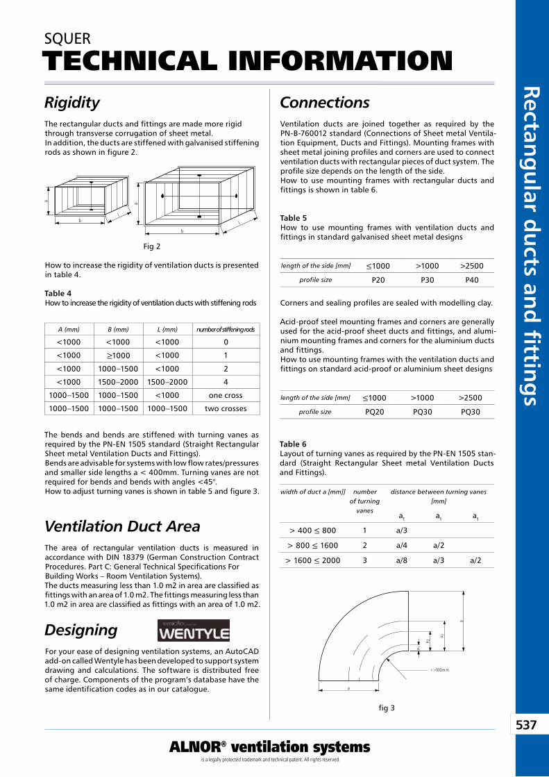
537
ALNOR® ventilation systemsis a legally protected trademark and technical patent. All rights reserved.
Rectang
ular d
ucts an
d fi ttin
gs
Download WentyleDownload AlnorCAM
Buy via B2B
Rigidity
SQUER
TECHNICAL INFORMATION
The rectangular ducts and fittings are made more rigid through transverse corrugation of sheet metal.In addition, the ducts are stiffened with galvanised stiffening rods as shown in figure 2.
How to increase the rigidity of ventilation ducts is presented in table 4.
Fig 2
fig 3
Table 4How to increase the rigidity of ventilation ducts with stiffening rods
The bends and bends are stiffened with turning vanes as required by the PN-EN 1505 standard (Straight Rectangular Sheet metal Ventilation Ducts and Fittings).Bends are advisable for systems with low flow rates/pressures and smaller side lengths a < 400mm. Turning vanes are not required for bends and bends with angles <45°.How to adjust turning vanes is shown in table 5 and figure 3.
ConnectionsVentilation ducts are joined together as required by the PN-B-760012 standard (Connections of Sheet metal Ventila-tion Equipment, Ducts and Fittings). Mounting frames with sheet metal joining profiles and corners are used to connect ventilation ducts with rectangular pieces of duct system. The profile size depends on the length of the side.How to use mounting frames with rectangular ducts and fittings is shown in table 6.
Table 5How to use mounting frames with ventilation ducts and fittings in standard galvanised sheet metal designs
Corners and sealing profiles are sealed with modelling clay.
Acid-proof steel mounting frames and corners are generally used for the acid-proof sheet ducts and fittings, and alumi-nium mounting frames and corners for the aluminium ducts and fittings.How to use mounting frames with the ventilation ducts and fittings on standard acid-proof or aluminium sheet designs
Table 6Layout of turning vanes as required by the PN-EN 1505 stan-dard (Straight Rectangular Sheet metal Ventilation Ducts and Fittings).
Ventilation Duct AreaThe area of rectangular ventilation ducts is measured in accordance with DIN 18379 (German Construction Contract Procedures. Part C: General Technical Specifications For Building Works – Room Ventilation Systems).The ducts measuring less than 1.0 m2 in area are classified as fittings with an area of 1.0 m2. The fittings measuring less than 1.0 m2 in area are classified as fittings with an area of 1.0 m2.
For your ease of designing ventilation systems, an AutoCAD add-on called Wentyle has been developed to support system drawing and calculations. The software is distributed free of charge. Components of the program’s database have the same identification codes as in our catalogue.
A (mm) B (mm) L (mm) number of stiffening rods
one cross
two crosses
length of the side [mm]
profile size
length of the side [mm]
profile size
width of duct a [mm]] number of turning
vanes
distance between turning vanes [mm]
Designing
l
l
aa
b
b
r>100m m
a 1
a 2
a 3
a
a
<1000 <1000 <1000 0
<1000 ≥1000 <1000 1
<1000 1000–1500 <1000 2
<1000 1500–2000 1500–2000 4
1000–1500 1000–1500 <1000
1000–1500 1000–1500 1000–1500
≤1000 >1000 >2500
P20 P30 P40
≤1000 >1000 >2500
PQ20 PQ30 PQ30
a1 a1 a1
> 400 ≤ 800 1 a/3
> 800 ≤ 1600 2 a/4 a/2
> 1600 ≤ 2000 3 a/8 a/3 a/2
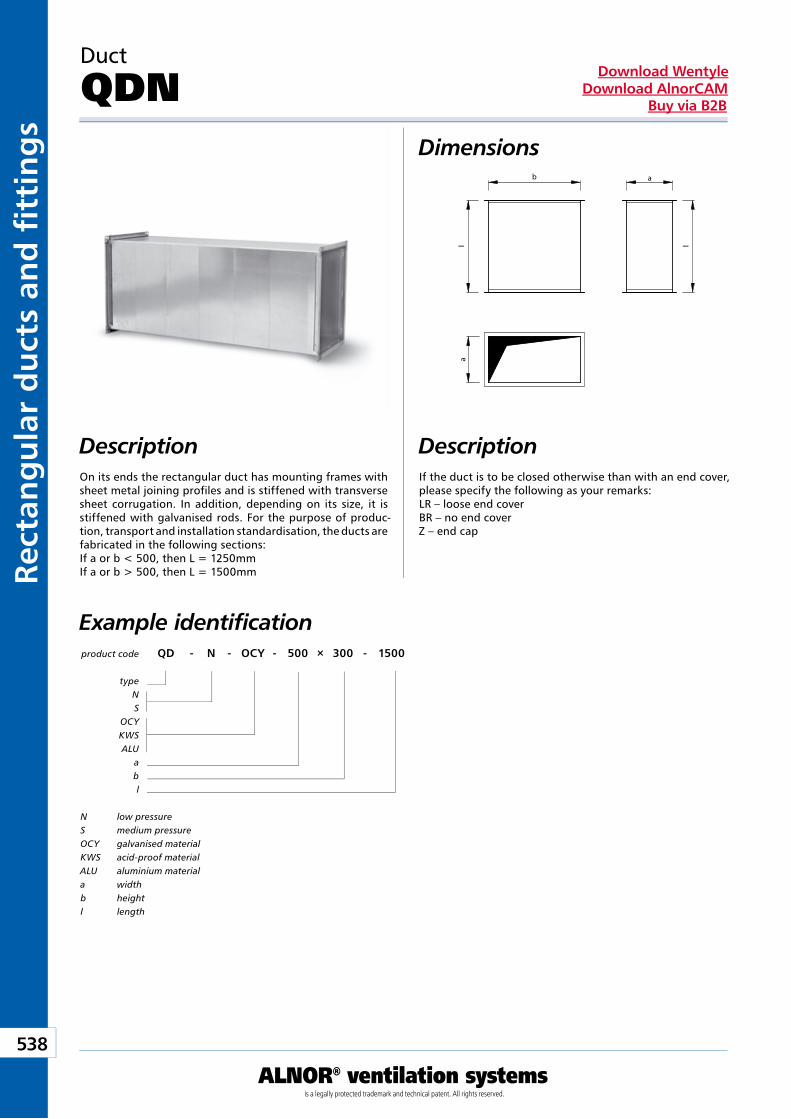
Kan
ały
i ksz
tałt
ki p
rost
oką
tne
538
ALNOR® ventilation systemsis a legally protected trademark and technical patent. All rights reserved.
Rect
ang
ula
r d
uct
s an
d fi
tti
ng
sDownload Wentyle
Download AlnorCAMBuy via B2B
Duct
QDNDimensions
DescriptionOn its ends the rectangular duct has mounting frames with sheet metal joining profiles and is stiffened with transverse sheet corrugation. In addition, depending on its size, it is stiffened with galvanised rods. For the purpose of produc-tion, transport and installation standardisation, the ducts are fabricated in the following sections:If a or b < 500, then L = 1250mm If a or b > 500, then L = 1500mm
If the duct is to be closed otherwise than with an end cover, please specify the following as your remarks: LR – loose end coverBR – no end coverZ – end cap
product code QD - N - OCY - 500 × 300 - 1500
typeNS
OCYKWSALU
abl
Example identification
N low pressureS medium pressureOCY galvanised materialKWS acid-proof materialALU aluminium materiala widthb heightl length
Description
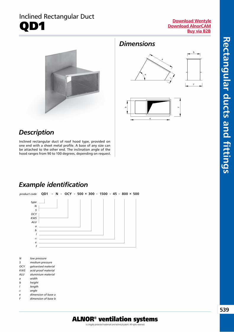
539
ALNOR® ventilation systemsis a legally protected trademark and technical patent. All rights reserved.
Rectang
ular d
ucts an
d fi ttin
gs
Download WentyleDownload AlnorCAM
Buy via B2B
Inclined Rectangular Duct
QD1Dimensions
DescriptionInclined rectangular duct of roof hood type, provided on one end with a sheet metal profile. A base of any size can be attached to the other end. The inclination angle of the hood ranges from 90 to 100 degrees, depending on request.
product code QD1 - N - OCY - 500 × 300 - 1500 - 45 - 800 × 500
typeNS
OCYKWSALU
abl
a
ef
Example identification
N low pressureS medium pressureOCY galvanised materialKWS acid-proof materialALU aluminium materiala widthb heightl lengtha anglee dimension of base af dimension of base b
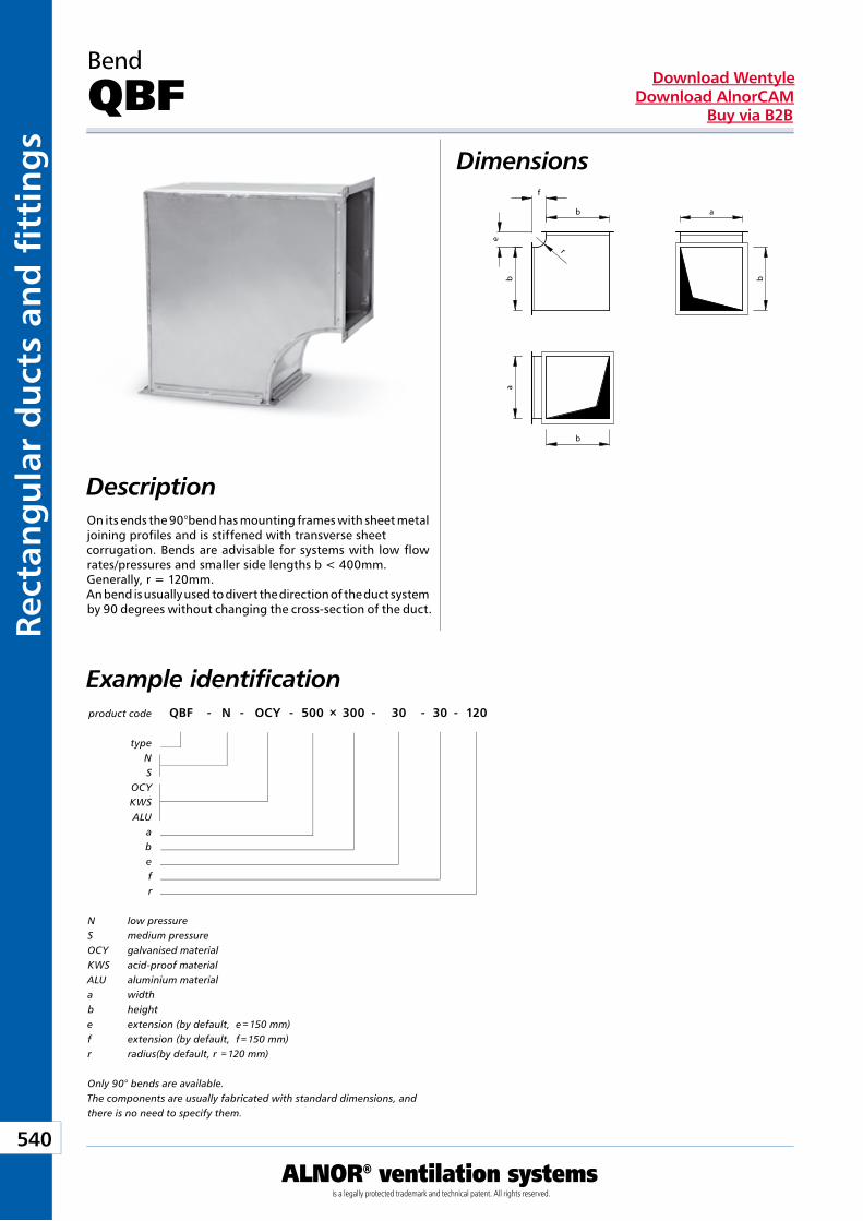
Kan
ały
i ksz
tałt
ki p
rost
oką
tne
540
ALNOR® ventilation systemsis a legally protected trademark and technical patent. All rights reserved.
Rect
ang
ula
r d
uct
s an
d fi
tti
ng
sDownload Wentyle
Download AlnorCAMBuy via B2B
Bend
QBFDimensions
Description
product code QBF - N - OCY - 500 × 300 - 30 - 30 - 120
typeNS
OCYKWSALU
abefr
Example identification
N low pressureS medium pressureOCY galvanised materialKWS acid-proof materialALU aluminium materiala widthb heighte extension (by default, e = 150 mm)f extension (by default, f = 150 mm)r radius(by default, r = 120 mm)
Only 90° bends are available.The components are usually fabricated with standard dimensions, and there is no need to specify them.
On its ends the 90°bend has mounting frames with sheet metal joining profiles and is stiffened with transverse sheet corrugation. Bends are advisable for systems with low flow rates/pressures and smaller side lengths b < 400mm. Generally, r = 120mm.An bend is usually used to divert the direction of the duct system by 90 degrees without changing the cross-section of the duct.
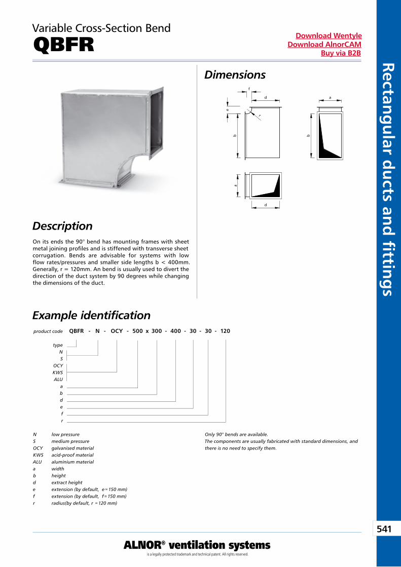
541
ALNOR® ventilation systemsis a legally protected trademark and technical patent. All rights reserved.
Rectang
ular d
ucts an
d fi ttin
gs
Download WentyleDownload AlnorCAM
Buy via B2B
Variable Cross-Section Bend
QBFRDimensions
DescriptionOn its ends the 90° bend has mounting frames with sheet metal joining profiles and is stiffened with transverse sheet corrugation. Bends are advisable for systems with low flow rates/pressures and smaller side lengths b < 400mm. Generally, r = 120mm. An bend is usually used to divert the direction of the duct system by 90 degrees while changing the dimensions of the duct.
product code QBFR - N - OCY - 500 x 300 - 400 - 30 - 30 - 120
typeNS
OCYKWSALU
abdefr
Example identification
N low pressureS medium pressureOCY galvanised materialKWS acid-proof materialALU aluminium materiala widthb heightd extract heighte extension (by default, e = 150 mm)f extension (by default, f = 150 mm)r radius(by default, r = 120 mm)
Only 90° bends are available.The components are usually fabricated with standard dimensions, and there is no need to specify them.
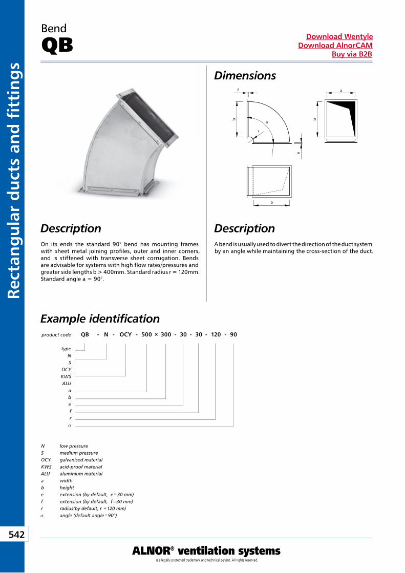
Kan
ały
i ksz
tałt
ki p
rost
oką
tne
542
ALNOR® ventilation systemsis a legally protected trademark and technical patent. All rights reserved.
Rect
ang
ula
r d
uct
s an
d fi
tti
ng
sDownload Wentyle
Download AlnorCAMBuy via B2B
Bend
QBDimensions
product code QB - N - OCY - 500 × 300 - 30 - 30 - 120 - 90
typeNS
OCYKWSALU
abefr
a
Example identification
N low pressureS medium pressureOCY galvanised materialKWS acid-proof materialALU aluminium materiala widthb heighte extension (by default, e = 30 mm)f extension (by default, f = 30 mm)r radius(by default, r = 120 mm)a angle (default angle = 90°)
DescriptionOn its ends the standard 90° bend has mounting frames with sheet metal joining profiles, outer and inner corners, and is stiffened with transverse sheet corrugation. Bends are advisable for systems with high flow rates/pressures and greater side lengths b > 400mm. Standard radius r = 120mm. Standard angle a = 90°.
A bend is usually used to divert the direction of the duct system by an angle while maintaining the cross-section of the duct.
Description
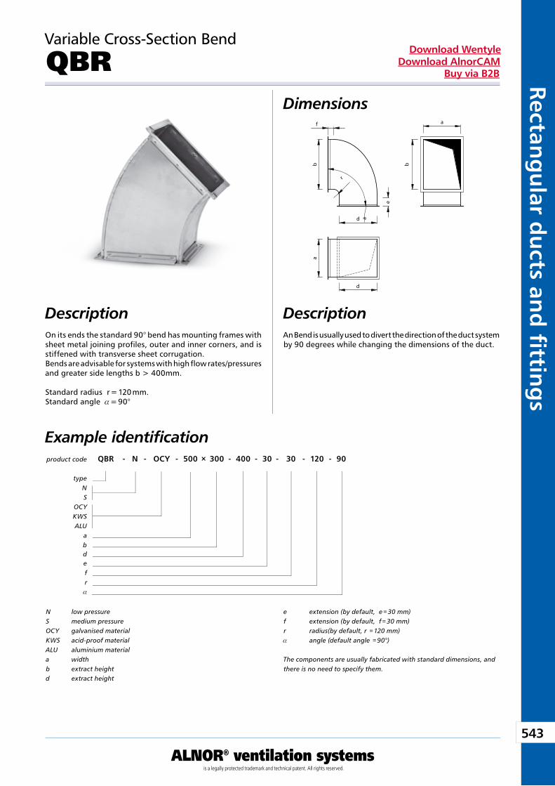
543
ALNOR® ventilation systemsis a legally protected trademark and technical patent. All rights reserved.
Rectang
ular d
ucts an
d fi ttin
gs
Download WentyleDownload AlnorCAM
Buy via B2B
Variable Cross-Section Bend
QBRDimensions
Description
product code QBR - N - OCY - 500 × 300 - 400 - 30 - 30 - 120 - 90
typeNS
OCYKWSALU
abdefr
a
Example identification
N low pressureS medium pressureOCY galvanised materialKWS acid-proof materialALU aluminium materiala widthb extract heightd extract height
e extension (by default, e = 30 mm)f extension (by default, f = 30 mm)r radius(by default, r = 120 mm)a angle (default angle = 90°)
The components are usually fabricated with standard dimensions, and there is no need to specify them.
On its ends the standard 90° bend has mounting frames with sheet metal joining profiles, outer and inner corners, and is stiffened with transverse sheet corrugation. Bends are advisable for systems with high flow rates/pressures and greater side lengths b > 400mm.
Standard radius r = 120 mm.Standard angle a = 90°
An Bend is usually used to divert the direction of the duct system by 90 degrees while changing the dimensions of the duct.
Description
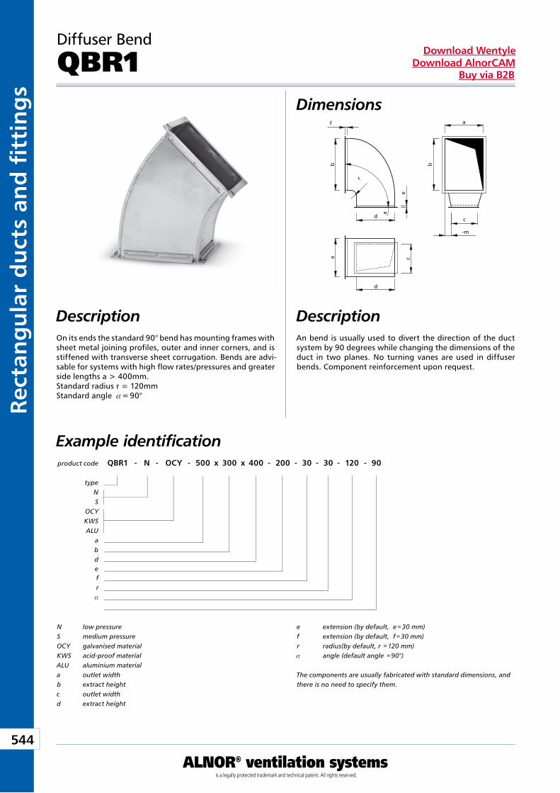
Kan
ały
i ksz
tałt
ki p
rost
oką
tne
544
ALNOR® ventilation systemsis a legally protected trademark and technical patent. All rights reserved.
Rect
ang
ula
r d
uct
s an
d fi
tti
ng
sDownload Wentyle
Download AlnorCAMBuy via B2B
Diffuser Bend
QBR1Dimensions
DescriptionOn its ends the standard 90° bend has mounting frames with sheet metal joining profiles, outer and inner corners, and is stiffened with transverse sheet corrugation. Bends are advi-sable for systems with high flow rates/pressures and greater side lengths a > 400mm.Standard radius r = 120mmStandard angle a = 90°
An bend is usually used to divert the direction of the duct system by 90 degrees while changing the dimensions of the duct in two planes. No turning vanes are used in diffuser bends. Component reinforcement upon request.
product code QBR1 - N - OCY - 500 x 300 x 400 - 200 - 30 - 30 - 120 - 90
typeNS
OCYKWSALU
abdefr
a
Example identification
N low pressureS medium pressureOCY galvanised materialKWS acid-proof materialALU aluminium materiala outlet widthb extract heightc outlet widthd extract height
e extension (by default, e = 30 mm)f extension (by default, f = 30 mm)r radius(by default, r = 120 mm)a angle (default angle = 90°)
The components are usually fabricated with standard dimensions, and there is no need to specify them.
Description
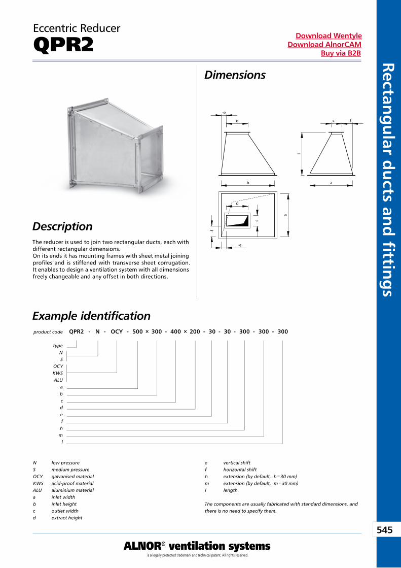
545
ALNOR® ventilation systemsis a legally protected trademark and technical patent. All rights reserved.
Rectang
ular d
ucts an
d fi ttin
gs
Download WentyleDownload AlnorCAM
Buy via B2B
Eccentric Reducer
QPR2Dimensions
DescriptionThe reducer is used to join two rectangular ducts, each with different rectangular dimensions.On its ends it has mounting frames with sheet metal joining profiles and is stiffened with transverse sheet corrugation. It enables to design a ventilation system with all dimensions freely changeable and any offset in both directions.
product code QPR2 - N - OCY - 500 × 300 - 400 × 200 - 30 - 30 - 300 - 300 - 300
typeNS
OCYKWSALU
abcdefhm
l
Example identification
N low pressureS medium pressureOCY galvanised materialKWS acid-proof materialALU aluminium materiala inlet widthb inlet heightc outlet widthd extract height
e vertical shiftf horizontal shifth extension (by default, h = 30 mm)m extension (by default, m = 30 mm)l length
The components are usually fabricated with standard dimensions, and there is no need to specify them.
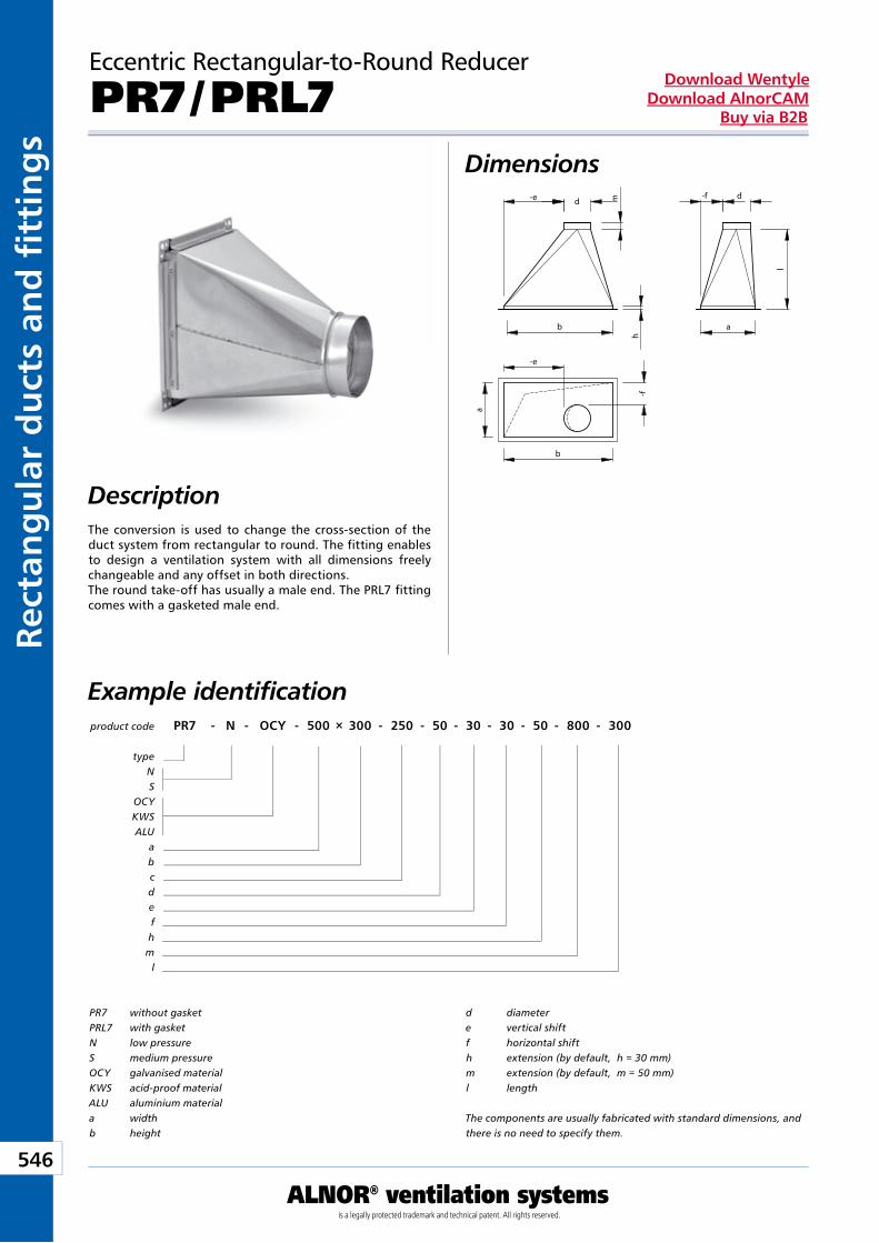
Kan
ały
i ksz
tałt
ki p
rost
oką
tne
546
ALNOR® ventilation systemsis a legally protected trademark and technical patent. All rights reserved.
Rect
ang
ula
r d
uct
s an
d fi
tti
ng
sDownload Wentyle
Download AlnorCAMBuy via B2B
Eccentric Rectangular-to-Round Reducer
PR7 / PRL7Dimensions
DescriptionThe conversion is used to change the cross-section of the duct system from rectangular to round. The fitting enables to design a ventilation system with all dimensions freely changeable and any offset in both directions.The round take-off has usually a male end. The PRL7 fitting comes with a gasketed male end.
product code PR7 - N - OCY - 500 × 300 - 250 - 50 - 30 - 30 - 50 - 800 - 300
typeNS
OCYKWSALU
abcdefhm
l
Example identification
PR7 without gasketPRL7 with gasketN low pressureS medium pressureOCY galvanised materialKWS acid-proof materialALU aluminium materiala widthb height
d diametere vertical shiftf horizontal shifth extension (by default, h = 30 mm)m extension (by default, m = 50 mm)l length
The components are usually fabricated with standard dimensions, and there is no need to specify them.
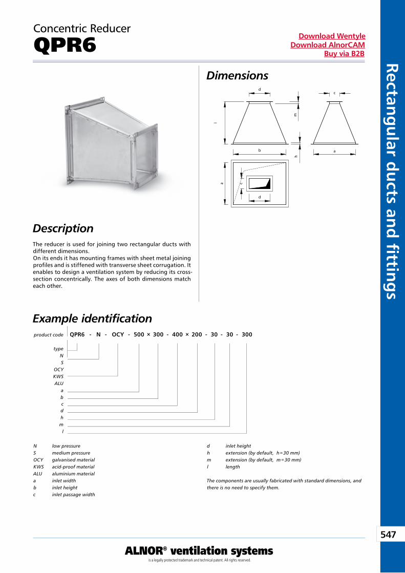
547
ALNOR® ventilation systemsis a legally protected trademark and technical patent. All rights reserved.
Rectang
ular d
ucts an
d fi ttin
gs
Download WentyleDownload AlnorCAM
Buy via B2B
Concentric Reducer
QPR6Dimensions
DescriptionThe reducer is used for joining two rectangular ducts with different dimensions.On its ends it has mounting frames with sheet metal joining profiles and is stiffened with transverse sheet corrugation. It enables to design a ventilation system by reducing its cross-section concentrically. The axes of both dimensions match each other.
product code QPR6 - N - OCY - 500 × 300 - 400 × 200 - 30 - 30 - 300
typeNS
OCYKWSALU
abcdhm
l
Example identification
N low pressureS medium pressureOCY galvanised materialKWS acid-proof materialALU aluminium materiala inlet widthb inlet heightc inlet passage width
d inlet heighth extension (by default, h = 30 mm)m extension (by default, m = 30 mm)l length
The components are usually fabricated with standard dimensions, and there is no need to specify them.
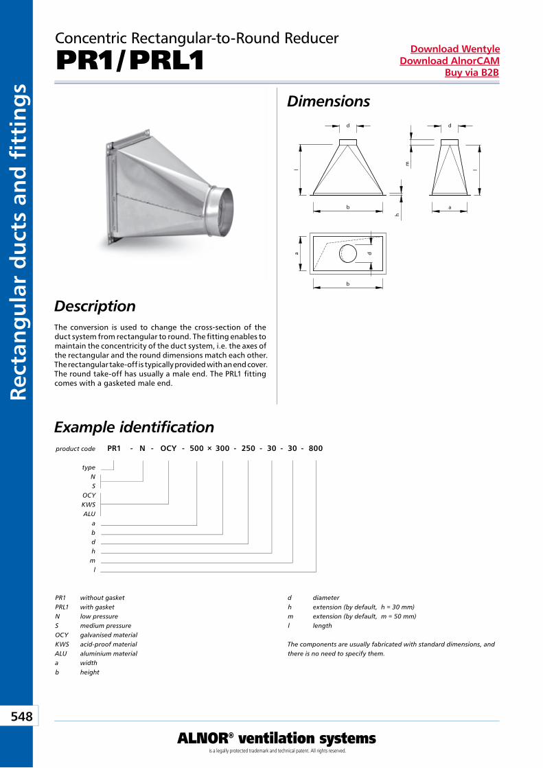
Kan
ały
i ksz
tałt
ki p
rost
oką
tne
548
ALNOR® ventilation systemsis a legally protected trademark and technical patent. All rights reserved.
Rect
ang
ula
r d
uct
s an
d fi
tti
ng
sDownload Wentyle
Download AlnorCAMBuy via B2B
Concentric Rectangular-to-Round Reducer
PR1 / PRL1Dimensions
DescriptionThe conversion is used to change the cross-section of the duct system from rectangular to round. The fitting enables to maintain the concentricity of the duct system, i.e. the axes of the rectangular and the round dimensions match each other. The rectangular take-off is typically provided with an end cover.The round take-off has usually a male end. The PRL1 fitting comes with a gasketed male end.
product code PR1 - N - OCY - 500 × 300 - 250 - 30 - 30 - 800
typeNS
OCYKWSALU
abdhm
l
Example identification
PR1 without gasketPRL1 with gasketN low pressureS medium pressureOCY galvanised materialKWS acid-proof materialALU aluminium materiala widthb height
d diameterh extension (by default, h = 30 mm)m extension (by default, m = 50 mm)l length
The components are usually fabricated with standard dimensions, and there is no need to specify them.
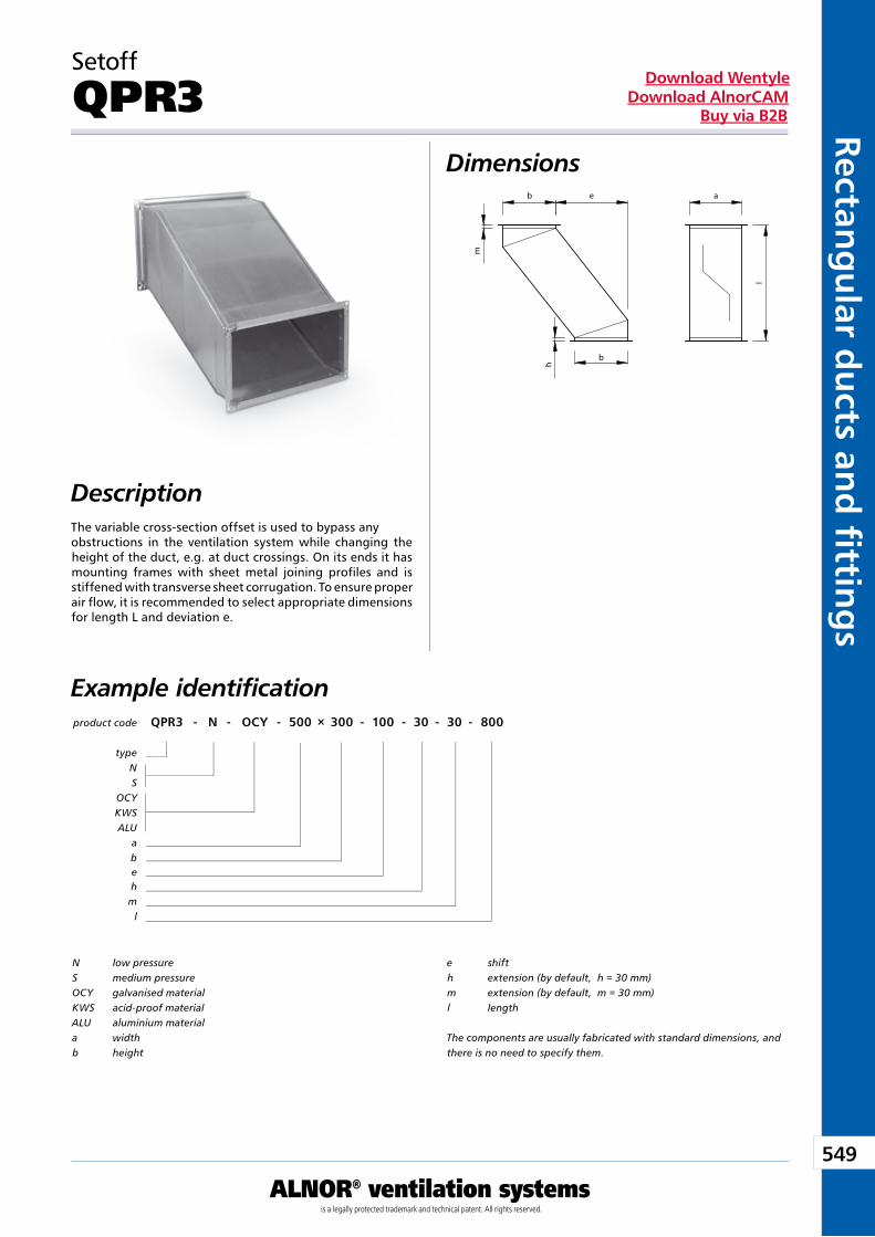
549
ALNOR® ventilation systemsis a legally protected trademark and technical patent. All rights reserved.
Rectang
ular d
ucts an
d fi ttin
gs
Download WentyleDownload AlnorCAM
Buy via B2B
Setoff
QPR3Dimensions
DescriptionThe variable cross-section offset is used to bypass any obstructions in the ventilation system while changing the height of the duct, e.g. at duct crossings. On its ends it has mounting frames with sheet metal joining profiles and is stiffened with transverse sheet corrugation. To ensure proper air flow, it is recommended to select appropriate dimensions for length L and deviation e.
product code QPR3 - N - OCY - 500 × 300 - 100 - 30 - 30 - 800
typeNS
OCYKWSALU
abehm
l
Example identification
N low pressureS medium pressureOCY galvanised materialKWS acid-proof materialALU aluminium materiala widthb height
e shift h extension (by default, h = 30 mm)m extension (by default, m = 30 mm)l length
The components are usually fabricated with standard dimensions, and there is no need to specify them.
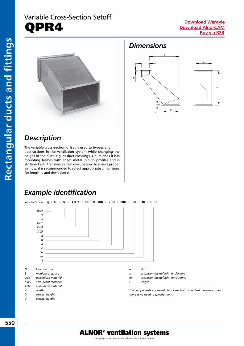
Kan
ały
i ksz
tałt
ki p
rost
oką
tne
550
ALNOR® ventilation systemsis a legally protected trademark and technical patent. All rights reserved.
Rect
ang
ula
r d
uct
s an
d fi
tti
ng
sDownload Wentyle
Download AlnorCAMBuy via B2B
Variable Cross-Section Setoff
QPR4Dimensions
DescriptionThe variable cross-section offset is used to bypass any obstructions in the ventilation system while changing the height of the duct, e.g. at duct crossings. On its ends it has mounting frames with sheet metal joining profiles and is stiffened with transverse sheet corrugation. To ensure proper air flow, it is recommended to select appropriate dimensions for length L and deviation e.
product code QPR4 - N - OCY - 500 × 300 - 200 - 100 - 30 - 30 - 800
typeNS
OCYKWSALU
abdehm
l
Example identification
N low pressureS medium pressureOCY galvanised materialKWS acid-proof materialALU aluminium materiala widthb extract heightd extract height
e shifth extension (by default, h = 30 mm)m extension (by default, m = 30 mm)l length
The components are usually fabricated with standard dimensions, and there is no need to specify them.
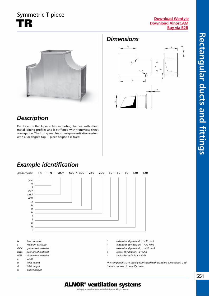
551
ALNOR® ventilation systemsis a legally protected trademark and technical patent. All rights reserved.
Rectang
ular d
ucts an
d fi ttin
gs
Download WentyleDownload AlnorCAM
Buy via B2B
Symmetric T-piece
TRDimensions
DescriptionOn its ends the T-piece has mounting frames with sheet metal joining profiles and is stiffened with transverse sheet corrugation. The fitting enables to design a ventilation system with a 90 degree tap. T-piece height a is fixed.
product code TR - N - OCY - 500 × 300 - 250 - 200 - 30 - 30 - 30 - 120 - 120
typeNS
OCYKWSALU
abdhij
pqr
Example identification
N low pressureS medium pressureOCY galvanised materialKWS acid-proof materialALU aluminium materiala widthb inlet heightd inlet heighth outlet height
i extension (by default, i = 30 mm)j extension (by default, j = 30 mm)p extension (by default, p = 30 mm)q radius (by default, q = 120)r radius(by default, r = 120)
The components are usually fabricated with standard dimensions, and there is no need to specify them.
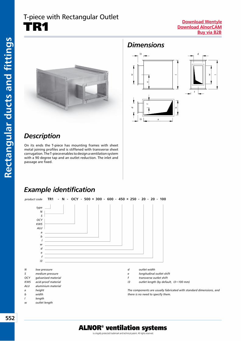
Kan
ały
i ksz
tałt
ki p
rost
oką
tne
552
ALNOR® ventilation systemsis a legally protected trademark and technical patent. All rights reserved.
Rect
ang
ula
r d
uct
s an
d fi
tti
ng
sDownload Wentyle
Download AlnorCAMBuy via B2B
T-piece with Rectangular Outlet
TR1Dimensions
Description
product code TR1 - N - OCY - 500 × 300 - 600 - 450 × 250 - 20 - 20 - 100
typeNS
OCYKWSALU
abl
wdef
I3
Example identification
N low pressureS medium pressureOCY galvanised materialKWS acid-proof materialALU aluminium materiala heightb widthl lengthw outlet length
d outlet widthe longitudinal outlet shiftf transverse outlet shiftI3 outlet length (by default, I3 = 100 mm)
The components are usually fabricated with standard dimensions, and there is no need to specify them.
On its ends the T-piece has mounting frames with sheet metal joining profiles and is stiffened with transverse sheet corrugation. The T-piece enables to design a ventilation system with a 90 degree tap and an outlet reduction. The inlet and passage are fixed.
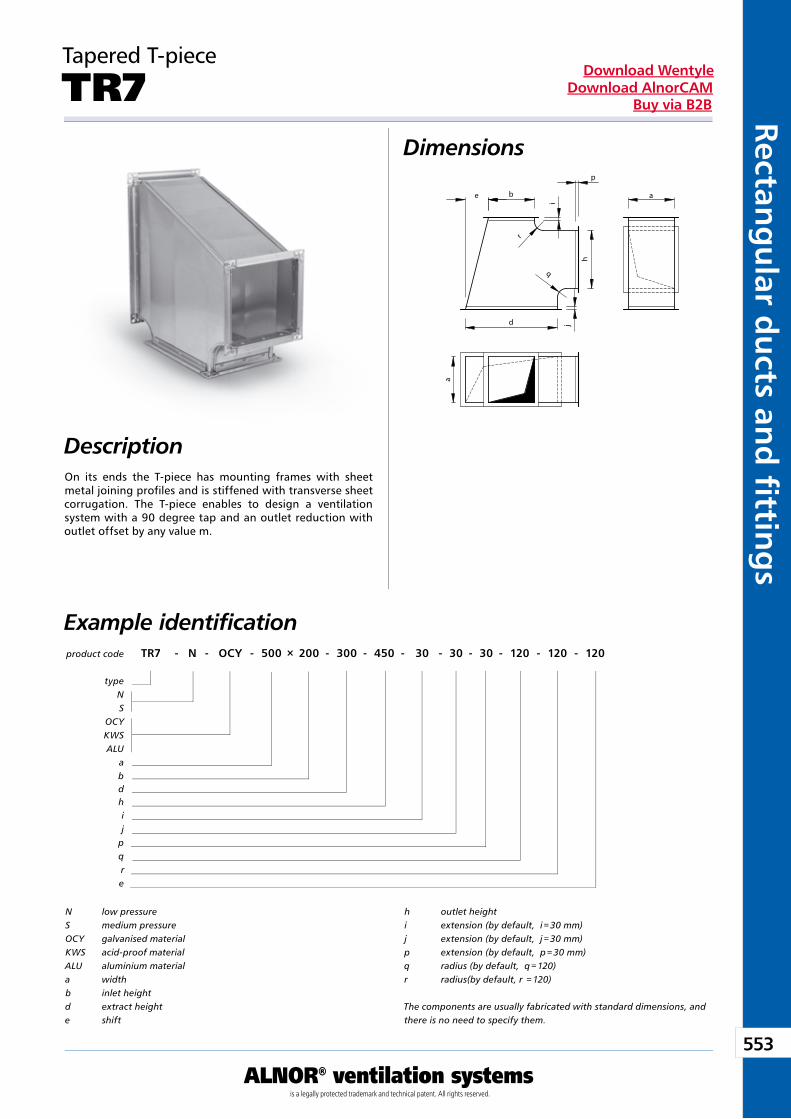
553
ALNOR® ventilation systemsis a legally protected trademark and technical patent. All rights reserved.
Rectang
ular d
ucts an
d fi ttin
gs
Download WentyleDownload AlnorCAM
Buy via B2B
Tapered T-piece
TR7Dimensions
DescriptionOn its ends the T-piece has mounting frames with sheet metal joining profiles and is stiffened with transverse sheet corrugation. The T-piece enables to design a ventilation system with a 90 degree tap and an outlet reduction with outlet offset by any value m.
product code TR7 - N - OCY - 500 × 200 - 300 - 450 - 30 - 30 - 30 - 120 - 120 - 120
typeNS
OCYKWSALU
abdhij
pqre
Example identification
N low pressureS medium pressureOCY galvanised materialKWS acid-proof materialALU aluminium materiala widthb inlet heightd extract heighte shift
h outlet heighti extension (by default, i = 30 mm)j extension (by default, j = 30 mm)p extension (by default, p = 30 mm)q radius (by default, q = 120)r radius(by default, r = 120)
The components are usually fabricated with standard dimensions, and there is no need to specify them.
q
h
j
e
d
a
b
r
a
i
p
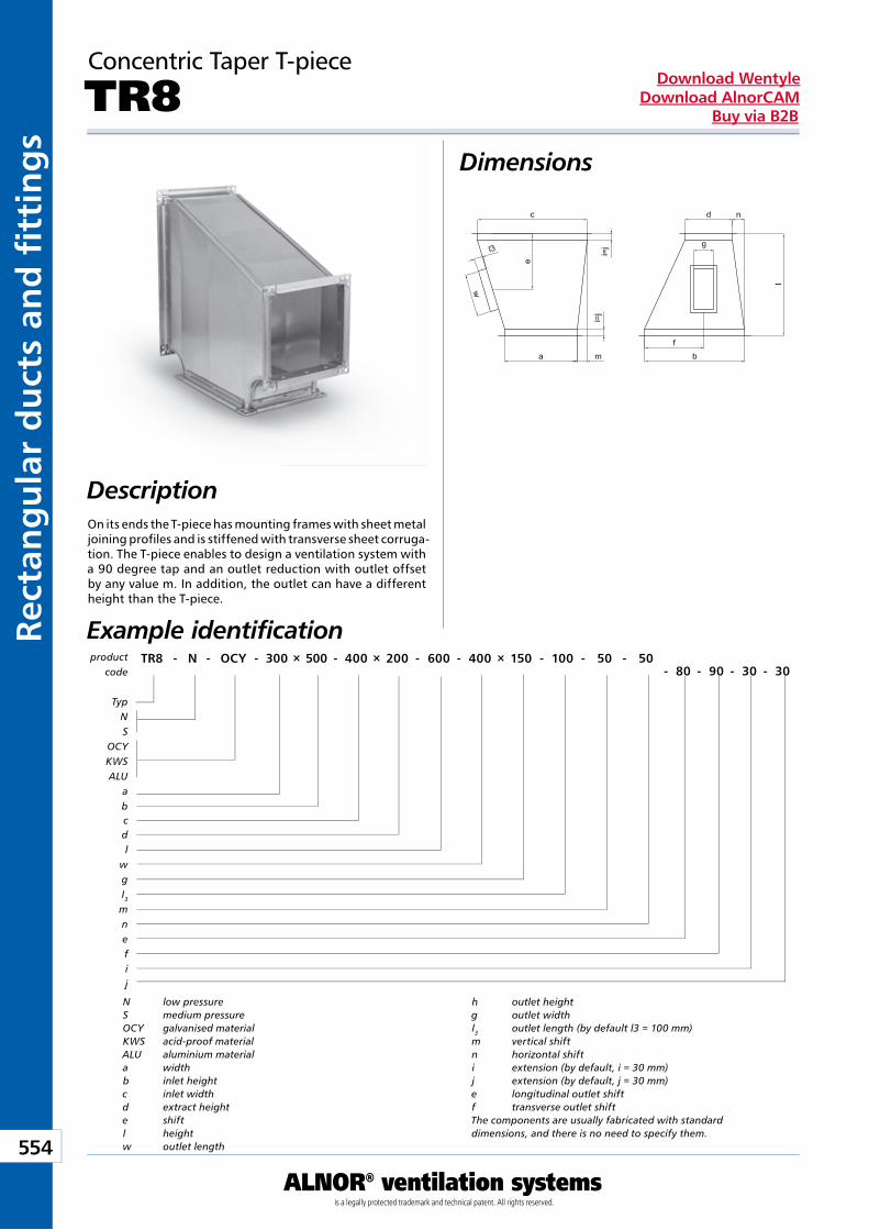
Kan
ały
i ksz
tałt
ki p
rost
oką
tne
554
ALNOR® ventilation systemsis a legally protected trademark and technical patent. All rights reserved.
Rect
ang
ula
r d
uct
s an
d fi
tti
ng
sDownload Wentyle
Download AlnorCAMBuy via B2B
Concentric Taper T-piece
TR8Dimensions
DescriptionOn its ends the T-piece has mounting frames with sheet metal joining profiles and is stiffened with transverse sheet corruga-tion. The T-piece enables to design a ventilation system with a 90 degree tap and an outlet reduction with outlet offset by any value m. In addition, the outlet can have a different height than the T-piece.
Example identification
N low pressureS medium pressureOCY galvanised materialKWS acid-proof materialALU aluminium materiala widthb inlet heightc inlet widthd extract heighte shiftl heightw outlet length
h outlet heightg outlet widthl3 outlet length (by default l3 = 100 mm)m vertical shiftn horizontal shifti extension (by default, i = 30 mm)j extension (by default, j = 30 mm)e longitudinal outlet shiftf transverse outlet shiftThe components are usually fabricated with standard dimensions, and there is no need to specify them.
product code
TR8 - N - OCY - 300 × 500 - 400 × 200 - 600 - 400 × 150 - 100 - 50 - 50- 80 - 90 - 30 - 30
TypNS
OCYKWSALU
abcdl
wgI3mnefij
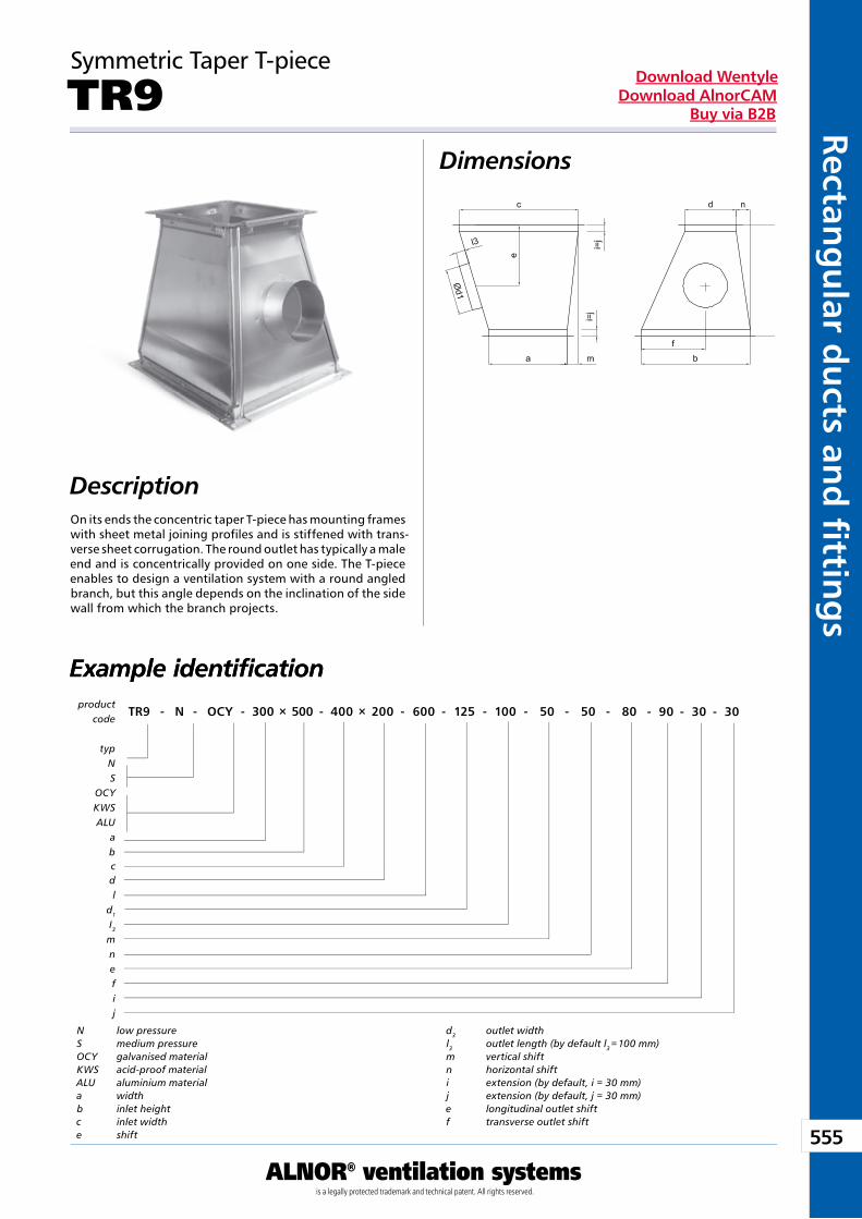
555
ALNOR® ventilation systemsis a legally protected trademark and technical patent. All rights reserved.
Rectang
ular d
ucts an
d fi ttin
gs
Download WentyleDownload AlnorCAM
Buy via B2B
Symmetric Taper T-piece
TR9Dimensions
DescriptionOn its ends the concentric taper T-piece has mounting frames with sheet metal joining profiles and is stiffened with trans-verse sheet corrugation. The round outlet has typically a male end and is concentrically provided on one side. The T-piece enables to design a ventilation system with a round angled branch, but this angle depends on the inclination of the side wall from which the branch projects.
Example identificationExample identification
N low pressureS medium pressureOCY galvanised materialKWS acid-proof materialALU aluminium materiala widthb inlet heightc inlet widthe shift
d3 outlet widthl3 outlet length (by default l3 = 100 mm)m vertical shiftn horizontal shifti extension (by default, i = 30 mm)j extension (by default, j = 30 mm)e longitudinal outlet shiftf transverse outlet shift
product code
TR9 - N - OCY - 300 × 500 - 400 × 200 - 600 - 125 - 100 - 50 - 50 - 80 - 90 - 30 - 30
typNS
OCYKWSALU
abcdl
d1
I3mnefij
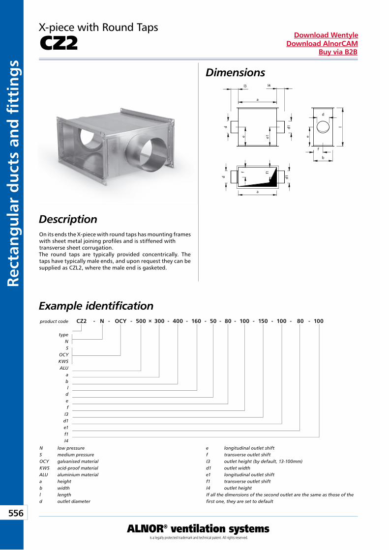
Kan
ały
i ksz
tałt
ki p
rost
oką
tne
556
ALNOR® ventilation systemsis a legally protected trademark and technical patent. All rights reserved.
Rect
ang
ula
r d
uct
s an
d fi
tti
ng
sDownload Wentyle
Download AlnorCAMBuy via B2B
X-piece with Round Taps
CZ2Dimensions
DescriptionOn its ends the X-piece with round taps has mounting frames with sheet metal joining profiles and is stiffened with transverse sheet corrugation.The round taps are typically provided concentrically. The taps have typically male ends, and upon request they can be supplied as CZL2, where the male end is gasketed.
Example identificationproduct code CZ2 - N - OCY - 500 × 300 - 400 - 160 - 50 - 80 - 100 - 150 - 100 - 80 - 100
typeNS
OCYKWSALU
abl
def
I3d1e1f1I4
N low pressureS medium pressureOCY galvanised materialKWS acid-proof materialALU aluminium materiala heightb widthl lengthd outlet diameter
e longitudinal outlet shiftf transverse outlet shiftI3 outlet height (by default, 13-100mm)d1 outlet widthe1 longitudinal outlet shiftf1 transverse outlet shiftI4 outlet heightIf all the dimensions of the second outlet are the same as those of the first one, they are set to default
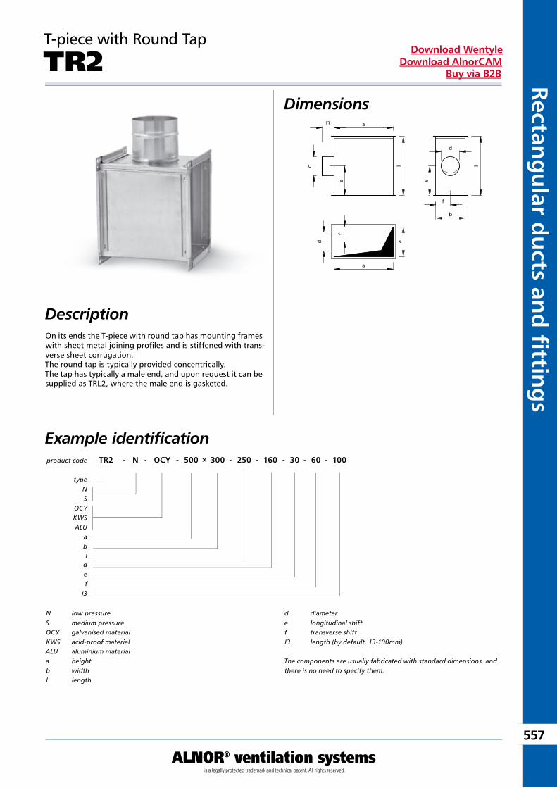
557
ALNOR® ventilation systemsis a legally protected trademark and technical patent. All rights reserved.
Rectang
ular d
ucts an
d fi ttin
gs
Download WentyleDownload AlnorCAM
Buy via B2B
T-piece with Round Tap
TR2Dimensions
DescriptionOn its ends the T-piece with round tap has mounting frames with sheet metal joining profiles and is stiffened with trans-verse sheet corrugation.The round tap is typically provided concentrically. The tap has typically a male end, and upon request it can be supplied as TRL2, where the male end is gasketed.
Example identificationproduct code TR2 - N - OCY - 500 × 300 - 250 - 160 - 30 - 60 - 100
typeNS
OCYKWSALU
abl
def
I3
N low pressureS medium pressureOCY galvanised materialKWS acid-proof materialALU aluminium materiala heightb widthl length
d diametere longitudinal shiftf transverse shiftI3 length (by default, 13-100mm)
The components are usually fabricated with standard dimensions, and there is no need to specify them.
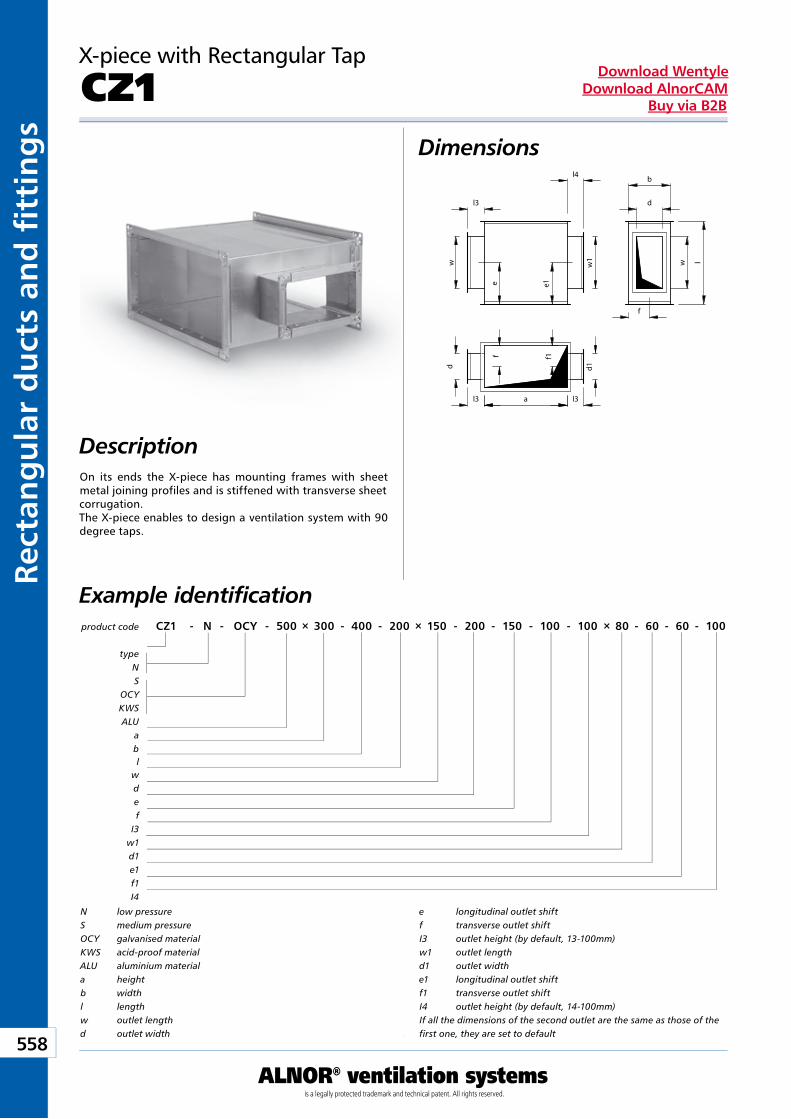
Kan
ały
i ksz
tałt
ki p
rost
oką
tne
558
ALNOR® ventilation systemsis a legally protected trademark and technical patent. All rights reserved.
Rect
ang
ula
r d
uct
s an
d fi
tti
ng
sDownload Wentyle
Download AlnorCAMBuy via B2B
X-piece with Rectangular Tap
CZ1Dimensions
DescriptionOn its ends the X-piece has mounting frames with sheet metal joining profiles and is stiffened with transverse sheet corrugation. The X-piece enables to design a ventilation system with 90 degree taps.
Example identificationproduct code CZ1 - N - OCY - 500 × 300 - 400 - 200 × 150 - 200 - 150 - 100 - 100 × 80 - 60 - 60 - 100
typeNS
OCYKWSALU
abl
wdef
I3w1d1e1f1I4
N low pressureS medium pressureOCY galvanised materialKWS acid-proof materialALU aluminium materiala heightb widthl lengthw outlet lengthd outlet width
e longitudinal outlet shiftf transverse outlet shiftI3 outlet height (by default, 13-100mm)w1 outlet lengthd1 outlet widthe1 longitudinal outlet shiftf1 transverse outlet shiftI4 outlet height (by default, 14-100mm)If all the dimensions of the second outlet are the same as those of the first one, they are set to default
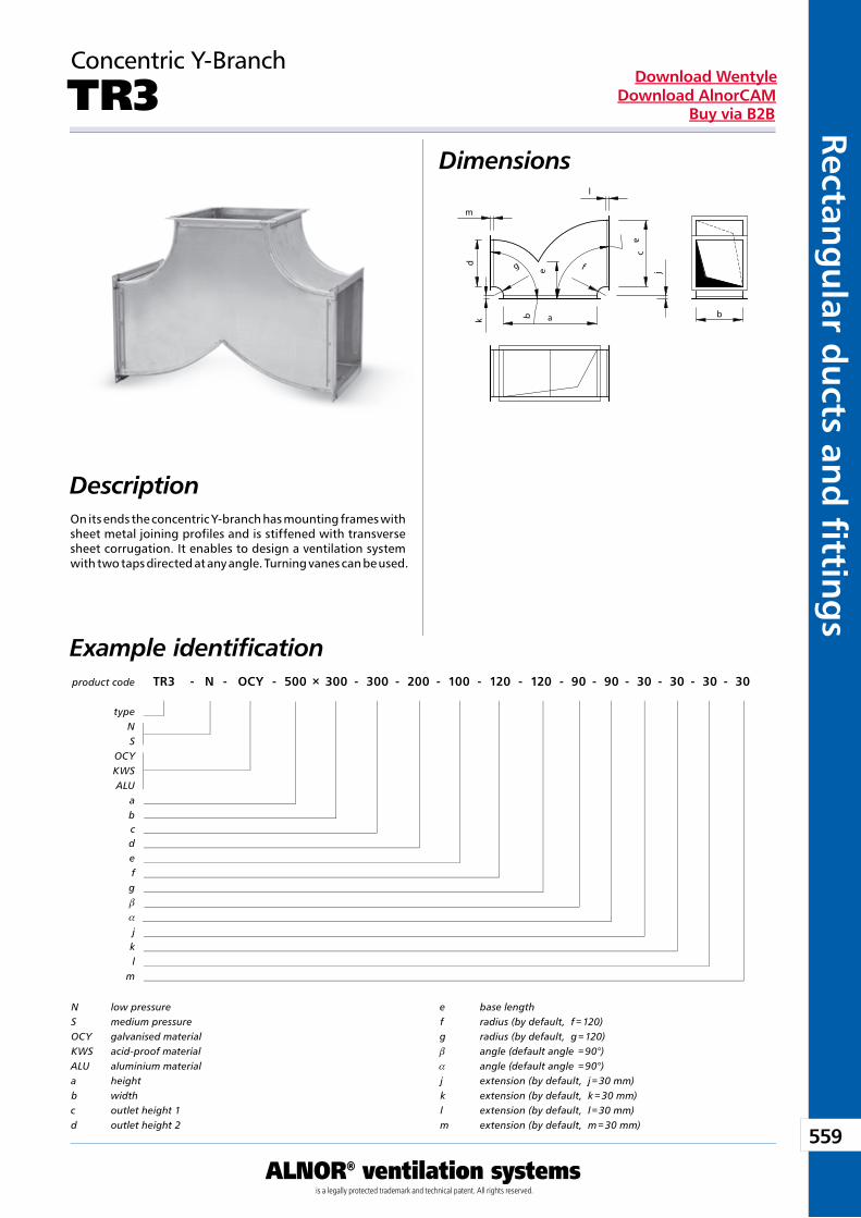
559
ALNOR® ventilation systemsis a legally protected trademark and technical patent. All rights reserved.
Rectang
ular d
ucts an
d fi ttin
gs
Download WentyleDownload AlnorCAM
Buy via B2B
Concentric Y-Branch
TR3Dimensions
DescriptionOn its ends the concentric Y-branch has mounting frames with sheet metal joining profiles and is stiffened with transverse sheet corrugation. It enables to design a ventilation system with two taps directed at any angle. Turning vanes can be used.
Example identificationproduct code TR3 - N - OCY - 500 × 300 - 300 - 200 - 100 - 120 - 120 - 90 - 90 - 30 - 30 - 30 - 30
typeNS
OCYKWSALU
abcdefgb
a
jkl
m
N low pressureS medium pressureOCY galvanised materialKWS acid-proof materialALU aluminium materiala heightb widthc outlet height 1d outlet height 2
e base lengthf radius (by default, f = 120)g radius (by default, g = 120)b angle (default angle = 90°)a angle (default angle = 90°)j extension (by default, j = 30 mm)k extension (by default, k = 30 mm)l extension (by default, l = 30 mm)m extension (by default, m = 30 mm)
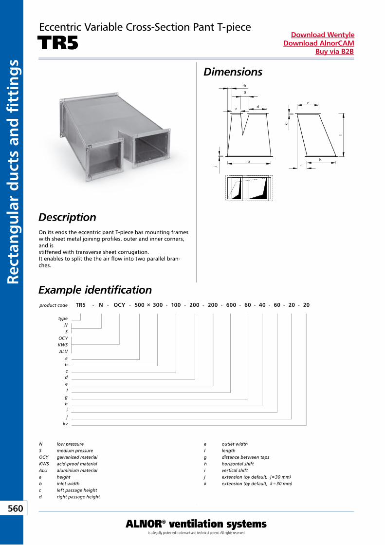
Kan
ały
i ksz
tałt
ki p
rost
oką
tne
560
ALNOR® ventilation systemsis a legally protected trademark and technical patent. All rights reserved.
Rect
ang
ula
r d
uct
s an
d fi
tti
ng
sDownload Wentyle
Download AlnorCAMBuy via B2B
Eccentric Variable Cross-Section Pant T-piece
TR5Dimensions
DescriptionOn its ends the eccentric pant T-piece has mounting frames with sheet metal joining profiles, outer and inner corners, and is stiffened with transverse sheet corrugation. It enables to split the the air flow into two parallel bran-ches.
Example identificationproduct code TR5 - N - OCY - 500 × 300 - 100 - 200 - 200 - 600 - 60 - 40 - 60 - 20 - 20
typeNS
OCYKWSALU
abcdel
ghij
kv
N low pressureS medium pressureOCY galvanised materialKWS acid-proof materialALU aluminium materiala heightb inlet widthc left passage heightd right passage height
e outlet widthl lengthg distance between tapsh horizontal shifti vertical shiftj extension (by default, j = 30 mm)k extension (by default, k = 30 mm)
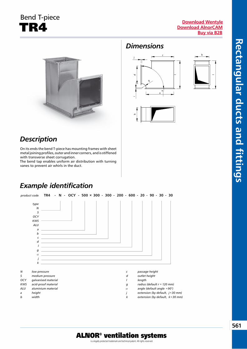
561
ALNOR® ventilation systemsis a legally protected trademark and technical patent. All rights reserved.
Rectang
ular d
ucts an
d fi ttin
gs
Download WentyleDownload AlnorCAM
Buy via B2B
Bend T-piece
TR4Dimensions
DescriptionOn its ends the bend T-piece has mounting frames with sheet metal joining profiles, outer and inner corners, and is stiffened with transverse sheet corrugation. The bend tap enables uniform air distribution with turning vanes to prevent air whirls in the duct.
Example identificationproduct code TR4 - N - OCY - 500 × 300 - 300 - 200 - 600 - 20 - 90 - 30 - 30
typeNS
OCYKWSALU
abcdl
ga
jk
N low pressureS medium pressureOCY galvanised materialKWS acid-proof materialALU aluminium materiala heightb width
c passage heightd outlet heightl lengthg radius (default r = 120 mm)a angle (default angle = 90°) j extension (by default, j = 30 mm)k extension (by default, k = 30 mm)
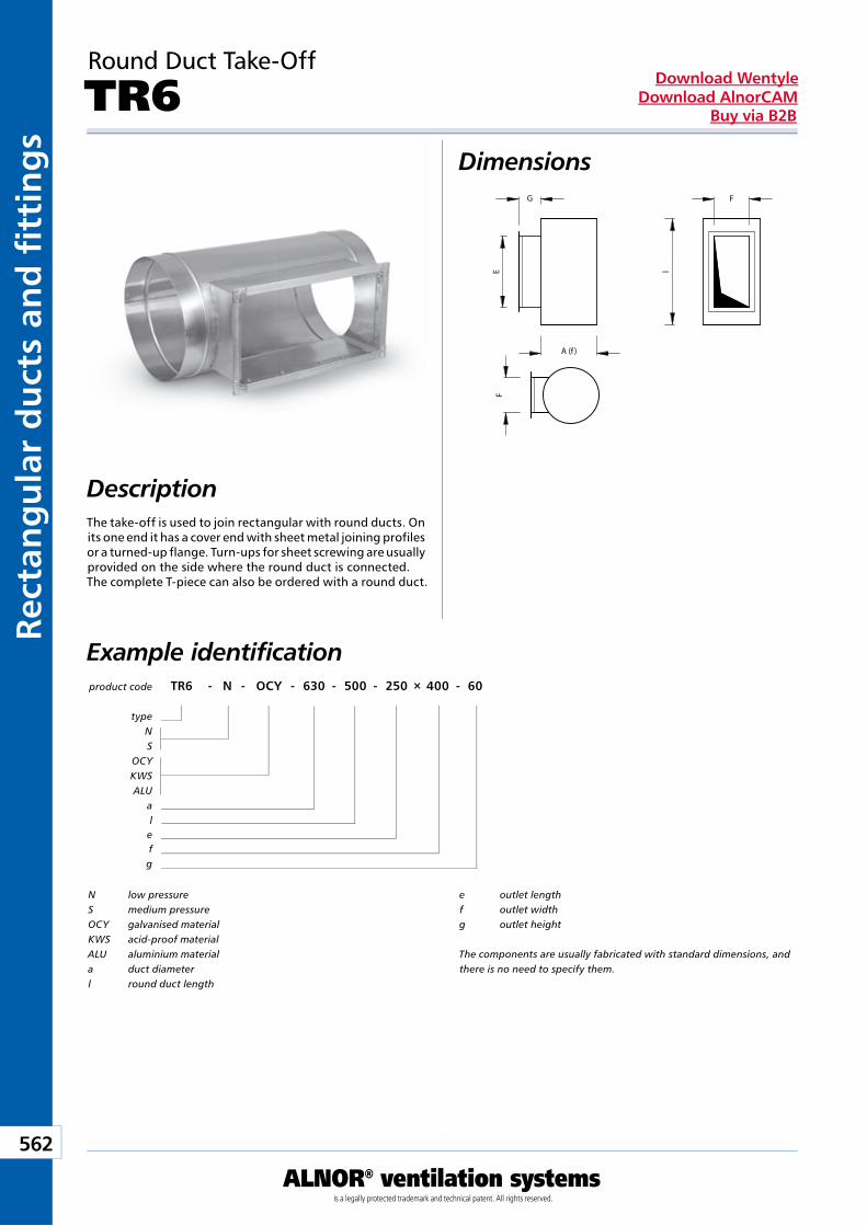
Kan
ały
i ksz
tałt
ki p
rost
oką
tne
562
ALNOR® ventilation systemsis a legally protected trademark and technical patent. All rights reserved.
Rect
ang
ula
r d
uct
s an
d fi
tti
ng
sDownload Wentyle
Download AlnorCAMBuy via B2B
Round Duct Take-Off
TR6Dimensions
DescriptionThe take-off is used to join rectangular with round ducts. On its one end it has a cover end with sheet metal joining profiles or a turned-up flange. Turn-ups for sheet screwing are usually provided on the side where the round duct is connected. The complete T-piece can also be ordered with a round duct.
Example identificationproduct code TR6 - N - OCY - 630 - 500 - 250 × 400 - 60
typeNS
OCYKWSALU
alefg
N low pressureS medium pressureOCY galvanised materialKWS acid-proof materialALU aluminium materiala duct diameterl round duct length
e outlet lengthf outlet widthg outlet height
The components are usually fabricated with standard dimensions, and there is no need to specify them.
lE
G F
A (f )
F
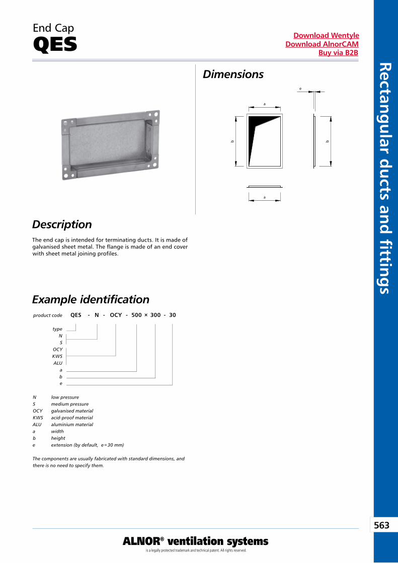
563
ALNOR® ventilation systemsis a legally protected trademark and technical patent. All rights reserved.
Rectang
ular d
ucts an
d fi ttin
gs
Download WentyleDownload AlnorCAM
Buy via B2B
End Cap
QES Dimensions
DescriptionThe end cap is intended for terminating ducts. It is made of galvanised sheet metal. The flange is made of an end cover with sheet metal joining profiles.
Example identification
N low pressureS medium pressureOCY galvanised materialKWS acid-proof materialALU aluminium materiala widthb heighte extension (by default, e = 30 mm)
The components are usually fabricated with standard dimensions, and there is no need to specify them.
product code QES - N - OCY - 500 × 300 - 30
typeNS
OCYKWSALU
abe
Pre-insulated ducts and fittingsIZOL®system
We reserve the right to make changes in the dimensions and technical data products due to their continuous improvement
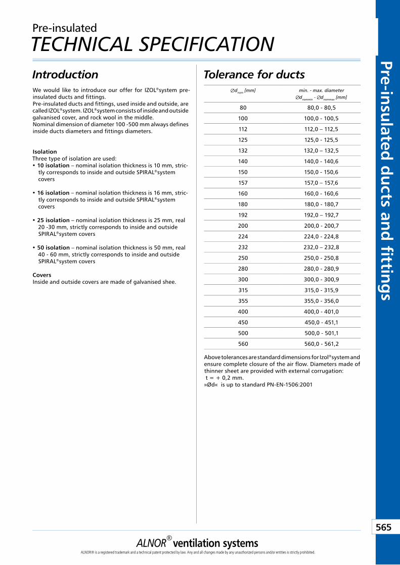
ALNOR® ventilation systemsALNOR® is a registered trademark and a technical patent protected by law. Any and all changes made by any unauthorized persons and/or entities is strictly prohibited.
565
Order in B2B
Download WentyleDownload AlnorCAM
Pre-insulated
du
cts and
fitting
s
Tolerance for ductsIntroductionWe would like to introduce our offer for IZOL®system pre-insulated ducts and fittings. Pre-insulated ducts and fittings, used inside and outside, are called IZOL®system. IZOL®system consists of inside and outside galvanised cover, and rock wool in the middle.Nominal dimension of diameter 100 -500 mm always defines inside ducts diameters and fittings diameters.
IsolationThree type of isolation are used:• 10 isolation – nominal isolation thickness is 10 mm, stric-
tly corresponds to inside and outside SPIRAL®system covers
• 16 isolation – nominal isolation thickness is 16 mm, stric-tly corresponds to inside and outside SPIRAL®system covers
• 25 isolation – nominal isolation thickness is 25 mm, real 20 -30 mm, strictly corresponds to inside and outside SPIRAL®system covers
• 50 isolation – nominal isolation thickness is 50 mm, real 40 - 60 mm, strictly corresponds to inside and outside SPIRAL®system covers
CoversInside and outside covers are made of galvanised shee.
Above tolerances are standard dimensions for Izol®system and ensure complete closure of the air flow. Diameters made of thinner sheet are provided with external corrugation: t = + 0,2 mm.»Ød« is up to standard PN-EN-1506:2001
Pre-insulated
TECHNICAL SPECIFICATION
Ædnom [mm] min. - max. diameterdnommin - dnommax [mm]
80 80,0 - 80,5
100 100,0 - 100,5
112 112,0 – 112,5
125 125,0 - 125,5
132 132,0 – 132,5
140 140,0 - 140,6
150 150,0 - 150,6
157 157,0 – 157,6
160 160,0 - 160,6
180 180,0 - 180,7
192 192,0 – 192,7
200 200,0 - 200,7
224 224,0 - 224,8
232 232,0 – 232,8
250 250,0 - 250,8
280 280,0 - 280,9
300 300,0 - 300,9
315 315,0 - 315,9
355 355,0 - 356,0
400 400,0 - 401,0
450 450,0 - 451,1
500 500,0 - 501,1
560 560,0 - 561,2
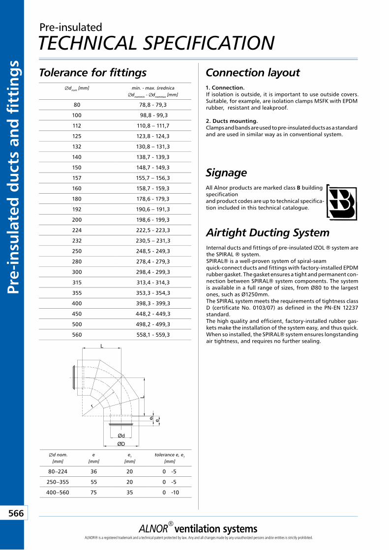
ALNOR® ventilation systemsALNOR® is a registered trademark and a technical patent protected by law. Any and all changes made by any unauthorized persons and/or entities is strictly prohibited.
566
Order in B2B
Download WentyleDownload AlnorCAM
Pre-
insu
late
d d
uct
s an
d f
itti
ng
s
Tolerance for fittingsÆdnom [mm] min. - max. średnica
dnommin - dnommax [mm]
80 78,8 - 79,3
100 98,8 - 99,3
112 110,8 – 111,7
125 123,8 - 124,3
132 130,8 – 131,3
140 138,7 - 139,3
150 148,7 - 149,3
157 155,7 – 156,3
160 158,7 - 159,3
180 178,6 - 179,3
192 190,6 – 191,3
200 198,6 - 199,3
224 222,5 - 223,3
232 230,5 – 231,3
250 248,5 - 249,3
280 278,4 - 279,3
300 298,4 - 299,3
315 313,4 - 314,3
355 353,3 - 354,3
400 398,3 - 399,3
450 448,2 - 449,3
500 498,2 - 499,3
560 558,1 - 559,3
Æd nom. [mm]
e [mm]
e1 [mm]
tolerance e, e1
[mm]
80–224 36 20 0 -5
250–355 55 20 0 -5
400–560 75 35 0 -10
Connection layout1. Connection.If isolation is outside, it is important to use outside covers. Suitable, for example, are isolation clamps MSFK with EPDM rubber, resistant and leakproof.
2. Ducts mounting.Clamps and bands are used to pre-insulated ducts as a standard and are used in similar way as in conventional system.
SignageAll Alnor products are marked class B building specificationand product codes are up to technical specifica-tion included in this technical catalogue.
Pre-insulated
TECHNICAL SPECIFICATION
ØdØD
L
L
r
ee 1
Airtight Ducting SystemInternal ducts and fittings of pre-insulated IZOL ® system are the SPIRAL ® system.SPIRAL® is a well-proven system of spiral-seam quick-connect ducts and fittings with factory-installed EPDM rubber gasket. The gasket ensures a tight and permanent con-nection between SPIRAL® system components. The system is available in a full range of sizes, from Ø80 to the largest ones, such as Ø1250mm.The SPIRAL system meets the requirements of tightness class D (certificate No. 0103/07) as defined in the PN-EN 12237 standard.The high quality and efficient, factory-installed rubber gas-kets make the installation of the system easy, and thus quick. When so installed, the SPIRAL® system ensures longstanding air tightness, and requires no further sealing.
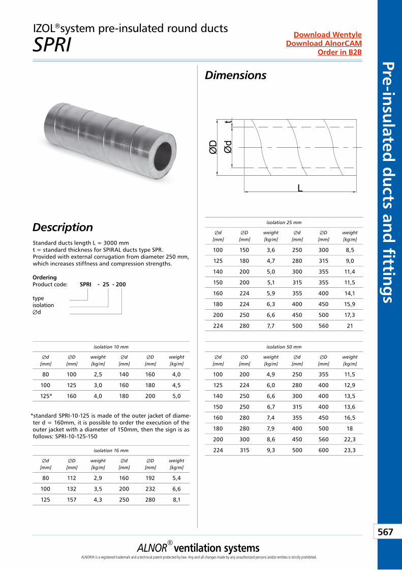
ALNOR® ventilation systemsALNOR® is a registered trademark and a technical patent protected by law. Any and all changes made by any unauthorized persons and/or entities is strictly prohibited.
567
Order in B2B
Download WentyleDownload AlnorCAM
Pre-insulated
du
cts and
fitting
sIZOL®system pre-insulated round ducts
SPRI Dimensions
DescriptionStandard ducts length L = 3000 mmt = standard thickness for SPIRAL ducts type SPR.Provided with external corrugation from diameter 250 mm,which increases stiffness and compression strengths.
ØD Ød
t
L
isolation 25 mm
Æd[mm]
ÆD[mm]
weight[kg/m]
Æd[mm]
ÆD[mm]
weight[kg/m]
100 150 3,6 250 300 8,5
125 180 4,7 280 315 9,0
140 200 5,0 300 355 11,4
150 200 5,1 315 355 11,5
160 224 5,9 355 400 14,1
180 224 6,3 400 450 15,9
200 250 6,6 450 500 17,3
224 280 7,7 500 560 21
isolation 50 mm
Æd[mm]
ÆD[mm]
weight[kg/m]
Æd[mm]
ÆD[mm]
weight[kg/m]
100 200 4,9 250 355 11,5
125 224 6,0 280 400 12,9
140 250 6,6 300 400 13,5
150 250 6,7 315 400 13,6
160 280 7,4 355 450 16,5
180 280 7,9 400 500 18
200 300 8,6 450 560 22,3
224 315 9,3 500 600 23,3isolation 16 mm
Æd[mm]
ÆD[mm]
weight[kg/m]
Æd[mm]
ÆD[mm]
weight[kg/m]
80 112 2,9 160 192 5,4
100 132 3,5 200 232 6,6
125 157 4,3 250 280 8,1
isolation 10 mm
Æd[mm]
ÆD[mm]
weight[kg/m]
Æd[mm]
ÆD[mm]
weight[kg/m]
80 100 2,5 140 160 4,0
100 125 3,0 160 180 4,5
125* 160 4,0 180 200 5,0
*standard SPRI-10-125 is made of the outer jacket of diame-ter d = 160mm, it is possible to order the execution of the outer jacket with a diameter of 150mm, then the sign is as follows: SPRI-10-125-150
OrderingProduct code: SPRI - 25 - 200
typeisolationÆd
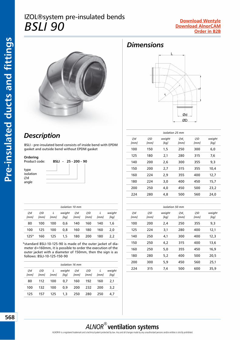
ALNOR® ventilation systemsALNOR® is a registered trademark and a technical patent protected by law. Any and all changes made by any unauthorized persons and/or entities is strictly prohibited.
568
Order in B2B
Download WentyleDownload AlnorCAM
Pre-
insu
late
d d
uct
s an
d f
itti
ng
sIZOL®system pre-insulated bends
BSLI 90 Dimensions
Description isolation 25 mm
Æd[mm]
ÆD[mm]
weight[kg]
Æd1
[mm]ÆD
[mm]weight
[kg]
100 150 1,5 250 300 6,0
125 180 2,1 280 315 7,6
140 200 2,6 300 355 9,3
150 200 2,7 315 355 10,4
160 224 2,9 355 400 12,7
180 224 3,0 400 450 15,7
200 250 4,0 450 500 23,2
224 280 4,8 500 560 24,0
isolation 50 mm
Æd[mm]
ÆD[mm]
weight[kg]
Æd1
[mm]ÆD
[mm]weight
[kg]
100 200 2,4 250 355 9,3
125 224 3,1 280 400 12,1
140 250 4,1 300 400 12,3
150 250 4,2 315 400 13,6
160 250 5,0 355 450 16,9
180 280 5,2 400 500 20,5
200 300 5,9 450 560 25,1
224 315 7,4 500 600 35,9isolation 16 mm
Æd[mm]
ÆD[mm]
L[mm]
weight[kg]
Æd[mm]
ÆD[mm]
L[mm]
weight[kg]
80 112 100 0,7 160 192 160 2,1
100 132 100 0,9 200 232 200 3,2
125 157 125 1,3 250 280 250 4,7
isolation 10 mm
Æd[mm]
ÆD[mm]
L[mm]
weight[kg]
Æd[mm]
ÆD[mm]
L[mm]
weight[kg]
80 100 100 0,6 140 160 140 1,6
100 125 100 0,8 160 180 160 2,0
125* 160 125 1,5 180 200 180 2,2
*standard BSLI-10-125-90 is made of the outer jacket of dia-meter d=160mm, it is possible to order the execution of the outer jacket with a diameter of 150mm, then the sign is as follows: BSLI-10-125-150-90
ØdØD
L
L
r
OrderingProduct code: BSLI - 25 - 200 - 90
typeisolationÆdangle
BSLI - pre-insulated bend consists of inside bend with EPDM gasket and outside bend without EPDM gasket
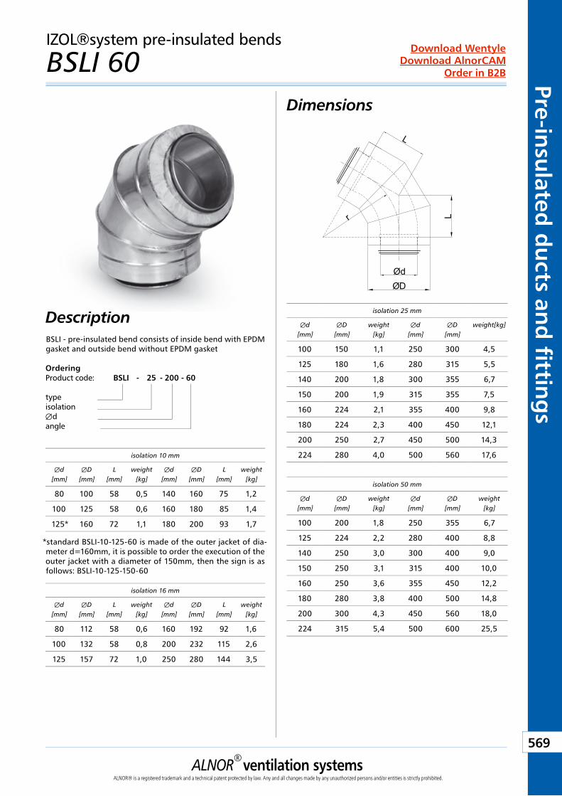
ALNOR® ventilation systemsALNOR® is a registered trademark and a technical patent protected by law. Any and all changes made by any unauthorized persons and/or entities is strictly prohibited.
569
Order in B2B
Download WentyleDownload AlnorCAM
Pre-insulated
du
cts and
fitting
sIZOL®system pre-insulated bends
BSLI 60 Dimensions
DescriptionDescription
ØdØD
r L
L
isolation 25 mm
Æd[mm]
ÆD[mm]
weight[kg]
Æd[mm]
ÆD[mm]
weight[kg]
100 150 1,1 250 300 4,5
125 180 1,6 280 315 5,5
140 200 1,8 300 355 6,7
150 200 1,9 315 355 7,5
160 224 2,1 355 400 9,8
180 224 2,3 400 450 12,1
200 250 2,7 450 500 14,3
224 280 4,0 500 560 17,6
isolation 50 mm
Æd[mm]
ÆD[mm]
weight[kg]
Æd[mm]
ÆD[mm]
weight[kg]
100 200 1,8 250 355 6,7
125 224 2,2 280 400 8,8
140 250 3,0 300 400 9,0
150 250 3,1 315 400 10,0
160 250 3,6 355 450 12,2
180 280 3,8 400 500 14,8
200 300 4,3 450 560 18,0
224 315 5,4 500 600 25,5
isolation 16 mm
Æd[mm]
ÆD[mm]
L[mm]
weight[kg]
Æd[mm]
ÆD[mm]
L[mm]
weight[kg]
80 112 58 0,6 160 192 92 1,6
100 132 58 0,8 200 232 115 2,6
125 157 72 1,0 250 280 144 3,5
isolation 10 mm
Æd[mm]
ÆD[mm]
L[mm]
weight[kg]
Æd[mm]
ÆD[mm]
L[mm]
weight[kg]
80 100 58 0,5 140 160 75 1,2
100 125 58 0,6 160 180 85 1,4
125* 160 72 1,1 180 200 93 1,7
*standard BSLI-10-125-60 is made of the outer jacket of dia-meter d=160mm, it is possible to order the execution of the outer jacket with a diameter of 150mm, then the sign is as follows: BSLI-10-125-150-60
OrderingProduct code: BSLI - 25 - 200 - 60
typeisolationÆdangle
BSLI - pre-insulated bend consists of inside bend with EPDM gasket and outside bend without EPDM gasket
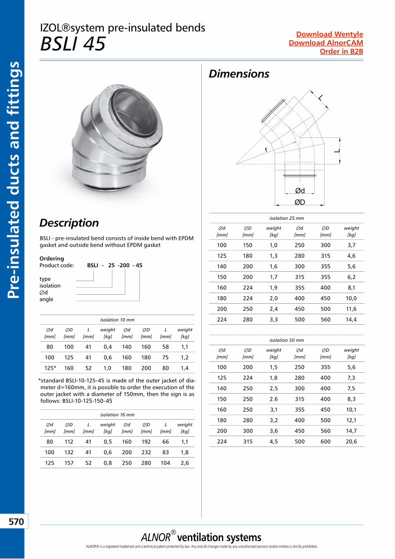
ALNOR® ventilation systemsALNOR® is a registered trademark and a technical patent protected by law. Any and all changes made by any unauthorized persons and/or entities is strictly prohibited.
570
Order in B2B
Download WentyleDownload AlnorCAM
Pre-
insu
late
d d
uct
s an
d f
itti
ng
sIZOL®system pre-insulated bends
BSLI 45 Dimensions
Description
ØdØD
r L
L
isolation 25 mm
Æd[mm]
ÆD[mm]
weight[kg]
Æd[mm]
ÆD[mm]
weight[kg]
100 150 1,0 250 300 3,7
125 180 1,3 280 315 4,6
140 200 1,6 300 355 5,6
150 200 1,7 315 355 6,2
160 224 1,9 355 400 8,1
180 224 2,0 400 450 10,0
200 250 2,4 450 500 11,6
224 280 3,3 500 560 14,4
isolation 50 mm
Æd[mm]
ÆD[mm]
weight[kg]
Æd[mm]
ÆD[mm]
weight[kg]
100 200 1,5 250 355 5,6
125 224 1,8 280 400 7,3
140 250 2,5 300 400 7,5
150 250 2.6 315 400 8,3
160 250 3,1 355 450 10,1
180 280 3,2 400 500 12,1
200 300 3,6 450 560 14,7
224 315 4,5 500 600 20,6
isolation 16 mm
Æd[mm]
ÆD[mm]
L[mm]
weight[kg]
Æd[mm]
ÆD[mm]
L[mm]
weight[kg]
80 112 41 0,5 160 192 66 1,1
100 132 41 0,6 200 232 83 1,8
125 157 52 0,8 250 280 104 2,6
isolation 10 mm
Æd[mm]
ÆD[mm]
L[mm]
weight[kg]
Æd[mm]
ÆD[mm]
L[mm]
weight[kg]
80 100 41 0,4 140 160 58 1,1
100 125 41 0,6 160 180 75 1,2
125* 160 52 1,0 180 200 80 1,4
*standard BSLI-10-125-45 is made of the outer jacket of dia-meter d=160mm, it is possible to order the execution of the outer jacket with a diameter of 150mm, then the sign is as follows: BSLI-10-125-150-45
OrderingProduct code: BSLI - 25 - 200 - 45
typeisolationÆdangle
BSLI - pre-insulated bend consists of inside bend with EPDM gasket and outside bend without EPDM gasket
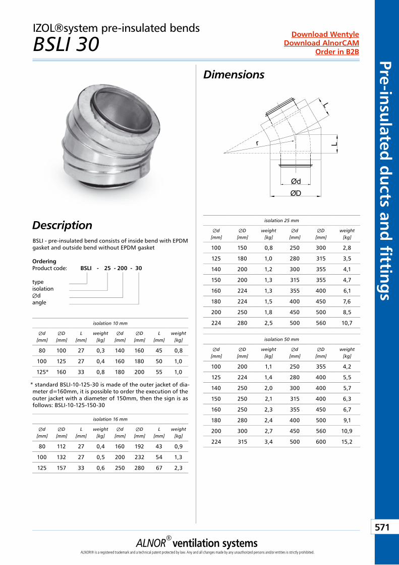
ALNOR® ventilation systemsALNOR® is a registered trademark and a technical patent protected by law. Any and all changes made by any unauthorized persons and/or entities is strictly prohibited.
571
Order in B2B
Download WentyleDownload AlnorCAM
Pre-insulated
du
cts and
fitting
sIZOL®system pre-insulated bends
BSLI 30 Dimensions
Description
ØdØD
r L
L
isolation 25 mm
Æd[mm]
ÆD[mm]
weight[kg]
Æd[mm]
ÆD[mm]
weight[kg]
100 150 0,8 250 300 2,8
125 180 1,0 280 315 3,5
140 200 1,2 300 355 4,1
150 200 1,3 315 355 4,7
160 224 1,3 355 400 6,1
180 224 1,5 400 450 7,6
200 250 1,8 450 500 8,5
224 280 2,5 500 560 10,7
isolation 50 mm
Æd[mm]
ÆD[mm]
weight[kg]
Æd[mm]
ÆD[mm]
weight[kg]
100 200 1,1 250 355 4,2
125 224 1,4 280 400 5,5
140 250 2,0 300 400 5,7
150 250 2,1 315 400 6,3
160 250 2,3 355 450 6,7
180 280 2,4 400 500 9,1
200 300 2,7 450 560 10,9
224 315 3,4 500 600 15,2
isolation 16 mm
Æd[mm]
ÆD[mm]
L[mm]
weight[kg]
Æd[mm]
ÆD[mm]
L[mm]
weight[kg]
80 112 27 0,4 160 192 43 0,9
100 132 27 0,5 200 232 54 1,3
125 157 33 0,6 250 280 67 2,3
isolation 10 mm
Æd[mm]
ÆD[mm]
L[mm]
weight[kg]
Æd[mm]
ÆD[mm]
L[mm]
weight[kg]
80 100 27 0,3 140 160 45 0,8
100 125 27 0,4 160 180 50 1,0
125* 160 33 0,8 180 200 55 1,0
* standard BSLI-10-125-30 is made of the outer jacket of dia-meter d=160mm, it is possible to order the execution of the outer jacket with a diameter of 150mm, then the sign is as follows: BSLI-10-125-150-30
OrderingProduct code: BSLI - 25 - 200 - 30
typeisolationÆdangle
BSLI - pre-insulated bend consists of inside bend with EPDM gasket and outside bend without EPDM gasket
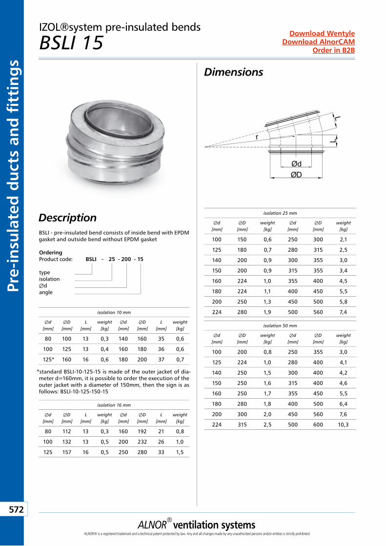
ALNOR® ventilation systemsALNOR® is a registered trademark and a technical patent protected by law. Any and all changes made by any unauthorized persons and/or entities is strictly prohibited.
572
Order in B2B
Download WentyleDownload AlnorCAM
Pre-
insu
late
d d
uct
s an
d f
itti
ng
sIZOL®system pre-insulated bends
BSLI 15 Dimensions
Description
ØdØD
r L
L
isolation 25 mm
Æd[mm]
ÆD[mm]
weight[kg]
Æd[mm]
ÆD[mm]
weight[kg]
100 150 0,6 250 300 2,1
125 180 0,7 280 315 2,5
140 200 0,9 300 355 3,0
150 200 0,9 315 355 3,4
160 224 1,0 355 400 4,5
180 224 1,1 400 450 5,5
200 250 1,3 450 500 5,8
224 280 1,9 500 560 7,4
isolation 50 mm
Æd[mm]
ÆD[mm]
weight[kg]
Æd[mm]
ÆD[mm]
weight[kg]
100 200 0,8 250 355 3,0
125 224 1,0 280 400 4,1
140 250 1,5 300 400 4,2
150 250 1,6 315 400 4,6
160 250 1,7 355 450 5,5
180 280 1,8 400 500 6,4
200 300 2,0 450 560 7,6
224 315 2,5 500 600 10,3
isolation 16 mm
Æd[mm]
ÆD[mm]
L[mm]
weight[kg]
Æd[mm]
ÆD[mm]
L[mm]
weight[kg]
80 112 13 0,3 160 192 21 0,8
100 132 13 0,5 200 232 26 1,0
125 157 16 0,5 250 280 33 1,5
isolation 10 mm
Æd[mm]
ÆD[mm]
L[mm]
weight[kg]
Æd[mm]
ÆD[mm]
L[mm]
weight[kg]
80 100 13 0,3 140 160 35 0,6
100 125 13 0,4 160 180 36 0,6
125* 160 16 0,6 180 200 37 0,7
*standard BSLI-10-125-15 is made of the outer jacket of dia-meter d=160mm, it is possible to order the execution of the outer jacket with a diameter of 150mm, then the sign is as follows: BSLI-10-125-150-15
OrderingProduct code: BSLI - 25 - 200 - 15
typeisolationÆdangle
BSLI - pre-insulated bend consists of inside bend with EPDM gasket and outside bend without EPDM gasket
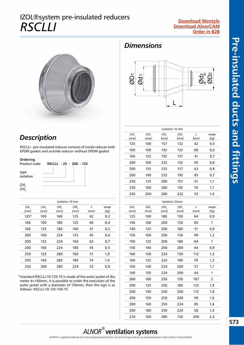
ALNOR® ventilation systemsALNOR® is a registered trademark and a technical patent protected by law. Any and all changes made by any unauthorized persons and/or entities is strictly prohibited.
573
Order in B2B
Download WentyleDownload AlnorCAM
Pre-insulated
du
cts and
fitting
sIZOL®system pre-insulated reducers
RSCLLI Dimensions
DescriptionØ
d1
2
L
Ød
ØD
1 2Ø
D
OrderingProduct code: RSCLLI - 25 - 200 - 125
typeisolation
Æd1Æd2
isolation 16 mm
Æd1
[mm]ÆD1
[mm]Æd2
[mm]ÆD2
[mm]L
[mm]waga[kg]
125 100 157 132 42 0,5
160 100 192 132 60 0,6
160 125 192 157 41 0,7
200 100 232 132 45 0,8
200 125 232 157 63 0,8
200 160 232 192 45 0,7
250 125 280 157 51 1,1
250 160 280 192 74 1,1
250 200 280 232 53 1,0
isolation 10 mm
Æd1
[mm]Æd2
[mm]ÆD1
[mm]ÆD2
[mm]L
[mm]waga[kg]
125* 100 160 125 42 0,3
160 100 180 125 60 0,4
160 125 180 160 41 0,5
200 100 224 125 45 0,6
200 125 224 160 63 0,7
200 160 224 180 45 0,5
250 125 280 160 51 1,0
250 160 280 180 74 1,0
250 200 280 224 53 0,9
isolation 25mm
Æd1
[mm]ÆD1
[mm]Æd2
[mm]ÆD2
[mm]L
[mm]waga[kg]
125 100 180 150 64 0,9
140 100 200 150 85 1
140 125 200 180 51 0,9
150 100 200 150 99 1,2
150 125 200 180 64 1
150 140 200 200 44 0,9
160 100 224 150 112 1,3
160 125 224 180 78 1,2
160 140 224 200 57 1,1
160 150 224 200 44 1
200 100 250 150 167 2
200 125 250 180 133 1,9
200 140 250 200 112 1,8
200 150 250 200 99 1,6
200 160 250 224 85 1,6
200 180 250 224 58 1,4
224 100 280 150 200 2,4
RSCLLI - pre-insulated reducer consists of inside reducer with EPDM gasket and outside reducer without EPDM gasket
*standard RSCLLI-10-125-15 is made of the outer jacket of dia-meter d=160mm, it is possible to order the execution of the outer jacket with a diameter of 150mm, then the sign is as follows: RSCLLI-10-125-150-15
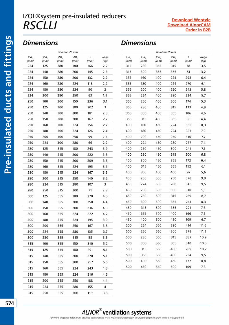
ALNOR® ventilation systemsALNOR® is a registered trademark and a technical patent protected by law. Any and all changes made by any unauthorized persons and/or entities is strictly prohibited.
574
Order in B2B
Download WentyleDownload AlnorCAM
Pre-
insu
late
d d
uct
s an
d f
itti
ng
sIZOL®system pre-insulated reducers
RSCLLI Dimensions Dimensions
isolation 25 mm
Æd1
[mm]Æd2
[mm]ÆD1
[mm]ÆD2
[mm]L
[mm]waga[kg]
224 125 280 180 166 2,2
224 140 280 200 145 2,3
224 150 280 200 132 2,2
224 160 280 224 118 2,2
224 180 280 224 90 2
224 200 280 250 63 1,9
250 100 300 150 236 3,1
250 125 300 180 202 3
250 140 300 200 181 2,8
250 150 300 200 167 2,7
250 160 300 224 154 2,7
250 180 300 224 126 2,4
250 200 300 250 99 2,4
250 224 300 280 66 2,2
280 125 315 180 243 3,9
280 140 315 200 222 3,8
280 150 315 200 209 3,6
280 160 315 224 195 3,5
280 180 315 224 167 3,3
280 200 315 250 140 3,2
280 224 315 280 107 3
280 250 315 300 71 2,8
300 125 355 180 270 4,5
300 140 355 200 250 4,4
300 150 355 200 236 4,3
300 160 355 224 222 4,2
300 180 355 224 195 3,9
300 200 355 250 167 3,8
300 224 355 280 135 3,7
300 280 355 315 58 3,3
315 100 355 150 310 5,2
315 125 355 180 291 5,1
315 140 355 200 270 5,1
315 150 355 200 257 5,5
315 160 355 224 243 4,8
315 180 355 224 216 4,5
315 200 355 250 188 4,4
315 224 355 280 155 4
315 250 355 300 119 3,8
isolation 25 mm
Æd1
[mm]Æd2
[mm]ÆD1
[mm]ÆD2
[mm]L
[mm]waga[kg]
315 280 355 315 78 3,5
315 300 355 355 51 3,2
355 160 400 224 298 6,4
355 180 400 224 270 6,1
355 200 400 250 243 5,8
355 224 400 280 224 5,7
355 250 400 300 174 5,3
355 280 400 315 133 4,9
355 300 400 355 106 4,6
355 315 400 355 85 4,4
400 160 450 224 365 8,3
400 180 450 224 337 7,9
400 200 450 250 310 7,7
400 224 450 280 277 7,4
400 250 450 300 241 7,1
400 280 450 315 200 6,8
400 300 450 355 172 6,4
400 315 450 355 152 6,1
400 355 450 400 97 5,6
450 200 500 250 378 9,8
450 224 500 280 346 9,5
450 250 500 300 310 9,1
450 280 500 315 269 8,7
450 300 500 355 241 8,3
450 315 500 355 221 7,8
450 355 500 400 166 7,3
450 400 500 450 109 6,7
500 224 560 280 414 11,6
500 250 560 300 378 11,3
500 280 560 315 337 10,9
500 300 560 355 310 10,5
500 315 560 400 289 10,2
500 355 560 400 234 9,5
500 400 560 450 177 8,8
500 450 560 500 109 7,8
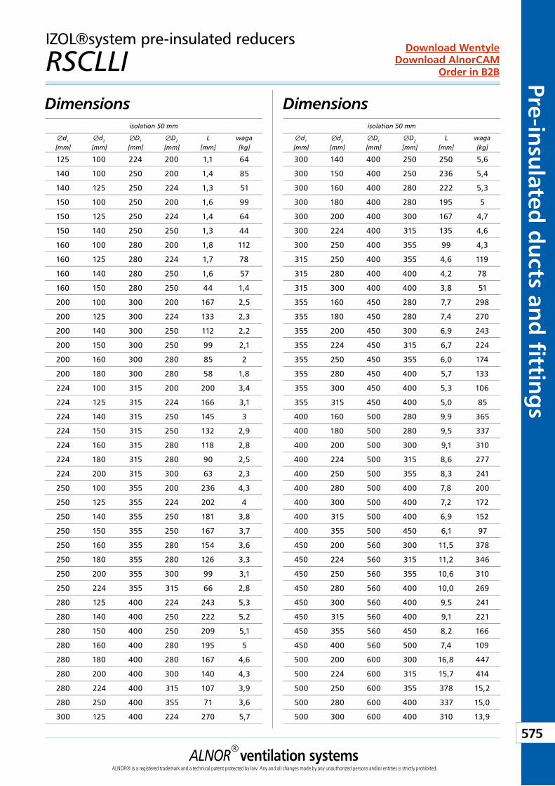
ALNOR® ventilation systemsALNOR® is a registered trademark and a technical patent protected by law. Any and all changes made by any unauthorized persons and/or entities is strictly prohibited.
575
Order in B2B
Download WentyleDownload AlnorCAM
Pre-insulated
du
cts and
fitting
s
DimensionsDimensionsisolation 50 mm
Æd1
[mm]Æd2
[mm]ÆD1
[mm]ÆD2
[mm]L
[mm]waga[kg]
125 100 224 200 1,1 64
140 100 250 200 1,4 85
140 125 250 224 1,3 51
150 100 250 200 1,6 99
150 125 250 224 1,4 64
150 140 250 250 1,3 44
160 100 280 200 1,8 112
160 125 280 224 1,7 78
160 140 280 250 1,6 57
160 150 280 250 44 1,4
200 100 300 200 167 2,5
200 125 300 224 133 2,3
200 140 300 250 112 2,2
200 150 300 250 99 2,1
200 160 300 280 85 2
200 180 300 280 58 1,8
224 100 315 200 200 3,4
224 125 315 224 166 3,1
224 140 315 250 145 3
224 150 315 250 132 2,9
224 160 315 280 118 2,8
224 180 315 280 90 2,5
224 200 315 300 63 2,3
250 100 355 200 236 4,3
250 125 355 224 202 4
250 140 355 250 181 3,8
250 150 355 250 167 3,7
250 160 355 280 154 3,6
250 180 355 280 126 3,3
250 200 355 300 99 3,1
250 224 355 315 66 2,8
280 125 400 224 243 5,3
280 140 400 250 222 5,2
280 150 400 250 209 5,1
280 160 400 280 195 5
280 180 400 280 167 4,6
280 200 400 300 140 4,3
280 224 400 315 107 3,9
280 250 400 355 71 3,6
300 125 400 224 270 5,7
isolation 50 mm
Æd1
[mm]Æd2
[mm]ÆD1
[mm]ÆD2
[mm]L
[mm]waga[kg]
300 140 400 250 250 5,6
300 150 400 250 236 5,4
300 160 400 280 222 5,3
300 180 400 280 195 5
300 200 400 300 167 4,7
300 224 400 315 135 4,6
300 250 400 355 99 4,3
315 250 400 355 4,6 119
315 280 400 400 4,2 78
315 300 400 400 3,8 51
355 160 450 280 7,7 298
355 180 450 280 7,4 270
355 200 450 300 6,9 243
355 224 450 315 6,7 224
355 250 450 355 6,0 174
355 280 450 400 5,7 133
355 300 450 400 5,3 106
355 315 450 400 5,0 85
400 160 500 280 9,9 365
400 180 500 280 9,5 337
400 200 500 300 9,1 310
400 224 500 315 8,6 277
400 250 500 355 8,3 241
400 280 500 400 7,8 200
400 300 500 400 7,2 172
400 315 500 400 6,9 152
400 355 500 450 6,1 97
450 200 560 300 11,5 378
450 224 560 315 11,2 346
450 250 560 355 10,6 310
450 280 560 400 10,0 269
450 300 560 400 9,5 241
450 315 560 400 9,1 221
450 355 560 450 8,2 166
450 400 560 500 7,4 109
500 200 600 300 16,8 447
500 224 600 315 15,7 414
500 250 600 355 378 15,2
500 280 600 400 337 15,0
500 300 600 400 310 13,9
IZOL®system pre-insulated reducers
RSCLLI
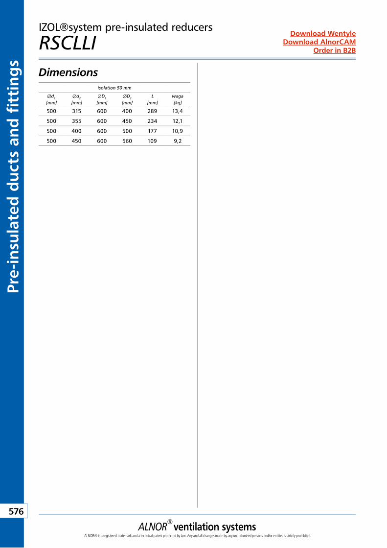
ALNOR® ventilation systemsALNOR® is a registered trademark and a technical patent protected by law. Any and all changes made by any unauthorized persons and/or entities is strictly prohibited.
576
Order in B2B
Download WentyleDownload AlnorCAM
Pre-
insu
late
d d
uct
s an
d f
itti
ng
s
isolation 50 mm
Æd1
[mm]Æd2
[mm]ÆD1
[mm]ÆD2
[mm]L
[mm]waga[kg]
500 315 600 400 289 13,4
500 355 600 450 234 12,1
500 400 600 500 177 10,9
500 450 600 560 109 9,2
IZOL®system pre-insulated reducers
RSCLLI Dimensions
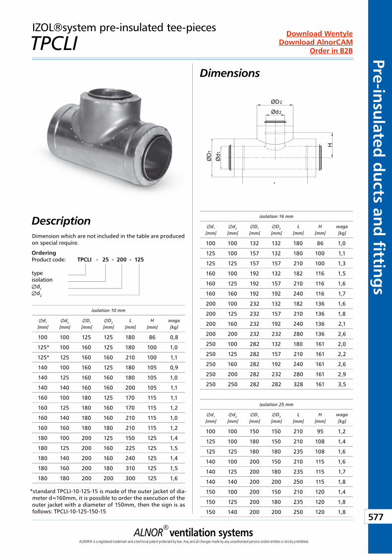
ALNOR® ventilation systemsALNOR® is a registered trademark and a technical patent protected by law. Any and all changes made by any unauthorized persons and/or entities is strictly prohibited.
577
Order in B2B
Download WentyleDownload AlnorCAM
Pre-insulated
du
cts and
fitting
sIZOL®system pre-insulated tee-pieces
TPCLIDimensions
DescriptionDimension which are not included in the table are produced on special require.
Ød1
L
Ød2
H
ØD
1
ØD2
OrderingProduct code: TPCLI - 25 - 200 - 125
typeisolationÆd1Æd2
isolation 16 mm
Æd1
[mm]Æd2
[mm]ÆD1
[mm]ÆD2
[mm]L
[mm]H
[mm]waga[kg]
100 100 132 132 180 86 1,0
125 100 157 132 180 100 1,1
125 125 157 157 210 100 1,3
160 100 192 132 182 116 1,5
160 125 192 157 210 116 1,6
160 160 192 192 240 116 1,7
200 100 232 132 182 136 1,6
200 125 232 157 210 136 1,8
200 160 232 192 240 136 2,1
200 200 232 232 280 136 2,6
250 100 282 132 180 161 2,0
250 125 282 157 210 161 2,2
250 160 282 192 240 161 2,6
250 200 282 232 280 161 2,9
250 250 282 282 328 161 3,5
isolation 10 mm
Æd1
[mm]Æd2
[mm]ÆD1
[mm]ÆD2
[mm]L
[mm]H
[mm]waga[kg]
100 100 125 125 180 86 0,8
125* 100 160 125 180 100 1,0
125* 125 160 160 210 100 1,1
140 100 160 125 180 105 0,9
140 125 160 160 180 105 1,0
140 140 160 160 200 105 1,1
160 100 180 125 170 115 1,1
160 125 180 160 170 115 1,2
160 140 180 160 210 115 1,0
160 160 180 180 210 115 1,2
180 100 200 125 150 125 1,4
180 125 200 160 225 125 1,5
180 140 200 160 240 125 1,4
180 160 200 180 310 125 1,5
180 180 200 200 300 125 1,6
isolation 25 mm
Æd1
[mm]Æd2
[mm]ÆD1
[mm]ÆD2
[mm]L
[mm]H
[mm]waga[kg]
100 100 150 150 210 95 1,2
125 100 180 150 210 108 1,4
125 125 180 180 235 108 1,6
140 100 200 150 210 115 1,6
140 125 200 180 235 115 1,7
140 140 200 200 250 115 1,8
150 100 200 150 210 120 1,4
150 125 200 180 235 120 1,8
150 140 200 200 250 120 1,8
*standard TPCLI-10-125-15 is made of the outer jacket of dia-meter d=160mm, it is possible to order the execution of the outer jacket with a diameter of 150mm, then the sign is as follows: TPCLI-10-125-150-15
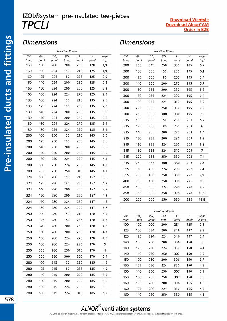
ALNOR® ventilation systemsALNOR® is a registered trademark and a technical patent protected by law. Any and all changes made by any unauthorized persons and/or entities is strictly prohibited.
578
Order in B2B
Download WentyleDownload AlnorCAM
Pre-
insu
late
d d
uct
s an
d f
itti
ng
sIZOL®system pre-insulated tee-pieces
TPCLIDimensionsDimensions
isolation 25 mm
Æd1
[mm]Æd2
[mm]ÆD1
[mm]ÆD2
[mm]L
[mm]H
[mm]waga[kg]
150 150 200 200 260 120 1,9
160 100 224 150 210 125 1,9
160 125 224 180 235 125 2,0
160 140 224 200 250 125 2,2
160 150 224 200 260 125 2,2
160 160 224 224 270 125 2,3
180 100 224 150 210 135 2,5
180 125 224 180 235 135 2,9
180 140 224 200 250 135 3,2
180 150 224 200 260 135 3,2
180 160 224 224 270 135 3,4
180 180 224 224 290 135 3,4
200 100 250 150 210 145 3,0
200 125 250 180 235 145 3,6
200 140 250 200 250 145 3,5
200 150 250 200 260 145 3,5
200 160 250 224 270 145 4,1
200 180 250 224 290 145 4,2
200 200 250 250 310 145 4,7
224 100 280 150 210 157 3,5
224 125 280 180 235 157 4,2
224 140 280 200 250 157 3,8
224 150 280 200 260 157 4,2
224 160 280 224 270 157 4,6
224 180 280 224 290 157 3,7
250 100 280 150 210 170 3,9
250 125 280 180 235 170 4,5
250 140 280 200 250 170 4,6
250 150 280 200 260 170 4,7
250 160 280 224 270 170 4,9
250 180 280 224 290 170 5
250 200 280 250 310 170 4
250 250 280 300 360 170 5,4
280 100 315 150 230 185 4,6
280 125 315 180 255 185 4,9
280 140 315 200 270 185 5,3
280 150 315 200 280 185 5,5
280 160 315 224 290 185 5,6
280 180 315 224 310 185 5,7
isolation 25 mm
Æd1
[mm]Æd2
[mm]ÆD1
[mm]ÆD2
[mm]L
[mm]H
[mm]waga[kg]
280 200 315 250 330 185 5,7
300 100 355 150 230 195 5,1
300 125 355 180 255 195 5,4
300 140 355 200 270 195 5,7
300 150 355 200 280 195 5,8
300 160 355 224 290 195 6,4
300 180 355 224 310 195 5,9
300 200 355 250 330 195 6,3
300 250 355 300 380 195 7,1
315 100 355 150 230 203 5,7
315 125 355 180 255 203 6
315 140 355 200 270 203 6,4
315 150 355 200 280 203 6,3
315 160 355 224 290 203 6,8
315 180 355 224 310 203 7
315 200 355 250 330 203 7,1
315 250 355 300 380 203 7,8
355 160 400 224 290 222 7,4
355 200 400 250 330 222 7,9
400 200 450 250 330 245 9,5
450 160 500 224 290 270 9,9
450 200 500 250 330 270 10,5
500 200 560 250 330 295 12,8
isolation 50 mm
Æd1
[mm]Æd2
[mm]ÆD1
[mm]ÆD2
[mm]L
[mm]H
[mm]waga[kg/m]
100 100 200 200 281 125 2,5
125 100 224 200 346 137 3,2
125 125 224 224 346 137 3,4
140 100 250 200 306 150 3,5
140 125 250 224 350 150 4,1
140 140 250 250 307 150 3,9
150 100 250 200 306 150 3,7
150 125 250 224 350 150 4,2
150 140 250 250 307 150 3,9
150 150 205 250 307 150 3,9
160 100 280 200 306 165 4,0
160 125 280 224 350 165 4,5
160 140 280 250 380 165 4,5
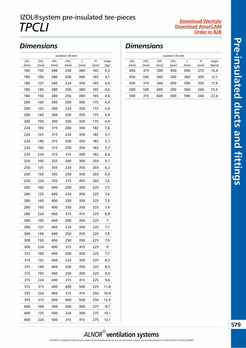
ALNOR® ventilation systemsALNOR® is a registered trademark and a technical patent protected by law. Any and all changes made by any unauthorized persons and/or entities is strictly prohibited.
579
Order in B2B
Download WentyleDownload AlnorCAM
Pre-insulated
du
cts and
fitting
s
isolation 50 mm
Æd1
[mm]Æd2
[mm]ÆD1
[mm]ÆD2
[mm]L
[mm]H
[mm]waga[kg]
160 150 280 250 380 165 4,5
180 100 280 200 306 165 4,1
180 125 280 224 350 165 4,6
180 140 280 250 380 165 4,6
180 150 280 250 380 165 4,6
200 100 300 200 306 175 4,4
200 125 300 224 350 172 4,9
200 140 300 250 350 175 4,9
200 150 300 250 350 175 4,9
224 100 315 200 306 182 7,8
224 125 315 224 350 182 5,7
224 140 315 250 350 182 5,7
224 150 315 250 350 182 5,7
224 224 315 315 390 182 6,6
250 100 355 200 306 203 5,7
250 125 355 224 350 203 6,2
250 150 355 250 350 203 6,4
250 224 355 315 455 203 7,8
280 100 400 200 300 225 7,3
280 125 400 224 350 225 7,6
280 140 400 250 350 225 7,3
280 150 400 250 350 225 7,4
280 224 400 315 415 225 8,8
300 100 400 200 300 225 7
300 125 400 224 350 225 7,7
300 140 400 250 350 225 7,8
300 150 400 250 350 225 7,9
300 224 400 315 415 225 9
315 100 400 200 300 225 7,7
315 125 400 224 350 225 8,5
315 140 400 250 350 225 8,5
315 150 400 250 350 225 8,6
315 224 400 315 415 225 9,8
315 315 400 400 500 225 11,8
355 224 400 315 415 250 10,9
355 315 400 400 500 250 12,9
400 100 500 200 300 275 9,7
400 125 500 224 300 275 10,1
400 224 500 315 415 275 12,1
isolation 50 mm
Æd1
[mm]Æd2
[mm]ÆD1
[mm]ÆD2
[mm]L
[mm]H
[mm]waga[kg/m]
400 315 500 400 500 275 14,4
450 100 560 200 360 305 12,1
450 315 560 400 590 305 17,9
500 100 600 200 360 340 15,5
500 315 600 400 590 340 22,6
IZOL®system pre-insulated tee-pieces
TPCLIDimensionsDimensions
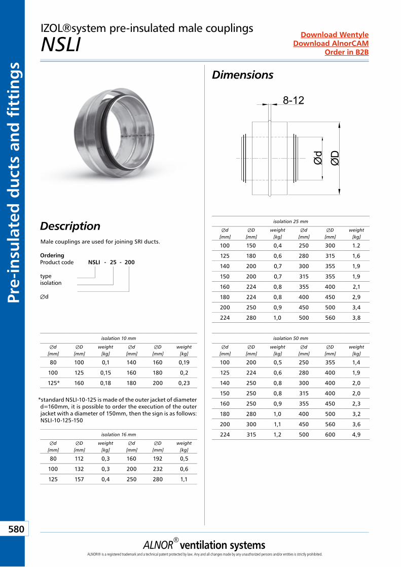
ALNOR® ventilation systemsALNOR® is a registered trademark and a technical patent protected by law. Any and all changes made by any unauthorized persons and/or entities is strictly prohibited.
580
Order in B2B
Download WentyleDownload AlnorCAM
Pre-
insu
late
d d
uct
s an
d f
itti
ng
sIZOL®system pre-insulated male couplings
NSLI Dimensions
DescriptionMale couplings are used for joining SRI ducts.
Ød
ØD
8-12
isolation 25 mm
Æd[mm]
ÆD[mm]
weight[kg]
Æd[mm]
ÆD[mm]
weight[kg]
100 150 0,4 250 300 1.2
125 180 0,6 280 315 1,6
140 200 0,7 300 355 1,9
150 200 0,7 315 355 1,9
160 224 0,8 355 400 2,1
180 224 0,8 400 450 2,9
200 250 0,9 450 500 3,4
224 280 1,0 500 560 3,8
isolation 50 mm
Æd[mm]
ÆD[mm]
weight[kg]
Æd[mm]
ÆD[mm]
weight[kg]
100 200 0,5 250 355 1,4
125 224 0,6 280 400 1,9
140 250 0,8 300 400 2,0
150 250 0,8 315 400 2,0
160 250 0,9 355 450 2,3
180 280 1,0 400 500 3,2
200 300 1,1 450 560 3,6
224 315 1,2 500 600 4,9
isolation 10 mm
Æd[mm]
ÆD[mm]
weight[kg]
Æd[mm]
ÆD[mm]
weight[kg]
80 100 0,1 140 160 0,19
100 125 0,15 160 180 0,2
125* 160 0,18 180 200 0,23
isolation 16 mm
Æd[mm]
ÆD[mm]
weight[kg]
Æd[mm]
ÆD[mm]
weight[kg]
80 112 0,3 160 192 0,5
100 132 0,3 200 232 0,6
125 157 0,4 250 280 1,1
*standard NSLI-10-125 is made of the outer jacket of diameter d=160mm, it is possible to order the execution of the outer jacket with a diameter of 150mm, then the sign is as follows: NSLI-10-125-150
OrderingProduct code NSLI - 25 - 200
typeisolation
Æd
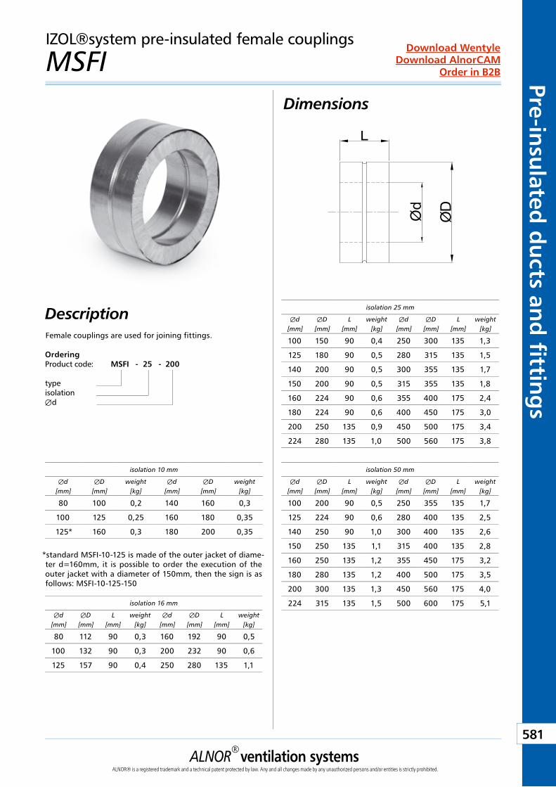
ALNOR® ventilation systemsALNOR® is a registered trademark and a technical patent protected by law. Any and all changes made by any unauthorized persons and/or entities is strictly prohibited.
581
Order in B2B
Download WentyleDownload AlnorCAM
Pre-insulated
du
cts and
fitting
sIZOL®system pre-insulated female couplings
MSFI Dimensions
DescriptionFemale couplings are used for joining fittings.
Ød
ØD
L
isolation 25 mm
Æd[mm]
ÆD[mm]
L[mm]
weight[kg]
Æd[mm]
ÆD[mm]
L[mm]
weight[kg]
100 150 90 0,4 250 300 135 1,3
125 180 90 0,5 280 315 135 1,5
140 200 90 0,5 300 355 135 1,7
150 200 90 0,5 315 355 135 1,8
160 224 90 0,6 355 400 175 2,4
180 224 90 0,6 400 450 175 3,0
200 250 135 0,9 450 500 175 3,4
224 280 135 1,0 500 560 175 3,8
isolation 50 mm
Æd[mm]
ÆD[mm]
L[mm]
weight[kg]
Æd[mm]
ÆD[mm]
L[mm]
weight[kg]
100 200 90 0,5 250 355 135 1,7
125 224 90 0,6 280 400 135 2,5
140 250 90 1,0 300 400 135 2,6
150 250 135 1,1 315 400 135 2,8
160 250 135 1,2 355 450 175 3,2
180 280 135 1,2 400 500 175 3,5
200 300 135 1,3 450 560 175 4,0
224 315 135 1,5 500 600 175 5,1isolation 16 mm
Æd[mm]
ÆD[mm]
L[mm]
weight[kg]
Æd[mm]
ÆD[mm]
L[mm]
weight[kg]
80 112 90 0,3 160 192 90 0,5
100 132 90 0,3 200 232 90 0,6
125 157 90 0,4 250 280 135 1,1
isolation 10 mm
Æd[mm]
ÆD[mm]
weight[kg]
Æd[mm]
ÆD[mm]
weight[kg]
80 100 0,2 140 160 0,3
100 125 0,25 160 180 0,35
125* 160 0,3 180 200 0,35
*standard MSFI-10-125 is made of the outer jacket of diame-ter d=160mm, it is possible to order the execution of the outer jacket with a diameter of 150mm, then the sign is as follows: MSFI-10-125-150
OrderingProduct code: MSFI - 25 - 200
typeisolationÆd
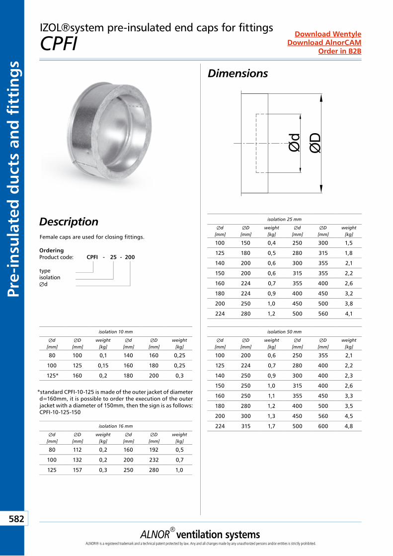
ALNOR® ventilation systemsALNOR® is a registered trademark and a technical patent protected by law. Any and all changes made by any unauthorized persons and/or entities is strictly prohibited.
582
Order in B2B
Download WentyleDownload AlnorCAM
Pre-
insu
late
d d
uct
s an
d f
itti
ng
sIZOL®system pre-insulated end caps for fittings
CPFI Dimensions
DescriptionFemale caps are used for closing fittings.
isolation 25 mm
Æd[mm]
ÆD[mm]
weight[kg]
Æd[mm]
ÆD[mm]
weight[kg]
100 150 0,4 250 300 1,5
125 180 0,5 280 315 1,8
140 200 0,6 300 355 2,1
150 200 0,6 315 355 2,2
160 224 0,7 355 400 2,6
180 224 0,9 400 450 3,2
200 250 1,0 450 500 3,8
224 280 1,2 500 560 4,1
isolation 50 mm
Æd[mm]
ÆD[mm]
weight[kg]
Æd[mm]
ÆD[mm]
weight[kg]
100 200 0,6 250 355 2,1
125 224 0,7 280 400 2,2
140 250 0,9 300 400 2,3
150 250 1,0 315 400 2,6
160 250 1,1 355 450 3,3
180 280 1,2 400 500 3,5
200 300 1,3 450 560 4,5
224 315 1,7 500 600 4,8isolation 16 mm
Æd[mm]
ÆD[mm]
weight[kg]
Æd[mm]
ÆD[mm]
weight[kg]
80 112 0,2 160 192 0,5
100 132 0,2 200 232 0,7
125 157 0,3 250 280 1,0
isolation 10 mm
Æd[mm]
ÆD[mm]
weight[kg]
Æd[mm]
ÆD[mm]
weight[kg]
80 100 0,1 140 160 0,25
100 125 0,15 160 180 0,25
125* 160 0,2 180 200 0,3
*standard CPFI-10-125 is made of the outer jacket of diameter d=160mm, it is possible to order the execution of the outer jacket with a diameter of 150mm, then the sign is as follows: CPFI-10-125-150
Ød
ØD
OrderingProduct code: CPFI - 25 - 200
typeisolationÆd
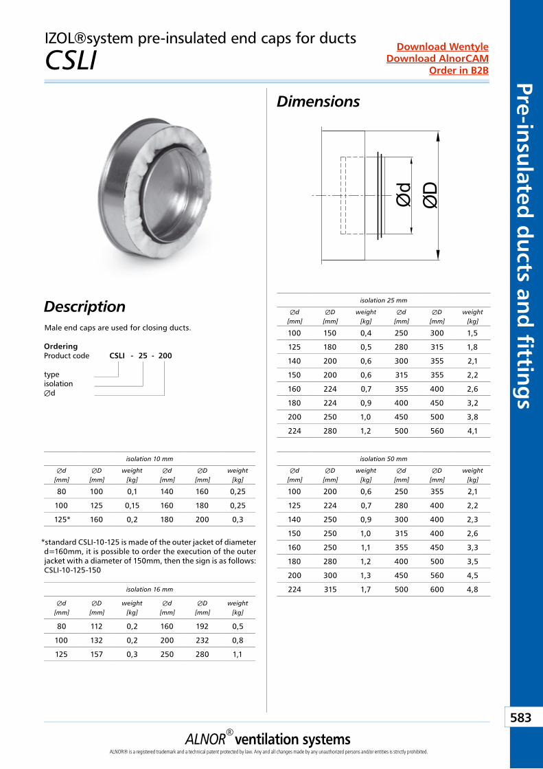
ALNOR® ventilation systemsALNOR® is a registered trademark and a technical patent protected by law. Any and all changes made by any unauthorized persons and/or entities is strictly prohibited.
583
Order in B2B
Download WentyleDownload AlnorCAM
Pre-insulated
du
cts and
fitting
sIZOL®system pre-insulated end caps for ducts
CSLI Dimensions
DescriptionMale end caps are used for closing ducts.
isolation 25 mm
Æd[mm]
ÆD[mm]
weight[kg]
Æd[mm]
ÆD[mm]
weight[kg]
100 150 0,4 250 300 1,5
125 180 0,5 280 315 1,8
140 200 0,6 300 355 2,1
150 200 0,6 315 355 2,2
160 224 0,7 355 400 2,6
180 224 0,9 400 450 3,2
200 250 1,0 450 500 3,8
224 280 1,2 500 560 4,1
isolation 50 mm
Æd[mm]
ÆD[mm]
weight[kg]
Æd[mm]
ÆD[mm]
weight[kg]
100 200 0,6 250 355 2,1
125 224 0,7 280 400 2,2
140 250 0,9 300 400 2,3
150 250 1,0 315 400 2,6
160 250 1,1 355 450 3,3
180 280 1,2 400 500 3,5
200 300 1,3 450 560 4,5
224 315 1,7 500 600 4,8isolation 16 mm
Æd[mm]
ÆD[mm]
weight[kg]
Æd[mm]
ÆD[mm]
weight[kg]
80 112 0,2 160 192 0,5
100 132 0,2 200 232 0,8
125 157 0,3 250 280 1,1
isolation 10 mm
Æd[mm]
ÆD[mm]
weight[kg]
Æd[mm]
ÆD[mm]
weight[kg]
80 100 0,1 140 160 0,25
100 125 0,15 160 180 0,25
125* 160 0,2 180 200 0,3
*standard CSLI-10-125 is made of the outer jacket of diameter d=160mm, it is possible to order the execution of the outer jacket with a diameter of 150mm, then the sign is as follows: CSLI-10-125-150
Ød
ØD
OrderingProduct code CSLI - 25 - 200
typeisolationÆd
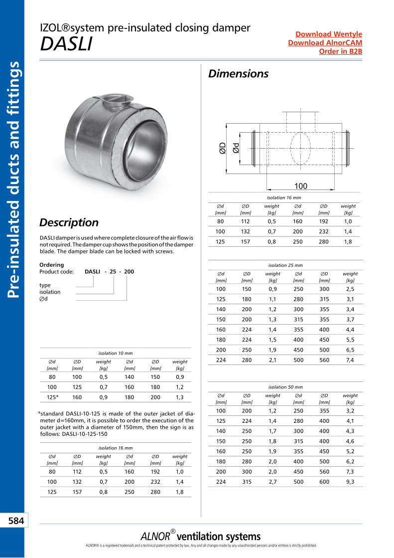
ALNOR® ventilation systemsALNOR® is a registered trademark and a technical patent protected by law. Any and all changes made by any unauthorized persons and/or entities is strictly prohibited.
584
Order in B2B
Download WentyleDownload AlnorCAM
Pre-
insu
late
d d
uct
s an
d f
itti
ng
sIZOL®system pre-insulated closing damper
DASLI Dimensions
DescriptionDASLI damper is used where complete closure of the air flow is not required. The damper cup shows the position of the damper blade. The damper blade can be locked with screws.
ØD
100
Ød
isolation 25 mm
Æd[mm]
ÆD[mm]
weight[kg]
Æd[mm]
ÆD[mm]
weight[kg]
100 150 0,9 250 300 2,5
125 180 1,1 280 315 3,1
140 200 1,2 300 355 3,4
150 200 1,3 315 355 3,7
160 224 1,4 355 400 4,4
180 224 1,5 400 450 5,5
200 250 1,9 450 500 6,5
224 280 2,1 500 560 7,4
isolation 50 mm
Æd[mm]
ÆD[mm]
weight[kg]
Æd[mm]
ÆD[mm]
weight[kg]
100 200 1,2 250 355 3,2
125 224 1,4 280 400 4,1
140 250 1,7 300 400 4,3
150 250 1,8 315 400 4,6
160 250 1,9 355 450 5,2
180 280 2,0 400 500 6,2
200 300 2,0 450 560 7,3
224 315 2,7 500 600 9,3
isolation 16 mm
Æd[mm]
ÆD[mm]
weight[kg]
Æd[mm]
ÆD[mm]
weight[kg]
80 112 0,5 160 192 1,0
100 132 0,7 200 232 1,4
125 157 0,8 250 280 1,8
isolation 10 mm
Æd[mm]
ÆD[mm]
weight[kg]
Æd[mm]
ÆD[mm]
weight[kg]
80 100 0,5 140 150 0,9
100 125 0,7 160 180 1,2
125* 160 0,9 180 200 1,3
isolation 16 mm
Æd[mm]
ÆD[mm]
weight[kg]
Æd[mm]
ÆD[mm]
weight[kg]
80 112 0,5 160 192 1,0
100 132 0,7 200 232 1,4
125 157 0,8 250 280 1,8
*standard DASLI-10-125 is made of the outer jacket of dia-meter d=160mm, it is possible to order the execution of the outer jacket with a diameter of 150mm, then the sign is as follows: DASLI-10-125-150
OrderingProduct code: DASLI - 25 - 200
typeisolationÆd
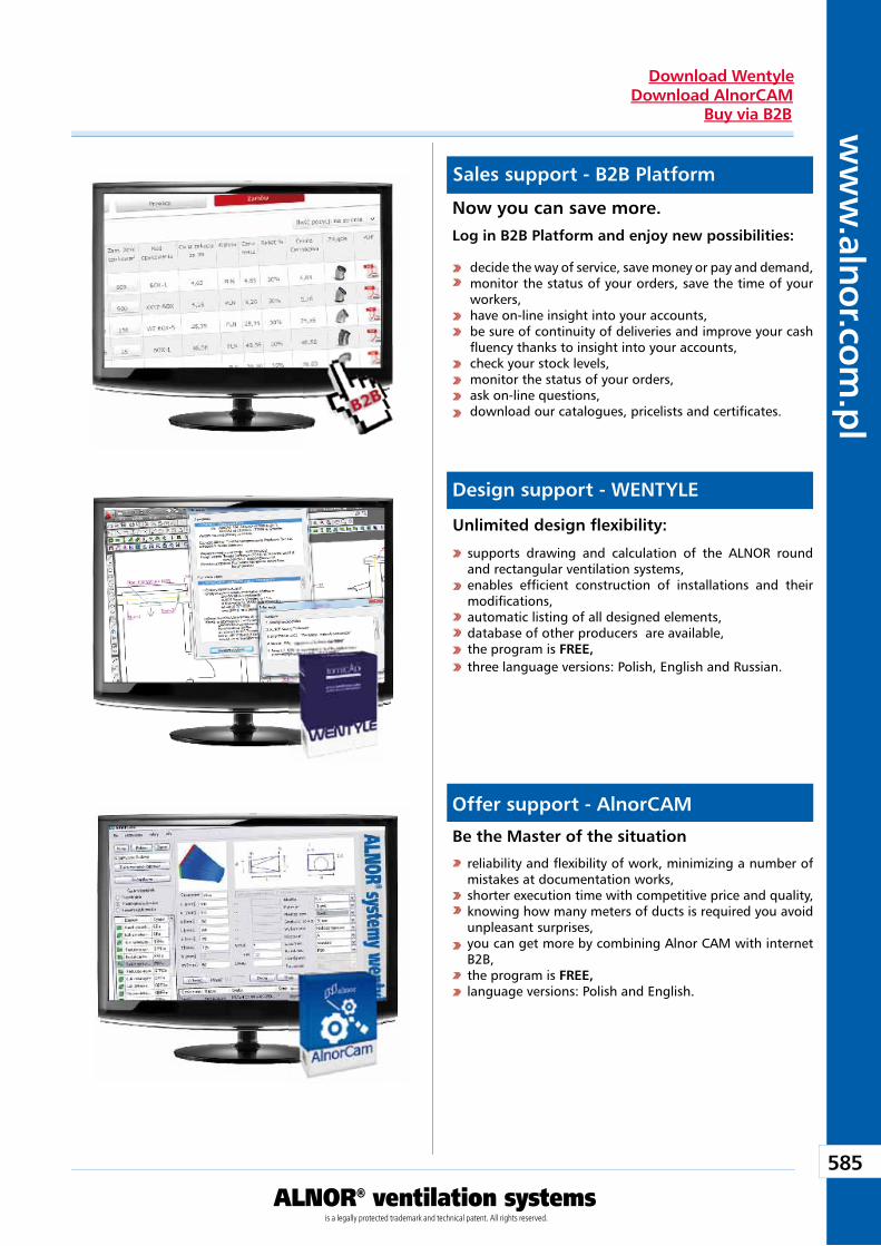
585
ww
w.alnor.com
.pl
ALNOR® ventilation systemsis a legally protected trademark and technical patent. All rights reserved.
Download WentyleDownload AlnorCAM
Buy via B2B
Sales support - B2B Platform
Design support - WENTYLE
Offer support - AlnorCAM
Now you can save more. Log in B2B Platform and enjoy new possibilities:
supports drawing and calculation of the ALNOR round and rectangular ventilation systems, enables effi cient construction of installations and their modifi cations, automatic listing of all designed elements, database of other producers are available,the program is FREE,three language versions: Polish, English and Russian.
reliability and fl exibility of work, minimizing a number of mistakes at documentation works, shorter execution time with competitive price and quality, knowing how many meters of ducts is required you avoid unpleasant surprises, you can get more by combining Alnor CAM with internet B2B, the program is FREE, language versions: Polish and English.
decide the way of service, save money or pay and demand,monitor the status of your orders, save the time of your workers, have on-line insight into your accounts, be sure of continuity of deliveries and improve your cash fl uency thanks to insight into your accounts, check your stock levels, monitor the status of your orders, ask on-line questions, download our catalogues, pricelists and certifi cates.
Unlimited design fl exibility:
Be the Master of the situation


![[www tailieutienganh net]Cam 8](https://img.pdfslide.net/doc/110x75/6349500a2cd4c1a3540d7318/www-tailieutienganh-netcam-8.jpg)


![[www fisierulmeu ro] Gramatica limbii romane](https://img.pdfslide.net/doc/110x75/6313873cc32ab5e46f0c758a/www-fisierulmeu-ro-gramatica-limbii-romane.jpg)