Embed Size (px)
Citation preview
~ 1 ~
~ 2 ~
HOW TO PERFORM RESIDENTIAL ELECTRICAL INSPECTIONS
The purpose of this publication is to provide accurate and useful information for performing electrical
inspections of residential properties. This book is designed to augment the student’s knowledge in
preparation for InterNACHI’s online Electrical Inspection Course and Exam (www.NACHI.org), and includes
practice quizzes for select sections. This manual also provides a practical reference guide for use on-site
at home inspections.
Authors: Nick Gromicko, Founder, International Association of Certified Home Inspectors
Gerry Beaumont, InterNACHI National Training Consultant
Paul Abernathy, National Electrical Code Expert (www.TheElectricalGuru.com)
Graphics by: Wylie Robinson
Edited by: Kate Tarasenko / Crimea River
To order online, visit: www.InspectorOutlet.com
Copyright © 2013 International Association of Certified Home Inspectors
www.NACHI.org
All rights reserved.
~ 3 ~
This book is dedicated to the memory of Gerry Beaumont, InterNACHI’s first Education Director.
Gerry was the author of our original residential electrical inspection course, which evolved into our latest course on which this book is based. Gerry was instrumental in developing the foundation of InterNACHI’s educational curriculum. He helped countless inspectors over the years, guiding them with his professionalism and expertise.
We are grateful that Gerry shared his light with us, and we are forever indebted to him for spreading his wealth of knowledge and his abundant enthusiasm for life.
~ 4 ~
Residential Electrical Inspection
Introduction…....................................................................................... 5
Safety First: Electrical Safety............................................ 5
Basic Terms……………………………………………………… 6
Simple Theory.. ………………………………………………… 7
Conductor Sizes………………………………………………… 9
Service Entrance……………………………………..………………………….. 15
Service Drop………………..…………………………………… 15
Service Mast and Attachments………………………………. 19
Service Lateral……………...…………………………………… 22
Electric Meters and Bases.…………………………………… 24
Service Entrance Cable..……………………………………… 26
Grounding and Bonding…………..…………………………………………… 33
Grounding System……………………………………………… 33
Bonding of Components……….……………………………… 38
Panels and Enclosures………………………………………… 39
Service Panels……………………………...………………...………………….. 45
The Main Disconnect……….…………………..……………… 45
Service Amperage……………..……………………………….. 48
Inspecting Enclosures, Part I………………………………… 50
Inspecting Enclosures, Part II...……………………………… 53
Inspecting Enclosures, Part III….……………………………. 55
Edison Base Screw Fuse Panels..…………………………… 58
Circuit Breaker Panels……………..………………………….. 61
Problem Panels……………………..………………………….. 66
3-Phase Panels……..…………………………………………… 73
Panel Oddities…………………………………………………… 75
Electrical Distribution…………………...……………………………………… 80
Wiring Types…………….………………………………………. 80
Aluminum Wiring……..………………………………………… 85
Branch Circuit Connections..………………………………… 87
Protection of Wiring…….……………………………………… 92
120-Volt Terminations….……………………………………… 96
Testing Outlets…………..……………………………………… 100
240-Volt Terminations….……………………………………… 110
GFCI Circuits…………….……………………………………… 112
Lighting Circuits………………………………………………… 115
AFCI Requirements……..……………………………………… 119
~ 5 ~
INTRODUCTION SAFETY FIRST: ELECTRICAL SAFETY
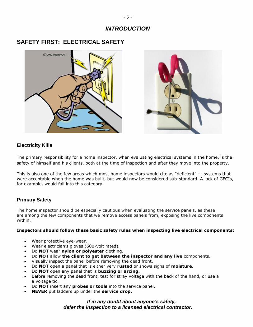
Electricity Kills
The primary responsibility for a home inspector, when evaluating electrical systems in the home, is the
safety of himself and his clients, both at the time of inspection and after they move into the property.
This is also one of the few areas which most home inspectors would cite as "deficient" –- systems that
were acceptable when the home was built, but would now be considered sub-standard. A lack of GFCIs,
for example, would fall into this category.
Primary Safety
The home inspector should be especially cautious when evaluating the service panels, as these
are among the few components that we remove access panels from, exposing the live components
within.
Inspectors should follow these basic safety rules when inspecting live electrical components:
Wear protective eye-wear.
Wear electrician’s gloves (600-volt rated).
Do NOT wear nylon or polyester clothing.
Do NOT allow the client to get between the inspector and any live components.
Visually inspect the panel before removing the dead front.
Do NOT open a panel that is either very rusted or shows signs of moisture.
Do NOT open any panel that is buzzing or arcing.
Before removing the dead front, test for stray voltage with the back of the hand, or use a
a voltage tic.
Do NOT insert any probes or tools into the service panel.
NEVER put ladders up under the service drop.
If in any doubt about anyone’s safety, defer the inspection to a licensed electrical contractor.
~ 6 ~
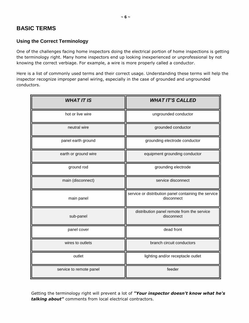
BASIC TERMS Using the Correct Terminology
One of the challenges facing home inspectors doing the electrical portion of home inspections is getting
the terminology right. Many home inspectors end up looking inexperienced or unprofessional by not
knowing the correct verbiage. For example, a wire is more properly called a conductor.
Here is a list of commonly used terms and their correct usage. Understanding these terms will help the
inspector recognize improper panel wiring, especially in the case of grounded and ungrounded
conductors.
WHAT IT IS WHAT IT’S CALLED
hot or live wire ungrounded conductor
neutral wire grounded conductor
panel earth ground grounding electrode conductor
earth or ground wire equipment grounding conductor
ground rod grounding electrode
main (disconnect) service disconnect
main panel
service or distribution panel containing the service disconnect
sub-panel
distribution panel remote from the service disconnect
panel cover dead front
wires to outlets branch circuit conductors
outlet lighting and/or receptacle outlet
service to remote panel feeder
Getting the terminology right will prevent a lot of "Your inspector doesn't know what he's
talking about" comments from local electrical contractors.
~ 7 ~
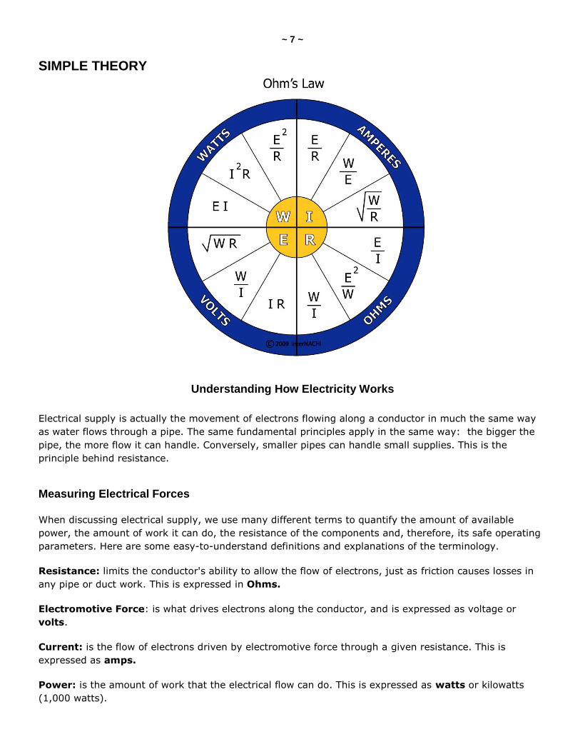
SIMPLE THEORY
Understanding How Electricity Works
Electrical supply is actually the movement of electrons flowing along a conductor in much the same way
as water flows through a pipe. The same fundamental principles apply in the same way: the bigger the
pipe, the more flow it can handle. Conversely, smaller pipes can handle small supplies. This is the
principle behind resistance.
Measuring Electrical Forces
When discussing electrical supply, we use many different terms to quantify the amount of available
power, the amount of work it can do, the resistance of the components and, therefore, its safe operating
parameters. Here are some easy-to-understand definitions and explanations of the terminology.
Resistance: limits the conductor's ability to allow the flow of electrons, just as friction causes losses in
any pipe or duct work. This is expressed in Ohms.
Electromotive Force: is what drives electrons along the conductor, and is expressed as voltage or
volts.
Current: is the flow of electrons driven by electromotive force through a given resistance. This is
expressed as amps.
Power: is the amount of work that the electrical flow can do. This is expressed as watts or kilowatts
(1,000 watts).
~ 8 ~
Ohms Laws
Georg Simon Ohm was a German physicist born in Erlangen,
Bavaria on March 16, 1787. Ohm started his research with the
then-recently invented electric cell (invented by Italian Conte
Alessandro Volta). Using equipment of his own creation, Ohm
determined that the current that flows through a wire is
proportional to its cross-sectional area, and inversely proportional
to its length. Using the results of his experiments, Ohm was able
to define the fundamental relationship between voltage, current
and resistance.
These fundamental relationships are of such great importance
that they represent the true beginning of electrical circuit analysis.
Unfortunately, when Ohm published his findings in 1827, his ideas
were dismissed by his colleagues. Ohm was forced to resign from
his high school teaching position, and he lived in poverty and
shame. However, his research efforts gained a lot of support outside of Germany. In 1849, Georg Simon
Ohm was finally recognized for his efforts by being appointed as a professor at the University of Munich.
How do the Ohms Laws help us?
Ohms Laws are basically a series of mathematical models that show us how to work out safe working
loads for conductors and electrical components. This allows us to understand why, for example, a 30-amp
fuse should not be connected to a 14-AWG wire (that's about resistance and overheating wires).
The most common Ohms Laws are:
E = I x R or Electromotive Force (E) equals Amps (I) multiplied by Resistance (R)
or Volts equals Amps times Ohms.
Simple manipulation of this equation allows one to work out any figure, given the other two components.
For example, 120 volts pushed through 60 Ohms of resistance equals 2 amps.
I = E ÷ R or Amps (I) equals Electromotive Force (E) divided by Resistance (R).
Simply put, Amps equals Volts divided by Resistance.
So, a 120-volt circuit and 25 Ohms of resistance to a ground rod equals 4.8 amps.
Note: This will not trip any circuit breaker.
~ 9 ~
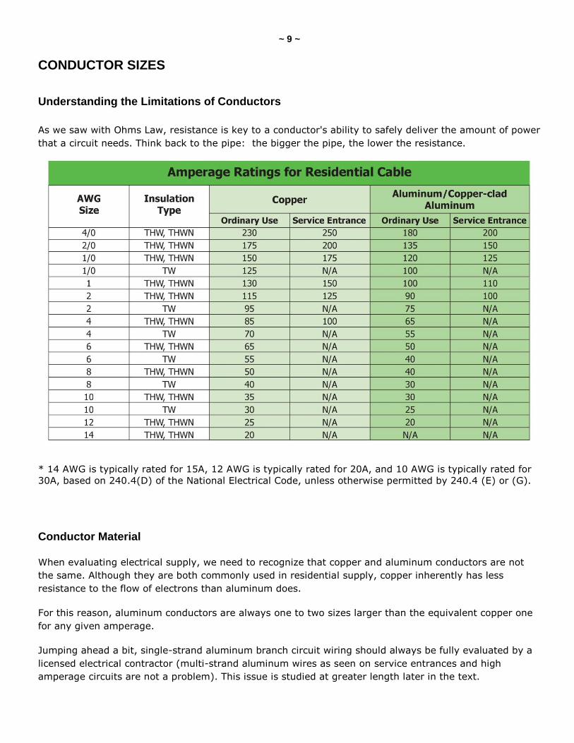
CONDUCTOR SIZES
Understanding the Limitations of Conductors
As we saw with Ohms Law, resistance is key to a conductor's ability to safely deliver the amount of power
that a circuit needs. Think back to the pipe: the bigger the pipe, the lower the resistance.
* 14 AWG is typically rated for 15A, 12 AWG is typically rated for 20A, and 10 AWG is typically rated for
30A, based on 240.4(D) of the National Electrical Code, unless otherwise permitted by 240.4 (E) or (G).
Conductor Material
When evaluating electrical supply, we need to recognize that copper and aluminum conductors are not
the same. Although they are both commonly used in residential supply, copper inherently has less
resistance to the flow of electrons than aluminum does.
For this reason, aluminum conductors are always one to two sizes larger than the equivalent copper one
for any given amperage.
Jumping ahead a bit, single-strand aluminum branch circuit wiring should always be fully evaluated by a
licensed electrical contractor (multi-strand aluminum wires as seen on service entrances and high
amperage circuits are not a problem). This issue is studied at greater length later in the text.
~ 10 ~
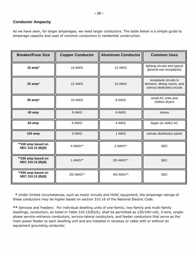
Conductor Ampacity
As we have seen, for larger amperages, we need larger conductors. The table below is a simple guide to
amperage capacity and uses of common conductors in residential construction.
Breaker/Fuse Size Copper Conductor Aluminum Conductor Common Uses
15 amp* 14 AWG 12 AWG lighting circuits and typical general-use receptacles
20 amp* 12 AWG 10 AWG receptacle circuits in
kitchens, dining rooms, and various dedicated circuits
30 amp* 10 AWG 8 AWG small AC units and
clothes dryers
40 amp 8 AWG 6 AWG stoves
60 amp 6 AWG 4 AWG larger (or older) AC
100 amp 3 AWG 1 AWG remote distribution panel
**100 amp based on NEC 310.15 (B)(6)
4 AWG** 2 AWG** SEC
**150 amp based on NEC 310.15 (B)(6)
1 AWG** 2/0 AWG** SEC
**250 amp based on NEC 310.15 (B)(6)
2/0 AWG** 4/0 AWG** SEC
* Under limited circumstances, such as motor circuits and HVAC equipment, the amperage ratings of
these conductors may be higher based on section 310.16 of the National Electric Code.
** Services and Feeders: For individual dwelling units of one-family, two-family and multi-family
dwellings, conductors, as listed in Table 310.15(B)(6), shall be permitted as 120/240-volt, 3-wire, single-
phase service-entrance conductors, service-lateral conductors, and feeder conductors that serve as the
main power feeder to each dwelling unit and are installed in raceway or cable with or without an
equipment grounding conductor.
~ 11 ~
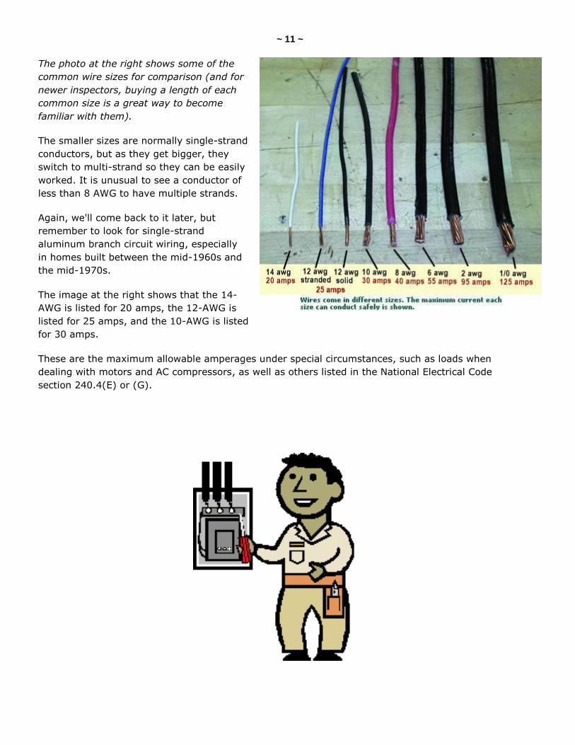
The photo at the right shows some of the
common wire sizes for comparison (and for
newer inspectors, buying a length of each
common size is a great way to become
familiar with them).
The smaller sizes are normally single-strand
conductors, but as they get bigger, they
switch to multi-strand so they can be easily
worked. It is unusual to see a conductor of
less than 8 AWG to have multiple strands.
Again, we'll come back to it later, but
remember to look for single-strand
aluminum branch circuit wiring, especially
in homes built between the mid-1960s and
the mid-1970s.
The image at the right shows that the 14-
AWG is listed for 20 amps, the 12-AWG is
listed for 25 amps, and the 10-AWG is listed
for 30 amps.
These are the maximum allowable amperages under special circumstances, such as loads when
dealing with motors and AC compressors, as well as others listed in the National Electrical Code
section 240.4(E) or (G).
~ 12 ~
QUIZ on INTRODUCTION
1. Which of the following should NOT be worn during an inspection?
safety glasses
leather shoes
nylon clothing
2. Which of the following should be inserted into an electrical panel during an inspection?
none of these
a torque wrench
an amp probe
a wire gauge
3. The electrical panel should NOT be opened if which of the following conditions are present?
any of these
moisture dripping from the enclosure
rusting enclosure
sounds of arcing
4. The correct name for a live wire is ___________.
a grounded conductor
an ungrounded conductor
a grounding conductor
5. An electrical panel cover is more properly called the __________.
dead front
enclosure
distribution center
6. A service panel that does not contain the disconnect is called the __________.
main panel
sub panel
service panel
distribution panel (continued)
~ 13 ~
7. Wires to outlets are called __________.
receptacle cables
Romex®
branch circuit conductors
8. Electromotive force is measured in ___________.
watts
amps
volts
ohms
9. Ohms are a measurement of __________.
resistance
power
amperage
10. Voltage is equal to ____________.
power x amperage
watts x current
amps x resistance
11. Finish the equation: W = E x ___
O
Q
I
R 12. Aluminum branch circuit conductors should be sized ________ than copper.
two sizes smaller
the same as
one to two sizes smaller
one to two sizes larger
(continued)
~ 14 ~
13. A 20-amp breaker should feed a minimum ______ conductor.
12-AWG
8-AWG
14-AWG
10-AWG
14. What would be the minimum service entrance cable size for a 200-amp supply?
1/0 copper or 2/0 aluminum
2/0 copper or 4/0 aluminum
2/0 copper or 1/0 aluminum
4/0 copper or 2/0 aluminum
Answer Key to Quiz on Introduction
1. Which of the following should NOT be worn during an inspection?
Answer: nylon clothing
2. Which of the following should be inserted into an electrical panel during an inspection?
Answer: none of these
3. The electrical panel should NOT be opened if which of the following conditions are present?
Answer: any of these
4. The correct name for a live wire is an ungrounded conductor.
5. An electrical panel cover is more properly called the dead front.
6. A service panel that does not contain the disconnect is called the distribution panel.
7. Wires to outlets are called branch circuit conductors.
8. Electromotive force is measured in volts.
9. Ohms are a measurement of resistance.
10. Voltage is equal to amps x resistance.
11. Finish the equation: W = E x I
12. Aluminum branch circuit conductors should be sized one to two sizes larger than copper.
13. A 20-amp breaker should feed a minimum 12-AWG conductor.
14. What would be the minimum service entrance cable size for a 200-amp supply?
Answer: 2/0 copper or 4/0 aluminum
~ 15 ~
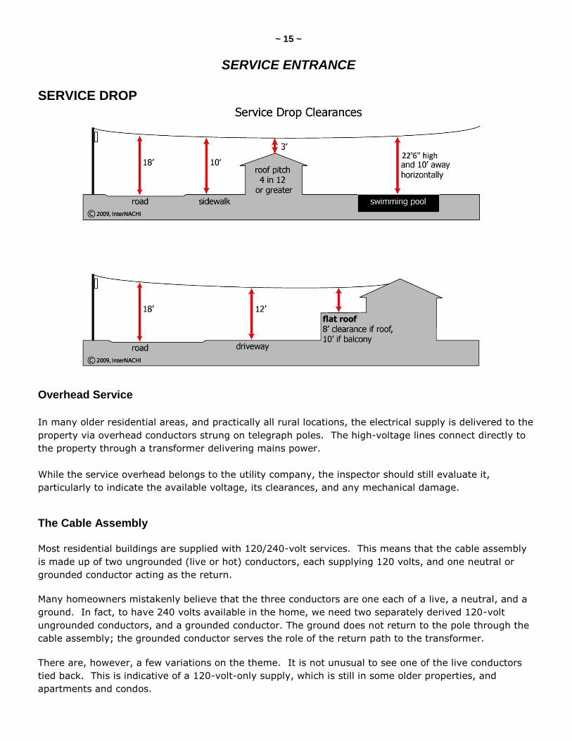
SERVICE ENTRANCE SERVICE DROP
Overhead Service
In many older residential areas, and practically all rural locations, the electrical supply is delivered to the
property via overhead conductors strung on telegraph poles. The high-voltage lines connect directly to
the property through a transformer delivering mains power.
While the service overhead belongs to the utility company, the inspector should still evaluate it,
particularly to indicate the available voltage, its clearances, and any mechanical damage.
The Cable Assembly
Most residential buildings are supplied with 120/240-volt services. This means that the cable assembly
is made up of two ungrounded (live or hot) conductors, each supplying 120 volts, and one neutral or
grounded conductor acting as the return.
Many homeowners mistakenly believe that the three conductors are one each of a live, a neutral, and a
ground. In fact, to have 240 volts available in the home, we need two separately derived 120-volt
ungrounded conductors, and a grounded conductor. The ground does not return to the pole through the
cable assembly; the grounded conductor serves the role of the return path to the transformer.
There are, however, a few variations on the theme. It is not unusual to see one of the live conductors
tied back. This is indicative of a 120-volt-only supply, which is still in some older properties, and
apartments and condos.
~ 16 ~
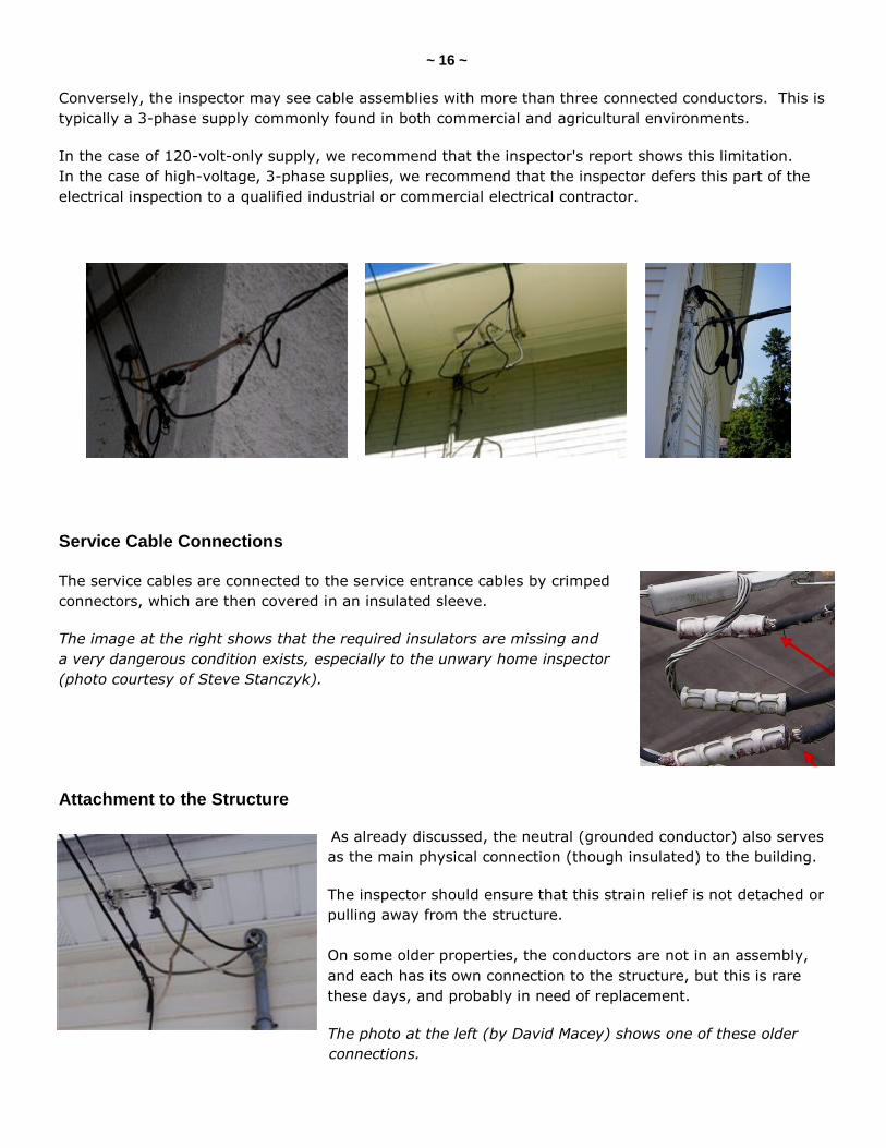
Conversely, the inspector may see cable assemblies with more than three connected conductors. This is
typically a 3-phase supply commonly found in both commercial and agricultural environments.
In the case of 120-volt-only supply, we recommend that the inspector's report shows this limitation.
In the case of high-voltage, 3-phase supplies, we recommend that the inspector defers this part of the
electrical inspection to a qualified industrial or commercial electrical contractor.
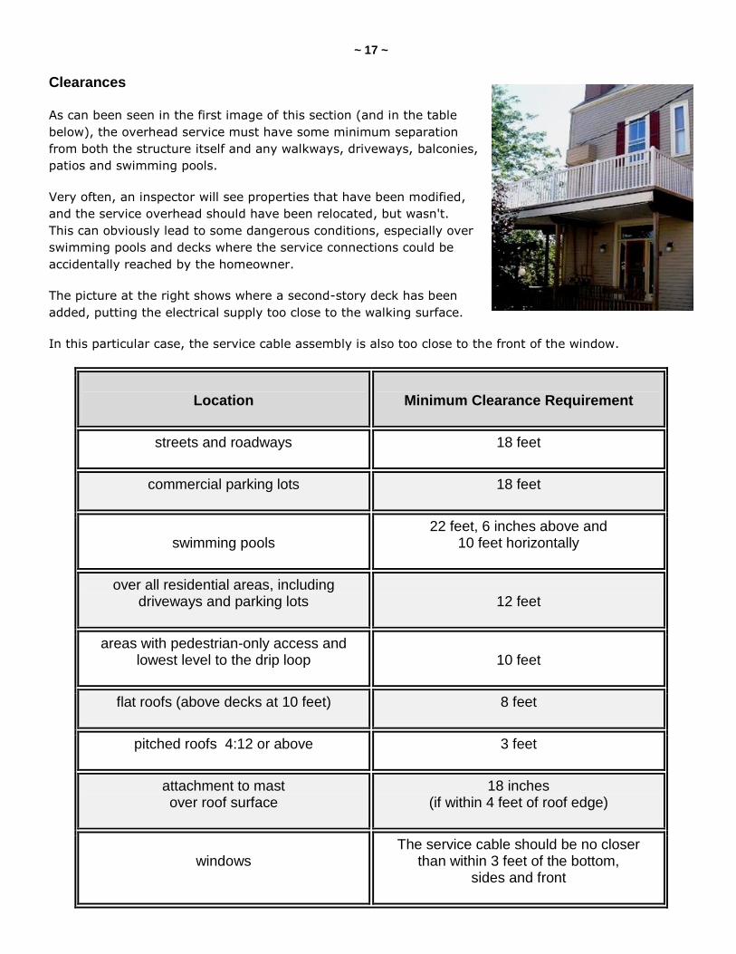
Service Cable Connections
The service cables are connected to the service entrance cables by crimped
connectors, which are then covered in an insulated sleeve.
The image at the right shows that the required insulators are missing and
a very dangerous condition exists, especially to the unwary home inspector
(photo courtesy of Steve Stanczyk).
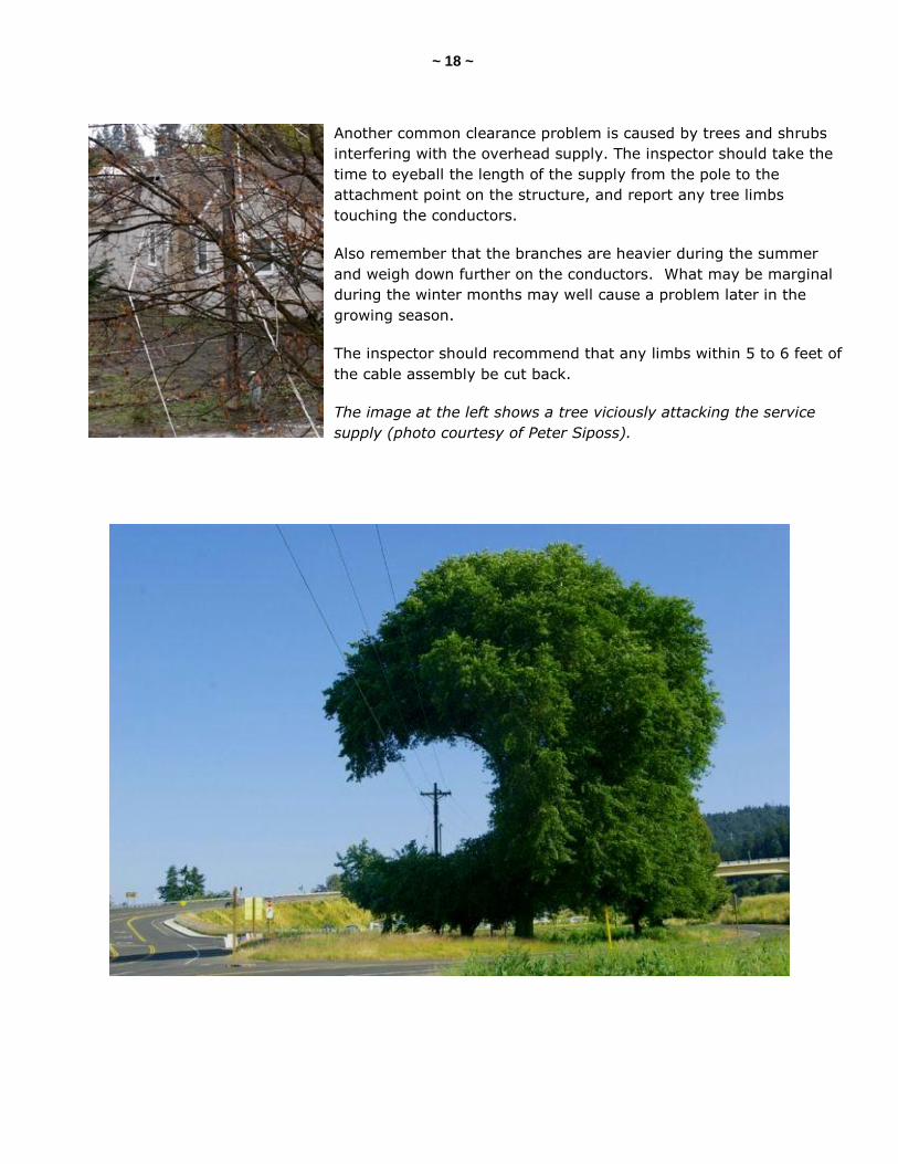
Attachment to the Structure
As already discussed, the neutral (grounded conductor) also serves
as the main physical connection (though insulated) to the building.
The inspector should ensure that this strain relief is not detached or
pulling away from the structure.
On some older properties, the conductors are not in an assembly,
and each has its own connection to the structure, but this is rare
these days, and probably in need of replacement.
The photo at the left (by David Macey) shows one of these older
connections.
~ 17 ~
Clearances
As can been seen in the first image of this section (and in the table
below), the overhead service must have some minimum separation
from both the structure itself and any walkways, driveways, balconies,
patios and swimming pools.
Very often, an inspector will see properties that have been modified,
and the service overhead should have been relocated, but wasn't.
This can obviously lead to some dangerous conditions, especially over
swimming pools and decks where the service connections could be
accidentally reached by the homeowner.
The picture at the right shows where a second-story deck has been
added, putting the electrical supply too close to the walking surface.
In this particular case, the service cable assembly is also too close to the front of the window.
Location
Minimum Clearance Requirement
streets and roadways 18 feet
commercial parking lots 18 feet
swimming pools
22 feet, 6 inches above and 10 feet horizontally
over all residential areas, including driveways and parking lots
12 feet
areas with pedestrian-only access and lowest level to the drip loop
10 feet
flat roofs (above decks at 10 feet) 8 feet
pitched roofs 4:12 or above 3 feet
attachment to mast over roof surface
18 inches (if within 4 feet of roof edge)
windows
The service cable should be no closer than within 3 feet of the bottom,
sides and front
~ 18 ~
Another common clearance problem is caused by trees and shrubs
interfering with the overhead supply. The inspector should take the
time to eyeball the length of the supply from the pole to the
attachment point on the structure, and report any tree limbs
touching the conductors.
Also remember that the branches are heavier during the summer
and weigh down further on the conductors. What may be marginal
during the winter months may well cause a problem later in the
growing season.
The inspector should recommend that any limbs within 5 to 6 feet of
the cable assembly be cut back.
The image at the left shows a tree viciously attacking the service
supply (photo courtesy of Peter Siposs).
~ 19 ~
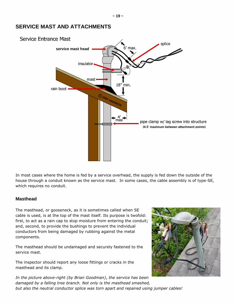
SERVICE MAST AND ATTACHMENTS
In most cases where the home is fed by a service overhead, the supply is fed down the outside of the
house through a conduit known as the service mast. In some cases, the cable assembly is of type-SE,
which requires no conduit.
Masthead
The masthead, or gooseneck, as it is sometimes called when SE
cable is used, is at the top of the mast itself. Its purpose is twofold:
first, to act as a rain cap to stop moisture from entering the conduit;
and, second, to provide the bushings to prevent the individual
conductors from being damaged by rubbing against the metal
components.
The masthead should be undamaged and securely fastened to the
service mast.
The inspector should report any loose fittings or cracks in the
masthead and its clamp.
In the picture above-right (by Brian Goodman), the service has been
damaged by a falling tree branch. Not only is the masthead smashed,
but also the neutral conductor splice was torn apart and repaired using jumper cables!
service mast head
(4.5’ maximum between attachment points)
~ 20 ~
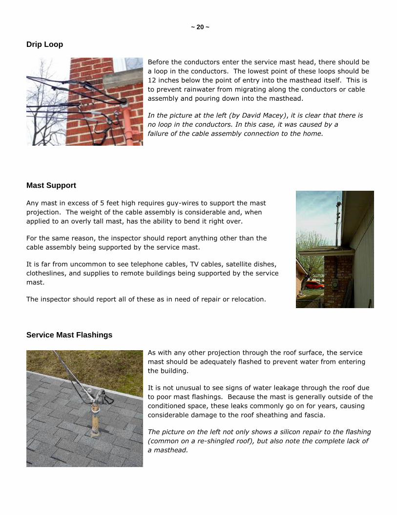
Drip Loop
Before the conductors enter the service mast head, there should be
a loop in the conductors. The lowest point of these loops should be
12 inches below the point of entry into the masthead itself. This is
to prevent rainwater from migrating along the conductors or cable
assembly and pouring down into the masthead.
In the picture at the left (by David Macey), it is clear that there is
no loop in the conductors. In this case, it was caused by a
failure of the cable assembly connection to the home.
Mast Support
Any mast in excess of 5 feet high requires guy-wires to support the mast
projection. The weight of the cable assembly is considerable and, when
applied to an overly tall mast, has the ability to bend it right over.
For the same reason, the inspector should report anything other than the
cable assembly being supported by the service mast.
It is far from uncommon to see telephone cables, TV cables, satellite dishes,
clotheslines, and supplies to remote buildings being supported by the service
mast.
The inspector should report all of these as in need of repair or relocation.
Service Mast Flashings
As with any other projection through the roof surface, the service
mast should be adequately flashed to prevent water from entering
the building.
It is not unusual to see signs of water leakage through the roof due
to poor mast flashings. Because the mast is generally outside of the
conditioned space, these leaks commonly go on for years, causing
considerable damage to the roof sheathing and fascia.
The picture on the left not only shows a silicon repair to the flashing
(common on a re-shingled roof), but also note the complete lack of
a masthead.
~ 21 ~
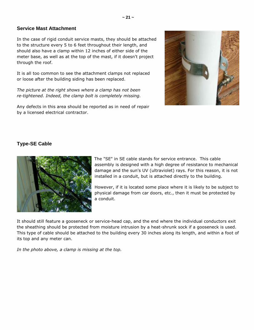
Service Mast Attachment
In the case of rigid conduit service masts, they should be attached
to the structure every 5 to 6 feet throughout their length, and
should also have a clamp within 12 inches of either side of the
meter base, as well as at the top of the mast, if it doesn't project
through the roof.
It is all too common to see the attachment clamps not replaced
or loose after the building siding has been replaced.
The picture at the right shows where a clamp has not been
re-tightened. Indeed, the clamp bolt is completely missing.
Any defects in this area should be reported as in need of repair
by a licensed electrical contractor.
Type-SE Cable
The "SE" in SE cable stands for service entrance. This cable
assembly is designed with a high degree of resistance to mechanical
damage and the sun's UV (ultraviolet) rays. For this reason, it is not
installed in a conduit, but is attached directly to the building.
However, if it is located some place where it is likely to be subject to
physical damage from car doors, etc., then it must be protected by
a conduit.
It should still feature a gooseneck or service-head cap, and the end where the individual conductors exit
the sheathing should be protected from moisture intrusion by a heat-shrunk sock if a gooseneck is used.
This type of cable should be attached to the building every 30 inches along its length, and within a foot of
its top and any meter can.
In the photo above, a clamp is missing at the top.
~ 22 ~
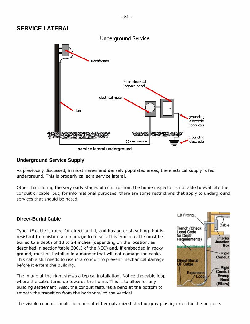
SERVICE LATERAL
Underground Service Supply
As previously discussed, in most newer and densely populated areas, the electrical supply is fed
underground. This is properly called a service lateral.
Other than during the very early stages of construction, the home inspector is not able to evaluate the
conduit or cable, but, for informational purposes, there are some restrictions that apply to underground
services that should be noted.
Direct-Burial Cable
Type-UF cable is rated for direct burial, and has outer sheathing that is
resistant to moisture and damage from soil. This type of cable must be
buried to a depth of 18 to 24 inches (depending on the location, as
described in section/table 300.5 of the NEC) and, if embedded in rocky
ground, must be installed in a manner that will not damage the cable.
This cable still needs to rise in a conduit to prevent mechanical damage
before it enters the building.
The image at the right shows a typical installation. Notice the cable loop
where the cable turns up towards the home. This is to allow for any
building settlement. Also, the conduit features a bend at the bottom to
smooth the transition from the horizontal to the vertical.
The visible conduit should be made of either galvanized steel or gray plastic, rated for the purpose.
service lateral underground
~ 23 ~
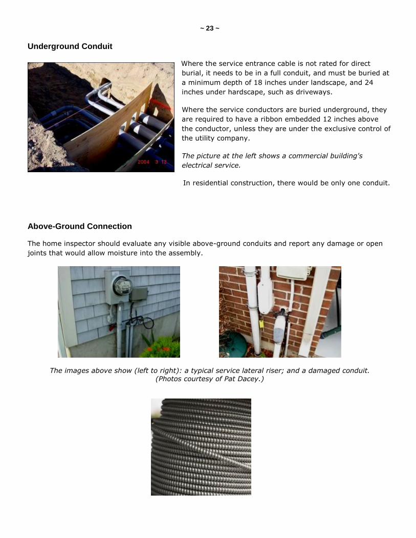
Underground Conduit
Where the service entrance cable is not rated for direct
burial, it needs to be in a full conduit, and must be buried at
a minimum depth of 18 inches under landscape, and 24
inches under hardscape, such as driveways.
Where the service conductors are buried underground, they
are required to have a ribbon embedded 12 inches above
the conductor, unless they are under the exclusive control of
the utility company.
The picture at the left shows a commercial building's
electrical service.
In residential construction, there would be only one conduit.
Above-Ground Connection
The home inspector should evaluate any visible above-ground conduits and report any damage or open
joints that would allow moisture into the assembly.
The images above show (left to right): a typical service lateral riser; and a damaged conduit.
(Photos courtesy of Pat Dacey.)
~ 24 ~
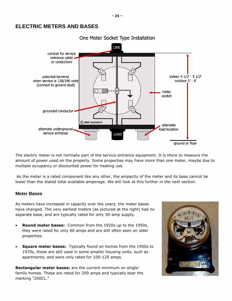
ELECTRIC METERS AND BASES
The electric meter is not normally part of the service entrance equipment. It is there to measure the
amount of power used on the property. Some properties may have more than one meter, maybe due to
multiple occupancy or discounted power for heating use.
As the meter is a rated component like any other, the ampacity of the meter and its base cannot be
lower than the stated total available amperage. We will look at this further in the next section.
Meter Bases
As meters have increased in capacity over the years, the meter bases
have changed. The very earliest meters (as pictured at the right) had no
separate base, and are typically rated for only 30-amp supply.
Round meter bases: Common from the 1920s up to the 1950s,
they were rated for only 60 amps and are still often seen on older
properties.
Square meter bases: Typically found on homes from the 1950s to
1970s, these are still used in some smaller housing units, such as
apartments, and were only rated for 100-125 amps.
Rectangular meter bases: are the current minimum on single-
family homes. These are rated for 200 amps and typically bear the
marking "200CL."
~ 25 ~
Understanding meter bases is an important part of being able to properly evaluate the maximum
available amperage in the home, but should not be relied on completely when sizing a service.
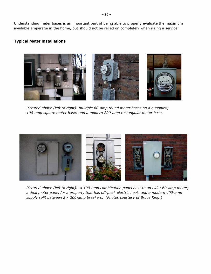
Typical Meter Installations
Pictured above (left to right): multiple 60-amp round meter bases on a quadplex;
100-amp square meter base; and a modern 200-amp rectangular meter base.
Pictured above (left to right): a 100-amp combination panel next to an older 60-amp meter;
a dual meter panel for a property that has off-peak electric heat; and a modern 400-amp
supply split between 2 x 200-amp breakers. (Photos courtesy of Bruce King.)
~ 26 ~
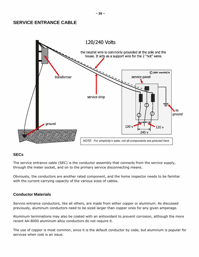
SERVICE ENTRANCE CABLE
SECs
The service entrance cable (SEC) is the conductor assembly that connects from the service supply,
through the meter socket, and on to the primary service disconnecting means.
Obviously, the conductors are another rated component, and the home inspector needs to be familiar
with the current-carrying capacity of the various sizes of cables.
Conductor Materials
Service entrance conductors, like all others, are made from either copper or aluminum. As discussed
previously, aluminum conductors need to be sized larger than copper ones for any given amperage.
Aluminum terminations may also be coated with an antioxidant to prevent corrosion, although the more
recent AA-8000 aluminum alloy conductors do not require it.
The use of copper is most common, since it is the default conductor by code, but aluminum is popular for
services when cost is an issue.
NOTE: For simplicity’s sake, not all components are pictured here.
~ 27 ~
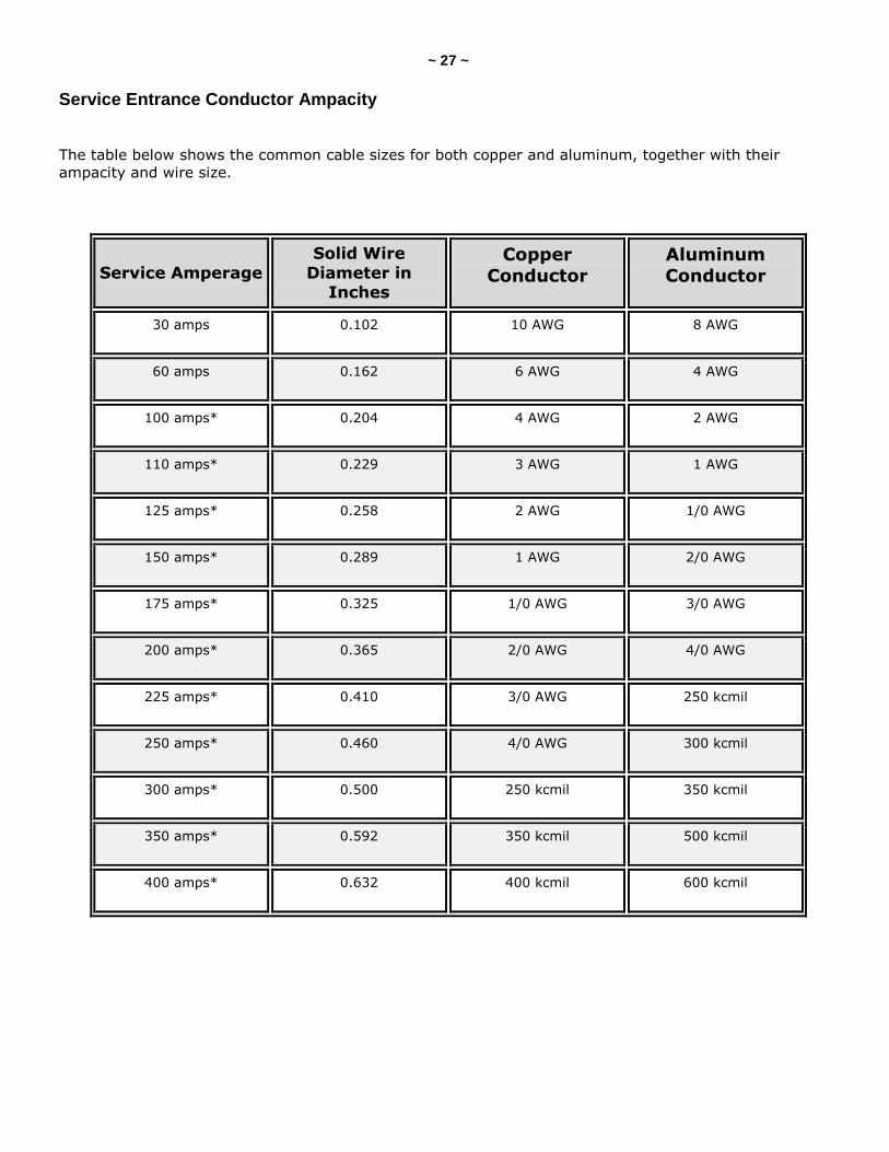
Service Entrance Conductor Ampacity
The table below shows the common cable sizes for both copper and aluminum, together with their
ampacity and wire size.
Service Amperage
Solid Wire
Diameter in Inches
Copper
Conductor
Aluminum
Conductor
30 amps 0.102 10 AWG 8 AWG
60 amps 0.162 6 AWG 4 AWG
100 amps* 0.204 4 AWG 2 AWG
110 amps* 0.229 3 AWG 1 AWG
125 amps* 0.258 2 AWG 1/0 AWG
150 amps* 0.289 1 AWG 2/0 AWG
175 amps* 0.325 1/0 AWG 3/0 AWG
200 amps* 0.365 2/0 AWG 4/0 AWG
225 amps* 0.410 3/0 AWG 250 kcmil
250 amps* 0.460 4/0 AWG 300 kcmil
300 amps* 0.500 250 kcmil 350 kcmil
350 amps* 0.592 350 kcmil 500 kcmil
400 amps* 0.632 400 kcmil 600 kcmil
~ 28 ~
NOTE:
Increasing gauge numbers provides decreasing wire diameters. For example, when the diameter of a wire
is doubled, the AWG decreases by 6. The AWG sizes are for single, solid, round conductors. The AWG of
a stranded wire is determined by the total cross-sectional area of the conductor, which determines the
current-carrying capacity and electrical resistance. The stranded wire is about 5% larger in overall
diameter than a solid wire of the same AWG.
* 100-amp to 400-amp services are based on 3-wire, 120/240-volt systems, and 310.15 (B)(6) of the
NEC.
AWG = American wire gauge, also known as the Brown & Sharpe wire gauge, is a standardized wire
gauge system used in the U.S. and Canada. ―AWG‖ is referred to as a gauge, and the zeroes in large wire
sizes are referred to as ―aught.‖ Wire sized 1 AWG is referred to as ―one gauge‖ or ―No. 1‖ wire. Smaller-
diameter wires are called ―x gauge‖ or ―No. X‖ wire, where x is the positive-integer AWG number. No. 0,
written 1/0, is referred to as ―1 aught‖ wire. 2/0 is referred to as ―2 aught,‖ and so on.
kcmil = This wire size is the equivalent cross-sectional area in thousands of circular mils. A circular mil
is the area of a circle with a diameter of one-thousandth (0.001) of an inch. In North America, conductors
larger than 4/0 AWG are typically identified by kcmil.
~ 29 ~
QUIZ on SEC
1. Which of the following would describe most residential services?
110/220-volt
120/240-volt
240-volt only
120-volt only
2. A service entrance with four connected conductors is a ________ supply.
120/240
120-volt only
3-phase
3. The service drop should not pass closer than _____ to the bottom, front or sides of a window.
5 feet
6 feet
8 feet
3 feet
4 feet
4. The minimum service drop clearance over a flat roof used as a roof garden should be _______.
18 feet
8 feet
10 feet
12 feet
5. Service drops around a swimming pool should be _______.
10 feet above and 22 feet horizontally away
18 feet above and 10 feet horizontally away
10 feet above and 20 feet horizontally away
22½ feet above and 10 feet horizontally away
15 feet above and 8 feet horizontally away
12 feet above and 15 feet horizontally away
(continued)
~ 30 ~
6. Service drops should never pass closer than ________ above the ridge of a conventional pitched roof.
5 feet
3 feet
8 feet
7. Tree limbs should be trimmed back to ________ away from the service drop.
5 to 6 feet
1 to 2 feet
4 to 5 feet
2 to 3 feet
8. An electrical service mast that extends more than ______ above the roof surface should be separately supported.
6 feet
3 feet
5 feet
4 feet
9. Which of the following may also be supported by the electrical service mast?
all of these
telephone cables
satellite dishes
none of these
clothes lines
10. Rigid service masts should be secured to the structure every _______.
36 to 48 inches
2 to 3 feet
30 inches
5 to 6 feet
(continued)
~ 31 ~
11. Which type of cable is listed for direct burial?
UV
BX
AC
Romex®
UF
UL
12. An underground service entrance is called a ________.
service lateral
service drop
subterranean supply
13. Square electric meter bases are indicative of a _________.
150-amp supply
60-amp supply
100-amp supply
30-amp supply
14. Most modern 200-amp electrical meters are marked __________.
200 CL
200 UL
200 SEC
100 CL
100 UL
100 SEC
15. The minimum conductor size for a 100-amp service is ___________.
2 AWG copper or 4 AWG aluminum
4 AWG copper or 2 AWG aluminum
2 AWG copper or 1 AWG aluminum
1 AWG copper or 2 AWG aluminum
Answer Key is on the next page.
~ 32 ~
Answer Key to Quiz on SEC
1. Which of the following would describe most residential services? Answer: 120/240-volt
2. A service entrance with four connected conductors is a 3-phase supply.
3. The service drop should not pass closer than 3 feet to the bottom, front or sides of a window.
4. The minimum service drop clearance over a flat roof used as a roof garden should be 10 feet.
5. Service drops around a swimming pool should be 22½ feet above and 10 feet horizontally away.
6. Service drops should never pass closer than 3 feet above the ridge of a conventional pitched roof.
7. Tree limbs should be trimmed back to 5 to 6 feet away from the service drop.
8. An electrical service mast that extends more than 5 feet above the roof surface should be separately supported.
9. Which of the following may also be supported by the electrical service mast? Answer: none of these
10. Rigid service masts should be secured to the structure every 5 to 6 feet.
11. Which type of cable is listed for direct burial? Answer: UF
12. An underground service entrance is called a service lateral.
13. Square electric meter bases are indicative of a 100-amp supply.
14. Most modern 200-amp electrical meters are marked 200 CL.
15. The minimum conductor size for a 100-amp service is 4-AWG copper or 2-AWG aluminum.
~ 33 ~
GROUNDING AND BONDING
GROUNDING SYSTEM
What Is Grounding?
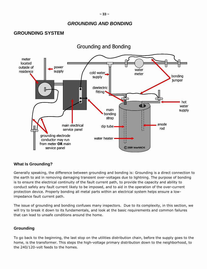
Generally speaking, the difference between grounding and bonding is: Grounding is a direct connection to
the earth to aid in removing damaging transient over-voltages due to lightning. The purpose of bonding
is to ensure the electrical continuity of the fault current path, to provide the capacity and ability to
conduct safely any fault current likely to be imposed, and to aid in the operation of the over-current
protection device. Properly bonding all metal parts within an electrical system helps ensure a low-
impedance fault current path.
The issue of grounding and bonding confuses many inspectors. Due to its complexity, in this section, we
will try to break it down to its fundamentals, and look at the basic requirements and common failures
that can lead to unsafe conditions around the home.
Grounding
To go back to the beginning, the last stop on the utilities distribution chain, before the supply goes to the
home, is the transformer. This steps the high-voltage primary distribution down to the neighborhood, to
the 240/120-volt feeds to the homes.
~ 34 ~
This transformer has a winding known as a phase coil that is center-tapped to provide voltage
stabilization, and a return path for the higher voltage system to aid in clearing primary side faults. As
discussed earlier, on a typical 240/120-volt service drop, we will have two ungrounded conductors and a
single grounded conductor.
This means that we have to establish our own grounding electrode system at the dwelling. It is vital in
removing dangerous voltages imposed on the system via lightning strikes and over-voltage surges from
higher voltages on power lines. If ground-rod, pipe or plate electrodes are used, they must have a rating
of 25 Ohms or less; otherwise, an additional electrode must be added, per Section 250.56 of the NEC.
Grounding Electrodes
There are several methods of connecting the grounding system to the ground, with a driven rod being the
most common in most areas. Most residential construction requires two separate grounding electrodes in
any combination of the following (which need to be at least 6 feet apart):
driven rods;
metal water pipes;
well casings;
Ufer grounds;
ground plates;
steel framing; and
ground rings.
Historically, the grounding system had just one connection to ground, and this was nearly always made
on the water supply pipe. However, two connections are now required by most jurisdictions to ensure a
low-impedance ground (one with little resistance).
Because most utility companies now install plastic potable water supply lines, a water pipe cannot be
used as a grounding means, so one of the other electrodes listed must be used. It is also important to
note that all electrodes that are present in the dwelling must be bonded together to form a single and
complete grounding electrode system.
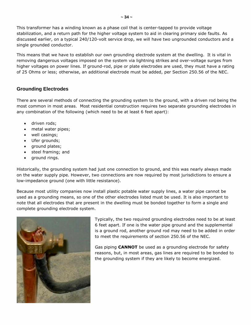
Typically, the two required grounding electrodes need to be at least
6 feet apart. If one is the water pipe ground and the supplemental
is a ground rod, another ground rod may need to be added in order
to meet the requirements of section 250.56 of the NEC.
Gas piping CANNOT be used as a grounding electrode for safety
reasons, but, in most areas, gas lines are required to be bonded to
the grounding system if they are likely to become energized.
~ 35 ~
Driven Rods
Rods made of stainless steel and copper, or zinc-coated steel, shall be at least 5/8-inch in diameter,
unless listed, but not less than ½-inch in diameter. The rods should be driven 8 feet into the earth. If
pipe or conduit is used as a grounding electrode, it must also be no less than 8 feet in length, and no
smaller than trade size or ¾-inch. Pipe or conduit made of steel shall have an outer surface that is
galvanized or otherwise metal-coated to resist corrosion. The ground wire (the grounding electrode
conductor) needs to be fastened with the correct approved clamp/s, and these need to be rated for
direct burial, if located below ground.
It is common to see these "acorn" clamps installed improperly, with the conductor clamped under the
screw rather than to the solid part of the clamp which has the biggest contact area. The photo on the
previous page demonstrates this problem.
Sometimes, in very rocky earth, the rods cannot be driven perpendicular to the ground, so they may be
driven at an angle of less than 45 degrees. If they cannot be driven at all due to unfavorable soil
conditions, they can be installed in a trench no less than 30 inches deep. But no part of any grounding
electrode can be closer than 6 feet to any other.
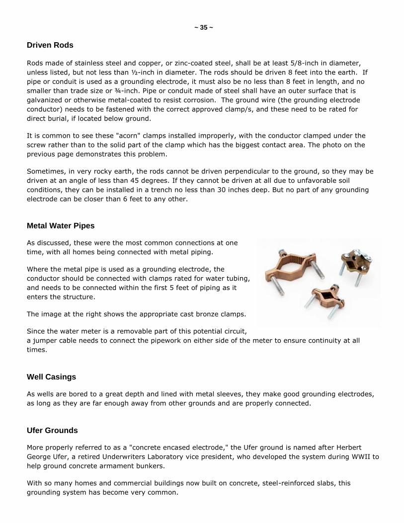
Metal Water Pipes
As discussed, these were the most common connections at one
time, with all homes being connected with metal piping.
Where the metal pipe is used as a grounding electrode, the
conductor should be connected with clamps rated for water tubing,
and needs to be connected within the first 5 feet of piping as it
enters the structure.
The image at the right shows the appropriate cast bronze clamps.
Since the water meter is a removable part of this potential circuit,
a jumper cable needs to connect the pipework on either side of the meter to ensure continuity at all
times.
Well Casings
As wells are bored to a great depth and lined with metal sleeves, they make good grounding electrodes,
as long as they are far enough away from other grounds and are properly connected.
Ufer Grounds
More properly referred to as a "concrete encased electrode," the Ufer ground is named after Herbert
George Ufer, a retired Underwriters Laboratory vice president, who developed the system during WWII to
help ground concrete armament bunkers.
With so many homes and commercial buildings now built on concrete, steel-reinforced slabs, this
grounding system has become very common.
~ 36 ~
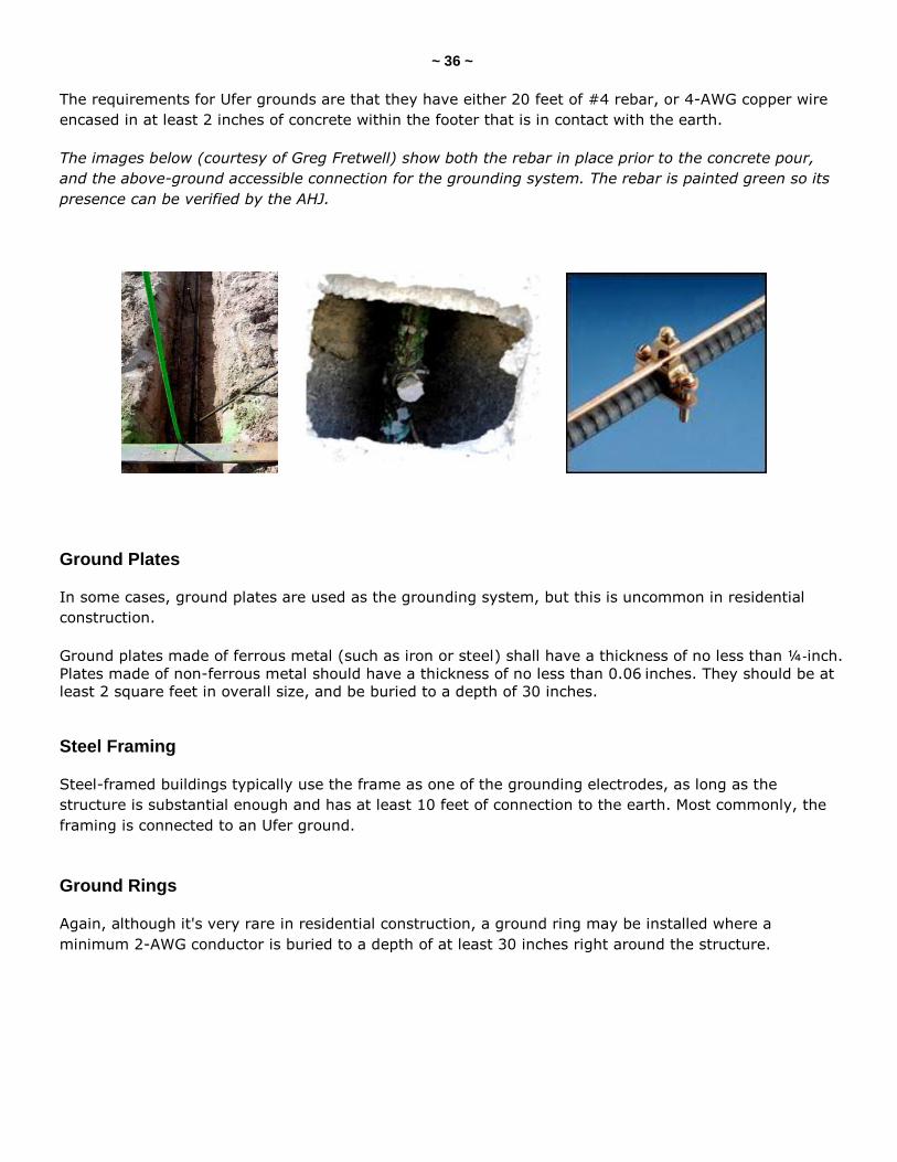
The requirements for Ufer grounds are that they have either 20 feet of #4 rebar, or 4-AWG copper wire
encased in at least 2 inches of concrete within the footer that is in contact with the earth.
The images below (courtesy of Greg Fretwell) show both the rebar in place prior to the concrete pour,
and the above-ground accessible connection for the grounding system. The rebar is painted green so its
presence can be verified by the AHJ.
Ground Plates
In some cases, ground plates are used as the grounding system, but this is uncommon in residential
construction.
Ground plates made of ferrous metal (such as iron or steel) shall have a thickness of no less than ¼-inch.
Plates made of non-ferrous metal should have a thickness of no less than 0.06 inches. They should be at
least 2 square feet in overall size, and be buried to a depth of 30 inches.
Steel Framing
Steel-framed buildings typically use the frame as one of the grounding electrodes, as long as the
structure is substantial enough and has at least 10 feet of connection to the earth. Most commonly, the
framing is connected to an Ufer ground.
Ground Rings
Again, although it's very rare in residential construction, a ground ring may be installed where a
minimum 2-AWG conductor is buried to a depth of at least 30 inches right around the structure.
~ 37 ~
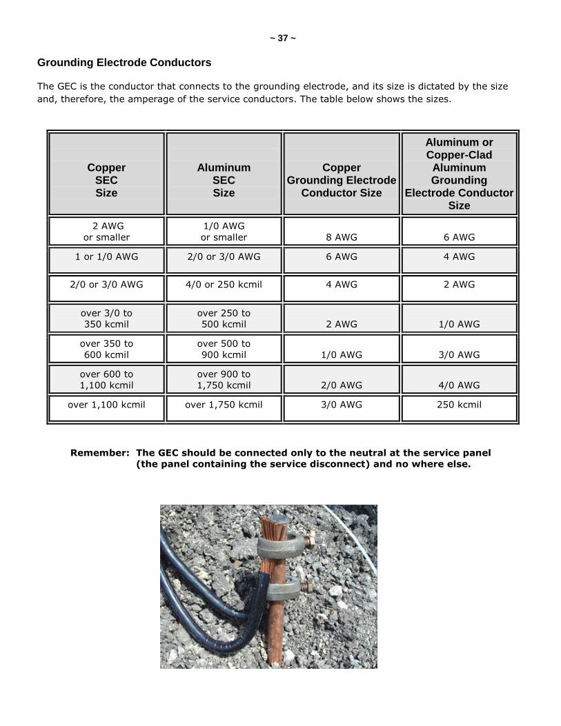
Grounding Electrode Conductors
The GEC is the conductor that connects to the grounding electrode, and its size is dictated by the size
and, therefore, the amperage of the service conductors. The table below shows the sizes.
Copper SEC Size
Aluminum SEC Size
Copper Grounding Electrode
Conductor Size
Aluminum or Copper-Clad
Aluminum Grounding
Electrode Conductor Size
2 AWG
or smaller
1/0 AWG
or smaller
8 AWG
6 AWG
1 or 1/0 AWG 2/0 or 3/0 AWG 6 AWG 4 AWG
2/0 or 3/0 AWG 4/0 or 250 kcmil 4 AWG 2 AWG
over 3/0 to
350 kcmil
over 250 to
500 kcmil
2 AWG
1/0 AWG
over 350 to
600 kcmil
over 500 to
900 kcmil
1/0 AWG
3/0 AWG
over 600 to
1,100 kcmil
over 900 to
1,750 kcmil
2/0 AWG
4/0 AWG
over 1,100 kcmil over 1,750 kcmil 3/0 AWG 250 kcmil
Remember: The GEC should be connected only to the neutral at the service panel
(the panel containing the service disconnect) and no where else.
~ 38 ~
BONDING OF COMPONENTS
The purpose of bonding is to ensure the electrical continuity of the fault current path, provide the
capacity and ability to conduct safely any fault current likely to be imposed, and to aid in the operation of
the over-current protection device.
As discussed in the section on panel enclosures, they need to be bonded to the grounding system.
But there is also a very long list of other components that need to be connected to ground, since they
have the potential to become energized to electrical faults. These components include:
interior water piping;
water heaters;
around water meters;
gas lines;
electrical enclosures;
electrical raceways;
electric outlets or junction boxes;
CSST gas piping (manufacturer’s compliance); and
telephone and cable TV systems.
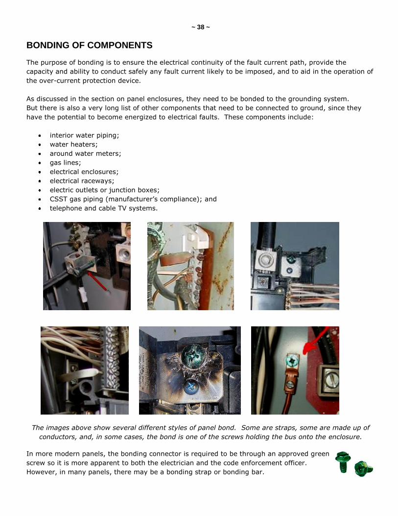
The images above show several different styles of panel bond. Some are straps, some are made up of
conductors, and, in some cases, the bond is one of the screws holding the bus onto the enclosure.
In more modern panels, the bonding connector is required to be through an approved green
screw so it is more apparent to both the electrician and the code enforcement officer.
However, in many panels, there may be a bonding strap or bonding bar.
~ 39 ~
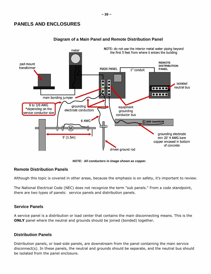
PANELS AND ENCLOSURES
NOTE: All conductors in image shown as copper.
Remote Distribution Panels
Although this topic is covered in other areas, because the emphasis is on safety, it's important to review.
The National Electrical Code (NEC) does not recognize the term "sub panels." From a code standpoint,
there are two types of panels: service panels and distribution panels.
Service Panels
A service panel is a distribution or load center that contains the main disconnecting means. This is the
ONLY panel where the neutral and grounds should be joined (bonded) together.
Distribution Panels
Distribution panels, or load-side panels, are downstream from the panel containing the main service
disconnect(s). In these panels, the neutral and grounds should be separate, and the neutral bus should
be isolated from the panel enclosure.
Diagram of a Main Panel and Remote Distribution Panel
REMOTE DISTRIBUTION PANEL
~ 40 ~
The only exception to this is in existing detached structures where no metallic path exists between the
structures. In this exception, a connection between the grounded conductor and the metal case via a
bonding jumper is permitted. According to the 2008 NEC, this is not allowed in new construction, so, in
all cases, a 4-wire feed to the detached structure is required in order to isolate the grounded conductors
from the equipment grounding conductors.
There are two methods of providing ground continuity back to the service panel:
1. four conductor feeders with:
two hot or ungrounded conductors;
one neutral or grounded conductor; and
one equipment grounding conductor.
2. three conductor feeders with:
two hot or ungrounded conductors;
one neutral or grounded conductor; and
equipment grounding through conduit/tubing, electrically linking the two panels (allowed by
section 250.118 of the NEC).
Inspecting Service Panels
1. Are the neutral and ground connected (bonded)?
2. Is the panel enclosure connected (bonded) to ground?
3. Does each neutral conductor terminate at a separate lug on its bus?
Inspecting Distribution Panels
1. How is the service grounded back to the service panel?
2. Are the neutrals and grounds separated?
3. Is the neutral bus isolated from the panel enclosure?
4. Is the panel enclosure connected (bonded) to the grounding bus?
5. Does each neutral conductor terminate at a separate lug on its bus?
IMPORTANT NOTE: Every structure is required to have a grounding electrode system. If they are
present in the structure, they must all be bonded together. If a detached structure has a remote
distribution panel located at the structure, then it requires a grounding electrode system of its own. The
equipment grounding conductor in a 4-wire feeder does not take the place of the required grounding
electrodes. It is also important to understand that if the detached structure is being fed by a single
branch circuit, and it contains an equipment grounding conductor which is used for grounding the non-
current-carrying metal parts of equipment, then no grounding electrode system is required.
~ 41 ~
Further Evaluation
The inspector should pay very close attention to the grounding and bonding of all electrical circuits.
Sometimes, it is very hard to figure out which components are electrically connected to others.
Do not disturb conductors in the panel! The inspector is limited to a visual inspection only. Probing
around inside energized panels may cause loose conductors to become detached, or result in electric
shock.
When in doubt, defer to a licensed electrical contractor.
~ 42 ~
QUIZ on GROUNDING and BONDING
1. Most jurisdictions require _____ separate grounding means.
four
three
one
two
2. The minimum size for a stainless steel, unlisted driven grounding rod is _______.
5/8-inch diameter and 6 feet long
½-inch diameter and 8 feet long
½-inch diameter and 6 feet long
5/8-inch diameter and 8 feet long
3. T/F: Driven grounding rods can only be perfectly vertical.
True
False
4. Which of the following cannot be used as a grounding means?
steel framing
water piping
gas supply piping
well casings
5. T/F: Only panel enclosures containing the service disconnect need to be bonded to ground.
True
False
6. The grounded and grounding conductors can share a common bus only in________.
the service panel
any electrical panel
the distribution panel
(continued)
~ 43 ~
7. The ungrounded and grounding conductors can share a common bus ?
in any distribution panels
never
in the downstream distribution panels
in the service panel
8. Which of the following is an acceptable means of bonding a remote distribution panel?
connecting the enclosure to the grounding bus
connecting the enclosure to the ungrounded conductor bus
connecting the enclosure to the neutral bus
9. Conductors between the main service disconnect and the distribution panels are called __________.
legs
runners
feeders
travelers
Answer Key is on the next page.
~ 44 ~
Answer Key to Quiz on Grounding and Bonding
1. Most jurisdictions require two separate grounding means.
2. The minimum size for a stainless steel, unlisted driven grounding rod is ½-inch diameter and 8 feet long.
3. T/F: Driven grounding rods can only be perfectly vertical. Answer: False
4. Which of the following cannot be used as a grounding means? Answer: gas supply piping
5. T/F: Only panel enclosures containing the service disconnect need to be bonded to ground. Answer: False
6. The grounded and grounding conductors can share a common bus only in the service panel.
7. The ungrounded and grounding conductors can share a common bus never.
8. Which of the following is an acceptable means of bonding a remote distribution panel? Answer: connecting the enclosure to the grounding bus
9. Conductors between the main service disconnect and the distribution panels are called feeders.
~ 45 ~
SERVICE PANELS
THE MAIN DISCONNECT
The Service Disconnect
All electrical systems require a means of disconnection so that the service can be shut down quickly if any
dangerous conditions exist. In this section, we will look at the types of disconnects, and the common
problems that need to be reported.
Requirements
It is required that the entire electrical supply to the home be able to be shut off with six or fewer moves
of the hand. This can be in the form of one or more knife switches, one or more fuses or fuse blocks, and,
most commonly and in more recently built homes, by throwing the breaker(s).
If the supply cannot be disconnected from one location in this manner, the home inspector should report
that the system is in need of repairs or upgrade.
Types of Disconnect
As discussed, different systems are in common use today, depending on the age of the property:
knife switch: This is the oldest type of disconnecting means. We all remember the old horror
movies where Dr. Frankenstein was shown energizing his creation. The switches he used
were knife switches.
fuse blocks: Often called mains and range panels, the electrical supply is shut down by pulling
the two fuse blocks from the panel.
breaker(s): This is the most common type of disconnect we encounter. Throwing one or more
breakers shuts off the electrical power. In most cases, we see a single main breaker, but there are
"split bus" panels where the homeowner would need to trip several breakers to effect a total shut-
down.
Again, the rating (or fuse or breaker size) of the disconnect relates to the total amperage available within
the home. If the main disconnect is, for example, rated only at 100 amps, it doesn't matter that the SECs
are rated for 200 amps.
~ 46 ~
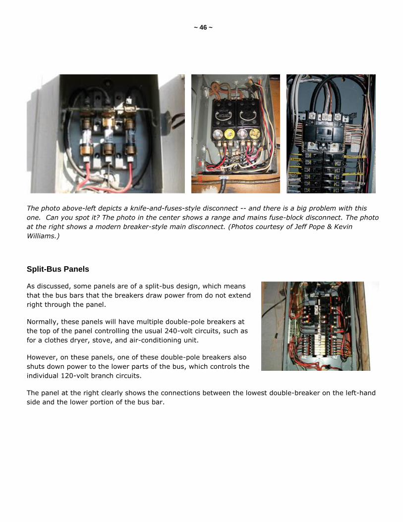
The photo above-left depicts a knife-and-fuses-style disconnect -- and there is a big problem with this
one. Can you spot it? The photo in the center shows a range and mains fuse-block disconnect. The photo
at the right shows a modern breaker-style main disconnect. (Photos courtesy of Jeff Pope & Kevin
Williams.)
Split-Bus Panels
As discussed, some panels are of a split-bus design, which means
that the bus bars that the breakers draw power from do not extend
right through the panel.
Normally, these panels will have multiple double-pole breakers at
the top of the panel controlling the usual 240-volt circuits, such as
for a clothes dryer, stove, and air-conditioning unit.
However, on these panels, one of these double-pole breakers also
shuts down power to the lower parts of the bus, which controls the
individual 120-volt branch circuits.
The panel at the right clearly shows the connections between the lowest double-breaker on the left-hand
side and the lower portion of the bus bar.
~ 47 ~
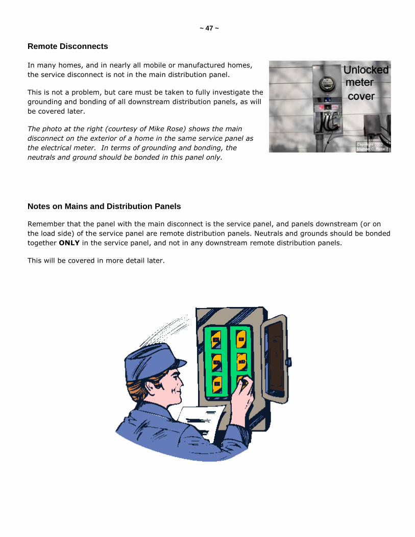
Remote Disconnects
In many homes, and in nearly all mobile or manufactured homes,
the service disconnect is not in the main distribution panel.
This is not a problem, but care must be taken to fully investigate the
grounding and bonding of all downstream distribution panels, as will
be covered later.
The photo at the right (courtesy of Mike Rose) shows the main
disconnect on the exterior of a home in the same service panel as
the electrical meter. In terms of grounding and bonding, the
neutrals and ground should be bonded in this panel only.
Notes on Mains and Distribution Panels
Remember that the panel with the main disconnect is the service panel, and panels downstream (or on
the load side) of the service panel are remote distribution panels. Neutrals and grounds should be bonded
together ONLY in the service panel, and not in any downstream remote distribution panels.
This will be covered in more detail later.
~ 48 ~
SERVICE AMPERAGE
Reporting Amperage
Industry standards require that the home inspector reports the total available amperage in the home.
This is important for two reasons. First, an older home may not have enough power for a modern family's
needs. Second, many insurance companies will not insure a property with less than a 100-amp service.
As illustrated in the section on meters, electrical services have gotten much bigger since we first started
wiring homes for electricity over 100 years ago. When homes were first wired for power, there were few
electrical devices available, so a couple of 15-amp lighting circuits, and maybe a radiogram outlet, were
all that was needed.
Obviously, in the modern age, we have gotten much more ambitious with our use of electric power. Just
about every room in the home has multiple appliances in it, and we need high-amperage 240-volt circuits
to run systems such as central air conditioning and electric clothes dryers.
Development of Power Needs
The list below is intended to be no more than a rough rule of thumb covering the average unimproved
electrical supply over the last century, and would cover the average 1,500- to 2,000-square-foot home.
1900s to 1930s: 30-amp supply
1930s to 1950s: 60-amp supply
1950s to 1970s: 100-amp supply
1970s to 1980s: 150-amp supply
1980s to 2000s: 200-amp supply
Obviously, larger and more expensive home have always required more power than the norm, and it is
not unusual now to see 400+-amp services in high-end homes.
Calculating Available Amperage
In many cases, the listing information about a home is incorrect regarding the service amperage because
brokers or owners rely solely on the size of the main breaker or fuse. Many people are also under the
mistaken impression that the available amperage is the total of the individual breakers or fuses in the
service panel.
The correct way to determine the available amperage is to determine the ampacity of the lowest-rated
or the weakest link of the following components:
service supply;
electric meter and socket;
service entrance conductors;
service disconnect; or
distribution panel.
~ 49 ~
Here are a couple of examples:
Example #1:
A 200-amp service lateral,
a 200-amp meter and base,
a 175-amp-rated SEC,
a 150-amp-rated panel, and
+ a 125-amp service disconnect
= A 125-amp reportable service supply
Example #2:
A 150-amp service drop,
a 60-amp meter and base,
a 150-amp SEC,
a 100-amp-rated panel, and
+ a 100-amp service disconnect
= A 60-amp reportable service supply
A home inspector getting this wrong could potentially end up paying for a service upgrade costing several
thousand dollars.
~ 50 ~
INSPECTING ENCLOSURES, Part I
Reportable Panel Issues, Part I
All panels and enclosures, regardless of their purpose, should be inspected for the following safety-
related issues. Any deficiencies should be reported as in need of repair or replacement by a licensed
electrical contractor.
All of the following hark back to the beginning of this text, as they are all related to safety:
panel access;
missing knockouts;
missing bushings;
moisture;
rust;
signs of arcing;
incorrect dead-front screws;
panel listings (UL ratings);
missing legend;
damaged breakers; and
panel bonding.
~ 51 ~
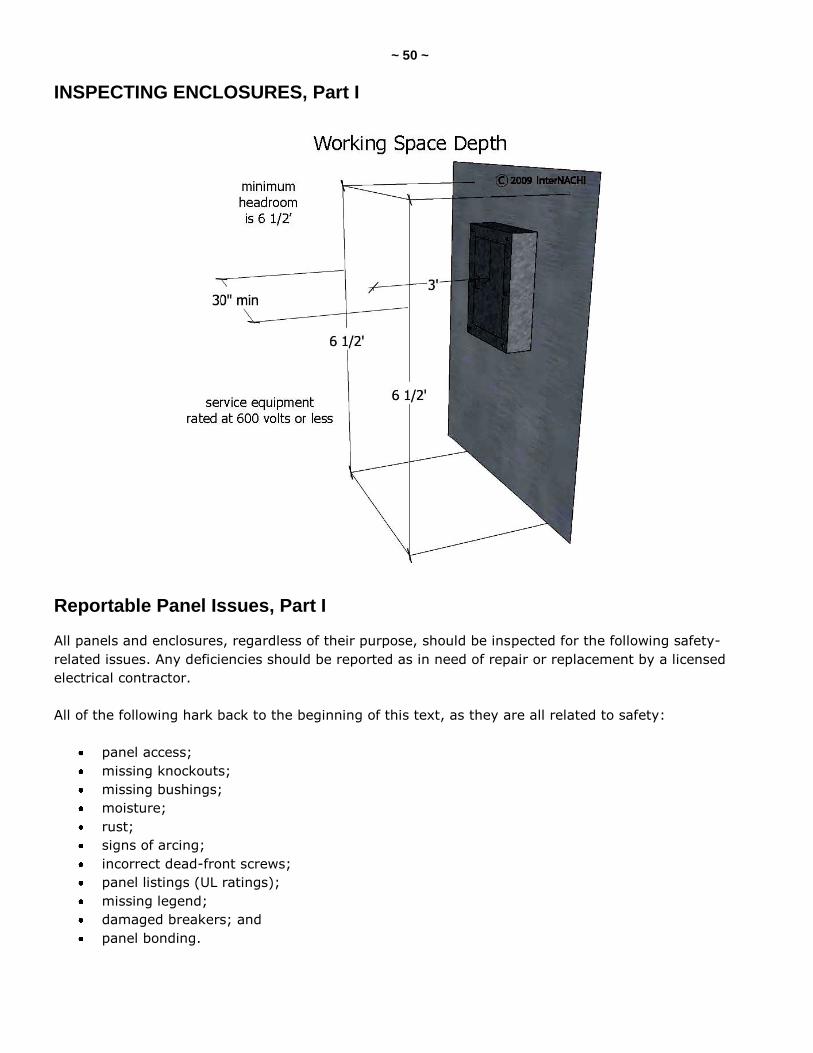
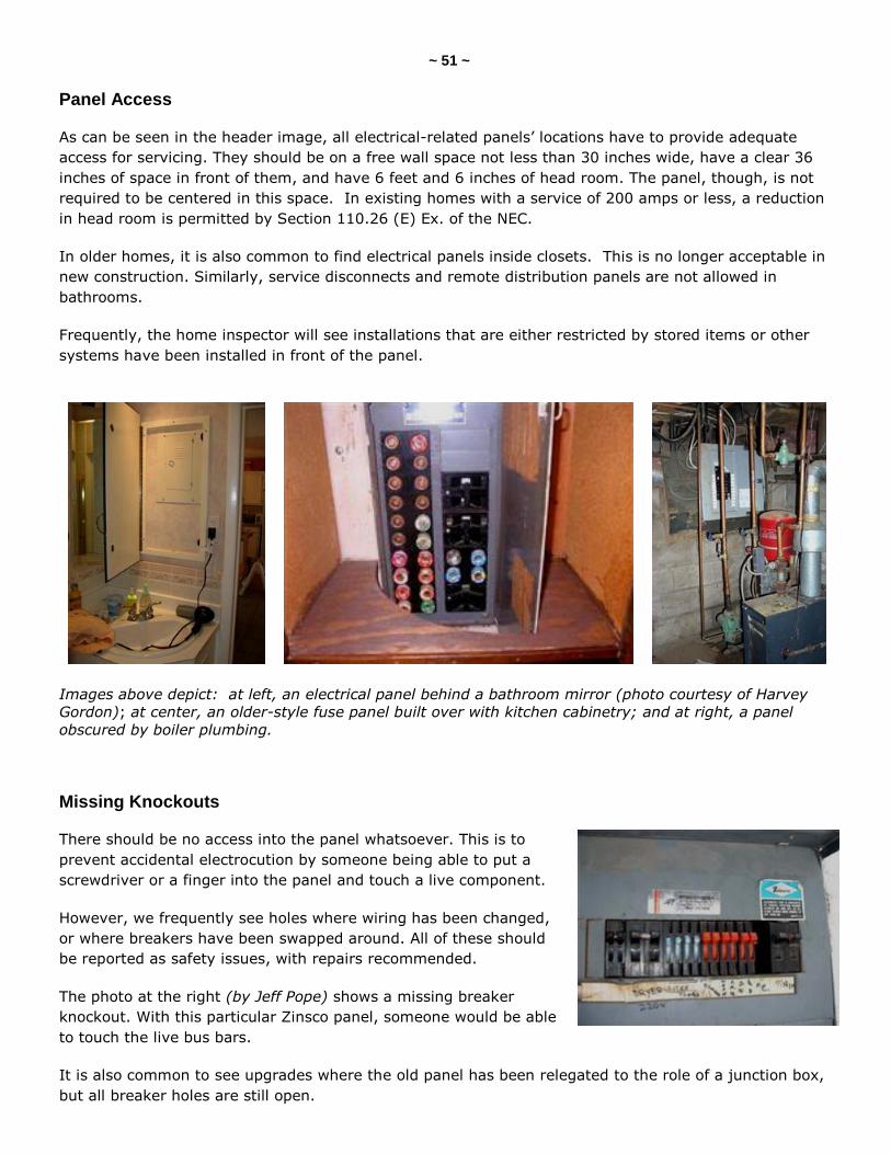
Panel Access
As can be seen in the header image, all electrical-related panels’ locations have to provide adequate
access for servicing. They should be on a free wall space not less than 30 inches wide, have a clear 36
inches of space in front of them, and have 6 feet and 6 inches of head room. The panel, though, is not
required to be centered in this space. In existing homes with a service of 200 amps or less, a reduction
in head room is permitted by Section 110.26 (E) Ex. of the NEC.
In older homes, it is also common to find electrical panels inside closets. This is no longer acceptable in
new construction. Similarly, service disconnects and remote distribution panels are not allowed in
bathrooms.
Frequently, the home inspector will see installations that are either restricted by stored items or other
systems have been installed in front of the panel.
Images above depict: at left, an electrical panel behind a bathroom mirror (photo courtesy of Harvey
Gordon); at center, an older-style fuse panel built over with kitchen cabinetry; and at right, a panel
obscured by boiler plumbing.
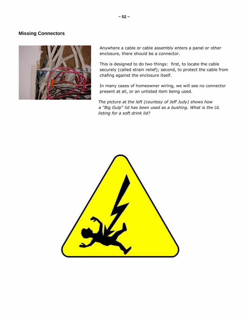
Missing Knockouts
There should be no access into the panel whatsoever. This is to
prevent accidental electrocution by someone being able to put a
screwdriver or a finger into the panel and touch a live component.
However, we frequently see holes where wiring has been changed,
or where breakers have been swapped around. All of these should
be reported as safety issues, with repairs recommended.
The photo at the right (by Jeff Pope) shows a missing breaker
knockout. With this particular Zinsco panel, someone would be able
to touch the live bus bars.
It is also common to see upgrades where the old panel has been relegated to the role of a junction box,
but all breaker holes are still open.
~ 52 ~
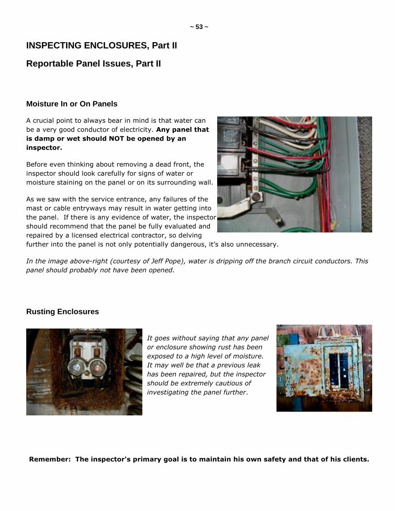
Missing Connectors
Anywhere a cable or cable assembly enters a panel or other
enclosure, there should be a connector.
This is designed to do two things: first, to locate the cable
securely (called strain relief); second, to protect the cable from
chafing against the enclosure itself.
In many cases of homeowner wiring, we will see no connector
present at all, or an unlisted item being used.
The picture at the left (courtesy of Jeff Judy) shows how
a "Big Gulp" lid has been used as a bushing. What is the UL
listing for a soft drink lid?
~ 53 ~
INSPECTING ENCLOSURES, Part II
Reportable Panel Issues, Part II
Moisture In or On Panels
A crucial point to always bear in mind is that water can
be a very good conductor of electricity. Any panel that
is damp or wet should NOT be opened by an
inspector.
Before even thinking about removing a dead front, the
inspector should look carefully for signs of water or
moisture staining on the panel or on its surrounding wall.
As we saw with the service entrance, any failures of the
mast or cable entryways may result in water getting into
the panel. If there is any evidence of water, the inspector
should recommend that the panel be fully evaluated and
repaired by a licensed electrical contractor, so delving
further into the panel is not only potentially dangerous, it’s also unnecessary.
In the image above-right (courtesy of Jeff Pope), water is dripping off the branch circuit conductors. This
panel should probably not have been opened.
Rusting Enclosures
It goes without saying that any panel
or enclosure showing rust has been
exposed to a high level of moisture.
It may well be that a previous leak
has been repaired, but the inspector
should be extremely cautious of
investigating the panel further.
Remember: The inspector's primary goal is to maintain his own safety and that of his clients.

~ 54 ~
Damaged Breakers
There are several issues related to circuit breakers:
1. Are they rated for the model of panel they are installed in?
2. Do they have their handle ties in place on double-pole breakers so that both sides of the circuit
can be shut off at the same moment?
3. Are there any signs of arcing, burning or smoke damage that would indicate that the breaker is
not tripping as intended?
We will look at these issues in more detail later.
Signs of Arcing
As part of the initial visual inspection of a panel, the inspector should look closely for any signs of arcing
or burn marks on the panel. Again, these may be the result of previously repaired problems, but don't
count on it. Also, take a second to listen to the panel because, in many cases, you may hear arcing.
Arcing or smoke damage on the outside of the panel is obviously indicative of a previously significant and
dangerous condition. It is recommended that the inspector, at a minimum, ask the homeowner for details
of the damage, and its repair, prior to opening the panel.
Remember, there are many issues that can lead to this kind of telltale marking, and many of those can
lead to the panelboard being live, or short circuits being caused by removal of the dead front.
In the images above: Notice the burn mark above the air freshener in the photo at the left (photo
courtesy of Home Works Inspection). In the center photo, what caused the flash mark on this dead
front? (Photo courtesy of John Onofrey.) The photo at the right shows a smoke-damaged fuse panel
(courtesy of Charles Buell).
~ 55 ~
INSPECTING ENCLOSURES, Part III
Reportable Panel Issues, Part III
Incorrect Dead-Front Screws
As was discussed for arcing issues, many faults related to damage to conductors inside the panel are
caused by either the wrong screws being used, or the correct screws running up against the live
conductors and causing a dead short against the panelboard.
The result is that an arc flash vaporizes the steel of the screw and panel, or the copper of the conductor,
and can send a cloud of molten metal and sparks straight out.
That's why the inspector needs to be wearing safety glasses and cotton clothing.
The images above (courtesy of John Onofrey) show what happens when a pointed sheet-metal screw is
used, rather than the correct snub-nosed machine screw -- a hole can be seen in the insulation.
In the photo at the left (also from the
previous page), the burn mark was
caused by the dead-front screw cutting
through the insulation of the
conductor.
~ 56 ~
Missing Legends
All fuse or breaker panels are required to have an accurate listing
of what the circuits are connected to. This is properly called a
legend.
An unsafe condition can easily exist if the homeowner turns off a
breaker, believing to have killed the power on the circuit, only to
find that s/he tripped the wrong breaker. For this reason, any
deficiencies in the labeling of panels should be noted, with the
client made aware of the need for this to be rectified.
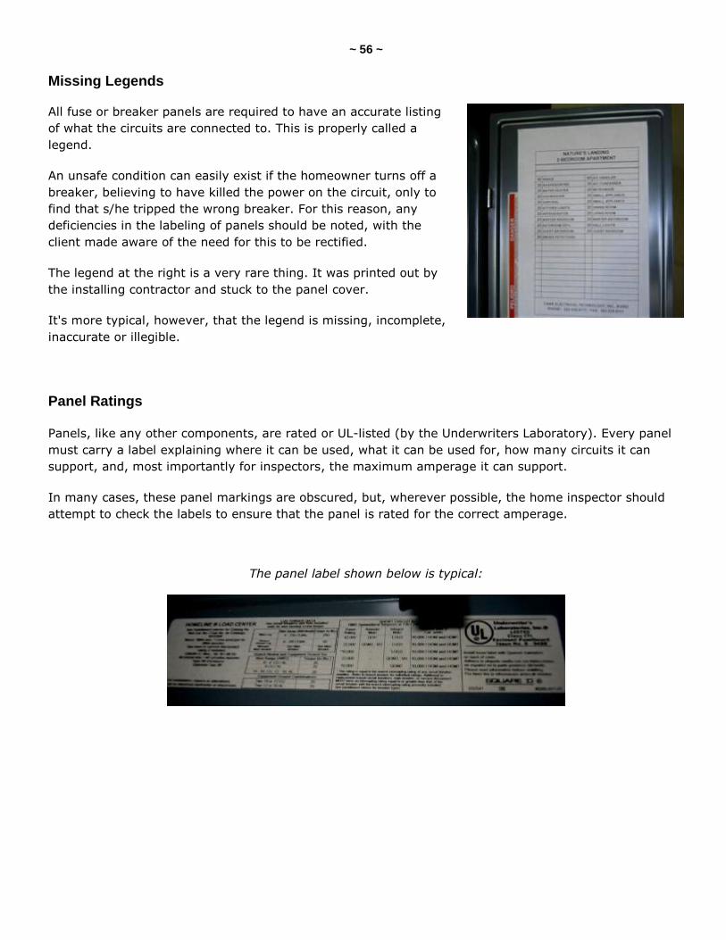
The legend at the right is a very rare thing. It was printed out by
the installing contractor and stuck to the panel cover.
It's more typical, however, that the legend is missing, incomplete,
inaccurate or illegible.
Panel Ratings Panels, like any other components, are rated or UL-listed (by the Underwriters Laboratory). Every panel
must carry a label explaining where it can be used, what it can be used for, how many circuits it can
support, and, most importantly for inspectors, the maximum amperage it can support.
In many cases, these panel markings are obscured, but, wherever possible, the home inspector should
attempt to check the labels to ensure that the panel is rated for the correct amperage.
The panel label shown below is typical:
~ 57 ~
Panel Bonding
While looking at general panel conditions, the inspector should pay
attention to the requirements for all panels to be bonded to the
grounding system.
This ensures that any electricity that is imposed onto any metal
parts of the electrical system is safely transferred to the grounded
conductor, and, in the case of a fault condition, allows the over-
current protection device to activate properly. In applications
where the grounding bus is screwed directly to the panel, this
connection is already there.
Where the grounds and neutrals (grounded conductors)
share a bus, a bond should bridge between that bus and
the enclosure.
If the ground bus is isolated from the enclosure (for example, by an insulated plastic bushing),
a bonding jumper needs to be installed between the bus and the metal enclosure.
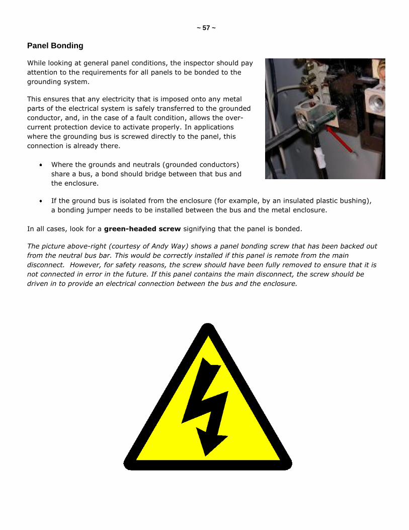
In all cases, look for a green-headed screw signifying that the panel is bonded.
The picture above-right (courtesy of Andy Way) shows a panel bonding screw that has been backed out
from the neutral bus bar. This would be correctly installed if this panel is remote from the main
disconnect. However, for safety reasons, the screw should have been fully removed to ensure that it is
not connected in error in the future. If this panel contains the main disconnect, the screw should be
driven in to provide an electrical connection between the bus and the enclosure.
~ 58 ~
EDISON BASE SCREW FUSE PANELS
These panels were universal from the earliest days of electricity in the home, right up to the 1950s when
breaker panels started to appear in residential construction. Many homes built up until the late 1960s still
had fuse panels.
Fuse panels are generally seen as being more reliable than breaker panels because of the fact that they
will always blow when overloaded, either by loads imposed on them or under dead-short conditions.
Breakers, on the other hand, have been known not to trip at the specified amperages.
Many insurance companies, however, will either not insure these homes that still have fuse panels, or will
insure them at higher premiums. This is not due to any danger from the fuses themselves; rather, it is
indicative of a generally older, unimproved system which, statistically, is more likely to produce an
electrical fire.
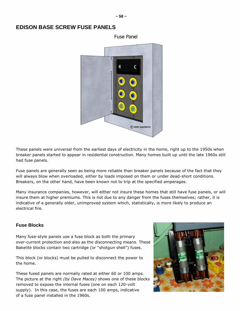
Fuse Blocks
Many fuse-style panels use a fuse block as both the primary
over-current protection and also as the disconnecting means. These
Bakelite blocks contain two cartridge (or ―shotgun shell‖) fuses.
This block (or blocks) must be pulled to disconnect the power to
the home.
These fused panels are normally rated at either 60 or 100 amps.
The picture at the right (by Dave Macey) shows one of these blocks
removed to expose the internal fuses (one on each 120-volt
supply). In this case, the fuses are each 100 amps, indicative
of a fuse panel installed in the 1960s.
~ 59 ~
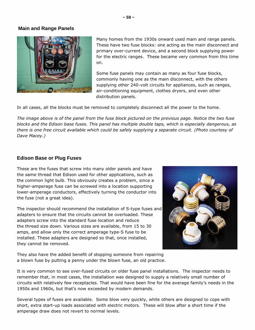
Main and Range Panels
Many homes from the 1930s onward used main and range panels.
These have two fuse blocks: one acting as the main disconnect and
primary over-current device, and a second block supplying power
for the electric ranges. These became very common from this time
on.
Some fuse panels may contain as many as four fuse blocks,
commonly having one as the main disconnect, with the others
supplying other 240-volt circuits for appliances, such as ranges,
air-conditioning equipment, clothes dryers, and even other
distribution panels.
In all cases, all the blocks must be removed to completely disconnect all the power to the home.
The image above is of the panel from the fuse block pictured on the previous page. Notice the two fuse
blocks and the Edison base fuses. This panel has multiple double taps, which is especially dangerous, as
there is one free circuit available which could be safely supplying a separate circuit. (Photo courtesy of
Dave Macey.)
Edison Base or Plug Fuses
These are the fuses that screw into many older panels and have
the same thread that Edison used for other applications, such as
the common light bulb. This obviously creates a problem, since a
higher-amperage fuse can be screwed into a location supporting
lower-amperage conductors, effectively turning the conductor into
the fuse (not a great idea).
The inspector should recommend the installation of S-type fuses and
adapters to ensure that the circuits cannot be overloaded. These
adapters screw into the standard fuse location and reduce
the thread size down. Various sizes are available, from 15 to 30
amps, and allow only the correct amperage type-S fuse to be
installed. These adapters are designed so that, once installed,
they cannot be removed.
They also have the added benefit of stopping someone from repairing
a blown fuse by putting a penny under the blown fuse, an old practice.
It is very common to see over-fused circuits on older fuse panel installations. The inspector needs to
remember that, in most cases, the installation was designed to supply a relatively small number of
circuits with relatively few receptacles. That would have been fine for the average family's needs in the
1950s and 1960s, but that's now exceeded by modern demands.
Several types of fuses are available. Some blow very quickly, while others are designed to cope with
short, extra start-up loads associated with electric motors. These will blow after a short time if the
amperage draw does not revert to normal levels.
~ 60 ~
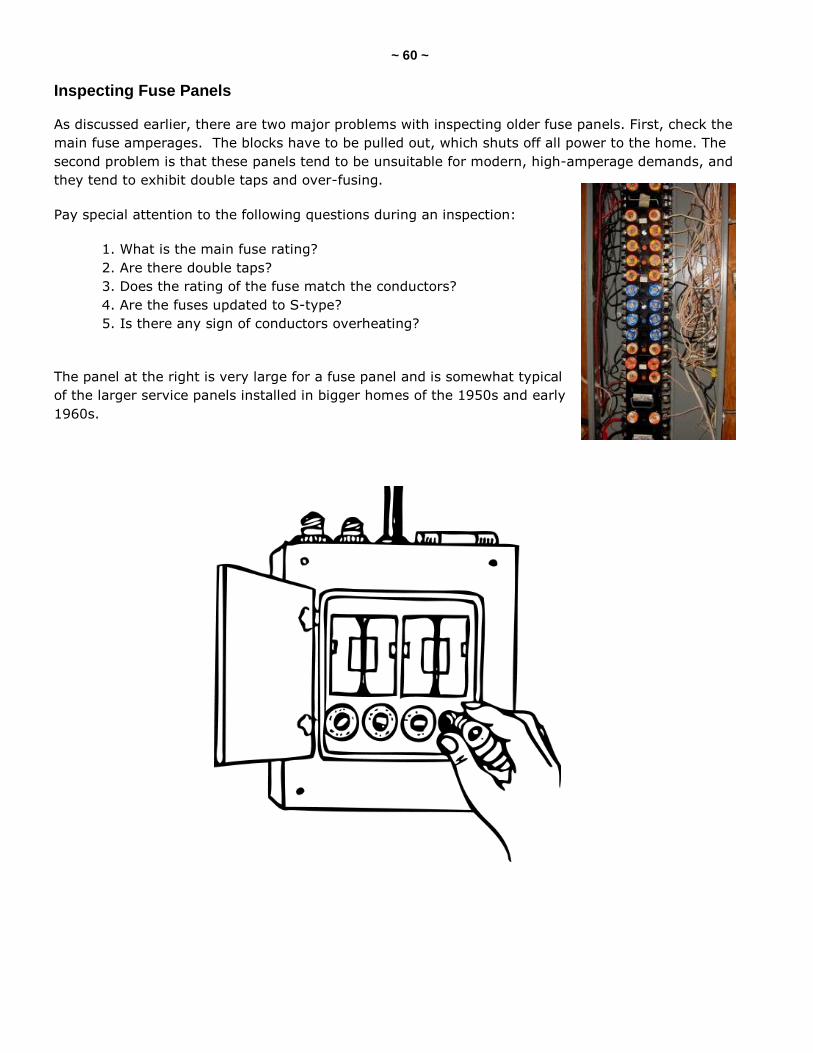
Inspecting Fuse Panels
As discussed earlier, there are two major problems with inspecting older fuse panels. First, check the
main fuse amperages. The blocks have to be pulled out, which shuts off all power to the home. The
second problem is that these panels tend to be unsuitable for modern, high-amperage demands, and
they tend to exhibit double taps and over-fusing.
Pay special attention to the following questions during an inspection:
1. What is the main fuse rating?
2. Are there double taps?
3. Does the rating of the fuse match the conductors?
4. Are the fuses updated to S-type?
5. Is there any sign of conductors overheating?
The panel at the right is very large for a fuse panel and is somewhat typical
of the larger service panels installed in bigger homes of the 1950s and early
1960s.
~ 61 ~
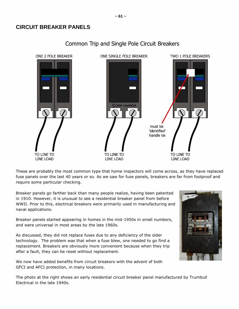
CIRCUIT BREAKER PANELS
These are probably the most common type that home inspectors will come across, as they have replaced
fuse panels over the last 40 years or so. As we saw for fuse panels, breakers are far from foolproof and
require some particular checking.
Breaker panels go farther back than many people realize, having been patented
in 1910. However, it is unusual to see a residential breaker panel from before
WWII. Prior to this, electrical breakers were primarily used in manufacturing and
naval applications.
Breaker panels started appearing in homes in the mid-1950s in small numbers,
and were universal in most areas by the late 1960s.
As discussed, they did not replace fuses due to any deficiency of the older
technology. The problem was that when a fuse blew, one needed to go find a
replacement. Breakers are obviously more convenient because when they trip
after a fault, they can be reset without replacement.
We now have added benefits from circuit breakers with the advent of both
GFCI and AFCI protection, in many locations.
The photo at the right shows an early residential circuit breaker panel manufactured by Trumbull
Electrical in the late 1940s.
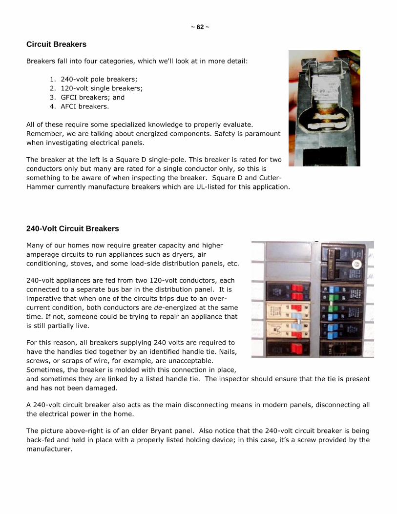
~ 62 ~
Circuit Breakers
Breakers fall into four categories, which we'll look at in more detail:
1. 240-volt pole breakers;
2. 120-volt single breakers;
3. GFCI breakers; and
4. AFCI breakers.
All of these require some specialized knowledge to properly evaluate.
Remember, we are talking about energized components. Safety is paramount
when investigating electrical panels.
The breaker at the left is a Square D single-pole. This breaker is rated for two
conductors only but many are rated for a single conductor only, so this is
something to be aware of when inspecting the breaker. Square D and Cutler-
Hammer currently manufacture breakers which are UL-listed for this application.
240-Volt Circuit Breakers
Many of our homes now require greater capacity and higher
amperage circuits to run appliances such as dryers, air
conditioning, stoves, and some load-side distribution panels, etc.
240-volt appliances are fed from two 120-volt conductors, each
connected to a separate bus bar in the distribution panel. It is
imperative that when one of the circuits trips due to an over-
current condition, both conductors are de-energized at the same
time. If not, someone could be trying to repair an appliance that
is still partially live.
For this reason, all breakers supplying 240 volts are required to
have the handles tied together by an identified handle tie. Nails,
screws, or scraps of wire, for example, are unacceptable.
Sometimes, the breaker is molded with this connection in place,
and sometimes they are linked by a listed handle tie. The inspector should ensure that the tie is present
and has not been damaged.
A 240-volt circuit breaker also acts as the main disconnecting means in modern panels, disconnecting all
the electrical power in the home.
The picture above-right is of an older Bryant panel. Also notice that the 240-volt circuit breaker is being
back-fed and held in place with a properly listed holding device; in this case, it’s a screw provided by the
manufacturer.
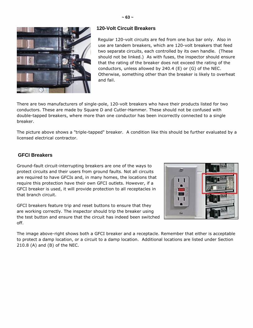
~ 63 ~
120-Volt Circuit Breakers
Regular 120-volt circuits are fed from one bus bar only. Also in
use are tandem breakers, which are 120-volt breakers that feed
two separate circuits, each controlled by its own handle. (These
should not be linked.) As with fuses, the inspector should ensure
that the rating of the breaker does not exceed the rating of the
conductors, unless allowed by 240.4 (E) or (G) of the NEC.
Otherwise, something other than the breaker is likely to overheat
and fail.
There are two manufacturers of single-pole, 120-volt breakers who have their products listed for two
conductors. These are made by Square D and Cutler-Hammer. These should not be confused with
double-tapped breakers, where more than one conductor has been incorrectly connected to a single
breaker.
The picture above shows a "triple-tapped" breaker. A condition like this should be further evaluated by a
licensed electrical contractor.
GFCI Breakers
Ground-fault circuit-interrupting breakers are one of the ways to
protect circuits and their users from ground faults. Not all circuits
are required to have GFCIs and, in many homes, the locations that
require this protection have their own GFCI outlets. However, if a
GFCI breaker is used, it will provide protection to all receptacles in
that branch circuit.
GFCI breakers feature trip and reset buttons to ensure that they
are working correctly. The inspector should trip the breaker using
the test button and ensure that the circuit has indeed been switched
off.
The image above-right shows both a GFCI breaker and a receptacle. Remember that either is acceptable
to protect a damp location, or a circuit to a damp location. Additional locations are listed under Section
210.8 (A) and (B) of the NEC.
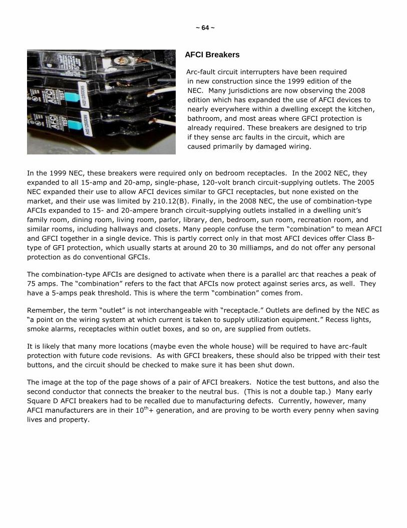
~ 64 ~
AFCI Breakers
Arc-fault circuit interrupters have been required
in new construction since the 1999 edition of the
NEC. Many jurisdictions are now observing the 2008
edition which has expanded the use of AFCI devices to
nearly everywhere within a dwelling except the kitchen,
bathroom, and most areas where GFCI protection is
already required. These breakers are designed to trip
if they sense arc faults in the circuit, which are
caused primarily by damaged wiring.
In the 1999 NEC, these breakers were required only on bedroom receptacles. In the 2002 NEC, they
expanded to all 15-amp and 20-amp, single-phase, 120-volt branch circuit-supplying outlets. The 2005
NEC expanded their use to allow AFCI devices similar to GFCI receptacles, but none existed on the
market, and their use was limited by 210.12(B). Finally, in the 2008 NEC, the use of combination-type
AFCIs expanded to 15- and 20-ampere branch circuit-supplying outlets installed in a dwelling unit’s
family room, dining room, living room, parlor, library, den, bedroom, sun room, recreation room, and
similar rooms, including hallways and closets. Many people confuse the term ―combination‖ to mean AFCI
and GFCI together in a single device. This is partly correct only in that most AFCI devices offer Class B-
type of GFI protection, which usually starts at around 20 to 30 milliamps, and do not offer any personal
protection as do conventional GFCIs.
The combination-type AFCIs are designed to activate when there is a parallel arc that reaches a peak of
75 amps. The ―combination‖ refers to the fact that AFCIs now protect against series arcs, as well. They
have a 5-amps peak threshold. This is where the term ―combination‖ comes from.
Remember, the term ―outlet‖ is not interchangeable with ―receptacle.‖ Outlets are defined by the NEC as
―a point on the wiring system at which current is taken to supply utilization equipment.‖ Recess lights,
smoke alarms, receptacles within outlet boxes, and so on, are supplied from outlets.
It is likely that many more locations (maybe even the whole house) will be required to have arc-fault
protection with future code revisions. As with GFCI breakers, these should also be tripped with their test
buttons, and the circuit should be checked to make sure it has been shut down.
The image at the top of the page shows of a pair of AFCI breakers. Notice the test buttons, and also the
second conductor that connects the breaker to the neutral bus. (This is not a double tap.) Many early
Square D AFCI breakers had to be recalled due to manufacturing defects. Currently, however, many
AFCI manufacturers are in their 10th+ generation, and are proving to be worth every penny when saving
lives and property.
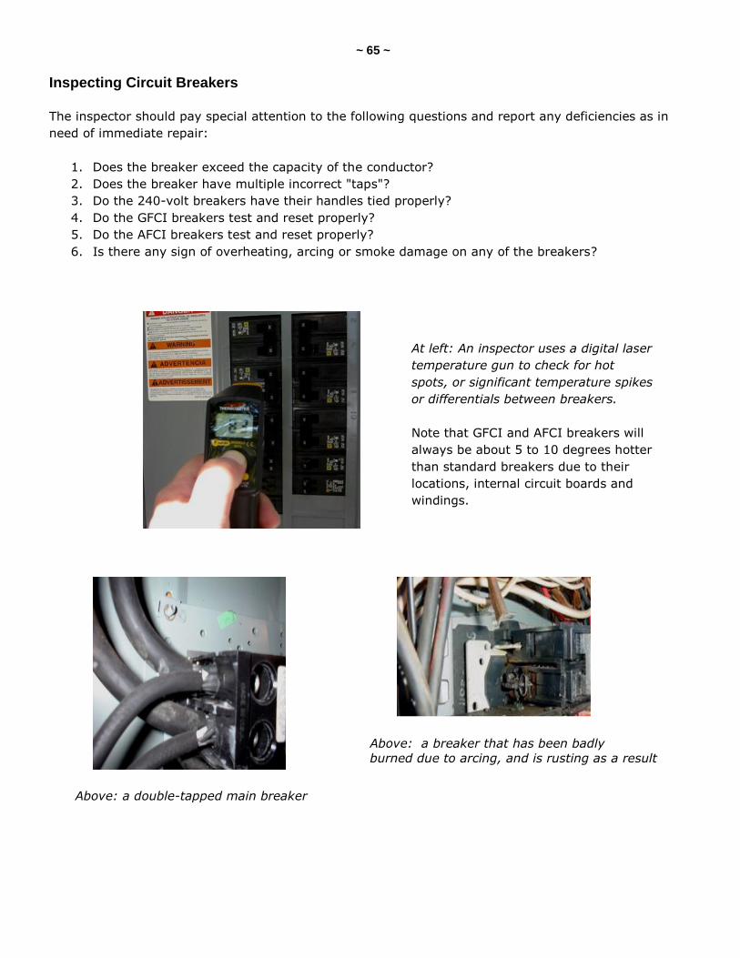
~ 65 ~
Inspecting Circuit Breakers
The inspector should pay special attention to the following questions and report any deficiencies as in
need of immediate repair:
1. Does the breaker exceed the capacity of the conductor?
2. Does the breaker have multiple incorrect "taps"?
3. Do the 240-volt breakers have their handles tied properly?
4. Do the GFCI breakers test and reset properly?
5. Do the AFCI breakers test and reset properly?
6. Is there any sign of overheating, arcing or smoke damage on any of the breakers?
At left: An inspector uses a digital laser
temperature gun to check for hot
spots, or significant temperature spikes
or differentials between breakers.
Note that GFCI and AFCI breakers will
always be about 5 to 10 degrees hotter
than standard breakers due to their
locations, internal circuit boards and
windings.
Above: a double-tapped main breaker
Above: a breaker that has been badly
burned due to arcing, and is rusting as a result
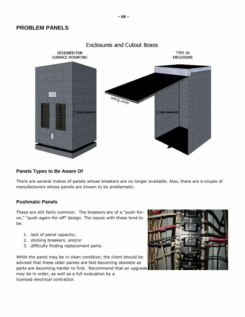
~ 66 ~
PROBLEM PANELS
Panels Types to Be Aware Of
There are several makes of panels whose breakers are no longer available. Also, there are a couple of
manufacturers whose panels are known to be problematic.
Pushmatic Panels
These are still fairly common. The breakers are of a "push-for-
on," "push-again-for-off" design. The issues with these tend to
be:
1. lack of panel capacity;
2. sticking breakers; and/or
3. difficulty finding replacement parts.
While the panel may be in clean condition, the client should be
advised that these older panels are fast becoming obsolete as
parts are becoming harder to find. Recommend that an upgrade
may be in order, as well as a full evaluation by a
licensed electrical contractor.
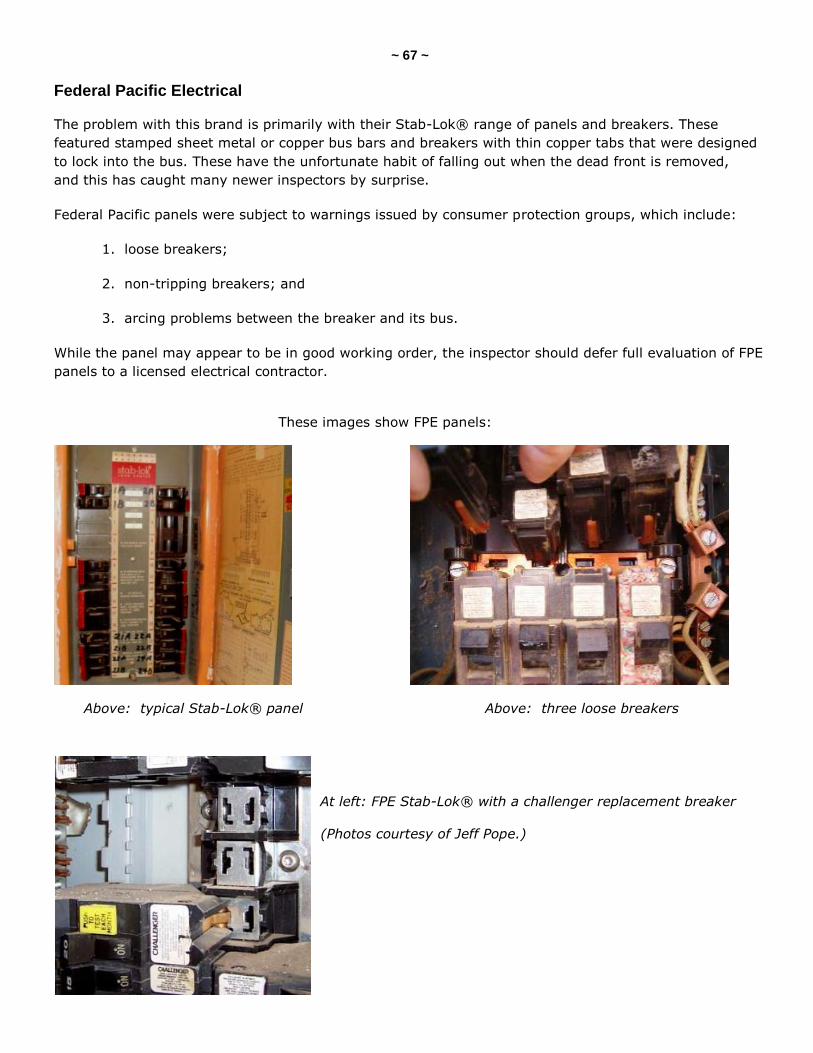
~ 67 ~
Federal Pacific Electrical
The problem with this brand is primarily with their Stab-Lok® range of panels and breakers. These
featured stamped sheet metal or copper bus bars and breakers with thin copper tabs that were designed
to lock into the bus. These have the unfortunate habit of falling out when the dead front is removed,
and this has caught many newer inspectors by surprise.
Federal Pacific panels were subject to warnings issued by consumer protection groups, which include:
1. loose breakers;
2. non-tripping breakers; and
3. arcing problems between the breaker and its bus.
While the panel may appear to be in good working order, the inspector should defer full evaluation of FPE
panels to a licensed electrical contractor.
These images show FPE panels:
Above: typical Stab-Lok® panel Above: three loose breakers
At left: FPE Stab-Lok® with a challenger replacement breaker
(Photos courtesy of Jeff Pope.)
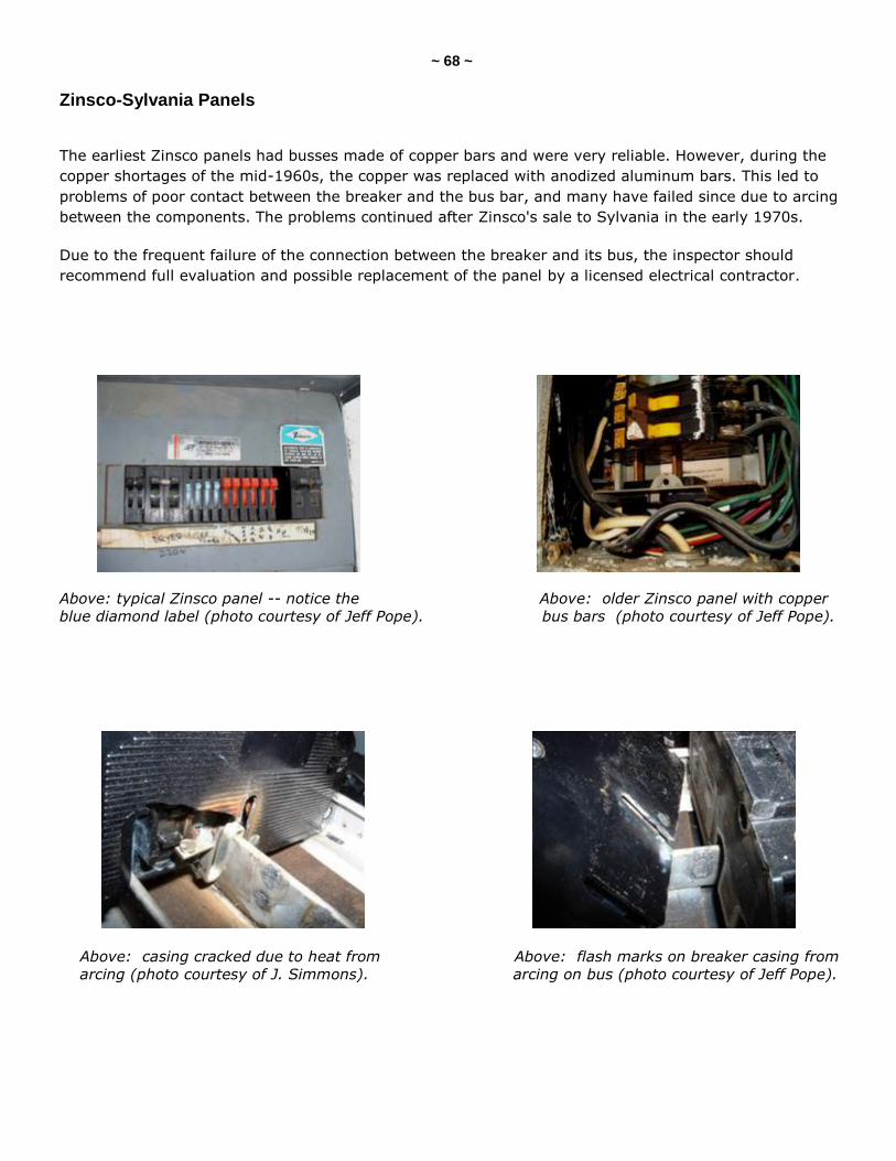
~ 68 ~
Zinsco-Sylvania Panels
The earliest Zinsco panels had busses made of copper bars and were very reliable. However, during the
copper shortages of the mid-1960s, the copper was replaced with anodized aluminum bars. This led to
problems of poor contact between the breaker and the bus bar, and many have failed since due to arcing
between the components. The problems continued after Zinsco's sale to Sylvania in the early 1970s.
Due to the frequent failure of the connection between the breaker and its bus, the inspector should
recommend full evaluation and possible replacement of the panel by a licensed electrical contractor.
Above: typical Zinsco panel -- notice the Above: older Zinsco panel with copper
blue diamond label (photo courtesy of Jeff Pope). bus bars (photo courtesy of Jeff Pope).
Above: casing cracked due to heat from Above: flash marks on breaker casing from
arcing (photo courtesy of J. Simmons). arcing on bus (photo courtesy of Jeff Pope).
~ 69 ~
QUIZ on AMPERAGE and PANELS
1. The minimum service amperage required for a newer single-family home is __________.
60 amps
200 amps
100 amps
150 amps
2. An electrical panel that uses a double-pole breaker to isolate the 120-volt circuits is called a ________________ panel.
Federal Pacific
partial-bus
part-load
split-bus
3. The electrical supply should be able to be shut down with _______ or fewer moves of the hand.
eight
seven
six
five
four
4. The available service amperage is based on _______________.
the total of all the branch circuit breakers
the size of the service entrance
the size of the main disconnect
the lowest-rated component
5. Most homes constructed between 1930 and 1950 originally had a ______ service.
40-amp
30-amp
60-amp
100-amp
(continued)
~ 70 ~
6. Which of the following would NOT be an electrical panel defect?
lack of legend
rusted enclosures
missing knockouts
wire splices
7. Electrical service panels should be in a clear space measuring _______________.
30" wide by 78" high by 36" deep
36" wide by 78" high by 30" deep
30" wide by 78" high by 30" deep
36" wide by 78" high by 36" deep
8. Electrical panels do not have to be fully enclosed as long as no hole is bigger than _________.
3/4-inch
½-inch
¼-inch
none of these
9. T/F: Water dripping from an electrical panel should be fully investigated by the home inspector.
True
False
10. A common cause of arc flashes when removing panel fronts is __________.
over-fused circuits
incorrect fasteners
rusted enclosures
double-tapped breakers
11. Which of the following should the inspector be wearing while evaluating electrical panels?
all of these
none of these
non-synthetic clothing
safety glasses
electrician’s gloves
(continued)
~ 71 ~
12. Which of the following should be reported as a problem with an electrical panel?
pigtails (two wires joined to a common breaker)
splices in the panel
unlinked double-pole breakers
GFCI breakers
13. A(n) ___________ connection should connect the grounding bus to the electrical enclosure?
bonding
jumper
grounding
earthen
Answer Key is on the next page.
~ 72 ~
Answer Key to Quiz on Amperage and Panels
1. The minimum service amperage required for a newer single-family home is 100 amps.
2. An electrical panel that uses a double-pole breaker to isolate the 120-volt circuits is called a split-bus panel.
3. The electrical supply should be able to be shut down with six or fewer moves of the hand.
4. The available service amperage is based on the lowest-rated component.
5. Most homes constructed between 1930 and 1950 originally had a 60-amp service.
6. Which of the following would NOT be an electrical panel defect? Answer: wire splices
7. Electrical service panels should be in a clear space measuring 30" wide by 78" high by 36" deep.
8. Electrical panels do not have to be fully enclosed as long as no hole is bigger than none of these.
9. T/F: Water dripping from an electrical panel should be fully investigated by the home inspector. Answer: False
10. A common cause of arc flashes when removing panel fronts is incorrect fasteners.
11. Which of the following should the inspector be wearing while evaluating electrical panels? Answer: all of these
12. Which of the following should be reported as a problem with an electrical panel? Answer: unlinked double-pole breakers
13. A bonding connection should connect the grounding bus to the electrical enclosure.
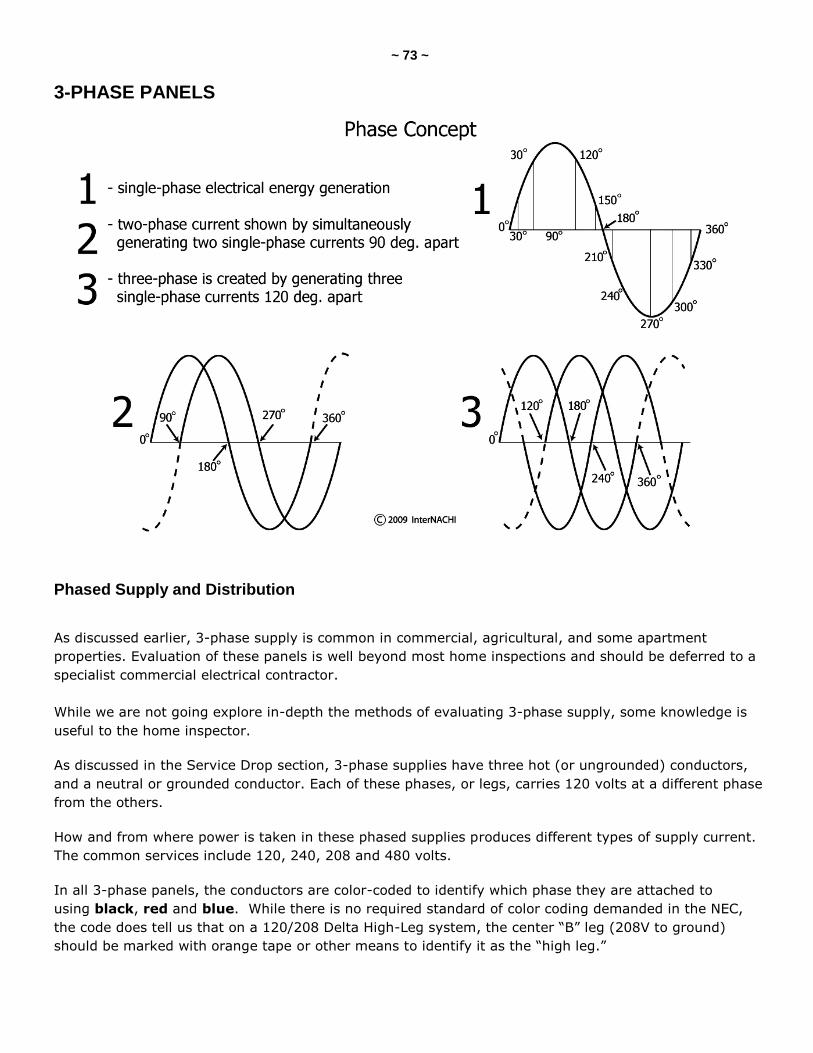
~ 73 ~
3-PHASE PANELS
Phased Supply and Distribution
As discussed earlier, 3-phase supply is common in commercial, agricultural, and some apartment
properties. Evaluation of these panels is well beyond most home inspections and should be deferred to a
specialist commercial electrical contractor.
While we are not going explore in-depth the methods of evaluating 3-phase supply, some knowledge is
useful to the home inspector.
As discussed in the Service Drop section, 3-phase supplies have three hot (or ungrounded) conductors,
and a neutral or grounded conductor. Each of these phases, or legs, carries 120 volts at a different phase
from the others.
How and from where power is taken in these phased supplies produces different types of supply current.
The common services include 120, 240, 208 and 480 volts.
In all 3-phase panels, the conductors are color-coded to identify which phase they are attached to
using black, red and blue. While there is no required standard of color coding demanded in the NEC,
the code does tell us that on a 120/208 Delta High-Leg system, the center ―B‖ leg (208V to ground)
should be marked with orange tape or other means to identify it as the ―high leg.‖
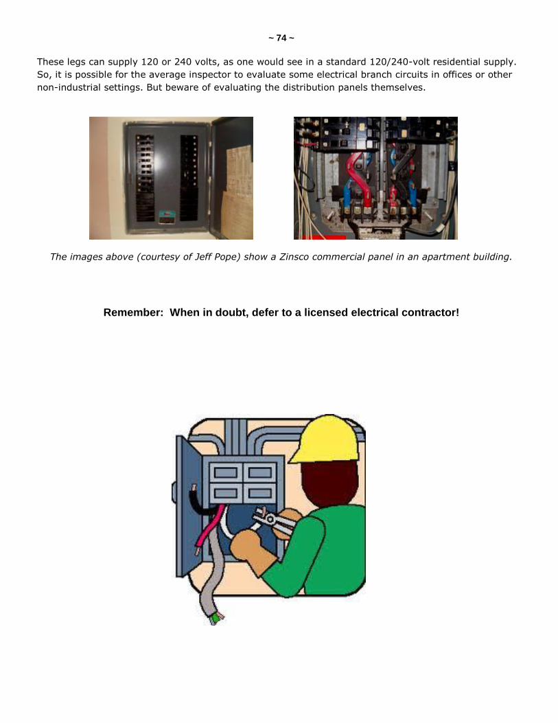
~ 74 ~
These legs can supply 120 or 240 volts, as one would see in a standard 120/240-volt residential supply.
So, it is possible for the average inspector to evaluate some electrical branch circuits in offices or other
non-industrial settings. But beware of evaluating the distribution panels themselves.
The images above (courtesy of Jeff Pope) show a Zinsco commercial panel in an apartment building.
Remember: When in doubt, defer to a licensed electrical contractor!
~ 75 ~
PANEL ODDITIES
The Weird and the Wonderful!
The inspector will occasionally see some very unusual panels in the home. Some are now obsolete. Some
are just plain dangerous.
No Panel
A hundred-plus years ago when we started wiring homes for electricity, there were no standards for
panel enclosures. In fact, if an early panel had any kind of enclosure, it was probably built on site from
timber and may have had an asbestos liner.
Even today, some homeowners will build a distribution center without the benefit and protection of a
listed enclosure.
The photos above show: (top-left) a 1920s panel with no enclosure (courtesy of Jeff Pope);
(top-right) a "homeowner special" with panelboard only mounted on particleboard!
Fused Neutral Panels
For a period in the 1920s, fused neutral circuits were very common. They
were outlawed in 1928 by the NEC.
The problem with these is that if the neutral -- rather than the live -- fuse
blows, then the circuit will appear not to be live. However, someone working
on the system would easily be able to complete the circuit to the source,
providing a return path for the current, and thus be electrocuted.
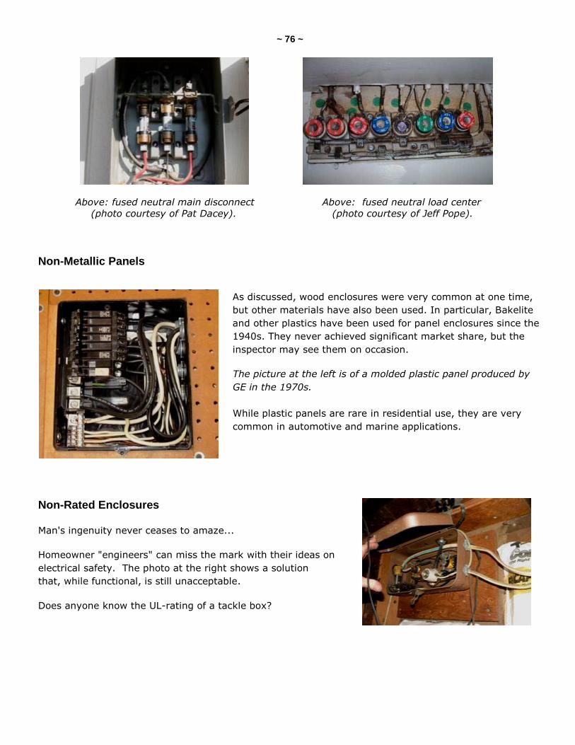
~ 76 ~
Above: fused neutral main disconnect Above: fused neutral load center
(photo courtesy of Pat Dacey). (photo courtesy of Jeff Pope).
Non-Metallic Panels
As discussed, wood enclosures were very common at one time,
but other materials have also been used. In particular, Bakelite
and other plastics have been used for panel enclosures since the
1940s. They never achieved significant market share, but the
inspector may see them on occasion.
The picture at the left is of a molded plastic panel produced by
GE in the 1970s.
While plastic panels are rare in residential use, they are very
common in automotive and marine applications.
Non-Rated Enclosures Man's ingenuity never ceases to amaze...
Homeowner "engineers" can miss the mark with their ideas on
electrical safety. The photo at the right shows a solution
that, while functional, is still unacceptable.
Does anyone know the UL-rating of a tackle box?
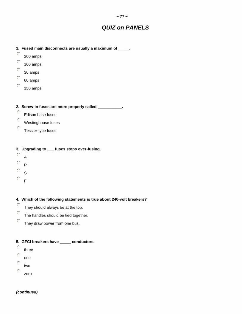
~ 77 ~
QUIZ on PANELS
1. Fused main disconnects are usually a maximum of _____.
200 amps
100 amps
30 amps
60 amps
150 amps
2. Screw-in fuses are more properly called ___________.
Edison base fuses
Westinghouse fuses
Tessler-type fuses
3. Upgrading to ___ fuses stops over-fusing.
A
P
S
F
4. Which of the following statements is true about 240-volt breakers?
They should always be at the top.
The handles should be tied together.
They draw power from one bus.
5. GFCI breakers have _____ conductors.
three
one
two
zero
(continued)
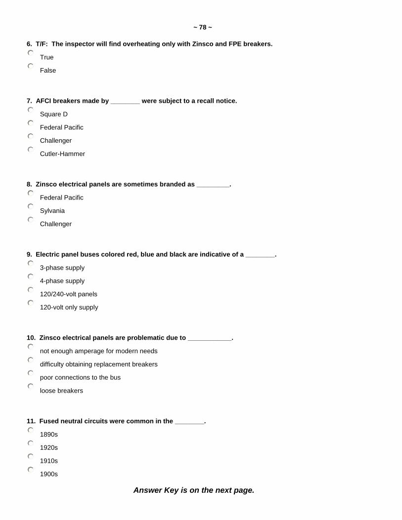
~ 78 ~
6. T/F: The inspector will find overheating only with Zinsco and FPE breakers.
True
False
7. AFCI breakers made by ________ were subject to a recall notice.
Square D
Federal Pacific
Challenger
Cutler-Hammer
8. Zinsco electrical panels are sometimes branded as _________.
Federal Pacific
Sylvania
Challenger
9. Electric panel buses colored red, blue and black are indicative of a ________.
3-phase supply
4-phase supply
120/240-volt panels
120-volt only supply
10. Zinsco electrical panels are problematic due to ____________.
not enough amperage for modern needs
difficulty obtaining replacement breakers
poor connections to the bus
loose breakers
11. Fused neutral circuits were common in the ________.
1890s
1920s
1910s
1900s
Answer Key is on the next page.
~ 79 ~
Answer Key to Quiz on Panels
1. Fused main disconnects are usually a maximum of 100 amps.
2. Screw-in fuses are more properly called Edison base fuses.
3. Upgrading to S-fuses stops over-fusing.
4. Which of the following statements is true about 240-volt breakers? Answer: The handles should be tied together.
5. GFCI breakers have two conductors.
6. T/F: The inspector will find overheating only with Zinsco and FPE breakers. Answer: False.
7. AFCI breakers made by Square D were subject to a recall notice.
8. Zinsco electrical panels are sometimes branded as Sylvania.
9. Electric panel buses colored red, blue and black are indicative of a 3-phase supply.
10. Zinsco electrical panels are problematic due to poor connections to the bus.
11. Fused neutral circuits were common in the 1920s.
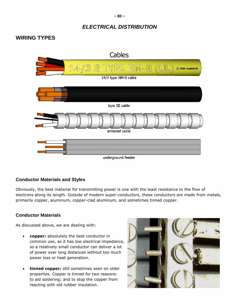
~ 80 ~
ELECTRICAL DISTRIBUTION
WIRING TYPES
Conductor Materials and Styles
Obviously, the best material for transmitting power is one with the least resistance to the flow of
electrons along its length. Outside of modern super-conductors, these conductors are made from metals,
primarily copper, aluminum, copper-clad aluminum, and sometimes tinned copper.
Conductor Materials
As discussed above, we are dealing with:
copper: absolutely the best conductor in
common use, as it has low electrical impedance,
so a relatively small conductor can deliver a lot
of power over long distances without too much
power loss or heat generation.
tinned copper: still sometimes seen on older
properties. Copper is tinned for two reasons:
to aid soldering; and to stop the copper from
reacting with old rubber insulation.
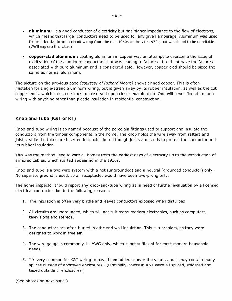
~ 81 ~
aluminum: is a good conductor of electricity but has higher impedance to the flow of electrons,
which means that larger conductors need to be used for any given amperage. Aluminum was used
for residential branch circuit wiring from the mid-1960s to the late 1970s, but was found to be unreliable.
(We'll explore this later.)
copper-clad aluminum: coating aluminum in copper was an attempt to overcome the issue of
oxidization of the aluminum conductors that was leading to failures. It did not have the failures
associated with pure aluminum and is considered safe. However, copper-clad should be sized the
same as normal aluminum.
The picture on the previous page (courtesy of Richard Moore) shows tinned copper. This is often
mistaken for single-strand aluminum wiring, but is given away by its rubber insulation, as well as the cut
copper ends, which can sometimes be observed upon closer examination. One will never find aluminum
wiring with anything other than plastic insulation in residential construction.
Knob-and-Tube (K&T or KT)
Knob-and-tube wiring is so named because of the porcelain fittings used to support and insulate the
conductors from the timber components in the home. The knob holds the wire away from rafters and
joists, while the tubes are inserted into holes bored though joists and studs to protect the conductor and
its rubber insulation.
This was the method used to wire all homes from the earliest days of electricity up to the introduction of
armored cables, which started appearing in the 1930s.
Knob-and-tube is a two-wire system with a hot (ungrounded) and a neutral (grounded conductor) only.
No separate ground is used, so all receptacles would have been two-prong only.
The home inspector should report any knob-and-tube wiring as in need of further evaluation by a licensed
electrical contractor due to the following reasons:
1. The insulation is often very brittle and leaves conductors exposed when disturbed.
2. All circuits are ungrounded, which will not suit many modern electronics, such as computers,
televisions and stereos.
3. The conductors are often buried in attic and wall insulation. This is a problem, as they were
designed to work in free air.
4. The wire gauge is commonly 14-AWG only, which is not sufficient for most modern household
needs.
5. It's very common for K&T wiring to have been added to over the years, and it may contain many
splices outside of approved enclosures. (Originally, joints in K&T were all spliced, soldered and
taped outside of enclosures.)
(See photos on next page.)
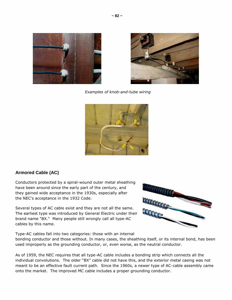
~ 82 ~
Examples of knob-and-tube wiring
Armored Cable (AC)
Conductors protected by a spiral-wound outer metal sheathing
have been around since the early part of the century, and
they gained wide acceptance in the 1930s, especially after
the NEC's acceptance in the 1932 Code.
Several types of AC cable exist and they are not all the same.
The earliest type was introduced by General Electric under their
brand name "BX." Many people still wrongly call all type-AC
cables by this name.
Type-AC cables fall into two categories: those with an internal
bonding conductor and those without. In many cases, the sheathing itself, or its internal bond, has been
used improperly as the grounding conductor, or, even worse, as the neutral conductor.
As of 1959, the NEC requires that all type-AC cable includes a bonding strip which connects all the
individual convolutions. The older ―BX‖ cable did not have this, and the exterior metal casing was not
meant to be an effective fault current path. Since the 1960s, a newer type of AC-cable assembly came
onto the market. The improved MC cable includes a proper grounding conductor.
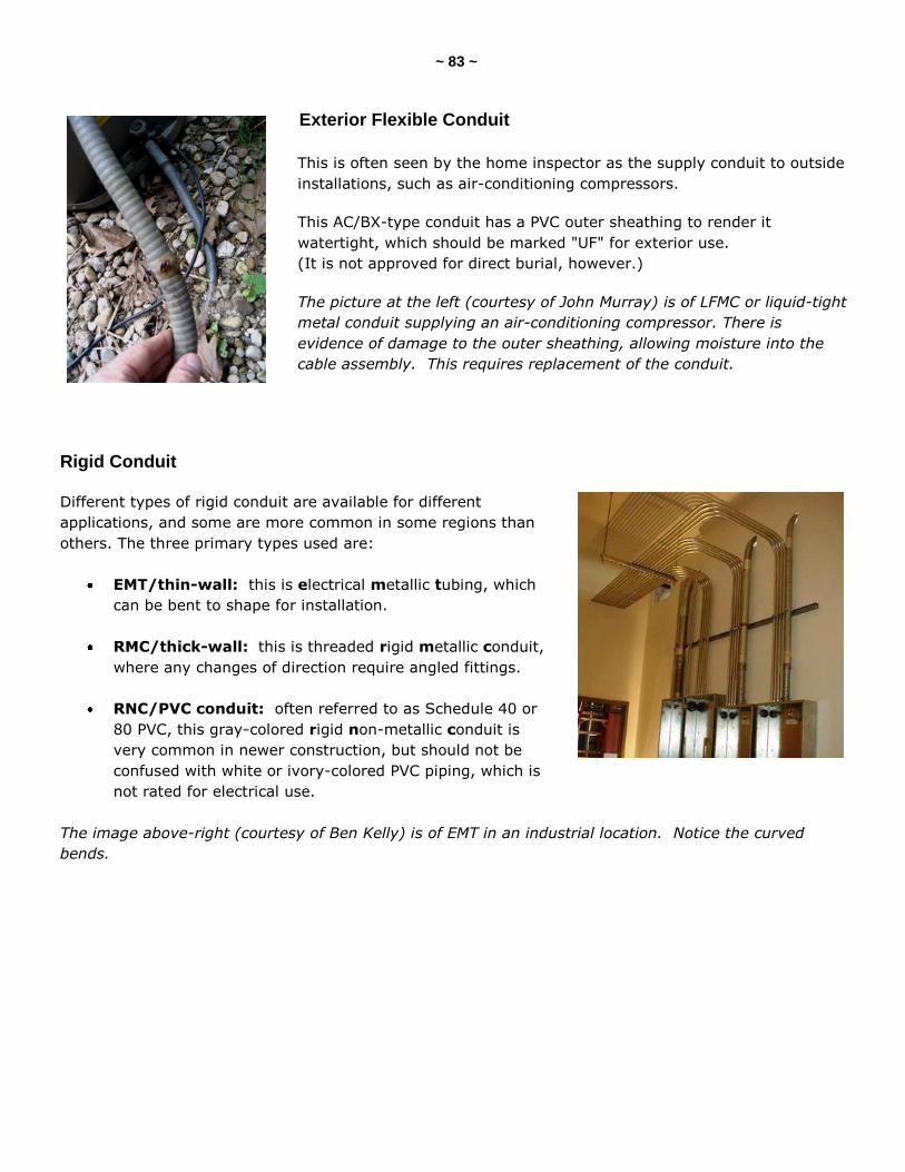
~ 83 ~
Exterior Flexible Conduit
This is often seen by the home inspector as the supply conduit to outside
installations, such as air-conditioning compressors.
This AC/BX-type conduit has a PVC outer sheathing to render it
watertight, which should be marked "UF" for exterior use.
(It is not approved for direct burial, however.)
The picture at the left (courtesy of John Murray) is of LFMC or liquid-tight
metal conduit supplying an air-conditioning compressor. There is
evidence of damage to the outer sheathing, allowing moisture into the
cable assembly. This requires replacement of the conduit.
Rigid Conduit
Different types of rigid conduit are available for different
applications, and some are more common in some regions than
others. The three primary types used are:
EMT/thin-wall: this is electrical metallic tubing, which
can be bent to shape for installation.
RMC/thick-wall: this is threaded rigid metallic conduit,
where any changes of direction require angled fittings.
RNC/PVC conduit: often referred to as Schedule 40 or
80 PVC, this gray-colored rigid non-metallic conduit is
very common in newer construction, but should not be
confused with white or ivory-colored PVC piping, which is
not rated for electrical use.
The image above-right (courtesy of Ben Kelly) is of EMT in an industrial location. Notice the curved
bends.
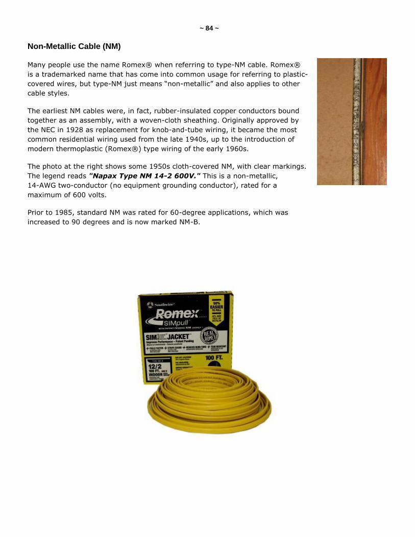
~ 84 ~
Non-Metallic Cable (NM)
Many people use the name Romex® when referring to type-NM cable. Romex®
is a trademarked name that has come into common usage for referring to plastic-
covered wires, but type-NM just means ―non-metallic‖ and also applies to other
cable styles.
The earliest NM cables were, in fact, rubber-insulated copper conductors bound
together as an assembly, with a woven-cloth sheathing. Originally approved by
the NEC in 1928 as replacement for knob-and-tube wiring, it became the most
common residential wiring used from the late 1940s, up to the introduction of
modern thermoplastic (Romex®) type wiring of the early 1960s.
The photo at the right shows some 1950s cloth-covered NM, with clear markings.
The legend reads "Napax Type NM 14-2 600V." This is a non-metallic,
14-AWG two-conductor (no equipment grounding conductor), rated for a
maximum of 600 volts.
Prior to 1985, standard NM was rated for 60-degree applications, which was
increased to 90 degrees and is now marked NM-B.
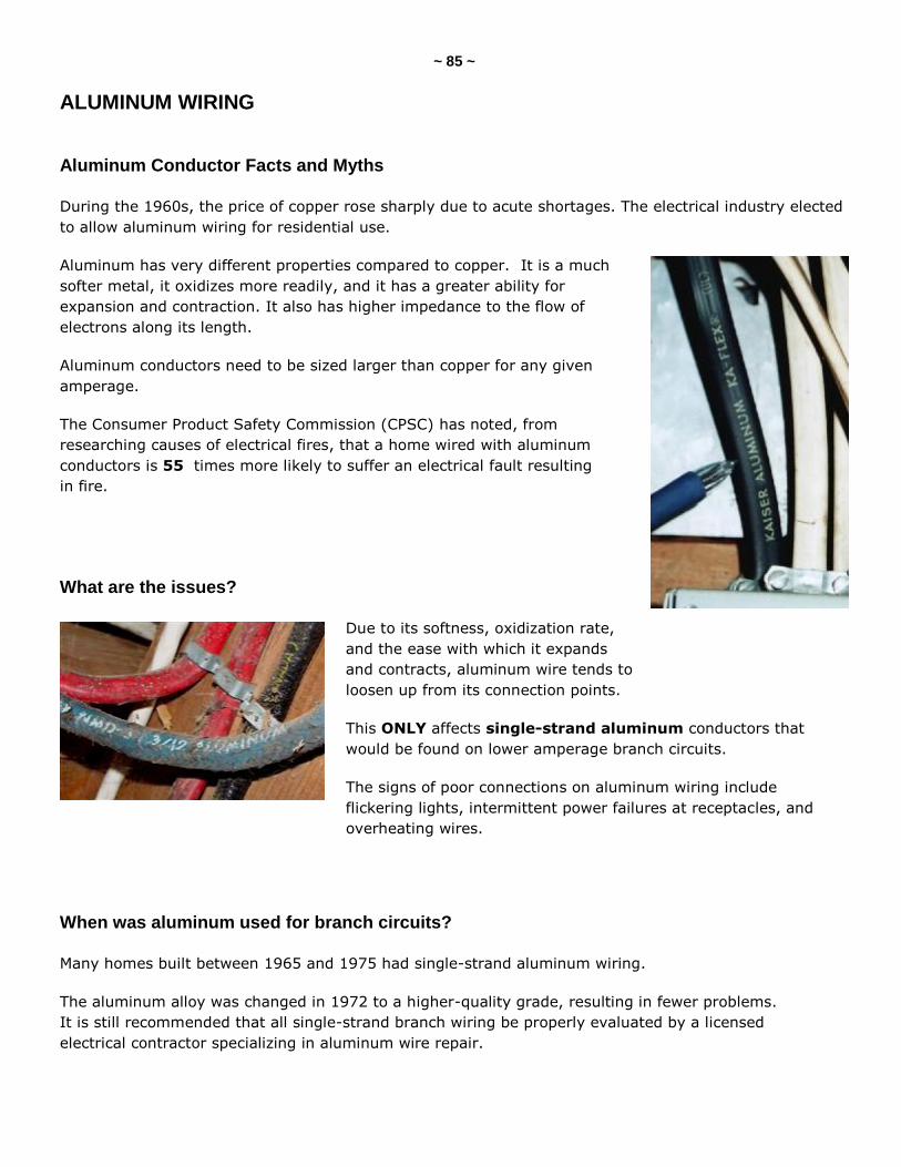
~ 85 ~
ALUMINUM WIRING
Aluminum Conductor Facts and Myths
During the 1960s, the price of copper rose sharply due to acute shortages. The electrical industry elected
to allow aluminum wiring for residential use.
Aluminum has very different properties compared to copper. It is a much
softer metal, it oxidizes more readily, and it has a greater ability for
expansion and contraction. It also has higher impedance to the flow of
electrons along its length.
Aluminum conductors need to be sized larger than copper for any given
amperage.
The Consumer Product Safety Commission (CPSC) has noted, from
researching causes of electrical fires, that a home wired with aluminum
conductors is 55 times more likely to suffer an electrical fault resulting
in fire.
What are the issues?
Due to its softness, oxidization rate,
and the ease with which it expands
and contracts, aluminum wire tends to
loosen up from its connection points.
This ONLY affects single-strand aluminum conductors that
would be found on lower amperage branch circuits.
The signs of poor connections on aluminum wiring include
flickering lights, intermittent power failures at receptacles, and
overheating wires.
When was aluminum used for branch circuits?
Many homes built between 1965 and 1975 had single-strand aluminum wiring.
The aluminum alloy was changed in 1972 to a higher-quality grade, resulting in fewer problems.
It is still recommended that all single-strand branch wiring be properly evaluated by a licensed
electrical contractor specializing in aluminum wire repair.
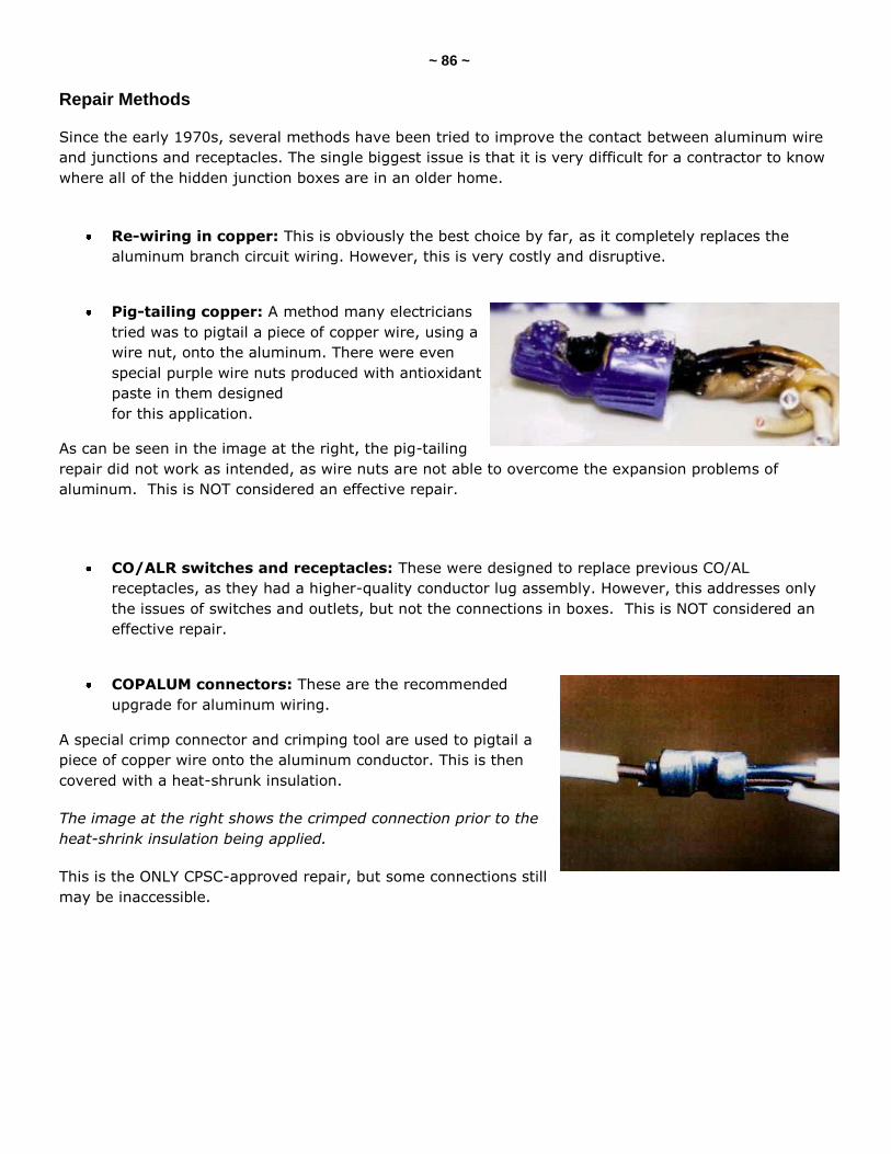
~ 86 ~
Repair Methods
Since the early 1970s, several methods have been tried to improve the contact between aluminum wire
and junctions and receptacles. The single biggest issue is that it is very difficult for a contractor to know
where all of the hidden junction boxes are in an older home.
Re-wiring in copper: This is obviously the best choice by far, as it completely replaces the
aluminum branch circuit wiring. However, this is very costly and disruptive.
Pig-tailing copper: A method many electricians
tried was to pigtail a piece of copper wire, using a
wire nut, onto the aluminum. There were even
special purple wire nuts produced with antioxidant
paste in them designed
for this application.
As can be seen in the image at the right, the pig-tailing
repair did not work as intended, as wire nuts are not able to overcome the expansion problems of
aluminum. This is NOT considered an effective repair.
CO/ALR switches and receptacles: These were designed to replace previous CO/AL
receptacles, as they had a higher-quality conductor lug assembly. However, this addresses only
the issues of switches and outlets, but not the connections in boxes. This is NOT considered an
effective repair.
COPALUM connectors: These are the recommended
upgrade for aluminum wiring.
A special crimp connector and crimping tool are used to pigtail a
piece of copper wire onto the aluminum conductor. This is then
covered with a heat-shrunk insulation.
The image at the right shows the crimped connection prior to the
heat-shrink insulation being applied.
This is the ONLY CPSC-approved repair, but some connections still
may be inaccessible.
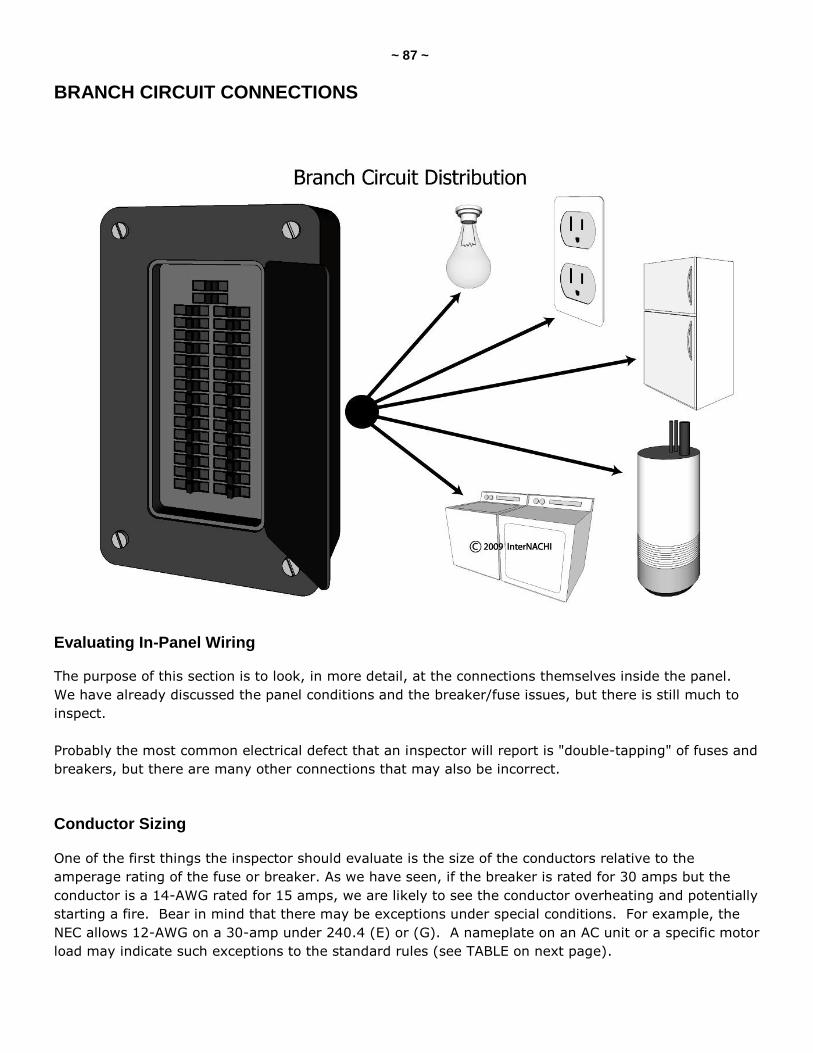
~ 87 ~
BRANCH CIRCUIT CONNECTIONS
Evaluating In-Panel Wiring
The purpose of this section is to look, in more detail, at the connections themselves inside the panel.
We have already discussed the panel conditions and the breaker/fuse issues, but there is still much to
inspect.
Probably the most common electrical defect that an inspector will report is "double-tapping" of fuses and
breakers, but there are many other connections that may also be incorrect.
Conductor Sizing
One of the first things the inspector should evaluate is the size of the conductors relative to the
amperage rating of the fuse or breaker. As we have seen, if the breaker is rated for 30 amps but the
conductor is a 14-AWG rated for 15 amps, we are likely to see the conductor overheating and potentially
starting a fire. Bear in mind that there may be exceptions under special conditions. For example, the
NEC allows 12-AWG on a 30-amp under 240.4 (E) or (G). A nameplate on an AC unit or a specific motor
load may indicate such exceptions to the standard rules (see TABLE on next page).
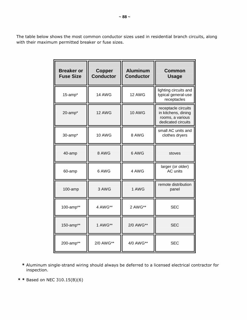
~ 88 ~
The table below shows the most common conductor sizes used in residential branch circuits, along
with their maximum permitted breaker or fuse sizes.
Breaker or Fuse Size
Copper
Conductor
Aluminum Conductor
Common
Usage
15-amp*
14 AWG
12 AWG
lighting circuits and typical general-use
receptacles
20-amp*
12 AWG
10 AWG
receptacle circuits in kitchens, dining rooms, a various dedicated circuits
30-amp*
10 AWG
8 AWG
small AC units and clothes dryers
40-amp
8 AWG
6 AWG
stoves
60-amp
6 AWG
4 AWG
larger (or older) AC units
100-amp
3 AWG
1 AWG
remote distribution panel
100-amp**
4 AWG**
2 AWG**
SEC
150-amp**
1 AWG**
2/0 AWG**
SEC
200-amp**
2/0 AWG**
4/0 AWG**
SEC
* Aluminum single-strand wiring should always be deferred to a licensed electrical contractor for
inspection.
* * Based on NEC 310.15(B)(6)
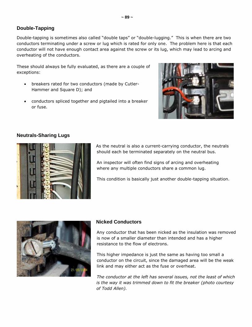
~ 89 ~
Double-Tapping
Double-tapping is sometimes also called ―double taps‖ or ―double-lugging.‖ This is when there are two
conductors terminating under a screw or lug which is rated for only one. The problem here is that each
conductor will not have enough contact area against the screw or its lug, which may lead to arcing and
overheating of the conductors.
These should always be fully evaluated, as there are a couple of
exceptions:
breakers rated for two conductors (made by Cutler-
Hammer and Square D); and
conductors spliced together and pigtailed into a breaker
or fuse.
Neutrals-Sharing Lugs
As the neutral is also a current-carrying conductor, the neutrals
should each be terminated separately on the neutral bus.
An inspector will often find signs of arcing and overheating
where any multiple conductors share a common lug.
This condition is basically just another double-tapping situation.
Nicked Conductors
Any conductor that has been nicked as the insulation was removed
is now of a smaller diameter than intended and has a higher
resistance to the flow of electrons.
This higher impedance is just the same as having too small a
conductor on the circuit, since the damaged area will be the weak
link and may either act as the fuse or overheat.
The conductor at the left has several issues, not the least of which
is the way it was trimmed down to fit the breaker (photo courtesy
of Todd Allen).
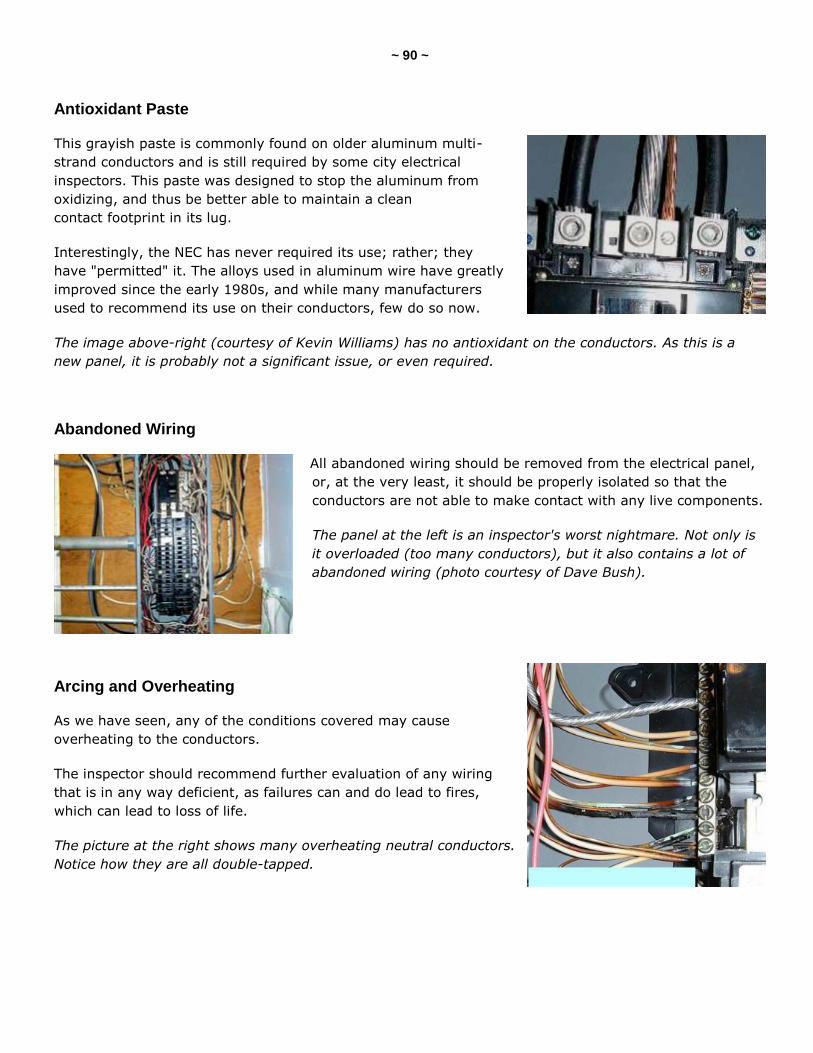
~ 90 ~
Antioxidant Paste
This grayish paste is commonly found on older aluminum multi-
strand conductors and is still required by some city electrical
inspectors. This paste was designed to stop the aluminum from
oxidizing, and thus be better able to maintain a clean
contact footprint in its lug.
Interestingly, the NEC has never required its use; rather; they
have "permitted" it. The alloys used in aluminum wire have greatly
improved since the early 1980s, and while many manufacturers
used to recommend its use on their conductors, few do so now.
The image above-right (courtesy of Kevin Williams) has no antioxidant on the conductors. As this is a
new panel, it is probably not a significant issue, or even required.
Abandoned Wiring
All abandoned wiring should be removed from the electrical panel,
or, at the very least, it should be properly isolated so that the
conductors are not able to make contact with any live components.
The panel at the left is an inspector's worst nightmare. Not only is
it overloaded (too many conductors), but it also contains a lot of
abandoned wiring (photo courtesy of Dave Bush).
Arcing and Overheating
As we have seen, any of the conditions covered may cause
overheating to the conductors.
The inspector should recommend further evaluation of any wiring
that is in any way deficient, as failures can and do lead to fires,
which can lead to loss of life.
The picture at the right shows many overheating neutral conductors.
Notice how they are all double-tapped.
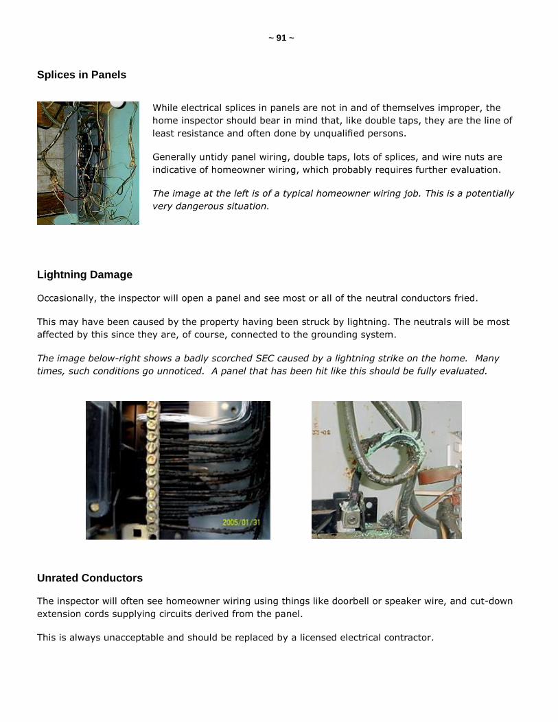
~ 91 ~
Splices in Panels
While electrical splices in panels are not in and of themselves improper, the
home inspector should bear in mind that, like double taps, they are the line of
least resistance and often done by unqualified persons.
Generally untidy panel wiring, double taps, lots of splices, and wire nuts are
indicative of homeowner wiring, which probably requires further evaluation.
The image at the left is of a typical homeowner wiring job. This is a potentially
very dangerous situation.
Lightning Damage
Occasionally, the inspector will open a panel and see most or all of the neutral conductors fried.
This may have been caused by the property having been struck by lightning. The neutrals will be most
affected by this since they are, of course, connected to the grounding system.
The image below-right shows a badly scorched SEC caused by a lightning strike on the home. Many
times, such conditions go unnoticed. A panel that has been hit like this should be fully evaluated.
Unrated Conductors
The inspector will often see homeowner wiring using things like doorbell or speaker wire, and cut-down
extension cords supplying circuits derived from the panel.
This is always unacceptable and should be replaced by a licensed electrical contractor.
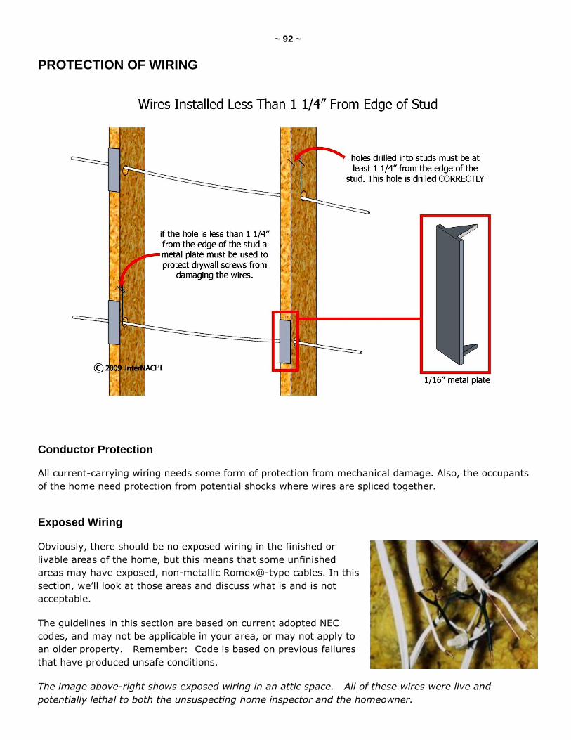
~ 92 ~
PROTECTION OF WIRING
Conductor Protection
All current-carrying wiring needs some form of protection from mechanical damage. Also, the occupants
of the home need protection from potential shocks where wires are spliced together.
Exposed Wiring
Obviously, there should be no exposed wiring in the finished or
livable areas of the home, but this means that some unfinished
areas may have exposed, non-metallic Romex®-type cables. In this
section, we’ll look at those areas and discuss what is and is not
acceptable.
The guidelines in this section are based on current adopted NEC
codes, and may not be applicable in your area, or may not apply to
an older property. Remember: Code is based on previous failures
that have produced unsafe conditions.
The image above-right shows exposed wiring in an attic space. All of these wires were live and
potentially lethal to both the unsuspecting home inspector and the homeowner.
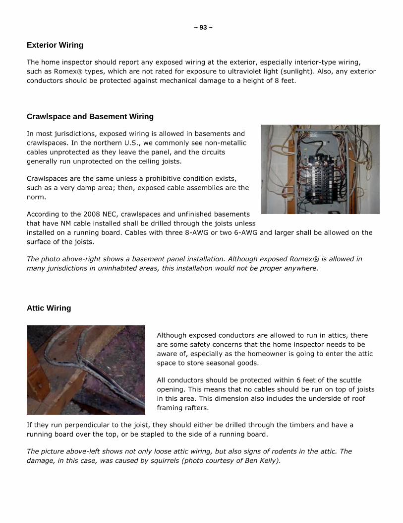
~ 93 ~
Exterior Wiring
The home inspector should report any exposed wiring at the exterior, especially interior-type wiring,
such as Romex® types, which are not rated for exposure to ultraviolet light (sunlight). Also, any exterior
conductors should be protected against mechanical damage to a height of 8 feet.
Crawlspace and Basement Wiring
In most jurisdictions, exposed wiring is allowed in basements and
crawlspaces. In the northern U.S., we commonly see non-metallic
cables unprotected as they leave the panel, and the circuits
generally run unprotected on the ceiling joists.
Crawlspaces are the same unless a prohibitive condition exists,
such as a very damp area; then, exposed cable assemblies are the
norm.
According to the 2008 NEC, crawlspaces and unfinished basements
that have NM cable installed shall be drilled through the joists unless
installed on a running board. Cables with three 8-AWG or two 6-AWG and larger shall be allowed on the
surface of the joists.
The photo above-right shows a basement panel installation. Although exposed Romex® is allowed in
many jurisdictions in uninhabited areas, this installation would not be proper anywhere.
Attic Wiring
Although exposed conductors are allowed to run in attics, there
are some safety concerns that the home inspector needs to be
aware of, especially as the homeowner is going to enter the attic
space to store seasonal goods.
All conductors should be protected within 6 feet of the scuttle
opening. This means that no cables should be run on top of joists
in this area. This dimension also includes the underside of roof
framing rafters.
If they run perpendicular to the joist, they should either be drilled through the timbers and have a
running board over the top, or be stapled to the side of a running board.
The picture above-left shows not only loose attic wiring, but also signs of rodents in the attic. The
damage, in this case, was caused by squirrels (photo courtesy of Ben Kelly).
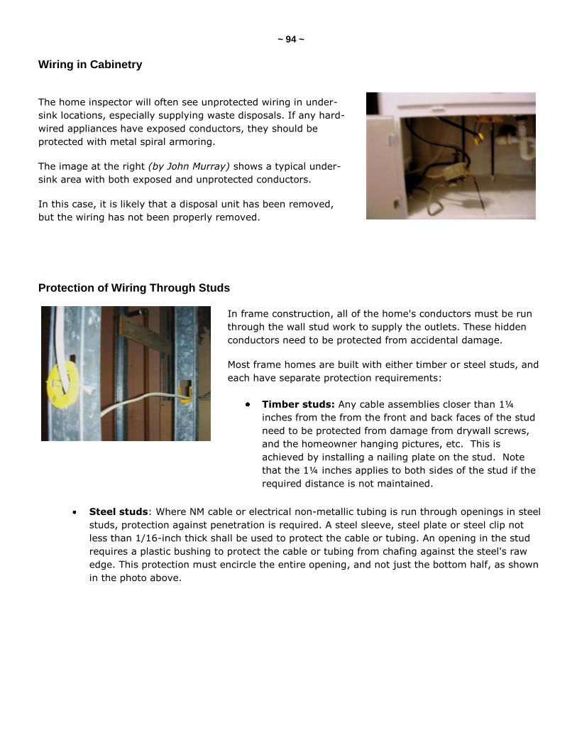
~ 94 ~
Wiring in Cabinetry
The home inspector will often see unprotected wiring in under-
sink locations, especially supplying waste disposals. If any hard-
wired appliances have exposed conductors, they should be
protected with metal spiral armoring.
The image at the right (by John Murray) shows a typical under-
sink area with both exposed and unprotected conductors.
In this case, it is likely that a disposal unit has been removed,
but the wiring has not been properly removed.
Protection of Wiring Through Studs
In frame construction, all of the home's conductors must be run
through the wall stud work to supply the outlets. These hidden
conductors need to be protected from accidental damage.
Most frame homes are built with either timber or steel studs, and
each have separate protection requirements:
Timber studs: Any cable assemblies closer than 1¼
inches from the from the front and back faces of the stud
need to be protected from damage from drywall screws,
and the homeowner hanging pictures, etc. This is
achieved by installing a nailing plate on the stud. Note
that the 1¼ inches applies to both sides of the stud if the
required distance is not maintained.
Steel studs: Where NM cable or electrical non-metallic tubing is run through openings in steel
studs, protection against penetration is required. A steel sleeve, steel plate or steel clip not
less than 1/16-inch thick shall be used to protect the cable or tubing. An opening in the stud
requires a plastic bushing to protect the cable or tubing from chafing against the steel's raw
edge. This protection must encircle the entire opening, and not just the bottom half, as shown
in the photo above.
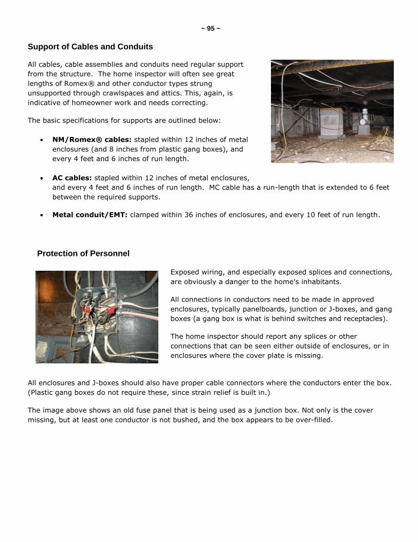
~ 95 ~
Support of Cables and Conduits
All cables, cable assemblies and conduits need regular support
from the structure. The home inspector will often see great
lengths of Romex® and other conductor types strung
unsupported through crawlspaces and attics. This, again, is
indicative of homeowner work and needs correcting.
The basic specifications for supports are outlined below:
NM/Romex® cables: stapled within 12 inches of metal
enclosures (and 8 inches from plastic gang boxes), and
every 4 feet and 6 inches of run length.
AC cables: stapled within 12 inches of metal enclosures,
and every 4 feet and 6 inches of run length. MC cable has a run-length that is extended to 6 feet
between the required supports.
Metal conduit/EMT: clamped within 36 inches of enclosures, and every 10 feet of run length.
Protection of Personnel
Exposed wiring, and especially exposed splices and connections,
are obviously a danger to the home's inhabitants.
All connections in conductors need to be made in approved
enclosures, typically panelboards, junction or J-boxes, and gang
boxes (a gang box is what is behind switches and receptacles).
The home inspector should report any splices or other
connections that can be seen either outside of enclosures, or in
enclosures where the cover plate is missing.
All enclosures and J-boxes should also have proper cable connectors where the conductors enter the box.
(Plastic gang boxes do not require these, since strain relief is built in.)
The image above shows an old fuse panel that is being used as a junction box. Not only is the cover
missing, but at least one conductor is not bushed, and the box appears to be over-filled.
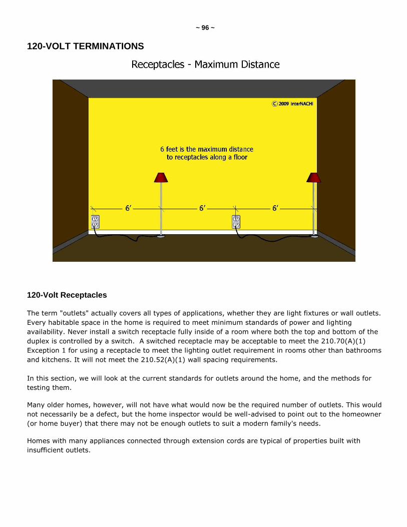
~ 96 ~
120-VOLT TERMINATIONS
120-Volt Receptacles
The term "outlets" actually covers all types of applications, whether they are light fixtures or wall outlets.
Every habitable space in the home is required to meet minimum standards of power and lighting
availability. Never install a switch receptacle fully inside of a room where both the top and bottom of the
duplex is controlled by a switch. A switched receptacle may be acceptable to meet the 210.70(A)(1)
Exception 1 for using a receptacle to meet the lighting outlet requirement in rooms other than bathrooms
and kitchens. It will not meet the 210.52(A)(1) wall spacing requirements.
In this section, we will look at the current standards for outlets around the home, and the methods for
testing them.
Many older homes, however, will not have what would now be the required number of outlets. This would
not necessarily be a defect, but the home inspector would be well-advised to point out to the homeowner
(or home buyer) that there may not be enough outlets to suit a modern family's needs.
Homes with many appliances connected through extension cords are typical of properties built with
insufficient outlets.
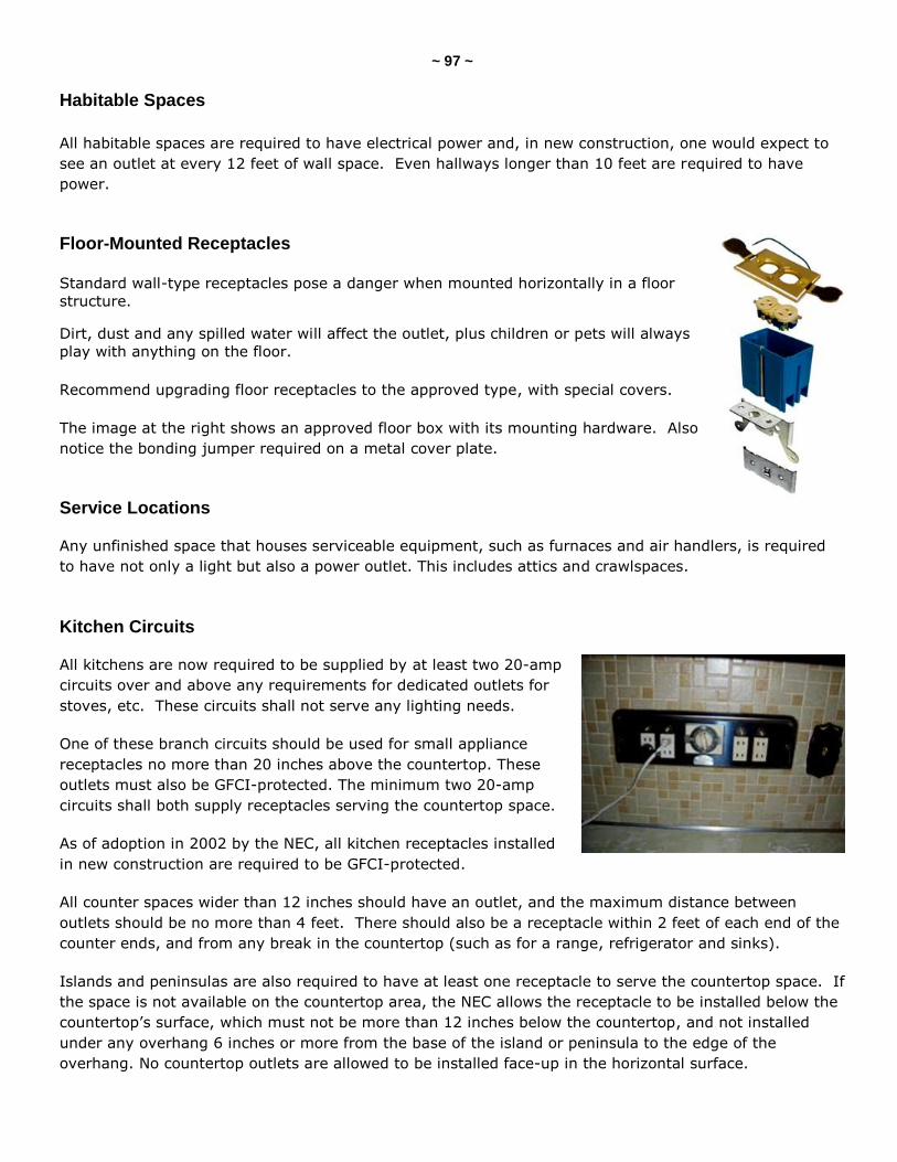
~ 97 ~
Habitable Spaces
All habitable spaces are required to have electrical power and, in new construction, one would expect to
see an outlet at every 12 feet of wall space. Even hallways longer than 10 feet are required to have
power.
Floor-Mounted Receptacles Standard wall-type receptacles pose a danger when mounted horizontally in a floor
structure.
Dirt, dust and any spilled water will affect the outlet, plus children or pets will always
play with anything on the floor.
Recommend upgrading floor receptacles to the approved type, with special covers.
The image at the right shows an approved floor box with its mounting hardware. Also
notice the bonding jumper required on a metal cover plate.
Service Locations
Any unfinished space that houses serviceable equipment, such as furnaces and air handlers, is required
to have not only a light but also a power outlet. This includes attics and crawlspaces.
Kitchen Circuits
All kitchens are now required to be supplied by at least two 20-amp
circuits over and above any requirements for dedicated outlets for
stoves, etc. These circuits shall not serve any lighting needs.
One of these branch circuits should be used for small appliance
receptacles no more than 20 inches above the countertop. These
outlets must also be GFCI-protected. The minimum two 20-amp
circuits shall both supply receptacles serving the countertop space.
As of adoption in 2002 by the NEC, all kitchen receptacles installed
in new construction are required to be GFCI-protected.
All counter spaces wider than 12 inches should have an outlet, and the maximum distance between
outlets should be no more than 4 feet. There should also be a receptacle within 2 feet of each end of the
counter ends, and from any break in the countertop (such as for a range, refrigerator and sinks).
Islands and peninsulas are also required to have at least one receptacle to serve the countertop space. If
the space is not available on the countertop area, the NEC allows the receptacle to be installed below the
countertop’s surface, which must not be more than 12 inches below the countertop, and not installed
under any overhang 6 inches or more from the base of the island or peninsula to the edge of the
overhang. No countertop outlets are allowed to be installed face-up in the horizontal surface.
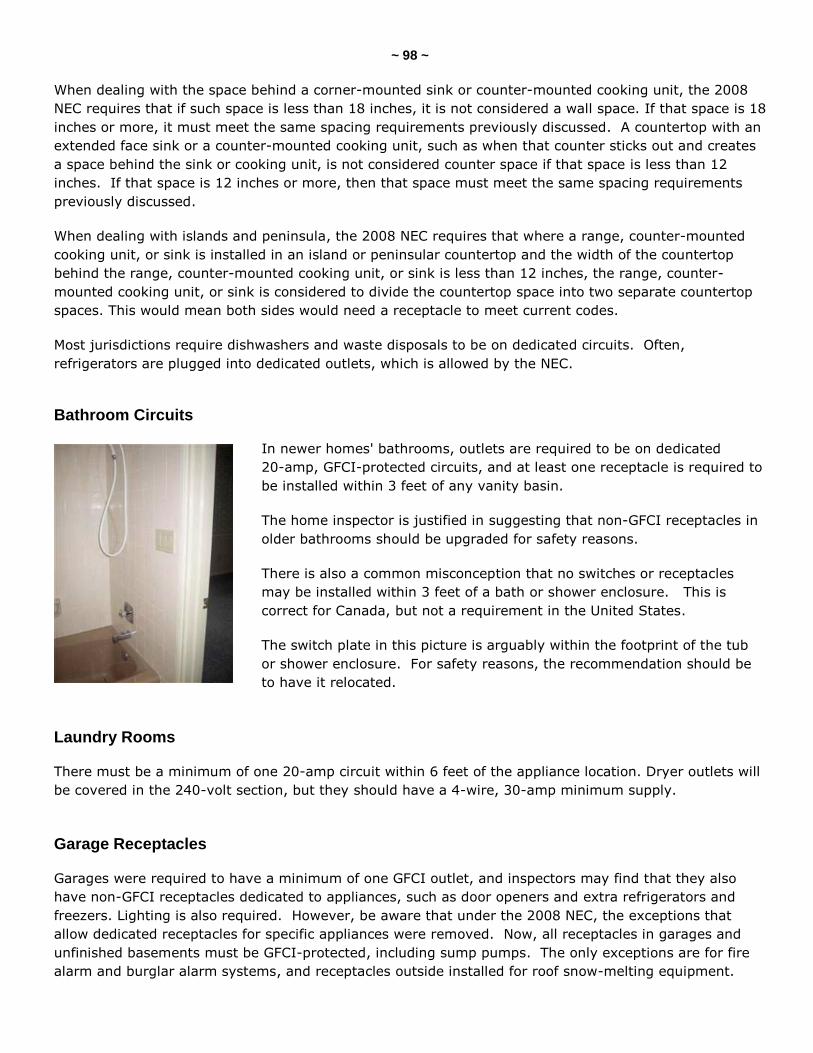
~ 98 ~
When dealing with the space behind a corner-mounted sink or counter-mounted cooking unit, the 2008
NEC requires that if such space is less than 18 inches, it is not considered a wall space. If that space is 18
inches or more, it must meet the same spacing requirements previously discussed. A countertop with an
extended face sink or a counter-mounted cooking unit, such as when that counter sticks out and creates
a space behind the sink or cooking unit, is not considered counter space if that space is less than 12
inches. If that space is 12 inches or more, then that space must meet the same spacing requirements
previously discussed.
When dealing with islands and peninsula, the 2008 NEC requires that where a range, counter-mounted
cooking unit, or sink is installed in an island or peninsular countertop and the width of the countertop
behind the range, counter-mounted cooking unit, or sink is less than 12 inches, the range, counter-
mounted cooking unit, or sink is considered to divide the countertop space into two separate countertop
spaces. This would mean both sides would need a receptacle to meet current codes.
Most jurisdictions require dishwashers and waste disposals to be on dedicated circuits. Often,
refrigerators are plugged into dedicated outlets, which is allowed by the NEC.
Bathroom Circuits
In newer homes' bathrooms, outlets are required to be on dedicated
20-amp, GFCI-protected circuits, and at least one receptacle is required to
be installed within 3 feet of any vanity basin.
The home inspector is justified in suggesting that non-GFCI receptacles in
older bathrooms should be upgraded for safety reasons.
There is also a common misconception that no switches or receptacles
may be installed within 3 feet of a bath or shower enclosure. This is
correct for Canada, but not a requirement in the United States.
The switch plate in this picture is arguably within the footprint of the tub
or shower enclosure. For safety reasons, the recommendation should be
to have it relocated.
Laundry Rooms
There must be a minimum of one 20-amp circuit within 6 feet of the appliance location. Dryer outlets will
be covered in the 240-volt section, but they should have a 4-wire, 30-amp minimum supply.
Garage Receptacles
Garages were required to have a minimum of one GFCI outlet, and inspectors may find that they also
have non-GFCI receptacles dedicated to appliances, such as door openers and extra refrigerators and
freezers. Lighting is also required. However, be aware that under the 2008 NEC, the exceptions that
allow dedicated receptacles for specific appliances were removed. Now, all receptacles in garages and
unfinished basements must be GFCI-protected, including sump pumps. The only exceptions are for fire
alarm and burglar alarm systems, and receptacles outside installed for roof snow-melting equipment.
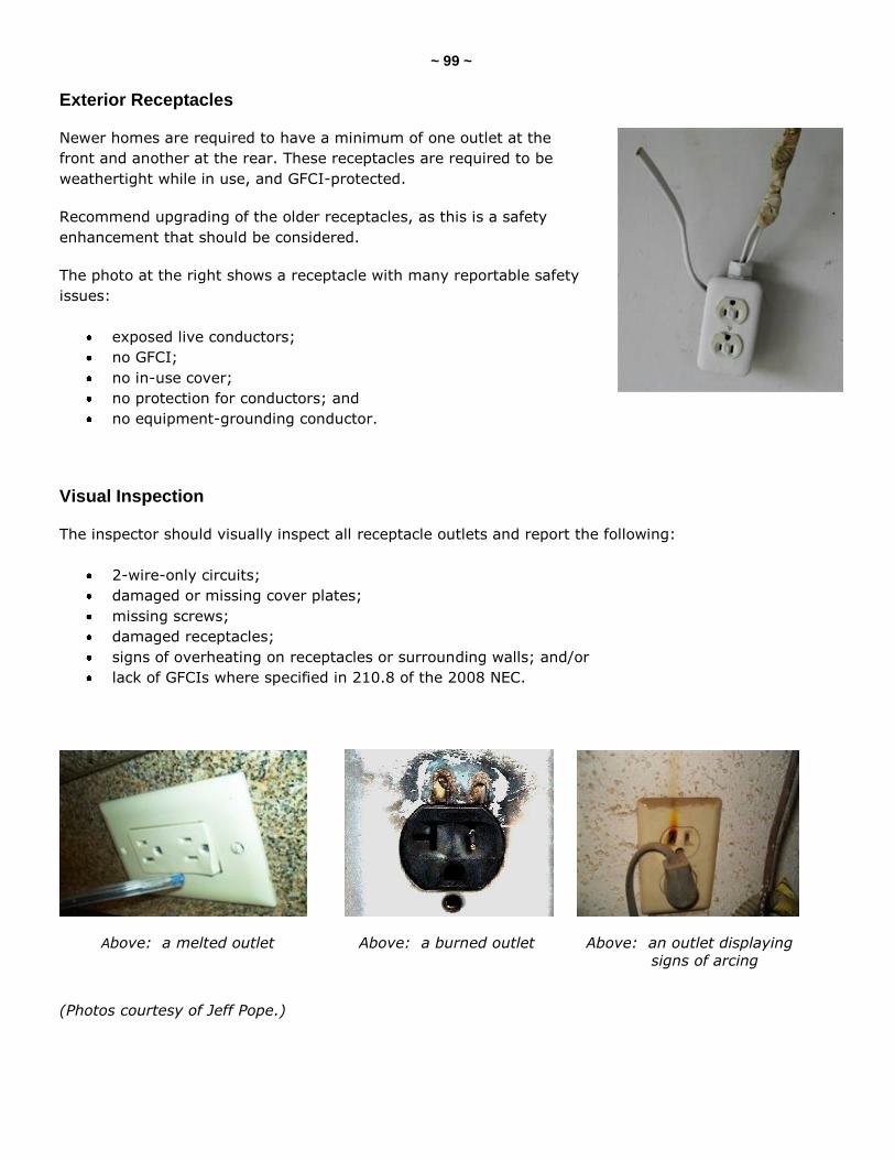
~ 99 ~
Exterior Receptacles
Newer homes are required to have a minimum of one outlet at the
front and another at the rear. These receptacles are required to be
weathertight while in use, and GFCI-protected.
Recommend upgrading of the older receptacles, as this is a safety
enhancement that should be considered.
The photo at the right shows a receptacle with many reportable safety
issues:
exposed live conductors;
no GFCI;
no in-use cover;
no protection for conductors; and
no equipment-grounding conductor.
Visual Inspection
The inspector should visually inspect all receptacle outlets and report the following:
2-wire-only circuits;
damaged or missing cover plates;
missing screws;
damaged receptacles;
signs of overheating on receptacles or surrounding walls; and/or
lack of GFCIs where specified in 210.8 of the 2008 NEC.
Above: a melted outlet Above: a burned outlet Above: an outlet displaying
signs of arcing
(Photos courtesy of Jeff Pope.)
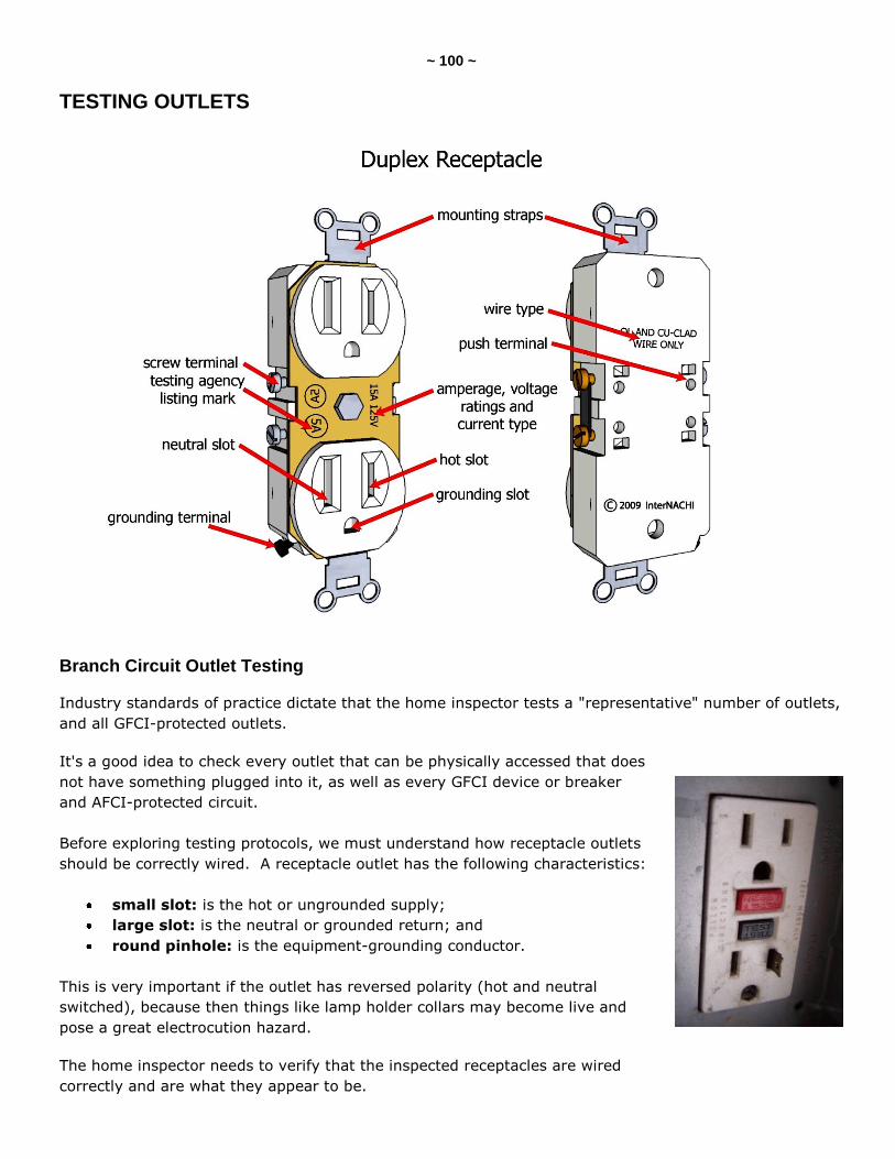
~ 100 ~
TESTING OUTLETS
Branch Circuit Outlet Testing
Industry standards of practice dictate that the home inspector tests a "representative" number of outlets,
and all GFCI-protected outlets.
It's a good idea to check every outlet that can be physically accessed that does
not have something plugged into it, as well as every GFCI device or breaker
and AFCI-protected circuit.
Before exploring testing protocols, we must understand how receptacle outlets
should be correctly wired. A receptacle outlet has the following characteristics:
small slot: is the hot or ungrounded supply;
large slot: is the neutral or grounded return; and
round pinhole: is the equipment-grounding conductor.
This is very important if the outlet has reversed polarity (hot and neutral
switched), because then things like lamp holder collars may become live and
pose a great electrocution hazard.
The home inspector needs to verify that the inspected receptacles are wired
correctly and are what they appear to be.
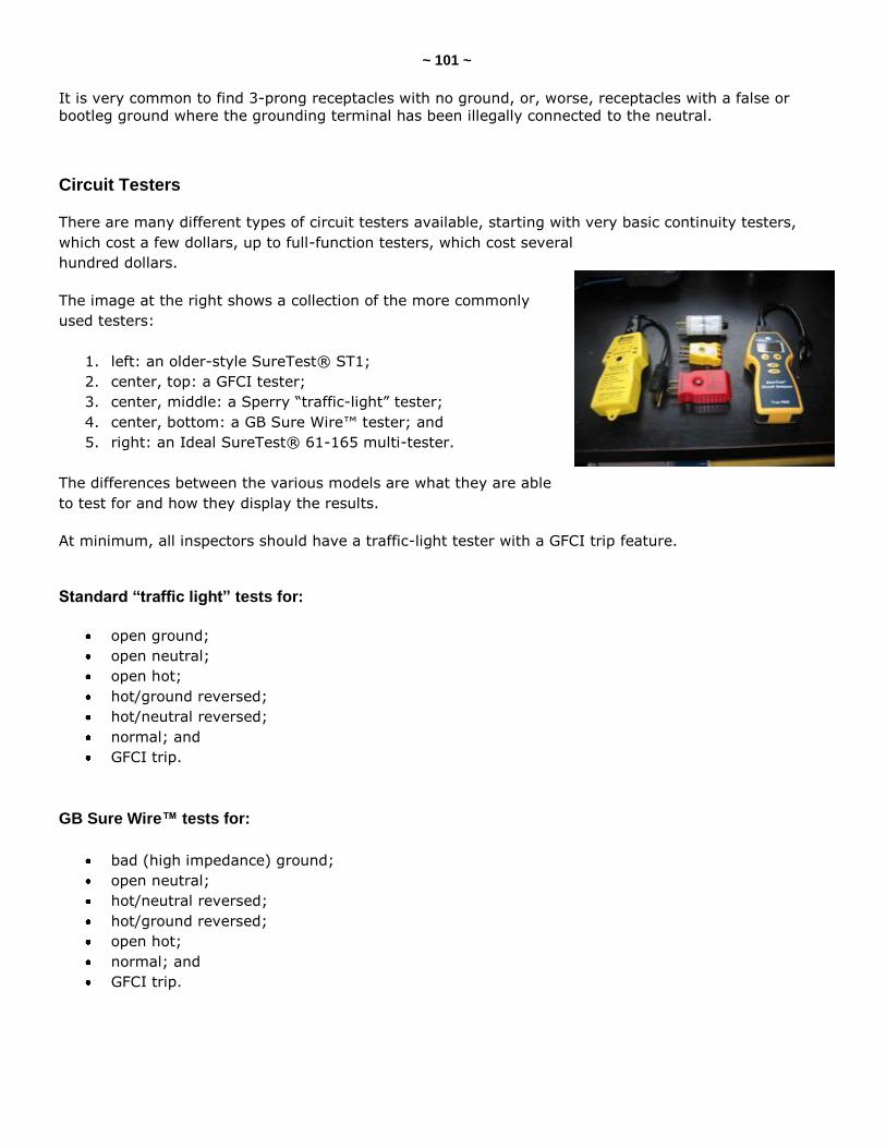
~ 101 ~
It is very common to find 3-prong receptacles with no ground, or, worse, receptacles with a false or
bootleg ground where the grounding terminal has been illegally connected to the neutral.
Circuit Testers
There are many different types of circuit testers available, starting with very basic continuity testers,
which cost a few dollars, up to full-function testers, which cost several
hundred dollars.
The image at the right shows a collection of the more commonly
used testers:
1. left: an older-style SureTest® ST1;
2. center, top: a GFCI tester;
3. center, middle: a Sperry ―traffic-light‖ tester;
4. center, bottom: a GB Sure Wire™ tester; and
5. right: an Ideal SureTest® 61-165 multi-tester.
The differences between the various models are what they are able
to test for and how they display the results.
At minimum, all inspectors should have a traffic-light tester with a GFCI trip feature.
Standard “traffic light” tests for:
open ground;
open neutral;
open hot;
hot/ground reversed;
hot/neutral reversed;
normal; and
GFCI trip.
GB Sure Wire™ tests for:
bad (high impedance) ground;
open neutral;
hot/neutral reversed;
hot/ground reversed;
open hot;
normal; and
GFCI trip.
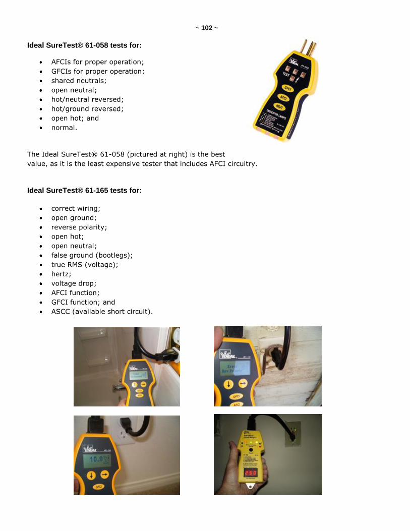
~ 102 ~
Ideal SureTest® 61-058 tests for:
AFCIs for proper operation;
GFCIs for proper operation;
shared neutrals;
open neutral;
hot/neutral reversed;
hot/ground reversed;
open hot; and
normal.
The Ideal SureTest® 61-058 (pictured at right) is the best
value, as it is the least expensive tester that includes AFCI circuitry.
Ideal SureTest® 61-165 tests for:
correct wiring;
open ground;
reverse polarity;
open hot;
open neutral;
false ground (bootlegs);
true RMS (voltage);
hertz;
voltage drop;
AFCI function;
GFCI function; and
ASCC (available short circuit).
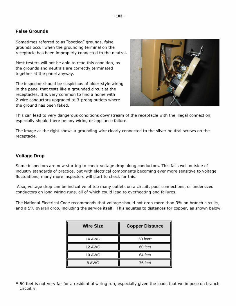
~ 103 ~
False Grounds
Sometimes referred to as ―bootleg‖ grounds, false
grounds occur when the grounding terminal on the
receptacle has been improperly connected to the neutral.
Most testers will not be able to read this condition, as
the grounds and neutrals are correctly terminated
together at the panel anyway.
The inspector should be suspicious of older-style wiring
in the panel that tests like a grounded circuit at the
receptacles. It is very common to find a home with
2-wire conductors upgraded to 3-prong outlets where
the ground has been faked.
This can lead to very dangerous conditions downstream of the receptacle with the illegal connection,
especially should there be any wiring or appliance failure.
The image at the right shows a grounding wire clearly connected to the silver neutral screws on the
receptacle.
Voltage Drop
Some inspectors are now starting to check voltage drop along conductors. This falls well outside of
industry standards of practice, but with electrical components becoming ever more sensitive to voltage
fluctuations, many more inspectors will start to check for this.
Also, voltage drop can be indicative of too many outlets on a circuit, poor connections, or undersized
conductors on long wiring runs, all of which could lead to overheating and failures.
The National Electrical Code recommends that voltage should not drop more than 3% on branch circuits,
and a 5% overall drop, including the service itself. This equates to distances for copper, as shown below.
Wire Size Copper Distance
14 AWG 50 feet*
12 AWG 60 feet
10 AWG 64 feet
8 AWG 76 feet
* 50 feet is not very far for a residential wiring run, especially given the loads that we impose on branch
circuitry.
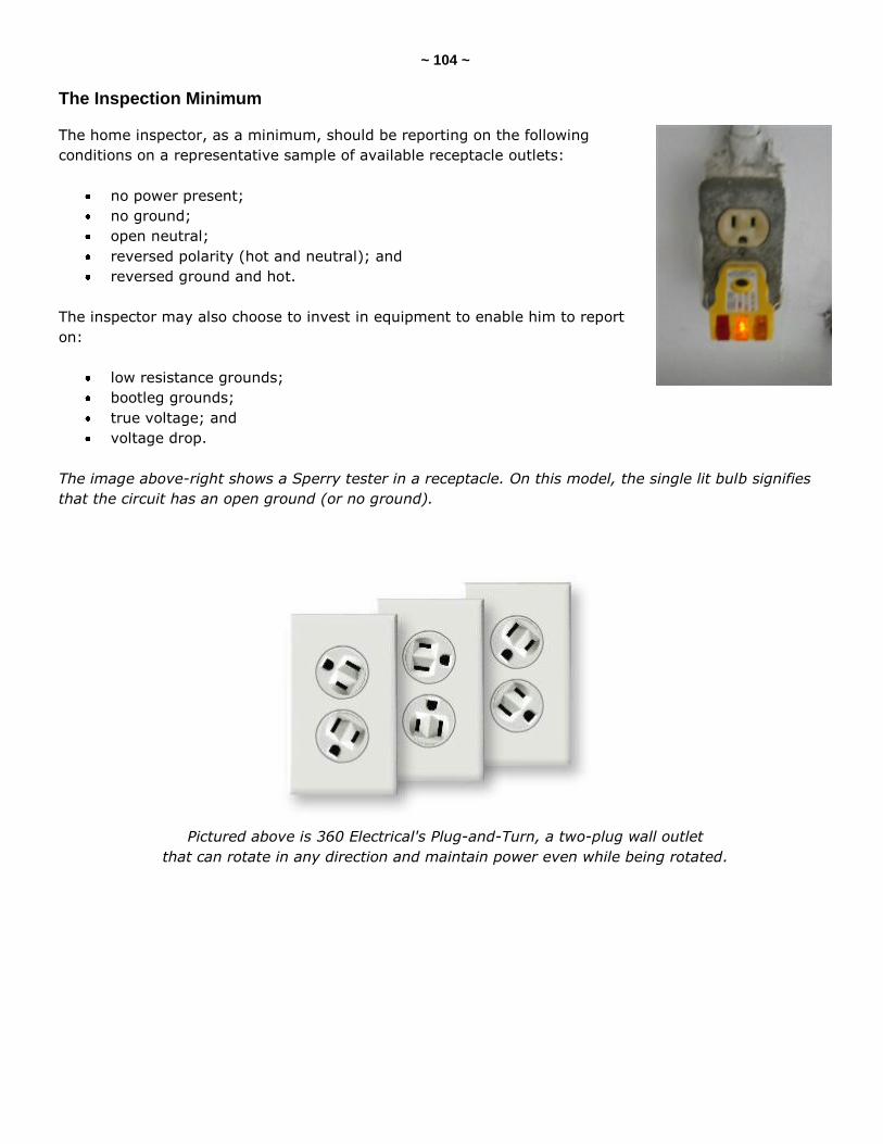
~ 104 ~
The Inspection Minimum
The home inspector, as a minimum, should be reporting on the following
conditions on a representative sample of available receptacle outlets:
no power present;
no ground;
open neutral;
reversed polarity (hot and neutral); and
reversed ground and hot.
The inspector may also choose to invest in equipment to enable him to report
on:
low resistance grounds;
bootleg grounds;
true voltage; and
voltage drop.
The image above-right shows a Sperry tester in a receptacle. On this model, the single lit bulb signifies
that the circuit has an open ground (or no ground).
Pictured above is 360 Electrical's Plug-and-Turn, a two-plug wall outlet
that can rotate in any direction and maintain power even while being rotated.
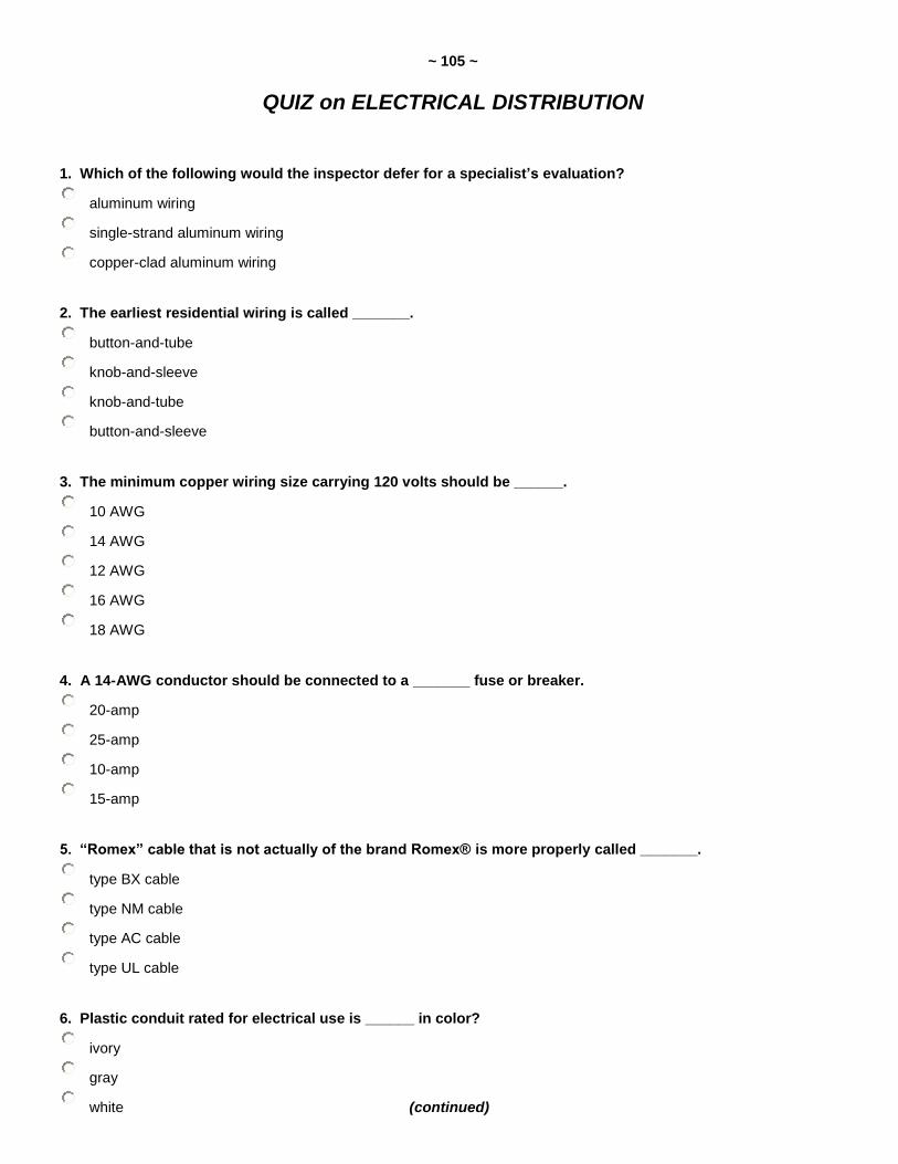
~ 105 ~
QUIZ on ELECTRICAL DISTRIBUTION
1. Which of the following would the inspector defer for a specialist’s evaluation?
aluminum wiring
single-strand aluminum wiring
copper-clad aluminum wiring
2. The earliest residential wiring is called _______.
button-and-tube
knob-and-sleeve
knob-and-tube
button-and-sleeve
3. The minimum copper wiring size carrying 120 volts should be ______.
10 AWG
14 AWG
12 AWG
16 AWG
18 AWG
4. A 14-AWG conductor should be connected to a _______ fuse or breaker.
20-amp
25-amp
10-amp
15-amp
5. “Romex” cable that is not actually of the brand Romex® is more properly called _______.
type BX cable
type NM cable
type AC cable
type UL cable
6. Plastic conduit rated for electrical use is ______ in color?
ivory
gray
white (continued)
~ 106 ~
7. Electric water heaters should be fed with _____ minimum copper conductors.
6-AWG
10-AWG
8-AWG
8. T/F: Several grounded conductors can terminate on the same lug.
True
False
depends on circuit amperage
9. T/F: Antioxidant paste should be seen on all aluminum conductors.
True
False
10. T/F: The inspector should report all in-panel electrical splices as improper.
True
False
11. Wiring closer than ____ to the front of a stud requires protection.
1 inch
1-1/8 inches
1-3/16 inches
1¼ inches
12. Unprotected attic electrical wiring should not be within _______ of the entrance opening.
5 feet
3 feet
4 feet
6 feet
8 feet
13. T/F: Unsupported cable assemblies are acceptable in crawlspaces only.
True
False
(continued)
~ 107 ~
14. Are horizontally mounted face-up countertop receptacles allowed?
Not if within 3 feet of the sink
Yes
No
15. Bathroom receptacles should be on ______ circuits.
20-amp, AFCI-protected
20-amp, GFCI-protected
15-amp, GFCI-protected
15-amp, AFCI-protected
16. Which of the following is the inspector NOT required to test for on electrical receptacles?
open hot
open ground
voltage drop
reversed polarity
17. In a false or bootleg grounded receptacle, the ground wire is connected to ____________.
the grounding wire
the ungrounded wire
the receptacle box
the grounded conductor
18. On a standard 120-volt outlet, the smaller rectangular slot is the __________.
ungrounded conductor
grounding conductor
bonding conductor
grounded conductor
19. The home inspector is required to test ___________.
all available receptacles
all receptacles
a representative number of receptacles
(continued)
~ 108 ~
20. Which is the only approved repair to aluminum wire terminations?
CO/ALR
COPALUM
CU/ALR
CU/AL
Answer Key is on the next page.
~ 109 ~
Answer Key to Quiz on Electrical Distribution
1. Which of the following would the inspector defer for a specialist's evaluation? Answer: single-strand aluminum wiring 2. The earliest residential wiring is called knob-and-tube. 3. The minimum copper wiring size carrying 120 volts should be 14 AWG. 4. A 14-AWG conductor should be connected to a 15-amp fuse or breaker. 5. “Romex” cable that is not actually of the brand Romex® is more properly called type-NM cable. 6. Plastic conduit rated for electrical use is gray in color. 7. Electric water heaters should be fed with 10-AWG minimum copper conductors. 8. T/F: Several grounded conductors can terminate on the same lug. Answer: False 9. T/F: Antioxidant paste should be seen on all aluminum conductors. Answer: False 10. T/F: The inspector should report all in-panel electrical splices as improper. Answer: False 11. Wiring closer than 1¼ inches to the front of a stud requires protection. 12. Unprotected attic electrical wiring should not be within 6 feet of the entrance opening. 13. T/F: Unsupported cable assemblies are acceptable in crawlspaces only. Answer: False 14. Are horizontally mounted face-up countertop receptacles allowed? Answer: No. 15. Bathroom receptacles should be on 20-amp, GFCI-protected circuits. 16. Which of the following is the inspector NOT required to test for on electrical receptacles? Answer: voltage drop 17. In a false or bootleg grounded receptacle, the ground wire is connected to the grounded conductor. 18. On a standard 120-volt outlet, the smaller rectangular slot is the ungrounded conductor. 19. The home inspector is required to test a representative number of receptacles. 20. Which is the only approved repair to aluminum wire terminations? Answer: COPALUM
~ 110 ~
240-VOLT TERMINATIONS
240-Volt Systems
In today's homes, we typically see appliances, such as clothes dryers, stoves, heating units and air-
conditioning equipment that use two to three times more power than was required in homes built
decades ago.
As many of these appliances are required to be hard-wired, the home inspector does not do the same
evaluation of 240-volt outlets that s/he would for 120-volt receptacles. However, all attachment plugs
inserted into receptacles should be removed so that both components can be checked for signs of
overheating and damage. One method is to check the 240-volt systems with a voltage ticker. Placing
the end in each slot, one at a time, will at least determine there are 120 volts on each leg and none on
the grounded or grounding legs.
3-Wire Appliances
Prior to the adoption of the 1996 NEC code revisions, 3-wire, 240V supplies were common. The cable
assembly carries:
two 120-volt ungrounded (hot) conductors; and
one grounded (neutral) conductor.
As there is no separate grounding means in this installation, the metal frame of the appliance was
allowed to be bonded to the neutral. This is no longer allowed in new construction.
4-Wire Appliances
Since adoption of the 1996 NEC, all 240V circuits are required to be 4-conductor assemblies carrying:
two 120V ungrounded (hot) conductors;
one grounded (neutral) conductor; and
one equipment grounding conductor.
Some appliances still have the bond between the cabinet and the neutral, and this needs to be removed
when used on a 4-wire circuit.
If a 3-wire configuration exists and one wishes to extend the circuit (for example, in a renovation), it
would be considered a new installation and must be re-wired in a cable with four conductors.
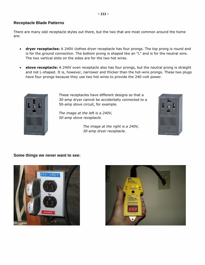
~ 111 ~
Receptacle Blade Patterns There are many odd receptacle styles out there, but the two that are most common around the home
are:
dryer receptacles: A 240V clothes dryer receptacle has four prongs. The top prong is round and
is for the ground connection. The bottom prong is shaped like an "L" and is for the neutral wire.
The two vertical slots on the sides are for the two hot wires.
stove receptacle: A 240V oven receptacle also has four prongs, but the neutral prong is straight
and not L-shaped. It is, however, narrower and thicker than the hot-wire prongs. These two plugs
have four prongs because they use two hot wires to provide the 240-volt power.
These receptacles have different designs so that a
30-amp dryer cannot be accidentally connected to a
50-amp stove circuit, for example.
The image at the left is a 240V,
50-amp stove receptacle.
The image at the right is a 240V,
30-amp dryer receptacle.
Some things we never want to see:
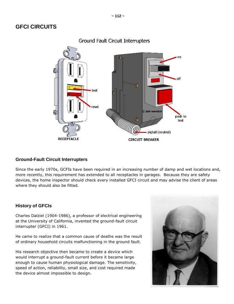
~ 112 ~
GFCI CIRCUITS
Ground-Fault Circuit Interrupters
Since the early 1970s, GCFIs have been required in an increasing number of damp and wet locations and,
more recently, this requirement has extended to all receptacles in garages. Because they are safety
devices, the home inspector should check every installed GFCI circuit and may advise the client of areas
where they should also be fitted.
History of GFCIs
Charles Dalziel (1904-1986), a professor of electrical engineering
at the University of California, invented the ground-fault circuit
interrupter (GFCI) in 1961.
He came to realize that a common cause of deaths was the result
of ordinary household circuits malfunctioning in the ground fault.
His research objective then became to create a device which
would interrupt a ground-fault current before it became large
enough to cause human physiological damage. The sensitivity,
speed of action, reliability, small size, and cost required made
the device almost impossible to design.
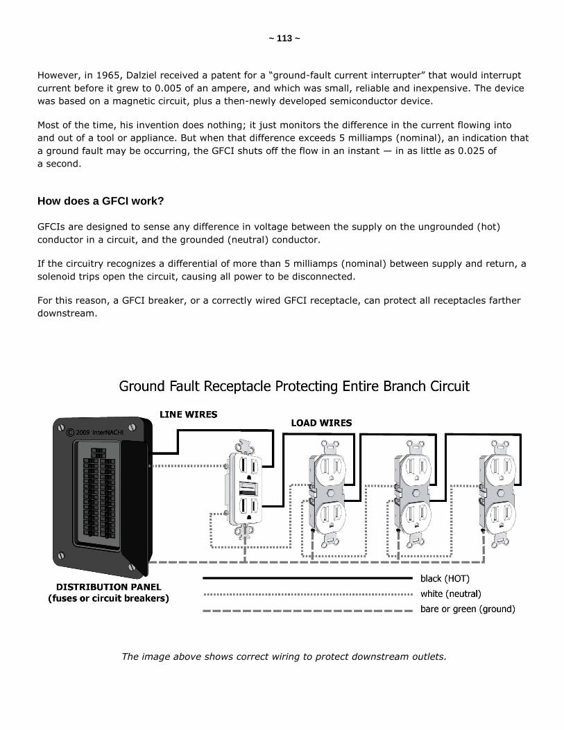
~ 113 ~
However, in 1965, Dalziel received a patent for a ―ground-fault current interrupter‖ that would interrupt
current before it grew to 0.005 of an ampere, and which was small, reliable and inexpensive. The device
was based on a magnetic circuit, plus a then-newly developed semiconductor device.
Most of the time, his invention does nothing; it just monitors the difference in the current flowing into
and out of a tool or appliance. But when that difference exceeds 5 milliamps (nominal), an indication that
a ground fault may be occurring, the GFCI shuts off the flow in an instant — in as little as 0.025 of
a second.
How does a GFCI work?
GFCIs are designed to sense any difference in voltage between the supply on the ungrounded (hot)
conductor in a circuit, and the grounded (neutral) conductor.
If the circuitry recognizes a differential of more than 5 milliamps (nominal) between supply and return, a
solenoid trips open the circuit, causing all power to be disconnected.
For this reason, a GFCI breaker, or a correctly wired GFCI receptacle, can protect all receptacles farther
downstream.
The image above shows correct wiring to protect downstream outlets.
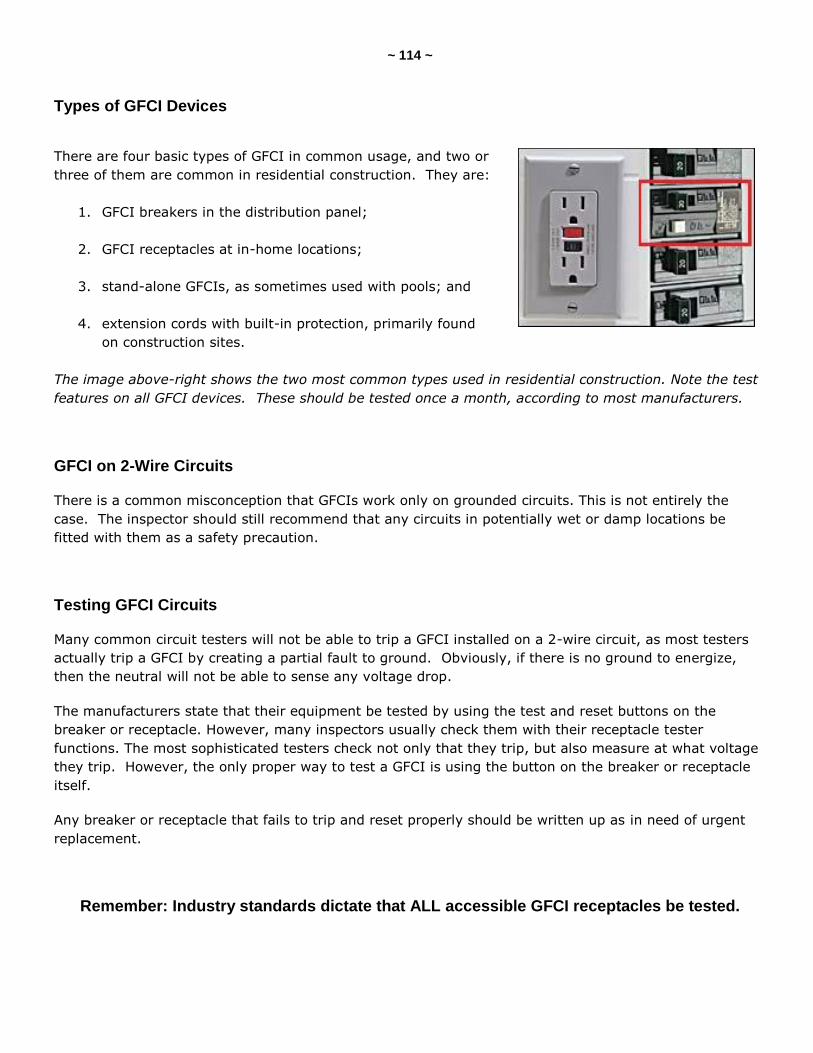
~ 114 ~
Types of GFCI Devices
There are four basic types of GFCI in common usage, and two or
three of them are common in residential construction. They are:
1. GFCI breakers in the distribution panel;
2. GFCI receptacles at in-home locations;
3. stand-alone GFCIs, as sometimes used with pools; and
4. extension cords with built-in protection, primarily found
on construction sites.
The image above-right shows the two most common types used in residential construction. Note the test
features on all GFCI devices. These should be tested once a month, according to most manufacturers.
GFCI on 2-Wire Circuits
There is a common misconception that GFCIs work only on grounded circuits. This is not entirely the
case. The inspector should still recommend that any circuits in potentially wet or damp locations be
fitted with them as a safety precaution.
Testing GFCI Circuits
Many common circuit testers will not be able to trip a GFCI installed on a 2-wire circuit, as most testers
actually trip a GFCI by creating a partial fault to ground. Obviously, if there is no ground to energize,
then the neutral will not be able to sense any voltage drop.
The manufacturers state that their equipment be tested by using the test and reset buttons on the
breaker or receptacle. However, many inspectors usually check them with their receptacle tester
functions. The most sophisticated testers check not only that they trip, but also measure at what voltage
they trip. However, the only proper way to test a GFCI is using the button on the breaker or receptacle
itself.
Any breaker or receptacle that fails to trip and reset properly should be written up as in need of urgent
replacement.
Remember: Industry standards dictate that ALL accessible GFCI receptacles be tested.
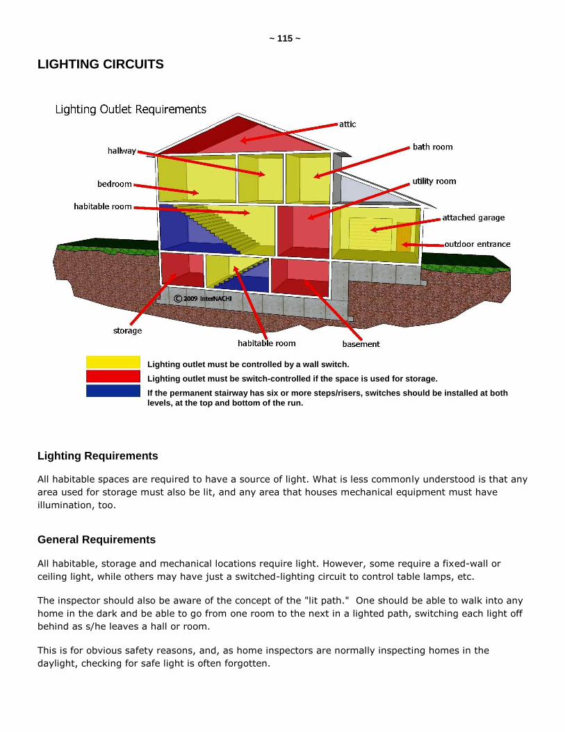
~ 115 ~
LIGHTING CIRCUITS
Lighting Requirements
All habitable spaces are required to have a source of light. What is less commonly understood is that any
area used for storage must also be lit, and any area that houses mechanical equipment must have
illumination, too.
General Requirements
All habitable, storage and mechanical locations require light. However, some require a fixed-wall or
ceiling light, while others may have just a switched-lighting circuit to control table lamps, etc.
The inspector should also be aware of the concept of the "lit path." One should be able to walk into any
home in the dark and be able to go from one room to the next in a lighted path, switching each light off
behind as s/he leaves a hall or room.
This is for obvious safety reasons, and, as home inspectors are normally inspecting homes in the
daylight, checking for safe light is often forgotten.
Lighting outlet must be controlled by a wall switch.
Lighting outlet must be switch-controlled if the space is used for storage.
If the permanent stairway has six or more steps/risers, switches should be installed at both
levels, at the top and bottom of the run.
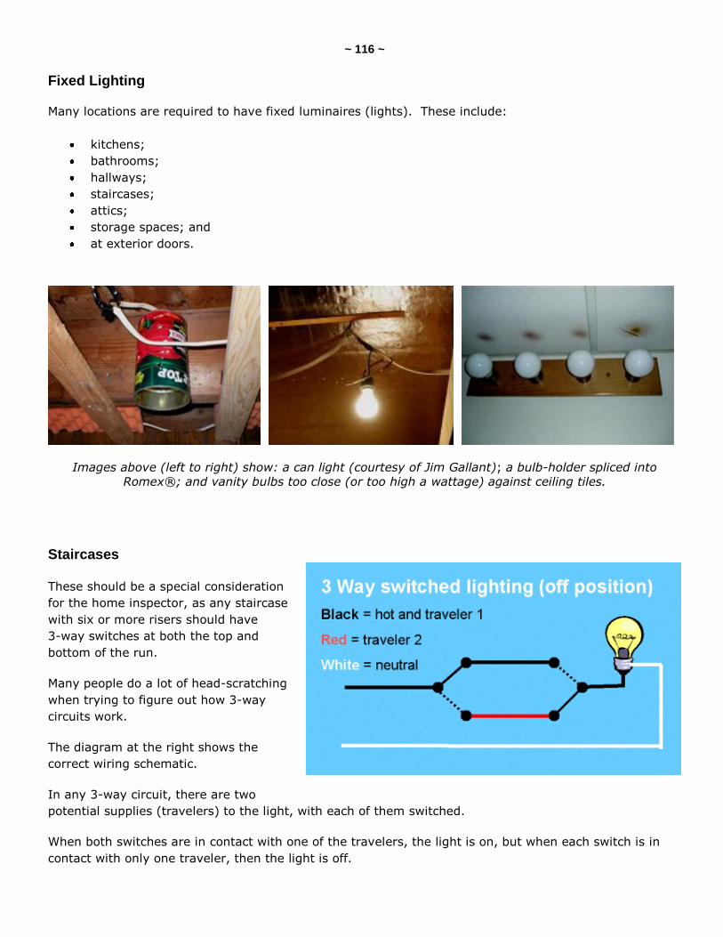
~ 116 ~
Fixed Lighting
Many locations are required to have fixed luminaires (lights). These include:
kitchens;
bathrooms;
hallways;
staircases;
attics;
storage spaces; and
at exterior doors.
Images above (left to right) show: a can light (courtesy of Jim Gallant); a bulb-holder spliced into
Romex®; and vanity bulbs too close (or too high a wattage) against ceiling tiles.
Staircases These should be a special consideration
for the home inspector, as any staircase
with six or more risers should have
3-way switches at both the top and
bottom of the run.
Many people do a lot of head-scratching
when trying to figure out how 3-way
circuits work.
The diagram at the right shows the
correct wiring schematic.
In any 3-way circuit, there are two
potential supplies (travelers) to the light, with each of them switched.
When both switches are in contact with one of the travelers, the light is on, but when each switch is in
contact with only one traveler, then the light is off.
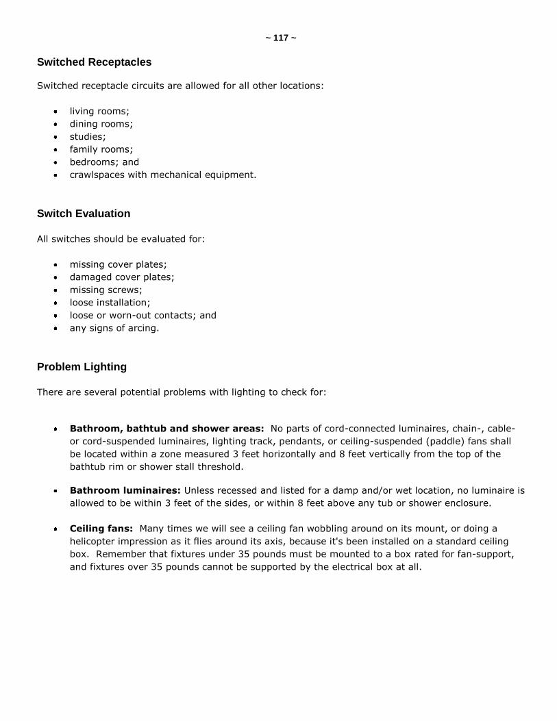
~ 117 ~
Switched Receptacles
Switched receptacle circuits are allowed for all other locations:
living rooms;
dining rooms;
studies;
family rooms;
bedrooms; and
crawlspaces with mechanical equipment.
Switch Evaluation
All switches should be evaluated for:
missing cover plates;
damaged cover plates;
missing screws;
loose installation;
loose or worn-out contacts; and
any signs of arcing.
Problem Lighting
There are several potential problems with lighting to check for:
Bathroom, bathtub and shower areas: No parts of cord-connected luminaires, chain-, cable-
or cord-suspended luminaires, lighting track, pendants, or ceiling-suspended (paddle) fans shall
be located within a zone measured 3 feet horizontally and 8 feet vertically from the top of the
bathtub rim or shower stall threshold.
Bathroom luminaires: Unless recessed and listed for a damp and/or wet location, no luminaire is
allowed to be within 3 feet of the sides, or within 8 feet above any tub or shower enclosure.
Ceiling fans: Many times we will see a ceiling fan wobbling around on its mount, or doing a
helicopter impression as it flies around its axis, because it's been installed on a standard ceiling
box. Remember that fixtures under 35 pounds must be mounted to a box rated for fan-support,
and fixtures over 35 pounds cannot be supported by the electrical box at all.
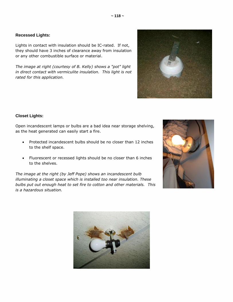
~ 118 ~
Recessed Lights:
Lights in contact with insulation should be IC-rated. If not,
they should have 3 inches of clearance away from insulation
or any other combustible surface or material.
The image at right (courtesy of B. Kelly) shows a "pot" light
in direct contact with vermiculite insulation. This light is not
rated for this application.
Closet Lights:
Open incandescent lamps or bulbs are a bad idea near storage shelving,
as the heat generated can easily start a fire.
Protected incandescent bulbs should be no closer than 12 inches
to the shelf space.
Fluorescent or recessed lights should be no closer than 6 inches
to the shelves.
The image at the right (by Jeff Pope) shows an incandescent bulb
illuminating a closet space which is installed too near insulation. These
bulbs put out enough heat to set fire to cotton and other materials. This
is a hazardous situation.
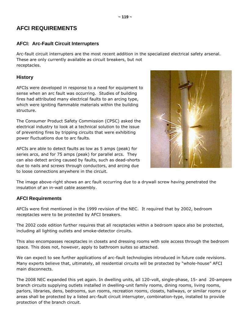
~ 119 ~
AFCI REQUIREMENTS
AFCI: Arc-Fault Circuit Interrupters
Arc-fault circuit interrupters are the most recent addition in the specialized electrical safety arsenal.
These are only currently available as circuit breakers, but not
receptacles.
History
AFCIs were developed in response to a need for equipment to
sense when an arc fault was occurring. Studies of building
fires had attributed many electrical faults to an arcing type,
which were igniting flammable materials within the building
structure.
The Consumer Product Safety Commission (CPSC) asked the
electrical industry to look at a technical solution to the issue
of preventing fires by tripping circuits that were exhibiting
power fluctuations due to arc faults.
AFCIs are able to detect faults as low as 5 amps (peak) for
series arcs, and for 75 amps (peak) for parallel arcs. They
can also detect arcing caused by faults, such as dead-shorts
due to nails and screws through conductors, and arcing due
to loose connections anywhere in the circuit.
The image above-right shows an arc fault occurring due to a drywall screw having penetrated the
insulation of an in-wall cable assembly.
AFCI Requirements
AFCIs were first mentioned in the 1999 revision of the NEC. It required that by 2002, bedroom
receptacles were to be protected by AFCI breakers.
The 2002 code edition further requires that all receptacles within a bedroom space also be protected,
including all lighting outlets and smoke-detector circuits.
This also encompasses receptacles in closets and dressing rooms with sole access through the bedroom
space. This does not, however, apply to bathroom suites so attached.
We can expect to see further applications of arc-fault technologies introduced in future code revisions.
Many experts believe that, ultimately, all residential circuits will be protected by ―whole-house‖ AFCI
main disconnects.
The 2008 NEC expanded this yet again. In dwelling units, all 120-volt, single-phase, 15- and 20-ampere
branch circuits supplying outlets installed in dwelling-unit family rooms, dining rooms, living rooms,
parlors, libraries, dens, bedrooms, sun rooms, recreation rooms, closets, hallways, or similar rooms or
areas shall be protected by a listed arc-fault circuit interrupter, combination-type, installed to provide
protection of the branch circuit.
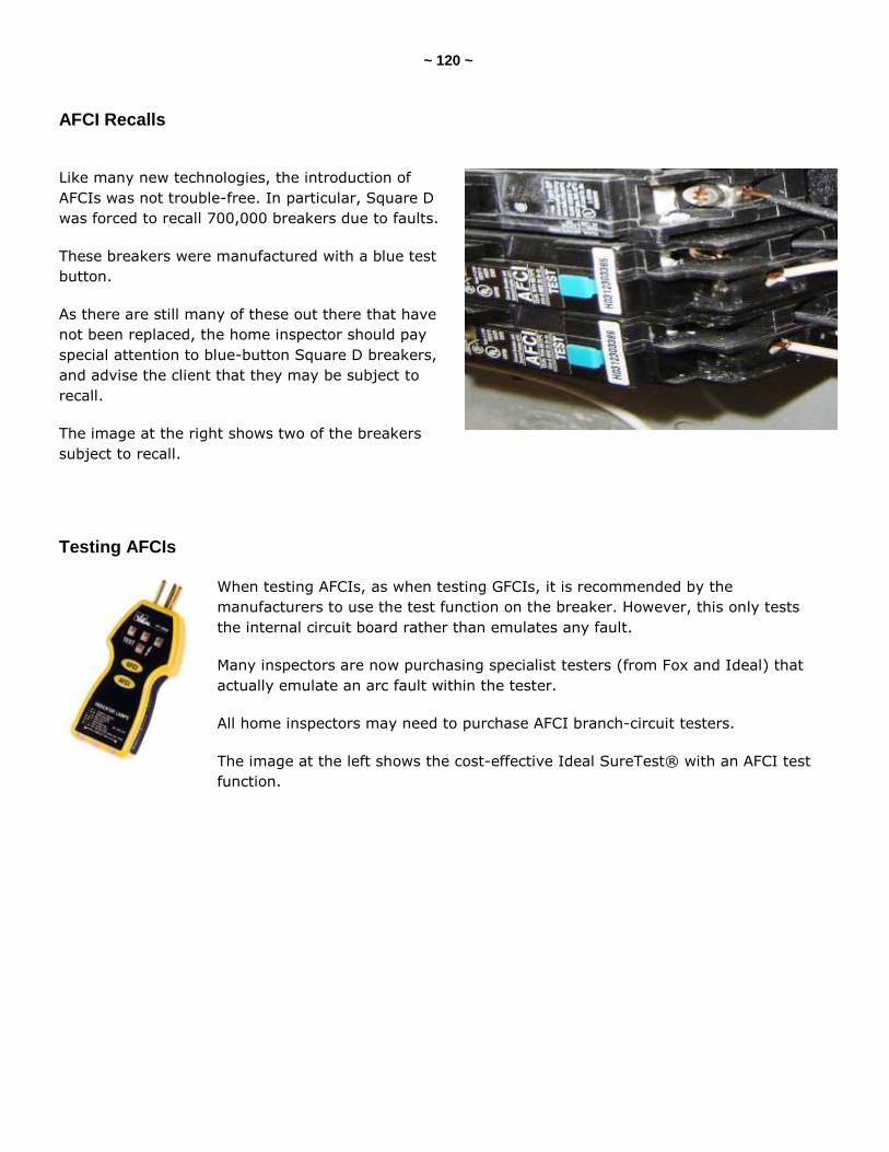
~ 120 ~
AFCI Recalls
Like many new technologies, the introduction of
AFCIs was not trouble-free. In particular, Square D
was forced to recall 700,000 breakers due to faults.
These breakers were manufactured with a blue test
button.
As there are still many of these out there that have
not been replaced, the home inspector should pay
special attention to blue-button Square D breakers,
and advise the client that they may be subject to
recall.
The image at the right shows two of the breakers
subject to recall.
Testing AFCIs
When testing AFCIs, as when testing GFCIs, it is recommended by the
manufacturers to use the test function on the breaker. However, this only tests
the internal circuit board rather than emulates any fault.
Many inspectors are now purchasing specialist testers (from Fox and Ideal) that
actually emulate an arc fault within the tester.
All home inspectors may need to purchase AFCI branch-circuit testers.
The image at the left shows the cost-effective Ideal SureTest® with an AFCI test
function.
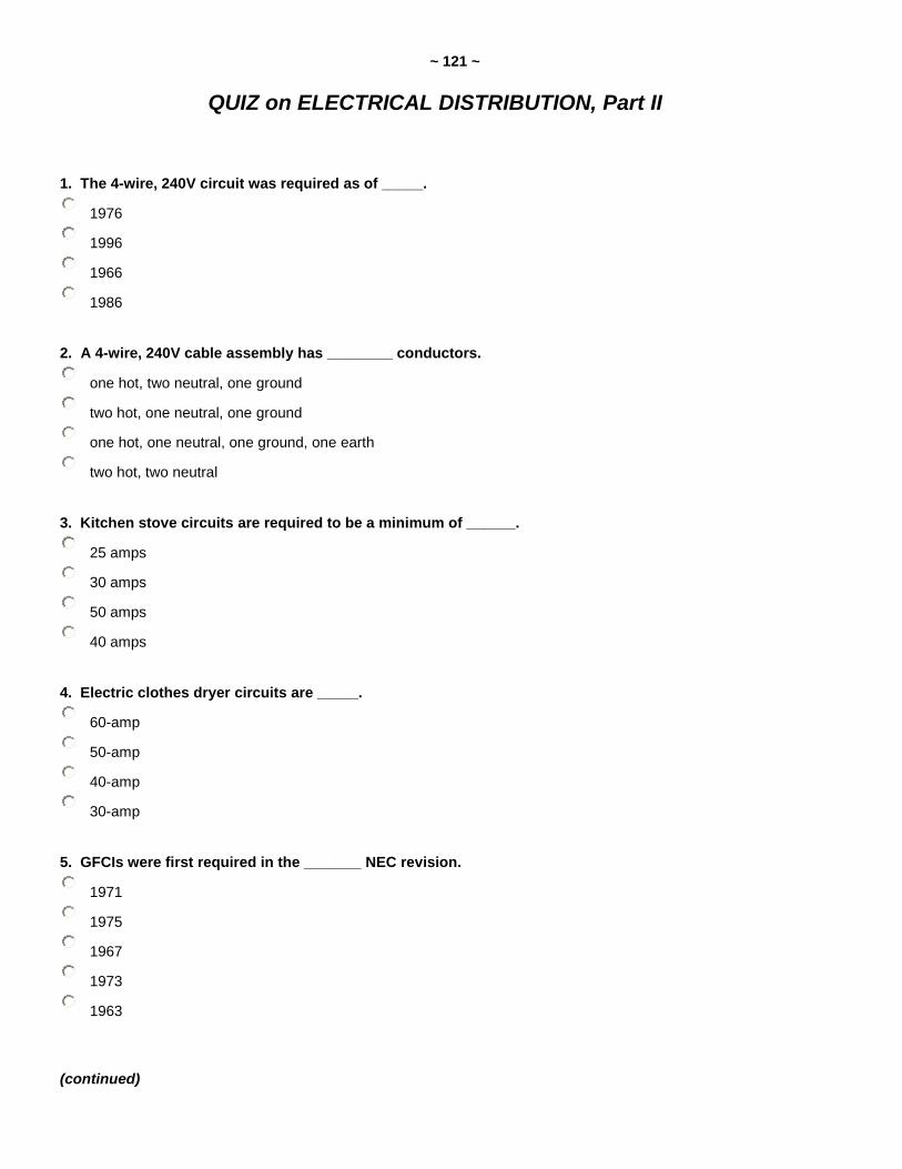
~ 121 ~
QUIZ on ELECTRICAL DISTRIBUTION, Part II
1. The 4-wire, 240V circuit was required as of _____.
1976
1996
1966
1986
2. A 4-wire, 240V cable assembly has ________ conductors.
one hot, two neutral, one ground
two hot, one neutral, one ground
one hot, one neutral, one ground, one earth
two hot, two neutral
3. Kitchen stove circuits are required to be a minimum of ______.
25 amps
30 amps
50 amps
40 amps
4. Electric clothes dryer circuits are _____.
60-amp
50-amp
40-amp
30-amp
5. GFCIs were first required in the _______ NEC revision.
1971
1975
1967
1973
1963
(continued)
~ 122 ~
6. Kitchen counter GFCIs became a requirement with the adoption of the __________ NEC edition.
1977
1987
1967
1981
7. Which of the following locations require GFCI protection?
boat houses
all of these
garages
crawlspaces
none of these
exterior receptacles
8. T/F: GFCI receptacles work on only 3-wire circuits.
True
False
9. GFCI receptacles can protect ____________ receptacles, if properly wired.
all receptacles on the circuit
upstream
downstream
10. AFCIs are required to protect _________________ circuits.
bedroom
kitchen
bathroom
11. Which of the following locations require fixed lighting?
living rooms
bedrooms
all crawlspaces
kitchens
(continued)
~ 123 ~
12. Staircases with ___ or more risers require a light switch at the top and bottom of the run.
eight
four
five
seven
three
six
13. Recessed ceiling lights should be rated ____ if installed against insulation.
EC
IC
GC
CC
Answer Key is on the next page.
~ 124 ~
Answer Key to Quiz on Electrical Distribution, Part II
1. The 4-wire, 240V circuit was required as of 1996.
2. A 4-wire, 240V cable assembly has two hot, one neutral, one ground conductors.
3. Kitchen stove circuits are required to be a minimum of 40 amps.
4. Electric clothes dryer circuits are 30-amp.
5. GFCIs were first required in the 1971 NEC revision.
6. Kitchen counter GFCIs became a requirement with the adoption of the 1987 NEC edition.
7. Which of the following locations require GFCI protection? Answer: all of these
8. T/F: GFCI receptacles work on only 3-wire circuits. Answer: False
9. GFCI receptacles can protect downstream receptacles, if properly wired.
10. AFCIs are required to protect bedroom circuits.
11. Which of the following locations require fixed lighting? Answer: kitchens
12. Staircases with six or more risers require a light switch at the top and bottom of the run.
13. Recessed ceiling lights should be rated IC if installed against insulation.

~ 125 ~
InspectorOutlet.com is your source for all things inspection-related!
We are the official source for InterNACHI, the International Association of Certified Home Inspectors
(www.NACHI.org). We strive to provide the lowest prices on the highest-quality tools, products, supplies, safety apparel and equipment, as well as educational books, articles and marketing materials to help home and commercial property inspectors stay on the cutting edge of the inspection industry. "Inspector Outlet is officially endorsed by InterNACHI for the best prices in the business for our members." -- Nick Gromicko, Founder of InterNACHI At InspectorOutlet.com, we are constantly expanding and adding new products, so check our site often. If there is something you would like to see in our store, please feel free to email us with your suggestions.
We appreciate your business, and we’re here to help you find what you need!