Embed Size (px)
Citation preview

ETSI TR 101 953-1-1 V1.1.1 (2002-11)
Technical Report
Access and Terminals (AT);Unified and Generic Testing Methods
for European Specific DSL splitters;Part 1: ADSL splitters for European deployment;
Sub-part 1: Specification of Testing methodsfor Low Pass part of ADSL/POTS splitters

ETSI
ETSI TR 101 953-1-1 V1.1.1 (2002-11) 2
Reference DTR/AT-010091-01-01
Keywords ADSL, POTS, splitter, testing
ETSI
650 Route des Lucioles F-06921 Sophia Antipolis Cedex - FRANCE
Tel.: +33 4 92 94 42 00 Fax: +33 4 93 65 47 16
Siret N° 348 623 562 00017 - NAF 742 C
Association à but non lucratif enregistrée à la Sous-Préfecture de Grasse (06) N° 7803/88
Important notice
Individual copies of the present document can be downloaded from: http://www.etsi.org
The present document may be made available in more than one electronic version or in print. In any case of existing or perceived difference in contents between such versions, the reference version is the Portable Document Format (PDF).
In case of dispute, the reference shall be the printing on ETSI printers of the PDF version kept on a specific network drive within ETSI Secretariat.
Users of the present document should be aware that the document may be subject to revision or change of status. Information on the current status of this and other ETSI documents is available at
http://portal.etsi.org/tb/status/status.asp
If you find errors in the present document, send your comment to: [email protected]
Copyright Notification
No part may be reproduced except as authorized by written permission. The copyright and the foregoing restriction extend to reproduction in all media.
© European Telecommunications Standards Institute 2002.
All rights reserved.
DECTTM, PLUGTESTSTM and UMTSTM are Trade Marks of ETSI registered for the benefit of its Members. TIPHONTM and the TIPHON logo are Trade Marks currently being registered by ETSI for the benefit of its Members. 3GPPTM is a Trade Mark of ETSI registered for the benefit of its Members and of the 3GPP Organizational Partners.

ETSI
ETSI TR 101 953-1-1 V1.1.1 (2002-11) 3
Contents
Intellectual Property Rights ................................................................................................................................4
Foreword.............................................................................................................................................................4
1 Scope ........................................................................................................................................................5
2 References ................................................................................................................................................5
3 Definitions and abbreviations...................................................................................................................6 3.1 Definitions..........................................................................................................................................................6 3.2 Abbreviations .....................................................................................................................................................6
4 Introduction ..............................................................................................................................................6
5 Test conditions and general notes ............................................................................................................7
6 List of test cases for the low pass part of the ADSL over POTS splitter .................................................9 6.1 Insertion Loss in the Pass Band (POTS) ............................................................................................................9 6.2 Insertion Loss Distortion in the Pass Band (POTS) ...........................................................................................9 6.3 Return loss in the pass band (POTS) ................................................................................................................12 6.4 Group delay distortion in the pass band (POTS) ..............................................................................................14 6.5 Isolation (Insertion Loss) at 32 kHz to 1 100 kHz............................................................................................15 6.6 Distortion and intermodulation.........................................................................................................................17 6.6.1 Distortion ....................................................................................................................................................17 6.6.2 Intermodulation...........................................................................................................................................19 6.7 DC requirements ..............................................................................................................................................22 6.7.1 DC resistance to earth .................................................................................................................................22 6.7.2 DC Resistance between a-wire and b-wire (open ports) .............................................................................24 6.7.3 DC series resistance ....................................................................................................................................25 6.8 Ringing frequency requirements ......................................................................................................................27 6.8.1 Voltage drop at 25 Hz and 50 Hz................................................................................................................27 6.8.2 Total harmonic distortion at 25 Hz and 50 Hz............................................................................................29 6.9 Ringing Impedance...........................................................................................................................................31 6.10 Unbalance about earth ......................................................................................................................................33 6.11 Noise ................................................................................................................................................................34 6.11.1 Noise in the band from 300 Hz to 4 000 Hz (POTS band) .........................................................................34 6.11.2 Noise in the band from 26 kHz to 1 100 kHz (ADSL band).......................................................................36 6.12 Metering at 12 kHz or 16 kHz..........................................................................................................................39
History ..............................................................................................................................................................42

ETSI
ETSI TR 101 953-1-1 V1.1.1 (2002-11) 4
Intellectual Property Rights IPRs essential or potentially essential to the present document may have been declared to ETSI. The information pertaining to these essential IPRs, if any, is publicly available for ETSI members and non-members, and can be found in ETSI SR 000 314: "Intellectual Property Rights (IPRs); Essential, or potentially Essential, IPRs notified to ETSI in respect of ETSI standards", which is available from the ETSI Secretariat. Latest updates are available on the ETSI Web server (http://webapp.etsi.org/IPR/home.asp).
Pursuant to the ETSI IPR Policy, no investigation, including IPR searches, has been carried out by ETSI. No guarantee can be given as to the existence of other IPRs not referenced in ETSI SR 000 314 (or the updates on the ETSI Web server) which are, or may be, or may become, essential to the present document.
Foreword This Technical Report (TR) has been produced by ETSI Technical Committee Access and Terminals (AT).
• AT Analogue of Technical Committee Access and Terminals (AT), and
• TM6 of Technical Committee Transmission and Multiplexing (TM).
The present document is part 1, sub-part 1 of a multi-part deliverable covering Unified and Generic Testing Methods for European Specific DSL splitters, as identified below:
Part 1: "ADSL splitters for European deployment";
Sub-part 1: "Specification of Testing methods for Low Pass part of ADSL/POTS splitters";
Sub-part 2: "Specification of Testing methods for High Pass part of ADSL/POTS splitters";
Sub-part 3: "Specification of Testing methods for ADSL/ISDN splitters";
Part 2: "VDSL splitters for European deployment".
NOTE: The choice of a multi-part format for the present document is to facilitate maintenance and future enhancements.

ETSI
ETSI TR 101 953-1-1 V1.1.1 (2002-11) 5
1 Scope The present document describes test methods for the low pass section of POTS/ADSL splitters. These splitters are intended to be installed at the Local Exchange side of the local loop and at the user side near the NTP. In the case of splitters at the user side, the present document describes test methods for the master splitter that is intended for use at the demarcation point of the customer premises. Distributed filters are not concerned by the present document.
2 References For the purposes of this Technical Report (TR) the following references apply:
[1] ETSI ETR 328: "Transmission and Multiplexing (TM); Asymmetric Digital Subscriber Line (ADSL); Requirements and performance".
[2] ETSI TS 101 388: "Transmission and Multiplexing (TM); Access transmission systems on metallic access cables; Asymmetric Digital Subscriber Line (ADSL) - European specific requirements [ITU-T Recommendation G.992.1 modified]".
[3] ETSI EG 201 120: "Public Switched Telephone Network (PSTN); Method of rating terminal equipment so that it can be connected in series and/or in parallel to a Network Termination Point (NTP)".
[4] ETSI TR 102 139: "Compatibility of POTS terminal equipment with xDSL systems".
[5] ITU-T Recommendation G.992.2: "Splitterless asymmetric digital subscriber line (ADSL) transceivers".
[6] ITU-T Recommendation G.992.1: "Asymmetric Digital Subscriber Line (ADSL) transceivers".
[7] ETSI TBR 38: "Public Switched Telephone Network (PSTN); Attachment requirements for a terminal equipment incorporating an analogue handset function capable of supporting the justified case service when connected to the analogue interface of the PSTN in Europe".
[8] ETSI TBR 21: "Terminal Equipment (TE); Attachment requirements for pan-European approval for connection to the analogue Public Switched Telephone Networks (PSTNs) of TE (excluding TE supporting the voice telephony service) in which network addressing, if provided, is by means of Dual Tone Multi Frequency (DTMF) signalling".
[9] ETSI TR 101 728: "Access and Terminals (AT); Study for the specification of low pass filter section of POTS/ADSL splitters".
[10] ETSI TS 101 952-1-1: "Access network xDSL transmission filters; Part 1: ADSL splitters for European deployment; Sub-part 1: Specification of the low pass part of ADSL/POTS splitters".
[11] ITU-T Recommendation O.42: "Equipment to measure non-linear distortion using the 4-tone intermodulation method".

ETSI
ETSI TR 101 953-1-1 V1.1.1 (2002-11) 6
3 Definitions and abbreviations
3.1 Definitions For the purposes of the present document, the following terms and definitions apply:
A-wire and B-wire: wires in the 2-wire local loop connection provided from the exchange to the NTP
on-hook: state of the POTS equipment at either end of a POTS loop connection when the NTP terminal equipment is in the quiescent state
NOTE: In the case where there are multiple TE present at the customer end of the loop, then only when all of these are on-hook should the CPE be considered to be on hook from the perspective of testing the splitter.
off-hook: ostate of the POTS equipment at either end of a loop connection when the NTP terminal equipment is in the steady loop state
3.2 Abbreviations For the purposes of the present document, the following abbreviations apply:
ADSL Asymmetric Digital Subscriber Line CPE Customer Premise Equipment dBm Absolute power level expressed in decibels relative to 1 mW dBV Absolute voltage level expressed in decibels relative to 1 Volt DC Direct Current ITU International Telecommunication Union LE Local Exchange (Central Office) NF Narrow-band Frequency NTP Network Termination Point OP Operational Amplifier POTS Plain Old Telephone Service TE Terminal Equipment (e.g. Telephone, Fax, voice band modem etc.)
4 Introduction The present document is part 1 of a multi-part deliverable supporting different aspects of European Specific DSL splitters.
It has been produced based on the activities of ETSI STF 215.
The present document describes test methods for the low pass part of ADSL/POTS splitters.
The test methods of the present document are based on requirements of different documents describing ADSL/POTS splitters:
- TS 101 952-1-1 [10] (ES 201 952-1-1);
- TR 101 728 [9];
- TS 101 388;
- ITU-T Recommendation G.992.1 [6], annex E (E1. Type 1 - European).
The requirements from TR 101 728 [9] and TS 101 952-1-1 [10] are assessed to be the "essential" or minimum tests. The additional tests that are required in ITU-T Recommendation G.992.1 [6] have been assessed as "optional" tests. There are two columns in each test matrix which inform about the "essential" and the "optional" tests.

ETSI
ETSI TR 101 953-1-1 V1.1.1 (2002-11) 7
For each test, the present document describes:
- Title of the test;
- Purpose of the test;
- Requirement and reference to the specifications;
- Test configuration;
- Test set up;
- Test parameters;
- Test results matrix; and
- Measuring notes.
5 Test conditions and general notes For each test, feeding bridge and holding circuit must comply to the requirements as specified in TBR 38 [7] with respect to the low frequency range. Similar performance is required for the high frequency range (up to 1 MHz). An equivalent accuracy may be obtained by calibrating the feeding bridge and holding circuit across the relevant frequency range.
UF RF
Feeding Bridge
A IF
DC feeding
Signal injection
a a
b b
Test connection
Figure 1: External circuitry for feeding bridge
RDC
a
b
Holding Circuit
DC
a
b
Figure 2: External circuitry for holding circuit

ETSI
ETSI TR 101 953-1-1 V1.1.1 (2002-11) 8
General notes:
Polarity of the feeding current may impact the additional insertion loss caused by feeding bridge and holding circuit. A calibration/normalization measurement need to be taken before each single measurement step.
For active splitters the connection of the DC feeding is essential i.e. for LE splitters the feeding bridge should be connected to the POTS port and the holding circuit should be connected to the LINE port. For TE splitters the feeding bridge should be connected to the LINE port and the holding circuit should be connected to the POTS port.
The inaccuracy of the measurement which results from tolerances in the test set-up and its containing equipment should be carefully considered. When giving a verdict on the test results with respect to the requirement in the related standard this tolerance in the test results need to be taken into account.
Before splitters are tested the class of splitter should be categorized. Basis for this could be the schematic of the splitter or a statement of the manufacturer. The following classes have been identified so far in the course of this project:
• passive: splitters which do exclusively contain passive components.
• passive with current/voltage detection: splitters which perform NF filtering using passive components, which are enhanced by detection circuits based on the DC voltage and/or the DC current.
• active: splitters which contain active components (like OP amplifier) to perform the NF filtering.
NOTE: The splitters which have been evaluated during the validation of the test methods described herein are to be classified in clusters "passive" or "passive with current/voltage detection". No "active" splitters could be made available for evaluation. The results of the STF 215 work could be validated for the first two classes, for the third class (active splitters) theoretical test case validations have been discussed.
At some test cases in the present document, a difference is made between splitters which do not break the DC path and splitters which do break the DC path. The following drawings should give a guidance for the separation of this two different types:
Power sink
active filte-ring NF de-
coupling
NF coupling
Figure 3: Example for a splitter not breaking the DC path
Power sink
active filte-ring Power
Source
Figure 4: Example for a splitter breaking the DC path
Filters with current/voltage detection must be classified under the first type of splitters for their operating range (e.g. DC current above detection limit) and under the second type of splitters in the blocking range (e.g. DC current below detection limit).

ETSI
ETSI TR 101 953-1-1 V1.1.1 (2002-11) 9
6 List of test cases for the low pass part of the ADSL over POTS splitter
6.1) Insertion loss in the pass band (POTS)
6.2) Insertion loss distortion in the pass band (POTS)
6.3) Return loss in the pass band (POTS)
6.4) Group delay distortion in the pass band (POTS)
6.5) Isolation (insertion loss) at 32 kHz to 1 100 kHz
6.6) Distortion and Intermodulation
6.6.1) Distortion (distortion and intermodulation)
6.6.2) Intermodulation (distortion and intermodulation)
6.7) DC Requirements
6.7.1) DC resistance to earth
6.7.2) DC resistance between a-wire and b-wire (open ports)
6.7.3) DC series resistance
6.8) Ringing Voltage Requirements
6.8.1) Voltage drop at 25 Hz and 50 Hz (ringing frequency requirements)
6.8.2) Total harmonic distortion at 25 Hz and 50 Hz (ringing frequency requirements)
6.9) Impedance at 25 Hz and 50 Hz (ringing frequency requirements)
6.10) Unbalance about earth for the low pass filter
6.11) Noise Requirements
6.11.1) Noise in the band from 300 Hz to 4 000 Hz (POTS band)
6.11.2) Noise in the band from 26 kHz to 1 100 kHz (ADSL band)
6.12) Metering at 12 kHz or 16 kHz
6.1 Insertion Loss in the Pass Band (POTS) Void.
6.2 Insertion Loss Distortion in the Pass Band (POTS)
Table 1
Test case name: Insertion Loss in the Pass Band (POTS) and Insertion Loss Distortion in the Pass Band (POTS)
Reference: TS 101 952-1-1 [10], clauses 6.4.1, 6.4.2 and 6.5 Test purpose: To evaluate the Insertion Loss in the Pass Band (POTS) as well as the Insertion Loss
Distortion in the Pass Band (POTS) in Off-Hook and in On-Hook state when tested with the test parameters as given in the related standards
Test configuration: See Test Set-up; DUT not configured

ETSI
ETSI TR 101 953-1-1 V1.1.1 (2002-11) 10
Test set-up:
Zs Us
UF RF
Feeding Bridge
A RDC
Signal V
IF
U1
~
Holding Circuit
a
b
DC ZLoad
a
b
a
b
Splitter (DUT) LINE
a
b
UF RF
Feeding Bridge
A RDC
Signal V
IF
U2
Zs ~
Us
Holding Circuit
a
b
DC ZLoad
POTS a
b
ZT-ADSL
xDSL
Figure 5: Test set-up for insertion loss testing on a splitter
Test parameters:
Table 2
Parameter Value Level of the test signal Us -4 dBV emf
Frequency of the test signal Us
-1 000 Hz for clause 2.1.1 - Insertion Loss in the Pass Band (POTS) -200 Hz to 4 000 Hz for clause 2.1.2 - Insertion Loss Distortion in the Pass Band (POTS)
Combination of Source and Load Impedances
combination 1: source: ZR, load: ZR, RDC = 470 Ω
combination 2: source: 600 Ω, load: 600 Ω, RDC = 470 Ω
(for combinations 1 and 2 RF should be adjusted to feeding current values) combination 3: source: ZR, load: ZON, RF = 0, RDC = variable (to be adjusted to feeding
current values) Termination at xDSL: ZT-
ADSL ZT-ADSL = ZADSL
ZT-ADSL = open circuit
Level of feeding voltage +50 VDC
-50 VDC
Level of feeding current in on-hook state
0,4 mA 2,5 mA
Level of feeding current in off-hook state
80 mA 13 mA
Direction of Transmission passive: LINE - POTS passive with current/voltage detection: LINE - POTS active: LINE - POTS and POTS - LINE
Optional tests IDC = 100 mA; positive polarity UF = 60 V, RF = 0 Ω
IDC = 100 mA; negative polarity UF = -60 V, RF = 0 Ω
combination 4: source: Zcomplex(2); load: Zcomplex(2); RDC = 470 Ω
combination 5: source: Zcomplex(3); load: Zcomplex(3); RDC = 470 Ω
combination 6: source: 800 Ω; load: 800 Ω; RDC = 470 Ω

ETSI
ETSI TR 101 953-1-1 V1.1.1 (2002-11) 11
Test Matrix:
Table 3
TR 101 728 [9]
TS 101 952-1-1 [10]
ITU-T Recommendation
G.992.1 [6]
essential Tests
optional Tests
level of the test signal -4 dBV emf X X X X X Frequency of the test signal 1 000 Hz
or 200 Hz to 4 000 Hz for distortion X X X X X
source/load combination 1 X X X X source/load combination 2 X X X X source/load combination 3 X X source/load combination 4 X X source/load combination 5 X X source/load combination 6 X X
Level of feeding voltage 50 VDC X X X Level of feeding voltage 60 VDC X X Level of feeding current 0,4 mA X X X X X Level of feeding current 2,5 mA X X X Level of feeding current 13 mA X X X Level of feeding current 80 mA X X X
Level of feeding current 100 mA X X polarity of the feeding current alternating alternating alternating alternating alternating
ZT-ADSL = ZADSL X X X ZT-ADSL = open circuit X X X
Direction LINE - POTS active and passive
active and passive
active and passive active and passive
active and passive
Direction POTS - LINE active only active only active only active only active only Number of tests passive: 16
active: 32 passive: 12 active: 24
passive: 10 active: 20
passive: 12 active: 24
passive: 6 active: 12
Test procedure notes:
NOTE 1: Polarity of the feeding current should not impact the insertion loss of splitters.
NOTE 2: For passive splitters and for passive splitters with current/voltage detection it is sufficient to measure insertion loss in one direction (LINE to POTS or POTS to LINE). Differences in the insertion loss in the two directions might be visible due to differences in the impedance matching, however, this will anyhow be seen in the return loss measurement. For active splitters it is necessary to measure both directions.
NOTE 3: When verifying the test set-up, a verification measurement should not just be taken with 0 Ω, but also with a resistor which leads to an insertion loss of about 1 dB for 600 Ω source/load impedance. A simple way to set-up such an attenuation is by inserting 2 x 75 Ω resistors instead of the SUT.
NOTE 4: If necessary, the feeding voltage can be increased to achieve the specified feeding current.
NOTE 5: The feeding conditions for active splitters and for passive splitters with current/voltage detection need to be determined and are for further study.
NOTE 6: It need to be clarified, if a specific signal (e.g. ringing signal) must be sent to the device under test before performing off-hook tests on active splitters or passive splitters with current/voltage detection.
NOTE 7: For active and for passive splitters it is sufficient to measure at the lowest and the highest specified current for both off-hook condition and on-hook condition.
Test results:
Test Result should be recorded in dB, where: IL = 20 lg (U2/U1), where U2 is the voltage observed when the splitter is
connected as in Test Set-Up and where U1 is the voltage observed when the splitter is replaced by a direct wire connection of less than 0,01 Ω.

ETSI
ETSI TR 101 953-1-1 V1.1.1 (2002-11) 12
Measuring notes:
See general notes.
6.3 Return loss in the pass band (POTS)
Table 4
Test case name: Return Loss Reference: TS 101 952-1-1 [10], clause 6.6
Test purpose: To evaluate the splitter return loss when tested with the test parameters as given in the related standards
Test configuration: See Test Set-up; DUT not configured
Test set-up:
SignalSource
Splitter(DUT)
ImpedanceAnalyser
Z2
ADSL porttermination
LINEport
POTSport
ADSLport
Z1
FeedingBridge
A
RF
IFUF
HoldingCircuit
R DC
a a
bb
Figure 6: Test set-up for return loss testing on a splitter ( at the Line Port )
SignalSource
Splitter(DUT)Z1
ADSL porttermination
LINEport
POTSport
ADSLport
ImpedanceAnalyser
Z2
FeedingBridge
A
RF
IFUF
HoldingCircuit
R DC
b
a a
b
Figure 7: Test set-up for insertion loss testing on a splitter ( at the POTS Port )

ETSI
ETSI TR 101 953-1-1 V1.1.1 (2002-11) 13
Test parameters:
Table 5
Parameter Value Level of test signal -10 dBV Frequency range of test signal 300 Hz to 4 000 Hz Combination of Port and load Impedances
Option A combination 1: ZR/LINE Port test
combination 2: ZR/POTS Port test
combination 3: ZSL/LINE Port test
combination 4: ZSL/POTS Port test Option B combination 1: ZR/LINE Port test
combination 2: ZR/POTS Port test
Termination at xDSL ADSL load = ZADSL
ADSL load = open circuit Level of feeding voltage +50 VDC
-50 VDC
Load resistance RDC 470 Ω in off-hook state
DC feeding current IF in
off-hook state
13 mA 80 mA
Optional tests IDC = 100 mA; positive polarity UF = 50 VDC
IDC = 100 mA; negative polarity UF = -50 VDC
Test matrix:
Table 6
TR 101 728 [9]
TS 101 952-1-1 [10]
ITU-T Recommendation
G.992.1 [6]
Essential Tests
Optional Tests
Level of test signal –10 dBV X X X X X Impedance of a splitter (Option A) combination 1: ZR/Line Port test X X X X X combination 2: ZR/Pots Port test X X X X X combination 3: ZSL/Line Port test X X X combination 4: ZSL/Pots Port test X X X
Impedance of a splitter (Option B) combination 1: ZR/Line Port test X X X X X
combination 2: ZR/Pots Port X X X X X
Level of feeding voltage +50 VDC X X X X X Level of feeding voltage -50 VDC X X X X X
Value of feeding current 13 mA X X X X Value of feeding current 80 mA X X X X
Value of feeding current 100 mA X X ADSL load = ZADSL X X X X
ADSL load = open circuit X X X X Number of Tests
(Option A) (Option B)
32 Tests 16 Tests
16 Tests 8 Tests
24 Tests 24 Tests
16 Tests 8 Tests
4 Tests 4 Tests
2 port splitter (no ADSL load) (Option A) (Option B)
16 Tests 8 Tests
8 Tests 4 Tests
12 Tests 12 Tests
8 Tests 4 Tests
2 Tests 2 Tests
Test procedure notes:
None.

ETSI
ETSI TR 101 953-1-1 V1.1.1 (2002-11) 14
Test result:
Test Result should be the return following the definition:
21
21lg20ZZ
ZZRL −
+=
Measuring notes:
NOTE 1: The reduction of line feeding currents to just 13 mA and 80 mA has shown to be appropriate as no significant differences were evident between the various current results.
NOTE 2: Positive and negative feed voltages produced no significant differences in the return loss results. However, it is suggested that the positive/negative aspect of the test should still be present. Consequently, it is recommended that the results are measured with half of the tests performed with +50 V and the remaining half performed with -50 V (alternating polarity).
6.4 Group delay distortion in the pass band (POTS)
Table 7
Test case name: Group delay distortion in the pass band (POTS) Reference: TR 101 728 [9], clause 5.11
TS 101 952-1-1 [10], clause 6.12 Test purpose: To measure the increase in group delay distortion in the POTS band caused by the splitter
with ADSL load, relative to the lowest measured delay without the splitter, when tested with the test parameters as given in the related standards
Test configuration: See Test Set-up; DUT not configured
Test set-up:
Z source
Splitter
(DUT)
Group
Delay
Meter
Z load
ADSL port ter mination
LINE port
POTS port
ADSL port
Feeding
Bridge
A
R F
I F U F
Holding
Circuit
R DC
a a
b b
Signal source
Figure 8: Test set-up for group delay distortion testing on a splitter
Test parameters:
Table 8
Parameter Value Level of the test signal -10 dBV Source impedance Balanced 600 Ω resistive (test 1); ZR (test 2)
Load impedance Balanced 600 Ω resistive (test 1); ZR (test 2)
ADSL termination ZADSL
DC feeding current IF in off-hook state 13 mA 80 mA
Optional tests None

ETSI
ETSI TR 101 953-1-1 V1.1.1 (2002-11) 15
Test matrix:
Table 9
TR 101 728 [9]
TS 101 952-1-1 [10]
ITU-T Recommendation
G.992.1 [6]
Essential Tests
Optional Tests
Source: 600 Ω resistive (test 1) X X X Source: ZR (test 2) X X X
Load: 600 Ω resistive (test 1) X X X Load: ZR (test 2) X X X
Value of feeding current 13 mA Value of feeding current 80 mA
X X
X X
X X
Number of tests 4 Tests 4 Tests 0 Tests 4 Tests 0 Tests
Test procedure notes:
GDDf formula is as follows:
minGDGDGDD nff −=
where:
GDDf is the Group Delay Distortion at frequency f
GDnf is the normalized Group Delay at frequency f
GDmin is the minimum normalized Group Delay for all frequencies for that load
Measuring notes:
For each test case, the normalized group delay is to be obtained by subtracting the group delay values without the splitter from the group delay values with the splitter at each measured frequency point:
fsfnf GDGDGD 0−=
where:
GDnf is the normalized Group Delay at frequency f
GDsf is measured Group Delay at frequency f with splitter in circuit
GDof is measured Group Delay at frequency f without splitter in circuit
NOTE: It was noted that the requirement states that the increase in group delay distortion caused by the splitter must be less than 20 µs. This seems excessively large. In practice the increase in GDD indicated results in the order of 40 µs worst case (lower frequency range).
6.5 Isolation (Insertion Loss) at 32 kHz to 1 100 kHz
Table 10
Test case name: Isolation (Insertion loss) at 32 kHz to 1 100 kHz Reference: TR 101 728 [9], clause 5.8
TS 101 952-1-1 [10], clause 6.9 Test purpose: To measure the isolation of the POTS port from the ADSL signals in the frequency range
from 32 kHz to 1 100 kHz which may impact voice-band services through non-linear or other effects
Test configuration: See Test Set-up; DUT not configured

ETSI
ETSI TR 101 953-1-1 V1.1.1 (2002-11) 16
Test set-up:
UF RF
Feeding Bridge
A RDC
Signal V
IF
U1
Zs ~
Us
Holding Circuit
a
b
DC ZLoad
a
b
a
b
Splitter (DUT) LINE
a
b
UF RF
Feeding Bridge
A RDC
Signal V
IF
U2
Zs ~
Us
Holding Circuit
a
b
DC ZLoad
POTS a
b
ZT-ADSL
xDSL
Figure 9: Test set-up for isolation testing on a splitter
NOTE: Feeding Bridge and Holding Circuit have to be evaluated with respect to their influence on the measurement accuracy, especially at frequencies above 4 kHz (not considered in TBR 38 [7]). It is expected that the insertion loss of Feeding Bridge and Holding Circuit is lower than 1 dB.
Test Parameters:
Table 11
Parameter Value Level of test signal US -6 dBV emf (corresponds to -3,78 dBm into 600 Ω)
Frequency range of US 32 kHz to 1 104 kHz off-hook; 25 kHz to 1 104 kHz on-hook
Combinations of directions
On-hook state: combination 1: LINE to POTS combination 2: POTS to LINE Off-hook state: combination 1: LINE to POTS combination 2: ADSL to POTS combination 3: POTS to ADSL
Source impedance ZSource ZRHF
Load impedance ZLoad ZRHF in off-hook state; ZON in on-hook state
LINE termination ZT-Line ZRHF
ADSL termination ZT-ADSL ZADSL
Level of feeding voltage
+50 VDC -50 VDC
Load resistance RDC 470 Ω in off-hook state; variable in on-hook state (to be adjusted to meet the current requirement)
DC feeding current IF in
on-hook state 0,4 mA 2,5 mA
DC feeding current IF in
off-hook state 13 mA 80 mA
Optional tests None

ETSI
ETSI TR 101 953-1-1 V1.1.1 (2002-11) 17
Test matrix:
Table 12
TR 101 728 [9]
TS 101 952-1-1 [10]
ITU-T Recommendation
G.992.1 [6]
Essential Tests
Optional Tests
Level of test signal -6 dBV X X X Frequency range in on-hook state Frequency range in off-hook state
X
X X
X X
On-hook state: combination 1: LINE to POTS combination 2: POTS to LINE
X X
X X
Off-hook state: combination 1: LINE to POTS combination 2: ADSL to POTS combination 3: POTS to ADSL
X X X
X X X
X X X
Level of feeding voltage +50 VDC Level of feeding voltage -50 VDC
X X
X X
X X
Value of feeding current 0,4 mA Value of feeding current 2,5 mA
X X
X X
Value of feeding current 13 mA Value of feeding current 80 mA
X X
X X
X X
Number of tests 6 Test 10 Test 0 Tests 10 Test 0 Tests
Test procedure notes:
None.
Measuring notes:
See general notes.
6.6 Distortion and intermodulation
6.6.1 Distortion
Table 13
Test case name: Distortion Reference: TR 101 728 [9], clause 5.10.1
Test purpose: To measure the harmonic distortion caused by non-linearities of the splitter Test configuration: See Test Set-up; DUT not configured

ETSI
ETSI TR 101 953-1-1 V1.1.1 (2002-11) 18
Test set-up:
HoldingCircuit
Splitter(DUT)
LINEport
POTSport
ADSLport
ZSource
Us
SignalSourcef=1020Hz RDC
U
FeedingBridge
A
RF
IFF
Signal V U1
ZLoad
NoiseLevelmeter
NotchFilter
1020Hz
ZT-ADSL
ADSLport
ReferenceSplitter
ZT-ADSL
POTSport
b
a a
b
Figure 10: Test set-up for distortion testing on a splitter without ADSL signal (verification)
Holding
Circuit
Splitter
(DUT)
ADSL modem generating upstream signal
LINE port
POTS port
ADSL port
Reference
Splitter
ADSL modem generating
downstream signal
ADSL port
ZSource
US
Signal
Source f = 1 020 Hz
RDC
Feeding
Bridge
A
RF
IF UF
Signal V U1
Zload
Noise Level meter
Notch
1 020 Hz
POTS
port a
b b Filter
a
Figure 11: Test set-up for distortion testing on a splitter with ADSL signal
Test parameters:
Table 14
Parameter Value Level of the POTS test signal US -9 dBV into ZR at 1 020 Hz
Level of the ADSL downstream test signal ≥ 19,9 dBm (see note 5) Level of the ADSL upstream test signal ≥ 12,5 dBm Frequency range of test signal 300 Hz to 4 000 Hz Source impedance ZSource ZR
Load impedance ZLoad ZR
ADSL termination ZT-ADSL ZADSL
Level of feeding voltage
+50 VDC -50 VDC
Load resistance RDC 470 Ω in off-hook state
DC feeding current IF in off-hook state 13 mA 80 mA
Optional tests None

ETSI
ETSI TR 101 953-1-1 V1.1.1 (2002-11) 19
Test matrix:
Table 15
TS 101 952-1-1 [10]
TR 101 728 [9]
ITU-T Recommendation
G.992.1 [6]
Essential Tests
Optional Tests
Level of POTS test signal -9 dBV X X Source impedance: ZR X X
Load impedance: ZR X X
Level of feeding voltage +50 VDC Level of feeding voltage -50 VDC
X X
X X
Value of feeding current 13 mA Value of feeding current 80 mA
X X
X X
Number of tests 0 Tests 2 Tests 0 Test 2 Tests 0 Tests
Test procedure notes
NOTE 1: When verifying the test set-up, a test measurement without ADSL signal with the two splitters connected and with DC-feeding should be performed. The result of the measurement shall be at least 20 dB better than the required value.
NOTE 2: Polarity of the feeding current does not impact the distortion of splitters. So the test should be performed with alternating polarity using the specified current values.
NOTE 3: If necessary, the feeding voltage can be increased to achieve the specified feeding current.
NOTE 4: For practical reasons it is suggested to use an ADSL link in normal operation to simulate the upstream and downstream signal appropriately. It is expected that the ADSL downstream signal will be reduced (because of the automatic downstream power back-off) by up to 12 dB. This will be leading to an aggregate downstream power between 8,1 dBm and 19,9 dBm. Although there is a difference of 12 dB between the values it hasbeen shown in the validation process that this change is not going to change the result of this test significantly.
Test results:
Table 16
Frequency range (Hz) Maximum Total power of distortion and
noise (dBV) 300 to 4 000
Measuring notes:
See general notes.
6.6.2 Intermodulation
Table 17
Test case name: Intermodulation Reference: TS 101 952-1-1 [10], clause 6.11
Test purpose: To measure the intermodulation products caused by non-linearities of the splitter Test configuration: See Test Set-up; DUT not configured

ETSI
ETSI TR 101 953-1-1 V1.1.1 (2002-11) 20
Test set-up:
Holding Circuit
Splitter (DUT)
LINE
port
POTS
port
ADSL port
ZSource
US
Signal Source 4 tones
RDC
Feeding Bridge
A
RF
IF UF
Signal V U1
ZLoad
Noise Level meter
Band Filter
ZT-ADSL
Reference Splitter
POTS
port
a
b
ZT-ADSL
ADSL port
a
b
Figure 12: Test set-up for intermodulation testing on a splitter without ADSL signal (verification)
Holding
Circuit
Splitter (DUT)
ADSL modem generating
upstream signal
LINE
port
POTS
port
ADSL port
Reference
Splitter
ADSL modem generating
downstream signal
ADSL port
ZSource
Us
Signal Source 4 tones
RDC
Feeding
Bridge A
RF
IF UF
Signal V U1
ZLoad
Noise
Level meter
Band
Filter
POTS
port a a
b b
Figure 13: Test set-up for intermodulation testing on a splitter with ADSLsignal
Test parameters:
Table 18
Parameter Value Level of the 4-tone POTS test signal Us -9 dBV into ZR according to ITU-T Recommendation O.42 [11]
Frequencies of the 4-tone POTS test signal US
f1 = 857 Hz f2 = 863 Hz f3 = 1 372 Hz f4 = 1 388 Hz
Level of the ADSL downstream test signal ≥ 19,9 dBm (see note 5) Level of the ADSL upstream test signal ≥ 12,5 dBm Source impedance ZSource ZR
Load impedance ZLoad ZR with filters: 1 900 Hz, 520 Hz and 2 240 Hz
ADSL termination ZADSL
Level of feeding voltage
+50 VDC -50 VDC
Load resistance RDC 470 Ω in off-hook state
DC feeding current IF in off-hook state
13 mA 80 mA
Optional tests None

ETSI
ETSI TR 101 953-1-1 V1.1.1 (2002-11) 21
Test matrix:
Table 19
TR 101 728 [9]
TS 101 952-1-1 [10]
ITU-T Recommendation
G.992.1 [6]
Essential Tests
Optional Tests
Level of the 4-tone POTS test signal -9 dBV
X X X
Source impedance: ZR X X X
Load impedance: ZR X X X
Level of feeding voltage +50 VDC Level of feeding voltage -50 VDC
X X
X X
X X
Value of feeding current 13 mA Value of feeding current 80 mA
X X
X X
X X
Number of tests 2 Tests 2 Tests 0 Tests 2 Tests 0 Tests
Test procedure notes
NOTE 1: When verifying the test set-up, a test measurement without ADSL signal with the two splitters connected and with DC-feeding has to be performed. The result of the measurement should be at least 20 dB better than the required value.
NOTE 2: Polarity of the feeding current does not impact the distortion of splitters. So the test should be performed with alternating polarity using the specified current values.
NOTE 3: If necessary, the feeding voltage can be increased to achieve the specified feeding current.
NOTE 4: For practical reasons it is suggested to use an ADSL link in normal operation to simulate the upstream and downstream signal appropriately. It is expected that the ADSL downstream signal will be reduced (because of the automatic downstream power back-off) by up to 12 dB. This will be leading to an aggregate downstream power between 8,1 dBm and 19,9 dBm. Although there is a difference of 12 dB between the values it has been shown in the validation process that this change is not going to change the result of this test significantly.
Test results:
Table 20
Order of harmonic distortion Maximum Intermodulation product (dB)
Second order harmonic distortion Third order harmonic distortion
Measuring notes:
See general notes.

ETSI
ETSI TR 101 953-1-1 V1.1.1 (2002-11) 22
6.7 DC requirements
6.7.1 DC resistance to earth
Table 21
Test case name: DC resistance to earth Reference: TR 101 728 [9], clause 5.1
TS 101 952-1-1 [10], clause 6.2.1 Test purpose: To evaluate the DC resistance between a-wire and earth as well as b-wire
and earth. This test only applies to splitters which provide a terminal which is connected to ground (see note)
Test configuration: See Test Set-up; DUT not configured
NOTE: A splitter is considered to provide a earth connection, as soon as there is a specific terminal which might lead to the reasonable assumption that is could be connected to ground. Furthermore, this test is to be performed, when there are non-insulated conducting parts at the enclosure.
Test set-up:
b
a
UF RF
Feeding Bridge Splitter (DUT) S
A
V
Earth
Ut U
I
LINE
A
POTS
xDSL
Zr
Holding
Circuit
POTS '
DC RDC = 470 Ω
IF
Figure 14: Test set-up for DC resistance between terminal and earth when testing LINE port

ETSI
ETSI TR 101 953-1-1 V1.1.1 (2002-11) 23
Test parameters:
Table 22
Parameter Value Level of the DC test voltage Ut 100 VDC
-100 VDC
Level of feeding voltage UF 50 VDC -50 VDC
DC feeding current IF in off-hook state
0 mA 13 mA 30 mA 60 mA 80 mA
Position of Switch S a-wire Termination at POTS port Zr; RDC = 470 Ω
Termination at xDSL port open circuit ports to be tested (probe to be connected to) LINE
POTS (only for splitters breaking the DC path in any way) xDSL
Test matrix:
Table 23
TR 101 728 [9]
TS 101 952-1-1 [10]
ITU-T Recommendation
G.992.1 [6]
Essential Tests
Optional Tests
DC source voltage Ut= +100 VDC X X X X X DC source voltage Ut= –100 VDC X X X X X
Ut applied to LINE X X X X X Ut applied to POTS (for splitters
breaking the DC path only!) X X X X X
Ut applied to xDSL X X X X X Switch in Position a X X X X X Switch in Position b X X X X X
Feeding Voltage UF = +50 VDC X X X Feeding Voltage UF = -50 VDC X X X
Value of feeding current 0 mA X X X X Value of feeding current 13 mA X X X Value of feeding current 30 mA X X X Value of feeding current 60 mA X X X Value of feeding current 80 mA X X X
Termination at POTS Zr, RDC = 470 ΩΩΩΩ X X X
Termination at POTS open circuit X X number of tests 24 Tests
(36 for splitters
breaking the DC path)
24 Tests (36 for splitters
breaking the DC path)
12 Tests 24 Tests (36 for
splitters breaking the DC path)
12 Tests
Test procedure notes:
NOTE 1: When a DC current is flowing, the difference in the test results between the measurements from a-wire to earth and b-wire to earth is negligible (only the RDC and the series resistance of the holding circuit is
added to the result). With this, at the LINE port and the POTS port testing only one wire against earth is sufficient when there is no break in the DC path.
NOTE 2: Splitters breaking the DC path should be tested completely (all three ports), splitters not breaking the DC path can use a reduced test which only requires testing at the xDSL port and the LINE port.

ETSI
ETSI TR 101 953-1-1 V1.1.1 (2002-11) 24
NOTE 3: At the xDSL port a- and b- wire should be tested separately, however, a DC current need not be applied.
NOTE 4: Verification of the test result: To verify the test result, a well-known resistor of about 5 MΩ (measured independently at an uncertainty of less than 0,1 %) should be connected to the test set-up and the resulting current should be compared with the theoretically expected result.
Test results:
Test Result has to be recorded in two ways:
- I in µA, where: I is the value of the observed current, which is flooding into the tip under test;
- RDC-wire-earth, where RDC-wire-earth = Ut/I.
Measuring notes:
See general notes.
6.7.2 DC Resistance between a-wire and b-wire (open ports)
Table 24
Test case name: DC Resistance between a-wire and b-wire (open ports) Reference: TS 101 952-1-1 [10], clause 6.2.2;
TR 101 728 [9], clause 5.1 Test purpose: To evaluate the DC series resistance between a-wire and b-wire of the various ports when
all the ports are left open Test configuration: See Test Set-up; DUT not configured
Test set-up:
Splitter (DUT) V
Earth
Ut
I
LINE
POTS
xDSL
A
a
b
Figure 15: Test set-up for DC resistance between a- and b- terminal when testing LINE port
Test parameters:
Table 25
Parameter Value Level of the test voltage Ut 100 VDC
-100 VDC
Termination at ports under test open circuit Termination at ports not under test (while testing at another one)
open circuit
ports to be tested (probe to be connected to) LINE POTS (only for splitters breaking the DC path)
Optional tests None

ETSI
ETSI TR 101 953-1-1 V1.1.1 (2002-11) 25
Test matrix:
Table 26
TR 101 728 [9]
TS 101 952-1-1 [10]
ITU-T Recommendation
G.992.1 [6]
Essential Tests
Optional Tests
DC source voltage +100 VDC X X X X DC source voltage –100 VDC X X X X
VDC applied to LINE X X X X VDC applied to POTS (for splitters
breaking the DC path only!) X X X X
VDC applied to xDSL Number of tests 2 Tests (4
for splitters breaking the
DC path)
2 Tests (4 for splitters
breaking the DC path)
2 Tests (4 for splitters breaking
the DC path)
2 Tests (4 for
splitters breaking the DC path)
0 Tests
Test procedure notes:
NOTE 1: If the splitter is not breaking the DC path, it is sufficient to measure at one port (the LINE port). If the splitter is breaking the DC path, both ports (LINE and POTS) should be measured.
NOTE 2: Verification of the test result: To verify the test result, a well-known resistor of about 5 MΩ (measured independently at an uncertainty of less than 0,1 %) should be connected to the test set-up and the resulting current should be compared with the theoretically expected result.
NOTE 3: Testing the xDSL port with respect to the DC resistance between open wires has been cancelled as it is not to be expected that a DC of that level occurs in normal operation at the xDSL port. Even if the DC resistance is lower than 5 MΩ this need not necessarily lead to a performance loss on the DSL path.
Test results:
Test Result has to be recorded in two ways:
- I in µA, where: I is the value of the observed current, which is flooding into the tip under test;
- RDC-wire-earth, where RDC-wire-earth = Ut/I.
Measuring notes:
See general notes.
6.7.3 DC series resistance
Table 27
Test case name: DC series resistance Reference: TS 101 952-1-1 [10], clause 6.2.3
TR 101 728 [9], clause 5.1 Test purpose: To evaluate the DC series resistance between a-wire and b-wire of the LINE port, when a
termination is connected to the POTS port and an open circuit is applied to the xDSL port Test configuration: See Test Set-up; DUT not configured

ETSI
ETSI TR 101 953-1-1 V1.1.1 (2002-11) 26
Test set-up:
UF RF
Feeding Bridge Splitter
(DUT)
A
RDC
LINE
POTS
xDSL
V
V IF
U2
U1
a
b
a b
IF
Figure 16: Test set-up for DC series resistance testing on a splitter
Test parameters:
Table 28
Parameter Value Level of feeding voltage 50 VDC
Value of feeding current 13 mA 30 mA 60 mA 80 mA
Polarity of feeding current Alternating Termination at xDSL port open circuit Termination at POTS port RDC
short circuit ports to be tested LINE
Test matrix:
Table 29
TR 101 728 [9]
TS 101 952-1-1 [10]
ITU-T Recommendation G.992.1 [6]
Essential Tests
Optional Tests
level of feeding voltage 50 VDC X X X X X
level of feeding current 13 mA X X X X X level of feeding current 30 mA X X X X X level of feeding current 60 mA X X X X X level of feeding current 80 mA X X X X X
polarity of feeding current alternating alternating alternating alternating alternating
Termination at POTS RDC X X X Termination at POTS short circuit X X Termination at xDSL open circuit X X X X X
Number of tests 4 Tests 4 Tests 4 Tests 4 Tests 4 Tests
Test procedure notes:
NOTE 1: The DC series resistance of passive splitters without current/voltage detection does not change with the value of the current. Furthermore, The DC series resistance of passive splitters without current/voltage detection does not change with the polarity of the current.
ETSI
ETSI TR 101 953-1-1 V1.1.1 (2002-11) 27
NOTE 2: The DC series resistance of passive splitters with current/voltage detection changes significantly (or at least may change significantly) with the value of the current. However, the DC series resistance of passive splitters with current/voltage detection does not change its tendency with the polarity of the current.
NOTE 3: The current leakage which is present for passive splitters with current/voltage detection and for active splitters is not defined in ETSI TS 101 952-1-1 [10], yet. A validation of the test is not possible without having specific knowledge on the splitters implementation as long as the (current/voltage dependent) power consumption of the splitter itself is not clear. Until clarification this test case does not apply for passive splitters with current/voltage detection and for active splitters.
NOTE 4: Splitters that do break the DC path cannot be assessed using this type of test. The assessment of active splitters and splitters that break the DC path in any way is for further study.
NOTE 5: Verification of the test result: To verify the test result, two well-known resistors of about 25 Ω (measured independently at an uncertainty not more than of 0,1 %) should be connected to the test set-up, simulating two DC branches of the splitter. The resulting current should be compared with the theoretically expected result.
Test results:
Test result has to be recorded in three ways:
- U1 and U2 in V, where: U1 is the voltage drop between a-wire of the LINE port and the a-wire of the POTS port and U2 is the voltage drop between b-wire of the LINE port and the b-wire of the POTS port;
- IF in mA, where IF is the resulting feeding current;
- RDC-series, where RDC-series = (U1 + U2)/IF.
Measuring notes:
See general notes.
6.8 Ringing frequency requirements
6.8.1 Voltage drop at 25 Hz and 50 Hz
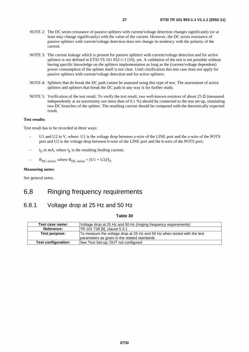
Table 30
Test case name: Voltage drop at 25 Hz and 50 Hz (ringing frequency requirements) Reference: TR 101 728 [9], clause 5.3.1
Test purpose: To measure the voltage drop at 25 Hz and 50 Hz when tested with the test parameters as given in the related standards
Test configuration: See Test Set-up; DUT not configured

ETSI
ETSI TR 101 953-1-1 V1.1.1 (2002-11) 28
Test set-up:
V S
I F
b b
a a
V1
Feeding Bridge
A
Splitter (DUT)
ADSL
LINE POTS
Z ADSL
Z SOURCE
Z LOAD
V V2 V
U F R F
Figure 17: Test set-up for voltage drop testing on a splitter
Test parameters:
Table 31
Parameter Value Frequency of the test signal (i) 25 Hz
(ii) 50 Hz Amplitude of the test signal (i) 60 Vrms superimposed on 60 VDC (TR 101 728 [9], clause 5.3.1)
(ii) 35 Vrms superimposed on 60 VDC (TS 101 952-1-1 [10], clause 6.3.1)
Source impedance ZSOURCE 850 Ω resistive
Load impedance ZLOAD 2,7 kΩ + 2,2 µF for 25H z 2,7 kΩ + 1,0 µF for 50 Hz
ADSL termination ZADSL
Optional tests (i) 100 V rms superimposed on 100 VDC (see ITU-T Recommendation G.992.1 [6],
annex E1)
Test matrix:
Table 32
TR 101 728 [9]
TS 101 952-1-1 [10]
ITU-T Recommendation G.992.1 [6]
Essential Tests
Optional Tests
25 Hz signal frequency X X X X X 50 Hz signal frequency X X X X X
60 Vrms superimposed on 60 VDC X X 35 Vrms superimposed on 60 VDC X X
100 Vrms superimposed on 100 VDC X X
Number of tests 2 Tests 2 Tests 2 Tests 4 Tests 2 Tests
Test procedure note:
NOTE: This test should be performed for both polarities of the test signal.
Test results:
The voltage drop measured should be recorded.
Measuring Notes:
Suggested configuration for ZLOAD (approx modulus 4 000 Ω, angle -45˚):

ETSI
ETSI TR 101 953-1-1 V1.1.1 (2002-11) 29
2 700 Ω
2,2 µF
Figure 18: ZLOAD for 25 Hz
2 700 Ω
1,0 µF
Figure 19: ZLOAD for 50 Hz
6.8.2 Total harmonic distortion at 25 Hz and 50 Hz
Table 33
Test case name: Total harmonic distortion at 25 Hz and 50 Hz (Ringing frequency requirements)
Reference: TS 101 952-1-1 [10], clause 6.3.3 Test purpose: To measure the total harmonic distortion at 25 Hz and 50 Hz when tested with the test
parameters as given in the related standards Test configuration: See Test Set-up; DUT not configured
Test set-up:
IF UF
b b
a a
Feeding Bridge
A
VS
Splitter (DUT)
ADSL
LINE POTS
ZADSL
ZSource
ZLoad
Spectrum Analyser
RF
Figure 20: Test set-up for total harmonic distortion testing on a splitter
ETSI
ETSI TR 101 953-1-1 V1.1.1 (2002-11) 30
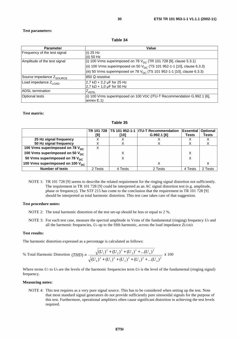
Test parameters:
Table 34
Parameter Value Frequency of the test signal (i) 25 Hz
(ii) 50 Hz Amplitude of the test signal (i) 100 Vrms superimposed on 78 VDC (TR 101 728 [9], clause 5.3.1)
(ii) 100 Vrms superimposed on 50 VDC (TS 101 952-1-1 [10], clause 6.3.3) (iii) 50 Vrms superimposed on 78 VDC (TS 101 952-1-1 [10], clause 6.3.3)
Source impedance ZSOURCE 850 Ω resistive
Load impedance ZLOAD 2,7 kΩ + 2,2 µF for 25 Hz 2,7 kΩ + 1,0 µF for 50 Hz
ADSL termination ZADSL
Optional tests (i) 100 Vrms superimposed on 100 VDC (ITU-T Recommendation G.992.1 [6], annex E.1)
Test matrix:
Table 35
TR 101 728 [9]
TS 101 952-1-1 [10]
ITU-T Recommendation G.992.1 [6]
Essential Tests
Optional Tests
25 Hz signal frequency X X X X X 50 Hz signal frequency X X X X X
100 Vrms superimposed on 78 VDC X 100 Vrms superimposed on 50 VDC X X 50 Vrms superimposed on 78 VDC X X
100 Vrms superimposed on 100 VDC X X
Number of tests 2 Tests 4 Tests 2 Tests 4 Tests 2 Tests
NOTE 1: TR 101 728 [9] seems to describe the related requirement for the ringing signal distortion not sufficiently. The requirement in TR 101 728 [9] could be interpreted as an AC signal distortion test (e.g. amplitude, phase or frequency). The STF 215 has come to the conclusion that the requirement in TR 101 728 [9] should be interpreted as total harmonic distortion. This test case takes care of that suggestion.
Test procedure notes:
NOTE 2: The total harmonic distortion of the test set-up should be less or equal to 2 %.
NOTE 3: For each test case, measure the spectral amplitude in Vrms of the fundamental (ringing) frequency U0 and all the harmonic frequencies, Un up to the fifth harmonic, across the load impedance ZLOAD.
Test results:
The harmonic distortion expressed as a percentage is calculated as follows:
% Total Harmonic Distortion 22
32
22
12
0
223
22
21
)...()()()()(
)...()()()()(
n
n
UUUUU
UUUUTHD
++++
+++= x 100
Where terms U1 to Un are the levels of the harmonic frequencies term U0 is the level of the fundamental (ringing signal) frequency.
Measuring notes:
NOTE 4: This test requires as a very pure signal source. This has to be considered when setting up the test. Note that most standard signal generators do not provide sufficiently pure sinosoidal signals for the purpose of this test. Furthermore, operational amplitiers often cause significant distortion in achieving the test levels required.

ETSI
ETSI TR 101 953-1-1 V1.1.1 (2002-11) 31
NOTE 5: Assuming standard terminal equipment it is not expected that distortion of the ringing signal do cause any problem to the TE.
6.9 Ringing Impedance
Table 36
Test case name: Impedance at 25 Hz and 50 Hz (ringing frequency requirements) Reference: TR 101 728 [9], clause 5.4
Test purpose: To evaluate the ringing impedance at 25 Hz and 50 Hz when tested with the test parameters as given in the related standards
Test configuration: See Test Set-up; DUT not configured
Test set-up:
IF RF
b b
a a
Feeding Bridge
A
VS ZSource
V
IC
VL
Splitter (DUT)
LINE
ADSL
POTS
A
UF
Figure 21: Test set-up for ringing impedance testing on a splitter at LINE Port
I F R F U F
b b
a a
Feeding Bridge
A
V S Z SOURCE
V
I C
V L
Splitter (DUT)
POTS
ADSL
LINE
A
Figure 22: Test set-up for ringing impedance testing on a splitter at POTS Port
NOTE: Figure 22 requires that there is DC feeding of the splitter from the POTS port. If the splitter is sensitive to which port is power fed, feeding has to be done via the LINE port. A holding circuit is to be used to inject the test signal at the POTS port in that situation.

ETSI
ETSI TR 101 953-1-1 V1.1.1 (2002-11) 32
Test parameters:
Table 37
Parameter Value Level of the test signal (i) 25 Hz at 60 Vrms superimposed on 60 VDC
(ii) 50 Hz at 60 Vrms superimposed on 60 VDC
Termination at ADSL port No ADSL load Optional tests None
Test matrix:
Table 38
TR 101 728 [9]
TS 101 952-1-1 [10]
ITU-T Recommendation
G.992.1 [6]
Essential Tests
Optional Tests
25 Hz at 60 Vrms, 60 VDC Line Port X X X 25 Hz at 60 Vrms, 60VDC POTS Port X X X 50 Hz at 60 Vrms, 60 VDC Line Port X X X
50 Hz at 60 Vrms, 60 VDC POTS Port X X X Number of tests: 4 Tests 4 Tests 0 Tests 4 Tests 0 Tests
Test procedure notes:
• Ringing Impedance Circuit:
- Configure the circuit as per figure 21 (for Line Port test) or figure 22 (for POTS Port test) as required.
- For each test case, set the ringing signal at the signal generator in accordance with the Test Parameters.
- Measure the current IC and the voltage VL dropped across the splitter port under test.
Ringing impedance is calculated thus:
C
LL I
VR =
Test results:
Table 39
Ringing Impedance (kΩ) 25 Hz ringing signal at Line Port 50 Hz ringing signal at Line Port 25 Hz ringing signal at POTS Port 50 Hz ringing signal at POTS Port
Measuring notes:
See general notes.

ETSI
ETSI TR 101 953-1-1 V1.1.1 (2002-11) 33
6.10 Unbalance about earth
Table 40
Test case name: Unbalance about earth for the low pass filter Reference: TS 101 952-1-1 [10], clause 6.8
Test purpose: To evaluate the Unbalance about earth of the low pass filter when tested with the test parameters as given in the related standards
Test configuration: See Test Set-up; DUT not configured
Test set-up:
Earth point
R
R
S2
Lineport
POTS
ADSLport
U0
R
R
Splitter (DUT)
Earth point
~ Earth
terminal
S1
150Ω
100Ω
UTport
aa
b b
HoldingCircuit
RDC
FeedingBridge
A
RF
IFUF
Figure 23: Test set-up for unbalance about earth testing on a splitter
Test parameters:
Table 41
Parameter Value Level of test signal -4 dBm Frequency Ranges 50 Hz to 4 kHz (600 Ω terminations)
4 kHz to 5 MHz (100 Ω terminations) Test Combinations Combination 1 (measurement at POTS port)
S2 Open, R = 300 Ω, for 50 Hz to 4 000 Hz Combination 2 (measurement at POTS port) S2 Open, R = 50 Ω, for 4 000 Hz to 5 MHz Combination 3 (measurement at POTS port) S2 Closed, R = 300 Ω for 50 Hz to 4 000 Hz Combination 4 (measurement at POTS port) S2 Closed, R = 50 Ω, for 4 000 Hz to 5 MHz Combination 5 (measurement at LINE port) S2 Closed, R = 300 Ω for 50 Hz to 4 000 Hz Combination 6 (measurement at LINE port) S2 Closed, R = 50 Ω, for 4 000 Hz to 5 MHz
ADSL termination 100 Ω Optional tests None
ETSI
ETSI TR 101 953-1-1 V1.1.1 (2002-11) 34
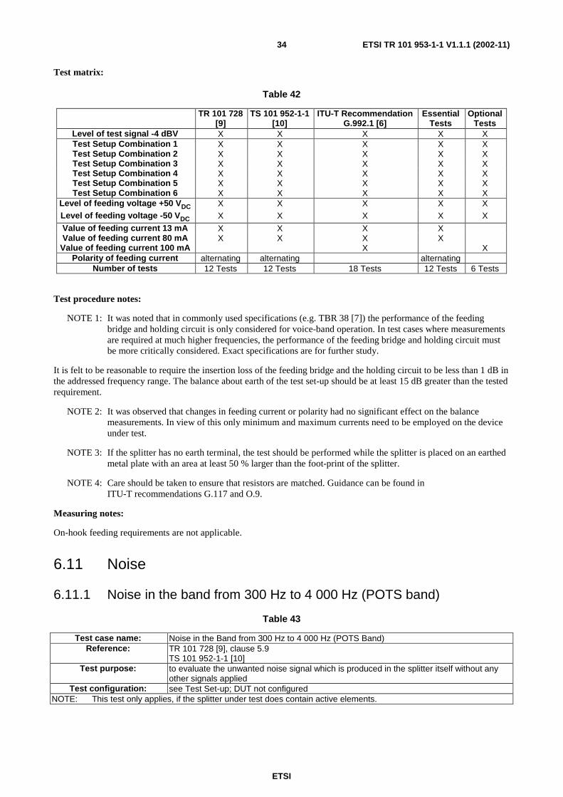
Test matrix:
Table 42
TR 101 728 [9]
TS 101 952-1-1 [10]
ITU-T Recommendation G.992.1 [6]
Essential Tests
Optional Tests
Level of test signal -4 dBV X X X X X Test Setup Combination 1 X X X X X Test Setup Combination 2 X X X X X Test Setup Combination 3 X X X X X Test Setup Combination 4 X X X X X Test Setup Combination 5 X X X X X Test Setup Combination 6 X X X X X
Level of feeding voltage +50 VDC X X X X X Level of feeding voltage -50 VDC X X X X X
Value of feeding current 13 mA X X X X Value of feeding current 80 mA X X X X
Value of feeding current 100 mA X X Polarity of feeding current alternating alternating alternating
Number of tests 12 Tests 12 Tests 18 Tests 12 Tests 6 Tests
Test procedure notes:
NOTE 1: It was noted that in commonly used specifications (e.g. TBR 38 [7]) the performance of the feeding bridge and holding circuit is only considered for voice-band operation. In test cases where measurements are required at much higher frequencies, the performance of the feeding bridge and holding circuit must be more critically considered. Exact specifications are for further study.
It is felt to be reasonable to require the insertion loss of the feeding bridge and the holding circuit to be less than 1 dB in the addressed frequency range. The balance about earth of the test set-up should be at least 15 dB greater than the tested requirement.
NOTE 2: It was observed that changes in feeding current or polarity had no significant effect on the balance measurements. In view of this only minimum and maximum currents need to be employed on the device under test.
NOTE 3: If the splitter has no earth terminal, the test should be performed while the splitter is placed on an earthed metal plate with an area at least 50 % larger than the foot-print of the splitter.
NOTE 4: Care should be taken to ensure that resistors are matched. Guidance can be found in ITU-T recommendations G.117 and O.9.
Measuring notes:
On-hook feeding requirements are not applicable.
6.11 Noise
6.11.1 Noise in the band from 300 Hz to 4 000 Hz (POTS band)
Table 43
Test case name: Noise in the Band from 300 Hz to 4 000 Hz (POTS Band) Reference: TR 101 728 [9], clause 5.9
TS 101 952-1-1 [10] Test purpose: to evaluate the unwanted noise signal which is produced in the splitter itself without any
other signals applied Test configuration: see Test Set-up; DUT not configured
NOTE: This test only applies, if the splitter under test does contain active elements.
ETSI
ETSI TR 101 953-1-1 V1.1.1 (2002-11) 35
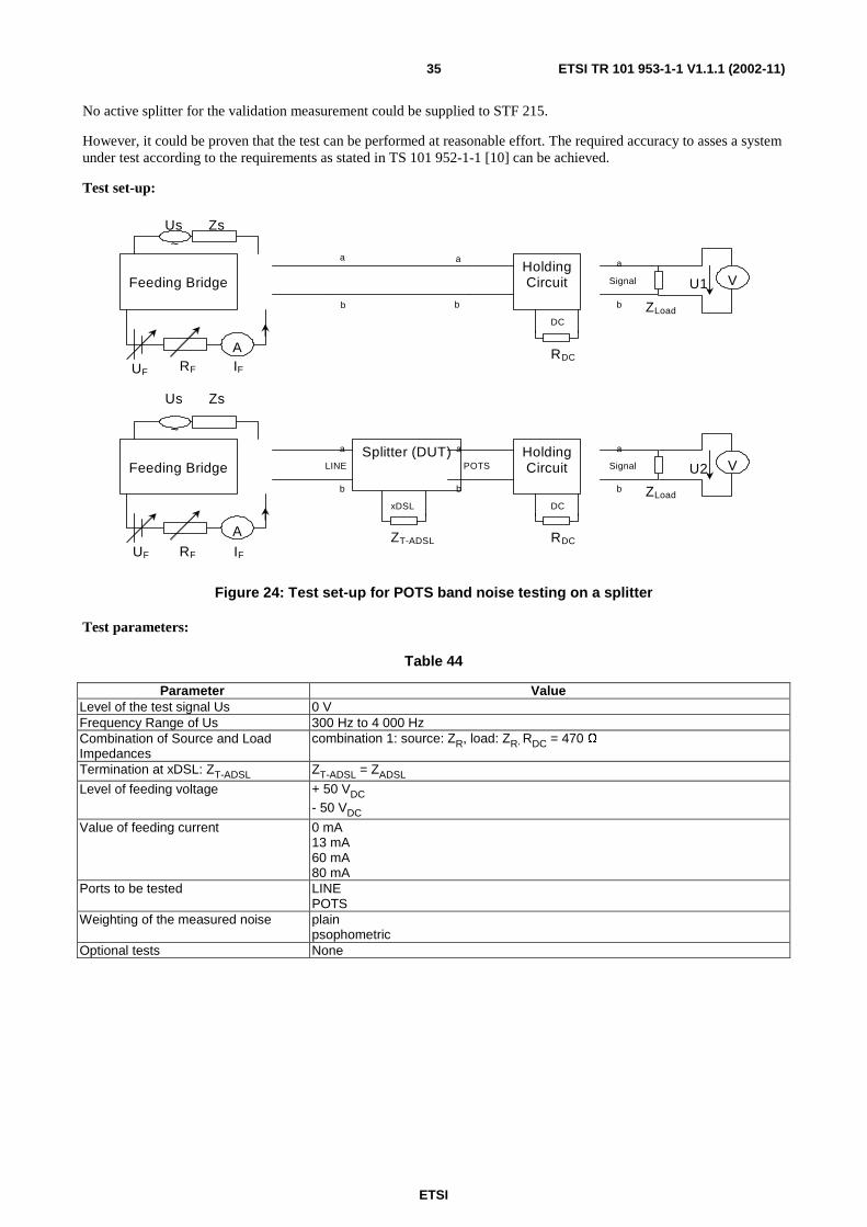
No active splitter for the validation measurement could be supplied to STF 215.
However, it could be proven that the test can be performed at reasonable effort. The required accuracy to asses a system under test according to the requirements as stated in TS 101 952-1-1 [10] can be achieved.
Test set-up:
UF RF
Feeding Bridge
A RDC
Signal V
IF
U1
Zs ~
Us
Holding Circuit
a
b
DC ZLoad
a a
b b
Zs Us
Splitter (DUT) LINE
a
b
UF RF
Feeding Bridge
A RDC
Signal V
IF
U2
~
Holding Circuit
a
b
DC ZLoad
POTS a
b
ZT-ADSL
xDSL
Figure 24: Test set-up for POTS band noise testing on a splitter
Test parameters:
Table 44
Parameter Value Level of the test signal Us 0 V Frequency Range of Us 300 Hz to 4 000 Hz Combination of Source and Load Impedances
combination 1: source: ZR, load: ZR, RDC = 470 Ω
Termination at xDSL: ZT-ADSL ZT-ADSL = ZADSL
Level of feeding voltage + 50 VDC - 50 VDC
Value of feeding current 0 mA 13 mA 60 mA 80 mA
Ports to be tested LINE POTS
Weighting of the measured noise plain psophometric
Optional tests None

ETSI
ETSI TR 101 953-1-1 V1.1.1 (2002-11) 36
Test matrix:
Table 45
TR 101 728 [9]
TS 101 952-1-1 [10]
ITU-T Recommendation
G.992.1 [6]
Essential Tests
Optional Tests
level of the test signal 0 V X X X X Frequency Range of Us
300 to 4 000 Hz X X X X
source/load combination 1 X X X X Level of feeding voltage +50 VDC X X X X Level of feeding voltage -50 VDC X X X X
Value of feeding current 0 mA X X X X Value of feeding current 13 mA X X X X Value of feeding current 60 mA X X X X Value of feeding current 80 mA X X X X
Plarity of feeding current alternating alternating alternating ZT-ADSL = ZADSL X X X X
measured at port POTS X X X X Measured at port xDSL X X X X
measured with plain weighting X X X X measured with psophometric weighting X X X X
Number of tests 16 Tests 16 Tests 0 Tests 16 Tests 0 Tests
Test procedure notes:
Before starting the measurements the test set-up has to be verified with respect to the noise present when having the DC source as well as the holding circuit present in the set-up but not having connected the splitter under test. Measuring U1 as shown in the test set-up is an appropriate way to do so. The observed value for U1 (in dBV and dBVp) should be at least 10 dB lower than the value which is to be proven.
Test results:
Test Result has to be recorded in two ways:
- U2 in dBV, where U2 is the voltage observed, when the splitter is connected as in Test Set-Up;
- U2 in dBVp, where U2 is the voltage observed and weighted psophometrically, when the splitter is connected as in Test Set-Up.
Measuring notes:
See general notes.
6.11.2 Noise in the band from 26 kHz to 1 100 kHz (ADSL band)
Table 46
Test case name: Noise in the band from 26 kHz to 1 100 kHz (ADSL band) Reference: TR 101 728 [9], clause 5.9
Test purpose: To evaluate the unwanted noise signal which is produced in the splitter itself without any other signals applied.
Test configuration: See Test Set-up; DUT not configured
NOTE This test only applies, if the splitter under test does contain active elements.
No active splitter for the validation measurement could be supplied to STF 215.
However, it could be proven that the test can be performed at reasonable effort. The required accuracy to asses a system under test according to the requirements as stated in TS 101 952-1-1 [10] can be achieved.

ETSI
ETSI TR 101 953-1-1 V1.1.1 (2002-11) 37
Test set-up:
UF RF IF
Feeding Bridge
A RDC
~
Holding Circuit
DC
Signal
a
b
V U1
ZLoad adaptation
Zs Us
a a
b b
Figure 25: Verification of the test set-up
xDSL
Splitter (DUT) LINE
a
b
UF RF
Feeding Bridge
A RDC IF
Zs ~
Us
Holding Circuit
DC
POTS a
b
Signal
a
b
V
U2
ZLoad adaptation
ZPOTS
Figure 26: Test set up for noise testing in the ADSL band on a splitter at the xDSL port
ZLoad
xDSL
Splitter (DUT) LINE
a
b
UF RF
Feeding Bridge
A RDC IF
Zs ~
Us
Holding Circuit
DC
POTS a
b
Signal
a
b
U3
adaptation
ZPOTS
V
Figure 27: Test set up for noise testing in the ADSL band on a splitter at the xDSL port
The insertion loss of Feeding Bridge and Holding Circuit in the "signal" path should be less than 1 dB in the frequency range from 26 kHz to 1 100 kHz.

ETSI
ETSI TR 101 953-1-1 V1.1.1 (2002-11) 38
Test parameters:
Table 47
Parameter Value Level of the test signal Us 0 V Frequency Range of Us 26 kHz to 1 100 kHz Combination of Source and Load Impedances combination 1: Zsource = ZRHF, ZPOTS = ZHRF, Zload = 100 Ω, RDC = 470 Ω,
Adaptation: adaptation 1; combination 2: Zsource = 100 Ω, ZPOTS = ZHRF, Zload = 100 Ω, RDC = 470 Ω, Adaptation: adaptation 1 combination 3: Zsource = 100 Ω, ZPOTS = 100 Ω, Zload = 100 Ω, RDC = 470 Ω, Adaptation: adaptation 1
Level of feeding voltage +50 VDC -50 VDC
Value of feeding current 0 mA 13 mA 60 mA 80 mA
Ports to be tested LINE ADSL
Resolution Bandwidth of the Measuring Filter 10 kHz Optional tests None
Test matrix:
Table 48
TR 101 728 [9]
TS 101 952-1-1 [10]
ITU-T Recommendation G.992.1 [6]
Essential Tests
Optional Tests
level of the test signal 0 V X X X Frequency Range of Us
26 kHz to 1 100 kHz X X X
source/load combination 1 (for test at xDSL port only)
X X X
source/load combination 2 (for test at LINE Port only)
X X
source/load combination 3 (for test at LINE Port only)
X X
Level of feeding voltage +50 VDC X X X Level of feeding voltage -50 VDC X X X
Value of feeding current 0 mA X X X Value of feeding current 13 mA X X X Value of feeding current 60 mA X X X Value of feeding current 80 mA X X X
Polarity of feeding current alternating alternating alternating measured at port LINE X X X Measured at port xDSL X X X
Number of tests 8 Tests 8 Tests 0 Tests 12 Tests 0 Tests
Test procedure notes:
Before starting the measurements the test set-up should be verified with respect to the noise present when having the DC source as well as the holding circuit present in the set-up but not having connected the splitter under test. Measuring U1 (and P1 respectively) as shown in the test set-up figure 1 is an appropriate way to do so. The observed value for P1 (in dBm) should be at least 10 dB lower than the value which is to be proven.

ETSI
ETSI TR 101 953-1-1 V1.1.1 (2002-11) 39
Test results:
Test Result has to be recorded in two ways:
- P2 in dBm/Hz, where P2 is the noise power spectral density, when the splitter is connected as in test set-up figure 26;
- P3 in dBm/Hz, where P3 is the noise power spectral density, when the splitter is connected as in test set-up figure 27.
Measuring notes:
When testing with a selective power measurement method, at least 120 measuring points should be selected over the frequency band. When testing with a frequency sweep mode, one needs to carefully take into account of the choice of resolution bandwidth, video bandwidth and frequency range when defining the sweep time.
The adaptation that is given in figure 25 through figure 27 in the test set-up should be as follows:
This port to be connected with ZLoad
This port to be connected with Splitter Port/Holding Circuit
100 nF
100 nF
47 mH
6.12 Metering at 12 kHz or 16 kHz
Table 49
Test case name: Metering at 12 kHz or 16 kHz Reference: TR 101 728 [9], clause 5.12
TS 101 952-1-1 [10], clause 6.7 Test purpose: To measure the insertion loss at a frequency of 12 kHz or 16 kHz of metering signals
Test configuration: See Test Set-up; DUT not configured

ETSI
ETSI TR 101 953-1-1 V1.1.1 (2002-11) 40
Test set-up:
Feeding Bridge
Holding Circuit LINE POTS
RDC
Signal V U1
ZLoad
Level
meter A
RF
IF UF
ZSource
Us
Signal
source
a
b
a
b
Feeding Bridge
Holding Circuit
Splitter
(DUT) LINE POTS
ADSL port RDC
Signal V U2
ZLoad
Level
meter
ZT-ADSL
A
RF
IF UF
ZSource
Us
Signal
source
a
b
a
b
Figure 28: Test set-up for insertion loss testing on a splitter
Test parameters:
Table 50
Parameter Value Level of the test signal Us 3,53 Vrms Frequency of the test signal 12 kHz ±1 % or 16 kHz ±1 % DC feeding current IF in on-hook state
0,4 mA 2,5 mA
DC feeding current IF in off-hook state
13 mA 80 mA NOTE: The values of IF are set by adjusting the values of the external circuitry
(UF, RF and RDC).
Polarity of current IF Alternating
Source impedance ZSource 200 Ω
Load impedance ZLoad 200 Ω
ADSL termination ZT-ADSL ZADSL open circuit
Level of feeding voltage 50 VDC
Optional tests IDC = 100 mA; positive polarity UF = 60 V, RF = 0 Ω IDC = 100 mA; negative polarity UF = - 60 V, RF = 0 Ω

ETSI
ETSI TR 101 953-1-1 V1.1.1 (2002-11) 41
Test matrix:
Table 51
TR 101 728 [9]
TS 101 952-1-1 [10]
ITU-T Recommendation G.992.1 [6]
Essential Tests
Optional Tests
Source: 200 Ω X X X X X Load: 200 Ω X X X X X
Level of feeding voltage 50 VDC X X Level of feeding voltage 60 VDC X X
Value of feeding current 0,4 mA X X X Value of feeding current 2,5 mA X X X Value of feeding current 13 mA X X X Value of feeding current 80 mA X X X
Value of feeding current 100 mA X X Polarity of feeding current alternating alternating
Termination at xDSL = ZADSL X X Termination at xDSL = open circuit X X
Number of tests 1 Test 8 Tests 5 Tests 8 Tests 1 Test
Test procedure notes:
NOTE 1: The test frequency of 12 kHz or 16 kHz is dependent on the network operator specific requirement.
NOTE 2: Polarity of the feeding current does not impact the insertion loss of splitters.
NOTE 3: Polarity of the feeding current may impact the additional insertion loss caused by feeding bridge and holding circuit. A calibration/normalization measurement need to be taken before each single measurement step.
NOTE 4: For any kind of splitter it is sufficient to measure insertion loss in one direction (LINE to POTS).
NOTE 5: A test case verification measurement should be taken using a flat attenuation leading to an insertion loss of about 3 dB. A simple way to set-up such an attenuation is by adding 165 Ω instead of the unit under test.
NOTE 6: If necessary, the feeding voltage can be increased to achieve the specified feeding current.
NOTE 7: The feeding conditions for active splitters and for passive splitters with current/voltage detection need to be determined.
NOTE 8: Due to the possibility of receiving metering pulses a certain time after hanging-up the splitters should be tested in on-hook case as well.
NOTE 9: There is a recognizable difference (about 0,5 dB) in the test result when measuring with and without ZADSL. Both conditions are likely to occur in real life as modems do change their input impedance when
switched off. Both conditions with and without ZADSL should be tested.
Test results:
Test result has to be recorded in dB, where IL = 20 log (U2/U1), where U2 is the voltage observed when the splitter is connected as in Test Set-Up and where U1 is the voltage observed when the splitter is replaced by a direct wire connection of less than 0,01 Ω.
Table 52
Frequency (kHz) Maximum Insertion loss (dB)
12 ±1% or 16 ±1%
Measuring notes:
See general notes.

ETSI
ETSI TR 101 953-1-1 V1.1.1 (2002-11) 42
History
Document history
V1.1.1 November 2002 Publication


![íßqù]l^Ë‘ä éqçiæl^ßé¢]í Â]…‡ ê† Ö]ÜÓ£]æÄÊ]æ‚Ö]](https://img.pdfslide.net/doc/110x75/6159f157ec064c0157386184/ql-qil.jpg)