Embed Size (px)
Citation preview
Vasos Vassiliou
Information TheoryΘεωρία της Πληροφορίας

2
Network/Link Design Factors• Transmission media
– Signals are transmitted over transmission media– Examples: telephone cables, fiber optics, twisted pairs,
coaxial cables • Bandwidth (εύρος ζώνης)
– Higher bandwidth gives higher data rate• Transmission impairments
– Attenuation (εξασθένηση)– Interference (παρεμβολή)
• Number of receivers– In guided media– More receivers (multi-point) introduce more attenuation
3
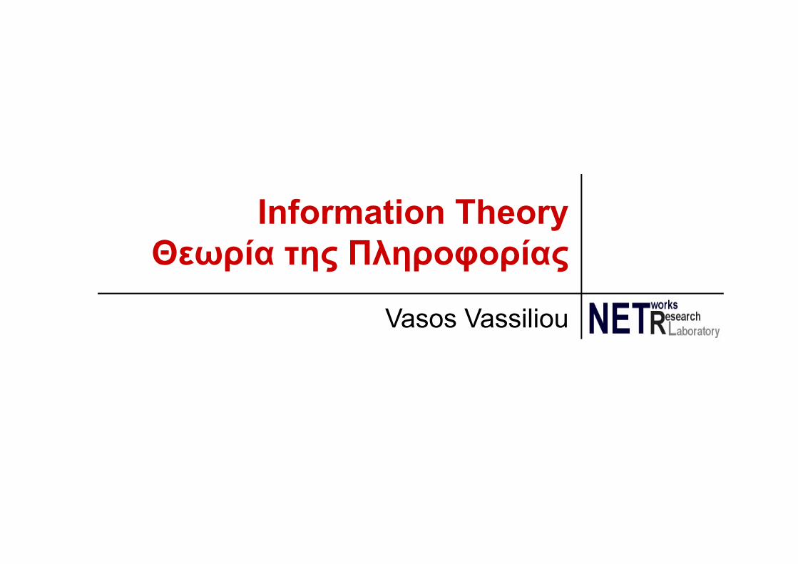
Channel Capacity• Data rate
– In bits per second– Rate at which data can be communicated– Baud rate (symbols/sec) ≠ bit rate (bits/sec)
• Number of symbol changes made to the transmission medium per second
• One symbol can carry more than one bit of information
• Bandwidth– In cycles per second, or Hertz– Constrained by transmitter and transmission medium

4
Data Rate and Bandwidth• Any transmission system has a limited band of
frequencies• This limits the data rate that can be carried• E.g., telephone cables can carry signals within
frequencies 300Hz – 3400Hz
5
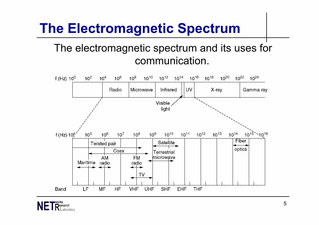
The Electromagnetic SpectrumThe electromagnetic spectrum and its uses for
communication.
6
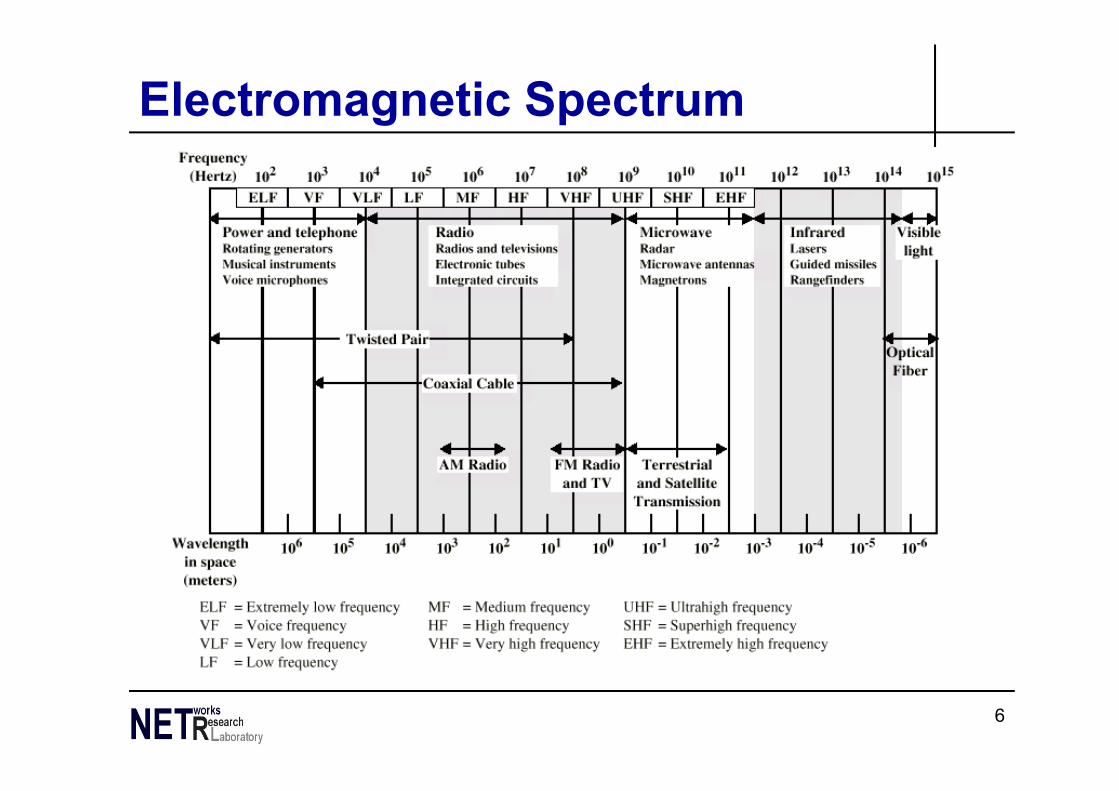
Electromagnetic Spectrum
7
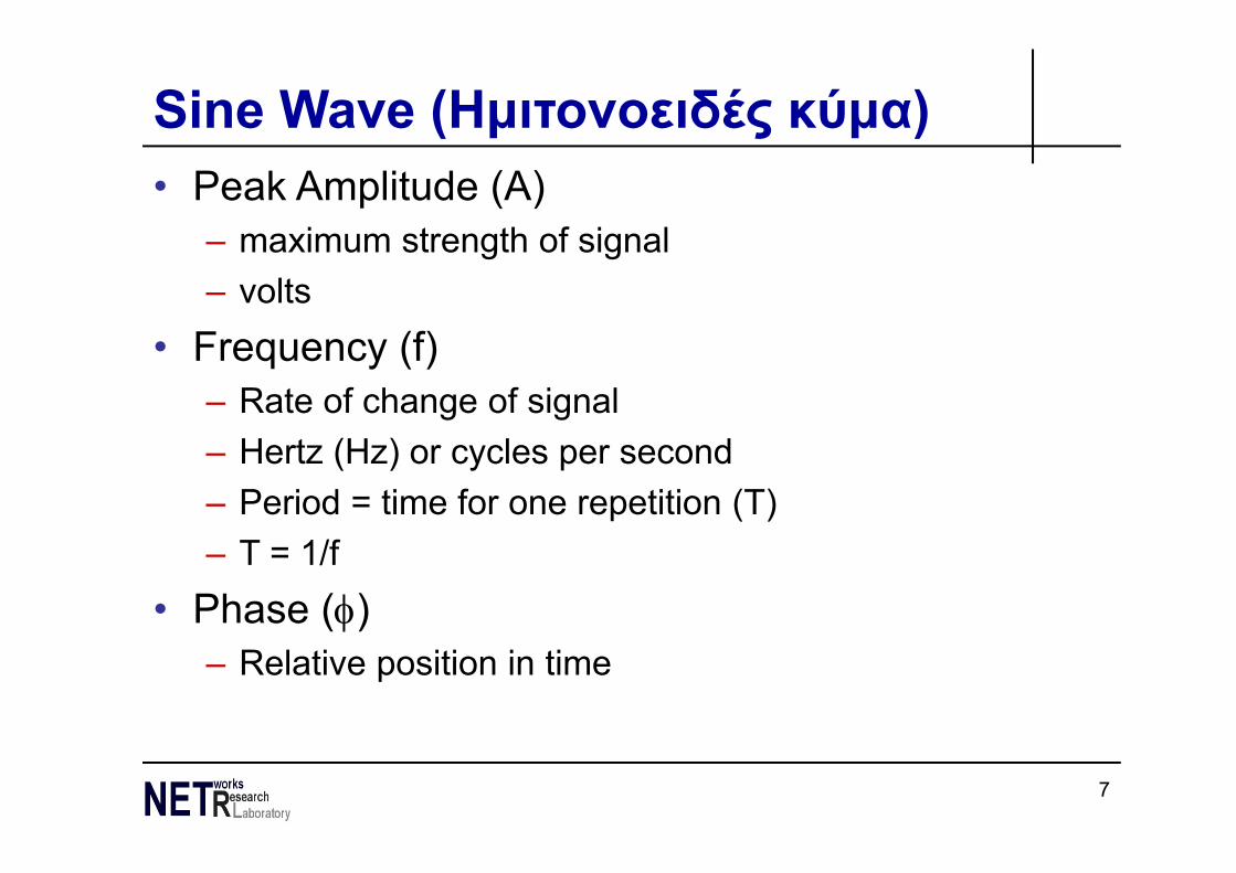
Sine Wave (Ημιτονοειδές κύμα)• Peak Amplitude (A)
– maximum strength of signal– volts
• Frequency (f)– Rate of change of signal– Hertz (Hz) or cycles per second– Period = time for one repetition (T)– T = 1/f
• Phase ()– Relative position in time

8
Varying Sine Waves
9
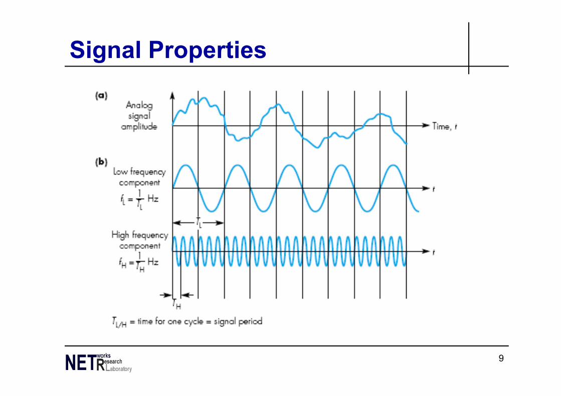
Signal Properties
10
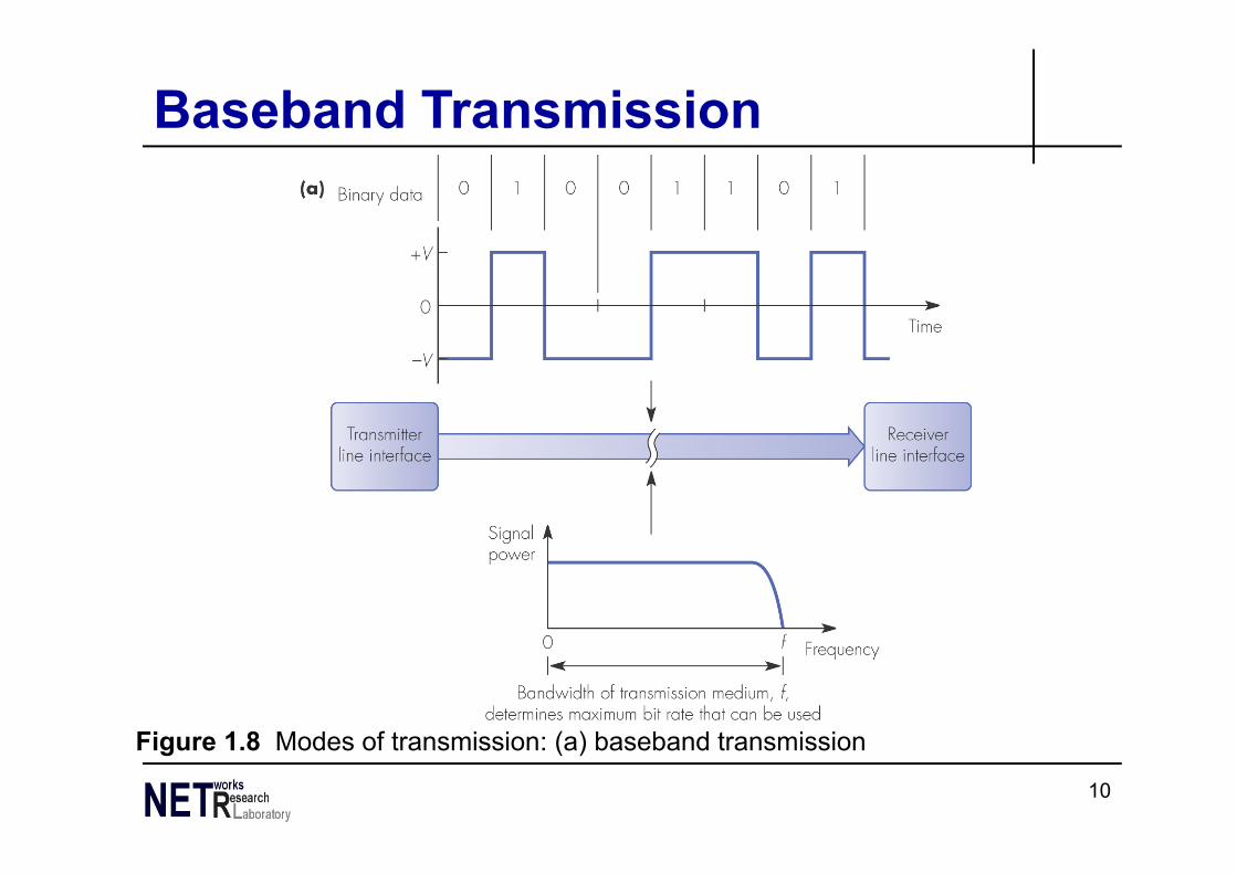
Figure 1.8 Modes of transmission: (a) baseband transmission
Baseband Transmission
11
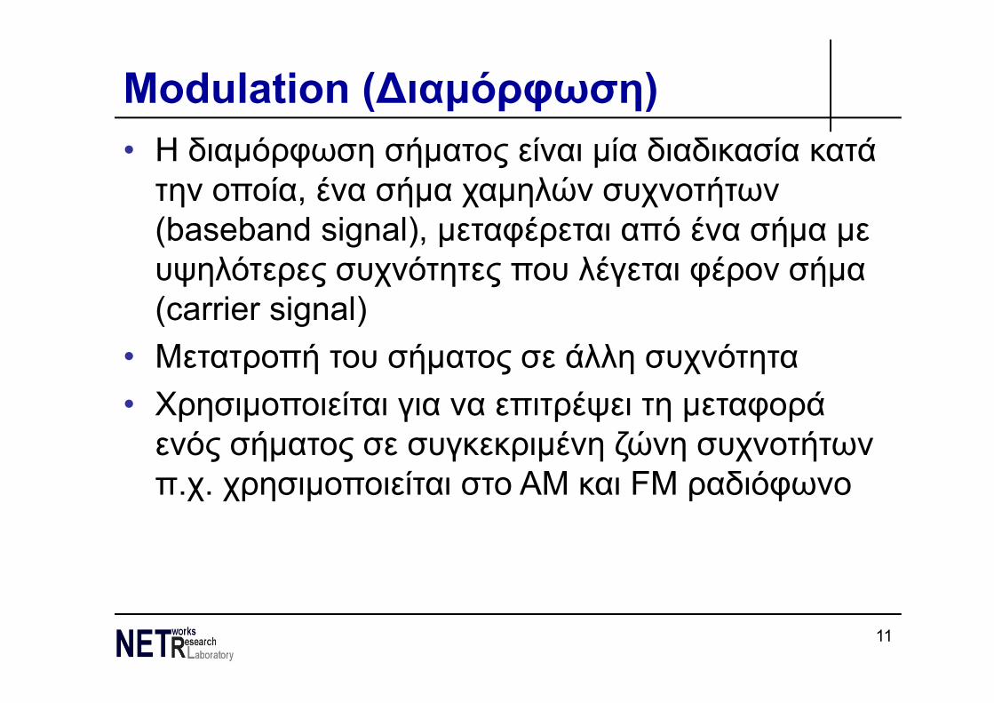
Modulation (∆ιαμόρφωση)• Η διαμόρφωση σήματος είναι μία διαδικασία κατά την οποία, ένα σήμα χαμηλών συχνοτήτων (baseband signal), μεταφέρεται από ένα σήμα με υψηλότερες συχνότητες που λέγεται φέρον σήμα (carrier signal)
• Μετατροπή του σήματος σε άλλη συχνότητα• Χρησιμοποιείται για να επιτρέψει τη μεταφορά ενός σήματος σε συγκεκριμένη ζώνη συχνοτήτων π.χ. χρησιμοποιείται στο ΑΜ και FM ραδιόφωνο
12
Πλεονεκτήματα ∆ιαμόρφωσης• ∆υνατότητα εύκολης μετάδοσης του σήματος • ∆υνατότητα χρήσης πολυπλεξίας (ταυτόχρονη μετάδοση πολλαπλών σημάτων)
• ∆υνατότητα υπέρβασης των περιορισμών των μέσων μετάδοσης
• ∆υνατότητα εκπομπής σε πολλές συχνότητες ταυτόχρονα
• ∆υνατότητα περιορισμού θορύβου και παρεμβολών

13
Figure 1.8 Modes of transmission: (b) modulated transmission
Modulated Transmission

14
Continuous & Discrete SignalsAnalog & Digital Signals

15
Analog Signals Carrying Analog and Digital Data
16
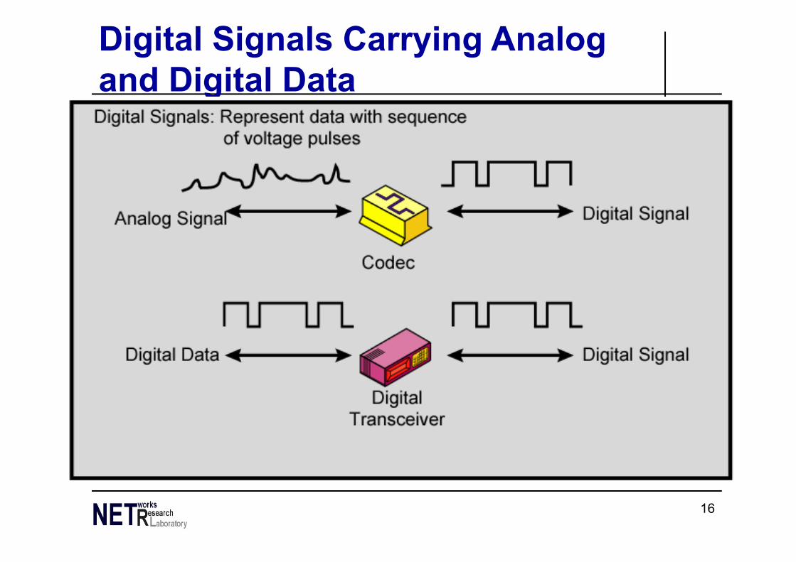
Digital Signals Carrying Analog and Digital Data
17
Digital Data, Digital Signal
18
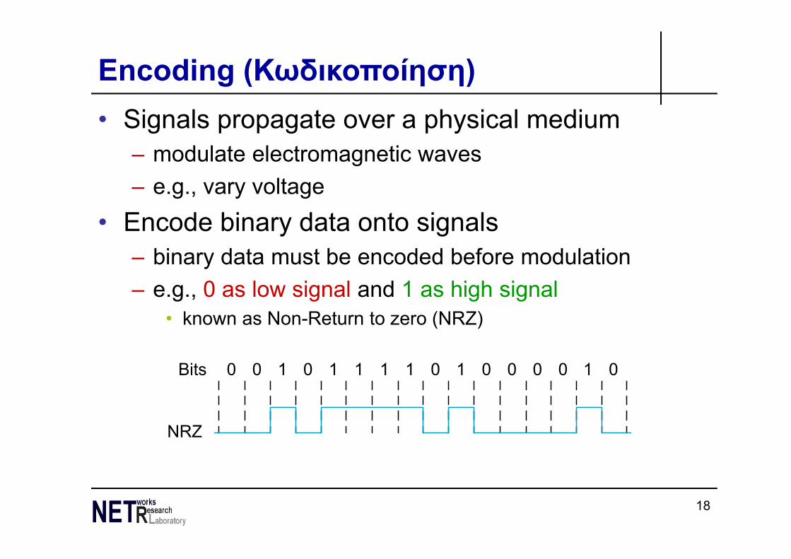
Encoding (Κωδικοποίηση)• Signals propagate over a physical medium
– modulate electromagnetic waves– e.g., vary voltage
• Encode binary data onto signals– binary data must be encoded before modulation– e.g., 0 as low signal and 1 as high signal
• known as Non-Return to zero (NRZ)
Bits
NRZ
0 0 1 0 1 1 1 1 0 1 0 0 0 0 1 0
19
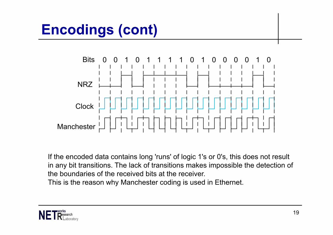
Encodings (cont)
Bits
NRZ
Clock
Manchester
0 0 1 0 1 1 1 1 0 1 0 0 0 0 1 0
If the encoded data contains long 'runs' of logic 1's or 0's, this does not result in any bit transitions. The lack of transitions makes impossible the detection ofthe boundaries of the received bits at the receiver.This is the reason why Manchester coding is used in Ethernet.

20
Other Encoding Schemes• Nonreturn to Zero-Level (NRZ) Unipolar• Nonreturn to Zero-Level (NRZ) Polar• Nonreturn to Zero Inverted (NRZI)• Bipolar - AMI• Manchester
– Used in Ethernet• Differential Manchester
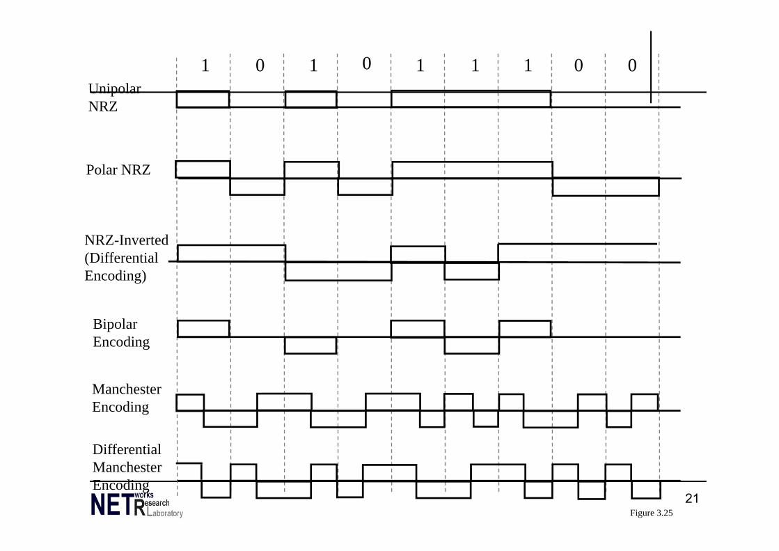
21
1 0 1 0 1 1 0 01UnipolarNRZ
NRZ-Inverted(DifferentialEncoding)
BipolarEncoding
ManchesterEncoding
DifferentialManchesterEncoding
Polar NRZ
Figure 3.25
22
Digital Data, Analog Signal• After encoding of digital data, the resulting digital
signal must be modulated before transmitted• Use modem (modulator-demodulator)
– Amplitude shift keying (ASK)– Frequency shift keying (FSK)– Phase shift keying (PSK)
23
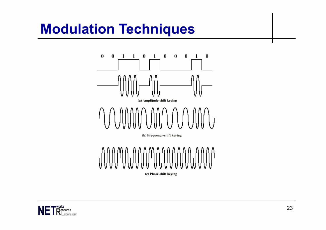
Modulation Techniques
24
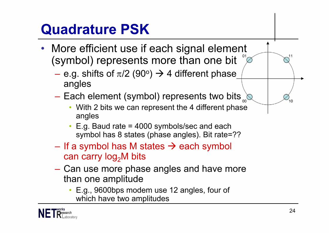
Quadrature PSK• More efficient use if each signal element
(symbol) represents more than one bit– e.g. shifts of /2 (90o) 4 different phase
angles– Each element (symbol) represents two bits
• With 2 bits we can represent the 4 different phase angles
• E.g. Baud rate = 4000 symbols/sec and each symbol has 8 states (phase angles). Bit rate=??
– If a symbol has M states each symbol can carry log2M bits
– Can use more phase angles and have more than one amplitude
• E.g., 9600bps modem use 12 angles, four of which have two amplitudes
25
Modems (2)
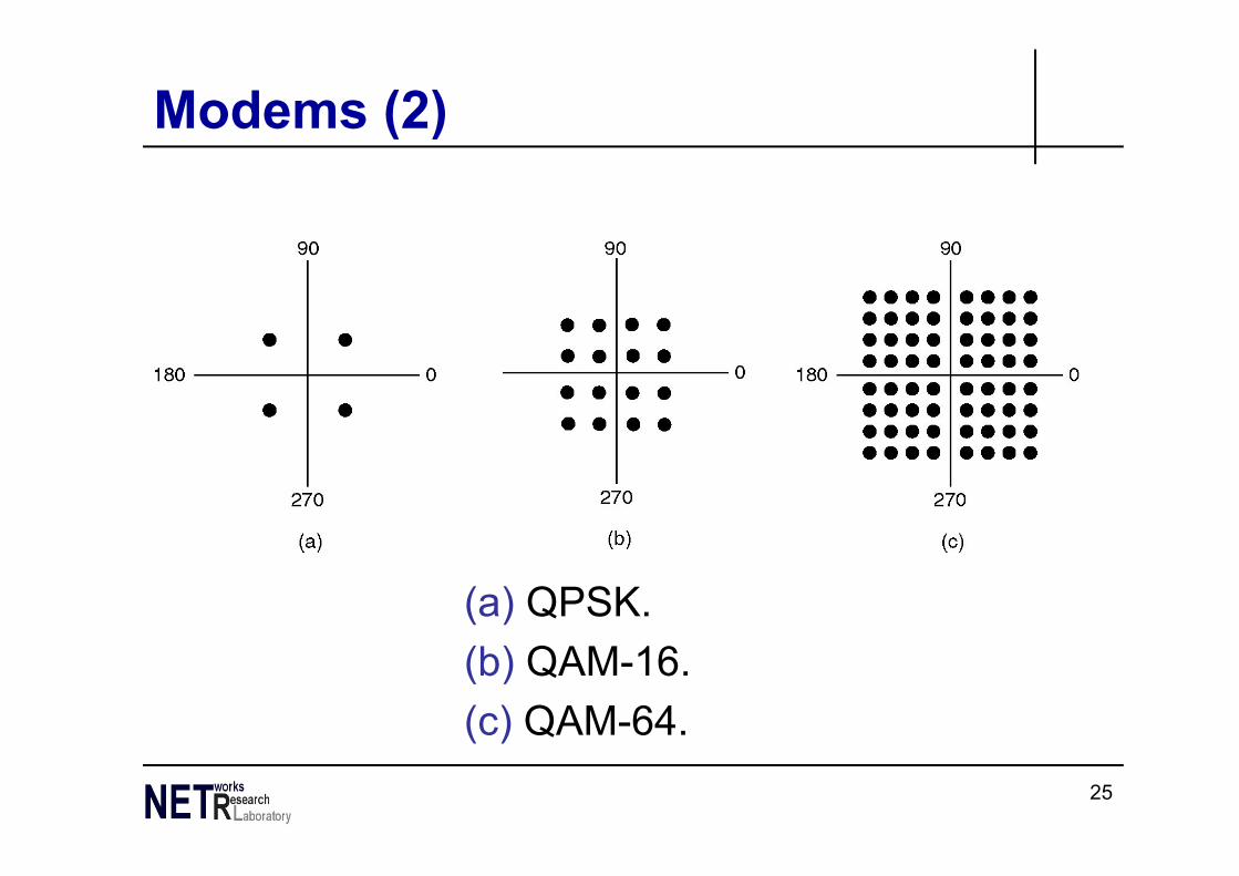
(a) QPSK.(b) QAM-16.(c) QAM-64.
26
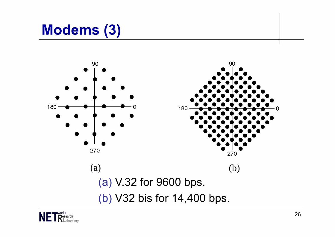
Modems (3)
(a) V.32 for 9600 bps.(b) V32 bis for 14,400 bps.
(a) (b)
27
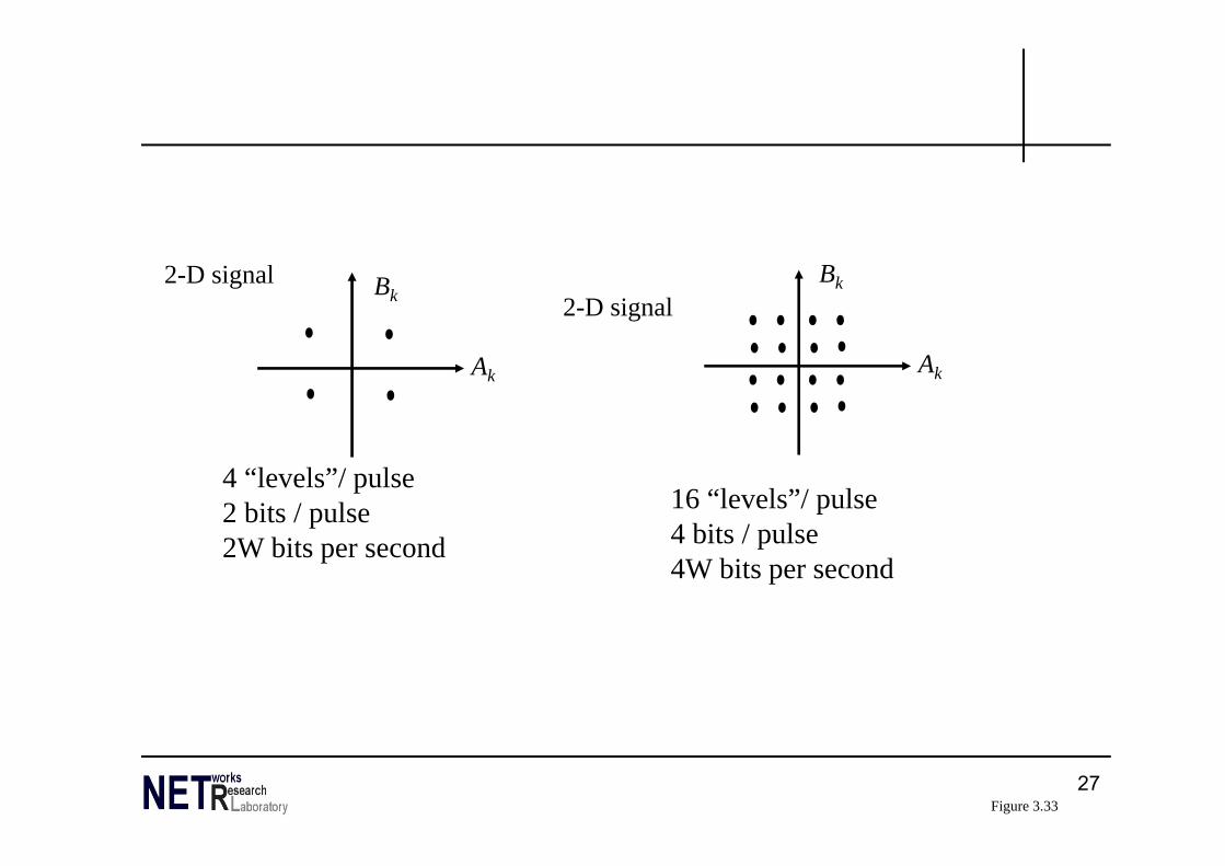
Ak
Bk
16 “levels”/ pulse4 bits / pulse4W bits per second
Ak
Bk
4 “levels”/ pulse2 bits / pulse2W bits per second
2-D signal2-D signal
Figure 3.33
28
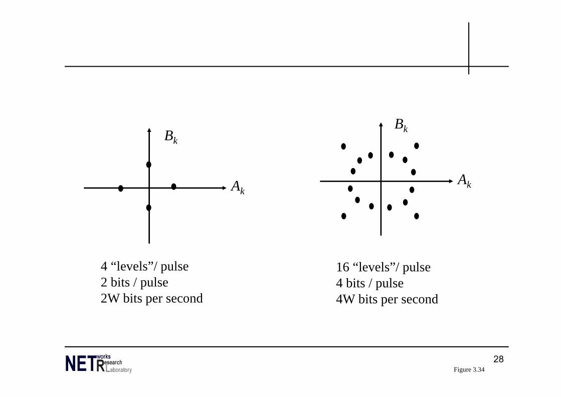
Ak
Bk
4 “levels”/ pulse2 bits / pulse2W bits per second
Ak
Bk
16 “levels”/ pulse4 bits / pulse4W bits per second
Figure 3.34
29
Analog Data, Digital Signal

30
Signal Sampling and Encoding
31
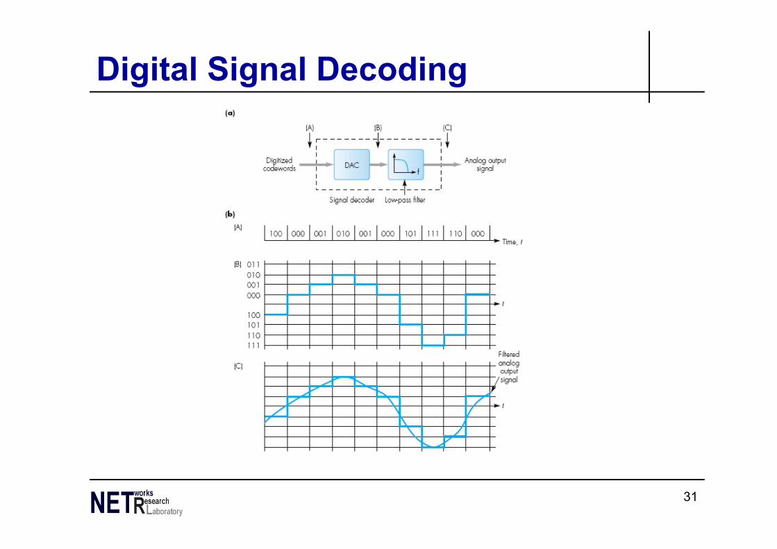
Digital Signal Decoding
32
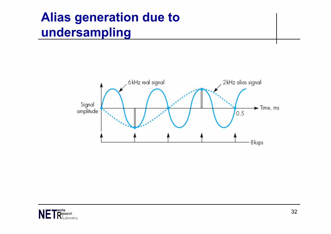
Alias generation due to undersampling
33
Nyquist Bandwidth• If rate of signal transmission is 2B then signal with
frequencies no greater than B is sufficient to carry signal rate
• Given bandwidth B, highest signal (baud) rate is 2B
• Given binary signal, data rate supported by B Hz is 2B bps (if each symbol carries one bit)
• Can be increased by using M signal levels• C= 2B log2M
34
Transmission Impairments• Signal received may differ from signal transmitted• Analog degradation of signal quality• Digital bit errors• Caused by
– Attenuation and attenuation distortion– Delay distortion– Noise
35
Attenuation• Signal strength falls off with distance• Depends on medium• Received signal strength:
– must be enough to be detected– must be sufficiently higher than noise to be received
without error• Attenuation is an increasing function of frequency
36
Noise (1)• Additional signals inserted between transmitter
and receiver• Thermal
– Due to thermal agitation of electrons– Uniformly distributed– White noise
• Intermodulation– Signals that are the sum and difference of original
frequencies sharing a medium
37
Noise (2)• Crosstalk
– A signal from one line is picked up by another• Impulse
– Irregular pulses or spikes– e.g. External electromagnetic interference– Short duration– High amplitude
38
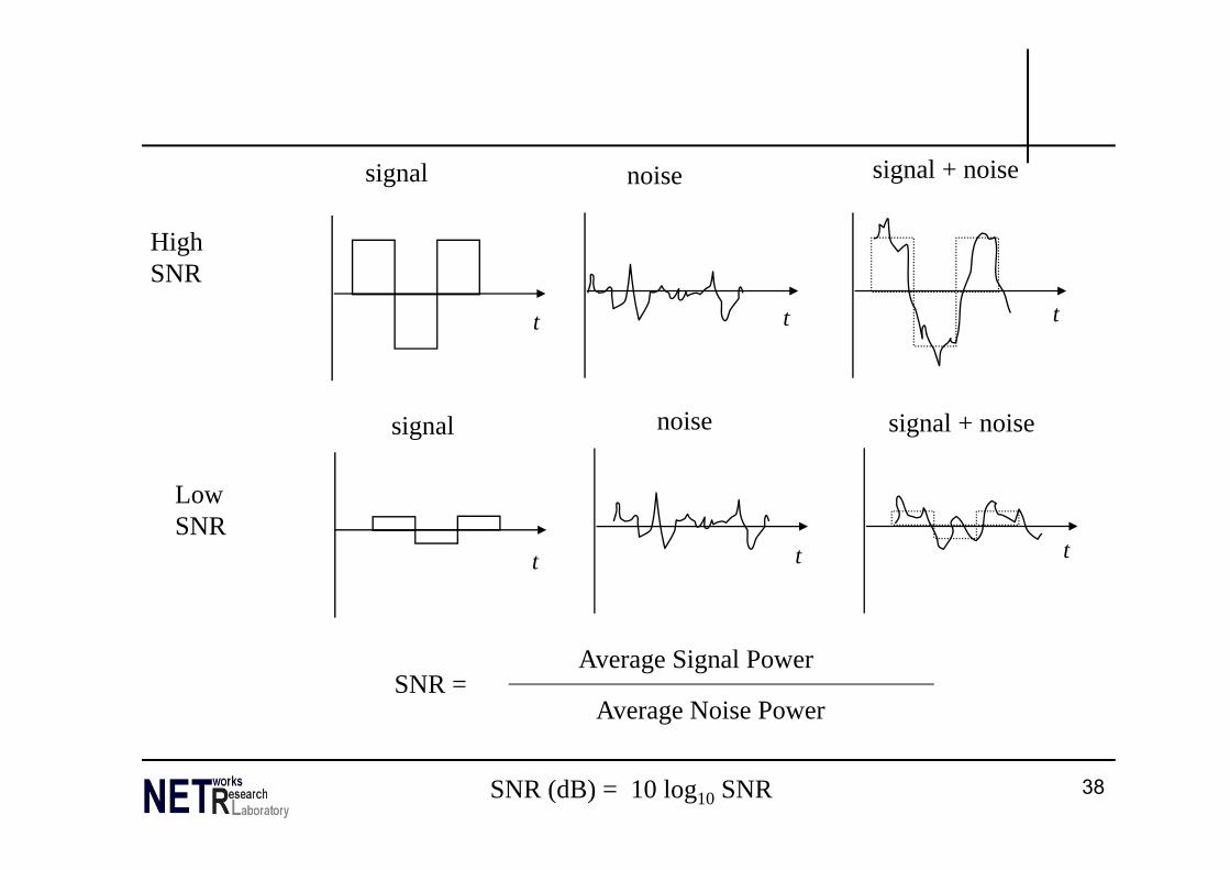
signal noise signal + noise
signal noise signal + noise
HighSNR
LowSNR
SNR = Average Signal Power
Average Noise Power
SNR (dB) = 10 log10 SNR
t t t
t t t
39
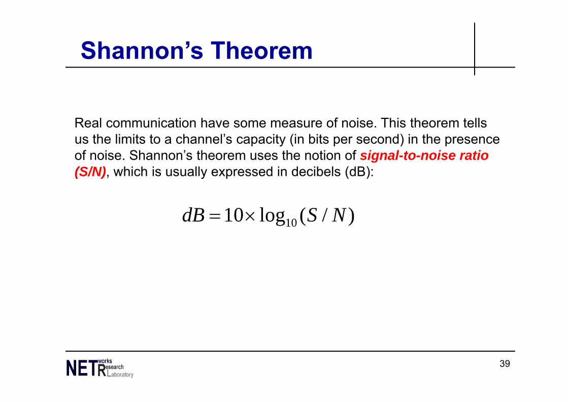
Shannon’s Theorem
Real communication have some measure of noise. This theorem tells us the limits to a channel’s capacity (in bits per second) in the presence of noise. Shannon’s theorem uses the notion of signal-to-noise ratio (S/N), which is usually expressed in decibels (dB):
)/(log10 10 NSdB
40
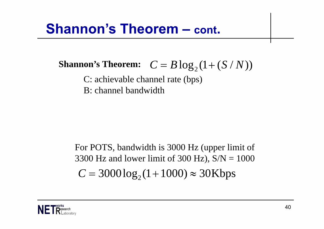
Shannon’s Theorem – cont.
))/(1(log2 NSBC
Kbps30)10001(log3000 2 C
Shannon’s Theorem:C: achievable channel rate (bps)B: channel bandwidth
For POTS, bandwidth is 3000 Hz (upper limit of 3300 Hz and lower limit of 300 Hz), S/N = 1000
41
42