Embed Size (px)
Citation preview
IP Multicasting
Instructor: Hamid R. Rabiee
Spring 2012
Outline
Multicasting
IP Multicasting
IP Multicast Addressing
IGMP
Reverse Path Forwarding
Digital Media Lab - Sharif University of Technology2
Multicasting
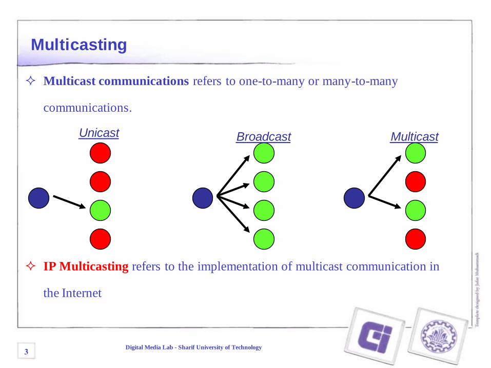
Multicast communications refers to one-to-many or many-to-many
communications.
IP Multicasting refers to the implementation of multicast communication in
the Internet
Unicast Broadcast Multicast
3Digital Media Lab - Sharif University of Technology
Multicast Groups
The set of receivers for a multicast transmission is called a multicast group
A multicast group is identified by a multicast address
A user that wants to receive multicast transmissions joins the corresponding
multicast group, and becomes a member of that group
After a user joins, the network builds the necessary routing paths so that the user
receives the data sent to the multicast group
Multicast groups are identified by IP addresses in the range 224.0.0.0 -239.255.255.255 (class D address)
The IP Multicast service is unreliable
4Digital Media Lab - Sharif University of Technology
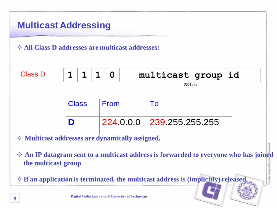
Multicast Addressing
Class D 1 multicast group id28 bits
01 1
All Class D addresses are multicast addresses:
Class From To
D 224.0.0.0 239.255.255.255
Multicast addresses are dynamically assigned.
An IP datagram sent to a multicast address is forwarded to everyone who has joined
the multicast group
If an application is terminated, the multicast address is (implicitly) released.
5Digital Media Lab - Sharif University of Technology
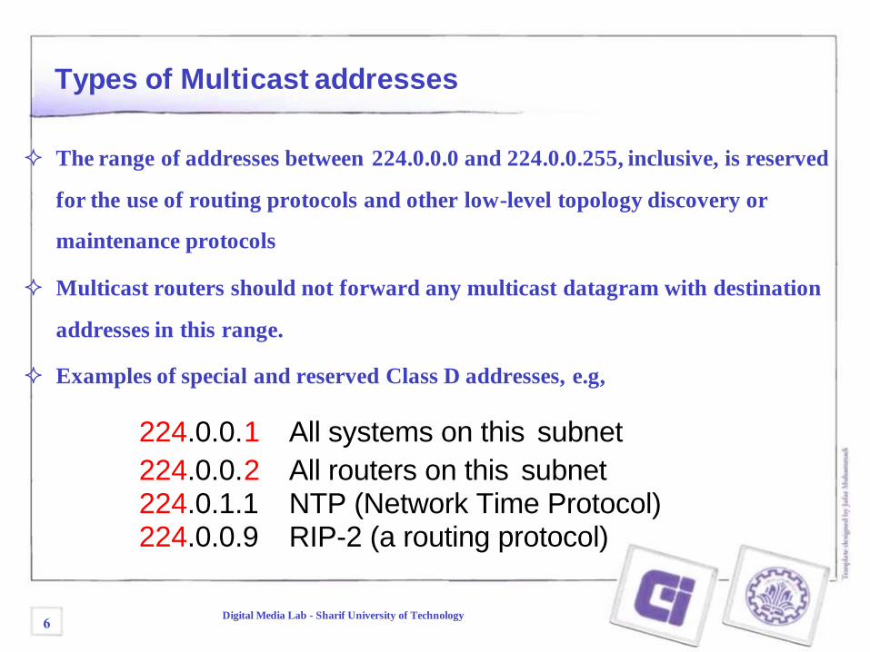
Types of Multicast addresses
The range of addresses between 224.0.0.0 and 224.0.0.255, inclusive, is reserved
for the use of routing protocols and other low-level topology discovery or
maintenance protocols
Multicast routers should not forward any multicast datagram with destination
addresses in this range.
Examples of special and reserved Class D addresses, e.g,
224.0.0.1 All systems on this subnet
224.0.0.2 All routers on this subnet224.0.1.1 NTP (Network Time Protocol)224.0.0.9 RIP-2 (a routing protocol)
6Digital Media Lab - Sharif University of Technology
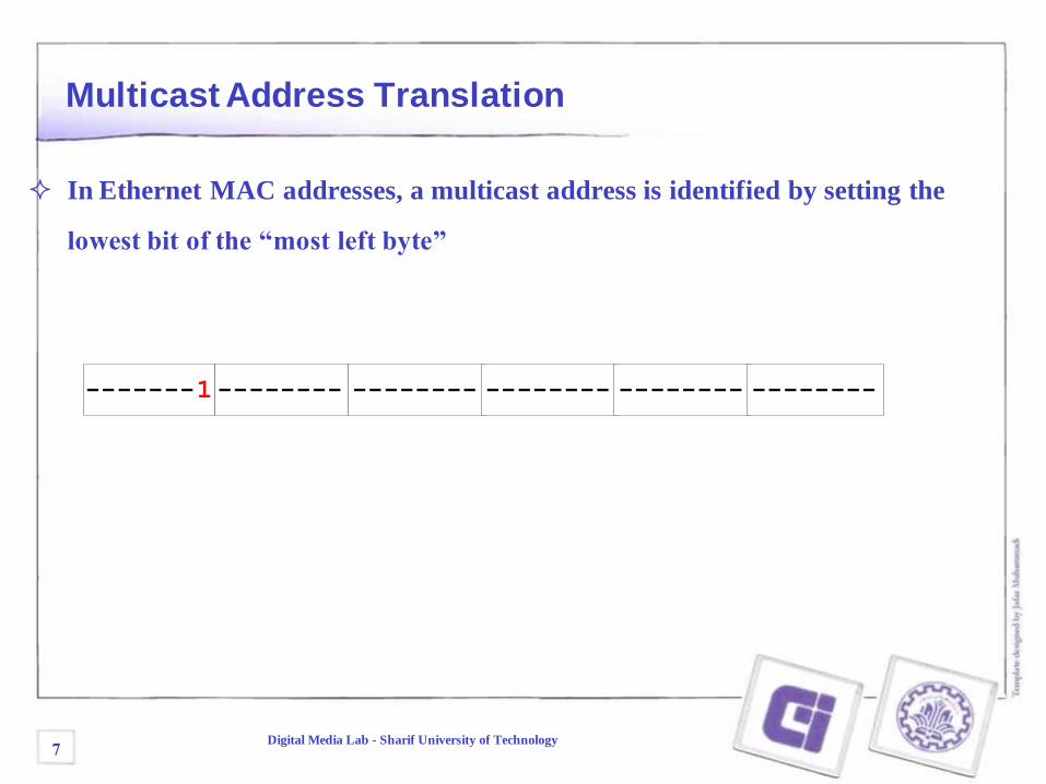
Multicast Address Translation
In Ethernet MAC addresses, a multicast address is identified by setting the
lowest bit of the “most left byte”
-------1-------- -------- -------- -------- --------
7Digital Media Lab - Sharif University of Technology
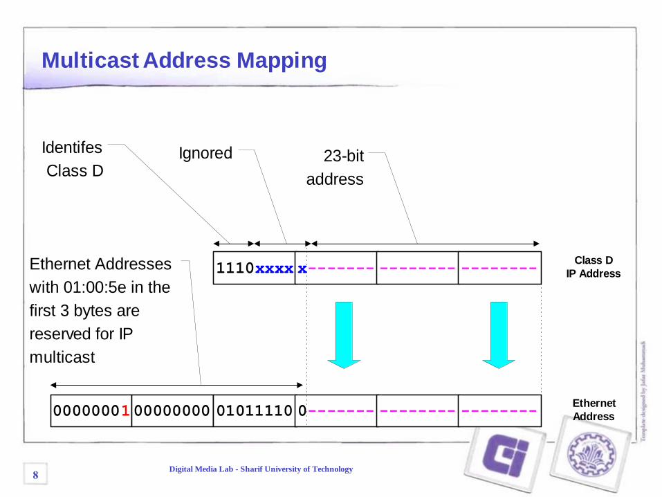
Multicast Address Mapping
0000000100000000 01011110 0-------Ethernet
Address
1110xxxx x------- -------- --------Class D
IP Address
Identifes
Class DIgnored 23-bit
address
-------- --------
Ethernet Addresses
with 01:00:5e in the
first 3 bytes are
reserved for IP
multicast
8Digital Media Lab - Sharif University of Technology
IGMP
The Internet Group Management Protocol (IGMP) is a simple protocol for
the support of IP multicast.
IGMP is defined in RFC 1112.
IGMP operates on a physical network (e.g., single Ethernet Segment.
IGMP is used by multicast routers to keep track of membership in a
multicast group.
Support for:
Joining a multicast group
Query membership
Send membership reports
9Digital Media Lab - Sharif University of Technology
A host sends an IGMP report when it joins a multicast group (Note:
multiple processes on a host can join. A report is sent only for the first
process).
No report is sent when a process leaves a group
A multicast router regularly multicasts an IGMP query to all hosts (group
address is set to zero).
A host responds to an IGMP query with an IGMP report.
Multicast router keeps a table on the multicast groups that have joined
hosts. The router only forwards a packet, if there is a host still joined.
Note: Router does not keep track which host is joined.
IGMP Protocol
10Digital Media Lab - Sharif University of Technology
IGMP Protocol (cont.)
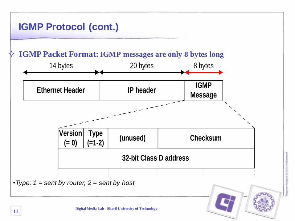
IGMP Packet Format: IGMP messages are only 8 bytes long
Ethernet Header IP headerIGMP
Message
8 bytes20 bytes14 bytes
Version
(= 0)
Type
(=1-2)(unused)
32-bit Class D address
Checksum
•Type: 1 = sent by router, 2 = sent by host
11Digital Media Lab - Sharif University of Technology
IGMP Protocol (cont.)
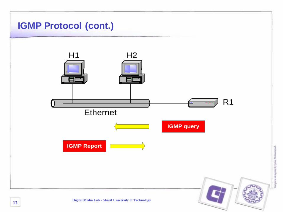
IGMP query
IGMP Report
R1
Ethernet
H1 H2
12Digital Media Lab - Sharif University of Technology
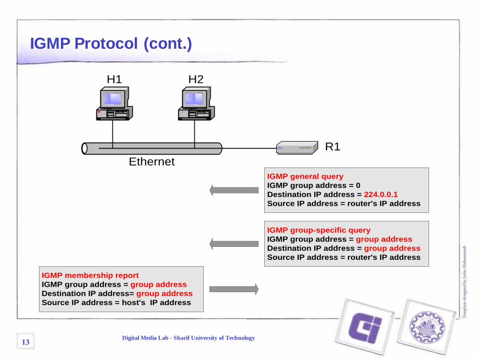
IGMP Protocol (cont.)
R1
Ethernet
IGMP general query
IGMP group address = 0
Destination IP address = 224.0.0.1
Source IP address = router's IP address
IGMP membership report
IGMP group address = group address
Destination IP address= group address
Source IP address = host's IP address
H1 H2
IGMP group-specific query
IGMP group address = group address
Destination IP address = group address
Source IP address = router's IP address
13Digital Media Lab - Sharif University of Technology
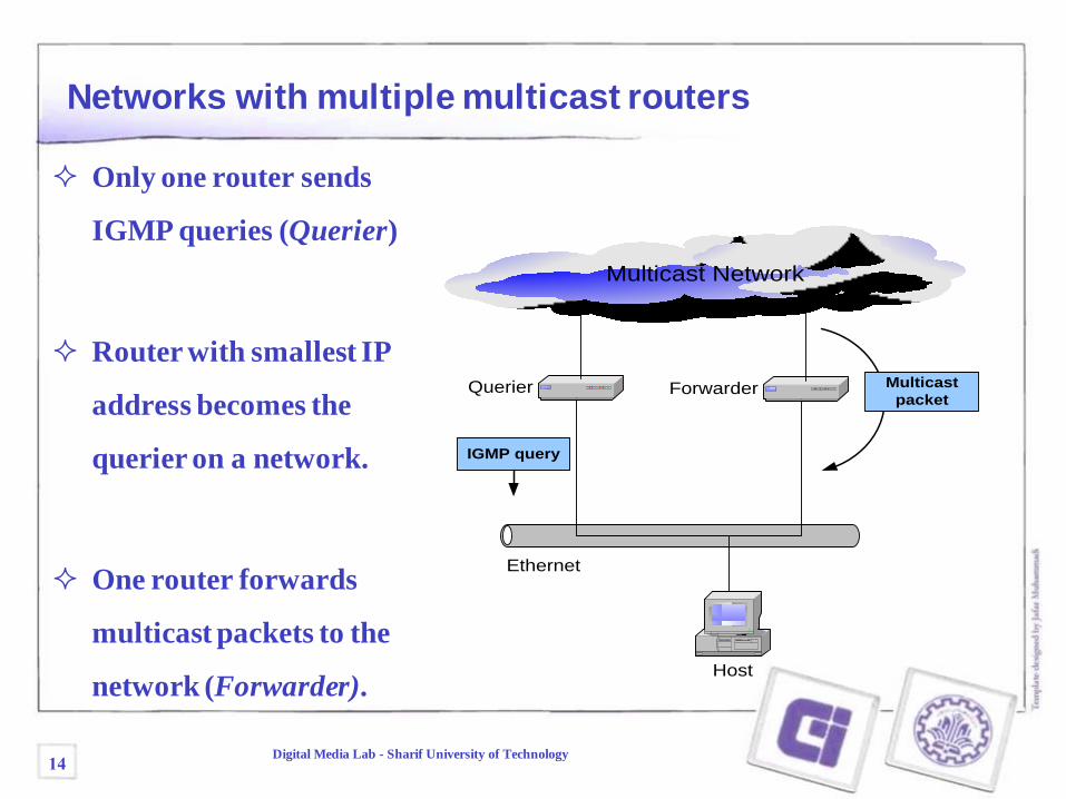
Networks with multiple multicast routers
Only one router sends
IGMP queries (Querier)
Router with smallest IP
address becomes the
querier on a network.
One router forwards
multicast packets to the
network (Forwarder).
Ethernet
Host
Querier Forwarder
Multicast Network
IGMP query
Multicast
packet
14Digital Media Lab - Sharif University of Technology
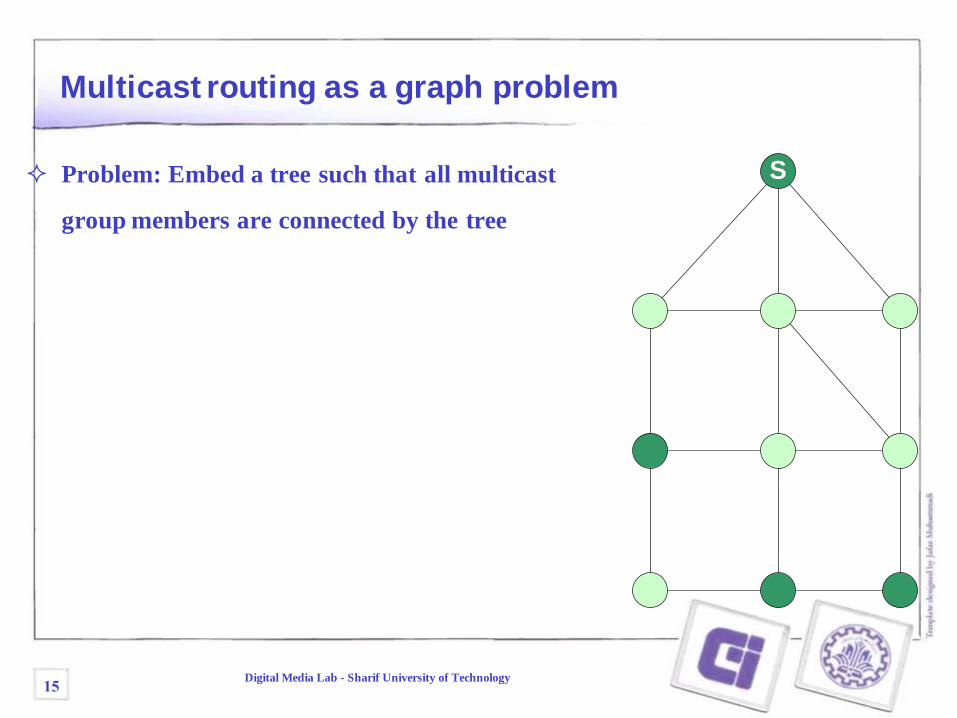
Multicast routing as a graph problem
S Problem: Embed a tree such that all multicast
group members are connected by the tree
15Digital Media Lab - Sharif University of Technology
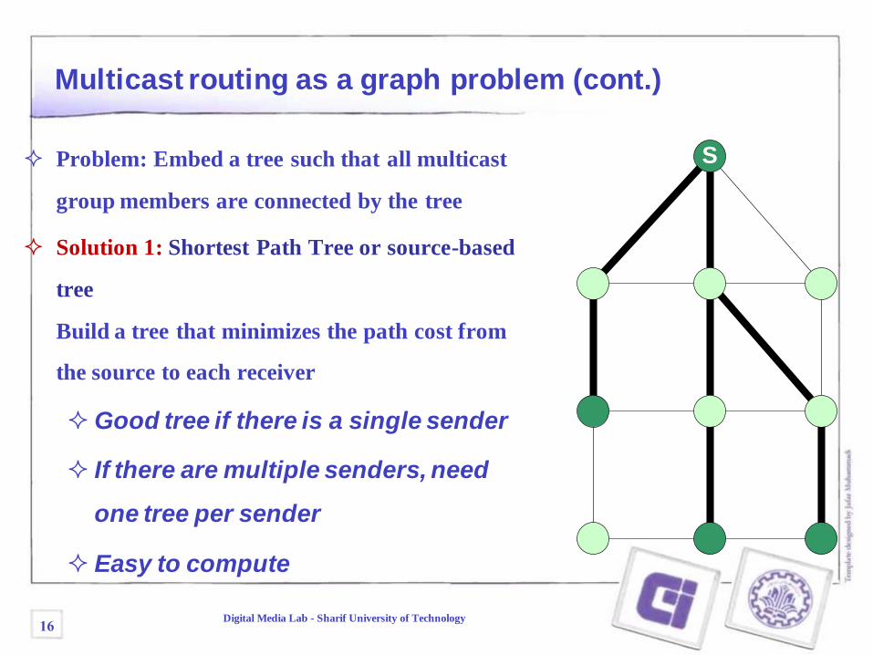
Multicast routing as a graph problem (cont.)
(c) Minimum-cost tree
S Problem: Embed a tree such that all multicast
group members are connected by the tree
Solution 1: Shortest Path Tree or source-based
tree
Build a tree that minimizes the path cost from
the source to each receiver
Good tree if there is a single sender
If there are multiple senders, need
one tree per sender
Easy to compute
16Digital Media Lab - Sharif University of Technology
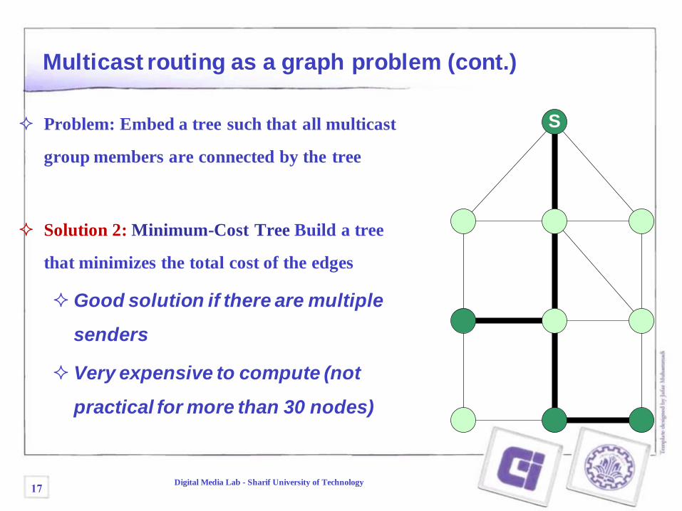
Multicast routing as a graph problem (cont.)
S Problem: Embed a tree such that all multicast
group members are connected by the tree
Solution 2: Minimum-Cost Tree Build a tree
that minimizes the total cost of the edges
Good solution if there are multiple
senders
Very expensive to compute (not
practical for more than 30 nodes)
17Digital Media Lab - Sharif University of Technology
Multicast routing in practice
Routing Protocols implement one of two approaches:
1. Source Based Tree: – Essentially implements Solution 1.
– Builds one shortest path tree for each sender
– Tree is built from receiver to the sender reverse shortest path /reverse path forwarding
2. Core-based Tree: – Build a single distribution tree that is shared by all senders
– Does not use Solution 2 (because it is too expensive)
– Selects one router as a “core” (also called “rendezvous point”)– All receivers build a shortest path to the core reverse shortest
path /reverse path forwarding
18Digital Media Lab - Sharif University of Technology
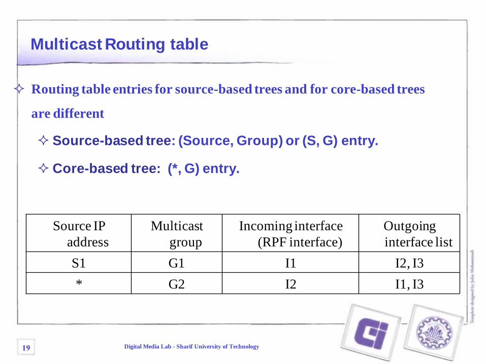
Multicast Routing table
Routing table entries for source-based trees and for core-based trees
are different
Source-based tree: (Source, Group) or (S, G) entry.
Core-based tree: (*, G) entry.
Source IP
address
Multicast
group
Incoming interface
(RPF interface)
Outgoing
interface list
S1 G1 I1 I2, I3
* G2 I2 I1, I3
19 Digital Media Lab - Sharif University of Technology
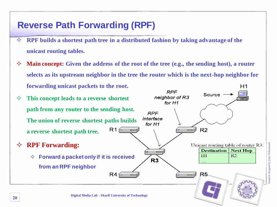
Reverse Path Forwarding (RPF)
RPF builds a shortest path tree in a distributed fashion by taking advantage of the
unicast routing tables.
Main concept: Given the address of the root of the tree (e.g., the sending host), a router
selects as its upstream neighbor in the tree the router which is the next-hop neighbor for
forwarding unicast packets to the root.
This concept leads to a reverse shortest
path from any router to the sending host.
The union of reverse shortest paths builds
a reverse shortest path tree.
RPF Forwarding:
Forward a packet only if it is received
from an RPF neighbor
20Digital Media Lab - Sharif University of Technology
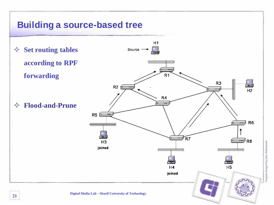
Building a source-based tree
Set routing tables
according to RPF
forwarding
Flood-and-Prune
21Digital Media Lab - Sharif University of Technology
H2
H3
H5H4
H1
Source
R1
R2
R6
R4
R5
R3
R8R7
joined
joined
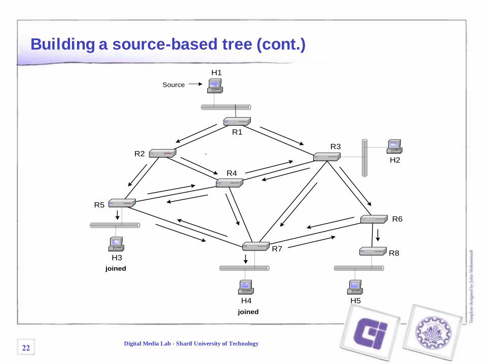
Building a source-based tree (cont.)
22Digital Media Lab - Sharif University of Technology
H2
H3
H5H4
H1
Source
R1
R2
R6
R4
R5
R3
R8R7
joined
joined
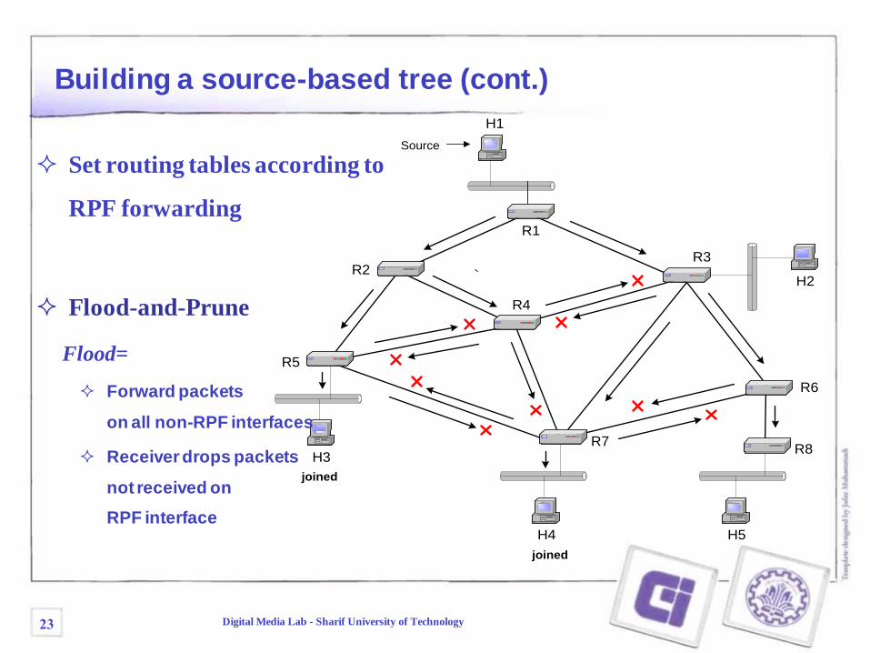
Building a source-based tree (cont.)
Set routing tables according to
RPF forwarding
Flood-and-Prune
Flood=
Forward packets
on all non-RPF interfaces
Receiver drops packets
not received on
RPF interface
23 Digital Media Lab - Sharif University of Technology
H2
H3
H5H4
H1
Source
R1
R2
R6
R4
R5
R3
R8R7
Prune
joined
joined
Prune
Pru
ne
PrunePrune
Prune
Prune
Prune
Prune
Pru
ne
Pru
ne
Prune
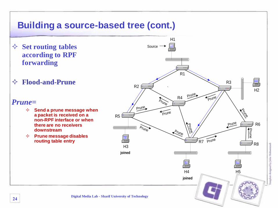
Building a source-based tree (cont.)
Set routing tables
according to RPF forwarding
Flood-and-Prune
Prune= Send a prune message when
a packet is received on a non-RPF interface or when there are no receivers downstream
Prune message disables routing table entry
24Digital Media Lab - Sharif University of Technology
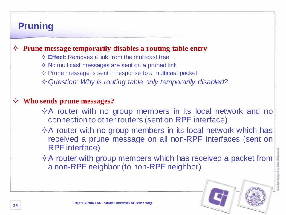
Pruning
Prune message temporarily disables a routing table entry
Effect: Removes a link from the multicast tree
No multicast messages are sent on a pruned link
Prune message is sent in response to a multicast packet
Question: Why is routing table only temporarily disabled?
Who sends prune messages?
A router with no group members in its local network and noconnection to other routers (sent on RPF interface)
A router with no group members in its local network which hasreceived a prune message on all non-RPF interfaces (sent onRPF interface)
A router with group members which has received a packet froma non-RPF neighbor (to non-RPF neighbor)
25Digital Media Lab - Sharif University of Technology
H2
H3
H5H4
H1
Source
R1
R2
R6
R4
R5
R3
R8R7
joined
joined
Gra
ft
Graft
joined
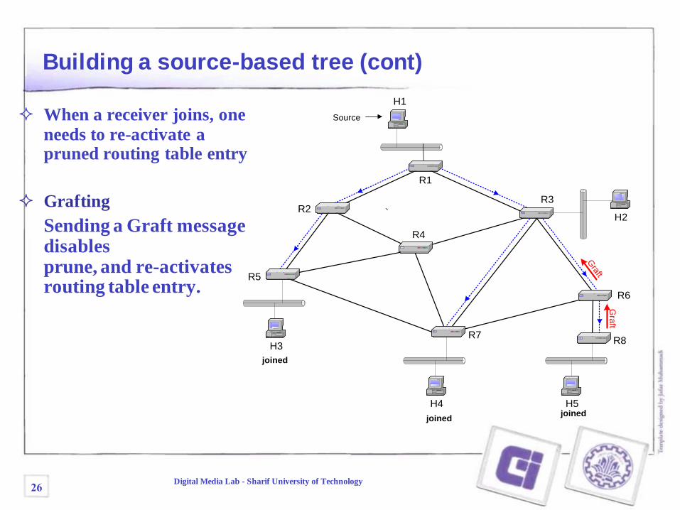
Building a source-based tree (cont)
When a receiver joins, one
needs to re-activate a pruned routing table entry
Grafting
Sending a Graft message disables prune, and re-activates routing table entry.
26Digital Media Lab - Sharif University of Technology
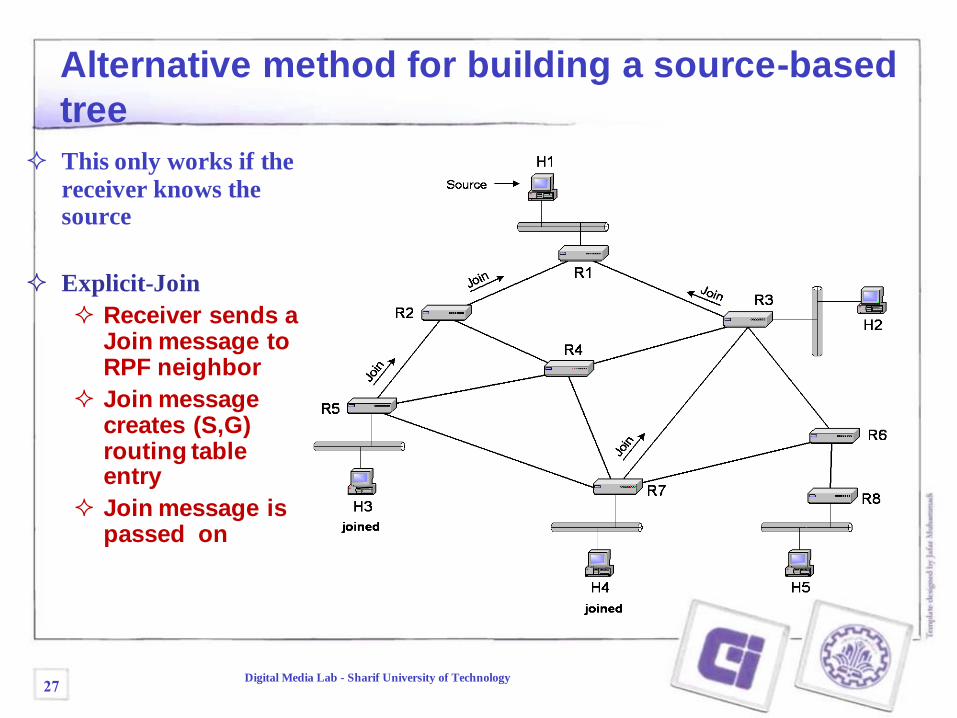
Alternative method for building a source-based
tree
This only works if the
receiver knows the source
Explicit-Join
Receiver sends a Join message to RPF neighbor
Join message creates (S,G) routing table entry
Join message is passed on
27Digital Media Lab - Sharif University of Technology
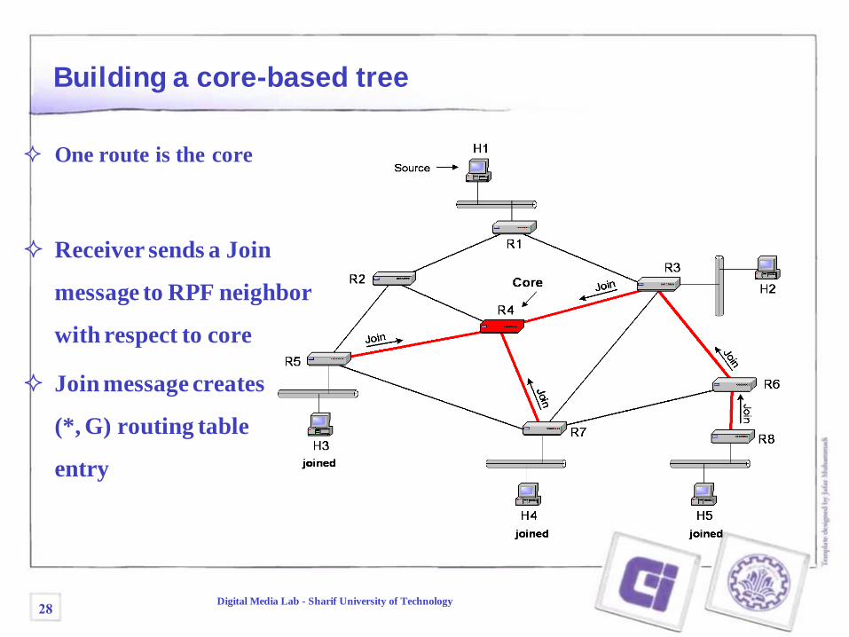
Building a core-based tree
One route is the core
Receiver sends a Join
message to RPF neighbor
with respect to core
Join message creates
(*, G) routing table
entry
28Digital Media Lab - Sharif University of Technology
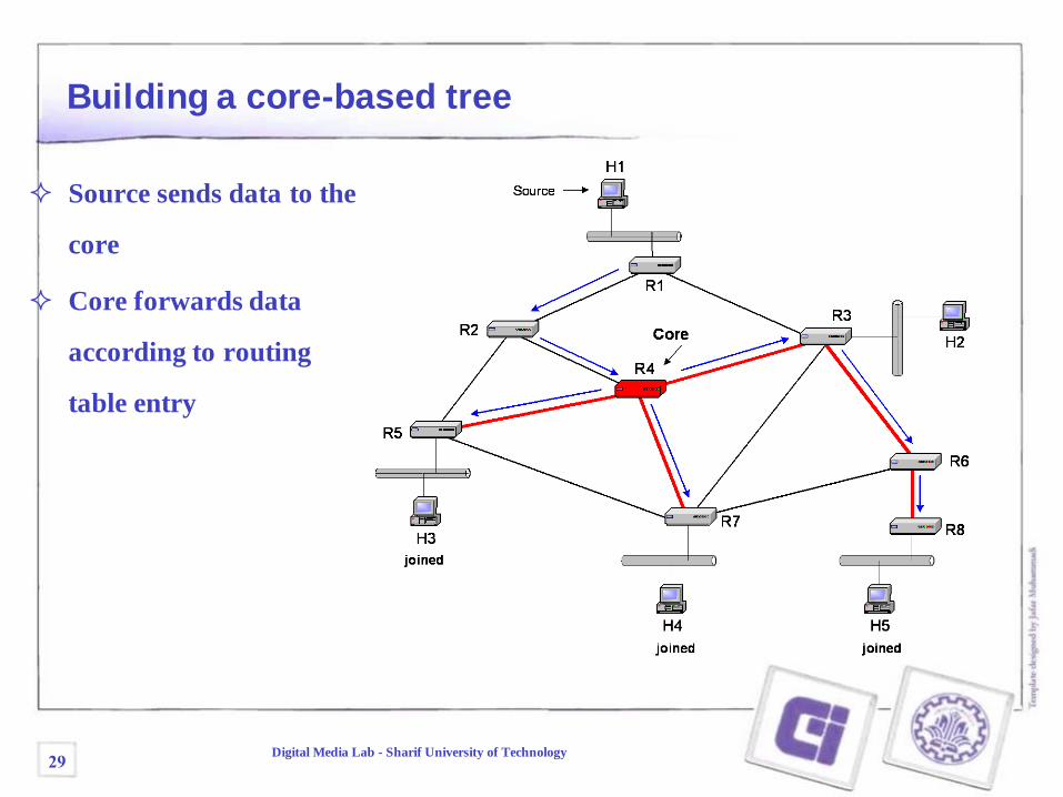
Building a core-based tree
Source sends data to the
core
Core forwards data
according to routing
table entry
29Digital Media Lab - Sharif University of Technology
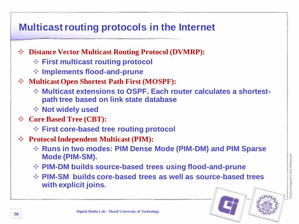
Multicast routing protocols in the Internet
Distance Vector Multicast Routing Protocol (DVMRP):
First multicast routing protocol
Implements flood-and-prune
Multicast Open Shortest Path First (MOSPF):
Multicast extensions to OSPF. Each router calculates a shortest-path tree based on link state database
Not widely used
Core Based Tree (CBT):
First core-based tree routing protocol
Protocol Independent Multicast (PIM):
Runs in two modes: PIM Dense Mode (PIM-DM) and PIM Sparse Mode (PIM-SM).
PIM-DM builds source-based trees using flood-and-prune
PIM-SM builds core-based trees as well as source-based trees with explicit joins.
30Digital Media Lab - Sharif University of Technology
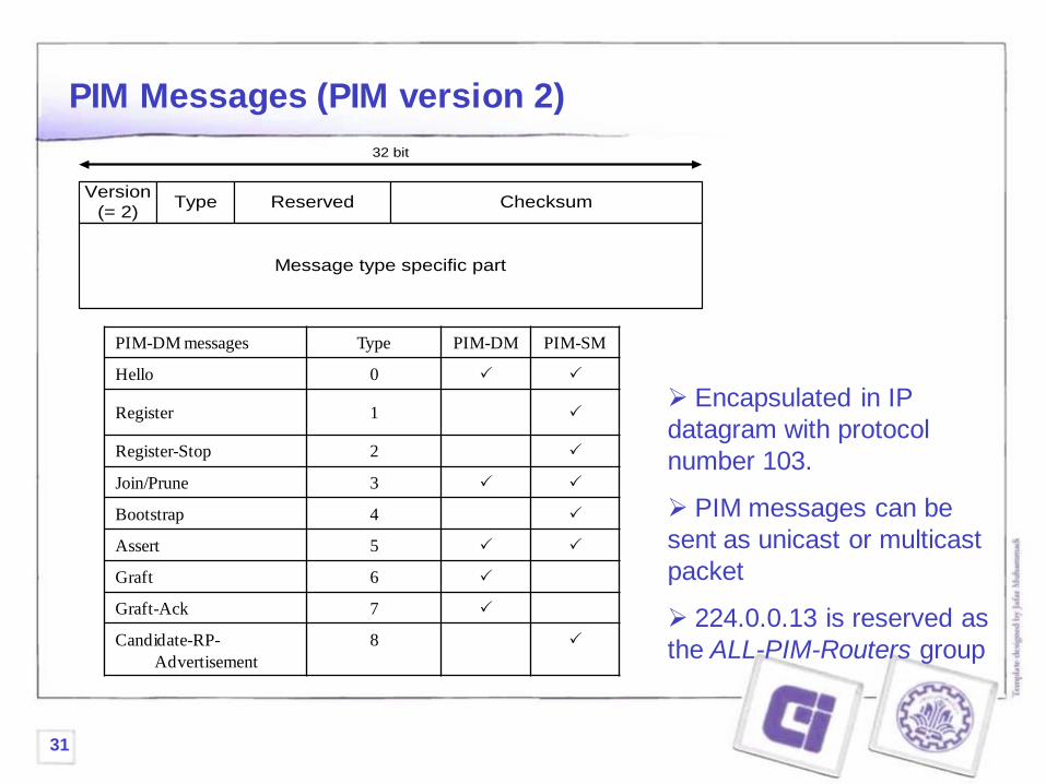
PIM Messages (PIM version 2)
Version
(= 2)Type Reserved Checksum
32 bit
Message type specific part
PIM-DM messages Type PIM-DM PIM-SM
Hello 0
Register 1
Register-Stop 2
Join/Prune 3
Bootstrap 4
Assert 5
Graft 6
Graft-Ack 7
Candidate-RP-
Advertisement
8
Encapsulated in IP
datagram with protocol
number 103.
PIM messages can be
sent as unicast or multicast
packet
224.0.0.13 is reserved as
the ALL-PIM-Routers group
31
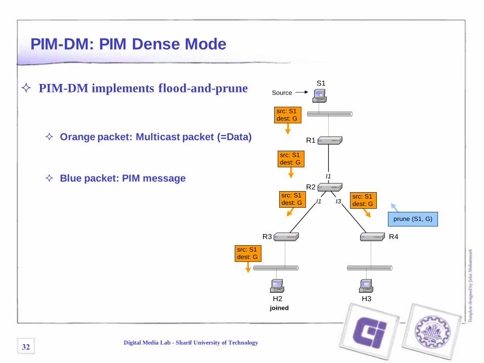
PIM-DM: PIM Dense Mode
PIM-DM implements flood-and-prune
Orange packet: Multicast packet (=Data)
Blue packet: PIM message
H3H2
S1
Source
R1
R3
joined
R4
R2
src: S1
dest: G
src: S1
dest: G
src: S1
dest: G
src: S1
dest: G
src: S1
dest: G
prune (S1, G)
I1
I1 I3
32Digital Media Lab - Sharif University of Technology
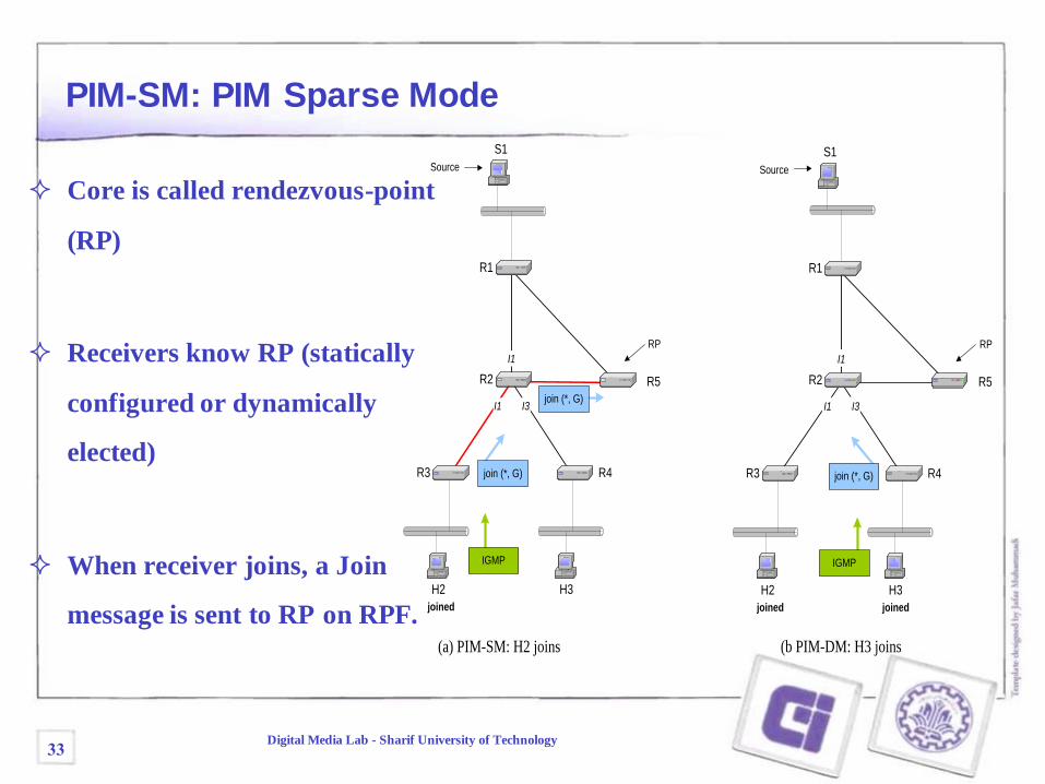
PIM-SM: PIM Sparse Mode
Core is called rendezvous-point
(RP)
Receivers know RP (statically
configured or dynamically
elected)
When receiver joins, a Join
message is sent to RP on RPF.H3H2
S1
Source
R3
joined
R4
H3H2
S1
Source
R3
joined
R4
I1
I1 I3
I1
I2 I3
(a) PIM-SM: H2 joins (b PIM-DM: H3 joins
RP
R1
R2 R5
IGMP
joined
join (*, G)
join (*, G)
IGMP
join (*, G)
I1
I1 I3
RP
R5
R1
R2
33Digital Media Lab - Sharif University of Technology
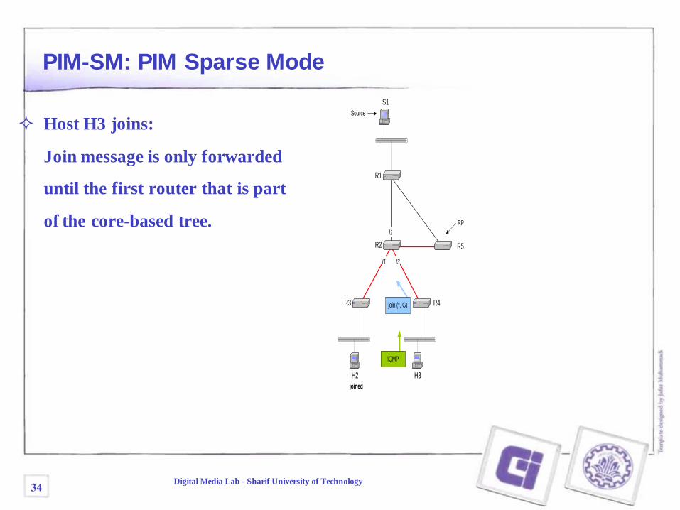
PIM-SM: PIM Sparse Mode
Host H3 joins:
Join message is only forwarded
until the first router that is part
of the core-based tree.
H3H2
S1
Source
R3
joined
R4
I1
I1 I3
RP
R1
R2 R5
IGMP
join (*, G)
34Digital Media Lab - Sharif University of Technology
H3H2
S1
Source
R3
joined
R4
src: S1
dest: G
src: S1
dest: G
I1
I1 I3
RP
R1
R2 R5
src: S1
dest: G
src: S1
dest: G
H3H2
S1
Source
R3
joined
R4
src: S1
dest: G
src: S1
dest: G
I1
I1 I3
(a) PIM-SM: Register
message to RP
(b) PIM-SM: Register Stop
message to S1
RP
R1
R2 R5
join (S1,G)
register
(S1, G)
src: S1
dest: G
src: S1
dest: G
src: S1
dest: G
src: S1
dest: G
register stop (S1,G)
register
(S1, G)
src: S1
dest: G
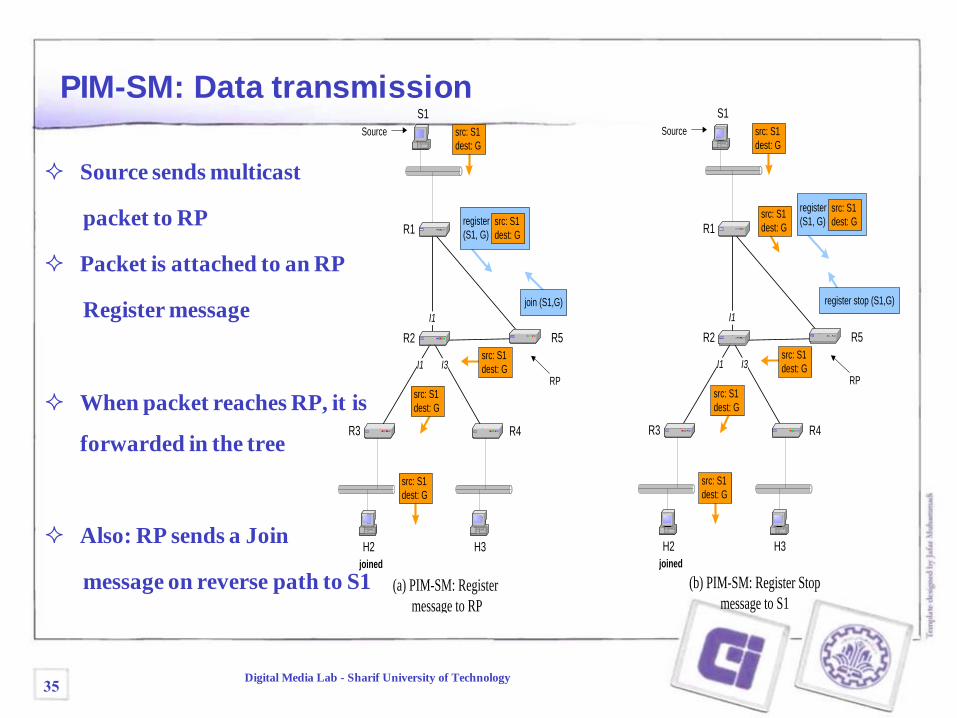
PIM-SM: Data transmission
Source sends multicast
packet to RP
Packet is attached to an RP
Register message
When packet reaches RP, it is
forwarded in the tree
Also: RP sends a Join
message on reverse path to S1
35Digital Media Lab - Sharif University of Technology
H3H2
S1
Source
R3
joined
R4
src: S1
dest: G
src: S1
dest: G
I1
I1 I3
RP
R1
R2 R5
src: S1
dest: G
src: S1
dest: G
H3H2
S1
Source
R3
joined
R4
src: S1
dest: G
src: S1
dest: G
I1
I1 I3
(b) PIM-SM: Register Stop message to S1
RP
R1
R2 R5
src: S1
dest: G
src: S1
dest: G
src: S1
dest: G
register
(S1, G)
src: S1
dest: G
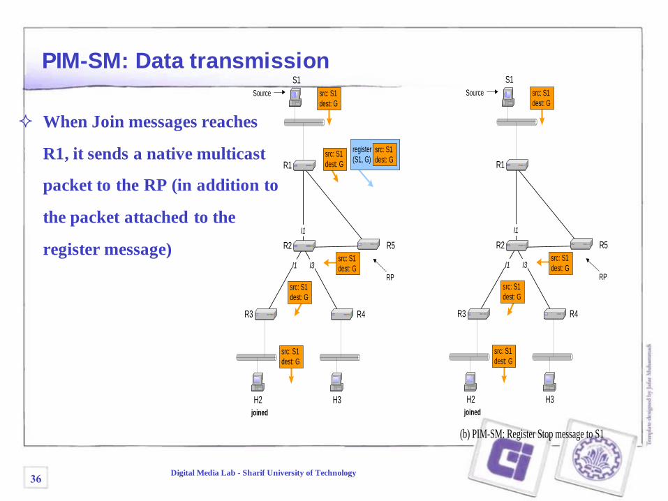
PIM-SM: Data transmission
When Join messages reaches
R1, it sends a native multicast
packet to the RP (in addition to
the packet attached to the
register message)
36Digital Media Lab - Sharif University of Technology
H3H2
S1
Source
R3
joined
R4
src: S1
dest: G
src: S1
dest: G
I1
I1 I3
RP
R1
R2 R5
src: S1
dest: G
src: S1
dest: G
H3H2
S1
Source
R3
joined
R4
src: S1
dest: G
src: S1
dest: G
I1
I1 I3
(b) PIM-SM: Register Stop message to S1
RP
R1
R2 R5
src: S1
dest: G
src: S1
dest: G
src: S1
dest: G
register stop (S1,G)
register
(S1, G)
src: S1
dest: G
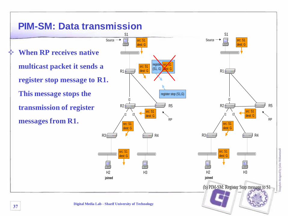
PIM-SM: Data transmission
When RP receives native
multicast packet it sends a
register stop message to R1.
This message stops the
transmission of register
messages from R1.
37Digital Media Lab - Sharif University of Technology
src: S1
dest: G
H3H2
S1
Source
R3
joined
R4
I1
I1 I3
RP
R1
R2 R5
H3H2
S1
Source
R3
joined
R4
I1
I1 I3
(a) PIM-SM: R3 switches
to a SPT
(b) PIM-SM: Data
follows a SPT
RP
R1
R2 R5
join (S1,G)
join (S1,G)
src: S1
dest: G
prune
(S,G,RPT)
src: S1
dest: G
prune
(S,G,RPT)
src: S1
dest: G
src: S1
dest: G
src: S1
dest: G
src: S1
dest: G
src: S1
dest: G
src: S1
dest: G
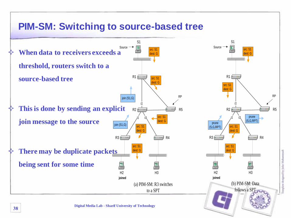
PIM-SM: Switching to source-based tree
When data to receivers exceeds a
threshold, routers switch to a
source-based tree
This is done by sending an explicit
join message to the source
There may be duplicate packets
being sent for some time
38Digital Media Lab - Sharif University of Technology
src: S1
dest: G
H3H2
S1
Source
R3
joined
R4
I1
I1 I3
RP
R1
R2 R5
(b) PIM-SM: Data follows a SPT
src: S1
dest: G
prune
(S,G,RPT)
src: S1
dest: G
prune
(S,G,RPT)
src: S1
dest: G
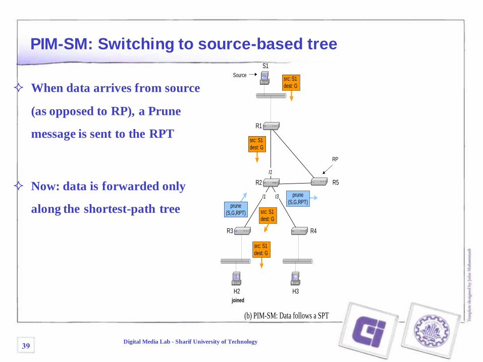
PIM-SM: Switching to source-based tree
When data arrives from source
(as opposed to RP), a Prune
message is sent to the RPT
Now: data is forwarded only
along the shortest-path tree
39Digital Media Lab - Sharif University of Technology
Next Session
Application Layer Multicast
40Digital Media Lab - Sharif University of Technology