Embed Size (px)
Citation preview

1000 Park Drive • Lawrence, PA 15055-1018 • 724-746-5500 • Fax 724-746-0746
© Copyright 2004. Black Box Corporation. All rights reserved.
CUSTOMERSUPPORT
INFORMATION
Order toll-free in the U.S.: Call 877-877-BBOX (outside U.S. call 724-746-5500)FREE technical support 24 hours a day, 7 days a week: Call 724-746-5500 or fax 724-746-0746Mailing address: Black Box Corporation, 1000 Park Drive, Lawrence, PA 15055-1018Web site: www.blackbox.com • E-mail: [email protected]
JULY 2004LW6200ALW6201A
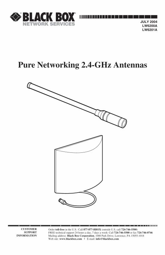
Pure Networking 2.4-GHz Antennas

1
FCC AND IC RFI STATEMENTS
FEDERAL COMMUNICATIONS COMMISSIONand INDUSTRY CANADA
RADIO FREQUENCY INTERFERENCE STATEMENTS
Class B Digital Device. This equipment has been tested and found to comply withthe limits for a Class B computing device pursuant to Part 15 of the FCC Rules.These limits are designed to provide reasonable protection against harmfulinterference in a residential installation. However, there is no guarantee thatinterference will not occur in a particular installation. This equipment generates,uses, and can radiate radio frequency energy, and, if not installed and used inaccordance with the instructions, may cause harmful interference to radiocommunications. If this equipment does cause harmful interference to radio ortelephone reception, which can be determined by turning the equipment off andon, the user is encouraged to try to correct the interference by one of the followingmeasures:
• Reorient or relocate the receiving antenna.
• Increase the separation between the equipment and receiver.
• Connect the equipment into an outlet on a circuit different from that to whichthe receiver is connected.
• Consult an experienced radio/TV technician for help.
CAUTIONChanges or modifications not expressly approved by the partyresponsible for compliance could void the user’s authority to operatethe equipment.
To meet FCC requirements, shielded cables and power cords are required toconnect this device to a personal computer or other Class B certified device.
This digital apparatus does not exceed the Class B limits for radio noise emission from digitalapparatus set out in the Radio Interference Regulation of Industry Canada.

2
PURE NETWORKING 2.4-GHZ ANTENNAS
TRADEMARKS USED IN THIS MANUAL
Any trademarks mentioned in this manual are acknowledged to be the property of thetrademark owners.

3
CONTENTS
ContentsChapter Page
1. Specifications . . . . . . . . . . . . . . . . . . . . . . . . . . . . . . . . . . . . . . . . . . . . . . . . . . 41.1 General . . . . . . . . . . . . . . . . . . . . . . . . . . . . . . . . . . . . . . . . . . . . . . . . . . . 41.2 Radiation Patterns . . . . . . . . . . . . . . . . . . . . . . . . . . . . . . . . . . . . . . . . . . 5
2. Introduction . . . . . . . . . . . . . . . . . . . . . . . . . . . . . . . . . . . . . . . . . . . . . . . . . . . 62.1 Overview . . . . . . . . . . . . . . . . . . . . . . . . . . . . . . . . . . . . . . . . . . . . . . . . . . 62.2 What’s Included . . . . . . . . . . . . . . . . . . . . . . . . . . . . . . . . . . . . . . . . . . . . 6
3. Installation . . . . . . . . . . . . . . . . . . . . . . . . . . . . . . . . . . . . . . . . . . . . . . . . . . . . 83.1 Guidelines . . . . . . . . . . . . . . . . . . . . . . . . . . . . . . . . . . . . . . . . . . . . . . . . . 83.2 Mounting the Antenna. . . . . . . . . . . . . . . . . . . . . . . . . . . . . . . . . . . . . . . 8
3.2.1 8-dBi Omnidirectional Antenna. . . . . . . . . . . . . . . . . . . . . . . . . . 83.2.2 14-dBi Directional Panel Antenna . . . . . . . . . . . . . . . . . . . . . . . 10
3.3 Installing the Surge Arrestor . . . . . . . . . . . . . . . . . . . . . . . . . . . . . . . . . 133.4 Connecting to the Wireless Access Point . . . . . . . . . . . . . . . . . . . . . . . 14
4. Troubleshooting . . . . . . . . . . . . . . . . . . . . . . . . . . . . . . . . . . . . . . . . . . . . . . 154.1 Calling Black Box . . . . . . . . . . . . . . . . . . . . . . . . . . . . . . . . . . . . . . . . . . 154.2 Shipping and Packaging . . . . . . . . . . . . . . . . . . . . . . . . . . . . . . . . . . . . 15

4
PURE NETWORKING 2.4-GHZ ANTENNAS
1. Specifications
1.1 GeneralApplication: LW6200A: Outdoor/indoor (pole); LW6201A: Outdoor/indoor (wall/pole)
Frequency Range: 2.4000–2.5 GHz
Gain: LW6200A: 8 dBi; LW6201A: 14 dBi
Beam Width: LW6200A: H360, V15; LW6201A: H30, V30
Approximate Range: LW6200A: 0.62 mi. (1 km); LW6201A: 1.86 mi. (3 km)
Impedance: 50 ohms
Survival Wind Speed: 111.8 mi./hr. (180 km/hr.)
Lightning Protection: DC ground
Cable Length: LW6200A: 19.7" (50 cm); LW6201A: 11.8" (30 cm)
Connector: (1) N female
Temperature Tolerance: -40 to +122°F (-40 to +50°C)
Humidity: Up to 100%
Size: LW6200A: 0.7"W x 24.8"L (18 x 63 cm); LW6201A: 9.4"H x 9.4"W x 2.8"D (23.9 x 23.9 x 7.1 cm)
5
CHAPTER 1: Specifications
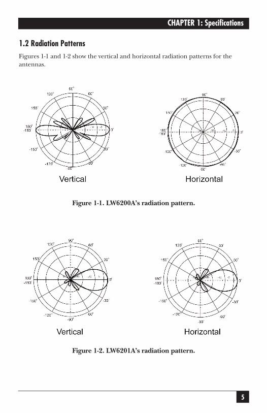
1.2 Radiation PatternsFigures 1-1 and 1-2 show the vertical and horizontal radiation patterns for theantennas.
Figure 1-1. LW6200A’s radiation pattern.
Figure 1-2. LW6201A’s radiation pattern.
6
PURE NETWORKING 2.4-GHZ ANTENNAS
2. Introduction
2.1 OverviewThe Pure Networking 2.4-GHz Antenna is an outdoor/indoor antenna thatextends an IEEE 802.11g wireless access point’s transmitting and receiving power.With this antenna, your wireless network will have extraordinary transmissiondistances and a wider coverage range.
Installers can easily and conveniently build a wireless network in a building’sinterior or exterior. The antenna is completely waterproof, wind resistant, and ismade out of corrosion-resistant material to withstand harsh environments.
Two models are available:
• 8-dBi Omnidirectional 2.4-GHz Antenna(LW6200A)
• 13-dBi Directional Panel 2.4-GHz Antenna (LW6201A)
2.2 What’s IncludedYour package should include the following items. If anything is missing ordamaged, contact Black Box at 724-746-5500.
LW6200A:
• (1) Antenna
• (1) Metal tube
• (2) U-shaped screws
• (4) M8 x 110 bolts
• (4) Screw clamps
• (4) 1⁄4 spring washers
• (4) 1⁄4 nuts
• (4) M8 spring washers
• (4) M8 nuts
7
CHAPTER 2: Overview
• (1) N male to N female 1.64-ft. (0.5-m)/0.43-dB transmission lossinterconnecting cable
• (1) lightning surge arrestor and static electricity protector/N female to N male
• This users’ manual
LW6201A:
• (1) Antenna
• (2) M-shaped metal fixings
• (8) M8 spring washers
• (2) M8 x 12 screws
• (1) steel tube
• (5) M8 washers
• (3) M8 x 110 bolt
• (5) M8 nuts
• (2) M8 x 16 screws
• (4) M6 x 10 screws
• (4) M6 washers
• (1) triangle stand
• (1) half-round metal stand
• (2) tapping screws
• (2) plastic wall tigers
• (1) lightning surge arrestor and static electricity protector/N female to N male
• (1) ring clamp
• (2) screw clamps
• This users’ manual
8
PURE NETWORKING 2.4-GHZ ANTENNAS
3. Installation
3.1 GuidelinesObserve the following guidelines when you are installing the antenna.
• Avoid placing the antenna behind obstacles. Obstructions such as concretewalls, trees, power lines, and thick metals limit radio signal penetration andreduce throughput and the wireless device’s range.
• Mount the antenna vertically. This antenna is vertically polarized. Since it hasvertical gain, mount the antenna in a vertical (not leaning) position foroptimal performance.
• Use a surge arrestor for the antenna when it’s installed outdoors. A surgearrestor can protect your wireless device from high voltage surges caused bythe antenna’s discharge and transient voltages.
• Do not point the antenna in the direction of people or animals. Mount theantenna to minimize the potential for human or animal contact duringnormal operation.
3.2 Mounting the Antenna
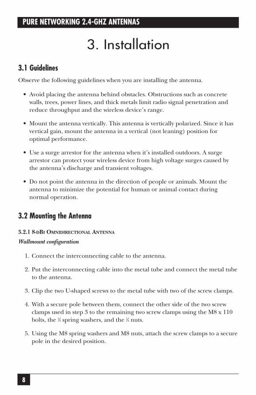
3.2.1 8-DBI OMNIDIRECTIONAL ANTENNA
Wallmount configuration
1. Connect the interconnecting cable to the antenna.
2. Put the interconnecting cable into the metal tube and connect the metal tubeto the antenna.
3. Clip the two U-shaped screws to the metal tube with two of the screw clamps.
4. With a secure pole between them, connect the other side of the two screwclamps used in step 3 to the remaining two screw clamps using the M8 x 110bolts, the 1⁄4 spring washers, and the 1⁄4 nuts.
5. Using the M8 spring washers and M8 nuts, attach the screw clamps to a securepole in the desired position.
9
CHAPTER 3: Installation
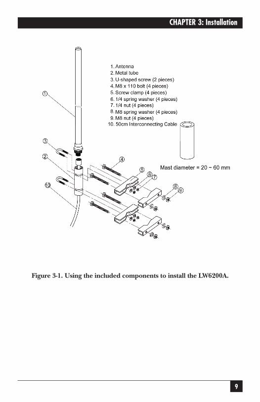
Figure 3-1. Using the included components to install the LW6200A.
10
PURE NETWORKING 2.4-GHZ ANTENNAS
3.2.2 14-DBI DIRECTIONAL PANEL ANTENNA
Wallmount configuration
NOTEYou will not need to use all of the included components to install theantenna on the wall.
1. Using one M8 spring washer and one M8 x 12 screw, attach one of theM-shaped metal fixings to the back of the antenna.
2. Attach the half-round metal stand with the two plastic wall tigers and twotapping screws horizontally in the desired mounting position.
3. Connect the other M-shaped metal fixing and the triangle stand with oneM8 x 12 screw and one M8 spring washer.
4. Using the four M6 x 10 screws and four M6 washers, attach the triangle standto the half-round metal stand. The antenna can be horizontally aligned withthis connection.
5. Attach one M8 x 110 bolt to one M-shaped metal fixing using one M8 washer,then slide the steel tube over this bolt. Connect the two M-shaped metalfixings together with the same M8 x 110 bolt, a second M8 washer, and oneM8 nut. The antenna can be vertically aligned with this connection.
6. Connect the triangle stand to the M-shaped metal fixings with two M8 x16 screws.
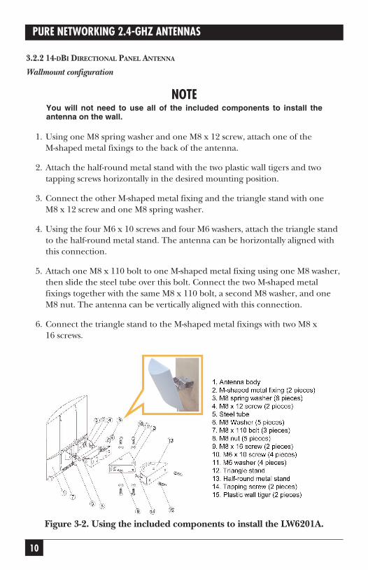
Figure 3-2. Using the included components to install the LW6201A.

11
CHAPTER 3: Installation
Pole-mount configuration
Using a ring clamp
NOTEYou will not need to use all of the included components to install theantenna on a pole using a ring clamp.
1. Using one M8 spring washer and one M8 x 12 screw, attach one of theM-shaped metal fixings to the back of the antenna.
2. Push the ring clamp through the other M-shaped metal fixing as shown in thediagram.
3. Attach the clamp to a secure pole in the desired position. The diameter of thepole should be less than 2 inches (5.1 cm).
4. Attach one M8 x 110 bolt to one M-shaped metal fixing using one M8washers, then slide the steel tube over this bolt. Connect the two M-shapedmetal fixings together with the same M8 x 110 bolt, a second M8 washer, andone M8 nut. The antenna can be vertically aligned with this connection.
Figure 3-3. 14-dBi Directional Panel Antenna mounted on a pole, secured with a ring clamp.

12
PURE NETWORKING 2.4-GHZ ANTENNAS
Using a screw clamp
NOTEYou will not need to use all of the included components to install theantenna on a pole using a screw clamp.
1. Using one M8 spring washer and one M8 x 12 screw, attach one of theM-shaped metal fixings to the back of the antenna.
2. Push the two M8 x 110 bolts through the other M-shaped metal fixing withtwo M8 washers and both screw clamps.
3. Attach the screw clamps to a secure pole in the desired position.
4. Attach one M8 x 110 bolt to one M-shaped metal fixing using one M8washers, then slide the steel tube over this bolt. Connect the two M-shapedmetal fixings together with the same M8 x 110 bolt, a second M8 washer, andone M8 nut. The antenna can be vertically aligned with this connection.
Figure 3-4. 14-dBi Directional Panel Antenna mounted on a pole, secured with a screw clamp.

13
CHAPTER 3: Installation
3.3 Installing the Surge ArrestorWith the surge arrestor attached to the lightning protector of the building, alldevices downstream are protected from lightning strikes. Follow the steps below toinstall the surge arrestor.
1. Connect one end of the surge arrestor (#1 in Figure 3-5) to the antenna.
2. Connect the other end of the surge arrestor (#2) to the extension cablelinked to the wireless access point.
3. Connect the building’s lightning protector to the surge arrestor (#3).
Figure 3-5. The surge arrestor’s connections.
14
PURE NETWORKING 2.4-GHZ ANTENNAS
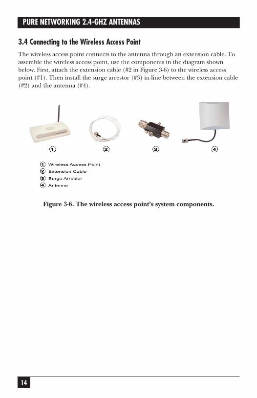
3.4 Connecting to the Wireless Access PointThe wireless access point connects to the antenna through an extension cable. Toassemble the wireless access point, use the components in the diagram shownbelow. First, attach the extension cable (#2 in Figure 3-6) to the wireless accesspoint (#1). Then install the surge arrestor (#3) in-line between the extension cable(#2) and the antenna (#4).
Figure 3-6. The wireless access point’s system components.

15
CHAPTER 4: Troubleshootng
4. Troubleshooting
4.1 Calling Black BoxIf you determine that your 2.4-GHz Antenna is malfunctioning, do not attempt toalter or repair the unit. It contains no user-serviceable parts. Contact Black Box at724-746-5500.
Before you do, make a record of the history of the problem. We will be able toprovide more efficient and accurate assistance if you have a complete description,including:
• the nature and duration of the problem.
• when the problem occurs.
• the components involved in the problem.
• any particular application that, when used, appears to create the problem ormake it worse.
4.2 Shipping and PackagingIf you need to transport or ship your 2.4-GHz Antenna:
• Package it carefully. We recommend that you use the original container.
• If you are shipping the 2.4-GHz Antenna for repair, make sure you includeeverything that came in the original package. Before you ship, contact BlackBox to get a Return Authorization (RA) number.