Embed Size (px)
Citation preview

Conversion coefficients from air kerma to personal dose equivalent Hp(3) for eye-lens dosimetry ORAMED project Rapport CEA J. Daures(1), J. Gouriou(1), JM Bordy(1) (1)CEA, LIST, Laboratoire National Henri Becquerel (LNE LNHB), F-91191 Gif-sur-Yvette, France. Summary
This work has been performed within the frame of the European Union ORAMED project
(Optimization of RAdiation protection for MEDical staff). The main goal of the project is to
improve standards of protection for medical staff for procedure resulting in potentially high
exposures and to develop methodologies for better assessing and for reducing exposures to
medical staff.
The Work Package WP2 is involved in the development of practical eye lens dosimetry in
interventional radiology. This study is complementary of the part of the ENEA report
concerning the calculations with the MCNP code of the conversion factors related to the
operational quantity Hp(3).
A set of energy and angular dependent conversion coefficients Hp(3)/Kair in the new
proposed square cylindrical phantom of ICRU tissue, have been calculated with the Monte-
Carlo code PENELOPE. The Hp(3) values have been determined in terms of absorbed dose,
according to the definition of this quantity, and also with the kerma approximation as
formerly reported in ICRU reports. At low photon energy, up to 1 MeV, the two sets of
conversion coefficients are consistent. Nevertheless, the differences increase at higher
energy. This is mainly due to the lack of electronic equilibrium, especially for small angle
incidences.
The values of the conversion coefficients obtained with the code MCNP published by
ENEA, agree with the kerma approximation calculations with PENELOPE. They are coherent
with previous calculations in phantoms different in shape.
1
But above 1 MeV, differences between conversion coefficient values calculated with the
absorbed dose and with kerma approximation are significantly increasing, especially at low
incidence angles. At those energies the electron transport has to be simulated.
Key Words : Personal dose equivalent, eye-lens dosimetry; conversion coefficients; PENELOPE code; Mont-Carlo simulations; operational quantities Coefficients de conversion du kerma dans l'air à l'équivalent de dose individuel Hp(3) pour la dosimétrie du cristallin ORAMED project Rapport CEA J. Daures(1), J. Gouriou(1), JM Bordy(1) (1)CEA, LIST, Laboratoire National Henri Becquerel (LNE LNHB), F-91191 Gif-sur-Yvette, France. Résumé
Ce travail a été effectué dans le cadre du projet ORAMED (Optimization of RAdiation
protection for MEDical staff) de l'Union Européenne. L'objet principal de ce projet est
d'améliorer les standards de protection du personnel médical pour les procédures pouvant
conduire à des expositions potentiellement élevées et de développer des méthodologies pour
une meilleure estimation et une réduction de l'exposition.
Le groupe de travail WP2 est en charge du développement d'une dosimétrie du cristallin
dans la pratique en radiologie interventionnelle. Cette étude est complémentaire de la partie
du rapport de l'ENEA concernant le calcul des coefficients de conversion liés à la grandeur
opérationnelle Hp(3).
Un ensemble de coefficients de conversion Hp(3)/Kair , en fonction de l'énergie et de l'angle,
dans le nouveau fantôme proposé constitué d'un cylindrique droit en matériau tissu quatre
éléments, ont été calculés à l'aide du code de Monte-Carlo PENELOPE. Les valeurs de Hp(3)
ont été déterminées en termes de dose absorbée, conformément à la définition de cette
grandeur, ainsi qu'en utilisant l'approximation kerma précédemment reportée dans les rapports
2
de l'ICRU. Pour les photons de faible énergie, jusqu'à 1 MeV, les deux séries de facteurs de
conversions sont en bon accord. Néanmoins, les différences augmentent à plus haute énergies.
Ceci est principalement du au manque d'équilibre électronique, particulièrement pour les
faibles angles d'incidence.
Les valeurs des coefficients de conversion obtenues avec le code MCNP publiées par
l'ENEA sont en accord avec les calculs PENELOPE selon l'approximation kerma. Ils sont
cohérents avec des calculs antérieurs dans des fantômes de géométries différentes.
Cependant, à partir de 1 MeV les différences entre les facteurs de conversion calculés en
termes de dose absorbée ou avec l'approximation kerma augmentent significativement,
particulièrement pour les faibles angles d'incidence. A ces énergies le transport des électrons
doit être simulé.
Mots Clés : Equivalent de dose individuel; dosimétrie du cristallin; coefficients de conversion; PENELOPE code; simulations Mont-Carlo; grandeurs opérationnelles.
The present study is supported by the ORAMED Contract (FP7 Grant Agreement
211361 started on February 1st 2008).
CEA SACLAY DIRECTION DE LA RECHERCHE TECHNOLOGIQUE
LABORATOIRE D'INTEGRATION DES SYSTEMES ET DES TECHNOLOGIES DEPARTEMENT DES TECHNOLOGIES DU CAPTEUR ET DU SIGNAL
LABORATOIRE NATIONAL HENRI BECQUEREL
3
CONTENTS
1 Introduction ........................................................................................................................ 5 2 Materials and methods ....................................................................................................... 6
2.1 Hp(3) calculations ...................................................................................................... 6 2.2 Kair calculations .......................................................................................................... 8
3 Results ................................................................................................................................ 9 3.1 Kair determination ....................................................................................................... 9 3.2 Hp(3)/Kair conversion coefficients, with Hp(3) calculated in terms of kerma approximation....................................................................................................................... 10 3.3 Hp(3)/Kair conversion coefficients, with Hp(3) calculated in terms of absorbed dose 15
4 Discussions....................................................................................................................... 21 5 Conclusions ...................................................................................................................... 30
4
1 Introduction
This work has been performed within the frame of the European Union ORAMED project
(Optimization of RAdiation protection for MEDical staff) [1]. The main goal of the project is
to improve standards of protection for medical staff for procedure resulting in potentially high
exposures and develop methodologies for better assessing and reducing exposures to medical
staff.
The Work Package WP2 is involved in the development of practical eye lens dosimetry in
interventional radiology. This study is complementary of the part of the ENEA report [2]
concerning the calculations of the conversion factors.
The design of a phantom well suited for eye-lens dosimetry has been discussed within WP2.
It appears that a right cylinder, 20 cm in diameter and 20 cm height, is more appropriate than
the 30 cm x 30 cm x 15 cm ISO slab phantom or even the reduced slab phantom (20 cm x 20
cm x 15 cm). This new phantom constituted of ICRU four elements is used to calculate the
personal dose equivalent Hp(3) and the conversion coefficient Hp(3)/Kair. These values of the
conversion coefficient Hp(3)/Kair will be very helpful because ICRU 57 [3] do not provide
tabulated values for the depth of 3 mm for photons.
Similar phantom in shape, a cylinder of PMMA having a wall of 1 cm, filled with water
will be then used to perform the calibration of the personal dosimeters.
In this study a set of energy and angular dependent conversion coefficient Hp(3)/Kair in the
new proposed right cylindrical phantom made of ICRU tissue have been calculated with the
Monte-Carlo code PENELOPE [4]. The Hp(3) values are calculated in terms of absorbed
dose, according to the ICRU definition of this quantity [5] [6], together with the kerma
approximation as formerly used. The Kair values have been also calculated with PENELOPE
for global coherence.
The results of this work are compared with similar simulations performed at ENEA [2] with
the code MCNP. It is important to have several independent determinations of the conversion
coefficients.
5
2 Materials and methods The simulations have been carried out with the Monte-Carlo code PENELOPE parallelised
at CEA-LIST [7] on the LNHB cluster constituted of 112 processors (2.8 MHz).
The Hp(3)/Kair conversion factor calculation implies the simulation of Hp(3) and Kair.
Both quantities refer to unit fluence, but for a sake of simplicity, Hp(3)/ is written Hp(3)
and Kair / is written Kair
2.1 Hp(3) calculations The personal dose equivalent Hp(3) is defined as the dose equivalent in tissue at 3 mm
depth in the phantom. As it is recommended to take the quality factor Q equal to 1 for photons
[8,9], Hp(3) is equal to the absorbed dose in these specified conditions.
ICRU tissue phantom Φ = 20cm h = 20cm
Phantom Mid-plane for scoring volumes
Parallel photon beam in vacuum
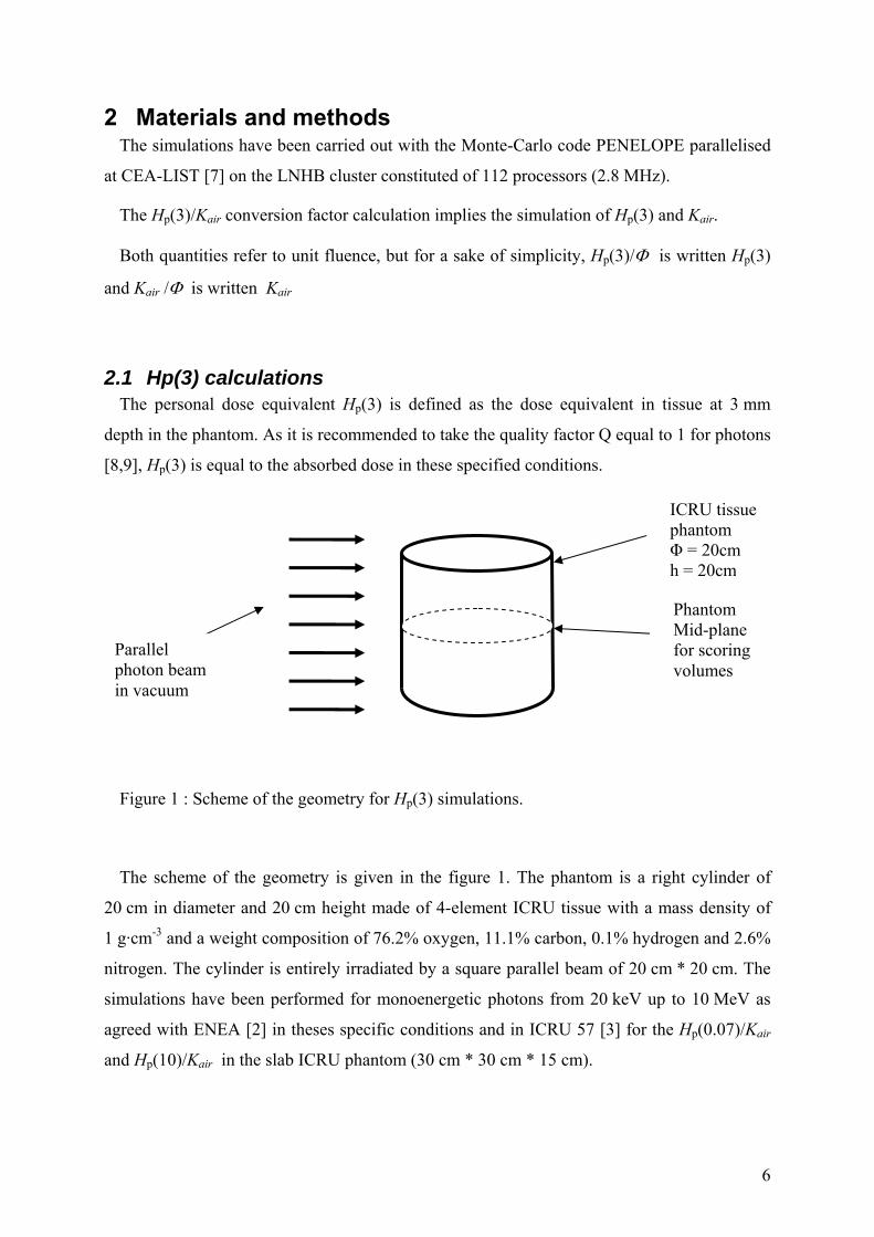
Figure 1 : Scheme of the geometry for Hp(3) simulations.
The scheme of the geometry is given in the figure 1. The phantom is a right cylinder of
20 cm in diameter and 20 cm height made of 4-element ICRU tissue with a mass density of
1 g·cm-3 and a weight composition of 76.2% oxygen, 11.1% carbon, 0.1% hydrogen and 2.6%
nitrogen. The cylinder is entirely irradiated by a square parallel beam of 20 cm * 20 cm. The
simulations have been performed for monoenergetic photons from 20 keV up to 10 MeV as
agreed with ENEA [2] in theses specific conditions and in ICRU 57 [3] for the Hp(0.07)/Kair
and Hp(10)/Kair in the slab ICRU phantom (30 cm * 30 cm * 15 cm).
6
Due to the cylindrical geometry, the angular coefficients have been calculated in the same
run. The scoring volumes have been positioned every 15 degrees.
The centers of the scoring volumes are positioned on the mid plane at the depth of 3 mm.
The thickness is 0.5 mm along the radius, the height is 5 cm and the angle 0.4 degree
(corresponding to a width of is 1 mm).
The output screen of the geometry defined in PENELOPE on the phantom mid plane is
given in figure 2.
The behaviour of the secondary particles electrons and positrons in PENELOPE, is
governed by the absorption energy parameters Eabs(1) and Eabs(3) respectively, which are
the energies where particles are assumed to be effectively stopped and absorbed in the
medium.
The interesting output value from PENELOPE is the average deposited energy in the
scoring volume. This quantity expressed in joule, divided by the mass corresponding to the
scoring volume expressed in kg leads to the kerma or absorbed dose depending on the
parameters used for the transport of the charged particles.
- If Eabs(1) and Eabs(3) are greater than the most energetic secondary particles, all the
energy transferred to the secondary charged particles is absorbed in the medium at the
point of interaction, matching the kerma definition. This represents the
kerma-approximation.
- If Eabs(1) and Eabs(3) are low, for example 1 or 10 keV, then the charged particles are
carefully followed until they stop which characterize the energy imparted to the to the
matter, corresponding to the absorbed dose definition.
Hp(3) has been calculated both way, in terms of kerma and in terms of absorbed dose.
The results are given in section 3.
7

volume elements thickness 0.5 mm width 1 mm height 5 cm
parallel extended beam
Figure 2 : Output screen of the geometry for Hp(3) simulations
2.2 Kair calculations The values of air kerma per unit fluence have been given in ICRU report 57 [3]. It can also
be calculated from the mass energy-transfer coefficient (µtr/ ρ)air determined from Hubbell
[10] by applying the following equation :
Kair / = E · (µtr / ρ)air
Nevertheless, for a better consistency of the ratio Hp(3)/Kair , calculations have been
performed with PENELOPE using the same set of cross sections. The parameters Eabs(1) and
Eabs(3) are greater than the most energetic secondary particles to match the kerma definition.
8
The results are given in section 3.
3 Results
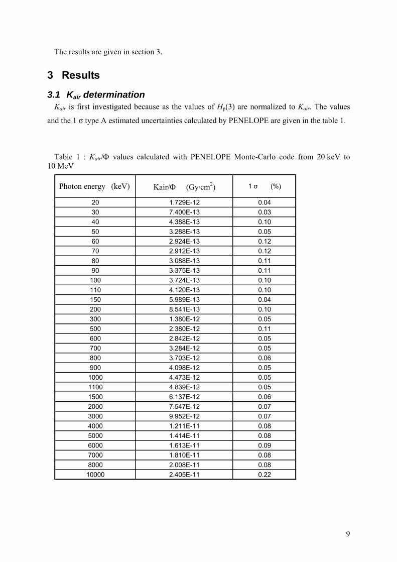
3.1 Kair determination Kair is first investigated because as the values of Hp(3) are normalized to Kair. The values
and the 1 σ type A estimated uncertainties calculated by PENELOPE are given in the table 1.
Table 1 : Kair/ values calculated with PENELOPE Monte-Carlo code from 20 keV to 10 MeV
Photon energy (keV) Kair/ (Gy·cm2) 1 σ (%)
20 1.729E-12 0.04
30 7.400E-13 0.03
40 4.388E-13 0.10
50 3.288E-13 0.05
60 2.924E-13 0.12
70 2.912E-13 0.12
80 3.088E-13 0.11
90 3.375E-13 0.11
100 3.724E-13 0.10
110 4.120E-13 0.10
150 5.989E-13 0.04
200 8.541E-13 0.10
300 1.380E-12 0.05
500 2.380E-12 0.11
600 2.842E-12 0.05
700 3.284E-12 0.05
800 3.703E-12 0.06
900 4.098E-12 0.05
1000 4.473E-12 0.05
1100 4.839E-12 0.05
1500 6.137E-12 0.06
2000 7.547E-12 0.07
3000 9.952E-12 0.07
4000 1.211E-11 0.08
5000 1.414E-11 0.08
6000 1.613E-11 0.09
7000 1.810E-11 0.08
8000 2.008E-11 0.08
10000 2.405E-11 0.22
9
These values are consistent with the ICRU 57 values, except at low energy (20 to 60 keV)
where the difference is between 1 and 2 %.
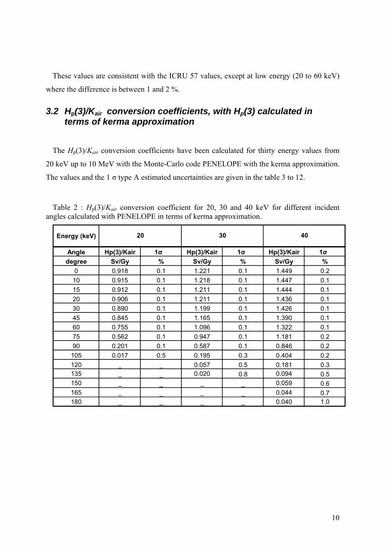
3.2 Hp(3)/Kair conversion coefficients, with Hp(3) calculated in terms of kerma approximation
The Hp(3)/Kair conversion coefficients have been calculated for thirty energy values from
20 keV up to 10 MeV with the Monte-Carlo code PENELOPE with the kerma approximation.
The values and the 1 σ type A estimated uncertainties are given in the table 3 to 12.
Table 2 : Hp(3)/Kair conversion coefficient for 20, 30 and 40 keV for different incident angles calculated with PENELOPE in terms of kerma approximation.
Energy (keV)
Angle Hp(3)/Kair 1σ Hp(3)/Kair 1σ Hp(3)/Kair 1σ
degree Sv/Gy % Sv/Gy % Sv/Gy %
0 0.918 0.1 1.221 0.1 1.449 0.2
10 0.915 0.1 1.218 0.1 1.447 0.1
15 0.912 0.1 1.211 0.1 1.444 0.1
20 0.906 0.1 1.211 0.1 1.436 0.1
30 0.890 0.1 1.199 0.1 1.426 0.1
45 0.845 0.1 1.165 0.1 1.390 0.1
60 0.755 0.1 1.096 0.1 1.322 0.1
75 0.562 0.1 0.947 0.1 1.181 0.2
90 0.201 0.1 0.587 0.1 0.846 0.2
105 0.017 0.5 0.195 0.3 0.404 0.2
120 _ _ 0.057 0.5 0.181 0.3135 _ _ 0.020 0.8 0.094 0.5150 _ _ _ _ 0.059 0.6165 _ _ _ _ 0.044 0.7180 _ _ _ _ 0.040 1.0
20 30 40
10
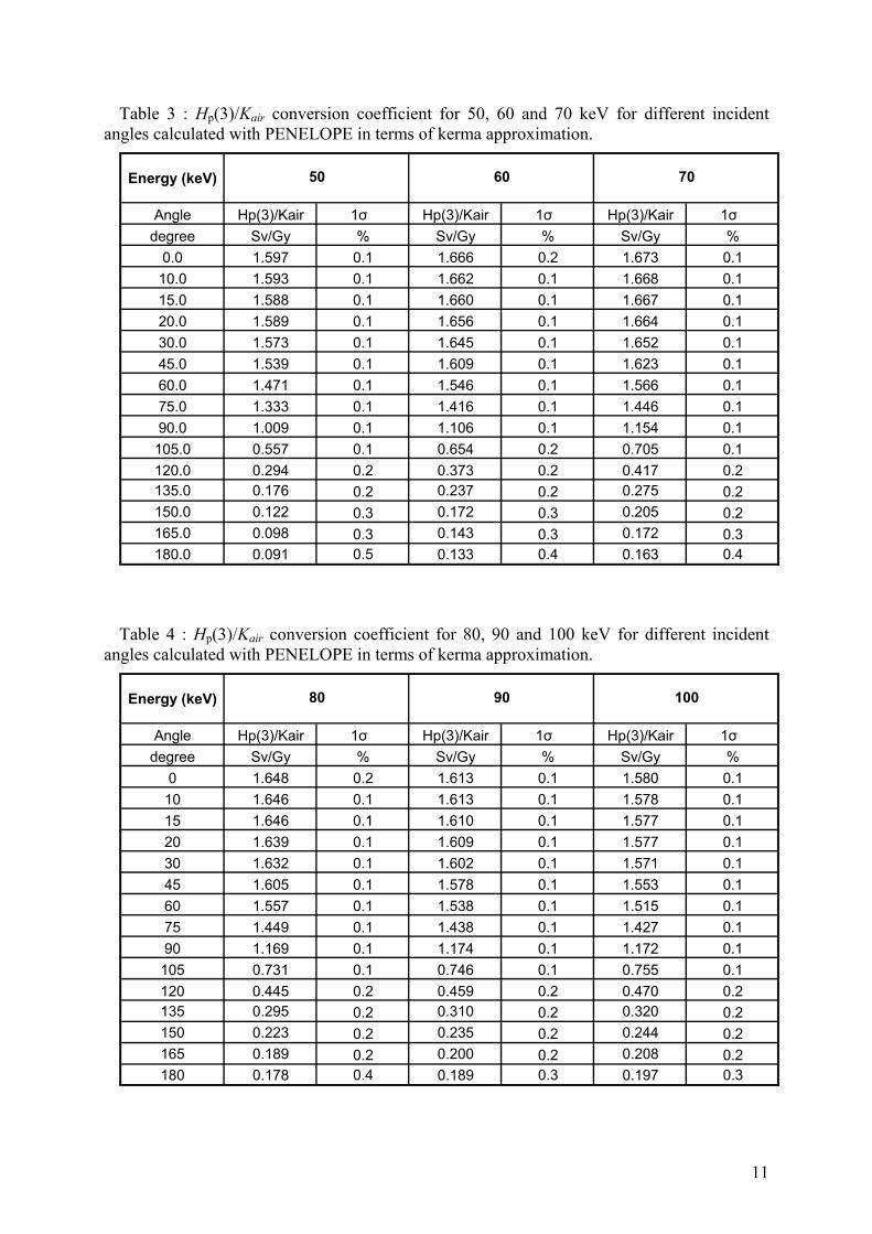
Table 3 : Hp(3)/Kair conversion coefficient for 50, 60 and 70 keV for different incident angles calculated with PENELOPE in terms of kerma approximation.
Energy (keV)
Angle Hp(3)/Kair 1σ Hp(3)/Kair 1σ Hp(3)/Kair 1σ
degree Sv/Gy % Sv/Gy % Sv/Gy %
0.0 1.597 0.1 1.666 0.2 1.673 0.1
10.0 1.593 0.1 1.662 0.1 1.668 0.1
15.0 1.588 0.1 1.660 0.1 1.667 0.1
20.0 1.589 0.1 1.656 0.1 1.664 0.1
30.0 1.573 0.1 1.645 0.1 1.652 0.1
45.0 1.539 0.1 1.609 0.1 1.623 0.1
60.0 1.471 0.1 1.546 0.1 1.566 0.1
75.0 1.333 0.1 1.416 0.1 1.446 0.1
90.0 1.009 0.1 1.106 0.1 1.154 0.1
105.0 0.557 0.1 0.654 0.2 0.705 0.1
120.0 0.294 0.2 0.373 0.2 0.417 0.2135.0 0.176 0.2 0.237 0.2 0.275 0.2150.0 0.122 0.3 0.172 0.3 0.205 0.2165.0 0.098 0.3 0.143 0.3 0.172 0.3180.0 0.091 0.5 0.133 0.4 0.163 0.4
50 60 70
Table 4 : Hp(3)/Kair conversion coefficient for 80, 90 and 100 keV for different incident angles calculated with PENELOPE in terms of kerma approximation.
Energy (keV)
Angle Hp(3)/Kair 1σ Hp(3)/Kair 1σ Hp(3)/Kair 1σ
degree Sv/Gy % Sv/Gy % Sv/Gy %
0 1.648 0.2 1.613 0.1 1.580 0.1
10 1.646 0.1 1.613 0.1 1.578 0.1
15 1.646 0.1 1.610 0.1 1.577 0.1
20 1.639 0.1 1.609 0.1 1.577 0.1
30 1.632 0.1 1.602 0.1 1.571 0.1
45 1.605 0.1 1.578 0.1 1.553 0.1
60 1.557 0.1 1.538 0.1 1.515 0.1
75 1.449 0.1 1.438 0.1 1.427 0.1
90 1.169 0.1 1.174 0.1 1.172 0.1
105 0.731 0.1 0.746 0.1 0.755 0.1
120 0.445 0.2 0.459 0.2 0.470 0.2135 0.295 0.2 0.310 0.2 0.320 0.2150 0.223 0.2 0.235 0.2 0.244 0.2165 0.189 0.2 0.200 0.2 0.208 0.2180 0.178 0.4 0.189 0.3 0.197 0.3
80 90 100
11
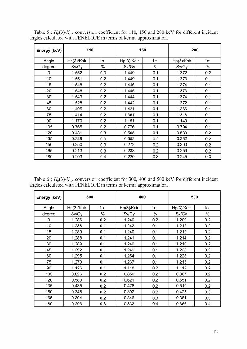
Table 5 : Hp(3)/Kair conversion coefficient for 110, 150 and 200 keV for different incident angles calculated with PENELOPE in terms of kerma approximation.
Energy (keV)
Angle Hp(3)/Kair 1σ Hp(3)/Kair 1σ Hp(3)/Kair 1σ
degree Sv/Gy % Sv/Gy % Sv/Gy %
0 1.552 0.3 1.449 0.1 1.372 0.2
10 1.551 0.2 1.449 0.1 1.373 0.1
15 1.548 0.2 1.446 0.1 1.374 0.1
20 1.546 0.2 1.445 0.1 1.373 0.1
30 1.543 0.2 1.444 0.1 1.374 0.1
45 1.528 0.2 1.442 0.1 1.372 0.1
60 1.495 0.2 1.421 0.1 1.366 0.1
75 1.414 0.2 1.361 0.1 1.318 0.1
90 1.170 0.2 1.151 0.1 1.140 0.1
105 0.765 0.2 0.776 0.1 0.794 0.1
120 0.481 0.3 0.505 0.1 0.533 0.2135 0.329 0.3 0.353 0.2 0.382 0.2150 0.250 0.3 0.272 0.2 0.300 0.2165 0.213 0.3 0.233 0.2 0.259 0.2180 0.203 0.4 0.220 0.3 0.245 0.3
110 150 200
Table 6 : Hp(3)/Kair conversion coefficient for 300, 400 and 500 keV for different incident angles calculated with PENELOPE in terms of kerma approximation.
Energy (keV)
Angle Hp(3)/Kair 1σ Hp(3)/Kair 1σ Hp(3)/Kair 1σ
degree Sv/Gy % Sv/Gy % Sv/Gy %
0 1.286 0.2 1.240 0.2 1.209 0.2
10 1.288 0.1 1.242 0.1 1.212 0.2
15 1.289 0.1 1.240 0.1 1.212 0.2
20 1.288 0.1 1.241 0.1 1.214 0.2
30 1.289 0.1 1.240 0.1 1.210 0.2
45 1.292 0.1 1.249 0.1 1.223 0.2
60 1.295 0.1 1.254 0.1 1.228 0.2
75 1.270 0.1 1.237 0.1 1.215 0.2
90 1.126 0.1 1.118 0.2 1.112 0.2
105 0.826 0.2 0.850 0.2 0.867 0.2
120 0.583 0.2 0.621 0.2 0.651 0.2135 0.435 0.2 0.476 0.2 0.510 0.2150 0.348 0.2 0.392 0.2 0.425 0.3165 0.304 0.2 0.346 0.3 0.381 0.3180 0.293 0.3 0.332 0.4 0.366 0.4
300 400 500
12
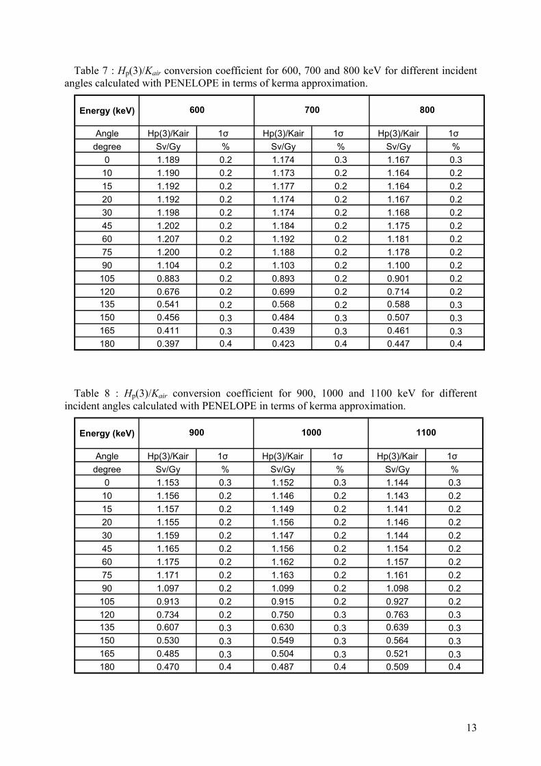
Table 7 : Hp(3)/Kair conversion coefficient for 600, 700 and 800 keV for different incident angles calculated with PENELOPE in terms of kerma approximation.
Energy (keV)
Angle Hp(3)/Kair 1σ Hp(3)/Kair 1σ Hp(3)/Kair 1σ
degree Sv/Gy % Sv/Gy % Sv/Gy %
0 1.189 0.2 1.174 0.3 1.167 0.3
10 1.190 0.2 1.173 0.2 1.164 0.2
15 1.192 0.2 1.177 0.2 1.164 0.2
20 1.192 0.2 1.174 0.2 1.167 0.2
30 1.198 0.2 1.174 0.2 1.168 0.2
45 1.202 0.2 1.184 0.2 1.175 0.2
60 1.207 0.2 1.192 0.2 1.181 0.2
75 1.200 0.2 1.188 0.2 1.178 0.2
90 1.104 0.2 1.103 0.2 1.100 0.2
105 0.883 0.2 0.893 0.2 0.901 0.2
120 0.676 0.2 0.699 0.2 0.714 0.2135 0.541 0.2 0.568 0.2 0.588 0.3150 0.456 0.3 0.484 0.3 0.507 0.3165 0.411 0.3 0.439 0.3 0.461 0.3180 0.397 0.4 0.423 0.4 0.447 0.4
700 800600
Table 8 : Hp(3)/Kair conversion coefficient for 900, 1000 and 1100 keV for different incident angles calculated with PENELOPE in terms of kerma approximation.
Energy (keV)
Angle Hp(3)/Kair 1σ Hp(3)/Kair 1σ Hp(3)/Kair 1σ
degree Sv/Gy % Sv/Gy % Sv/Gy %
0 1.153 0.3 1.152 0.3 1.144 0.3
10 1.156 0.2 1.146 0.2 1.143 0.2
15 1.157 0.2 1.149 0.2 1.141 0.2
20 1.155 0.2 1.156 0.2 1.146 0.2
30 1.159 0.2 1.147 0.2 1.144 0.2
45 1.165 0.2 1.156 0.2 1.154 0.2
60 1.175 0.2 1.162 0.2 1.157 0.2
75 1.171 0.2 1.163 0.2 1.161 0.2
90 1.097 0.2 1.099 0.2 1.098 0.2
105 0.913 0.2 0.915 0.2 0.927 0.2
120 0.734 0.2 0.750 0.3 0.763 0.3135 0.607 0.3 0.630 0.3 0.639 0.3150 0.530 0.3 0.549 0.3 0.564 0.3165 0.485 0.3 0.504 0.3 0.521 0.3180 0.470 0.4 0.487 0.4 0.509 0.4
900 1000 1100
13
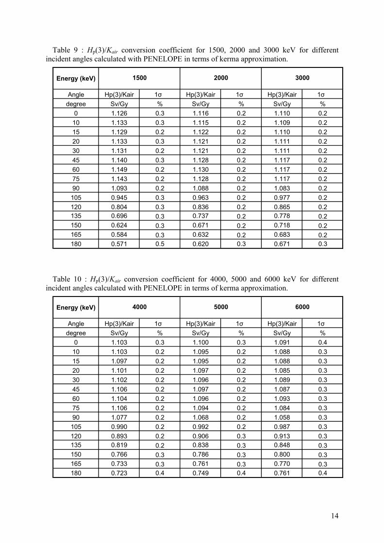
Table 9 : Hp(3)/Kair conversion coefficient for 1500, 2000 and 3000 keV for different incident angles calculated with PENELOPE in terms of kerma approximation.
Energy (keV)
Angle Hp(3)/Kair 1σ Hp(3)/Kair 1σ Hp(3)/Kair 1σ
degree Sv/Gy % Sv/Gy % Sv/Gy %
0 1.126 0.3 1.116 0.2 1.110 0.2
10 1.133 0.3 1.115 0.2 1.109 0.2
15 1.129 0.2 1.122 0.2 1.110 0.2
20 1.133 0.3 1.121 0.2 1.111 0.2
30 1.131 0.2 1.121 0.2 1.111 0.2
45 1.140 0.3 1.128 0.2 1.117 0.2
60 1.149 0.2 1.130 0.2 1.117 0.2
75 1.143 0.2 1.128 0.2 1.117 0.2
90 1.093 0.2 1.088 0.2 1.083 0.2
105 0.945 0.3 0.963 0.2 0.977 0.2
120 0.804 0.3 0.836 0.2 0.865 0.2135 0.696 0.3 0.737 0.2 0.778 0.2150 0.624 0.3 0.671 0.2 0.718 0.2165 0.584 0.3 0.632 0.2 0.683 0.2180 0.571 0.5 0.620 0.3 0.671 0.3
1500 2000 3000
Table 10 : Hp(3)/Kair conversion coefficient for 4000, 5000 and 6000 keV for different incident angles calculated with PENELOPE in terms of kerma approximation.
Energy (keV)
Angle Hp(3)/Kair 1σ Hp(3)/Kair 1σ Hp(3)/Kair 1σ
degree Sv/Gy % Sv/Gy % Sv/Gy %
0 1.103 0.3 1.100 0.3 1.091 0.4
10 1.103 0.2 1.095 0.2 1.088 0.3
15 1.097 0.2 1.095 0.2 1.088 0.3
20 1.101 0.2 1.097 0.2 1.085 0.3
30 1.102 0.2 1.096 0.2 1.089 0.3
45 1.106 0.2 1.097 0.2 1.087 0.3
60 1.104 0.2 1.096 0.2 1.093 0.3
75 1.106 0.2 1.094 0.2 1.084 0.3
90 1.077 0.2 1.068 0.2 1.058 0.3
105 0.990 0.2 0.992 0.2 0.987 0.3
120 0.893 0.2 0.906 0.3 0.913 0.3135 0.819 0.2 0.838 0.3 0.848 0.3150 0.766 0.3 0.786 0.3 0.800 0.3165 0.733 0.3 0.761 0.3 0.770 0.3180 0.723 0.4 0.749 0.4 0.761 0.4
4000 5000 6000
14
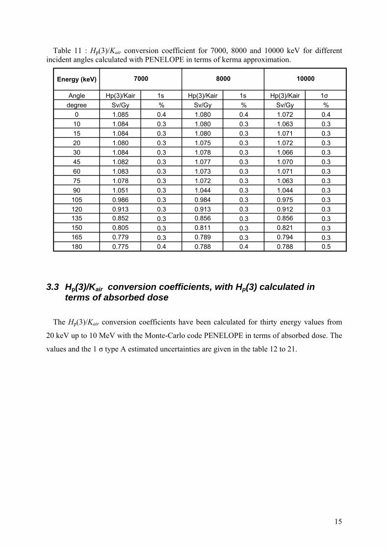
Table 11 : Hp(3)/Kair conversion coefficient for 7000, 8000 and 10000 keV for different incident angles calculated with PENELOPE in terms of kerma approximation.
Energy (keV)
Angle Hp(3)/Kair 1s Hp(3)/Kair 1s Hp(3)/Kair 1σ
degree Sv/Gy % Sv/Gy % Sv/Gy %
0 1.085 0.4 1.080 0.4 1.072 0.4
10 1.084 0.3 1.080 0.3 1.063 0.3
15 1.084 0.3 1.080 0.3 1.071 0.3
20 1.080 0.3 1.075 0.3 1.072 0.3
30 1.084 0.3 1.078 0.3 1.066 0.3
45 1.082 0.3 1.077 0.3 1.070 0.3
60 1.083 0.3 1.073 0.3 1.071 0.3
75 1.078 0.3 1.072 0.3 1.063 0.3
90 1.051 0.3 1.044 0.3 1.044 0.3
105 0.986 0.3 0.984 0.3 0.975 0.3
120 0.913 0.3 0.913 0.3 0.912 0.3135 0.852 0.3 0.856 0.3 0.856 0.3150 0.805 0.3 0.811 0.3 0.821 0.3165 0.779 0.3 0.789 0.3 0.794 0.3180 0.775 0.4 0.788 0.4 0.788 0.5
8000 100007000
3.3 Hp(3)/Kair conversion coefficients, with Hp(3) calculated in terms of absorbed dose
The Hp(3)/Kair conversion coefficients have been calculated for thirty energy values from
20 keV up to 10 MeV with the Monte-Carlo code PENELOPE in terms of absorbed dose. The
values and the 1 σ type A estimated uncertainties are given in the table 12 to 21.
15
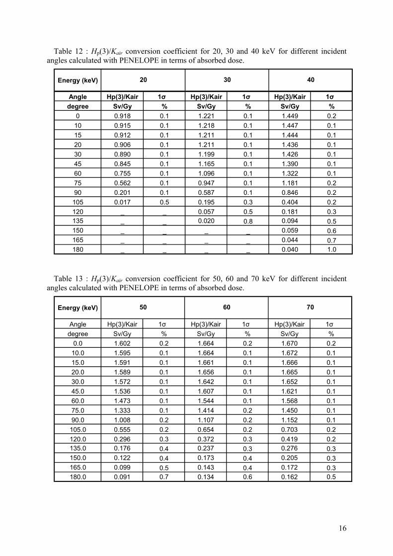
Table 12 : Hp(3)/Kair conversion coefficient for 20, 30 and 40 keV for different incident angles calculated with PENELOPE in terms of absorbed dose.
Energy (keV)
Angle Hp(3)/Kair 1σ Hp(3)/Kair 1σ Hp(3)/Kair 1σ
degree Sv/Gy % Sv/Gy % Sv/Gy %
0 0.918 0.1 1.221 0.1 1.449 0.2
10 0.915 0.1 1.218 0.1 1.447 0.1
15 0.912 0.1 1.211 0.1 1.444 0.1
20 0.906 0.1 1.211 0.1 1.436 0.1
30 0.890 0.1 1.199 0.1 1.426 0.1
45 0.845 0.1 1.165 0.1 1.390 0.1
60 0.755 0.1 1.096 0.1 1.322 0.1
75 0.562 0.1 0.947 0.1 1.181 0.2
90 0.201 0.1 0.587 0.1 0.846 0.2
105 0.017 0.5 0.195 0.3 0.404 0.2
120 _ _ 0.057 0.5 0.181 0.3135 _ _ 0.020 0.8 0.094 0.5150 _ _ _ _ 0.059 0.6165 _ _ _ _ 0.044 0.7180 _ _ _ _ 0.040 1.0
20 30 40
Table 13 : Hp(3)/Kair conversion coefficient for 50, 60 and 70 keV for different incident angles calculated with PENELOPE in terms of absorbed dose.
Energy (keV)
Angle Hp(3)/Kair 1σ Hp(3)/Kair 1σ Hp(3)/Kair 1σ
degree Sv/Gy % Sv/Gy % Sv/Gy %
0.0 1.602 0.2 1.664 0.2 1.670 0.2
10.0 1.595 0.1 1.664 0.1 1.672 0.1
15.0 1.591 0.1 1.661 0.1 1.666 0.1
20.0 1.589 0.1 1.656 0.1 1.665 0.1
30.0 1.572 0.1 1.642 0.1 1.652 0.1
45.0 1.536 0.1 1.607 0.1 1.621 0.1
60.0 1.473 0.1 1.544 0.1 1.568 0.1
75.0 1.333 0.1 1.414 0.2 1.450 0.1
90.0 1.008 0.2 1.107 0.2 1.152 0.1
105.0 0.555 0.2 0.654 0.2 0.703 0.2
120.0 0.296 0.3 0.372 0.3 0.419 0.2135.0 0.176 0.4 0.237 0.3 0.276 0.3150.0 0.122 0.4 0.173 0.4 0.205 0.3165.0 0.099 0.5 0.143 0.4 0.172 0.3180.0 0.091 0.7 0.134 0.6 0.162 0.5
50 60 70
16
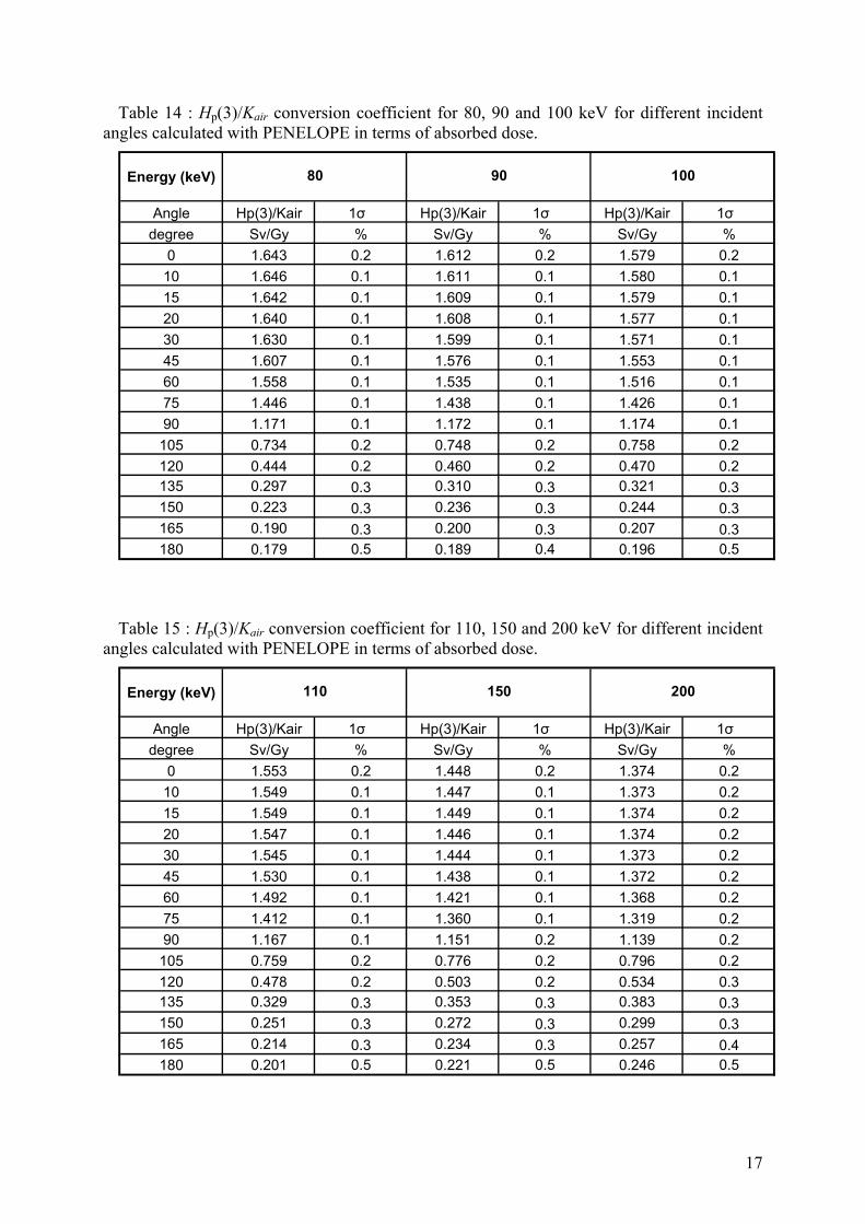
Table 14 : Hp(3)/Kair conversion coefficient for 80, 90 and 100 keV for different incident angles calculated with PENELOPE in terms of absorbed dose.
Energy (keV)
Angle Hp(3)/Kair 1σ Hp(3)/Kair 1σ Hp(3)/Kair 1σ
degree Sv/Gy % Sv/Gy % Sv/Gy %
0 1.643 0.2 1.612 0.2 1.579 0.2
10 1.646 0.1 1.611 0.1 1.580 0.1
15 1.642 0.1 1.609 0.1 1.579 0.1
20 1.640 0.1 1.608 0.1 1.577 0.1
30 1.630 0.1 1.599 0.1 1.571 0.1
45 1.607 0.1 1.576 0.1 1.553 0.1
60 1.558 0.1 1.535 0.1 1.516 0.1
75 1.446 0.1 1.438 0.1 1.426 0.1
90 1.171 0.1 1.172 0.1 1.174 0.1
105 0.734 0.2 0.748 0.2 0.758 0.2
120 0.444 0.2 0.460 0.2 0.470 0.2135 0.297 0.3 0.310 0.3 0.321 0.3150 0.223 0.3 0.236 0.3 0.244 0.3165 0.190 0.3 0.200 0.3 0.207 0.3180 0.179 0.5 0.189 0.4 0.196 0.5
80 90 100
Table 15 : Hp(3)/Kair conversion coefficient for 110, 150 and 200 keV for different incident angles calculated with PENELOPE in terms of absorbed dose.
Energy (keV)
Angle Hp(3)/Kair 1σ Hp(3)/Kair 1σ Hp(3)/Kair 1σ
degree Sv/Gy % Sv/Gy % Sv/Gy %
0 1.553 0.2 1.448 0.2 1.374 0.2
10 1.549 0.1 1.447 0.1 1.373 0.2
15 1.549 0.1 1.449 0.1 1.374 0.2
20 1.547 0.1 1.446 0.1 1.374 0.2
30 1.545 0.1 1.444 0.1 1.373 0.2
45 1.530 0.1 1.438 0.1 1.372 0.2
60 1.492 0.1 1.421 0.1 1.368 0.2
75 1.412 0.1 1.360 0.1 1.319 0.2
90 1.167 0.1 1.151 0.2 1.139 0.2
105 0.759 0.2 0.776 0.2 0.796 0.2
120 0.478 0.2 0.503 0.2 0.534 0.3135 0.329 0.3 0.353 0.3 0.383 0.3150 0.251 0.3 0.272 0.3 0.299 0.3165 0.214 0.3 0.234 0.3 0.257 0.4180 0.201 0.5 0.221 0.5 0.246 0.5
110 150 200
17
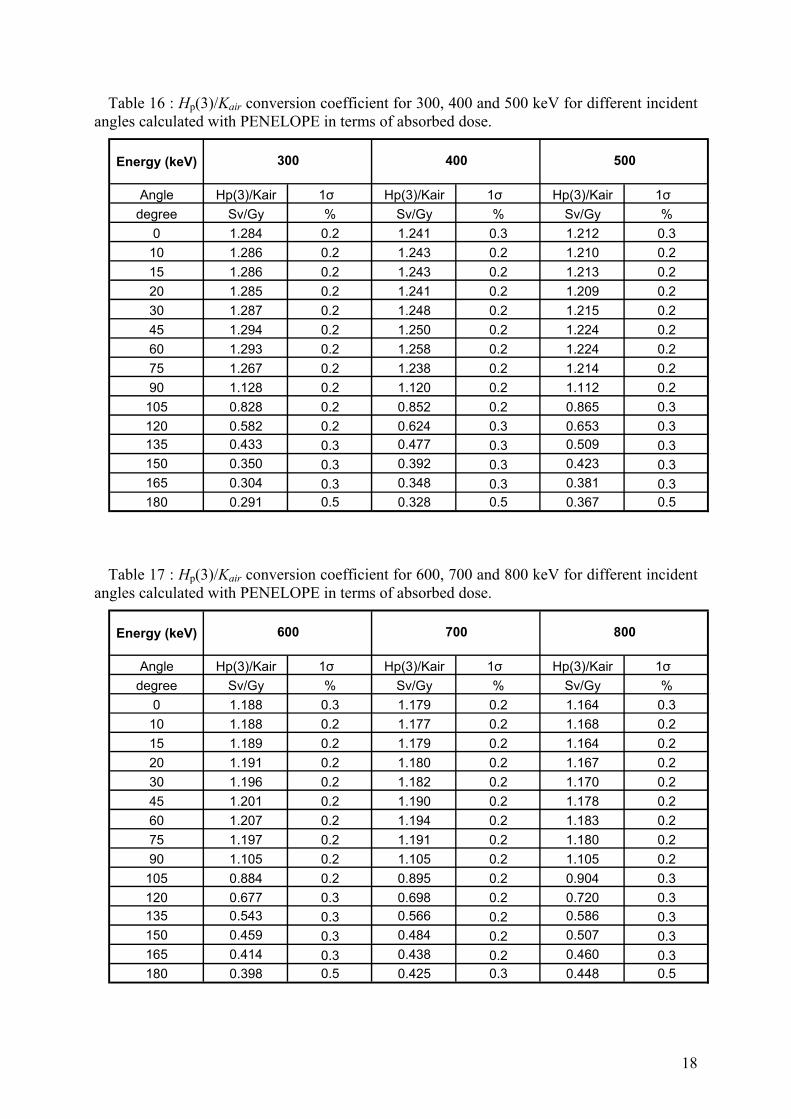
Table 16 : Hp(3)/Kair conversion coefficient for 300, 400 and 500 keV for different incident angles calculated with PENELOPE in terms of absorbed dose.
Energy (keV)
Angle Hp(3)/Kair 1σ Hp(3)/Kair 1σ Hp(3)/Kair 1σ
degree Sv/Gy % Sv/Gy % Sv/Gy %
0 1.284 0.2 1.241 0.3 1.212 0.3
10 1.286 0.2 1.243 0.2 1.210 0.2
15 1.286 0.2 1.243 0.2 1.213 0.2
20 1.285 0.2 1.241 0.2 1.209 0.2
30 1.287 0.2 1.248 0.2 1.215 0.2
45 1.294 0.2 1.250 0.2 1.224 0.2
60 1.293 0.2 1.258 0.2 1.224 0.2
75 1.267 0.2 1.238 0.2 1.214 0.2
90 1.128 0.2 1.120 0.2 1.112 0.2
105 0.828 0.2 0.852 0.2 0.865 0.3
120 0.582 0.2 0.624 0.3 0.653 0.3135 0.433 0.3 0.477 0.3 0.509 0.3150 0.350 0.3 0.392 0.3 0.423 0.3165 0.304 0.3 0.348 0.3 0.381 0.3180 0.291 0.5 0.328 0.5 0.367 0.5
300 400 500
Table 17 : Hp(3)/Kair conversion coefficient for 600, 700 and 800 keV for different incident angles calculated with PENELOPE in terms of absorbed dose.
Energy (keV)
Angle Hp(3)/Kair 1σ Hp(3)/Kair 1σ Hp(3)/Kair 1σ
degree Sv/Gy % Sv/Gy % Sv/Gy %
0 1.188 0.3 1.179 0.2 1.164 0.3
10 1.188 0.2 1.177 0.2 1.168 0.2
15 1.189 0.2 1.179 0.2 1.164 0.2
20 1.191 0.2 1.180 0.2 1.167 0.2
30 1.196 0.2 1.182 0.2 1.170 0.2
45 1.201 0.2 1.190 0.2 1.178 0.2
60 1.207 0.2 1.194 0.2 1.183 0.2
75 1.197 0.2 1.191 0.2 1.180 0.2
90 1.105 0.2 1.105 0.2 1.105 0.2
105 0.884 0.2 0.895 0.2 0.904 0.3
120 0.677 0.3 0.698 0.2 0.720 0.3135 0.543 0.3 0.566 0.2 0.586 0.3150 0.459 0.3 0.484 0.2 0.507 0.3165 0.414 0.3 0.438 0.2 0.460 0.3180 0.398 0.5 0.425 0.3 0.448 0.5
700 800600
18
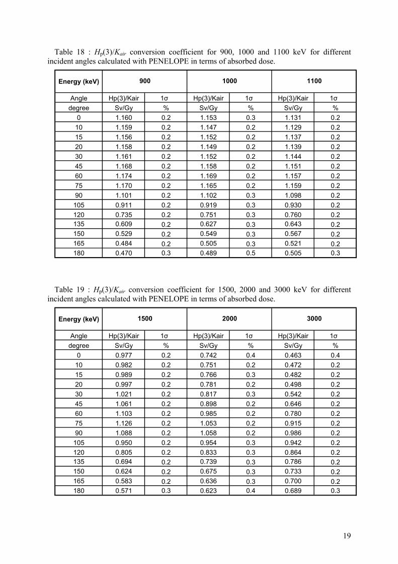
Table 18 : Hp(3)/Kair conversion coefficient for 900, 1000 and 1100 keV for different incident angles calculated with PENELOPE in terms of absorbed dose.
Energy (keV)
Angle Hp(3)/Kair 1σ Hp(3)/Kair 1σ Hp(3)/Kair 1σ
degree Sv/Gy % Sv/Gy % Sv/Gy %
0 1.160 0.2 1.153 0.3 1.131 0.2
10 1.159 0.2 1.147 0.2 1.129 0.2
15 1.156 0.2 1.152 0.2 1.137 0.2
20 1.158 0.2 1.149 0.2 1.139 0.2
30 1.161 0.2 1.152 0.2 1.144 0.2
45 1.168 0.2 1.158 0.2 1.151 0.2
60 1.174 0.2 1.169 0.2 1.157 0.2
75 1.170 0.2 1.165 0.2 1.159 0.2
90 1.101 0.2 1.102 0.3 1.098 0.2
105 0.911 0.2 0.919 0.3 0.930 0.2
120 0.735 0.2 0.751 0.3 0.760 0.2135 0.609 0.2 0.627 0.3 0.643 0.2150 0.529 0.2 0.549 0.3 0.567 0.2165 0.484 0.2 0.505 0.3 0.521 0.2180 0.470 0.3 0.489 0.5 0.505 0.3
900 1000 1100
Table 19 : Hp(3)/Kair conversion coefficient for 1500, 2000 and 3000 keV for different incident angles calculated with PENELOPE in terms of absorbed dose.
Energy (keV)
Angle Hp(3)/Kair 1σ Hp(3)/Kair 1σ Hp(3)/Kair 1σ
degree Sv/Gy % Sv/Gy % Sv/Gy %
0 0.977 0.2 0.742 0.4 0.463 0.4
10 0.982 0.2 0.751 0.2 0.472 0.2
15 0.989 0.2 0.766 0.3 0.482 0.2
20 0.997 0.2 0.781 0.2 0.498 0.2
30 1.021 0.2 0.817 0.3 0.542 0.2
45 1.061 0.2 0.898 0.2 0.646 0.2
60 1.103 0.2 0.985 0.2 0.780 0.2
75 1.126 0.2 1.053 0.2 0.915 0.2
90 1.088 0.2 1.058 0.2 0.986 0.2
105 0.950 0.2 0.954 0.3 0.942 0.2
120 0.805 0.2 0.833 0.3 0.864 0.2135 0.694 0.2 0.739 0.3 0.786 0.2150 0.624 0.2 0.675 0.3 0.733 0.2165 0.583 0.2 0.636 0.3 0.700 0.2180 0.571 0.3 0.623 0.4 0.689 0.3
1500 2000 3000
19
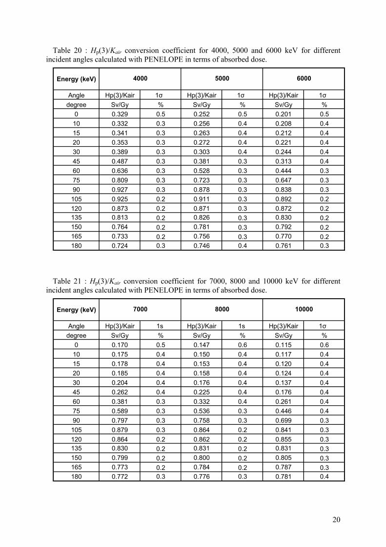
Table 20 : Hp(3)/Kair conversion coefficient for 4000, 5000 and 6000 keV for different incident angles calculated with PENELOPE in terms of absorbed dose.
Energy (keV)
Angle Hp(3)/Kair 1σ Hp(3)/Kair 1σ Hp(3)/Kair 1σ
degree Sv/Gy % Sv/Gy % Sv/Gy %
0 0.329 0.5 0.252 0.5 0.201 0.5
10 0.332 0.3 0.256 0.4 0.208 0.4
15 0.341 0.3 0.263 0.4 0.212 0.4
20 0.353 0.3 0.272 0.4 0.221 0.4
30 0.389 0.3 0.303 0.4 0.244 0.4
45 0.487 0.3 0.381 0.3 0.313 0.4
60 0.636 0.3 0.528 0.3 0.444 0.3
75 0.809 0.3 0.723 0.3 0.647 0.3
90 0.927 0.3 0.878 0.3 0.838 0.3
105 0.925 0.2 0.911 0.3 0.892 0.2
120 0.873 0.2 0.871 0.3 0.872 0.2135 0.813 0.2 0.826 0.3 0.830 0.2150 0.764 0.2 0.781 0.3 0.792 0.2165 0.733 0.2 0.756 0.3 0.770 0.2180 0.724 0.3 0.746 0.4 0.761 0.3
4000 5000 6000
Table 21 : Hp(3)/Kair conversion coefficient for 7000, 8000 and 10000 keV for different incident angles calculated with PENELOPE in terms of absorbed dose.
Energy (keV)
Angle Hp(3)/Kair 1s Hp(3)/Kair 1s Hp(3)/Kair 1σ
degree Sv/Gy % Sv/Gy % Sv/Gy %
0 0.170 0.5 0.147 0.6 0.115 0.6
10 0.175 0.4 0.150 0.4 0.117 0.4
15 0.178 0.4 0.153 0.4 0.120 0.4
20 0.185 0.4 0.158 0.4 0.124 0.4
30 0.204 0.4 0.176 0.4 0.137 0.4
45 0.262 0.4 0.225 0.4 0.176 0.4
60 0.381 0.3 0.332 0.4 0.261 0.4
75 0.589 0.3 0.536 0.3 0.446 0.4
90 0.797 0.3 0.758 0.3 0.699 0.3
105 0.879 0.3 0.864 0.2 0.841 0.3
120 0.864 0.2 0.862 0.2 0.855 0.3135 0.830 0.2 0.831 0.2 0.831 0.3150 0.799 0.2 0.800 0.2 0.805 0.3165 0.773 0.2 0.784 0.2 0.787 0.3180 0.772 0.3 0.776 0.3 0.781 0.4
8000 100007000
20
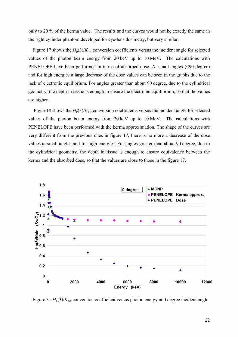
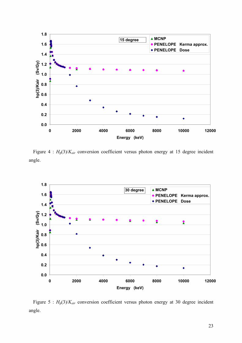
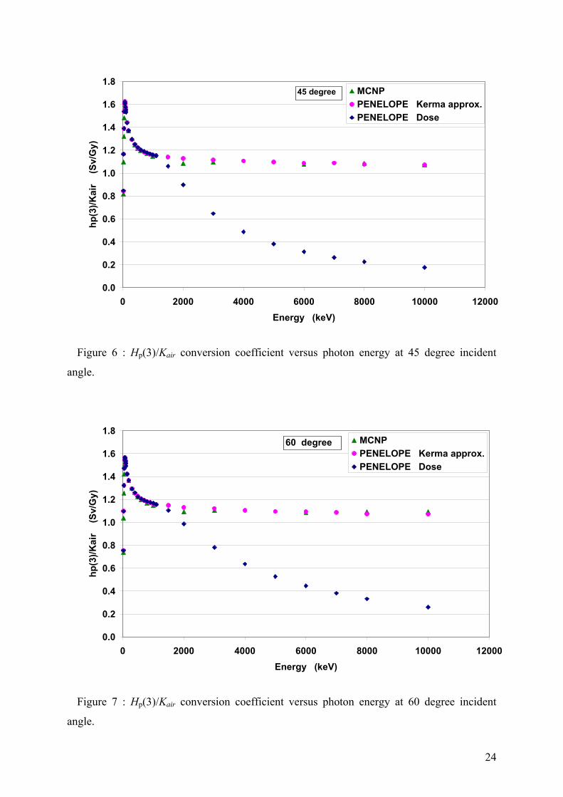
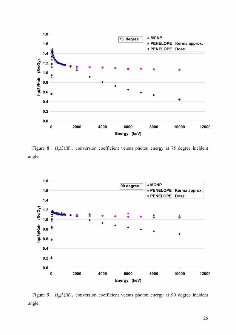
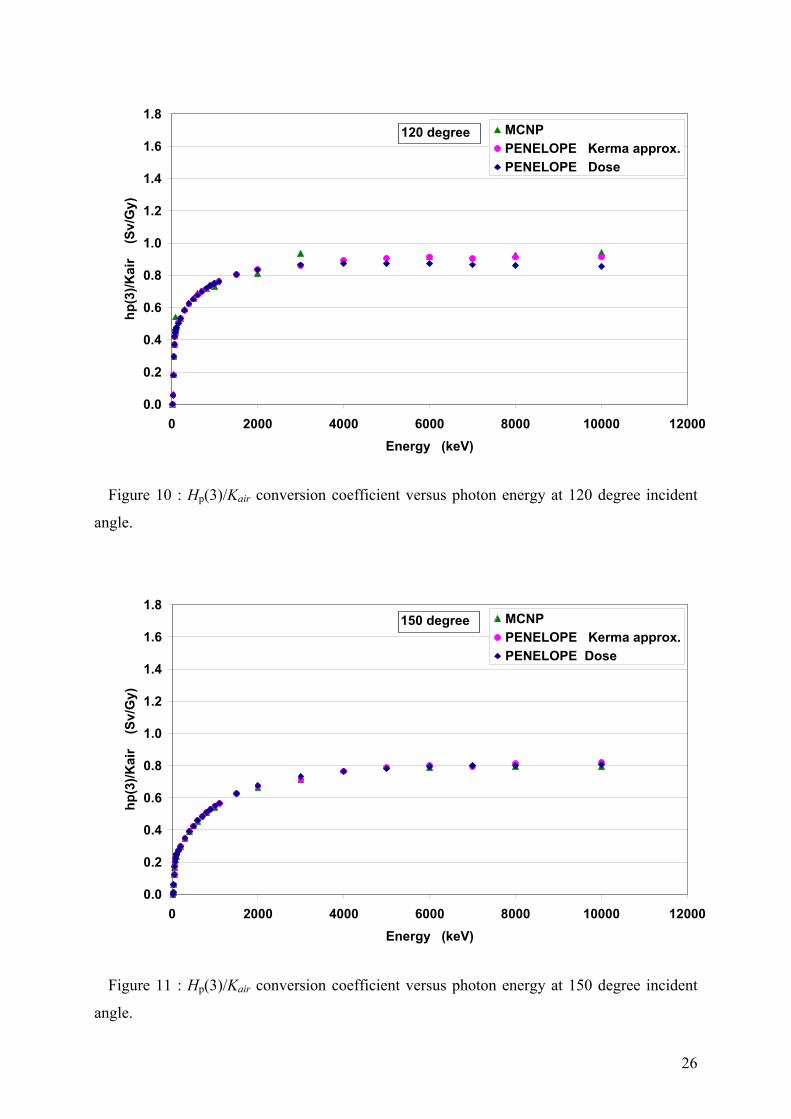
4 Discussions In order to illustrate the discussion, some of the Hp(3)/Kair conversion coefficients versus
photon energy are represented in the figures 3 to 12 for 0 to 180 degree incident angles. It is
to be noted that the errors bars are not visible on the graphs, being hidden by the size of the
representative points. The green triangles represent the calculations performed by ENEA with
the Monte-Carlo code MCNP [2]. The pink spots represent the values calculated in this work
with the Monte-Carlo code PENELOPE [6] with the kerma approximation considering that
the energy transferred by the photons to the secondary electrons is deposited at the point of
interaction without the simulation of the transport of electrons through the medium. The blue
diamond-shaped points represent the values calculated in this work with PENELOPE taking
into account the simulation of the electron transport through the medium for the determination
of Hp(3), meaning that absorbed dose is determined.
In all conditions, the MCNP values (F6 tally specification card, which correspond to a
kerma estimation, must have been used) agree with the values calculated with PENELOPE in
the kerma approximation mode.
Nevertheless, above 1 MeV, the discrepancy between kerma approximation and absorbed
dose values increase with the photon energy. This difference is drastic at small incident angles
and decreases significantly from 90 degree to 180 degree.
This difference at high energy is due to the lack of electronic equilibrium at depths lower
than the range of electrons in the medium. As the representative point of the lens is situated at
the small depth of 3 mm, this effect is perceptible from 1 MeV, and increases with the photon
energy as the electron range enlarges.
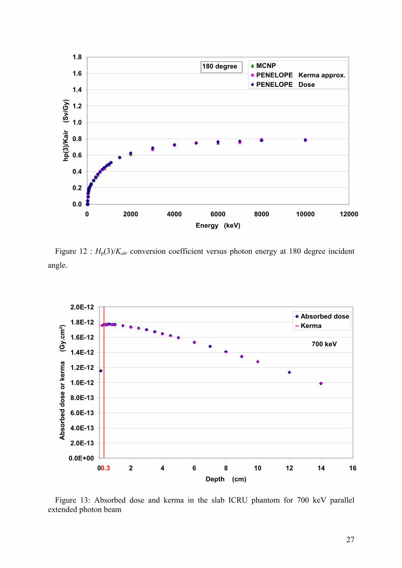
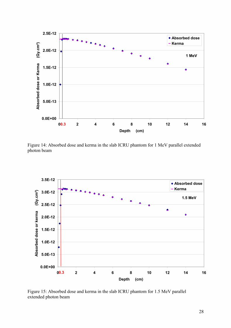
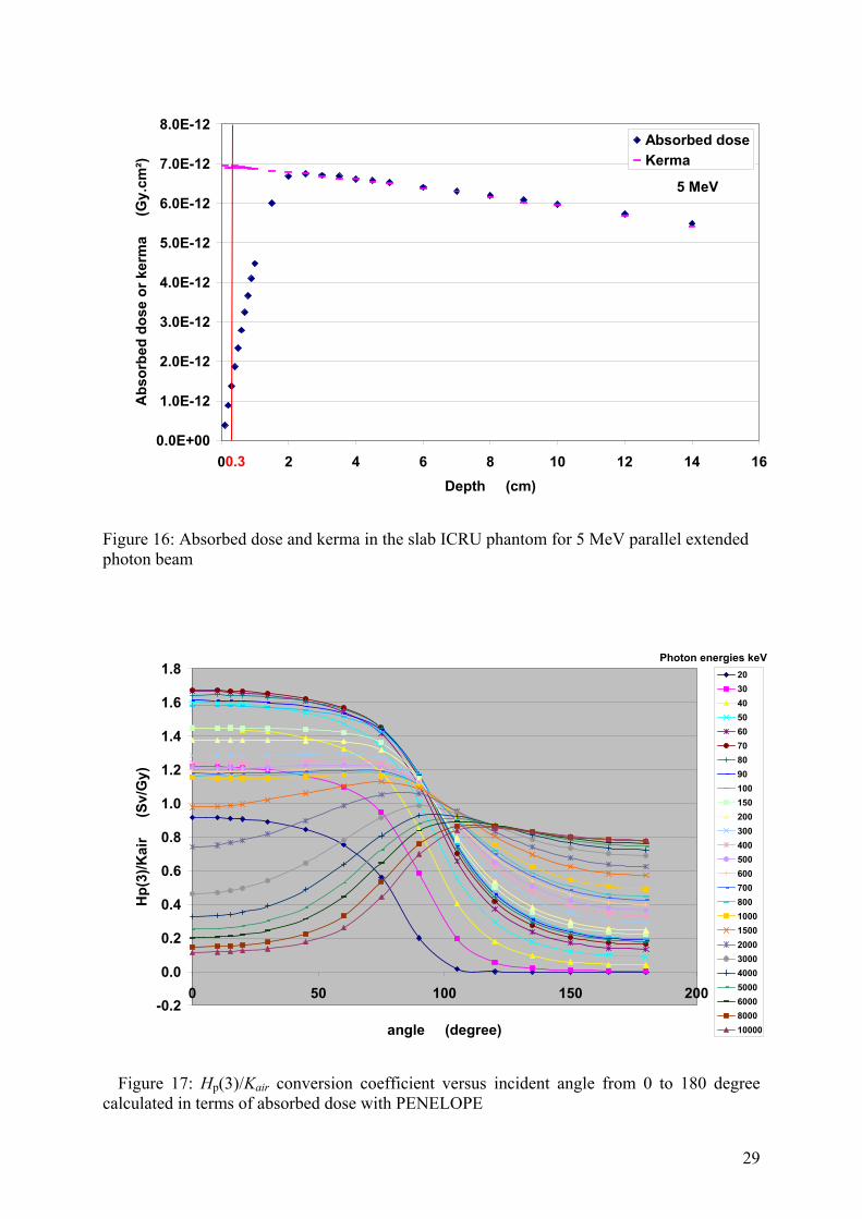
For a better understanding of this behavior, calculation have been performed in the ICRU
slab phantom (30 cm · 30 cm · 15 cm made of 4-element ICRU tissue). Both Absorbed dose
and kerma in tissue have been calculated against the depth for 700 keV, 1 MeV, 1.5 MeV and
5 MeV photon energies at several depth in this phantom. The results are summarized in the
figures 13 to 16. At the energy of 700 keV the only noticeable difference occurs at the depth
of 1 mm. At 3 mm depth, no difference appears between absorbed dose and kerma. At the
energy of 1 MeV, there is a very small difference between absorbed dose and kerma values at
the depth of 3 mm. For 1.5 MeV, at the depth of 3 mm, the absorbed dose value is only about
70 % of the kerma value. At the same depth, for 5 MeV, the absorbed dose value correspond
21
only to 20 % of the kerma value. The results and the curves would not be exactly the same in
the right cylinder phantom developed for eye-lens dosimetry, but very similar.
Figure 17 shows the Hp(3)/Kair conversion coefficients versus the incident angle for selected
values of the photon beam energy from 20 keV up to 10 MeV. The calculations with
PENELOPE have been performed in terms of absorbed dose. At small angles (<90 degree)
and for high energies a large decrease of the dose values can be seen in the graphs due to the
lack of electronic equilibrium. For angles greater than about 90 degree, due to the cylindrical
geometry, the depth in tissue is enough to ensure the electronic equilibrium, so that the values
are higher.
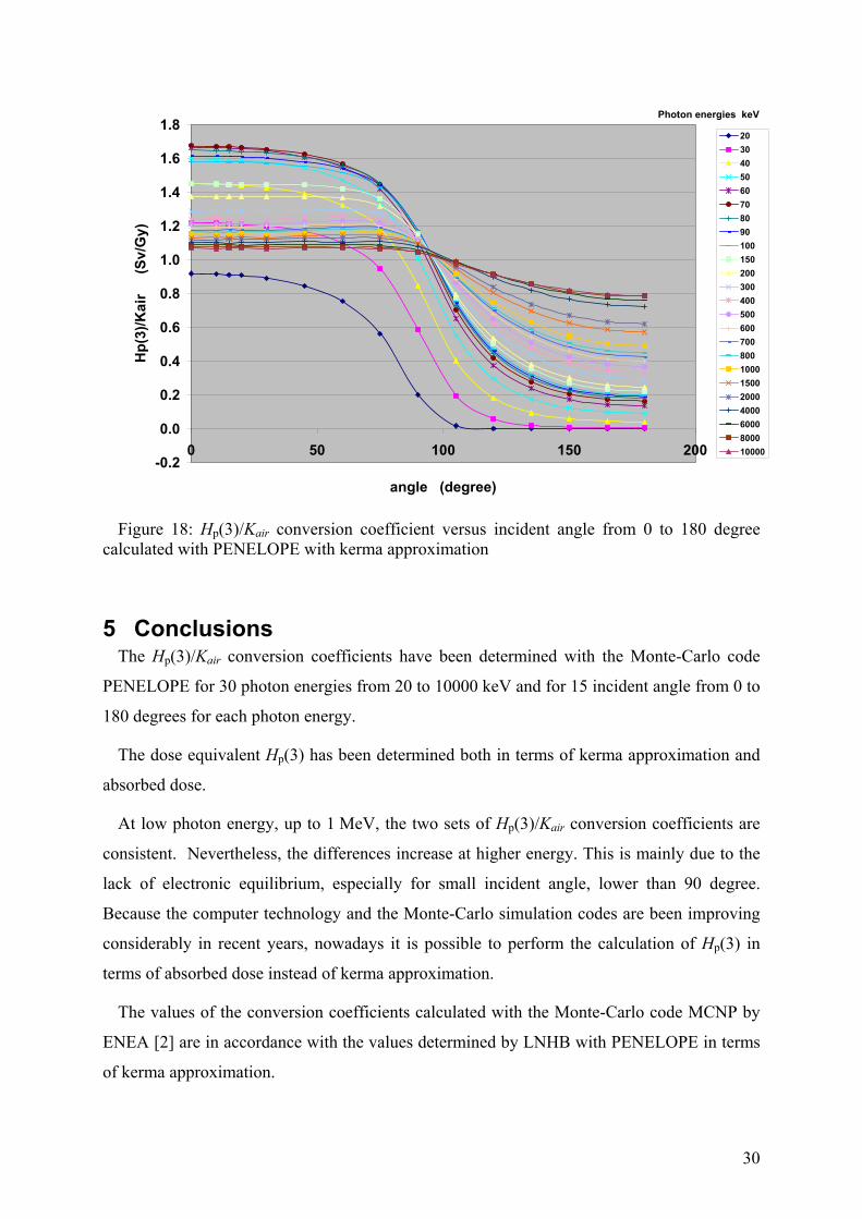
Figure18 shows the Hp(3)/Kair conversion coefficients versus the incident angle for selected
values of the photon beam energy from 20 keV up to 10 MeV. The calculations with
PENELOPE have been performed with the kerma approximation. The shape of the curves are
very different from the previous ones in figure 17, there is no more a decrease of the dose
values at small angles and for high energies. For angles greater than about 90 degree, due to
the cylindrical geometry, the depth in tissue is enough to ensure equivalence between the
kerma and the absorbed dose, so that the values are close to those in the figure 17.
0
0.2
0.4
0.6
0.8
1
1.2
1.4
1.6
1.8
0 2000 4000 6000 8000 10000 12000Energy (keV)
hp
(3)/
Kai
r
(Sv/
Gy)
MCNP
PENELOPE Kerma approx.
PENELOPE Dose
0 degree
Figure 3 : Hp(3)/Kair conversion coefficient versus photon energy at 0 degree incident angle.
22
0.0
0.2
0.4
0.6
0.8
1.0
1.2
1.4
1.6
1.8
0 2000 4000 6000 8000 10000 12000
Energy (keV)
hp
(3)/
Kai
r
(Sv/
Gy)
MCNP
PENELOPE Kerma approx.
PENELOPE Dose
15 degree
Figure 4 : Hp(3)/Kair conversion coefficient versus photon energy at 15 degree incident
angle.
0.0
0.2
0.4
0.6
0.8
1.0
1.2
1.4
1.6
1.8
0 2000 4000 6000 8000 10000 12000
Energy (keV)
hp
(3)/
Kai
r
(S
v/G
y)
MCNP
PENELOPE Kerma approx.
PENELOPE Dose
30 degree
Figure 5 : Hp(3)/Kair conversion coefficient versus photon energy at 30 degree incident
angle.
23
0.0
0.2
0.4
0.6
0.8
1.0
1.2
1.4
1.6
1.8
0 2000 4000 6000 8000 10000 12000
Energy (keV)
hp
(3)/
Kai
r
(S
v/G
y)
MCNP
PENELOPE Kerma approx.
PENELOPE Dose
45 degree
Figure 6 : Hp(3)/Kair conversion coefficient versus photon energy at 45 degree incident
angle.
0.0
0.2
0.4
0.6
0.8
1.0
1.2
1.4
1.6
1.8
0 2000 4000 6000 8000 10000 12000
Energy (keV)
hp
(3)/
Kai
r
(S
v/G
y)
MCNP
PENELOPE Kerma approx.
PENELOPE Dose
60 degree
Figure 7 : Hp(3)/Kair conversion coefficient versus photon energy at 60 degree incident
angle.
24
0.0
0.2
0.4
0.6
0.8
1.0
1.2
1.4
1.6
1.8
0 2000 4000 6000 8000 10000 12000
Energy (keV)
hp
(3)/
Kai
r
(S
v/G
y)
MCNP
PENELOPE Kerma approx.
PENELOPE Dose
75 degree
Figure 8 : Hp(3)/Kair conversion coefficient versus photon energy at 75 degree incident
angle.
0.0
0.2
0.4
0.6
0.8
1.0
1.2
1.4
1.6
1.8
0 2000 4000 6000 8000 10000 12000
Energy (keV)
hp
(3)/
Kai
r
(S
v/G
y)
MCNP
PENELOPE Kerma approx.
PENELOPE Dose
90 degree
Figure 9 : Hp(3)/Kair conversion coefficient versus photon energy at 90 degree incident
angle.
25
0.0
0.2
0.4
0.6
0.8
1.0
1.2
1.4
1.6
1.8
0 2000 4000 6000 8000 10000 12000
Energy (keV)
hp
(3)/
Kai
r
(S
v/G
y)
MCNP
PENELOPE Kerma approx.
PENELOPE Dose
120 degree
Figure 10 : Hp(3)/Kair conversion coefficient versus photon energy at 120 degree incident
angle.
0.0
0.2
0.4
0.6
0.8
1.0
1.2
1.4
1.6
1.8
0 2000 4000 6000 8000 10000 12000
Energy (keV)
hp
(3)/
Kai
r
(S
v/G
y)
MCNP
PENELOPE Kerma approx.
PENELOPE Dose
150 degree
Figure 11 : Hp(3)/Kair conversion coefficient versus photon energy at 150 degree incident
angle.
26
0.0
0.2
0.4
0.6
0.8
1.0
1.2
1.4
1.6
1.8
0 2000 4000 6000 8000 10000 12000
Energy (keV)
hp
(3)/
Ka
ir
(S
v/G
y)MCNP
PENELOPE Kerma approx.
PENELOPE Dose
180 degree
Figure 12 : Hp(3)/Kair conversion coefficient versus photon energy at 180 degree incident
angle.
0.0E+00
2.0E-13
4.0E-13
6.0E-13
8.0E-13
1.0E-12
1.2E-12
1.4E-12
1.6E-12
1.8E-12
2.0E-12
0 2 4 6 8 10 12 14 1
Depth (cm)
Ab
sorb
ed d
ose
or
kerm
a
(G
y.cm
²)
6
Absorbed dose
Kerma
700 keV
0.3
Figure 13: Absorbed dose and kerma in the slab ICRU phantom for 700 keV parallel extended photon beam
27
0.0E+00
5.0E-13
1.0E-12
1.5E-12
2.0E-12
2.5E-12
0 2 4 6 8 10 12 14 16
Depth (cm)
Ab
sorb
ed d
ose
or
Ker
ma
(
Gy.
cm²)
Absorbed dose
Kerma
1 MeV
0.3
Figure 14: Absorbed dose and kerma in the slab ICRU phantom for 1 MeV parallel extended photon beam
0.0E+00
5.0E-13
1.0E-12
1.5E-12
2.0E-12
2.5E-12
3.0E-12
3.5E-12
0 2 4 6 8 10 12 14 16
Depth (cm)
Ab
sorb
ed d
ose
or
ker
ma
(
Gy
.cm
²)
Absorbed dose
Kerma
1.5 MeV
0.3
Figure 15: Absorbed dose and kerma in the slab ICRU phantom for 1.5 MeV parallel extended photon beam
28
0.0E+00
1.0E-12
2.0E-12
3.0E-12
4.0E-12
5.0E-12
6.0E-12
7.0E-12
8.0E-12
0 2 4 6 8 10 12 14 16
Depth (cm)
Ab
sorb
ed d
ose
or
kerm
a
(G
y.cm
²)Absorbed dose
Kerma
5 MeV
0.3
Figure 16: Absorbed dose and kerma in the slab ICRU phantom for 5 MeV parallel extended photon beam
-0.2
0.0
0.2
0.4
0.6
0.8
1.0
1.2
1.4
1.6
1.8
0 50 100 150 200
angle (degree)
Hp
(3)/
Kai
r
(S
v/G
y)
20
30
40
50
60
70
80
90
100
150
200
300
400
500
600
700
800
1000
1500
2000
3000
4000
5000
6000
8000
10000
Photon energies keV
Figure 17: Hp(3)/Kair conversion coefficient versus incident angle from 0 to 180 degree calculated in terms of absorbed dose with PENELOPE
29
-0.2
0.0
0.2
0.4
0.6
0.8
1.0
1.2
1.4
1.6
1.8
0 50 100 150 200
angle (degree)
Hp
(3)/
Ka
ir
(S
v/G
y)20
30
40
50
60
70
80
90
100
150
200
300
400
500
600
700
800
1000
1500
2000
4000
6000
8000
10000
Photon energies keV
Figure 18: Hp(3)/Kair conversion coefficient versus incident angle from 0 to 180 degree calculated with PENELOPE with kerma approximation
5 Conclusions The Hp(3)/Kair conversion coefficients have been determined with the Monte-Carlo code
PENELOPE for 30 photon energies from 20 to 10000 keV and for 15 incident angle from 0 to
180 degrees for each photon energy.
The dose equivalent Hp(3) has been determined both in terms of kerma approximation and
absorbed dose.
At low photon energy, up to 1 MeV, the two sets of Hp(3)/Kair conversion coefficients are
consistent. Nevertheless, the differences increase at higher energy. This is mainly due to the
lack of electronic equilibrium, especially for small incident angle, lower than 90 degree.
Because the computer technology and the Monte-Carlo simulation codes are been improving
considerably in recent years, nowadays it is possible to perform the calculation of Hp(3) in
terms of absorbed dose instead of kerma approximation.
The values of the conversion coefficients calculated with the Monte-Carlo code MCNP by
ENEA [2] are in accordance with the values determined by LNHB with PENELOPE in terms
of kerma approximation.
30
31
References
[1] ORAMED Contract FP7 Grant Agreement 211361, Bruxelles 2008.
[2] F. Marriotti, G. Gualdrini. ORAMED Project Eye-Lens Dosimetry. A new approach to
define the operational quantity Hp(3). ENEA Report RT/2009/1/BAS
[3] ICRU Report 57:1998, Conversion coefficients for use in radiation protection against
external radiation.
[4] ICRU Report 47: 1992 Measurement of Dose Equivalents from External Photon and
Electron Radiations.
[5] ICRU Report 51: 1993 Quantities and Units in Radiation Protection Dosimetry.
[6] Francesc Salvat, José M. Fernández-Varea and Josep Sempau PENELOPE-2006: A Code
System for Monte Carlo Simulation of Electron and Photon Transport
[7] F. TOLA, B. POUMAREDE, B. HABIB, M. GMAR. Optimization of Monte Carlo Codes
PENELOPE 2006 and PENFAST by parallelization and variance reduction
implementationOPTIMIZATION OF MONTE CARLO CODES PENELOPE 2006 AND
PENFAST BY PARALLELIZATION AND REDUCTION VARIANCE
IMPLEMENTATION ., Second European Workshop on Monte Carlo Treatment
planning. Cardiff 19-21 October MCTP 2009.
[8] G. Dietze and W. G. Alberts Why it is advisable to keep WR=1 and Q=1 for photons and
electrons. Radiation Protection Dosimetry (2004), Vol. 109, No. 4, pp. 297-302
[9] ICRP Publication 103. The 2007 Recommendations of the International Commission on
Radiological Protection
[10] J.H.Hubbell, S.M.Seltzer : Tables of X-ray mass attenuation coefficients and mass
energy-absorption coefficients, NISTIR 5632, Gaithersburg, MD: National Institute of
Standards and Technology, 1995.