Embed Size (px)
Citation preview
DEVELOPMENT OF PASSIVE DESIGN TOOL USING 3D-CAD COMPATIBLE THERMAL SIMULATION-PREDICTION OF INDOOR RADIATION ENVIRONMENT CONSIDERING SOLAR SHADING BY SURROUNDING TREES AND BUILDINGS-
Kazuaki Nakaohkubo1 and Akira Hoyano2
1Department of Architecture and Civil Engineering Graduate School of Science and Engineering, Saga University, Saga, Japan
2Department of Environmental Science and Technology, Interdisciplinary Graduate Science and Engineering, Tokyo Institute of Technology, Yokohama, Japan
ABSTRACTIn this paper, a s imulat ion tool for passive design considering indoor and outdoor radiation environment using a three-dimensional computer-aided design (3D-CAD) system is developed. This tool predicts surface temperature distribution on indoor and outdoor surfaces of a building considering the spatial geometry, materials used, and solar shading. A radiation model algorithm with a high-resolution voxel model was developed to calculate surface temperature distribution and mean radiant temperature (MRT) distribution while considering the detailed spatial design. The results of the application of this developed tool to a passive design housing using direct heat gain and deciduous tree cover confirmed that this simulation tool is useful for evaluating the effect of passive design on the thermal environment at the design stage.
INTRODUCTIONIn recent years, sustainable architecture has increasingly attracted attention because of global environmental issues. As a sustainable design method, passive design is an alternative approach for ensuring thermal comfort conditioning inside buildings by taking advantage of local climatic conditions, while lowering energy consumption.To generate an effective passive architectural design, designers should consider the effect of their passive design on the thermal environment of a building. To this end, there are many building simulation tools such as EnergyPlus, eQuest, and Energy-10 as well as studies on passive design support tools such as the one by Abraham (2009). These building simulation tools simulate room temperature, heat load, and energy consumption of a building. However, most previous studies have not focused on simulating the influence of the design of outdoor and indoor spaces on the thermal environment of a building. We argue that it is important to predict the influence of the design of indoor and outdoor surfaces on the surface temperature distribution of a building. The surface temperature of a building influences the local radiative environment and air temperature. Furthermore, surface temperature has a direct relationship with architectural design parameters
such as material position, material types, and spatial geometry of a building. In other words, the detailed spatial geometry of a building decides its position with respect to the sun, and therefore, the amount of solar radiation in the room, and the building material decides the thermophysical properties such as heat capacity and coefficient of thermal conductivity. Thus, it is important to create the passive solar design considering not only the architectural design but also the surface temperature distribution.In this paper, we developed a simulation tool for passive design that takes into account the indoor and outdoor radiation environments. This tool predicts surface temperature distribution on indoor and outdoor surfaces and the mean radiant temperature (MRT) distribution considering spatial geometry, building material, and solar shading due to surrounding objects such as trees, other buildings. This tool uses an all-purpose three-dimensional computer-aided design (3D-CAD) software package as the pre-post processor because 3D-CAD would be quite useful to architectural designers and developers as practical simulation tools.
PASSIVE DESIGN TOOL CONCEPTThe fol lowing three features are important considerations in developing the passive design tool that allows architects to numerically simulate the effects of their passive designs.
(1) The passive tool should predict the thermal influence of passive design of a building
The effects of passive design such as direct heat gain, Trombe's wall, solar shading by deciduous trees and so on, on indoor thermal radiative environment depend on spatial geometry, material position and material types. Thus, it is important to evaluate the influence of difference in these designs on thermal radiation environment. In this tool, the heat balance on the surface is simulated using high –resolution voxel mesh models. This tool evaluates the impact of the design proposed building on thermal comfort within the building in terms of two indices. The two indices for evaluating the thermal radiant environment are surface temperature distribution and mean radiant temperature distribution (MRT).
(2) Input and pre-processing method using the
Proceedings of Building Simulation 2011: 12th Conference of International Building Performance Simulation Association, Sydney, 14-16 November.
- 2711 -
3D-CAD system and the graphical user interface (GUI)
To create passive design architecture, designers estimate the effects of a proposed design on the thermal environment inside the building at both the planning and the design stages. Thus, pre- and post processing such as inputting calculation data, messing, and visualization of calculation result, obtained from the 3D-CAD system.
(3) Visual expression of the calculation resultsRedesigning a proposed buildings design according to calculation results leads to a more effective passive design. Thus, it is important to express comprehensibly the calculation results visually in order to understand and evaluate the effects of spatial geometry and materials on the thermal radiative environment around a building.
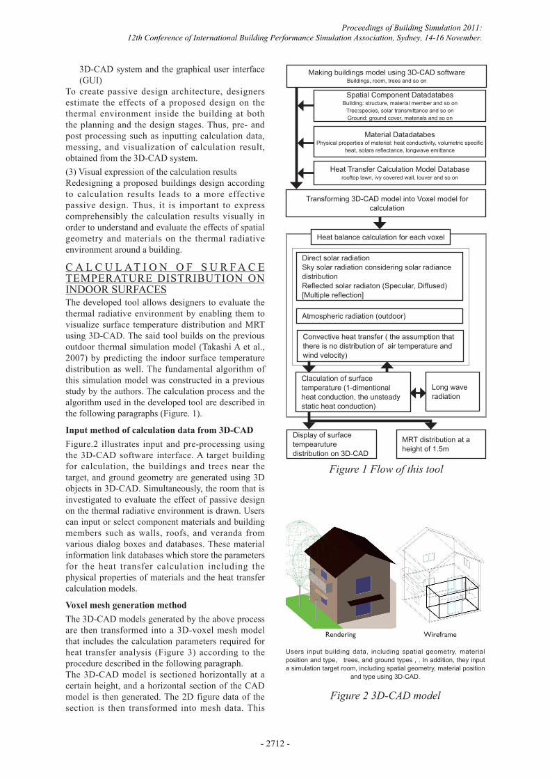
C A L C U L AT I O N O F S U R F A C E TEMPERATURE DISTRIBUTION ON INDOOR SURFACESThe developed tool allows designers to evaluate the thermal radiative environment by enabling them to visualize surface temperature distribution and MRT using 3D-CAD. The said tool builds on the previous outdoor thermal simulation model (Takashi A et al., 2007) by predicting the indoor surface temperature distribution as well. The fundamental algorithm of this simulation model was constructed in a previous study by the authors. The calculation process and the algorithm used in the developed tool are described in the following paragraphs (Figure. 1).
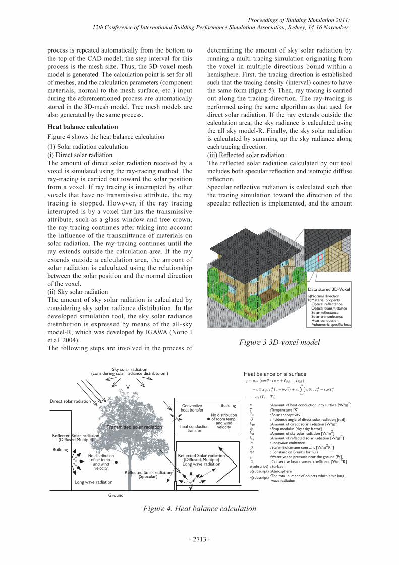
Input method of calculation data from 3D-CADFigure.2 illustrates input and pre-processing using the 3D-CAD software interface. A target building for calculation, the buildings and trees near the target, and ground geometry are generated using 3D objects in 3D-CAD. Simultaneously, the room that is investigated to evaluate the effect of passive design on the thermal radiative environment is drawn. Users can input or select component materials and building members such as walls, roofs, and veranda from various dialog boxes and databases. These material information link databases which store the parameters for the heat transfer calculation including the physical properties of materials and the heat transfer calculation models.
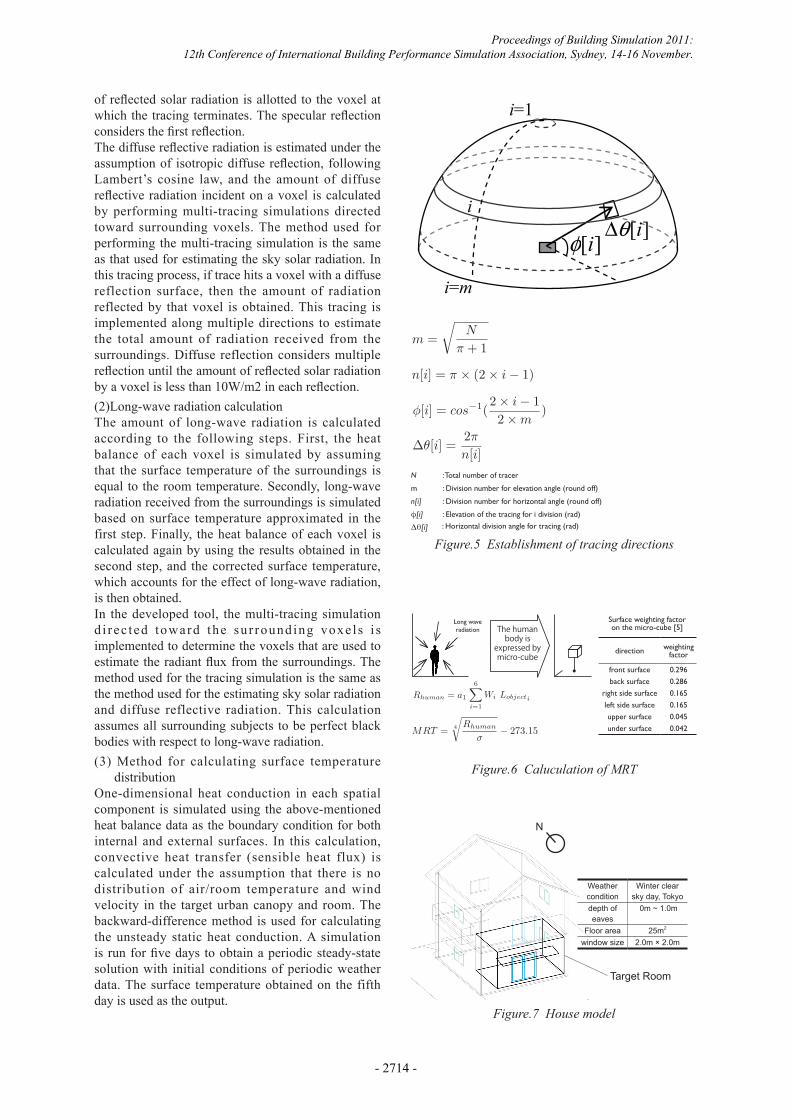
Voxel mesh generation methodThe 3D-CAD models generated by the above process are then transformed into a 3D-voxel mesh model that includes the calculation parameters required for heat transfer analysis (Figure 3) according to the procedure described in the following paragraph.The 3D-CAD model is sectioned horizontally at a certain height, and a horizontal section of the CAD model is then generated. The 2D figure data of the section is then transformed into mesh data. This
Figure 2 3D-CAD model
Rendering Wireframe
Users input building data, including spatial geometry, material position and type, trees, and ground types , . In addition, they input a simulation target room, including spatial geometry, material position
and type using 3D-CAD.
Making buildings model using 3D-CAD softwareBuildings, room, trees and so on
Transforming 3D-CAD model into Voxel model for calculation
Spatial Component DatadatabesBuilding: structure, material member and so on
Tree:species, solar transmittance and so onGround: ground cover, materials and so on
Material DatadatabesPhysical properties of material: heat conductivity, volumetric specific
heat, solara reflectance, longwave emittance
Heat Transfer Calculation Model Databaserooftop lawn, ivy covered wall, louver and so on
Heat balance calculation for each voxel
Direct solar radiationSky solar radiation considering solar radiance distributionReflected solar radiaton (Specular, Diffused) [Multiple reflection]
Atmospheric radiation (outdoor)
Convective heat transfer ( the assumption that there is no distribution of air temperature and wind velocity)
Claculation of surface temperature (1-dimentional heat conduction, the unsteady static heat conduction)
Display of surface tempearuture distribution on 3D-CAD
MRT distribution at a height of 1.5m
Long wave radiation
Figure 1 Flow of this tool
Proceedings of Building Simulation 2011: 12th Conference of International Building Performance Simulation Association, Sydney, 14-16 November.
- 2712 -
process is repeated automatically from the bottom to the top of the CAD model; the step interval for this process is the mesh size. Thus, the 3D-voxel mesh model is generated. The calculation point is set for all of meshes, and the calculation parameters (component materials, normal to the mesh surface, etc.) input during the aforementioned process are automatically stored in the 3D-mesh model. Tree mesh models are also generated by the same process.
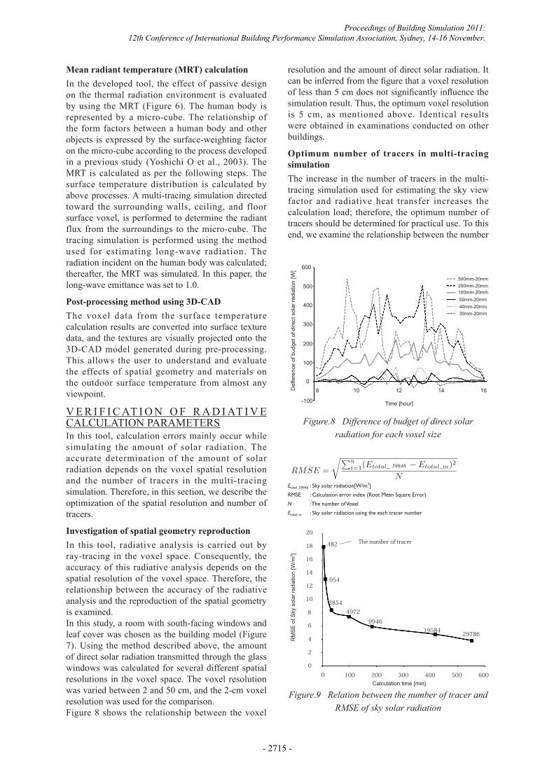
Heat balance calculationFigure 4 shows the heat balance calculation
(1) Solar radiation calculation(i) Direct solar radiationThe amount of direct solar radiation received by a voxel is simulated using the ray-tracing method. The ray-tracing is carried out toward the solar position from a voxel. If ray tracing is interrupted by other voxels that have no transmissive attribute, the ray tracing is stopped. However, if the ray tracing interrupted is by a voxel that has the transmissive attribute, such as a glass window and tree crown, the ray-tracing continues after taking into account the influence of the transmittance of materials on solar radiation. The ray-tracing continues until the ray extends outside the calculation area. If the ray extends outside a calculation area, the amount of solar radiation is calculated using the relationship between the solar position and the normal direction of the voxel. (ii) Sky solar radiationThe amount of sky solar radiation is calculated by considering sky solar radiance distribution. In the developed simulation tool, the sky solar radiance distribution is expressed by means of the all-sky model-R, which was developed by IGAWA (Norio I et al. 2004).The following steps are involved in the process of
Figure 4. Heat balance calculation
q = asu (cosθ · IDR + ΦskyISR + IRR)q = asu (cosθ · IDR + ΦskyISR + IRR)
+εsΦskyσT 4a
(a + b
√e)
+ εs
n∑
i=1
εiΦiσT 4i − εsσT 4
s
+αc (Ta − Ts)
: Amount of heat conduction into surface [W/m2]: Temperature [K]: Solar absorptivity: Incidence angle of direct solar radiation [rad]: Amount of direct solar radiation [W/m2]: Shap modulus [sky : sky factor]: Amount of sky solar radiation [W/m2]: Amount of reflected solar radiation [W/m2]: Longwave emittance: Stefan Boltzmann constant [W/m2K4]: Constant on Brunt's formula: Water vapor pressure near the ground [Pa]: Convective heat transfer coefficient [W/m2K]: Surface: Atmosphere: The total number of objects which emit long wave radiation
a(subscript)s(subscript)
n(subscript)
qTasuθIDRΦISRIRRεσa,b
αe
Sky solar radiation(considering solar radiance distribtuion )
Reflected Solar radiation(Diffused,Multiple)
Reflected Solar radiation(Diffused, Multiple)Long wave radiation
Reflected Solar radiation(Specular)
Long wave radiation
Direct solar radiation
Building
Ground
BuildingConvective heat transfer
heat conduction transfer
No distribution of room temp.
and wind velocity
No distribution of air temp.and wind velocity
Transmitted solar radiation
c
Heat balance on a surface
Figure 3 3D-voxel model
Data stored 3D-Voxel a)Normal directionb)Material property Optical reflectance Optical transmittance Solar reflectance Solar transmittance Heat conduction Volumetric specific heat
determining the amount of sky solar radiation by running a multi-tracing simulation originating from the voxel in multiple directions bound within a hemisphere. First, the tracing direction is established such that the tracing density (interval) comes to have the same form (figure 5). Then, ray tracing is carried out along the tracing direction. The ray-tracing is performed using the same algorithm as that used for direct solar radiation. If the ray extends outside the calculation area, the sky radiance is calculated using the all sky model-R. Finally, the sky solar radiation is calculated by summing up the sky radiance along each tracing direction. (iii) Reflected solar radiationThe reflected solar radiation calculated by our tool includes both specular reflection and isotropic diffuse reflection. Specular reflective radiation is calculated such that the tracing simulation toward the direction of the specular reflection is implemented, and the amount
Proceedings of Building Simulation 2011: 12th Conference of International Building Performance Simulation Association, Sydney, 14-16 November.
- 2713 -
of reflected solar radiation is allotted to the voxel at which the tracing terminates. The specular reflection considers the first reflection.The diffuse reflective radiation is estimated under the assumption of isotropic diffuse reflection, following Lambert’s cosine law, and the amount of diffuse reflective radiation incident on a voxel is calculated by performing multi-tracing simulations directed toward surrounding voxels. The method used for performing the multi-tracing simulation is the same as that used for estimating the sky solar radiation. In this tracing process, if trace hits a voxel with a diffuse reflection surface, then the amount of radiation reflected by that voxel is obtained. This tracing is implemented along multiple directions to estimate the total amount of radiation received from the surroundings. Diffuse reflection considers multiple reflection until the amount of reflected solar radiation by a voxel is less than 10W/m2 in each reflection.
(2)Long-wave radiation calculationThe amount of long-wave radiation is calculated according to the following steps. First, the heat balance of each voxel is simulated by assuming that the surface temperature of the surroundings is equal to the room temperature. Secondly, long-wave radiation received from the surroundings is simulated based on surface temperature approximated in the first step. Finally, the heat balance of each voxel is calculated again by using the results obtained in the second step, and the corrected surface temperature, which accounts for the effect of long-wave radiation, is then obtained.In the developed tool, the multi-tracing simulation d i rec ted toward the sur rounding voxe l s i s implemented to determine the voxels that are used to estimate the radiant flux from the surroundings. The method used for the tracing simulation is the same as the method used for the estimating sky solar radiation and diffuse reflective radiation. This calculation assumes all surrounding subjects to be perfect black bodies with respect to long-wave radiation.
(3) Method for calculating surface temperature distribution
One-dimensional heat conduction in each spatial component is simulated using the above-mentioned heat balance data as the boundary condition for both internal and external surfaces. In this calculation, convective heat transfer (sensible heat flux) is calculated under the assumption that there is no distribution of air/room temperature and wind velocity in the target urban canopy and room. The backward-difference method is used for calculating the unsteady static heat conduction. A simulation is run for five days to obtain a periodic steady-state solution with initial conditions of periodic weather data. The surface temperature obtained on the fifth day is used as the output.
Fig.3 Establishment of tracing directions
][iφ ][iθ∆
i=1
i
i=m
Figure.5 Establishment of tracing directions
Figure.6 Caluculation of MRT
Figure.7 House model
m =
√N
π + 1
n[i] = π × (2 × i − 1)
φ[i] = cos−1(2 × i − 12 × m
)
∆θ[i] =2π
n[i]: Total number of tracer
φ[i]
m
n[i]
Δθ[i] : Horizontal division angle for tracing (rad)
: Division number for horizontal angle (round off)
: Division number for elevation angle (round off)
: Elevation of the tracing for i division (rad)
N
Target Room
Weather condition
Winter clear sky day, Tokyo
depth of eaves
0m ~ 1.0m
Floor area 25m2
window size 2.0m × 2.0m
N
The human body is
expressed by micro-cube
Long wave radiation
direction weighting factor
front surface 0.296
back surface 0.286
right side surface 0.165
left side surface 0.165
upper surface 0.045
under surface 0.042
Surface weighting factor on the micro-cube [5]
Rhuman = a1{Ap
Shuman· Ib +
6∑
i=1
Wi(Idi + Iri)} + a2
6∑
i=1
Wi(Lobjecti + Lskyi)
MRT = 4
√Rhuman
σ− 273.15
Rhuman = a1{Ap
Shuman· Ib +
6∑
i=1
Wi(Idi + Iri)} + a2
6∑
i=1
Wi(Lobjecti + Lskyi)
Proceedings of Building Simulation 2011: 12th Conference of International Building Performance Simulation Association, Sydney, 14-16 November.
- 2714 -
Mean radiant temperature (MRT) calculationIn the developed tool, the effect of passive design on the thermal radiation environment is evaluated by using the MRT (Figure 6). The human body is represented by a micro-cube. The relationship of the form factors between a human body and other objects is expressed by the surface-weighting factor on the micro-cube according to the process developed in a previous study (Yoshichi O et al., 2003). The MRT is calculated as per the following steps. The surface temperature distribution is calculated by above processes. A multi-tracing simulation directed toward the surrounding walls, ceiling, and floor surface voxel, is performed to determine the radiant flux from the surroundings to the micro-cube. The tracing simulation is performed using the method used for estimating long-wave radiation. The radiation incident on the human body was calculated; thereafter, the MRT was simulated. In this paper, the long-wave emittance was set to 1.0.
Post-processing method using 3D-CADThe voxel data from the surface temperature calculation results are converted into surface texture data, and the textures are visually projected onto the 3D-CAD model generated during pre-processing. This allows the user to understand and evaluate the effects of spatial geometry and materials on the outdoor surface temperature from almost any viewpoint.
V E R I F I C AT I O N O F R A D I AT I V E CALCULATION PARAMETERSIn this tool, calculation errors mainly occur while simulating the amount of solar radiation. The accurate determination of the amount of solar radiation depends on the voxel spatial resolution and the number of tracers in the multi-tracing simulation. Therefore, in this section, we describe the optimization of the spatial resolution and number of tracers.
Investigation of spatial geometry reproductionIn this tool, radiative analysis is carried out by ray-tracing in the voxel space. Consequently, the accuracy of this radiative analysis depends on the spatial resolution of the voxel space. Therefore, the relationship between the accuracy of the radiative analysis and the reproduction of the spatial geometry is examined.In this study, a room with south-facing windows and leaf cover was chosen as the building model (Figure 7). Using the method described above, the amount of direct solar radiation transmitted through the glass windows was calculated for several different spatial resolutions in the voxel space. The voxel resolution was varied between 2 and 50 cm, and the 2-cm voxel resolution was used for the comparison. Figure 8 shows the relationship between the voxel
: Sky solar radiation[W/m2]Etotal_59846
Etotal_m
RMSE
N : The number of Voxel
: Calculation error index (Root Mean Square Error)
: Sky solar radiation using the each tracer number
RMSE =
√∑ni=1(Etotal 16249 − Etotal m)2
N
600
8 10 12 14 16
500mm-20mm200mm-20mm100mm-20mm50mm-20mm40mm-20mm30mm-20mm
500
400
300
200
100
-100
0
00 100 200 300 400 500 600
2
4
6
8
10
12
14
16
18
20
Def
fere
nce
of b
udge
t of d
irect
sol
ar ra
diat
ion
[W]
RM
SE
of S
ky s
olar
radi
atio
n [W
/m2 ]
Time [hour]
Calculation time [min]
Figure.8 Difference of budget of direct solar radiation for each voxel size
Figure.9 Relation between the number of tracer and RMSE of sky solar radiation
482
954
28544972
994619584
29786
The number of tracer
59846
resolution and the amount of direct solar radiation. It can be inferred from the figure that a voxel resolution of less than 5 cm does not significantly influence the simulation result. Thus, the optimum voxel resolution is 5 cm, as mentioned above. Identical results were obtained in examinations conducted on other buildings.
Optimum number of tracers in multi-tracing simulationThe increase in the number of tracers in the multi-tracing simulation used for estimating the sky view factor and radiative heat transfer increases the calculation load; therefore, the optimum number of tracers should be determined for practical use. To this end, we examine the relationship between the number
Proceedings of Building Simulation 2011: 12th Conference of International Building Performance Simulation Association, Sydney, 14-16 November.
- 2715 -
Living
N
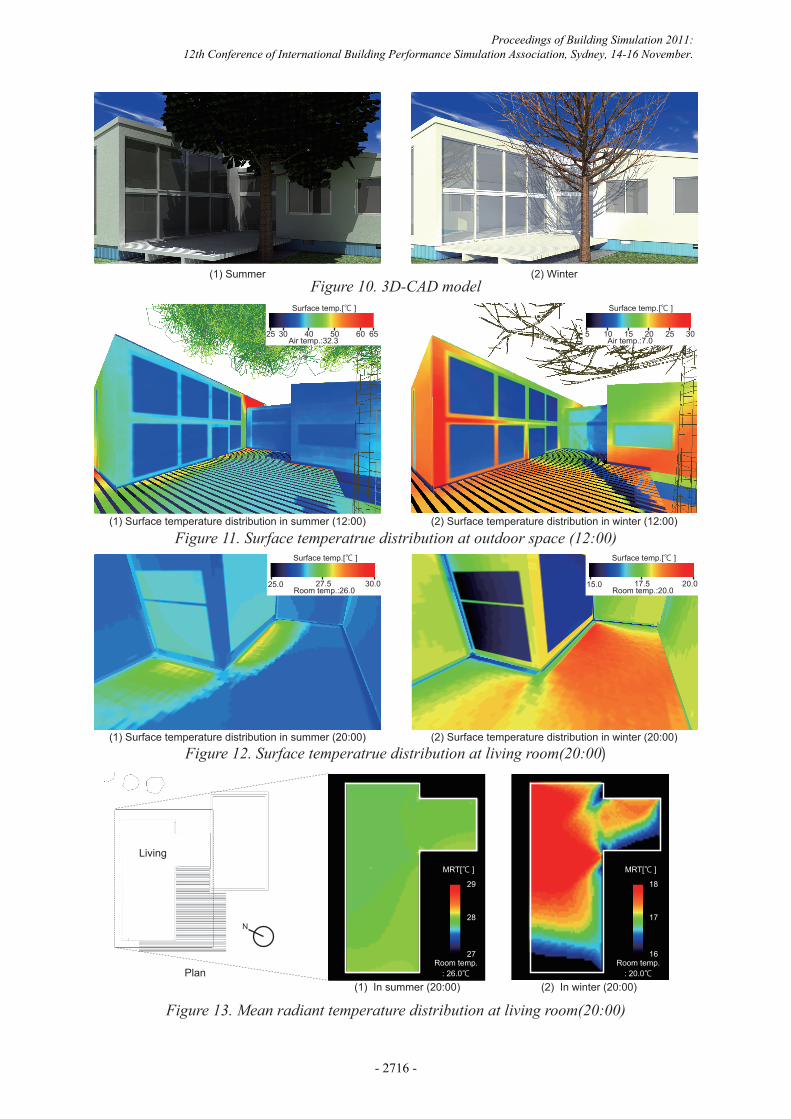
Figure 10. 3D-CAD model
Figure 11. Surface temperatrue distribution at outdoor space (12:00)
Figure 12. Surface temperatrue distribution at living room(20:00)
Figure 13. Mean radiant temperature distribution at living room(20:00)
(1) Summer
(1) Surface temperature distribution in summer (12:00)
(1) Surface temperature distribution in summer (20:00)
(1) In summer (20:00)Plan
(2) In winter (20:00)
(2) Surface temperature distribution in winter (12:00)
(2) Surface temperature distribution in winter (20:00)
(2) Winter
Air temp.:32.325 30 40 50 60 65
Air temp.:7.05 10 15 20 25 30
28 17
29 18
MRT[℃ ] MRT[℃ ]
Room temp.: 26.0℃
Room temp.: 20.0℃
27 16
15.0 17.5 20.0Room temp.:20.0
25.0 27.5 30.0Room temp.:26.0
Surface temp.[℃ ] Surface temp.[℃ ]
Surface temp.[℃ ]Surface temp.[℃ ]
Proceedings of Building Simulation 2011: 12th Conference of International Building Performance Simulation Association, Sydney, 14-16 November.
- 2716 -

ensures a comfortable radiative environment during both summer and winter.These results reveal that the developed tool is able to simulate the effects of solar shading by a large tree and direct heat gain on the surface temperature distribution and the MRT. Therefore, this tool can be used to evaluate the effects of passive design on thermal radiative environment around a building.
CONCLUSIONSIn this paper, we described a passive design tool that is capable of predicting the surface temperature distribution and the MRT for both outdoor and indoor surfaces. To allow for the consideration of detailed spatial geometry as well as material positions, material types, and trees, a radiation analysis algorithm with a high-resolution voxel model was developed. Then, the simulation parameters, i.e., optimum voxel size and the number of tracers in the multi-tracing simulation, were established.The results of applying this tool for creating passive design architecture revealed that it was capable of simulating the effects of passive design such as solar shading of tree, building spatial geometry, and materials on the surface temperature and MRT distribution, and that it could be used to study the passive design at the design stage.In future work, this system will be combined with building heat load simulation for the comprehensive evaluation of a passive design.
ACKNOWLEDGEMENTThis work was supported by Grants-in-Aid for Young Scientists (B)(21760446).
REFERENCESAbraham Yezioro, 2009. Renewable Energy, Volume
34, pp.769-779
EnergyPlus, Web homepage (www.eere.energy.gov/ buildings/energyplus)
eQuest, Web homepage (www.energydesignresources.com)
Energy-10, Web homepage (http://www.sbicouncil.org/energy10-soft)
Norio Igawa, Yasuko Koga, Tomoko Matsuzawa, Hiroshi Nakamura, 2004. Solar Energy, No. 77, pp.137-157
Takashi Asawa, Akira Hoyano, Kazuaki Nakaohkubo, 2008. Building and Environment, Volume 43, Issue 12, pp.2112-2123
Yoshiichi Ozeki, Tetsuya Hiramatsu, Shin-ichi Tanabe, 2003. J. Environ. Eng., AIJ, No. 566, pp. 47-50
of tracers in the multi-tracing simulation and the calculation accuracy, using the sky solar radiation.The building model used for this examination is the same as that shown in Figure 7. The root mean square error (RMSE) index is used for determining the calculation accuracy. The standard maximum number of tracers for calculating the RMSE is more 50,000. The relationship between the number of tracers and the RMSE index of the sky solar radiation for the entire floor voxel is shown in Figure 9. The difference in the RMSE is small when more than 3000 tracers are used. This finding confirms that for the multi-tracing simulation, the optimum number of tracers is more than 3000.
SIMULATION TOOL APPLICATIONThe effectiveness of the developed tool in evaluating the effects of passive design on a thermal radiative environment of a building was determined by applying the tool to a purpose-built passive solar house.Figure 10 shows the target passive design house. The house has large windows directed toward the south and a large deciduous tree on the wooden deck in front of the windows. During summer, the large tree shades the house from direct solar radiation. In winter, the leafless huge tree transmits direct solar radiation into the house. The concrete floor of the aforementioned room has huge heat capacity and can therefore store heat from the incident solar radiation during winter.The summer and winter weather conditions used for calculation were representative of days with clear skies in the respective seasons.Figure 11 shows the surface temperature distribution in outdoor space during both summer and winter (12:00). In summer, the surface temperature of the wooden deck is low because it is shaded by the large tree. However, the surface temperature of the wooden deck during winter is the same as that of the ground because the lealfess tree directs the solar radiation to the wooden deck.Figure 12 shows the surface temperature distribution in the indoor living space during both summer and winter (20:00). The surface temperature of the floor in summer is low because the large tree prevents the direct incidence of solar radiation into the room during daytime. However, surface temperature in winter is high because the floor, which is made of a high heat capacity material, stores the heat from the solar radiation incident during the day.Figure 13 depicts the MRT distribution at a height of 1.5 m in the living room during summer and winter (20:00). In summer, at 20:00, there is no distribution of MRT. In winter, the value of MRT in the space near the window, which was exposed to solar radiation, is 2°C higher than that in other spaces because of the heat stage. This finding shows that passive design
Proceedings of Building Simulation 2011: 12th Conference of International Building Performance Simulation Association, Sydney, 14-16 November.
- 2717 -