Embed Size (px)
Citation preview


Table of Contents Introduction ............................................................................................................................................1
Indications for Use ...................................................................................................................................2
Theory of Operation .................................................................................................................................2
What is rSO2 and How is it Measured? ............................................................................................................ 2
What is %SpO2? ............................................................................................................................................... 3
System Components ................................................................................................................................4
System Setup ...........................................................................................................................................5
X-100H Hub ...................................................................................................................................................... 5
Connect/Disconnect the Hub to the Monitor ............................................................................................. 5
X-100HH Hub Holster ...................................................................................................................................... 5
X-100SP Signal Processors ............................................................................................................................... 6
Connect/Disconnect a Signal Processor ...................................................................................................... 7
System Sensors ........................................................................................................................................7
Connect/Disconnect a Sensor to/from the Signal Processor ...................................................................... 7
rSO2 Sensors ..................................................................................................................................................... 7
rSO2 Sensor Application ............................................................................................................................... 8
SpO2 Sensors .................................................................................................................................................... 9
Reusable Pulse Oximetry (SpO2) Sensor Application ................................................................................... 9
X-100EC Extension Cables ............................................................................................................................. 10
System Power on/off ..................................................................................................................................... 10
Review of the Model X-100 Universal Oximetry System Setup ................................................................ 11
Monitor Features ................................................................................................................................... 12
Controls and Navigation ......................................................................................................................... 13
System Display ....................................................................................................................................... 15
System Configuration Screens and Menus .............................................................................................. 17
Settings Menu ................................................................................................................................................ 17
Sensor Site ................................................................................................................................................. 18
Sensor Type ............................................................................................................................................... 18
Baseline (Manual Setting) .......................................................................................................................... 18
i of ii
Setting High and Low Alarm Limits for rSO2 or SpO2 ................................................................................. 19
Graph Position ........................................................................................................................................... 19
Review Current Preset ............................................................................................................................... 20
Presets Menu ................................................................................................................................................. 20
Case Menu ..................................................................................................................................................... 21
System Menu ................................................................................................................................................. 22
Review System Menus ................................................................................................................................... 24
System Alarm Indicators ........................................................................................................................ 25
High Priority Alarms ....................................................................................................................................... 25
Medium Priority Alarms ................................................................................................................................ 25
Troubleshooting ............................................................................................................................................ 26
System Memory ..................................................................................................................................... 28
System Data Outputs ............................................................................................................................. 28
Cleaning the System Components .......................................................................................................... 29
Warranty ............................................................................................................................................... 30
How to Get Help - Service and Support ................................................................................................... 30
Customer and Technical Service Contact Information .................................................................................. 30

SenSmart™ Model X-100 Universal Oximetry System In-Service Training
1 of 31
Introduction This In-Service Training material is designed to help you become familiar with the SenSmart Model X-100 Universal Oximetry System components and functions. It is not intended to replace the SenSmart System Operator’s Manual, which includes warnings, cautions, complete functions of all components, and technical information about the SenSmart System. The training is designed to
1) Introduce you to the SenSmart System components and functions, 2) Learn what actions are needed to make the system function properly, and 3) Provide you the opportunity to demonstrate what you have learned.
Training format conventions in this document you should be aware of: • SenSmart System features that perform an action, such as the navigation buttons Up/Down,
Left/Right and Select, are in bold font. • Menus and options in the display interface that can be selected to configure the SenSmart
System are in bold font, such as the Settings, Presets, Case, and System menus, and any option within these menus.
• Important notes regarding a specific function are italicized. • Warnings and Cautions for safe operation of the system are in bold font.

SenSmart™ Model X-100 Universal Oximetry System In-Service Training
2 of 31
Indications for Use The SenSmart Model X-100 Universal Oximetry System is a modular system and is indicated for use in simultaneously measuring, displaying, monitoring, and recording up to six (6) channels of functional oxygen saturation of arterial hemoglobin (SpO2) and pulse rate or cerebral or somatic hemoglobin oxygen saturation (rSO2) of blood underneath the sensor. Patient populations include adult, pediatric, infant, and neonate through the use of SenSmart-compatible sensors. The SenSmart System is intended for use in hospitals, long-term care, medical facilities, sleep laboratories, sub-acute environments, and Emergency Medical Services (EMS), including patient transport. The X-100 SenSmart System may be used for spot-checking and continuous Monitoring with patient alarms. The SenSmart pulse oximetry (SpO2) functionality is suitable for use in both motion and non-motion conditions, including patients who are well or poorly perfused. WARNING: This device is intended only as an adjunct device in patient assessment. It should not be used as the sole basis for diagnosis or therapy decisions. It must be used in conjunction with other methods of assessing clinical signs and symptoms.
Theory of Operation What is rSO2 and How is it Measured?
• rSO2 is a representation of oxygen saturation in tissue.
o rSO2 correlates to a jugular bulb saturation measurement.
o rSO2 has been validated to agree with an assumed 70:30 mix of venous and arterial blood in the tissue capillary bed.
• To measure rSO2, the SenSmart Universal Oximetry System uses 3 or 4 distinct wavelengths of light and 4 light paths to penetrate and determine hemoglobin oxygen saturation of blood in the area under the sensor.
• Nonin’s patented dual light emitter/dual detector architecture allows the sensor to spatially resolve the differences between shallow tissue artifacts and deeper target tissue.
SenSmart™ Model X-100 Universal Oximetry System In-Service Training
3 of 31
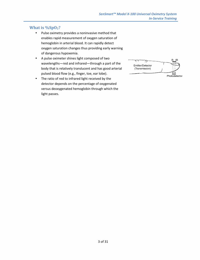
What is %SpO2? Pulse oximetry provides a noninvasive method that
enables rapid measurement of oxygen saturation of hemoglobin in arterial blood. It can rapidly detect oxygen saturation changes thus providing early warning of dangerous hypoxemia.
A pulse oximeter shines light composed of two wavelengths—red and infrared—through a part of the body that is relatively translucent and has good arterial pulsed blood flow (e.g., finger, toe, ear lobe).
The ratio of red to infrared light received by the detector depends on the percentage of oxygenated versus deoxygenated hemoglobin through which the light passes.
SenSmart™ Model X-100 Universal Oximetry System In-Service Training
4 of 31
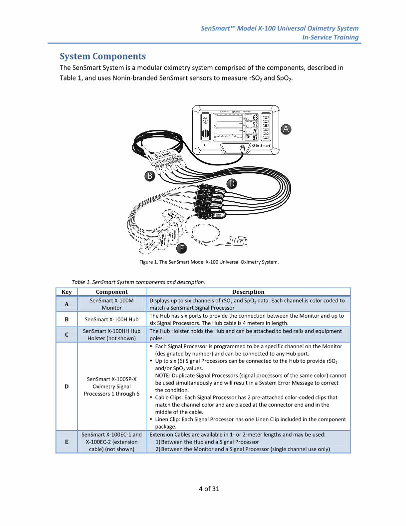
System Components The SenSmart System is a modular oximetry system comprised of the components, described in Table 1, and uses Nonin-branded SenSmart sensors to measure rSO2 and SpO2.
Figure 1. The SenSmart Model X-100 Universal Oximetry System.
Table 1. SenSmart System components and description.
Key Component Description
A SenSmart X-100M Monitor
Displays up to six channels of rSO2 and SpO2 data. Each channel is color coded to match a SenSmart Signal Processor
B SenSmart X-100H Hub The Hub has six ports to provide the connection between the Monitor and up to six Signal Processors. The Hub cable is 4 meters in length.
C SenSmart X-100HH Hub Holster (not shown)
The Hub Holster holds the Hub and can be attached to bed rails and equipment poles.
D SenSmart X-100SP-X
Oximetry Signal Processors 1 through 6
Each Signal Processor is programmed to be a specific channel on the Monitor (designated by number) and can be connected to any Hub port.
Up to six (6) Signal Processors can be connected to the Hub to provide rSO2 and/or SpO2 values. NOTE: Duplicate Signal Processors (signal processors of the same color) cannot be used simultaneously and will result in a System Error Message to correct the condition.
Cable Clips: Each Signal Processor has 2 pre-attached color-coded clips that match the channel color and are placed at the connector end and in the middle of the cable.
Linen Clip: Each Signal Processor has one Linen Clip included in the component package.
E SenSmart X-100EC-1 and
X-100EC-2 (extension cable) (not shown)
Extension Cables are available in 1- or 2-meter lengths and may be used: 1) Between the Hub and a Signal Processor 2) Between the Monitor and a Signal Processor (single channel use only)

SenSmart™ Model X-100 Universal Oximetry System In-Service Training
5 of 31
Key Component Description
F SenSmart Sensors Available to measure rSO2 and SpO2. Sensors are described in more detail in the SenSmart Sensor section on page 7.
Power supply and cord (not shown)
SenSmart Download
Software (CD not shown)
Data management software
System Setup This section describes the features of the SenSmart components and how to connect the components to prepare for patient monitoring.
X-100H Hub • The Hub and cable connects to the port on the front of the
Monitor and provides connections for up to six Signal Processors using the Hub ports. See Figure 2.
• The Hub ports are protected from environmental contamination with covers that are opened to connect a Signal Processor. If the Hub port is not being used, the cover should remain closed to eliminate the potential for environmental contamination.
Connect/Disconnect the Hub to the Monitor 1. To connect:
a. Align the arrow on the Hub cable connector with the small triangle on the Monitor connector port.
b. Push the Hub cable connector straight into the port until it clicks and locks into place.
2. To disconnect: a. Grasp the sleeve on the Hub cable connector. b. Retract the sleeve to unlock, and pull the Hub cable
connector straight back to detach from the Monitor as shown in Figure 3.
X-100HH Hub Holster The Hub can be placed in the Hub Holster to stabilize the Hub when attaching it to bed linens, bed rail, or a pole by using the clamp on the back of the Hub Holster.
1. To place the Hub in to the Hub Holster a. Align the Hub and hub cable to the Hub Holster as shown in Figure 4A. Push firmly
into the Hub Holster. b. Attach to bed linens, bed rail, or a pole using the clip as shown in Figure 4B.
Figure 3. Align the arrows and push the Hub cable connector into the Monitor port.
Figure 2. SenSmart Hub with port covers.

SenSmart™ Model X-100 Universal Oximetry System In-Service Training
6 of 31
2. To remove the Hub from the Hub Holster:
a. Pull the clip back on the tip of the Hub Holster and pull the Hub out of the Hub Holster as shown in Figure 4C.
X-100SP Signal Processors • Up to six (6) Signal Processors can be used with the System. • The Signal Processor has a cable connector on one end to connect
to any port on the Hub or directly to the Monitor, and the sensor connection port on the other end with the clear plastic sensor lock to secure the sensor firmly in the Signal Processor. See Figure 5.
• The measurement from the Signal Processor will display on the Monitor screen in the same color and channel location as shown on the Signal Processor labels. See Table 2.
Table 2. SenSmart Signal Processors and channel colors. SenSmart Signal Processor Model Color
X-100SP-1 (Channel 1) Blue X-100SP-2 (Channel 2) Orange X-100SP-3 (Channel 3) White X-100SP-4 (Channel 4) Purple X-100SP-5 (Channel 5) Green X-100SP-6 (Channel 6) Pink
Figure 4C. Removing the Hub from the Hub Holster.
Figure 4A. Inserting the Hub in to the Hub Holster.
Figure 4B. Hub Holster attached to pole.
Figure 5. Signal Processor showing cable connector and clear sensor lock.
SenSmart™ Model X-100 Universal Oximetry System In-Service Training
7 of 31
Figure 6. Inserting the Signal Processor into the Hub port.
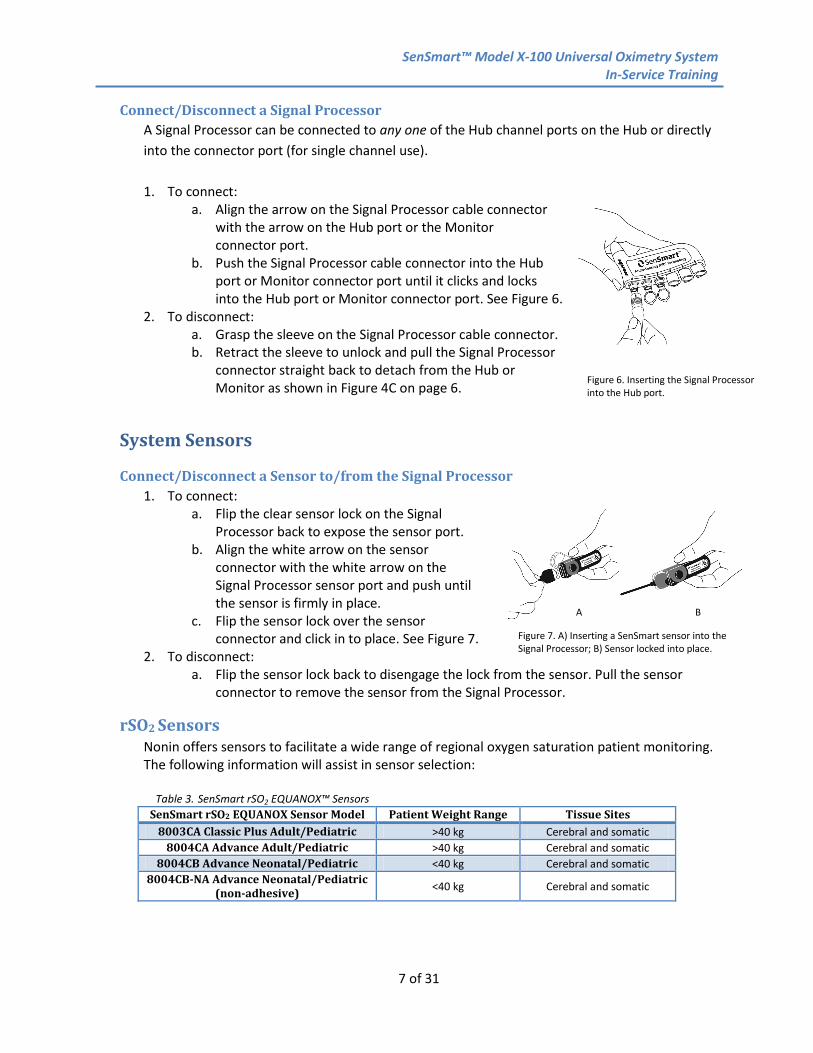
Connect/Disconnect a Signal Processor A Signal Processor can be connected to any one of the Hub channel ports on the Hub or directly into the connector port (for single channel use).
1. To connect:
a. Align the arrow on the Signal Processor cable connector with the arrow on the Hub port or the Monitor connector port.
b. Push the Signal Processor cable connector into the Hub port or Monitor connector port until it clicks and locks into the Hub port or Monitor connector port. See Figure 6.
2. To disconnect: a. Grasp the sleeve on the Signal Processor cable connector. b. Retract the sleeve to unlock and pull the Signal Processor
connector straight back to detach from the Hub or Monitor as shown in Figure 4C on page 6.
System Sensors
Connect/Disconnect a Sensor to/from the Signal Processor 1. To connect:
a. Flip the clear sensor lock on the Signal Processor back to expose the sensor port.
b. Align the white arrow on the sensor connector with the white arrow on the Signal Processor sensor port and push until the sensor is firmly in place.
c. Flip the sensor lock over the sensor connector and click in to place. See Figure 7.
2. To disconnect: a. Flip the sensor lock back to disengage the lock from the sensor. Pull the sensor
connector to remove the sensor from the Signal Processor.
rSO2 Sensors Nonin offers sensors to facilitate a wide range of regional oxygen saturation patient monitoring. The following information will assist in sensor selection:
Table 3. SenSmart rSO2 EQUANOX™ Sensors SenSmart rSO2 EQUANOX Sensor Model Patient Weight Range Tissue Sites
8003CA Classic Plus Adult/Pediatric >40 kg Cerebral and somatic 8004CA Advance Adult/Pediatric >40 kg Cerebral and somatic
8004CB Advance Neonatal/Pediatric <40 kg Cerebral and somatic 8004CB-NA Advance Neonatal/Pediatric
(non-adhesive) <40 kg Cerebral and somatic
Figure 7. A) Inserting a SenSmart sensor into the Signal Processor; B) Sensor locked into place.
A B

SenSmart™ Model X-100 Universal Oximetry System In-Service Training
8 of 31
rSO2 Sensor Application See the Sensor IFU for complete instructions, cautions and warnings.
1. Signal Processor site(s) and cable pathways: a. Select an appropriate site to clip or otherwise stabilize the Signal Processor. The
ideal site avoids the patient’s body resting on the Signal Processor or the Signal Processor pulling unnecessarily on the sensor. Ensure the sensor cable and extension cable pathways are clear and unencumbered.
WARNING: As with all medical equipment, carefully route patient cables and connections to reduce the possibility of entanglement or strangulation.
2. Cerebral site: a. Select the site(s) on the patient’s forehead lateral of the superior sagittal sinus,
superior to the eyebrow and inferior to the hairline (Figure 8).
Figure 8. Proper placement of cerebral sensors on adult and neonate/pediatric patients.
b. The area(s) should be free of hair or surface blemishes such as moles or freckles. c. Avoid placing the sensor(s) over nevi, sinus cavities, hematomas, or arteriovenous
malformations. 3. Somatic site(s):
a. Select the site(s) that provides optimal access to desired tissue (Figure 9).
Figure 9. Proper placement of somatic sensors on adult and neonate/pediatric patients.
CAUTION: Avoid excessive pressure to the sensor application site(s) as this may cause damage to the skin beneath the sensor.
4. Skin preparation: a. Gently cleanse the patient’s skin with isopropyl alcohol to remove oils, makeup, or
soil that might interfere with adhesive or block light. b. Ensure the skin is thoroughly dried.
5. Removal from packaging and pre-check: a. Carefully remove the sensor from the plastic pouch and uncoil the sensor cable. b. Check the sensor for any sign of damage in transport. c. If signs of damage are found, replace the sensor.
6. Sensor placement: a. Remove the protective backing from the sensor pad and gently, but firmly, place the
sensor(s) on the desired site(s).
SenSmart™ Model X-100 Universal Oximetry System In-Service Training
9 of 31
b. Ensure the sensor surface adheres fully to the skin to prevent light from traveling between emitting or receiving elements or ambient light from entering between the sensor and the skin.
CAUTION: An improperly placed sensor may result in inaccurate readings. 7. Sensor connections:
a. Flip the clear sensor lock on the Signal Processor back to expose the sensor port. (See Figure 7 on page 7.)
b. Align the white arrow on the sensor connector with the white arrow on the Signal Processor sensor port and push until the sensor is firmly in place
c. Flip the sensor lock over the sensor connector and click into place. d. rSO2 values and trend lines should begin displaying within seconds. Note: If these measurements are not clearly identified or alarm conditions are
generated, consult the Troubleshooting section on page 26.
WARNING: Use only Nonin-branded SenSmart Signal Processors, sensors, and accessories. The sensors are manufactured to meet the accuracy specifications for this System. Using other manufacturers’ sensors can result in improper oximeter performance. CAUTION: The sensor is designed for external use only. CAUTION: Do not apply sensor over open wound, incision, compromised skin, or pre-existing skin condition (e.g., eczema or dermatitis). CAUTION: Do not use if patient has pre-existing sensitivity to adhesive tapes or adhesives on electrocardiogram (ECG) pads.
SpO2 Sensors Nonin offers reusable SpO2 sensors for a wide range of patients. The following information will help assist in sensor selection.
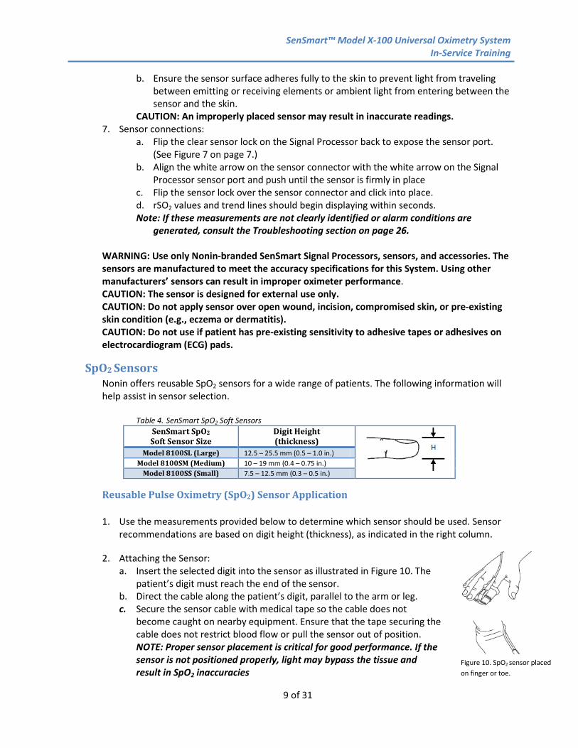
Table 4. SenSmart SpO2 Soft Sensors
SenSmart SpO2 Soft Sensor Size
Digit Height (thickness)
Model 8100SL (Large) 12.5 – 25.5 mm (0.5 – 1.0 in.) Model 8100SM (Medium) 10 – 19 mm (0.4 – 0.75 in.)
Model 8100SS (Small) 7.5 – 12.5 mm (0.3 – 0.5 in.)
Reusable Pulse Oximetry (SpO2) Sensor Application
1. Use the measurements provided below to determine which sensor should be used. Sensor recommendations are based on digit height (thickness), as indicated in the right column.
2. Attaching the Sensor: a. Insert the selected digit into the sensor as illustrated in Figure 10. The
patient’s digit must reach the end of the sensor. b. Direct the cable along the patient’s digit, parallel to the arm or leg. c. Secure the sensor cable with medical tape so the cable does not
become caught on nearby equipment. Ensure that the tape securing the cable does not restrict blood flow or pull the sensor out of position. NOTE: Proper sensor placement is critical for good performance. If the sensor is not positioned properly, light may bypass the tissue and result in SpO2 inaccuracies
Figure 10. SpO2 sensor placed on finger or toe.
SenSmart™ Model X-100 Universal Oximetry System In-Service Training
10 of 31
3. Sensor Connections: a. Flip the sensor lock on the Signal Processor back to expose the sensor connector port. b. Insert the sensor connector into the Signal Processor connector port. c. Flip the Signal Processor sensor lock over the sensor connector and click into place. d. SpO2 and HR values should begin displaying within seconds.
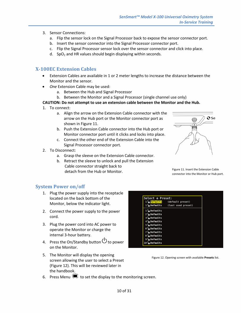
X-100EC Extension Cables • Extension Cables are available in 1 or 2 meter lengths to increase the distance between the
Monitor and the sensor. • One Extension Cable may be used:
a. Between the Hub and Signal Processor b. Between the Monitor and a Signal Processor (single channel use only)
CAUTION: Do not attempt to use an extension cable between the Monitor and the Hub. 1. To connect:
a. Align the arrow on the Extension Cable connector with the arrow on the Hub port or the Monitor connector port as shown in Figure 11.
b. Push the Extension Cable connector into the Hub port or Monitor connector port until it clicks and locks into place.
c. Connect the other end of the Extension Cable into the Signal Processor connector port.
2. To Disconnect: a. Grasp the sleeve on the Extension Cable connector. b. Retract the sleeve to unlock and pull the Extension Cable connector straight back to detach from the Hub or Monitor.
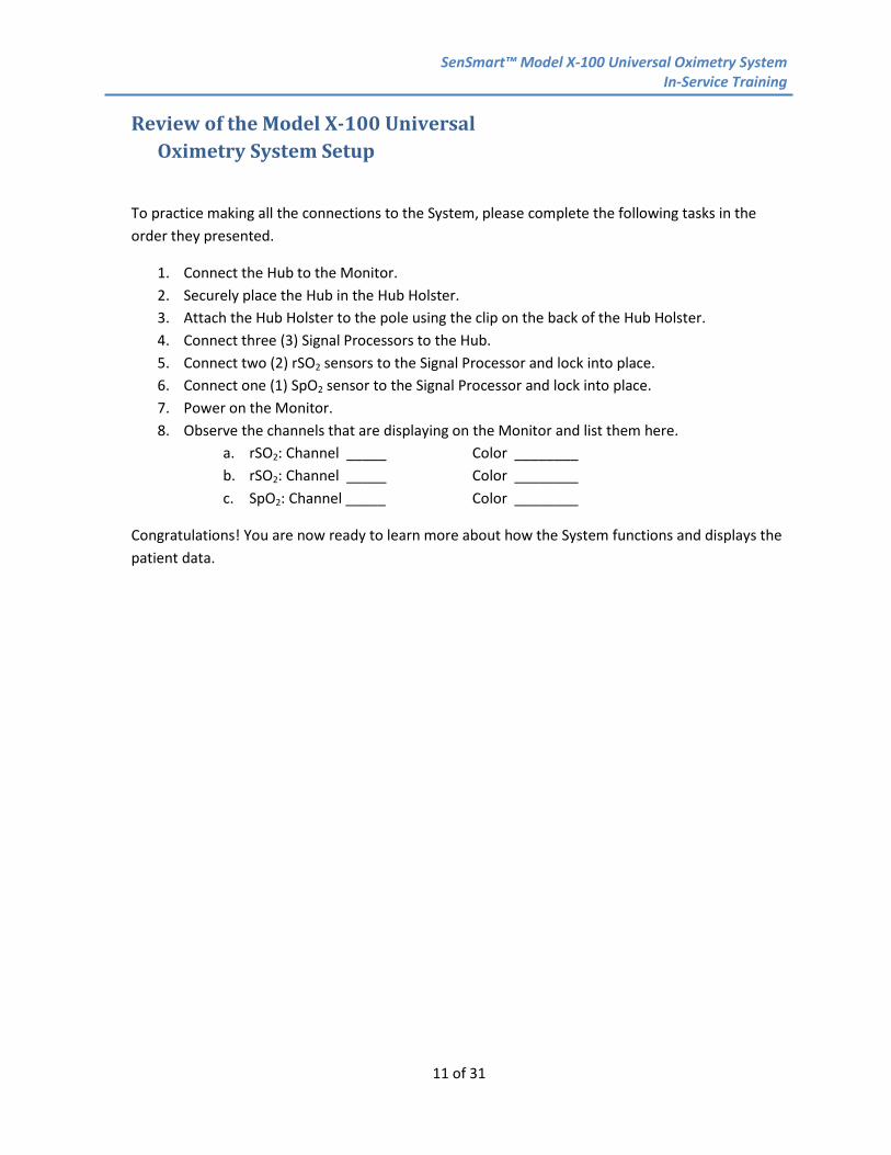
System Power on/off 1. Plug the power supply into the receptacle
located on the back bottom of the Monitor, below the indicator light.
2. Connect the power supply to the power cord.
3. Plug the power cord into AC power to operate the Monitor or charge the internal 3-hour battery.
4. Press the On/Standby button to power on the Monitor.
5. The Monitor will display the opening screen allowing the user to select a Preset (Figure 12). This will be reviewed later in the handbook.
6. Press Menu to set the display to the monitoring screen.
Figure 12. Opening screen with available Presets list.
Figure 11. Insert the Extension Cable connector into the Monitor or Hub port.
SenSmart™ Model X-100 Universal Oximetry System In-Service Training
11 of 31
Review of the Model X-100 Universal Oximetry System Setup
To practice making all the connections to the System, please complete the following tasks in the order they presented.
1. Connect the Hub to the Monitor. 2. Securely place the Hub in the Hub Holster. 3. Attach the Hub Holster to the pole using the clip on the back of the Hub Holster. 4. Connect three (3) Signal Processors to the Hub. 5. Connect two (2) rSO2 sensors to the Signal Processor and lock into place. 6. Connect one (1) SpO2 sensor to the Signal Processor and lock into place. 7. Power on the Monitor. 8. Observe the channels that are displaying on the Monitor and list them here.
a. rSO2: Channel _____ Color ________ b. rSO2: Channel _____ Color ________ c. SpO2: Channel _____ Color ________
Congratulations! You are now ready to learn more about how the System functions and displays the patient data.
SenSmart™ Model X-100 Universal Oximetry System In-Service Training
12 of 31
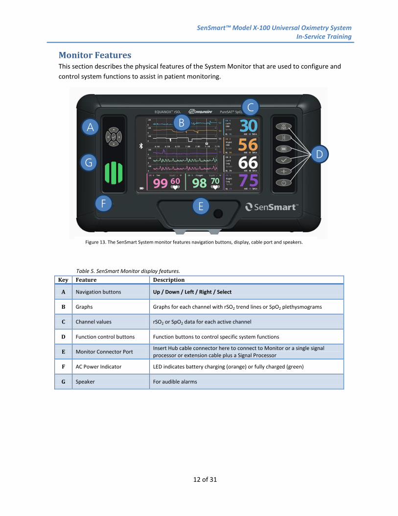
Monitor Features This section describes the physical features of the System Monitor that are used to configure and control system functions to assist in patient monitoring.
Table 5. SenSmart Monitor display features.
Key Feature Description
A Navigation buttons Up / Down / Left / Right / Select
B Graphs Graphs for each channel with rSO2 trend lines or SpO2 plethysmograms
C Channel values rSO2 or SpO2 data for each active channel
D Function control buttons Function buttons to control specific system functions
E Monitor Connector Port Insert Hub cable connector here to connect to Monitor or a single signal processor or extension cable plus a Signal Processor
F AC Power Indicator LED indicates battery charging (orange) or fully charged (green)
G Speaker For audible alarms
Figure 13. The SenSmart System monitor features navigation buttons, display, cable port and speakers.
A
G
F
B
E
C
D

SenSmart™ Model X-100 Universal Oximetry System In-Service Training
13 of 31
Controls and Navigation
Configuring the System is controlled using the Navigation buttons on the left and the Function buttons on the right side of the Monitor.
Table 6. SenSmart System controls and navigation buttons.
Key Feature How to Use
A
Navigation Buttons
Up and Down Left and Right
Select
1. Up / Down and Left / Right: In menus, used to navigate between items. 2. Up / Down: Change rSO2 trend line timescale. 3. Left / Right: Scroll back/forward in time in the current case. 4. Select (in center of navigation buttons and between Menu and Baseline
buttons). a. Select item to edit. b. Save entered or changed values.
B Alarm Silence
1. Press once to silence audible alarms for 2 minutes. 2. Press once to reactivate audible alarms before the 2-minute silence period
is over. NOTE: All silenced audible alarms are automatically reactivated when a new physiological alarm goes off.
C Event Mark
1. Press once to mark an event with an alpha character (A-Z) in 1) memory, 2) on the trend line, and 3) in real-time serial data.
NOTE: If more than 26 events are marked in a single case, the event marks begin again at A.
2. Press and hold for 2 seconds to open the Event Mark table which shows the last 10 event marks with date/time and values for each channel. See Figure 17 on page 16.
Figure 14. The SenSmart System features buttons to navigate all menus and control display functions of the system.
B C D A E F
A
SenSmart™ Model X-100 Universal Oximetry System In-Service Training
14 of 31
Key Feature How to Use
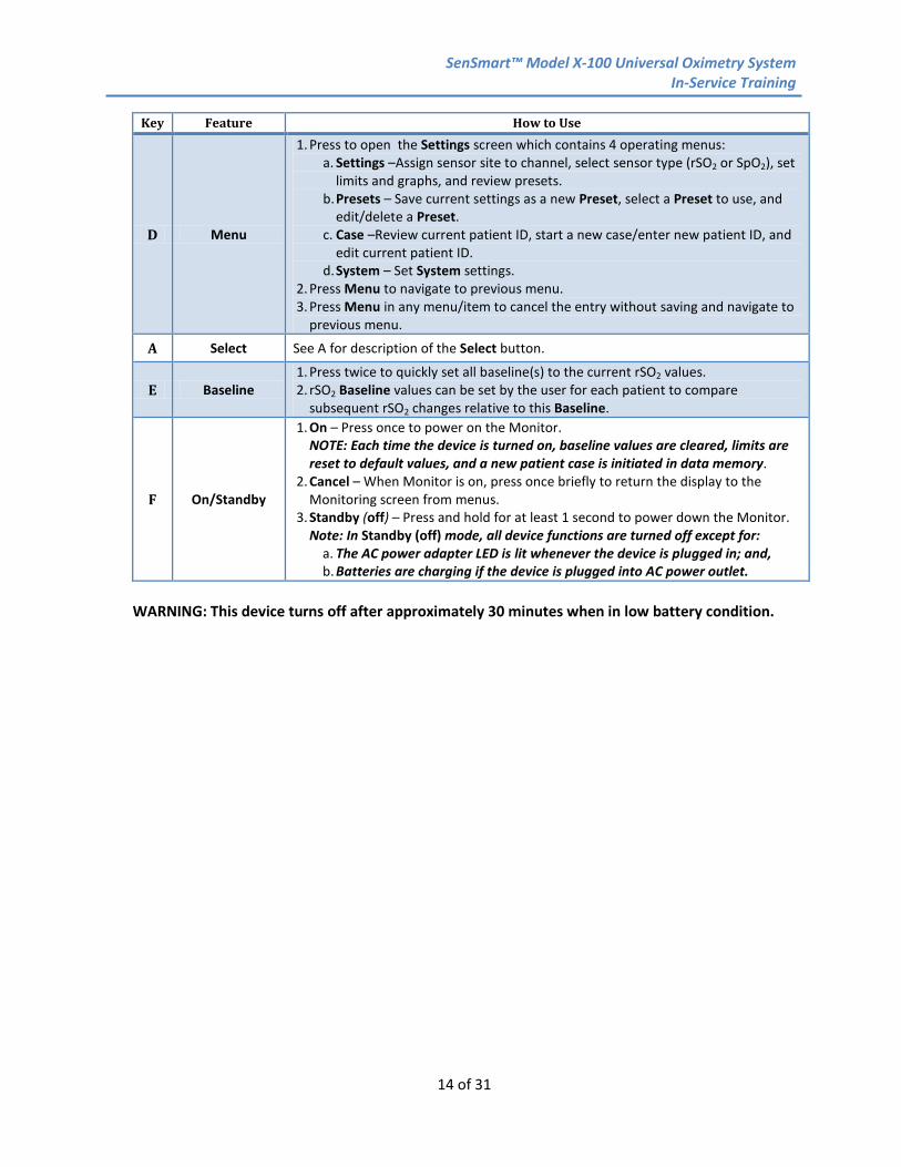
D Menu
1. Press to open the Settings screen which contains 4 operating menus: a. Settings –Assign sensor site to channel, select sensor type (rSO2 or SpO2), set
limits and graphs, and review presets. b. Presets – Save current settings as a new Preset, select a Preset to use, and
edit/delete a Preset. c. Case –Review current patient ID, start a new case/enter new patient ID, and
edit current patient ID. d. System – Set System settings.
2. Press Menu to navigate to previous menu. 3. Press Menu in any menu/item to cancel the entry without saving and navigate to
previous menu.
A Select See A for description of the Select button.
E Baseline 1. Press twice to quickly set all baseline(s) to the current rSO2 values. 2. rSO2 Baseline values can be set by the user for each patient to compare
subsequent rSO2 changes relative to this Baseline.
F On/Standby
1. On – Press once to power on the Monitor. NOTE: Each time the device is turned on, baseline values are cleared, limits are reset to default values, and a new patient case is initiated in data memory.
2. Cancel – When Monitor is on, press once briefly to return the display to the Monitoring screen from menus.
3. Standby (off) – Press and hold for at least 1 second to power down the Monitor. Note: In Standby (off) mode, all device functions are turned off except for:
a. The AC power adapter LED is lit whenever the device is plugged in; and, b. Batteries are charging if the device is plugged into AC power outlet.
WARNING: This device turns off after approximately 30 minutes when in low battery condition.
SenSmart™ Model X-100 Universal Oximetry System In-Service Training
15 of 31
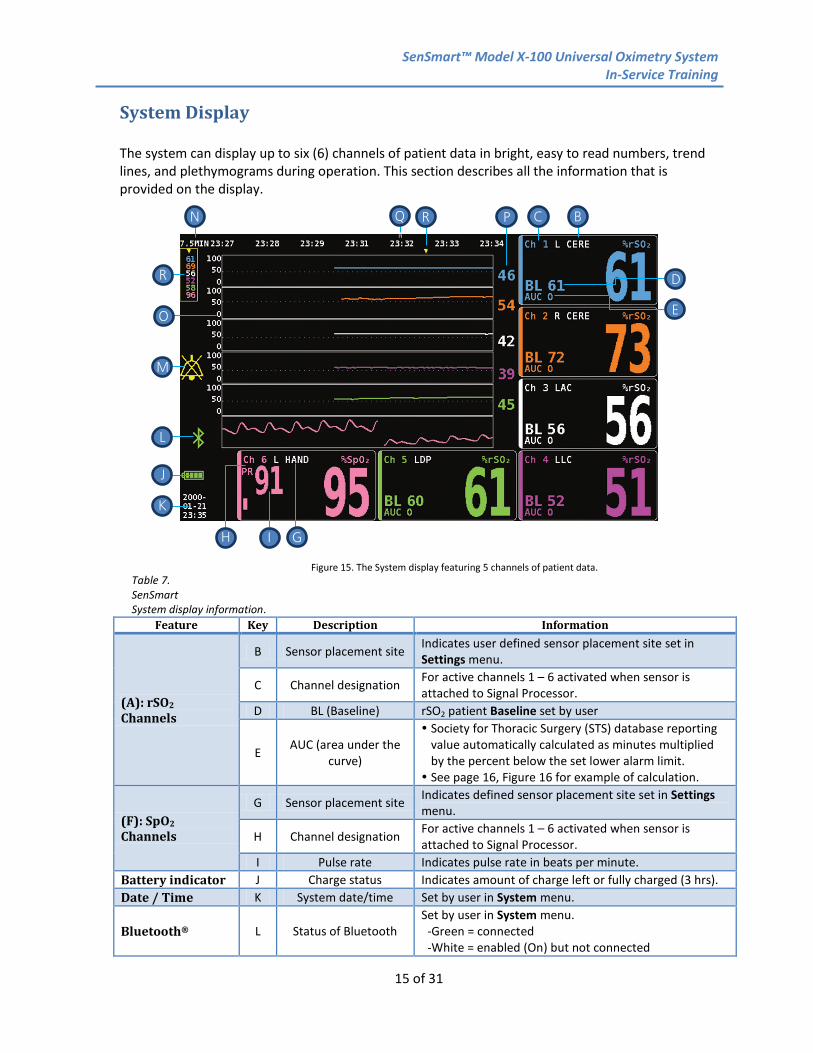
System Display The system can display up to six (6) channels of patient data in bright, easy to read numbers, trend lines, and plethymograms during operation. This section describes all the information that is provided on the display.
Table 7. SenSmart System display information.
Feature Key Description Information
(A): rSO2 Channels
B Sensor placement site Indicates user defined sensor placement site set in Settings menu.
C Channel designation For active channels 1 – 6 activated when sensor is attached to Signal Processor.
D BL (Baseline) rSO2 patient Baseline set by user
E AUC (area under the curve)
Society for Thoracic Surgery (STS) database reporting value automatically calculated as minutes multiplied by the percent below the set lower alarm limit. See page 16, Figure 16 for example of calculation.
(F): SpO2 Channels
G Sensor placement site Indicates defined sensor placement site set in Settings menu.
H Channel designation For active channels 1 – 6 activated when sensor is attached to Signal Processor.
I Pulse rate Indicates pulse rate in beats per minute. Battery indicator J Charge status Indicates amount of charge left or fully charged (3 hrs). Date / Time K System date/time Set by user in System menu.
Bluetooth® L Status of Bluetooth Set by user in System menu. -Green = connected -White = enabled (On) but not connected
Figure 15. The System display featuring 5 channels of patient data.
M
R
D
E
B
C
N
O
P
Q R
J
K
L
H
I G
SenSmart™ Model X-100 Universal Oximetry System In-Service Training
16 of 31
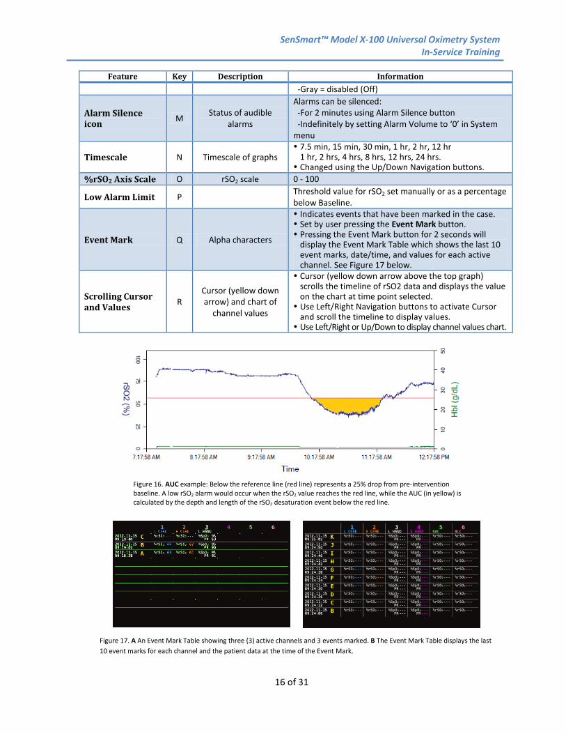
Feature Key Description Information -Gray = disabled (Off)
Alarm Silence icon M Status of audible
alarms
Alarms can be silenced: -For 2 minutes using Alarm Silence button -Indefinitely by setting Alarm Volume to ‘0’ in System menu
Timescale N Timescale of graphs 7.5 min, 15 min, 30 min, 1 hr, 2 hr, 12 hr
1 hr, 2 hrs, 4 hrs, 8 hrs, 12 hrs, 24 hrs. Changed using the Up/Down Navigation buttons.
%rSO2 Axis Scale O rSO2 scale 0 - 100
Low Alarm Limit P Threshold value for rSO2 set manually or as a percentage below Baseline.
Event Mark Q Alpha characters
Indicates events that have been marked in the case. Set by user pressing the Event Mark button. Pressing the Event Mark button for 2 seconds will
display the Event Mark Table which shows the last 10 event marks, date/time, and values for each active channel. See Figure 17 below.
Scrolling Cursor and Values R
Cursor (yellow down arrow) and chart of
channel values
Cursor (yellow down arrow above the top graph) scrolls the timeline of rSO2 data and displays the value on the chart at time point selected. Use Left/Right Navigation buttons to activate Cursor
and scroll the timeline to display values. Use Left/Right or Up/Down to display channel values chart.
Figure 16. AUC example: Below the reference line (red line) represents a 25% drop from pre-intervention baseline. A low rSO2 alarm would occur when the rSO2 value reaches the red line, while the AUC (in yellow) is calculated by the depth and length of the rSO2 desaturation event below the red line.
Figure 17. A An Event Mark Table showing three (3) active channels and 3 events marked. B The Event Mark Table displays the last 10 event marks for each channel and the patient data at the time of the Event Mark.
SenSmart™ Model X-100 Universal Oximetry System In-Service Training
17 of 31
System Configuration Screens and Menus The System has four (4) operating menus to configure the system for specific needs.
1. Settings 2. Presets 3. Case 4. System
All menus are accessed via the Menu button and are then navigated using the Navigation buttons on the left side of the Monitor.
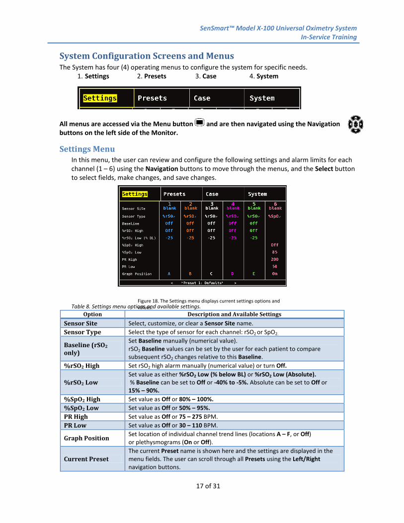
Settings Menu In this menu, the user can review and configure the following settings and alarm limits for each channel (1 – 6) using the Navigation buttons to move through the menus, and the Select button to select fields, make changes, and save changes.
Table 8. Settings menu options and available settings.
Option Description and Available Settings Sensor Site Select, customize, or clear a Sensor Site name. Sensor Type Select the type of sensor for each channel: rSO2 or SpO2.
Baseline (rSO2 only)
Set Baseline manually (numerical value). rSO2 Baseline values can be set by the user for each patient to compare subsequent rSO2 changes relative to this Baseline.
%rSO2 High Set rSO2 high alarm manually (numerical value) or turn Off.
%rSO2 Low Set value as either %rSO2 Low (% below BL) or %rSO2 Low (Absolute). % Baseline can be set to Off or -40% to -5%. Absolute can be set to Off or 15% – 90%.
%SpO2 High Set value as Off or 80% – 100%. %SpO2 Low Set value as Off or 50% – 95%. PR High Set value as Off or 75 – 275 BPM. PR Low Set value as Off or 30 – 110 BPM.
Graph Position Set location of individual channel trend lines (locations A – F, or Off) or plethysmograms (On or Off).
Current Preset The current Preset name is shown here and the settings are displayed in the menu fields. The user can scroll through all Presets using the Left/Right navigation buttons.
Figure 18. The Settings menu displays current settings options and values.
SenSmart™ Model X-100 Universal Oximetry System In-Service Training
18 of 31
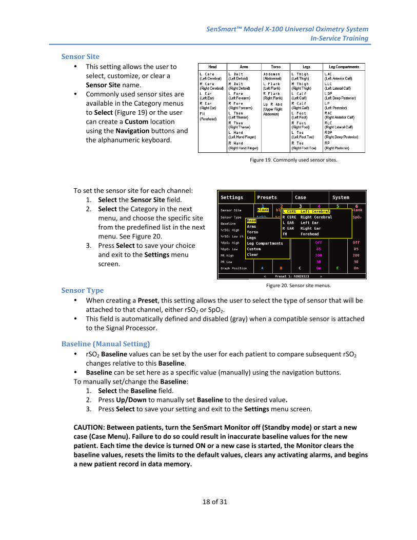
Sensor Site This setting allows the user to
select, customize, or clear a Sensor Site name.
Commonly used sensor sites are available in the Category menus to Select (Figure 19) or the user can create a Custom location using the Navigation buttons and the alphanumeric keyboard.
To set the sensor site for each channel: 1. Select the Sensor Site field. 2. Select the Category in the next
menu, and choose the specific site from the predefined list in the next menu. See Figure 20.
3. Press Select to save your choice and exit to the Settings menu screen.
Sensor Type When creating a Preset, this setting allows the user to select the type of sensor that will be
attached to that channel, either rSO2 or SpO2. This field is automatically defined and disabled (gray) when a compatible sensor is attached
to the Signal Processor.
Baseline (Manual Setting) rSO2 Baseline values can be set by the user for each patient to compare subsequent rSO2
changes relative to this Baseline. Baseline can be set here as a specific value (manually) using the navigation buttons. To manually set/change the Baseline:
1. Select the Baseline field. 2. Press Up/Down to manually set Baseline to the desired value. 3. Press Select to save your setting and exit to the Settings menu screen.
CAUTION: Between patients, turn the SenSmart Monitor off (Standby mode) or start a new case (Case Menu). Failure to do so could result in inaccurate baseline values for the new patient. Each time the device is turned ON or a new case is started, the Monitor clears the baseline values, resets the limits to the default values, clears any activating alarms, and begins a new patient record in data memory.
Figure 19. Commonly used sensor sites.
Figure 20. Sensor site menus.

SenSmart™ Model X-100 Universal Oximetry System In-Service Training
19 of 31
Figure 22. Alarm limits factory defaults and setting options.
Figure 21. High and low alarm limit options in the Settings menu.
Setting High and Low Alarm Limits for rSO2 or SpO2 1. Connect a sensor to the Signal
Processor. 2. Use Left/Right and Up/Down to move
to and Select the desired channel and the alarm limit setting (shown in the red rectangle).
3. Press Up/Down and Select to change and Save the setting. See Figure 22 below for alarm limit setting options.
4. Repeat as needed for each of the high and low alarm limit settings on all active channels. When complete, press Menu twice to return to the monitoring screen, or allow the screen to time out.
WARNING: Ensure all alarm volumes are set appropriately and are audible in all situations. Do not cover or otherwise block the speaker opening.
Graph Position Data can be graphed for each channel on
the display. Regional oximetry values will be graphed as a trend line, pulse oximetry values will be graphed as a plethysmogram.
The System can display from one to six graphs, showing the rSO2 trend line data or the SpO2 plethysmograms, color-coded to match the channel and Signal Processor colors.
Multiple rSO2 trend lines (up to six) can be placed on one graph; however, rSO2 trend lines and SpO2 plethysmograms cannot be on the same graph, and multi SpO2 plethysmograms cannot be on the same graph.
rSO2 trend lines: select A through F, or Off, SpO2 plethysmograms: select On or Off Trend lines appear in order of channels from A through F; plethysmograms follow on the
screen and display in order of the channel selected.
To select and edit graph positions for each channel: 1. Select the Graph Position setting in the desired channel. 2. Press Up/Down and Select to change and save the setting.
SenSmart™ Model X-100 Universal Oximetry System In-Service Training
20 of 31
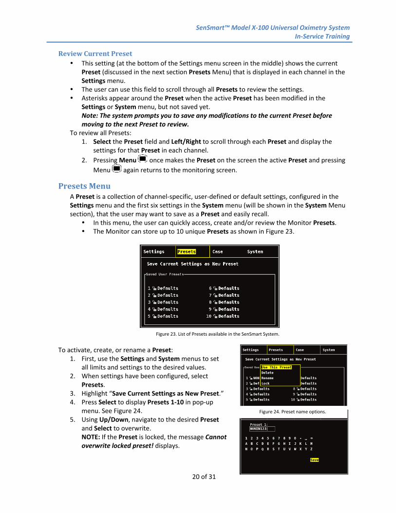
Review Current Preset This setting (at the bottom of the Settings menu screen in the middle) shows the current
Preset (discussed in the next section Presets Menu) that is displayed in each channel in the Settings menu.
The user can use this field to scroll through all Presets to review the settings. Asterisks appear around the Preset when the active Preset has been modified in the
Settings or System menu, but not saved yet. Note: The system prompts you to save any modifications to the current Preset before moving to the next Preset to review.
To review all Presets: 1. Select the Preset field and Left/Right to scroll through each Preset and display the
settings for that Preset in each channel. 2. Pressing Menu once makes the Preset on the screen the active Preset and pressing
Menu again returns to the monitoring screen.
Presets Menu A Preset is a collection of channel-specific, user-defined or default settings, configured in the Settings menu and the first six settings in the System menu (will be shown in the System Menu section), that the user may want to save as a Preset and easily recall. In this menu, the user can quickly access, create and/or review the Monitor Presets. The Monitor can store up to 10 unique Presets as shown in Figure 23.
To activate, create, or rename a Preset:
1. First, use the Settings and System menus to set all limits and settings to the desired values.
2. When settings have been configured, select Presets.
3. Highlight “Save Current Settings as New Preset.” 4. Press Select to display Presets 1-10 in pop-up
menu. See Figure 24. 5. Using Up/Down, navigate to the desired Preset
and Select to overwrite. NOTE: If the Preset is locked, the message Cannot overwrite locked preset! displays.
Figure 23. List of Presets available in the SenSmart System.
Figure 24. Preset name options.

SenSmart™ Model X-100 Universal Oximetry System In-Service Training
21 of 31
6. Enter Preset name (maximum of 11 alphanumeric characters) using the Navigation buttons on the alphanumeric keyboard. See Figure 25.
7. Press Down to highlight Save, and Select to save and activate the Preset. 8. The display returns to the monitoring screen.
Case Menu The Case menu screen allows the user to view the Current patient ID, Start a new case and enter a new patient ID, or Edit patient ID on the current case. See Figure 26.
Open the Case Menu
1. Press Menu. 2. Press right twice to highlight the Case tab. Case Menu screen displays.
Start a New Case 1. While in the Case Menu screen, use the navigation
buttons to move to and highlight “Start new case.” 2. Press Select. “Start new case?” pop-up displays with
No highlighted. 3. Press the down navigation arrow to highlight Yes. 4. Press Select. • If system is set up to enter a patient ID at the start of a new case (see “Patient ID Request” for more information):
- Alphanumeric keyboard screen displays. Follow steps 3 – 6 in the next procedure, “Edit a Patient ID.” See Figure 27 - After patient ID is entered, “Starting new case...” displays. Monitor returns to monitoring screen and all baselines from the previous case are cleared.
• If system is not set up to enter a patient ID at the start of a new case: - “Starting new case...” displays. Monitor returns to monitoring screen and all baselines from the previous case are cleared.
- The case will not have a patient ID.
Figure 25. Alphanumeric keyboard used to name a Preset.
Figure 26. Case menu options.
Figure 27. Start new case menu options.
SenSmart™ Model X-100 Universal Oximetry System In-Service Training
22 of 31
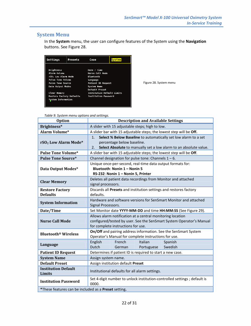
System Menu In the System menu, the user can configure features of the System using the Navigation buttons. See Figure 28.
Table 9. System menu options and settings.
Option Description and Available Settings Brightness* A slider with 15 adjustable steps; high to low. Alarm Volume* A slider bar with 15 adjustable steps; the lowest step will be Off.
rSO2 Low Alarm Mode* 1. Select % Below Baseline to automatically set low alarm to a set
percentage below baseline. 2. Select Absolute to manually set a low alarm to an absolute value.
Pulse Tone Volume* A slider bar with 15 adjustable steps; the lowest step will be Off. Pulse Tone Source* Channel designation for pulse tone: Channels 1 – 6.
Data Output Modes* Unique once-per-second, real-time data output formats for: Bluetooth: Nonin 1 – Nonin 5 RS-232: Nonin 1 – Nonin 5, Printer
Clear Memory Deletes all patient data recordings from Monitor and attached signal processors.
Restore Factory Defaults
Discards all Presets and institution settings and restores factory defaults.
System Information Hardware and software versions for SenSmart Monitor and attached Signal Processors.
Date/Time Set Monitor date YYYY-MM-DD and time HH:MM:SS (See Figure 29).
Nurse Call Mode Allows alarm notification at a central monitoring location configured/tested by user. See the SenSmart System Operator’s Manual for complete instructions for use.
Bluetooth® Wireless On/Off and pairing address information. See the SenSmart System Operator’s Manual for complete instructions for use.
Language English Dutch
French German
Italian Portuguese
Spanish Swedish
Patient ID Request Determines if patient ID is required to start a new case. System Name Assign system name. Default Preset Assign institution default Preset Institution Default Limits Institutional defaults for all alarm settings.
Institution Password Set 4-digit number to unlock institution-controlled settings ; default is 0000.
*These features can be included as a Preset setting.
Figure 28. System menu
SenSmart™ Model X-100 Universal Oximetry System In-Service Training
23 of 31
To select and change the System settings:
1. Use the Navigation buttons to move to and Select the desired feature in the System Menu.
2. Press Up/Down and Left/Right to edit settings and Select to save the setting. 3. Repeat as needed for each of the settings. 4. When complete, press Menu twice to return to the monitoring screen, or allow the
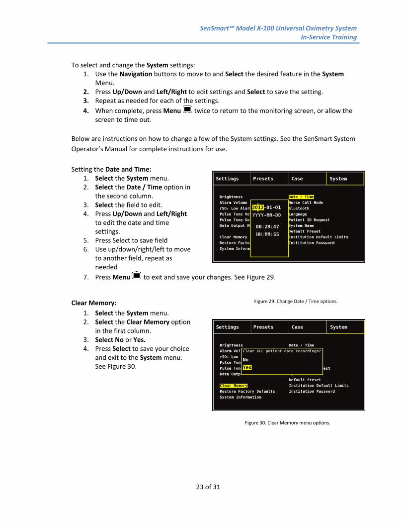
screen to time out. Below are instructions on how to change a few of the System settings. See the SenSmart System Operator’s Manual for complete instructions for use. Setting the Date and Time:
1. Select the System menu. 2. Select the Date / Time option in
the second column. 3. Select the field to edit. 4. Press Up/Down and Left/Right
to edit the date and time settings.
5. Press Select to save field 6. Use up/down/right/left to move
to another field, repeat as needed
7. Press Menu to exit and save your changes. See Figure 29.
Clear Memory: 1. Select the System menu. 2. Select the Clear Memory option
in the first column. 3. Select No or Yes. 4. Press Select to save your choice
and exit to the System menu. See Figure 30.
Figure 29. Change Date / Time options.
Figure 30. Clear Memory menu options.

SenSmart™ Model X-100 Universal Oximetry System In-Service Training
24 of 31
Review System Menus To review what you have learned about the System menus during configuration of the System, please complete the following tasks:
1. In the Settings Menu: a. Set the Sensor Site for Channel 1 to Left Cerebral. b. Set Channel 1 Sensor Type to rSO2. c. Set the Sensor Site for Channel 2 to Right Cerebral. d. Set Channel 2 Sensor Type to rSO2. e. Set the Sensor Site for Channel 3 to Left Hand Finger. f. Set Channel 3 Sensor Type to SpO2. g. For Channel 3, set the SpO2 High alarm setting at 100% and the SpO2 Low at 90%. h. For Channel 3, set the PR High alarm setting at 150 and the PR Low alarm setting at
50. i. Set both rSO2 channels to a rSO2% Low alarm setting of -25. j. Set both rSO2 channels to a rSO2% High alarm setting of 90.
2. Verify your new settings in the Settings Menu. 3. Save these new settings as a Preset named TRAINING in the Presets Menu. 4. In the System Menu:
a. Set the Date/Time to the current date and current time. b. Set the Alarm Volume to the lowest setting.
5. In the System Menu: a. Set the rSO2 Low Alarm Mode to Absolute.
6. In the Settings Menu: a. Set the %rSO2 Low (Abs) in the rSO2 channels to 49.
7. In the Preset Menu: a. Save the new settings as a Preset named TRAINING2. b. Return to the monitoring screen.
8. Set the rSO2 Baselines to the current rSO2 values at this time. 9. Mark an Event at this time.
a. Note the Event alpha character that appears _______ b. Note the channel 1 rSO2 value at this time _______ c. Note the SpO2 value at this time _______
Congratulations! You will now be able to set up the System and begin patient monitoring.
SenSmart™ Model X-100 Universal Oximetry System In-Service Training
25 of 31
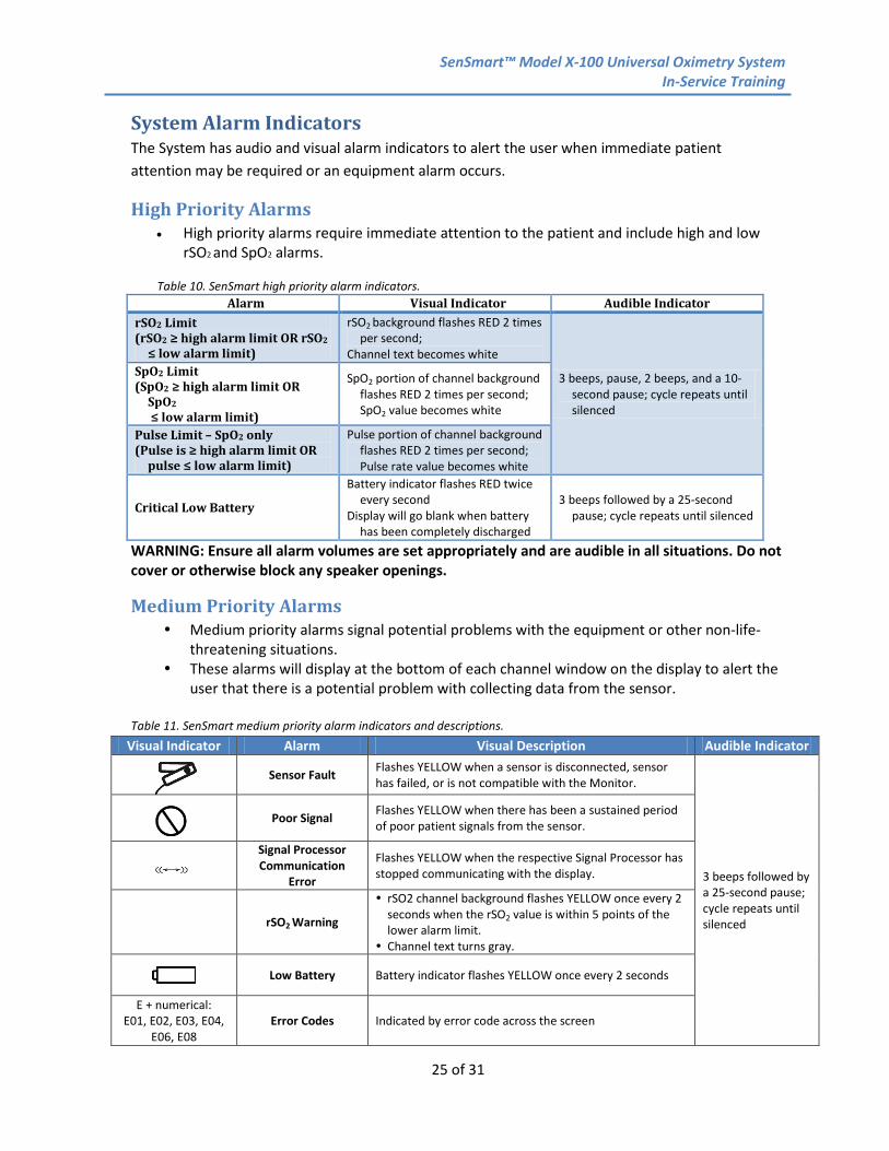
System Alarm Indicators The System has audio and visual alarm indicators to alert the user when immediate patient attention may be required or an equipment alarm occurs.
High Priority Alarms • High priority alarms require immediate attention to the patient and include high and low
rSO2 and SpO2 alarms. Table 10. SenSmart high priority alarm indicators.
Alarm Visual Indicator Audible Indicator rSO2 Limit (rSO2 ≥ high alarm limit OR rSO2
≤ low alarm limit)
rSO2 background flashes RED 2 times per second;
Channel text becomes white
3 beeps, pause, 2 beeps, and a 10-second pause; cycle repeats until silenced
SpO2 Limit (SpO2 ≥ high alarm limit OR
SpO2 ≤ low alarm limit)
SpO2 portion of channel background flashes RED 2 times per second; SpO2 value becomes white
Pulse Limit – SpO2 only (Pulse is ≥ high alarm limit OR
pulse ≤ low alarm limit)
Pulse portion of channel background flashes RED 2 times per second; Pulse rate value becomes white
Critical Low Battery
Battery indicator flashes RED twice every second
Display will go blank when battery has been completely discharged
3 beeps followed by a 25-second pause; cycle repeats until silenced
WARNING: Ensure all alarm volumes are set appropriately and are audible in all situations. Do not cover or otherwise block any speaker openings.
Medium Priority Alarms Medium priority alarms signal potential problems with the equipment or other non-life-
threatening situations. These alarms will display at the bottom of each channel window on the display to alert the
user that there is a potential problem with collecting data from the sensor.
Table 11. SenSmart medium priority alarm indicators and descriptions. Visual Indicator Alarm Visual Description Audible Indicator
Sensor Fault Flashes YELLOW when a sensor is disconnected, sensor has failed, or is not compatible with the Monitor.
3 beeps followed by a 25-second pause; cycle repeats until silenced
Poor Signal Flashes YELLOW when there has been a sustained period
of poor patient signals from the sensor.
Signal Processor Communication
Error
Flashes YELLOW when the respective Signal Processor has stopped communicating with the display.
rSO2 Warning
rSO2 channel background flashes YELLOW once every 2 seconds when the rSO2 value is within 5 points of the lower alarm limit.
Channel text turns gray.
Low Battery Battery indicator flashes YELLOW once every 2 seconds
E + numerical: E01, E02, E03, E04,
E06, E08 Error Codes Indicated by error code across the screen

SenSmart™ Model X-100 Universal Oximetry System In-Service Training
26 of 31
Troubleshooting • If you encounter any of the following visual or audible alarms, please review the possible
causes and solutions to resolve the problem. • Save all suspect components for return to Nonin Technical Service for evaluation. • If these actions do not resolve the problem, please contact Nonin Technical Service at: USA and Canada 800-356-8874 Outside USA and Canada +1 763-553-9968 Europe +46 650 401500
Table 12. SenSmart troubleshooting guide.
Visual Indicator Problem/Possible Cause Possible Solutions
CHANNEL DOES NOT APPEAR ON MONITOR
Signal processor is attached, but the channel does not
appear on the display
Turn the X-100M off and then back on again. If the signal processor does still not display, go to the System Menu, and then the System Information pop-up. If the channel is not in the list of attached sensors, the signal processor is not communicating to the display device. Contact Nonin Technical Service.
DASHES (- - -) APPEAR IN THE rO2 CHANNEL DISPLAY
Sensor or Signal Processor is
disconnected
1. Ensure all connections between components are secure. a. Check the connection between the sensor and the
Signal Processor. b. Check the connection between the Signal Processor
and the Hub. c. Check the connection between the Hub and the
Monitor.
The signal from the
sensor is inadequate
1. Check sensor application to ensure it is properly adhered to the patient.
a. Cover the sensor with your hand and apply very light pressure to see if this eliminates the error. If a value displays again, this is an indication that the sensor is lifting from the skin due to moisture or poor adhesion.
2. Ensure the sensor edges are secure. 3. Remove the sensor and wipe away the moisture if
possible. 4. Sensor should be replaced if it does not adhere properly.
A system component
is not functioning
properly
1. Remove the sensor from the patient to observe if the sensor emitters are flashing red while the system is on.
a. If one emitter is not flashing, replace the sensor. b. If both emitters are not flashing, disconnect and
reconnect the Signal Processor at the Hub connection. If both emitters continue to not flash, replace the sensor.
c. If both emitters are flashing and an alarm symbol is present, replace the sensor.

SenSmart™ Model X-100 Universal Oximetry System In-Service Training
27 of 31
Visual Indicator Problem/Possible Cause Possible Solutions
2. If the new sensor does not work, replace the Signal Processor at this time.
3. Save all suspect components for return to Nonin Technical Service for evaluation.
4. Contact Nonin Technical Service
The Signal Processor is
damaged or not functioning
properly. Connections may
not be secure.
1. Ensure all connections between components are secure. a. Check the connection between the sensor and the
Signal Processor. b. Check the connection between the Signal Processor
and the Hub. c. Check the connection between the Hub and the
Monitor. 2. Turn the Monitor off and then back on again. 3. Contact Nonin Technical Service.
The SenSmart display is not functioning.
1. If all channels show dashes, verify secure connections on the Hub to the Signal Processor and to the Monitor.
2. Contact Nonin Technical Service. ONE OR MORE CHANNELS DISPLAY MESSAGE “UNRECOGNIZED PACKET)"
One or more channels display
the message “Unrecognized
packet.”
Verify that duplicate signal processors are not attached to the hub. Remove or replace the duplicate signal processor.
AN ERROR CODE APPEARS IN THE DISPLAY AREA.
E01, E02, E03, E04, E06, E08
The SenSmart System
encountered an error.
1. Turn the Monitor off to go through a proper shutdown process.
2. Turn the Monitor on again. 3. If the error persists, note the error code and contact Nonin
Technical Service.
THE UNIT IS IN ALARM MODE, BUT NO AUDIBLE ALARMS CAN BE HEARD.
The 2-minute Alarm Silence
button is activated
1. Press Alarm Silence to re-engage alarm volume. 2. After 2 minutes of silence, alarm tones automatically re-
engage.
Audible volume
set to “0” in alarm limits.
1. Adjust volume up through System menu. 2. Contact Nonin Technical Service if alarm tones continue to
not be audible.
SENSMART SYSTEM WILL NOT ACTIVATE.
Blank display The unit has no power.
1. Plug in the AC adapter. 2. Turn the Monitor on. 3. If the Monitor does not power on, contact Nonin Technical
Service.

SenSmart™ Model X-100 Universal Oximetry System In-Service Training
28 of 31
Visual Indicator Problem/Possible Cause Possible Solutions
SENSMART SYSTEM WILL NOT OPERATE ON BATTERIES.
The battery pack is not charged.
1. Plug in the SenSmart System AC Adapter to charge the battery pack.
2. Turn the Monitor on. 3. If Monitor does not power on, contact Nonin Technical
Service.
The battery pack is inoperable. Contact Nonin Technical Service for repair or replacement.
System Memory Data Recording in the System functions in an endless loop, meaning that when the memory
capacity is reached, as described in Table 13 below, the System begins overwriting the oldest data with new data.
rSO2 or SpO2 and HR is sampled and recorded once every 4 seconds for each channel. Patient data can be cleared using the
Clear Memory option in the System menu. See Figure 31. Table 13. SenSmart System memory. Hours of Memory Channels in Use
840 2 420 4 280 6
System Data Outputs The System features 5 different once-per-second, real-time data output formats, Nonin 1 –
Nonin 5. Data output formats can be selected through the Data Output Modes option in the Systems
menu. See the SenSmart System Operator’s Manual for complete information and instructions for
use for all data output formats.
Figure 31. Clear Memory menu options.
SenSmart™ Model X-100 Universal Oximetry System In-Service Training
29 of 31
Cleaning the System Components 1. Wipe all components (Monitor, Signal Processors, Hub, Hub Holster, and SenSmart 8100SX
Pulse Oximetry Soft Sensors) with a soft cloth dampened with a mild detergent or a 10% bleach solution (household bleach [5.25% sodium hypochlorite]). Do not use undiluted bleach or any cleaning solution other than those recommended here, as permanent damage could result.
2. Dry with a soft cloth or allow to air dry. 3. SenSmart rSO2 sensors are single use and should be discarded after one use. CAUTION: Do not sterilize, autoclave, immerse, spray with liquid, or use caustic or abrasive cleaning agents. Do not use cleaning agents or cleaning products that contain ammonium chloride.
SenSmart™ Model X-100 Universal Oximetry System In-Service Training
30 of 31
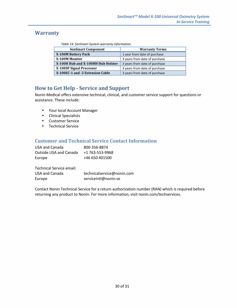
Warranty
Table 14. SenSmart System warranty information. SenSmart Component Warranty Terms
X-100M Battery Pack 1 year from date of purchase X-100M Monitor 3 years from date of purchase X-100H Hub and X-100HH Hub Holster 3 years from date of purchase X-100SP Signal Processor 3 years from date of purchase X-100EC-1 and -2 Extension Cable 3 years from date of purchase
How to Get Help - Service and Support Nonin Medical offers extensive technical, clinical, and customer service support for questions or assistance. These include: Your local Account Manager Clinical Specialists Customer Service Technical Service
Customer and Technical Service Contact Information USA and Canada 800-356-8874 Outside USA and Canada +1 763-553-9968 Europe +46 650 401500 Technical Service email: USA and Canada [email protected] Europe [email protected] Contact Nonin Technical Service for a return authorization number (RAN) which is required before returning any product to Nonin. For more information, visit nonin.com/techservices.

SenSmart™ Model X-100 Universal Oximetry System In-Service Training
31 of 31