Embed Size (px)
Citation preview
(
(
(
Bandwidth Efficient Filter Banks for Tran3multiplexers
by
Ravi Prakash Ramachandran M.Eng. (Electrical)
A thesis submittcd to the Faculty of Graduate Studies and Rescarch in partial fulfillment of the requirements
fol' the dcgree of Dodor of Philosophy
Dcpartment of ElectrÎcaI Erigineering McGill University Montréal, Canada Scptembcr 1990
© Ravi Prakash Ramachandran, 1990
Abstract This thesis addresses the problem of simultaneously transmitting several data
signaIs across a single channcl. For this purpose, a transmultiplexcr that uses modu
latcd fi/ter hanks is studied. Modulated filter banks comprise filters that are bandpass
versions of a lowpass prototype. The filters serve to assign portions of the channel
bandwidth to the data signais. The impulse responses of the filters are parameter
ized hy a ccnt.er frequency, delay and phase factor. The objectives in configuring
modulakd filter hanks arc to use the full channel bandwitlth for transmission, cancel
cl'Osstalk hctwecn signaIs (arises when signaIs share bandwidth) and cancel intersym
hol intcrfrrellcr in each data signal. Assuming an ideal channel, a r,)'nth"'sis procedure
is dev('loped hy assigning a handwidth to the lowpass prototype and deriving relation
sltips among th(' ccnt.er fl'equencies, delays and phases suclt thcü the ent.ire channel
bandwidt.h is ut.ilized and crasstalk is canccllcd. New design procedmcs for an FIR
lowpass protot.ype arc proposed stlch that the intcrsymbol interfclencc is suppressed.
Olle drsign mrt.hod is based 011 a minimax criterion. Another approach involves an
lI11constraincd optimization of an error function.
The synt.hcsis procedure leads to five bandwidth efficient transmultiplexers. Threc
of t.he systC\I1lS implcment multicarrier Quadrature Amplitude Modulation (QAM) and
I.wo accolllplish mult.icarricl' Vestigial Sidcband ~1f)r1ulation (VSI3). The performance
of t.he fi \'l' syst.ems is compared with filtcrs obtained by the ncw design appl'oaches.
Also, t.hc issue' of channel distortion is addresscd. Finally, the tral1smultiplexel's ean
be converl.('d into new subband systcms.
- z -
Sommaire La transmission simulta,née de plusieurs signaux llumériques sm un cilnaluniqu('
constitue le sujet de cctte thèse. POUf accomplir cette t.âche, \lll t.l'anslllllltipl('x(·1I\' uti
lisant un banc de filtres modulés est étudié. Les ban(s dt, filt,\(·s lllodlll(~~ ~Ollt. f()rlll(~CS
des filtres qui SOllt des versions passe-handes de prototYI)(' pass('-bas. ],,,s filt \'('S onl
pour fonction l'attributioll de ponions de la ballde dl' f\'(~qll(,II«' d" (',ln,11 él.IIX ~iP;lI,lllX
numériques. Les paramètres servant à caractériser les \,(~pOIIS('S ilIlplllslol\lH'II('s des
filtres sont la fréquencc ccntrale, le d(~lai ct 1(, f"d('ul de phase'. ],('s obj('( 1 Ifs, IO\~ ,1('
la configuration de bancs de filtrps nIOd Il Ic~s, sont 1'11 ti lisa t ion d(' 1" plein(' 1,1 rgPII r (h·
bande lOIS de la transmission, l'éliminatioll d(' la diapholli(' ('Ilt.I(· 1<-.. ',igll,IIIX (('C1 SIII
vient lorsque les signaux partilg('I1t unc mt'm(' band(' dl' f\("qIlCll«') ('1 ],(:IillIl Il,t! iOll dl'
l'interférellcc el1tle symbolcs dans chaclIll des signal!'x Illllll(~\'lql\f'~. :\~~IIIl1,llIl Illl (ail,"
idéal, une méthode de syn thèse est Mveloppée' e'1I assiglla Il 1 nIJ(' ba Il dt' dl' fI (~qll('lI(,('
au prototype passe-bas ('t ('II d(?rivant (ks IPlaliolls (,lIlle' I('s f\'(;qll('I\('I'~ «·IIt.ral<-s,
les délais ct les phases qui assurellt lllH' ent iè're ut ili..,,,t iOll dl' la hall(1<- dl' fI l~qIlPll(,('
du canal ct l'élimillat.ion de la diaphonie. D(· lIOIIV(·I\I'S \1lpl hod('" dl' (Olll <'l't iOll el('
prototype passe-bas HI F, a~surant 1 'éli mi nat ion dt· 1 ï li t 1'1 f(~n'I\( (' ('11 t \1' ~ylll \'ol<-s, !'lOIlI
proposées. Une méthode de conception est ha~{>(' suc 1(· nit( " llIinilltax. lhl(' ail 1, II'
approche utilise t1ne optimi~ation "ans conl r"illlps d'lllH' fOII< tiOll d'('IICIII.
La méthodc de syllth(.~e ~'ollduit à cinq 1 rcllblllull ipl('xelll S III dl~allt 1ft balld(· dl'
fréquence efficaccl1len t. l'lOis d('s systèmcs é!CCOill pl i~~('ll t Q:\:--I, alOI ~ q 11(' d('IIX il Il tl (':'
utilisent VSB. La per[01111élnCC de ce~ cinq Sy:~tl'I\l(,S, IIlili~cllll h'~ fillll'~ olll('III1:' ,IV('I
les l1CJuvelies métll(l~ies de conceptioll, l'st (~v(dl\(~('. Ik plll~. 1<. plOhli'lI\(' (1<,1,\ di:.tOlsioIl
provoquée par le canal l'st con:.idéré. Fina!p\ll(,llt., \C>" tran:'lIlIJ!tipl<'x('I\I'S IWI\VPllt ('1,1<'
convertis en nouvelles fOrn1<'8 de systèll1('s ell SOIlS- h,tlj(I("~.
- Il -
J
A ~knowledgements
1 would likc to thank my supervisor Dr. Peter I\abal for his guidance. The major
portion of the' re'search was conductcd al. INRS. The laboratory facilities given by
INHS if: gn'atly apprcciated. Moreovcr, part of the investigation was carried out at
t.he Univ('fsity of Califol'llia, Santa Barbara (UCSll). A special thanks goes to Dr. A.
(;('\sl1o fOl giving Ill(' the' Oppol'tullity 1.0 work al. UCSll The scholarships awarded by
t.Ilf' Nat, 111 al Sci('!)("(,s aIld Engineering Rcscarch CouIIcil of C'ana.:la and Fonds FCAR
arc app\'e'cÎatcd. In additioll, 1 thank Dr. Peter Kabal for his financial support during
the final year of my Ph.D. studics.
r owc a very Rpecial thai1ks to my parents for their con tinuous support and e'1-
coul'ag<'lIwllt throughout Illy studicR. My thanks also goes 1.0 Dr. 1\1. 1,. B10stein for
the fruitflll discussioll on filter design. The following classmates also deserve men
t.ion for providing the ITIllch necdcd companionship during tll(' course of this work:
(in alphal)('tical ordpr), Duncan Becs, Daniel Bot!(lIeau, Vast! Iyengar, Ahmad Jalali,
Hag,havélll I\allllurpatti and Guylain Roy. 1 also thank DaniC'1 Doudrcau for translat
ÎlIg t.he ahst.ract il\to Flcnch.
- ut-
,
Table of Contents
Abstract ........................................................... .
Somrnail'e . . . . . . . . . . . . . . . . . . . . . . . . . . . . . . . . . . . . . . . . . . . . . . . . . . . . . . . . . . .. /1
Aclcnowledgements . . . . . . . . . . . . . . . . . . . . . . . . . . . . . . . . . . . . . .. ....... ... III
Table of Contents. . . . . . . . . . . . . . . . . . . . . . . . . . . . . . . . . . . . . . . . . . . . . . . . . . . .. II'
List of Figures. . . . . . . . . . . . . . . . . . . . . . . . . . . . . . .. ............ .......... l'
List of Table8. . . . . . . . . . . . . . . . . . . . . . . . . . . . . . . . . . . . . . . . . . . . . . . . . . . . . . . .. 1'1
Chapter 1 Introduction . ...................................... . 1.1 Scope and Organization of tl)(' Thesi-; . . . . . . . . . . . . . . . . . . . . . . . .. ... S
Chapter 2 Multirate Digital Filter Banks............ .... 10
2.1 Transl11ultiplcxcrs and Subband Sy~t('llls ............ . ... , . . . . .. JO
:?1.1 Interpolation and Decimation........... .. ............... 10
2.1.2 Transl1111ltiplcxcr... ............................ .... . . II
2.1.3 Subband System. . . . . . . . . . . . . . . . . . . . . . . . . . . . . . .. ., . . .. J.I
2.1.4 l'omplemcntary Natlll'c of tllC' Systellls '" . .. . .. " .. 1 r")
2.1..5 Net",ork Dllality " ... " ......................... '" . . .... I!)
2.2 Perfect RecoJ1struct ion Prop('rty. . . . . . . . . . . . . . . . . . .. ............ '21
2.2.1 'l'wo Band Cas(' .............................. .......... '21
2.2.2 The N Band Case ............................ . ...... , '2~
2.3 FOClts of Rcscarch Problem . . . . . . . . . . . . . . . . . . . . . . . . . . . . . . . . . . . .. '2Î
Chapter 3 Transmultiplexer Synthesis . . .. ... ...... ..... :n 3.1 Filter Specification ................................... ........ :J 1
3.2 Bandwidth COllstraints. . . . . . . . . .. ..................... :1~
3.3 Input-Output Tran~f('r Functioll .. .. . . . . . ... . . . . .. . ....... " . :1!i
3,4 Analysis of Crosstalk .......................................... :n 3..1.1 Cro~~talk: Diffcl('llt CCllter Freqll<'lIcic·s of SC'I,s 1 and '2 .. .... :1~
3,4.2 l'rosstal k: H(·pC'atc·d ('enter FI<'<!uc·lIcies. . .. ................ -II
3.L3 Uistind ('ellte) Freqll('ncies of Set :3. . . . . . . . . . . . . . . . . . . . . . .. ·1:l
3.5 Syllt.hc~ized Trall.,nllllt iplex('rs ......................... .... .. -H
3.5.1 Systc'Ill '1' 1 .... . . . . . . . . . . . . . . . . . . . . . . . . . . . . . . . . .. .. .... 1!)
:3.5.2
:3.5.3
Systern 1'2 ....................... , .............. . .... .
Systcrn ']':3 ..................................... .
- lV -
\
( ,
:J)),4
3.0 .. /j
:t5.6 :J,!).7
Systern 1',1 . . . . . . . . . . . . . . . . . . . . . . . . . . . . . . . . . . . . . . . . . . . . .. 49
Systef:l 1'.1) . . . . . • . . . . . . . . . . . . . . . . . . . . . . . . . . . • . . . . . 51
Modification of th<, Paramctcrs .. . . . . . . . . . . . . . . . . . . . . . . . . .. 52
Elimination of Int,<'lsymbol Interference. . . . . . . . . . . . . . . . . . . .. 53
:U, Multi, ctni('r QA~I and VSB Sy:.tel1ls ............ , .......... , . . . .. 53
:J. 7 The 'l'wo Band Case .......................................... 57
:J.8 SubhRlld COlllplml<'llts ........................ , .......... , . . . .. 60
Chapter 4 Minimax FiIter Design .. . . . . . . . . . . . . . . . . . . . . . . .. 62
'1.1 D('sigll Prohlelll .,. . . . . . . . . . . . . . . . . . . . . . . . . . . . . . . . . . . . . . . . . . . .. 62
.1.1.1 Tilll<' and Fr('(I'H'llcy Domain R<,quircmen ts . . . . . . . . . . . . . . . .. 62
.1.1.2 Nyquist Filters " ....................................... 63
't.~ Olle PlOtotype Systel11fo. ........................... . . . . . . . . . . . .. 65
.t.:-~ Two Prototype Syst cm . . . . . . . . . . . . . . . . . . . . . . . . . . . . . . . . . . . . . . . .. 67
,1..1 Factorable Minimax D<,sign Procedures. . . . . . . . . . . . . . . . . . . . . . . . . .. 69
.1.'1.1 Filst ~-1ethod ........................ , ............ , . . . . .. 70
,1..1.2 S('coIHI Mcthod . . . . . . . . . . . . . . . . . . . . . . . . . . . . . . . . . . . . . . . . .. 73
.1.5 The Fadol'izat.iol1 PlOblem ........................ . . . . . . . . . . . .. 7.5
.I,fi Discussio' ùf t.he Df':.ign 1'{'chniques ...... . . . . . . . . . . . . . . . . . . . . . .. ïï lUi. 1 ('oll1pam,on of the Two PlOposed ~Iethods. . . . . . . . . . . . . . . . .. 78
.1.(i.2 D('sign Exampl{'s ........................................ 78
.1.6.3 Croup O(·I"y . . . . . . . . . . . . . . . . . . . . . . . . . . . . . . . . . . . . . . . . . . .. 80
,1.7 COlllparisoll \Vith Other ApPl'Oaches................ ............. 82
.1. 7.1
·1.7.2
·1.7.3
Lincar Proglamllling Technique ........................... .
Eigenfilter FOI rnulation .................................. .
l)ired Use of the McClcllan-Parks Algorithm ............... .
82
83
84
Chapter 5 Optimized FHter Banks . ....................... . 89
!l.I Systf'1lI Imperfectiolls . . . . . . . . . . . . . . . . . . . . . . . . . . . . . . . . . . . . . . . . .. 90
5.2
5.:J
5..1
5.5
5.1.1 The Input-Out put Transfcr Function ..................... ,. 91
5.1.2 Crosstalk FUllctions ..................................... , 93
Errol' FUllctioll Formulation. . . . . . . . . . . . . . . . . . . . . . . . . . . . . . . . . . . .. 96
Design Exampl(·s ............................................ , 102
Translllult iplcxf'l Performance. . . . . . . . . . . . . . . . . . . . . . . . . . . . . . . . .. 105
Design for t h(' Complcmcn tary Su bband Systems. . . . . . . . . . . . . . . .. 115
- v -
r Chapter 6 Channel Distortion and
Compensation. . . . . . . . . . . . . . . . . . . . . . . . . . . . . . . . . . .. II ~
6.1 Combating Channel Effecls .. ................................. II~
6.1.1 1'heorct.ical Developll1ent ........... ........ ........... lUI
6.1.2 Performance Evaluation... . . ..... . . . ..... . . . . . ... . . . .... 11ï
6.1.3 Application to Sp('eifie Systems.... . . . ..... . . .. .. ....... 1:10
6.1.'1 Chann(·1 Effecls in a Suhhand Sysl<'lll ........... ......... I:JI
Chapter 7 Conclusions. . . . . . . . . . . . . . . . . . . . . . . . . . . . . . . . . . . . . . . 1 :J:l
7.1 Contributions ....................................... ··.······ l:l:J
7.2 SUnlmarj ..................................... ··············· 1 :J-I
7.3 Recomnwndations fol' Futlll'e RcsC'arch . . . . . . . . . . . . . . . . . . . . . . . . . . 1 :l!l
7.3.1 Adaptive Equalization of ChalllH'ls . . . . . .. .. . . . .. . .. . . . .. .. I:J!1
7.:3.2 Computational ComplC'xit.y. . . . .. .. . . . ... .. . . . . . .. ...... 1·10
7.3.3 Non-Uniform ~lodulatC'd FiltC'r Ballks ......... ........ 1·\0
7.3..1 Subband Coding of SpC'C'ch . . . .. . .. . . . . . . .. .... 1·11
Appendix A. Phdse Factors in Relotion to t.he Synt IH':-is Procedure. . . . . .. ........................ . ..... .. 112
Appendix B. Derivation of Equctl\oll (3.9).. . . . . . . .. . . . . . . . .. . . . I-H
Appendix C. Exr.rnination of the C\'o~stalk Fundioll, Eq. (3.12) . . . . . . . . . . . . . . . . . . . . . . . . . . . . . . .. .......... 1·1.1
Appendix D. 1'wo Rand Systems: Rcpcated ('ent.c'\' Fr('<lI\('\)( i('s ...... , I·Jï
Appcndix E. Constraints 011 the pa\'allletc'\'s 10 and Il ................ I·IX
Appendix F. The Rat.io Itllo: Lowe\' and Upper Boullds ..... ........ 1·1!1
F.1 Lowcr llound . . . . . . . . . . . . . . . . . . . . . . . . . . . . . . . . . . . . . . . . . . . . H9
F.2 Upper llound . . . . . . . . . . . . . . . . . . . . . . . . . . . . . . . . . . . . . . . 1,)0
Appendix G. Number of Exact. Crosstalk Callc('lIat iOIl:- for il
Specifie Case. . . . . . . . . . . . . . . . . . . . . . . . . . . . . . .. ..... . :.11
llcfrl'cnccs . . . . . . . . . . . . . . . . . . . . . . . . . . . . . . . . . . . . . . . . . . . . . . . . . . . . . . . . . 1.12
- vz -
...
! 1
List of Figures
1.1 GC'lleral t.ransrnultiplexcr st.ructure. . . . . . . . . . . . . . . . . . . . . . . . . . . . . . .. 2
1.2 Filter charad.('ristics wit.h spectral ovcrlap . . . . . . . . . . . . . . . . . . . . . . . .. 4
1.3 General illustration of a suhballd system ................ , .. , ..... , 7
2.1 A transIDultipl('xcr system ..................................... , 12
2.2 A suhhand syst('m . . . . . . . . . . . . . . . . . . . . . . . . . . . . . . . . . . . . . . . . . . . .. 14
2.:3 Block dingram intC'l'prctation illu:.trating complemcntary lIatuJ'(' . . . . . . . . . . . . . . . . . . . . . . . . . . . . . . . . . . . . . . . . . . . . . . . . . . . . . . .. 17
2..1 Application of delny factors. . . . . . . . . . . . . . . . . . . . . . . . . . . . . . . . . . . .. 18
2 . .1 Frequcncy chalaclcnstic of n gel1elal bandlimit.cd 100\"pa!'ls prototype' ............................................ , . . . . . . .. 29
:l.l Input. signal spèctnllll and lesponses of the filt('rs used in syst ems TIto 1'5 (shown fOl N ('ven) ................ . . . . . . . . . . .. 56
,LI Typical Nyqllist !'('sponse f(1l) (shown for f{ = 5, M = 39 and /~ = 0.2) ...................................................... 76
.1.2 Magnitude respons(' (jf the Nyqui:,t filter: Exalllpl(' 1 . . . . . . . . . . . .. . i9
1.:3 Magnitude r('!-JpoI\S(' of the Nyqui~t filtt'r: EXdmple 2 . . . . . . . . . . . . . .. 81
,1.'1
·1.5
5.1
Group dclclY respollse of the minimum pha:,(' part· Examplc 2 . . . . . .. 81
Magllit udf' rcspollse of th(' minimum phase pdl t of the Nyqui:,t filkr design('d with the same paramet('IS él!-J in [2fl] ................. 84
f\lagllit.udp r(,spol\~C of the lowpass filtel' for sy!-JtC'11l TI. The weighting factors al(' hl, ,':l, 1'3, 1'4) = (100,1. 1,0.01). ............. 103
Magnit.ude r(,spoll~{, of the lowpass filter for system Tl. TIl(' weighting factors are hl, Î:l, 1'3, "d = (100,1,1.0.01) .............. 105
5.:1 Magnit ude \('!-Jponse of the lowpas!-J filt('r for system '1'.1. ........... 106
G.I Chann('1 distortion in a transmultiplcxer. . . . . . . . . . . . . . . . . . . . . . . .. 119
G.2 Transmission over an analog chal1nd . . . . . . . . . . . . . . . . . . . . . . . . . . .. 129
- vu -

if
List of Tables
~.1 Synthcsizcd Two Band Syst,('ms .. . . . . . . . . . . . . . . . . . . . . . . . r,!)
.5.1 Numb('r of Exact Crosstalk Cano'llations roI' EMil 0111 put rrcnninal . . . . . . . . . . . . . . . . . . . . . .. ......... . . . . . . . . !Ir)
.5.2 Peak distm t iOIl (in dB) ror tréUlSlIlult Ipl('\('1"S TI to T.S. Elit 1 i('s along a IOW l('f('/' 10 outpul t«'lminals 1 = 0, 1 alld 2 rcspecti \"cly. . . . . . . . . . . . . . . . . . . . . . . . .. ........ ......... III
5.3 RMS distortion (in dB) for trallslllultipIt-x('rs '1'110 'l'!). Elltli('~
along a row rder to output tcrrnÎllélb 1 = 0, 1 alld 2 respect l "cly. . . . . . . . . . . . . . . . . . . . . . . .. ........ .......... . . .. 112
.1.1 Normalized Clo~stéllk power (in dB) f01" tlallslllllltiplex('IS TI to TS. Entl1('s along cl 10W rd(,1" 1.0 output t('llIlill,\!.., 1 = 0,1 and 2 respect ivelj. . ... ...... ..... ....... ........... il 1
6.1 Channel compcn~at iOIl filtC'r and o\,('rall illpllt-olll l'lit t I,ln:.,fl'I functiolls for the mcthods . . . . . . . . . . . . . . . .. .. ..... ...... 1 ~(i
- mu -
Chapter 1 Introduction
This III('sis addrcsscs the problcm of sirntlltallcollsly transrnitting several data sig
naIs acl'OSS a singll' chanllcl. 'l'hl' data signaIs arC' difo>CI'ctc tiJl)e contiIluous amplitude
sigllals, In ploccl'ding \Vil Il 1 his problcm, wc stlldy a typc of I11llltirate system [1)
known as a translllllltipl('x('1. Originally, the trllll trall~lllllltiplexcr \Vas rC'ferrcd to
as a c!('vic(' tha \, cOII\'('rt ~ bct\\'('('1l t i Ill(' di vi~ion III Il 1 tiplexcd (TD M) and frcqueney
division lIl11ltipl('xl'd (Fn~l) formats [2J, In this thl'sis, ft tran'illlllltiplC'x('r is vicwcd
in a HW/(' g('IH'lal cOIlt.ext. Wc rdl'r to a tran~/l111ltiplcxer as a multi-inpllt, multi
out pllt. ~yst.(,1l1 t I!rlt lIS('S sélmplillg rate a\t('rat.i0!1 and filtering to cOl1lbine N signaIs
for t 1 dllSllli~~ioll acros~ il chall/H'( and thell l'l'cover the .V input. signaIs, II. consists of
t.wo subsyst('/J1S, nalll('ly, a transmittcr and receiver as shown in Fig, 1,1. At the trans
lIlitt,(·r. t.l1<' N input. data. signaIs arc obta.ined by sa!llpling continuous time signaIs
at a ('('I-tain rat.", They ale t.hen comhincd into a single composite signal opcrating
at. N time,., the (lriginal sampling rate, Implicit modulation of the data signaIs is
(tccolllplish{'d hr t II(' Halllpling rate il!C1'case. The filtel's assign a frequency band to
('ael! data sigllal fol' t.rallsmission. The composite signal is sent. ovel' a chanllel. At the
l"<'('(·i\'(·I", t he original dat.a signaIs arc scparatcd from the composite signal by filtering
- 1 -
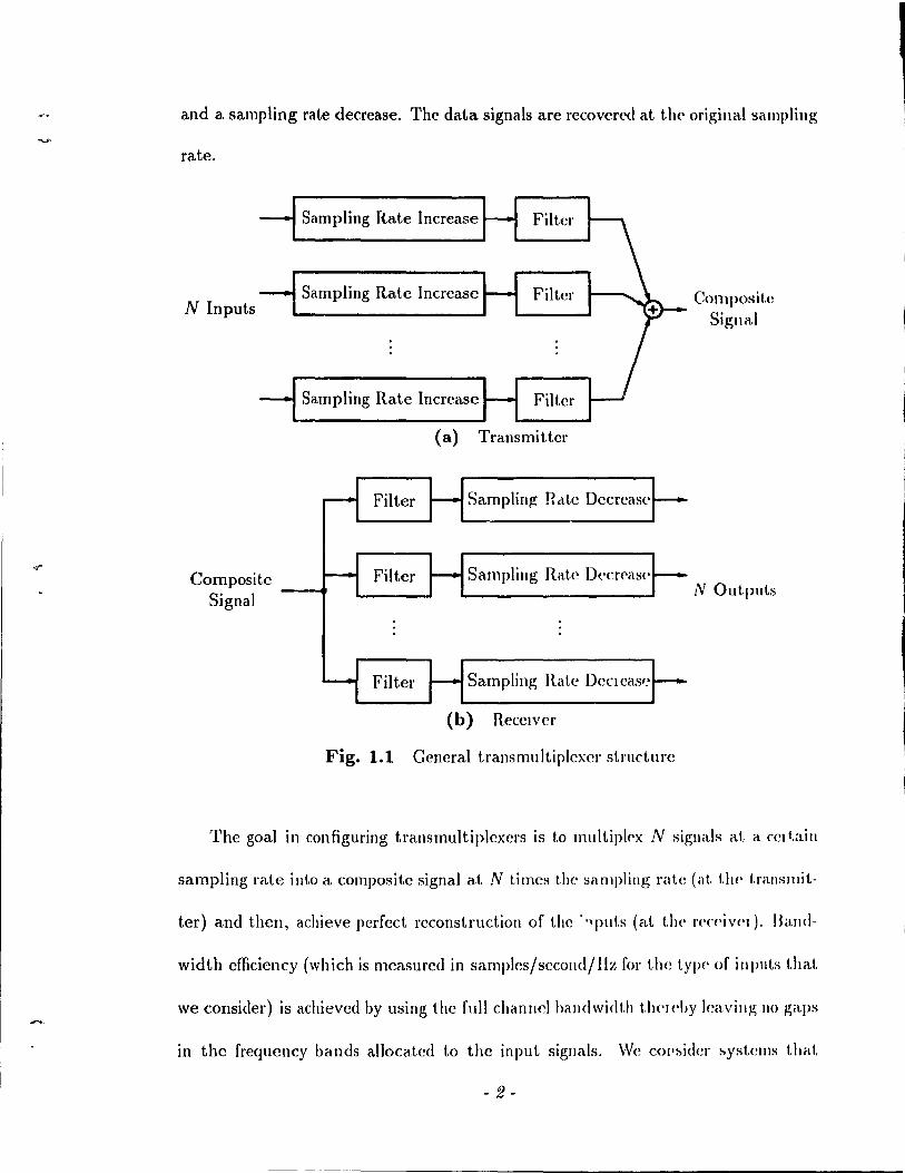
and a. sampling rate decrease. Thc data signais are rccovcl'cd at t.11<' original sampling
rate.
N Inputs
Composite Signal
Sampling Rate Increase Filtcl'
Sampling Rate Incrcase Filter
Sampling Rate Incrcasc Filtcr
(a) Transmittcr
r-- Filter f- SampIin~ Rdtc Decrcas(' f--
~ Filter f- Sampling Rate Decrcas(' f--
- Filter ~ Sampling Rate DeCleaS(~ ~
(h) Recclver
Fig. 1.1 Gencral transmultiplexcr structure
Composit.e Signal
N Out.puts
The goal in configuring transmultipIcxcrs is to muItiplC'x N signaIs at. a rCI tain
sampling rate illto a compositc signal at N timcs the séll1lpling rate (at. tlH' t.ranslllit.-
ter) and then, achieve perfect reconstruction of thc '., pu t.s (al. li\(· }'('('('i V('I ). Band-
width cfficiency (which is measured in sampIcs/sccond/I1~ for the typc' of illputs t.hat.
we consider) is achieved by using the full channel handwidt.h th('I('hy leaving 110 gaps
in the frequency bands allocatcd 1.0 the input. signaIs. "Ve cOI':,ider :,yst.clIls th .. lI.
- 2 -
accornplish frcquency division multiplexing (FDM). In these systems, the composite
signal is a frcqucllcy division multiplexed form of the N data signaIs. The full channel
balldwidth Î[î u[î('d for transmis1'tion and equal portIOns of the channel bandwidth is
alloc ,ttc'c1 to each data signal. The various signaIs are confined to different frequency
bands t.helcby lcading 1.0 aIl implicit separation of the data signaIs.
An applicat.iolJ of FDM systems is in long distance transmission over telephone
and gl'Ouphand Iille~. The resulting transmultiplexers are used in multicarrier voice
band and grollplmnd data modems. In FO:M systems, the bit rate cau he maximized
hy appropriatc information assignment toeach frequcncy band. This is brought about
by assigning 1I10re bits to the bands that are less affect cd by the chanllel charaderis
tic. In [a], LlIC prob1clll of maximizing the bit rate by optimal power division among
frcquc/lcy hands and an optimal choice of thc number of bits pel· data symbol subject
to the constraints that the total transmitted power is fixed and the probability of error
of l'very symbol is the same (for additive white Gaussian noise) is addrcssed. Results
show that. for challlleis with a sharply decreasing amplitude chara<:teristic that ap
proachcs a l1ull, there is much potcntial for achieving a high bit rate by putting more
transl1littcr power in the bands that are unaffccted by the sharply decreasing ampli
tudl' characlerist ie. Another aspect of FDl\f systems is that the channel distortion
is relati\'('ly lowcr ill (Oach of the N bands as compared to over the elltire bandwidth.
Sine<' il pclrt.icular data signal is only affected by the channel distortion within its
allocatcd fr('(I'H'llcy band, equalization cali be pcrformcd in each individual frcqucncy
band as oppo!-lcd to t.he CHUre frcquency range. The cqllalizers in eaeh band only have
to d('al wit.h this lclatively lower distortion.
- 3 -
In this thesis, we are mainly interestcd in dcvcloping new bandwidt.h ('fficicut.
transmultiplexers that implcment FDl\J. Note that t.he plcvious discussiol\ on informa
tion assignment and equalization was rneant 1.0 briefly indicate wh)' OIH' is illt('rt'd,('d
in FDM systems. The actual dctails of achicving high bit rdtes and )wrforllling adap
tive equalization is outside the sC'Jpe of this study. In configl\l'illg d transnlllltiplcx('1
with an FDM composite signal, considcr the use of idcal halldpass filt('IS su('h t.hat.
their frequency responses do not ovcrlap and such that. t.he ('ut.in' avail,d>lc' h,lll<lwidt.h
is uscd. These bandpass filtcrs allocatc diffel'elü port.ions of the challllel bill)(lwidt.h 1.0
each data signal. I1owevcr, su ch ideal bandpass filtcls cannot 1)(' d(':-.igll<'d ill )J'adif'('
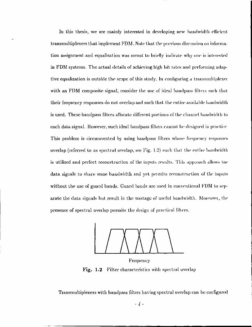
This problem is circlIl11ventcd hy using balldpass filters whosc fr('qu<'llcy J'('SPOIlS('S
overlap (rcferred 1.0 as spectral overlap, see Fig. 1.2) such t.hat. the' ('Ilt.il<' h,lll<\widt.h
is lItilized and pcl'fcd reconstruction of the inplIt~ l'e~lIlts. Tlli~ rIPPIO(\Ch ,,1I()w~ (,j)('
data signaIs ta share sorne bandwidth and yet. pelmits J'('const rllct.ion of t.h(' iuput.s
without the use of guard bands. Cuard bands arc usee! in convent.iollal FDM 1.0 S('P
arate the data signaIs but result in the wastage of usdu! bandwidth. MOI('ov('I, 1.1)('
presence of spectral ovetlap pcrmits the dcsigll of practical filt.ers.
Frcqucllcy
Fig. 1.2 Filter charactcristics \Vith spectral overlap
Transmllltiplexers with bandpass filtcrs having spedral overlap can be configured
- 4 -

(
(
(
by (hffcrent rncthods that lead 1,0 perfect reconstruction assuming no channel effectst .
For two band systems, the standard approach is 1,0 use quadrature mirror filter (QMF)
banks [1J or the Smith-Barnwell structure [5J. In the case of N bands, the use of
tree-structllrcd QMF banks [I J, a matrix fonnalism [6][7], lossless structures [8J and
modlllatc'd filter ban ks [9][ 10J accomplish perfect reconstruction.
Of the various methods that implement FDM, the focus of the research is 1,0
explore Illodlllated filter banks in depth. M~dulated filter banks have a specifie struc-
t\ll'e in that ail the filters arc frequency shifted versions of a lowpass prototype. The
filters are ohtained by mu lt,iplying the lowj)ass impulse response by a modulating
function having a specified center frequency and phase shift. This leads 1,0 a set of
bandpass filters whose spectra are centered al, various frequencies which are usually
eqlla1\y spared. The inherellt structure of modulated fi 1 1,'_'1' banks implies that only the
design of a lowpass prototype is required 1,0 ohtain complete control of the bandpass
freqll<'llcy responses. Also, modulated banks have been shown to lend themselves to
a comput.at.ionally efficient. implementation through the use of a polyphase network
and fast transforms [10][11].
Now, wc' have focllsed the investigat.ion to the study of modulated filter banks.
'l'lU' main mot ivat.ion that commenccs the investigation is 1,0 devclop alternate con-
figurat.ions for modulated filter banks that accomplish perfect reconstruction. This
is ('<tuival<'nt 1,0 examining the various ways of specifying the lowpass prototype and
t.he parameters of the modl1lating function stlch that we get modulated filter banks
Although thr&t' I1wthods wcre onglllally proposcd for a subballd systcm (explained later), they <lrt' apphcable t 0 t rauslllult lplexers.
- 5 -
1 ,
1
;1
'--
,-
that reconstruct the input data signaIs. In proc('('ding, wc note that. t.he 1I10dlllat,<'d
systems in [9][1O][11J have a specific approach 1.0 descrihe the filt,('J's .wel 1I10J'('OWI',
use distinct. center frcqucilcies. \Ve provide an additiollal d('gr<'<, of 1'1'<'<,dol11 in <1('
scribing the filters by introducing dclay factors. The l'esultl11g filt('!'!'> are <!elrl,ye<! and
frequency shiftcd vel'sions of il lowpass protot.yp<' obt.ainc<1 hy lIlult.iplying t.h(' lowpass
impulse response by a modulating function having a specifi('cl ('(·nt.e!' fn'<\I\('lIcy and
phase shift and then applying a delay factor. The prc~ence of d<'lay factors ùllows fol'
the possibility of using the saille center fl'cquency 1.0 t!'ansmit two signais (a COI)«·Pt.
used in analog communication systems 1.0 send two signais in quadrature' al. t1w Sil III<'
frequcncy). The use of l'cpeated center frequencÎ('s leads 1.0 (,olllplcl<' '''Iwct.ral overlap
betwcen the corrcspollding bandpass filtCl'S whicl! must 1)(' cal\cell('d to n'( oni>tl'Ild
the inputs. Given the main him of configuring new syst.?Il1S, wc 1)) on'ed by fOl'1I1111al.
ing a synth~sis procedure for modulated filt,el' banks in a t.ranslllult,iplf'x(·r such t.hat.
perfcct reconstruction is accomplished assuming an idcal chanllel.
The synthcsis procedure lcads 1.0 t.he configmatioll of new t.ra liS 11111 1 t,ipl(·x(,l's.
There are two classes of systems with equally spaccd cCllt,('r [I(·qlwllci(·s. fil olle t..Y\)(',
aIl the center frf'qucncies arc dbtinct. with one signal h('i!l~ SPlit at ('(\('il [1'(·<jI1('IU·Y.
Another type of transl1lultiplcxer uses repcatcd cellLer freqlJ('lIcÎPs. Two signaIs arc'
sent in quadrature al. cach rcpeated center [reqlJ('llcy. SOIII(' of the C(mtl'ihut.iolls of
the work lie ill t.he formulation of the sylltlJesÎs proCCdIlH', ((mfiglll atioll o[ 1,1)(' 1l('W
systems and theÎr Îlltcrprclat.ioJ) from a commullicatiolJ!'> poillt of vic'w [12J[l:~J. Ot!)('1
contributions include Ilew de~igIl procedures for a finit(· irnpllb(· )'('hJ>0IlS(~ (FlH) low
pass prototype to be used in the new transmultiplcxers [i4][1!)][Hi] <lnd al)('lfol'llIanœ
N components
Analysis Filtering Sampling Rate Input - and Sampling Increa'3e and ~ Output
Rate Decrease SYllthesis Filtering
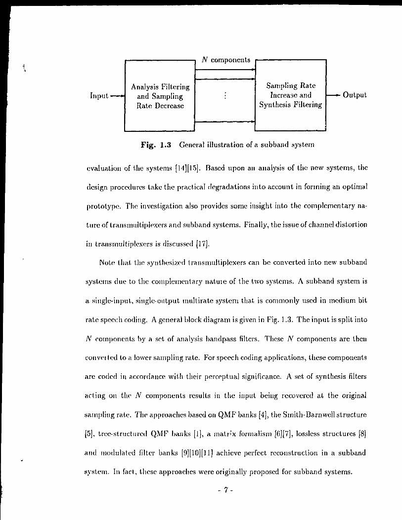
Fig. 1.3 General illustration of a subband system
evaluatioll of the systems (14][1.5]. Dased upon an analysis of the new systems, the
design procedures take the pradical degradations into account in forming an optimal
prototype. The investigation also provides sorne illsight into the cornplernentary na-
ture of transll1uItiplexers and subband systems. Finally, the issue of channel distortion
ill trallsmultiplexcrs is discusscd [17}.
Note that the synthesized transmultiplexers can he converted into new subband
systems due tü the complcIJ1ent.ary natme of the two systems. A subband system is
a single-input, Ringle-olltput multirate system that is commonly used in medium bit
rate speech coding. A general block diagram is given in Fig. 1.3. The input is split into
N romponcnts by a Ret of analysis bandpass filters. Thcse N components are then
conv('Ited tü a lowcr sampling rate. For speech coding applications, these components
arc cüdcd in accordance with thcir perceptuaJ significance. A set of synthesis filters
acting on the' N components results in the input being recüvercd at the original
sampling rat.e. 'fhC' appl'Oachcs based on QMF banks [4J, the Srnith-Darnwell structure
[5}, tl'ee-structmed QMF banks [I}, a matr;x formalism [6J[7}, Jossless structures [8)
élnd IJlOdulntcd filter banks [9J[10)[1l] achieve pcrfcct reconstruction in a subband
system. ln faet, thesc approachcs were originally proposcd for subband systems.
- 7 -
The new subband systems formed from the synt hesized t ransllllllt.iplt'xt'rs lISt'
modulated filter banks. Also, the sllbband systems helong to Olle' of t,wo dasst's. TIlt'
subband systems which use only distinct center fl't'<!ut'ncit's split t.ht' input. inl.o N
components that rcpreSCIl t di [CI'Cli t frcqucllcy rang<'s. The su hlla nd syst ('IIIS wh icI!
use repcated center frcquencies arc unusud\. Each of tlH' l't'peated ('('III.t'1' fl'<'<!ut'n
cies cstablishes signal componcnts that cxist in «uadratur<' and 1('\>1'<'8('111. t.11t' S,\lIIt'
frcquency range.
1.1 Scope and Organization of the Thesis
The entire thcsis is organizcd into sevcn {:haptcrs. Afte'r the introduction, Chapt.t'I'
2 provides background material concerning the input-output dpscript.ions of trélnslllul
tiplexers and subband systems and the a( hievPfIlpnt of pCl'fcd. l('collstruct.ion. 'l'II<'
complementary nature of the t\\'o systems is also disclIsscd. '1'1)(' latter part of I.IIt'
chapter describes the rcsearch problem and the dpploach mec!.
Chapter 3 gives the transmultiplexer sy:llhesis proC<'duJ'(' in dt'tai\. Theil, fi\'(' dif
ferent crosstalk-frcc transmultiplexers are synt.hcsized and c\et>cril)('d flOm a cOllllIlllni
cations point of view. New subband systems arise as cOlllplc'lll<'uts of t1H' synt.hc'si/wel
transmultiplcxcl's. The two band case is treated in 11101<' ddcli\.
Chapters 4 and 5 arc devoted to formulating procc'dlllcS to d('~igll t.ht' lowpass
prototype. In Chapter 4, wc considel' mct.hods hascd on a millilllélx (1 itc'rioll tbat
simultaneously assure a lowpass behaviour and aUcmpt to SUppIC'S"i t11<' ilJtc'r~ylllbol
interference. In Chapter 5, an optimizcd design Ill<'thod based 011 the' lIlinilllizat.ioll of
- 8 -
J
~ (
ail crror fUllction is dcscribcd. The crror function is formulated so as to takc practical
degradations into account. Design examples are provided in both chapters. Also, the
l
performance of tllc systcms is evaluatcd for both the minimax and optimizcd design j
approaches.
Chapt,er G provides methods to configure a channel compensation fiIter when
channel diRtortioll is present. Thc channel compensation filter cancels crosstalk in
the pn'sell('e of a channel but lcaves residual intersymbol interfcrence. The relative
pcrformance of thcsc mcthods is discussed in tenns of suppression of the intcrsymbol
illterfel'Cllcc. Chapter 7 records the conclusions of the investigation and gives sorne
sugg<,st.ions fol' future rescarch.
(
(
- 9 -
Chapter 2 Multirate Digital Filter Banks
This chapter discusses background rnaterial on 1.ranslllult.iplt'x('rs and slIhband
systems. A mathematical description of the t.\\'o syste'ms kads t.o t.he fOlllllllatioll of
the perfect reconstruction propert.y. AIso, this estahli~hes the colllplellH'1I t.ary lIatlll"('
of the two systems (a concept used later in the thesis). l\lcthocls to éH "il'v(' !)('rfcd
reconstruction are described. Finally, the focus of the' rescal rh prol>l('1II étlld t.h('
approach used are discusscd.
2.1 Transnlultiplexers and Subband Systems
2.1.1 Interpolation and Decimation
Multirate systems use boLh interpolation and decimatioll to accolllplish sétlllplillg
rate alteration. The basic notion of interpolation lies in filling in a ,,('1. of fllndion Vetl
ues betwccn two known values. Consid('r a discl'<'te time signal ohtained IJy sétlllpling
a continuous lime signal. Intcrpolcttion of tllis signal is il t.wo ..,te·p proe ('~s. Filst,
the insertion of N - 1 zelO-valued samples hetwc('1J ('élch pail of ~alllpl(' va!tws {Jf the'
discrete time signal is rcfcrrcd t.o as sampling rat c expansion hy an int('grell fador
- 10-
j
N. The resulting output discrete time signal is subsequently filtered to providc a
smooth transition betwccn the non zero samples. This smooth transition consists of
cstilllatcs of the continuous time signal between the already known nonzero samples.
The filt.('/'(·d signal can he vicwcd as a representation of a more finely samplcd version
of t.h(· cont.inuous time signal in which the ncw sampling rate is N times the original
sampling rate.
Th(' process of dccimation accomplishes sampling rate reduction. Again, (:onsidcr
a discrc'le t.illw signal obLained by sampling a cont.inuous Lime signal. The extrac
tion of cvC'ry Nth salllpic of the discret.e time signal is lefcrrcd 1.0 as sampling rate
cOlllpl'eshion byan illl.cglili factor N. The resuIt.ing out.put can be obtained from the
cOIIl.illllOIlS t.irne signal al. 1/ N times the original sampling rate. Note t.hat dccimation
IIsually illcludcs lowpass filtering prior to sampling rate compression to avoid aliasing
al. the lowcr ratC'.
2.1.2 Transl11uJHplexer
A multi-input, Illulti-output transmultiplexer is shown in Fig. 2.1. At the trans
mit.t('r, illlplicit modulation is accomplished by the sampling rate expander (sym
bolicrllly <1<'1101.('<1 by N j) since the spectrum of t.he input signal is replicated with
p('\'iod '27r/N. An Împlicit spt of carrier frequencies at multiples of 27r/N results.
Th(' combining filler bank (comprising the combining filters Alz)) allocates different
pori ions of 1 he channel bandwidth 1.0 the various input signaIs by selccting a set of
N cent('\' fl'equC'llcirs for the purposes of transmission. The outputs of the combining
HIt('rs al"<' ll1ult.ipl(\xcd into 01lC' composite signal. The composite signal is sent over a
- 11 -
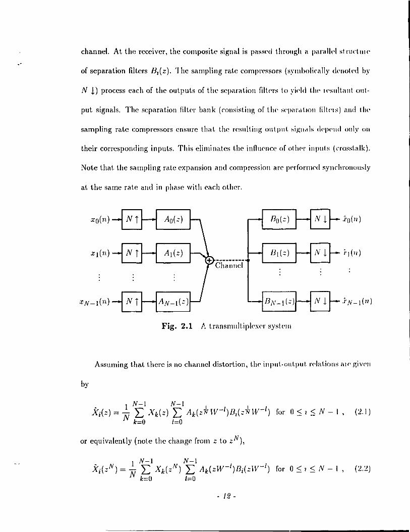
channel. At thc rcccivcr, the composite signal is passf'd t.hrollgh a paralh'l st rllct.III('
of separation filtcrs B,(z). 1 he sampling rat.e comprf'ssors (sYllIholically <!('not('<! hy
N !) proccss each of the outputs of the separation filtc'l's to yic'Id t.he H'sult,ant out-
put signais. The separat.ion filt('\, bank (consisting of tl\(' sq>éll'<lt,lon liltels) é\nd tl\l'
sampling rate compressors cnsurc that the result.ing out.put :-.ignc\ls <1('\)('11<1 only on
their corresponding inputs. This eliminates the infhlC'llce of oth('\' inputs (crosst.alk).
Note that. the sampling rate expansion and compression are !>c'rfo\'l1}('d synchronously
at the same rate and in phase \Vith each other.
xo(n) Bo(z)
xN-l(n) -/ flN-l (::)1--8- .Î'N-l (1/)
Fig. 2.1 !-. transml1ltiplexer syst.elll
Assuming that thcl'c is no channel distortion, thf' input-out.put. \'c,lat.iolls aH' giV('1I
by
1 N-l N-l Xi(Z) = N L Xk(z) L Ak{Z* IV-/)/3I(z~ W- /) for 0 ~ l ~ N - 1, (2.1)
k=O 1=0
or equivalently (note the change from z to zN),
1 N-l N-l .~i{zN) = N L Xk{zN) L Ak(ZW-/)Bj{zW-/) for 0 ~ 1 ~ N - 1, (:l.:l)
k=O 1=0
- 12-

(
(
(
-
where W = e-j~. Eadl output signal Ki(zN) is rclatcd to each input signal Xk(zN)
via a transfcr fuuction -Jv'lki(zN) whcre
N-1 Tki(zN):= L Ak(ZW-1)Bi(ZW-/) .
1=0 (2.3)
Whcn ~. :f; i, 1kl (zN) is eallccl a erosstalk function and represents the contribution
of the 1I11dcsircd input Xk(zN) 1,0 the output }[i(:;N). Wc refer to the input-output
transfC'1' functioll at the zth terminal as Tiz(zN). For eliminating crosstalk (Tki(zN) =
o for k :f; l) and achieving an identical input-output relation T1i(zN) = T(zN) for
cvel'y tC'l'minal i, the matrix equation
(2.4)
lIIust be satisfred where
[ AO( =) AO(z~V-l ) AO(zW-N+l) 1
A(z) = Al.(Z) Al(ZW-1) Al(ZW-N+1) (2.5)
AN~dz) AN_l(ZW-l) AN -1 (z~V-N+l)
[ BO(') BO(zW- 1) BO(=W-
N+
1) 1
B(z) = Bl.(Z) BdzH'-l) BdzW- N+ 1) (2.6)
BN~dz) BN_l(Z~V-l) BN -1 (z~V-N+l) and 1 is t.he idcntity ll1at.rix. If the above matrix equation is satisfied, each of the
output signaIs .\',(:) ::= -}yT(::)Xi(Z). Intersymbol illterference is present jf the sam-
1'1('8 at 1.1)(' output dcp<,ud 0/1 past and future input samples. Intersymbol interference
is e1illlinélt.ed if alld only if T(z) is of the form c:;-p. Then, perfeet reconstruction
is achic\"l'd in that. the output samplcs are a scaled and delayed version of the input
sampl(\s.
- 13 -
.1 7
, ; 1 •
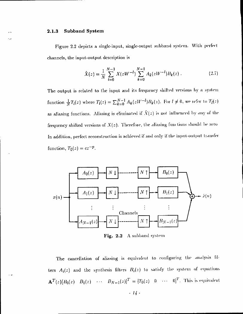
2.1.3 Subballd System
Figure 2.2 depicts a single-input, single-output subhalld s)'st('IlI. With p('!'f('d
channels, the input-output description is
• 1 N-l N-) X(=) = N L X(zW- /) L Ak(=lV-/)JJA'(::) .
1=0 k=O
( 2.Î)
The output is rclatcd 1,0 t.he input and its freqllcncy shift,('d V('l'sions hy il sysklll
as aliasing functions. Aliasing is eli mi na ted if .\- (::) is Ilot i Il fi 11<'11('(·<1 by .\11)' of t.!\('
frequency shifted vcrsions of X(z). Thereforc, the ctliasing f\llle t.iolls ~ho\lld 1)(' Z('l'O
In addition, perfed reconstruction is achi('vcd if and only if tl\(' input.-out.put t.rclllsf(·l'
- Ao(=) r-- Nt Bo (::)
x(n) - i\)(:) ~ Nt - --------- N T
Channcls
- AN-d::) - Nt ---------8 JJ N - ) ( :: )
Fig. 2.2 A suhhand sy~l<'l11
The canccllation of aliasing is cqllivalmt to C'ollfigul'illg t1lC' .llltlly~is fil-
ters A;(::) and the sYllthesis filU'l'S B,(::) 1,0 ~ati~fy UI<' syst('JIl of ('qll;ltioll~
- 14 -

to satisfying the matrix equation
(2.8)
o
If the dbove rnatrix ('(jllation is satisfied, the output signal 5;(z) = *To(z)X(z). To
provide a di:,t.inction \Vlt.h transl11ultiplexers, the filter banks in subband systems are
ref('rred to as analysis and synthesis banks.
2.1.4 Complelnel1tary Nature of the Systems
The fundalllC'lItal complementary nature between transmultiplexers and subband
systems relat.es crosstalk cancclIat,ion in the former and aliasing climination in the
latter [il. \V€' continuc to assume that there are no channel effeds in both the trans-
1I1111t,iplpx('r and the sllbband system. It has bccn shown in [7] that crosstalk and
aliasing cctnc('lIatiol1 ale cquivalcnt if and only if the prodllct of the A(z) and B(z)
llIatli«'s (01\(' of t.hern b('ing transpo~ed) is equal to a function in zN multiplied by
th€' id<'Ilt.ity llIatrix. By rclat.ing Eqs. (2.4) and (2.8), this is equivalent to stating that
éilly <Oll1hining/s<'paration filter banks t.hat c1iminat,e crosstalk and achieve the same
input-ollt pllt. trall:"fer function for ail pairs of corresponding terminaIs in a trans-
llIult.iplex(')' will célncpl aliasing wlwn utilizcd as analysis/synthesis filter banks in a
suhband system. 1I0wc\'cr, the reverse is Ilot true unless the input-output transfer
functioll of the subhand system is a fllnction of zN. Analysis/synthesis filter banks
for a suhband system that cancel aliasing and achieve an input-output transfer fUllC-
t.ioll in zN )'esult. in the rc1ationship .\'(z) = *T(zN)X(z). These same filter banks
- 15 -
eliminatc crosstalk in a transmultiplcxer and achicvc .\,,(.;) = irT(z)Xj(z) for 1 = 0
to N - 1.
A further interpretation of this rcsult is as follows. Suppose we design a suhband
system that achieves perfect reconstruction. In gc'llCral. t hesc filt.cl hall ks will ilOt.
cancel crosstalk in a transmultiplexer unless the transf('r f\ludion of t.h(' sllbh,lIId
system, T(z) = c.;-p has a value of p which is a lIlultiple of N. Fir-,t SIlPpOS(" (' = N
and p = O. The resulting filter banks can 1)(' applied in eiUH'r il subhélnd Syst.I'IlI or il
transmultiplexer. Fm thermore, there is a pcrfect complemen t.ary nature sinn' th(' two
systems are identity systems (the output samplcs arc idcntical to t.he COII('spol!ding
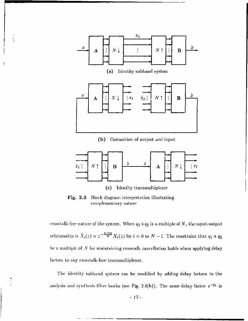
input samplesj there is no delay factor). This is further mot.ivelted fI 0111 t.lu· ~('qll('n«' of
block diagram interpretations shown in Fig. 2.:3. Thc id(,llt.ity Sil 1>1>,11 1<1 ~ystelll allows
us to connect t.he input and output and break the connections hd.w(·(·n tl\(' ~alllplillp,
rate compressors and expanders thereby forming an eqllivalellt trallt>IIII1It.iplt'x<'I' t.h"t
is also an identity system. Note that the analysis filter bank in a slIhhillld sy~telll
corresponds naturally to the separation filter hank in a translllllItipl<'x('1'. Abo, t.\\I'It'
exists a similar corrcspondcncc between the synthesis and cOlllhining filtcl billlks.
Consider the application of delay fadors to ail id('ntity tl'é1II~lIl1t1tiplex('r (s('('
Fig. 2.4(a)). The same delay factor Z-IJI is applicd to eclcll cOlIlhinillg filtt·l. ~1I11ilarly,
the delay factor Z-IJ2 is applied to each separation filter. TIH' constraillt fil + fi'/. is
a multiple of N is neccssary for crosstalk canccllatio!l 1.0 he pH·s('J'ved. Otl\('rwis(',
the sampling rate compressors and expalldcl's opt'ratt' out. of pha~(' éllld CI O'ist.a Ik will
no longer be cancclled. In addition, if 'Il + '1'2 is él nl\lltipl<' of N, the d('lays can he
moved across the sampling rate compressors alld expand('rs wit.hollt distllrbillg the
- 16-
x' r- I r-r- i-
x NL NT B A
r- r-r- I-
(a) Idcntity subband system
x B A
(b) Connection of output dUt! input
l- r-r- . r-
Ni x x A :Z" , B 1 •
r- I-r- I-
(c) Identity transmultiplexer
Fig. 2.3 Block diagram intcrpretation i1lustrating C0111 plemcn tary lIat ure
NJ
x
A
X
: ,Tl
croHstalk-frec lIature of the system. When ql +q2 is a multiple of N, the ll1put-output
rclat.lollship is .\·i(Z) = :;_ql~q2 Xi(Z) for i = 0 to N -1. The constraint that ql + q2
he il lIlult.iple of N for maintaining cross\,alk cancellation holds whcn applying delay
factorh t.o any crosstalk-frcc transmultiplexer.
The idellt ity subband syst.em can be modified by ddding delay factors to the
dnalysis élnd sylltlH'sis filter banks (sec Fig. 2.4(b)), The same dclay factor Z-Pl is
- 17 -

, ,
applied to each analysis fil ter. Similarly, the dclay factor :;-P2 is appli('(\ to ('(\ch
synthesis filter. Now, the input-out.put transfc'" function is T{z) = Nz-1' ",11<'1(,
P = Pl + P2. Note that the alias-free nature of any subhalld syst.em is I>I'('S('\'\'(,(\ art.('\,
applying the dclay factors Z-PI and Z-P2 to the analysis alld syllt.lH'sih lilt,(·\, h,\Ilks
respectivcly. In a practical approach, the delay factors art' chohcn HO that callsal filt('1
hanks result.
~ ~ f--~ - 1---
Xi : Ni A f-- :;-ql - :;-q2 f-- B Nt : ,l',
- -- -( a) Transl11ult.iplcxcr
- 1-- '. -x Nl Ni ,1' - Z-PI f-- A B - ~-Jl'2 - -- -
(b) Suhband sy~tell1
Fig. 2.4 Application of delay f;tcl.ors
'flle inherent differencc bctwecn transmult.iplexe\'s alld slIbband syst<'lIIs (,OII<'('I'IJ-
ing the application of delay factors lies in the g,r<'éttcl flCCdolll th'lL exi~ts in ('hOO~1I1p,
the delay factors for subband systems. This rd UrIlS 1I~ t.o t!1<' 1>1 i IIci pit· that (Lily
crosstalk-frcc transmultiplexer with the same input-output tlélllsf!'l' flllld.Î(JIlS for ('v-
ery pair of terminais can he converted to an alias-free suhband systelll.
- 18 -
( 2.1.5 Network Duality
'J'ransmllltip)exers and subband systems are configured by cascading two subsys-
te ms in difrerent orders. One is a multi-input, single-output system that comprises a
parallcl connection of sampling rate expanders and filters. The other is a single-input,
mlliti-out.put system consisting of a parallcl connection of filters and sampling rate
cOl1lpressors. Digital network transposition transforms one subsystcm into another.
The proccss of nctwork transposition II1volvcs intcrchanging the roles of the input and
output, reversing t.he direction of ail branches and replacing branch operat.ions by t.heir
duals [1]. Since a filter is its own dual and sampling rate expansion/compression arc
dual operations [1], the two subsyst.ems arc transposes of cach othcr. Furthermore,
silice a nct.work and its transpose are duals, t.he two structures ale dual syst.ems. The
two dual systems are cascaded witn cach othe[' to yield two complementary multirate
systems, namely, the transmultiplexer and the suhband system.
By (>C'rfonning nctwork transposition, we see that the dllals of subband systems
and t[élIlSlIlult.iplexers arc again subband syst('ms and tIansIIIultiplexcrs with the filter
ballks illtcrChel.lIged. COllsider a subbétlld system whicb i& in gencrallinear and tirne-
varying. 1'11(' dllal sllbband syst.em is also linear and tirnc-varying but is describcd
by diffpr(,lIt. aliasing (lIndions t.han the original syst.em. A freqllency shift.ed version
of the aliasillg fUl1ction T,(z), namely, T,(zW'), of the original system is equal to
the aliélf.illg [\luct.ion TN _,(:::) of the dual system. The subband system becornes
t.illH'-iuvarié\nt. ",hen aliasing is cancclled and is dcscribcd byan input-output transfer
« f\lndion T(z). TIH'rdorc, the dual will also be alias-free and have the same T(z) [1].
- 19 -
'.fi .
Therefore, as shown in [18], swapping the filter banks prcscrv('s aliasing canccllat.ion
and rnaintains the sarne input-out.put. transfer fUllct.ion.
Now, consider a transmultiplexer which in gCllcral is Ilot cl'Osstalk-free. The dual
transrnuitiplexer is also not crosst.alk-free. The input-out.Pllt transf<'r fllndions '/i.:d::)
(k = 0 to N -1) arc the same for bot.h systems. The crosstalk fundions '1i.:1(::) in
the original network (rclating the out.put at terminal 1 t.o tlJ(' input. al, 1('lminal ~.)
are equai to t.he fnnctions Tu:(z) of t.he dual n('f,work (rclat.ing t.he output al. h' 1.01,11<'
input. at. 1). If a transmultipkx<,l' is crosst.alk-flcc, the' dllal translllllltipl("\('1' fOlnH'd
by swapping the filt.er banks is also crosstalk-fl'c<, and has the SélllH' inpllt-outpllt
transfer functions as the original system.
The swapping property which addresses the qll<'st.ion of whet.her or not <'xchanging
the positions of the filter banks preserves the reconst.ruction PIO))<'[ 1, y was discuss('cl
in [18] for subband systems. Wc have shown that t)w ~allle proj)('ll.y holds for él
transmultiplexer with no specifie assumptiolls abOlit the fil 1.('[ sor ahollt. N. Mon'ov('I',
we have provided the interprctat.ion in t.crms of network t.ransposit.ion as Oppos('cl 1,0 il
direct mathcmatical proof. A mat.hematical proof starls by ~wappillg t,J\(' filIn h(lIlks
of a crosstalk-free transl11ultiplexer and examines the' ne\V ilia 1 rix produd
thereby establishing the swapping property t.
The proof assumes that the input-output. transfer fUllc! iOIl is the same for pacl! p:ur of com'sponding terminaIs. It can he extended 1.0 the ca.~e of havlIlg dtfferellt Illput-output trall~fpr functions.
- 20 -
J
2.2 Perfect Reconstruction Property
Givcn the rl'quirements on A(z) and B(z) for transrnultiplexers and subband
systc'ms as in Eqs. (2.1) and (2.8), rncthods to achieve perfect reconstruction are
discussed. First, the two band case is considered. Then, wc proceed to the case of
arbitnuy N.
2.2.1 Two Band Case
In two band systems, the classical solution is to use quadrature mirror filter banks
(QMF) [4][19]. These banks consist of a lowpass/highpass filter pair whose magnitude
responscs are symmctric about the quarter sampling frequency 7r /2. A one prototype
QMF system [4] is dcscribed by the following filter banks.
aO(l1) = h(n) bo(n) = h(n) (2.10)
For a t.ransmultiplexer, t.he common input-output transfer function is
(2.11 )
This l'l'sults in the rclationship .\'j(z) = ~T(z)Xi(Z) for i = 0 and 1. In the corn ple
mental')' subband system, .\"(z) = ~T(z2)X(z). To make T(z) = cz-P and thereby
adlie\'e pcrfcct. reconst.ruction, the even-indexcd samples of the impulse response of
//2 (::) Illust be zero cxccpt for a rcference coefficient at. a time index of 2p. The
odd-indexcd samplcs of 1/2(::) are arbitrary and can be uscd to shape the frequency
\'('sponsl' of thc filtl'r. A filter with rcgular zero CroSSillgS in its impulse rcsponse
- 21 -

, except for a rcference coefficient is callcd a Nyquist filt,cr. In this cas<" 112(::) is a
Nyquist filter with a zero crossing interval equal to two samples.
The two band system described by Eq. (2.10) can he IIlodificd ln indudc t,wo
prototypes H( z) and C( z) as follows.
aO(n) = h(n) bo(n) = g(n) (2.12)
bl(n) = (-1)"h(n + 1)
In the general case, this is not strictly a QMF bank sincc the magnit.lld(' l'<'SPOIISI'S
of the lowpass/highpass pair Il(z) and G(-z) may Bot he syn11l1l'tlical ahout 1f/'2.
However, any t\Vo filters H(::) and G(::) such that ll(::)(;(::) is a NyqlJist. liltp)' \Vith
a zero crossing interval of two samples rcsults in pc)'fed J'I'COIIStl U('tIOIJ. III (uldit.ioll,
methods to get a lowpass lIe::) and G(z) are givCJl in [6][7]. A sl)('ciéll CéI!->(' of Eq. (2.1'2)
arises when G(z) = H(z-l). The resulting systcm, known as a Slllit.It-Ba)'Jlw('1I
structure [5], requires a Nyquist filter H(z)II(::-l) to achi('V(' J)(')'fcct. 1('Collstlllct.ioll
A lowpass Nyquist filter must he factored into its minimum and maxilllullI plttlSI'
components.
Note tbat the descriptions in Eqs. (2.10) and (2.12) can I('ad 1,0 noncé\llséll filtc'Is.
However, given the previous discussion on the application of (l<'Iay fado)'s, Wl' Célll
modify any noncausal bank to make it causal sllch thal pc'rfc( 1, )'('COllstl lIct.ion is
preserved.
2.2.2 The N Band Case
The perfcct reconstruction condition for the N band ca!->c depencb on t.he prod1Jct.
of A(z) and B(z) (one of them bcing transposed). The rncthods p)'opos(,cI 1,0 configurc'
- 22 -
the filter banks that are based on a matrix formalism and on Iossless structures impose
a specific structUle on A(z). Then, B(z) is determined givcn A(z) thereby rendering
a particular rclationship between Bk(Z) and Ak(z). Modulated fllter banks specify
Ak(z) and /3k(Z) in terms of a lowpass prototype and a modulating function. It is
the charadcristics of the prototype and the modulating function that ensure perfect
reconstruction.
2.2.2.1 Matrix Formalism
The liSe' of a matrix formalism ln determining the filter banks has been described
in the context of a subband system in [6]. The mcthod comprises two stages. The
first stage introducei' a way of directly solving for the synthesis filter bank in terms of
the analysis bank sl1ch that the system described by Eq. (2.8) is satisfied. This results
in the canccllation of aliasing. Given the resulting input-output transfer function, the
second stage is devoted to designing the filters to get perfect reconstruction .
. In the first stdge, a polyphase matrix is defined as P(z) = frFAT(z) where the
entries of Fare F(m, 11) = umm for m, n = 0 to N - 1. Then, the entries of P(z)
arc P(i,j) = z-iAIJ(zN) for i,) = 0 to N -1 where AiJ(zN) is t.he jth polyphase
component of Alz). As opposed to AT(z), P(z) has the advantage of being purely
l'cal and exhibits no redundancy (in AT(z), each filter coeflicient appears N times).
It is shown in [6] that. choosing Bk(Z) such that [Bo(z) Bt(z)
[1 1 l]CT(z) wherc C(z) is the cofactor matrix of P(z) results in an alias
[l'c(' subband system with .\"(::) = [Det P(z)]X(z). The abbreviation Det refers to
d('tcrmi na n t.
- 23-
At the second stage, the analysis filters arl Jesigned to re,duC(' Det. P(z) t.o
the form cz-p• Thercfore, a specifie restriction on A(:) is illlposl'd to ('IISHr(' that
Det P(z) = c::-p . A mcthod to dC'sign FIH filters of ('(1'ldl kngt.h f, to sat.isfy t.1H'
determinant constraint is discusscd in [G][7]. A total of N - 1 of t.he i\nalysis fIIt.('l's
Ak(z) arc each dcsigned separatcly with a Icngth L that is ~l1rrki('nt. t.o gel, an acc<'pt.
able freqllency r('sponse. AIso, N - 1 of the coefficiC'nts of t.J1<' rC'mai\lin)!; fi\t.('1 a\('
chosen thereby leaving L - N + l unknown coefficients. Note that. tll<'re cl\(' fJ - N + \
nonzero coefficients in Oct P(::). ThercfOlc, a linear sy~t.('1ll of ('qu,d,ions t.hal. solve
for the L - N + 1 coefficients of the rcmaining filter \'eslllts s1\ch thal. I)(,t P(::) is
reduced to the form cz-p. Note that the constraint L > N - 1 is 1\('C('SSétry 1.0 ('wm\'('
that the determinant of C(::) is not zero. After d\ .;igning the anéllysis filt.('rs, /Jk(::)
is determined as dcscribed above.
Although perfcct reconstruction is accoll1plished by this nl<'thod, t.1J('\(' is no clin'ct.
control of the fl'equcncy response of one of the filt,ers. Moreover, the filt.('l's Bd:) arC'
generally longer than the Ak(z) [6]. This approach bas('d 011 a lllat.1 ix fOl'II1alis1l1
is apnlicable to the configuration of perfect leconst.ruction t.rall~JI11\It.lpl(·,(,IS. Th(,
combining filtel's Ak(::) and the sepalation filters Bd:::) (clll \)(' obt.aÎJH'cI,,~ c!c'snÎlwc!
above. Howevcr, dclay factors Illay have to he applied lo li\(' S('!Hlrat.ÎolI filt.ers t.o
achicve pcrfect. reconstruction in a transmultiplexcr.
2.2.2.2 Lossless Structures
A matrix function G( z) is said to be losslcss [8] if il, is stable a.Jl(1 :-.atisfies th('
- 24 -

(
(
(
rdation
G H (z-1 )G(z) = l , (2.13)
wherc the sllpcrscript 1/ den otes the complcx conjllgation of the coefficients of each
cllt.ry of the matI ix followcd by transposition and 1 Îs the identity matrix. In partic
ilia!', tlris IIIcallS "liaI. G is 1I11ital'y on the unit circle z = ejw . It is known that the
scatterillg llIatrix of any lossless multiport allalog nctwork is unitary [20]. Bence, the
term losslcss has been used duc tü dcscribe any G(z) which satisfies EC}. (2.13) and
is Irellcc, IIl1italy 011 the unit circle. In the case of a scalar function, G(z) is lossless
if il. is st"ble alld allpass.
In [8], the lo:,slcss property is imposed on A(z) in order to get a set of syn
t.Jlcsis filt(~rs 111.'(:) = cz- fJ Ak(Z-I) for a perfect reconstruction subband system.
li can be shown iltat hy making A( z) lossk""', a set of separation filters given by
Bk(Z) = cz-mN Ad z-l) results in a pcrfed re :onstruction transmultiplexer. A de
sigll procedure in [8] lcacls 1,0 a set of FIR bdndpass filters Ak('::) such that A(z) is
lossless. First, the filtC'rs Ak( z) arc dcrived from a cascade of losslcss building blocks
composcd of tire product of a unit.ary matrix and a diagonal matrix whose cntries are
delrlyelelllents. The t'utries of the unitary matrices are jointly optimized to yield a
sd of balldpass filters Ak(z), Oy examining the simple relationship bctween Bk(Z)
élnd AA'(:)' w<, o1>s(\rv(' t.hat their magnitudc rcsponscs are idcntical. Mor'cover, the
1Iulllber of co<'lIicients of the FIH 13k(z) is the same as that of the FIR Ak(z),
2.2.2.3 Modulated Filter Banks
In 1lI0du\ated filtcr banks, ail the filtcrs are frcquency shifted versions of a low
- 25 -
pass prototype. This gives a set of bandpass filt.crs ",hose impulsp \'('SPOIlSPS art' of t.IH'
form h(n) cos (wn + ,) where 11(11) is a lowpass prototype'. Th(, Illodulatillg fil net iOIl
is described by a center frequency w and a phase factor ,. For tht' ('·\SC of distillct.
center frequencies, the prototype is bandlimilC'd such tlwt tl\('\'(' is sp('drill l)\'('rI,\!>
only between adjacent bandpass filters. Ilc-nCf', any out.put. signal <lt t('lllIlIlal 1 in
a tral1smultiplexer will experiel1C<' crosstalk only flo\l1 input ~ignal~ .lt. adja«'nt ler
minaIs 1 - 1 and 1 + 1. The otller crossl.alk functions arc ;1,('10 sin('(' t.1l<' 1Il.lgnitudc
responses of the corresponding handpass fi\t('r~ ale nOI1O\·(·r1'IJ>ping. III a !->ubhand
system, the only aliasing terms are thor,e duc to !->pC'ctral o\!'tlrlp. 'l'II<' ot h('\' ,1Iiasing
terms are zero due to the bandlimitedness of t.he lowpass prototype'. TI\(' closst.alk
and aliasing ter ms due to spectral overlap ale cancellc:d hy fixing t1\(' pal alll!'!.t'''s of
the modulating fllnct.ion. This gives clOsstalk-free translIlultipl('x('rs ,U1d alias-fn'('
subband systems with bandlimited filters. Finally, !>erf('cI. recon!->t.nH tioll is acllicved
by satisfying the Nyquist criterion for zero intersymbol interf(·reIH·('. III " practical
situation, the lowpass protot.ype is designed to have a sufficicntly high st.ophilnd att.(·I1-
uation and such that a Nyquist rcsponse is eithcr approxilllatcly or ('xactly achie'v('d.
Modulated filter hallks have the advantagcs of allowlIlg for complete' «H1t.lol of 1.11<'
frequency responses of the bandpass filters through the design of a lowpa~!-> prototype
and being computationally cfficient to irnplc\11cnt.
The modulatcd filtcr banks in [9][10][11] wcre originally proposec! fol' a suhballd
system. The filter banks in [9][10] are applicahlC' in a trallSlllllltiplc'xpr TIH' systelll
in [9] is not a regular structure in thal, the cellt.er frcqucllciC's al'<' lIot ('qllally spfLced
and two prototypes of different bandwidths are lIscd. The ~yst(,lII ill [IO]II:'(,s olle
- 26-

protot.ype h(n) which is handlimitcd to no more than 'TrIN. Also, the centerfrequen-
cics arc ode! multiples of 'Tr 12N. Thercfore, the ccnter frequcncics are equally spaced
and exadly the same bandwidth is allocatcd to each input signal.
2.3 Focus of Research Problem
The invest.igat.ion concent.rat.es on modulated filtcr banks in a transmultiplexer.
Thc main purpos:~ is to find alternative configurations of modulatcd filter banks to
t.hose alrcady d(,!:lcribed in t.he litcrature. This goal is achicvcd through the formu-
lat.ion of a synt.hesis procedure. The synthesis procedure allows for a systematic
devclopmcnt in Hilding modulated filtcr banks. \Ve start with a set of assumptions
that fonn a charactcrization of t.he filter banks. These assumptions al/ow for more
gencralit,y in dcscl'ibing the filters than in prcviously configured systems. Then, spe-
cific !'(·Iationships among the pal'arnctcl's of the fiJt.crs are dcrived SUCI} that crosstalk
is Cét/ledlcd and the input-output transfcr function between cvcry pair of correspond-
illg t('rmillals is the saille. This constructive approach results in the configuration of
lIew erosstalk-fl'ec translllultiplexcrs. The intcrsymbol interferencc is suppressed by
dcsigning t.he lowpass protot.ype.
The g('lIcralllatul'c of the starting assumptions providcs greater flcxibility in spec-
ifying the filt,er banks as comparcd to the existing systems. In particular, the assump-
t.ions made are as follows:
1. The filt<·!' banks eonsist of a set of bandpass filters that are modulatcd versions of a lowpass prototype.
- 27-
-.
2. The impulse responses of the filters are <!cscriheù hy t1H' illlpllls(' I"('SpOIlS(' of the prototype and th ree free pal'alllders, lIéUlH'ly. cl ('('II 1 ('1' fn'(!l\l'!Icy, ph'lM' factor and dclay.
3. Equally spaced center frcquencies al'(' usc'd. III 011(' ca:.c', ail 1 II(' fr<'(!lwllci('s are distinct. In another case, 1 h(' center fi eqll('l\cic's a n' al1o\\'ed to H'lH"lt slIch that the ~ame ccnter frequcncy is t1s('d for t\\'o hancl~.
Note that a perfcct cha n nd is aSSllllH'd. A d iSCII~~ioll of c bel 1111('1 d isl 01 1 iOIl IS ,l!,1\'('1I
in Chapter 6.
Assumption 2 provides an extra frcc paramcter, uamel)', a d('lay fador in (I<'scrih-
ing the impulse responses of the hanclpass. filt('r~ as comparc'c1 t.o (·xist.ing syst('IIlS
that only allow fol' a cent.er frequene)' and phase facto!. 'l'Il<' icl('cl of P('lllllttin).'; ('('11-
ter frequencies to repcat allows for two signaIs to \)(' ~('I\t al. 1 h(, ~al\)(, f\(,(1' 1('11 ( y a~
compared to existing seheme~ in \\Thicl! aIl the Ct'nkr frequ('Il< i('!-> c\l(' disl in( 1.. Addi-
tional freedoll1 is provided over the cxisting N halld Illodulcll,<'d hcUlk:-. Ih,t!. hcl\,(' t.h('
multirate structure of Fig. 2.1, lIse one lowpass prototype to d('rive a:.d of hctlHlpass
filters and maintain eqllally spaced œnter frcqIH·IICÎ('S.
The c('ntral objective of formulatÎng a s)'nthesÎs procedule ÎnvolVt's t.1lt' following
steps.
1. The bandwidth of the lowpass protot.ype is det('rmincd sueh that (1) SIW('\,lc.! overlap oecms oIlly between bandpass filtcors CC'1l1er('d al. adjc\('('llt ('('111,('1 fwquencies and at the same een ter f!'equcncy and (2) tIlt' sel of hall cl pa!iS fi 1 tc'l'~
fill up the enUre frcquency rangc (0 to 7r).
2. Rclationships among the th l'CC frcc' para Ilwl (" s (C(,1l tc'!' fJ('q lwnci('s, phas(' factors and dclays) are dClived Ruch that the 1(,~lIltillg 1 l'all!->lI11tltlpl('x('I~ Il,LV(' 1,\1<'
following propertics.
(a) Thc input-output trallsf('l' fUlIctloil i~ t11<' !->elIlW fOI ('VC'I'Y pelll of ('01'1'<'
sponding terminaIs.
(b) The crosstalk componcnts in the ouI put data sigIlal that. dl is(' fl'olJ\ otller data signaIs due to the sharing of balldwiclth al(' (,lilJliIlat('d.
- 28-

•.
The synthcsis procedure is dcvcloped bascd on a bandIimited lowpass prototype.
A filter lI(z) is a bandlimited lowpass prototype if ll(eiw ) is exactly equal to zero
in the stophand region Ws :::; W :::; 7r. The frequency characteristic of a general
handlimited 10wpaHs prototype with a tapered transition band is shown in Fig. 2.5.
J n Step l, wc determinc the stopband edge Ws (thereby detcrmining the bandwidth
of tlH' plOtotype) for the purposes of restricting spectral overlap and allowing for full
bandwidth utilization. For systems in which ail the center frequencies are distinct,
an output signal at a pal ticular terminal will cxperience crosstalk from input signaIs
tl'ansmittcd al. adjacent center frequencies. For systems with rcpcated frequencies,
thcre is (1) partial spectral overlap between bandpass filters ccntered al, adjacent
cellter fre<juellcies and (2) complete spectral overlap between bandpass filters centered
al, the samc ccnter frequency. Then, an output signal al, a particular terminal will
experiellcc crosstalk from input signaIs transmitted al, adjacent center frequencies and
another signal sent aL the sarne center frequency.
-r------------~-----------W o Ws
Fig. 2.5 Frcquency characteristic of a general bandlimited lowpass prototype
Step 2 consists of two parts each devoted to forrning re!ationships among the
cent.er frcquencies, phase factors and delays. First, the transfer function between
('élch pair of COIT<'sponding terminaIs is made to be the same. The transfer function
- 29-
. -,
...
is brought to a form which allows us to design a lowpas~ prot.ot.ypt' snch t.hat. t.h('
intersymbol interferencc is suppressed (discussed in later chapl.t'I's). ;\Iso, t.he t.rans
multiplexers can be converted into subbant! systems which l'plit. the elltir(' spect.rullI
of the input signal into N frequellcy bands. In Step 2(b), the crosstalk COlllpOn('lIl.s
due to spectral overlap are cancclled. The crosstalk lwtwpcn signaIs I.hat. do not shan'
any bandwidth is zero for bandlimited filters.
The next chapter gives the synthcsis procedure in detai!. Sincc haml1illlit.et! filt.Pls
(stopba!1d resrJùnse is exadly zero) cannot be dcsig,ned, a nat.ural (l'\('st.ioll COI\('('\"IIS
how the design of a pl'actical lowpass prot.ot.ype cali he perfornwd. ;\ pract.iral low
pass prot.otype is distinguished from a bandlimited prototype in t.hal t!Je [1'('ql\('I)('y
response of the practicai filter ollly appl'oximales the characteristic shown ill Fig. 2.1) .
In particular, the practical prot.ot.ype has a stopband response which is SllIrlll but. ilOt.
exactly zero (stopband attenuation is high but not infinit!'). In Chapt,('1 s '. alld .1,
new design methods fOl· a practical FIR lowpass prototype éll"{ .. • d('vdop('d with 1.1)('
aim of suppressing both intersymbol interfercncc and crosst.alk .
- 30 -
,
...
Chapter 3 Transmultiplexer Synthesis
This chapter discusscs the synthesis procedure for modulated banks in a trans-
mlllt.iplexer. The first stcp is to state the gcneral assumptions. This includes the
specification of the impulse responses of the cOltlbining and separation filters in tenllS
of a lowpass prototype, center frequency, ph~se factor dnd delay. The synthesis proce-
dure Rt.arts by imposing a bandwidth const.raint on the lowpass prototype. Then, the
input-output II allHf(') function and the crosstalk functions are examined. This leads
to lIe'W C1'osstlllk-frcc t.ransnlllltiplexcrs. The last portion of t.his chapter exclusively
d('als \Vith two band trauRmultiplexcrs. Finally, the complcmcntary subband systems
that C'lllcrg(' from the synthcsized transmultiplexers are discusscd.
3.1 Filter Specification
[n dcvclopil~g a synthcsis procedurc, the tirst assumption characterizes the filter
hallks. W(' confine' ail t.he filtcrs to be modtllated and dclayed versions of one ban-
dlimit.ed lowpass prot.otype h(n). This condition will be l'claxed laier to allow for two
prototyp('s. The impulse l'espOl1ses of the combining filters Ak(z) and the separation
filtel's Bd::) an' paran1<'terized by a center frcqucncy (wk), phase factor (ak or f3k)
- 31 -

and de1ay (nk or Pk)' Their impulse responses are gi vcn by
p.l)
and
respectivelyt. In the z-transform domain, Ak(z) and Bk(::) are givclI hy
and
(:J..1 )
The transmultiplexers have N bands. Also, N is the sampling ra 1.(' expall-
sion/ compression factor.
We further assume that the center frequencies Wk are cqually sJ>accd allcl li!'
bctween 0 and 71" (inclusive). In addition, two types of syst.ems al'(' cOIl~id('I'('(1. 111011('
type, aH the center frequencies arc distinct. In the othe') ca~(" ('('Il 1.('1 fIC'qlll'IH i('~ <ll'l'
repeated (\Vith the exception of 0 and 71") in that the salf1(' fl('qu('lIe)' is Il . ..,('<1 for I,wo
bands. Finally, notc that the synthesis procedure is dpve)op('d giv<'11 thal, 110 c11él,1\11<'1
distortion is present.
3.2 Bandwidth Constraints
The first step in the synthesis procedure is 1.0 impose a bandwidth COIlSt.1 aint. 01\
the lowpass prototype. Consider the type of system in which ail 1.1)(' œil \.('r fi ('ql)('IICi('s
t Dependmg on the signs of Tlk and Pk, either a dday or advance i::. used III llll' rf'lIlllllldcr of lhe thesis, wc refer ta 1Ik and Pk as delay factorf> regardlrbs of whetlwr t1lf'y ,Hf' pO~ltIVf' or IIl'gatlvf'
- :J2 -

are distinct. The bandwidth of the bandlimited lowpass prototype h(n) (stophand
rcspons(' is exattly zero) is selccL('d such that spectral ovcrlap éxists only between
filters centercd al adjacent ccnter fl'equencies. In addition, the entire range 0 to 1r
i3 ut!li7.cd. Givcn h(n), there arc N bandpass filter responses ccntered at different
fre<)ucllcies and having the same bandwidth. The minimum bandwidth of the N
bandpass filters stleh that their frequency responses arc mutnal1y exclusivc (no spec-
tral ovcrlap), an cqual bandwidth is al10cated to caeh input and the full frequency
rallge 0 to 7r is covered is 7r / N. Moreover, the ccnter frequcncies arc odd multiples of
7r /2N. TItis t.lallslatcs to a minimum bandwidth of 7r /2N for 11(/1). Spectral overlap is
rcstricled to handpass filtel's celltel'ed at adjacent frequencies by allowing the lowpass
prot.otype to have a bê.ndwidth of no more than 100 percent in excess of its minimum
bandwidt'l. The stopband of the bandlimitcd lowpass prototype h(n) extends from
w.., to 7r where 7r/2N ~ Ws ~ 7r/N.
Now, cOllsider the type of system in which the center frequencies repcat. Two
siplals are trallsmitted at every repeating center frequency (0 and 7r cxcluded). The
minimulIl bandwidth of the bandpass filters which allows for fiItCls cclltclcd at dif~
f(·\'C'Ilt. f\,('<!uel1cies to have mutually exclusive frequcncy J'cspomes is 27r / N. This
trallslat(·s t.o a minimum handwidth of 1r/N for h(n). Morcover, there arc two pos-
sihlC' sets of ('ellt('1' fl'('quencics. In one set, two of the center flequencies arc 0 and 1r
and t.Jt(' ot.h(·r J'(·peat.ing fl'C'CjuC'l1cies are multiples of 27r / N. Anothcr possibility is to
ha\'(' ail the fr<'quencics J'e!>eat. and he odd multiples of 7r / Nt. The idca is to allow for
Wc havt' IlllpllCltly conc,Hlcred (he case when N is even. When N is odd, one of t.he center frequPllclCs i~ 0 or 71" Wl( Il the relllallllllg ccnter frcquPllcies repcatlllg The spacmg between ndjact'll( frt'qUt>llClCS is 211"/ N The minimum bandwldth of the filters IS the same as for Neven.
- 33-
iF
spectral overlap only betwccn filters cent.crcd at the sanl<' frequ('llcy c\lld al. adjan'nt
frequcncies. For both sets of ccnt.er frequcncies, this is possibh' if \.ht' lo\\'pc\ss prot.o-
type h(n) is bandlimited to no more than îOO percmt, over the minimlllll b,I1Hlwidt.h.
The stopband of h(n) extends from Ws to rr whcre rr/N:::; w, ~ '2rrjN.
The bandwidth constraint is diffcrcnt for lepeatc'cl and dist.inct ('('111.('1' freqll<'nci('s
Given the above constraints on ws, the devclopmcllt of t.he ,\ lit IH'sis 1>1 o('(·dll \'(. evol\'('~
by assuming that. the lowpass prototype h( 11) bas il st,opballd l'<'SPOIIS(' t,hat. is exadly
zero (bandlimitcd plototype). Laler, wc will cOllsider systc'Ills wit.h pradical filt!'ls.
We have established thrcc sets of equally spaced CCII!.(·!' flcqucnci('s. For the CilS('
of repeated center frequencics, the two sets are
Set 1 : 2rr 2rr 411" 411" 2rr 211"
0, N' N' N' N' 11"- - 11"-- rr
N' N'
and
Set 2 : 11" 11" 3rr 311" 11" 11"
N' N' N' N' rr -- rr - LV . N'
Both Sets 1 and 2 ensure complete bandwidth utilizatioll (freqll<'llcy lallg!' 0 1,0 'Tr
is covered) given a lowpass prototype with a stopband fn'ql\cll<'y w., ~ 'TrjN. Also,
spectral overlap is restrictcd to filters ccnt.erC'd at the san\(' f!('(pH'llc)' ,1I1d al. adj,u·('Il\.
centcr frcqucncies if W s ~ 2rrjN. Note t.hat fOI Sets 1 cllld 2, it i" ,\S~III1J('d t.hat. N is
even. Later, wc will sec that. this is ncccssary for l('alizillg illtc'gléll dday fa( t.ors.
The set of N distinct equally spaced cellter flC'qllellcÏcs is givcll hy
rr 3rr 511" 7'Tr Set 3: 2N' 2N' 2N' 2N'
rr 'Tr---
2N
The center frequcncies of Set 3 arc the same as those in [10]. COlllplde ballclwidth
utilization is achicved given a lowpass prototype with a stophalld eclg(' Wb ~ 11" j'lN.
- ·'34 -
AIso, spectral ovcrlap is restricted to bandpass filters centered at adjacent frequencies
ifws <1r/N.
3.3 Input-Output Transfer Function
The next step is to make the input-output transfer function the same for every
pail of corresponding terminaIs. The kth input-output terminal pair has a transfer
functinn given by
N-l 1kdzN ) = L A~.(zIV-l)Bk(zIV-i)
z=O l N-l = 4Z-(11 k- P/:) L Wi (711-Pk) [ej(ll'k+.Bk) H 2(e- jwk zW-i )
l=O
+ e-j (ll'k+f3k) H 2( e jwk ::W- i )
+ 2cos(Ok - ,Bk)H(e-iwkzW-i)H(ejwkzW-i)].
(3.5)
The strategy will be t.o try 1.0 make the transfer function Tkk( zN) independent of k.
'1'0 t.his end, it is assumed that nk - Pk = s for every k. The expression for the input-
output transfer function consists of tJuee terms. Note that the last term in Eq. (3.5)
will he z<'ro for e<>ntcr frcqucncies sufficiently awa.y from 0 and 7r (the spectra. in the
Il (.) t('rl11s do Ilot owrlap). Specifically, this will be truc for Wb ~ wk ~ 7r - wb where
Wb is tl\(' maximum bandwidth of the lowpass prototype (7r/N for distinct center
fre<!u('lIci(,s and 27r / N for rt'pea ted CCIl ter frequcllcies). For the cen ter frequencies
BeaI' 0 or 7r, ch, .osing 0' k - th 1.0 be an odd 1l11!ltiple of 7r /2 will sufficc 1.0 set the
la:.;\, t(,l'Ill tn 7,<'1'0. Wc now formulatc two sets of con :litions for idcntical input-output
t.ransf('r funet ions.
- 35 -
, Difference Criterion
For the diffcrencc critcrion, thc differcllC<' bctweell any t \\'0 c('lIt.('r fr('<\uellci('s is
constrained to be a multiple of 27r'l N. Wc first Ilote that t.!w fr(,«\I('II('Y l'('SPOIIS(' of
Tkk{zN) is periodic in 27r'l N. Equation (3.5) remaillsllllchallgedif.illit.s first. t.wo
terms, Wk is replaccd by WI = Wk + 2m7r/N (where 111 is an illlegc'r) and IIk - ]II.. = ....
is a multiple of N (recall that the last term is zelO from !.II(' jH'('«'din!!, discussioll).
Then, the same transfer functions at terminaIs k· alld 1 arC' cI( hic'v('d hy adh('rillg, 1,0
the following set of mies.
1. If a particular Wk does not. sat.isfy t.he illC'qllality Wb ::;; wk :::; 7r-WI" t.h(,l1 nI.' -Ih must he an odd multiple of 7r /2. The same restrictioll holds fol' t.('l'Illill,t! 1.
2. The phases are chose11 such tha1. O'k + rh = 01 + (31'
3. The delay factors are chosen su ch that. l1k - 1)k = 1/1 - 1)1' !\10l'('ov('J', hot.h
nk - Pk and 1tl - PI are multiples of N.
The above rules generate a reduced fonTI of Tkk(:;N) = Tu(:;N) aH giV<'lI by
SUlU Criterion
It can be shown that if wc confine the sum of the ccnter fl'('<!u('llci('s '.JJk + WI =
21111r/N (where 171, is an integer), another set of rules for which 'J'kk(:;N) = 'II/(:;N)
emerges as follows.
1. If a particular Wk <locs not satisfy the inC'qllality Wb ::;; wk :::; 7r -Win t!WlI O'k - (-lk
must he an odd multiple of 7r /2. The saille rChtrict.ioll holds for terlllillai 1.
2. The phases al'(' chosen su ch that Ok + fJk = -(0,/ + fJl)'
- 36 -
r ,
3. The dclay factors arc choscn such that nk - Pk - ni - PI' Moreover, both nk - Pk and 1tl - Pl arc multiples of N.
This gcncratcs a rcduccd fonn for thc input-output transfer function as above.
Center Frequencies
The ccntcr frequcncies of Set 1 and Set 2 satisfy both the difference and sum
('\'it('ria. In faet, the conditions for the two criteria are equivaleI~~ for the frequencies
of Set.s 1 élnd 2. Any two cent.er frequencies of Set 3 satisfy ('ither the difference or the
sum critcrio!!. At this stage, we confinc Ok + f3k to be a multiple of 7r for Sets 1, 2 and
3. Appcndix A claboratcs on this aspcct and just.ifies t.his choice. For the cnd center
frcqucncics (thosc that do not satisfy the inequality Wb ~ wk < 7r - Wb), the phase
differcncc Ok - f3k is constrained to be an odd multiple of 7r /2. Combining this with
the constraint OB Ok + f3k gives the condition that the phases Ok and f3k are of the
forlll (21' + 1)7r /,1, whcrc l' is an intcger, for the end frequencics. The cnd frequencies
arc 0 and 7r fol' Set 1, 7r / N and 7r - 7r / N for Set 2 and 7r /2N and 7r - 7r /2N for Set 3.
3.4 Analysis of Crosstalk
This section analy7,cs the crosstalk functions for signaIs sent at adjacent center
fn'<\ucncics and t.Jw crosstalk functions fol' signaIs sent at the same center frequency.
The crosst.a Ik [unet ions associa ted with signaIs whose allocated bandwidths do not
ov('rlap arC' ('quaI to 7,('1'0. Wc will adhere to the restrictions generated in Section 3.3 for
t.h(' input-out.put t ransfe! function and formulate additional conditions for cancelling
('\'osst.alk. Th<' Célse when the center frequencies repeat and the case when they are
- 37-
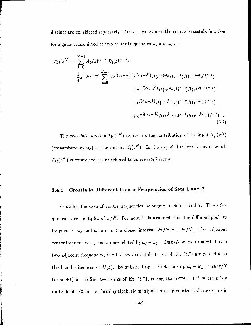
, r
, ,
distinct are considcred separatcly. To start, wc express the' g('ncl'al C1'osst.alk fUllctiol\
for signaIs transmitted at two ccnter freqll<'llcics Wk and Wl as
N-I Tkl(zN) = L: Ak(ZW-1 )BI(zW- i )
i=O 1 N-I = _z-(nk-p,) L: ""V1(lIk-P,) [cj(ok+fid II( c- jWk zW- 1) 1/ (c- )W, z W- i )
4 i=O
+ c -j(O'k-;3,) Il (C jWL ::: IV- i ) Il (('- jw,::: W- 1)]
(:1.7)
The crossfalk functwlI Tkl{zN) l'epresents the cOIlt.lihution of t1w input. .'\d::: N)
(transmitted at wk) to the output '};I{zN). In the scqucl, thc folll' t('rlll~ of which
Tkl(ZN) is comprised of are referred to as crosstalk fcrms.
3.4.1 Crosstalk: Different Center Frequencies of Sets 1 and 2
Considcr the case of centcr frcqucncics bclonging to Sets 1 and 2. 'l'h('s(' fl'('-
quencies are multiples of 1r / N. For now, it is assumed that the diffcn'/It po~itiv('
frcquencics Wk and Wi arc in the closed intcrval [21r / N, 7r - 211'/ N]. Two adja('('nt
center freqllcncies ~ 'k and W[ arc related by Wl - Wk = 2nt7r / N wh('l'c' 11/ = ± 1. Civ('1\
two adjacent frcquellcics, the last two crosstalk tCl'IllS of Eq. (:J.7) ar(' ~('IO dl)(' 1.0
the bandlimitedncss of l/(z). By slIbstituting the rdation~hip Wl - Wk = 21111r / N
(m = ±1) in the first two terms of Eq. (3.7), /Ioting that cJWk = Wl1 w}H'I'C ]J is a
multiple of 1/2 and perforllling algebraic manipulation to give identical (l'osst.(·I'IllS ill
- :]8 -

If (.), w(' gct. a simplified expression for the crosstalk function as
(3.8)
From Eq. (:1.8), we devclop a general rule rclating the phases, delays, m and p as
given by (discussion in Appendix il)
f.l - [(m - 2p)(nk - pd ~] Ok + pl - 7r N + 2 (3.9)
Sinn' m = ±1, we have considered crosstalk due 1,0 spectral overlap between signaIs
transmitted al, any two adjacent center frequencies in the closed interval [27l" / N, 7l" -
27l" / NJ. Then, Eq. (3.9) hecomes
f3 [(±1 - 2p)(nk - PI) 1] o~. + 1 = 7f N +:2 (3.1 0)
ln sccking solutions to Eq. (3.10), we first note that p is either an even or odd
multiple of 1/2 th('reby making ±1 - 2]1 odd or even respectively. Equation (3.10) de-
pict.s a gClJcl'é1ln'latiollship betwccn two unknowns D:k + {31 and nk - PI' In establishing
part.iculal relat.lollships bctwccll thcse two unknowns, we express nk - PI as a rational
Illult.iple of N, nélllH'ly aN/b where Cl and b are relativcly prime. '1'0 realize integral
d('lay fadaIS, aN/b must he an integer thereby imposing a restriction 011 N or the
1I111111)('r of hands tü be ail iIltcgral multiple of b. To avoid excessive restrictions on N,
b IIIl1st b<' kcpt to a minimum. \Ve consider the cases in which b = 1 (no !'estriction
011 N) and b = :2 (N is c\·('n). This givcs two different types of solutions 1.0 Eq. (3.10)
which al(' IH'('('SSéHY sinCC' two signais are sent with the same center frcqucncy. Also,
( ... N is COBst rained 1,0 he cven as a result.
- 39 -
... 7
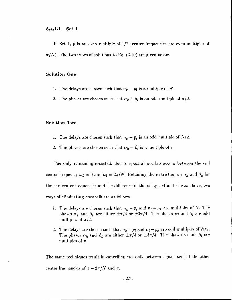
3.4.1.1 Set 1
In Set 1, pis an even multiplc of 1/2 (center freqnencies arc eV('1l 1ll111t.iptpH of
'Tr/N). The two t.ypes of solutions 1.0 Eq. (3.10) are givcn bctow.
Solution One
1. The delays are choscn such that 11 k - PI is a mut tipl(' of N.
2. Thc phases are chosen snch that Qk + (31 is an odd multiple of 11"/2.
Solution Two
1. The delays are chosen such that nI.; - PI is an odd mult.iple of N /'!..
2. The phases are chosen such that Qk + (31 is a multiple of 11".
The only remaining crosstalk duc to spectral overlap DCClII H \)('tW('('1l t1l<' ('IICI
center frequency WI.; = 0 and WI = 211"/N. Rctaining the restrictioll (>JI Ct/.; <LIHI {JI.; for
the end center frequencies and the differencc in the delay factors to he as abov(" two
ways of climinating crosstalk arc as follows.
1. The dclays are choscn such that nk - PI and ni -l)k arc rnultipl<'s of N. 'l'II<' phases Qk and #/.; arc cither ±1I"/'1 or ±311"/1. The phases Ctl and {il al(' ()(Iel multiples of 'Tr /2.
2. The dclays arc chosen surh that 111.; - PI and 111- Pk are odd lIIult.iplC's of N/'!.. The phases Ok and Ih are eitller ±'Tr/'l or ±311"/1. The phc\s('s (ft cL/Hl {-JI ,L/e
multiples of 'Tr.
The same techniques rcsult in cancelling crosstalk bctwccn sigl/als ~ent. at t.he oth('1
center frequencies of 11" - 2'Tr / N and 11".
- 40 -

(
(
3.4.1.2 Set 2
Fol' Set 2, P is an odd multiple of 1/2 (center frequencies are odd multiples of
7r / N). A type of solution to Eq. (3.10) is given bclow.
Solution
1. The delays are choscn such that nk - PI is a multiple of N /2.
2. The phases are choseH stlch that O'k + /31 is an odd multiple of 7r /2.
For the end center frequency Wk = 7r/N, spectral overlap occurs with WI = 3'1r/N.
By examilling the crosstalk function, it is found that the climination of crosstaik is
feasible if both of the conditions bclow are satisfied.
1. The dclays are choscn such that nk - PI and 111 - Pk are multiples of N /2.
2. Thc phases arc chosen such that (O'b/3l) and (!3bO'/) arc (7r/4,'Ir/4 ± m'Ir), (-7r/4, -7r/4 ± m7r), (37r/4,37r/4 ± m'Ir) or (-3'1r/4, -37r/4 ± m7r) where mis
an integer.
'l'Il<' same conditions result for cancclling the crosstalk betwcen signaIs sent at a center
frl'queney of 7r - :37r / N and the othcr end frequency 'Ir - 'Ir / N.
Although th(' prcccding analysis gencrate5 ollly one type of solution, there are in
rad. 1.\\'0 (,/llbedd('d solutions that arise by making t.he difference in the delay factors
ail odd or even Illultiple of N /2.
3.4.2 Crosstalk: Repeated Center Frequencies
IIeJ'(~, wc examine the crosstalk function associated with two signaIs transmitted
wit.h the same center frequency. vVe return to the original expression for the crosstalk
- 41 -
\II .
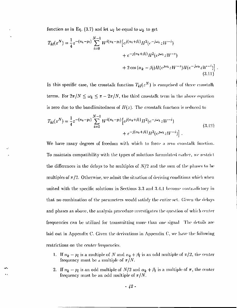
.,.,"'.
function as in Eq. (3.7) and let Wl bc cqual to Wk to gel
1 N-l Tkl(zN) = _Z-( 71 k-pd L Wi(71k-p,)[ci(nl+,B/)1I2(c-iw4zW-i)
4 i=O
+ 2eos {O'k - ;-JI)II(C)WlzIV-')lI(c-iwkzW-i}]
(:U 1)
In this specifie case, the erosstalk funetioll 7'kl(::N) is (,olllprispd of I.lIn·(· C1osst.alk
terms. For 27r / N ~ Wk ~ 7r - 27r / N, the thin! erosstalk tc'nll in the "bo\'<' ('<\lIat.ioll
is zero due to the bandIimitedness of 11(::). The crosstalk fllnct.IOIl is \('du('cd 1,0
(:l.1 ~)
We have many degrees of freedom with which to force' il Z('IO C10shtalk fUllct.ion.
To maintaill eompatibility with the types of solutiolls rormulatl'd (· .. r1wr, \V(' rt'htri( t.
the differenccs in the delays to hc multiples of N /2 and th(' :mm of the phas('s 1,0 1)('
multiples of 7r /2. Otherwise, wc admit the situation of dt'riving conditions whidl wll('l1
united with the specifie solutions in Sections 3.3 and :lA.1 !){'COTlJ(' (ollt.',IClidory ill
that no eombination of the paramct('J's would ~at.isfy t h<, ('lit in' sd .. Giv('11 t II(' d('lays
and phases as aoo\'e, the analysis procedure III\'estigal.('s the qll('~tioll of \Vhi( h ('('111.('1'
frequencies cnn be utilizcd for transmitting more than 011(' ...,ignal TI\(' <ld,ails (li'('
laid out in Appendix C. Given the derivations in Appelldix C, w(' h,IV(' t.he- fol!owillg
restrictions on the center freqllcncics.
1. If nk - Pl is a multiple of N and Qk + ;-11 is ail odd lIlultiple of 7r /'2, 1.11(' C('lIter frcqueney must be cl Illultiph' of 7r / N .
2. If llk - PI is an odd multiple of N/2 and ak + /~I is a 1Il11ltiJ>I(~ of 7r, t.he ('(~IIt.er frcqueney must be an odd multipl<' of 7r / N.
- 42-
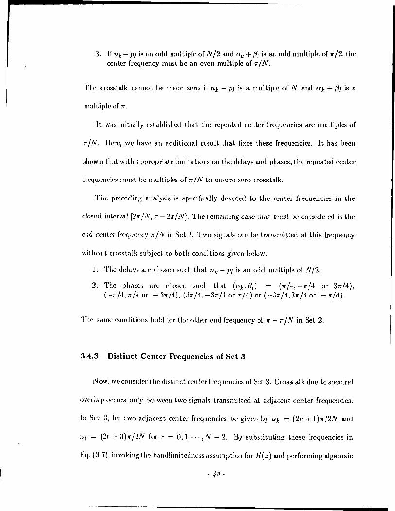
3. If nk - PI is an odd multiple of N /2 and Qk + PI is an odd multiple of 1r /2, the center frequency must be an even multiple of 1r / N.
The crosstalk cannot be made zero if nk - PI is a multiple of N and Qk + PI is a
mult.iple of 1r.
It. was initially established that the repeated center frequel1cies are multiples of
1r / N. IIere, we have an addit.ional result that fixes these frequencics. It has been
shown that with appropriate limitations on the delays and phases, the repeated center
frequc/lcÎ('S IllUSt. he multiples of 11" / N t.o ensure zero crosstalk.
The prcccding analysis is spccifical1y devoted to the center frequencies in the
closed illterval ['21r / N, 7r - 27r / NJ. The rcmaining case that must be considered is the
e/ld cent.er frcqucllcy 7r / N in Set 2. Two signaIs can be transmitted at this frequency
withollt cl'O<;stalk subjcct to both conditions given bclow.
1. The delays are choscn sueh that 11k - PI is an odd mult.iple of N/2.
2. The phases are chosen such that (O:k.Pd = (1r/4,-1r/4 or 37r/4), (-1I"jtt,7r/'10r - 311"/4), (311"/4,-37r/4 or 7r/4) or (-37r/4,37r/4 or -7r/4).
The same conditions hold for the other end frequency of 7r - 1r / N in Set 2.
3.4.3 Distinct Center Frequencies of Set 3
Now, wc consider t.he distinct center frequencies of Set 3. Crosstalk due to spectral
O\'('rlap occurs orrly bctwccn two signais transmittcd at adjacent center frequencies.
ln Set 3, let. two adjaC<'llt ccnter frequencÎes be given by Wk = (21' + 1)7r /2N and
WI = (2r + :J)7l' /2N for r = 0,1,"', N - 2. Dy substituting thesc frequencies in
EC]. (~1.ï), invokingt.hc bandlimitcdncss assumption for H(::) and performing algebraic
- 43 -
,',
manipulation just as in Section 3.4.1 givcs a rclationship similar t.o E(!. (:UO) ml
(a.l :l)
Note that the same rclat.ionship holds betwccn 0'1 + !~k and 1/1 - PA"
Just like Eq. (3.10), Eq. (3.13) dcpict.s a gellcral l'<'lat.iollship h<,tw('<'n t.wo 1111-
knowns Qk + PI and nk - PI' In contrast to the situat.ion of having l'('!wat<'d Cl'lIt<'J'
frequencies, only one type of solution to Eq. (3.1:l) is nCCC'SSélly sinn' III<' cent.C'r fl<'-
quencies are distinct. This is providcd without any {'('strict ion on N hy sPI,t,ing 11 k -1'1
to be a multiple of N. lIowevcr, we can maintain the' principl<' of making I/k - 1)1 a
rational multiple of _IV and impose the mild limitat ion of ail ('\'('Il N \'0 gd <1 M'colld
type of solution (similar to the approach in Section 3..t.l). The two t.ypes of solut.ions
lead to t\Vo different transmultiplexers.
Solution One
1. The delays are chosen such that nk - PI and ni - Pk are multiples of N.
2. The phases are chosen such that Qk + {JI and 0'1 + Ih are odd multipks of 7r /'2.
Solution 'l.'wo
1. The delays are choscn such that nk - PI and 711 - Pk arC' odd 1ll1lltiplc's of N /'2.
2. If l' is odd, O'k + 131 and 0'1 + {Jk are odd mult.iples of 7r /'2, If l' is eVC'II, rrk + l'JI and QI + {Jk are multiples of 7r.
3.5 Synthesized Transmultiplexers
The specifie solutions proposed in Sections 3.3, :l.1.\, :lA.2 and :l.t1.:J compris('
a set of sufficicnt conditions fol' an N band crosstalk-frec translllllltiplex('r with ail
- 44 -
idcntical input-output transfer function for every pair of c,"mesponding terminaIs.
Given thcs(' solutions, wc cstablish values for the free parameters and synthcsize five
diffcl'cnt types of transmu/tiplcxC'l's. The first three use repeated center frequencies
(Set l or 2). The other two use the distinct frequcncics of Set 3. In four of the five
systclm;, il, is ncccssary to implemellt dclays which are odd multiples of N /2. For
thesc cases, tllC parameter N is constrainC',j to be even.
3.5.1 System Tl
In the' first. system Tl, wc use center frequencies in Set 1. The combining and
:,cparé,tion filte'l's correspondin[, '" the cud frequeney wo = 0 are assoeiated with
paramc\'Cl:' 1/0 = PO = 0 and 0'0 = -/30 = 7r /4. The next center frequcney, w} ==
W2 == 27r/N is t1scd to transmit two signaIs. Crosstalk is climinatcd bctwecn thesc
two signais and wit.h the signal sent al zero frequency by sctting nI == Pl = N /2,
(YJ = -{31 = 7r, 122 = P2 = 0 and (\'2 = -(32 = -7r/2. Now, wc procccd to the
rrC'quP(lcy W3 = W4 == 47r / N. To cancel crosstalk betwecn signais sent at 27r / N and
47rJN, wc' set 113 = pa = 0, 0'3 = -/3a = 0, nl\ = P4 == N/2 and 0'1\ = -/34 = 37r/2.
TheSl' paran1<'ters climinate crosstalk bctwc<'l1 the two signais sent at 47r / N due to
the fOlllpatibihl \' in the rllies forl1lcd for cancclling crosstalk due to spectral overlap
\)('1 \\'('('11 adjac('nt. élnd rcp<,atcd frcqucncics. \\Te continue this procedure in a sequclltial
fashiol\ for ('ach ('('111('1' [rl'quclley. This establishcs the combining and separation filters
- 45 -

, r ~
f , \
of Tl as follows:
11" ao(n) = h(n) cos "4
N 211" al (Tl) = h( n - 2" ) cos N 11
a2( n) = h( 11) sin ~ n
17r a3(n) = h(n) cos NH
N 411" a4(n)=h(n-"2)sin N ll
7r bO ( 11) = Il ( 11 ) cos -:t
N 1}7r
b 1 ( n) = Il (11 + '2 ) cos ~ 11
.}
b2(n) = -h(1/)sill -;1/ ·17r
b3(n) = 11(11) cos fin
N ·t7r b,,(n) = -11(11 + 2 )sin Nil
(:l.1 ,t)
It is noted that for Tl, the delay c1ernen ts of N /2 a lt,(,l'IIa tp 1)('1. \\'('l'II t.!H' (,()!-li 11(' and
sine carriers and thal. the separation filters associat('d wit h t.1H' sill(' CeIITi('1 S have' il
minus SigIl associated with 11(11). ft is also ohserv('d that a delely ('I('III('nt of N/'2 is
associated with a ccnter frequcncy of 7r onl)' if N = 2, (l,la, . '" The inpllt-ollt.pllt.
transfer function for any pair of corresponoing terminaIs is
1 N-I T(zN) =? L 1I2(zW- i )
~ i=O
= J~ [ ••• + v( -2N)z2N + v( -N)zN + v(O) + u(N)z-N + p(2N):;-'2N + .. ] ( :l.I !) )
where v(ll) is the inverse z-transform of 112(::).
3.5.2 System T2
In the second system T2, we use center frequ('llci('s in Set 2. 'l'Il(' (OI11bininl!,
and separation filters for the signaIs scnt with t.he ('lId ccnter frc'<!uc'lIcy 7r / N have'
parameters 110 = Po = 0, 00 = -/30 = 11"/1, 11 1 = Jl1 = N /2 amI (q = -(il =
11"/4. There is no crosstalk betweC'n the sigmds trall~lllitted at 7r/N. For a ff'('ql)('lIcy
- 46 -
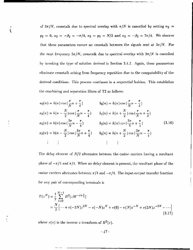
of 37r / N, crosslalk duc to spectral overlap with 7r / N is cancelled by setting n2 =
1'2 = 0, a2 = -(32 = -7r/4, n3 = P3 = N/2 and a3 = -(33 = 77r/4. Wc observe
that. thcsc paramct.crs cnsure no crosstalk bctween the signais sent at 37r / N. For
the ncxt frcqucncy 57r / N, crosstalk due 1.0 spectral overlap with 37r / N is cancelled
hy invokillg the type of solution derived in Section 3.4.1. Again, these parameters
e1irninal,e crosstalk arising from frequency repetition due to the compatabi1ity of the
dcrivcd conditions. This process continues in a sequential fashion. This establishes
the combining and separation filters of T2 as follows:
7r 7r (la ( 11) = Il ( 11 ) cos ( N n + "4 )
N 7r 7r (LJ ( 11) = Il (1/ - 2) cos ( N n - "4 )
37r 7r (l2( 11) = h( 11) cos ( N 11 - "4)
N 37r 7r a:J ( 11) -= Il (n - 2) cos ( N n + '4 )
7r 7r bO(n) = h(n) cos (Nn - -)
·1 N 7r 7r
bl(n) = h(n + - )cos(-Vn +-) 2 1'1 4
3i!" 7r b2(n) = h(n) (0<; (-y1l + "1)
N, :31r 7r b3 ( n) = h (n + "2 ) cos ( N n - -4" )
(3.16)
The ddity clem('nt, of N/2 alternatcs between the cosin~ carriers having a resultant
phasf' of -7r /4 and 7r /4. When no delay clement is present, the resultant phase of the
cosine carriers altcrnat,C's bcf,wC'C'n 7r /4 and -7r /4. The input-output. transfer function
for ally pair of corrcsponding terminais is
1 N-l ,/,(;;N) =? L lf2(;;W-i+~)
~ ;=0
= ~ [ ... + tI( _2N):;2N - v( -N)zN + v(O) - v(N)z-N + v(2N)z-2N - ... ]
(3.17)
wherc l'(") is the inverse z-transform of l/2(z).
- 47 -

r 3.5.3 System T3
A third transmultiplexer is synthesized by rclaxing the assulllpt.ion of u~ing ollly
a single lowpass prototype. The system uses two lowpass protot.ypes h(l1) élnd g(1I)
which are each bandlimited t.o no less t.han 7r / N and no mol'<' t.hélll 27r / N. E<I< h of
the combining and separation filters is a modulated and dday<'d v('rsion of Ol\(' of li\('
lowpass prototypes just as in Eqs. (3.1) and (3.2).
Suppose Tl is modified to include two prot.otypcs by alt.crnat.ing t.h(' posit.ions of
h(n) and g(n) between t.he combining and separation filt,ers for ('ach ('('I\t.('I' fl'cqllC'llcy.
This leads to a ncw transmult.iplexcr T3 descrihcd as follows.
7r ao(n) = h(n)cos '4
N 211' al (n) = g( n - 2" ) cos N n
a2(n) = g(n)sin ~n 47r
a3(n) = h(n) cos N n
a4(n) = h(n - ~) sin ~ n
7r bo(n) = g(11)COS-
4 N 27r
bt{n) = h(n + 2 )cosNH
,)
b2(n) = -h(71)sin-;n
47r b3(n) = g(n)cosNlI
N . 41r b4(n) = -g(lI + :2 ) Slll Nil
The crosstalk bet.wccn two signaIs sent at adjacent freC!lwnci('s is eiimillaü'd éI~ in
Tl. Moreover, il. can he shown t.hat. the crosstalk b('twccn two signais tlclnsrniU(·d
at. the same center freqllency Wk where 27r / N :S Wk :S 7r - '27r / N is ('Iilllinat(·cl hy
the same approaches as derivcd in Section 3.4.2 evcn whcn two plOtotype~ are used.
Thercfore, system 1'3 is crosstalk-frec. The input-output trallsf<'l' fUllction fOI (Lily
- 48 -
pair of corresponding terminaIs Îs
1 N-l T(zN) = - L J/(zW-i)G(zW- i )
2 i::::O
= ~ [ ... + w(-2N)z2N + w(-N)zN + w(O)
+ w(N)z-N + w(2N)z-2N + ... ]
whcre w(n) is the inverse z-transform of ll(z)G(z).
(3.19)
Consider modifying T2 to include two prototypes. Again, we alternate the posi-
tions of 11(71) and 9(11) betwccn the combining and separation filters for each center
fr<'quency. In this case, the crosstalk betwcen two signaIs sent at an end center fre-
qucllcy (71) N or (N - 1)7r / N) is Ilot cancelled with two prototypes. Therefore, T2
cannot be modificd to includc two prototypes.
Not.e that. t.here arc other ways of modifying the transmultiplexers to allow for two
prototypes. !Iowcver, any otller arrangement Ieads to a crosstalk function Tkl(zN)
for two !lignaIs S('lIt at adjacent frequencics to be expressed in terms of Il(z) and
G(::). Then, the crosstalk terms in Tkl(::N) that involve spectral overlap cannot
be canceller!. 1'0 cOllclude, wc observe that only Tl can bc modified to allow for
two prototypf'l'. Moreover, t1H' modification must be perforrncd in the unique way
dcscribcd ahov~.
3.5.4 SyStelll T4
The ('{'/]ter frequencies of Sel, 3 are used to synthesize !'ystem T4. A lowpass
prototype with a maximum bandwidth of 7r / N is used. One of the specifie solutions
fOI Illulat.cd in S<,ction :3,·1.3 is invoked to cst.ablish the parameters. Ail the delay
- 49 -
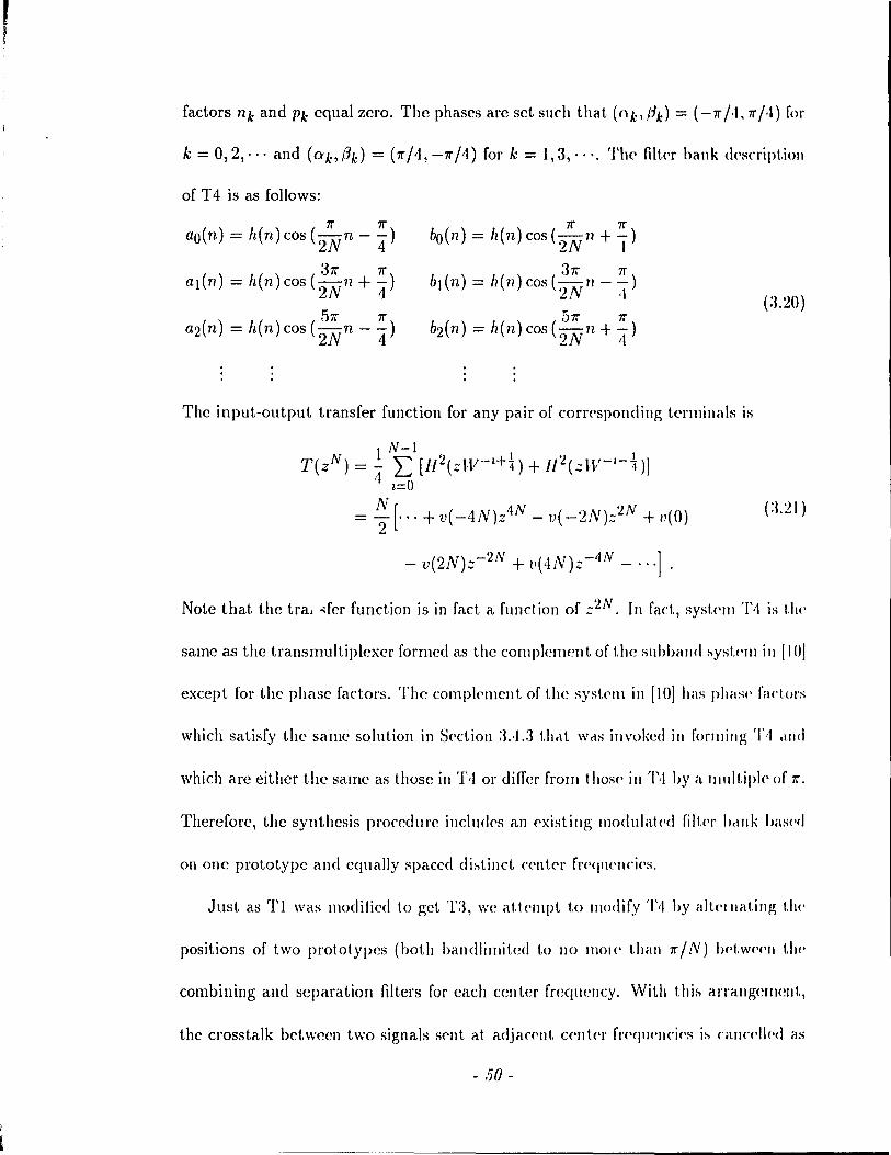
1
factors 11k and Pk equal zero. The phases are set su ch that (ok,#k) = (-7r/.l,7r;.t) fol'
k = 0,2,'" and (O'bf3k) = (7r/4,-7r/4) for k = 1,3, .. ·. Th{' filkr hallk d(\script.ioll
of T 4 is as follows:
7r 7r ao(n) = h(n) cos (2Nn - 4)
7r 7r bo ( n) = Iz ( n ) cos ( ? N 11 + - )
~ 1 37r 7r
al(n) = h(n) cos (2Nll +"4) 37r 7r
bl(n) = 1z(1l) cos (-. -ri - -) UV ·1
57r 7r a2(n) = h(n)cos(2N n - 4)
The input-output transfer function for any pair of corr{'spondillg t.erminals is
1 N-l T(zN) = 4" L [l/2(zW-z+~) + 1I~(zW-I-~)]
z=o N [ . = 2 '" + v( --4N)z4N - v( -2N):;~N + u(O)
- v(2N)z-2N + v( 4N)z-4N - ... ] .
Note that the tra ... fer function is in fad a function of z'2N. III faet, syst(\111 ')"1 is Uw
same as the transmultiplexer formed as the complement of the subbélJl(! :-.yst(\111 in [10]
except for the phase factors. The comp!C'll1ent of the syst<'1ll in [10] bas pllils(\ fadors
which satisfy the same solution in S(\etion :l..l.3 thrlt \VrlS invnked in forlJling 'l'II ,1IId
which are either the same as those in T·I or differ frol11 t !tOS(' in '1'·1 hy a Illllltipl(' of 7r.
Therefore, the synthesis procedure illclndC's an cxisting lI1odlllat(>d filt(>1' hrlnk has(>eI
on one prototype and equally spaced di:-.tinet c{'nter fr<'<jllt'nci('s.
Just as Tl \Vas ll10dified to get 'Cl, wc atl(>l1lpt 1,0 lIIodify 'J"I hy éllt('llIélting 1.1)('
positions of t\Vo prototypes (hoth balldlilllited tn 110 mol(' théln 7r / N) 1H't.W(·(·11 tlJ('
combining and separation filters for each center frcqucncy. With thi:-. arrangemellt,
the crosstalk betwcen two signaIs Sf'llt af. adjacC'nt C('lIt(·1' fr<\qllC'lIcÎ<'s i:-. Cilll(,f'Il<·eI as
- 50 -
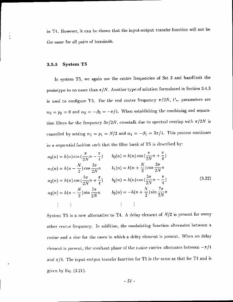
in '1'4. However, it can be shown that the input-output transfer function will not be
the sarne for ail pairs of terminaIs.
3.5.5 System T5
In system T.5, we again use the center frequencies of Set 3 and bandlimit the
prototype to no more thall 1T' / N. Another type of solution formulated in Section 3.4.3
is used to configure 'J'5. For the end ecn ter frequency 1T' /2N, t l,,, parameters are
no = Po = 0 and QO = -{30 = -1T' (1. When establishing the combining and separa-
tion filt.ers for the frequency 37r /2N, crosstalk due to spectral overlap with 1T' /2N is
cancclled by setting 11 1 = Pl = N/2 and (YI = -fh = 31T' (1. This process continues
in a seqlwntial f,u;hion ~uch that the filter bank of T5 is de~cribed by:
1T' 1T' bo(n) = h(n)cos(2N 7l + 4) 1T' 1T'
ao(n) = 11(11) cos ( N lI - -) 2 4
N 31T' b}(n) = h(n + -) cos -v ri
2 21 N 31T'
(LI (n) = 11(11 - 2 ) cos 2N n
51T' 1T' b2(n) = h(n)cos( N n --)
2 4 51T' 1T'
a1( 71) = Il (11 ) cos ('lN 17 + 4 ) (3.22)
b3(n) = -h(n + ~-) sin ;~ 17 N 71T'
fl'3(n) = 11(71- -)sin-n , 2 2N
Syst.em '1'5 is a new alternative to T1. A delay clement of N/2 is present for every
oUlcr (,ClIt L'r frcql1cncy. In addition, the modulating function alt.crnat.es bctween a
cosinc and a sille' for the cases in which a dclay c1ellH'Ilt is present. \Vhen no delay
e!('IllCllt is pr<'S('IÜ, the Icsultc\llt phase of the cusinc carriCI alternates bctween -1T' /4
and 7r;'1. The input.-out.put. t.rc\nsfcr funct.ion for T5 is t.he same as that for T4 and is
gi\'t'II hy Eq. (~1.21).
- 51 -

As for T4, wc attcmpt to modify T5 1.0 accornmodat.c t.wo protot.ypes. In gt'llt'ral,
the transfer function is not the same bctween ('very pair of cO\Tespondinp, tt'I'minals.
However, an except.ion occurs for the case N = 2 (see Section :l.ï).
3.5.6 Modification of the Parameters
We address the question of whether the paramctC'rs chos('11 from t.h(' s)wcific solu
tions proposed in Sections 3.3, 3.4.1, 3.4.2 and 3.4.3 to configure t1H' t lëlIlSll1l1lt.ipkx(,l~
are unique. For the cases wheTl the dclay clenH'1l t. is O. él d('la)' feH'\'OI of t II<' f01'l1l (/ N / il
where a and b arc relativcly Plimc coulcl be lIs('d. Tlwll. tll<' c!('lelY ('II'I1Wllts of N/'2
would be replaccd by aN/b+ N/2 = (2([ + b)N/2b, III tll<' ,!!,1'1l('lill ("~(', wlJ('1l 2(/ + Il
and 2b are rclatively prime, N is restricted 1.0 be ail integralllluit ipll' of 211 in orel.'I'
to rcalize intcgral dclay factOls. Otherwisc, N must he ail illt(',!!,lallllllltipl(' or b. 0111'
choicc of delay factors imposes the most rnild lestrictioll 011 N ill thelt N IIII1S\' \)('
even.
Any set of phase factors (ob/3k) can be }'eplaced by (ok+1II7I'",/1A.-1II71'") wh('I'<' 1/1
is an integer. AIso, note that. the transIllllltiplexers Tl throllgh T!) W('I(' c!('V<'lop('e1 by
starting wit.h phase factors 71'" /4 and -71'" /,t fOI the 10'\'I'sl. ('IHl fl'<'l1 11('11 ('y. 1I0w('vl'l, ,1I1Y
odd multiple of 71'"/4 could \)(' us('d as the startillg poillt. III thi~ cas(" th(' filll'rs ill TI
and T3 arc either the sanw as or ncgatives of tho~(' pJ('~(,Il{(,d (l1>OW·. III ~yHt.('IllS '1'2, '1'<1
and T5, the phase factors lIsed in aIl the filters wOllld ~lill Il'IIlaill 1,0 he odel 1Il11ltipl('s
of 71'" /4. The cosine and sine carriers al the odd-llldex('d tprlllillélb of TG collid ),('(,OIlU'
sine and cosine carriers rcspectivcly. '1'0 concllld(', \V(' Ilot (' lhat tl)(' ( h()~(,1l P,1I (lll)('I,{'1 S
are not unique. I1owevcr, chang!':, in the dday fart ors will I(·~tl i( t. t.h!' 1lllllllwI 01
- .52 -
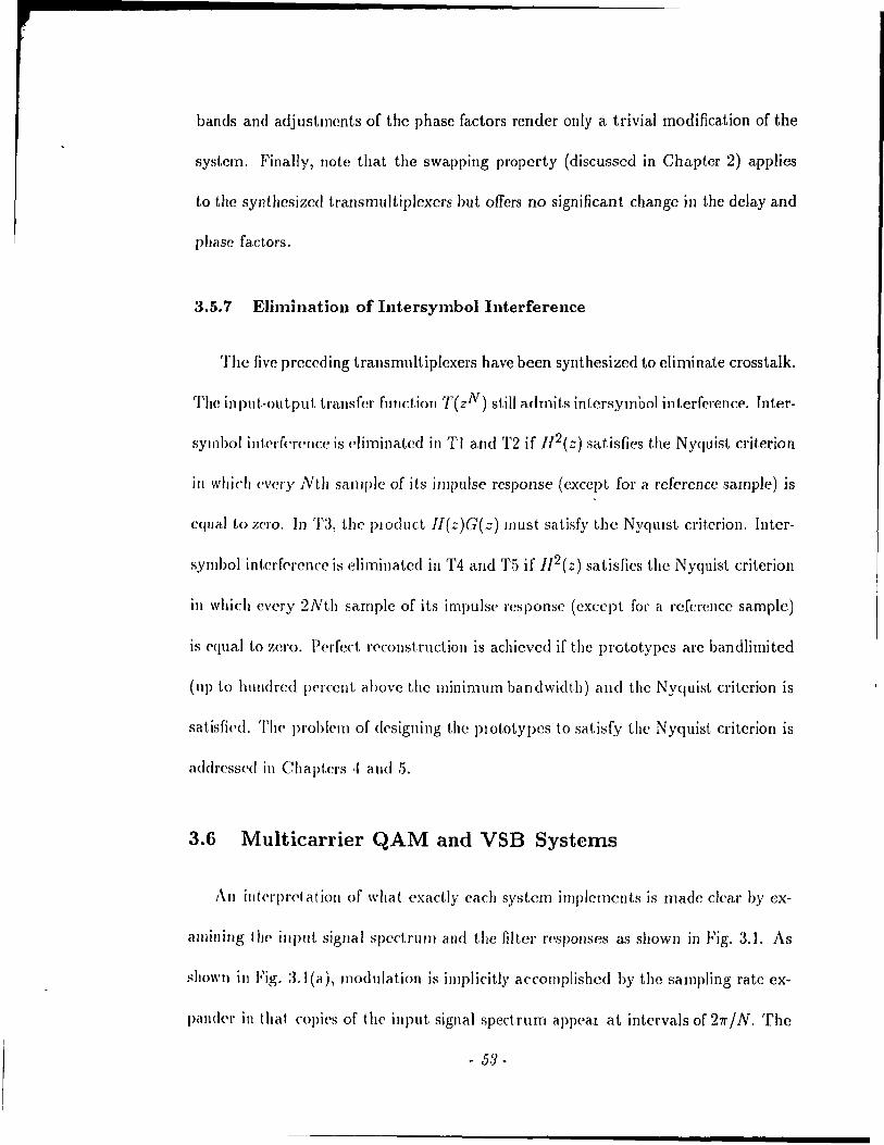
bands and adjuslments of the phase factors render only a trivial modification of the
syst.em. Finally, note t.hat the swapping propcrty (discussed in Chapter 2) applies
to the sYIlthcsizcd transmultiplcxcrs but offers no significant change in the delay and
phase faciors.
3.5.7 E1imination of Intersymbol Interference
The fivc preceding transmult.iplexers have been synthesized to eliminate crosstalk.
The input·output trallsfer function T(zN) still admits intcrsymbol interfcrence. Inter
symbol interfcrellcc is f'liminatcd in Tl and T2 if //2(z) satisfics the Nyquist criterion
in wltich every Nth salllplc of its impulse response (cxccpt for a referencc sample) is
cqual to zero. In T:J, the pIOduct J/(z)G(::) must satisfy the NyqUlst criterion. Inter
symbol interf('rcl1cc is eliminatcd in T4 and T·5 if 112(;;) satisfics the Nyquist critcrion
in which every 2Nth sarnplc of its impulse l'csponse (except for a rcfcrcllcc sample)
is ('quai ta :r,cro. PCl'fe\t rf'construclion is achicvcd if the protot.ypes are bandlimitcd
(llp lo hUlldrcd pf'rcent abovc the minimum bandwidth) and the Nyquist critcrion is
sat.isfi('d. Thf' problem of df'signing the plOtOtypcs to satisfy the Nyquist critcrion is
addres~><,d in Chaptel's ,1 and 5.
3.6 Multicarrier QAM and VSB Systems
An illkl'pl'datioll of what cxactly cach system irnpleIllcnts is made clca.r by ex
éllllining t 11(' input sigllal spcctrullI and the filtcr l'<'spO/lses as shown in Fig. 3.1. As
sllo\\'l1 in Fig. :J.l(a), modulation is impli('itly accornplished by the sampling rate cx
pand<'l' in that copi('s of the input signal spect.rum appcal at intcrvals of 27rfN. The
- 53-

three systems Tl, T2 and T3 accomplish l1l11lticarrier Quadrature Amplit.ude 1\lod
ulation (QAM) in the form of a digital multiratc filt.l'r struct.\II'(' as in Fi~. 2.1. For
each unique center frequency (exccpt 0 and 1T'), t.wo sigll,ds are sellt. ill quadtatlll"l'
Systems Tl and T3 explicitly accomplish QAI\1 in t hat. a P,I. t.icular cOlllhining filt('r
extracts one of the replicated copies of the mput. spectnllll éllOllll<1 c,IlTi('1 freqll('lIcie:-.
al. multiples of 21T' / N (sec Fig. 3.1). The same is not t.rue of '1'2 in th"t 1 II<' (()lIIhininp,
filters, whose center frequencies are odd lIlultiples of 1T' / N, ('xtr,l<t cl portloll of t.wo
adjacent. copies of the input spcdrum. System '1'2 CclII })(' ("OIlV('1 f,cd tu ,1 tn\(' QAM
scheme as follows. Suppose each of the input signab is lIlultlpli(·d hy (-1 Y' prior t.o
sampling rate expansion. Then, the input Sp<,ctlUnl :-.hifts in suth cl Wdy t.hal a 1"1<'1
sampling rate expansion, the replicated copies are C('nt('lcd at impllCit. (clii i('IS ('qu.Ii
to odd multipks of 1T'/N (shown in Fig. :3.1(h)). Now, l'éH" of t.he comhillinp; filt('ls
will extract a rC'plicated copy ccn t.ercd at an odd Inultipl(' of 7r / N. TI\(' origllléli sigllél Is
can be recoveled Gy lI1ultiplying each of the out.pub by (-1 V'.
Multicarrier QuadlatllJe Amphtude l\fodulation systt'Ills havt' \)('<'1\ \(',diZ<'d in
continuous tiL1e [21] and in discrete Ume [22]. A180, a data mod('1lI has('cl on tht' QAl\l
technique is dcscribcd in [2:3]. The system in [22] ll:-'éS on(' lowpa!'>!'> prot.otyp(· éllld a
set of equally spaccd frequellcies for tlan3trli!'>~ioll. Also, il IS oV('I!'>alllpl<-d as oppo!'>(·<1
to the cri tically sampled sysL('ms t hat Wt' consid('r. 1 Il fi Il over:-,alllplc·c1 :-.y:-,t,('IlI, t.ilt'
sampling rate expansion/compression factor is gl(';ü('r than tht' 1l11l111H'1 of fl\'(jl\(,llcy
bands. This givcs additional flccdom ill choo!'>illg t!1<' \(·()(·ctt.('d ('('II\('I f!('qlwll< i('s bllt.
cioes Ilot gencrally lesult III the utilization of the clItin' IclllP"(' 0 10 Ti III (·Vt'Iy !J,iIId,
the lowpass prototype perforlll!-> an int<orpolcltloll fUllctlOIl by <'xtrél( tlll)!; t.1\(' (Opy of t.1\('
- 54 -
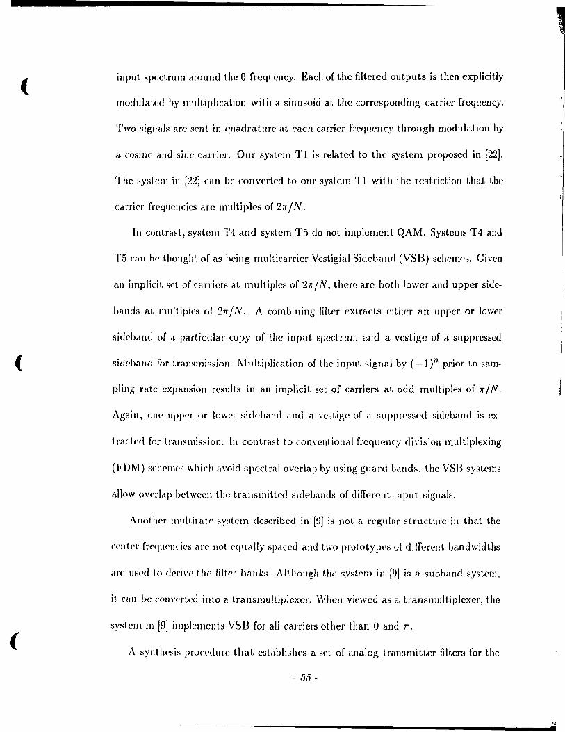
( input. spectrum around thc 0 frcqllcncy. Each of the filtered outputs is thcn cxplicitly
rnodulated I>y multiplication with a sinusoid at the corresponding carrier frequency.
Two sigwtls arc sent in quadrat ure at each carrier frequcncy through modulation by
a cosine amI sine carrier. Our sysit'm Tl is rclatcd to the system proposed in [22].
The system in [22J can be converted to our system Tl with the restriction that the
càrriC'r frC'<jucncies arc multiples of 27r / N.
In contrast, system 1'4 and system T5 do not implemcnt QAM. Systems T4 anJ
1'5 cati b(' thought of as heing multicarrier Vestigial Sideband (VSB) schemes. Given
an implicit sd, of carriers at mult.iples of 27r / N, there arc both lower and upper siJe-
bands at multiples of 27r / N. A combilling filter cxtract.s cither an upper or lower
sid('band of a. particular copy of the input spcctrum and a vestige of a suppressed
( sid('ball(1 for transmission. Multiplication of the input signal by (_l)n prior to sam-
pling rat.e expansion results in an implicit set of carriers at odd multiples of 7r / N.
Again, one upper or low('r sidcband and a vestige of a suppresscd sideband is ex-
traded for transmission. In contrast to cOllvcntional frcquenry division multiplexing
(FDM) schelllcs which avoid spectral overlap by lIsing guard band~, the VSB systems
allow overlc\p betwcell the transmitted sidebands of diffcrcnt input signais.
Anot.!te\' 1l1111t.ilatc system dcscribed in [9J is not a rcgulé1l" structure in that the
cent.e\' f\'eqlH'11l ics a\'e not cqudlly spaccd and two prototypes of differcllt bandwidths
arc t1s('d t,o <!c\'iv(' t.he filtc[" ballks. Althollgh t.he system in [9J is a sllbband system,
il. cali Oc COII\'c\'tcd illto a translIlultiplcxcr. When viewed as a transmultiplcxer, the
system in [~)l illlplcmcuLs VSB for all carriers other tIJan 0 and 7r.
( A syntll<'sis pron'dll\'c that. cstablishcs a set of analog transmitter filters for the
- 55 -
>.l .
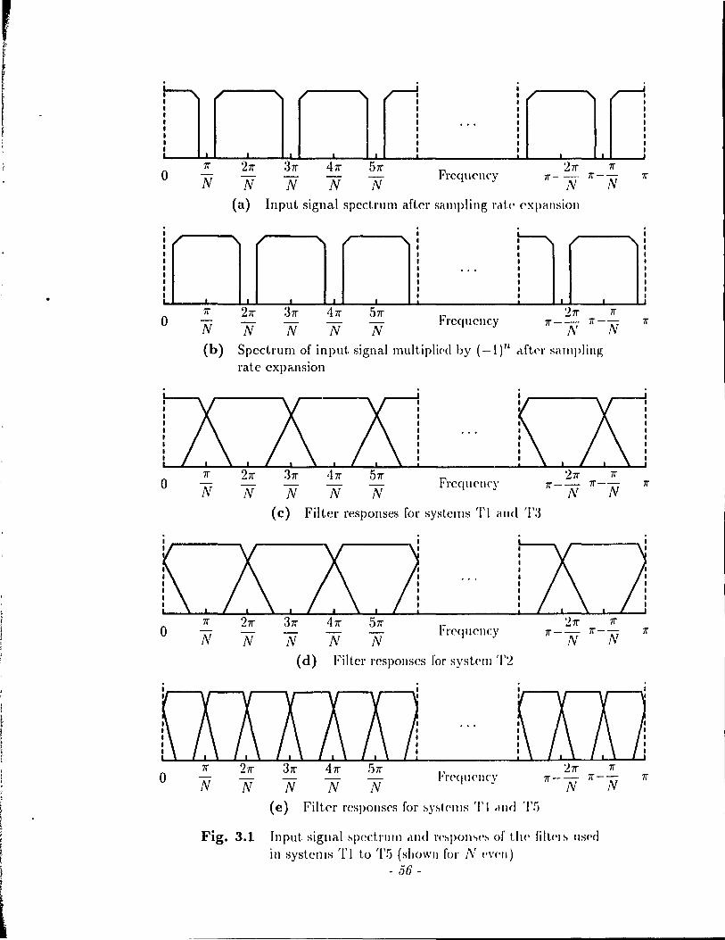
! ~ 1 1 , l
o N
1 1 ~ 1 1 1 1 1 1 1 1
'Tf' 0 N
(b)
o N
1l" o N
3 'Tf'
N 41l"
N
5 'Tf'
N FrcqU<'llCY
2 'Tf' 'Tf' 'Tf'-- 'Tf'--
N N 21l"
N (a) Input signal spcctrum after sampling rot.(' expallsion
1 , ~ , 1 1 ~
1 1 1 1 1 1 1 ... 1 1 1 1 1 1 1 1 1 • • 1 . ~
2 'Tf' 3 'Tf' 41l" 5 'Tf' 21l" 'Tf' - - Frcqucncy 1l"-- 'Tf'--
N N N N N N Spectrum of input signal multiplipd by (_I)n clJtC'\' séllIIpling rate expansion
N N Frequcllcy
Filter responses for systems TI and
N :h N
(cl) N
Freq1\cncy
Filter l'eSpOllSes for systelIl '1'2
T:J
21l" 'Tf'--
N
'Tf' 'Tf'--
N
1
" 1 1 1 1 1 1 1 1 1
lT
'Tf'
. . . .
mliTJJ ITJJ o 'Tf' 2 'Tf' 3 'Tf'
N N N (e)
N N FreqlJ('ncy
21l" 'Tf' 'Tf'-- 'Tf'--
N N 41l" 5 'Tf'
Filtel' rcspolls(,s for :-,y:-,tC'llIs Tl ,lIld Tf)
Fig. 3.1 Input sigllal :-,pectrlllll <lIId re:-,pol\,>(':-, of t!H' filt.('I:-' llS('<I
i 11 systems Tito T!j (showll for N ('\'('11)
- .56 -
(
(
(
simllitancolls transmission of data is developed in [24]. The approach in [24] consists
of silllullancously dcriving conditions on the amplitude and phase characteristics of
thc filters such that crosstalk and intersymbol interference are cancelled. This leads
to a c1ass of rnulticalTier analog transmission systems. In this thesis, an equivalent
c1ass of digit.al systems are configured. In contrast to the method in [24J, our synthe
sis plOC('dure decouples the problems of crosstalk and intersymbol interference. The
pal'alllet.el's of th(' cosine modulating function allow for crosstalk duc to spectral over
lap t.o 1)(' ciLllccllcd. Intersymbol interference is climinated by designinp; the lowpass
pl'ot.otyp(' 11(11) (discussed in Chapter 4). Transmultiplexer T4 is a digital counterpart
1,0 lia' systelll configul'cd in [24].
3.7 The Two Band Case
This sect.iOll examines two band systems as a separate case. Although two band
vel'sions of transllItlltiplexels Tl to T5 exist, we anticipate t,hat a synthesis procedure
devoted ouly to the N = 2 case will lcad to more flexible conditions t,han the N band
Cé\SC' éllld cOlls('(IIj('lltly, lead to many transrnultiplexers. As bcfore, the combining
fIlt,ers Ak(':) ha\'(' paramcters Wb 11k and Ct'.k for k = 0 and 1. The separation filters
Bk(':) hav(' pdramet.ers Wb Pk and Pk for li = 0 and 1. We do not impose any
halldwidt.h ('strictioll on the lowpass prototypes in formulating iL synthesis procedure
for crosslalk-frcc II ansmult iplexers with two identical input-output transfer functions.
For syst.<'llIs IMsrd Oll ollr prototype filter and with two distinct center frequencies,
tI\(' following conditions must hold.
1. Tht> 1 \\'0 «('(\Ier fr<'qucncies must satisfy the relation WQ + Wl = 'Tf'.
- 57-
,

2. The delays are chosen su ch that:
(i) The relat~onship no - PO = 711 - Pl must. be satisficd. l'"tor('ovel", hot.h nO - PO and nI - Pl are even.
(ii) Both nO - Pl and ni - PO arc odd.
3. The phases are choscn such that:
(i) If Wo "1 0 and W} "1 11", then 0'0 + /30 = -(al + /31). If wo = 0 and W} = 11", then ao + /30 = ±(al + /31).
(ii) The relationship ao - f30 = ±(~1 - f3t) must hold.
(iii) If wo "10 and W1 "111", both 0'0 + (31 and a} + (30 are llIult.ipl<'s of 11".
For the case in which both center frequencics are t.he same, w(' have' the sali\(' l'('st.ric-
tions on the delays as given above. The center frequcncy is 11" /'2. /\. PP('lIdix J) justifies
this choice. The restrictions on the phases are as abov(' except t.hat :~(i) lH'collwS
Now, consider the case when two prototypes 11(::) (tnd 0(::) etH' Wowd. TI\(' filt('rh
AO(::) and B}(::) are frequency shifted versions of 11(::). Silllilarly, 11J(::) alld JJ()(:-)
arc frequency shifted versions of G(z). The condit.ions for the (,clllc('llat.ioll of Cl'osstalk
remain the same as above. The input-out.put transfcr functioll ih eX<lllllll<'d t.o ('st.ahlihh
any further requircmcnts. For distinct center frequellci('s except. 0 éllld 11", t.11<' rlll<-s M('
the same as for the single prototype Lase cxccpt. that 3(ii) chanpps 1. 0 °0-/'0 = ~I-/'l.
If wo = 0 and Wl = 11", the rules are the saTllc as the sillgl<' pr(JtotyP(' ('e'h('. For tl\('
case in which the center frequencies are the same, the rules are agaill t.h(' haln(' ah lit<'
single prototype case.
As anticipated, the above rules permit the syntl}('sis of PJally two halld t.1 allslllul-
tiplexers. There is no balldwid th restriction on the protOtYP('h for t II(' t wo balld case.
This allows for more frccdom in choosing the' een ter fr<'q\l('II('ie~ fOI tll<' '2 balld C;th('
- 58-
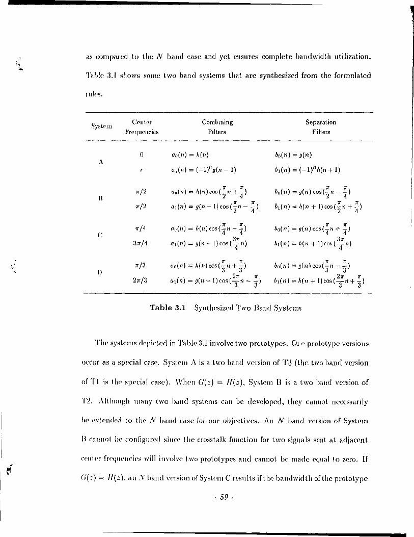
as comparcd tü the N band case and yet ensures complete bandwidth utilization.
Table 3.1 shows SOlJ1C two band systems that arc synthesized from the formulated
Illles.
Syi>t('1J) C('II ter Combming Separation
Frcqu('ncic!> Flltcrs Filters
0 ao(n) = Ii(n) bO(71) = g(11) A
11" a1(1I) = (-I)"g(n - 1) bl{n) = (-lth(n + 1)
11"/2 1r 11" 11" 11"
aO(71) = h(71)cos("2u+4) bo{u) = g(11) COS ("2" -"4) B
1r/2 11" 1r
al(71) = y(n -l)cos("2 7l - 4) 11" 11" b1(n) = h(u + 1) cos ("27l +"4)
1r /4 11" 11" 11" 11"
aO(71) = h(n) COs (-:f' - 4) bo(n) = g(n)cos(4 11 + 4) C
311" 31r :J1r 1'1 a1(n) = g(n-l)cos(-;rn) b1(n) = h(n + l)cos(-;r1/)
1r/3 11" 11" 11" 11"
" a 0 ( 1/) = "( 71) cos ( 3" 11 + 3" ) ho( 71) = g{ n) cos (3" Il - 3" ) i·' J)
211" 11" 211" 11" 211"/3 a1(7I) = g(n -l)cos(-II --) b 1 ( 71) ::: h (71 + 1) cos ( "3 n + 3" )
3 3
Table 3.1 Synthcsized Two Band Systf'IDS
The> syst.C'llIs c1f'pict.cd in Table:U involve two prdotypcs. 01 (> prototype versions
OCClIl' as é\ special case. System A is a two band version of T3 (the two band version
of TI is tlH' spf'cial case). When G(z) = 11(:;), Sy!>tem Bis a t.wo band version of
'1'2. A lt.hollgh 1I1éllly t \\'0 hand syst.ems can be devcloped, they call1lot Ileccssarily
hc' (·xt(·[HI(·'-! 1.0 t 11(> N band case for our objectives. An N band V<'/'SiOll of System
B CilllllOl })(' connglll'cd sincc 1 he crosstalk fllllction for two signais sent at adjacent
('('Illt'r f['(>qll('llci(>s will il1\'o)\'(> t\\'o prototypes and cannot. b<> made cqual to zero. If
(,'( =) = 1/ (:;), a Il .\' band vCl'sion of Sys1,('1ll C !'csul ts if the bandwid th of the prototype
- 59 -
,',.
is redllced to rrlN (system T5). Ilowe\'er, an N band syst.('111 witl! two pl'ot.otyp!'s
cannot be formed ('ven with the redllccd handwidt.h sin('(' 1 II<' illplll -0111 put Iransf!'r
function is not. the same for ('vcry pair of tcnnillals, Syskm \) is syllt Iwsiz('d b~'
taking advantagc of thc flcxibiliLy ill choosing tll<' ('('nter fl('qll('II('i(':-' s))('('ific;t1ly for
the Lwo band case. Thc g<'Beral "yllt.he~is plo('('duJ(~ in tl\l:-' (hdpl<'l dol'~ Ilot I(,dd 1.0
an N band version of System D l'ven if G( z) = II (z),
3.8 Subband Complements
Transmultiplexcrs Tl t hrough T.5 arc crossta Ik- fI e(·. Mon'ov(·I', c(\( h t l'il IlSlIllriI.i
plexcr has an idcntical input-output trallsfC'r functioll for ('\'('ry pair of COI l'<':-,polld i Il)!;
terminaIs, Thl'rC'fore, syst.C'l1ls Tl to '1'5 cali he ('011\'('1'1('<1 illtn alie\s-frl'I' slIl,l>.Il1d
systems SI, S2, S:3, S·l and S5 rC'specti\'(·ly (this complelll<'lItary lIéltlll(' of 1.11<' two
multirate systems was discmsed in Chapter 2). The IWW slIhballd SySt('1I1S SI, S2
and 8:3 ha\'e repeat.C'd cClller fre<!uC'llcies. 'l'Il<' sllhhalld ~yst('llIs S·l elll<l sr) ha\'(' tl)l'
saille distinct c<'nter frequenri('s. S) stem S 1 Ics('lllhl<,s t1l<' 011(' in [1 OJ whil<' sr) i:-. ail
altel'llati\'l' cmploying delay factors. Note' thélt tlt(' otll<'l t",o ",lIlel Irall~lllllltipl('xI'I"
that arc: )'nthcsized ill Sectioll :3. ï call also he rOIl\ ('I\(,d into :-'lIl,hillld ~j'st(,llls.
The input-output. trélnsfer fUllctioll fol' the' tl'clll!'llllldtiplC'xl'rs is giv('11 il" '['{:;N)
in Eqs. (3.15), (:J.li), (:3.19) and (:1.21). For t!J<' trélllslllltltipl('XI'IS. the' illPllt olltpllt.
rc1atiollship is '\'k(':) = *T(:;)Xdz) for /.. = 0 10 N - 1. For t1l<' (olllpl('II)('lIt,Uy
subband sy~tclll~, .\:(.:) = *,/,(.:i\')X(:;). Not(· tltal titis inpllt-olltPllt J(·I,lIioll~hlp I~
dependent 011 halldlimil(·d prototypes \Vith a J'('~t 1 iete·c1 ~topbéllld ('dg(' (;.,'.~ (\" for t Il('
- 60 -
j
J
tl cl.I1SITlIlIt.ipleXN:'. Moreover, perfeet reconstruction is achieved in the complementary
subband sy~tcrns if the Nyqui~t critcrion is satisficd (as for the transmultiplexers).
Wc hav<' umfigul'cd translllultiplcxers and subband systems that achieve per
f{·ct J'ecolIs! rtlctioJI giwlI t1,a! ! hl' prototypes arc bandlilllitcd (up to hundrcd per
ccnt above t1)(' minimtllll balldwidt.h, as discusscd carlicl') and th(' Nyquist. critcrion
is sat,isfi{'d. WI\('ll G(::) = 1/(::-1) in syst.ems T3 and S:3, t.he 1.\\'0 conditions of
halldlilllit,edlless alld tht' Nyquist charact.cristi(' Icad to perfcct reconstruction \Vith
13d::) = Ad=-I). Tht·r(.fole, both systems arc los51('s8 [SJ lIndel' the sal1le two COII
dil.ions. For t.hp special case of N = 2, SI l'edllces to 1 he c1assical QMF atrangcmcnt
d{'!-,('J'il)('d by Eq. (~.IO). Note litat system S3 becomes the Slllith-Balllwcll structure
P,J for the' cas(' N = :2 if (,'(=) = 11(=-1). For ail arbitrary 11(=) alld G(=), system
S:l d('g('J)('ra /.('S illto a W'llcral t \\'0 ba nd two pl'Otot ype sy~t(,1lI pl'Opo~cd i Il [6][7J (also
disctls:-('d ill Chap!cl ~). III ('ffcct, \\'c ha\'e dc\'clopcd ~lIbballd systems which are N
band g('J)('J ali/':a! iOlls of t!Je Ql\lF ballk, the Smith- BarIlwcl\ ~truct Ille and the gencral
1 \\'0 band syst.em proposcd in [G][7J elllploying two prototypes.
- 61 -
Chapter 4 Minimax Filter Design
Givcn the synthesizcd transI11ultipkxNs Tl to '1'5 alld the compl('IlH'lltary SlIh
band systems SI to S5, w[' procecd to design t\\(' practical 1()\Vpa~s prot.ot.ypl's t hat
describe the filter banks. III additioll to the fleqllcllcy rcspollSC r<'quin'IIH'llt, t1w tilJ\('
domain constraints on the impulse respollse of the prototyp('~ th,lI aH' Ill'{'(kd t,o
satisfy the Nyquist critelion arp taken into accoullt. Th(' <k~\gll of t II<' prototYI>('" \:
bascd on a rninimax criterion.
4.1 Design Problem
The design ploblelll of simultaneously satisÎyillg t II<' tilll<' ,1Ild fl'<'qlll'llCy <!olllaill
collstraints to yicld Nyquist filters is introdu('('d. Tlwll. tllC' g<'IH'ral ('iraI,\( t('ri:-t.I<''' of
Nyquist filters ale d('scribed.
4.1.1 Time and Frequency Domain Requirements
For the QAM trallslllult,iplc'xf'rs Tl and '1'2 alld t II<'ÎI :-Ilbbantl rOIll pl('11 Il'11 1 ", Ut<'
lowpass prototype //(::) must hl' bandlimited 1.0 110 I('~:- t1léUl 'Ir/N ,lIlel 110 Il,on' thall
- 62 -
m
(
(
(
'21r / N. In addition, 1(2(::) must be a Nyquist filter with an impulse responsc having
f'xact ~C'ro crohsings every Nth sarnplc (cxcC'pt for a rcfercBec sample). Similar rc-
qllin'III('f1b"xist fOi T,l, T.5, S,1 éllld S.5 in that the' lowpass 11(:::) must be bandlimitf'd
1,0/10 h·l-os thall rr/'2N and 110 morc than rrjN. Also, 112(:;) must he a Nyquist filter
wi! Il ail illlpuise J'('SpOIlSf' having exact Ze'l'O crossings every 2iYth sample (exccpt for
Syht('lItS '1':3 alld S3 illvolv(' two lowpass prototypes JJ(:) and G(z). Both must
1)(· hillldlilllit('d 1,0 110 b~ thall 'TrjN and no 11101(' than '2iTjJ\'. AIso, 11(::)(;(:::) must
1)(' il NY<Jllist fi 11.('1 with an Impulse response having eXd( t 2elO clOssings ('very Nth
S;\llIpl(· (<,x('!'p! for éI 1'<.[('J'{·lIce hampll'). In céllryillg out the filter design, we set
(,'(::) = 1/(::-1). Theil, both the plototypes have identicallllagnitude responses but
difr(·/'('IIt. pltah(' 1('1-0/>0115('5. /\ Nyquist filter l/(::)lI(:;-l) must I){' designcd and split
illt.o fi millilllullI phaM' WIlII)oIl(\/It 11(::) and a maximum phase compone)]t H(z-l).
4.1.2 Nyquist Filters
Sill(,(' tl1(' d(':;ign pl'Obl('111 mandates Nyquist filters, SaIlle of their basic charader-
tst in; a['(' illf,roduccc! togetlwJ' with l'devant terminology IIscd in the rcmailldel' of the
t h('his A NyquÎst filtcl' F(::) bas tlte following impulse l'CSp01JSC charactcristjc:
f(,]\) ~ { :'
for i = 0 (4.1 )
for i =1= 0
'1')1(' pal'élll}('t(·1' 1\' is the zero Cl'OsslIlg int('rval in the time response J(n) t The
Actlléllly, /(0) l'an he ail)' COlllot,l/lt I1owever, setting /(0) = 1//\ makes the right hand side or El( (·1 2) \'qua\ to l
- 63 -

rcference coefficient is f(O)t. ln the frcquency domain, this ('olTesponds (,0
1\ -1 L F( eJ(W-21T1/ 1\)) = 1 . (-1.:2 ) i=O
The minimum bandwidth solution is an ideallowpass filt.<,1' handlilllikd (,0 'Ir 1 /\',
We allow an eXCCSf, bandwidl li of f37r 1 J\ 10 bring the o\,(,l'all ha ndwÎ(lt,h 1,0 (1 + l'J)'Ir 1/\'.
The parameter f3 is the roll-off fador of IF(eiw)l. In t.he QAI\l sy~t,(,llIs (TI, '1'2 amI
T3) and their subbancl complements, the ;',('1"0 crossing intervetl l\ is <'quaI t,o 1.111'
number of bands N. The situation differs fol' the VSB syst.ellls ('1'-1 clll<l '1'.1) cllld
their subband complements in that JO; = 'lN. '1'0 cnslIIc Ihelt Ill<' lowpa:-.s plOtolYIH'
is bandlimited as disCllf,:"l'd in Section -1.1.1, t.\w parametcr li ~ 1. III t.his (clS(" only
adjacent rC'plicas of the spectl'um of F(c jW ) (locatcd at CCIlt,C'! frc«II<'IlCi('s thal. an'
multiples of 2rr / J\') overlap. AbD, the upper edge of the passhand is wJI = (1 -
(3)rr 1 1\ alld the lowcr e<lge of the stopband is Ws = (1 + j3)7r / /\', 'l'II<' id(',d fr('qIlP!1< y
characteristic is
for 0 < Iwl ~ u..J1'
fol' ws ~ Iwi ~ 7r
Passband Stop band
The rcspollse of an idcal filtC'r makcs a symmct.rical transit.ion 1'10111 t!l<' pas..,halld 1,0
the stopband passing through tlll' vahl(, 0.5 al w = rr 1"'.
Wc considl'r dc~igl1 approaches for h prclct.ical lilWil" phel~P FIH Nyqui:-.t fill.cl
F(::) that approxi mal C','" t 1)(' idca 1 lIlagn i t ude charaderistic. Thp pa!-.sbilll cl (·dg(· wl1
and the stopband cdge WH arc' as defined abovp, 'l'Il<' gC'lH'ral Z('IO (ollst.dlatioll of
F(::) invol\'cs l'cal }lxis zeros which occur in pairs al. z = '::0 alld z()I. Ullit. (11c1(~
Note t.hat thc rcfercIlcc coemclCnt nced not occur al tllP z(>rot.h .. alllplf' \VI' '''/l'( If Y Il Ill. 1 1 If' zeroth sam pIc for purposcs of cxpo!.itlolJ
- 64 -
;r,CIOS 0<:(,\11' in complex eonjugatp pairs, The gcneral eomplex zeros of F( z) oecur in
groups of Cotir ai z = zO, zô' zOI and (zOI )*. WhCIl F(::) = lf2(z), ail its zeros must
OCCLU' as double ord('r "-cros and it must have an odd Humber of taps. For tbe case
F(::) = 1I(:;)II(z-I), wc l'('fcl' to F(::) as a [adorable Nyquist filter. An FIR filler
F(z) i~ J1cccssary to cllsurc stability of both its factors. Moreovcr, F(z) is inherently
z('I'O-phas(' élnd has an odd nUJl1bcr of tap'3, For F(z) to 1)(' factOlablc into minimum
and maxilllulIl ph(I~(' parts II(::} and H(::-l) respccti\e1y, the additional constraint
is th.lI, ail of it~ Z<'I'OS on the unit. circle must occur as dOllble oldel zeros.
Fillally, Ilote (hat aIt hOllgh \\'(' dcal with an F(::) which may yicld noncausal
IOWPélS" Fm prototypes, célu~ality Célll be CIlSlllCd in c1n actllal implementation of
!.Il(' t rallslIIlIlt ipl('x('rs and ~ubballd systems by applying appropridtf' delay fadors
(dis( lisser! jlJ Chapt.cl 2).
4.2 One Prototype Systems
For the t rallsmllltipl('xels and sllbband complements which arc based on one
pIO!'otyp<', F(::} = Jl2(z}. For a linear phase F(z), If(z) is a lincar phase FIR filte!'.
Considcr systcms Tl, T2, 51 and S2. For tliese systems, N must be evell, If 1I(z)
has ail odd Il li llJ 1)('1' of laps, al! appropriatc choire of filtcr dclay rcsults ill the cellter
or 1 (.[('/'('IIn' col'fficicllt of 112(z) clllclgillg at. a time index which is a multiple of N. If
11(::) has (lIl ('\'('Il 1I1l1ll!>('I" of Iii!>:'>, thl'H' is !lO cholce of dclay that allows the rcferencc
codlici(,111 of Il'2(z) to ('Illcrge al, a till1P index which is a llIultiplcof N, For an lI(z)
\Vith an C\'(,I1I\\1l11bcl' of taps, the 1cl"crcncc coefficient of [{2(::) never shows up in the
- 65 -
expression for the input-output lransfl'r functioll T(::N). For syst,<'llls TI, T!), S·l dllt!
85, it ean also he shown that a lincar phase J/(::) III Il st hd\,(, ,U! odd nllllllH'1 of t.\»s.
Therefore, a Iinear phase' ll(::) is COlIstl aincd to havI' an odd 1I111ll1H'1' of l.,'ps. For t hl'
rernainder of the thl'sis, we design f!(::) slIch thal Ill<' rcfcl<'lIcc' «}('fli( \('lIt of Il'2(::)
ernergcs at t.he zcroth san'pl{'.
The desi~'1 problem mandates a lowpass 11(::) su ch thal /(2(::) is il Nyqllist fiI!.(·1'
with exact zero crossings in ils impulse Icsponsc. It i:, now :,howll thilt. botll t he..,('
lime and frl'quellc)' dOl11aill rcqllil'cmcnts callnot 1)(' m<'l III g,('!H'I,,1 'l'II(' "1>\>10"( h il'
to dctermilll' the timl' domaiIl l'('qllirell1ellts 011 11(::) for F(::) = Il'2(::) to ('xhihit ,\
N yqllisl charaderist ie.
First, \"'c dcal with the eose whcn the zcro cros~illg illl<'r\'ai 1\ =~. (~oll:-.id(·1' a
zero-phdsc 11(11) which has 2L+l t.aps frolll Il = -1. ta L. TlwIl, /'(11) b,,:, .t/,+) Llp:-,
from 11 = -2L 10 2L. Also, J('2i) = 0 t'xccpt fol' cl r('fcl'cJIl'(' (odli( 1<'11 t {(Ol = ) j'!...
8incc J(2L) = f(-2L) = O. it impli{'~ that h(L) = h(-L) = O. 'l'hl' 11111111)('1 of t"p:-.
of h(n) and f(n) arc l'eclucl'd. Now. 11(1/) has 2/,-1 Ic\p:-, fI o III Il = -(/,-)\ 10
L - 1 and J(I1) has ,IL - :3 taps from 11 = -('2L - '2) 1.0 '2/, - '!... Aga III , Ill<' ('lId
coefficients J('2L - 2) = f( -21. + 2) = 0 implyillg, t hat h( /, - )) = h( -- /, -1- 1) =- ()
thel'<'by lcducing, the 11l1l11ber of cOCmCi(,l1ts of 1/(::) by t\\'o TitIs IJlO«'S~ (Olltlllll(':-.
and rl'sults in the uniqlle solutioll I/(::) = 1/../2. This tl'ivi,t1 1('~lIlt i~ t111' ollly fi\t.('1
I/(::} that gual'antech exact Z('IO crossings in tlw J'('SPOIl"'(' of Il'2(:.) fOI /\' = '!...
Consider the' case whell 1\' > 2. If the filt{'l'S aH' ~hOlt ('21- < 1\'), t)WIl 1/(::) will
have mOlC than 011(' tap and will he fr('e of ail)' t illJ(' dOIIl"1Il C<JIlht r,lillt:-.. IIow('V<'J,
the llumher of laps of II(::} is Ilot suffici('lIt for ail cl( ("('ptrthl(' I()wp,\ ... ~ (1!,\I,tI'tpri ... t.i(.
- (j(j -
( For IOllg('r filtcrs ('21, > f{), mally nonlinear constraints on h( n) are imposed which
lTlay colllprollli~c t.he desired lowpass nature.
CiV('1I 1.1.(' difficllity of simllltan(,ollsly mccting the time and frequency domain
f('qllil('!IWllts, our ~tlat.cgy is t.o g('t. a lowpass filt.er and only approxirnatcly satisfy
t1w t.iIlH' dOlllain COllstraints. Although the zero crossings in J(1I) are Ilot exactly
IIIC'1" t.1l<' respollsP is h('pt. ~llIal1 at t h(' time' indices at. which t he zero crossings should
OCCIII'. TII('re are c1os('d forll1 expressions for the frcquency rcspons(' of a Nyquist filter
giV<'1I /1 :; 1, OIlC of which i~ a raised cosine spectrulll. A lowpass // (::) is desig!H'd by
tl\(' l\IcCldlan- Pal ks algorit hm [2.1] to approxirnatc the "qu,tr(· 100t of a raised cosine
spectnllll wit.h a gÎV<'1I !oll-off factor. Wc gel, a IÎnear phase filter whose frequeney
("('sl)(>IIs(' i~ a millÎmax appIOximatioll of the desired respollse. Both equiripple and
lIolH'«uirippl(' lowpa~s prototypes are designed with appropriate wcighting functions.
4.3 Two Prototype System
III cont.rast. t.o th(' one prototype systems, the practical Nyquist filter F(z) =
1/(::)//(::-1) for '1'3 and S:3 can he dcsigned sueh that lI(z) is a good lowpass filter
(lI\d F(::) has exact zero crossings in its impulse response. Since F(z) is a zero-
pha:-w fUIlct.ioll, tlH' rcferellce coefficient is J(O). Although F(z) must have an odd
lIumher of taps, there are IlO cOlIst.raint.s on the number of coefficients of ll(z) and
//(;;-1). Wc devclop two IICW approaches to design F(z) known as fadorable mini-
Illax 1I\('t.hods. Tl\(' 1.\\'0 applOaches use the l\1cClclla1l- Parks algorithm [2.5] as a first
stq) 10 {(>IIt.rol the stopba1ld r<·Sp01lS<.'. The subsequent step incorpora tes the time
- 67-
J =
domain constraints by forcing zero crossings in the implIh,(, n'sp(}Il~('. This I(wls to
a spcdrum that exactly satisfles Eq (·1.2). \Vit h a !cspons(' ~at,i~fyillg Eq (.I.~), ,Ill
approximatcly ZCIO ~tophand charac!.e!istic assures .lll apploxllllatc-ly (oll~talll IMSS-
band characteristic (as~lIllling I~ < 1) A lc'w itC'lctt ions of 11\l' ,dm\ (' ~I('p~ produ('cs
a fadorable Nyqui~t flltc! \\'ith a Clwhysh('\' stoph<llld re~pon~('. 'l'hl' Nyquist lilt('1
designed by Ol1\' approaches i~ flilldan1('ntally equirippl('. :\ nOIH'qllllIPpl(' lilll'r (',11\ 1)('
obtained hy applying additional fIC'quency \\'eight ing. Fillelll\', t 1((' 100Vpe1S~ prololyp('~
H(::) and 11(::-1) arc obtaineù froPI the NY(JlllSI fillc'r
In the pasl, FIn Nyqtli~t fllters ha,,(' \)c('n d('~ignc'd tl~inp, linear plOgl <1 1111111 ng I('ch
niques [~(i][2i]. by the eigC'nfiltel' applOach [2S][29], e\ll(l hy 1 he 1I~(' of 1 hl' l\lcClc'llclll
Parks algorithm as an inkrmediate sl<'l) [:m][:~ 1 ][:~~][:~:~]. TI\(' Illpl hods in [n][~!)J[:~ Ij
allow fol' the splittillg of Ihe flltC'1 inlo ils minimlllll elll<l IlIé1Xillllllll ph<l~(' pelltS.
Salazar and La\vJ('ncc [2i] sC't tlp tllC' dC'~ign as a lin('ar plOp,ralllllling PI'OI>I('1I1 111-
corpol'ating the lime domain constraillts. In addition, tl\(' fl'e<jIl(,lIcy \('SpOll .... 1' of t.!(('
filter is fOl'Ced to be 1I0Ilncgati\'C' in ol'dcl' that. Il}(' minillllllli ,111<1 III<lxillllllll pha~('
factorizatioll he possible. l\lintzel' [:31] d('als ('xclusivl'Iy \Vith the' (el~(' \\'11('11 tl\l' l('10
crossings occur fol' e"el'y second sample. In t hat papC'l', 1 II(' fl'C'qlH'lIcy rc~pOIlS(' of illI
uncollstrained fi1tel' is offset. 1.0 ellsur(' that il. hl'colll<'s llolllH'gat ive. III [2!J], 1 hl' ('Iw'n
filtel' concept is applied to obtain a Nyquist filtel' that i~ fel< IOl'd.bk int.o Il 1111 i III 11/1 1
and maximull1 phelSC parts.
Nyquist filtcl's with Chcb'y~I\('v stophalld lH'ha\ i01l1' haVI' hl'I'II d<' ... lgllf·d in [:~:~I
using a multistage st l'uct III e. 'l'hl' focus in [:n] is on a COIl1 pli 1 aliollal l y dhcWIl t lJlul
tistage il1lplelllentalioll. IJowevl'r, the resultillg filt('If> a\'(' Ilot II('C('S"'ellily f,ldOlill)lc.
- 68 -
Olle cali makp thes<, filters factorable by adding a positive constant to the frequency
!"('SPOIIS(' (a~ in [~ll], s('(' abo [:H]) to make il. nonnegative. IIowever, this fixup exces-
sive,ly n'du('('s the stophalld au'f'llllation for noneqlliripplc filtcrs.
III t1!(' factorablC' lllillill1ax mcthods, wc di:-ectly achieve a nonnegative frequency
l'('SP<H1S(' wit.h <olltl'Olkd stophand charaderistics. Furthermore, t.he polynomial fac-
tori~at]oll prohl('llI fOl t Il(' dctf'rmination of the minimulll phase part is considcrably
('asC'd. Thc' cOlllpkxity of polynomial factorization is directly rdated to the order and
11<'11('<', to the lellgth of the designed Nyqllist fil ter. Wc reclucc t.his complexity by
det.erlllining a part.ial fat torizc\tion of the transfer fUlldioll of thc Nyquist filter as a
byproduct of t.h(' df':-.igll procedure. The remaining factoI'lzation involvcs a polyno-
lilial of llIuc!t lo\\'c'] orcier than the oH'rali tIansfcr function. The l'est of this chapter
. 4 , is dc'\'ol<'d 1.0 the cksign of F(:::) = 1/(::)11(:::-1) for T:J and S3.
4.4 Factorable Minimax Design Procedures
As in [29], \\'(' fa ct 01 F(::) as F(::) = Fo(::)F'f(:::) whelc F[(:::) cont.ains ail the
doubl(' ,W\'o!'> of F(:::) 011 the unit circle and f'o(:::) contains the other zeros of F(::).
'l'Il<' doublc' Z('IOS of Ff( ) on t.h<, ullit circle imply t.hat. it \tas an odd number of
nwffi('iellts c\nel that it i~ a ~ero-phase functioll. TI\(' ZCI'OS of J'o(.::) must occur in
1I111'1'0\' illlc\ge pairs rcf!cC"tcd about 1.11<' unit cirdC'. II Cil cc, /<'o(z) also has an odd
1I111ll1H'r of ("()('f!icicllb éllld I~ cl z('ro-ph, ~e fUlldion.
L(,t t 1)(' lellgt h~ of l'u(:::) and Fr (:::) be 2/0 + 1 alld 2/1 + 1 respccti vcly. The Humber
of ('Odlicic'nts of t II(' u\'C']'c\ll Nyqlli:-.t fille]' P(::) is .\1 = 2(10 + Id + 1. Note that the
- 69 -
i
l
case 10 + Il = k/\ (fol' any int,<'gcr k) l'csults in a Nyqllist. fillel' wit.h f( -/0 - II) =
f(lo + Id = 0 thcreby l'cducing the effectiv(' lengt,h Il)' t.wo. Th(' iJ\\'('\,S(' z-t.ransfol'llIl>
of F(z), Fo(:) aIld F[(z) an defined to 1)(' f(II), fO(I/) and d(1/) \'('s)H'd.iy('ly.
4.4.1 First Method
The design procedure fol' the flrst mcthod is as fo11ows:
1. Initialization: Fix 10, Il, l\, and ws. Set Fo(z) = 1. The w(·ight.illg is giv('11 as
IV(w).
2. Design FJ{z) using the ~1cCkllan-Pa\'ks c\lgOlithlll ~lI('h t.h,t!. It has zC'ros ollly on the unit circlc III the ~topband l'('gion [w.~, 11"].
3. Impos<, the time dOl11clin constraints hy soiving for t11<' coC'fficic·nt.s of l'h(z) through a linear system of c((uations.
4. Form the l'\yquist filter F(z). If the design warrants improvenl<'nt., go h,IC).; 1.0
step 2.
5. Split F( z) Înto its minimum and maximum phase part.s.
Wc now describe steps 2 to 5 in more detail.
4.4.1.1 Step 2: Frequency Domain Specifications
The McClellan-Parks algorithm is used to get t.he coefficient.s of F{(:::). 'l'II(' SI)('('1-
fieations ale that. the frequenc)' If'sponse must be onC' ,lt. w = 0 and IlIUSt. approxIlIlc\tC'
zero in the 5topband lcgioll [W,5, 71"]. The wcight.ing fUllctioll applic's lo F[(:::). '1'1)('
weighting fundion is ~V(w)I/~(()W)I. Initially, il. is ~"(w) sin«' l'h(z) = 1. Suh~(·-
quent iteléüions involye an Ilpdatc of the weighting f\lndlon ,IS J'()(:) is J'(·(olll)lut.ed.
For the design of Fd:), tablllated value~ of t11<' sq\laJ'(' foot of t.1l(' W('ightillg f\llldiOIl
arC' inputs t.u t.he cligorithlll.
- 70 -

III the stopband, the frequency response of Fl(Z) exhibits a ripple-like behaviour
with local minima and maxima occurring at the extremal frequcncies. If lt is even,
FI (z) lias ail odd number of coefficients (lI + 1). Two of the extremal frequencies are
a and 'Ir [a!)]. lIowever, the total Humber of zeros is a mult.iple of two, ail occurring in
cOll1plex cOlljugal<' pairs (no zero at z = -1). At w = 'Ir, either a local maximum or a
local lIlinimulll ocolrs. If 11 is odd, Fl(Z) has an even number of coefficients. In this
case, a zero o(curs at z = -1. lIowever, 'Ir is not an extremal frequency. The other
,wros OCCIII in complex conjugate pairs bringing the total number of zeros to Il,
4.4.1.2 Step 3: Time Domain Constraints
GiV<'1l FI (.::), wC' form Ff(':;) and solve for the coeflî.cientsof Fo(z) such that F(z)
has the Nyquist pl'operty. Since 1(n) has samples for n = -(/0 + 11) to 10 + lb the
Illlllllwl'ofzero-vallled samples that occur as n goes from 1 to 10+11 is l(lo + 11}j/{J.
The saille holds tlU(' as 11 goes from -1 to -(/0 + IJ). Since, the sample for n = 0 is
also kIlOWIl, t.!t(, Ilumber of kllown coefficients of F(z) is t
(4.4)
The coefficients of F(z) itrc found by pcrforming the convolution 10(n)*d(n). By
expéi l1ding t Il(' cOllvolllt iOIl SUIll, olle can uniquely determine FoC::) such that the time
dOIllain COllst l'cUllts are satisfied [2~)1 if the number of unknown coefficien ts of Fo{z)
('quaIs the IlllllibN of knowll coefficients of F(z). This results in a system of linear
<'quat iOlls of dilll<'llsion '210 + 1. Dy further exploitillg the time domain symmetry
This rorlllul,l IS a eorrcrtcd version of the formula given in [29].
- 71 -
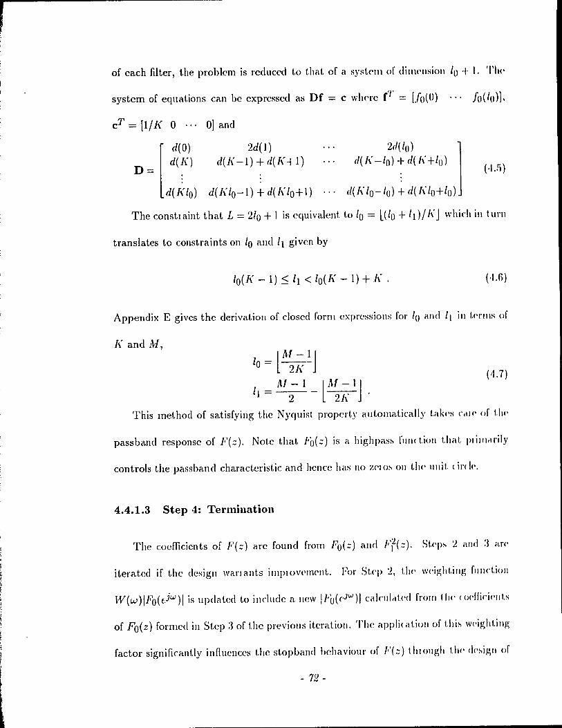
, ;
of each filter, the problem is redllced to t.hat of a systC'1ll of dillH'lIsioll 10 + t, 'l'ht'
system of equations can be expressed as Dr = c wll<'re (J' = [J()(O) , " 10(10)].
cT = [1/I< 0 , .. 0] and
D= [
d(O) d(I\)
d(I~/o)
2d(l) d( f( -1) + d( J( -t 1)
2d(lo) 1 d(l( -10) + d( [\' +/0)
d(I( 10- /0) ~ <1(1\10+ /0)
(.\..1)
d(J( /0- 1) + d(l( 10+ 1)
The constIaint that L = 210 + 1 is cqllivalent to 10 = l(lo + Id//\'J whi('h in lul'll
translates to constraints on 10 and 11 given by
10(I( - 1) ~ Il < lo(l( - 1) + 1\ , (·Ui)
Appendix E gives the derivation of c10scd forl11 expressions fol' 10 and I( ill t.(·l'ms of
J( and M,
lAI-IJ 10 = ~J~-
~ \
1 = Al - 1 _lAt - 1 J 1 2 2l(
This method of satisfying the Nyquisl property alltomatically t.ak(·s C<ll(' of t.1)('
passband response of F(;;), Note that Fo(;;) is a highpas~ fUII< lion t,hat. 1>1 ilJlrll'ily
controls the passband characteristic and hencc has 1\0 7,('1 o~ 011 the ullit ( il'< 1('.
4.4.1.3 Step ·1: Termillatioll
The coefficients of F(;;) are found from F'o(.:) alld Fr(.:), St.('p~ 2 and :J aI'l'
iterated if the desigll wanallts implOv('mellL For St,<'J) 2, t!l<' w('ightillg fUIlct.ion
IV(w)lFo(t-iu.,,) 1 is updated to include a lIew !/'ü(eJW)1 calcul<lt,('d from Il)(' (odfic'i(·lll.s
of Fo(z) formed ill St.ep:1 of the prcvious iteration, The appli(atioll of t,hi~ w!'ightillg
factor significantly influences the stopband behaviour of F(::} II1Iollgh t1w (h'~ip,1I of
- 72 -
FI (z). 1" t.he w('ighting fundion, the factor 1 Fo( eiW)lleach; 1,0 a stopband behaviour of
Fr(::) that. cOlllpellsittCi> for t.he highpass response of Fo( z). The stopband behaviour
of F(::) i~ cit.her eqlliripple or none(juiripple depending on the other factor W(w) in
t.\w weighting fUll( tion. The iteratiolls are tcrminated when the extlcmal frequencies
o\lt.ained by d(,~igllillg Fd::) do not. change by more t.han a given threshold.
4.4.1.4 Step 5: Final Filter
This ~t('J> faclors F(::) into minimum and maximum phase parts. The minimum
phclS(' part of F(::) is 1I(::) = Fo-(::)Fd::) where Fo(z) is the minimum phase part
of Fo(::). The' factor Fü(z) cantains ail the zeros of Fo(.::) that. arc within the unit
cird('. 'l'Il(' factor Fl(::) (has zeros on the unit circle) is known as a byproduct of t.he
<bi!!,11 proC(·dur<' Ollly F'o(::) needs to be factorcd in order to derive its minimum
pha:-,(' part.. '1'11(' Illaximum pha~e palt, H(z-l), is obtained by time reversing the
co('ffki('11 I.s of Il (::).
4.4.2 Second Method
'l'II<' diff('f'('11C<' be1.\\'('('11 the second method and the pleviolls approach lies in Step
:! 11\ whi,h il cOllslrained form of the l\1cCkllan-Parks algorithrn is lIsed to directly
comput(' III<' co('fIirients of Ff(::) rath('r t.han to filst dc~igll Fl(::)' The specifications
iH<' t hat t he fr('ql1<'Il(,~' respOllS(, must he one at w = 0 and must approximate zero
in Ill(' slophand ['('gion [ws,71-]. 1\S befof(', t.he weighting fUllctioll is W(w)lllO(cJW)I·
Tahulatt'd nlllcs of the weighting fllllctlon ar(' suppli('d as illplltS. SllIU~ double zeros
Ol\ 1 Île unit circl(' cH<' l('quir('d. wC' ronslraill the fre<!u('l1cy l'('SpOIll'>(, to be nonnegativc
- 7.'3-
in the stophand region. vVe implcll1f'llt the procf'durc ill [:W] (St'(' .. Iso [:li]) 10 ohtaill
a minimax approximation to a desin'e! rcspon~(' t hat ~é\l isli('s gi\ ('II "PIH'r alld low('r
constrai n ts.
In the stopbano, the frcqu<'llcy l'<'SI)()J1S(' of "'r(z) ('xhihils cl rippl('-lil\(,IH'!trlviol\l'
with local minima alte! maxima on:11lrillg at tll<' (~:drclllai fl<'«II('11( i('s 'l'II(' local
minima correspond to the fl'('qllenci('~ al, whidl tilt' )('''POIl~(' 101\t1\('~ Z('IO. Il is Il!('~(,
frcqucncics which dcterminc tilt' dO\Jble /,('IO~ of F[(.:) (JI! II\(' IIl1it (il< 1(,. (;1\1('11 Ih,II
Ff(z) ha~ 21 1 + 1 coef!iclCnl~, ri lotal of Il + 1 ('\.11<'111<11 Ilt'qll('IICI<'~ 1t'~1111 [:l:l] 'l'wo
of the ext.ren1r11 frcql1<'l1( ic~ al'<' 0 and 7r l'eg,lIdles." of 1 III' \"hlt' of Il If Il I~ oeld, 1 lit'
extremum al. 7r is a loc-l.1 minimum thC'l<'by produclIlg a dOIl hl<, zero ,t! :: = -1. TIlt'
other zeros OCClII' in groups of four in tilt' stopband l'('g,ioll bl'lllging, t.h(' tol,t! 11111111)('1
of zeros to 211. If II is c\'en, the extremum at 7r is a loc,t! lIIélxi III Il III (110 Z('IO al.
::: = -1), The totalnumber of zeros is a mult.iplc' of fom alld 0('('\11 in g,IOllp~ 01 l'OUI
in the stopband Icgion.
Steps 3 and 4 are idcntical to the first. approach. In spliltillg F(::) illlo Ih IIlilll
mum and maximum pha~e pal ts, wc take advant.ag,(' of the fad 1 hat 1 hl' f!('(I'It'lI('il'~
correspondillg to t!l(' double zcros of Ff(::) arc a\lailabk as il hyproc!lI( toI' tlH' IIlOcl
ified .\lcClel\an-Parb algorithm (similar t.o the' appl'Oél( h lI,,('d ill [:n] 10 .!!,('III'létl ..
minimum phasc filt('l's), Gi\len these frequclI('i('s clll<l 11<'11('1', 1 \1(' loe at.iOIlH of tll(' z('ro~
on the un il circle, Pd::) can hc formcd witltou! <Iilect.ly fclctoling Ff(z). A~ \)('fOI(',
ollly 1"0(::) must be factored to fonn 11(::) = l'ü-(z)FJ{.::).
The llcxt section discusscs tll<' lIwrits of factllllllg ollly "()(::) él!-> opP'N'c110 F(::)
in dctcrmilling t.he mini 111 UIll phét!->c P,II t. A 1,,0, ob"('1 vat. iOlls COlI( ('[ Il i IIg 1 II<' 1 l,la t 1 \1('
- 74 -
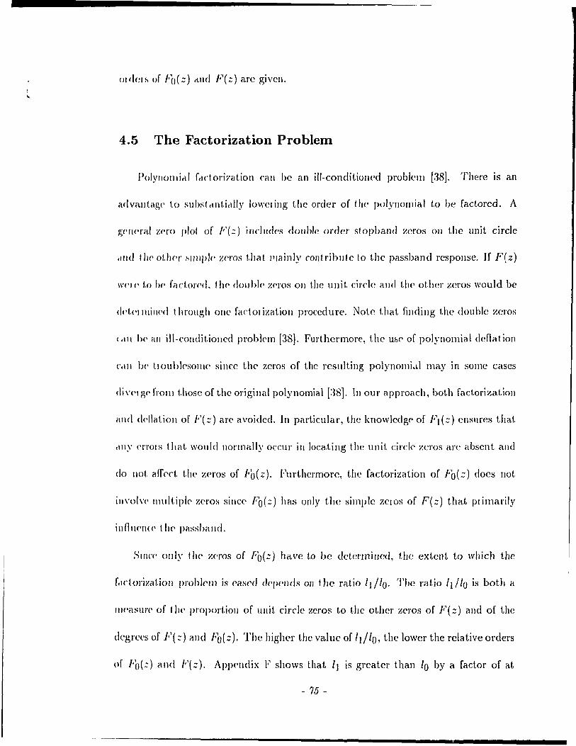
ordel~ of Fo(z) ctlld F(z) are givcn.
4.5 The Factorization Problem
PolYllolllirll fcld.oril'éltion call be an ill-conditiolled problell1 [38J. There is an
advétlltag(' 1,0 subst cllitirllly lo\\'cIÎng the order of the polynoIllial 1,0 be factored. A
P;('II(' raI /':('1'0 plot of F (::) i Ilcluc!('s dou hic order st opband zeros on the unit circle
d!ld tll(' ot/H'I' ~llllpl(' Z('I"OS that Plainly contribute to the passband rcspOllSC. If F(z)
\\'('/(' 1,0 h(, fa ctOI'f'c!. t Il(' dOIl bl(, Zf'ros 011 t.he un il. circle and 1,1](' other zeros would be
c1!'!.('1 IllilH'd t hrougl! one factol ization procedure. Note that fincling the double zeros
(,lII 1)(' ail ill-condit.iollcd prohl('1l1 [38J. Furthermore, the Uf,<, of polynomial deOat ion
(',Ill 1)(' tlOuhksOIllC sillee the zeros of the resulting polynollli,tl may in some cases
dive'. pp l'rom t.hosc of the original polynomial [:~8J, ln OUI' approach, both factorizatioll
and dt'f1atioll of F(z) are avoided, In particular, the knowledg,<' of Fl(::) enslll'es that
.lIly ('l'l'OIS tbat wOI\I<1 Bormally OCClll' in locating the unit circl<' zeros arc absent and
do Ilot aff'<,ct. tire zC'ros of Fb( z). Furthcrmore, the fadorization of Fb(.:) does Ilot
ill\'ol\'(' mult.ipl<, zeros sincf' Fb(:::) has only the simple ZClOS of F(z) that Plimarily
inflll('I\«' t h(' passbaIld.
SilICe' ollly t II<' Z('I'OS of fb{ =-) have to be clctcnnined, the extent to which the
f,lctol'ixatioll p/'OI>I<,II] is cascd dCPCllds 011 the ratio IJllo. The ratio fdfo is both a
/IH'aslli'(' of llH' proportioll of ullit eÎl·cle zeros 1,0 the other zcros of F(::) and of the
degrc(·g of F(::) alld I~(::), The highcr the value of 1 Il 10 , the lower the relative orclers
of ['()(:) and F(::). ApP<'IHlix F shows that 11 is greater than 10 by a factor of at
- 75 -

!east J( - 1. Thercfore, the in!H'lc'llt ad\'alltag<' in krms of pol~'nollli,d fadol il"t iOIl
increascs as J( increases. 1I0wever, e\,('11 for the lo\\'('st \'alll(" [\' = 2, t II<' <lq!,J'('t' 01
F( z} is at least t wire the degr<'<, of Fo (.z). Note t hel t tilt' 10\\'1'1 1>01111<1 for 11/ l() = /\' -- 1
is satisficd whcII t,lw end points of t,l\(' illlpllJ..,e l'I'!-opollse al'<' Zt'IO-\',IIIJ('d (show Il ill
Appcndix F). We discard this aIl,ifjrial CelS(, !)('Cclll!-o(' tilt' \'allll's of 10 ,111<1 :\1 C,III hl'
l'educed by 1 and 2 rcspectively tllf'rt'by givillg a Ilt'W \',dUt, of 11/10
J(71} 1
1
,s' pl ,
1 , Iii , , ,
~' , 1 ,
Fig. 4.1 T:'pical Nyqllist respollsc' f(lI) (showlI fOi /\' =.ï, M = :39 alld (3 = 0.2)
A typical designed Nyqllist le~pOIlSC' J( 1/) is IIt'pi( t('cl ill FIg, 1 1 TIlt' t 1111(' Il'
SpOllSC cOllsi~ts of a maill lobe betwe(,1l 11 = -/.; ,Ille! /1 = /\' ,lIltl cl "'('IIt'~ 01 ~ICkl()I)('~
each orcurrillg bctw<,ell the zero C1'ossillgs. 'l'II(' \'altJ(' of 10 is ,l lIlt'él~III(' ul tilt' 11111111)('1
of ~idclohes. As the number of coefficiŒts ,\1 ill('J('a~('s, 1] abo iJl( I(·a~('s. FOI cl fix/·d
Humber of lobes (constant. value of 10), illcrCdsillg ,\1 J(':'lIlb III ,\ hlg,"('1 :,tophclllCl
attelluatioll ",hill' maintailling the sallH' fclet ol'izat iOIl (olllpl('\lt y. llellt (', 10) ,t fi X('rI
number of lobes, one can lIIaxillliz<, IIf/u by inn('a~illg!ll TIlt' 1,lIppst. di"IJclIIt.y in
the relative orders of Fo(z) and F(z) l't'slllts by choosillg th!' filt(,) 1('IIg,tll:' to 1)(' of
- 76 -
t h(' fo l'Ill !II = '2 h'/\ - 1.
CiV('1l that. t.he filter Icngths arc constrained to be of the t'onn M = 2/d{ - 1, the
rat.io 1) /10 is
11 10
= k(l{ - 1)
k-1 ( 4.8)
This l'dllO is a maximlllll fol' /, = 2t. As h' in<T('ascs, a trat/l'off l'('slIlts ill tllat il
hip,!II'r ~jOpbcll)(1 atklllliltioll due to a longer fi/ter Îs ohtail]('d ,ü the cxpclIse of both
il 10\\,('1' '1//0 and a hig!l('1' 10' 'l'Il(' subseqllent examples show that a value of k = .5
n'stilb ill abolit ail 80 dB stophillJ(1 attf'nllatioll for a loll-,)ff fa< tOI of 0 .. 52. '1'1\('11.
f!l/o = :'(1\' - 1)/1 clIId 10 = 1. Ollly an t"lghth ordN polynomIal with silllph' ze'lO:'
Il('('d~ 10 1)(' rcl( 101('<1. Small('1' roll-off filctors 1('<llIil(, il large) nll1ll1wI' 01 Iclp:' (Iatg<'1
\',dl)(, of q <111<1 h('II«', c\ 10\\'('1 vahJ(' of 11/10 and cl highe·) ",dllc of 10 fot dll 80 dB
~toph<lllci al kllllal 1011.
4.6 Discussion of the Design Techniques
'l'III' 111'0 Il)('lhod~ ill l!ti~ ('!tapll'I (<in he wwd I() d('~igll fcHlorabl!' Nyqui:,t filtC'l'>
",il h ('!lI'b) ~I)(',' stopb,iIId 1)('1!,l\'iolll' and exact z('ro < lo ... sings ill ils illlPube IC'~pOIl:,e.
:\11 ('<llIil'ippl<' ~t.Opbéllld i~ ohtairl<'d w1H'1l W(w) = 1. A nOlwquil'ipple design is
,\('hl<'\'('<1 hy ~pl'cifyillg a noncollstant W(w). The main ad\'anlages of the desigll
t ('( 11IIiquI'S dl'<' t hat tilt' polYllomial fclctorizatiol' cOlllplexity in fîndillg the minilllulll
ph"~I' p,HI i~ cOllsidcl'ahly ('é\s('d alld that. arhll.!al')' fi ('qlJ('ncy weight.inp; Célll \)(' ,lppli('d
\\' i 1 hou l ,,<Id il iona 1 (Olll pli t al JOII,\ 1 o\·C'rh('ad. TlllS S('( t ion dlsclIsses the relative mel its
t '1'111100 I~ also ,\ 11111<)\11' maXlI1\1111\ for a W'IH'ral M (sPI' Apprl1dlx F)
- 77-
of thc two ne\\' fadorable minimax Hwt hods and gi\'('s d('sign (·'\('llIIpl(·:-. FIII,lIly. 1 It.,
group delay bchaviour or the minimum phase part i:- ('XiilIIll\(·d
4.6.1 Comparison of the Two Proposed Methods
In the first I1wthod, wC' dC'slgn an unconslraill('d F((::). \\'I\(,II Ilth 1-'((::) 1:-
squared, the l'csulting nonl1C'gati\'c rl'('qll('IHY )"('SPOII"(' Itcl~ (''\(IIt'II1,1I rl:'(III('11I J('" 111,11
includ(' thos(' obtallJ('d ill Ihe d('sigll or Ft{:;). TII<':-{' ,lit· ,ll\gIlH'III(,d Il.\' clllullH'I ,,1'\
at whidl tl\(' 1 (':-POII ... (' i" Z('IO. III II\(' :-'('(011<1 1IH'I!Jod. W(' ck"igll f·'f(:;) dll('C Ih 'l'III'
C'I'I'OI' i~ lI1inillliz('c l ()\'('l' tl)(' ~alllt' (lo~('d J('gioll cl~ ill III<' 111:-1 11H'llIod \\'lId(' 111,11111"111
illg the sélmc totalllllllllwl' or ('xll('lml! rl'('qll!'IHW:- SIIICC' IIIC' (OIl"llrllllI'd 1111111111<1\
appJOxilllcttion i:-. 1llliqll(, [:JG]. 1:[(::) I~ 1 hl' :-',lIl\{' for bol Il 1III'IIIUt!"
D(,"pil(' Ilw tll<'01<'1I(é\l ('(l'II\ill('II((' of Ilw 1\\'0 IlwlllU'!:-. 11111111'111," cllIl('I('II(':-'
do an"(·. 'l'hl' e()('ffieic'lIl" or Ff(:;) obtclll}('<1 by 1 Il<' 1 \\'0 IIld 1I0cl" dll[('1 "llght Iv III
prad in'. Ait hough t I}('"C' slllclll difr(·J(·I1<·(· ... lC'cHl 10 IllOI(' prOlllJlIlI( (·d dilr(')('I1( (':-' III t III'
codficil'l1ts of J'(J(.::). tltt' codficiC'lIb or Ill<' 0\'('1,111 :'\yqllht filt"I" fUIllII'cI 1,\, tlll' Iwo
IIld hods :,h0\\' ollly ~lI1all diff{'J('II«'s '1 h(':-'(, dilfl'r(,lIc {':-' 1I1c11Id(·:-.1 t IlI'lIh"" {'" IIID"tlv III
thC' :,tophélnd legion of tll<' fr('qll<'lHY r(':-.poml' :\11 {'qllillpph' (h,lIcll kll"tl( 1" 111(1)('
elosely apploac!H'd by t l}(' fil ,,(, Hwl hod.
4.6.2 Design Examples
EXéllllpks an' preM'I!t('d to d{'1Il0mtlcltl' 1>0111 ('qllllippil' dlld 1I0IH''1l1il:PP!{' d"
Slgll~. 'l'Il(' design COlllput a t ion:-. W('J'(' dOIlt' u:-,i Ilg clou hl(' Il 1 ('( I:-.iull f\o,!1l11g pOllJ1
- 7t5 -
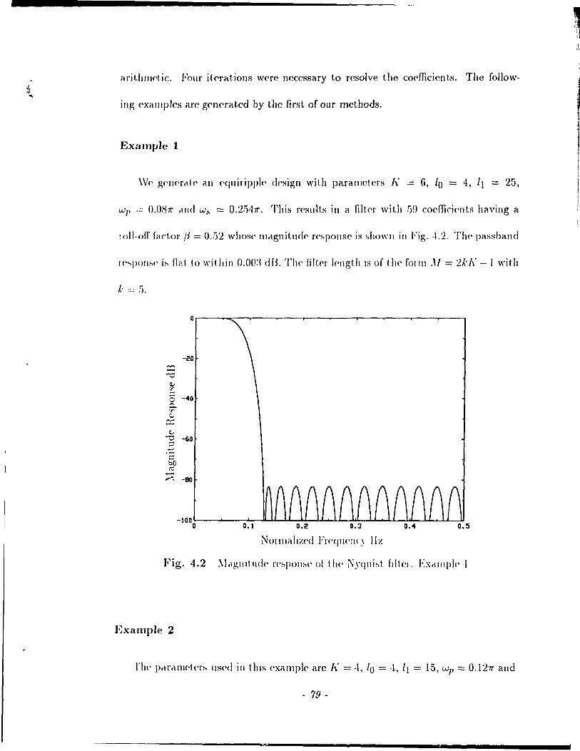
aritllllld ie. Four it ('rations were neCC'ssary to resolve the codficicn ts. The follow-
ill~ ('Xéllllplcs arc gelwratcd by the flrst of our rncthods.
ExampJe 1
WC' gC'IH'rrltC' <HI f'quiripplc> design with paramctcrs 1\ -= 6, 10 = 4, /1 = 25,
Wl' = (l.O~7r ,md Wb = 0.2.1,111". This rcsults in a filt('r with G!) coefficients having a
:oll-ofr factor /1 = 0 . .12 whosc' mrlgnitude' r('~ponse is ~howll in Fig. ,1.2. TIl(' passband
J(''''pon~{' i~ (lill to within o.oo:~ dB. The nlt"r I('ngth IS of the fOI 111 ,li = 2kA' -1 witlt
l· = ti,
-20 =: -c il; :r
[ -40
'f' c...
c::::: ...s -60 '-' -'
.+oJ
C bO ~ ---,.-"; -80
NOllllélllz('d Fr('ej1l<'lI{} IIz
Fig. 4.2 :\ltl,l!,IJlt IId{· J'('~pOIl:-'(' 01 (II(' Nyqlli~t fdte!. Ex,lIl1plp 1
EXHInpie 2
- 79 -

w~ = 0.3811". The weighting is
(-I.!)) IV(w) = { ~o 211" (w - ws) + 1
for w = 0
This glvcs a noncquiripple N yquist filtc'r with :HJ co('ffici('n t s and a IOll-off rad or
/3 = 0.52. The filt.cr lellgth is of the fonn M = "2kl\' - 1 \Vil h J.: = 0. Flp,u\(' t.:l
shows the magnitude response of the fill.er. Th(, pal-."band Il'SPOIII-.(' is liaI. 10 \VIt hill
0.002 dB. Figure 4.'1 shows the group dday respOIIS(' of 1 hl' lIliniJ1ll\l1l ph,I"(' parI of
the filter.
4.6.3 Group Delay
TI\(' glOup c\clay of the llIillil1ll1Tll phrls(, parI is only illlpollalll ln 1 II<' p"s'.h<llld
(111<1 is primanly lIIf1ucllccd hy th(' pa~!:>band zC'\"OS wlllch al<' wil hill II\(' IIlIil CIl< h'
For a giv(,11 l1ull1b('r of laps and éI gi\'(,\1 1\', the' group dc'Ia)' I<>lId:-, 1.0 1)(' 1110\(' (Oll:-.t.llll.
as the IOIl-off farlor in<TC'ases. 1\lso. for a givc'n roll-off faclol ,lIul ,1 p,i\ ('II 1\', il l,II g('1
lIulIIl)('r of taps p\Oduce~ a group d('lay with rl p,1('all'l d('\'I(tllolI 'l'II<' 111111111111111
phase' filt,el'. g<'lwrale'd in Example:-, 1 rllHI 2 1 bell ,1( hil'v(' ,">0111 el ,10 dB :--fopl,,,lId
att(,IIUéllioll ha\(' cl \'(·lélti\'(·I~' slllall pas:-,band gloup d(·la)' \'"riclllOlI (,IPpl()xilll"klv
0.15 ZCIO (ros~illg inlervab).
Fclclorizalioll of F(::) illto Iwo «)n~léllll grollp <Id".\' fIlIHll()ll'. 1/(::) ,llId (,'(.:) fo
1)(' u:-,('d in T:J alld S:l i~ po~~ibl(' riS fol 10\\':-'. Flrsl. 1 II(' dOIl bl(, Z('[O'. (Jf Ff(:") <l\('
allocatcd one ('(\(h lu 11(:::) and 10 (,'(:::). TI 1('11 , \\'l'II,,'.'.lIy 1111' ZI'J()'. (If l'()(·.) III poldl
Older of 0 and Ihe IIIl1ror-1I11agc pairs al(' all('llIell<·ly ii'.~I,L!;[l!'d 10 1/(:..) alld (,'(:.-)
- HO -
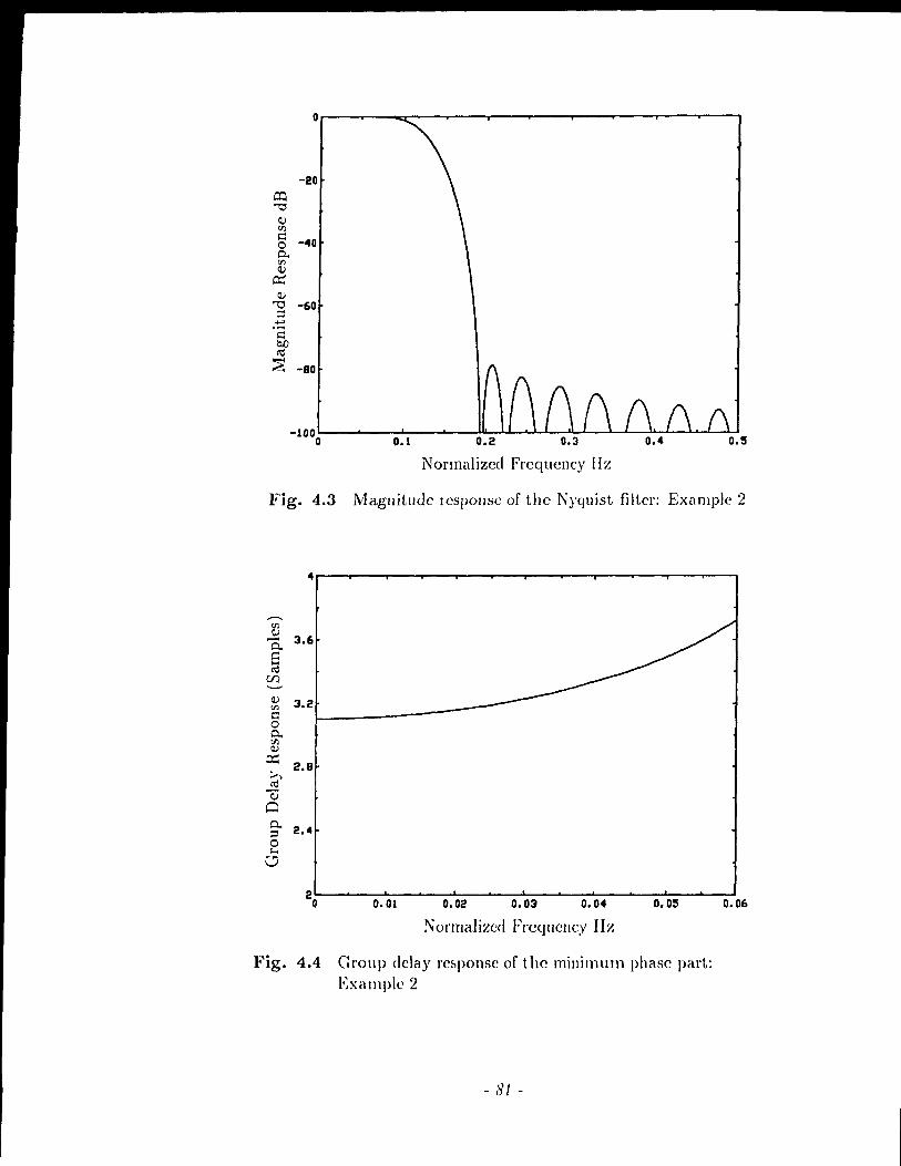
Or---~--~----~--~--------~--~----r---~---,
-20 o:::l "'0
Q) fil 1:: -40 0 Cl. fil Q)
~ Q)
"'0 :::l
-60 ~ .-1:: QD ~
"""' ~ -Ba
Normalized Frequency Hz
Fig. 4.3 Magnitude lcsponse of the Nyquist filter: Example 2
4
..--.. fil Q)
3.6 P.. 8 ~
r.f)
Q) 3.2 fil 1:: 0 Cl. fil Q)
~ ;..., 2.8 ~ ~ Cl Cl. 2.4 :::l 0 1-<
V
0.01 0.02 0.03 0.04 0.05 0.06
Normalizcd Fl'cqUCllC,V IIz
Fig. 4.4 Group dday ref>ponse of the minimum phase part: EXé\mple 2
- 81 -

r ,
This ellsures that bot.h 1/ (::) and G(::) have COllst a nt gIOII p d('ldY, Nol<' t h,1I 1 l' l(l h
odd, the uumber of taps of 11(::) and G(::) diffe'r by \'\\,0, Oth('lwis(" th('y ha\'t' 1 lit'
sal11e Humber o[ taps, Du(' 1,0 the pre's(,Il(,(, of idC'ul iCcd stophand Ze'I'OS in 1/ (:::), Cr'(:::)
and F(::), the stophand },C'spOl1ses of boUI 11(::) (IIHI (,'(:) al(' !!,ood 110\\'('\'(,1 tl\('
pa&shand respomws can deviatc ~igllificé\nt\y fl'0111 é\ rollstant '1'11<'1'(,[01'<', f,H lOI iZIIl~
il Nyquist filter iuto two geul'ral factOls //(::) rlllel (,'(::) for IIS(' in '1':\ ,11\11 S:J \\'ill
assure ronsta n t gl'Oll P dclay factol's but é\ t the' cxp<'ns(' of <III ,\('('('pl ,1 1,1(, IIl,1~1I11 IIdl'
response,
4.7 Comparison With Other Approaches
This &ection dlscusscs the' relative m('rits of t1H' fc\ctOlélbl(' IIlillllll":'; dl'~I,!.',11 Il)('111
)lIs when compared with otller approaches,
4.7.1 Linear Progranuning Technique
In [27], a lincar programmi Ilg appl'Oach t ha t. is also bé\~('d 011 " IIlII1 i III a x ( 1 i 1.('1 iOIl
IS lIsed to design a factol'c\ble Njqllist fillel'. Fol' COlllpallSOll, \\'(' P,('I1('l'dt<- " fil1('1
\\'ith the same parametcrs as the example in [27] (.\/ = :Jl. /\' = -l, !1 = 0 l~r) <111<1
IV(w) = 1) \Ising our [adol'able miuimax appl'oach, It. i~ oh:-'('I'v('t! th,tI (1)(' IlIdp,llillldl'
and group delay respollses of the filtcrs give'1I by tl1(' 1 wo dC':-'lgll.., cl1(' \'('IY ..,illlilai 'l'Ill'
eqlliripple l1lc\gnitllde charactel'istic is 11101'(' ('xactly g,i\'l'II by 0111 <IPIJlO<lllI, Alhlll<lly
wcighting céIn be ('ctilily applicd i11 both the f,H tOI',lbl(' 1l1illillldX "1>1))0,1( II clllIl d lilw,11
pl'Ogramming [olln 1I1at ion (sec [:Wj) ,
- 82-
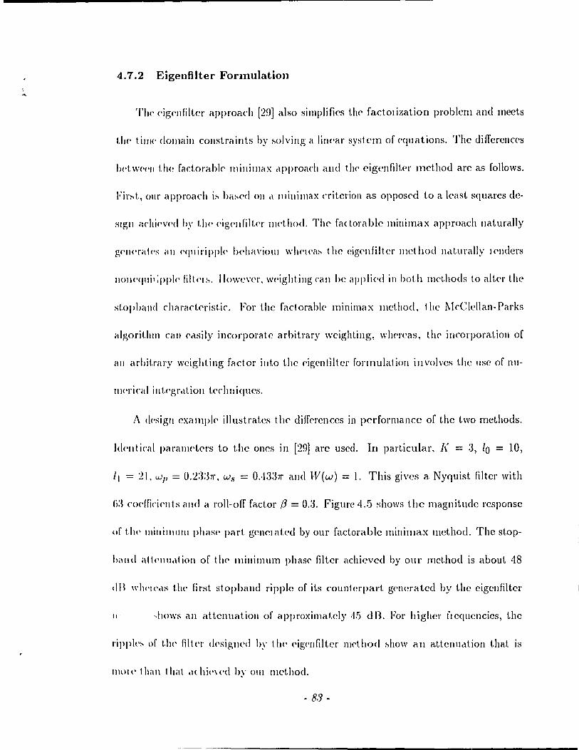
4.7.2 Eigel1fllter Fornlulation
'l'II(' ('ig(,llfilter approach [29J also simplifies thc> fac1OIization problcm and meets
1.1)(' tillw domaiu cOllstraints by :'>olvillg a linC'ar system of ('qllations. The differcnccs
l)('tw('('11 the fadorabl(' lIliJlilllaX rlpproach alld t!H' cigenfiltpr mcthod arc as follows.
Fir:-.t., 0111' approach i:-. ba:-.ed on cl millimax criterion as opposcd to a \cast squares de
slgJl étchi('V<'d ily 1. he ('ig('Jl fil \,('r 111('1. hod. l'Il(' fa< tOl'a bIc min i ma x a pproach nat urally
g('lJ('ral<'s ail <'«llil'ippl<' J)('haviolll wlw!ea:-. the cigcllfiltcr Illethocl nellmally !C'!l(lers
Iloll<'qlli':pple lilt('I!'l. Ilowc\'er. w('ight.ing cali be applif'd in bot.h mcthods to alter the
st.opbillId characlerist.ic. Fol' the faclorablc minimax mdhod, the l\lcClcllan-Parks
algorithm l'ail ('rlsily incorporatc arbitrary wcighting, wlH'rcas, the' incorporation of
élIl arbitrary weight.ing faclor iuto the eigenliltcr formulatioll involvcs the lise of nu-
llwrical ill1.('gretl,ioll 1,('c!lIIiqucs.
/\ <ksign eXéllllpl(' illustrates tlte differenccs in performance of the two methods.
Id('111 irai parallH't('l's ta t.he ones in [29] are uscd. In parlicular, f( = 3, 10 = 10,
'1 = 21, wp = 0.2:3:37l', Ws = 0..1337l' and W(w) = 1. This gives a Nyquist filter with
(i:J co<'!firi('IIt.s and él roll-off factor f3 = 0.3. Figlll'c 4 .. 5 shows the magnitude response
of t.h!' minilllum phas(' parI. genel ated by our factorable millimax mcthod. The stop
band alt<'lIu.ttioll of 111<, lIlinimum pllase' filtcr achicved by our mct.hod is about 48
dB \\'hl'I('.\:-> th(' fin.;t stophand l'ipple of iLs countcl'part ge'llcratcd by thc cigcllfiltcr
III ~hows ail attclluatioll of approximal,c1y ,15 dB. For higllcl' f!cqucncies, the
l'ippk:-. of th, lilt<,l' d<'signcd by t II<' C'ig<'Ilfiltcr Ilwthod ~how an attcllucüion that is
mOI (' t han t hat ,l( lIit'\ ('d hy OUI method.
- 88 -
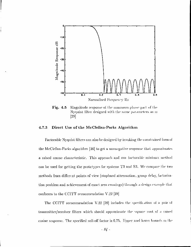
O~---~------~--__ ----T------~---~---__ ------~---~---~
-10
Q:l "'0 Il) -20 Vl c:: 0 0.-Vl Il) -30 ~ Il)
"'0 ;::l
.-+;: -40 c:: b.() cil ..,.. ~
-50
-60 0 0.1 0.2 o.~ 0.4 0.5
NOl'maliz(·d FI<'(I'l<'wy IIz
Fig. 4.5 Magnitudc l'(,SpOIl~(' of t h(' \11111 III 1 Il III ph<lh(' 1"'1 t of 1 hl'
Nyqui~t filtc')' dcsigl\('d wil Il 1 II<' Sillll<' pel\ (1\11('1<'1'~ as III
[29]
4.7.3 Direct Use of the McClellan-Parks Algoritlull
Factorable Nyquist filters Céln also 1)(' design<'d by invoking t.h<· lOllstl',lill('d l' o l'Ill 01
thc IVlcClcllan-Parks algorithm [:3G] to gel a llol\lH'gat.iv<' l'('SPOIISI' t.hal r1Pp\oxjlllat.(·~
a raiscd cosll1e chalarteristic. This appl'Oach and OUI ladorabl(' 1I1inilllax Il}('t,hod
can bc used rOI' gctting the pIOtOt.ypc's rnr systems '1':3 and S:L W(' COlllpill l' 1 Ill' t.wo
mcthods rrom diffcrc nt points of view (stoJ>balld attC'lluatioll, group d<·lelY, f,ldol'iza-
tion problem and adlicvclllcllt of cxa{\, Zf'fO C1'ossillgs) thlollgh " desigll ('\(.lllIpl<· that
confonns to the CCITT rc'comn}('lIdati(>I\ V.22 [:39]
The CCITT rccommcndation v.n [:W] illclucl('s 1 Il!' "pC'cifi( ,II iOIl 01 a pilil' 01
transmitterjrcceivcr filtcrs \\lhich should apPlOxilllat<· 11r<' "qllill(' 100t of rl \ai~l·d
cosmc ICSpOnS(~. The spccificd IOII-olT faclol' is 0.7.1. lJppC'1' and 10\\'('\ 1)(1I\lId" III 1111'
- 84 -
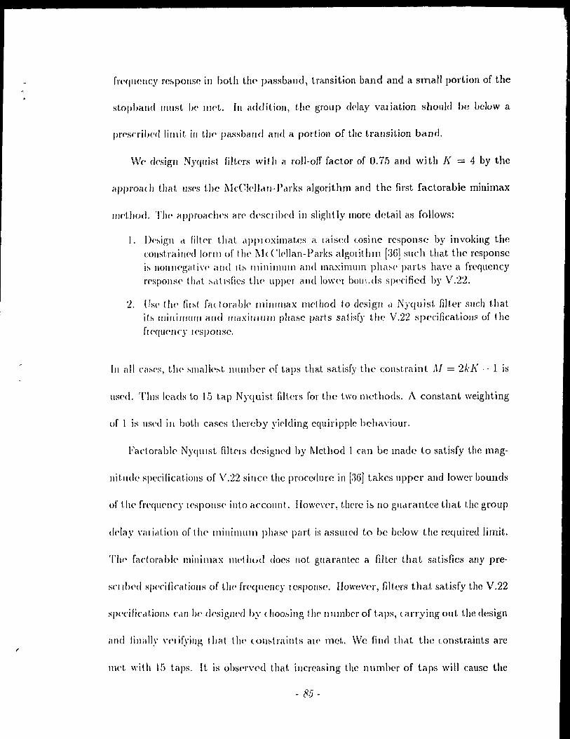
freqllC!ncy re~ponse in hoth thp passband, transition band and a small portion of the
st.op"and III Il st 1)(, 1IH't. III addition, the group d<'lay val iation should be below a
pn'scri/'('d lilllit ill tlJ(' passband and a portion of the transition band.
We design Nyqllist filt<,l's wit h a roll-off factor of O.ï5 and with ]( = 4 by the
approéH h that 11S('8 the l\IeCkllclll-]\Hks algorithm and the first [adorable minimax
Il)('tllod. '1'1)(' approaclH's arc' d('sCl ibed in slight ly more detail as follows:
1. J)('~ign cl filter that cl!>ploximates a laiscd (Qsine rcsponse by invoking the eOllstrained 101'111 of the [\I( C'kllan-Parks algOIithm [:JG] slIch lhat the response i~ nOIlI){'gativ(' and ,t~ Illinillllllll and maximum pha~(' parts have a frcqucncy )'('spons<' thclt !-.clt ,..,fics t!w lIppCI and IOW('l bO\lu!s spccified by V.22.
2. Use th(' fil!'>t fa( torélble lIlillllllaX mdllOd to design cl Nyquist. filter slleh that ib millimulIl and mélximum phase parts satisfy the V.22 specifieatioll!> of the fI ('(1 1l<'1ley 1 ('s ponse.
ln ail ca~('s, t!)(' ~Illall('~t number (lf Laps that, satisfy the cOIli:>t.raint M = 21.:]( - 1 is
IIsed. 'l'lus leads 1,0 15 tap Nyquist filters for the two mcthods. A constant weighting
of 1 is l1s('d in bot.h cases thcreby yi('lding equiripplc behaviour.
Fact.orablC' Nyqtllst filtc'18 desiglled by l\lethod 1 can he made to satisfy the mag-
llit.lldc specificat.ions of V.22 8ince the procedure in [36J takes upper and lower bouuds
of t.he fr('quelle)' )('SPOIl8(, int.o accoullt. IIow('\,er, thpre i~ 110 gllclralltcë that the group
(!Play "ali,d,ion of the millimlllll phase part is assUleu to he bclow the l'equircd li mit.
Th(, fa et ora hl<' min i max lI\('t hut! does Ilot gllarantce a filter t.ha t sa tisfies any pre-
sn II>('d specificatiolls of Ut<' fl'('qucney lcsponse. IIowcvcr, filters that satisfy the V.22
spt'cificcüio1l1-l C<lll he dt'siglH'd hy (hoo~illg tJJ(' 1I111l1bC'r of laps, tarrying out. the design
illld lillillly "('Iifying that t))(' (olll'>traints al(' met. Wc filld thcü the wllstraints are
lIlt'l with 15 t.aps. It is ohser\'cd that illcrcasing the numher of taps will cause the
- 85 -
frequency response consiraints to be violated since' OH' transit.ion hand !WCOI1WS mon'
steep and lies olltside the acceptable l'('gion.
For pel'forming a min/max phase' splIt., ractorillg F(z) d('signed hy I\klhod 1 ('dn
be avoided sincc the' uuit circle zeros cali 1)(' ('xtrad('d rrom t.1\(' ('xl rCIl\.1I !'t('<\\(('I1( i('s.
I1owever, the otllel' zeros would have to 1)(' det('rlllill('d by fil st d(·f1.1I111p, t.!w ollginal
polynomial. Also, there Îs no gell<'ral <'XpI<'SS iOIl rOI lit<' pl'OpOI t. iOIl of 1111 i 1 ('Ircl(' Z('WS
to the otIler zeros of F(z). lt is observcd in [38] that dcflatioll is lIIore sl .. hlc If t.IH'ï,(·IOS
of sm aller magn itude \Vere ext.ractcd fi l'st. This ru rI h('(' cl is( O\ll'<I,l!,{'S t. he di \'IsiOIl of 11)('
original polynomial hy il polynomicll tltai has lite 1I1111. ('ilclc ï('IOS :-'111('(' Ihey ha\/'.I
larger magnitude thall the zeros within the unit. circle which :-,hollid 1)(' ('xII .let(·c1 li!'"t,
to enhancc the stability of tlJ(' dcOation pro('css. A l'('IIlC'dy t.o IllIs J>l'Ohl('1Il is 10 1I~"
Lagrange interpolation as in [37] to obt.aill a polynomIal t.ltal l'<'PH'S(·IIt.s t.!)(' pas~hal1d
zeros and then facto! it to obtain tlll' zeros illsid(· tlt<' unit cilcl('. Ail dlt.(·I'II,ttiv(' is 1.0
use a modified Newtoll'8 iteratioll [40] 011 tllC' origillal polynolllict! 10 oht.aill t1H' Z('I 0"
insidc the unit circle. l\Icthod 2 directly 8eparat('s F{z} int.o t.wo polYlIollli,tls Fr( z)
and Fo(::) havillg zeros on and off the unit cilcle J'(·spectiv(·ly. This avol<b tlll' t,ct~b
of approximating Fo(::) by Lagrange interpolation and det.(·rIllÎnÎng t\l(' ;1,<'1 os of f'h(.::)
by considering the original F(::).
After carryillg out tlw de~igJl of the 15 tap NY«lIi:,t. fill('rs hy boLh l\'lc·t.ltods 1
and 2, we compale thelll in ternIS of the stophéllld att.(,lIUatioll ac\li('v('d l,y F(.::), t1)('
group delay of the facLorized minimulll phase filt<'r 1/ (:::) in t hl' J'('gioll cOII~id('f'(·d ill
the V.22 specifications and ill tel'ms of the Icsidual illt('f~ylllhoi inkl f(·I(·n«·. Md,!rot!
1 does Ilot assure exact Z('I'O cr()s~illgs ill t 11(' tillte H'SpOIl!-l(' J ('/1) H('II( (', wc' II~('
- 8(j -
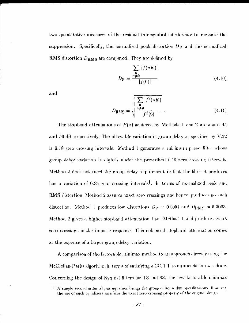
two quantitativc measures of the rcsidual intcrsYlllbol illlcrf('n'Il( (' t 0 Il\Cé\SII\'(' the
suppression. Specifically, the normalized peak dist.ort.ion [)p alld tilt' Ilorlllalizcd
RMS distortion DRMS arc computed. They arc dpfillcd by
and
L 1/(11/\)1 n
111=0 Dp = 11(0)\ (·1.10)
The stopband attenuations of F(::) achic'vcd by Mcthods 1 alld 2 an' abolit ·I!i
and 50 dB respectively. The allowable variation in group delay a:; Sl)('cili,'d by v.~~
is 0.18 zero crossillg intcrvals. Method 1 generates a J\Ii IIi 1Il11I1 1 pha:,(' filt('1 who:-w
group delay variation is sligh t.ly IIneler t.he pre~('J'il)('d 0.1 S zero (J'os:'ln1!, ill',('rv<lb.
\1:ethod 2 cloes Ilot mect the group <lclay l'eqlJir<'lllC'nt in that. t.!H' fill<'r il, prod1J( ('S
has a variat.ion of 0.24 zero cro&sing intervalst. III t.erms of norlllaliz('d IWilk and
RMS distort.ion, Mcthod 2 assures exact zero crossings and IH'lIcP, Plo«lIl(,('S 110 slIch
distOltion. Met.hod 1 produccs low distortions [)p = 0.000·1 and /JHMS = (l.ooo:t
Method 2 gives a hig,her stop band attenuation (helll :\lethod 1 <llId P!Odll«'S <'xa<t.
zero crossing,s ill the impulse l'eSp0I18('. This ellha!\( cd ~topbaJld aU('llwüioll COIII('S
at the expensc of a largcr group <Ida)' variation.
A comparisoll of the fadorable Illinimax llH'tho<l to élll approach <Iin'dly \lsillg 1./)('
McClcllan-Palks algorithm in tCl'IIlS of satisfying cl CCITT 1 ('(()lIl1IlC'!l(lilt.ioJJ WilS dOIl('.
Conccrning the design of Nyquir-,t flltcl's for T3 alld S:J, t.!J(' IlC'W ftl( lm cl 1>1(, IIli/lllll(tX
A sllIIple second order allpass eqllahLCf brlllgs the group (h-Iay WI\,hlll :'PI'( lliratlllll!-> llowl'vl'r, the use of su ch eqllalizcrs sacrifices the exact zero croshlllg proprrty of 1111' orJJ.!)/l<d df'hlJ!;1I
- 87 -
rnethod does ofrer advalltagcs over its McClellan-Parks counterpart. First, the new
method Icads to exact zero crmlsings in the impulse response. The factorization
problern can he alleviatcd in both approachcs. Howevcr, the new method can bring
down the fadorization complexity by choosing appropriate filter lengths. AIso, the
polynomial reprcscn ting the zeros off the unit circle is directly computed in the new
IIld,hod. IIence, this does not ncccssitatc any polynomial approximation or a zero
finding algorithm based on the original F(.::).
- 88-
Chapter 5 Optimized Filter Banks
The minimax design procedures describcd in the pr<,violls dwpt.er givp lowpass
prototypes such that the Ny()uist criterion i8 eit.her approxilllrlt('d or (,xé\ct.ly selt.isfi('(1.
The designs <Ire bascd on a common input-out.put. t ram,[('\, fUlIct.ioll fOI {'\'('I Y pail of
terminaIs in the transmultiplcxers. Rel.urning to the synt!l<'sis proc<,dllr(' ill Chclpt.<'1"
3, wc note that tbc achievemcnt of fi COIl1mon jnpu t-outpllt t 1 dllhf('1' fllll<'t,ioll pellt,j,dly
relies on the bandlimitcdness of the protot.ypf', Morf'()\'('r, th(~ ('ros~tillk-Ir('I' Il élf.III'{' I~
heavily depcndent on the bandlill1itcdncss propcrty in thclt 1 his PIOP('l'l.y i~ wu'c1 f.o
cancel the crosst.alk tcrms (which comprise t.hccrosstalk fUllctiops) UI"t do 1I0!. illvolw'
spectral overlap, As bcfor<" wc l'cCcl' to bandlimitcd lo\\'pcls~ plototypes a~ th(IS(' wit.h
a stopband rcsponsc which is exactly zero. Silice bandlilllit('<! prototypes CilIlIlOf. 1)('
desigl1 cci, thcre cxis\' practical impcrfcct,ions in til(' ~ylltll('~iz(,d ~y~t('III~, Fil st, t1w
input-output tutllsfer fU!lctÎon may be difrercnt for ('ach t '1lllillcJ! pelll'. S('colld, tlwJ'('
may be rcsidual crossialk bdwc(,11 signaIs sent ai nOIl-adja(('llt ('('111.('1' fn'qu('lIci('s,
Wc procœd to analy?'{' the syn t.Il<'sii:!'d t. ra IlSl1lul tipl<''{('1 s \Vi th r(':-p('( t t () hot.h t.1H'
input-output transfcl' functioll and the crossl.alk wh('Jl Plil( ti<cll nlt,(,!,!> (\)(' IIs(·d. A
practical lowpass prototype i8 not handlimited in tl!rü its freqlJ('Jlcy 1'('SPOIlS(~ ollly
- 89 -

•
approximates zero in the stopband (stopband attenuation is high but not infinite).
Ba:-ed on the allalysis, opt.illlized lowpass Fm filters that attempt to achieve a high
slIppr('s:-ion 01 Iwth illtel symbol int.crfcl'f'llcc and crosstalk are designed by minimizing
an eITor fUllctioll. Thcl'cforc, the practical degradations (both illtersymbol interfcr
cnee and crosstalk) arc taken into account in the filter design procedure. In contrast
1.0 t.he minilllax approac.hcs, the optilllized designs take crosstalk into account. Thc
p('rfOllllclllL'l' uf t hf> II cUlslllultip!ex('rf> jf> e\·<tlllated ",ith both the optimized and the
llIillilllaX filt<>r:- \V(· cOll1pare the t\\'o desigll approaches wit h rcspect to the resulting
perforlllallce'. Finally, the feasibility of this technique fOl the subband complements
is discussed.
5.1 System Imperfections
'l'ransl11ultiplexers Tl th"ough '1'5 have eaeh been configlll'ed with bandlimited
filt.crs such that (1) the input-out.put transfer function is the same for every prtir
of cOlTespondillg termillals c1lld (2) crosstalk is cancelled. Ir addition, satisfying
the' Nyquist criterion elilllinate:- inte'l::'ylllbol interference and hence, achieves perfect
reconstructioll. With practical filter:-, the input-output transfcr lunction may not
he the saIlle for ail pair& of terlllilldis. III addition, the design procedure may give
filtcl's sneh that the Nyqllist cl'itcrion is Ilot cxactly satisfied. Therefore, intcrsymbol
inl.cl'fel'l'lIcc nl'ed not bc elill1inated at each output termiual. Moreover, the use of
P!',\( (ical lilt('r~ Illa)' lL'ad (0 rcsidu,ll ('l'osstalk which would othenvise be cancelled
",it Il " h,lI11IlIIllÎkd pl'l)tl>typl'.
- 90 -
In this section, we further analyze each trc\nslllll1t.ipl('x('l' in 1(,l'IIlS of t.lw possihl('
limitation of not achieving perfcct recolI~trllction cl tI(' 10 t Il(' liS!' of prad i( il 1 fill ('1:-'.
The next section shows ho\\' tl\(' limita! iOIl is 1 ak('11 illto é1r('OUIl! in an op! illlizl'd lksip,n
of the pl'é1ctical protot ypc. Th('Il, t Il(' 1)(,l'rol'l na 1\('(' or t II(' syst ('IlIS \Vi 1 Il pr,\(·t ira \ fil kl's
is evaluaLed.
5.1.1 The Input-Output Transfer Function
ln é1l1cll'yzill~ the trall,>lllllltipl(",(,I''>. W(' 1'('1 1I111 t.u t.11l' :-'.)'111 h(·~i~ pl'O( (·dlll(·
III Chapter :3 to s('C' \\'11('1'(' tht' hélllcllilllJt('dll('::'~ pl'o)wrty WrlS \I~('d ill ppt.-
ting a cOlTlmon illlHlt-output tram,fer fllllctioll. COllsi(kr the' ~('J1('l al ('xpn's-
SIon for the input-output transfer function Tkk(::N) givPIl by Eq. (:1.:»). '1'1)('
bandlimitedness of the lowpass plotOtYr\' was illVoked to ('a 11<'('\ t.h(· Irl:'t. tc'\'IlI
L~Ol W 1(lI k - PA)2cos(Ok - rh)l/(r-J ...... A::ll'-')I/((JwA::W-') 1'01 :'O[\H' or III<' t.('lllIi
naIs. IIowcvel', tItis t(,1'1Il i!-t uat lIrally célllcell"d for ail t('rrnillab ill '1'2, TI alld TI)
and for the terminaIs in Tl opcrating at the c('ute)' fr('C)u(,llcics of (J ulld 7r. Silllilrllly,
for system T3, the gencral expression for the input.-output trans[,,!' [\If1ctioll 'll·d:;N)
is examin('d. Thc bcllHllimitedncss of 1 Jl(' PrototYI)('S lIlust 1)(' iIJvok(·d t () (,clllce'l !-tOIlI('
terms III TH.(:;N) 1'01 t.hl·1l'lIl1illélb lhcll do lIo1 (1)('1'(11<, al 1,\)(' ('11<1 In·<jl(('lJ('i(·:-,. '1'1\(':,(·
terms an' \lat l1I'aJ\y CèlllCplkd (\Yil h01l1 lllvol,illg, 1 II<' halldlim!I(·(hl<'ss propPI 1.y) for Ut<'
terminais operating at the ("llel frcqucllcies of 0 and 7r.
The prcccding analysis rcveals that the input-output trétIlSr(·!' fUllrtioll is illde(·d
the same for etH pair~ of tf'l'minals in (>é1ch of tire sy~tems T~, T,t alld T!). [Vlon'ovC'!',
thih pl'opel'ty IlOlds fOl allY plclctil<ll pwtotyP(' 1/(::). 'l'11('J'('f()I(', for cllly 1/(::), t.1J('
- 9 J -
(
... , •
(
, î
(OIlIIlI(11l iIlPIII-(J11IplIl tlall:-.f('1 fUllctiun F(:;'v) 1'> gi\'clI hy Eq. (3.17) for system 1'2
,llld by Eq. (:L:ll) for 'l"l and T.5. Now, consid('r systems Tl and '1'3. The com-
111011 illput-out.put t.létllsfer fUllct.ion T(::N) as givP!1 in Eq. (3.15) (system Tl) and in
Eq. (:U9) (sy:-.I('III T:3) IlOlds only for tllP tl'l'minals specified by center frequencies of
o "lId lr. /\gtlill, t.hi:-. i!'l t.nl<' 1'01 pltl< ti(,t! pIOtotyP('!'I 'l'II<' illput-out.put trallsfel fUllc-
t.ioll:: fol' III<' otll<'l t('llllillal.., of TI dlld T:~ al'<' di ff('rf'1It l'rom t.hosf' gi\'PII by Eqs (3.1.5)
dlld (:J 19) \\'11<'11 pl'actic,d filter:-. dl'<' t1'ied. Thesf' differencf's arc duc 10 t.he faet t.hat
t.he prototyp!''' alc Ilot handlinlltcd.
Th!' Il<'xl :-,t('P i!'l to ide'nl if y 1 II<' ~Olll ccs of intf'rsymbol intcrfel enec in cach of t.hc
tltlll:-'lllldtiple,\('I..,. III :-,\..,t('111"> T~. TI ,1IId TI). inlpisylllhol inl(,l'f<'rence is cilncplled al.
alltt'I'lllilltlb gi\'('11 ail) 11(::) if fI'2(:) :-.tlli..,flC':-' Ill<' !"\yqlli:,t critcl'ion. The only pot.cn-
liai sou\'('(' of illtf'\'syl1lhol illlc,\,fc'\,cllce is duc 10 the' limilation of t.he desigll procedure
ill gi\'ing 1/(::) such Ihat 11 2(::) docs not exactly satisfy the Nyqui:;t critcrioll. There-
1'0\'(', tll<' Illillimax d('sign of Chapt('l' ,1 will lC'éid to l'e~idllal intel'symbol illtcrfel'cncc
in T~. TI and 'l'!).
\\'11<'11 d(',dillg \l'ilh "'.\!'lll'Im. TI alld '1':3, two ca:-,C's lIlu:,l bc Wl1sidcl'cd. First, con-
"idc'I' t II(' t('l'lllillals opC'l'<\t ing at «'ni ('1' fl'('(jIH'IH'iC's of 0 and 7r. At. t1wsc terminaIs, the
onl,\' sour('(' of i III <'rsYlllbol i Il 1. CI' 1'('1'('11 ('(' i!'l cl lie 1.0 t.he design pl o cccl ure in giving filtcrs
SI\('h 1 hat t hl' N.\ quisl ('\,it('l'iOll is 1101 C'xact 1)' sati~·,flcd. At. the otller tel'lllillClls, clll ad-
dllional !'-OUI'<C' DI' illl('I'S~ IlIhol illlelf('lc'II('(' êllis('s !'IllIce III<' fdte,l's arc 1101 bandlimitcd.
(:iVl'1I the lIIinilllax d(':-,ign of t II(' !>l'('\'iolls chapter, int('l'sYlllbol int.erfel'el1ce will be
p\'('sellt at ail Ih(· t(·l'IIlinalsofTl. FOl'translllultiplexcrT:3 \Vith G(::) = 11(::-1), the
1',lCtorabl<' lllillimélX (Jc.sign ll1ethod assules that no intcl'symbol interff'rence is j)rescilt
- 92 -
al the termillals sp<'cifiC'd b~ c('llt('r fn'ql((,l)( i(·.., of 0 alld iT, 1I0\\'('\'cl. illtel ~ylllhlli
IIlt('rl'<'l'ell((' dl..,IOIIIOII ",ill ('\hl ,If Il)(· (Jlh, 1 1('1'111111,11 ... of 'l':J ..,illn·IIH' pJ'l)I\lI,\'p('~ <11'('
not bandlimitl'll.
5.1.2 Crosstalk FUllctiol1s
Berc, \\'(' wish to dC'lcrlllillc the !>O\II'({'~ of nos~I,dk thal <Il'i~<' wlth P\ <1<'1 \(',d hl\t'l~
From tbe :,~ IItbe!'>i~ pwccduI(' III ('lldpI('l :L llU..,:,!.di, ('<lII( ('\l,II iOIl ",it h h,lIldlllllikd
prototypcs o('('urs in two \Va,vs, Fil"'!. 1('1'111'" ill Il)(' Clo..,..,I,dk fllllcliull 'f'k/(:;,y) Ih,lI
i Il \'01 ve (·i 1 he!' part i aloI' co/) 1 plel,(' s peclr,d 0\'('1 ln Il il 1 (' (' d Il ce'lI ( ,cl hy (' hoo" i IIg Il)(' ( ('111<'1'
fl'cqucllcics, dclay~ and phas('s, This ulllcC'IIi11 iOIl d('(J('IIc1s olll\' 011 1/)(' ('('I!I('I' fi ('«U('II
cie:,. deldy'" éllld 1)llil~('''' ,1 Il cl IS Îllclq)(,II<1('llt 01 <Ill." 1'<111 i< 11/,11 fOI III (Jf 1/ (-; J ,lIId (,'(: J,
Therl'for('. 11t(,..,(, ICI Ill:' culllillllC' lu 1)(' CdIIU·I\(,d \\'illt 1>1<1('11(111 filt('\'.., S('('Ollc!, tC'IIII'"
ill t!lC' ('J'o~slcdk fUllctlOll Iltat do Ilol 1I1\'(Jln' :'j>('('tla/ 0\'('1'1<11' ,11(' zelo <111(' I() IIi<'
bandlimitcdllcss of tl\(' prototypes lIo\\'C'\('r, t1l(':,(' C1o..,.,t,dk 1 ('J'lJI:. al(' Ilot ZC'IO with
practical filu'ls, This will l('ad 10 I( .. .,i<lllnl ('Jo~:.lillk SUlllllldrizillg, W(' 1101<' th,II ,dl
the c)'(,s..,lalk l('J'lJl~ in T",(::'\:') Ibdl ill\'oh'(' "'(H'('[liil O\'c·rI'if} \\'ilh 1'(I;ldlilllil('c\ Idl(',..,
continll(' to )(' (,(\\1C<'Ih-d ",il Il PI,)l t il (d hlle'I~,
~tJtt' t!t,t! ",ith pl arti('cd nltl'I"', ,dl hUlIgl1 1 II(' Il'I'Ill''' III T",(:;N) \ Ilit! ill\'oh'(' ~I}(,l
tral ovcrlap me canccllcd (as di~(,lI~s<'d ,,1>0\'('), thi~ <I01'S Ilot p,<'I[('J(llly illlply 1 Il,11,
Tkl(:;N) = 0, Wt' Itlltll<'l' êlllal~'z(' ('(t<1I of 11\(· 11'(\llsllll\llipJ<.:-.<'I'~ 10 c\('1 ('J'J\li 11(' III('
IlUlTlb(,J'of C1os"lalk IUllctiUI\., Illdl .11(' (':\(\(11\' Zl'IO \Vith jJldcti('al lilll·l., (éll..,o Ide'l'n·rI
- 9,1 -
nllly 011 tllC' (('lIkr fI'PfjIlCIICip<;, Jelays alld pha:-.(·s aile! OC(,UJ'~ indepcndent.ly of thl' pl'O-
1()IYJt('~ 1/(:) éllld (,'(::) Fol' éI parliclllcII' output terminal, thcre are N - 1 cl'Osst.alk
111111 1 Juil .... Fui t'd( Il ur tll<' 11"1I:'lIlllllipl(·\(·I~. cl ('C'llclill Iluml>l'I' of thesc J\' - 1 func-
1', ll~ 111<1,\ 1)(' 1'~c1' III' ;tl'Iu \\'(' prUI('('" lu ('IIIIIlll'lcllC' thl' 1I11111bcl' of exact Cl'osstalk
(dIH'(·II,,1 iUII"
III ... y~I(·IIJ Tl, th<, C1'o~stalk is <'''<lrtly Z('I'O hell\'C('1I t\\'o sigllals :,cnt at the sall1C
C('lIle'l' fl'('<Jltc'IICY, al. (,Plltel' fl'eqllcllci(,s sepalateel by an odd Illultiple of 2r.I'" anJ at
«'I!I<'I flt'qlll'llI'it':-' ~('P"ldl<'c1I),\'cllI ('IC'IIIJIlrlllplc'ol 2ii'j.Viftheclifrcl'<·llc('ill Ihedelay
1',11 tOI'" 1 ... ,III odcl 11I1I1tiplt' of ,\Il. III ",\':-.1('111 T~. c'x"ct 1I0 ...... I,t1k Ccl Il ('C'lIat 1011 OCCUI:'
l)('t\\'('('11 dlly t\\'o ~igll,ds a ... IOllg c1~ the' diflc'!('IIU'1I1 tllC' dpla)' factor:, of thl' a~:,o('iakJ
cOlllbillillg éllld sC'pal'at.ioll filtrl'fo, if. an oele! mu Il iplc of IV /2, Syst.em T3, likl' TI.
Iws cro:,s t éllk functiolls in vol l'illg olle prot ot.ypl' fol' signaIs sent at ccn tN fH'quencil's
sc'pal<l«'d b,\' ,\JI odd Illlllt iple of 2iT /l\', Fol' t hpfo,C' ('a~C's. t hC' cl'osstalk fil net iOIl is
('X<I<lI,\ Zel'O, \\"I\t'II t\\'o jll(}lutIIH· ... ,\J!' ill\()h'('d in tlll' C1'osstalk fllnctioll. eXdct
( IO:-."t Il 1 k (d lit ('II,t! iOIl 011 Iy O( ('li l' ... 1 Il'! \\'('('11 l ,,'{) ... igllé! 1 ... :-'1'11 1 wi 1 II a eCJI ter rl'equC'llcy of
7r /'2 (thi~ ('('1111'1' fl'C'Cjucllcy appl'al'S \\'1tC'1I N i", a Illult.iplc of ,1). Fol' t.ral1srnult iplcxer
TI, 11011(' or t h(' C1'o:-.~talk rUllcl.ioll" i:-. exact Iy ZI'I'O, III 1',1, the crosstalk fundion
ï~,J(::J\') 1 ... (''',Iclly ZC'IO ,,'~, + 1 = \' - 1 fol' 1\' Ilot a Illultiple of ,1. If IV is éL multiple
1 1 .,. ( \)' l 'l'-Il • j U:::' .... Ill'I ('1 ('\(Il! 1'/1'10 III ,)
(:1\'('11 1 hl' »1'<'( <,dillg di:-'('lIssioll, ,dl 1 lit' ccl"'('~ \\'('1'<' ('xéllllilled in dC'tail and the llUIl1-
1)('1' of ('xact Cl'osstalk calln,lIdtiOIlS C'lllll1H'l'at.cd fol' eé\eh OUt.pllt terminal. Table 5.1
,If ~Ulllllléll'iz(':,. the l'('HUIt::., :\ ppclldix G gil'cs the dCl'ivatioll of one case' for system Tl,
IIdlill'I,\. lUI lllilput Il'1111111<11 ... OP('I<l1 Ill)!, dl t ('lllC'1' flC'quellcir s t.hat. are' ('VCII Tl1ultipks
- .ll,f -
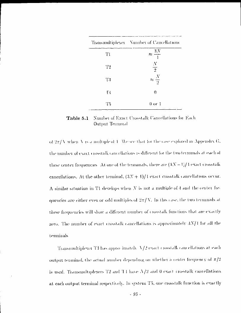
TI
'1'2
"111111)('1 ur ( '.111( (,11.1 t 10llS
.\' :::::;-
,)
o
001'
Table 5.1 ;\lIll1b{'1 or EXit( t ('lo~"t(t1k ('.IIl((·lIatioIlS rOI Lldl 0111 put 'l'('IIllIll,t1
ul ~;;,I\ ",111'11 \ 1'" d 1111!lllpl('l)1 1 \\(''''('('llldl lui III!' (d'o(' ('\1'101('" 111 ·\pl)(,lIdl\ (;,
tl\(' 1I111ll1H'1 ull'\cld lltN,talk (clll\ l'11,l! iUII" 1 .... ddlc'l\'lIt lui t III' 1 \\'u 1('1 Il Il Il ct! " cil l'clC!t 01
t!tC:'(, lellicl fr('tjUCIICle:, :\1 l!lll' 01 t II<' tI'IIHlllclh, t 111'1'(' ,\1(, (:~.\' - 1:11 (',\,1( t (rl):-.:-.talk
cancclla t ion", :\ t the other l<'rlIIi lia 1. (:L\' + 1) / 1 {'X,I( 1 CI o~:-.t alk ( cII\CI'II.1I101\:-' on Il r,
A similar :-'Itllatioll in Tl d('\'('lop" ",lwll ,V i:-. Ilot cl Illllitiplc' 01'·1.111<1 tll<' «'llt<'1 fl<'·
quel\cics cHe l'ither e\'l'II or oeld Illllitipl(,~ 1I1 ~:7/\'. III thl" (c1"(', III(' Iwo 1I-11lIIII,lb ,d
zero, 'l'II<' 11111111)('1 of ('\art (1'l)..,~t(t1k 1 dlll'l'Ilcll i()l1~ h c1ppl'u,illlilll·lr ,LVII loI' .dl Ill1'
lprmillab
OIlt.pUt tl'llllillet!, tilt' elClllet! 111111")('1 d('()('lldlllg (JII \\'111'1111'1 ,1 (('1111'1 hl'qll(')11 r ul roi'.!.
is lI~ed, Tlclll:-'lllllltlpkx('I':-' '1'2 clllt! ï 1 IlcI\c' .\1'1. tllld 0 ("d(1 (1U!'>"téllk CillJ(('II;t!,ioll:'
at cach outpllt terlllillélll'espcdi\('I), III ..,y:,tc'III T!). 011(' CI o:-.:-.talk fllllctieJII i:-. ('xactly
- .'J:j -
.. "
Z('I'CJ fol' ('it( h Ollt.pllt t('l'IIlilléll whell .'\' is Ilot a l11ull iple of '1. \Vhcn JV is a multiple
of ,l, /10/1(' of t Ill' (I(),,~t,dk fll/lctioll:' 1'" (',aetl,\' z('ro ill 'J'5.
Of IIIt' Il dll:'llllllt Ipl('\('I:'. Tf dl IIII'V('''' III<' lllos1 lllllllh('1' of exact. crosstalk can-
«'/I,dIOIl:' (alJulIl :J/'I 01 11)(' loled 1l1lllllH'1' of cl'Osslalk funct.ions). In systems T2 and
T.J, ri !JOli 1 half of 1 he cl'osstalk fUllctio/l'i éll'C exact Iy zero. ThC' tahle shows that fOi
1'('élsoll,lIlly Irll g(' N, t he QA~I "c1tc'II\(':' (TL T2 and T:l) aclric\'e man)' more exact
( IlJ:-'~ 1 ct! k (." 1 ('( ,1/ ,II i 0 Il:-' tir d Il 1 Ir f' il VS B ( 0 Il Ill<' 1 P Cl ri., ( T, 1 élll d T.J).
5.2 Errol' Function Formulation
Th 1:, :'('( 11011 cl 1..,1 Il:-':''(':' t 1)(' d(':,igll Ill' ,Ill FI H lo"'pas'i prot oty pc that is bélsed on
1111' III11lilllIZ<l11lJ1l 01 <III ('IIUI fllll( 1 i011. \\'(' IOlhidC'1' IJOI h the pl'élrti( al d('gradations of
11111'1"'\ 11I1,ul IIlt('tI('II'II( (' dlld (Iu:-.~I,dk 111 tl)(' dl':-'Igll of tlll? plo1.o1.yP(·. The lIlinimax
Iilu'l d(·:-.igll appl'oaclw:-. of ('lrap1<'1' 1 (ln' llilscd (Jn the input-output tl'élnsf!~1' functions
).!;I\'(·n III ('/taptel' :J (COIllI11011 fol' ail terlllillals). A150, the cl'O'istalk is not explicitly
(O/l:-.id(·1 (·d.
\V(' (':-.laIJ/r"h ,III ('1'1'01' fll/l<1ioll t!titl take:, the \'êlliOIlS di:-.tortions int.o élccount.
~IIIlIllIlilllg 11)(' ('II'UI !tlnl 11011 "IJOlIld gi\'(' a lo\\'pa:-." plototypC' wit.h iL good fltopband
j,(.!t,1\ 10111 dlltl ill addltioll, should bit! 10 lo\\' intL'l'~ylllbol intC'l'f('I'('llc(, and C1'05Stédk
di:-.lorl iOlls. :\s fo)' lh(' lIIillimax dC'sign, the -.lophalld cdg(' fl'('ql\('IlCY is w.~ = (1 +
'1) ..... ·111111 \\'IIl'I(' ..... ·111111 i~ t 1)(' Illillillllllll halldwidth of the ]owpa:,s plOtotype and 0 ::; f3 ~
\\1' l'l·\'.dlilleli ",,'111111 = 7ï/.\' lUI 1'1 1 ~ dllli T.~ alld ..... ·111111 = r./2"\, roI' Tl and T.5 .
.\bu. tlll' Pdldllll'l('l .i (1I11Illdlll(·d III ('hapl('1 1) i:, 11)(' IOII-offr,lctol' that controls the
- f}(i -
bandwidth 111 <'xc('ss of ""'111111' 1'\01<' th"l 1111' 1>,I:--.,I>,llId (h,II(\cl('J'I:--tic i~ 1I0! ("plin! Iy
:\ lincal phase prototype' h(l/) i~ de':--ignl'cl 1'01 "y~t('III:-- Tl, T:.!, 'l'.) ,\1111 T!i Fol'
lIot.a.tional COll \'CII iCIH'(', \VI' c1"~1I1lj(' 1 III ()1I~llollt t li ,II li( Il) i:-- ill /.('IO-pItM.(· rO l' Il 1 ,uul
ha~ '1.1.+ Il .. p .... fl'JllllI = -1. tu L 1\ 1I01lIill",\1 pit".,,, 11(11) \\illr J.+ 11.11>" l'toi Il 1/ = 0
a wcig,hted tiucal' (,olllbinalÎo\l of \',UiOll" r.1(·I()I~, {'(H'" of wlti( h i:-- di:-,( II~:--('d Iwlo\\'.
Stopband
'l'hl' fa('(ol ill tht' ('JIUI !l1I11 IluII 1('PI(''''('lIlll1~ Ill!' .,topb,lIld CII"I .. ('\P11~tÎ( i~ dc-
( !i. 1 )
Illlmbcr of laps (dc~igll('d fol' 1 Il(' Dl\(' pl'Ototyp<' sy:--I<'lll"). t 1lC' fi ('(l'H'II( Y IC':--pOIl:-,e (',III
be cxprcsscd 'lS
L fi (t J .... ) =.- L Ii( Il ) ('0., ...... /1
11=0
",/telL' b(U) = 11(0) cllid /1(1/) = :!.//(I/) 11I1 Il -f (J. l'lit' ql1<llltlty ~ (,lIl \)(' (·xpl<':-,:--(·d
as bl'Pb \\'h('I(' b = [11(0) fI(l) li( /. )(1' alld P i~ il po.,lll\·(· ddillil(' :--yllllllt'Il i(
- 97 -
, ( 1111111 i x wllO:'(' f!T1 tri!':, ,11'C> gi V('II by
1 1;'1" 1 J( / , .... ) =: . (0., /'"",,' 1 0':> ........ N/v.) Il ..... c
(0.3)
fol' (J ::; l', .... :s; L
Sill«> (,'(.:) = 1/(::-1) III sy"tclll T:~, Ih!' slopballd ('I)('rgies of both filters are
Il](' :,aJJ!{' Fol' cl /lolllincéll pha:,C' 1/(::), vr::::h céln agclill be exp l'CSS cd ill quadratic
T f0111l h'J'Rh \\'111'1(' h = ["(0) 11(1) ... h( L)] éllld Ris il positivc definite symmetric
III,dll\ \\ 11U~(' ('Ill rI('., dit' gl "('11 li"
(.1. 1 )
fol' (J :s l', .... :s 1..
IlItersymbol Interfel'ence Distortion
:\1 ulll plll 1('11I11I1al/. 1 hl' IJl('dll-";<ilJal(' illll'I'sylllboi illl,C'J'f('J'erJcl' clistOltioll is givcll
Il.\' :\~:! LI/il) 'r,(II) \\'I]('J'(' 'II( Il) Î:- t 1](, IIJ\('I ~(' .:-1 J'rllI~form of the' illpllt-Ol'tput trallsfcr
l'lIl1cl iO/l '/itf::) 'l'Il!' IIWé\ 1I-~qllaJ'(' III 1 el ~yll1hol intC'rfC'rcncc distortioll dqwTlds 011
,,11I(h uillplll Il'lllIill,t! i~ cOlhirl('I(·d 1100\'("'C'I,gi\'cn the discu:-,sioll in Spction ,5.1.1,
1111' lldll'ol('1 Illll( 110111 ... 1111' "dll\{, lOI IllcllI\ IlIplll-Olllplll t('J'mi/lé\1 pail!-> when practical
filtl'!'''' ,lIl' ll'ol,d l'IIC'l'f,rUI'<'. l1H' 111<'dll-<;<!ilill(' ill\(ol'~ylnbol illt('rfercnce distortion will
IJ(' Iht' Sc\II\I' al Illall,\' olllput IC'!'lIl1l1cds.
('()II~id('1 :-y ... l(·Ill~ T2. Tl dllrl '!'."). :h 1ll!'111 iOIlC'd in Section 5.1.1, tU(n) is the sarnc
for ('\,('1'.' 1('1 1111 Il il 1 1 ("'C'II witII j>lilctic,t! filte·l's. I!e'nce, it is sufficirllt to determinc
1 ht' 11l('a II-~q 11<1 ('(' i li 1 t'l's.\'llIIJol 1111 ('1 rI '1( '11('(' d htOl1 ion atoll Iy olle tf'l'll1i na!. Moreovcr,
- .98 -
-
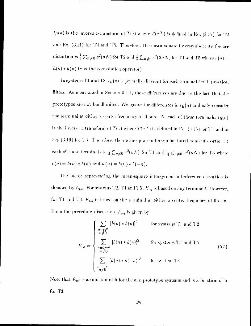
tll(n) is the ill\'crse ;;-trall:-.lol'lI1 of T(::) \\ 111'11' 'J'(:;.\') is dl'Iill(·d in Eq. (:I.1 ï) 1'01 T:!
and EC(. (:3.:21) for T·j and 'l'fi. T1IcldoJ'(·. 1 he> 1II(·.\lI-::-qUil),(· illl('n"Ylllholll\l('rf('I'('IIc('
di!'>tortion is! LntfO v'2(nN) fol' '1'2 and i LI/t() 1''2(1/1.'\') fol' rl\j cllld 'l'fi whl,\"(' 1'(11) =
h(n) * h(l1) (* is the cOII\'ollltioll 0»(')',1101)
ln systems Tl allc! '1':3, lll(lI) i., 3('11('1 ,dlJ di!!('1 ('III fOI ('<I('h \cl III 1 1Ié1 1 1 wil h pro\( t.ic,t!
filtcrs. As mcntioHcd in ScdiOl: 5.1.1, Ihcsl' difrc'IC'IlCC'S arc' d'lC' 10 t!1C' filet Ihilt. llH'
prototypes arc not bandlimitcd. \Vc ignolc t II(' difrc'rellccs ill (,,(II) alld ollly c ollsicll'I'
t}le terminal éll eit.lter a ('cn1er f)'C'qucllcy or 001' ïr. At Pélch or tl\('s(' tc>l'Inillab, ,,,(1/)
is the' ill\'C'I:"c' ::-11011:..1'01111 nI' T(:) \\"1)('1(' T( :,\,) i., d('fill(,c! in Eq (:11;») loI' TI .Incl in
Eq. (:3.1V) 101' T:J TIt('Id'ull'. tll<' Ill<'dll-:-.qll<-lI(' inlt't"'>YIIlIJOI illtC'I('(')('Il«' di:-.\'ol'tlOn dt
v ( 1/) = 11\ 1/) * Il ( 11) a Il d (1' ( 11) = Il ( 11 ) -+: 11 ( -Il ).
Tht:' factor rcprcsciltillg tll<' Ilwan-:-.quél),(, intcrsymbol inü'rfen'I1C<' distOltion is
Jcnotcd by 1~lsl' For systell1:" '1'2. '1',1 and '1'5. I~'I>'I is bascd 011 ally tel'millalt. 110\\,('\'('1',
for Tl and '1'3, EI~' is basec! 011 tlte' t('l'Il1illill cl! ('itlJ('1 éI ('('llt(>1 fJ'('qlf('JJ('Y of 001 71'.
From th(' prccC'ding discu<;sioll. 1~1"1 i:-. gi\'('11 by
L [11(11) * h(II)]'2 for systellls TI ami '1'2 lI=cN IIto
fOI ... y:-.tems T/j éllld Tf) (!).!)) 1~1~1
L [h(lI) * h(lI)f 1I='2C/V I/tu
L [11(11) ~ h(-I/)f 1/=(' \'
"tu
Note that Eu;i is a fUllctioll of b for the olle plOtotype systems ami Îs a fUllctioll of h
for T3.
- 99 -
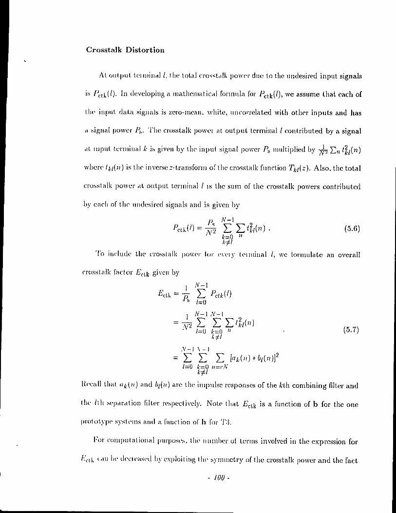
Crosstalk Distortion
A 1, ou t pli t tCIlllincd l, the toI, a 1 cro,",,,tctlk pO\\,('1' due to the undesired input signaIs
is Pcr.dl). In devcloping a mathelllaticcll formula for Pctd/), we assume that cach of
1,11(' input data signais is zerO-lllean, white, uncol'l'elated with other inputs and has
,1 ~igllal power p..,. The crosstalk pO\\'CI al, output terminal 1 contributed by a signal
cil, IllpUt. tel'Illillall.' i:, giwn by the input signal power I~" l1Iultiplied by ~ 2::/1 t~/(n)
whcl'<' 1 k/(lI) is the inverse ;-tl'élnsforll1 of the crosstalk function Tkf(Z). AIso, the total
cro~stalk power clt output terminal 1 18 the sum of the crosstalk powers contributed
by cach of t1)(' IIndesil'ed signaIs and is given by
}) (/) _ Pc;, ct" - JV'2 (.5.6)
'1'0 illdude the Cl'osstalk power loI' ('\'('1)' 1 (,llllillal l, we iOl'l11ulate an overall
crosstalk factor Ectk gi"en by
N-I\-I
L L L [adll).j: b/(I1)]2 /=0 ~'=o Il = ('J'v'
kil
(5.7)
({('call that (//,:(1/) and b,(II) are the implllse rcsponses of the kth combining filter and
t he li h ::'('pcl\'cI t ion filte\' \'e:,pect ively. Note> t.hat Ectk is il function of b for the one
1>1'0101,,\'1'(' sysh'll1s and a fUllet ion of h for T:L
Fol' COlllplltatiollalIHll·pOS(·::'. th(' Illlllllw)' of tenllS involved in the expression for
I:'l't h. l cl Il bl' deC! (·as(·d Il)' ('xploi t illg t Il(' !>yll1l1lctry of the crosstalk power and the rad
- 100-
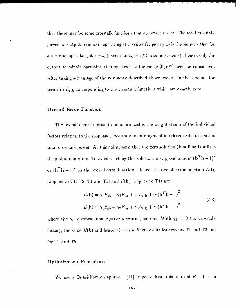
that there may hc some crosstalk fUlIctiOJ1S that c\l'l' exact Iy z('('o, Tl\(' tot.al C1'osstalk
power for output t.erminall o)('\'ating at cl ('('nlC'\' fl'c i\IO!lcy W[ is t Il<' l-Iall1(' ml 1 hal, 1'01
a terminal o)>I'l'atlllg at 7i -..;.,'[ (e:-;:('('p\.IOI u.-'[ = if /2 in SOl1lt' s\'skms), lIel1(,(" (111)' the
output terminaIs opcrc\.ting at frequcllCÎPS i1l the rallg(' [0, Tt /,2] nCl'lI 1)(' l'l>tlsid(,lt,(\.
Aftel' ta king Mlvétlltage of the symnK'try descrihed abov(', wc Cé\1l furtlH'l (,:-;:('II\(\<· t.he
tcrms in Ectk corresponding to th(' crosstalk fllnctiolls which are cxc\ct.\y ~(,I'O,
Overall Error Function
The ovel'all errol' fUllctioll to hc Illillllllizcd is t.he weig,ltt<'d SUIl! of !.I1<' individll,lI
factors relating to the stopband, mean-squaJ'e intt'l's)'ll1bol ill\'('J'fc'J'C'J)('C' disl ortioll fllld
total crosstalk poweJ', At titis point, note tltat the zero solut.ioll (h == 0 OJ' h == 0) is
the global minimulll, To <l\'oirl J'caching 1 hi.., ,",olut.ioll, \\'P appC'lld il t.C'1'l1l (b'J'b - l)~
or (h1'h - 1/ to tlw o\'cl'c\1I ('1'\'01 fllll( tioll. H('IIC1'. tll!' ()\'('I,dl (1'/'01' flllJ('t.Îo!l e(b)
(applies to Tl, T2, '1'·1 alld 'l'ô) éllld f(h) (dppli('~ 10 T:n élJ'('
E(b) = IIEsb + Î2RI~1 + Î:3 Ectk + Il,(bTb - 1)2 (!i.H)
whcl'c the Î'/ l'eprCM'lIt llollllegati\'e \\'('iglttillg factols, \VitlJ Î:~ = () (110 nosst.alk
factor), the same .t,'(b) and hCllce. tllP sallw 1111,('1' J'('sults for systellll-l '/') dlld T~ illld
for rl\l and '1',5.
Optimization Proced ure
We lise a QUél:;.i-Nc'wloll <lppl'Oillii [II] to pp1 él lo('al 111111111111111 of g Il 1:-' élll
-101-

( Iteralive IlJethoc! spc(ifi('d by the t\\'o equatiolls\
(5.9) dk+1 = clk + ).,ksk
whel'e k is the iteration index, Hk is the IIessian matrix, Sk is the direction of descent,
\lE is the gradient. of I~' and ).,1.' is a scaling factor which specifies the extent to which
1II0V('lIlent. cdong the directioll of desccllt oC( IIrs t.o get ail update. Note that cl is the
vectol' of vanables to b(· optimized and is updated in cach itel'ation. Then, cl = b
fol' t.he olle plOtotypc syfltcllIS and cl = h fol' 1'3. \\Te express the gradient \lE in
c10sed [onn and f'valuatc it al dl.: ill each iteration. Although the IIessian matrix can
be cxpl'es~('d in c10sed fol'l Il , W(' II~e th(' BloydclI-Flctcher-Goldfal'b-Shanno (nFGS)
update [·11] in each it('ratioll. III Il)(' cl( lual illlplclllclltation, we use a rout.ine From
the IMSL libl'ary [42] to pel'fol'lll tl)(' lIlillilllizatÎoll. An initial condition is supplied
as ail illput.. Also, subroutiucs ta calcula te the crror function and its gradient arc
supplicd by the usel.
5.3 Design Examples
\-\/11<'11 1)('lfolllllllg éllI 1IIH:onsLl'éllll('d Illillilllization of t.he enor function, we use
tlw opt.imizatioll pl'Oc('dur(' described above. The computations \Vere performed using
dOllbl(' pJ'('cisioll f!oatiug point. élrit.hmctic. Note that the initial conditions affect the
fillélilocallllinillllllli Fol' t \)(' Oll<' prototypc' systems, the initial condition wc use corre-
spollds to éHI ('<[uil'ipplf' III1('élI' phase fdu'l (\\'ith ullity gaill al zcro frequcncy) having a
fl'l'quelle." J'('SpOIlS(> t hat IS a minima, approximation of the square root of a raised co-
sill(' spect l'li III. For t l'élllsl1Iultiplexel' T:3, the initial condition we use corresponds ta an
- 102 -
, j j
j , l
!
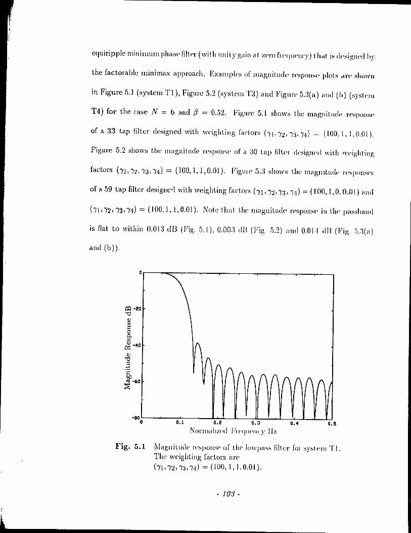
cquiripple mini mum phase fi ItC'r (\Vi th li Il i t Y gel ill a t Z('!'O fl<'<llll'Ilcy) t hel! is dt 'sigllt'd il,\'
the factorable minimax approach. EXéllllpks of magllitllde rc'SI)()tI~t' plots .U·(' showll
in Figure 5.1 (system Tl), Figure 5.2 (systelll 'Cl) and Figl\l'C' 5.:3( a) a Ild (h) (syst t'Ill
T4) for the case N = b and fi = 0 .. 52. Figure 5.1 shows the magnit IIdl' n'spolls\'
of a 33 tap filter designcd \Vith w('ight.illg fac\.ors ht''')'~'Î:I''')''I) = (IOO,I, 1,0.(1).
Figurc 5.2 tiho\\'s the magllit ude respolI<.;(' of il :30 \.ap filtcl dt'siglH'd \\'ith \\'('ighl illg
factors (-~fl,")';!)'3,,1) = (100,1,1,0.01). FiglllC' 5.:3 shows the lIlagllltlldt, n'~pOIlS('S
of a 59 tap filter designcrl \Vith \Vcighting factors hl,,:2, ,:1, Î,t} = (100, 1,0, 0.(1) il 11<1
hl,,2,/,3,,1) = (100,1,1,0.01). Note Ihat t.he lIlagnit.llde rf'spOIlS(' ill tilt' passhalld
is fiat to withill 0.01:3 dB (Fig. 5.1), 0.00:3 dB (Fig 5.2) and 0.01·1 dB (Fig G.:l(a)
and (b)).
o:l -20 'ï;j
Il) Vl
= o 0.. Vl
~ -40
Il) 'ï;j
;:::l .., = co (';j -60 ~
-BOL---~--~--~ __ ~~~~ ___ ~~~~~~_~~~ o 0.1 0.2 0.3 0.4 0.:5
NOI'1I1e!lIZ(·d FI l'qll('I1( Y IIz
Fig. 5.1 l'vlagllitllde !'('~pons(' of thc' 1()\Vpa..,~ filtcl' fOI Sy~t('lll Tl. The weightillg factors an' ht,/'2";J".t} = (100, 1, 1.0.01).
-10:1-
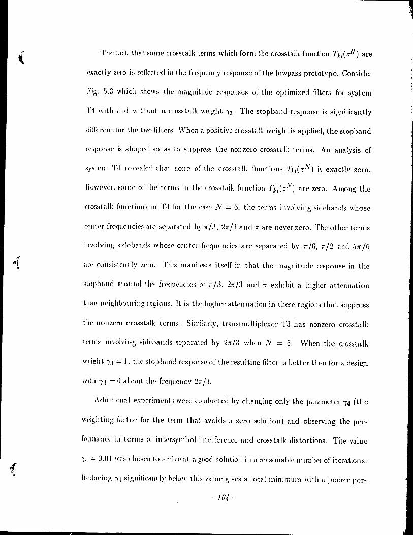
( The faet that somc crosstalk Lerms which form the crosstalk function Tk,(zN) are
exact.!y ;"CIO i~ l'efkrt(·d ill the frequ('llty respol1se of the lowpass prototype. Consider
Fig. 5.:3 whicJ. shows the magnitude r(,spoll~CS of the optimized filters for system
T~ wIl.h éllld withollt a rl'Osstalk weight )3. The stopband response is significant.ly
differelit fol' the two filtcrs. When a positive crosstalk wcight is applied, the stopband
J'('~po/lse is shaped so as to supprcss the nonzero crosstalk terms. An analysis of
~.Y~tCIll Ti IPv('akd that none of Lhe crosstalk fllnctions TI.-/( zN) i~ exactly zero.
lIowever, SOIlI<' of the' tC'I'IllS ill tll<' cl'Osstalk fundion 71..,(;:N) are zero. Arnollg the
cl'Osstalk fllllctiolls in Til 1'01 the' case' N = 6, the tC'rms involving sidebands whose
('('nt('r f/'('quC'Ilcies ale separated by 'Ir ;:3, 2 'Ir /3 and 'Ir are Bever zero. The other ter ms
involving sidpbands whose' center fl'eqlwncies are separated by rr/6, rr/2 and .511"/6
éll'(' cOllsist.elltly zero. This manifc~ts itsc>lf in that the mctbnitudc l'esponse in the
st.opballd éllOlllld t.he frc'qucllcÏes of 'lrj:3, '2'1rj:3 and 'Ir exhibit a highcr attenuation
thall neighbollring rcgiolls. It is the higher attenllation in thesc regions that suppress
thC' 110117,('1'0 crosstalk terms. Similarly, trausl11ultiplexer T3 has non7,e1'O cros5talk
tPJ'Il1S illvolvillg sidcba/lds scparatcd by 2 'Ir /3 when N = 6. \Vhen the crosstalk
\\'t.'ight 1:1 = 1. the stopband l'('spons(' of t1le l'eslilting filte/' is better th an for a design
wit.h 1:1 = () about tl)(' frcqllency '2'1r/:3.
AdditiolJal (,x!)(,J'iments were conducted by changing only the parameter 14 (the
w('ighting factor fol' the t(ll'm that avoids a zero solution) and observing the per-
fOI'lllaIlc(' ill tcnns of intersymhol iliterfcrelJce and crosstalk distortions. The value
1 1·1 = 0.01 \\'a~ chos(,11 to dl'l i,'(' at a good solution in a l'casonablc 1111mlwrof iteratiol1s.
.. Hl'dllcillg 1.1 siglJiliccllIt Iy lwlow this vaille gives a local minimum \Vith a pool'er pcr-
- 104 -
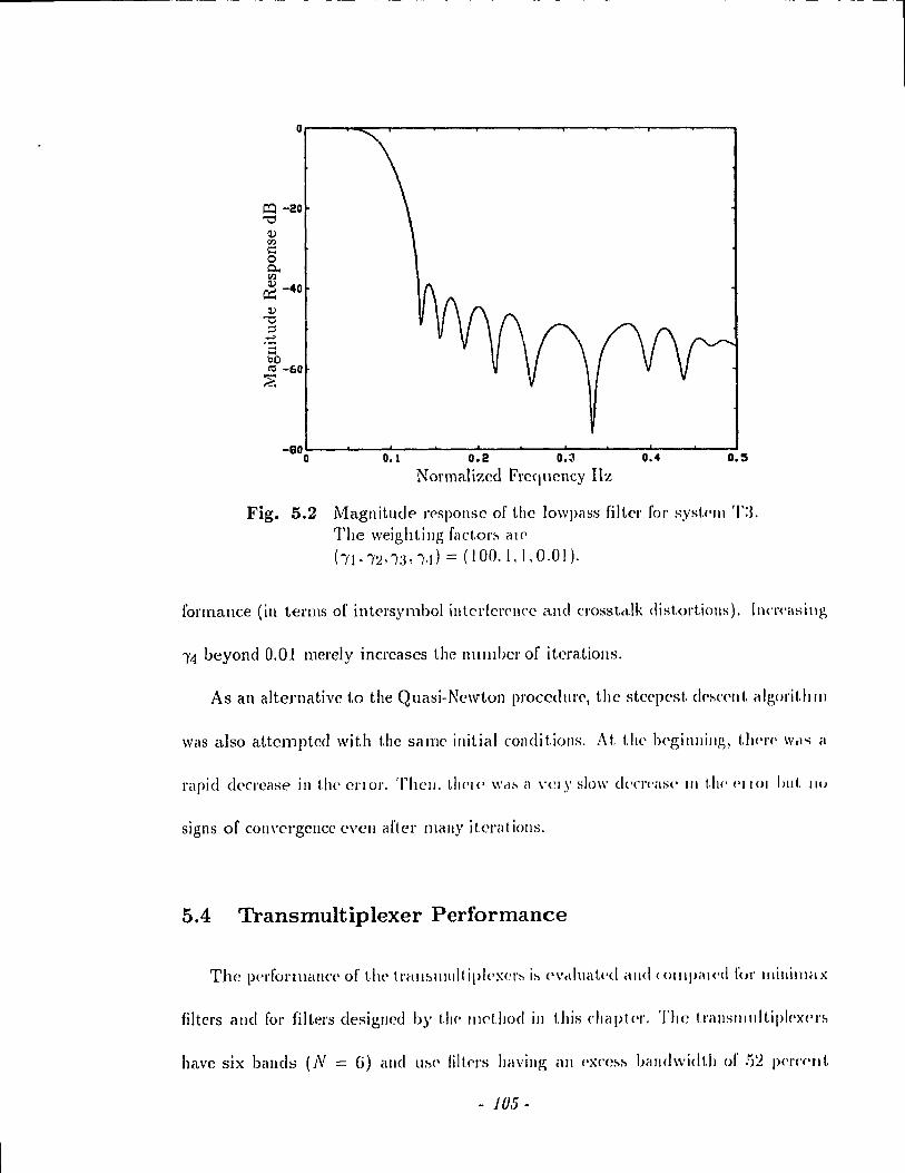
----------- --- -- ------- ---------------,
-ao~--~--~----~--~----~--~----~--~--~~~ o 0.1 0.2 O.~, 0.4 O.S
Normaliz(~d Frequcncy Hz
Fig. 5.2 Magnitude l'f'SpOIlSC of the )OWpélSS fiJter for syst.<'JIl T:L The weightillg fact,or~ aI('
hl":2,1:3".1l = (100,1,1,0.01).
formallce (in terllls of intcl'symbol illlcrtcl'('IH'C and Cl'osstd.lk distortiolls). In('l'('asillg
14 beyond 0.01 merely inCl'cases the numher of iterations.
As an alternative ta the Quasi-Newton procedurc, the stcc(>cst. d('~('('IIt. algorit.h III
\Vas also attcmpted with the sal1le initial condit.ions. At. the lH'gillllillg, t.li<'\,(' W.t'-; il
rapid d('cl'case in the cnol'. Theil. th('I(' \\'d~ il \'Clj' slow d('(T('é1S(' III t.h(· ('1101 Illil. 110
signs of convergence evell artel' mail)' i tera t iOlls.
5.4 Transmultiplexer Performance
The perfOl'lllèllj('(' of tltt' trall~lI11dtipl('xel':-' i:-, ('Vetillat('d alld (Olllpal(·d for IIlillÎlllax
filters and for filters clesigncd by t11C' lIlelllod in this chapt(·!'. The trillISlIll\ltipl('x('I'~
havc six bands (N == G) ami li!'>!' filtf'rs having an ('x('e~~ béllldwidth of !)~ p(·rcC'Jl!.
- 105 -
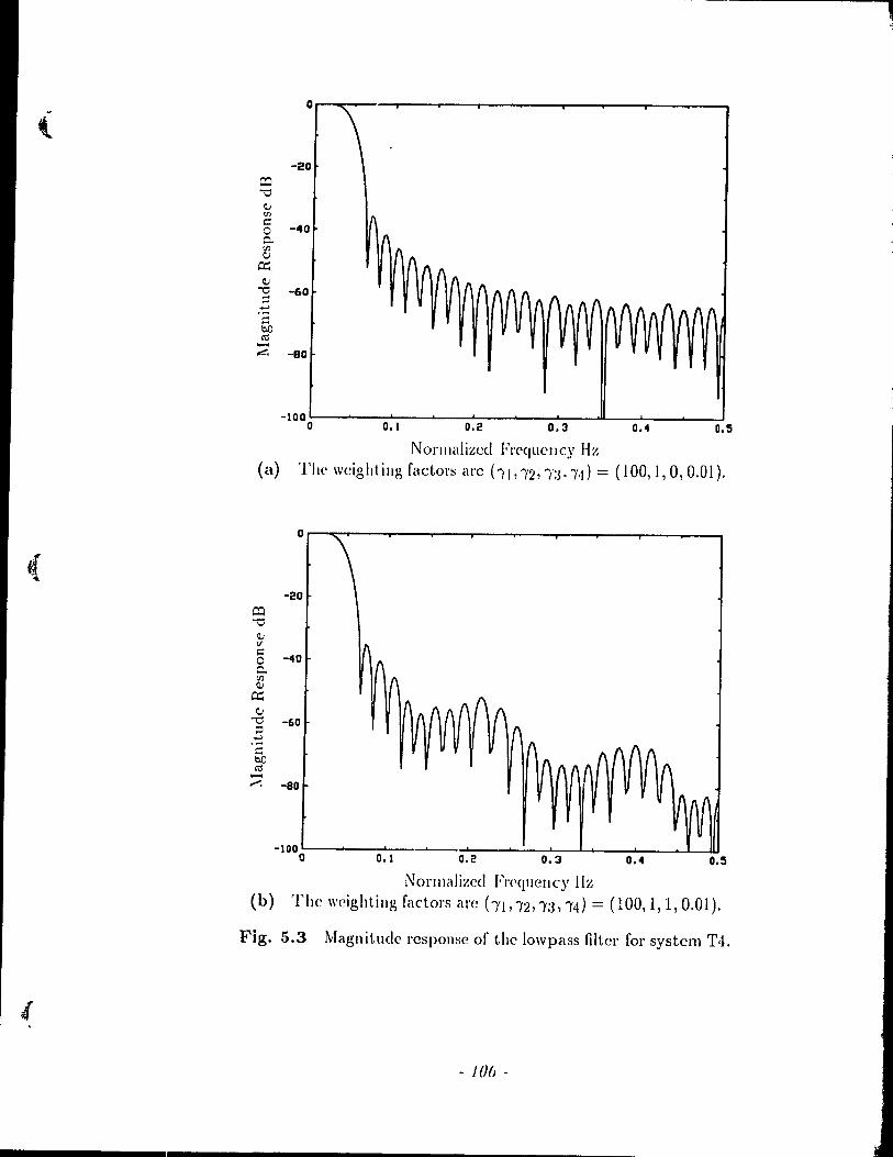
0
'--20
CO "'0 il,; 'Il :::
-40 0 0-(fJ C,i
cr: il,;
"'0 -60 --..., .... bo O'j -~ -BO
-100~--~--~--~--~~------~~~L-~~ __ ~ __ ~ o 0.1 0.2 0.3 0.4 0.5
Norlllalizccl FrequclIcy Hz (a) The weighting factors arc hl"2,')';j."j) = (100,1,0,0.01).
0
( -20
CO "'0
il,; <f :::
-40 0 0-(fJ il,;
cr: C,i
"'0 -60 ;:l ..., ::: bO O'j .....
.<'. -80
-100~------~~~~-~~--~--~~~~ __ ~ __ ~~~ o 0.1 0.2 0.3 0.4 O.S
Norlllalized FI'<'C!uency Hz (b) The weightillg factors arc ("YI, /2, la, 1'4) = (100, l, 1, 0.01).
Fig. 5.3 Magnitude rcspollse of the lowpass filtcr for system T,1.
, - JOu -
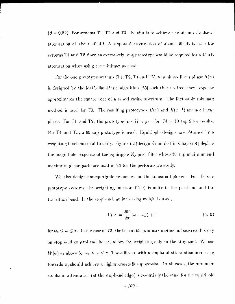
(/3 = 0.52). For sysl<'I11s TI, T2 and TL the ailll is to (\chi('\'(' a JI1illillllllll stopl>,llld
aitcnuation of about ,10 dB. A ~tophalld ,1It('lIlldtioll or ,tlJOlll :ir) dB i:-- u~l'd for
systems T4 and '1'5 sillce an cxccssi\'ely long prot otyp<' would \)(' \'e<)uÎr(,d for il \0 d Il
attcnuation whcn llsillg the minimax !l1<,f hod.
For t Il<' one pl olot ypc Syhte'IllS ('1' l, T2, T l ,lIId 'l'Pi), a 111111 i 1 Il il '( li 1\(',1 l' Il hase /1 ~ :: )
approximâtes the square 100t of él l'i1is('d cosillc S]Wdnllll. l'Il<' faci,ol'al>lc IllÎllilllax
rncthod is llsed for 1'3. The rcsllilillg plototypc's 1/(::) cllHI 1/(::-1) il 1'<' Ilot lilll'ill'
phase. Fol' TI and '1'2\ the prototype ha!" 7ï telp" For T.J, a :W t"p filtcl Il' .. 11 1 \<...
\wighting functioll equal ta ullit y. Figurl' 1.2 (dC'higll Exalllpll' 1 ill ('11'1]>11'1' ,1) dl'I'iet ~
the magnitude rc~pon:-,c of the cquiripple Nyqllist filll'I' \\'110:-'(' :W t il]> Illinillllllll HUtl
maximum phase parts arc l1sec! in T:-J for the performancc stlldy.
\Ve also design nOllcfluiripplc rC'hpOIlSel> (or the' \.1',llISlIIlIlt Îp!('XPI s. FOI t hl' 011('
plOtOtypC systems, thp weightillg fUllctlOIl Il'( ...... ) i" ullity ill tlll' P;I~~I)dlld .tl1d t.1l('
transition bcllHI. III t 11(' .. topband. cil 1 in\! ('<l .. illg \\'('ight i .. u:-,(,<I.
. :200 n ( ..... ) = 1-( .... : - ..... ~) + 1 _'Ir
(!j.IO)
forws:S w:S 'Ir. In the case ofT:3, 1!t('félrtorahl('lIlillill1a-x Illl'l!tod i~ !J,\:·wt! (,xc!llsiwly
011 stopbêllld colltrol élllt! 1i('ll<e. allo\\'~ fOI \\'('ighl illg olll~' III Ill<' ..,tuph'IIHI. \VI' IlSI'
lV(w) as abo\'e fol' w.~ :::; "'" :::; 'Ir. TII('~(' fillc'l's, ",it Il a ~topb(\IId at.l<'lIl\at.ioll ill(,I'<',I:,illj1;
towards 7l', should achieve a higlter Cl'ohslalk hll]>]>l'(·:-,sioll. III ail cas('s, (1)(' lIlillillltllll
stopband attcnuatioIl (at the :,topband edg<') is C':-,:-,c·lIt.ially the SlIlIJ(' fOI 1.1)(' cqlliripplc·
- 1 ()'l -
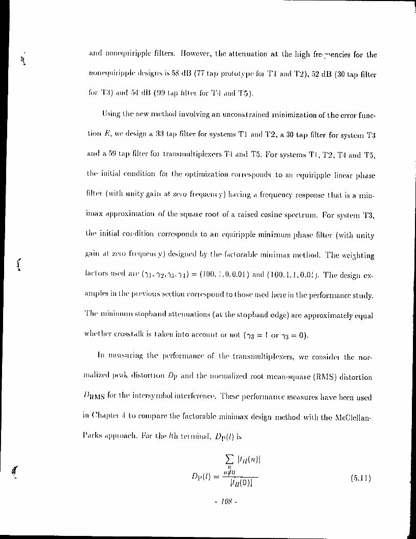
and lIol)('qlliripplc filtcrs. I1owc\'('I', the attenuation at the high fl'e r :' 1encies for the
Il{)/H'<jllilipph- ck:-.igm i:-.!)~ dB (ÎÏ ta!> prototype' fOI Tl and '1'2),.12 dB (30 tap filtel'
fol' Tl) <llld :,,) dB um Ici» frltc'I fol' '1'-1 dnel T5).
()sillg thc' Ilf'W method involving an ul1con!'>tl'aincd minimization of the el'l'Ol' func-
tiO!l R, wc' dC':-.ign a :3~1 tap filtc'I' fol' systems Tl ilnd 1'2, a 30 tap filtel' fol' system T:3
alld il !)!) t.a!> filler fOI trallslllult i»lex('r~ T~ cll1d 1'5. For sy~tems TI, 1'2, 1',1 and T5,
t/)(' initial (,olldition l'al Ihe optiJ/lizatioll c:O/r('~p()f)d.., 1,0 ail <'quiripple linear phase
fillc'I (with \Il1it.y gaill al zeta 1'1< 'Cf li l'Il ( y) b,l\'illg cl fl'cqueney l'esponsc that is il min-
illlélX clpproximatioll of tbe squclle 1'00t of ét l'aised cosille specLl'ull1. For syslem '1'3,
t!\(' init.ial col,dit.ioll corresponds to an l'quiripple minimum phase filter (with unit y
p,aill <lI zelo flC'qllc'llcy) c!e:-.igllC'd 1))' Ilt(' frlctorablp minil1lclx lIH'thoe!. The wei.:?,htillg
lad Ol'S Il:-.('(\ al (' (Î J • Î:!, 1:j. Î 1) = (100. 1. (J. 0.01) élnd (100. l, 1. O.O! J. The design ex-
a III p1<>s in tll<' ))( ('\'iOll ~ ~ectioll COI'II':-.pond 10 1 hase u:,ed hel e in the perforlllance st udy.
'l'Il<' /Ilinilll\llll stopband att<'lIuations (aL the :;Iopband cdge) arc approximatcly cqual
",ll<'t 1)('1' Cl'os:,t,dk is t élk('n illlo élCCOllllt 01 Ilot (Î3 = 1 or /3 = 0).
III II1('a:-'llrillg the' 1H'l'fort Ilél Il cc' of t!l(' t l'anslIllllt ipl('xcl's, wc eOllsidf') t.he no\'-
llI,diz('d peak di:-.tol'llOn Dp and tll(' llormaliz('d \'001. rncélll-sqlléllC (RI\IS) di:;tortion
J>Bl\tS fol' titI' illt<'l'sylllbol illtl'l'f('I'C'IlC('. Thc~(' perfol'lI1éll!(e lIledSUres have been usee!
in Ch,Ip!.('1 .) ta cOlllpare the l'adorable minimélx design met.hod with the I\leClcllan-
P,ll'ks 'IpPloach. Fol' the' /th !(,llllillal, Dp(l) i:-.
L /111(11)/ 1/
Il:fO /Jp(l) = /1,,(0)/ (.1.11)
- 10S-
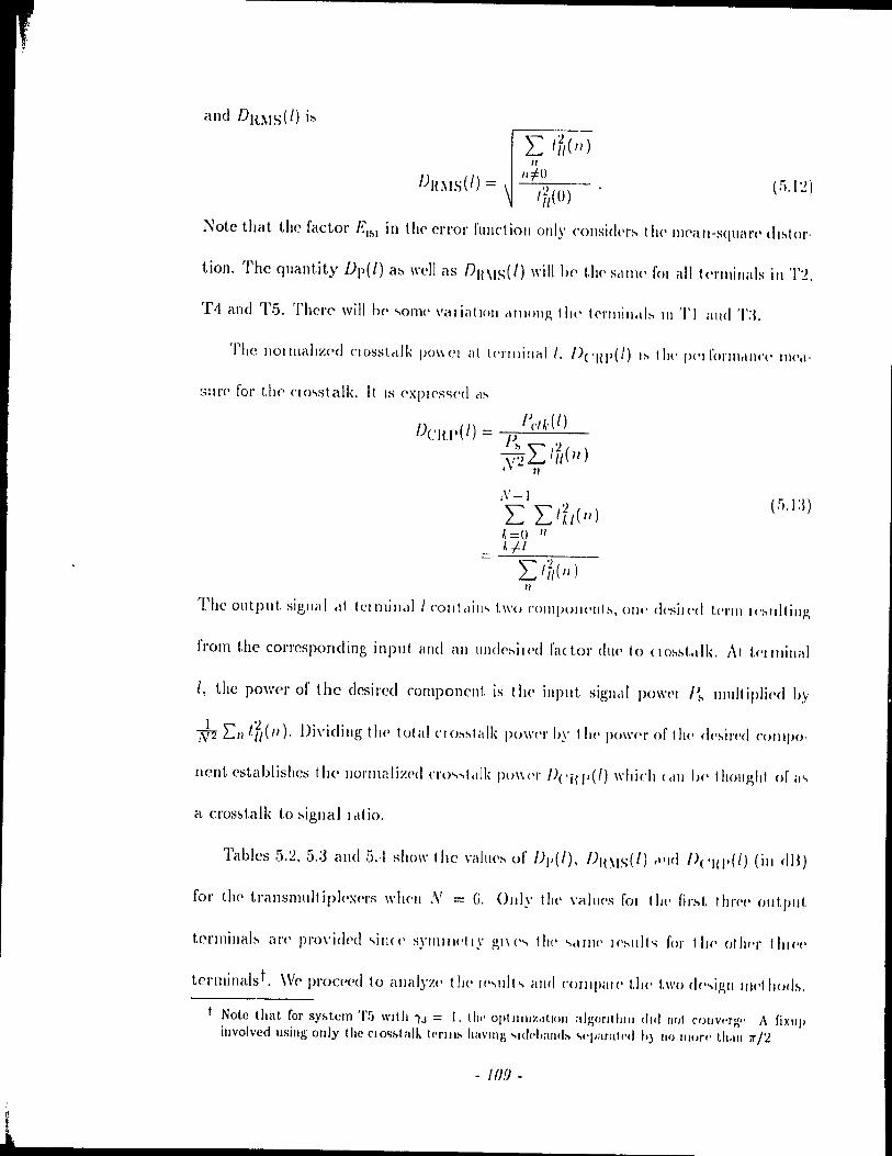
i
1
" "t60 (!j.I:!)
Note that the factor E'i>' in tl\(' elTor f\llldioll ollly (,ollsid('r~ 1 II<' 1II('éln-sqllélJ'(' (1I~lor.
tion. The quantity Dp(l) at> \\'ell as {)H\IS(l) will 1)(, t1l<' Sdlll(' fOi ail l<'I'lIIinélls in '1'2.
T4 and Tfi. The\'(~ will 1)(' ",onll' \'al ial 1011 ,l1IHllIP. t II<' t<'l'lIIill,"~ III '1' 1 and T:L
The lIollllallz('d C10sstctlk (>0\\<.'1 allc'l'Il1illéd 1. n('HI'(/) 1:-' tilt' f)('lfol'lIlt1I1(,(' 11I('cl-
3:11'(' for tlw ('Jo,>sl,alk. It IS ('XPI('S<;('c\ cl:-
1) , (1) - IJeU' (l) C H.P - 1)
i'> '" :l \':! L.. / II( 11 ) J 7/
" The Olltpllt. sigllaI clt tl'll11ill,t11 C'olltcli" .. two ('OIIlIH>I«'III:-, 01((' desilC'd 1.('1'111 1(.:-t1ltill)!,
t'rom the cOl'l'esponding input élnd élll 1I1](1(·~il('d l'a(tor dll(' 10 (Io:-:-.t,tlk. At tC'lllIill,d
1, the power of the desired compOIlcllt is 1 he' input siglltll PO\\'('I e ... IIIl1lt ipli('d by
~ Ln t[,(II). Dividillg Ih(· total no:-.:-tidk pO\\'('1' IJy t 1)(' fW\\'C'1' of Ihe dc':-.il'!'d ('()lllpO'
nent cstablishes the 1l01'lllalizC'd no ..... ttllk PO\\('I' f)('Ï{I'(l) whi('h CciII 1)(' tholl)!,"t of ,1",
a cros:;l,alk to :-.ignal l,If io.
Tables 5.~, 5.:3 and 5.-1 sho\\' the \,<lItH':-' of /)1'(1), /)H~IS(l) ,l'Id /)('111'(1) (ill dB)
for the translllult ipI('x<,l's \\'h('11 N = G. Ollly the \<Ihws fOI t III' fil':-.t Ilm'c' out.put.
tcr111illab arc' pro\'idC'd "ill«' S)'llIlIwtly gl\('.., tll<' ..... 1\1(· 1('!-lIlt" for tll!' 0111('1' flllc'('
ter11linaIst. W(, proCC'cd to élllillyz(' tll(' \(· .. IIIt ... alld (,Olllpal(' t.llC' t.wo dc· ... igll 1\wt horl:-..
Note that for sy),tcll1 '1'5 \Vllh ".1 = 1.1111' Opllllllz,ltloll afgorlllllll dlll flol (,ollvl'rg" A fixlI(l illvolvcd lISilig ollly Ihe ('1 0<;),1 al" krlll:- havlIlg "H!r·IJ1IlId:- '>"paral!'d h) 110 Ill/If/' th.11I rr/'l.
- 10.9 -

Intersymbol Interference Suppression
III S(·(tloll !j.I.I, wc' icl(·lItifi(·d two potplllial :-.ources of intersymbol intcrfPlcllcc.
'1'111':-'(' ill'(' (1) tlH' lilllitcltion of t,llf' d('sigll prou'clme in gi\ llIg filters such that the
N yq \1 ist (rit('1 1011 i:-. Ilot ('XiHtly sa t i"fled clnel (:2) the fad 1 ha t the prot.otypes are
not bélncllillIiu·d. The~e causes of intersYl1lbol intc'lfelC'llcc arc reflected in r; ables 5.2
and ,!j.a. III t.!1C' forthcoming analysis, we rdC'r to these sources of intersymbol inter-
f(,I'I'IIe<' as SOllrcc' (1) alld SOlller (2), :\l~o, oltr oh~<.'n·ations me cOllfilled 1.0 the nrst
t1I1C(' Icllllill,t!:-. of Il)(' Il'clll!-nlltllipl(''\('I'' 110\\'('\,<.'1" Il)(':-.(' ollsen'cl/ions will holcl for
!.II<' COIT('~polldi[]g la:-.t t 111'('1' tellllill,ll" due 10 "yllllllC't l'y.
First, cOllsid('1' the minilllax designs. SOUlce (1) is the only potential cause of
illt('rsYlllbol intC'lf('J'('lIn' in sy:-.tellls '1'2. TI and T5 and at termillal 0 of Tl and T:3.
'1'11<')'(' I~ 110 11I1('r~ylllb()1 inl('lf('I('I)«'ill 1('lllllllill 0 01''1':3 ~ill(,c the fclClolclhle millimélx
Il.C'I hoc! <l~~1I1('~ cl l'\Y<IIII:-.1 (lIdI'Cl( 1l'11~1 i(. FOl 1110 otllC'1 ca~e:,. cl llIinil1lax design
thal apploxilllat(·:, 11J(' :-.quélJ'(· 100t of a N,rqllisl chéll'acterislÎc leads to illtersymbol
illtc'l'f('J'('ncC'. Hegarding terminaIs 1 and 2 of transmultiplcxer Tl, both Source (1) and
SOllrc(' (2) Will 1 ihllll' 10 intc'rsYlllhol illterfercll('e. IIo\\'c\'er, th0 small variation in the
\'."I1(·~ uf /)1' <111(1 f)H~IS rul' TI ~ho\\'., t II<d SOI1I'({' (2) is Ilot :='C\'Cl'C'. At t('l'minals 1 and
:2 of T:L (111)' SOIll'(,(' (:2) cOIIllihut('s 10 illtl'l's.\'IIlI)ol illt('lfC'ICIl('. TIJ(' low l1ol'Tllalized
p<,ak ,lIlel Hl\IS dislOl tions for \('l'Illillals 1 alld :2 of T3 agclill :-.how that Source (2) is
1101 se\'('1 ('. III fclet, T:I ou t P('I fOI'I11s the otlH'r systel1ls illdica t.i IIg t ha t Source (1) is the
dOlllillclll1 call~(' of illt('I'~yll!h{)1 illt('rf('J'('llcc', Applyillg ail incrcasing frcquellcy wright
ill tht' ~luph,1I1l1 do('!- Ilot .tlr(·( t 1 Ill' IlUlllldlll'cd p('ak alld H\IS di!>tol tlOlI:' ~igllincalltly
- 1/0-
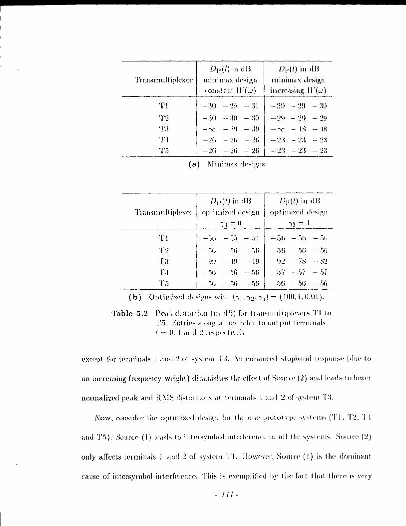
DI'(l) in dB /)1'(/) i" dB Tl'élllsmull iplexer llIillillla:-- d(·sigll llIillilll.l X dt'~igll
IOll~léllll 11'( ... .:) ÎIlCl'(Wiillg Il'( ... ,.')
Tl -:30 - '29 - :31 -~~) - '19 -:Hl
T2 -:Hl -- :w -:Hl -~q - ~q - ~!)
T,I -x - ,Il) - .l!) - :x: - I~ - lx Tl -~() - ~b - 2(i -~.I - ~:I - ~:l
TI': .) -:W -:W -:W -~:l - ~:I - :!:l
(a) ~I ill il\l,\x c!(' ... iglls
Dp(l) ill dB DI'(l) i" dB
Trallslllldt ipl('x('1 opl iIllÎI'(·d d('~Îgll opt illliz(·d d(· ... igll
~I:! = () Î:l = 1
TI - .... Jb - .... J .... J - .-) 1 -,Sb - .... Jb - .... lb
T~ -.')6 - :jei - ~(j -:)(j - !l(i - !)(i
'1':3 -9!J - l!J - 1 !J -9~ - i~ - ~~
r·1 -.1G - !l(j - !)() -!)ï - !li - !li
'1'5 -!j(i - 5G - .~(j -!)(i - 5G - S(i
Table 5.2 PC<lk (II'iIOitioll (III dB) fol' tl'dil'dllldlI\JII'\('I'" '1'110 ')'!) Elill i('", (dong cl 1011' l<'fl'I tu Ollt pli! ''·l'III1I1.tI,~
1 = 0, 1 dlld ~ Il· ... p(·( 11\ (·h
an incrcasing frcqucncy weight) dilllilli,,\i<'s III<' ('[1'('( t of SOUlte (~) and 1t'.Hb 10 11l\\'1'1
nOl'malizcd IWclk and H :'-oIS di~tui t iOll" ,\1 1<'1111lllab 1 alld ~ of ".\, ... t(',,\ T:L
Now. cOII~ld('r tilt' optll\liz(·d dl'~igll lUI (II(' 011<' pW!otVPI' "~"'(('1II'" (TI. T~. '1
only affect:; lellllillct!:; l alld:2 of sy~I('1I1 TI, 110\\'('\'('1', SOUI ('(' (1) i~ t 1)(' dOlllil1nllt.
cause of illtersymbol illtcrfprellCf'. Thi~ i!'> ('x('ll\plifiC'd hy tll<' filet Ihat. Ilw/(' 1" \'('IY
- /1/-
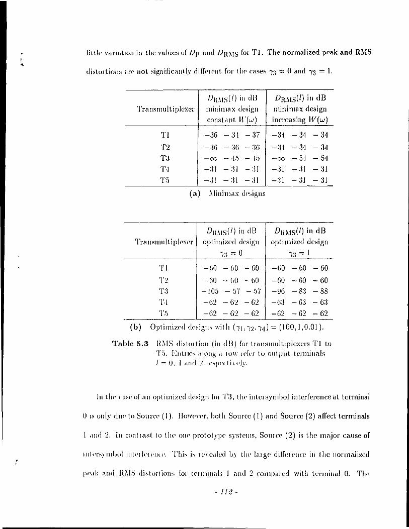
r
little VcU'Iitt.101I ill the values of Dp alld DHl\IS fol' Tl. The nOl'malized peak and RMS
distOltiolls al'<' Ilot signifjeallt.ly diffc'lPllt fol' th(' célse~ 13 = 0 and 13 = 1.
f)l{l\IS(l) ill dB DRMS(l) in dB 'l'ransll1ul ti plexer millimax design minimax design
constclllt W(w) incrcasing IV(w)
Tl -36 - 31 - 3i -3'1 -:H - 31
T2 -36 - :36 - :36 -:H - 31 - 34
'1':3 -00 - 'u) - -II) -00 - 54 -54 Tl -:JI - :JI -:n -,31 -:H -:31 'l':') -,~l -:H - :31 -:31 - :31 - :31
(a) MillilllélX d('~iglls
DH~IS(l) ill dU DRl\1S(l) in dB Tl' a liS III Il 1 t. i plC'xc'l' opl illlized d('sigll optimizcd design
Î:l = 0 Îa = 1
'1'1 -GO - 60 - GO -GO - 60 - 60
'1'2 -GO - (JO - hO -GO - no - 60 '1':3 -105 - !Ji - ;Ji -!J(j - 8:3 - SS
Tl -6'2 - 62 - G'2 -G:3 - 6:3 - 6:3 Tf) -G2 - 6'2 - 62 -62 - 62 - 62
(b) Optimizc'd d('~igm witl! hl,'l."d = (100,1,0.01).
Table 5.3 H~IS di:-.tOlliulI (ill dB) fol' tl'éllISllIultiplcxers Tl to TG, Elltll(· ... (dollg cl IO\\' I('fl'I' tu Olltpllt tCl'millals 1 = 0.1 dlld ~ 1(,"'pc·cti\(·ly,
III t.11C' (a~('of éllI oplimized dC'signlOl '1':3. t!l(' illtclsymbol interferenceat terminal
Il IS ollly du<' 10 Sourc(' (1). 110\\'('\'('1', hol h Sourcc (1) and Source (2) affect terminaIs
1 cllld '2. III COli 1 [ast 10 1 lit' 01](' prot olypc systcms, Sou l'ce (2) is the major cause of
11l1l'1':-',\ IIIIHll 111t('1 !('II'IlU', Tlli!'. i:-. 1('\ c,lIed b) t!J(' lalg{' diffelcllcc ill the llormaliz:cd
Ill',lk alld H~IS di:-.tol'tioll:-' fOl t('l'lIlillals 1 élnd 2 COlllpéll'cd \Vith tcrmillal O. The
-11:2-

initial condition used in the optimizat.io!l cO!'I'<'sj)onds to .\ filt.c'!' 11(::) t.hat. aSSIlIt'S
exact zero crossings in the impulse l'csponse of /1(::)11(;-1). The use' of this init.ial
condition l'esults in an optimi:œd filtel' 11(:::) tllat sacrifices tllC' zero <rossing plopt'!'ty
of H(::)I-J(:::-J). 1I0\\,('\,c1', thc l'cslllting il\t{,l'~yll\hol intt'rft'Il'IIl'<' distortioll is \'t'I)'
low at terminal O. A c\'osstalk \\'l'lgh!. (Î:\ = 1) I('ads to 1II0l'<' di~t()l't iOIl dt (t'l'millal 0
and less distortion at terminais 1 élnd 2 comptl\'ed to the' (,d~C' Î:I = O. FOI terminaIs
1 and 2 of T3, the bandlimitcdncss propcrty is lIsc>d t.o cancel t{'rl1l~ in t.11C' inpllt.
output transfc!' fllllction illvol\'ing ~ld('IJ(\IIds \\'hmw C('IIU'!' f\'('(j\lc'nci('s arC' ~('p"I"lf'd
by 2r.j:3. Sourc(' (2) cOllt\'ibllte~ 10 intC'lsynd){)1 inl<'r/('I('II( (' ill 1111''-,(' Icl'lllill,d..,. 'l'II!'
cnhanced stoplJé\lld attcl1uéltion ahoul '2r./:3 Iltat \'(,~lIlts t'IOIIl III<' lIS(' or cl (lo:"ltiV<'
CIosstalk weight diminishcs the cffect of Source (2). This 1'rsult'l in Cl 10\\'('1 ilJtl'\':-'ylllbol
interfclcnce distortion al terminals land 2.
Crosstalk Suppression
The QAM systems (Tl, T2 alld '1':3) gCllclally élchit,\,(' a !illich lo\\'('\' 1l0l'lJlétliz('(:
crosstalk power than the VSB transmultiplcxcl's ('1',1 and T5) prilllarily IWCclll:-'(' QAM
systems exhihit mally more cl'OsstalJ.:: fllllctions thc\t tHe' exactly Z('I'O. 1~11 ('x('('pt.ioll
arises fol' the optimizcd design \\'it.h Î:J = O. III titis Cél'le'. T,I élnd 'l'!) aclli('ve a low('/'
l1orll1alizpd crosslalk power t Ilclll T:~. Ilo\\·(·\'('r. 1 hi" OCClll'~ Il,\' lISillg a filt(,!, ill 'J"I
and T5 that has lllore taps and cl 1)('\ t.er overall slophcllld n'~polls(, tltall the! fil"!'r
used in T3. Also, wC! notice that lhe (,l'osslalk PO\\'('1 Îs <'xadly Z<'l'O fol' !.('llIlinal
2 of Tl. Among the QAl'vl system:.., Tl and T'2 outpe'l'fol'Ill 'l':J bul al t.llt' ('XIH'IlSe
of more filter coefficients (the dispéll'ity in t.he nUJIlber of coefficj('JJts is IIlIICI. mo/,('
-I/.J-
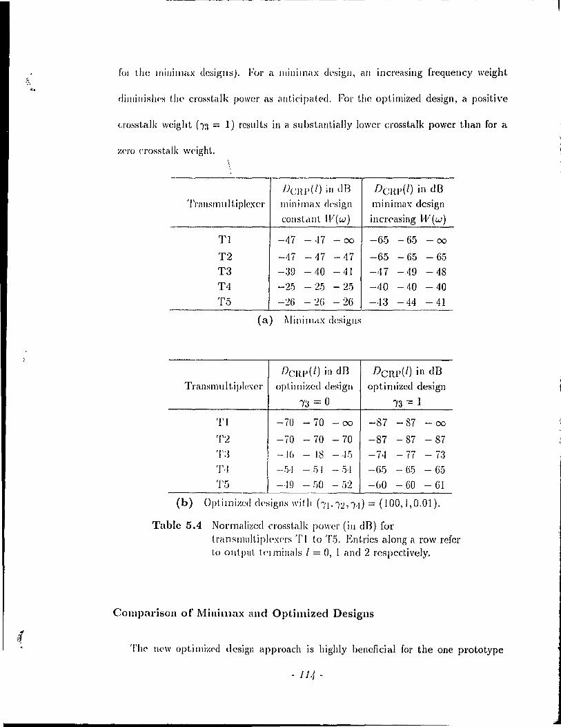
fOI LlJ(! lrIillilllélx desiglls). Fol' a Illillimélx (ksigll, ail incl'casing frequency weight
dilllillis/ws the crosstalk powcr as élllticipat<"d. Fol' tllC optimized design, a positive
cJ'ossta/k wcight h3 = 1) rcsll!ts in a substillltially lowcr crosstalk power than for a
~('J'O cl'osstalk w(·ight. \ \ \
J)CRP(l) ill dB DCRP(l) in dB TI'<llls1l1111 tip/cxcl' minimax design minimax design
COllstdllt lV(w) illcreasing W(w)
Tl -47 -n - 00 -6.5 - 6.5 - 00
T2 -:17 - 47 - 47 -65 - 65 - 65
T3 -39 - 40 - 41 -47 - 49 - 48
T4 -2.5 - 2.5 - 2.5 -40 - 40 - 40
T.5 -2G -:W - 2G -·13 - 44 - 41
(a) ~rillilllctX desiglls
DCRP(l) in dB DCRP(l) in dB Transl11u 1 t,iplcxcr optimizcd design optimi:wd design
,3 = a ,3 -= 1
Tl -70 -70 - 00 -87 - 87 - 00
'1':2 -70 -70 -70 -87 - 87 - 87 T:~ -H) - J8 - -J.5 -7·1 -ÏÎ - 73 1',1 -I},I - 51 - ,1),1 -6.5 - 65 - 65
TS -·19 - !JO - 52 -GO - 60 - 61
(b) Opt.imizcd designs ",it h hl· IL ",J) = (100, 1,0.01).
Table 5.4 Normalized crosstalk power (in dB) for tl'anslllultiplC'xf'l's TI to T.5. Entrics along a row rcref 1,0 output t('llllillélls 1 = 0, 1 élnd 2 rcspectively.
Comparison of MinÏlllax and Optimized Designs
'l'h(' new opt.imized design approach is highly bencficial for the one prototype
-11/,-

systems (Tl, T2, T/t and T5). A rnuch 10\\'cl' ill!ersymhol in!Nf('l'cllce and Cl'osslalk
distortion is achievt'd (evcll \Vith (l crosstalk \\'{'ight of Z('IO) wit.h \lI,UI)' f(·w(·, (ill('\'
taps as cOl1lpared to a mill i III a x design. III ddd il iOll. t Ill' opt. i mizl,J d<'sign a llows fOI
the flexibilit.y of takillg crosst.alk illto c\CCOUllt I)y s('\ t.ing, 1:\ > O.
For system T3, wc have proposed Ile,," lIIillil\lax and optimiz('d desigll .Ipproaclws.
For the performance st.udy, the llumber of fil tel coefflciellt.s for t.1l<' lIIinillla, cllld opl Î-
mized designs are tlte same l'vIo\'(,O\,t'I. 1 II<' Illinimél'i: filt.NS ~('r\'(' as inil ia l cOlldit.ions
for the optimi%C'd deSIgn. 'l'II<' 1\I,lin Hch'alll clgc of t II(' opt.illlizc·cI d(':,igll o\'('\' t.1H' lIlini
max design plimarily lies ill using il po..,ili\'(· cl'osstalk \\'c'ight 10 subst.allt.ially c1i/llinish
the crosstalk power. The optimized filter!'> design cd \Vith a posit.iv(· crossl.dk \\'c'ight.
lead to a lower crosstalk dislo\'tioll (cil ail !c'rnIÎnals) and a lowc'\' ÎIII<'IS)'IIlIJOI Îllll'I
ference distortion (clt tel'llllllals l <\I\(I 2) d~ cOlllpaled 10 llIillilllaX fill('I:' \Vlt.ltolll
a crosstalk \\'cighl, t !tel'e i~ 110 Cle'iIl' aJ\'alllclgC' of t!l(' opl illliz(·d cI(':'l.!!,l) 111 f .. d., tJ)('
fadorable minimax approach \Vit.h an illclTdsilJg slopballd wcight illld 1.11(' optillllz('d
design wilh 13 = 0 lead to a similar performance. Fillally, in COlltl il';!, \.0 II\(' lIIilli
max approclch, an optimizcd dc~ig,11 will 1101, ~)i\'(' ail 11(:::) slIeli tltat 11(::)11(;;-1) is
a Nyquist filter \Vith exact %('1'0 cro:,-,ings (1)(,I'('h~ le~lIltill/!, ill I('sidllal ]1It<'I'~yllllJ()1
intcl'ferellCC al tc'l'llliUéll O.
5.5 Design for the Complementary Subband Systems
Given the desigll metltod fOl t1lC' tl'élllsllIull iplcxcJ'~, wc 1l0W att.clIlpt lo ~:i('e whdl)('1'
this filter design applOach canie.., 0\'('] to t!t(' WlIlplf'IIWlltêll y ~uhband Sy:-.lc·lll:-'. 1'\0t.('
. 115 .
.
t.hat the I1llllimax design approaches can be used for both the transmultiplexers and
tlteii' subbétlld complc·ments. The complemcntary subband systems have an input-
out.put. rc·lat.ioJlship .k(z) = -JvT(zN)X(z) if the prototypes are bandlimited where
,/,(zN) is defill<,d in Eqs. (3.15), (3.17), (3.19) and (3.21). In addition, perfcct re-
C ollst.ruct iOIl i~ (1( (olllpli.:;IlC'd by sdtisfying tlJ(' Nyqui5t u iterion. With practical
prot.otypes, thcre il'> residual aliasing in t.hclt the input-output rclationship becomes
.\·(z) = -JvT(zN)X(z) + ter ms due to aliasing. In a practical design, the st.opband
<,dge fr('qucllcy is rest.rictcd as in the case of t.ransmultipl<,xcrs. In formulating a suit-
abl(' enor fUllctioll, t he factors E~b, Ei~l and the factor that avoids a zero solution
(~b'J'b - 1)"2 01 (hl'h - 1 )~) él1(' t1H' ""Ille a~ for the trallsll1ultiplexer~. The remaiuing
question is about ho\\' to Lclke aliasillg into account. In general, the output of a sub-
band system is a combination of a filtercd input and filtered frequency shifted versions
of the input. Evc'lI for a zero-l11ean white input, the filtered input is corrclated with
t.he filterc'd f)('qllC'IICY shifted versiolls of the input. This makes il. diŒcult to express
t.he Lot.al PO\\'('1 (II t Il<' out.put duc t.o alia~l1Ig in relation 1.0 the power of t.he desired
COlllpOIll'I1t. due 10 the input. especially for an arbitrary N. Howc\'er, filtcrs can he
dcsigned b.v Illinimizing the error function having the factors Esb, E1Si and thc factor
t.hat avoids a zero solut.ion. The filt.ers that were previously dcsigned with /3 = 0 can
\H' Illlcd in the' complertlC'ntary sllhband systell1st.
Silllil,lI ('l'lor functions 1'01 designing a protot.ype for subband systems have bren
proj>o:,C'<! in [19][<13]. A suhbaud system with two bands which accomplishes a natmal
t Nole' 1 hat filtcrs dcsigncù \Vith ')'3 = 1 do Ilot SCCI11 to pcrform any bcLLcr (or any wor:;e) \Vith rl'spc('1 10 suppn'S<;lon of aliasillg than filters dcslgned wIth 1'3 = 0
- 116 -

cancellation of aliasing is the fOClts of [19J[.13]. The Cl'rol' funct.ions ar(' w{'ight.('d lit\('(\J'
combinatiolls of two components. 'l'Il<' fil ~t (Ol11poll<,n1. is \.he Stophellld (·!I('rgy which
in [19] is expres'icd as an integrell e\llt! whirh in [,1:3J is apploxillla1.cd dS é\ SUIIl ovel' d
dense grid. The second CO!1lpOIl<'llt is the !1I<'élIH.,q\lnl'c distortion al, t.ll<' OUt.pll\.. TIlt'
a(: ual expressions in [19] and [43] diffcr in that a tin1<' domain appro<tch is lIs('d in t.11('
former and a freql1ency domain approach is used in the lcltter. The ('1 ror [\Illdion for
our subbanc1 syst.ems cOI1!'>isting of éI \\'{'ight,('d IiIH'ar combinaI ion of 11((' f,('rrllS I~'~b,
Els1 and the \'(,1111 t,hat a\'oid~ a /:('10 ~()JIII iOIl is bas('cI (JIl cl 1 in\(' dOlllain approi\ch él~
in [19).
- 117-
Channel Distortion Chapter 6
and Compensation
Ulltil 1I0W, the investigation on l110clulated filter hanks assumecl that there is no
challll('1 dist.ol'tioll. IIowever, a challllei is plcsent when data is tldnsmitted from one
locat.ioll tu i1llot.het. ThiH brings up the question of how to achieve reconstruction
of the input. data signaIs when there is channel distortion given that reconstruction
cali he accomplished in the absence of a channel. This chapter provides prcliminary
J"('Sltlts that. dcal wit.h this issue. r\'Iethods to configure a channel compensation filtcr
lo cumbat challlH·1 distol't.ion al'f> derived. AI:,o, the pe'l'fol'mancc' of t.hese mcthods is
evaluatcd for a specifie channel.
6.1 Combating Channel Effects
III cl t 1 éI liS III li 1 t.i plex('I'. t.he· com posit.e signa 1 passes through a si ngle chan nel. The
oV(>l'all !>ystl'Ill is sho\\'11 ill Fig. G 1 \\'lwl'e the challlle! has a system function Q(z). In
att('lIlpt ing Lü alleviate the cffects of the chctnncl Q(.:), wc assume that the combining
.,. and separation hanks are configured to sat.isfy A(z)BT(z) = T(zN)I. Therefore, 1
in Ut(' ahsC'lIc(, of a channel, the transmultiplexcr is crosst.alk-free and has the same
- 118-
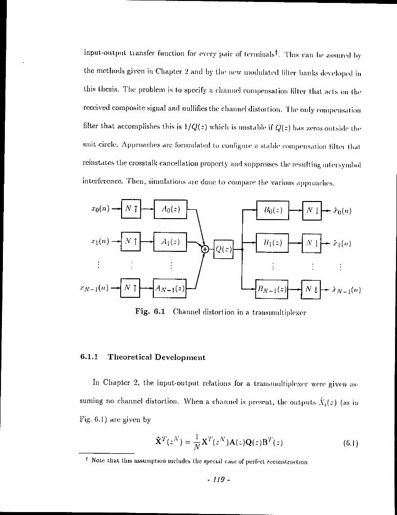
input-output tlansfcl' function for ('\'C'l'Y petir of t<'rlllilia h.,t, Tills cali 1)(' assul'l'd hy
the rncthods givcn ill Chapter 2 and b)' tl\(' 1\('\\' llIodulat,('d lilu'l' banks <ll'\'('lol><,d ill
this thesis, The (>roble111 i'i ta specify a chail Il el COllllH'lIsatioll lilt<'r tltat. ad:-. 011 tlll'
reccivet! composite signal and nullifies the challlJ('1 distOJ t ion, TI\(' ollly ('011 IJ)('IlS<I 1 iOIl
filter that accol1lplishes this is l/Q(::) which is 1II1stc\bl(, if Q(::) belS ;',<'1'OS ollbidc the
ullit circle, Approaches MC fOJ'lllulated to cOllfigllJ(' él st.<lbll· (,()II\IH'Il'i<lt.ioll filt.l'I t Il,11
rcinst,lte~ the crosstalk canccllatiolJ pl'operty and Su(>pl'csse:-. t!)(' )'('sidl illg IlIkl :-'YlIlhol
interferencc, 'l'hen, simulatiolls <lIC dOlle to Compal'<' tll(' various ,lJlJ>loacll<'s,
:l'o(n) ,Î'O( Il)
,q(n)
Ni Nl
Fig. 6.1 Channel distort ion in a trélllslllllltipl('xc'J'
6.1.1 Theoretical Development
In Chapter 2, the input-out.put relatiolls for a tr<tll!'llllldlipl('xc'J' \\'('1'(' glV<'1I i1S
suming no channel distortion, Whcn ét channel is 1»'CSc'lIt, the outplll.:-. \(::) (ilS in
Fig, 6.1) arc gi ven by
(G,I )
Note that thls ru.SUllIptlOlI IIIcludc& the s(wCI,d Cd • .,e of perfi'ct reCOIlf,l,ru('tIOIl
- 119 -
wher<'
Q(z) = Diag [q(z), Q(.:-W- l ), "', Q(zW-N +1)] , (6.2)
X(zN) = [ :~~i.;Z~ l, X(zN) = [ 1~i.;Z~ l XN_~(zN) .kN_~(zN)
(6.3)
<Incl A(z) ilild B(::) élre delilled as in C'hapteJ 2. Sillcc the system \Vith no channel
dJ~to)'t.ioll ((2(::) = J) eliminaLcs cro~st.alk and has the SdlTIC input-output transfer
fUllctioll for cvery pair of (('l'minaIs, A(:: )B'f (z) = T( zN )1. To cancel crosstalk with
the {>l'C'sencc of a chal1Jwl, one necds ta sat.isfy the augmentccl equation
III the ~('(fl)('l, it is aSSlIlllcd that Q(::) is a stable function. No restriction on
t.he Z('l'O~ of Q(::) i:, imposed. A challlle! compensation filtc)' E(::) that aets on the
re'cci \'cd composite sigllal is equivalellt ta modifying the separation filters ta Bi:(;;) =
IJ~.(::)E(::) for /.. = 0 ta N -1. Then, a new separatioll filter matl'ix B'(z) = B(z)R(z)
!CSlllb whcJ('
If R(z) is chos('1l ~llch tltat Q(::)R(::) = 3(::1\')1, Eq. (6.4) becollles
A(z)Q(z)[B'(z)]T = A(z)Q(z)R(z)BT(z)
= S(zN)IA(z)BT(z)
= S( :-N )'1'( zN)1 .
III choosing R(::). th(' ~t(lbility of E(:::) Illllst he ensmed.
(6.5)
(6.6)
The special case ill which the channel response q(z) is itself a function of zN
('J\sure" that A(::)Q(::)BT(z) l'emains a function of zN and consequently, no crosstalk
- 120 -
l
is introduced by the channel [H]. A S()('Ci'IJ cas(' is whell q(.:-) is il Plll(' d(·J,IY of
the fonn ::-mN. This is t'quivaJ('nl 10 ,1(>pJying d('Jay faetOls 10 (II<' (olllhilllll)-', illld
separatioll filt!'r banks. Theil, the PC'l f(\cl \('('011<;1 ruc( iOIl pl'Op('rl~' i~ pl'<'s('r\'('d for <Ill
identity translI1ldtiplex('r as discus~wd in Ch'II>(t'r 1.
An obvious solution to Q(.:-)R(::) = S(::N)I is (0 ('hoose R(.:-) = Q-I(.:-). T"i~
makcs S(zN) = land E(::) = 1/Q(::). IIo\\'('\'('r, this solut.ion i~ inapplOprial(' if ()(.:-)
ha~ zeros oubide tbL' unit. circle sill(,(' élll ulI,,!,"}I(· C()III(}('n~(lIi()1I lilll'I I~'(~) 1'('~IIII~,
To achieve clOsslcdk cêtllcC'IIc1lioll, R(.:-) i" ,,('1 III ()('
(j,7)
whcrc (p(::N) is any arbitrary fundion of :;N and CQ(.:) i~ III<' (()félclol' lIlélt.rix of
Q(::) givcn by
Theil,
and
N-l II Q(:: W- /) o o i=O '=1=0
o
o
N-l II CJ(::W- l
) o 1=0 if.: 1
N-I o II (J(.:-1V- 1
)
N-I
I=() rj;N-1
Q(z)R(::) = <p(::N) II q(::IV-1)I
= S(zN)I
N-l R(::) = eJ)(::N) II CJ(zlF- 1
) •
1=1
- 121 -
(G.!))
((j.(O)
z
Tite cltallllel q(:.:) and tlte cOlllpensatioll fil ter E(::) in troducc an extra term S( zN)
JIl the inp1lt-output transfcr function. The on'rall input-output transfer function is
S'(::N )'/,(::1\'). The compellsation filtel E(:::) cali be thought of as being composcd
of t\Vo filt.el":. 'l'he filter witlt system fllllction f1~11 Q(::1V- 1 ) wheIJ cascadee! \Vith
(J(::) call 1)(' viewcd as Ct composite challll<'1 n;~o 1 Q(::1V- 1), wltich being a fllnction of
:::N, CIlSlIIC'S the ('allccllation of crosstalk. HO\\'('\'er, rcsidual intersymbol intcrfclellcc
1'C'lllaills. The ot Iter fil ter q)(::N) should be ct funet ion of ::N to preserve the crosstalk
Célllcclléll,ioll plOpcrty IIO\\'<'\'cr, iLs a('tu,tl roll' is 1.0 suppress the lpsidual intc'rsymbol
illl.t'rf<'J('!I«' ,l(lllliUc'd by tlJ(' f<letol S(::·v). \Ve igllore tlJ(' illtersylllbol interfelCllcc
(lCllllit.t<'d by the facto! T(::N) ~ill(,C' il. call be supprcssecl or cven cance'lIed bye!esigni!lg
the fi 1 tel' banks. In effcct, the channel compC'l1sation filter consists of t\\'o cornponents,
OIlC which cXclct.ly cancels crosstalk and onc wltich supprcsscs illtcrsymbol intcrfel'cncc.
Silln' Q(:::) is ~tabl(', it follows tltat E(::) is st.able providing (p(zN) is stable, Ba,<;cd
Oll the s()('cificéllioll for R(::). difr(']'('lIt clppl'o(lChes of choosillg ([>(::N) are givell.
6.1.1.1 ChoÎces for q)(::N)
Method 1
'l'hl' sill1p I('st lI1<'t hod. Iléllllely, ([>(:: N) = 1 docs not é\ t tcmpt to control the in tcr
sYlllbol ill(('lfeJ('IlC<'. II. intlOdu('l's thl' factor 8(.:N) = n;;'(jl Q(::W-i) ill thc ovcrall
illput -output. t.ré\w;f('l' fl:nct.ion.
Method 2
A s('coIHI procC'dul'e clllcviates the problcl11 of é\ high order input-output transfer
- 12:!-
function th,tt is present in t.he prc'\'ioll~ approach. Suppose' Q(z) i~ ~plil Il)) ,IS
((i.l 1 )
whcrC' U+(::) contains the zeros of Q(:::) within the uuit circlc alld fT_(.:) n>JlI<lill~ t!1<'
zeros of Q(.:::) 011 and outsidc the unit. ,il'clp. SIIlC(' q(z) is ,1"'SIIIlH'd 1(1)(' sl.lhl!', J>(z)
has ail its Z('I'O" within the' Hllit cil ('1(, Bv :-,('11 ill).!,
((LI:.!)
wc gel a lowcr ordel' factor in the input-out.put tl'ansfer fil net ion
N-l S(:::"') = II fT_(:::W- / } ,
I=U
and a ~tclbl(' channel (,ollll)(,ll~a\1CJ1l filtl')
((i.1 I)
Since the order of the ov(>rall input-output trélllsfC'r functioJl i~ rec!llc('d OV('I t hat. or
l\1cthod l, the resulting Lime ~paJl or t Il<' illt('r~yl11b()1 intel f('I'('IIC1' i~ :-.llort('JJ('d.
Method 3
Assumc that t11(> original transfC'r fUllction T(:::N) is élllpélss and t1lélt (J{::) bas 110
zcros on the unit circle (in élnalogy wit.h t1w dc\'('loPIlWllt ill [18]). Now, wc' l)l'o('('('d
to cxamilw whet her the èlllp;IS~ pro»('I'\ \' or t II<' illpul -0111 pllt 1 1,IIlS!'('!' 1'11111 tioll Cilll hl'
pl'esel'vcd. ScttÎng
((i.I!»)
- '2.'1-
'.
" 1
)('r)(I(~1 Il a new allpass facto l'
(6.16)
tlllel cl SLlbl(' challnel COlllpclIsatioll filter
((U7)
MC'lhod :i J>I<'s('rve~ tlH' (dlpa~s ploperty of the input-out.put transfer function but.
illtl'Odllcc:, ail illfl/lite tillle spal1 for the illtelsYlIlbol interfcrcnce,
Method 4
So fal, \\'(' havC' prcselltcd Illet hods that citlwr control the t imc span or the allpass
lIat.lIlC of 1,11<' ill(>ut-Olltput trélll~rer fllnctioll. No\\', we attempt ta chaose an FIn
(I)(:;N) 50 <1:-. 1.,) 5UppICSS the illtclsj'lllhol illterfC'l'cnce. Gi\'cn that
N-l S(::N) = iP(::N) II Q( z Iv-i )
1=0 (6.18)
= if>(::N)IP(::N)
Ol' equivaklltly S(::) = 1)(:::)1/1(::), W(' determillP the coefficients of an FIR <P(z) to
l1lillimize the lllcall-squéln' illters)'mbol intel ferenec LU:fO s:l(n). Since s(n) = ljJ(n) *
1/'(1/), il. cali bc shown that LII#O 82(11) = ljJTWljJ whcre ~ ;s the column veetor of
coefTiciC'1I ts of if>(::) and \II is a positive dcfinite symmctric matrix whose en tries w(k, 1)
an' gi\'('11 hy
\11(1.',1) = L ~'(I/ -1.')~'(11 -i) . 1/
1/:fO
- 124 -
(6.19)

------------------- -------------------------------
To avoid the trivial solution cfJ(::) = 0, \\'C illlpose tl\(' (,Oll~trélillt 4>'\'4> = 1. Th('II,4>
is the eigenvcctol' cOll'cspondillg t.a lI\(' minilllulI1 <'ig,cllvalul' of \11, Nf)t<, th,lI 1\ldho<l
4 can be viewcd as attcmpting 1,0 applo'\illlcltf' tlI<' in\'('\'~(' "f Ihe ('OlllpositC' C 1\(\1\1)('1
Method 5
An altcl nat.i ve methad ta suppress tlw i Il t,c'I'sj'mbol i Il!.C·!fC'J('II('(' is 1.0 choos(' (/'(:: N )
ta be
((i,:W)
Thcn, .\' -1
S(:;N) = ~(::N) I1 [T_(.::IV- / ) , (fUI) 1=0
An FIR Ll(zN) is detcrmincd 1.0 SllPP\('S~ the mCillH'C)lWI'C illl.('l's)'l\Ihol illl.('l'fc·\('Il(,c'.
As compared to Mcthod ·1, l\Icthocl ;:, only p('lfOlI1lS an applOxilllat.ioll or thc' iIIVC'ISC'
of a maximum phase flllllt.ioll tllal contaill'> Il)(' Z('IO .... of (2(:) on <-1l1d ollt1-lidc' UIC' u\lit.
eil'cle. A factor of <P(:;.\') cxüctly ('all(,l'I~ li\(' ze\o:., tlBd pole:., uf CJ(.::) wit.hlll t!lC' \llIit.
cil'cle.
Summary of Methods
Table fi.l shows the COll1pC'\I~ati()1l hlter Jj'(:::) cl\Hlt!Je oV('ntll inpllt-outPIlt. tralls!'c'\
functions 1'(:;N)S(::N) rc:mltillg troll 1 the mcthods presellt.c'c1 a!Jo\'(', SlIPp01-l(' \V('
have an FIR chanllel Q(:;). This lead:., to eitll<'l' ail Fm o\' lm ('oll1p('lIsat.ion filte,\,
depcnding on the method utilizcd. Assuming that T(zN) is an FIR f'ullct.ion (this
is oftcn the case si nee pcIfcct l'cconstl'uct ion is d('~i n'd), t1l<' ove\ 11 Il i Il l'Il t.-ou 1. pllt
- f f!.5 -
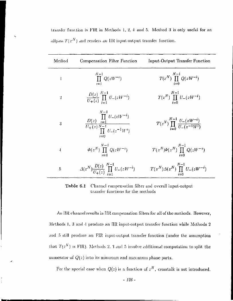
.. tl'élm.fel' f'lIllctioll is Fm ill Methods l, ~, ,1 alld .5. Mcthod;3 is only useful for an
(t1lpcl~~ ï'(::N) (llJ(l l'clldel~ cLlI IIH illput-output t.rallsfcI fUllction.
Mcthod Compcnsation Filt.er Function Input-Output Transfer Function
;J
,1
5
N-I Il Q(::W- l
)
1=1
N-I c[J(::N) II Q(::W- 1
)
1=1
N-I T(zN) Il Q(zW-i )
i=O
N-I T(zN) II U_(.:-W- i )
i=O
N-l T(zN)iP(:;N) Il Q(::W- 1
)
i=O
N-I T(zN).:J(zN) II U_{zlIV- i )
i=O
Table 6.1 Chanllel compensation filter and ovcrall input-output. tl'c\nsfer fUllctiol1s fol' the rncthods
Ail I11{ chal1nell'csults in IIR compensation filters for ail of the methods. Howcvcr,
~kthods l, 3 and ,1 pl'oducc an TIR input-output transfcr function while l\1cthods 2
,1IIe1 !) still producc an Fm illput-out.put t.ransfcr function (under the assumption
Ihal. '/'l::N) IS FlH). I\kthod::. :l, '3 ell1(1 !) involvc cldditionctl computatioll to split the
1l1lll1cnlior of q(::) in to its lllinlIl1Um and maXlInUIIl phase parts.
For the special case when Q(::) is a. fUllction of ::N, crosstalk is 110t introduced.
- 126-
Then, the compensation filtel's for ~lcthods 1 and <1 assUIlH' a spt'cial fOI'Ill. ~It'I hot!
1 rendel's a compensatioll fIlter E(.:) :..:: (LV - I)Q(.:) ",lliel! is Ilot pMtieul.I)'ly "p-
propriate sillCt, crosstalk is ailccHly absellt c\1Ie1 110 sp('ciflc (ont 1'01 of t \)(' int ('l''''~ 1111,01
intcl'ferencc is providecl fOl'. In Mcthod ·1, the rorm or the compensatioll filt.er l>hould
l'educe ta E(::) = W(zN) as no additiol1rll fador Îs IH'('('ssary \'0 ('al\(('1 (ï'o),st.alk.
Then, <p(::N) will approximatc the illverse of Q(.:). Note that. 1'01' a !!,<'lIcral (2(.:) (Ilot
a function of ::N), lIsing a compensatioll filt.(,1' 10 suppr<,"s t,Jj(' 1l1C,UI-squc\\'(' illkl'~yll\
bol interfelcncc docs not l'C'!-iult in cros~tédk (C\I!(<,lIati,>II.
6.1.2 Performance Evaluation
\Vc evaluate the performance of él tJanslI1tlltiplexC'r whell the' diff('I<'IIt dlHIIII('1
eOlllpeuscltiull filtel~ cLIC lI!>(·d. ('oll~id('1 tif(' \.\\'0 1)(\IIt! (N = ~) V('I'!-iiUII of t I,IIISIIIIII-
tiplexer '1'3 with G(::) = 1/(.:-1). The frltels 11(::) allCI 11(::-1) arc' obt.ailU'd hy t!l<'
fadorable minimax approaeh stleh that T(::N) = N (ail idelltity Lralll>llllrl:iplc,ycr).
Thcrefore, with pract.ical fîlters, both intcrs)'mbol inlcrrc!'clICC and el'osstalk (lI'(' ('x
aetly cancclll'd w hcn no Chd IlIwl d i~ tortioll is 1)I'('sen t. Thc' pl'CSC 11('(' of r1 cita 1111<'1
and a compen:,ation filler l'cinstatcs t1)(' <'XéHt Clos:,tall, (',t1lcelléltio!1 plOp<'lty ,LIId
intl'Oduces the extra term S(zN) in the input-out.put tr,wsfC'r f\llldioll. 'l'II!' l'(':,idll"!
intersynlbol Întcrfercnce is only duc to Q(::) and E(::) and not the !>l'élctÎcal filt('ls
used ir. the eombilling alld separation filler hanks, TII<'I'('fo1'e, lite (·vdluat.ioll of tlte
performélllc(, only dt'pellds 011 the COlllp(,lIsat iOIl filler, By calculatillg .~(1/) (1.11<' in-
verse' .::-t.1'all~forlll of ,':;'(.:)), \\'l' Il)(,d~III(' IJOI II t II<' lIol'lllaliz(·d pC'é1k di!-itol t,ioll /JI' and
. 1:17·
... t.he Ilonnalized ftMS distortion D/{J\IS' The nonnali7,ed peak distortion is given by
L 18(11)1 Tl
_71...!..:f;.....:O~ __ Dp = 18(0)1
'l'hl' Ilormalized Rl'vlS distortion is given by
(6.22)
(6.23)
JIl man,)' cOll1munications applications, the multiplexed output of t.he combining
ballk is converted to a lowpass analog <:ignal, moclulated, sent across a channel and
d('1l10duldl<'d hrlCk to ba~ebilnd. Tht'!1, cOlltinuous time to discrde time (CID) con-
vel sioll t.étkc~ pla( (> prior ta t Il(' a<.tion of the sepal a t ion baille Firs!., formillg a lowpass
c\lIalog sigllrd l'rom t ht' disel l'tc tillle ou( put of the cOl1lbilling bank involves converting
the discrctc (ilIIe sigllal in to an impulse train and passing the impulse train through
il lowpass élllrliog filter (Die cOII\'crsion). Note thclt CID conv<'rsion is <'CJuivalent to
~i1tnplillg t III' ('011 ( lnuou~ t illlC> input. This ovel'all ()l'OC('SS is equi\'alent to transmit-
tillg the' I()\\'pd~s allalog signal (fol'mC'd by Die COIl\'l'l'sion) O\'er a lowpass cquivaleut
challllei and (lwll perfonning CID convcrsion as shown in Fig. 6.2, The DIC and
CID cOIl\'C'rsiolls élrC' pl'rfol'lI1ed ill phasct and at the saille samp!ing rate Is = liTs.
For OUI ()('rfolmancC' stllc!Y, wC' 1H'C'c! a di'icrcte time eCJuivalent Q(::) that models
(he sysl<'lll of Fig. G.2 The' ()l'O(,C'S~ of Die con \'crsion tra n<;!a tes the cliscretc time
inpu( into <ln illlplll<;(' train and llS('<.; an iclC'al rais('c1 Losilw filter \Vith .50 pC'l'ccnt l'oll-
off to gel the lowpass ana log sigllal. In tbe absence of a cbannel, the discrete time
l'\oll' that Ir th .. Die and CID convcr<:jnns are donc out or phase, tlus can be modellcrl as an l''\t rel Illlcar phdlle rompont'Ilt in the channel
- 1:28 -

egnivalent Q(::) = 1. We consider a lowpass equlvéll('nt challllt'i wit.h a cuhic phase
characteristic (parabolic group dclay) 0(0) giV(,ll by [-1!)J
0(0) = _L(rrr ):1 'J ~ s· .,7!"
( (i,:! 1 )
In cffed\ we are using a channel with ct h(,é\vily dlst.ortcd phase' J'('S\)(HlSI' th,ll. 1)('-
eomes morc severe with increasillg p, Such éI phase lIo11linC'arity ('xist.s 0\'('1' \'('Iq>holl(,
ehanncls alld has been used to study the perforn1dll( C of lI1ulticarric'l' ll10c!t'lI1S [1:IJ,
From combiniug - Ole t-belll k
LowȎlss cqu i \' ,drlll
ch all Il el
To ~ CID ~~('J>éU'cltioli
bclll k
Fig. 6.2 TrétllSllli&siOll o\'cr élll élllaiog challlll'i
Specifically, we consider the discrete time cquivalclI\. It'SpOll~(' q(n) rOI \.lI<' (,":-.t'
p = 5, This is rcpresentativc of the group delay distortion Ihat is :-iet'Il hy cl high sp(,t'd
modem ove1' a telephone channel. The dis(l'ctc tillle' rcspOll:-i(, 1/(11) dill1illi~lI('s Idpidly
with Inl, An FIR Q(::) \\'ith ,1:3 coefficients spans t.he sigllific,lll\. )>cIlt of tht' (':-./>011:-.(',
The mag.-.itucle respOllSC of Q(::) i5 fiat up to the quart('1 ~éllllJ>lillg flcqll<'l}('Y and
thC11 dccreases by 6 dB at the balf sampling frequency duc 1.0 aliasillg efr('cI,:-i, The
group dclay is pat'abolie up t.o the qUclrtel' sampling frc'q1\clIcy and t1lt'1l Iw('ol11cs Illon'
&c\'(:,l'e,
In cakulating, the nOl'malized p('ak and H;\lS di"tol'tioll'i for tlH' f11':-it, Ihn'!' llH'th-
ods, the tcfcrcnc(' coefficiellt that leads to the minimum distortion is aligJl('cI with t11<'
zel'oth time index. This is equivalent to applying an additional tirne ad VélT1( e 1.0 t.IlP
compensation filte!'. Althnugh the impul"e l'e:-.pon~c is ilJfilJitC' ilJ ('xtc!lIt fOI MetilOd
- 129-
:3, lower hounds for the normalizcd peak élnd RMS distortions are computed by con
siderillg th(' first GO salllple!>. for I\1cthods <1 alld 5, the' eigC'llvector corresponding to
the minimu/Il C'ig<'lIvaltH' of t.he positive dcfilli(e mcürix is of dimeIlSion 61. Tbercfore,
t1l<' componellt of the compensation filter involvillg the Fm least-squares approxi
llIation (dcnoted by r/>(zN) or d(zN)) has 61 non zero coefficients. In addition, the
("o('HicwJ\(s of (IJ(::N) or d(zN) are centercd about the zeroth time' index. This time
illdc'x COI J"('-' pOli (I!> to th(' be:,t rcferc'ncc coefficient of ,~(17) \\"itllOut the least-squares
filt.er.
The Ilormalized peak and IU'IS distortIOns resulting from Methods l, 2 and 3
are much larger thé\l1 for Metboc\s <1 and .5 primarily because tbere is no explicit
suppression of the inters)'mbol interfere'nce. Specifically, l\'lethods 1, 2 and 3 give
peak dist.ort.ions of 1..17, OA6 and 1.11 respC'ctivelyand Rl\lS distOltions of 0.91, 0.37
and 0.58 lespcctivcly. Of the filst three approaches, MetllOd 2 achif'ves the lowest
distortion alld constrains the time span of the intersymbol iuterferencc. Mcthod 3 is
highly specifie (,0 preserving a stable IIR allpass transfcr function. Even though the
illlpulse rcspon!-oC' dies out \Vith Lime, a large distortion results. IvlethocIs 4 and .5 are
sucn'ssful ill UI.!t (he,) r('sult in V<'ry low p<'ak and I1MS di~tortions. ail of which are
I)l'Io\\' 10-'\.
6.1.3 Application to Specifie Systems
The' met hods lIsed to configure a channel compensation filter assume that the
(l'ilnslllult.iplt'xer is crosstalk-free élnd results in the saille input.-output tl'ansfel' func
lion for <'\'<'l'y pail' of terminaIs ill t!1(' absence of a channe\. The dCl'ivation is general
- 130 -
in that thcrc are no specifie rcquirel1wnt.s 011 tlH' l'mm of the COlllhillillg alld st'p<lrat ion
filter banks. In addit.ion, N can be an)' inlegcr. Thcrcfol'<" th<, channel COII\!>('lIs<ltioll
fillers are applicable lo (,\\,0 band Qr..!f bcll\ks, tll<' t.wo bcllHI Sll1it h-B,Il'1l"'t'lI st.r\lc
ture, the N band systems configUled by the use' of cl Illatt ix fot'IlI,dislII and N h,lIld
lossless filter banks (sec Chapter 2).
With handlimited prototypcs, transmult iplcxers T) to T!) sat.isfy t.h(· asslIlllpt.iollS
for configuring the channel compensation filters. TlwrcfoJ(', the chanllel COIll)H'lIsat iOIl
methods of thi~ chapt('r ccm he <lppli(·d to Ih('se tt<lIl~ll\llltiplc·x(·I:-'. Note' Ihat with
practical filters. resiclual (ros~télll, i~ "dlllittcd. Suppose 1 II(' ch"IIIH'1 (OIIl)H'IISill iOIl
schemes arc applicù to the tl ansmultipk~('rs that Il:-.C prclctlCcd fiIU·r:-.. '1'111'11, t!w ('xl 1 ri
factor S(::;N) is introduced in the input-out.put transfcr f\ludion and th\' Cl'os~t,dk
functions. Specifically, the crosstalk fUllctions hccomc Tkl(:;N)8(::;N) wlw\'(' 'I~'/(:;N)
arc the crosstalk fUllction:-. of t.he syst.em ill the absence of cl cllallll<'l. Md horls .)
and 5 are particularly effecti"e ill tiraI, thl' l'cldol' ,)'( zN) is apPl'oxilllat('ly a COllst a lit.
Then, the normalized crosstalk po\\'er will 1)(> about tlJ(' Silll1(' as tll<' closst"lk »0\\'('1
that is admitted in the absence of a chan ne\.
6.1.4 Channel Effects in a Subband Systenl
Channel dbtortioll i~ illt roc\uced in Cl "illhhallcl \ystC'1Il \\'11<'11 ('é1( Il of t!l<' illll'I
mcdiatc sigllals forlllcù aftel' séll1lplillg rate' cOlllpr<"..,sioll is pa~sed tlll o\1~h CI cllalllll'I.
Given that the original system \Vith 110 channel distort.iol\ e1iminaü·s alia:oillg, the pro
cedure given in (18] describcs how t.o modify the sYllthesis filters t,o comba.t. clrarlll('1
distortion ,Just as in 0\11' approac1H's fol' a tlansllltlltiplf'x(·I'. 110 sp('cifie asstllllpl jOI1~
- /.,,]J-

about the filLer banks 01' thc number of bands N are made. Each of the synthesis
filt(!rs is modified by a difrercnt factor that d<'pends OIl the system function of cach of
the chann<'ls su ch that the cancellation of aliasing is reinstated. Our methods modify
the separation filters by the same factor t . Our Mcthods l, 2 and 3 are analogous
1,0 t1H' aplJl'oacll<'s 11\ [18J. In addition, wc have proposcd two additional procedures
tu cOlltrol t.he IlItel'~yl1lbol intcrfel'ellce. The modificatioll approaches for both sub-
band syst.ems ,1Ile! transl11ul tiplcxcrs do not assure pel'fcct reconstruction. Sincc the
~lIhballd system::. Sl Lo S.5 are alias-fl'ce with bandIimited filters, t.he compensation
schernes ill [18J apply.
WI' l'an l'xtt'IHI OUI' approdch tü allo\\' for diffcl'cnt colllj>Cll&atioll filters Edz) in each band. If Q(:)l~'dz) 18 a fUllctlO1I of zN for cach k, crosstalk IS callcelled. Difrerent. input-output transfer fUII<'Iion:- Will re8ult, for t'Heh pmI' of !{'rminals,
- 132 -
Chapter 7 Conclusions
The thesid has explored a class of transll1ultiplexcl's I.ltal. us(~ Illo<lulill.(·d filt.('r
banks. l\'loduJated filter ballks tise ban<lpa~s \'clsioIlS of il ICI'ipass />Iol.ol.y(>(·. \VI'
have also dealt \Vith subband systems whiclt arc COmpll'lIlC·nt.ary t.o I.I'élIlSlIIlIll.iplc'xC'IS.
In this chapter, a list of I.he contribut.ions tltal. have élri:,cll [rol1l t.11C' invc.~tigilt.ioll
arc presented. Then, a summary of the cntire thesis is given. Re·('Olllll1e·IHlélt.ioIlS l'DI
future research are outlined.
7.1 Contributions
The contributions resulting [rom the rcsearch are as fo"ow~:
1. A synthcsis proceclllle based on a bandlimitc'd lowpass prot.ot.ypP Wél~ de'velop('d for trallsmultiplexers thal. use IlJOc!ulated filt.er ballb. '1'1)(' aim is 1.0 (·all('(·1 crosstalk and mailltaill the sallie input-output tl'all~fc'I' l'Ullct iOIl fOI ('ve'I'Y pail' of terlllinals.
2. As a consequence' of tlw sYlltltcsis pI'OCCdUIC', fiv(' l)illldwidt.h ('flic ie·llt. 1.1 il IlSmult.iplexers emergc'.
3. The systems can he intel'pretcd frolll il cOlllmunicat.iolls point of view. ThlC'(' of the systems implemcllt ITIulticétnier Quadrature A lI1plil.ude Modulai iOIl (QAM). The ot.hel' two impleInCllt lIlult icarrier V('stigial Sidc·IJillld Modlllat.ioll (VSI3).
- 1.'1:1 -
,1. 'l'Il<' two band cél~e was examined in morc detail. This Icd to the synthesis of II('\V two balld tlclll">lIlllltiplex('r:, .
. 1. 'l'II(' sYllthc::,;i7.cd traIl~multiplexers cali be converted illto new subband systems.
G. New design rnethods for a practical FIR lowpa::. prototype were formulated to suppress intersymbol interference and crosstalk.
(a) The rninimax designs take intersymbol interfcrence into account.
(])) The desiglls bdsed 011 t.he 1I1illimization of an error function at tempt 10 :-'u PPI('ss bol il intersYll1boi i ni,crference and crosstalk. III fa ct , this d(':,ign i~ hclS('c! 011 clll allalysi~ of the t.l allsll1ultiplexels \Vith respect 1.0 both inter~ylllhol interfelencf' and cIos<;tcdk fol' practical filtcrs.
7. The pcrformélllce ()j t.he tl,lIlSIl1ldtiplexers \Vith the c!('siglled pIactical filters was evaluatcd. This pel jOI'IllélllCC cvaluation allows us 1,0 compare the trclllSmultiplf'xcrs and tlH' t \\'0 df'sign I1l<'thods.
S. Filtcr desigll Illet hoels fOI the subband complements were described based on 1,11<' éIPPIOclc!J(':' fol' tI clI1SIIIUIt ipl('xeI~,
!). 111 the j>J('S(' Il cc' 01 challllel (!J.,;lortioll in trall:,multiplexers, [ive' approaches to (,oIlfigll\,(' c1IélIlIlf'1 COI1lpCllsatIOIl filters WCle fOl'll111lated to cancel crosstalk. 'l'Il<' performance of these lllet!Jods \Vas compared with respect to the suppression of tJ)(' reslllting illt.ersymbol interferencc gi\'en a realistic channel.
7.2 Summary
'J'Ii(' lIloti Vél tion bchind t}/{' i 11 \'e~t igél Lioll \Vas LO dC'vclop alternaLe cOllfigmations
for t.l'ansllIlIlt,ip!exns that lise Illodulated filter banks This was accompli shed by for-
lIlulat.ing a synt.hesis procedure based on a bandlimited 10wpass prototype (stopband
Il'SpOIlS<' is ('xactly z(,l'o). The synthesis procedure is a constructive approach for de-
\'l'lopiIlg Il('\\, systellls. As a result, fi\'(' ll'élI1slllultiplexers (Tl to T.5) were cOllfigured
su ch (hat: (1) The input-out.put tl'ansf'<.'I' funetion bctwccn each pair of terminaIs is
1 hl' sali\(' alld (2) The crosstalk is cancclled. FouI' of the systems arc new while T'1
- 134 -
resembles an existing modulated filtel' bank. Translllllltipll'xl'rs Tl, '1'2. '1'-1 alld T!)
arc based 011 one prototype JJ(::). Systelll T:J IIS(,!; 1."'0 pl'Ot.olypps 1/(::) and (,'(::)
EdCh of tll<' transmultiplexcl's imph'IllC'1l1 S il fOi III of Frc'Cillf'llCy Di vision T\'lult i pll'x
ing (FOl"l) \\'ithout the use of guard bands. 'l'h(,lcfo\'(', t.h(' fulll'hallnel hand\\'Hllh 18
utilizcd by allowing for spectral overlap amolli!, the filters, ln additioll, the' tr.\IIslIl\Il
tiplexers arc bandwidth efficient. Considcl 1 he cas(' in \Vlti( h l'dch illput sigllal lo \.lI('
transmultiplexcr is sampled at Jo II;,,, Thcll, t.he t.otal illfollllalioll l'at.e is J.~ = NIl!
sitmplcs/:,('(olJd whclf' lb IS the' ... alllpling rclte of Il)(' cOlll»osi\(' sigllrt! ",hi( h 0('( IIpi('s
a bandwidth of /:,/2 Hz. 'l'Il<' halldwidth pfliriC'llcy of each of Ill<' systl'Ills is t1)(' ratio
of the info\'mation rate Us samples/second) 10 t Il<' total handwidt.h U\/'2 Il;,,) .llId
is equal to 2 samples/second/Hz, The syntlwsized t.ransrnult.iplex('rs ill'<' hillldwidth
efficient in that the full informat ion in cael! input is t \'éUlsmitt('d and t IH' illput.s an'
recovcrcd.
Although ail of the t.ral1s111ultipb:els accomplish FDl\I, il fllrtlH'r illt.('I'J>l'd.at.ioll
from a communications point of \'iew can he madc'. Threc of t h(' lIC'W sYS!'C'lIIS (T l,
1'2 and 1'3) implcment. multicarrier QUéldratlll'<' Amplitude Modulat.ion (QAl\I), 'J'wC)
signais are sent in quaclrélt Ul'(' at pacl! rq)(,éltillg (,<.'IlIC'I' fr('qw'IlCY. Th(' (11)('1' \'wo ('1"1
alld T5) accornplish lllulticéllTi('r Vestigial SiddJétIJd l\lodlllation (VSB) in whirh Oll<'
signal is Sl'nt al. cé\ch di~tinct fr(,</Il<'IlCY.
The N band trallsmultiplpxPlS TI to 'l':) rail })(' cOIl\,('rl('(\ inlo :-'lIblHllld COIlIpl(!
ments SIl.o S5 respectively, Systems SI, S2, S3 and S5 are llCW whi1e S,I l'csC'l1lhks ,lIl
existillg system, Subband !lyst,ellls SI, S2 alld S:l allow for rPIWal('d C('III('1' frc'ql\{'I1-
cies, System SI is ail IV balld g('IlC'l'ali~élt iOIl of t.he' t.wo 1>;111<1 Q~f Jo' hélll!.: Sy:-.I.l'1I1 S:i
- 1.1.5 -
( IS (LI 1 N balld g(~neralization of il two band, two prototype system. For a particular
cas(' ((,'(::) = 1/(:;-1 )), S:3 is lossless and is an N band generalization of the two band
Smit.JI-Bill'llwcll structure. Both S4 and S.5 use distinct center frequcllcies.
TJ'ilnslllultipl('x('rs Tl throllgh T.5 havf' cach bcen configured with bandlimitee!
fi 1 t.('I'S SIIC li that. (1) the i Il put-ou tpll t tl'ansfer function is the same for every pair
of correspollding termillals ami (2) crosstalk is cancellcd. In addition, satisfying
t.!J(' Nyqllist. critcrioll ('liminaLes intcrsymbol intcrfcrence and henee, achieves perfect
reconstruction. Fol' t.he onf' prototype systems (Tl, T2, 1',1 and T5) spccificd by a
lowJlass 11(::), II l (::) should be a Nyquist filler. For tranbll1ldtiplexcr T3 specifiee!
hy two lowpass fill<'l's 11(::) and rr'(::), 11(:;)0(::) should he a Nyquist filLer. Sincc
j"lIldlilllited fillers cannot he designf'd and the Nyquist criterion may not bc exactly
( s",tisficd, ncit.her intersymbol interference nor crosstalk is exactly cancelled. New
d<'sign mct.hods fol' a ))ractical FIR lowpass prototype \Vere introduccd with the added
c1ÎIII of slIp(>l'<'ssing inlf'l'symbol Întcrfpl'f'ncp and crosstalk.
011<' of t 11<' c1C'sigll Illethods is basC'd 011 il minirnax approach to achieve a lowpass
J'('SPOIIS('. III addition, the dC'sirccl Nyquist charactcristic is takcn into account. For
t.he olle pl'ototypC' systems, thcrc is an inhel'cnt difficulty in designing a lowpass H(::)
s\lcll t.llat. /1'2(::) C'xactly satisfies the Nyquist criterion. We used the McClellan-Parks
algOl itilln 10 g<,1 a lill('(\r phase' lowpass l/(::) t.hat approximatcs the square 1'00t of a
I"i~(·d ('o~ilH' rt'~poll:-'C'. F'or :-.y~t(,1Il '1':3 with G(::) = lI(z-I), il lowpass 1/(::) can be
lksigllVd sudl IItal l/(::)II(::-I) is a Nyquist fil tel'. This is the advantagc of using
( 1\\'0 prot.olyp<'s in configlll'ing T3.
'1'\\'0 n('\\' appl'oclches callC'd félclorablc minimax mcthods \Vere formulated to de-
- J;J(i-
sign a lowpass N yquist filt.er JJ (::) Il (::-1) IlH ving él Chehys hc\' st Oph,\IHI r<'SPOIIM'.
Both methods circ itel'ative and rOlll iterrll iom; \\,<'1(' roulld 10 1)(' suflicicnt in 0111'
cxamplcs to resolvc the co('fficicllls. The main clll\'antagcs or the c1c~iglJ It'('hlliqu('~
are that tll<' polynomial fact.orb:atioll comp \exit Y in fhuli ng t he min i 11\1\ \li ph a~i(' pal \.
//(z) is considerably cascd and th,lt a! bit rary fr('qll('ncy weigltt.ing cali 1)(' applit'd
without additional computational o\'crl\('ad. AIl hOllgh 1 II<' 1 \\'0 d('sigll (lppl'oa('h('~
shoulcl thcorC'tically glvc the Sélllle filter, the fÎI'~1 or OUI Illl'thods is 1111111<'1 i( ,dly 1110)('
accurate and hence, J('Il(lcl'~ <l 'ilight Iy I)('ttel' fl('qll<'lICy 1 (':-.»on:-.(', ('0Il1P,1I Î:-'Oll.., \Vil h
both a Iincar plOgl'amming approach and the ('ig<'lIfill('1 fOlIllIlI,d iOIl :-.!tow('d 1 h.d, t1)('
proposed met.hods are good in tel'ms of boUI magnil udf' !t'sj>ons(' and gl'Ollp <!clclY
variation.
The otller lIew design approach \\'rlS forlllulall'cI 1 () take t II<' pract.icéll d<,!~rad.1I iOlls
duc to both inlcrsymbol illt<'rfel'('II('I' ,1IId cl'o'islalk illto «CCOllIII, Fit':-.!, .III dn;dy~is (JI
thcse practical imperfections was c10lle for eaclt of the systems. Basf'd 011 t.ltis i1llillysls,
the desirecl lo,,"pass nature and Nyquist chal'élclcl'istic \\'('1'(' cOlJsidel'C'd log('t.Il<'l' wit.h
the crosHtéllk that arisf's due 10 prél( 1 inti filtl'I'S, TI\(' dC':-.ip,1J 1'10('('</111(' illvol\'(':-. tJ\('
optimi2atioll of ail errol' fUJlction th"t i-, pPI fortncd by a QUélsi-Newton 1 ('Chlliqll('. 'l'II<'
fUllctioll proposcd is baspd on (1) él('hi('ving a lo\\' stopballd ('III'Iï!"y. (2) sllp/>n'ssillp,
the mea.n-square intcrsymbol intelfl'l'('l1(,c éllld (:3) diminishilJg Ut(' (,l'os:-.I al\.: [>OW(')'.
\Vith an initia.l condition corrcsponding to a. lowpass filt.cl' wit.h clll élppl'oxilllclt(· 01
exact square l'Oot N yqu ist fl'<'qucll(,Y !('SpOIl "il', t hl' l'<'sHI t.ing opt.illliz('d fi 1 tc'I' Ipilds 1,0
low intC'l's)'lllbol illtel'f('I'('l1cC' and (,Io:,~tcll" di~l()rtioll~.
TIIC' Ile! forlllancc of thl' five tlélll:-'llIl1lt.ipll'x('I':-' Wil~ COlllpil)'(·d fol' boUI 1l111l1ln;tX
- 1.'31 -
-
filte!'s and the optimized filtc!'s. The intersymbol interference distortion is gcnerally
the lowest for system Ta. This is duc to the fad that for T3, a minimax design leads
to filter:, lhal ('xallly ~ati:-,r.Y the Nyquist t!'itelioll alld thc oplimized dcsign uses
minimax filt.el,) a:, tlJ(' initicll condition. The normali;l,ccl clO:,.stalk power was observed
lo be g('IlC'1 cdly 10\\'e1' fol' tIJ(' QAM systcms as colllpared tü the VSB systems.
In cOlllparing the d('sign mcthods, wc observed that lowcr intersymbol interference
alld cl'Osstalk distortions with fcwer filtc!' coefficicnts arc achieved by the optimized
design \\' Iwn (0111 [léll cd tü mi Il i ilia x fil ter" i Il t 1](' C(1:'C of t he one prototype systems.
Thelcf'ule. 1.11<' optillllZed dcsigll 1.., pl<·fcl'I'ed fOI Tl. T:2, 'J'cl alld '1'5. In the case of 1':3,
both the lIIinimé\x alld the optimized design appl'OaclH's are ne\\'. Thc advalltagc of t.he
optimized design lies in using él crüsstalk weight. This leads to a llluch Iowcr crosstalk
power than the minimax design fol' the sarne nUll1ber of filtcr coefficients. Also, the
resulting illtersymbol interference di~tortioll is very low althüugh the Nyquist critcrion
i:-; not exactly satisficcl by the optimizecl design. Whcn no Clüsstalk weight is applicd,
the optilllized and minimax de~;ign approélchcs lead to a similar performance. For
'1'3, t.lwre is a tradeoff hct,w('en achicving a very low crosstalk distortion (optimized
d('sign) and (''(aetly sati:-;f,ying thc Nyqllist cl'itc!'ion (minimax design).
'l'Il(' cOlllpl(,lI1cll1.al,v slIbband :-;y~tellls SI 1.0 S5 élchievc p('rfc·ct reconstruction if
th(· pl'ototype:-; HI'(' bancllimikd and the Nyquist cl'itcrioll is satisficd. Thcrcfore, the
minimax designs fol' the t ransllndt iplex<,!'s calT)' OYC!' to the subband complements.
~Io\'('o\'('r, th(\ optimizcd dC'signs without a crosstalk weight also carry over to the
:-;u bballd t'olllplell1CIl ts.
Fillally. tlH' Î:-':-'lI(' of cl!anllC'1 distortion in transmultiplexcrs was dealt \Vith. In
- 1;J8 -
combating channel effeds, the gc[]('ral prillciplc is 10 l1h(' a singl<' ("Oll1pc'IlSat.ioll fil-
ter that acts on thc recei \'cd composite signa 1 prior Lo t hl' action of 1 Il<' S('!>" ra 1 iOll
filter bank. This compensation filtC'\" \Vas shown to have two COmpOI\C'lltS. 011(' lix<'c\
component cancels crosstalk. Th(' sc'colld (OmpOlH'IIt. cali hp chmwll 1,0 S\lppr<'SS in-
tersymbol illte) fercuce. Flvc choiccs 1'01 t!\(' .,c'co[\(1 COltlpOll<'lIl WCl"<' !!,i\'('lI. Th<' (il st
choicc makcs no attclllpt to COll 1.1"01 the in 1 ('r"ly)\\1>ol 11l te! f('['('llce. 'l'\\'o 01 hl'r choin's
attempt to control cithcr the time spall of the intcrsymbol ill!'erfp1"C'IH'(' or III<' forlll of
the input-output tran.,fcr fllnctioll. The la~t. t\\'o choiccs ~.;t[ppn'!->s t.hC·II\C'élll-sqll<l\"C' ill-
ter~ymbol interfc]'pnlC'. A p('[ fonnélllc(' ('\"cdllatioll il1\"olvillg éI Chclllll,,1 wit.h <1 pal "IJOli(
group deldj' ~lro\\'<:'d thal the Iclst t\\"o c1lOi( ('~ acl1Îc\"(' d lo\\' illl<'[ sYlllbol ill!.c·! f('[('lIc ('
j distort iOIl.
This investigation has Ipc! to !H'W t,ransmlllt iplcxcl sand IWW filt el' dC'sigll st! ,t1,C'gi('s 1
that achicve an excellent performance. We anticipate that the new transl1\lIltipl('x('rs
will be important. in practical dat.a communication syht.cms employillg Illlllt.icl\n i(·1'
transmission. AIso, t.be ncw subbéllld ~yst(,JllS ~hollid IJ<' lIhc.[lIl fol' hIH'('C Il (odillg
applicatiolls.
7.3 Recommendations for Future Research
7.3.1 Adaptive Equalization of Channels
The èOldlg,uratioll of tlt<' cltcllltl<'l (,OIIl!>C'ttsùtioll fille·th \V.th 11<1..,(·<1 011 tltc' Hl-.hlllllp-
tion that the challnel chal'éLcteri~tic is Imowll and is fixed for ail tilll<'. lIow('v<'I", tlH' .-case of havillg a challnel characlcristic t.hat is 1I11kllOWIl ami whiclt varies with tilll<'
- f .'19 -
should he invcstigated. Therefore, an adaptive equalizer that approximatcs the in
VCI ~c- of t.he channel chal acteristic is needed. The use of decision dirccted equalization
is Olle pOf,~ible appl'Oach [46][47].
7.3.2 Computational COlnplexity
A polyphase decomposition in conjunction with the use of a Fast Fourier Trans
fmlll has hec'II shown 1,0 subsl,antially "educe the computational complexity of imple-
lIICIlt.illg t.hl' fdU-r bclllks ill [1O][22J. III tact, tllIS is an attracti,'e l'eature of modulated
filter ballks. \Ne é11lt.idpate that this technique is applicable to our new systems.
The possibilit.y of applying this technique to the new systems and comparing the
t rallslllllltipkxcrs ill I,prms of comput.ational complexity is worth explo1'Ïng.
7.3.3 Non-Unifoi'lU Modulated Filter Banks
This thesis lias exclusively dealt with modulated filter banks in which each data
sigllal is allocaf,c'd exactly the same bandwidth. A pending problem involvcs relax
ing t1l<' aS~llll1(>t.ion of having equal bandwidth filter banks and synthesizing non
lllliforlll ballks. He'cclllly, sllbbancl systems with an arbitliuy Ilumber of bands with
fill('!' !Jclllb hêl\'illg IlOIl-lllliform magnit.ude responses have been analyzed [l1SJ. These
sllhhand systems diffcr from conventional structures in that the sampling rate com
pl('ssioll/l''\pallsioll factors are differellt in each band. Ifowc"er, there are ncccssary
rondit iOlls on t hl' sal1lplillg rclte compression/expansion factors for aliasing cancella
t ion [18]. First, Cl Il ct!ogoIls cond i t iOlls fol' crosstalk canC('lIatioll in transmu 1 tiplexers
- 140-
wit.h difl'el'ent sampling rate expansion/colJ1pr('ssion factors shotlld Ill' dd(,\,llIill('d.
Then, non-uniform modulated filter banks Illust be sYlltlH'si:œd. TIlt' <t1wsl iOIl or
filter design should also emerge.
7.3.4 Subband Coding of Speech
Subhand systems usuéllly split the input spf'ech iut.o COIllPOI\('IlÜ; t.hal l"('))I'('s('III,
different frcquency ranges. For individually roding (,é\ch suhbéllld, the bit. allocat iOIl
can be weighted so that flner qnanlizat.ioll is pcrfo\'mcd fol' lI\(' suhhands 1 hal an'
perceptuallr more significant. Systems S l dUt! S5 d('colllpOSt' 1 he spc('ch 1111,0 (011\
poneuts \,('preseut.illg di/fen'lIl, frcqucllcj' rélllg(·~. The "cluc.! dpplicat iOIl of Si) alld S:ï
to speech coding remains to be invcstigated. Systems SI, 82 and S:l an' IIl1llSllal ifl
that modulatcd filter banks with repcated ccnter flWJllencies an' IIS('<I. TI\(, pol.l'lI
tial advanlages of SI. S2 and S3 for speech coding applicat.ions should be' (·xplon'd.
Botll scalar and vector qUé\IIt.izatiofl ~t.I"ltegi('s :';)\0111<1 1)(' (,ofl~id('J('d ifl codlIIg (',Ich
subbaud.
- 141 -
Appendix A. Phase Factr tS in Relation to the Synthesis Procedure
CiV('1I tl)(' SUIlI and differencc criteria allcl the three sets of center frequencies, the
Sil 111 of tlJ(' phase factors llk + th was confined ta he a multiple of 'Ir for every terminal
k. IIcre, wc justify this chain:' based 011 a crosstalk analysis and design constraints.
COllsidel' 1 he' C('11 tel' fl'cqllCl1cics ilJ Set 1 which lead ta system TI. For crosstalk
(clll('(·lIal iOIl hd \\'('('ll t \Vo :,oigllals sellt at v..,'/ .. = 0 alld ...,', = 27r /N, the condition that
0, eUH.! /1, br' odd multiples of 7r /2 ell1el'g<' if llk - p, and n, - Pk arc multiples of N.
Th('II, 0, + /3, is a multiplc of 'Ir. Considering eithcr the sum or differencc criterion
rl'veals that the sum of the phase factors should be a multiplc of 7r for each terminal.
COllsidC'1' the fl'C<jU0llCics of Sct 2 which leacls to system T2. In particular, wc
('XélllliJl(' tl)(' (,l'OSSledk fllllctioll [('Ialillg 1 \\'0 signais tl'éln:-.mi1,ted at W/.: = WI = 'Ir/N
(clll ('lIcl fl'eC!II('"ey). If th uIffel'cnce in the delay factors nk - PI is an odd multiple
of N/'2, 01.; + ;:JI should bc a multiple of 7r and QI.; - /3, should be an odd multiple of
7r /2 fol' cancelling thc crosslalk. Combining these restrictions \Vith thOS0 for either
III«' :-'UIlI 01' dirr('I'('Il('(' cl'll('['ion and 1l0tillg th<, conditiolls on t.11C phase factors for the
l'[ICI fl'('<jll<·llci(':-. I(·ad., liS tu cOllfi[w 1 hl' ~1I1l1 of Ihe phase factOIs Qk + ,/J" alld 0'/ + /3,
1 () IH' il Illlllt ipl<' of 7r. Thi~ r<,stl'ict iOIl 011 1 he sUn! of the phasc factors will thcn hold
fol' <'\'l'l'y t(·l'Illinal.
III tll<' Cc'\:-'C' of the fl'cqucncies of Set 3, the arbitral'y nat.ure of the sum of the
p"cI~l' 1',Il 101' ... cdlo\\'s liS 10 sy"llw<;iz<, sy.,tPIlls othel' théln 1',1 and T.5. The phasc
f<lclOIS Ok dllt! :1". of tll('sp :-.ysIcms will be difrel'ent frolll those in '1'4 and T.5. A180,
111t' illpllt-oulplll tlclll:-.f('1' fUllrlions of the~e systems will diffcr from that of Tt! and
- 142 -
T5 in t.llat thcy will be a function of :;N as opposed t() :;'2.\' as ill Tl alld Tri (SC't'
Eq. (:.3.21)). Then, the condition for cétn('cllillg inlclsYlllhol inl(,lfeH'IIC<' is t.llal 1/1(::)
should he a Nyquist fllter \Vith an impulse response havillg zero cl'Ossings t'\'('ry Nt Il
samplc (exccpt for a refercncc sampl(~). This \,('quir('s rl minimum bandwicllh of Tr/N
(cxplained in Chapt.er 4) which correspond~ to the maximulIl ha Il cl \\' id 1 Il ,,110\\,('<1 fOI
the lowpass j)l'Ototype 1/(:::). IIc-nc(', therc' i~ a lOldlict in the balldwidt Il COllst l.tint:-.
Wllich rcnelcrs ail unsuitablc design p1'oble111. Dy lcst.rict.ing 01.; + th, 10 1><, " 1I11I1t iplt'
of 7r for e\'ery terminal. wc encounte1' the feasible NYQUÎ5t (h'sigll problcl11.
- IFJ-

Appendix B. Derivation of Equation (3.9)
The (.[OSSlcllk fUllct.ioll specifiee! by Eq. (:3.8) is
(B.1)
Fol' Ilotatiolléll conveniencc, let 711.: - p, = s, 111 - 2p = l' and Ct'I.: + /3, = O. The crosstalk
ru ndioll is Z:CI'O il'
or eqll i valellt/y
'l'hi:-. 11lIpll<'s that.
!+'''.'>c jO + (. -jO = 0
e)20 = __ 1_ lI'rs
)'2"I'S = -e N
III t('I'IIlS of the original paramcters, Eq. (BA) hecomes
- 14{ -
(B.2)
(B.3)
(13.5)
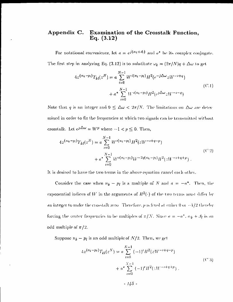
Appendix C. Examination of the Crosstalk Function, Eq. (3.12)
For IlotatÎonal collveuieucc, let (L = c j «(IA+dt) and a* \)(' it.~ complc'x cOlljugat!'.
The flrsL step in analy.dng Eq. (3.12) is to substitu\.e wk = (2'Tr/N)q + 61.,) to ppt
N-l 4;:;(nA.-pt}T~'/(;:;N) = a I: W-i(1I1-Pt}II'2(c-j6w.;:W-I+I{)
i=O
N-l (C.I)
+ a* L Il'I( liA -pd fi '2 ( eJ6w .:: \1'-1-1/)
1=0
Note Lhat q 18 an integf'r and 0 ~ 6",,' < 'l'TrIN. TIH' limit.ations ou 6w <II'<' dc'I('I-
mined in orcier to fix the frcqnencÎps ai which two sigllals ('an 1)(' trèlnsllli\.\'('c! wit hout.
crosstalk. Let eJ6w = 1VJl where -1 < p < 0, Theil,
N-l 4;:;(nk-/id1k/(:/'v) = a L Hrl(lI\-l'd JJ2(;:;W- 1+If-P)
1=0
,v-l (':!)
+ (l* L \V 1(II A-l'd W-'2q(IlI..-/It} 1/'2( :-W- 1+1/+/1 ) •
1=0
It is desil ed to have the t\\'o t('l'ms in the aho\'C' equatioll callcel Cil( Il olll<'l.
Consickl' the case whcn l1k - 1}1 is amuIt iplc of IV éllle! (( = -a*. Theil, I.IIf'
cxponcntial indices of IV in t.he argumellt.s of 1/'2(.) of Il)(' 1.\\'0 Ic'IIII~ 11111:--1 ddfC'1 by
fOl'cillg the ('1Ih'l' f'rc(!1wllcÎc':-, 1,0 Iw I\Illltipks or ir/.\'. Sill\(' 1/ = -1/*, n~. + :"/[ i~ tlil
ode! multipl(' of 7r /'2.
Suppose l1k - PI is an odd multiple of .IV /'2. TI1<'Il, wc' pp!
N-I .1;:;(lI k - lId '[kl(.;:N) = (/ L (_I)III:!(.::\I'-'+'1-1' )
1=0 ((':1)
,\'-1 + (/* 2: (_1)'1/'2(:11'-1+1(+11
).
I=U
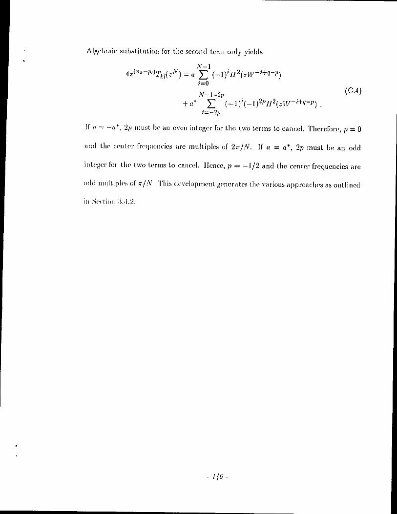
;\/W'blilic sllb~t.itlltioll for the second term only yiclds
N-l 1Z(1I k - pd Tk/(zN) = a L (-1/ n 2(zW- i+q- p)
i=O
N-1-2p +a* L (-1)i(_1)2PH 2(zlV-i+Q-P).
i=-2p
(CA)
If (J = -a*, '2p lIIust 1)(' ail evell integer for the two terms to cancel. Thercfore, p = 0
alld the' (:('11(('1' fl'<'qllcncies are multiples of 21r/N. If a = a*, 2]) must be an odd
integer for the two tcrms to cancel. IIence,]J = -1/2 and the center frequencies are
odd lIlult.ip/(':-, of 7r / N Thi~ development g('!1crcttcs the' various approaches as outlined
in S('c! iUIl :3.·1.2.
- 1 {(j -
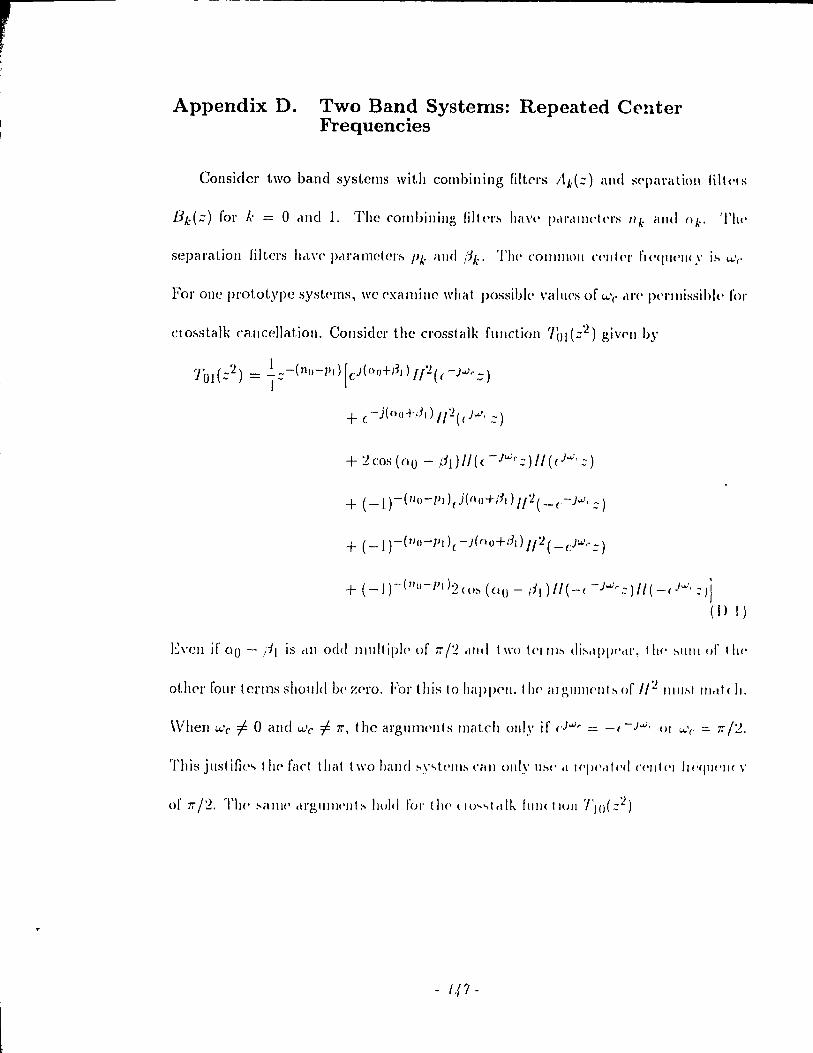
, ,
Appendix D. Two Band Systems: Repeated Center Frequencies
Consider two band systems wit.h combining filt.ers Ak(:) and s('\laratioll lilt(,\ s
separatioll filters hel\'(' pc1ramcter~ Pk ;111<1 ('ik' 'l'Ill' ('OIlIlIlOJl ('('Itlpl' fl('<fIl('Jl(Y i:-- u,,'(,
For onc prototype syst('II1S, wc ('xallliIlc ",Ital possible \"édues of w(' <l),(' j>(,l'llIissihl(' fOI'
Clofotstalk cancellation. Considcr the crosstalk flllldion 'lhl (:2) giV<'1I b)'
'1"'01(.:;2) = ~:-(n()-}Jd[c)(Ü()+I~dlI~((-)..vr.:;)
+ (-j(nu+13d Il'2( e j ...J·.::)
+ ( -1) -( 1Iu-l'd2 «)~ (00 - l'i 1) Il ( -( - j...J r ::)" ( - ( j"';, ::- J j (1) 1)
E\'cll if 00 - ;'i[ is cil 1 odd lIIultipl(' or iT /'2 c1Jld t \\'o tellll~ di:-'dpP('<lI', tilt' :-'llill of t Il('
olller four terll1s sllould !Je zero. For this 10 happC'Jl. t 1 If' éll gllllJ('Jlt ~ or /(2 11111:-.1 III .. t ( II.
\Vhen lJ.'c f; 0 and lJ.'c f; iT, the éll'gllnlC'llls ll111tch OJlly if eJ"';, = _c-j..v, <JI 1.4..'(' = iT/'2.
This justifie.., t 11(' faet tlléll 1 \\'0 band :-.y..,tl'JII:-' CéllI OJlly Il:--('.t 1('p('.tu'c1 ('('111<'1 Il ('(jI 11'1 1( V
- f ,p -
Appendix E. Constraints on the parameters 10 and I}
Ld t Ile :/.('10 cl'Ossillg illtel'val 1)(' 1\ and the Illllllber of filter coefficients be AI =
'2(10 + 1 j) + 1. The parametcrs 10 anù Il satisfy
10(1{ -1) ~ Il < 10{K -1)+ f( . (E.l)
Silln' II = (.\/ - 1 )/'2 - 10, the illl'quality l'edULCS to
M-l 1 0 ~ .) r < 10 + 1 . - \
(E.2)
Thih 11('\\' illC'quéllity is satisfied by a unique 10 givcn by
lM -lJ 10 = "21\' . (E.3)
_M-I lM-IJ II - 2 - 2A' . (EA)
- 148-
,
r
Appendix F. The Ratio IJl/o: Lower and Upper Bounds
This appendix derivcs lower and upper hOllUds for 11/10 and l-\ho\\'l-\ how t \) lix 1 hl'
filier length Al = 2(10 + Id + 1 to achieve tb's(' bOlillds, 'l'Il(' Z('('O cr()~l-\ill).!, illtc!'val
is f(, The ratio LIllO is ollly fillit<' fol' 10 i:- 0 \\'hich i~ il I('a~ollabl(' aS~IIIJJptiol1, Il
10 = 0, the filicl' leng,ih j\l < 21\' - 1 t 11<'1',,1>)' giving illl il\lplll~(' 1('~I)()\lS(, \VII Il \lo Z('("O
crossings and heucc, an insufficicnt Icug,th fol' ail eH'('('plable ~t.opl>.tlld ,tI,L('\II\,ÜiOll,
F.I Lower Bound
The lowc!' boulld fol' Il/lu i~ giv('11 by tilt' Idth<llid ~id(, or Eq (1-: 1),
Il j , - > \-1 10 -
The lo\\'cr boune! is achic\'cd if a\ld onl)' if 10 éllld Il arc gi\'('\1 b)'
1 _ .\1 - 1 o - ')/ - \
1 _ (.\ 1 - 1)( /\ - 1) 1 - ')j' - \
(1-' 1)
(V ~)
In this ca~(', the filL('!' knglh is of tl\(' l'mm .\l::: '210 /\' + 1 tl\l'l't'hy gl\'ill).!, <Ill illlpllb('
rcspoIlSC with the Lwo elld codficiclIls ('quai 10 Z'~IO,
If 10 alld II dl'(' choS('1I ct.,; aho\'(', \ lit' ~y..,I('1Il of ('qllal iOIl~ Dr = c 1 Il;11, ~(jl\'(· fUI 1111'
cocfficiellt~ of /'h(::) (ail \)(' d(,(,ol\pled illto d 1('<111«'<1 ~y..,t('111 uf dilllt'll:-.ioll II) .l1ld tlll'
additiollaI L'qlléll ion dUI )'/0(/0) = 0, 11<'11('<', J()( -10) = Jil(lO) = 0 1,11('1('11,)' I<'dllC III).!,
the eH't'cli\'e veducs of 10 dlld .\/ by 1 alld '2 J('spcc t j\,ply, Slldl d choj( (' of (Jill illlll'l('I:-'
gi\'<'& l'esult~ that arC' id('lIt ical to t II<' Cil~(, ",!t('11 lCl i~ J(·dll('(·d Ily 1.
F.2 Upper Bound
'l'II(' UPI)(!I bOlIlld 1'01 Idlo IS obtailled by cxam1ll1l1g the righthancl sicle of
Eq. (KI),
/} , J( -<1\-1+-. 10 10
(F.3)
Sillc (' tIf(' lIIillilllUIJl value of 10 is l, an upper houncl is 2f{ - 1. Achievillg a ratio
('qllill t.o il \',tllIC' of '2/{ - '2 is possible if alJd only if 10 = 1 and/} = 2K - 2. If 10 > l,
t.ht' lIPIH'1 bOlilld 1\. - 1 -1- 1\/10 :::; 21\" - '2 fol' t'vcry I{ ~ 2. JIcnce, 111/0 < 2f{ - 2 for
l'V('ry 10 > 1. 'l'If(' final conclusiolJ is that for a givCll J(, thcrc exists only one filtcr
!l'llgth, Il <1 1l1C'ly, fil = ·1 A" - 1 that achic"cs the maximum value 11110 = 21{ - 2.
- 150-

, Appendix G. Number of Exact Crosstalk CancellatiollS
for a Specifie Case
Consiàcr a center frcquelley Wc that is ail l'V('1l lllultiplp or ~1l' / N «'xrludill!!, ()
and 7r) in syst.em Tl wit.h N heillg a lIlullipl<- 01'·1. Fol''' sigllal SI'llt ,II W(" ('XMl
erosstalk eanccl\a tioll \Vi th ot her ::.igna Is SC'Il! ,II odd III Il 1 1 i pIcs of 27r 1 N is (ll'h Îc\'cd.
Sincc thcrc arc N /4 fICqucncics that are odd Illllitiples of 27r / N ,lIld two :-.ip,Il,t\s al l'
scnt aL ca ch of thcsC' fl'f'qllencies, a total of NI2 cl'Osstalk fllllctiom, ,III' ('xMlly /:1'10.
In Tl, thC'rc are a total of (N - ,1 );'1 c('lIler 1')'('</11('11('1(':-' t.h," c\l'I' (,\'('11 1111111 ipl(':-. of
211' IN. Thc C\os~talk lwt\\'<.'(,11 tll(' signal sell(. al u..'c alld OIU' of t III' :-.igll,ds :-'('111 ,d
othe!' frequcl\('i('fo> that f\re' <.'\'(·I\Il1\1ltipks of 211'IN will \)(' l'X;\( tly ZI'IO c!1'))('llIlillg 011
the delay factors. FUt thcnnorC', 1 hc crosst.alk b('lw('C'11 t he' 1.\\'0 ~igllals S<'lIt al W(' will
hc exactly ze)'o. i\'ow, \\'C' hcL\'c an addiliollal (N - 1)1 t cro~"talk fllllctiolls Ih,\1. ,II'<'
exactly Z('I'O bl'lllging 1 he lotal 10 (:L\' - ,1)11. III clddit iOIl. 1 Ill' (J'osslalk 1)('1.\\'('('11 011('
of Ihe ~igllal:-, :-'l'Ilt cl! ..... 'e <llIti ,Il(' :-.igllcds :'('111 al 0 <llId 7r willl)!' ("\él< II\' Z('\() d('IH'lIdill,l!,
ail the d('lay factOlS. DI'!){'IHlillg 011 tll<' ~igllHI :-'('111, Hf ..... 'c' t!J(' ()\·l'I.tillIllIll)WI (lI ('''<I( 1
CJ'ossl,cdk ci1Il('('lIat.iolls is ('ilhel (:3N - 1)/101 (:3:\' +·1 )/1.
- /5/ -
References
1. Il. K Crochi('re and L. R. Rabincr, l\Iultirate Digit,al Signal Proccssing, PrenticeHall, 198:3.
~. fI. SChCIl<'llIlilllll and II. Gocklcr, "A comprehensive survey of digital transmult.iph·'\1I1J.!, Il)('thod~'', Proc. of the IEEE, vol. 69, pp. 1-119-1450, Nov. 1981.
:$. f. 1\,11('\, "TIH' IJlultituIlf' clIélIlIWI", IEEE 'fnllJ . ., CO/flm., vol. COM-37, pp. 119-J ~,J, b·b J !)~!)
,1. C. B C;ctlcllHI i1lld Il .. J Nussballlll('r, ";\Tc\\, quadrature mirror filter structures", ll~m.; TreiJJs ACOllSI. Speech, Signal [Jroccssing, vol. ASSP-32, pp .. 522--531, .J tille J 9tH.
5. 1\1. .1. T. SlIlit h rllJd T. P. 13 ,\1'1 1\\'e Il , "Exact reconstruction techniques fol' trcc~tllJctlll('d ~ubbaJ\d ()(I('ls". IEEE Trans. Acollst,., Speech, Signal Proccssing, vol ASSP-'jl, pp I.ll Ill. .JUIl(' 19S(j.
G. i\1 \'('!.«orlr. "Filtel IJdllh ,t11oll'illg p<,\'rect lecon!:>tructioll", .Signal PlOLCssiIlg, \'01. 10. pp ~19 ~ II. Apl ri 1 \)SfJ
ï. ]\1. \'et tc·tli ... :\ t Il('or~ 01 lllllltllcltc fille'\' ballks", 1Ef<.;E Trans. AïOlIst .• Speech, S'igl/,d PI()('('so.;i1/p). \'01. ASSP-:35. pp. :35fi-:3ï2, 1\ldJ(.h 1987
8. P. P. V,lIdYclllrlthall. "Theory and design of ,U challnel maximally dccill1atcd qllculratllr<' lIlinor filter!':> with rlrbitraly ill, ha\ing the perfect-rcconstruction PIOP(·lty·'. IEEE 'IlaIl.~. J\row,t .. Spcech, Signal Proccssing, vol. ASSP-35, pp. ·17G ln. April 19Sï
q P L ('1111. "QllcldrdtlJl'(' 1l1111'Ol' filt"1 design for ail arbitral)' 1l111ll!)('r of ('quai b,lIldll'ldt Il (h"III1('I:-.··. I/:'EE 'J'rdIl... :\coust. SpccciJ. SIgnal I)l'Occc,."ing, vol. ASSP-:H. pp. ~lJ.J -~ I~. F(·b l!)~!j.
10 II..J N ll~ .. llrIIllll<'l clll<l 1\1 V('tlcrll. "C'ol1lputcüiollct!ly effIcient QivlF filter b,lJl"~". PIO(' lEEE In/. ('OIlf. A cou, .. !., Spccch, Sigllc-tl Pwcessing, SeUl Diego, ('aL, pp. II:Ll 1 t..~ 1. !\far<ll 1981.
Il. J. l\la~~()n ,llId Z. Pin'!. "Flc'\ible design of cOIllplltatiol1riIly efficient nearly I)('rf('ct Q 1\ 1 F b,1I1 b, ". PlOC IEEE III t. Conf A colIsl .. Speech, Signal Processing, 'J'.lJllpc\. Flolldrt. pp 117.1 11.7.1, l\lalcll 1!JS.5.
I~ B P. ILIIIlcll hc\lIdr<l1l ,1I1t! P. I\rlb,t!. "Brllldwiclth efficient tran!':>Illllltiplexers -1',lIt 1 S\Ii!II<'~I"'''' 'I«('pted 101 plllJlicrltloli ill IEEE 'J'l'cll/., A WlI .... t. , Speech, Slp,II,t! Pl (}('(·",-.illp,.
l.1 B P ILlllld( h,1I1clldll ,lIle! P !\,t1MI. "Syntlw!:>is of bélIldwidth efficient OQAl\I <lllcl \'SB t 1 dll..,llllrlt ipl(''\('I'''' Pro( Il~EE IlIt. ('ollf A CO 1/ .... t. . Speech, ,<,'iglldl P/'O«'.-..-.ill<~ . . \lhllqll(·I<jIl(" j\(.\\, l\ 1 ("\1 lO, pp. Ib.J!)-16·1~, Aplil I<JDO.
II. B. P. ILIIIl.I('lrdlldrclll <llIcI P. !\d1Ja!, "Bandwidth cffici('Jlt trélll,,>multiplcxers _ 1',11 t :2: SlIhh,lIId cOlllplf'IIWllts cllld perfOlIl1é1nc(' cOl1sideratiolls", acccptcd for pllhlrc,tlioll in IEEf-.' nrlll." :\COIl ... t, Speech. S\gllrll Processing.
-l.i'!-
15. R. P. Héllllélcb,llIdran élnd P. 1\,t1)dI, "Configuration <IIld pt'I fOrllltlllCl' of llIodu
latecl filter banks" PlOC. IEEE Ill/. Syllll) Ol/ Circllit ... ,II/ri ,":1)'1->/('/1/.'" Ne\\' Ol'lc,lIls, Loui8lclllâ. pp. 1809 181'2, l\'la~ 1990
16. R. P. Hamacballdran ,lllcl P. I\ctb,d. "l\lillilllé\x (ksigll of Ll< t.(Hall)<' Nyqllist. liller:fOl data tlan~lllissioll ~ystCI1l:-", Sl~lldl PJ()C(' .... Sill,~, vol. I~, pp. :l:.n :l:Hl, No\'. 1989.
17. R. P. Ram<lchandran and P. l\abal, '·'l'rilW,IlI11lt.ip)t'xf>I:-: P<,rf('( t r('('ollst.ru( t.ioll
and compensation of channel distort iOll", ac('('ptcd for pllJ,lic.ÜlOlI ill SiRII.t! Processmg.
18. P. P. V.udyallathan. "A Ilot(' 011 g<'llpl'èd j)aralkl Q~I F !J,lIlk ... ", IEEE '1'1<11/.'1
Cil'cuit~ rllJd SysteI1J~, \'ol. CAS-:~I, pp. lOI 10:3, ,Lili I~)~ï.
19. V. K. ,Jaïn ane! H. E. CroChH'!'(', "Quadldlnr(' lIlillOl fille!' d(':-igll III III(' tlll\<' d0ll1c\in'·. IEEE 'J] rlllS ACOIlSL, Spc('( II, Slg1l.d pJïl('C . .,Sillp" \'01. i\SSP-:t~, pp. 353 :3GI, Aplll 1981
20. N. Balaballldll, T. A. BH.kml and S. S('~hll. EIl'clrrc(l} NI'IlI'orJ.: 'J'1J('ory, .JOIIII \Viley and Sons, 1969.
21. 13. IIilOsaki, "AlI allc1ly~i~ of clutOll1è\tlC ('qudli:œr~ fOl ol'thogol\cdly 1IlIlItipl<'x('d QAl\1 sJ ... te1m", IEEE Tl'dl1" ('ollml, \'01 CO~I-2~, pp. ï:~ ~:L .Jall I!)~O.
22. B. Iliro~akl. ".\Il Ollllùgullèllly 1I1l1111ple'Xt·d QA ~1 ~y~tclll lI~llIg t Ill' disrrt'l,c FOllI'H'1 li <\1I..,lull11" , lEff T/eI/I.., ('0/1/111. \'\)\. :'O~I-~q, PI' !)~~ !)X!), .11/1)' I!)~l
2:3. 13. IIiro">dki. S Il cl "('gd\\',l <lllt! \. S,d)dtu, ":\<!\dIlU·d gH)Upl)dlld ddt.1 11IO<!t'lIl Il''>
ing ol'lhogOIl,1I1y Illulllplnl'd Q.\~I t('( hlllqll(,", }1';I';E 'frclllo; ('UIII/Il, \'o!. CO!\l-31, pp. 587-5!1'2. ,lUlIl' 19~()
2·1. R. W. Chang, "Sylltb('~i~ 01 1),\}Hllllllikd oJthogollet! ~i~lI,tls fOl Illldh'l!dlll\l'I
da ta tl alJ~mIS~lon", nell Sy:- t ('Jll 'Iech f/l( ,t! JOllI lied, pp. 1 ïï5 17%, D('( 1 !)(;(i.
2,'). ,1. II. l\kCldlan, T \V Parb a]}(! L. H. Hahillc'I, ',/\ (ompll! C'I' plOgl'illll for designing optimum FIn lillCdl plta..,c' digit al filtc'r~", [l';EE Trdll.~ :\ lulio illld
Elccil'Oilcoubl . vol. A U-:H, pp 5Gb ,')2(;, Dcc. 1 !)ï:~
26. J. 1\ Liallg. R . .J P. J)pFlglJ('il(·t!O .11\(1 F (' Lu, "J)('..,igll ul ()/llllll,tl N\'qlll~t,
pattl<11It·"pOIl~(·. Xtll !>,llid dllt! 11l)llll Il J!Ul 111 LI!> "p,t( Ill,!!, FI\{ !hgl1.tl 1111('1:-' Il;,III!!,
lincar plugltlll\llling t('<.ltI\Hjll«', IEEE ïld/h (';1(1111" dllfl .<.., .. .,((·,11 .... vol. (',\S-32, pp. :~~h :3t)~. ;\ pl 11 1 \18.).
27. A. C. S,dc\zc\1 ,lIId V. B L\\\,J('IIl'(" "l)('~igll <II\(\ illlpl<'JlH'llt<lIJ()1l ul Il<lll~lIlitlcl
alld 1('('1\'('1 filten, \Vith pel iodi<. codlit 1<'111 lIull.., fOI digit ,t! ~yo.;!('J\I"''', /'/0(' lIo;E/'; Inl. ('ollf. :\COll'it , ,':ip('('ch. SÏ,gfl,tl PlOcc . .".,icl,/!" P,III:-', I-'Idll«" pp. :W(i :i!O, [\101,)'
]982 28. P. P. V<lid,)'dlldthdll <llIcl T. Q. 0:~U\ <'Il. "Eigcllfilt(%· :\ IWW ,\j)!)\(!tl< h !u hw.,!
Sqllcl!'l'S FI n fill('!' d('~lgll ,\1Id a\lp!tc,t!IOIl'" ilH Illdlll)!, :'\) <(111"1 lill (·1 ...... lI';{';{'; 'l'l'illl'''
Ci/( /lit.- cl/Hi S\ ::'/('lJI">, \'ul (':\S-'j l. pp. 11 :2,L .Jdll 1 QSÎ.
29. T. Q. 0:gU) ('Il, T. S,tI dlll,tld d lit 1 P P \ ,lIdYdll<1I hdll, . Llg('lIldt ('\:-' lOI 1 hl' d(·;,igll
of sp('ej,d Il,1110.;/('1 111l1<tIOll'" \\'Ith ,lpp!t(',tlIOllo., III lIIllltll.lIC' :-'lglJ,tl PI()(C'~~IJI)!,",
Proe. If FE ll1t. ('onf i\(()/I .... t • S'p('('( JI, ,','i,glJelJ fJl()«(,'o ... III,g, ~('\V YUI!.:, f\.Y., pp.
],lG7-1IïO. :\Plil 1988
-1.53·
:W. F. Milltzel, "011 half-hand, thirel-hand and Nth-band FIR filters and thcir design", IEEE Tnlll8 Acollst., Speech, Signal Processing, vol. ASSP-30, pp. 734-ï:38, 0< t t!H32.
:JI. F i\lilltZ('I. "lïltel,) fOI di~toltioll-fre(' two-band Inultirettc filtcr bilnks", IEEE 'J'/'rll/'> Amust , SliCcch, 8igl/cll PJOcc8sillg, vol. ASSP-:J3, pp. 626--630, June 1985.
:J2. P P Vrlidyallat hein dllel T. Q. Nguyell, "A TB ICK for the design of FIR haH-1>,111<1 filt('IS", IEEE TraIlS. Ci/cuits and Systems, vol. CAS-34, pp. 297-300, Mardi 1987.
:3:3. T. Sdrarnaki ami Y. Nc'uvo, "A c1ass of FIR Nyquist (Nth band) fiIters with zero illtcrsymbol intcrfcrence", IEEE Trans. Circuits and Systems, vol. CAS-34, pp. 1182-1190, Oct. 1987.
:H. 0 lIen lIlallll alld "V Schussler, "Design of nonrecursivc (ligital filters \Vith minillllllll phrls<,'·. Elcctrollics Lct./C'r8, vol. 6, pp. 329-330, April 1970.
:~!) L. H ILdlill('1 dlld B Ciold. 'J'heO! l' dIld Applications of Digit,al Signal Pro cessil/g, Ptt'Ilti( ('-lIédl, 197.5.
:W F. Gn'/H'z, "D('~igll of lillcc1r ellld minimum phase Fm filters by constraincd Chebyshev c1pp/Oximation", SIgnal Proccssing, vol. 5, pp. 32,5-332, July 198~j.
;J7. Y. Kalllp alld C. J. Wellekcns, "Optimal design of minimum phase Fm Hlters", ŒEE TrdllS A COllSt. , SpCC'(h, Signal Proccssing, vol. ASSP-31, pp. 922-926, Aug. E)S:3.
:lS .. 1. II. \Vilkillwn, UOl/lIdÎllg ElIOl8 in Algcbraic Proccsses, Prcnticc-llall, 1963.
:39 .. /),11<1 (Olllllllllllc,1! ion ('\'('1 the tcl<'phollc Il et work", CCITT He<-ommcndation V.~~. Hec! Book. V Sel ipso 01'1 11)811.
·10. X. ('lw1I <llld T. W. Park~, "I)c!>igll of opllll1al 1111llllllUlll phase FIR filters by dill'Ct faclorizatioll", .':iigIlcd P/Occssing, vol. 10, pp. 369-383, June 1986.
'Il .1. K J)elllli'i éllld H. E. Schllal>cl, Nl/l11crical Methods [or Unconstraincù Optirnizatioll ancl N01llillC'rll Eql/rltjollS, Prcntice-I1all, 1983.
·12. I~ISL lJ~('r's l\lallual (~Idth/Liblary), Vol. 3, Chapter 8, April 1987.
·n .1. [) .Jollll~ton. "A filt('r family (bigncd for use in quadraturc mij"'or filtcr ballks". PlOC IEEI'; Int ('onf. \ml/st., Speech, Signal Proœssi:lg, Dell'/er, ColO! ,\(10. pp. :!~) 1 2!J.I, ,\ pl il 1 ()~O
1·1 1\1 \'\'1 (<'Iii. "1'('II('cl Tl ,11I~llIult ipl("(,I~". PlOC IEEE Int. Conf Acoust., Speech, SI!!,llit! J)J(J((,,,."./IJ,'-:. '!'ok.\'o .. J'Ij)dll, pp. ·IS.V.l-·IS.9.l, Apl il 19SG.
·If> IL \\' Lurl,y . .J. Srllz rllld E .J Wpldoll, Prillciplcs of Data Communication, J\!ce: 1 <1 \\'-11 dl. 1 ~)()~
.1(;. S. U. II. Qllwslti, "Adapti\'(' Equéllizatioll", Pme. of t.he IEEE, vol. 73, pp. 131!l-1:1~7, Scp. 19S5.
li. S. lJ.lykill, :\c/elptive Filter 'l'henry, Prcnticc-IIalI, 1986.
I~. P.-Q 110<111' rllld P. P \'rlldY<lllclthan, "Non-Uniform lllultiratc filter banks: Theur.\ <1 Il cl d('~igll". PlOt' IEEE Jllt S.I'II1I). 011 Cll'Cliits illlcl Systems, Portland, Oregull. pp :l'ïl :li t. ;\Id~ 19X9.
- 15,[ -
, ,


![signal [Mode de compatibilité] - educnet.enpc.fr · Classification des signaux signaux déterministes aléatoires permanents transitoires stationnaires non-stationnaires Signaux](https://img.pdfslide.net/doc/110x75/5b9956f909d3f2cb468b9fda/signal-mode-de-compatibilite-classification-des-signaux-signaux-deterministes.jpg)