Embed Size (px)
Citation preview
Exploring Computational Origami with iFoldCSC 2522 - Term Project Report
Sam Hasinoff, 991045980December 14, 2000
AbstractComputational origami is a relatively new and esoteric field, but one which continues to offer a fertile source of interesting problems in geometry. One recent result demonstrates several methods that allow any polyhedron to be gift-wrapped with a single piece of paper—in other words, all origami is proved theoretically possible!
This report is structured in three parts. First the (limited) computational origami literature is reviewed. Next follows a detailed description of the zig-zag method, one of the theoretical algorithms shown to solve the gift-wrapping problem. Finally iFold is presented, a prototype system constructed to model and visualize simple origami, in particular the zig-zag method..
Deliverables (found under ~hasinoff/2522/ifold/) include: this report (origami.doc) polyhedral mesh source (subdivision.jar) origami visualization source (origami.jar) geometric models used for testing (models/*) [coming soon] demonstration movies (movies/*)
1. Introduction
1.1 Background
People have been folding paper into shapes for centuries, perhaps ever since paper was invented in China in the first century. The earliest paper folding techniques were brought to Japan in the sixth century, where they were absorbed enthusiastically by a culture that was already deeply involved with paper. The word origami is the Japanese name for the art of paper folding, where the root kami is interestingly a homonym for both paper and god. Indeed, traditional origami still plays an important role in both Shinto religious ceremony and much of Japanese architecture. Many of the original folding forms have survived to this day. [8]
In its purest form, origami involves folding a figure from a single square piece of paper without cutting, however some renegade variants have relaxed these restrictions. Modern practitioners of origami have achieved stunning results by applying a generally more sophisticated approach to figure design, and by experimenting with different media and paper colouring [8, 13, 17]. There has also been exciting work in unit origami, a newer branch of origami which seeks to assemble shapes from a collection of simpler base units [7].
1.2 Previous Work
Although the mathematical approach to origami had its proper beginning in the early nineties, its roots can be traced to a number of informal heuristics known for many years, related to designing shapes based on the number of appendages. Another older technical approach involves the construction of origami molecules, or basic building blocks that can be repeated [8].
The field of computational origami finally exploded with the popular talk delivered by Robert Lang at the ACM Symposium on Computational Geometry [11]. There he described his TreeMaker software for generating the solution of a crease pattern for an origami base given an arbitrary skeleton represented as a 1D tree. One can supposedly extend much of the theory to finding crease patterns from 2D meshes (polyhedrons), but this is still work in progress since there are special conditions that occur at concave vertices [12]. The general method involves posing an optimization problem in terms of the smallest square of paper necessary, and an elegant relationship is shown with the problem of circle-packing. The most troublesome part of the technique is that even given a crease pattern with an assignment of mountain and valley folds, finding a folding sequence to obtain the base usually cannot be determined: actually folding the base from the crease pattern may require crumpling several folds together at once or may be completely impossible. Even so, TreeMaker remains a valuable tool to help origami experts create new bases of unprecedented complexity.
Soon thereafter followed complexity results for origami [4], showing that assigning mountain and valley folds for an arbitrary pattern is an NP-hard problem. Moreover, determining a suitable overlap order for flaps to fold flat is also NP-hard, even given a valid mountain-valley assignment. The latter result was accomplished using a clever construction of folding gadgets that can be reduced to solving a variant of 3-SAT. In practice, if you construct the creases yourself, you usually have enough extra information to make crease assignment a P problem, but determining a suitable order of folding from a crease pattern is frequently impossible [12].
Recently, Erik Demaine, Martin Demaine, and Joseph Mitchell formulated an important theoretical breakthrough in origami, which has larger implications for computational geometry as well. They first showed that any connected polygonal silhouette is foldable from a single piece of paper [5], and then later extended their result to show that any polyhedron can be gift-wrapped from a single piece of paper [6]. The consequence is that folding any conceivable origami figure is always possible!
In fact, three different methods are presented in [6] to solve the gift-wrapping problem, all of which are convincing but none of which seem very practical for constructing real origami. All the methods involve folding a very long and narrow strip. To summarize briefly, the zig-zag method (described in more detail later) operates by zig-zagging across the triangles along a Hamiltonian path, which can always be constructed by adding O(n) vertices, and tucking any excess paper under the triangles. An alternative is the ring method, which employs the straight skeleton [1] to induce a decomposition of polygons into rings chosen to be the thickness of the strip. With the ring method, gift-wrapping involves walking between rings using a turning gadget, and following around rings as far as is needed to reach the joining place for the next adjacent ring. Finally, the convex decomposition method calculates a convex decomposition of the polyhedron [9], covering each convex polygon in turn with many layers of tucking under, and employing such tricks as dynamically varying the width of the strip.
2. Zig-Zag Method
2.1 OverviewThe heart of the zig-zag method is using a narrow strip of paper to zig-zag across all of the triangles in a mesh in sequence. The method operates in two main stages. First the mesh to be gift-wrapped is refined into one possessing a Hamiltonian path (a total ordering on the triangles such that consecutive faces share an edge). This is shown to be possible for any mesh. Next the strip is zig-zagged across the triangles. Basic folds are used to effect the zig-zags, different turning gadgets are used reorient the strip between triangles, and any excess paper is readily tucked out of the way.
2.2 Hiding PaperIt is easy to hide excess paper behind a convex polygon. The basic idea is to perform mountain folds along the edges of the polygon, to tuck under the regions of paper that lie outside. The naïve algorithm involves folding under the edges of the polygon in order and repeating until everything is tucked under. This algorithm is simple to prove correct, and performs well unless the amount of paper to be tucked under is relatively large. A more sophisticated algorithm is presented in [6] which does extra folding in advance to bring the excess paper within a small distance of the convex polygon. In this way, a bound of O(V log(δ/ρ) + 1/θmin) folds can be proved, where V is the number of vertices in the convex polygon, δ is the diameter, ρ is the minimum feature size, and θmin is the smallest interior angle.
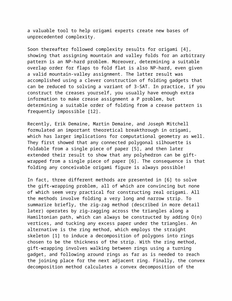
2.3 Turn GadgetAnother basic tool for folding a strip of paper is the ability to turn the strip. The first attempt at a turn gadget is shown in Figure 1. It involves two folds, one perpendicular to the strip, and another to effect the turn.
Figure 1. Basic turn gadget, shown for a turn greater than 90˚.
Unfortunately, if several layers of paper are involved, the first fold of a basic turn gadget has the potential effect of undoing the effect of previous turn gadgets. We can remedy this problem by using a generalized form of the turn gadget, as shown in Figure 2, which allows the strip to continue past the fold, only making the perpendicular fold after the trouble area has been passed. The ability to produce any amount of overhang actually proves useful later in §2.5, when turning from one triangle to the next.
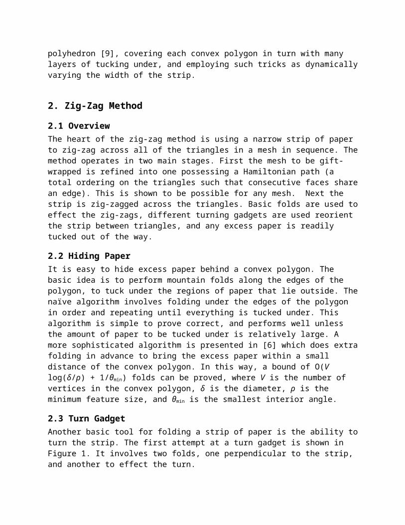
Figure 2. Generalized turn gadget, shown for a turn less than 90˚. Note that the first step can be modified to produce any desired amount of overhang.
It is noted in [6] that turns made with the generalized turn gadget can produce arbitrarily large amounts of excess paper as the angle approaches 180˚. A more complicated alternate turn gadget (of no practical interest) is presented, involving more layers of folding but using only O(w2) excess paper, where w is the width of the strip. The alternate gadget allows the total area of excess paper to be bounded, in order to prove optimality of the zig-zag method in a slim theoretical sense, as the strip approaches a width of zero! As will be argued later, this metric of optimality is deeply flawed for real origami.
2.4 Hamiltonian RefinementA triangulation is said to contain Hamiltonian path if there exists a total ordering of the triangles such that consecutive triangles share an edge. Of course, not every triangulation will contain a Hamiltonian path, but any triangulation with n triangles can always be made Hamiltonian by adding exactly n Steiner points [2]. We refer to this process as Hamiltonian refinement.
For every triangle in the original triangulation T, we first place a Steiner point at the incentre (the centre of the largest inscribed circle) of the triangle. The incentre has a simple formula in barycentric coordinates (a:b:c), and serves to guarantee that minimum angle of the Hamiltonian refinement will not be less than half of the minimum angle of the original triangulation. Next, we consider a spanning tree of the dual graph of T. Edges crossed by the spanning tree are split at the midpoint and connected to the Steiner points of the faces on either side of the edge. This last modification will give a Hamiltonian triangulation, where the Hamiltonian path can be recovered by walking around the spanning tree, as shown in Figure 3. The subtriangles created from the Hamiltonian refinement inherit the colour of their parent triangle.
Figure 3. Hamiltonian refinement of a twelve triangle mesh. The light dashed edges come from inserting the Steiner points, while the heavy dashed edges correspond to the spanning tree, constructed in a depth-first fashion. The final Hamiltonian path is shown as a curved dotted line.
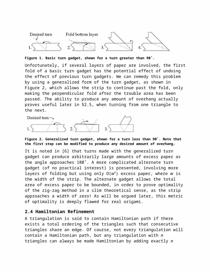
The original intent of [2] was to use Hamiltonian paths in order to find long (continuous) stripifications for fast rendering. The fact that the number triangles are more than quadrupled makes the method totally impractical, but it still remains a result of interesting theoretical importance. Indeed, it was this guaranteed existence of a Hamiltonian refinement for any mesh that enabled Demaine, et al. to extend their zig-zag method from folding flat silhouettes to folding arbitrary polyhedrons.
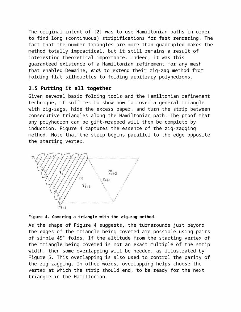
2.5 Putting it all togetherGiven several basic folding tools and the Hamiltonian refinement technique, it suffices to show how to cover a general triangle with zig-zags, hide the excess paper, and turn the strip between consecutive triangles along the Hamiltonian path. The proof that any polyhedron can be gift-wrapped will then be complete by induction. Figure 4 captures the essence of the zig-zagging method. Note that the strip begins parallel to the edge opposite the starting vertex.
Figure 4. Covering a triangle with the zig-zag method.
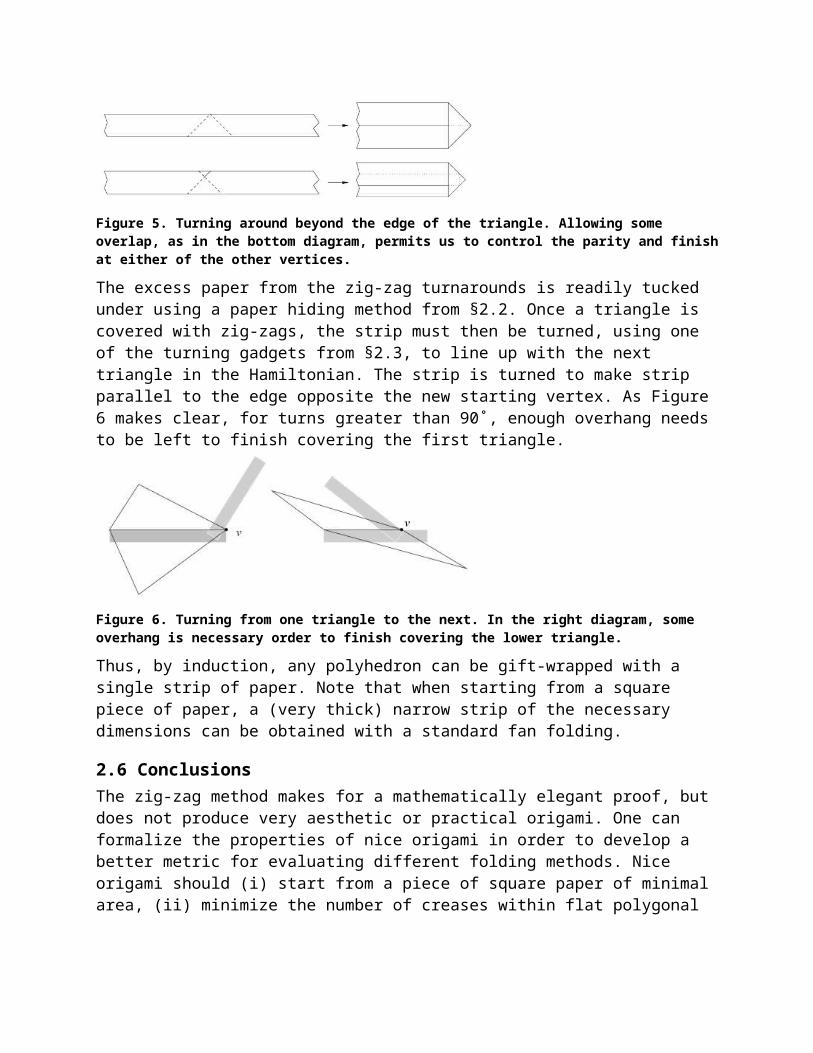
As the shape of Figure 4 suggests, the turnarounds just beyond the edges of the triangle being covered are possible using pairs of simple 45˚ folds. If the altitude from the starting vertex of the triangle being covered is not an exact multiple of the strip width, then some overlapping will be needed, as illustrated by Figure 5. This overlapping is also used to control the parity of the zig-zagging. In other words, overlapping helps choose the vertex at which the strip should end, to be ready for the next triangle in the Hamiltonian.
Figure 5. Turning around beyond the edge of the triangle. Allowing some overlap, as in the bottom diagram, permits us to control the parity and finish at either of the other vertices.
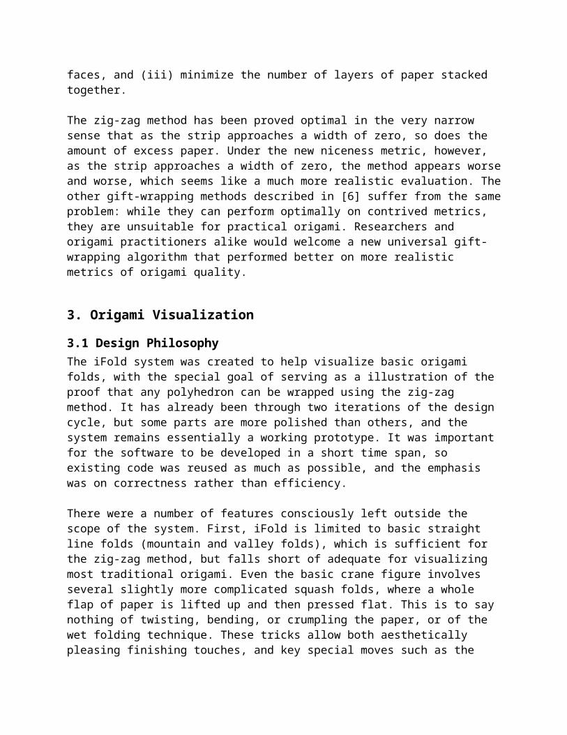
The excess paper from the zig-zag turnarounds is readily tucked under using a paper hiding method from §2.2. Once a triangle is covered with zig-zags, the strip must then be turned, using one of the turning gadgets from §2.3, to line up with the next triangle in the Hamiltonian. The strip is turned to make strip parallel to the edge opposite the new starting vertex. As Figure 6 makes clear, for turns greater than 90˚, enough overhang needs to be left to finish covering the first triangle.
Figure 6. Turning from one triangle to the next. In the right diagram, some overhang is necessary order to finish covering the lower triangle.
Thus, by induction, any polyhedron can be gift-wrapped with a single strip of paper. Note that when starting from a square piece of paper, a (very thick) narrow strip of the necessary dimensions can be obtained with a standard fan folding.
2.6 ConclusionsThe zig-zag method makes for a mathematically elegant proof, but does not produce very aesthetic or practical origami. One can formalize the properties of nice origami in order to develop a better metric for evaluating different folding methods. Nice origami should (i) start from a piece of square paper of minimal area, (ii) minimize the number of creases within flat polygonal faces, and (iii) minimize the number of layers of paper stacked together. The zig-zag method has been proved optimal in the very narrow sense that as the strip approaches a width of zero, so does the amount of excess paper. Under the new niceness metric, however, as the strip approaches a width of zero, the method appears worse and worse, which seems like a much more realistic evaluation. The other gift-wrapping methods described in [6] suffer from the same problem: while they can perform optimally on contrived metrics, they are unsuitable for practical origami. Researchers and origami practitioners alike would welcome a new universal gift-wrapping algorithm that performed better on more realistic metrics of origami quality.
3. Origami Visualization
3.1 Design PhilosophyThe iFold system was created to help visualize basic origami folds, with the special goal of serving as a illustration of the proof that any polyhedron can be wrapped using the zig-zag method. It has already been through two iterations of the design cycle, but some parts are more polished than others, and the system remains essentially a working prototype. It was important
for the software to be developed in a short time span, so existing code was reused as much as possible, and the emphasis was on correctness rather than efficiency.
There were a number of features consciously left outside the scope of the system. First, iFold is limited to basic straight line folds (mountain and valley folds), which is sufficient for the zig-zag method, but falls short of adequate for visualizing most traditional origami. Even the basic crane figure involves several slightly more complicated squash folds, where a whole flap of paper is lifted up and then pressed flat. This is to say nothing of twisting, bending, or crumpling the paper, or of the wet folding technique. These tricks allow both aesthetically pleasing finishing touches, and key special moves such as the inversion of a cone, which are otherwise impossible on a geometric level [12]. Modeling these sorts of non-geometric folds would clearly add great complexity to the system.
Another feature omitted from the system is collision detection, which could report or prevent impossible folds. This would have been simple enough to add, using the basic intersection testing built into Java 3D or my own (previously developed) more sophisticated sphere tree routines. It was decided, however, that collision detection would have added an unnecessary layer of complication, since all of the foldings ever visualized are known in advance to be valid.
The final feature missing from iFold is an interactive user interface. With such an interface, preventing impossible folds would certainly have been more of an issue. The current system presents a framework for viewing and animating hard-coded folds, but folding decisions cannot be made interactively. While an interactive 3D user interface would certainly have been very nice, time constraints did not permit the task of constructing one essentially from scratch.
One special feature of iFold is that paper thickness is modeled explicitly. This was deemed an important area for investigation, since a powerful criticism of the zig-zag and related methods is that folding too many layers of paper make them impossible to realize physically. Modeling the paper thickness is also important for aesthetic reasons, to make the folded shapes appear more realistic.
3.2 Implementation DetailsThe iFold prototype was implemented on an AMD K6-III 450, with 128 MB of primary memory, and equipped with a Diamond Viper V770 video card. All of the code was written in pure Java using the Java 2 SDK 1.3 [14]. Extensive use was also made of Java 3D 1.2.1 (Beta 1) [15], a standard extension to Java which describes a high-level scenegraph language, similar in spirit to VRML and Open Inventor.
One major advantage of using Java was the possibility of leveraging an existing code base for manipulating and viewing polyhedral meshes (part of previous work on subdivision surfaces), for quick start-up time. Java also has the advantage of good and well-documented library support, and structural features that enable fast development. As an added bonus, Java is also fairly portable, and different Java 3D implementations exist for Windows 98/NT, Linux, and Solaris. The notion that Java is too slow for practical graphics is fundamentally a myth, as any calls to the rendering pipeline are made to the native OpenGL or DirectX layer, and are thus take advantage of whatever hardware acceleration exists.
The next best alternative would have been starting from scratch on the graphics side, and learning how to use CGAL (Computational Geometry Algorithms Library) [16] in C++ for dealing with the geometry. While this would have reduced coding in some areas, the time that would have been needed to get reacquainted with C++ and OpenGL as well as become competent with a complicated (and more powerful than needed) library was prohibitive. There were certainly problems with using Java. With no sophisticated IDE available, debugging facilities were abysmal. Furthermore, all of the bad design decisions and problems relating to the old reused code were inherited into iFold. To give one example, some of the origami code had to be added directly to the polyhedral mesh package, to circumvent built-in visibility restrictions. Moreover, most of the interface to the Java 3D rendering cycle had to be rewritten to allow for a changing mesh structure, since the old code had assumed static meshes, where only the vertex coordinates were changeable. Finally, a serious bug was discovered in the OpenGL implementation of Java 3D, where vertex colours would be randomly corrupted under special conditions. Switching to the DirectX implementation fixed this.
3.3 Polyhedral MeshThe polyhedral mesh is one of the most basic structures for representing 3D shapes in computer graphics. As well as storing vertex coordinates, it is possible to augment the data structure with extra information in order to represent connectivity. An entire family of data structures which capture this connectivity is enumerated and analysed for memory requirements by Kettner [10]. Polyhedral meshes are formally 2-manifolds, reflecting their mathematical relationship to planar subdivisions.
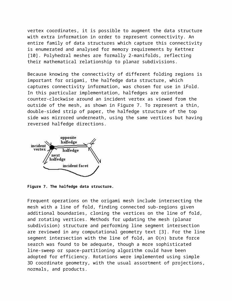
Because knowing the connectivity of different folding regions is important for origami, the halfedge data structure, which captures connectivity information, was chosen for use in iFold. In this particular implementation, halfedges are oriented counter-clockwise around an incident vertex as viewed from the outside of the mesh, as shown in Figure 7. To represent a thin, double-sided strip of paper, the halfedge structure of the top side was mirrored underneath, using the same vertices but having reversed halfedge directions.
Figure 7. The halfedge data structure.
Frequent operations on the origami mesh include intersecting the mesh with a line of fold, finding connected sub-regions given additional boundaries, cloning the vertices on the line of
fold, and rotating vertices. Methods for updating the mesh (planar subdivision) structure and performing line segment intersection are reviewed in any computational geometry text [3]. For the line segment intersection with the line of fold, an O(n) brute force search was found to be adequate, though a more sophisticated line-sweep or space-partitioning algorithm could have been adopted for efficiency. Rotations were implemented using simple 3D coordinate geometry, with the usual assortment of projections, normals, and products.
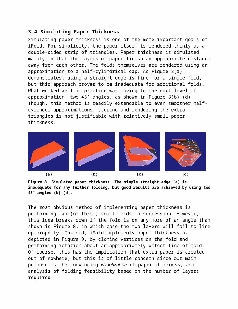
3.4 Simulating Paper Thickness Simulating paper thickness is one of the more important goals of iFold. For simplicity, the paper itself is rendered thinly as a double-sided strip of triangles. Paper thickness is simulated mainly in that the layers of paper finish an appropriate distance away from each other. The folds themselves are rendered using an approximation to a half-cylindrical cap. As Figure 8(a) demonstrates, using a straight edge is fine for a single fold, but this approach proves to be inadequate for additional folds. What worked well in practice was moving to the next level of approximation, two 45˚ angles, as shown in Figure 8(b)-(d). Though, this method is readily extendable to even smoother half-cylinder approximations, storing and rendering the extra triangles is not justifiable with relatively small paper thickness.
(a) (b) (c) (d)
Figure 8. Simulated paper thickness. The simple straight edge (a) is inadequate for any further folding, but good results are achieved by using two 45˚ angles (b)-(d).
The most obvious method of implementing paper thickness is performing two (or three) small folds in succession. However, this idea breaks down if the fold is on any more of an angle than shown in Figure 8, in which case the two layers will fail to line up properly. Instead, iFold implements paper thickness as depicted in Figure 9, by cloning vertices on the fold and performing rotation about an appropriately offset line of fold. Of course, this has the implication that extra paper is created out of nowhere, but this is of little concern since our main purpose is the convincing visualization of paper thickness, and analysis of folding feasibility based on the number of layers required.

Figure 9. Paper thickness implementation. Vertices are cloned and then rotated about an offset point, so that the layers will line up properly. Note in the lower diagram that one of the clones is only rotated half as much (90˚) to achieve the angular half-cylinder effect.
Knowing how much to offset the rotation depends on the existing layers of paper on either side of the fold, and whether the fold is a mountain fold or a valley fold. In iFold, a brute force search finds the extremal points in directions normal to the fold, and performs a simple calculation to get the correct offset. This process could be greatly streamlined if the different thicknesses and layers of fold were managed explicitly.
Another point of note is that when folding about a line, it is actually a plane (whose normal lies in the plane of the paper being folded) used to find intersections with the mesh. In this way, all the layers which are vertically offset from each other (from the simulation of paper thickness) are sliced through as desired. One final comment is that simulating paper thickness has the added bonus of eliminating the aliasing effects that would be associated with rendering triangles directly on top of each other, as in the naïve approach to folding a thin strip.
3.5 Visualizing the Zig-Zag MethodOne demo was created to find a Hamiltonian refinement of an arbitrary mesh, and to show the sequence of triangles on the Hamiltonian path using animation. As Figure 10 illustrates, there is no restriction on the topology of the mesh. We can thus convince ourselves that the zig-zag method will work for all polyhedral meshes, even those with holes and non-convexity.
(a) (b) (c)
Figure 10. Hamiltonian refinement. The original mesh (a) can have arbitrary topology. Detail of the Hamiltonian refinement (b) is shown with edges on the spanning tree coloured green. The final Hamiltonian path (c) is shown here by colouring triangles along the path with increasing darkness.
Another demo was created to animate the zig-zag method applied to an arbitrary single triangle. The progression of zig-zags, followed by multiple tuck-unders is shown in Figure 11. Even with a number of known inefficiencies, and a design philosophy favouring brute force and simplicity, iFold was able to animate the folding of simple models at better than frame rate.
(a) (b) (c)
Figure 11. Applying the zig-zag method to a triangle. First, the triangle is covered with zig-zags using basic turn gadgets (a). The excess is then tucked under, in order to obtain the final result (b). The underside of the triangle (c) reveals many layers of folding.
The criticism that the zig-zag method is unsuitable for constructing real origami because of the prohibitive number folding layers required is shown to be unfounded. Experiments with iFold and (actual) paper confirm that even for relatively narrow triangles this aspect of the method is not that much of a problem. The real problem folding the actual paper models (apart from their ugliness) is their inability to hold themselves together, and the fact that the starting strip must be many hundreds of times longer than wide, even for medium-sized models.
3.6 Future Work In the short term, the prototype should be polished so that the code works more generally and so that certain hidden assumptions about allowable folding (which have no effect on the zig-zag method) can be eliminated. While the mesh manipulation and folding primitives work well, there should be easier ways to call them, and to combine these calls into meaningful functional units. Also needed is a simpler unified framework for performing the animations and for producing screen captures so as to be able to generate MPEG movies. It would also be worthwhile to develop a simple user interface in addition to the basic virtual trackball-style viewer. Even a minimal interface using Java Swing menus, giving the ability to specify parameters and run animations would help avoid unnecessary recompilation and shorten the development cycle.
The list of desirable capabilities for any origami modeling system is long. At a bare minimum, the system would include many different types of folds to permit the folding of most traditional origami. While including a library of standard folding moves (like the squash fold) is nice, any piecewise-affine fold imaginable should be possible too. Another direction in which to expand the system is to automatically produce standard origami notation and folding diagrams given a folding sequence, or possibly to do the reverse. Ideally, the system could serve as a sort of virtual workbench for creative work in origami, and would include such tools as “generate the base and crease assignment for a given 3D skeleton,” and “hide all the excess paper behind a specified
polygon.” Another attractive feature would be the ability to perform physically-based animation of origami figures, like the classic crane who flaps its wings when its tail is wiggled, perhaps using a simple mass-spring model.
Any serious attempt to produce professional-quality commercial origami modeling software would be hotly anticipated by origami practitioners and dilettantes (like myself). Unfortunately, the minuscule market for such software probably makes it a doomed enterprise from the outset. On a slightly less ambitious scale, one could consider the development of a Maya plug-in to regard origami as a sort of non-photorealistic rendering technique, giving one the ability to visualize a scene or animation in an origami-esque way.
References[1] Oswin Aichholzer and Franz Aurenhammer, Straight skeletons for general polygonal figures in the plane, in: Proceedings of the 2nd Annual International Computing and Combinatorics Conference, Lecture Notes in Computer Science, Vol. 1090 (Hong Kong, 1996) 117-126.
[2] Esther M. Arkin, Martin Held, Joseph S. B. Mitchell, and Steven S. Skiena, Hamiltonian triangulations for fast rendering, The Visual Computer 12 (1996) 429-444.
[3] Mark de Berg, Marc van Krevald, Mark Overmar, Otfried Schwarzkopf, Computational Geometry: Algorithms and Applications. (Springer-Verlag, Berlin, 1997) 19-43.
[4] Marshall Bern and Barry Hayes, The complexity of flat origami, in: Proceedings of the 7th Annual ACM-SIAM Symposium on Discrete Algorithms (Atlanta, 1996) 175-183.
[5] Erik D. Demaine, Martin L. Demaine, and Joseph S. B. Mitchell, Folding any silhouette from a strip, in: Proceedings of the 3rd CGC Workshop on Computational Geometry, (Providence, 1998).
[6] Erik D. Demaine, Martin L. Demaine, and Joseph S. B. Mitchell, Folding flat silhouettes and wrapping polyhedral packages: New results in computational origami, in: Special issue of selected papers from the 1998 CGC Workshop on Computational Geometry, Vol. 16 (2000) 3-21.
[7] Andrew S. Glassner. Andrew Glassner's Notebook: Recreational Computer Graphics. (Morgan Kaufmann, San Francisco, 1999) 38-71.
[8] Kunihiko Kasahara, Origami Omnibus, (Japan Publications: 1988).
[9] J. Mark Keil, Decomposing a polygon into simpler components, SIAM Journal onComputing 14 (1985) 799-817.
[10] Lutz Kettner, Designing a data structure for polyhedral surfaces, in: Proceedings of the 14th Annual Symposium on Computational Geometry (1998) 146-154.
[11] Robert J. Lang, A computational algorithm for origami design, in: Proceedings of the 12th Annual ACM Symposium on Computational Geometry (Philadelphia, 1996) 98-105.
[12] Robert J. Lang, private communication, 2000.
[13] John Montroll, Origami for the Enthusiast, (Dover Publications: 1979).
[14] Sun Microsystems, Inc. Java 2 Platform Standard Edition. http://java.sun.com/j2se/, 2000.
[15] Sun Microsystems, Inc. Java 3D API 1.2. http://java.sun.com/products/java-media/3D/, 2000.
[16] Universiteit Utrecht. Computational Geometry Algorithms Library. http://www.cgal.org/, 2000.
[17] Joseph Wu. Joseph Wu’s Origami Page. http://www.origami.vancouver.bc.ca/, 2000.


![Recovering High Dynamic Range Radiance Maps from Photographs [Debevec, Malik - SIGGRAPH’97] Presented by Sam Hasinoff CSC2522 – Advanced Image Synthesis](https://img.pdfslide.net/doc/110x75/56649de85503460f94ae2187/recovering-high-dynamic-range-radiance-maps-from-photographs-debevec-malik.jpg)