Embed Size (px)
Citation preview

Tutorial: 01
Mechanics of solid
Scope & Objective of the course:
The subject of mechanics of solids deals with determination of strength, deformation and stability of structural and machine elements. The methods are based on Laws of Newtonian mechanics, applied to bodies in static equilibrium geometry and experimentation. These laws are applied to simple situations with engineering judgment to arrive at results of significance to the designer. At the end of the course the student will be in a position to design and analyze simple structural elements, which involve calculation of stresses, strain and deformation. This is an essential feature in a design process.
What is a Mechanical Engineering?Mechanical engineering is one of the largest, broadest, and oldest engineering disciplines.
Mechanical engineers use the principles of energy, materials, and mechanics to design and manufacture machines and devices of all types. They create the processes and systems that drive technology and industry. Mechanical engineering plays a dominant role in enhancing safety, economic vitality, enjoyment and overall quality of life throughout the world. Mechanical engineers are concerned with the principles of force, energy and motion. The men and women who work as mechanical engineers are professionals with expert knowledge of the design and manufacture of mechanical systems and thermal devices and processes. Some examples of products and processes developed by mechanical engineers include engines and control systems for automobiles and aircraft, electric power generation plants, lifesaving medical devices and consumer products ranging from air conditioners to personal computers and athletic equipment. They also design the machines that mass-produce these products. Virtually every aspect of life is touched by mechanical engineering. If something moves or uses energy, a mechanical engineer was probably involved in its design or production.
Mechanics:Mechanics is the physical science of forces and motion. It concerned with deformation of
a body acted on by mechanical , thermal or other loads. During study of mechanics of solid we mainly concerned with applied mechanics, i.e. applying the principle of mechanics to system of practical interest in order to :
Understand their behavior. Develop rational rule for their design.

Solid:Solid is one of the three classical states of matter (the others being gas and liquid). It is characterized by structural rigidity and resistance to changes of shape or volume. Here we mainly concerned with ordinary engineering structural members: rod, beam, shaft, etc.
The mechanical properties of materials describe characteristics such as their strength and resistance to deformation. For example, steel beams are used in construction because of their high strength, meaning that they neither break nor bend significantly under the applied load. Mechanical properties include elasticity and plasticity, tensile strength, compressive strength, shear strength, fracture toughness, ductility (low in brittle materials), and indentation hardness.
So Solid mechanics is the study of the behavior of solid matter under external actions such as external forces and temperature changes.
Assignment 01 Q. what are the fundamental Principles of Mechanics?
Forces:
Any action that tends to change the state of rest or change the state of rest of a body to which it is
applied. There are many kinds of forces, such as gravity force, the force of magnetic attraction,
steam or gas pressure in a cylinder, wind pressure, atmospheric pressure and frictional resistance
between the surfaces. For the complete definition of a force we must know (a) its magnitude, (b)
its point of application, and (c) its direction
Force is a vector quantity and it makes a interaction between ‘bodies’ or better to say vector
interaction between the bodies. Force interaction may occur either when there is direct contact
between systems (Example spring force) or occur between systems which are physically
separated (example electric magnetic and gravitational forces). Force interaction have two
principle effects, (1) they tend to alter the motion of the systems involved, and (2) they tend to
deform or distort the shape of the system. SI unit of force is Newton (N). 1 N is defined as that
force which gives an acceleration of 1 m/s2 to a mass of 1 kg.
Moment of a Force:Let F be a force vector applied at p and let o be a fixed point in space. The moment or torque of F about the point o is defined as the vector cross product r x F, where r is the displacement vector form o to p which is shown in fig 1.1 below
Fig. 1.1 The moment of a force about a point ‘O’The moment itself is a vector quantity. Its direction is perpendicular to the plane containing position vector r and force F.
Fig 1.2 Magnitude of cross product r x F is the area of parallelogramMoment of force F about O i.e. M = r x F = Fr sin ¢

Where F and r are the magnitudes of the vectors F and r and ¢ is the angle between r and F shown in fig 1.2.
M = hF where h = r sin¢ i.e. it is the length of the perpendicular dropped from o to AB (line of action of force). SI unit of moment is newton-meter (Nm).
If two-dimensional structure (X-Y plane) F= Fx i + Fy j & r = x i + y j
M = (x i + y j) x (Fx i + Fy j) = k (xFy - yFx )
Or M = k hF Where k is unit vector in the z-direction perpendicular to the plane of X and Y.
Fig. 1.3 Moment about ‘O’
Moment about a line (OQ) which passes through ‘O’
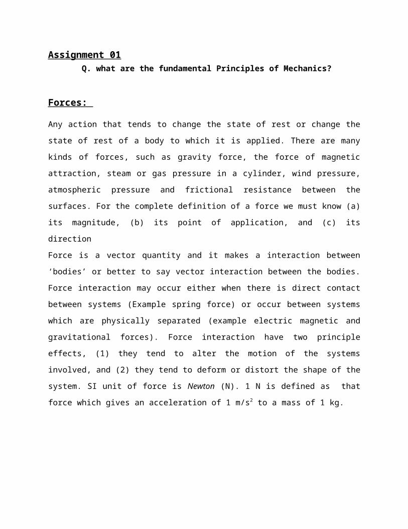
The component of r x F along OQ is called the moment of F about the line or axis OQ, refers fig. 1.1. . The magnitude of this component along the line OQ is the projection of the vector M along OQ. This is given by the dot product of M and a unit vector in the direction of OQ.
Malog OQ = (r x F) cosα
= hF cosα
Example 1.1 Determine the moment M about the shaft axis oo due to the force P applied to the crank handle as shown in fig. below.

Sol.
When several forces F1, F2, F3, …….Fn act, there total moment about a fixed point o is defined as the sum
r1 x F1 + r2 x F2 + r3 x F3 + ……….. + rn x Fn = ∑j=1
n
rj x Fj
where the rj are displacement vectors from o to points on the lines of action of the Fj.
Couple: when there are two equal and parallel forces F1 and F2 which have opposite sense, such a configuration of forces is called a couple which is shown in fig. 1.4.
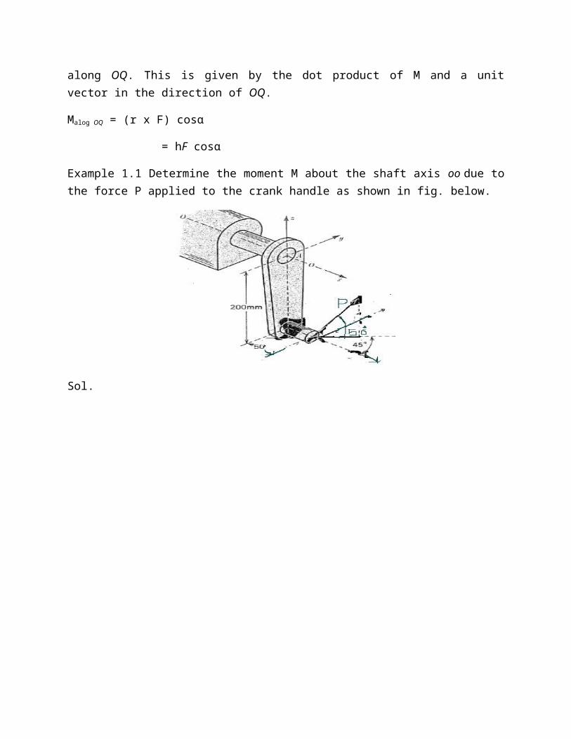
Fig. 1.4 the moment of a couple about the point O
Sum of moments (M) of F1 and F2 about O = r1 x F1 + r2 x F2
From fig 1.4, r1 = r + a & F1 = F2 = F,
M = (r1 + a) x F1 + r2 x F2
= r x (F1 + F2) + a x F1
Where r1and r2 are vectors to arbitraya point on the lines of action of F1 and F2 .
Now F1 and F2 are of equle magnitude and opposite sense and therfor cancel when added at the same point . F1 + F2 = 0
M = a x F1
Fig. 1.5 Couple is represented by a moment vector.
M = a x F
= hF
Where a is the displacement vector going from an arbitrary point on F2 to an arbitrary point on F1. h is the perpendicular distance between the vectors F and –F.
Example 1.2 A beam AB of length L is supported as snow in fig. below and subjected to equal but opposite vertical forces P at its two ends. Find the reactions at the supports C and D.

Sol.
Conditions for Equilibrium
When several forces F1, F2 , ….Fn act on a particle or in the system so the necessary and sufficient condition for the particle or system to be in equilibrium are :
F1 + F2 + F3 + ………….Fn = ∑j=1
n
F j = 0 ……………………..(Eq 1)
r1 x F1 + r2 x F2 + r3 x F3 + ……….. + rn x Fn = ∑j=1
n
rj x Fj = 0 …..(Eq 2)
Example 1.3 Two equal cylinder, each weighing 900N are placed in a box as shown in fig below. Neglecting friction between the cylinder and the box, estimate the reactions at A, B and C.
Sol.
Two-force member

A system is in equilibrium under the action of only two external forces applied at A and B. Then they must satisfy the conditions:
The two forces can not have random orientation; they must be directed along AB.
FA = - FB
Three-force member
A system is in equilibrium under the action of only three external forces applied at A, B, C. Then it must satisfy the conditions:
The three forces cannot have random orientation. They must all lie in the plane ABC if the total moment about each of the point
A, B and C is to vanish. They must all intersect in a common point O.
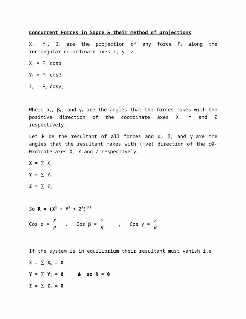
Concurrent Forces in Sapce & their method of projections
Xi, Yi, Zi are the projection of any force Fi along the rectangular co-ordinate axes x, y, z.
Xi = Fi cosαi
Yi = Fi cosβi
Zi = Fi cosγi
Where αi, βi, and γi are the angles that the forces makes with the positive direction of the coordinate axes X, Y and Z respectively.
Let R be the resultant of all forces and α, β, and γ are the angles that the resultant makes with (+ve) direction of the c0-0rdinate axes X, Y and Z respectively.
X = ∑ Xi
Y = ∑ Yi
Z = ∑ Zi
So R = (X2 + Y2 + Z2)1\2
Cos α = XR , Cos β =
YR , Cos γ =
ZR
If the system is in equilibrium their resultant must vanish i.e
X = ∑ Xi = 0
Y = ∑ Yi = 0 & so R = 0
Z = ∑ Zi = 0
Example 1.4 Find the resultant force and the angle α, β, and γ of the three forces which are given in the table below.
Fi Newtons (N) αi βi γi
F1 40 56 33 90
F2 10 46 80 46
F3 30 77 115 80
Sol.

Couples in Space
The system of couples in space as represented by moment vector M1, M2,……………Mn shown in Fig. Taking coordinate axes x, y ,z , as shown , and αi,βi and γi are the direction angles of the vector Mi.
Mx(i)=Mi cosα
My(i)=Mi cosβ
Mz(i)=Mi cosγ
Preceding in the same manner with moment M1,M2,M3,……………Mn and adding algebraically all corresponding projections, we obtain the three rectangular component of the resultant couple M as follows:
Mx =∑ ¿¿ x) (i)
= M1 cosα1 + M2 cosα2 +…………………………………..+ Mn cosαn
My =∑ ¿¿y) (i)
=M1 cosβ1 + M2 cosβ2 +…………………………………….+ Mn cosβn
Mz = ∑ ¿¿z) (i)
=M1 cosγ1 + M2 cosγ2 +………………………………………..+Mn cosγn
M= (Mx2 + My
2 + Mz2)1/2
α, β and γ are direction of angle that the normal to the plane of the resultant couple M makes with the coordinate axes x, y , z respectively.
Cos α = MM
x, cos β = MM
y and cos γ = MM
z
For Equilibrium
Mx = 0 , My = 0 , Mz = 0
Example 1.5 Five equal forces P act on the corners of cube with edge of length a as shown in fig. Find the equilibrium of this system of forces.
Sol.

Coplanar forces system ( forces in 2D plane)
Taking an arbitrary point in the plane and an arbitrary orientation of the xy plane, the condition for the vector sum of the external forces to vanish (condition of equilibrium) is simply
∑i
Fi = ∑
i¿¿
ix i + Fiy j ) = 0
Or each component of the resultant force vector must vanish or zero.
∑i
Fix = 0
∑i
Fiy = 0
The condition that the total moment about O should vanish may be written
∑i
ri x Fi = ∑
i¿¿
i i + yi j ) x (Fix i + Fiy j )
= k ∑i
¿¿iFiy – yi Fix ) = 0
Example 1.6 Using the above method of projections, find the magnitude and direction of resultant R of the four concurrent forces shown in Fig. below
Sol.

Free body Diagram
To investigate the equilibrium of a constrained body, we shall always imagine that we remove the supports and replace them by the reactions which they exert on the body. Thus all the reactions or forces acting on the body shown by vectors is called a free-body diagram.
Free body diagram
Friction
The surfaces of two bodies are in contact there will be a limited amount of resistance to sliding between them, which is called friction. The question of friction between clean dry surfaces was first investigated in a complete manner by coulomb, who published in 1781 the results of large number of experiments. For given dry surfaces in contact, the results of these experiments may be summarized briefly by following law of friction
1. The total friction that can be developed is independent of magnitude of the area of contact.
2. The total friction that can be developed is proportional to the normal force.3. For low velocities of sliding the total friction that can be developed is practically
independent of the velocity, although the experiments shows that the force necessary to start sliding is greater than that necessary to maintain sliding.
Merits & demerits
Marits: friction helps in
walking on a road motion of locomotive on rails Transmission of power by belts, gear etc.

The friction between the wheels and the road is essential for the car to move forward.
Demerits:
At every joint in a machine, the force of friction arises due to the relative motion between two parts and hence some energy is wasted in overcoming the friction.
It produces undesirable noise. It promotes wear and tear between the surfaces. Because of friction energy is wasted.
The friction classified as:
1. Friction between unlubricated surfaces: The friction experienced between two dry and unlubricated surfaces in contact is known as dry or solid friction. It is due to the surface roughness. The dry or solid friction includes the sliding friction and rolling friction as discussed above.
2. Friction Between Lubricated Surfaces: When lubricant (i.e. oil or grease) is applied between two surfaces in contact, then the friction appears between them is called friction between lubricated surfaces.
Laws of Static Friction:
Friction
Static friction: it is the friction, experienced by a body, when at rest
Dynamic friction or (kinetic friction): It is the friction experienced by a body when in motion and is less than the static friction
Sliding friction: It is the friction, experienced by a body, when it slides over anotherbody.
Rolling friction: It is the friction, experienced between the surfaces which has balls or rollers interposed between them.
Pivot friction: It is the friction, experienced by a body, due to the motion of rotation asin case of foot step bearings

Following are the laws of static friction :1. The force of friction always acts in a direction, opposite to that in which the body tends to move.2. The magnitude of the force of friction is exactly equal to the force, which tends the body to move.3. The magnitude of the limiting friction (F ) bears a constant ratio to the normal reaction (RN) between the two surfaces. Mathematically F/RN = constant4. The force of friction is independent of the area of contact, between the two surfaces.5. The force of friction depends upon the roughness of the surfaces.
Laws of Kinetic or Dynamic Friction:
Following are the laws of kinetic or dynamic friction :1. The force of friction always acts in a direction, opposite to that in which the body is moving.2. The magnitude of the kinetic friction bears a constant ratio to the normal reaction between the two surfaces. But this ratio is slightly less than that in case of limiting friction.3. For moderate speeds, the force of friction remains constant. But it decreases slightly with the increase of speed.
Limiting frictionThis maximum value of frictional force, which comes into play, when a body just begins to slide over the surface of the other body, is known as limiting force of friction or simply limiting friction. It may be noted that when the applied force is less than the limiting friction, the body remains at rest, and the friction into play is called static friction which may have any value between zero and limiting friction.
Coefficient of Friction: It is defined as the ratio of the limiting friction (F) to the normal reaction (RN) between the two bodies. It is generally denoted by μ. Mathematically, coefficient of friction
μ = F/RN
Limiting Angle of Friction
Consider that a body A of weight (W) is resting on a horizontal plane B, as shown in Fig. below. If a horizontal force P is applied to the body, no relative motion will take place until the applied force P is equal to the force of friction F, acting opposite to the direction of motion. The magnitude of this force of friction is F = μ.W = μ.RN, where RN is the normal reaction. In the limiting case, when the motion just begins, the body will be in equilibrium under the action of the following three forces :1. Weight of the body (W),

2. Applied horizontal force (P), and3. Reaction (R) between the body A and the plane B
The reaction R must, therefore, be equal and opposite to the resultant of W and P and will be inclined at an angle φ to the normal reaction RN. This angle φ is known as the limiting angle of friction. It may be defined as the angle which the resultant reaction R makes with the normal reaction RN. From above Fig., tan φ = F/RN = μ RN / RN = μ
Angle of ReposeConsider that a body A of weight (W) is resting on an inclined plane B, as shown in Fig. If the angle of inclination α of the plane to the horizontal is such that the body begins to move down the plane, then the angle α is called the angle of repose.
The body will only begin to movedown the plane, whenW sin α = F = μ.RN = μ.W cos α ( RN = W cos α) tan α = μ = tan φ or α = φ ( μ = tan φ) fig. Angle of repose
Minimum Force Required to Slide a Body on a Rough Horizontal Plane
Consider that a body A of weight (W) is resting on a horizontal plane B as shown in Fig. Let an effort P is applied at an angle θ to the horizontal such that the body A just moves. The various forces acting on the body are shown in Fig.. Resolving the force P into two components, i.e. P sin θ acting upwards and P cos θ acting horizontally. Now for the equilibrium of the body A,RN + P sin θ = Wor RN = W – P sin θ ...(i)and P cos θ = F = μ.RN ...(ii) ( F = μ.RN) fig. Minimum force required to slide a body
Substituting the value of RN from equation (i), we haveP cos θ = μ (W – P sin θ) = tan φ (W – P sin θ) ( μ = tan φ) = sin φ / cos φ (W – P sin θ )P cos θ .cos φ = W sin φ – P sin θ.sin φP cos θ.cos φ + P sin θ.sin φ = W sin φP cos (θ – φ) = W sin φ ...[_cos θ. cos φ + sin θ.sin φ = cos (θ – φ)] P = W sin φ / cos (θ – φ) ………(iii)For P to be minimum, cos (θ – φ) should be maximum, i.e.cos (θ – φ) = 1 or θ – φ = 0° or θ = φIn other words, the effort P will be minimum, if its inclination with the horizontal is equal to

the angle of friction.So Pmin = W sin θ ...[From equation (iii)]
Example 10.1. A body, resting on a rough horizontal plane required a pull of 180 N inclined at 30º to the plane just to move it. It was found that a push of 220 N inclined at 30º to the plane just moved the body. Determine the weight of the body and the coefficient of friction.Solution.
Given : θ = 30ºLet W = Weight of the body in newtons,RN = Normal reaction,μ = Coefficient of friction, andF = Force of friction. Fig. 1 Fig. 2First of all, let us consider a pull of 180 N. The force of friction (F) acts towards left as shown in Fig.1Resolving the forces horizontally,F = 180 cos 30º = 180 × 0.866 = 156 NNow resolving the forces vertically,RN = W – 180 sin 30º = W – 180 × 0.5 = (W – 90) NWe know that F = μ.RN or 156 = μ (W – 90) ...(i)Now let us consider a push of 220 N. The force of friction (F) acts towards right as shown in Fig. 2Resolving the forces horizontally,F = 220 cos 30º = 220 × 0.866 = 190.5 NNow resolving the forces vertically,RN = W + 220 sin 30º = W + 220 × 0.5 = (W + 110) NWe know that F = μ.RN or 190.5 = μ (W + 110) ...(ii)From equations (i) and (ii),W = 1000 N, and μ = 0.1714 Ans.
Assignment 01 Q (3.) what do you mean by plane truss? Write down their applications.