Embed Size (px)
Citation preview
Modeling, Part Programming, Optimization and 5 Axis Machining of 3D Impeller of Centrifugal Compressor
A Project report submitted towards Partial Fulfillment of the Requirements
for the award of Degree of`
Master of Technology
In
MANUFACTURING ENGINEERING
Submitted
By
K.Vinay Kumar (ME093106)
Under the guidance of
G.MADHAVULU B.KOTIVEERACHARIDGM (TDL) PROFESSOR BHEL R& D, MECHANICAL ENGINEERING DEPARTMENT, HYD NATIONAL INSTITUTE OF
TECHNOLOGY, WARANGAL
Department of Mechanical Engineering
NATIONAL INSTITUTE OF TECHNOLOGY (Deemed University)
WARANGAL 2009-2011

DEPARTMENT OF MECHANICAL ENGINEERING
NATIONAL INSTITUTE OF TECHNOLOGY WARANGAL(DEEMED UNIVERSITY)
WARANGAL-506004 (A.P.)
CERTIFICATE
This is to certify that the dissertation work entitled “MODELING,PART
PROGRAMMING,OPTIMIZATION AND 5 AXIS MACHINING OF 3D IMPELLER OF
CENTRIFUGAL COMPRESSOR", is a bonafide work carried out by K. VINAY KUMAR, Roll
No: ME093106, submitted in partial fulfillment of the requirements for the award of the degree of
MASTER OF TECHNOLOGY in MANUFACTURING ENGINEERING to the Department of
Mechanical Engineering, NATIONAL INSTITUTE OF TECHNOLOGY, WARANGAL, during
the year 2010-2011.
Prof.B.Kotiveerachari Dr. N. Venkaiah
Project Guide & Professor Co-ordinator & Assistant ProfessorManufacturing Engineering Manufacturing Engineering Department of Mechanical Engineering Department of Mechanical EngineeringNIT Warangal NIT Warangal
Sri G. Venkateswara Rao Prof. A.V. Narasimha Rao
Head of Production Engineering Section Head of Department Department of Mechanical Engineering (NITW) Department of Mechanical
Engineering ` NIT Warangal

DECLARATION
This is to certify that the work reported in the present thesis titled “MODELING,
PART PROGRAMMING, OPTIMIZATION AND MACHINING OF 3D IMPELLER OF
CENTRIFUGAL COMPRESSOR” is a record work done by me in the BHARAT
HEAVY ELECTICALS LIMITED, CORPORATE RESEARCH & DEVELOPMENT
DIVISION, VIKAS NAGAR, HYDERABAD.
No part of the thesis is copied from books/ journals/ internet and wherever the
portion is taken; the same has been duly referred in the text. The report is based on
the project work done entirely by me and not copied from any other source.
K.VINAY KUMAR
(ME093106)

ACKNOWLEDGEMENT
I express my sincere thanks to BHEL management for giving permission to carry out this project
work at their esteemed organization.
My special thanks to Mr.S.Biswas, GM, TWA, BHEL R&D, for allowing me to carry out this
project out at TDL and CIMAR Laboratory.
I express my gratitude to Mr.G.MADHAVULU, DGM, TDL, BHEL R& D for valuable
guidance during this project work.
I am indebted to Dr.P.V.Raj Gopal, AGM (HRD & ATE), BHEL Corp. (R&D) for granting me
permission to do the project in this esteemed organization.
I would also like to thank Mr.SRINU, ENGINEER, CIMAR Dept, BHEL R&D,
HYDERABAD for his constant guidance throughout this project.
I like to express our gratitude to all members of TDL Dept. who were friendly and co-operative,
especially Mr.N.Satya Siva Kumar for all his support and motivation when we needed it the
most.
I express my sincere gratitude to NIT WARANGAL for sponsoring my name to enroll as a
M.Tech project student at BHEL, R&D.I would also like to thank B.KOTIVEERACHARI,
professor of Mechanical engineering department, NIT Warangal for his constant support as my
internal guide in doing this project.
I would like to convey gratitude to my Parents whose prayers and blessings were always there
with me. Last but not the least, I would like to thank my friends and others who directly or
indirectly helped me in successful completion of this work.
CONTENTS
Abstract……………………………………………………………………………………… i
List of Figures………………………………………………………………………………. ii
Introduction…………………………………………………………………………. ………iii
1. Compressors and their technical details
1.1 Classification of Compressors……………………………………………………….01 1.2 Centrifugal Compressors…………………………………………………………….02
2. Impellers and their technical details
2.1 Manufacturing processes of different types of Impellers……………………………. 8 2.2 Process details of 2-D Impeller……………………………………………………… 9 2.3 Process details of 3-D Impeller………………………………………………………11
3. CNC and DNC
3.1 Numerical Control………………………………………………………………….. 13 3.2 Computer Numerical Control………………………………………………………. 14 3.3 Distributed Numerical Control…………………………………………………….. 14
4. Part Program Structure
4.1 Programming Formats………………………………………………………………..16 4.2 Parameters in Fanuc…………………………………………………………………..17
5. CNC Milling
5.1 Milling Cutters……………………………………………………………………….. 23 5.2 CNC 5-Axis Milling Machining Center ……………………………………………...24 5.3 Macro Designation …………………………………………………………………... 26
6. Design process…………………………………………………………………………...28
7. Part Programming……………………………………………………………………… 38
8. 3-D Impeller and Optimization
8.1 Methods of 5 Axes CNC Part Programming and Machining of 3-D Impeller………..58 8.2 Problems in Flank Milling…………………………………………………………….60 8.3 Extent of Undercut in Flank Milling…………………………………………………..61 8.4 Mathematical Solution for Minimizing Undercut……………………………………..62 8.5 Parameter Lines Optimization Technique for Minimizing Undercut………………… 62
9. Inspection.............................................................................................................................64
10. Results and Conclusion………………………………………………………………….65
11. References and Bibliography…………………………………………………………...66

ABSTRACT
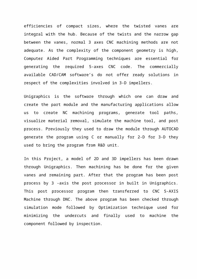
Impeller is the most vital component in functioning of a centrifugal compressor which consists
of curved vanes which are fitted symmetrically. The fluid enters the impeller axially at the eye of
impeller and then flows radially out of impeller. The gas then goes through diffuser to the return
channel and further goes into next impeller. The rotating impeller imparts kinetic energy to the
flowing gas, which is then converted into pressure energy in the diffuser.
Rapid developments in the field of engineering and their applications in manufacturing processes
have brought about a sea change in product designs, evolving more ancient and complex
designs.”3-D IMPELLER” is one of such complex designs in turbo machinery products. These
are designed to achieve higher efficiencies of compact sizes, where the twisted vanes are integral
with the hub. Because of the twists and the narrow gap between the vanes, normal 3 axes CNC
machining methods are not adequate. As the complexity of the component geometry is high,
Computer Aided Part Programming techniques are essential for generating the required 5-axes
CNC code. The commercially available CAD/CAM software’s do not offer ready solutions in
respect of the complexities involved in 3-D impellers.
Unigraphics is the software through which one can draw and create the part module and the
manufacturing applications allow us to create NC machining programs, generate tool paths,
visualize material removal, simulate the machine tool, and post process. Previously they used to
draw the module through AUTOCAD generate the program using C or manually for 2-D for 3-D
they used to bring the program from R&D unit.
In this Project, a model of 2D and 3D impellers has been drawn through Unigraphics. Then
machining has be done for the given vanes and remaining part. After that the program has been
post process by 3 -axis the post processor in built in Unigraphics. This post processor program
then transferred to CNC 5-AXIS Machine through DNC. The above program has been checked
through simulation mode followed by Optimization technique used for minimizing the undercuts
and finally used to machine the component followed by inspection.
List of Figures
1. Fig1: Open and Close type impellers……………………………………………7
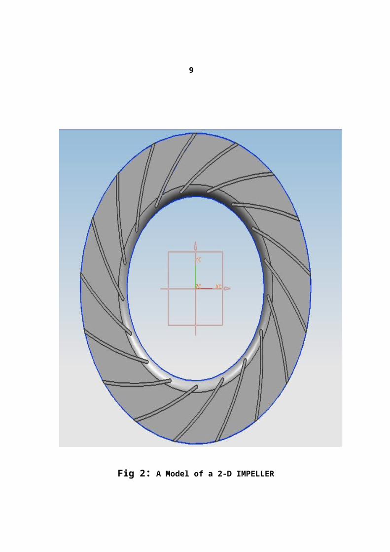
2. Fig2: A Model of 2-d Impeller………………………………………………….10
3. Fig3: A Model of 3-d Impeller………………………………………………….12
4. Fig4: A Typical DNC system…………………………………………………...15
5. Fig5: Designation of Machine Axes and Main Assemblies……………………..21
6. Fig6: A Typical 5-Axis CNC Machining Center………………………………..25
7. Fig7: Manufacturing of 2-d and 3-d Impellers…………………………………..30
8. Fig8: Flank, Point and Strip Milling……………………………………………..59
9. Fig9: Parameter Lines of the Vane Surface for Tool……………………………62
10. Fig10: Reduced Undercut using Optimization Technique……………………….63
INTRODUCTION
1. COMPRESSORS AND THEIR TECHNICAL DETAILS:
Compressor as the name indicates is a machine used to compress the vapor refrigerant from the evaporator and to raise its pressure so that the corresponding saturation temperature is higher than that of cooling medium.
1.1 CLASSIFICATION OF COMPRESSORS:-
1. According to the method of compression:- Reciprocating compressors Rotary compressors Centrifugal compressors
2. According to the number of working strokes:- Single acting compressors Double acting compressors
3. According to number of stages :- Single stage compressors Multistage compressors
4. According to the method of drive employed :- Direct drive compressors Belt drive compressors
5. According to the location of the prime mover:- Semi hermetic compressors(direct drive , motor and compressor in separate housings) ,
and Hermetic compressors (direct drive, motor and compressor in same housings).
1
1.2 CENTRIFUGAL COMPRESSORS:-
A single stage centrifugal compressor in its simplest form consists of an impeller to which a number of curved vanes are fitted symmetrically. The impeller rotates in an air tight volute casing with inlet and outlet points. When the impeller rotates, it pushes the gases from the centre of the impeller to its periphery by centrifugal force.
The centrifugal compressors used are of the following types namely:-
MCL:-
HORIZONTALLY SPLIT
VERTICALLY SPLIT (PROCESS)
VERTICALLY SPLIT (PIPE LINE)
MCL
2MCL
3MCL
DMCL
BCL
2BCL
DBCL
PCL

These are multistage compressors with horizontally split casing, for pressure upto 40Kg/cm2 and capacities upto 3, 60,000m3/hr at suction condition. These are mainly used in
Ethylene plants Refrigerating services Gasification plants for fertilizer industry Drug and food processing plants
2
SERIES BCL:-
They are multi stage compressors with vertical split casing for pressure upto 350Kg/cm2 and capacities of 50,000m3/hr at suction conditions. They are mainly used in:-
Ammonia synthesis plants Urea synthesis plants Natural gas compression stations
The components of compressor are:-
1. Rotor2. Casing 3. Diaphragms4. Seals5. End covers6. Capacity control systems7. Journal bearings8. Thrust bearings9. Assembly of the compressor
ROTOR:-
Rotor is the part of the centrifugal compressor, which has been mostly subjected to technical design developments. The constituent elements of rotor are shaft, impellers, and spacers, balancing drum, seal brushes, locking rings, and thrust collar.
CASINGS:-
Casing for BCL type of compressor are vertically split type.
Casings for MCL type of compressor are horizontally split type.
In horizontally split type of casings usually the bottom half casing has got the suction and discharge has conduits which are not going to be machined, but have to be subjected to sand blasting and grinding for smooth gas flow. Casings are generally made of castings conforming to the following material specifications.
Steel castings
Cast iron
3
DIAPHRAGMS:-
Diaphragms are in two halves split along the horizontal centerline. Depending upon the characteristics of the machine and depending on the pressure and gases to be handled the raw material its quality is selected. IN a machine, diaphragms are
Suction diaphragm
Intermediate diaphragm
Discharge diaphragm
Depending upon the type of construction, diaphragms are:
Cast diaphragms for low-pressure difference.
Milled vanes diaphragms for high pressure.
SEALS:-
Seals are provided in the clearance between the moving and stationary parts of the compressor. It helps in avoiding the wear of the rotating part. It also stops the leakage of the gas.
TYPES OF SEALS:-
Labyrinth seals
Gas seals
Oil seals
Labyrinth and gas seals are in two halves whereas the oil seals are in the form of full rings and are of floating types. Manufacturing features of labyrinth and gas seals consist in finish machining the parting plane of two halves individually and finish machining by holding the two halves together using special clamping fixtures.
4
END COVERS:-
BCL type compressors have end covers with integral bearing housing.
CAPACITY CONTROL SYSTEM:-
The following methods are available for maintaining the capacity, the suction and discharge pressure content under varying process conditions:
Variation of compressor speed
Discharge throttling
Suction throttling
Adjustable inlet guide vanes (IV)
In multistage machine, IGV can only be fitted before the first stage and are controlled
manually or through a servomotor.
JOURNAL BEARING AND THRUST BEARING:-
Force-fed plain type bearings are used throughout. They are externally mounted and can therefore be inspected without releasing the pressure inside the compressor. Depending on the elastic behavior of the rotor, elliptical or tilting pad type main bearings are used; they are highly effective in dampening vibrations.
MCL TYPE BCL TYPE
CASINGS Horizontally split Vertically split
END COVERS No Yes
DIAPHRAGMS Generally cast type Cast and fabricated type

The thrust bearing is of the tilting pad type, to ensure equal thrust distribution and has collar to minimize the frictional losses due to oil entrainment.
5
ASSEMBLY OF COMPRESSORS:-
Assembly of rotor
Preparation of top and bottom pack of diaphragms, each concentrically assembled.
Pinning the upper pack of the diaphragm to the lower pack, to ensure the correct
relative position of each to one another.
Dismantle the upper half diaphragm from lower and position them on a concentrically
inspection fixture.
Assemble the seals at individual diaphragm with suitable adjustments.
Mount the rotor on concentricity inspection fixture.
Determine the correct position of rotor axially, at which the passage of all impellers
and diaphragms will be ideally located with respect to one another.
Mount the one-ring seals and oil seals at the respective position on the rotor.
Assemble the upper half of the diaphragm over the lower, with rotor inside.
Gradually guide the entire diaphragm pack with rotor into the casing using assembly
fixture
Assemble the journal bearing
Assemble the thrust bearing.
2. IMPELLERS AND THEIR TECHNICAL DETAILS
IMPELLERS:
Impeller is the vital rotary part in the functioning of the compressor. The fluid (gas or air) enters the impeller axially at the eye of the impeller and then flows radially out of the impeller. The gas goes through the diffuser to the return channel and further goes into the next impeller. It is one of the most stressed components of the compressor, demanding highly precise manufacturing methods. Each impeller is dynamically balanced and subjected to over speed test. They are mounted, shrink fitted and keyed on the shaft, which is coupled to an external source (generally electric motor). This source imparts the required energy and makes it to rotate. In an impeller, the energy transferred is in the
form of kinetic energy, which is then converted into pressure energy in the diffuser. The pressure ratio of any compressor depends mainly on the impeller diameter, rotational speed and volume flow.
6
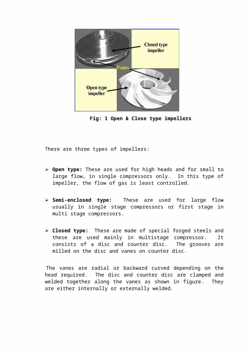
Fig: 1 Open & Close type impellers
There are three types of impellers:
Open type: These are used for high heads and for small to large flow, in single compressors only. In this type of impeller, the flow of gas is least controlled.
Semi-enclosed type: These are used for large flow usually in single stage compressors or first stage in multi stage compressors.
Closed type: These are made of special forged steels and these are used mainly in multistage compressor. It consists of a disc and counter disc. The grooves are milled on the disc and vanes on counter disc.
The vanes are radial or backward curved depending on the head required. The disc and counter disc are clamped and welded together along the vanes as shown in figure. They are either internally or externally welded.
7
2.1 The Manufacturing processes of different types of impellers are briefly
presented below:
Milled and welded type:
Disc and counter disc sections of the impeller are turned separately and the vanes are milled on one of them by 3D copy milling machine. Both the disc are welded together internally along the vanes. The smooth transition is ensured by hand grinding the welded area.
Vane welded type or internal welded type:
The disc is machined on 5-axes CNC machine. The vanes are formed from plate material welded to the disc and counter disc from inside.
Externally welded type:
For impellers of narrow channels width externally welded method is adopted. The disc and counter disc are machined on 5-axes CNC machine.
The vanes are milled on the disc along with the path of the vane and vanes are milled on the counter disc. The welding of both the disc and counter disc is carried out on a special purpose TIG welding machine.
The vanes are radial or backward curved depending on the head required. The disc and counter disc are clamped and welded together along the vanes as shown in figure. They are either internally or externally welded.
8
2.2 2-D IMPELLER (PROCESS DETAILS):
NAME OF THE PART: 2-D IMPELLER (INTERNAL WELDED TYPE)
Process details:
Verify the material attestation marks on the forgings.
Collect disc/hub counter disc/shroud and provide them for further operation.
Inspect and ensure the forgings for dimensional stability and attestations. Finish
machining disc and counter disc completely including bore diameter.
Drill and tap on counter disc two holes for M20*28/37 as per diagram drill and tap on
outside diameter of disc two holes for M20*30/57.
Mill the 17 vanes on the disc increase the height of the vanes by shrinkage allowance
of 2+0.5mm during milling and a positive allowance of 0.5mm on vane thickness.
Clean the milled surfaces and deburs the sharp edges check the contact surfaces and
clean them.
Assemble the disc and counter disc and get them tack-welded using auxiliary pieces.
Weld the vanes as per welding instruction sheet.
Hardening and tempering of impellers is done to get the required proof and impact
strength.
Clean the impeller internal surfaces thoroughly by sand blasting.
Conduct dye-penetrating test on impeller especially on welding to detect any cracks.
Inspect and ensure the concentricity of outside diameter, eye diameter, bore diameter
and record their dimensions.
Balance the impeller dynamically and remove the unbalance material from the places
indicated by testing engineer in the presence of inspector.

Perform the over speed test and ensure bore for any elongation.
Clamp, align accurately with respect to hub diameter and finish machine the bore to
dimensions as per assembly requirements.
9
Fig 2: A Model of a 2-D IMPELLER
10
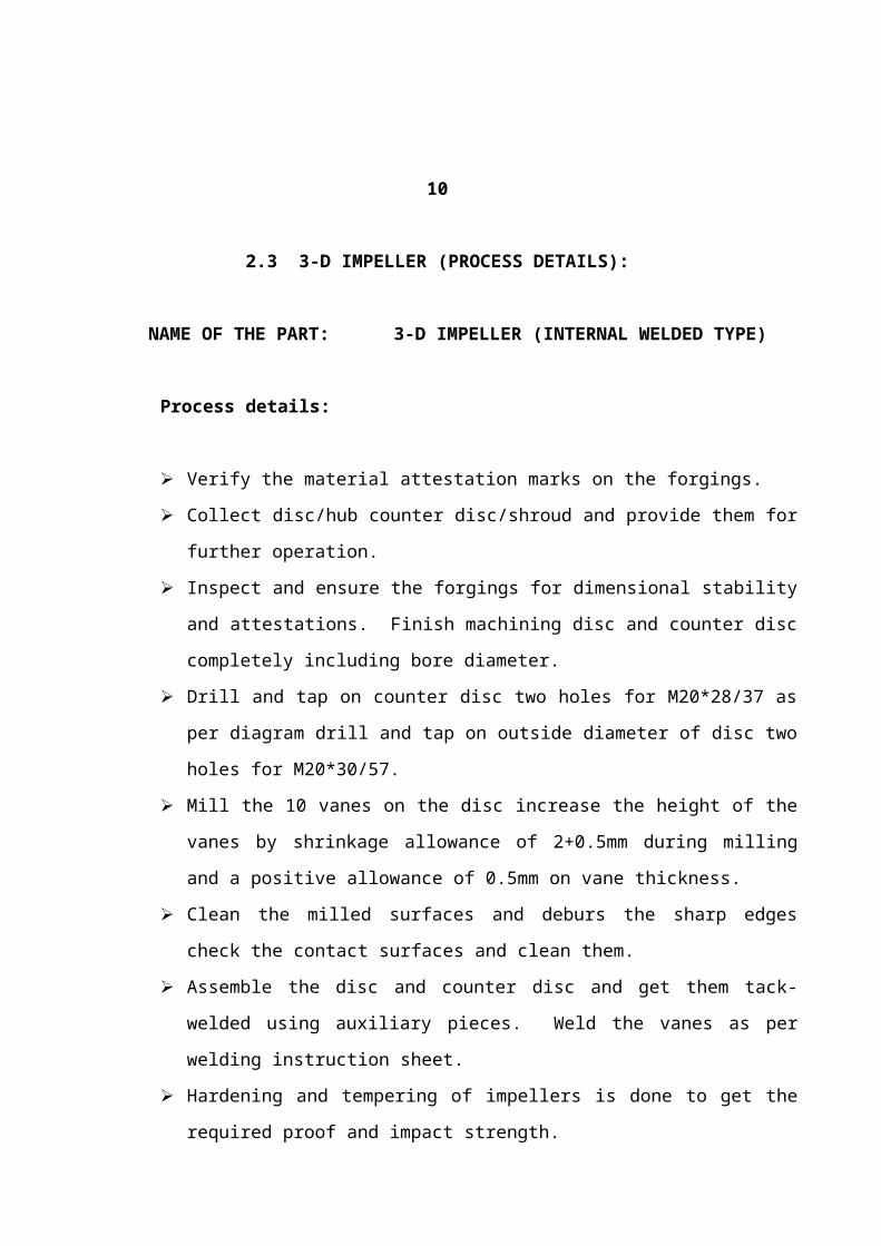
2.3 3-D IMPELLER (PROCESS DETAILS):
NAME OF THE PART: 3-D IMPELLER (INTERNAL WELDED TYPE)
Process details:
Verify the material attestation marks on the forgings.
Collect disc/hub counter disc/shroud and provide them for further operation.
Inspect and ensure the forgings for dimensional stability and attestations. Finish
machining disc and counter disc completely including bore diameter.
Drill and tap on counter disc two holes for M20*28/37 as per diagram drill and tap on
outside diameter of disc two holes for M20*30/57.
Mill the 10 vanes on the disc increase the height of the vanes by shrinkage allowance
of 2+0.5mm during milling and a positive allowance of 0.5mm on vane thickness.
Clean the milled surfaces and deburs the sharp edges check the contact surfaces and
clean them.
Assemble the disc and counter disc and get them tack-welded using auxiliary pieces.
Weld the vanes as per welding instruction sheet.
Hardening and tempering of impellers is done to get the required proof and impact
strength.
Clean the impeller internal surfaces thoroughly by sand blasting.
Conduct dye-penetrating test on impeller especially on welding to detect any cracks.
Inspect and ensure the concentricity of outside diameter, eye diameter, bore diameter
and record their dimensions.
Balance the impeller dynamically and remove the unbalance material from the places
indicated by testing engineer in the presence of inspector.
Perform the over speed test and ensure bore for any elongation.
Clamp, align accurately with respect to hub diameter and finish machine the bore to
dimensions as per assembly requirements.
11
Fig 3: A Model of a 3-D IMPELLER
12
3. INTRODUCTION TO COMPUTER NUMERICAL CONTROL
3.1 NUMERICAL CONTNROL
NUMERICAL CONTROL
TYPE OF MACHINE
TYPE OF CONTROL
POINT-TO-POINT NC
CONTINUOUS NC
OPEN LOOP
CLOSED LOOP
STRUCTURE OF CONTROL
H/W BASED NC
CNC
PROGRAMMING METHODS
INCREMENTAL
ABSOLUTE
STORAGE MEDIAPUNCHED PAPER
PUNCHED CARDMAGNETIC TAPEMAGNETIC DISCMAGENETIC DRUM
13
The control systems and machine tools in numerically controlled machine tools have varying complexities and capabilities. The instructions to the NC machines are fed through an external medium i.e., paper tape or magnetic tape. The information read from the tape is stored into the memory of the control system called ‘Buffer Storage’ and is processed by the machine step by step. So when the machine is working on one instruction block, the next block is read from the tape and stored in the memory of the machine control system.
3.2 COMPUTER NUMERICAL CONTROL
Computer Numerical Control is an NC system that utilizes a dedicated stored program computer to perform some or all the basic numerical control functions.
Tape reader for
initial program
entry
Minicomputer or microcomputer (software functions and NC part program storage)
Computer hardware
interface and servo system
Motion feedback

3.3 DNC SYSTEM
A DNC system is nothing more than a computer that is networked with one or more CNC machines. Once the program is developed, it must be loaded into the CNC control. Though the setup person could type the program right into the control machining centres.
THE CNC CONTROL:
The CNC control will interpret a CNC program and activate the series of commands in sequential order. As it reads the program, the CNC control will activate the appropriate machine functions, cause axis motion, and in general, follow the instructions given in the program.
14
The CNC controls also allows programs to be modified if mistakes are found, allows special verification functions (like dry run) to confirm the correctness of the CNC program and allows certain important operator inputs to be specified separate from the program, like tool length values. If the CNC program is developed with the help of a CAM system, then it is already in the form of a text file. If the program is written manually, it can be typed into any computer using a common word processor (though most companies use a special CNC text editor for this purpose).
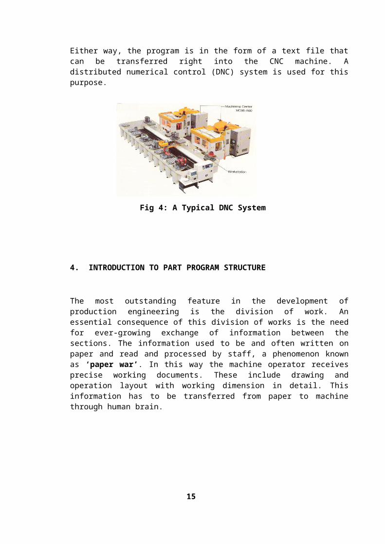
Either way, the program is in the form of a text file that can be transferred right into the CNC machine. A distributed numerical control (DNC) system is used for this purpose.
Fig 4: A Typical DNC System
4. INTRODUCTION TO PART PROGRAM STRUCTURE
The most outstanding feature in the development of production engineering is the division of work. An essential consequence of this division of works is the need for ever-growing exchange of information between the sections. The information used to be and often written on paper and read and processed by staff, a phenomenon known as ‘paper war’. In this way the machine operator receives precise working documents. These include drawing and operation layout with working dimension in detail. This information has to be transferred from paper to machine through human brain.
15
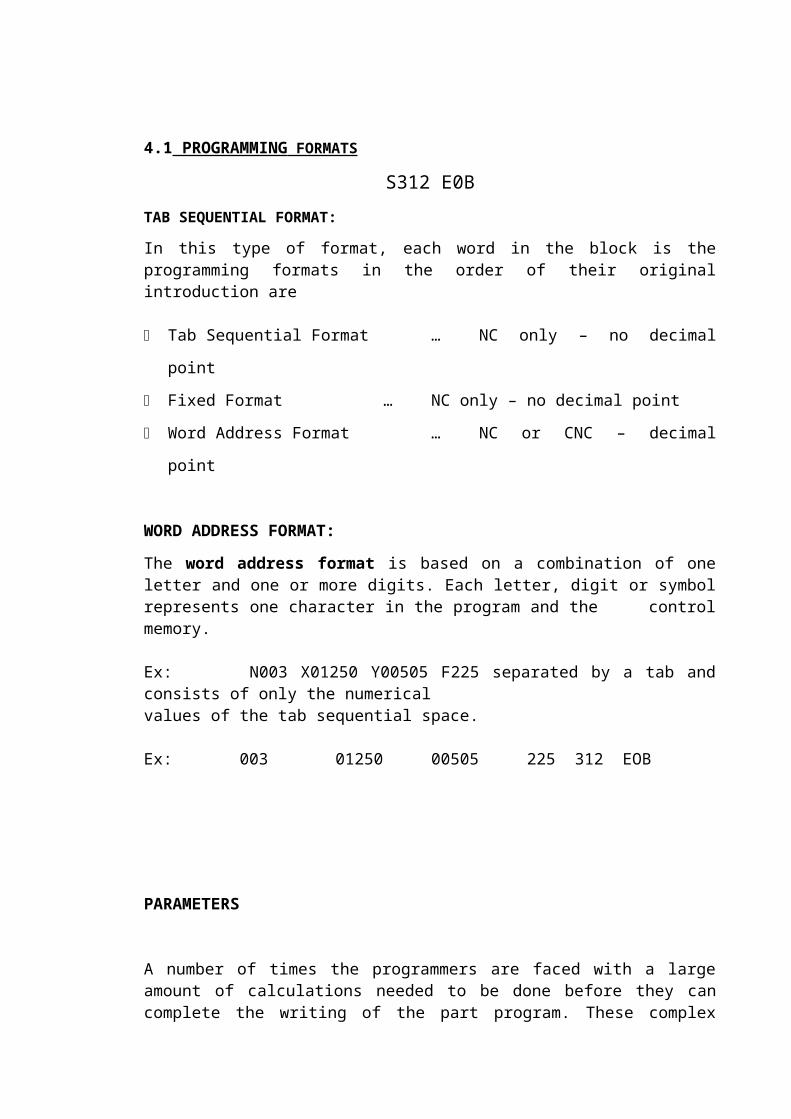
4.1 PROGRAMMING FORMATS
S312 E0BTAB SEQUENTIAL FORMAT:
In this type of format, each word in the block is the programming formats in the order of their original introduction are
Tab Sequential Format … NC only – no decimal point
Fixed Format … NC only – no decimal point
Word Address Format … NC or CNC – decimal point
WORD ADDRESS FORMAT:
The word address format is based on a combination of one letter and one or more digits. Each letter, digit or symbol represents one character in the program and the control memory. Ex: N003 X01250 Y00505 F225 separated by a tab and consists of only the numerical values of the tab sequential space.
Ex: 003 01250 00505 225 312 EOB
PARAMETERS
A number of times the programmers are faced with a large amount of calculations needed to be done before they can complete the writing of the part program. These complex calculations once completed are difficult to trace after sometime, if any debugging of the program is to done. Further the accuracy of the calculations is always a problem. Hence many of the controllers allow for defining variables in a program in such a way that the arithmetic calculations can be carried using these variables. Further these variables can be used to specify the various values in association with the word addresses in a program. These will allow for a large amount of complex programming. It is therefore necessary to understand the concept of these variable usages. Variables can be used to carry out the arithmetic operations as well as assign the values for the word addresses in given block.
16
4.2 PARAMETERS IN FANUC:
The parameters in FANUC are broadly categorized into 3 types:
Local Variables
Common Variables
System Variables
Local Variables (#1 to #33):
The local variable is a variable locally used in the macro. That is, a local variable #i used in the macro called at one point in time, is different from #i used in the macro (whether it is the same macro or not) called at another point in time. A local variable is used for an argument transfer. A local variable without a transferred argument is vacant in its initial status and can be used freely.
Common Variables (#100 to #199, #500 to #999):
Just as a local variable is used locally in the macro, a common variable is in common use throughout the main program, throughout each subprogram called in the main program and throughout each macro. That is #i used in certain macro is same as #i used in another macro. Accordingly, the calculated value of a common variable #i in a certain macro can be used in another macro.
System Variables (#1000 to #9999):
Parameters in Fanuc controllers are identified by # and can vary from 0000 to 9999.There are some variables, which have specified meaning and are called system variables. They cannot be used by programmers.They are as follows:
#1000 to #1032
#1100 to #1132
#2000 to #2200
#2500 to #2506
#2600 to #2606
#2700 to #2706
#2800 to #2806
#3000 to #3012
#3901 to #3902
#4001 to #4120
#5001 to #5104
#8000 to #8150 for G codes and word addresses information.
17
In addition to this, all the arithmetic calculations can be carried out in the program using the following operations and functions.
#1 = 120.5 Assignment
#1 = #1 + #2 Addition
#1 = #2 - #5 Subtraction
#1 = #3 * #5 Multiplication
#1 = #5 / #8 Division
SUBPROGRAMS:
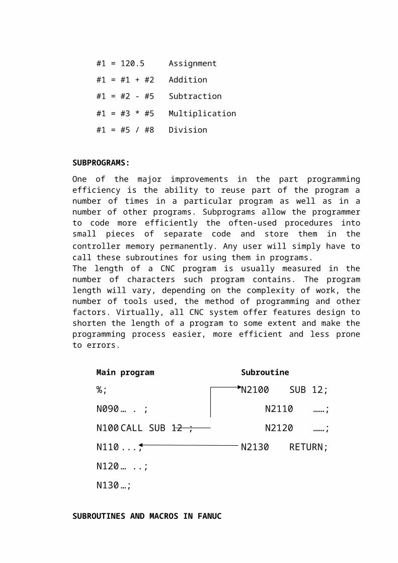
One of the major improvements in the part programming efficiency is the ability to reuse part of the program a number of times in a particular program as well as in a number of other programs. Subprograms allow the programmer to code more efficiently the often-used procedures into small pieces of separate code and store them in the controller memory permanently. Any user will simply have to call these subroutines for using them in programs.The length of a CNC program is usually measured in the number of characters such program contains. The program length will vary, depending on the complexity of work, the number of tools used, the method of programming and other factors. Virtually, all CNC system offer features design to shorten the length of a program to some extent and make the programming process easier, more efficient and less prone to errors.
Main program Subroutine
%; N2100 SUB 12;
N090 … . ; N2110 ……;
N100 CALL SUB 12 ; N2120 ……;
N110 ...; N2130 RETURN;
N120 … ..;
N130 …;
SUBROUTINES AND MACROS IN FANUC
In Fanuc controls two types of subprograms are used.
Subroutines, which are temporary in nature and would be specific to a particular main program.
Macros that are permanent in nature and therefore will be permanently stored in the controller memory and can be used by any program.
18
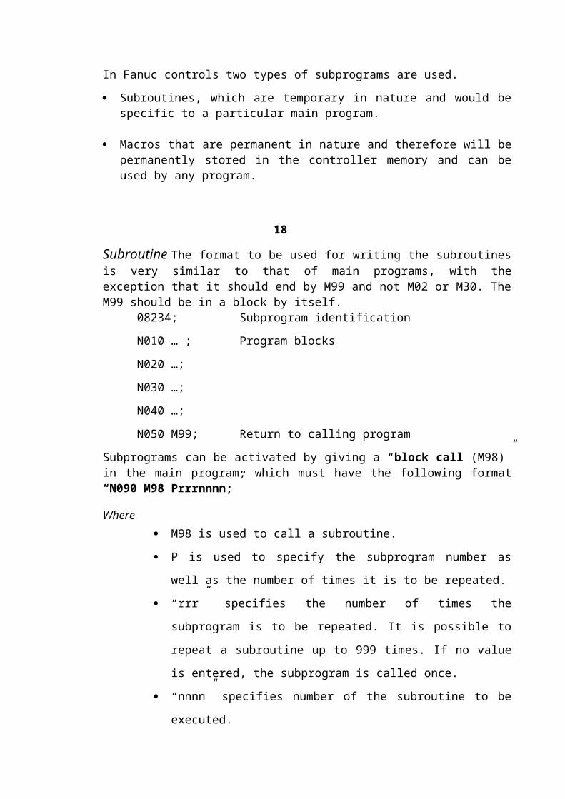
Subroutine The format to be used for writing the subroutines is very similar to that of main programs, with the exception that it should end by M99 and not M02 or M30. The M99 should be in a block by itself.
08234; Subprogram identification
N010 … ; Program blocks
N020 …;
N030 …;
N040 …;
N050 M99; Return to calling program
Subprograms can be activated by giving a “block call (M98)” in the main program, which must have the following format “N090 M98 Prrrnnnn;”
Where M98 is used to call a subroutine.
P is used to specify the subprogram number as well as the number of
times it is to be repeated.
“rrr” specifies the number of times the subprogram is to be repeated. It is
possible to repeat a subroutine up to 999 times. If no value is entered, the
subprogram is called once.
“nnnn” specifies number of the subroutine to be executed.

A few examples are given below to clarify the usage.
N090 M98 P0028023;Subroutine 8023 is to be repeated twiceN140 M98 P8142;Subroutine 8142 is to be repeated once
Permanent Macro in Fanuc is meant for storing permanently in the controller memory. Any program can call these. For this purpose G65 code is used for calling a macro in the main program.
The following is the procedure as implemented in Fanuc 0.
NO55 G65 P2012 L01 A… B… C…;
Arguments are assigned using the word address in the main program where as they have an equivalent variable number in the subprogram as follows:A B C D E F H I J K M#1 #2 #3 #7 #8 #9 #11 #4 #5 #6 #13
Q R S T U V W X Y Z#17 #18 #19 #20 #21 #22 #23 #24 #25
19
In the main program
G65 P1021 A12.5 B23.4 C15.4 D10 X43
In the sub program
#1 = 12.5
#2 = 23.5
#3 = 15.6
#4 = 10
#24 = 43.5Program number of a custom macro can vary from 0001 to 8999.
CNC MACHINE PROGRAM PLANNING:
Machine tools features.
Part complexity.
Manual programming/ Computerized programming.
Typical programming procedures.

Part drawing/ Engineering data.
Methods to select material.
Tooling selection.
Part setup.
Technological decisions.
5. CNC MILLING
Milling Machine is a machine capable of a simultaneous cutting motion, using an end mill as the primary cutter tool, along at least two axes at the same time.
20
Types of Milling Machines:
Milling machines can be divided into three categories:
By the number of axes - two, three and more.
By the orientation of axes - vertical or horizontal.
By the presence or absence of a tool changer.
Conventionally, milling machines, where the spindle motion is up and down, are categorized as vertical machines. Milling machines where the spindle motion is in and out are categorized as horizontal machines.
The majority of modern machines designed for milling are capable of doing a multitude of machining tasks, besides traditional milling. These machines are also capable of many other ‘metal removing’ operations mainly drilling, reaming, boring, tapping, profiling, thread, cutting and many others.
They may be equipped with a multi tool-magazine, a fully Automatic Tool Changer (ATC) and an Automatic Pallet Changer (APC), a powerful computerized control unit (CNC), and so on.
Some machine models may have additional features, such as adaptive control, robot interface, automatic loading and unloading, probing system, high speed machining features and other marvels of modern technology.

MACHINE AXES:
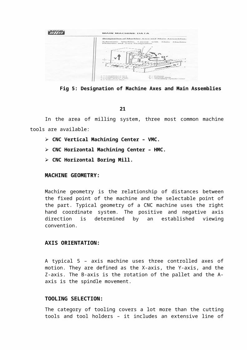
Milling machines and machining centers have at least three axes - X, Y and Z. The machines become more flexible if they have the fourth axes, usually an indexing or a rotary axis (the A axis for vertical models or the B-axis for horizontal models). A simple machine with five axes may be a boring mill that has three major axes, plus a rotary axis (usually the W axis).
Fig 5: Designation of Machine Axes and Main Assemblies
21
In the area of milling system, three most common machine tools are available:
CNC Vertical Machining Center – VMC.
CNC Horizontal Machining Center – HMC.
CNC Horizontal Boring Mill.
MACHINE GEOMETRY:
Machine geometry is the relationship of distances between the fixed point of the machine and the selectable point of the part. Typical geometry of a CNC machine uses the right hand coordinate system. The positive and negative axis direction is determined by an established viewing convention.
AXIS ORIENTATION:
A typical 5 – axis machine uses three controlled axes of motion. They are defined as the X-axis, the Y-axis, and the Z-axis. The B-axis is the rotation of the pallet and the A-axis is the spindle movement.
TOOLING SELECTION:
The category of tooling covers a lot more than the cutting tools and tool holders – it includes an extensive line of accessories, including numerous vices, fixtures, chucks, indexing tables, clamps, collets and many other holding devices.
The cutting tool should be selected by two main criteria
Efficiency of usage.
Safety in operation.
The horizontal machining center mainly differs from a vertical machining center in its general functionality. While a vertical machine is mostly used for work on many faces of the part during a single set up. Between programming and set up, there are three major differences on a horizontal machining center:
Presence of a fourth axis, typically an indexing B axis.
Presence of a pallet changer.
Richer variety of set up and offset settings.
22
5.1 MILLING CUTTERS
Milling is a process of cutting away material by feeding a work piece part a rotating multiple tooth cutters. The cutting action of the many teeth around the milling cutter provides a fast method of machining. The machined surface can be flat, angular, or curved. The surface may also be milled to any combination of shapes. The machine for holding the work piece, rotating the cutter, and feeding it is known as a Milling Machine.
Milling cutters are broadly grouped into 2 categories: Standard and Special.
Standard Tooth Form: Teeth are said to be radial when each teeth face lies along a line that cuts through the center of the cutter, Teeth are cut either with radial tooth face or at a 00 (zero), positive or negative rake angle to the radial line. The tool life and the performance of the carbide tipped teeth, which operate at exceedingly high speeds and coarse feeds, are improved when the teeth have negative rake.
The angle formed by the cutting face and the land is the teeth angle, the body of the tooth is cut at a secondary angel and at a third angle. The design provides maximum support in the cutting edge. It also provides the chip space for the fast removal of chips.
Formed Tooth form: Formed tooth cutter has a contour or tooth outline, of a particular shape. The concave milling cutter with a specified diameter produces a round shape on a work-piece. The flute cutter cuts flutes or drills, reamers, taps and other cutting tools. In applications, that involve the milling of a whole contour, formed cutters may be set up in combination.
STANDARD TYPES OF MILLING CUTTERS:
The diameter and the width of a cutter depend on whether a part is to be slab milled (milling a wide, flat surface) or requires a narrow width slot, There are 3 broad classifications of plain milling cutters are Light-Duty, Heavy-Duty and Helical.
Side Milling Cutters Plain Side Milling Cutters
Half Side Milling Cutters
Staggered Tooth Side Milling Cutters
Interlocking Side Milling Cutters
Slitting Saws
Angle Milling Cutters
End Mill Cutters
23
5.2 CNC 5-Axis Milling Machining Center:
CNC machining centers are far more popular and efficient than drills and mills, mainly for their flexibility. The main benefit the user gets out of a CNC machining center is the ability to group several diverse operations into a single set up. For example, drilling, boring, counter boring, spot facing and contour milling can be incorporated into a single CNC program. In addition, the flexibility is enhanced by automatic tool changing, using pallets to minimize idle time, indexing to a different side of the part, using a rotary movement of additional axis, and a number of other features. CNC machining centers can be equipped with special software that controls the speeds and feeds, the life of the cutting tool, automatic in-process gauging and offset adjustment and other production enhancing and time saving devices.
There are two basic designs of a typical CNC machining center. They are the Vertical and the Horizontal machining centers. The major difference between the two types is the nature of work that can be done on them efficiently. For a vertical CNC machining center, the most suitable type of work are flat parts, either mounted on to the fixture on the table, or held in a vice or a chuck. The work that requires machining on two or more faces in a single setup is more desirable to be done on a CNC Horizontal machining center.
SPECIFICATIONS OF 5-AXIS CNC MACHINING CENTER:
Model: Rigid ZT – 800/130
Make : Standard Rigid, Switzerland
Axes Movements
X-axis : 1800mm
Y-axis : 1000mm
Z-axis : 1320mm
A-axis : +60 to –100 degrees
B-axis : 360 degrees rollover
Feed rate (X, Y, Z) : 0.1 to 15000mm/min
Rapid Traverse : 20000mm/min
Spindle Power : 37KW
RPM Range : 32 to 5400
Pallet Size : 800mmX800 mm
24
Maximum Load on Pallet : 4000kg
Tool Magazine Capacity : 96 tools
CNC Control System : Fanuc 15-M, 5-axis simultaneous control
Positional Accuracy (X, Y, Z) : 0.012mm
Positional Accuracy (A, B) : 12 arc seconds
Repeatability (X, Y, Z) : 0.005mm
Repeatability (A, B) : 5 arc seconds
Special Features : ReniShaw Touch – Trigger Probe
(For in-process inspection)
Digitizing
PC-Based Tool Management
Cost of Machine : 809 lakhs
Commissioned in : 1995
Fig 6: A Typical 5-Axis CNC Machining Center
25
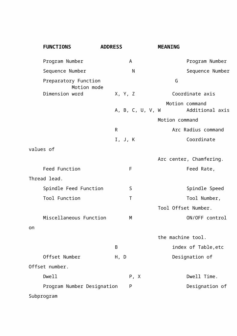
5.3 MACRO DESIGNATION:
FUNCTIONS ADDRESS MEANING
Program Number A Program Number
Sequence Number N Sequence Number
Preparatory Function G Motion mode Dimension word X, Y, Z Coordinate axis
Motion commandA, B, C, U, V, W Additional axis
Motion command
R Arc Radius command
I, J, K Coordinate values of
Arc center, Chamfering.
Feed Function F Feed Rate, Thread
lead.
Spindle Feed Function S Spindle Speed
Tool Function T Tool Number,
Tool Offset Number.
Miscellaneous Function M ON/OFF control on
the machine tool.
B index of Table,etc
Offset Number H, D Designation of Offset number.
Dwell P, X Dwell Time.
Program Number Designation P Designation of Subprogram
Sequence Number Designation P Designation of Sequence
Under Where the
Program is to be repeated
Repetitive Count L Repetitive counts in
the Subprogram.
Parameter P, Q, R Parameters in the
Canned cycles
26
The preparation of this set of instructions to carry out the machining of a work piece is calledPart Programming. Each line of these instructions is capable of specifying dimensional andnon-dimensional data and is written in a specific format. N G XYZAB S F T M EOB
Thus an information about an operation conveyed to the controller of the machine tool would consists of operation number, operation code, co-ordinates for position or motion, tool information, speed and feed for the operation, etc.
Preparatory Function (G):This information is given by a word which is prefixed by the letter G followed by the numerical code for the operation for which the control unit is to instruct the machine tool. G90 and G91 are used for specifying that the data in the following block be in absolute mode (relative to a common datum) or incremental mode (relative to current position) respectively.
Miscellaneous Function (M):Words used for instructions such as to star the spindle and have its rotation clockwise or anti-clockwise, starting or stopping the coolant etc. is termed as miscellaneous functions. These do not pertain to the dimensions of the work, but are required for carrying out the operation.
Tool Information (T):This information is given by a work prefixed by the letter T and followed by the numerical code for tool position in the tool turret or tool magazine when Automatic Tool Changer is used.
ABOUT UNIGRAPHICS:-
Unigraphics is sophisticated software used to create complex designs with great precision. The design intent of any 3 – Dimensional model or an assembly is defined by its specifications and its use. One can use the powerful tool of Unigraphics to capture the design intent of any complex model by incorporating intelligence into the design.
To make the design process simple and quick this software package has divided the steps of designing is completed in different module.
27
The design process consists of the following steps:-
Sketching using the basic sketch entities Connecting the sketch into features and parts Assembling different parts and analyzing them Documentation of the parts and assembly in terms of drawing views Manufacturing the final part and assembly
All these steps are divided into different modes:-
SKETCH SOLID MODELLING MANUFACTURING DRAFTING ASSEMBLY DRAWING SHEETMETAL
LAYOUT
6. DESIGN PROCESS
SKETCH:-
Sketch is the one which is used to create 2 – Dimensional representations of profiles associated with your part. One can create a rough outline of curves and then specify conditions called constraints to define the shapes more precisely and capture the design intent. Each curve is referred to as a sketch object.
SOLID MODELLING:-
One can create solid bodies by:-
Sweeping sketch and non sketch geometry to create associative features, OR
Creating primitives for the basic building blocks, and then adding more specific features to give further details
Creating a solid body using primitive’s results in a simple geometry solid body. Swept features are bodies created by extruding or revolving sketch geometry.
28
ASSEMBLY:-
In assembly, one can assemble different parts by selecting the planes and axis and analyze them, thus it creates its 3-Dimensional view completely with all the features of the component.
MANUFACTURING:-
The manufacturing applications allow us to create NC machining programs, generate tool paths, visualize material removal, simulate the machine tool, and post process.
The sequence of operations to be performed in order to manufacture an impeller are:-
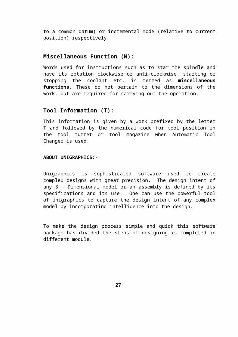
CREATING A TOOL
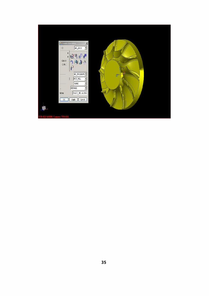
INSERTING AN OPERATION
CREATING GEOMETRY
CREATING PROGRAM
POST PROCESS
Hence the Design process starts with the Creating a tool by which the appropriate tool is selected, Required Operation is being inserted to further process.
After inserting an operation, the geometry has to be created in which the main model comes into picture then the part program has to be created and After that the program has been post process by 3 -axis the post processor in built in Unigraphics.
This post processor program then transferred to CNC 5-AXIS Machine through DNC. The above program has been checked through simulation mode and finally machining has been done for the component followed by inspection.
29
FOR 2D IMPELLER)
CREATING A TOOL:-
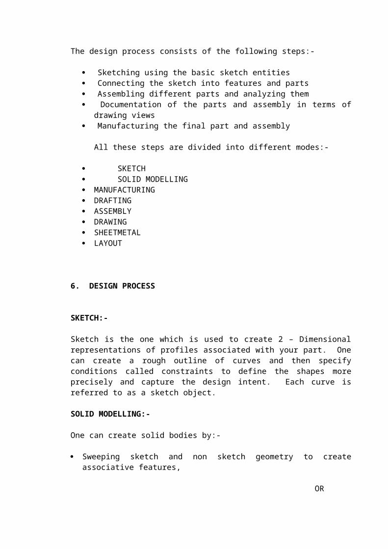
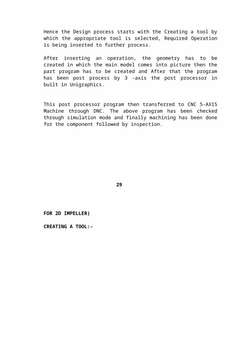
TOOL PATH
30
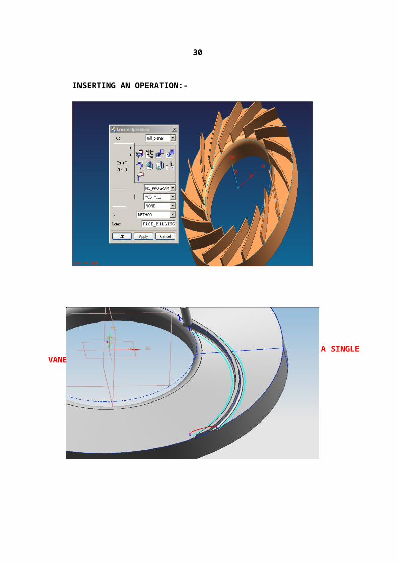
INSERTING AN OPERATION:-
MACHINING OF A SINGLE VANE
31
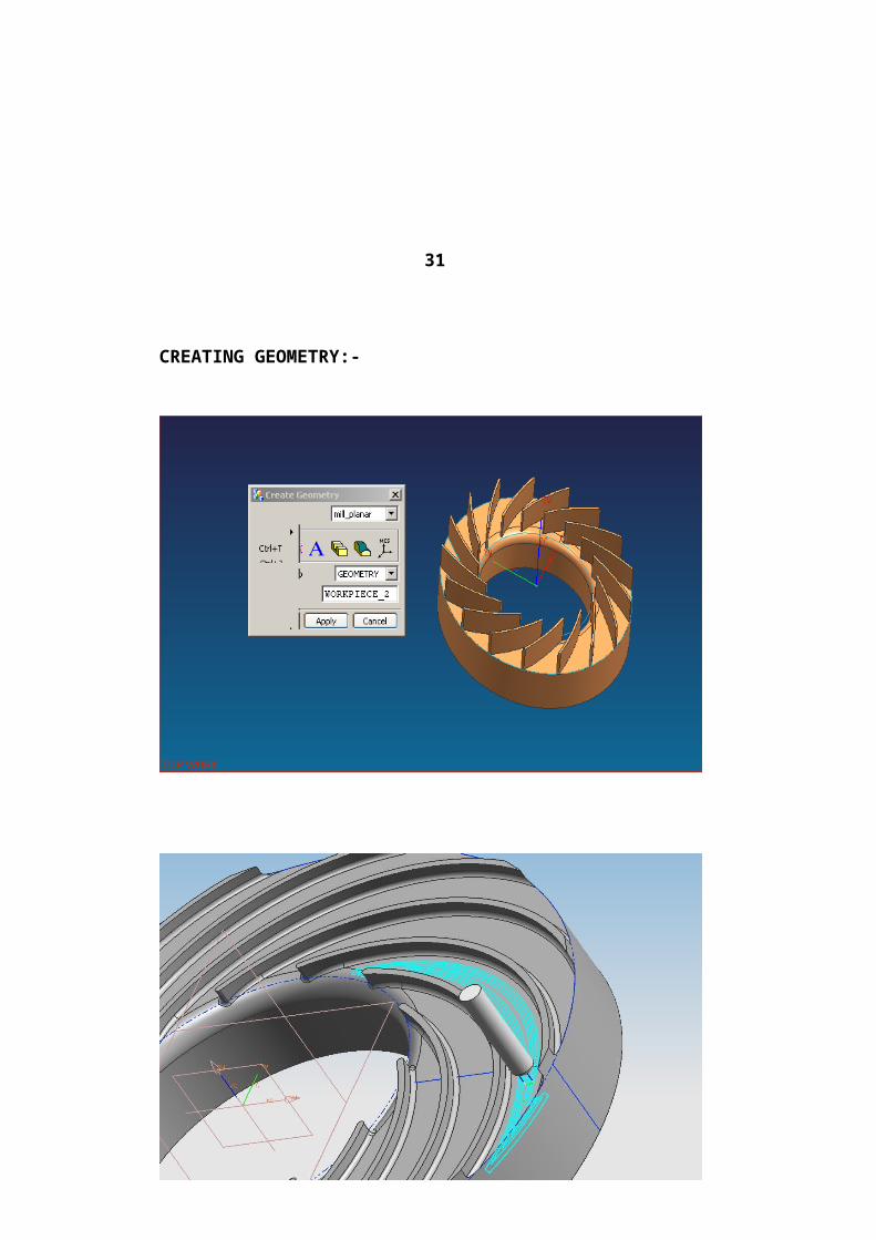
CREATING GEOMETRY:-
PART BEING MACHINED
32
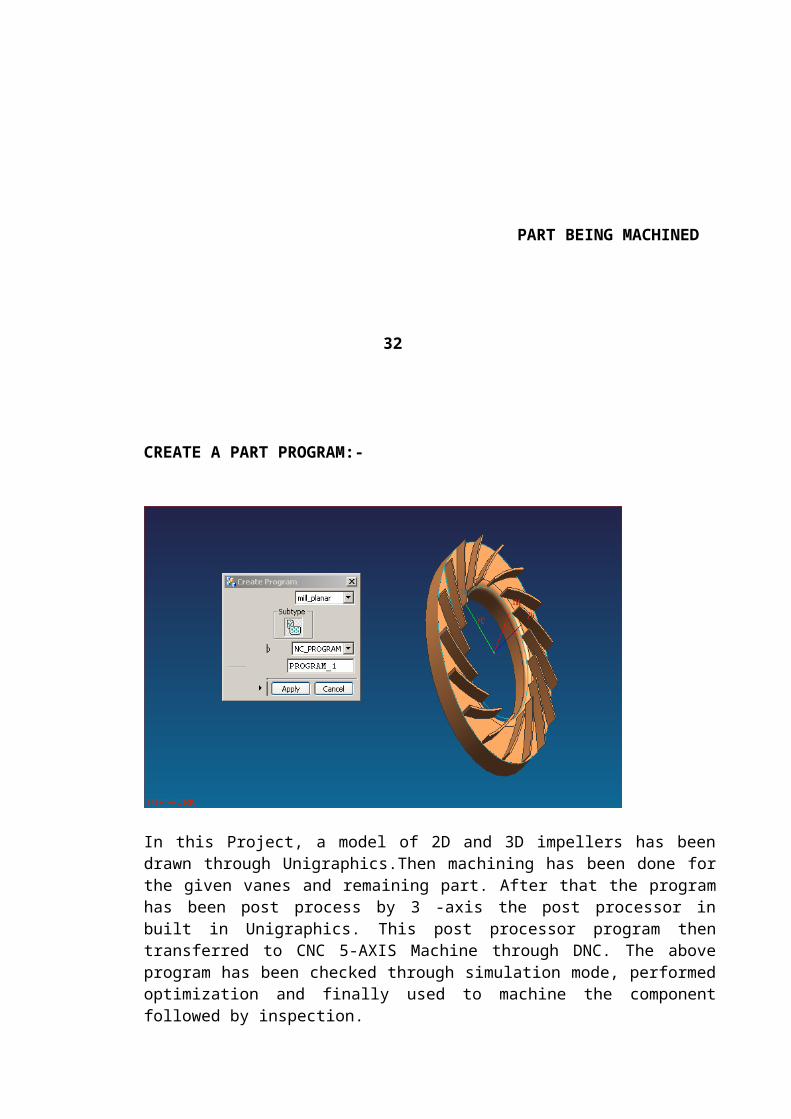
CREATE A PART PROGRAM:-
In this Project, a model of 2D and 3D impellers has been drawn through Unigraphics.Then machining has been done for the given vanes and remaining part. After that the program has been post process by 3 -axis the post processor in built in Unigraphics. This post processor program then transferred to CNC 5-AXIS Machine through DNC. The above program has been checked through simulation mode, performed optimization and finally used to machine the component followed by inspection.
ADVANTAGES:-
1. Using Unigraphics one can machine 3-dimensional component on CNC machine.2. It has zero error and accuracy can be attained.3. Curve and fillets can be machined accurately.4. It can generate the program by its self for a given module.5. Mock-up machining totally eliminated for impeller
FUTURE ASPECTS:-
1. Currently they are manufacturing 2-D impellers and certain types of Steam turbine Blade profiles using Unigraphics.
2. Efforts are being made to manufacture 3-D impellers of Complex designs3. Aerospace profile blades
4. Blade masters for Gas turbines
33
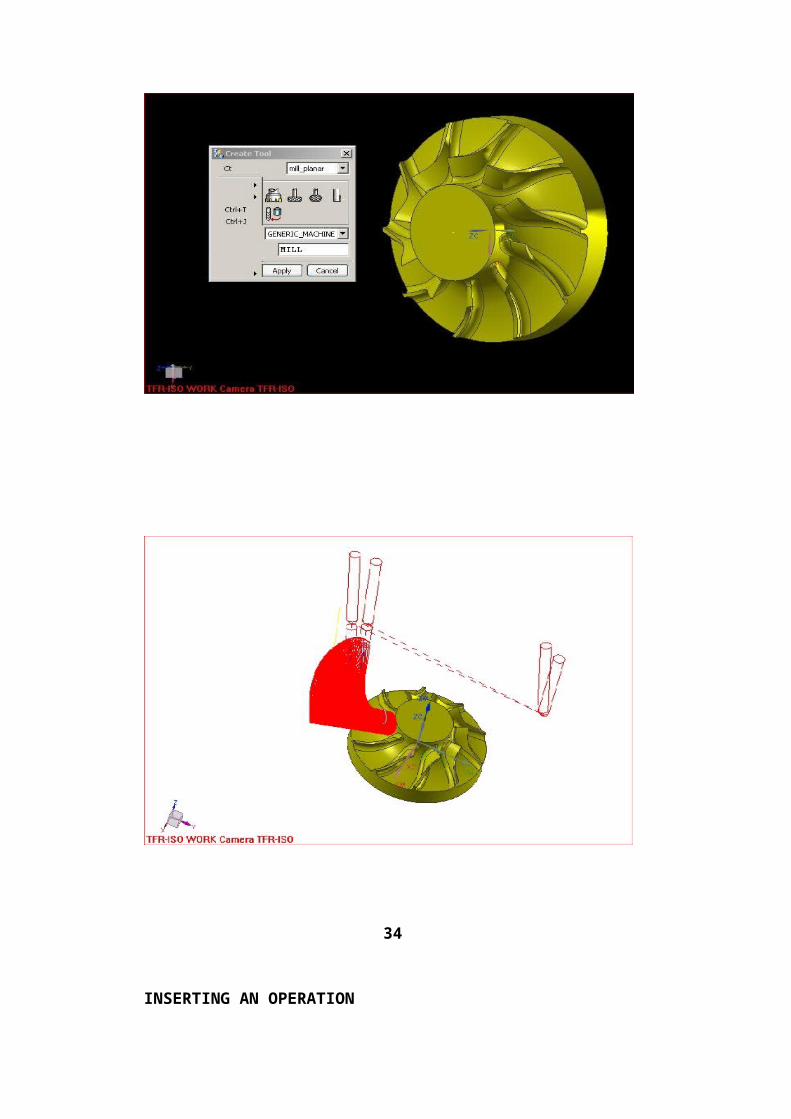
(FOR 3D IMPELLER)
CREATING A TOOL
34
INSERTING AN OPERATION
35
CREATING GEOMETRY

36

CREATING PROGRAM
37
7. PART PROGRAMMING
MAIN PROGRAM FOR IMPELLER
%N0006G21N0007G90N0008G01X614.941Y55.405Z262.002A=DC(304.367)B65.86F5000N0009X469.209Z196.69F2000N0010X469.328Y54.147Z199.048F4000N0011X469.338Y52.89Z201.357N0012X469.245Y51.633Z203.619N0013X469.053Y50.376Z205.837N0014X468.768Y49.118Z208.014N0015X465.484Y48.844Z215.258A=DC(306.332)B64.906N0016X456.477Y50.418Z231.089A=DC(310.884)B62.231N0017X446.6Y51.481Z247.202A=DC(314.438)B59.567N0018X436.218Y52.223Z262.878A=DC(317.252)B56.993N0019X425.685Y52.76Z277.633A=DC(319.514)B54.565N0020X415.322Y53.162Z291.172A=DC(321.359)B52.322N0021X405.304Y53.475Z303.457A=DC(322.899)B50.269N0022X395.903Y53.727Z314.352A=DC(324.199)B48.433N0023X387.398Y53.932Z323.749A=DC(325.301)B46.841N0024X379.928Y54.105Z331.686A=DC(326.247)B45.496N0025X373.566Y54.259Z338.246A=DC(327.077)B44.392N0026X363.4Y54.583Z348.353A=DC(328.594)B42.711N0027X356.852Y54.964Z354.676A=DC(330.031)B41.719N0028X353.688Y55.459Z357.687A=DC(331.524)B41.337N0029X352.069Y56.171Z359.012A=DC(333.297)B41.222N0030X349.893Y57.047Z360.649A=DC(335.254)B41.007N0031X348.143Y57.535Z362.009A=DC(336.28)B40.784 N0032X345.653Y58.041Z364.008A=DC(337.308)B40.434N0033X342.521Y58.563Z366.544A=DC(338.332)B39.976N0034X339.941Y59.108Z368.56A=DC(339.365)B39.616N0035X338.26Y59.67Z369.776A=DC(340.399)B39.412N0036X337.396Y60.249Z370.28A=DC(341.43)B39.348N0037X337.131Y60.848Z370.251A=DC(342.467)B39.386N0038X337.46Y61.468Z369.689A=DC(343.513)B39.525N0039X338.379Y62.108Z368.585A=DC(344.57)B39.765N0040X339.894Y62.771Z366.919A=DC(345.641)B40.108N0041X341.806Y63.451Z364.854A=DC(346.72)B40.521N0042X343.081Y64.13Z363.343A=DC(347.769)B40.825N0043X343.584Y64.801Z362.538A=DC(348.778)B40.995N0044X343.381Y65.46Z362.403A=DC(349.739)B41.042N0045X340.898Y66.75Z364.118A=DC(351.528)B40.773N0046X337.287Y68.073Z366.826A=DC(353.282)B40.307N0047X333.57Y69.446Z369.532A=DC(355.05)B39.823N0048X330.023Y70.836Z372.047A=DC(356.784)B39.369N0049X327.766Y72.212Z373.474A=DC(358.437)B39.138N0050X326.958Y73.584Z373.68A=DC(.031)B39.155N0051X327.046Y74.953Z373.143A=DC(1.567)B39.325
38

N0052X327.299Y76.313Z372.5A=DC(3.04)B39.523N0053X327.687Y77.679Z371.752A=DC(4.473)B39.744N0054X328.189Y79.067Z370.885A=DC(5.896)B39.984N0055X328.803Y80.51Z369.823A=DC(7.369)B40.241N0056X329.53Y82.011Z368.548A=DC(8.901)B40.515N0057X330.368Y83.569Z367.053A=DC(10.494)B40.806N0058X331.302Y85.2Z365.292A=DC(12.183)B41.11N0059X332.343Y86.907Z363.202A=DC(13.994)B41.428N0060X333.563Y88.657Z360.755A=DC(15.89)B41.773N0061X335.024Y90.386Z358.003A=DC(17.78)B42.158N0062X336.603Y91.949Z355.486A=DC(19.379)B42.571N0063X338.155Y93.385Z353.326A=DC(20.722)B42.987N0064X339.51Y94.763Z351.568A=DC(21.909)B43.374N0065X340.57Y96.257Z349.851A=DC(23.245)B43.706N0066X341.397Y97.954Z347.807A=DC(24.913)B43.987N0067X342.097Y99.79Z345.426A=DC(26.833)B44.237N0068X342.737Y101.681Z342.791A=DC(28.899)B44.469N0069X343.14Y103.522Z340.375A=DC(30.934)B44.653N0070X343.315Y105.291Z338.244A=DC(32.9)B44.791N0071X343.321Y106.975Z336.389A=DC(34.772)B44.894N0072X343.419Y108.528Z334.786A=DC(36.422)B45.015N0073X343.696Y109.968Z333.416A=DC(37.827)B45.174N0074X343.981Y111.353Z332.299A=DC(39.089)B45.337N0075X344.144Y112.762Z331.301A=DC(40.364)B45.477N0076X344.235Y114.288Z329.868A=DC(41.906)B45.597N0077X344.396Y115.887Z327.921A=DC(43.659)B45.724N0078X344.764Y117.499Z325.459A=DC(45.532)B45.886N0079X345.306Y119.045Z322.892A=DC(47.331)B46.08N0080X345.897Y120.505Z320.545A=DC(48.967)B46.284N0081X346.506Y121.902Z318.413A=DC(50.467)B46.492N0082X347.092Y123.251Z316.504A=DC(51.855)B46.696N0083X347.617Y124.564Z314.828A=DC(53.152)B46.888N0084X348.074Y125.857Z313.323A=DC(54.396)B47.066N0085X348.48Y127.142Z311.904A=DC(55.62)B47.233N0086X348.789Y128.422Z310.585A=DC(56.842)B47.379N0087X348.991Y129.696Z309.383A=DC(58.06)B47.502N0088X349.092Y130.962Z308.304A=DC(59.268)B47.603N0089X349.132Y132.216Z307.324A=DC(60.457)B47.69N0090X349.2Y133.458Z306.352A=DC(61.623)B47.781N0091X349.309Y134.689Z305.376A=DC(62.764)B47.879N0092X349.461Y135.907Z304.404A=DC(63.877)B47.984N0093X349.663Y137.112Z303.434A=DC(64.959)B48.098N0094X349.916Y138.306Z302.471A=DC(66.009)B48.221N0095X350.215Y139.49Z301.507A=DC(67.033)B48.352N0096X350.553Y140.665Z300.548A=DC(68.032)B48.49N0097X350.927Y141.832Z299.586A=DC(69.012)B48.634N0098X351.326Y142.994Z298.626A=DC(69.976)B48.782N0099X351.745Y144.151Z297.664A=DC(70.928)B48.933N0100X352.165Y145.305Z296.709A=DC(71.874)B49.083N0101X352.582Y146.455Z295.771A=DC(72.812)B49.231N0102X352.99Y147.601Z294.856A=DC(73.742)B49.376
39
N0103X353.399Y148.743Z293.957A=DC(74.662)B49.52N0104X353.804Y149.879Z293.084A=DC(75.571)B49.662N0105X354.209Y151.011Z292.233A=DC(76.468)B49.803N0106X354.621Y152.137Z291.404A=DC(77.351)B49.944N0107X355.056Y153.258Z290.575A=DC(78.22)B50.089N0108X355.539Y154.374Z289.708A=DC(79.079)B50.243N0109X356.059Y155.488Z288.803A=DC(79.932)B50.404N0110X356.598Y156.601Z287.871A=DC(80.784)B50.568N0111X357.104Y157.711Z286.981A=DC(81.633)B50.724N0112X357.568Y158.819Z286.147A=DC(82.478)B50.87N0113X358.001Y159.926Z285.356A=DC(83.32)B51.008N0114X358.429Y161.03Z284.58A=DC(84.157)B51.144N0115X358.866Y162.135Z283.786A=DC(84.995)B51.281N0116X359.737Y164.363Z282.057A=DC(86.72)B51.551N0117X360.96Y166.635Z279.273A=DC(88.635)B51.894N0118X361.779Y167.778Z277.402A=DC(89.651)B52.11N0119X362.653Y168.912Z275.48A=DC(90.651)B52.338N0120X363.5Y170.039Z273.669A=DC(91.62)B52.56N0121X364.304Y171.162Z271.952A=DC(92.572)B52.772N0122X365.623Y173.418Z268.838A=DC(94.487)B53.129N0123X366.453Y175.67Z266.395A=DC(96.38)B53.371N0124X366.915Y177.899Z264.877A=DC(98.124)B53.524N0125X366.961Y180.133Z264.204A=DC(99.781)B53.576N0126X367.354Y182.382Z262.932A=DC(101.462)B53.702N0127X368.473Y184.651Z261.21A=DC(102.97)B53.992N0128X370.133Y187.Z259.933A=DC(104.135)B54.407N0129X372.524Y189.508Z258.819A=DC(104.954)B54.996N0130X373.603Y190.827Z258.936A=DC(105.214)B55.264N0131X374.573Y192.192Z259.557A=DC(105.374)B55.506N0132X375.417Y193.604Z260.716A=DC(105.434)B55.717N0133X376.116Y195.062Z262.453A=DC(105.392)B55.892N0134X376.215Y197.79Z267.046A=DC(105.374)B55.919N0135X376.272Y203.199Z276.364N0136X461.458Z333.997F5000N0137G00X612.162Y0.Z403.039A=DC(0.)B75.964N0138G01X614.561Y56.204Z262.472A=DC(304.367)B65.86N0139X468.263Z196.906F2000N0140X468.387Y54.947Z199.266F4000N0141X468.404Y53.69Z201.578N0142X468.32Y52.433Z203.845N0143X468.14Y51.175Z206.069N0144X467.868Y49.918Z208.251N0145X464.602Y49.664Z215.459A=DC(306.332)B64.906N0146X455.614Y51.281Z231.185A=DC(310.884)B62.231N0147X445.761Y52.372Z247.21A=DC(314.438)B59.567N0148X435.407Y53.135Z262.812A=DC(317.252)B56.993N0149X424.903Y53.687Z277.506A=DC(319.514)B54.565N0150X414.569Y54.099Z290.995A=DC(321.359)B52.322N0151X404.579Y54.421Z303.239A=DC(322.899)B50.269N0152X395.207Y54.678Z314.102A=DC(324.199)B48.433N0153X386.727Y54.889Z323.472A=DC(325.301)B46.841N0154X379.281Y55.066Z331.389A=DC(326.247)B45.496
40
N0155X372.941Y55.223Z337.934A=DC(327.077)B44.392N0156X362.814Y55.552Z348.018A=DC(328.594)B42.711N0157X356.297Y55.938Z354.325A=DC(330.031)B41.719N0158X353.157Y56.437Z357.325A=DC(331.524)B41.337N0159X351.556Y57.152Z358.636A=DC(333.297)B41.222N0160X349.398Y58.031Z360.256A=DC(335.254)B41.007N0161X347.658Y58.52Z361.605A=DC(336.28)B40.784N0162X345.179Y59.027Z363.593A=DC(337.308)B40.434N0163X342.06Y59.55Z366.116A=DC(338.332)B39.976N0164X339.491Y60.096Z368.119A=DC(339.365)B39.616N0165X337.82Y60.66Z369.324A=DC(340.399)B39.412N0166X336.964Y61.239Z369.817A=DC(341.43)B39.348N0167X336.707Y61.838Z369.779A=DC(342.467)B39.386N0168X337.042Y62.458Z369.208A=DC(343.513)B39.525N0169X337.966Y63.099Z368.096A=DC(344.57)B39.765N0170X339.484Y63.761Z366.422A=DC(345.641)B40.108N0171X341.399Y64.442Z364.349A=DC(346.72)B40.521N0172X342.678Y65.12Z362.831A=DC(347.769)B40.825N0173X343.185Y65.79Z362.019A=DC(348.778)B40.995N0174X342.989Y66.449Z361.876A=DC(349.739)B41.042N0175X340.52Y67.739Z363.574A=DC(351.528)B40.773N0176X336.921Y69.06Z366.263A=DC(353.282)B40.307N0177X333.216Y70.432Z368.951A=DC(355.05)B39.823N0178X329.678Y71.82Z371.45A=DC(356.784)B39.369N0179X327.428Y73.194Z372.865A=DC(358.437)B39.138N0180X326.626Y74.566Z373.065A=DC(.031)B39.155N0181X326.718Y75.933Z372.523A=DC(1.567)B39.325N0182X326.975Y77.293Z371.876A=DC(3.04)B39.523N0183X327.367Y78.658Z371.126A=DC(4.473)B39.744N0184X327.873Y80.044Z370.256A=DC(5.896)B39.984N0185X328.491Y81.486Z369.192A=DC(7.369)B40.241N0186X329.221Y82.985Z367.913A=DC(8.901)B40.515N0187X330.062Y84.542Z366.413A=DC(10.494)B40.806N0188X330.996Y86.171Z364.646A=DC(12.183)B41.11N0189X332.038Y87.876Z362.549A=DC(13.994)B41.428N0190X333.256Y89.625Z360.095A=DC(15.89)B41.773N0191X334.713Y91.353Z357.34A=DC(17.78)B42.158N0192X336.292Y92.915Z354.825A=DC(19.379)B42.571N0193X337.844Y94.35Z352.669A=DC(20.722)B42.987N0194X339.203Y95.727Z350.913A=DC(21.909)B43.374N0195X340.267Y97.218Z349.193A=DC(23.245)B43.706N0196X341.097Y98.913Z347.139A=DC(24.913)B43.987N0197X341.798Y100.746Z344.746A=DC(26.833)B44.237N0198X342.437Y102.633Z342.099A=DC(28.899)B44.469N0199X342.839Y104.472Z339.671A=DC(30.934)B44.653N0200X343.013Y106.239Z337.532A=DC(32.9)B44.791N0201X343.018Y107.922Z335.673A=DC(34.772)B44.894N0202X343.115Y109.475Z334.07A=DC(36.422)B45.015N0203X343.394Y110.914Z332.703A=DC(37.827)B45.174N0204X343.681Y112.299Z331.59A=DC(39.089)B45.337N0205X343.848Y113.707Z330.592A=DC(40.364)B45.477N0206X343.942Y115.23Z329.153A=DC(41.906)B45.597N0207X344.104Y116.826Z327.198A=DC(43.659)B45.724
41

N0208X344.474Y118.435Z324.728A=DC(45.532)B45.886N0209X345.016Y119.979Z322.156A=DC(47.331)B46.08N0210X345.607Y121.438Z319.807A=DC(48.967)B46.284N0211X346.217Y122.833Z317.676A=DC(50.467)B46.492N0212X346.806Y124.182Z315.771A=DC(51.855)B46.696N0213X347.333Y125.495Z314.098A=DC(53.152)B46.888N0214X347.793Y126.788Z312.598A=DC(54.396)B47.066N0215X348.203Y128.072Z311.182A=DC(55.62)B47.233N0216X348.515Y129.351Z309.868A=DC(56.842)B47.379N0217X348.72Y130.625Z308.668A=DC(58.06)B47.502N0218X348.825Y131.89Z307.592A=DC(59.268)B47.603N0219X348.869Y133.144Z306.616A=DC(60.457)B47.69N0220X348.941Y134.386Z305.648A=DC(61.623)B47.781N0221X349.054Y135.616Z304.677A=DC(62.764)B47.879N0222X349.21Y136.834Z303.71A=DC(63.877)B47.984N0223X349.416Y138.04Z302.747A=DC(64.959)B48.098N0224X349.674Y139.234Z301.79A=DC(66.009)B48.221N0225X349.976Y140.418Z300.833A=DC(67.033)B48.352N0226X350.319Y141.593Z299.882A=DC(68.032)B48.49N0227X350.697Y142.762Z298.927A=DC(69.012)B48.634N0228X351.101Y143.924Z297.975A=DC(69.976)B48.782N0229X351.525Y145.081Z297.021A=DC(70.928)B48.933N0230X351.95Y146.236Z296.073A=DC(71.874)B49.083N0231X352.371Y147.386Z295.143A=DC(72.812)B49.231N0232X352.784Y148.533Z294.235A=DC(73.742)B49.376N0233X353.197Y149.675Z293.344A=DC(74.662)B49.52N0234X353.607Y150.812Z292.478A=DC(75.571)B49.662N0235X354.017Y151.944Z291.635A=DC(76.468)B49.803N0236X354.433Y153.071Z290.814A=DC(77.351)B49.944N0237X354.873Y154.192Z289.994A=DC(78.22)B50.089N0238X355.36Y155.309Z289.134A=DC(79.079)B50.243N0239X355.885Y156.424Z288.238A=DC(79.932)B50.404N0240X356.429Y157.537Z287.313A=DC(80.784)B50.568N0241X356.94Y158.648Z286.43A=DC(81.633)B50.724N0242X357.409Y159.757Z285.604A=DC(82.478)B50.87N0243X357.846Y160.863Z284.82A=DC(83.32)B51.008N0244X358.279Y161.968Z284.051A=DC(84.157)B51.144N0245X358.721Y163.073Z283.263A=DC(84.995)B51.281N0246X359.154Y164.183Z282.454A=DC(85.844)B51.415N0247X359.601Y165.301Z281.544A=DC(86.72)B51.551N0248X360.834Y167.572Z278.767A=DC(88.635)B51.894N0249X361.657Y168.715Z276.899A=DC(89.651)B52.11N0250X362.536Y169.848Z274.981A=DC(90.651)B52.338N0251X363.388Y170.974Z273.172A=DC(91.62)B52.56N0252X364.197Y172.097Z271.459A=DC(92.572)B52.772N0253X365.526Y174.35Z268.347A=DC(94.487)B53.129N0254X366.367Y176.599Z265.905A=DC(96.38)B53.371N0255X366.839Y178.827Z264.39A=DC(98.124)B53.524N0256X366.897Y181.059Z263.719A=DC(99.781)B53.576N0257X367.3Y183.306Z262.449A=DC(101.462)B53.702N0258X368.429Y185.572Z260.726A=DC(102.97)B53.992N0259X370.099Y187.914Z259.439A=DC(104.135)B54.407N0260X372.499Y190.41Z258.302A=DC(104.954)B54.996
42
N0261X373.584Y191.721Z258.404A=DC(105.214)B55.264N0262X374.559Y193.077Z259.007A=DC(105.374)B55.506N0263X375.407Y194.478Z260.145A=DC(105.434)B55.717N0264X376.111Y195.923Z261.859A=DC(105.392)B55.892N0265X376.217Y198.649Z266.452A=DC(105.374)B55.919N0266X376.282Y204.058Z275.776N0267X460.778Z332.942F5000N0268G00X612.162Y0.Z403.039A=DC(0.)B75.964N0269G01X614.177Y57.004Z262.94A=DC(304.367)B65.86N0270X467.329Z197.128F2000N0271X467.457Y55.747Z199.49F4000N0272X467.481Y54.49Z201.805N0273X467.406Y53.232Z204.076N0274X467.237Y51.975Z206.304N0275X466.978Y50.718Z208.493N0276X463.728Y50.484Z215.663A=DC(306.332)B64.906N0277X454.759Y52.143Z231.285A=DC(310.884)B62.231N0278X444.929Y53.264Z247.221A=DC(314.438)B59.567N0279X434.6Y54.047Z262.749A=DC(317.252)B56.993N0280X424.123Y54.613Z277.382A=DC(319.514)B54.565N0281X413.817Y55.036Z290.82A=DC(321.359)B52.322N0282X403.856Y55.366Z303.023A=DC(322.899)B50.269N0283X394.51Y55.63Z313.851A=DC(324.199)B48.433N0284X386.056Y55.845Z323.195A=DC(325.301)B46.841N0285X378.634Y56.026Z331.092A=DC(326.247)B45.496N0286X372.315Y56.187Z337.62A=DC(327.077)B44.392N0287X362.226Y56.521Z347.68A=DC(328.594)B42.711N0288X355.74Y56.912Z353.972A=DC(330.031)B41.719N0289X352.623Y57.414Z356.96A=DC(331.524)B41.337N0290X351.041Y58.133Z358.257A=DC(333.297)B41.222N0291X348.901Y59.015Z359.86A=DC(335.254)B41.007N0292X347.171Y59.505Z361.198A=DC(336.28)B40.784N0293X344.703Y60.014Z363.174A=DC(337.308)B40.434N0294X341.595Y60.538Z365.684A=DC(338.332)B39.976N0295X339.037Y61.084Z367.675A=DC(339.365)B39.616N0296X337.377Y61.649Z368.868A=DC(340.399)B39.412N0297X336.529Y62.229Z369.351A=DC(341.43)B39.348N0298X336.279Y62.828Z369.303A=DC(342.467)B39.386N0299X336.62Y63.449Z368.722A=DC(343.513)B39.525N0300X337.549Y64.089Z367.602A=DC(344.57)B39.765N0301X339.071Y64.752Z365.921A=DC(345.641)B40.108N0302X340.988Y65.432Z363.841A=DC(346.72)B40.521N0303X342.271Y66.11Z362.315A=DC(347.769)B40.825N0304X342.783Y66.78Z361.495A=DC(348.778)B40.995N0305X342.593Y67.439Z361.345A=DC(349.739)B41.042N0306X340.138Y68.727Z363.026A=DC(351.528)B40.773N0307X336.551Y70.047Z365.695A=DC(353.282)B40.307N0308X332.857Y71.417Z368.364A=DC(355.05)B39.823N0309X329.329Y72.804Z370.847A=DC(356.784)B39.369N0310X327.087Y74.177Z372.251A=DC(358.437)B39.138N0311X326.289Y75.548Z372.444A=DC(.031)B39.155
43
N0312X326.386Y76.914Z371.897A=DC(1.567)B39.325N0313X326.647Y78.273Z371.248A=DC(3.04)B39.523N0314X327.043Y79.636Z370.496A=DC(4.473)B39.744N0315X327.554Y81.021Z369.624A=DC(5.896)B39.984N0316X328.175Y82.462Z368.556A=DC(7.369)B40.241N0317X328.909Y83.96Z367.274A=DC(8.901)B40.515N0318X329.752Y85.515Z365.769A=DC(10.494)B40.806N0319X330.687Y87.142Z363.995A=DC(12.183)B41.11N0320X331.729Y88.845Z361.892A=DC(13.994)B41.428N0321X332.946Y90.593Z359.432A=DC(15.89)B41.773N0322X334.401Y92.32Z356.675A=DC(17.78)B42.158N0323X335.978Y93.881Z354.161A=DC(19.379)B42.571N0324X337.532Y95.316Z352.009A=DC(20.722)B42.987N0325X338.894Y96.691Z350.256A=DC(21.909)B43.374N0326X339.963Y98.181Z348.533A=DC(23.245)B43.706N0327X340.795Y99.872Z346.47A=DC(24.913)B43.987N0328X341.497Y101.701Z344.065A=DC(26.833)B44.237N0329X342.136Y103.586Z341.404A=DC(28.899)B44.469N0330X342.537Y105.421Z338.967A=DC(30.934)B44.653N0331X342.71Y107.187Z336.819A=DC(32.9)B44.791N0332X342.714Y108.868Z334.955A=DC(34.772)B44.894N0333X342.811Y110.421Z333.354A=DC(36.422)B45.015N0334X343.091Y111.861Z331.99A=DC(37.827)B45.174N0335X343.381Y113.245Z330.881A=DC(39.089)B45.337N0336X343.552Y114.651Z329.882A=DC(40.364)B45.477N0337X343.649Y116.173Z328.437A=DC(41.906)B45.597N0338X343.813Y117.765Z326.475A=DC(43.659)B45.724N0339X344.183Y119.372Z323.996A=DC(45.532)B45.886N0340X344.726Y120.913Z321.42A=DC(47.331)B46.08N0341X345.318Y122.371Z319.07A=DC(48.967)B46.284N0342X345.93Y123.765Z316.94A=DC(50.467)B46.492N0343X346.52Y125.113Z315.038A=DC(51.855)B46.696N0344X347.051Y126.425Z313.37A=DC(53.152)B46.888N0345X347.514Y127.718Z311.874A=DC(54.396)B47.066N0346X347.927Y129.001Z310.462A=DC(55.62)B47.233N0347X348.242Y130.281Z309.151A=DC(56.842)B47.379N0348X348.452Y131.554Z307.955A=DC(58.06)B47.502N0349X348.56Y132.818Z306.883A=DC(59.268)B47.603N0350X348.608Y134.072Z305.91A=DC(60.457)B47.69N0351X348.684Y135.314Z304.946A=DC(61.623)B47.781N0352X348.801Y136.544Z303.98A=DC(62.764)B47.879N0353X348.961Y137.762Z303.019A=DC(63.877)B47.984N0354X349.172Y138.968Z302.061A=DC(64.959)B48.098N0355X349.434Y140.162Z301.111A=DC(66.009)B48.221N0356X349.741Y141.346Z300.162A=DC(67.033)B48.352N0357X350.088Y142.522Z299.217A=DC(68.032)B48.49N0358X350.471Y143.691Z298.271A=DC(69.012)B48.634N0359X350.879Y144.854Z297.326A=DC(69.976)B48.782N0360X351.308Y146.012Z296.38A=DC(70.928)B48.933N0361X351.737Y147.166Z295.44A=DC(71.874)B49.083N0362X352.163Y148.317Z294.518A=DC(72.812)B49.231N0363X352.58Y149.464Z293.617A=DC(73.742)B49.376
44
N0364X352.999Y150.607Z292.734A=DC(74.662)B49.52N0365X353.413Y151.744Z291.876A=DC(75.571)B49.662N0366X353.828Y152.877Z291.04A=DC(76.468)B49.803N0367X354.249Y154.004Z290.227A=DC(77.351)B49.944N0368X354.694Y155.126Z289.415A=DC(78.22)B50.089N0369X355.186Y156.244Z288.563A=DC(79.079)B50.243N0370X355.715Y157.359Z287.675A=DC(79.932)B50.404N0371X356.263Y158.473Z286.758A=DC(80.784)B50.568N0372X356.779Y159.584Z285.882A=DC(81.633)B50.724N0373X357.253Y160.694Z285.063A=DC(82.478)B50.87N0374X357.695Y161.801Z284.286A=DC(83.32)B51.008N0375X358.132Y162.906Z283.524A=DC(84.157)B51.144N0376X358.579Y164.012Z282.743A=DC(84.995)B51.281N0377X359.017Y165.121Z281.939A=DC(85.844)B51.415N0378X359.469Y166.239Z281.034A=DC(86.72)B51.551N0379X360.711Y168.51Z278.264A=DC(88.635)B51.894N0380X361.539Y169.651Z276.399A=DC(89.651)B52.11N0381X362.422Y170.784Z274.485A=DC(90.651)B52.338N0382X363.28Y171.909Z272.679A=DC(91.62)B52.56N0383X364.094Y173.031Z270.968A=DC(92.572)B52.772N0384X365.433Y175.282Z267.858A=DC(94.487)B53.129N0385X366.285Y177.529Z265.419A=DC(96.38)B53.371N0386X366.768Y179.755Z263.907A=DC(98.124)B53.524N0387X366.836Y181.985Z263.237A=DC(99.781)B53.576N0388X367.249Y184.23Z261.968A=DC(101.462)B53.702N0389X368.388Y186.493Z260.245A=DC(102.97)B53.992N0390X370.067Y188.828Z258.946A=DC(104.135)B54.407N0391X372.478Y191.312Z257.787A=DC(104.954)B54.996N0392X373.567Y192.615Z257.873A=DC(105.214)B55.264N0393X374.547Y193.962Z258.458A=DC(105.374)B55.506N0394X375.399Y195.352Z259.576A=DC(105.434)B55.717N0395X376.107Y196.785Z261.266A=DC(105.392)B55.892N0396X376.219Y199.508Z265.859A=DC(105.374)B55.919N0397X376.293Y204.917Z275.188N0398X460.085Z331.878F5000N0399G00X612.162Y0.Z403.039A=DC(0.)B75.964N0400G01X613.984Y57.404Z263.174A=DC(304.367)B65.86N0401X466.867Z197.241F2000N0402X466.997Y56.147Z199.604F4000N0403X467.024Y54.89Z201.92N0404X466.954Y53.632Z204.193N0405X466.789Y52.375Z206.424N0406X466.536Y51.118Z208.615N0407X463.295Y50.894Z215.767A=DC(306.332)B64.906N0408X454.334Y52.575Z231.336A=DC(310.884)B62.231N0409X444.515Y53.71Z247.228A=DC(314.438)B59.567N0410X434.199Y54.503Z262.718A=DC(317.252)B56.993N0411X423.735Y55.076Z277.321A=DC(319.514)B54.565N0412X413.443Y55.505Z290.734A=DC(321.359)B52.322N0413X403.494Y55.839Z302.915A=DC(322.899)B50.269N0414X394.162Y56.106Z313.727A=DC(324.199)B48.433N0415X385.721Y56.324Z323.057A=DC(325.301)B46.841
45
N0416X378.31Y56.507Z330.943A=DC(326.247)B45.496N0417X372.002Y56.669Z337.462A=DC(327.077)B44.392N0418X361.932Y57.006Z347.511A=DC(328.594)B42.711N0419X355.46Y57.399Z353.794A=DC(330.031)B41.719N0420X352.355Y57.903Z356.776A=DC(331.524)B41.337N0421X350.782Y58.623Z358.067A=DC(333.297)B41.222N0422X348.651Y59.506Z359.661A=DC(335.254)B41.007N0423X346.926Y59.997Z360.994A=DC(336.28)B40.784N0424X344.463Y60.507Z362.963A=DC(337.308)B40.434N0425X341.362Y61.031Z365.467A=DC(338.332)B39.976N0426X338.81Y61.578Z367.451A=DC(339.365)B39.616N0427X337.154Y62.143Z368.639A=DC(340.399)B39.412N0428X336.31Y62.724Z369.116A=DC(341.43)B39.348N0429X336.064Y63.323Z369.063A=DC(342.467)B39.386N0430X336.408Y63.944Z368.478A=DC(343.513)B39.525N0431X337.339Y64.585Z367.354A=DC(344.57)B39.765N0432X338.863Y65.247Z365.669A=DC(345.641)B40.108N0433X340.782Y65.927Z363.585A=DC(346.72)B40.521N0434X342.066Y66.605Z362.055A=DC(347.769)B40.825N0435X342.581Y67.275Z361.232A=DC(348.778)B40.995N0436X342.394Y67.933Z361.078A=DC(349.739)B41.042N0437X339.945Y69.221Z362.75A=DC(351.528)B40.773N0438X336.365Y70.54Z365.409A=DC(353.282)B40.307N0439X332.676Y71.91Z368.069A=DC(355.05)B39.823N0440X329.153Y73.296Z370.544A=DC(356.784)B39.369N0441X326.914Y74.669Z371.943A=DC(358.437)B39.138N0442X326.12Y76.039Z372.131A=DC(.031)B39.155N0443X326.219Y77.404Z371.583A=DC(1.567)B39.325N0444X326.482Y78.762Z370.932A=DC(3.04)B39.523N0445X326.88Y80.125Z370.179A=DC(4.473)B39.744N0446X327.393Y81.51Z369.306A=DC(5.896)B39.984N0447X328.016Y82.95Z368.237A=DC(7.369)B40.241N0448X328.751Y84.447Z366.953A=DC(8.901)B40.515N0449X329.595Y86.001Z365.445A=DC(10.494)B40.806N0450X330.532Y87.627Z363.669A=DC(12.183)B41.11N0451X331.574Y89.33Z361.562A=DC(13.994)B41.428N0452X332.79Y91.076Z359.1A=DC(15.89)B41.773N0453X334.243Y92.803Z356.341A=DC(17.78)B42.158N0454X335.82Y94.364Z353.828A=DC(19.379)B42.571N0455X337.375Y95.799Z351.678A=DC(20.722)B42.987N0456X338.739Y97.173Z349.927A=DC(21.909)B43.374N0457X339.81Y98.661Z348.202A=DC(23.245)B43.706N0458X340.643Y100.352Z346.135A=DC(24.913)B43.987N0459X341.346Y102.179Z343.724A=DC(26.833)B44.237N0460X341.985Y104.062Z341.057A=DC(28.899)B44.469N0461X342.386Y105.896Z338.614A=DC(30.934)B44.653N0462X342.558Y107.661Z336.462A=DC(32.9)B44.791N0463X342.562Y109.342Z334.596A=DC(34.772)B44.894N0464X342.658Y110.895Z332.995A=DC(36.422)B45.015N0465X342.939Y112.334Z331.634A=DC(37.827)B45.174N0466X343.231Y113.718Z330.526A=DC(39.089)B45.337N0467X343.404Y115.123Z329.527A=DC(40.364)B45.477
46
N0468X343.503Y116.644Z328.08A=DC(41.906)B45.597N0469X343.667Y118.235Z326.113A=DC(43.659)B45.724N0470X344.038Y119.84Z323.631A=DC(45.532)B45.886N0471X344.581Y121.381Z321.052A=DC(47.331)B46.08N0472X345.174Y122.837Z318.702A=DC(48.967)B46.284N0473X345.786Y124.231Z316.573A=DC(50.467)B46.492N0474X346.378Y125.579Z314.672A=DC(51.855)B46.696N0475X346.91Y126.891Z313.006A=DC(53.152)B46.888N0476X347.375Y128.183Z311.512A=DC(54.396)B47.066N0477X347.79Y129.466Z310.103A=DC(55.62)B47.233N0478X348.107Y130.745Z308.793A=DC(56.842)B47.379N0479X348.318Y132.018Z307.599A=DC(58.06)B47.502N0480X348.429Y133.282Z306.528A=DC(59.268)B47.603N0481X348.478Y134.536Z305.558A=DC(60.457)B47.69N0482X348.556Y135.778Z304.596A=DC(61.623)B47.781N0483X348.676Y137.008Z303.632A=DC(62.764)B47.879N0484X348.838Y138.226Z302.674A=DC(63.877)B47.984N0485X349.051Y139.431Z301.719A=DC(64.959)B48.098N0486X349.314Y140.626Z300.773A=DC(66.009)B48.221N0487X349.624Y141.81Z299.826A=DC(67.033)B48.352N0488X349.974Y142.986Z298.886A=DC(68.032)B48.49N0489X350.359Y144.155Z297.944A=DC(69.012)B48.634N0490X350.769Y145.318Z297.003A=DC(69.976)B48.782N0491X351.2Y146.477Z296.061A=DC(70.928)B48.933N0492X351.632Y147.632Z295.125A=DC(71.874)B49.083N0493X352.06Y148.783Z294.206A=DC(72.812)B49.231N0494X352.48Y149.93Z293.309A=DC(73.742)B49.376N0495X352.901Y151.072Z292.43A=DC(74.662)B49.52N0496X353.317Y152.211Z291.575A=DC(75.571)B49.662N0497X353.735Y153.344Z290.744A=DC(76.468)B49.803N0498X354.158Y154.471Z289.935A=DC(77.351)B49.944N0499X354.605Y155.593Z289.126A=DC(78.22)B50.089N0500X355.099Y156.711Z288.279A=DC(79.079)B50.243N0501X355.631Y157.827Z287.394A=DC(79.932)B50.404N0502X356.182Y158.941Z286.481A=DC(80.784)B50.568N0503X356.7Y160.053Z285.61A=DC(81.633)B50.724N0504X357.176Y161.162Z284.794A=DC(82.478)B50.87N0505X357.621Y162.27Z284.021A=DC(83.32)B51.008N0506X358.061Y163.375Z283.262A=DC(84.157)B51.144N0507X358.51Y164.481Z282.484A=DC(84.995)B51.281N0508X358.95Y165.591Z281.683A=DC(85.844)B51.415N0509X359.404Y166.709Z280.78A=DC(86.72)B51.551N0510X360.651Y168.978Z278.013A=DC(88.635)B51.894N0511X361.481Y170.12Z276.15A=DC(89.651)B52.11N0512X362.367Y171.252Z274.238A=DC(90.651)B52.338N0513X363.227Y172.377Z272.434A=DC(91.62)B52.56N0514X364.044Y173.499Z270.724A=DC(92.572)B52.772N0515X365.389Y175.748Z267.615A=DC(94.487)B53.129N0516X366.245Y177.994Z265.177A=DC(96.38)B53.371N0517X366.734Y180.219Z263.666A=DC(98.124)B53.524N0518X366.808Y182.448Z262.997A=DC(99.781)B53.576N0519X367.225Y184.692Z261.729A=DC(101.462)B53.702
47

N0520X368.369Y186.953Z260.005A=DC(102.97)B53.992N0521X370.053Y189.285Z258.701A=DC(104.135)B54.407N0522X372.468Y191.763Z257.53A=DC(104.954)B54.996N0523X373.559Y193.062Z257.608A=DC(105.214)B55.264N0524X374.541Y194.404Z258.184A=DC(105.374)B55.506N0525X375.396Y195.789Z259.291A=DC(105.434)B55.717N0526X376.106Y197.216Z260.97A=DC(105.392)B55.892N0527X376.221Y199.938Z265.562A=DC(105.374)B55.919N0528X376.299Y205.346Z274.894N0529X459.733Z331.342F5000N0530G00X612.162Y0.Z403.039A=DC(0.)B75.964N0531G01X613.79Y57.804Z263.407A=DC(304.367)B65.86N0532X466.408Z197.355F2000N0533X466.54Y56.547Z199.719F4000N0534X466.57Y55.29Z202.037N0535X466.503Y54.032Z204.311N0536X466.344Y52.775Z206.544N0537X466.097Y51.518Z208.738N0538X462.864Y51.304Z215.872A=DC(306.332)B64.906N0539X453.911Y53.006Z231.389A=DC(310.884)B62.231N0540X444.103Y54.155Z247.236A=DC(314.438)B59.567N0541X433.799Y54.959Z262.689A=DC(317.252)B56.993N0542X423.348Y55.539Z277.26A=DC(319.514)B54.565N0543X413.069Y55.973Z290.647A=DC(321.359)B52.322N0544X403.134Y56.311Z302.807A=DC(322.899)B50.269N0545X393.814Y56.581Z313.602A=DC(324.199)B48.433N0546X385.385Y56.802Z322.918A=DC(325.301)B46.841N0547X377.986Y56.987Z330.793A=DC(326.247)B45.496N0548X371.689Y57.151Z337.305A=DC(327.077)B44.392N0549X361.637Y57.491Z347.341A=DC(328.594)B42.711N0550X355.18Y57.886Z353.616A=DC(330.031)B41.719N0551X352.087Y58.392Z356.592A=DC(331.524)B41.337N0552X350.523Y59.113Z357.875A=DC(333.297)B41.222N0553X348.401Y59.998Z359.461A=DC(335.254)B41.007N0554X346.68Y60.49Z360.788A=DC(336.28)B40.784N0555X344.223Y61.Z362.752A=DC(337.308)B40.434N0556X341.128Y61.525Z365.249A=DC(338.332)B39.976N0557X338.581Y62.072Z367.227A=DC(339.365)B39.616N0558X336.93Y62.638Z368.408A=DC(340.399)B39.412N0559X336.091Y63.218Z368.881A=DC(341.43)B39.348N0560X335.848Y63.819Z368.823A=DC(342.467)B39.386N0561X336.195Y64.439Z368.233A=DC(343.513)B39.525N0562X337.128Y65.08Z367.105A=DC(344.57)B39.765N0563X338.654Y65.742Z365.416A=DC(345.641)B40.108N0564X340.575Y66.422Z363.328A=DC(346.72)B40.521N0565X341.861Y67.1Z361.795A=DC(347.769)B40.825N0566X342.379Y67.77Z360.968A=DC(348.778)B40.995N0567X342.194Y68.428Z360.81A=DC(349.739)B41.042N0568X339.751Y69.715Z362.472A=DC(351.528)B40.773N0569X336.177Y71.034Z365.122A=DC(353.282)B40.307N0570X332.494Y72.403Z367.772A=DC(355.05)B39.823N0571X328.975Y73.788Z370.239A=DC(356.784)B39.369
48
N0572X326.741Y75.16Z371.632A=DC(358.437)B39.138N0573X325.949Y76.53Z371.817A=DC(.031)B39.155N0574X326.051Y77.894Z371.267A=DC(1.567)B39.325N0575X326.315Y79.252Z370.615A=DC(3.04)B39.523N0576X326.716Y80.615Z369.861A=DC(4.473)B39.744N0577X327.231Y81.999Z368.987A=DC(5.896)B39.984N0578X327.857Y83.438Z367.917A=DC(7.369)B40.241N0579X328.593Y84.934Z366.632A=DC(8.901)B40.515N0580X329.438Y86.488Z365.121A=DC(10.494)B40.806N0581X330.376Y88.113Z363.341A=DC(12.183)B41.11N0582X331.418Y89.815Z361.231A=DC(13.994)B41.428N0583X332.633Y91.56Z358.767A=DC(15.89)B41.773N0584X334.085Y93.286Z356.006A=DC(17.78)B42.158N0585X335.662Y94.847Z353.495A=DC(19.379)B42.571N0586X337.217Y96.281Z351.347A=DC(20.722)B42.987N0587X338.583Y97.655Z349.597A=DC(21.909)B43.374N0588X339.656Y99.143Z347.871A=DC(23.245)B43.706N0589X340.491Y100.831Z345.799A=DC(24.913)B43.987N0590X341.195Y102.657Z343.382A=DC(26.833)B44.237N0591X341.834Y104.539Z340.709A=DC(28.899)B44.469N0592X342.234Y106.371Z338.261A=DC(30.934)B44.653N0593X342.406Y108.135Z336.105A=DC(32.9)B44.791N0594X342.41Y109.815Z334.237A=DC(34.772)B44.894N0595X342.506Y111.368Z332.636A=DC(36.422)B45.015N0596X342.787Y112.807Z331.277A=DC(37.827)B45.174N0597X343.081Y114.191Z330.172A=DC(39.089)B45.337N0598X343.256Y115.596Z329.172A=DC(40.364)B45.477N0599X343.356Y117.115Z327.722A=DC(41.906)B45.597N0600X343.522Y118.705Z325.751A=DC(43.659)B45.724N0601X343.892Y120.308Z323.265A=DC(45.532)B45.886N0602X344.436Y121.848Z320.685A=DC(47.331)B46.08N0603X345.03Y123.304Z318.333A=DC(48.967)B46.284N0604X345.643Y124.697Z316.205A=DC(50.467)B46.492N0605X346.236Y126.044Z314.306A=DC(51.855)B46.696N0606X346.769Y127.356Z312.642A=DC(53.152)B46.888N0607X347.236Y128.648Z311.151A=DC(54.396)B47.066N0608X347.652Y129.931Z309.744A=DC(55.62)B47.233N0609X347.972Y131.21Z308.436A=DC(56.842)B47.379N0610X348.185Y132.482Z307.244A=DC(58.06)B47.502N0611X348.297Y133.746Z306.175A=DC(59.268)B47.603N0612X348.349Y135.Z305.206A=DC(60.457)B47.69N0613X348.429Y136.241Z304.246A=DC(61.623)B47.781N0614X348.551Y137.471Z303.285A=DC(62.764)B47.879N0615X348.715Y138.689Z302.329A=DC(63.877)B47.984N0616X348.93Y139.895Z301.377A=DC(64.959)B48.098N0617X349.196Y141.09Z300.434A=DC(66.009)B48.221N0618X349.508Y142.275Z299.492A=DC(67.033)B48.352N0619X349.86Y143.451Z298.556A=DC(68.032)B48.49N0620X350.247Y144.62Z297.617A=DC(69.012)B48.634N0621X350.66Y145.783Z296.68A=DC(69.976)B48.782N0622X351.093Y146.942Z295.742A=DC(70.928)B48.933N0623X351.528Y148.097Z294.81A=DC(71.874)B49.083
49
N0624X351.958Y149.248Z293.895A=DC(72.812)B49.231N0625X352.38Y150.396Z293.002A=DC(73.742)B49.376N0626X352.803Y151.538Z292.126A=DC(74.662)B49.52N0627X353.222Y152.677Z291.276A=DC(75.571)B49.662N0628X353.642Y153.81Z290.448A=DC(76.468)B49.803N0629X354.068Y154.938Z289.643A=DC(77.351)B49.944N0630X354.517Y156.06Z288.838A=DC(78.22)B50.089N0631X355.014Y157.179Z287.995A=DC(79.079)B50.243N0632X355.548Y158.295Z287.114A=DC(79.932)B50.404N0633X356.101Y159.409Z286.205A=DC(80.784)B50.568N0634X356.622Y160.521Z285.337A=DC(81.633)B50.724N0635X357.1Y161.631Z284.526A=DC(82.478)B50.87N0636X357.547Y162.738Z283.756A=DC(83.32)B51.008N0637X357.989Y163.844Z283.001A=DC(84.157)B51.144N0638X358.441Y164.95Z282.226A=DC(84.995)B51.281N0639X358.884Y166.06Z281.427A=DC(85.844)B51.415N0640X359.34Y167.178Z280.527A=DC(86.72)B51.551N0641X359.903Y168.308Z279.307A=DC(87.654)B51.709N0642X360.592Y169.447Z277.764A=DC(88.635)B51.894N0643X361.425Y170.588Z275.902A=DC(89.651)B52.11N0644X362.313Y171.721Z273.991A=DC(90.651)B52.338N0645X363.176Y172.845Z272.189A=DC(91.62)B52.56N0646X363.995Y173.966Z270.48A=DC(92.572)B52.772N0647X365.345Y176.215Z267.373A=DC(94.487)B53.129N0648X366.207Y178.459Z264.936A=DC(96.38)B53.371N0649X366.701Y180.683Z263.427A=DC(98.124)B53.524N0650X366.78Y182.911Z262.758A=DC(99.781)B53.576N0651X367.203Y185.154Z261.491A=DC(101.462)B53.702N0652X368.35Y187.413Z259.766A=DC(102.97)B53.992N0653X370.039Y189.742Z258.456A=DC(104.135)B54.407N0654X372.459Y192.214Z257.273A=DC(104.954)B54.996N0655X373.552Y193.509Z257.344A=DC(105.214)B55.264N0656X374.536Y194.846Z257.911A=DC(105.374)B55.506N0657X375.393Y196.226Z259.007A=DC(105.434)B55.717N0658X376.105Y197.646Z260.674A=DC(105.392)B55.892N0659X376.223Y200.367Z265.266A=DC(105.374)B55.919N0660X376.305Y205.776Z274.601N0661X459.378Z330.804F5000N0662G00X612.162Y0.Z403.039A=DC(0.)B75.964N0663G01X613.595Y58.204Z263.64A=DC(304.367)B65.86N0664X465.952Z197.471F2000N0665X466.085Y56.947Z199.835F4000N0666X466.119Y55.689Z202.155N0667X466.056Y54.432Z204.431N0668X465.902Y53.175Z206.666N0669X465.661Y51.918Z208.863N0670X462.435Y51.714Z215.978A=DC(306.332)B64.906N0671X453.491Y53.437Z231.442A=DC(310.884)B62.231N0672X443.692Y54.601Z247.245A=DC(314.438)B59.567N0673X433.4Y55.414Z262.661A=DC(317.252)B56.993N0674X422.962Y56.003Z277.2A=DC(319.514)B54.565N0675X412.695Y56.442Z290.562A=DC(321.359)B52.322
50
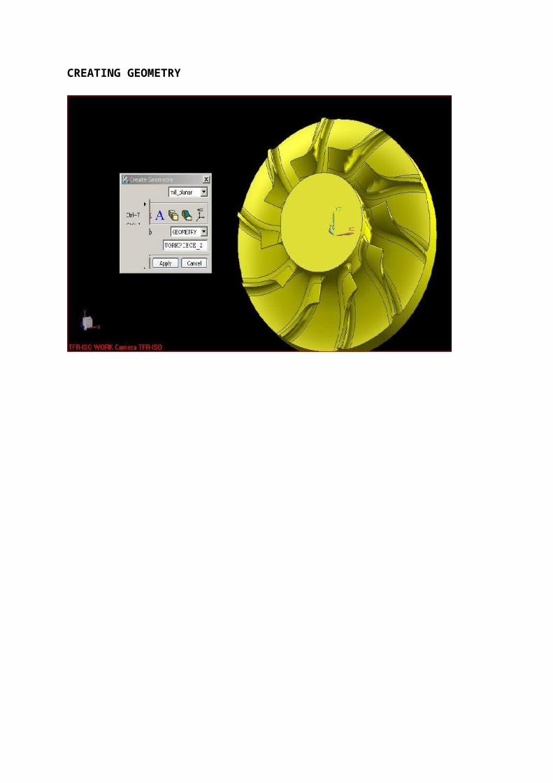
N0676X402.773Y56.784Z302.7A=DC(322.899)B50.269N0677X393.467Y57.057Z313.477A=DC(324.199)B48.433N0678X385.05Y57.28Z322.78A=DC(325.301)B46.841N0679X377.662Y57.467Z330.644A=DC(326.247)B45.496N0680X371.375Y57.633Z337.147A=DC(327.077)B44.392N0681X361.341Y57.976Z347.171A=DC(328.594)B42.711N0682X354.9Y58.373Z353.438A=DC(330.031)B41.719N0683X351.818Y58.88Z356.407A=DC(331.524)B41.337N0684X350.263Y59.604Z357.684A=DC(333.297)B41.222N0685X348.15Y60.49Z359.26A=DC(335.254)B41.007N0686X346.434Y60.983Z360.582A=DC(336.28)B40.784N0687X343.983Y61.493Z362.539A=DC(337.308)B40.434N0688X340.893Y62.019Z365.03A=DC(338.332)B39.976N0689X338.352Y62.567Z367.002A=DC(339.365)B39.616N0690X336.706Y63.132Z368.177A=DC(340.399)B39.412N0691X335.871Y63.713Z368.644A=DC(341.43)B39.348N0692X335.631Y64.314Z368.581A=DC(342.467)B39.386N0693X335.981Y64.934Z367.987A=DC(343.513)B39.525N0694X336.917Y65.575Z366.854A=DC(344.57)B39.765N0695X338.445Y66.238Z365.162A=DC(345.641)B40.108N0696X340.367Y66.917Z363.071A=DC(346.72)B40.521N0697X341.655Y67.595Z361.534A=DC(347.769)B40.825N0698X342.175Y68.264Z360.703A=DC(348.778)B40.995N0699X341.993Y68.922Z360.541A=DC(349.739)B41.042N0700X339.556Y70.209Z362.194A=DC(351.528)B40.773N0701X335.988Y71.527Z364.833A=DC(353.282)B40.307N0702X332.31Y72.895Z367.474A=DC(355.05)B39.823N0703X328.797Y74.28Z369.934A=DC(356.784)B39.369N0704X326.566Y75.652Z371.321A=DC(358.437)B39.138N0705X325.777Y77.02Z371.503A=DC(.031)B39.155N0706X325.881Y78.385Z370.95A=DC(1.567)B39.325N0707X326.148Y79.742Z370.297A=DC(3.04)B39.523N0708X326.551Y81.104Z369.542A=DC(4.473)B39.744N0709X327.068Y82.487Z368.667A=DC(5.896)B39.984N0710X327.696Y83.925Z367.596A=DC(7.369)B40.241N0711X328.434Y85.421Z366.309A=DC(8.901)B40.515N0712X329.281Y86.974Z364.796A=DC(10.494)B40.806N0713X330.219Y88.599Z363.013A=DC(12.183)B41.11N0714X331.261Y90.3Z360.9A=DC(13.994)B41.428N0715X332.476Y92.044Z358.432A=DC(15.89)B41.773N0716X333.927Y93.77Z355.671A=DC(17.78)B42.158N0717X335.503Y95.33Z353.161A=DC(19.379)B42.571N0718X337.059Y96.764Z351.015A=DC(20.722)B42.987N0719X338.427Y98.138Z349.266A=DC(21.909)B43.374N0720X339.502Y99.623Z347.539A=DC(23.245)B43.706N0721X340.339Y101.311Z345.463A=DC(24.913)B43.987N0722X341.043Y103.135Z343.04A=DC(26.833)B44.237N0723X341.682Y105.015Z340.361A=DC(28.899)B44.469N0724X342.082Y106.846Z337.907A=DC(30.934)B44.653N0725X342.254Y108.608Z335.748A=DC(32.9)B44.791N0726X342.257Y110.289Z333.878A=DC(34.772)B44.894
51

N0727X342.353Y111.841Z332.278A=DC(36.422)B45.015N0728X342.635Y113.28Z330.92A=DC(37.827)B45.174N0729X342.93Y114.664Z329.817A=DC(39.089)B45.337N0730X343.108Y116.068Z328.818A=DC(40.364)B45.477N0731X343.21Y117.586Z327.365A=DC(41.906)B45.597N0732X343.376Y119.174Z325.39A=DC(43.659)B45.724N0733X343.747Y120.776Z322.9A=DC(45.532)B45.886N0734X344.291Y122.315Z320.317A=DC(47.331)B46.08N0735X344.886Y123.77Z317.965A=DC(48.967)B46.284N0736X345.5Y125.163Z315.838A=DC(50.467)B46.492N0737X346.094Y126.51Z313.941A=DC(51.855)B46.696N0738X346.629Y127.821Z312.279A=DC(53.152)B46.888N0739X347.097Y129.113Z310.79A=DC(54.396)B47.066N0740X347.516Y130.396Z309.385A=DC(55.62)B47.233N0741X347.837Y131.675Z308.079A=DC(56.842)B47.379N0742X348.052Y132.947Z306.889A=DC(58.06)B47.502N0743X348.167Y134.211Z305.821A=DC(59.268)B47.603N0744X348.22Y135.464Z304.855A=DC(60.457)B47.69N0745X348.302Y136.705Z303.897A=DC(61.623)B47.781N0746X348.426Y137.935Z302.938A=DC(62.764)B47.879N0747X348.592Y139.153Z301.985A=DC(63.877)B47.984N0748X348.81Y140.359Z301.037A=DC(64.959)B48.098N0749X349.078Y141.554Z300.097A=DC(66.009)B48.221N0750X349.392Y142.739Z299.158A=DC(67.033)B48.352N0751X349.747Y143.915Z298.226A=DC(68.032)B48.49N0752X350.137Y145.085Z297.291A=DC(69.012)B48.634N0753X350.552Y146.248Z296.358A=DC(69.976)B48.782N0754X350.987Y147.407Z295.424A=DC(70.928)B48.933N0755X351.424Y148.562Z294.496A=DC(71.874)B49.083N0756X351.857Y149.714Z293.584A=DC(72.812)B49.231N0757X352.282Y150.861Z292.695A=DC(73.742)B49.376N0758X352.707Y152.004Z291.823A=DC(74.662)B49.52N0759X353.128Y153.143Z290.977A=DC(75.571)B49.662N0760X353.551Y154.277Z290.153A=DC(76.468)B49.803N0761X353.978Y155.405Z289.352A=DC(77.351)B49.944N0762X354.43Y156.528Z288.551A=DC(78.22)B50.089N0763X354.929Y157.646Z287.712A=DC(79.079)B50.243N0764X355.466Y158.762Z286.835A=DC(79.932)B50.404N0765X356.022Y159.877Z285.93A=DC(80.784)B50.568N0766X356.544Y160.989Z285.066A=DC(81.633)B50.724N0767X357.025Y162.099Z284.258A=DC(82.478)B50.87N0768X357.475Y163.207Z283.492A=DC(83.32)B51.008N0769X357.919Y164.313Z282.74A=DC(84.157)B51.144N0770X358.373Y165.419Z281.968A=DC(84.995)B51.281N0771X358.818Y166.529Z281.172A=DC(85.844)B51.415N0772X359.278Y167.647Z280.274A=DC(86.72)B51.551N0773X359.842Y168.777Z279.056A=DC(87.654)B51.709N0774X360.534Y169.916Z277.515A=DC(88.635)B51.894N0775X361.369Y171.056Z275.655A=DC(89.651)B52.11N0776X362.26Y172.188Z273.746A=DC(90.651)B52.338N0777X363.125Y173.312Z271.945A=DC(91.62)B52.56
52
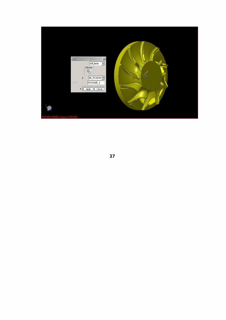
N0778X363.947Y174.433Z270.238A=DC(92.572)B52.772N0779X365.302Y176.681Z267.132A=DC(94.487)B53.129N0780X366.169Y178.924Z264.695A=DC(96.38)B53.371N0781X366.669Y181.147Z263.188A=DC(98.124)B53.524N0782X366.753Y183.373Z262.52A=DC(99.781)B53.576N0783X367.18Y185.616Z261.253A=DC(101.462)B53.702N0784X368.333Y187.874Z259.528A=DC(102.97)B53.992N0785X370.026Y190.199Z258.212A=DC(104.135)B54.407N0786X372.45Y192.665Z257.017A=DC(104.954)B54.996N0787X373.546Y193.956Z257.08A=DC(105.214)B55.264N0788X374.532Y195.289Z257.638A=DC(105.374)B55.506N0789X375.391Y196.663Z258.724A=DC(105.434)B55.717N0790X376.105Y198.077Z260.379A=DC(105.392)B55.892N0791X376.226Y200.797Z264.97A=DC(105.374)B55.919N0792X376.311Y206.205Z274.307N0793X459.019Z330.264F5000N0794G00X612.162Y0.Z403.039A=DC(0.)B75.964N0795G01X613.399Y58.604Z263.872A=DC(304.367)B65.86N0796X465.499Z197.588F2000N0797X465.634Y57.346Z199.953F4000N0798X465.67Y56.089Z202.274N0799X465.611Y54.832Z204.552N0800X465.462Y53.575Z206.789N0801X465.227Y52.318Z208.988N0802X462.008Y52.124Z216.085A=DC(306.332)B64.906N0803X453.072Y53.868Z231.497A=DC(310.884)B62.231N0804X443.283Y55.047Z247.255A=DC(314.438)B59.567N0805X433.003Y55.87Z262.633A=DC(317.252)B56.993N0806X422.577Y56.466Z277.141A=DC(319.514)B54.565N0807X412.323Y56.911Z290.477A=DC(321.359)B52.322N0808X402.414Y57.256Z302.594A=DC(322.899)B50.269N0809X393.12Y57.533Z313.353A=DC(324.199)B48.433N0810X384.714Y57.758Z322.642A=DC(325.301)B46.841N0811X377.338Y57.948Z330.495A=DC(326.247)B45.496N0812X371.061Y58.115Z336.989A=DC(327.077)B44.392N0813X361.046Y58.46Z347.A=DC(328.594)B42.711N0814X354.619Y58.86Z353.259A=DC(330.031)B41.719N0815X351.549Y59.369Z356.221A=DC(331.524)B41.337N0816X350.003Y60.094Z357.491A=DC(333.297)B41.222N0817X347.898Y60.982Z359.059A=DC(335.254)B41.007N0818X346.187Y61.475Z360.375A=DC(336.28)B40.784N0819X343.741Y61.986Z362.326A=DC(337.308)B40.434N0820X340.658Y62.512Z364.811A=DC(338.332)B39.976N0821X338.122Y63.061Z366.775A=DC(339.365)B39.616N0822X336.48Y63.627Z367.945A=DC(340.399)B39.412N0823X335.65Y64.208Z368.407A=DC(341.43)B39.348N0824X335.414Y64.809Z368.339A=DC(342.467)B39.386N0825X335.766Y65.429Z367.74A=DC(343.513)B39.525N0826X336.705Y66.07Z366.603A=DC(344.57)B39.765N0827X338.235Y66.733Z364.907A=DC(345.641)B40.108
53
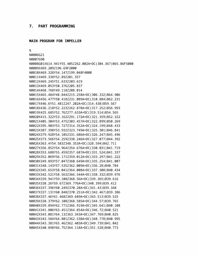
N0828X340.158Y67.413Z362.813A=DC(346.72)B40.521N0829X341.449Y68.09Z361.272A=DC(347.769)B40.825N0830X341.971Y68.759Z360.438A=DC(348.778)B40.995N0831X341.791Y69.417Z360.271A=DC(349.739)B41.042N0832X339.36Y70.703Z361.914A=DC(351.528)B40.773N0833X335.798Y72.021Z364.543A=DC(353.282)B40.307N0834X332.126Y73.388Z367.175A=DC(355.05)B39.823N0835X328.617Y74.772Z369.626A=DC(356.784)B39.369N0836X326.39Y76.143Z371.008A=DC(358.437)B39.138N0837X325.605Y77.511Z371.186A=DC(.031)B39.155N0838X325.711Y78.875Z370.632A=DC(1.567)B39.325N0839X325.98Y80.232Z369.977A=DC(3.04)B39.523N0840X326.385Y81.593Z369.222A=DC(4.473)B39.744N0841X326.905Y82.976Z368.347A=DC(5.896)B39.984N0842X327.535Y84.413Z367.275A=DC(7.369)B40.241N0843X328.274Y85.909Z365.985A=DC(8.901)B40.515N0844X329.122Y87.46Z364.47A=DC(10.494)B40.806N0845X330.061Y89.084Z362.684A=DC(12.183)B41.11N0846X331.103Y90.784Z360.568A=DC(13.994)B41.428N0847X332.317Y92.528Z358.098A=DC(15.89)B41.773N0848X333.768Y94.253Z355.335A=DC(17.78)B42.158N0849X335.343Y95.814Z352.826A=DC(19.379)B42.571N0850X336.9Y97.247Z350.683A=DC(20.722)B42.987N0851X338.27Y98.62Z348.936A=DC(21.909)B43.374N0852X339.348Y100.105Z347.207A=DC(23.245)B43.706N0853X340.186Y101.79Z345.127A=DC(24.913)B43.987N0854X340.891Y103.613Z342.698A=DC(26.833)B44.237N0855X341.53Y105.491Z340.012A=DC(28.899)B44.469N0856X341.93Y107.321Z337.553A=DC(30.934)B44.653N0857X342.101Y109.082Z335.391A=DC(32.9)B44.791N0858X342.104Y110.762Z333.519A=DC(34.772)B44.894N0859X342.2Y112.315Z331.919A=DC(36.422)B45.015N0860X342.484Y113.754Z330.564A=DC(37.827)B45.174N0861X342.78Y115.137Z329.462A=DC(39.089)B45.337N0862X342.96Y116.54Z328.463A=DC(40.364)B45.477N0863X343.063Y118.057Z327.007A=DC(41.906)B45.597N0864X343.231Y119.644Z325.028A=DC(43.659)B45.724N0865X343.603Y121.245Z322.535A=DC(45.532)B45.886N0866X344.147Y122.782Z319.95A=DC(47.331)B46.08N0867X344.742Y124.236Z317.598A=DC(48.967)B46.284N0868X345.357Y125.629Z315.471A=DC(50.467)B46.492N0869X345.953Y126.975Z313.575A=DC(51.855)B46.696N0870X346.489Y128.287Z311.916A=DC(53.152)B46.888N0871X346.959Y129.579Z310.429A=DC(54.396)B47.066N0872X347.38Y130.861Z309.026A=DC(55.62)B47.233N0873X347.703Y132.139Z307.723A=DC(56.842)B47.379N0874X347.92Y133.411Z306.534A=DC(58.06)B47.502N0875X348.036Y134.675Z305.468A=DC(59.268)B47.603N0876X348.092Y135.928Z304.504A=DC(60.457)B47.69N0877X348.176Y137.169Z303.548A=DC(61.623)B47.781N0878X348.302Y138.399Z302.592A=DC(62.764)B47.879
54
N0879X348.471Y139.617Z301.641A=DC(63.877)B47.984N0880X348.69Y140.823Z300.696A=DC(64.959)B48.098N0881X348.961Y142.018Z299.76A=DC(66.009)B48.221N0882X349.277Y143.203Z298.825A=DC(67.033)B48.352N0883X349.634Y144.38Z297.896A=DC(68.032)B48.49N0884X350.027Y145.549Z296.965A=DC(69.012)B48.634N0885X350.444Y146.713Z296.037A=DC(69.976)B48.782N0886X350.882Y147.872Z295.106A=DC(70.928)B48.933N0887X351.321Y149.027Z294.182A=DC(71.874)B49.083N0888X351.757Y150.179Z293.274A=DC(72.812)B49.231N0889X352.183Y151.327Z292.389A=DC(73.742)B49.376N0890X352.611Y152.47Z291.521A=DC(74.662)B49.52N0891X353.035Y153.609Z290.678A=DC(75.571)B49.662N0892X353.46Y154.743Z289.858A=DC(76.468)B49.803N0893X353.89Y155.872Z289.061A=DC(77.351)B49.944N0894X354.344Y156.995Z288.265A=DC(78.22)B50.089N0895X354.846Y158.114Z287.43A=DC(79.079)B50.243N0896X355.385Y159.23Z286.557A=DC(79.932)B50.404N0897X355.943Y160.345Z285.656A=DC(80.784)B50.568N0898X356.468Y161.458Z284.795A=DC(81.633)B50.724N0899X356.951Y162.568Z283.991A=DC(82.478)B50.87N0900X357.403Y163.676Z283.228A=DC(83.32)B51.008N0901X357.85Y164.782Z282.48A=DC(84.157)B51.144N0902X358.306Y165.888Z281.711A=DC(84.995)B51.281N0903X358.754Y166.998Z280.918A=DC(85.844)B51.415N0904X359.216Y168.116Z280.023A=DC(86.72)B51.551N0905X359.783Y169.246Z278.807A=DC(87.654)B51.709N0906X360.477Y170.384Z277.266A=DC(88.635)B51.894N0907X361.315Y171.525Z275.409A=DC(89.651)B52.11N0908X362.208Y172.656Z273.501A=DC(90.651)B52.338N0909X363.076Y173.78Z271.702A=DC(91.62)B52.56N0910X363.9Y174.9Z269.996A=DC(92.572)B52.772N0911X365.261Y177.147Z266.891A=DC(94.487)B53.129N0912X366.133Y179.389Z264.455A=DC(96.38)B53.371N0913X366.639Y181.611Z262.95A=DC(98.124)B53.524N0914X366.727Y183.836Z262.282A=DC(99.781)B53.576N0915X367.159Y186.078Z261.016A=DC(101.462)B53.702N0916X368.316Y188.334Z259.29A=DC(102.97)B53.992N0917X370.014Y190.656Z257.969A=DC(104.135)B54.407N0918X372.442Y193.115Z256.762A=DC(104.954)B54.996N0919X373.54Y194.403Z256.817A=DC(105.214)B55.264N0920X374.528Y195.731Z257.365A=DC(105.374)B55.506N0921X375.389Y197.1Z258.44A=DC(105.434)B55.717N0922X376.105Y198.508Z260.083A=DC(105.392)B55.892N0923X376.229Y201.226Z264.674A=DC(105.374)B55.919N0924X376.317Y206.635Z274.013N0925X458.657Z329.721F5000N0926G00X612.162Y0.Z403.039A=DC(0.)B75.964N0927G01X613.202Y59.004Z264.104A=DC(304.367)B65.86N0928X465.049Z197.707F2000N0929X465.186Y57.746Z200.072F4000N0930X465.224Y56.489Z202.394
55

N0931X465.169Y55.232Z204.674N0932X465.025Y53.975Z206.914N0933X464.795Y52.717Z209.115N0934X461.584Y52.534Z216.193A=DC(306.332)B64.906N0935X452.655Y54.3Z231.552A=DC(310.884)B62.231N0936X442.876Y55.493Z247.266A=DC(314.438)B59.567N0937X432.606Y56.326Z262.606A=DC(317.252)B56.993N0938X422.192Y56.929Z277.083A=DC(319.514)B54.565N0939X411.951Y57.379Z290.392A=DC(321.359)B52.322N0940X402.055Y57.729Z302.488A=DC(322.899)B50.269N0941X392.773Y58.009Z313.229A=DC(324.199)B48.433N0942X384.379Y58.237Z322.504A=DC(325.301)B46.841N0943X377.014Y58.428Z330.346A=DC(326.247)B45.496N0944X370.747Y58.596Z336.831A=DC(327.077)B44.392N0945X360.75Y58.945Z346.829A=DC(328.594)B42.711N0946X354.338Y59.347Z353.079A=DC(330.031)B41.719N0947X351.279Y59.858Z356.035A=DC(331.524)B41.337N0948X349.742Y60.585Z357.298A=DC(333.297)B41.222N0949X347.646Y61.474Z358.857A=DC(335.254)B41.007N0950X345.94Y61.968Z360.168A=DC(336.28)B40.784N0951X343.499Y62.479Z362.113A=DC(337.308)B40.434N0952X340.422Y63.006Z364.59A=DC(338.332)B39.976N0953X337.891Y63.555Z366.549A=DC(339.365)B39.616N0954X336.255Y64.121Z367.712A=DC(340.399)B39.412N0955X335.428Y64.703Z368.168A=DC(341.43)B39.348N0956X335.195Y65.304Z368.096A=DC(342.467)B39.386N0957X335.551Y65.924Z367.493A=DC(343.513)B39.525N0958X336.492Y66.566Z366.352A=DC(344.57)B39.765N0959X338.024Y67.228Z364.651A=DC(345.641)B40.108N0960X339.949Y67.908Z362.554A=DC(346.72)B40.521N0961X341.241Y68.585Z361.009A=DC(347.769)B40.825N0962X341.766Y69.254Z360.171A=DC(348.778)B40.995N0963X341.588Y69.912Z360.A=DC(349.739)B41.042N0964X339.163Y71.197Z361.633A=DC(351.528)B40.773N0965X335.607Y72.514Z364.252A=DC(353.282)B40.307N0966X331.941Y73.881Z366.874A=DC(355.05)B39.823N0967X328.437Y75.264Z369.318A=DC(356.784)B39.369N0968X326.214Y76.635Z370.694A=DC(358.437)B39.138N0969X325.431Y78.002Z370.869A=DC(.031)B39.155N0970X325.539Y79.365Z370.313A=DC(1.567)B39.325N0971X325.811Y80.721Z369.657A=DC(3.04)B39.523N0972X326.219Y82.082Z368.901A=DC(4.473)B39.744N0973X326.741Y83.464Z368.025A=DC(5.896)B39.984N0974X327.373Y84.901Z366.952A=DC(7.369)B40.241N0975X328.114Y86.396Z365.66A=DC(8.901)B40.515N0976X328.963Y87.947Z364.143A=DC(10.494)B40.806N0977X329.903Y89.57Z362.354A=DC(12.183)B41.11N0978X330.945Y91.269Z360.235A=DC(13.994)B41.428N0979X332.159Y93.012Z357.762A=DC(15.89)B41.773N0980X333.608Y94.737Z354.999A=DC(17.78)B42.158
56
N0981X335.183Y96.297Z352.491A=DC(19.379)B42.571N0982X336.741Y97.73Z350.35A=DC(20.722)B42.987N0983X338.113Y99.102Z348.605A=DC(21.909)B43.374N0984X339.193Y100.585Z346.874A=DC(23.245)B43.706N0985X340.033Y102.27Z344.79A=DC(24.913)B43.987N0986X340.739Y104.091Z342.355A=DC(26.833)B44.237N0987X341.377Y105.968Z339.664A=DC(28.899)B44.469N0988X341.777Y107.796Z337.2A=DC(30.934)B44.653N0989X341.949Y109.556Z335.033A=DC(32.9)B44.791N0990X341.951Y111.235Z333.159A=DC(34.772)B44.894N0991X342.047Y112.788Z331.56A=DC(36.422)B45.015N0992X342.332Y114.227Z330.207A=DC(37.827)B45.174N0993X342.63Y115.61Z329.107A=DC(39.089)B45.337N0994X342.811Y117.012Z328.108A=DC(40.364)B45.477N0995X342.917Y118.528Z326.65A=DC(41.906)B45.597N0996X343.086Y120.113Z324.667A=DC(43.659)B45.724N0997X343.458Y121.713Z322.17A=DC(45.532)B45.886N0998X344.002Y123.249Z319.582A=DC(47.331)B46.08N0999X344.599Y124.703Z317.23A=DC(48.967)B46.284N1000X345.215Y126.095Z315.104A=DC(50.467)B46.492N1001X345.812Y127.441Z313.21A=DC(51.855)B46.696N1002X346.35Y128.752Z311.553A=DC(53.152)B46.888N1003X346.821Y130.044Z310.069A=DC(54.396)B47.066N1004X347.244Y131.326Z308.668A=DC(55.62)B47.233N1005X347.569Y132.604Z307.367A=DC(56.842)B47.379N1006X347.788Y133.875Z306.18A=DC(58.06)B47.502N1007X347.907Y135.139Z305.116A=DC(59.268)B47.603N1008X347.965Y136.392Z304.153A=DC(60.457)B47.69N1009X348.051Y137.633Z303.2A=DC(61.623)B47.781N1010X348.179Y138.863Z302.246A=DC(62.764)B47.879N1011X349.891Z345.504F5000N1012G00X612.162Y0.Z403.039A=DC(0.)B75.964
57

8. 3-D IMPELLER
Typically, in a 3-D Impeller the vane surfaces are twisted ruled surfaces. The twist in the ruled surface results in varied orientations of the normals at the extreme points of the same rulings. The difference in orientation of the normals on the same ruling will cause undercut while machining the vane by keeping the ball nose end mill cutter tangential at any one end of the rulings. To minimise the undercuts and keep the impeller within the geometrical tolerances, it is necessary to adopt new techniques while placing the cutter along the vane surface. The normal 3-axes CNC machining methods are not adequate, and hence 5-axes CNC codes are required to be generated.
In order to exercise better control over the tool orientation, it is essential that specific user-developed modules are integrated with the CAD/CAM packages for successful generation of 5-axes CNC codes. This paper discusses the important aspects of 5-axes CNC programming for 3-D Impellers and an optimisation technique for minimising undercuts.
8.1 METHODS OF 5-AXES CNC PART PROGRAMMING AND MACHINING OF 3-D IMPELLER
Scooping (Roughing operation between vanes)
"Scooping" is the operation required for removing material between vanes. Since the gap between vanes is narrow, tool selection is one of the primary considerations to avoid the interference of tool with the adjacent vane surfaces. After selection of the proper tool, one of the methods for scooping operation is to divide the gap between the two vanes into a sufficient number of sections and build imaginary vane surfaces of smooth transition. Tool path is generated under restrictions of gouging the hub surface, the tool being tangential to hub as well as the fictitious vane surfaces.
This method generates hub surface with good surface integrity and avoids interference with the adjoining vane surfaces, while removing the bulk material available between vanes.
Vane Finishing
Various methods can be followed to machine the vane surfaces, based on the dimensional tolerances and surface finish required. Following are some of the methods.
58
Flank Milling (Swarf Machining)
In this method, the tool is placed parallel to the rulings of the vane surface and the side of the cutter machines the vane surface. By this method, the surface finish on the vane surface is excellent, but considerable amount of undercut is formed on the vane surface.
Point Milling
In this method the tool makes only a point contact on the vane. Since the number of passes becomes enormous, to cover the entire vane surface for achieving the required surface finish, this method is prohibitively time-consuming with poorer surface finish; however, undercuts on the vane can be completely eliminated. This method is suitable where the construction of the vane surface does not allow flank milling, like blisks (bladed disks) with arbitrary surfaces.
Strip Milling
In this method, the total vane surface is divided into a number of strip surface elements, based on the surface finish requirement, and each strip is machined separately using a tool with cutter contact equal to the strip width or tilting the relieved tool. This method reduces the undercut, depending on the width of the strip. The method tends to Point Milling when the width of the strip tends to a point resulting poorer surface finish and higher machining time, in comparison with the Flank Milling method.
Fig 8: Flank, Point and Strip Milling
59
Flank Milling Strip Milling

Comparison of the Methods
Of the methods discussed above, flank milling method offers better surface finish and faster operating cycles except for the undercuts, which can be controlled by exercising control on tool orientations. The authors would further emphasise on Flank Milling method and techniques to avoid undercuts in the vane surface, for effective programming and machining of 3-D Impeller.
8.2 PROBLEMS IN FLANK MILLING
In the Flank Milling method, as explained earlier, the side of the cutter is placed along the rulings of the twisted ruled surface i.e. vane surface. Because of the twist in the ruled surface, the orientation of the normals at the extreme points of the same ruling, i.e. at the hub and shroud parameter lines, will be different. Due to the variation in the normals, while placing the tool tangential to the two parameter lines of the vane, the undercut will be more in the middle of vane. This will lead to thinning of the vane. The amount of undercut will be varying from inlet to outlet of the vane surface as the variation in slopes will be changing gradually.
60
Undercut on Vane Surface

8.3 EXTENT OF UNDERCUT IN FLANK MILLING
The extent of undercut (d) formed in the Flank Milling method, basically depends on the difference in the slopes of the two parameter lines of the vane surface. This is nothing but the deviation in the angles (A) of the normals. The other parameter which influences the undercut is the cutter radius (R). The undercut is the function of the cutter radius and the variation in normals, as given below:
d = R {1-cos (A/2)}.... (1)
61
This feature can be appreciated by studying the concept of machining a cylinder with the side of the cutter whose axis is skewed. Since the normals of the two end points on the cylinder surface are at different orientations, the undercut will be formed. This will be the maximum in the middle of the cylinder and will decrease gradually to the two ends. This amount of undercut will depend on the angle made by the two axes and the cutter radius. Though the cutter radius is one of the criteria, the selection of cutter radius is constrained because of two main considerations: a) the fillet radius between the vane and the hub; b) the slenderness of the cutter. Hence, the programmer is left with an option of optimising the tool orientations for achieving the dimensional tolerances.
8.4 MATHEMATICAL SOLUTION FOR MINIMISING UNDERCUT
In the normal practice, the placement of the tool will be with respect to the hub and shroud parameter lines of the vane, i.e. the 0 and 100 percent of vane surface, which results in undercuts at the middle of the vane surface. An iterative procedure is adopted to distribute the undercut throughout the vane, to achieve the required dimensional tolerances.
8.5 PARAMETER LINES OPTIMISATION TECHNIQUE FOR MINIMISING UNDERCUT
In this technique, the parameter lines of the vane surface at various levels, such as PL0, PL25, PL75 and PL100, are used as rails for guiding the. In the normal Flank Milling method, 0 and 100 percent parameter lines, designated as PL0 and PL100, are used for placing the tool tangential to the surface. In this optimisation technique, the angle between the two normals is optimised by selecting two parameter lines (e.g., PL25 and PL75) for distributing the undercut over the vane surface. The software sub-modules are to be developed for choosing the parameter lines on the vane surface in an iterative manner, to minimise the extent of undercut.
Fig 9:
62
The iterations are carried out to identify those parameter lines of the vane surface which will have the 25% and 75% of the included angle values with the base parameter line PL0. Since the twist of the vane is not uniform, the vane surfaces are divided into a number of patches, for which the optimal parameter lines to form the rails, for placing the tool, are identified. Subsequently, the complete tool path is evaluated and the Cutter Location data is generated.
Fig 10:
This method eliminates undercut of the order of 50% of the undercut developed under the normal Flank Milling method.
A 3-D Impeller of 600 mm diameter, vane width varying from 20 mm to 70 mm from the outlet to inlet, with 10 vanes, was machined. The machining was carried out using 16 mm diameter ball nose cutter. An undercut of 0.20 mm was observed on the vane when the
Parameter Lines of the Vane Surface for Tool
PL
PL100
VAN
PL7PL2
Undercut reduced significantly, using Optimization Technique
normal Flank Milling option was used. The undercut reduced to 0.10 mm when the above optimisation technique was used.
63
9. INSPECTION
Material Undercut
Impeller life varies according to the type of machine, material swept, water volume, and Impeller RPM. Because of this service life variation, it’s important to clean and inspect the impeller for debris build up and/or damage every 50 hours as directed in the operators manual and maintenance chart. Wear damage includes: Knife Edge Vanes, Blow Through and Wear Holes. These issues must be resolved or impeller failure may occur which can lead to damage of other components, and could cause serious bodily injury and/or death..
During inspection, inspect impeller body and all weld areas of each vane, including Hub requires inspection mirror and light) for structural integrity. If the impeller is worn or imbalanced to the point a crack appears, REPLACE THE IMPELLER. Do not attempt repair, Do Not Re-Weld.
5-Axis Machining of 3-D Impeller and finished 3-D

1. Clean all air passageways including impeller thoroughly every shift. Follow all safety and cleaning instructions included in the operator’s manual.
2. Weekly or every fifty (50) hours of operation remove impeller housing inspection cover and inspect all surfaces of the impeller and its housing. Daily inspection may be required when swept materials are sticky or abrasive.
3. If excessive machine vibration occurs, shut “off” sweeper engine and take corrective action. If vibration continues, replace impeller and repair housing.
64
10. RESULTS AND CONCLUSION
In the present scenario of machining impellers, a much-sophisticated program is employed to achieve higher standards in the Engineering and Production departments. A few features of the method of programming are:
Ease to incorporate the changes in the Dimension
Optimization of tool path
In this Project, a model of 3D impeller was drawn through Unigraphics. Then machining has been done for the given vanes and remaining part. After that the program has been post process by 3 -axis the post processor in built in Unigraphics. This post processor program then transferred to CNC 5-AXIS Machine through DNC. The above program has been checked through simulation mode, performed optimization and finally machining has been done for the component followed by inspection.
A reduction of 50% in the undercut is observed using the parameter line optimisation technique, against the normal Flank Milling method. This technique for minimising undercut is found to be very fast and accurate, without necessitating any manual intervention or trial-and-error procedure.
The optimisation technique dealt with in this project limits itself to selecting the appropriate parameter lines as rails for guiding the tool which is parallel to the rulings. There is, however, greater scope for further improvisation by reorienting the tool axis with respect to the surface rulings.
65
11. REFERENCES AND BIBILOGRAPHY
[1] Hand book of CNC Machines by ADITAN & PABLA.
[2] Computer Aided Design/Computer Aided Manufacturing by MIKELL.P.GROOVER
[3] Hand book of Unigraphics by CITD.
[4] A Practical Guide to Compressor Technology by HEINZ P.BLOCH
[5] Optimization with Ruled Surface by YAYUN ZHOU.
[6] Advanced Modeling and Optimization of Manufacturing Processes by R.VENKATA RAO.
[7] Advanced Numerical Methods to optimize cutting operations of Milling Machines by STANISLAV S.MAKHANOV, WEERACHAI ANOTAIPAIBOON.
[8] “Flank Milling of Impellers”, Northern Regional and Engineering Corporation (NREC), Vol 6, Issue 4, Fall 1992.
[9] HANSEN, K. E., JØRGENSEN, P., and LARSEN, P. S. (1981). Experimental and theoretical study of surge in a small centrifugal compressor. ASME J. Fluids Engineering, 103, 391–395.
[10] AMBROSET, A., (2000),``Analysis of high efficiency impellers for CSTRs'', Ms Thesis, University of Udine
[11] ZHOU, G., and KRESTA, S., M., (1996),``Impact of tank geometry on the maximum turbulence energy dissipation rate for impellers'', AIChE J., 42, 2476-2490.
[12] HUNZIKER R and GYARMATHY G 1994,The Operational Stability of Centrifugal Compressor and Its Dependence On the Characteristics of the Subcomponents,ASME Journal of Turbo machinery Vol 116.
66