Embed Size (px)
Citation preview

DISCUSSION PAPERDRAFT CONCEPT
DELEGATED ACT ON
monitoring of in-service NRMM engines v1
This document does not represent an official position of the European Commission. It is a tool to explore the views of interested parties. The suggestions contained in this document do not prejudge the form and content of any possible future proposal by the European Commission.
EN EN
COMMISSION DELEGATED REGULATION (EU) 2016/..
of XXX
supplementing Regulation (EU) 2015/XXX of the European Parliament and of the Council with regard to monitoring of emissions of in-service internal combustion
engines installed on non-road mobile machinery
(Text with EEA relevance)
THE EUROPEAN COMMISSION,
Having regard to the Treaty on the Functioning of the European Union,
Having regard to Regulation No 2015/XXX of the European Parliament and of the Council on requirements relating to emission limits and type-approval for internal combustion engines for non-road mobile machinery1, and in particular Articles 18(2), and 55 thereto,
Whereas:
(1) This Regulation aims to set out the technical requirements and test methods relating to monitoring of emissions of in-service engines installed in non-road mobile machinery.
(2) …
(3) …
(4) This Regulation should apply from the date of application of Regulation (EU) 2015/XXX,
HAS ADOPTED THIS REGULATION:
Article 1
Subject matter
This Regulation establishes the detailed technical requirements and test procedures relating to relating to monitoring of emissions of in-service internal combustion engines installed on non-road mobile machinery in accordance with Regulation (EU) 2015/XXX.
Article 2
Definitions
The following definitions shall apply:
(1) ….
(2) ….
1 OJ L
Article 3Manufacturer’s general obligations regarding engine technical requirements and test
procedures
1. Manufacturers shall monitor the gaseous pollutant and particulate emissions of engine types or engine families in service by testing engines installed in non-road mobile machinery operated over their normal operating duty cycles.
2. Such testing shall be conducted on engines that have been correctly maintained and shall comply with the provisions on the selection of engines, testing procedures and reporting of results for the different engine categories set out in Articles 4 to 6.
3.[1.] Manufacturers shall ensure that replacement engines that are made available on the market or are entering into service in the Union comply with the detailed technical requirements and test procedures referred to in this Regulation. Non-road mobile machinery equipped with such a replacement engine shall meet the same test requirements and performance limit values as non-road mobile machinery equipped with an original engine.
Article 4Requirements for monitoring of emissions of in-service engines
The detailed requirements with regard to the selection of engines relating to monitoring of emissions of in-service engines referred to in Article 18(2) of Regulation (EU) 2015/XXX shall be laid down in Annex VI to this Regulation.
Article 5
Entry into force and application
This Regulation shall enter into force on the twentieth day following that of its publication in the Official Journal of the European Union. It shall apply from 1 January 2017.
This Regulation shall be binding in its entirety and directly applicable in all Member States.
Done at Brussels,
For the Commission The President

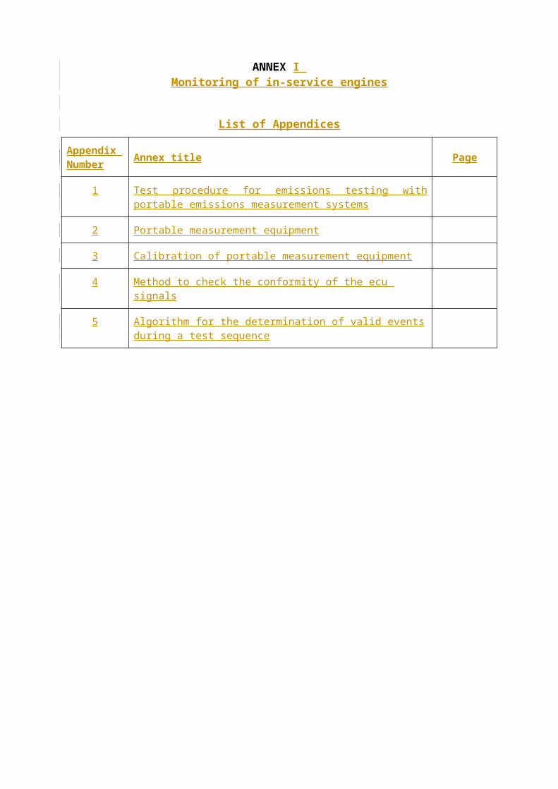
ANNEX I Monitoring of in-service engines
List of Appendices
Appendix Number Annex title Page
1 Test procedure for emissions testing with portable emissions measurement systems
2 Portable measurement equipment
3 Calibration of portable measurement equipment
4 Method to check the conformity of the ecu signals
5 Algorithm for the determination of valid events during a test sequence
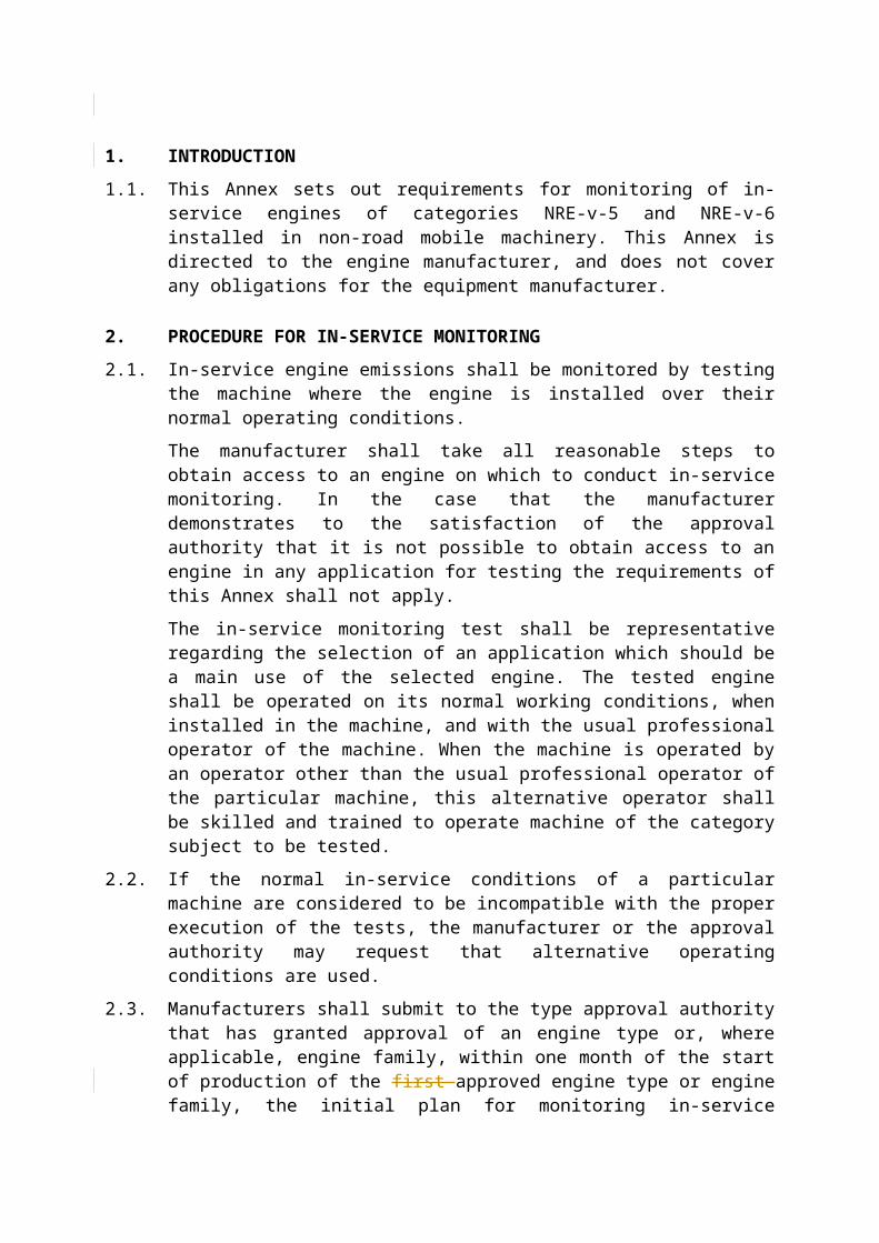
1. INTRODUCTION
1.1. This Annex sets out requirements for monitoring of in-service engines of categories NRE-v-5 and NRE-v-6 installed in non-road mobile machinery. This Annex is directed to the engine manufacturer, and does not cover any obligations for the equipment manufacturer.
2. PROCEDURE FOR IN-SERVICE MONITORING
2.1. In-service engine emissions shall be monitored by testing the machine where the engine is installed over their normal operating conditions.
The manufacturer shall take all reasonable steps to obtain access to an engine on which to conduct in-service monitoring. In the case that the manufacturer demonstrates to the satisfaction of the approval authority that it is not possible to obtain access to an engine in any application for testing the requirements of this Annex shall not apply.
The in-service monitoring test shall be representative regarding the selection of an application which should be a main use of the selected engine. The tested engine shall be operated on its normal working conditions, when installed in the machine, and with the usual professional operator of the machine. When the machine is operated by an operator other than the usual professional operator of the particular machine, this alternative operator shall be skilled and trained to operate machine of the category subject to be tested.
2.2. If the normal in-service conditions of a particular machine are considered to be incompatible with the proper execution of the tests, the manufacturer or the approval authority may request that alternative operating conditions are used.
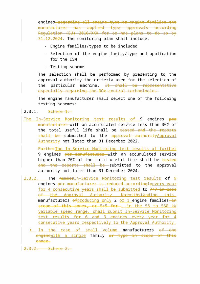
2.3. Manufacturers shall submit to the type approval authority that has granted approval of an engine type or, where applicable, engine family, within one month of the start of production of the first approved engine type or engine family, the initial plan for monitoring in-service engines regarding all engine type or engine families the manufacturer has applied type approvals according Regulation (EU) 2016/XXX for or has plans to do so by 31.12.2024. The monitoring plan shall include:
- Engine families/types to be included
- Selection of the engine family/type and application for the ISM
- Testing scheme
The selection shall be performed by presenting to the approval authority the criteria used for the selection of the particular machine. It shall be representative especially regarding the NOx control technologies
The engine manufacturer shall select one of the following testing schemes:
2.3.1. Scheme 1:
The In-Service Monitoring test results of 9 engines per manufacturer with an accumulated service less than 30% of the total useful life shall be tested and the reports shall be submitted to the approval authorityApproval Authority not later than 31 December 2022.
FurtherThe In-Service Monitoring test results of further 9 engines per manufacturer with an accumulated service higher than 70% of the total useful life shall be tested and the reports shall be submitted to the approval authority not later than 31 December 2024.
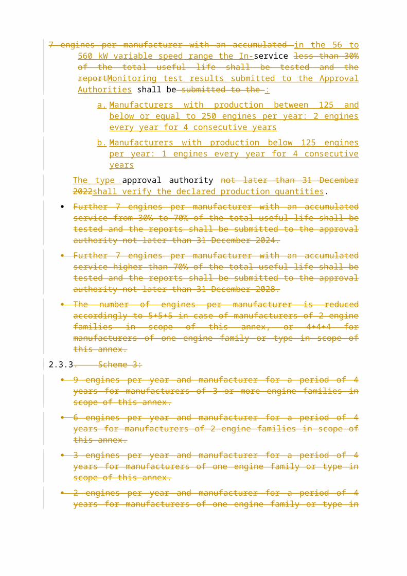
2.3.2. The numberIn-Service Monitoring test results of 9 engines per manufacturer is reduced accordinglyevery year for 4 consecutive years shall be submitted to 7+7 in case of the Approval Authority. Notwithstanding this, manufacturers ofproducing only 2 or 1 engine families in scope of this annex, or 5+5 for , in the 56 to 560 kW variable speed range, shall submit In-Service Monitoring test results for 6 and 3 engines every year for 4 consecutive years respectively to the Approval Authority.
In the case of small volume manufacturers of one enginewith a single family or type in scope of this annex.
2.3.2. Scheme 2:
7 engines per manufacturer with an accumulated in the 56 to 560 kW variable speed range the In-service less than 30% of the total useful life shall be tested and the reportMonitoring test results submitted to the Approval Authorities shall be submitted to the :
a. Manufacturers with production between 125 and below or equal to 250 engines per year: 2 engines every year for 4 consecutive years
b. Manufacturers with production below 125 engines per year: 1 engines every year for 4 consecutive years
The type approval authority not later than 31 December 2022shall verify the declared production quantities.
Further 7 engines per manufacturer with an accumulated service from 30% to 70% of the total useful life shall be tested and the reports shall be submitted to the approval authority not later than 31 December 2024.
Further 7 engines per manufacturer with an accumulated service higher than 70% of the total useful life shall be tested and the reports shall be submitted to the approval authority not later than 31 December 2028.
The number of engines per manufacturer is reduced accordingly to 5+5+5 in case of manufacturers of 2 engine families in scope of this annex, or 4+4+4 for manufacturers of one engine family or type in scope of this annex.
2.3.3. Scheme 3:
9 engines per year and manufacturer for a period of 4 years for manufacturers of 3 or more engine families in scope of this annex.
6 engines per year and manufacturer for a period of 4 years for manufacturers of 2 engine families in scope of this annex.
3 engines per year and manufacturer for a period of 4 years for manufacturers of one engine family or type in scope of this annex.
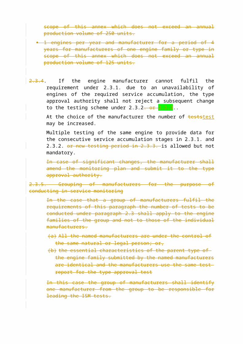
2 engines per year and manufacturer for a period of 4 years for manufacturers of one engine family or type in scope of this annex which does not exceed an annual production volume of 250 units.
1 engines per year and manufacturer for a period of 4 years for manufacturers of one engine family or type in scope of this annex which does not exceed an annual production volume of 125 units.
2.3.4. If the engine manufacturer cannot fulfil the requirement under 2.3.1. due to an unavailability of engines of the required service accumulation, the type approval authority shall not reject a subsequent change to the testing scheme under 2.3.2. or 2.3.3..
At the choice of the manufacturer the number of teststest may be increased.
Multiple testing of the same engine to provide data for the consecutive service accumulation stages in 2.3.1. and 2.3.2. or new testing period in 2.3.3. is allowed but not mandatory.
In case of significant changes, the manufacturer shall amend the monitoring plan and submit it to the type approval authority.
2.3.5. Grouping of manufacturers for the purpose of conducting in-service monitoring
In the case that a group of manufacturers fulfil the requirements of this paragraph the number of tests to be conducted under paragraph 2.3 shall apply to the engine families of the group and not to those of the individual manufacturers.
[(a)] All the named manufacturers are under the control of the same natural or legal person; or,
[(b)] the essential characteristics of the parent type of the engine family submitted by the named manufacturers are identical and the manufacturers use the same test report for the type approval test
In this case the group of manufacturers shall identify one manufacturer from the group to be responsible for leading the ISM tests.
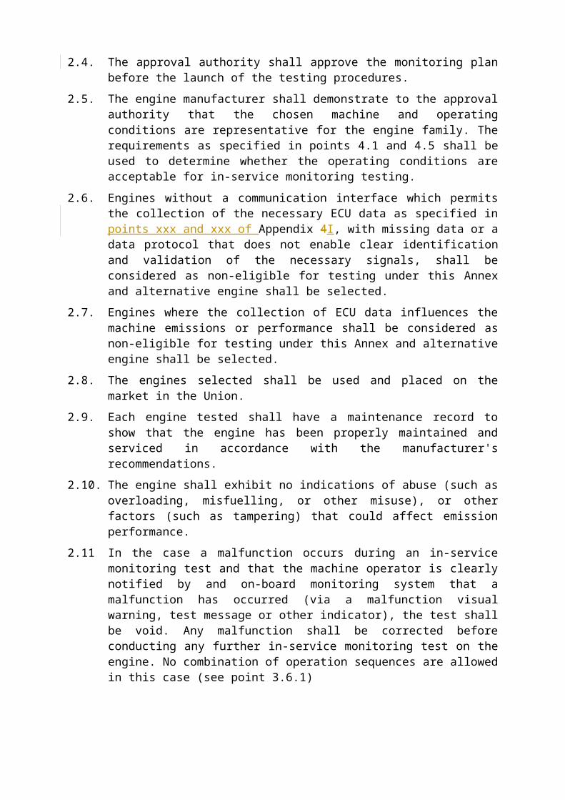
2.4. The approval authority shall approve the monitoring plan before the launch of the testing procedures.
2.5. The engine manufacturer shall demonstrate to the approval authority that the chosen machine and operating conditions are representative for the engine family. The requirements as specified in points 4.1 and 4.5 shall be used to determine whether the operating conditions are acceptable for in-service monitoring testing.
2.6. Engines without a communication interface which permits the collection of the necessary ECU data as specified in points xxx and xxx of Appendix 4I, with missing data or a data protocol that does not enable clear identification and validation of the necessary signals, shall be considered as non-eligible for testing under this Annex and alternative engine shall be selected.
2.7. Engines where the collection of ECU data influences the machine emissions or performance shall be considered as non-eligible for testing under this Annex and alternative engine shall be selected.
2.8. The engines selected shall be used and placed on the market in the Union.
2.9. Each engine tested shall have a maintenance record to show that the engine has been properly maintained and serviced in accordance with the manufacturer's recommendations.
2.10. The engine shall exhibit no indications of abuse (such as overloading, misfuelling, or other misuse), or other factors (such as tampering) that could affect emission performance.
2.11 In the case a malfunction occurs during an in-service monitoring test and that the machine operator is clearly notified by and on-board monitoring system that a malfunction has occurred (via a malfunction visual warning, test message or other indicator), the test shall be void. Any malfunction shall be corrected before conducting any further in-service monitoring test on the engine. No combination of operation sequences are allowed in this case (see point 3.6.1)
2.12. All emission control system components on the engine and machine shall be in conformity with those stated in the applicable type-approval documents.
3. TEST CONDITIONS
3.1. General
For the purpose of in- service monitoring testing the operating conditions may be reproduced by a representative load cycle.
In this case a suitable load cycle shall be determined by the manufacturer in consultation with the type approval authority, in accordance with section 4.5 of this Annex.
3.2. Ambient conditions
The test shall be conducted under ambient conditions meeting the following conditions:
Atmospheric pressure greater than or equal to 82,5 kPa,
Temperature greater than or equal to 266 K (-7°C) and less than or equal to the temperature determined by the following equation at the specified atmospheric pressure:
T = -0,4514 * (101,3 – pb) + 311
where:
– T is the ambient air temperature, K
– pb is the atmospheric pressure, kPa
3.3. Engine coolant temperature
The engine coolant temperature shall be in accordance with point 2.6.2. of Appendix 1.
3.4. The lubricating oil, fuel and reagent shall be within the specifications issued by the manufacturer.
3.4.1. Lubricating oil
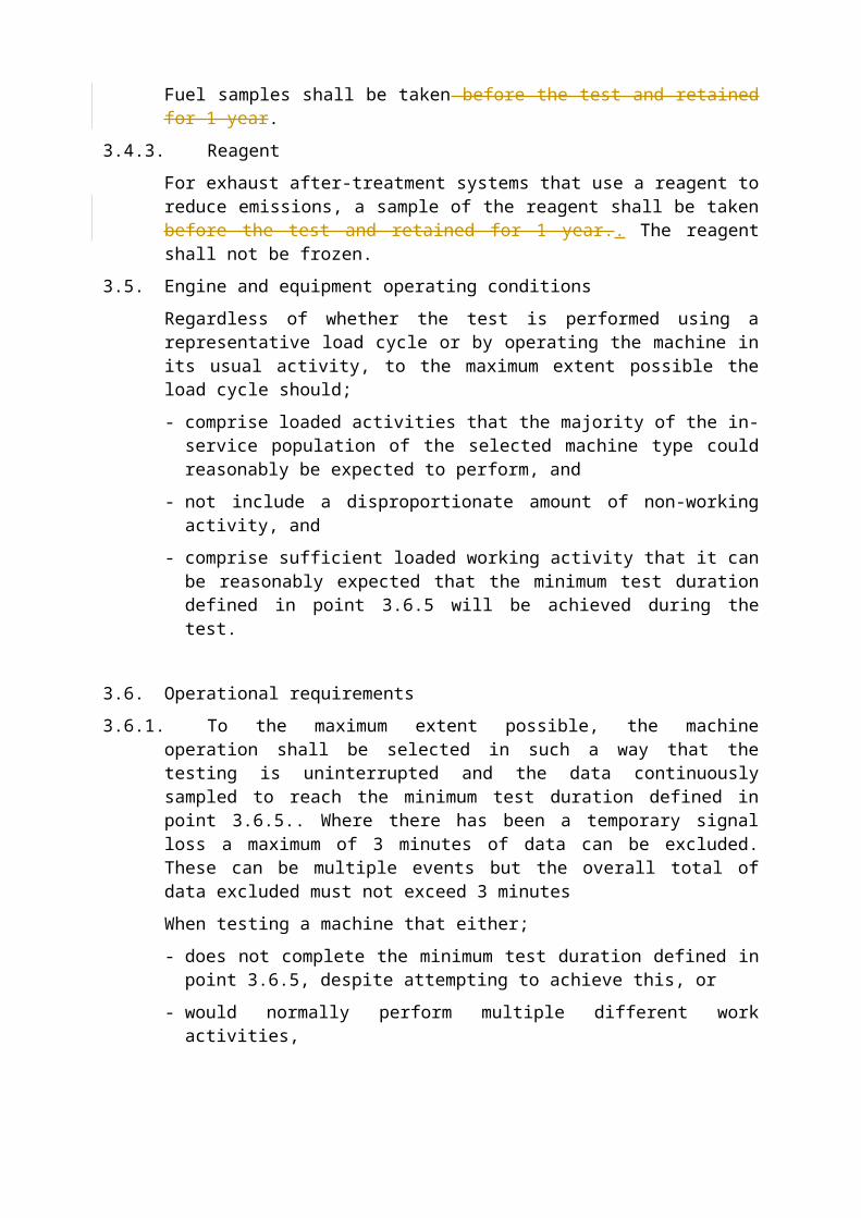
Oil samples shall be taken before the test and retained for 1 year.
3.4.2. Fuel
The test fuel shall be market fuel or reference fuel as specified in Annex V to Regulation (EU) 20162015/XXX. Fuel samples shall be taken before the test and retained for 1 year.
3.4.3. Reagent
For exhaust after-treatment systems that use a reagent to reduce emissions, a sample of the reagent shall be taken before the test and retained for 1 year.. The reagent shall not be frozen.
3.5. Engine and equipment operating conditions
Regardless of whether the test is performed using a representative load cycle or by operating the machine in its usual activity, to the maximum extent possible the load cycle should;
- comprise loaded activities that the majority of the in-service population of the selected machine type could reasonably be expected to perform, and
- not include a disproportionate amount of non-working activity, and
- comprise sufficient loaded working activity that it can be reasonably expected that the minimum test duration defined in point 3.6.5 will be achieved during the test.
3.6. Operational requirements
3.6.1. To the maximum extent possible, the machine operation shall be selected in such a way that the testing is uninterrupted and the data continuously sampled to reach the minimum test duration defined in point 3.6.5.. Where there has been a temporary signal loss a maximum of 3 minutes of data can be excluded. These can be multiple events but the overall total of data excluded must not exceed 3 minutes
When testing a machine that either;
- does not complete the minimum test duration defined in point 3.6.5, despite attempting to achieve this, or
- would normally perform multiple different work activities,
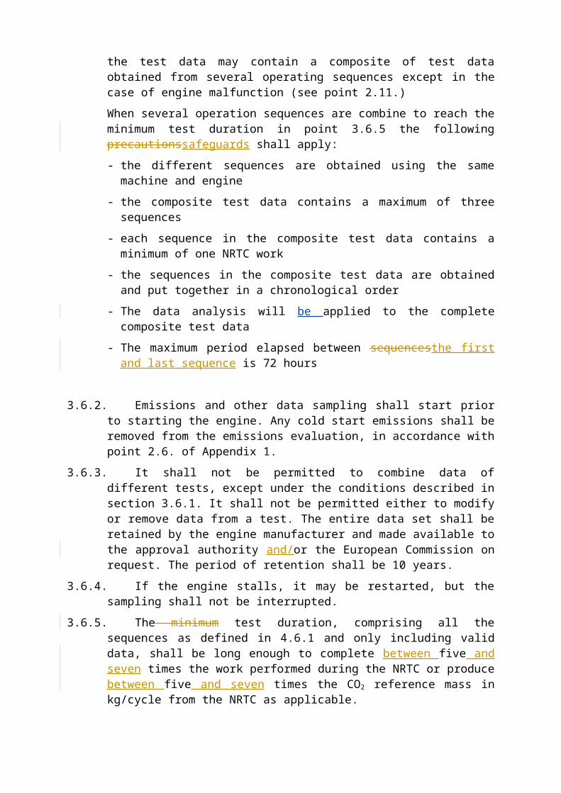
the test data may contain a composite of test data obtained from several operating sequences except in the case of engine malfunction (see point 2.11.)
When several operation sequences are combine to reach the minimum test duration in point 3.6.5 the following precautionssafeguards shall apply:
- the different sequences are obtained using the same machine and engine
- the composite test data contains a maximum of three sequences
- each sequence in the composite test data contains a minimum of one NRTC work
- the sequences in the composite test data are obtained and put together in a chronological order
- The data analysis will be applied to the complete composite test data
- The maximum period elapsed between sequencesthe first and last sequence is 72 hours
3.6.2. Emissions and other data sampling shall start prior to starting the engine. Any cold start emissions shall be removed from the emissions evaluation, in accordance with point 2.6. of Appendix 1.
3.6.3. It shall not be permitted to combine data of different tests, except under the conditions described in section 3.6.1. It shall not be permitted either to modify or remove data from a test. The entire data set shall be retained by the engine
manufacturer and made available to the approval authority and/or the European Commission on request. The period of retention shall be 10 years.
3.6.4. If the engine stalls, it may be restarted, but the sampling shall not be interrupted.
3.6.5. The minimum test duration, comprising all the sequences as defined in 4.6.1 and only including valid data, shall be long enough to complete between five and seven times the work performed during the NRTC or produce between five and seven times the CO2 reference mass in kg/cycle from the NRTC as applicable.
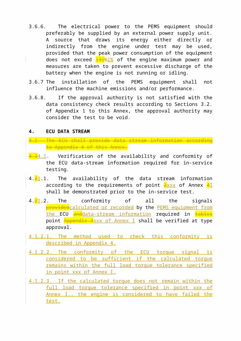
3.6.6. The electrical power to the PEMS equipment should preferably be supplied by an external power supply unit. A source that draws its energy either directly or indirectly from the engine under test may be used, provided that the peak power consumption of the equipment does not exceed [3]%1% of the engine maximum power and measures are taken to prevent excessive discharge of the battery when the engine is not running or idling.
3.6.7 The installation of the PEMS equipment shall not influence the machine emissions and/or performance.
3.6.8. If the approval authority is not satisfied with the data consistency check results according to Sections 3.2. of Appendix 1 to this Annex, the approval authority may consider the test to be void.
4. ECU DATA STREAM
4.1 The ECU shall provide data stream information according to Appendix 4 of this Annex.
4.24.1. Verification of the availability and conformity of the ECU data-stream information required for in-service testing.
4.21.1. The availability of the data stream information according to the requirements of point 2xxx of Annex 4I shall be demonstrated prior to the in-service test.
4.21.2. The conformity of all the signals providedcalculated or recorded by the PEMS equipment from the ECU anddata-stream information required in tables point Appendix 4xxx of Annex I shall be verified at type approval.
4.1.2.1. The method used to check this conformity is described in Appendix 4.
4.1.2.2. The conformity of the ECU torque signal is considered to be sufficient if the calculated torque remains within the full load torque tolerance specified in point xxx of Annex I.
4.1.2.3. If the calculated torque does not remain within the full load torque tolerance specified in point xxx of Annex I., the engine is considered to have failed the test.
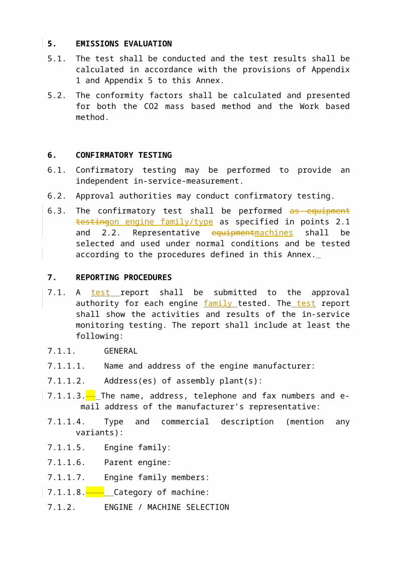
5. EMISSIONS EVALUATION
5.1. The test shall be conducted and the test results shall be calculated in accordance with the provisions of Appendix 1 and Appendix 5 to this Annex.
5.2. The conformity factors shall be calculated and presented for both the CO2 mass based method and the Work based method.

6. CONFIRMATORY TESTING
6.1. Confirmatory testing may be performed to provide an independent in-service-measurement.
6.2. Approval authorities may conduct confirmatory testing.
6.3. The confirmatory test shall be performed as equipment testingon engine family/type as specified in points 2.1 and 2.2. Representative equipmentmachines shall be selected and used under normal conditions and be tested according to the procedures defined in this Annex.
7. REPORTING PROCEDURES
7.1. A test report shall be submitted to the approval authority for each engine family tested. The test report shall show the activities and results of the in-service monitoring testing. The report shall include at least the following:
7.1.1. GENERAL
7.1.1.1. Name and address of the engine manufacturer:
7.1.1.2. Address(es) of assembly plant(s):
7.1.1.3. The name, address, telephone and fax numbers and e-mail address of the manufacturer’s representative:
7.1.1.4. Type and commercial description (mention any variants):
7.1.1.5. Engine family:
7.1.1.6. Parent engine:
7.1.1.7. Engine family members:
7.1.1.8. Category of machine:
7.1.2. ENGINE / MACHINE SELECTION
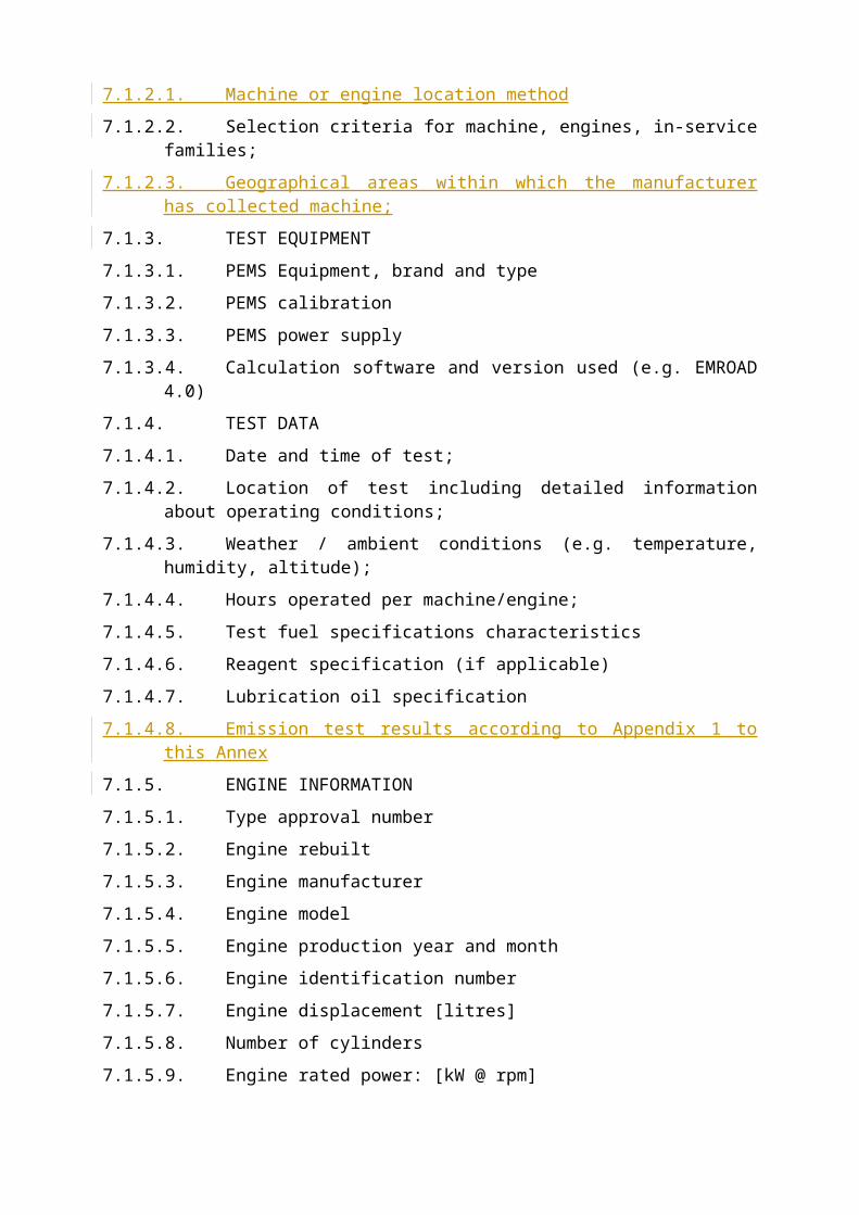
7.1.2.1. Machine or engine location method
7.1.2.2. Selection criteria for machine, engines, in-service families;
7.1.2.3. Geographical areas within which the manufacturer has collected machine;
7.1.3. TEST EQUIPMENT
7.1.3.1. PEMS Equipment, brand and type
7.1.3.2. PEMS calibration
7.1.3.3. PEMS power supply
7.1.3.4. Calculation software and version used (e.g. EMROAD 4.0)
7.1.4. TEST DATA
7.1.4.1. Date and time of test;
7.1.4.2. Location of test including detailed information about operating conditions;
7.1.4.3. Weather / ambient conditions (e.g. temperature, humidity, altitude);
7.1.4.4. Hours operated per machine/engine;
7.1.4.5. Test fuel specifications characteristics
7.1.4.6. Reagent specification (if applicable)
7.1.4.7. Lubrication oil specification
7.1.4.8. Emission test results according to Appendix 1 to this Annex
7.1.5. ENGINE INFORMATION
7.1.5.1. Type approval number
7.1.5.2. Engine rebuilt
7.1.5.3. Engine manufacturer
7.1.5.4. Engine model
7.1.5.5. Engine production year and month
7.1.5.6. Engine identification number
7.1.5.7. Engine displacement [litres]
7.1.5.8. Number of cylinders
7.1.5.9. Engine rated power: [kW @ rpm]
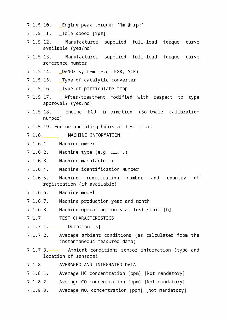
7.1.5.10. Engine peak torque: [Nm @ rpm]
7.1.5.11. Idle speed [rpm]
7.1.5.12. Manufacturer supplied full-load torque curve available (yes/no)
7.1.5.13. Manufacturer supplied full-load torque curve reference number
7.1.5.14. DeNOx system (e.g. EGR, SCR)
7.1.5.15. Type of catalytic converter
7.1.5.16. Type of particulate trap
7.1.5.17. After-treatment modified with respect to type approval? (yes/no)
7.1.5.18. Engine ECU information (Software calibration number)
7.1.5.19. Engine operating hours at test start
7.1.6. MACHINE INFORMATION
7.1.6.1. Machine owner
7.1.6.2. Machine type (e.g. ………..)
7.1.6.3. Machine manufacturer
7.1.6.4. Machine identification Number
7.1.6.5. Machine registration number and country of registration (if available)
7.1.6.6. Machine model
7.1.6.7. Machine production year and month
7.1.6.8. Machine operating hours at test start [h]
7.1.7. TEST CHARACTERISTICS
7.1.7.1. Duration [s]
7.1.7.2. Average ambient conditions (as calculated from the instantaneous measured data)
7.1.7.3. Ambient conditions sensor information (type and location of sensors)
7.1.8. AVERAGED AND INTEGRATED DATA
7.1.8.1. Average HC concentration [ppm] [Not mandatory]
7.1.8.2. Average CO concentration [ppm] [Not mandatory]
7.1.8.3. Average NOx concentration [ppm] [Not mandatory]
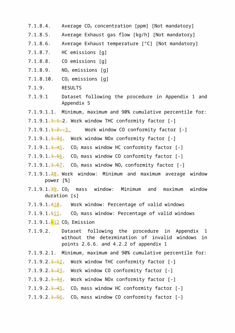
7.1.8.4. Average CO2 concentration [ppm] [Not mandatory]
7.1.8.5. Average Exhaust gas flow [kg/h] [Not mandatory]
7.1.8.6. Average Exhaust temperature [°C] [Not mandatory]
7.1.8.7. HC emissions [g]
7.1.8.8. CO emissions [g]
7.1.8.9. NOx emissions [g]
7.1.8.10.CO2 emissions [g]
7.1.9. RESULTS
7.1.9.1 Dataset following the procedure in Appendix 1 and Appendix 5
7.1.9.1.1. Minimum, maximum and 90% cumulative percentile for:
7.1.9.1.1.1.2. Work window THC conformity factor [-]
7.1.9.1.1.2..3. Work window CO conformity factor [-]
7.1.9.1.1.34. Work window NOx conformity factor [-]
7.1.9.1.1.45. CO2 mass window HC conformity factor [-]
7.1.9.1.1.56. CO2 mass window CO conformity factor [-]
7.1.9.1.1.67. CO2 mass window NOx conformity factor [-]
7.1.9.1.28. Work window: Minimum and maximum average window power [%]
7.1.9.1.39. CO2 mass window: Minimum and maximum window duration [s]
7.1.9.1.410. Work window: Percentage of valid windows
7.1.9.1.511. CO2 mass window: Percentage of valid windows
7.1.9.1.612 CO2 Emission
7.1.9.2. Dataset following the procedure in Appendix 1 without the determination of invalid windows in points 2.6.6. and 4.2.2 of appendix 1
7.1.9.2.1. Minimum, maximum and 90% cumulative percentile for:
7.1.9.2.1.12. Work window THC conformity factor [-]
7.1.9.2.1.23. Work window CO conformity factor [-]
7.1.9.2.1.34. Work window NOx conformity factor [-]
7.1.9.2.1.45. CO2 mass window HC conformity factor [-]
7.1.9.2.1.56. CO2 mass window CO conformity factor [-]
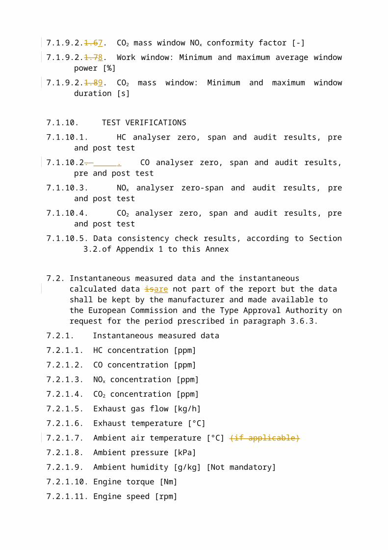
7.1.9.2.1.67. CO2 mass window NOx conformity factor [-]
7.1.9.2.1.78. Work window: Minimum and maximum average window power [%]
7.1.9.2.1.89. CO2 mass window: Minimum and maximum window duration [s]
7.1.10. TEST VERIFICATIONS
7.1.10.1. HC analyser zero, span and audit results, pre and post test
7.1.10.2. . CO analyser zero, span and audit results, pre and post test
7.1.10.3. NOx analyser zero-span and audit results, pre and post test
7.1.10.4. CO2 analyser zero, span and audit results, pre and post test
7.1.10.5. Data consistency check results, according to Section 3.2.of Appendix 1 to this Annex
7.2. Instantaneous measured data and the instantaneous calculated data isare not part of the report but the data shall be kept by the manufacturer and made available to the European Commission and the Type Approval Authority on request for the period prescribed in paragraph 3.6.3.
7.2.1. Instantaneous measured data
7.2.1.1. HC concentration [ppm]
7.2.1.2. CO concentration [ppm]
7.2.1.3. NOx concentration [ppm]
7.2.1.4. CO2 concentration [ppm]
7.2.1.5. Exhaust gas flow [kg/h]
7.2.1.6. Exhaust temperature [°C]
7.2.1.7. Ambient air temperature [°C] (if applicable)
7.2.1.8. Ambient pressure [kPa]
7.2.1.9. Ambient humidity [g/kg] [Not mandatory]
7.2.1.10. Engine torque [Nm]
7.2.1.11. Engine speed [rpm]
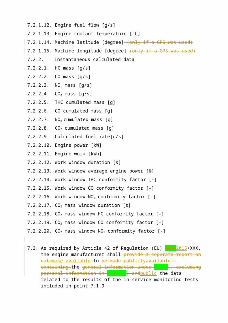
7.2.1.12. Engine fuel flow [g/s]
7.2.1.13. Engine coolant temperature [°C]
7.2.1.14. Machine latitude [degree] (only if a GPS was used)
7.2.1.15. Machine longitude [degree] (only if a GPS was used)
7.2.2. Instantaneous calculated data
7.2.2.1. HC mass [g/s]
7.2.2.2. CO mass [g/s]
7.2.2.3. NOx mass [g/s]
7.2.2.4. CO2 mass [g/s]
7.2.2.5. THC cumulated mass [g]
7.2.2.6. CO cumulated mass [g]
7.2.2.7. NOx cumulated mass [g]
7.2.2.8. CO2 cumulated mass [g]
7.2.2.9. Calculated fuel rate[g/s]
7.2.2.10. Engine power [kW]
7.2.2.11. Engine work [kWh]
7.2.2.12. Work window duration [s]
7.2.2.13. Work window average engine power [%]
7.2.2.14. Work window THC conformity factor [-]
7.2.2.15. Work window CO conformity factor [-]
7.2.2.16. Work window NOx conformity factor [-]
7.2.2.17. CO2 mass window duration [s]
7.2.2.18. CO2 mass window HC conformity factor [-]
7.2.2.19. CO2 mass window CO conformity factor [-]
7.2.2.20. CO2 mass window NOx conformity factor [-]
7.3. As required by Article 42 of Regulation (EU) 20162015/XXX, the engine manufacturer shall provide a seperate report on datamake available to be made publiclyavailable containing the general information under 7.1.1., excluding personal information in 7.1.1.3, andpublic the data related to the results of the in-service monitoring tests included in point 7.1.9
Appendix 1
TEST PROCEDURE FOR EMISSIONS TESTING WITH PORTABLE EMISSIONS MEASUREMENT SYSTEMS
1 INTRODUCTION
This Appendix describes the procedure to determine gaseous emissions from on-machine in-service measurements using Portable Emissions Measurement Systems (hereinafter PEMS). The gaseous emissions to be measured from the exhaust of the engine include the following components: carbon monoxide, total hydrocarbons and nitrogen oxides. Additionally, carbon dioxide shall be measured to enable the calculation procedures described in Sections 4 and 5.
2. TEST PROCEDURE
2.1. General requirements
The tests shall be carried out with a PEMS comprised of:
2.1.1. Gas analysers to measure the concentrations of regulated gaseous pollutants in the exhaust gas;
2.1.2. An exhaust mass flow meter based on the averaging Pitot or equivalent principle;
2.1.3. A Global Positioning System (hereinafter GPS) (not mandatory);
2.1.4. Sensors to measure the ambient temperature and pressure;
2.1.5. A connection with the vehicle Engine Control Unit (hereinafter ECU);
2.2. Test parameters
The parameters summarized in Table 1 shall be measured and recorded:
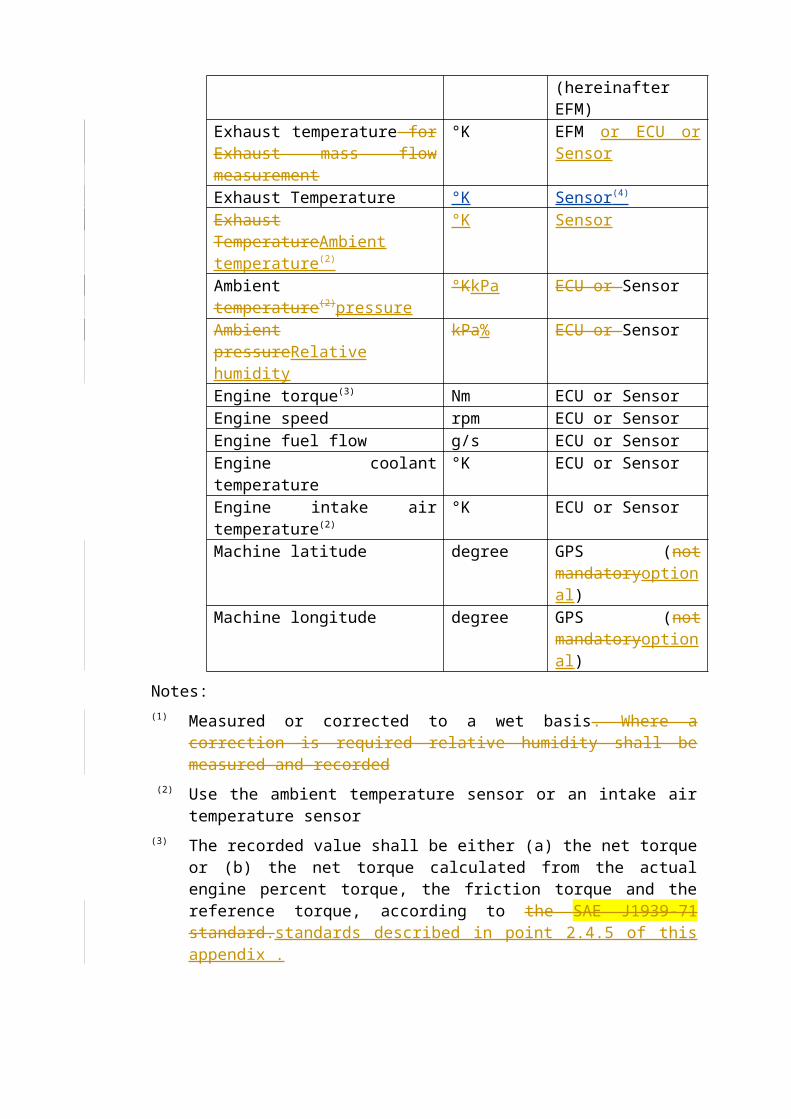
Table 1: Test parameters
Parameter Unit SourceHC concentration (1) ppm AnalyserCO concentration (1) ppm AnalyserNOx concentration (1) ppm AnalyserCO2 concentration (1) ppm AnalyserExhaust gas flow kg/h Exhaust Flow Meter
(hereinafter EFM)Exhaust temperature for Exhaust mass flow measurement
°K EFM or ECU or Sensor
Exhaust Temperature °K Sensor(4) Exhaust TemperatureAmbient temperature(2)
°K Sensor
Ambient temperature(2)pressure °KkPa ECU or SensorAmbient pressureRelative humidity
kPa% ECU or Sensor
Engine torque(3) Nm ECU or SensorEngine speed rpm ECU or SensorEngine fuel flow g/s ECU or SensorEngine coolant temperature °K ECU or SensorEngine intake air temperature(2) °K ECU or Sensor
Machine latitude degree GPS (not mandatoryoptional)
Machine longitude degree GPS (not mandatoryoptional)
Notes:(1) Measured or corrected to a wet basis. Where a correction is required relative
humidity shall be measured and recorded (2) Use the ambient temperature sensor or an intake air temperature sensor(3) The recorded value shall be either (a) the net torque or (b) the net torque
calculated from the actual engine percent torque, the friction torque and the reference torque, according to the SAE J1939-71 standard.standards described in point 2.4.5 of this appendix .
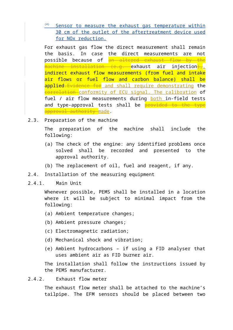
(4) Sensor to measure the exhaust gas temperature within 30 cm of the outlet of the aftertreatment device used for NOx reduction.
For exhaust gas flow the direct measurement shall remain the basis. In case the direct measurements are not possible because of an altered exhaust flow by the machine installation (e.g. exhaust air injection),, indirect exhaust flow measurements (from fuel and intake air flows or fuel flow and carbon balance) shall be applied.Evidence for and shall require demonstrating the correlation conformity of ECU signal. The calibration of fuel / air flow measurements during both in-field tests and type-approval tests shall be provided to the type approval authority made.
2.3. Preparation of the machine
The preparation of the machine shall include the following:
(a) The check of the engine: any identified problems once solved shall be recorded and presented to the approval authority.
(b) The replacement of oil, fuel and reagent, if any.
2.4. Installation of the measuring equipment
2.4.1. Main Unit
Whenever possible, PEMS shall be installed in a location where it will be subject to minimal impact from the following:
(a) Ambient temperature changes;
(b) Ambient pressure changes;
(c) Electromagnetic radiation;
(d) Mechanical shock and vibration;
(e) Ambient hydrocarbons – if using a FID analyser that uses ambient air as FID burner air.
The installation shall follow the instructions issued by the PEMS manufacturer.
2.4.2. Exhaust flow meter
The exhaust flow meter shall be attached to the machine’s tailpipe. The EFM sensors should be placed between two pieces of straight tube whose length should be at least 2 times the EFM diameter (upstream and downstream). It is recommended to place
the EFM after the machine silencer, to limit the effect of exhaust gas pulsations upon the measurement signals.
The installation shall follow the instructions issued by the EFM / PEMS manufacturer.
2.4.3. Global Positioning System
If a global positioning system is used, theThe antenna should be mounted at the highest possible location, without risking interference with any obstructions encountered during in-use operation.
2.4.4. Ambient temperature
The ambient temperature shall be measured at the [beginning of the test] and [also at the end of the test] within a reasonable distance from the machine. It is allowed to use the CAN signal for Intake Air temperature (Temperature experienced by the engine).
2.4.5. Connection with the engine ECU
A data logger shall be used to record the engine parameters listed in Table 1 of Appendix . This data logger can make use of the Control Area Network (hereinafter CAN) bus of the vehicle to access the ECU data broadcasted on the CAN according to standard protocols such as SAE J1939, J1708, ISO 27145 or ISO 15765-4.
2.4.6. Sampling of gaseous emissions
The sample line shall be heated according to the specifications of point 2.3. of Appendix 2 and properly insulated at the connection points (sample probe and back of the main unit), to avoid the presence of cold spots that could lead to a contamination of the sampling system by condensed hydrocarbons.
The sample probe shall be installed in the exhaust pipe in accordance with the requirements of Section 9.3. of Annex 4B of UN/ECE Regulation 96.
If the length of the sample line is changed, the system transport times shall be verified and if necessary corrected.
2.5. Pre-test procedures
2.5.1. Starting and stabilizing the PEMS instruments
The main units shall be warmed up and stabilized according to the instrument manufacturer specifications until pressures, temperatures and flows have reached their operating set points.
2.5.2. Cleaning the sampling system
To prevent system contamination, the sampling lines of the PEMS instruments shall be purged until sampling begins, according to the instrument manufacturer specifications.
2.5.3. Checking and calibrating the analysers
The zero and span calibration and the linearity checks of the analysers shall be performed using calibration gases meeting the requirements of Section 9.5.1 of Annex 4B of UN/ECE Regulation 96.
2.5.4. Cleaning the EFM
The EFM shall be purged at the pressure transducer connections in accordance with the instrument manufacturer specifications. This procedure shall remove
condensation and diesel particulate matter from the pressure lines and the associated flow tube pressure measurement ports.
2.6. Emissions test run
2.6.1 Definitions
‘Test’ or ‘test run’ is the uninterrupted machine operation with data continuously being sampled to reach the minimum test duration as defined in point 4.6.5 of this annex.
‘Segment’ is each of the operating sequences allowed by point 4.6.1 of this annex when testing a machine that does not complete eh minimum test duration (defined in point 4.6.5) or that I would normally perform multiple different work activities.
2.6.2. Test start
Emissions sampling, measurement of the exhaust parameters and recording of the engine and ambient data shall start prior to starting the engine. The data evaluation shall start after the coolant temperature has reached 343K (70 °C) for the first time or after the coolant temperature is stabilized within +/– 2K over a period of 5 minutes whichever comes first but no later than 20 minutes after engine start.
2.6.3. Test run
Emission sampling, measurement of the exhaust parameters and recording of the engine and ambient data shall continue throughout the normal in-use operation of the engine. The engine may be stopped and started, but emissions sampling shall continue throughout the entire test unless the test is composed of various segments as defined in point 2.6.1 of this appendix and comply with point 4.6.1. of this annex .
2.6.4. End of test sequence
At the end of the test, sufficient time shall be given for the sampling systems to allow their response times to elapse. The engine may be shut down before or after sampling is stopped.
2.6.5 Periodic zero drift correction of instruments during a test run
Zero checks of the gas analyzers shall be conducted at least every 2 hours during a test run and the results may be used to perform a zero drift correction.
2.6.6 Identification of valid data points for emissions calculation
The valid data points for the emissions calculation are determined by the algorithm in Appendix 5.
In addition, the data recorded during the periodic instruments checks shall be flagged and shall not be used for the emission calculations.
2.7. Verification of the measurements
2.7.1. Checking of the analysers
The zero, span and linearity checks of the analysers as described in point 2.5.3 shall be performed using calibration gases meeting the requirements of Section 9.5.1 of Annex 4B of UN/ECE Regulation 96.
2.7.2. Zero drift
Zero response is defined as the mean response, including noise, to a zero gas during a time interval of at least 30 seconds. The drift of the zero response shall be less than 2 per cent of full scale on the lowest range used.
2.7.3. Span drift
Span response is defined as the mean response, including noise, to a span gas during a time interval of at least 30 seconds. The drift of the span response shall be less than 2 per cent of full scale on the lowest range used.
2.7.4. Drift verification
This shall apply only if, during the test, no zero drift correction was made.
As soon as practical but no later than 30 minutes after the test is complete the gaseous analyser ranges used shall be zeroed and spanned to check their drift compared to the pre-test results.
The following provisions shall apply for analyser drift:
(a) If the difference between the pre-test and post-test results is less than 2 per cent as specified in points 2.7.2.and 2.7.3., the measured concentrations may be used uncorrected or may be corrected for drift according to point 2.7.5.;
(b) If the difference between the pre-test and post-test results is equal to or greater than 2 per cent as specified in points 2.7.2. and 2.7.3., the test shall be voided or the measured concentrations shall be corrected for drift according to point 2.7.5.
2.7.5. Drift correction
If drift correction is applied in accordance with point 2.7.4., the corrected concentration value shall be calculated according to appendix 7 or 8 of Annex 4B of UN/ECE Regulation 96.
The difference between the uncorrected and the corrected brake-specific emission values shall be within ± 6 per cent of the uncorrected brake-specific emission values. If the drift is greater than 6 per cent, the test shall be voided. If drift correction is applied, only the drift-corrected emission results shall be used when reporting emissions.
3. CALCULATION OF THE EMISSIONS
The final test result shall be rounded in one step to the number of places to the right of the decimal point indicated by the applicable emission standard plus one additional significant figure, in accordance with ASTM E 29-06b. No rounding of intermediate values leading to the final brake-specific emission result shall be allowed.
3.1. Time alignment of data
To minimize the biasing effect of the time lag between the different signals on the calculation of mass emissions, the data relevant for emissions calculation shall be time aligned, as described in points 3.1.1 to 3.1.4.
3.1.1. Gas analysers data
The data from the gas analysers shall be properly aligned using the procedure in Section 8.1.5. of Annex 4B to UN/ECE Regulation 96.

3.1.2. Gas analysers and EFM data
The data from the gas analysers shall be properly aligned with the data of the EFM using the procedure in point 3.1.4.
3.1.3. PEMS and engine data
The data from the PEMS (gas analysers and EFM) shall be properly aligned with the data from the engine ECU using the procedure in point 3.1.4.
3.1.4. Procedure for improved time-alignment of the PEMS data
The test data listed in Table 1 are split into 3 different categories:
1: Gas analysers (HC, CO, CO2, NOx concentrations);
2: Exhaust Flow Meter (Exhaust mass flow and exhaust temperature);
3: Engine (Torque, speed, temperatures, fuel rate, from ECU).
The time alignment of each category with the other categories shall be verified by finding the highest correlation coefficient between two series of parameters. All the parameters in a category shall be shifted to maximize the correlation factor. The following parameters shall be used to calculate the correlation coefficients:
To time-align:
(a) Categories 1 and 2 (Analysers and EFM data) with category 3 (Engine data): from the ECU.
(b) Category 1 with category 2: the CO2 concentration and the exhaust mass;
(c) Category 2 with category 3: the CO2 concentration and the engine fuel flow.
3.2. Data consistency checks
3.2.1. Analysers and EFM data
The consistency of the data (exhaust mass flow measured by the EFM and gas concentrations) shall be verified using a correlation between the measured fuel flow from the ECU and the fuel flow calculated using the procedure in section 9.4.5. of Annex 4B to UN/ECE Regulation 96. A linear regression shall be performed for the measured and calculated fuel rate values. The method of least squares shall be used, with the best fit equation having the form:
y = mx + b
Where:
– y is the calculated fuel flow [g/s]
– m is the slope of the regression line
– x is the measured fuel flow [g/s]
– b is the y intercept of the regression line
The slope (m) and the coefficient of determination (r²) shall be calculated for each regression line. It is recommended to perform this analysis in the range from 15 per cent of the maximum value to the maximum value and at a frequency greater or equal to 1 Hz. For a test to be considered valid, the following two criteria shall be evaluated:
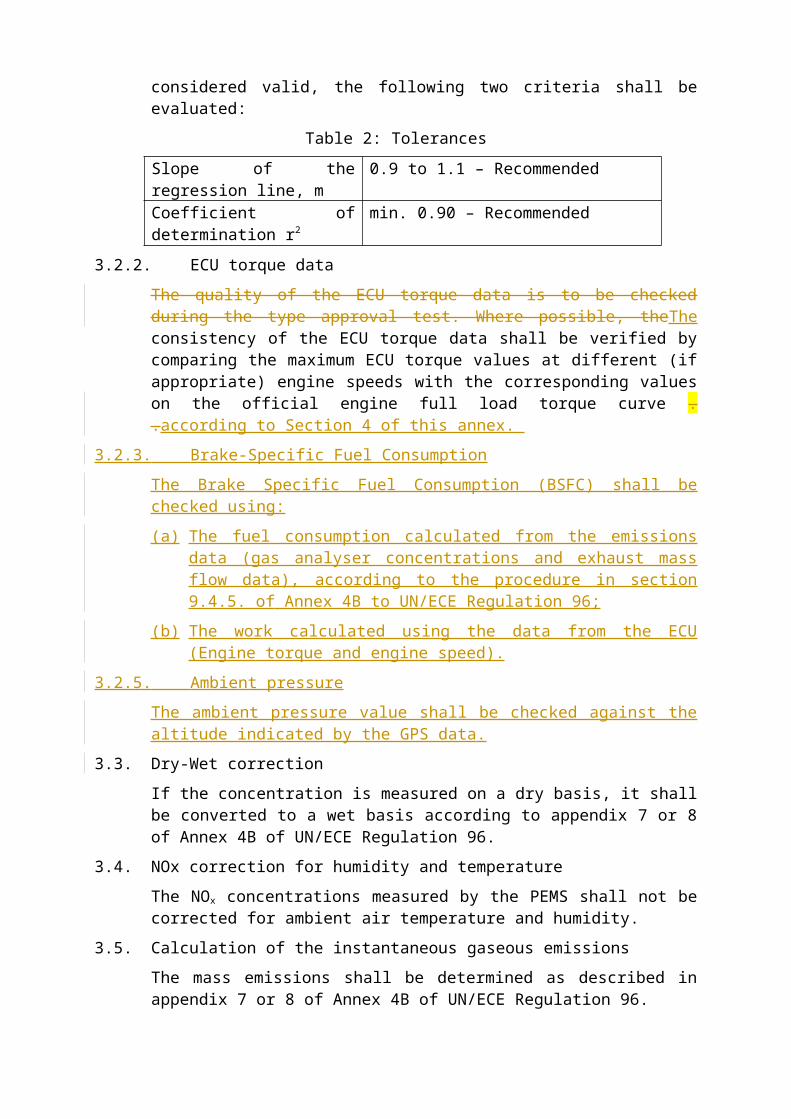
Table 2: Tolerances

Slope of the regression line, m 0.9 to 1.1 – RecommendedCoefficient of determination r2 min. 0.90 – Recommended
3.2.2. ECU torque data
The quality of the ECU torque data is to be checked during the type approval test. Where possible, theThe consistency of the ECU torque data shall be verified by comparing the maximum ECU torque values at different (if appropriate) engine speeds with the corresponding values on the official engine full load torque curve . .according to Section 4 of this annex.
3.2.3. Brake-Specific Fuel Consumption
The Brake Specific Fuel Consumption (BSFC) shall be checked using:
(a) The fuel consumption calculated from the emissions data (gas analyser concentrations and exhaust mass flow data), according to the procedure in section 9.4.5. of Annex 4B to UN/ECE Regulation 96;
(b) The work calculated using the data from the ECU (Engine torque and engine speed).
3.2.5. Ambient pressure
The ambient pressure value shall be checked against the altitude indicated by the GPS data.
3.3. Dry-Wet correction
If the concentration is measured on a dry basis, it shall be converted to a wet basis according to appendix 7 or 8 of Annex 4B of UN/ECE Regulation 96.
3.4. NOx correction for humidity and temperature
The NOx concentrations measured by the PEMS shall not be corrected for ambient air temperature and humidity.
3.5. Calculation of the instantaneous gaseous emissions
The mass emissions shall be determined as described in appendix 7 or 8 of Annex 4B of UN/ECE Regulation 96.
4. DETERMINATION OF EMISSIONS AND CONFORMITY FACTORS
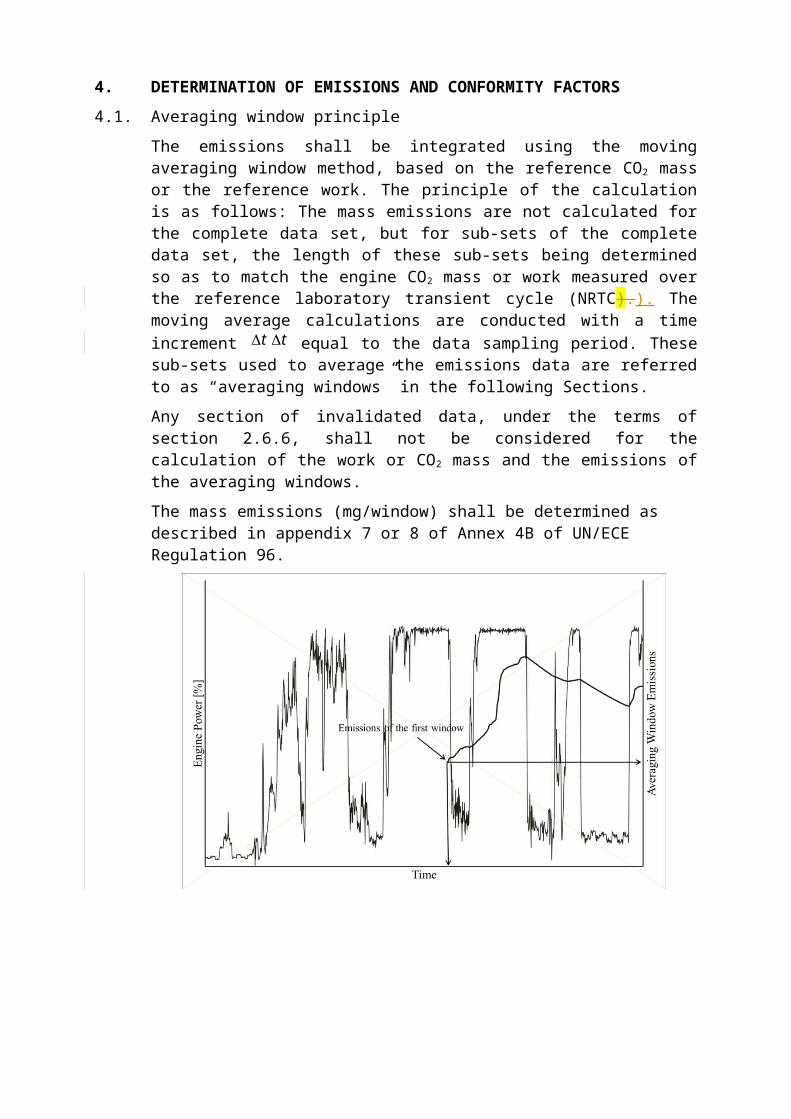
4.1. Averaging window principle
The emissions shall be integrated using the moving averaging window method, based on the reference CO2 mass or the reference work. The principle of the calculation is as follows: The mass emissions are not calculated for the complete data set, but for sub-sets of the complete data set, the length of these sub-sets being determined so as to match the engine CO2 mass or work measured over the reference laboratory transient cycle (NRTC).). The moving average calculations are conducted with a time increment t equal to the data sampling period. These sub-sets used to average the emissions data are referred to as “averaging windows” in the following Sections.
Any section of invalidated data, under the terms of section 2.6.6, shall not be considered for the calculation of the work or CO2 mass and the emissions of the averaging windows.
t
The mass emissions (mg/window) shall be determined as described in appendix 7 or 8 of Annex 4B of UN/ECE Regulation 96.
Figure 1. Engine power versus time and engine averaged emissions, starting from the first averaging window, versus time.
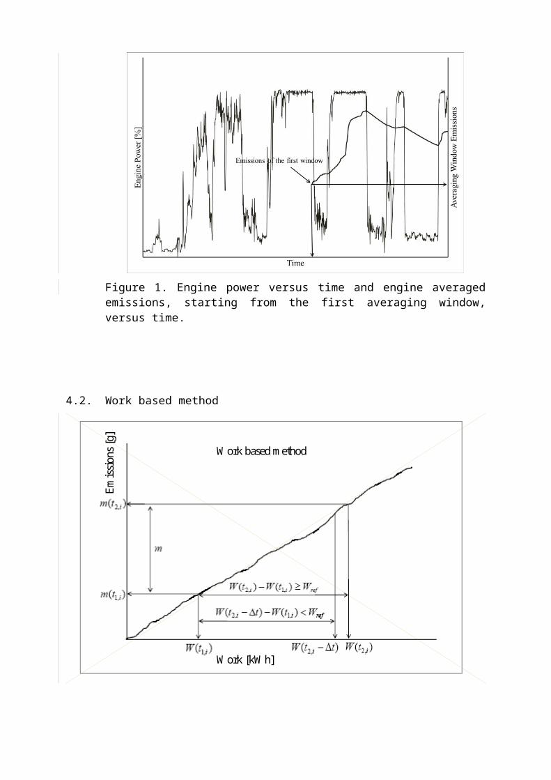
4.2. Work based method
Work based method
Emis
sion
s [g]
Work [kWh]
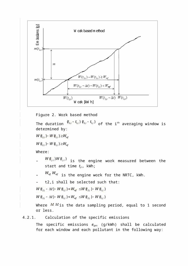
Figure 2. Work based method
The duration )( ,1,2 ii tt of the ith averaging window is determined by:
refii WtWtW )()( ,1,2
Where:
Work based method
Emis
sion
s [g]
Work [kWh]
)( ,1,2 ii tt
refii WtWtW )()( ,1,2
– )( ,ijtW is the engine work measured between the start and time tj,i, kWh;
– refW is the engine work for the NRTC, kWh.
– t2,i shall be selected such that:
)()()()( ,1,2,1,2 iirefii tWtWWtWttW
Where t is the data sampling period, equal to 1 second or less.
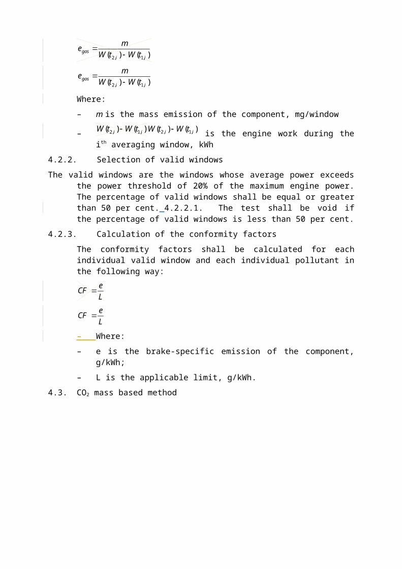
4.2.1. Calculation of the specific emissions
The specific emissions egas (g/kWh) shall be calculated for each window and each pollutant in the following way:
)()( ,1,2 iigas tWtW
me
Where:
– m is the mass emission of the component, mg/window
– )()( ,1,2 ii tWtW is the engine work during the ith averaging window, kWh
4.2.2. Selection of valid windows
The valid windows are the windows whose average power exceeds the power threshold of 20% of the maximum engine power. The percentage of valid windows shall be equal or greater than 50 per cent. 4.2.2.1. The test shall be void if the percentage of valid windows is less than 50 per cent.
4.2.3. Calculation of the conformity factors
The conformity factors shall be calculated for each individual valid window and each individual pollutant in the following way:
LeCF
– Where:
– e is the brake-specific emission of the component, g/kWh;
– L is the applicable limit, g/kWh.
4.3. CO2 mass based method
)( ,ijtW
refW
)()()()( ,1,2,1,2 iirefii tWtWWtWttW
t
)()( ,1,2 iigas tWtW
me
)()( ,1,2 ii tWtW
LeCF

CO2 mass based method
CO2 emissions [kg]
Emis
sion
s [g]
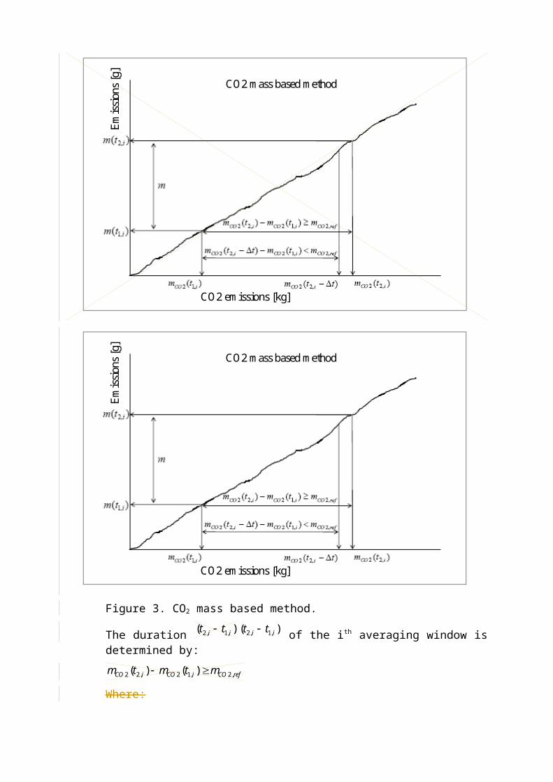
Figure 3. CO2 mass based method.
The duration )( ,1,2 ii tt of the ith averaging window is determined by:
refCOiCOiCO mtmtm ,2,12,22 )()(
Where:
)( ,2 ijCO tm
CO2 mass based method
CO2 emissions [kg]
Emis
sion
s [g]
)( ,1,2 ii tt
refCOiCOiCO mtmtm ,2,12,22 )()(
Where:
– is the CO2 mass measured between the test start and time tj,i, kg;
– refCOm ,2 is the CO2 mass determined for the NRTC, kg;
– t2,i shall be selected such as:
)()()()( ,12,22,2,12,22 iCOiCOrefCOiCOiCO tmtmmtmttm
Where t is the data sampling period, equal to 1 second or less.
The CO2 masses are calculated in the windows by integrating the instantaneous emissions calculated according to the requirements introduced in point 3.5.
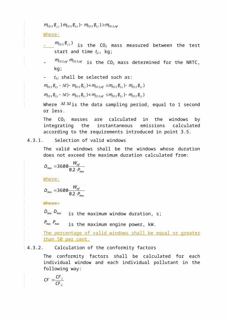
4.3.1. Selection of valid windows
The valid windows shall be the windows whose duration does not exceed the maximum duration calculated from:
Where:
maxmax 2.0
3600P
WD ref
Where:
maxD is the maximum window duration, s;
maxP is the maximum engine power, kW.
The percentage of valid windows shall be equal or greater than 50 per cent.
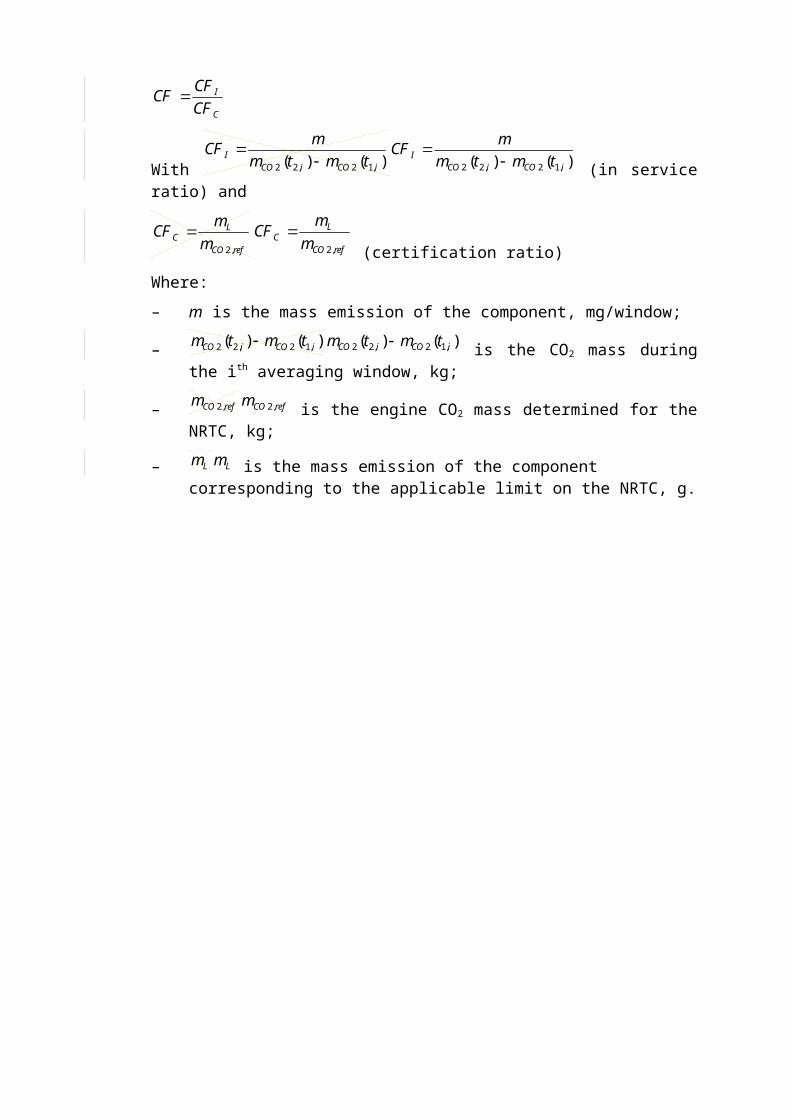
4.3.2. Calculation of the conformity factors
The conformity factors shall be calculated for each individual window and each individual pollutant in the following way:
C
I
CFCF
CF
With )()( ,12,22 iCOiCOI tmtm
mCF
(in service ratio) and
refCO
LC m
mCF
,2
(certification ratio)
Where:
– m is the mass emission of the component, mg/window;
)( ,2 ijCO tm
refCOm ,2
)()()()( ,12,22,2,12,22 iCOiCOrefCOiCOiCO tmtmmtmttm
t
maxmax 2.0
3600P
WD ref
maxD
maxP
C
I
CFCF
CF
)()( ,12,22 iCOiCOI tmtm
mCF
refCO
LC m
mCF
,2
– )()( ,12,22 iCOiCO tmtm is the CO2 mass during the ith
averaging window, kg;
– refCOm ,2 is the engine CO2 mass determined for the NRTC, kg;
– Lm is the mass emission of the component corresponding to the applicable limit on the NRTC, g.
)()( ,12,22 iCOiCO tmtm
refCOm ,2
Lm
Appendix 2
PORTABLE MEASUREMENT EQUIPMENT
1. GENERAL
The gaseous emissions shall be measured according to the protocol described in Appendix 1. The present Appendix describes the characteristics of the portable measurement equipment that shall be used to perform such tests.
2. MEASURING EQUIPMENT
2.1. Gas analysers general specifications
The PEMS gas analysers specifications shall meet the requirements set out in Section 9.4. of Annex 4B to UN/ECE Regulation 96.
2.2. Gas analysers technology
The gases shall be analysed using the technologies specified in Section 9.5.of Annex 4B to UN/ECE Regulation 96.
2.3. Sampling of gaseous emissions
The sampling probes shall meet the requirements defined in Section 9.3.1.1 of Annex 4B of UN/ECE Regulation 96. The sampling line shall be heated to 190°C (+/-10°C).
2.4. Other instruments
The measuring instruments shall satisfy the requirements given in Table 8.2 and Section 8.1 of Annex 4B of UN/ECE Regulation 96.
3. AUXILIARY EQUIPMENT
3.1. Exhaust Gas Flow Meter (EFM) tailpipe connection
The installation of the EFM shall not increase the backpressure by more than the value recommended by the engine manufacturer,.. As for the all the components of the PEMS equipment, the installation of the EFM shall comply with the locally applicable safety regulations and insurance requirements.
3.2. PEMS location and mounting hardware
The PEMS equipment shall be installed as specified in Section 2.4. of Appendix 1.
3.3. Electrical power
The PEMS equipment shall be powered using the method described in point 43.6.6. of this Annex II.Wrong reference
Appendix 3
CALIBRATION OF PORTABLE MEASUREMENT EQUIPMENT
1. EQUIPMENT CALIBRATION AND VERIFICATION
1.1. Calibration gases
The PEMS gas analysers shall be calibrated using gases meeting the requirements as set out in Section 9.5.1 of Annex 4B to UN/ECE Regulation 96.
1.2. Leakage test
The PEMS leakage tests shall be conducted following the requirements defined in Section 8.1.8.7. of Annex 4B to UN/ECE Regulation 96.
1.3. Response time check of the analytical system
The response time check of the PEMS analytical system shall be conducted in accordance with the requirements set out in Section 8.1.6. of Annex 4B to UN/ECE Regulation 96.
Appendix 4
REQUIREMENTS ON ECU DATA STREAM INFFORMATION
[1.] General
METHOD TO CHECK THE CONFORMITY OF THE ECU SIGNALS
1. INTRODUCTION
This Appendix sets outdescribes in a non-detailed manner the requirements on the engine control unit method used to provide data stream informationcheck the conformity of the ECU torque-signal during ISC-PEMS testing.
The detailed applicable procedure is left to the PEMS measurement equipmentengine manufacturer, subject to approval of the approval authority.
[2.] Data to be provided
The ECU shall provide at a minimum the measurement data listed in table 1 of this appendix.
Table 1: Measurement data
Parameter Unit
Engine torque(1) Nm
Engine speed Rpm
Engine coolant temperature °K
Notes:
2. THE "MAXIMUM TORQUE" METHOD
(1) 2.1 The provided value shall be either (a) the net brake engine "Maximum torque or (b) the net brake engine " method consists of demonstrating that a point on the reference maximum torque calculated from other appropriate torque valuescurve as defined in the corresponding protocol standard according to paragraph 3.1.
Where either ambient pressure or ambient temperature are not measured by external sensors, they shall be provided by the ECU according to table 2. Where exhaust mass flow is not measured directly the engine fuel flow shall be provided.
Table 2: Additional measurement data
Parameter Unit
Ambient temperature(2) °K
Ambient pressure kPa
EN 0
EN
Engine fuel flow g/s
Notes:[(1)] Alternatively ambient temperature or engine intake air temperature
[3.] Communication requirements
[3.1] Access to data stream information
Access to data stream information shall be provided in accordance with at least onea function of the following series of standards:
(a) ISO 27145 with ISO 15765-4 (CAN-based);
(b) ISO 27145 with ISO 13400 (TCP/IP-based);
(c) SAE J1939-73.
The ECUengine speed has to support the corresponding services of at least one of the standards mentioned above to provide the data of table 1 in paragraph 2. The implementation of additional features of the standard(s) in the ECU is permitted but not mandatory. been reached during vehicle testing.
Access to data stream information shall be possible by the means of a wired connection.
3.2. CAN based wired communication
The communication speed on the wired data link shall be either 250 kbps or 500 kbps.
The connection interface between the engine and the PEMS measurement equipment shall be standardised and shall meet all of the requirements of ISO 15031-3 Type A (12 VDC power supply), Type B (24 VDC power supply) or SAE J1939-13 (12 or 24 VDC power supply).
3.3 Documentation requirements
The manufacturer shall document the communication standard used for the communication of ECU data stream information according to 3.2 in the information document
2.2. If a point on the reference maximum torque curve as a function of the engine speed has not been reached during the ISC PEMS emissions testing, the manufacturer is entitled to modify the load of the machine and/or the test run as necessary in order to perform that demonstration after the ISC PEMS emissions test.
EN 1
EN
3. ALTERNATIVE METHOD REQUIRED
3.1 In case that the "Maximum torque" method is not possible, due to system constraints, an alternative method needs to be applied.
EN 2
EN
Appendix 5
ALGORITHM FOR THE DETERMINATION OF VALID EVENTS DURING A TEST SEQUENCE
1. General
This appendix present the methodology for the determination of valid events during a test sequence based in the concept of working and non-working events and the definition of areas in the data for exclusion
2. Concept of working / non-working events
Those events where the engine power is below 10% of the engine maximum power are considered as the machine being in a “non-working” condition.
3. Procedure to determine valid events
3.1. Criteria for the exclusion of test data points
3.1.1. Data corresponding to engine system cold conditions (i.e. cold start - based on coolant temperature) as defined in section 2.4.4 of Appendix 1 of this Annex.
3.1.2. Data not fulfilling the ambient conditions as defined in section 4.2. of this Annex (Ambient conditions)
3.1.3. Short (<D2 min) and Long “NON WORKING” (>D2 min) events. See table 1 for the values of D2
3.1.4. For all non-working events, the first D1 minutes of the event are valid. See table 1 for the values of D1
[3.1.5.] For long non-working events, the take-off phase following the non-working event may also be excluded until the exhaust gas temperature reaches 523 K. If the exhaust gas temperature does not reach 523 K within D3 minutes, the data analysis shall restart. (See table 1 for the values of D3). For the purpose of this paragraph the exhaust temperature shall be measured within 30 cm downstream of the exhaust aftertreatment.)
3.2. Criteria for the exclusion of averaged window data.
The remaining valid test data is used to conduct the moving averaging window calculations. The engine performance will be assessed from the window averaged emissions using:
3.2.1. The windows, whose average power exceeds the power threshold value of 20%, are considered as ‘valid’.
3.2.2. A percentile obtained from the distribution of valid window emissions (baseline value 90% cumulative percentile)
4. “Machine Work” marking algorithm
4.1. Step 1: Detection, data splitting into working and non-working events
EN 3
EN
4.1.1. Detect working/non-working data points, using a power criterion (see section 2 of this Appendix)
4.1.2. Calculate the duration of “non-working events”
4.1.3. Mark the non-working events shorter than D0 minutes as ‘working’. (See table 1 for the values of D0)
4.1.4. Calculate the duration of the remaining non-working events
4.2. Step 2: Merging of short working events into non-working
4.2.1. Working events shorter than D0 are merged with surrounding non-working events longer than D1
4.3. Step 3: Exclusion of post non-working (take off) data
4.3.1. Exclusion of D3 minutes (take off) after long non-working events (See table 1 for the values of D3)
4.4. Step 4: Inclusion of post-working data
4.4.1. Inclusion of D1 minutes of non-working at the end of working events. (See table 1 for the values of D1)
5. Table 1: Values for the parameters D0, D1, D2 and D3
Parameters Value
D0 2 minutes
D1 2 minutes
D2 10 minutes
D3 4 minutes
EN 4
EN
6. Examples
Exclusions non-working data at the end of Step 1
EN 5
EN
Exclusions non-working data at the end of Step 2
EN 6
EN
Exclusions of non-working data at the end of Step 3
EN 7
EN

End of Step4 - Final
EN 8
EN