Embed Size (px)
Citation preview
S I G N A L S T H E B E S T
Архангельск (8182)63-90-72Астана (7172)727-132Астрахань (8512)99-46-04Барнаул (3852)73-04-60Белгород (4722)40-23-64Брянск (4832)59-03-52Владивосток (423)249-28-31Волгоград (844)278-03-48Вологда (8172)26-41-59Воронеж (473)204-51-73Екатеринбург (343)384-55-89 Иваново (4932)77-34-06Ижевск (3412)26-03-58Казань (843)206-01-48
Калининград (4012)72-03-81Калуга (4842)92-23-67Кемерово (3842)65-04-62Киров (8332)68-02-04Краснодар (861)203-40-90Красноярск (391)204-63-61Курск (4712)77-13-04Липецк (4742)52-20-81Магнитогорск (3519)55-03-13Москва (495)268-04-70Мурманск (8152)59-64-93Набережные Челны (8552)20-53-41Нижний Новгород (831)429-08-12Новокузнецк (3843)20-46-81
Новосибирск (383)227-86-73Омск (3812)21-46-40Орел (4862)44-53-42Оренбург (3532)37-68-04Пенза (8412)22-31-16Пермь (342)205-81-47Ростов-на-Дону (863)308-18-15Рязань (4912)46-61-64Самара (846)206-03-16Санкт-Петербург (812)309-46-40Саратов (845)249-38-78Севастополь (8692)22-31-93Симферополь (3652)67-13-56Смоленск (4812)29-41-54
Сочи (862)225-72-31Ставрополь (8652)20-65-13Сургут (3462)77-98-35Тверь (4822)63-31-35Томск (3822)98-41-53Тула (4872)74-02-29Тюмень (3452)66-21-18Ульяновск (8422)24-23-59Уфа (347)229-48-12Хабаровск (4212)92-98-04Челябинск (351)202-03-61Череповец (8202)49-02-64Ярославль (4852)69-52-93
Единый адрес для всех регионов: [email protected] || www.prelectronic.nt-rt.ru
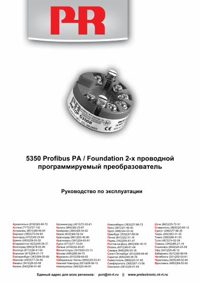
5350 Profibus PA / Foundation 2-х проводной программируемый преобразователь
Руководство по эксплуатации

5350L111-RU 1
МОДУЛЬ ДЛЯ ПРОМЫШЛЕННЫХ СЕТЕЙ СО СВЯЗЬЮ ЧЕРЕЗ PROFIBUS® PA / FOUNDATION™ FIELDBUS
PRETRANS 5350
СОДЕРжаНиЕ
PR Electronics предлагает обширную программу аналоговых и дискретных модулей обработки сигналов для целей промышленной автоматизации. Производственная программа включает барьеры искробезопасности, дисплеи-индикаторы, датчики температуры, универсальные преобразователи и т.д. На наши модули можно положиться в самых тяжелых условиях работы, – с высоким уровнем вибраций и электромагнитных помех и с большими колебаниями температуры. Все наши изделия соответствуют самым жестким международным стандартам. Наш девиз ”Signals the Best” отражает эту философию – и служит вашей гарантией качества.
RU
Декларация соответствия EC ............................................................... 2Области применения............................................................................... 3Техническая характеристика ............................................................... 3Монтаж / установка .................................................................................. 3Схемы применений .................................................................................. 4Расшифровка кода заказа: 5350 ......................................................... 5Электрические данные ........................................................................... 5Схемы присоединения ........................................................................... 10Установочные размеры .......................................................................... 11Монтаж кабеля датчика ......................................................................... 11Принципиальная схема .......................................................................... 12Подключение в шинной структуре ................................................... 13Приложение ................................................................................................. 15 ATEX Installation Drawing - 5350A ............................................... 16 ATEX Installation Drawing - 5350B ................................................ 17 FM / CSA Installation Drawing ........................................................ 19 INMETRO Instruções de Segurança .............................................. 25 NEPSI Installation Drawing............................................................... 26

2 5350L111-RU 5350L111-RU 3
ДЕкЛаРациЯ СООТВЕТСТВиЯ ECИзготовитель
PR electronics A/S
настоящим заявляет, что изделие:
Тип: 5350
Наименование: Модуль для промышленных сетей со
связью через PROFIBUS® PA / FOUNDATIONTM Fieldbus
отвечает требованиям следующих директив и стандартов:
Директивы по ЭМС 2004/108/EC и последующих к ней дополнений
EN 61326-1 : 2006
Точную информацию о приемлемом уровне ЭМС см. в электрических данных модуля.
Директивы ATEX 94/9/EC с последующими дополнениями
EN 60079-0 : 2006, EN 60079-11 : 2007,
EN 60079-15 : 2005, EN 60079-26: 2007,
EN 60079-27 : 2006, EN 60079-27 : 2008
EN 61241-0 : 2006 и EN 61241-11 : 2006 Сер-
тификат ATEX: KEMA 03ATEX1011 X (5350A)
Сертификат ATEX: KEMA 02ATEX1318 (5350B)Уполномоченный орган:
KEMA Quality B.V. (0344)
Kim Rasmussen Подпись изготовителя
МОДУЛЬ ДЛЯ ПРОМЫШЛЕННЫХ СЕТЕЙ PROFI-BUS®
PA / FOUNDATION™ FIELDBUS - PRETOP 5350
• Протокол PROFIBUS® PA версия 3.0 • Протокол FOUNDATION™ Fieldbus версия ITK 4.6 • Функция автоматического переключения • Сертификат FISCO- • Функциональные возможности Basic с F.F.
Области применения
• Линеаризация температуры, измеренной RTD-датчиком или термопарой.
• Измерение разности температур, с резервным каналом или среднего значения тепературы терморезистивным датчиком или термопарой.
• Измерение сопротивления, потенциометрическое и биполярного mV-сигнала.
Техническая характеристика
• Шинный модуль, поддерживающий протоколы обмена данными PROFIBUS® PA и FOUNDATION™ Fieldbus. Автоматическое переключение между протоколами.
• Конфигурирование системы PROFIBUS® PA при помощи ПО Siemens Simatic® PDM®, ABB Melody / Harmony и Metso DNA XD, а FOUN DATION™ Fieldbus - при помощи ПО Emerson DeltaV, Yokogawa CS 1000 / CS 3000, ABB Melody / Harmony и Honeywell Experion.
• Посредством магнита можно активировать функцию моделирования.
• Не зависящее от полярности питание от шины.
• 24-битовый АЦП обеспечивает высокое разрешение сигнала.
• Блоки функций PROFIBUS® PA: 2 аналоговых.
• Блоки функций FOUNDATION™ Fieldbus: 2 аналоговых и 1 PID.
• Функциональные возможности FOUNDATION™ Fieldbus: Basic или LAS.
Монтаж / установка
• Может монтироваться в корпус датчика по ст. DIN форма B. Во взрывобезопас-ных зонах измерительный преобразователь 5350 можно монтировать на рейку DIN при помощи PR крепления тип 8421.

4 5350L111-RU 5350L111-RU 5
СХЕМЫ ПРиМЕНЕНиЙ
+
-
+
-
+- 1
+2
+-
+-
2
12
1
-
RTD кшине - каналу связи
Сопротивление кшине - каналу связи
mV кшине - каналу связи
Термопара кшине - каналу связи
Измерение разности температур, с резервным каналом или ср. знач.;
RTD, термопара или mV
или
*Внимание! Заказывайте PR sim-ключ тип 8422, если желательно задействовать функцию моделирования.
Электрические данныеДиапазон рабочих температур среды:От -40°C до +85°CОбщие данные:Напряжение питания, DC Стандартное исполнение ................................ 9,0...32 V ATEX, FM и CSA ...................................................... 9,0...30 V В FISCO-системах ................................................. 9...17,5 V Потребляемая мощность ....................................... < 11 mA Макс. повышение потребления тока в случае сбоя ......................................................... < 7 mA Изоляция, напряжение тестовое ....................... 1,5 kVAC за 60 сек. Изоляция, напряжение рабочее ........................ 50 VRMS / 75 VDC Время разогрева ........................................................ 30 сек. Отношение сигнал/шум ......................................... мин. 60 dB Время реакции (программируемое) ................ 1...60 сек. Время актуализации ................................................ < 400 мсек. Время выполнения, аналоговый вход ............. < 50 мсек. Динамический диапазон сигнала, вход .......... 24 bit Температура калибровки ...................................... 20...28°C Точность, большее из общих и базовых значений:
Общие значения
Типы входов
Абс. погрешность
Зависимость- от температуры
Все ≤ ±0,05% от показа ≤ ±0,002% от показа / °C
Расшифровка кода заказа: 5350
Тип исполнение
5350 Стандарт : A ATEX, FM и CSA : B

6 5350L111-RU 5350L111-RU 7
Устойчивость к вибрации (DIN класс B) .......... IEC 60068-2-6 и IEC 60068-2-64 4 g / 2...100 HzОтн. влажность воздуха ......................................... < 95% (без конденсата) Размеры ......................................................................... Ø 44 x 20,2 мм Класс защиты (корпус/клемма) ........................... IP68 / IP00 Вес .................................................................................... 55 гЭлектрические данные, вход:Вход RTD и линейного сопротивления:
Сопротивление кабеля на жилу (макс.) .......... 50 Ω Ток датчика ................................................................... Номинальный 0,2 mA Влияние сопротивления кабеля (3-/4-жильного) . < 0,002 Ω / Ω Обнаружитель сбоя датчика ................................ да Обнаружение КЗ ........................................................ < 15 Ω
Базовые значения
Типы входов
Основная- погрешность
Зависимость- от температуры
Pt100 и Pt1000 ≤ ±0,1°C ≤ ±0,002°C / °C
Ni100 ≤ ±0,15°C ≤ ±0,002°C / °C
Cu10 ≤ ±1,3°C ≤ ±0,02°C / °C
Лин. R ≤ ±0,05 Ω ≤ ±0,002 Ω / °C
Напряжение ≤ ±10 µV ≤ ±0,2 µV / °C
Типы термопар: E, J, K, L, N, T, U
≤ ±0,5°C
≤ ±0,010°C / °C
Типы термопар: B, R, S, W3, W5
≤ ±1°C
≤ ±0,025°C / °C
Зависимость помехоустойчивости по ЭМС ...... < ±0,1% от показа Улучшенная помехоустойчивость по ЭМС: NAMUR NE 21, исп. импульсным напр. уровня A < ±1% от показа
Тип - RTD
Мин. значение
Макс. значение
Норма
Pt25...Pt1000 Ni25...Ni1000
Cu10...Cu1000 Лин. сопрот.
Потенциометр
-200°C -60°C -50°C 0 Ω 0 Ω
+850°C +250°C +200°C 10 kΩ
100 kΩ
IEC60751/JIS C 1604 IEC60751
α = 0,00427 - -
Вход термопар:
Компенсация холодного спая (CJC) .................. < ±0,5 °C Обнаружение сбоя датчика .................................. да Ток обнаружения сбоя датчика: в процессе обнаружения ................................. номинальный 4 μA иначе ......................................................................... 0 μA Обнаружение КЗ ........................................................ < 3 mVВход напряжения:Диапазон измерения ............................................... -800...+800 mV Входное сопротивление ........................................ 10 MΩВыход:Система PROFIBUS® PA:Протокол PROFIBUS® PA ........................................... Profil A&B, версия 3.0 Стандарт протокола PROFIBUS® PA ..................... EN 50170 том 2 Адрес PROFIBUS® PA (при поставке) ................... 126 Блоки функций PROFIBUS® PA ................................ 2 аналоговыхСистема FOUNDATIONTM Fieldbus:Протокол FOUNDATIONTM Fieldbus ......................... FF-протокол Стандарт протоколаFOUNDATIONTM Fieldbus ... Констр. спецификации FF Функц. возможности FOUNDATIONTM Fieldbus .. LAS или Basic Версия FOUNDATIONTM Fieldbus .............................. ITK 4.6 Блоки функций FOUNDATIONTM Fieldbus ............. 2 аналоговых и 1 PID
Тип
Мин. значение
Maкс. значение
Норма
B E J K L N R S T U
W3 W5
Внеш. CJC
+400°C -100°C -100°C -180°C -200°C -180°C
-50°C -50°C
-200°C -200°C
0°C 0°C
-40°C
+1820°C +1000°C +1200°C +1372°C
+900°C +1300°C +1760°C +1760°C
+400°C +600°C
+2300°C +2300°C
+135°C
IEC 60584-1 IEC 60584-1 IEC 60584-1 IEC 60584-1 DIN 43710
IEC 60584-1 IEC 60584-1 IEC 60584-1 IEC 60584-1 DIN 43710
ASTM E988-90 ASTM E988-90
IEC60751

8 5350L111-RU 5350L111-RU 9
Выполняет директивные требования: Стандарт:EMC 2004/108/ЕС. ...................................................... EN 61326-1ATEX 94/9/EC . .............................................................. EN 60079-0, EN 60079-11,
EN 60079-15, EN 60079-26,EN 60079-27, EN 61241-0 иEN 61241-11
FM . ................................................................................... 3600, 3610, 3611 CSA, CAN / CSA . .......................................................... C22.2 № 142, № 157, № 213CAN / CSA. ..................................................................... E79-0, -11, -15 ANSI / UL . ....................................................................... UL 60079-0, -11, -15INMETRO. ....................................................................... IEC 60079-0 и IEC 60079-11NEPSI . .............................................................................. GB3836.1-2000, GB3836.4-2000,
GB3836.8-2003
Сертификация по Ex - 5350A:KEMA 03ATEX1011 X . ................................................ II 3 GD Ex nA [nL] IIC T4...T6 или
II 3 GD Ex nL IIC T4...T6 илиII 3 GD Ex nA [ic] IIC T4...T6 илиII 3 GD Ex ic IIC T4...T6
ATEX установочная схема № ........................... 5350QE01
FM и CSA . ...................................................................... IS, Class I, Div. 2, Group A, B, C, DIS, Class I, Zone 2, Group IIC
NEPSI . .............................................................................. GYJ0091289UEx nA [L] IIC T4~T6
Сертификация по Ex / I.S. - 5350B:KEMA 02ATEX1318 . .................................................... II 1 G Ex ia IIC T4...T6 или
II 2 (1) G Ex ib [ia] IIC T4...T6II 1 D Ex iaD
Разрешение к применению в зоне . ................. 0, 1, 2, 20, 21 или 22ATEX установочная схема № ........................... 5350QE01
FM и CSA . ...................................................................... IS, Class I, Div. 1, Group A, B, C, DIS, Class I, Zone 0/1, Group IIC IS, Class I, Div. 2, Group A, B, C, D
FM и CSA установочная схема №.................. 5350QE01
INMETRO 08/UL-BRCO-0019 . ................................. BR-Ex ia IIC T4, T5, T6 илиBR-Ex ib [ia] IIC T4, T5, T6
INMETRO установочная схема № .................. 5350QE01
NEPSI . .............................................................................. GYJ091290XEx ia IIC T4~T6 Ex ib [ia] IIC T4~T6
NEPSI установочная схема № ......................... 5350QE01
Сертификат соответствия ГОСТ Р:VNIIM и VNIIFTRI

10 5350L111-RU 5350L111-RU 11
СХЕМЫ ПРиСОЕДиНЕНиЯСХЕМЫ ПРиСОЕДиНЕНиЯ
5 4 6 3 3 4 6 5
3 4 6 5
5 4 6 3
+ -
5 4 6 3
5 4 6 3
+ -
5 4 6 3
+
-
+
-
1 2
3 4 6 5 3 4 6 5 3 4 6 5
5 4 6 3
1
2
5 4 6 3
+ -
5 4 6 3 5 4 6 3
+ - + -
1
2 + -
5 4 6 3
5 4 6 3
1
2
3 4 6 5
3 4 6 5
1 2
+ - + -
1 2
3 4 6 5
S1
S2
Термопара, внутр. комп. хол.с пая
Сопрот., 4-проводн.
Термопара, 2-пров.внеш. комп.хол.спая
2 x mV
2 x сопротивление,2- / 3-проводн.
2 x RTD, 2- / 3-проводн.
Термопара, 3-пров.внеш. комп.хол.спая
2 x термопары,2-проводн. КХС
Потенциометр,комп. сопрот. кабеля
2 х 3-проводн.потенциометра
2 x термопары,внутр. КХС mV
2 x RTD, 2-проводн.
Присоединения с 2сенсорами можносконфигурироватьдля 2 видов измерений:разности, сред. знач. или с резервным каналом
Вход:
Сопрот., 2-проводн.
Пот-метр, 3-пров.
Сопрот., 3-проводн.
RTD, 2-проводн. RTD, 3-проводн. RTD, 4-проводн.
1 2
1 2 PA
Присоед. шины
Присоед. шины
Выход:
Куплер под-ключения к
сегменту
Куплер под-ключения к
сегменту
Окончаниешины
Окончаниешины
20.2 mm
+ -
+ -
D 44 mm
d 6 mm
33 mmПровод монтируют между пластинами
Установочные размеры Монтаж кабеля датчика

12 5350L111-RU 5350L111-RU 13
ПРиНциПиаЛЬНаЯ СХЕМа
1 5 6 4 3
2
5 3 5
0
C P
U
PROFIB
US
FOUNDATIO
N
Галь
вани
ческ
аяра
звяз
ка EEP
RO
M
Бл
ок
пр
еоб
раз
-ля
Фун
кц.
бло
ки
AI1,
AI2
Про
токо
л
Про
токо
л
АЦ
П
Пол
ност
ью ск
онф
игур
ир.
Поп
раво
чны
е ко
эфф
-ты
Нас
трой
ка и
згот
овит
еля
Вход
1Вх
од 2
Разн
ость
Сред
нее
знач
ение
Изм
ер. с
рез
ерв.
кан
алом
Тем
пера
тура
кле
мм
ы
Един
ицы
Диа
гнос
тика
Табл
ичн.
лин
еари
заци
яП
олин
ом. л
инеа
риза
ция
Кали
бров
ка п
роце
сса
Фун
кц.
бло
ки
Fou
nd
atio
nFi
eld
bu
s
PR
OFI
BU
S
Автоматическийпереколючатель
протоколов
Ex-цепь
Внут
ренн
яя
к
омпе
нс. х
ол. с
пая
Вход
1
Вход
ы п
о вы
бору
:
Вход
2
Под
соед
инен
ие ш
ины
RTD
Терм
опар
аД
вупо
лярн
ый
mV-
сигн
алO
hmП
отен
циом
етр
AI1,
AI2
PID
LAS
ПОДкЛЮЧЕНиЕ В ШиННОЙ СТРУкТУРЕ
PR5350A
PR5350B
1
2
1
2
PR5350A
PR5350A
PR5350B
PR5350B
DP PA
Питающее напряжение
Питающеенапряжение, Ex
Окончаниешины
Окончаниешины
Куплер подключения к сегменту
FOUNDATION макс. 16 каналов
FOUNDATION макс. 10 кан.
PROFIBUS макс. 32 канала
PROFIBUS макс. 10 кан.
Куплер подключения к сегменту, Ex
Взрывоопасная зонаБезопасная зона
К куплерамподключениядр. сегментов
и и

14 5350L111-RU 5350L111-RU 15
ПРиЛОжЕНиЕ
ATEX УСТаНОВОЧНаЯ СХЕМа - 5350A
ATEX УСТаНОВОЧНаЯ СХЕМа - 5350B
FM и CSA УСТаНОВОЧНаЯ СХЕМа № 5350QE01
INMETRO INSTRUçõES DE SEgURANçA
NEPSI УСТаНОВОЧНаЯ СХЕМа

16 5350L111-RU 5350L111-RU 17
5350QE01
Page: 1/1
ATEX Installation drawing 5350 For safe installation of 5350A the following must be observed. The module shall only be installed by qualified personnel who are familiar with the national and international laws, directives and standards that apply to this area. Year of manufacture can be taken from the first two digits in the serial number.
ATEX Certificate KEMA 03ATEX 1011X
Marking
Standards EN 60079-0 : 2006, EN 60079-11 : 2007,
EN 60079-15 : 2005, EN 60079-27 : 2006
Special conditions for safe use
For use in a potentially explosive atmosphere of flammable gasses, vapours or mists, the transmitter shall be mounted in an enclosure providing a degree of protection of at least IP54 in accordance to EN60529.
For use in the presence of combustible dusts the transmitter shall be mounted in an enclosure providing a degree of protection of at least IP6X in accordance with o EN60529. The surface temperature of the enclosure shall be determined after installation of the transmitter.
For an ambient temperature ≥ 60ºC, heat resistant cables shall be used with a rating of at least 20 K above the ambient temperature.
T4: -40 ≤ Ta ≤ 85ºC T6: -40 ≤ Ta ≤ 60ºC
II 3 GD Ex nA [nL] IIC T6..T4 II 3 GD Ex nL IIC T6..T4
II 3 GD Ex nA [ic] IIC T6..T4 II 3 GD Ex ic IIC T6..T4
Terminal: 3,4,5,6
Uo: 5.7 V Io: 8.4 mA Po: 12 mW Lo: 200 mH Co: 40 μF
Terminal: 1,2 Ex nA
U ≤ 32 VDC
Terminal: 1,2 Ex nL or Ex ic
Ui = 32 VDC Li = 1 μH Ci = 2.0 nF
Terminal: 1,2 FNICO
Ui = 17.5 VDC Li = 1 μH Ci = 2.0 nF
5350QE01
Page:
1/2
ATEX Installation drawing 5350 For safe installation of 5350B the following must be observed. The module shall only be installed by qualified personnel who are familiar with the national and international laws, directives and standards that apply to this area. Year of manufacture can be taken from the first two digits in the serial number.
ATEX Certificate KEMA 02ATEX 1318
Marking
Standards EN 60079-0 : 2006, EN 60079-11 : 2007, EN 60079-26 : 2007, EN 61241-0 : 2006, EN 61241-11 : 2006, EN 60079-27 : 2008
Non Hazardous Area Hazardous area Zone 0, 1, 2, 20, 21, 22
II 1 G Ex ia IIC T6..T4 or II 2 (1) G Ex ib [ia] IIC T6..T4 II 1 D Ex iaD
1
2
6
5
4
3
SegmentCoupler
5350BPowerSupply
1
2
6
5
4
35350B
1
2
6
5
4
35350B
Max 10 modules
Termination

18 5350L111-RU 5350L111-RU 19
5350QE01
Page:
2/2
Sensor input, terminal 3,4,5 and 6
Uo . ................................. : 5.7 VDC Io. . ................................. : 8.4 mA Po. . ................................ : 12 mW Lo . . ................................ : 200 mH Co. . ................................ : 40 µF
Installation notes.
The sensor circuit is not infallibly galvanic isolated from the input circuit. However, the galvanic isolation between the circuits is capable of withstanding a test voltage of 500Vac during 1 minute.
In a potentially explosive gas atmosphere, the transmitter shall be mounted in an enclosure in order to provide a degree of protection of at least IP20 according to EN60529.
If the transmitter is installed in an explosive atmosphere requiring the use of equipment of category 1G and if the enclosure is made of aluminium, it must be installed such, that even in the event of rare incidents, ignition sources due to impact and friction, sparks are excluded; if the enclosure is made of non-metallic materials, electrostatic charging shall be avoided.
For installation in a potentially explosive dust atmosphere, the following instructions apply:
The transmitter shall be mounted in a metal enclosure form B according to DIN43729 that is providing a degree of protection of at least IP6X according to EN60529, that is suitable for the application and correctly installed.
Cable entries and blanking elements shall be used that are suitable for the application and correctly installed.
For an ambient temperature ≥ 60ºC, heat resistant cables shall be used with a rating of at least 20 K above the ambient temperature.
The surface temperature of the enclosure is equal to the ambient temperature plus 20 K, for a dust layer with a thickness up to 5 mm
Supply, terminal 1,2 for Ex ia IIC Supply, terminal 1,2 for Ex ib IIC
Unit Barrier where Po < 0.84 W
Barrier where Po < 1.3 W
Suitable forFISCO
systems
Suitable forFISCO
systems Unit
Barrier where Po < 5.32 W
FISCO segment coupler
Ui
Ii Pi Li Ci
T1..T4 T5 T6
30 VDC 120 mADC
0.84 W 1 μH 2 nF
Tamb.< 85ºC Tamb.< 70ºC Tamb.< 60ºC
30 VDC 300 mADC
1.3 W 1 μH 2 nF
Tamb.< 75ºC Tamb.< 65ºC Tamb.< 45ºC
17.5 VDC 250 mADC
2.0 W 1 μH 2 nF
Tamb.< 85ºC Tamb.< 60ºC Tamb.< 45ºC
15 VDC 900 mADC
5.32 W 1 μH 2 nF
Tamb.< 85ºC Tamb.< 60ºC Tamb.< 45ºC
Ui
Ii Pi Li Ci
T1..T4 T5 T6
30 VDC 250 mADC
5.32 W 1 μH 2 nF
Tamb.< 85ºC Tamb.< 75ºC Tamb.< 60ºC
17.5 VDC any any 1 μH 2 nF
Tamb.< 85ºC Tamb.< 75ºC Tamb.< 60ºC
5350QE01
Page: 1/6
FM / CSA Installation drawing
See Installation notes.
Terminal 1,2
Class I, Zone 0, Ex ia IIC, Entity / FISCO
IS, Class I, Division 1, Group A, B, C, D Entity / FISCO
Barrier type:
Linear barrier
Trapezoid barrier
Suitable for FISCO
systems
Suitable for FISCO
systems
T1..T4: Ta +85C Ta +75C Ta +85C Ta +85C
T5: Ta +70C Ta +65C Ta +60C Ta +60C
T6: Ta +60C Ta +45C Ta +45C Ta +45C
Vmax or Ui 30 V 30 V 17.5 V 15 V
Imax or Ii 120 mA 300 mA 250 mA 900 mA
Pi 0.84 W 1.3 W 2.0 W 5.32W
Ci 2.0 nF 2.0 nF 2.0 nF 2.0 nF
Li 1 H 1 H 1 H 1 H
Unclassified LocationHazardous (Classified) Location
Class I,Division1, Groups, A,B,C,DORClass I, Zone 0, IIC
Associated ApparatusBarrier or
FISCO Supplywith
entity Parameters:
ApprovedTermi-nation
SENSOR
5350B
1 2
345
6
SENSOR
5350B
1 2
345
6
SENSOR
5350B
1 2
345
6
Terminal 3, 4, 5, 6Vt or Uo : 5,71 VIt or Io : 8,4 mAPt or Po : 12 mWCa or Co : 40 uFLa or Lo : 200 mH
UM < 250VVoc or Uo < Vmax or UiIsc or Io < Imax or IiPo < PiCa or Co > Ci + CcableLa or Lo > Li + Lcable
This device must not beconnected to any
associated apparatuswhich uses or generates
more than 250 VRMS

20 5350L111-RU 5350L111-RU 21
5350QE01
Page: 2/6
See Installation notes.
Nonincendive Field Wiring parameters Terminal 1, 2
NI, Class I, Division 2, Group A, B, C, D NIFW/ FNICO
T1..T4: Ta +85C Ta +85C
T5: Ta +75C Ta +75C
T6: Ta +60C Ta +60C
Vmax / Ui 30 V 17.5 V
Pi 5.32 W any
Ci 2.0 nF 2.0 nF
Li 1 H 1 H
For a current-controlled circuit the parameter Imax is not required and need not be aligned with the parameter Isc or It of the barrier or associated nonincendive field wiring apparatus.
Entity Parameters Terminal 1, 2
Class I, Zone 1, Ex ib IIC Entity / FISCO
Barrier type: Rectangular barrier
FISCO Segment coupler
T1..T4: Ta +85C Ta +85C
T5: Ta +75C Ta +75C
T6: Ta +60C Ta +60C
Vmax / Ui 30 V 17.5 V
Imax or Ii 250 mA any
Pi 5.32 W any
Ci 2.0 nF 2.0 nF
Li 1 H 1 H
Unclassified LocationHazardous (Classified) Location
Class I,Division2, Groups, A,B,C,DORClass I, Zone 1, IIC
Associated ApparatusBarrier with
entity Parameters:
ApprovedTermi-nation
SENSOR
5350B
1 2
345
6
SENSOR
5350B
1 2
345
6
SENSOR
5350B
1 2
345
6
Terminal 3, 4, 5, 6Vt or Uo : 5,71 VIt or Io : 8,4 mAPt or Po : 12 mWCa or Co : 40 uFLa or Lo : 200 mH
UM < 250VVoc or Uo < Vmax or UiIsc or Io < Imax or IiPo < PiCa or Co > Ci + CcableLa or Lo > Li + Lcable
orFISCO Supply
This device must not beconnected to any
associated apparatuswhich uses or generates
more than 250 VRMS
5350QE01
Page: 3/6
SENSOR
32VClass 2
Power Supply
Unclassified LocationHazardous (Classified) Location
5350A
1 2
345
6
Class I,Division2, Groups, A,B,C,DORClass I, Zone 2, IIC
SENSOR
ApprovedTermi-nation
SENSOR
5350A 5350AThis device must not be
connected to anyassociated apparatus
which uses or generatesmore than 250 VRMS
See installation notes:
T1..T4 -40C Ta +85C
T5 -40C Ta +75C
T6 -40C Ta +60C
Terminal 3, 4, 5, 6 Vt or Uo : 5.71 V It or Io : 8.4 mA Pt or Po : 12 mW Ca or Co : 40 F La or Lo : 200 mH
Terminal 1.2 Ci: 2.0 nF Li: 1 H

22 5350L111-RU 5350L111-RU 23
5350QE01
Page: 4/6
Installation notes: FM / CSA: For installation in the US the 5350 shall be installed according to the National Electrical Code (ANSI-NFPA 70). For installation in Canada the transmitter shall be installed in a suitable enclosure to meet installation codes stipulated in the Canadian Electrical Code (CEC).
The entity concept:
Equipment that is FM / CSA-approved for intrinsic safety may be connected to barriers based on the ENTITY CONCEPT. This concept permits interconnection of approved transmitters, meters and other devices in combinations which have not been specifically examined by FM / CSA, provided that the agency's criteria are met. The combination is intrinsically safe, if the entity concept is acceptable to the authority having jurisdiction over the installation. The entity concept criteria are as follows: The intrinsically safe devices, other than barriers, must not be a source of power. The maximum voltage Ui (VMAX) and current Ii (IMAX), and maximum power Pi (Pmax), which the device can receive and remain intrinsically safe, must be equal to or greater than the voltage (Uo or VOC or Vt) and current (Io or ISC or It) and the power Po which can be delivered by the barrier. The sum of the maximum unprotected capacitance (Ci) for each intrinsically device and the interconnecting wiring must be less than the capacitance (Ca) which can be safely connected to the barrier. The sum of the maximum unprotected inductance (Li) for each intrinsically device and the interconnecting wiring must be less than the inductance (La) which can be safely connected to the barrier. The entity parameters Uo,VOC or Vt and Io,ISC or It, and Ca and La for barriers are provided by the barrier manufacturer.
FISCO/FNICO rules: The FISCO Concept allows the interconnection of intrinsically safe apparatus to associated apparatus not specifically examined in such combination. The criterion for such interconnection is that the voltage (Vmax), the current (Imax) and the power (Pi) which intrinsically safe apparatus can receive and remain intrinsically safe, considering faults, must be equal or greater than the voltage (Uo, Voc, Vt), the current (Io, Isc, It,) and the power (Po) which can be provided by the associated apparatus (supply unit). In addition, the maximum unprotected residual capacitance (Ci) and inductance (Li) of each apparatus (other than the terminators) connected to the Fieldbus must be less than or equal to: FISCO: 5 nF and 10 H. FNICO: 5 nF and 20 H
5350QE01
Page: 5/6
The Nonincendive Field Wiring concept allows the interconnection of nonincendive field wiring apparatus using any of the wiring methods permitted for unclassified locations. Vmax >= Voc or Vt, Ca >= Ci +Ccable, La >= Li + Lcable"
The Nonincendive Field Wiring concept allows the interconnection of FM-approved nonincendive devices with FNICO parameters not specifically examined in combination as a system when: Uo or Voc or Vt <= Vmax, Po <= Pi
In each I.S. Fieldbus segment only one active source, normally the associated apparatus, is allowed to provide the necessary power for the Fieldbus system. The allowed voltage (Uo, Voc, Vt) of the associated apparatus used to supply the bus must be limited to the range of 14V d.c. to 24V d.c. All other equipment connected to the bus cable has to be passive, meaning that the apparatus is not allowed to provide energy to the system, except to a leakage current of 50 A for each connected device. Separately powered equipment needs a galvanic isolation to insure that the intrinsically safe Fieldbus circuit remains passive.
The cable used to interconnect the devices needs to comply with the following parameters:
Loop resistance R': 15 ...150 /Km Inductance per unit length L': 0.4…1mH/km Capacitance per unit length C': 80 ...200 nF/km C' = C' line/line + 0.5 C' line/screen, if both lines are floating or C'= C' line/line + C' line/screen, if the screen is connected to one line Length of spur Cable: max. 30 m Length of trunk cable: max. 1 Km Length of splice: max. 1 m
Terminators At each end of the trunk cable an approved line terminator with the following parameters is suitable: R = 90 ...100 C = 0 ...2.2 F.
System evaluation The number of passive devices like transmitters, actuators, connected to a single bus segment is not limited due to I.S. or N.I. reasons. Furthermore, if the above rules are respected, the inductance and capacitance of the cable need not to be considered and will not impair the intrinsic safety or nonincendive safety of the installation as applicable. The sensor circuit is not infallibly galvanically isolated from the Fieldbus input circuit. However, the galvanic isolation between the circuits is capable of withstanding a test voltage of 500 Vac during 1 minute.

24 5350L111-RU 5350L111-RU 25
5350QE01
Page: 6/6
Nonincendive Field Wiring Concept: The Nonincendive Field Wiring concept allows for the interconnection of nonincendive field wiring apparatus using any of the wiring methods permitted for unclassified locations. Vmax >= Voc or Vt, Ca >= Ci +Ccable, La >= Li + Lcable"
Installation Notes For FISCO and Entity Concepts:
1. The Intrinsic Safety Entity concept allows the interconnection of FM / UL / CSA-approved intrinsically safe devices (Div. 1 or Zone 0 or Zone1), with entity parameters not specifically examined in combination as a system when: Uo or Voc or Vt Vmax, Io or Isc or It Imax, Po Pi. Ca or Co Ci + Ccable, La or Lo Li + Lcable, Po Pi.
2. The Intrinsic Safety FISCO concept allows the interconnection of FM / UL / CSA-approved intrinsically safe devices with FISCO parameters not specifically examined in combination as a system when: Uo or Voc or Vt Vmax, Io or Isc or It Imax, Po Pi.
3. Control equipment connected to the Associated Apparatus must not use or generate more than 250 Vrms or Vdc.
4. Intrinsically Safe Installation should be in accordance with ANSI/ISA RP12.6.01 (except chapter 5 for FISCO Installations) “Installation of Intrinsically Safe Systems for Hazardous (Classified) Locations” and the National Electrical Code® (ANSI/NFPA 70) Sections 504 and 505.
5. The configuration of associated Apparatus must be FM Approvals or UL / CSA Approved under the associated concept.
6. Associated Apparatus manufacturer’s installation drawing must be followed when installing this equipment.
7. The 5350B is approved for Class I, Zone 0, applications. If connecting AEx[ib] associated Apparatus or AEx ib I.S. Apparatus to the 5350B the I.S. circuit is only suitable for Class I, Zone 1, or Class I, Zone 2, and is not suitable for Class I, Zone 0 or Class I, Division 1, Hazardous (Classified) Locations".
8. No revision to drawing without prior FM / UL / CSA Approval. 9. Simple Apparatus is defined as a device that neither generates nor stores more
than 1.5 V, 0.1 A or 25 mW. 10. The termination must be NRTL-approved, and the resistor must be infallible. 11. Warning:
For applications in Div. 2 or Zone 2 (Classified Locations) Explosion hazard: Except for nonincendive field circuits, do not disconnect the apparatus unless the area is known to be non hazardous.
12. Warning: Substitution of Components May Impair Safety.
Page:1/1
INMETRO Instruções de Segurança.Dados Ex: INMETRO 08/UL-BRCO-0019; BR-Ex ia IIC T4, T5, T6 ou BR-Ex ib [ia] IIC T4, T5, T6
Instalação Ex:
Para a instalação segura do transmissor 5350B em áreas classificadas, deve-se observar o seguinte: O módulo necessita ser instalado somente por pessoal qualificado e que tenham familiaridade com normas internacionais, diretivas e normalização aplicadas à estas áreas.
O ano de fabricação do instrumento pode ser obtido, observando-se os primeiros dois dígitos do seu número de série.
O circuito do sensor não está com isolação galvânica total em relação ao circuito de entrada. Todavia a isolação galvânica entre os circuitos é capaz de suportar teste de voltagem de 500Vac durante 1 minuto.
O transmissor precisa ser montado em um invólucro com um grau de proteção pelo menos IP-20.
Em atmosferas explosivas compostas por misturas de ar / poeira:
O transmissor somente poderá ser instalado em uma atmosfera potencialmente explosiva composta por poeira combustível se estiver montado no interior de um invólucro metálico forma B de acordo com a norma DIN 43729 com um grau de proteção pelo menos IP-6X de acordo com a norma IEC 60529, que seja adequado para esta aplicação e corretamente instalado.
As entradas dos cabos e outras barreiras a serem utilizadas devem ser adequadas e corretamente instaladas.
Onde a temperatura ambiente for ≥60ºC, devem ser utilizados cabos resistentes ao calor que resistam pelo menos 20K acima da temperatura ambiente.
Se o invólucro onde o transmissor está montado for feito de alumínio e instalado em Zona 0, 1 ou Zona 20,21 ou 22, este não deve conter mais do que 6% do seu peso total de magnésio e titânio.
Acessórios adicionais ao invólucro devem ser projetados e/ou instalados de tal modo que até mesmo eventos de rara incidência , fontes de ignição causadas por impactos e faíscas por fricção sejam excluídas.
Entrada do sensor, terminais 3, 4, 5 e 6: Uo . ......................................... : 5,7 VDC Lo......................................: 200 mH Io . . ......................................... : 8,4 mA Co..................................... : 40 µF Po . . ........................................ : 12 mW
Sinal de saída / alimentação , terminal 1 e 2
Ex ia IIC T6 / T4 , FISCO
Temp. ambiente max. depende de Po da barreira conectada.
Sinal de saída / alimentação , terminal 1 e 2
Ex ib IIC T6 / T4 , FISCO
Temp. ambiente max. depende de Po
Unidade Barreira ondePo < 0.85 W
Barreira ondePo < 1.3 W
Adequado parasistemas
FISCO
Adequado parasistemas
FISCOUnidade Barrier where
Po < 5.32 WFISCO
segment coupler
UiIiPiLiCi
T1..T4T5T6
30 VDC120 mADC
0,84 W1 μH2 nF
Tamb.< 85ºCTamb.< 70ºCTamb.< 60ºC
30 VDC300 mADC
1,3 W1 μH2 nF
Tamb.< 75ºCTamb.< 65ºCTamb.< 45ºC
17,5 VDC250 mADC
2,0 W1 μH2 nF
Tamb.< 85ºCTamb.< 60ºCTamb.< 45ºC
15 VDC900 mADC
5,32 W1 μH2 nF
Tamb.< 85ºCTamb.< 60ºCTamb.< 45ºC
UiIiPiLiCi
T1..T4T5T6
30 VDC250 mADC
5,32 W1 μH2 nF
Tamb.< 85ºCTamb.< 75ºCTamb.< 60ºC
17,5 VDCQualquer Qualquer
1 μH2 nF
Tamb.< 85ºCTamb.< 75ºCTamb.< 60ºC

26 5350L111-RU 5350L111-RU 27
5350QE01
Page: 1/2
NEPSI Installation drawing Transmitter with Bus technology of Series 5350A manufactured by PR Electronics A/S via the test made by NEPSI (National Supervision and Inspection Center for Explosion Protection and Safety of Instrumentation have been proved that they are fulfilling the General Requirements according to Article I, GB3836.1-2000 “Electrical equipement using in the Explosive gas Environment” and the specified requirements for “n” series in Article IX, GB3836.8-2000. The symbol of explosive protection applied should be Ex nA(L) II C T4~T6 while the Certificate No. is GYJ0091289U.
Firstly, Note for the use of the products 1. The Symbol U applied after the Cert. No., indicates that this transmitter cannot be applied in
explosive environment of danget until the Protection Grade of the box where the transmitter will later on be placed is not lower than IP54 (GB4208), and has been approved by the National Authorized Inspection Body.
2. The rated Voltage for the transmitter should be 32Vd.c. Proper measures should be applied to protect the working voltage from instantaneously jumping up to 40% of the rated Voltage caused by disturbance.
3. The relationship between the temperature Code and ambient temperature is indicated as follows:
4. the parameters of the transmitter output which will be connected with the inputs of the Sensor (X3, X4, X5, X6) are as follows: Uo=5.7V Io=8.4V Po=12mW Co=40 μ F lO=200 mH
5. Only when the transmitter is combined with other power-restraint devices which have also been tested and approved by the National Authorized Inspection Body and met the requirements of GB3836.1-2000 and GB3836.8-2000 can the explosion protection system be applied in the explosive environment. Uo<Ui Io<Ii Po≤Pi Co≤Cc+Ci Lo≥Lc+Li Note: Cc, Lc indicated the parameters of distributed electric capacity of connecting cable. Ui, Ii, Pi indicted the parameters of the output of other power-restraint devices; Ci, Li indicated the maximum of the external parameter of the power-restraint devices.
6. Users are not allowed to replace the inner electrical parts with permission. 7. The installation, implementation and maintenance of the transmitter should strictly
conformt to the Regulation of “Design Code for electricity Equipment used in explosive and flammable environment” in GB50058-1992 and “installation of Electrical Equipment in Dangerous Environment” the Article 15, Electrical Equipment of explosive gas Environment of GB3836.15-2000.
Temperature Code Ambient Temperature T4 -40~+85 T5 -40~+75 T6 -40~+60
5350QE01
Page: 2/2
Tranmsitter with Bus technology of Series 5350B manufactured by PR Electronics A/S via the test made by NEPSI (National Supervision and Inspection Center for Explosion Protection and Safety of Instrumentation) have been proved that they are fulfilling the General Requirements according to Article I, GB 3836.1-2000 “Electrical equipment using in the Explosive gas Environment” and the specified requirements for “i.” series in Article IX, GB3836.8-2000. The symbol of explosive protection are EX ia IIC T4~T6 or Ex ib(ia) IIC T4~T6 while the Certificate No. is GYJ091290X.
Note for the use of transmitter:
1. The Symbol “X” applied after the Cert. No., indicates that this transmitter cannot be applied in explosive environment of danger until the Protection Grade of the box where the transmitter will later on be placed is not lower thant IP20 (GB4208), and has been approved by the National Authorized Inspection Body. The metallic case must accord to item 8, GB3836.1-2000; the nonmetallic case must accord to item 7.3, GB3638.1-2000.
2. The relationship of the explosive protection ingress, the temperature Code, ambient temperature and max. output parameter is indicated as follows:
3.The max. inner capacitance and max. inner inductance of the transmitter are:
Ci=2nF Li=1 μ H
4. The transmitter in explosion protection system can only be applied in the explosive environment when it is combined with other Intrinsic safety devices which have also been tested and approved by the National Authorized Inspection Body and met the requirements of GB3836.1-2000 and GB3836.8- 2000. And this explosion protection system meets the requirements belows:
Uo≤Ui Io≤Ii Po≤Pi Co≥Cc+Ci Lo≥Lc+Li
Note: Cc, Lc are distributed electric capacity parameters of connection cable. Uo, Io, Po are maximum output parameters of relative devices; Co, Lo are maximum internal parameters of relative devices.
5. The connection cable between the transmitter and the intrinsically safe port of the associated equipment is 3-wires electric-shielded cable with the insulating jacket. The sectional acreage of wire > 0.5mm2. Its electric-shield jacket is grounded in non-dangerous area and is insulated with the house of the transmitter, the cable should be out of the electromagnetic interference.
Ex ia IIC Ex ib(ia) II C T4: -40°C~+85°C -40°C~+75°C -40°C~+85°C -40°C~+85°C T5 -40°C~+70°C -40°C~+65°C -40°C~+60°C -40°C~+75°C T6: -40°C~+60°C -40°C~+45°C -40°C~+45°C -40°C~+60°C Ui 30V 30V 17.5V 30V Li 120mA 300mA 250mA 250mA Pi 0.84W 1.3W 2.0W 5.32W

По вопросам продажи и поддержки обращайтесь:
Архангельск (8182)63-90-72Астана (7172)727-132Астрахань (8512)99-46-04Барнаул (3852)73-04-60Белгород (4722)40-23-64Брянск (4832)59-03-52Владивосток (423)249-28-31Волгоград (844)278-03-48Вологда (8172)26-41-59Воронеж (473)204-51-73Екатеринбург (343)384-55-89 Иваново (4932)77-34-06Ижевск (3412)26-03-58Казань (843)206-01-48
Калининград (4012)72-03-81Калуга (4842)92-23-67Кемерово (3842)65-04-62Киров (8332)68-02-04Краснодар (861)203-40-90Красноярск (391)204-63-61Курск (4712)77-13-04Липецк (4742)52-20-81Магнитогорск (3519)55-03-13Москва (495)268-04-70Мурманск (8152)59-64-93Набережные Челны (8552)20-53-41Нижний Новгород (831)429-08-12Новокузнецк (3843)20-46-81
Новосибирск (383)227-86-73Омск (3812)21-46-40Орел (4862)44-53-42Оренбург (3532)37-68-04Пенза (8412)22-31-16Пермь (342)205-81-47Ростов-на-Дону (863)308-18-15Рязань (4912)46-61-64Самара (846)206-03-16Санкт-Петербург (812)309-46-40Саратов (845)249-38-78Севастополь (8692)22-31-93Симферополь (3652)67-13-56Смоленск (4812)29-41-54
Сочи (862)225-72-31Ставрополь (8652)20-65-13Сургут (3462)77-98-35Тверь (4822)63-31-35Томск (3822)98-41-53Тула (4872)74-02-29Тюмень (3452)66-21-18Ульяновск (8422)24-23-59Уфа (347)229-48-12Хабаровск (4212)92-98-04Челябинск (351)202-03-61Череповец (8202)49-02-64Ярославль (4852)69-52-93
Единый адрес для всех регионов: [email protected] || www.prelectronic.nt-rt.ru