Embed Size (px)
Citation preview
NC8
301
thru
NC8
312
SHO
P AS
SEM
BLY
00-1
286B
PAG
E 7
-31
V36
G74G
76
G82
G82
V39
X04
G73
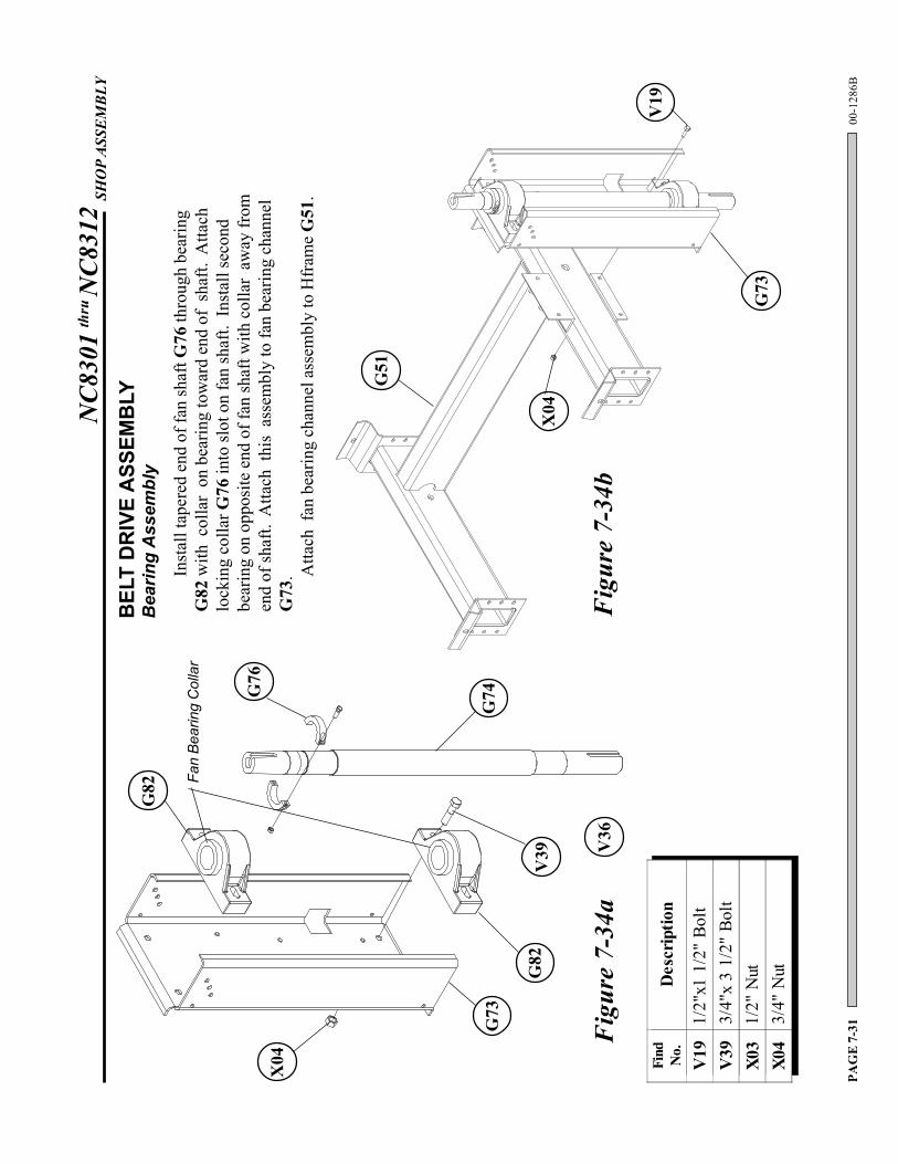
BEL
T D
RIV
E A
SSEM
BLY
Bea
ring
Ass
embl
y
Inst
all t
aper
ed e
nd o
f fan
shaf
t G76
thro
ugh
bear
ing
G82
with
col
lar
on b
earin
g to
war
d en
d of
sha
ft. A
ttach
lock
ing
colla
r G76
into
slot
on
fan
shaf
t. In
stal
l sec
ond
bear
ing
on o
ppos
ite e
nd o
f fan
shaf
t with
col
lar
away
from
end
of sh
aft.
Atta
ch t
his
asse
mbl
y to
fan
bear
ing
chan
nel
G73
. Atta
ch f
an b
earin
g ch
anne
l ass
embl
y to
Hfr
ame
G51
.
Fan
Bear
ing
Col
lar
V19
G73
G51
Figu
re 7
-34a
Figu
re 7
-34b
X04
Find No.
Des
crip
tion
V19
1/2"
x1 1
/2"
Bolt
V39
3/4"
x 3
1/2"
Bol
tX0
31/
2" N
utX0
43/
4" N
ut
NC8
301
thru
NC8
312
SHO
P AS
SEM
BLY
00-1
286B
PAG
E 7
-32
W30
X04
G68
G67
G69
G66
G69
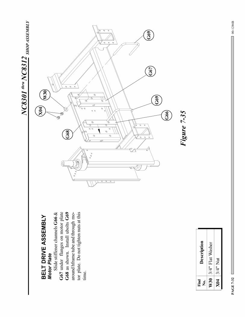
BEL
T D
RIV
E A
SSEM
BLY
Mot
or P
late
Slid
e stif
fene
r cha
nnel
s G66
&G
67 u
nder
fla
nges
on
mot
or p
late
G68
as
show
n.
Inst
all u
bolts
G69
arou
nd h
fram
e tub
e and
thro
ugh
mo-
tor
plat
e. D
o no
t tig
hten
nut
s at t
his
time.
Figu
re 7
-35
Find No.
Des
crip
tion
W30
3/4"
Fla
t Was
her
X04
3/4"
Nut
NC8
301
thru
NC8
312
SHO
P AS
SEM
BLY
00-1
286B
PAG
E 7
-33
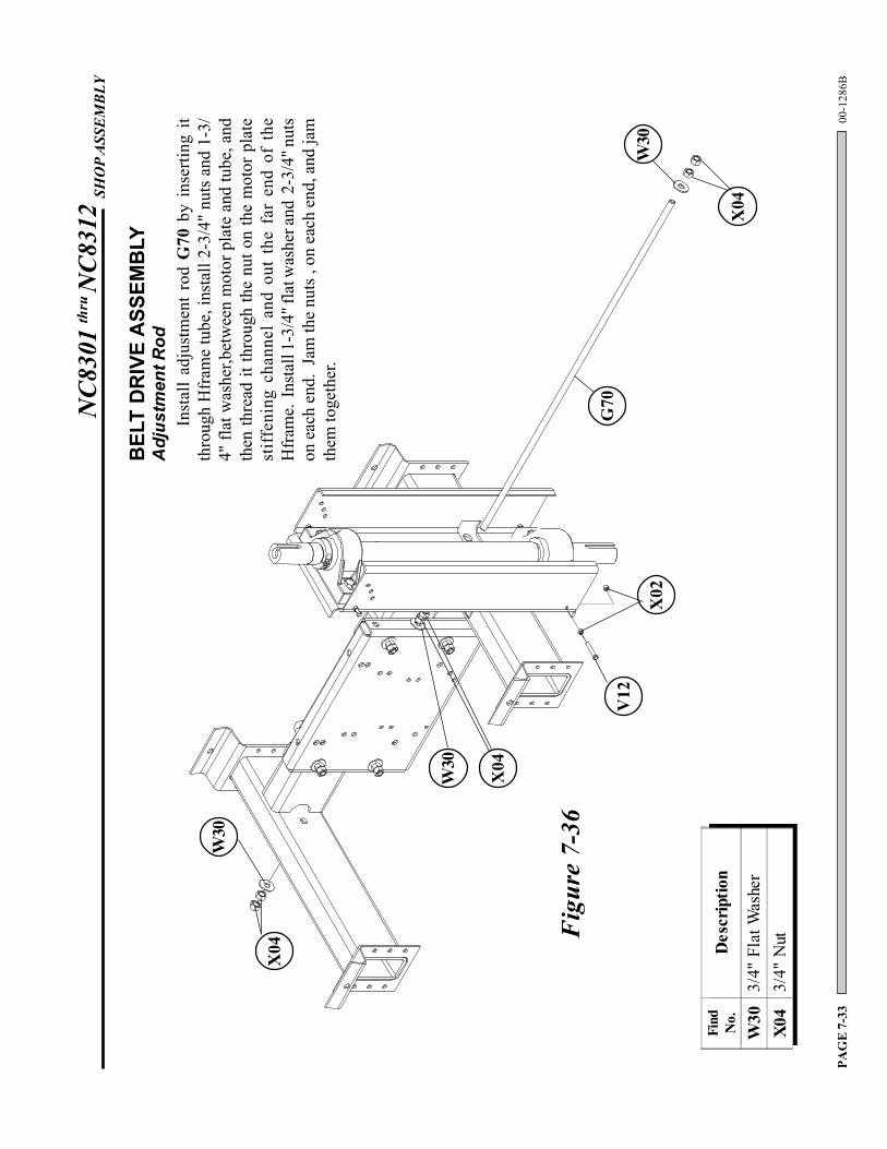
Inst
all
adju
stm
ent
rod
G70
by
inse
rting
it
thro
ugh
Hfr
ame
tube
, ins
tall
2-3/
4" n
uts a
nd 1
-3/
4" fl
at w
ashe
r,bet
wee
n m
otor
pla
te a
nd tu
be, a
ndth
en th
read
it th
roug
h th
e nu
t on
the
mot
or p
late
stif
feni
ng c
hann
el a
nd o
ut t
he f
ar e
nd o
f th
eH
fram
e. I
nsta
ll 1-
3/4"
flat
was
her a
nd 2
-3/4
" nut
son
eac
h en
d. J
am th
e nu
ts ,
on e
ach
end,
and
jam
them
toge
ther
.
BEL
T D
RIV
E A
SSEM
BLY
Adj
ustm
ent R
od
X04
W30
W30
V12
X02
X04
W30
G70
Figu
re 7
-36
X04
Find No.
Des
crip
tion
W30
3/4"
Fla
t Was
her
X04
3/4"
Nut
NC8
301
thru
NC8
312
SHO
P AS
SEM
BLY
00-1
286B
PAG
E 7
-34
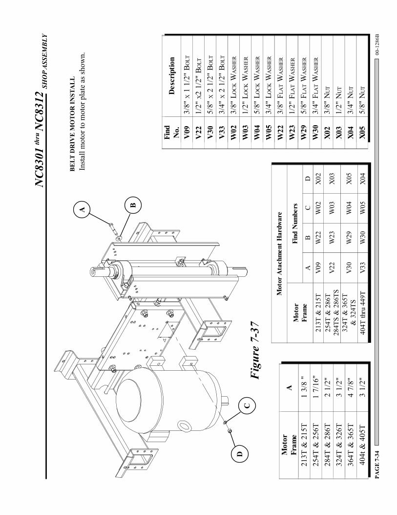
Figu
re 7
-37
BELT
DR
IVE
MO
TOR
INST
ALL
Inst
all m
otor
to m
otor
pla
te a
s sho
wn.
A B
DC
Mot
orFr
ame
A
213T
& 2
15T
1 3/
8 "
254T
& 2
56T
1 7/
16"
284T
& 2
86T
2 1/
2"32
4T &
326
T3
1/2"
364T
& 3
65T
4 7/
8"40
4t &
405
T3
1/2"
Mot
or A
tach
men
t Har
dwar
e
Mot
orFr
ame
Find
Num
bers
AB
CD
213T
& 2
15T
V09
W22
W02
X02
254T
& 2
86T
284T
S &
286
TSV2
2W
23W
03X
03
324T
& 3
65T
& 3
24TS
V30
W29
W04
X05
404T
thru
449
TV3
3W
30W
05X
04
Find No.
Des
crip
tion
V09
3/8"
X 1
1/2
" BO
LT
V22
1/2"
X2
1/2"
BO
LT
V30
5/8"
X 2
1/2
" BO
LT
V33
3/4"
X 2
1/2
" BO
LT
W02
3/8"
LO
CK W
ASH
ER
W03
1/2"
LO
CK W
ASH
ER
W04
5/8"
LO
CK W
ASH
ER
W05
3/4"
LO
CK W
ASH
ER
W22
3/8"
FLA
T W
ASH
ER
W23
1/2"
FLA
T W
ASH
ER
W29
5/8"
FLA
T W
ASH
ER
W30
3/4"
FLA
T W
ASH
ER
X02
3/8"
NUT
X03
1/2"
NUT
X04
3/4"
NUT
X05
5/8"
NUT
NC8
301
thru
NC8
312
SHO
P AS
SEM
BLY
00-1
286B
PAG
E 7
-35
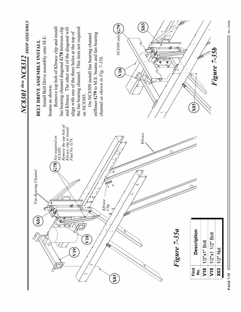
Figu
re 7
-35a
BELT
DR
IVE
ASS
EMBL
Y IN
STA
LL
G78
Not
requ
ired
onN
C83
05.
Rem
ove
the
top
bolt
ofK
brac
e cl
ip to
inst
all
Find
No.
G78
.
Kbr
ace
Clip
Kbr
ace
Fan
Bear
ing
Cha
nnel
Inst
all B
elt D
rive
asse
mbl
y on
to M
.E.
beam
s as s
how
n.R
emov
e to
p bo
lt of
Kbr
ace
clip
and
inst
all
fan
bear
ing
chan
nel d
iago
nal G
78 b
etw
een
clip
and
Kbr
ace.
The
oth
er e
nd o
f the
dia
gona
l will
alig
n w
ith o
ne o
f the
thre
e ho
les a
t the
top
ofth
e fa
n be
arin
g ch
anne
l. T
his i
tem
not
requ
ired
on N
C83
05.
On
NC
8309
inst
all f
an b
earin
g ch
anne
lst
iffen
er G
79 to
M.E
. bea
ms a
nd fa
n be
arin
gch
anne
l as s
how
n in
Fig
. 7-3
5b.
X03
V18
Find No.
Description
V18
1/2"
x1" B
olt
V19
1/2"
x1 1
/2" B
olt
X03
1/2"
Nut
X03
V19
Figu
re 7
-35b
G79
X03
X03
V18
NC
8309
onl
y
NC8
301
thru
NC8
312
SHO
P AS
SEM
BLY
00-1
286B
PAG
E 7
-36
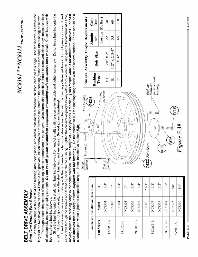
Iden
tify
fan
shea
ve M
22 o
r M24
and
bus
hing
M23
, bei
ng u
sed,
and
obt
ain
inst
alla
tion
dim
ensi
on "A
" fro
m c
hart
on th
is p
age.
The
fan
shea
ve is
alw
ays
the
larg
er o
f the
two
driv
e sh
eave
s an
d w
ill h
ave
3 to
8 g
roov
es.
All
fan
shea
ves
are
"rev
erse
mou
nted
" on
the
bush
ing
(fast
ener
s th
read
ed in
to b
ushi
ng) a
s sh
own.
Thor
ough
ly c
lean
the
exte
rior o
f the
bus
hing
and
the
tape
red
bore
of t
he s
heav
e. N
icks
, bur
rs, d
irt, a
nd c
hips
sho
uld
be re
mov
ed, s
ince
they
can
cau
se a
loss
of c
once
ntric
ity a
nd e
ven
grip
ping
stre
ngth
. D
o no
t use
oil,
gre
ase,
or a
ntis
ieze
com
poun
ds o
n bu
shin
g su
rfac
es, s
heav
e bo
re o
r sha
ft. C
heck
key
siz
e w
ithbo
th s
haft
and
bush
ing
keyw
ay.
Slid
e th
e bu
shin
g on
to th
e sh
aft (
with
bus
hing
hub
aw
ay fr
om e
nd o
f sha
ft) a
t dim
ensi
on g
iven
in ta
ble
and
tight
en s
et s
crew
. D
o no
t for
ce b
ushi
ng o
nto
the
shaf
t. If
it d
oes
not g
o on
eas
ily, c
heck
the
shaf
t, bu
shin
g, a
nd k
ey s
izes
. D
o no
t spr
ead
bush
ing!
Inse
rt sh
eave
loos
ely
over
bus
hing
with
the
unth
read
ed h
ole
of th
e sh
eave
mat
ched
with
the
bush
ing'
s th
read
ed h
oles
. D
o no
t pre
ss o
r dr
ive.
In
sert
caps
crew
s th
roug
h th
e sh
eave
and
thre
ad b
y ha
nd in
to th
e bu
shin
g. T
ight
en th
e ca
pscr
ews
prog
ress
ivel
y w
ith a
torq
ue w
renc
h us
ing
quar
ter t
o ha
lf tu
rns
at a
tim
e,m
ovin
g ar
ound
the
bush
ing
flang
e in
the
sam
e di
rect
ion
until
the
a to
rque
of 2
2 fo
ot p
ound
s is
reac
hed.
(Th
is to
rque
val
ue is
for a
lum
inum
she
aves
. Fo
r cas
tiro
n sh
eave
s us
e th
e to
rque
val
ue s
uppl
ied
with
the
bush
ing.
) D
o no
t atte
mpt
to p
ull t
he b
ushi
ng fl
ange
flus
h w
ith th
e sh
eave
sur
face
. Th
ere
shou
ld b
e a
clea
ranc
e ga
p w
hen
tight
ened
to s
peci
fied
torq
ue.
Inst
all f
an s
heav
e re
tain
er M
30.
BEL
T D
RIV
E A
SSEM
BLY
Step
One
Det
ails
Fan
She
ave
M23
Fan
bush
ing
M22
Fan
shea
ve
Fan
shaf
tO
ut o
fbu
shin
g
End
offa
n sh
aft
ABu
shin
gse
t scr
ew Bush
ing
hard
war
e(in
clud
ed w
ithbu
shin
g)
Figu
re 7
-39
M30
W03
V18
Fan
Shea
ve In
stal
latio
n D
imen
sion
Fan
Shea
veM
odel
A
18.4
x5B-
EN
C830
41
1/4"
NC8
305
0"
25.0
x5B-
EN
C830
41
1/4"
NC8
305
0"
30.0
x6B-
EN
C830
61
3/4"
NC8
307
1 1/
4"
38.0
x6B-
E
NC8
306
2 1/
4"
NC8
307
1 1/
4"
NC8
309
1 1/
2"
38.0
x7B-
EN
C830
91
3/8"
5V38
.0x6
-EN
C830
75/
8"
NC8
309
3/4"
Shea
ve A
ssem
bly
Torq
ue R
equi
rem
ents
Bus
hing
Typ
eB
olt
Size
Alu
min
-um
Cas
tIr
onTo
rque
(ft
. lbs
.)SF
3/8"
x 2
"22
30
E1/
2" x
2 3
/4"
3560
F9/
16"
6511
0
NC8
301
thru
NC8
312
SHO
P AS
SEM
BLY
00-1
286B
PAG
E 7
-37
BEL
T D
RIV
E A
SSEM
BLY
Step
Tw
o D
etai
ls M
otor
She
ave
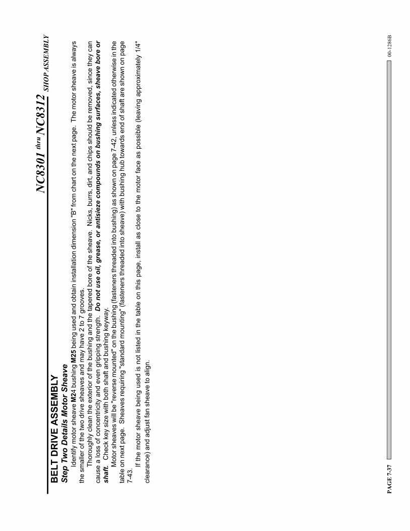
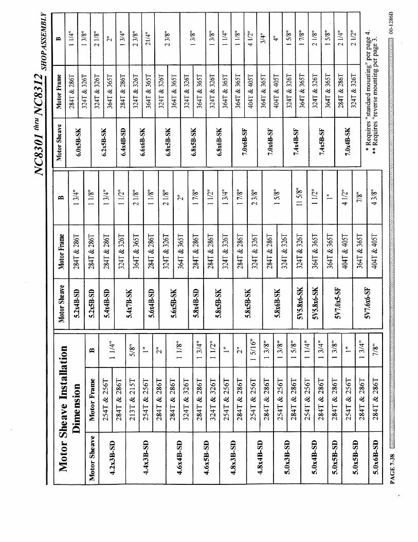
Iden
tify
mot
or s
heav
e M
24 b
ushi
ng M
25 b
eing
use
d an
d ob
tain
inst
alla
tion
dim
ensi
on "B
" fro
m c
hart
on th
e ne
xt p
age.
The
mot
or s
heav
e is
alw
ays
the
smal
ler o
f the
two
driv
e sh
eave
s an
d m
ay h
ave
2 to
7 g
roov
es.
Thor
ough
ly c
lean
the
exte
rior o
f the
bus
hing
and
the
tape
red
bore
of t
he s
heav
e. N
icks
, bur
rs, d
irt, a
nd c
hips
sho
uld
be re
mov
ed, s
ince
they
can
caus
e a
loss
of c
once
ntric
ity a
nd e
ven
grip
ping
stre
ngth
. D
o no
t use
oil,
gre
ase,
or a
ntis
ieze
com
poun
ds o
n bu
shin
g su
rfac
es, s
heav
e bo
re o
rsh
aft.
Che
ck k
ey s
ize
with
bot
h sh
aft a
nd b
ushi
ng k
eyw
ay.
Mot
or s
heav
es w
ill be
"rev
erse
mou
nted
" on
the
bush
ing
(fast
ener
s th
read
ed in
to b
ushi
ng) a
s sh
own
on p
age
7-42
, unl
ess
indi
cate
d ot
herw
ise
in th
eta
ble
on n
ext p
age.
She
aves
requ
iring
"sta
ndar
d m
ount
ing"
(fas
tene
rs th
read
ed in
to s
heav
e) w
ith b
ushi
ng h
ub to
war
ds e
nd o
f sha
ft ar
e sh
own
on p
age
7-43
. If th
e m
otor
she
ave
bein
g us
ed is
not
list
ed in
the
tabl
e on
this
pag
e, in
stal
l as
clos
e to
the
mot
or fa
ce a
s po
ssib
le (l
eavi
ng a
ppro
xim
atel
y 1/
4"cl
eara
nce)
and
adj
ust f
an s
heav
e to
alig
n.
NC8
301
thru
NC8
312
SHO
P AS
SEM
BLY
00-1
286B
PAG
E 7
-39
M25
Mot
or b
ushi
ng
M24
Mot
orsh
eave
Mot
or sh
aft
Out
of b
ushi
ng
End
of m
otor
shaf
t
B
Bush
ing
set s
crew
Bush
ing
hard
war
e(in
clud
ed w
ith b
ushi
ng)
BEL
T D
RIV
E A
SSEM
BLY
Step
Tw
o M
otor
She
ave
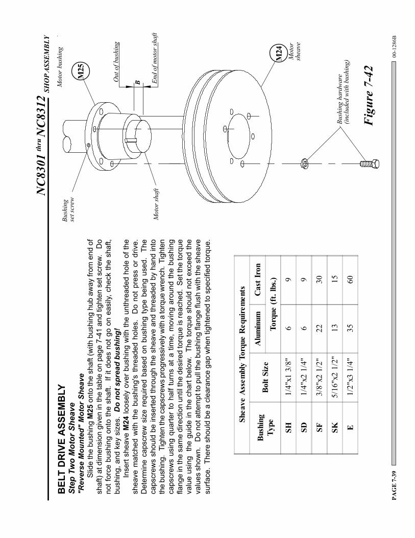
"Rev
erse
Mou
nted
" M
otor
She
ave
Slid
e th
e bu
shin
g M
25 o
nto
the
shaf
t (w
ith b
ushi
ng h
ub a
way
from
end
of
shaf
t) at
dim
ensi
on g
iven
in th
e ta
ble
on p
age
7-41
and
tigh
ten
set s
crew
. D
ono
t for
ce b
ushi
ng o
nto
the
shaf
t. If
it d
oes
not g
o on
eas
ily, c
heck
the
shaf
t,bu
shin
g, a
nd k
ey s
izes
. D
o no
t spr
ead
bush
ing!
Inse
rt sh
eave
M24
loos
ely
over
bus
hing
with
the
unth
read
ed h
ole
of th
esh
eave
mat
ched
with
the
bus
hing
's t
hrea
ded
hole
s.
Do
not
pres
s or
driv
e.D
eter
min
e ca
pscr
ew s
ize
requ
ired
base
d on
bus
hing
type
bei
ng u
sed.
Th
eca
pscr
ews
shou
ld b
e in
serte
d th
roug
h th
e sh
eave
and
thre
aded
by
hand
into
the
bush
ing.
Tig
hten
the
caps
crew
s pr
ogre
ssiv
ely
with
a to
rque
wre
nch.
Tig
hten
caps
crew
s us
ing
quar
ter
to h
alf t
urns
at a
tim
e, m
ovin
g ar
ound
the
bush
ing
flang
e in
the
sam
e di
rect
ion
until
the
desi
red
torq
ue is
reac
hed.
Set
the
torq
ueva
lue
usin
g th
e gu
ide
in th
e ch
art b
elow
. Th
e to
rque
sho
uld
not e
xcee
d th
eva
lues
sho
wn.
D
o no
t atte
mpt
to p
ull t
he b
ushi
ng fl
ange
flus
h w
ith th
e sh
eave
surfa
ce.
Ther
e sh
ould
be
a cl
eara
nce
gap
whe
n tig
hten
ed to
spe
cifie
d to
rque
.
Figu
re 7
-42
Shea
ve A
ssem
bly
Torq
ue R
equi
rem
ents
Bush
ing
Type
Bolt
Size
Alu
min
umC
ast I
ron
Torq
ue (f
t. lb
s.)
SH1/
4"x1
3/8
"6
9
SD1/
4"x2
1/4
"6
9
SF3/
8"x2
1/2
"22
30
SK5/
16"x
2 1/
2"13
15
E1/
2"x3
1/4
"35
60
NC8
301
thru
NC8
312
SHO
P AS
SEM
BLY
00-1
286B
PAG
E 7
-40
BELT
AN
D S
HEA
VE
INST
ALL
ATIO
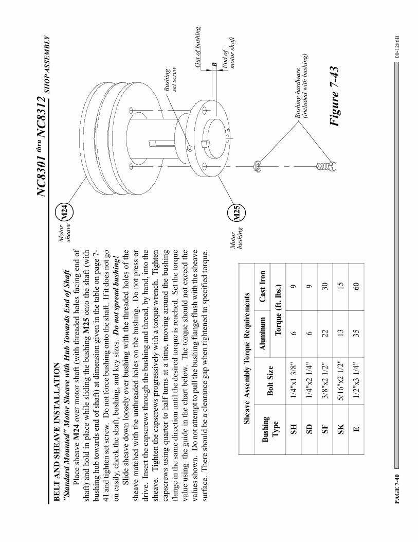
N"S
tand
ard
Mou
nted
" M
otor
She
ave
with
Hub
Tow
ards
End
of S
haft
Plac
e sh
eave
M24
ove
r mot
or s
haft
(with
thre
aded
hol
es fa
cing
end
of
shaf
t) an
d ho
ld in
pla
ce w
hile
slid
ing
the
bush
ing
M25
ont
o th
e sh
aft (
with
bush
ing
hub
tow
ards
end
of s
haft)
at d
imen
sion
giv
en in
the
tabl
e on
pag
e 7-
41 an
d tig
hten
set s
crew
. D
o no
t for
ce b
ushi
ng o
nto
the s
haft.
If i
t doe
s not
go
on e
asily
, che
ck th
e sh
aft,
bush
ing,
and
key
size
s. D
o no
t spr
ead
bush
ing!
Slid
e sh
eave
dow
n lo
osel
y ov
er b
ushi
ng w
ith th
e th
read
ed h
oles
of t
hesh
eave
mat
ched
with
the
unth
read
ed h
oles
on
the
bush
ing.
Do
not p
ress
or
driv
e. I
nser
t the
cap
scre
ws t
hrou
gh th
e bu
shin
g an
d th
read
, by
hand
, int
o th
esh
eave
. T
ight
en th
e ca
pscr
ews p
rogr
essi
vely
with
a to
rque
wre
nch.
Tig
hten
caps
crew
s us
ing
quar
ter t
o ha
lf tu
rns
at a
tim
e, m
ovin
g ar
ound
the
bush
ing
flang
e in
the s
ame d
irect
ion
until
the d
esire
d to
rque
is re
ache
d. S
et th
e tor
que
valu
e us
ing
the
guid
e in
the
char
t bel
ow.
The
torq
ue s
houl
d no
t exc
eed
the
valu
es sh
own.
Do
not a
ttem
pt to
pul
l the
bus
hing
flan
ge fl
ush
with
the s
heav
esu
rfac
e. T
here
shou
ld b
e a
clea
ranc
e ga
p w
hen
tight
ened
to sp
ecifi
ed to
rque
.
M25
Mot
orbu
shin
g
M24
Mot
orsh
eave
Out
of b
ushi
ng
End
ofm
otor
shaf
t
B
Bush
ing
set s
crew
Bush
ing
hard
war
e(in
clud
ed w
ith b
ushi
ng)
Figu
re 7
-43
Shea
ve A
ssem
bly
Torq
ue R
equi
rem
ents
Bush
ing
Type
Bolt
Size
Alu
min
umC
ast I
ron
Torq
ue (f
t. lb
s.)
SH1/
4"x1
3/8
"6
9
SD1/
4"x2
1/4
"6
9
SF3/
8"x2
1/2
"22
30
SK5/
16"x
2 1/
2"13
15
E1/
2"x3
1/4
"35
60
NC8
301
thru
NC8
312
SHO
P AS
SEM
BLY
00-1
286B
PAG
E 7
-41
Line
of s
ight
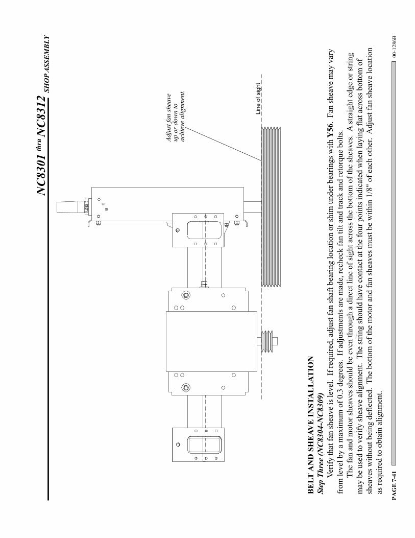
BELT
AN
D S
HEA
VE
INST
ALL
ATIO
NSt
ep T
hree
(NC8
304-
NC8
309)
Verif
y th
at fa
n sh
eave
is le
vel.
If re
quire
d, a
djus
t fan
shaf
t bea
ring
loca
tion
or sh
im u
nder
bea
rings
with
Y56
. Fa
n sh
eave
may
var
yfr
om le
vel b
y a
max
imum
of 0
.3 d
egre
es.
If a
djus
tmen
ts a
re m
ade,
rech
eck
fan
tilt a
nd tr
ack
and
reto
rque
bol
ts.
The
fan
and
mot
or sh
eave
s sho
uld
be e
ven
thro
ugh
a di
rect
line
of s
ight
acr
oss t
he b
otto
m o
f the
shea
ves.
A st
raig
ht e
dge
or st
ring
may
be
used
to v
erify
shea
ve a
lignm
ent.
The
strin
g sh
ould
hav
e co
ntac
t at t
he fo
ur p
oint
s ind
icat
ed w
hen
layi
ng fl
at a
cros
s bot
tom
of
shea
ves w
ithou
t bei
ng d
efle
cted
. Th
e bo
ttom
of t
he m
otor
and
fan
shea
ves m
ust b
e w
ithin
1/8
" of e
ach
othe
r. A
djus
t fan
shea
ve lo
catio
nas
requ
ired
to o
btai
n al
ignm
ent.
Adju
st fa
n sh
eave
up o
r dow
n to
achi
eve
alig
nmen
t.
NC8
301
thru
NC8
312
SHO
P AS
SEM
BLY
00-1
286B
PAG
E 7
-42
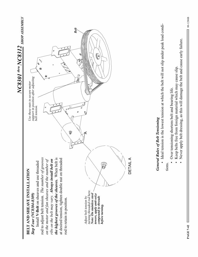
Use
thes
e nu
ts to
secu
re m
otor
supp
ort i
n po
sitio
n af
ter a
djus
ting
belt
tens
ion.
Adju
st b
elt t
ensi
on b
ytu
rnin
g th
read
ed ro
d he
re.
Not
e: O
n sta
inle
ss st
eel
towe
rs, a
pply
ant
i-sei
zeco
mpo
und
to th
read
sbe
fore
turn
ing.
BELT
AN
D S
HEA
VE
INST
ALL
ATIO
NSt
ep F
our (
NC8
304-
8309
)In
stal
l V-B
elt o
n sh
eave
s and
use
thre
aded
rod
to a
djus
t bel
t ten
sion
. Th
e nu
mbe
r of g
roov
eson
the
mot
or a
nd fa
n sh
eave
s and
the
num
ber o
fri
bs o
n th
e be
lt m
ay v
ary.
Alw
ays i
nsta
ll be
lt on
the
high
est g
roov
es o
f the
shea
ves.
Whe
n be
lt is
at d
esire
d te
nsio
n, ti
ghte
n do
uble
nut
on
thre
aded
rod
to re
tain
in p
ositi
on.
Gen
eral
Rul
es o
f Bel
t Ten
sioni
ng•
Idea
l ten
sion
is th
e lo
wes
t ten
sion
at w
hich
the
belt
will
not
slip
und
er p
eak
load
con
di-
tions
. •O
ver t
ensi
onin
g sh
orte
ns b
elt a
nd b
earin
g lif
e.•
Kee
p be
lts fr
ee fr
om fo
reig
n m
ater
ial w
hich
may
cau
se sl
ip.
•N
ever
app
ly b
elt d
ress
ing,
as t
his w
ill d
amag
e th
e be
lt an
d ca
use
early
failu
re.
Belt
A
DE
TAIL
A