Embed Size (px)
Citation preview
0.0 Preface -Title Page
767-400Operations Manual Volume 1
Delta Air Lines
REVIEWED BY:
______________________________Roger Pfannenstiel
767-400 - Technical Manager
APPROVED BY:
______________________________Ed Sternstein
767-400 - Chief Line Check Pilot
APPROVED BY:
______________________________Dean Bloom
757/767-300/-400 - Fleet Captain
Revision Number: 14Revision Date: December 19, 2007
© 2007

767-400 Operations Manual
Preface Chapter P1Table of Contents Section 0
FCO
M T
empl
ate
12/1
2/98
Copyright © Delta Air Lines, Inc. See title page for details.
Volume 1 Chapter
Preface . . . . . . . . . . . . . . . . . . . . . . . . . . . . . . . . . . . . . . . . . . . . . . . . P1Table of Contents . . . . . . . . . . . . . . . . . . . . . . . . . . . . . . . . . . . . P1.0Model Identification . . . . . . . . . . . . . . . . . . . . . . . . . . . . . . . . . P1.1Introduction . . . . . . . . . . . . . . . . . . . . . . . . . . . . . . . . . . . . . . . . P1.2Abbreviations. . . . . . . . . . . . . . . . . . . . . . . . . . . . . . . . . . . . . . . P1.3Revision Record / Highlights. . . . . . . . . . . . . . . . . . . . . . . . . . . P1.4List of Effective Pages . . . . . . . . . . . . . . . . . . . . . . . . . . . . . . . . P1.5Flight Crew Bulletin Record . . . . . . . . . . . . . . . . . . . . . . . . . . . P1.6
Limitations . . . . . . . . . . . . . . . . . . . . . . . . . . . . . . . . . . . . . . . . . . . . . LNormal Procedures . . . . . . . . . . . . . . . . . . . . . . . . . . . . . . . . . . . . . . NPSupplementary Procedures . . . . . . . . . . . . . . . . . . . . . . . . . . . . . . . . SP
P1.0.1September 9, 2002
767-400 Operations Manual
Preface -Table of Contents
Copyright © Delta Air Lines, Inc. See title page for details.
IntentionallyBlank
P1.0.2 September 9, 2002

767-400 Operations Manual
Preface Chapter P1Model Identification Section 1
FCO
M T
empl
ate
12/1
2/98
Copyright © Delta Air Lines, Inc. See title page for details.
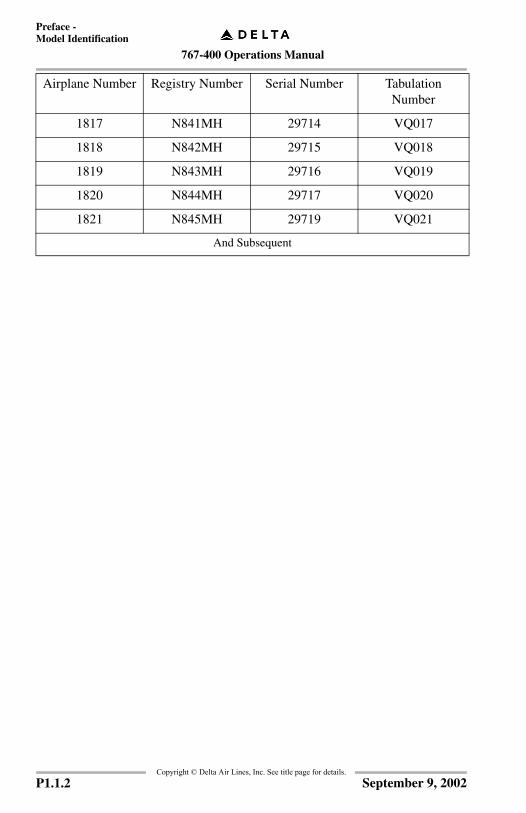
GeneralThe airplanes listed in the table below are covered in the operations manual. Thenumbers are used to distinguish data peculiar to one or more, but not all of theairplanes. Where data applies to all airplanes listed, no reference is made toindividual airplane numbers.
Use of the table below permits flight crew correlation of configuration differencesby number within an operator’s fleet for airplanes covered in this manual.Configuration data reflects the airplane as delivered configuration and is updatedfor service bulletin incorporations in conformance with the policy stated in theintroduction section of this chapter.
Airplane number is supplied by the operator. Registry number is supplied by thenational regulatory agency. Serial and tabulation numbers are supplied by Boeing.
Airplane Number Registry Number Serial Number Tabulation Number
1801 N825MH 29703 VQ001
1802 N826MH 29713 VQ002
1803 N827MH 29705 VQ003
1804 N828MH 29699 VQ004
1805 N829MH 29700 VQ005
1806 N830MH 29701 VQ006
1807 N831MH 29702 VQ007
1808 N832MH 29704 VQ008
1809 N833MH 29706 VQ009
1810 N834MH 29707 VQ010
1811 N835MH 29708 VQ011
1812 N836MH 29709 VQ012
1813 N837MH 29710 VQ013
1814 N838MH 29711 VQ014
1815 N839MH 29712 VQ015
1816 N840MH 29718 VQ016
P1.1.1September 9, 2002
767-400 Operations Manual
Preface -Model Identification
Copyright © Delta Air Lines, Inc. See title page for details.
1817 N841MH 29714 VQ017
1818 N842MH 29715 VQ018
1819 N843MH 29716 VQ019
1820 N844MH 29717 VQ020
1821 N845MH 29719 VQ021
And Subsequent
Airplane Number Registry Number Serial Number Tabulation Number
P1.1.2 September 9, 2002

767-400 Operations Manual
Preface Chapter P1Introduction Section 2
FCO
M T
empl
ate
12/1
2/98
Copyright © Delta Air Lines, Inc. See title page for details.
GeneralThe Boeing Company developed normal and non-normal procedures for the767-400 aircraft. Delta Air Lines, Inc., has modified some of the procedures forsimplification and standardization, when appropriate, with other Delta Air Lines,Inc., aircraft. Finally, the FAA has approved the procedures presented in theOperations Manual, with the exception of flight crew bulletins.
These procedures are company policy for pilots to follow during groundoperations and in flight. Deviations from these policies and procedures should bemade only with good cause and based on the safest course of action. If anabnormality occurs that is not covered by these procedures, the Captain must usehis best judgement.
Manual RightsThis 767-400 Operations Manual has been prepared for the exclusive use of DeltaAir Lines, Inc. Flight Operations personnel under the direction and authority ofDelta Air Lines and shall, at all times, remain the property of Delta Air Lines, Inc.The holder hereof acknowledges and agrees that this manual contains or maycontain trade secrets, copyrighted material and commercial and proprietaryinformation, privileged and confidential, to the interest of Delta Air Lines, Inc.,and the holder hereof further agrees that this manual may not be reproduced,distributed or copied, in whole or in part, without the express prior written consentof Delta Air Lines, Inc.
• In the event this 757/767-300/-400 Operations Manual is sold or distributed to any other party, no warranty or guarantee, expressed or implied, is made as to the accuracy, sufficiency or suitability of the materials contained herein or of any revision, supplement or bulletin hereto. It is understood and agreed to by such other party that it shall release indemnify and hold Delta Air Lines, Inc., its officers, employees and agents harmless against any and all claims or actions of whatever nature which may arise or claim to arise from the use hereof.
• To verify the latest version of this document, log on to the Delta Flight Operations portal (http://dalweb.delta.com/portal) and click the Revision Dates link on the right side of the appropriate My Delta Fleet webpage.
P1.2.1March 31, 2006
767-400 Operations Manual
Preface -Introduction
Copyright © Delta Air Lines, Inc. See title page for details.
Corrections to the ManualTo correct any errors or discrepancies discovered in this manual, or to submit asuggested change to any Aircraft Operating Manual (Volume 1, Volume 2, QRH,Flight Crew Training Manual), Normal Checklist, Airway Manual, FlightOperations Manual (FOM), OE/TOE Guide, Flight Crew Bulletin (FCB), or FlightOperations Bulletin (FOB):
Log on to the Delta Flight Operations Portal; http://dalweb.delta.com/portal andsubmit a Publications Change Request (PCR).
There are links to the PCR form on each fleet page and also on the Flight OpsManuals/Library Services page.
Once submitted, the PCR is automatically routed to the applicable Fleet TechnicalManager, Technical Writer, and Specialist for that manual.
OrganizationThe operations manual is organized in the following manner.
Volume 1
• Preface – contains general information regarding the manual’s purpose, structure, and content. It also contains lists of abbreviations, a record of revisions, a list of effective pages, and bulletins.
• Limitations and Normal Procedures chapters cover operational limitations and normal procedures. All operating procedures are based on a thorough analysis of crew activity required to operate the airplane, and reflect the latest knowledge and experience available.
• Supplementary Procedures chapter covers those procedures accomplished as required rather than routinely on each flight.
• Aircraft Differences chapter notes differences between aircraft types.
Volume 2 - Chapters 1 through 15 contain general airplane and systemsinformation. These chapters are generally subdivided into sections coveringcontrols and indicators and systems descriptions.
Quick Reference Handbook (QRH) - The QRH covers normal checklists,non-normal checklists, and non-normal maneuvers.
Flight Crew Training Manual (FCTM) - The Flight Crew Training Manualprovides information and recommendations on maneuvers and techniques.
P1.2.2 November 20, 2006
767-400 Operations Manual
Preface -Introduction
Copyright © Delta Air Lines, Inc. See title page for details.
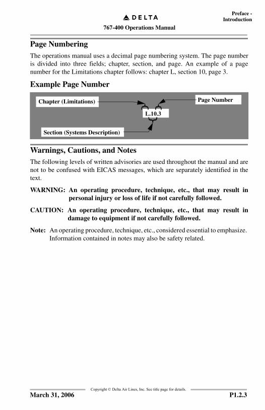
Page NumberingThe operations manual uses a decimal page numbering system. The page numberis divided into three fields; chapter, section, and page. An example of a pagenumber for the Limitations chapter follows: chapter L, section 10, page 3.
Example Page Number
Warnings, Cautions, and NotesThe following levels of written advisories are used throughout the manual and arenot to be confused with EICAS messages, which are separately identified in thetext.
WARNING: An operating procedure, technique, etc., that may result inpersonal injury or loss of life if not carefully followed.
CAUTION: An operating procedure, technique, etc., that may result indamage to equipment if not carefully followed.
Note: An operating procedure, technique, etc., considered essential to emphasize. Information contained in notes may also be safety related.
L.10.3
Chapter (Limitations) Page Number
Section (Systems Description)
P1.2.3March 31, 2006
767-400 Operations Manual
Preface -Introduction
Copyright © Delta Air Lines, Inc. See title page for details.
IntentionallyBlank
P1.2.4 September 9, 2002

767-400 Operations Manual
Preface Chapter P1Abbreviations Section 3
GeneralThe following abbreviations may be found throughout the manual. Someabbreviations may also appear in lowercase letters. Abbreviations having verylimited use are explained in the chapter where they are used. Since this list iscompiled across several fleets, there may be some abbreviations that do not applyto this specific fleet.
Copyright © Delta Air Lines, Inc. See title page for details.
A
ABV Above
AC Alternating Current or Aircraft
ACARS Aircraft Communications Addressing and Reporting System
ACE Actuator Control Electronics
ACP Audio Control Panel
ACT Active
ADC Air Data Computer
ADF Automatic Direction Finder
ADI Attitude Director Indicator
ADIRS Air Data Inertial Reference System
ADIRU Air Data Inertial Reference Unit
ADM Air Data Module
AED Automatic External Defribulator
AFDC Autopilot Flight Director Computer
AFDS Autopilot Flight Director System
AFE Above Field Elevation
AFM Airplane Flight Manual (FAA approved)
AFM - DPI Airplane Flight Manual - Digital Performance Information
AFS Automatic Flight System (Autopilot or Autothrottle)
A/G Air/Ground
AGL Above Ground Level
AH Alert Height
AHRS Attitude Heading Reference System
AI Anti-Ice
AIL Aileron
ALFA Safe Stall Margin Speed
ALT Altitude
ALT ACQ Altitude Acquire
ALT HOLD Altitude Hold
ALTN Alternate
AM Amplitude Modulation
P1.3.1January 17, 2005

767-400 Operations Manual
Preface - Abbreviations
AIMS Airplane Information Management System
AMI Airline Modifiable Information
ANP Actual Navigational Performance
ANT Antenna
ANU Aircraft Nose Up
AOA Angle of Attack
AOC Airline Operational Communication Data Link
A/P Autopilot
APL Airplane
APP Approach
APU Auxiliary Power Unit
ARINC Aeronautical Radio, Incorporated
ARM Aircraft Restrictions Manual
ARPT Airport
ARR Arrival
ART Automatic Reserve Thrust
ASA Autoland Status Annunciator
ASI Airspeed Indicator
ASR Airport Surveillance Radar
ASYM Asymmetry
A/T Autothrottle
ATA Actual Time of Arrival
ATC Air Traffic Control
Copyright © Delta Air Lines,
P1.3.2
ATIS Automated Terminal Information Service
ATM Assumed Temperature Method
ATT Attitude
AUTO Automatic
AUTO–THROT
Autothrottle
AUX Auxiliary
AVAIL Available
AWABS Automated Weight and Balance System
B
BARO Barometric
BAT Battery
B/C orB/CRS orBAC orBCS
Back Course
BFO Beat Frequency Oscillator
BITE Built-In Test Equipment
BKR Breaker
BLD Bleed
BLW Below
BRG Bearing
BRT Bright
BTL Bottle
BTL DISCH Bottle Discharge (fire extinguisher)
BTMS Brake Temperature Monitoring System
C
Inc. See title page for details.
March 31, 2006

767-400 Operations Manual
Preface - Abbreviations
C Captain or
Celsius or
Center or
Cool
CAA Civil Aviation Authority
CADC Central Air Data Computer
CALSEL Call Select
CANC/RCL Cancel/Recall
CANPA Constant Angle Non-Precision Approach
CAP Capture
CAPT Captain
CAWS Central Aural Warning System
CB Circuit Breaker
CCD Cursor Control Device
CDS Common Display System
CDU Control Display Unit
CFIT Controlled Flight Into Terrain
CG Center of Gravity
CHKL Checklist
CHR Chronograph
CKD Checked
CKT Circuit
CL Close
CLB Climb
CLMP Computer Lockout Manual Power
CLR Clear
CMD Command
Copyright © Delta Air Lines,March 31, 2006
Inc. See title page for details.
CO Company
COMM Communication
COMP Comparator
COMPT Compartment
CON Continuous
CONFIG Configuration
CONT Control
COOL Cooling
CRS Course
CRT Cathode Ray Tube
CRZ Cruise
CTL Control
CTR Center
CWS Control Wheel Steering
D
DA Decision Altitude
DA(H) Decision Altitude (Height)
DC Direct Current
DCU Display Concentrator Unit
D/D Direct Descent
DDA Derived Decision Altitude (MDA +50 feet)
DDG Dispatch Deviations Guide
DEL Delete
DEP Departure
DEP ARR Departure Arrival
DEPR Depressurize
DES Descent
DEU Display Electronic Unit
P1.3.3

767-400 Operations Manual
nc. See title page for details.
Preface - Abbreviations
Copyright © Delta Air Lines, I
DFCS Digital Flight Control System
DFGC Digital Flight Guidance Computer
DFGS Digital Flight Guidance System
DH Decision Height
DIFF Differential
DIR Direct
DISC Disconnect
DISCH Discharge
DK Deck
DME Distance Measuring Equipment
DN Down
DPC Display Processing Computer
DSP Display Select Panel
DSPL Display
DTG Distance to Go
DTW Distance to Waypoint
DU Display Unit
E
EADI Electronic Attitude Director Indicator
ECON Economy
E/D End of Descent
E/E Electrical/Electronic
EEC Electronic Engine Control
EFI Electronic Flight Instruments
P1.3.4
EFIS Electronic Flight Instrument System
EGPWS Enhanced Ground Proximity Warning System
EGT Exhaust Gas Temperature
EHSI Electronic Horizontal Situation Indicator
EICAS Engine Indication and Crew Alerting System
EIS Electronic Instrument System
ELEC Electrical
ELEV Elevator
EMER Emergency
ENG Engine
ENG OUT Engine Out
ENT Entry
EO or E/O Engine Out
EOAP Electronic Overhead Annunciation Panel
EPR Engine Pressure Ratio
EQPT or EQUIP
Equipment
ETOPS Extended Range Operation with Twin Engine Airplanes
EVAC Evacuation
EXEC Execute
EXT Extend or External
F
F Fahrenheit
FAC Final Approach Course
March 31, 2006

767-400 Operations Manual
Preface - Abbreviations
Copyright © Delta Air Lines, In
FAA Federal Aviation Administration
FADEC Full Authority Digital Engine Control
FAF Final Approach Fix
FAR Federal Aviation Regulation
FCB Flight Crew Bulletin
FCC Flight Control Computer
FCTL Flight Control
FCTM Flight Crew Training Manual
FD, F/D orFLT DIR
Flight Director
FF Fuel Flow
FFM Force Fight Monitor
FGCP Flight Guidance Control Panel
FGS Flight Guidance System
FILT Filter
FIR Flight Information Region
FL CH or FLCH
Flight Level Change
FLT Flight
FLT CTRL Flight Control
FLPRN Flaperon
FMA Flight Mode Annunciator
FMC Flight Management Computer
FMS Flight Management System
F/O or F O First Officer
FOM Flight Operations Manual
March 31, 2006
c. See title page for details.FPA Flight Path Angle
FPM Feet Per Minute
FPV Flight Path Vector
FREQ Frequency
F/S Fast/Slow
FT Feet
FWD Forward
FWSOV Fire Wall Shut Off Valve
FX Fix
G
GA Go–Around
GEN Generator
GLS GPS Landing System
GMT Greenwich Mean Time
GND Ground
GP orG/P
Glide Path
GPS Global Positioning System
GPWS Ground Proximity Warning System
GS Ground Speed
G/S Glide Slope
GW Gross Weight
H
HAA Height Above Airport
HAT Height Above Touchdown
HDG Heading or
Hydraulic Driven Generator
HDG REF Heading Reference
P1.3.5

767-400 Operations Manual
Preface - Abbreviations
HDG SEL Heading Select
HF High Frequency
HGS Head-Up Guidance System (HGS® is a registered trademark of Flight Dynamics)
HI High
HLD Hold
HPA Hectopascals
HPSOV High Pressure Shut Off Valve
HSI Horizontal Situation Indicator
HUD Head-Up Display
HYD Hydraulic
I
IAF Initial Approach Fix
IAN Instrument Approach Navigation
IAS Indicated Airspeed
IDENT Identification
IFE In-Flight Entertainment System
IFR Instrument Flight Rules
IGN Ignition
IGS Instrument Guidance System
ILS Instrument Landing System
IM Inner Marker
IMC Instrument Meteorological Conditions
IN Inches
Copyright © Delta Air Lines,
P1.3.6
INBD Inboard
IND Indicator
IND LTS Indicator Lights
INOP Inoperative
INIT Initialization
INSTR Instrument
INT or INTPH
Interphone
INTC Intercept
INTC CRS Intercept Course
IP Instructor Pilot
IRS Inertial Reference System
IRU Inertial Reference Unit
ISA International Standard Atmosphere
ISDU Inertial System Display Unit
ISFD Intergrated Standby Flight Display
ISLN Isolation
J
JAA Joint Aviation Authority
K
K or KTS Knots
KCAS Knots Calibrated Airspeed
KGS Kilograms
KIAS Knots Indicated Airspeed
L
L Left
LAT Latitude
Inc. See title page for details.
March 31, 2006

767-400 Operations Manual
Preface - Abbreviations
LBS Pounds
LD Load
LDA Localizer-type Directional Aid
LDG Landing
LDG ALT Landing Altitude
LE Leading Edge
LIM Limit
LIM SPD Limit Speed
LKD Locked
L NAV or LNAV
Lateral Navigation
LOC Localizer
LOC-BC Localizer Back Course
LOM Locator Outer Marker
LON Longitude
LRC Long Range Cruise
LRU Line Replaceable Unit
LSK Line Select Key
LT Light
LWR CTR Lower Center
LWR DSPLY orLWR DSPL
Lower Display
M
M Mach
MAG Magnetic
MAHP Missed Approach Holding Point
MAN Manual
MAP Missed Approach Point
MASI Mach/Airspeed Indicator
Copyright © Delta Air Lines,March 31, 2006
MAX Maximum
MCC Maintenance Control Center
MCDU Multi-purpose Control and Display Unit
MCO Maintenance Carry Over
MCP Mode Control Panel
MCT Maximum Continuous Thrust
MDA Minimum Descent Altitude
MDA(H) Minimum Descent Altitude (Height)
MDM Mechanical Dispatch Manual
MEA Minimum Enroute Altitude
MEL Minimum Equipment List
MFD Multifunction Display
MHZ Megahertz
MIC Microphone
MIN Minimum
MKR Marker
MLS Microwave Landing System
MM Middle Marker
MMO Maximum Mach Operating Speed
MNPS Minimum Navigation Performance Specification
MOCA Minimum Obstruction Clearance Altitude
Inc. See title page for details.
P1.3.7
767-400 Operations Manual
Preface - Abbreviations
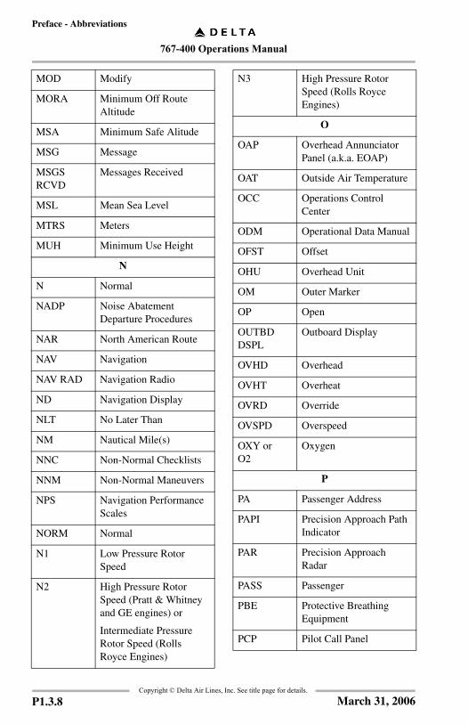
MOD Modify
MORA Minimum Off Route Altitude
MSA Minimum Safe Alitude
MSG Message
MSGS RCVD
Messages Received
MSL Mean Sea Level
MTRS Meters
MUH Minimum Use Height
N
N Normal
NADP Noise Abatement Departure Procedures
NAR North American Route
NAV Navigation
NAV RAD Navigation Radio
ND Navigation Display
NLT No Later Than
NM Nautical Mile(s)
NNC Non-Normal Checklists
NNM Non-Normal Maneuvers
NPS Navigation Performance Scales
NORM Normal
N1 Low Pressure Rotor Speed
N2 High Pressure Rotor Speed (Pratt & Whitney and GE engines) or
Intermediate Pressure Rotor Speed (Rolls Royce Engines)
Copyright © Delta Air Lines,
P1.3.8
N3 High Pressure Rotor Speed (Rolls Royce Engines)
O
OAP Overhead Annunciator Panel (a.k.a. EOAP)
OAT Outside Air Temperature
OCC Operations Control Center
ODM Operational Data Manual
OFST Offset
OHU Overhead Unit
OM Outer Marker
OP Open
OUTBD DSPL
Outboard Display
OVHD Overhead
OVHT Overheat
OVRD Override
OVSPD Overspeed
OXY orO2
Oxygen
P
PA Passenger Address
PAPI Precision Approach Path Indicator
PAR Precision Approach Radar
PASS Passenger
PBE Protective Breathing Equipment
PCP Pilot Call Panel
Inc. See title page for details.
March 31, 2006

767-400 Operations Manual
Preface - Abbreviations
PDC Pitch Data Computeror
Performance Data Computeror
Pre-Departure Clearance
PERF Performance
PERF INIT Performance Initialization
PES Pitch Enhancement System
PF Pilot Flying
PFC Primary Flight Computer
PFD Primary Flight Display
PI Performance Inflight
PIP Product Improvement Package
PM Pilot Monitoring
PMC Power Management Control
PNL Panel
POS Position
POS INIT Position Initialization
POS REF Position Reference
PPI Planned Position Indicator
PPOS Present Position
PRES or PRESS
Pressure
PREV Previous
PRI Primary
PROG Progress
PROX Proximity
Copyright © Delta Air Lines,
March 31, 2006
P/RST Push To Reset
PRV Pressure Regulating Valve
PSI Pounds Per Square Inch
PTH Path
PTT Push To Talk
PTU Power Transfer Unit
PWR Power
PWS Predictive Windshear System
Q
Q Quantity
QFE Local Station Pressure
QNH Altimeter Setting
QRH Quick Reference Handbook
QTY Quantity
R
R Right
RA Radio Altitude or
Resolution Advisory
RAD Radio
RAT Ram Air Temperature orRam Air Turbine
RCL Request for Clearance
RDMI Radio Distance Magnetic Indicator
REC Recorder
RECIR or RECIRC
Recirculation
REF Reference
RET Retract
Inc. See title page for details.
P1.3.9

767-400 Operations Manual
Preface - Abbreviations
REV Reverse
RF Radius-to-Fix (RF) Legsor
Refill
RMI Radio Magnetic Indicator
RNAV orRNV
Area Navigation
RNP Required Navigational Performance
RPL Rudder Pressure Limiter
RPM Revolutions Per Minute
RPR Rudder Pressure Reducer
RSEP Rudder System Enhancement Program
RST Reset
RSVR Reservoir
R/T Radio Transmit
RTE Route
RTO Rejected Takeoff
RTP Radio Tuning Panel
RUD Rudder
RVR Runway Visual Range
RVSM Reduced Vertical Separation Minimum
S
SAARU Secondary Attitude Air Data Reference Unit
SAT Static Air Temperature
orSatellite
SB Service Bulletin
S/B Speedbrake
S/C Step Climb
Copyright © Delta Air Lines,
P1.3.10
Inc. See title page for details.SDF Simplified Directional Facility
SEI Standby Engine Indicator
SEL Select
SELCAL Selective Calling
SENS Sensitivity
SERV Service
SG Symbol Generator
SPD Speed
SPDBRK Speedbrake
STA Station
STAB Stabilizer
STAT Status
STBY Standby
STD Standard
SYS System
T
T or TRU True
T or TK or TRK
Track (to a Navaid)
TA Traffic Advisory
TAA Terminal Arrival Area
TACAN Tactical Air Navigation
TAC Thrust Asymmetry Compensation
TAI Thermal Anti–Ice
TAS True Airspeed
TAT Total Air Temperature
T/C Top of Climb
TCA Terminal Control Area
March 31, 2006
767-400 Operations Manual
Preface - Abbreviations
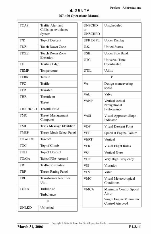
TCAS Traffic Alert and Collision Avoidance System
T/D Top of Descent
TDZ Touch Down Zone
TDZE Touch Down Zone Elevation
TE Trailing Edge
TEMP Temperature
TERR Terrain
TFC Traffic
TFR Transfer
THR Throttle or
Thrust
THR HOLD Throttle Hold
TMC Thrust Management Computer
TMI Track Message Identifier
TMSP Thrust Mode Select Panel
TO or T/O Takeoff
TOC Top of Climb
TOD Top of Descent
TO/GA Takeoff/Go–Around
TR Traffic Resolution
TRP Thrust Rating Panel
TRU Transformer Rectifier Unit
TURB Turbine or
Turbulence
U
UNLKD Unlocked
Copyright © Delta Air Lines,
March 31, 2006
UNSCHD or UNSCHED
Unscheduled
UPR DSPL Upper Display
U.S. United States
USB Upper Side Band
UTC Universal Time Coordinated
UTIL Utility
V
VA Design maneuvering speed
VAL Valve
VANP Vertical Actual Navigational Performance
VASI Visual Approach Slope Indicator
VDP Visual Descent Point
VEF Speed at Engine Failure
VERT Vertical
VFR Visual Flight Rules
VG Vertical Gyro
VHF Very High Frequency
VIB Vibration
VLV Valve
VMC Visual Meteorological Conditions
VMCA Minimum Control Speed Air or
Single Engine Minumum Control Airspeed
Inc. See title page for details.
P1.3.11

767-400 Operations Manual
Preface - Abbreviations
VMCG Minimum Control Speed Ground
VMO Maximum Operating Speed
V NAV or VNAV
Vertical Navigation
VOR VHF Omnidirectional Range
VR Rotation Speed
VREF Reference Speed
VRNP Vertical Required Navigation Performance
V/S Vertical Speed
VSCF Variable Speed Constant Frequency
VSD Vertical Situation Display
VSI Vertical Speed Indicator
VTK Vertical Track
V1 Takeoff Decision Speed
V1 (MCG) Minimum V1 for Control on the Ground
V2 Scheduled Takeoff Target Speed
W
W Warm
WATRS Western Atlantic Route System
WDR Weight Data Record
WGS-84 World Geodetic System of 1984
WHL Wheel
WPT Waypoint
WT Weight
Copyright © Delta Air Lines,
P1.3.12
WXR Weather Radar
X
X–FEED Crossfeed
XPDR or XPNDR
Transponder
XTK Cross Track
Inc. See title page for details.
March 31, 2006
767-400 Operations Manual
Preface Chapter P1Revision Record Section 4
FCO
M T
empl
ate
12/1
2/98
Copyright © Delta Air Lines, Inc. See title page for details.
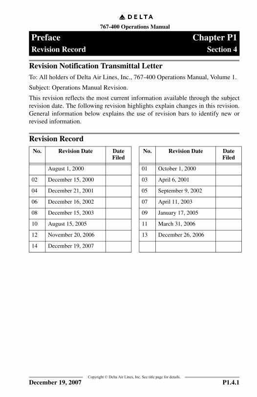
Revision Notification Transmittal LetterTo: All holders of Delta Air Lines, Inc., 767-400 Operations Manual, Volume 1.
Subject: Operations Manual Revision.
This revision reflects the most current information available through the subjectrevision date. The following revision highlights explain changes in this revision.General information below explains the use of revision bars to identify new orrevised information.
Revision Record
No. Revision Date Date Filed
No. Revision Date Date Filed
August 1, 2000 01 October 1, 2000
02 December 15, 2000 03 April 6, 2001
04 December 21, 2001 05 September 9, 2002
06 December 16, 2002 07 April 11, 2003
08 December 15, 2003 09 January 17, 2005
10 August 15, 2005 11 March 31, 2006
12 November 20, 2006 13 December 26, 2006
14 December 19, 2007
P1.4.1December 19, 2007
767-400 Operations Manual
Preface -Revision Record
Copyright © Delta Air Lines, Inc. See title page for details.
GeneralDelta Air Lines issues operations manual revisions to provide new or revisedprocedures and information. Formal revisions also incorporate appropriateinformation from previously issued Flight Crew Bulletins.
The revision date is the approximate date the revision material is distributed andconsidered current. The revision should be incorporated on the revision date, butmay be incorporated as much as 21 days after the revision date.
Formal revisions include a Transmittal Letter, a new Revision Record, RevisionHighlights, and a current List of Effective Pages. Use the information on the newRevision Record and List of Effective Pages to verify the operations manualcontent.
The Revision Record should be completed by the person incorporating the revisioninto the manual.
Filing InstructionsConsult the List of Effective Pages (P1.5). Pages identified with an asterisk (*) areeither replacement pages, new (original) issue pages, or deleted pages. Removecorresponding old pages and replace or add new pages. Remove pages markedDELETED; there are no replacement pages for deleted pages.
Be careful when inserting changes not to throw away pages from the manual thatare not replaced. The List of Effective Pages determines the correct content of themanual.
P1.4.2 December 19, 2007
767-400 Operations Manual
Preface -Model Identification
Copyright © Delta Air Lines, Inc. See title page for details.
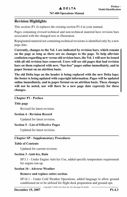
Revision HighlightsThis section (P1.4) replaces the existing section P1.4 in your manual.
Pages containing revised technical and non-technical material have revision barsassociated with the changed text or illustration.
Repaginated material not containing technical revisions is identified only by a newpage date.
Currently, changes to the Vol. 1 are indicated by revision bars, which remainon the page as long as there are no changes to the page. To help alleviateconfusion regarding new versus old revision bars, the Vol. 1 will now be issuedwith all old revision bars removed. Users will see old pages that had revisionbars on them replaced with new, “bar-less” pages online immediately, and inpaper format on an attrition basis.
The old Delta logo on the header is being replaced with the new Delta logo;the footer is being updated with copyright information. Pages will be updatedonline immediately, and in paper format on an attrition basis. These changeswill not be noted, nor will there be a new page date expressly for thesechanges.
Chapter P1 - Preface
Title pageRevised for latest revision.
Section 4 - Revision RecordUpdated for latest revision.
Section 5 - List of Effective PagesUpdated for latest revision.
Chapter SP - Supplementary Procedures
Table of ContentsUpdated for current revision.
Section 3 -Anti-Ice, RainSP.3.1 - Under Engine Anti-Ice Use, added specific temperature requirementfor engine run-up.
Section 16 - Adverse WeatherRemove and replace entire section.SP.16.1 - Under Cold Weather Operations, added language to allow groundconditioned air to be utilized for flight deck preparation and ground ops.
P1.4.3December 19, 2007

767-400 Operations Manual
Preface -Revision Record
Copyright © Delta Air Lines, Inc. See title page for details.
SP.16.6 - Deleted wipers as a representative surface.SP.16.7 - Under Ground Icing Conditions, added snow pellets and heavy icepellets to WARNING for takeoff prohibited.SP.16.15 - Changed bullet to indicate that the ground de-icing crew is toperform the External Check.SP.16.16 - Under Cabin Check, deleted all caveats for takeoff in freezingdrizzle with Type I fluid; there is no holdover time for that combination.SP.16.16 - Changed bullet to indicate that the ground de-icing crew is toperform the External Check.SP.16.17 - Under External Check, split paragraph into two. In CAUTION,deleted all caveats for takeoff in freezing drizzle with Type I fluid; there is noholdover time for that combination.SP.16.20-21 - Under Holdover Times, added seventh category to bullet list,Ice pellets. Deleted sentence for holdover time being shortened in heavyweather conditions for clarity.SP.16.21-23 - Under Establishing Holdover Time, item 2, added data thatallows for pilot judgment of type and intensity of precipitation. Item 3, addedice pellets.SP.16.24 - Under Adjusting Holdover Time, added information for ice pellets.SP.16.24 - In table for Required Action When Holdover Time Exceeded,changed to show Takeoff Not Authorized for Freezing Drizzle with Type Ifluid.SP.16.25 - Added Note to reference Securing For Cold Weather procedures.SP.16.27-30 - Reformatted information on hardcards. In post de/anti-icingreport, added readback of current local time. In run-up table, movedtemperature requirement to initial statement; this applies to all engines andaircraft. In Takeoff Decision Tree, added box for ice pellets; in bullet 1,deleted wipers as representative surface. Renamed and revised SpecialConsiderations for Ice Pellets section. In Special Considerations for HeavySnow, clarified fluid concentration, and identified check as Cabin Check.Added table for Ice Pellet Holdover Times. Moved Type II and Type III tablesto new page. Modified times for Type IV, added reference to Ice Pellets table.SP.16.31 - Added new page. Caused text shift in remainder of chapter.SP.16.34 - Clarified comment, no technical change.
P1.4.4 December 19, 2007
767-400 Operations Manual
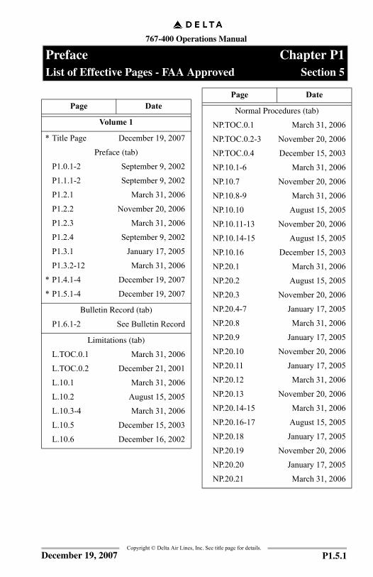
Preface Chapter P1List of Effective Pages - FAA Approved Section 5
Page Date
Volume 1
* Title Page December 19, 2007
Preface (tab)
P1.0.1-2 September 9, 2002
P1.1.1-2 September 9, 2002
P1.2.1 March 31, 2006
P1.2.2 November 20, 2006
P1.2.3 March 31, 2006
P1.2.4 September 9, 2002
P1.3.1 January 17, 2005
P1.3.2-12 March 31, 2006
* P1.4.1-4 December 19, 2007
* P1.5.1-4 December 19, 2007
Bulletin Record (tab)
P1.6.1-2 See Bulletin Record
Limitations (tab)
L.TOC.0.1 March 31, 2006
L.TOC.0.2 December 21, 2001
L.10.1 March 31, 2006
L.10.2 August 15, 2005
L.10.3-4 March 31, 2006
L.10.5 December 15, 2003
L.10.6 December 16, 2002
Normal Procedures (tab)
NP.TOC.0.1 March 31, 2006
NP.TOC.0.2-3 November 20, 2006
NP.TOC.0.4 December 15, 2003
NP.10.1-6 March 31, 2006
NP.10.7 November 20, 2006
NP.10.8-9 March 31, 2006
NP.10.10 August 15, 2005
NP.10.11-13 November 20, 2006
NP.10.14-15 August 15, 2005
NP.10.16 December 15, 2003
NP.20.1 March 31, 2006
NP.20.2 August 15, 2005
NP.20.3 November 20, 2006
NP.20.4-7 January 17, 2005
NP.20.8 March 31, 2006
NP.20.9 January 17, 2005
NP.20.10 November 20, 2006
NP.20.11 January 17, 2005
NP.20.12 March 31, 2006
NP.20.13 November 20, 2006
NP.20.14-15 March 31, 2006
NP.20.16-17 August 15, 2005
NP.20.18 January 17, 2005
NP.20.19 November 20, 2006
NP.20.20 January 17, 2005
NP.20.21 March 31, 2006
Page Date
Copyright © Delta Air Lines, Inc. See title page for details.P1.5.1December 19, 2007

767-400 Operations Manual
Preface -List of Effective Pages - FAA Approved
Normal procedures (tab)(cont.)
NP.20.22 November 20, 2006
NP.20.23 January 17, 2005
NP.20.24 August 15, 2005
NP.20.25 March 31, 2006
NP.20.26-27 August 15, 2005
NP.20.28-29 November 20, 2006
NP.20.30-33 March 31, 2006
NP.20.34-35 November 20, 2006
NP.20.36 March 31, 2006
NP.20.37 November 20, 2006
NP.20.38 August 15, 2005
NP.20.39 January 17, 2005
NP.20.40-42 August 15, 2005
NP.20.43-44 March 31, 2006
NP.20.45 January 17, 2005
NP.20.46-48 March 31, 2006
NP.20.49-52 November 20, 2006
NP.30.1 January 17, 2005
NP.30.2-3 September 9, 2002
NP.30.4 April 11, 2003
NP.30.5-12 March 31, 2006
NP.30.13-14 November 20, 2006
NP.30.15-20 March 31, 2006
Page Date
Copyright © Delta Air Lines,P1.5.2
Supplementary Procedures (tab)
SP.TOC.0.1 December 26, 2006
SP.TOC.0.2-3 November 20, 2006
SP.TOC.0.4 March 31, 2006
SP.TOC.0.5 December 26, 2006
* SP.TOC.0.6-7 December 19, 2007
SP.TOC.0.8 August 15, 2005
SP.05.1 March 31, 2006
SP.05.2 August 1, 2000
SP.1.1 November 20, 2006
SP.1.2 March 31, 2006
SP.1.3-5 December 26, 2006
SP.1.6 November 20, 2006
SP.2.1 November 20, 2006
SP.2.2 December 15, 2003
* SP.3.1-2 December 19, 2007
SP.4.1 August 1, 2000
SP.4.2-3 January 17, 2005
SP.4.4 April 6, 2001
SP.4.5-11 August 15, 2005
SP.4.12 March 31, 2006
SP.5.1-2 August 15, 2005
SP.5.3-8 March 31, 2006
SP.5.9 November 20, 2006
SP.5.10-14 March 31, 2006
SP.5.15 November 20, 2006
SP.5.16-36 March 31, 2006
Page Date
Inc. See title page for details.December 19, 2007

767-400 Operations Manual
Preface -List of Effective Pages -
FAA Approved
Copyright © Delta Air Lines, Inc. See title page for details.
Supplementary Procedures (tab)(cont.)
SP.6.1-3 December 15, 2003
SP.6.4 October 1, 2000
SP.7.1 March 31, 2006
SP.7.2-6 August 15, 2005
SP.8.1 January 17, 2005
SP.8.2 August 1, 2000
SP.10.1-2 March 31, 2006
SP.11.1-3 March 31, 2006
SP.11.4-9 August 15, 2005
SP.11.10 November 20, 2006
SP.11.11-28 August 15, 2005
SP.12.1 March 31, 2006
SP.12.2 August 1, 2000
SP.15.1-4 March 31, 2006
* SP.16.1-40 December 19, 2007
Page Date
P1.5.3December 19, 2007

767-400 Operations Manual
Preface -List of Effective Pages - FAA Approved
Copyright © Delta Air Lines, Inc. See title page for details.
IntentionallyBlank
P1.5.4 December 19, 2007
767-400 Operations Manual
Limitations Chapter LTable of Contents Section 0
FCO
M T
empl
ate
12/1
2/98
Copyright © Delta Air Lines, Inc. See title page for details.
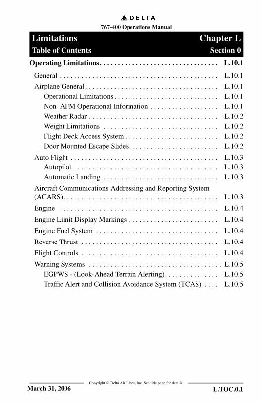
Operating Limitations. . . . . . . . . . . . . . . . . . . . . . . . . . . . . . . . . L.10.1
General . . . . . . . . . . . . . . . . . . . . . . . . . . . . . . . . . . . . . . . . . . . . L.10.1
Airplane General . . . . . . . . . . . . . . . . . . . . . . . . . . . . . . . . . . . . . L.10.1Operational Limitations . . . . . . . . . . . . . . . . . . . . . . . . . . . . . L.10.1Non–AFM Operational Information . . . . . . . . . . . . . . . . . . . L.10.1Weather Radar . . . . . . . . . . . . . . . . . . . . . . . . . . . . . . . . . . . . L.10.2Weight Limitations . . . . . . . . . . . . . . . . . . . . . . . . . . . . . . . . L.10.2Flight Deck Access System . . . . . . . . . . . . . . . . . . . . . . . . . . L.10.2Door Mounted Escape Slides. . . . . . . . . . . . . . . . . . . . . . . . . L.10.2
Auto Flight . . . . . . . . . . . . . . . . . . . . . . . . . . . . . . . . . . . . . . . . . L.10.3Autopilot . . . . . . . . . . . . . . . . . . . . . . . . . . . . . . . . . . . . . . . . L.10.3Automatic Landing . . . . . . . . . . . . . . . . . . . . . . . . . . . . . . . . L.10.3
Aircraft Communications Addressing and Reporting System(ACARS). . . . . . . . . . . . . . . . . . . . . . . . . . . . . . . . . . . . . . . . . . . L.10.3
Engine . . . . . . . . . . . . . . . . . . . . . . . . . . . . . . . . . . . . . . . . . . . . L.10.4
Engine Limit Display Markings . . . . . . . . . . . . . . . . . . . . . . . . . L.10.4
Engine Fuel System . . . . . . . . . . . . . . . . . . . . . . . . . . . . . . . . . . L.10.4
Reverse Thrust . . . . . . . . . . . . . . . . . . . . . . . . . . . . . . . . . . . . . . L.10.4
Flight Controls . . . . . . . . . . . . . . . . . . . . . . . . . . . . . . . . . . . . . . L.10.4
Warning Systems . . . . . . . . . . . . . . . . . . . . . . . . . . . . . . . . . . . . . L.10.5EGPWS - (Look-Ahead Terrain Alerting). . . . . . . . . . . . . . . L.10.5Traffic Alert and Collision Avoidance System (TCAS) . . . . L.10.5
L.TOC.0.1March 31, 2006

767-400 Operations Manual
Limitations -Table of Contents
Copyright © Delta Air Lines, Inc. See title page for details.
IntentionallyBlank
L.TOC.0.2 Draft

767-400 Operations Manual
Limitations Chapter LOperating Limitations Section 10
FCO
M T
empl
ate
12/1
2/98
Copyright © Delta Air Lines, Inc. See title page for details.
GeneralThis chapter contains limitations on aircraft and systems operation pertinent toflight crew operation of the aircraft. It is not intended to include items peculiar toaircraft certification data, or information peculiar to other manuals on board theaircraft.
767-400 aircraft must be operated in compliance with Certificate Limitations ofthe applicable FAA Approved Airplane Flight Manual and the MinimumEquipment List contained in the Mechanical Dispatch Manual (MDM).
Note: The symbol (#) indicates recall limitations. Recall limitations are those operationally significant limitations that must be committed to memory. Memorization is necessary because there are no placards, display indications, or markings indicating a limitation exists.
Airplane General
Operational Limitations
Non–AFM Operational Information
Note: The following items are not AFM limitations, but are provided for flight crew information.
# Turbulent air penetration speed is: 290 KIAS /.78 Mach, whichever is lower.
# The maximum takeoff and landing crosswind for normal operations is 29 knots.
# Runway slope +/- 2%
# Maximum Operating Altitude 43,100 feet pressure altitude
# Maximum Takeoff and Landing Altitude 8,400 feet pressure altitude
# Maximum Takeoff and Landing Tailwind Component
10 knots, or as permitted by Delta 10-0 special pages
L.10.1March 31, 2006
767-400 Operations Manual
Limitations -Operating Limitations
Copyright © Delta Air Lines, Inc. See title page for details.
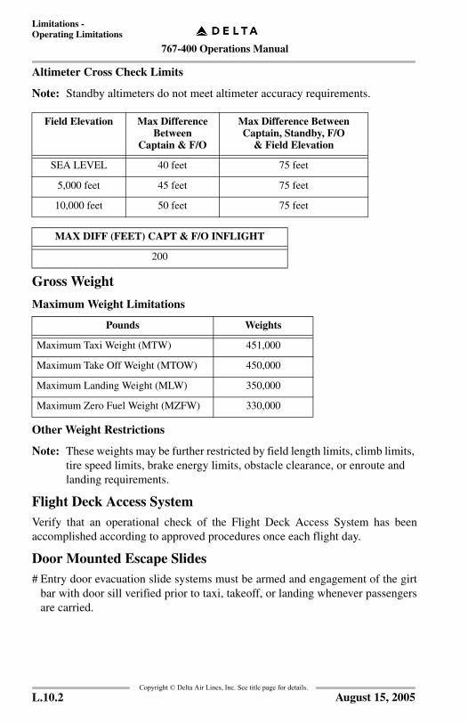
Altimeter Cross Check Limits
Note: Standby altimeters do not meet altimeter accuracy requirements.
Gross Weight
Maximum Weight Limitations
Other Weight Restrictions
Note: These weights may be further restricted by field length limits, climb limits, tire speed limits, brake energy limits, obstacle clearance, or enroute and landing requirements.
Flight Deck Access SystemVerify that an operational check of the Flight Deck Access System has beenaccomplished according to approved procedures once each flight day.
Door Mounted Escape Slides# Entry door evacuation slide systems must be armed and engagement of the girt
bar with door sill verified prior to taxi, takeoff, or landing whenever passengersare carried.
Field Elevation Max Difference Between
Captain & F/O
Max Difference BetweenCaptain, Standby, F/O
& Field Elevation
SEA LEVEL 40 feet 75 feet
5,000 feet 45 feet 75 feet
10,000 feet 50 feet 75 feet
MAX DIFF (FEET) CAPT & F/O INFLIGHT
200
Pounds Weights
Maximum Taxi Weight (MTW) 451,000
Maximum Take Off Weight (MTOW) 450,000
Maximum Landing Weight (MLW) 350,000
Maximum Zero Fuel Weight (MZFW) 330,000
L.10.2 August 15, 2005
767-400 Operations Manual
Limitations -Operating Limitations
Copyright © Delta Air Lines, Inc. See title page for details.
Auto Flight
Autopilot# After takeoff, the autopilot must not be engaged below 200 feet AGL.
# Use of aileron trim with the autopilot engaged is prohibited.
The autopilot must be disengaged before the airplane descends more than 50 feetbelow the MDA unless it is coupled to an ILS glideslope and localizer, or in thego-around mode.
When coupled to an ILS glideslope and localizer without LAND 2 or LAND 3annunciated, the autopilot must be disengaged below 100 feet radio altitude.
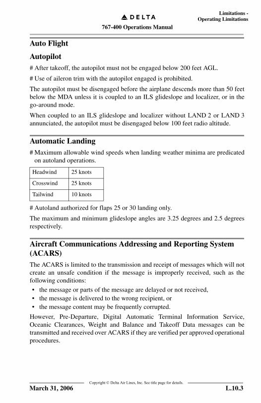
Automatic Landing# Maximum allowable wind speeds when landing weather minima are predicated
on autoland operations.
# Autoland authorized for flaps 25 or 30 landing only.
The maximum and minimum glideslope angles are 3.25 degrees and 2.5 degreesrespectively.
Aircraft Communications Addressing and Reporting System (ACARS)The ACARS is limited to the transmission and receipt of messages which will notcreate an unsafe condition if the message is improperly received, such as thefollowing conditions:
• the message or parts of the message are delayed or not received,• the message is delivered to the wrong recipient, or• the message content may be frequently corrupted.
However, Pre-Departure, Digital Automatic Terminal Information Service,Oceanic Clearances, Weight and Balance and Takeoff Data messages can betransmitted and received over ACARS if they are verified per approved operationalprocedures.
Headwind 25 knots
Crosswind 25 knots
Tailwind 10 knots
L.10.3March 31, 2006
767-400 Operations Manual
Limitations -Operating Limitations
Copyright © Delta Air Lines, Inc. See title page for details.
Engine # Continuous ignition must be on (engine start selector in the CONT position)
while operating in severe turbulence.
Note: Continuous ignition is automatically provided in icing conditions when engine anti–ice is on and when flaps are extended for takeoff and landing.
Engine Limit Display MarkingsMaximum and minimum limits are red.
Caution limits are amber.
Engine Fuel System# The use of Jet B and JP4 fuel is prohibited.
# The maximum fuel temperature is 49°C (120°F).
# The maximum fuel imbalance for dispatch is 1,500 pounds.
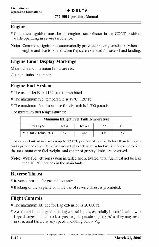
The minimum fuel temperature is:
The center tank may contain up to 22,050 pounds of fuel with less than full maintanks provided center tank fuel weight plus actual zero fuel weight does not exceedthe maximum zero fuel weight, and center of gravity limits are observed.
Note: With fuel jettison system installed and activated, total fuel must not be less than 10, 300 pounds in the main tanks.
Reverse Thrust# Reverse thrust is for ground use only.
# Backing of the airplane with the use of reverse thrust is prohibited.
Flight Controls# The maximum altitude for flap extension is 20,000 ft.
# Avoid rapid and large alternating control inputs, especially in combination withlarge changes in pitch, roll, or yaw (e.g. large side slip angles) as they may resultin structural failure at any speed, including below VA.
Minimum Inflight Fuel Tank Temperature
Fuel Type Jet A Jet A1 JP 5 TS 1
Min Tank Temp (°C) -37° -44° -43° -57°
L.10.4 March 31, 2006

767-400 Operations Manual
Limitations -Operating Limitations
Copyright © Delta Air Lines, Inc. See title page for details.
Warning Systems
Enhanced Ground Proximity Warning System (EGPWS)Do not use the terrain display for navigation.
The use of terrain awareness alerting and terrain display functions are prohibitedduring QFE operations.
The use of terrain awareness alerting and terrain display functions is prohibitedwithin 15 NM of takeoff, approach or landing at an airport not contained in theEGPWS terrain database. For runways/airports not contained in the installedEGPWS terrain data base, crews will be notified via EFCB and flight plan remarks.
Traffic Alert and Collision Avoidance System (TCAS)Pilots are authorized to deviate from their current ATC clearance to the extentnecessary to comply with a TCAS resolution advisory.
L.10.5December 15, 2003

767-400 Operations Manual
Limitations -Operating Limitations
Copyright © Delta Air Lines, Inc. See title page for details.
IntentionallyBlank
L.10.6 December 16, 2002

767-400 Operations Manual
Normal Procedures Chapter NPTable of Contents Section 0
FCO
M T
empl
ate
12/1
2/98
Copyright © Delta Air Lines, Inc. See title page for details.
Introduction . . . . . . . . . . . . . . . . . . . . . . . . . . . . . . . . . . . . . . . . NP.10.1
General . . . . . . . . . . . . . . . . . . . . . . . . . . . . . . . . . . . . . . . . . . . NP.10.1Controls and Indicators – Nomenclature . . . . . . . . . . . . . . . NP.10.1
Normal Procedures . . . . . . . . . . . . . . . . . . . . . . . . . . . . . . . . . . NP.10.1Autopilot Flight Director System and Flight Management System Monitoring . . . . . . . . . . . . . . . . . . . . NP.10.3RVSM Operations and System Requirements . . . . . . . . . . . NP.10.3CDU Operation . . . . . . . . . . . . . . . . . . . . . . . . . . . . . . . . . . NP.10.3
Crew Duties Reference Chart . . . . . . . . . . . . . . . . . . . . . . . . . . NP.10.4
ILS Airborne Equipment Requirements . . . . . . . . . . . . . . . . . . NP.10.9
Standard Callouts . . . . . . . . . . . . . . . . . . . . . . . . . . . . . . . . . . NP.10.10
Preflight and Postflight Panel Flow . . . . . . . . . . . . . . . . . . . . NP.10.14
Pilot Flying and Pilot Monitoring Areas ofResponsibility . . . . . . . . . . . . . . . . . . . . . . . . . . . . . . . . . . . . . NP.10.15
Amplified Procedures . . . . . . . . . . . . . . . . . . . . . . . . . . . . . . . . NP.20.1
First Flight Of The Day/ETOPS Items . . . . . . . . . . . . . . . . . . . NP.20.1
Exterior Inspection . . . . . . . . . . . . . . . . . . . . . . . . . . . . . . . . . . NP.20.2Walkaround . . . . . . . . . . . . . . . . . . . . . . . . . . . . . . . . . . . . . . NP.20.3
Preflight Procedure . . . . . . . . . . . . . . . . . . . . . . . . . . . . . . . . . NP.20.8
Before Start Procedure . . . . . . . . . . . . . . . . . . . . . . . . . . . . . . NP.20.26
Pushback/Start Procedure . . . . . . . . . . . . . . . . . . . . . . . . . . . . NP.20.28
Engine Start Procedure . . . . . . . . . . . . . . . . . . . . . . . . . . . . . . NP.20.30
After Start Procedure . . . . . . . . . . . . . . . . . . . . . . . . . . . . . . . NP.20.31
Taxi Procedure . . . . . . . . . . . . . . . . . . . . . . . . . . . . . . . . . . . . NP.20.32
Delayed Start Procedure . . . . . . . . . . . . . . . . . . . . . . . . . . . . . NP.20.33
Before Takeoff Procedure . . . . . . . . . . . . . . . . . . . . . . . . . . . . NP.20.34
Takeoff Procedure . . . . . . . . . . . . . . . . . . . . . . . . . . . . . . . . . . NP.20.36
After Takeoff Procedure . . . . . . . . . . . . . . . . . . . . . . . . . . . . . NP.20.37
Climb Procedure . . . . . . . . . . . . . . . . . . . . . . . . . . . . . . . . . . . NP.20.38
NP.TOC.0.1March 31, 2006
767-400 Operations Manual
Normal Procedures -Table of Contents
Copyright © Delta Air Lines, Inc. See title page for details.
Cruise Procedure . . . . . . . . . . . . . . . . . . . . . . . . . . . . . . . . . . . NP.20.38
Descent Procedure . . . . . . . . . . . . . . . . . . . . . . . . . . . . . . . . . . NP.20.40
Approach Procedure . . . . . . . . . . . . . . . . . . . . . . . . . . . . . . . . NP.20.42
Landing Procedure. . . . . . . . . . . . . . . . . . . . . . . . . . . . . . . . . . NP.20.42
Go–Around and Missed Approach Procedure. . . . . . . . . . . . . NP.20.43
Landing Roll Procedure. . . . . . . . . . . . . . . . . . . . . . . . . . . . . . NP.20.44
After Landing Procedure . . . . . . . . . . . . . . . . . . . . . . . . . . . . . NP.20.46
Shutdown Procedure . . . . . . . . . . . . . . . . . . . . . . . . . . . . . . . . NP.20.48
Secure Procedure . . . . . . . . . . . . . . . . . . . . . . . . . . . . . . . . . . . NP.20.51
Flight Patterns . . . . . . . . . . . . . . . . . . . . . . . . . . . . . . . . . . . . . . NP.30.1
Flight Pattern Principles . . . . . . . . . . . . . . . . . . . . . . . . . . . . . . NP.30.1
Takeoff Considerations . . . . . . . . . . . . . . . . . . . . . . . . . . . . . . . NP.30.1LNAV Used for Departure . . . . . . . . . . . . . . . . . . . . . . . . . . NP.30.1
Stabilized Approach Requirements . . . . . . . . . . . . . . . . . . . . . . NP.30.2IMC . . . . . . . . . . . . . . . . . . . . . . . . . . . . . . . . . . . . . . . . . . . NP.30.2VMC. . . . . . . . . . . . . . . . . . . . . . . . . . . . . . . . . . . . . . . . . . . NP.30.2Crossing the Runway Threshold . . . . . . . . . . . . . . . . . . . . . NP.30.3
ILS Precision Runway Monitor (PRM) Approach -Breakout Procedure . . . . . . . . . . . . . . . . . . . . . . . . . . . . . . . . . . NP.30.4
ILS Approach Procedures . . . . . . . . . . . . . . . . . . . . . . . . . . . . . NP.30.4
Low Visibility Approach Considerations (CAT II/CAT III) . . . NP.30.6CAT II Approach Considerations. . . . . . . . . . . . . . . . . . . . . NP.30.7CAT III Approach Considerations . . . . . . . . . . . . . . . . . . . . NP.30.7
Non-ILS Instrument Approach Considerations. . . . . . . . . . . . . NP.30.8Approach Preparations - General . . . . . . . . . . . . . . . . . . . . . NP.30.8
Visual Approach And Landing Considerations. . . . . . . . . . . . NP.30.12
NP.TOC.0.2 November 20, 2006

767-400 Operations Manual
Normal Procedures -Table of Contents
Copyright © Delta Air Lines, Inc. See title page for details.
Flight Profiles . . . . . . . . . . . . . . . . . . . . . . . . . . . . . . . . . . . . . NP.30.13Normal Takeoff Profile . . . . . . . . . . . . . . . . . . . . . . . . . . . . NP.30.13Special Takeoff Profile . . . . . . . . . . . . . . . . . . . . . . . . . . . . NP.30.14ILS Approach Profile. . . . . . . . . . . . . . . . . . . . . . . . . . . . . NP.30.15Instrument Approach Using VNAV Profile . . . . . . . . . . . . NP.30.16Instrument Approach Using V/S Profile . . . . . . . . . . . . . . NP.30.17Circling Approach Profile . . . . . . . . . . . . . . . . . . . . . . . . . NP.30.18Visual Traffic Pattern Profile . . . . . . . . . . . . . . . . . . . . . . . NP.30.19Go-Around and Missed Approach Profile . . . . . . . . . . . . . NP.30.20
NP.TOC.10.3November 20, 2006
767-400 Operations Manual
Normal Procedures -Table of Contents
Copyright © Delta Air Lines, Inc. See title page for details.
IntentionallyBlank
NP.TOC.0.4 December 15, 2003

767-400 Operations Manual
Normal Procedures Chapter NPIntroduction Section 10
FCO
M T
empl
ate
12/1
2/98
Copyright © Delta Air Lines, Inc. See title page for details.
GeneralThis chapter contains Normal Procedures. It incorporates routine normalprocedures and normal procedures associated with flight patterns.
Controls and Indicators – NomenclatureControls and indications appear in all UPPERCASE type to correspond to thewords on the control panel or display. For example, the following item hasUPPERCASE words to match what is found on the panel:
APU GENERATOR switch ................................................................ONThe word GENERATOR is spelled out, even though it is abbreviated on the panel.
The following appears in all lower case because there are no words identifying thepanel name:
Mode control panel ............................................................................. Set
Normal ProceduresNormal procedures are used by the trained flight crew to ensure airplane conditionis acceptable and that the flight deck is correctly configured for each phase offlight. These procedures assume all systems are operating normally and automatedfeatures are fully utilized. The procedures also assume that systems are notdeactivated unless directed by a procedure or required by an emergency situation.
Procedures are performed from recall and follow a panel flow. These proceduresare designed to minimize crew workload and are consistent with flight decktechnology. If the correct indication is not observed during accomplishment ofprocedures, verify controls are positioned correctly. If necessary, check theappropriate circuit breaker(s) and test the related system light(s).
Before engine start, lights or indications verify the systems’ condition orconfiguration. Review the EICAS status display before engine start to determineif messages are displayed which may affect dispatch and require maintenanceaction or compliance with the Minimum Equipment List (MEL).
Once dispatched (thrust levers advanced for takeoff), it is not necessary to checkstatus messages as any message having an adverse effect on safe continuation ofthe flight, and requiring crew attention, will appear as an EICAS alert message(warning, caution, or advisory).
NP.10.1March 31, 2006

767-400 Operations Manual
Normal Procedures -Introduction
Copyright © Delta Air Lines, Inc. See title page for details.
EICAS alert messages are the primary means of alerting the flight crew tonon–normal conditions or improper configuration. During engine start and prior totakeoff, any alert message requires accomplishment of the appropriate non–normalprocedure. Upon completion of the procedure and prior to takeoff, the MechanicalDispatch Manual (MDM) should be consulted to determine if MEL relief isavailable.
Exterior lighting, flight deck lighting, and personal comfort items (such asshoulder heaters) are systems assumed to have obvious procedural requirementsand are not addressed in this section.
General phase–of–flight responsibilities are as follows:
Pilot flying:
Pilot monitoring:
Phase–of–flight duties, beginning with the takeoff procedure and ending with thelanding roll procedure, are presented in table form in the appropriate proceduressection.
The First Officer, when flying the airplane, performs the duties listed under pilotflying and the Captain performs those duties listed under pilot monitoring.
Note: When the airplane is being flown manually, the pilot monitoring (PM) should update the mode control panel. However, the pilot flying (PF) may engage the autopilot and/or select/deselect the flight director and announce "autopilot on" or "my flight director is on/off."When the airplane is being flown with the autopilot on, the PF may update the mode control panel or direct the PM to do so.
The Captain retains final authority for all actions directed and performed.
• flight path and airspeed control• airplane configuration• navigation.
• checklist reading• communications• tasks requested by PF• fuel shutoff and fire switches
(with PF concurrence).
NP.10.2 March 31, 2006

767-400 Operations Manual
Normal Procedures -Introduction
Copyright © Delta Air Lines, Inc. See title page for details.
Autopilot Flight Director System and Flight Management System MonitoringWhen the autopilot, flight director, or autothrottle is in use and a mode change isselected or is scheduled to occur, the annunciation must be verified on the flightmode annunciation display. Airplane course, vertical path, and speed must alwaysbe monitored.
Similarly, when a thrust reference mode change is selected or is scheduled tooccur, the annunciation must be verified on the EICAS display.
In LNAV and VNAV, all airplane course, vertical path, thrust, and speed changesmust be verified.
RVSM Operations and System RequirementsRefer to the Airway Manual, Chapter 7, Navigation, Reduced Vertical SeparationMinimum (RVSM) section.
CDU OperationOn the ground, the control display unit (CDU) manipulations are normallyperformed by the PF and verified by the PM.
In flight, with the autopilot engaged, normally CDU entries are made by the PF andverified by the PM. With the autopilot not engaged, CDU entries are made by thePM with concurrence from the PF. CDU manipulations should be accomplishedprior to high workload periods such as departure, arrival, or holding. During highworkload periods, using autopilot modes such as heading select, flight levelchange, and speed intervention, along with the ND map and EFIS switches, maybe more efficient than entering complex route modifications into the CDU.
NP.10.3March 31, 2006
767-400 Operations Manual
Normal Procedures -Introduction
Copyright © Delta Air Lines, Inc. See title page for details.
Crew Duties Reference ChartThe Crew Duties Reference Chart below indicates normal divisions in pilot workload. This chart serves as a guide to help crew members coordinate their dutieswith regard to a typical flight.
• items not highlighted are required on every flight.• items highlighted with gray shading are required during class II navigation
only.• If operating in WATRS or class II airspace for one hour or less, the only
class II navigation duties required are those identified with (N).
The chart delineates areas in which a crew member must remain reasonablyproficient if crew coordination is to be maintained at an optimum level. Whenoperating with an additional First Officer, the Captain will designate one of theFirst Officers to perform relief pilot (RP) duties. When operating without anadditional First Officer, the F or PM will perform the duties listed for the RP. Theseare indicated by a bullet in parentheses (•). Special situations or unusualoccurrences may require some deviations from the charted duties; the Captainultimately makes that determination.
NP.10.4 March 31, 2006

767-400 Operations Manual
Normal Procedures -Introduction
Copyright © Delta Air Lines, Inc. See title page for details.
CREW DUTIES C F RP PF PM
FLIGHT PLANNING
Sign-in • • •
Confirm license, medical, ID, FCC license, passport, & visas (if req) are in possession & current
•
Brief F/O & RP •
Create flight folder contents • • •
Review flight plan: routing, remarks & alternates • • •
Review & brief weather information - departure, destination, enroute, alternates, NOTAMs, turbulence & winds charts (as appropriate)
(•) •
Verify Flight Plan with NARs & NAT message or check routing with P (H/L) 3 & 4 (as appropriate) • •
Prepare oceanic plotting chart (if required). Off airways, to/from Hawaii use P(H/L) 3/4
•
Verify oceanic plotting chart • •
Ensure flight folder delivered to aircraft •
FLIGHT DECK PREPARATION
Brief Flight Attendants •
Check aircraft log book • (•) •
Complete exterior & interior preflight (•) •
ACARS data/clocks UTC • •
Initialize & Align ADIRU •
Verify correct position initialization •
Log initialization coordinates on flight plan •
Departure ATIS (•) •
Perform altimeter crosscheck • •
Load routing, performance, winds & climb profile into FMS
•
Load ETPs & diversion airport(s) into Rte 2 •
Continued on next page
NP.10.5March 31, 2006
767-400 Operations Manual
Normal Procedures -Introduction
Copyright © Delta Air Lines, Inc. See title page for details.
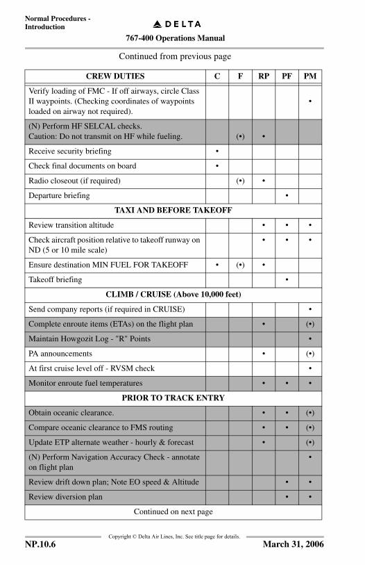
Continued from previous page
CREW DUTIES C F RP PF PM
Verify loading of FMC - If off airways, circle Class II waypoints. (Checking coordinates of waypoints loaded on airway not required).
•
(N) Perform HF SELCAL checks. Caution: Do not transmit on HF while fueling. (•) •
Receive security briefing •
Check final documents on board •
Radio closeout (if required) (•) •
Departure briefing •
TAXI AND BEFORE TAKEOFF
Review transition altitude • • •
Check aircraft position relative to takeoff runway on ND (5 or 10 mile scale)
• • •
Ensure destination MIN FUEL FOR TAKEOFF • (•) •
Takeoff briefing •
CLIMB / CRUISE (Above 10,000 feet)
Send company reports (if required in CRUISE) •
Complete enroute items (ETAs) on the flight plan • (•)
Maintain Howgozit Log - "R" Points •
PA announcements • (•)
At first cruise level off - RVSM check •
Monitor enroute fuel temperatures • • •
PRIOR TO TRACK ENTRY
Obtain oceanic clearance. • • (•)
Compare oceanic clearance to FMS routing • • (•)
Update ETP alternate weather - hourly & forecast • (•)
(N) Perform Navigation Accuracy Check - annotate on flight plan
•
Review drift down plan; Note EO speed & Altitude • •
Review diversion plan • •
Continued on next page
NP.10.6 March 31, 2006
767-400 Operations Manual
Normal Procedures -Introduction
Copyright © Delta Air Lines, Inc. See title page for details.
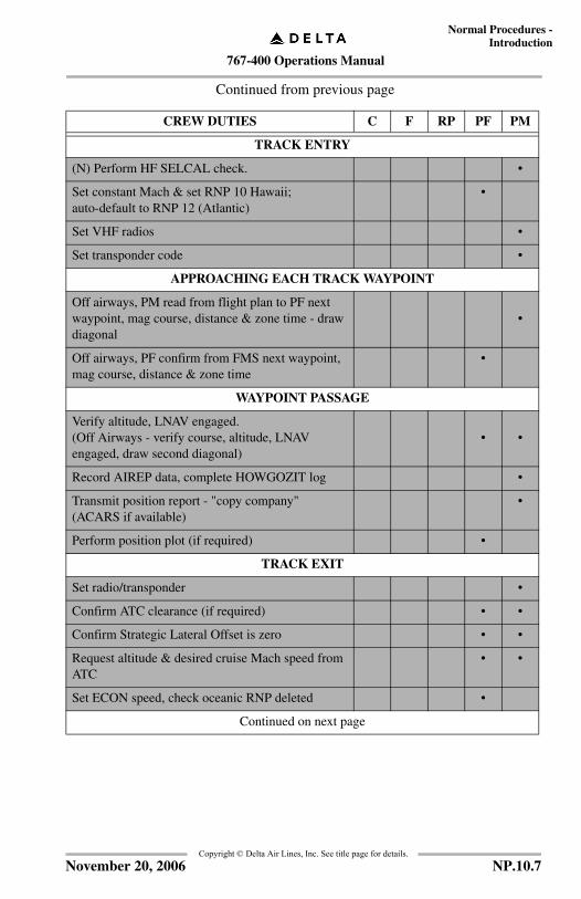
Continued from previous page
CREW DUTIES C F RP PF PM
TRACK ENTRY
(N) Perform HF SELCAL check. •
Set constant Mach & set RNP 10 Hawaii; auto-default to RNP 12 (Atlantic)
•
Set VHF radios •
Set transponder code •
APPROACHING EACH TRACK WAYPOINT
Off airways, PM read from flight plan to PF next waypoint, mag course, distance & zone time - draw diagonal
•
Off airways, PF confirm from FMS next waypoint, mag course, distance & zone time
•
WAYPOINT PASSAGE
Verify altitude, LNAV engaged. (Off Airways - verify course, altitude, LNAV engaged, draw second diagonal)
• •
Record AIREP data, complete HOWGOZIT log •
Transmit position report - "copy company" (ACARS if available)
•
Perform position plot (if required) •
TRACK EXIT
Set radio/transponder •
Confirm ATC clearance (if required) • •
Confirm Strategic Lateral Offset is zero • •
Request altitude & desired cruise Mach speed from ATC
• •
Set ECON speed, check oceanic RNP deleted •
Continued on next page
NP.10.7November 20, 2006
767-400 Operations Manual
Normal Procedures -Introduction
Copyright © Delta Air Lines, Inc. See title page for details.
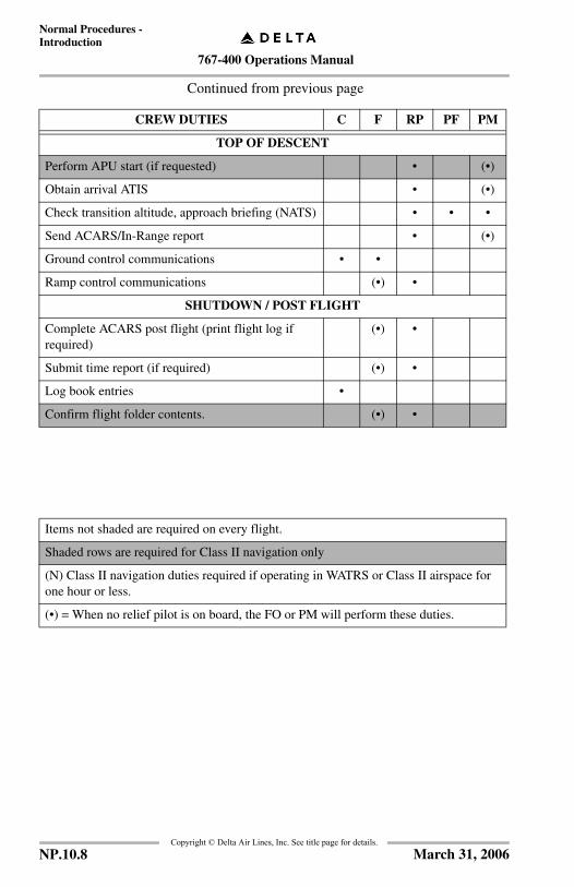
Continued from previous page
CREW DUTIES C F RP PF PM
TOP OF DESCENT
Perform APU start (if requested) • (•)
Obtain arrival ATIS • (•)
Check transition altitude, approach briefing (NATS) • • •
Send ACARS/In-Range report • (•)
Ground control communications • •
Ramp control communications (•) •
SHUTDOWN / POST FLIGHT
Complete ACARS post flight (print flight log if required)
(•) •
Submit time report (if required) (•) •
Log book entries •
Confirm flight folder contents. (•) •
Items not shaded are required on every flight.
Shaded rows are required for Class II navigation only
(N) Class II navigation duties required if operating in WATRS or Class II airspace for one hour or less.
(•) = When no relief pilot is on board, the FO or PM will perform these duties.
NP.10.8 March 31, 2006
767-400 Operations Manual
Normal Procedures -Introduction
Copyright © Delta Air Lines, Inc. See title page for details.
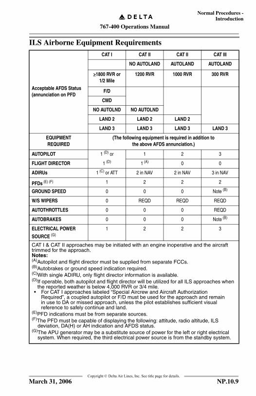
ILS Airborne Equipment Requirements
Acceptable AFDS Status(annunciation on PFD
CAT I CAT II CAT II CAT III
NO AUTOLAND AUTOLAND AUTOLAND
>1800 RVR or 1/2 Mile
1200 RVR 1000 RVR 300 RVR
F/D
CMD
NO AUTOLND NO AUTOLND
LAND 2 LAND 2 LAND 2
LAND 3 LAND 3 LAND 3 LAND 3
EQUIPMENTREQUIRED
(The following equipment is required in addition tothe above AFDS annunciation.)
AUTOPILOT 1 (D) or 1 2 3
FLIGHT DIRECTOR 1 (D) 1 (A) 0 0
ADIRUs 1 (C) or ATT 2 in NAV 2 in NAV 3 in NAV
PFDs (E) (F) 1 2 2 2
GROUND SPEED 0 0 0 Note (B)
W/S WIPERS 0 REQD REQD REQD
AUTOTHROTTLES 0 0 0 REQD
AUTOBRAKES 0 0 0 Note (B)
ELECTRICAL POWER
SOURCE (G)1 2 2 3
CAT I & CAT II approaches may be initiated with an engine inoperative and the aircraft trimmed for the approach.Notes:(A)Autopilot and flight director must be supplied from separate FCCs.(B)Autobrakes or ground speed indication required.(C)With single ADIRU, only flight director information is available.(D)If operable, both autopilot and flight director will be utilized for all ILS approaches when
the reported weather is below 4,000 RVR or 3/4 mile.• For CAT I approaches labeled “Special Aircrew and Aircraft Authorization
Required”, a coupled autopilot or F/D must be used for the approach and remain in use to DA or missed approach, unless the pilot establishes sufficient visual reference to safely continue and land.
(E)PFD indications must be from separate sources.(F)The PFD must be capable of displaying the following: attitude, radio altitude, ILS
deviation, DA(H) or AH indication and AFDS status.(G)The APU generator may be a substitute source of power for the left or right electrical
system. When required, the third electrical power source is from the standby system.
NP.10.9March 31, 2006

767-400 Operations Manual
Normal Procedures -Introduction
Copyright © Delta Air Lines, Inc. See title page for details.
Standard CalloutsThe callouts in the following chart are for normal line operations. During takeoffsand approaches the PM will call out flight mode annunciator progression.
Some callouts are made automatically by aircraft aural systems. When a requiredcallout is made automatically, it may be omitted by the appropriate crew member.
On any approach, when the Pilot Flying can maintain visual contact with therunway, the “Approaching Minimums” and “Minimums” callouts are not required.
The following callouts will be verbalized by the appropriate crew member.
PHASE OF FLIGHTCONDITION
CREWMEMBER
CALLOUTS
TAKEOFF
• At 80 KIAS when THR HOLD annunciated, if autothrottles used
• If autothrottles not used, THR HOLD will not be annunciated
PM “80 KNOTS, THROTTLE HOLD AND ENGINE INSTRUMENTS CHECKED”When PM announces “80 KNOTS”, the PF should silently verify that his airspeed indicator is operating properly
• At V1, VR and V2 PM Confirm automatic V1 callout or call “V1”- THEN CALL - “VR”- “V2”
• At positive rate of climb PM “POSITIVE RATE”
CLIMB
• 1,000 feet below each assigned altitude
PM “OUT OF ___ FOR ___”
• Approaching transition altitude
PM “ALTIMETERS SET TO STANDARD"
DESCENT
• 1,000 feet above each assigned altitude
PM “OUT OF ___ FOR ___”
• Approaching transition level PM “ALTIMETERS SET TO ___”
Continued on next page
NP.10.10 August 15, 2005

767-400 Operations Manual
Normal Procedures -Introduction
Copyright © Delta Air Lines, Inc. See title page for details.
TYPE OF APPROACH• CONDITION
CREWMEMBER
CALLOUTS
APPROACH AND LANDING
• Any significant deviation from planned flight path, airspeed or descent rate
PM “BUG ± ___KNOTS” or “SINK ____”, etc.
• At approximately 1,000 feet AGL
PM “1,000, CLEARED TO LAND” or
“1,000, NO LANDING CLEARANCE”
• At approximately 500 feet AGL
PM “500”
• Below 500 feet AGL:Any descent exceeding 1,000feet per minute
PM “SINK ___”
ALL INSTRUMENT APPROACHES
• PM will call out flight mode annunciator progression
PM “LOCALIZER CAPTURE”, “GLIDE SLOPE ARMED”, etc.
NON-ILS APPROACHES
• Within 5° of final approach course
PM “APPROACHING INBOUND COURSE”
• At approximately 1,000 feet AGL
PM “1,000, CLEARED TO LAND” or
“1,000, NO LANDING CLEARANCE”
• At approximately 500 feet AGL
PM "500"
• Approaching DA(H)/DDA(H)(approximately 80’ above minimums)
PM “APPROACHING MINIMUMS”
• At DA(H)/DDA(H) PM “MINIMUMS”
• When runway in sight PM “RUNWAY IN SIGHT”
• At missed approach point PM “MISSED APPROACH POINT”
• Prior to leaving DA(H)/DDA(H)
CAPT “APPROACH LIGHTS IN SIGHT”, or “RUNWAY IN SIGHT” or “MISSED APPROACH”
• F/O must acknowledge
Continued on next page
NP.10.11November 20, 2006
767-400 Operations Manual
Normal Procedures -Introduction
Copyright © Delta Air Lines, Inc. See title page for details.
TYPE OF APPROACH• CONDITION
CREWMEMBER
CALLOUTS
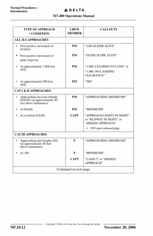
ALL ILS APPROACHES
• First positive movement of localizer
PM “LOCALIZER ALIVE”
• First positive movement of glide slope bar
PM “GLIDE SLOPE ALIVE”
• At approximately 1,000 feet AGL
PM “1,000, CLEARED TO LAND” or
“1,000, NO LANDING CLEARANCE”
• At approximately 500 feet AGL
PM "500"
CAT I & II APPROACHES
• Approaching decision altitude (DA(H)) (at approximately 80 feet above minimums)
PM “APPROACHING MINIMUMS”
• At DA(H) PM “MINIMUMS”
• At or before DA(H) CAPT “APPROACH LIGHTS IN SIGHT”, or “RUNWAY IN SIGHT” or “MISSED APPROACH”
• F/O must acknowledge
CAT III APPROACHES
• Approaching alert height (AH) (at approximately 80 feet above minimums)
F “APPROACHING MINIMUMS”
• At AH F “MINIMUMS”
CAPT “LAND 3” or “MISSED APPROACH”
Continued on next page
NP.10.12 November 20, 2006
767-400 Operations Manual
Normal Procedures -Introduction
Copyright © Delta Air Lines, Inc. See title page for details.
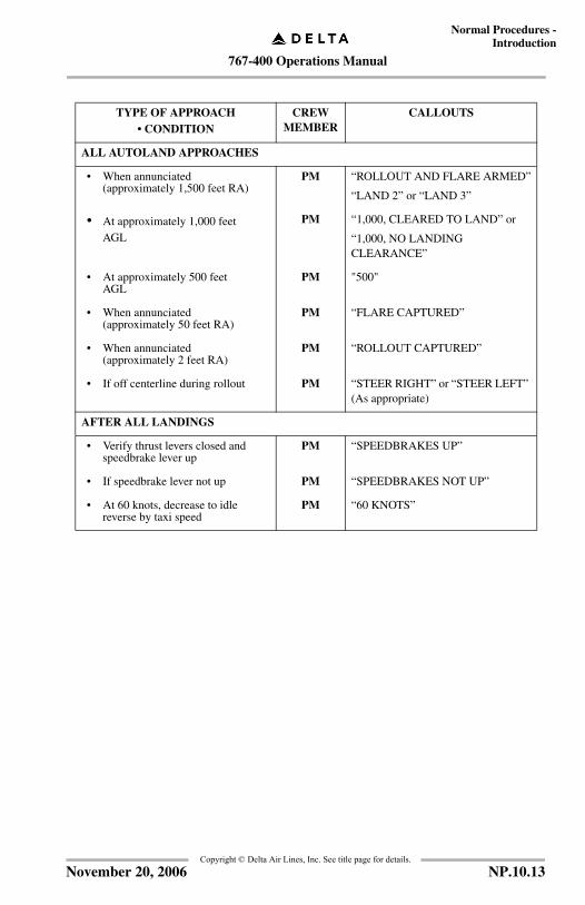
TYPE OF APPROACH• CONDITION
CREWMEMBER
CALLOUTS
ALL AUTOLAND APPROACHES
• When annunciated (approximately 1,500 feet RA)
PM “ROLLOUT AND FLARE ARMED”
“LAND 2” or “LAND 3”
• At approximately 1,000 feet AGL
PM “1,000, CLEARED TO LAND” or
“1,000, NO LANDING CLEARANCE”
• At approximately 500 feet AGL
PM "500"
• When annunciated (approximately 50 feet RA)
PM “FLARE CAPTURED”
• When annunciated (approximately 2 feet RA)
PM “ROLLOUT CAPTURED”
• If off centerline during rollout PM “STEER RIGHT” or “STEER LEFT” (As appropriate)
AFTER ALL LANDINGS
• Verify thrust levers closed and speedbrake lever up
PM “SPEEDBRAKES UP”
• If speedbrake lever not up PM “SPEEDBRAKES NOT UP”
• At 60 knots, decrease to idle reverse by taxi speed
PM “60 KNOTS”
NP.10.13November 20, 2006
767-400 Operations Manual
Normal Procedures -Introduction
Copyright © Delta Air Lines, Inc. See title page for details.
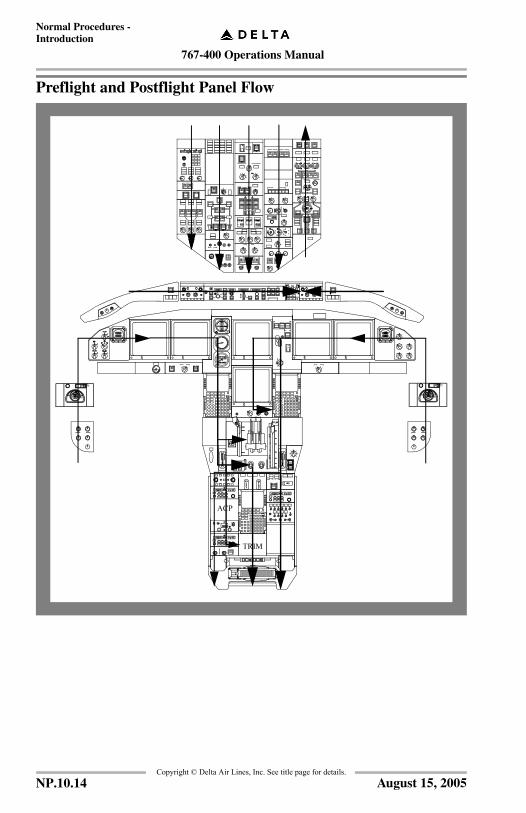
Preflight and Postflight Panel Flow
TRIM
ACP
RESETTEST
AEROSYSTEMS
EMER100%NORM
RESETTEST
AEROSYSTEMS
EMER100%NORM
NP.10.14 August 15, 2005
767-400 Operations Manual
Normal Procedures -Introduction
Copyright © Delta Air Lines, Inc. See title page for details.
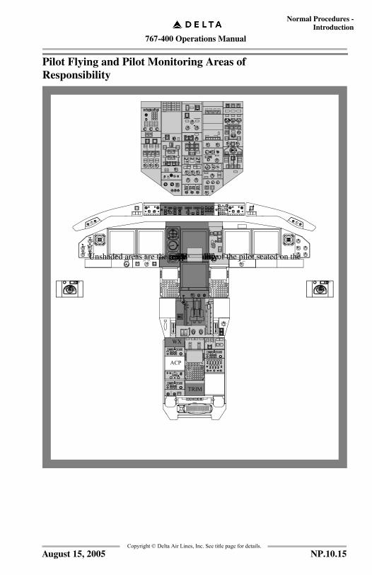
Pilot Flying and Pilot Monitoring Areas of Responsibility
WX
ACP
TRIM
respective side.Unshaded areas are the responsibility of the pilot seated on thePM area ofresponsibilityPF area ofresponsibility
RESETTEST
AEROSYSTEMS
EMER100%NORM
RESETTEST
AEROSYSTEMS
EMER100%NORM
NP.10.15August 15, 2005
767-400 Operations Manual
Normal Procedures -Introduction
Copyright © Delta Air Lines, Inc. See title page for details.
IntentionallyBlank
NP.10.16 December 15, 2003

767-400 Operations Manual
Normal Procedures Chapter NPAmplified Procedures Section 20
FCO
M T
empl
ate
12/1
2/98
Copyright © Delta Air Lines, Inc. See title page for details.
First Flight Of The Day/ETOPS Items
These checks need only be accomplished prior to the first flight each day(after midnight) local time or prior to ETOPS. If a system test is requiredand not procedurally covered in the expanded portion of the NORMALchecklist, see the appropriate section in this manual.
• FIRE WARNING
• STANDBY POWER
• GROUND PROXIMITY WARNING
• TCAS
• O2 MASK CHECK - OBSERVER POSITIONS
• FLIGHT DECK ACCESS SYSTEM
NP.20.1March 31, 2006

767-400 Operations Manual
Normal Procedures -Amplified Procedures
Copyright © Delta Air Lines, Inc. See title page for details.
Exterior InspectionA flight crew member shall make a complete exterior preflight inspection, reviewthe aircraft log book, and report any discrepancy to the Captain and toMaintenance as soon as possible. Emphasis should be placed on tire wear,airframe/control damage, or leaking fluids.
Prior to each flight, a flight crew member must verify the airplane is acceptable forflight. Check:
Flight control surfaces unobstructed and all surfaces clear of ice, snow, or frost.
Door and access panels (not in use) properly secured.
Ports and vents unobstructed.
Airplane free of damage and fluid leakage.
Wheel chocks in place, ground locking pins removed, and nose gear steering lever in the appropriate position.
Inspect tire. Notify Maintenance if there is:• Cord showing• A questionable cut• Any appearance of improper inflation• Any tread groove worn away completely around the tire.
Gear struts not fully compressed.
NP.20.2 August 15, 2005
767-400 Operations Manual
Normal Procedures -Amplified Procedures
Copyright © Delta Air Lines, Inc. See title page for details.
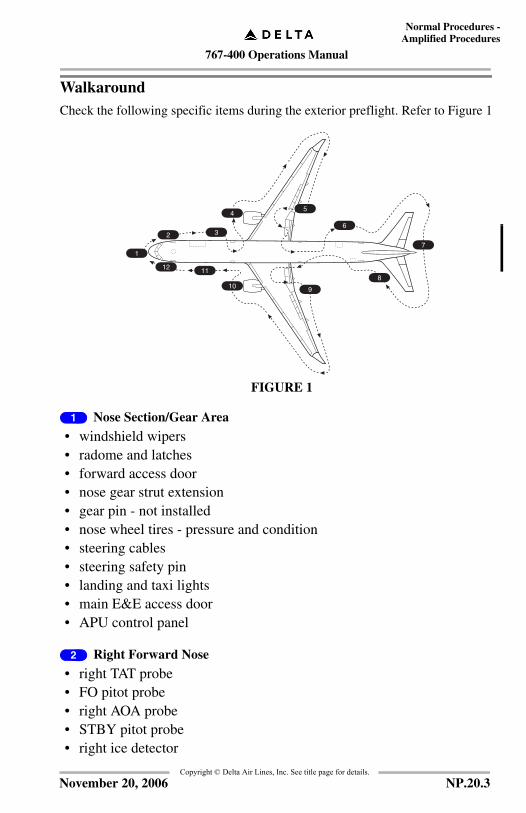
WalkaroundCheck the following specific items during the exterior preflight. Refer to Figure 1
1 Nose Section/Gear Area
• windshield wipers• radome and latches• forward access door• nose gear strut extension• gear pin - not installed• nose wheel tires - pressure and condition• steering cables• steering safety pin• landing and taxi lights• main E&E access door• APU control panel
2 Right Forward Nose
• right TAT probe• FO pitot probe• right AOA probe• STBY pitot probe• right ice detector
1
2 3
45
6
7
8
910
1112
FIGURE 1
NP.20.3November 20, 2006
767-400 Operations Manual
Normal Procedures -Amplified Procedures
Copyright © Delta Air Lines, Inc. See title page for details.
3 Right Forward Fuselage
• crew oxygen thermal discharge disc (green)• forward cargo door• negative pressure relief doors• static ports• pack air inlets and outlets• wing illumination light• antennas and red anti-collision light• ventilation ports
4 Right Wing Area And Engine
• landing light and turnoff light• engine strut and strake• thrust reverser and sleeve• cowlings and fasteners• fan blades• PT 2 probe• reverser blocker doors• aft fan blades• wing under surface area• leading edge slats• vortelons• fuel vent scoop• navigation lights (green)• strobe light• wing rakelets• static discharge wicks• fuel jettison nozzle• inboard and outboard ailerons• inboard and outboard flaps and fairings
NP.20.4 January 17, 2005
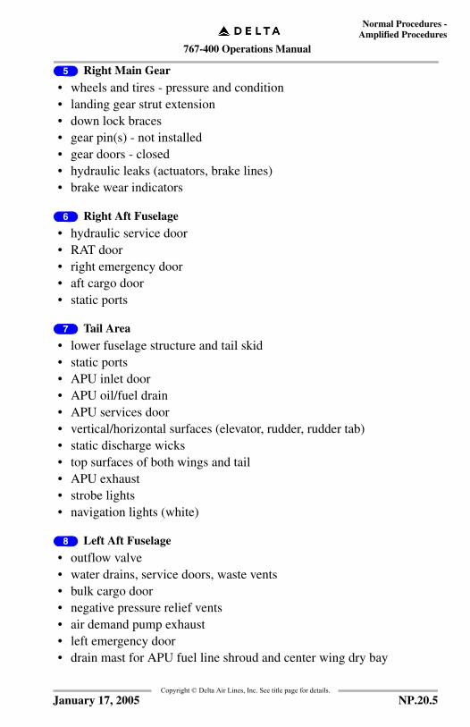
767-400 Operations Manual
Normal Procedures -Amplified Procedures
Copyright © Delta Air Lines, Inc. See title page for details.
5 Right Main Gear
• wheels and tires - pressure and condition• landing gear strut extension• down lock braces• gear pin(s) - not installed• gear doors - closed• hydraulic leaks (actuators, brake lines)• brake wear indicators
6 Right Aft Fuselage
• hydraulic service door• RAT door• right emergency door• aft cargo door• static ports
7 Tail Area
• lower fuselage structure and tail skid• static ports• APU inlet door• APU oil/fuel drain• APU services door• vertical/horizontal surfaces (elevator, rudder, rudder tab)• static discharge wicks• top surfaces of both wings and tail• APU exhaust• strobe lights• navigation lights (white)
8 Left Aft Fuselage
• outflow valve• water drains, service doors, waste vents• bulk cargo door• negative pressure relief vents• air demand pump exhaust• left emergency door• drain mast for APU fuel line shroud and center wing dry bay
NP.20.5January 17, 2005
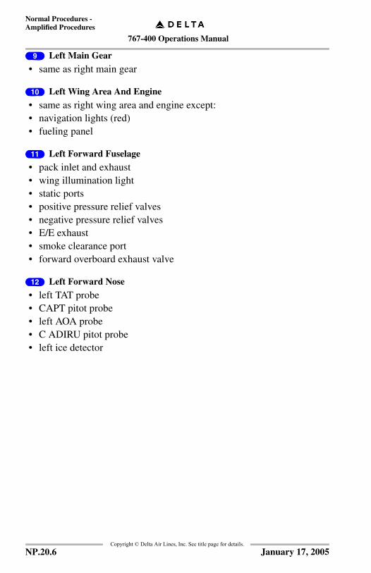
767-400 Operations Manual
Normal Procedures -Amplified Procedures
Copyright © Delta Air Lines, Inc. See title page for details.
9 Left Main Gear
• same as right main gear
10 Left Wing Area And Engine
• same as right wing area and engine except:• navigation lights (red)• fueling panel
11 Left Forward Fuselage
• pack inlet and exhaust• wing illumination light• static ports• positive pressure relief valves• negative pressure relief valves• E/E exhaust• smoke clearance port• forward overboard exhaust valve
12 Left Forward Nose
• left TAT probe• CAPT pitot probe• left AOA probe• C ADIRU pitot probe• left ice detector
NP.20.6 January 17, 2005
767-400 Operations Manual
Normal Procedures -Amplified Procedures
Copyright © Delta Air Lines, Inc. See title page for details.
IntentionallyBlank
NP.20.7January 17, 2005
767-400 Operations Manual
Normal Procedures -Amplified Procedures
Copyright © Delta Air Lines, Inc. See title page for details.
Preflight ProcedureFor a flight without flight attendants refer to SP.1.
Note: A full tank of potable water is required for all oceanic departures and the waste tanks should be checked empty.
This procedure assumes the supplementary power up procedure has beenaccomplished and electrical power is established. Refer to SP.6.
The following procedures are accomplished in their entirety on each originatingtrip or crew change, or following maintenance action.
Normally this procedure is accomplished by the First Officer. However, it does notpreclude the captain from completing the procedure if time and conditions dictate.
WARNING: If a red A/C Out-of-Service tag is installed, personnel are not to activate any system, control, switch, or circuit breaker without obtaining approval of Maintenance personnel (preferably the AMT actually performing the repairs).
Log book / Manuals .......................................................................Check
Check the aircraft log book to be familiar with the history and maintenance status of the aircraft.
• Ensure the Airworthiness Release has been signed by Maintenance.
• Ensure Pre-Departure Check is recorded prior to ETOPS departure.
• MCOs should be reviewed using the MEL to ensure compliance when special operating procedures are applicable.
• Check that QRH (2 copies), MDM, ARM, FRM, ODM, Engine Logbook, Offline Airway Manual (the "Brick"), and Operations Manual VOL 2 are on board.
• Check that Normal Checklist, International Conversion Card (if required for international operations), and Engine Out Driftdown Data Card are on board.
Effective dates of all checklists and manuals are found under the "current pubs" item in the sign-in menu.
Note: If in possession of a checklist dated later than in the computer system, use the later checklist on its effective date, pending computer system update.
NP.20.8 March 31, 2006
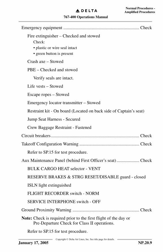
767-400 Operations Manual
Normal Procedures -Amplified Procedures
Copyright © Delta Air Lines, Inc. See title page for details.
Emergency equipment ................................................................... Check
Fire extinguisher – Checked and stowedCheck:
• plastic or wire seal intact
• green button is present
Crash axe – Stowed
PBE – Checked and stowed
Verify seals are intact.
Life vests – Stowed
Escape ropes – Stowed
Emergency locator transmitter – Stowed
Restraint kit - On board (Located on back side of Captain’s seat)
Jump Seat Harness - Secured
Crew Baggage Restraint - Fastened
Circuit breakers .............................................................................. Check
Takeoff Configuration Warning ..................................................... Check
Refer to SP.15 for test procedure.
Aux Maintenance Panel (behind First Officer’s seat) .................... Check
BULK CARGO HEAT selector - VENT
RESERVE BRAKES & STRG RESET/DISABLE guard - closed
ISLN light extinguished
FLIGHT RECORDER switch - NORM
SERVICE INTERPHONE switch - OFF
Ground Proximity Warning ........................................................... Check
Note: Check is required prior to the first flight of the day or Pre-Departure Check for Class II operations.
Refer to SP.15 for test procedure.
NP.20.9January 17, 2005
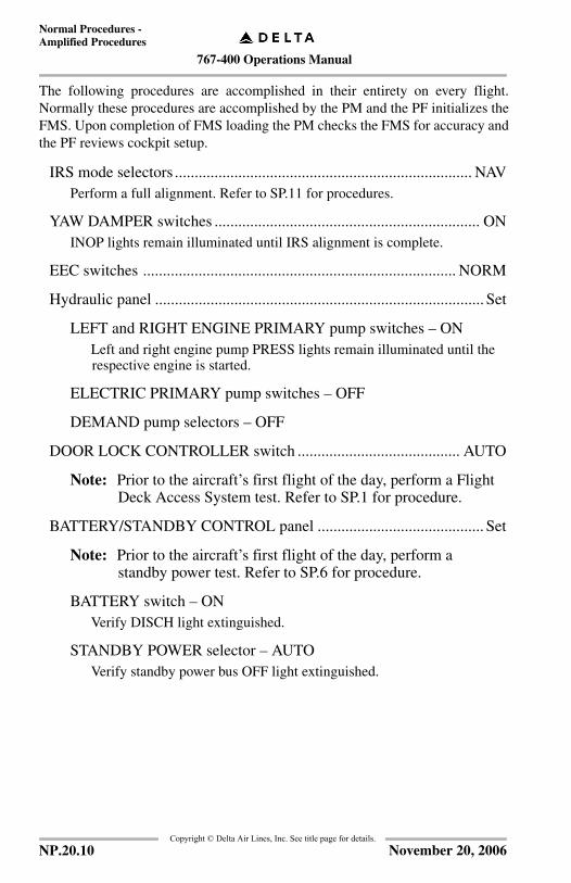
767-400 Operations Manual
Normal Procedures -Amplified Procedures
Copyright © Delta Air Lines, Inc. See title page for details.
The following procedures are accomplished in their entirety on every flight.Normally these procedures are accomplished by the PM and the PF initializes theFMS. Upon completion of FMS loading the PM checks the FMS for accuracy andthe PF reviews cockpit setup.
IRS mode selectors ........................................................................... NAVPerform a full alignment. Refer to SP.11 for procedures.
YAW DAMPER switches ................................................................... ONINOP lights remain illuminated until IRS alignment is complete.
EEC switches ............................................................................... NORM
Hydraulic panel ................................................................................... Set
LEFT and RIGHT ENGINE PRIMARY pump switches – ONLeft and right engine pump PRESS lights remain illuminated until the respective engine is started.
ELECTRIC PRIMARY pump switches – OFF
DEMAND pump selectors – OFF
DOOR LOCK CONTROLLER switch ......................................... AUTO
Note: Prior to the aircraft’s first flight of the day, perform a Flight Deck Access System test. Refer to SP.1 for procedure.
BATTERY/STANDBY CONTROL panel .......................................... Set
Note: Prior to the aircraft’s first flight of the day, perform a standby power test. Refer to SP.6 for procedure.
BATTERY switch – ONVerify DISCH light extinguished.
STANDBY POWER selector – AUTOVerify standby power bus OFF light extinguished.
NP.20.10 November 20, 2006
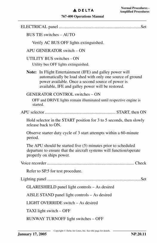
767-400 Operations Manual
Normal Procedures -Amplified Procedures
Copyright © Delta Air Lines, Inc. See title page for details.
ELECTRICAL panel ...........................................................................Set
BUS TIE switches – AUTO
Verify AC BUS OFF lights extinguished.
APU GENERATOR switch – ON
UTILITY BUS switches - ONUtility bus OFF lights extinguished.
Note: In Flight Entertainment (IFE) and galley power will automatically be load shed with only one source of ground power available. Once a second source of power is available, IFE and galley power will be restored.
GENERATOR CONTROL switches – ONOFF and DRIVE lights remain illuminated until respective engine is started.
APU selector ................................................................. START, then ON
Hold selector in the START position for 3 to 5 seconds, then slowly release back to ON.
Observe starter duty cycle of 3 start attempts within a 60-minute period.
The APU should be started five (5) minutes prior to scheduled departure to ensure that the aircraft systems will function/operate properly on ships power.
Voice recorder ................................................................................ Check
Refer to SP.5 for test procedure.
Lighting panel ......................................................................................Set
GLARESHIELD panel light controls – As desired
AISLE STAND panel light controls – As desired
LIGHT OVERRIDE switch – As desired
TAXI light switch – OFF
RUNWAY TURNOFF light switches – OFF
NP.20.11January 17, 2005

767-400 Operations Manual
Normal Procedures -Amplified Procedures
Copyright © Delta Air Lines, Inc. See title page for details.
EMERGENCY LIGHTS switch ................................................ARMED
Verify UNARMED light extinguished.
PASSENGER OXYGEN ON light ..................................... Extinguished
CAUTION: Switch activation causes deployment of passengeroxygen masks.
RAM AIR TURBINE UNLKD light .................................. Extinguished
WARNING: Switch activation may cause deployment of the ram air turbine.
ENGINE CONTROL panel ................................................................ Set
Engine ignition selector – SINGLE
Engine start selectors – AUTO
FUEL panel ......................................................................................... SetEnsure fueling is in progress or complete.
FUEL JETTISON – OFFLeft and Right FUEL JETTISON NOZZLE switches - OFF
CROSSFEED switches – OFFVerify VALVE lights extinguished.
FUEL PUMP switches – OFFLeft and right pump PRESS lights are illuminated.
Left forward pump PRESS light is extinguished if the APU is running.
Both center pump PRESS lights are extinguished.
Anti–ice panel ..................................................................................... Set
WING ANTI-ICE selector – OFF
ENGINE ANTI-ICE selectors – AUTO
WIPER selectors ...............................................................................OFF
NP.20.12 March 31, 2006
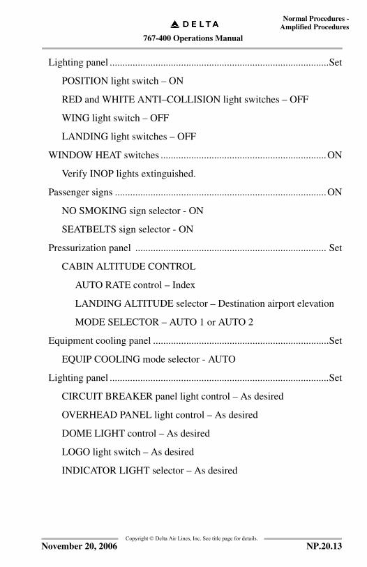
767-400 Operations Manual
Normal Procedures -Amplified Procedures
Copyright © Delta Air Lines, Inc. See title page for details.
Lighting panel ......................................................................................Set
POSITION light switch – ON
RED and WHITE ANTI–COLLISION light switches – OFF
WING light switch – OFF
LANDING light switches – OFF
WINDOW HEAT switches .................................................................ON
Verify INOP lights extinguished.
Passenger signs ...................................................................................ON
NO SMOKING sign selector - ON
SEATBELTS sign selector - ON
Pressurization panel ........................................................................... Set
CABIN ALTITUDE CONTROL
AUTO RATE control – Index
LANDING ALTITUDE selector – Destination airport elevation
MODE SELECTOR – AUTO 1 or AUTO 2
Equipment cooling panel .....................................................................Set
EQUIP COOLING mode selector - AUTO
Lighting panel ......................................................................................Set
CIRCUIT BREAKER panel light control – As desired
OVERHEAD PANEL light control – As desired
DOME LIGHT control – As desired
LOGO light switch – As desired
INDICATOR LIGHT selector – As desired
NP.20.13November 20, 2006
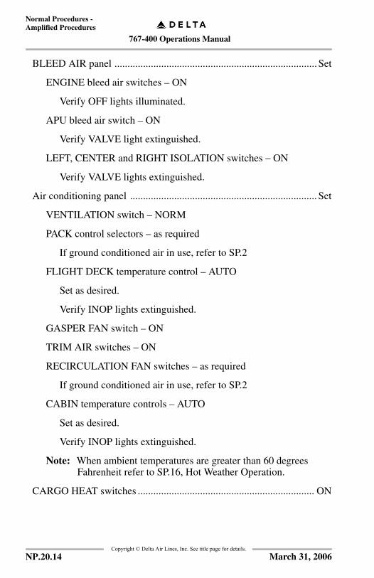
767-400 Operations Manual
Normal Procedures -Amplified Procedures
Copyright © Delta Air Lines, Inc. See title page for details.
BLEED AIR panel .............................................................................. Set
ENGINE bleed air switches – ON
Verify OFF lights illuminated.
APU bleed air switch – ON
Verify VALVE light extinguished.
LEFT, CENTER and RIGHT ISOLATION switches – ON
Verify VALVE lights extinguished.
Air conditioning panel ........................................................................ Set
VENTILATION switch – NORM
PACK control selectors – as required
If ground conditioned air in use, refer to SP.2
FLIGHT DECK temperature control – AUTO
Set as desired.
Verify INOP lights extinguished.
GASPER FAN switch – ON
TRIM AIR switches – ON
RECIRCULATION FAN switches – as required
If ground conditioned air in use, refer to SP.2
CABIN temperature controls – AUTO
Set as desired.
Verify INOP lights extinguished.
Note: When ambient temperatures are greater than 60 degrees Fahrenheit refer to SP.16, Hot Weather Operation.
CARGO HEAT switches .................................................................... ON
NP.20.14 March 31, 2006
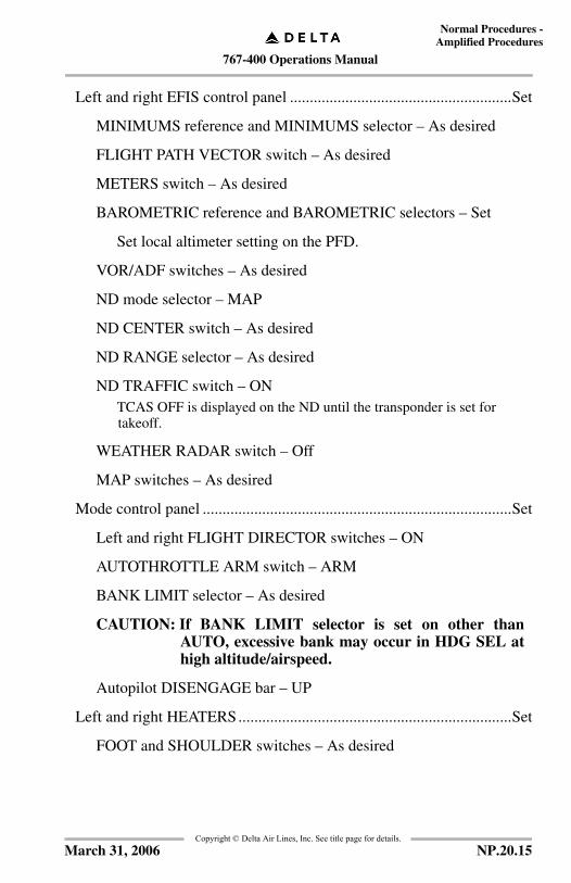
767-400 Operations Manual
Normal Procedures -Amplified Procedures
Copyright © Delta Air Lines, Inc. See title page for details.
Left and right EFIS control panel ........................................................Set
MINIMUMS reference and MINIMUMS selector – As desired
FLIGHT PATH VECTOR switch – As desired
METERS switch – As desired
BAROMETRIC reference and BAROMETRIC selectors – Set
Set local altimeter setting on the PFD.
VOR/ADF switches – As desired
ND mode selector – MAP
ND CENTER switch – As desired
ND RANGE selector – As desired
ND TRAFFIC switch – ONTCAS OFF is displayed on the ND until the transponder is set for takeoff.
WEATHER RADAR switch – Off
MAP switches – As desired
Mode control panel ..............................................................................Set
Left and right FLIGHT DIRECTOR switches – ON
AUTOTHROTTLE ARM switch – ARM
BANK LIMIT selector – As desired
CAUTION: If BANK LIMIT selector is set on other thanAUTO, excessive bank may occur in HDG SEL athigh altitude/airspeed.
Autopilot DISENGAGE bar – UP
Left and right HEATERS.....................................................................Set
FOOT and SHOULDER switches – As desired
NP.20.15March 31, 2006
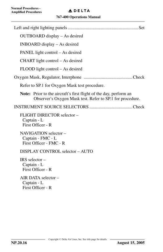
767-400 Operations Manual
Normal Procedures -Amplified Procedures
Copyright © Delta Air Lines, Inc. See title page for details.
Left and right lighting panels .............................................................. Set
OUTBOARD display – As desired
INBOARD display – As desired
PANEL light control – As desired
CHART light control – As desired
FLOOD light control – As desired
Oxygen Mask, Regulator, Interphone ...........................................Check
Refer to SP.1 for Oxygen Mask test procedure.
Note: Prior to the aircraft’s first flight of the day, perform an Observer’s Oxygen Mask test. Refer to SP.1 for procedure.
INSTRUMENT SOURCE SELECTORS ......................................Check
FLIGHT DIRECTOR selector – Captain - L First Officer - R
NAVIGATION selector – Captain - FMC - L First Officer - FMC - R
DISPLAY CONTROL selector – AUTO
IRS selector – Captain - L First Officer - R
AIR DATA selector – Captain - L First Officer - R
NP.20.16 August 15, 2005

767-400 Operations Manual
Normal Procedures -Amplified Procedures
Copyright © Delta Air Lines, Inc. See title page for details.
Altimeters ...................................................................................___, xckFor the blank, verbalize the correct altimeter setting.
Flight & nav instruments ............................................................... Check
Clocks – SetTIME/DATE pushbutton – UTC
Left and right PFD - Checked
Flight mode annunciations – Verify:• autothrottle mode is blank
• roll mode is TO
• pitch mode is TO
• AFDS status is FD.
Flight instrument indications are correct.
The NO V SPD flag is displayed until V–speeds are selected.
The LDG ALT flag is displayed until the FMS route is activated.
Verify no other flags displayed.
Left and right ND – Checked
Verify map mode displayed.
Route – Displayed, correct.
Verify no flags displayed.
RESERVE BRAKES & STEERING ............................................... OFFVerify VALVE light extinguished.
Left and right inboard display selectors .......................................... MFD
HEADING REFERENCE switch .................................................NORM
NP.20.17August 15, 2005

767-400 Operations Manual
Normal Procedures -Amplified Procedures
Copyright © Delta Air Lines, Inc. See title page for details.
Standby flight instruments .............................................................Check
Standby ADI – Check
ILS selector – OFF
Verify no flags displayed.
Airspeed indicator – Check
Verify instrument indications are correct.
Altimeter – Set
Set local altimeter setting.
Verify instrument indications are correct.
Landing gear panel .............................................................................. Set
Landing gear lever – DN
ALTERNATE GEAR EXTEND switch – OFF (guarded position)
GROUND PROXIMITY OVERRIDE switches ..............................OFF
GROUND PROXIMITY G/S INHIBIT light – Extinguished
GROUND PROXIMITY FLAP OVERRIDE switch – OFF
GROUND PROXIMITY GEAR OVERRIDE switch – OFF
GROUND PROXIMITY TERRAIN OVERRIDE switch – OFF
AUTOBRAKE selector .................................................................... RTO
NP.20.18 January 17, 2005

767-400 Operations Manual
Normal Procedures -Amplified Procedures
Copyright © Delta Air Lines, Inc. See title page for details.
EICAS/MFD ................................................................................. Check
Indications – Normal. Verify:• primary engine indications display existing conditions
• no exceedance values are displayed.
Secondary ENGINE display switch – Push
Secondary ENGINE display – Verify:• secondary engine indications display existing conditions
• no exceedance displayed
• oil quantity, 17 quarts recommended for start- If oil quantity less than 17 quarts, verify 8 quarts minimum following engine warm-up with engine at idle. If oil quantity less than 8 quarts following engine warm-up, dispatch approval is required.
STATUS DISPLAY switch – Push
STATUS display – Verify:• hydraulic quantities do not display RF
If any status message is displayed, refer to the Minimum Equipment List and Maintenance Dispatch Manual (MDM) to determine if dispatch relief is available.
DCU CONTROL selector – AUTO
NP.20.19November 20, 2006
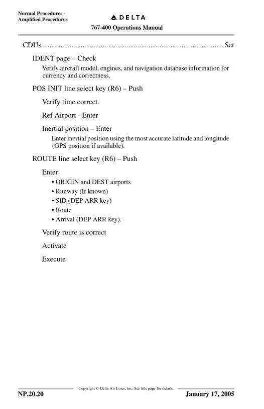
767-400 Operations Manual
Normal Procedures -Amplified Procedures
Copyright © Delta Air Lines, Inc. See title page for details.
CDUs ................................................................................................... Set
IDENT page – CheckVerify aircraft model, engines, and navigation database information for currency and correctness.
POS INIT line select key (R6) – Push
Verify time correct.
Ref Airport - Enter
Inertial position – EnterEnter inertial position using the most accurate latitude and longitude (GPS position if available).
ROUTE line select key (R6) – Push
Enter:• ORIGIN and DEST airports
• Runway (If known)
• SID (DEP ARR key)
• Route
• Arrival (DEP ARR key).
Verify route is correct
Activate
Execute
NP.20.20 January 17, 2005
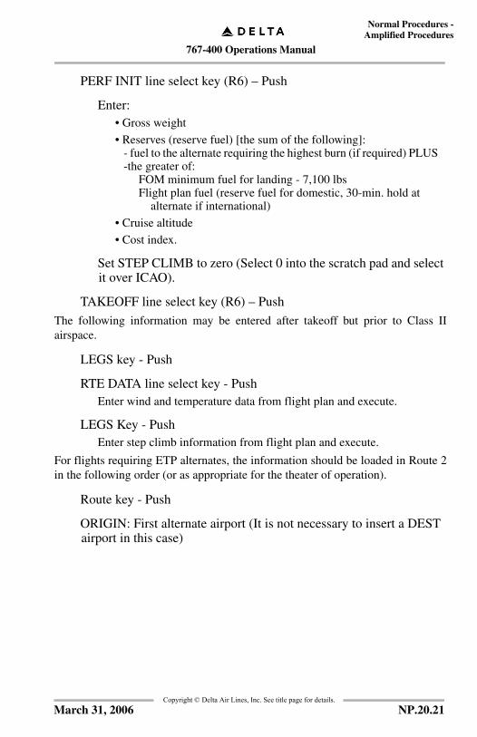
767-400 Operations Manual
Normal Procedures -Amplified Procedures
Copyright © Delta Air Lines, Inc. See title page for details.
PERF INIT line select key (R6) – Push
Enter:• Gross weight
• Reserves (reserve fuel) [the sum of the following]:- fuel to the alternate requiring the highest burn (if required) PLUS-the greater of:
FOM minimum fuel for landing - 7,100 lbsFlight plan fuel (reserve fuel for domestic, 30-min. hold at
alternate if international)
• Cruise altitude
• Cost index.
Set STEP CLIMB to zero (Select 0 into the scratch pad and select it over ICAO).
TAKEOFF line select key (R6) – Push
The following information may be entered after takeoff but prior to Class IIairspace.
LEGS key - Push
RTE DATA line select key - PushEnter wind and temperature data from flight plan and execute.
LEGS Key - PushEnter step climb information from flight plan and execute.
For flights requiring ETP alternates, the information should be loaded in Route 2in the following order (or as appropriate for the theater of operation).
Route key - Push
ORIGIN: First alternate airport (It is not necessary to insert a DEST airport in this case)
NP.20.21March 31, 2006

767-400 Operations Manual
Normal Procedures -Amplified Procedures
Copyright © Delta Air Lines, Inc. See title page for details.
Routing:First alternate airport
First ETP
Next alternate airport
Next ETP
Last alternate airport
Note: If required for noise abatement, enter a speed restriction on the climb page of VREF 30+80 to 2500 feet above field elevation. If VREF 30+80 is 250K or more, leave SPD/RESTR blank. This occurs at approximately 450,000 pounds takeoff weight.
FIX key - PushEnter first 2 reporting points.
Parking brake ...................................................................................... Set
Verify PARKING BRAKE SET message displayed.
Note: Accumulator pressure may be insufficient to prevent airplane from moving.
ALTERNATE STABILIZER TRIM switches .............................. Neutral
STABILIZER TRIM cutout switches ............NORM (guarded position)
SPEEDBRAKE lever ...................................................................DOWN
Reverse thrust levers ...................................................................... Down
WARNING: Movement of the reverse thrust lever could result in operation of the engine thrust reverser.
Thrust levers .................................................................................. Closed
FUEL CONTROL switches ......................................................CUTOFF
Flaps .................................................................................................... UP
WARNING: Do not move flaps without appropriate clearance from ground personnel.
ALTERNATE FLAPS ......................................................................... Set
ALTERNATE FLAPS selector – NORM
NP.20.22 November 20, 2006

767-400 Operations Manual
Normal Procedures -Amplified Procedures
Copyright © Delta Air Lines, Inc. See title page for details.
ALTERNATE FLAPS switches – OFF
Engine fire panel ..................................................................................Set
ENG BTL 1 DISCH and ENG BTL 2 DISCH lights – Extinguished
Engine fire switches – InVerify LEFT and RIGHT fire warning lights extinguished.
CARGO FIRE panel ............................................................................Set
CARGO FIRE ARM switches – OffVerify FWD and AFT fire warning lights extinguished.
CARGO FIRE BTL DISCH light – Extinguished
APU fire panel .....................................................................................Set
APU BTL DISCH lights – Extinguished
APU fire switch – InVerify APU fire warning light extinguished.
NP.20.23January 17, 2005
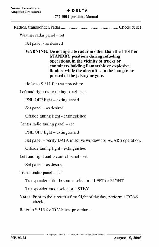
767-400 Operations Manual
Normal Procedures -Amplified Procedures
Copyright © Delta Air Lines, Inc. See title page for details.
Radios, transponder, radar .................................................... Check & set
Weather radar panel – set
Set panel - as desired
WARNING: Do not operate radar in other than the TEST or STANDBY positions during refueling operations, in the vicinity of trucks or containers holding flammable or explosive liquids, while the aircraft is in the hangar, or parked at the jetway or gate.
Refer to SP.11 for test procedure
Left and right radio tuning panel - set
PNL OFF light – extinguished
Set panel – as desired
Offside tuning light - extinguished
Center radio tuning panel – set
PNL OFF light – extinguished
Set panel – verify DATA in active window for ACARS operation.
Offside tuning light - extinguished
Left and right audio control panel - set
Set panel – as desired
Transponder panel – set
Transponder altitude source selector – LEFT or RIGHT
Transponder mode selector – STBY
Note: Prior to the aircraft’s first flight of the day, perform a TCAS check.
Refer to SP.15 for TCAS test procedure.
NP.20.24 August 15, 2005
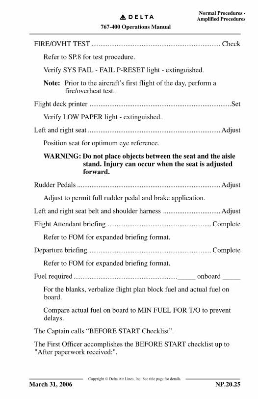
767-400 Operations Manual
Normal Procedures -Amplified Procedures
Copyright © Delta Air Lines, Inc. See title page for details.
FIRE/OVHT TEST ........................................................................ Check
Refer to SP.8 for test procedure.
Verify SYS FAIL - FAIL P-RESET light - extinguished.
Note: Prior to the aircraft’s first flight of the day, perform a fire/overheat test.
Flight deck printer ...............................................................................Set
Verify LOW PAPER light - extinguished.
Left and right seat .......................................................................... Adjust
Position seat for optimum eye reference.
WARNING: Do not place objects between the seat and the aisle stand. Injury can occur when the seat is adjusted forward.
Rudder Pedals ................................................................................ Adjust
Adjust to permit full rudder pedal and brake application.
Left and right seat belt and shoulder harness ................................ Adjust
Flight Attendant briefing .......................................................... Complete
Refer to FOM for expanded briefing format.
Departure briefing ..................................................................... Complete
Refer to FOM for expanded briefing format.
Fuel required .........................................................._____ onboard _____
For the blanks, verbalize flight plan block fuel and actual fuel on board.
Compare actual fuel on board to MIN FUEL FOR T/O to prevent delays.
The Captain calls “BEFORE START Checklist”.
The First Officer accomplishes the BEFORE START checklist up to "After paperwork received:".
NP.20.25March 31, 2006

767-400 Operations Manual
Normal Procedures -Amplified Procedures
Copyright © Delta Air Lines, Inc. See title page for details.
Before Start ProcedureThis procedure is accomplished after papers are on board. Two crewmembers mustrefer to the final AWABS/WDR to verify the takeoff performance andconfiguration data.
FMS & ACARS info ........................................................................Enter
ACARS - Refer to section SP.5 for procedure.
CDU - Set
INIT REF key – Push
Verify correct fuel quantity.
Enter:- Zero fuel weight
- Verify GR WT (Gross weight)
TAKEOFF line select key – Push
Enter: - Takeoff flap setting
- Assumed temperature derate (if selected)
- CG
- Position shift value (if GPS unable)
- V1, VR, V2 - Enter
CAUTION: Do not use Assumed Temperature (AT) thrust when:- Restricted at particular airports - refer to Delta Airways Manual 10-0 Special Pages.- Unstable weather conditions exist.- AWABS system is inoperative.
NEXT PAGE key – Push Complete entries as necessary.
NP.20.26 August 15, 2005
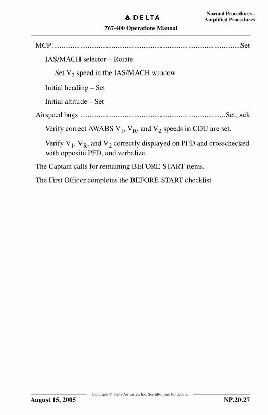
767-400 Operations Manual
Normal Procedures -Amplified Procedures
Copyright © Delta Air Lines, Inc. See title page for details.
MCP .....................................................................................................Set
IAS/MACH selector – Rotate
Set V2 speed in the IAS/MACH window.
Initial heading – Set
Initial altitude – Set
Airspeed bugs ..............................................................................Set, xck
Verify correct AWABS V1, VR, and V2 speeds in CDU are set.
Verify V1, VR, and V2 correctly displayed on PFD and crosschecked with opposite PFD, and verbalize.
The Captain calls for remaining BEFORE START items.
The First Officer completes the BEFORE START checklist
NP.20.27August 15, 2005

767-400 Operations Manual
Normal Procedures -Amplified Procedures
Copyright © Delta Air Lines, Inc. See title page for details.
Pushback/Start Procedure All appropriate procedural items will be completed prior to aircraft movement.
Doors ............................................................................................. ClosedAll doors should be closed and lights extinguished before pushback.
Received "CABIN IS READY FOR PUSHBACK" verbal from Flight Leader.
Hydraulic panel ................................................................................... Set
Note: Pressurize right system first to prevent fluid transfer between systems.
Right ELECTRIC DEMAND pump selector – AUTO
Verify PRESS lights extinguished.
C1 and C2 ELECTRIC PRIMARY pump switches – ON
Verify C1 PRESS light extinguished.
Center AIR DEMAND pump selector - AUTO
Verify PRESS lights extinguished.
Left ELECTRIC DEMAND pump selector - AUTO
Verify PRESS lights extinguished.
Note: C2 PRESS light will not be extinguished due to load shedding. Indication will be normal after engine start.
FUEL panel ......................................................................................... Set
LEFT and RIGHT FUEL PUMP switches – ON
Verify PRESS lights extinguished.
If center tank contains fuel:
CENTER FUEL PUMP switches – ON
Note: Both PRESS lights will not be extinguished due to load shedding. Indications will be normal after engine start.
NP.20.28 November 20, 2006

767-400 Operations Manual
Normal Procedures -Amplified Procedures
Copyright © Delta Air Lines, Inc. See title page for details.
Trim ..........................................................................................____, 0, 0
Stabilizer trim – ___ units
Set for takeoff.
Check in greenband.
Aileron trim – 0
Rudder trim – 0
Flight Deck door ...............................................................Close and lock
After pushback clearance or engine start clearance:
Transponder ...........................................................................As required
Select STBY or TA/RA as required by local airport operating systems.
RED ANTI–COLLISION light switch ...............................................ON
Select ON immediately prior to aircraft movement, or immediately prior to engine start (if starting at gate).
Air conditioning panel ......................................................................... set
PACK selectors - OFF
The Captain calls “PUSHBACK/START CHECKLIST.”
The First Officer accomplishes the PUSHBACK/START checklist.
NP.20.29November 20, 2006
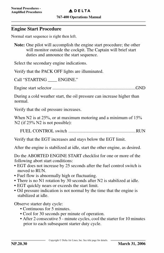
767-400 Operations Manual
Normal Procedures -Amplified Procedures
Copyright © Delta Air Lines, Inc. See title page for details.
Engine Start Procedure
Normal start sequence is right then left.
Note: One pilot will accomplish the engine start procedure; the other will monitor outside the cockpit. The Captain will brief start duties and announce the start sequence.
Select the secondary engine indications.
Verify that the PACK OFF lights are illuminated.
Call “STARTING ____ ENGINE.”
Engine start selector .........................................................................GND
During a cold weather start, the oil pressure can increase higher than normal.
Verify that the oil pressure increases.
When N2 is at 25%, or at maximum motoring and a minimum of 15% N2 (if 25% N2 is not possible):
FUEL CONTROL switch ...........................................................RUN
Verify that the EGT increases and stays below the EGT limit.
After the engine is stabilized at idle, start the other engine, as desired.
Do the ABORTED ENGINE START checklist for one or more of the following abort start conditions:• EGT does not increase by 25 seconds after the fuel control switch is
moved to RUN.• Fuel flow is abnormally high or fluctuating.• There is no N1 rotation by 30 seconds after N2 is stabilized at idle.• EGT quickly nears or exceeds the start limit.• Oil pressure indication is not normal by the time that the engine is
stabilized at idle.
Observe starter duty cycle:• Continuous for 5 minutes.• Cool for 30 seconds per minute of operation.• After 2 consecutive 5 - minute cycles, cool the starter for 10 minutes
prior to each subsequent starter duty cycle.
NP.20.30 March 31, 2006

767-400 Operations Manual
Normal Procedures -Amplified Procedures
Copyright © Delta Air Lines, Inc. See title page for details.
After Start Procedure
APU ......................................................................................As required
Note: APU may be left on if desired for delayed start procedures, but is normally off for takeoff.
ENGINE ANTI-ICE selectors ...............................................As required
Icing conditions (refer to SP.3).
Air conditioning panel .........................................................................Set
Single Engine Taxi:
LEFT and RIGHT ISOLATION switches - ON
PACK selectors - AUTO
Two Engine Taxi:
LEFT and RIGHT ISOLATION switches - OFF
PACK selectors - AUTO
AUTOBRAKE selector .................................................................... RTO
The Captain calls “AFTER START CHECKLIST.”
The First Officer accomplishes the AFTER START checklist.
NP.20.31March 31, 2006

767-400 Operations Manual
Normal Procedures -Amplified Procedures
Copyright © Delta Air Lines, Inc. See title page for details.
Taxi ProcedureAfter the agent’s salute is accepted by the Captain or First Officer, the First Officershould extend the flaps in preparation for taxi. Once clear of congested areas,continue with the taxi check.
TAXI lights switch ............................................................................. ON
Select OFF when stopped or waiting in line for takeoff.
Exterior lights ........................................................................ As requiredIt is recommended that all available exterior lighting is used when crossing runways.
Flaps .......................................................................................... ___ , ___
Move FLAP lever to takeoff setting as required by AWABS, and verify position of the flaps on the EICAS.
Flight controls ................................................................................Check
Display flight control synoptic.Displace control wheel and control column to full travel in both directions and verify:
• freedom of movement
• controls return to center
• proper flight control movement on EICAS display.
Hold the nose wheel steering tiller during rudder check to prevent undesired nose wheel movement.Displace rudder pedals to full travel in both directions and verify:
• freedom of movement
• rudder pedals return to center
• proper flight control movement on EICAS display.
Blank lower EICAS display after both engines are started.
The Captain calls “TAXI CHECKLIST.”
The First Officer accomplishes the TAXI checklist.
NP.20.32 November 20, 2006
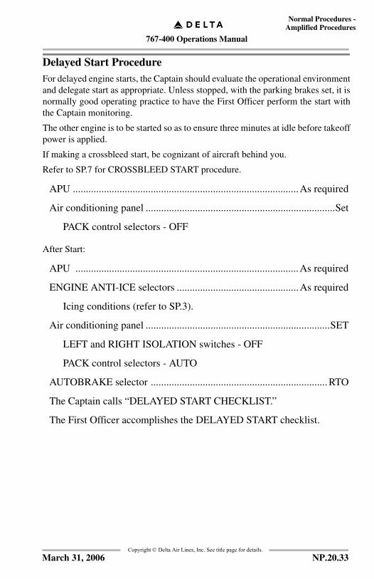
767-400 Operations Manual
Normal Procedures -Amplified Procedures
Copyright © Delta Air Lines, Inc. See title page for details.
Delayed Start ProcedureFor delayed engine starts, the Captain should evaluate the operational environmentand delegate start as appropriate. Unless stopped, with the parking brakes set, it isnormally good operating practice to have the First Officer perform the start withthe Captain monitoring.
The other engine is to be started so as to ensure three minutes at idle before takeoffpower is applied.
If making a crossbleed start, be cognizant of aircraft behind you.
Refer to SP.7 for CROSSBLEED START procedure.
APU .......................................................................................As required
Air conditioning panel .........................................................................Set
PACK control selectors - OFF
After Start:
APU ......................................................................................As required
ENGINE ANTI-ICE selectors ...............................................As required
Icing conditions (refer to SP.3).
Air conditioning panel .......................................................................SET
LEFT and RIGHT ISOLATION switches - OFF
PACK control selectors - AUTO
AUTOBRAKE selector .................................................................... RTO
The Captain calls “DELAYED START CHECKLIST.”
The First Officer accomplishes the DELAYED START checklist.
NP.20.33March 31, 2006

767-400 Operations Manual
Normal Procedures -Amplified Procedures
Copyright © Delta Air Lines, Inc. See title page for details.
Before Takeoff ProcedureOperate both engines at idle or taxi thrust a minimum of three minutes beforeapplying takeoff thrust.
Flaps .................................................................................. _____ , _____For the first blank, verify FLAP lever position either 5, 15,or 20.
For the second blank, verify flap indication either 5, 15, or 20.
Flight attendants ...................................................Notify & acknowledge
Prior to taking the active runway, the flight crew is required to make a PA announcement informing the flight attendants to ensure the cabin is prepared for takeoff.
The flight attendants must be given sufficient notification before takeoff to make their final cabin preparations and be seated for departure.
The Flight Leader must verbally confirm that the “CABIN IS READY FOR TAKEOFF”.
Takeoff will not be initiated until acknowledgment is received.
Windows .............................................................................. Close & lock
Verify the lock lever is in the locked (forward) position and the WINDOW NOT CLOSED decal is not in view.
Altimeters .................................................................................. ___, xckFor the blank, verbalize the correct altimeter setting.
Runway, departure, first fix ............................................... ___, ___, ___
Verify the selected runway, departure, and associated first fix in the FMS match the latest ATC departure clearance.
Verbalize the runway, departure procedure, and first fix.
Check aircraft versus runway position on ND (maximum of 10 nm scale). If required, perform the IRS Quick Alignment (QA)/Fast Realignment procedure in Supplementary Procedures, Flight Management, Navigation section.
NP.20.34 November 20, 2006
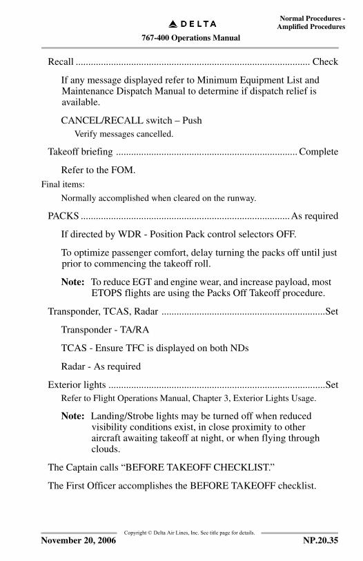
767-400 Operations Manual
Normal Procedures -Amplified Procedures
Copyright © Delta Air Lines, Inc. See title page for details.
Recall ............................................................................................. Check
If any message displayed refer to Minimum Equipment List and Maintenance Dispatch Manual to determine if dispatch relief is available.
CANCEL/RECALL switch – PushVerify messages cancelled.
Takeoff briefing ........................................................................ Complete
Refer to the FOM.Final items:
Normally accomplished when cleared on the runway.
PACKS ...................................................................................As required
If directed by WDR - Position Pack control selectors OFF.
To optimize passenger comfort, delay turning the packs off until just prior to commencing the takeoff roll.
Note: To reduce EGT and engine wear, and increase payload, most ETOPS flights are using the Packs Off Takeoff procedure.
Transponder, TCAS, Radar .................................................................Set
Transponder - TA/RA
TCAS - Ensure TFC is displayed on both NDs
Radar - As required
Exterior lights ......................................................................................SetRefer to Flight Operations Manual, Chapter 3, Exterior Lights Usage.
Note: Landing/Strobe lights may be turned off when reduced visibility conditions exist, in close proximity to other aircraft awaiting takeoff at night, or when flying through clouds.
The Captain calls “BEFORE TAKEOFF CHECKLIST.”
The First Officer accomplishes the BEFORE TAKEOFF checklist.
NP.20.35November 20, 2006
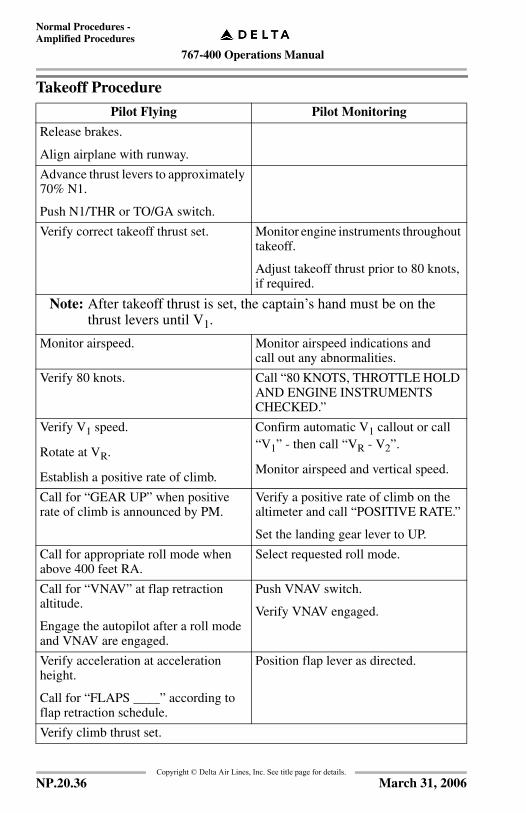
767-400 Operations Manual
Normal Procedures -Amplified Procedures
Copyright © Delta Air Lines, Inc. See title page for details.
Takeoff Procedure
Pilot Flying Pilot Monitoring
Release brakes.
Align airplane with runway.
Advance thrust levers to approximately 70% N1.
Push N1/THR or TO/GA switch.
Verify correct takeoff thrust set. Monitor engine instruments throughout takeoff.
Adjust takeoff thrust prior to 80 knots, if required.
Note: After takeoff thrust is set, the captain’s hand must be on the thrust levers until V1.
Monitor airspeed. Monitor airspeed indications andcall out any abnormalities.
Verify 80 knots. Call “80 KNOTS, THROTTLE HOLD AND ENGINE INSTRUMENTS CHECKED.”
Verify V1 speed.
Rotate at VR.
Establish a positive rate of climb.
Confirm automatic V1 callout or call “V1” - then call “VR - V2”.
Monitor airspeed and vertical speed.
Call for “GEAR UP” when positive rate of climb is announced by PM.
Verify a positive rate of climb on the altimeter and call “POSITIVE RATE.”
Set the landing gear lever to UP.
Call for appropriate roll mode when above 400 feet RA.
Select requested roll mode.
Call for “VNAV” at flap retraction altitude.
Engage the autopilot after a roll mode and VNAV are engaged.
Push VNAV switch.
Verify VNAV engaged.
Verify acceleration at acceleration height.
Call for “FLAPS ____” according to flap retraction schedule.
Position flap lever as directed.
Verify climb thrust set.
NP.20.36 March 31, 2006

767-400 Operations Manual
Normal Procedures -Amplified Procedures
Copyright © Delta Air Lines, Inc. See title page for details.
After Takeoff Procedure
The Pilot Flying calls “AFTER TAKEOFF CHECKLIST.”
The Pilot Monitoring accomplishes the AFTER TAKEOFF checklist.
Pilot Monitoring
Verify landing gear lever is UP, and EICAS indication is blank.
Confirm FLAP lever UP, and FLAP/SLATS EICAS indication is blank.
Set Climb Thrust as required.
After engine thrust is reduced, position one PACK control selector to AUTO.
When cabin pressure stabilizes, position the remaining PACK control selector to AUTO.
Note: If engine failure occurs, PACK control selectors should remain OFF until reaching 1,500 feet AFE, or until obstacle clearance height has been attained, whichever is higher.
Note: If, after takeoff, when either Pack Control Selector is selected to AUTO and the Bleed OFF light and/or the ENG BLEED OFF message is displayed, attempt one reset of the engine bleed air valve by selecting the affected bleed air switch OFF, then ON.
If the Bleed OFF light and/or ENG BLEED OFF EICAS message remains illuminated or re-illuminates, accomplish the ENGINE BLEED OFF checklist.
If the bleed system is reset, record the event in the logbook, as the cause of the bleed trip must be determined prior to the next dispatch.
Position WING and ENGINE ANTI-ICE selectors to AUTO.
Set APU as required.
NP.20.37November 20, 2006
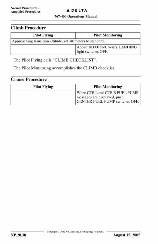
767-400 Operations Manual
Normal Procedures -Amplified Procedures
Copyright © Delta Air Lines, Inc. See title page for details.
Climb Procedure
The Pilot Flying calls “CLIMB CHECKLIST”.
The Pilot Monitoring accomplishes the CLIMB checklist.
Cruise Procedure
Pilot Flying Pilot Monitoring
Approaching transition altitude, set altimeters to standard.
Above 18,000 feet, verify LANDING light switches OFF.
Pilot Flying Pilot Monitoring
When CTR L and CTR R FUEL PUMP messages are displayed, push CENTER FUEL PUMP switches OFF.
NP.20.38 August 15, 2005

767-400 Operations Manual
Normal Procedures -Amplified Procedures
Copyright © Delta Air Lines, Inc. See title page for details.
IntentionallyBlank
NP.20.39January 17, 2005

767-400 Operations Manual
Normal Procedures -Amplified Procedures
Copyright © Delta Air Lines, Inc. See title page for details.
Descent ProcedureNormally, complete the DESCENT checklist at 18,000 feet or top of descent,whichever comes later. It is suggested that flight attendants be notified when 20minutes from landing. Local altimeter setting may be pre-set on EFIS controlpanel.
Pilot Flying Pilot Monitoring
Position SEATBELTS sign selector to ON.
Accomplish approach briefing. Refer to FOM.
Review all alert messages. Recall and review all alert messages.
Set AUTOBRAKE selector to desired brake setting.
Set RADIO or BARO minimums as required for approach, and verbalize.
APPROACHTYPE
BAROMIN REF
RADIOMIN REF
ILS TO CAT I PUBLISHEDDA
N/A
CAT II N/A PUBLISHEDRA
CAT III N/A 50’
STRAIGHT-IN(NON-PRECISION)
PUBLISHED MDA / DAor DDA (MDA + 50’)
N/A
CIRCLE TO LAND
HIGHER OF:PUBLISHED MDA ORFIELD ELEV + 1000’
N/A
VISUAL APPROACH MINIMUMS (1) N/A
(1) Set the approach minimums for the instrument approach used to back up thevisual approach. If no instrument approach is available, biased out of view.
Modify active route as required for arrival and approach. Set NAV RAD page.
Pressurization panel - Set.- Cabin Altitude Control - Set
Verify LDG ALT is set for destination airport. If landing at an airport using QFE, set to "0".
NP.20.40 August 15, 2005

767-400 Operations Manual
Normal Procedures -Amplified Procedures
Copyright © Delta Air Lines, Inc. See title page for details.
The Pilot Flying calls “DESCENT CHECKLIST”.
The Pilot Monitoring accomplishes the DESCENT checklist.
Approaching 18,000 ft., verify LANDING light switches - ON.
Verify flap setting and VREF speed using FMS and PFD, and verbalize(Example: FLAPS 30 / ___, XCKD).
Set altimeters as required, and verbalize.
Pilot Flying Pilot Monitoring
NP.20.41August 15, 2005

767-400 Operations Manual
Normal Procedures -Amplified Procedures
Copyright © Delta Air Lines, Inc. See title page for details.
Approach Procedure
The Pilot Flying calls “APPROACH CHECKLIST”.
The Pilot Monitoring accomplishes the APPROACH checklist.
Landing Procedure
The Pilot Flying calls “LANDING CHECKLIST”.
The Pilot Monitoring accomplishes the LANDING checklist.
Pilot Flying Pilot Monitoring
Flight and nav instruments, set and crosscheck.
• PFD/ND - Verify correct arrival and approach procedures selected.
Cycle NO SMOKING sign selector when descending through approximately 10,000 feet AFE.
Approaching transition level, set altimeters, and verbalize.
Pilot Flying Pilot Monitoring
Call for “FLAPS __” according to flap extension schedule.
Position flap lever as directed.
When on localizer intercept heading with localizer and glideslope pointers displayed, arm APP mode
At glideslope alive, call for:
“GEAR DOWN”
“FLAPS 20”
Position landing gear lever DN
Position flap lever to 20.
Position speedbrake lever to ARMED.
At glideslope capture, call for “FLAPS __” as required for landing.
Position flap lever as commanded.
At approximately 1,500 feet radio altitude, verify Autoland status (if applicable).
Ensure missed approach altitude in MCP by 1,000 feet AGL.
At final approach fix/OM, verify crossing altitude.
Monitor approach progress.
NP.20.42 August 15, 2005

767-400 Operations Manual
Normal Procedures -Amplified Procedures
Copyright © Delta Air Lines, Inc. See title page for details.
Go–Around and Missed Approach Procedure
The Pilot Flying calls “AFTER TAKEOFF CHECKLIST”.
The Pilot Monitoring accomplishes the AFTER TAKEOFF checklist.
Pilot Flying Pilot Monitoring
Push TO/GA switch.
Call for “FLAPS 20.”
Position flap lever to 20.
Verify rotation to go–around attitude and thrust increase.
Verify thrust adequate for go–around; adjust if necessary.
After positive rate of climb is announced by PM, call for “GEAR UP.”
Verify a positive rate of climb on the altimeter and call “POSITIVE RATE.”
Position the landing gear lever up when PF announces gear up.
Call for appropriate roll mode when above 400 feet RA.
Select requested roll mode.
At acceleration height, set speed to the maneuvering speed for the desired flap setting.
Call for “FLAPS __” according to flap retraction schedule.
Position flap lever as directed.
After flap retraction to the planned flap setting, select FLCH or VNAV if desired.
Ensure CLB thrust is set.
NP.20.43March 31, 2006

767-400 Operations Manual
Normal Procedures -Amplified Procedures
Copyright © Delta Air Lines, Inc. See title page for details.
Landing Roll Procedure
WARNING: After reverse thrust is initiated, a full stop landing must be made.
Pilot Flying Pilot Monitoring
Monitor rollout progress and proper auto brakes operation.
Verify thrust levers closed and SPEEDBRAKE lever UP.
Without delay, raise reverse thrust levers to the interlocks, hold light pressure until release, and then apply reverse thrust as required.
Verify SPEEDBRAKE lever UP and call “SPEEDBRAKES UP.” If SPEEDBRAKE lever not UP, call “SPEEDBRAKES NOT UP.”
By 60 knots, initiate movement of reverse thrust levers to reach reverse idle detent prior to taxi speed.
Position levers full down (forward thrust) when engines have decelerated to reverse idle.
Call “60 KNOTS.”
Prior to taxi speed, disarm the auto brakes and continue manual braking as required.
Disconnect autopilot prior to runway turnoff.
NP.20.44 March 31, 2006

767-400 Operations Manual
Normal Procedures -Amplified Procedures
Copyright © Delta Air Lines, Inc. See title page for details.
IntentionallyBlank
NP.20.45January 17, 2005

767-400 Operations Manual
Normal Procedures -Amplified Procedures
Copyright © Delta Air Lines, Inc. See title page for details.
After Landing Procedure
Accomplished when clear of the active runway.
Engines may be shut down after a three-minute cool down period. Shut down may be accomplished earlier if necessary for gate arrival.
Anti-ice .................................................................................. As required
ENGINE ANTI-ICE selectors - as required
Icing conditions (refer to SP.3)
WING ANTI-ICE selector - OFF
APU ....................................................................................... As required
Exterior lights ...................................................................................... Set
WHITE ANTI–COLLISION light switch - OFF
LANDING/TAXI light switches - as required
Note: When in congested areas, consider turning off lights that may adversely affect the vision of ground personnel.
SPEEDBRAKE lever ...................................................................DOWN
Radar ...................................................................................................Off
Flaps .................................................................................................... UP
AUTOBRAKE selector .....................................................................OFF
Transponder ........................................................................... As required
Select STBY or an active transponder setting as required by local airport operating systems.
Continued on next page
NP.20.46 March 31, 2006
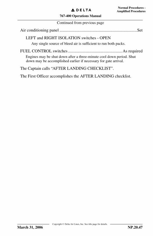
767-400 Operations Manual
Normal Procedures -Amplified Procedures
Copyright © Delta Air Lines, Inc. See title page for details.
Continued from previous page
Air conditioning panel .........................................................................Set
LEFT and RIGHT ISOLATION switches - OPENAny single source of bleed air is sufficient to run both packs.
FUEL CONTROL switches ...................................................As requiredEngines may be shut down after a three-minute cool down period. Shut down may be accomplished earlier if necessary for gate arrival.
The Captain calls “AFTER LANDING CHECKLIST”.
The First Officer accomplishes the AFTER LANDING checklist.
NP.20.47March 31, 2006
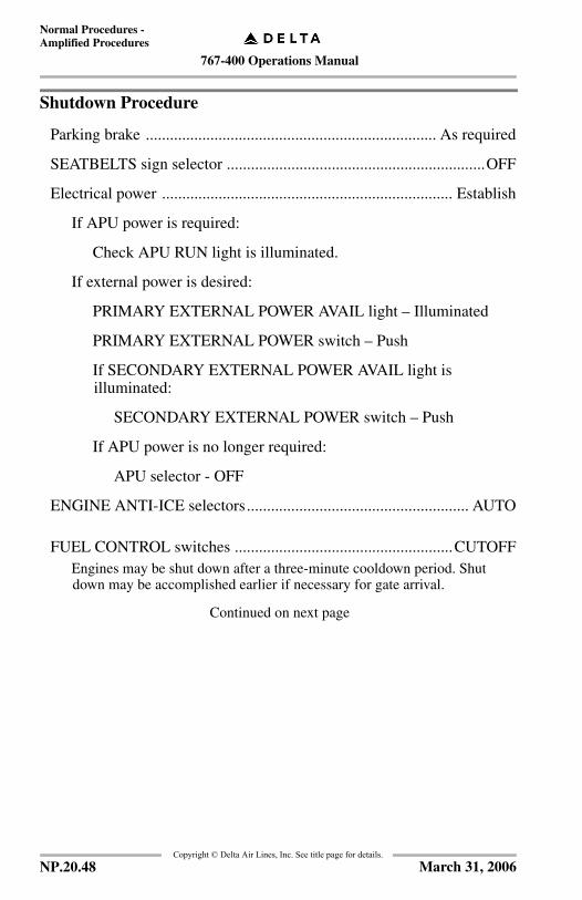
767-400 Operations Manual
Normal Procedures -Amplified Procedures
Copyright © Delta Air Lines, Inc. See title page for details.
Shutdown Procedure
Parking brake ........................................................................ As required
SEATBELTS sign selector ................................................................OFF
Electrical power ........................................................................ Establish
If APU power is required:
Check APU RUN light is illuminated.
If external power is desired:
PRIMARY EXTERNAL POWER AVAIL light – Illuminated
PRIMARY EXTERNAL POWER switch – Push
If SECONDARY EXTERNAL POWER AVAIL light is illuminated:
SECONDARY EXTERNAL POWER switch – Push
If APU power is no longer required:
APU selector - OFF
ENGINE ANTI-ICE selectors....................................................... AUTO
FUEL CONTROL switches ......................................................CUTOFFEngines may be shut down after a three-minute cooldown period. Shut down may be accomplished earlier if necessary for gate arrival.
Continued on next page
NP.20.48 March 31, 2006
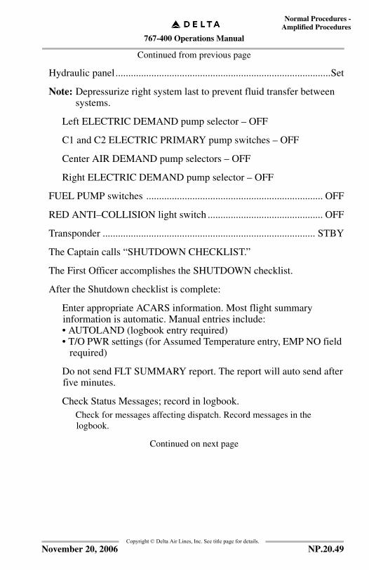
767-400 Operations Manual
Normal Procedures -Amplified Procedures
Copyright © Delta Air Lines, Inc. See title page for details.
Continued from previous page
Hydraulic panel....................................................................................Set
Note: Depressurize right system last to prevent fluid transfer between systems.
Left ELECTRIC DEMAND pump selector – OFF
C1 and C2 ELECTRIC PRIMARY pump switches – OFF
Center AIR DEMAND pump selectors – OFF
Right ELECTRIC DEMAND pump selector – OFF
FUEL PUMP switches ..................................................................... OFF
RED ANTI–COLLISION light switch ............................................. OFF
Transponder ................................................................................... STBY
The Captain calls “SHUTDOWN CHECKLIST.”
The First Officer accomplishes the SHUTDOWN checklist.
After the Shutdown checklist is complete:
Enter appropriate ACARS information. Most flight summary information is automatic. Manual entries include:• AUTOLAND (logbook entry required)• T/O PWR settings (for Assumed Temperature entry, EMP NO field
required)
Do not send FLT SUMMARY report. The report will auto send after five minutes.
Check Status Messages; record in logbook.Check for messages affecting dispatch. Record messages in the logbook.
Continued on next page
NP.20.49November 20, 2006
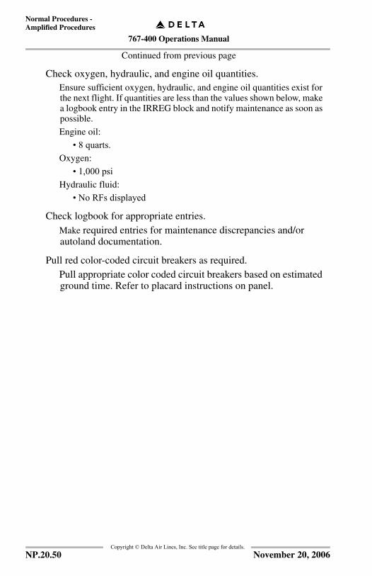
767-400 Operations Manual
Normal Procedures -Amplified Procedures
Copyright © Delta Air Lines, Inc. See title page for details.
Continued from previous page
Check oxygen, hydraulic, and engine oil quantities.Ensure sufficient oxygen, hydraulic, and engine oil quantities exist for the next flight. If quantities are less than the values shown below, make a logbook entry in the IRREG block and notify maintenance as soon as possible.
Engine oil:
• 8 quarts.Oxygen:
• 1,000 psiHydraulic fluid:
• No RFs displayed
Check logbook for appropriate entries.Make required entries for maintenance discrepancies and/or autoland documentation.
Pull red color-coded circuit breakers as required.Pull appropriate color coded circuit breakers based on estimated ground time. Refer to placard instructions on panel.
NP.20.50 November 20, 2006

767-400 Operations Manual
Normal Procedures -Amplified Procedures
Copyright © Delta Air Lines, Inc. See title page for details.
Secure Procedure
Note: In line operations, the aircraft may remain powered.
Only accomplish the Secure Checklist when:
• requested by Maintenance or Operations,• the aircraft is to remain for several hours, or• the aircraft is to remain overnight.
When operating the last flight of any day into a limited or non-maintenance station,accomplish the following:
• If a maintenance discrepancy is noted and entered in the logbook, the MCC must be contacted through the Dispatcher as soon as possible to facilitate corrective action and avoid delays. If a flight crew placard is applicable, it should be installed prior to departing the aircraft.
• Perform a postflight walkaround. Emphasis should be placed on tire condition, fluid leaks, oil quantity, and possible airframe or control surface damage.
If the aircraft will lay over in cold weather, ensure it is configured as described inSupplementary Procedures, Section 16, Adverse Weather.
IRS mode selectors ........................................................................... OFF
Emergency LIGHTS switch ............................................................. OFF
WINDOW HEAT switches ............................................................... OFF
CARGO HEAT switches .................................................................. OFF
PACK control selectors ..................................................................... OFF
Continued on next page
NP.20.51November 20, 2006

767-400 Operations Manual
Normal Procedures -Amplified Procedures
Copyright © Delta Air Lines, Inc. See title page for details.
Continued from previous page
APU/external power .............................................................. As required
Shut down the APU unless Maintenance is immediately available to work on the aircraft.
If electrical power is not required:
Accomplish Electrical Power Down Procedure. Refer to SP.6.
If only ground service power is required:
Note: Ground service bus can only be powered with the PRIMARY EXTERNAL POWER connected, and AVAIL light illuminated.
PRIMARY EXTERNAL POWER andSECONDARY EXTERNAL POWER switches - OFF.
STANDBY POWER - OFF
BATTERY switch - OFF
Place the GROUND SERVICE bus switch ON (located on the forward flight attendant panel).
The Captain calls “SECURE CHECKLIST.”
The First Officer accomplishes the SECURE checklist.
NP.20.52 November 20, 2006

767-400 Operations Manual
Normal Procedures Chapter NPFlight Patterns Section 30
FCO
M T
empl
ate
12/1
2/98
Copyright © Delta Air Lines, Inc. See title page for details.
Flight Pattern PrinciplesFlight patterns in this section are not designed to be comprehensive in nature.They have been developed as a tool for the experienced crew member. A quickreview may be obtained by referencing a flight pattern and its associated text. Fora complete analysis of a particular maneuver, the Flight Crew Training Manualshould be referenced in addition to the material found in this section.Flight patterns in this section do not include all standard callouts.Flight patterns in this section do not include every pilot action recommended tofly a particular flight pattern.
Takeoff Considerations
LNAV Used For DepartureIf LNAV is to be used for departure, accomplish the following procedures:
Verify the aircraft symbol is in close proximity to the departure end of the runwaysymbol on the ND in the 5 nm scale.
• If GPS NAV is on, the autothrottle update function is inhibited.• If GPS NAV is off, the FMC updates position to the runway threshold
with autothrottle system engagement.
CAUTION: The nav database runway position is the LAT/LON of therunway threshold marker. If departing from a runway witha displaced threshold, enter a negative value (the displacedrunway threshold distance) in the POS SHIFT line on theTAKEOFF REF page.
• When an intersection takeoff is made with GPS NAV off, the intersection displacement distance from the runway threshold must be entered on the TAKEOFF REF page.
Note: Do not use LNAV for departure if FMS position is incorrect.
NP.30.1January 17, 2005

767-400 Operations Manual
Normal Procedures -Flight Patterns
Copyright © Delta Air Lines, Inc. See title page for details.
Stabilized Approach RequirementsMaintaining a stable speed, descent rate, and vertical/lateral flight path in landingconfiguration is commonly referred to as the stabilized approach concept.
Any significant deviation from planned flight path, airspeed, or descent rate mustbe verbalized. The decision to execute a go-around is no indication of poorperformance.
WARNING: Do not attempt to land from an unstable approach.
IMCAt 1,000 feet AGL, and on final, the aircraft must be:
• Configured for landing.• Maintaining stabilized descent rate not to exceed 1,000 FPM.
Note: If a published approach procedure requires a sink rate greater than 1,000 FPM, a special briefing should be conducted.
• On target airspeed within tolerance, or speed being reduced toward target airspeed if higher was necessary.
• Established on course.
By 500 feet AGL, the aircraft must be:
• On target airspeed within tolerance.
WARNING: These conditions must be maintained throughout the rest of theapproach for it to be considered a stabilized approach. If theabove criteria cannot be established and maintained, initiate ago around.
At 100 feet HAT for all approaches, the aircraft must be positioned so the cockpitis within, and tracking so as to remain within, the lateral confines of the runwayextended.
VMCAt 1,000 feet AGL and on final, the aircraft must be:
• Configured for landing.• Maintaining stabilized descent rate, not to exceed 1,000 fpm.
Note: If a published approach procedure requires a sink rate greater than 1,000 FPM, a special briefing should be conducted.
By 500 feet AGL, the aircraft must be:
• On target airspeed within tolerance.• Lined up with runway except:
• Where the instrument approach or local procedures (such as River Visual at DCA) dictate otherwise.
NP.30.2 September 9, 2002

767-400 Operations Manual
Normal Procedures -Flight Patterns
Copyright © Delta Air Lines, Inc. See title page for details.
• Maneuvering (including runway changes). Maneuvering below 500 feet is not recommended unless the Captain has determined the operation to be safe after considering:• Descent rate change to acquire glide path not excessive.• Runway lateral displacement.• Runway threshold stagger.• Tailwind/crosswind components.• Runway length available.
WARNING: These conditions must be maintained throughout the rest of theapproach for it to be considered a stabilized approach. If theabove criteria cannot be established and maintained, initiate ago-around.
At 100 feet HAT for all approaches, the aircraft must be positioned so the cockpitis within, and tracking so as to remain within, the lateral confines of the runwayextended.
Crossing the Runway ThresholdAs the aircraft crosses the runway threshold it must be:
• Stabilized within tolerance on target airspeed until arresting descent rate at flare.
• On a stabilized flight path using normal maneuvering.• Positioned to make a normal landing in the touchdown zone, i.e., first
3,000 feet or first third of the runway, whichever is less.
WARNING: Initiate a go-around if the above criteria cannot be maintained.
NP.30.3September 9, 2002
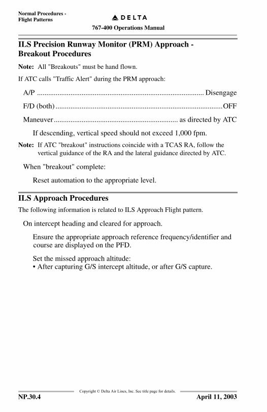
767-400 Operations Manual
Normal Procedures -Flight Patterns
Copyright © Delta Air Lines, Inc. See title page for details.
ILS Precision Runway Monitor (PRM) Approach - Breakout Procedures
Note: All "Breakouts" must be hand flown.
If ATC calls "Traffic Alert" during the PRM approach:
A/P .......................................................................................... Disengage
F/D (both) ..........................................................................................OFF
Maneuver ................................................................... as directed by ATC
If descending, vertical speed should not exceed 1,000 fpm.
Note: If ATC "breakout" instructions coincide with a TCAS RA, follow the vertical guidance of the RA and the lateral guidance directed by ATC.
When "breakout" complete:
Reset automation to the appropriate level.
ILS Approach ProceduresThe following information is related to ILS Approach Flight pattern.
On intercept heading and cleared for approach.
Ensure the appropriate approach reference frequency/identifier and course are displayed on the PFD.
Set the missed approach altitude:• After capturing G/S intercept altitude, or after G/S capture.
NP.30.4 April 11, 2003

767-400 Operations Manual
Normal Procedures -Flight Patterns
Copyright © Delta Air Lines, Inc. See title page for details.
IntentionallyBlank
NP.30.5March 31, 2006

767-400 Operations Manual
Normal Procedures -Flight Patterns
Copyright © Delta Air Lines, Inc. See title page for details.
Low Visibility Approach Considerations (CAT II/CAT III)Approach Preparation
Category II and Category III operations are not authorized with the following:
Captain must conduct approach. For inoperative equipment, refer to ILS AirborneEquipment Requirement Chart, NP.10.
Consider the following:
• Select standby ADI to display center ILS (select APP).• Autobrakes - level 3 or higher recommended, and must be used during
CAT III approach if operable.• First Officer should have the airport diagram or SMGCS page available
for taxi assistance.• Use landing/strobe lights and windshield wipers appropriately.• Review go-around procedures.• Review standard callouts (AFDS, DA or AH, Roll-out steering guidance).
Maximum reported runway winds:
• 15 knot crosswind.• 10 knot tailwind.• 25 knot headwind to autoland.
• SGL SOURCE DISPLAYS • SINGLE AIR DATA
• SGL SOURCE RAD ALT • SINGLE SOURCE IRS
• SINGLE SOURCE ILS • L AC BUS OFF
NP.30.6 March 31, 2006
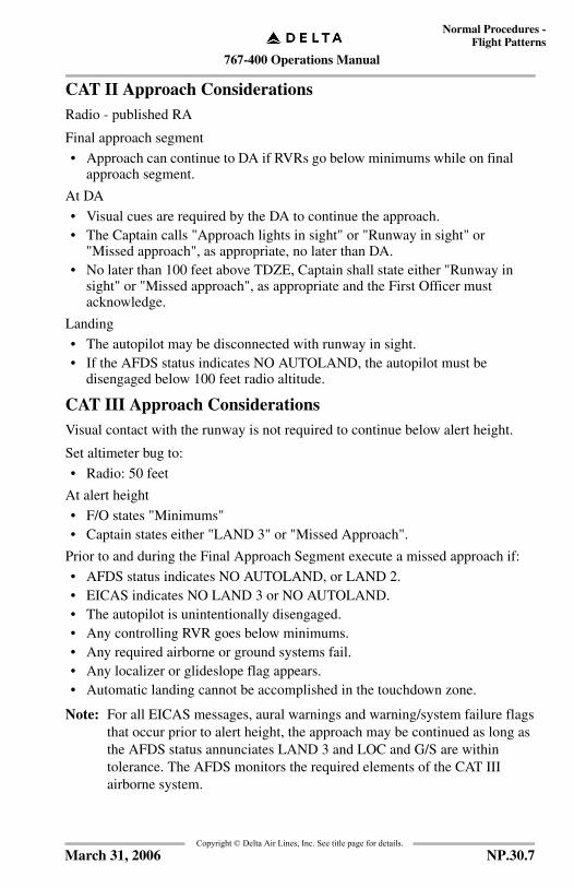
767-400 Operations Manual
Normal Procedures -Flight Patterns
Copyright © Delta Air Lines, Inc. See title page for details.
CAT II Approach ConsiderationsRadio - published RA
Final approach segment
• Approach can continue to DA if RVRs go below minimums while on final approach segment.
At DA
• Visual cues are required by the DA to continue the approach.• The Captain calls "Approach lights in sight" or "Runway in sight" or
"Missed approach", as appropriate, no later than DA.• No later than 100 feet above TDZE, Captain shall state either "Runway in
sight" or "Missed approach", as appropriate and the First Officer must acknowledge.
Landing
• The autopilot may be disconnected with runway in sight.• If the AFDS status indicates NO AUTOLAND, the autopilot must be
disengaged below 100 feet radio altitude.
CAT III Approach ConsiderationsVisual contact with the runway is not required to continue below alert height.
Set altimeter bug to:
• Radio: 50 feet
At alert height
• F/O states "Minimums"• Captain states either "LAND 3" or "Missed Approach".
Prior to and during the Final Approach Segment execute a missed approach if:
• AFDS status indicates NO AUTOLAND, or LAND 2.• EICAS indicates NO LAND 3 or NO AUTOLAND.• The autopilot is unintentionally disengaged.• Any controlling RVR goes below minimums.• Any required airborne or ground systems fail.• Any localizer or glideslope flag appears.• Automatic landing cannot be accomplished in the touchdown zone.
Note: For all EICAS messages, aural warnings and warning/system failure flags that occur prior to alert height, the approach may be continued as long as the AFDS status annunciates LAND 3 and LOC and G/S are within tolerance. The AFDS monitors the required elements of the CAT III airborne system.
NP.30.7March 31, 2006

767-400 Operations Manual
Normal Procedures -Flight Patterns
Copyright © Delta Air Lines, Inc. See title page for details.
Non - ILS Instrument Approach Considerations
Approach Preparations - GeneralDetermine raw data monitoring requirements and cockpit display.
Determine final approach pitch mode. (At the crew’s discretion, vertical speed maybe used on any non-ILS approach).
NP.30.8 March 31, 2006
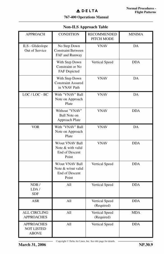
767-400 Operations Manual
Normal Procedures -Flight Patterns
Copyright © Delta Air Lines, Inc. See title page for details.
Non-ILS Approach Table
APPROACH CONDITION RECOMMENDED PITCH MODE
MINIMA
ILS - Glideslope Out of Service
No Step Down Constraint Between FAF and Runway
VNAV DA
With Step Down Constraint or No
FAF Depicted
Vertical Speed DDA
With Step Down Constraint Assured
in VNAV Path
VNAV DA
LOC / LOC - BC With "VNAV" Ball Note on Approach
Plate
VNAV DA
Without "VNAV" Ball Note on
Approach Plate
VNAV DDA
VOR With "VNAV" Ball Note on Approach
Plate
VNAV DA
W/out VNAV Ball Note & with valid
End of Descent Point
VNAV DDA
W/out VNAV Ball Note & w/out valid
End of Descent Point
Vertical Speed DDA
NDB /LDA /SDF
All Vertical Speed DDA
ASR All Vertical Speed (Required)
DDA
ALL CIRCLING APPROACHES
All Vertical Speed (Required)
MDA
APPROACHES NOT LISTED
ABOVE
All Vertical Speed DDA
NP.30.9March 31, 2006
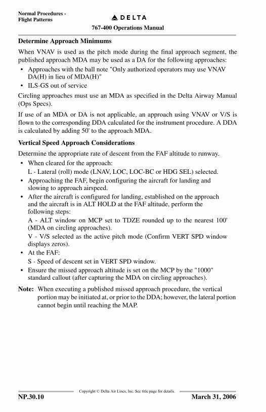
767-400 Operations Manual
Normal Procedures -Flight Patterns
Copyright © Delta Air Lines, Inc. See title page for details.
Determine Approach Minimums
When VNAV is used as the pitch mode during the final approach segment, thepublished approach MDA may be used as a DA for the following approaches:
• Approaches with the ball note "Only authorized operators may use VNAV DA(H) in lieu of MDA(H)"
• ILS-GS out of service
Circling approaches must use an MDA as specified in the Delta Airway Manual(Ops Specs).
If use of an MDA or DA is not applicable, an approach using VNAV or V/S isflown to the corresponding DDA calculated for the instrument procedure. A DDAis calculated by adding 50' to the approach MDA.
Vertical Speed Approach Considerations
Determine the appropriate rate of descent from the FAF altitude to runway.
• When cleared for the approach:L - Lateral (roll) mode (LNAV, LOC, LOC-BC or HDG SEL) selected.
• Approaching the FAF, begin configuring the aircraft for landing and slowing to approach airspeed.
• After the aircraft is configured for landing, established on the approach and the aircraft is in ALT HOLD at the FAF altitude, perform the following steps:A - ALT window on MCP set to TDZE rounded up to the nearest 100'(MDA on circling approaches).V - V/S selected as the active pitch mode (Confirm VERT SPD windowdisplays zeros).
• At the FAF:S - Speed of descent set in VERT SPD window.
• Ensure the missed approach altitude is set on the MCP by the "1000" standard callout (after capturing the MDA on circling approaches).
Note: When executing a published missed approach procedure, the vertical portion may be initiated at, or prior to the DDA; however, the lateral portion cannot begin until reaching the MAP.
NP.30.10 March 31, 2006

767-400 Operations Manual
Normal Procedures -Flight Patterns
Copyright © Delta Air Lines, Inc. See title page for details.
VNAV Approach Considerations
Select the approach from the FMS database.
Adjust the LEGS page airspeeds and altitudes, if necessary.
If VNAV path deviation scale is not displayed, enter an artificially high cruisealtitude on the CRZ page or select DES NOW on the DESCENT page.
• When cleared for the approach:L - Lateral (roll) mode (LNAV, LOC, LOC-BC or HDG SEL) selected.
• Approaching the FAF, begin configuring the aircraft for landing and slowing to approach airspeed.Note: The aircraft may balloon above current altitude if configuring in VNAV
and in level flight.
• After the aircraft is configured for landing, established on the approach and the FAF altitude is assured, confirm the following:A - ALT window on MCP set to TDZE rounded up to the nearest 100' V - VNAV PTH is selected as the active pitch mode.S - Speed intervention set to desired airspeed.
Note: Be aware of the following VNAV considerations:
• VNAV PATH must be enunciated on the FMA by the FAF.• If the vertical deviation pointer reaches ½ scale (200’ deviation), consider
executing a missed approach.• The auto throttles (on non-Pegasus equipped aircraft) must be
disconnected prior to reaching the approach EOD point.• The flight director pitch bar does not provide VNAV descent information
after passing the approach EOD point.
Ensure the missed approach altitude is set on the MCP by the “1000” standardcallout.
Missed Approach
A missed approach shall be initiated if any of the following conditions exist:
• Pitch mode other than VNAV PTH is displayed on the ADI after the FAF is crossed.
• The vertical deviation pointer reaches full scale (400’ deviation).
Note: When executing a published missed approach procedure, the vertical portion may be indicated at, or prior to minimums; however, the lateral portion cannot begin until reaching the MAP.
NP.30.11March 31, 2006

767-400 Operations Manual
Normal Procedures -Flight Patterns
Copyright © Delta Air Lines, Inc. See title page for details.
Visual Approach And Landing Considerations
FMS/ND Utilization• Using the FMS during visual approaches is optional.• Program the landing runway as the active waypoint.• With ND in 10 mile scale, turn to base leg when runway symbol
disappears (approximately 4-5 nm from approach end of runway).• Use distance remaining from runway (if active waypoint) and
runway elevation to determine 3-to-1 descent profile.• Green arc may be used to monitor descent if MCP set to runway
TDZE• Vertical speed may be utilized for normal descent rate.
Note: Autothrottle must be disconnected prior to the flare maneuver when not accomplishing an Autoland.
NP.30.12 March 31, 2006

767-400 Operations Manual
Normal Procedures -Flight Patterns
Copyright © Delta Air Lines, Inc. See title page for details.
Flight Profiles
Normal Takeoff (Distant/ICAO I) Profile
The following profile satisfies typical vertical noise abatement requirements.
Acc
eler
atio
n he
ight
(nor
mal
ly 1
,000
fee
t A
FE
)•
Sele
ct V
NA
V•
Sele
ct/v
erif
y C
LB
thru
st•
Acc
eler
ate
to f
laps
up
man
euve
ring
sp
eed
•R
etra
ct f
laps
on
sche
dule
Fla
ps u
p•
Do
the
Aft
er T
akeo
ff
chec
klis
t
Abo
ve 4
00 f
eet
RA
•S
elec
t rol
l mod
e
Take
off
roll
•S
et ta
keof
f th
rust
by
80 k
nots
•M
onito
r ai
rspe
ed•
Mai
ntai
n lig
ht f
orw
ard
pres
sure
Thr
ust
set
•M
anua
lly a
dvan
ce th
rust
to s
tabi
lize
•E
ngag
e au
toth
rott
le
Pos
itiv
e ra
te o
f cl
imb
•R
etra
ct g
ear
Init
ial c
limb
spee
d•
V2+
15 to
V2+
25 k
nots
Not
e:Fo
r an
imm
edia
te tu
rn a
fter
take
off,
m
aint
ain
initi
al c
limb
spee
d w
ith
take
off
flap
s w
hile
man
euve
ring
. Fo
llow
AF
DS
bank
lim
its.
V1
The
aut
opilo
t may
be
enga
ged
afte
r a
roll
mod
e an
d V
NA
V a
re s
elec
ted.
VR •R
otat
e2,
500
feet
AF
E•
Acc
eler
ate
to 2
50 k
nots
or
appr
oved
clim
b sp
eed
NP.30.13November 20, 2006

767-400 Operations Manual
Normal Procedures -Flight Patterns
Copyright © Delta Air Lines, Inc. See title page for details.
Special Takeoff (Close-In/ICAO II) ProfileThe following profile satisfies typical vertical noise abatement requirements fornoise sensitive areas in close proximity to the departure end of an airport runway.
Acc
eler
atio
n he
ight
, 3,
000
feet
AF
E•
Ret
ract
fla
ps o
n sc
hedu
le•
Do
the
Aft
er T
akeo
ff
chec
klis
t
Abo
ve 4
00 f
eet
RA
•S
elec
t rol
l mod
e
Thr
ust
set
•M
anua
lly a
dvan
ce th
rust
to s
tabi
lize
•E
ngag
e au
toth
rott
le
VR •R
otat
e
Pos
itiv
e ra
te o
f cl
imb
•R
etra
ct g
ear
Init
ial c
limb
spee
d•
V2+
15 k
nots
•R
educ
e pi
tch
attit
ude
to m
aint
ain
V2
+ 2
0
Eng
ine
fail
ure,
w
inds
hear
, or
an
yN
on-n
orm
al a
ffec
ting
saf
ety
of fl
ight
canc
els
the
Noi
se
Aba
tem
ent
proc
edur
e.
Take
off
roll
•Se
t tak
eoff
thru
st b
y 80
kno
ts•
Mon
itor
airs
peed
•M
aint
ain
light
for
war
d pr
essu
re
V1
Not
e:Fo
r an
imm
edia
te tu
rn a
fter
take
off,
m
aint
ain
initi
al c
limb
spee
d w
ith
take
off
flap
s w
hile
man
euve
ring
. Fo
llow
AFD
S ba
nk li
mits
.
1,50
0 fe
et A
FE
•Se
lect
VN
AV
•Se
lect
/ver
ify
CL
B th
rust
The
aut
opilo
t may
be
enga
ged
afte
r a
roll
mod
e an
d V
NA
V a
re s
elec
ted.
NP.30.14 November 20, 2006

767-400 Operations Manual
Normal Procedures -Flight Patterns
Copyright © Delta Air Lines, Inc. See title page for details.
ILS Approach Profile
•Fl
aps
1
Loc
aliz
er c
aptu
re•
Fina
l App
roac
h co
urse
he
adin
g
Fix
(LO
M, M
KR
, DM
E)
•V
erif
y cr
ossi
ng a
ltitu
de
Glid
eslo
pe in
terc
ept
•L
andi
ng f
laps
•E
nsur
e m
isse
d ap
proa
ch a
ltitu
de in
M
CP
by 1
,000
fee
t AG
L•
Do
the
Lan
ding
che
cklis
t
Glid
eslo
pe a
live
•G
ear
dow
n•
Flap
s 20
•A
rm s
peed
brak
e
App
roac
hing
inte
rcep
t he
adin
g•
Flap
s 5
•F
laps
5
On
RA
DA
R v
ecto
rs•
HD
G S
EL
•A
ppro
pria
te p
itch
mod
e
Inte
rcep
t H
eadi
ng•
ILS
tune
d an
d id
entif
ied
•L
OC
and
G/S
poi
nter
s di
spla
yed
•A
rm A
PP m
ode
Enr
oute
to
fix
•L
NA
V o
r ap
prop
riat
e ro
ll m
ode
•V
NA
V o
r ap
prop
riat
e pi
tch
mod
e
NP.30.15March 31, 2006

767-400 Operations Manual
Normal Procedures -Flight Patterns
Copyright © Delta Air Lines, Inc. See title page for details.
Instrument Approach Using VNAV Profile
At D
A/D
DA
•In
terc
ept l
andi
ng p
rofil
e•
Dis
conn
ect a
utop
ilot b
yD
A -5
0 fe
et /
DD
A -
100
feet
•D
isco
nnec
t aut
othr
ottle
pri
or to
the
flar
e
App
roac
hing
inte
rcep
t hea
ding
•Fl
aps 5
•Fl
aps 5
Inte
rcep
t hea
ding
•A
rm ap
prop
riate
ro
ll m
ode
Des
cend
to D
A/D
DA
•M
onito
r VN
AV p
ath
•En
sure
mis
sed
appr
oach
alti
tude
in
MC
P by
1,0
00 fe
et A
GL
•Fl
aps 1
Prio
r to
FA
F•
Gea
r dow
n•
Flap
s 20
•A
rm sp
eedb
rake
•La
ndin
g fla
ps•
Do
the
Land
ing
chec
klis
t
Enr
oute
to fi
x•
LNAV
or a
ppro
pria
te
roll
mod
e•
VN
AV o
r app
ropr
iate
pi
tch
mod
e
FAF
FAF
altit
ude
assu
red
•C
onfir
m T
DZE
roun
ded
up,
set
•C
onfir
m V
NAV
and
Spe
ed
Inte
rven
tion
sele
cted
On
RA
DA
R v
ecto
rs•
HD
G S
EL•
App
ropr
iate
pitc
h m
ode
NP.30.16 March 31, 2006
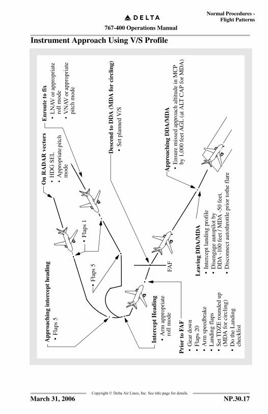
767-400 Operations Manual
Normal Procedures -Flight Patterns
Copyright © Delta Air Lines, Inc. See title page for details.
Instrument Approach Using V/S Profile
Lea
ving
DD
A/M
DA
•In
terc
ept l
andi
ng p
rofi
le•
Dis
enga
ge a
utop
ilot
by
DD
A -
100
feet
/ M
DA
-50
fee
t. •
Dis
conn
ect a
utot
hrot
tle p
rior
toth
e fl
are
App
roac
hing
DD
A/M
DA
•E
nsur
e m
isse
d ap
proa
ch a
ltitu
de in
MC
P by
1,0
00 f
eet A
GL
(at
ALT
CA
P fo
r M
DA
)
App
roac
hing
inte
rcep
t he
adin
g•
Fla
ps 5
•F
laps
5
Inte
rcep
t H
eadi
ng•
Arm
app
ropr
iate
ro
ll m
ode
Des
cend
to
DD
A (
MD
A fo
r ci
rclin
g)•
Set p
lann
ed V
/S
•F
laps
1
FAF
Pri
or t
o FA
F•
Gea
r do
wn
•Fl
aps
20•
Arm
spe
edbr
ake
•L
andi
ng f
laps
•Se
t TD
ZE
rou
nded
up
(MD
A f
or c
ircl
ing)
•
Do
the
Lan
ding
ch
eckl
ist
Enr
oute
to fi
x•
LNAV
or a
ppro
pria
te
roll
mod
e•
VN
AV o
r app
ropr
iate
pi
tch
mod
e
On
RA
DA
R v
ecto
rs•
HD
G S
EL•
App
ropr
iate
pitc
h m
ode
NP.30.17March 31, 2006

767-400 Operations Manual
Normal Procedures -Flight Patterns
Copyright © Delta Air Lines, Inc. See title page for details.
Circling Approach ProfileC
onfi
gura
tion
at
MD
A•
Gea
r do
wn
•Fl
aps
20 (
land
ing
flap
s op
tiona
l)•
Arm
Spe
edbr
ake
Turn
ing
Bas
e•
Lan
ding
fla
ps(i
f no
t pre
viou
sly
sele
cted
)•
Do
the
Lan
ding
che
cklis
t
Inte
rcep
ting
Lan
ding
Pro
file
•D
isen
gage
aut
opilo
t by
MD
A -
50
feet
Min
imum
Des
cent
Alt
itud
e•
Sele
ct A
LT H
LD
(i
f re
quir
ed)
•Se
t mis
sed
appr
oach
alti
tude
•Se
lect
HD
G S
EL
If a
mis
sed
appr
oach
is n
eede
d at
any
time
whi
le c
irclin
g, m
ake
anin
itial
clim
bing
turn
in th
e sh
orte
stdi
rect
ion
tow
ard
the
land
ing
runw
ayan
d in
terc
ept t
he m
isse
d ap
proa
ch
cour
se.
NP.30.18 March 31, 2006
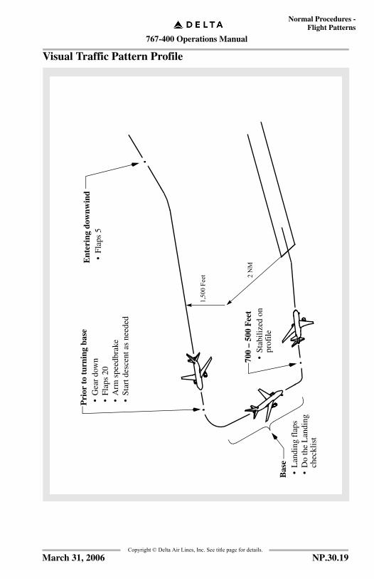
767-400 Operations Manual
Normal Procedures -Flight Patterns
Copyright © Delta Air Lines, Inc. See title page for details.
Visual Traffic Pattern Profile
Bas
e•
Lan
ding
fla
ps•
Do
the
Lan
ding
ch
eckl
ist
1,50
0 Fe
et 2 N
M
Ent
erin
g do
wnw
ind
•Fl
aps
5
Pri
or t
o tu
rnin
g ba
se•
Gea
r do
wn
•Fl
aps
20•
Arm
spe
edbr
ake
•St
art d
esce
nt a
s ne
eded
700
– 50
0 F
eet
•St
abili
zed
on
prof
ile
NP.30.19March 31, 2006
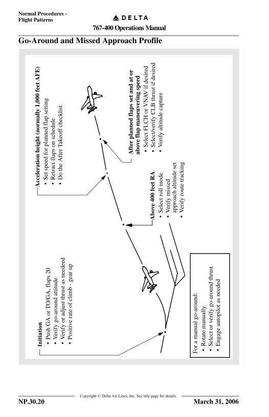
767-400 Operations Manual
Normal Procedures -Flight Patterns
Copyright © Delta Air Lines, Inc. See title page for details.
Go-Around and Missed Approach ProfileA
ccel
erat
ion
heig
ht (
norm
ally
1,0
00 f
eet
AF
E)
•Se
t spe
ed f
or p
lann
ed f
lap
setti
ng•
Ret
ract
fla
ps o
n sc
hedu
le•
Do
the
Aft
er T
akeo
ff c
heck
list
Initi
atio
n•
Pus
h G
A o
r T
O/G
A, f
laps
20
•V
erif
y go
-aro
und
attit
ude
•V
erif
y or
adj
ust t
hrus
t as
need
eed
•P
ositi
ve r
ate
of c
limb
- ge
ar u
p
Abo
ve 4
00 f
eet
RA
•Se
lect
rol
l mod
e•
Ver
ify
mis
sed
appr
oach
alti
tude
set
•V
erif
y ro
ute
trac
king
Aft
er p
lann
ed f
laps
set
and
at
or
abov
e fl
ap m
aneu
veri
ng s
peed
•S
elec
t FL
CH
or
VN
AV
if d
esir
ed•
Sel
ect/v
erif
y C
LB
thru
st if
des
ired
•V
erif
y al
titud
e ca
ptur
e
For
a m
anua
l go-
arou
nd:
•R
otat
e m
anua
lly•
Sele
ct o
r ve
rify
go-
arou
nd th
rust
•E
ngag
e au
topi
lot a
s ne
eded
NP.30.20 March 31, 2006
767-400 Operations Manual
Supplementary Procedures Chapter SPTable of Contents Section 0
FCO
M T
empl
ate
12/1
2/98
Copyright © Delta Air Lines, Inc. See title page for details.
Introduction . . . . . . . . . . . . . . . . . . . . . . . . . . . . . . . . . . . . . . . . SP.05.1
Airplane General, Emergency Equipment, Doors,Windows. . . . . . . . . . . . . . . . . . . . . . . . . . . . . . . . . . . . . . . . . . . SP.1.1
Doors. . . . . . . . . . . . . . . . . . . . . . . . . . . . . . . . . . . . . . . . . . . . . . . SP.1.1Flight Deck Access System . . . . . . . . . . . . . . . . . . . . . . . . . . . SP.1.1Entry Door Closing . . . . . . . . . . . . . . . . . . . . . . . . . . . . . . . . . SP.1.2Entry Door Opening . . . . . . . . . . . . . . . . . . . . . . . . . . . . . . . . SP.1.2
Windows . . . . . . . . . . . . . . . . . . . . . . . . . . . . . . . . . . . . . . . . . . . . SP.1.3Flight Deck Window Closing . . . . . . . . . . . . . . . . . . . . . . . . . SP.1.3Flight Deck Window Opening . . . . . . . . . . . . . . . . . . . . . . . . . SP.1.3
Lights . . . . . . . . . . . . . . . . . . . . . . . . . . . . . . . . . . . . . . . . . . . . . . SP.1.3Indicator Lights Test . . . . . . . . . . . . . . . . . . . . . . . . . . . . . . . . SP.1.3
Emergency Equipment . . . . . . . . . . . . . . . . . . . . . . . . . . . . . . . . . SP.1.4Emergency Oxygen Use . . . . . . . . . . . . . . . . . . . . . . . . . . . . . SP.1.3Oxygen Mask Test . . . . . . . . . . . . . . . . . . . . . . . . . . . . . . . . . . SP.1.4
Flights Without Flight Attendants. . . . . . . . . . . . . . . . . . . . . . . . . SP.1.5
Air Systems. . . . . . . . . . . . . . . . . . . . . . . . . . . . . . . . . . . . . . . . . . SP.2.1
Air Conditioning Packs . . . . . . . . . . . . . . . . . . . . . . . . . . . . . . . . . SP.2.1Ground Air Conditioning Use . . . . . . . . . . . . . . . . . . . . . . . . . SP.2.1
Packs Off Takeoff . . . . . . . . . . . . . . . . . . . . . . . . . . . . . . . . . . . . . SP.2.1
Anti-Ice, Rain . . . . . . . . . . . . . . . . . . . . . . . . . . . . . . . . . . . . . . . . SP.3.1
Ice Protection . . . . . . . . . . . . . . . . . . . . . . . . . . . . . . . . . . . . . . . . SP.3.1
Anti–Ice Use . . . . . . . . . . . . . . . . . . . . . . . . . . . . . . . . . . . . . . . . . SP.3.1
Engine Anti–Ice Use . . . . . . . . . . . . . . . . . . . . . . . . . . . . . . . . . . . SP.3.1
Wing Anti–Ice Use . . . . . . . . . . . . . . . . . . . . . . . . . . . . . . . . . . . . SP.3.2
Windshield Wiper Use . . . . . . . . . . . . . . . . . . . . . . . . . . . . . . . . . SP.3.2
SP.TOC.0.1December 26, 2006

767-400 Operations Manual
Supplementary Procedures -Table of Contents
Copyright © Delta Air Lines, Inc. See title page for details.
Automatic Flight. . . . . . . . . . . . . . . . . . . . . . . . . . . . . . . . . . . . . . SP.4.1
AFDS. . . . . . . . . . . . . . . . . . . . . . . . . . . . . . . . . . . . . . . . . . . . . . SP.4.1AFDS Operation. . . . . . . . . . . . . . . . . . . . . . . . . . . . . . . . . . . SP.4.1Heading Hold . . . . . . . . . . . . . . . . . . . . . . . . . . . . . . . . . . . . . SP.4.1Heading Select . . . . . . . . . . . . . . . . . . . . . . . . . . . . . . . . . . . . SP.4.1Altitude Hold . . . . . . . . . . . . . . . . . . . . . . . . . . . . . . . . . . . . . SP.4.2Flight Level Change, Climb or Descent. . . . . . . . . . . . . . . . . SP.4.2Vertical Speed, Climb or Descent . . . . . . . . . . . . . . . . . . . . . SP.4.2Altitude Intervention . . . . . . . . . . . . . . . . . . . . . . . . . . . . . . . SP.4.2Speed Intervention . . . . . . . . . . . . . . . . . . . . . . . . . . . . . . . . . SP.4.3Intermediate Level Off . . . . . . . . . . . . . . . . . . . . . . . . . . . . . . SP.4.3
Autothrottle Operation . . . . . . . . . . . . . . . . . . . . . . . . . . . . . . . . SP.4.5
Localizer Approach . . . . . . . . . . . . . . . . . . . . . . . . . . . . . . . . . . . SP.4.6
Localizer Back Course Approach . . . . . . . . . . . . . . . . . . . . . . . . SP.4.8
VOR Approach . . . . . . . . . . . . . . . . . . . . . . . . . . . . . . . . . . . . . SP.4.10
NDB Approach . . . . . . . . . . . . . . . . . . . . . . . . . . . . . . . . . . . . . SP.4.12
Communications. . . . . . . . . . . . . . . . . . . . . . . . . . . . . . . . . . . . . . SP.5.1
Cockpit Voice Recorder Test . . . . . . . . . . . . . . . . . . . . . . . . . . . . SP.5.1
HF System Test . . . . . . . . . . . . . . . . . . . . . . . . . . . . . . . . . . . . . . SP.5.2
Aircraft Communications Addressingand Reporting System (ACARS). . . . . . . . . . . . . . . . . . . . . . . . . SP.5.3
Pre-Departure Clearance . . . . . . . . . . . . . . . . . . . . . . . . . . . . . SP.5.3Digital-Automatic Information Service (D-ATIS) . . . . . . . . . SP.5.3Oceanic Clearances . . . . . . . . . . . . . . . . . . . . . . . . . . . . . . . . . SP.5.3Weight and Balance . . . . . . . . . . . . . . . . . . . . . . . . . . . . . . . . . SP.5.3Takeoff Data . . . . . . . . . . . . . . . . . . . . . . . . . . . . . . . . . . . . . . SP.5.3Company Communication Sequence . . . . . . . . . . . . . . . . . . . SP.5.3Menu Layout . . . . . . . . . . . . . . . . . . . . . . . . . . . . . . . . . . . . . SP.5.5Advisory Messages . . . . . . . . . . . . . . . . . . . . . . . . . . . . . . . . SP.5.7Preflight . . . . . . . . . . . . . . . . . . . . . . . . . . . . . . . . . . . . . . . . . SP.5.9En Route. . . . . . . . . . . . . . . . . . . . . . . . . . . . . . . . . . . . . . . . SP.5.17Postflight . . . . . . . . . . . . . . . . . . . . . . . . . . . . . . . . . . . . . . . SP.5.22
SP.TOC.0.2 November 20, 2006
767-400 Operations Manual
Supplementary Procedures -Table of Contents
Copyright © Delta Air Lines, Inc. See title page for details.
Other . . . . . . . . . . . . . . . . . . . . . . . . . . . . . . . . . . . . . . . . . . . SP.5.26FRM/CLD Code Downlinks . . . . . . . . . . . . . . . . . . . . . . . . . SP.5.30
Gander Oceanic Clearance via Datalink . . . . . . . . . . . . . . . . . . . SP.5.31System Problems . . . . . . . . . . . . . . . . . . . . . . . . . . . . . . . . . . SP.5.33
Shanwick Oceanic Clearance via Datalink . . . . . . . . . . . . . . . . . SP.5.34System Problems . . . . . . . . . . . . . . . . . . . . . . . . . . . . . . . . . . SP.5.36
Electrical. . . . . . . . . . . . . . . . . . . . . . . . . . . . . . . . . . . . . . . . . . . . . SP.6.1
Electrical Power Up . . . . . . . . . . . . . . . . . . . . . . . . . . . . . . . . . . . SP.6.1
Electrical Power Down . . . . . . . . . . . . . . . . . . . . . . . . . . . . . . . . . SP.6.2
Operation With Less Than 90 KVA External PowerSource . . . . . . . . . . . . . . . . . . . . . . . . . . . . . . . . . . . . . . . . . . . . . . SP.6.2
Before Start Procedure. . . . . . . . . . . . . . . . . . . . . . . . . . . . . . . SP.6.2After Start Procedure . . . . . . . . . . . . . . . . . . . . . . . . . . . . . . . . SP.6.2Shutdown Procedure . . . . . . . . . . . . . . . . . . . . . . . . . . . . . . . . SP.6.3
Transfer From External Power To APU Power. . . . . . . . . . . . . . . SP.6.3
Standby Power Check . . . . . . . . . . . . . . . . . . . . . . . . . . . . . . . . . . SP.6.4
Engines, APU . . . . . . . . . . . . . . . . . . . . . . . . . . . . . . . . . . . . . . . . . SP.7.1
Engines . . . . . . . . . . . . . . . . . . . . . . . . . . . . . . . . . . . . . . . . . . . . . SP.7.1Engine Battery Start. . . . . . . . . . . . . . . . . . . . . . . . . . . . . . . . . SP.7.1Engine Crossbleed Start. . . . . . . . . . . . . . . . . . . . . . . . . . . . . . SP.7.2Engine Ground Pneumatic Start . . . . . . . . . . . . . . . . . . . . . . . SP.7.2Reduced Thrust Selection Prior To Takeoff. . . . . . . . . . . . . . . SP.7.3Reduced Takeoff Thrust Change or Cancellation . . . . . . . . . . SP.7.3Reduced Climb Thrust Selection Prior To Takeoff . . . . . . . . . SP.7.4Reduced Climb Thrust Change or Cancellation . . . . . . . . . . . SP.7.4Reduced Climb Thrust Selection In-flight. . . . . . . . . . . . . . . . SP.7.4Manual Engine Performance Report . . . . . . . . . . . . . . . . . . . . SP.7.5
Fire Protection . . . . . . . . . . . . . . . . . . . . . . . . . . . . . . . . . . . . . . . . SP.8.1
Fire and Overheat Test . . . . . . . . . . . . . . . . . . . . . . . . . . . . . . . . . SP.8.1ENG/APU/Cargo Fire Test . . . . . . . . . . . . . . . . . . . . . . . . . . . SP.8.1Wheel Well Fire Test . . . . . . . . . . . . . . . . . . . . . . . . . . . . . . . . SP.8.1
SP.TOC.10.3November 20, 2006

767-400 Operations Manual
Supplementary Procedures -Table of Contents
Copyright © Delta Air Lines, Inc. See title page for details.
Flight Instruments, Displays . . . . . . . . . . . . . . . . . . . . . . . . . . . SP.10.1
Flight Recorder Test . . . . . . . . . . . . . . . . . . . . . . . . . . . . . . . . . SP.10.2
Heading Reference Switch Operation . . . . . . . . . . . . . . . . . . . . SP.10.2
Flight Management, Navigation . . . . . . . . . . . . . . . . . . . . . . . . SP.11.1
Transponder Test . . . . . . . . . . . . . . . . . . . . . . . . . . . . . . . . . . . . SP.11.1
Weather Radar Test . . . . . . . . . . . . . . . . . . . . . . . . . . . . . . . . . . SP.11.1
Radar Operation. . . . . . . . . . . . . . . . . . . . . . . . . . . . . . . . . . . . . SP.11.3Before Takeoff . . . . . . . . . . . . . . . . . . . . . . . . . . . . . . . . . . . SP.11.2Takeoff . . . . . . . . . . . . . . . . . . . . . . . . . . . . . . . . . . . . . . . . . SP.11.3Climb . . . . . . . . . . . . . . . . . . . . . . . . . . . . . . . . . . . . . . . . . . SP.11.3Cruise . . . . . . . . . . . . . . . . . . . . . . . . . . . . . . . . . . . . . . . . . . SP.11.4Descent . . . . . . . . . . . . . . . . . . . . . . . . . . . . . . . . . . . . . . . . . SP.11.5Approach . . . . . . . . . . . . . . . . . . . . . . . . . . . . . . . . . . . . . . . SP.11.5Radar Guidelines . . . . . . . . . . . . . . . . . . . . . . . . . . . . . . . . . SP.11.6
IRS. . . . . . . . . . . . . . . . . . . . . . . . . . . . . . . . . . . . . . . . . . . . . . SP.11.10Full Alignment . . . . . . . . . . . . . . . . . . . . . . . . . . . . . . . . . . SP.11.10Quick Alignment (QA) / Fast Realignment . . . . . . . . . . . SP.11.10High Latitude Alignment . . . . . . . . . . . . . . . . . . . . . . . . . . SP.11.11Align Lights Flashing. . . . . . . . . . . . . . . . . . . . . . . . . . . . . SP.11.12Position Entry Using IRS Mode Selector Panel. . . . . . . . . SP.11.12
Lateral Navigation . . . . . . . . . . . . . . . . . . . . . . . . . . . . . . . . . . SP.11.13Alternate Route Entry/Activation. . . . . . . . . . . . . . . . . . . . SP.11.13Direct To A Waypoint Using Overwrite. . . . . . . . . . . . . . . SP.11.13Estimate For Alternate . . . . . . . . . . . . . . . . . . . . . . . . . . . . SP.11.13Holding Pattern Entry. . . . . . . . . . . . . . . . . . . . . . . . . . . . . SP.11.14Holding Pattern Exit. . . . . . . . . . . . . . . . . . . . . . . . . . . . . . SP.11.14Intercept A Leg Or Course To A Waypoint UsingOverwrite . . . . . . . . . . . . . . . . . . . . . . . . . . . . . . . . . . . . . . SP.11.15Lateral Offset . . . . . . . . . . . . . . . . . . . . . . . . . . . . . . . . . . . SP.11.15Leg Modification . . . . . . . . . . . . . . . . . . . . . . . . . . . . . . . . SP.11.16Route Removal . . . . . . . . . . . . . . . . . . . . . . . . . . . . . . . . . . SP.11.16SID Change Or Runway Change . . . . . . . . . . . . . . . . . . . . SP.11.17STAR, Profile Descent Or Approach Change . . . . . . . . . . SP.11.18
SP.TOC.0.4 March 31, 2006

767-400 Operations Manual
Supplementary Procedures -Table of Contents
Copyright © Delta Air Lines, Inc. See title page for details.
Vertical Navigation . . . . . . . . . . . . . . . . . . . . . . . . . . . . . . . . . . SP.11.19Climb, Cruise Or Descent Speed Schedule Change . . . . . . SP.11.19Climb Or Descent Direct To MCP Altitude . . . . . . . . . . . . SP.11.19Cruise Altitude Change . . . . . . . . . . . . . . . . . . . . . . . . . . . . SP.11.19Speed/Altitude Constraint At Waypoint . . . . . . . . . . . . . . . SP.11.20Speed/Altitude Transition And Restriction . . . . . . . . . . . . . SP.11.20Temporary Altitude Restriction . . . . . . . . . . . . . . . . . . . . . . SP.11.20Temporary Speed Restriction . . . . . . . . . . . . . . . . . . . . . . . SP.11.21
Performance Data Entries . . . . . . . . . . . . . . . . . . . . . . . . . . . . . SP.11.21Descent Forecast . . . . . . . . . . . . . . . . . . . . . . . . . . . . . . . . . SP.11.21Step Climb Evaluation. . . . . . . . . . . . . . . . . . . . . . . . . . . . . SP.11.21Waypoint Winds. . . . . . . . . . . . . . . . . . . . . . . . . . . . . . . . . . SP.11.21
Additional CDU Functions . . . . . . . . . . . . . . . . . . . . . . . . . . . . SP.11.22Data Link Request . . . . . . . . . . . . . . . . . . . . . . . . . . . . . . . . SP.11.22Fix Page Entries . . . . . . . . . . . . . . . . . . . . . . . . . . . . . . . . . . SP.11.22ND Plan Mode Control . . . . . . . . . . . . . . . . . . . . . . . . . . . . SP.11.22Navaid Inhibit . . . . . . . . . . . . . . . . . . . . . . . . . . . . . . . . . . . SP.11.23Update Active Navigation Database . . . . . . . . . . . . . . . . . . SP.11.24
FMC Class II Navigation . . . . . . . . . . . . . . . . . . . . . . . . . . . . . SP.11.25Nav Accuracy Check . . . . . . . . . . . . . . . . . . . . . . . . . . . . . . SP.11.25
RNAV Departure Procedures . . . . . . . . . . . . . . . . . . . . . . . . . . SP.11.26During Preflight . . . . . . . . . . . . . . . . . . . . . . . . . . . . . . . . . . SP.11.26Taxi . . . . . . . . . . . . . . . . . . . . . . . . . . . . . . . . . . . . . . . . . . . SP.11.26During/After Takeoff . . . . . . . . . . . . . . . . . . . . . . . . . . . . . SP.11.27
FMS Preflight for Origins/DestinationsNot Contained in FMS Database . . . . . . . . . . . . . . . . . . . . . . . SP.11.28
Fuel . . . . . . . . . . . . . . . . . . . . . . . . . . . . . . . . . . . . . . . . . . . . . . . . SP.12.1
Fuel Balancing . . . . . . . . . . . . . . . . . . . . . . . . . . . . . . . . . . . . . . SP.12.1
Fuel Crossfeed Valve Check . . . . . . . . . . . . . . . . . . . . . . . . . . . . SP.12.1
Fuel Quantity Test. . . . . . . . . . . . . . . . . . . . . . . . . . . . . . . . . . . . SP.12.1
SP.TOC.10.5March 31, 2006

767-400 Operations Manual
Supplementary Procedures -Table of Contents
Copyright © Delta Air Lines, Inc. See title page for details.
Warning Systems . . . . . . . . . . . . . . . . . . . . . . . . . . . . . . . . . . . . . SP.15.1
EICAS Status Message Erase Procedure. . . . . . . . . . . . . . . . . . SP.15.1
Event Record . . . . . . . . . . . . . . . . . . . . . . . . . . . . . . . . . . . . . . . SP.15.1
Ground Proximity Warning Test . . . . . . . . . . . . . . . . . . . . . . . . SP.15.2
Traffic Alert and Collision Avoidance System (TCAS) Test . . SP.15.2
Takeoff Configuration Test . . . . . . . . . . . . . . . . . . . . . . . . . . . . SP.15.3
Adverse Weather . . . . . . . . . . . . . . . . . . . . . . . . . . . . . . . . . . . . . SP.16.1
Adverse Weather Operation. . . . . . . . . . . . . . . . . . . . . . . . . . . . SP.16.1
Cold Weather Operation . . . . . . . . . . . . . . . . . . . . . . . . . . . . . . SP.16.1Rejected Takeoff. . . . . . . . . . . . . . . . . . . . . . . . . . . . . . . . . . SP.16.2Landing . . . . . . . . . . . . . . . . . . . . . . . . . . . . . . . . . . . . . . . . SP.16.2Securing for Cold Weather . . . . . . . . . . . . . . . . . . . . . . . . . . SP.16.3
Ground De/Anti–Icing. . . . . . . . . . . . . . . . . . . . . . . . . . . . . . . . SP.16.4Definitions And Concepts . . . . . . . . . . . . . . . . . . . . . . . . . . SP.16.4Delta De/Anti-icing Program . . . . . . . . . . . . . . . . . . . . . . . . SP.16.8De/Anti-icing Fluids. . . . . . . . . . . . . . . . . . . . . . . . . . . . . . SP.16.11Forced Air Deicing. . . . . . . . . . . . . . . . . . . . . . . . . . . . . . . SP.16.14De/Anti-icing Checks. . . . . . . . . . . . . . . . . . . . . . . . . . . . . SP.16.15Communication Procedures . . . . . . . . . . . . . . . . . . . . . . . . SP.16.20Holdover Times . . . . . . . . . . . . . . . . . . . . . . . . . . . . . . . . . SP.16.20Configuring the Aircraft for De/Anti-icing . . . . . . . . . . . . SP.16.25
Ground De-Icing/Anti-Icing . . . . . . . . . . . . . . . . . . . . . . . . . . SP.16.27
Takeoff Decision Tree . . . . . . . . . . . . . . . . . . . . . . . . . . . . . . . SP.16.28
Holdover Time Guidelines . . . . . . . . . . . . . . . . . . . . . . . . . . . SP.16.28
Hot Weather Operation . . . . . . . . . . . . . . . . . . . . . . . . . . . . . . SP.16.33
Operation in Heavy Rain or Hail. . . . . . . . . . . . . . . . . . . . . . . SP.16.34
Turbulence . . . . . . . . . . . . . . . . . . . . . . . . . . . . . . . . . . . . . . . . SP.16.35Severe Turbulence . . . . . . . . . . . . . . . . . . . . . . . . . . . . . . . . SP.16.35
Windshear . . . . . . . . . . . . . . . . . . . . . . . . . . . . . . . . . . . . . . . . SP.16.36Avoidance . . . . . . . . . . . . . . . . . . . . . . . . . . . . . . . . . . . . . . SP.16.36Precautions . . . . . . . . . . . . . . . . . . . . . . . . . . . . . . . . . . . . . SP.16.36
SP.TOC.0.6 December 19, 2007

767-400 Operations Manual
Supplementary Procedures -Table of Contents
Copyright © Delta Air Lines, Inc. See title page for details.
Guidelines for Contaminated Runways . . . . . . . . . . . . . . . . . . SP.16.39Procedure Guidance . . . . . . . . . . . . . . . . . . . . . . . . . . . . . . SP.16.39
SP.TOC.10.7December 19, 2007

767-400 Operations Manual
Supplementary Procedures -Table of Contents
Copyright © Delta Air Lines, Inc. See title page for details.
IntentionallyBlank
SP.TOC.0.8 August 15, 2005
767-400 Operations Manual
Supplementary Procedures Chapter SPIntroduction Section 05
FCO
M T
empl
ate
12/1
2/98
Copyright © Delta Air Lines, Inc. See title page for details.
GeneralThis chapter contains procedures that may be required during routine operations,due to unusual situations, or as a result of a procedure referenced in a Non–NormalChecklist. Additionally, some procedures that are normally performed bymaintenance personnel are included.
At the discretion of the Captain, procedures may be performed by recall, byreviewing the procedure prior to accomplishment, or by reference to the procedureduring its accomplishment.
Supplementary procedures are provided by section. Section titles correspond tothe respective system titles, except for the adverse weather section.
SP.05.1March 31, 2006
767-400 Operations Manual
Supplementary Procedures -Introduction
Copyright © Delta Air Lines, Inc. See title page for details.
IntentionallyBlank
SP.05.2 August 1, 2000
767-400 Operations Manual
Chapter SPSupplementary Procedures
Airplane General, Emergency Equipment, Doors, Windows
Section 1
Copyright © Delta Air Lines, Inc. See title page for details.
Doors
Flight Deck Access System
Preflight
The following procedures must be accomplished once each flight day:
• Push and hold the Master Indicator Lights test switch on the overhead panel:- Verify the AUTO UNLK and LOCK FAIL lights illuminate, then releasethe test switch.
• With the flight deck door open, press ENT, then enter the access code on the keypad, then press ENT:- Verify the aural alert sounds, the door control panel AUTO UNLK lightilluminates and the amber light on the keypad illuminates.
• Position the flight deck door control selector to UNLKD:- Verify the AUTO UNLK light on the control panel extinguishes, theamber light extinguishes, and the green light on the keypad illuminates.
The door lock solenoid will disengage until the door lock selector is released.
Electrical Locking System Failure
Should any component of the electronic locking system fail prior to or duringflight, utilize the Mechanical Latch Pin to lock the flight deck door.
• Remove the Mechanical Latch Pin from the stowage hole.• Insert the Mechanical Latch Pin completely into the door catch
locking hole.If there is an electrical locking system failure, a second crew member is requiredto secure the flight deck door when a crewmember leaves the flight deck. Refer toFOM General Policy, Security, for flight deck entry/exit procedures.
SP.1.1November 20, 2006
767-400 Operations Manual
Supplementary Procedures -Airplane General, Emergency Equipment, Doors, Windows
Copyright © Delta Air Lines, Inc. See title page for details.
Entry Door Closing
Door .............................................................................................. LowerRaise door slightly, push and hold uplatch release button, then lower door approximately 2 inches (5 centimeters). Then, release button and continue to lower door until closed.
Doors with electrical operating systems may be lowered electrically using the control switch.
Door handle .................................................................................... DownRotate to the down (flush) position.
Arming lever (interior only) ......................................... SLIDE ARMEDWhile pushing arming lever release, position arming lever to SLIDE ARMED. Observe slide armed light illuminated, armed indicator in view and Direct Visual Indication of girt bar lockdown is completely yellow
Entry Door Opening
Arming Lever (interior only) ........................................ SLIDE DISARMPosition arming lever to SLIDE DISARMED. Observe slide armed light extinguished, armed indicator out of view, arming lever release button extended and girt bar lockdown indications show blank
Note: Slide disarms automatically when the door is opened from outside
Door handle ........................................................................................ UpRotate aft to the up position.
Door ................................................................................................ RaiseRaise the door until the uplatch is engaged.
Doors with electrical operating systems may be raised electrically using the control switch.
SP.1.2 March 31, 2006
767-400 Operations Manual
Supplementary Procedures -Airplane General, EmergencyEquipment, Doors, Windows
Copyright © Delta Air Lines, Inc. See title page for details.
Windows
Flight Deck Window Closing
Window crank ............................................................................... RotateCrank the window to the full closed position (the WINDOW NOT CLOSED placard is not visible and, the link arm assembly is approximately perpendicular to the lower track).
Window lock lever ........................................................................ RotateRotate the window lock lever forward to the locked position.
Pull on lock lever without depressing release button to ensure lock lever is secure.
Ensure the indicator at the top of window reads CLOSED.
Flight Deck Window Opening
Window lock lever ......................................................................... RotateRotate the window lock lever aft to the open position.
Window crank ................................................................................ RotateCrank the window to the full open position (the WINDOW NOT CLOSED placard is visible).
Lights
Indicator Lights Test
INDICATOR LIGHTS TEST switch ............................... Push and holdVerify all indicator lights in the flight deck, except lights in the fuel control and APU/engine fire switches illuminated.
INDICATOR LIGHTS TEST switch ......................................... Release
SP.1.3December 26, 2006

767-400 Operations Manual
Supplementary Procedures -Airplane General, Emergency Equipment, Doors, Windows
Copyright © Delta Air Lines, Inc. See title page for details.
Emergency Equipment
Emergency Oxygen UseEmergency oxygen should be used when necessary to provide positive pressure inthe masks and goggles to prevent or evacuate contaminants. When positivepressure is not required, but contamination of flight deck air exists, 100% oxygenmust be used. If prolonged use is required and the situation permits, oxygenavailability should be extended by selecting normal flow. When oxygen use is nolonger required, the oxygen compartment door with the Test/Reset switch must beclosed and the Test/Reset switch pushed to restore normal boom microphoneoperation.
Oxygen Mask Test
Mask – Stowed
Verify doors closed.
STATUS display - Verify
Note oxygen pressure (1,000 psi minimum).
Regulator Selector – Rotate to EMERGENCY
TEST/RESET switch - Push and hold.
Verify the yellow cross appears continuously in the flow indicator. One crewmember must continue to hold the TEST/RESET switch for 10 seconds.
Verify that the crew oxygen pressure does not decrease more than100 psi.
If the oxygen cylinder valve is not in the full open position, pressure can:• decrease rapidly, or• decrease more than 100 psi, or• increase slowly back to normal
TEST/RESET switch – Release
Regulator Selector – Rotate to 100%
Continued on next page
SP.1.4 December 26, 2006

767-400 Operations Manual
Supplementary Procedures -Airplane General, EmergencyEquipment, Doors, Windows
Copyright © Delta Air Lines, Inc. See title page for details.
Continued from previous page
TEST/RESET switch – Push and hold
Verify the yellow cross appears momentarily in the flow indicator.
Note: If the oxygen flow indicator (yellow) remains visible, a system leak has been detected.
TEST/RESET switch – Release
Verify the yellow cross no longer appears in the flow indicator.
Speaker Volume Control knob - Push
Flight Interphone Volume Control knob - Push
MICROPHONE/INTERPHONE switch - INT and hold
While holding TEST/RESET switch, tap the top of the O2 mask to ensure mic feedback.
MICROPHONE/INTERPHONE switch - Release
Flights Without Flight AttendantsFor a flight without a flight attendant staff (ferry flight, test flight, delivery flight,training flight, etc.), the pilots must secure the cabin.
After block-in, pilots must disarm all doors and pass a thumbs up to the gate agentwhen the main entry door is ready to be opened.
Doors - Secured and at least 1L and 1R armed.
Beverage carts - Stowed and locked in position.
Galley (coffee pots, doors and drawers, etc.) - Secured.
Overhead bins - Closed.
Closets - Closed and locked.
Lavatories - Inspect for general security; doors closed.
SP.1.5December 26, 2006

767-400 Operations Manual
Supplementary Procedures -Airplane General, Emergency Equipment, Doors, Windows
Copyright © Delta Air Lines, Inc. See title page for details.
IntentionallyBlank
SP.1.6 November 20, 2006

767-400 Operations Manual
Supplementary Procedures Chapter SPAir Systems Section 2
FCO
M T
empl
ate
12/1
2/98
Copyright © Delta Air Lines, Inc. See title page for details.
Air Conditioning Packs
Ground Air Conditioning Use
Before connecting ground air conditioning:
Pack Control selectors ................................................................. OFFPrevents pack operation if bleed air is supplied to airplane.
RECIRCULATION FANS switches ........................................... OFFAllows ground air conditioning to operate at maximum efficiency.
After disconnecting ground air conditioning:
Pack Control selectors ..............................................................AUTO
RECIRCULATION FANS switches .............................................ON
Packs Off Takeoff
Before takeoff:
Pack Control selectors ................................................................ OFFBoth Packs should be positioned to OFF just prior to commencing the takeoff roll.
After takeoff:
Note: If engine failure occurs, pack control selectors should remain OFF until reaching 1,500 feet AFE or until obstacle clearance height has been attained, whichever is higher.
Pack Control selector (one only) ..............................................AUTOAfter engine thrust is reduced from takeoff, position one pack control selector to AUTO.
Pack Control selector (remaining pack) ...................................AUTOWhen cabin pressurization stabilizes, position remaining pack control selector to AUTO.
SP.2.1November 20, 2006
767-400 Operations Manual
Supplementary Procedures -Air Systems
Copyright © Delta Air Lines, Inc. See title page for details.
IntentionallyBlank
SP.2.2 December 15, 2003

767-400 Operations Manual
Supplementary Procedures Chapter SPAnti-Ice, Rain Section 3
FCO
M T
empl
ate
12/1
2/98
Copyright © Delta Air Lines, Inc. See title page for details.
Ice ProtectionIce protection is provided by the airplane anti–ice systems.
Anti–Ice UseIcing conditions exist when OAT is 10°C (50°F) or below during groundoperations, takeoff, initial climb or go–around or; TAT is 10°C or below in–flightand:
• visible moisture (fog with visibility less than one mile, clouds, rain, snow, sleet, ice crystals, and so on) is present, or
• standing water, ice, or snow is present on the ramps, taxiways, or runways.
Engine Anti–Ice UseEngine anti–ice must be used during all ground and flight operations when icingconditions exist or are anticipated, except when temperature is below -40°C SAT.
If icing conditions are present, engine anti–ice must be selected ON immediatelyafter engine start.
During ground operation when engine anti-ice is required and OAT is +3°C (37°F) or less, periodically increase thrust to as high a thrust setting as practical(60% N1 desired). This run–up need not be made more frequently than 30 minuteintervals, for approximately 30 seconds duration.
Takeoff must be preceded by a static run–up to as high a thrust setting as practical(60% N1 desired), observing all primary engine indications to ensure normaloperation prior to brake release.
Inflight, in moderate to severe icing conditions for prolonged periods with N1settings at or below 70%, or if fan icing is suspected due to high engine vibration,increase thrust on one engine at a time to a minimum of 70% N1 for 10–30seconds every 10 minutes.
CAUTION: Do not operate engine anti–ice when the total airtemperature (TAT) is above 10°C.
SP.3.1December 19, 2007
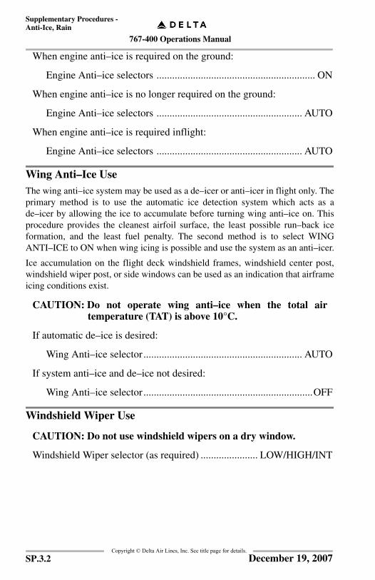
767-400 Operations Manual
Supplementary Procedures -Anti-Ice, Rain
Copyright © Delta Air Lines, Inc. See title page for details.
When engine anti–ice is required on the ground:
Engine Anti–ice selectors ............................................................. ON
When engine anti–ice is no longer required on the ground:
Engine Anti–ice selectors ........................................................ AUTO
When engine anti–ice is required inflight:
Engine Anti–ice selectors ........................................................ AUTO
Wing Anti–Ice UseThe wing anti–ice system may be used as a de–icer or anti–icer in flight only. Theprimary method is to use the automatic ice detection system which acts as ade–icer by allowing the ice to accumulate before turning wing anti–ice on. Thisprocedure provides the cleanest airfoil surface, the least possible run–back iceformation, and the least fuel penalty. The second method is to select WINGANTI–ICE to ON when wing icing is possible and use the system as an anti–icer.
Ice accumulation on the flight deck windshield frames, windshield center post,windshield wiper post, or side windows can be used as an indication that airframeicing conditions exist.
CAUTION: Do not operate wing anti–ice when the total airtemperature (TAT) is above 10°C.
If automatic de–ice is desired:
Wing Anti–ice selector............................................................. AUTO
If system anti–ice and de–ice not desired:
Wing Anti–ice selector.................................................................OFF
Windshield Wiper Use
CAUTION: Do not use windshield wipers on a dry window.
Windshield Wiper selector (as required) ...................... LOW/HIGH/INT
SP.3.2 December 19, 2007
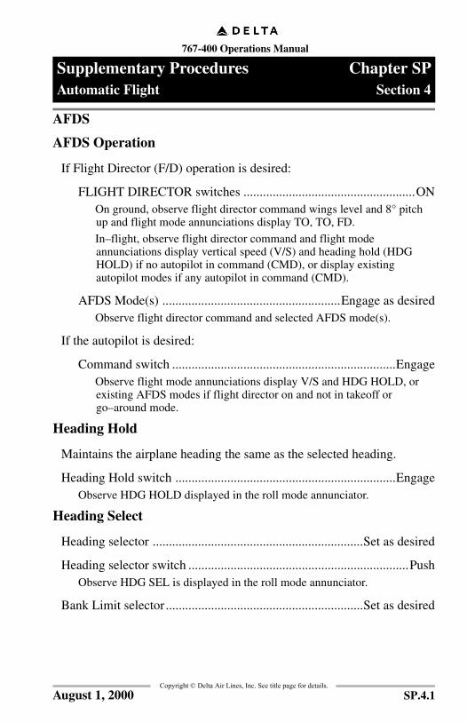
767-400 Operations Manual
Supplementary Procedures Chapter SPAutomatic Flight Section 4
FCO
M T
empl
ate
12/1
2/98
Copyright © Delta Air Lines, Inc. See title page for details.
AFDS
AFDS Operation
If Flight Director (F/D) operation is desired:
FLIGHT DIRECTOR switches .....................................................ONOn ground, observe flight director command wings level and 8° pitch up and flight mode annunciations display TO, TO, FD.
In–flight, observe flight director command and flight mode annunciations display vertical speed (V/S) and heading hold (HDG HOLD) if no autopilot in command (CMD), or display existing autopilot modes if any autopilot in command (CMD).
AFDS Mode(s) .......................................................Engage as desiredObserve flight director command and selected AFDS mode(s).
If the autopilot is desired:
Command switch .....................................................................EngageObserve flight mode annunciations display V/S and HDG HOLD, or existing AFDS modes if flight director on and not in takeoff or go–around mode.
Heading Hold
Maintains the airplane heading the same as the selected heading.
Heading Hold switch ....................................................................EngageObserve HDG HOLD displayed in the roll mode annunciator.
Heading Select
Heading selector .................................................................Set as desired
Heading selector switch ....................................................................PushObserve HDG SEL is displayed in the roll mode annunciator.
Bank Limit selector.............................................................Set as desired
SP.4.1August 1, 2000
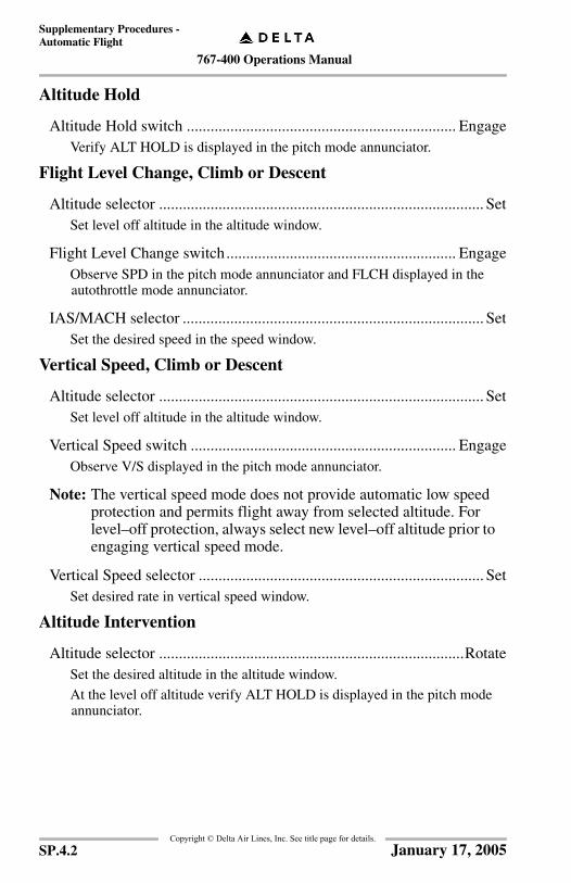
767-400 Operations Manual
Supplementary Procedures -Automatic Flight
Copyright © Delta Air Lines, Inc. See title page for details.
Altitude Hold
Altitude Hold switch .................................................................... EngageVerify ALT HOLD is displayed in the pitch mode annunciator.
Flight Level Change, Climb or Descent
Altitude selector .................................................................................. SetSet level off altitude in the altitude window.
Flight Level Change switch.......................................................... EngageObserve SPD in the pitch mode annunciator and FLCH displayed in the autothrottle mode annunciator.
IAS/MACH selector ............................................................................ SetSet the desired speed in the speed window.
Vertical Speed, Climb or Descent
Altitude selector .................................................................................. SetSet level off altitude in the altitude window.
Vertical Speed switch ................................................................... EngageObserve V/S displayed in the pitch mode annunciator.
Note: The vertical speed mode does not provide automatic low speed protection and permits flight away from selected altitude. For level–off protection, always select new level–off altitude prior to engaging vertical speed mode.
Vertical Speed selector ........................................................................ SetSet desired rate in vertical speed window.
Altitude Intervention
Altitude selector .............................................................................RotateSet the desired altitude in the altitude window.
At the level off altitude verify ALT HOLD is displayed in the pitch mode annunciator.
SP.4.2 January 17, 2005

767-400 Operations Manual
Supplementary Procedures -Automatic Flight
Copyright © Delta Air Lines, Inc. See title page for details.
To resume climb or descent:
Altitude selector ....................................................................... RotateSet the desired altitude in the altitude window.
If using VNAV:
VNAV switch .....................................................................EngageVerify VNAV PTH or VNAV SPD is displayed in the pitch mode annunciator.
If using Flight Level Change:
Flight Level Change switch................................................EngageVerify SPD displayed in the pitch mode annunciator and FLCH displayed in the autothrottle mode annunciator.
IAS/MACH selector ............................................................ RotateSet the desired speed in the IAS/MACH window.
Speed Intervention
IAS/MACH selector .........................................................................PushVerify IAS/MACH window opens.
IAS/MACH selector ...................................................................... RotateSet the desired speed in the IAS/MACH window.
To resume FMC speed schedule:
IAS/MACH selector ....................................................................PushVerify IAS/MACH window blanks.
Intermediate Level Off
Altitude selector ......................................................... Set desired altitude
At MCP altitude:
Verify ALT HOLD is displayed in the pitch mode annunciator.
SP.4.3January 17, 2005
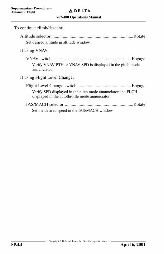
767-400 Operations Manual
Supplementary Procedures -Automatic Flight
Copyright © Delta Air Lines, Inc. See title page for details.
To continue climb/descent:
Altitude selector ........................................................................RotateSet desired altitude in altitude window.
If using VNAV:
VNAV switch ..................................................................... EngageVerify VNAV PTH or VNAV SPD is displayed in the pitch mode annunciator.
If using Flight Level Change:
Flight Level Change switch ............................................... EngageVerify SPD displayed in the pitch mode annunciator and FLCH displayed in the autothrottle mode annunciator.
IAS/MACH selector ............................................................RotateSet the desired speed in the IAS/MACH window.
SP.4.4 April 6, 2001

767-400 Operations Manual
Supplementary Procedures -Automatic Flight
Copyright © Delta Air Lines, Inc. See title page for details.
Autothrottle Operation
Autothrottle switch .................................................................. A/T ARM
If N1 mode desired:
N1 switch .................................................................................EngageObserve N1 displayed in the autothrottle mode annunciator.
If Speed mode desired:
Speed switch ............................................................................EngageObserve SPD displayed in the autothrottle mode annunciator.
IAS/MACH selector .......................................................................SetSet the desired speed in the IAS/MACH window.
SP.4.5August 15, 2005

767-400 Operations Manual
Supplementary Procedures -Automatic Flight
Copyright © Delta Air Lines, Inc. See title page for details.
Localizer ApproachPitch mode may be VNAV or V/S. If using VNAV, verify proper approach andaltitudes have been entered in the CDU and use speed intervention for airspeedcontrol. Roll mode may be LOC or LNAV.
Monitor the localizer course.
When on an intercept heading to the localizer course:
LOC or LNAV switch ................................................................. Push
Verify LNAV or LOC ARM mode annunciates.
Verify LOC engaged mode annunciates upon localizer capture when using LOC.
LOC is the preferred roll mode when conducting a localizer approach.
Prior to descent:
Altitude Selector ............................................................................ SetSet MCP altitude to TDZE rounded up to the nearest 100 feet.
When established on a published segment and cleared for the approach:
If using VNAV:
VNAV Switch ........................................................................ PushVerify VNAV PTH annunciated.
Speed Intervention ................................................................. PushSelect speed intervention after MCP speed window closes. Set desired speed.
If using V/S:
V/S switch.............................................................................. PushAt FAF, establish a vertical speed not to exceed a sustained 1000 feet per minute.
Note: The VNAV path or vertical speed descent rate should result in arrival at, or near, the visual descent point by DA/DDA. When authorized, the MDA will be used as a DA, otherwise a DDA will be computed (DDA = MDA + 50 ft.).
Be prepared to land or go around at the DA/DDA.
SP.4.6 August 15, 2005
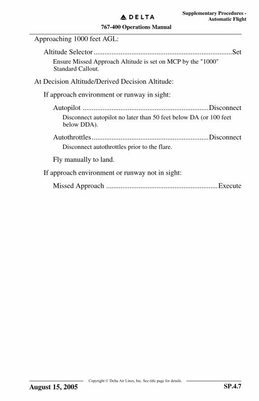
767-400 Operations Manual
Supplementary Procedures -Automatic Flight
Copyright © Delta Air Lines, Inc. See title page for details.
Approaching 1000 feet AGL:
Altitude Selector .............................................................................SetEnsure Missed Approach Altitude is set on MCP by the "1000" Standard Callout.
At Decision Altitude/Derived Decision Altitude:
If approach environment or runway in sight:
Autopilot ......................................................................DisconnectDisconnect autopilot no later than 50 feet below DA (or 100 feet below DDA).
Autothrottles .................................................................DisconnectDisconnect autothrottles prior to the flare.
Fly manually to land.
If approach environment or runway not in sight:
Missed Approach ..............................................................Execute
SP.4.7August 15, 2005
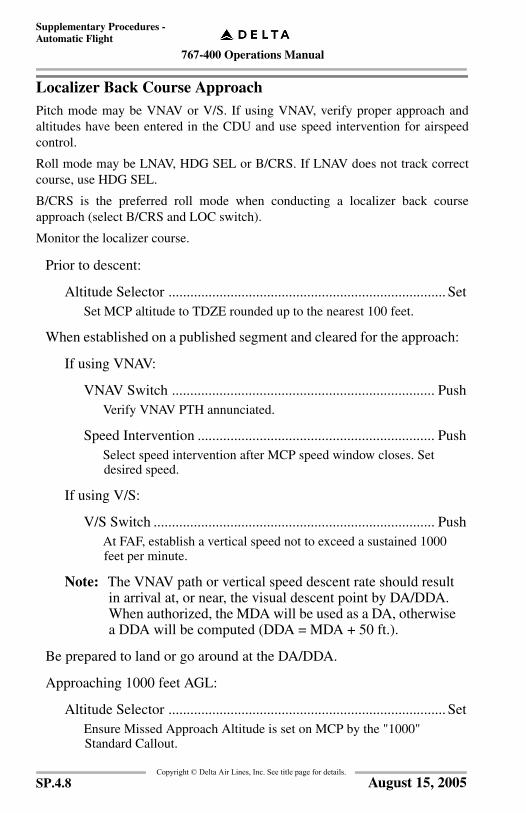
767-400 Operations Manual
Supplementary Procedures -Automatic Flight
Copyright © Delta Air Lines, Inc. See title page for details.
Localizer Back Course ApproachPitch mode may be VNAV or V/S. If using VNAV, verify proper approach andaltitudes have been entered in the CDU and use speed intervention for airspeedcontrol.
Roll mode may be LNAV, HDG SEL or B/CRS. If LNAV does not track correctcourse, use HDG SEL.
B/CRS is the preferred roll mode when conducting a localizer back courseapproach (select B/CRS and LOC switch).
Monitor the localizer course.
Prior to descent:
Altitude Selector ............................................................................ SetSet MCP altitude to TDZE rounded up to the nearest 100 feet.
When established on a published segment and cleared for the approach:
If using VNAV:
VNAV Switch ........................................................................ PushVerify VNAV PTH annunciated.
Speed Intervention ................................................................. PushSelect speed intervention after MCP speed window closes. Set desired speed.
If using V/S:
V/S Switch ............................................................................. PushAt FAF, establish a vertical speed not to exceed a sustained 1000 feet per minute.
Note: The VNAV path or vertical speed descent rate should result in arrival at, or near, the visual descent point by DA/DDA. When authorized, the MDA will be used as a DA, otherwise a DDA will be computed (DDA = MDA + 50 ft.).
Be prepared to land or go around at the DA/DDA.
Approaching 1000 feet AGL:
Altitude Selector ............................................................................ SetEnsure Missed Approach Altitude is set on MCP by the "1000" Standard Callout.
SP.4.8 August 15, 2005
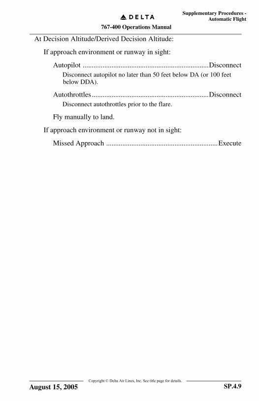
767-400 Operations Manual
Supplementary Procedures -Automatic Flight
Copyright © Delta Air Lines, Inc. See title page for details.
At Decision Altitude/Derived Decision Altitude:
If approach environment or runway in sight:
Autopilot ......................................................................DisconnectDisconnect autopilot no later than 50 feet below DA (or 100 feet below DDA).
Autothrottles .................................................................DisconnectDisconnect autothrottles prior to the flare.
Fly manually to land.
If approach environment or runway not in sight:
Missed Approach ..............................................................Execute
SP.4.9August 15, 2005
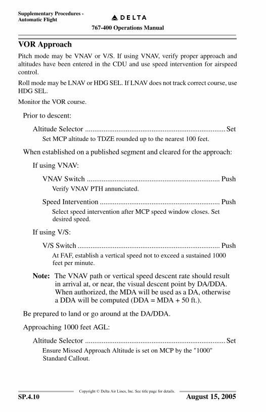
767-400 Operations Manual
Supplementary Procedures -Automatic Flight
Copyright © Delta Air Lines, Inc. See title page for details.
VOR ApproachPitch mode may be VNAV or V/S. If using VNAV, verify proper approach andaltitudes have been entered in the CDU and use speed intervention for airspeedcontrol.
Roll mode may be LNAV or HDG SEL. If LNAV does not track correct course, useHDG SEL.
Monitor the VOR course.
Prior to descent:
Altitude Selector ............................................................................ SetSet MCP altitude to TDZE rounded up to the nearest 100 feet.
When established on a published segment and cleared for the approach:
If using VNAV:
VNAV Switch ........................................................................ PushVerify VNAV PTH annunciated.
Speed Intervention ................................................................. PushSelect speed intervention after MCP speed window closes. Set desired speed.
If using V/S:
V/S Switch ............................................................................. PushAt FAF, establish a vertical speed not to exceed a sustained 1000 feet per minute.
Note: The VNAV path or vertical speed descent rate should result in arrival at, or near, the visual descent point by DA/DDA. When authorized, the MDA will be used as a DA, otherwise a DDA will be computed (DDA = MDA + 50 ft.).
Be prepared to land or go around at the DA/DDA.
Approaching 1000 feet AGL:
Altitude Selector ............................................................................ SetEnsure Missed Approach Altitude is set on MCP by the "1000" Standard Callout.
SP.4.10 August 15, 2005

767-400 Operations Manual
Supplementary Procedures -Automatic Flight
Copyright © Delta Air Lines, Inc. See title page for details.
At Decision Altitude/Derived Decision Altitude:
If approach environment or runway in sight:
Autopilot ......................................................................DisconnectDisconnect autopilot no later than 50 feet below DA (or 100 feet below DDA).
Autothrottles .................................................................DisconnectDisconnect autothrottles prior to the flare.
Fly manually to land.
If approach environment or runway not in sight:
Missed Approach ..............................................................Execute
SP.4.11August 15, 2005

767-400 Operations Manual
Supplementary Procedures -Automatic Flight
Copyright © Delta Air Lines, Inc. See title page for details.
NDB ApproachRecommended pitch mode is V/S.
Roll mode may be LNAV or HDG SEL. If LNAV does not track correct course, useHDG SEL.
Monitor the NDB course.
Prior to descent:
Altitude Selector ............................................................................ SetSet TDZE rounded up to the nearest 100 feet.
When established on a published segment and cleared for the approach:
V/S Switch .................................................................................. PushAt FAF, establish a vertical speed not to exceed a sustained 1000 feet per minute.
Note: The vertical speed descent rate should result in arrival at, or near, the visual descent point by the DDA. The DDA will be computed as MDA + 50 ft.
Be prepared to land or go around at the DDA.
Approaching 1000 feet AGL:
Altitude Selector ............................................................................ SetEnsure Missed Approach Altitude is set on MCP by the "1000" Standard Callout.
At Derived Decision Altitude:
If approach environment or runway in sight:
Autopilot ...................................................................... DisconnectDisconnect autopilot no later than 100 feet below DDA.
Autothrottles ................................................................ DisconnectDisconnect autothrottles prior to the flare.
Fly manually to land.
If approach environment or runway not in sight:
Missed Approach .............................................................. Execute
SP.4.12 March 31, 2006
767-400 Operations Manual
Supplementary Procedures Chapter SPCommunications Section 5
FCO
M T
empl
ate
12/1
2/98
Copyright © Delta Air Lines, Inc. See title page for details.
Cockpit Voice Recorder Test
Voice Recorder Test switch...............................................................PushHold the test switch for approximately 5 seconds. A tone may be heard with headset plugged into headset jack. The monitor light illuminates when the test is successfully complete.
SP.5.1August 15, 2005

767-400 Operations Manual
Supplementary Procedures -Communications
Copyright © Delta Air Lines, Inc. See title page for details.
HF System Test
CAUTION: Do not operate the HF transmitter while fuelingoperations are in progress.
Mode Selector .................................................................... USB OR AMUse of USB is preferable for all the HF communications.
Select HF FrequencyCall on VHF to arrange HF check.
See Airway Manual, Communications section for HF frequency chart.
Rotate HF Sensitivity (HF SENSE) control knob clockwise to increase sensitivity.
Push HF MIC Selector Switch.
Key microphone.
Note: A 1,000 Hz coupler tone can be heard up to 20 seconds during HF antenna tuning. When the HF antenna is tuned to that frequency, the 1,000 Hz ceases and the HF system is ready to transmit.
Listen for good side tone.
Listen for other traffic on same frequency.
Rotate HF SENSE control knob counter clockwise to decrease sensitivity, and reduce noise and static.
Note: Decreasing sensitivity too far prevents reception, including SELCAL monitoring of HF radio.
Accomplish SELCAL check before takeoff or enroute.
Enroute
Obtain SELCAL Check with each agency to be utilized.
Note: Once a SELCAL check is made with GP radio, flights are expected to remain on that frequency as required by the Airway Manual and region.
Note: For enroute HF communication information, refer to the Airway Manual, Communications section.
SP.5.2 August 15, 2005
767-400 Operations Manual
Supplementary Procedures -Communications
Copyright © Delta Air Lines, Inc. See title page for details.
Aircraft Communication Addressing and Reporting System (ACARS)
Pre-Departure ClearanceThe flight crew shall manually verify (compare) the filed flight plan versus thedigital pre-departure clearance and shall initiate voice contact with Air TrafficControl if any question/confusion exists between the filed flight plan and thedigital pre-departure clearance.
Digital-Automatic Information Service (D-ATIS)The flight crew shall verify that the D-ATIS altimeter setting numeric value andalpha value are identical. The alpha value is the numeric altimeter setting spelledout (i.e., two niner niner two). This will be depicted on the ACARS ATIS message.If the D-ATIS altimeter setting altimeter numeric value and alpha values aredifferent, the flight crew must not accept the D-ATIS altimeter setting.
Oceanic ClearancesThe flight crew shall manually verify (compare) the filed flight plan versus thedigital oceanic clearance and shall initiate voice contact with Air Traffic Controlif any question/confusion exists between the filed flight plan and the digitaloceanic clearance.
Weight and BalanceThe flight crew shall verify the Weight and Balance numeric and alphabeticalvalues are identical. If the Weight and Balance numeric and alphabetical values aredifferent, the flight crew must not accept the Weight and Balance data.
Takeoff DataThe flight crew shall verify the Takeoff Data numeric and alphabetic values areidentical. If the Takeoff Data numeric and alphabetic values are different, the flightcrew must not accept the Takeoff Data message.
Company Communications SequenceThe COMMUNICATIONS SEQUENCE chart depicts DATA LINK functions thatare currently in effect for Delta Air Lines. The chronological sequence in whichDATA LINK messages should be sent is shown as a function of flight phase. Themessages that appear above the profile are ROUTINE and should be sent wheneverappropriate on every flight. The messages below the profile are NON ROUTINEand should be sent as needed.
Messages are delivered to the Flight Control dispatcher’s cue and are also directlyprocessed by Flight Following. This direct processing of DATA LINK messagesresults in system wide updates in our host computers.
SP.5.3March 31, 2006
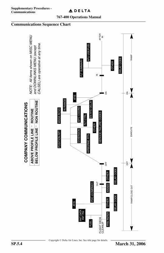
767-400 Operations Manual
Supplementary Procedures -Communications
Copyright © Delta Air Lines, Inc. See title page for details.
Communications Sequence Chart
AIR
BO
RN
E R
TN
IN R
AN
GE
MS
GS
RC
VD
PO
SIT
ION
RP
T
FLI
GH
T D
EC
KC
LEA
NU
P
PD
C (
CO
MPA
NY
)
OU
T
OF
FO
N
FLT
SU
MM
AR
Y
AF
TE
RIN
MT
C C
OO
RD
FLT
CT
RL
EN
RT
E D
ELA
Y
IN
PR
N P
AP
ER
CO
MPA
NY
CO
MM
UN
ICA
TIO
NS
AB
OV
E P
RO
FIL
E L
INE
BE
LO
W P
RO
FIL
E L
INE
RO
UT
INE
NO
N R
OU
TIN
E
NO
TE
: A
ll ite
ms
show
n on
MIS
C M
EN
U
and
DO
WN
LIN
KS
ME
NU
(ex
cept
C
ALS
EL)
are
ope
rativ
e at
any
tim
e.
RA
MP
/CLO
SE
OU
T
OF
F
EN
RO
UT
ER
AM
P
ON
_ _
ATIS
DIV
ER
SIO
NIN
IT D
ATA
INIT
RQ
AW
AB
S
ATIS
ATIS
OT
HE
R
OT
HE
R
OT
HE
R
AP
U U
SE
/FU
EL
FU
EL
DE
LAY
CO
DE
DE
LAY
CO
DE
SE
RV
ICE
FA
ILU
RE
CO
DE
S
OT
HE
R
DE
LAY
CO
DE
SP.5.4 March 31, 2006

767-400 Operations Manual
Supplementary Procedures -Communications
Copyright © Delta Air Lines, Inc. See title page for details.
Menu LayoutThis section provides general usage information and menu layouts for operatingthe Collins ACARS unit. The system is interactive, and methods for using it areconsistent for all messages. With some experimentation and use, it will becomesimple to use each feature.
Ground support for some ACARS functions is still in development and thereforethese functions should not be used. Refer to the DATA LINK INDEX menu treeon the next page for operational functions. If in doubt about the status of anoperational message, use normal company radio procedures.
Reports can be accessed through the DATA LINK INDEX page shown below.
The menu tree on the next page shows menu/submenu layout and can bereferenced to lead the flight crew to the proper pages for transmission ofdesired/required reports.
A C A R S - D A T A L I N K I N D E X
< P R E F L I G H T F L T L O G >
< E N R O U T E A T I S >
< P O S T F L I G H T W E A T H E R >
< M I S C M E N U D O W N L I N K S >
< A T C L O G M S G S R C V D >
H H : M M
SP.5.5March 31, 2006
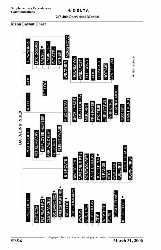
767-400 Operations Manual
Supplementary Procedures -Communications
Copyright © Delta Air Lines, Inc. See title page for details.
Menu Layout Chart
PD
C (
CO
MPA
NY
)
PR
ED
EPA
RT
RQ
FU
EL
RP
T
UN
DE
L M
SG
S
DO
WN
LIN
KS
MT
C C
OO
RD
CA
LSE
L
EN
GIN
E R
PT
FLT
CT
RL
OT
HE
R
INIT
DAT
A
FLT
PLA
N R
Q
CLE
AR
AN
CE
S
AW
AB
S
UT
C T
IME
DE
PT
DE
LAY
WE
ATH
ER
FLI
GH
T P
HA
SE
FLT
SU
MM
AR
Y
EM
PLO
YE
E N
UM
BE
R
PR
EF
LIG
HT
AR
RIV
AL
DE
LAY
FU
EL
RP
T
FLI
GH
T P
HA
SE
PO
ST
FLI
GH
T
MS
GS
RC
VD
WE
ATH
ER
HO
UR
LY W
X
AR
EA
FC
ST
FLT
LO
G
MIS
C M
EN
U
MS
G D
ISP
LAY
7500
RP
T
PR
N P
AP
ER
LIN
K S
TAT
US
VH
F C
TR
L
MIS
C R
PT
MA
INT
ME
NU
UT
C T
IME
DIV
ER
SIO
N
AIR
BO
RN
E R
TN
PO
SIT
ION
RP
T
EN
RT
E D
ELA
Y
RE
V F
LT P
LN
IN R
AN
GE
AT
IS
WE
ATH
ER
FLI
GH
T P
HA
SE
EN
RO
UT
E
DO
WN
LIN
KS
DA
TA
LIN
K IN
DE
X
FLD
CO
ND
TE
RM
FC
ST
NO
TAM
S
SE
VE
RE
WX
CH
AN
GE
MO
DE
OC
EA
NIC
RQ
ATC
LO
G
H
★
★
★
★
★
★ N
ot fu
nctio
nal
★
ICE
DE
TE
CT
★
AT
ISAT
IS
FU
EL
AT
C L
OG
AT
IS
SP.5.6 March 31, 2006

767-400 Operations Manual
Supplementary Procedures -Communications
Copyright © Delta Air Lines, Inc. See title page for details.
Advisory Messages
Alert Advisories
Alert advisories appear on the CDU signifying that either a condition requiresattention, a function is available, or an uplink has been received. Selecting theadvisory will access the required menu. The advisories are listed below in orderfrom highest to lowest priority.
FAIL Internal failure of MU. Refer to the ACARSINOP Non-Normal Checklist in the QRH.
POWER Power interruption resulting in loss ofinitialization data.
SELCAL SELCAL uplink message received.
ATC MSG ATC uplink message received.
DEPT CL ATC predeparture clearance message received.
MESSAGE Non-ATC uplink message received.
INIT Initialization data incomplete.
DATAMD Datalink attempted with ACARS in VOICEmode or ACARS in VOICE mode for greaterthan 105 seconds.
ATIS ATC ATIS message received and not viewed.
INRANGE Alert to send the In Range Report.
ARRDLA Alert to send the Arrival Delay Report.
DEPDLA Alert to send the Departure Delay Report.
SUMMARY Summary Report has not been sent.
PAPER Printer is out of paper.
SP.5.7March 31, 2006
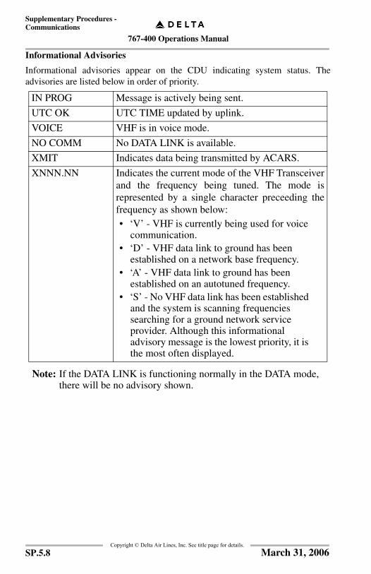
767-400 Operations Manual
Supplementary Procedures -Communications
Copyright © Delta Air Lines, Inc. See title page for details.
Informational Advisories
Informational advisories appear on the CDU indicating system status. Theadvisories are listed below in order of priority.
Note: If the DATA LINK is functioning normally in the DATA mode, there will be no advisory shown.
IN PROG Message is actively being sent.
UTC OK UTC TIME updated by uplink.
VOICE VHF is in voice mode.
NO COMM No DATA LINK is available.
XMIT Indicates data being transmitted by ACARS.
XNNN.NN Indicates the current mode of the VHF Transceiverand the frequency being tuned. The mode isrepresented by a single character preceeding thefrequency as shown below:• ‘V’ - VHF is currently being used for voice
communication.• ‘D’ - VHF data link to ground has been
established on a network base frequency.• ‘A’ - VHF data link to ground has been
established on an autotuned frequency.• ‘S’ - No VHF data link has been established
and the system is scanning frequencies searching for a ground network service provider. Although this informational advisory message is the lowest priority, it is the most often displayed.
SP.5.8 March 31, 2006
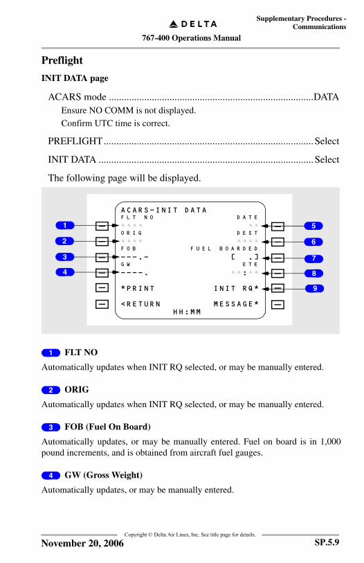
767-400 Operations Manual
Supplementary Procedures -Communications
Copyright © Delta Air Lines, Inc. See title page for details.
Preflight
INIT DATA page
ACARS mode .................................................................................DATAEnsure NO COMM is not displayed.
Confirm UTC time is correct.
PREFLIGHT...................................................................................Select
INIT DATA .....................................................................................Select
The following page will be displayed.
1 FLT NO
Automatically updates when INIT RQ selected, or may be manually entered.
2 ORIG
Automatically updates when INIT RQ selected, or may be manually entered.
3 FOB (Fuel On Board)
Automatically updates, or may be manually entered. Fuel on board is in 1,000pound increments, and is obtained from aircraft fuel gauges.
4 GW (Gross Weight)
Automatically updates, or may be manually entered.
A C A R S - I N I T D A T AF L T N O D A T E
£ £ £ £ £ £O R I G D E S T
£ £ £ £ £ £ £ £F O B F U E L B O A R D E D
- - - . - [ . ]G W E T E
- - - - . £ £ : £ £
* P R I N T I N I T R Q *
< R E T U R N M E S S A G E *H H : M M
2
1
4
3 7
5
6
8
9
SP.5.9November 20, 2006

767-400 Operations Manual
Supplementary Procedures -Communications
Copyright © Delta Air Lines, Inc. See title page for details.
5 DATE
Automatically updates when INIT RQ selected, or may be manually entered.
6 DEST
Automatically updates when INIT RQ selected, or may be manually entered.
7 FUEL BOARDED
Enter manually. This is the amount of fuel listed on the fuel service record.
8 ETE
Enter manually.
9 INIT RQ
Automatically updates FLT NO, DATE, ORIG, and DEST.
SP.5.10 March 31, 2006

767-400 Operations Manual
Supplementary Procedures -Communications
Copyright © Delta Air Lines, Inc. See title page for details.
ATIS
PREFLIGHT...................................................................................Select
ATIS ................................................................................................Select
This page allows request of digital ATIS information, when provided by airport.
Note: Availability of digital ATIS is indicated on airport diagrams (10-9 Jeppesen plate) by “D-ATIS” in the “ACARS” communications block.
The following page will be displayed.
1 AIRPORT
The AIRPORT field defaults to departure airport prior to “OFF” time, thendefaults to arrival airport after “OFF” time. If diversion page is transmitted with anairport other than planned arrival airport, the default will be the diversion airport.
2 TYPE
The TYPE field allows selection of Departure, Arrival, Departure/Arrival (used inconjunction with Auto Update Mode), and Enroute Information Services weatherproducts.
A T S - A T I S R QA I R P O R T
S E R V I C E T Y P E
| A A A A A A A A A A A A A A A A A A AA U T O U P D A T E
A A A A
S E N D *
< R E T U R N M E S S A G E *H H : M M
2
1
3
SP.5.11March 31, 2006
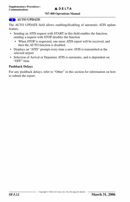
767-400 Operations Manual
Supplementary Procedures -Communications
Copyright © Delta Air Lines, Inc. See title page for details.
3 AUTO UPDATE
The AUTO UPDATE field allows enabling/disabling of automatic ATIS updatefeature.
• Sending an ATIS request with START in this field enables the function; sending a request with STOP disables the function• When STOP is requested, one more ATIS report will be received, and
then the AUTO function is disabled. • Displays an “ATIS” prompt every time a new ATIS is transmitted at the
selected airport• Selection of Arrival or Departure ATIS is automatic, and is dependent on
“OFF” time.
Pushback Delays
For any pushback delays, refer to “Other” in this section for information on howto submit the report.
SP.5.12 March 31, 2006
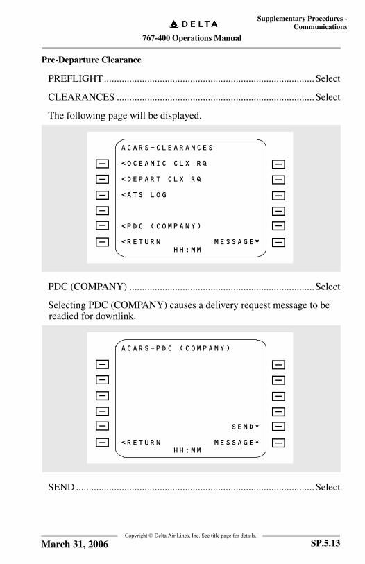
767-400 Operations Manual
Supplementary Procedures -Communications
Copyright © Delta Air Lines, Inc. See title page for details.
Pre-Departure Clearance
PREFLIGHT...................................................................................Select
CLEARANCES ..............................................................................Select
The following page will be displayed.
PDC (COMPANY) .........................................................................Select
Selecting PDC (COMPANY) causes a delivery request message to be readied for downlink.
SEND ..............................................................................................Select
A C A R S - C L E A R A N C E S
< O C E A N I C C L X R Q
< D E P A R T C L X R Q
< A T S L O G
< P D C ( C O M P A N Y )
< R E T U R N M E S S A G E *H H : M M
A C A R S - P D C ( C O M P A N Y )
S E N D *
< R E T U R N M E S S A G E *H H : M M
SP.5.13March 31, 2006
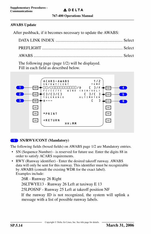
767-400 Operations Manual
Supplementary Procedures -Communications
Copyright © Delta Air Lines, Inc. See title page for details.
AWABS Update
After pushback, if it becomes necessary to update the AWABS:
DATA LINK INDEX ................................................................ Select
PREFLIGHT ............................................................................. Select
AWABS ..................................................................................... Select
The following page (page 1/2) will be displayed. Fill in each field as described below.
1 SN/RWY/CONT (Mandatory)
The following fields (boxed fields) on AWABS page 1/2 are Mandatory entries.
• SN (Sequence Number) - is reserved for future use. Enter the digits 88 in order to satisfy ACARS requirements.
• RWY (Runway identifier) - Enter the desired takeoff runway. AWABS data will only be sent for this runway. This identifier must be recognizable by AWABS (consult the existing WDR for the exact label). Examples include:
26R - Runway 26 Right26LTWYE13 - Runway 26 Left at taxiway E 1325LPOSNF - Runway 25 Left at takeoff position NFIf the runway ID is not recognized, the system will uplink amessage with a list of possible runway labels.
A C A R S - A W A B S 1 / 2S N / R W Y / C O N T T E M P
/ / D [ ] / FF C / C C / Y C W I N D ( D I R / V E L )
[ ] / [ ] / [ ] [ ] / [ ]T O L E R A N C E A L T I M E T E R
| - - - [ ]
* P R I N T
< R E T U R NH H : M M
2
1
3 6
4
5
SP.5.14 March 31, 2006

767-400 Operations Manual
Supplementary Procedures -Communications
Copyright © Delta Air Lines, Inc. See title page for details.
• CONT (Contamination) - The runway contaminant condition you desire. Choices are:
If you are overweight for the requested contaminant, you will receive amessage uplink advising you of this, but you will not receive a WDRuplink.
2 FC/CC/YC (Optional)
Passenger count. Enter only changes from the existing WDR passengerdistribution. Refer to WDR to determine class of service.
Examples:
• To change YC from 20/00/200 to 20/00/210, ENTER / /210• To change FC from 20/00/200 to 25/00/200, ENTER 25/ /
3 TOLERANCE (Optional)
Passenger/Cargo tolerance. Choices are “OFF,” “ON,” and “---.”
• “---” (default) will leave tolerance the same as it was on the latest WDR• “OFF” forces the tolerance off• “ON” forces tolerance on.
4 TEMP (Optional)
Current temperature in degrees Fahrenheit (default) or Celsius (C).
5 WIND (DIR/VEL) (Optional)
Use 360 for North. Range of directions is 001 - 360.
6 ALTIMETER (Optional)
Altimeter setting. Any entry greater than 2000 is considered inches of mercury (inHG). Any entry less than or equal to 2000 is considered Hectopascals (hPa).
D Dry (default entry)
W Wet
I Icy
Q Quarter Clutter (25 CTR)
H Half Clutter (50 CTR)
SP.5.15November 20, 2006

767-400 Operations Manual
Supplementary Procedures -Communications
Copyright © Delta Air Lines, Inc. See title page for details.
AWABS - continued (Page 2/2)
After completing the required entries on AWABS page 1/2, you must move to page 2/2 in order to access the SEND prompt.
NEXT ........................................................................................ Select
The following page will be displayed.
Note: All fields on AWABS page 2/2 are for future use and should be left blank.
SEND ........................................................................................ Select
Departure Delays
For any departure delays, refer to “Other” in this section for information on howto submit the report.
A C A R S - A W A B S 2 / 2C G O - F U E L E 1 I N C A D J Z F W
[ ] / [ ] [ . ]C G O - F U E L E 2 M E L C D L
[ ] / [ ] [ ]
* P R I N T
< R E T U R N M E S S A G E *H H : M M
SP.5.16 March 31, 2006

767-400 Operations Manual
Supplementary Procedures -Communications
Copyright © Delta Air Lines, Inc. See title page for details.
En Route
Position Report
Access the EN ROUTE page from the DATA LINK INDEX page.
EN ROUTE.....................................................................................Select
POSITION RPT..............................................................................SelectThis report consists of 2 pages, the second of which can be accessed through the use of the PREV or the NEXT prompt.
The following page (page 1/2) will be displayed.
1 POSITION
Enter report point (R) identifier from the flight plan.
2 FLT LEVEL ALT
Enter the three digit flight level the plane is currently cruising at.
3 NEXT POSITION• If NEXT POSITION and ETA are entered, they will automatically move
to POSITION and TIME for the next POSITION RPT once SEND is pressed.
• Partially completed pages will retain entered data until report is sent or the end of the flight.
Go to page 2 after entering information on page 1.
A C A R S - P O S I T I O N R P T 1 / 2P O S I T I O N T I M E
H H : M MF L T L E V E L A L T M A C H
F L - - - . - -F O B
- - - . -N E X T P O S I T I O N E T A
[ ] [ : ]E N S U I N G P O S I T I O N
[ ]
< R E T U R N M E S S A G E *H H : M M
2
1
3
SP.5.17March 31, 2006
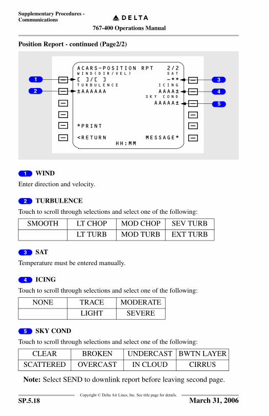
767-400 Operations Manual
Supplementary Procedures -Communications
Copyright © Delta Air Lines, Inc. See title page for details.
Position Report - continued (Page2/2)
1 WIND
Enter direction and velocity.
2 TURBULENCE
Touch to scroll through selections and select one of the following:
3 SAT
Temperature must be entered manually.
4 ICING
Touch to scroll through selections and select one of the following:
5 SKY COND
Touch to scroll through selections and select one of the following:
Note: Select SEND to downlink report before leaving second page.
SMOOTH LT CHOP MOD CHOP SEV TURB
LT TURB MOD TURB EXT TURB
NONE TRACE MODERATE
LIGHT SEVERE
CLEAR BROKEN UNDERCAST BWTN LAYER
SCATTERED OVERCAST IN CLOUD CIRRUS
A C A R S - P O S I T I O N R P T 2 / 2W I N D ( D I R / V E L ) S A T
[ ] / [ ] - * *T U R B U L E N C E I C I N G
| A A A A A A A A A A |S K Y C O N D
A A A A A |
* P R I N T
< R E T U R N M E S S A G E *H H : M M
2
1
5
3
4
SP.5.18 March 31, 2006

767-400 Operations Manual
Supplementary Procedures -Communications
Copyright © Delta Air Lines, Inc. See title page for details.
In Range
Access the EN ROUTE page from the DATA LINK INDEX page.
EN ROUTE.....................................................................................Select
IN RANGE .....................................................................................SelectThis report consists of 2 pages, the second of which can be accessed through the use of the PREV or the NEXT prompt.
The following page (page 1/2) will be displayed.
1 DEST
Automatically fills in using information from INIT DATA or DIVERSION pages(if report was sent).
2 WHEEL CHAIR
Enter total number of wheel chairs required at destination.
3 RED COAT
Toggle YES or NO.
4 SECURITY
Toggle YES or NO.
5 ERT
Automatically fills in using information from INIT DATA or DIVERSION pages(if report was sent).
A C A R S - I N R A N G E 1 / 2D E S T E R T
:W H E E L C H R U N A C C M I N O R
[ ] [ ]R E D C O A T M E D I C A L
| A A A A A A |S E C U R I T Y L A N G A S S I S T
| A A A A A A |
* P R I N T
< R E T U R N M E S S A G E *H H : M M
2
1
4
5
3
6
7
8
SP.5.19March 31, 2006

767-400 Operations Manual
Supplementary Procedures -Communications
Copyright © Delta Air Lines, Inc. See title page for details.
6 UNACC MINOR
Fill in only if more than what was listed in Flight Attendant Departure Report.
7 MEDICAL
Toggle YES or NO.
8 LANG ASSIST
Toggle YES or NO.
Go to page 2/2 after entering information on page 1/2.
1 LAV SRVC
Toggle YES or NO.
2 CABIN SRVC
Toggle YES or NO.
3 EDIT TEXT
Use text field for sending special requests not listed in the report.
Note: Select SEND to downlink report before leaving second page.
A C A R S - I N R A N G E 2 / 2L A V S R V C C A B I N S E R V
| A A A A A A |
E D I T T E X T >[ ][ ][ ][ ]
* P R I N T
< R E T U R N M E S S A G E *H H : M M
1 2
3
SP.5.20 March 31, 2006

767-400 Operations Manual
Supplementary Procedures -Communications
Copyright © Delta Air Lines, Inc. See title page for details.
Service Failure During Flight
If a service failure was reported during the flight or the service failure wasaccepted prior to pushback, refer to “Other” in this section for information on howto submit the report.
Arrival Delays
For any arrival delays, refer to “Other” in this section for information on how tosubmit the report.
SP.5.21March 31, 2006

767-400 Operations Manual
Supplementary Procedures -Communications
Copyright © Delta Air Lines, Inc. See title page for details.
Postflight
FLT SUMMARY page 1/2
Access the POSTFLIGHT page from the DATA LINK INDEX page.
POSTFLIGHT ................................................................................ Select
FLT SUMMARY............................................................................ Select
The following page will be displayed. Fill in each field as described below.
1 EMP NO - TAKEOFF
Employee number of crew member that performed the takeoff.
• Selection causes EMPLOYEE NUMBER page to be displayed where employee number received in the Init Data uplink when available may be chosen or manual data entry may be made.
2 EMP NO - LANDING
Employee number of crew member that performed the landing.
• Selection causes EMPLOYEE NUMBER page to be displayed where employee number received in the Init Data uplink when available may be chosen or manual data entry may be made.
3 T/O PWR
Enter takeoff power from the following range:
• TO (Default)• ALTN (Not used).
A C A R S - F L T S U M M A R Y 1 / 2E M P N O - - T A K E O F F - - T / O P W R
< A A A A A A A A A A AO T H E R
A A A A |E M P N O - - L A N D I N G - - - - - - F O B
< A A A A A A A A A A |
H O U R S - - - - - A P U - - - - - C Y C L E S
- - - - - . - - - - - - -
< R E T U R N M E S S A G E *H H : M M
2
1
5
3
4
6
SP.5.22 March 31, 2006
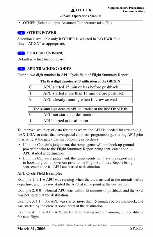
767-400 Operations Manual
Supplementary Procedures -Communications
Copyright © Delta Air Lines, Inc. See title page for details.
• OTHER (Select to input Assumed Temperature takeoffs.)
4 OTHER POWER
Selection is available only if OTHER is selected in T/O PWR field.Enter “AT XX” as appropriate.
5 FOB (Fuel On Board)
Default is actual fuel on board.
6 APU TRACKING CODES
Enter a two digit number in APU Cycle field of Flight Summary Report.
To improve accuracy of data for cities where the APU is needed for tow-in (e.g.,LAX, LGA) or cities that have special emphasis programs (e.g., starting APU priorto arriving at the gate), use the following procedures:
• If, in the Captain’s judgement, the ramp agents will not hook up ground power/air prior to the Flight Summary Report being sent, enter code 1- APU started at destination.
• If, in the Captain’s judgement, the ramp agents will have the opportunity to hook up ground power/air prior to the Flight Summary Report being sent, enter code 0 - APU not started at destination.
APU Cycle Field Examples
Example 1: 9 1 = APU was running when the crew arrived at the aircraft beforedeparture, and the crew started the APU at some point at the destination.
Example 2: 0 0 = Normal APU start within 15 minutes of pushback and the APUwas not started at the destination.
Example 3: 1 1 = The APU was started more than 15 minutes before pushback, andwas started by the crew at some point at the destination.
Example 4: 1 1 or 9 1 = APU started after landing and left running until pushbackfor next flight.
The first digit denotes APU utilization at the ORIGIN
0 APU started 15 min or less before pushback
1 APU started more than 15 min before pushback
9 APU already running when flt crew arrived
The second digit denotes APU utilization at the DESTINATION
0 APU not started at destination
1 APU started at destination
SP.5.23March 31, 2006
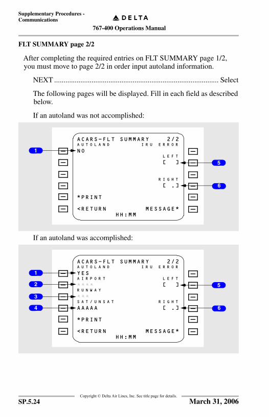
767-400 Operations Manual
Supplementary Procedures -Communications
Copyright © Delta Air Lines, Inc. See title page for details.
FLT SUMMARY page 2/2
After completing the required entries on FLT SUMMARY page 1/2, you must move to page 2/2 in order input autoland information.
NEXT ........................................................................................ Select
The following pages will be displayed. Fill in each field as described below.
If an autoland was not accomplished:
If an autoland was accomplished:
A C A R S - F L T S U M M A R Y 2 / 2A U T O L A N D I R U E R R O R
N OL E F T
[ ]
R I G H T
[ . ]
* P R I N T
< R E T U R N M E S S A G E *H H : M M
1
6
5
A C A R S - F L T S U M M A R Y 2 / 2A U T O L A N D I R U E R R O R
Y E SA I R P O R T L E F T
£ £ £ £ [ ]R U N W A Y
£ £ £S A T / U N S A T R I G H T
A A A A A [ . ]
* P R I N T
< R E T U R N M E S S A G E *H H : M M
1
6
52
3
4
SP.5.24 March 31, 2006
767-400 Operations Manual
Supplementary Procedures -Communications
Copyright © Delta Air Lines, Inc. See title page for details.
1 AUTOLAND• Default value is NO, indicating an autoland was not performed.• If an autoland was performed, depress 1L key, default will change to YES,
then complete the following fields:
2 AIRPORT
Default value is landing airport.
3 RUNWAY
Runway upon which autoland was performed.
4 SAT/UNSAT
Default value is SAT. Depress the 4L key to indicate UNSAT.
Note: Parameters for a successful autoland attempt are delineated in the MDM, TOPP Dispatch Documents Section, Aircraft Log System, Completed Log Sheet Example.
Note: SATISFACTORY autoland information is only required to be recorded under the Autoland column of the aircraft logsheet, next to the T/O Power column.
Note: UNSATISFACTORY autoland attempts must also be recorded in the aircraft logbook as an irregularity.
5 LEFT
No entry required.
6 RIGHT
No entry required.
After completing all entries Do Not manually send the report. Allow ACARS to do so automatically. This will allow for proper sequencing in the Times report.
SP.5.25March 31, 2006
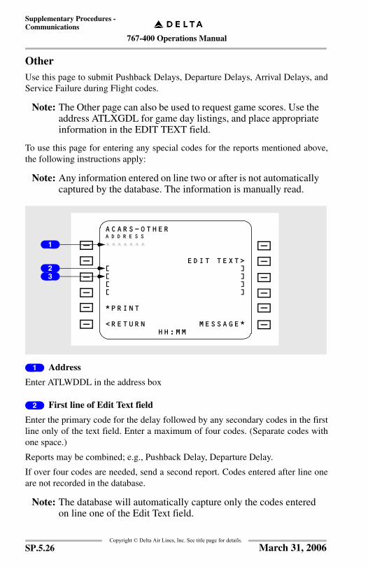
767-400 Operations Manual
Supplementary Procedures -Communications
Copyright © Delta Air Lines, Inc. See title page for details.
OtherUse this page to submit Pushback Delays, Departure Delays, Arrival Delays, andService Failure during Flight codes.
Note: The Other page can also be used to request game scores. Use the address ATLXGDL for game day listings, and place appropriate information in the EDIT TEXT field.
To use this page for entering any special codes for the reports mentioned above,the following instructions apply:
Note: Any information entered on line two or after is not automatically captured by the database. The information is manually read.
1 Address
Enter ATLWDDL in the address box
2 First line of Edit Text field
Enter the primary code for the delay followed by any secondary codes in the firstline only of the text field. Enter a maximum of four codes. (Separate codes withone space.)
Reports may be combined; e.g., Pushback Delay, Departure Delay.
If over four codes are needed, send a second report. Codes entered after line oneare not recorded in the database.
Note: The database will automatically capture only the codes entered on line one of the Edit Text field.
A C A R S - O T H E RA D D R E S S
£ £ £ £ £ £ £
E D I T T E X T >[ ][ ][ ][ ]
* P R I N T
< R E T U R N M E S S A G E *H H : M M
1
23
SP.5.26 March 31, 2006

767-400 Operations Manual
Supplementary Procedures -Communications
Copyright © Delta Air Lines, Inc. See title page for details.
3 Second line of Edit Text field
Any additional free text remarks may be entered starting on line two.
Send the reports when crew workload permits and safety is not compromised.
Use the codes on the following pages for each report:
Note: If submitting a COR, mention "Operation Clockwork" in the narrative. If submitting a POE, select ACARS Metrics, then Clockwork Metrics.
Pushback Delays
Report any pushback delay that exceeds D-0.
If a delay or service failure occurs up to dispatch agent salute:
Code Reason
PBRD Boarding not complete/paperwork not available
PCAB Cabin not ready for pushback/passenger issue
PATC ATC wheels up time
PPSH Pushback clearance not available/ramp blocked
PFUL Fueling not completed/late completion
PCAT Catering not completed/late completion
PCLN Cabin cleaning not completed/late completion
PCRW Flight crew (Pilot or FA) late to aircraft (less than 30 minutes prior to departure)
PEQP Late arriving equipment to gate
PCGO Ground crew servicing (e.g., loading cargo, water servicing, late bags, etc.)
PMTC Maintenance issue
PLAV Lavatory service not completed/late completion
PSEC Security issues
SP.5.27March 31, 2006

767-400 Operations Manual
Supplementary Procedures -Communications
Copyright © Delta Air Lines, Inc. See title page for details.
Departure Delays
Report any departure delay that exceeds planned taxi time by 15 minutes or more.
If a delay occurs after dispatch agent salute and prior to takeoff:
Service Failure During Flight
If a service failure is reported during the flight or the service failure was acceptedprior to pushback:
• A flight attendant will contact the cockpit and provide a list of services that were not available.
Code Reason
DATC ATC flow control issues/runway change
DWAY Airport/taxiway congested
DRMP Ramp congested
DWDR AWABS update/closeout required
DICE De/Anti-icing delay
DMTC Maintenance issue which delayed takeoff
Code Reason
SICE Ice or beverages serviced to min specs
SWTR Aircraft not serviced with potable water
SBEE Aircraft had "B spec" cleaning to expedite on-timedeparture
SLAV Lavatories poorly cleaned/strong odor present
SBKT Aircraft not stocked with adequate blankets
SGAL Aircraft missing galley equipment
SCAT Flight not fully catered
SPAX Failed to load pax/non-revs with seats available.
SP.5.28 March 31, 2006
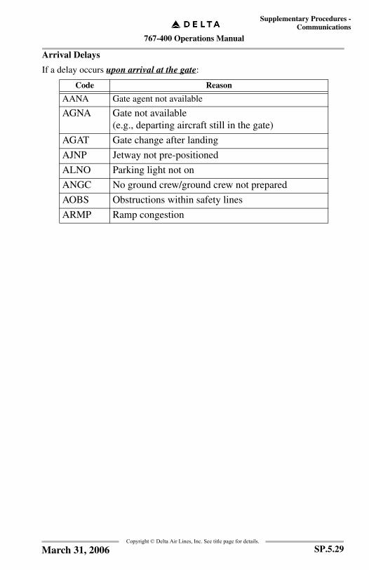
767-400 Operations Manual
Supplementary Procedures -Communications
Copyright © Delta Air Lines, Inc. See title page for details.
Arrival Delays
If a delay occurs upon arrival at the gate:
Code Reason
AANA Gate agent not available
AGNA Gate not available (e.g., departing aircraft still in the gate)
AGAT Gate change after landing
AJNP Jetway not pre-positioned
ALNO Parking light not on
ANGC No ground crew/ground crew not prepared
AOBS Obstructions within safety lines
ARMP Ramp congestion
SP.5.29March 31, 2006

767-400 Operations Manual
Supplementary Procedures -Communications
Copyright © Delta Air Lines, Inc. See title page for details.
FRM/CDL Code Downlinks
MTC COORD Page
Access the MTC COORD page from the DOWNLINKS page.
DOWNLINKS................................................................................ Select
MTC REPORT ............................................................................... Select
The following page will be displayed. Fill in each field as described below.
1 Free Text Field
EDIT TEXT ................................................................................... SelectEnter “FRC” in the free text area followed by the FRM and/or CDL discrepancy codes (for example: FRC 254.30.05C). Select the next line to enter text in the free text field.
SEND ............................................................................................. Select
A C A R S - M TC R E P O R T 1 / 1F R M / F I M / C D L C O D E
£ £ £ £ £ £ £ ££/ £ £ £ / £ £ £
E D I T T E X T >[ ][ ][ ][ ][ ]< N E X T R EPO R T
< R E T U R N M E S S A G E *H H : M M
1
SP.5.30 March 31, 2006
767-400 Operations Manual
Supplementary Procedures -Communications
Copyright © Delta Air Lines, Inc. See title page for details.
Gander Oceanic Clearance via Datalink
Request clearance no more than 90 minutes prior to and not later than 30 minutes prior to Gander Oceanic Boundary.
Utilizing the ACARS screen:
PREFLIGHT (L1) .....................................................................Select
CLEARANCES (L3) .................................................................Select
OCEANIC CLX RQ (L1) .........................................................Select
Complete the OCEANIC CLEARANCE request page in full.
Enter the following information in the required fields:• The Entry Fix (Gander Oceanic Boundary point)• ETA for crossing the fix• MACH, filed MACH speed• Flight Level, filed altitude• Gander does not use information in the text for alternative tracks
or max flight levels at this time.• Under Facility enter “Gander”
SEND (R6) ................................................................................SelectThe following acknowledgement of the request for clearance will be received within 5 minutes:
IF NO CLEARANCE RECIEVED WITHIN 15 MINUTES OF OCEANIC ENTRY POINT REVERT TO VOICE PROCEDURESEND OF MESSAGEIf the following uplinked message is received, revert to voice procedures:GO TO VOICEEND OF MESSAGE
Note: Reference Chart AT 1/2 for voice procedures.
SP.5.31March 31, 2006

767-400 Operations Manual
Supplementary Procedures -Communications
Copyright © Delta Air Lines, Inc. See title page for details.
Upon receipt of clearance, view the message on the ACARS CDU.• Check Flight Identification
• Check clearance for additional information and/or changes
• Check that the route coordinates received match with the published Nat track message
• Advise Gander of any discrepancies via voice
• Check Clearance ends with “END OF MESSAGE”
ACCEPT......................................................................................... Select
SEND ............................................................................................. Select
When within 200nm of the frequency location, call Gander Clearance Delivery on the appropriate frequency published on the daily Nat track message and give your ETA for the Entry Point and the Clearance Sequence Number. The 5-digit Clearance Sequence Number (CSN) may be found on the uplinked clearance immediately following the words OCEANIC CLEARANCE. This voice confirmation is necessary because Gander does not issue a datalink confirmation message at this time.
Note: In some circumstances, the crew may receive the clearance prior to sending the Request for Clearance (RCL). If the crew does not send an RCL within 90 - 30 minutes of track entry, an unsolicited uplinked clearance will be sent to the aircraft via ACARS and the crew will call Gander Clearance Delivery on the appropriate frequency and give their ETA for the Entry Point, NAT track or route coordinates if random routing, flight level, mach, and Clearance Sequence Number or Track Message Identifier (TMI).
Crews requesting a profile different from the clearance profile should make their request by voice with Gander Clearance Delivery. To improve delivery success rates for amended clearances, crews should downlink another RCL before making their voice request.
Note: If a crew requests a new clearance, or ATC requires a change to an existing clearance, one or more reclearances may be received via ACARS, annotated by an alpha character at the end of the Clearance Sequence Number (e.g., 04239A or 04239B, etc.).
SP.5.32 March 31, 2006
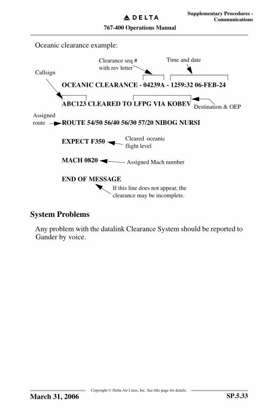
767-400 Operations Manual
Supplementary Procedures -Communications
Copyright © Delta Air Lines, Inc. See title page for details.
Oceanic clearance example:
System Problems
Any problem with the datalink Clearance System should be reported to Gander by voice.
OCEANIC CLEARANCE - 04239A - 1259:32 06-FEB-24
ABC123 CLEARED TO LFPG VIA KOBEV
ROUTE 54/50 56/40 56/30 57/20 NIBOG NURSI
EXPECT F350
MACH 0820
END OF MESSAGEIf this line does not appear, theclearance may be incomplete.
Time and date
Destination & OEP
Callsign
Cleared oceanicflight level
Assigned Mach number
Assignedroute
Clearance seq #with rev letter
SP.5.33March 31, 2006
767-400 Operations Manual
Supplementary Procedures -Communications
Copyright © Delta Air Lines, Inc. See title page for details.
Shanwick Oceanic Clearance via Datalink
Request clearance no more than 90 minutes prior to and not later than 30 minutes from the Shanwick Oceanic Boundary.
Utilizing the ACARS screen:
PREFLIGHT (L1) ..................................................................... Select
CLEARANCES (L3) ................................................................ Select
OCEANIC CLX RQ (L1) ......................................................... Select
Enter the following information in the required fields:• The Entry Fix (Shanwick Oceanic Boundary Point)
• ETA for crossing the fix
• MACH, filed MACH speed
• Flight Level, filed altitude
• Use only the following abbreviations in the EDIT TEXT field: 2ND for alternative track or flight level request, e.g., 2ND NAT C or 2ND F370, MAX for maximum acceptable flight level at oceanic boundary, e.g., MAX 350. These messages can be used in any sequence or combination, e.g., 2ND NAT C 2ND F330 MAX F350.
• Under Facility enter “Shanwick”.
SEND (R6) ................................................................................ SelectAn acknowledgement of the request for clearance, will be received within 5 minutes.
Note: If no clearance within 15 minutes revert to voice procedures. Also, if crew receives uplinked message “GO TO VOICE” revert to voice procedures.
Note: Reference Chart AT 1/2 for voice procedures.
Upon receipt of clearance, view the message on the ACARS CDU.
Check Flight Identification
Check Clearance ends with “END OF MESSAGE”
ACCEPT ................................................................................... Select
SEND ........................................................................................ SelectA CLEARANCE CONFIRMED message should be received within a few minutes.
SP.5.34 March 31, 2006

767-400 Operations Manual
Supplementary Procedures -Communications
Copyright © Delta Air Lines, Inc. See title page for details.
Clearance
Check clearance for additional information and/or changes.
Check that the route coordinates received match the published NAT track message.
Advise Shanwick of any discrepancies.
System Problems
Any problem with the datalink Clearance System should be reported to Shanwick by voice.
Note: This process is only available with Shanwick Oceanic Boundary. DO NOT attempt to use with Reykjavik or Santa Maria. Reykjavik and Santa Maria clearances are voice only.
SP.5.35March 31, 2006
767-400 Operations Manual
Supplementary Procedures -Communications
Copyright © Delta Air Lines, Inc. See title page for details.
IntentionallyBlank
SP.5.36 March 31, 2006
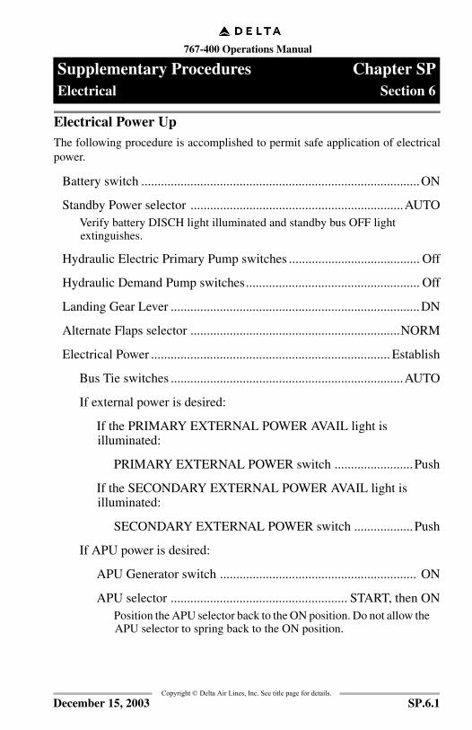
767-400 Operations Manual
Supplementary Procedures Chapter SPElectrical Section 6
FCO
M T
empl
ate
12/1
2/98
Copyright © Delta Air Lines, Inc. See title page for details.
Electrical Power UpThe following procedure is accomplished to permit safe application of electricalpower.
Battery switch .....................................................................................ON
Standby Power selector .................................................................AUTOVerify battery DISCH light illuminated and standby bus OFF light extinguishes.
Hydraulic Electric Primary Pump switches ........................................ Off
Hydraulic Demand Pump switches..................................................... Off
Landing Gear Lever ............................................................................DN
Alternate Flaps selector ................................................................NORM
Electrical Power ......................................................................... Establish
Bus Tie switches .......................................................................AUTO
If external power is desired:
If the PRIMARY EXTERNAL POWER AVAIL light is illuminated:
PRIMARY EXTERNAL POWER switch ........................Push
If the SECONDARY EXTERNAL POWER AVAIL light is illuminated:
SECONDARY EXTERNAL POWER switch ..................Push
If APU power is desired:
APU Generator switch ............................................................ ON
APU selector ...................................................... START, then ONPosition the APU selector back to the ON position. Do not allow the APU selector to spring back to the ON position.
SP.6.1December 15, 2003
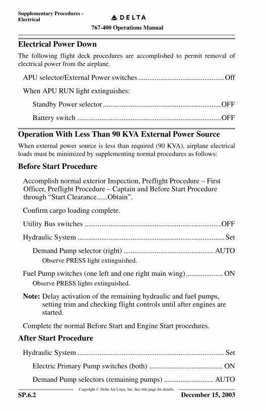
767-400 Operations Manual
Supplementary Procedures -Electrical
Copyright © Delta Air Lines, Inc. See title page for details.
Electrical Power DownThe following flight deck procedures are accomplished to permit removal ofelectrical power from the airplane.
APU selector/External Power switches ...............................................Off
When APU RUN light extinguishes:
Standby Power selector ................................................................OFF
Battery switch ..............................................................................OFF
Operation With Less Than 90 KVA External Power SourceWhen external power source is less than required (90 KVA), airplane electricalloads must be minimized by supplementing normal procedures as follows:
Before Start Procedure
Accomplish normal exterior Inspection, Preflight Procedure – First Officer, Preflight Procedure – Captain and Before Start Procedure through “Start Clearance......Obtain”.
Confirm cargo loading complete.
Utility Bus switches ..........................................................................OFF
Hydraulic System ................................................................................ Set
Demand Pump selector (right) ................................................. AUTOObserve PRESS light extinguished.
Fuel Pump switches (one left and one right main wing) .................... ONObserve PRESS lights extinguished.
Note: Delay activation of the remaining hydraulic and fuel pumps, setting trim and checking flight controls until after engines are started.
Complete the normal Before Start and Engine Start procedures.
After Start Procedure
Hydraulic System ................................................................................ Set
Electric Primary Pump switches (both) ........................................ ON
Demand Pump selectors (remaining pumps) ........................... AUTO
SP.6.2 December 15, 2003

767-400 Operations Manual
Supplementary Procedures -Electrical
Copyright © Delta Air Lines, Inc. See title page for details.
Utility Bus switches ............................................................................ON
Fuel Pump switches (remaining pumps) ............................................ONPosition switches ON for all tanks containing fuel.
Trim .....................................................................................................Set
Complete normal After Start procedure.
Shutdown Procedure
After park brake is set and prior to establishing external power:
Hydraulic System ...........................................................................Set
Electric Primary Pump switches (both) ................................. OFF
Demand Pump selectors (All) ................................................ OFF
Fuel Pump switches ..................................................................... OFF
Accomplish normal Shutdown procedure.
Transfer From External Power To APU PowerPrior to disconnecting external power:
External Power switches ...................................................................PushObserve ON light extinguish.
SP.6.3December 15, 2003
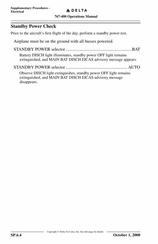
767-400 Operations Manual
Supplementary Procedures -Electrical
Copyright © Delta Air Lines, Inc. See title page for details.
Standby Power CheckPrior to the aircraft’s first flight of the day, perform a standby power test.
Airplane must be on the ground with all busses powered.
STANDBY POWER selector ............................................................BATBattery DISCH light illuminates, standby power OFF light remains extinguished, and MAIN BAT DISCH EICAS advisory message appears.
STANDBY POWER selector ........................................................ AUTOObserve DISCH light extinguishes, standby power OFF light remains extinguished, and MAIN BAT DISCH EICAS advisory message disappears.
SP.6.4 October 1, 2000
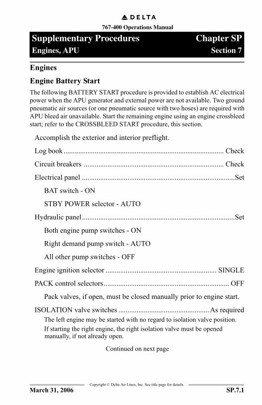
767-400 Operations Manual
Supplementary Procedures Chapter SPEngines, APU Section 7
FCO
M T
empl
ate
12/1
2/98
Copyright © Delta Air Lines, Inc. See title page for details.
Engines
Engine Battery StartThe following BATTERY START procedure is provided to establish AC electricalpower when the APU generator and external power are not available. Two groundpneumatic air sources (or one pneumatic source with two hoses) are required withAPU bleed air unavailable. Start the remaining engine using an engine crossbleedstart; refer to the CROSSBLEED START procedure, this section.
Accomplish the exterior and interior preflight.
Log book ........................................................................................ Check
Circuit breakers ............................................................................. Check
Electrical panel ....................................................................................Set
BAT switch - ON
STBY POWER selector - AUTO
Hydraulic panel....................................................................................Set
Both engine pump switches - ON
Right demand pump switch - AUTO
All other pump switches - OFF
Engine ignition selector ............................................................. SINGLE
PACK control selectors..................................................................... OFF
Pack valves, if open, must be closed manually prior to engine start.
ISOLATION valve switches ..................................................As requiredThe left engine may be started with no regard to isolation valve position.If starting the right engine, the right isolation valve must be opened manually, if not already open.
Continued on next page
SP.7.1March 31, 2006

767-400 Operations Manual
Supplementary Procedures -Engines, APU
Copyright © Delta Air Lines, Inc. See title page for details.
Continued from previous page
Landing gear.................................................................................DOWN
Alternate flaps ....................................................................NORM / OFF
Flaps .................................................................................................... Set
Position FLAP lever to agree with flap position.
FUEL CONTROL switches ......................................................CUTOFF
Parking brake ...................................................................................... Set
Communications ....................................................................... Establish
Establish communications with ground crew.
Accomplish engine start
Observe engine start parameters on compacted upper EICAS screen.
Electrical panel ...............................................................................Check
Observe AC BUS OFF and utility BUS OFF lights extinguished.
Accomplish entire BEFORE START checklist.
Engine Crossbleed Start
The APU must be shut down.
Check that the area behind the airplane is clear.
Engine Bleed Air switch (operating engine) ...................................... ON
Advance thrust on operating engine to approximately 70% N2 and accomplish normal Engine Start procedure.
Engine Ground Pneumatic Start
Check duct pressure 30 psi or greater.
Start engine using normal Engine Start procedure.
Note: Two ground pneumatic air sources (or one pneumatic source with two hoses) are required with APU bleed air unavailable.
SP.7.2 August 15, 2005

767-400 Operations Manual
Supplementary Procedures -Engines, APU
Copyright © Delta Air Lines, Inc. See title page for details.
Reduced Thrust Selection Prior To Takeoff
If reduced climb thrust desired:
Climb thrust line ........................................................................SelectOn the FMS Thrust Limit page, select desired climb thrust reference: CLB 1 or CLB 2.Observe <ARM> adjacent to the desired climb thrust.<ARM> will change to <SEL> when the armed climb mode becomes active.
If reduced takeoff thrust desired:
Assumed Temperature ....................................................................SetOn the FMS Thrust Limit page or Takeoff Reference page, enter desired assumed temperature.Observe assumed temperature and D-TO displayed (45°C D-TO for example).
Note: If preselected reduced climb thrust is changed or cancelled and reduced takeoff thrust is still desired, reduced takeoff thrust must be reselected
Reduced Takeoff Thrust Change or Cancellation
If change desired:
Assumed Temperature ....................................................................SetEnter new temperature value on Thrust Limit page or Takeoff Reference page.Observe new temperature and D-TO displayed (35°C D-TO for example).
If cancellation desired:
Assumed Temperature .............................................................. DeleteDelete the assumed temperature by selecting the FMS Delete key and then selecting the Takeoff line select key.Observe TO displayed.
Note: If full takeoff thrust desired during takeoff following 80 knots (autothrottle in THR HOLD mode) thrust levers must be adjusted manually.
SP.7.3August 15, 2005

767-400 Operations Manual
Supplementary Procedures -Engines, APU
Copyright © Delta Air Lines, Inc. See title page for details.
Reduced Climb Thrust Selection Prior To Takeoff
If fixed thrust derate desired:
Climb Thrust Line ..................................................................... SelectOn the FMS thrust limit page, select desired climb thrust reference: CLB1 or CLB2.Observe <ARM> adjacent to the desired climb thrust.
Reduced Climb Thrust Change or Cancellation
If fixed thrust derate desired:
Climb Thrust Line ..................................................................... SelectOn the FMS Thrust Limit page, select desired climb thrust reference: CLB, CLB 1, or CLB 2.Observe <SEL> adjacent to the desired climb thrust.
If cancellation desired:
Climb Thrust Line ..................................................................... SelectOn the FMS Thrust Limit page, select desired climb thrust reference: CLB, CLB 1, or CLB 2.Observe <SEL> adjacent to the desired climb thrust.
Note: If preselected reduced climb thrust is changed or cancelled and reduced takeoff thrust is still desired, reduced takeoff thrust must be reselected.
Reduced Climb Selection In–flight
Climb Thrust Line .......................................................................... SelectOn the FMS Thrust Limit page, select desired climb thrust reference: CLB 1 or CLB 2.Observe <SEL> adjacent to the desired climb thrust.
SP.7.4 August 15, 2005
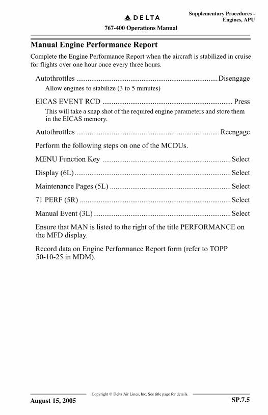
767-400 Operations Manual
Supplementary Procedures -Engines, APU
Copyright © Delta Air Lines, Inc. See title page for details.
Manual Engine Performance ReportComplete the Engine Performance Report when the aircraft is stabilized in cruisefor flights over one hour once every three hours.
Autothrottles ............................................................................DisengageAllow engines to stabilize (3 to 5 minutes)
EICAS EVENT RCD ...................................................................... PressThis will take a snap shot of the required engine parameters and store them in the EICAS memory.
Autothrottles .............................................................................Reengage
Perform the following steps on one of the MCDUs.
MENU Function Key .....................................................................Select
Display (6L) ....................................................................................Select
Maintenance Pages (5L) .................................................................Select
71 PERF (5R) .................................................................................Select
Manual Event (3L)..........................................................................Select
Ensure that MAN is listed to the right of the title PERFORMANCE on the MFD display.
Record data on Engine Performance Report form (refer to TOPP 50-10-25 in MDM).
SP.7.5August 15, 2005

767-400 Operations Manual
Supplementary Procedures -Engines, APU
Copyright © Delta Air Lines, Inc. See title page for details.
IntentionallyBlank
SP.7.6 August 15, 2005
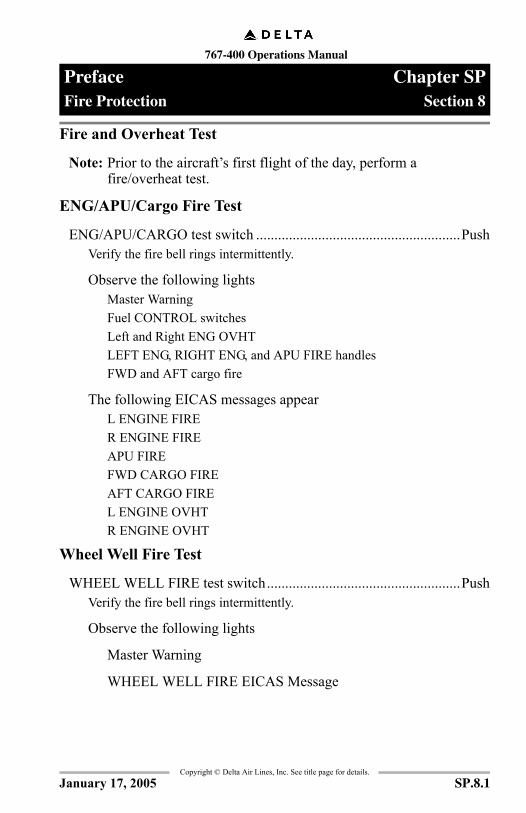
767-400 Operations Manual
Preface Chapter SPFire Protection Section 8
FCO
M T
empl
ate
12/1
2/98
Copyright © Delta Air Lines, Inc. See title page for details.
Fire and Overheat Test
Note: Prior to the aircraft’s first flight of the day, perform a fire/overheat test.
ENG/APU/Cargo Fire Test
ENG/APU/CARGO test switch ........................................................PushVerify the fire bell rings intermittently.
Observe the following lightsMaster WarningFuel CONTROL switchesLeft and Right ENG OVHTLEFT ENG, RIGHT ENG, and APU FIRE handlesFWD and AFT cargo fire
The following EICAS messages appearL ENGINE FIRER ENGINE FIREAPU FIREFWD CARGO FIREAFT CARGO FIREL ENGINE OVHTR ENGINE OVHT
Wheel Well Fire Test
WHEEL WELL FIRE test switch.....................................................PushVerify the fire bell rings intermittently.
Observe the following lights
Master Warning
WHEEL WELL FIRE EICAS Message
SP.8.1January 17, 2005

767-400 Operations Manual
Preface -Fire Protection
Copyright © Delta Air Lines, Inc. See title page for details.
IntentionallyBlank
SP.8.2 August 1, 2000
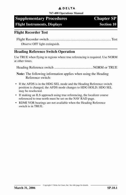
767-400 Operations Manual
Supplementary Procedures Chapter SPFlight Instruments, Displays Section 10
FCO
M T
empl
ate
12/1
2/98
Copyright © Delta Air Lines, Inc. See title page for details.
Flight Recorder Test
Flight Recorder switch .......................................................................TestObserve OFF light extinguish.
Heading Reference Switch OperationUse TRUE when flying in regions where true referencing is required. Use NORMat other times.
Heading Reference switch ............................................NORM or TRUE
Note: The following information applies when using the Heading Reference switch:
• If the AFDS is in the HDG SEL mode and the Heading Reference switch position is changed, the AFDS mode changes to HDG HOLD; HDG SEL may be reselected.
• If making an ILS approach using true referencing, the localizer course referenced to true north must be set on the NAV RAD page.
• RDMI VOR bearings are not available when the Heading Reference switch is in TRUE.
SP.10.1March 31, 2006
767-400 Operations Manual
Supplementary Procedures -Flight Instruments, Displays
Copyright © Delta Air Lines, Inc. See title page for details.
IntentionallyBlank
SP.10.2 March 31, 2006
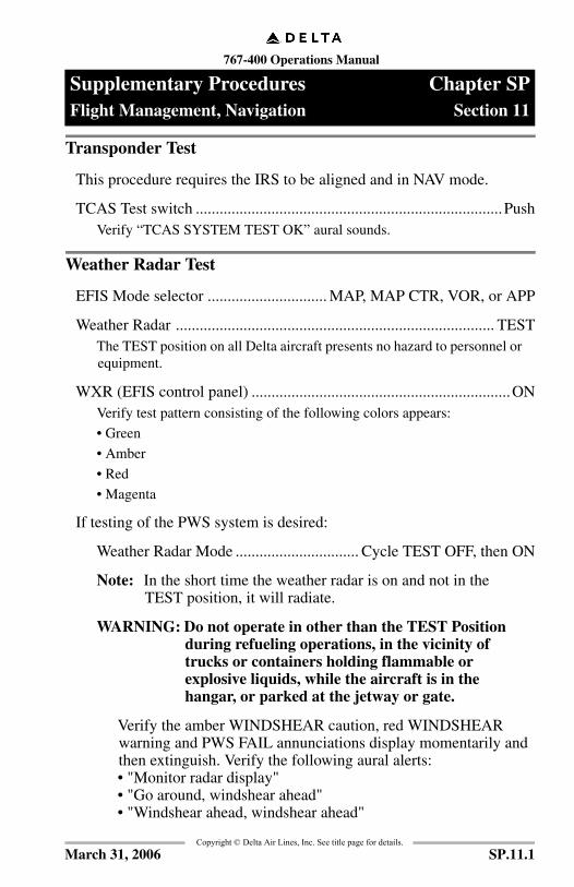
767-400 Operations Manual
Supplementary Procedures Chapter SPFlight Management, Navigation Section 11
FCO
M T
empl
ate
12/1
2/98
Copyright © Delta Air Lines, Inc. See title page for details.
Transponder Test
This procedure requires the IRS to be aligned and in NAV mode.
TCAS Test switch .............................................................................PushVerify “TCAS SYSTEM TEST OK” aural sounds.
Weather Radar Test
EFIS Mode selector .............................. MAP, MAP CTR, VOR, or APP
Weather Radar ................................................................................ TESTThe TEST position on all Delta aircraft presents no hazard to personnel or equipment.
WXR (EFIS control panel) .................................................................ONVerify test pattern consisting of the following colors appears:
• Green
• Amber
• Red
• Magenta
If testing of the PWS system is desired:
Weather Radar Mode ............................... Cycle TEST OFF, then ON
Note: In the short time the weather radar is on and not in the TEST position, it will radiate.
WARNING: Do not operate in other than the TEST Position during refueling operations, in the vicinity of trucks or containers holding flammable or explosive liquids, while the aircraft is in the hangar, or parked at the jetway or gate.
Verify the amber WINDSHEAR caution, red WINDSHEAR warning and PWS FAIL annunciations display momentarily and then extinguish. Verify the following aural alerts:• "Monitor radar display"• "Go around, windshear ahead"• "Windshear ahead, windshear ahead"
SP.11.1March 31, 2006

767-400 Operations Manual
Supplementary Procedures -Flight Management, Navigation
Copyright © Delta Air Lines, Inc. See title page for details.
WXR (EFIS control panel)................................................................OFF
Weather Radar Mode............................................................... As desired
WXRTEST
TEST0
WXRTEST
TEST0
REDAMBER
GREEN
MAGENTA
SP.11.2 March 31, 2006
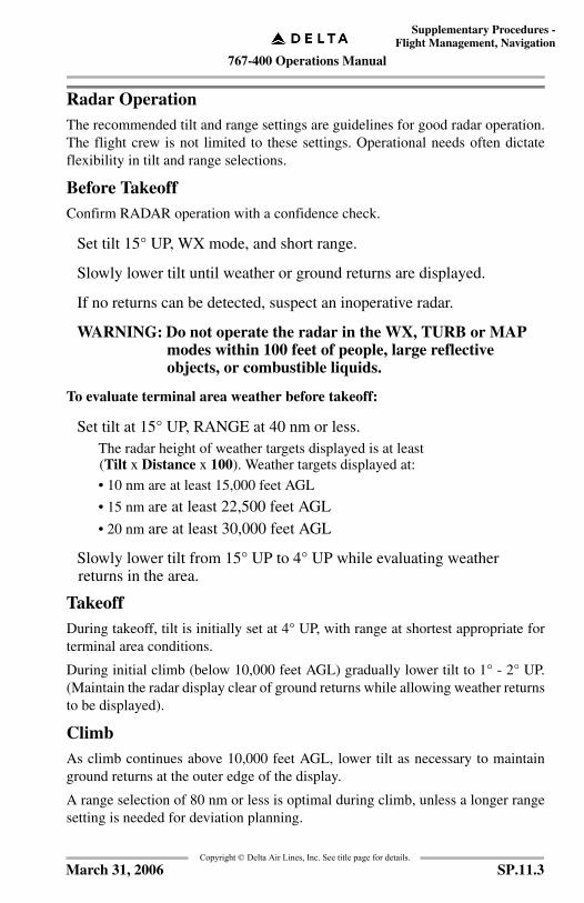
767-400 Operations Manual
Supplementary Procedures -Flight Management, Navigation
Copyright © Delta Air Lines, Inc. See title page for details.
Radar OperationThe recommended tilt and range settings are guidelines for good radar operation.The flight crew is not limited to these settings. Operational needs often dictateflexibility in tilt and range selections.
Before TakeoffConfirm RADAR operation with a confidence check.
Set tilt 15° UP, WX mode, and short range.
Slowly lower tilt until weather or ground returns are displayed.
If no returns can be detected, suspect an inoperative radar.
WARNING: Do not operate the radar in the WX, TURB or MAP modes within 100 feet of people, large reflective objects, or combustible liquids.
To evaluate terminal area weather before takeoff:
Set tilt at 15° UP, RANGE at 40 nm or less.The radar height of weather targets displayed is at least(Tilt x Distance x 100). Weather targets displayed at:
• 10 nm are at least 15,000 feet AGL
• 15 nm are at least 22,500 feet AGL• 20 nm are at least 30,000 feet AGL
Slowly lower tilt from 15° UP to 4° UP while evaluating weather returns in the area.
TakeoffDuring takeoff, tilt is initially set at 4° UP, with range at shortest appropriate forterminal area conditions.
During initial climb (below 10,000 feet AGL) gradually lower tilt to 1° - 2° UP.(Maintain the radar display clear of ground returns while allowing weather returnsto be displayed).
ClimbAs climb continues above 10,000 feet AGL, lower tilt as necessary to maintainground returns at the outer edge of the display.
A range selection of 80 nm or less is optimal during climb, unless a longer rangesetting is needed for deviation planning.
SP.11.3March 31, 2006

767-400 Operations Manual
Supplementary Procedures -Flight Management, Navigation
Copyright © Delta Air Lines, Inc. See title page for details.
Cruise
To establish enroute park:
Set RANGE at 80 nm or less.
Adjust tilt to produce ground returns at the outer edge of radar display.This tilt setting guards against overscanning nearby weather areas and provides continuous confirmation that the radar is working. Weather targets will separate from ground returns and move toward the bottom of the display.
Range settings above 100 nm should be selected occasionally for long-range planning.
Set tilt to produce a scattering of ground returns beyond 100 nm.
Storms detected at long range will increase in displayed intensity as they are approached. Plan early deviations accordingly.
Note: Nearby weather areas may not be detected due to overscanning. When returning to a shorter range, lower tilt to enroute park position.
At cruise altitudes above 30,000 feet:
Use sufficient down tilt to direct the beam into unfrozen areas of nearby storms.
Confidence Check:
Enroute radar performance can be checked by adjusting tilt to display farthestpossible ground returns.
In WX mode and with GAIN control in AUTO, a properly functioning radarshould detect ground returns to the following distances:
Continued on next page
10,000 ft. AGL 100 nm
20,000 ft. AGL 140 nm
30,000 ft. AGL 175 nm
40,000 ft. AGL 200 nm
SP.11.4 August 15, 2005
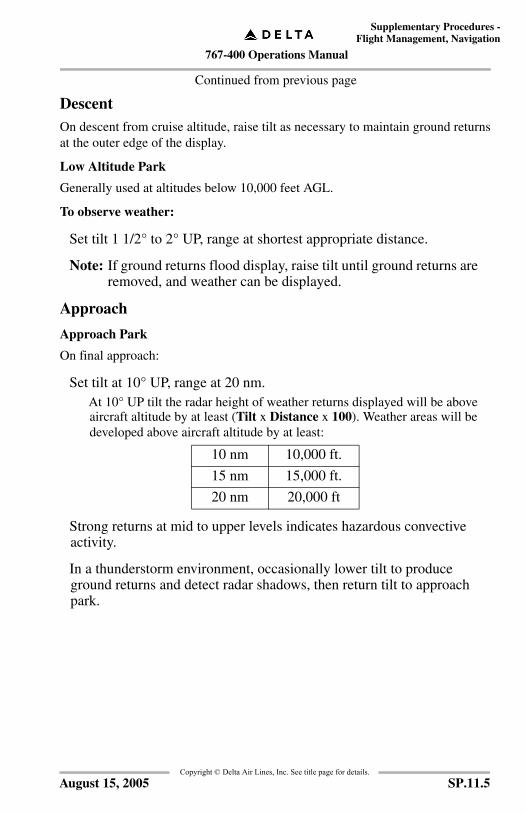
767-400 Operations Manual
Supplementary Procedures -Flight Management, Navigation
Copyright © Delta Air Lines, Inc. See title page for details.
Continued from previous page
DescentOn descent from cruise altitude, raise tilt as necessary to maintain ground returnsat the outer edge of the display.
Low Altitude Park
Generally used at altitudes below 10,000 feet AGL.
To observe weather:
Set tilt 1 1/2° to 2° UP, range at shortest appropriate distance.
Note: If ground returns flood display, raise tilt until ground returns are removed, and weather can be displayed.
Approach
Approach Park
On final approach:
Set tilt at 10° UP, range at 20 nm.At 10° UP tilt the radar height of weather returns displayed will be above aircraft altitude by at least (Tilt x Distance x 100). Weather areas will be developed above aircraft altitude by at least:
Strong returns at mid to upper levels indicates hazardous convective activity.
In a thunderstorm environment, occasionally lower tilt to produce ground returns and detect radar shadows, then return tilt to approach park.
10 nm 10,000 ft.
15 nm 15,000 ft.
20 nm 20,000 ft
SP.11.5August 15, 2005
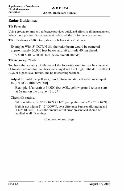
767-400 Operations Manual
Supplementary Procedures -Flight Management, Navigation
Copyright © Delta Air Lines, Inc. See title page for details.
Radar Guidelines
Tilt Formula
Using ground returns as a reference provides quick and effective tilt management.When more precise tilt management is desired, the tilt formula can be used.
Tilt x Distance x 100 = feet (above or below) aircraft altitude.
Example: With 5° DOWN tilt, the radar beam would be centered approximately 20,000 feet below aircraft altitude 40 nm ahead.
5 X 40 X 100 = 20,000 feet (below aircraft altitude).
Tilt Accuracy Check
To check the accuracy of tilt control the following exercise can be conducted.Optimal conditions for this check are straight and level flight, altitude 10,000 feetAGL or higher, level terrain, and no intervening weather.
Adjust tilt until the yellow ground return arc starts at a distance equal to [2 x AGL altitude/1000].
Example: If aircraft at 34,000 feet AGL, yellow ground returns start at 68 nm on the display (2 x 34).
Check tilt setting.Tilt should be at 3 1/2° DOWN ±1 1/2° (acceptable limits 2° - 5° DOWN).
If tilt is not within 2° - 5° DOWN, note difference between tilt setting and 3 1/2° DOWN. This is the amount of tilt error present and should be applied to all tilt settings.
Continued on next page
SP.11.6 August 15, 2005

767-400 Operations Manual
Supplementary Procedures -Flight Management, Navigation
Copyright © Delta Air Lines, Inc. See title page for details.
Continued from previous page
Gain Control
For proper calibration of the receiver, GAIN control must be in AUTO.
Manual GAIN can be used to evaluate the relative strength of surrounding weatherareas.
Observe weather targets while slowly reducing the GAIN.
Weaker targets will shrink and disappear while stronger targets persist. At minimum GAIN any weather targets still displayed contain extremely heavy rain.
If display becomes filled with red returns:
Check tilt, raise if necessary to remove ground returns from the display.
Weather area being scanned may be Level 3 in strength.
Reduce GAIN level until only heavier areas display as red, to differentiate rain intensity within the weather area.
If GAIN control is out of AUTO:
- A blue CAL legend will be displayed on the radar scope.
- No blue CAL legend will be displayed on HSI display.
WARNING: At reduced levels of GAIN, some weather targets will disappear from the indicator. Targets which are displayed will understate the true strength of the weather. Return GAIN to AUTO, immediately after using manual GAIN.
Continued on next page
SP.11.7August 15, 2005

767-400 Operations Manual
Supplementary Procedures -Flight Management, Navigation
Copyright © Delta Air Lines, Inc. See title page for details.
Continued from previous page
Attenuation
Expect attenuation any time weather targets reach Level 3, when the radome is wetor ice covered, or when operating within precipitation.
To locate intense rain areas that may be totally attenuated:
Watch for crescent shaped returns, concave on the back side.
Note an absence of returns or shadow beyond the target.
Use ground returns to confirm radar penetration, and locate radar shadows.
When flying through areas of moderate to heavy rain, radar range may become limited by attenuation:
Set tilt to attempt to produce ground returns beyond the weather returns. If attenuation is confirmed:
Monitor the outer edge of the weather returns.
Turn away from shadows that dip towards the bottom of the display.
Fly towards the area of farthest returns (this is the area of lightest precipitation).
Advise ATC that your radar range is limited and request vectors away from known thunderstorm areas.
WARNING: Radar shadows are areas of unknown weather intensity. Never penetrate a storm that produces a radar shadow.
Continued on next page
SP.11.8 August 15, 2005
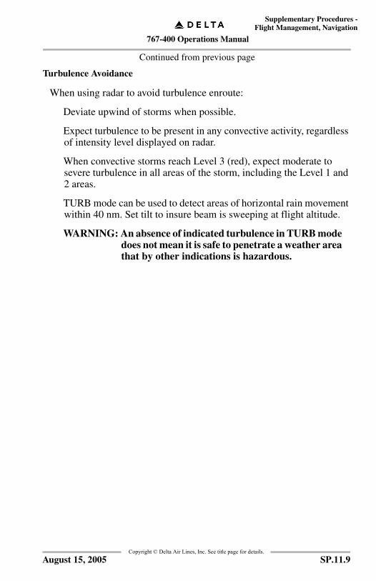
767-400 Operations Manual
Supplementary Procedures -Flight Management, Navigation
Copyright © Delta Air Lines, Inc. See title page for details.
Continued from previous page
Turbulence Avoidance
When using radar to avoid turbulence enroute:
Deviate upwind of storms when possible.
Expect turbulence to be present in any convective activity, regardless of intensity level displayed on radar.
When convective storms reach Level 3 (red), expect moderate to severe turbulence in all areas of the storm, including the Level 1 and 2 areas.
TURB mode can be used to detect areas of horizontal rain movement within 40 nm. Set tilt to insure beam is sweeping at flight altitude.
WARNING: An absence of indicated turbulence in TURB mode does not mean it is safe to penetrate a weather area that by other indications is hazardous.
SP.11.9August 15, 2005
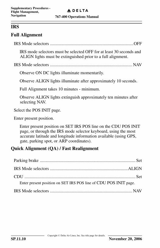
767-400 Operations Manual
Supplementary Procedures -Flight Management, Navigation
Copyright © Delta Air Lines, Inc. See title page for details.
IRS
Full Alignment
IRS Mode selectors ...........................................................................OFF
IRS mode selectors must be selected OFF for at least 30 seconds and ALIGN lights must be extinguished prior to a full alignment.
IRS Mode selectors .......................................................................... NAV
Observe ON DC lights illuminate momentarily.
Observe ALIGN lights illuminate after approximately 10 seconds.
Full Alignment takes 10 minutes - minimum.
Observe ALIGN lights extinguish approximately ten minutes after selecting NAV.
Select the POS INIT page.
Enter present position.
Enter present position on SET IRS POS line on the CDU POS INIT page, or through the IRS mode selector keyboard, using the most accurate latitude and longitude information available (using GPS, gate, parking spot, or ARP coordinates).
Quick Alignment (QA) / Fast Realignment
Parking brake ...................................................................................... Set
IRS Mode selectors ......................................................................ALIGN
CDU .................................................................................................... SetEnter present position on SET IRS POS line of CDU POS INIT page.
IRS Mode selectors .......................................................................... NAV
SP.11.10 November 20, 2006

767-400 Operations Manual
Supplementary Procedures -Flight Management, Navigation
Copyright © Delta Air Lines, Inc. See title page for details.
High Latitude Alignment
This procedure applies to alignment at latitudes greater than 70°12.0' and less than 78°15.0'.
IRS Mode selectors ..................................................... OFF, then ALIGN
POS INIT page ....................................................................................SetEnter present position on SET IRS POS line using the most accurate latitude and longitude available.
IRS Mode selectors ...........................................................................NAVSelect NAV after remaining in ALIGN for 17 minutes minimum. Verify ALIGN lights extinguished.
SP.11.11August 15, 2005
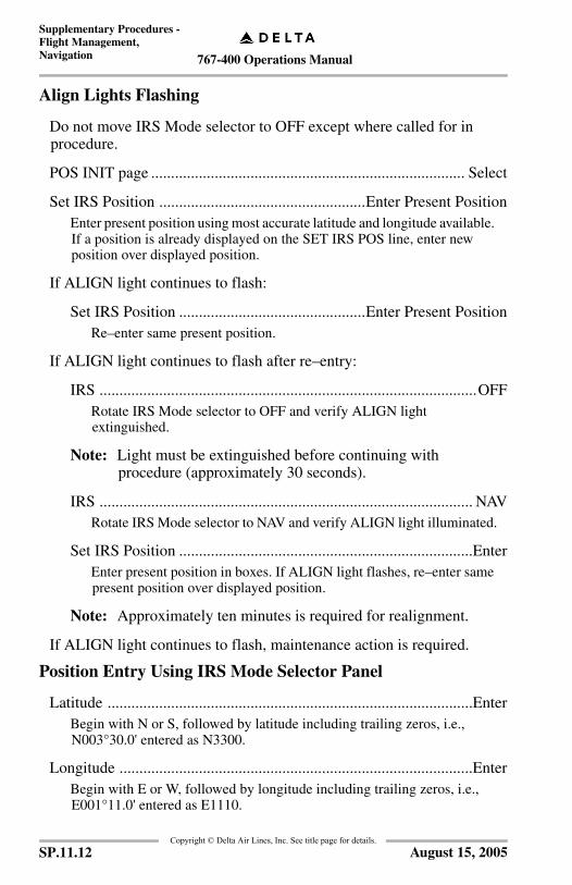
767-400 Operations Manual
Supplementary Procedures -Flight Management, Navigation
Copyright © Delta Air Lines, Inc. See title page for details.
Align Lights Flashing
Do not move IRS Mode selector to OFF except where called for in procedure.
POS INIT page ............................................................................... Select
Set IRS Position ....................................................Enter Present PositionEnter present position using most accurate latitude and longitude available. If a position is already displayed on the SET IRS POS line, enter new position over displayed position.
If ALIGN light continues to flash:
Set IRS Position ...............................................Enter Present PositionRe–enter same present position.
If ALIGN light continues to flash after re–entry:
IRS ...............................................................................................OFFRotate IRS Mode selector to OFF and verify ALIGN light extinguished.
Note: Light must be extinguished before continuing with procedure (approximately 30 seconds).
IRS .............................................................................................. NAVRotate IRS Mode selector to NAV and verify ALIGN light illuminated.
Set IRS Position ..........................................................................EnterEnter present position in boxes. If ALIGN light flashes, re–enter same present position over displayed position.
Note: Approximately ten minutes is required for realignment.
If ALIGN light continues to flash, maintenance action is required.
Position Entry Using IRS Mode Selector Panel
Latitude ............................................................................................EnterBegin with N or S, followed by latitude including trailing zeros, i.e., N003°30.0' entered as N3300.
Longitude .........................................................................................EnterBegin with E or W, followed by longitude including trailing zeros, i.e., E001°11.0' entered as E1110.
SP.11.12 August 15, 2005
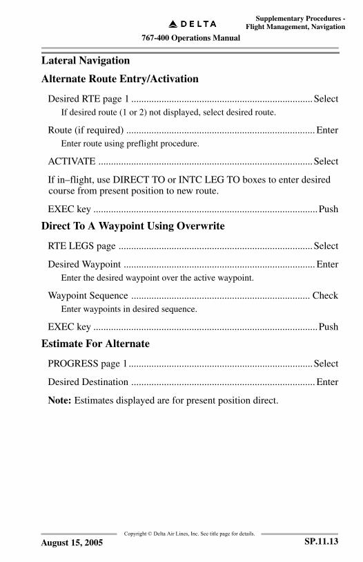
767-400 Operations Manual
Supplementary Procedures -Flight Management, Navigation
Copyright © Delta Air Lines, Inc. See title page for details.
Lateral Navigation
Alternate Route Entry/Activation
Desired RTE page 1 ........................................................................SelectIf desired route (1 or 2) not displayed, select desired route.
Route (if required) ........................................................................... EnterEnter route using preflight procedure.
ACTIVATE .....................................................................................Select
If in–flight, use DIRECT TO or INTC LEG TO boxes to enter desired course from present position to new route.
EXEC key .........................................................................................Push
Direct To A Waypoint Using Overwrite
RTE LEGS page .............................................................................Select
Desired Waypoint ............................................................................ EnterEnter the desired waypoint over the active waypoint.
Waypoint Sequence ....................................................................... CheckEnter waypoints in desired sequence.
EXEC key .........................................................................................Push
Estimate For Alternate
PROGRESS page 1.........................................................................Select
Desired Destination ......................................................................... Enter
Note: Estimates displayed are for present position direct.
SP.11.13August 15, 2005

767-400 Operations Manual
Supplementary Procedures -Flight Management, Navigation
Copyright © Delta Air Lines, Inc. See title page for details.
Holding Pattern Entry
Holding fix must be a route waypoint or present position before accomplishing following steps.
HOLD key ........................................................................................ Push
NEXT HOLD (if displayed)........................................................... Select
Holding Fix ......................................................................................EnterTo hold at present position, select PPOS. To hold at waypoint, enter waypoint identifier in HOLD AT boxes.
HOLD page ....................................................................................Check
EXEC key......................................................................................... Push
Holding Pattern Exit
To exit holding accomplish the following procedure or refer to one of the “Direct to a Waypoint” procedures.
EXIT HOLD................................................................................... Select
EXEC key......................................................................................... Push
SP.11.14 August 15, 2005
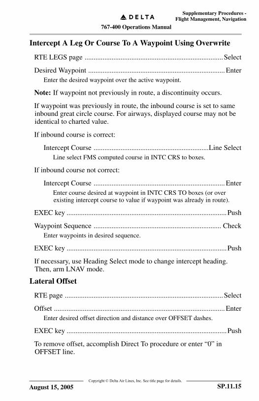
767-400 Operations Manual
Supplementary Procedures -Flight Management, Navigation
Copyright © Delta Air Lines, Inc. See title page for details.
Intercept A Leg Or Course To A Waypoint Using Overwrite
RTE LEGS page .............................................................................Select
Desired Waypoint ............................................................................ EnterEnter the desired waypoint over the active waypoint.
Note: If waypoint not previously in route, a discontinuity occurs.
If waypoint was previously in route, the inbound course is set to same inbound great circle course. For airways, displayed course may not be identical to charted value.
If inbound course is correct:
Intercept Course ................................................................Line SelectLine select FMS computed course in INTC CRS to boxes.
If inbound course not correct:
Intercept Course ......................................................................... EnterEnter course desired at waypoint in INTC CRS TO boxes (or over existing intercept course to value if waypoint was already in route).
EXEC key .........................................................................................Push
Waypoint Sequence ....................................................................... CheckEnter waypoints in desired sequence.
EXEC key .........................................................................................Push
If necessary, use Heading Select mode to change intercept heading. Then, arm LNAV mode.
Lateral Offset
RTE page ........................................................................................Select
Offset ............................................................................................... EnterEnter desired offset direction and distance over OFFSET dashes.
EXEC key .........................................................................................Push
To remove offset, accomplish Direct To procedure or enter “0” in OFFSET line.
SP.11.15August 15, 2005

767-400 Operations Manual
Supplementary Procedures -Flight Management, Navigation
Copyright © Delta Air Lines, Inc. See title page for details.
Leg Modification
To modify active waypoint or leg, accomplish one of the Direct To or Intercept A Leg Or Course procedures except when entering along track waypoints.
RTE LEGS page ............................................................................. Select
To change waypoint sequence:
Desired Waypoint Sequence .......................................................Enter
Note: If waypoint not previously in route a discontinuity occurs except when entering along track waypoints.
EXEC key ................................................................................... Push
To delete a waypoint at end of route:
DEL key ...................................................................................... Push
Waypoint ................................................................................... Select
EXEC key ................................................................................... Push
To enter along track waypoints:
Along Track Displacement .........................................................EnterSelect reference waypoint to scratch pad and modify for desired displacement.
Reference Waypoint .................................................................. SelectThe FMC will automatically position the created waypoint to the appropriate position.
EXEC key ................................................................................... Push
Route Removal
RTE page 1 ..................................................................................... Select
Origin ...............................................................................................Enter
If EXEC key illuminates:
EXEC key ................................................................................... Push
SP.11.16 August 15, 2005
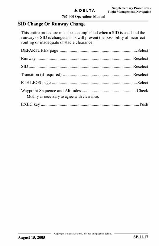
767-400 Operations Manual
Supplementary Procedures -Flight Management, Navigation
Copyright © Delta Air Lines, Inc. See title page for details.
SID Change Or Runway Change
This entire procedure must be accomplished when a SID is used and the runway or SID is changed. This will prevent the possibility of incorrect routing or inadequate obstacle clearance.
DEPARTURES page ......................................................................Select
Runway ....................................................................................... Reselect
SID .............................................................................................. Reselect
Transition (if required) ............................................................... Reselect
RTE LEGS page .............................................................................Select
Waypoint Sequence and Altitudes ................................................. CheckModify as necessary to agree with clearance.
EXEC key .........................................................................................Push
SP.11.17August 15, 2005
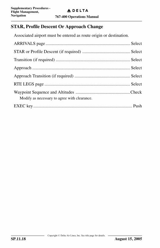
767-400 Operations Manual
Supplementary Procedures -Flight Management, Navigation
Copyright © Delta Air Lines, Inc. See title page for details.
STAR, Profile Descent Or Approach Change
Associated airport must be entered as route origin or destination.
ARRIVALS page ............................................................................ Select
STAR or Profile Descent (if required) ........................................... Select
Transition (if required) ................................................................... Select
Approach ........................................................................................ Select
Approach Transition (if required) .................................................. Select
RTE LEGS page ............................................................................. Select
Waypoint Sequence and Altitudes .................................................CheckModify as necessary to agree with clearance.
EXEC key......................................................................................... Push
SP.11.18 August 15, 2005
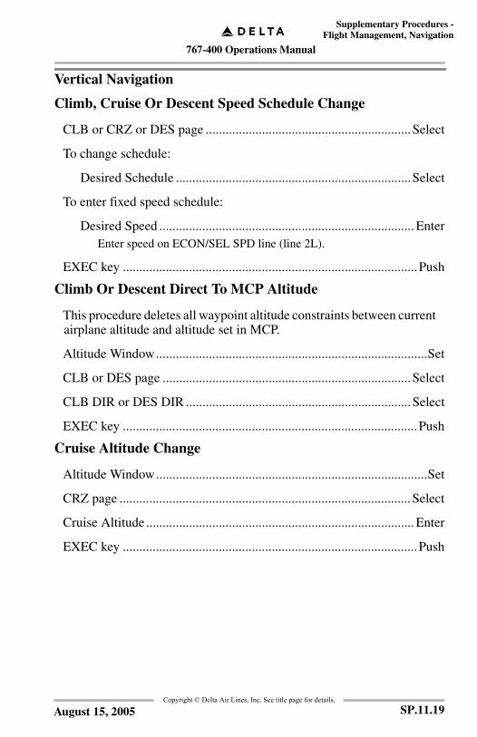
767-400 Operations Manual
Supplementary Procedures -Flight Management, Navigation
Copyright © Delta Air Lines, Inc. See title page for details.
Vertical Navigation
Climb, Cruise Or Descent Speed Schedule Change
CLB or CRZ or DES page ..............................................................Select
To change schedule:
Desired Schedule .......................................................................Select
To enter fixed speed schedule:
Desired Speed ............................................................................. EnterEnter speed on ECON/SEL SPD line (line 2L).
EXEC key .........................................................................................Push
Climb Or Descent Direct To MCP Altitude
This procedure deletes all waypoint altitude constraints between current airplane altitude and altitude set in MCP.
Altitude Window..................................................................................Set
CLB or DES page ...........................................................................Select
CLB DIR or DES DIR ....................................................................Select
EXEC key .........................................................................................Push
Cruise Altitude Change
Altitude Window..................................................................................Set
CRZ page ........................................................................................Select
Cruise Altitude ................................................................................. Enter
EXEC key .........................................................................................Push
SP.11.19August 15, 2005

767-400 Operations Manual
Supplementary Procedures -Flight Management, Navigation
Copyright © Delta Air Lines, Inc. See title page for details.
Speed/Altitude Constraint At Waypoint
RTE LEGS page ............................................................................. Select
To enter or modify constraint:
Speed/Altitude ............................................................................Enter
Note: Speed entry requires “/” mark and altitude.
EXEC key ................................................................................... Push
To delete constraint:
DEL key ...................................................................................... Push
Speed/Altitude .......................................................................... SelectSelect undesired constraint and observe estimated values appear.
EXEC key ................................................................................... Push
Speed/Altitude Transition And Restriction
CLB or DES page .......................................................................... Select
To enter speed/altitude restriction:
Speed/Altitude ............................................................................Enter
EXEC key ................................................................................... Push
To delete speed/altitude restriction or transition:
DEL key ...................................................................................... Push
Speed/Altitude .......................................................................... Select
EXEC key ................................................................................... Push
Temporary Altitude Restriction
Altitude Window ................................................................................. Set
To resume climb or descent:
Altitude Window ............................................................................ Set
VNAV...................................................................................... Engage
SP.11.20 August 15, 2005

767-400 Operations Manual
Supplementary Procedures -Flight Management, Navigation
Copyright © Delta Air Lines, Inc. See title page for details.
Temporary Speed Restriction
IAS/MACH selector .........................................................................Push
Speed Window .....................................................................................Set
To resume FMC speed schedule:
IAS/MACH selector ....................................................................Push
Performance Data Entries
Descent Forecast
DES page ........................................................................................Select
DESCENT FORECAST page ........................................................Select
Transition Level ............................................................................. Check
Thermal Anti–ice On Altitude (if required) .................................... Enter
Wind Altitude .................................................................................. EnterEnter altitude over dashes on left.
Wind Direction/Speed ..................................................................... Enter
Step Climb Evaluation
CRZ page ........................................................................................Select
Step to Altitude ................................................................................ Enter
Savings ........................................................................................... Check
Waypoint Winds
RTE LEGS page .............................................................................Select
RTE DATA page .............................................................................Select
WINDS page...................................................................................Select
Altitude and Wind............................................................................ Enter
EXEC key .........................................................................................Push
SP.11.21August 15, 2005
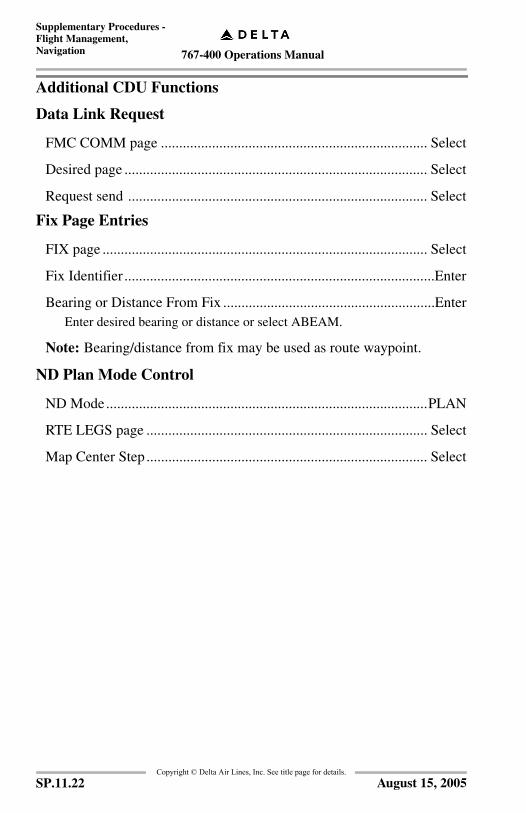
767-400 Operations Manual
Supplementary Procedures -Flight Management, Navigation
Copyright © Delta Air Lines, Inc. See title page for details.
Additional CDU Functions
Data Link Request
FMC COMM page ......................................................................... Select
Desired page ................................................................................... Select
Request send .................................................................................. Select
Fix Page Entries
FIX page ......................................................................................... Select
Fix Identifier .....................................................................................Enter
Bearing or Distance From Fix ..........................................................EnterEnter desired bearing or distance or select ABEAM.
Note: Bearing/distance from fix may be used as route waypoint.
ND Plan Mode Control
ND Mode........................................................................................PLAN
RTE LEGS page ............................................................................. Select
Map Center Step ............................................................................. Select
SP.11.22 August 15, 2005
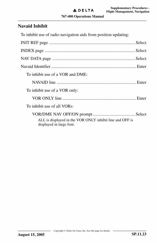
767-400 Operations Manual
Supplementary Procedures -Flight Management, Navigation
Copyright © Delta Air Lines, Inc. See title page for details.
Navaid Inhibit
To inhibit use of radio navigation aids from position updating:
INIT REF page ...............................................................................Select
INDEX page ...................................................................................Select
NAV DATA page ............................................................................Select
Navaid Identifier .............................................................................. Enter
To inhibit use of a VOR and DME:
NAVAID line ......................................................................... Enter
To inhibit use of a VOR only:
VOR ONLY line .................................................................... Enter
To inhibit use of all VORs:
VOR/DME NAV OFF/ON prompt .......................................SelectALL is displayed in the VOR ONLY inhibit line and OFF is displayed in large font.
SP.11.23August 15, 2005
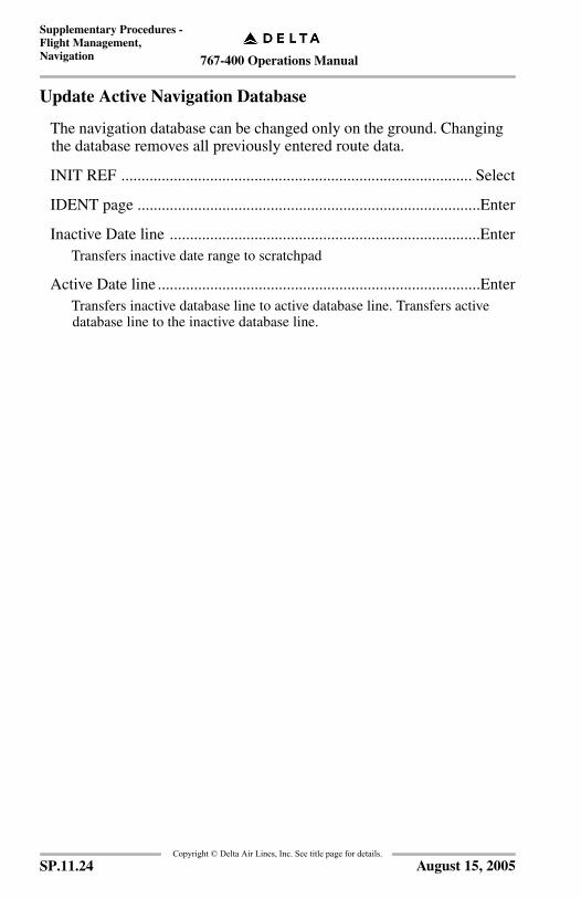
767-400 Operations Manual
Supplementary Procedures -Flight Management, Navigation
Copyright © Delta Air Lines, Inc. See title page for details.
Update Active Navigation Database
The navigation database can be changed only on the ground. Changing the database removes all previously entered route data.
INIT REF ....................................................................................... Select
IDENT page .....................................................................................Enter
Inactive Date line .............................................................................EnterTransfers inactive date range to scratchpad
Active Date line ................................................................................EnterTransfers inactive database line to active database line. Transfers active database line to the inactive database line.
SP.11.24 August 15, 2005
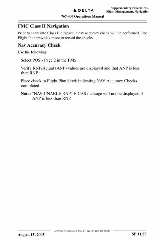
767-400 Operations Manual
Supplementary Procedures -Flight Management, Navigation
Copyright © Delta Air Lines, Inc. See title page for details.
FMC Class II NavigationPrior to entry into Class II airspace, a nav accuracy check will be performed. TheFlight Plan provides space to record the checks.
Nav Accuracy CheckUse the following:
Select POS - Page 2 in the FMS.
Verify RNP/Actual (ANP) values are displayed and that ANP is less than RNP.
Place check in Flight Plan block indicating NAV Accuracy Checks completed.
Note: "NAV UNABLE RNP" EICAS message will not be displayed if ANP is less than RNP.
SP.11.25August 15, 2005
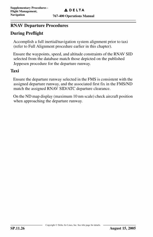
767-400 Operations Manual
Supplementary Procedures -Flight Management, Navigation
Copyright © Delta Air Lines, Inc. See title page for details.
RNAV Departure Procedures
During Preflight
Accomplish a full inertial/navigation system alignment prior to taxi (refer to Full Alignment procedure earlier in this chapter).
Ensure the waypoints, speed, and altitude constraints of the RNAV SID selected from the database match those depicted on the published Jeppesen procedure for the departure runway.
Taxi
Ensure the departure runway selected in the FMS is consistent with the assigned departure runway, and the associated first fix in the FMS/ND match the assigned RNAV SID/ATC departure clearance.
On the ND map display (maximum 10 nm scale) check aircraft position when approaching the departure runway.
SP.11.26 August 15, 2005

767-400 Operations Manual
Supplementary Procedures -Flight Management, Navigation
Copyright © Delta Air Lines, Inc. See title page for details.
During/After Takeoff
The appropriate roll mode should be selected to comply with the departure procedure and clearance. If the departure procedure and clearance require an LNAV track from the runway, arm LNAV before takeoff; LNAV automatically engages at 50 feet.
Pay close attention to takeoff clearance. "Delta 123, cleared for takeoff" is the standard clearance issued to fly the RNAV SID as published.
Use of the autopilot is strongly encouraged. Optimum course adherence is ensured if the autopilot is engaged at approximately 1,000 ft. AFE. Recommend engaging autopilot after "VNAV, flaps 5".
Whenever a significant course change is depicted, expect the FMC to use turn anticipation for fly-by waypoints (waypoints depicted on Jeppesen charts without a circle around them).
RNAV SID/STAR design is based on path keeping accuracy bounded within 0.5nm. On the ND map display, the tip of the airplane symbol represents the precise present position of the aircraft. On straight-line flight path segments, the base of the airplane symbol approximates one-tenth of the selected ND map scale (e.g., in the 10 nm scale, the base of the airplane symbol represents approximately 1 nm.) Pilots may use the airplane symbol or the appropriate progress page in the FMS to monitor path-keeping accuracy.
Notify ATC of any degradation of performance or inability of the FMS to provide accurate navigation and request amended clearance.
SP.11.27August 15, 2005

767-400 Operations Manual
Supplementary Procedures -Flight Management, Navigation
Copyright © Delta Air Lines, Inc. See title page for details.
FMS Preflight for Origins/Destinations Not Contained in FMS DatabaseCertain Offline Airports may not be in the FMS Database. If necessary use thefollowing procedures when FMS database support is unavailable:
Conduct a full alignment of the IRS using the most accurate information available; GPS coordinates, gate coordinates, or Airport Reference Point.
Enter the closest online airport as the airdrome of Origin/Destination on the FMS Route page.
Create a waypoint for the actual Offline Airport using Lat/Long or an available navaid collocated on the field; load this waypoint in the appropriate sequence on the Route Legs page.
Display and use Raw data as applicable for all Departures/Arrivals/ Approaches/ Missed Approaches at airports not supported by the FMC database.
SP.11.28 August 15, 2005
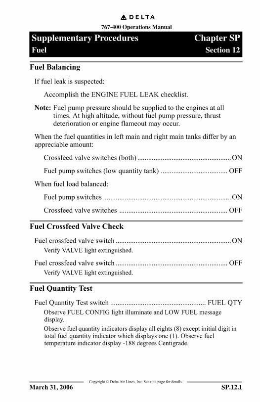
767-400 Operations Manual
Supplementary Procedures Chapter SPFuel Section 12
FCO
M T
empl
ate
12/1
2/98
Copyright © Delta Air Lines, Inc. See title page for details.
Fuel Balancing
If fuel leak is suspected:
Accomplish the ENGINE FUEL LEAK checklist.
Note: Fuel pump pressure should be supplied to the engines at all times. At high altitude, without fuel pump pressure, thrust deterioration or engine flameout may occur.
When the fuel quantities in left main and right main tanks differ by an appreciable amount:
Crossfeed valve switches (both) ....................................................ON
Fuel pump switches (low quantity tank) ..................................... OFF
When fuel load balanced:
Fuel pump switches .......................................................................ON
Crossfeed valve switches ............................................................ OFF
Fuel Crossfeed Valve Check
Fuel crossfeed valve switch ................................................................ONVerify VALVE light extinguished.
Fuel crossfeed valve switch .............................................................. OFFVerify VALVE light extinguished.
Fuel Quantity Test
Fuel Quantity Test switch ..................................................... FUEL QTYObserve FUEL CONFIG light illuminate and LOW FUEL message display.Observe fuel quantity indicators display all eights (8) except initial digit in total fuel quantity indicator which displays one (1). Observe fuel temperature indicator display -188 degrees Centigrade.
SP.12.1March 31, 2006

767-400 Operations Manual
Supplementary Procedures -Fuel
Copyright © Delta Air Lines, Inc. See title page for details.
IntentionallyBlank
SP.12.2 August 1, 2000

767-400 Operations Manual
Supplementary Procedures Chapter SPWarning Systems Section 15
FCO
M T
empl
ate
12/1
2/98
Copyright © Delta Air Lines, Inc. See title page for details.
EICAS Status Message Erase ProcedureAny status message that appears following dispatch requires an entry in thelogbook. Do not erase status messages that appear following dispatch.A status message displayed prior to preflight requires maintenance coordinatorapproval prior to attempting a status message erase procedure.
If a status message appears during pre-flight prior to dispatch, proceed as follows:
MENU key (center MCDU) ........................................................Push
DSPLY (L6)...............................................................................Select
MAINTENANCE PAGES (L5) ................................................Select
31 MCDP/MSG (L4) .................................................................Select
ERASE (R4) ..............................................................................Select
RETURN (L6) ...........................................................................Select
To return to ACARS
MENU key (center MCDU) ........................................................Push
Event Record
Event Record switch .........................................................................PushUse as directed by Flight Operations for maintenance analysis or at the discretion of the captain to manually record parameters for a suspect condition.
SP.15.1March 31, 2006
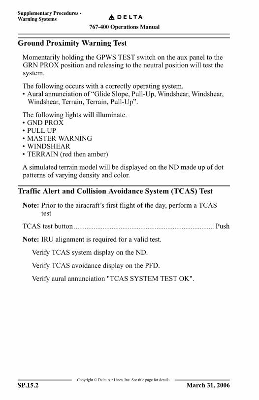
767-400 Operations Manual
Supplementary Procedures -Warning Systems
Copyright © Delta Air Lines, Inc. See title page for details.
Ground Proximity Warning Test
Momentarily holding the GPWS TEST switch on the aux panel to the GRN PROX position and releasing to the neutral position will test the system.
The following occurs with a correctly operating system.• Aural annunciation of “Glide Slope, Pull-Up, Windshear, Windshear,
Windshear, Terrain, Terrain, Pull-Up”.
The following lights will illuminate.• GND PROX• PULL UP• MASTER WARNING• WINDSHEAR• TERRAIN (red then amber)
A simulated terrain model will be displayed on the ND made up of dot patterns of varying density and color.
Traffic Alert and Collision Avoidance System (TCAS) Test
Note: Prior to the airacraft’s first flight of the day, perform a TCAS test
TCAS test button .............................................................................. Push
Note: IRU alignment is required for a valid test.
Verify TCAS system display on the ND.
Verify TCAS avoidance display on the PFD.
Verify aural annunciation "TCAS SYSTEM TEST OK".
SP.15.2 March 31, 2006

767-400 Operations Manual
Supplementary Procedures -Warning Systems
Copyright © Delta Air Lines, Inc. See title page for details.
Takeoff Configuration Warning Test
Establish one or more of the following conditions:Flaps not in takeoff positionSpeedbrakes not downStabilizer units set greater than green bandPark brake set
Configuration Test switch .................................................................. T/OObserve CONFIG light illuminate, and appropriate configuration warning message(s) display.
Establish appropriate configuration.
SP.15.3March 31, 2006

767-400 Operations Manual
Supplementary Procedures -Warning Systems
Copyright © Delta Air Lines, Inc. See title page for details.
IntentionallyBlank
SP.15.4 March 31, 2006

767-400 Operations Manual
Supplementary Procedures Chapter SPAdverse Weather Section 16
Copyright © Delta Air Lines, Inc. See title page for details.
Adverse Weather OperationAirplane operation in adverse weather conditions may require additional considerations due to the effects of extreme temperatures, severe turbulence, and windshear. The following additional instructions are intended to supplement the normal operating procedures and should be observed when applicable.
Cold Weather OperationConsiderations associated with cold weather operation are primarily those concerned with low temperatures and with ice and snow on the aircraft, ramps, taxiways, and runways.For flight deck preparation and ground operation, use normal air conditioning procedures, with all packs, trim air, and recirculation fans on, to provide cabin heating, unless ground conditioned air is utilized. Keep airplane windows and doors closed as much as possible to limit heat loss.Although removal of surface snow, ice or frost is normally a maintenance function, the flight crew should use additional care and scrutiny during preflight preparation to inspect areas where surface snow or frost could change or affect normal system operations.If any area will require special attention during deicing, coordinate with the ground crew.After extended cold soaking, equipment or systems may not operate or start when initially selected on. Should this occur, the control may be cycled OFF then ON one time to restore operation.During cold weather starts, displays may require additional warm–up time before displayed engine indications can accurately show changing values. Also, displays may appear less bright than normal.Use normal start procedures; however, note that oil pressure may be slow to rise and will initially be higher than normal. After engine start, use the Engine Anti–Ice Use supplementary procedures (refer to Section 3 – Anti–Ice, Rain).
SP.16.1December 19, 2007

767-400 Operations Manual
Supplementary Procedures -Adverse Weather
Copyright © Delta Air Lines, Inc. See title page for details.
For taxi, exercise caution by taxiing at a slower speed than normal. Taxi with flaps up if slush and standing water are present. Use smaller than normal tiller and rudder steering inputs, apply minimum thrust evenly and smoothly, and use anti–ice supplementary procedures for engine run–up.
Rejected TakeoffWhen aborting a takeoff on a slippery runway, extend spoilers if not deployed and use maximum allowable symmetrical reverse thrust. If a side slip develops, correct back to centerline by reducing reverse thrust to reverse idle and releasing brakes. This allows the tire cornering forces to be used for realignment to runway centerline. Use rudder, steering and differential braking, as required, to prevent over correcting past the centerline. When re-established on centerline, apply maximum braking and reverse thrust to stop the aircraft.
LandingTo minimize stopping distance on a contaminated runway:
• Use autobrakes for maximum stopping effectiveness.• Avoid excessive approach speed.• Touchdown within 1,500 feet from the approach end of the runway.• Assure spoilers deploy.• Use maximum allowable symmetrical reverse thrust.• Reduce reverse thrust to reverse idle prior to 60 knots.• The thrust levers should be positioned to reverse idle by taxi speed,
then to full down after the engines have decelerated to idle• If side slipping off the runway, select reverse idle and release
brakes to return to centerline.• Aircraft will tend to drift off the runway nose first with forward
thrust and tail first with reverse thrust.• Reverse thrust may reduce forward visibility due to blowing snow.• Avoid abrupt steering inputs.
After making an approach in icing conditions, or landing on a runway covered with snow or slush, do not retract the flaps until the flap areas have been checked free of debris by the ground crew.
SP.16.2 December 19, 2007
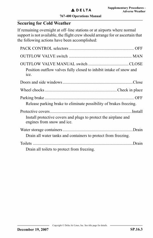
767-400 Operations Manual
Supplementary Procedures -Adverse Weather
Copyright © Delta Air Lines, Inc. See title page for details.
Securing for Cold WeatherIf remaining overnight at off–line stations or at airports where normal support is not available, the flight crew should arrange for or ascertain that the following actions have been accomplished:
PACK CONTROL selectors ............................................................. OFF
OUTFLOW VALVE switch ........................................................... MAN
OUTFLOW VALVE MANUAL switch ...................................... CLOSEPosition outflow valves fully closed to inhibit intake of snow and ice.
Doors and side windows ..................................................................Close
Wheel chocks ....................................................................Check in place
Parking brake .................................................................................... OFFRelease parking brake to eliminate possibility of brakes freezing.
Protective covers.............................................................................InstallInstall protective covers and plugs to protect the airplane and engines from snow and ice.
Water storage containers ..................................................................DrainDrain all water tanks and containers to protect from freezing.
Toilets ..............................................................................................DrainDrain all toilets to protect from freezing.
SP.16.3December 19, 2007

767-400 Operations Manual
Supplementary Procedures -Adverse Weather
Copyright © Delta Air Lines, Inc. See title page for details.
Ground De/Anti-Icing
Definitions and ConceptsGround de/anti-icing background information and policies are described in this section and the Airway Manual, Weather - Icing. Procedures for aircraft specific de/anti-icing are located in this section.
Deicing
Deicing is the procedure of removing frost, ice, slush, or snow from the aircraft in order to provide clean surfaces. On the ground this may be accomplished by:
• Using any mechanical or pneumatic means that will not damage the aircraft.
• Using heated deicing fluid to remove all forms of frozen contamination (including environmental frost). Heated fluids penetrate the frozen contaminants and contact the aircraft skin. The high thermal conductivity of the aircraft skin causes the heat to spread, breaking the bond of the ice and snow, causing it to melt or fall off the aircraft.
Anti-icing
Anti-icing is a precautionary procedure that provides protection against the formation of frost or ice, and accumulation of snow or slush on treated surfaces of the aircraft for a limited period of time (holdover time). Anti-icing fluid is the only protection against airfoil icing prior to getting airborne. Therefore, fluid application should be completed as close to takeoff time as possible.
De/Anti-icing
A combination of the deicing and anti-icing procedures.
Secondary De/Anti-icing
If an aircraft which has been de/anti-iced is delayed on the ground long enough that anti-icing protection is no longer effective, or if for any reason the de/anti-icing process is interrupted while freezing/frozen precipitation is falling, the ground de/anti-icing procedure must be reaccomplished in its entirety. This is referred to as secondary de/anti-icing.
SP.16.4 December 19, 2007
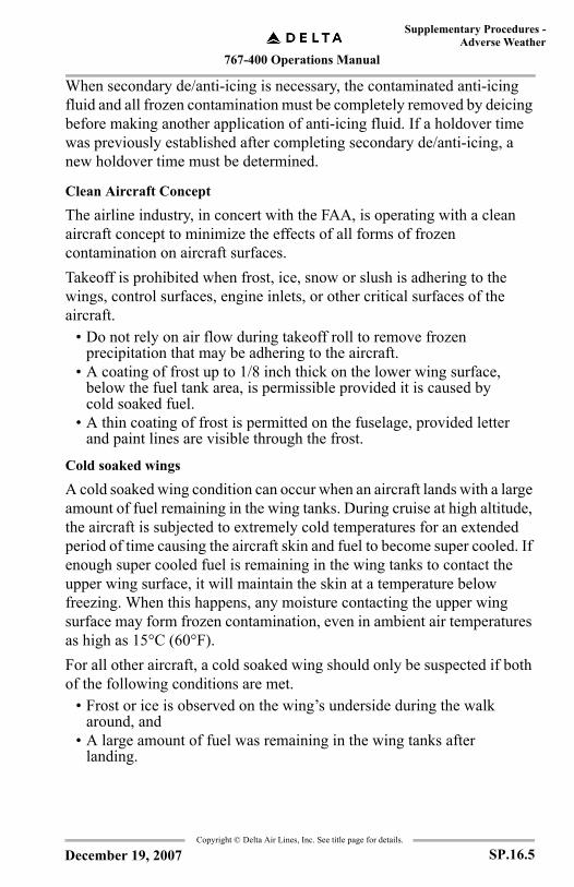
767-400 Operations Manual
Supplementary Procedures -Adverse Weather
Copyright © Delta Air Lines, Inc. See title page for details.
When secondary de/anti-icing is necessary, the contaminated anti-icing fluid and all frozen contamination must be completely removed by deicing before making another application of anti-icing fluid. If a holdover time was previously established after completing secondary de/anti-icing, a new holdover time must be determined.
Clean Aircraft Concept
The airline industry, in concert with the FAA, is operating with a clean aircraft concept to minimize the effects of all forms of frozen contamination on aircraft surfaces.Takeoff is prohibited when frost, ice, snow or slush is adhering to the wings, control surfaces, engine inlets, or other critical surfaces of the aircraft.
• Do not rely on air flow during takeoff roll to remove frozen precipitation that may be adhering to the aircraft.
• A coating of frost up to 1/8 inch thick on the lower wing surface, below the fuel tank area, is permissible provided it is caused by cold soaked fuel.
• A thin coating of frost is permitted on the fuselage, provided letter and paint lines are visible through the frost.
Cold soaked wings
A cold soaked wing condition can occur when an aircraft lands with a large amount of fuel remaining in the wing tanks. During cruise at high altitude, the aircraft is subjected to extremely cold temperatures for an extended period of time causing the aircraft skin and fuel to become super cooled. If enough super cooled fuel is remaining in the wing tanks to contact the upper wing surface, it will maintain the skin at a temperature below freezing. When this happens, any moisture contacting the upper wing surface may form frozen contamination, even in ambient air temperatures as high as 15°C (60°F).For all other aircraft, a cold soaked wing should only be suspected if both of the following conditions are met.
• Frost or ice is observed on the wing’s underside during the walk around, and
• A large amount of fuel was remaining in the wing tanks after landing.
SP.16.5December 19, 2007
767-400 Operations Manual
Supplementary Procedures -Adverse Weather
Copyright © Delta Air Lines, Inc. See title page for details.
If cold soaked wings are suspected, cabin windows may be used during the preflight to visually inspect the upper wing surfaces for frost or ice. The quickest way to alleviate a cold soaked wing condition is to add warm fuel to the wing tanks.
Critical Aircraft Surfaces
Critical aircraft surfaces are those surfaces which must be clear of adhering frozen contamination before beginning takeoff roll. Critical aircraft surfaces include, but may not be limited to:
• Wings, slats, flaps, ailerons, spoilers.• Horizontal stabilizer and elevator.• Vertical stabilizer and rudder.• Pitot heads, static ports, ram-air intakes, engine and flight
instrument probes, other kinds of instrument sensor pickups.• Engine and APU inlets and exhausts.• Landing gear and landing gear doors.• Fuel vents.• Radome
Representative Aircraft Surfaces
Representative aircraft surfaces are those which the pilot can readily observe to determine whether or not frost, ice, or snow is accumulating or forming on that surface. By using a representative surface, a pilot can make a reasoned judgement regarding whether or not frost, ice, or snow is adhering to other aircraft surfaces.Representative aircraft surfaces visible from the flight deck are:
• Fuselage.• Radome.
Representative aircraft surfaces visible from the best vantage point(s) in the cabin are:
• Wing area upper surfaces.• Wing leading edges.• Engine inlets.
SP.16.6 December 19, 2007

767-400 Operations Manual
Supplementary Procedures -Adverse Weather
Copyright © Delta Air Lines, Inc. See title page for details.
Best Vantage Point(s)
The best vantage point is the location in the aircraft where a pilot can best check representative aircraft surfaces. This will normally be a passenger window in the over-wing area. It may be necessary in some circumstances to move forward a few rows to get the best view of the engines. Outside lighting conditions and glare may also affect which specific location is the best vantage point.
Holdover Time
Holdover time is the estimated time that anti-icing fluid will prevent the formation of frozen contaminants on the treated surfaces of the aircraft. Holdover time is determined by the pilot using the Holdover Time Tables.Holdover time starts when the final application of fluid begins. The final fluid applied will be either:
• De/Anti-icing fluid in the one step procedure, or• Anti-icing fluid in the two step procedure.
Holdover time ends when either:• The applied fluid loses its effectiveness, or • The time extracted from the holdover time range expires.
Ground Icing Conditions
Guidance for determining precipitation categories (type) and intensities (light, moderate, and heavy) is located in the Airway Manual, Weather, Hazardous Weather - Icing.
WARNING:Do not take off during hail, moderate or heavy freezing rain, snow pellets, or heavy ice pellets.
Operational Effects of Frozen Contamination
Frost, ice, and/or snow adhering to airfoils, engine inlets, flight controls and flight instrument sensors, even in small amounts, can have a critical effect on aircraft performance. For example, ice formations on the wing’s leading edges and upper surfaces creating texture roughness of medium to coarse sandpaper can reduce lift as much as 30 percent and increase drag by 40 percent. Therefore, frozen contamination on the aircraft in any form poses a serious threat to flight safety due to degraded operational performance.
SP.16.7December 19, 2007

767-400 Operations Manual
Supplementary Procedures -Adverse Weather
Copyright © Delta Air Lines, Inc. See title page for details.
Degraded aerodynamic performance such as:• Lift decreases - Frozen contamination may destroy the lifting
ability of an airfoil, including leading edge devices. The aircraft may not lift off at a normal pitch attitude. Required gaps in leading edge devices may be blocked and further reduce lift on one or both wings.
• Drag/weight increases - An aircraft may fail to reach takeoff speed in the calculated distance.
• Stall speed increases - Buffet or stall may occur before activation of stall warning systems.
• Controllability decreases - Caused by changing the aerodynamic properties of the control surface due to ice. For example, ice on the leading edge of the horizontal stabilizer can affect pitch control, especially during rotation.
Reduction in available engine power caused by:• Icing of engine inlets, guide vanes or compressor blades.• Ingestion of ice shedding from other parts of the aircraft.
Impairment of flight and engine performance indicators resulting in: • Incorrect power settings due to EPR probe icing.• Incorrect airspeed indication caused by pitot/static probe icing.• Erroneous stall warning caused by ice on the AOA probe.
Degraded flight control response as ice may interfere with the free movement of the flight controls.
Delta De/Anti-icing ProgramDelta Air Lines’ Ground De/Anti-icing Program is coordinated among Airport Customer Service, Maintenance, Flight Control, Flight Operations, Fleet Management and Reliability, and Flight Safety. Each Delta deicing station will have designated trained personnel on duty to determine when to initiate ground de/anti-icing operations. At airports where no Delta personnel are permanently assigned, the Captain may declare the de/anti-icing program in effect. In this case, the Captain shares responsibility for the effectiveness of the effort with the ground crew. The procedures outlined in this section will help guide the Captain through this decision making process.There are several components to Delta’s De/Anti-icing Program. Pilots need to be aware of how key components play an integral part in ensuring safe winter flight operations.
SP.16.8 December 19, 2007
767-400 Operations Manual
Supplementary Procedures -Adverse Weather
Copyright © Delta Air Lines, Inc. See title page for details.
De/Anti-icing Alert Plan
A Deicing Alert Chart will be issued daily by Delta Meteorology to the OCC Duty Director. This chart reflects forecasted freezing/frozen precipitation for specific geographic regions for the next day’s flying (24 - 48 hours in advance). Affected stations will be notified, and plans will be made to initiate local de/anti-icing operations. Flight Control will work in conjunction with individual stations to determine possible changes to the flight schedule based on any anticipated decrease in airport air traffic capacity.
Station De/Anti-icing Plans
Each Delta station that conducts de/anti-icing operations is required to have a detailed de/anti-icing plan on file. This plan contains, but is not limited to the following information:
• Persons responsible for implementing/terminating the de/anti-icing plan.
• Deicing equipment and fluids.• Location of de/anti-icing areas.• Local procedures including communication with the flight crew
and coordination with local ATC.ATC will be notified whenever the local de/anti-icing plan is in effect. Departure runway queues will be managed by ATC in order to minimize the amount of time an aircraft spends on the ground after being de/anti-iced.Special procedures for the pilots will be contained in the Airway Manual, 10-0 Delta Special Pages (green pages), or noted in the Airport Remarks section of the flight plan.
Responsibility for De/Anti-icing of Aircraft
The Captain has the ultimate responsibility for ensuring the aircraft’s critical surfaces are free of frozen contamination and the flight can be operated safely. The ground deicing crew shares in this responsibility by providing an aircraft that complies with the clean aircraft concept.Normally, aircraft de/anti-icing will be performed by:
• Delta Maintenance.• Airport Customer Service (ACS).• Business partner (contractor).• Any combination of the above.
SP.16.9December 19, 2007

767-400 Operations Manual
Supplementary Procedures -Adverse Weather
Copyright © Delta Air Lines, Inc. See title page for details.
ACS and/or contractors accomplish the majority of aircraft de/anti-icing. As always, pilot vigilance is paramount during any de/anti-icing procedure. If possible, the pilots should evaluate the operation from the flight deck as it is being conducted and:
• If deicing or anti-icing is not being performed properly and safety is jeopardized, stop the operation and attempt to have the problem corrected.
• When possible, provide timely feedback on individual station de/anti-icing performance to the Dispatcher. A telephone report is preferred.
• Document all de/anti-icing problems or kudos on a COR.Depending on the circumstances and local station procedures, aircraft de/anti-icing may be accomplished:
• Whenever requested by the Captain.• Prior to taxiing into the gate (to prevent accumulation).• During overnight parking (prior to pilots’ arrival).• At the gate - prior to pushback.• After pushback - clear of the gate.• During taxi operations, i.e., car wash.
Deicing at Offline Stations
If de/anti-icing is required at an offline station, consult with Flight Control.In unusual circumstances, such as when operating at an offline station, the pilots may be required to supervise the de/anti-icing operation. In this case, the pilots must ensure the aircraft is free of frozen contamination in accordance with the clean aircraft concept. If the Captain determines that the pilots are unable to effectively supervise the de/anti-icing procedure, the flight will not operate.
Note:Contact the Dispatcher if a noncertified fluid must be used. Refer to Noncertified Fluids section in this chapter.
SP.16.10 December 19, 2007

767-400 Operations Manual
Supplementary Procedures -Adverse Weather
Copyright © Delta Air Lines, Inc. See title page for details.
De/Anti-icing Fluids
Type I Fluid
Type I fluid is a deicing and anti-icing fluid with low viscosity and is considered an unthickened fluid. It forms a very thin wetting film on aircraft surfaces and has excellent deicing properties. Type I fluid can be orange-colored or colorless. Due to its low viscosity, it provides minimal anti-icing protection. Type I fluid is always diluted because adding water ensures fluid freeze point protection and ensures proper aerodynamic flow-off characteristics. Type I fluid is never applied 100 percent. Different dilution ratios of Type I fluids affect the freeze point of the fluid, but do not alter its holdover time significantly. Consequently, there are no ratio break outs on the Type I Holdover Time Table. The Type I Holdover Table will apply when this fluid is used.
Type II Fluid
Type II fluid is a deicing and anti-icing fluid of high viscosity and is considered a thickened fluid. It adheres to the aircraft surfaces to provide a protective film. It creates a thicker layer than Type I fluid and thus has improved anti-icing capability. Type II fluid can be straw-colored or colorless. Airflow during takeoff roll causes the fluid to shed so that by rotation the surfaces are aerodynamically clean. Varying concentration levels of Type II fluid affect its holdover time. Delta prefers to use 100 percent concentration of Type II fluid, but other concentration levels may be used at contract or overseas facilities. Not all stations will have Type II available. The Type II Holdover Table will apply when this fluid is used.
Type III Fluid
Type III fluid is a deicing and anti-icing fluid with longer [holdover] times than Type I fluid, but lower viscosity than Type IV fluids. It was primarily designed for use on aircraft with slower rotation speeds to ease shedding of the fluid during takeoff, but it is fully approved for use on Delta aircraft. Type III fluid is bright yellow in color. Few stations are expected to have Type III fluid available. The Type III Holdover Table will apply when this fluid is used.Type III fluid or fluid/water mixtures are normally applied heated when used for deicing (contamination removal), but may be heated or unheated for anti-icing (surface protection).
SP.16.11December 19, 2007
767-400 Operations Manual
Supplementary Procedures -Adverse Weather
Copyright © Delta Air Lines, Inc. See title page for details.
Type IV Fluid
Type IV fluid is an enhanced performance deicing and anti-icing fluid with characteristics similar to Type II. Type IV fluid is green colored, except in Japan, where it is colorless. Its anti-icing effectiveness is superior to Type II fluid and holdover time is increased by a significant factor under most conditions. There is a separate Holdover Time Table for Type IV which reflects this improved performance. Additionally, Type IV fluid has some unique visual characteristics. It is pale green in color and considerably thicker than Type II fluid. When applied to the wings, the extra thickness may cause the fluid to appear wavy or bumpy. Varying concentration levels of Type IV fluid affect its holdover time. Delta prefers to use 100 percent concentration of Type IV, but other concentration levels may be used at contract or overseas facilities. Not all stations will have Type IV available. The Type IV Holdover Table will apply when this fluid is used.Some contract deicing ground crews may communicate a specific brand of Type IV fluid during the Post De/Anti-icing Report, for example, “Type IV, Octagon, Max-Flight.” Flight crews should disregard the fluid brand information and utilize the Type IV Holdover Time Table.
Noncertified Fluids
A de/anti-icing fluid that does not meet SAE/ISO certification requirements (including military fluids) is classified as noncertified, Type I, Type II, Type III, or Type IV fluid. These fluids may be encountered at certain international stations, or during offline operations at military bases. The use of noncertified Type I fluid is not authorized for takeoff during active icing conditions. Contact the Dispatcher if a noncertified Type I fluid is used. Noncertified Type II, Type III, or Type IV fluids are not authorized under any circumstances.
Fluid Standards
Deicing fluids are:• Heated water when OAT is above or equal to -3°C (27°F).• Heated water mixed with Type I fluid.• Heated water mixed with one of the following SAE/ISO fluids:
•Type II, or•Type III, or•Type IV.
SP.16.12 December 19, 2007
767-400 Operations Manual
Supplementary Procedures -Adverse Weather
Copyright © Delta Air Lines, Inc. See title page for details.
Anti-icing fluids must be certified by the:• Society of Automotive Engineers (SAE).• International Standards Organization (ISO).
Anti-icing fluids are:• Heated or unheated water mixed with one of the following
SAE/ISO fluids:•Type I,•Type II,•Type III, or•Type IV.
• Undiluted SAE/ISO Type II fluid.• Undiluted SAE Type III fluid• Undiluted SAE/ISO Type IV fluid
All de/anti-icing fluids have a limit to their low operational temperature use. Ground deicing crews and Dispatchers have access to this information in the Technical Operations Policies and Procedures (TOPP) 20-30-05. The following is an approximate low temperature limit of the fluids:
• Type I has the lowest temperature use, approximately -30°C (-22°F)
• Type II and IV are approximately -25°C (-13°F)• Type III is approximately -29°C (-20°F)
Under extremely low temperature conditions consider using alternate means of deicing, such as brooms or nonheated forced air.
Fluid Effects on Braking and Steering
Generally, Type I, Type II, Type III, and Type IV fluids are considered to have the same affect on braking and steering as water.
CAUTION:A slippery condition may exist in and around the de/anti-icing ramp and taxi ways, particularly during dry weather conditions or light precipitation.
De/Anti-icing Fluid vs. Hydraulic Fluid
It is very difficult to distinguish between de/anti-icing fluids and hydraulic fluid. In small quantities and thin coatings, both fluids will have similar coloring and feel slippery to the touch. During the exterior inspection, if residual fluids on aircraft surfaces cannot be identified, contact local Maintenance or call the MCC through the Dispatcher for guidance.
SP.16.13December 19, 2007
767-400 Operations Manual
Supplementary Procedures -Adverse Weather
Copyright © Delta Air Lines, Inc. See title page for details.
Fluid Application Methods
De/anti-icing can be performed using a one or two step procedure.• One step procedure - This procedure is a combination of deicing
and anti-icing performed at the same time with the same fluid (de/anti-icing). The fluid used to deice the aircraft is always heated and remains on the surface to provide anti-icing protection. This procedure can be repeated so as to minimize the time required to complete the final application of fluid.
• Two step procedure - This procedure consists of two distinct fluid applications. The first step, deicing with a heated fluid, is followed by the second step, anti-icing, as a separate fluid application. Normally, Type II or Type IV fluid is used during the second step; however, Type I or Type III fluid may be used.
Note:Areas in front of the most forward passenger door are normally treated only with Type I or Type III fluid. International stations may use a thin mixture of Type II or Type IV fluid when Type I or Type III fluid is not available.
Note:Holdover time starts when the final application begins in either the one step or two step procedure.
Forced Air DeicingAt some stations, forced air deicing equipment is used to facilitate contamination removal. Forced air deicing utilizes an air stream to help remove frozen accumulations from an aircraft with or without deicing fluid. Forced air deicing has the advantage of reducing the total amount of glycol needed for deicing, providing economic and environmental benefits. Forced air only (without fluid) may be especially helpful for removing frozen accumulations from RON aircraft surfaces.Forced air applications (with or without fluid) may not eliminate the need for conventional de/anti-icing procedures. After a forced air application has occurred, conventional deicing (using fluid only) may be needed to ensure complete contamination removal.Holdover times are not associated with forced air deicing. To use Type I holdover time tables, anti-icing using heated Type I fluid without forced air must occur. To use Type II, Type III, or Type IV holdover time tables, anti-icing using Type II, Type III, or Type IV fluid without forced air must occur.The post-de/anti-icing check and report (below) should still occur even if forced-air deicing is the only task performed.
SP.16.14 December 19, 2007
767-400 Operations Manual
Supplementary Procedures -Adverse Weather
Copyright © Delta Air Lines, Inc. See title page for details.
De-/Anti-icing ChecksThere are four types of de/anti-icing checks: Post De/Anti-icing Check, Flight Deck Check, Cabin Check, and External Check.
Post De/Anti-icing Check
This check is an integral part of the de/anti-icing process. After aircraft de/anti-icing is complete, the deicing ground crew performs a Post De/Anti-icing Check to confirm that the critical surfaces are free of any contamination. Confirmation that the Post De/Anti-icing Check has been successfully completed will be communicated to the pilots during the Post De/Anti-icing Report by stating; “POST DE/ANTI-ICING CHECK COMPLETE”.
Flight Deck Check
This check is an integral part of the holdover time and is performed by the pilots. Because of the limitations and cautions associated with the use of the Holdover Time Tables, the pilots must not rely on the use of holdover times as the sole determinant that the aircraft is free of contamination. They must continually assess the current weather, environmental conditions, and the aircraft’s condition. Several Flight Deck Checks are required during the holdover time period to maintain awareness of the aircraft’s condition.The Flight Deck Check is performed by the pilots just prior to takeoff and is required anytime:
• Ground icing conditions exist, and• The holdover time is still valid.
The Flight Deck Check consists of:• A check of representative aircraft surfaces which are visible from
the flight deck.• If desired or if any doubt exists, conduct a Cabin Check.
When circumstances do not permit a satisfactory visual check from inside the aircraft, return to the designated area and:
• Have ground de-icing crew perform an External Check, or• If any doubt exists as to the condition of the aircraft, repeat the
Ground De/Anti-icing procedure.
SP.16.15December 19, 2007
767-400 Operations Manual
Supplementary Procedures -Adverse Weather
Copyright © Delta Air Lines, Inc. See title page for details.
Cabin Check
This check is performed by the pilots and is required:• Any time the aircraft has been de/anti-iced, and holdover time is
exceeded during conditions of frost, freezing fog, or snow, or• Within 5 minutes of takeoff any time a pilot-assessed change in
intensity is to be used, or• When doubt exists after conducting the Flight Deck Check, or• During conditions of heavy snow (provided Type IV fluid has been
used for anti-icing).Since clear ice formation cannot be detected visually from inside the aircraft, the Cabin Check is not authorized when:
• Type I fluid has been applied during freezing drizzle.• Type II , Type III, or Type IV fluid has been applied during
freezing drizzle, light freezing rain, or rain on cold soaked wings and holdover time has expired. Secondary de/anti-icing or an External check must be accomplished prior to takeoff.
• Ice pellets have fallen.The Cabin Check consists of a visual inspection of all representative aircraft surfaces which are visible from the best vantage point(s) in the cabin. Normally, de/anti-icing fluid failure will first occur on the leading or trailing edges of the wing rather than the mid-chord. Therefore, the leading edges and upper surfaces of both wings must be visually checked for evidence of fluid failure. Additionally, engine inlets must be inspected for contamination. Takeoff must occur within five minutes of the most recent check.The ability to adequately perform this check from inside the aircraft is highly dependent upon several factors. Lighting conditions, cleanliness of cabin/flight deck windows, and outside visibility may severely hinder or prevent the pilot’s ability to satisfactorily assess aircraft surfaces for contamination. When circumstances do not permit a satisfactory visual check from inside the aircraft, return to the designated area and:
• Have ground de-icing crew perform the External Check.• If any doubt exists as to the condition of the aircraft, repeat the
ground de/anti-icing procedure.
SP.16.16 December 19, 2007

767-400 Operations Manual
Supplementary Procedures -Adverse Weather
Copyright © Delta Air Lines, Inc. See title page for details.
External Check
This check is performed by the de/anti-icing ground crew and is required anytime:
• Doubt exists after conducting a Cabin Check, or• The aircraft has been anti-iced with Type II, Type III, or Type IV
fluid, and holdover time is exceeded during freezing drizzle, light freezing rain, or rain on cold soaked wings.
This check consists of a close visual inspection of the aircraft’s upper wing surfaces and leading edges for frozen contamination. Takeoff must occur within five minutes of the External Check.If the External Check cannot be accomplished, return for secondary de/anti-icing.
CAUTION:An External Check is not authorized during freezing drizzle when Type I fluid is used.
Contact local operations for specific locations on the airfield to accomplish the External Check. Be aware that some stations may conduct secondary de/anti-icing as an alternative to the External Check.
Visual Indications of Loss of Fluid Effectiveness
It is difficult to determine when anti-icing fluid is beginning to fail, however, when any ice or snow can be seen accumulating on treated surfaces, the fluid has lost its effectiveness. Any ice, frost, or snow on top of deicing or anti-icing fluids must be considered as adhering to the aircraft, and secondary de/anti-icing must be accomplished prior to takeoff.
• Normally, de/anti-icing fluid failure will first occur on the leading or trailing edges of the wing rather than the mid-chord. However, when the aircraft is pointing downwind the mid-chord will fail first.
• The leading edges and upper surfaces of both wings must be visually checked for evidence of fluid failure.
• If the leading edges and upper surfaces of both wings cannot be inspected from the cabin, return for an External Check or secondary de/anti-icing.
Type I Fluid
When Type I fluid has lost its effectiveness, frozen precipitation will begin to accumulate on the aircraft surface in much the same manner as it would on a nontreated surface.
SP.16.17December 19, 2007

767-400 Operations Manual
Supplementary Procedures -Adverse Weather
Copyright © Delta Air Lines, Inc. See title page for details.
Type II, Type III, and Type IV Fluid
When Type II, Type III, or Type IV fluid has lost its effectiveness and is no longer able to absorb the freezing moisture, look for the following visual indications.
• Gray or white appearance and buildup of ice crystals in or on top of the fluid.
• Progressive surface freezing.• Snow accumulation.• Dulling of surface reflectiveness caused by the gradual
deterioration of the fluid to slush (loss of gloss or orange peel appearance).
• Ice buildup on the wing life raft attach points (if installed), adjacent to the over-wing exits.
SP.16.18 December 19, 2007
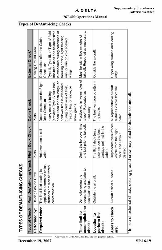
767-400 Operations Manual
Supplementary Procedures -Adverse Weather
Copyright © Delta Air Lines, Inc. See title page for details.
Types of De/Anti-icing ChecksTY
PE
S O
F D
E/A
NT
I-IC
ING
CH
EC
KS
* In
lieu
of e
xter
nal c
heck
, dei
cing
gro
und
crew
may
ele
ct to
de/
anti-
ice
airc
raft.
Typ
e o
f C
hec
kP
ost
De/
An
ti-i
cin
g C
hec
kF
ligh
t D
eck
Ch
eck
Cab
in C
hec
kE
xter
nal
Ch
eck*
Per
form
ed b
y:D
eici
ng G
roun
d C
rew
Pilo
tsP
ilots
Dei
cing
Gro
und
Cre
w
Req
uir
ed w
hen
:T
he fi
nal f
luid
coa
ting
is
appl
ied
to d
eter
min
e cr
itica
l su
rfac
es a
re fr
ee o
f fro
zen
cont
amin
atio
n.
Hol
dove
r tim
e is
stil
l va
lid.
Dou
bt e
xist
s af
ter
the
Flig
ht
Dec
k C
heck
, or
heav
y sn
ow is
falli
ng
(pro
vide
d T
ype
IV fl
uid
has
been
use
d fo
r an
ti-ic
ing)
, or
hold
over
tim
e is
exc
eede
d du
ring
cond
ition
s of
fros
t, fr
eezi
ng fo
g, o
r sn
ow, o
r
snow
gra
ins.
Dou
bt e
xist
s af
ter
the
Cab
in
Che
ck, o
r
Typ
e II,
Typ
e III
, or
Typ
e IV
flui
d ha
s be
en u
sed
and
hold
over
tim
e is
exc
eede
d du
ring
cond
ition
s of
fr
eezi
ng d
rizzl
e, li
ght f
reez
ing
rain
, or
rain
on
cold
soa
ked
win
gs.
Tim
e lim
it t
o
acco
mp
lish
th
e ch
eck:
Dur
ing/
follo
win
g th
e de
/ant
i-ici
ng a
nd p
rior
to
push
back
or
taxi
.
Dur
ing
the
hold
over
tim
e an
d ju
st p
rior
to ta
keof
f.M
ust b
e w
ithin
five
min
utes
of
take
off.
Rep
eate
d as
ne
cess
ary.
Mus
t be
with
in fi
ve m
inut
es o
f ta
keof
f. R
epea
ted
as n
eces
sary
.
Lo
cati
on
to
p
erfo
rm t
he
chec
k:
Out
side
the
airc
raft.
The
flig
ht d
eck
(may
al
so in
clud
e th
e be
st
vant
age
poin
t(s)
in th
e ca
bin)
.
The
bes
t van
tage
poi
nt(s
) in
th
e ca
bin.
O
utsi
de th
e ai
rcra
ft.
Are
as t
o c
hec
k ar
e:A
ircra
ft cr
itica
l sur
face
s.R
epre
sent
ativ
e su
rfac
es
visi
ble
from
the
fligh
t de
ck (
and
cabi
n if
desi
red)
.
All
repr
esen
tativ
e ai
rcra
ft su
rfac
es v
isib
le fr
om th
e ca
bin.
Upp
er w
ing
surf
ace
and
lead
ing
edge
.
SP.16.19December 19, 2007
767-400 Operations Manual
Supplementary Procedures -Adverse Weather
Copyright © Delta Air Lines, Inc. See title page for details.
Communication ProceduresAny airport specific deicing procedures will be contained in the Airway Manual, 10-0 Delta Special Pages (green pages), or noted in the Airport Remarks section of the flight plan.It is critical to establish communications with the ground crew prior to commencing de/anti-icing. Once the deicing operation commences, any aircraft movement or changes in configuration must be coordinated with the ground crew.
Post De/Anti-icing Report
After the aircraft has been de/anti-iced, a Post De/Anti-icing Report must be directly communicated to the Captain using the format specified on the GROUND DE/ANTI-ICING procedure card. The pilot is required to read back this information to verify accuracy.
Note:A report is not required when the aircraft is deiced due to frost, prior to the pilot’s arrival, and no active frost is forming.
Holdover Times
Use of Holdover Time Tables
Holdover times provide an operational guideline for departure planning. They must be used in conjunction with the Flight Deck Check. Holdover Time Tables are located in this section. Holdover times published in the tables are only approximate and must be adjusted after considering all variables. The source of the Holdover Time Tables is the Aerospace Division of the Society of Automotive Engineers (SAE). Time data is derived from an analysis of testing conducted in field and laboratory conditions, as well as airline operational experience. Numerous factors affect the actual time that anti-icing fluid will provide protection against frozen contamination. The times specified in the tables represent the approximate holdover times for seven categories of active precipitation.
• Frost.• Freezing fog.• Snow.• Freezing drizzle.• Freezing rain (light).
SP.16.20 December 19, 2007
767-400 Operations Manual
Supplementary Procedures -Adverse Weather
Copyright © Delta Air Lines, Inc. See title page for details.
• Ice pellets• Rain on cold soaked wings.
Three precipitation categories specify a time range (snow, freezing drizzle, and rain on cold soaked wings), and four categories specify a single time (freezing fog, frost, light freezing rain and ice pellets).Whenever a time range is given, the lower time in the range is for moderate precipitation conditions and the upper time is for light conditions.When a single time is specified in the table, it represents the approximate holdover time limit for that weather condition. However, it may be necessary to adjust the holdover time downward after considering other environmental factors.
Establishing Holdover Time
A holdover time is established using the following five steps.(1) Obtain the Post De/Anti-icing Report from the ground crew and
read back the information. The following data from the report is used to establish a holdover time:•Fluid type: Type I, Type II, Type III, or Type IV.•Fluid concentration: Mixture information is only required for
Type II, Type III, or Type IV fluid. There are no fluid mixture break outs on the Type I Holdover Time Table because dilution ratios do not significantly affect holdover time for Type I fluids.
•Local time that the final (anti-icing) fluid application began. This is the point at which the holdover timing starts.
(2) Determine the current weather conditions (OAT, type of precipitation, and intensity of precipitation).•OAT is determined by the most current weather report or ATIS.•The Holdover tables allow pilots to determine holdover times
based partly upon the type and intensity of the frozen precipitation that is falling.
•The type and intensity of frozen precipitation (light, moderate, or heavy) is officially determined by the most current official weather report (e.g.,from National Weather Service [NWS], NWS-approved automated system, or other agent approved by the NWS).
•If at any time a pilot assesses intensity greater than that being reported, he/she shall use the heavier precipitation when entering the holdover tables for holdover time.
SP.16.21December 19, 2007
767-400 Operations Manual
Supplementary Procedures -Adverse Weather
Copyright © Delta Air Lines, Inc. See title page for details.
•If, in the pilot’s judgement, the intensity is less than that being reported, the pilot shall request (e.g., to the tower or trained weather observer) a new observation be taken and reported or shall wait long enough for an update to an automated meteorological observation to be taken and reported as applicable.
•A pilot may act on their own assessment of lesser precipitation intensity only in those cases concerning snowfall or ice pellets where the officially reported (e.g., from NWS, NWS-approved automated system, or other agent approved by the NWS) meteorological precipitation intensity is grossly different from that which is obviously occurring. (For example: precipitation is reported when there is no actual precipitation occurring.)
•If an adjustment to intensity is pilot-assessed, the pilots shall communicate the newly assessed intensity to flight control via ACARS.
•If a pilot acts based upon their own assessment that precipitation intensity levels are LOWER than the official reported intensity level, a Cabin Check is required within the 5 minutes preceding takeoff.
•Pilot assessment of precipitation intensity levels may only be used when there is enough natural sunlight or artificial lighting available to provide adequate exterior visibility. All windows through which the assessment is made must be adequately transparent so as to not restrict the pilot’s visibility under the lighting conditions present.
•The Snowfall Intensities as a Function of Prevailing Visibility chart in the Flight Crew Operations Manual, Volume 1, is based on prevailing visibility and allowances are made for the effects of night light conditions.
•Ice pellet intensity shall be assessed using the following criteria:•Light - scattered pellets that do not completely cover
exposed surfaces regardless of duration•Moderate - slow accumulation on the ground•Heavy - rapid accumulation on the ground
•Pilots are not permitted to self-assess intensity in the case of reported freezing drizzle or freezing rain unless no precipitation is actually falling. Freezing drizzle and freezing rain quickly adhere to cold surfaces and can be difficult to see; for this reason, if conditions are reported or anticipated the aircraft shall be de-iced and/or treated with anti-icing fluid as a precaution against encountering these conditions during taxi-out.
SP.16.22 December 19, 2007
767-400 Operations Manual
Supplementary Procedures -Adverse Weather
Copyright © Delta Air Lines, Inc. See title page for details.
(3) Based on all the information obtained in steps 1 and 2, reference the appropriate Holdover Time Table and determine:•A single time from the frost, freezing fog, light freezing rain or
ice pellets column, or•A time range from the snow, freezing drizzle, or rain on cold
soaked wings column.(4) If a single time was extracted from the table, go to step 5. If a
time range was extracted, determine a specific holdover time from this range by assessing:•Intensity of precipitation. As a general rule, holdover time
ranges should be interpreted as follows:•Light conditions = Upper end of time range.•Moderate conditions = Lower end of time range.•Heavy conditions = Less than the lower time value.
•When determining intensity, the pilots must consider the rate, density, and moisture content of the precipitation. For example, wet snow is considered more intense than dry/powdery snow and will have a lower holdover time. Wet snow occurs at or near freezing temperatures of -1°C (30°F) or above.
(5) Further refine the determined holdover time after considering the following additional factors:•Environmental factors - Jet blast, high wind velocity, and wind
direction may cause anti-icing fluid to flow off aircraft surfaces thus reducing holdover time. Blowing snow due to wind or jet blast could decrease holdover time by increasing the amount of precipitation contacting aircraft surfaces and diluting the fluid. Solar radiation from direct sunlight may increase holdover time by warming aircraft surfaces.
•Aircraft skin temperature - Although this is difficult to determine, pilots need to be aware that aircraft skin temperature lower than OAT may decrease holdover time. One of the best ways to assess wing skin temperature is by referencing the fuel temperature, if available. Fuel temperature significantly lower than OAT may decrease holdover time.
•Operational experience of the pilots - For example, pilots who rarely fly in ground icing conditions may feel more comfortable using more conservative holdover times. Additionally, any background knowledge or experiences can be applied by the pilots.
SP.16.23December 19, 2007
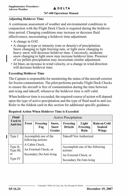
767-400 Operations Manual
Supplementary Procedures -Adverse Weather
Copyright © Delta Air Lines, Inc. See title page for details.
Adjusting Holdover Time
A continuous assessment of weather and environmental conditions in conjunction with the Flight Deck Check is required during the holdover time period. Changing conditions may increase or decrease fluid effectiveness, necessitating a holdover time adjustment.
• A change in OAT.• A change in type or intensity (rate or density) of precipitation.
Snow changing to light freezing rain, or light snow changing to heavy snow will decrease holdover time. Conversely, moderate snow changing to light snow may increase holdover time. Presence of ice pellets precipitation may necessitate similar adjustment.
• Jet blast, an increase in wind velocity, or a change in wind direction will decrease holdover time.
Exceeding Holdover Time
The Captain is responsible for monitoring the status of the aircraft exterior for frozen contamination. The pilot performs periodic Flight Deck Checks to ensure the aircraft is free of contamination during the time between anti-icing and takeoff, whenever the holdover time is still valid.When holdover time is exceeded, the required course of action will depend upon the type of active precipitation and the type of fluid used to anti-ice. Refer to the foldout card in this section for additional specific guidance.
Required Action When Holdover Time is Exceeded
Fluid Used to Anti-Ice
Active Precipitation
Frost Freezing Fog
Snow, Snow
Grains
Freezing Drizzle
Light Freezing
Rain
Rain on Cold Soaked Wings
Type I Accomplish one of the following actions:A Cabin Check,An External Check, orSecondary De/Anti-Icing
Takeoff Not Authorized
Type II, Type III, or Type IV
Accomplish one of the following actions:An External Check, or Secondary De/Anti-Icing
SP.16.24 December 19, 2007
767-400 Operations Manual
Supplementary Procedures -Adverse Weather
Copyright © Delta Air Lines, Inc. See title page for details.
Configuring the Aircraft for De/Anti-icingIt is the responsibility of the pilots to ensure the aircraft is properly configured prior to commencing de/anti-icing operations.
Note: Whenever de/anti-icing will occur during overnight parking, the pilots must ensure the aircraft is properly configured prior to leaving for the night. Refer to the Securing for Cold Weather procedure contained in this section.
SP.16.25December 19, 2007
767-400 Operations Manual
Supplementary Procedures -Adverse Weather
Copyright © Delta Air Lines, Inc. See title page for details.
IntentionallyBlank
SP.16.26
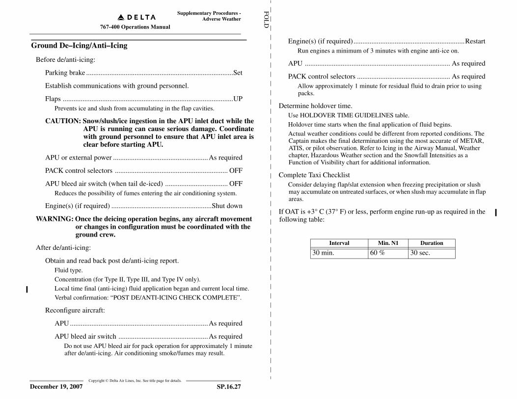
767-400 Operations Manual
Supplementary Procedures -Adverse Weather
FOL
D
Ground De–Icing/Anti–Icing
Before de/anti-icing:
Parking brake ..................................................................................Set
Establish communications with ground personnel.
Flaps ...............................................................................................UPPrevents ice and slush from accumulating in the flap cavities.
CAUTION: Snow/slush/ice ingestion in the APU inlet duct while theAPU is running can cause serious damage. Coordinatewith ground personnel to ensure that APU inlet area isclear before starting APU.
APU or external power .....................................................As required
PACK control selectors ............................................................... OFF
APU bleed air switch (when tail de-iced) ................................... OFFReduces the possibility of fumes entering the air conditioning system.
Engine(s) (if required) ........................................................Shut down
WARNING: Once the deicing operation begins, any aircraft movement or changes in configuration must be coordinated with the ground crew.
After de/anti-icing:
Obtain and read back post de/anti-icing report.Fluid type.
Concentration (for Type II, Type III, and Type IV only).
Local time final (anti-icing) fluid application began and current local time.
Verbal confirmation: “POST DE/ANTI-ICING CHECK COMPLETE”.
Reconfigure aircraft:
APU .............................................................................As required
APU bleed air switch ..................................................As requiredDo not use APU bleed air for pack operation for approximately 1 minute after de/anti-icing. Air conditioning smoke/fumes may result.
Copyright © Delta Air Lines, Inc. See title page for details.
SP.16.27December 19, 2007
Engine(s) (if required)..............................................................RestartRun engines a minimum of 3 minutes with engine anti-ice on.
APU ................................................................................. As required
PACK control selectors .................................................... As requiredAllow approximately 1 minute for residual fluid to drain prior to using packs.
Determine holdover time.Use HOLDOVER TIME GUIDELINES table.
Holdover time starts when the final application of fluid begins.
Actual weather conditions could be different from reported conditions. The Captain makes the final determination using the most accurate of METAR, ATIS, or pilot observation. Refer to Icing in the Airway Manual, Weather chapter, Hazardous Weather section and the Snowfall Intensities as a Function of Visibility chart for additional information.
Complete Taxi ChecklistConsider delaying flap/slat extension when freezing precipitation or slush may accumulate on untreated surfaces, or when slush may accumulate in flap areas.
If OAT is +3° C (37° F) or less, perform engine run-up as required in the following table:
Interval Min. N1 Duration
30 min. 60 % 30 sec.

767-400 Operations Manual
Supplementary Procedures - Adverse Weather
Takeoff Decision Tree
CABINCHECK
EXTERNALCHECK
CLEAN
CLEAN
NOTCLEAN
NOTCLEAN
TAKEOFF
DE/ANTI-ICE AIRCRAFT
FrostFreezing Fog
Light to Mod. Snow/ Snow Grains
EXTERNALCHECK
TAKEOFF within 5 minutes.If unable, repeat De/Anti-icing.
TAKEOFF within
5 minutes.
If unable, repeat Cabin
Check or External Check.
CLEAN
Freezing Drizzle
Light Freezing Rain
Rain on Cold Soaked Wings
Holdover Time Ends
Holdover Time Begins
TAKEOFF within 5 minutes.
If unable, repeat Cabin Check.
1
2
3
3
2
3
FLIGHT DECKCHECK
CABINCHECK
EXTERNALCHECK
FluidType
NOTCLEAN
NOT SURE
NOT SURE
NOTCLEAN
TYPE II, III, OR IV
CLEAN
NOT SURE
NOTCLEAN
NOTCLEAN
CLEAN CLEAN
See SpecialConsiderationsfor Heavy Snow
TYPE I
Ice Pellets
Copyright © Delta Air Lines, Inc. See title page for details.
SP.16.28 December 19, 2007
Flight deck checkInspect aircraft components visible from the flight deck for frozen contamination.
• Inspect the fuselage and radome.
Cabin checkInspect aircraft components visible from the cabin for frozen contamination.
Inspect all the following from the best vantage point in the cabin:
• Engine inlets.• Both wings: upper surface and leading edge. (Best vantage points are the
passenger windows forward of and at the overwing area. Use the wing illumination lights.)
External checkContact local operations.
• Secondary de/anti-icing may be performed in lieu of EXTERNAL CHECK.
Holdover Time Guidelines (All Locations & Fluid Types)• Holdover times DO NOT exist for conditions of snow pellets, heavy
snow, moderate to heavy freezing rain, or hail, and takeoff is NOT authorized under these conditions. An exception for heavy snow might be possible when Type IV anti-icing fluid is used; see Special Considerations for Heavy Snow.
• Holdover time ranges are for moderate to light conditions. During heavy weather conditions, the holdover time will be less than the lower time specified in the range.
• Jet blast, high wind velocity, high moisture content, and aircraft skin temperature lower than OAT may decrease holdover time below the lowest time specified in the range.
• Ground de-/anti-icing fluids are not intended for and do not provide ice protection during flight.
• For shaded areas either the holdover times have not been established or the weather conditions generally do not occur within the respective temperature range.
• These tables are for use in departure planning only, and should be used in conjunction with the pre-takeoff Flight Deck check.
Continued on next page

767-400 Operations Manual
Supplementary Procedures -Adverse Weather
FOL
D
Copyright © Delta Air Lines, Inc. See title page for details.
Continued from previous page Special Considerations for Ice Pellets
Ice pellets generally remain in the frozen state, imbedded in anti-icing fluid, and are notabsorbed by fluid in the same manner as other forms of frozen precipitation. In the past,presence of a contaminant not absorbed by the fluid would be an indication of a failed fluid.Ice pellets imbedded in anti-icing fluid are difficult to detect using a cabin check.Therefore, a cabin check during ice pellet conditions may not be of value and is notrequired.
Use of Holdover Time Tables for Ice Pellets and Ice Pellet Mixtures
After proper deicing and anti-icing, takeoff is allowed under conditions of light ice pellets,moderate ice pellets, and ice pellets mixed with other forms of precipitation by using the"Ice Pellet Holdover Times" table and accompanying footnotes. If the holdover time hasbeen exceeded, the aircraft must be completely deiced, and if precipitation is still present,anti-iced again prior to a subsequent takeoff. The ice pellet holdover time cannot beextended by a cabin check or an external check of the aircraft critical surfaces.
❄ Special Considerations for Heavy Snow
Takeoffs are allowed in heavy snow provided:
• The aircraft has been anti-iced with 100% concentration Type IV fluid following deicing, and
• A Cabin Check is accomplished within the 5 minutes preceding takeoff.
If a definitive fluid failure determination cannot be made using this check due tosnowfall, lighting conditions, or any other reason, the aircraft must be completelydeiced and anti-iced (if precipitation is still present) prior to takeoff.
SP.16.29December 19, 2007
Ice
Pel
let
Hol
dove
r T
imes
(10
0% T
ype
IV F
luid
Onl
y)
OA
TH
OL
DO
VE
R T
IME
S (M
INU
TE
S)
°C°F
LIG
HT
IC
EPE
LL
ET
SO
NLY
MO
DE
RA
TE
ICE
PEL
LE
TS
ON
LY
LIG
HT
IC
E P
EL
LE
TS
MIX
ED
WIT
H:
LT-M
OD
SN
OW
LT-M
OD
FRE
EZ
ING
DR
IZZ
LE
LTF
RE
EZ
ING
RA
IN
LT R
AIN
> 0
> 3
250
2525
2525
25
< 0
to -
5<
32
to 2
350
2525
2525
< -
5 to
-10
< 2
3 to
14
3010
1010
< -
10<
14
3010
NO
T A
UT
HO
RIZ
ED
Hol
dove
r tim
es b
egin
at t
he s
tart
of
the
anti-
icin
g ap
plic
atio
n.
Ice
pelle
t hol
dove
r tim
es a
re v
alid
pro
vide
d:
•U
ndilu
ted
(100
%)
Type
IV
flu
id is
use
d fo
r an
ti-ic
ing.
•C
ritic
al s
urfa
ces
are
free
of
cont
amin
atio
n be
fore
app
lyin
g Ty
pe I
V a
nti-
icin
g fl
uid
(i.e
., ic
e pe
llets
can
not b
e fa
lling
dur
ing
eith
er
the
deic
e or
ant
i-ic
e st
eps)
.•
The
tabl
e’s
prec
ipit
atio
n in
tens
ity a
nd te
mpe
ratu
re li
mits
are
not
exc
eede
d.Ty
pe I
V a
nti-
icin
g fl
uid
is c
onsi
dere
d ef
fect
ive
for
90 m
inut
es a
fter
the
star
t of
appl
icat
ion,
und
er th
e fo
llow
ing
cond
itio
ns:
•If
pre
cipi
tati
on s
tops
fal
ling
at a
ny ti
me
duri
ng th
e ho
ldov
er p
erio
d, a
nd•
the
hold
over
tim
e ha
s no
t bee
n ex
ceed
ed, a
nd•
the
OA
T h
as n
ot d
ecre
ased
.If
pre
cipi
tatio
n re
sum
es, t
he o
rigi
nal h
oldo
ver
time
mus
t not
be
exce
eded
.
•If
the
tem
pera
ture
dec
reas
es, o
r co
nditi
ons
degr
ade
to a
poi
nt w
here
a d
iffe
rent
hol
dove
r tim
e w
ould
app
ly, t
hat d
iffe
rent
hol
dove
r tim
e m
ust n
ot b
e ex
ceed
ed (
from
the
star
t of
the
anti-
icin
g st
ep).

767-400 Operations Manual
Supplementary Procedures - Adverse Weather
Con
vers
ions
Snow
fall
Inte
nsit
ies
as a
Fun
ctio
n of
Pre
vaili
ng V
isib
ility
Tim
e of
D
ayO
AT
Vis
ibil
ity
(Sta
tute
Mil
e)
RV
R F
eet
RV
R
Met
ers
Sta
tute
M
iles
°C°F
> 2
½ <
2½
- 2
< 2
- 1
½ <
1½
- 1
< 1
- ¾
< ¾
- ½
< ½
Snowfall Intensity
6000
2000
1-1/
4D
ay>
-1
> 3
0 V
ery
Lig
htL
ight
Lig
htM
oder
ate
Mod
erat
eH
eavy
Hea
vy
5000
1600
1<
-1
< 3
0 V
ery
Lig
htV
ery
Lig
htL
ight
Lig
htM
oder
ate
Mod
erat
eH
eavy
4000
1200
3/4
Nig
ht>
-1
> 3
0 V
ery
Lig
htL
ight
Mod
erat
eH
eavy
Hea
vyH
eavy
Hea
vy
2400
800
1/2
< -
1<
30
Ver
y L
ight
Lig
htM
oder
ate
Mod
erat
eH
eavy
Hea
vyH
eavy
TY
PE
I
OA
TA
PPR
OX
IMA
TE
HO
LD
OV
ER
TIM
ES
(MIN
UT
ES)
°C°F
AC
TIV
EF
RO
STFR
EE
ZIN
GF
OG
SNO
W/S
NO
W G
RA
INS
❋FR
EE
ZIN
G
DR
IZZ
LE
LIG
HT
FRE
EZ
ING
R
AIN
RA
IN O
N
CO
LD
S
OA
KE
D
WIN
GV
ER
Y L
IGH
TL
IGH
TM
OD
ER
AT
E
> -3
> 2
745
1118
- 2
2 ◆
◆11
- 1
8 ◆
◆6
-11
◆◆
TAK
EO
FF
NO
T A
UT
HO
RIZ
ED
< -
3 to
-6
< 2
7 to
21
458
14 -
17
◆◆
8 -
14 ◆
◆5
- 8
◆◆
< -
6 to
-10
< 2
1 to
14
456
11 -
13
◆◆
6 -
11 ◆
◆4
- 6
◆◆
< -
10
< 1
445
57
- 8
◆◆
4 -
7 ◆
◆
◆◆
To
use
thes
e ti
mes
the
flui
d m
ust b
e he
ated
to a
min
imum
tem
pera
ture
of
60°C
(12
0°F
) at
the
nozz
le a
nd a
t lea
st 1
lite
r pe
r sq
uare
met
er (
2 ga
llon
s pe
r 10
0 sq
uare
fee
t) m
ust
be a
ppli
ed to
de-
iced
sur
face
s.
* R
efer
to “
Sno
wfa
ll I
nten
siti
es a
s a
func
tion
of P
reva
iling
Vis
ibil
ity”
char
t if
no o
ther
env
iron
men
tal f
acto
rs in
hibi
ting
vis
ibil
ity, i
. e.,
smok
e or
fog
, are
pre
sent
.
Hol
dove
r ti
mes
DO
NO
T e
xist
for
con
diti
ons
of ic
e pe
llet
s, s
now
pel
lets
, hea
vy s
now
, fre
ezin
g dr
izzl
e, f
reez
ing
rain
, or
hail,
and
take
off
is N
OT
aut
hori
zed
unde
r th
ese
cond
itio
ns.
Copyright © Delta Air Lines, Inc. See title page for details.
SP.16.30 December 19, 2007
TY
PE
IV
OA
T
Flu
id
Con
cent
ratio
n(F
luid
/Wat
er)
AP
PR
OX
IMA
TE
HO
LD
OV
ER
TIM
ES
(M
INU
TE
S)
°C°F
AC
TIV
EF
RO
ST
FR
EE
ZIN
GF
OG
SN
OW
/SN
OW
GR
AIN
S*
ICE
PEL
LE
TS
◆
FR
EE
ZIN
G
DR
IZZ
LE
**L
IGH
TF
RE
EZ
ING
R
AIN
RA
IN O
N
CO
LD
S
OA
KE
D
WIN
G†
MO
D -
LG
TH
EA
VY
MO
D -
LG
TM
OD
- L
GT
> -3
> 27
100/
012
hrs
7535
-75
❄
See Ice
Pel
lets
Hol
dove
rT
imes
Tabl
e
40-7
025
10-5
0
75/2
55
hrs
6520
-55
35-5
015
5-35
50/5
03
hrs
155-
1510
-20
< -
3 to
-10
< 2
7 to
14
100/
012
hrs
2020
-40
❄20
-45
10
75/2
55
hrs
2515
-35
15-3
010
< -
10 to
-14
< 1
4 to
7
100/
012
hrs
2020
-40
❄
TA
KE
OF
F N
OT
AU
TH
OR
IZE
D75
/25
5 hr
s25
15-3
5
< -
14 to
-25
< 7
to -
1310
0/0
12 h
rs15
15-3
0❄
< -
25<
-13
US
E T
YPE
I F
LU
ID
† U
se o
nly
for
0° C
(32
° F)
or
abov
e.
* R
efer
to “
Snow
fall
Int
ensi
ties
as
a fu
ncti
on o
f Pr
evai
ling
Vis
ibil
ity”
char
t if
no o
ther
env
iron
men
tal f
acto
rs in
hibi
ting
vis
ibil
ity, i
. e. s
mok
e or
fog
, are
pre
sent
.
** I
f po
sitiv
e id
entif
icat
ion
of f
reez
ing
driz
zle
is n
ot p
ossi
ble,
use
ligh
t fre
ezin
g ra
in h
oldo
ver
times
.
❄ T
akeo
ffs
are
allo
wed
in h
eavy
sno
w p
rovi
ded:
(1)
the
airc
raft
has
bee
n an
ti-i
ced
wit
h 10
0/0
conc
entr
atio
n Ty
pe I
V f
luid
fol
low
ing
deic
ing,
and
(2)
a pr
e-ta
keof
f co
ntam
inat
ion
(cab
in)
chec
k is
acc
ompl
ishe
d w
ithi
n th
e 5
min
utes
pre
cedi
ng ta
keof
f.If
a d
efin
itive
flu
id f
ailu
re d
eter
min
atio
n ca
nnot
be
mad
e us
ing
this
che
ck d
ue to
sno
wfa
ll, li
ghti
ng c
ondi
tion
s, o
r an
y ot
her
reas
on, t
he a
ircr
aft m
ust b
e co
mpl
etel
y de
iced
an
d an
ti-ic
ed (
if p
reci
pita
tion
is s
till
pre
sent
) pr
ior
to ta
keof
f.
◆ R
efer
to I
ce P
elle
ts H
oldo
ver
Tim
es ta
ble
in th
is s
ecti
on.
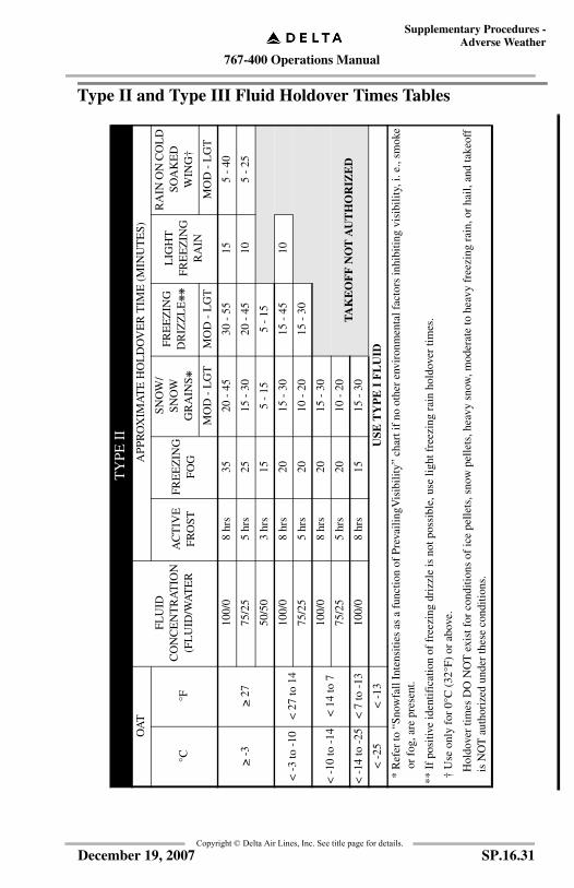
767-400 Operations Manual
Supplementary Procedures -Adverse Weather
Copyright © Delta Air Lines, Inc. See title page for details.
Type II and Type III Fluid Holdover Times TablesT
YPE
II
OA
T
FLU
ID
CO
NC
EN
TR
AT
ION
(FL
UID
/WA
TE
R
APP
RO
XIM
AT
E H
OL
DO
VE
R T
IME
(M
INU
TE
S)
°C°F
AC
TIV
EFR
OST
FRE
EZ
ING
FOG
SNO
W/
SNO
W
GR
AIN
S ❋
FRE
EZ
ING
DR
IZZ
LE
❋❋
L
IGH
TFR
EE
ZIN
GR
AIN
RA
IN O
N C
OL
D
SOA
KE
D
WIN
G†
MO
D -
LG
TM
OD
- L
GT
MO
D -
LG
T
> -3
> 27
100/
08
hrs
3520
- 4
530
- 5
515
5 -
40
75/2
55
hrs
2515
- 3
020
- 4
510
5 -
25
50/5
03
hrs
155
- 15
5 -
15
< -
3 to
-10
< 2
7 to
14
100/
08
hrs
2015
- 3
015
- 4
510
75/2
55
hrs
2010
- 2
015
- 3
0
< -
10 to
-14
< 1
4 to
710
0/0
8 hr
s20
15 -
30
75/2
55
hrs
2010
- 2
0T
AK
EO
FF
NO
T A
UT
HO
RIZ
ED
< -
14 to
-25
< 7
to -
1310
0/0
8 hr
s15
15 -
30
< -
25<
-13
USE
TY
PE
I F
LU
ID
* R
efer
to “
Snow
fall
Inte
nsiti
es a
s a
func
tion
of P
reva
ilin
gVis
ibili
ty”
char
t if
no o
ther
env
iron
men
tal f
acto
rs in
hibi
ting
visi
bili
ty, i
. e.,
smok
e or
fog
, are
pre
sent
.
** I
f po
sitiv
e id
entif
icat
ion
of f
reez
ing
driz
zle
is n
ot p
ossi
ble,
use
ligh
t fre
ezin
g ra
in h
oldo
ver
times
.
† U
se o
nly
for
0°C
(32
°F)
or a
bove
.
Hol
dove
r tim
es D
O N
OT
exi
st f
or c
ondi
tions
of
ice
pelle
ts, s
now
pel
lets
, hea
vy s
now
, mod
erat
e to
hea
vy f
reez
ing
rain
, or
hail,
and
take
off
is N
OT
aut
hori
zed
unde
r th
ese
cond
ition
s.
SP.16.31December 19, 2007

767-400 Operations Manual
Supplementary Procedures -Adverse Weather
Copyright © Delta Air Lines, Inc. See title page for details.
TY
PE
III
OA
T
FL
UID
C
ON
CE
NT
RA
TIO
N(W
AT
ER
/FL
UID
)
APP
RO
XIM
AT
E H
OL
DO
VE
R T
IME
S (M
INU
TE
S)
°C°F
AC
TIV
EFR
OST
FRE
EZ
ING
FOG
SNO
W/S
NO
W G
RA
INS
❋
FR
EE
ZIN
G
DR
IZZ
LE
❋❋
LIG
HT
FRE
EZ
ING
R
AIN
RA
IN O
N
CO
LD
S
OA
KE
D
WIN
G†
VE
RY
L
IGH
TL
IGH
TM
OD
ER
AT
E
> -3
> 27
100/
012
020
35 -
40
20 -
35
10 -
20
10 -
20
86
- 20
75/2
560
1525
- 3
515
- 2
58
- 15
8 -
156
50/5
030
1015
- 2
08
- 15
4 -
85
- 9
< -
3 to
-10
< 2
7 to
14
100/
012
020
30 -
35
15 -
30
9 -
1510
- 2
08
75/2
560
1525
- 3
010
- 2
57
- 10
9 -
126
< -
10 to
-29
< 1
4 to
-20
100/
012
020
30 -
35
15 -
30
8 -
15TA
KE
OFF
NO
T A
UT
HO
RIZ
ED
< -
29<
-20
USE
TY
PE
I F
LU
ID
† U
se o
nly
for
0° C
(32
° F)
or
abov
e.
* R
efer
to “
Snow
fall
Inte
nsiti
es a
s a
func
tion
of P
reva
iling
Vis
ibili
ty”
char
t if
no o
ther
env
iron
men
tal f
acto
rs in
hibi
ting
visi
bilit
y, i.
e.,
smok
e or
fog
, are
pr
esen
t.
** I
f po
sitiv
e id
entif
icat
ion
of f
reez
ing
driz
zle
is n
ot p
ossi
ble,
use
ligh
t fre
ezin
g ra
in h
oldo
ver
times
.
SP.16.32 December 19, 2007
767-400 Operations Manual
Supplementary Procedures -Adverse Weather
Copyright © Delta Air Lines, Inc. See title page for details.
Hot Weather OperationDuring ground operation the following considerations will help keep the airplaneas cool as possible:
• If a ground source of conditioned air is available, the supply should be plugged in immediately after engine shutdown and should not be removed until either the APU or the engines are started.
• If a ground source of conditioned air is not available, use both air conditioning packs and recirculation fans.
• Keep all doors and windows, including cargo doors, closed as much as possible.
• Electronic components which contribute to a high temperature level in the flight deck should be turned off while not in use.
• Open all passenger cabin gasper outlets and close all window shades on the sun–exposed side of the passenger cabin.
• Open all flight deck air outlets.
Note: If only a ground source of conditioned air is supplied (no bleed air from the APU or ground external air), then TAT probes are not aspirated. Because of high TAT probe temperatures, the FMCs or TMSP may not accept an assumed temperature derate. Delay selecting an assumed temperature derate until after bleed air is available.
SP.16.33December 19, 2007
767-400 Operations Manual
Supplementary Procedures -Adverse Weather
Copyright © Delta Air Lines, Inc. See title page for details.
Operation In Heavy Rain or HailWhen flight in or near heavy rain or hail is encountered or anticipated, accomplishthe following:
ENGINE START selectors ............................................................ CONTMaintains a minimum thrust setting of approach idle and provides continuous ignition.
SP.16.34 December 19, 2007

767-400 Operations Manual
Supplementary Procedures -Adverse Weather
Copyright © Delta Air Lines, Inc. See title page for details.
TurbulenceDuring flight in light to moderate turbulence, the autopilot may remain engagedunless airspeed, altitude or attitude deviations require use of manual control. Theturbulent air penetration speed is 290 knots/.78 Mach, whichever is lower. Below10,000 feet a speed between 240 and 250 knots provides adequate buffet margin.
SEATBELTS sign selector ..................................................................ONAdvise passengers to fasten seat belts prior to entering areas of reported or anticipated turbulence. Instruct flight attendants to check all passengers’ seat belts are fastened.
Severe TurbulenceSevere turbulence should be avoided if at all possible. If severe turbulence cannotbe avoided, an increased buffet margin is recommended. This can be obtained bydescending approximately 4,000 feet below optimum altitude. The autothrottleshould be off in severe turbulence.
SP.16.35December 19, 2007
767-400 Operations Manual
Supplementary Procedures -Adverse Weather
Copyright © Delta Air Lines, Inc. See title page for details.
WindshearWindshear is a change of wind speed and/or direction over a short distance alongthe flight path. Indications of windshear are listed in the Windshear non-normalmaneuver in this manual.
AvoidanceThe flight crew should search for any clues to the presence of windshear along theintended flight path. Stay clear of thunderstorm cells and heavy precipitation andareas of known windshear. If windshear is indicated, delay takeoff or do notcontinue an approach.
The presence of windshear may be indicated by:
• Thunderstorm activity• Virga (rain that evaporates before reaching the ground)• Pilot reports• Low level windshear alerting system (LLWAS) warnings.
PrecautionsIf windshear is suspected, Takeoffs, Approaches and Landings are notrecommended. In the vicinity of unstable weather conditions, be alert for any ofthe danger signals and be prepared for the possibility of an inadvertent encounter.The following precautionary actions are recommended:
Continued on next page
SP.16.36 December 19, 2007
767-400 Operations Manual
Supplementary Procedures -Adverse Weather
Copyright © Delta Air Lines, Inc. See title page for details.
Continued from previous page
Takeoff
• Use full rated thrust instead of reduced thrust.• Use the Flap setting (Flaps 5, 15, 20) selected by AWABS for the
runway in use. This setting satisfies runway, obstacle clearance, and climb gradient requirements and provides optimum takeoff performance.
• Use the longest suitable runway provided it is clear of areas of known windshear.
• Consider increasing Vr speed using the Runway Allowable Takeoff Weight (RATOW) from the AWABS. Refer to the ODM to determine the higher rotation speed, not to exceed actual gross weight Vr+20 knots. Set V speeds for the actual gross weight. Rotate at the adjusted (higher) rotation speed. This increased rotation speed results in an increased stall margin, and meets takeoff performance requirements. If windshear is encountered at or beyond the actual gross weight Vr, do not attempt to accelerate to the increased Vr, but rotate without hesitation.
• Be alert for any airspeed fluctuations during takeoff and initial climb. Such fluctuations may be the first indication of windshear.
• Know the all–engine initial climb pitch attitude. Rotate at the normal rate to this attitude for all non–engine failure takeoffs. Minimize reductions from the initial climb pitch attitude until terrain and obstruction clearance is assured, unless stick shaker activates.
• Crew coordination and awareness are very important. Develop an awareness of normal values of airspeed, attitude, vertical speed and airspeed build–up. Closely monitor vertical flight path instruments such as vertical speed and altimeters. The pilot monitoring should be especially aware of vertical path instruments and call out any deviations from normal.
• Should airspeed fall below the trim airspeed, unusual control column forces may be required to maintain the desired pitch attitude. Stick shaker must be respected at all times.
Continued on next page
SP.16.37December 19, 2007

767-400 Operations Manual
Supplementary Procedures -Adverse Weather
Copyright © Delta Air Lines, Inc. See title page for details.
Continued from previous page
Approach and Landing
• Establish a stabilized approach no lower than 1000 feet above the airport to improve windshear recognition capability.
• Use the most suitable runway that avoids the areas of suspected windshear and is compatible with crosswind or tailwind limitations. Use ILS G/S, VNAV path or VASI/PAPI indications to detect flight path deviations and help with timely detection of possible windshear.
• Add an appropriate airspeed correction (correction applied in the same manner as gust), up to a maximum of 20 knots.
• Avoid large thrust reductions or trim changes in response to sudden airspeed increases as these may be followed by airspeed decreases.
• Crosscheck flight director commands using vertical flight path instruments.
• Crew coordination and awareness are very important, particularly at night or in marginal weather conditions. Closely monitor the vertical flight path instruments such as vertical speed, altimeters and glide slope displacement. The pilot monitoring should call out any deviations from normal. Use of the autopilot and autothrottle for the approach may provide more monitoring and recognition time.
Recovery
Accomplish the Windshear Escape Maneuver found in the Non–NormalManeuvers section the QRH.
SP.16.38 December 19, 2007

767-400 Operations Manual
Supplementary Procedures -Adverse Weather
Copyright © Delta Air Lines, Inc. See title page for details.
Guidelines For Contaminated RunwaysWhen there is contamination on the runway or the braking action is less than good,Captains must evaluate crew, aircraft, and environmental conditions indetermining the safety of operating their flight.
For takeoffs, refer to Flight Operations Manual, Chapter 5, Flight Planning,Weight Data Record (WDR), Contaminated Runways for additional guidance.
Refer to the Airway Manual, Chapter 4 (“Weather”) for Braking Action Reportdiscussion.
Procedure Guidance
General
• Consider crew capability.• Consider current Maintenance Carry Overs (MCOs) - reversers,
antiskid, etc.• Consider type and amount of contaminant.• Consider source and age of reported braking action.• Consider usable runways and taxiways (NOTAMS, ATIS, etc.).
Taxi
• Be aware that ramps and taxiways may be very slippery.• Be cautious of jetblast on contaminated surfaces. People and
equipment behind may be in jeopardy.• Taxi onto and off runways at an extremely slow speed. Nose wheel
slippage may occur causing the aircraft to continue straight ahead and possibly off the paved surface.
Crosswind
• On slippery runways, crosswind guidelines are a function of runway surface condition, airplane loading, and assume proper pilot technique.
• The following crosswind guidelines are applicable to all Delta aircraft for takeoff and landing.
Braking Action Crosswind Limit Tailwind Limit
Good Aircraft Limits 10 kts*
Fair 20 kts 5 kts
Poor 10 kts 0 kts
Nil Do Not Operate
* Unless the aircraft and airport are authorized to 15 kts.
SP.16.39December 19, 2007

767-400 Operations Manual
Supplementary Procedures -Adverse Weather
Copyright © Delta Air Lines, Inc. See title page for details.
Notes:
• Crosswind guidelines are not considered limitations. Refer to Volume 1, Limitations chapter, for crosswind limits.
• Reduce crosswind guidelines by 5 knots with a reverser inoperative.• When multiple reports are present, e.g. "Braking Action Fair to
Good", use the lower crosswind value.
Takeoff
• Do not take off with braking action report of NIL by any air carrier aircraft or airport operator.
• A rolling takeoff is strongly advised when the crosswind exceeds 20 knots.
• Do not take off with standing water, slush, or wet snow in excess of 1/2 inch (1.2 cm) depth.
• Do not take off in dry snow in excess of 4 inches (10 cm) depth.
Landing
• Do not land with a braking action report of NIL by any air carrier aircraft or airport operator in the landing or rollout portion of the runway.
• Do not land with standing water, slush, or wet snow in excess of1 inch (2.5 cm) depth.
• Do not land in dry snow in excess of 4 inches (10 cm) depth.
• Land as early in the touchdown zone as possible.• Ensure the ground spoilers are extended at touchdown.• Use autobrakes, if available.• Use reverse thrust judiciously.• Do not assume the last 2,000 feet of the runway will have braking
action as good as the touchdown zone.• Be aware of the possibility of white out effect from reverse thrust
use in dry snow.
SP.16.40 December 19, 2007