Embed Size (px)
Citation preview

003-004 Overhead Set
Measure
General Information
All overhead lash measurements must bemade when the engine is cold. Stabilizedcoolant temperature must be at 60°C [140°F]or below.
Remove the rocker lever cover. Refer toProcedure 003-011 in Section 3.
WARNING
Do not pull or pry on the fan blades to rotatethe crankshaft. Doing so can damage thefan blades. Damaged fans blades can causepremature fan failures, which can result in

serious personal injury or property damage.
The valve set marks are located on theaccessory drive pulley. The marks align with apointer on the gear housing.
Use the accessory driveshaft to rotate thecrankshaft.
The crankshaft rotation is clockwise, whenviewed from the front of the engine.
The cylinders are numbered from the front endof the engine.
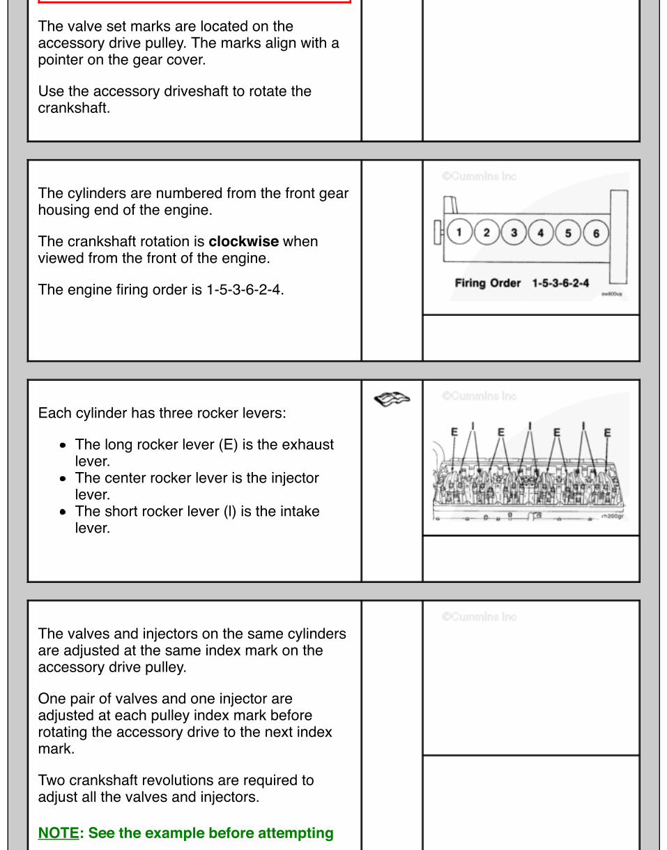
The firing order is 1-5-3-6-2-4.
Rotate the accessory drive clockwise until the“A” valve set mark on the accessory drivepulley is aligned with the pointer on the gearcover.
Each cylinder has three rocker levers:
The long rocker lever (E) is the exhaustlever.The center rocker lever is the injectorleverThe short rocker lever (I) is the intakelever.
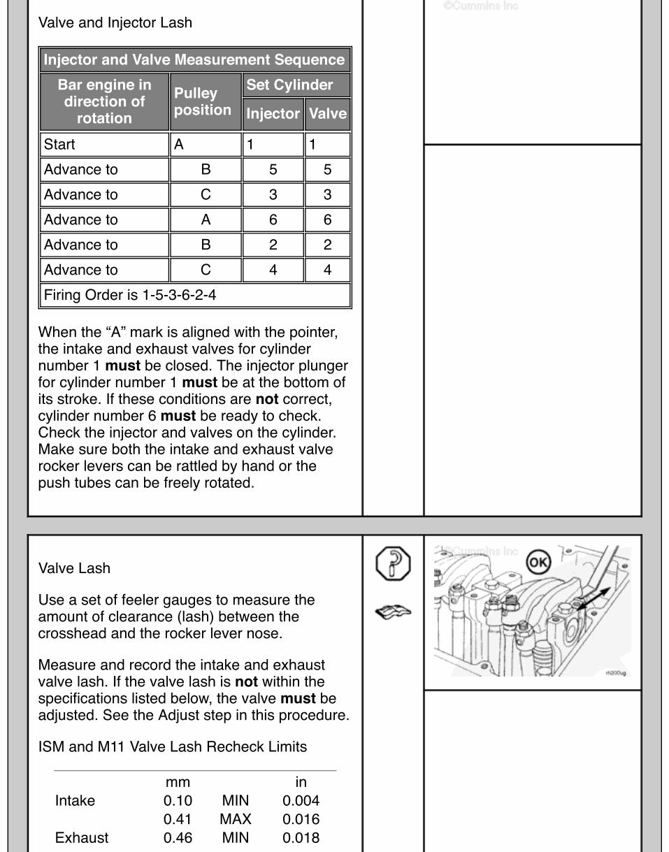
Valve and Injector Lash
Injector and Valve Measurement SequenceBar engine indirection of
rotationPulleyposition
Set Cylinder
Injector Valve
Start A 1 1Advance to B 5 5Advance to C 3 3Advance to A 6 6Advance to B 2 2Advance to C 4 4Firing Order is 1-5-3-6-2-4
When the “A” mark is aligned with the pointer,the intake and exhaust valves for cylindernumber 1 must be closed. The injector plungerfor cylinder number 1 must be at the bottom ofits stroke. If these conditions are not correct,cylinder number 6 must be ready to check.Check the injector and valves on the cylinder.Make sure both the intake and exhaust valverocker levers can be rattled by hand or thepush tubes can be freely rotated.
Valve Lash
Use a set of feeler gauges to measure theamount of clearance (lash) between thecrosshead and the rocker lever nose.
Measure and record the intake and exhaustvalve lash. If the valve lash is not within thespecifications listed below, the valve must beadjusted. See the Adjust step in this procedure.
ISM and M11 Valve Lash Recheck Limits
mm inIntake 0.10 MIN 0.004 0.41 MAX 0.016Exhaust 0.46 MIN 0.018
0.76 MAX 0.030
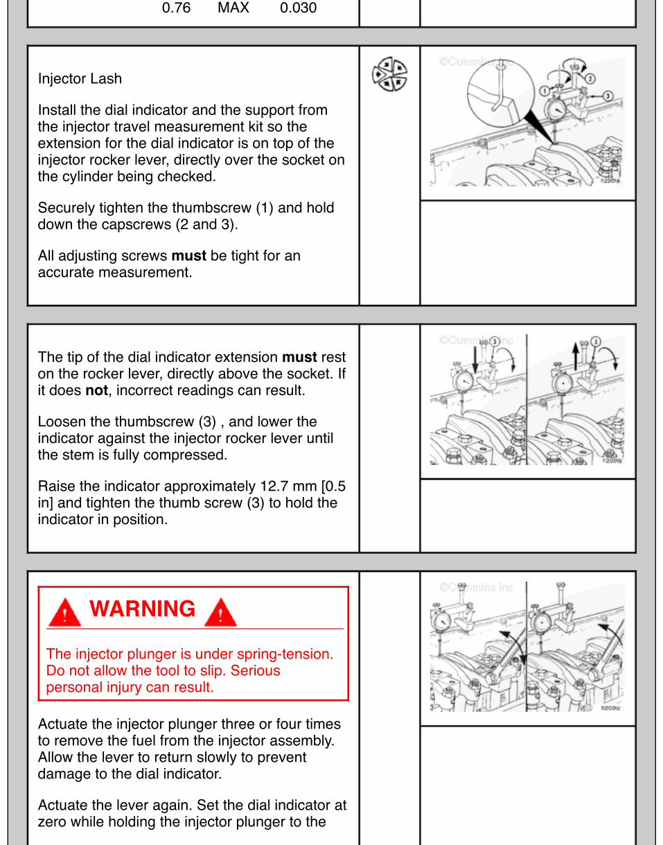
Injector Lash
Install the dial indicator and the support fromthe injector travel measurement kit so theextension for the dial indicator is on top of theinjector rocker lever, directly over the socket onthe cylinder being checked.
Securely tighten the thumbscrew (1) and holddown the capscrews (2 and 3).
All adjusting screws must be tight for anaccurate measurement.
The tip of the dial indicator extension must reston the rocker lever, directly above the socket. Ifit does not, incorrect readings can result.
Loosen the thumbscrew (3) , and lower theindicator against the injector rocker lever untilthe stem is fully compressed.
Raise the indicator approximately 12.7 mm [0.5in] and tighten the thumb screw (3) to hold theindicator in position.
WARNING
The injector plunger is under spring-tension.Do not allow the tool to slip. Seriouspersonal injury can result.
Actuate the injector plunger three or four timesto remove the fuel from the injector assembly.Allow the lever to return slowly to preventdamage to the dial indicator.
Actuate the lever again. Set the dial indicator atzero while holding the injector plunger to the

bottom of its travel.
Slowly release the actuator and check the dialindicator travel. Record the measured value.
If the injector setting is not within thespecification listed below, the injector must beadjusted. See the Adjust section in thisprocedure.
ISM and M11 Injector Lash Recheck Limits
mm in0.51 MIN 0.0202.04 MAX 0.080
If the engine is equipped with engine brakes,check the brake piston clearance. Refer toProcedure 020-024 in Section 20.
Install the rocker lever cover. Refer toProcedure 003-011 in Section 3.

Adjust
General Information
Valves, injectors, and engine brakes must becorrectly adjusted for the engine to operateefficiently. Valve, injector, and engine brakeadjustment must be performed using thevalues listed in this section. The accompanyingtable gives the adjustment specifications.
If the valves and injectors have been adjustedduring troubleshooting or before this scheduledinterval, adjustment is not required at this time.
Valve, Injector, and Engine BrakeAdjustment Specifications mm in
Intake 0.36 0.014Exhaust 0.69 0.027
All valve and injector adjustments must bemade when the engine is cold (stabilizedcoolant temperature at 60°C [140°F] or below).
WARNING
When using solvents, acids, or alkalinematerials for cleaning, follow themanufacturer's recommendations for use.

WARNING
Use skin and eye protection when handlingcaustic solutions to reduce the possibility ofpersonal injury.
WARNING
Some solvents are flammable and toxic.Read the manufacturer's instructions beforeusing.
Clean the timing plunger to remove the varnishfrom the top edge.
Apply a non-chlorinated carburetor cleaner(Pyroil®, or equivalent). Use a narrow boreorifice or extension tube of 2 mm [0.079 in]maximum outside diameter (O.D.), into theinjector weep hole.
If the entire overhead is to be reset, everyinjector is to be sprayed at this time.
Remove the rocker lever cover and gasket.Refer to Procedure 003-011 in Section 3.
WARNING
Do not straighten a bent fan blade orcontinue to use a damaged fan. A bent ordamaged fan blade can fail during operationand cause personal injury or propertydamage.
The valve set marks are located on theaccessory drive pulley. The marks align with apointer on the gear cover.
Use the accessory driveshaft to rotate thecrankshaft.
The cylinders are numbered from the front gearhousing end of the engine.
The crankshaft rotation is clockwise whenviewed from the front of the engine.
The engine firing order is 1-5-3-6-2-4.
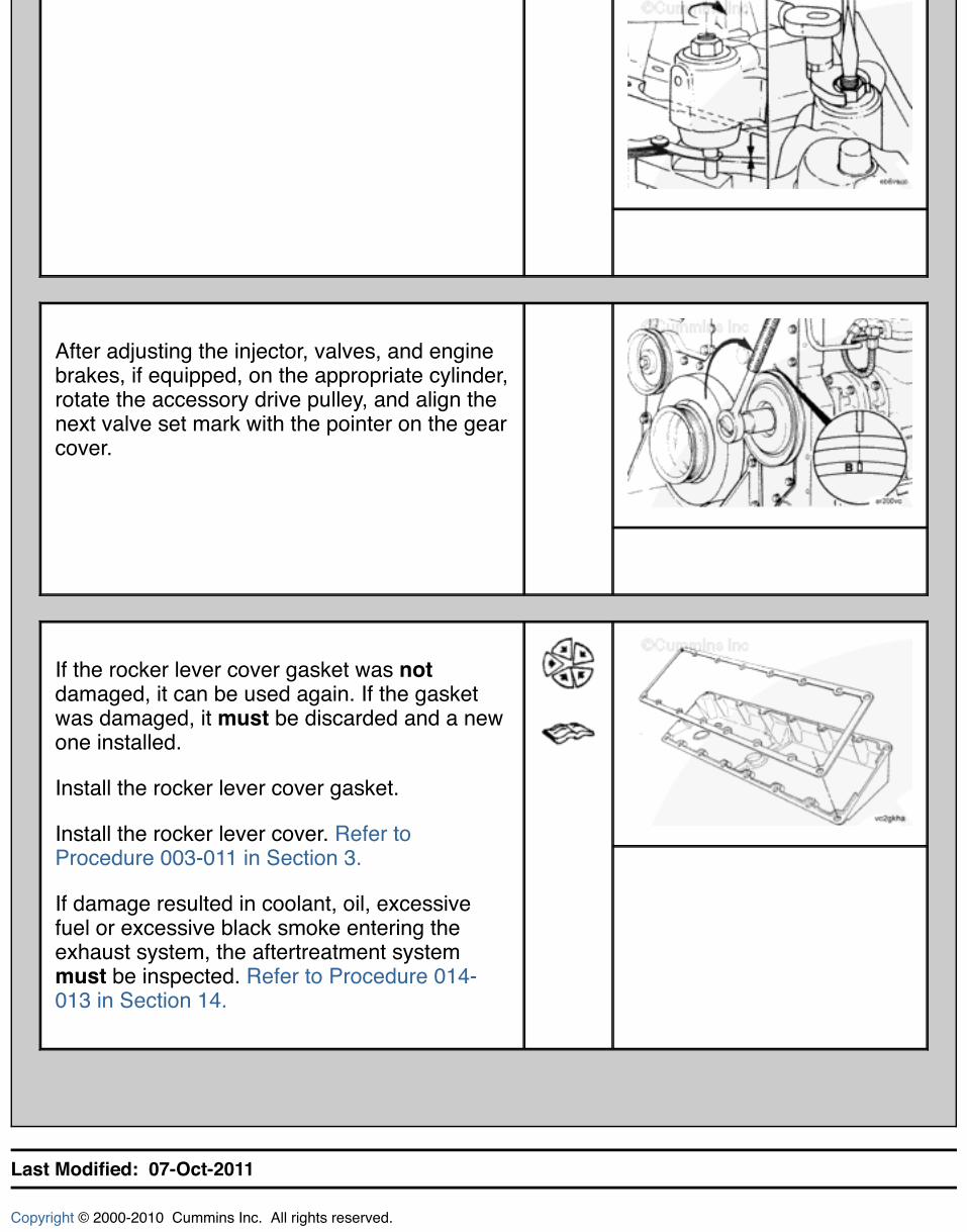
Each cylinder has three rocker levers:
The long rocker lever (E) is the exhaustlever.The center rocker lever is the injectorlever.The short rocker lever (l) is the intakelever.
The valves and injectors on the same cylindersare adjusted at the same index mark on theaccessory drive pulley.
One pair of valves and one injector areadjusted at each pulley index mark beforerotating the accessory drive to the next indexmark.
Two crankshaft revolutions are required toadjust all the valves and injectors.
NOTE: See the example before attempting

to begin the adjustment procedure.
NOTE: Set the injector on the same cylinderbefore setting the valves.
Adjust all the injectors, valves, and brakes, ifequipped, according to the following table.
Injector and Valve Measurement SequenceBar engine indirection of
rotationPulley
positionSet Cylinder
Injector Valve
Start A 1 1Advance to B 5 5Advance to C 3 3Advance to A 6 6Advance to B 2 2Advance to C 4 4Firing Order: 1-5-3-6-2-4
The adjustment can begin on any valve setmark. In the following example, the adjustmentwill begin on the "A" valve set mark withcylinder number 1 valves closed and ready foradjustment.
Rotate the accessory drive clockwise until the"A" valve set mark on the accessory drivepulley is aligned with the pointer on the gearcover.
When the "A" mark is aligned with the pointer,the intake and exhaust valves for cylinderNumber 1 must be closed. If these conditionsare not correct, cylinder number 6 injector andvalves must be ready to set. Set the injectorand valves on the cylinder so that both theintake and exhaust valve rocker lever arms areloose and can be moved from side-to-side.

Both valves are closed when both rocker leversare loose and can be moved from side-to-side.
Injectors
Loosen the injector adjusting screw locknut.
Use a screwdriver or a box end wrench, ifequipped with engine brakes) to adjust thescrew. Bottom the injector plunger three or fourtimes to remove the fuel.
Turn the adjusting screw in until it just bottomsthe plunger.
NOTE: Do not use excessive force whenbottoming the plunger.
Back out the adjusting screw two flats, 120degrees.
Hold the adjusting screw, and tighten thelocknut.
Torque Value: 61 n.m [45 ft-lb]
After setting the injector, set the valves on thesame cylinder.
Valves
With the "A" valve set mark aligned with the

pointer on the gear cover and both valvesclosed on the cylinder to be adjusted, loosenthe adjusting screw locknuts on the intake andexhaust valves.
Select a feeler gauge for the correct valve lashspecification.
Valve Lash Specifications
mm inIntake Valve 0.36 MIN 0.014Exhaust Valve 0.69 MIN 0.027
Insert the feeler gauge between the top of thecrosshead and the rocker lever pad.
Two different methods for establishing valvelash clearance are described below. Eithermethod can be used; however, the torquewrench method has proven to be the mostconsistent. It eliminates the need to feel thedrag on the feeler gauge.
Torque Wrench Method: Insert the correctfeeler gauge. Use an inch-pound torquewrench, Part Number 3376592, normallyused to set preload on top-stop injectors,and tighten the adjusting screw.
Torque Value: 0.7 n.m [6 in-lb]
Touch Method: Tighten the adjustingscrew until a slight drag is felt on thefeeler gauge.

Hold the adjusting screw in the position shown.The adjusting screw must not turn when thelocknut is tightened.
Torque Value:Without torque wrench adapter:
1. 61 n.m [45 ft-lb]
Torque Value:With torque wrench adapter, Part Number3163196:
1. 47 n.m [35 ft-lb]
After tightening the locknut to the correct torquevalue, check to make sure the feeler gauge willslide backward and forward between thecrosshead and the rocker lever with only aslight drag.
If using the touch method, attempt to insert afeeler gauge that is 0.03 mm [0.001 in] thickerbetween the crosshead and the rocker leverpad. The valve lash is not correct when athicker feeler gauge will fit.
If the engine is equipped with an engine brake,adjust the brakes. Refer to Procedure 020-024in Section 20.
After adjusting the injector, valves, and enginebrakes, if equipped, on the appropriate cylinder,rotate the accessory drive pulley, and align thenext valve set mark with the pointer on the gearcover.
If the rocker lever cover gasket was notdamaged, it can be used again. If the gasketwas damaged, it must be discarded and a newone installed.
Install the rocker lever cover gasket.
Install the rocker lever cover. Refer toProcedure 003-011 in Section 3.
If damage resulted in coolant, oil, excessivefuel or excessive black smoke entering theexhaust system, the aftertreatment systemmust be inspected. Refer to Procedure 014-013 in Section 14.
Last Modified: 07-Oct-2011
Copyright © 2000-2010 Cummins Inc. All rights reserved.


![003 004 SPIS WSTEP.QXD 003 004 SPIS WSTEPaesthetica.com.pl/clients/25/files/files/Aesthetica_nr22s.pdf · Tab. 1. Czynniki prowokujące wystąpienie łuszczycy[3,4,7]. Czynniki egzogenne](https://img.pdfslide.net/doc/110x75/5c77546f09d3f2cd0e8b89bd/003-004-spis-wstepqxd-003-004-spis-tab-1-czynniki-prowokujace-wystapienie.jpg)