Embed Size (px)
Citation preview
8/3/2019 003-0561-00
http://slidepdf.com/reader/full/003-0561-00 1/12
Go To Table Of Contents
Place Order
To purchase a printed copy of this manual,click on the "Place Order" button below.
8/3/2019 003-0561-00
http://slidepdf.com/reader/full/003-0561-00 2/12
TABLE OF CONTENTS
SUBJECT
Important Instructions . . . . . . . . . . . . . . . . . . . . . .
Introduction . . . . . . . . . . . . . . . . . . . . . . . . . . .
Unpacking & Installation . . . . . . . . . . . . . . . . . . . . .
Operation of Table Power Features . . . . . . . . . . . . . . .
Patient Positioning . . . . . . . . . . . . . . . . . . . . . . . .
Table Features. . . . . . . . . . . . . . . . . . . . . . . . . .
Headlock Adjustment . . . . . . . . . . . . . . . . . . . . . .
Care of Table. . . . . . . . . . . . . . . . . . . . . . . . . . .
Maintenance . . . . . . . . . . . . . . . . . . . . . . . . . . .
PAGE
1
2
2
3
3
4
6
7
7
FOR YOUR PROTECTlONTHESE GOODS LEFT OUR FACTORY IN PERFECT ORDER and we hold the Carrier’s Receiptfor them; in this condition.IF THESE GOODS ARE DAMAGED in Transit, such damaged goods should either be refused,
or not accepted until the Transportation Company’s Agent has noted on the freight bill, whichhe will give you, the nature and extent of the damage. He is required to do this. In the samemanner, if any goods are LOST in transit, have the shortage noted on the freight bill by theagent.
CONCEALED DAMAGE. If there should be damage of such nature that it could not be detecteduntil the goods were unpacked have the Transportation Company’s Agent call AT ONCE andinspect them. Require him to give you a “concealed” bad order report, stating the conditionof the goods when examined. It is his duty to do this and you should INSIST upon it.
IF THE ABOVE INSTRUCTIONS ARE COMPLIED WITH we shall cheerfully render all possibleassistance in establishing claims against the Transportation Companies for loss anddamage in transit.
WE DO NOT ACCEPTGOODS RETURNED FOR CREDIT, EXCHANGE, REPAIRS, or for any other
reason, unless you have first communicated with us and secured our written permission.
Copyright by Midmark Corporation- 1991
8/3/2019 003-0561-00
http://slidepdf.com/reader/full/003-0561-00 3/12
IMPORTANT INSTRUCTIONS
SAFETY FIRST: The primary concern of Midmark Corporation
is that this equipment be operated and maintained with the
safety of the patient and doctor in mind. To assure safer and
more reliable operation:
1. Read this manual before installing or operating your
equipment.
2. It is the responsibility of the purchaser to assure that ap-
propriate personnel are informed of the contents of thismanual.
3. Be sure that you understand the instructions contained in
this manual before attempting to install or operate this
equipment.
4. This manual should remain permanently affixed to this
equipment.
Throughout this manual are “Notes,” “CAUTIONS,” and
“DANGER” warnings that call attention to particular procedures.
The items are used as follows:
NoteA note is used to amplify an operating procedure, practice, or
condition.
A CAUTION IS USED FOR AN OPERATING PROCEDURE,
PRACTICE, OR CONDITION WHICH, IF NOT CORRECTLY
FOLLOWED, COULD RESULT IN EQUIPMENT DAMAGE.
A DANGER IS USED FOR AN OPERATING PROCEDURE,
PRACTICE, OR CONDITION WHICH, IF NOT CORRECTLYFOLLOWED, COULD RESULT IN PERSONAL INJURY.
For your personal safety and that of your patients, all
DANGER warnings are repeated here. Become thoroughly
familiar with them and observe them at all times.
DO NOT LIFT AT POINTS B, FIG. 1. THESE POINTS
ARE NOT SUPPORTED AREAS. LIFTING AT THESE
POINTS COULD CAUSE PERSONAL INJURY OR
DAMAGE TO THE TABLE (Page 2).
DO NOT USE STIRRUPS TO LIFT OR MOVE TABLE.
USING THE STIRRUPS FOR THIS PURPOSE COULD
RESULT IN PERSONAL INJURY OR EQUIPMENTDAMAGE (Page 2).
USE 115 VOLT, 60 HERTZ ALTERNATING CURRENT
ONLY. FAILURE TO DO SO COULD RESULT IN PER-
SONAL INJURY OR EQUIPMENT DAMAGE (Page 2).
DO NOT USE THIS TABLE IN AN EXPLOSIVE OR
OXYGEN-ENRICHED ATMOSPHERE. USING THE
1
5.
6.
7.
8.
9.
10.
11.
12.
TABLE IN THESE SITUATIONS COULD CAUSE PER-
SONAL INJURY OR EQUIPMENT DAMAGE (Page 2).
ALL EXPOSED METAL PARTS OF TABLE ARE
ELECTRICALLY GROUNDED. WHEN PERFORMING A
CAUTERIZATION OR SIMILAR TREATMENT, PATIENT
MUST BE INSULATED FROM THE METAL PORTIONS
OF THE TABLE BY NON-CONDUCTIVE MATERIAL.
FAILURE TO DO THIS COULD RESULT IN ELECTRICAL
SHOCK OR BURNS TO THE PATIENT (Page 2).
IF THE TABLE MALFUNCTIONS, IMMEDIATELY
REMOVE YOUR FOOT FROM THE CONTROL SWlTCH,
UNPLUG THE POWER CORD FROM THE WALL
RECEPTACLE, AND ASSISTTHE PATIENT FROM THE
CHAIR (Page 3).
KEEP ALL FOREIGN OBJECTS AWAY FROM THE
FOOTSWITCH SO THAT THE PEDALS ARE NOT
ACCIDENTALLY ACTIVATED. FAILURE TO DO SO
COULD RESULT IN PERSONAL INJURY OR DAMAGE
TO THE TABLE (Page 3).
KEEP YOUR ARMS AND LEGS AND YOUR PATIENT’S
ARMS AND LEGS CLEAR OF ALL MOVING PARTS
WHEN CHANGING TABLE POSITIONS. FAILURE TO
DO SO COULD RESULT IN PERSONAL INJURY (Page
3).
BE SURE ALL PERSONS AND EQUIPMENT ARE CLEAR
OF TABLE BEFORE ACTUATING AUTO RETURN.
FAILURE TO DO SO COULD RESULT IN PERSONAL
INJURY OR EQUIPMENT DAMAGE (Page 4).
FAILURE TO LOCK THE KNEE REST SUPPORT INTO
POSITION COULD RESULT IN PERSONAL INJURY OR
EQUIPMENT DAMAGE (Page 5 ).
FAILURE TO ENGAGELATERAL LOCKING MECHANISM
COULD RESULT IN PERSONAL INJURY (Page 5).
FAILURE TO PERFORM A PERIODIC INSPECTIONCOULD RESULT IN PERSONAL INJURY OR EQUIP-
MENT DAMAGE (Page 7).
WARRANTY
IMPORTANT: FILL OUT AND MAIL THE WARRANTY
REGISTRATION CARD WITHIN 7 DAYS AFTER DELIVERY
OF YOUR MODEL 111 OR 119 TABLE. Your Model 111 or 119
Table is warranted for a period of 12 months from date of
delivery as specified in the “LIMITED WARRANTY” printed on
the backcover. Warranty claims will be handled promptly when
the Warranty Card is on file at Midmark. In the event of
equipment failure, immediately contact the authorized Midmark
dealer who sold you the equipment. He will make the necessarywarranty repairs. Do not attempt to disassemble or substitute
parts ot another manufacturer. Such action will void the
warranty and may render operation of the equipment unsafe.
THE "LIMITED WARRANTY” PRlNTED ON THE BACK COVER
OF THIS MANUAL IS IN LlEU OF ALL OTHER WARRANTlES
EXPRESSED OR IMPLIED, AND ALL OTHER OBLIGATIONS
OR LIABILITIES ON THE PARTOFTHE COMPANY.
Return To Table Of Contents
8/3/2019 003-0561-00
http://slidepdf.com/reader/full/003-0561-00 4/12
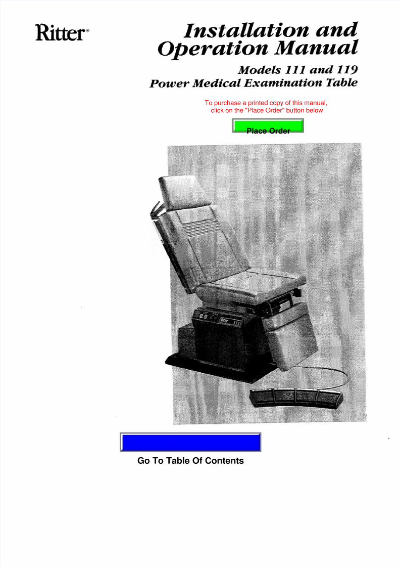
INSTALLATION AND OPERATION MANUAL FOR THE111 and 119 MEDICAL EXAMINATION TABLES
GENERAL OPERATION ANDCARE OF EQUIPMENT
INTRODUCTION
This manual covers complete instructions for the instal-
lation, operation, and normal care of the 111 and 119
Medical Examination Tables.
For the purpose of this manual, the word TABLE issynonymous with the word CHAIR.
This table has been designed to help reduce effort and
work fatigue involved in the examination and treatment
of an ever-increasing number of patients during the
doctor’s normal working day.
The height of the table, the angle of the table top, and the
upper section of the table top are easily adjusted by the
use of an electric-hydraulic power unit. Height of the
table can be adjusted from 26” to 42”. The angle of the
table top may be varied from horizontal to and the
upper portion of the table top can be adjusted from
horizontal to a full chair position. The foot/leg support
may be adjusted from horizontal or vertical positions.
The combination of these four motions provides a table
which can not only be tailored to meet the individualdoctor’s requirements, but will meet the requirements of
most examinations and treatments being performed in
the doctor’s office today.
Adjustments are controlled by a foot control switch,
leaving both hands free while adjustments are being
made.
There is also an “Auto Return” feature (111 model only)
which lowers the base function to its minimum height with
a momentary touch of a button.
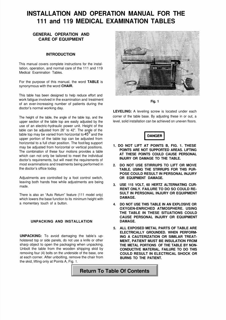
UNPACKING AND INSTALLATION
UNPACKING: To avoid damaging the table’s up-
holstered top or side panels, do not use a knife or other
sharp object to open the packaging when unpacking.Unbolt the table from the wooden shipping skid by
removing four (4) bolts on the underside of the base, oneat each corner. After unbolting, remove the chair from
the skid, lifting only at Points A, Fig. 1.
2
Fig. 1
LEVELING: A leveling screw is located under eachcorner of the table base. By adjusting these in or out, a
level, solid installation can be achieved on uneven floors.
1. DO NOT LIFT AT POINTS B, FIG. 1. THESE
POINTS ARE NOT SUPPORTED AREAS. LlFTING
AT THESE POINTS COULD CAUSE PERSONAL
INJURY OR DAMAGE TO THE TABLE.
2. DO NOT USE STIRRUPS TO LIFT OR MOVE
TABLE. USING THE STIRRUPS FOR THIS PUR-POSE COULD RESULT IN PERSONAL INJURYOR EQUIPMENT DAMAGE.
3. USE 115 VOLT, 60 HERTZ ALTERNATING CUR-
RENT ONLY. FAILURE TO DO SO COULD RE-SULT IN PERSONAL INJURY OR EQUIPMENT
DAMAGE.
4. DO NOT USE THIS TABLE IN AN EXPLOSIVE OR
OXYGEN-ENRICHED ATMOSPHERE. USING
THE TABLE IN THESE SITUATIONS COULD
CAUSE PERSONAL INJURY OR EQUIPMENTDAMAGE.
5. ALL EXPOSED METAL PARTS OF TABLE ARE
ELECTRICALLY GROUNDED. WHEN PERFORM-
ING A CAUTERIZATION OR SIMILAR TREAT-
MENT, PATIENT MUST BE INSULATION FROM
THE METAL PORTlONS OF THE TABLE BY NON-CONDUCTIVE MATERIAL. FAILURE TO DO THIS
COULD RESULT IN ELECTRICAL SHOCK OR
BURNS TO THE PATIENT.
Return To Table Of Contents
8/3/2019 003-0561-00
http://slidepdf.com/reader/full/003-0561-00 5/12
ELECTRICAL: The electrical rating for the Model 111
and 119 tables is 115 VAC, 60 Hertz, 12 Ampere. The
three-pronged grounding plug on the table power cord
must be inserted into a matched three-pronged,
GROUNDED, NON-ISOLATED, CORRECTLYPOLARIZED, 115 volt receptacle.
The single table power cord provides power for both theelectric-hydraulic power unit and the duplex receptacles
(111 model only) located on each side of the table (Fig.3,
Item A).
OPERATION OF TABLE POWER FEATURES
For optimal performance, allow the table to reach room
temperature before operating.
Note
This equipment is not designed for continuous operation.If the unit is operated continually, a thermal overload
switch will shut off the table motor. If normal operation
ceases, immediately remove your foot from the control
switch. The overload switch will automatically reset after
the motor cools (minimum 10 minutes).
Should the unit fail to start after a cool down period,
contact an authorized service center to investigate the
cause of the failure.
IF THE TABLE MALFUNCTIONS, IMMEDIATELY
REMOVE YOUR FOOTFROMTHECONTROL
SWITCH, UNPLUG THE POWER CORD FROM THEWALL RECEPTACLE, AND ASSIST THE PATIENT
FROM THE TABLE.
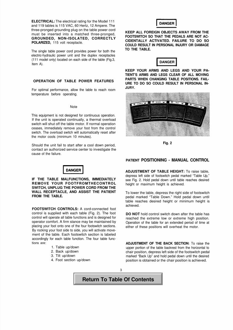
FOOTSWITCH CONTROLS: A cord-connected foot
control is supplied with each table (Fig. 2). The foot
control will operate all table functions and is designed for
operator comfort. A firm stance may be maintained by
placing your foot onto one of the four footswitch sections.
By rocking your foot side to side, you will activate move-ment of the table. Each footswitch section is labeled
accordingly for each table function. The four table func-
tions are:1. Table up/down
2. Back up/down
3. Tilt up/down
4. Foot section up/down
KEEP ALL FOREIGN OBJECTS AWAY FROM THE
FOOTSWITCH SO THAT THE PEDALS ARE NOT AC-
CIDENTALLY ACTIVATED. FAILURE TO DO SO
COULD RESULT IN PERSONAL INJURY OR DAMAGE
TO THE TABLE.
DANGER
KEEP YOUR ARMS AND LEGS AND YOUR PA-
TIENT’S ARMS AND LEGS CLEAR OF ALL MOVING
PARTS WHEN CHANGING TABLE POSITIONS. FAIL-
URE TO DO SO COULD RESULT IN PERSONAL IN-JURY.
Fig. 2
PATIENT POSITIONING - MANUAL CONTROL
ADJUSTMENT OF TABLE HEIGHT: To raise table,
depress left side of footswitch pedal marked “Table Up,”
see Fig. 2. Hold pedal down until table reaches desiredheight or maximum height is achieved.
To lower the table, depress the right side of footswitchpedal marked “Table Down.” Hold pedal down until
table reaches desired height or minimum height is
achieved.
DO NOT hold control switch down after the table has
reached the extreme low or extreme high position.
Operation of the table for an extended period of time at
either of these positions will overheat the motor.
ADJUSTMENT OF THE BACK SECTION: To raise the
upper portion of the table backrest from the horizontal to
chair position, depress left side of the footswitch pedalmarked “Back Up” and hold pedal down until the desired
position is obtained or the chair position is achieved.
3
Return To Table Of Contents
8/3/2019 003-0561-00
http://slidepdf.com/reader/full/003-0561-00 6/12
To lower the table backrest, depress right side of thefootswitch pedal marked “Back Down” and hold pedaldown until the desired position is obtained or the mini-mum position is achieved.
DO NOT hold control switch down after either of theextreme positions has been reached. Extended opera-tion of the motor at either of these positions will overheatthe motor.
ADJUSTMENT OF THE TABLE TOP ANGLE: To tilt theseat section, depress left side of footswitch pedal marked“Tilt Up” and hold pedal down until the desired degree oftilt is obtained or the maximum tilt is reached.
To bring the seat section back into the horizontal posi-tion, depress right side of the footswitch pedal marked“Tilt Down” and hold pedal down until the desired posi-tion is obtained or the horizontal position is achieved.
DO NOT hold control switch down after either of theextreme positions has been reached. Extended opera-tion of the motor at either of these positions will overheatthe motor.
ADJUSTMENT OF THE FOOT/LEG REST SUPPORT:To raise the foot/leg rest support from vertical to horizon-tal position, depress left side of footswitch pedal marked“Foot Up” and hold pedal down until the desired positionis obtained or the horizontal position is achieved.
To lower foot/leg rest support from horizontal to verticalposition, depress right side of footswitch pedal marked“Foot Down” and hold pedal down until the desired
position is obtained or the vertical position is achieved.
DO NOT hold control switch down after either of theextreme positions has been reached. Extendedoperation of the motor at either of these positions willoverheat the motor.
Note
A safety switch prevents operation of the foot/leg restwhen the irrigation pan is extended. The irrigation panis standard on 111 models and is optional on 119models. Should operation of the power foot/leg rest be
impossible, check that the irrigation pan is in its fullystored position (Fig. 8, Item #A).
AUTOMATlC RETURN (111 only): The “Auto Return” willlower the table base to its lowest position with amomentary touch of a button. To actuate the “AutoReturn” feature with the base in any raised position press
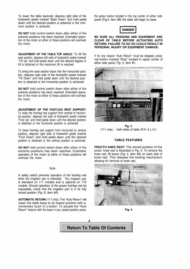
the green button located in the top center of either sidepanel (Fig.3, Item #B) the table will begin to lower.
BE SURE ALL PERSONS AND EQUIPMENT ARE
CLEAR OF TABLE BEFORE ACTUATING AUTO
RETURN. FAILURE TO DO SO COULD RESULT IN
PERSONAL INJURY OR EQUIPMENT DAMAGE.
If for any reason “Auto Return” must be stopped, pressred button marked “Stop” located in upper center ofeither side panel, Fig. 3, Item #C.
Fig. 3
(111 only) - - both sides of table (R.H. & L.H.)
TABLE FEATURES
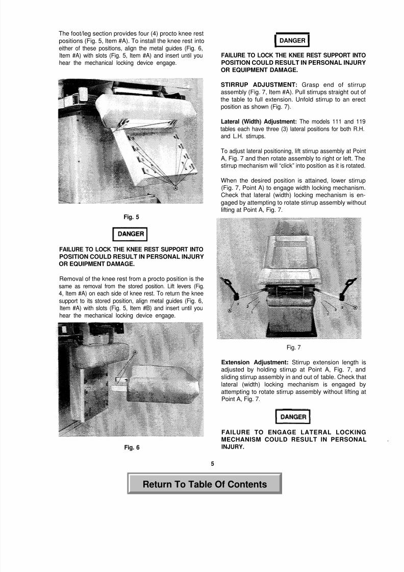
PROCTO KNEE REST: The stored position of theprocto knee rest is illustrated in Fig. 4. To remove theknee rest, lift levers (Fig. 4, Item #A) on each side ofknee rest. This releases the locking mechanismallowing for removal of knee rest.
Fig. 4
44
Return To Table Of Contents
8/3/2019 003-0561-00
http://slidepdf.com/reader/full/003-0561-00 7/12
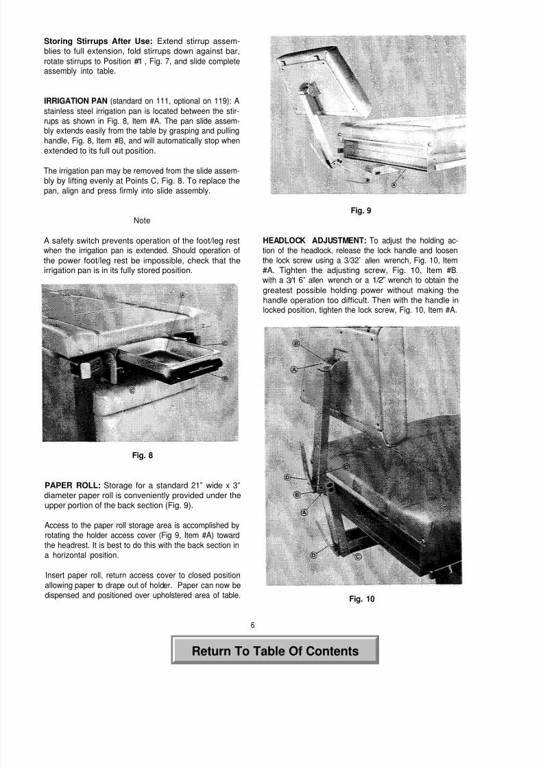
The foot/leg section provides four (4) procto knee rest
positions (Fig. 5, Item #A). To install the knee rest into
either of these positions, align the metal guides (Fig. 6,Item #A) with slots (Fig. 5, Item #A) and insert until youhear the mechanical locking device engage.
Fig. 5
FAILURE TO LOCK THE KNEE REST SUPPORT INTOPOSITION COULD RESULT IN PERSONAL INJURYOR EQUIPMENT DAMAGE.
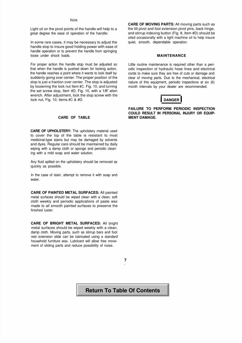
Removal of the knee rest from a procto position is thesame as removal from the stored position. Lift levers (Fig.
4, Item #A) on each side of knee rest. To return the knee
support to its stored position, align metal guides (Fig. 6,Item #A) with slots (Fig. 5, Item #B) and insert until you
hear the mechanical locking device engage.
Fig. 6
DANGER
FAILURE TO LOCK THE KNEE REST SUPPORT INTO
POSITION COULD RESULT IN PERSONAL INJURYOR EQUIPMENT DAMAGE.
STIRRUP ADJUSTMENT: Grasp end of stirrupassembly (Fig. 7, Item #A). Pull stirrups straight out of
the table to full extension. Unfold stirrup to an erectposition as shown (Fig. 7).
Lateral (Width) Adjustment: The models 111 and 119
tables each have three (3) lateral positions for both R.H.and L.H. stirrups.
To adjust lateral positioning, lift stirrup assembly at Point
A, Fig. 7 and then rotate assembly to right or left. Thestirrup mechanism will “click” into position as it is rotated.
When the desired position is attained, lower stirrup(Fig. 7, Point A) to engage width locking mechanism.Check that lateral (width) locking mechanism is en-
gaged by attempting to rotate stirrup assembly withoutlifting at Point A, Fig. 7.
Fig. 7
Extension Adjustment: Stirrup extension length isadjusted by holding stirrup at Point A, Fig. 7, and
sliding stirrup assembly in and out of table. Check that
lateral (width) locking mechanism is engaged by
attempting to rotate stirrup assembly without lifting at
Point A, Fig. 7.
FAILURE TO ENGAGE LATERAL LOCKINGMECHANISM COULD RESULT IN PERSONALINJURY.
5
Return To Table Of Contents
8/3/2019 003-0561-00
http://slidepdf.com/reader/full/003-0561-00 8/12
Storing Stirrups After Use: Extend stirrup assem-
blies to full extension, fold stirrups down against bar,
rotate stirrups to Position #1 , Fig. 7, and slide completeassembly into table.
IRRIGATION PAN (standard on 111, optional on 119): A
stainless steel irrigation pan is located between the stir-
rups as shown in Fig. 8, Item #A. The pan slide assem-
bly extends easily from the table by grasping and pullinghandle, Fig. 8, Item #B, and will automatically stop when
extended to its full out position.
The irrigation pan may be removed from the slide assem-
bly by lifting evenly at Points C, Fig. 8. To replace the
pan, align and press firmly into slide assembly.
Fig. 9
Note
A safety switch prevents operation of the foot/leg restwhen the irrigation pan is extended. Should operation of
the power foot/leg rest be impossible, check that the
irrigation pan is in its fully stored position.
Fig. 8
PAPER ROLL: Storage for a standard 21” wide x 3”
diameter paper roll is conveniently provided under the
upper portion of the back section (Fig. 9).
Access to the paper roll storage area is accomplished by
rotating the holder access cover (Fig 9, Item #A) towardthe headrest. It is best to do this with the back section in
a horizontal position.
Insert paper roll, return access cover to closed position
allowing paper to drape out of holder. Paper can now be
dispensed and positioned over upholstered area of table.
HEADLOCK ADJUSTMENT: To adjust the holding ac-
tion of the headlock, release the lock handle and loosen
the lock screw using a 3/32” allen wrench, Fig. 10, Item
#A. Tighten the adjusting screw, Fig. 10, Item #B,with a 3/1 6” allen wrench or a 1/2” wrench to obtain the
greatest possible holding power without making the
handle operation too difficult. Then with the handle inlocked position, tighten the lock screw, Fig. 10, Item #A.
Fig. 10
6
Return To Table Of Contents
8/3/2019 003-0561-00
http://slidepdf.com/reader/full/003-0561-00 9/12
Note
Light oil on the pivot points of the handle will help to agreat degree the ease of operation of the handle:
In some rare cases, it may be necessary to adjust the
handle stop to insure good holding power with ease of
handle operation or to prevent the handle from springing
loose under shock loads.
For proper action the handle stop must be adjusted so
that when the handle is pushed down for locking action,the handle reaches a point where it wants to lock itself by
suddenly going over center. The proper position of the
stop is just a fraction over center. The stop is adjusted
by loosening the lock nut Item #C, Fig. 10, and turning
the set screw stop, Item #D, Fig. 10, with a 1/8” alien
wrench. After adjustment, lock the stop screw with the
lock nut, Fig. 10, Items #C & #D.
CARE OF TABLE
CARE OF UPHOLSTERY: The upholstery material used
to cover the top of the table is resistant to most
medicinal-type stains but may be damaged by solventsand dyes. Regular care should be maintained by daily
wiping with a damp cloth or sponge and periodic clean-
ing with a mild soap and water solution.
Any fluid spilled on the upholstery should be removed as
quickly as possible.
In the case of stain, attempt to remove it with soap and
water.
CARE OF PAINTED METAL SURFACES: All painted
metal surfaces should be wiped clean with a clean, softcloth weekly and periodic applications of paste wax
made to all smooth painted surfaces to preserve thefinished luster.
CARE OF BRIGHT METAL SURFACES: All brightmetal surfaces should be wiped weekly with a clean,
damp cloth. Moving parts, such as stirrup bars and foot
rest extension slide can be lubricated using a standard
household furniture wax. Lubricant will allow free move-ment of sliding parts and reduce possibility of noise.
CARE OF MOVING PARTS: All moving parts such as
the tilt pivot and foot extension pivot pins, back hinge,
and stirrup indexing button (Fig. 8, Item #D) should be
oiled occasionally with a light machine oil to help insure
quiet, smooth, dependable operation.
MAINTENANCE
Little routine maintenance is required other than a peri-
odic inspection of hydraulic hose lines and electrical
cords to make sure they are free of cuts or damage and
clear of moving parts. Due to the mechanical, electricalnature of this equipment, periodic inspections at six (6)
month intervals by your dealer are recommended.
DANGER
FAILURE TO PERFORM PERIODIC INSPECTION
COULD RESULT IN PERSONAL INJURY OR EQUIP-MENT DAMAGE.
77
Return To Table Of Contents

8/3/2019 003-0561-00
http://slidepdf.com/reader/full/003-0561-00 10/12
Return To Table Of Contents

8/3/2019 003-0561-00
http://slidepdf.com/reader/full/003-0561-00 11/12
Return To Table Of Contents
8/3/2019 003-0561-00
http://slidepdf.com/reader/full/003-0561-00 12/12
LIMITED EQUIPMENT WARRANTY
The Company shall repair or replace any products or parts thereof, which proveto be defective in workmanship and/or material. Except as it may otherwise speci-fically agree in writing the Company shall not be liable for transportation, labor or othercharges for adjustments, repairs, replacement parts, installation or other work whichmay be done upon or in connection with such products by the Company’s authorizedDealers or others.
Any part or parts of a product to be repaired or replaced under this limitedwarranty must be returned to the factory f.o.b.
This warranty does not apply to any part or product which examination discloseshas been misused, abused, altered or tampered with in any way. This warranty shallbe in effect for a period of twelve months from the date of shipment to the customer.
In no event shall the company be liable for consequential or special damages inthe event of warranty repair or replacement of its products.
THE FOREGOING IS IN LIEU OF ALL WARRANTIES EXPRESSED OR IMPLIED,AND ALL OTHER OBLIGATIONS OR LIABILITIES ON THE PART OF THE COMPANY.
Midmark Corporation, Versailles, Ohio 45380 U.S.A.937-526-3662 FAX 937-526-5542
003-0561-00 REV. B.
Return To Table Of Contents