Embed Size (px)
Citation preview
SECTION 4B
FOUNDATIONS DESIGNA. SAMER EZELDIN
4B.1 INTRODUCTION 4.53 4B.8 MAT FOUNDATIONS 4.744B.2 FOOTING TYPES 4.53 4B.8.1 Introduction 4.744B.3 BEARING CAPACITY OF SOILS 4B.8.2 Types of Mat Foundations
UNDER SHALLOW 4.74FOUNDATIONS 4.54 4B.8.3 Design Methods 4.75
4B.4 TYPES OF FAILURE OF 4B.9 FOUNDATIONS IN COLD FOOTINGS 4.56 REGIONS 4.79
4B.4.1 Diagonal Tension Failure 4.56 4B.10 FOUNDATIONS IN 4B.4.2 One-Way Shear Failure 4.56 EARTHQUAKE REGIONS4B.4.3 Flexure Failure 4.57 4.814B.4.4 Additional Design Aspects 4B.10.1 General 4.81
4.58 4B.10.2 Dynamic Properties of 4B.5 RECTANGULAR FOOTINGS 4.63 Soils 4.814B.6 ECCENTRICALLY LOADED SPREAD 4B.10.3 Design Considerations
FOOTINGS 4.67 4.834B.7 COMBINED FOOTINGS 4.68 4B.11 REFERENCES 4.85
4B.1 INTRODUCTION
Footings are structural elements that transfer the loads from a structure above ground surface (su-perstructure) to the underlying soil. The soil-carrying capacity is in general much lower than thehigh stress intensities carried by the columns and walls in the superstructure. Hence the footings(substructure or foundations) can be considered as interface elements that spread the high-intensitystresses in the supporting elements to much lower stress levels along the weaker soil. This sectionwill be limited to the design of foundations at a shallow depth. Design considerations for founda-tions in cold regions and in earthquake regions will be also presented.
4B.2 FOOTING TYPES
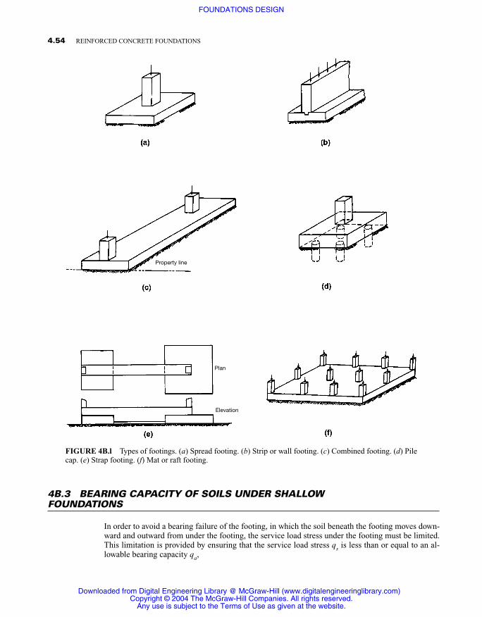
The most common types of footings are illustrated in Fig. 4B.1.
� Isolated spread footings are used beneath individual columns. They can be square or rectangularin shape. They spread the load of the column to the soil in two perpendicular directions.
� Strip footings or wall footings support bearing walls essentially in a one-dimensional action bycantilevering out on both sides of the wall.
� Combined footings are used to support two or more columns. Usually they have a rectangular ortrapezoidal plan. Such footings are often used when a column is close to a property line.
� Pile caps are used to transmit the loads of columns or bearing walls to a series of piles. Thesepiles transfer the loads from the upper poor soil layers to deeper and stronger soil layers.
� A mat or raft foundation is one large footing carrying the loads of all the columns of the struc-ture. This type of foundation is used when weak soil layers are present but piles are not used.
4.53
Source: PRACTICAL FOUNDATION ENGINEERING HANDBOOK
Downloaded from Digital Engineering Library @ McGraw-Hill (www.digitalengineeringlibrary.com)Copyright © 2004 The McGraw-Hill Companies. All rights reserved.
Any use is subject to the Terms of Use as given at the website.
4B.3 BEARING CAPACITY OF SOILS UNDER SHALLOWFOUNDATIONS
In order to avoid a bearing failure of the footing, in which the soil beneath the footing moves down-ward and outward from under the footing, the service load stress under the footing must be limited.This limitation is provided by ensuring that the service load stress qs is less than or equal to an al-lowable bearing capacity qa,
4.54 REINFORCED CONCRETE FOUNDATIONS
FIGURE 4B.l Types of footings. (a) Spread footing. (b) Strip or wall footing. (c) Combined footing. (d) Pilecap. (e) Strap footing. (f) Mat or raft footing.
Property line
Plan
Elevation
Downloaded from Digital Engineering Library @ McGraw-Hill (www.digitalengineeringlibrary.com)Copyright © 2004 The McGraw-Hill Companies. All rights reserved.
Any use is subject to the Terms of Use as given at the website.
FOUNDATIONS DESIGN
qs � qa = (4B.l)
where qult is the ultimate bearing capacity corresponding to failure of thefooting, and FS is a factor of safety, usually taken to be 2.0 to 3.0. Soilmechanics principles are relied upon to establish the ultimate bearing ca-pacity, which depends on the shape of the footing, its depth, the surchargeon top of the footing, the position of the underground water table, and thesoil type. The allowable bearing capacity may vary from 15,000 psf forrock to 2000 psf for clay.
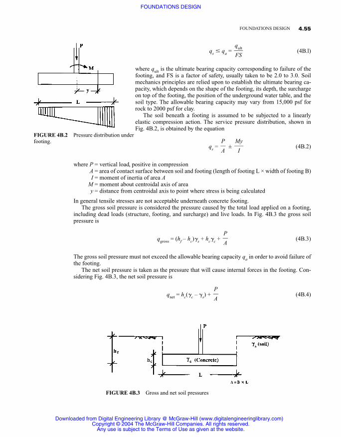
The soil beneath a footing is assumed to be subjected to a linearlyelastic compression action. The service pressure distribution, shown inFig. 4B.2, is obtained by the equation
qs = ± (4B.2)
where P = vertical load, positive in compression A = area of contact surface between soil and footing (length of footing L × width of footing B) I = moment of inertia of area A
M = moment about centroidal axis of area y = distance from centroidal axis to point where stress is being calculated
In general tensile stresses are not acceptable underneath concrete footing.The gross soil pressure is considered the pressure caused by the total load applied on a footing,
including dead loads (structure, footing, and surcharge) and live loads. In Fig. 4B.3 the gross soilpressure is
qgross = (hf – hc)�s + hc�c + (4B.3)
The gross soil pressure must not exceed the allowable bearing capacity qa in order to avoid failure ofthe footing.
The net soil pressure is taken as the pressure that will cause internal forces in the footing. Con-sidering Fig. 4B.3, the net soil pressure is
qnet = hc(�c – �s) + (4B.4)P�A
P�A
My�
I
P�A
qult�FS
4.55FOUNDATIONS DESIGN
FIGURE 4B.2 Pressure distribution underfooting.
FIGURE 4B.3 Gross and net soil pressures
Downloaded from Digital Engineering Library @ McGraw-Hill (www.digitalengineeringlibrary.com)Copyright © 2004 The McGraw-Hill Companies. All rights reserved.
Any use is subject to the Terms of Use as given at the website.
FOUNDATIONS DESIGN
The net soil pressure is used to calculate the flexural reinforcement and the shear strength of theconcrete footing.
4B.4 TYPES OF FAILURE OF FOOTINGS
Three different types of failure may occur in a concrete footing subjected to a concentrated load(Fintel, 1985; Winterkorn and Fang, 1975).
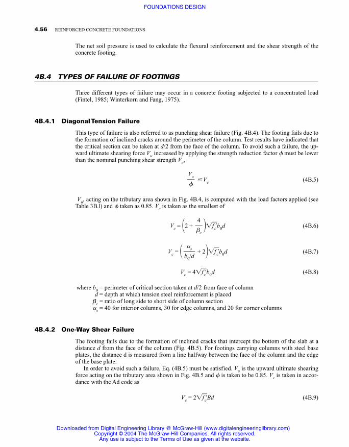
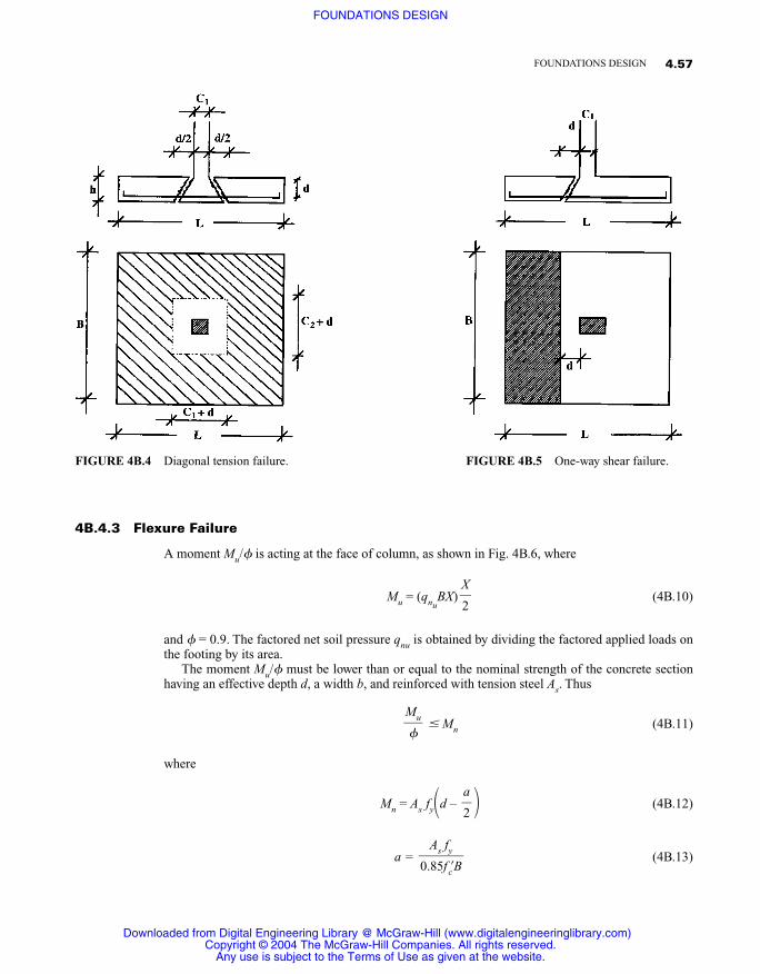
4B.4.1 Diagonal Tension Failure
This type of failure is also referred to as punching shear failure (Fig. 4B.4). The footing fails due tothe formation of inclined cracks around the perimeter of the column. Test results have indicated thatthe critical section can be taken at d/2 from the face of the column. To avoid such a failure, the up-ward ultimate shearing force Vu increased by applying the strength reduction factor � must be lowerthan the nominal punching shear strength Vc,
� Vc (4B.5)
Vu, acting on the tributary area shown in Fig. 4B.4, is computed with the load factors applied (seeTable 3B.l) and � taken as 0.85. Vc is taken as the smallest of
Vc = �2 + ��f�c�b0d (4B.6)
Vc = � + 2��f�c�b0d (4B.7)
Vc = 4�f�c�b0d (4B.8)
where b0 = perimeter of critical section taken at d/2 from face of columnd = depth at which tension steel reinforcement is placed
�c = ratio of long side to short side of column section�s = 40 for interior columns, 30 for edge columns, and 20 for corner columns
4B.4.2 One-Way Shear Failure
The footing fails due to the formation of inclined cracks that intercept the bottom of the slab at adistance d from the face of the column (Fig. 4B.5). For footings carrying columns with steel baseplates, the distance d is measured from a line halfway between the face of the column and the edgeof the base plate.
In order to avoid such a failure, Eq. (4B.5) must be satisfied. Vu is the upward ultimate shearingforce acting on the tributary area shown in Fig. 4B.5 and � is taken to be 0.85. Vc is taken in accor-dance with the Ad code as
Vc = 2�f�c�Bd (4B.9)
�s�b0/d
4��c
Vu��
4.56 REINFORCED CONCRETE FOUNDATIONS
Downloaded from Digital Engineering Library @ McGraw-Hill (www.digitalengineeringlibrary.com)Copyright © 2004 The McGraw-Hill Companies. All rights reserved.
Any use is subject to the Terms of Use as given at the website.
FOUNDATIONS DESIGN
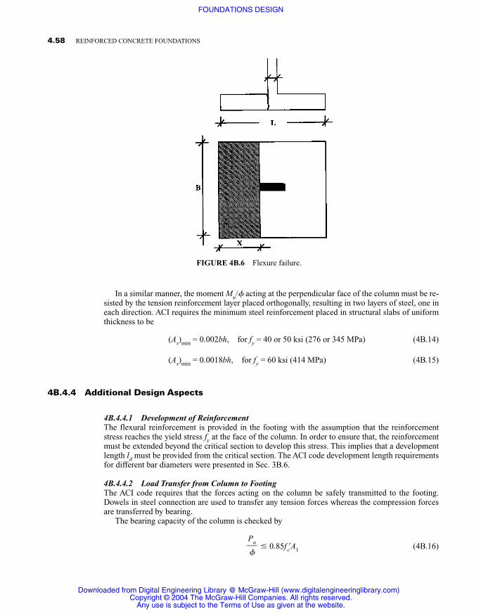
4B.4.3 Flexure Failure
A moment Mu/� is acting at the face of column, as shown in Fig. 4B.6, where
Mu = (qnuBX) (4B.10)
and � = 0.9. The factored net soil pressure qnu is obtained by dividing the factored applied loads onthe footing by its area.
The moment Mu/� must be lower than or equal to the nominal strength of the concrete sectionhaving an effective depth d, a width b, and reinforced with tension steel As. Thus
� Mn (4B.11)
where
Mn = As fy�d – � (4B.12)
a = (4B.13)As fy�0.85f�cB
a�2
Mu��
X�2
4.57FOUNDATIONS DESIGN
FIGURE 4B.4 Diagonal tension failure. FIGURE 4B.5 One-way shear failure.
Downloaded from Digital Engineering Library @ McGraw-Hill (www.digitalengineeringlibrary.com)Copyright © 2004 The McGraw-Hill Companies. All rights reserved.
Any use is subject to the Terms of Use as given at the website.
FOUNDATIONS DESIGN
In a similar manner, the moment Mu/� acting at the perpendicular face of the column must be re-sisted by the tension reinforcement layer placed orthogonally, resulting in two layers of steel, one ineach direction. ACI requires the minimum steel reinforcement placed in structural slabs of uniformthickness to be
(As)min = 0.002bh, for fy = 40 or 50 ksi (276 or 345 MPa) (4B.14)
(As)min = 0.0018bh, for fy = 60 ksi (414 MPa) (4B.15)
4B.4.4 Additional Design Aspects
4B.4.4.1 Development of ReinforcementThe flexural reinforcement is provided in the footing with the assumption that the reinforcementstress reaches the yield stress fy at the face of the column. In order to ensure that, the reinforcementmust be extended beyond the critical section to develop this stress. This implies that a developmentlength ld must be provided from the critical section. The ACI code development length requirementsfor different bar diameters were presented in Sec. 3B.6.
4B.4.4.2 Load Transfer from Column to FootingThe ACI code requires that the forces acting on the column be safely transmitted to the footing.Dowels in steel connection are used to transfer any tension forces whereas the compression forcesare transferred by bearing.
The bearing capacity of the column is checked by
� 0.85f�cA1 (4B.16)Pu��
4.58 REINFORCED CONCRETE FOUNDATIONS
FIGURE 4B.6 Flexure failure.
Downloaded from Digital Engineering Library @ McGraw-Hill (www.digitalengineeringlibrary.com)Copyright © 2004 The McGraw-Hill Companies. All rights reserved.
Any use is subject to the Terms of Use as given at the website.
FOUNDATIONS DESIGN
where � = 0.7Pu = ultimate load applied on columnA1 = the column area
The bearing capacity of the concrete footing is checked by
� 0.85f�cA1�� (4B.17)
where A2 is the maximum area of the supporting surface that is geometrically similar and concentricwith A1. The value of �A�2/�A�1� should not be greater than 2.
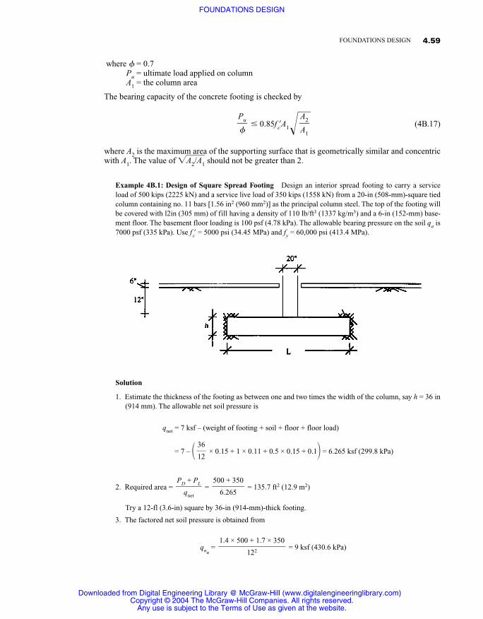
Example 4B.1: Design of Square Spread Footing Design an interior spread footing to carry a serviceload of 500 kips (2225 kN) and a service live load of 350 kips (1558 kN) from a 20-in (508-mm)-square tiedcolumn containing no. 11 bars [1.56 in2 (960 mm2)] as the principal column steel. The top of the footing willbe covered with l2in (305 mm) of fill having a density of 110 lb/ft3 (1337 kg/m3) and a 6-in (152-mm) base-ment floor. The basement floor loading is 100 psf (4.78 kPa). The allowable bearing pressure on the soil qa is7000 psf (335 kPa). Use f�c = 5000 psi (34.45 MPa) and fy = 60,000 psi (413.4 MPa).
Solution
1. Estimate the thickness of the footing as between one and two times the width of the column, say h = 36 in(914 mm). The allowable net soil pressure is
qnet = 7 ksf – (weight of footing + soil + floor + floor load)
= 7 – � × 0.15 + 1 × 0.11 + 0.5 × 0.15 + 0.1� = 6.265 ksf (299.8 kPa)
2. Required area = = = 135.7 ft2 (12.9 m2)
Try a 12-fl (3.6-in) square by 36-in (914-mm)-thick footing.
3. The factored net soil pressure is obtained from
qnu= = 9 ksf (430.6 kPa)
1.4 × 500 + 1.7 × 350���
122
500 + 350��
6.265
PD + PL�
qnet
36�12
A2�A1
Pu��
4.59FOUNDATIONS DESIGN
Downloaded from Digital Engineering Library @ McGraw-Hill (www.digitalengineeringlibrary.com)Copyright © 2004 The McGraw-Hill Companies. All rights reserved.
Any use is subject to the Terms of Use as given at the website.
FOUNDATIONS DESIGN
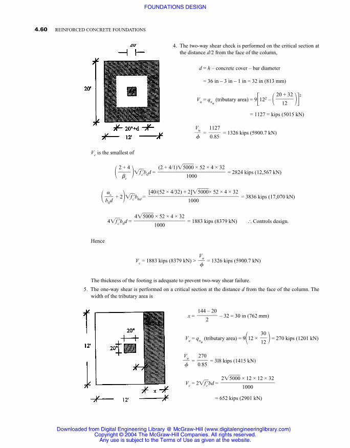
4. The two-way shear check is performed on the critical section atthe distance d/2 from the face of the column,
d = h – concrete cover – bar diameter
= 36 in – 3 in – 1 in = 32 in (813 mm)
Vu = qnu(tributary area) = 9�122 – � ��2
= 1127 = kips (5015 kN)
= = 1326 kips (5900.7 kN)
Vc is the smallest of
� ��f�c�b0d = = 2824 kips (12,567 kN)
� + 2��f�c�b0d = = 3836 kips (17,070 kN)
4�f�c�b0d = = 1883 kips (8379 kN) � Controls design.
Hence
Vc = 1883 kips (8379 kN) > = 1326 kips (5900.7 kN)
The thickness of the footing is adequate to prevent two-way shear failure.
5. The one-way shear is performed on a critical section at the distance d from the face of the column. Thewidth of the tributary area is
x = – 32 = 30 in (762 mm)
Vu = qnu(tributary area) = 9�12 × � = 270 kips (1201 kN)
= = 3l8 kips (1415 kN)
Vc = 2�f�c�bd =
= 652 kips (2901 kN)
2�5�0�0�0� × 12 × 12 × 32���
1000
270�0.85
Vu��
30�12
144 – 20�
2
Vu��
4�5�0�0�0� × 52 × 4 × 32���
1000
[40/(52 × 4/32) + 2]�5�0�0�0�× 52 × 4 × 32�����
1000
�s�b0d
(2 + 4/1)�5�0�0�0� × 52 × 4 × 32����
1000
2 + 4�
�c
1127�0.85
Vu��
20 + 32�
12
4.60 REINFORCED CONCRETE FOUNDATIONS
Downloaded from Digital Engineering Library @ McGraw-Hill (www.digitalengineeringlibrary.com)Copyright © 2004 The McGraw-Hill Companies. All rights reserved.
Any use is subject to the Terms of Use as given at the website.
FOUNDATIONS DESIGN
Hence
Vc = 652 kips (2901 kN) > = 318 kips (1415 kN)
The thickness of the footing is capable of preventing one-way shear failure.
6. Design for flexure reinforcement. The width of the tributary area is
y = � � = 62 in (1575 mm)
Mu = 9�12 × × � = 1442 ft · kip 1955 kN · m)
= = 1602 ft · kips (2172.6 kN · m)
Mn = As fy�d – �
Assuming (d – a/2) = 0.9d,
(As)req = = = 11 in2 (7095 mm2)
(As)min = 0.00l8bh = 0.0018(144 × 36) = 9.3 in2 (5998 mm2)
Choose 11 no. 9 each way; then As = 11 in2 > (As)min.Check the chosen area of the reinforcement:
a = = = 1.08 in (27.4 mm)
Then
Mn = As fy�d – � = 11 × 60,000�32 – � = 20.8 × 10⁶ in · lb (2350 kN · m)
= 1730 ft kips (2350kN · m) > = 1602 ft · kips (2172.6 kN · m)
7. Check the development length:
Idb = 0.04 = 0.04 = 33.94 in 34 in (864 mm) 1.0 × 60,000��
�5�0�0�0�
Ab fy��f�c�
Mu��
1.08�
2
a�2
11 × 60,000��0.85 × 5000 × 144
As fy�0.85f�cb
1602 × 12,000��60,000(0.9 × 32)
Mu/��fy(0.9d)
a�2
1442�
0.9
Mu��
62�2 × 12
62�12
144 – 20��
2
Vu��
4.61FOUNDATIONS DESIGN
Downloaded from Digital Engineering Library @ McGraw-Hill (www.digitalengineeringlibrary.com)Copyright © 2004 The McGraw-Hill Companies. All rights reserved.
Any use is subject to the Terms of Use as given at the website.
FOUNDATIONS DESIGN

No increase in the basic development length Id is needed to account for the effects of bar spacing, cover,stirrup confinement, and reinforcement location.
(Id)min = 0.03db = 0.03 × 1.125 = 28.7 in (729 mm)
Hence choose Id = 34 in (864 mm).The bar length available from the location of the maximum moment on each side is
y – concrete cover = 62 – 3 = 59 in (1499 mm) > 34 in (864 mm)
Therefore the development length is provided.
8. Check the bearing at the column-footing interface:
Pu = 1.4 × 500 + 1.7 × 350 = 1295 kips (5763 kN)
= = 1850 kips (8233 kN)
Footing capacity:
Pn = 0.85f�cA1��
�� = �� = 7.2 � Use �� = 2.
Then
Pn = = 3400 kips (15,l30 kN)
Pn = 3400 kips (15,130 kN) > = 1850 kips (8233 kN) O.K.
Column capacity:
Pn = 0.85f�cA1 = = 1700 kips (7565 kN)
Pn <
Hence dowels are needed to transfer the excess load.
Area of dowel required = = = 2.5 in2 (1613 mm2)150�60
1850 – 1700��
fy
Pu��
0.85 × 5000 × 20 × 20���
1000
Pu��
0.85 × 5000 × 20 × 20 × 2���
1000
A2�A1
144 × 144��
20 × 20
A2�A1
A2�A1
1295�
0.7
Pu��
60,000��5�0�0�0�
fy��f�c�
4.62 REINFORCED CONCRETE FOUNDATIONS
Downloaded from Digital Engineering Library @ McGraw-Hill (www.digitalengineeringlibrary.com)Copyright © 2004 The McGraw-Hill Companies. All rights reserved.
Any use is subject to the Terms of Use as given at the website.
FOUNDATIONS DESIGN
The area of the dowel must be higher than the minimum specified by the ACI code,
(Area of dowel)min = 0.005Ag = 0.005 × 20 × 20 = 2 in2 (1290 mm2) < 2.5 in2 (1613 mm2)
Hence the value of 2.5 in2 controls. Choose 4 no. 8 bars [3.16 in2 (2038 mm2)]. The dowels must extendat least the compression development length of the 8 bar into the footing,
Idb = 0.02db � 0.0003db fy
Idb = 15 in (381 mm) < l6 in (406 mm)
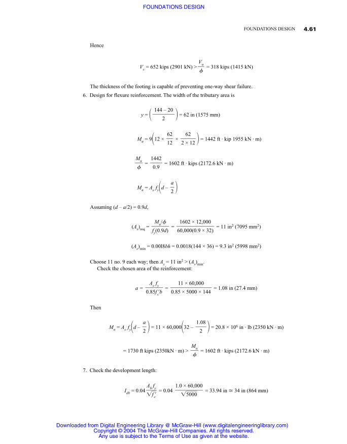
Hence extend 4 no. 8 dowels at least 16 in (406 mm) into the footing.
The complete design is detailed here.
4B.5 RECTANGULAR FOOTINGS
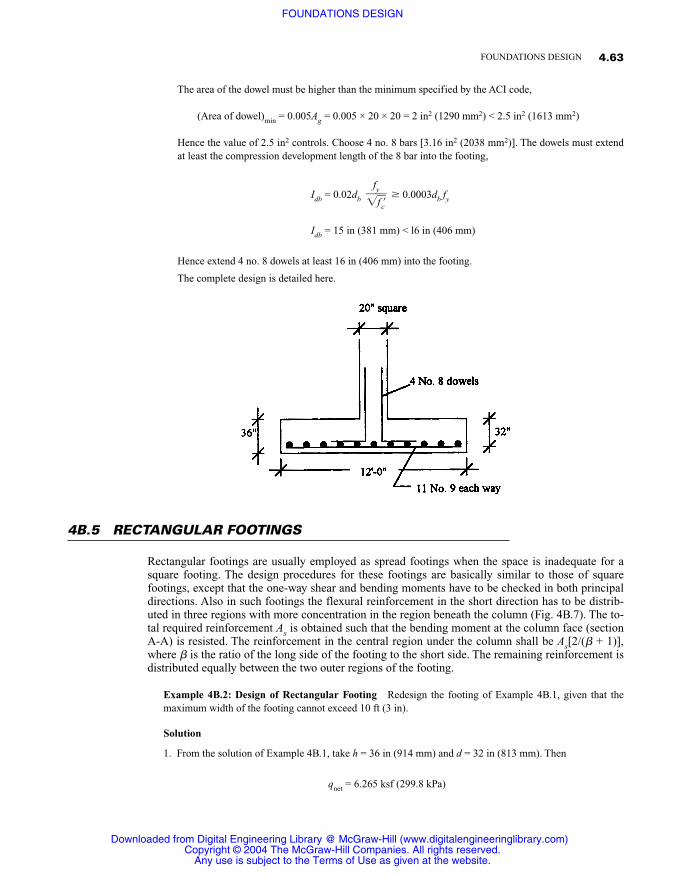
Rectangular footings are usually employed as spread footings when the space is inadequate for asquare footing. The design procedures for these footings are basically similar to those of squarefootings, except that the one-way shear and bending moments have to be checked in both principaldirections. Also in such footings the flexural reinforcement in the short direction has to be distrib-uted in three regions with more concentration in the region beneath the column (Fig. 4B.7). The to-tal required reinforcement As is obtained such that the bending moment at the column face (sectionA-A) is resisted. The reinforcement in the central region under the column shall be As[2/(� + 1)],where � is the ratio of the long side of the footing to the short side. The remaining reinforcement isdistributed equally between the two outer regions of the footing.
Example 4B.2: Design of Rectangular Footing Redesign the footing of Example 4B.1, given that themaximum width of the footing cannot exceed 10 ft (3 in).
Solution
1. From the solution of Example 4B.1, take h = 36 in (914 mm) and d = 32 in (813 mm). Then
qnet = 6.265 ksf (299.8 kPa)
fy��f�c�
4.63FOUNDATIONS DESIGN
Downloaded from Digital Engineering Library @ McGraw-Hill (www.digitalengineeringlibrary.com)Copyright © 2004 The McGraw-Hill Companies. All rights reserved.
Any use is subject to the Terms of Use as given at the website.
FOUNDATIONS DESIGN
2. Required area = = = 135.7 ft2 (12.9 m2)
Required length = = 13.57 ft (4.2 m) Take L = 14 ft (4.25 m).
Try a footing 10 ft (3 m) wide by 14 ft (4.25 m) long by 36 in (914 mm) thick.
3. The factored net soil pressure is
qnu= = 9.25 ksf (442.6 kPa)
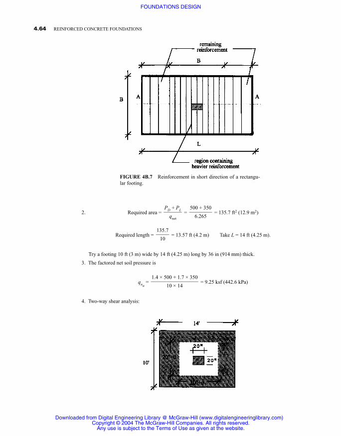
4. Two-way shear analysis:
1.4 × 500 + 1.7 × 350���
10 × 14
135.7�
10
500 + 350��
6.265
PD + PL�
qnet
4.64 REINFORCED CONCRETE FOUNDATIONS
FIGURE 4B.7 Reinforcement in short direction of a rectangu-lar footing.
Downloaded from Digital Engineering Library @ McGraw-Hill (www.digitalengineeringlibrary.com)Copyright © 2004 The McGraw-Hill Companies. All rights reserved.
Any use is subject to the Terms of Use as given at the website.
FOUNDATIONS DESIGN
Vu = qnu(tributary area) = 9.25�140 – � �2� = 1121 kips (4988 kN)
= = 1319 kips (5869 kN)
Vc = 4�f�c�b0d = = 1883 kips (8379 kN)
Hence
Vc = 1883 kips (8379 kN) > = 1319 kips (5869 kN)
The thickness of the footing is adequate to prevent two-way shear failure.
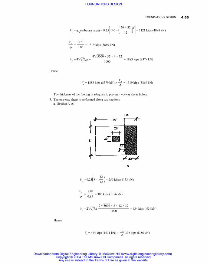
5. The one-way shear is performed along two sections.a. Section A-A:
Vu = 9.25�8 × � = 259 kips (1153 kN)
= = 305 kips (1356 kN)
Vc = 2�f�c�bd = 434 kips (l93l kN)
Hence
Vc = 434 kips (1931 kN) > 305 kips (l356 kN)Vu��
2�5�0�0�0� × 8 × 12 × 32���
1000
259�0.85
Vu��
42�12
Vu��
4�5�0�0�0� × 52 × 4 × 32���
1000
1121�0.85
Vu��
20 + 32�
12
4.65FOUNDATIONS DESIGN
Downloaded from Digital Engineering Library @ McGraw-Hill (www.digitalengineeringlibrary.com)Copyright © 2004 The McGraw-Hill Companies. All rights reserved.
Any use is subject to the Terms of Use as given at the website.
FOUNDATIONS DESIGN
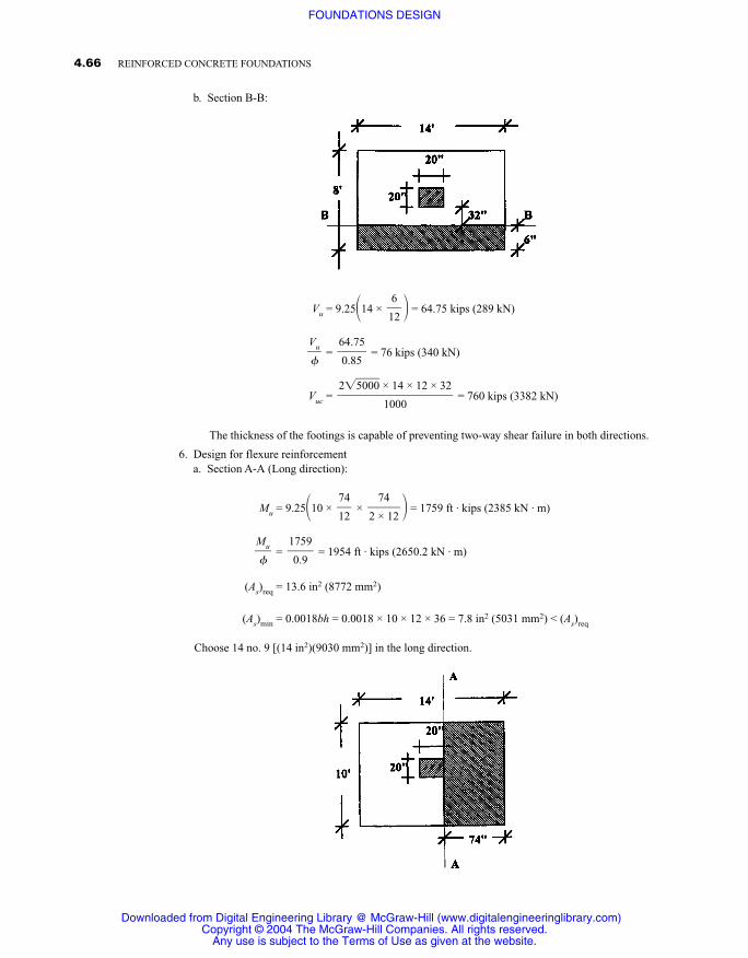
b. Section B-B:
Vu = 9.25�14 × � = 64.75 kips (289 kN)
= = 76 kips (340 kN)
Vuc = = 760 kips (3382 kN)
The thickness of the footings is capable of preventing two-way shear failure in both directions.
6. Design for flexure reinforcementa. Section A-A (Long direction):
Mu = 9.25�10 × × � = 1759 ft · kips (2385 kN · m)
= = 1954 ft · kips (2650.2 kN · m)
(As)req = 13.6 in2 (8772 mm2)
(As)min = 0.0018bh = 0.0018 × 10 × 12 × 36 = 7.8 in2 (5031 mm2) < (As)req
Choose 14 no. 9 [(14 in2)(9030 mm2)] in the long direction.
1759�
0.9
Mu��
74�2 × 12
74�12
2�5�0�0�0� × 14 × 12 × 32���
1000
64.75�0.85
Vu��
6�12
4.66 REINFORCED CONCRETE FOUNDATIONS
Downloaded from Digital Engineering Library @ McGraw-Hill (www.digitalengineeringlibrary.com)Copyright © 2004 The McGraw-Hill Companies. All rights reserved.
Any use is subject to the Terms of Use as given at the website.
FOUNDATIONS DESIGN
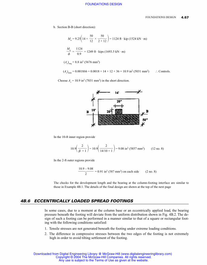
b. Section B-B (short direction):
Mu = 9.25�14 × × � = 1124 ft · kip (1524 kN · m)
= = 1249 ft · kips (1693.5 kN · m)
(As)req = 8.8 in2 (5676 mm2)
(As)min = 0.0018bh = 0.0018 × 14 × 12 × 36 = 10.9 in2 (5031 mm2) � Controls.
Choose As = 10.9 in2 (7031 mm2) in the short direction.
In the 10-ft inner region provide
10.9� � = 10.9� � = 9.08 in2 (5857 mm2) (12 no. 8)
In the 2-ft outer regions provide
= 0.91 in2 (587 mm2) on each side (2 no. 8)
The checks for the development length and the bearing at the column-footing interface are similar tothose in Example 4B.1. The details of the final design are shown at the top of the next page
4B.6 ECCENTRICALLY LOADED SPREAD FOOTINGS
In some cases, due to a moment at the column base or an eccentrically applied load, the bearingpressure beneath the footing will deviate from the uniform distribution shown in Fig. 4B.2. The de-sign of such a footing can be performed in a manner similar to that of a square or rectangular foot-ing with the following conditions satisfied:
1. Tensile stresses are not generated beneath the footing under extreme loading conditions.
2. The difference in compressive stresses between the two edges of the footing is not extremelyhigh in order to avoid tilting settlement of the footing.
10.9 – 9.08��
2
2��14/10 + 1
2�� + 1
1124�
0.9
Mu��
50�2 × 12
50�12
4.67FOUNDATIONS DESIGN
Downloaded from Digital Engineering Library @ McGraw-Hill (www.digitalengineeringlibrary.com)Copyright © 2004 The McGraw-Hill Companies. All rights reserved.
Any use is subject to the Terms of Use as given at the website.
FOUNDATIONS DESIGN
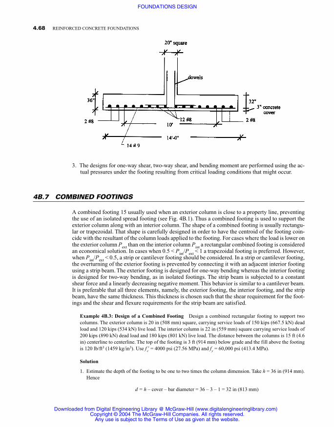
3. The designs for one-way shear, two-way shear, and bending moment are performed using the ac-tual pressures under the footing resulting from critical loading conditions that might occur.
4B.7 COMBINED FOOTINGS
A combined footing 15 usually used when an exterior column is close to a property line, preventingthe use of an isolated spread footing (see Fig. 4B.1). Thus a combined footing is used to support theexterior column along with an interior column. The shape of a combined footing is usually rectangu-lar or trapezoidal. That shape is carefully designed in order to have the centroid of the footing coin-cide with the resultant of the column loads applied to the footing. For cases where the load is lower onthe exterior column Pext than on the interior column Pint a rectangular combined footing is consideredan economical solution. In cases when 0.5 < Pint/Pext < 1 a trapezoidal footing is preferred. However,when Pint/Pext < 0.5, a strip or cantilever footing should be considered. In a strip or cantilever footing,the overturning of the exterior footing is prevented by connecting it with an adjacent interior footingusing a strip beam. The exterior footing is designed for one-way bending whereas the interior footingis designed for two-way bending, as in isolated footings. The strip beam is subjected to a constantshear force and a linearly decreasing negative moment. This behavior is similar to a cantilever beam.It is preferable that all three elements, namely, the exterior footing, the interior footing, and the stripbeam, have the same thickness. This thickness is chosen such that the shear requirement for the foot-ings and the shear and flexure requirements for the strip beam are satisfied.
Example 4B.3: Design of a Combined Footing Design a combined rectangular footing to support twocolumns. The exterior column is 20 in (508 mm) square, carrying service loads of 150 kips (667.5 kN) deadload and 120 kips (534 kN) live load. The interior column is 22 in (559 mm) square carrying service loads of200 kips (890 kN) dead load and 180 kips (801 kN) live load. The distance between the columns is 15 ft (4.6in) centerline to centerline. The top of the footing is 3 ft (914 mm) below grade and the fill above the footingis 120 lb/ft3 (1459 kg/in3). Use f�c = 4000 psi (27.56 MPa) and fy = 60,000 psi (413.4 MPa).
Solution
1. Estimate the depth of the footing to be one to two times the column dimension. Take h = 36 in (914 mm).Hence
d = h – cover – bar diameter = 36 – 3 – 1 = 32 in (813 mm)
4.68 REINFORCED CONCRETE FOUNDATIONS
Downloaded from Digital Engineering Library @ McGraw-Hill (www.digitalengineeringlibrary.com)Copyright © 2004 The McGraw-Hill Companies. All rights reserved.
Any use is subject to the Terms of Use as given at the website.
FOUNDATIONS DESIGN
The allowable net soil pressure is
qnet = 5 – (weight of footing + soil) = 5 – (3 × 0.15) – (3 × 0.12) = 4.19 ksf (200.5 kPa)
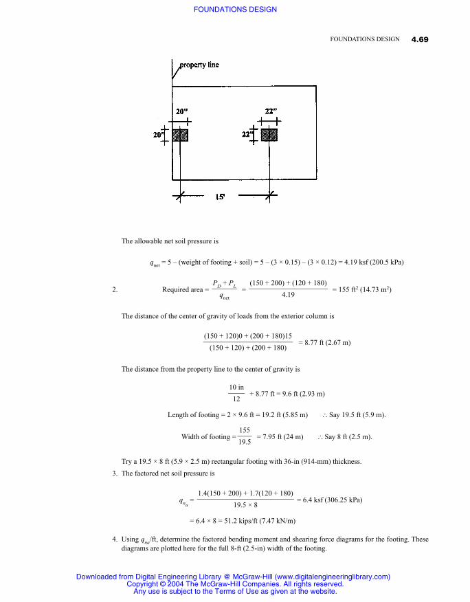
2. Required area = = = 155 ft2 (14.73 m2)
The distance of the center of gravity of loads from the exterior column is
= 8.77 ft (2.67 m)
The distance from the property line to the center of gravity is
+ 8.77 ft = 9.6 ft (2.93 m)
Length of footing = 2 × 9.6 ft = 19.2 ft (5.85 m) � Say 19.5 ft (5.9 m).
Width of footing = = 7.95 ft (24 m) � Say 8 ft (2.5 m).
Try a 19.5 × 8 ft (5.9 × 2.5 m) rectangular footing with 36-in (914-mm) thickness.
3. The factored net soil pressure is
qnu= = 6.4 ksf (306.25 kPa)
= 6.4 × 8 = 51.2 kips/ft (7.47 kN/m)
4. Using qna/ft, determine the factored bending moment and shearing force diagrams for the footing. Thesediagrams are plotted here for the full 8-ft (2.5-in) width of the footing.
1.4(150 + 200) + 1.7(120 + 180)����
19.5 × 8
155�19.5
10 in�
12
(150 + 120)0 + (200 + 180)15����
(150 + 120) + (200 + 180)
(150 + 200) + (120 + 180)���
4.19
PD + PL�
qnet
4.69FOUNDATIONS DESIGN
Downloaded from Digital Engineering Library @ McGraw-Hill (www.digitalengineeringlibrary.com)Copyright © 2004 The McGraw-Hill Companies. All rights reserved.
Any use is subject to the Terms of Use as given at the website.
FOUNDATIONS DESIGN
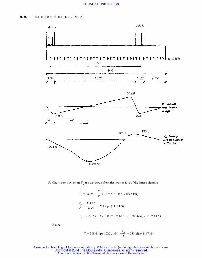
5. Check one-way shear: Vu at a distance d from the interior face of the inner column is
Vu = 349.9 – 51.2 = 213.3 kips (949.5 kN)
= = 251 kips (1117 kN)
Vc = 2�f�c�bd = 2�4�0�0�0� × 8 × 12 × 32 = 388.6 kips (1729.3 kN)
Hence,
Vc = 388.6 kips (l729.3 kN) > = 251 kips (1117 kN)Vu��
213.37�
0.85
Vu��
32�12
4.70 REINFORCED CONCRETE FOUNDATIONS
414 k586 k
15'
1.67'
19'-6''
51.2 k/ft
13.25' 1.83' 2.75'
349.9
236328.56.42'1.67'
123.9193.6
1329.78
274.3
Downloaded from Digital Engineering Library @ McGraw-Hill (www.digitalengineeringlibrary.com)Copyright © 2004 The McGraw-Hill Companies. All rights reserved.
Any use is subject to the Terms of Use as given at the website.
FOUNDATIONS DESIGN
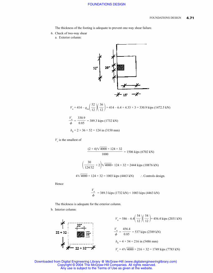
The thickness of the footing is adequate to prevent one-way shear failure.
6. Check of two-way sheara. Exterior column:
Vu = 414 – qna� �� � = 414 – 6.4 × 4.33 × 3 = 330.9 kips (1472.5 kN)
= = 389.3 kips (1732 kN)
b0 = 2 × 36 + 52 = 124 in (3150 mm)
Vc is the smallest of
= 1506 kips (6702 kN)
� + 2��4�0�0�0�× 124 × 32 = 2444 kips (10876 kN)
4�4�0�0�0� × 124 × 32 = 1003 kips (4463 kN) � Controls design.
Hence
= 389.3 kips (1732 kN) < 1003 kips (4463 kN)
The thickness is adequate for the exterior column.
b. Interior column:
Vu = 586 – 6.4� �� �= 456.4 kips (2031 kN)
= = 537 kips (2389 kN)
b0 = 4 × 54 = 216 in (5486 mm)
Vc = 4�4�0�0�0� × 216 × 32 = 1749 kips (7783 kN)
456.4�0.85
Vu��
54�12
54�12
Vu��
30�124/32
(2 + 4)�4�0�0�0� × 124 × 32���
1000
330.9�0.85
Vu��
36�12
52�12
4.71FOUNDATIONS DESIGN
Downloaded from Digital Engineering Library @ McGraw-Hill (www.digitalengineeringlibrary.com)Copyright © 2004 The McGraw-Hill Companies. All rights reserved.
Any use is subject to the Terms of Use as given at the website.
FOUNDATIONS DESIGN
Hence
= 537 kips (2389 kN) < 1749 kips (7783 kN)
The thickness is adequate for the interior column.
7. Design for flexure reinforcementa. Midspan negative moment:
= = 1477.5 ft · kips (2003.5 kN · m)
Mn = As fy�d – �Assuming (d – a/2) = 0.9d,
(As)req = = = 10.26 in2 (6618 mm2)
(As)min = 0.00l8bh = 0.0018 × 8 × 12 × 36 = 6.22 in2 (4012 mm2)
Choose 11 no.9 � As = 11 in2 (7095 mm2) > (As)min
Checking the area of the reinforcement,
a = = = 2.0 in (50.8 mm)
Mn = 11 × 60,000�32 – � = 20.45 × 10⁶ in · lb
= 1704 ft · kips (2311 kN · m) > 1477.5 ft · kips (2003.49 kN · m)
Use 11 no. 9 top bars at midspan.
b. Interior column positive moment:
= = 215 ft · kips (291.54 kN · m)
This would require As = 2 in2 (1290 mm2), which is less than (As)min = 6.22 in2 (4012 mm2). Use 7 no. 9bottom bars for the interior column.
8. Design for transverse beams under columns. It is assumed that transverse beams under each columntransmit the load from the longitudinal direction into the columns. The width of the transverse beam istaken to be the width of the column plus an extension d/2 on each side of the column.
a. Transverse steel under interior column:
Beam width = 22 + 2� � = 54 in (1372 mm)32�2
193.6�
0.9
Mu��
2�2
11 × 60,000���0.85 × 4000 × 8 × 12
As fy�0.85f�cb
1477.5 × 12,000��60,000 × 0.9 × 32
Mu/��fy(0.9d)
a�2
1329.78�
0.9
Mu��
Vu��
4.72 REINFORCED CONCRETE FOUNDATIONS
Downloaded from Digital Engineering Library @ McGraw-Hill (www.digitalengineeringlibrary.com)Copyright © 2004 The McGraw-Hill Companies. All rights reserved.
Any use is subject to the Terms of Use as given at the website.
FOUNDATIONS DESIGN
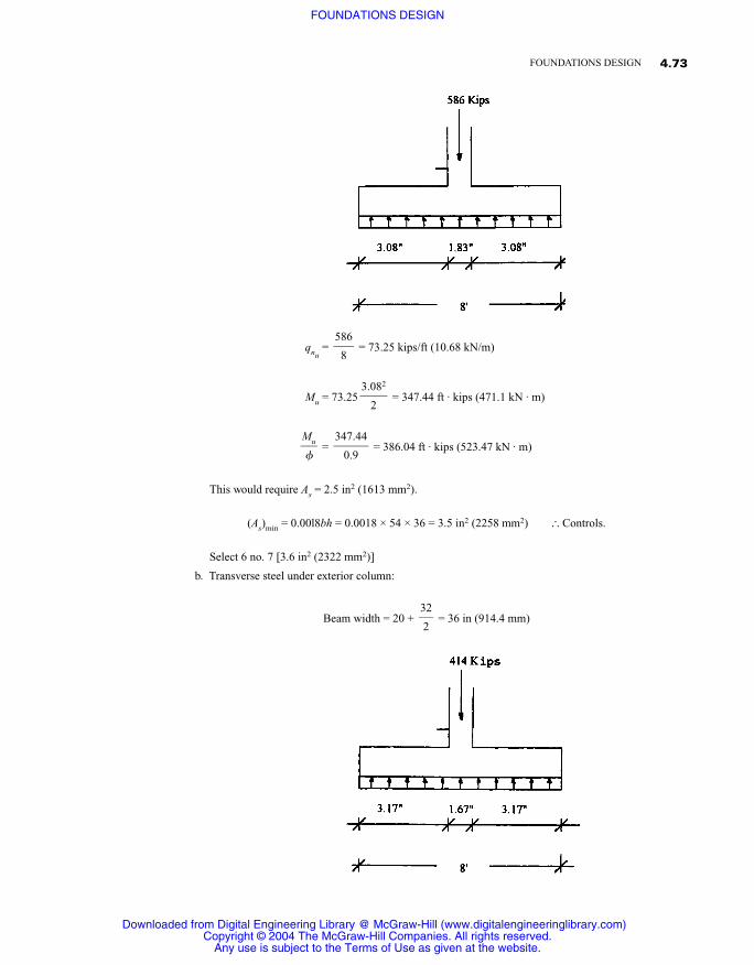
qnu= = 73.25 kips/ft (10.68 kN/m)
Mu = 73.25 = 347.44 ft · kips (471.1 kN · m)
= = 386.04 ft · kips (523.47 kN · m)
This would require As = 2.5 in2 (1613 mm2).
(As)min = 0.00l8bh = 0.0018 × 54 × 36 = 3.5 in2 (2258 mm2) � Controls.
Select 6 no. 7 [3.6 in2 (2322 mm2)]
b. Transverse steel under exterior column:
Beam width = 20 + = 36 in (914.4 mm)32�2
347.44�
0.9
Mu��
3.082
�2
586�
8
4.73FOUNDATIONS DESIGN
Downloaded from Digital Engineering Library @ McGraw-Hill (www.digitalengineeringlibrary.com)Copyright © 2004 The McGraw-Hill Companies. All rights reserved.
Any use is subject to the Terms of Use as given at the website.
FOUNDATIONS DESIGN
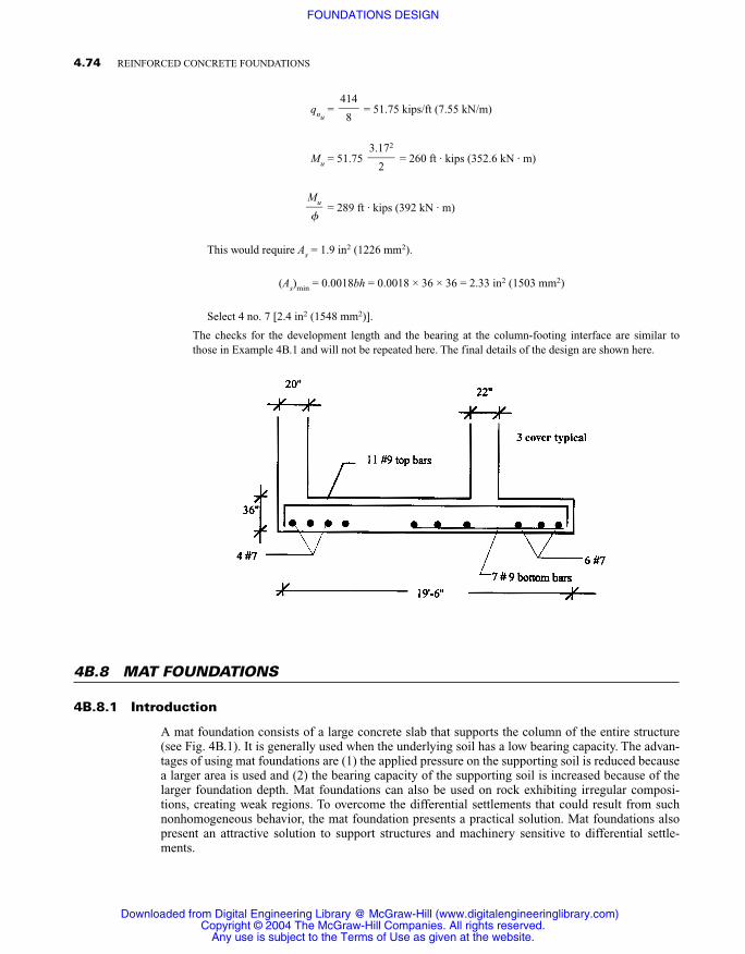
qnu= = 51.75 kips/ft (7.55 kN/m)
Mu = 51.75 = 260 ft · kips (352.6 kN · m)
= 289 ft · kips (392 kN · m)
This would require As = 1.9 in2 (1226 mm2).
(As)min = 0.0018bh = 0.0018 × 36 × 36 = 2.33 in2 (1503 mm2)
Select 4 no. 7 [2.4 in2 (1548 mm2)].
The checks for the development length and the bearing at the column-footing interface are similar tothose in Example 4B.1 and will not be repeated here. The final details of the design are shown here.
4B.8 MAT FOUNDATIONS
4B.8.1 Introduction
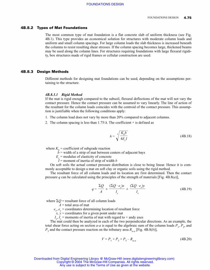
A mat foundation consists of a large concrete slab that supports the column of the entire structure(see Fig. 4B.1). It is generally used when the underlying soil has a low bearing capacity. The advan-tages of using mat foundations are (1) the applied pressure on the supporting soil is reduced becausea larger area is used and (2) the bearing capacity of the supporting soil is increased because of thelarger foundation depth. Mat foundations can also be used on rock exhibiting irregular composi-tions, creating weak regions. To overcome the differential settlements that could result from suchnonhomogeneous behavior, the mat foundation presents a practical solution. Mat foundations alsopresent an attractive solution to support structures and machinery sensitive to differential settle-ments.
Mu��
3.172
�2
414�
8
4.74 REINFORCED CONCRETE FOUNDATIONS
Downloaded from Digital Engineering Library @ McGraw-Hill (www.digitalengineeringlibrary.com)Copyright © 2004 The McGraw-Hill Companies. All rights reserved.
Any use is subject to the Terms of Use as given at the website.
FOUNDATIONS DESIGN
4B.8.2 Types of Mat Foundations
The most common type of mat foundation is a flat concrete slab of uniform thickness (see Fig.4B.1). This type provides an economical solution for structures with moderate column loads anduniform and small column spacings. For large column loads the slab thickness is increased beneaththe columns to resist resulting shear stresses. If the column spacing becomes large, thickened beamsmay be used along the column lines. For structures requiring foundations with large flexural rigidi-ty, box structures made of rigid frames or cellular construction are used.
4B.8.3 Design Methods
Different methods for designing mat foundations can be used, depending on the assumptions per-taining to the structure.
4B.8.3.1 Rigid MethodIf the mat is rigid enough compared to the subsoil, flexural deflections of the mat will not vary thecontact pressure. Hence the contact pressure can be assumed to vary linearly. The line of action ofthe resultant for the column loads coincides with the centroid of the contact pressure. This assump-tion is justifiable when the following conditions apply:
1. The column load does not vary by more than 20% compared to adjacent columns.
2. The column spacing is less than 1.75/. The coefficient × is defined as
= �4 � (4B.18)
where Kb = coefficient of subgrade reactionb = width of a strip of mat between centers of adjacent bays
Ec = modulus of elasticity of concreteI = moment of inertia of strip of width b
On soft soils the actual contact pressure distribution is close to being linear. Hence it is com-monly acceptable to design a mat on soft clay or organic soils using the rigid method.
The resultant force of all column loads and its location are first determined. Then the contactpressure q can be calculated using the principles of the strength of materials [Fig. 4B.8(a)],
q = ± ± (4B.19)
where Q = resultant force of all column loadsA = total area of mat
ex, ey = coordinates determining location of resultant forcex, y = coordinates for a given point under mat
Ix, Iy = moments of inertia of mat with regard to × andy axesThe mat could then be analyzed in each of the two perpendicular directions. As an example, the
total shear force acting on section a-a is equal to the algebraic sum of the column loads P1, P2, andP3 and the contact pressure reaction on the tributary area Ra-a [Fig. 4B.8(b)],
V = P1 + P2 + P3 – Ra-a (4B.20)
(Q · ex)y��
Ix
(Q · ey)x��
Iy
Q�
A
Kbb�4EcI
4.75FOUNDATIONS DESIGN
Downloaded from Digital Engineering Library @ McGraw-Hill (www.digitalengineeringlibrary.com)Copyright © 2004 The McGraw-Hill Companies. All rights reserved.
Any use is subject to the Terms of Use as given at the website.
FOUNDATIONS DESIGN
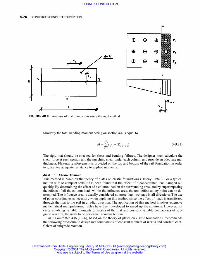
Similarly the total bending moment acting on section a-a is equal to
M = n
i=1
Pixi – (Ra-axa-a) (4B.21)
The rigid mat should be checked for shear and bending failures. The designer must calculate theshear force at each section and the punching shear under each column and provide an adequate matthickness. Flexural reinforcement is provided on the top and bottom of the raft foundation in orderto guarantee adequate resistance to applied moments.
4B.8.3.2 Elastic MethodThis method is based on the theory of plates on elastic foundations (Hetenyi, 1946). For a typicalmat on stiff or compact soils it has been found that the effect of a concentrated load damped outquickly. By determining the effect of a column load on the surrounding area, and by superimposingthe effects of all the column loads within the influence area, the total effect at any point can be de-termined. The influence area is usually considered no more than two bays in all directions. The useof polar coordinates is necessary when applying this method since the effect of loads is transferredthrough the mat to the soil in a radial direction. The application of this method involves extensivemathematical manipulations. Tables have been developed to speed up the solutions. However, forcases involving variable moments of inertia of the mat and possibly variable coefficients of sub-grade reaction, the work to be performed remains tedious.
ACI Committee 436 (1966), based on the theory of plates on elastic foundations, recommendsthe following procedure to design mat foundations of constant moment of inertia and constant coef-ficient of subgrade reaction.
4.76 REINFORCED CONCRETE FOUNDATIONS
FIGURE 4B.8 Analysis of mat foundations using the rigid method
Downloaded from Digital Engineering Library @ McGraw-Hill (www.digitalengineeringlibrary.com)Copyright © 2004 The McGraw-Hill Companies. All rights reserved.
Any use is subject to the Terms of Use as given at the website.
FOUNDATIONS DESIGN
1. The mat thickness h is chosen such that shear at critical sections is adequately resisted.
2. The coefficient K of subgrade reaction is determined.
3. The flexural rigidity of the mat foundation is calculated using
D = (4B.22)
where E = modulus of elasticity of concrete� = Poisson’s ratio of concrete
4. The radius of effective stiffness l is determined using
l = �4 � (4B.23)
where Kb is the coefficient of subgrade reaction adjusted for mat size.
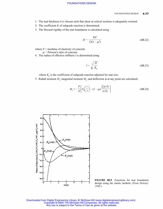
5. Radial moment Mr, tangential moment Mt, and deflection � at any point are calculated:
Mr = – �Z4� � – (1 – �) � (4B.24)Z�3(r/l)�
(r/l)
r�l
P�4
D�Kb
Eh3
��12(1 – �2)
4.77FOUNDATIONS DESIGN
FIGURE 4B.9 Functions for mat foundationdesign using the elastic method. (From Hetenyi,1946.)
Downloaded from Digital Engineering Library @ McGraw-Hill (www.digitalengineeringlibrary.com)Copyright © 2004 The McGraw-Hill Companies. All rights reserved.
Any use is subject to the Terms of Use as given at the website.
FOUNDATIONS DESIGN
Mt = – ��Z4� � – (1 – �) � (4B.25)
� = – Z3� � (4B.26)
where P = column loadr = distance of point of interest from column load along radius l
Z3� �, Z�3� �, Z4� � = functions for moments and deflections (Fig. 4B.9)
6. The radial and tangential moments are transformed to rectangular coordinates,
Mx = Mr cos2� + Mt sin2� (4B.27)
My = Mr sin2� + Mt cos2� (4B.28)
where tan � = y/x.
7. The shear force Q for a unit width of the mat foundation is determined by
Q = – Z�4� � (4B.29)
where Z�4(l/r) is the function for shear (Fig. 4B.10).
8. The moments and shear forces computed for each column are superimposed to obtain the totalmoment on shear design values.
4B.8.3.3 Numerical MethodsWith the increasing use of computers in design applications, numerical methods capable of handlingcases of variable moments of inertia and variable coefficients of subgrade reaction are becomingmore and more attractive. The methods of finite difference and of finite elements are among themostly used numerical techniques.
The finite-difference method is based on the assumption that the effect of the underlying soil canbe represented by uniformly distributed elastic springs. These springs have an elastic constant Kequal to the subgrade reaction. The differential equation of such a mat foundation is
l�r
P�4l
r�l
r�l
r�l
r�l
Pl2
�4D
Z�3(r/l)�
(r/l)
r�l
P�4
4.78 REINFORCED CONCRETE FOUNDATIONS
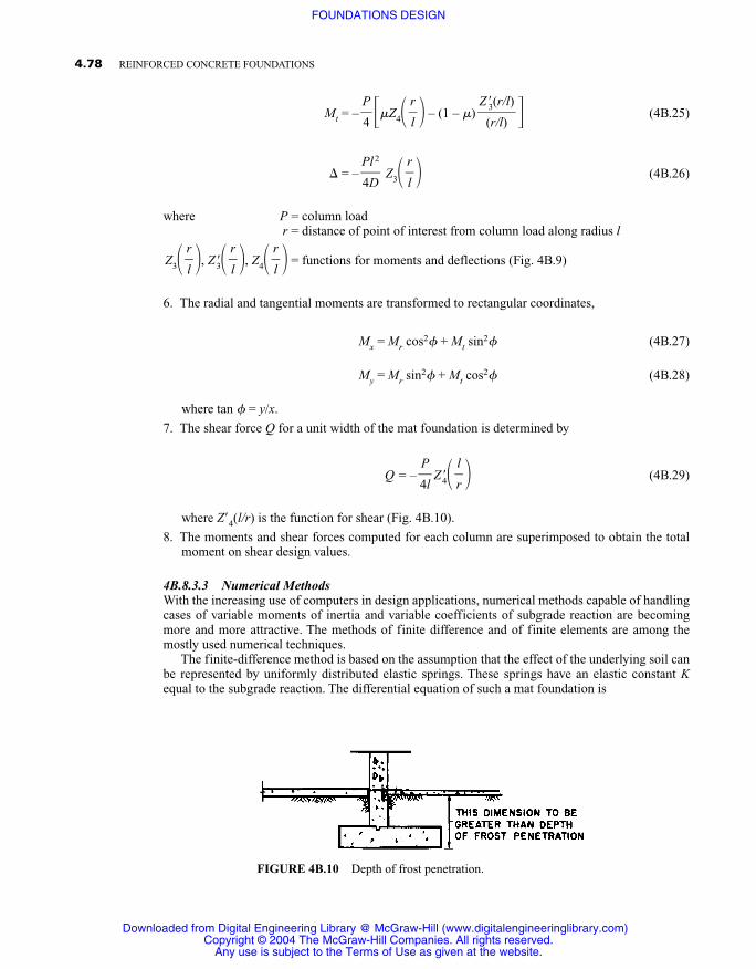
FIGURE 4B.10 Depth of frost penetration.
Downloaded from Digital Engineering Library @ McGraw-Hill (www.digitalengineeringlibrary.com)Copyright © 2004 The McGraw-Hill Companies. All rights reserved.
Any use is subject to the Terms of Use as given at the website.
FOUNDATIONS DESIGN
+ + = (4B.30)
where q = subgrade reaction per unit area of matK = coefficient of subgrade reactionw = deflectionD = rigidity of mat defined in Eq. (4B.22)
The deflection of any point can be related to the deflection at the adjacent points to the right, left,top, and bottom using a numerical difference equation. The mat foundation is divided into a networkof points. The difference equations for these points are formulated and rapidly solved for the deflec-tions with a programmed computer. With the knowledge of deflections, the bending moments andshear forces can be determined from the theory of elasticity. The accuracy of the results obtainedwith the finite-difference method largely depends on the size and number of networks used.
The finite-element method uses the concept of matrix structural analysis to address the problemof plates on elastic foundations. The mat foundation is idealized as a mesh of plates (finite ele-ments) interconnected only at the nodes, where isolated springs are used to model the soil reactions.A more detailed discussion of this method and its applications for foundation design can be found inWeaver and Johnston (1984).
4B.9 FOUNDATIONS IN COLD REGIONS
A locality, city, or state that spends a large amount of its financial resources to maintain a programfor continuous social and economical operations under cold weather conditions and snow storms isconsidered located in a cold region. Seasonal and permanently frozen grounds are characteristics ofcold regions and require special attention from the foundations designer.
In areas of seasonal frost during winter months, the foundation depth is carefully taken below thefrost line (Fig. 4B.10). This is a necessary measure to prevent heaving of the structure due to freezingof the underlying soil. Heave is a phenomenon caused by the formation and growth of ice particles inthe soil. If a foundation is placed at or above the frost line, it will move upward as the underlying soilfreezes and expands. Later it will suddenly settle when thawing occurs. An additional problem is en-countered in the case of fine-grained soils, namely, the decrease in the soil shear strength when itthaws after being frozen. This loss of strength is due to thawing, liberating moisture that had beensoaked up by the soil particles during freezing. Thus the moisture content of the soil is increased com-pared to conditions prior to freezing. Such a loss of shear strength could result in a foundation failure.
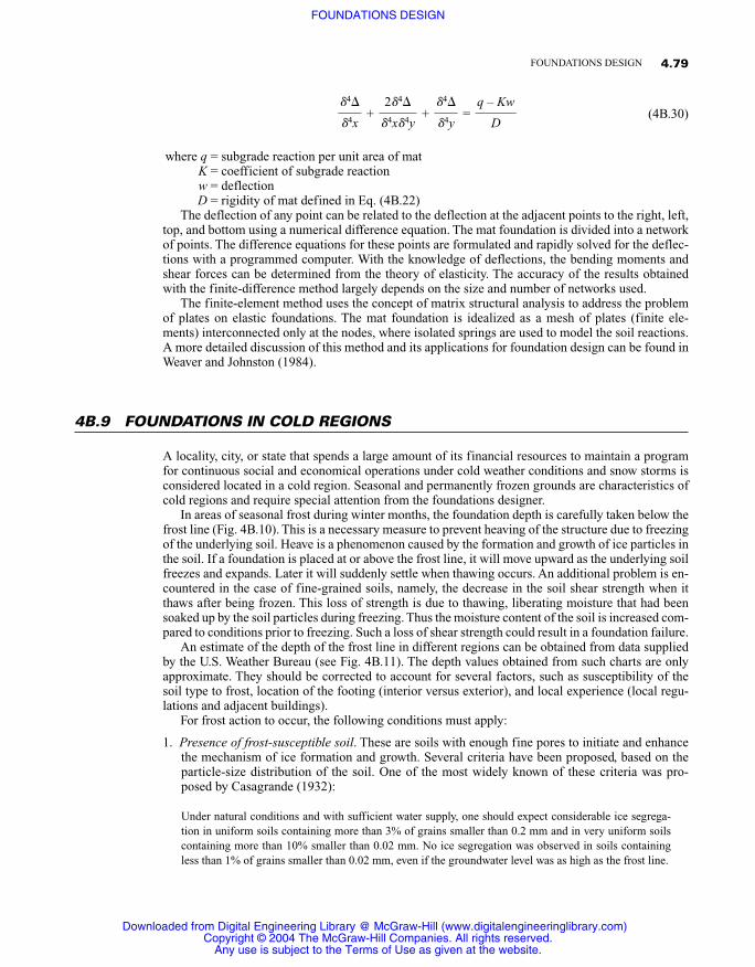
An estimate of the depth of the frost line in different regions can be obtained from data suppliedby the U.S. Weather Bureau (see Fig. 4B.11). The depth values obtained from such charts are onlyapproximate. They should be corrected to account for several factors, such as susceptibility of thesoil type to frost, location of the footing (interior versus exterior), and local experience (local regu-lations and adjacent buildings).
For frost action to occur, the following conditions must apply:
1. Presence of frost-susceptible soil. These are soils with enough fine pores to initiate and enhancethe mechanism of ice formation and growth. Several criteria have been proposed, based on theparticle-size distribution of the soil. One of the most widely known of these criteria was pro-posed by Casagrande (1932):
Under natural conditions and with sufficient water supply, one should expect considerable ice segrega-tion in uniform soils containing more than 3% of grains smaller than 0.2 mm and in very uniform soilscontaining more than 10% smaller than 0.02 mm. No ice segregation was observed in soils containingless than 1% of grains smaller than 0.02 mm, even if the groundwater level was as high as the frost line.
q – Kw�
D
4�� 4y
2 4�� 4x 4y
4�� 4x
4.79FOUNDATIONS DESIGN
Downloaded from Digital Engineering Library @ McGraw-Hill (www.digitalengineeringlibrary.com)Copyright © 2004 The McGraw-Hill Companies. All rights reserved.
Any use is subject to the Terms of Use as given at the website.
FOUNDATIONS DESIGN
A definite distinction between soils that are frost-susceptible and those that are not is not avail-able. Thus soils that are borderline should be used with caution.
2. Availability of water. For the ice particles to grow, water in the liquid phase must move in the soilto the frost line. This movement is carried by the capillary action and by suction due to super-cooling at the frost front.
3. Freezing conditions. These conditions are determined by air temperature, solar radiation, snowcover, and exposure to wind.
In permanently frozen regions (permafrost areas), the loads of the structure are transmitted to thefrozen soil with utmost attention to maintaining the frozen state. This is usually performed by insu-lating and ventilating between the building and the frozen ground such that the presence of the build-ing will not alter the temperature of the ground. Another possible solution is to excavate the soil downto foundation depth and then replace it with soil that is not susceptible to frost action. Thus the foun-dations will not be affected by the freezing and thawing cycles. In some cases foundations are allowedto bear on frozen ground with a source of artificial refrigeration provided to keep the soil under thefootings permanently frozen. This approach is, however, used rarely because of its high cost.
In general the same foundation types used in moderate regions can be used in cold regions, suchas spread footings, mat foundations, piles, and caissons. The selection of a specific type of founda-tion will depend on the particular site conditions, particularly soil type, temperature characteristics,and structural loads. Detailed discussions of the mechanical properties of frozen soil and its bearingcapacity are presented in the Canadian Foundation Engineering Manual, Andersland and Anderson(1978), and Sodhi (1991). The design of foundations in cold regions rarely requires higher-strengthmaterials to resist the stresses induced from the frost-susceptible soils. What is necessary instead aretechniques to avoid problems of frost heaving.
4.80 REINFORCED CONCRETE FOUNDATIONS
FIGURE 4B.l1 Frost penetration map.
Downloaded from Digital Engineering Library @ McGraw-Hill (www.digitalengineeringlibrary.com)Copyright © 2004 The McGraw-Hill Companies. All rights reserved.
Any use is subject to the Terms of Use as given at the website.
FOUNDATIONS DESIGN
4B.10 FOUNDATIONS IN EARTHQUAKE REGIONS
4B.10.1 General
Earthquakes can produce extensive damage to foundations and structures supported on them. Thisdamage could be related to a gross instability of the soil or to ground movement developing high-in-tensity stress on the structural systems. Instability of the soil can occur in loose dry sand depositswhich are compacted by the ground vibrations of earthquakes, leading to large settlements and dif-ferential settlements of the ground surface. The settlements are larger for sands with smaller relativedensity. In cases where the soil consists of saturated loose sand, the compaction by ground vibrationscould increase the hydrostatic pressure to a sufficient magnitude to cause “liquefaction” of the soil.Liquefaction is a phenomenon whereby saturated loose granular soil loses its shear strength due to theearthquake motion. Reports on many earthquakes refer to such liquefaction causing large settlements,tilting, and overturning of structures. Sudden increases in pore water pressures due to ground vibra-tion in deposits of soft clay and sands have been the cause for major landslides in earthquake regions.
Liquefaction is likely to occur under the following soil conditions (Oshaki, 1970):
1. The sand layer is within 45 to 60 ft (15 to 20 m) of the ground level and is not subjected to highoverburden pressure.
2. The sand deposits consist of uniform medium-size particles and are below the groundwater level(saturated).
3. The standard penetration test is below a certain value.
To reduce the possibility of liquefaction, several measures can be taken:
1. Increasing the sand relative density by compaction
2. Replacing the sand with another soil having better characteristics to withstand liquefaction
3. Lowering the ground water level or installing drainage equipment
4B.10.2 Dynamic Properties of Soils
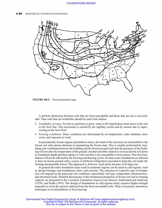
In order to perform a seismic design for foundations in an earthquake region, the dynamic soil char-acteristics must be determined. The following is a brief description of tests used to obtain such data(Wakabayashi, 1986).
4.81FOUNDATIONS DESIGN
FIGURE 4B.l2 Zone of liquefaction potential for cohesionless soils.(From Ohsaki, 1970.)
Downloaded from Digital Engineering Library @ McGraw-Hill (www.digitalengineeringlibrary.com)Copyright © 2004 The McGraw-Hill Companies. All rights reserved.
Any use is subject to the Terms of Use as given at the website.
FOUNDATIONS DESIGN
4B.10.2.1 Particle Size DistributionThe soil particle size distribution is related to the liquefaction of saturated cohesionless soils. Figure4B.12 indicates a liquefaction potential zone based on the performance of cohesionless soils in pre-vious earthquakes.
4B.10.2.2 Relative Density TestThis test indicates the degree of soil compaction. It gives helpful information in determining thepossibility of excessive settlement for dry sands and the potential of liquefaction for saturated sandsin earthquake regions. The relative density is obtained from one of the equations
Dr =
Dr = (4B.31)
where emax, emin = maximum and minimum void ratios�max, �min = maximum and minimum unit mass
e = in situ void ratio� = in situ unit mass
4B.10.2.3 Cyclic Triaxial TestThis test is performed to determine the shear modulus and damping of cohesive and cohesionlesssoils. The shear modulus can be obtained from the compressive modulus of elasticity E using
G = (4B.32)
where v is Poisson’s ratio.
E�2(1 + v)
�max(� – �min)���(�max – �min)
emax – e��emax – emin
4.82 REINFORCED CONCRETE FOUNDATIONS
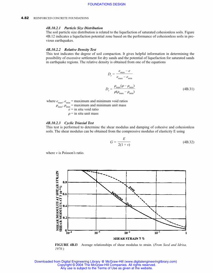
FIGURE 4B.l3 Average relationships of shear modulus to strain. (From Seed and Idrisa,1970.)
Downloaded from Digital Engineering Library @ McGraw-Hill (www.digitalengineeringlibrary.com)Copyright © 2004 The McGraw-Hill Companies. All rights reserved.
Any use is subject to the Terms of Use as given at the website.
FOUNDATIONS DESIGN
It can also be obtained directly by performing cyclic shear tests to obtain stress-strain relation-ships. The shear modulus is strain-dependent. Hence the level at which G is determined must be de-fined. Average relationships of shear modulus to strain for clay and sand are shown in Fig. 4B.13.During earthquakes, developed shear strains may range from 10–3 to 10–1%, with a different maxi-mum strain at each cycle. For this reason it has been suggested to use a value of two-thirds the shearmodulus measured at the maximum strain developed for earthquake design purposes. In the field,the shear modulus of soil can be estimated from a shear wave velocity test. An explosive charge or avibration source is used to initiate waves in the soil. The velocity of these waves is measured and thefollowing relationship is used to determine the shear modulus of elasticity:
G = �vs2 (4B.33)
where � = mass density of soilvs = shear wave velocity
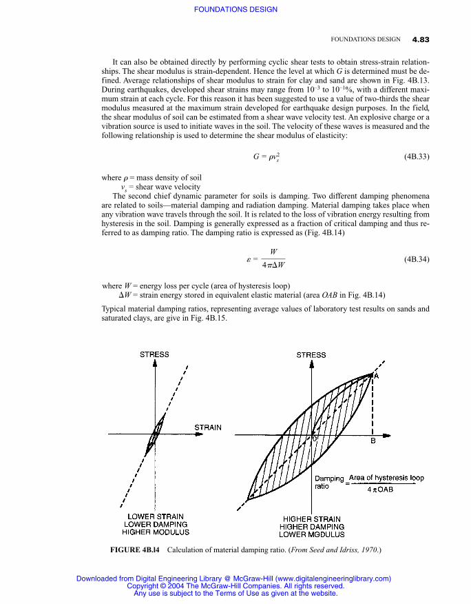
The second chief dynamic parameter for soils is damping. Two different damping phenomenaare related to soils—material damping and radiation damping. Material damping takes place whenany vibration wave travels through the soil. It is related to the loss of vibration energy resulting fromhysteresis in the soil. Damping is generally expressed as a fraction of critical damping and thus re-ferred to as damping ratio. The damping ratio is expressed as (Fig. 4B.14)
� = (4B.34)
where W = energy loss per cycle (area of hysteresis loop)�W = strain energy stored in equivalent elastic material (area OAB in Fig. 4B.14)
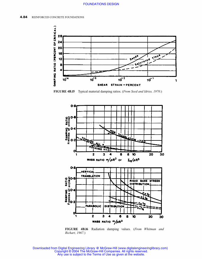
Typical material damping ratios, representing average values of laboratory test results on sands andsaturated clays, are give in Fig. 4B.15.
W�4��W
4.83FOUNDATIONS DESIGN
FIGURE 4B.l4 Calculation of material damping ratio. (From Seed and Idriss, 1970.)
Downloaded from Digital Engineering Library @ McGraw-Hill (www.digitalengineeringlibrary.com)Copyright © 2004 The McGraw-Hill Companies. All rights reserved.
Any use is subject to the Terms of Use as given at the website.
FOUNDATIONS DESIGN
4.84 REINFORCED CONCRETE FOUNDATIONS
FIGURE 4B.l5 Typical material damping ratios. (From Seed and Idriss, 1970.)
FIGURE 4B.l6 Radiation damping values. (From Whitman andRichart, 1967.)
Downloaded from Digital Engineering Library @ McGraw-Hill (www.digitalengineeringlibrary.com)Copyright © 2004 The McGraw-Hill Companies. All rights reserved.
Any use is subject to the Terms of Use as given at the website.
FOUNDATIONS DESIGN
Radiation damping is a measure of the loss of energy through the radiation of waves from thestructure. It is related to the geometrical properties of the foundation. The theory for the elastic half-space has been used to provide estimates for radiation damping. Figure 4B.16 shows values of radi-ation damping for circular footings of machinery obtained by Whitman and Richart (1967).
4B.10.3 Design Considerations
Additional design considerations for foundations in earthquake regions include (1) transmission ofhorizontal base shear forces from the structure to the soil, (2) resisting the earthquake-induced over-turuing moments, and (3) differential settlements and liquefaction of the subsoil (Wakabayashi,1986; Dorwick, 1987).
Generally in earthquake design practice two separate stress systems are considered—seismicvertical stress resulting from overturning moments and seismic horizontal stresses caused by thebase shear on the structure. Unless it is very slender, overturuing moments are not a design prob-lem for the structure as a whole. However, they can drastically impact on individual footings.Hence the foundation should be proportioned so as to maintain the maximum bearing pressurescaused by the overturning moments and gravity loads within the allowable seismic bearing capac-ity of the present soil. Safe seismic bearing pressures vary from one location to another, and localcodes should be used for guidelines. In general most soils are capable of resisting higher short-term loads than long-term loads. Some sensitive clays that lose strength under dynamic loadingare an exception.
With shallow foundations the base shear is assumed to be resisted by friction on the bottom sur-faces of footings. The total resistance to horizontal displacement of a structure is taken to be equalto the product of the dead load of the structure and the coefficient of friction between soil and foot-ings. Some codes recommend the use of 75% of the standard friction coefficients. Additional hori-zontal resistance can be obtained from the passive soil pressures developed against footing surfaces.However, if this resistance is to be relied upon, reducing the computed total resistance becomes nec-essary. This can be done by reducing either the frictional force or the passive resistance by about50%. Also, careful compaction of the backfill against the sides of the footing must be performed inorder to rely on the passive restraint of the soil.
To avoid or minimize damage to the foundation structure in earthquake regions due to differen-tial settlements, it is recommended to provide ties or beams between column footings. These tiesshould be designed to withstand a prescribed differential movement between the connected foot-ings.
4B.11 REFERENCES
ACI Committee 436, “Suggested Design Procedures for Combined Footings and Mats,” ACI J., Oct. 1966. An-dersland, 0. B., and D. M. Anderson (Eds.), Geotechnical Engineering for Cold Regions, McGraw-Hill, NewYork, 1978.
Canadian Foundation Engineering Manual, 2d ed., Canadian Geotechnical Society, 1985.Casagrande, A., “A New Theory on Frost Heaving,” Highway Res. Board Proc., no. 11, pp. 168–172, 1932.Dorwick, D. J., Earthquake Resistant Design for Engineers and Architects, 2d ed., Wiley, New York, 1987.Fintel, M. (Ed.), Handbook of Concrete Engineering, 2d ed., Van Nostrand Reinhold, Princeton, N.J., 1985.Hetenyi, M., Beams on Elastic Foundation, University of Michigan Press, Ann Arbor, Mich., 1946.Ohsaki, Y., “Effects of Sand Compaction on Liquefaction during the Tokachi-Oki Earthquake,” Soil Founda-
tions, vol. 10, no. 2, pp. 112–128, 1970.Seed, H. B., and I. M. Idriss, “Soil Moduli and Damping Factors for Dynamic Response Analysis,” Report
EERC 70-10, Earthquake Engineering Research Center, University of California, Berkeley, Calif., 1970.Sodhi, D. S. (Ed.), Cold Regions Engineering, Proc. 6th mt. Specially Conf., American Society of Civil Engi-
neers, West Lebanon, N.H., 1991.
4.85FOUNDATIONS DESIGN
Downloaded from Digital Engineering Library @ McGraw-Hill (www.digitalengineeringlibrary.com)Copyright © 2004 The McGraw-Hill Companies. All rights reserved.
Any use is subject to the Terms of Use as given at the website.
FOUNDATIONS DESIGN

Wakahayashi, M., Design of Earthquake-Resistant Buildings, McGraw-Hill, New York, 1986.Weaver, W., Jr., and P. R. Johnston, Finite Elements for Structural Analysis, Prentice-Hall, Englewood Cliffs,
N.J., 1984.Whitman, R. V., and F. E. Richart, “Design Procedures for Dynamicalty Loaded Foundations,” J. Soil Mech.
Found. Div., ASCE, vol. 93, no. 5M6, pp. 169–91, 1967.Winterkorn, H. E., and H. Y. Fang (Eds.), Foundation Engineering Handbook, Van Nostrand Reinhold, Prince-
ton, N.J., 1975.
4.86 REINFORCED CONCRETE FOUNDATIONS
Downloaded from Digital Engineering Library @ McGraw-Hill (www.digitalengineeringlibrary.com)Copyright © 2004 The McGraw-Hill Companies. All rights reserved.
Any use is subject to the Terms of Use as given at the website.
FOUNDATIONS DESIGN


