Embed Size (px)
Citation preview
7/27/2019 01 Bss Overview
http://slidepdf.com/reader/full/01-bss-overview 1/6
6-65895 v4 /17.12.2003/MoWe1
BSS overviewBSS overview
BSS S11
7/27/2019 01 Bss Overview
http://slidepdf.com/reader/full/01-bss-overview 2/6
6-65895 v4 /17.12.2003/MoWe2
BSS overviewBSS overview
Following this module you will be able to:
• Name the GSM subsystems and their functions• Name the BSS network elements and their functions• Name the BSS interfaces
Refer to S11 Documentation:
• Descriptions\SystemDescriptions\NokiaBase Station SubsystemDescription\Overview to Nokia Base Station Subsystem
• Descriptions\System Descriptions\NokiaBase Station SubsystemDescription\GSM network architecture
Refer to S11 Documentation:
• Descriptions\System Descriptions\NokiaBase Station Subsystem Description\ Overviewto Nokia Base StationSubsystem
• Descriptions\System Descriptions\NokiaBase Station Subsystem Description\ GSMnetwork architecture
Further refer to:
• Descriptions\System Descriptions\NokiaBase Station Subsystem Description\ . . .
• Nokia Talk Family Customer Documentation: Product Description
• Nokia UltraSiteEdge Customer Documentation
• Nokia Talk InSiteCustomer Documentation
• Nokia Talk MetroSiteCustomer Documentation
• Nokia PrimeSiteCustomer Documentation
7/27/2019 01 Bss Overview
http://slidepdf.com/reader/full/01-bss-overview 3/6
6-65895 v4 /17.12.2003/MoWe3
GSM subsystemsGSM subsystems
NSS BSS
Control flow
Userdata flowPSTN
PLMN
PSPDN
CSPDN
ISDN
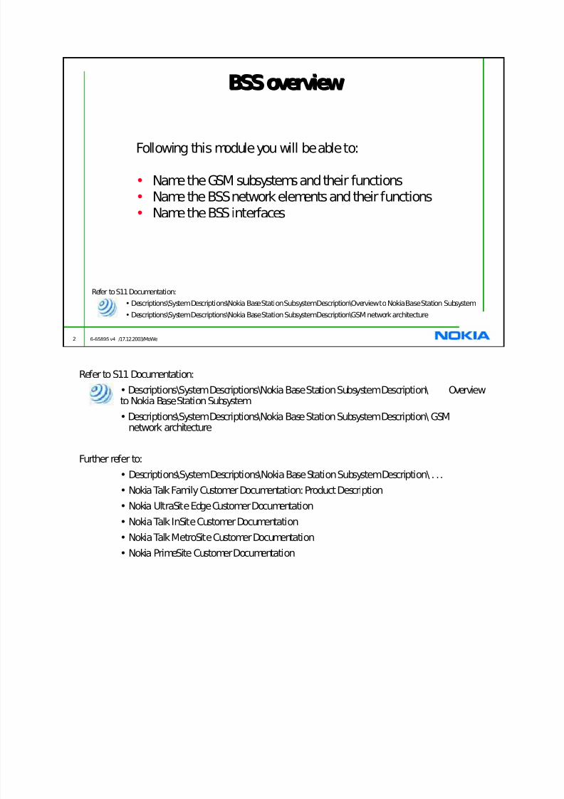
PSTN Public Switched TelephoneNetwork
PSPDN Packet SwitchedPublicData Network
PLMN Public Land MobileNetwork
CSPDN Circuit-SwitchedPublicData Network
ISDN IntegratedServices Digital Network
OSS
Refer to S11 Documentation:
• Descriptions\ System Descriptions\ NokiaBase Station SubsystemDescription\ GSMnetwork architecture
The GSM network is divided into three subsystems: Network Switching Subsystem, Base StationSubsystem and Network Management System.
The main task of theBase Station Subsystem(BSS) is to connect the mobile user to the NetworkSwitching Subsystem through a radio interface. It controls the cellular radio interface and thetransmission links between the elements of the BSS.
TheNetwork Switching Subsystem(NSS) is responsible for setting up connections between mobile usersand other telecommunication users. It manages the set-up, charging, and security aspects of the call.
TheOperations Support System(OSS) is used to manage the GSM/DCS network, gathering alarms and
statistics on the network’s performance. It is also used to control the network by remote commands sentinto the Network Elements.

7/27/2019 01 Bss Overview
http://slidepdf.com/reader/full/01-bss-overview 4/6
6-65895 v4 /17.12.2003/MoWe4
BSS Network ElementsBSS Network Elements
OSS
MSC
BTS
BTS
BTS
BSC
MS
BSS
SGSN
TCSM2
Transcoder, TCSM2- considered as part of the BSC- normally at the MSC site- used for converting the bit rate of traffic
channels between 64 and 16kbit/s- speech activity detection- framing and synchronisation of the vocoder
block- interfaces to the MSC / BSC
Base Station Controller, BSC- terrestrial channel management- configuration and management of traffic channels- frequency hopping control
- paging- BTS and MS power control- idle channel quality monitor- quality and field strength control for active channels- handover control- maintenance of BTS / BSC / TC- interfaces to the NMS / BTS / TC / SGSN
Base Transceiver Station, BTS- timing Broadcast Control Channels (BCCH) and Common Control Channels (CCCH)- forwarding MS and BTS measurements to the BSC- detecting RACHs(Random Access Channels) from the MS- channel coding and decoding on the radio path- interleaving and deinterleavingon the radio path- encryption and decryption on the radio path- performing frequency hopping- GMSK modulation, demodulation, up / down conversion and power amplifying- transmitter RF signal combining- receiver RF signal filtering, amplifying and multicoupling- reporting idle traffic channel quality to the BSC
Transmission Unit TRU- providesAbis interface- reallocates the Traffic and signalling channels in the BTS

7/27/2019 01 Bss Overview
http://slidepdf.com/reader/full/01-bss-overview 5/6
6-65895 v4 /17.12.2003/MoWe5
BSS interfacesBSS interfaces
MSC
SGSN
ET
ET
ET
ET
ET ET
A IF Ater IF Abis IF Air IF
Gb IF
ET
ET
ET
ET
TCSM2E
MS
BTS
TRU
BSC
ET
ET
ET
Refer to S11 Documentation:
• Plan\Network Element\Engineering for BSC\The BSC in the GSM Network
• Plan\Network Element\Engineering for BSC3i\The BSC in the GSM Network\Introducingthe BSC3i\Overviewof the BSC3 in GSM/EDGE mobilenetwork
A interface: - between MSC and TCSM
- 2 Mbit/s interface (G.703)
Ater interface: - between TCSM and BSC
- 2 Mbit/s interface (G.703)
Abisinterface: - between BSC and BTS
- 2 Mbit/s interface (G.703)
- structure depends on the connection type and signalling (64kbit/s,32kbit/s or 16kbit/s) used
Air interface: - between BTS and MS
- TDMA frame for sending signals intended for various users on thesame radio frequency in different time slots.
X.25: - between MSC / BSC and OMC
- two ways to implement: analogue X.25 and digital X.25
Gbinterface: - between SGSN and BSC
- Frame Relay Protocol on 2 Mbit/s interface (G.703)
7/27/2019 01 Bss Overview
http://slidepdf.com/reader/full/01-bss-overview 6/6
6-65895 v4 /17.12.2003/MoWe6
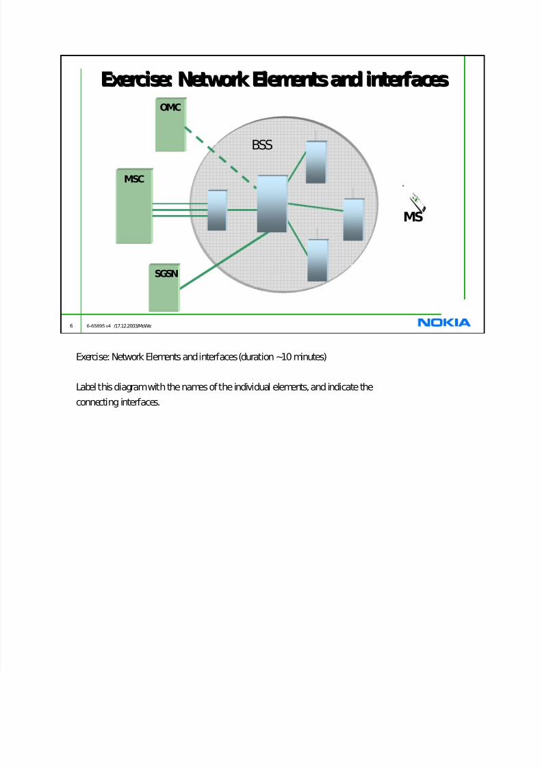
Exercise: Network Elements and interfacesExercise: Network Elements and interfaces
OMC
MSC
MS
BSS
SGSN
Exercise: Network Elements and interfaces (duration ~10 minutes)
Label this diagram with the names of the individual elements, and indicate the
connecting interfaces.


![Telecom OSS[BSS] an Overview](https://img.pdfslide.net/doc/110x75/54fc24d34a7959d43c8b4c53/telecom-ossbss-an-overview.jpg)


![Brochure - Comarch BSS Suite [Comarch’s Strengths in BSS]](https://img.pdfslide.net/doc/110x75/5479a818b4795990098b4836/brochure-comarch-bss-suite-comarchs-strengths-in-bss.jpg)