Embed Size (px)
Citation preview
Copyright - Refer to Title Page document.docFOR TRAINING PURPOSES ONLY Page 1

Copyright - Refer to Title Page document.docFOR TRAINING PURPOSES ONLY Page 2
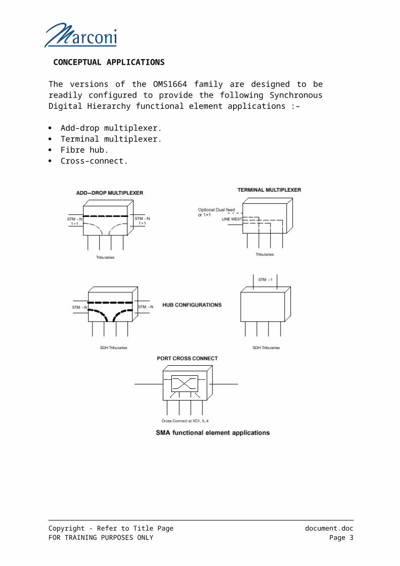
CONCEPTUAL APPLICATIONS
The versions of the OMS1664 family are designed to be readily configured to provide the following Synchronous Digital Hierarchy functional element applications :–
Add–drop multiplexer. Terminal multiplexer. Fibre hub. Cross–connect.
The figure above illustrates the applications. They can be created from any of the OMS1664 family versions by choosing the appropriate configuration of plug–in card units. The version and configuration will reflect the level of traffic to be handled, what electrical or optical paths are to be serviced and the position of the element in the network hierarchy.
Copyright - Refer to Title Page document.docFOR TRAINING PURPOSES ONLY Page 3

Functional Building Blocks
SwitchThe Switch card provides the traffic connectivity between the line or tributary card traffic interfaces. It provides switching of the SDH signals down to VC-12 granularity.
Line InterfaceThe line interface provides connectivity to the ‘Line’. The ‘Line’ connections are those connections considered to be the main traffic paths and usually carry the largest STM-n SDH signals. In the case of the OMS1664 family the Tributary connections may also be able to carry SDH signals of the same size.
Tributary Card
Copyright - Refer to Title Page document.docFOR TRAINING PURPOSES ONLY Page 4
COMMS CARD
MUX CONTROLLER
SWITCH LINE INTERFACE
TRIBUTARY CARD
L TU
TRIBUTARY CARD
FRONT PLUG UP
TRIBUTARY CARD
L TU
L TU
L TU
LINE INTERFACE
L TU
Auxiliary Card
Power Supply
In practice several functional blocks may be included into one physical card.
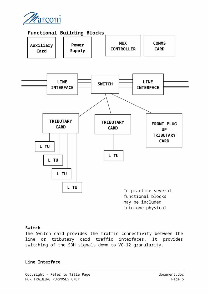
The tributary card provides connection for signals that are to be added / dropped at this network node, or perhaps fed to a sub network. The portfolio of Tributary card types provides interfaces for a variety of traffic types, these may include STM-n signals up to and including the line rate, as well as lower rate PDH signals and Data Cards. The Data cards currently include Ethernet, Fast Ethernet, Gigabit Ethernet and in future releases ESCON, FICON, Fibre Channel, DVB-ASI.In some cases the physical interface will be located on the Tributary card itself, these are refered to as ‘Front Plug Up’ cards, in other cases the Tributary card will work in conjunction with a ‘Line Termination Unit’ (LTU) described below.
Line Termination Unit (LTU)Line termination units provide the physical interface for signals to and from Tributary cards. For Tributary cards implementing large numbers of traffic ports there may be several LTU’s associated with the one Tributary card.
For the OMS1664 family references for cross connections may be to the LTU itself rather than its parent Tributary card.
Power SupplyThe power supply provides DC to DC voltage conversion to provide the lower voltages for multiplexer cards form the –48Volt to –60Volt supply provided at network node sites. In some cases the power supply may be a built in function of the multiplxer cards themselves.
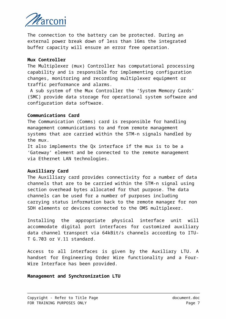
The connection to the battery can be protected. During an external power break down of less than 16ms the integrated buffer capacity will ensure an error free operation.
Mux ControllerThe Multiplexer (mux) Controller has computational processing capability and is responsible for implementing configuration changes, monitoring and recording multiplexer equipment or traffic performance and alarms. A sub system of the Mux Controller the ‘System Memory Cards’ (SMC) provide data storage for operational system software and configuration data software.
Communications CardThe Communication (Comms) card is responsible for handling management communications to and from remote management systems that are carried within the STM-n signals handled by the mux.It also implements the Qx interface if the mux is to be a ‘Gateway’ element and be connected to the remote management via Ethernet LAN technologies.
Auxilliary CardThe Auxilliary card provides connectivity for a number of data channels that are to be carried within the STM-n signal using section overhead bytes allocated for that purpose. The data channels can be used for a number of purposes including carrying status information back to the remote manager for non SDH elements or devices connected to the OMS multiplexer.
Copyright - Refer to Title Page document.docFOR TRAINING PURPOSES ONLY Page 5
Installing the appropriate physical interface unit will accommodate digital port interfaces for customized auxiliary data channel transport via 64kBit/s channels according to ITU-T G.703 or V.11 standard.
Access to all interfaces is given by the Auxiliary LTU. A handset for Engineering Order Wire functionality and a Four-Wire Interface has been provided.
Management and Synchronization LTU
A common LTU for Synchronization as well as TMN/NMS and LCT access is provided.
Synchronization Interface
The Management and Synchronization LTU supports the connectors for:
• Two T3 clock inputs according to G.703/G.704• Two T4 clock outputs according to G.703/G.704
Copyright - Refer to Title Page document.docFOR TRAINING PURPOSES ONLY Page 6
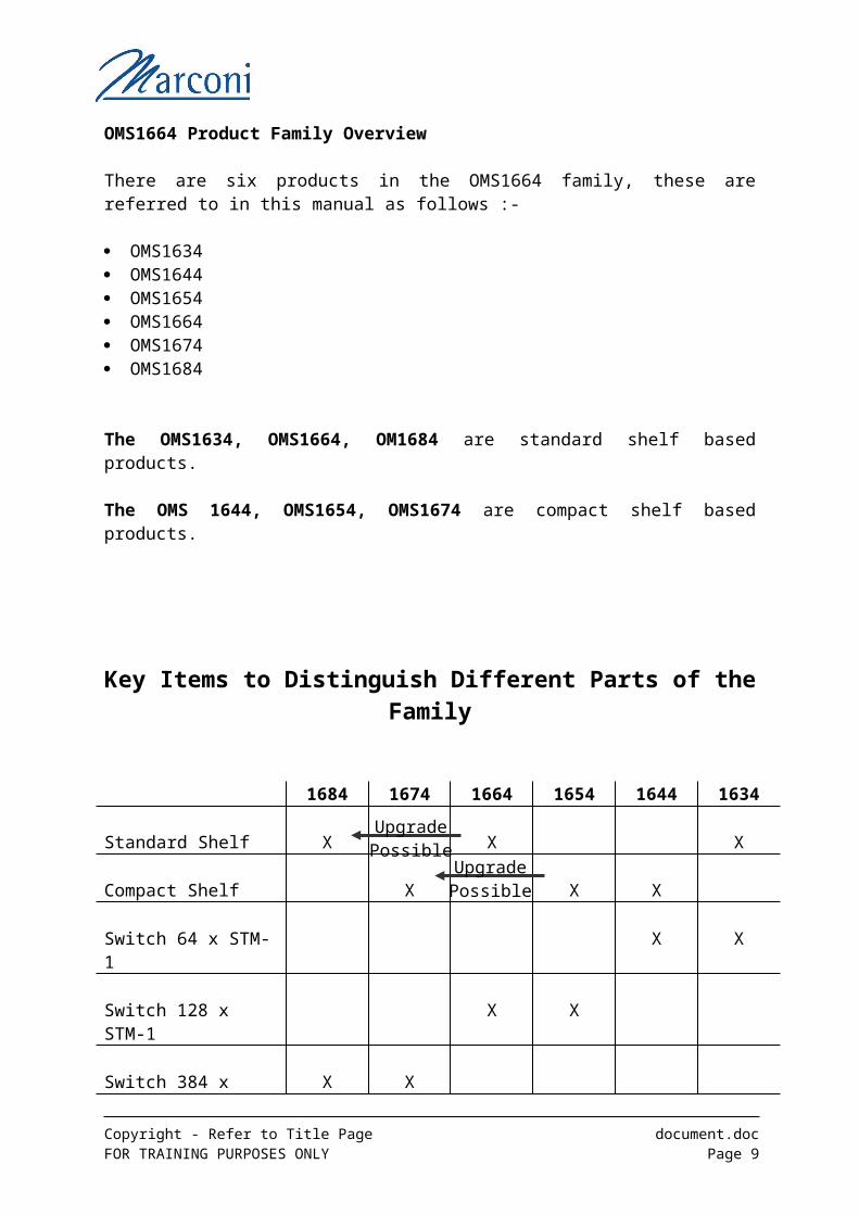
OMS1664 Product Family Overview
There are six products in the OMS1664 family, these are referred to in this manual as follows :-
OMS1634 OMS1644 OMS1654 OMS1664 OMS1674 OMS1684
The OMS1634, OMS1664, OM1684 are standard shelf based products.
The OMS 1644, OMS1654, OMS1674 are compact shelf based products.
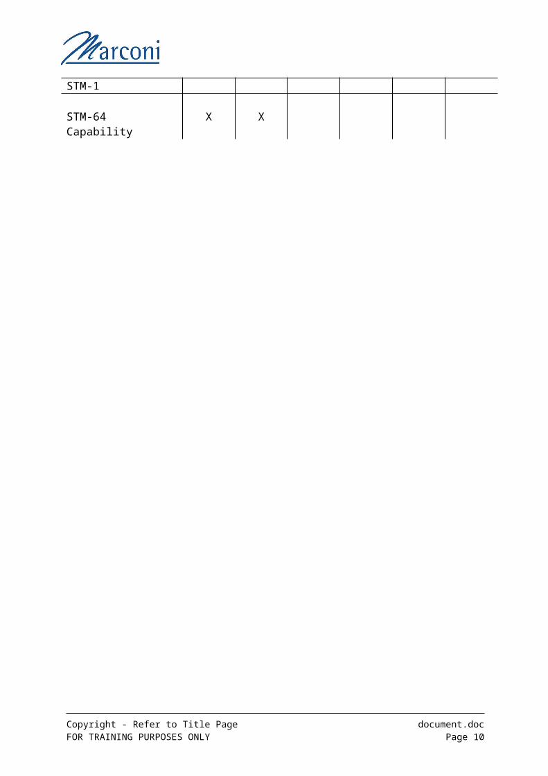
Key Items to Distinguish Different Parts of the Family
1684 1674 1664 1654 1644 1634
Standard Shelf X X X
Compact Shelf X X X
Switch 64 x STM-1 X X
Switch 128 x STM-1 X X
Switch 384 x STM-1 X X
STM-64 Capability X X
Copyright - Refer to Title Page document.docFOR TRAINING PURPOSES ONLY Page 7
Upgrade Possible
Upgrade Possible
Remote Network Management
The OMS 1664 Family can be remotely managed by the Marconi Management decribed below. Connection(s) can be made via LAN/WAN technologies to one or more OMS16xx elements which are implementing a Qx TMN interface (Fast Ethernet) interface.
Service on Optical MV38 / MV36 either Core 1 or Core 2
Service on Access Release 6.2 together with Device Driver 1.x
Local Operator ManagementThe OMS1664 family can also be locally managed using terminal software, known as ‘Local Craft Terminal’ (LCT).
The Local Craft Terminal software can be run on an IBM compatible PC or Laptop using several of the Windows platforms.(Windows is © of the Microsoft Corporation)
Connection to the Element is via an ‘F’ interface (RS232) and suitable lead to the serial port of the PC.
Local Craft TerminalThree levels of operation access are catered for: - Casual operator (read access with some limited local write access), with
restricted access to mainly display Alarm and configuration status details.
System operator (read-write access), with full access to the OMS1664/OMS 1654 database in the absence of a network management system.
Admin Operator (Highest Class) with the additional ability to add and delete users and change user passwords.
For the exercises, the user name is ADMIN
The default Password is SDHMUXES
Both User Name and password are case sensitive and need to be UPPERCASE
If you are prompted to enter a new password, due to expiry of the existing password, please alternate between SDHMUXES (default) and SDHMUXES1.
Copyright - Refer to Title Page document.docFOR TRAINING PURPOSES ONLY Page 8
Copyright - Refer to Title Page document.docFOR TRAINING PURPOSES ONLY Page 9
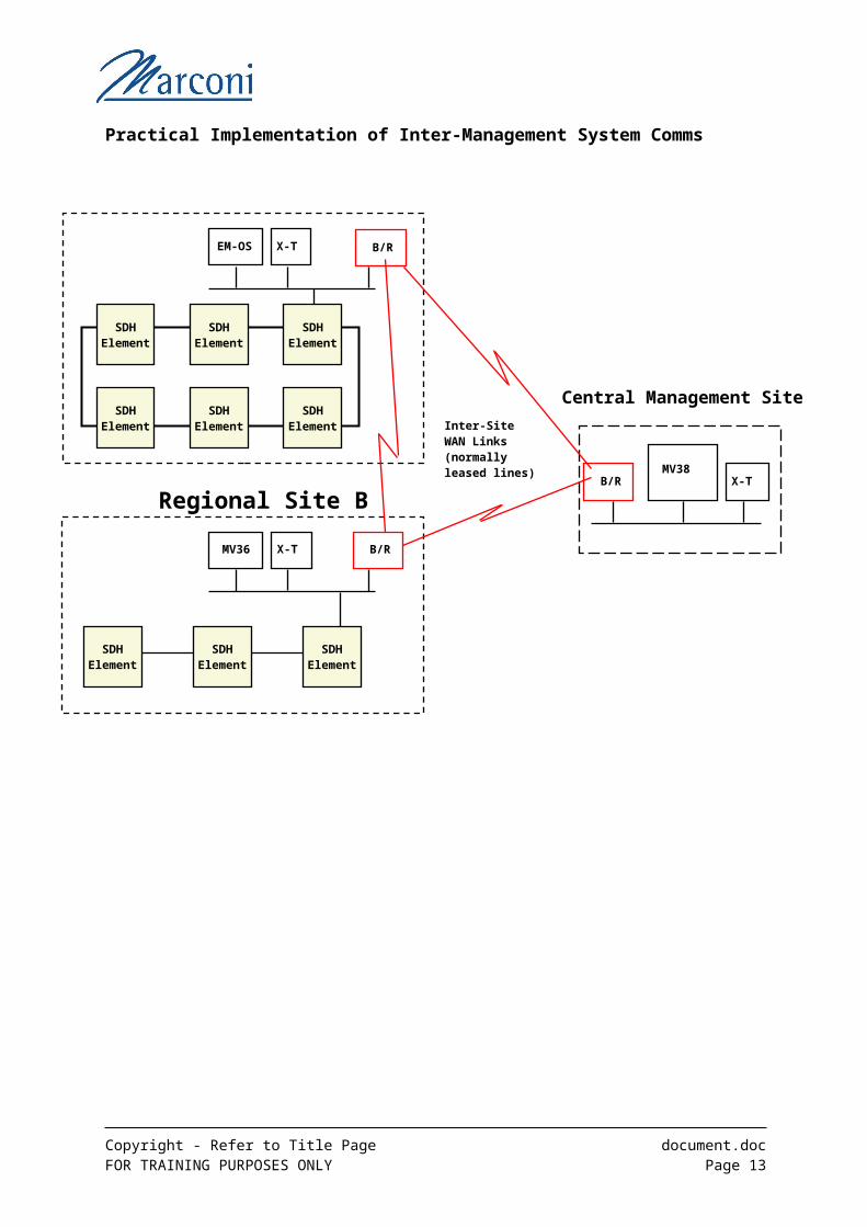
Practical Implementation of Inter-Management System Comms
Copyright - Refer to Title Page document.docFOR TRAINING PURPOSES ONLY Page 10
B/R
B/R
B/R
MV38X-T
Inter-Site WAN Links(normallyleased lines)
Central Management Site
Regional Site B
EM-OS X-T
MV36 X-T
SDH Element
SDH Element
SDH Element
SDH Element
SDH Element
SDH Element
SDH Element
SDH Element
SDH Element
Overview of the Compact Shelf Versions (OMS1644, OMS1654, OMS1674)
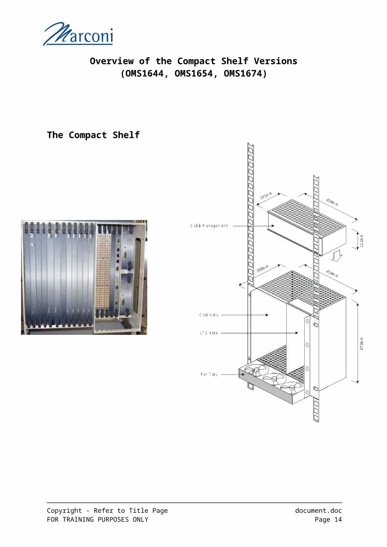
The Compact Shelf
The compact shelf together with a Cable Management unit and Fan Tray can be fitted in the Standard 19 inche or ETSI racks.
Copyright - Refer to Title Page document.docFOR TRAINING PURPOSES ONLY Page 11
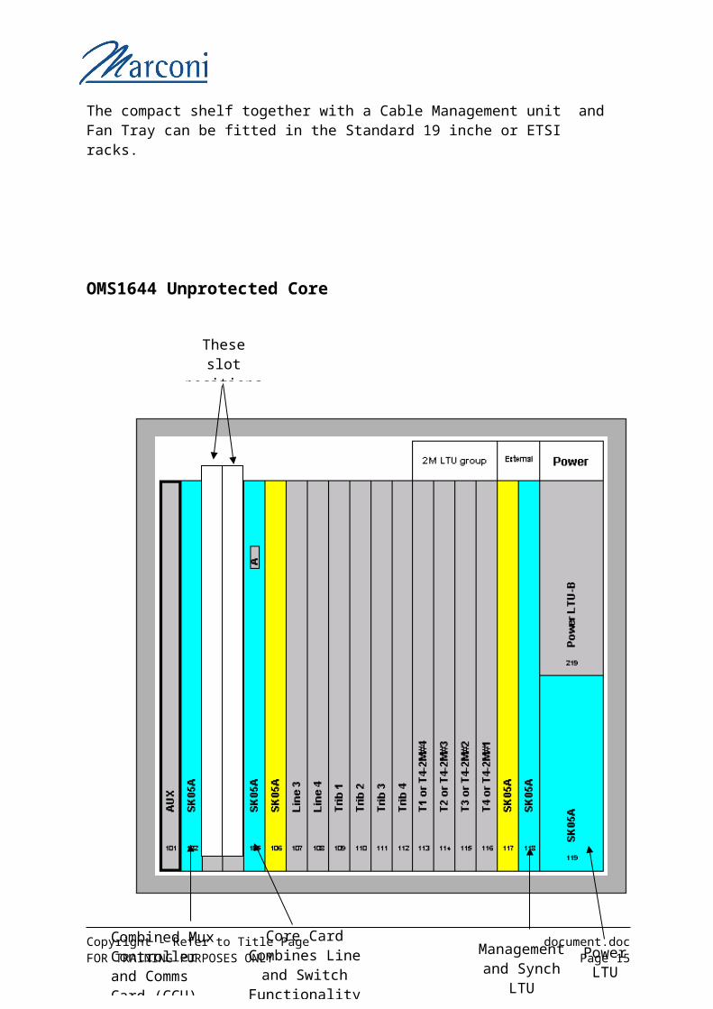
OMS1644 Unprotected Core
Copyright - Refer to Title Page document.docFOR TRAINING PURPOSES ONLY Page 12
These slot positions unused
Core Card Combines Line and
Switch Functionality
Combined Mux Controller and Comms Card (CCU)
Management and Synch
LTU
Power LTU
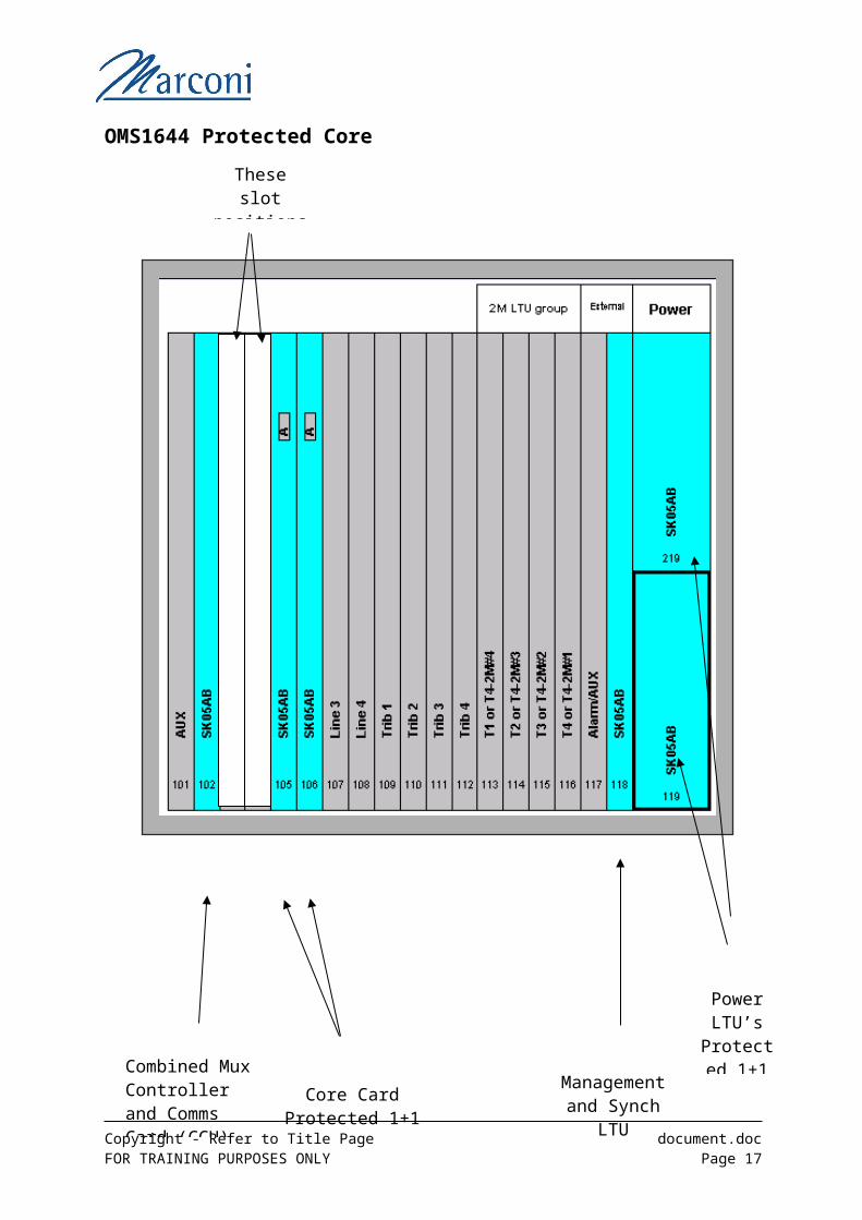
OMS1644 Protected Core
Copyright - Refer to Title Page document.docFOR TRAINING PURPOSES ONLY Page 13
Core Card Protected 1+1
Combined Mux Controller and Comms Card (CCU)
Management and Synch
LTU
Power LTU’s
Protected 1+1
These slot positions unused
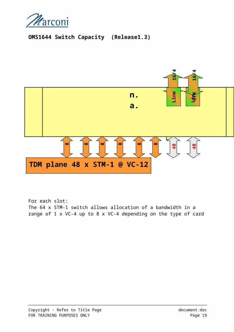
OMS1644 Switch Capacity (Release1.3)
For each slot:The 64 x STM-1 switch allows allocation of a bandwidth in a range of 1 x VC-4 up to 8 x VC-4 depending on the type of card
Copyright - Refer to Title Page document.docFOR TRAINING PURPOSES ONLY Page 14
TDM plane 48 x STM-1 @ VC-12
32
L3L4T1T2T3T4
32
48
48
n.a.
n.a.
8
8
8
8
8
8
ST
M
1
6/4
Lin
e
Lin
e ST
M
1
6/4
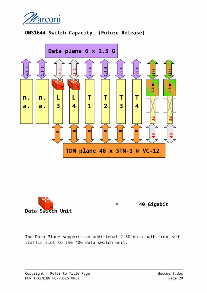
OMS1644 Switch Capacity (Future Release)
= 40 Gigabit Data Switch Unit
The Data Plane supports an additional 2.5G data path from each traffic slot to the 40G data switch unit.
Copyright - Refer to Title Page document.docFOR TRAINING PURPOSES ONLY Page 15
TDM plane 48 x STM-1 @ VC-12 3
2
L3
L4
T1
T2
T3
T4
32
48
48
Data plane 6 x 2.5 G
n.a.
n.a.
8 8
8
8
8
8
15
G
15
G
2.5
G
2.5
G
2.5
G
2.5
G
2.5
G
2.5
G
16
/4L
ine
Lin
e1
6/4
SW SW
SW

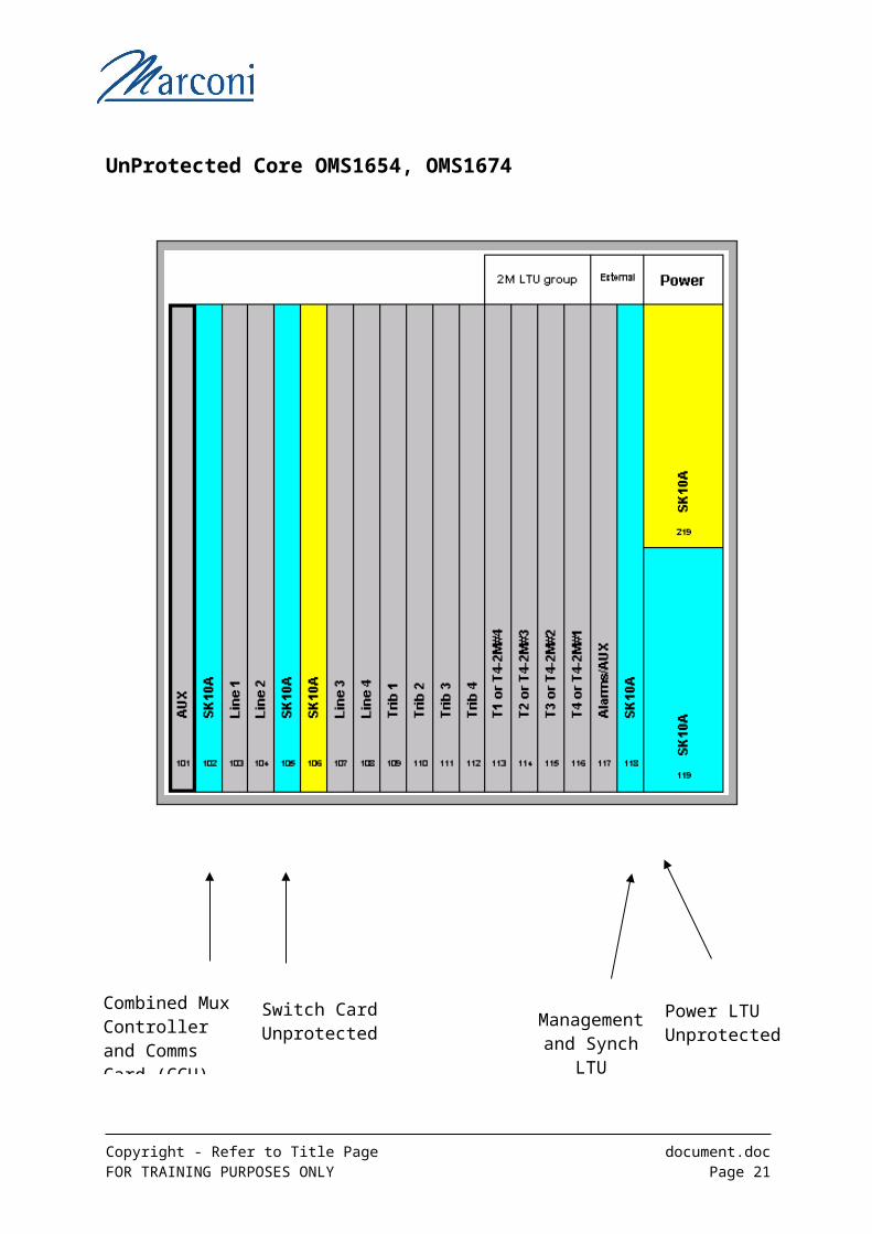
UnProtected Core OMS1654, OMS1674
Copyright - Refer to Title Page document.docFOR TRAINING PURPOSES ONLY Page 16
Combined Mux Controller and Comms Card (CCU)
Switch Card Unprotected
Power LTU Unprotected
Management and Synch
LTU
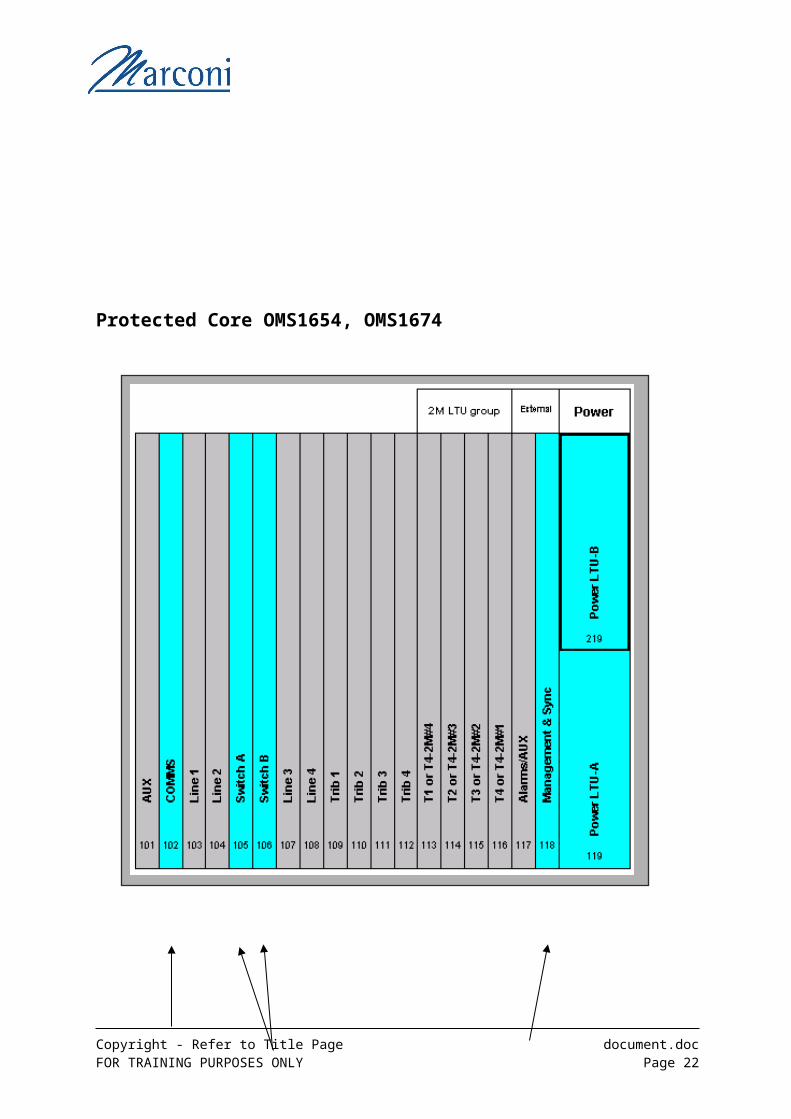
Protected Core OMS1654, OMS1674
Copyright - Refer to Title Page document.docFOR TRAINING PURPOSES ONLY Page 17
Combined Mux Controller and Comms Card (CCU)
Switch Card Protected 1+1
Power LTU Protected 1+1
Management and Synch
LTU

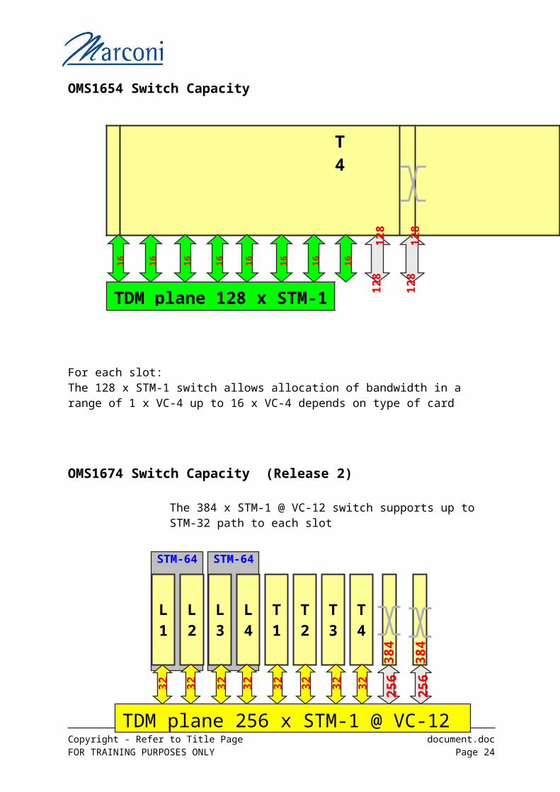
OMS1654 Switch Capacity
For each slot:The 128 x STM-1 switch allows allocation of bandwidth in a range of 1 x VC-4 up to 16 x VC-4 depends on type of card
OMS1674 Switch Capacity (Release 2)
The 384 x STM-1 @ VC-12 switch supports up to STM-32 path to each slot
For each slot:The 384 x STM-1 switch allows allocation of bandwidth in a range of 1 x VC-4 up to 16 x VC-4 depends on type of card
Copyright - Refer to Title Page document.docFOR TRAINING PURPOSES ONLY Page 18
L1
TDM plane 128 x STM-1
12
8
L2L3L4T1T2T3T4
12
8
12
8
12
8
16
16
16
16
16
16
16
16
STM-64 STM-64
L1
TDM plane 256 x STM-1 @ VC-12
384
L2
L3
L4
T1
T2
T3
T4
384
256
256
32 32
32
32
32 32
32
32
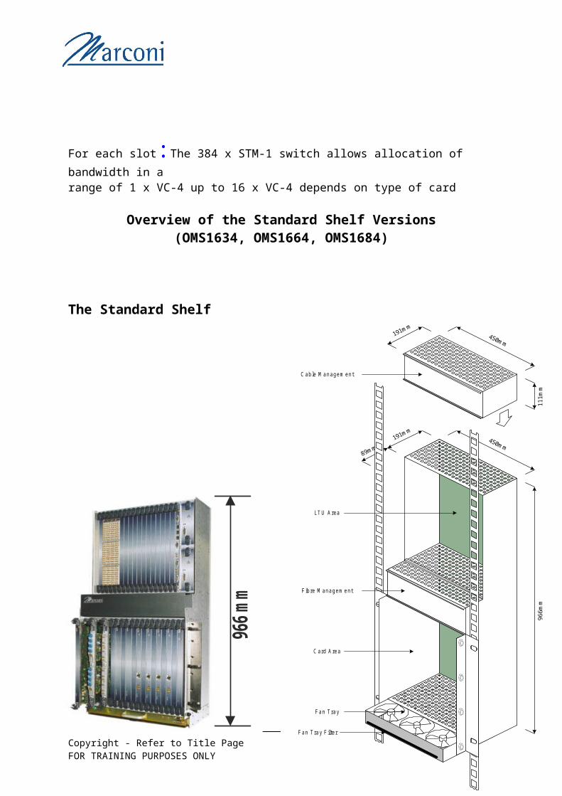
Overview of the Standard Shelf Versions(OMS1634, OMS1664, OMS1684)
The Standard Shelf
The Standard Shelf together with a Cable Management unit and Fan Tray can be fitted in the Standard 19 inch or ETSI racks.
Copyright - Refer to Title Page document.docFOR TRAINING PURPOSES ONLY Page 19
89mm
450mm
96
6m
m
191mm
450mm
11
1m
m
191mm
C able M anagem ent
Fan T ray
C ard A rea
LT U Area
F ibre M anagem ent
Fan T ray F ilter
966
mm
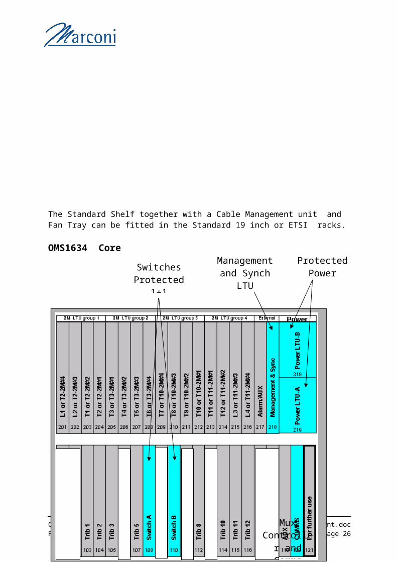
OMS1634 Core
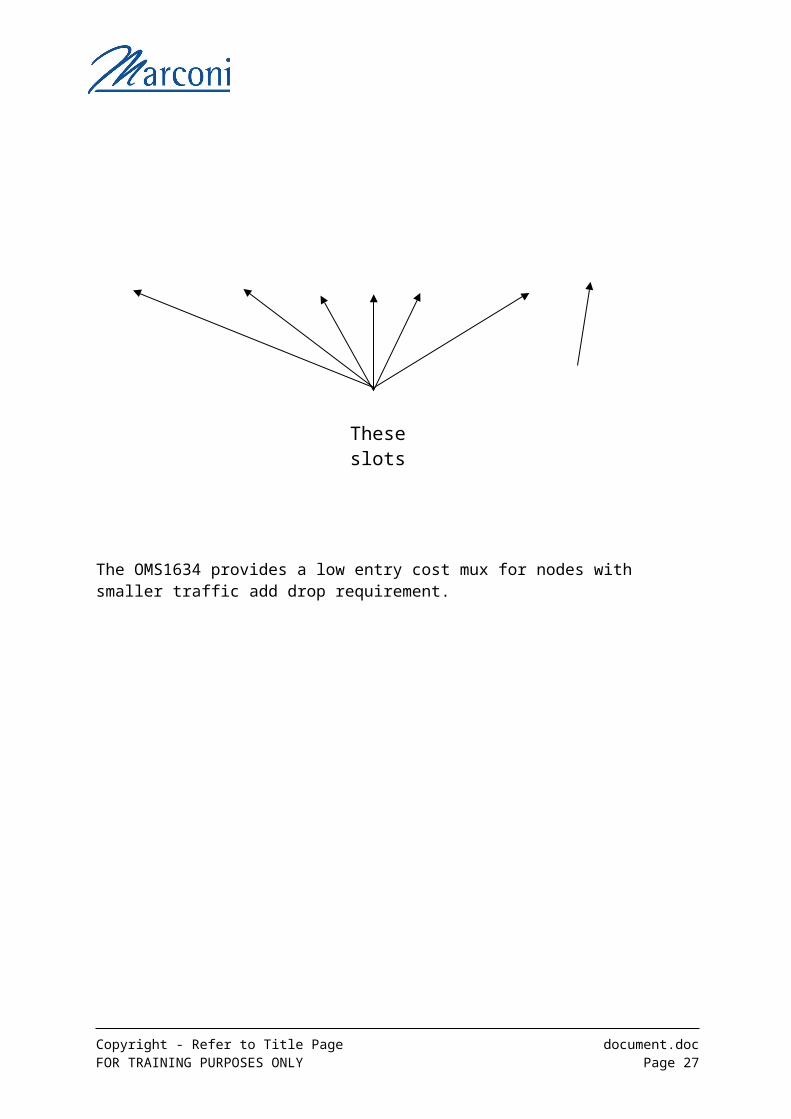
The OMS1634 provides a low entry cost mux for nodes with smaller traffic add drop requirement.
Copyright - Refer to Title Page document.docFOR TRAINING PURPOSES ONLY Page 20
Switches Protected
1+1
Protected Power LTU’s
Mux Controller
and Comms card.
These slots Unused
Management and Synch
LTU
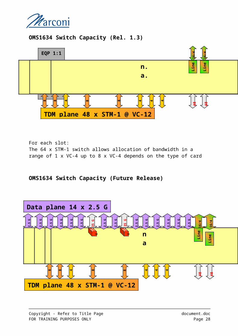
OMS1634 Switch Capacity (Rel. 1.3)
For each slot:The 64 x STM-1 switch allows allocation of bandwidth in a range of 1 x VC-4 up to 8 x VC-4 depends on the type of card
OMS1634 Switch Capacity (Future Release)
The Data Plane supports an additional 2.5G data path from each traffic slot to the 40G data switch unit
Copyright - Refer to Title Page document.docFOR TRAINING PURPOSES ONLY Page 21
EQP 1:1
n.a.
32
T1
T2T3T10T11T12
32
n.a.
n.a.
T5n.a.n.a.
T8n.a.n.a.n.a.
TDM plane 48 x STM-1 @ VC-12
48
48 8 8 8 8 4 4 4 4
16/4
Lin
e
16/4
Lin
e
T8T5
TDM plane 48 x STM-1 @ VC-12
Data plane 14 x 2.5 G
32
32
48
48
35 G
35 G
2.5
G
8 8 4 8 8 4 4 4
na
na
T1
T2T3nananana
T10T11T12nana
16/4
Lin
e
SW SW
2.5
G
2.5
G
2.5
G
2.5
G
2.5
G
2.5
G
2.5
G
2.5
G
2.5
G
2.5
G
2.5
G
2.5
G
2.5
G
16/4
Lin
e
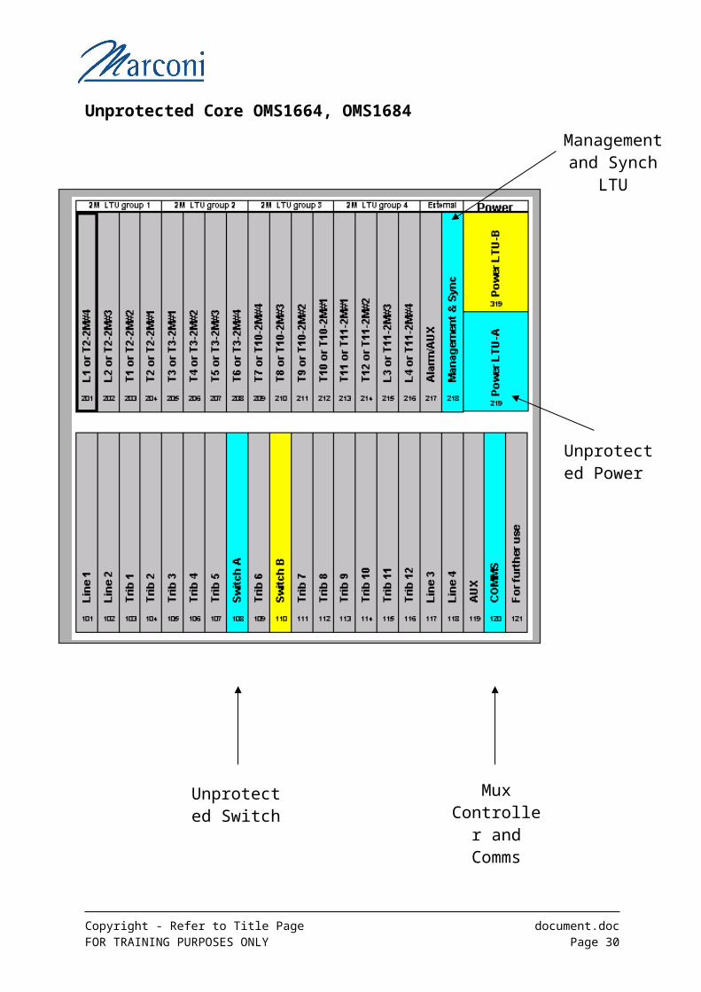
Unprotected Core OMS1664, OMS1684
Copyright - Refer to Title Page document.docFOR TRAINING PURPOSES ONLY Page 22
Unprotected Switch Card
Unprotected Power LTU
Mux Controller
and Comms Card (CCU)
Management and Synch
LTU
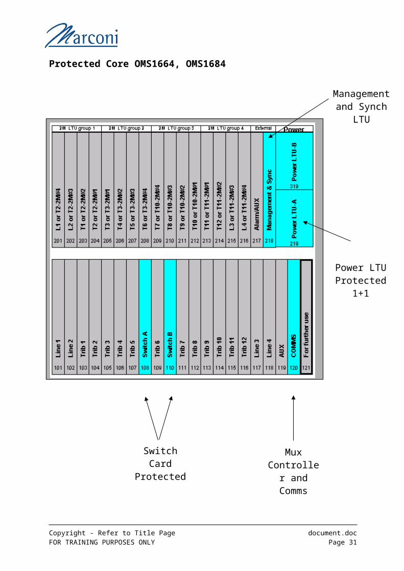
Protected Core OMS1664, OMS1684
Copyright - Refer to Title Page document.docFOR TRAINING PURPOSES ONLY Page 23
Switch Card Protected
1+1
Power LTU Protected
1+1
Mux Controller
and Comms Card (CCU)
Management and Synch
LTU
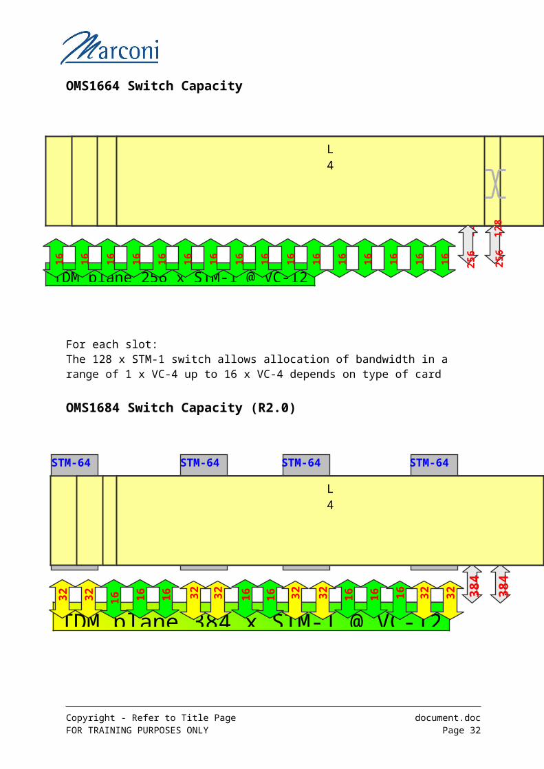
OMS1664 Switch Capacity
For each slot:The 128 x STM-1 switch allows allocation of bandwidth in a range of 1 x VC-4 up to 16 x VC-4 depends on type of card
OMS1684 Switch Capacity (R2.0)
The 384 x STM-1 @ VC-12 switch supports a STM-16 path to each slot and a STM-32 path to several slots
Copyright - Refer to Title Page document.docFOR TRAINING PURPOSES ONLY Page 24
L1
TDM plane 256 x STM-1 @ VC-12
12
8
L2
T1
T2T3T4T5T6T7T8T9T10T11T12L3L4
25
6
16
12
82
56
16
16
16
16
16
16
16
16
16
16
16
16
16
16
16
STM-64 STM-64 STM-64STM-64
TDM plane 384 x STM-1 @ VC-12
384
384
384
384 32
32
3
2
3
2
3
2
3
2
3
2
3
2
16
16
16
16
16
16
16
1
6
L1
L2
T1
T2T3T4T5T6T7T8T9T10T11T12L3L4
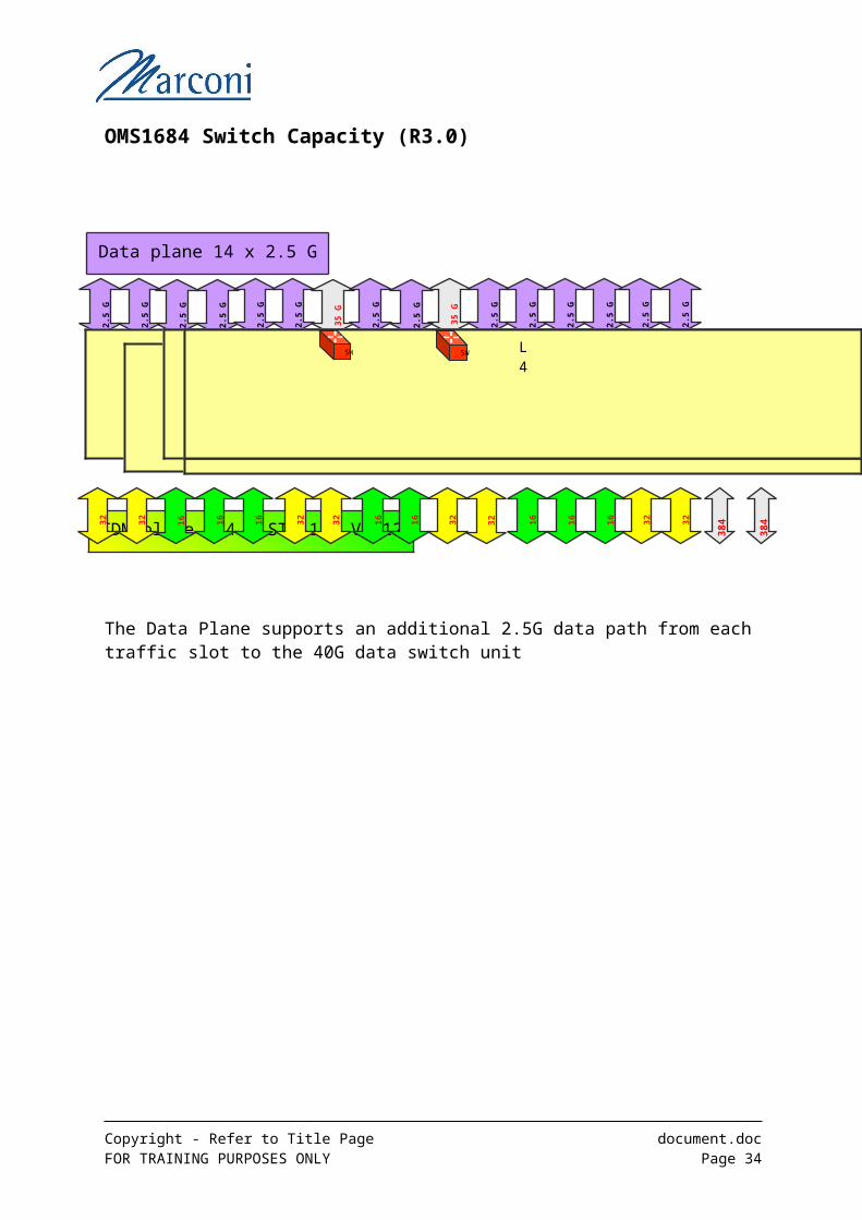
OMS1684 Switch Capacity (R3.0)
The Data Plane supports an additional 2.5G data path from each traffic slot to the 40G data switch unit
Copyright - Refer to Title Page document.docFOR TRAINING PURPOSES ONLY Page 25
T8T5
TDM plane 384 x STM-1 @ VC-12
Data plane 14 x 2.5 G
384
384
384
38432
32
32
32
32
32 32
32
16 16
16
16
16
16
16
16
2.5
G
35
G
35
G
2.5
G
2.5
G
2.5
G
2.5
G
2.5
G
2.5
G
2.5
G
2.5
G
2.5
G
2.5
G
2.5
G
2.5
G
2.5
G
L1
L2
T1
T2T3T4T6T7T9T10T11T12L3L4
SW SW
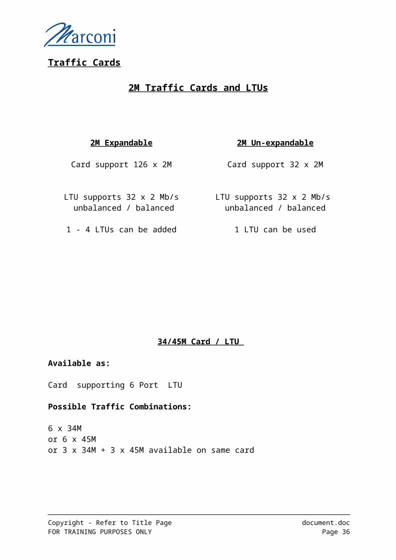
Traffic Cards
2M Traffic Cards and LTUs
2M Expandable 2M Un-expandable
Card support 126 x 2M Card support 32 x 2M
LTU supports 32 x 2 Mb/s unbalanced / balanced
LTU supports 32 x 2 Mb/s unbalanced / balanced
1 - 4 LTUs can be added 1 LTU can be used
34/45M Card / LTU
Available as:
Card supporting 6 Port LTU
Possible Traffic Combinations:
6 x 34M or 6 x 45Mor 3 x 34M + 3 x 45M available on same card
Copyright - Refer to Title Page document.docFOR TRAINING PURPOSES ONLY Page 26
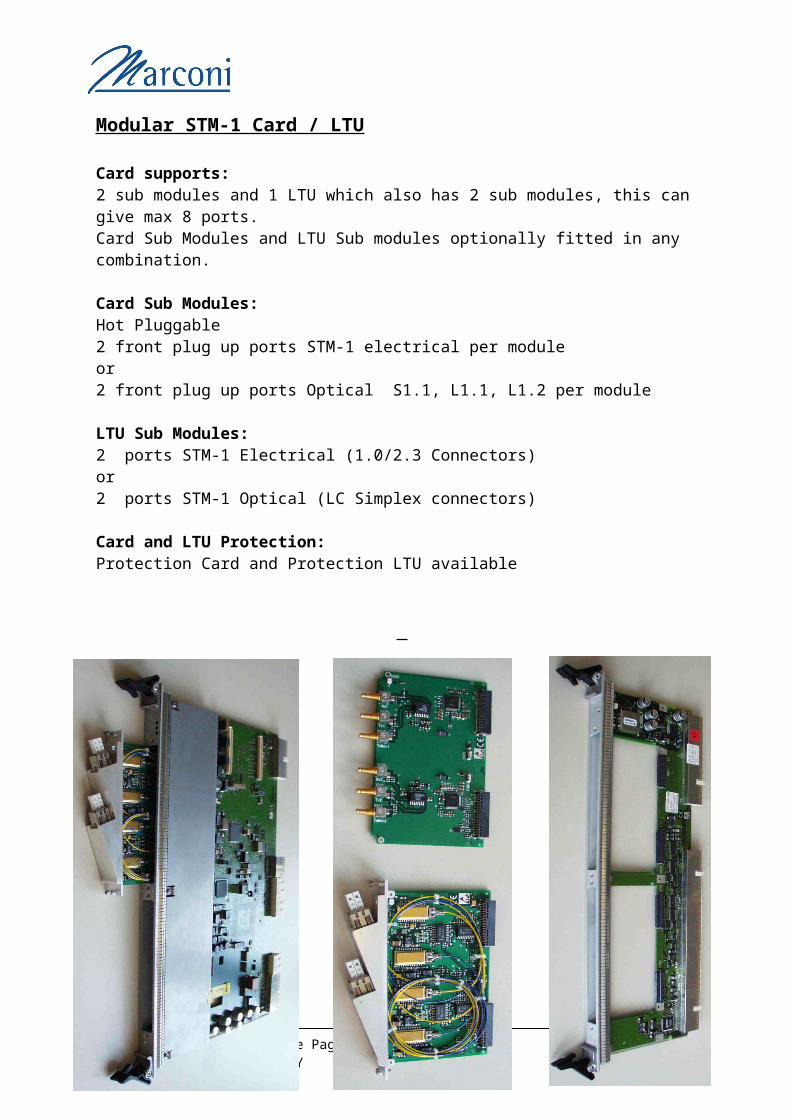
Modular STM-1 Card / LTU
Card supports:2 sub modules and 1 LTU which also has 2 sub modules, this can give max 8 ports.Card Sub Modules and LTU Sub modules optionally fitted in any combination.
Card Sub Modules:Hot Pluggable 2 front plug up ports STM-1 electrical per moduleor2 front plug up ports Optical S1.1, L1.1, L1.2 per module
LTU Sub Modules:2 ports STM-1 Electrical (1.0/2.3 Connectors)or 2 ports STM-1 Optical (LC Simplex connectors)
Card and LTU Protection:Protection Card and Protection LTU available
Copyright - Refer to Title Page document.docFOR TRAINING PURPOSES ONLY Page 27
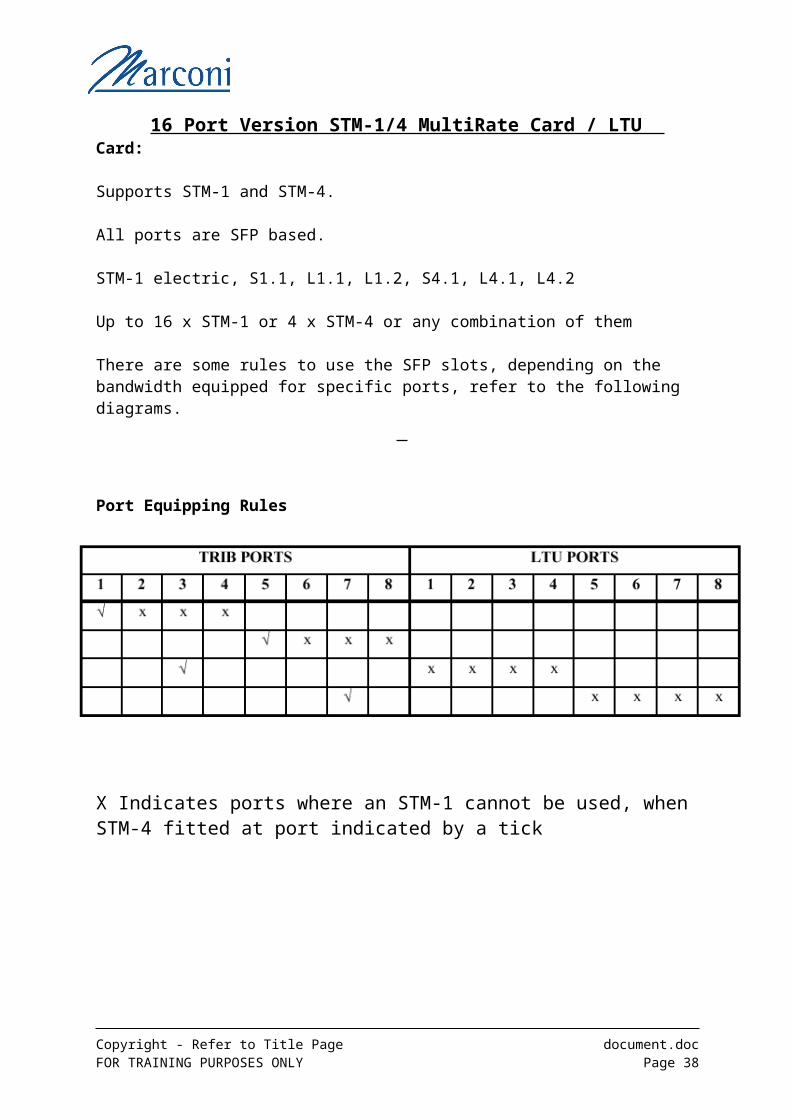
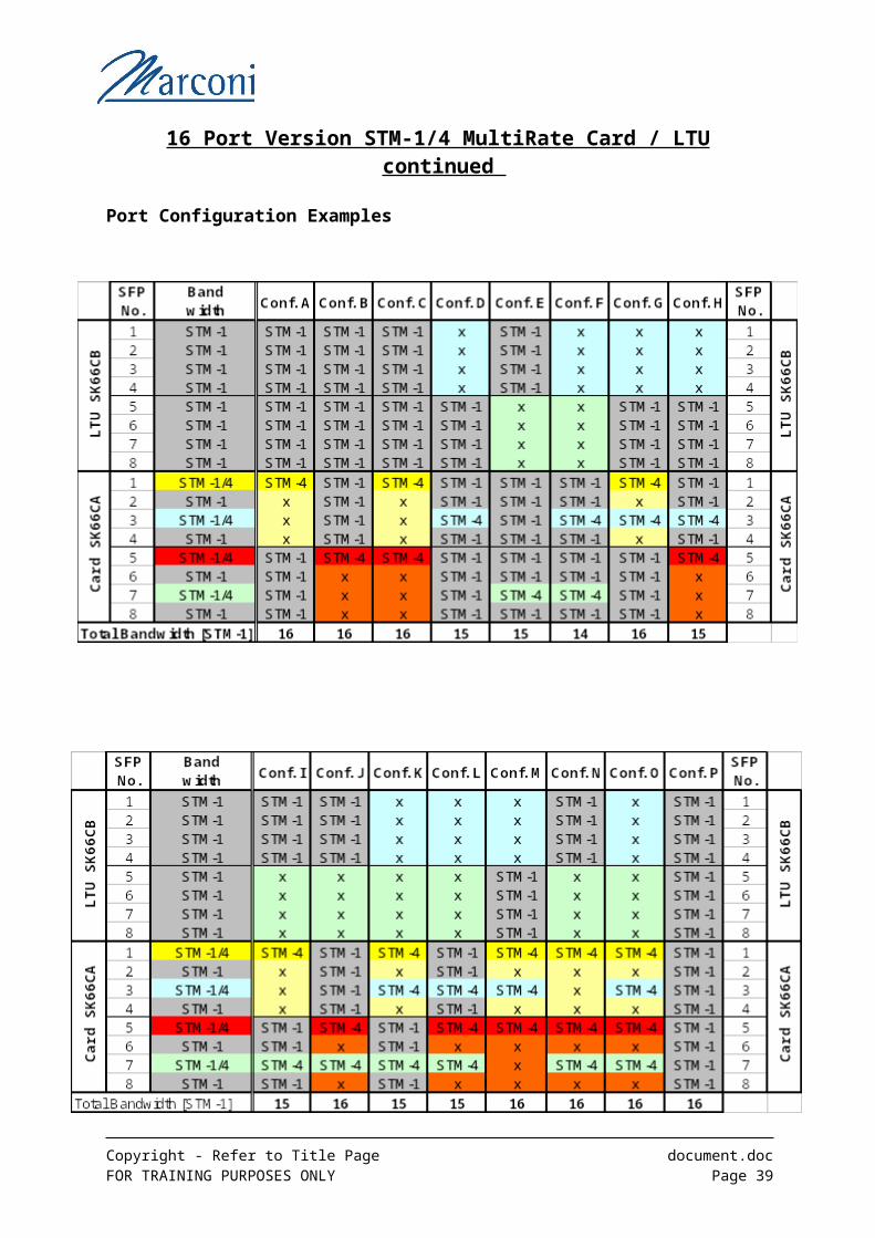
16 Port Version STM-1/4 MultiRate Card / LTU Card:
Supports STM-1 and STM-4.
All ports are SFP based.
STM-1 electric, S1.1, L1.1, L1.2, S4.1, L4.1, L4.2
Up to 16 x STM-1 or 4 x STM-4 or any combination of them
There are some rules to use the SFP slots, depending on the bandwidth equipped for specific ports, refer to the following diagrams.
Port Equipping Rules
X Indicates ports where an STM-1 cannot be used, when STM-4 fitted at port indicated by a tick
Copyright - Refer to Title Page document.docFOR TRAINING PURPOSES ONLY Page 28
16 Port Version STM-1/4 MultiRate Card / LTU continued
Port Configuration Examples
Copyright - Refer to Title Page document.docFOR TRAINING PURPOSES ONLY Page 29
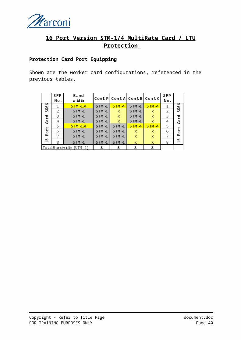
16 Port Version STM-1/4 MultiRate Card / LTU Protection
Protection Card Port Equipping
Shown are the worker card configurations, referenced in the previous tables.
Copyright - Refer to Title Page document.docFOR TRAINING PURPOSES ONLY Page 30
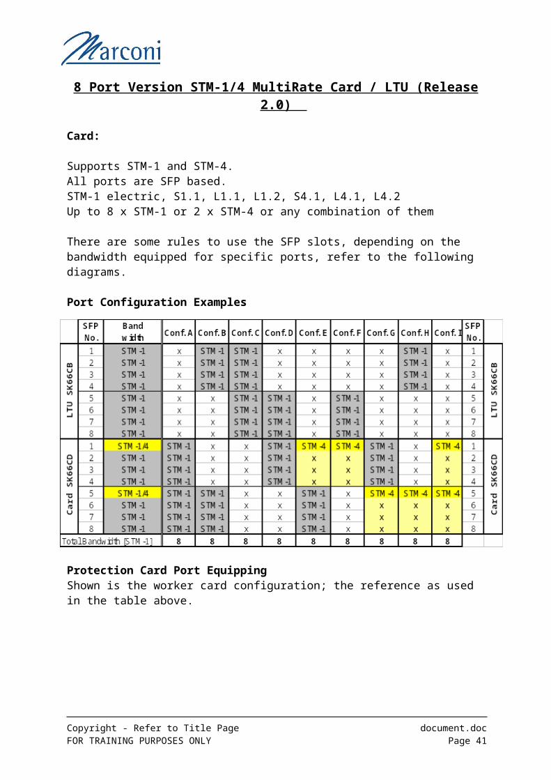
8 Port Version STM-1/4 MultiRate Card / LTU (Release 2.0)
Card:
Supports STM-1 and STM-4. All ports are SFP based.STM-1 electric, S1.1, L1.1, L1.2, S4.1, L4.1, L4.2Up to 8 x STM-1 or 2 x STM-4 or any combination of them
There are some rules to use the SFP slots, depending on the bandwidth equipped for specific ports, refer to the following diagrams.
Port Configuration Examples
Protection Card Port EquippingShown is the worker card configuration; the reference as used in the table above.
Copyright - Refer to Title Page document.docFOR TRAINING PURPOSES ONLY Page 31
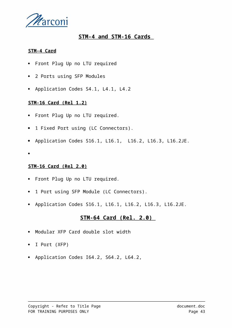
STM-4 and STM-16 Cards
STM-4 Card
Front Plug Up no LTU required
2 Ports using SFP Modules
Application Codes S4.1, L4.1, L4.2
STM-16 Card (Rel 1.2)
Front Plug Up no LTU required.
1 Fixed Port using (LC Connectors).
Application Codes S16.1, L16.1, L16.2, L16.3, L16.2JE.
STM-16 Card (Rel 2.0)
Front Plug Up no LTU required.
1 Port using SFP Module (LC Connectors).
Application Codes S16.1, L16.1, L16.2, L16.3, L16.2JE.
STM-64 Card (Rel. 2.0)
Modular XFP Card double slot width
I Port (XFP)
Application Codes I64.2, S64.2, L64.2,
Copyright - Refer to Title Page document.docFOR TRAINING PURPOSES ONLY Page 32

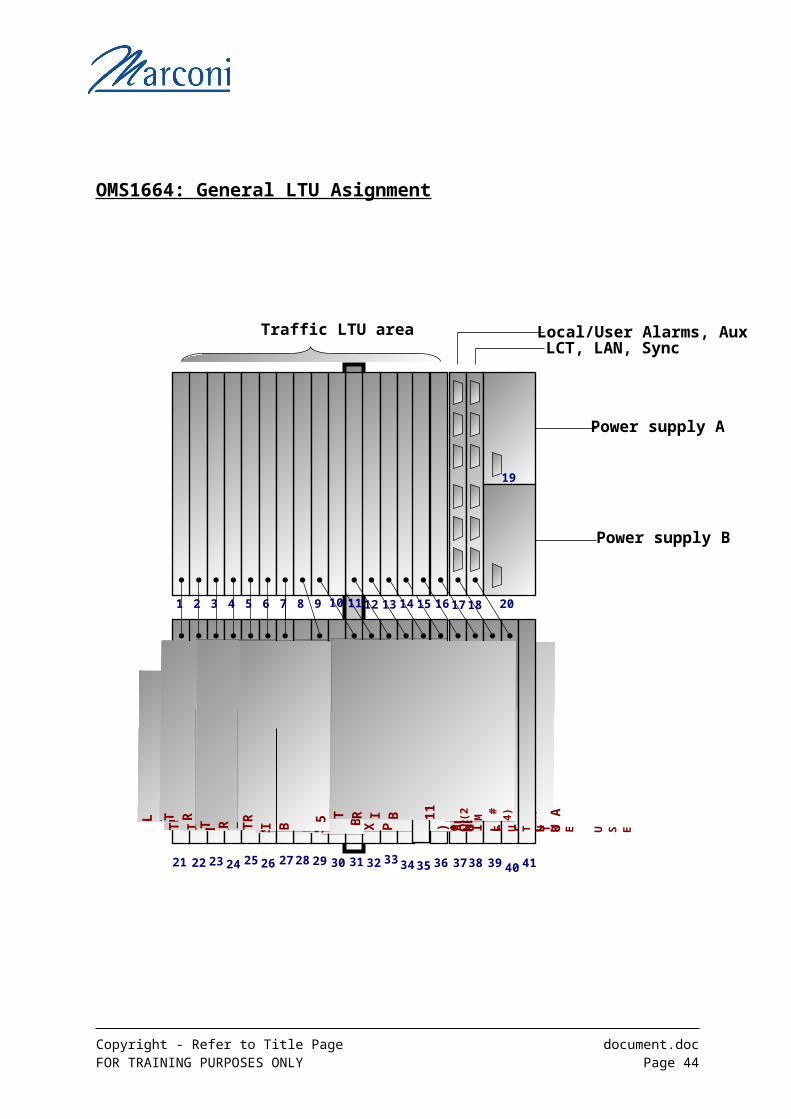
OMS1664: General LTU Asignment
Copyright - Refer to Title Page document.docFOR TRAINING PURPOSES ONLY Page 33
Traffic LTU area Local/User Alarms, AuxLCT, LAN, Sync
Power supply B
Power supply A
L I NE
1LIN
E 2
T R I B
1
TR
I B 2 ( 2M
#1)
T R I B 3 ( 2 M # 2)
TR
I B 4SW
IT
CH
AT R I B 7 S
W B
E X P N )TR
I B 8TR
I B 9T R I B 10 ( 2 M # 3)T R I B
12 ( 2 M P R O TLIN
E
3L I NE
4AU
XI L I A
RY
C C U A
F O R F U T U R E U S E
21 22 23 24 25 26 27 28 29 30 31 32 33 34 35 36 37 38 39 40 41
1 2 3 4 5 6 7 8 9 10 11 12 13 14 15 16 17 18
T R I B 6 S
W
A E X P N )SW
ITC
H
BT R I B 11 ( 2 M # 4)
TR
I B 5
19
20
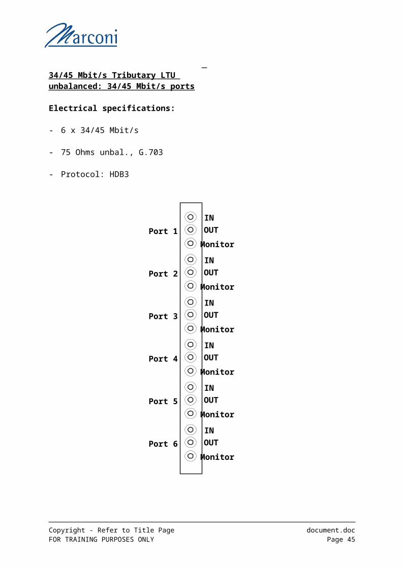
34/45 Mbit/s Tributary LTU unbalanced: 34/45 Mbit/s ports
Electrical specifications:
- 6 x 34/45 Mbit/s
- 75 Ohms unbal., G.703
- Protocol: HDB3
Copyright - Refer to Title Page document.docFOR TRAINING PURPOSES ONLY Page 34
IN
OUT
Monitor
Port 1
IN
OUT
Monitor
Port 2
IN
OUT
Monitor
Port 3
IN
OUT
Monitor
Port 4
IN
OUT
Monitor
Port 5
IN
OUT
Monitor
Port 6

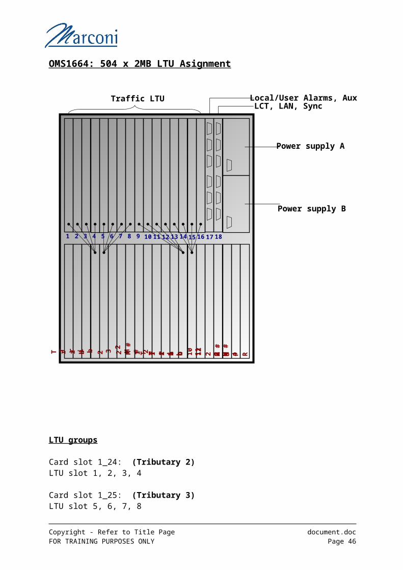
OMS1664: 504 x 2MB LTU Asignment
LTU groups
Card slot 1_24: (Tributary 2)LTU slot 1, 2, 3, 4
Card slot 1_25: (Tributary 3)LTU slot 5, 6, 7, 8
Card slot 1_34: (Tributary 10)LTU slot 9, 10, 11, 12
Card slot 1_35: (Tributary 11)LTU slot 13, 14, 15, 16
Copyright - Refer to Title Page document.docFOR TRAINING PURPOSES ONLY Page 35
Traffic LTU Local/User Alarms, Aux
Power supply B
Power supply A
T r i b 2 2 M #
1T r i b 3 2 M # 2 T r i b 10
2 M #
3
LCT, LAN, Sync
1 2 3 4 5 6 7 8 9 10 11 12 13 14 15 16 17 18
T r i b 11
2 M #
4T r i b 12
2 M
P R
2 Mbit/s Tributary LTU unbalanced: 2 Mbit/s ports For LTU’s associated with Expandable 2Mbits/s (Tribs 1-25 and 1-35)
Copyright - Refer to Title Page document.docFOR TRAINING PURPOSES ONLY Page 36
Electrical specifications:- 32 x 2 Mbit/s75 Ohms unbalanced, G.703- Protocol: HDB3
1
32
input outputut
These LTU’s only have 31 traffic ports. The 32nd ports can be connected to the Test Bus and used to monitthe traffic of any of the other ports one at a time.
10
11
22
23
2 Mbit/s Tributary LTU unbalanced: 2 Mbit/s ports For LTU’s associated with Expandale 2Mbits/s (Tribs 1-24 and 1-34)
Copyright - Refer to Title Page document.docFOR TRAINING PURPOSES ONLY Page 37
These LTU’s only have 31 traffic ports. The 32nd ports can be connected to the Test Bus and used to monitthe traffic of any of the other ports one at a time.
Electrical specifications:- 32 x 2 Mbit/s75 Ohms unbalanced, G.703- Protocol: HDB3
1
32
input outputut
10
11
22
23
For Other LTU and connection details please see Appendix A Section 9
Summary of Traffic Interfaces
Compact Shelf Versions
OMS1674 OMS1654 OMS1644
SDH Line Interfaces STM-n
n = 1,4,16,64 n = 1,4,8,16
n = 1,4 (Line Slots)
n = 4,16 (Core Card)
SDH Tributary Interfaces STM-n
n = 1,4,16,64 n = 1,4,16 n = 1,4
PDH Tributary Interfaces
2 Mbit/s
34 Mbit/s45 Mbit/s
2 Mbit/s
34 Mbit/s
45 Mbit/s
2 Mbit/s
34 Mbit/s
45 Mbit/s
Data Tributary Cards
Fast Ethernet. Gigabit Ethernet.
Layer 2 Aggregation. Multi Protocol.
Fast Ethernet. Gigabit Ethernet.
Layer 2 Aggregation. Multi Protocol.
Fast Ethernet. Gigabit Ethernet.
Layer 2 Aggregation. Multi Protocol.
Standard Shelf Versions
OMS1684 OMS1664 OMS1634
SDH Line Interfaces STM-n
n = 1,4,16,64 n = 1,4,16
n = 1,4 (Line Slots)
n = 4,16 (Core Card)
SDH Tributary Interfaces STM-n
n = 1,4,16,64 n = 1,4,16 n = 1,4
PDH Tributary Interfaces
2 Mbit/s
34 Mbit/s45 Mbit/s
2 Mbit/s
34 Mbit/s
45 Mbit/s
2 Mbit/s
34 Mbit/s
45 Mbit/s
Data Tributary Cards
Fast Ethernet. Gigabit Ethernet.
Layer 2 Aggregation. Multi Protocol.
Fast Ethernet. Gigabit Ethernet.
Layer 2 Aggregation. Multi Protocol.
Fast Ethernet. Gigabit Ethernet.
Layer 2 Aggregation. Multi Protocol.
Copyright - Refer to Title Page document.docFOR TRAINING PURPOSES ONLY Page 38
AUX / EOW (Rel. 1.3)
AUX Features
Data Channels: Support of 4 x V.11 and 4 x G.703 interfacesCarrying in SOH E1 / E2 and F1 byte
EOW Features
Hand Set supports selective calling, multiple calling conferenceby MF signalling
4-Wire interface for interconnection of EOW on different networks without E&M signalling
Protection If SDH protection switching takes place, the EOW / AUX cannel will follow the working line
Summary PDH Cards and LTUs
Type Rel. No. of ports Connector Protection
2M Card 1.1 126 n.a Card Pr.
2M LTU bal 1.1 32 D-SUB Card Pr.
2M LTU unbal 1.1 32 1.0/2.3 coax Card Pr.
34/45M Card 1.2 6 n.a. Card Pr.
34/45 LTU
unbal
1.2 6 1.0/2.3 coax Card Pr.
Copyright - Refer to Title Page document.docFOR TRAINING PURPOSES ONLY Page 39
Summary SDH Cards and LTUs
STMx Rel. No. of ports SFP Protection
STM-1 Card 1.1 4 No 1:N MSP
STM-1 LTU 1.1 4 No Card Pr.
STM-1/4 Card 1.3 8/4 * Yes 1:N MSP
STM-1/4 LTU 1.3 8/0 * Yes Card Pr.
STM-4 1.1 2 Yes 1:N MSP
STM-16 1.1 1 No 1:N MSP
STM-16 2.0 1 Yes 1:N MSP
STM-64 2.0 1 Yes 1:N MSP
STM-4 Core 2.0 1 Yes 1:N MSP STM-16 Core 1.3 1 Yes 1:N MSP
* 8/4 = 8 Ports up to 4 of which can be STM-4* 8/0 = 8 Ports none of which can be STM-4
Copyright - Refer to Title Page document.docFOR TRAINING PURPOSES ONLY Page 40
Summary Data Cards and LTUs
Type Rel. No. of ports SFP
FastE
10/100M Card 1.2 --- ---
10/100M LTUe 1.2 16 No RJ45
10/100M LTUo 1.2 16 Yes
GigE 1.2 2 Yes
Layer 2
Layer2 Card 2.0 2 x GigE Yes
10/100M LTUe 2.0 16 No RJ45
10/100M LTUo 2.0 16 Yes
Multiprotocol
Card
2.1 8 GigE
2 SAN
Yes
Copyright - Refer to Title Page document.docFOR TRAINING PURPOSES ONLY Page 41

System Memory Cards
Caution !!
Copyright - Refer to Title Page document.docFOR TRAINING PURPOSES ONLY Page 42
The Comms/Controller Card must not be removed from the sub–rack when its amber LED is flashing (i.e. when it is performing a write sequence), this can cause EEPROM corruption, necessitating software reload.
Flash Cards
Software for all the various card types are stored on the CCU in Flash memory (NVMs) within 2 logical banks.
The Flash cards are the core brain of the shelf containing all configuration and connectivity details.
This Flash card has two Banks, which are software partitioned to hold software.
Dual System Memory Banks offer an operator the following facilities: -
a) The ability to maintain two working copies of the software required for any card fitted in the shelf.
b) Enables software upgrades to be made to cards without firmware changes and without any loss of traffic.
Copyright - Refer to Title Page document.docFOR TRAINING PURPOSES ONLY Page 43
The Active Status of the partitions in the Flash Memory Cards Banks can be: -
Empty Bank or Banks do not contain any structured software
Inhibit Bank or Banks contain structured software, but this software has no priority status
Current Bank contains structured software and has been given the priority status of currently in use
Non Current Bank contains structured software and has been given the priority status of not currently in use
It is important that at any time an operating authority knows: -
(a) The version of system software held in the System Memory cards for every card type.
(b) The active status of the partitions in the Banks containing the system software.
The only cards that do not need system software to enable them to function correctly are: -
Engineers Order Wire (EOW) Auxiliary Card Power Supply Unit (PSU)
Copyright - Refer to Title Page document.docFOR TRAINING PURPOSES ONLY Page 44
Cross ConnectionsThe Switch can implement cross-connections at VC4, VC3, VC2, VC12 granularity.A number of crossconnections can also be concatenated together, either contiguously or virtually.
An operator can create cross connections routed through the switch card between any two ports whether these are on the LTU or on the front of a card.Some examples are shown above.
It is also possible to cross-connect a port to itself, effectively creating a loopback condition.
Note this should not be confused with inbuilt loopback facilities.
Note: - for Releases prior to Release 2.0, a port has to be effectively enabled by assigning switch capacity to the port.
If this is not done it will not be possible to create cross connections to that port.
Copyright - Refer to Title Page document.docFOR TRAINING PURPOSES ONLY Page 45
FRONT
PLUG
UP
FRONT
PLUG
UP
TRIBUTARY
1
2 2
3
LTU
1
Copyright - Refer to Title Page document.docFOR TRAINING PURPOSES ONLY Page 46