Embed Size (px)
Citation preview
®®PROPHECY INBONEPreoperative Navigation Guides
SURGIC AL TECHNIQUE

PROPHECY® INBONE®
Total Ankle System
SURGICAL TECHNIQUE

Contents
Chapter 1 1 Product Information 1 PROPHECY® INBONE® Alignment Guide Product Information 1 General Product Information 1 Intended Use 1 INBONE® Total Ankle Product Information 1 General Product Information 2 Intended Use 2 Indications 3 Contraindications
Chapter 2 4 CT Scan ProtocolChapter 3 5 Surgical Technique 5 Tibia Alignment Guide Fluoroscopic Check Assembly 6 Alignment and Resections 7 Intraoperative Tibia Alignment Guide Fluoroscopic Checks 18 Build the C-Bracket Assembly 20 Drill Primary Hole 24 Ream the Tibia 30 Install Tibia Stems 33 Install Tibia Tray 35 Verify Talar Dome Size 36 Trial Reduction 40 Ream for Talar Stem 41 Assemble Talar Stem 42 Install Talar Dome 43 Install Poly Insert 46 Morse Taper Release 47 Explant Information 47 Postoperative Management
Appendix A 48 PROPHECY® INBONE® InstrumentationAppendix B 49 Stem SpecificationsAppendix C 50 Implant SpecificationsAppendix D 51 Ordering InformationAppendix E 55 PROPHECY® Tie-In to the INBONE® Foot Holder Surgical ProcedureAppendix F 57 Intraoperative Tibia Stem Guide Fluoroscopic Check AssemblyAppendix G 58 Additional Holes in Talus Alignment GuideAppendix H 60 Tips and Tricks
Wright recognizes that proper surgical procedures and techniques are the responsibility of the medical professional. The following guidelines are furnished for information purposes only. Each surgeon must evaluate the appropriateness of the procedures based on his or her personal medical training, experience, and patient condition. Prior to use of the system, the surgeon should refer to the product Instructions For Use package insert (146636) for additional warnings, precautions, indications, contraindications and adverse effects. Instructions For Use package inserts are also available by contacting the manufacturer. Contact information can be found on the back of this surgical technique and the Instructions For Use package inserts are available on wmt.com under the link for Prescribing Information.
Please contact your local Wright representative for product availability.

Chapter 1 Description of Section
1chap
ter
ChapterTitle
PROPHECY® INBONE® Alignment Guide Product Information
General Product InformationThese surgical instruments are designed for single use only. They are manufactured with certain patient-specifi c features, which render them unusable in cases other than that for which they were designed. These surgical instruments are supplied clean and non-sterile, and must be sterilized before use. After use, these instruments must be properly disposed of. Please refer to the PROPHECY® INBONE® Instrument package insert #146636 for instructions on the proper steps for processing Wright Medical disposable surgical instruments.
Intended UseWright’s PROPHECY® INBONE® Preoperative Navigation Alignment Guides are intended to be used as patient-specifi c surgical instrumentation to assist in the positioning of total ankle replacement components intraoperatively and in guiding the marking of bone before cutting. The PROPHECY® INBONE® Preoperative Navigation Alignment Guides are intended for use with Wright’s INBONE® Total Ankle Systems and their cleared indications for use, provided that anatomic landmarks necessary for alignment and positioning of the implant are identifi able on patient imaging scans. The PROPHECY® INBONE® Preoperative Navigation Alignment Guides are intended for single use only.
INBONE® Total Ankle Product Information
General Product InformationThrough the advancement of partial and total joint replacement, the surgeon has been provided with a means of restoring mobility, correcting deformity, and reducing pain for many patients. While the prostheses used are largely successful in attaining these goals, it must be recognized that they are manufactured from a variety of materials and that any joint replacement system, therefore, cannot be expected to withstand activity levels and loads as would normal healthy bone. In addition, the system, including the implant/bone interface, will not be as strong, reliable, or durable as a natural human joint.
Ankle joint replacement components consist of a talar dome, a talar stem that attaches to the talar dome with a Morse Taper, a tibial platform, a four-component tibial stem assembly that attaches to the tibial platform with a Morse Taper, and an UHMWPE component. Components are available in a variety of sizes and design confi gurations intended for both primary and revision applications.
ProductInformation
Chapter 1 Product Information 1

2 Chapter 1 Product Information
IndicationsThe INBONE® Total Ankle is indicated for patients with ankle joints damaged by severe rheumatoid, post-traumatic, or degenerative arthritis. The INBONE® Total Ankle is additionally indicated for patients with a failed previous ankle surgery.
CAUTION: In the United States, the ankle prosthesis is intended for cement use only.

3Chapter 1 Product Information
ContraindicationsContraindications include:
1. Osteomyelitis;
2. Insufficient bone stock or bone quality;
3. Infection at the ankle site or infections at distant sites that could migrate to the ankle;
4. Sepsis;
5. Vascular deficiency in the ankle joint;
6. Skeletally immature patients (patient is less than 21 years of age at the time of surgery);
7. Cases where there is inadequate neuromuscular status (e.g., prior paralysis, fusion and/or inadequate abductor strength), poor skin coverage around the joint which would make the procedure unjustifiable;
8. Neuropathic joints;
9. Excessive loads as caused by activity or patient weight;
10. Patient pregnancy;
11. Severely compromised musculature or neuromuscular function.
12. Uncooperative patient or patient with neurologic disorders, incapable of following instructions
WARNING: This device is not intended for subtalar joint fusion or subtalar joint impingement. Please carefully evaluate the anatomy of each patient before implantation. High levels of activity may increase the risk of adverse events. Surgeons should carefully consider the advisability of ankle replacement in patients with metabolic disorders or pharmacological treatments that impair bone formation or with conditions that may impede wound healing (e.g., end stage diabetes or malnutrition).

4
2chap
ter
CT Scan Protocol
Chapter 2 CT Scan Protocol
CT Scan Protocol PROPHECY® INBONE® Preoperative Navigation Guides are patient-specific instruments designed using patient anatomy from a CT scan of the patient’s extremity. One significant requirement for a successful case is adhering to the PROPHECY® Ankle CT Scan Protocol document. Engineers at Wright Medical Technology have determined the necessary scanning parameters which are described in document #008380 and can be found on our website (http://documents.wmt.com/Document/Get/008380).
In every case, please have the scanning facility follow the specific instructions outlined in this document.
The Centers for Medicare & Medicaid Services (CMS) established a National Coverage Determination (NCD) for CT Scans. It states, in part, the following, “Diagnostic examinations of the head (head scans) and of other parts of the body (body scans) performed by computerized tomography (CT) scanners are covered if medical and scientific literature and opinion support the effective use of a scan for the condition, and the scan is: (1) reasonable and necessary for the individual patient.” CTs performed prior to total joint replacement procedures for diagnostic purposes may be considered medically necessary. In which case, the procedure should be billed using the CPT codes that accurately describe the imaging procedure furnished to the patient. These same images from the diagnostic CT scan may, in turn, be further utilized for developing the personalized cutting or navigation guides that are used in orthopaedic procedures. However, if providers perform CT scans solely for the purpose of developing personalized cutting instruments or guides, providers should contact the payer for billing and coverage guidance and/or the American College of Radiology with billing questions.
PROPHECY® Ankle CT Scan Protocol
#008380

5
SurgicalTechnique 3ch
apte
r
Chapter 3 Surgical Technique
| FIGURE 4 | FIGURE 5 | FIGURE 6
Tibia Alignment Guide Fluoroscopic Check Assembly Prior to beginning the case, the surgical scrub tech should pre-assemble the fluoroscopic check guide wires into the PROPCHECY® Tibia Alignment Guide (PROPINB or PROPINBE [Australia and EU only] ). Using the Pin Cutter (200427) and a needle driver, cut two ½” (~12mm) segments of a 2.4mm Steinmann Pin (200072).| FIGURE 4 Press-fit the two ½” segments into the holes in the base of the PROPCHECY® Tibia Alignment Guide. | FIGURE 5 Insert the remainder of the cut 2.4mm Steinmann Pin in the handle of the PROPCHECY® Tibia Alignment Guide. | FIGURE 6
CAUTION: To be assembled in the sterile field.
PROPHECY® Tibia Alignment GuidePROPINB
PROPINBE (Australia and EU only)
PROPHECY® Tibia Alignment GuidePROPINB
2.4mm Steinmann Pin200072
Pin Cutter200427
6
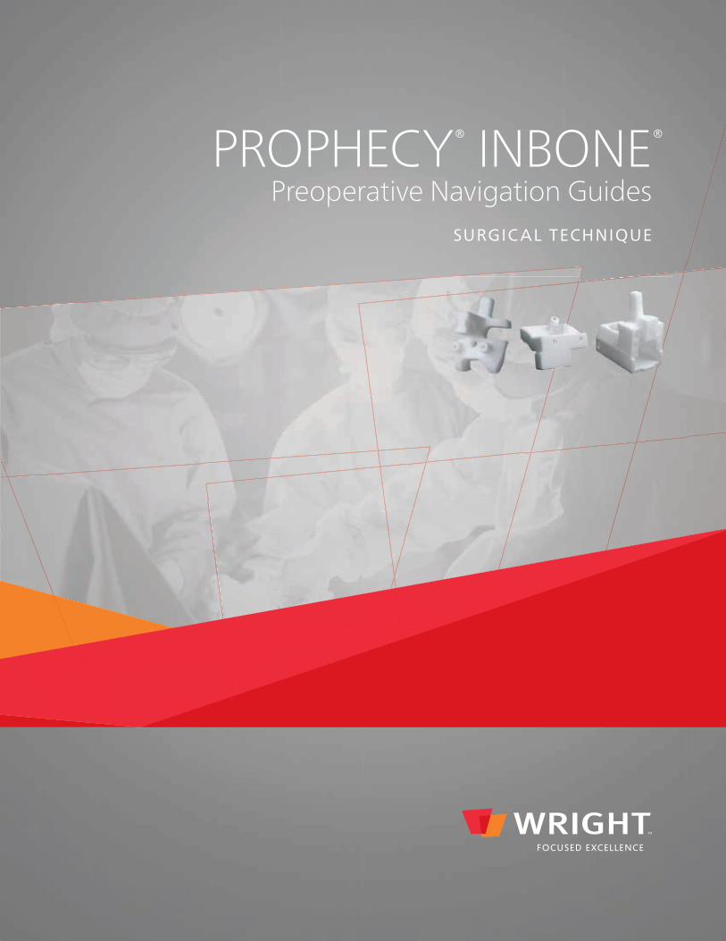
Alignment and Resections Make the Anterior incision approximately 125mm long directly lateral of the tibialis, avoiding the anterior tendons and nerve bundle, exposing the tibia, talus and a portion of the midfoot.
PROPHECY® INBONE® alignment guides are designed to incorporate fixed osteophytes on or near the articulating surfaces, and therefore should not be removed. Any loose bodies, however, may be removed if they interfere with the seating of the PROPHECY® INBONE® guides.
Ensure the area of the anterior tibia, where the PROPHECY® guide will surface match, is free of soft tissue and place the PROPHECY® Tibia Alignment Guide (PROPINB or PROPINBE [Australia and EU only] ) in the best fit location. | FIGURE 7 Please note that the guides are designed to fit in one and only one proper location.
• If the tibia guide does not sit flush against the tibia - before driving any pins into the bone - remove the PROPHECY® guide and clean off any remaining soft tissue covering the bone.
• Re-evaluate the surface match fit between the guide and the bone. Repeat these steps until the guide sits flush against the bone in the best fit location.
Once surface match fit is flush against the tibia, place one 2.4mm Steinmann Pin (200072) through the guide and into both corticies of the tibia, then check it with fluoro. | FIGURE 8 Then, if an adjustment is necessary, pull the pin from the first hole, and use the second hole which has fresh bone stock, to pin into.
Chapter 3 Surgical Technique
| FIGURE 8| FIGURE 7
7Chapter 3 Surgical Technique
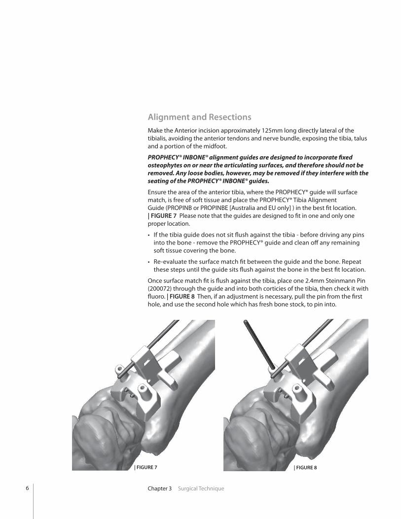
Intraoperative Tibia Alignment Guide Fluoroscopic Checks Compare the intra-op fluoro image | FIGURE 9, to the sample case pre-op report image showing the planned tibia stem axis. | FIGURE 10 The intra-op fluoro check shows the long central k-wire between the two short embedded k-wire segments in the tibia alignment guide like a “gun-sight,” which is similar to the case report image.
IMPORTANT NOTE: If your fluoro check shows you are significantly different than the plan: remove the alignment guide and any pins in the bone, ensure the periosteum has been cleaned from the tibia and verify that the retractor(s) are preventing any soft tissue creepage. Also, make sure the foot is in slight plantar-flexion and that a bump has been placed under the tibia to elevate it.
| FIGURE 9 | FIGURE 10
After correct alignment and positioning is achieved, place the second 2.4mm Steinmann Pin through the guide and into both corticies of the tibia. Do not cut the pins at this time. Remove the PROPHECY® guide by sliding it up and over the pins, leaving the pins in place. It may be helpful to attach a Kocher clamp in the notches built into the rectangular anterior handle to pull the tibia guide up.

8
Resection GuidePTA00092 through PTA00096
Select the appropriate sized metal Resection Guide (PTA00092 through PTA00096) and position the two distal tibial holes over the two Steinmann Pins in the tibia. | FIGURE 11 The appropriate Resection Guide size can be found detailed in the PROPHECY® preoperative surgical plan. Slide the Resection Guide down to the anterior surface of the tibia. | FIGURE 12
| FIGURE 12
The surgeon has the option to fl uoroscopically verify the saw guide size and positional orientation prior to tibial resection as follows:
• Obtain a fl uoroscopic AP view of the ankle perpendicular to the installed resection block. This view is achieved when the holes in the resection block appear as perfect circles. In this view the surgeon can verify the medial/lateral translation, proximal/distal location and coronal rotation of the resection block. | FIGURE 13
• Obtain a fl uoroscopic lateral view of the ankle and drop a saw blade into the proximal slot of the resection block. In this view the surgeon can verify the resection height and fl exion/extension angle of the resection block.
• Refer to the PROPHECY® Pre-Op Plan for verifi cation of the resection. At this point the surgeon can choose to revert back to the traditional INBONE® foot holder surgical technique if there are any concerns with the planned resection.
Resection GuidePTA00092 through PTA00096
| FIGURE 13
Distal Tibial Pin Hole Locations
| FIGURE 11
Chapter 3 Surgical Technique
Insert additional 2.4mm Steinmann Pins into the cross-pin hole of the Resection Guide, as well as the medial and lateral gutter locations.
Optionally, two additional 2.4mm Steinmann Pins can be inserted in the two proximal tibial holes of the Resection Guide. This will allow removal of the two distal tibial pins prior to tibial resection. This may be done to allow the saw blade to reach the corners of the tibia resection.
Use the Pin Cutter to cut the Steinmann Pins close to the surface of the Resection Guide. For the cross-pin only, be sure to leave approximately 2 inches to facilitate removal with a pin puller. | FIGURE 14
| FIGURE 14
9
| FIGURE 16
Saw Blade
| FIGURE 17 | FIGURE 18
Chapter 3 Surgical Technique
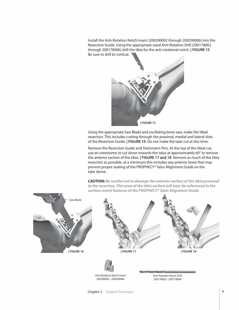
Install the Anti-Rotation Notch Insert (200290002 through 200290006) into the Resection Guide. Using the appropriate sized Anti-Rotation Drill (200178002 through 200178006) drill the tibia for the anti-rotational notch. | FIGURE 15 Be sure to drill bi-cortical.
Using the appropriate Saw Blade and oscillating bone saw, make the tibial resection. This includes cutting through the proximal, medial and lateral slots of the Resection Guide. | FIGURE 16 Do not make the talar cut at this time.
Remove the Resection Guide and Steinmann Pins. At the top of the tibial cut, use an osteotome to cut down towards the talus at approximately 60° to remove the anterior section of the tibia. | FIGURE 17 and 18 Remove as much of the tibia resection as possible, at a minimum this includes any anterior bone that may prevent proper seating of the PROPHECY® Talus Alignment Guide on the talar dome.
CAUTION: Be careful not to damage the anterior surface of the tibia proximal to the resection. This area of the tibia surface will later be referenced in the surface match features of the PROPHECY® Stem Alignment Guide.
| FIGURE 15
Anti-Rotation Notch Insert200290002 - 200290006
Anti-Rotation Notch Drill 200178002 - 200178006
10 Chapter 3 Surgical Technique
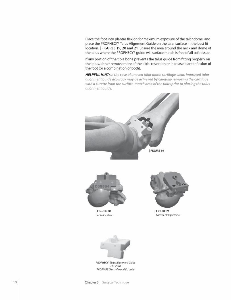
Place the foot into plantar fl exion for maximum exposure of the talar dome, and place the PROPHECY® Talus Alignment Guide on the talar surface in the best fi t location. | FIGURES 19, 20 and 21 Ensure the area around the neck and dome of the talus where the PROPHECY® guide will surface match is free of all soft tissue.
If any portion of the tibia bone prevents the talus guide from fi tting properly on the talus, either remove more of the tibial resection or increase plantar fl exion of the foot (or a combination of both).
HELPFUL HINT: In the case of uneven talar dome cartilage wear, improved talar alignment guide accuracy may be achieved by carefully removing the cartilage with a curette from the surface-match area of the talus prior to placing the talus alignment guide.
| FIGURE 19
Anterior View Lateral-Oblique View| FIGURE 21
PROPHECY® Talus Alignment GuidePROPINB
PROPINBE (Australia and EU only)
| FIGURE 20

11Chapter 3 Surgical Technique
| FIGURE 23
While holding the PROPHECY® guide in place install one 2.4mm Steinmann Pin through the top of the guide into the dome of the talus to temporarily hold the guide in place. | FIGURE 22 Next, install two 2.4mm Steinmann Pins through the anterior pin holes of the Talus Alignment Guide and into the talar bone. Remove the Steinmann Pin in the top of the guide. | FIGURE 23 Do not cut the remaining pins at this time. Remove the PROPHECY® guide by sliding it up and over the pins, leaving the pins in place. It may be helpful to attach a Kocher clamp to the notches built into the central triangular feature of the talar guide to pull the guide up.
Choose the appropriate sized metal Resection Guide, position the 2 talar pin holes over the 2 pins from the PROPHECY® Talus Alignment Guide and slide down to the anterior surface of the talar dome. | FIGURE 24 The Resection Guide will not necessarily be the same size used in the tibial resection. Consult the PROPHECY® pre-op plan for confirmation.
| FIGURE 24
| FIGURE 22
12 Chapter 3 Surgical Technique
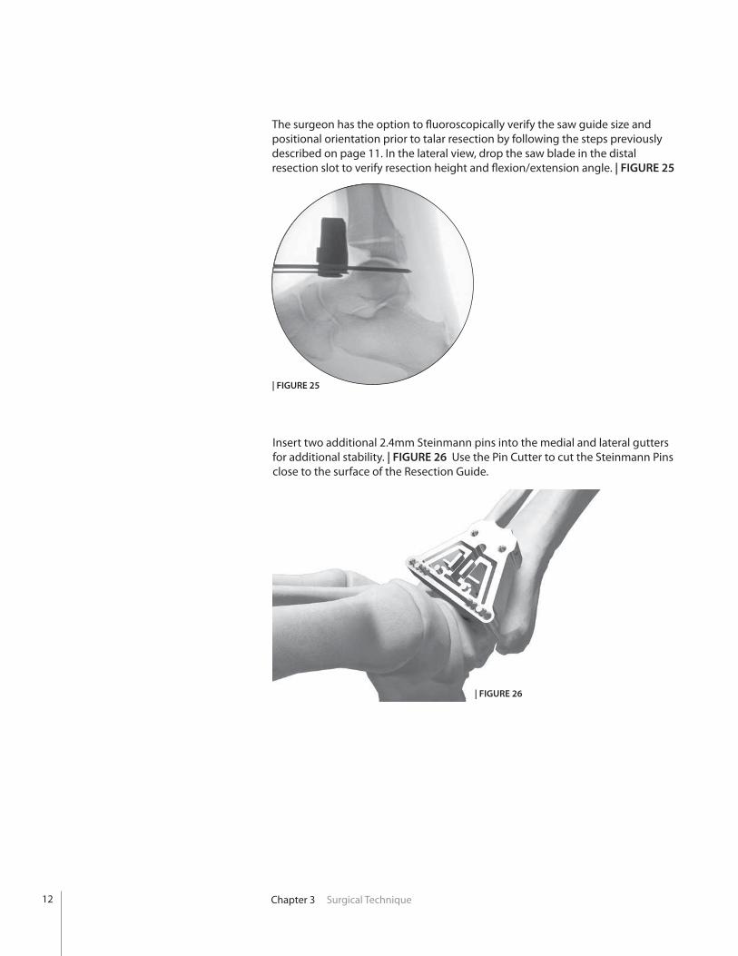
Insert two additional 2.4mm Steinmann pins into the medial and lateral gutters for additional stability. | FIGURE 26 Use the Pin Cutter to cut the Steinmann Pins close to the surface of the Resection Guide.
| FIGURE 26
The surgeon has the option to fluoroscopically verify the saw guide size and positional orientation prior to talar resection by following the steps previously described on page 11. In the lateral view, drop the saw blade in the distal resection slot to verify resection height and flexion/extension angle. | FIGURE 25
| FIGURE 25

13Chapter 3 Surgical Technique
Using the appropriate Saw Blade and oscillating bone saw, make the talar resection (distal slot of the Saw Guide). | FIGURE 27
CAUTION: It may be necessary to manually hold the resection guide in place as excessive vibration from the saw can cause the Saw Guide to work itself off the ends of the cut Steinmann Pins.
Remove the Resecton Guide. Check that your talar resection is complete by using a ½” osteotome. Complete the cut if necessary and gently lever the resected dome out anteriorly. It can typically be removed in one piece by grabbing the Steinmann Pins. | FIGURE 28
| FIGURE 27| FIGURE 28
Corner ChiselIB200070
To facilitate removal of the remaining posterior tibia, the Corner Chisel (IB200070) and a mallet can be used to finish off bone cuts in the proximal corners of the resected tibia. | FIGURE 29 The Corner Chisel is laser marked to indicate the anterior to posterior depth of the various size tibial trays.
CAUTION: Care must be taken to ensure that the Corner Chisel does not penetrate too deeply, as neurovascular injury may occur. Do not rely solely on the depth indications on the Chisel to determine resection depth. If unsure, utilize a lateral fluoroscopic image to confirm proper depth of the chisel.
| FIGURE 29

14 Chapter 3 Surgical Technique
Using a pin driver, insert the Bone Removal Screw (IB200051) into the resected tibial bone. Attach the Ratcheting Handle (44180025) to the Bone Removal Screw to aid in removing the remaining tibial section through traction. | FIGURE 30
Insert the 90° Posterior Capsule Release Tool (IB200050) into the joint space and use to free up the posterior capsule soft tissues attachments to the resected tibia. | FIGURES 31 and 32
Bone Removal Screw(Ratcheting Handle not shown)
Bone Removal Screw
Posterior CapsuleRelease Tool
| FIGURE 31 | FIGURE 32
| FIGURE 30
Bone Removal ScrewIB200051
Posterior Capsule Release ToolIB200050
Ratcheting Handle44180025
Ratcheting Handle
15Chapter 3 Surgical Technique
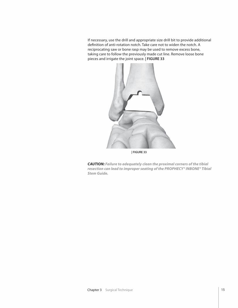
If necessary, use the drill and appropriate size drill bit to provide additional definition of anti-rotation notch. Take care not to widen the notch. A reciprocating saw or bone rasp may be used to remove excess bone, taking care to follow the previously made cut line. Remove loose bone pieces and irrigate the joint space. | FIGURE 33
| FIGURE 33
CAUTION: Failure to adequately clean the proximal corners of the tibial resection can lead to improper seating of the PROPHECY® INBONE® Tibial Stem Guide.

16 Chapter 3 Surgical Technique
Insert the Drill Guide Cartridge (PTA00070) into the PROPHECY® Tibial Stem Guide. The cartridge is fully seated when the ball detent is engaged and the anterior surfaces of the Drill Guide Cartridge and the Anterior Mounting Plate are fl ush. | FIGURE 36
Alternatively the PROPHECY® Tibial-Stem Guide, Anterior Mounting Plate, and Drill Guide Cartridge may be assembled outside of the foot and then inserted into the joint space in one step.
| FIGURE 36
| FIGURE 34 | FIGURE 35
Slightly distract the ankle and place the PROPHECY® Tibial-Stem Alignment Guide (PROPINB or PROPINBE [Australia and EU only] ) into the resected joint space. The guide has surface matching features referencing the anterior surface of the tibia, and all four flat surfaces within the resection joint space. | FIGURE 34
Place the metal Anterior Mounting Plate (PTA00040) onto the anterior surface of the PROPHECY® Tibial Stem Guide. The two metal dowel pins protruding from the back side of the Anterior Mounting Plate are designed to fit into round holes of the PROPHECY® Guide. The two flat mating surfaces must be fully seated. | FIGURE 35
PROPHECY® Tibia Stem Alignment GuidePROPINB
PROPINBE (Australia and EU only)
Anterior Mounting PlatePTA00040
Drill Guide CartridgePTA00070
Drill Guide Cartridge
17Chapter 3 Surgical Technique
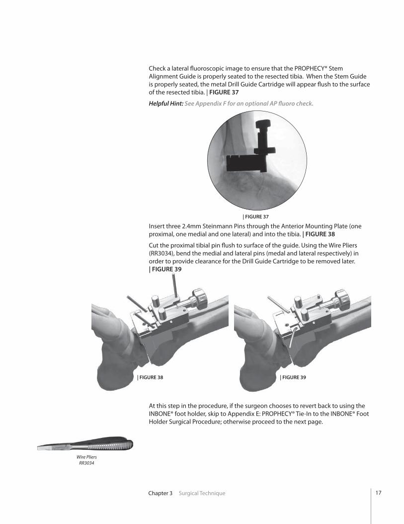
Insert three 2.4mm Steinmann Pins through the Anterior Mounting Plate (one proximal, one medial and one lateral) and into the tibia. | FIGURE 38
Cut the proximal tibial pin flush to surface of the guide. Using the Wire Pliers (RR3034), bend the medial and lateral pins (medal and lateral respectively) in order to provide clearance for the Drill Guide Cartridge to be removed later. | FIGURE 39
| FIGURE 38 | FIGURE 39
Wire PliersRR3034
At this step in the procedure, if the surgeon chooses to revert back to using the INBONE® foot holder, skip to Appendix E: PROPHECY® Tie-In to the INBONE® Foot Holder Surgical Procedure; otherwise proceed to the next page.
Check a lateral fluoroscopic image to ensure that the PROPHECY® Stem Alignment Guide is properly seated to the resected tibia. When the Stem Guide is properly seated, the metal Drill Guide Cartridge will appear flush to the surface of the resected tibia. | FIGURE 37
Helpful Hint: See Appendix F for an optional AP fluoro check.
| FIGURE 37
18 Chapter 3 Surgical Technique
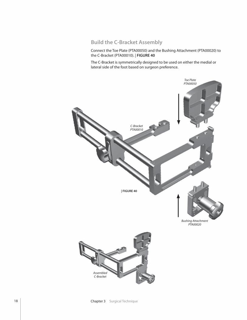
Build the C-Bracket AssemblyConnect the Toe Plate (PTA00050) and the Bushing Attachment (PTA00020) to the C-Bracket (PTA00010). | FIGURE 40
The C-Bracket is symmetrically designed to be used on either the medial or lateral side of the foot based on surgeon preference.
Toe PlatePTA00050
C-BracketPTA00010
Bushing AttachmentPTA00020
| FIGURE 40
Assembled C-Bracket
19Chapter 3 Surgical Technique
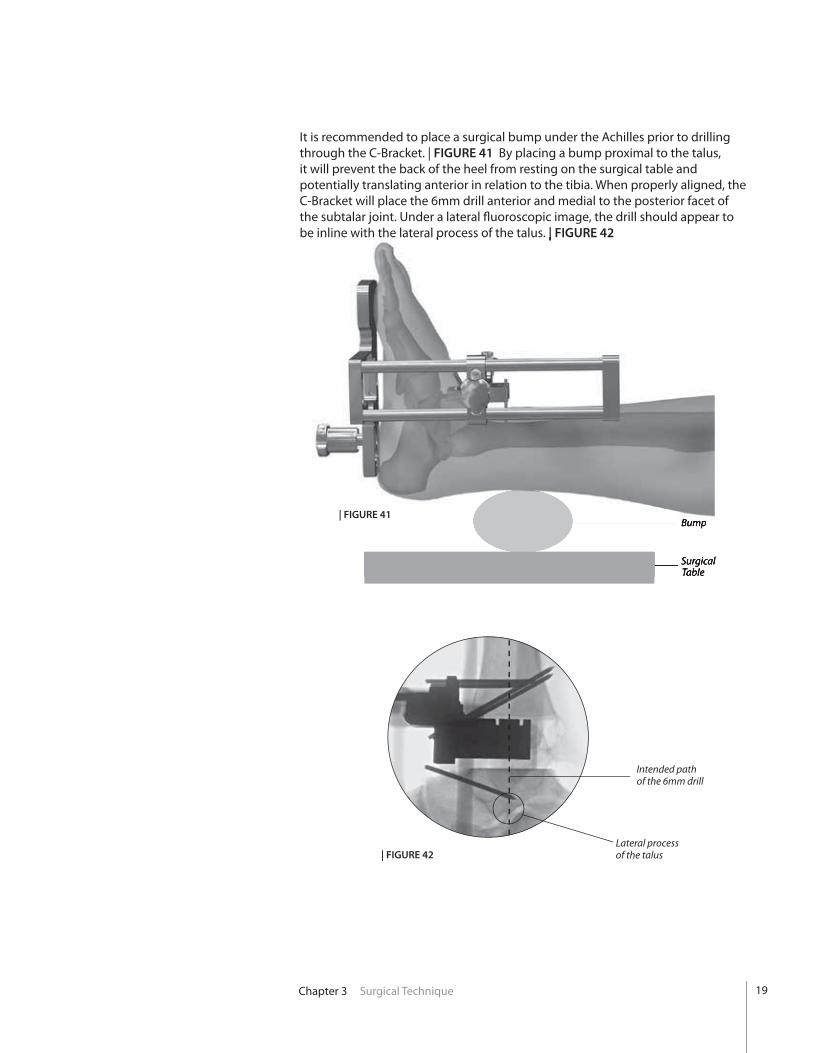
It is recommended to place a surgical bump under the Achilles prior to drilling through the C-Bracket. | FIGURE 41 By placing a bump proximal to the talus, it will prevent the back of the heel from resting on the surgical table and potentially translating anterior in relation to the tibia. When properly aligned, the C-Bracket will place the 6mm drill anterior and medial to the posterior facet of the subtalar joint. Under a lateral fl uoroscopic image, the drill should appear to be inline with the lateral process of the talus. | FIGURE 42
Intended path of the 6mm drill
Lateral process of the talus
Bump
Surgical Table
| FIGURE 42
be inline with the lateral process of the talus. | FIGURE 42
Bump
Surgical Table
| FIGURE 41

20 Chapter 3 Surgical Technique
Drill Primary HoleLower the C-Bracket assembly down over the Anterior Mounting Plate and attach through the two protruding dowel pins. | FIGURE 43 The surface of the C-Bracket arm must sit flat against the Anterior Mounting Plate.
| FIGURE 42
| FIGURE 45 | FIGURE 46| FIGURE 44
C-Bracket Arm
Swivel Rod & Screw
Secure the C-Bracket to the Anterior Mounting Plate by rotating the swivel rod up and over the C-Bracket arm and tightening the screw on the end of the swivel rod. | FIGURES 44, 45 and 46

21
Slide Lock Button
| FIGURE 47
Chapter 3 Surgical Technique
TrocarCannula
Place the foot in slight dorsiflexion. Press and hold in the slide lock button on the outside arm of the C-Bracket and slide the distal end of the C-Bracket assembly close to the bottom of the foot. Leave a slight gap between the heel and the Bushing Attachment to facilitate it’s removal. | FIGURE 47 To prevent the C-Bracket assembly from binding while adjusting the length, push the bottom of the assembly in-line with the side rods. Also, sterile mineral oil can be used to lubricate the side rods. Release the slide lock button and tighten the slide lock knob to lock the position of the C-Bracket.
With a skin marker, put ink on the tip of the Trocar (200099) and insert into the Cannula (200166). Insert the Trocar and Cannula through the Bushing Attachment and push the tip against the skin to mark the incision point. | FIGURE 48
Remove the Trocar and Cannula and push the Bushing Release Button on the C-Bracket to remove the Bushing Attachment. Centering on the previously marked spot, insert a #15 Scalpel and make a 1cm vertical incision in the bottom of the heel. | FIGURE 49
| FIGURE 48
Scalpel| FIGURE 49
Trocar200099
Cannula200166
Bushing Release Button
22 Chapter 3 Surgical Technique
6mm Drill
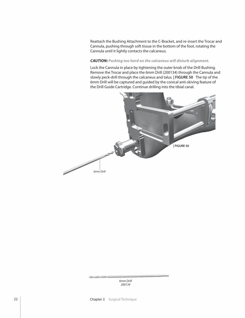
Reattach the Bushing Attachment to the C-Bracket, and re-insert the Trocar and Cannula, pushing through soft tissue in the bottom of the foot, rotating the Cannula until it lightly contacts the calcaneus.
CAUTION: Pushing too hard on the calcaneus will disturb alignment.
Lock the Cannula in place by tightening the outer knob of the Drill Bushing. Remove the Trocar and place the 6mm Drill (200134) through the Cannula and slowly peck-drill through the calcaneus and talus. | FIGURE 50 The tip of the 6mm Drill will be captured and guided by the conical anti-skiving feature of the Drill Guide Cartridge. Continue drilling into the tibial canal.
6mm Drill200134
| FIGURE 50
23Chapter 3 Surgical Technique
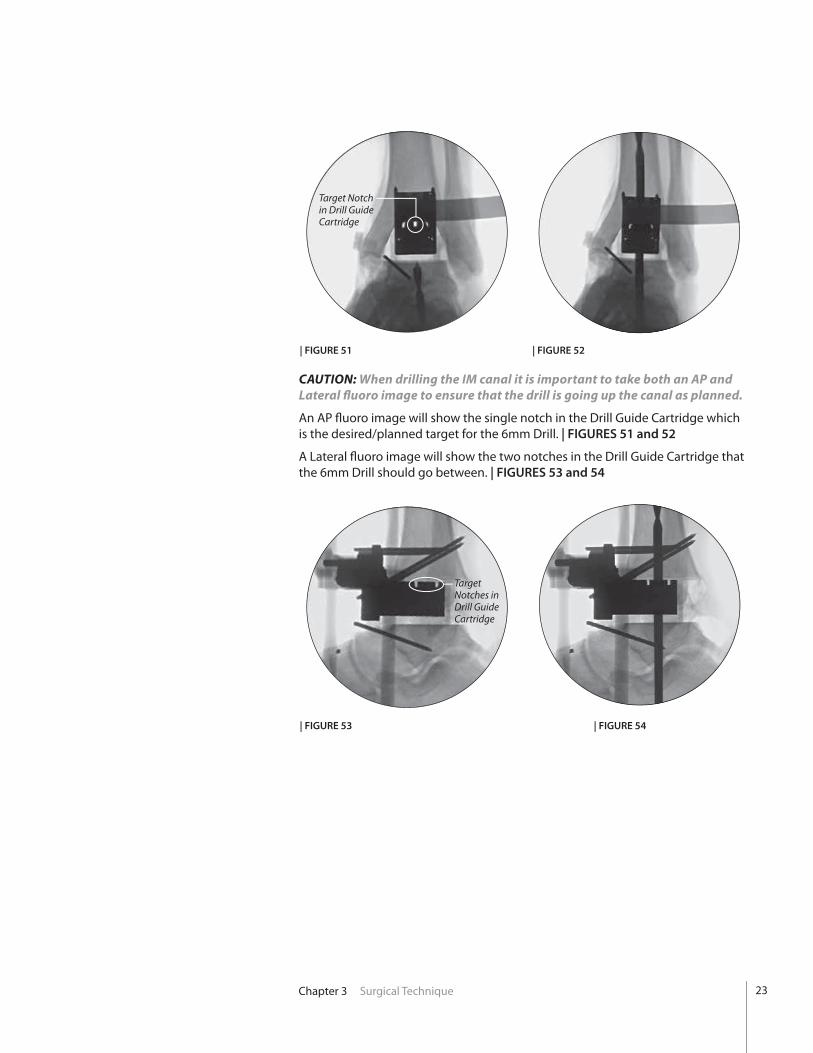
CAUTION: When drilling the IM canal it is important to take both an AP and Lateral fl uoro image to ensure that the drill is going up the canal as planned.
An AP fl uoro image will show the single notch in the Drill Guide Cartridge which is the desired/planned target for the 6mm Drill. | FIGURES 51 and 52
A Lateral fl uoro image will show the two notches in the Drill Guide Cartridge that the 6mm Drill should go between. | FIGURES 53 and 54
Target Notch in Drill Guide Cartridge
Target Notches in Drill Guide Cartridge
| FIGURE 51 | FIGURE 52
| FIGURE 53 | FIGURE 54

24
Reamer Drive Rod
Clip
Reamer Tip
| FIGURE 56
Chapter 3 Surgical Technique
With the C-Bracket still secured, place the Reamer Drive Rod (with Jacobs chuck attached) through the distal bushing, calcaneus, and talus and into the resected joint space.
Using the appropriate size Tibial Stem Clip (200381001 through 200381004), attach and lower the appropriate size Reamer Tip (200046001 through 200046004) into the joint space through the anterior opening of the Anterior Mounting Plate. | FIGURE 56
Connect the Reamer Tip to the Reamer Drive Rod (200089 or 200395) and push the tip of the Reamer into the 6mm hole in the Tibia.
| FIGURE 55
Tibial Reamer Tip200046001 - 200046004
Tibial Stem Clip200381001 - 200381004
Tibial Reamer Drive Rods200089 or 200395 (T-Handle)
Ream the TibiaRemove the 6mm Drill from the foot and C-Bracket. Attach the M4 Attachment Screw (200329103) to the anterior threaded hole on the Drill Guide Cartridge and pull the Cartridge out anteriorly. | FIGURE 55
M4 Attachment Screw
M4 Attachment Screw200329103

25Chapter 3 Surgical Technique
| FIGURE 57
Reamer Stabilizer Instructions
Insert the Reamer Stabilizer Guide (PTA00060) through the anterior opening of the Anterior Mounting Plate and push down until the side latch of the Guide connects to the Mounting Plate. | FIGURE 57
Reamer Stabilizer GuidePTA00060
After inserting the Reamer Stabilizer, press the top button (A) to activate the rod capture mechanism. To disengage the rod capture mechanism, slide button (B) over as shown. To remove the Reamer Stabilizer from the Anterior Mounting Plate, pull up on lever (C) to release the side latch. | FIGURE 58
(A) engage
release (C)
(B) disengage
rod capturemechanism
| FIGURE 58
Reamer Stabilizer Guide
26 Chapter 3 Surgical Technique
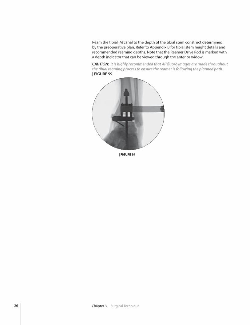
Ream the tibial IM canal to the depth of the tibial stem construct determined by the preoperative plan. Refer to Appendix B for tibial stem height details and recommended reaming depths. Note that the Reamer Drive Rod is marked with a depth indicator that can be viewed through the anterior widow.
CAUTION: It is highly recommended that AP fluoro images are made throughout the tibial reaming process to ensure the reamer is following the planned path. | FIGURE 59
| FIGURE 59
27Chapter 3 Surgical Technique
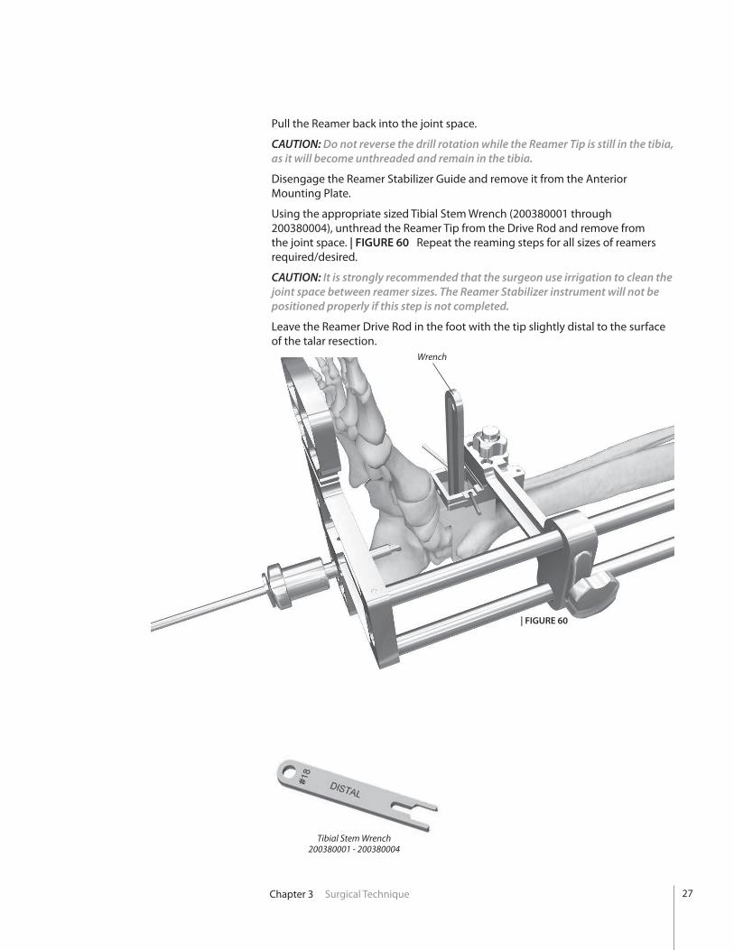
Pull the Reamer back into the joint space.
CAUTION: Do not reverse the drill rotation while the Reamer Tip is still in the tibia, as it will become unthreaded and remain in the tibia.
Disengage the Reamer Stabilizer Guide and remove it from the Anterior Mounting Plate.
Using the appropriate sized Tibial Stem Wrench (200380001 through 200380004), unthread the Reamer Tip from the Drive Rod and remove from the joint space. | FIGURE 60 Repeat the reaming steps for all sizes of reamers required/desired.
CAUTION: It is strongly recommended that the surgeon use irrigation to clean the joint space between reamer sizes. The Reamer Stabilizer instrument will not be positioned properly if this step is not completed.
Leave the Reamer Drive Rod in the foot with the tip slightly distal to the surface of the talar resection.
| FIGURE 60
Wrench
Tibial Stem Wrench200380001 - 200380004

28 Chapter 3 Surgical Technique
Release the screw and swivel rod attachment from the Anterior Mounting Plate.
Release the slide lock on the side arm of the C-Bracket Assembly and, with the Reamer Drive Rod still in the foot, slide the distal portion of the C-Bracket Assembly away from the bottom of the foot.
Release the Toe Plate Attachment from the C-Bracket Assembly by pressing the button on the side of the foot plate. | FIGURE 61
Release the Bushing Attachment from the C-Bracket Assembly by pressing the button on the side of the Foot Plate. Lift the C-Bracket off the foot anteriorly leaving the Bushing Attachment on the Reamer Drive Rod. | FIGURE 62
| FIGURE 62
| FIGURE 61
Toe Plate Attachment

29Chapter 3 Surgical Technique
Tibial Tray AP SizerIB282902 (left) - IB282906 (right)
Select the appropriate size Tibial Tray AP Sizer (IB282902 through IB282906) and insert into the resected joint space, using both ends of the sizing tool to determine the optimum AP size Tibial Tray (standard or long). The Strike Rod (200085) should be used to fully seat the Sizer into the tibial resection.
Utilize a lateral fluoroscopic image to evaluate the coverage (anterior and posterior) of the tibial cortex. | FIGURE 64 It is critical to obtain sagittal plane coverage of the tibia, particularly anteriorly where more load is distributed. Thus, in choosing the correct size, overhang of the prosthesis is permitted if the standard size does not rest upon the tibial cortex.
The Tibial Tray AP Sizer is also used to check the tibial cut surfaces and ensure that no bone fragments will impede proper positioning of the Tibial Tray. Remove excess bone as necessary and irrigate.
AP Standard - illustrating undersized coverage. AP Long - illustrating optimal coverage.
Strike Rod200085
| FIGURE 63
Remove the Anterior Mounting Plate and PROPHECY® Tibial Stem Guide from the joint space and slide the Bushing Attachment along the Drive Rod until it contacts the bottom of the foot and secure to the calcaneus with three 2.4mm Steinmann Pins. Two pins can be inserted through the bottom holes of the bushing attachment (one medial and one lateral) with the 3rd pin in one of the top hole locations (preferably on the lateral side). | FIGURE 63 Remove the Drive Rod.
| FIGURE 64
30
| FIGURE 65
| FIGURE 66
Chapter 3 Surgical Technique
X-Drive200071
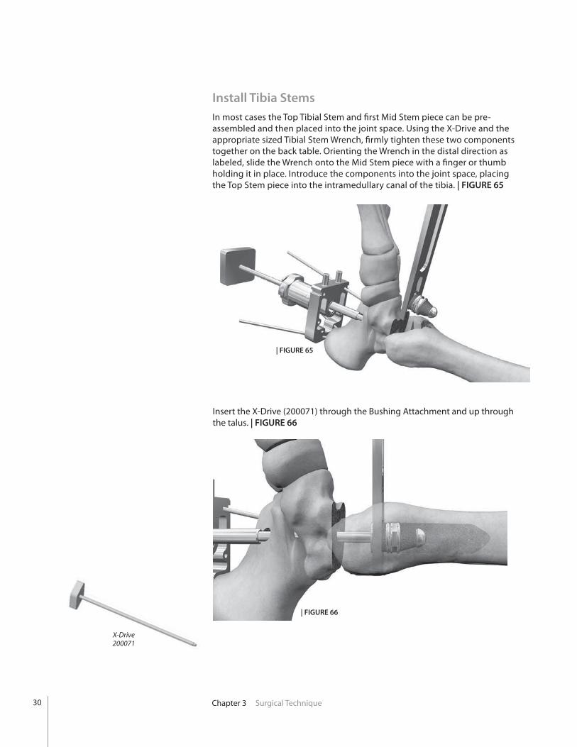
Install Tibia StemsIn most cases the Top Tibial Stem and fi rst Mid Stem piece can be pre-assembled and then placed into the joint space. Using the X-Drive and the appropriate sized Tibial Stem Wrench, fi rmly tighten these two components together on the back table. Orienting the Wrench in the distal direction as labeled, slide the Wrench onto the Mid Stem piece with a fi nger or thumb holding it in place. Introduce the components into the joint space, placing the Top Stem piece into the intramedullary canal of the tibia. | FIGURE 65
Insert the X-Drive (200071) through the Bushing Attachment and up through the talus. | FIGURE 66
31Chapter 3 Surgical Technique
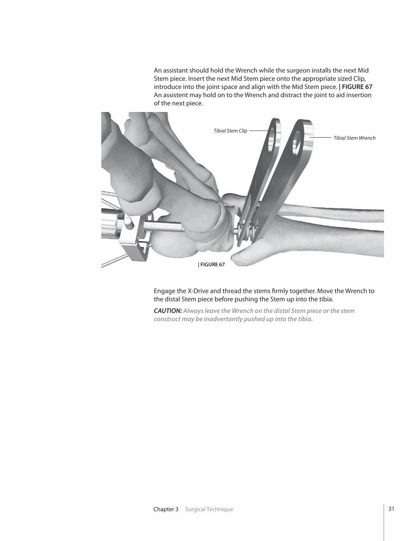
An assistant should hold the Wrench while the surgeon installs the next Mid Stem piece. Insert the next Mid Stem piece onto the appropriate sized Clip, introduce into the joint space and align with the Mid Stem piece. | FIGURE 67 An assistent may hold on to the Wrench and distract the joint to aid insertion of the next piece.
Tibial Stem Wrench
| FIGURE 67
Engage the X-Drive and thread the stems firmly together. Move the Wrench to the distal Stem piece before pushing the Stem up into the tibia.
CAUTION: Always leave the Wrench on the distal Stem piece or the stem construct may be inadvertantly pushed up into the tibia.
Tibial Stem Clip
32
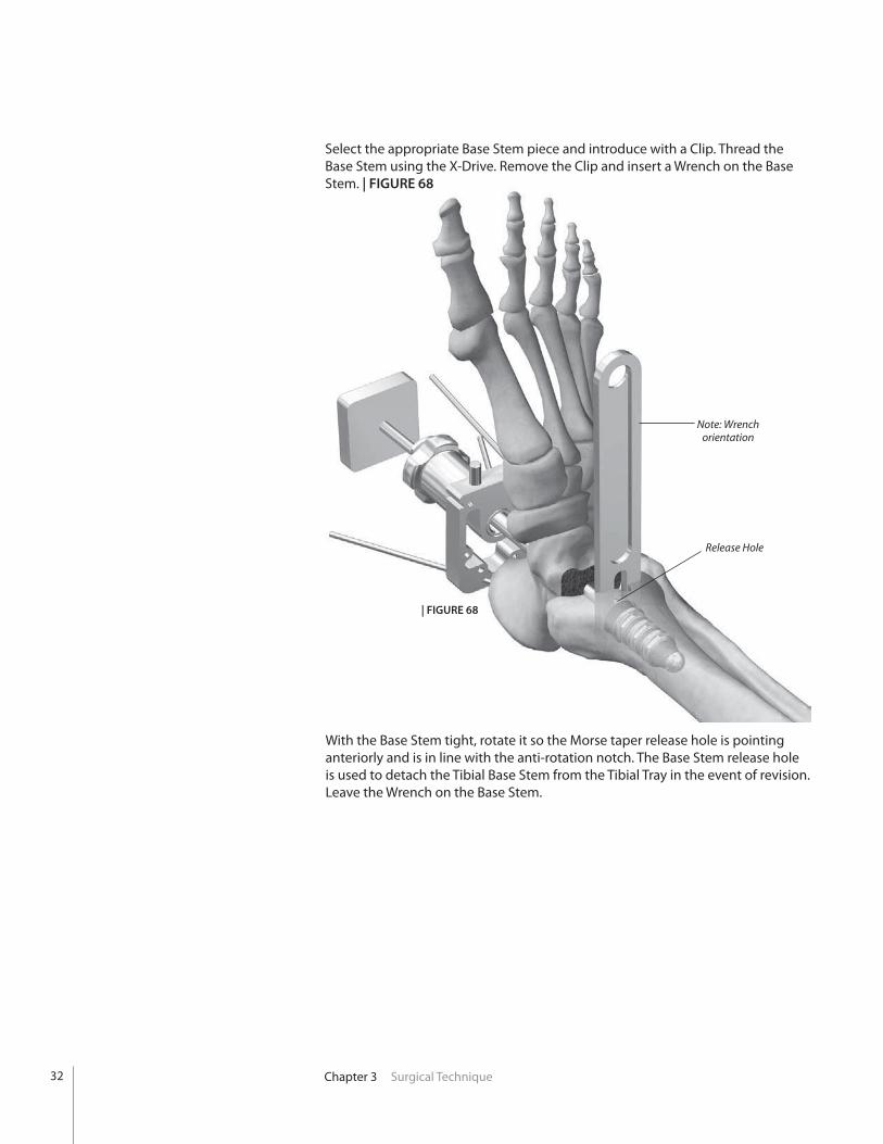
Note: Wrench orientation
Release Hole
Chapter 3 Surgical Technique
Select the appropriate Base Stem piece and introduce with a Clip. Thread the Base Stem using the X-Drive. Remove the Clip and insert a Wrench on the Base Stem. | FIGURE 68
With the Base Stem tight, rotate it so the Morse taper release hole is pointing anteriorly and is in line with the anti-rotation notch. The Base Stem release hole is used to detach the Tibial Base Stem from the Tibial Tray in the event of revision. Leave the Wrench on the Base Stem.
| FIGURE 68
33Chapter 3 Surgical Technique
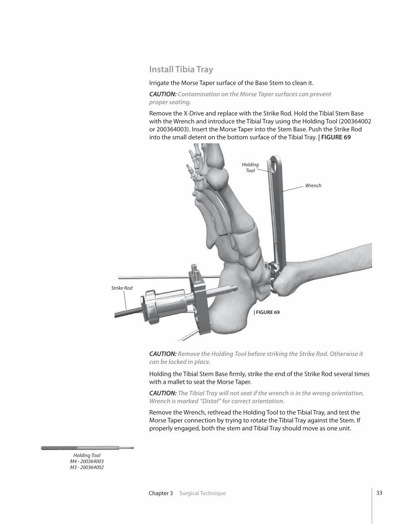
| FIGURE 69
Holding Tool
Strike Rod
Wrench
Install Tibia TrayIrrigate the Morse Taper surface of the Base Stem to clean it.
CAUTION: Contamination on the Morse Taper surfaces can prevent proper seating.
Remove the X-Drive and replace with the Strike Rod. Hold the Tibial Stem Base with the Wrench and introduce the Tibial Tray using the Holding Tool (200364002 or 200364003). Insert the Morse Taper into the Stem Base. Push the Strike Rod into the small detent on the bottom surface of the Tibial Tray. | FIGURE 69
CAUTION: Remove the Holding Tool before striking the Strike Rod. Otherwise it can be locked in place.
Holding the Tibial Stem Base firmly, strike the end of the Strike Rod several times with a mallet to seat the Morse Taper.
CAUTION: The Tibial Tray will not seat if the wrench is in the wrong orientation. Wrench is marked “Distal” for correct orientation.
Remove the Wrench, rethread the Holding Tool to the Tibial Tray, and test the Morse Taper connection by trying to rotate the Tibial Tray against the Stem. If properly engaged, both the stem and Tibial Tray should move as one unit.
Holding ToolM4 - 200364003M3 - 200364002

34 Chapter 3 Surgical Technique
| FIGURE 70
If choosing to use bone cement, apply it to the top and sidewalls of the Tibial Tray component.
CAUTION: In the United States, the INBONE® Total Ankle is intended for cemented use only.
CAUTION: Be sure not to get any cement on the anterior face or bottom of the Tray.
Seat the assembly firmly into the tibia using a mallet and the Strike Rod. Remove the Strike Rod and visually check the anterior alignment. Check the lateral fluoroscopic image for proper posterior seating. | FIGURE 70

35Chapter 3 Surgical Technique
Verify Talar Dome SizeThe surgeon has two options for Talar Dome implant size at this juncture: either the matching size for the implanted Tibial Tray, or one size smaller. It is beneficial to assess both sizes under A/P and lateral fluoroscopic images. Please note that the A/P image is critical for sizing the talar component, as the surgeon’s goal is to minimize overhang of the talar component, and thus minimize prosthetic impingement in the medial and lateral gutters of the ankle joint.
Talar Dome Trial Holding Tool
IB200010Talar Dome Trials
IB220901-905
Size-matched Talar Dome Trial showing medial and lateral talar overhang.
One size smaller Talar Dome Trial showing optimal coverage of the resected talus.
Release the foot from the Foot Holder and remove the Foot Holder from the operating table.
Perform a thorough gutter debridement. The surgeon must be certain that there is no residual bone impinging between the talus and the medial fibula and lateral tibia. The talus must now be completely independent of the remaining ankle joint, free to rotate into its anatomic center of rotation, as well as translate to establish a position beneath the tibial tray. To achieve this, a generous debridement may be necessary.
Select the appropriate size Talar Dome Trial (IB220901-905) and Talar Dome Holding Tool (IB200010) and assemble.
Assess overhang of the Talar Dome Trial in both the A/P and Lateral planes. Choose the Talar Dome that allows the most congruous coverage of the talar cut line.
36 Chapter 3 Surgical Technique
Poly Insert Trial
Poly Insert TrialHolding Tool
| FIGURE 73
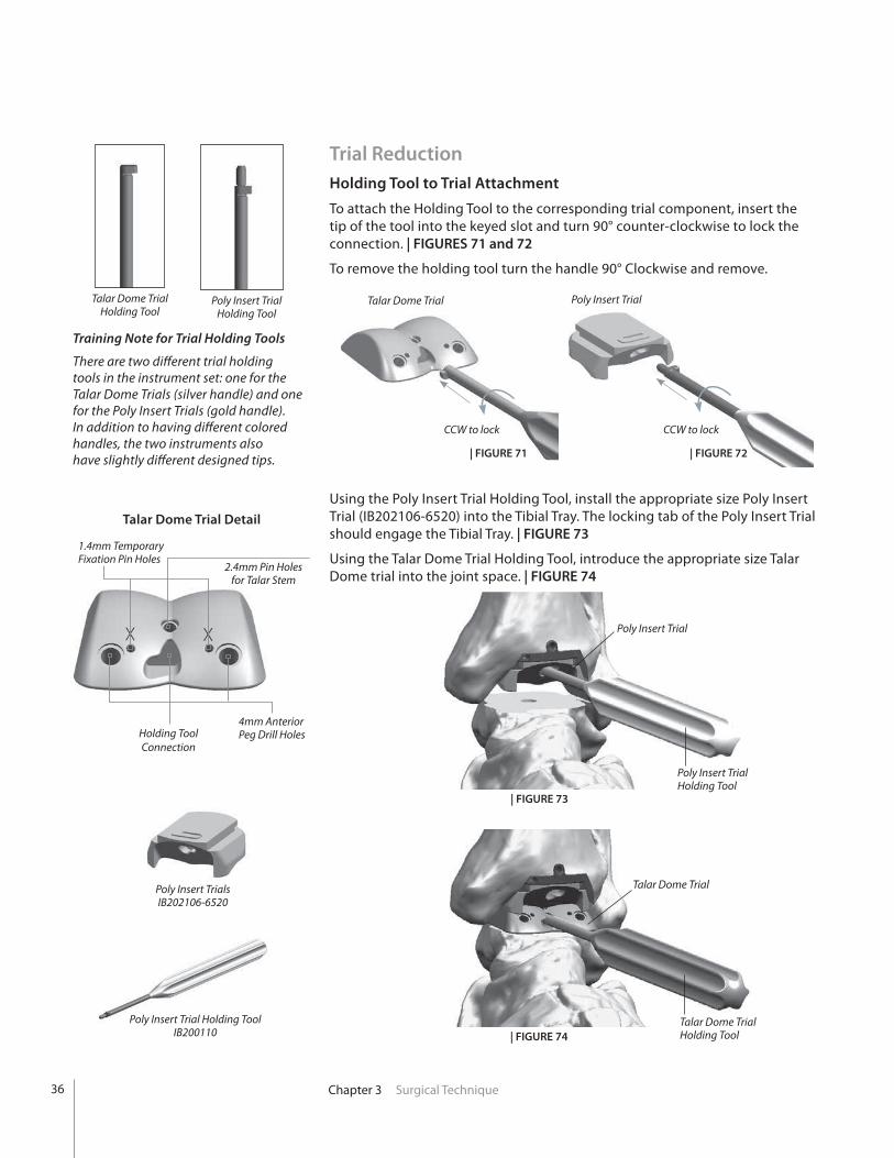
Training Note for Trial Holding Tools
There are two different trial holding tools in the instrument set: one for the Talar Dome Trials (silver handle) and one for the Poly Insert Trials (gold handle). In addition to having different colored handles, the two instruments also have slightly different designed tips.
Talar Dome Trial Holding Tool
Poly Insert Trial Holding Tool
Trial ReductionHolding Tool to Trial Attachment
To attach the Holding Tool to the corresponding trial component, insert the tip of the tool into the keyed slot and turn 90° counter-clockwise to lock the connection. | FIGURES 71 and 72
To remove the holding tool turn the handle 90° Clockwise and remove.
Using the Poly Insert Trial Holding Tool, install the appropriate size Poly Insert Trial (IB202106-6520) into the Tibial Tray. The locking tab of the Poly Insert Trial should engage the Tibial Tray. | FIGURE 73
Using the Talar Dome Trial Holding Tool, introduce the appropriate size Talar Dome trial into the joint space. | FIGURE 74
Talar Dome Trial
Talar Dome Trial Holding Tool
Talar Dome Trial Poly Insert Trial
CCW to lock CCW to lock
| FIGURE 72| FIGURE 71
| FIGURE 74
Poly Insert Trial Holding ToolIB200110
Talar Dome Trial Detail
Poly Insert TrialsIB202106-6520
1.4mm TemporaryFixation Pin Holes
2.4mm Pin Holesfor Talar Stem
4mm Anterior Peg Drill HolesHolding Tool
Connection
X X

37Chapter 3 Surgical Technique
Polyethylene Thickness
While the final polyethylene thickness does not have to be definitively chosen during the trial phase, it is important to have what is perceived to be the appropriate size trial poly to accurately determine the placement of the talar component. The trial poly used for the reduction should fit appropriately to determine the center of rotation of the talar component; therefore, trialing multiple size polys may be necessary. Note that after insertion of the final talar dome, the height of the poly can be reassessed.
In order to determine proper polyethylene height the following factors must be considered:
• Smooth range of motion of the ankle without anterior or posterior impingement.
• Ligaments are tensioned both medially and laterally WITHOUT over-tensioning. Over-tensioning is noted when the trial talar component tilts following trial poly insertion. Alternatively, with range of motion, the talar component becomes incongruent with the trial poly, which can identify too much tension on the ankle replacement. Over-tensioned joints may cause increased polyethylene wear, and should be avoided.
• Stress the ankle joint into varus and valgus. The trial components should not tilt.
• The trial poly should engage the sulcus in the talar dome trial without allowing medial/lateral translation.

38 Chapter 3 Surgical Technique
Under lateral plane fluoroscopy, ensure the posterior portion of the talar component is resting on the posterior portion of the patient’s residual talus (establish congruence). | FIGURE 75
While holding the talus in this position, use a marking pen to mark the anterior portion of the talar component with reference to the patient’s residual talus.
Be sure to observe the talar component with reference to the line on the residual talus previously drawn. This will ensure the talar component does not migrate anteriorly during the range of motion.
To accurately perform the range of motion, place some axial compression of the components to maintain position, and flex and extend the ankle. The surgeon will observe the talar component rotating into the anatomic position for this particular patient. Note that the surgeon must not only be cognizant of the talar position in the lateral plane, but must simultaneously maintain medial/lateral coverage as evidenced by the previous A/P plane fluoroscopic views.
Once Talar Dome Trial has settled into optimum anatomical position, install two 1.4mm pins through the Talar Dome Trial to temporarily hold it in place. | FIGURE 76
Note that with the talar component pinned in position, the surgeon should once again place the ankle through a range of motion to ensure tibio-talar articular congruence. Also, confirm through lateral fluoroscopy that the prosthesis did not shift anteriorly.
| FIGURE 75
1.4mm Pins
| FIGURE 76

39Chapter 3 Surgical Technique
2.4mm Pin
Using the 4mm Anterior Peg Drill (IB200020), drill a hole through the medial and lateral openings in the Talar Dome Trial. The drill has a hard stop designed to set the appropriate drilling depth in the talus for the Talar Dome anterior pegs. | FIGURE 77
Remove 1.4mm Pins and use the Talar Dome Trial Holding Tool to slide Talar Dome Trial off the remaining 2.4mm Steinmann Pin. The foot may be plantarflexed to aid in removal of Talar Dome Trial.
Install a 2.4mm Steinmann Pin through the center of the Talar Dome Trial to the depth of the selected Talar Stem using a lateral view to verify depth. Be certain that the Talar Dome Trial is sitting flush with the cut line of the talus before placing this pin. | FIGURE 80
Anterior Peg Drill
Use the Poly Insert Trial Holding Tool to remove the Poly Insert Trial. Foot may be plantarflexed to aid in removal of Poly Insert Trial. | FIGURES 78 and 79
CAUTION: The Poly Insert Trial has a small locking tab that engages the Tibial Tray. To remove Poly Insert Trial, be sure to first pull down on the holding tool to disengage tab before pulling out.
| FIGURE 80
| FIGURE 77
| FIGURE 79| FIGURE 78
4mm Anterior Peg DrillIB200020
40 Chapter 3 Surgical Technique
Talar Stem Reamer
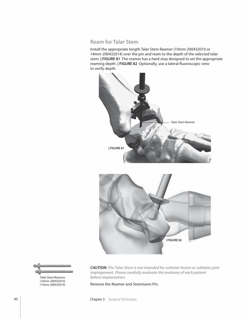
Ream for Talar StemInstall the appropriate length Talar Stem Reamer (10mm-200432010 or 14mm-200432014) over the pin and ream to the depth of the selected talar stem. | FIGURE 81 The reamer has a hard stop designed to set the appropriate reaming depth. | FIGURE 82 Optionally, use a lateral fluoroscopic view to verify depth.
CAUTION: The Talar Stem is not intended for subtalar fusion or subtalar joint impingement. Please carefully evaluate the anatomy of each patient before implantation.
Remove the Reamer and Steinmann Pin.
| FIGURE 81
| FIGURE 82
Talar Stem Reamers(10mm-200432010)(14mm-200432014)
41Chapter 3 Surgical Technique
Dome Strike Tool
Talar Dome
Strike Block
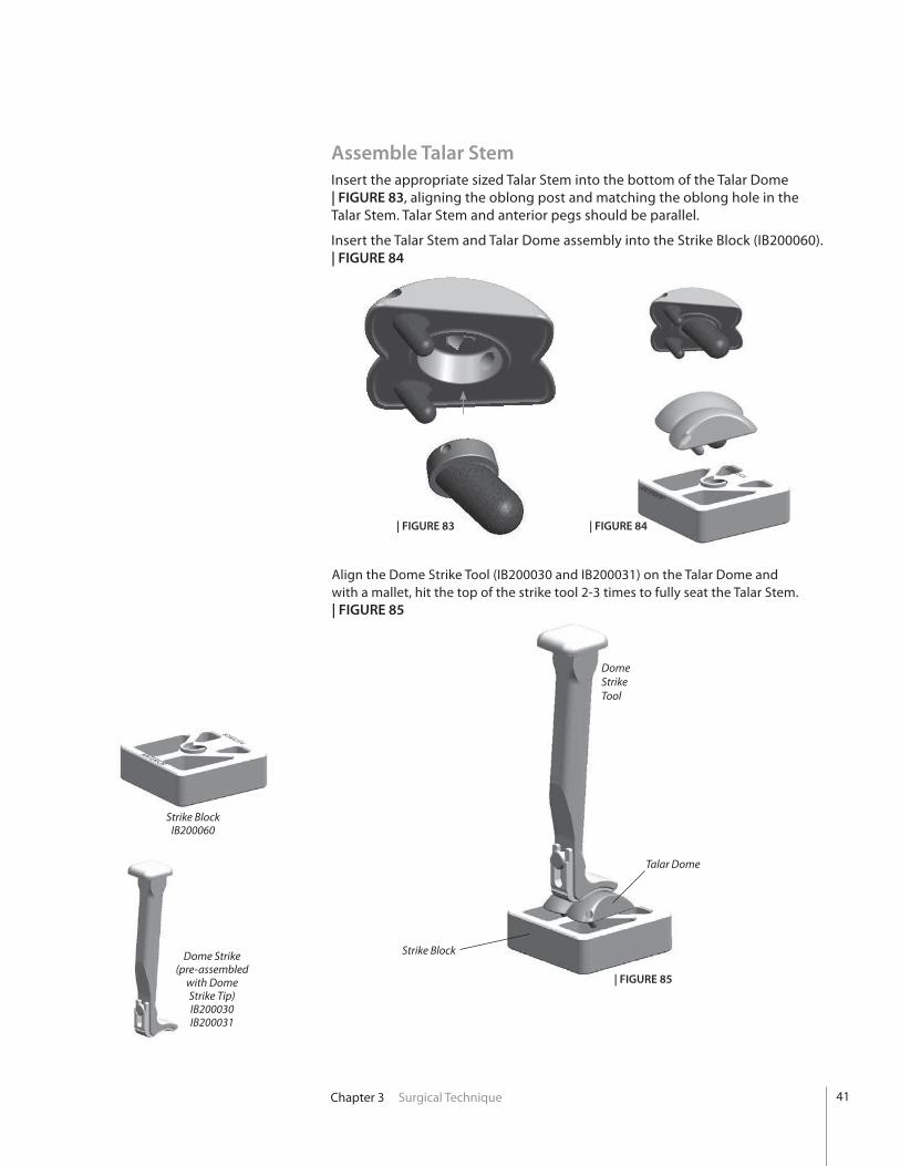
Assemble Talar StemInsert the appropriate sized Talar Stem into the bottom of the Talar Dome | FIGURE 83, aligning the oblong post and matching the oblong hole in the Talar Stem. Talar Stem and anterior pegs should be parallel.
Insert the Talar Stem and Talar Dome assembly into the Strike Block (IB200060). | FIGURE 84
| FIGURE 85
Dome Strike(pre-assembled
with Dome Strike Tip)IB200030IB200031
ANTERIOR
POSTERIOR
ANTERIOR
POSTERIOR
Align the Dome Strike Tool (IB200030 and IB200031) on the Talar Dome and with a mallet, hit the top of the strike tool 2-3 times to fully seat the Talar Stem. | FIGURE 85
| FIGURE 84| FIGURE 83
Strike BlockIB200060
42 Chapter 3 Surgical Technique
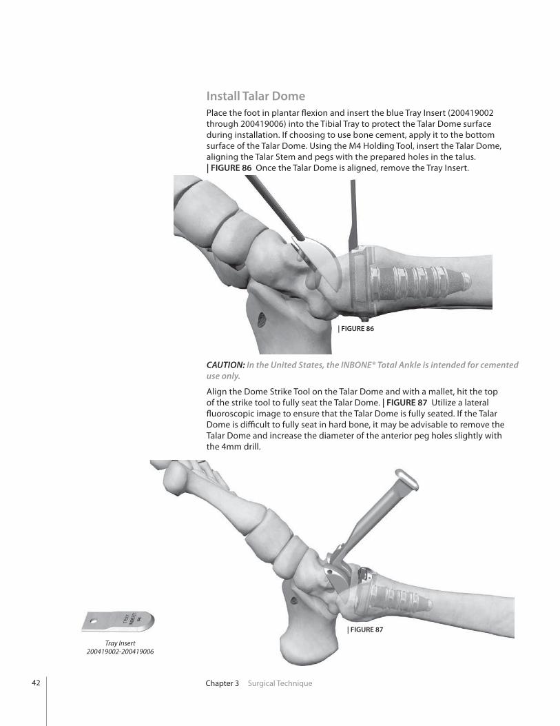
Install Talar DomePlace the foot in plantar flexion and insert the blue Tray Insert (200419002 through 200419006) into the Tibial Tray to protect the Talar Dome surface during installation. If choosing to use bone cement, apply it to the bottom surface of the Talar Dome. Using the M4 Holding Tool, insert the Talar Dome, aligning the Talar Stem and pegs with the prepared holes in the talus. | FIGURE 86 Once the Talar Dome is aligned, remove the Tray Insert.
Tray Insert200419002-200419006
| FIGURE 86
CAUTION: In the United States, the INBONE® Total Ankle is intended for cemented use only.
Align the Dome Strike Tool on the Talar Dome and with a mallet, hit the top of the strike tool to fully seat the Talar Dome. | FIGURE 87 Utilize a lateral fluoroscopic image to ensure that the Talar Dome is fully seated. If the Talar Dome is difficult to fully seat in hard bone, it may be advisable to remove the Talar Dome and increase the diameter of the anterior peg holes slightly with the 4mm drill.
| FIGURE 87

43Chapter 3 Surgical Technique
Install Poly InsertSelect the appropriate size Poly Insertion Tool (1000600102 through 100063106) and Plunger Block (200277002-006). Place a Nut Insert (200422) into the pocket of the Poly Insertion Tool. Position the Plunger Block at the back of the tool and retain with the appropriate Jack Screw (200278 or IB200040). | FIGURE 88 Jack Screw must match the Tibial Tray, e.g. size 3 Long Tibial Tray requires the use of the Long Jack Screw. Long Jack Screw is gold colored and standard Jack Screw is silver.
Select proper size Poly Insert and slide into the dovetail of the insertion tool.The anterior face of the Poly Insert (indentation) must face the Plunger.
Install the appropriate Attachment Screw (200329101 through 200329103) into the anti-rotation notch of the Tibial Tray. | FIGURE 89
Poly Insertion Tool
Poly Insert(note indention)
Jack Screw Plunger Block
Nut Insert
Attachment Screw
| FIGURE 89
Poly Insertion ToolLeft: 100063102-100063106
Right: 1000600102-1000600106
Nut Insert200422
Jack ScrewStandard: 200278
Long: IB200040
Attachment ScrewSize 1 & 2: 200329101Size 3 & 4: 200329102Size 5: 200329103
Plunger Block200277002-006
| FIGURE 88

44
Attachment Nut200329201
Chapter 3 Surgical Technique
Attachment Nut
Jack Screw
Insertion Tool
Tibial Tray
Attachment Screw
| FIGURE 90
Apply Reaction Force to keep tool at 90°
Slide the Poly Insertion Tool assembly over the Attachment Screw and align flush with the anterior surface of the Tibial Tray. Thread the Attachment Nut (200329201) onto the Attachment Screw to lock the Poly Insertion Tool to the Tibial Tray. | FIGURE 90
Turn the Jack Screw to advance the Poly Insert into the Tibial Tray.
CAUTION: To prevent incomplete seating of the poly insert, properly irrigate the tibial tray prior to poly insertion.
Apply slight “Reaction Force” as necessary to keep Insertion Tool at 90° to Tibia. | FIGURE 91
| FIGURE 91
90°
45Chapter 3 Surgical Technique
Poly Impact Tool200286
Poly Impact Tool
| FIGURE 91
Final Procedures
Check for proper articulation.
Close the wound.
Cast the foot in a slight dorsiflexion position.
Keep the foot non-weight bearing for 6 weeks.
| FIGURE 93 | FIGURE 94
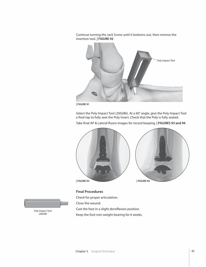
Select the Poly Impact Tool (200286). At a 60° angle, give the Poly Impact Tool a final tap to fully seat the Poly Insert. Check that the Poly is fully seated.
Take final AP & Lateral fluoro images for record keeping. | FIGURES 93 and 94
Continue turning the Jack Screw until it bottoms out, then remove the insertion tool. | FIGURE 92

46 Chapter 3 Surgical Technique
Morse Taper ReleaseThread Morse Taper Release Pin (200356003) into Morse Taper Release Handle (200355).
Insert tip of the Morse Taper Release Pin into the Morse Taper Release Hole of the Implant.
Angled surface of the Release Pin should face distally.
Holding the implant firmly, strike the end of the Morse Taper Release Handle with a mallet until the Morse Taper becomes unseated. | FIGURE 95
Morse Taper Release Pin
Threaded hole for holding tool
Morse Taper Release hole
Talar Dome
Talar Stem
Morse Taper Release Pin Tibial Tray
Morse Taper Release Hole
Base Stem
Tibial TrayTalar Dome
Morse Taper Release hole
Talar Dome
Note pin orientation
(Assembled Tool)
Morse Taper Release Handle(200355)
Morse Taper Release Pin, 3mm(200356003)
CAUTION: Release pin must be inserted into the Talar Dome from anterior to posterior to disengage taper. Failure to do so could result in pin becoming permanently jammed.
| FIGURE 95

47Chapter 3 Surgical Technique
Explant Information
INSERT REPLACEMENT
To remove the Poly Insert, first install two large diameter threaded Steinmann Pins into the anterior face of the implant. With a pair of pliers, pull distally on the Steinmann Pins in attempt to unlock the Insert from the Tibial Tray. A narrow osteotome may be inserted into the anterior region of the insert to facilitate removal. A hemostat may be used to remove the insert once it is no longer locked to the tibial base. Care must be taken not to scratch or mar any component that is not intended to be removed.
TIBIA AND TALAR COMPONENTS
To remove the components, small osteotomes, power saws, or other surgical instruments may be used to disrupt the bone-cement interface. Care must be exhibited to save remaining bone stock as well as to prevent fracture. Once the components have been removed, rongeurs or small osteotomes, as well as other surgical instruments, may be used to remove the remaining cement.
Postoperative ManagementPostoperative care is the responsibility of the medical professional.
48 Appendix A PROPHECY® INBONE® Instrumentation
Ap
pen
dix
A
PROPHECY® INBONE®Instrumentation
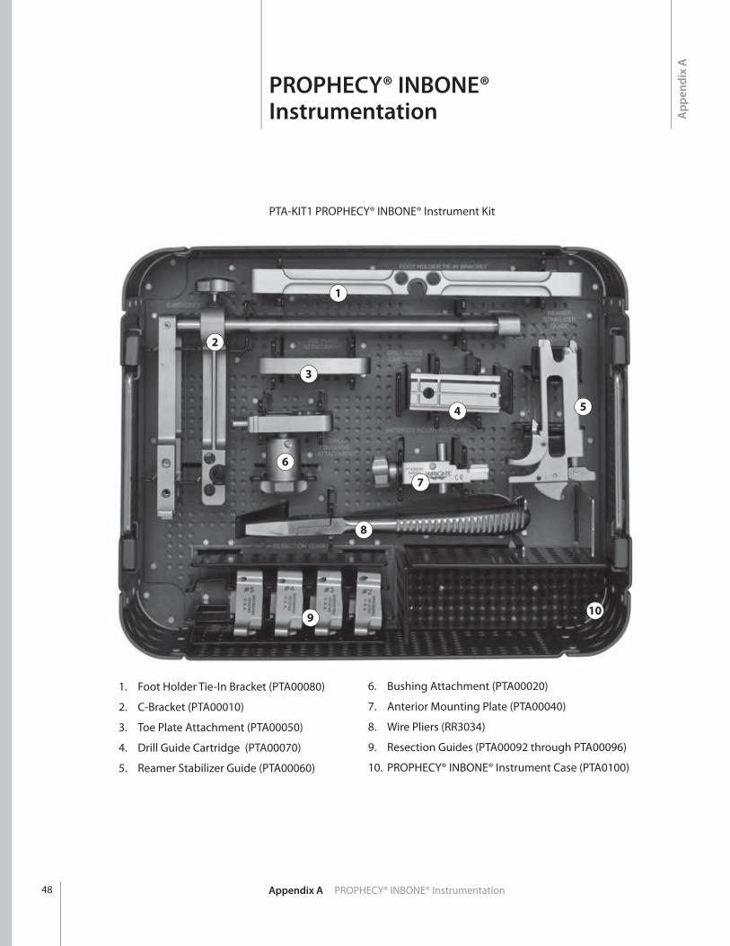
PTA-KIT1 PROPHECY® INBONE® Instrument Kit
1. Foot Holder Tie-In Bracket (PTA00080)
2. C-Bracket (PTA00010)
3. Toe Plate Attachment (PTA00050)
4. Drill Guide Cartridge (PTA00070)
5. Reamer Stabilizer Guide (PTA00060)
6. Bushing Attachment (PTA00020)
7. Anterior Mounting Plate (PTA00040)
8. Wire Pliers (RR3034)
9. Resection Guides (PTA00092 through PTA00096)
10. PROPHECY® INBONE® Instrument Case (PTA0100)
1
3
4
6
7
8
2
5
109
49Appendix B Stem Specifi cations
Ap
pen
dix
B
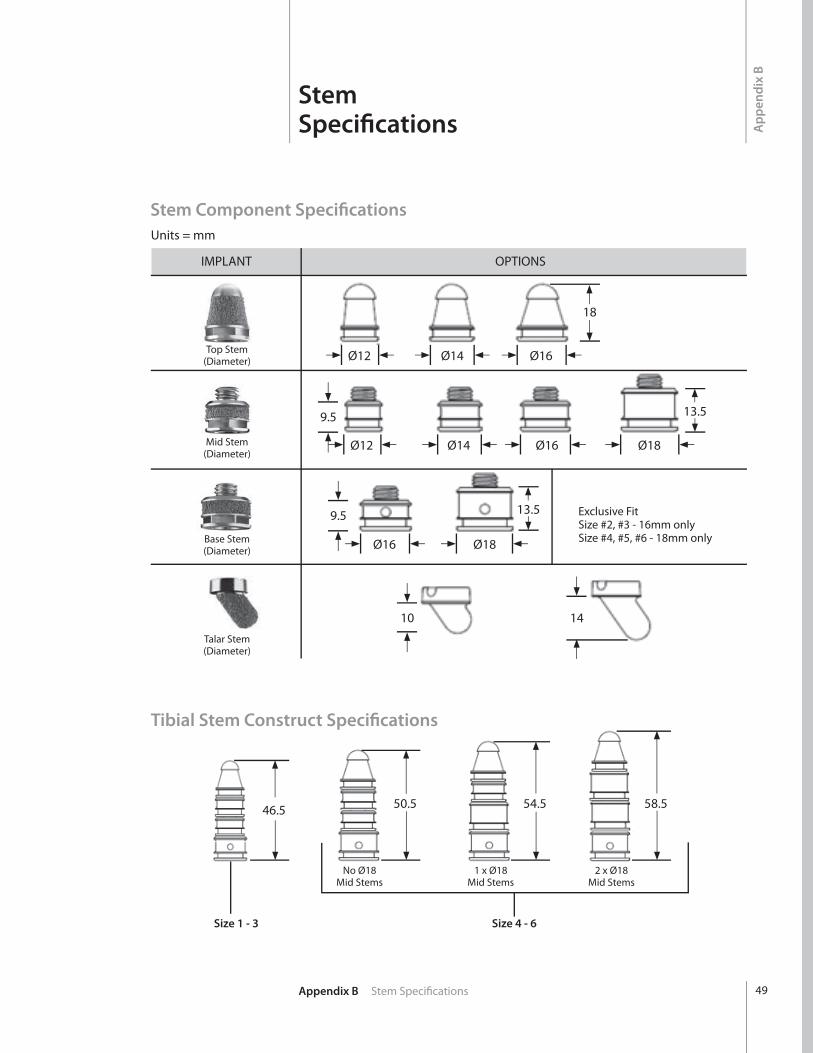
StemSpecifi cations
Units = mm
IMPLANT OPTIONS
Ø12 Ø14 Ø16Top Stem(Diameter)
Mid Stem(Diameter)
Base Stem(Diameter)
Talar Stem(Diameter)
18
10 14
Ø16 Ø18
9.5
9.5 13.5
13.5
Ø12 Ø14 Ø16 Ø18
Exclusive FitSize #2, #3 - 16mm onlySize #4, #5, #6 - 18mm only
Stem Component Specifi cations
Tibial Stem Construct Specifi cations
Size 1 - 3 Size 4 - 6
No Ø18Mid Stems
1 x Ø18Mid Stems
2 x Ø18Mid Stems
46.5 50.5 54.5 58.5

50 Appendix C Implant Specifi cations
Ap
pen
dix
C
ImplantSpecifi cations
Size A B C
2 26 32 7 2 Long 26 36 7 3 28 36 7.5 3 Long 28 39 7.5 4 31 39 8 4 Long 31 42 8 5 34 42 9 5 Long 34 46 9 6 37 46 10
INBONE® Tibial Component
C
(mm)
A
(mm)
B
(mm)
B
(mm)
A
(mm)
C
(mm)
Size A B C
1 30 32 10 2 33 34 10 3 36 36 10 4 39 39 11 5 42 42 12
INBONE® Sulcus Talar Component

51Appendix D Ordering Information
Ap
pen
dix
D
OrderingInformation
Tibial Stems Plasma Coated
Catalog # Description200011901 Top Stem, 14mm, Plasma Coated
200011902 Top Stem, 16mm, Plasma Coated
200011904 Top Stem, 12mm, Plasma Coated
200010901 Mid Stem, 14mm, Plasma Coated
200010902 Mid Stem, 16mm, Plasma Coated
200010903 Mid Stem, 18mm, Plasma Coated
200010904 Mid Stem, 12mm, Plasma Coated
200009901 Base Stem, 16mm, Plasma Coated
200009902 Base Stem, 18mm, Plasma Coated
Standard Tibial Trays
Catalog # Description200252902 Size #2, Left
200252903 Size #3, Left
200252904 Size #4, Left
200252905 Size #5, Left
200252906 Size #6, Left
200222902 Size #2, Right
200222903 Size #3, Right
200222904 Size #4, Right
200222905 Size #5, Right
200222906 Size #6, Right
Long Tibial Trays
Catalog # Description220252902 Size #2 Long, Left
220252903 Size #3 Long, Left
220252904 Size #4 Long, Left
220252905 Size #5 Long, Left
220222902 Size #2 Long, Right
220222903 Size #3 Long, Right
220222904 Size #4 Long, Right
220222905 Size #5 Long, Right
Tibial Stems Smooth Coated
Catalog # Description200012904 Top Stem, 12mm, Smooth200012901 Top Stem, 14mm, Smooth200012902 Top Stem, 16mm, Smooth200014904 Mid Stem, 12mm, Smooth200014901 Mid Stem, 14mm, Smooth200014902 Mid Stem, 16mm, Smooth200014903 Mid Stem, 18mm, Smooth

52 Appendix D Ordering Information
Sulcus Talar Dome
Catalog # Description220220902 Size #2, Right & Left
220220903 Size #3, Right & Left
220220904 Size #4, Right & Left
220220905 Size #5, Right & Left
Talar Stem
Catalog # Description200347901 10mm Long
200347902 14mm Long
Sulcus Poly Insert
Catalog # Description220222106E Size #1+, 6mm Thick, Right & Left
220222108E Size #1+, 8mm Thick, Right & Left
220222206E Size #2, 6mm Thick, Right & Left
220222208E Size #2, 8mm Thick, Right & Left
220222210E Size #2, 10mm Thick, Right & Left
220222212E Size #2, 12mm Thick, Right & Left
220223308E Size #3, 8mm Thick, Right & Left
220223310E Size #3, 10mm Thick, Right & Left
220223312E Size #3, 12mm Thick, Right & Left
220223314E Size #3, 14mm Thick, Right & Left
220224409E Size #4, 9mm Thick, Right & Left
220224411E Size #4, 11mm Thick, Right & Left
220224413E Size #4, 13mm Thick, Right & Left
220224415E Size #4, 15mm Thick, Right & Left
220225509E Size #5, 9mm Thick, Right & Left
220225511E Size #5, 11mm Thick, Right & Left
220225513E Size #5, 13mm Thick, Right & Left
220225515E Size #5, 15mm Thick, Right & Left

53Appendix D Ordering Information
Sulcus Plus-Size Poly Insert
Catalog # Description220223208E Size #2 Plus, 8mm Thick, Right & Left
220223210E Size #2 Plus, 10mm Thick, Right & Left
220223212E Size #2 Plus, 12mm Thick, Right & Left
220223214E Size #2 Plus, 14mm Thick, Right & Left
220224310E Size #3 Plus, 10mm Thick, Right & Left
220224312E Size #3 Plus, 12mm Thick, Right & Left
220224314E Size #3 Plus, 14mm Thick, Right & Left
220224316E Size #3 Plus, 16mm Thick, Right & Left
220225410E Size #4 Plus, 10mm Thick, Right & Left
220225412E Size #4 Plus, 12mm Thick, Right & Left
220225414E Size #4 Plus, 14mm Thick, Right & Left
220225416E Size #4 Plus, 16mm Thick, Right & Left
220226510E Size #5 Plus, 10mm Thick, Right & Left
220226512E Size #5 Plus, 12mm Thick, Right & Left
220226514E Size #5 Plus, 14mm Thick, Right & Left
220226516E Size #5 Plus, 16mm Thick, Right & Left
Accessories
Catalog # Description200178002 Drill, Size 2 Anti-Rotation Notch
200178003 Drill, Size 3 Anti-Rotation Notch
200178004 Drill, Size 4 Anti-Rotation Notch
200178005 Drill, Size 5 Anti-Rotation Notch
200178006 Drill, Size 6 Anti-Rotation Notch
200134 Drill, 6mm
200072 2.4mm Steinmann Pin
500036 1.4mm K-Wire
IB200051 Bone Removal Screw
200138101S Saw Blade Stryker Narrow
200138102S Saw Blade Stryker Wide
200138103S Saw Blade Hall/Linvatec Narrow
200138104S Saw Blade Hall/Linvatec Wide
200138105S Saw Blade Stryker System 6 Narrow
200138106S Saw Blade Stryker System 6 Wide
200138107S Saw Blade Stryker System 7 Narrow
200138108S Saw Blade Stryker System 7 Wide

54
Large Revision Polys
Catalog # Description220222114E INBONE® Poly SZ 1+ 14mm Sulcus Total Ankle
220222116E INBONE® Poly SZ 1+ 16mm Sulcus Total Ankle
220222214E INBONE® Poly SZ 2 14mm Sulcus Total Ankle
220222216E INBONE® Poly SZ 2 16mm Sulcus Total Ankle
220223216E INBONE® Poly SZ 2+ 16mm Sulcus Total Ankle
220223218E INBONE® Poly SZ 2+ 18mm Sulcus Total Ankle
220223316E INBONE® Poly SZ 3 16mm Sulcus Total Ankle
220223318E INBONE® Poly SZ 3 18mm Sulcus Total Ankle
220224318E INBONE® Poly SZ 3+ 18mm Sulcus Total Ankle
220224320E INBONE® Poly SZ 3+ 20mm Sulcus Total Ankle
220224417E INBONE® Poly SZ 4 17mm Sulcus Total Ankle
220224419E INBONE® Poly SZ 4 19mm Sulcus Total Ankle
220225418E INBONE® Poly SZ 4+ 18mm Sulcus Total Ankle
220225420E INBONE® Poly SZ 4+ 20mm Sulcus Total Ankle
220225517E INBONE® Poly SZ 5 17mm Sulcus Total Ankle
220225519E INBONE® Poly SZ 5 19mm Sulcus Total Ankle
220226518E INBONE® Poly SZ 5+ 18mm Sulcus Total Ankle
220226520E INBONE® Poly SZ 5+ 20mm Sulcus Total Ankle
Appendix D Ordering Information

55Appendix E PROPHECY® Tie-In to the INBONE® Foot Holder Surgical Technique
PROPHECY® Tie-In to the INBONE® Foot Holder Surgical Procedure
Tie-In BracketPTA00080
The following steps must occur after the Tibia Stem Guide assembly is secured in the resected joint space.
Attach the Foot Holder Tie-In Bracket (PTA00080) to the Anterior Mounting Plate. | FIGURES 96 and 97
Lower the Foot Holder Tie-In Bracket assembly down over the Anterior Mounting Plate and attach through the two protruding dowel pins. The surface of the Foot Holder Tie-In Bracket arm must sit flat against the Anterior Mounting Plate. | FIGURE 98
Secure the Foot Holder Tie-In Bracket to the Anterior Mounting Plate by rotating the swivel rod up and over the Foot Holder Tie-In Bracket arm and tightening the screw on the end of the swivel rod. | FIGURES 99 and 100
| FIGURE 96 | FIGURE 97
| FIGURE 98 | FIGURE 99 | FIGURE 100
Foot Holder Tie-In Bracket
Ap
pen
dix
E

56 Appendix E PROPHECY® Tie-In to the INBONE® Foot Holder Surgical Technique
INBONE® Foot Holder
| FIGURE 101 | FIGURE 102
Place the foot in the INBONE® Foot Holder. (The foot holder must be set to zero/neutral location for all adjustment directions.) | FIGURE 101
Place the M/L Guide Rods through the INBONE® foot holder and through the matching holes in the Tie-In Bracket. (Adjust the location of the entire foot holder and the foot until the holes are aligned. Adjust the Achilles and Calf supports to align the foot to the ML alignment rods in the AP direction.) | FIGURE 102
Slide the foot down until it hits the foot plate. Do not secure the foot/leg to the foot holder at this time. Follow the standard procedure for marking and starting the distal incision.
Use the AP and ML alignment rods with fluoroscopy to confirm the alignment in the foot holder. Secure the foot/leg to the foot holder with coban and k-wires into the calcaneous. Remove the M/L Guide Rods, the Tie-In Bracket, and the Tibia Stem Guide assembly.
Complete the procedure following the standard INBONE® surgical technique (FA553-712) for alignment (if necessary), drilling, reaming, and implantation.
57Appendix F Tibia Alignment Guide Fluoroscopic Check Assembly
Ap
pen
dix
F
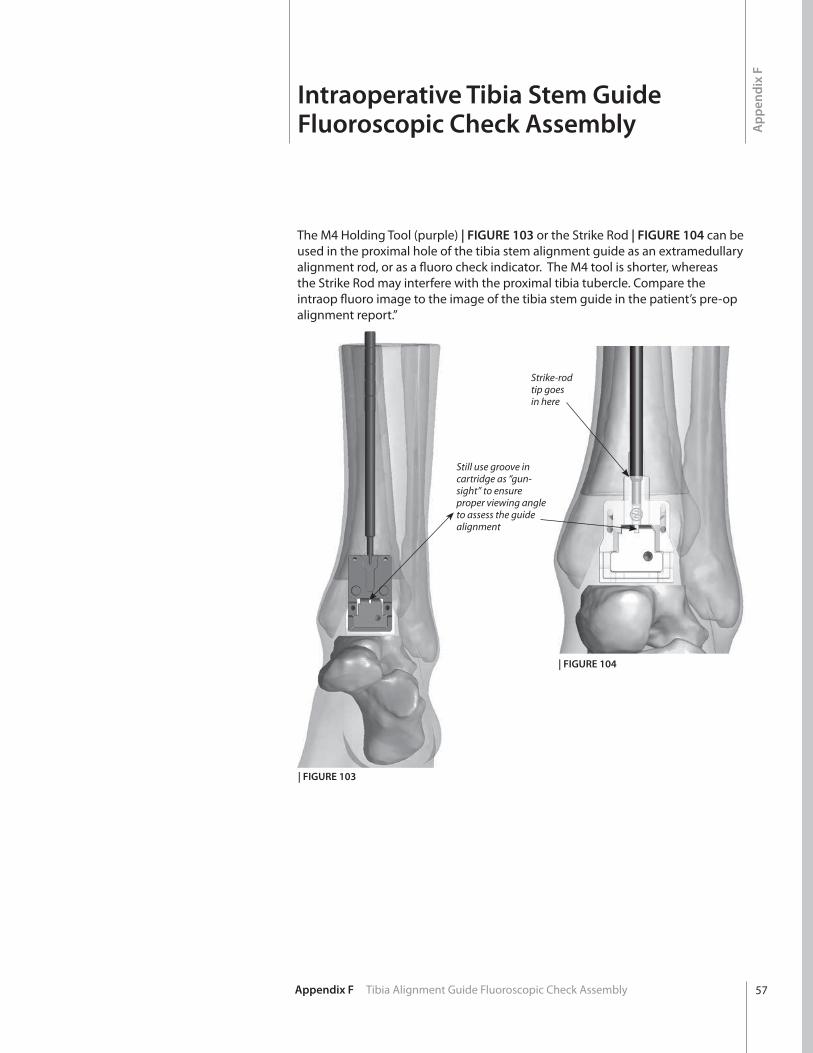
The M4 Holding Tool (purple) | FIGURE 103 or the Strike Rod | FIGURE 104 can be used in the proximal hole of the tibia stem alignment guide as an extramedullary alignment rod, or as a fluoro check indicator. The M4 tool is shorter, whereas the Strike Rod may interfere with the proximal tibia tubercle. Compare the intraop fluoro image to the image of the tibia stem guide in the patient’s pre-op alignment report.”
| FIGURE 103
| FIGURE 104
Still use groove in cartridge as “gun-sight” to ensure proper viewing angle to assess the guide alignment
Strike-rod tip goes in here
Intraoperative Tibia Stem Guide Fluoroscopic Check Assembly
58 Appendix G Additional Holes in Talus Alignment Guide
Ap
pen
dix
G
Additional Holes inTalus Alignment Guide
| FIGURE 106
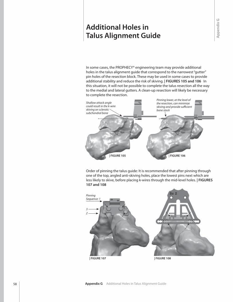
Order of pinning the talus guide: It is recommended that after pinning through one of the top, angled anti-skiving holes, place the lowest pins next which are less likely to skive, before placing k-wires through the mid-level holes. | FIGURES 107 and 108
| FIGURE 105
In some cases, the PROPHECY® engineering team may provide additional holes in the talus alignment guide that correspond to the narrowest “gutter” pin holes of the resection block. These may be used in some cases to provide additional stability and reduce the risk of skiving. | FIGURES 105 and 106 In this situation, it will not be possible to complete the talus resection all the way to the medial and lateral gutters. A clean-up resection will likely be necessary to complete the resection.
| FIGURE 108| FIGURE 107
PinningSequence: 1
32
Shallow attack angle could result in the k-wire skiving on sclerotic subchondral bone
Pinning lower, at the level of the resection, can minimize skiving and provide sufficient bone stock

59Appendix G Additional Holes in Talus Alignment Guide
For severely flat-topped taluses or other conditions in which insufficient bone stock for pinning exists, holes may be provided in the talus alignment guide for the size 6 cut block in an upside-down orientation. This allows us to place pins below the level of the resection in order to get sufficient bone fixation.
When pinning above the resection could result in k-wire skiving or insufficient fixation in thin bone stock as shown in FIGURE 109, the alternative talus alignment guide design may be implemented by the case processing engineers, as depicted in FIGURES 110, 111 and 112.
For this flat-topped talus, the resection level shown as dotted line, results in k-wires in shallow bone stock.
As an alternative, the talus alignment guide may be designed to place k-wires below the resection level which match with the k-wires of the size 6 resection guide in an upside-down orientation (see black arrows).
| FIGURE 109 | FIGURE 110
| FIGURE 111 | FIGURE 112
60 Appendix H Tips and Tricks
Ap
pen
dix
H
Tips & Tricks
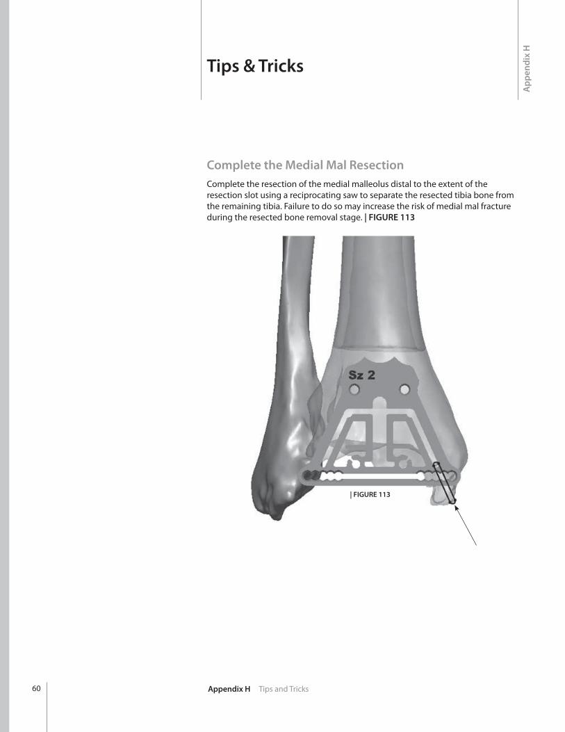
Complete the Medial Mal ResectionComplete the resection of the medial malleolus distal to the extent of the resection slot using a reciprocating saw to separate the resected tibia bone from the remaining tibia. Failure to do so may increase the risk of medial mal fracture during the resected bone removal stage. | FIGURE 113
| FIGURE 113

™Trademarks and ®Registered marks of Wright Medical Technology, Inc. ©2015 Wright Medical Technology, Inc.All Rights Reserved. 011943B_18-Aug-2015
1023 Cherry RoadMemphis, TN 38117800 238 7117901 867 9971www.wright.com
62 Quai Charles de Gaulle69006 LyonFrance+33 (0)4 72 84 10 30www.tornier.com
Unit 1, Campus FiveLetchworth Garden CityHertfordshire SG6 2JF United Kingdom+011 44 (0)845 833 4435