Embed Size (px)
Citation preview
Edition 2.0 Controller series A CE1U2355en_02 3. Juli 2008
Siemens Switzerland LtdHVAC Products
Albatros2
Heat pump controller User manual
RVS41.813RVS61.843
AVS75..AVS37..QAA75..QAA78..QAA55..

2/235
Siemens Switzerland Ltd Basic units RVS61.843 and RVS41.813 CE1U2355en_02 HVAC Products 3. Juli 2008
3/235
Siemens Switzerland Ltd Basic units RVS61.843 and RVS41.813 CE1U2355en_02 HVAC Products Contents 3. Juli 2008
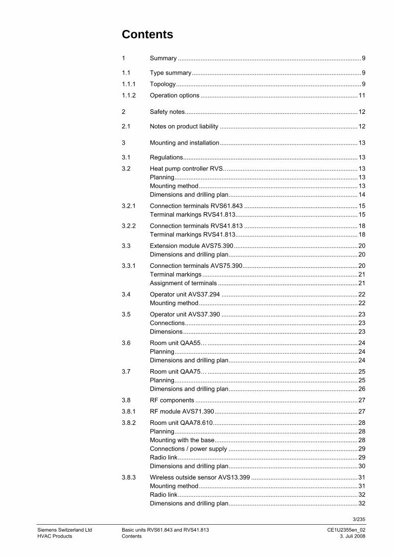
Contents
1 Summary .........................................................................................................9
1.1 Type summary.................................................................................................9 1.1.1 Topology..........................................................................................................9 1.1.2 Operation options ..........................................................................................11
2 Safety notes...................................................................................................12
2.1 Notes on product liability ...............................................................................12
3 Mounting and installation...............................................................................13
3.1 Regulations....................................................................................................13 3.2 Heat pump controller RVS.............................................................................13
Planning.........................................................................................................13 Mounting method...........................................................................................13 Dimensions and drilling plan..........................................................................14
3.2.1 Connection terminals RVS61.843 .................................................................15 Terminal markings RVS41.813......................................................................15
3.2.2 Connection terminals RVS41.813 .................................................................18 Terminal markings RVS41.813......................................................................18
3.3 Extension module AVS75.390.......................................................................20 Dimensions and drilling plan..........................................................................20
3.3.1 Connection terminals AVS75.390..................................................................20 Terminal markings .........................................................................................21 Assignment of terminals ................................................................................21
3.4 Operator unit AVS37.294 ..............................................................................22 Mounting method...........................................................................................22
3.5 Operator unit AVS37.390 ..............................................................................23 Connections...................................................................................................23 Dimensions....................................................................................................23
3.6 Room unit QAA55… ......................................................................................24 Planning.........................................................................................................24 Dimensions and drilling plan..........................................................................24
3.7 Room unit QAA75… ......................................................................................25 Planning.........................................................................................................25 Dimensions and drilling plan..........................................................................26
3.8 RF components .............................................................................................27 3.8.1 RF module AVS71.390..................................................................................27 3.8.2 Room unit QAA78.610...................................................................................28
Planning.........................................................................................................28 Mounting with the base..................................................................................28 Connections / power supply ..........................................................................29 Radio link.......................................................................................................29 Dimensions and drilling plan..........................................................................30
3.8.3 Wireless outside sensor AVS13.399 .............................................................31 Mounting method...........................................................................................31 Radio link.......................................................................................................32 Dimensions and drilling plan..........................................................................32
4/235
Siemens Switzerland Basic units RVS61.843 and RVS41.813 CE1U2355en_02 HVAC Products Contents 3. Juli 2008
3.8.4 RF repeater AVS14.390.................................................................................33 Mounting method ...........................................................................................33 Connections ...................................................................................................33 Radio link .......................................................................................................33 Dimensions and drilling plan ..........................................................................34
3.8.5 Checking the RF components........................................................................34
4 Commissioning ..............................................................................................35
4.1 Heat pump controller......................................................................................35
5 Handling.........................................................................................................36
5.1 QAA75.. / QAA78.. / AVS37...........................................................................36 5.1.1 Operation .......................................................................................................36
Operating elements........................................................................................36 Display choices ..............................................................................................37 Selection of space heating mode...................................................................37 Selecting cooling mode..................................................................................38 Selecting DHW heating mode........................................................................38 Adjusting the room temperature setpoint .......................................................39 Occupancy button ..........................................................................................39 Displaying information....................................................................................39 Manual defrost of HP / reset ..........................................................................41
5.1.2 Programming the QAA75... / QAA78… / AVS37.. .........................................42 Setting principle .............................................................................................42 Example “Setting the time of day“..................................................................42
5.1.3 User levels .....................................................................................................43 Setting structure “Enduser“ ............................................................................44 Setting structure ”Heating engineer“ ..............................................................44
5.1.4 Overview of the settings.................................................................................45 5.2 QAA55... ........................................................................................................74 5.2.1 Operation .......................................................................................................74
Operating elements........................................................................................74 Display choices ..............................................................................................74 Selection of space heating mode...................................................................74 Indication of cooling mode (if available).........................................................75 Adjusting the room temperature setpoint .......................................................75 Occupancy button ..........................................................................................75
5.2.2 Programming .................................................................................................75
6 The settings in detail ......................................................................................77
6.1 Time of day and date .....................................................................................77 6.2 Operator section ............................................................................................77
Operation and display ....................................................................................77 Heating circuit assignment.............................................................................79 Room sensor..................................................................................................79 Device data ....................................................................................................80
6.3 Radio links .....................................................................................................80 Binding ...........................................................................................................80 List of RF devices ..........................................................................................80
6.4 Time programs...............................................................................................81
5/235
Siemens Switzerland Ltd Basic units RVS61.843 and RVS41.813 CE1U2355en_02 HVAC Products Contents 3. Juli 2008
Switching points.............................................................................................81 Standard program..........................................................................................81
6.5 Holidays.........................................................................................................81 6.6 Heating circuits ..............................................................................................82
Operating mode.............................................................................................82 Setpoints........................................................................................................82 ECO functions ...............................................................................................84 Flow temperature setpoint limitations ............................................................85 Room influence..............................................................................................86 Room temperature limitation .........................................................................87 Boost heating.................................................................................................87 Quick setback ................................................................................................88 Optimum start / stop control ..........................................................................88 Raising the Reduced setpoint........................................................................89 Overtemp prot pump heating circuit ..............................................................89 Mixing valve control .......................................................................................90 Floor curing function ......................................................................................90 Excess heat draw ..........................................................................................93 Buffer storage tank / primary controller .........................................................93 Remote control ..............................................................................................94 Frost protection for the heating circuit ...........................................................94
6.7 Cooling circuit 1 .............................................................................................94 Setpoints........................................................................................................95 Release .........................................................................................................96 Cooling curve.................................................................................................96 ECO...............................................................................................................97 Summer compensation..................................................................................97 Flow temperature setpoint limitations ............................................................98 Room influence..............................................................................................98 Room temperature limitation .........................................................................99 Mixing valve control .....................................................................................100 Dewpoint supervision ..................................................................................100 Buffer storage tank / primary controller .......................................................102 Remote control ............................................................................................102 Frost protection for the heating circuit .........................................................102
6.8 Domestic hot water......................................................................................102 Summary .....................................................................................................102 Setpoints......................................................................................................102 Release .......................................................................................................103 Charging priority ..........................................................................................104 Legionella function.......................................................................................105 Circulating pump..........................................................................................106
6.9 Hx pumps ....................................................................................................106 Hx pumps ....................................................................................................106
6.10 Swimming pool ............................................................................................108 Summary .....................................................................................................108 Setpoints......................................................................................................108 Priority .........................................................................................................108 Plant hydraulics ...........................................................................................109
6.11 Primary controller/system pump..................................................................109 Summary .....................................................................................................109 Primary controller/system pump..................................................................109
6.12 Heat pump ...................................................................................................109
6/235
Siemens Switzerland Basic units RVS61.843 and RVS41.813 CE1U2355en_02 HVAC Products Contents 3. Juli 2008
Function diagrams .......................................................................................109 Condenser pump .........................................................................................110 Source pump................................................................................................111 Compressor control in plants without buffer or combi storage tank .............113 Compressor control in plants with buffer or combi storage tank ..................114 Compressor settings ....................................................................................114 Compressor 2 ..............................................................................................116 Electric immersion heater in the flow ...........................................................118 Heat pump protection during DHW charging ...............................................120 General parameters .....................................................................................121 Defrost function for air-to-water heat pumps................................................124 Automatic defrost function ...........................................................................124
6.13 Cascade.......................................................................................................130 Control .........................................................................................................130 Heat source sequence .................................................................................131 Auto source seq exclusion ...........................................................................132 Electric immersion heaters in the cascade ..................................................132
6.14 Supplementary source (only RVS41...)........................................................133 Operating mode ...........................................................................................133 Overtemperature protection .........................................................................133
6.15 Solar.............................................................................................................135 Summary......................................................................................................135 Charging controller solar (dT) ......................................................................135 Priority..........................................................................................................136 Start function................................................................................................137 Collector frost protection ..............................................................................137 Overtemperature protection for the collector ...............................................137 Medium’s evaporation temperature .............................................................138 Speed control...............................................................................................138 Yield measurement ......................................................................................138
6.16 Buffer sensor................................................................................................139 Summary......................................................................................................139 Forced charging ...........................................................................................139 Automatic locks............................................................................................140 Schichtschutz...............................................................................................141 Overtemperature protection .........................................................................141 Recooling .....................................................................................................142 Electric immersion heater ............................................................................142 Solar integration...........................................................................................143
6.17 DHW storage tank........................................................................................143 Abortion of DHW charging ...........................................................................143 Charging control...........................................................................................143 Overtemperature protection .........................................................................144 Recooling .....................................................................................................144 Electric immersion heater ............................................................................145 Excess heat draw.........................................................................................146 Plant hydraulics............................................................................................146 Speed-controlled pump................................................................................147 Transfer........................................................................................................148
6.18 Instantaneous DHW heater (only RVS61.843) ............................................149 Summary......................................................................................................149 Configuration................................................................................................149 Setpoints ......................................................................................................149
7/235
Siemens Switzerland Ltd Basic units RVS61.843 and RVS41.813 CE1U2355en_02 HVAC Products Contents 3. Juli 2008
Speed-controlled pump ...............................................................................150 Mixing valve control .....................................................................................150
6.19 Configuration ...............................................................................................150 Procedure ....................................................................................................150 Preselection of plant diagram.....................................................................150 Manual setting / adjustment of partial diagrams.........................................150 Heating/cooling circuit 1 ..............................................................................151 Heating circuit 2...........................................................................................152 DHW controlling element Q3 .......................................................................152 Separate DHW circuit ..................................................................................152 Heat pump ...................................................................................................153 Solar ............................................................................................................154 Buffer storage tank ......................................................................................155 Output relay QX...........................................................................................155 Function output QX4-Mod ...........................................................................160 Sensor input BX1, BX2, BX3, BX4, BX5 .....................................................160 Input H1, H3 ................................................................................................161 Input EX1, EX2, EX3, EX4, EX5, EX6, EX7................................................166 Mixing group ................................................................................................169 Extension module ........................................................................................169 Frost protection on the extension module ...................................................170 QX extension module ..................................................................................171 BX extension module...................................................................................171 H2 extension module...................................................................................172 10V output UX .............................................................................................172 Types of sensor / readjustment ...................................................................173 Building and room model.............................................................................173 Frost protection for the plant........................................................................174 Air dehumidifier............................................................................................174 Sensors .......................................................................................................175 Parameters ..................................................................................................175 Plant diagram ..............................................................................................175 Device data..................................................................................................178
6.20 LPB..............................................................................................................178 Address / power supply ...............................................................................178 Central functions..........................................................................................179 Clock............................................................................................................180
6.21 Errors...........................................................................................................181 Reset ...........................................................................................................181 Error message functions..............................................................................181 Error history .................................................................................................181 Error list .......................................................................................................182
6.22 Service / special operation ..........................................................................185 Maintenance functions.................................................................................185 Other maintenance messages.....................................................................187 Economy mode............................................................................................188 Emergency operation ..................................................................................188 Simulation....................................................................................................189 Manual defrost.............................................................................................189 Resetting limitations ....................................................................................189 Definition of responsibilities .........................................................................189
6.23 Input / output test.........................................................................................189 Output test relays ........................................................................................189 Output test UX.............................................................................................190
8/235
Siemens Switzerland Basic units RVS61.843 and RVS41.813 CE1U2355en_02 HVAC Products Contents 3. Juli 2008
Input test sensors.........................................................................................190 Input test E...................................................................................................191
6.24 State.............................................................................................................192 Messages.....................................................................................................192 History..........................................................................................................196
6.25 Diagnostics cascade ....................................................................................196 Priority/state .................................................................................................196
6.26 Diagnostics heat source...............................................................................196 Brine-to-water heat pump ............................................................................196 Setpoints and actual values .........................................................................197 Time / start counter ......................................................................................198 Heat pump air ..............................................................................................198 Solar.............................................................................................................199
6.27 Diagnostics consumers................................................................................200 Outside temperature ....................................................................................200 Room temperature .......................................................................................200 Heating circuits 1, 2, P .................................................................................201 Cooling circuit 1 ...........................................................................................201 Domestic hot water ......................................................................................202 Swimming pool.............................................................................................202 Primary controller.........................................................................................202 Common flow...............................................................................................202 Buffer sensor................................................................................................202 Input H1 .......................................................................................................203 Water pressure ............................................................................................203 States multifunctional relays ........................................................................203 States of relays extension modules 1 and 2 ................................................203
6.28 Pump kick ....................................................................................................204
7 Plant diagrams.............................................................................................205
7.1 Basic diagrams ............................................................................................205 Legend (catalog of plant diagrams and extra functions) ..............................220
8 Technical data..............................................................................................221
8.1 Basic units RVS61.843 and RVS41.813......................................................221 8.2 Extension module AVS75.390 .....................................................................222 8.3 Operator and room unit AVS37... / QAA7x… / QAA55.. ..............................223 8.4 RF module AVS71.390 ................................................................................224 8.5 Wireless outside sensor AVS13.399............................................................225 8.6 RF repeater AVS14.390...............................................................................226 8.7 Sensor characteristics..................................................................................227 8.7.1 NTC 1k.........................................................................................................227 8.7.2 NTC 10k.......................................................................................................228 8.7.3 Pt1000..........................................................................................................228
9/235
Siemens Schweiz AG Basic units RVS61.843 and RVS41.813 CE1U2355en_02 Landis & Staefa Division Summary 3. Juli 2008
1 Summary
The present User Manual describes the products listed in the following table and covers handling and configuration of the controls for readers ranging from endusers to heating engineers.
Product No. (ASN) Name
RVS41.813 Basic unit heat pump RVS61.843 Basic unit heat pump AVS75.390 Extension module AVS37.290 Operator unit without text display (PCB version) AVS37.294 Operator unit with text display QAA75.610 Room unit, for wiring QAA75.611 Room unit, for wiring, with backlit display QAA78.610 Room unit, wireless QAA55.110 Room unit AVS38.291 Dummy cover (96 x 144 mm) AVS71.390 RF module AVS14.390 RF repeater AVS13.399 Outside sensor with RF module AVS82.490 Ribbon cable for extension module AVS82.491 Ribbon cable for operator unit
The following products are described in separate pieces of documentation:
QAC34 Outside sensor QAD36 Strap-on temperature sensor QAZ36 Immersion temperature sensor
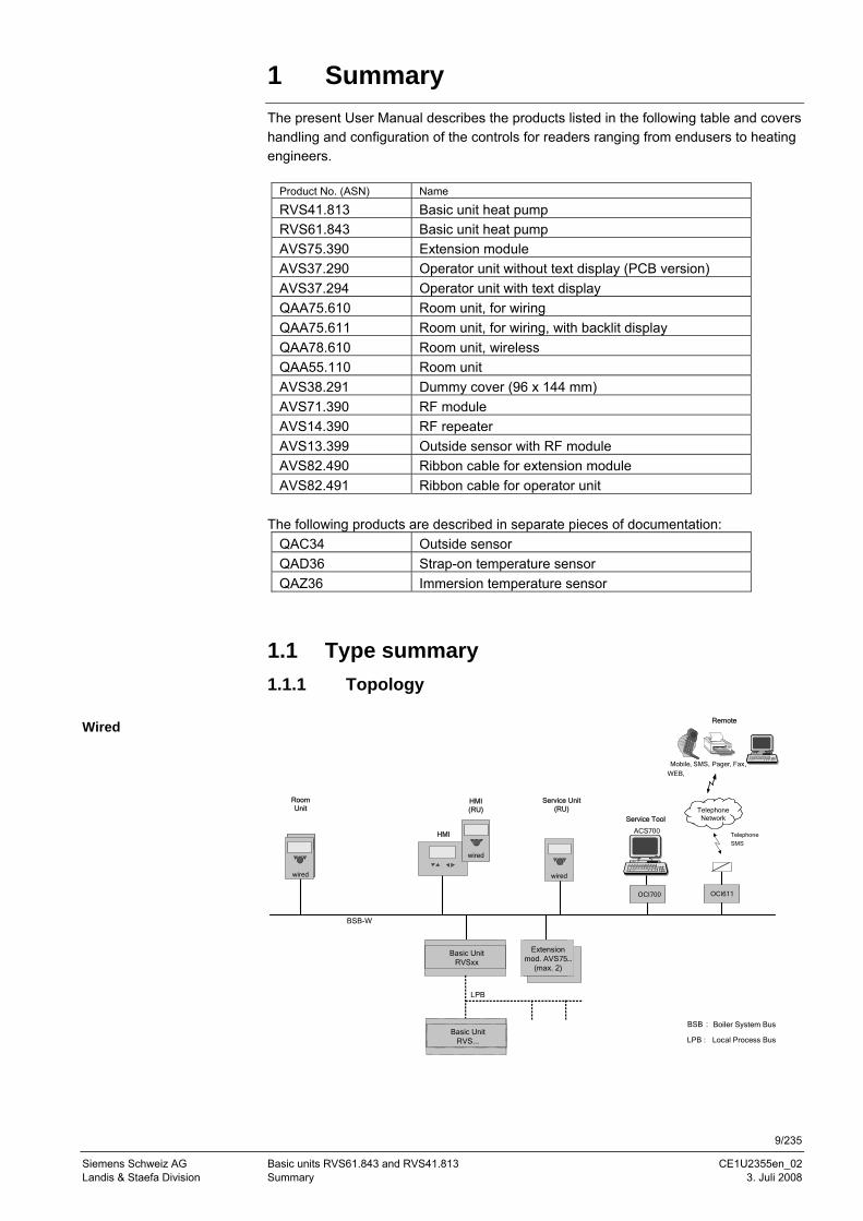
1.1 Type summary 1.1.1 Topology
Remote
Service Tool
Mobile, SMS, Pager, Fax,
WEB,
TelephoneNetwork
Telephone
SMS
OCI611OCI700
ACS700
BSB : Boiler System Bus
Room Unit
Service Unit (RU)
HMI
HMI (RU)
wired
wired
wired
Basic Unit RVSxx
Extension mod. AVS75…
(max. 2)
BSB-W
LPB : Local Process BusBasic Unit
RVS...
LPB
Wired
10/235
Siemens Switzerland Basic units RVS61.843 and RVS41.813 CE1U2355en_02 HVAC Products Contents 3. Juli 2008
Remote
Service Tool
Mobile, SMS, Pager, Fax,
WEB,
TelephoneNetwork
Telephone
SMS
OCI611OCI700
RFmodule
ACS700
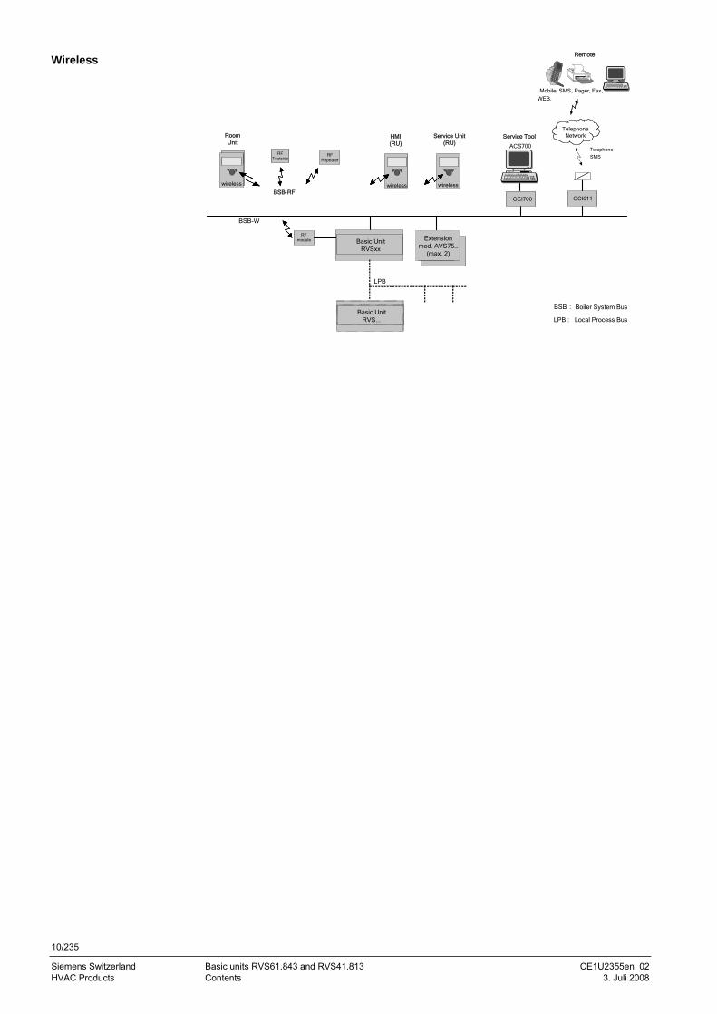
BSB : Boiler System Bus
Room Unit
RF Repeater
RFToutside
BSB-RF
Service Unit (RU)
HMI (RU)
wireless wireless wireless
Basic Unit RVSxx
Extension mod. AVS75…
(max. 2)
BSB-W
LPB : Local Process BusBasic Unit
RVS...
LPB
Wireless
11/235
Siemens Schweiz AG Basic units RVS61.843 and RVS41.813 CE1U2355en_02 Landis & Staefa Division Summary 3. Juli 2008
1.1.2 Operation options Wired Wireless
C
D
A
2359
Z01
T
C
DF
A
2359
Z03
T
CE1
D
A
2359
Z66
T
C
DF
A
2359
Z67
T
E1
CE
D
A
2359
Z02
T
C
DF
A
E
2359
Z04
T
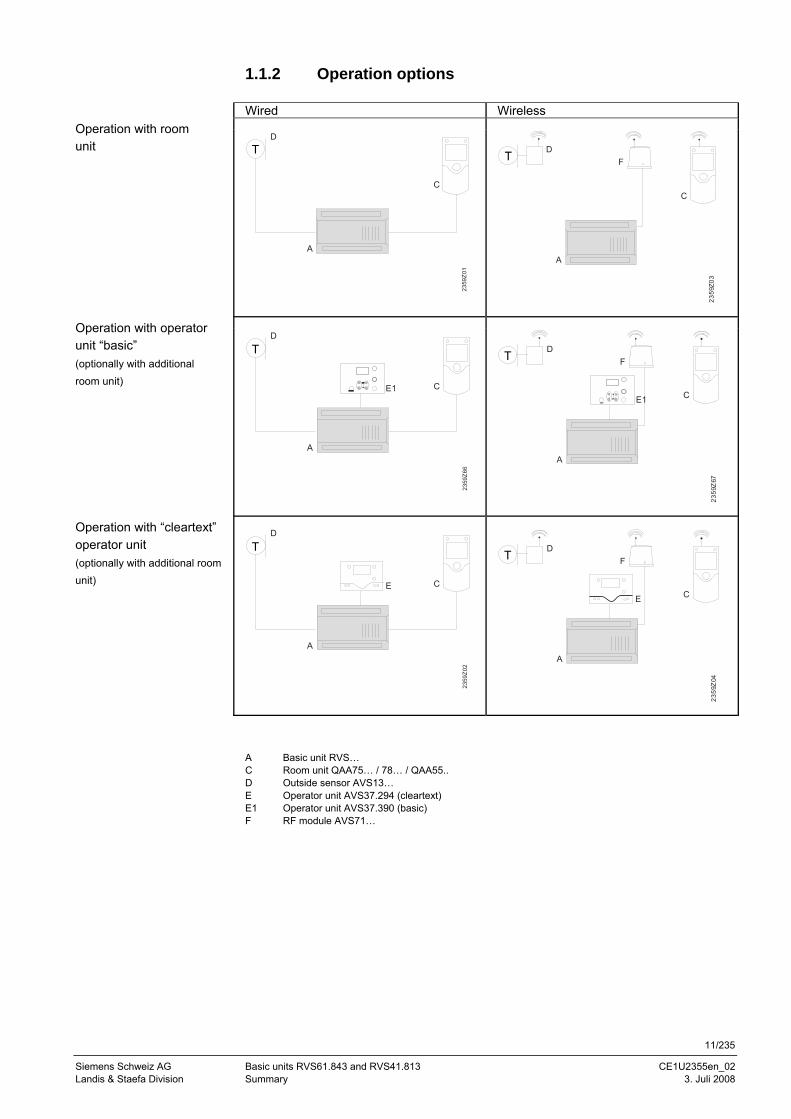
A Basic unit RVS… C Room unit QAA75… / 78… / QAA55.. D Outside sensor AVS13… E Operator unit AVS37.294 (cleartext) E1 Operator unit AVS37.390 (basic) F RF module AVS71…
Operation with room unit
Operation with operator unit “basic” (optionally with additional room unit)
Operation with “cleartext” operator unit (optionally with additional room unit)
12/235
Siemens Switzerland Basic units RVS61.843 and RVS41.813 CE1U2355en_02 HVAC Products Contents 3. Juli 2008
2 Safety notes
2.1 Notes on product liability
• The products may only be used in building services plant and on applications as described in this document
• When using the products, all requirements specified in chapters "Handling" and "Technical data" must be satisfied
• The local regulations (for installation, etc.) must be complied with • Do not open the units. If not observed, warranty becomes void.
13/235
Siemens Schweiz AG Basic units RVS61.843 and RVS41.813 CE1U2355en_02 Landis & Staefa Division Mounting and installation 3. Juli 2008
2359
Z09
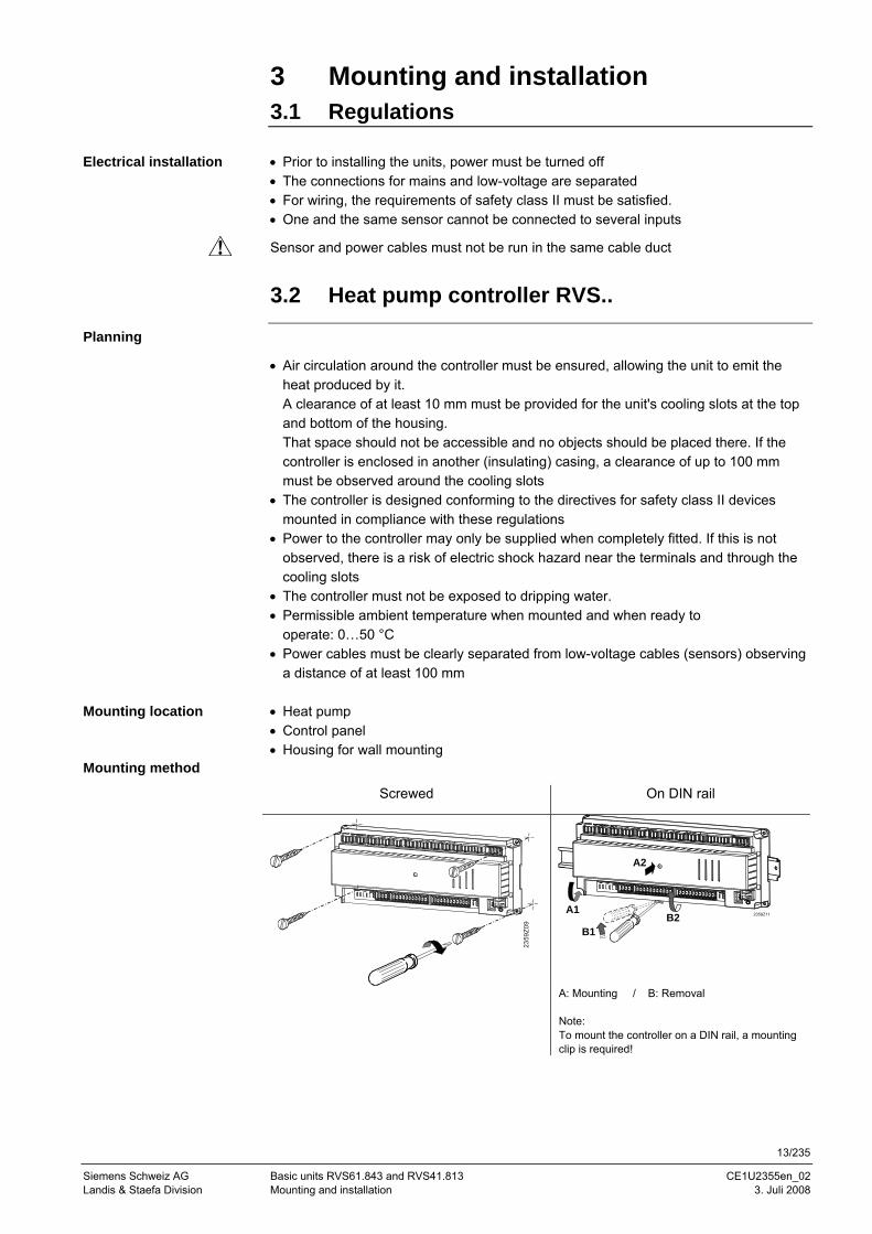
3 Mounting and installation 3.1 Regulations • Prior to installing the units, power must be turned off • The connections for mains and low-voltage are separated • For wiring, the requirements of safety class II must be satisfied. • One and the same sensor cannot be connected to several inputs
Sensor and power cables must not be run in the same cable duct
3.2 Heat pump controller RVS..
Planning
• Air circulation around the controller must be ensured, allowing the unit to emit the heat produced by it. A clearance of at least 10 mm must be provided for the unit's cooling slots at the top and bottom of the housing. That space should not be accessible and no objects should be placed there. If the controller is enclosed in another (insulating) casing, a clearance of up to 100 mm must be observed around the cooling slots
• The controller is designed conforming to the directives for safety class II devices mounted in compliance with these regulations
• Power to the controller may only be supplied when completely fitted. If this is not observed, there is a risk of electric shock hazard near the terminals and through the cooling slots
• The controller must not be exposed to dripping water. • Permissible ambient temperature when mounted and when ready to
operate: 0…50 °C • Power cables must be clearly separated from low-voltage cables (sensors) observing
a distance of at least 100 mm • Heat pump • Control panel • Housing for wall mounting
Mounting method
Screwed On DIN rail
A: Mounting / B: Removal Note: To mount the controller on a DIN rail, a mounting clip is required!
Electrical installation
Mounting location
A1
A2
B1B2 2359Z11
14/235
Siemens Switzerland Basic units RVS61.843 and RVS41.813 CE1U2355en_02 HVAC Products Contents 3. Juli 2008
2359Z10
x
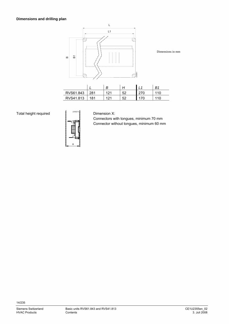
Dimensions and drilling plan L
B
L1
B1
2358
M01
L B H L1 B1 RVS61.843 281 121 52 270 110 RVS41.813 181 121 52 170 110
Dimension X: Connectors with tongues, minimum 70 mm Connector without tongues, minimum 60 mm
Total height required
Dimensions in mm
15/235
Siemens Schweiz AG Basic units RVS61.843 and RVS41.813 CE1U2355en_02 Landis & Staefa Division Mounting and installation 3. Juli 2008
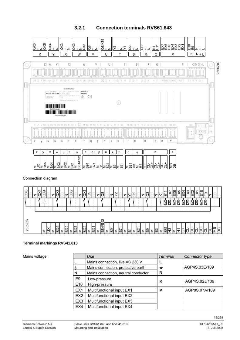
3.2.1 Connection terminals RVS61.843
QX4
N QX3
N QX2
N QX1
Q9
N Q8/
K19
N Y2 N Y1 Q2
N Q3
N K1 E11
EX6
EX5
EX4
EX3
EX2
EX1
E10
E9 N L
N
M B91 M B71 M B1 M B21 M B9 M B3 H3
M H1
G+
CL-
CL+
CL-
CL+
CL-
CL+
Y X W V U T S R Q P
r q ep n k h b
K L
2355
Z09
QX6
N QX
5
Z
EX7
M BX5
M BX4
M BX3
M BX2
M BX1 M B84
/B92
y x w u t s
M UX
z
MB
DB
a
M B81
f
070621A000020RVS61.843/109
1PRVS61.843/109
S070621000020
QX6
N QX5
QX4
N QX3
N QX2
N QX1
Q9
N Q8
N Y2 N Y1 Q2
N Q3
N K1 E11
EX7
EX6
EX5
EX4
EX3
EX2
EX1
E10
E9 N L
2355
Z02
M UX
M BX5
M BX4
M BX3
M BX2
M BX1
M M B91
M B71
M B1 M B21
M B9 M B3 M B81
H3
M H1
G+
CL-
CL+
CL-
CL+
CL-
CL+
MB
DB
B84/
B92
Terminal markings RVS41.813
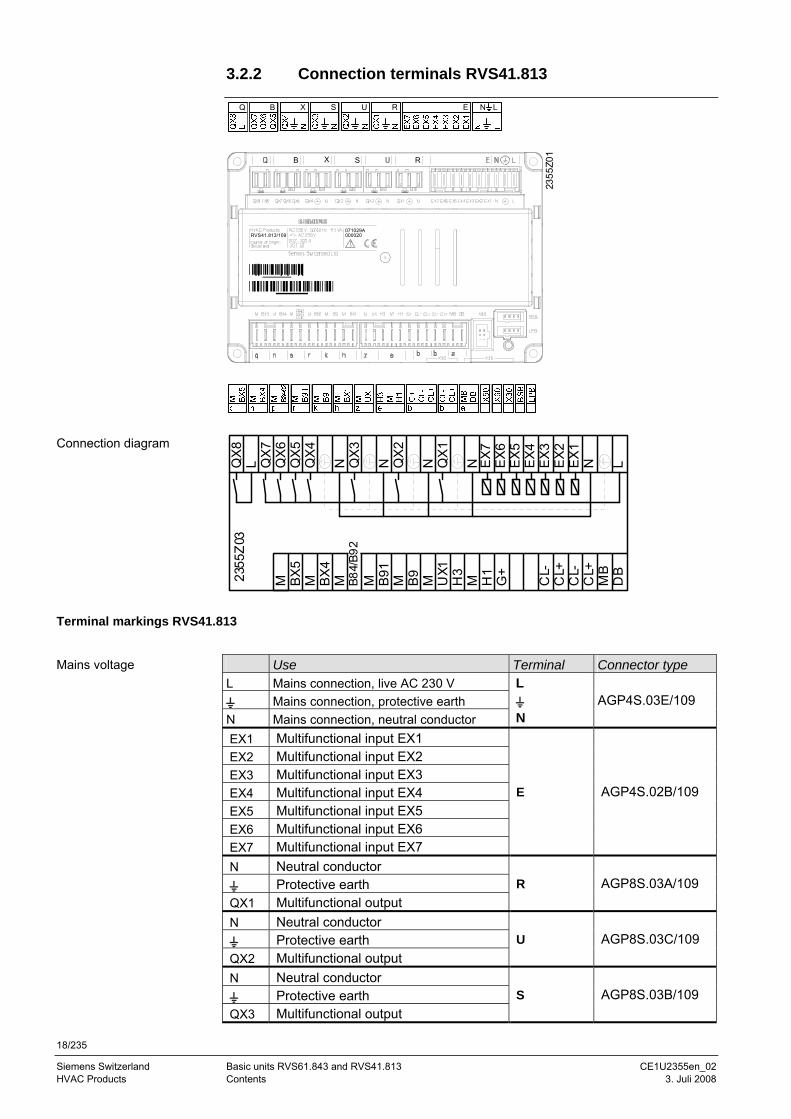
Use Terminal Connector type L Mains connection, live AC 230 V
Mains connection, protective earth N Mains connection, neutral conductor
L
N
AGP4S.03E/109
E9 Low-pressure E10 High-pressure
K AGP4S.02J/109
EX1 Multifunctional input EX1 EX2 Multifunctional input EX2 EX3 Multifunctional input EX3 EX4 Multifunctional input EX4
P AGP8S.07A/109
Connection diagram
Mains voltage
16/235
Siemens Switzerland Basic units RVS61.843 and RVS41.813 CE1U2355en_02 HVAC Products Contents 3. Juli 2008
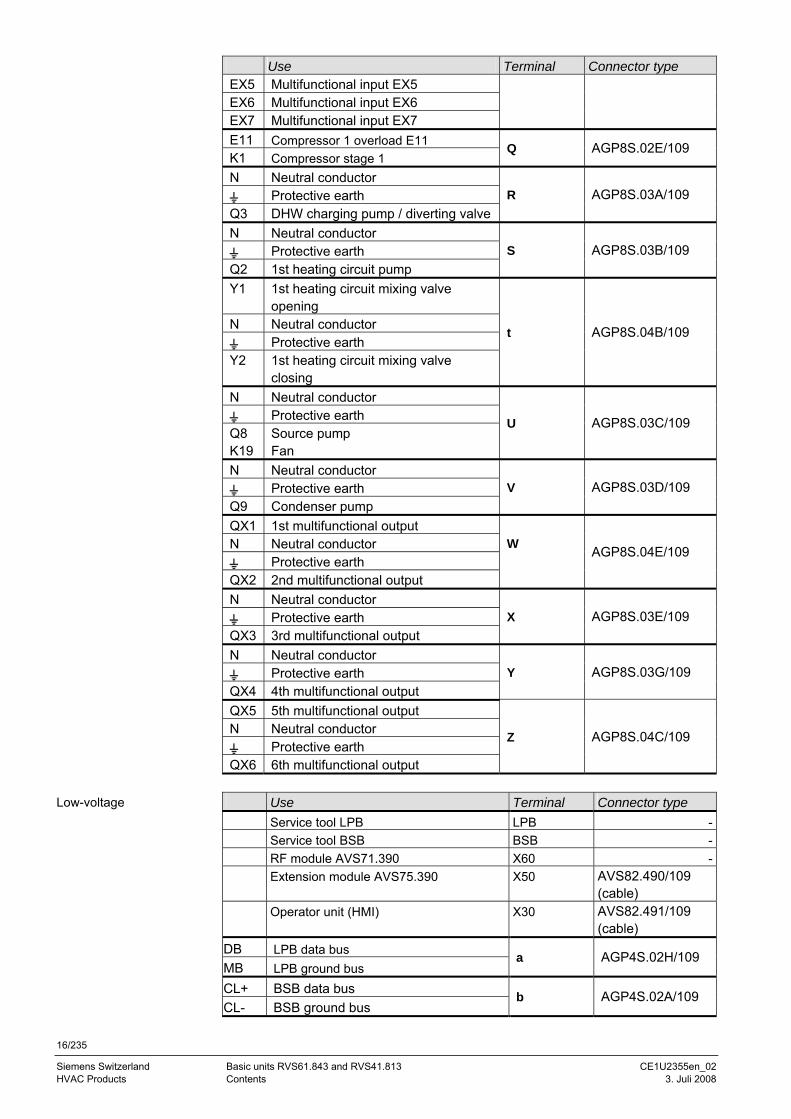
Use Terminal Connector type EX5 Multifunctional input EX5 EX6 Multifunctional input EX6 EX7 Multifunctional input EX7 E11 Compressor 1 overload E11 K1 Compressor stage 1
Q AGP8S.02E/109
N Neutral conductor Protective earth
Q3 DHW charging pump / diverting valve R AGP8S.03A/109
N Neutral conductor Protective earth
Q2 1st heating circuit pump S AGP8S.03B/109
Y1 1st heating circuit mixing valve opening
N Neutral conductor Protective earth
Y2 1st heating circuit mixing valve closing
t AGP8S.04B/109
N Neutral conductor Protective earth
Q8 K19
Source pump Fan
U AGP8S.03C/109
N Neutral conductor Protective earth
Q9 Condenser pump V AGP8S.03D/109
QX1 1st multifunctional output N Neutral conductor
Protective earth QX2 2nd multifunctional output
W
AGP8S.04E/109
N Neutral conductor Protective earth
QX3 3rd multifunctional output X AGP8S.03E/109
N Neutral conductor Protective earth
QX4 4th multifunctional output Y AGP8S.03G/109
QX5 5th multifunctional output N Neutral conductor
Protective earth QX6 6th multifunctional output
Z AGP8S.04C/109
Use Terminal Connector type Service tool LPB LPB - Service tool BSB BSB - RF module AVS71.390 X60 - Extension module AVS75.390 X50 AVS82.490/109
(cable) Operator unit (HMI) X30 AVS82.491/109
(cable) DB LPB data bus MB LPB ground bus
a AGP4S.02H/109
CL+ BSB data bus CL- BSB ground bus
b AGP4S.02A/109
Low-voltage
17/235
Siemens Schweiz AG Basic units RVS61.843 and RVS41.813 CE1U2355en_02 Landis & Staefa Division Mounting and installation 3. Juli 2008
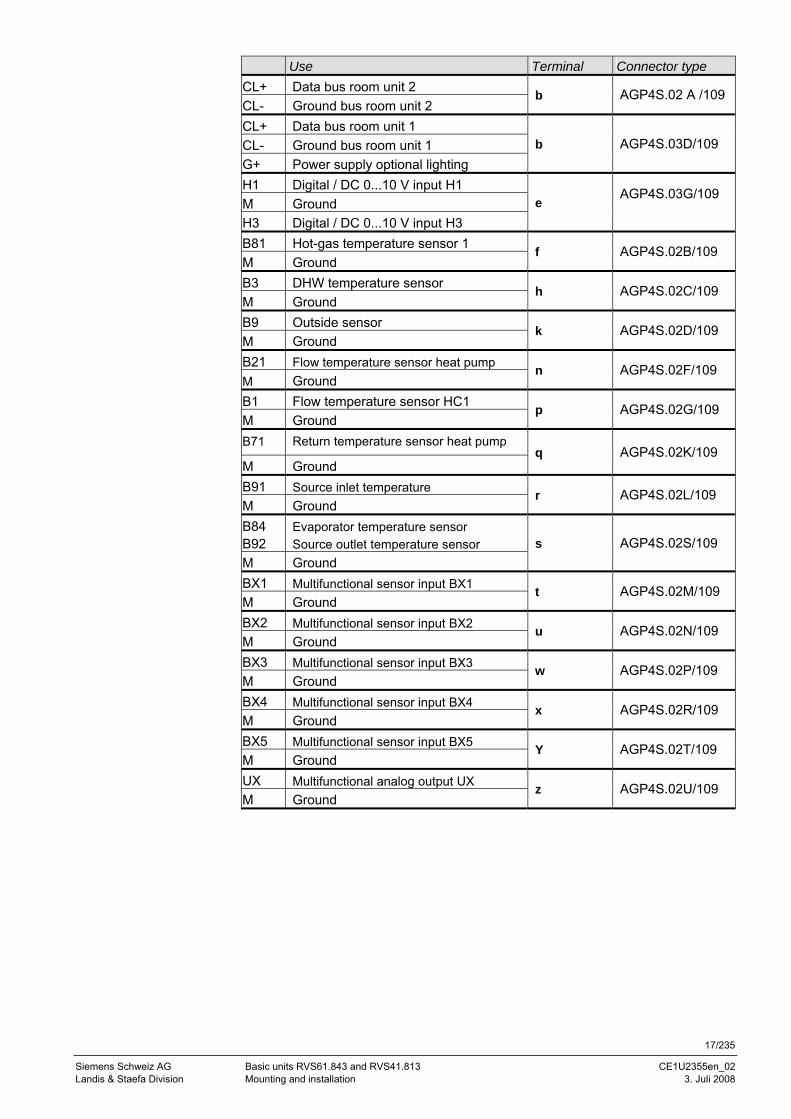
Use Terminal Connector type CL+ Data bus room unit 2 CL- Ground bus room unit 2
b AGP4S.02 A /109
CL+ Data bus room unit 1 CL- Ground bus room unit 1 G+ Power supply optional lighting
b AGP4S.03D/109
H1 Digital / DC 0...10 V input H1 M Ground H3 Digital / DC 0...10 V input H3
e AGP4S.03G/109
B81 Hot-gas temperature sensor 1 M Ground
f AGP4S.02B/109
B3 DHW temperature sensor M Ground
h AGP4S.02C/109
B9 Outside sensor M Ground
k AGP4S.02D/109
B21 Flow temperature sensor heat pump M Ground
n AGP4S.02F/109
B1 Flow temperature sensor HC1 M Ground
p AGP4S.02G/109
B71 Return temperature sensor heat pump
M Ground q AGP4S.02K/109
B91 Source inlet temperature M Ground
r AGP4S.02L/109
B84 B92
Evaporator temperature sensor Source outlet temperature sensor
M Ground s AGP4S.02S/109
BX1 Multifunctional sensor input BX1 M Ground
t AGP4S.02M/109
BX2 Multifunctional sensor input BX2 M Ground
u AGP4S.02N/109
BX3 Multifunctional sensor input BX3 M Ground
w AGP4S.02P/109
BX4 Multifunctional sensor input BX4 M Ground
x AGP4S.02R/109
BX5 Multifunctional sensor input BX5 M Ground
Y AGP4S.02T/109
UX Multifunctional analog output UX M Ground
z AGP4S.02U/109
18/235
Siemens Switzerland Basic units RVS61.843 and RVS41.813 CE1U2355en_02 HVAC Products Contents 3. Juli 2008
3.2.2 Connection terminals RVS41.813
U RBQ X S LNE
071029A000020RVS41.813/109
2355
Z01
B X S R
QX
8L Q
X7
QX
6Q
X5
QX
4
QX
3N N Q
X2
N QX
1
N EX7
EX6
EX5
EX4
EX3
EX2
EX1
N L
2355
Z03
B91
M BX5
M BX4
M M B9M M UX1
H3
M H1
G+
CL-
CL+
CL-
CL+
MB
DB
B84/
B92
Terminal markings RVS41.813
Use Terminal Connector type L Mains connection, live AC 230 V
Mains connection, protective earth N Mains connection, neutral conductor
L
N
AGP4S.03E/109
EX1 Multifunctional input EX1 EX2 Multifunctional input EX2 EX3 Multifunctional input EX3 EX4 Multifunctional input EX4 EX5 Multifunctional input EX5 EX6 Multifunctional input EX6 EX7 Multifunctional input EX7
E AGP4S.02B/109
N Neutral conductor Protective earth
QX1 Multifunctional output R AGP8S.03A/109
N Neutral conductor Protective earth
QX2 Multifunctional output U AGP8S.03C/109
N Neutral conductor Protective earth
QX3 Multifunctional output S AGP8S.03B/109
Connection diagram
Mains voltage
19/235
Siemens Schweiz AG Basic units RVS61.843 and RVS41.813 CE1U2355en_02 Landis & Staefa Division Mounting and installation 3. Juli 2008
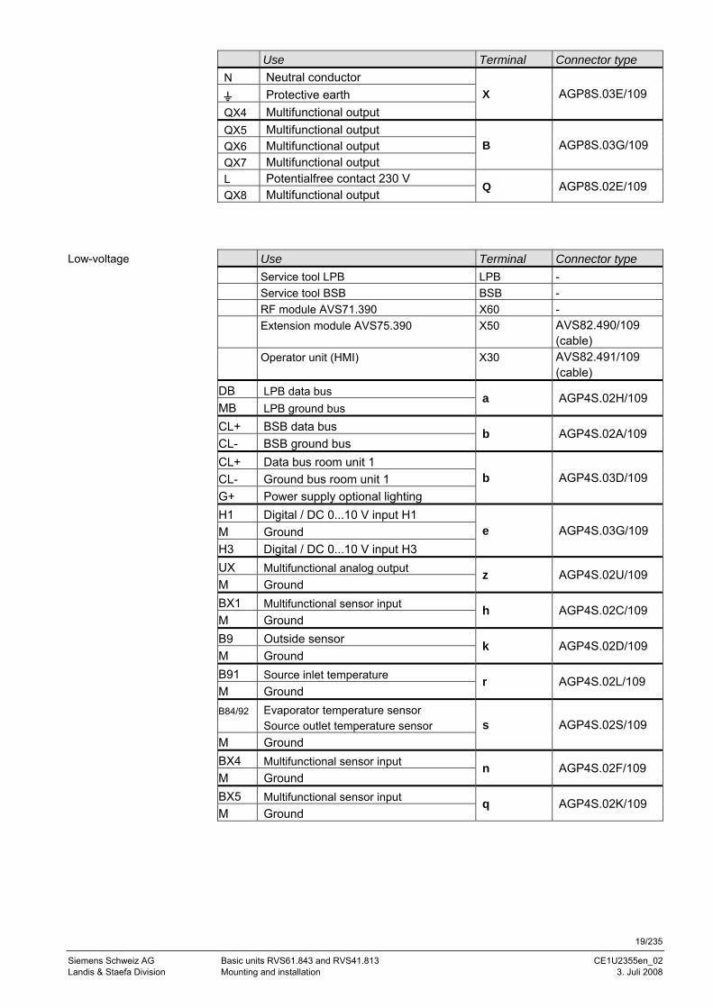
Use Terminal Connector type N Neutral conductor
Protective earth QX4 Multifunctional output
X AGP8S.03E/109
QX5 Multifunctional output QX6 Multifunctional output QX7 Multifunctional output
B AGP8S.03G/109
L Potentialfree contact 230 V QX8 Multifunctional output
Q AGP8S.02E/109
Use Terminal Connector type Service tool LPB LPB - Service tool BSB BSB - RF module AVS71.390 X60 - Extension module AVS75.390 X50 AVS82.490/109
(cable) Operator unit (HMI) X30 AVS82.491/109
(cable) DB LPB data bus MB LPB ground bus
a AGP4S.02H/109
CL+ BSB data bus CL- BSB ground bus
b AGP4S.02A/109
CL+ Data bus room unit 1 CL- Ground bus room unit 1 G+ Power supply optional lighting
b AGP4S.03D/109
H1 Digital / DC 0...10 V input H1 M Ground H3 Digital / DC 0...10 V input H3
e AGP4S.03G/109
UX Multifunctional analog output M Ground
z AGP4S.02U/109
BX1 Multifunctional sensor input M Ground
h AGP4S.02C/109
B9 Outside sensor M Ground
k AGP4S.02D/109
B91 Source inlet temperature M Ground
r AGP4S.02L/109
B84/92 Evaporator temperature sensor Source outlet temperature sensor
M Ground s AGP4S.02S/109
BX4 Multifunctional sensor input M Ground
n AGP4S.02F/109
BX5 Multifunctional sensor input M Ground
q AGP4S.02K/109
Low-voltage
20/235
Siemens Switzerland Basic units RVS61.843 and RVS41.813 CE1U2355en_02 HVAC Products Contents 3. Juli 2008
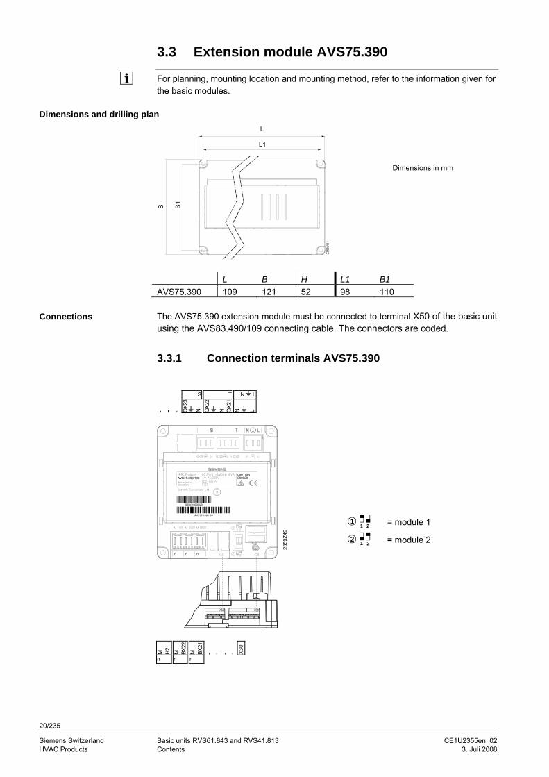
3.3 Extension module AVS75.390
For planning, mounting location and mounting method, refer to the information given for the basic modules.
Dimensions and drilling plan L
B
L1
B1
2358
M01
L B H L1 B1 AVS75.390 109 121 52 98 110 The AVS75.390 extension module must be connected to terminal X50 of the basic unit using the AVS83.490/109 connecting cable. The connectors are coded.
3.3.1 Connection terminals AVS75.390
S T N L
- - - QX2
3
N
QX2
2
N
QX2
1 N
L
050110A000020AVS75.390/109
1PAVS75.390/109
S050110000020
2359
Z49
Connections
M
H2
M
BX22
M
BX
21
- - - - X30
n n n
11 2 = module 1
21 2 = module 2
Dimensions in mm
21/235
Siemens Schweiz AG Basic units RVS61.843 and RVS41.813 CE1U2355en_02 Landis & Staefa Division Mounting and installation 3. Juli 2008
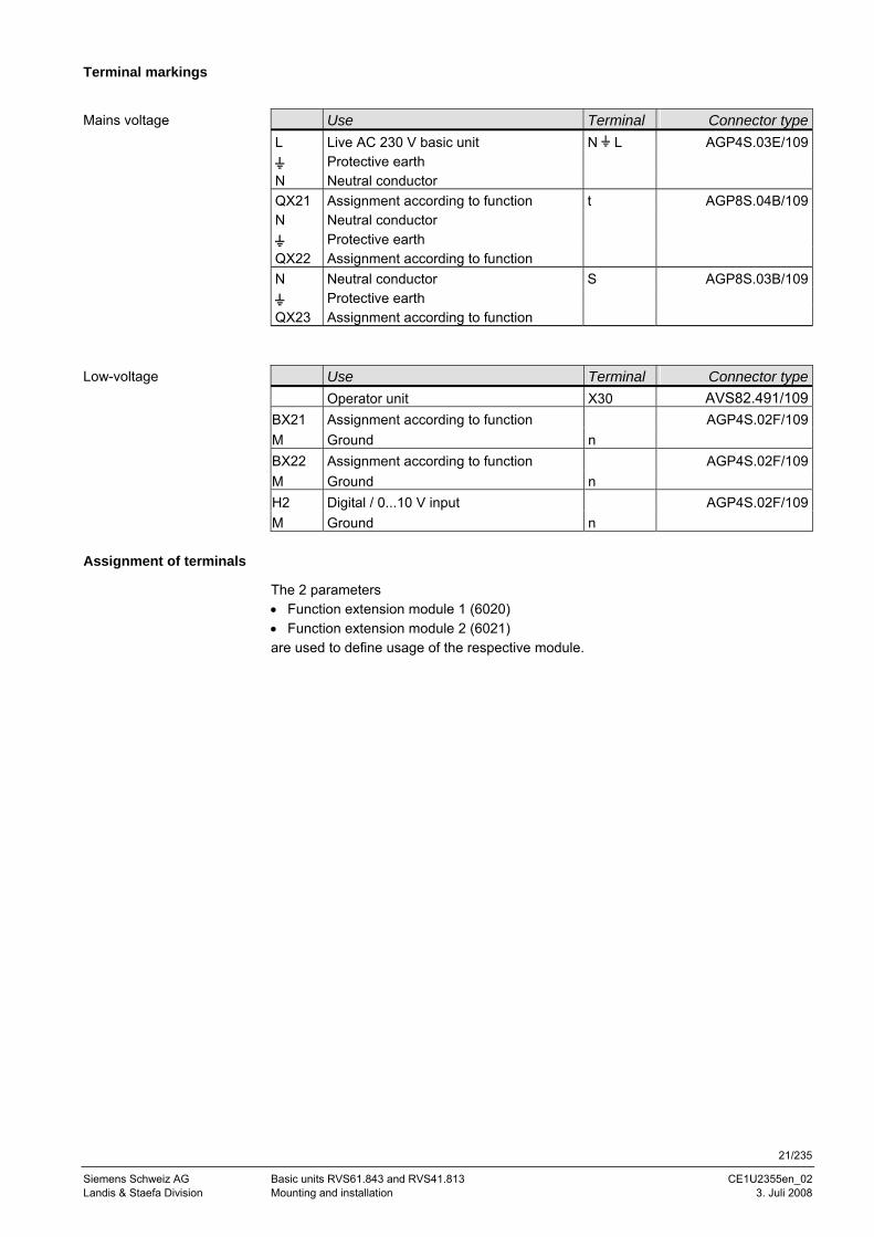
Terminal markings
Use Terminal Connector typeL Live AC 230 V basic unit N L AGP4S.03E/109
Protective earth N Neutral conductor QX21 Assignment according to function t AGP8S.04B/109N Neutral conductor
Protective earth QX22 Assignment according to function N Neutral conductor S AGP8S.03B/109
Protective earth QX23 Assignment according to function
Use Terminal Connector type Operator unit X30 AVS82.491/109BX21 Assignment according to function AGP4S.02F/109M Ground n BX22 Assignment according to function AGP4S.02F/109M Ground n H2 Digital / 0...10 V input AGP4S.02F/109M Ground n
Assignment of terminals
The 2 parameters • Function extension module 1 (6020) • Function extension module 2 (6021) are used to define usage of the respective module.
Mains voltage
Low-voltage
22/235
Siemens Switzerland Basic units RVS61.843 and RVS41.813 CE1U2355en_02 HVAC Products Contents 3. Juli 2008
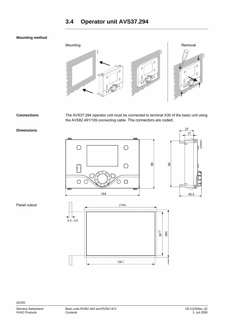
3.4 Operator unit AVS37.294
Mounting method
Mounting Removal
2358
Z30
2358
Z31
2358
Z32
The AVS37.294 operator unit must be connected to terminal X30 of the basic unit using the AVS82.491/109 connecting cable. The connectors are coded.
(144)
0.5...3.0
92+0
.8 0
138+10
2358
M05
(96)
Connections
Dimensions
Panel cutout 23
58M
03
144
96 90
27
42.4
17
23/235
Siemens Schweiz AG Basic units RVS61.843 and RVS41.813 CE1U2355en_02 Landis & Staefa Division Mounting and installation 3. Juli 2008
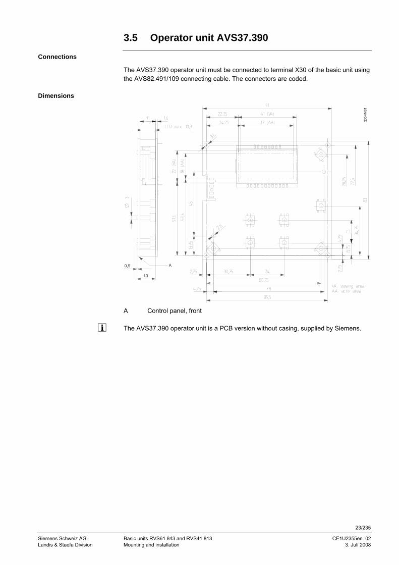
3.5 Operator unit AVS37.390
Connections
The AVS37.390 operator unit must be connected to terminal X30 of the basic unit using the AVS82.491/109 connecting cable. The connectors are coded.
Dimensions
2354
M01
13
0,5 A
A Control panel, front The AVS37.390 operator unit is a PCB version without casing, supplied by Siemens.
24/235
Siemens Switzerland Basic units RVS61.843 and RVS41.813 CE1U2355en_02 HVAC Products Contents 3. Juli 2008
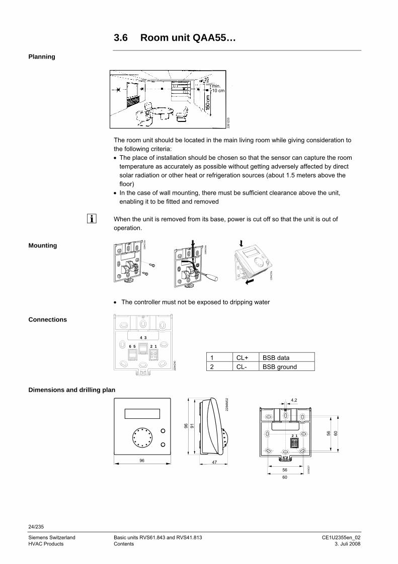
3.6 Room unit QAA55…
Planning
min. 10 cm
2261
Z03
The room unit should be located in the main living room while giving consideration to the following criteria: • The place of installation should be chosen so that the sensor can capture the room
temperature as accurately as possible without getting adversely affected by direct solar radiation or other heat or refrigeration sources (about 1.5 meters above the floor)
• In the case of wall mounting, there must be sufficient clearance above the unit, enabling it to be fitted and removed
When the unit is removed from its base, power is cut off so that the unit is out of operation.
2284
Z33a
2284
Z34a
2284
Z35a
• The controller must not be exposed to dripping water
1
34
56 2
2284
Z40
Dimensions and drilling plan
2284
M02
96
96 91
47
12
2359
Z27
4,2
56 60
56
60
Mounting
Connections
1 CL+ BSB data 2 CL- BSB ground
25/235
Siemens Schweiz AG Basic units RVS61.843 and RVS41.813 CE1U2355en_02 Landis & Staefa Division Mounting and installation 3. Juli 2008
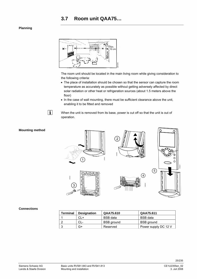
3.7 Room unit QAA75…
Planning
min. 10 cm
2261
Z03
The room unit should be located in the main living room while giving consideration to the following criteria: • The place of installation should be chosen so that the sensor can capture the room
temperature as accurately as possible without getting adversely affected by direct solar radiation or other heat or refrigeration sources (about 1.5 meters above the floor)
• In the case of wall mounting, there must be sufficient clearance above the unit, enabling it to be fitted and removed
When the unit is removed from its base, power is cut off so that the unit is out of operation.
Terminal Designation QAA75.610 QAA75.611 1 CL+ BSB data BSB data 2 CL- BSB ground BSB ground 3 G+ Reserved Power supply DC 12 V
Mounting method
Connections
2359
Z25
2359
Z20
2359
Z26
2359
Z24
2359
Z21
26/235
Siemens Switzerland Basic units RVS61.843 and RVS41.813 CE1U2355en_02 HVAC Products Contents 3. Juli 2008
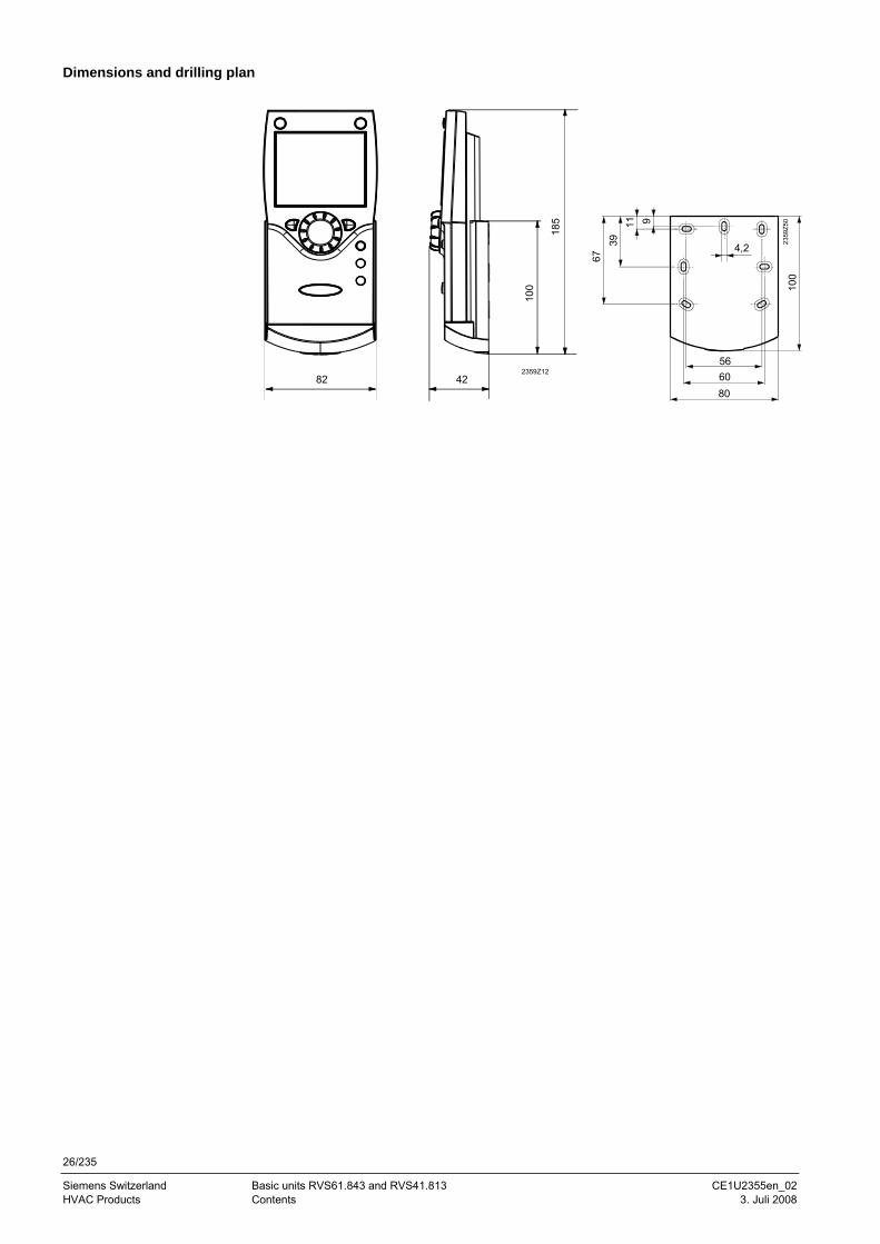
Dimensions and drilling plan
42
185
2359Z12
100
82
2359
Z50
4,2
9
5660
100
80
1139
67
27/235
Siemens Schweiz AG Basic units RVS61.843 and RVS41.813 CE1U2355en_02 Landis & Staefa Division Mounting and installation 3. Juli 2008
3.8 RF components
The wireless components should be located such that transmission is as interference-free as possible. The following criteria must be observed: • Not in the vicinity of electrical cables, strong magnetic fields or equipment, such as
PCs, TV sets, microwave ovens, etc. • Not near larger metal structures or constructional elements with fine metal meshes,
such as special glass or special concrete • The distance to the transmitter should not exceed 30 meters or 2 floors
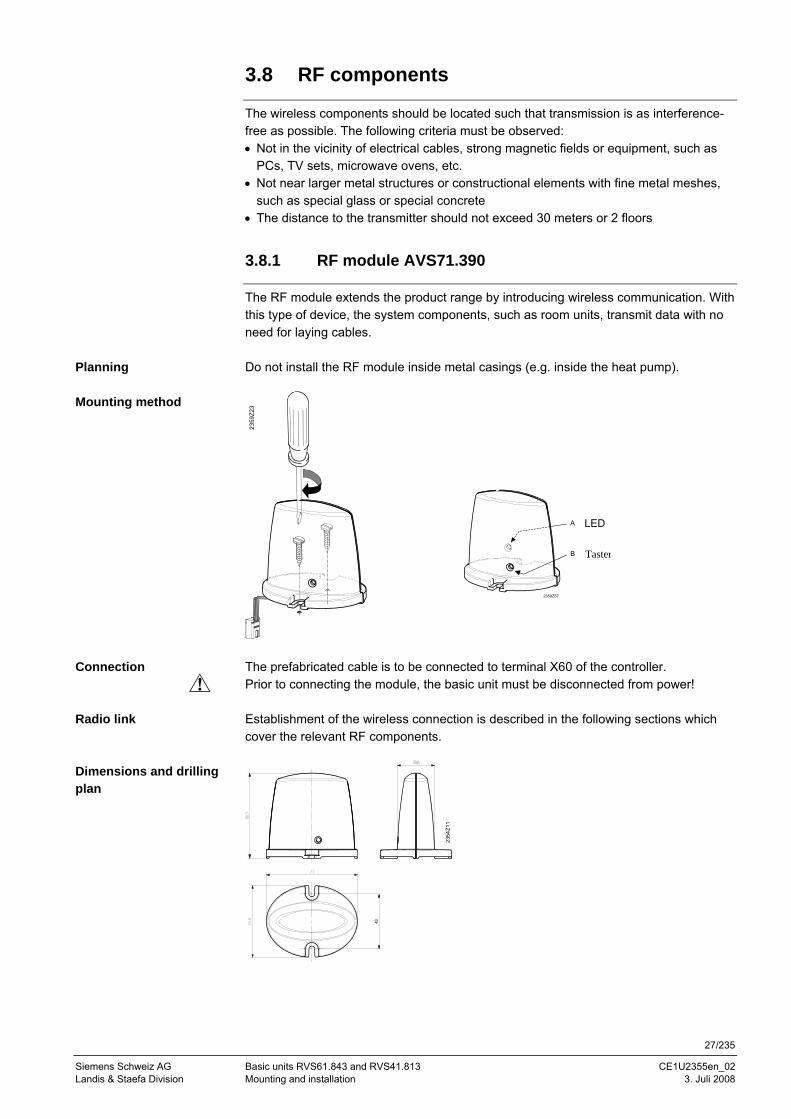
3.8.1 RF module AVS71.390
The RF module extends the product range by introducing wireless communication. With this type of device, the system components, such as room units, transmit data with no need for laying cables. Do not install the RF module inside metal casings (e.g. inside the heat pump).
2359
Z23
The prefabricated cable is to be connected to terminal X60 of the controller. Prior to connecting the module, the basic unit must be disconnected from power! Establishment of the wireless connection is described in the following sections which cover the relevant RF components.
43
2354
Z11
Planning
Mounting method
Connection
Radio link
Dimensions and drilling plan
2359Z57
A
B
LED
Taster
28/235
Siemens Switzerland Basic units RVS61.843 and RVS41.813 CE1U2355en_02 HVAC Products Contents 3. Juli 2008
3.8.2 Room unit QAA78.610
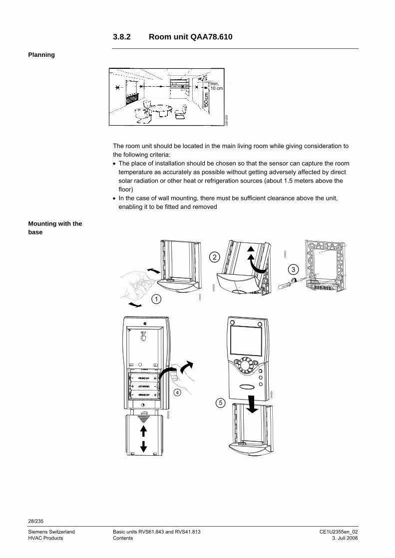
Planning
min. 10 cm
2261
Z03
The room unit should be located in the main living room while giving consideration to the following criteria: • The place of installation should be chosen so that the sensor can capture the room
temperature as accurately as possible without getting adversely affected by direct solar radiation or other heat or refrigeration sources (about 1.5 meters above the floor)
• In the case of wall mounting, there must be sufficient clearance above the unit, enabling it to be fitted and removed
Mounting with the base
2359
Z25
2359
Z20
2359
Z26
2359
Z22
2359
Z21
29/235
Siemens Schweiz AG Basic units RVS61.843 and RVS41.813 CE1U2355en_02 Landis & Staefa Division Mounting and installation 3. Juli 2008
2359
Z61
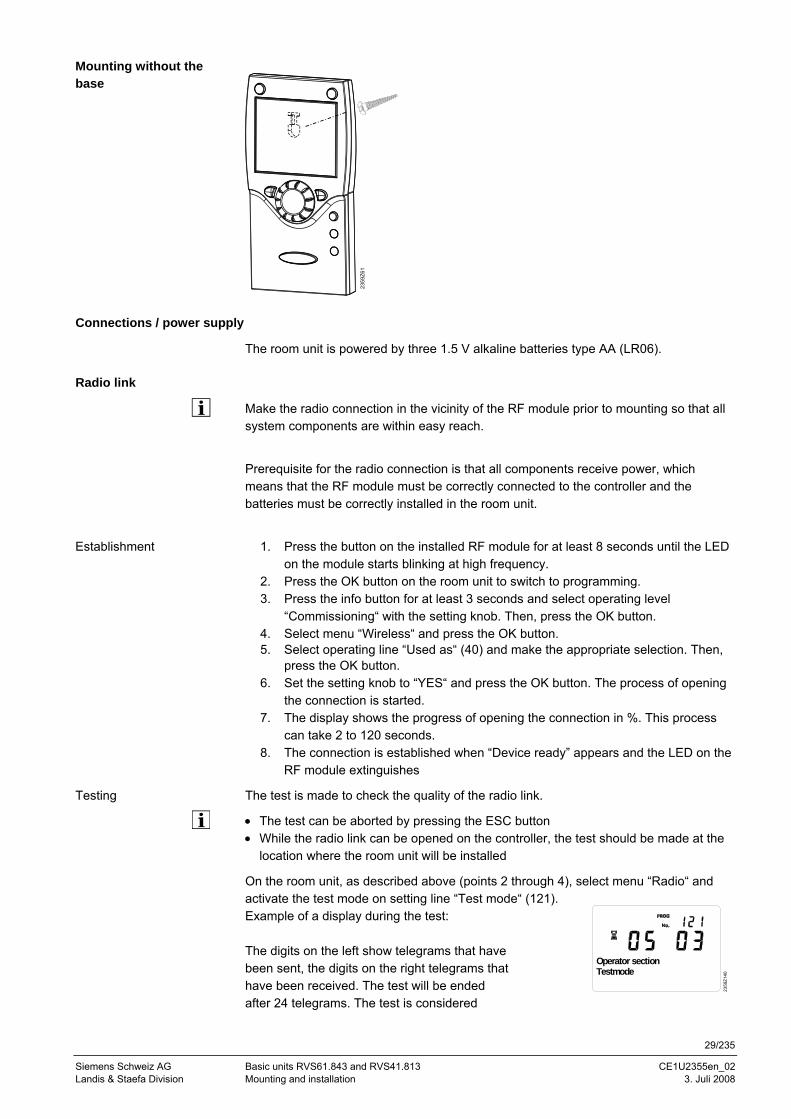
Connections / power supply
The room unit is powered by three 1.5 V alkaline batteries type AA (LR06).
Radio link
Make the radio connection in the vicinity of the RF module prior to mounting so that all system components are within easy reach.
Prerequisite for the radio connection is that all components receive power, which means that the RF module must be correctly connected to the controller and the batteries must be correctly installed in the room unit.
1. Press the button on the installed RF module for at least 8 seconds until the LED
on the module starts blinking at high frequency. 2. Press the OK button on the room unit to switch to programming. 3. Press the info button for at least 3 seconds and select operating level
“Commissioning“ with the setting knob. Then, press the OK button. 4. Select menu “Wireless“ and press the OK button. 5. Select operating line “Used as“ (40) and make the appropriate selection. Then,
press the OK button. 6. Set the setting knob to “YES“ and press the OK button. The process of opening
the connection is started. 7. The display shows the progress of opening the connection in %. This process
can take 2 to 120 seconds. 8. The connection is established when “Device ready” appears and the LED on the
RF module extinguishes
The test is made to check the quality of the radio link.
• The test can be aborted by pressing the ESC button • While the radio link can be opened on the controller, the test should be made at the
location where the room unit will be installed
On the room unit, as described above (points 2 through 4), select menu “Radio“ and activate the test mode on setting line “Test mode“ (121). Example of a display during the test: The digits on the left show telegrams that have been sent, the digits on the right telegrams that have been received. The test will be ended after 24 telegrams. The test is considered
2359
Z140
Operator sectionTestmode
Mounting without the base
Establishment
Testing
30/235
Siemens Switzerland Basic units RVS61.843 and RVS41.813 CE1U2355en_02 HVAC Products Contents 3. Juli 2008
successful when at least 50% of the telegrams sent have been received.
If the test was not successful, some other mounting location should be chosen, or the AVS14.390 RF repeater should be used.
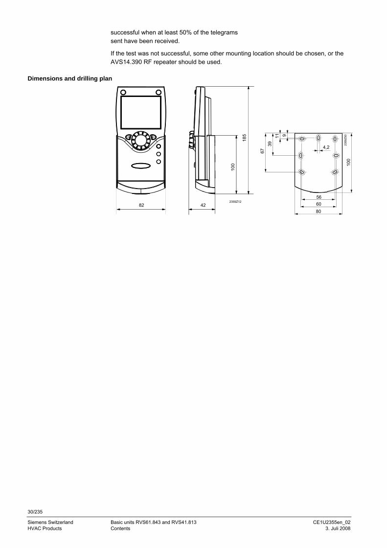
Dimensions and drilling plan
42
185
2359Z12
100
82
2359
Z50
4,2
9
5660
100
80
1139
67
31/235
Siemens Schweiz AG Basic units RVS61.843 and RVS41.813 CE1U2355en_02 Landis & Staefa Division Mounting and installation 3. Juli 2008
2359
Z53
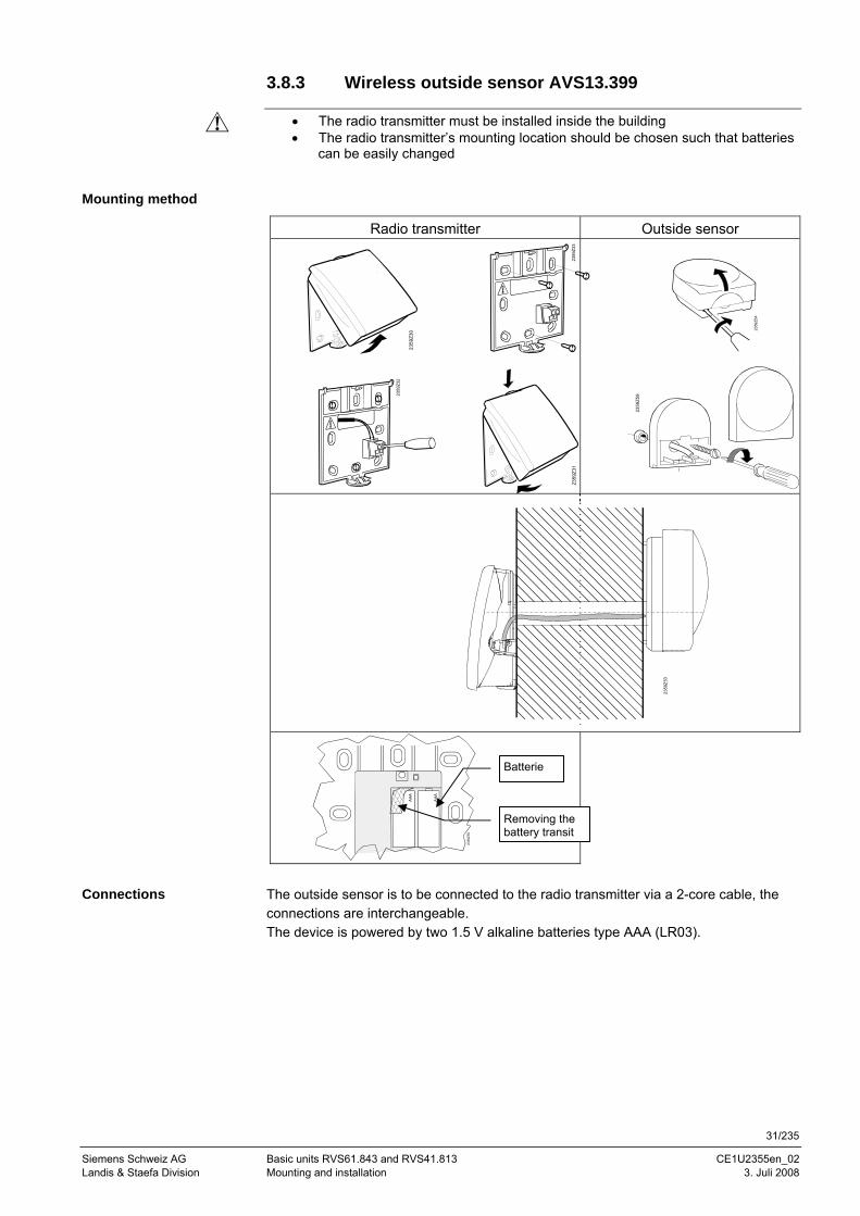
3.8.3 Wireless outside sensor AVS13.399
• The radio transmitter must be installed inside the building • The radio transmitter’s mounting location should be chosen such that batteries
can be easily changed
Mounting method
Radio transmitter Outside sensor
The outside sensor is to be connected to the radio transmitter via a 2-core cable, the connections are interchangeable. The device is powered by two 1.5 V alkaline batteries type AAA (LR03).
Connections
2359
Z54
2359
Z30
2359
Z33
2359
Z59
2359
Z31
2359
Z55
AAA
AAA
Removing the battery transit t b
Batterie
2359
Z32
32/235
Siemens Switzerland Basic units RVS61.843 and RVS41.813 CE1U2355en_02 HVAC Products Contents 3. Juli 2008
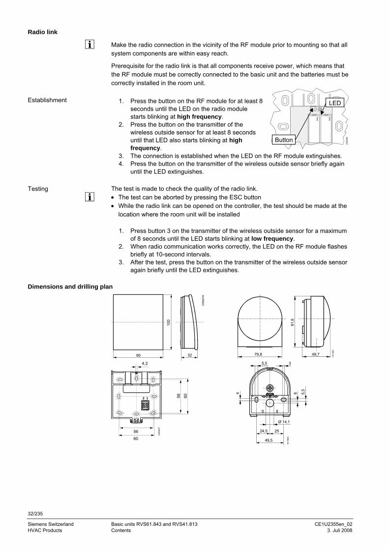
Radio link
Make the radio connection in the vicinity of the RF module prior to mounting so that all system components are within easy reach.
Prerequisite for the radio link is that all components receive power, which means that the RF module must be correctly connected to the basic unit and the batteries must be correctly installed in the room unit.
1. Press the button on the RF module for at least 8 seconds until the LED on the radio module starts blinking at high frequency.
2. Press the button on the transmitter of the wireless outside sensor for at least 8 seconds until that LED also starts blinking at high frequency.
3. The connection is established when the LED on the RF module extinguishes. 4. Press the button on the transmitter of the wireless outside sensor briefly again
until the LED extinguishes. The test is made to check the quality of the radio link. • The test can be aborted by pressing the ESC button • While the radio link can be opened on the controller, the test should be made at the
location where the room unit will be installed
1. Press button 3 on the transmitter of the wireless outside sensor for a maximum of 8 seconds until the LED starts blinking at low frequency.
2. When radio communication works correctly, the LED on the RF module flashes briefly at 10-second intervals.
3. After the test, press the button on the transmitter of the wireless outside sensor again briefly until the LED extinguishes.
Dimensions and drilling plan
90
100
32
2359
Z16
79,8
91,6
49,7
1811
M01
12
2359
Z27
4,2
56 60
56
60
35,5
Ø 14,1
2524,5
49,5
4 5,5
6
1811
M02
Establishment
Testing
2359
Z58
AAA
AAA
LED
Button
33/235
Siemens Schweiz AG Basic units RVS61.843 and RVS41.813 CE1U2355en_02 Landis & Staefa Division Mounting and installation 3. Juli 2008
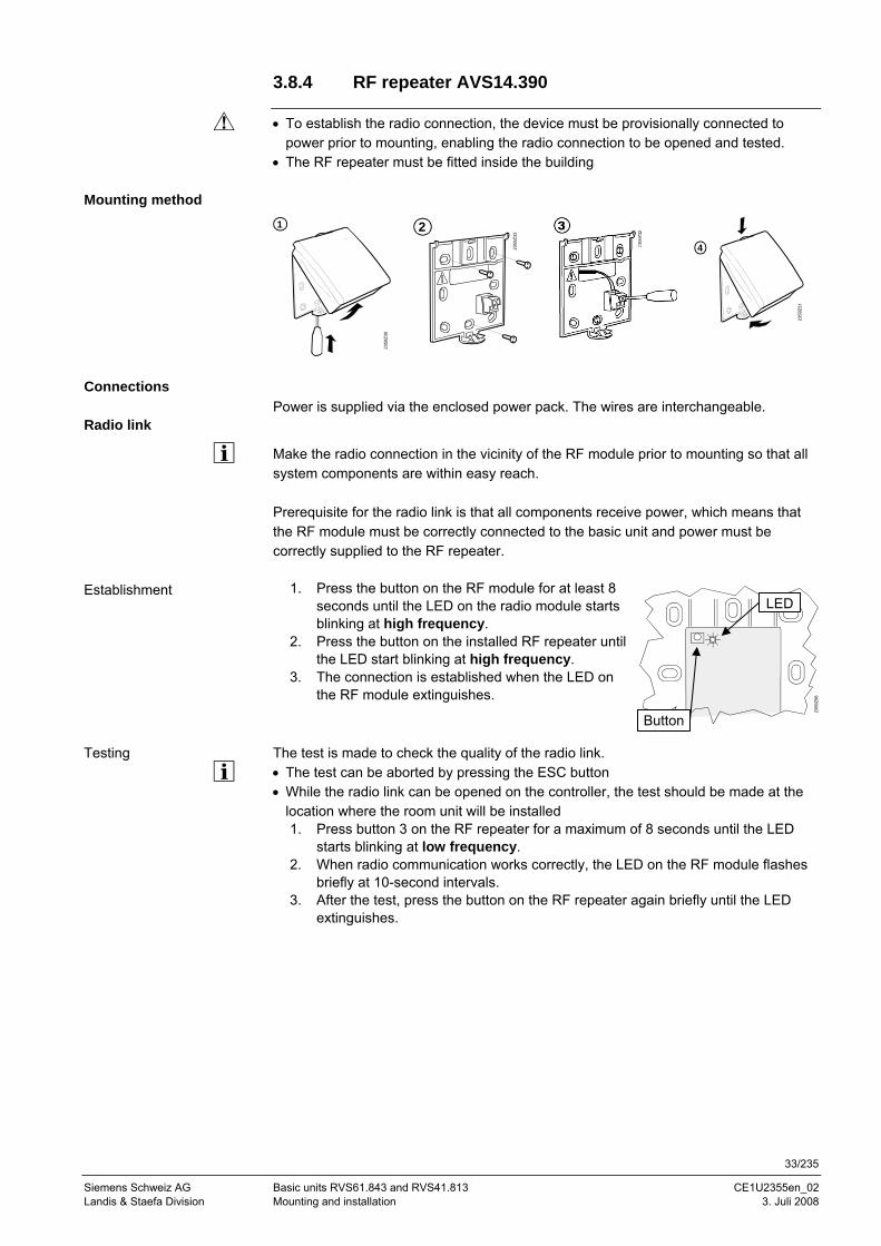
3.8.4 RF repeater AVS14.390
• To establish the radio connection, the device must be provisionally connected to power prior to mounting, enabling the radio connection to be opened and tested.
• The RF repeater must be fitted inside the building
Mounting method 1
2359
Z30
2
2359
Z33
4
2359
Z31
Connections
Power is supplied via the enclosed power pack. The wires are interchangeable. Radio link
Make the radio connection in the vicinity of the RF module prior to mounting so that all system components are within easy reach. Prerequisite for the radio link is that all components receive power, which means that the RF module must be correctly connected to the basic unit and power must be correctly supplied to the RF repeater.
1. Press the button on the RF module for at least 8 seconds until the LED on the radio module starts blinking at high frequency.
2. Press the button on the installed RF repeater until the LED start blinking at high frequency.
3. The connection is established when the LED on the RF module extinguishes.
The test is made to check the quality of the radio link. • The test can be aborted by pressing the ESC button • While the radio link can be opened on the controller, the test should be made at the
location where the room unit will be installed 1. Press button 3 on the RF repeater for a maximum of 8 seconds until the LED
starts blinking at low frequency. 2. When radio communication works correctly, the LED on the RF module flashes
briefly at 10-second intervals. 3. After the test, press the button on the RF repeater again briefly until the LED
extinguishes.
Establishment
Testing
2359
Z56
LED
Button
34/235
Siemens Switzerland Basic units RVS61.843 and RVS41.813 CE1U2355en_02 HVAC Products Contents 3. Juli 2008
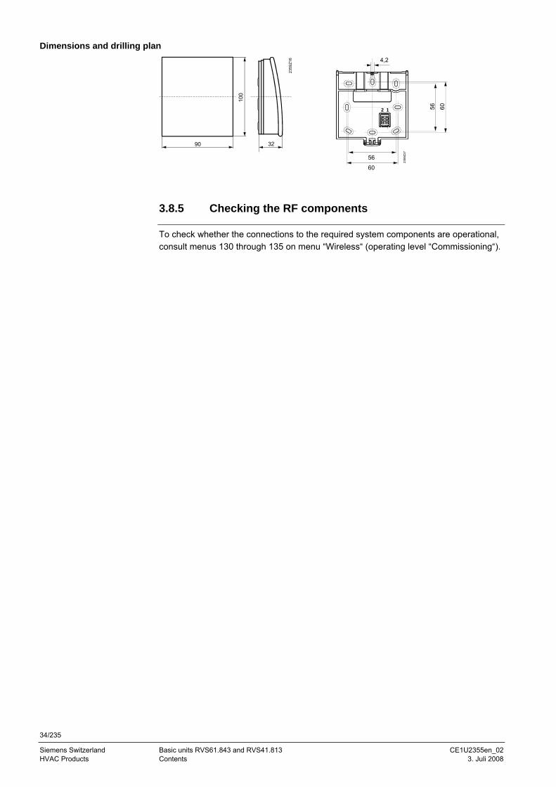
Dimensions and drilling plan
90
100
32
2359
Z16
12
2359
Z27
4,2
56 60
56
60
3.8.5 Checking the RF components
To check whether the connections to the required system components are operational, consult menus 130 through 135 on menu “Wireless“ (operating level “Commissioning“).
35/235
Siemens Schweiz AG Basic units RVS61.843 and RVS41.813 CE1U2355en_02 Landis & Staefa Division Commissioning 3. Juli 2008
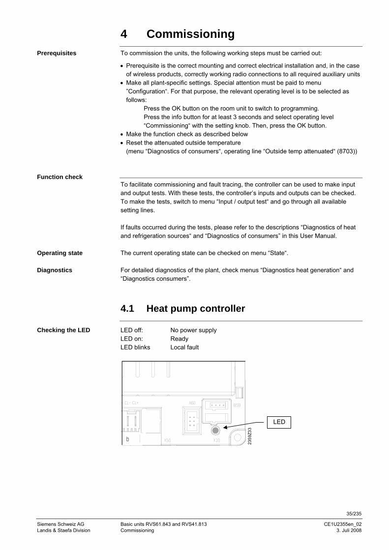
4 Commissioning
To commission the units, the following working steps must be carried out:
• Prerequisite is the correct mounting and correct electrical installation and, in the case of wireless products, correctly working radio connections to all required auxiliary units
• Make all plant-specific settings. Special attention must be paid to menu ”Configuration“. For that purpose, the relevant operating level is to be selected as follows:
Press the OK button on the room unit to switch to programming. Press the info button for at least 3 seconds and select operating level “Commissioning“ with the setting knob. Then, press the OK button.
• Make the function check as described below • Reset the attenuated outside temperature
(menu “Diagnostics of consumers“, operating line “Outside temp attenuated“ (8703))
To facilitate commissioning and fault tracing, the controller can be used to make input and output tests. With these tests, the controller’s inputs and outputs can be checked. To make the tests, switch to menu “Input / output test“ and go through all available setting lines. If faults occurred during the tests, please refer to the descriptions “Diagnostics of heat and refrigeration sources“ and “Diagnostics of consumers” in this User Manual. The current operating state can be checked on menu “State“. For detailed diagnostics of the plant, check menus “Diagnostics heat generation“ and “Diagnostics consumers”.
4.1 Heat pump controller
LED off: No power supply LED on: Ready LED blinks Local fault
Prerequisites
Function check
Operating state
Diagnostics
Checking the LED
2359
Z33
LED
36/235
Siemens Switzerland Basic units RVS61.843 and RVS41.813 CE1U2355en_02 HVAC Products Contents 3. Juli 2008
5 Handling 5.1 QAA75.. / QAA78.. / AVS37.. 5.1.1 Operation
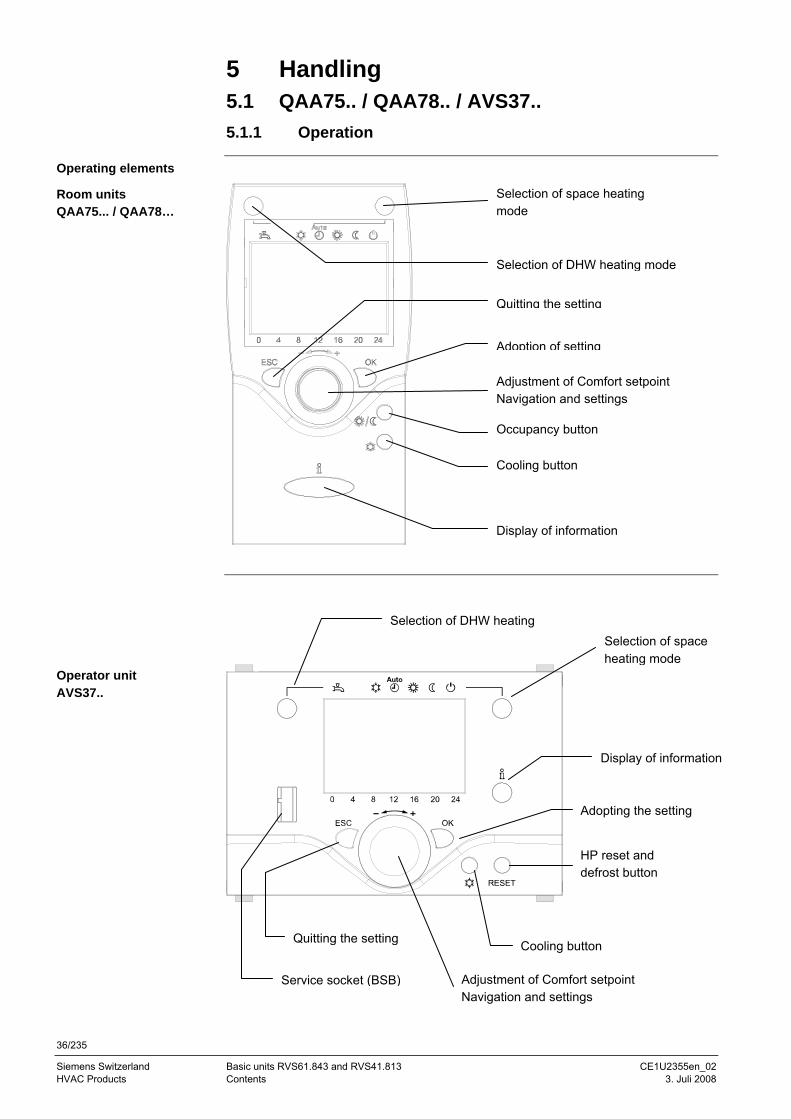
Operating elements
Room units QAA75... / QAA78…
Operator unit AVS37..
Selection of space heating mode
Selection of DHW heating mode
Display of information
Adjustment of Comfort setpoint Navigation and settings
Occupancy button
Quitting the setting
Adoption of setting
Selection of DHW heating Selection of space heating mode
Display of information
Quitting the setting
Adjustment of Comfort setpoint Navigation and settings
Adopting the setting
Service socket (BSB)
Cooling button
Cooling button
HP reset and defrost button
37/235
Siemens Schweiz AG Basic units RVS61.843 and RVS41.813 CE1U2355en_02 Landis & Staefa Division Handling 3. Juli 2008
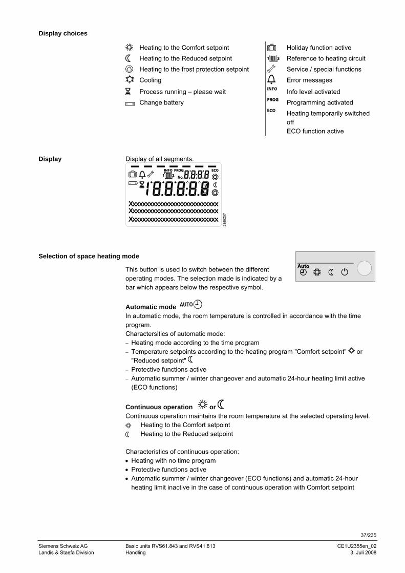
Display choices
Heating to the Comfort setpoint Holiday function active
Heating to the Reduced setpoint Reference to heating circuit
Heating to the frost protection setpoint Service / special functions
Cooling Error messages
Process running – please wait Info level activated
Change battery Programming activated
Heating temporarily switched off ECO function active
Display of all segments.
2358
Z07
XxxxxxxxxxxxxxxxxxxxxxxxxxxXxxxxxxxxxxxxxxxxxxxxxxxxxxXxxxxxxxxxxxxxxxxxxxxxxxxxx
Selection of space heating mode
This button is used to switch between the different operating modes. The selection made is indicated by a bar which appears below the respective symbol. Automatic mode In automatic mode, the room temperature is controlled in accordance with the time program. Charactersitics of automatic mode: − Heating mode according to the time program − Temperature setpoints according to the heating program "Comfort setpoint" or
"Reduced setpoint" − Protective functions active − Automatic summer / winter changeover and automatic 24-hour heating limit active
(ECO functions)
Continuous operation or Continuous operation maintains the room temperature at the selected operating level.
Heating to the Comfort setpoint Heating to the Reduced setpoint
Characteristics of continuous operation: • Heating with no time program • Protective functions active • Automatic summer / winter changeover (ECO functions) and automatic 24-hour
heating limit inactive in the case of continuous operation with Comfort setpoint
Display
38/235
Siemens Switzerland Basic units RVS61.843 and RVS41.813 CE1U2355en_02 HVAC Products Contents 3. Juli 2008
Protection When using Protection, the heating system is off. But it remains protected against frost (frost protection temperature) provided there is no power failure. Characteristics of continuous operation: • Heating off • Temperature according to frost protection • Protective functions active • Automatic summer / winter changeover (ECO functions) and automatic 24-hour
heating limit active
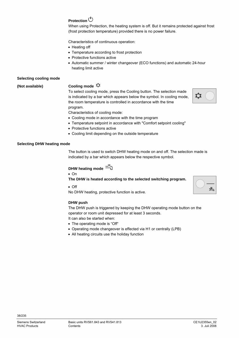
Selecting cooling mode
Cooling mode To select cooling mode, press the Cooling button. The selection made is indicated by a bar which appears below the symbol. In cooling mode, the room temperature is controlled in accordance with the time program. Characteristics of cooling mode: • Cooling mode in accordance with the time program • Temperature setpoint in accordance with "Comfort setpoint cooling" • Protective functions active • Cooling limit depending on the outside temperature
Selecting DHW heating mode
The button is used to switch DHW heating mode on and off. The selection made is indicated by a bar which appears below the respective symbol.
DHW heating mode • On The DHW is heated according to the selected switching program.
• Off No DHW heating, protective function is active. DHW push The DHW push is triggered by keeping the DHW operating mode button on the operator or room unit depressed for at least 3 seconds. It can also be started when: • The operating mode is “Off“ • Operating mode changeover is effected via H1 or centrally (LPB) • All heating circuits use the holiday function
(Not available)
39/235
Siemens Schweiz AG Basic units RVS61.843 and RVS41.813 CE1U2355en_02 Landis & Staefa Division Handling 3. Juli 2008
Adjusting the room temperature setpoint
Turn the setting knob to increase or decrease the Comfort setpoint and confirm by pressing the OK button. During active heating
mode, you can readjust Comfort setpoint “Heating”, and during active cooling mode, you can readjust Comfort setpoint “Cooling”. For the Reduced setpoint − Press the OK button − Select menu “Heating circuit” and − Adjust the “Reduced setpoint“ After each readjustment, wait at least 2 hours, allowing the room temperature to adapt. The Reduced setpoint can only be set in the case of heating mode. In cooling mode, there is no Reduced setpoint, only the Comfort setpoint.
Occupancy button
If, during the Comfort period, the rooms are not used for short periods of time, you can press the occupancy button to lower the room temperature, thus saving heating energy (changeover from Comfort to Reduced setpoint), or saving cooling energy (changeover from Comfort setpoint to OFF). When the rooms are occupied again, press again the occupancy button to return to normal heating (changeover from Reduced to Comfort setpoint), or to cooling (changeover from OFF to Comfort setpoint). In heating mode: In cooling mode:
Heating to the Comfort setpoint Cooling to the Comfort setpoint Heating to the Reduced setpoint Cooling off (no symbol)
• The occupancy button is only active in automatic operation • The current selection is active until the next switching action according to the heating
program takes place
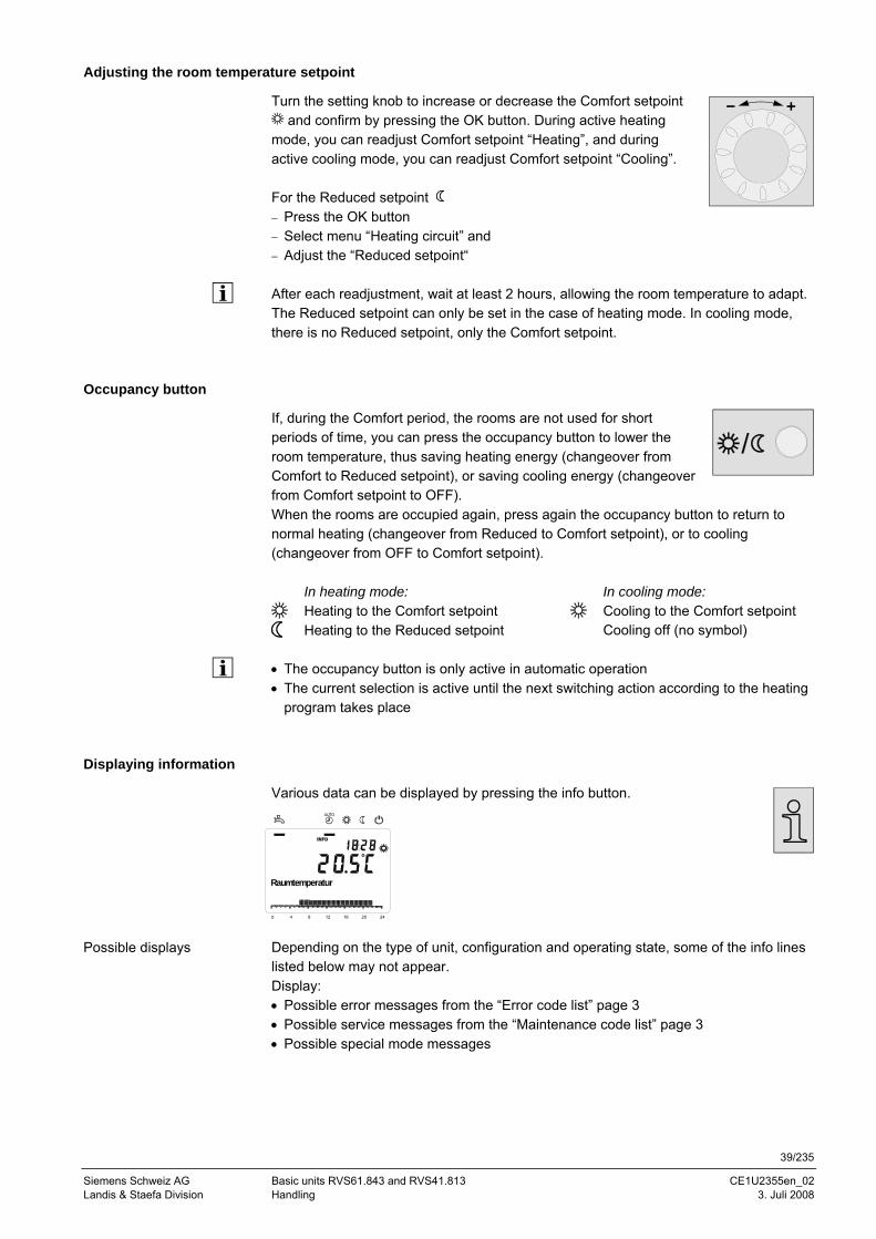
Displaying information
Various data can be displayed by pressing the info button.
Depending on the type of unit, configuration and operating state, some of the info lines listed below may not appear. Display: • Possible error messages from the “Error code list” page 3 • Possible service messages from the “Maintenance code list” page 3 • Possible special mode messages
Possible displays
0 4 8 12 16 20 24
AUTO
Raumtemperatur
40/235
Siemens Switzerland Basic units RVS61.843 and RVS41.813 CE1U2355en_02 HVAC Products Contents 3. Juli 2008
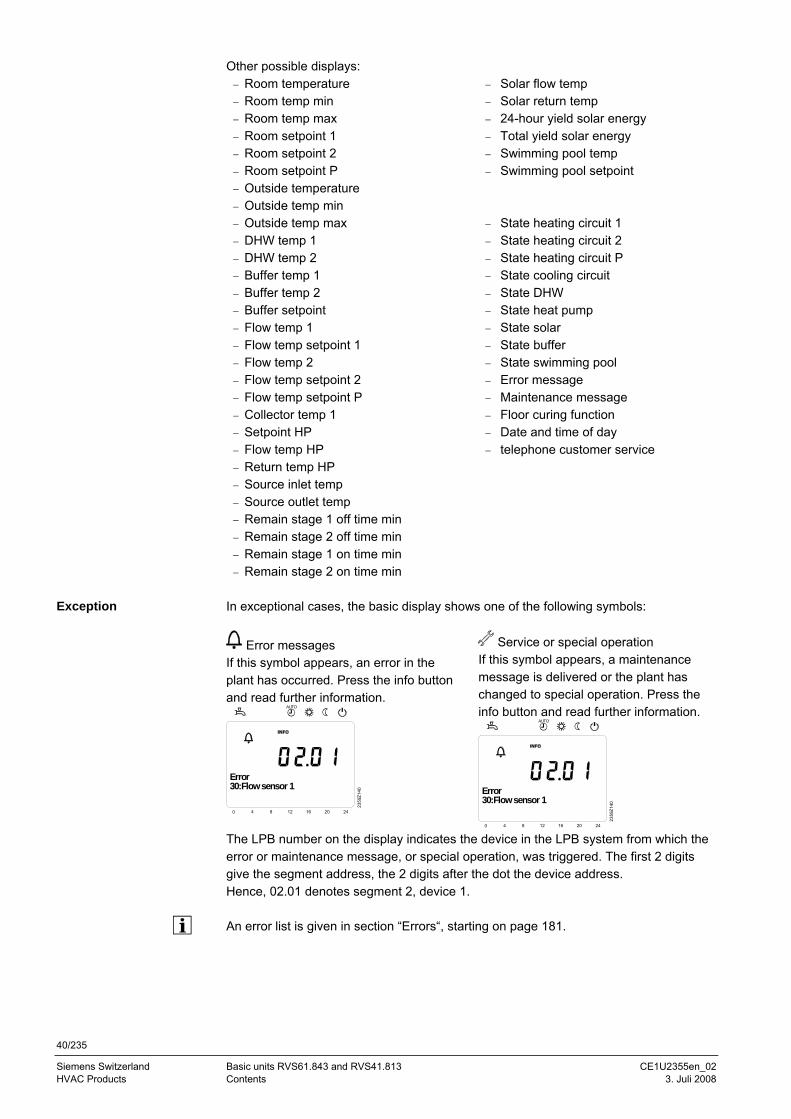
Other possible displays: − Room temperature − Solar flow temp − Room temp min − Solar return temp − Room temp max − 24-hour yield solar energy − Room setpoint 1 − Total yield solar energy − Room setpoint 2 − Swimming pool temp − Room setpoint P − Swimming pool setpoint − Outside temperature − Outside temp min − Outside temp max − State heating circuit 1 − DHW temp 1 − State heating circuit 2 − DHW temp 2 − State heating circuit P − Buffer temp 1 − State cooling circuit − Buffer temp 2 − State DHW − Buffer setpoint − State heat pump − Flow temp 1 − State solar − Flow temp setpoint 1 − State buffer − Flow temp 2 − State swimming pool − Flow temp setpoint 2 − Error message − Flow temp setpoint P − Maintenance message − Collector temp 1 − Floor curing function − Setpoint HP − Date and time of day − Flow temp HP − telephone customer service − Return temp HP − Source inlet temp − Source outlet temp − Remain stage 1 off time min − Remain stage 2 off time min − Remain stage 1 on time min − Remain stage 2 on time min
In exceptional cases, the basic display shows one of the following symbols:
Error messages If this symbol appears, an error in the plant has occurred. Press the info button and read further information.
Text3 Text40 4 8 12 16 20 24
AUTO
2359
Z140
30:Flow sensor 1Error
Service or special operation If this symbol appears, a maintenance message is delivered or the plant has changed to special operation. Press the info button and read further information.
Text3 Text40 4 8 12 16 20 24
AUTO
2359
Z140
30:Flow sensor 1Error
The LPB number on the display indicates the device in the LPB system from which the error or maintenance message, or special operation, was triggered. The first 2 digits give the segment address, the 2 digits after the dot the device address. Hence, 02.01 denotes segment 2, device 1. An error list is given in section “Errors“, starting on page 181.
Exception
41/235
Siemens Schweiz AG Basic units RVS61.843 and RVS41.813 CE1U2355en_02 Landis & Staefa Division Handling 3. Juli 2008
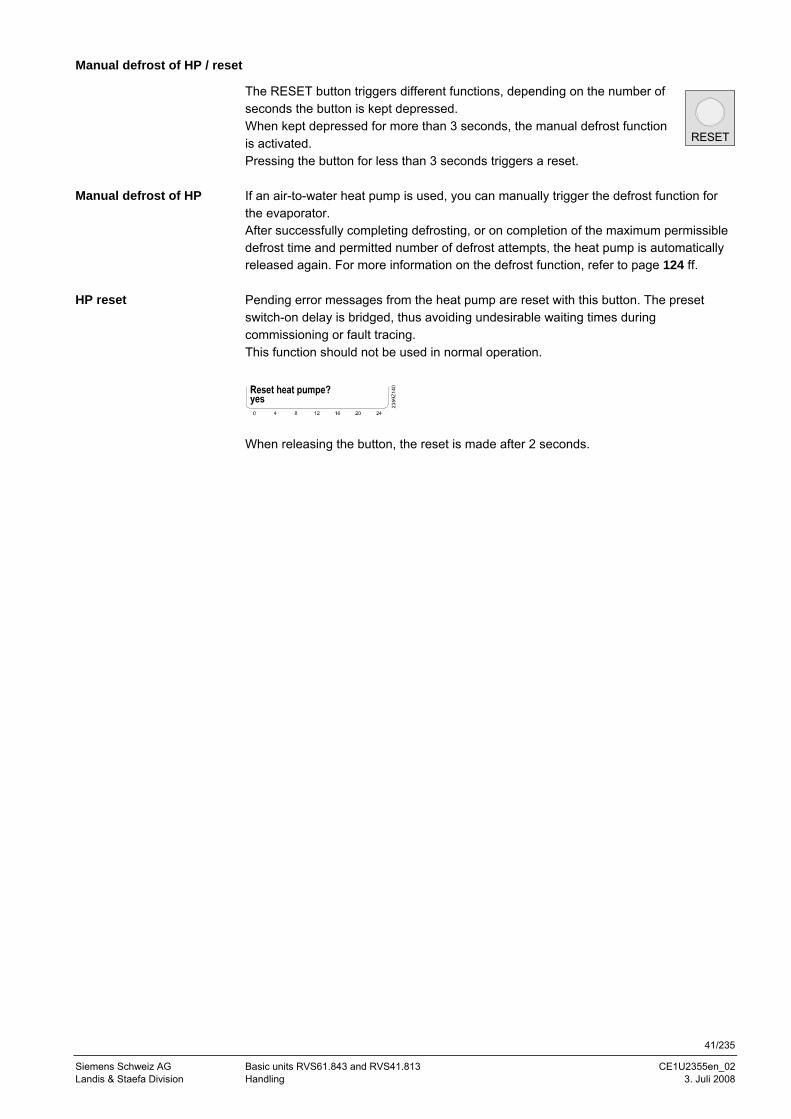
Manual defrost of HP / reset
The RESET button triggers different functions, depending on the number of seconds the button is kept depressed. When kept depressed for more than 3 seconds, the manual defrost function is activated. Pressing the button for less than 3 seconds triggers a reset. If an air-to-water heat pump is used, you can manually trigger the defrost function for the evaporator. After successfully completing defrosting, or on completion of the maximum permissible defrost time and permitted number of defrost attempts, the heat pump is automatically released again. For more information on the defrost function, refer to page 124 ff. Pending error messages from the heat pump are reset with this button. The preset switch-on delay is bridged, thus avoiding undesirable waiting times during commissioning or fault tracing. This function should not be used in normal operation.
When releasing the button, the reset is made after 2 seconds.
Manual defrost of HP
HP reset
RESET
42/235
Siemens Switzerland Basic units RVS61.843 and RVS41.813 CE1U2355en_02 HVAC Products Contents 3. Juli 2008
5.1.2 Programming the QAA75... / QAA78… / AVS37..
Setting principle
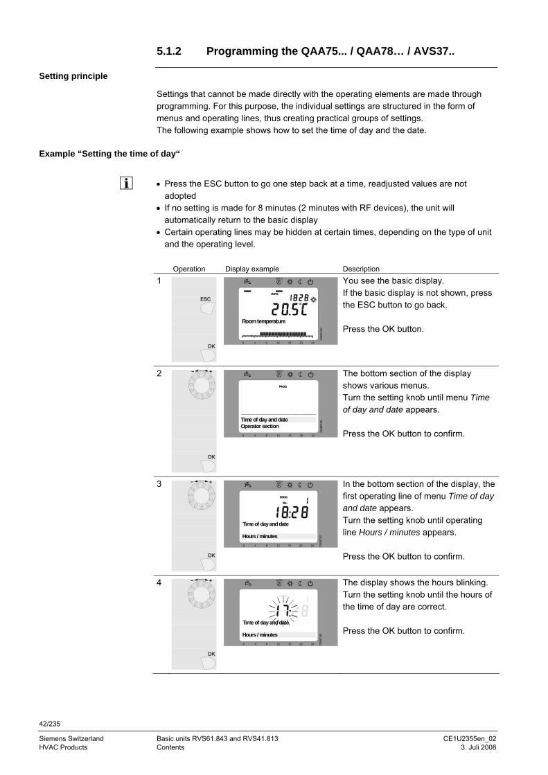
Settings that cannot be made directly with the operating elements are made through programming. For this purpose, the individual settings are structured in the form of menus and operating lines, thus creating practical groups of settings. The following example shows how to set the time of day and the date.
Example “Setting the time of day“
• Press the ESC button to go one step back at a time, readjusted values are not
adopted • If no setting is made for 8 minutes (2 minutes with RF devices), the unit will
automatically return to the basic display • Certain operating lines may be hidden at certain times, depending on the type of unit
and the operating level. Operation Display example Description
1
0 4 8 12 16 20 24
AUTO
2359
Z140
Room temperature
You see the basic display. If the basic display is not shown, press the ESC button to go back. Press the OK button.
2
Text30 4 8 12 16 20 24
AUTO
2359
Z140
Operator sectionTime of day and date
The bottom section of the display shows various menus. Turn the setting knob until menu Time of day and date appears. Press the OK button to confirm.
3
0 4 8 12 16 20 24
AUTO
2359
Z140
Time of day and date
Hours / minutes
In the bottom section of the display, the first operating line of menu Time of day and date appears. Turn the setting knob until operating line Hours / minutes appears. Press the OK button to confirm.
4
0 4 8 12 16 20 24
AUTO
2359
Z140
Time of day and date
Hours / minutes
The display shows the hours blinking. Turn the setting knob until the hours of the time of day are correct. Press the OK button to confirm.
43/235
Siemens Schweiz AG Basic units RVS61.843 and RVS41.813 CE1U2355en_02 Landis & Staefa Division Handling 3. Juli 2008
5
0 4 8 12 16 20 24
AUTO
2359
Z140
Time of day and date
Hours / minutes
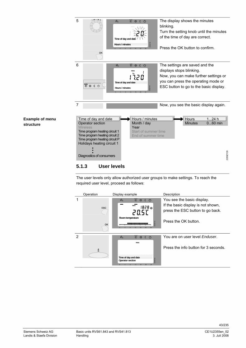
The display shows the minutes blinking. Turn the setting knob until the minutes of the time of day are correct. Press the OK button to confirm.
6
0 4 8 12 16 20 24
AUTO
2359
Z140
Time of day and date
Hours / minutes
The settings are saved and the displays stops blinking. Now, you can make further settings or you can press the operating mode or ESC button to go to the basic display.
7 Now, you see the basic display again.
2359
Z139
Time of day and dateOperator sectionWirelessTime program heating circuit 1Time program heating circuit 2Time program heating circuit PHolidays heating circuit 1
Diagnostics of consumers
Hours / minutesMonth / dayYearStart of summer timeEnd of summer time
Hours 1...24 hMinutes 0...60 min
5.1.3 User levels
The user levels only allow authorized user groups to make settings. To reach the required user level, proceed as follows: Operation Display example Description
1
0 4 8 12 16 20 24
AUTO
2359
Z140
Room temperature
You see the basic display. If the basic display is not shown, press the ESC button to go back. Press the OK button.
2
Text3
0 4 8 12 16 20 24
AUTO
2359
Z140
Operator sectionTime of day and date
You are on user level Enduser. Press the info button for 3 seconds.
Example of menu structure
44/235
Siemens Switzerland Basic units RVS61.843 and RVS41.813 CE1U2355en_02 HVAC Products Contents 3. Juli 2008
Text30 4 8 12 16 20 24
AUTO
2359
Z140
CommissioningEnduser
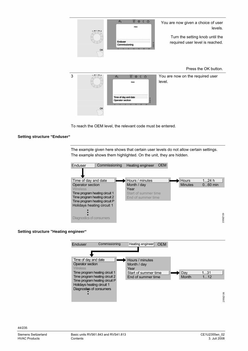
You are now given a choice of user levels.
Turn the setting knob until the required user level is reached.
Press the OK button.
3
Text30 4 8 12 16 20 24
AUTO
2359
Z140
Operator sectionTime of day and date
You are now on the required user level.
To reach the OEM level, the relevant code must be entered.
Setting structure “Enduser“
The example given here shows that certain user levels do not allow certain settings. The example shows them highlighted. On the unit, they are hidden.
2359
Z139
OEM
Time of day and dateOperator sectionWirelessTime program heating circuit 1Time program heating circuit 2Time program heating circuit PHolidays heating circuit 1
Diagnostics of consumers
Hours / minutesMonth / dayYearStart of summer timeEnd of summer time
Hours 1...24 hMinutes 0...60 min
Heating engineerCommissioningEnduser
Setting structure ”Heating engineer“
Time of day and dateOperator section
Holidays heating circuit 1Diagnostics of consumers
Time program heating circuit 1Time program heating circuit 2Time program heating circuit P
Wireless
Hours / minutesMonth / dayYearStart of summer timeEnd of summer time
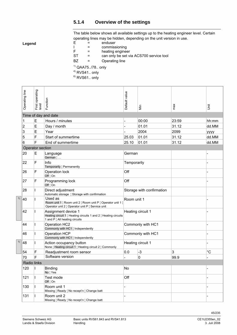
45/235
Siemens Schweiz AG Basic units RVS61.843 and RVS41.813 CE1U2355en_02 Landis & Staefa Division Handling 3. Juli 2008
5.1.4 Overview of the settings
The table below shows all available settings up to the heating engineer level. Certain operating lines may be hidden, depending on the unit version in use. E = enduser I = commissioning F = heating engineer ST = can only be set via ACS700 service tool BZ = Operating line 1) QAA75../78.. only 4) RVS41.. only 6) RVS61.. only
Ope
ratin
g lin
e
Firs
t ope
ratin
g le
vel
Func
tion
Def
ault
valu
e
Min
max
Uni
t
Time of day and date 1 E Hours / minutes - 00:00 23:59 hh:mm 2 E Day / month - 01.01 31.12 dd.MM 3 E Year - 2004 2099 yyyy 5 F Start of summertime 25.03 01.01 31.12 dd.MM 6 F End of summertime 25.10 01.01 31.12 dd.MM Operator section 20 E Language
German ¦ … German -
22 F Info Temporarily ¦ Permanently
Temporarily -
26 F Operation lock Off ¦ On
Off -
27 F Programming lock Off ¦ On
Off -
28 I Direct adjustment Automatic storage ¦ Storage with confirmation
Storage with confirmation
40 I Used as Room unit 1 ¦ Room unit 2 ¦ Room unit P ¦ Operator unit 1 ¦ Operator unit 2 ¦ Operator unit P ¦ Service unit
Room unit 1 -
42 I Assignment device 1 Heating circuit 1 ¦ Heating circuits 1 and 2 ¦ Heating circuits 1 and P ¦ All heating circuits
Heating circuit 1 -
44 I Operation HC2 Commonly with HC1 ¦ Independently
Commonly with HC1 -
46 I Operation HCP Commonly with HC1 ¦ Independently
Commonly with HC1 -
48 I Action occupancy button None ¦ Heating circuit 1 ¦ Heating circuit 2 ¦ Commonly
Heating circuit 1 -
54 F Readjustment room sensor 0.0 -3 3 °C 70 F Software version - 0 99.9 - Radio links 120 I Binding
No ¦ Yes No -
121 I Test mode Off ¦ On
Off -
130 I Room unit 1 Missing ¦ Ready ¦ No recept’n ¦ Change batt
- -
131 I Room unit 2 Missing ¦ Ready ¦ No recept’n ¦ Change batt
- -
Legend
1)
1)
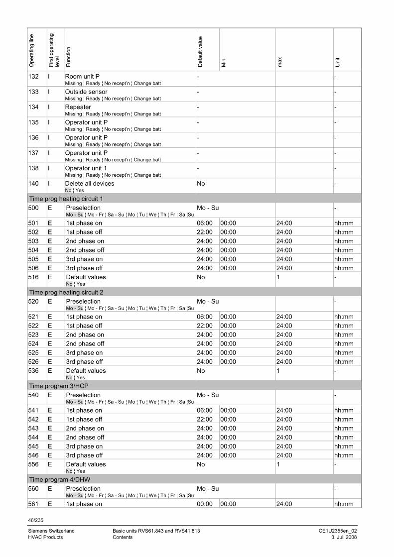
46/235
Siemens Switzerland Basic units RVS61.843 and RVS41.813 CE1U2355en_02 HVAC Products Contents 3. Juli 2008
Ope
ratin
g lin
e
Firs
t ope
ratin
g le
vel
Func
tion
Def
ault
valu
e
Min
max
Uni
t
132 I Room unit P Missing ¦ Ready ¦ No recept’n ¦ Change batt
- -
133 I Outside sensor Missing ¦ Ready ¦ No recept’n ¦ Change batt
- -
134 I Repeater Missing ¦ Ready ¦ No recept’n ¦ Change batt
- -
135 I Operator unit P Missing ¦ Ready ¦ No recept’n ¦ Change batt
- -
136 I Operator unit P Missing ¦ Ready ¦ No recept’n ¦ Change batt
- -
137 I Operator unit P Missing ¦ Ready ¦ No recept’n ¦ Change batt
- -
138 I Operator unit 1 Missing ¦ Ready ¦ No recept’n ¦ Change batt
- -
140 I Delete all devices No ¦ Yes
No -
Time prog heating circuit 1 500 E Preselection
Mo - Su ¦ Mo - Fr ¦ Sa - Su ¦ Mo ¦ Tu ¦ We ¦ Th ¦ Fr ¦ Sa ¦SuMo - Su -
501 E 1st phase on 06:00 00:00 24:00 hh:mm 502 E 1st phase off 22:00 00:00 24:00 hh:mm 503 E 2nd phase on 24:00 00:00 24:00 hh:mm 504 E 2nd phase off 24:00 00:00 24:00 hh:mm 505 E 3rd phase on 24:00 00:00 24:00 hh:mm 506 E 3rd phase off 24:00 00:00 24:00 hh:mm 516 E Default values
No ¦ Yes No 1 -
Time prog heating circuit 2 520 E Preselection
Mo - Su ¦ Mo - Fr ¦ Sa - Su ¦ Mo ¦ Tu ¦ We ¦ Th ¦ Fr ¦ Sa ¦SuMo - Su -
521 E 1st phase on 06:00 00:00 24:00 hh:mm 522 E 1st phase off 22:00 00:00 24:00 hh:mm 523 E 2nd phase on 24:00 00:00 24:00 hh:mm 524 E 2nd phase off 24:00 00:00 24:00 hh:mm 525 E 3rd phase on 24:00 00:00 24:00 hh:mm 526 E 3rd phase off 24:00 00:00 24:00 hh:mm 536 E Default values
No ¦ Yes No 1 -
Time program 3/HCP 540 E Preselection
Mo - Su ¦ Mo - Fr ¦ Sa - Su ¦ Mo ¦ Tu ¦ We ¦ Th ¦ Fr ¦ Sa ¦SuMo - Su -
541 E 1st phase on 06:00 00:00 24:00 hh:mm 542 E 1st phase off 22:00 00:00 24:00 hh:mm 543 E 2nd phase on 24:00 00:00 24:00 hh:mm 544 E 2nd phase off 24:00 00:00 24:00 hh:mm 545 E 3rd phase on 24:00 00:00 24:00 hh:mm 546 E 3rd phase off 24:00 00:00 24:00 hh:mm 556 E Default values
No ¦ Yes No 1 -
Time program 4/DHW 560 E Preselection
Mo - Su ¦ Mo - Fr ¦ Sa - Su ¦ Mo ¦ Tu ¦ We ¦ Th ¦ Fr ¦ Sa ¦SuMo - Su -
561 E 1st phase on 00:00 00:00 24:00 hh:mm
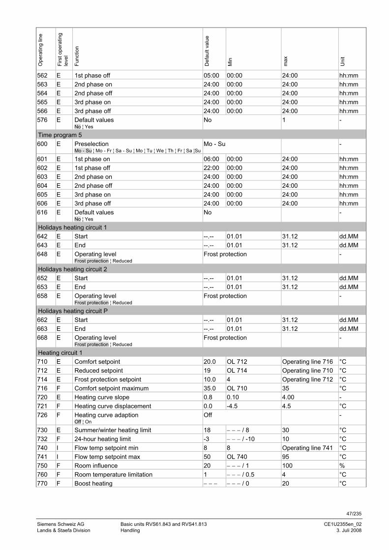
47/235
Siemens Schweiz AG Basic units RVS61.843 and RVS41.813 CE1U2355en_02 Landis & Staefa Division Handling 3. Juli 2008
Ope
ratin
g lin
e
Firs
t ope
ratin
g le
vel
Func
tion
Def
ault
valu
e
Min
max
Uni
t
562 E 1st phase off 05:00 00:00 24:00 hh:mm 563 E 2nd phase on 24:00 00:00 24:00 hh:mm 564 E 2nd phase off 24:00 00:00 24:00 hh:mm 565 E 3rd phase on 24:00 00:00 24:00 hh:mm 566 E 3rd phase off 24:00 00:00 24:00 hh:mm 576 E Default values
No ¦ Yes No 1 -
Time program 5 600 E Preselection
Mo - Su ¦ Mo - Fr ¦ Sa - Su ¦ Mo ¦ Tu ¦ We ¦ Th ¦ Fr ¦ Sa ¦SuMo - Su -
601 E 1st phase on 06:00 00:00 24:00 hh:mm 602 E 1st phase off 22:00 00:00 24:00 hh:mm 603 E 2nd phase on 24:00 00:00 24:00 hh:mm 604 E 2nd phase off 24:00 00:00 24:00 hh:mm 605 E 3rd phase on 24:00 00:00 24:00 hh:mm 606 E 3rd phase off 24:00 00:00 24:00 hh:mm 616 E Default values
No ¦ Yes No -
Holidays heating circuit 1 642 E Start --.-- 01.01 31.12 dd.MM 643 E End --.-- 01.01 31.12 dd.MM 648 E Operating level
Frost protection ¦ Reduced Frost protection -
Holidays heating circuit 2 652 E Start --.-- 01.01 31.12 dd.MM 653 E End --.-- 01.01 31.12 dd.MM 658 E Operating level
Frost protection ¦ Reduced Frost protection -
Holidays heating circuit P 662 E Start --.-- 01.01 31.12 dd.MM 663 E End --.-- 01.01 31.12 dd.MM 668 E Operating level
Frost protection ¦ Reduced Frost protection -
Heating circuit 1 710 E Comfort setpoint 20.0 OL 712 Operating line 716 °C 712 E Reduced setpoint 19 OL 714 Operating line 710 °C 714 E Frost protection setpoint 10.0 4 Operating line 712 °C 716 F Comfort setpoint maximum 35.0 OL 710 35 °C 720 E Heating curve slope 0.8 0.10 4.00 - 721 F Heating curve displacement 0.0 -4.5 4.5 °C 726 F Heating curve adaption
Off ¦ On Off -
730 E Summer/winter heating limit 18 − − − / 8 30 °C 732 F 24-hour heating limit -3 − − − / -10 10 °C 740 I Flow temp setpoint min 8 8 Operating line 741 °C 741 I Flow temp setpoint max 50 OL 740 95 °C 750 F Room influence 20 − − − / 1 100 % 760 F Room temperature limitation 1 − − − / 0.5 4 °C 770 F Boost heating − − − − − − / 0 20 °C
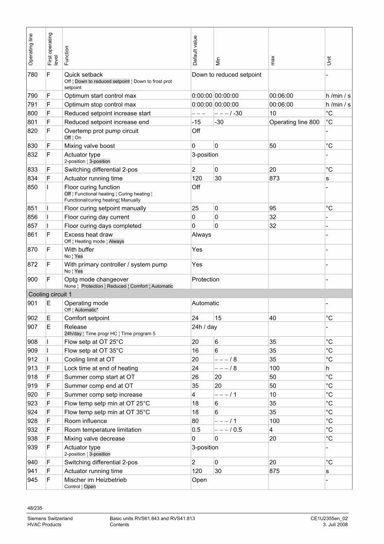
48/235
Siemens Switzerland Basic units RVS61.843 and RVS41.813 CE1U2355en_02 HVAC Products Contents 3. Juli 2008
Ope
ratin
g lin
e
Firs
t ope
ratin
g le
vel
Func
tion
Def
ault
valu
e
Min
max
Uni
t
780 F Quick setback Off ¦ Down to reduced setpoint ¦ Down to frost prot setpoint
Down to reduced setpoint -
790 F Optimum start control max 0:00:00 00:00:00 00:06:00 h /min / s791 F Optimum stop control max 0:00:00 00:00:00 00:06:00 h /min / s800 F Reduced setpoint increase start − − − − − − / -30 10 °C 801 F Reduced setpoint increase end -15 -30 Operating line 800 °C 820 F Overtemp prot pump circuit
Off ¦ On Off -
830 F Mixing valve boost 0 0 50 °C 832 F Actuator type
2-position ¦ 3-position 3-position -
833 F Switching differential 2-pos 2 0 20 °C 834 F Actuator running time 120 30 873 s 850 I Floor curing function
Off ¦ Functional heating ¦ Curing heating ¦ Functional/curing heating¦ Manually
Off -
851 I Floor curing setpoint manually 25 0 95 °C 856 I Floor curing day current 0 0 32 - 857 I Floor curing days completed 0 0 32 - 861 F Excess heat draw
Off ¦ Heating mode ¦ Always Always -
870 F With buffer No ¦ Yes
Yes -
872 F With primary controller / system pump No ¦ Yes
Yes -
900 F Optg mode changeover None ¦ Protection ¦ Reduced ¦ Comfort ¦ Automatic
Protection -
Cooling circuit 1 901 E Operating mode
Off ¦ Automatic* Automatic -
902 E Comfort setpoint 24 15 40 °C 907 E Release
24h/day ¦ Time progr HC ¦ Time program 5 24h / day -
908 I Flow setp at OT 25°C 20 6 35 °C 909 I Flow setp at OT 35°C 16 6 35 °C 912 I Cooling limit at OT 20 − − − / 8 35 °C 913 F Lock time at end of heating 24 − − − / 8 100 h 918 F Summer comp start at OT 26 20 50 °C 919 F Summer comp end at OT 35 20 50 °C 920 F Summer comp setp increase 4 − − − / 1 10 °C 923 F Flow temp setp min at OT 25°C 18 6 35 °C 924 F Flow temp setp min at OT 35°C 18 6 35 °C 928 F Room influence 80 − − − / 1 100 °C 932 F Room temperature limitation 0.5 − − − / 0.5 4 °C 938 F Mixing valve decrease 0 0 20 °C 939 F Actuator type
2-position ¦ 3-position 3-position -
940 F Switching differential 2-pos 2 0 20 °C 941 F Actuator running time 120 30 875 s 945 F Mischer im Heizbetrieb
Control ¦ Open Open -
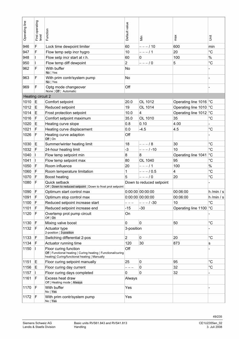
49/235
Siemens Schweiz AG Basic units RVS61.843 and RVS41.813 CE1U2355en_02 Landis & Staefa Division Handling 3. Juli 2008
Ope
ratin
g lin
e
Firs
t ope
ratin
g le
vel
Func
tion
Def
ault
valu
e
Min
max
Uni
t
946 F Lock time dewpoint limiter 60 − − − / 10 600 min 947 F Flow temp setp incr hygro 10 − − − / 1 20 °C 948 I Flow setp incr start at r.h. 60 0 100 % 950 I Flow temp diff dewpoint 2 − − − / 0 5 °C 962 F With buffer
No ¦ Yes No -
963 F With prim contr/system pump No ¦ Yes
No -
969 F Optg mode changeover None ¦ Off ¦ Automatic
Off -
Heating circuit 2 1010 E Comfort setpoint 20.0 OL 1012 Operating line 1016 °C 1012 E Reduced setpoint 19 OL 1014 Operating line 1010 °C 1014 E Frost protection setpoint 10.0 4 Operating line 1012 °C 1016 F Comfort setpoint maximum 35.0 OL 1010 35 °C 1020 E Heating curve slope 0.8 0.10 4.00 - 1021 F Heating curve displacement 0.0 -4.5 4.5 °C 1026 F Heating curve adaption
Off ¦ On Off -
1030 E Summer/winter heating limit 18 − − − / 8 30 °C 1032 F 24-hour heating limit -3 − − − / -10 10 °C 1040 I Flow temp setpoint min 8 8 Operating line 1041 °C 1041 I Flow temp setpoint max 80 OL 1040 95 °C 1050 F Room influence 20 − − − / 1 100 % 1060 F Room temperature limitation 1 − − − / 0.5 4 °C 1070 F Boost heating 5 − − − / 0 20 °C 1080 F Quick setback
Off ¦ Down to reduced setpoint ¦ Down to frost prot setpointDown to reduced setpoint -
1090 F Optimum start control max 0:00:00 00:00:00 00:06:00 h /min / s1091 F Optimum stop control max 0:00:00 00:00:00 00:06:00 h /min / s1100 F Reduced setpoint increase start − − − − − − / -30 10 °C 1101 F Reduced setpoint increase end -15 -30 Operating line 1100 °C 1120 F Overtemp prot pump circuit
Off ¦ On On -
1130 F Mixing valve boost 0 0 50 °C 1132 F Actuator type
2-position ¦ 3-position 3-position -
1133 F Switching differential 2-pos 2 0 20 °C 1134 F Actuator running time 120 30 873 s 1150 I Floor curing function
Off ¦ Functional heating ¦ Curing heating ¦ Functional/curing heating¦ Curing/functional heating ¦ Manually
Off -
1151 E Floor curing setpoint manually 25 0 95 °C 1156 E Floor curing day current − − − 0 32 °C 1157 I Floor curing days completed 0 0 32 - 1161 F Excess heat draw
Off ¦ Heating mode ¦ Always Always
1170 F With buffer No ¦ Yes
Yes -
1172 F With prim contr/system pump No ¦ Yes
Yes
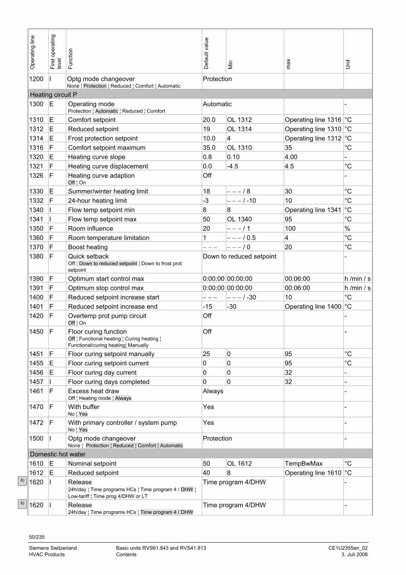
50/235
Siemens Switzerland Basic units RVS61.843 and RVS41.813 CE1U2355en_02 HVAC Products Contents 3. Juli 2008
Ope
ratin
g lin
e
Firs
t ope
ratin
g le
vel
Func
tion
Def
ault
valu
e
Min
max
Uni
t
1200 I Optg mode changeover None ¦ Protection ¦ Reduced ¦ Comfort ¦ Automatic
Protection
Heating circuit P 1300 E Operating mode
Protection ¦ Automatic ¦ Reduced ¦ Comfort Automatic -
1310 E Comfort setpoint 20.0 OL 1312 Operating line 1316 °C 1312 E Reduced setpoint 19 OL 1314 Operating line 1310 °C 1314 E Frost protection setpoint 10.0 4 Operating line 1312 °C 1316 F Comfort setpoint maximum 35.0 OL 1310 35 °C 1320 E Heating curve slope 0.8 0.10 4.00 - 1321 F Heating curve displacement 0.0 -4.5 4.5 °C 1326 F Heating curve adaption
Off ¦ On Off -
1330 E Summer/winter heating limit 18 − − − / 8 30 °C 1332 F 24-hour heating limit -3 − − − / -10 10 °C 1340 I Flow temp setpoint min 8 8 Operating line 1341 °C 1341 I Flow temp setpoint max 50 OL 1340 95 °C 1350 F Room influence 20 − − − / 1 100 % 1360 F Room temperature limitation 1 − − − / 0.5 4 °C 1370 F Boost heating − − − − − − / 0 20 °C 1380 F Quick setback
Off ¦ Down to reduced setpoint ¦ Down to frost prot setpoint
Down to reduced setpoint -
1390 F Optimum start control max 0:00:00 00:00:00 00:06:00 h /min / s1391 F Optimum stop control max 0:00:00 00:00:00 00:06:00 h /min / s1400 F Reduced setpoint increase start − − − − − − / -30 10 °C 1401 F Reduced setpoint increase end -15 -30 Operating line 1400 °C 1420 F Overtemp prot pump circuit
Off ¦ On Off -
1450 F Floor curing function Off ¦ Functional heating ¦ Curing heating ¦ Functional/curing heating¦ Manually
Off -
1451 F Floor curing setpoint manually 25 0 95 °C 1455 E Floor curing setpoint current 0 0 95 °C 1456 E Floor curing day current 0 0 32 - 1457 I Floor curing days completed 0 0 32 - 1461 F Excess heat draw
Off ¦ Heating mode ¦ Always Always -
1470 F With buffer No ¦ Yes
Yes -
1472 F With primary controller / system pump No ¦ Yes
Yes -
1500 I Optg mode changeover None ¦ Protection ¦ Reduced ¦ Comfort ¦ Automatic
Protection -
Domestic hot water 1610 E Nominal setpoint 50 OL 1612 TempBwMax °C 1612 E Reduced setpoint 40 8 Operating line 1610 °C 1620 I Release
24h/day ¦ Time programs HCs ¦ Time program 4 / DHW ¦ Low-tariff ¦ Time prog 4/DHW or LT
Time program 4/DHW -
1620 I Release 24h/day ¦ Time programs HCs ¦ Time program 4 / DHW
Time program 4/DHW -
6)
6)
6)
6)
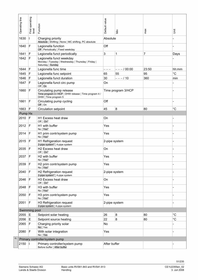
51/235
Siemens Schweiz AG Basic units RVS61.843 and RVS41.813 CE1U2355en_02 Landis & Staefa Division Handling 3. Juli 2008
Ope
ratin
g lin
e
Firs
t ope
ratin
g le
vel
Func
tion
Def
ault
valu
e
Min
max
Uni
t
1630 I Charging priority Absolute ¦ Shifting ¦ None ¦ MC shifting, PC absolute
Absolute -
1640 F Legionella function Off ¦ Periodically ¦ Fixed weekday
Off -
1641 F Legionella funct periodically 3 1 7 Days 1642 F Legionella funct weekday
Monday ¦ Tuesday ¦ Wednesday ¦ Thursday ¦ Friday ¦ Saturday ¦ Sunday
-
1644 F Legionella func time − − − − − − / 00:00 23:50 hh:mm 1645 F Legionella func setpoint 65 55 95 °C 1646 F Legionella funct duration 30 − − − / 10 360 min 1647 F Legionella funct circ pump
Off ¦ On On -
1660 F Circulating pump release Time program 3 / HCP ¦ DHW release ¦ Time program 4 / DHW ¦ Time program 5
Time program 3/HCP -
1661 F Circulating pump cycling Off ¦ On
Off -
1663 F Circulation setpoint 45 8 80 °C Pump Hx 2010 F H1 Excess heat draw
Off ¦ On* On -
2012 F H1 with buffer No ¦ Yes*
Yes -
2014 F H1 prim contr/system pump No ¦ Yes*
Yes -
2015 F H1 Refrigeration request 2-pipe system* ¦ 4-pipe system
2-pipe system -
2035 F H2 Excess heat draw Off ¦ On*
On -
2037 F H2 with buffer No ¦ Yes*
Yes -
2039 F H2 prim contr/system pump No ¦ Yes*
Yes -
2040 F H2 Refrigeration request 2-pipe system* ¦ 4-pipe system
2-pipe system -
2046 F H3 Excess heat draw Off ¦ On*
On -
2048 F H3 with buffer No ¦ Yes*
Yes -
2050 F H3 prim contr/system pump No ¦ Yes*
Yes -
2051 F H3 Refrigeration request 2-pipe system ¦ 4-pipe-system
2-pipe system -
Swimming pool 2055 E Setpoint solar heating 26 8 80 °C 2056 E Setpoint source heating 22 8 80 °C 2065 F Charging priority solar
No ¦ Yes No -
2080 F With solar integration No ¦ Yes
Yes -
Primary controller/system pump 2150 I Primary controller/system pump
Before buffer ¦ After buffer After buffer -
6)
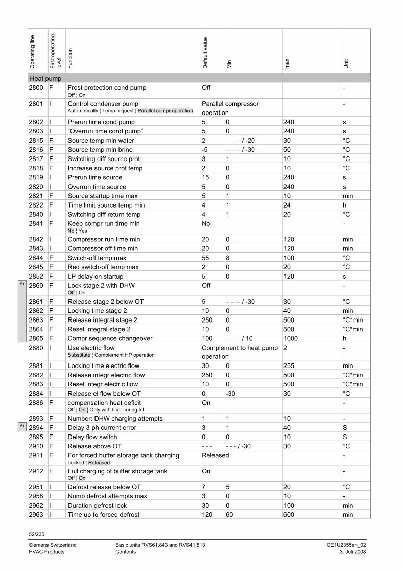
52/235
Siemens Switzerland Basic units RVS61.843 and RVS41.813 CE1U2355en_02 HVAC Products Contents 3. Juli 2008
Ope
ratin
g lin
e
Firs
t ope
ratin
g le
vel
Func
tion
Def
ault
valu
e
Min
max
Uni
t
Heat pump 2800 F Frost protection cond pump
Off ¦ On Off -
2801 I Control condenser pump Automatically ¦ Temp request ¦ Parallel compr operation
Parallel compressor operation
-
2802 I Prerun time cond pump 5 0 240 s 2803 I “Overrun time cond pump” 5 0 240 s 2815 F Source temp min water 2 − − − / -20 30 °C 2816 F Source temp min brine -5 − − − / -30 50 °C 2817 F Switching diff source prot 3 1 10 °C 2818 F Increase source prot temp 2 0 10 °C 2819 I Prerun time source 15 0 240 s 2820 I Overrun time source 5 0 240 s 2821 F Source startup time max 5 1 10 min 2822 F Time limit source temp min 4 1 24 h 2840 I Switching diff return temp 4 1 20 °C 2841 F Keep compr run time min
No ¦ Yes No -
2842 I Compressor run time min 20 0 120 min 2843 I Compressor off time min 20 0 120 min 2844 F Switch-off temp max 55 8 100 °C 2845 F Red switch-off temp max 2 0 20 °C 2852 F LP delay on startup 5 0 120 s 2860 F Lock stage 2 with DHW
Off ¦ On Off -
2861 F Release stage 2 below OT 5 − − − / -30 30 °C 2862 F Locking time stage 2 10 0 40 min 2863 F Release integral stage 2 250 0 500 °C*min 2864 F Reset integral stage 2 10 0 500 °C*min 2865 F Compr sequence changeover 100 − − − / 10 1000 h 2880 I Use electric flow
Substitute ¦ Complement HP operation Complement to heat pump operation
2 -
2881 I Locking time electric flow 30 0 255 min 2882 I Release integr electric flow 250 0 500 °C*min 2883 I Reset integr electric flow 10 0 500 °C*min 2884 I Release el flow below OT 0 -30 30 °C 2886 F compensation heat deficit
Off ¦ On ¦ Only with floor curing fct On -
2893 F Number: DHW charging attempts 1 1 10 - 2894 F Delay 3-ph current error 3 1 40 S 2895 F Delay flow switch 0 0 10 S 2910 F Release above OT - - - - - - / -30 30 °C 2911 F For forced buffer storage tank charging
Locked ¦ Released Released -
2912 F Full charging of buffer storage tank Off ¦ On
On -
2951 I Defrost release below OT 7 5 20 °C 2958 I Numb defrost attempts max 3 0 10 - 2962 I Duration defrost lock 30 0 100 min 2963 I Time up to forced defrost 120 60 600 min
6)
6)
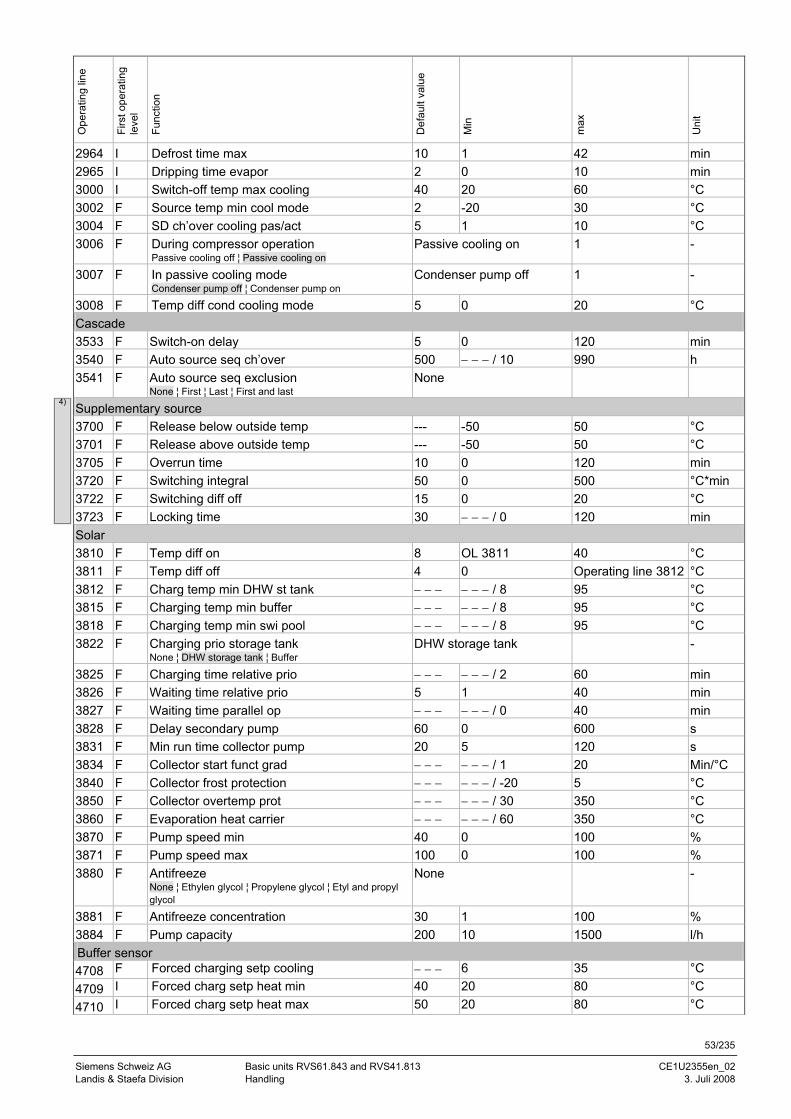
53/235
Siemens Schweiz AG Basic units RVS61.843 and RVS41.813 CE1U2355en_02 Landis & Staefa Division Handling 3. Juli 2008
Ope
ratin
g lin
e
Firs
t ope
ratin
g le
vel
Func
tion
Def
ault
valu
e
Min
max
Uni
t
2964 I Defrost time max 10 1 42 min 2965 I Dripping time evapor 2 0 10 min 3000 I Switch-off temp max cooling 40 20 60 °C 3002 F Source temp min cool mode 2 -20 30 °C 3004 F SD ch’over cooling pas/act 5 1 10 °C 3006 F During compressor operation
Passive cooling off ¦ Passive cooling on Passive cooling on 1 -
3007 F In passive cooling mode Condenser pump off ¦ Condenser pump on
Condenser pump off 1 -
3008 F Temp diff cond cooling mode 5 0 20 °C Cascade 3533 F Switch-on delay 5 0 120 min 3540 F Auto source seq ch’over 500 − − − / 10 990 h 3541 F Auto source seq exclusion
None ¦ First ¦ Last ¦ First and last None
Supplementary source 3700 F Release below outside temp --- -50 50 °C 3701 F Release above outside temp --- -50 50 °C 3705 F Overrun time 10 0 120 min 3720 F Switching integral 50 0 500 °C*min 3722 F Switching diff off 15 0 20 °C 3723 F Locking time 30 − − − / 0 120 min Solar 3810 F Temp diff on 8 OL 3811 40 °C 3811 F Temp diff off 4 0 Operating line 3812 °C 3812 F Charg temp min DHW st tank − − − − − − / 8 95 °C 3815 F Charging temp min buffer − − − − − − / 8 95 °C 3818 F Charging temp min swi pool − − − − − − / 8 95 °C 3822 F Charging prio storage tank
None ¦ DHW storage tank ¦ Buffer DHW storage tank -
3825 F Charging time relative prio − − − − − − / 2 60 min 3826 F Waiting time relative prio 5 1 40 min 3827 F Waiting time parallel op − − − − − − / 0 40 min 3828 F Delay secondary pump 60 0 600 s 3831 F Min run time collector pump 20 5 120 s 3834 F Collector start funct grad − − − − − − / 1 20 Min/°C 3840 F Collector frost protection − − − − − − / -20 5 °C 3850 F Collector overtemp prot − − − − − − / 30 350 °C 3860 F Evaporation heat carrier − − − − − − / 60 350 °C 3870 F Pump speed min 40 0 100 % 3871 F Pump speed max 100 0 100 % 3880 F Antifreeze
None ¦ Ethylen glycol ¦ Propylene glycol ¦ Etyl and propyl glycol
None -
3881 F Antifreeze concentration 30 1 100 % 3884 F Pump capacity 200 10 1500 l/h Buffer sensor 4708 F Forced charging setp cooling − − − 6 35 °C 4709 I Forced charg setp heat min 40 20 80 °C 4710 I Forced charg setp heat max 50 20 80 °C
4)
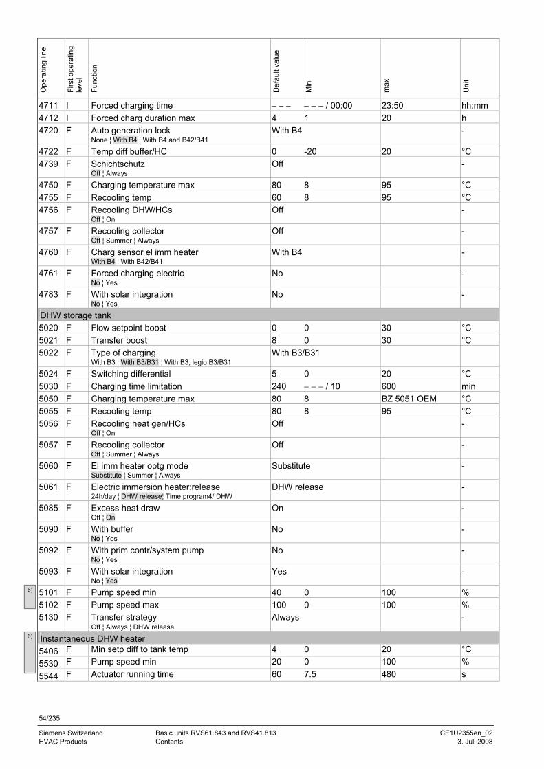
54/235
Siemens Switzerland Basic units RVS61.843 and RVS41.813 CE1U2355en_02 HVAC Products Contents 3. Juli 2008
Ope
ratin
g lin
e
Firs
t ope
ratin
g le
vel
Func
tion
Def
ault
valu
e
Min
max
Uni
t
4711 I Forced charging time − − − − − − / 00:00 23:50 hh:mm 4712 I Forced charg duration max 4 1 20 h 4720 F Auto generation lock
None ¦ With B4 ¦ With B4 and B42/B41 With B4 -
4722 F Temp diff buffer/HC 0 -20 20 °C 4739 F Schichtschutz
Off ¦ Always Off -
4750 F Charging temperature max 80 8 95 °C 4755 F Recooling temp 60 8 95 °C 4756 F Recooling DHW/HCs
Off ¦ On Off -
4757 F Recooling collector Off ¦ Summer ¦ Always
Off -
4760 F Charg sensor el imm heater With B4 ¦ With B42/B41
With B4 -
4761 F Forced charging electric No ¦ Yes
No -
4783 F With solar integration No ¦ Yes
No -
DHW storage tank 5020 F Flow setpoint boost 0 0 30 °C 5021 F Transfer boost 8 0 30 °C 5022 F Type of charging
With B3 ¦ With B3/B31 ¦ With B3, legio B3/B31 With B3/B31
5024 F Switching differential 5 0 20 °C 5030 F Charging time limitation 240 − − − / 10 600 min 5050 F Charging temperature max 80 8 BZ 5051 OEM °C 5055 F Recooling temp 80 8 95 °C 5056 F Recooling heat gen/HCs
Off ¦ On Off -
5057 F Recooling collector Off ¦ Summer ¦ Always
Off -
5060 F El imm heater optg mode Substitute ¦ Summer ¦ Always
Substitute -
5061 F Electric immersion heater:release 24h/day ¦ DHW release¦ Time program4/ DHW
DHW release -
5085 F Excess heat draw Off ¦ On
On -
5090 F With buffer No ¦ Yes
No -
5092 F With prim contr/system pump No ¦ Yes
No -
5093 F With solar integration No ¦ Yes
Yes -
5101 F Pump speed min 40 0 100 % 5102 F Pump speed max 100 0 100 % 5130 F Transfer strategy
Off ¦ Always ¦ DHW release Always -
Instantaneous DHW heater 5406 F Min setp diff to tank temp 4 0 20 °C 5530 F Pump speed min 20 0 100 % 5544 F Actuator running time 60 7.5 480 s
6)
6)
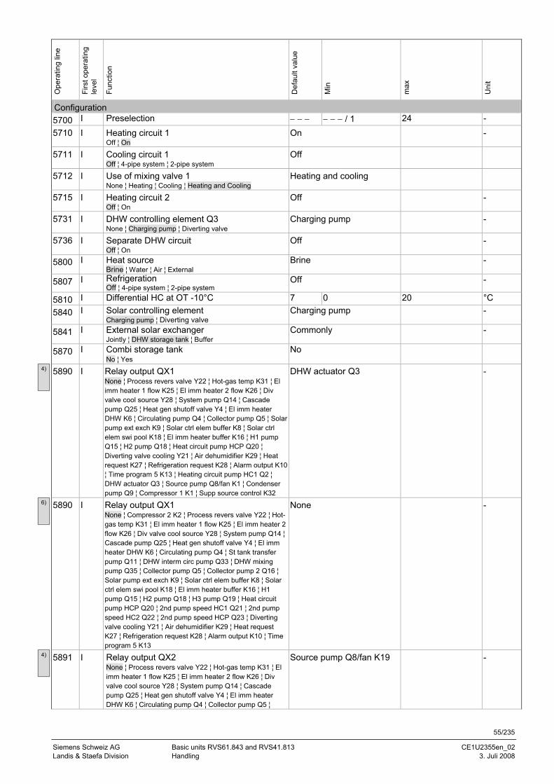
55/235
Siemens Schweiz AG Basic units RVS61.843 and RVS41.813 CE1U2355en_02 Landis & Staefa Division Handling 3. Juli 2008
Ope
ratin
g lin
e
Firs
t ope
ratin
g le
vel
Func
tion
Def
ault
valu
e
Min
max
Uni
t
Configuration 5700 I Preselection − − − − − − / 1 24 - 5710 I Heating circuit 1
Off ¦ On On -
5711 I Cooling circuit 1 Off ¦ 4-pipe system ¦ 2-pipe system
Off
5712 I Use of mixing valve 1 None ¦ Heating ¦ Cooling ¦ Heating and Cooling
Heating and cooling
5715 I Heating circuit 2 Off ¦ On
Off -
5731 I DHW controlling element Q3 None ¦ Charging pump ¦ Diverting valve
Charging pump -
5736 I Separate DHW circuit Off ¦ On
Off -
5800 I Heat source Brine ¦ Water ¦ Air ¦ External
Brine -
5807 I Refrigeration Off ¦ 4-pipe system ¦ 2-pipe system
Off -
5810 I Differential HC at OT -10°C 7 0 20 °C 5840 I Solar controlling element
Charging pump ¦ Diverting valve Charging pump -
5841 I External solar exchanger Jointly ¦ DHW storage tank ¦ Buffer
Commonly -
5870 I Combi storage tank No ¦ Yes
No
5890 I Relay output QX1 None ¦ Process revers valve Y22 ¦ Hot-gas temp K31 ¦ El imm heater 1 flow K25 ¦ El imm heater 2 flow K26 ¦ Div valve cool source Y28 ¦ System pump Q14 ¦ Cascade pump Q25 ¦ Heat gen shutoff valve Y4 ¦ El imm heater DHW K6 ¦ Circulating pump Q4 ¦ Collector pump Q5 ¦ Solar pump ext exch K9 ¦ Solar ctrl elem buffer K8 ¦ Solar ctrl elem swi pool K18 ¦ El imm heater buffer K16 ¦ H1 pump Q15 ¦ H2 pump Q18 ¦ Heat circuit pump HCP Q20 ¦ Diverting valve cooling Y21 ¦ Air dehumidifier K29 ¦ Heat request K27 ¦ Refrigeration request K28 ¦ Alarm output K10 ¦ Time program 5 K13 ¦ Heating circuit pump HC1 Q2 ¦ DHW actuator Q3 ¦ Source pump Q8/fan K1 ¦ Condenser pump Q9 ¦ Compressor 1 K1 ¦ Supp source control K32
DHW actuator Q3 -
5890 I Relay output QX1 None ¦ Compressor 2 K2 ¦ Process revers valve Y22 ¦ Hot-gas temp K31 ¦ El imm heater 1 flow K25 ¦ El imm heater 2 flow K26 ¦ Div valve cool source Y28 ¦ System pump Q14 ¦ Cascade pump Q25 ¦ Heat gen shutoff valve Y4 ¦ El imm heater DHW K6 ¦ Circulating pump Q4 ¦ St tank transfer pump Q11 ¦ DHW interm circ pump Q33 ¦ DHW mixing pump Q35 ¦ Collector pump Q5 ¦ Collector pump 2 Q16 ¦ Solar pump ext exch K9 ¦ Solar ctrl elem buffer K8 ¦ Solar ctrl elem swi pool K18 ¦ El imm heater buffer K16 ¦ H1 pump Q15 ¦ H2 pump Q18 ¦ H3 pump Q19 ¦ Heat circuit pump HCP Q20 ¦ 2nd pump speed HC1 Q21 ¦ 2nd pump speed HC2 Q22 ¦ 2nd pump speed HCP Q23 ¦ Diverting valve cooling Y21 ¦ Air dehumidifier K29 ¦ Heat request K27 ¦ Refrigeration request K28 ¦ Alarm output K10 ¦ Time program 5 K13
None -
5891 I Relay output QX2 None ¦ Process revers valve Y22 ¦ Hot-gas temp K31 ¦ El imm heater 1 flow K25 ¦ El imm heater 2 flow K26 ¦ Div valve cool source Y28 ¦ System pump Q14 ¦ Cascade pump Q25 ¦ Heat gen shutoff valve Y4 ¦ El imm heater DHW K6 ¦ Circulating pump Q4 ¦ Collector pump Q5 ¦
Source pump Q8/fan K19 -
6)
4)
4)
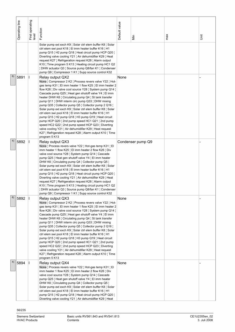
56/235
Siemens Switzerland Basic units RVS61.843 and RVS41.813 CE1U2355en_02 HVAC Products Contents 3. Juli 2008
Ope
ratin
g lin
e
Firs
t ope
ratin
g le
vel
Func
tion
Def
ault
valu
e
Min
max
Uni
t
Solar pump ext exch K9 ¦ Solar ctrl elem buffer K8 ¦ Solar ctrl elem swi pool K18 ¦ El imm heater buffer K16 ¦ H1 pump Q15 ¦ H2 pump Q18 ¦ Heat circuit pump HCP Q20 ¦ Diverting valve cooling Y21 ¦ Air dehumidifier K29 ¦ Heat request K27 ¦ Refrigeration request K28 ¦ Alarm output K10 ¦ Time program 5 K13 ¦ Heating circuit pump HC1 Q2 ¦ DHW actuator Q3 ¦ Source pump Q8/fan K1 ¦ Condenser pump Q9 ¦ Compressor 1 K1 ¦ Supp source control K32
5891 I Relay output QX2 None ¦ Compressor 2 K2 ¦ Process revers valve Y22 ¦ Hot-gas temp K31 ¦ El imm heater 1 flow K25 ¦ El imm heater 2 flow K26 ¦ Div valve cool source Y28 ¦ System pump Q14 ¦ Cascade pump Q25 ¦ Heat gen shutoff valve Y4 ¦ El imm heater DHW K6 ¦ Circulating pump Q4 ¦ St tank transfer pump Q11 ¦ DHW interm circ pump Q33 ¦ DHW mixing pump Q35 ¦ Collector pump Q5 ¦ Collector pump 2 Q16 ¦ Solar pump ext exch K9 ¦ Solar ctrl elem buffer K8 ¦ Solar ctrl elem swi pool K18 ¦ El imm heater buffer K16 ¦ H1 pump Q15 ¦ H2 pump Q18 ¦ H3 pump Q19 ¦ Heat circuit pump HCP Q20 ¦ 2nd pump speed HC1 Q21 ¦ 2nd pump speed HC2 Q22 ¦ 2nd pump speed HCP Q23 ¦ Diverting valve cooling Y21 ¦ Air dehumidifier K29 ¦ Heat request K27 ¦ Refrigeration request K28 ¦ Alarm output K10 ¦ Time program 5 K13
None -
5892 I Relay output QX3 None ¦ Process revers valve Y22 ¦ Hot-gas temp K31 ¦ El imm heater 1 flow K25 ¦ El imm heater 2 flow K26 ¦ Div valve cool source Y28 ¦ System pump Q14 ¦ Cascade pump Q25 ¦ Heat gen shutoff valve Y4 ¦ El imm heater DHW K6 ¦ Circulating pump Q4 ¦ Collector pump Q5 ¦ Solar pump ext exch K9 ¦ Solar ctrl elem buffer K8 ¦ Solar ctrl elem swi pool K18 ¦ El imm heater buffer K16 ¦ H1 pump Q15 ¦ H2 pump Q18 ¦ Heat circuit pump HCP Q20 ¦ Diverting valve cooling Y21 ¦ Air dehumidifier K29 ¦ Heat request K27 ¦ Refrigeration request K28 ¦ Alarm output K10 ¦ Time program 5 K13 ¦ Heating circuit pump HC1 Q2 ¦ DHW actuator Q3 ¦ Source pump Q8/fan K1 ¦ Condenser pump Q9 ¦ Compressor 1 K1 ¦ Supp source control K32
Condenser pump Q9 -
5892 I Relay output QX3 None ¦ Compressor 2 K2 ¦ Process revers valve Y22 ¦ Hot-gas temp K31 ¦ El imm heater 1 flow K25 ¦ El imm heater 2 flow K26 ¦ Div valve cool source Y28 ¦ System pump Q14 ¦ Cascade pump Q25 ¦ Heat gen shutoff valve Y4 ¦ El imm heater DHW K6 ¦ Circulating pump Q4 ¦ St tank transfer pump Q11 ¦ DHW interm circ pump Q33 ¦ DHW mixing pump Q35 ¦ Collector pump Q5 ¦ Collector pump 2 Q16 ¦ Solar pump ext exch K9 ¦ Solar ctrl elem buffer K8 ¦ Solar ctrl elem swi pool K18 ¦ El imm heater buffer K16 ¦ H1 pump Q15 ¦ H2 pump Q18 ¦ H3 pump Q19 ¦ Heat circuit pump HCP Q20 ¦ 2nd pump speed HC1 Q21 ¦ 2nd pump speed HC2 Q22 ¦ 2nd pump speed HCP Q23 ¦ Diverting valve cooling Y21 ¦ Air dehumidifier K29 ¦ Heat request K27 ¦ Refrigeration request K28 ¦ Alarm output K10 ¦ Time program 5 K13
None -
5894 I Relay output QX4 None ¦ Process revers valve Y22 ¦ Hot-gas temp K31 ¦ El imm heater 1 flow K25 ¦ El imm heater 2 flow K26 ¦ Div valve cool source Y28 ¦ System pump Q14 ¦ Cascade pump Q25 ¦ Heat gen shutoff valve Y4 ¦ El imm heater DHW K6 ¦ Circulating pump Q4 ¦ Collector pump Q5 ¦ Solar pump ext exch K9 ¦ Solar ctrl elem buffer K8 ¦ Solar ctrl elem swi pool K18 ¦ El imm heater buffer K16 ¦ H1 pump Q15 ¦ H2 pump Q18 ¦ Heat circuit pump HCP Q20 ¦ Diverting valve cooling Y21 ¦ Air dehumidifier K29 ¦ Heat
None -
6)
4)
6)
4)
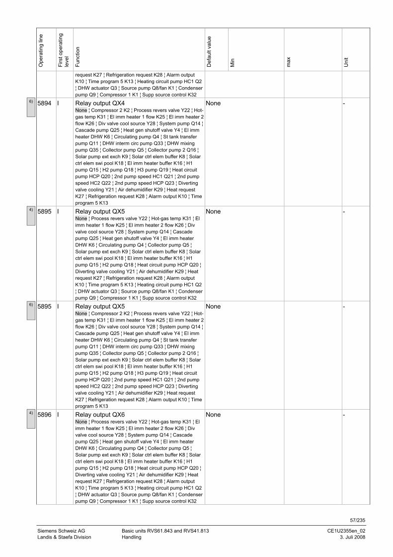
57/235
Siemens Schweiz AG Basic units RVS61.843 and RVS41.813 CE1U2355en_02 Landis & Staefa Division Handling 3. Juli 2008
Ope
ratin
g lin
e
Firs
t ope
ratin
g le
vel
Func
tion
Def
ault
valu
e
Min
max
Uni
t
request K27 ¦ Refrigeration request K28 ¦ Alarm output K10 ¦ Time program 5 K13 ¦ Heating circuit pump HC1 Q2 ¦ DHW actuator Q3 ¦ Source pump Q8/fan K1 ¦ Condenser pump Q9 ¦ Compressor 1 K1 ¦ Supp source control K32
5894 I Relay output QX4 None ¦ Compressor 2 K2 ¦ Process revers valve Y22 ¦ Hot-gas temp K31 ¦ El imm heater 1 flow K25 ¦ El imm heater 2 flow K26 ¦ Div valve cool source Y28 ¦ System pump Q14 ¦ Cascade pump Q25 ¦ Heat gen shutoff valve Y4 ¦ El imm heater DHW K6 ¦ Circulating pump Q4 ¦ St tank transfer pump Q11 ¦ DHW interm circ pump Q33 ¦ DHW mixing pump Q35 ¦ Collector pump Q5 ¦ Collector pump 2 Q16 ¦ Solar pump ext exch K9 ¦ Solar ctrl elem buffer K8 ¦ Solar ctrl elem swi pool K18 ¦ El imm heater buffer K16 ¦ H1 pump Q15 ¦ H2 pump Q18 ¦ H3 pump Q19 ¦ Heat circuit pump HCP Q20 ¦ 2nd pump speed HC1 Q21 ¦ 2nd pump speed HC2 Q22 ¦ 2nd pump speed HCP Q23 ¦ Diverting valve cooling Y21 ¦ Air dehumidifier K29 ¦ Heat request K27 ¦ Refrigeration request K28 ¦ Alarm output K10 ¦ Time program 5 K13
None -
5895 I Relay output QX5 None ¦ Process revers valve Y22 ¦ Hot-gas temp K31 ¦ El imm heater 1 flow K25 ¦ El imm heater 2 flow K26 ¦ Div valve cool source Y28 ¦ System pump Q14 ¦ Cascade pump Q25 ¦ Heat gen shutoff valve Y4 ¦ El imm heater DHW K6 ¦ Circulating pump Q4 ¦ Collector pump Q5 ¦ Solar pump ext exch K9 ¦ Solar ctrl elem buffer K8 ¦ Solar ctrl elem swi pool K18 ¦ El imm heater buffer K16 ¦ H1 pump Q15 ¦ H2 pump Q18 ¦ Heat circuit pump HCP Q20 ¦ Diverting valve cooling Y21 ¦ Air dehumidifier K29 ¦ Heat request K27 ¦ Refrigeration request K28 ¦ Alarm output K10 ¦ Time program 5 K13 ¦ Heating circuit pump HC1 Q2 ¦ DHW actuator Q3 ¦ Source pump Q8/fan K1 ¦ Condenser pump Q9 ¦ Compressor 1 K1 ¦ Supp source control K32
None -
5895 I Relay output QX5 None ¦ Compressor 2 K2 ¦ Process revers valve Y22 ¦ Hot-gas temp K31 ¦ El imm heater 1 flow K25 ¦ El imm heater 2 flow K26 ¦ Div valve cool source Y28 ¦ System pump Q14 ¦ Cascade pump Q25 ¦ Heat gen shutoff valve Y4 ¦ El imm heater DHW K6 ¦ Circulating pump Q4 ¦ St tank transfer pump Q11 ¦ DHW interm circ pump Q33 ¦ DHW mixing pump Q35 ¦ Collector pump Q5 ¦ Collector pump 2 Q16 ¦ Solar pump ext exch K9 ¦ Solar ctrl elem buffer K8 ¦ Solar ctrl elem swi pool K18 ¦ El imm heater buffer K16 ¦ H1 pump Q15 ¦ H2 pump Q18 ¦ H3 pump Q19 ¦ Heat circuit pump HCP Q20 ¦ 2nd pump speed HC1 Q21 ¦ 2nd pump speed HC2 Q22 ¦ 2nd pump speed HCP Q23 ¦ Diverting valve cooling Y21 ¦ Air dehumidifier K29 ¦ Heat request K27 ¦ Refrigeration request K28 ¦ Alarm output K10 ¦ Time program 5 K13
None -
5896 I Relay output QX6 None ¦ Process revers valve Y22 ¦ Hot-gas temp K31 ¦ El imm heater 1 flow K25 ¦ El imm heater 2 flow K26 ¦ Div valve cool source Y28 ¦ System pump Q14 ¦ Cascade pump Q25 ¦ Heat gen shutoff valve Y4 ¦ El imm heater DHW K6 ¦ Circulating pump Q4 ¦ Collector pump Q5 ¦ Solar pump ext exch K9 ¦ Solar ctrl elem buffer K8 ¦ Solar ctrl elem swi pool K18 ¦ El imm heater buffer K16 ¦ H1 pump Q15 ¦ H2 pump Q18 ¦ Heat circuit pump HCP Q20 ¦ Diverting valve cooling Y21 ¦ Air dehumidifier K29 ¦ Heat request K27 ¦ Refrigeration request K28 ¦ Alarm output K10 ¦ Time program 5 K13 ¦ Heating circuit pump HC1 Q2 ¦ DHW actuator Q3 ¦ Source pump Q8/fan K1 ¦ Condenser pump Q9 ¦ Compressor 1 K1 ¦ Supp source control K32
None -
6)
4)
6)
4)
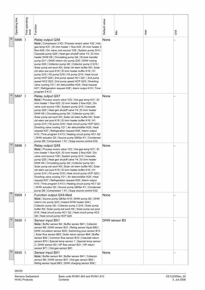
58/235
Siemens Switzerland Basic units RVS61.843 and RVS41.813 CE1U2355en_02 HVAC Products Contents 3. Juli 2008
Ope
ratin
g lin
e
Firs
t ope
ratin
g le
vel
Func
tion
Def
ault
valu
e
Min
max
Uni
t
5896 I Relay output QX6 None ¦ Compressor 2 K2 ¦ Process revers valve Y22 ¦ Hot-gas temp K31 ¦ El imm heater 1 flow K25 ¦ El imm heater 2 flow K26 ¦ Div valve cool source Y28 ¦ System pump Q14 ¦ Cascade pump Q25 ¦ Heat gen shutoff valve Y4 ¦ El imm heater DHW K6 ¦ Circulating pump Q4 ¦ St tank transfer pump Q11 ¦ DHW interm circ pump Q33 ¦ DHW mixing pump Q35 ¦ Collector pump Q5 ¦ Collector pump 2 Q16 ¦ Solar pump ext exch K9 ¦ Solar ctrl elem buffer K8 ¦ Solar ctrl elem swi pool K18 ¦ El imm heater buffer K16 ¦ H1 pump Q15 ¦ H2 pump Q18 ¦ H3 pump Q19 ¦ Heat circuit pump HCP Q20 ¦ 2nd pump speed HC1 Q21 ¦ 2nd pump speed HC2 Q22 ¦ 2nd pump speed HCP Q23 ¦ Diverting valve cooling Y21 ¦ Air dehumidifier K29 ¦ Heat request K27 ¦ Refrigeration request K28 ¦ Alarm output K10 ¦ Time program 5 K13
None -
5897 I Relay output QX7 None ¦ Process revers valve Y22 ¦ Hot-gas temp K31 ¦ El imm heater 1 flow K25 ¦ El imm heater 2 flow K26 ¦ Div valve cool source Y28 ¦ System pump Q14 ¦ Cascade pump Q25 ¦ Heat gen shutoff valve Y4 ¦ El imm heater DHW K6 ¦ Circulating pump Q4 ¦ Collector pump Q5 ¦ Solar pump ext exch K9 ¦ Solar ctrl elem buffer K8 ¦ Solar ctrl elem swi pool K18 ¦ El imm heater buffer K16 ¦ H1 pump Q15 ¦ H2 pump Q18 ¦ Heat circuit pump HCP Q20 ¦ Diverting valve cooling Y21 ¦ Air dehumidifier K29 ¦ Heat request K27 ¦ Refrigeration request K28 ¦ Alarm output K10 ¦ Time program 5 K13 ¦ Heating circuit pump HC1 Q2 ¦ DHW actuator Q3 ¦ Source pump Q8/fan K1 ¦ Condenser pump Q9 ¦ Compressor 1 K1 ¦ Supp source control K32
None -
5898 I Relay output QX8 None ¦ Process revers valve Y22 ¦ Hot-gas temp K31 ¦ El imm heater 1 flow K25 ¦ El imm heater 2 flow K26 ¦ Div valve cool source Y28 ¦ System pump Q14 ¦ Cascade pump Q25 ¦ Heat gen shutoff valve Y4 ¦ El imm heater DHW K6 ¦ Circulating pump Q4 ¦ Collector pump Q5 ¦ Solar pump ext exch K9 ¦ Solar ctrl elem buffer K8 ¦ Solar ctrl elem swi pool K18 ¦ El imm heater buffer K16 ¦ H1 pump Q15 ¦ H2 pump Q18 ¦ Heat circuit pump HCP Q20 ¦ Diverting valve cooling Y21 ¦ Air dehumidifier K29 ¦ Heat request K27 ¦ Refrigeration request K28 ¦ Alarm output K10 ¦ Time program 5 K13 ¦ Heating circuit pump HC1 Q2 ¦ DHW actuator Q3 ¦ Source pump Q8/fan K1 ¦ Condenser pump Q9 ¦ Compressor 1 K1 ¦ Supp source control K32
None -
5909 I Function output QX4-Mod None ¦ Source pump Q8/fan K19 ¦ DHW pump Q3 ¦ DHW interm circ pump Q33 ¦ Instant DHW heater Q34 ¦ Collector pump Q5 ¦ Collector pump 2 Q16 ¦ Solar pump buffer K8 ¦ Solar pump ext exch K9 ¦ Solar pump swi pool K18 ¦ Heat circuit pump HC1 Q2 ¦ Heat circuit pump HC2 Q6 ¦ Heat circuit pump HCP Q20
None -
5930 I Sensor input BX1 None ¦ Buffer sensor B4 ¦ Buffer sensor B41 ¦ Collector sensor B6 ¦ DHW sensor B31 ¦ Refrig sensor liquid B83 ¦ DHW circulation sensor B39 ¦ Swimming pool sensor B13 ¦ Solar flow sensor B63 ¦ Solar return sensor B64 ¦ Buffer sensor B42 ¦ Common flow sensor B10 ¦ Cascade return sensor B70 ¦ Special temp sensor 1 ¦ Special temp sensor 2 ¦ DHW sensor B3 ¦ HP flow sensor B21 ¦ HP return sensor B71 ¦ Hot-gas sensor B81
DHW sensor B3 -
5930 I Sensor input BX1 None ¦ Buffer sensor B4 ¦ Buffer sensor B41 ¦ Collector sensor B6 ¦ DHW sensor B31 ¦ Hot-gas sensor B82 ¦ Refrig sensor liquid B83 ¦ DHW charging sensor B36 ¦
None -
6)
4)
4)
6)
4)
6)
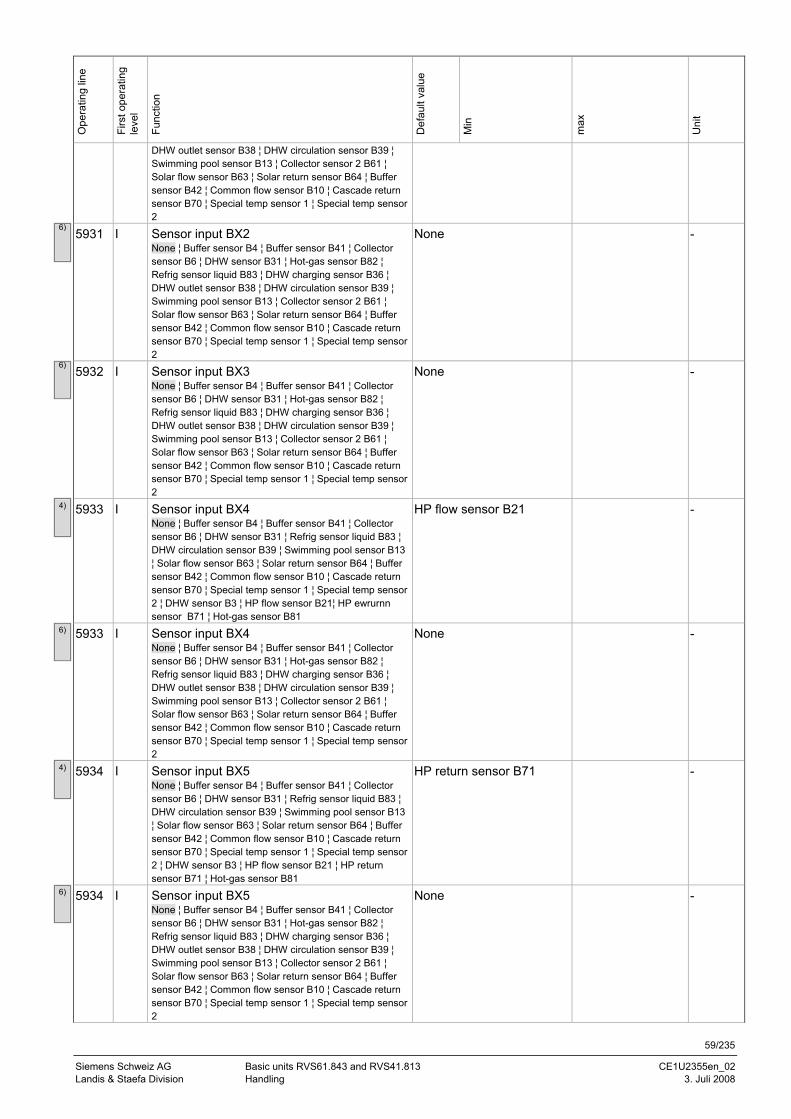
59/235
Siemens Schweiz AG Basic units RVS61.843 and RVS41.813 CE1U2355en_02 Landis & Staefa Division Handling 3. Juli 2008
Ope
ratin
g lin
e
Firs
t ope
ratin
g le
vel
Func
tion
Def
ault
valu
e
Min
max
Uni
t
DHW outlet sensor B38 ¦ DHW circulation sensor B39 ¦ Swimming pool sensor B13 ¦ Collector sensor 2 B61 ¦ Solar flow sensor B63 ¦ Solar return sensor B64 ¦ Buffer sensor B42 ¦ Common flow sensor B10 ¦ Cascade return sensor B70 ¦ Special temp sensor 1 ¦ Special temp sensor 2
5931 I Sensor input BX2 None ¦ Buffer sensor B4 ¦ Buffer sensor B41 ¦ Collector sensor B6 ¦ DHW sensor B31 ¦ Hot-gas sensor B82 ¦ Refrig sensor liquid B83 ¦ DHW charging sensor B36 ¦ DHW outlet sensor B38 ¦ DHW circulation sensor B39 ¦ Swimming pool sensor B13 ¦ Collector sensor 2 B61 ¦ Solar flow sensor B63 ¦ Solar return sensor B64 ¦ Buffer sensor B42 ¦ Common flow sensor B10 ¦ Cascade return sensor B70 ¦ Special temp sensor 1 ¦ Special temp sensor 2
None -
5932 I Sensor input BX3 None ¦ Buffer sensor B4 ¦ Buffer sensor B41 ¦ Collector sensor B6 ¦ DHW sensor B31 ¦ Hot-gas sensor B82 ¦ Refrig sensor liquid B83 ¦ DHW charging sensor B36 ¦ DHW outlet sensor B38 ¦ DHW circulation sensor B39 ¦ Swimming pool sensor B13 ¦ Collector sensor 2 B61 ¦ Solar flow sensor B63 ¦ Solar return sensor B64 ¦ Buffer sensor B42 ¦ Common flow sensor B10 ¦ Cascade return sensor B70 ¦ Special temp sensor 1 ¦ Special temp sensor 2
None -
5933 I Sensor input BX4 None ¦ Buffer sensor B4 ¦ Buffer sensor B41 ¦ Collector sensor B6 ¦ DHW sensor B31 ¦ Refrig sensor liquid B83 ¦ DHW circulation sensor B39 ¦ Swimming pool sensor B13 ¦ Solar flow sensor B63 ¦ Solar return sensor B64 ¦ Buffer sensor B42 ¦ Common flow sensor B10 ¦ Cascade return sensor B70 ¦ Special temp sensor 1 ¦ Special temp sensor 2 ¦ DHW sensor B3 ¦ HP flow sensor B21¦ HP ewrurnn sensor B71 ¦ Hot-gas sensor B81
HP flow sensor B21 -
5933 I Sensor input BX4 None ¦ Buffer sensor B4 ¦ Buffer sensor B41 ¦ Collector sensor B6 ¦ DHW sensor B31 ¦ Hot-gas sensor B82 ¦ Refrig sensor liquid B83 ¦ DHW charging sensor B36 ¦ DHW outlet sensor B38 ¦ DHW circulation sensor B39 ¦ Swimming pool sensor B13 ¦ Collector sensor 2 B61 ¦ Solar flow sensor B63 ¦ Solar return sensor B64 ¦ Buffer sensor B42 ¦ Common flow sensor B10 ¦ Cascade return sensor B70 ¦ Special temp sensor 1 ¦ Special temp sensor 2
None -
5934 I Sensor input BX5 None ¦ Buffer sensor B4 ¦ Buffer sensor B41 ¦ Collector sensor B6 ¦ DHW sensor B31 ¦ Refrig sensor liquid B83 ¦ DHW circulation sensor B39 ¦ Swimming pool sensor B13 ¦ Solar flow sensor B63 ¦ Solar return sensor B64 ¦ Buffer sensor B42 ¦ Common flow sensor B10 ¦ Cascade return sensor B70 ¦ Special temp sensor 1 ¦ Special temp sensor 2 ¦ DHW sensor B3 ¦ HP flow sensor B21 ¦ HP return sensor B71 ¦ Hot-gas sensor B81
HP return sensor B71 -
5934 I Sensor input BX5 None ¦ Buffer sensor B4 ¦ Buffer sensor B41 ¦ Collector sensor B6 ¦ DHW sensor B31 ¦ Hot-gas sensor B82 ¦ Refrig sensor liquid B83 ¦ DHW charging sensor B36 ¦ DHW outlet sensor B38 ¦ DHW circulation sensor B39 ¦ Swimming pool sensor B13 ¦ Collector sensor 2 B61 ¦ Solar flow sensor B63 ¦ Solar return sensor B64 ¦ Buffer sensor B42 ¦ Common flow sensor B10 ¦ Cascade return sensor B70 ¦ Special temp sensor 1 ¦ Special temp sensor 2
None -
6)
6)
4)
6)
4)
6)
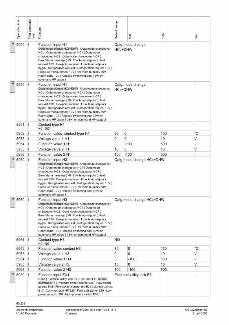
60/235
Siemens Switzerland Basic units RVS61.843 and RVS41.813 CE1U2355en_02 HVAC Products Contents 3. Juli 2008
Ope
ratin
g lin
e
Firs
t ope
ratin
g le
vel
Func
tion
Def
ault
valu
e
Min
max
Uni
t
5950 I Function input H1 Optg mode change HCs+DHW ¦ Optg mode changeover HCs ¦ Optg mode changeover HC1 ¦ Optg mode changeover HC2 ¦ Optg mode changeover HCP ¦ Error/alarm message ¦ Min flow temp setpoint ¦ Heat request 10V ¦ Dewpoint monitor ¦ Flow temp setp incr hygro ¦ Refrigeration request ¦ Refrigeration request 10V ¦ Pressure measurement 10V ¦ Rel room humidity 10V ¦ Room temp 10V ¦ Release swimming pool ¦ Swi-on command HP stage 1
Optg mode change HCs+DHW
-
5950 I Function input H1 Optg mode change HCs+DHW ¦ Optg mode changeover HCs ¦ Optg mode changeover HC1 ¦ Optg mode changeover HC2 ¦ Optg mode changeover HCP ¦ Error/alarm message ¦ Min flow temp setpoint ¦ Heat request 10V ¦ Dewpoint monitor ¦ Flow temp setp incr hygro ¦ Refrigeration request ¦ Refrigeration request 10V ¦ Pressure measurement 10V ¦ Rel room humidity 10V ¦ Room temp 10V ¦ Release swimming pool ¦ Swi-on command HP stage 1 ¦ Swi-on command HP stage 2
Optg mode change HCs+DHW
-
5951 I Contact type H1 NC ¦ NO*
-
5952 I Function value, contact type H1 30 0 130 °C 5953 I Voltage value 1 H1 0 0 10 V 5954 I Function value 1 H1 0 -100 500 - 5955 I Voltage value 2 H1 10 0 10 V 5956 I Function value 2 H1 100 -100 500 - 5960 I Function input H3
Optg mode change HCs+DHW ¦ Optg mode changeover HCs ¦ Optg mode changeover HC1 ¦ Optg mode changeover HC2 ¦ Optg mode changeover HCP ¦ Error/alarm message ¦ Min flow temp setpoint ¦ Heat request 10V ¦ Dewpoint monitor ¦ Flow temp setp incr hygro ¦ Refrigeration request ¦ Refrigeration request 10V ¦ Pressure measurement 10V ¦ Rel room humidity 10V ¦ Room temp 10V ¦ Release swimming pool ¦ Swi-on command HP stage 1
Optg mode change HCs+DHW -
5960 I Function input H3 Optg mode change HCs+DHW ¦ Optg mode changeover HCs ¦ Optg mode changeover HC1 ¦ Optg mode changeover HC2 ¦ Optg mode changeover HCP ¦ Error/alarm message ¦ Min flow temp setpoint ¦ Heat request 10V ¦ Dewpoint monitor ¦ Flow temp setp incr hygro ¦ Refrigeration request ¦ Refrigeration request 10V ¦ Pressure measurement 10V ¦ Rel room humidity 10V ¦ Room temp 10V ¦ Release swimming pool ¦ Swi-on command HP stage 1 ¦ Swi-on command HP stage 2
Optg mode change HCs+DHW -
5961 I Contact type H3 NC ¦ NO
NO -
5962 I Function value contact H3 30 0 130 °C 5963 I Voltage value 1 H3 0 0 10 V 5964 I Function value 1 H3 0 -100 500 - 5965 I Voltage value 2 H3 10 0 10 V 5966 I Function value 2 H3 100 -100 500 - 5980 I Function input EX1
None ¦ Electrical utility lock E6 ¦ Low-tariff E5 ¦ Source overload E14 ¦ Pressure switch source E26 ¦ Flow switch source E15 ¦ Flow switch consumers E24 ¦ Manual defrost E17 ¦ Common fault HP E20 ¦ Fault soft starter E25 ¦ Low-pressure switch E9 ¦ High-pressure switch E10 ¦
Electrical utility lock E6 -
4)
6)
4)
4)
6)
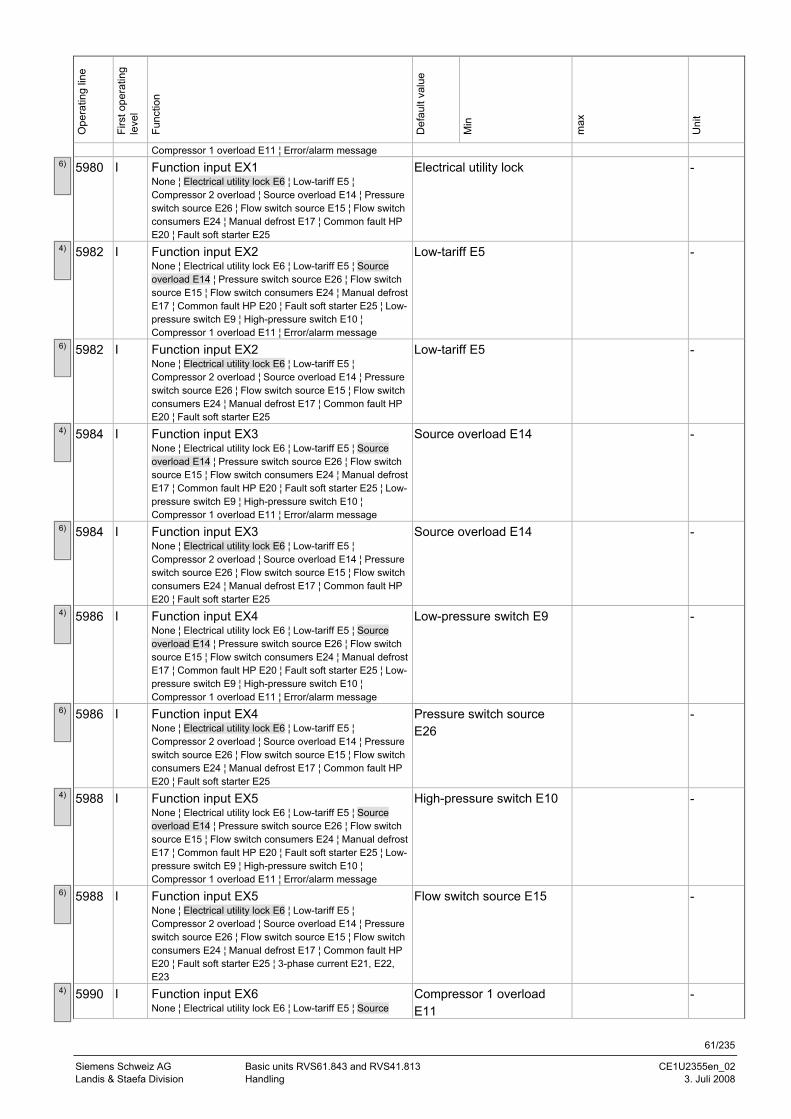
61/235
Siemens Schweiz AG Basic units RVS61.843 and RVS41.813 CE1U2355en_02 Landis & Staefa Division Handling 3. Juli 2008
Ope
ratin
g lin
e
Firs
t ope
ratin
g le
vel
Func
tion
Def
ault
valu
e
Min
max
Uni
t
Compressor 1 overload E11 ¦ Error/alarm message
5980 I Function input EX1 None ¦ Electrical utility lock E6 ¦ Low-tariff E5 ¦ Compressor 2 overload ¦ Source overload E14 ¦ Pressure switch source E26 ¦ Flow switch source E15 ¦ Flow switch consumers E24 ¦ Manual defrost E17 ¦ Common fault HP E20 ¦ Fault soft starter E25
Electrical utility lock -
5982 I Function input EX2 None ¦ Electrical utility lock E6 ¦ Low-tariff E5 ¦ Source overload E14 ¦ Pressure switch source E26 ¦ Flow switch source E15 ¦ Flow switch consumers E24 ¦ Manual defrost E17 ¦ Common fault HP E20 ¦ Fault soft starter E25 ¦ Low-pressure switch E9 ¦ High-pressure switch E10 ¦ Compressor 1 overload E11 ¦ Error/alarm message
Low-tariff E5 -
5982 I Function input EX2 None ¦ Electrical utility lock E6 ¦ Low-tariff E5 ¦ Compressor 2 overload ¦ Source overload E14 ¦ Pressure switch source E26 ¦ Flow switch source E15 ¦ Flow switch consumers E24 ¦ Manual defrost E17 ¦ Common fault HP E20 ¦ Fault soft starter E25
Low-tariff E5 -
5984 I Function input EX3 None ¦ Electrical utility lock E6 ¦ Low-tariff E5 ¦ Source overload E14 ¦ Pressure switch source E26 ¦ Flow switch source E15 ¦ Flow switch consumers E24 ¦ Manual defrost E17 ¦ Common fault HP E20 ¦ Fault soft starter E25 ¦ Low-pressure switch E9 ¦ High-pressure switch E10 ¦ Compressor 1 overload E11 ¦ Error/alarm message
Source overload E14 -
5984 I Function input EX3 None ¦ Electrical utility lock E6 ¦ Low-tariff E5 ¦ Compressor 2 overload ¦ Source overload E14 ¦ Pressure switch source E26 ¦ Flow switch source E15 ¦ Flow switch consumers E24 ¦ Manual defrost E17 ¦ Common fault HP E20 ¦ Fault soft starter E25
Source overload E14 -
5986 I Function input EX4 None ¦ Electrical utility lock E6 ¦ Low-tariff E5 ¦ Source overload E14 ¦ Pressure switch source E26 ¦ Flow switch source E15 ¦ Flow switch consumers E24 ¦ Manual defrost E17 ¦ Common fault HP E20 ¦ Fault soft starter E25 ¦ Low-pressure switch E9 ¦ High-pressure switch E10 ¦ Compressor 1 overload E11 ¦ Error/alarm message
Low-pressure switch E9 -
5986 I Function input EX4 None ¦ Electrical utility lock E6 ¦ Low-tariff E5 ¦ Compressor 2 overload ¦ Source overload E14 ¦ Pressure switch source E26 ¦ Flow switch source E15 ¦ Flow switch consumers E24 ¦ Manual defrost E17 ¦ Common fault HP E20 ¦ Fault soft starter E25
Pressure switch source E26
-
5988 I Function input EX5 None ¦ Electrical utility lock E6 ¦ Low-tariff E5 ¦ Source overload E14 ¦ Pressure switch source E26 ¦ Flow switch source E15 ¦ Flow switch consumers E24 ¦ Manual defrost E17 ¦ Common fault HP E20 ¦ Fault soft starter E25 ¦ Low-pressure switch E9 ¦ High-pressure switch E10 ¦ Compressor 1 overload E11 ¦ Error/alarm message
High-pressure switch E10 -
5988 I Function input EX5 None ¦ Electrical utility lock E6 ¦ Low-tariff E5 ¦ Compressor 2 overload ¦ Source overload E14 ¦ Pressure switch source E26 ¦ Flow switch source E15 ¦ Flow switch consumers E24 ¦ Manual defrost E17 ¦ Common fault HP E20 ¦ Fault soft starter E25 ¦ 3-phase current E21, E22, E23
Flow switch source E15 -
5990 I Function input EX6 None ¦ Electrical utility lock E6 ¦ Low-tariff E5 ¦ Source
Compressor 1 overload E11
-
6)
4)
6)
4)
6)
4)
6)
4)
6)
4)
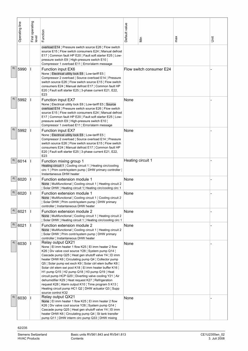
62/235
Siemens Switzerland Basic units RVS61.843 and RVS41.813 CE1U2355en_02 HVAC Products Contents 3. Juli 2008
Ope
ratin
g lin
e
Firs
t ope
ratin
g le
vel
Func
tion
Def
ault
valu
e
Min
max
Uni
t
overload E14 ¦ Pressure switch source E26 ¦ Flow switch source E15 ¦ Flow switch consumers E24 ¦ Manual defrost E17 ¦ Common fault HP E20 ¦ Fault soft starter E25 ¦ Low-pressure switch E9 ¦ High-pressure switch E10 ¦ Compressor 1 overload E11 ¦ Error/alarm message
5990 I Function input EX6 None ¦ Electrical utility lock E6 ¦ Low-tariff E5 ¦ Compressor 2 overload ¦ Source overload E14 ¦ Pressure switch source E26 ¦ Flow switch source E15 ¦ Flow switch consumers E24 ¦ Manual defrost E17 ¦ Common fault HP E20 ¦ Fault soft starter E25 ¦ 3-phase current E21, E22, E23
Flow switch consumer E24 -
5992 I Function input EX7 None ¦ Electrical utility lock E6 ¦ Low-tariff E5 ¦ Source overload E14 ¦ Pressure switch source E26 ¦ Flow switch source E15 ¦ Flow switch consumers E24 ¦ Manual defrost E17 ¦ Common fault HP E20 ¦ Fault soft starter E25 ¦ Low-pressure switch E9 ¦ High-pressure switch E10 ¦ Compressor 1 overload E11 ¦ Error/alarm message
None -
5992 I Function input EX7 None ¦ Electrical utility lock E6 ¦ Low-tariff E5 ¦ Compressor 2 overload ¦ Source overload E14 ¦ Pressure switch source E26 ¦ Flow switch source E15 ¦ Flow switch consumers E24 ¦ Manual defrost E17 ¦ Common fault HP E20 ¦ Fault soft starter E25 ¦ 3-phase current E21, E22, E23
None -
6014 I Function mixing group 1 Heating circuit 1 ¦ Cooling circuit 1 ¦ Heating circ/cooling circ 1 ¦ Prim contr/system pump ¦ DHW primary controller ¦ Instantaneous DHW heater
Heating circuit 1 -
6020 I Function extension module 1 None ¦ Multifunctional ¦ Cooling circuit 1 ¦ Heating circuit 2 ¦ Solar DHW ¦ Heating circuit 1¦ Heating circ/cooling circ 1
None -
6020 I Function extension module 1 None ¦ Multifunctional ¦ Cooling circuit 1 ¦ Cooling circuit 2 ¦ Solar DHW ¦ Prim contr/system pump ¦ DHW primary controller ¦ Instantaneous DHW heater
None -
6021 I Function extension module 2 None ¦ Multifunctional ¦ Cooling circuit 1 ¦ Heating circuit 2 ¦ Solar DHW ¦ Heating circuit 1 ¦ Heating circ/cooling circ 1
None -
6021 I Function extension module 2 None ¦ Multifunctional ¦ Cooling circuit 1 ¦ Heating circuit 2 ¦ Solar DHW ¦ Prim contr/system pump ¦ DHW primary controller ¦ Instantaneous DHW heater
None -
6030 I Relay output QX21 None ¦ El imm heater 1 flow K25 ¦ El imm heater 2 flow K26 ¦ Div valve cool source Y28 ¦ System pump Q14 ¦ Cascade pump Q25 ¦ Heat gen shutoff valve Y4 ¦ El imm heater DHW K6 ¦ Circulating pump Q4 ¦ Collector pump Q5 ¦ Solar pump ext exch K9 ¦ Solar ctrl elem buffer K8 ¦ Solar ctrl elem swi pool K18 ¦ El imm heater buffer K16 ¦ H1 pump Q15 ¦ H2 pump Q18 ¦ H3 pump Q19 ¦ Heat circuit pump HCP Q20 ¦ Diverting valve cooling Y21 ¦ Air dehumidifier K29 ¦ Heat request K27 ¦ Refrigeration request K28 ¦ Alarm output K10 ¦ Time program 5 K13 ¦ Heating circuit pump HC1 Q2 ¦ DHW actuator Q3 ¦ Supp source control K32
None -
6030 I Relay output QX21None ¦ El imm heater 1 flow K25 ¦ El imm heater 2 flow K26 ¦ Div valve cool source Y28 ¦ System pump Q14 ¦ Cascade pump Q25 ¦ Heat gen shutoff valve Y4 ¦ El imm heater DHW K6 ¦ Circulating pump Q4 ¦ St tank transfer pump Q11 ¦ DHW interm circ pump Q33 ¦ DHW mixing
None -
6)
4)
6)
4)
6)
4)
6)
4)
6)
6)
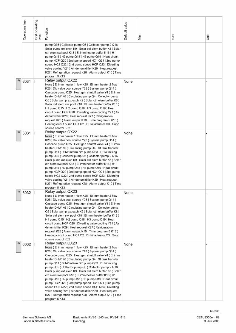
63/235
Siemens Schweiz AG Basic units RVS61.843 and RVS41.813 CE1U2355en_02 Landis & Staefa Division Handling 3. Juli 2008
Ope
ratin
g lin
e
Firs
t ope
ratin
g le
vel
Func
tion
Def
ault
valu
e
Min
max
Uni
t
pump Q35 ¦ Collector pump Q5 ¦ Collector pump 2 Q16 ¦ Solar pump ext exch K9 ¦ Solar ctrl elem buffer K8 ¦ Solar ctrl elem swi pool K18 ¦ El imm heater buffer K16 ¦ H1 pump Q15 ¦ H2 pump Q18 ¦ H3 pump Q19 ¦ Heat circuit pump HCP Q20 ¦ 2nd pump speed HC1 Q21 ¦ 2nd pump speed HC2 Q22 ¦ 2nd pump speed HCP Q23 ¦ Diverting valve cooling Y21 ¦ Air dehumidifier K29 ¦ Heat request K27 ¦ Refrigeration request K28 ¦ Alarm output K10 ¦ Time program 5 K13
6031 I Relay output QX22 None ¦ El imm heater 1 flow K25 ¦ El imm heater 2 flow K26 ¦ Div valve cool source Y28 ¦ System pump Q14 ¦ Cascade pump Q25 ¦ Heat gen shutoff valve Y4 ¦ El imm heater DHW K6 ¦ Circulating pump Q4 ¦ Collector pump Q5 ¦ Solar pump ext exch K9 ¦ Solar ctrl elem buffer K8 ¦ Solar ctrl elem swi pool K18 ¦ El imm heater buffer K16 ¦ H1 pump Q15 ¦ H2 pump Q18 ¦ H3 pump Q19 ¦ Heat circuit pump HCP Q20 ¦ Diverting valve cooling Y21 ¦ Air dehumidifier K29 ¦ Heat request K27 ¦ Refrigeration request K28 ¦ Alarm output K10 ¦ Time program 5 K13 ¦ Heating circuit pump HC1 Q2 ¦ DHW actuator Q3 ¦ Supp source control K32
None -
6031 I Relay output QX22 None ¦ El imm heater 1 flow K25 ¦ El imm heater 2 flow K26 ¦ Div valve cool source Y28 ¦ System pump Q14 ¦ Cascade pump Q25 ¦ Heat gen shutoff valve Y4 ¦ El imm heater DHW K6 ¦ Circulating pump Q4 ¦ St tank transfer pump Q11 ¦ DHW interm circ pump Q33 ¦ DHW mixing pump Q35 ¦ Collector pump Q5 ¦ Collector pump 2 Q16 ¦ Solar pump ext exch K9 ¦ Solar ctrl elem buffer K8 ¦ Solar ctrl elem swi pool K18 ¦ El imm heater buffer K16 ¦ H1 pump Q15 ¦ H2 pump Q18 ¦ H3 pump Q19 ¦ Heat circuit pump HCP Q20 ¦ 2nd pump speed HC1 Q21 ¦ 2nd pump speed HC2 Q22 ¦ 2nd pump speed HCP Q23 ¦ Diverting valve cooling Y21 ¦ Air dehumidifier K29 ¦ Heat request K27 ¦ Refrigeration request K28 ¦ Alarm output K10 ¦ Time program 5 K13
None -
6032 I Relay output QX23 None ¦ El imm heater 1 flow K25 ¦ El imm heater 2 flow K26 ¦ Div valve cool source Y28 ¦ System pump Q14 ¦ Cascade pump Q25 ¦ Heat gen shutoff valve Y4 ¦ El imm heater DHW K6 ¦ Circulating pump Q4 ¦ Collector pump Q5 ¦ Solar pump ext exch K9 ¦ Solar ctrl elem buffer K8 ¦ Solar ctrl elem swi pool K18 ¦ El imm heater buffer K16 ¦ H1 pump Q15 ¦ H2 pump Q18 ¦ H3 pump Q19 ¦ Heat circuit pump HCP Q20 ¦ Diverting valve cooling Y21 ¦ Air dehumidifier K29 ¦ Heat request K27 ¦ Refrigeration request K28 ¦ Alarm output K10 ¦ Time program 5 K13 ¦ Heating circuit pump HC1 Q2 ¦ DHW actuator Q3 ¦ Supp source control K32
None -
6032 I Relay output QX23 None ¦ El imm heater 1 flow K25 ¦ El imm heater 2 flow K26 ¦ Div valve cool source Y28 ¦ System pump Q14 ¦ Cascade pump Q25 ¦ Heat gen shutoff valve Y4 ¦ El imm heater DHW K6 ¦ Circulating pump Q4 ¦ St tank transfer pump Q11 ¦ DHW interm circ pump Q33 ¦ DHW mixing pump Q35 ¦ Collector pump Q5 ¦ Collector pump 2 Q16 ¦ Solar pump ext exch K9 ¦ Solar ctrl elem buffer K8 ¦ Solar ctrl elem swi pool K18 ¦ El imm heater buffer K16 ¦ H1 pump Q15 ¦ H2 pump Q18 ¦ H3 pump Q19 ¦ Heat circuit pump HCP Q20 ¦ 2nd pump speed HC1 Q21 ¦ 2nd pump speed HC2 Q22 ¦ 2nd pump speed HCP Q23 ¦ Diverting valve cooling Y21 ¦ Air dehumidifier K29 ¦ Heat request K27 ¦ Refrigeration request K28 ¦ Alarm output K10 ¦ Time program 5 K13
None -
4)
6)
4)
6)
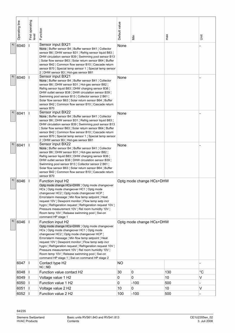
64/235
Siemens Switzerland Basic units RVS61.843 and RVS41.813 CE1U2355en_02 HVAC Products Contents 3. Juli 2008
Ope
ratin
g lin
e
Firs
t ope
ratin
g le
vel
Func
tion
Def
ault
valu
e
Min
max
Uni
t
6040 I Sensor input BX21 None ¦ Buffer sensor B4 ¦ Buffer sensor B41 ¦ Collector sensor B6 ¦ DHW sensor B31 ¦ Refrig sensor liquid B83 ¦ DHW circulation sensor B39 ¦ Swimming pool sensor B13 ¦ Solar flow sensor B63 ¦ Solar return sensor B64 ¦ Buffer sensor B42 ¦ Common flow sensor B10 ¦ Cascade return sensor B70 ¦ Special temp sensor 1 ¦ Special temp sensor 2 ¦ DHW sensor B3 ¦ Hot-gas sensor B81
None -
6040 I Sensor input BX21 None ¦ Buffer sensor B4 ¦ Buffer sensor B41 ¦ Collector sensor B6 ¦ DHW sensor B31 ¦ Hot-gas sensor B82 ¦ Refrig sensor liquid B83 ¦ DHW charging sensor B36 ¦ DHW outlet sensor B38 ¦ DHW circulation sensor B39 ¦ Swimming pool sensor B13 ¦ Collector sensor 2 B61 ¦ Solar flow sensor B63 ¦ Solar return sensor B64 ¦ Buffer sensor B42 ¦ Common flow sensor B10 ¦ Cascade return sensor B70
None -
6041 I Sensor input BX22 None ¦ Buffer sensor B4 ¦ Buffer sensor B41 ¦ Collector sensor B6 ¦ DHW sensor B31 ¦ Refrig sensor liquid B83 ¦ DHW circulation sensor B39 ¦ Swimming pool sensor B13 ¦ Solar flow sensor B63 ¦ Solar return sensor B64 ¦ Buffer sensor B42 ¦ Common flow sensor B10 ¦ Cascade return sensor B70 ¦ Special temp sensor 1 ¦ Special temp sensor 2 ¦ DHW sensor B3 ¦ Hot-gas sensor B81
None -
6041 I Sensor input BX22 None ¦ Buffer sensor B4 ¦ Buffer sensor B41 ¦ Collector sensor B6 ¦ DHW sensor B31 ¦ Hot-gas sensor B82 ¦ Refrig sensor liquid B83 ¦ DHW charging sensor B36 ¦ DHW outlet sensor B38 ¦ DHW circulation sensor B39 ¦ Swimming pool sensor B13 ¦ Collector sensor 2 B61 ¦ Solar flow sensor B63 ¦ Solar return sensor B64 ¦ Buffer sensor B42 ¦ Common flow sensor B10 ¦ Cascade return sensor B70
None -
6046 I Function input H2 Optg mode change HCs+DHW ¦ Optg mode changeover HCs ¦ Optg mode changeover HC1 ¦ Optg mode changeover HC2 ¦ Optg mode changeover HCP ¦ Error/alarm message ¦ Min flow temp setpoint ¦ Heat request 10V ¦ Dewpoint monitor ¦ Flow temp setp incr hygro ¦ Refrigeration request ¦ Refrigeration request 10V ¦ Pressure measurement 10V ¦ Rel room humidity 10V ¦ Room temp 10V ¦ Release swimming pool ¦ Swi-on command HP stage 1
Optg mode change HCs+DHW
6046 I Function input H2 Optg mode change HCs+DHW ¦ Optg mode changeover HCs ¦ Optg mode changeover HC1 ¦ Optg mode changeover HC2 ¦ Optg mode changeover HCP ¦ Error/alarm message ¦ Min flow temp setpoint ¦ Heat request 10V ¦ Dewpoint monitor ¦ Flow temp setp incr hygro ¦ Refrigeration request ¦ Refrigeration request 10V ¦ Pressure measurement 10V ¦ Rel room humidity 10V ¦ Room temp 10V ¦ Release swimming pool ¦ Swi-on command HP stage 1 ¦ Swi-on command HP stage 2
Optg mode change HCs+DHW
6047 I Contact type H2 NC ¦ NO
NO -
6048 I Function value contact H2 30 0 130 °C 6049 I Voltage value 1 H2 0 0 10 V 6050 I Function value 1 H2 0 -100 500 - 6051 I Voltage value 2 H2 10 0 10 V 6052 I Function value 2 H2 100 -100 500 -
4)
6)
4)
6)
4)
6)
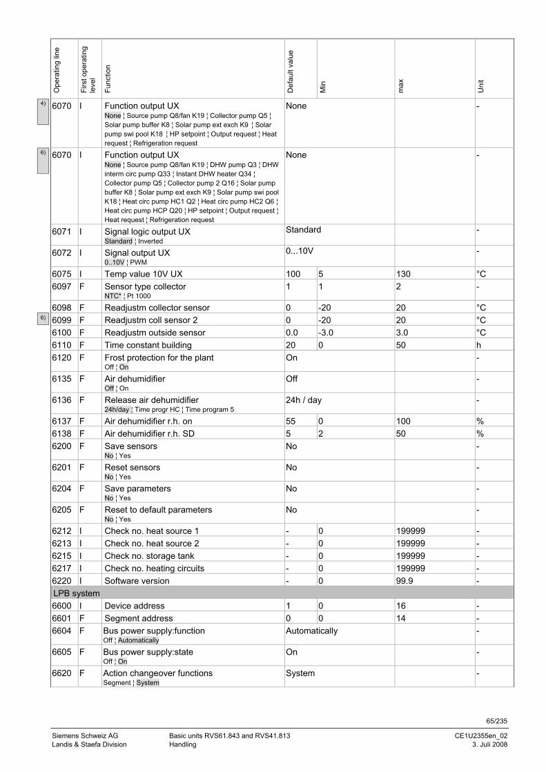
65/235
Siemens Schweiz AG Basic units RVS61.843 and RVS41.813 CE1U2355en_02 Landis & Staefa Division Handling 3. Juli 2008
Ope
ratin
g lin
e
Firs
t ope
ratin
g le
vel
Func
tion
Def
ault
valu
e
Min
max
Uni
t
6070 I Function output UX None ¦ Source pump Q8/fan K19 ¦ Collector pump Q5 ¦ Solar pump buffer K8 ¦ Solar pump ext exch K9 ¦ Solar pump swi pool K18 ¦ HP setpoint ¦ Output request ¦ Heat request ¦ Refrigeration request
None -
6070 I Function output UX None ¦ Source pump Q8/fan K19 ¦ DHW pump Q3 ¦ DHW interm circ pump Q33 ¦ Instant DHW heater Q34 ¦ Collector pump Q5 ¦ Collector pump 2 Q16 ¦ Solar pump buffer K8 ¦ Solar pump ext exch K9 ¦ Solar pump swi pool K18 ¦ Heat circ pump HC1 Q2 ¦ Heat circ pump HC2 Q6 ¦ Heat circ pump HCP Q20 ¦ HP setpoint ¦ Output request ¦ Heat request ¦ Refrigeration request
None -
6071 I Signal logic output UX Standard ¦ Inverted
Standard -
6072 I Signal output UX 0..10V ¦ PWM
0...10V -
6075 I Temp value 10V UX 100 5 130 °C 6097 F Sensor type collector
NTC* ¦ Pt 1000 1 1 2 -
6098 F Readjustm collector sensor 0 -20 20 °C 6099 F Readjustm coll sensor 2 0 -20 20 °C 6100 F Readjustm outside sensor 0.0 -3.0 3.0 °C 6110 F Time constant building 20 0 50 h 6120 F Frost protection for the plant
Off ¦ On On -
6135 F Air dehumidifier Off ¦ On
Off -
6136 F Release air dehumidifier 24h/day ¦ Time progr HC ¦ Time program 5
24h / day -
6137 F Air dehumidifier r.h. on 55 0 100 % 6138 F Air dehumidifier r.h. SD 5 2 50 % 6200 F Save sensors
No ¦ Yes No -
6201 F Reset sensors No ¦ Yes
No -
6204 F Save parameters No ¦ Yes
No -
6205 F Reset to default parameters No ¦ Yes
No -
6212 I Check no. heat source 1 - 0 199999 - 6213 I Check no. heat source 2 - 0 199999 - 6215 I Check no. storage tank - 0 199999 - 6217 I Check no. heating circuits - 0 199999 - 6220 I Software version - 0 99.9 - LPB system 6600 I Device address 1 0 16 - 6601 F Segment address 0 0 14 - 6604 F Bus power supply:function
Off ¦ Automatically Automatically -
6605 F Bus power supply:state Off ¦ On
On -
6620 F Action changeover functions Segment ¦ System
System -
6)
4)
6)
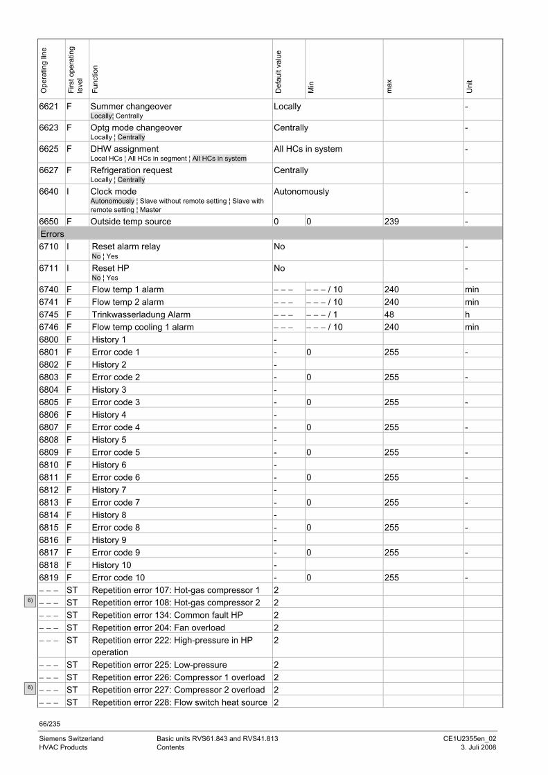
66/235
Siemens Switzerland Basic units RVS61.843 and RVS41.813 CE1U2355en_02 HVAC Products Contents 3. Juli 2008
Ope
ratin
g lin
e
Firs
t ope
ratin
g le
vel
Func
tion
Def
ault
valu
e
Min
max
Uni
t
6621 F Summer changeover Locally¦ Centrally
Locally -
6623 F Optg mode changeover Locally ¦ Centrally
Centrally -
6625 F DHW assignment Local HCs ¦ All HCs in segment ¦ All HCs in system
All HCs in system -
6627 F Refrigeration request Locally ¦ Centrally
Centrally
6640 I Clock mode Autonomously ¦ Slave without remote setting ¦ Slave with remote setting ¦ Master
Autonomously -
6650 F Outside temp source 0 0 239 - Errors 6710 I Reset alarm relay
No ¦ Yes No -
6711 I Reset HP No ¦ Yes
No -
6740 F Flow temp 1 alarm − − − − − − / 10 240 min 6741 F Flow temp 2 alarm − − − − − − / 10 240 min 6745 F Trinkwasserladung Alarm − − − − − − / 1 48 h 6746 F Flow temp cooling 1 alarm − − − − − − / 10 240 min 6800 F History 1 - 6801 F Error code 1 - 0 255 - 6802 F History 2 - 6803 F Error code 2 - 0 255 - 6804 F History 3 - 6805 F Error code 3 - 0 255 - 6806 F History 4 - 6807 F Error code 4 - 0 255 - 6808 F History 5 - 6809 F Error code 5 - 0 255 - 6810 F History 6 - 6811 F Error code 6 - 0 255 - 6812 F History 7 - 6813 F Error code 7 - 0 255 - 6814 F History 8 - 6815 F Error code 8 - 0 255 - 6816 F History 9 - 6817 F Error code 9 - 0 255 - 6818 F History 10 - 6819 F Error code 10 - 0 255 - − − − ST Repetition error 107: Hot-gas compressor 1 2 − − − ST Repetition error 108: Hot-gas compressor 2 2 − − − ST Repetition error 134: Common fault HP 2 − − − ST Repetition error 204: Fan overload 2 − − − ST Repetition error 222: High-pressure in HP
operation 2
− − − ST Repetition error 225: Low-pressure 2 − − − ST Repetition error 226: Compressor 1 overload 2 − − − ST Repetition error 227: Compressor 2 overload 2 − − − ST Repetition error 228: Flow switch heat source 2
6)
6)
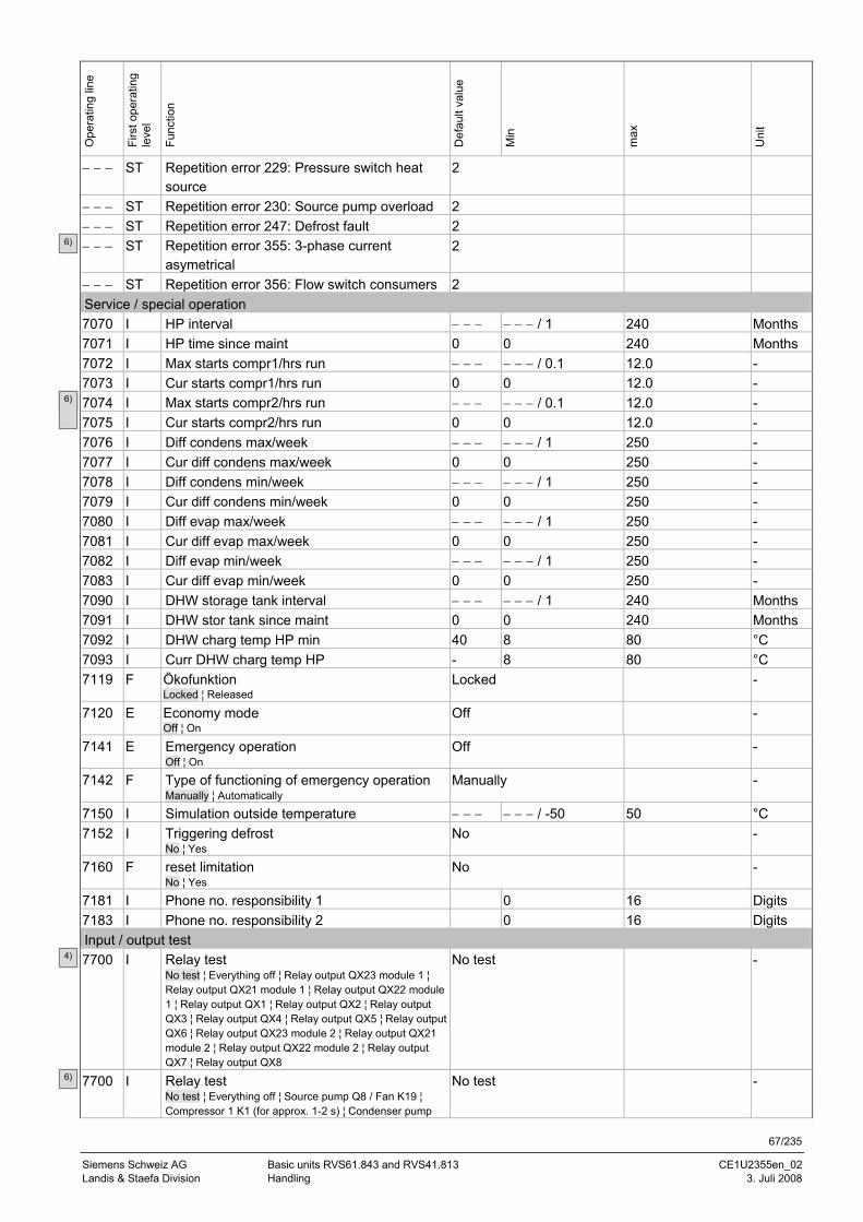
67/235
Siemens Schweiz AG Basic units RVS61.843 and RVS41.813 CE1U2355en_02 Landis & Staefa Division Handling 3. Juli 2008
Ope
ratin
g lin
e
Firs
t ope
ratin
g le
vel
Func
tion
Def
ault
valu
e
Min
max
Uni
t
− − − ST Repetition error 229: Pressure switch heat source
2
− − − ST Repetition error 230: Source pump overload 2 − − − ST Repetition error 247: Defrost fault 2 − − − ST Repetition error 355: 3-phase current
asymetrical 2
− − − ST Repetition error 356: Flow switch consumers 2 Service / special operation 7070 I HP interval − − − − − − / 1 240 Months 7071 I HP time since maint 0 0 240 Months 7072 I Max starts compr1/hrs run − − − − − − / 0.1 12.0 - 7073 I Cur starts compr1/hrs run 0 0 12.0 - 7074 I Max starts compr2/hrs run − − − − − − / 0.1 12.0 - 7075 I Cur starts compr2/hrs run 0 0 12.0 - 7076 I Diff condens max/week − − − − − − / 1 250 - 7077 I Cur diff condens max/week 0 0 250 - 7078 I Diff condens min/week − − − − − − / 1 250 - 7079 I Cur diff condens min/week 0 0 250 - 7080 I Diff evap max/week − − − − − − / 1 250 - 7081 I Cur diff evap max/week 0 0 250 - 7082 I Diff evap min/week − − − − − − / 1 250 - 7083 I Cur diff evap min/week 0 0 250 - 7090 I DHW storage tank interval − − − − − − / 1 240 Months 7091 I DHW stor tank since maint 0 0 240 Months 7092 I DHW charg temp HP min 40 8 80 °C 7093 I Curr DHW charg temp HP - 8 80 °C 7119 F Ökofunktion
Locked ¦ Released Locked -
7120 E Economy mode Off ¦ On
Off -
7141 E Emergency operation Off ¦ On
Off -
7142 F Type of functioning of emergency operation Manually ¦ Automatically
Manually -
7150 I Simulation outside temperature − − − − − − / -50 50 °C 7152 I Triggering defrost
No ¦ Yes No -
7160 F reset limitation No ¦ Yes
No -
7181 I Phone no. responsibility 1 0 16 Digits 7183 I Phone no. responsibility 2 0 16 Digits Input / output test 7700 I Relay test
No test ¦ Everything off ¦ Relay output QX23 module 1 ¦ Relay output QX21 module 1 ¦ Relay output QX22 module 1 ¦ Relay output QX1 ¦ Relay output QX2 ¦ Relay output QX3 ¦ Relay output QX4 ¦ Relay output QX5 ¦ Relay output QX6 ¦ Relay output QX23 module 2 ¦ Relay output QX21 module 2 ¦ Relay output QX22 module 2 ¦ Relay output QX7 ¦ Relay output QX8
No test -
7700 I Relay test No test ¦ Everything off ¦ Source pump Q8 / Fan K19 ¦ Compressor 1 K1 (for approx. 1-2 s) ¦ Condenser pump
No test -
6) 6)
6)
4)
6)
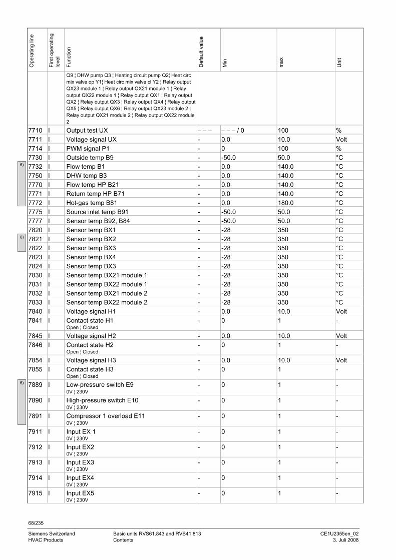
68/235
Siemens Switzerland Basic units RVS61.843 and RVS41.813 CE1U2355en_02 HVAC Products Contents 3. Juli 2008
Ope
ratin
g lin
e
Firs
t ope
ratin
g le
vel
Func
tion
Def
ault
valu
e
Min
max
Uni
t
Q9 ¦ DHW pump Q3 ¦ Heating circuit pump Q2¦ Heat circ mix valve op Y1¦ Heat circ mix valve cl Y2 ¦ Relay output QX23 module 1 ¦ Relay output QX21 module 1 ¦ Relay output QX22 module 1 ¦ Relay output QX1 ¦ Relay output QX2 ¦ Relay output QX3 ¦ Relay output QX4 ¦ Relay output QX5 ¦ Relay output QX6 ¦ Relay output QX23 module 2 ¦ Relay output QX21 module 2 ¦ Relay output QX22 module 2
7710 I Output test UX − − − − − − / 0 100 % 7711 I Voltage signal UX - 0.0 10.0 Volt 7714 I PWM signal P1 - 0 100 % 7730 I Outside temp B9 - -50.0 50.0 °C 7732 I Flow temp B1 - 0.0 140.0 °C 7750 I DHW temp B3 - 0.0 140.0 °C 7770 I Flow temp HP B21 - 0.0 140.0 °C 7771 I Return temp HP B71 - 0.0 140.0 °C 7772 I Hot-gas temp B81 - 0.0 180.0 °C 7775 I Source inlet temp B91 - -50.0 50.0 °C 7777 I Sensor temp B92, B84 - -50.0 50.0 °C 7820 I Sensor temp BX1 - -28 350 °C 7821 I Sensor temp BX2 - -28 350 °C 7822 I Sensor temp BX3 - -28 350 °C 7823 I Sensor temp BX4 - -28 350 °C 7824 I Sensor temp BX3 - -28 350 °C 7830 I Sensor temp BX21 module 1 - -28 350 °C 7831 I Sensor temp BX22 module 1 - -28 350 °C 7832 I Sensor temp BX21 module 2 - -28 350 °C 7833 I Sensor temp BX22 module 2 - -28 350 °C 7840 I Voltage signal H1 - 0.0 10.0 Volt 7841 I Contact state H1
Open ¦ Closed - 0 1 -
7845 I Voltage signal H2 - 0.0 10.0 Volt 7846 I Contact state H2
Open ¦ Closed - 0 1 -
7854 I Voltage signal H3 - 0.0 10.0 Volt 7855 I Contact state H3
Open ¦ Closed - 0 1 -
7889 I Low-pressure switch E9 0V ¦ 230V
- 0 1 -
7890 I High-pressure switch E10 0V ¦ 230V
- 0 1 -
7891 I Compressor 1 overload E11 0V ¦ 230V
- 0 1 -
7911 I Input EX 1 0V ¦ 230V
- 0 1 -
7912 I Input EX2 0V ¦ 230V
- 0 1 -
7913 I Input EX3 0V ¦ 230V
- 0 1 -
7914 I Input EX4 0V ¦ 230V
- 0 1 -
7915 I Input EX5 0V ¦ 230V
- 0 1 -
6)
6)
6)
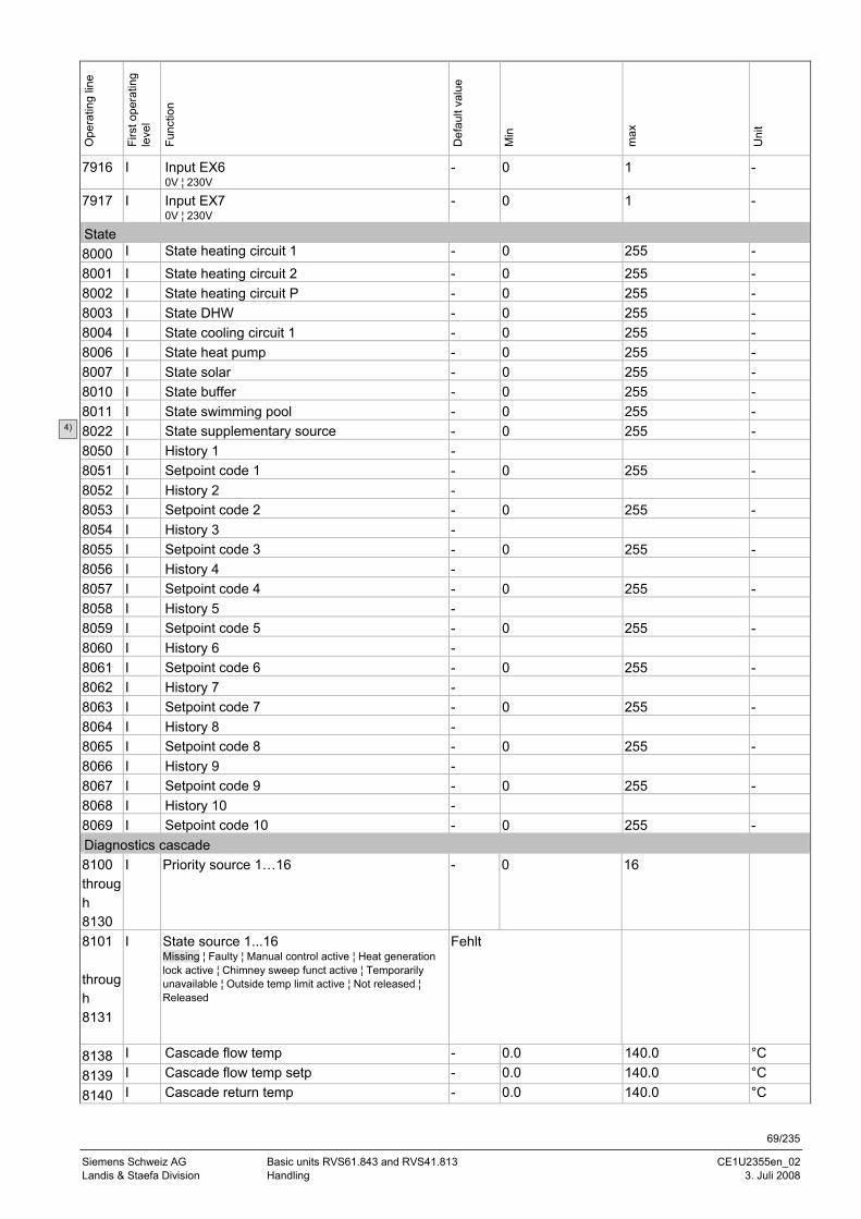
69/235
Siemens Schweiz AG Basic units RVS61.843 and RVS41.813 CE1U2355en_02 Landis & Staefa Division Handling 3. Juli 2008
Ope
ratin
g lin
e
Firs
t ope
ratin
g le
vel
Func
tion
Def
ault
valu
e
Min
max
Uni
t
7916 I Input EX6 0V ¦ 230V
- 0 1 -
7917 I Input EX7 0V ¦ 230V
- 0 1 -
State 8000 I State heating circuit 1 - 0 255 - 8001 I State heating circuit 2 - 0 255 - 8002 I State heating circuit P - 0 255 - 8003 I State DHW - 0 255 - 8004 I State cooling circuit 1 - 0 255 - 8006 I State heat pump - 0 255 - 8007 I State solar - 0 255 - 8010 I State buffer - 0 255 - 8011 I State swimming pool - 0 255 - 8022 I State supplementary source - 0 255 - 8050 I History 1 - 8051 I Setpoint code 1 - 0 255 - 8052 I History 2 - 8053 I Setpoint code 2 - 0 255 - 8054 I History 3 - 8055 I Setpoint code 3 - 0 255 - 8056 I History 4 - 8057 I Setpoint code 4 - 0 255 - 8058 I History 5 - 8059 I Setpoint code 5 - 0 255 - 8060 I History 6 - 8061 I Setpoint code 6 - 0 255 - 8062 I History 7 - 8063 I Setpoint code 7 - 0 255 - 8064 I History 8 - 8065 I Setpoint code 8 - 0 255 - 8066 I History 9 - 8067 I Setpoint code 9 - 0 255 - 8068 I History 10 - 8069 I Setpoint code 10 - 0 255 - Diagnostics cascade 8100 through 8130
I Priority source 1…16 - 0 16
8101 through 8131
I State source 1...16 Missing ¦ Faulty ¦ Manual control active ¦ Heat generation lock active ¦ Chimney sweep funct active ¦ Temporarily unavailable ¦ Outside temp limit active ¦ Not released ¦ Released
Fehlt
8138 I Cascade flow temp - 0.0 140.0 °C 8139 I Cascade flow temp setp - 0.0 140.0 °C 8140 I Cascade return temp - 0.0 140.0 °C
4)
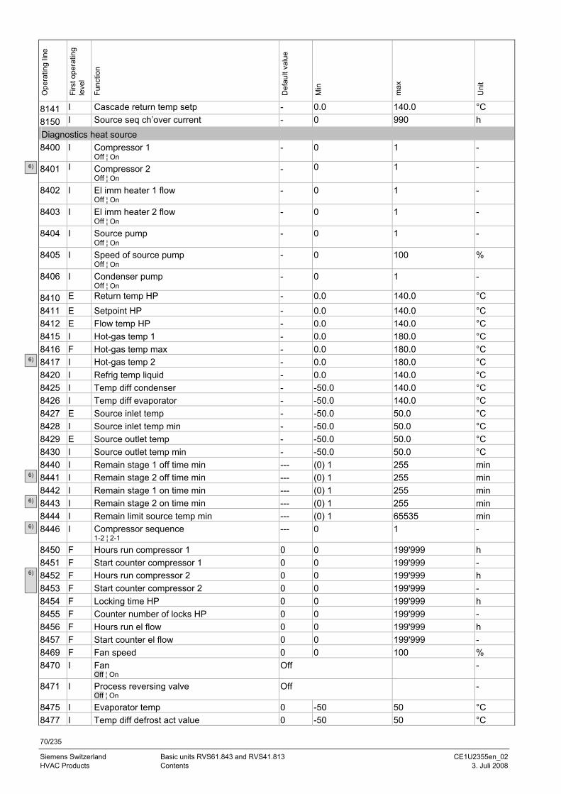
70/235
Siemens Switzerland Basic units RVS61.843 and RVS41.813 CE1U2355en_02 HVAC Products Contents 3. Juli 2008
Ope
ratin
g lin
e
Firs
t ope
ratin
g le
vel
Func
tion
Def
ault
valu
e
Min
max
Uni
t
8141 I Cascade return temp setp - 0.0 140.0 °C 8150 I Source seq ch’over current - 0 990 h Diagnostics heat source 8400 I Compressor 1
Off ¦ On - 0 1 -
8401 I Compressor 2 Off ¦ On
- 0 1 -
8402 I El imm heater 1 flow Off ¦ On
- 0 1 -
8403 I El imm heater 2 flow Off ¦ On
- 0 1 -
8404 I Source pump Off ¦ On
- 0 1 -
8405 I Speed of source pump Off ¦ On
- 0 100 %
8406 I Condenser pump Off ¦ On
- 0 1 -
8410 E Return temp HP - 0.0 140.0 °C 8411 E Setpoint HP - 0.0 140.0 °C 8412 E Flow temp HP - 0.0 140.0 °C 8415 I Hot-gas temp 1 - 0.0 180.0 °C 8416 F Hot-gas temp max - 0.0 180.0 °C 8417 I Hot-gas temp 2 - 0.0 180.0 °C 8420 I Refrig temp liquid - 0.0 140.0 °C 8425 I Temp diff condenser - -50.0 140.0 °C 8426 I Temp diff evaporator - -50.0 140.0 °C 8427 E Source inlet temp - -50.0 50.0 °C 8428 I Source inlet temp min - -50.0 50.0 °C 8429 E Source outlet temp - -50.0 50.0 °C 8430 I Source outlet temp min - -50.0 50.0 °C 8440 I Remain stage 1 off time min --- (0) 1 255 min 8441 I Remain stage 2 off time min --- (0) 1 255 min 8442 I Remain stage 1 on time min --- (0) 1 255 min 8443 I Remain stage 2 on time min --- (0) 1 255 min 8444 I Remain limit source temp min --- (0) 1 65535 min 8446 I Compressor sequence
1-2 ¦ 2-1 --- 0 1 -
8450 F Hours run compressor 1 0 0 199'999 h 8451 F Start counter compressor 1 0 0 199'999 - 8452 F Hours run compressor 2 0 0 199'999 h 8453 F Start counter compressor 2 0 0 199'999 - 8454 F Locking time HP 0 0 199'999 h 8455 F Counter number of locks HP 0 0 199'999 - 8456 F Hours run el flow 0 0 199'999 h 8457 F Start counter el flow 0 0 199'999 - 8469 F Fan speed 0 0 100 % 8470 I Fan
Off ¦ On Off -
8471 I Process reversing valve Off ¦ On
Off -
8475 I Evaporator temp 0 -50 50 °C 8477 I Temp diff defrost act value 0 -50 50 °C
6)
6)
6)
6)
6)
6)
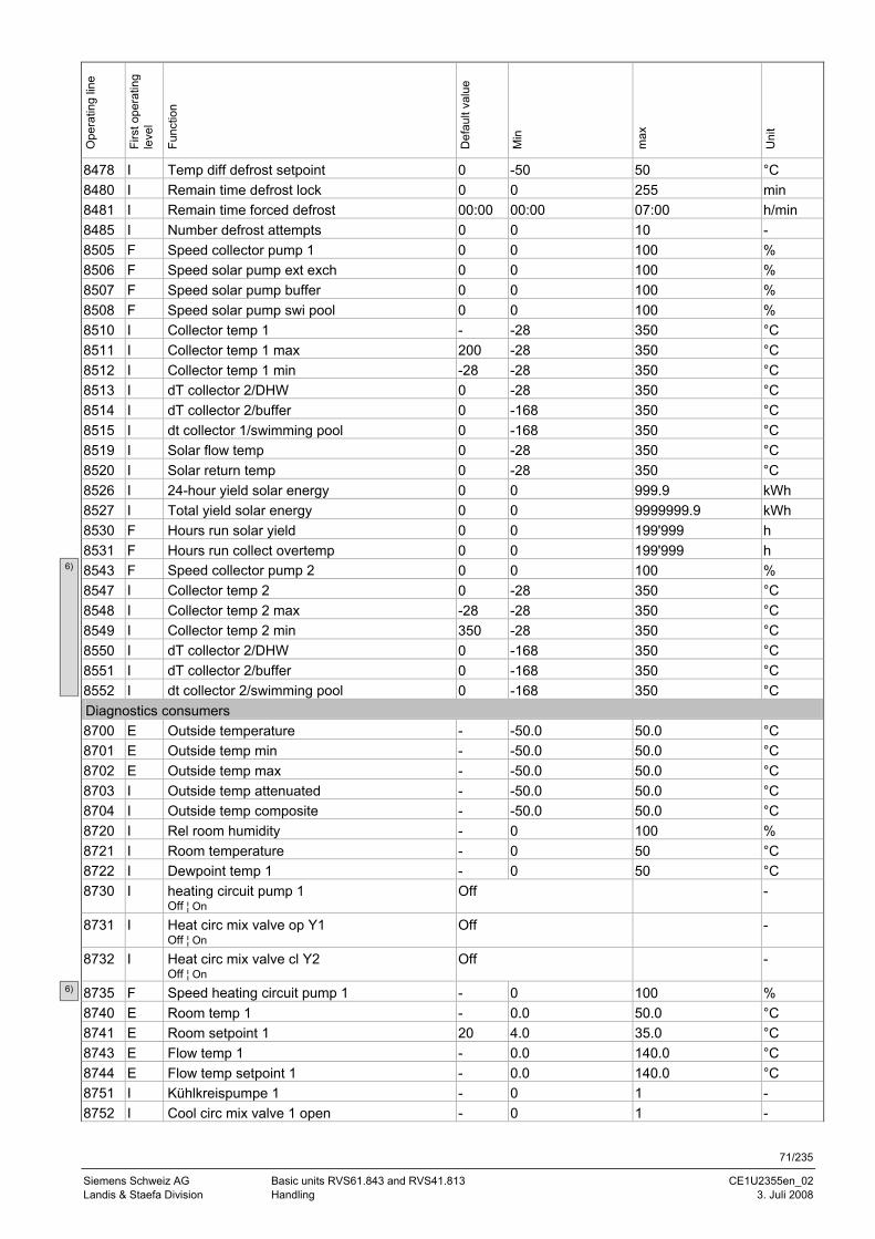
71/235
Siemens Schweiz AG Basic units RVS61.843 and RVS41.813 CE1U2355en_02 Landis & Staefa Division Handling 3. Juli 2008
Ope
ratin
g lin
e
Firs
t ope
ratin
g le
vel
Func
tion
Def
ault
valu
e
Min
max
Uni
t
8478 I Temp diff defrost setpoint 0 -50 50 °C 8480 I Remain time defrost lock 0 0 255 min 8481 I Remain time forced defrost 00:00 00:00 07:00 h/min 8485 I Number defrost attempts 0 0 10 - 8505 F Speed collector pump 1 0 0 100 % 8506 F Speed solar pump ext exch 0 0 100 % 8507 F Speed solar pump buffer 0 0 100 % 8508 F Speed solar pump swi pool 0 0 100 % 8510 I Collector temp 1 - -28 350 °C 8511 I Collector temp 1 max 200 -28 350 °C 8512 I Collector temp 1 min -28 -28 350 °C 8513 I dT collector 2/DHW 0 -28 350 °C 8514 I dT collector 2/buffer 0 -168 350 °C 8515 I dt collector 1/swimming pool 0 -168 350 °C 8519 I Solar flow temp 0 -28 350 °C 8520 I Solar return temp 0 -28 350 °C 8526 I 24-hour yield solar energy 0 0 999.9 kWh 8527 I Total yield solar energy 0 0 9999999.9 kWh 8530 F Hours run solar yield 0 0 199'999 h 8531 F Hours run collect overtemp 0 0 199'999 h 8543 F Speed collector pump 2 0 0 100 % 8547 I Collector temp 2 0 -28 350 °C 8548 I Collector temp 2 max -28 -28 350 °C 8549 I Collector temp 2 min 350 -28 350 °C 8550 I dT collector 2/DHW 0 -168 350 °C 8551 I dT collector 2/buffer 0 -168 350 °C 8552 I dt collector 2/swimming pool 0 -168 350 °C Diagnostics consumers 8700 E Outside temperature - -50.0 50.0 °C 8701 E Outside temp min - -50.0 50.0 °C 8702 E Outside temp max - -50.0 50.0 °C 8703 I Outside temp attenuated - -50.0 50.0 °C 8704 I Outside temp composite - -50.0 50.0 °C 8720 I Rel room humidity - 0 100 % 8721 I Room temperature - 0 50 °C 8722 I Dewpoint temp 1 - 0 50 °C 8730 I heating circuit pump 1
Off ¦ On Off -
8731 I Heat circ mix valve op Y1 Off ¦ On
Off -
8732 I Heat circ mix valve cl Y2 Off ¦ On
Off -
8735 F Speed heating circuit pump 1 - 0 100 % 8740 E Room temp 1 - 0.0 50.0 °C 8741 E Room setpoint 1 20 4.0 35.0 °C 8743 E Flow temp 1 - 0.0 140.0 °C 8744 E Flow temp setpoint 1 - 0.0 140.0 °C 8751 I Kühlkreispumpe 1 - 0 1 - 8752 I Cool circ mix valve 1 open - 0 1 -
6)
6)
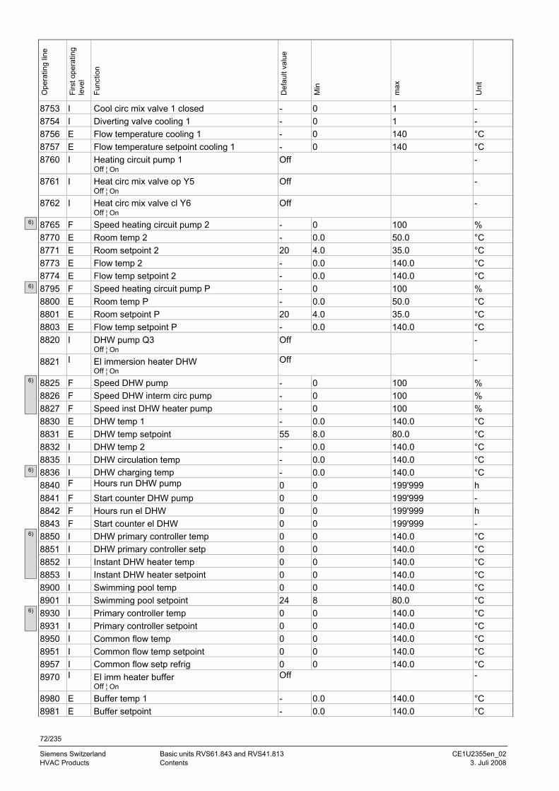
72/235
Siemens Switzerland Basic units RVS61.843 and RVS41.813 CE1U2355en_02 HVAC Products Contents 3. Juli 2008
Ope
ratin
g lin
e
Firs
t ope
ratin
g le
vel
Func
tion
Def
ault
valu
e
Min
max
Uni
t
8753 I Cool circ mix valve 1 closed - 0 1 - 8754 I Diverting valve cooling 1 - 0 1 - 8756 E Flow temperature cooling 1 - 0 140 °C 8757 E Flow temperature setpoint cooling 1 - 0 140 °C 8760 I Heating circuit pump 1
Off ¦ On Off -
8761 I Heat circ mix valve op Y5 Off ¦ On
Off -
8762 I Heat circ mix valve cl Y6 Off ¦ On
Off -
8765 F Speed heating circuit pump 2 - 0 100 % 8770 E Room temp 2 - 0.0 50.0 °C 8771 E Room setpoint 2 20 4.0 35.0 °C 8773 E Flow temp 2 - 0.0 140.0 °C 8774 E Flow temp setpoint 2 - 0.0 140.0 °C 8795 F Speed heating circuit pump P - 0 100 % 8800 E Room temp P - 0.0 50.0 °C 8801 E Room setpoint P 20 4.0 35.0 °C 8803 E Flow temp setpoint P - 0.0 140.0 °C 8820 I DHW pump Q3
Off ¦ On Off -
8821 I El immersion heater DHW Off ¦ On
Off -
8825 F Speed DHW pump - 0 100 % 8826 F Speed DHW interm circ pump - 0 100 % 8827 F Speed inst DHW heater pump - 0 100 % 8830 E DHW temp 1 - 0.0 140.0 °C 8831 E DHW temp setpoint 55 8.0 80.0 °C 8832 I DHW temp 2 - 0.0 140.0 °C 8835 I DHW circulation temp - 0.0 140.0 °C 8836 I DHW charging temp - 0.0 140.0 °C 8840 F Hours run DHW pump 0 0 199'999 h 8841 F Start counter DHW pump 0 0 199'999 - 8842 F Hours run el DHW 0 0 199'999 h 8843 F Start counter el DHW 0 0 199'999 - 8850 I DHW primary controller temp 0 0 140.0 °C 8851 I DHW primary controller setp 0 0 140.0 °C 8852 I Instant DHW heater temp 0 0 140.0 °C 8853 I Instant DHW heater setpoint 0 0 140.0 °C 8900 I Swimming pool temp 0 0 140.0 °C 8901 I Swimming pool setpoint 24 8 80.0 °C 8930 I Primary controller temp 0 0 140.0 °C 8931 I Primary controller setpoint 0 0 140.0 °C 8950 I Common flow temp 0 0 140.0 °C 8951 I Common flow temp setpoint 0 0 140.0 °C 8957 I Common flow setp refrig 0 0 140.0 °C 8970 I El imm heater buffer
Off ¦ On Off -
8980 E Buffer temp 1 - 0.0 140.0 °C 8981 E Buffer setpoint - 0.0 140.0 °C
6)
6)
6)
6)
6)
6)
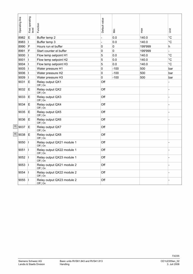
73/235
Siemens Schweiz AG Basic units RVS61.843 and RVS41.813 CE1U2355en_02 Landis & Staefa Division Handling 3. Juli 2008
Ope
ratin
g lin
e
Firs
t ope
ratin
g le
vel
Func
tion
Def
ault
valu
e
Min
max
Uni
t
8982 E Buffer temp 2 - 0.0 140.0 °C 8983 I Buffer temp 3 - 0.0 140.0 °C 8990 F Hours run el buffer 0 0 199'999 h 8991 F Start counter el buffer 0 0 199'999 - 9000 I Flow temp setpoint H1 5 0.0 140.0 °C 9001 I Flow temp setpoint H2 5 0.0 140.0 °C 9004 I Flow temp setpoint H3 5 0.0 140.0 °C 9005 I Water pressure H1 0 -100 500 bar 9006 I Water pressure H2 0 -100 500 bar 9009 I Water pressure H3 0 -100 500 bar 9031 E Relay output QX1
Off ¦ On Off -
9032 E Relay output QX2 Off ¦ On
Off -
9033 E Relay output QX3 Off ¦ On
Off -
9034 E Relay output QX4 Off ¦ On
Off -
9035 E Relay output QX5 Off ¦ On
Off -
9036 E Relay output QX6 Off ¦ On
Off -
9037 E Relay output QX7 Off ¦ On
Off
9038 E Relay output QX8 Off ¦ On
Off
9050 I Relay output QX21 module 1 Off ¦ On
Off -
9051 I Relay output QX22 module 1 Off ¦ On
Off -
9052 I Relay output QX23 module 1 Off ¦ On
Off -
9053 I Relay output QX21 module 2 Off ¦ On
Off -
9054 I Relay output QX22 module 2 Off ¦ On
Off -
9055 I Relay output QX23 module 2 Off ¦ On
Off -
4)
4)
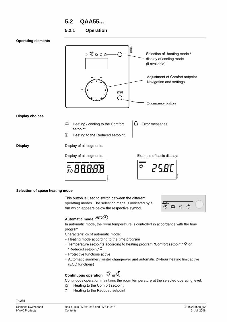
74/235
Siemens Switzerland Basic units RVS61.843 and RVS41.813 CE1U2355en_02 HVAC Products Contents 3. Juli 2008
5.2 QAA55... 5.2.1 Operation
Operating elements
2358
Z34
Display choices
Heating / cooling to the Comfort setpoint
Error messages
Heating to the Reduced setpoint Display of all segments. Display of all segments. Example of basic display:
2354
Z09
2354
Z09
Selection of space heating mode
This button is used to switch between the different operating modes. The selection made is indicated by a bar which appears below the respective symbol. Automatic mode In automatic mode, the room temperature is controlled in accordance with the time program. Characteristics of automatic mode: − Heating mode according to the time program − Temperature setpoints according to heating program "Comfort setpoint" or
"Reduced setpoint" − Protective functions active − Automatic summer / winter changeover and automatic 24-hour heating limit active
(ECO functions)
Continuous operation or Continuous operation maintains the room temperature at the selected operating level.
Heating to the Comfort setpoint Heating to the Reduced setpoint
Display
Selection of heating mode / display of cooling mode (if available)
Occupancy button
Adjustment of Comfort setpoint Navigation and settings
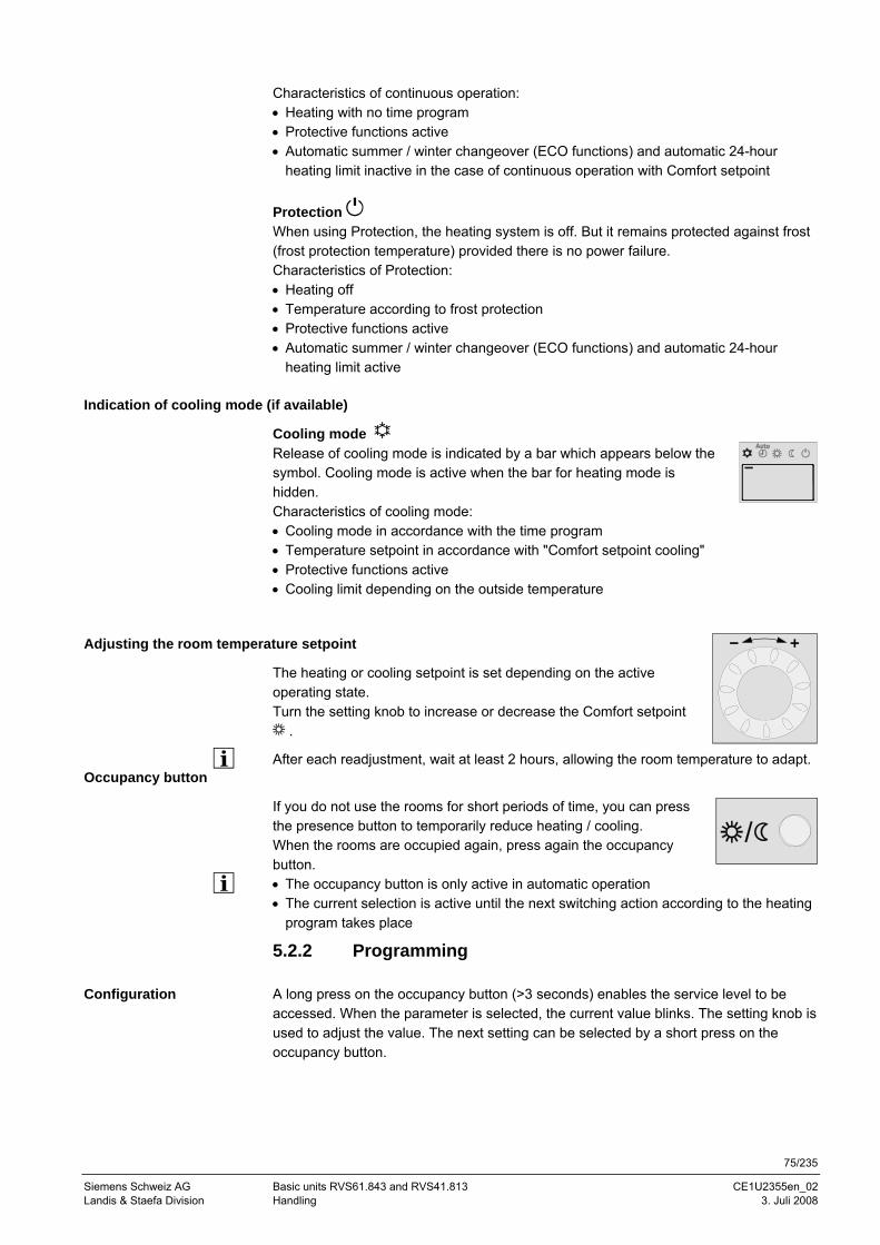
75/235
Siemens Schweiz AG Basic units RVS61.843 and RVS41.813 CE1U2355en_02 Landis & Staefa Division Handling 3. Juli 2008
Characteristics of continuous operation: • Heating with no time program • Protective functions active • Automatic summer / winter changeover (ECO functions) and automatic 24-hour
heating limit inactive in the case of continuous operation with Comfort setpoint Protection When using Protection, the heating system is off. But it remains protected against frost (frost protection temperature) provided there is no power failure. Characteristics of Protection: • Heating off • Temperature according to frost protection • Protective functions active • Automatic summer / winter changeover (ECO functions) and automatic 24-hour
heating limit active
Indication of cooling mode (if available)
Cooling mode Release of cooling mode is indicated by a bar which appears below the symbol. Cooling mode is active when the bar for heating mode is hidden. Characteristics of cooling mode: • Cooling mode in accordance with the time program • Temperature setpoint in accordance with "Comfort setpoint cooling" • Protective functions active • Cooling limit depending on the outside temperature
Adjusting the room temperature setpoint
The heating or cooling setpoint is set depending on the active operating state. Turn the setting knob to increase or decrease the Comfort setpoint
.
After each readjustment, wait at least 2 hours, allowing the room temperature to adapt. Occupancy button
If you do not use the rooms for short periods of time, you can press the presence button to temporarily reduce heating / cooling. When the rooms are occupied again, press again the occupancy button. • The occupancy button is only active in automatic operation • The current selection is active until the next switching action according to the heating
program takes place
5.2.2 Programming A long press on the occupancy button (>3 seconds) enables the service level to be accessed. When the parameter is selected, the current value blinks. The setting knob is used to adjust the value. The next setting can be selected by a short press on the occupancy button.
Configuration
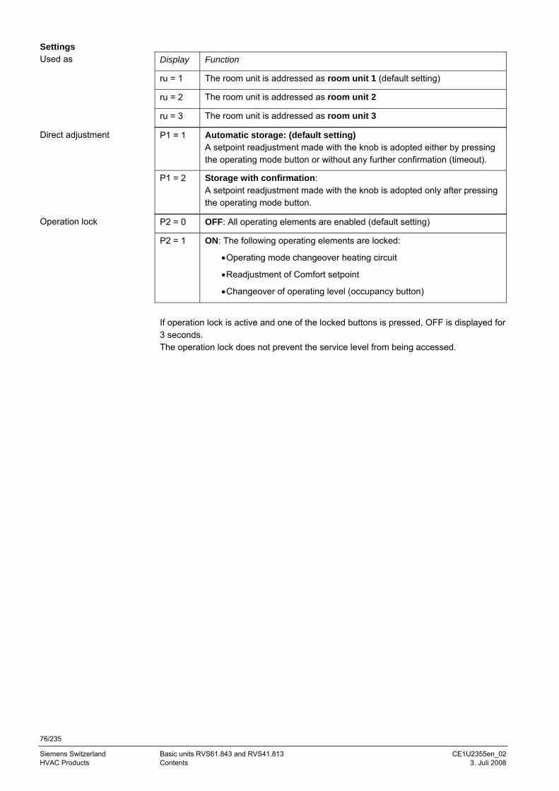
76/235
Siemens Switzerland Basic units RVS61.843 and RVS41.813 CE1U2355en_02 HVAC Products Contents 3. Juli 2008
Display Function
ru = 1 The room unit is addressed as room unit 1 (default setting)
ru = 2 The room unit is addressed as room unit 2
ru = 3 The room unit is addressed as room unit 3
P1 = 1 Automatic storage: (default setting) A setpoint readjustment made with the knob is adopted either by pressing the operating mode button or without any further confirmation (timeout).
P1 = 2 Storage with confirmation: A setpoint readjustment made with the knob is adopted only after pressing the operating mode button.
P2 = 0 OFF: All operating elements are enabled (default setting)
P2 = 1 ON: The following operating elements are locked:
• Operating mode changeover heating circuit
• Readjustment of Comfort setpoint
• Changeover of operating level (occupancy button)
If operation lock is active and one of the locked buttons is pressed, OFF is displayed for 3 seconds. The operation lock does not prevent the service level from being accessed.
Settings Used as
Direct adjustment
Operation lock
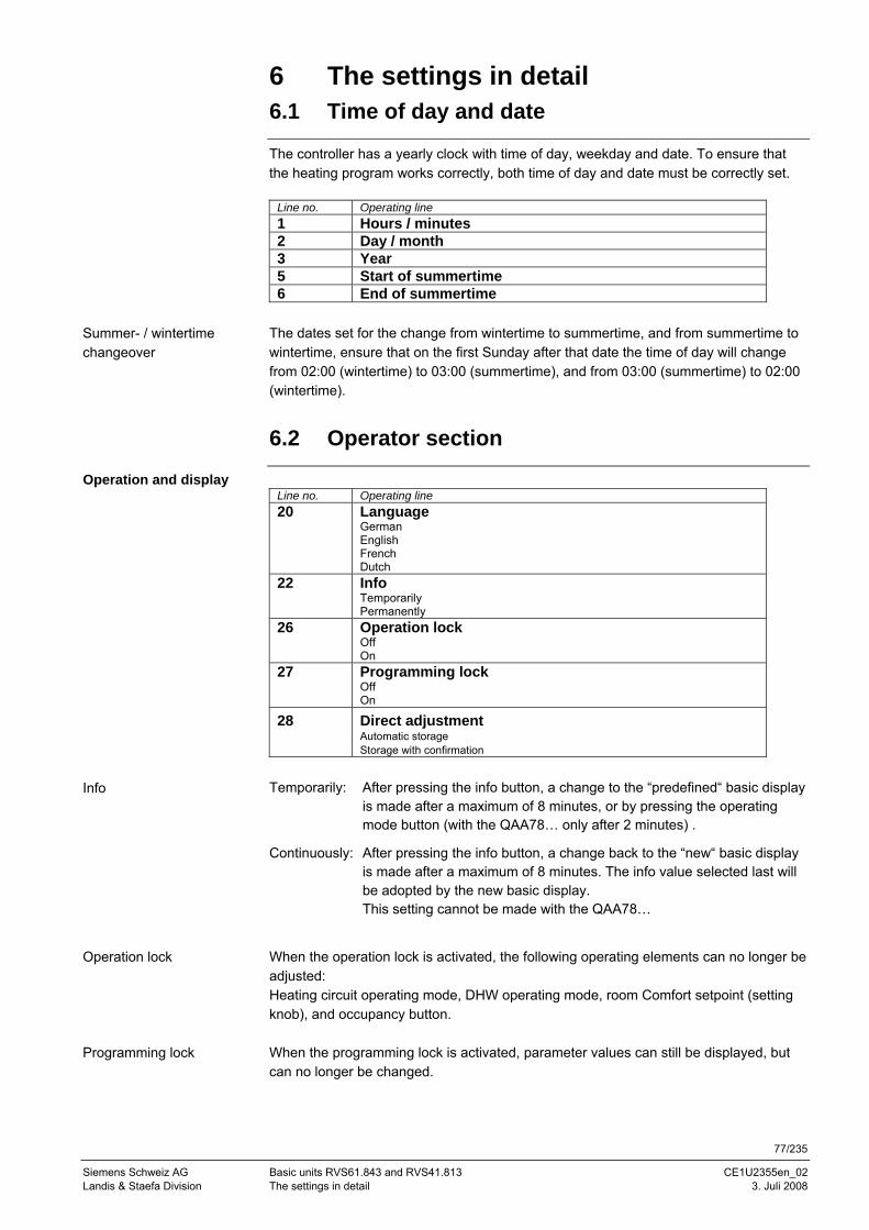
77/235
Siemens Schweiz AG Basic units RVS61.843 and RVS41.813 CE1U2355en_02 Landis & Staefa Division The settings in detail 3. Juli 2008
6 The settings in detail 6.1 Time of day and date
The controller has a yearly clock with time of day, weekday and date. To ensure that the heating program works correctly, both time of day and date must be correctly set.
Line no. Operating line 1 Hours / minutes 2 Day / month 3 Year 5 Start of summertime 6 End of summertime
The dates set for the change from wintertime to summertime, and from summertime to wintertime, ensure that on the first Sunday after that date the time of day will change from 02:00 (wintertime) to 03:00 (summertime), and from 03:00 (summertime) to 02:00 (wintertime).
6.2 Operator section
Operation and display Line no. Operating line 20 Language
German English French Dutch
22 Info Temporarily Permanently
26 Operation lock Off On
27 Programming lock Off On
28 Direct adjustment Automatic storage Storage with confirmation
Temporarily: After pressing the info button, a change to the “predefined“ basic display
is made after a maximum of 8 minutes, or by pressing the operating mode button (with the QAA78… only after 2 minutes) .
Continuously: After pressing the info button, a change back to the “new“ basic display is made after a maximum of 8 minutes. The info value selected last will be adopted by the new basic display. This setting cannot be made with the QAA78…
When the operation lock is activated, the following operating elements can no longer be adjusted: Heating circuit operating mode, DHW operating mode, room Comfort setpoint (setting knob), and occupancy button. When the programming lock is activated, parameter values can still be displayed, but can no longer be changed.
Summer- / wintertime changeover
Info
Operation lock
Programming lock
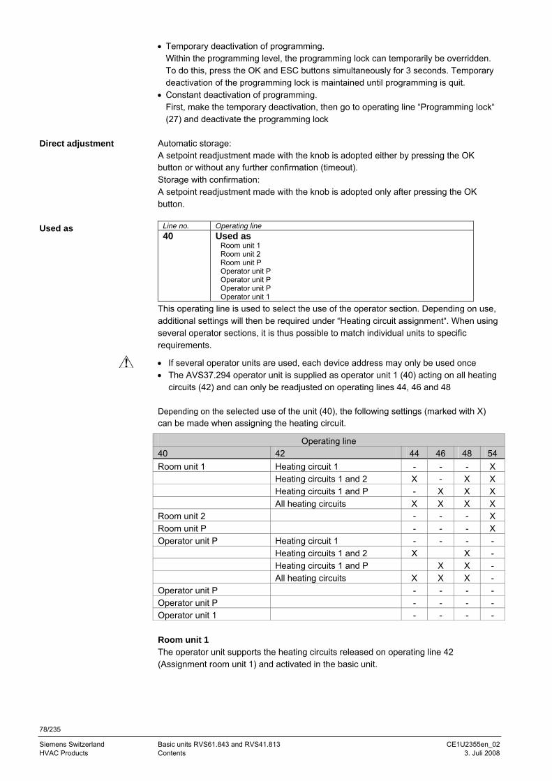
78/235
Siemens Switzerland Basic units RVS61.843 and RVS41.813 CE1U2355en_02 HVAC Products Contents 3. Juli 2008
• Temporary deactivation of programming. Within the programming level, the programming lock can temporarily be overridden. To do this, press the OK and ESC buttons simultaneously for 3 seconds. Temporary deactivation of the programming lock is maintained until programming is quit.
• Constant deactivation of programming. First, make the temporary deactivation, then go to operating line “Programming lock“ (27) and deactivate the programming lock
Automatic storage: A setpoint readjustment made with the knob is adopted either by pressing the OK button or without any further confirmation (timeout). Storage with confirmation: A setpoint readjustment made with the knob is adopted only after pressing the OK button.
Line no. Operating line 40 Used as
Room unit 1 Room unit 2 Room unit P Operator unit P Operator unit P Operator unit P Operator unit 1
This operating line is used to select the use of the operator section. Depending on use, additional settings will then be required under “Heating circuit assignment“. When using several operator sections, it is thus possible to match individual units to specific requirements.
• If several operator units are used, each device address may only be used once • The AVS37.294 operator unit is supplied as operator unit 1 (40) acting on all heating
circuits (42) and can only be readjusted on operating lines 44, 46 and 48 Depending on the selected use of the unit (40), the following settings (marked with X) can be made when assigning the heating circuit.
Operating line 40 42 44 46 48 54 Room unit 1 Heating circuit 1 - - - X Heating circuits 1 and 2 X - X X Heating circuits 1 and P - X X X All heating circuits X X X X Room unit 2 - - - X Room unit P - - - X Operator unit P Heating circuit 1 - - - - Heating circuits 1 and 2 X X - Heating circuits 1 and P X X - All heating circuits X X X - Operator unit P - - - - Operator unit P - - - - Operator unit 1 - - - - Room unit 1 The operator unit supports the heating circuits released on operating line 42 (Assignment room unit 1) and activated in the basic unit.
Direct adjustment
Used as
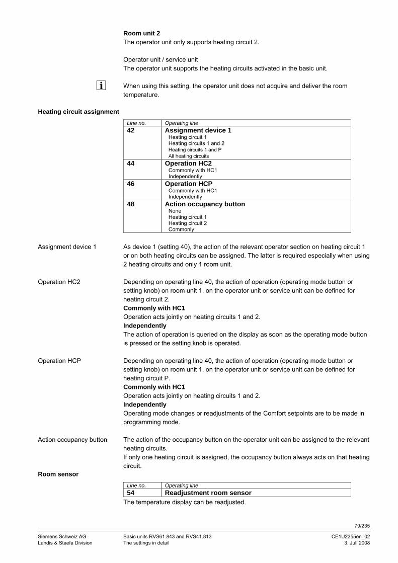
79/235
Siemens Schweiz AG Basic units RVS61.843 and RVS41.813 CE1U2355en_02 Landis & Staefa Division The settings in detail 3. Juli 2008
Room unit 2 The operator unit only supports heating circuit 2. Operator unit / service unit The operator unit supports the heating circuits activated in the basic unit. When using this setting, the operator unit does not acquire and deliver the room temperature.
Heating circuit assignment
Line no. Operating line 42 Assignment device 1
Heating circuit 1 Heating circuits 1 and 2 Heating circuits 1 and P All heating circuits
44 Operation HC2 Commonly with HC1 Independently
46 Operation HCP Commonly with HC1 Independently
48 Action occupancy button None Heating circuit 1 Heating circuit 2 Commonly
As device 1 (setting 40), the action of the relevant operator section on heating circuit 1 or on both heating circuits can be assigned. The latter is required especially when using 2 heating circuits and only 1 room unit. Depending on operating line 40, the action of operation (operating mode button or setting knob) on room unit 1, on the operator unit or service unit can be defined for heating circuit 2. Commonly with HC1 Operation acts jointly on heating circuits 1 and 2. Independently The action of operation is queried on the display as soon as the operating mode button is pressed or the setting knob is operated. Depending on operating line 40, the action of operation (operating mode button or setting knob) on room unit 1, on the operator unit or service unit can be defined for heating circuit P. Commonly with HC1 Operation acts jointly on heating circuits 1 and 2. Independently Operating mode changes or readjustments of the Comfort setpoints are to be made in programming mode. The action of the occupancy button on the operator unit can be assigned to the relevant heating circuits. If only one heating circuit is assigned, the occupancy button always acts on that heating circuit.
Room sensor
Line no. Operating line 54 Readjustment room sensor
The temperature display can be readjusted.
Assignment device 1
Operation HC2
Operation HCP
Action occupancy button
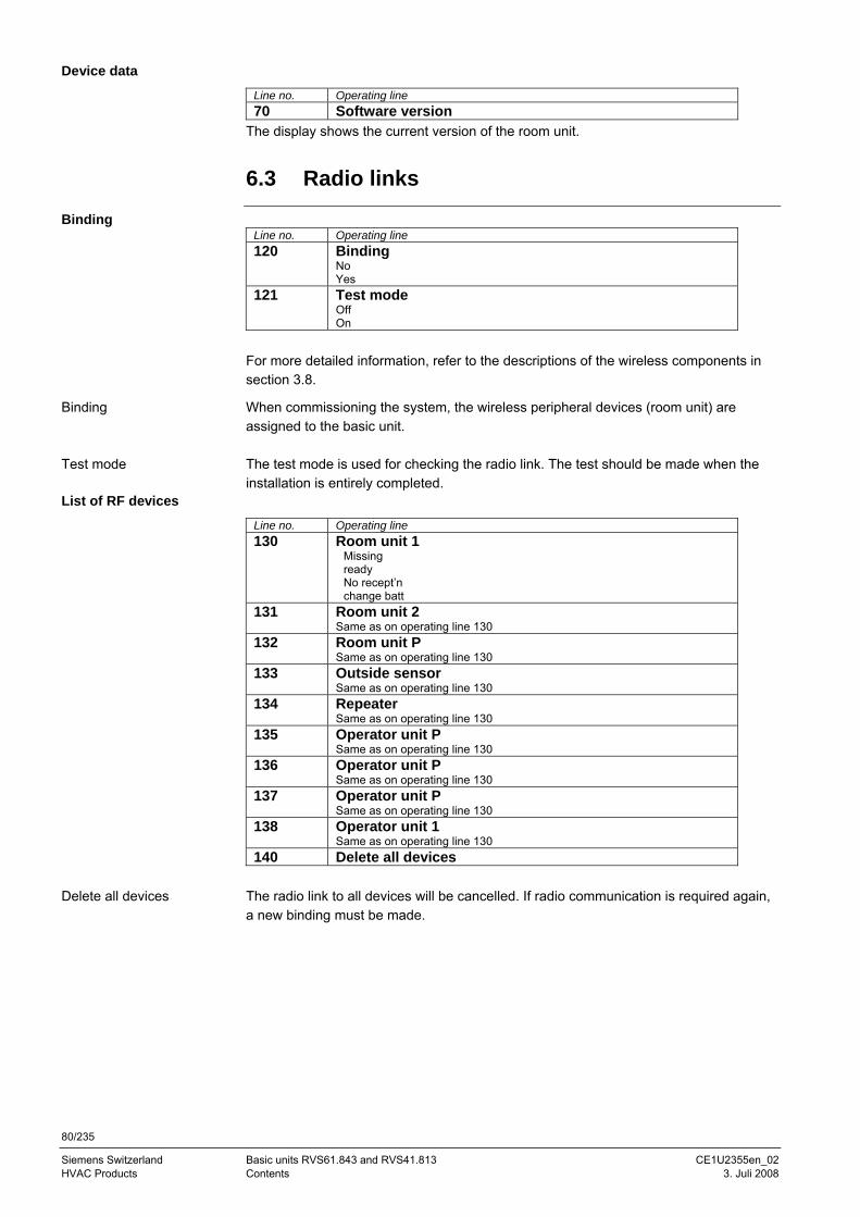
80/235
Siemens Switzerland Basic units RVS61.843 and RVS41.813 CE1U2355en_02 HVAC Products Contents 3. Juli 2008
Device data
Line no. Operating line 70 Software version
The display shows the current version of the room unit.
6.3 Radio links
Binding Line no. Operating line 120 Binding
No Yes
121 Test mode Off On
For more detailed information, refer to the descriptions of the wireless components in section 3.8.
When commissioning the system, the wireless peripheral devices (room unit) are assigned to the basic unit. The test mode is used for checking the radio link. The test should be made when the installation is entirely completed.
List of RF devices
Line no. Operating line 130 Room unit 1
Missing ready No recept’n change batt
131 Room unit 2 Same as on operating line 130
132 Room unit P Same as on operating line 130
133 Outside sensor Same as on operating line 130
134 Repeater Same as on operating line 130
135 Operator unit P Same as on operating line 130
136 Operator unit P Same as on operating line 130
137 Operator unit P Same as on operating line 130
138 Operator unit 1 Same as on operating line 130
140 Delete all devices The radio link to all devices will be cancelled. If radio communication is required again, a new binding must be made.
Binding
Test mode
Delete all devices
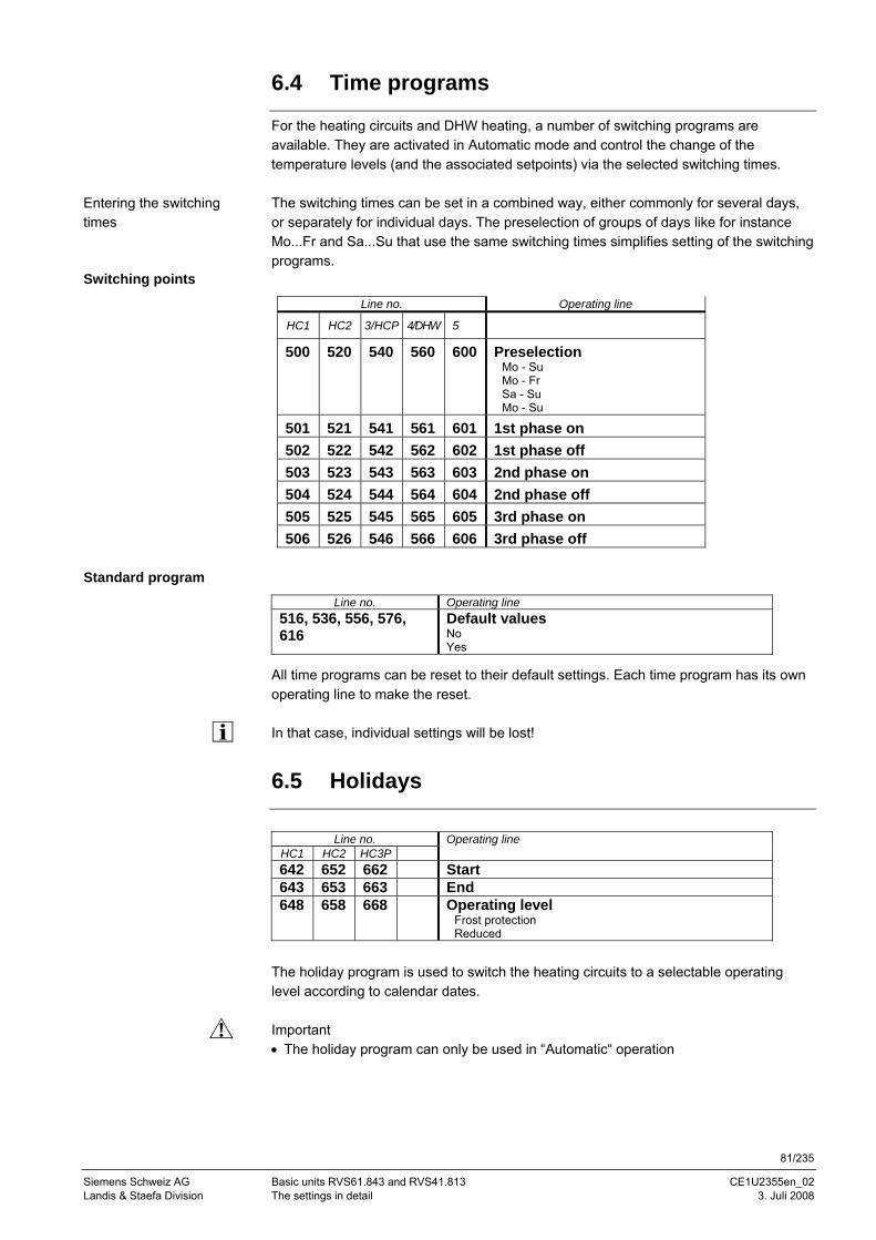
81/235
Siemens Schweiz AG Basic units RVS61.843 and RVS41.813 CE1U2355en_02 Landis & Staefa Division The settings in detail 3. Juli 2008
6.4 Time programs
For the heating circuits and DHW heating, a number of switching programs are available. They are activated in Automatic mode and control the change of the temperature levels (and the associated setpoints) via the selected switching times. The switching times can be set in a combined way, either commonly for several days, or separately for individual days. The preselection of groups of days like for instance Mo...Fr and Sa...Su that use the same switching times simplifies setting of the switching programs.
Switching points
Line no. Operating line
HC1 HC2 3/HCP 4/DHW 5
500 520 540 560 600 Preselection Mo - Su Mo - Fr Sa - Su Mo - Su
501 521 541 561 601 1st phase on 502 522 542 562 602 1st phase off 503 523 543 563 603 2nd phase on 504 524 544 564 604 2nd phase off 505 525 545 565 605 3rd phase on 506 526 546 566 606 3rd phase off
Standard program
Line no. Operating line 516, 536, 556, 576, 616
Default values No Yes
All time programs can be reset to their default settings. Each time program has its own operating line to make the reset. In that case, individual settings will be lost!
6.5 Holidays
Line no. Operating line
HC1 HC2 HC3P 642 652 662 Start 643 653 663 End 648 658 668 Operating level
Frost protection Reduced
The holiday program is used to switch the heating circuits to a selectable operating level according to calendar dates. Important • The holiday program can only be used in “Automatic“ operation
Entering the switching times
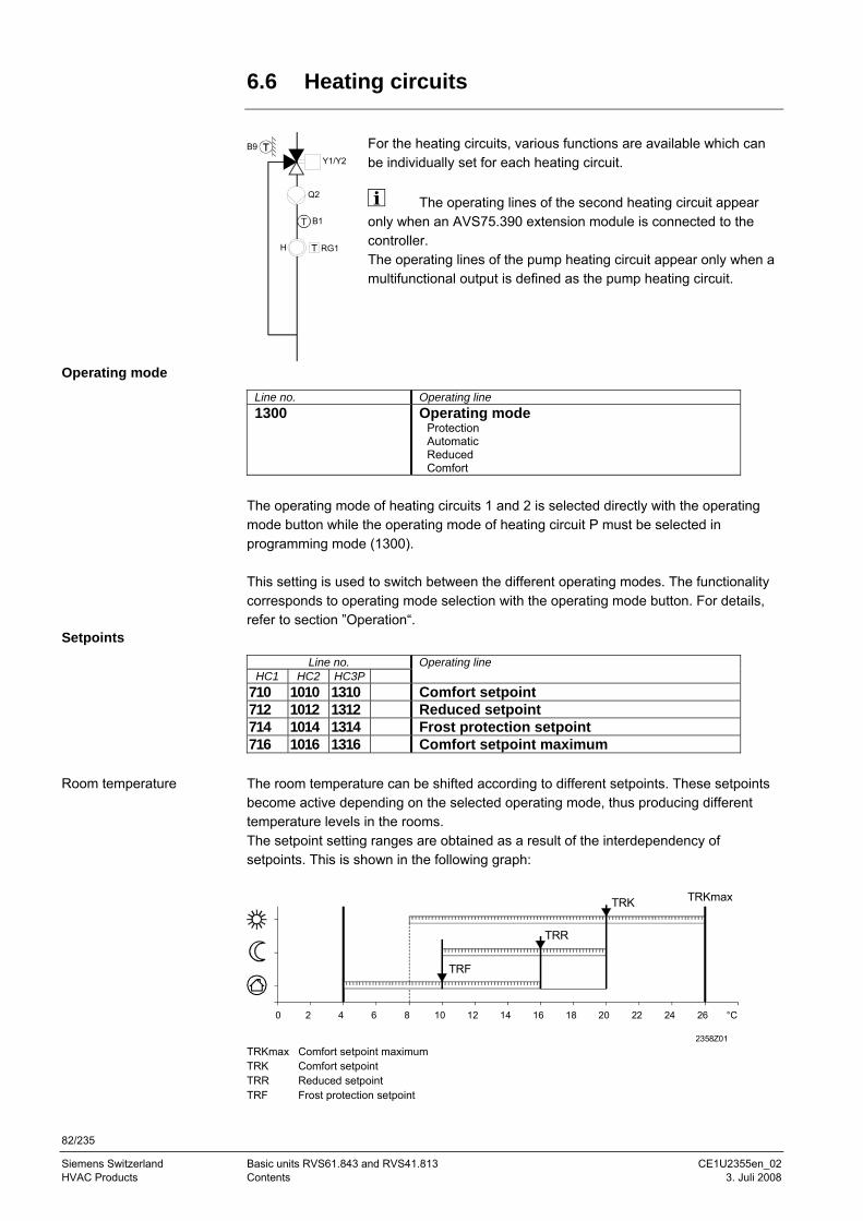
82/235
Siemens Switzerland Basic units RVS61.843 and RVS41.813 CE1U2355en_02 HVAC Products Contents 3. Juli 2008
6.6 Heating circuits
Y1/Y2
B1
Q2
RG1
B9
H
For the heating circuits, various functions are available which can be individually set for each heating circuit.
The operating lines of the second heating circuit appear only when an AVS75.390 extension module is connected to the controller. The operating lines of the pump heating circuit appear only when a multifunctional output is defined as the pump heating circuit.
Operating mode
Line no. Operating line 1300 Operating mode
Protection Automatic Reduced Comfort
The operating mode of heating circuits 1 and 2 is selected directly with the operating mode button while the operating mode of heating circuit P must be selected in programming mode (1300). This setting is used to switch between the different operating modes. The functionality corresponds to operating mode selection with the operating mode button. For details, refer to section ”Operation“.
Setpoints
Line no. Operating line HC1 HC2 HC3P
710 1010 1310 Comfort setpoint 712 1012 1312 Reduced setpoint 714 1014 1314 Frost protection setpoint 716 1016 1316 Comfort setpoint maximum The room temperature can be shifted according to different setpoints. These setpoints become active depending on the selected operating mode, thus producing different temperature levels in the rooms. The setpoint setting ranges are obtained as a result of the interdependency of setpoints. This is shown in the following graph:
TRKmax Comfort setpoint maximum TRK Comfort setpoint TRR Reduced setpoint TRF Frost protection setpoint
Room temperature
0 2 4 6 8 10 12 14 16 18 20 22 24 26 °C
2358Z01
TRK
TRR
TRF
TRKmax

83/235
Siemens Schweiz AG Basic units RVS61.843 and RVS41.813 CE1U2355en_02 Landis & Staefa Division The settings in detail 3. Juli 2008
In Protection mode, the room temperature is prevented from falling below a certain level. This means that the frost protection setpoint of the room temperature will be maintained.
Line no. Operating line HC1 HC2 HC3P
720 1020 1320 Heating curve slope 721 1021 1321 Heating curve displacement 726 1026 1326 Heating curve adaption The heating curve generates the flow temperature setpoint, which is used to maintain a certain flow temperature depending on the prevailing weather conditions. The heating curve can be adjusted via a number of settings, thus matching heat output and room temperature to individual needs. The steeper the heating curve slope, the greater the change of flow temperature at low outside temperatures. In other words, if the room temperature is not correct at low outside temperatures, but at higher outside temperatures, the heating curve slope needs readjusting.
Increasing the setting: Raises the flow temperature, especially when outside temperatures are low.
Decreasing the setting: Lowers the flow temperature, especially when outside temperatures are low.
The set heating curve is based on a room temperature setpoint of 20 °C. If the room temperature setpoint is adjusted, the heating curve adapts automatically to the new value.
20 10 0 -10 -20 -30
90
80
70
60
50
40
30
°C
°C
4 3,5 3 2,75 2,5 2,25
2
1,75
1,5
1,25
1
0,75
0,5
0,25
100
2000
D02
Parallel displacement of the heating curve is used to change the flow temperature evenly across the entire outside temperature range or, in other words, if the room temperature is always too high or too low, a readjustment must be made via parallel displacement.
Adaption of the heating curve is used by the controller to automatically adapt the heating curve to the prevailing weather conditions. It can only be switched on or off. In that case, a readjustment of heating curve slope and parallel displacement is not required.
Frost protection
Heating curve
Heating curve slope
Heating curve displacement
Adaption
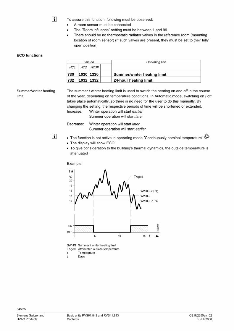
84/235
Siemens Switzerland Basic units RVS61.843 and RVS41.813 CE1U2355en_02 HVAC Products Contents 3. Juli 2008
To assure this function, following must be observed: • A room sensor must be connected • The ”Room influence“ setting must be between 1 and 99 • There should be no thermostatic radiator valves in the reference room (mounting
location of room sensor) (If such valves are present, they must be set to their fully open position)
ECO functions
Line no. Operating line
HC1 HC2 HC3P
730 1030 1330 Summer/winter heating limit 732 1032 1332 24-hour heating limit The summer / winter heating limit is used to switch the heating on and off in the course of the year, depending on temperature conditions. In Automatic mode, switching on / off takes place automatically, so there is no need for the user to do this manually. By changing the setting, the respective periods of time will be shortened or extended. Increase: Winter operation will start earlier
Summer operation will start later
Decrease: Winter operation will start later Summer operation will start earlier
• The function is not active in operating mode ”Continuously nominal temperature“ • The display will show ECO • To give consideration to the building’s thermal dynamics, the outside temperature is
attenuated Example:
SWHG Summer / winter heating limit TAged Attenuated outside temperature t Temperature t Days
Summer/winter heating limit
ON
17
T
SWHG
TAged°C
OFFt
2358
Z08
SWHG +1 °C
SWHG -1 °C16
18
19
20
50 10 15
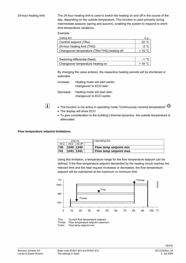
85/235
Siemens Schweiz AG Basic units RVS61.843 and RVS41.813 CE1U2355en_02 Landis & Staefa Division The settings in detail 3. Juli 2008
The 24-hour heating limit is used to switch the heating on and off in the course of the day, depending on the outside temperature. This function is used primarily during intermediate seasons (spring and autumn), enabling the system to respond to short-time temperature variations..
Example: Setting line E.g.
Comfort setpoint (TRw) 22 °C 24-hour heating limit (THG) -3 °C Changeover temperature (TRw-THG) heating off = 19 °C
Switching differential (fixed) -1 °C Changeover temperature heating on = 18 °C
By changing the value entered, the respective heating periods will be shortened or extended.
Increase: Heating mode will start earlier, changeover to ECO later.
Decrease: Heating mode will start later, changeover to ECO earlier.
• The function is not active in operating mode ”Continuously nominal temperature“ • The display will show ECO • To give consideration to the building’s thermal dynamics, the outside temperature is
attenuated
Flow temperature setpoint limitations
Line no. Operating line
HC1 HC2 HC3P 740 1040 1340 Flow temp setpoint min 741 1041 1341 Flow temp setpoint max Using this limitation, a temperature range for the flow temperature setpoint can be defined. If the flow temperature setpoint demanded by the heating circuit reaches the relevant limit and the heat request increases or decreases, the flow temperature setpoint will be maintained at the maximum or minimum limit.
TVw Current flow temperature setpoint TVmax Flow temperature setpoint maximum Tvmin Flow temp setpoint min
24-hour heating limit
0 10 20 30 40 50 60 70 80 90 100
TV
max
min
akt
°C
2358
Z09
TVw
TVmin
TVmax
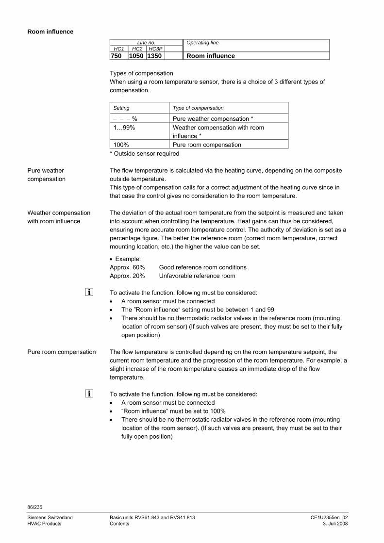
86/235
Siemens Switzerland Basic units RVS61.843 and RVS41.813 CE1U2355en_02 HVAC Products Contents 3. Juli 2008
Room influence
Line no. Operating line HC1 HC2 HC3P
750 1050 1350 Room influence Types of compensation When using a room temperature sensor, there is a choice of 3 different types of compensation.
Setting Type of compensation
− − − % Pure weather compensation * 1…99% Weather compensation with room
influence * 100% Pure room compensation
* Outside sensor required The flow temperature is calculated via the heating curve, depending on the composite outside temperature. This type of compensation calls for a correct adjustment of the heating curve since in that case the control gives no consideration to the room temperature. The deviation of the actual room temperature from the setpoint is measured and taken into account when controlling the temperature. Heat gains can thus be considered, ensuring more accurate room temperature control. The authority of deviation is set as a percentage figure. The better the reference room (correct room temperature, correct mounting location, etc.) the higher the value can be set.
• Example: Approx. 60% Good reference room conditions Approx. 20% Unfavorable reference room To activate the function, following must be considered: • A room sensor must be connected • The ”Room influence“ setting must be between 1 and 99 • There should be no thermostatic radiator valves in the reference room (mounting
location of room sensor) (If such valves are present, they must be set to their fully open position)
The flow temperature is controlled depending on the room temperature setpoint, the current room temperature and the progression of the room temperature. For example, a slight increase of the room temperature causes an immediate drop of the flow temperature. To activate the function, following must be considered: • A room sensor must be connected • “Room influence“ must be set to 100% • There should be no thermostatic radiator valves in the reference room (mounting
location of the room sensor). (If such valves are present, they must be set to their fully open position)
Pure weather compensation
Weather compensation with room influence
Pure room compensation
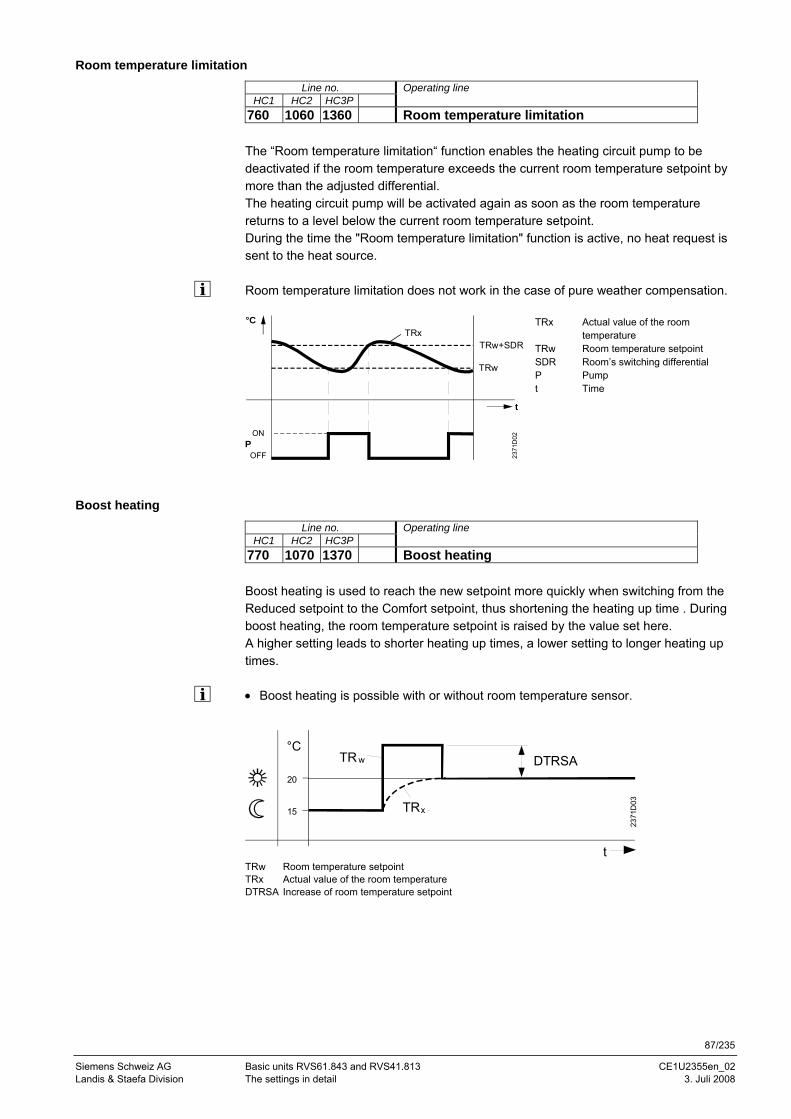
87/235
Siemens Schweiz AG Basic units RVS61.843 and RVS41.813 CE1U2355en_02 Landis & Staefa Division The settings in detail 3. Juli 2008
Room temperature limitation
Line no. Operating line HC1 HC2 HC3P
760 1060 1360 Room temperature limitation The “Room temperature limitation“ function enables the heating circuit pump to be deactivated if the room temperature exceeds the current room temperature setpoint by more than the adjusted differential. The heating circuit pump will be activated again as soon as the room temperature returns to a level below the current room temperature setpoint. During the time the "Room temperature limitation" function is active, no heat request is sent to the heat source. Room temperature limitation does not work in the case of pure weather compensation.
OFF
ONP
°CTRx
TRw+SDR
2371
D02
TRw
t
TRx Actual value of the room temperature
TRw Room temperature setpoint SDR Room’s switching differential P Pump t Time
Boost heating
Line no. Operating line HC1 HC2 HC3P
770 1070 1370 Boost heating Boost heating is used to reach the new setpoint more quickly when switching from the Reduced setpoint to the Comfort setpoint, thus shortening the heating up time . During boost heating, the room temperature setpoint is raised by the value set here. A higher setting leads to shorter heating up times, a lower setting to longer heating up times. • Boost heating is possible with or without room temperature sensor.
TRw Room temperature setpoint TRx Actual value of the room temperature DTRSA Increase of room temperature setpoint
20
15
°C
t
TR w
TRx
2371
D03
DTRSA
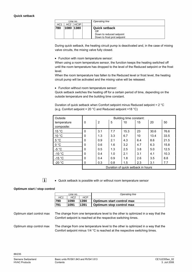
88/235
Siemens Switzerland Basic units RVS61.843 and RVS41.813 CE1U2355en_02 HVAC Products Contents 3. Juli 2008
Quick setback
Line no. Operating line HC1 HC2 HC3P
780 1080 1380 Quick setback Off Down to reduced setpoint Down to frost prot setpoint
During quick setback, the heating circuit pump is deactivated and, in the case of mixing valve circuits, the mixing valve fully closed. • Function with room temperature sensor: When using a room temperature sensor, the function keeps the heating switched off until the room temperature has dropped to the level of the Reduced setpoint or the frost level. When the room temperature has fallen to the Reduced level or frost level, the heating circuit pump will be activated and the mixing valve will be released. • Function without room temperature sensor: Quick setback switches the heating off for a certain period of time, depending on the outside temperature and the building time constant. Duration of quick setback when Comfort setpoint minus Reduced setpoint = 2 °C (e.g. Comfort setpoint = 20 °C and Reduced setpoint =18 °C)
Building time constant: Outside temperature composite:
0 2 5 10 15 20 50
15 °C 0 3.1 7.7 15.3 23 30.6 76.6 10 °C 0 1.3 3.3 6.7 10 13.4 33.5 5 °C 0 0.9 2.1 4.3 6.4 8.6 21.5 0 °C 0 0.6 1.6 3.2 4.7 6.3 15.8 -5 °C 0 0.5 1.3 2.5 3.8 5.0 12.5 -10 °C 0 0.4 1.0 2.1 3.1 4.1 10.3 -15 °C 0 0.4 0.9 1.8 2.6 3.5 8.8 -20 °C 0 0.3 0.8 1.5 2.3 3.1 7.7 Duration of quick setback in hours • Quick setback is possible with or without room temperature sensor
Optimum start / stop control
Line no. Operating line HC1 HC2 HCP
790 1090 1390 Optimum start control max 791 1091 1391 Optimum stop control max The change from one temperature level to the other is optimized in a way that the Comfort setpoint is reached at the respective switching times. The change from one temperature level to the other is optimized in a way that the Comfort setpoint minus 1/4 °C is reached at the respective switching times.
Optimum start control max
Optimum stop control max
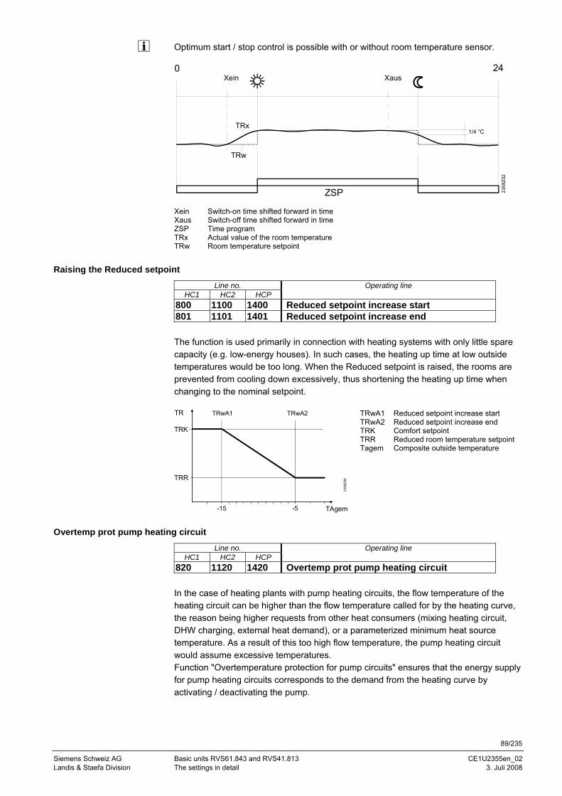
89/235
Siemens Schweiz AG Basic units RVS61.843 and RVS41.813 CE1U2355en_02 Landis & Staefa Division The settings in detail 3. Juli 2008
Optimum start / stop control is possible with or without room temperature sensor.
Xein Switch-on time shifted forward in time Xaus Switch-off time shifted forward in time ZSP Time program TRx Actual value of the room temperature TRw Room temperature setpoint
Raising the Reduced setpoint
Line no. Operating line HC1 HC2 HCP
800 1100 1400 Reduced setpoint increase start 801 1101 1401 Reduced setpoint increase end The function is used primarily in connection with heating systems with only little spare capacity (e.g. low-energy houses). In such cases, the heating up time at low outside temperatures would be too long. When the Reduced setpoint is raised, the rooms are prevented from cooling down excessively, thus shortening the heating up time when changing to the nominal setpoint.
2358
Z06
-15 -5
TR
TRK
TAgem
TRwA2TRwA1
TRR
TRwA1 Reduced setpoint increase start TRwA2 Reduced setpoint increase end TRK Comfort setpoint TRR Reduced room temperature setpoint Tagem Composite outside temperature
Overtemp prot pump heating circuit
Line no. Operating line HC1 HC2 HCP
820 1120 1420 Overtemp prot pump heating circuit In the case of heating plants with pump heating circuits, the flow temperature of the heating circuit can be higher than the flow temperature called for by the heating curve, the reason being higher requests from other heat consumers (mixing heating circuit, DHW charging, external heat demand), or a parameterized minimum heat source temperature. As a result of this too high flow temperature, the pump heating circuit would assume excessive temperatures. Function "Overtemperature protection for pump circuits" ensures that the energy supply for pump heating circuits corresponds to the demand from the heating curve by activating / deactivating the pump.
0 24
2358
Z02
Xein Xaus
TRx
TRw
ZSP
1/4 °C
90/235
Siemens Switzerland Basic units RVS61.843 and RVS41.813 CE1U2355en_02 HVAC Products Contents 3. Juli 2008
Important: The function may only be activated in plants with buffer or combi storage tanks. In the case of plants without storage tank, there is a risk of a compressor being in operation without having a consumer pump running.
Mixing valve control
Line no. Operating line HC1 HC2
830 1130 Mixing valve boost 832 1132 Actuator type
2-position ¦ 3-position 833 1133 Switching differential 2-pos 834 1134 Actuator running time The controller adds the mixing valve boost set here to the current flow temperature setpoint and uses the value as the temperature setpoint for heat generation. 2-position The controller drives the actuator with only one relay output. When the output delivers a signal, the valve opens. When there is no signal, the valve closes automatically.
3-position The controller drives the actuator with 2 relay outputs. One of the outputs is used for opening the valve, the other for closing the valve. For the 2-position actuator, the "2-position switching differential" must also be adapted. The switching differential has no impact on 3-position actuators. For the 3-position actuator, the running time of the mixing valve actuator can be adjusted. The actuator running time has no impact on 2-position actuators.
Floor curing function
The floor curing function serves for controlled drying of the floor. It controls the flow temperature according to a certain temperature profile. Drying of the floor is ensured via the floor heating system by the mixing or pump heating circuit. • Observe the relevant standards and regulations of the company supplying the floor! • Proper functioning is ensured only when the plant is correctly installed (hydraulic
system, electrical installation, settings)! If not observed, the floor might get damaged!
• The function can be aborted prematurely by selecting Off • Maximum limitation of the flow temperature remains active
Mixing valve boost
Actuator type
Switching differential 2-pos
Actuator running time
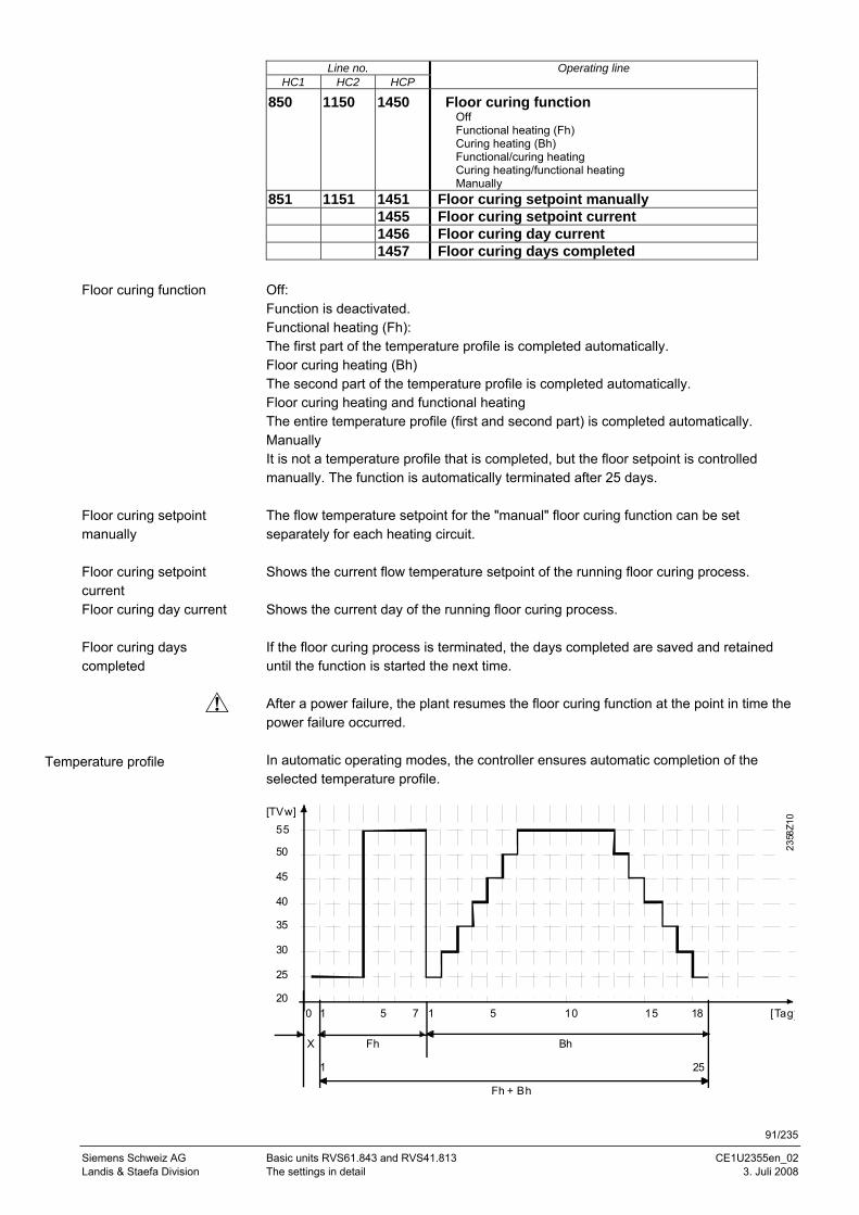
91/235
Siemens Schweiz AG Basic units RVS61.843 and RVS41.813 CE1U2355en_02 Landis & Staefa Division The settings in detail 3. Juli 2008
Line no. Operating line HC1 HC2 HCP
850 1150 1450 Floor curing function Off Functional heating (Fh) Curing heating (Bh) Functional/curing heating Curing heating/functional heating Manually
851 1151 1451 Floor curing setpoint manually 1455 Floor curing setpoint current 1456 Floor curing day current 1457 Floor curing days completed Off: Function is deactivated. Functional heating (Fh): The first part of the temperature profile is completed automatically. Floor curing heating (Bh) The second part of the temperature profile is completed automatically. Floor curing heating and functional heating The entire temperature profile (first and second part) is completed automatically. Manually It is not a temperature profile that is completed, but the floor setpoint is controlled manually. The function is automatically terminated after 25 days. The flow temperature setpoint for the "manual" floor curing function can be set separately for each heating circuit. Shows the current flow temperature setpoint of the running floor curing process. Shows the current day of the running floor curing process. If the floor curing process is terminated, the days completed are saved and retained until the function is started the next time. After a power failure, the plant resumes the floor curing function at the point in time the power failure occurred. In automatic operating modes, the controller ensures automatic completion of the selected temperature profile.
50
45
40
35
30
205 10 15 18 [Tag]0
25
55
Fh Bh
1 15 7
X
Fh + Bh
1 25
2358
Z10[TVw]
Floor curing function
Floor curing setpoint manually
Floor curing setpoint current Floor curing day current
Floor curing days completed
Temperature profile
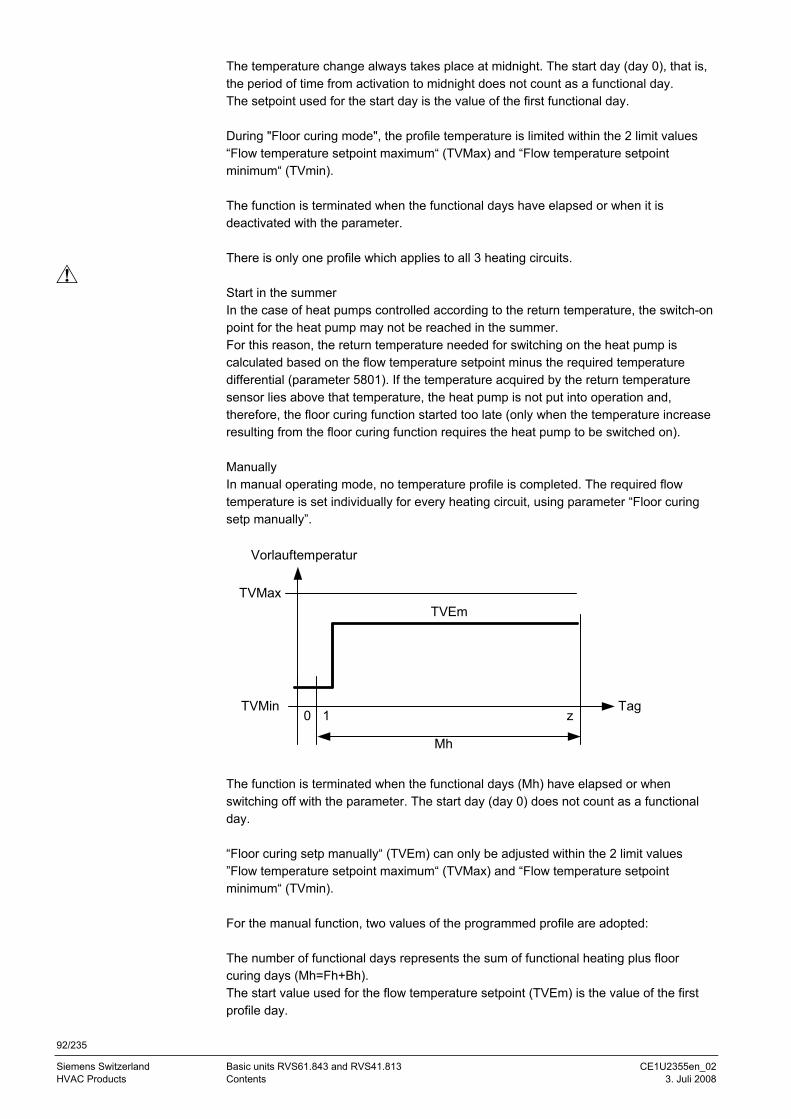
92/235
Siemens Switzerland Basic units RVS61.843 and RVS41.813 CE1U2355en_02 HVAC Products Contents 3. Juli 2008
The temperature change always takes place at midnight. The start day (day 0), that is, the period of time from activation to midnight does not count as a functional day. The setpoint used for the start day is the value of the first functional day. During "Floor curing mode", the profile temperature is limited within the 2 limit values “Flow temperature setpoint maximum“ (TVMax) and “Flow temperature setpoint minimum“ (TVmin). The function is terminated when the functional days have elapsed or when it is deactivated with the parameter. There is only one profile which applies to all 3 heating circuits. Start in the summer In the case of heat pumps controlled according to the return temperature, the switch-on point for the heat pump may not be reached in the summer. For this reason, the return temperature needed for switching on the heat pump is calculated based on the flow temperature setpoint minus the required temperature differential (parameter 5801). If the temperature acquired by the return temperature sensor lies above that temperature, the heat pump is not put into operation and, therefore, the floor curing function started too late (only when the temperature increase resulting from the floor curing function requires the heat pump to be switched on). Manually In manual operating mode, no temperature profile is completed. The required flow temperature is set individually for every heating circuit, using parameter “Floor curing setp manually”.
Vorlauftemperatur
Tag
Mh
TVMax
0 1 zTVMin
TVEm
The function is terminated when the functional days (Mh) have elapsed or when switching off with the parameter. The start day (day 0) does not count as a functional day. “Floor curing setp manually“ (TVEm) can only be adjusted within the 2 limit values ”Flow temperature setpoint maximum“ (TVMax) and “Flow temperature setpoint minimum“ (TVmin). For the manual function, two values of the programmed profile are adopted: The number of functional days represents the sum of functional heating plus floor curing days (Mh=Fh+Bh). The start value used for the flow temperature setpoint (TVEm) is the value of the first profile day.
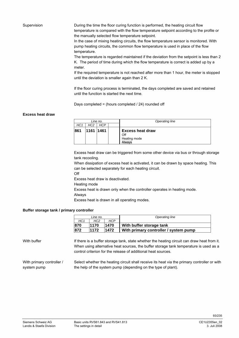
93/235
Siemens Schweiz AG Basic units RVS61.843 and RVS41.813 CE1U2355en_02 Landis & Staefa Division The settings in detail 3. Juli 2008
During the time the floor curing function is performed, the heating circuit flow temperature is compared with the flow temperature setpoint according to the profile or the manually selected flow temperature setpoint. In the case of mixing heating circuits, the flow temperature sensor is monitored. With pump heating circuits, the common flow temperature is used in place of the flow temperature. The temperature is regarded maintained if the deviation from the setpoint is less than 2 K. The period of time during which the flow temperature is correct is added up by a meter. If the required temperature is not reached after more than 1 hour, the meter is stopped until the deviation is smaller again than 2 K. If the floor curing process is terminated, the days completed are saved and retained until the function is started the next time. Days completed = (hours completed / 24) rounded off
Excess heat draw
Line no. Operating line HC1 HC2 HCP
861 1161 1461 Excess heat draw Off Heating mode Always
Excess heat draw can be triggered from some other device via bus or through storage tank recooling. When dissipation of excess heat is activated, it can be drawn by space heating. This can be selected separately for each heating circuit. Off Excess heat draw is deactivated. Heating mode Excess heat is drawn only when the controller operates in heating mode. Always Excess heat is drawn in all operating modes.
Buffer storage tank / primary controller
Line no. Operating line HC1 HC2 HCP
870 1170 1470 With buffer storage tank 872 1172 1472 With primary controller / system pump If there is a buffer storage tank, state whether the heating circuit can draw heat from it. When using alternative heat sources, the buffer storage tank temperature is used as a control criterion for the release of additional heat sources. Select whether the heating circuit shall receive its heat via the primary controller or with the help of the system pump (depending on the type of plant).
Supervision
With buffer
With primary controller / system pump
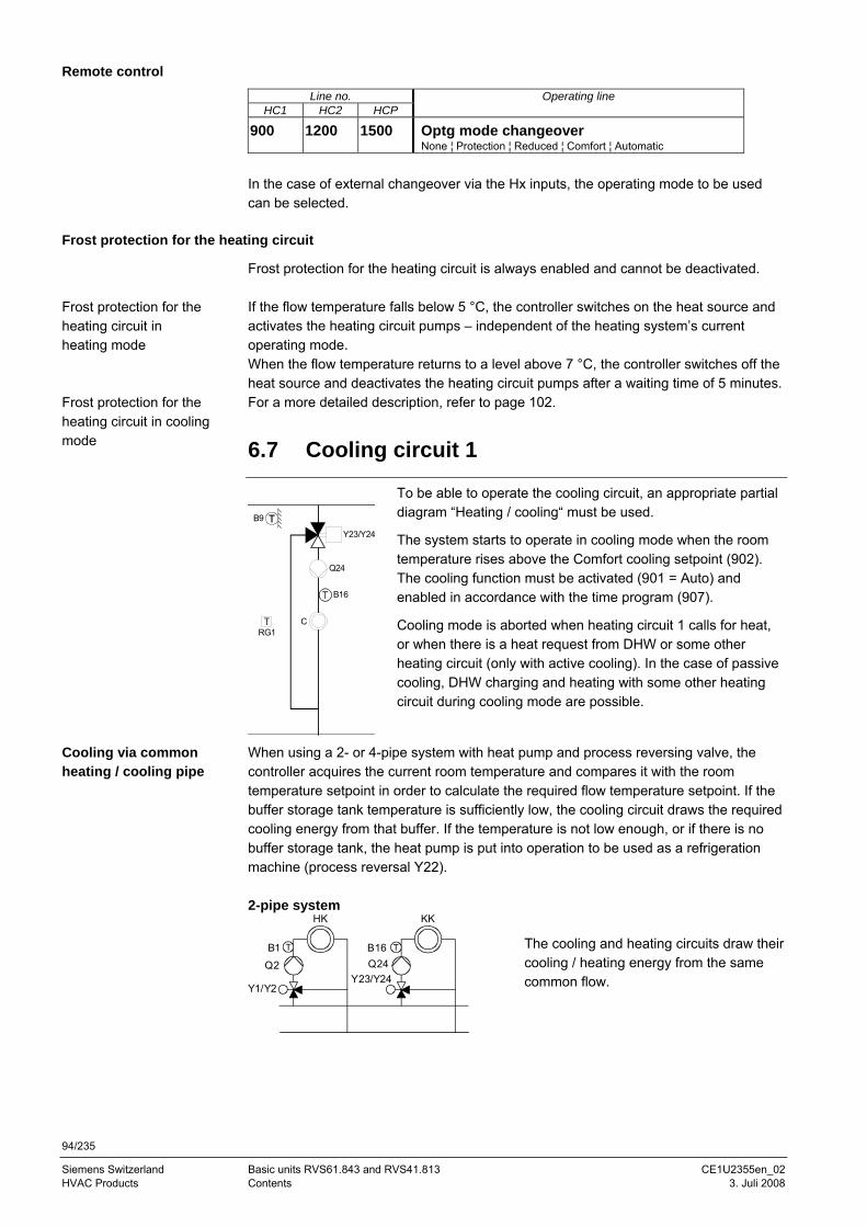
94/235
Siemens Switzerland Basic units RVS61.843 and RVS41.813 CE1U2355en_02 HVAC Products Contents 3. Juli 2008
Remote control
Line no. Operating line HC1 HC2 HCP
900 1200 1500 Optg mode changeover None ¦ Protection ¦ Reduced ¦ Comfort ¦ Automatic
In the case of external changeover via the Hx inputs, the operating mode to be used can be selected.
Frost protection for the heating circuit
Frost protection for the heating circuit is always enabled and cannot be deactivated. If the flow temperature falls below 5 °C, the controller switches on the heat source and activates the heating circuit pumps – independent of the heating system’s current operating mode. When the flow temperature returns to a level above 7 °C, the controller switches off the heat source and deactivates the heating circuit pumps after a waiting time of 5 minutes. For a more detailed description, refer to page 102.
6.7 Cooling circuit 1
RG1
B9
Y23/Y24
B16
Q24
C
To be able to operate the cooling circuit, an appropriate partial diagram “Heating / cooling“ must be used.
The system starts to operate in cooling mode when the room temperature rises above the Comfort cooling setpoint (902). The cooling function must be activated (901 = Auto) and enabled in accordance with the time program (907).
Cooling mode is aborted when heating circuit 1 calls for heat, or when there is a heat request from DHW or some other heating circuit (only with active cooling). In the case of passive cooling, DHW charging and heating with some other heating circuit during cooling mode are possible.
When using a 2- or 4-pipe system with heat pump and process reversing valve, the controller acquires the current room temperature and compares it with the room temperature setpoint in order to calculate the required flow temperature setpoint. If the buffer storage tank temperature is sufficiently low, the cooling circuit draws the required cooling energy from that buffer. If the temperature is not low enough, or if there is no buffer storage tank, the heat pump is put into operation to be used as a refrigeration machine (process reversal Y22). 2-pipe system
Q2
HK
T
Y1/Y2
B1Q24
KK
T
Y23/Y24
B16
The cooling and heating circuits draw their cooling / heating energy from the same common flow.
Frost protection for the heating circuit in heating mode
Frost protection for the heating circuit in cooling mode
Cooling via common heating / cooling pipe
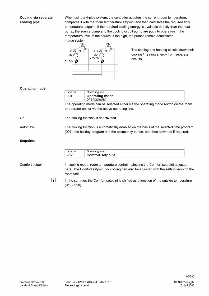
95/235
Siemens Schweiz AG Basic units RVS61.843 and RVS41.813 CE1U2355en_02 Landis & Staefa Division The settings in detail 3. Juli 2008
When using a 4-pipe system, the controller acquires the current room temperature, compares it with the room temperature setpoint and then calculates the required flow temperature setpoint. If the required cooling energy is available directly from the heat pump, the source pump and the cooling circuit pump are put into operation. If the temperature level of the source is too high, the pumps remain deactivated. 4-pipe system
Q2
HK
T
Y1/Y2
B1Q24
KK
T
Y23/Y24
B16
The cooling and heating circuits draw their cooling / heating energy from separate circuits.
Line no. Operating line 901 Operating mode
Off ¦ Automatic*
The operating mode can be selected either via the operating mode button on the room or operator unit or via the above operating line. The cooling function is deactivated. The cooling function is automatically enabled on the basis of the selected time program (907), the holiday program and the occupancy button, and then activated if required.
Setpoints
Line no. Operating line 902 Comfort setpoint
In cooling mode, room temperature control maintains the Comfort setpoint adjusted here. The Comfort setpoint for cooling can also be adjusted with the setting knob on the room unit.
In the summer, the Comfort setpoint is shifted as a function of the outside temperature (918 - 920).
Cooling via separate cooling pipe
Operating mode
Off
Automatic
Comfort setpoint
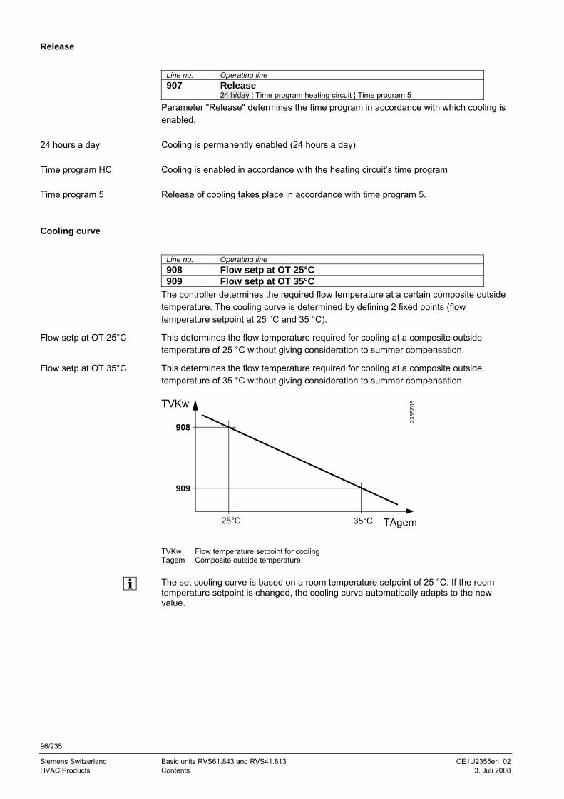
96/235
Siemens Switzerland Basic units RVS61.843 and RVS41.813 CE1U2355en_02 HVAC Products Contents 3. Juli 2008
Release
Line no. Operating line 907 Release
24 h/day ¦ Time program heating circuit ¦ Time program 5
Parameter "Release" determines the time program in accordance with which cooling is enabled. Cooling is permanently enabled (24 hours a day) Cooling is enabled in accordance with the heating circuit’s time program Release of cooling takes place in accordance with time program 5.
Cooling curve
Line no. Operating line 908 Flow setp at OT 25°C 909 Flow setp at OT 35°C
The controller determines the required flow temperature at a certain composite outside temperature. The cooling curve is determined by defining 2 fixed points (flow temperature setpoint at 25 °C and 35 °C).
This determines the flow temperature required for cooling at a composite outside temperature of 25 °C without giving consideration to summer compensation.
This determines the flow temperature required for cooling at a composite outside temperature of 35 °C without giving consideration to summer compensation.
TVKw Flow temperature setpoint for cooling Tagem Composite outside temperature The set cooling curve is based on a room temperature setpoint of 25 °C. If the room temperature setpoint is changed, the cooling curve automatically adapts to the new value.
24 hours a day
Time program HC
Time program 5
Flow setp at OT 25°C
Flow setp at OT 35°C
TVKw
35°C TAgem
2355
Z06
25°C
909
908
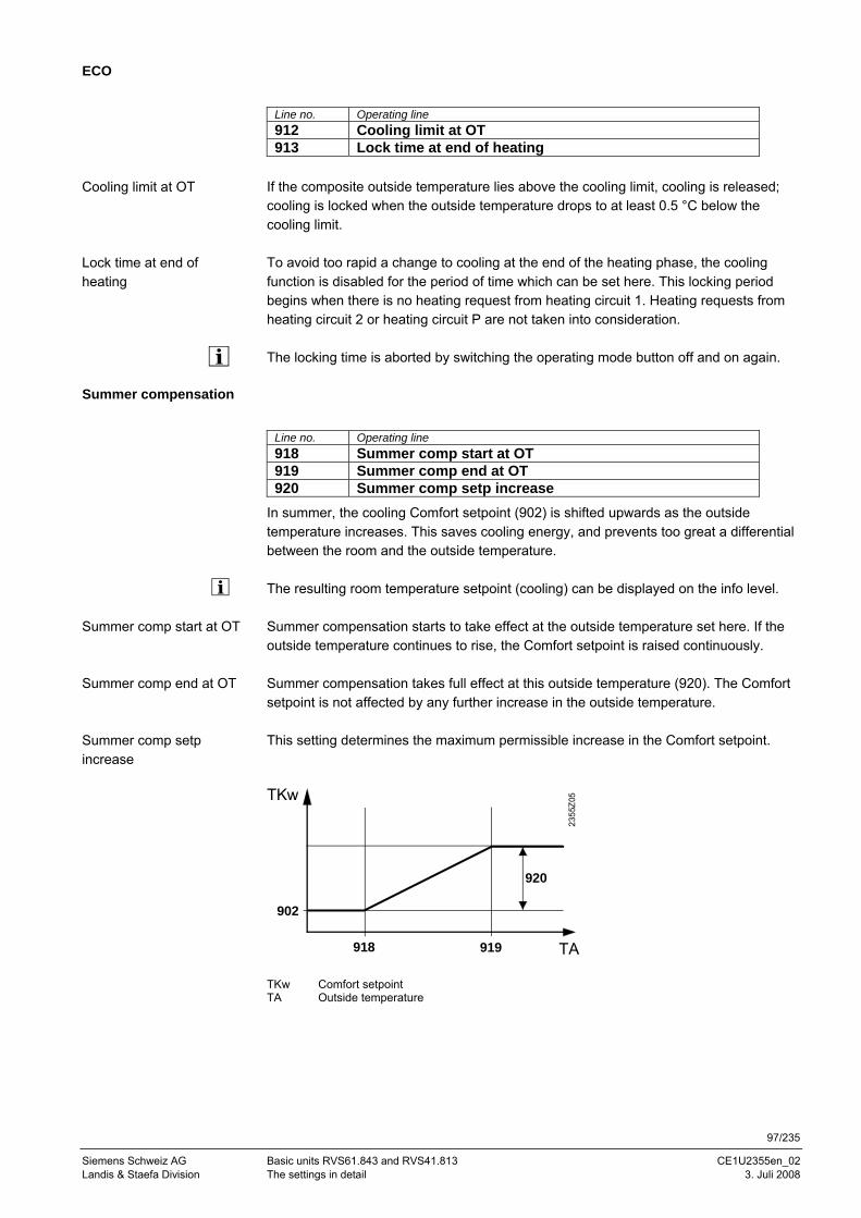
97/235
Siemens Schweiz AG Basic units RVS61.843 and RVS41.813 CE1U2355en_02 Landis & Staefa Division The settings in detail 3. Juli 2008
ECO
Line no. Operating line 912 Cooling limit at OT 913 Lock time at end of heating
If the composite outside temperature lies above the cooling limit, cooling is released; cooling is locked when the outside temperature drops to at least 0.5 °C below the cooling limit. To avoid too rapid a change to cooling at the end of the heating phase, the cooling function is disabled for the period of time which can be set here. This locking period begins when there is no heating request from heating circuit 1. Heating requests from heating circuit 2 or heating circuit P are not taken into consideration. The locking time is aborted by switching the operating mode button off and on again.
Summer compensation
Line no. Operating line 918 Summer comp start at OT 919 Summer comp end at OT 920 Summer comp setp increase
In summer, the cooling Comfort setpoint (902) is shifted upwards as the outside temperature increases. This saves cooling energy, and prevents too great a differential between the room and the outside temperature. The resulting room temperature setpoint (cooling) can be displayed on the info level. Summer compensation starts to take effect at the outside temperature set here. If the outside temperature continues to rise, the Comfort setpoint is raised continuously. Summer compensation takes full effect at this outside temperature (920). The Comfort setpoint is not affected by any further increase in the outside temperature. This setting determines the maximum permissible increase in the Comfort setpoint. TKw
920
919 TA
2355
Z05
918
902
TKw Comfort setpoint TA Outside temperature
Cooling limit at OT
Lock time at end of heating
Summer comp start at OT
Summer comp end at OT
Summer comp setp increase
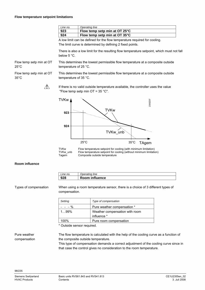
98/235
Siemens Switzerland Basic units RVS61.843 and RVS41.813 CE1U2355en_02 HVAC Products Contents 3. Juli 2008
Flow temperature setpoint limitations
Line no. Operating line 923 Flow temp setp min at OT 25°C 924 Flow temp setp min at OT 35°C
A low limit can be defined for the flow temperature required for cooling. The limit curve is determined by defining 2 fixed points.
There is also a low limit for the resulting flow temperature setpoint, which must not fall below 5 °C.
This determines the lowest permissible flow temperature at a composite outside temperature of 25 °C.
This determines the lowest permissible flow temperature at a composite outside temperature of 35 °C. If there is no valid outside temperature available, the controller uses the value "Flow temp setp min OT = 35 °C". TVKw
35°C TAgem23
55Z0
7
25°C
924
923TVKw
TVKw_unb
TVKw Flow temperature setpoint for cooling (with minimum limitation) TVKw_unb Flow temperature setpoint for cooling (without minimum limitation) Tagem Composite outside temperature
Room influence
Line no. Operating line 928 Room influence
When using a room temperature sensor, there is a choice of 3 different types of compensation.
Setting Type of compensation
− − − % Pure weather compensation * 1…99% Weather compensation with room
influence * 100% Pure room compensation
* Outside sensor required. The flow temperature is calculated with the help of the cooling curve as a function of the composite outside temperature. This type of compensation demands a correct adjustment of the cooling curve since in that case the control gives no consideration to the room temperature.
Flow temp setp min at OT 25°C
Flow temp setp min at OT 35°C
Types of compensation
Pure weather compensation
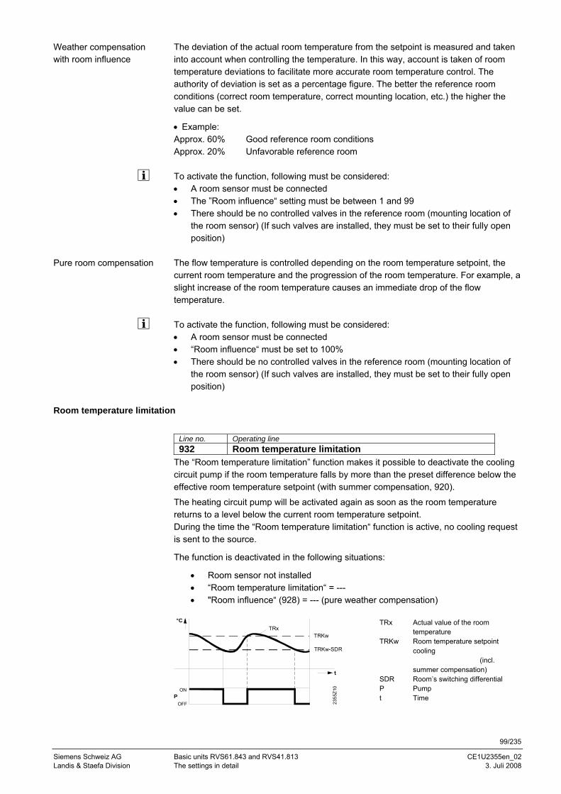
99/235
Siemens Schweiz AG Basic units RVS61.843 and RVS41.813 CE1U2355en_02 Landis & Staefa Division The settings in detail 3. Juli 2008
The deviation of the actual room temperature from the setpoint is measured and taken into account when controlling the temperature. In this way, account is taken of room temperature deviations to facilitate more accurate room temperature control. The authority of deviation is set as a percentage figure. The better the reference room conditions (correct room temperature, correct mounting location, etc.) the higher the value can be set.
• Example: Approx. 60% Good reference room conditions Approx. 20% Unfavorable reference room To activate the function, following must be considered: • A room sensor must be connected • The ”Room influence“ setting must be between 1 and 99 • There should be no controlled valves in the reference room (mounting location of
the room sensor) (If such valves are installed, they must be set to their fully open position)
The flow temperature is controlled depending on the room temperature setpoint, the current room temperature and the progression of the room temperature. For example, a slight increase of the room temperature causes an immediate drop of the flow temperature. To activate the function, following must be considered: • A room sensor must be connected • “Room influence“ must be set to 100% • There should be no controlled valves in the reference room (mounting location of
the room sensor) (If such valves are installed, they must be set to their fully open position)
Room temperature limitation
Line no. Operating line 932 Room temperature limitation
The “Room temperature limitation” function makes it possible to deactivate the cooling circuit pump if the room temperature falls by more than the preset difference below the effective room temperature setpoint (with summer compensation, 920).
The heating circuit pump will be activated again as soon as the room temperature returns to a level below the current room temperature setpoint. During the time the “Room temperature limitation“ function is active, no cooling request is sent to the source.
The function is deactivated in the following situations:
• Room sensor not installed • “Room temperature limitation“ = --- • "Room influence“ (928) = --- (pure weather compensation)
ON
TRKw-SDR
2355
Z10
TRKwTRx
POFF
°C
TRx Actual value of the room temperature
TRKw Room temperature setpoint cooling (incl. summer compensation)
SDR Room’s switching differential P Pump t Time
Weather compensation with room influence
Pure room compensation
100/235
Siemens Switzerland Basic units RVS61.843 and RVS41.813 CE1U2355en_02 HVAC Products Contents 3. Juli 2008
Mixing valve control
Line no. Operating line 938 Mixing valve decrease 939 Actuator type
2-position ¦ 3-position 940 Switching differential 2-pos 941 Actuator running time 945 Mixing valve in heating mode
Control ¦ Open
The refrigeration request from the mixing valve circuit to the source is reduced by the preset value. The purpose of this reduction is to enable the mixing valve controller to compensate for the variation in temperature caused by the source (2-position control). 2-position The controller drives the actuator with only one relay output. When the output delivers a signal, the valve opens. When there is no signal, the valve closes automatically.
3-position The controller drives the actuator with 2 relay outputs. One of the outputs is used for opening the valve, the other for closing the valve. For the 2-position actuator, the "2-position switching differential" must also be adapted. The switching differential has no impact on 3-position actuators. For the 3-position actuator, the running time of the mixing valve actuator can be adjusted. The actuator running time has no impact on 2-position actuators. This defines the position of mixing valve 1 (Y1 / Y2) when heating mode is active. This parameter has no impact on systems with hydraulically separate heating and cooling circuits. Control The valve provides control in heating and cooling mode. Open The valve is used for control in cooling mode, it is open in heating
mode.
Dewpoint supervision
Line no. Operating line 946 Lock time dewpoint limiter 947 Flow temp setp incr hygro 948 Flow setp incr start at r.h. 950 Flow temp diff dewpoint
When the connected dewpoint limiter detects the formation of condensation, it closes its contact, thereby deactivating cooling. The "Lock time dewpoint limiter" set here starts running as soon as the contact reopens. Cooling can only start after expiry of this locking time.
The dewpoint limiter must be assigned to one of the Hx inputs as a “Dewpoint limiter”.
Mixing valve decrease
Actuator type
Switching differential 2-pos
Actuator running time
Mixing valve in heating mode
Lock time dewpoint limiter
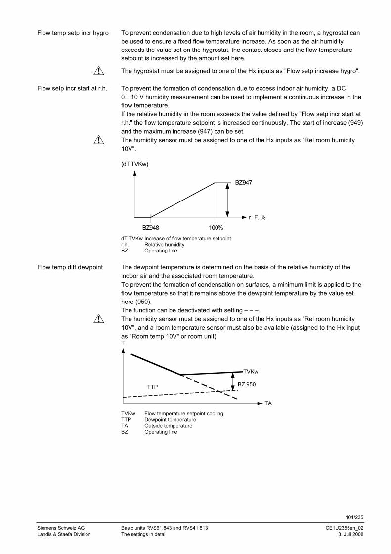
101/235
Siemens Schweiz AG Basic units RVS61.843 and RVS41.813 CE1U2355en_02 Landis & Staefa Division The settings in detail 3. Juli 2008
To prevent condensation due to high levels of air humidity in the room, a hygrostat can be used to ensure a fixed flow temperature increase. As soon as the air humidity exceeds the value set on the hygrostat, the contact closes and the flow temperature setpoint is increased by the amount set here.
The hygrostat must be assigned to one of the Hx inputs as "Flow setp increase hygro". To prevent the formation of condensation due to excess indoor air humidity, a DC 0…10 V humidity measurement can be used to implement a continuous increase in the flow temperature. If the relative humidity in the room exceeds the value defined by "Flow setp incr start at r.h." the flow temperature setpoint is increased continuously. The start of increase (949) and the maximum increase (947) can be set. The humidity sensor must be assigned to one of the Hx inputs as "Rel room humidity 10V".
r. F. %
(dT TVKw)
BZ948
BZ947
100% dT TVKw Increase of flow temperature setpoint r.h. Relative humidity BZ Operating line The dewpoint temperature is determined on the basis of the relative humidity of the indoor air and the associated room temperature. To prevent the formation of condensation on surfaces, a minimum limit is applied to the flow temperature so that it remains above the dewpoint temperature by the value set here (950). The function can be deactivated with setting – – –. The humidity sensor must be assigned to one of the Hx inputs as "Rel room humidity 10V", and a room temperature sensor must also be available (assigned to the Hx input as "Room temp 10V" or room unit).
TA
TVKw
TTP
T
BZ 950
TVKw Flow temperature setpoint cooling TTP Dewpoint temperature TA Outside temperature BZ Operating line
Flow temp setp incr hygro
Flow setp incr start at r.h.
Flow temp diff dewpoint
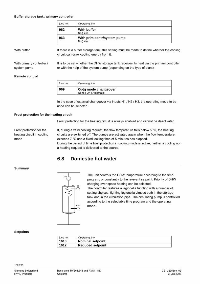
102/235
Siemens Switzerland Basic units RVS61.843 and RVS41.813 CE1U2355en_02 HVAC Products Contents 3. Juli 2008
Buffer storage tank / primary controller
Line no. Operating line
962 With buffer No ¦ Yes
963 With prim contr/system pump No ¦ Yes
If there is a buffer storage tank, this setting must be made to define whether the cooling circuit can draw cooling energy from it. It is to be set whether the DHW storage tank receives its heat via the primary controller or with the help of the system pump (depending on the type of plant).
Remote control
Line no. Operating line
969 Optg mode changeover None ¦ Off ¦ Automatic
In the case of external changeover via inputs H1 / H2 / H3, the operating mode to be used can be selected.
Frost protection for the heating circuit
Frost protection for the heating circuit is always enabled and cannot be deactivated. If, during a valid cooling request, the flow temperature falls below 5 °C, the heating circuits are switched off. The pumps are activated again when the flow temperature exceeds 7 °C and a fixed locking time of 5 minutes has elapsed. During the period of time frost protection in cooling mode is active, neither a cooling nor a heating request is delivered to the source.
6.8 Domestic hot water
Summary
B3
B31
Q3
The unit controls the DHW temperature according to the time program, or constantly to the relevant setpoint. Priority of DHW charging over space heating can be selected. The controller features a legionella function with a number of setting choices, fighting legionella viruses both in the storage tank and in the circulation pipe. The circulating pump is controlled according to the selectable time program and the operating mode.
Setpoints
Line no. Operating line 1610 Nominal setpoint 1612 Reduced setpoint
With buffer
With primary controller / system pump
Frost protection for the heating circuit in cooling mode
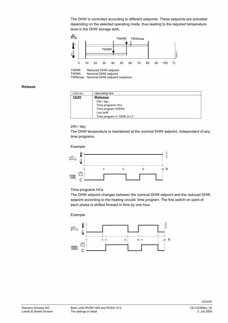
103/235
Siemens Schweiz AG Basic units RVS61.843 and RVS41.813 CE1U2355en_02 Landis & Staefa Division The settings in detail 3. Juli 2008
The DHW is controlled according to different setpoints. These setpoints are activated depending on the selected operating mode, thus leading to the required temperature level in the DHW storage tank.
TWWR Reduced DHW setpoint TWWN Nominal DHW setpoint TWWmax Nominal DHW setpoint maximum
Release
Line no. Operating line 1620 Release
24h / day Time programs HCs Time program 4/DHW Low tariff Time program 4 / DHW or LT
24h / day The DHW temperature is maintained at the nominal DHW setpoint, independent of any time programs. Example:
Time programs HCs The DHW setpoint changes between the nominal DHW setpoint and the reduced DHW setpoint according to the heating circuits’ time program. The first switch-on point of each phase is shifted forward in time by one hour. Example:
0 10 20 30 40 50 60 70 80 90 100 °C
2358
Z11
TWWR
TWWN TWWmax
0 6 12 18 24 h23
71Z1
8
0 6 12 245 h
2377
Z16
16 17
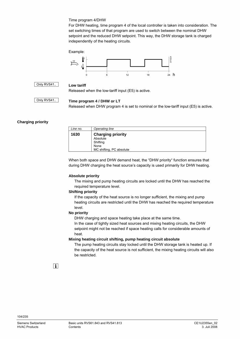
104/235
Siemens Switzerland Basic units RVS61.843 and RVS41.813 CE1U2355en_02 HVAC Products Contents 3. Juli 2008
Time program 4/DHW For DHW heating, time program 4 of the local controller is taken into consideration. The set switching times of that program are used to switch between the nominal DHW setpoint and the reduced DHW setpoint. This way, the DHW storage tank is charged independently of the heating circuits. Example:
Low tariff Released when the low-tariff input (E5) is active. Time program 4 / DHW or LT Released when DHW program 4 is set to nominal or the low-tariff input (E5) is active.
Charging priority
Line no. Operating line
1630 Charging priority Absolute Shifting None MC shifting, PC absolute
When both space and DHW demand heat, the “DHW priority“ function ensures that during DHW charging the heat source’s capacity is used primarily for DHW heating. Absolute priority
The mixing and pump heating circuits are locked until the DHW has reached the required temperature level.
Shifting priority If the capacity of the heat source is no longer sufficient, the mixing and pump heating circuits are restricted until the DHW has reached the required temperature level.
No priority DHW charging and space heating take place at the same time. In the case of tightly sized heat sources and mixing heating circuits, the DHW setpoint might not be reached if space heating calls for considerable amounts of heat.
Mixing heating circuit shifting, pump heating circuit absolute The pump heating circuits stay locked until the DHW storage tank is heated up. If the capacity of the heat source is not sufficient, the mixing heating circuits will also be restricted.
0 6 12 18 24 h
2373
Z24
Only RVS41..
Only RVS41..
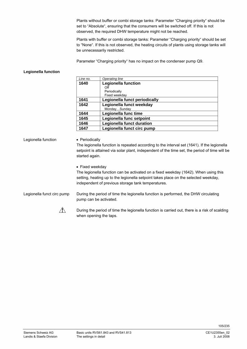
105/235
Siemens Schweiz AG Basic units RVS61.843 and RVS41.813 CE1U2355en_02 Landis & Staefa Division The settings in detail 3. Juli 2008
Plants without buffer or combi storage tanks: Parameter “Charging priority“ should be set to “Absolute“, ensuring that the consumers will be switched off. If this is not observed, the required DHW temperature might not be reached.
Plants with buffer or combi storage tanks: Parameter “Charging priority“ should be set to “None“. If this is not observed, the heating circuits of plants using storage tanks will be unnecessarily restricted. Parameter “Charging priority“ has no impact on the condenser pump Q9.
Legionella function
Line no. Operating line 1640 Legionella function
Off Periodically Fixed weekday
1641 Legionella funct periodically 1642 Legionella funct weekday
Monday…Sunday 1644 Legionella func time 1645 Legionella func setpoint 1646 Legionella funct duration 1647 Legionella funct circ pump
• Periodically The legionella function is repeated according to the interval set (1641). If the legionella setpoint is attained via solar plant, independent of the time set, the period of time will be started again. • Fixed weekday The legionella function can be activated on a fixed weekday (1642). When using this setting, heating up to the legionella setpoint takes place on the selected weekday, independent of previous storage tank temperatures. During the period of time the legionella function is performed, the DHW circulating pump can be activated. During the period of time the legionella function is carried out, there is a risk of scalding when opening the taps.
Legionella function
Legionella funct circ pump
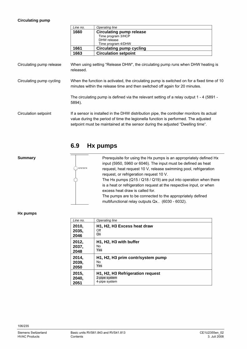
106/235
Siemens Switzerland Basic units RVS61.843 and RVS41.813 CE1U2355en_02 HVAC Products Contents 3. Juli 2008
Circulating pump
Line no. Operating line 1660 Circulating pump release
Time program 3/HCP DHW release Time program 4/DHW
1661 Circulating pump cycling 1663 Circulation setpoint
When using setting “Release DHW“, the circulating pump runs when DHW heating is released. When the function is activated, the circulating pump is switched on for a fixed time of 10 minutes within the release time and then switched off again for 20 minutes. The circulating pump is defined via the relevant setting of a relay output 1 - 4 (5891 - 5894). If a sensor is installed in the DHW distribution pipe, the controller monitors its actual value during the period of time the legionella function is performed. The adjusted setpoint must be maintained at the sensor during the adjusted “Dwelling time“.
6.9 Hx pumps
Q15/18/19
Prerequisite for using the Hx pumps is an appropriately defined Hx input (5950, 5960 or 6046). The input must be defined as heat request, heat request 10 V, release swimming pool, refrigeration request, or refrigeration request 10 V. The Hx pumps (Q15 / Q18 / Q19) are put into operation when there is a heat or refrigeration request at the respective input, or when excess heat draw is called for. The pumps are to be connected to the appropriately defined multifunctional relay outputs Qx.. (6030 - 6032).
Hx pumps
Line no. Operating line
2010, 2035, 2046
H1, H2, H3 Excess heat draw Off On
2012, 2037, 2048
H1, H2, H3 with buffer No Yes
2014, 2039, 2050
H1, H2, H3 prim contr/system pump No Yes
2015, 2040, 2051
H1, H2, H3 Refrigeration request 2-pipe system 4-pipe system
Circulating pump release
Circulating pump cycling
Circulation setpoint
Summary
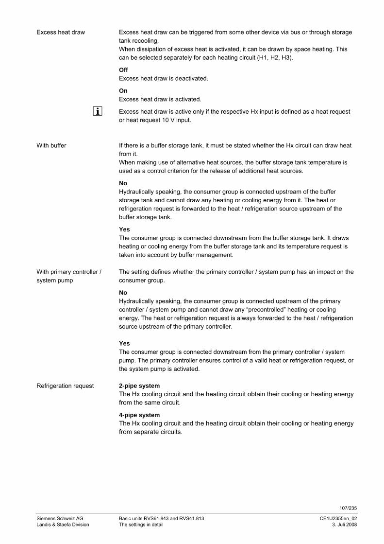
107/235
Siemens Schweiz AG Basic units RVS61.843 and RVS41.813 CE1U2355en_02 Landis & Staefa Division The settings in detail 3. Juli 2008
Excess heat draw can be triggered from some other device via bus or through storage tank recooling. When dissipation of excess heat is activated, it can be drawn by space heating. This can be selected separately for each heating circuit (H1, H2, H3).
Off Excess heat draw is deactivated.
On Excess heat draw is activated.
Excess heat draw is active only if the respective Hx input is defined as a heat request or heat request 10 V input. If there is a buffer storage tank, it must be stated whether the Hx circuit can draw heat from it. When making use of alternative heat sources, the buffer storage tank temperature is used as a control criterion for the release of additional heat sources.
No Hydraulically speaking, the consumer group is connected upstream of the buffer storage tank and cannot draw any heating or cooling energy from it. The heat or refrigeration request is forwarded to the heat / refrigeration source upstream of the buffer storage tank.
Yes The consumer group is connected downstream from the buffer storage tank. It draws heating or cooling energy from the buffer storage tank and its temperature request is taken into account by buffer management. The setting defines whether the primary controller / system pump has an impact on the consumer group.
No Hydraulically speaking, the consumer group is connected upstream of the primary controller / system pump and cannot draw any “precontrolled” heating or cooling energy. The heat or refrigeration request is always forwarded to the heat / refrigeration source upstream of the primary controller. Yes The consumer group is connected downstream from the primary controller / system pump. The primary controller ensures control of a valid heat or refrigeration request, or the system pump is activated. 2-pipe system The Hx cooling circuit and the heating circuit obtain their cooling or heating energy from the same circuit.
4-pipe system The Hx cooling circuit and the heating circuit obtain their cooling or heating energy from separate circuits.
Excess heat draw
With buffer
With primary controller / system pump
Refrigeration request
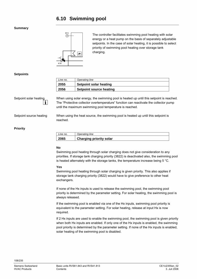
108/235
Siemens Switzerland Basic units RVS61.843 and RVS41.813 CE1U2355en_02 HVAC Products Contents 3. Juli 2008
6.10 Swimming pool
Summary
K18
10
B13
The controller facilitates swimming pool heating with solar energy or a heat pump on the basis of separately adjustable setpoints. In the case of solar heating, it is possible to select priority of swimming pool heating over storage tank charging.
Setpoints
Line no. Operating line
2055 Setpoint solar heating 2056 Setpoint source heating
When using solar energy, the swimming pool is heated up until this setpoint is reached. The “Protective collector overtemperature” function can reactivate the collector pump until the maximum swimming pool temperature is reached. When using the heat source, the swimming pool is heated up until this setpoint is reached.
Priority
Line no. Operating line
2065 Charging priority solar No Swimming pool heating through solar charging does not give consideration to any priorities. If storage tank charging priority (3822) is deactivated also, the swimming pool is heated alternately with the storage tanks, the temperature increase being 5 °C.
Yes Swimming pool heating through solar charging is given priority. This also applies if storage tank charging priority (3822) would have to give preference to other heat exchangers. If none of the Hx inputs is used to release the swimming pool, the swimming pool priority is determined by the parameter setting. For solar heating, the swimming pool is always released.
If the swimming pool is enabled via one of the Hx inputs, swimming pool priority is equivalent to the parameter setting. For solar heating, release at input Hx is now required.
If 2 Hx inputs are used to enable the swimming pool, the swimming pool is given priority when both Hx inputs are enabled. If only one of the Hx inputs is enabled, the swimming pool priority is determined by the parameter setting. If none of the Hx inputs is enabled, solar heating of the swimming pool is disabled.
Setpoint solar heating
Setpoint source heating

109/235
Siemens Schweiz AG Basic units RVS61.843 and RVS41.813 CE1U2355en_02 Landis & Staefa Division The settings in detail 3. Juli 2008
Plant hydraulics
Line no. Operating line
2080 With solar integration This setting is made to indicate whether the swimming pool can be charged by solar energy.
6.11 Primary controller/system pump
Summary
Q14
Y19
B15
2358
A19
The primary controller makes it possible to mix the flow, aimed at obtaining flow temperatures for heating / cooling groups with setpoints higher or lower than those of the common flow.
The system pump can be used to overcome the pressure drop to remote heating / cooling groups.
Primary controller/system pump
Line no. Operating line
2150 Primary controller/system pump Before buffer After buffer
If the plant uses a buffer storage tank, it is to be set here whether – hydraulically speaking – the primary controller or the system pump is installed upstream of or downstream from the buffer storage tank.
6.12 Heat pump
The heat pump draws energy from the environment (brine, water or air) and delivers it to the heating system at a higher temperature level. If the heat pump is equipped with a process reversing valve, it can also be used for active cooling. Also, brine-to-water and water-to-water heat pumps can be employed for passive cooling.
Function diagrams
The following function diagrams show the components and designations used in the description:
Primary controller/system pump
Only RVS41.. Only RVS61..
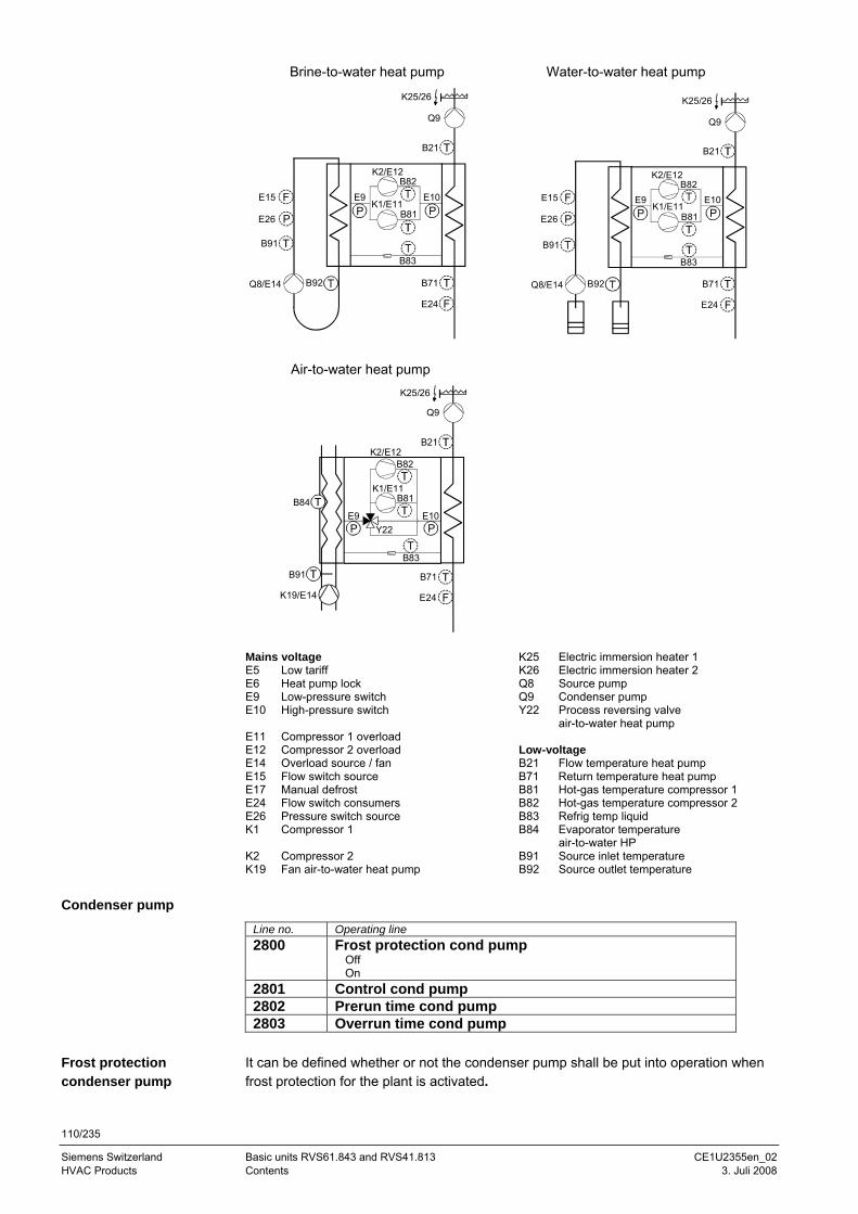
110/235
Siemens Switzerland Basic units RVS61.843 and RVS41.813 CE1U2355en_02 HVAC Products Contents 3. Juli 2008
Brine-to-water heat pump Water-to-water heat pump
B21
K1/E11
B71B92
B91
E26 P
E15 F
Q8/E14
Q9
E9PP B81
E10
B83
K2/E12B82
E24 F
K25/26
B21
K1/E11
B71
Q9
E9PP B81
E10
B92Q8/E14
B91
E26 P
E15 F
K2/E12B82
E24 F
B83
K25/26
Air-to-water heat pump
K1/E11
B71
E9PP
B81
E10
B83
Y22
B91
B84
K19/E14
K2/E12B82
B21
Q9
E24 F
K25/26
Mains voltage K25 Electric immersion heater 1 E5 Low tariff K26 Electric immersion heater 2 E6 Heat pump lock Q8 Source pump E9 Low-pressure switch Q9 Condenser pump E10 High-pressure switch Y22 Process reversing valve
air-to-water heat pump E11 Compressor 1 overload E12 Compressor 2 overload Low-voltage E14 Overload source / fan B21 Flow temperature heat pump E15 Flow switch source B71 Return temperature heat pump E17 Manual defrost B81 Hot-gas temperature compressor 1 E24 Flow switch consumers B82 Hot-gas temperature compressor 2 E26 Pressure switch source B83 Refrig temp liquid K1 Compressor 1 B84 Evaporator temperature
air-to-water HP K2 Compressor 2 B91 Source inlet temperature K19 Fan air-to-water heat pump B92 Source outlet temperature
Condenser pump
Line no. Operating line 2800 Frost protection cond pump
Off On
2801 Control cond pump 2802 Prerun time cond pump 2803 Overrun time cond pump
It can be defined whether or not the condenser pump shall be put into operation when frost protection for the plant is activated.
Frost protection condenser pump
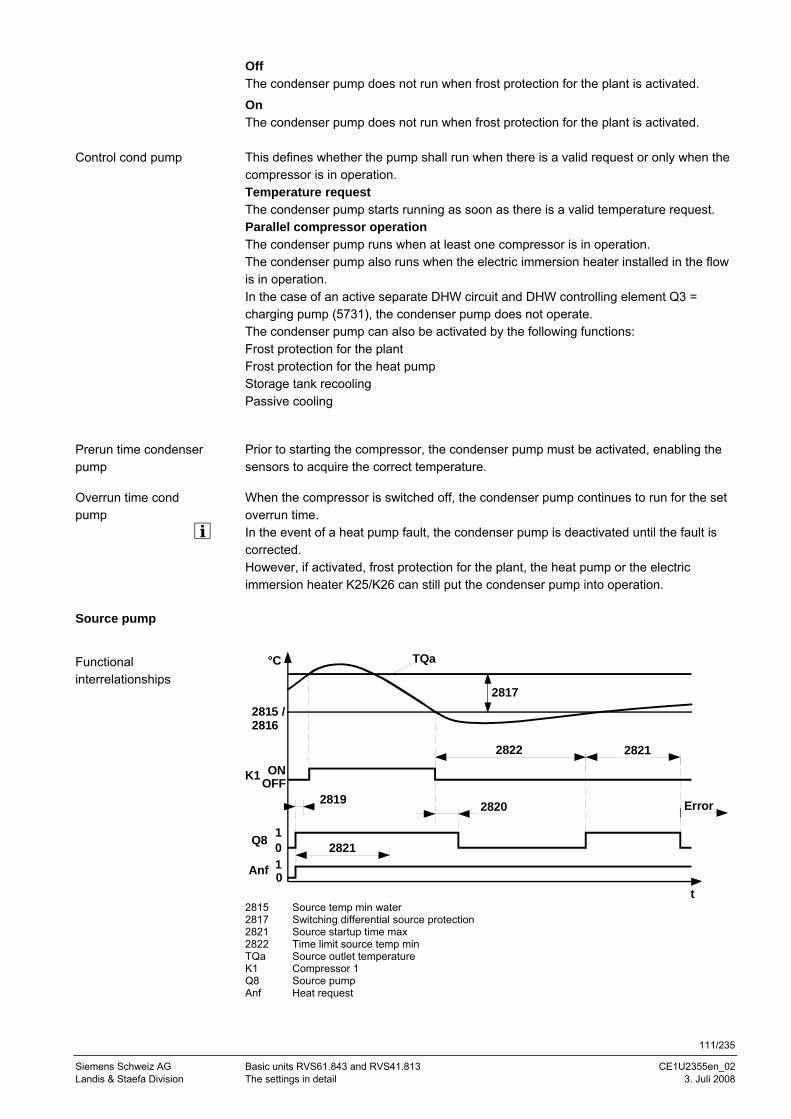
111/235
Siemens Schweiz AG Basic units RVS61.843 and RVS41.813 CE1U2355en_02 Landis & Staefa Division The settings in detail 3. Juli 2008
Off The condenser pump does not run when frost protection for the plant is activated.
On The condenser pump does not run when frost protection for the plant is activated. This defines whether the pump shall run when there is a valid request or only when the compressor is in operation. Temperature request The condenser pump starts running as soon as there is a valid temperature request. Parallel compressor operation The condenser pump runs when at least one compressor is in operation. The condenser pump also runs when the electric immersion heater installed in the flow is in operation. In the case of an active separate DHW circuit and DHW controlling element Q3 = charging pump (5731), the condenser pump does not operate. The condenser pump can also be activated by the following functions: Frost protection for the plant Frost protection for the heat pump Storage tank recooling Passive cooling
Prior to starting the compressor, the condenser pump must be activated, enabling the sensors to acquire the correct temperature.
When the compressor is switched off, the condenser pump continues to run for the set overrun time. In the event of a heat pump fault, the condenser pump is deactivated until the fault is corrected. However, if activated, frost protection for the plant, the heat pump or the electric immersion heater K25/K26 can still put the condenser pump into operation.
Source pump
TQa
t
°C
Q8 10
28172815 /2816
OFFK1 ON
0Anf 1
2822 2821
2821
2819 2820 Error
2815 Source temp min water 2817 Switching differential source protection 2821 Source startup time max 2822 Time limit source temp min TQa Source outlet temperature K1 Compressor 1 Q8 Source pump Anf Heat request
Control cond pump
Prerun time condenser pump
Overrun time cond pump
Functional interrelationships
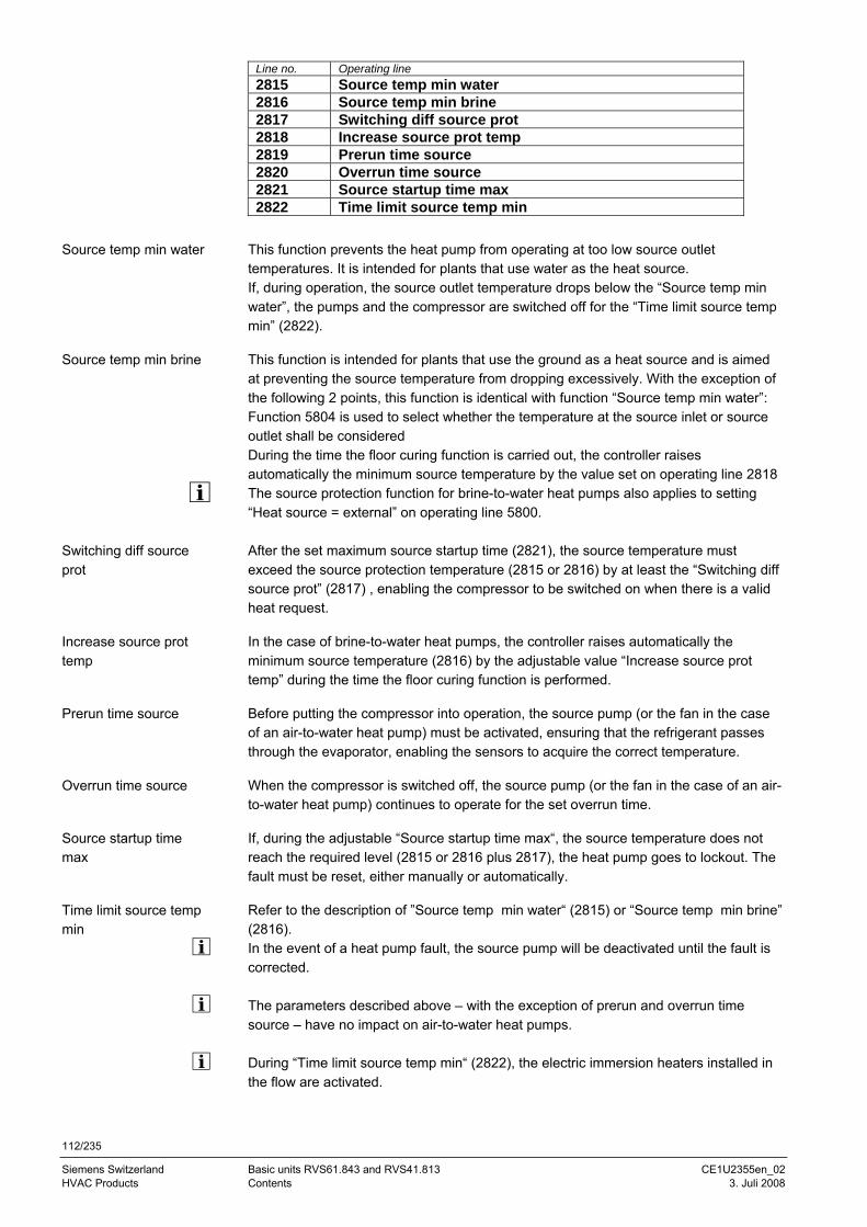
112/235
Siemens Switzerland Basic units RVS61.843 and RVS41.813 CE1U2355en_02 HVAC Products Contents 3. Juli 2008
Line no. Operating line 2815 Source temp min water 2816 Source temp min brine 2817 Switching diff source prot 2818 Increase source prot temp 2819 Prerun time source 2820 Overrun time source 2821 Source startup time max 2822 Time limit source temp min
This function prevents the heat pump from operating at too low source outlet temperatures. It is intended for plants that use water as the heat source. If, during operation, the source outlet temperature drops below the “Source temp min water”, the pumps and the compressor are switched off for the “Time limit source temp min” (2822).
This function is intended for plants that use the ground as a heat source and is aimed at preventing the source temperature from dropping excessively. With the exception of the following 2 points, this function is identical with function “Source temp min water”: Function 5804 is used to select whether the temperature at the source inlet or source outlet shall be considered During the time the floor curing function is carried out, the controller raises automatically the minimum source temperature by the value set on operating line 2818 The source protection function for brine-to-water heat pumps also applies to setting “Heat source = external” on operating line 5800. After the set maximum source startup time (2821), the source temperature must exceed the source protection temperature (2815 or 2816) by at least the “Switching diff source prot” (2817) , enabling the compressor to be switched on when there is a valid heat request.
In the case of brine-to-water heat pumps, the controller raises automatically the minimum source temperature (2816) by the adjustable value “Increase source prot temp” during the time the floor curing function is performed.
Before putting the compressor into operation, the source pump (or the fan in the case of an air-to-water heat pump) must be activated, ensuring that the refrigerant passes through the evaporator, enabling the sensors to acquire the correct temperature.
When the compressor is switched off, the source pump (or the fan in the case of an air-to-water heat pump) continues to operate for the set overrun time.
If, during the adjustable “Source startup time max“, the source temperature does not reach the required level (2815 or 2816 plus 2817), the heat pump goes to lockout. The fault must be reset, either manually or automatically.
Refer to the description of ”Source temp min water“ (2815) or “Source temp min brine” (2816). In the event of a heat pump fault, the source pump will be deactivated until the fault is corrected. The parameters described above – with the exception of prerun and overrun time source – have no impact on air-to-water heat pumps. During “Time limit source temp min“ (2822), the electric immersion heaters installed in the flow are activated.
Source temp min water
Source temp min brine
Switching diff source prot
Increase source prot temp
Prerun time source
Overrun time source
Source startup time max
Time limit source temp min
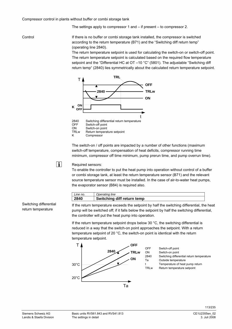
113/235
Siemens Schweiz AG Basic units RVS61.843 and RVS41.813 CE1U2355en_02 Landis & Staefa Division The settings in detail 3. Juli 2008
Compressor control in plants without buffer or combi storage tank
The settings apply to compressor 1 and – if present – to compressor 2. If there is no buffer or combi storage tank installed, the compressor is switched according to the return temperature (B71) and the “Switching diff return temp” (operating line 2840). The return temperature setpoint is used for calculating the switch-on or switch-off point. The return temperature setpoint is calculated based on the required flow temperature setpoint and the “Differential HC at OT –10 °C“ (5801). The adjustable “Switching diff return temp“ (2840) lies symmetrically about the calculated return temperature setpoint.
TOFF
OFFON
TRL
2840
K
t
ON
TRLw
2840 Switching differential return temperature OFF Switch-off point ON Switch-on point TRLw Return temperature setpoint K Compressor The switch-on / off points are impacted by a number of other functions (maximum switch-off temperature, compensation of heat deficits, compressor running time minimum, compressor off time minimum, pump prerun time, and pump overrun time).
Required sensors: To enable the controller to put the heat pump into operation without control of a buffer or combi storage tank, at least the return temperature sensor (B71) and the relevant source temperature sensor must be installed. In the case of air-to-water heat pumps, the evaporator sensor (B84) is required also.
Line no. Operating line 2840 Switching diff return temp
If the return temperature exceeds the setpoint by half the switching differential, the heat pump will be switched off; if it falls below the setpoint by half the switching differential, the controller will put the heat pump into operation.
If the return temperature setpoint drops below 30 °C, the switching differential is reduced in a way that the switch-on point approaches the setpoint. With a return temperature setpoint of 20 °C, the switch-on point is identical with the return temperature setpoint.
2840T OFF
ON
Ta
20°C
30°C
TRLw
OFF Switch-off point ON Switch-on point 2840 Switching differential return temperature Ta Outside temperature t Temperature of heat pump return TRLw Return temperature setpoint
Control
Switching differential return temperature
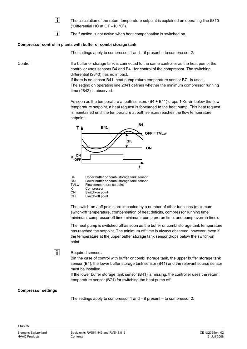
114/235
Siemens Switzerland Basic units RVS61.843 and RVS41.813 CE1U2355en_02 HVAC Products Contents 3. Juli 2008
The calculation of the return temperature setpoint is explained on operating line 5810 (“Differential HC at OT –10 °C”).
The function is not active when heat compensation is switched on.
Compressor control in plants with buffer or combi storage tank
The settings apply to compressor 1 and – if present – to compressor 2. If a buffer or storage tank is connected to the same controller as the heat pump, the controller uses sensors B4 and B41 for control of the compressor. The switching differential (2840) has no impact. If there is no sensor B41, heat pump return temperature sensor B71 is used. The setting on operating line 2841 defines whether the minimum compressor running time (2842) is observed. As soon as the temperature at both sensors (B4 + B41) drops 1 Kelvin below the flow temperature setpoint, a heat request is forwarded to the heat pump. This heat request is maintained until the temperature at both sensors reaches the flow temperature setpoint.
ON
OFF = TVLw
B4
K
1K
B41T
OFFON
t B4 Upper buffer or combi storage tank sensor B41 Lower buffer or combi storage tank sensor TVLw Flow temperature setpoint K Compressor ON Switch-on point OFF Switch-off point The switch-on / off points are impacted by a number of other functions (maximum switch-off temperature, compensation of heat deficits, compressor running time minimum, compressor off time minimum, pump prerun time, and pump overrun time).
The heat pump is switched off as soon as the buffer or combi storage tank temperature has reached the setpoint. The minimum off time is always observed, however, even if the temperature at the upper buffer storage tank sensor drops below the switch-on point. Required sensors: Bin the case of control with buffer or combi storage tank, the upper buffer storage tank sensor (B4), the lower buffer storage tank sensor (B41) and the relevant source sensor must be installed. If the lower buffer storage tank sensor (B41) is missing, the controller uses the return temperature sensor (B71) for switching the heat pump off.
Compressor settings
The settings apply to compressor 1 and – if present – to compressor 2.
Control
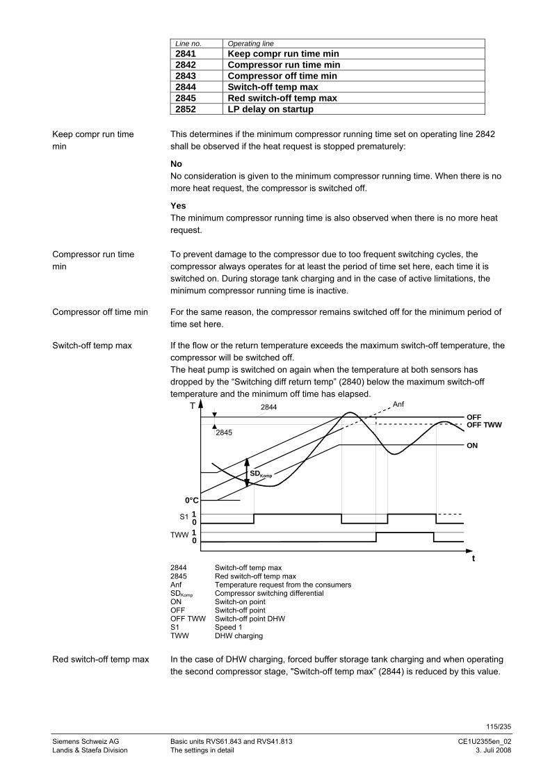
115/235
Siemens Schweiz AG Basic units RVS61.843 and RVS41.813 CE1U2355en_02 Landis & Staefa Division The settings in detail 3. Juli 2008
Line no. Operating line 2841 Keep compr run time min 2842 Compressor run time min 2843 Compressor off time min 2844 Switch-off temp max 2845 Red switch-off temp max 2852 LP delay on startup
This determines if the minimum compressor running time set on operating line 2842 shall be observed if the heat request is stopped prematurely:
No No consideration is given to the minimum compressor running time. When there is no more heat request, the compressor is switched off.
Yes The minimum compressor running time is also observed when there is no more heat request. To prevent damage to the compressor due to too frequent switching cycles, the compressor always operates for at least the period of time set here, each time it is switched on. During storage tank charging and in the case of active limitations, the minimum compressor running time is inactive.
For the same reason, the compressor remains switched off for the minimum period of time set here.
If the flow or the return temperature exceeds the maximum switch-off temperature, the compressor will be switched off. The heat pump is switched on again when the temperature at both sensors has dropped by the “Switching diff return temp” (2840) below the maximum switch-off temperature and the minimum off time has elapsed.
t
T Anf
0S1 1
OFF
ON
2845
0°C
2844
0TWW 1
SDKomp
OFF TWW
2844 Switch-off temp max 2845 Red switch-off temp max Anf Temperature request from the consumers SDKomp Compressor switching differential ON Switch-on point OFF Switch-off point OFF TWW Switch-off point DHW S1 Speed 1 TWW DHW charging In the case of DHW charging, forced buffer storage tank charging and when operating the second compressor stage, "Switch-off temp max” (2844) is reduced by this value.
Keep compr run time min
Compressor run time min
Compressor off time min
Switch-off temp max
Red switch-off temp max
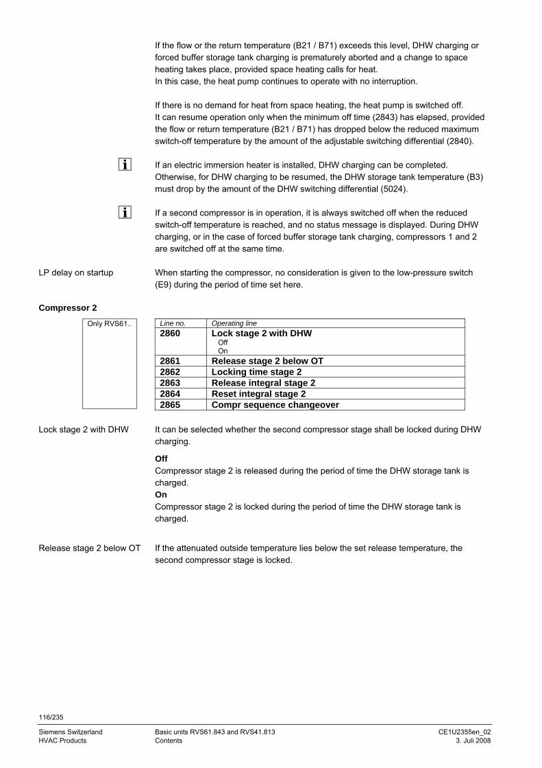
116/235
Siemens Switzerland Basic units RVS61.843 and RVS41.813 CE1U2355en_02 HVAC Products Contents 3. Juli 2008
If the flow or the return temperature (B21 / B71) exceeds this level, DHW charging or forced buffer storage tank charging is prematurely aborted and a change to space heating takes place, provided space heating calls for heat. In this case, the heat pump continues to operate with no interruption. If there is no demand for heat from space heating, the heat pump is switched off. It can resume operation only when the minimum off time (2843) has elapsed, provided the flow or return temperature (B21 / B71) has dropped below the reduced maximum switch-off temperature by the amount of the adjustable switching differential (2840). If an electric immersion heater is installed, DHW charging can be completed. Otherwise, for DHW charging to be resumed, the DHW storage tank temperature (B3) must drop by the amount of the DHW switching differential (5024). If a second compressor is in operation, it is always switched off when the reduced switch-off temperature is reached, and no status message is displayed. During DHW charging, or in the case of forced buffer storage tank charging, compressors 1 and 2 are switched off at the same time. When starting the compressor, no consideration is given to the low-pressure switch (E9) during the period of time set here.
Compressor 2
Line no. Operating line 2860 Lock stage 2 with DHW
Off On
2861 Release stage 2 below OT 2862 Locking time stage 2 2863 Release integral stage 2 2864 Reset integral stage 2 2865 Compr sequence changeover
It can be selected whether the second compressor stage shall be locked during DHW charging.
Off Compressor stage 2 is released during the period of time the DHW storage tank is charged. On Compressor stage 2 is locked during the period of time the DHW storage tank is charged.
If the attenuated outside temperature lies below the set release temperature, the second compressor stage is locked.
LP delay on startup
Lock stage 2 with DHW
Release stage 2 below OT
Only RVS61..
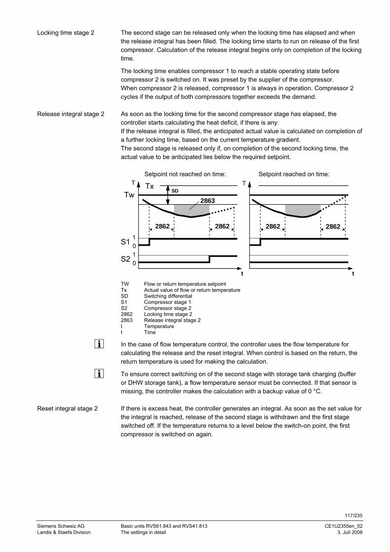
117/235
Siemens Schweiz AG Basic units RVS61.843 and RVS41.813 CE1U2355en_02 Landis & Staefa Division The settings in detail 3. Juli 2008
The second stage can be released only when the locking time has elapsed and when the release integral has been filled. The locking time starts to run on release of the first compressor. Calculation of the release integral begins only on completion of the locking time.
The locking time enables compressor 1 to reach a stable operating state before compressor 2 is switched on. It was preset by the supplier of the compressor. When compressor 2 is released, compressor 1 is always in operation. Compressor 2 cycles if the output of both compressors together exceeds the demand. As soon as the locking time for the second compressor stage has elapsed, the controller starts calculating the heat deficit, if there is any. If the release integral is filled, the anticipated actual value is calculated on completion of a further locking time, based on the current temperature gradient. The second stage is released only if, on completion of the second locking time, the actual value to be anticipated lies below the required setpoint. Setpoint not reached on time: Setpoint reached on time:
2863
28622862
TxTw
0S1 1
SD
0S2 1
2862 2862
T
t t
T
TW Flow or return temperature setpoint Tx Actual value of flow or return temperature SD Switching differential S1 Compressor stage 1 S2 Compressor stage 2 2862 Locking time stage 2 2863 Release integral stage 2 t Temperature t Time
In the case of flow temperature control, the controller uses the flow temperature for calculating the release and the reset integral. When control is based on the return, the return temperature is used for making the calculation.
To ensure correct switching on of the second stage with storage tank charging (buffer or DHW storage tank), a flow temperature sensor must be connected. If that sensor is missing, the controller makes the calculation with a backup value of 0 °C. If there is excess heat, the controller generates an integral. As soon as the set value for the integral is reached, release of the second stage is withdrawn and the first stage switched off. If the temperature returns to a level below the switch-on point, the first compressor is switched on again.
Locking time stage 2
Release integral stage 2
Reset integral stage 2
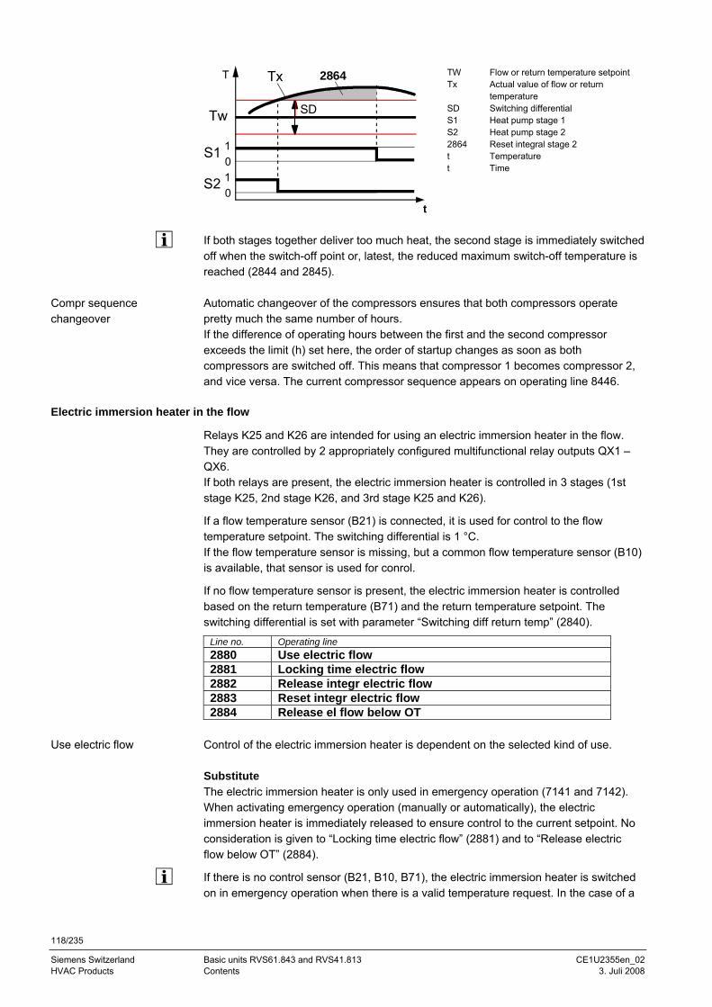
118/235
Siemens Switzerland Basic units RVS61.843 and RVS41.813 CE1U2355en_02 HVAC Products Contents 3. Juli 2008
SD
Tx
Tw
0S1 1
0S2 1
2864T
t
TW Flow or return temperature setpoint Tx Actual value of flow or return
temperature SD Switching differential S1 Heat pump stage 1 S2 Heat pump stage 2 2864 Reset integral stage 2 t Temperature t Time
If both stages together deliver too much heat, the second stage is immediately switched off when the switch-off point or, latest, the reduced maximum switch-off temperature is reached (2844 and 2845). Automatic changeover of the compressors ensures that both compressors operate pretty much the same number of hours. If the difference of operating hours between the first and the second compressor exceeds the limit (h) set here, the order of startup changes as soon as both compressors are switched off. This means that compressor 1 becomes compressor 2, and vice versa. The current compressor sequence appears on operating line 8446.
Electric immersion heater in the flow
Relays K25 and K26 are intended for using an electric immersion heater in the flow. They are controlled by 2 appropriately configured multifunctional relay outputs QX1 – QX6. If both relays are present, the electric immersion heater is controlled in 3 stages (1st stage K25, 2nd stage K26, and 3rd stage K25 and K26).
If a flow temperature sensor (B21) is connected, it is used for control to the flow temperature setpoint. The switching differential is 1 °C. If the flow temperature sensor is missing, but a common flow temperature sensor (B10) is available, that sensor is used for conrol.
If no flow temperature sensor is present, the electric immersion heater is controlled based on the return temperature (B71) and the return temperature setpoint. The switching differential is set with parameter “Switching diff return temp” (2840).
Line no. Operating line 2880 Use electric flow 2881 Locking time electric flow 2882 Release integr electric flow 2883 Reset integr electric flow 2884 Release el flow below OT
Control of the electric immersion heater is dependent on the selected kind of use. Substitute The electric immersion heater is only used in emergency operation (7141 and 7142). When activating emergency operation (manually or automatically), the electric immersion heater is immediately released to ensure control to the current setpoint. No consideration is given to “Locking time electric flow” (2881) and to “Release electric flow below OT” (2884).
If there is no control sensor (B21, B10, B71), the electric immersion heater is switched on in emergency operation when there is a valid temperature request. In the case of a
Compr sequence changeover
Use electric flow
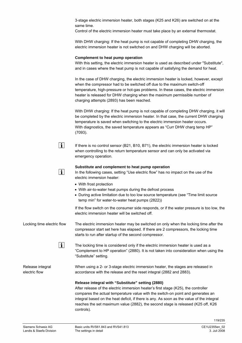
119/235
Siemens Schweiz AG Basic units RVS61.843 and RVS41.813 CE1U2355en_02 Landis & Staefa Division The settings in detail 3. Juli 2008
3-stage electric immersion heater, both stages (K25 and K26) are switched on at the same time. Control of the electric immersion heater must take place by an external thermostat. With DHW charging: If the heat pump is not capable of completing DHW charging, the electric immersion heater is not switched on and DHW charging will be aborted. Complement to heat pump operation With this setting, the electric immersion heater is used as described under "Substitute", and in cases where the heat pump is not capable of satisfying the demand for heat. In the case of DHW charging, the electric immersion heater is locked, however, except when the compressor had to be switched off due to the maximum switch-off temperature, high-pressure or hot-gas problems. In these cases, the electric immersion heater is released for DHW charging when the maximum permissible number of charging attempts (2893) has been reached. With DHW charging: If the heat pump is not capable of completing DHW charging, it will be completed by the electric immersion heater. In that case, the current DHW charging temperature is saved when switching to the electric immersion heater occurs. With diagnostics, the saved temperature appears as “Curr DHW charg temp HP” (7093).
If there is no control sensor (B21, B10, B71), the electric immersion heater is locked when controlling to the return temperature sensor and can only be activated via emergency operation. Substitute and complement to heat pump operation In the following cases, setting “Use electric flow” has no impact on the use of the electric immersion heater:
• With frost protection • With air-to-water heat pumps during the defrost process • During active limitation due to too low source temperature (see “Time limit source
temp min” for water-to-water heat pumps (2822))
If the flow switch on the consumer side responds, or if the water pressure is too low, the electric immersion heater will be switched off. The electric immersion heater may be switched on only when the locking time after the compressor start set here has elapsed. If there are 2 compressors, the locking time starts to run after startup of the second compressor. The locking time is considered only if the electric immersion heater is used as a “Complement to HP operation” (2880). It is not taken into consideration when using the “Substitute” setting. When using a 2- or 3-stage electric immersion heater, the stages are released in accordance with the release and the reset integral (2882 and 2883). Release integral with “Substitute” setting (2880) After release of the electric immersion heater’s first stage (K25), the controller compares the actual temperature value with the switch-on point and generates an integral based on the heat deficit, if there is any. As soon as the value of the integral reaches the set maximum value (2882), the second stage is released (K25 off, K26 controls).
Locking time electric flow
Release integral electric flow
120/235
Siemens Switzerland Basic units RVS61.843 and RVS41.813 CE1U2355en_02 HVAC Products Contents 3. Juli 2008
The controller continues to compare the actual value of the temperature with the switch-on point and calculates again the heat deficit in the release integral. When the release integral reaches the set value (2882), the third stage of the electric immersion heater is released (K25 fixed on, and K26 controls). Release integral with setting “Complement HP operation“ (2880) On completion of “Locking time electric flow“, the controller starts calculating the heat deficit, if there is any. The first stage of the electric immersion heater (K25) is released only when the heat deficit has reached the level set here.
For the second and third stage of the electric immersion heater, the locking time is not taken into consideration, but the release integral must again reach the set value.
Tx
Tw
0Verd1 1
SD TRL
01
2881
t
K25
01K26
2882 2882 2882
SD TRL Switching differential return temperature Verd1 Compressor 1 K25 Electric immersion heater relay K25 K26 Electric immersion heater relay K26 Tw Temperature setpoint (switch-on point) Tx Actual value of temperature 2881 Locking time electric flow 2882 Release integr electric flow t Time If the actual value lies above the switch-off point, the controller switches off the (controlling) stage switched on last and – based on excess heat, if available – starts to compute the reset integral. The next lower stage is switched off when excess heat reaches the set reset integral (2883). For a new release, the release integral must be filled again. The electric immersion heater is released only when the attenuated outside temperature lies below the temperature set here. This setting is considered only if the electric immersion heater is used as “Complement to HP operation” (2880). With the “Substitute” setting, the electric immersion heater is always released.
Heat pump protection during DHW charging
The heat pump switches off, when the high-pressure switch response during DHW charging or because the hot-gas or flow temperature approaches its maximum value. Parameter "Number DHW charg attempts" (2893) is used to select whether charging shall immediately be aborted or whether the heat pump shall make a certain number of charging attempts. In the case of several attempts, the heat pump starts the next charging attempt each time the minimum off time has elapsed. If the heat pump shall make only one charging attempt or if, after the selected number of attempts, the DHW has still not reached the required temperature, DHW charging will
Reset integr electric flow
Release el flow below OT
121/235
Siemens Schweiz AG Basic units RVS61.843 and RVS41.813 CE1U2355en_02 Landis & Staefa Division The settings in detail 3. Juli 2008
be aborted, the controller will save the current DHW temperature and readjust the switch-on point to DHW temperature minus the switching differential DHW. With diagnostics, the saved temperature appears as “Curr DHW charg temp HP” (7093). The value is maintained until – due to limitation – the heat pump must again abort DHW charging. If the “Curr DHW charg temp HP“ lies below the adjustable value of “DHW charg temp HP min” (7092) a maintenance message appears. If the reduced setpoint lies below “DHW charg temp HP min“ and the heat pump can terminate DHW charging, the controller will not generate a service message. In the case of sudden setpoint changes, the switch-on point changes to setpoint minus the switching differential.
General parameters
Line no. Operating line 2886 Compensation heat deficit
Off ¦ On ¦ Only with floor curing fct 2893 Number DHW charg attempts 2894 Delay 3-ph current error 2895 Delay flow switch 2910 Release above OT 2911 For forced buffer storage tank charging 2912 Full charging of buffer storage tank
This function compensates for excess heat and heat deficits. These can occur in the following situations:
• Minimum compressor on and off times
• In the case of low temperature requests, the flow temperature can lie below the required setpoint, but the return temperature may not drop below the switch-on point for a longer period of time. In this situation, the heat pump must be switched on to prevent heat deficits
The controller compares continuously the flow temperature setpoint with the actual value and integrates excess heat and heat deficits. Differences are compensated for by extending the compressor on and off times. If the compressor is not switched on or off due to excess heat / heat deficits, the controller displays an appropriate status message.
The function can only be used when control is based on the return temperature. In the case of plants with buffer or combi storage tanks, the setting (on / off) has no impact.
“Compensation heat deficit“ only acts in heating mode. The parameter is inactive in cooling mode.
The maximum switch-off temperature is given priority over the compensation function. In the case of sudden setpoint changes, both integrals will be deleted. Behavior in connection with the floor curing function When activating the floor curing function, the integral is set to a level representing 1.5 times the predefined value (default setting). If the actual temperature lies at least 2 K below the required setpoint, the heat pump will immediately be switched on. If compensation of excess heat / heat deficits shall act only when the floor curing function is active, the respective setting is to be selected. This means that the parameter is deactivated in normal heating mode.
Compensation heat deficit
Only RVS61..
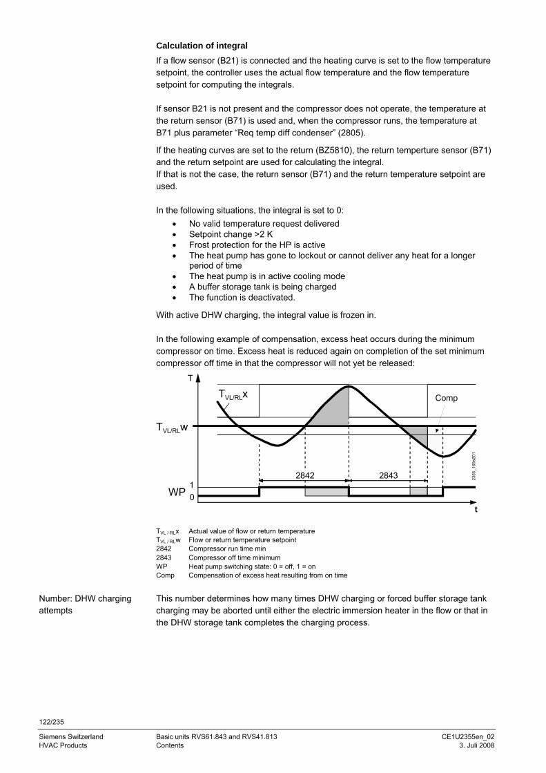
122/235
Siemens Switzerland Basic units RVS61.843 and RVS41.813 CE1U2355en_02 HVAC Products Contents 3. Juli 2008
Calculation of integral If a flow sensor (B21) is connected and the heating curve is set to the flow temperature setpoint, the controller uses the actual flow temperature and the flow temperature setpoint for computing the integrals. If sensor B21 is not present and the compressor does not operate, the temperature at the return sensor (B71) is used and, when the compressor runs, the temperature at B71 plus parameter “Req temp diff condenser” (2805).
If the heating curves are set to the return (BZ5810), the return temperture sensor (B71) and the return setpoint are used for calculating the integral. If that is not the case, the return sensor (B71) and the return temperature setpoint are used. In the following situations, the integral is set to 0:
• No valid temperature request delivered • Setpoint change >2 K • Frost protection for the HP is active • The heat pump has gone to lockout or cannot deliver any heat for a longer
period of time • The heat pump is in active cooling mode • A buffer storage tank is being charged • The function is deactivated.
With active DHW charging, the integral value is frozen in. In the following example of compensation, excess heat occurs during the minimum compressor on time. Excess heat is reduced again on completion of the set minimum compressor off time in that the compressor will not yet be released:
01
WP
T
2842 2843
t
TVL/RLx Comp
TVL/RLw
2355
_169
aZ01
TVL / RLx Actual value of flow or return temperature TVL / RLw Flow or return temperature setpoint 2842 Compressor run time min 2843 Compressor off time minimum WP Heat pump switching state: 0 = off, 1 = on Comp Compensation of excess heat resulting from on time
This number determines how many times DHW charging or forced buffer storage tank charging may be aborted until either the electric immersion heater in the flow or that in the DHW storage tank completes the charging process.
Number: DHW charging attempts
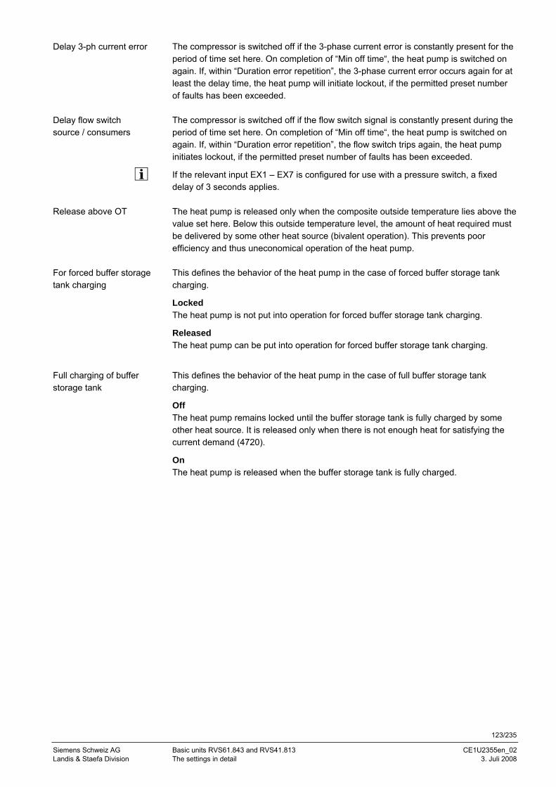
123/235
Siemens Schweiz AG Basic units RVS61.843 and RVS41.813 CE1U2355en_02 Landis & Staefa Division The settings in detail 3. Juli 2008
The compressor is switched off if the 3-phase current error is constantly present for the period of time set here. On completion of “Min off time“, the heat pump is switched on again. If, within “Duration error repetition”, the 3-phase current error occurs again for at least the delay time, the heat pump will initiate lockout, if the permitted preset number of faults has been exceeded. The compressor is switched off if the flow switch signal is constantly present during the period of time set here. On completion of “Min off time“, the heat pump is switched on again. If, within “Duration error repetition”, the flow switch trips again, the heat pump initiates lockout, if the permitted preset number of faults has been exceeded.
If the relevant input EX1 – EX7 is configured for use with a pressure switch, a fixed delay of 3 seconds applies. The heat pump is released only when the composite outside temperature lies above the value set here. Below this outside temperature level, the amount of heat required must be delivered by some other heat source (bivalent operation). This prevents poor efficiency and thus uneconomical operation of the heat pump. This defines the behavior of the heat pump in the case of forced buffer storage tank charging.
Locked The heat pump is not put into operation for forced buffer storage tank charging.
Released The heat pump can be put into operation for forced buffer storage tank charging.
This defines the behavior of the heat pump in the case of full buffer storage tank charging.
Off The heat pump remains locked until the buffer storage tank is fully charged by some other heat source. It is released only when there is not enough heat for satisfying the current demand (4720).
On The heat pump is released when the buffer storage tank is fully charged.
Delay 3-ph current error
Delay flow switch source / consumers
Release above OT
For forced buffer storage tank charging
Full charging of buffer storage tank
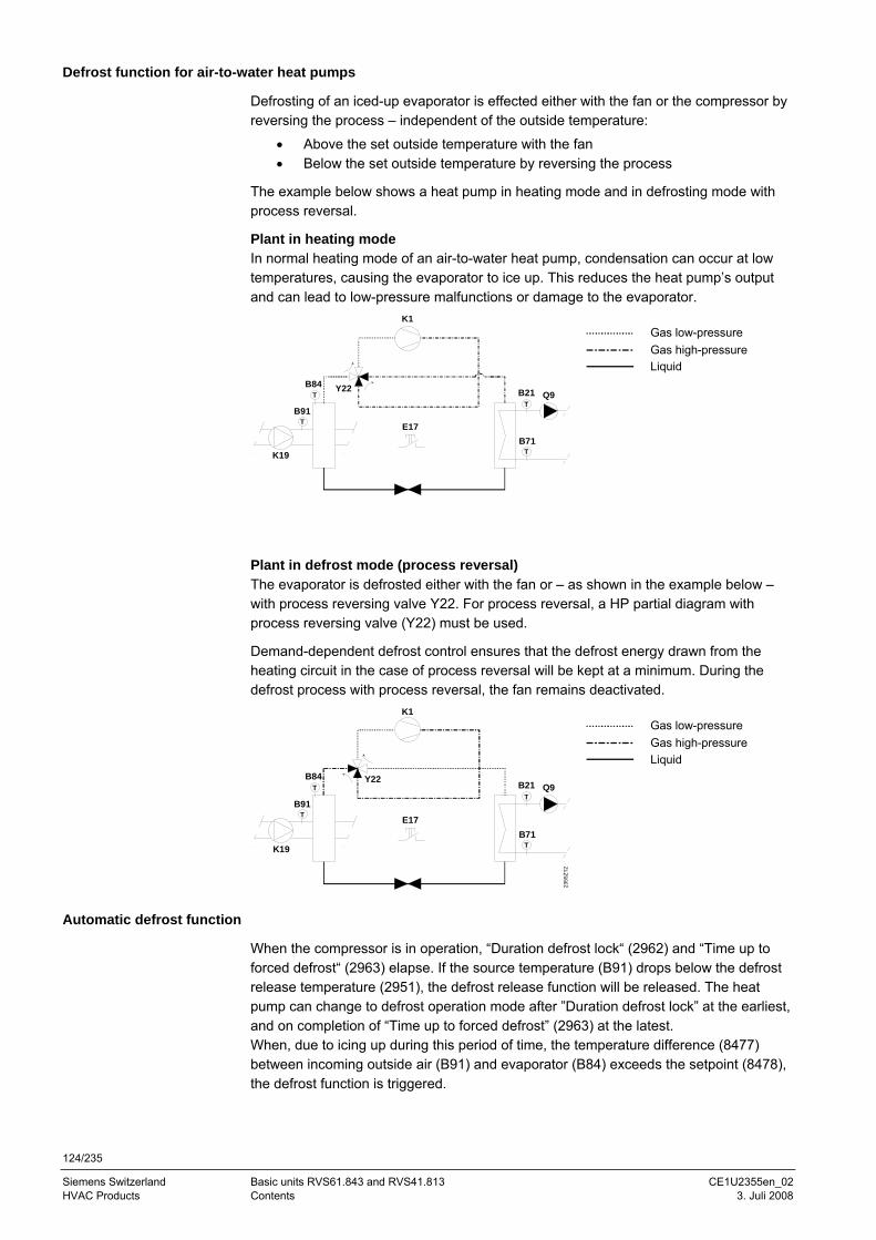
124/235
Siemens Switzerland Basic units RVS61.843 and RVS41.813 CE1U2355en_02 HVAC Products Contents 3. Juli 2008
Defrost function for air-to-water heat pumps
Defrosting of an iced-up evaporator is effected either with the fan or the compressor by reversing the process – independent of the outside temperature:
• Above the set outside temperature with the fan • Below the set outside temperature by reversing the process
The example below shows a heat pump in heating mode and in defrosting mode with process reversal.
Plant in heating mode In normal heating mode of an air-to-water heat pump, condensation can occur at low temperatures, causing the evaporator to ice up. This reduces the heat pump’s output and can lead to low-pressure malfunctions or damage to the evaporator.
B21
B71
Q9
B91
T
T
T
K19
B84T
K1
Y22
E17
Gas low-pressure Gas high-pressure Liquid
Plant in defrost mode (process reversal) The evaporator is defrosted either with the fan or – as shown in the example below – with process reversing valve Y22. For process reversal, a HP partial diagram with process reversing valve (Y22) must be used.
Demand-dependent defrost control ensures that the defrost energy drawn from the heating circuit in the case of process reversal will be kept at a minimum. During the defrost process with process reversal, the fan remains deactivated.
B21
B71
Q9
B91
T
T
T
K19
B84T
K1
Y22
E17
2355
Z12
Gas low-pressure Gas high-pressure Liquid
Automatic defrost function
When the compressor is in operation, “Duration defrost lock“ (2962) and “Time up to forced defrost“ (2963) elapse. If the source temperature (B91) drops below the defrost release temperature (2951), the defrost release function will be released. The heat pump can change to defrost operation mode after ”Duration defrost lock” at the earliest, and on completion of “Time up to forced defrost” (2963) at the latest. When, due to icing up during this period of time, the temperature difference (8477) between incoming outside air (B91) and evaporator (B84) exceeds the setpoint (8478), the defrost function is triggered.

125/235
Siemens Schweiz AG Basic units RVS61.843 and RVS41.813 CE1U2355en_02 Landis & Staefa Division The settings in detail 3. Juli 2008
2965
2963 2962
8478
2951
2959 OEM
(2963) (2962)
8477 2952 OEM
8477
2954 OEM
8478
t
°C
10
2355
Z16
1010
Y22
B91
K19
K1
B84
B91 Source inlet temp 2951 Defrost release below OT B84 Evaporator temp 2952 OEM Swi diff defrost Y22 Process reversing valve 2954 OEM Evapor temp defrost end K19 Fan source inlet 2959 Defrost settling time K1 Compressor 1 2962 Duration defrost lock 2963 Time up to forced defrost 2965 Dripping time evapor 8477 Temp diff defrost act value 8478 Temp diff defrost setpoint
When defrosting is successful, the evaporator temperature (B84) rises. If the evaporator temperature exceeds “Evapor temp defrost end“ (2954 OEM), the defrost process can be successfully completed and the compressor is switched off during the dripping time (2965). Then, heating mode is resumed. Defrosting with the fan is considered completed when one of the 2 following conditions is satisfied:
• The temperature difference (8477) between incoming outside air (B91) and evaporator (B84) is smaller than that set by your supplier
• When defrosting with the fan, the defrost time is reached The defrost process at low outside temperatures takes more time than at higher outside temperatures. Heating mode is resumed after successful completion of the defrost process either through process reversal or with the fan. “Duration defrost lock“, “Time up to forced defrost“ and “Defrost settling time“ (2959 OEM) start to run again. On completion of “Defrost settling time“ (2959 OEM), “Temp diff defrost icefree“ is acquired and used to generate the new setpoint (8478). When there is a heat pump lock pending, any active defrost process is completed.
Defrosting by reversing the process can also be accomplished manually, either via input Ex1..7 or via the operating line (7152). With manual defrosting, no consideration is given to the release temperature (2951) and to “Duration defrost lock“ (2962).
Defrost end when defrosting through process reversal
Defrost end when defrosting with the fan
Resuming heating mode and preparing the next defrost process
Manual defrost
126/235
Siemens Switzerland Basic units RVS61.843 and RVS41.813 CE1U2355en_02 HVAC Products Contents 3. Juli 2008
Manual defrosting is also possible during ”Duration defrost lock” and above “Defrost release below OT” (2951). A defrost process in progress is completed, independent of “Defrost release below OT“.
Line no. Operating line 2951 Defrost release below OT 2958 Numb defrost attempts max 2962 Duration defrost lock 2963 Time up to forced defrost 2964 Defrost time max 2965 Dripping time evapor
The defrost function can be released only when the source inlet temperature (B91) lies below the release temperature set here. Above this outside temperature, the automatic defrost function is not active. If the defrost process could not be successfully completed, another attempt is made after a preheating phase (see “Duration defrost lock”). If, during the number of attempts set here, it was still not possible to successfully complete the defrost process, the heat pump is switched off and generates an error message.
For the heat pump to resume operation, the fault must be manually reset. When the heat pump is switched on in heating mode, “Duration defrost lock” begins to run. It is at the end of this period of time at the earliest the controller is allowed to start the next evaporator defrost attempt. Prerequisite for defrosting is that the source temperature (B91) lies below the set release temperature (2951).
After a prematurely aborted defrosting attempt (see “Defrost time max“), the heating water is preheated during the period of time “Duration defrost lock”. If an electric immersion heater is installed in the flow or in the buffer / combi storage tank, it is switched on to support preheating. Then, a direct change to defrost mode is made. If the heat pump was in operation during the period of time set here, without defrosting in the meantime, forced defrosting will take place. The same prerequisite applies here: the source temperature (B91) must lie below the set release temperature (2951). If, in the case of defrost through process reversal, it was not possible to successfully defrost during “Defrost time max“, the controller aborts the defrost process and tries again after the preheating phase (see “Duration defrost lock”). The permitted number of defrost attempts is limited by “Numb defrost attempts max“ (2958). Before the heat pump is allowed to resume heating mode after successfully defrosting through process reversal, the “Dripping time evapor“ set here must elapse. The heat pump resumes operation only on completion of this period of time and the fan is switched on after a delay time preset by the supplier. Frost protection for the heat pump leads to release of the heat pump as soon as the flow or the return temperature falls below 5 °C. After both sensors have reached the level of 6 °C, the heat pump’s release is maintained for 5 minutes. If an electric immersion heater is installed in the flow, it is switched on for this period of time. In the case of a 3-stage electric immersion heater (K25 and K26), both relays are energized.
Defrost release below OT
Numb defrost attempts max
Duration defrost lock
Time up to forced defrost
Defrost time max
Dripping time evapor
Frost protection for the heat pump
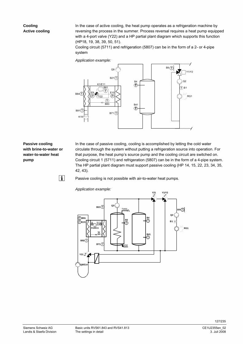
127/235
Siemens Schweiz AG Basic units RVS61.843 and RVS41.813 CE1U2355en_02 Landis & Staefa Division The settings in detail 3. Juli 2008
In the case of active cooling, the heat pump operates as a refrigeration machine by reversing the process in the summer. Process reversal requires a heat pump equipped with a 4-port valve (Y22) and a HP partial plant diagram which supports this function (HP18, 19, 38, 39, 50, 51). Cooling circuit (5711) and refrigeration (5807) can be in the form of a 2- or 4-pipe system
Application example:
B4
B41
B9
Y1/Y2
Q2
B1
B21
K1/E11
B71B91
E9PP
B81
E10
B83
Q9
Y22B84
K19
RG1
In the case of passive cooling, cooling is accomplished by letting the cold water circulate through the system without putting a refrigeration source into operation. For that purpose, the heat pump’s source pump and the cooling circuit are switched on. Cooling circuit 1 (5711) and refrigeration (5807) can be in the form of a 4-pipe system. The HP partial plant diagram must support passive cooling (HP 14, 15, 22, 23, 34, 35, 42, 43).
Passive cooling is not possible with air-to-water heat pumps. Application example:
B21
K1/E11
B71
B83
B81 E10P
E9P
B92
Q8/E14
B91
E15P
Q3
KW
TWW
Y21 Y1/Y2
B4B3
B41
Q2
B9
B1
RG1
Y21
Cooling Active cooling
Passive cooling with brine-to-water or water-to-water heat pump
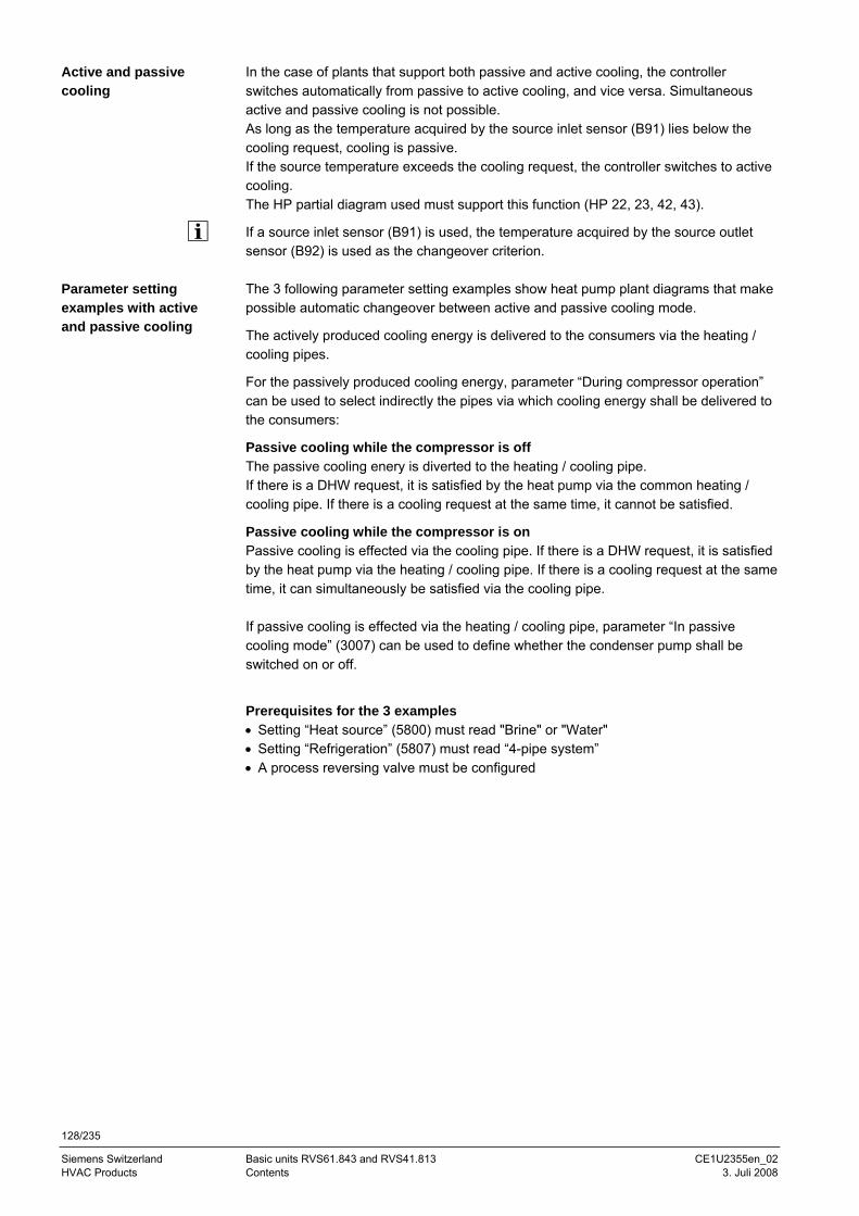
128/235
Siemens Switzerland Basic units RVS61.843 and RVS41.813 CE1U2355en_02 HVAC Products Contents 3. Juli 2008
In the case of plants that support both passive and active cooling, the controller switches automatically from passive to active cooling, and vice versa. Simultaneous active and passive cooling is not possible. As long as the temperature acquired by the source inlet sensor (B91) lies below the cooling request, cooling is passive. If the source temperature exceeds the cooling request, the controller switches to active cooling. The HP partial diagram used must support this function (HP 22, 23, 42, 43).
If a source inlet sensor (B91) is used, the temperature acquired by the source outlet sensor (B92) is used as the changeover criterion. The 3 following parameter setting examples show heat pump plant diagrams that make possible automatic changeover between active and passive cooling mode.
The actively produced cooling energy is delivered to the consumers via the heating / cooling pipes.
For the passively produced cooling energy, parameter “During compressor operation” can be used to select indirectly the pipes via which cooling energy shall be delivered to the consumers:
Passive cooling while the compressor is off The passive cooling enery is diverted to the heating / cooling pipe. If there is a DHW request, it is satisfied by the heat pump via the common heating / cooling pipe. If there is a cooling request at the same time, it cannot be satisfied.
Passive cooling while the compressor is on Passive cooling is effected via the cooling pipe. If there is a DHW request, it is satisfied by the heat pump via the heating / cooling pipe. If there is a cooling request at the same time, it can simultaneously be satisfied via the cooling pipe. If passive cooling is effected via the heating / cooling pipe, parameter “In passive cooling mode” (3007) can be used to define whether the condenser pump shall be switched on or off.
Prerequisites for the 3 examples • Setting “Heat source” (5800) must read "Brine" or "Water" • Setting “Refrigeration” (5807) must read “4-pipe system” • A process reversing valve must be configured
Active and passive cooling
Parameter setting examples with active and passive cooling
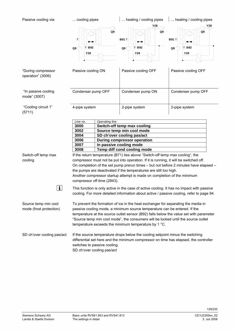
129/235
Siemens Schweiz AG Basic units RVS61.843 and RVS41.813 CE1U2355en_02 Landis & Staefa Division The settings in detail 3. Juli 2008
... cooling pipes ... heating / cooling pipes ... heating / cooling pipes
Q9
Q8 B92
Y28
T
T
Q9
Q8 B92
Y28
TB91
T
Y28
Q9
Q8 B92
Y28
TB91
T
Y28
Passive cooling ON Passive cooling OFF Passive cooling OFF Condenser pump OFF Condenser pump ON Condenser pump OFF 4-pipe system 2-pipe system 2-pipe system
Line no. Operating line 3000 Switch-off temp max cooling 3002 Source temp min cool mode 3004 SD ch’over cooling pas/act 3006 During compressor operation 3007 In passive cooling mode 3008 Temp diff cond cooling mode
If the return temperature (B71) lies above “Switch-off temp max cooling“, the compressor must not be put into operation. If it is running, it will be switched off. On completion of the set pump prerun times – but not before 2 minutes have elapsed – the pumps are deactivated if the temperatures are still too high. Another compressor startup attempt is made on completion of the minimum compressor off time (2843).
This function is only active in the case of active cooling. It has no impact with passive cooling. For more detailed information about active / passive cooling, refer to page 94. To prevent the formation of ice in the heat exchanger for separating the media in passive cooling mode, a minimum source temperature can be entered. If the temperature at the source outlet sensor (B92) falls below the value set with parameter “Source temp min cool mode”, the consumers will be locked until the source outlet temperature exceeds the minimum temperature by 1 °C. If the source temperature drops below the cooling setpoint minus the switching differential set here and the minimum compressor on time has elapsed, the controller switches to passive cooling. SD ch’over cooling pas/act
Passive cooling via:
“During compressor operation” (3006)
“In passive cooling mode” (3007)
“Cooling circuit 1” (5711)
Switch-off temp max cooling
Source temp min cool mode (frost protection)
SD ch’over cooling pas/act
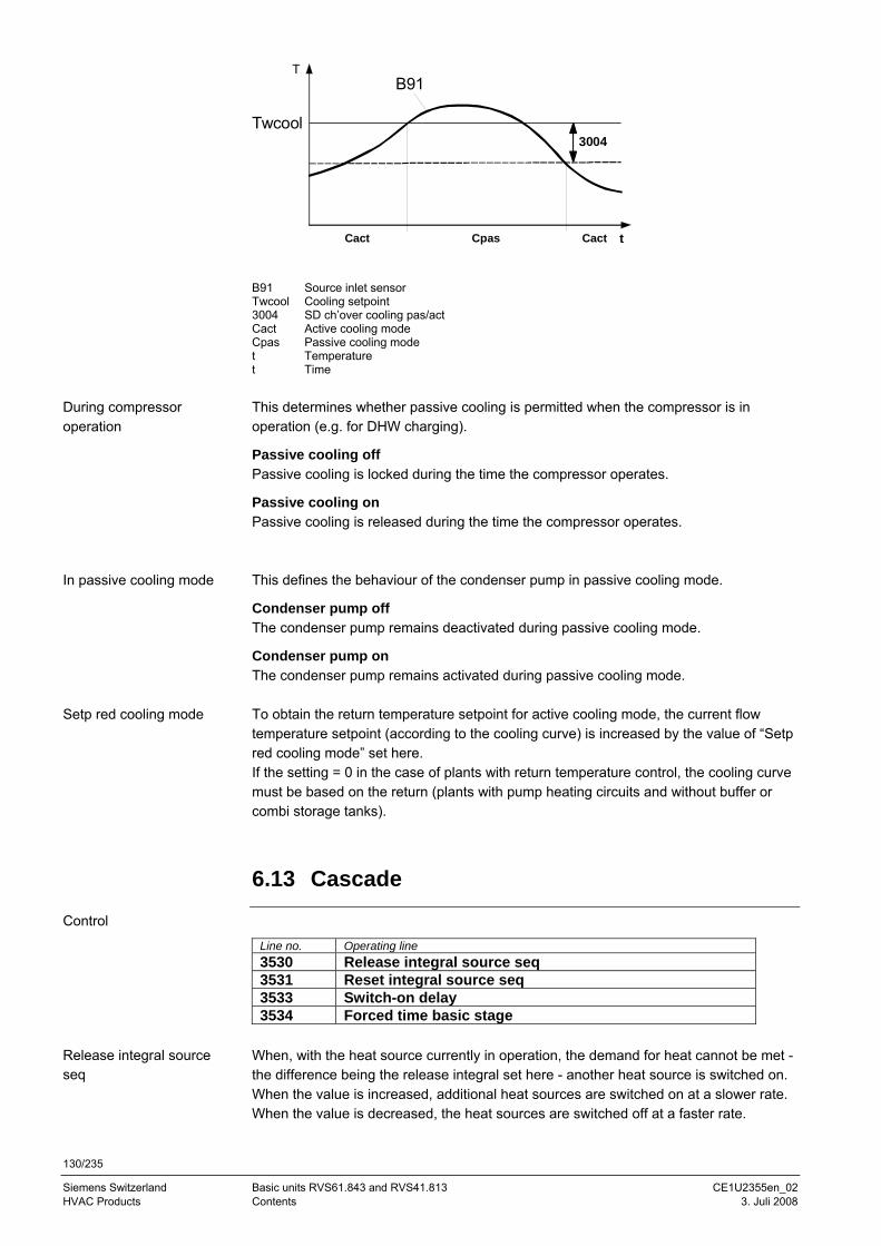
130/235
Siemens Switzerland Basic units RVS61.843 and RVS41.813 CE1U2355en_02 HVAC Products Contents 3. Juli 2008
Twcool3004
Cact
T
t
B91
Cpas Cact
B91 Source inlet sensor Twcool Cooling setpoint 3004 SD ch’over cooling pas/act Cact Active cooling mode Cpas Passive cooling mode t Temperature t Time This determines whether passive cooling is permitted when the compressor is in operation (e.g. for DHW charging).
Passive cooling off Passive cooling is locked during the time the compressor operates.
Passive cooling on Passive cooling is released during the time the compressor operates. This defines the behaviour of the condenser pump in passive cooling mode.
Condenser pump off The condenser pump remains deactivated during passive cooling mode.
Condenser pump on The condenser pump remains activated during passive cooling mode. To obtain the return temperature setpoint for active cooling mode, the current flow temperature setpoint (according to the cooling curve) is increased by the value of “Setp red cooling mode” set here. If the setting = 0 in the case of plants with return temperature control, the cooling curve must be based on the return (plants with pump heating circuits and without buffer or combi storage tanks).
6.13 Cascade
Control
Line no. Operating line 3530 Release integral source seq 3531 Reset integral source seq 3533 Switch-on delay 3534 Forced time basic stage
When, with the heat source currently in operation, the demand for heat cannot be met - the difference being the release integral set here - another heat source is switched on. When the value is increased, additional heat sources are switched on at a slower rate. When the value is decreased, the heat sources are switched off at a faster rate.
During compressor operation
In passive cooling mode
Setp red cooling mode
Release integral source seq
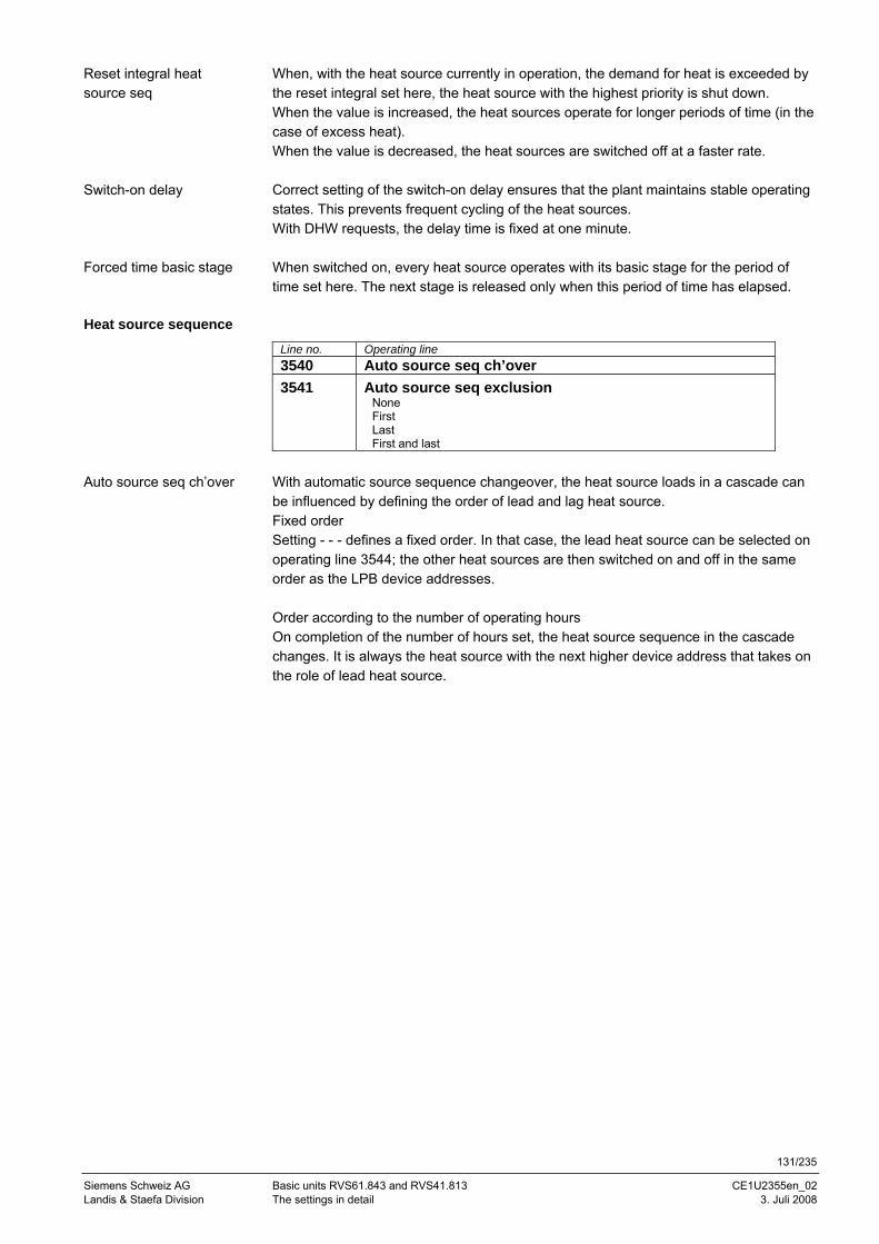
131/235
Siemens Schweiz AG Basic units RVS61.843 and RVS41.813 CE1U2355en_02 Landis & Staefa Division The settings in detail 3. Juli 2008
When, with the heat source currently in operation, the demand for heat is exceeded by the reset integral set here, the heat source with the highest priority is shut down. When the value is increased, the heat sources operate for longer periods of time (in the case of excess heat). When the value is decreased, the heat sources are switched off at a faster rate. Correct setting of the switch-on delay ensures that the plant maintains stable operating states. This prevents frequent cycling of the heat sources. With DHW requests, the delay time is fixed at one minute. When switched on, every heat source operates with its basic stage for the period of time set here. The next stage is released only when this period of time has elapsed.
Heat source sequence
Line no. Operating line 3540 Auto source seq ch’over 3541 Auto source seq exclusion
None First Last First and last
With automatic source sequence changeover, the heat source loads in a cascade can be influenced by defining the order of lead and lag heat source. Fixed order Setting - - - defines a fixed order. In that case, the lead heat source can be selected on operating line 3544; the other heat sources are then switched on and off in the same order as the LPB device addresses. Order according to the number of operating hours On completion of the number of hours set, the heat source sequence in the cascade changes. It is always the heat source with the next higher device address that takes on the role of lead heat source.
Reset integral heat source seq
Switch-on delay
Forced time basic stage
Auto source seq ch’over
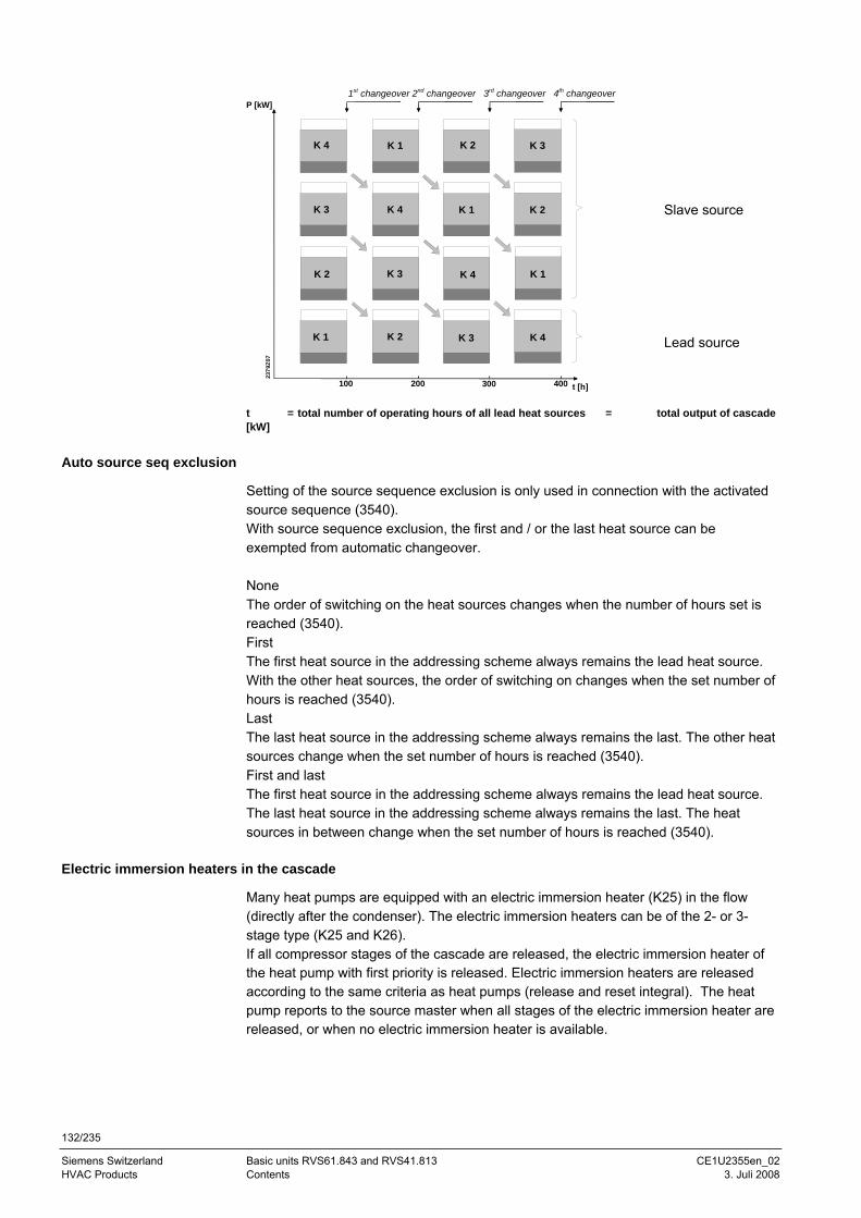
132/235
Siemens Switzerland Basic units RVS61.843 and RVS41.813 CE1U2355en_02 HVAC Products Contents 3. Juli 2008
1st changeover 2nd changeover 3rd changeover 4th changeover
K 1
K 2
K 3
K 4
K 2
K 3
K 4
K 1
K 3
K 4
K 1
K 2
K 4
K 1
K 2
K 3
t [h]100 300 400200
P [kW]
2379
Z07
Slave source Lead source
t = total number of operating hours of all lead heat sources = total output of cascade [kW]
Auto source seq exclusion
Setting of the source sequence exclusion is only used in connection with the activated source sequence (3540). With source sequence exclusion, the first and / or the last heat source can be exempted from automatic changeover. None The order of switching on the heat sources changes when the number of hours set is reached (3540). First The first heat source in the addressing scheme always remains the lead heat source. With the other heat sources, the order of switching on changes when the set number of hours is reached (3540). Last The last heat source in the addressing scheme always remains the last. The other heat sources change when the set number of hours is reached (3540). First and last The first heat source in the addressing scheme always remains the lead heat source. The last heat source in the addressing scheme always remains the last. The heat sources in between change when the set number of hours is reached (3540).
Electric immersion heaters in the cascade
Many heat pumps are equipped with an electric immersion heater (K25) in the flow (directly after the condenser). The electric immersion heaters can be of the 2- or 3-stage type (K25 and K26). If all compressor stages of the cascade are released, the electric immersion heater of the heat pump with first priority is released. Electric immersion heaters are released according to the same criteria as heat pumps (release and reset integral). The heat pump reports to the source master when all stages of the electric immersion heater are released, or when no electric immersion heater is available.
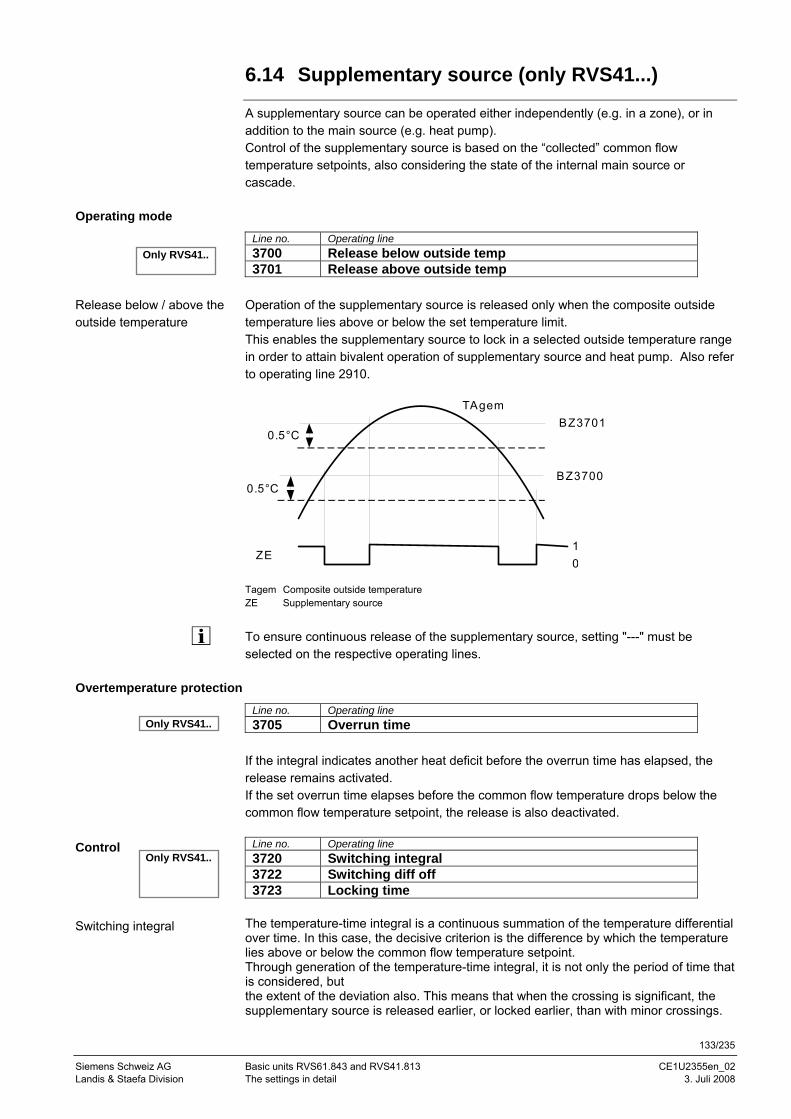
133/235
Siemens Schweiz AG Basic units RVS61.843 and RVS41.813 CE1U2355en_02 Landis & Staefa Division The settings in detail 3. Juli 2008
6.14 Supplementary source (only RVS41...)
A supplementary source can be operated either independently (e.g. in a zone), or in addition to the main source (e.g. heat pump). Control of the supplementary source is based on the “collected” common flow temperature setpoints, also considering the state of the internal main source or cascade.
Operating mode
Line no. Operating line 3700 Release below outside temp 3701 Release above outside temp
Operation of the supplementary source is released only when the composite outside temperature lies above or below the set temperature limit. This enables the supplementary source to lock in a selected outside temperature range in order to attain bivalent operation of supplementary source and heat pump. Also refer to operating line 2910.
TAgemBZ3701
BZ3700
10
ZE
0.5°C
0.5°C
Tagem Composite outside temperature ZE Supplementary source
To ensure continuous release of the supplementary source, setting "---" must be selected on the respective operating lines.
Overtemperature protection
Line no. Operating line 3705 Overrun time
If the integral indicates another heat deficit before the overrun time has elapsed, the release remains activated. If the set overrun time elapses before the common flow temperature drops below the common flow temperature setpoint, the release is also deactivated.
Line no. Operating line 3720 Switching integral 3722 Switching diff off 3723 Locking time
The temperature-time integral is a continuous summation of the temperature differential over time. In this case, the decisive criterion is the difference by which the temperature lies above or below the common flow temperature setpoint. Through generation of the temperature-time integral, it is not only the period of time that is considered, but the extent of the deviation also. This means that when the crossing is significant, the supplementary source is released earlier, or locked earlier, than with minor crossings.
Release below / above the outside temperature
Control
Switching integral
Only RVS41..
Only RVS41..
Only RVS41..
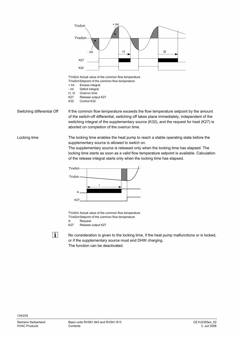
134/235
Siemens Switzerland Basic units RVS61.843 and RVS41.813 CE1U2355en_02 HVAC Products Contents 3. Juli 2008
t1 t2
TVxSch
TVwSch
K27
K32
- Int
+ Int
TVxSch Actual value of the common flow temperature TVwSch Setpoint of the common flow temperature + Int Excess integral - Int Deficit integral t1, t2 Overrun time K27 Release output K27 K32 Control K32
If the common flow temperature exceeds the flow temperature setpoint by the amount of the switch-off differential, switching off takes place immediately, independent of the switching integral of the supplementary source (K32), and the request for heat (K27) is aborted on completion of the overrun time. The locking time enables the heat pump to reach a stable operating state before the supplementary source is allowed to switch on. The supplementary source is released only when the locking time has elapsed. The locking time starts as soon as a valid flow temperature setpoint is available. Calculation of the release integral starts only when the locking time has elapsed.
t
TVxSch
TVwSch
K27
A
TVxSch Actual value of the common flow temperature TVwSch Setpoint of the common flow temperature A Request K27 Release output K27
No consideration is given to the locking time, if the heat pump malfunctions or is locked, or if the supplementary source must end DHW charging. The function can be deactivated.
Switching differential Off
Locking time
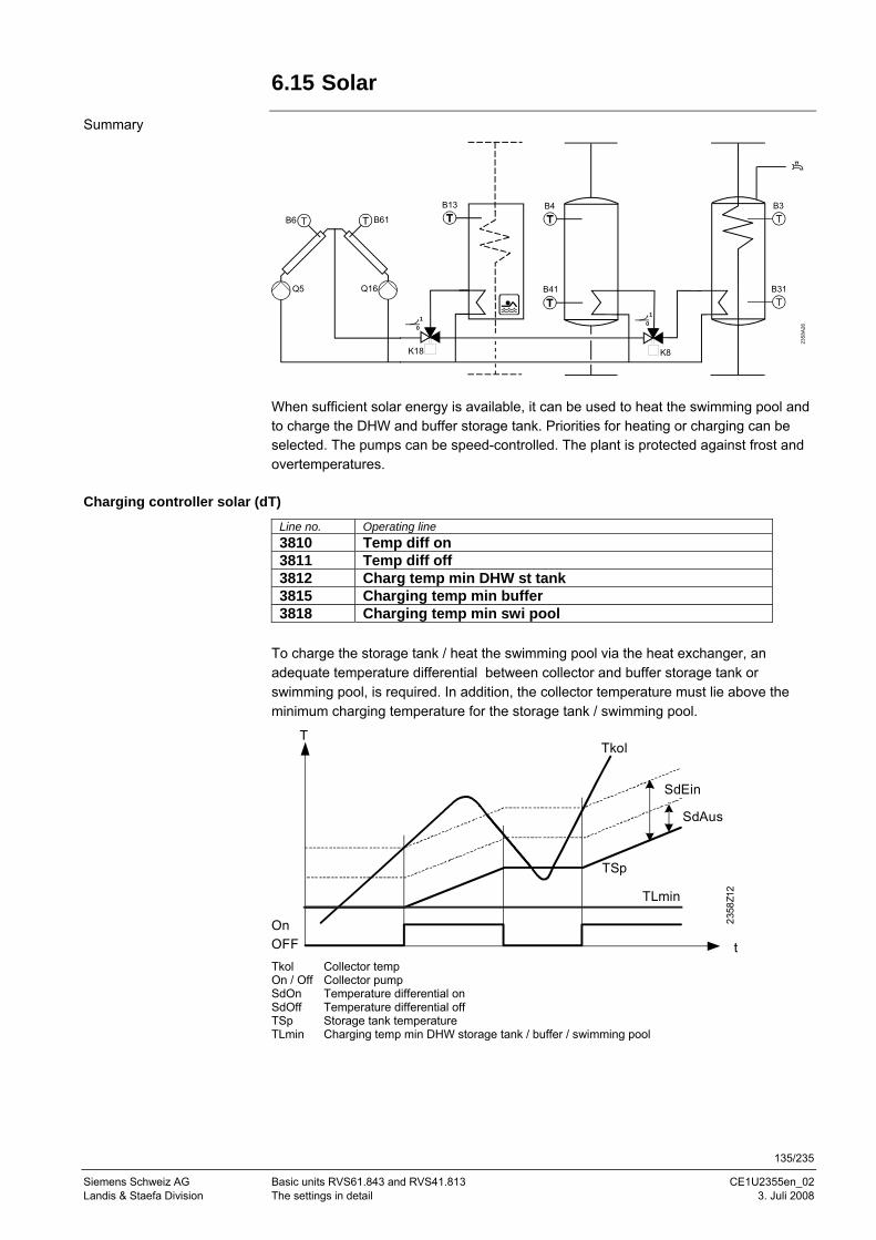
135/235
Siemens Schweiz AG Basic units RVS61.843 and RVS41.813 CE1U2355en_02 Landis & Staefa Division The settings in detail 3. Juli 2008
6.15 Solar
Summary
2358
A26
B31
B3B4
B41
B6
Q5
B61
Q16
K8
10
K18
10
B13
When sufficient solar energy is available, it can be used to heat the swimming pool and to charge the DHW and buffer storage tank. Priorities for heating or charging can be selected. The pumps can be speed-controlled. The plant is protected against frost and overtemperatures.
Charging controller solar (dT)
Line no. Operating line 3810 Temp diff on 3811 Temp diff off 3812 Charg temp min DHW st tank 3815 Charging temp min buffer 3818 Charging temp min swi pool
To charge the storage tank / heat the swimming pool via the heat exchanger, an adequate temperature differential between collector and buffer storage tank or swimming pool, is required. In addition, the collector temperature must lie above the minimum charging temperature for the storage tank / swimming pool.
T
t
TSp
Tkol
SdEin
SdAus
OnOFF
2358
Z12
TLmin
Tkol Collector temp On / Off Collector pump SdOn Temperature differential on SdOff Temperature differential off TSp Storage tank temperature TLmin Charging temp min DHW storage tank / buffer / swimming pool
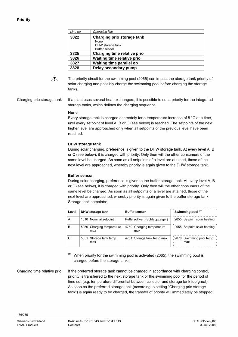
136/235
Siemens Switzerland Basic units RVS61.843 and RVS41.813 CE1U2355en_02 HVAC Products Contents 3. Juli 2008
Priority
Line no. Operating line
3822 Charging prio storage tank None DHW storage tank Buffer sensor
3825 Charging time relative prio 3826 Waiting time relative prio 3827 Waiting time parallel op 3828 Delay secondary pump
The priority circuit for the swimming pool (2065) can impact the storage tank priority of solar charging and possibly charge the swimming pool before charging the storage tanks. If a plant uses several heat exchangers, it is possible to set a priority for the integrated storage tanks, which defines the charging sequence.
None Every storage tank is charged alternately for a temperature increase of 5 °C at a time, until every setpoint of level A, B or C (see below) is reached. The setpoints of the next higher level are approached only when all setpoints of the previous level have been reached. DHW storage tank During solar charging, preference is given to the DHW storage tank. At every level A, B or C (see below), it is charged with priority. Only then will the other consumers of the same level be charged. As soon as all setpoints of a level are attained, those of the next level are approached, whereby priority is again given to the DHW storage tank. Buffer sensor During solar charging, preference is given to the buffer storage tank. At every level A, B or C (see below), it is charged with priority. Only then will the other consumers of the same level be charged. As soon as all setpoints of a level are attained, those of the next level are approached, whereby priority is again given to the buffer storage tank. Storage tank setpoints: Level DHW storage tank Buffer sensor Swimming pool (1)
A 1610 Nominal setpoint Puffersollwert (Schleppzeiger) 2055 Setpoint solar heating
B 5050 Charging temperature max
4750 Charging temperature max
2055 Setpoint solar heating
C 5051 Storage tank temp max
4751 Storage tank temp max 2070 Swimming pool temp max
(1) When priority for the swimming pool is activated (2065), the swimming pool is charged before the storage tanks.
If the preferred storage tank cannot be charged in accordance with charging control, priority is transferred to the next storage tank or the swimming pool for the period of time set (e.g. temperature differential between collector and storage tank too great). As soon as the preferred storage tank (according to setting "Charging prio storage tank") is again ready to be charged, the transfer of priority will immediately be stopped.
Charging prio storage tank
Charging time relative prio
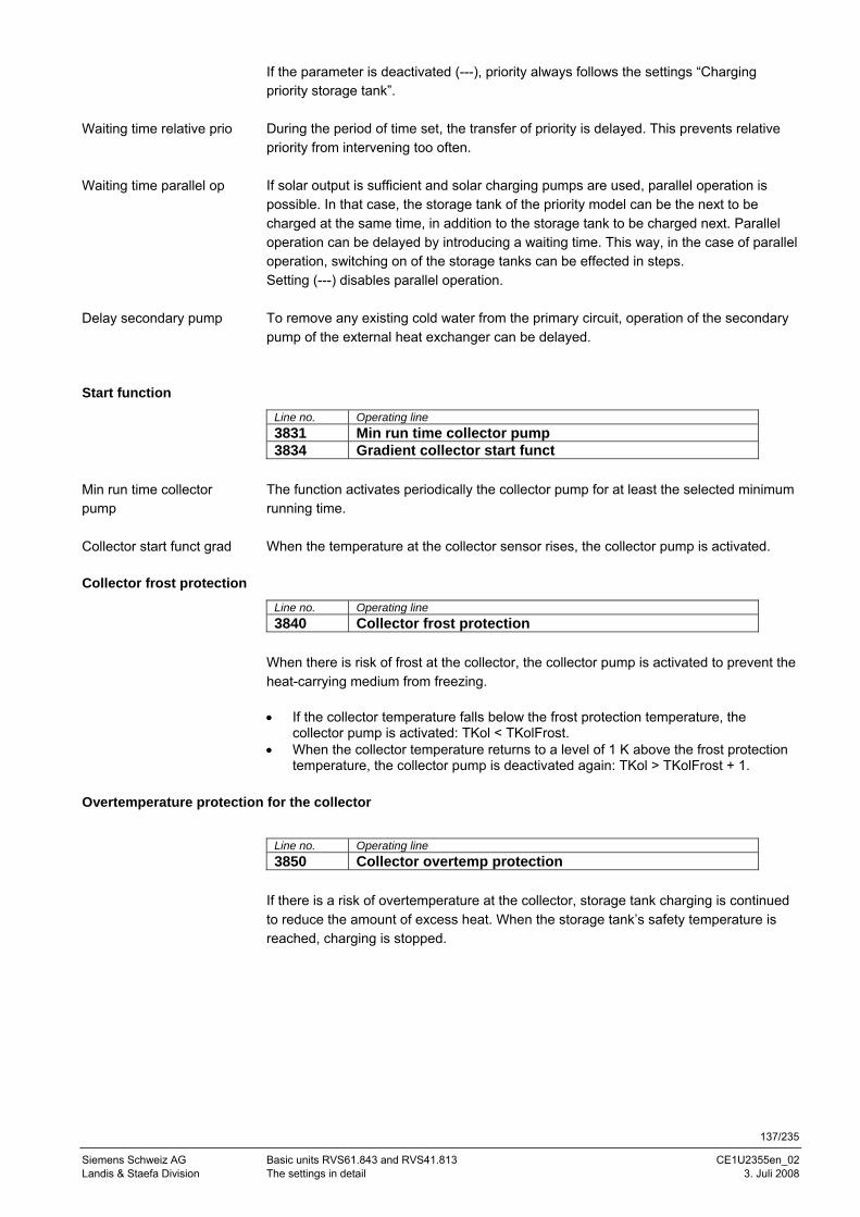
137/235
Siemens Schweiz AG Basic units RVS61.843 and RVS41.813 CE1U2355en_02 Landis & Staefa Division The settings in detail 3. Juli 2008
If the parameter is deactivated (---), priority always follows the settings “Charging priority storage tank”. During the period of time set, the transfer of priority is delayed. This prevents relative priority from intervening too often. If solar output is sufficient and solar charging pumps are used, parallel operation is possible. In that case, the storage tank of the priority model can be the next to be charged at the same time, in addition to the storage tank to be charged next. Parallel operation can be delayed by introducing a waiting time. This way, in the case of parallel operation, switching on of the storage tanks can be effected in steps. Setting (---) disables parallel operation. To remove any existing cold water from the primary circuit, operation of the secondary pump of the external heat exchanger can be delayed.
Start function
Line no. Operating line 3831 Min run time collector pump 3834 Gradient collector start funct
The function activates periodically the collector pump for at least the selected minimum running time. When the temperature at the collector sensor rises, the collector pump is activated.
Collector frost protection
Line no. Operating line 3840 Collector frost protection
When there is risk of frost at the collector, the collector pump is activated to prevent the heat-carrying medium from freezing. • If the collector temperature falls below the frost protection temperature, the
collector pump is activated: TKol < TKolFrost. • When the collector temperature returns to a level of 1 K above the frost protection
temperature, the collector pump is deactivated again: TKol > TKolFrost + 1.
Overtemperature protection for the collector
Line no. Operating line 3850 Collector overtemp protection
If there is a risk of overtemperature at the collector, storage tank charging is continued to reduce the amount of excess heat. When the storage tank’s safety temperature is reached, charging is stopped.
Waiting time relative prio
Waiting time parallel op
Delay secondary pump
Min run time collector pump
Collector start funct grad
138/235
Siemens Switzerland Basic units RVS61.843 and RVS41.813 CE1U2355en_02 HVAC Products Contents 3. Juli 2008
TSpSi Storage tank safety temperature TSp Storage tank temperature TKolUe Collector temperature for overtemperature protection TSpmax Maximum charging temperature Tkol Collector temp On / Off Collector pump T Temperature t Time
Medium’s evaporation temperature
Line no. Operating line 3860 Evaporation heat carrier
If there is a risk of the heat-carrying medium evaporating due to high collector temperatures, the collector pump is deactivated to prevent overtemperatures. This is a protective pump function.
Speed control
Line no. Operating line 3870 Pump speed min 3871 Pump speed max
The speed range of the solar pump is limited by the minimum and maximum permissible speed.
Yield measurement
Line no. Operating line 3880 Antifreeze 3881 Antifreeze concentration 3884 Pump capacity
To ensure accurate solar yield measurement, both additional sensors (B63 in the solar flow and B64 in the solar return) should be connected. If one or both sensors are missing, the controller uses collector sensor B6 or B61 and the respective storage tank sensor B31 or B41 for the calculation. Accurate measurements are made with B63/B64. The 24-hour and total solar energy yield (8526 and 8527) is calculated, based on these data. Since the mixing ratio of the collector medium has an impact on heat transmission, the type of antifreeze used and its concentration must be entered in order to be able to determine the energy yield.
Pump speed min / max
Antifreeze
2358
Z14
Tkol
TSp
TKolUe
TSpMax
1°C
1°C
T
t
TSp
TSpSi
OnOff
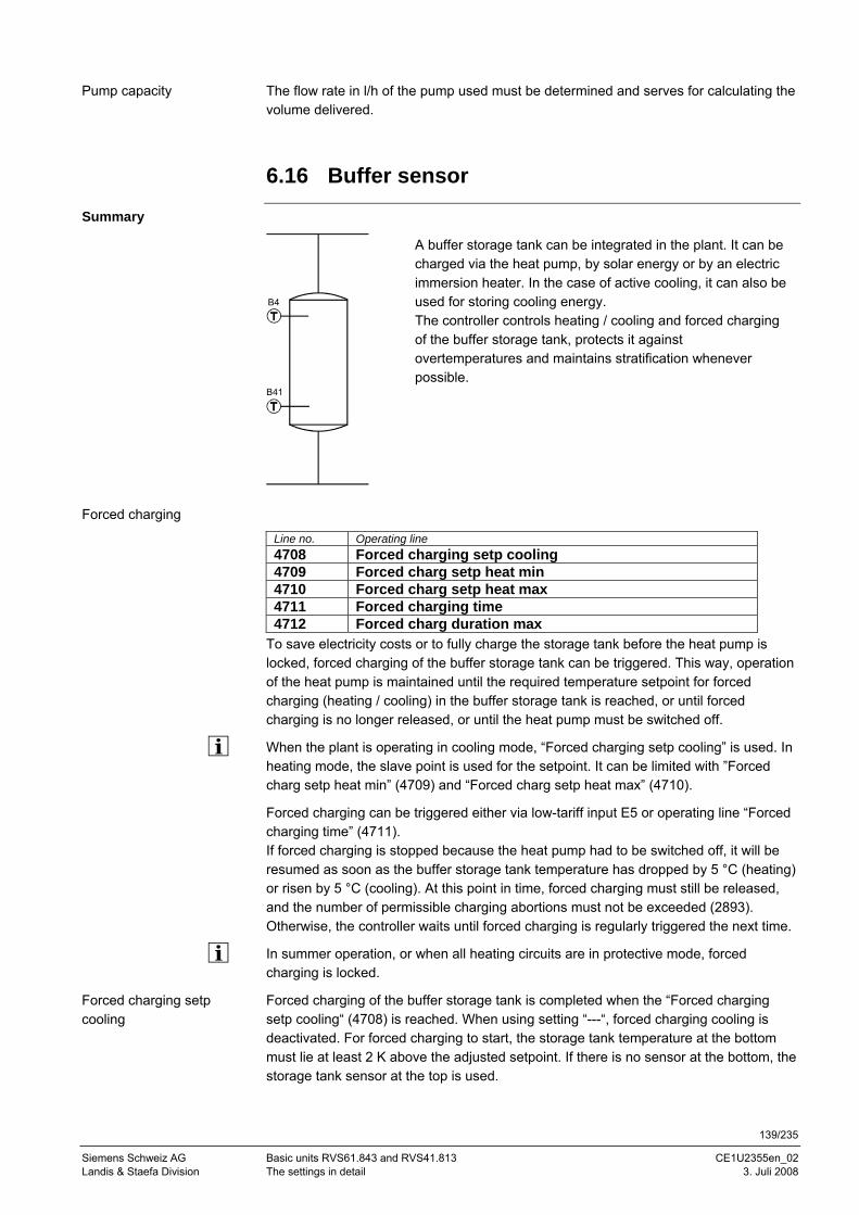
139/235
Siemens Schweiz AG Basic units RVS61.843 and RVS41.813 CE1U2355en_02 Landis & Staefa Division The settings in detail 3. Juli 2008
The flow rate in l/h of the pump used must be determined and serves for calculating the volume delivered.
6.16 Buffer sensor
Summary
B4
B41
A buffer storage tank can be integrated in the plant. It can be charged via the heat pump, by solar energy or by an electric immersion heater. In the case of active cooling, it can also be used for storing cooling energy. The controller controls heating / cooling and forced charging of the buffer storage tank, protects it against overtemperatures and maintains stratification whenever possible.
Forced charging
Line no. Operating line 4708 Forced charging setp cooling 4709 Forced charg setp heat min 4710 Forced charg setp heat max 4711 Forced charging time 4712 Forced charg duration max
To save electricity costs or to fully charge the storage tank before the heat pump is locked, forced charging of the buffer storage tank can be triggered. This way, operation of the heat pump is maintained until the required temperature setpoint for forced charging (heating / cooling) in the buffer storage tank is reached, or until forced charging is no longer released, or until the heat pump must be switched off.
When the plant is operating in cooling mode, “Forced charging setp cooling” is used. In heating mode, the slave point is used for the setpoint. It can be limited with ”Forced charg setp heat min” (4709) and “Forced charg setp heat max” (4710).
Forced charging can be triggered either via low-tariff input E5 or operating line “Forced charging time” (4711). If forced charging is stopped because the heat pump had to be switched off, it will be resumed as soon as the buffer storage tank temperature has dropped by 5 °C (heating) or risen by 5 °C (cooling). At this point in time, forced charging must still be released, and the number of permissible charging abortions must not be exceeded (2893). Otherwise, the controller waits until forced charging is regularly triggered the next time.
In summer operation, or when all heating circuits are in protective mode, forced charging is locked.
Forced charging of the buffer storage tank is completed when the “Forced charging setp cooling“ (4708) is reached. When using setting “---“, forced charging cooling is deactivated. For forced charging to start, the storage tank temperature at the bottom must lie at least 2 K above the adjusted setpoint. If there is no sensor at the bottom, the storage tank sensor at the top is used.
Pump capacity
Forced charging setp cooling
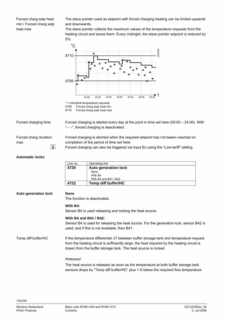
140/235
Siemens Switzerland Basic units RVS61.843 and RVS41.813 CE1U2355en_02 HVAC Products Contents 3. Juli 2008
The slave pointer used as setpoint with forced charging heating can be limited upwards and downwards. The slave pointer collects the maximum values of the temperature requests from the heating circuit and saves them. Every midnight, the slave pointer setpoint is reduced by 5%.
2392
Z09
°C
t
*
4710
*
*
*
** *
**
**
24:00 24:00 24:00 24:00 24:00 24:00 24:00
** ** *
**
**
*
***
**
***
*
**
4709
* = individual temperature requests 4709 Forced charg setp heat min 4710 Forced charg setp heat max
Forced charging is started every day at the point in time set here (00:00 – 24:00). With “- - -“, forced charging is deactivated. Forced charging is aborted when the required setpoint has not beeen reached on completion of the period of time set here. Forced charging can also be triggered via input Ex using the “Low-tariff” setting.
Automatic locks Line no. Operating line 4720 Auto generation lock
None With B4 With B4 and B41 / B42
4722 Temp diff buffer/HC None The function is deactivated.
With B4: Sensor B4 is used releasing and locking the heat source.
With B4 and B41 / B42: Sensor B4 is used for releasing the heat source. For the generation lock, sensor B42 is used, and if this is not available, then B41. If the temperature differential ΔT between buffer storage tank and temperature request from the heating circuit is sufficiently large, the heat required by the heating circuit is drawn from the buffer storage tank. The heat source is locked. Released The heat source is released as soon as the temperature at both buffer storage tank sensors drops by “Temp diff buffer/HC“ plus 1 K below the required flow temperature.
Forced charg setp heat min / Forced charg setp heat max
Forced charging time
Forced charg duration max
Auto generation lock
Temp diff buffer/HC
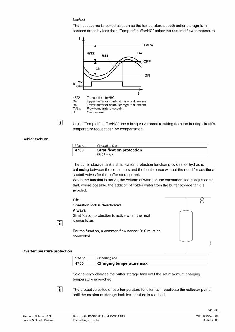
141/235
Siemens Schweiz AG Basic units RVS61.843 and RVS41.813 CE1U2355en_02 Landis & Staefa Division The settings in detail 3. Juli 2008
Locked The heat source is locked as soon as the temperature at both buffer storage tank sensors drops by less than “Temp diff buffer/HC” below the required flow temperature.
ON
OFF
B4
K
1K
B41
T
OFFON
t
TVLw
4722
4722 Temp diff buffer/HC B4 Upper buffer or combi storage tank sensor B41 Lower buffer or combi storage tank sensor TVLw Flow temperature setpoint K Compressor
Using “Temp diff buffer/HC“, the mixing valve boost resulting from the heating circuit’s temperature request can be compensated.
Schichtschutz
Line no. Operating line 4739 Stratification protection
Off ¦ Always
The buffer storage tank’s stratification protection function provides for hydraulic balancing between the consumers and the heat source without the need for additional shutoff valves for the buffer storage tank. When the function is active, the volume of water on the consumer side is adjusted so that, where possible, the addition of colder water from the buffer storage tank is avoided.
Off: Operation lock is deactivated. Always: Stratification protection is active when the heat source is on. For the function, a common flow sensor B10 must be connected.
Overtemperature protection
Line no. Operating line
4750 Charging temperature max Solar energy charges the buffer storage tank until the set maximum charging temperature is reached. The protective collector overtemperature function can reactivate the collector pump until the maximum storage tank temperature is reached.
2358
A42
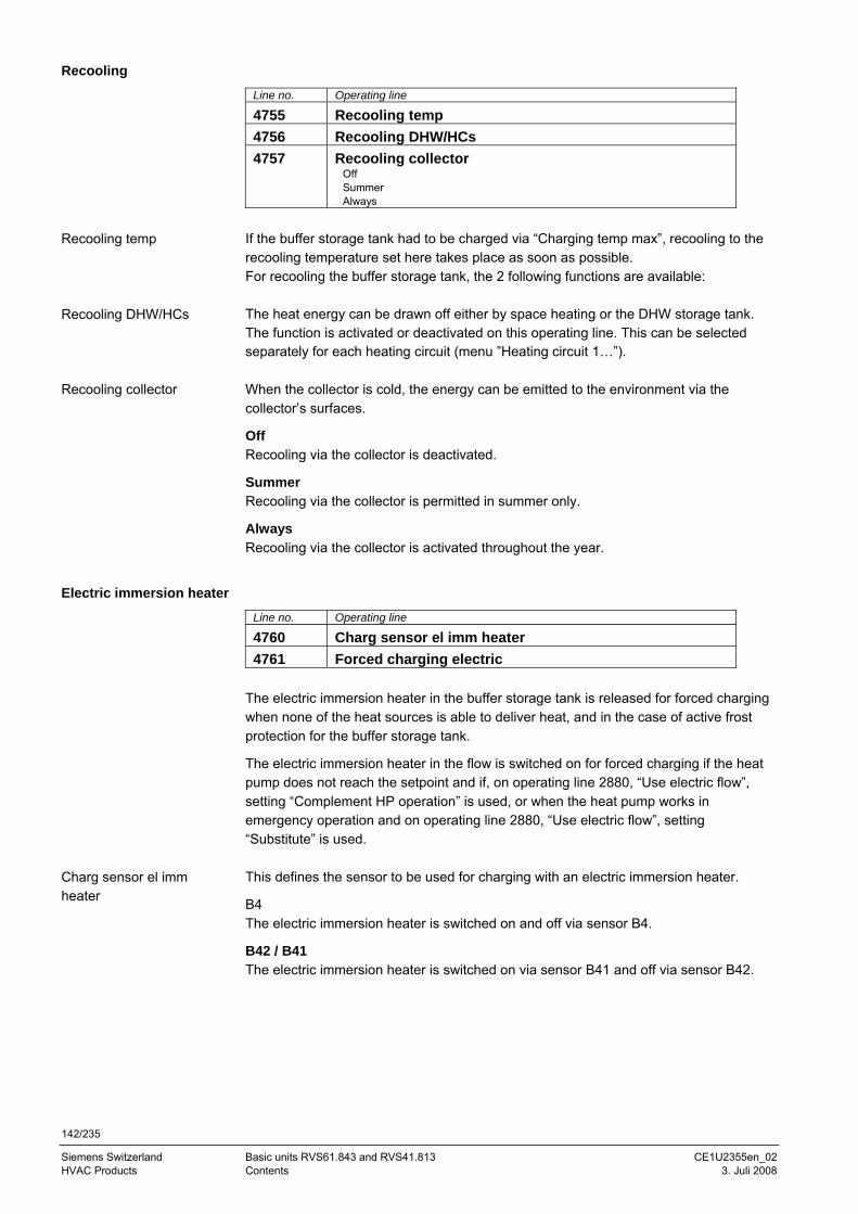
142/235
Siemens Switzerland Basic units RVS61.843 and RVS41.813 CE1U2355en_02 HVAC Products Contents 3. Juli 2008
Recooling
Line no. Operating line
4755 Recooling temp 4756 Recooling DHW/HCs 4757 Recooling collector
Off Summer Always
If the buffer storage tank had to be charged via “Charging temp max”, recooling to the recooling temperature set here takes place as soon as possible. For recooling the buffer storage tank, the 2 following functions are available: The heat energy can be drawn off either by space heating or the DHW storage tank. The function is activated or deactivated on this operating line. This can be selected separately for each heating circuit (menu ”Heating circuit 1…”). When the collector is cold, the energy can be emitted to the environment via the collector’s surfaces.
Off Recooling via the collector is deactivated.
Summer Recooling via the collector is permitted in summer only.
Always Recooling via the collector is activated throughout the year.
Electric immersion heater
Line no. Operating line
4760 Charg sensor el imm heater 4761 Forced charging electric
The electric immersion heater in the buffer storage tank is released for forced charging when none of the heat sources is able to deliver heat, and in the case of active frost protection for the buffer storage tank.
The electric immersion heater in the flow is switched on for forced charging if the heat pump does not reach the setpoint and if, on operating line 2880, “Use electric flow”, setting “Complement HP operation” is used, or when the heat pump works in emergency operation and on operating line 2880, “Use electric flow”, setting “Substitute” is used. This defines the sensor to be used for charging with an electric immersion heater.
B4 The electric immersion heater is switched on and off via sensor B4.
B42 / B41 The electric immersion heater is switched on via sensor B41 and off via sensor B42.
Recooling temp
Recooling DHW/HCs
Recooling collector
Charg sensor el imm heater
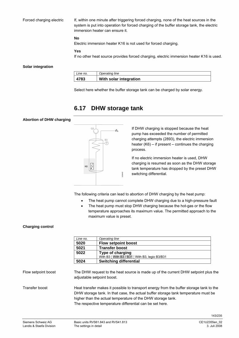
143/235
Siemens Schweiz AG Basic units RVS61.843 and RVS41.813 CE1U2355en_02 Landis & Staefa Division The settings in detail 3. Juli 2008
If, within one minute after triggering forced charging, none of the heat sources in the system is put into operation for forced charging of the buffer storage tank, the electric immersion heater can ensure it.
No Electric immersion heater K16 is not used for forced charging.
Yes If no other heat source provides forced charging, electric immersion heater K16 is used.
Solar integration
Line no. Operating line
4783 With solar integration Select here whether the buffer storage tank can be charged by solar energy.
6.17 DHW storage tank
Abortion of DHW charging 23
58A0
5
B3
Q3
K6
If DHW charging is stopped because the heat pump has exceeded the number of permitted charging attempts (2893), the electric immersion heater (K6) – if present – continues the charging process.
If no electric immersion heater is used, DHW charging is resumed as soon as the DHW storage tank temperature has dropped by the preset DHW switching differential.
The following criteria can lead to abortion of DHW charging by the heat pump:
• The heat pump cannot complete DHW charging due to a high-pressure fault • The heat pump must stop DHW charging because the hot-gas or the flow
temperature approaches its maximum value. The permitted approach to the maximum value is preset.
Charging control
Line no. Operating line 5020 Flow setpoint boost 5021 Transfer boost 5022 Type of charging
With B3 ¦ With B3 / B31 ¦ With B3, legio B3/B31 5024 Switching differential
The DHW request to the heat source is made up of the current DHW setpoint plus the adjustable setpoint boost. Heat transfer makes it possible to transport energy from the buffer storage tank to the DHW storage tank. In that case, the actual buffer storage tank temperature must be higher than the actual temperature of the DHW storage tank. The respective temperature differential can be set here.
Forced charging electric
Flow setpoint boost
Transfer boost
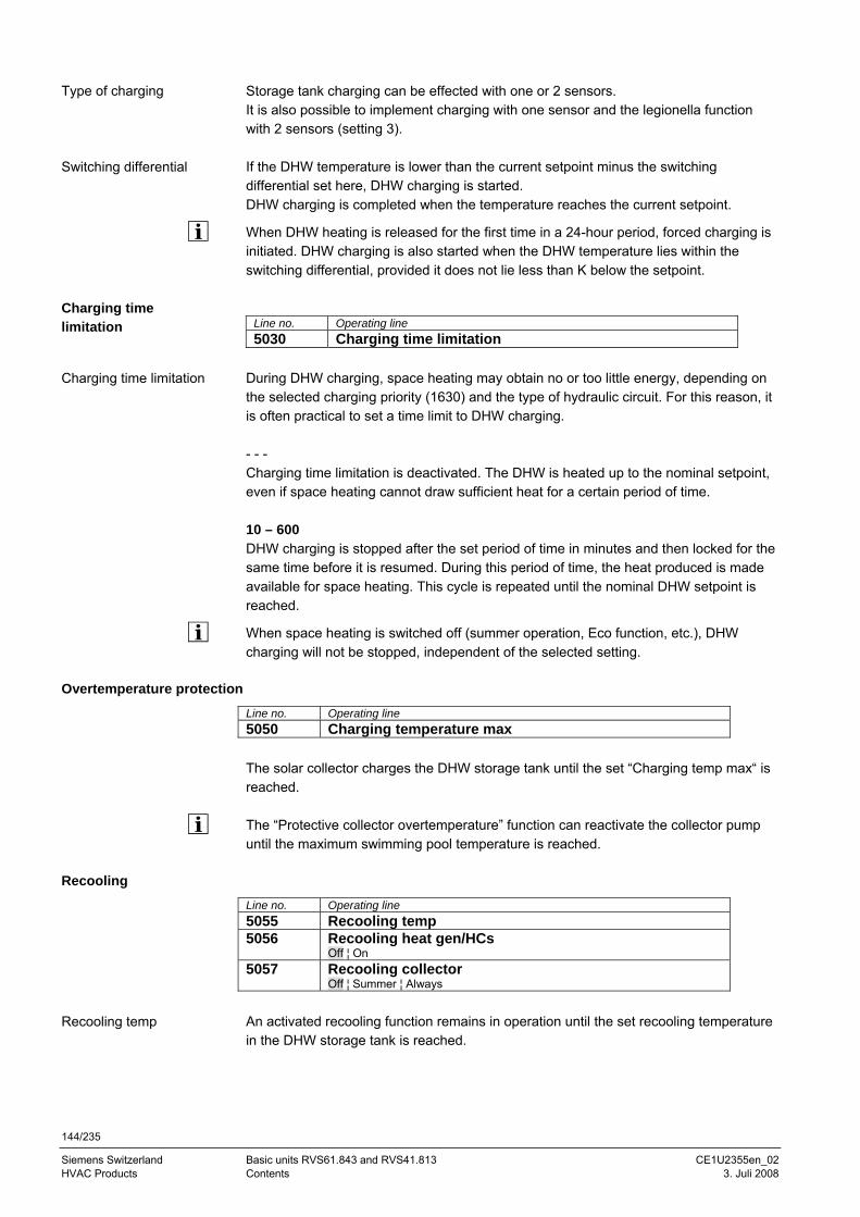
144/235
Siemens Switzerland Basic units RVS61.843 and RVS41.813 CE1U2355en_02 HVAC Products Contents 3. Juli 2008
Storage tank charging can be effected with one or 2 sensors. It is also possible to implement charging with one sensor and the legionella function with 2 sensors (setting 3). If the DHW temperature is lower than the current setpoint minus the switching differential set here, DHW charging is started. DHW charging is completed when the temperature reaches the current setpoint.
When DHW heating is released for the first time in a 24-hour period, forced charging is initiated. DHW charging is also started when the DHW temperature lies within the switching differential, provided it does not lie less than K below the setpoint.
Line no. Operating line 5030 Charging time limitation
During DHW charging, space heating may obtain no or too little energy, depending on the selected charging priority (1630) and the type of hydraulic circuit. For this reason, it is often practical to set a time limit to DHW charging. - - - Charging time limitation is deactivated. The DHW is heated up to the nominal setpoint, even if space heating cannot draw sufficient heat for a certain period of time. 10 – 600 DHW charging is stopped after the set period of time in minutes and then locked for the same time before it is resumed. During this period of time, the heat produced is made available for space heating. This cycle is repeated until the nominal DHW setpoint is reached.
When space heating is switched off (summer operation, Eco function, etc.), DHW charging will not be stopped, independent of the selected setting.
Overtemperature protection
Line no. Operating line 5050 Charging temperature max The solar collector charges the DHW storage tank until the set “Charging temp max“ is reached. The “Protective collector overtemperature” function can reactivate the collector pump until the maximum swimming pool temperature is reached.
Recooling
Line no. Operating line 5055 Recooling temp 5056 Recooling heat gen/HCs
Off ¦ On 5057 Recooling collector
Off ¦ Summer ¦ Always
An activated recooling function remains in operation until the set recooling temperature in the DHW storage tank is reached.
Type of charging
Switching differential
Charging time limitation
Charging time limitation
Recooling temp
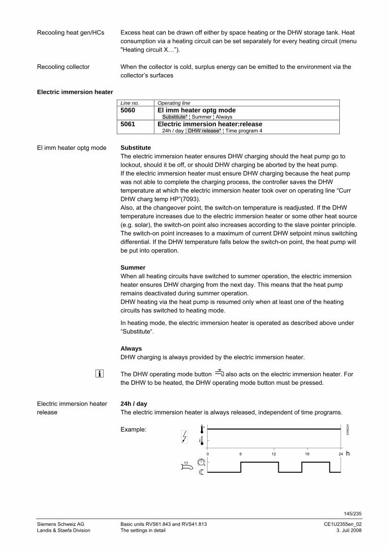
145/235
Siemens Schweiz AG Basic units RVS61.843 and RVS41.813 CE1U2355en_02 Landis & Staefa Division The settings in detail 3. Juli 2008
Excess heat can be drawn off either by space heating or the DHW storage tank. Heat consumption via a heating circuit can be set separately for every heating circuit (menu "Heating circuit X…”). When the collector is cold, surplus energy can be emitted to the environment via the collector’s surfaces
Electric immersion heater
Line no. Operating line 5060 El imm heater optg mode
Substitute* ¦ Summer ¦ Always 5061 Electric immersion heater:release
24h / day ¦ DHW release* ¦ Time program 4
Substitute The electric immersion heater ensures DHW charging should the heat pump go to lockout, should it be off, or should DHW charging be aborted by the heat pump. If the electric immersion heater must ensure DHW charging because the heat pump was not able to complete the charging process, the controller saves the DHW temperature at which the electric immersion heater took over on operating line “Curr DHW charg temp HP”(7093). Also, at the changeover point, the switch-on temperature is readjusted. If the DHW temperature increases due to the electric immersion heater or some other heat source (e.g. solar), the switch-on point also increases according to the slave pointer principle. The switch-on point increases to a maximum of current DHW setpoint minus switching differential. If the DHW temperature falls below the switch-on point, the heat pump will be put into operation. Summer When all heating circuits have switched to summer operation, the electric immersion heater ensures DHW charging from the next day. This means that the heat pump remains deactivated during summer operation. DHW heating via the heat pump is resumed only when at least one of the heating circuits has switched to heating mode.
In heating mode, the electric immersion heater is operated as described above under “Substitute“. Always DHW charging is always provided by the electric immersion heater. The DHW operating mode button also acts on the electric immersion heater. For the DHW to be heated, the DHW operating mode button must be pressed.
24h / day The electric immersion heater is always released, independent of time programs. Example:
Recooling heat gen/HCs
Recooling collector
El imm heater optg mode
Electric immersion heater release
0 6 12 18 24 h
2358
Z24
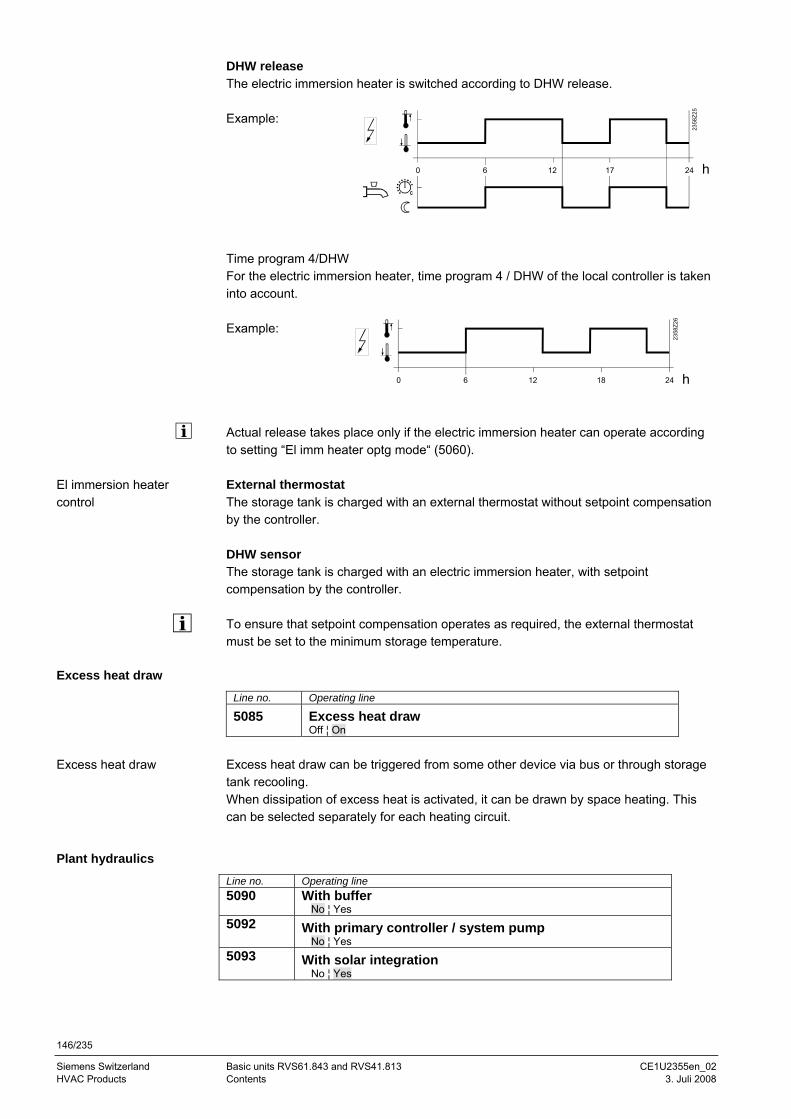
146/235
Siemens Switzerland Basic units RVS61.843 and RVS41.813 CE1U2355en_02 HVAC Products Contents 3. Juli 2008
DHW release The electric immersion heater is switched according to DHW release. Example:
Time program 4/DHW For the electric immersion heater, time program 4 / DHW of the local controller is taken into account. Example:
Actual release takes place only if the electric immersion heater can operate according to setting “El imm heater optg mode“ (5060). External thermostat The storage tank is charged with an external thermostat without setpoint compensation by the controller. DHW sensor The storage tank is charged with an electric immersion heater, with setpoint compensation by the controller. To ensure that setpoint compensation operates as required, the external thermostat must be set to the minimum storage temperature.
Excess heat draw
Line no. Operating line
5085 Excess heat draw Off ¦ On
Excess heat draw can be triggered from some other device via bus or through storage tank recooling. When dissipation of excess heat is activated, it can be drawn by space heating. This can be selected separately for each heating circuit.
Plant hydraulics
Line no. Operating line 5090 With buffer
No ¦ Yes 5092 With primary controller / system pump
No ¦ Yes 5093 With solar integration
No ¦ Yes
El immersion heater control
Excess heat draw
0 6 12 18 24 h
2358
Z26
0 6 12 24 h
2358
Z25
17
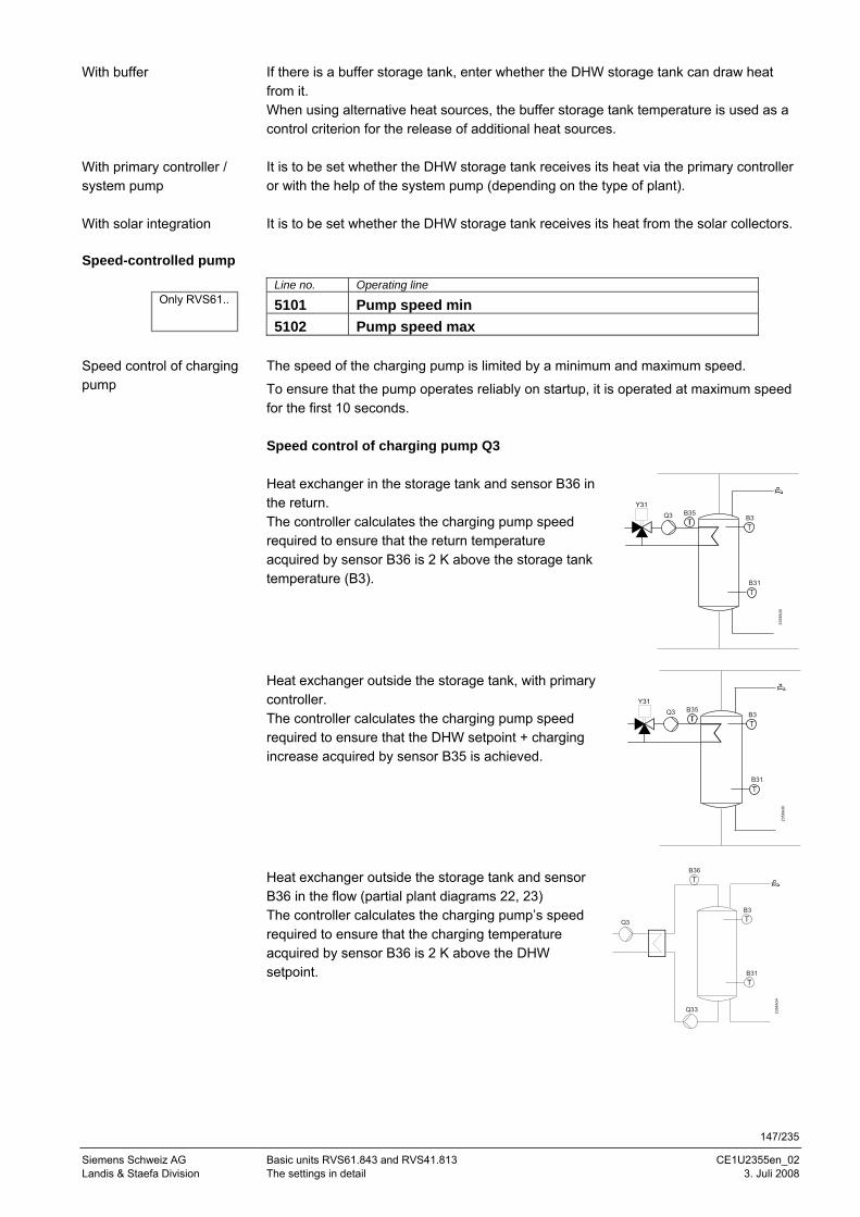
147/235
Siemens Schweiz AG Basic units RVS61.843 and RVS41.813 CE1U2355en_02 Landis & Staefa Division The settings in detail 3. Juli 2008
If there is a buffer storage tank, enter whether the DHW storage tank can draw heat from it. When using alternative heat sources, the buffer storage tank temperature is used as a control criterion for the release of additional heat sources. It is to be set whether the DHW storage tank receives its heat via the primary controller or with the help of the system pump (depending on the type of plant). It is to be set whether the DHW storage tank receives its heat from the solar collectors.
Speed-controlled pump
Line no. Operating line
5101 Pump speed min 5102 Pump speed max
The speed of the charging pump is limited by a minimum and maximum speed.
To ensure that the pump operates reliably on startup, it is operated at maximum speed for the first 10 seconds. Speed control of charging pump Q3 Heat exchanger in the storage tank and sensor B36 in the return. The controller calculates the charging pump speed required to ensure that the return temperature acquired by sensor B36 is 2 K above the storage tank temperature (B3).
2358
A30
B3Q3Y31
B31
B35
Heat exchanger outside the storage tank, with primary controller. The controller calculates the charging pump speed required to ensure that the DHW setpoint + charging increase acquired by sensor B35 is achieved.
2358
A30
B3Q3Y31
B31
B35
Heat exchanger outside the storage tank and sensor B36 in the flow (partial plant diagrams 22, 23) The controller calculates the charging pump’s speed required to ensure that the charging temperature acquired by sensor B36 is 2 K above the DHW setpoint.
2358
A34
B3
Q3
B31
B36
Q33
With buffer
With primary controller / system pump
With solar integration
Speed control of charging pump
Only RVS61..
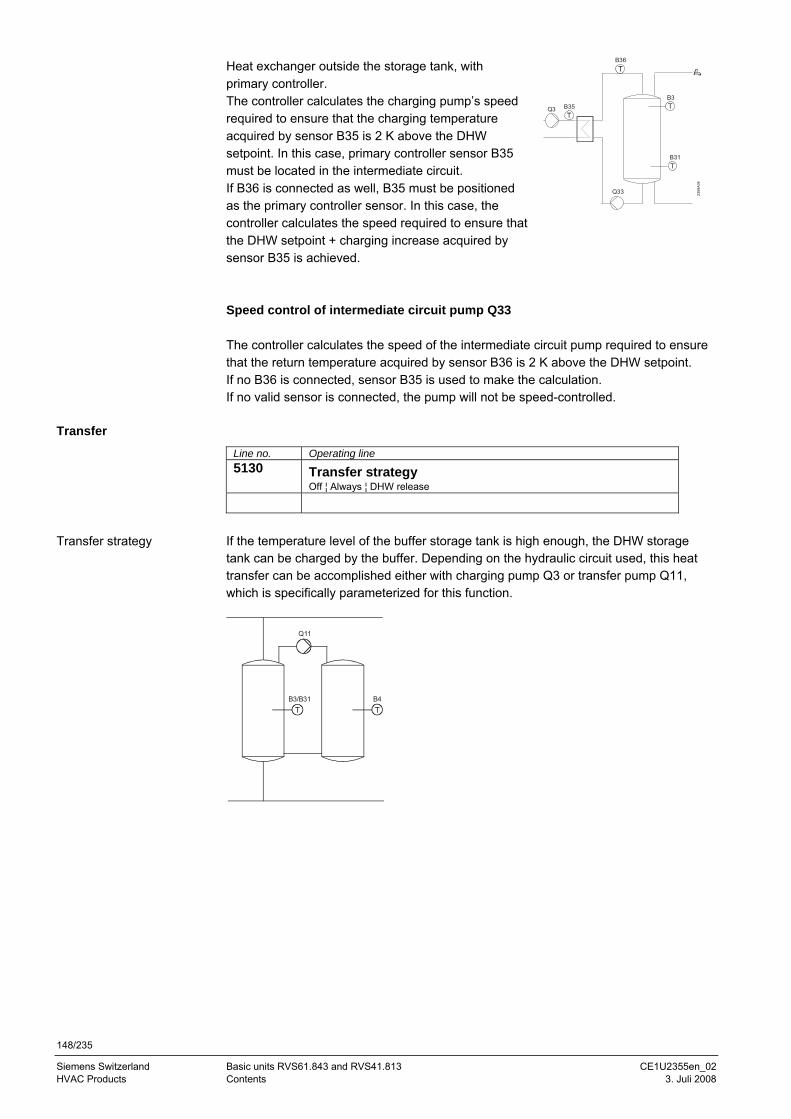
148/235
Siemens Switzerland Basic units RVS61.843 and RVS41.813 CE1U2355en_02 HVAC Products Contents 3. Juli 2008
Heat exchanger outside the storage tank, with primary controller. The controller calculates the charging pump’s speed required to ensure that the charging temperature acquired by sensor B35 is 2 K above the DHW setpoint. In this case, primary controller sensor B35 must be located in the intermediate circuit. If B36 is connected as well, B35 must be positioned as the primary controller sensor. In this case, the controller calculates the speed required to ensure that the DHW setpoint + charging increase acquired by sensor B35 is achieved.
2358
A34
B3
Q3
B31
B36
Q33
B35
Speed control of intermediate circuit pump Q33 The controller calculates the speed of the intermediate circuit pump required to ensure that the return temperature acquired by sensor B36 is 2 K above the DHW setpoint. If no B36 is connected, sensor B35 is used to make the calculation. If no valid sensor is connected, the pump will not be speed-controlled.
Transfer
Line no. Operating line 5130 Transfer strategy
Off ¦ Always ¦ DHW release
If the temperature level of the buffer storage tank is high enough, the DHW storage tank can be charged by the buffer. Depending on the hydraulic circuit used, this heat transfer can be accomplished either with charging pump Q3 or transfer pump Q11, which is specifically parameterized for this function.
B3/B31 B4
Q11
Transfer strategy
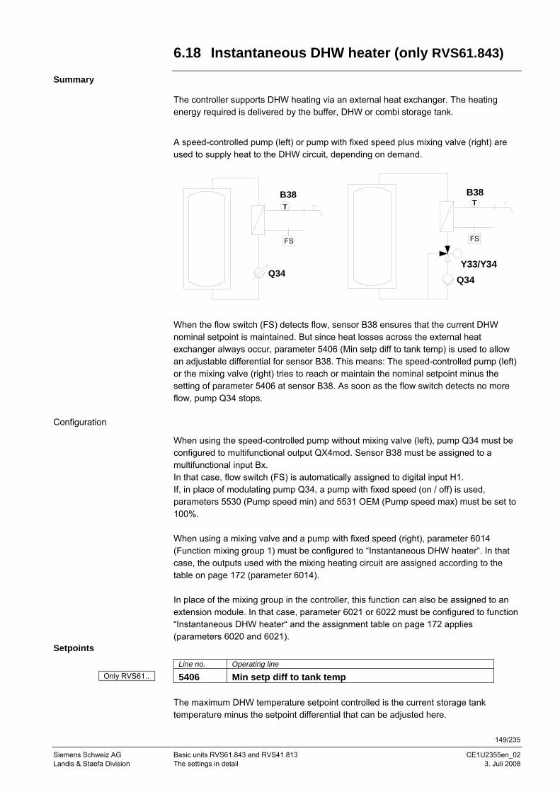
149/235
Siemens Schweiz AG Basic units RVS61.843 and RVS41.813 CE1U2355en_02 Landis & Staefa Division The settings in detail 3. Juli 2008
6.18 Instantaneous DHW heater (only RVS61.843)
Summary
The controller supports DHW heating via an external heat exchanger. The heating energy required is delivered by the buffer, DHW or combi storage tank.
A speed-controlled pump (left) or pump with fixed speed plus mixing valve (right) are used to supply heat to the DHW circuit, depending on demand.
B38T
Q34
FS
T
Y33/Y34
B38
Q34
FS
When the flow switch (FS) detects flow, sensor B38 ensures that the current DHW nominal setpoint is maintained. But since heat losses across the external heat exchanger always occur, parameter 5406 (Min setp diff to tank temp) is used to allow an adjustable differential for sensor B38. This means: The speed-controlled pump (left) or the mixing valve (right) tries to reach or maintain the nominal setpoint minus the setting of parameter 5406 at sensor B38. As soon as the flow switch detects no more flow, pump Q34 stops.
Configuration
When using the speed-controlled pump without mixing valve (left), pump Q34 must be configured to multifunctional output QX4mod. Sensor B38 must be assigned to a multifunctional input Bx. In that case, flow switch (FS) is automatically assigned to digital input H1. If, in place of modulating pump Q34, a pump with fixed speed (on / off) is used, parameters 5530 (Pump speed min) and 5531 OEM (Pump speed max) must be set to 100%. When using a mixing valve and a pump with fixed speed (right), parameter 6014 (Function mixing group 1) must be configured to “Instantaneous DHW heater“. In that case, the outputs used with the mixing heating circuit are assigned according to the table on page 172 (parameter 6014). In place of the mixing group in the controller, this function can also be assigned to an extension module. In that case, parameter 6021 or 6022 must be configured to function “Instantaneous DHW heater“ and the assignment table on page 172 applies (parameters 6020 and 6021).
Setpoints
Line no. Operating line
5406 Min setp diff to tank temp The maximum DHW temperature setpoint controlled is the current storage tank temperature minus the setpoint differential that can be adjusted here.
Only RVS61..
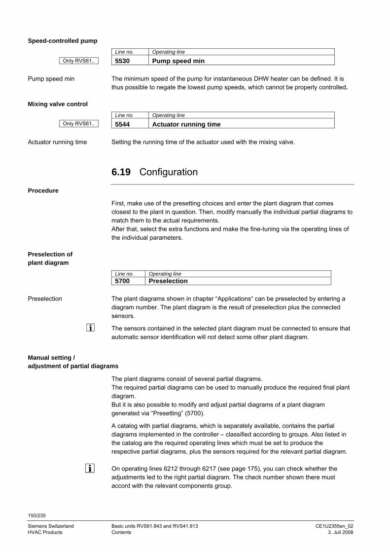
150/235
Siemens Switzerland Basic units RVS61.843 and RVS41.813 CE1U2355en_02 HVAC Products Contents 3. Juli 2008
Speed-controlled pump
Line no. Operating line
5530 Pump speed min The minimum speed of the pump for instantaneous DHW heater can be defined. It is thus possible to negate the lowest pump speeds, which cannot be properly controlled.
Mixing valve control
Line no. Operating line
5544 Actuator running time Setting the running time of the actuator used with the mixing valve.
6.19 Configuration
Procedure
First, make use of the presetting choices and enter the plant diagram that comes closest to the plant in question. Then, modify manually the individual partial diagrams to match them to the actual requirements. After that, select the extra functions and make the fine-tuning via the operating lines of the individual parameters.
Preselection of plant diagram
Line no. Operating line 5700 Preselection
The plant diagrams shown in chapter “Applications“ can be preselected by entering a diagram number. The plant diagram is the result of preselection plus the connected sensors.
The sensors contained in the selected plant diagram must be connected to ensure that automatic sensor identification will not detect some other plant diagram.
Manual setting / adjustment of partial diagrams
The plant diagrams consist of several partial diagrams. The required partial diagrams can be used to manually produce the required final plant diagram. But it is also possible to modify and adjust partial diagrams of a plant diagram generated via “Presetting” (5700).
A catalog with partial diagrams, which is separately available, contains the partial diagrams implemented in the controller – classified according to groups. Also listed in the catalog are the required operating lines which must be set to produce the respective partial diagrams, plus the sensors required for the relevant partial diagram. On operating lines 6212 through 6217 (see page 175), you can check whether the adjustments led to the right partial diagram. The check number shown there must accord with the relevant components group.
Pump speed min
Actuator running time
Preselection
Only RVS61..
Only RVS61..
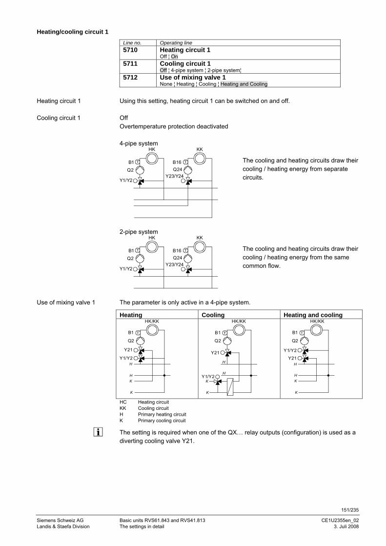
151/235
Siemens Schweiz AG Basic units RVS61.843 and RVS41.813 CE1U2355en_02 Landis & Staefa Division The settings in detail 3. Juli 2008
Heating/cooling circuit 1
Line no. Operating line 5710 Heating circuit 1
Off ¦ On 5711 Cooling circuit 1
Off ¦ 4-pipe system ¦ 2-pipe system¦ 5712 Use of mixing valve 1
None ¦ Heating ¦ Cooling ¦ Heating and Cooling
Using this setting, heating circuit 1 can be switched on and off. Off Overtemperature protection deactivated 4-pipe system
Q2
HK
T
Y1/Y2
B1Q24
KK
T
Y23/Y24
B16
The cooling and heating circuits draw their cooling / heating energy from separate circuits.
2-pipe system
Q2
HK
T
Y1/Y2
B1Q24
KK
T
Y23/Y24
B16
The cooling and heating circuits draw their cooling / heating energy from the same common flow.
The parameter is only active in a 4-pipe system.
Heating Cooling Heating and cooling
Q2
HK/KK
TB1
Y1/Y2
Y21
H
K
K
H
Q2
HK/KK
TB1
Y1/Y2
Y21
H
K
H
K
Q2
HK/KK
TB1
Y1/Y2
Y21H
K
K
H
HC Heating circuit KK Cooling circuit H Primary heating circuit K Primary cooling circuit
The setting is required when one of the QX… relay outputs (configuration) is used as a diverting cooling valve Y21.
Heating circuit 1
Cooling circuit 1
Use of mixing valve 1
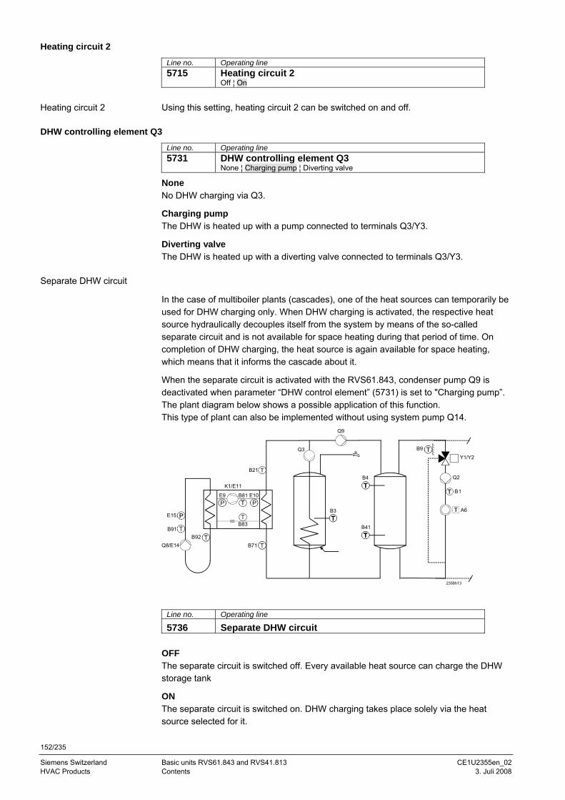
152/235
Siemens Switzerland Basic units RVS61.843 and RVS41.813 CE1U2355en_02 HVAC Products Contents 3. Juli 2008
Heating circuit 2
Line no. Operating line 5715 Heating circuit 2
Off ¦ On
Using this setting, heating circuit 2 can be switched on and off.
DHW controlling element Q3
Line no. Operating line 5731 DHW controlling element Q3
None ¦ Charging pump ¦ Diverting valve
None No DHW charging via Q3.
Charging pump The DHW is heated up with a pump connected to terminals Q3/Y3.
Diverting valve The DHW is heated up with a diverting valve connected to terminals Q3/Y3.
Separate DHW circuit
In the case of multiboiler plants (cascades), one of the heat sources can temporarily be used for DHW charging only. When DHW charging is activated, the respective heat source hydraulically decouples itself from the system by means of the so-called separate circuit and is not available for space heating during that period of time. On completion of DHW charging, the heat source is again available for space heating, which means that it informs the cascade about it.
When the separate circuit is activated with the RVS61.843, condenser pump Q9 is deactivated when parameter “DHW control element” (5731) is set to "Charging pump”. The plant diagram below shows a possible application of this function. This type of plant can also be implemented without using system pump Q14.
2358h13
B3
Q3
Q9
B21
K1/E11
B71B92
Q8/E14
B91
E15
E9PP
B81 E10
B83
B4
B41
B9
Y1/Y2
Q2
B1
A6
Line no. Operating line
5736 Separate DHW circuit OFF The separate circuit is switched off. Every available heat source can charge the DHW storage tank
ON The separate circuit is switched on. DHW charging takes place solely via the heat source selected for it.
Heating circuit 2
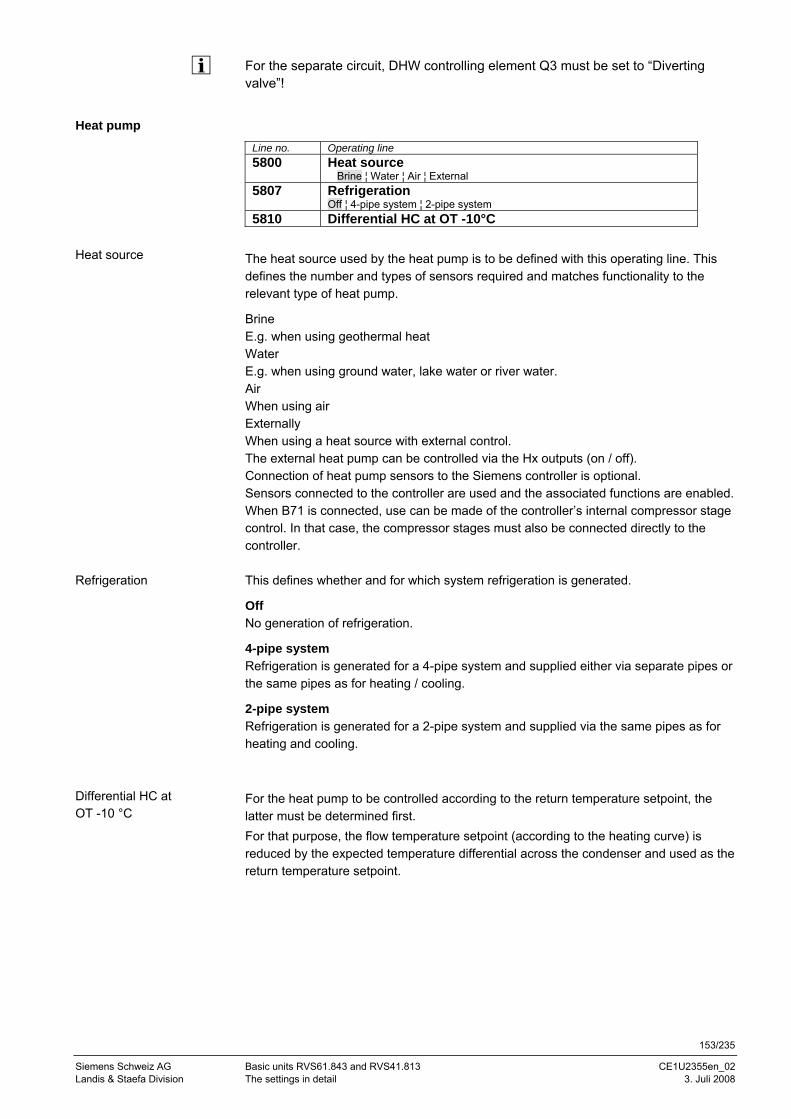
153/235
Siemens Schweiz AG Basic units RVS61.843 and RVS41.813 CE1U2355en_02 Landis & Staefa Division The settings in detail 3. Juli 2008
For the separate circuit, DHW controlling element Q3 must be set to “Diverting valve”!
Heat pump
Line no. Operating line 5800 Heat source
Brine ¦ Water ¦ Air ¦ External 5807 Refrigeration
Off ¦ 4-pipe system ¦ 2-pipe system 5810 Differential HC at OT -10°C
The heat source used by the heat pump is to be defined with this operating line. This defines the number and types of sensors required and matches functionality to the relevant type of heat pump.
Brine E.g. when using geothermal heat Water E.g. when using ground water, lake water or river water. Air When using air Externally When using a heat source with external control. The external heat pump can be controlled via the Hx outputs (on / off). Connection of heat pump sensors to the Siemens controller is optional. Sensors connected to the controller are used and the associated functions are enabled. When B71 is connected, use can be made of the controller’s internal compressor stage control. In that case, the compressor stages must also be connected directly to the controller. This defines whether and for which system refrigeration is generated.
Off No generation of refrigeration.
4-pipe system Refrigeration is generated for a 4-pipe system and supplied either via separate pipes or the same pipes as for heating / cooling.
2-pipe system Refrigeration is generated for a 2-pipe system and supplied via the same pipes as for heating and cooling. For the heat pump to be controlled according to the return temperature setpoint, the latter must be determined first. For that purpose, the flow temperature setpoint (according to the heating curve) is reduced by the expected temperature differential across the condenser and used as the return temperature setpoint.
Heat source
Refrigeration
Differential HC at OT -10 °C
154/235
Siemens Switzerland Basic units RVS61.843 and RVS41.813 CE1U2355en_02 HVAC Products Contents 3. Juli 2008
The temperature differential at an outside temperature of -10 °C that is entered on this operating line is transformed to the current composite outside temperature. At an outside temperature of –10 °C, the flow temperature setpoint is reduced by the set value, and there is no more reduction at an outside temperature of 20 °C.
T
TRL
Ta20°C
TVL
-10°C
5801
TVL Flow temperature tRL Return temperature Ta Outside temperature
Important! Instead of entering the correct temperature differential at –10 °C, it is also possible to enter 0 as the temperature differential. In that case, the heating curve must be set for the return temperature setpoint. But this choice only exists for plants without mixing heating circuit. Parameter 5810 is active only if there is no buffer storage tank. In cooling mode, the parameter has no impact. In the case of return temperature control, the cooling curve must be based on the return temperature setpoint.
Solar
Line no. Operating line
5840 Solar controlling element Charging pump Diverting valve
5841 External solar exchanger Commonly DHW storage tank Buffer sensor
In place of a collector pump and diverting valves for integrating the storage tanks, the solar plant can also be operated with charging pumps. When using a diverting valve, it is always only one heat exchanger that can be used at a time. Only alternative operation is possible. When using a charging pump, all heat exchangers can be used at the same time. Either parallel or alternative operation is possible. In the case of solar plants with 2 storage tanks, it must be selected whether the external heat exchanger shall be used for DHW and as a buffer storage tank, or exclusively for one of the two.
Solar controlling element
External solar exchanger
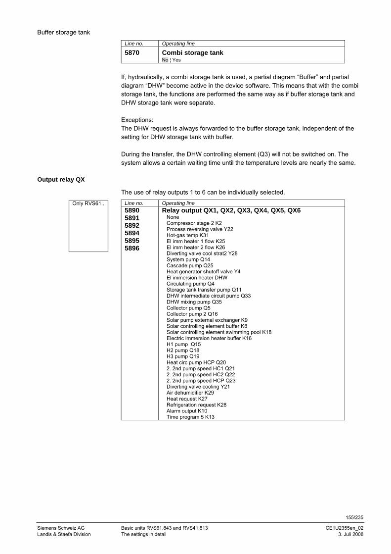
155/235
Siemens Schweiz AG Basic units RVS61.843 and RVS41.813 CE1U2355en_02 Landis & Staefa Division The settings in detail 3. Juli 2008
Buffer storage tank
Line no. Operating line
5870 Combi storage tank No ¦ Yes
If, hydraulically, a combi storage tank is used, a partial diagram “Buffer” and partial diagram “DHW" become active in the device software. This means that with the combi storage tank, the functions are performed the same way as if buffer storage tank and DHW storage tank were separate. Exceptions: The DHW request is always forwarded to the buffer storage tank, independent of the setting for DHW storage tank with buffer. During the transfer, the DHW controlling element (Q3) will not be switched on. The system allows a certain waiting time until the temperature levels are nearly the same.
Output relay QX
The use of relay outputs 1 to 6 can be individually selected.
Line no. Operating line 5890 5891 5892 5894 5895 5896
Relay output QX1, QX2, QX3, QX4, QX5, QX6 None Compressor stage 2 K2 Process reversing valve Y22 Hot-gas temp K31 El imm heater 1 flow K25 El imm heater 2 flow K26 Diverting valve cool strat2 Y28 System pump Q14 Cascade pump Q25 Heat generator shutoff valve Y4 El immersion heater DHW Circulating pump Q4 Storage tank transfer pump Q11 DHW intermediate circuit pump Q33 DHW mixing pump Q35 Collector pump Q5 Collector pump 2 Q16 Solar pump external exchanger K9 Solar controlling element buffer K8 Solar controlling element swimming pool K18 Electric immersion heater buffer K16 H1 pump Q15 H2 pump Q18 H3 pump Q19 Heat circ pump HCP Q20 2. 2nd pump speed HC1 Q21 2. 2nd pump speed HC2 Q22 2. 2nd pump speed HCP Q23 Diverting valve cooling Y21 Air dehumidifier K29 Heat request K27 Refrigeration request K28 Alarm output K10 Time program 5 K13
Only RVS61..
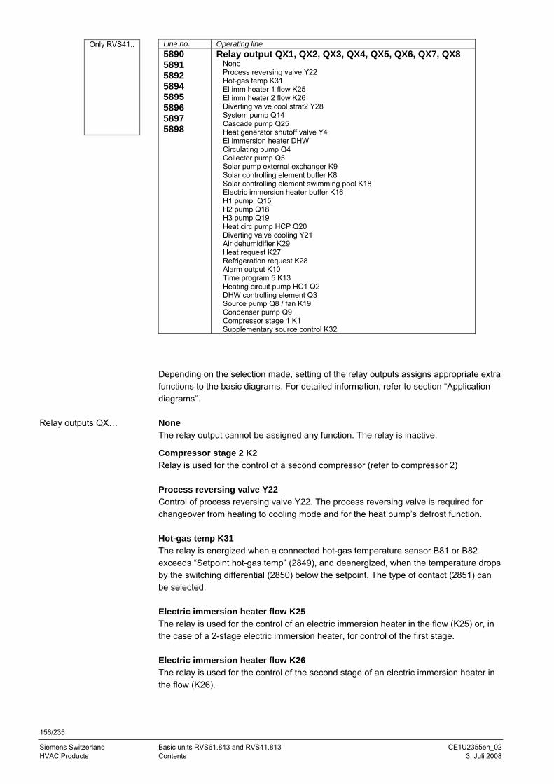
156/235
Siemens Switzerland Basic units RVS61.843 and RVS41.813 CE1U2355en_02 HVAC Products Contents 3. Juli 2008
Line no. Operating line 5890 5891 5892 5894 5895 5896 5897 5898
Relay output QX1, QX2, QX3, QX4, QX5, QX6, QX7, QX8 None Process reversing valve Y22 Hot-gas temp K31 El imm heater 1 flow K25 El imm heater 2 flow K26 Diverting valve cool strat2 Y28 System pump Q14 Cascade pump Q25 Heat generator shutoff valve Y4 El immersion heater DHW Circulating pump Q4 Collector pump Q5 Solar pump external exchanger K9 Solar controlling element buffer K8 Solar controlling element swimming pool K18 Electric immersion heater buffer K16 H1 pump Q15 H2 pump Q18 H3 pump Q19 Heat circ pump HCP Q20 Diverting valve cooling Y21 Air dehumidifier K29 Heat request K27 Refrigeration request K28 Alarm output K10 Time program 5 K13 Heating circuit pump HC1 Q2 DHW controlling element Q3 Source pump Q8 / fan K19 Condenser pump Q9 Compressor stage 1 K1 Supplementary source control K32
Depending on the selection made, setting of the relay outputs assigns appropriate extra functions to the basic diagrams. For detailed information, refer to section “Application diagrams“. None The relay output cannot be assigned any function. The relay is inactive.
Compressor stage 2 K2 Relay is used for the control of a second compressor (refer to compressor 2) Process reversing valve Y22 Control of process reversing valve Y22. The process reversing valve is required for changeover from heating to cooling mode and for the heat pump’s defrost function. Hot-gas temp K31 The relay is energized when a connected hot-gas temperature sensor B81 or B82 exceeds “Setpoint hot-gas temp” (2849), and deenergized, when the temperature drops by the switching differential (2850) below the setpoint. The type of contact (2851) can be selected. Electric immersion heater flow K25 The relay is used for the control of an electric immersion heater in the flow (K25) or, in the case of a 2-stage electric immersion heater, for control of the first stage. Electric immersion heater flow K26 The relay is used for the control of the second stage of an electric immersion heater in the flow (K26).
Relay outputs QX…
Only RVS41..
157/235
Siemens Schweiz AG Basic units RVS61.843 and RVS41.813 CE1U2355en_02 Landis & Staefa Division The settings in detail 3. Juli 2008
Diverting valve cool strat2 Y28 Control of optional diverting valve cooling Y28 for changeover to passive cooling. In the case of simultaneous heating mode, this ensures hydraulic disconnection of the heating circuit from the cooling circuit. System pump Q14 The connected pump serves as a system pump for supplying heat to other consumers. The system pump is put into operation as soon as one of consumers calls for heat. If there is no heat request, the pump will be deactivated followed by overrun. Cascade pump Q25 Common pump for all heat sources in a cascade. Heat generator shutoff valve Y4 If the buffer storage tank holds a sufficient amount of heat, the consumers can draw their heat from it, and the heat sources need not be put into operation. Automatic heat generation lock locks the heat sources and hydraulically disconnects them from the rest of the plant with the help of shutoff valve Y4. This means that the heat consumers draw energy from the buffer storage tank and wrong circulation through the heat sources is prevented. El immersion heater DHW Using the connected electric immersion heater, the DHW can be charged according to operating lines “El imm heater optg mode” (5660) and “El immersion heater release” (5061). The electric immersion heater must be equipped with a safety limit thermostat! “El imm heater optg mode” must be appropriately set. Circulating pump Q4 The connected pump serves as a DHW circulating pump. The time schedule for the circulating pump can be set on operating line “Circulating pump release” (1660). “Circulating pump cycling” can be set on operating line 1661, “Circulation setpoint” on operating line 1663. . Storage tank transfer pump Q11 If the temperature level of the buffer storage tank is high enough, the DHW storage tank can be charged by the buffer. This heat transfer can take place by means of transfer pump Q11. DHW intermediate circuit pump Q33 Charging pump with DHW storage tank using an external heat exchanger. DHW mixing pump Q35 Separate pump for storage tank circulation during the time the legionella function is active. Collector pump Q5 For control of the collector pump. Collector pump 2 Q16 For control of the circulating pump of a second solar collector circuit.
158/235
Siemens Switzerland Basic units RVS61.843 and RVS41.813 CE1U2355en_02 HVAC Products Contents 3. Juli 2008
Solar pump external exchanger K9 For the external heat exchanger, solar pump “Ext heat exchanger K9“ must be set at the multifunctional relay output (QX). If both a DHW and a buffer storage tank are available, operating line 5841 “External solar exchanger“ must also be set. Solar controlling element buffer K8 If several heat exchangers are used, the buffer storage tank must be set at the respective relay output and, in addition, the type of solar controlling element must be defined on operating line 5840). Solar controlling element swimming pool K18 If several heat exchangers are used, the swimming pool must be set at the respective relay output and, in addition, the type of solar controlling element must be defined on operating line 5840). Electric immersion heater buffer K16 The relay is used for the control of an electric immersion heater in the buffer storage tank.
Important! Electric immersion heaters must be fitted with a safety limit thermostat. H1 pump Q15 Pump H1 can be used for an additional consumer. Together with an external request for heating / cooling at input H1, the application is suited for an air heating coil / air cooling coil, for instance. The pump’s overrun time is always 1 minute. H2 pump Q18 Pump H1 can be used for an additional consumer. Together with an external request for heating / cooling at input H2, the application is suited for an air heating coil / air cooling coil, for instance. The pump’s overrun time is always 1 minute. H3 pump Q19 Pump H1 can be used for an additional consumer. Together with an external request for heating / cooling at input H3, the application is suited for an air heating coil / air cooling coil, for instance. The pump’s overrun time is always 1 minute. Heat circuit pump HCP Q20 The relay is used for the control of heating circuit pump Q20. 2. Pump speed HC1 Q21 / HC2 Q22 / HCP Q23 This function facilitates control of a 2-speed heating circuit pump, allowing the pump’s capacity to be lowered in Reduced mode (e.g. during night setback). In that case, after pump speed 1, pump speed 2 is switched on as follows via “Multifunctional relay RX“:
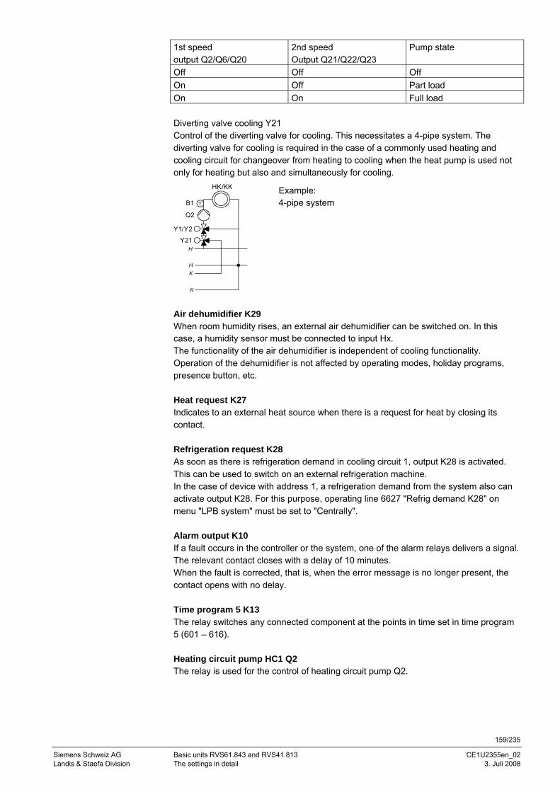
159/235
Siemens Schweiz AG Basic units RVS61.843 and RVS41.813 CE1U2355en_02 Landis & Staefa Division The settings in detail 3. Juli 2008
1st speed output Q2/Q6/Q20
2nd speed Output Q21/Q22/Q23
Pump state
Off Off Off On Off Part load On On Full load Diverting valve cooling Y21 Control of the diverting valve for cooling. This necessitates a 4-pipe system. The diverting valve for cooling is required in the case of a commonly used heating and cooling circuit for changeover from heating to cooling when the heat pump is used not only for heating but also and simultaneously for cooling.
Q2
HK/KK
TB1
Y1/Y2
Y21H
K
K
H
Example: 4-pipe system
Air dehumidifier K29 When room humidity rises, an external air dehumidifier can be switched on. In this case, a humidity sensor must be connected to input Hx. The functionality of the air dehumidifier is independent of cooling functionality. Operation of the dehumidifier is not affected by operating modes, holiday programs, presence button, etc. Heat request K27 Indicates to an external heat source when there is a request for heat by closing its contact. Refrigeration request K28 As soon as there is refrigeration demand in cooling circuit 1, output K28 is activated. This can be used to switch on an external refrigeration machine. In the case of device with address 1, a refrigeration demand from the system also can activate output K28. For this purpose, operating line 6627 "Refrig demand K28" on menu "LPB system" must be set to "Centrally". Alarm output K10 If a fault occurs in the controller or the system, one of the alarm relays delivers a signal. The relevant contact closes with a delay of 10 minutes. When the fault is corrected, that is, when the error message is no longer present, the contact opens with no delay. Time program 5 K13 The relay switches any connected component at the points in time set in time program 5 (601 – 616). Heating circuit pump HC1 Q2 The relay is used for the control of heating circuit pump Q2.
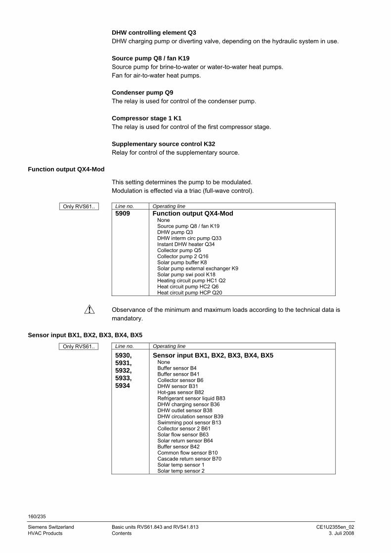
160/235
Siemens Switzerland Basic units RVS61.843 and RVS41.813 CE1U2355en_02 HVAC Products Contents 3. Juli 2008
DHW controlling element Q3 DHW charging pump or diverting valve, depending on the hydraulic system in use. Source pump Q8 / fan K19 Source pump for brine-to-water or water-to-water heat pumps. Fan for air-to-water heat pumps. Condenser pump Q9 The relay is used for control of the condenser pump. Compressor stage 1 K1 The relay is used for control of the first compressor stage. Supplementary source control K32 Relay for control of the supplementary source.
Function output QX4-Mod
This setting determines the pump to be modulated. Modulation is effected via a triac (full-wave control).
Line no. Operating line 5909 Function output QX4-Mod
None Source pump Q8 / fan K19 DHW pump Q3 DHW interm circ pump Q33 Instant DHW heater Q34 Collector pump Q5 Collector pump 2 Q16 Solar pump buffer K8 Solar pump external exchanger K9 Solar pump swi pool K18 Heating circuit pump HC1 Q2 Heat circuit pump HC2 Q6 Heat circuit pump HCP Q20
Observance of the minimum and maximum loads according to the technical data is mandatory.
Sensor input BX1, BX2, BX3, BX4, BX5
Line no. Operating line
5930, 5931, 5932, 5933, 5934
Sensor input BX1, BX2, BX3, BX4, BX5 None Buffer sensor B4 Buffer sensor B41 Collector sensor B6 DHW sensor B31 Hot-gas sensor B82 Refrigerant sensor liquid B83 DHW charging sensor B36 DHW outlet sensor B38 DHW circulation sensor B39 Swimming pool sensor B13 Collector sensor 2 B61 Solar flow sensor B63 Solar return sensor B64 Buffer sensor B42 Common flow sensor B10 Cascade return sensor B70 Solar temp sensor 1 Solar temp sensor 2
Only RVS61..
Only RVS61..
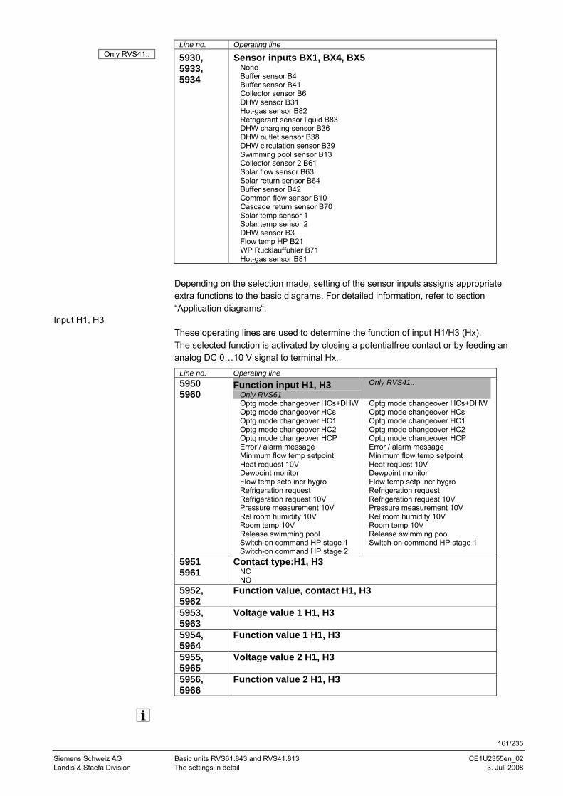
161/235
Siemens Schweiz AG Basic units RVS61.843 and RVS41.813 CE1U2355en_02 Landis & Staefa Division The settings in detail 3. Juli 2008
Line no. Operating line
5930, 5933, 5934
Sensor inputs BX1, BX4, BX5 None Buffer sensor B4 Buffer sensor B41 Collector sensor B6 DHW sensor B31 Hot-gas sensor B82 Refrigerant sensor liquid B83 DHW charging sensor B36 DHW outlet sensor B38 DHW circulation sensor B39 Swimming pool sensor B13 Collector sensor 2 B61 Solar flow sensor B63 Solar return sensor B64 Buffer sensor B42 Common flow sensor B10 Cascade return sensor B70 Solar temp sensor 1 Solar temp sensor 2 DHW sensor B3 Flow temp HP B21 WP Rücklauffühler B71 Hot-gas sensor B81
Depending on the selection made, setting of the sensor inputs assigns appropriate extra functions to the basic diagrams. For detailed information, refer to section “Application diagrams“.
Input H1, H3 These operating lines are used to determine the function of input H1/H3 (Hx). The selected function is activated by closing a potentialfree contact or by feeding an analog DC 0…10 V signal to terminal Hx.
Line no. Operating line 5950 5960
Function input H1, H3 Only RVS61
Only RVS41..
Optg mode changeover HCs+DHWOptg mode changeover HCs Optg mode changeover HC1 Optg mode changeover HC2 Optg mode changeover HCP Error / alarm message Minimum flow temp setpoint Heat request 10V Dewpoint monitor Flow temp setp incr hygro Refrigeration request Refrigeration request 10V Pressure measurement 10V Rel room humidity 10V Room temp 10V Release swimming pool Switch-on command HP stage 1 Switch-on command HP stage 2
Optg mode changeover HCs+DHWOptg mode changeover HCs Optg mode changeover HC1 Optg mode changeover HC2 Optg mode changeover HCP Error / alarm message Minimum flow temp setpoint Heat request 10V Dewpoint monitor Flow temp setp incr hygro Refrigeration request Refrigeration request 10V Pressure measurement 10V Rel room humidity 10V Room temp 10V Release swimming pool Switch-on command HP stage 1
5951 5961
Contact type:H1, H3 NC NO
5952, 5962
Function value, contact H1, H3
5953, 5963
Voltage value 1 H1, H3
5954, 5964
Function value 1 H1, H3
5955, 5965
Voltage value 2 H1, H3
5956, 5966
Function value 2 H1, H3
Only RVS41..
162/235
Siemens Switzerland Basic units RVS61.843 and RVS41.813 CE1U2355en_02 HVAC Products Contents 3. Juli 2008
The settings for input H2 are made on operating lines 6046 – 6052. Changeover of operating mode • Heating circuits
The operating mode of the respective heating circuit(s) is switched to Protection via terminal Hx (e.g. by means of a remote telephone switch).
• DHW DHW heating is locked only when using setting 1 (HCs+DHW) All temperature requests made by the heating circuits and by DHW are ignored. Frost protection is maintained.
Error / alarm message When input H1 closes, a controller-internal error message is triggered. If the alarm output (relay outputs QX1 – 6, 5890 – 5896) is appropriately configured, the error is forwarded or indicated by closing an additional contact (by an external lamp or horn). Minimum flow temp setpoint Consumers requiring a minimum flow temperature can request it via contact Hx (e.g. air heating coil for warm air curtain). When the contact closes, the temperature setpoint adjusted on operating line 5952 / 5962 is demanded. Heat request 10V Heat generation receives heat requests in the form of voltage signals (DC 0...10 V). The associated setpoint is calculated on the basis of the straight line defined with operating lines 5953 through 5956 (for H1), or 5963 through 5966 (for H3). Dewpoint monitor To detect the formation of condensation in the cooling circuit, a dewpoint monitor can be connected to input Hx. If the dewpoint monitor trips, the cooling circuit is immediately switched off. The cooling is enabled again when the dewpoint monitor reverts to normal and an adjustable locking time (946) has elapsed. Flow temp setp inc hygro To prevent the formation of condensation due to high indoor air humidity, a hygrostat can be connected to input Hx. If the hygrostat trips, the flow temperature setpoint is increased by the fixed value of "Flow temp setp incr hygro" (947). As soon as the hygrostat reverts to normal, the flow temperature setpoint returns to the "normal value". Refrigeration request If the connected contact closes, the controller drives the heat pump to the fixed temperature setpoint adjusted on operating line 5952 (for H1), 6048 (for H2), or 5962 (for H3). If the refrigeration request made is lower, consideration is given to it. Refrigeration request 10V Refrigeration generation receives the refrigeration request in the form of voltage signals (DC 0...10 V). The respective setpoint in °C is determined via the linear characteristic which is defined by 2 fixed points (voltage value 1 / function value 1, and voltage value 2 / function value 2).
Function input Hx
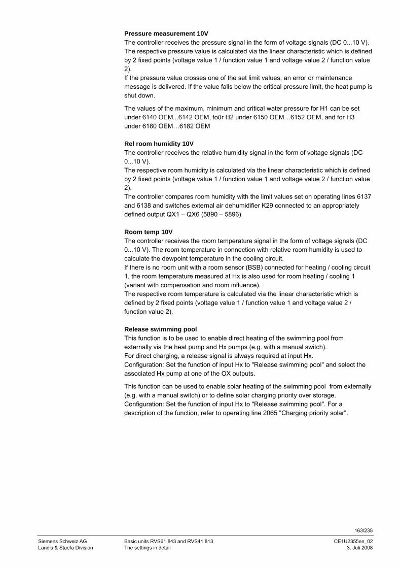
163/235
Siemens Schweiz AG Basic units RVS61.843 and RVS41.813 CE1U2355en_02 Landis & Staefa Division The settings in detail 3. Juli 2008
Pressure measurement 10V The controller receives the pressure signal in the form of voltage signals (DC 0...10 V). The respective pressure value is calculated via the linear characteristic which is defined by 2 fixed points (voltage value 1 / function value 1 and voltage value 2 / function value 2). If the pressure value crosses one of the set limit values, an error or maintenance message is delivered. If the value falls below the critical pressure limit, the heat pump is shut down.
The values of the maximum, minimum and critical water pressure for H1 can be set under 6140 OEM...6142 OEM, foür H2 under 6150 OEM…6152 OEM, and for H3 under 6180 OEM…6182 OEM Rel room humidity 10V The controller receives the relative humidity signal in the form of voltage signals (DC 0...10 V). The respective room humidity is calculated via the linear characteristic which is defined by 2 fixed points (voltage value 1 / function value 1 and voltage value 2 / function value 2). The controller compares room humidity with the limit values set on operating lines 6137 and 6138 and switches external air dehumidifier K29 connected to an appropriately defined output QX1 – QX6 (5890 – 5896). Room temp 10V The controller receives the room temperature signal in the form of voltage signals (DC 0...10 V). The room temperature in connection with relative room humidity is used to calculate the dewpoint temperature in the cooling circuit. If there is no room unit with a room sensor (BSB) connected for heating / cooling circuit 1, the room temperature measured at Hx is also used for room heating / cooling 1 (variant with compensation and room influence). The respective room temperature is calculated via the linear characteristic which is defined by 2 fixed points (voltage value 1 / function value 1 and voltage value 2 / function value 2). Release swimming pool This function is to be used to enable direct heating of the swimming pool from externally via the heat pump and Hx pumps (e.g. with a manual switch). For direct charging, a release signal is always required at input Hx. Configuration: Set the function of input Hx to "Release swimming pool" and select the associated Hx pump at one of the OX outputs.
This function can be used to enable solar heating of the swimming pool from externally (e.g. with a manual switch) or to define solar charging priority over storage. Configuration: Set the function of input Hx to "Release swimming pool". For a description of the function, refer to operating line 2065 "Charging priority solar".
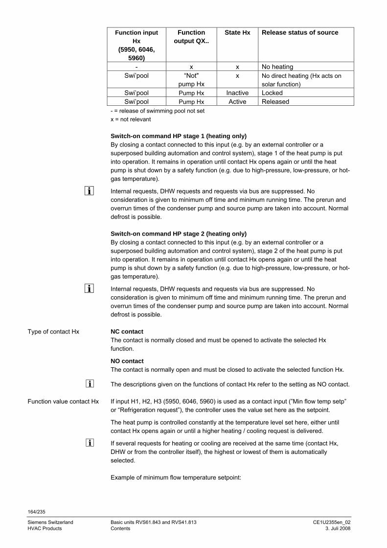
164/235
Siemens Switzerland Basic units RVS61.843 and RVS41.813 CE1U2355en_02 HVAC Products Contents 3. Juli 2008
Function input Hx
(5950, 6046, 5960)
Function output QX..
State Hx Release status of source
- x x No heating Swi’pool “Not"
pump Hx x No direct heating (Hx acts on
solar function) Swi’pool Pump Hx Inactive Locked Swi’pool Pump Hx Active Released
- = release of swimming pool not set x = not relevant Switch-on command HP stage 1 (heating only) By closing a contact connected to this input (e.g. by an external controller or a superposed building automation and control system), stage 1 of the heat pump is put into operation. It remains in operation until contact Hx opens again or until the heat pump is shut down by a safety function (e.g. due to high-pressure, low-pressure, or hot-gas temperature).
Internal requests, DHW requests and requests via bus are suppressed. No consideration is given to minimum off time and minimum running time. The prerun and overrun times of the condenser pump and source pump are taken into account. Normal defrost is possible. Switch-on command HP stage 2 (heating only) By closing a contact connected to this input (e.g. by an external controller or a superposed building automation and control system), stage 2 of the heat pump is put into operation. It remains in operation until contact Hx opens again or until the heat pump is shut down by a safety function (e.g. due to high-pressure, low-pressure, or hot-gas temperature).
Internal requests, DHW requests and requests via bus are suppressed. No consideration is given to minimum off time and minimum running time. The prerun and overrun times of the condenser pump and source pump are taken into account. Normal defrost is possible. NC contact The contact is normally closed and must be opened to activate the selected Hx function.
NO contact The contact is normally open and must be closed to activate the selected function Hx.
The descriptions given on the functions of contact Hx refer to the setting as NO contact. If input H1, H2, H3 (5950, 6046, 5960) is used as a contact input (”Min flow temp setp” or “Refrigeration request”), the controller uses the value set here as the setpoint.
The heat pump is controlled constantly at the temperature level set here, either until contact Hx opens again or until a higher heating / cooling request is delivered.
If several requests for heating or cooling are received at the same time (contact Hx, DHW or from the controller itself), the highest or lowest of them is automatically selected. Example of minimum flow temperature setpoint:
Type of contact Hx
Function value contact Hx
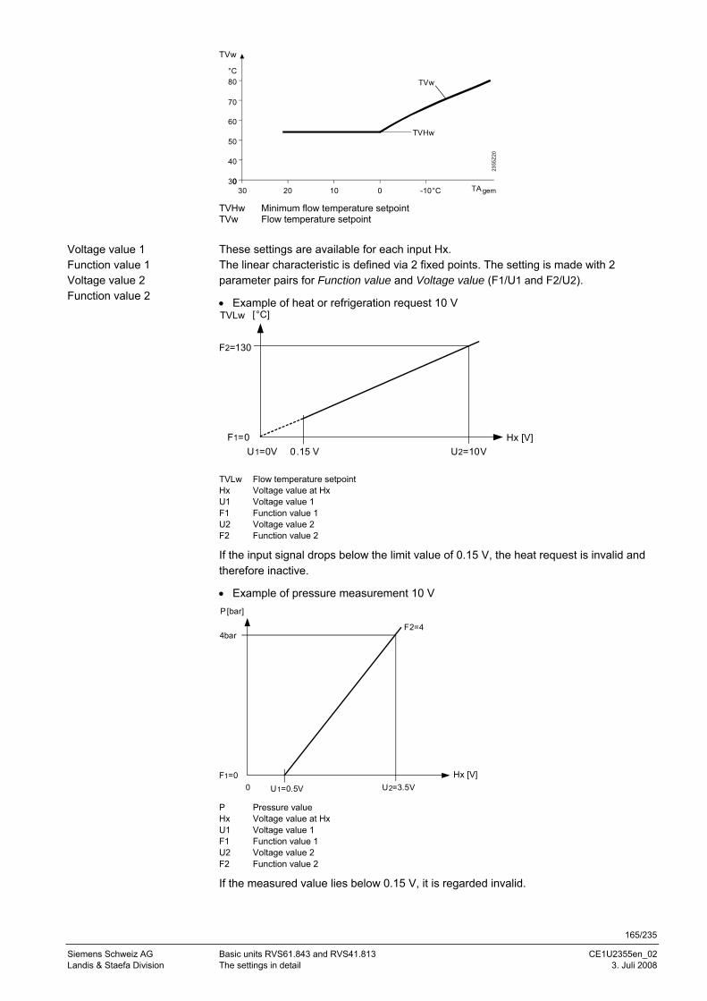
165/235
Siemens Schweiz AG Basic units RVS61.843 and RVS41.813 CE1U2355en_02 Landis & Staefa Division The settings in detail 3. Juli 2008
30 20 10 0 -10
40
30
60
50
80
70
TVw
TVw
2355
Z20
TA
°C
°C gem 0
TVHw
TVHw Minimum flow temperature setpoint TVw Flow temperature setpoint These settings are available for each input Hx. The linear characteristic is defined via 2 fixed points. The setting is made with 2 parameter pairs for Function value and Voltage value (F1/U1 and F2/U2).
• Example of heat or refrigeration request 10 V TVLw [°C]
Hx [V]U2=10VU1=0V
F1=00.15 V
F2=130
TVLw Flow temperature setpoint Hx Voltage value at Hx U1 Voltage value 1 F1 Function value 1 U2 Voltage value 2 F2 Function value 2
If the input signal drops below the limit value of 0.15 V, the heat request is invalid and therefore inactive.
• Example of pressure measurement 10 V P [bar]
U2=3.5V
4bar
0
F2=4
U1=0.5VF1=0 Hx [V]
P Pressure value Hx Voltage value at Hx U1 Voltage value 1 F1 Function value 1 U2 Voltage value 2 F2 Function value 2
If the measured value lies below 0.15 V, it is regarded invalid.
Voltage value 1 Function value 1 Voltage value 2 Function value 2
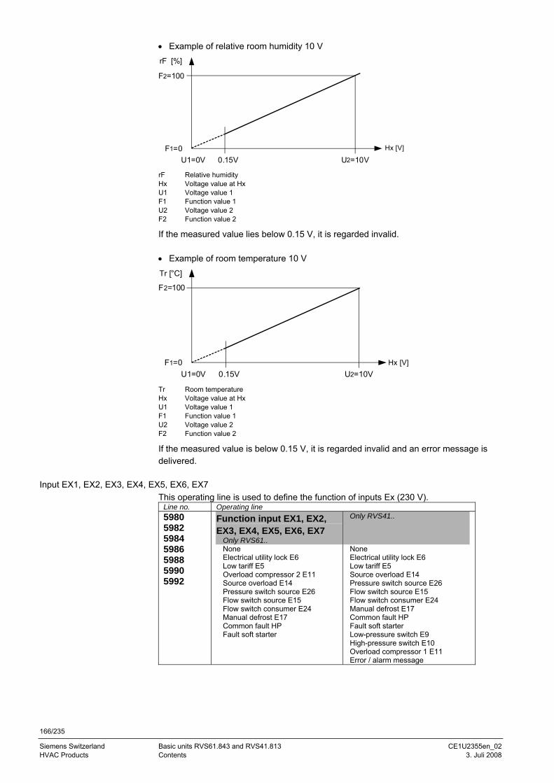
166/235
Siemens Switzerland Basic units RVS61.843 and RVS41.813 CE1U2355en_02 HVAC Products Contents 3. Juli 2008
• Example of relative room humidity 10 V
U2=10VU1=0VF1=0
F2=100
0.15V
rF [%]
Hx [V]
rF Relative humidity Hx Voltage value at Hx U1 Voltage value 1 F1 Function value 1 U2 Voltage value 2 F2 Function value 2
If the measured value lies below 0.15 V, it is regarded invalid. • Example of room temperature 10 V Tr [°C]
U2=10VU1=0VF1=0
0.15V
F2=100
Hx [V]
Tr Room temperature Hx Voltage value at Hx U1 Voltage value 1 F1 Function value 1 U2 Voltage value 2 F2 Function value 2
If the measured value is below 0.15 V, it is regarded invalid and an error message is delivered.
Input EX1, EX2, EX3, EX4, EX5, EX6, EX7 This operating line is used to define the function of inputs Ex (230 V).
Line no. Operating line 5980 5982 5984 5986 5988 5990 5992
Function input EX1, EX2, EX3, EX4, EX5, EX6, EX7
Only RVS61..
Only RVS41..
None Electrical utility lock E6 Low tariff E5 Overload compressor 2 E11 Source overload E14 Pressure switch source E26 Flow switch source E15 Flow switch consumer E24 Manual defrost E17 Common fault HP Fault soft starter
None Electrical utility lock E6 Low tariff E5 Source overload E14 Pressure switch source E26 Flow switch source E15 Flow switch consumer E24 Manual defrost E17 Common fault HP Fault soft starter Low-pressure switch E9 High-pressure switch E10 Overload compressor 1 E11 Error / alarm message
167/235
Siemens Schweiz AG Basic units RVS61.843 and RVS41.813 CE1U2355en_02 Landis & Staefa Division The settings in detail 3. Juli 2008
None Activation of input Ex has no impact.
Electrical utility lock Accepts an external locking signal (e.g. from the electrical utiliy) for the heat pump and locks it. If, in the case of air-to-water heat pumps, locking occurs during defrost, the controller completes the defrost process before locking the heat pump.
Low tariff The low tariff signal delivered by the electrical utility can be routed via an Ex input. As soon as the input is activated, forced charging of the storage tanks is triggered.
The point in time for forced storage tank charging can also be set as a fixed time on operating lines 4711 and 4712. Overload compressor 2 Takes the overload message from compressor 2 and shuts it down. If overload protection responds several times within the preset “Duration error repetition”, the heat pump initiates lockout and must be manually reset to resume operation.
When the compressor is started, no consideration is given to overload protection for 3 seconds. Overload source Takes the overload message delivered by the source pump / fan. As soon as the contact is closed, the controller switches the heat pump off. For the heat pump to resume operation, the minimum off time must have elapsed. If, within the preset ”Duration error repetition“, “Overload source” responds several times, the controller locks the heat pump. Operation can only be resumed by making a reset. Pressure switch source Takes the signal delivered by pressure switch source. If, during source pump operation, the contact closes for at least 3 seconds, and preselected monitoring (always or in heating mode only) is active, and the prerun time has elapsed, the heat pump is shut down.
On completion of “Min off time“, the heat pump is switched on again. If the pressure switch trips again within “Duration error repetition”, the heat pump initiates lockout and operation can only be resumed by making a reset. Flow switch source Takes the signal delivered by flow switch source. If, during source pump operation, the contact closes for at least the preset delay time (2895), and preselected monitoring (always or in heating mode only) is active, and the prerun time has elapsed, the heat pump is shut down and operation can only be resumed by making a reset.
On completion of “Min off time“, the heat pump is switched on again. If the flow switch trips again within “Duration error repetition”, the heat pump initiates lockout.
Function input EX1, EX2, EX3, EX4, EX5, EX6, EX7
168/235
Siemens Switzerland Basic units RVS61.843 and RVS41.813 CE1U2355en_02 HVAC Products Contents 3. Juli 2008
Flow switch consumers Takes the signal delivered by flow switch consumers. The flow switch is active only when the condenser pump runs and the prerun time has elapsed. The compressor is not switched on when, on completion of the prerun time and the preset delay time (2895), the flow switch signal is present. On completion of “Min off time“, the heat pump is switched on again. If the flow switch trips again within “Duration error repetition”, the heat pump initiates lockout. Operation can only be resumed by making a reset. Defrost manual Manual defrost is triggered by activating the appropriately defined Ex input. Common fault HP Takes a common fault and sets the heat pump to the fault state. For the heat pump to be switched on again, the common fault must disappear and “Min off time” (2843) must have elapsed. Fault soft starter Takes the fault status signal delivered by an external compressor soft starter. In the event of an active fault, the controller switches off both compressors. When the fault status message is no longer present, the heat pump is released again. 3-phase current For monitoring the 3-phase current, the 3 phases must be connected to inputs Ex5, Ex6 and Ex7 in the correct order (L1, L2, and L3). The controller monitors the correct temporal order of the 3 phases. Any phase asymmetry, phase interruption or too low rated voltage of one or several phases is regarded as a 3-phase error.
If a 3-phase error is continuously present during the period of time set under “Delay 3-phase error” (2894), the compressor is switched off for the minimum off time. The controller delivers status message 180: 3-phase current asymmetrical.
If the 3-phase error occurs again within “Duration error repetition” (2889) for at least the delay time, the heat pump initiates lockout, if the preselected number of errors has been exceeded. The controller delivers error message 355: 3-phase current asymmetrical. The heat pump must be manually reset. Low-pressure switch E9 Input of a low-pressure switch (AC 230 V) upstream of the compressor. High-pressure switch E10 Input of a high-pressure switch (AC 230 V) downstream from the compressor. Overload compressor 1 E11 Input of an overload protection signal (AC 230 V) to compressor 1. Error / alarm message Input of an external error / alarm signal (AC 230 V).
Only RVS41..
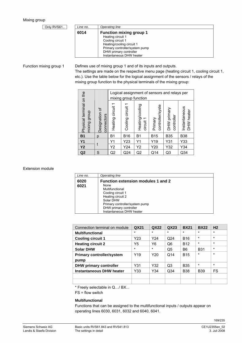
169/235
Siemens Schweiz AG Basic units RVS61.843 and RVS41.813 CE1U2355en_02 Landis & Staefa Division The settings in detail 3. Juli 2008
Mixing group
Line no. Operating line
6014 Function mixing group 1 Heating circuit 1 Cooling circuit 1 Heating/cooling circuit 1 Primary controller/system pump DHW primary controller Instantaneous DHW heater
Defines use of mixing group 1 and of its inputs and outputs. The settings are made on the respective menu page (heating circuit 1, cooling circuit 1, etc.). Use the table below for the logical assignment of the sensors / relays of the mixing group function to the physical terminals of the mixing group:
Logical assignment of sensors and relays per mixing group function
Phy
sica
l ter
min
al o
n th
e m
ixin
g gr
oup
Des
igna
tion
of
conn
ecto
rs
Hea
ting
circ
uit 1
Coo
ling
circ
uit 1
Hea
ting/
cool
ing
circ
uit 1
Prim
ary
cont
rolle
r/sys
te
DH
W p
rimar
y co
ntro
ller
Inst
anta
neou
s D
HW
hea
ter
B1 p B1 B16 B1 B15 B35 B38 Y1 Y1 Y23 Y1 Y19 Y31 Y33 Y2
t Y2 Y24 Y2 Y20 Y32 Y34
Q2 S Q2 Q24 Q2 Q14 Q3 Q34
Extension module
Line no. Operating line
6020 6021
Function extension modules 1 and 2 None Multifunctional Cooling circuit 1 Heating circuit 2 Solar DHW Primary controller/system pump DHW primary controller Instantaneous DHW heater
Connection terminal on module QX21 QX22 QX23 BX21 BX22 H2 Multifunctional * * * * * * Cooling circuit 1 Y23 Y24 Q24 B16 * * Heating circuit 2 Y5 Y6 Q6 B12 * * Solar DHW * * Q5 B6 B31 * Primary controller/system pump
Y19 Y20 Q14 B15 * *
DHW primary controller Y31 Y32 Q3 B35 * * Instantaneous DHW heater Y33 Y34 Q34 B38 B39 FS * Freely selectable in Q…/ BX... FS = flow switch
Multifunctional Functions that can be assigned to the multifunctional inputs / outputs appear on operating lines 6030, 6031, 6032 and 6040, 6041.
Function mixing group 1
Only RVS61..
170/235
Siemens Switzerland Basic units RVS61.843 and RVS41.813 CE1U2355en_02 HVAC Products Contents 3. Juli 2008
Cooling circuit 1 For this application, the respective settings of menu “Cooling circuit 1” can be adapted.
Heating circuit 2 For this application, the respective settings of menu “Heating circuit 2” can be adapted.
Solar DHW For this application, the respective settings of menu “Solar” can be adapted.
Primary controller/system pump For this application, the respective settings of menu “Primary controller / system pump” can be adapted.
DHW primary controller For this application, the respective settings of menu “DHW storage tank” can be adapted.
Instantaneous DHW heater For this application, the respective settings of menu “Instantaneous DHW heater” can be adapted.
Frost protection on the extension module
Frost protection for the heating circuit on the extension module operates the same way as frost protection for the heating circuit connected to the controller (see page 94).
Frost protection for the plant (see page 174) also acts on the heating circuit of the extension module.
If the frost protection function on the extension module responds, its pump (Q24) is activated and the mixing valve (Y23 / Y24) maintains the frost protection setpoint (10 °C). But the cooling circuit does not send a request to the heat source. For monitoring frost protection on the extension module, sensor B16 is used. When there is no flow temperature sensor installed, the frost protection function for the heating circuit is performed with the common flow temperature (B21).
Frost protection for the plant (see page 174) also acts on the cooling circuit of the extension module. The function can be activated / deactivated.
Heating circuit
Cooling circuit
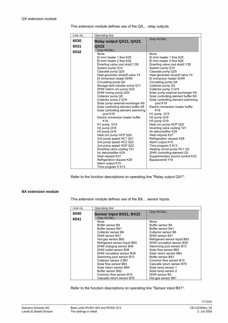
171/235
Siemens Schweiz AG Basic units RVS61.843 and RVS41.813 CE1U2355en_02 Landis & Staefa Division The settings in detail 3. Juli 2008
QX extension module
This extension module defines use of the QX… relay outputs.
Line no. Operating line
6030 6031 6032
Relay output QX21, QX22, QX23
Only RVS61..
Only RVS41..
None El imm heater 1 flow K25 El imm heater 2 flow K26 Diverting valve cool strat2 Y28 System pump Q14 Cascade pump Q25 Heat generator shutoff valve Y4 El immersion heater DHW Circulating pump Q4 Storage tank transfer pump Q11 DHW interm circ pump Q33 DHW mixing pump Q35 Collector pump Q5 Collector pump 2 Q16 Solar pump external exchanger K9 Solar controlling element buffer K8 Solar controlling element swimming
pool K18 Electric immersion heater buffer
K16 H1 pump Q15 H2 pump Q18 H3 pump Q19 Heat circ pump HCP Q20 2nd pump speed HC1 Q21 2nd pump speed HC2 Q22 2nd pump speed HCP Q23 Diverting valve cooling Y21 Air dehumidifier K29 Heat request K27 Refrigeration request K28 Alarm output K10 Time program 5 K13
None El imm heater 1 flow K25 El imm heater 2 flow K26 Diverting valve cool strat2 Y28 System pump Q14 Cascade pump Q25 Heat generator shutoff valve Y4 El immersion heater DHW Circulating pump Q4 Collector pump Q5 Collector pump 2 Q16 Solar pump external exchanger K9 Solar controlling element buffer K8 Solar controlling element swimming
pool K18 Electric immersion heater buffer
K16 H1 pump Q15 H2 pump Q18 H3 pump Q19 Heat circ pump HCP Q20 Diverting valve cooling Y21 Air dehumidifier K29 Heat request K27 Refrigeration request K28 Alarm output K10 Time program 5 K13 Heating circuit pump HC1 Q2 DHW controlling element Q3 Supplementary source control K32 Bypassventil Y16
Refer to the function descriptions on operating line "Relay output QX1".
BX extension module
This extension module defines use of the BX… sensor inputs.
Line no. Operating line
6040 6041
Sensor input BX21, BX22 Only RVS61..
Only RVS41..
None Buffer sensor B4 Buffer sensor B41 Collector sensor B6 DHW sensor B31 Hot-gas sensor B82 Refrigerant sensor liquid B83 DHW charging sensor B36 DHW outlet sensor B38 DHW circulation sensor B39 Swimming pool sensor B13 Collector sensor 2 B61 Solar flow sensor B63 Solar return sensor B64 Buffer sensor B42 Common flow sensor B10 Cascade return sensor B70
None Buffer sensor B4 Buffer sensor B41 Collector sensor B6 DHW sensor B31 Refrigerant sensor liquid B83 DHW circulation sensor B39 Swimming pool sensor B13 Solar flow sensor B63 Solar return sensor B64 Buffer sensor B42 Common flow sensor B10 Cascade return sensor B70 Solar temp sensor 1 Solar temp sensor 2 DHW sensor B3 Hot-gas sensor B81
Refer to the function descriptions on operating line "Sensor input BX1".
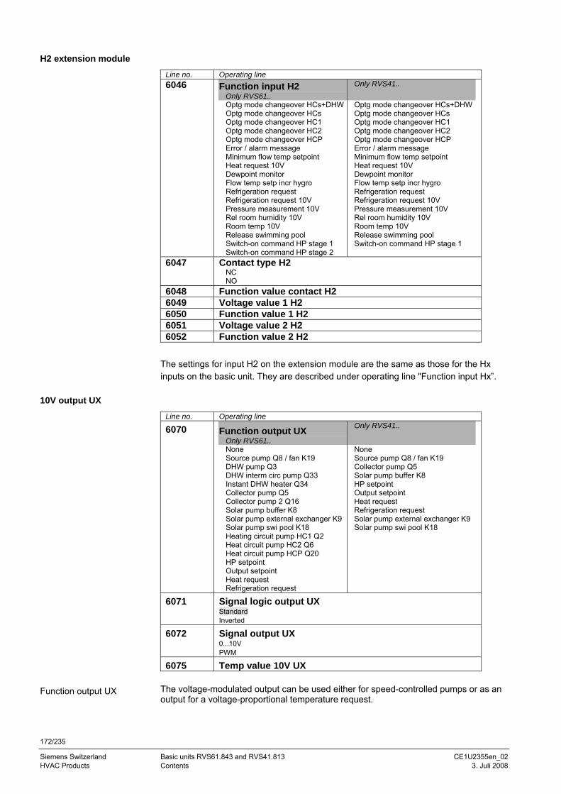
172/235
Siemens Switzerland Basic units RVS61.843 and RVS41.813 CE1U2355en_02 HVAC Products Contents 3. Juli 2008
H2 extension module
Line no. Operating line 6046 Function input H2
Only RVS61.. Only RVS41..
Optg mode changeover HCs+DHWOptg mode changeover HCs Optg mode changeover HC1 Optg mode changeover HC2 Optg mode changeover HCP Error / alarm message Minimum flow temp setpoint Heat request 10V Dewpoint monitor Flow temp setp incr hygro Refrigeration request Refrigeration request 10V Pressure measurement 10V Rel room humidity 10V Room temp 10V Release swimming pool Switch-on command HP stage 1 Switch-on command HP stage 2
Optg mode changeover HCs+DHWOptg mode changeover HCs Optg mode changeover HC1 Optg mode changeover HC2 Optg mode changeover HCP Error / alarm message Minimum flow temp setpoint Heat request 10V Dewpoint monitor Flow temp setp incr hygro Refrigeration request Refrigeration request 10V Pressure measurement 10V Rel room humidity 10V Room temp 10V Release swimming pool Switch-on command HP stage 1
6047 Contact type H2
NC NO
6048 Function value contact H2 6049 Voltage value 1 H2 6050 Function value 1 H2 6051 Voltage value 2 H2 6052 Function value 2 H2
The settings for input H2 on the extension module are the same as those for the Hx inputs on the basic unit. They are described under operating line "Function input Hx”.
10V output UX
Line no. Operating line
6070 Function output UX Only RVS61..
Only RVS41..
None Source pump Q8 / fan K19 DHW pump Q3 DHW interm circ pump Q33 Instant DHW heater Q34 Collector pump Q5 Collector pump 2 Q16 Solar pump buffer K8 Solar pump external exchanger K9 Solar pump swi pool K18 Heating circuit pump HC1 Q2 Heat circuit pump HC2 Q6 Heat circuit pump HCP Q20 HP setpoint Output setpoint Heat request Refrigeration request
None Source pump Q8 / fan K19 Collector pump Q5 Solar pump buffer K8 HP setpoint Output setpoint Heat request Refrigeration request Solar pump external exchanger K9 Solar pump swi pool K18
6071 Signal logic output UX
Standard Inverted
6072 Signal output UX 0...10V PWM
6075 Temp value 10V UX The voltage-modulated output can be used either for speed-controlled pumps or as an output for a voltage-proportional temperature request.
Function output UX
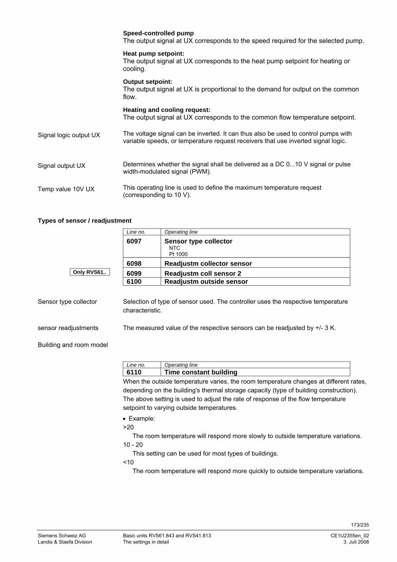
173/235
Siemens Schweiz AG Basic units RVS61.843 and RVS41.813 CE1U2355en_02 Landis & Staefa Division The settings in detail 3. Juli 2008
Speed-controlled pump The output signal at UX corresponds to the speed required for the selected pump.
Heat pump setpoint: The output signal at UX corresponds to the heat pump setpoint for heating or cooling.
Output setpoint: The output signal at UX is proportional to the demand for output on the common flow.
Heating and cooling request: The output signal at UX corresponds to the common flow temperature setpoint. The voltage signal can be inverted. It can thus also be used to control pumps with variable speeds, or temperature request receivers that use inverted signal logic. Determines whether the signal shall be delivered as a DC 0...10 V signal or pulse width-modulated signal (PWM). This operating line is used to define the maximum temperature request (corresponding to 10 V).
Types of sensor / readjustment
Line no. Operating line
6097 Sensor type collector NTC Pt 1000
6098 Readjustm collector sensor 6099 Readjustm coll sensor 2 6100 Readjustm outside sensor
Selection of type of sensor used. The controller uses the respective temperature characteristic. The measured value of the respective sensors can be readjusted by +/- 3 K.
Building and room model
Line no. Operating line 6110 Time constant building
When the outside temperature varies, the room temperature changes at different rates, depending on the building's thermal storage capacity (type of building construction). The above setting is used to adjust the rate of response of the flow temperature setpoint to varying outside temperatures.
• Example: >20
The room temperature will respond more slowly to outside temperature variations. 10 - 20
This setting can be used for most types of buildings. <10
The room temperature will respond more quickly to outside temperature variations.
Signal logic output UX
Signal output UX
Temp value 10V UX
Sensor type collector
sensor readjustments
Only RVS61..
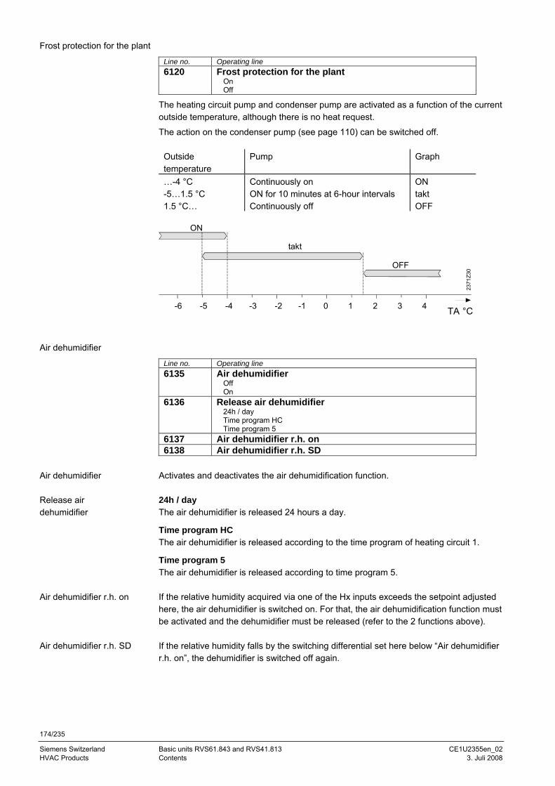
174/235
Siemens Switzerland Basic units RVS61.843 and RVS41.813 CE1U2355en_02 HVAC Products Contents 3. Juli 2008
Frost protection for the plant
Line no. Operating line 6120 Frost protection for the plant
On Off
The heating circuit pump and condenser pump are activated as a function of the current outside temperature, although there is no heat request.
The action on the condenser pump (see page 110) can be switched off. Outside temperature
Pump Graph
…-4 °C Continuously on ON -5…1.5 °C ON for 10 minutes at 6-hour intervals takt 1.5 °C… Continuously off OFF
-2
2371
Z30
TA °C
OFF
0 1 2 3 4-3-4-5-6 -1
takt
ON
Air dehumidifier
Line no. Operating line 6135 Air dehumidifier
Off On
6136 Release air dehumidifier 24h / day Time program HC Time program 5
6137 Air dehumidifier r.h. on 6138 Air dehumidifier r.h. SD
Activates and deactivates the air dehumidification function. 24h / day The air dehumidifier is released 24 hours a day.
Time program HC The air dehumidifier is released according to the time program of heating circuit 1.
Time program 5 The air dehumidifier is released according to time program 5. If the relative humidity acquired via one of the Hx inputs exceeds the setpoint adjusted here, the air dehumidifier is switched on. For that, the air dehumidification function must be activated and the dehumidifier must be released (refer to the 2 functions above). If the relative humidity falls by the switching differential set here below “Air dehumidifier r.h. on”, the dehumidifier is switched off again.
Air dehumidifier
Release air dehumidifier
Air dehumidifier r.h. on
Air dehumidifier r.h. SD
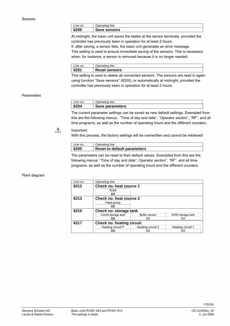
175/235
Siemens Schweiz AG Basic units RVS61.843 and RVS41.813 CE1U2355en_02 Landis & Staefa Division The settings in detail 3. Juli 2008
Sensors
Line no. Operating line 6200 Save sensors
At midnight, the basic unit saves the states at the sensor terminals, provided the controller has previously been in operation for at least 2 hours. If, after saving, a sensor fails, the basic unit generates an error message. This setting is used to ensure immediate saving of the sensors. This is necessary when, for instance, a sensor is removed because it is no longer needed.
Line no. Operating line 6201 Reset sensors
This setting is used to delete all connected sensors. The sensors are read in again using function “Save sensors“ (6200), or automatically at midnight, provided the controller has previously been in operation for at least 2 hours.
Parameters
Line no. Operating line 6204 Save parameters
The current parameter settings can be saved as new default settings. Exempted from this are the following menus: ”Time of day and date”, “Operator section”, “RF”, and all time programs, as well as the number of operating hours and the different counters..
Important: With this process, the factory settings will be overwritten and cannot be retrieved!
Line no. Operating line 6205 Reset to default parameters
The parameters can be reset to their default values. Exempted from this are the following menus: ”Time of day and date”, Operator section”, “RF”, and all time programs, as well as the number of operating hours and the different counters.
Plant diagram
Line no. Operating line 6212 Check no. heat source 1
Solar XX
6213 Check no. heat source 2 Heat pump
XX 6215 Check no. storage tank
Combi storage tank Buffer sensor DHW storage tank XX XX XX
6217 Check no. heating circuit Heating circuit P Heating circuit 2 Heating circuit 1
XX XX XX
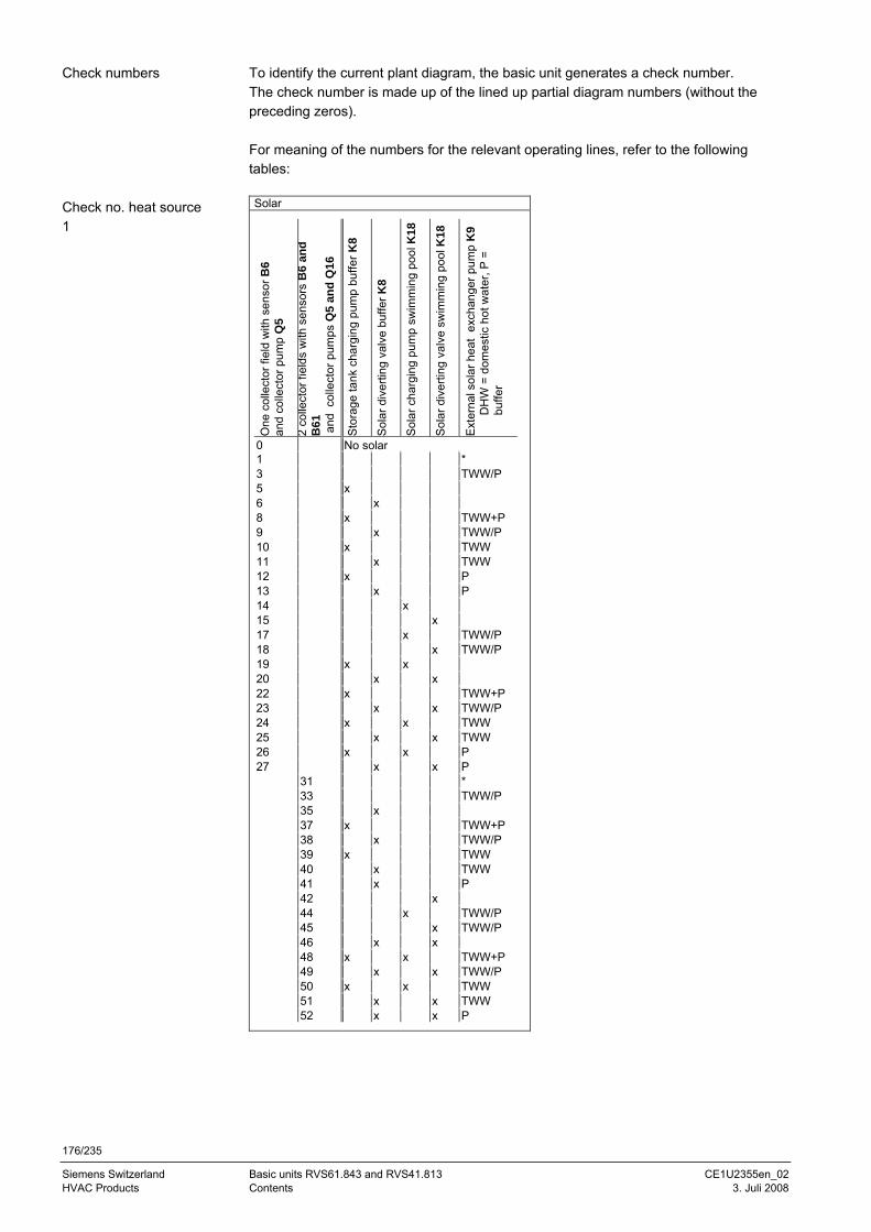
176/235
Siemens Switzerland Basic units RVS61.843 and RVS41.813 CE1U2355en_02 HVAC Products Contents 3. Juli 2008
To identify the current plant diagram, the basic unit generates a check number. The check number is made up of the lined up partial diagram numbers (without the preceding zeros). For meaning of the numbers for the relevant operating lines, refer to the following tables: Solar
One
col
lect
or fi
eld
with
sen
sor B
6
and
colle
ctor
pum
p Q
5
2 co
llect
or fi
elds
with
sen
sors
B6
and
B61
a
nd c
olle
ctor
pum
ps Q
5 an
d Q
16
Sto
rage
tank
cha
rgin
g pu
mp
buffe
r K8
Sol
ar d
iver
ting
valv
e bu
ffer K
8
Sol
ar c
harg
ing
pum
p sw
imm
ing
pool
K18
Sol
ar d
iver
ting
valv
e sw
imm
ing
pool
K18
Ext
erna
l sol
ar h
eat
exch
ange
r pum
p K
9 D
HW
= d
omes
tic h
ot w
ater
, P =
bu
ffer
0 No solar1 *3 TWW/P5 x 6 x8 x TWW+P9 x TWW/P10 x TWW11 x TWW12 x P13 x P14 x15 x17 x TWW/P18 x TWW/P19 x x20 x x22 x TWW+P23 x x TWW/P24 x x TWW25 x x TWW26 x x P27 x x P
31 *33 TWW/P35 x37 x TWW+P38 x TWW/P39 x TWW40 x TWW41 x P42 x44 x TWW/P45 x TWW/P46 x x48 x x TWW+P49 x x TWW/P50 x x TWW51 x x TWW52 x x P
Check numbers
Check no. heat source 1
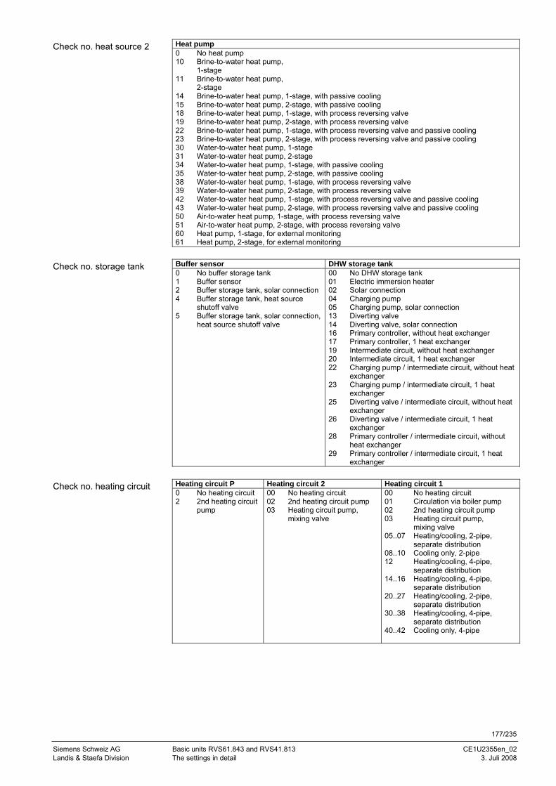
177/235
Siemens Schweiz AG Basic units RVS61.843 and RVS41.813 CE1U2355en_02 Landis & Staefa Division The settings in detail 3. Juli 2008
Heat pump 0 No heat pump 10 Brine-to-water heat pump,
1-stage 11 Brine-to-water heat pump,
2-stage 14 Brine-to-water heat pump, 1-stage, with passive cooling 15 Brine-to-water heat pump, 2-stage, with passive cooling 18 Brine-to-water heat pump, 1-stage, with process reversing valve 19 Brine-to-water heat pump, 2-stage, with process reversing valve 22 Brine-to-water heat pump, 1-stage, with process reversing valve and passive cooling 23 Brine-to-water heat pump, 2-stage, with process reversing valve and passive cooling 30 Water-to-water heat pump, 1-stage 31 Water-to-water heat pump, 2-stage 34 Water-to-water heat pump, 1-stage, with passive cooling 35 Water-to-water heat pump, 2-stage, with passive cooling 38 Water-to-water heat pump, 1-stage, with process reversing valve 39 Water-to-water heat pump, 2-stage, with process reversing valve 42 Water-to-water heat pump, 1-stage, with process reversing valve and passive cooling 43 Water-to-water heat pump, 2-stage, with process reversing valve and passive cooling 50 Air-to-water heat pump, 1-stage, with process reversing valve 51 Air-to-water heat pump, 2-stage, with process reversing valve 60 Heat pump, 1-stage, for external monitoring 61 Heat pump, 2-stage, for external monitoring
Buffer sensor DHW storage tank 0 No buffer storage tank 1 Buffer sensor 2 Buffer storage tank, solar connection 4 Buffer storage tank, heat source
shutoff valve 5 Buffer storage tank, solar connection,
heat source shutoff valve
00 No DHW storage tank 01 Electric immersion heater 02 Solar connection 04 Charging pump 05 Charging pump, solar connection 13 Diverting valve 14 Diverting valve, solar connection 16 Primary controller, without heat exchanger 17 Primary controller, 1 heat exchanger 19 Intermediate circuit, without heat exchanger 20 Intermediate circuit, 1 heat exchanger 22 Charging pump / intermediate circuit, without heat
exchanger 23 Charging pump / intermediate circuit, 1 heat
exchanger 25 Diverting valve / intermediate circuit, without heat
exchanger 26 Diverting valve / intermediate circuit, 1 heat
exchanger 28 Primary controller / intermediate circuit, without
heat exchanger 29 Primary controller / intermediate circuit, 1 heat
exchanger
Heating circuit P Heating circuit 2 Heating circuit 1 0 No heating circuit 2 2nd heating circuit
pump
00 No heating circuit 02 2nd heating circuit pump 03 Heating circuit pump,
mixing valve
00 No heating circuit 01 Circulation via boiler pump 02 2nd heating circuit pump 03 Heating circuit pump,
mixing valve 05..07 Heating/cooling, 2-pipe,
separate distribution 08..10 Cooling only, 2-pipe 12 Heating/cooling, 4-pipe,
separate distribution 14..16 Heating/cooling, 4-pipe,
separate distribution 20..27 Heating/cooling, 2-pipe,
separate distribution 30..38 Heating/cooling, 4-pipe,
separate distribution 40..42 Cooling only, 4-pipe
Check no. heat source 2
Check no. storage tank
Check no. heating circuit
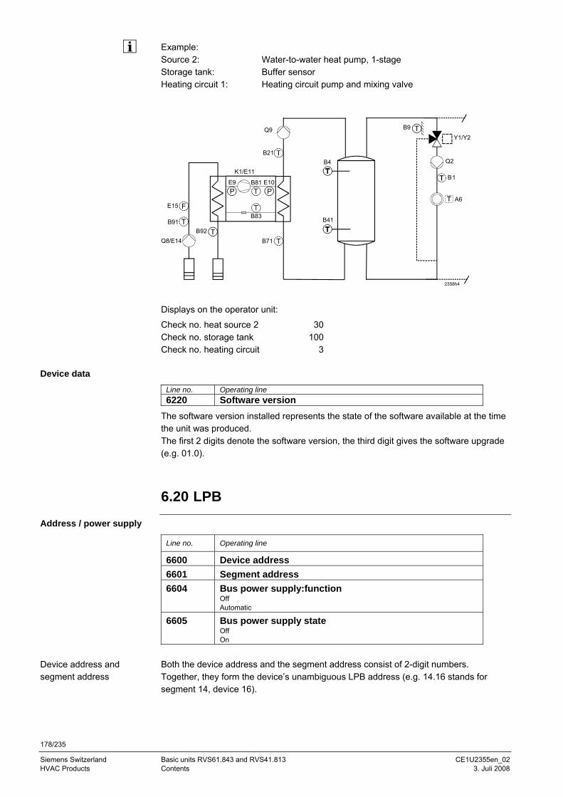
178/235
Siemens Switzerland Basic units RVS61.843 and RVS41.813 CE1U2355en_02 HVAC Products Contents 3. Juli 2008
Example: Source 2: Water-to-water heat pump, 1-stage Storage tank: Buffer sensor Heating circuit 1: Heating circuit pump and mixing valve
B4
B41
B21
K1/E11
B71B92
Q8/E14
B91
E15 F
E9PP
B81 E10
B83
Q9
2358h4
B9
Y1/Y2
Q2
B1
A6
Displays on the operator unit:
Check no. heat source 2 30 Check no. storage tank 100 Check no. heating circuit 3
Device data
Line no. Operating line 6220 Software version
The software version installed represents the state of the software available at the time the unit was produced. The first 2 digits denote the software version, the third digit gives the software upgrade (e.g. 01.0).
6.20 LPB
Address / power supply
Line no. Operating line
6600 Device address 6601 Segment address 6604 Bus power supply:function
Off Automatic
6605 Bus power supply state Off On
Both the device address and the segment address consist of 2-digit numbers. Together, they form the device’s unambiguous LPB address (e.g. 14.16 stands for segment 14, device 16).
Device address and segment address

179/235
Siemens Schweiz AG Basic units RVS61.843 and RVS41.813 CE1U2355en_02 Landis & Staefa Division The settings in detail 3. Juli 2008
The bus power supply enables the bus system to be powered directly by the individual controllers (no central bus power supply). The type of bus power supply can be selected. • Off: No bus power supply via the controller • Automatically: The bus power supply (LPB) via the controller is automatically
switched on and off depending on the requirements of the LPB The display shows whether the controller currently supplies power to the bus: • Off: Bus power supply via the controller is currently inactive • On: The bus power supply via controller is currently active. At the moment, the
controller supplies some of the power required by the bus
Central functions
Line no. Operating line
6620 Action changeover functions Segment System
6621 Summer changeover Locally Centrally
6623 Optg mode changeover Locally Centrally
6625 DHW assignment Local HCs All heating circuits in the segment: All HCs in system
6627 Refrigeration request Locally Centrally
6630 Cascade master Always Automatically
These settings are only relevant for device address 1. The range of action of central changeover can be defined. This concerns: • Changeover of operating mode via input H (when selecting “Centrally“ on operating
line 6623) • Summer changeover (when selecting ”Central“ on operating line 6621)
The possible settings are the following: • Segment: Changeover takes place with all controllers in the same segment • System: With all controllers, changeover takes place in the entire system (in all
segments). For that, the controller must be located in segment 0! The range of action of summer changeover is as follows:
• Local entry: Local action; the local heating circuit is switched on the basis of operating lines 730, 1030 and 1330
• Central entry: Central action; depending on the setting made on operating line “Action changeover functions“, either the heating circuits in the segment or those of the entire system are switched based on operating line 730
Bus power supply function
Bus power supply state
Action changeover functions
Summer changeover
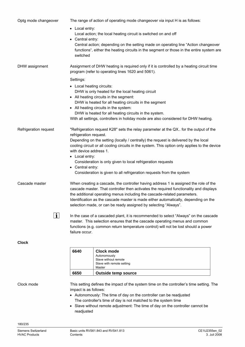
180/235
Siemens Switzerland Basic units RVS61.843 and RVS41.813 CE1U2355en_02 HVAC Products Contents 3. Juli 2008
The range of action of operating mode changeover via input H is as follows:
• Local entry: Local action; the local heating circuit is switched on and off
• Central entry: Central action; depending on the setting made on operating line “Action changeover functions“, either the heating circuits in the segment or those in the entire system are switched
Assignment of DHW heating is required only if it is controlled by a heating circuit time program (refer to operating lines 1620 and 5061).
Settings:
• Local heating circuits: DHW is only heated for the local heating circuit
• All heating circuits in the segment: DHW is heated for all heating circuits in the segment
• All heating circuits in the system: DHW is heated for all heating circuits in the system.
With all settings, controllers in holiday mode are also considered for DHW heating. "Refrigeration request K28" sets the relay parameter at the QX.. for the output of the refrigeration request. Depending on the setting (locally / centrally) the request is delivered by the local cooling circuit or all cooling circuits in the system. This option only applies to the device with device address 1. • Local entry:
Consideration is only given to local refrigeration requests • Central entry:
Consideration is given to all refrigeration requests from the system When creating a cascade, the controller having address 1 is assigned the role of the cascade master. That controller then activates the required functionality and displays the additional operating menus including the cascade-related parameters. Identification as the cascade master is made either automatically, depending on the selection made, or can be ready assigned by selecting “Always”. In the case of a cascaded plant, it is recommended to select “Always” on the cascade master. This selection ensures that the cascade operating menus and common functions (e.g. common return temperature control) will not be lost should a power failure occur.
Clock
6640 Clock mode Autonomously Slave without remote Slave with remote setting Master
6650 Outside temp source This setting defines the impact of the system time on the controller’s time setting. The impact is as follows: • Autonomously: The time of day on the controller can be readjusted
The controller's time of day is not matched to the system time • Slave without remote adjustment: The time of day on the controller cannot be
readjusted
Optg mode changeover
DHW assignment
Refrigeration request
Cascade master
Clock mode
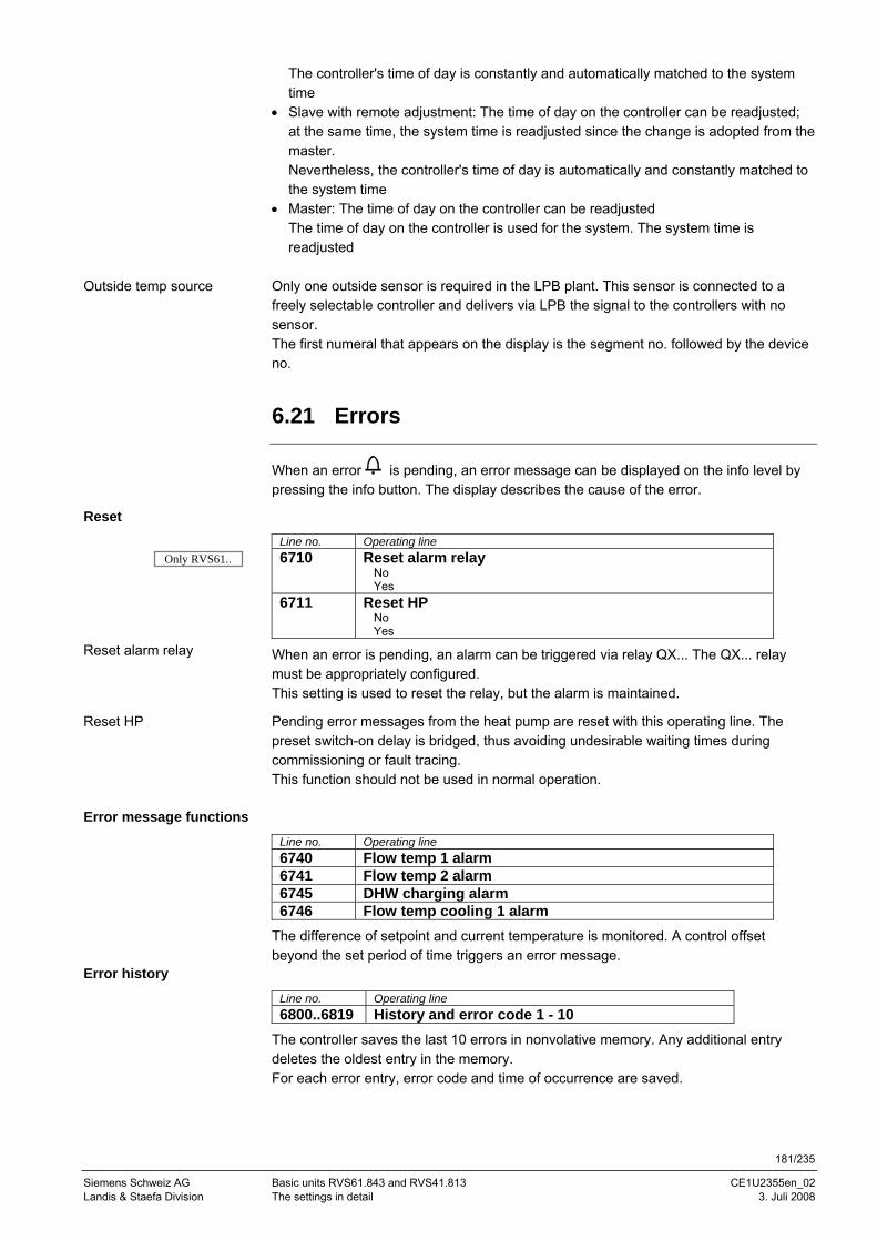
181/235
Siemens Schweiz AG Basic units RVS61.843 and RVS41.813 CE1U2355en_02 Landis & Staefa Division The settings in detail 3. Juli 2008
The controller's time of day is constantly and automatically matched to the system time
• Slave with remote adjustment: The time of day on the controller can be readjusted; at the same time, the system time is readjusted since the change is adopted from the master. Nevertheless, the controller's time of day is automatically and constantly matched to the system time
• Master: The time of day on the controller can be readjusted The time of day on the controller is used for the system. The system time is readjusted
Only one outside sensor is required in the LPB plant. This sensor is connected to a freely selectable controller and delivers via LPB the signal to the controllers with no sensor. The first numeral that appears on the display is the segment no. followed by the device no.
6.21 Errors
When an error is pending, an error message can be displayed on the info level by pressing the info button. The display describes the cause of the error.
Reset
Line no. Operating line 6710 Reset alarm relay
No Yes
6711 Reset HP No Yes
When an error is pending, an alarm can be triggered via relay QX... The QX... relay must be appropriately configured. This setting is used to reset the relay, but the alarm is maintained.
Pending error messages from the heat pump are reset with this operating line. The preset switch-on delay is bridged, thus avoiding undesirable waiting times during commissioning or fault tracing. This function should not be used in normal operation.
Error message functions
Line no. Operating line 6740 Flow temp 1 alarm 6741 Flow temp 2 alarm 6745 DHW charging alarm 6746 Flow temp cooling 1 alarm
The difference of setpoint and current temperature is monitored. A control offset beyond the set period of time triggers an error message.
Error history
Line no. Operating line 6800..6819 History and error code 1 - 10
The controller saves the last 10 errors in nonvolative memory. Any additional entry deletes the oldest entry in the memory. For each error entry, error code and time of occurrence are saved.
Outside temp source
Reset alarm relay
Reset HP
Only RVS61..
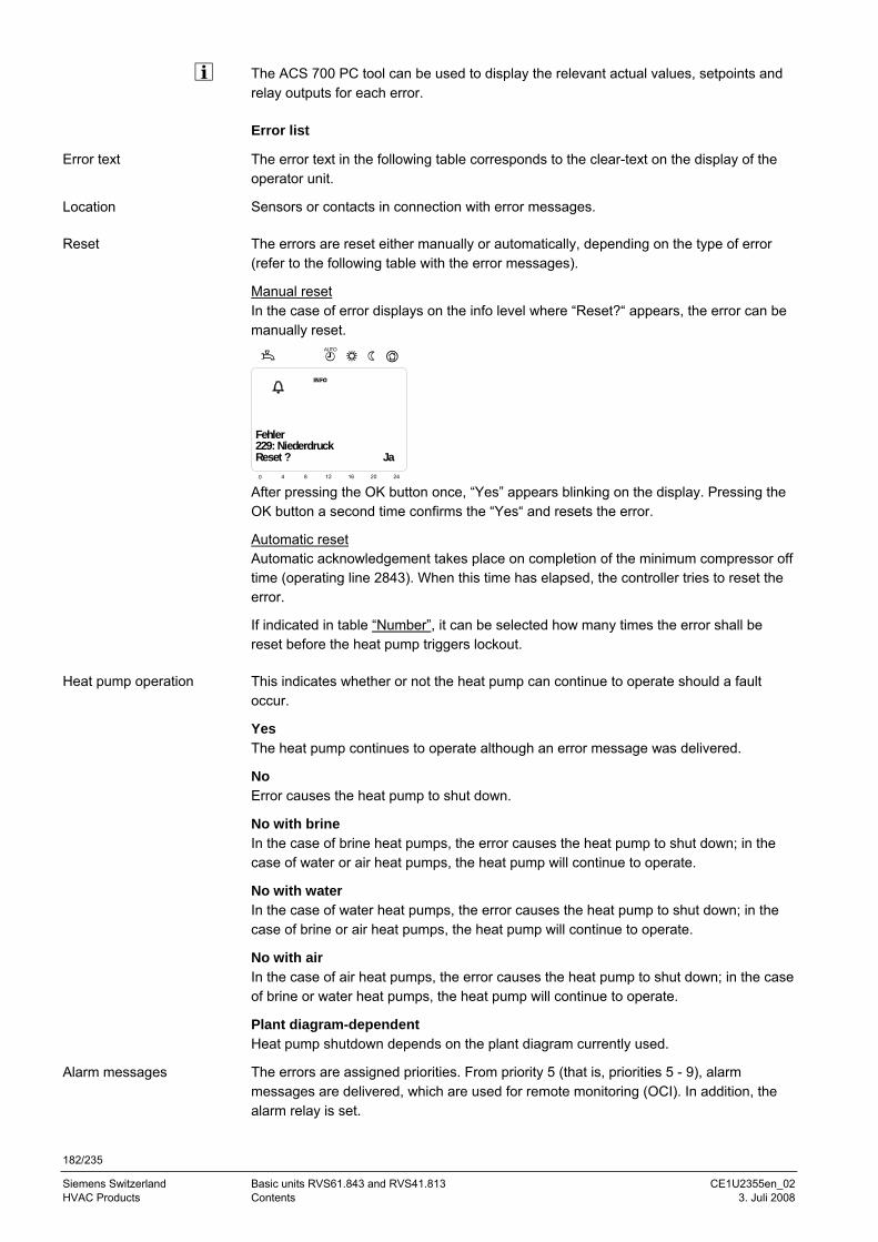
182/235
Siemens Switzerland Basic units RVS61.843 and RVS41.813 CE1U2355en_02 HVAC Products Contents 3. Juli 2008
The ACS 700 PC tool can be used to display the relevant actual values, setpoints and relay outputs for each error. Error list
The error text in the following table corresponds to the clear-text on the display of the operator unit.
Sensors or contacts in connection with error messages.
The errors are reset either manually or automatically, depending on the type of error (refer to the following table with the error messages).
Manual reset In the case of error displays on the info level where “Reset?“ appears, the error can be manually reset.
Ja229: Niederdruck
0 4 8 12 16 20 24
AUTO
Fehler
Reset ? Ja
After pressing the OK button once, “Yes” appears blinking on the display. Pressing the OK button a second time confirms the “Yes“ and resets the error.
Automatic reset Automatic acknowledgement takes place on completion of the minimum compressor off time (operating line 2843). When this time has elapsed, the controller tries to reset the error.
If indicated in table “Number”, it can be selected how many times the error shall be reset before the heat pump triggers lockout.
This indicates whether or not the heat pump can continue to operate should a fault occur.
Yes The heat pump continues to operate although an error message was delivered.
No Error causes the heat pump to shut down.
No with brine In the case of brine heat pumps, the error causes the heat pump to shut down; in the case of water or air heat pumps, the heat pump will continue to operate.
No with water In the case of water heat pumps, the error causes the heat pump to shut down; in the case of brine or air heat pumps, the heat pump will continue to operate.
No with air In the case of air heat pumps, the error causes the heat pump to shut down; in the case of brine or water heat pumps, the heat pump will continue to operate.
Plant diagram-dependent Heat pump shutdown depends on the plant diagram currently used.
The errors are assigned priorities. From priority 5 (that is, priorities 5 - 9), alarm messages are delivered, which are used for remote monitoring (OCI). In addition, the alarm relay is set.
Error text
Location
Reset
Heat pump operation
Alarm messages
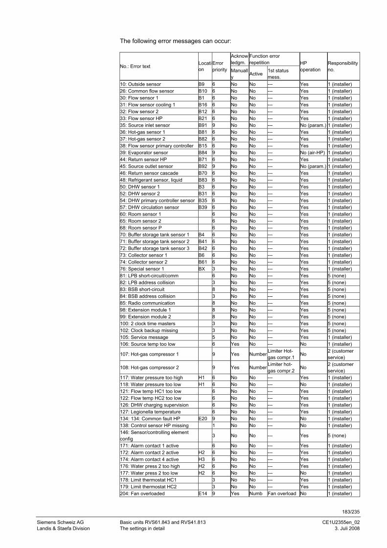
183/235
Siemens Schweiz AG Basic units RVS61.843 and RVS41.813 CE1U2355en_02 Landis & Staefa Division The settings in detail 3. Juli 2008
The following error messages can occur:
Acknowledgm.
Function error repetition
No.: Error text Location
Error priority Manuall
y Active 1st status mess.
HP operation
Responsibility no.
10: Outside sensor B9 6 No No --- Yes 1 (installer) 26: Common flow sensor B10 6 No No --- Yes 1 (installer) 30: Flow sensor 1 B1 6 No No --- Yes 1 (installer) 31: Flow sensor cooling 1 B16 6 No No --- Yes 1 (installer) 32: Flow sensor 2 B12 6 No No --- Yes 1 (installer) 33: Flow sensor HP B21 6 No No --- Yes 1 (installer) 35: Source inlet sensor B91 9 No No --- No (param.) 1 (installer) 36: Hot-gas sensor 1 B81 6 No No --- Yes 1 (installer) 37: Hot-gas sensor 2 B82 6 No No --- Yes 1 (installer) 38: Flow sensor primary controller B15 6 No No --- Yes 1 (installer) 39: Evaporator sensor B84 9 No No --- No (air-HP) 1 (installer) 44: Return sensor HP B71 6 No No --- Yes 1 (installer) 45: Source outlet sensor B92 9 No No --- No (param.) 1 (installer) 46: Return sensor cascade B70 6 No No --- Yes 1 (installer) 48: Refrigerant sensor, liquid B83 6 No No --- Yes 1 (installer) 50: DHW sensor 1 B3 6 No No --- Yes 1 (installer) 52: DHW sensor 2 B31 6 No No --- Yes 1 (installer) 54: DHW primary controller sensor B35 6 No No --- Yes 1 (installer) 57: DHW circulation sensor B39 6 No No --- Yes 1 (installer) 60: Room sensor 1 6 No No --- Yes 1 (installer) 65: Room sensor 2 6 No No --- Yes 1 (installer) 68: Room sensor P 6 No No --- Yes 1 (installer) 70: Buffer storage tank sensor 1 B4 6 No No --- Yes 1 (installer) 71: Buffer storage tank sensor 2 B41 6 No No --- Yes 1 (installer) 72: Buffer storage tank sensor 3 B42 6 No No --- Yes 1 (installer) 73: Collector sensor 1 B6 6 No No --- Yes 1 (installer) 74: Collector sensor 2 B61 6 No No --- Yes 1 (installer) 76: Special sensor 1 BX 3 No No --- Yes 1 (installer) 81: LPB short-circuit/comm 6 No No --- Yes 5 (none) 82: LPB address collision 3 No No --- Yes 5 (none) 83: BSB short-circuit 8 No No --- Yes 5 (none) 84: BSB address collision 3 No No --- Yes 5 (none) 85: Radio communication 8 No No --- Yes 5 (none) 98: Extension module 1 8 No No --- Yes 5 (none) 99: Extension module 2 8 No No --- Yes 5 (none) 100: 2 clock time masters 3 No No --- Yes 5 (none) 102: Clock backup missing 3 No No --- Yes 5 (none) 105: Service message 5 No No --- Yes 1 (installer) 106: Source temp too low 6 Yes No --- No 1 (installer)
107: Hot-gas compressor 1 9 Yes Number Limiter Hot-gas compr.1
No 2 (customer service)
108: Hot-gas compressor 2 9 Yes Number Limiter hot-gas compr.2
No 2 (customer service)
117: Water pressure too high H1 6 No No --- Yes 1 (installer) 118: Water pressure too low H1 6 No No --- No 1 (installer) 121: Flow temp HC1 too low 6 No No --- Yes 1 (installer) 122: Flow temp HC2 too low 6 No No --- Yes 1 (installer) 126: DHW charging supervision 6 No No --- Yes 1 (installer) 127: Legionella temperature 6 No No --- Yes 1 (installer) 134: 134: Common fault HP E20 9 No No --- No 1 (installer) 138: Control sensor HP missing 1 No No --- No 1 (installer) 146: Sensor/controlling element config
3 No No --- Yes 5 (none)
171: Alarm contact 1 active 6 No No --- Yes 1 (installer) 172: Alarm contact 2 active H2 6 No No --- Yes 1 (installer) 174: Alarm contact 4 active H3 6 No No --- Yes 1 (installer) 176: Water press 2 too high H2 6 No No --- Yes 1 (installer) 177: Water press 2 too low H2 6 No No --- No 1 (installer) 178: Limit thermostat HC1 3 No No --- Yes 1 (installer) 179: Limit thermostat HC2 3 No No --- Yes 1 (installer) 204: Fan overloaded E14 9 Yes Numb Fan overload No 1 (installer)
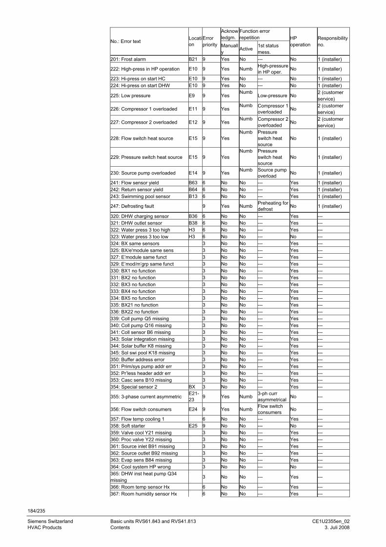
184/235
Siemens Switzerland Basic units RVS61.843 and RVS41.813 CE1U2355en_02 HVAC Products Contents 3. Juli 2008
Acknowledgm.
Function error repetition
No.: Error text Location
Error priority Manuall
y Active 1st status
mess.
HP operation
Responsibility no.
201: Frost alarm B21 9 Yes No --- No 1 (installer)
222: High-press in HP operation E10 9 Yes Numb High-pressure in HP oper. No 1 (installer)
223: Hi-press on start HC E10 9 Yes No --- No 1 (installer) 224: Hi-press on start DHW E10 9 Yes No --- No 1 (installer)
225: Low pressure E9 9 Yes Numb
Low-pressure No 2 (customer service)
226: Compressor 1 overloaded E11 9 Yes Numb Compressor 1
overloaded No 2 (customer service)
227: Compressor 2 overloaded E12 9 Yes Numb Compressor 2
overloaded No 2 (customer service)
228: Flow switch heat source E15 9 Yes Numb Pressure
switch heat source
No 1 (installer)
229: Pressure switch heat source E15 9 Yes Numb Pressure
switch heat source
No 1 (installer)
230: Source pump overloaded E14 9 Yes Numb Source pump overload No 1 (installer)
241: Flow sensor yield B63 6 No No --- Yes 1 (installer) 242: Return sensor yield B64 6 No No --- Yes 1 (installer) 243: Swimming pool sensor B13 6 No No --- Yes 1 (installer)
247: Defrosting fault 9 Yes Numb Preheating for defrost No 1 (installer)
320: DHW charging sensor B36 6 No No --- Yes --- 321: DHW outlet sensor B38 6 No No --- Yes --- 322: Water press 3 too high H3 6 No No --- Yes --- 323: Water press 3 too low H3 6 No No --- No --- 324: BX same sensors 3 No No --- Yes --- 325: BX/e'module same sens 3 No No --- Yes --- 327: E’module same funct 3 No No --- Yes --- 329: E’mod/m’grp same funct 3 No No --- Yes --- 330: BX1 no function 3 No No --- Yes --- 331: BX2 no function 3 No No --- Yes --- 332: BX3 no function 3 No No --- Yes --- 333: BX4 no function 3 No No --- Yes --- 334: BX5 no function 3 No No --- Yes --- 335: BX21 no function 3 No No --- Yes --- 336: BX22 no function 3 No No --- Yes --- 339: Coll pump Q5 missing 3 No No --- Yes --- 340: Coll pump Q16 missing 3 No No --- Yes --- 341: Coll sensor B6 missing 3 No No --- Yes --- 343: Solar integration missing 3 No No --- Yes --- 344: Solar buffer K8 missing 3 No No --- Yes --- 345: Sol swi pool K18 missing 3 No No --- Yes --- 350: Buffer address error 3 No No --- Yes --- 351: Prim/sys pump addr err 3 No No --- Yes --- 352: Pr’less header addr err 3 No No --- Yes --- 353: Casc sens B10 missing 3 No No --- Yes --- 354: Special sensor 2 BX 3 No No --- Yes ---
355: 3-phase current asymmetric E21-23 9 Yes Numb 3-ph curr
asymmetrical No ---
356: Flow switch consumers E24 9 Yes Numb Flow switch consumers No ---
357: Flow temp cooling 1 6 No No --- Yes --- 358: Soft starter E25 9 No No --- No --- 359: Valve cool Y21 missing 3 No No --- Yes --- 360: Proc valve Y22 missing 3 No No --- Yes --- 361: Source inlet B91 missing 3 No No --- Yes --- 362: Source outlet B92 missing 3 No No --- Yes --- 363: Evap sens B84 missing 3 No No --- Yes --- 364: Cool system HP wrong 3 No No --- No --- 365: DHW inst heat pump Q34 missing
3 No No --- Yes ---
366: Room temp sensor Hx 6 No No --- Yes --- 367: Room humidity sensor Hx 6 No No --- Yes ---
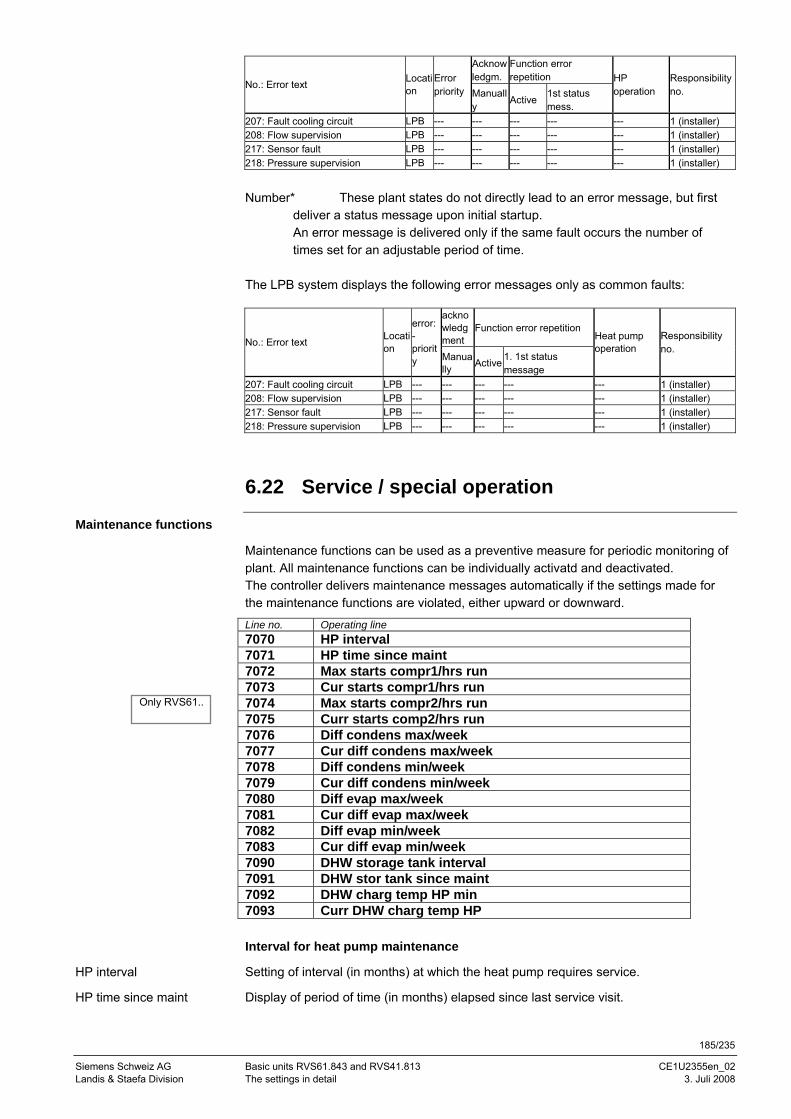
185/235
Siemens Schweiz AG Basic units RVS61.843 and RVS41.813 CE1U2355en_02 Landis & Staefa Division The settings in detail 3. Juli 2008
Acknowledgm.
Function error repetition
No.: Error text Location
Error priority Manuall
y Active 1st status
mess.
HP operation
Responsibility no.
207: Fault cooling circuit LPB --- --- --- --- --- 1 (installer) 208: Flow supervision LPB --- --- --- --- --- 1 (installer) 217: Sensor fault LPB --- --- --- --- --- 1 (installer) 218: Pressure supervision LPB --- --- --- --- --- 1 (installer)
Number* These plant states do not directly lead to an error message, but first
deliver a status message upon initial startup. An error message is delivered only if the same fault occurs the number of times set for an adjustable period of time.
The LPB system displays the following error messages only as common faults:
acknowledgment
Function error repetition No.: Error text Locati
on
error: -priority Manua
lly Active 1. 1st status message
Heat pump operation
Responsibility no.
207: Fault cooling circuit LPB --- --- --- --- --- 1 (installer) 208: Flow supervision LPB --- --- --- --- --- 1 (installer) 217: Sensor fault LPB --- --- --- --- --- 1 (installer) 218: Pressure supervision LPB --- --- --- --- --- 1 (installer)
6.22 Service / special operation
Maintenance functions
Maintenance functions can be used as a preventive measure for periodic monitoring of plant. All maintenance functions can be individually activatd and deactivated. The controller delivers maintenance messages automatically if the settings made for the maintenance functions are violated, either upward or downward.
Line no. Operating line 7070 HP interval 7071 HP time since maint 7072 Max starts compr1/hrs run 7073 Cur starts compr1/hrs run 7074 Max starts compr2/hrs run 7075 Curr starts comp2/hrs run 7076 Diff condens max/week 7077 Cur diff condens max/week 7078 Diff condens min/week 7079 Cur diff condens min/week 7080 Diff evap max/week 7081 Cur diff evap max/week 7082 Diff evap min/week 7083 Cur diff evap min/week 7090 DHW storage tank interval 7091 DHW stor tank since maint 7092 DHW charg temp HP min 7093 Curr DHW charg temp HP Interval for heat pump maintenance
Setting of interval (in months) at which the heat pump requires service.
Display of period of time (in months) elapsed since last service visit.
HP interval
HP time since maint
Only RVS61..
186/235
Siemens Switzerland Basic units RVS61.843 and RVS41.813 CE1U2355en_02 HVAC Products Contents 3. Juli 2008
If the value is above setting “HP interval“ (7070), symbol appears on the display and a maintenance message on the info level: 17: HP interval (priority 6)
This parameter can be reset, provided the respective access right is granted.
Maximum number of starts of compressor 1 per hour run
Setting the maximum permissible number of starts of compressor 1 per hour run.
Average number of starts of compressor 1 per hour run, reached over the last 6 weeks. If the value lies above setting “Max starts compr1/hrs run“ (7072), symbol appears on the display and a maintenance message on the info level: 8: Too many starts compr 1 (priority 9)
This parameter can be reset, provided the respective access right is granted.
Maximum number of starts of compressor 2 per hour run
Setting the maximum permissible number of starts of compressor 2 per hour run.
Average number of starts of compressor 2 per hour run, reached over the last 6 weeks. If the value is above setting “Max starts compr2/hrs run“ (7074), symbol appears on the display and a maintenance message on the info level: 9: Too many starts compr 2 (priority 9)
This parameter can be reset, provided the respective access right is granted.
Number of times per week the temperature differential across the condenser exceeds the maximum
Setting the number of times within a 7-day period the maximum temperature differential across the condenser may be exceeded.
Number of times the maximum temperature differential across the condenser was exceeded within a 7-day period. If the value is above setting “Diff condens max/week“ (7076), symbol appears on the display and a maintenance message on the info level: 13: Diff condens max (priority 3)
This parameter can be reset, provided the respective access right is granted.
Number of times per week the temperature differential across the condenser falls below the minimum
Indicates how many times the temperature differential across the condenser may drop below the minimum within a 7-day period.
Number of times the temperature differential across the condenser dropped below the minimum within a 7-day period. If the value is above setting “Diff condens min/week“ (7078), symbol appears on the display and a maintenance message on the info level: 14: Diff condens min (priority 3)
This parameter can be reset, provided the respective access right is granted.
Number of times per week the temperature differential across the evaporator exceeds the maximum
Reset
Max starts compr1/hrs run
Cur starts compr1/hrs run
Reset
Max starts compr2/hrs run
Curr starts comp2/hrs run
Reset
Diff condens max/week
Cur diff condens max/week
Reset
Diff condens min/week
Cur diff condens min/week
Reset
187/235
Siemens Schweiz AG Basic units RVS61.843 and RVS41.813 CE1U2355en_02 Landis & Staefa Division The settings in detail 3. Juli 2008
Indicates how many times within a 7-day period, the maximum temperature differential across the evaporator may be exceeded.
Number of times the maximum temperature differential across the evaporator was exceeded within a 7-day period. If the value lies above setting ”Diff evap max/week“ (operating line 7080), symbol appears on the display and the info level shows the following maintenance message: 15: Diff evap max (priority 3)
This parameter can be reset, provided the respective access right is granted.
Number of times per week the temperature differential across the evaporator drops below the minimum
Indicates how many times the temperature differential across the evaporator may drop below the minimum within a 7-day period.
Number of times the temperature differential across the evaporator dropped below the minimum level within a 7-day period. If the value is above setting “Diff evap min/week“ (7082), symbol appears on the display and a maintenance message on the info level: 16: Diff evap min (priority 3)
This parameter can be reset, provided the respective access right is granted.
Interval for maintenance of DHW storage tank
Setting of interval (in months) at which the DHW storage tank must be serviced.
Period of time (in months) elapsed since last service visit. If the value is above setting “DHW storage tank interval“ (7090), symbol appears on the display and a maintenance message on the info level: 11: DHW storage tank interval (priority 6)
This parameter can be reset, provided the respective access right is granted.
Minimum DHW charging temperature
Minimum temperature level to which the DHW storage tank must be charged by the heat pump with no abortion of charging.
The controller saves the DHW temperature at which charging by the heat pump was last aborted since the heat pump has reached the limitation for high-pressure, hot-gas, or the maximum switch-off temperature. If the value is below setting “DHW charg temp HP min“ (7092), symbol appears on the display and a maintenance message on the info level: 12: DHW charg temp HP too low (priority 6)
This parameter cannot be reset.
When, next time the DHW storage tank is charged, the minimum DHW charging temperature is exceeded again, the maintenance function is cancelled. But if not reached again, the maintenance message is maintained.
Other maintenance messages
5: Water pressure too low (priority 9) 18: Water pressure 2 too low (priority 9) 22: Water pressure 3 too low (priority 9)
Diff evap max/week
Cur diff evap max/week
Reset
Diff evap min/week
Cur diff evap min/week
Reset
DHW storage tank interval
DHW stor tank since maint
Reset
DHW charg temp HP min
Curr DHW charg temp HP
No reset
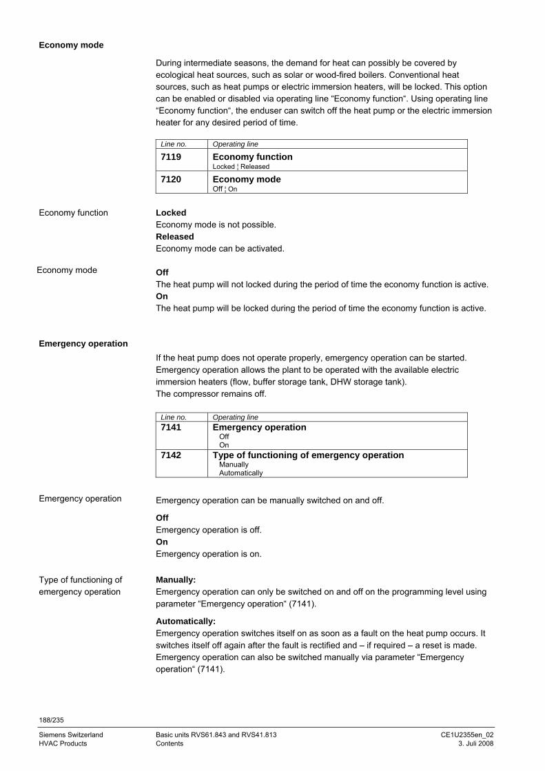
188/235
Siemens Switzerland Basic units RVS61.843 and RVS41.813 CE1U2355en_02 HVAC Products Contents 3. Juli 2008
Economy mode
During intermediate seasons, the demand for heat can possibly be covered by ecological heat sources, such as solar or wood-fired boilers. Conventional heat sources, such as heat pumps or electric immersion heaters, will be locked. This option can be enabled or disabled via operating line “Economy function“. Using operating line “Economy function“, the enduser can switch off the heat pump or the electric immersion heater for any desired period of time.
Line no. Operating line
7119 Economy function Locked ¦ Released
7120 Economy mode Off ¦ On
Locked Economy mode is not possible. Released Economy mode can be activated. Off The heat pump will not locked during the period of time the economy function is active. On The heat pump will be locked during the period of time the economy function is active.
Emergency operation If the heat pump does not operate properly, emergency operation can be started. Emergency operation allows the plant to be operated with the available electric immersion heaters (flow, buffer storage tank, DHW storage tank). The compressor remains off.
Line no. Operating line 7141 Emergency operation
Off On
7142 Type of functioning of emergency operation Manually Automatically
Emergency operation can be manually switched on and off.
Off Emergency operation is off. On Emergency operation is on. Manually: Emergency operation can only be switched on and off on the programming level using parameter “Emergency operation“ (7141).
Automatically: Emergency operation switches itself on as soon as a fault on the heat pump occurs. It switches itself off again after the fault is rectified and – if required – a reset is made. Emergency operation can also be switched manually via parameter “Emergency operation“ (7141).
Economy function
Economy mode
Emergency operation
Type of functioning of emergency operation
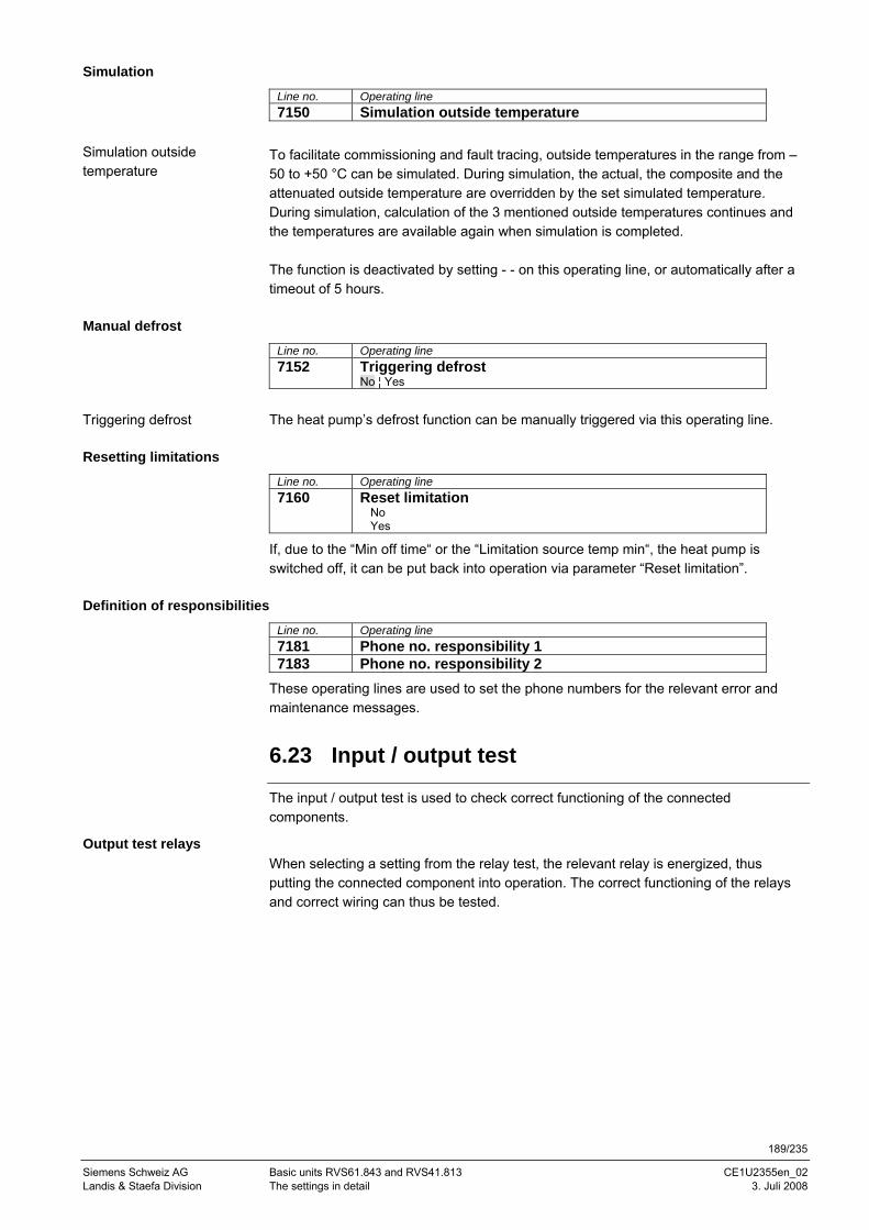
189/235
Siemens Schweiz AG Basic units RVS61.843 and RVS41.813 CE1U2355en_02 Landis & Staefa Division The settings in detail 3. Juli 2008
Simulation
Line no. Operating line 7150 Simulation outside temperature
To facilitate commissioning and fault tracing, outside temperatures in the range from –50 to +50 °C can be simulated. During simulation, the actual, the composite and the attenuated outside temperature are overridden by the set simulated temperature. During simulation, calculation of the 3 mentioned outside temperatures continues and the temperatures are available again when simulation is completed. The function is deactivated by setting - - on this operating line, or automatically after a timeout of 5 hours.
Manual defrost
Line no. Operating line 7152 Triggering defrost
No ¦ Yes
The heat pump’s defrost function can be manually triggered via this operating line.
Resetting limitations
Line no. Operating line 7160 Reset limitation
No Yes
If, due to the “Min off time“ or the “Limitation source temp min“, the heat pump is switched off, it can be put back into operation via parameter “Reset limitation”.
Definition of responsibilities
Line no. Operating line 7181 Phone no. responsibility 1 7183 Phone no. responsibility 2
These operating lines are used to set the phone numbers for the relevant error and maintenance messages.
6.23 Input / output test
The input / output test is used to check correct functioning of the connected components.
Output test relays When selecting a setting from the relay test, the relevant relay is energized, thus putting the connected component into operation. The correct functioning of the relays and correct wiring can thus be tested.
Simulation outside temperature
Triggering defrost
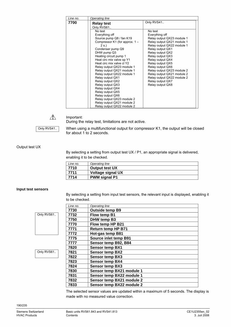
190/235
Siemens Switzerland Basic units RVS61.843 and RVS41.813 CE1U2355en_02 HVAC Products Contents 3. Juli 2008
Line no. Operating line 7700 Relay test
Only RVS61.. Only RVS41..
No test Everything off Source pump Q8 / fan K19 Compressor K1 (for approx. 1 –
2 s.) Condenser pump Q9 DHW pump Q3 Heating circuit pump 1 Heat circ mix valve op Y1 Heat circ mix valve cl Y2 Relay output QX23 module 1 Relay output QX21 module 1 Relay output QX22 module 1 Relay output QX1 Relay output QX2 Relay output QX3 Relay output QX4 Relay output QX5 Relay output QX6 Relay output QX23 module 2 Relay output QX21 module 2 Relay output QX22 module 2
No test Everything off Relay output QX23 module 1 Relay output QX21 module 1 Relay output QX22 module 1 Relay output QX1 Relay output QX2 Relay output QX3 Relay output QX4 Relay output QX5 Relay output QX6 Relay output QX23 module 2 Relay output QX21 module 2 Relay output QX22 module 2 Relay output QX7 Relay output QX8
Important: During the relay test, limitations are not active.
When using a multifunctional output for compressor K1, the output will be closed for about 1 to 2 seconds.
Output test UX By selecting a setting from output test UX / P1, an appropriate signal is delivered, enabling it to be checked.
Line no. Operating line 7710 Output test UX 7711 Voltage signal UX 7714 PWM signal P1
Input test sensors By selecting a setting from input test sensors, the relevant input is displayed, enabling it to be checked.
Line no. Operating line 7730 Outside temp B9 7732 Flow temp B1 7750 DHW temp B3 7770 Flow temp HP B21 7771 Return temp HP B71 7772 Hot-gas temp B81 7775 Source inlet temp B91 7777 Sensor temp B92, B84 7820 Sensor temp BX1 7821 Sensor temp BX2 7822 Sensor temp BX3 7823 Sensor temp BX4 7824 Sensor temp BX3 7830 Sensor temp BX21 module 1 7831 Sensor temp BX22 module 1 7832 Sensor temp BX21 module 2 7833 Sensor temp BX22 module 2
The selected sensor values are updated within a maximum of 5 seconds. The display is made with no measured value correction.
Only RVS61..
Only RVS61..
Only RVS41..
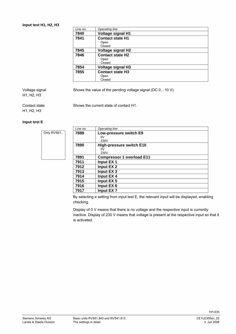
191/235
Siemens Schweiz AG Basic units RVS61.843 and RVS41.813 CE1U2355en_02 Landis & Staefa Division The settings in detail 3. Juli 2008
Line no. Operating line 7840 Voltage signal H1 7841 Contact state H1
Open Closed
7845 Voltage signal H2 7846 Contact state H2
Open Closed
7854 Voltage signal H3 7855 Contact state H3
Open Closed
Shows the value of the pending voltage signal (DC 0…10 V). Shows the current state of contact H1.
Input test E
Line no. Operating line 7889 Low-pressure switch E9
0V 230V
7890 High-pressure switch E10 0V 230V
7891 Compressor 1 overload E11 7911 Input EX 1 7912 Input EX 2 7913 Input EX 3 7914 Input EX 4 7915 Input EX 5 7916 Input EX 6 7917 Input EX 7
By selecting a setting from input test E, the relevant input will be displayed, enabling checking.
Display of 0 V means that there is no voltage and the respective input is currently inactive. Display of 230 V means that voltage is present at the respective input so that it is activated.
Input test H1, H2, H3
Voltage signal H1, H2, H3
Contact state H1, H2, H3
Only RVS61..
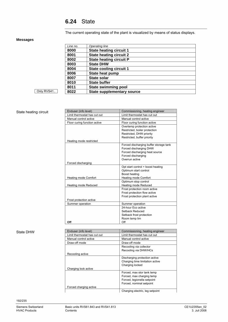
192/235
Siemens Switzerland Basic units RVS61.843 and RVS41.813 CE1U2355en_02 HVAC Products Contents 3. Juli 2008
6.24 State
The current operating state of the plant is visualized by means of status displays.
Messages
Line no. Operating line 8000 State heating circuit 1 8001 State heating circuit 2 8002 State heating circuit P 8003 State DHW 8004 State cooling circuit 1 8006 State heat pump 8007 State solar 8010 State buffer 8011 State swimming pool 8022 State supplementary source
Enduser (info level) Commissioning, heating engineer Limit thermostat has cut out Limit thermostat has cut out Manual control active Manual control active Floor curing function active Floor curing function active Overtemp protection active Restricted, boiler protection Restricted, DHW priority Restricted, buffer priority Heating mode restricted Forced discharging buffer storage tank Forced discharging DHW Forced discharging heat source Forced discharging Overrun active Forced discharging Opt start control + boost heating Optimum start control Boost heating Heating mode Comfort Heating mode Comfort Optimum stop control Heating mode Reduced Heating mode Reduced Frost protection room active Frost protection flow active Frost protection plant active Frost protection active Summer operation Summer operation 24-hour Eco active Setback Reduced Setback frost protection Room temp lim Off Off
Enduser (info level) Commissioning, heating engineer Limit thermostat has cut out Limit thermostat has cut out Manual control active Manual control active Draw-off mode Draw-off mode Recooling via collector Recooling via DHW/HCs Recooling active Discharging protection active Charging time limitation active Charging locked Charging lock active Forced, max stor tank temp Forced, max charging temp Forced, legionella setpoint Forced, nominal setpoint Forced charging active Charging electric, leg setpoint
State heating circuit
State DHW
Only RVS41..
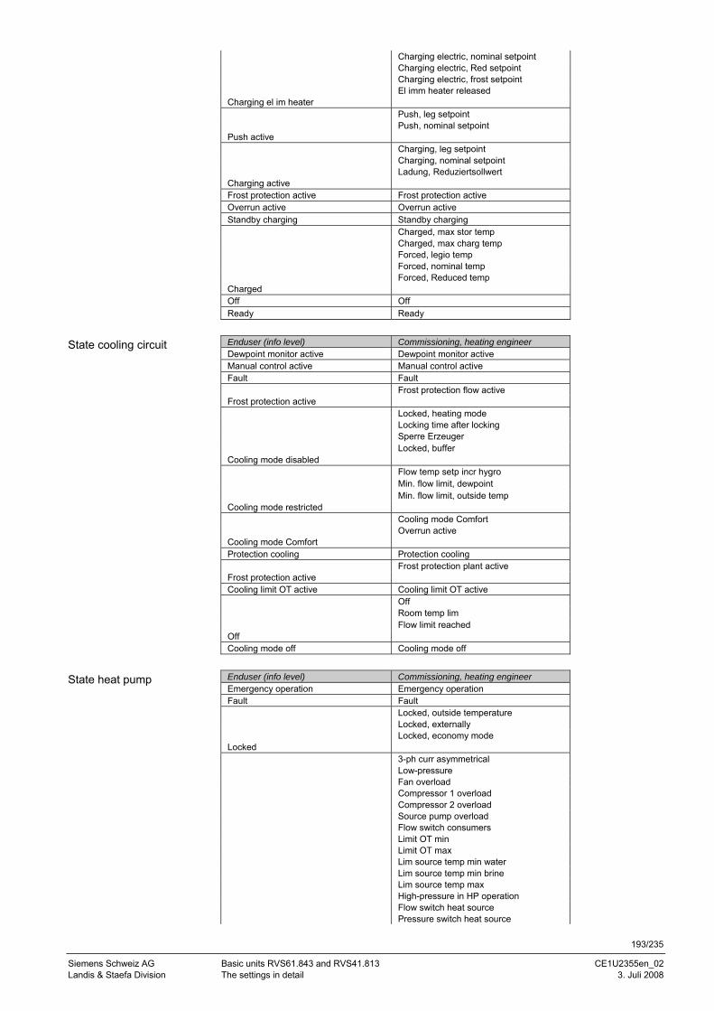
193/235
Siemens Schweiz AG Basic units RVS61.843 and RVS41.813 CE1U2355en_02 Landis & Staefa Division The settings in detail 3. Juli 2008
Charging electric, nominal setpoint Charging electric, Red setpoint Charging electric, frost setpoint El imm heater released Charging el im heater Push, leg setpoint Push, nominal setpoint Push active Charging, leg setpoint Charging, nominal setpoint Ladung, Reduziertsollwert Charging active Frost protection active Frost protection active Overrun active Overrun active Standby charging Standby charging Charged, max stor temp Charged, max charg temp Forced, legio temp Forced, nominal temp Forced, Reduced temp Charged Off Off Ready Ready
Enduser (info level) Commissioning, heating engineer Dewpoint monitor active Dewpoint monitor active Manual control active Manual control active Fault Fault Frost protection flow active Frost protection active Locked, heating mode Locking time after locking Sperre Erzeuger Locked, buffer Cooling mode disabled Flow temp setp incr hygro Min. flow limit, dewpoint Min. flow limit, outside temp Cooling mode restricted Cooling mode Comfort Overrun active Cooling mode Comfort Protection cooling Protection cooling Frost protection plant active Frost protection active Cooling limit OT active Cooling limit OT active Off Room temp lim Flow limit reached Off Cooling mode off Cooling mode off
Enduser (info level) Commissioning, heating engineer Emergency operation Emergency operation Fault Fault Locked, outside temperature Locked, externally Locked, economy mode Locked 3-ph curr asymmetrical Low-pressure Fan overload Compressor 1 overload Compressor 2 overload Source pump overload Flow switch consumers Limit OT min Limit OT max Lim source temp min water Lim source temp min brine Lim source temp max High-pressure in HP operation Flow switch heat source Pressure switch heat source
State cooling circuit
State heat pump
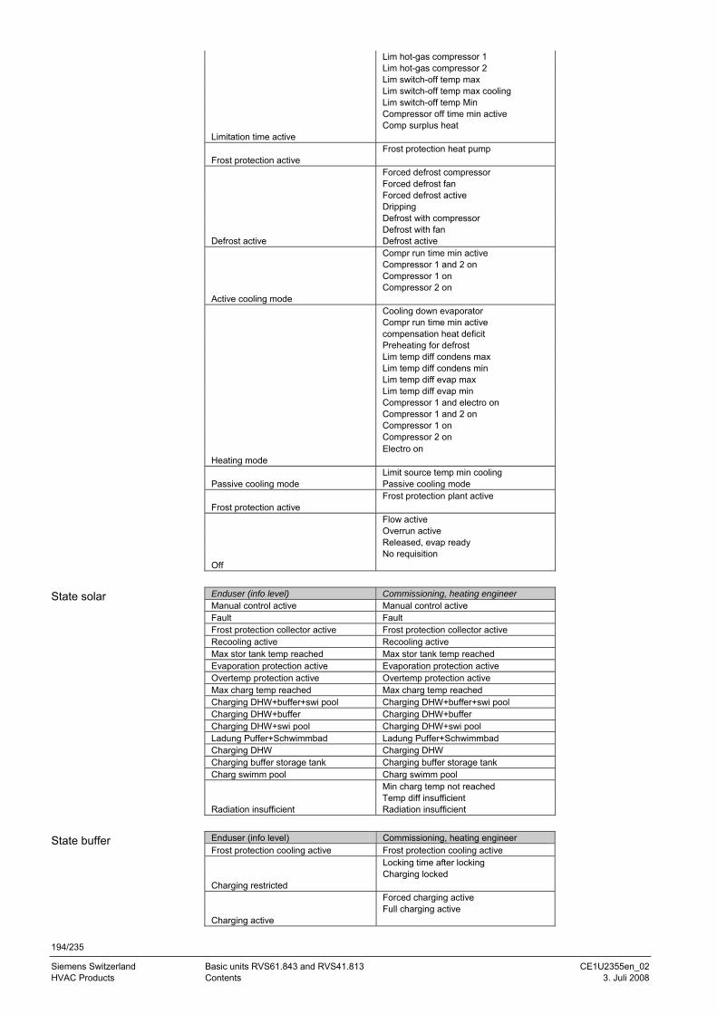
194/235
Siemens Switzerland Basic units RVS61.843 and RVS41.813 CE1U2355en_02 HVAC Products Contents 3. Juli 2008
Lim hot-gas compressor 1 Lim hot-gas compressor 2 Lim switch-off temp max Lim switch-off temp max cooling Lim switch-off temp Min Compressor off time min active Comp surplus heat Limitation time active Frost protection heat pump Frost protection active Forced defrost compressor Forced defrost fan Forced defrost active Dripping Defrost with compressor Defrost with fan Defrost active Defrost active Compr run time min active Compressor 1 and 2 on Compressor 1 on Compressor 2 on Active cooling mode Cooling down evaporator Compr run time min active compensation heat deficit Preheating for defrost Lim temp diff condens max Lim temp diff condens min Lim temp diff evap max Lim temp diff evap min Compressor 1 and electro on Compressor 1 and 2 on Compressor 1 on Compressor 2 on Electro on Heating mode Limit source temp min cooling Passive cooling mode Passive cooling mode Frost protection plant active Frost protection active Flow active Overrun active Released, evap ready No requisition Off
Enduser (info level) Commissioning, heating engineer Manual control active Manual control active Fault Fault Frost protection collector active Frost protection collector active Recooling active Recooling active Max stor tank temp reached Max stor tank temp reached Evaporation protection active Evaporation protection active Overtemp protection active Overtemp protection active Max charg temp reached Max charg temp reached Charging DHW+buffer+swi pool Charging DHW+buffer+swi pool Charging DHW+buffer Charging DHW+buffer Charging DHW+swi pool Charging DHW+swi pool Ladung Puffer+Schwimmbad Ladung Puffer+Schwimmbad Charging DHW Charging DHW Charging buffer storage tank Charging buffer storage tank Charg swimm pool Charg swimm pool Min charg temp not reached Temp diff insufficient Radiation insufficient Radiation insufficient
Enduser (info level) Commissioning, heating engineer Frost protection cooling active Frost protection cooling active Locking time after locking Charging locked Charging restricted Forced charging active Full charging active Charging active
State solar
State buffer
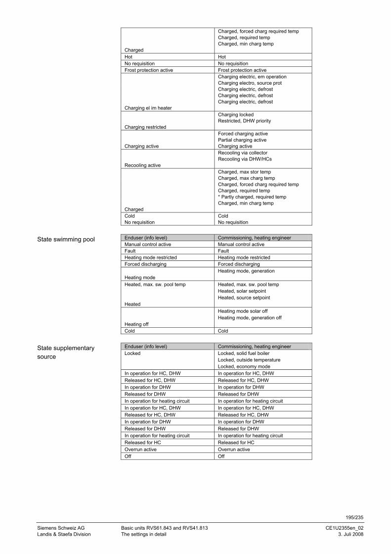
195/235
Siemens Schweiz AG Basic units RVS61.843 and RVS41.813 CE1U2355en_02 Landis & Staefa Division The settings in detail 3. Juli 2008
Charged, forced charg required temp Charged, required temp Charged, min charg temp Charged Hot Hot No requisition No requisition Frost protection active Frost protection active Charging electric, em operation Charging electro, source prot Charging electric, defrost Charging electric, defrost Charging electric, defrost Charging el im heater Charging locked Restricted, DHW priority Charging restricted Forced charging active Partial charging active Charging active Charging active Recooling via collector Recooling via DHW/HCs Recooling active Charged, max stor temp Charged, max charg temp Charged, forced charg required temp Charged, required temp * Partly charged, required temp Charged, min charg temp Charged Cold Cold No requisition No requisition
Enduser (info level) Commissioning, heating engineer Manual control active Manual control active Fault Fault Heating mode restricted Heating mode restricted Forced discharging Forced discharging Heating mode, generation Heating mode Heated, max. sw. pool temp Heated, max. sw. pool temp Heated, solar setpoint Heated, source setpoint Heated Heating mode solar off Heating mode, generation off Heating off Cold Cold
Enduser (info level) Commissioning, heating engineer Locked Locked, solid fuel boiler Locked, outside temperature Locked, economy mode In operation for HC, DHW In operation for HC, DHW Released for HC, DHW Released for HC, DHW In operation for DHW In operation for DHW Released for DHW Released for DHW In operation for heating circuit In operation for heating circuit In operation for HC, DHW In operation for HC, DHW Released for HC, DHW Released for HC, DHW In operation for DHW In operation for DHW Released for DHW Released for DHW In operation for heating circuit In operation for heating circuit Released for HC Released for HC Overrun active Overrun active Off Off
State swimming pool
State supplementary source
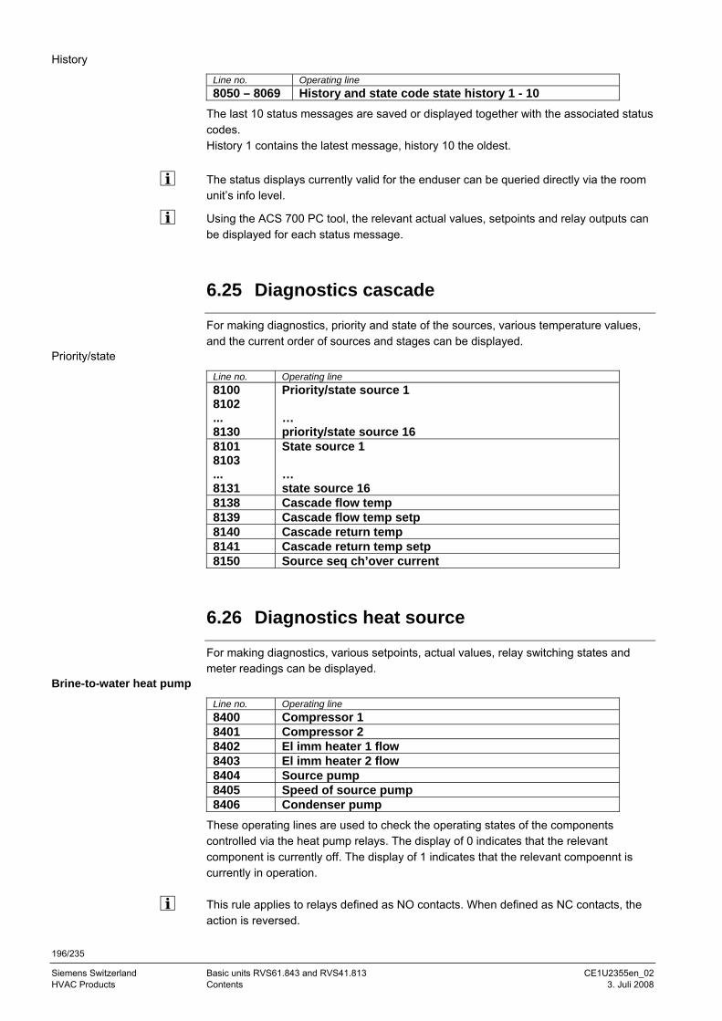
196/235
Siemens Switzerland Basic units RVS61.843 and RVS41.813 CE1U2355en_02 HVAC Products Contents 3. Juli 2008
History
Line no. Operating line 8050 – 8069 History and state code state history 1 - 10
The last 10 status messages are saved or displayed together with the associated status codes. History 1 contains the latest message, history 10 the oldest. The status displays currently valid for the enduser can be queried directly via the room unit’s info level.
Using the ACS 700 PC tool, the relevant actual values, setpoints and relay outputs can be displayed for each status message.
6.25 Diagnostics cascade
For making diagnostics, priority and state of the sources, various temperature values, and the current order of sources and stages can be displayed.
Priority/state
Line no. Operating line 8100 8102 ... 8130
Priority/state source 1 … priority/state source 16
8101 8103 ... 8131
State source 1 … state source 16
8138 Cascade flow temp 8139 Cascade flow temp setp 8140 Cascade return temp 8141 Cascade return temp setp 8150 Source seq ch’over current
6.26 Diagnostics heat source
For making diagnostics, various setpoints, actual values, relay switching states and meter readings can be displayed.
Brine-to-water heat pump
Line no. Operating line 8400 Compressor 1 8401 Compressor 2 8402 El imm heater 1 flow 8403 El imm heater 2 flow 8404 Source pump 8405 Speed of source pump 8406 Condenser pump
These operating lines are used to check the operating states of the components controlled via the heat pump relays. The display of 0 indicates that the relevant component is currently off. The display of 1 indicates that the relevant compoennt is currently in operation. This rule applies to relays defined as NO contacts. When defined as NC contacts, the action is reversed.
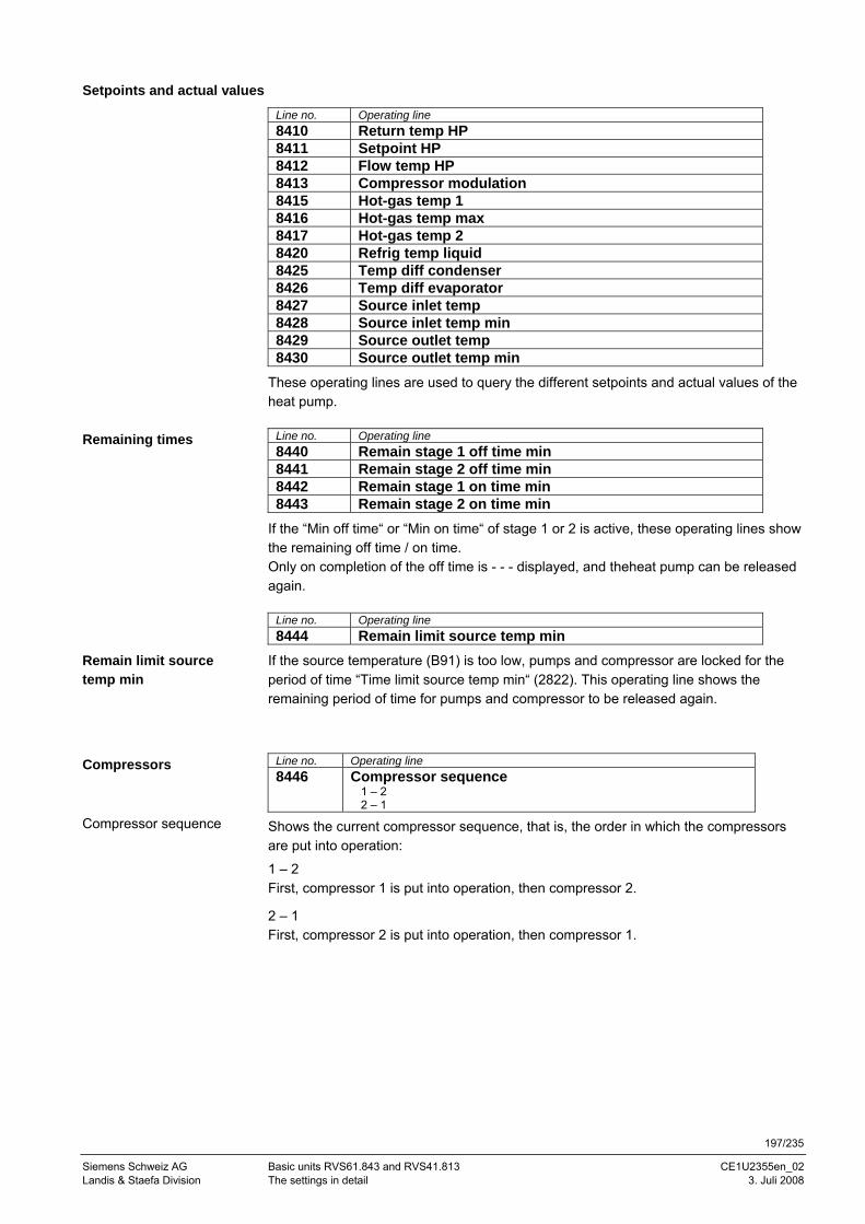
197/235
Siemens Schweiz AG Basic units RVS61.843 and RVS41.813 CE1U2355en_02 Landis & Staefa Division The settings in detail 3. Juli 2008
Setpoints and actual values
Line no. Operating line 8410 Return temp HP 8411 Setpoint HP 8412 Flow temp HP 8413 Compressor modulation 8415 Hot-gas temp 1 8416 Hot-gas temp max 8417 Hot-gas temp 2 8420 Refrig temp liquid 8425 Temp diff condenser 8426 Temp diff evaporator 8427 Source inlet temp 8428 Source inlet temp min 8429 Source outlet temp 8430 Source outlet temp min
These operating lines are used to query the different setpoints and actual values of the heat pump.
Line no. Operating line 8440 Remain stage 1 off time min 8441 Remain stage 2 off time min 8442 Remain stage 1 on time min 8443 Remain stage 2 on time min
If the “Min off time“ or “Min on time“ of stage 1 or 2 is active, these operating lines show the remaining off time / on time. Only on completion of the off time is - - - displayed, and theheat pump can be released again.
Line no. Operating line 8444 Remain limit source temp min
If the source temperature (B91) is too low, pumps and compressor are locked for the period of time “Time limit source temp min“ (2822). This operating line shows the remaining period of time for pumps and compressor to be released again.
Line no. Operating line 8446 Compressor sequence
1 – 2 2 – 1
Shows the current compressor sequence, that is, the order in which the compressors are put into operation:
1 – 2 First, compressor 1 is put into operation, then compressor 2.
2 – 1 First, compressor 2 is put into operation, then compressor 1.
Remaining times
Remain limit source temp min
Compressors
Compressor sequence
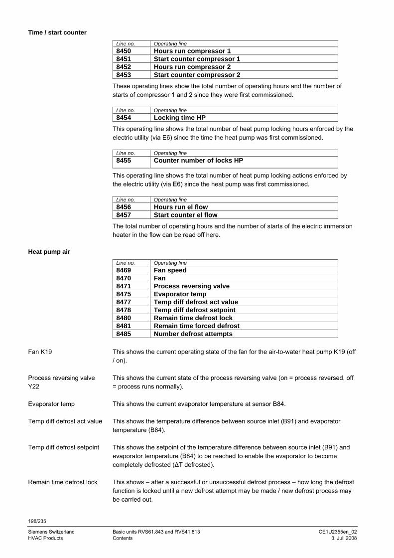
198/235
Siemens Switzerland Basic units RVS61.843 and RVS41.813 CE1U2355en_02 HVAC Products Contents 3. Juli 2008
Time / start counter
Line no. Operating line 8450 Hours run compressor 1 8451 Start counter compressor 1 8452 Hours run compressor 2 8453 Start counter compressor 2
These operating lines show the total number of operating hours and the number of starts of compressor 1 and 2 since they were first commissioned.
Line no. Operating line 8454 Locking time HP
This operating line shows the total number of heat pump locking hours enforced by the electric utility (via E6) since the time the heat pump was first commissioned.
Line no. Operating line 8455 Counter number of locks HP
This operating line shows the total number of heat pump locking actions enforced by the electric utility (via E6) since the heat pump was first commissioned.
Line no. Operating line 8456 Hours run el flow 8457 Start counter el flow
The total number of operating hours and the number of starts of the electric immersion heater in the flow can be read off here.
Heat pump air
Line no. Operating line 8469 Fan speed 8470 Fan 8471 Process reversing valve 8475 Evaporator temp 8477 Temp diff defrost act value 8478 Temp diff defrost setpoint 8480 Remain time defrost lock 8481 Remain time forced defrost 8485 Number defrost attempts
This shows the current operating state of the fan for the air-to-water heat pump K19 (off / on). This shows the current state of the process reversing valve (on = process reversed, off = process runs normally). This shows the current evaporator temperature at sensor B84. This shows the temperature difference between source inlet (B91) and evaporator temperature (B84). This shows the setpoint of the temperature difference between source inlet (B91) and evaporator temperature (B84) to be reached to enable the evaporator to become completely defrosted (ΔT defrosted). This shows – after a successful or unsuccessful defrost process – how long the defrost function is locked until a new defrost attempt may be made / new defrost process may be carried out.
Fan K19
Process reversing valve Y22
Evaporator temp
Temp diff defrost act value
Temp diff defrost setpoint
Remain time defrost lock
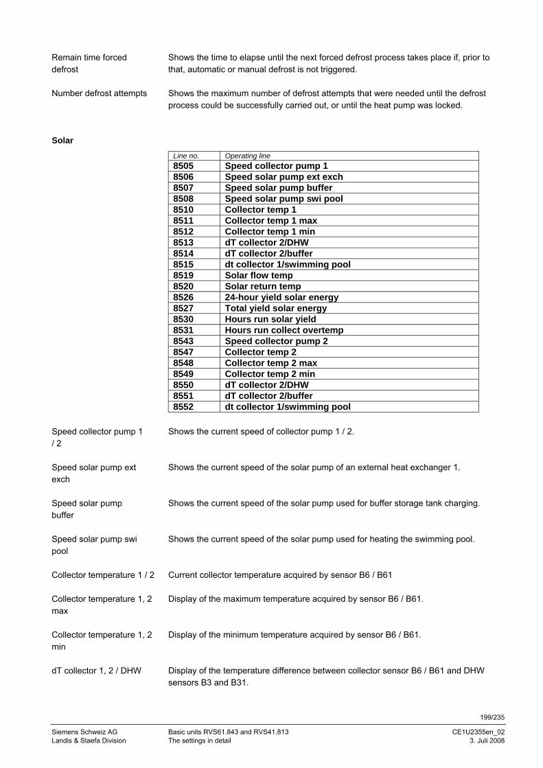
199/235
Siemens Schweiz AG Basic units RVS61.843 and RVS41.813 CE1U2355en_02 Landis & Staefa Division The settings in detail 3. Juli 2008
Shows the time to elapse until the next forced defrost process takes place if, prior to that, automatic or manual defrost is not triggered. Shows the maximum number of defrost attempts that were needed until the defrost process could be successfully carried out, or until the heat pump was locked.
Solar
Line no. Operating line 8505 Speed collector pump 1 8506 Speed solar pump ext exch 8507 Speed solar pump buffer 8508 Speed solar pump swi pool 8510 Collector temp 1 8511 Collector temp 1 max 8512 Collector temp 1 min 8513 dT collector 2/DHW 8514 dT collector 2/buffer 8515 dt collector 1/swimming pool 8519 Solar flow temp 8520 Solar return temp 8526 24-hour yield solar energy 8527 Total yield solar energy 8530 Hours run solar yield 8531 Hours run collect overtemp 8543 Speed collector pump 2 8547 Collector temp 2 8548 Collector temp 2 max 8549 Collector temp 2 min 8550 dT collector 2/DHW 8551 dT collector 2/buffer 8552 dt collector 1/swimming pool
Shows the current speed of collector pump 1 / 2. Shows the current speed of the solar pump of an external heat exchanger 1. Shows the current speed of the solar pump used for buffer storage tank charging. Shows the current speed of the solar pump used for heating the swimming pool. Current collector temperature acquired by sensor B6 / B61 Display of the maximum temperature acquired by sensor B6 / B61. Display of the minimum temperature acquired by sensor B6 / B61. Display of the temperature difference between collector sensor B6 / B61 and DHW sensors B3 and B31.
Remain time forced defrost
Number defrost attempts
Speed collector pump 1 / 2
Speed solar pump ext exch
Speed solar pump buffer
Speed solar pump swi pool
Collector temperature 1 / 2
Collector temperature 1, 2 max
Collector temperature 1, 2 min
dT collector 1, 2 / DHW
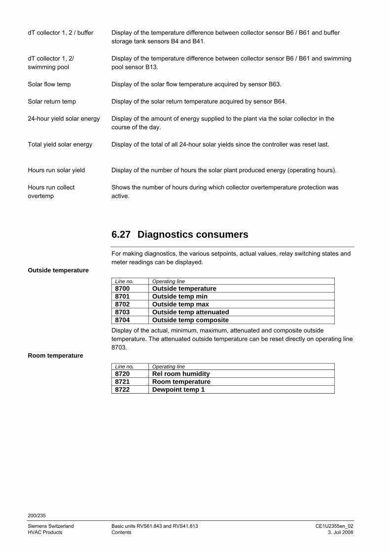
200/235
Siemens Switzerland Basic units RVS61.843 and RVS41.813 CE1U2355en_02 HVAC Products Contents 3. Juli 2008
Display of the temperature difference between collector sensor B6 / B61 and buffer storage tank sensors B4 and B41. Display of the temperature difference between collector sensor B6 / B61 and swimming pool sensor B13. Display of the solar flow temperature acquired by sensor B63. Display of the solar return temperature acquired by sensor B64. Display of the amount of energy supplied to the plant via the solar collector in the course of the day. Display of the total of all 24-hour solar yields since the controller was reset last. Display of the number of hours the solar plant produced energy (operating hours). Shows the number of hours during which collector overtemperature protection was active.
6.27 Diagnostics consumers
For making diagnostics, the various setpoints, actual values, relay switching states and meter readings can be displayed.
Outside temperature
Line no. Operating line 8700 Outside temperature 8701 Outside temp min 8702 Outside temp max 8703 Outside temp attenuated 8704 Outside temp composite
Display of the actual, minimum, maximum, attenuated and composite outside temperature. The attenuated outside temperature can be reset directly on operating line 8703.
Room temperature Line no. Operating line 8720 Rel room humidity 8721 Room temperature 8722 Dewpoint temp 1
dT collector 1, 2 / buffer
dT collector 1, 2/ swimming pool
Solar flow temp
Solar return temp
24-hour yield solar energy
Total yield solar energy
Hours run solar yield
Hours run collect overtemp
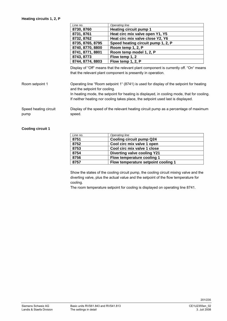
201/235
Siemens Schweiz AG Basic units RVS61.843 and RVS41.813 CE1U2355en_02 Landis & Staefa Division The settings in detail 3. Juli 2008
Heating circuits 1, 2, P
Line no. Operating line 8730, 8760 Heating circuit pump 1 8731, 8761 Heat circ mix valve open Y1, Y5 8732, 8762 Heat circ mix valve close Y2, Y6 8735, 8765, 8795 Speed heating circuit pump 1, 2, P 8740, 8770, 8800 Room temp 1, 2, P 8741, 8771, 8801 Room temp model 1, 2, P 8743, 8773 Flow temp 1, 2 8744, 8774, 8803 Flow temp 1, 2, P
Display of “Off“ means that the relevant plant component is currently off. “On“ means that the relevant plant component is presently in operation.
Operating line “Room setpoint 1“ (8741) is used for display of the setpoint for heating and the setpoint for cooling. In heating mode, the setpoint for heating is displayed, in cooling mode, that for cooling. If neither heating nor cooling takes place, the setpoint used last is displayed. Display of the speed of the relevant heating circuit pump as a percentage of maximum speed.
Cooling circuit 1
Line no. Operating line 8751 Cooling circuit pump Q24 8752 Cool circ mix valve 1 open 8753 Cool circ mix valve 1 close 8754 Diverting valve cooling Y21 8756 Flow temperature cooling 1 8757 Flow temperature setpoint cooling 1
Show the states of the cooling circuit pump, the cooling circuit mixing valve and the diverting valve, plus the actual value and the setpoint of the flow temperature for cooling. The room temperature setpoint for cooling is displayed on operating line 8741.
Room setpoint 1
Speed heating circuit pump
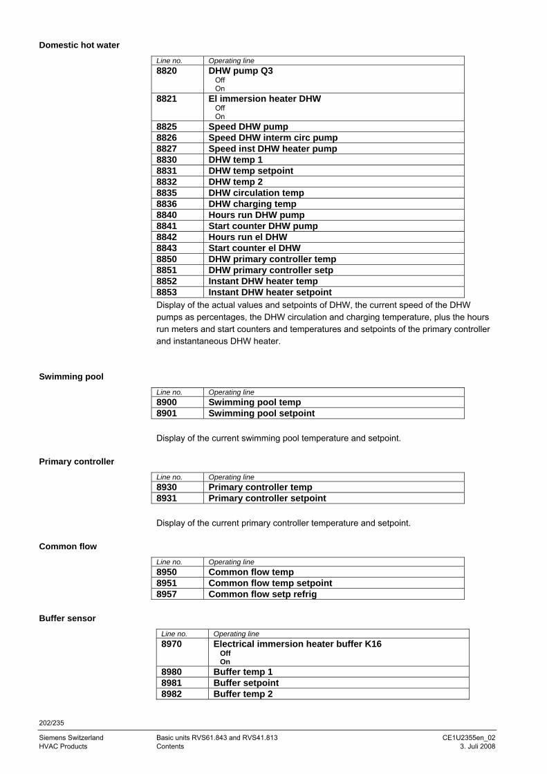
202/235
Siemens Switzerland Basic units RVS61.843 and RVS41.813 CE1U2355en_02 HVAC Products Contents 3. Juli 2008
Domestic hot water
Line no. Operating line 8820 DHW pump Q3
Off On
8821 El immersion heater DHW Off On
8825 Speed DHW pump 8826 Speed DHW interm circ pump 8827 Speed inst DHW heater pump 8830 DHW temp 1 8831 DHW temp setpoint 8832 DHW temp 2 8835 DHW circulation temp 8836 DHW charging temp 8840 Hours run DHW pump 8841 Start counter DHW pump 8842 Hours run el DHW 8843 Start counter el DHW 8850 DHW primary controller temp 8851 DHW primary controller setp 8852 Instant DHW heater temp 8853 Instant DHW heater setpoint Display of the actual values and setpoints of DHW, the current speed of the DHW pumps as percentages, the DHW circulation and charging temperature, plus the hours run meters and start counters and temperatures and setpoints of the primary controller and instantaneous DHW heater.
Swimming pool
Line no. Operating line 8900 Swimming pool temp 8901 Swimming pool setpoint Display of the current swimming pool temperature and setpoint.
Primary controller
Line no. Operating line 8930 Primary controller temp 8931 Primary controller setpoint Display of the current primary controller temperature and setpoint.
Common flow
Line no. Operating line 8950 Common flow temp 8951 Common flow temp setpoint 8957 Common flow setp refrig
Buffer sensor
Line no. Operating line 8970 Electrical immersion heater buffer K16
Off On
8980 Buffer temp 1 8981 Buffer setpoint 8982 Buffer temp 2
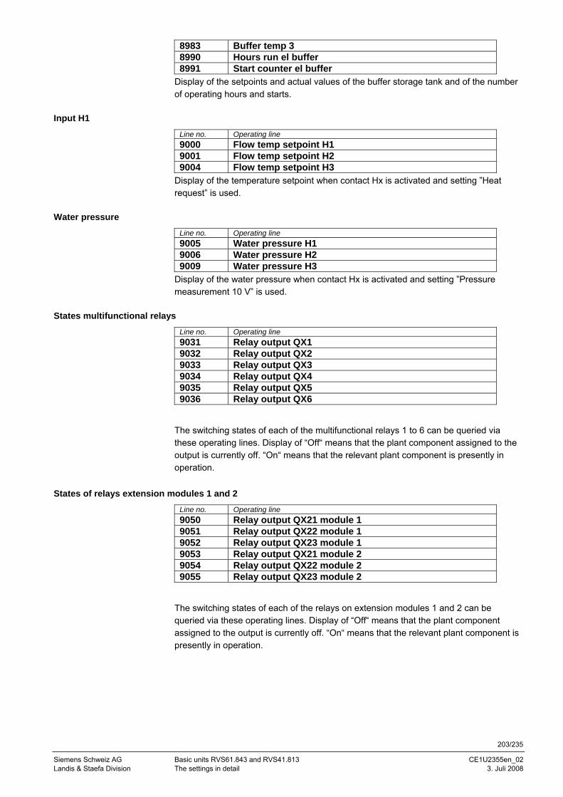
203/235
Siemens Schweiz AG Basic units RVS61.843 and RVS41.813 CE1U2355en_02 Landis & Staefa Division The settings in detail 3. Juli 2008
8983 Buffer temp 3 8990 Hours run el buffer 8991 Start counter el buffer
Display of the setpoints and actual values of the buffer storage tank and of the number of operating hours and starts.
Input H1
Line no. Operating line 9000 Flow temp setpoint H1 9001 Flow temp setpoint H2 9004 Flow temp setpoint H3
Display of the temperature setpoint when contact Hx is activated and setting ”Heat request” is used.
Water pressure
Line no. Operating line 9005 Water pressure H1 9006 Water pressure H2 9009 Water pressure H3
Display of the water pressure when contact Hx is activated and setting ”Pressure measurement 10 V” is used.
States multifunctional relays
Line no. Operating line 9031 Relay output QX1 9032 Relay output QX2 9033 Relay output QX3 9034 Relay output QX4 9035 Relay output QX5 9036 Relay output QX6
The switching states of each of the multifunctional relays 1 to 6 can be queried via these operating lines. Display of “Off“ means that the plant component assigned to the output is currently off. “On“ means that the relevant plant component is presently in operation.
States of relays extension modules 1 and 2
Line no. Operating line 9050 Relay output QX21 module 1 9051 Relay output QX22 module 1 9052 Relay output QX23 module 1 9053 Relay output QX21 module 2 9054 Relay output QX22 module 2 9055 Relay output QX23 module 2
The switching states of each of the relays on extension modules 1 and 2 can be queried via these operating lines. Display of “Off“ means that the plant component assigned to the output is currently off. “On“ means that the relevant plant component is presently in operation.
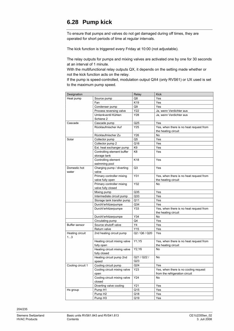
204/235
Siemens Switzerland Basic units RVS61.843 and RVS41.813 CE1U2355en_02 HVAC Products Contents 3. Juli 2008
6.28 Pump kick
To ensure that pumps and valves do not get damaged during off times, they are operated for short periods of time at regular intervals. The kick function is triggered every Friday at 10:00 (not adjustable). The relay outputs for pumps and mixing valves are activated one by one for 30 seconds at an interval of 1 minute. With the multifunctional relay outputs QX, it depends on the setting made whether or not the kick function acts on the relay. If the pump is speed-controlled, modulation output QX4 (only RVS61) or UX used is set to the maximum pump speed. Designation Relay Kick Heat pump Source pump Q8 Yes Fan K19 Yes Condenser pump Q9 Yes Process reversing valve Y22 Ja, wenn Verdichter aus Umlenkventil Kühlen
Schiene 2 Y28 Ja, wenn Verdichter aus
Cascade Cascade pump Q25 Yes Rücklaufmischer Auf Y25 Yes, when there is no heat request from
the heating circuit Rücklaufmischer Zu Y26 No Solar Collector pump Q5 Yes Collector pump 2 Q16 Yes Ext. heat exchanger pump K9 Yes Controlling element buffer
storage tank K8 Yes
Controlling element swimming pool
K18 Yes
Domestic hot water
Charging pump / diverting valve
Q3 Yes
Primary controller mixing valve fully open
Y31 Yes, when there is no heat request from the heating circuit
Primary controller mixing valve fully closed
Y32 No
Mixing pump Q35 Yes Intermediate circuit pump Q33 Yes Storage tank transfer pump Q11 Yes Durchl’erhitzerpumpe Q34 Yes Durchl’erhitzerpumpe Y33 Yes, when there is no heat request from
the heating circuit Durchl’erhitzerpumpe Y34 No Circulating pump Q4 Yes Buffer sensor Source shutoff valve Y4 Yes Return valve Y15 Yes Heating circuit 1...3
2nd heating circuit pump Q2 / Q6 / Q20 Yes
Heating circuit mixing valve fully open
Y1,Y5 Yes, when there is no heat request from the heating circuit
Heating circuit mixing valve fully closed
Y2,Y6 No
Heating circuit pump 2nd speed
Q21 / Q22 / Q23
No
Cooling circuit 1 Cooling circuit pump Q24 Yes Cooling circuit mixing valve
open Y23 Yes, when there is no cooling request
from the refrigeration circuit Cooling circuit mixing valve
closed Y24 No
Diverting valve cooling Y21 Yes Hx group Pump H1 Q15 Yes Pump H2 Q18 Yes Pump H3 Q19 Yes
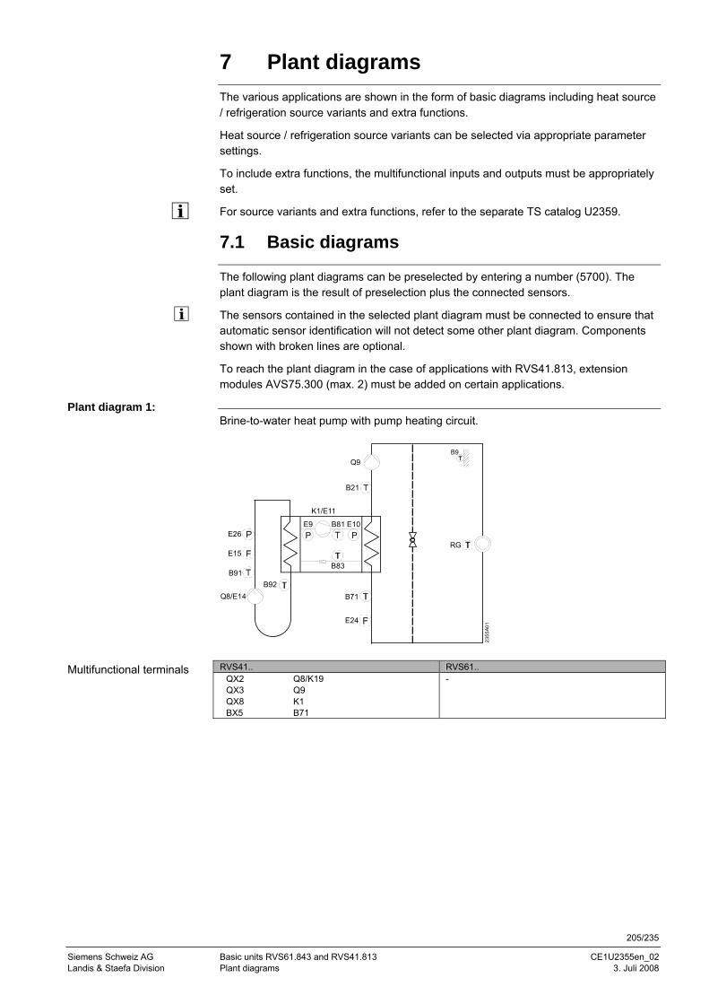
205/235
Siemens Schweiz AG Basic units RVS61.843 and RVS41.813 CE1U2355en_02 Landis & Staefa Division Plant diagrams 3. Juli 2008
7 Plant diagrams
The various applications are shown in the form of basic diagrams including heat source / refrigeration source variants and extra functions.
Heat source / refrigeration source variants can be selected via appropriate parameter settings.
To include extra functions, the multifunctional inputs and outputs must be appropriately set.
For source variants and extra functions, refer to the separate TS catalog U2359.
7.1 Basic diagrams
The following plant diagrams can be preselected by entering a number (5700). The plant diagram is the result of preselection plus the connected sensors.
The sensors contained in the selected plant diagram must be connected to ensure that automatic sensor identification will not detect some other plant diagram. Components shown with broken lines are optional.
To reach the plant diagram in the case of applications with RVS41.813, extension modules AVS75.300 (max. 2) must be added on certain applications.
Brine-to-water heat pump with pump heating circuit.
2355
A01
RG
B21
K1/E11
B71B92
Q8/E14
B91
E15
Q9
E9PP
B81 E10
B83
B9
E26
E24
RVS41.. RVS61..
QX2 Q8/K19 QX3 Q9 QX8 K1 BX5 B71
-
Plant diagram 1:
Multifunctional terminals
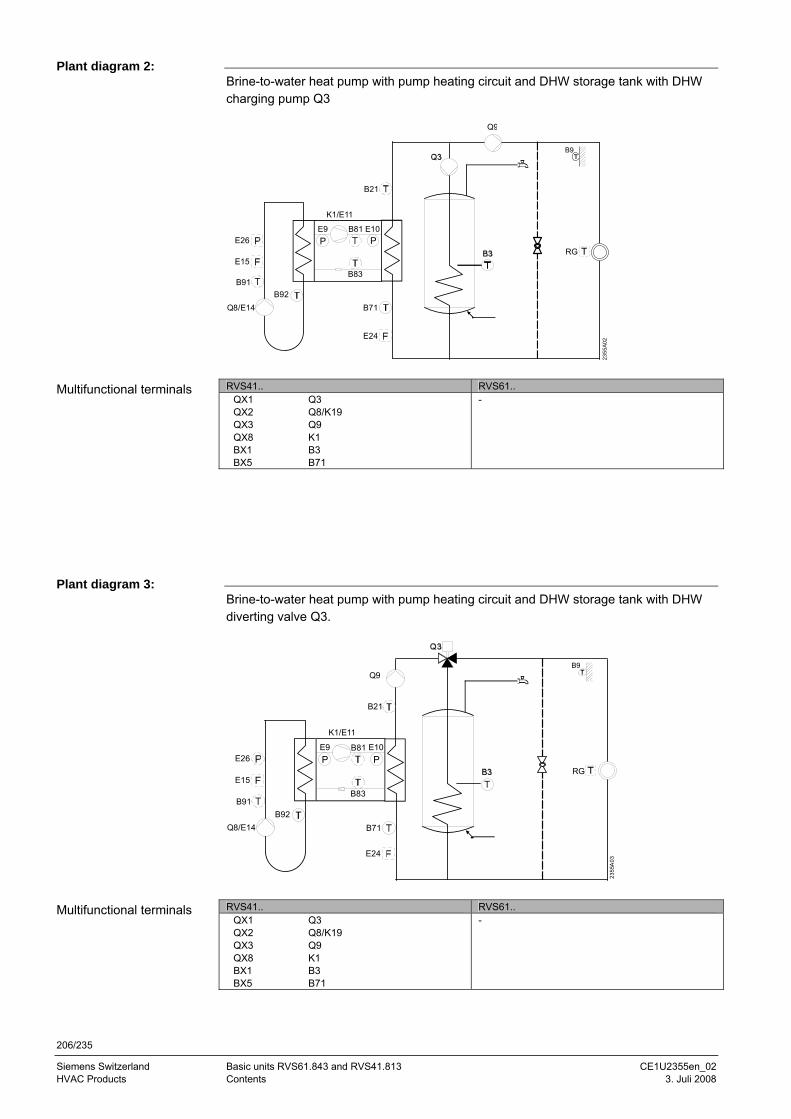
206/235
Siemens Switzerland Basic units RVS61.843 and RVS41.813 CE1U2355en_02 HVAC Products Contents 3. Juli 2008
Brine-to-water heat pump with pump heating circuit and DHW storage tank with DHW charging pump Q3
2355
A02
RG
Q9
B21
K1/E11
B71B92
Q8/E14
B91
E9PP
B81 E10
B83
B9
E15
E26
E24
RVS41.. RVS61..
QX1 Q3 QX2 Q8/K19 QX3 Q9 QX8 K1 BX1 B3 BX5 B71
-
Brine-to-water heat pump with pump heating circuit and DHW storage tank with DHW diverting valve Q3.
2355
A03
RG
B21
K1/E11
B71B92
Q8/E14
B91
E9PP
B81 E10
B83
Q9B9
E15
E26
E24
RVS41.. RVS61..
QX1 Q3 QX2 Q8/K19 QX3 Q9 QX8 K1 BX1 B3 BX5 B71
-
Plant diagram 2:
Multifunctional terminals
Plant diagram 3:
Multifunctional terminals
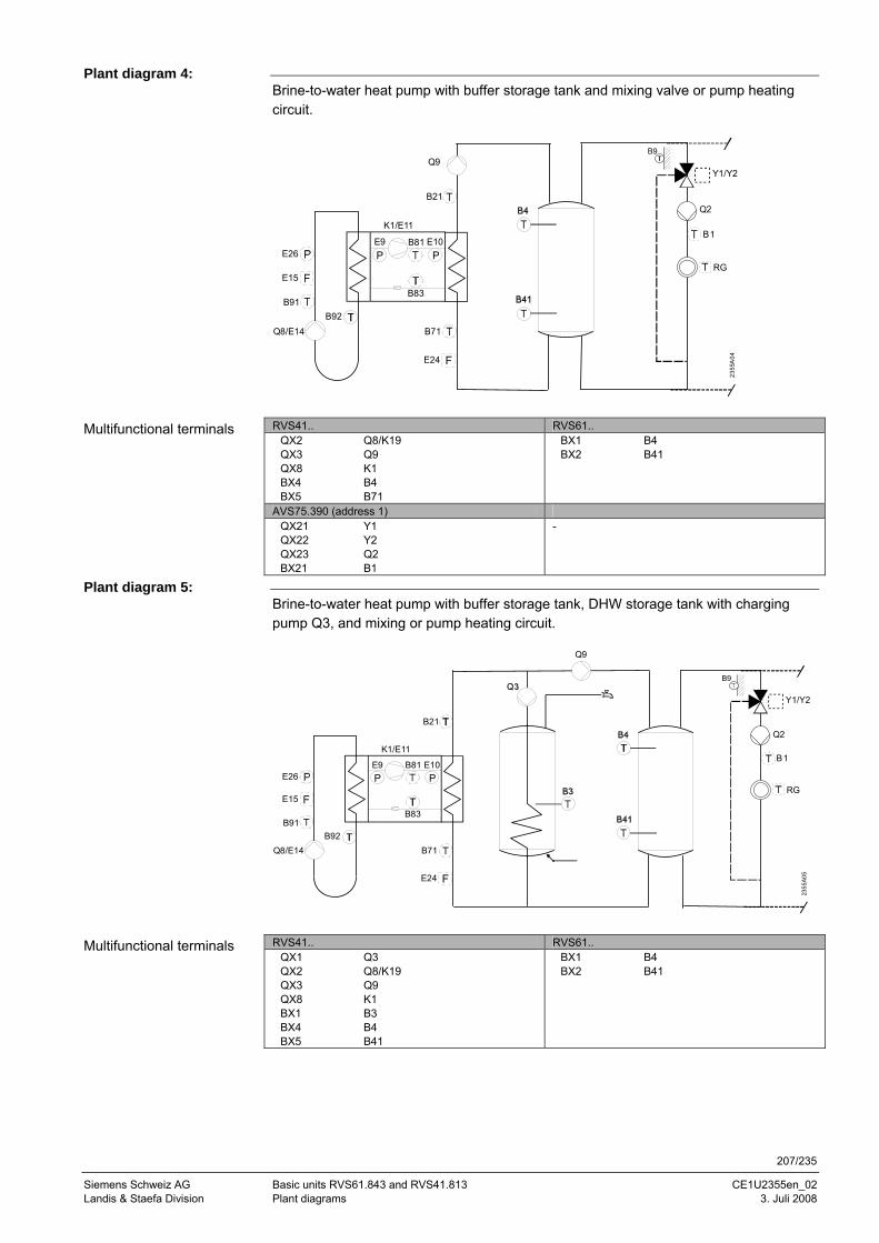
207/235
Siemens Schweiz AG Basic units RVS61.843 and RVS41.813 CE1U2355en_02 Landis & Staefa Division Plant diagrams 3. Juli 2008
Brine-to-water heat pump with buffer storage tank and mixing valve or pump heating circuit.
B21
K1/E11
B71B92
Q8/E14
B91
E9PP
B81 E10
B83
Q9
2355
A04
Y1/Y2
Q2
B1
RG
B9
E15
E26
E24
RVS41.. RVS61..
QX2 Q8/K19 QX3 Q9 QX8 K1 BX4 B4 BX5 B71
BX1 B4 BX2 B41
AVS75.390 (address 1) QX21 Y1 QX22 Y2 QX23 Q2 BX21 B1
-
Brine-to-water heat pump with buffer storage tank, DHW storage tank with charging pump Q3, and mixing or pump heating circuit.
2355
A05
Q9
B21
K1/E11
B71B92
Q8/E14
B91
E9PP
B81 E10
B83
Y1/Y2
Q2
B1
RGE26
E24
B9
E15
RVS41.. RVS61..
QX1 Q3 QX2 Q8/K19 QX3 Q9 QX8 K1 BX1 B3 BX4 B4 BX5 B41
BX1 B4 BX2 B41
Plant diagram 4:
Multifunctional terminals
Plant diagram 5:
Multifunctional terminals
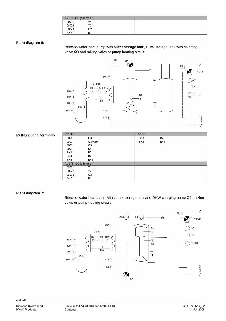
208/235
Siemens Switzerland Basic units RVS61.843 and RVS41.813 CE1U2355en_02 HVAC Products Contents 3. Juli 2008
AVS75.390 (address 1) QX21 Y1 QX22 Y2 QX23 Q2 BX21 B1
-
Brine-to-water heat pump with buffer storage tank, DHW storage tank with diverting valve Q3 and mixing valve or pump heating circuit.
Q9
B21
K1/E11
B71B92
Q8/E14
B91
E9PP
B81 E10
B83
Y1/Y2
Q2
B1
RG
2355
A06
E15
E26
E24
B9
RVS41.. RVS61..
QX1 Q3 QX2 Q8/K19 QX3 Q9 QX8 K1 BX1 B3 BX4 B4 BX5 B41
BX1 B4 BX2 B41
AVS75.390 (address 1) QX21 Y1 QX22 Y2 QX23 Q2 BX21 B1
Brine-to-water heat pump with combi storage tank and DHW charging pump Q3, mixing valve or pump heating circuit.
2355
A07
Y1/Y2
Q2
B1
RG
Q9
B21
K1/E11
B71B92
Q8/E14
B91
E9PP
B81 E10
B83
E15
E26
E24
B9
Plant diagram 6:
Multifunctional terminals
Plant diagram 7:
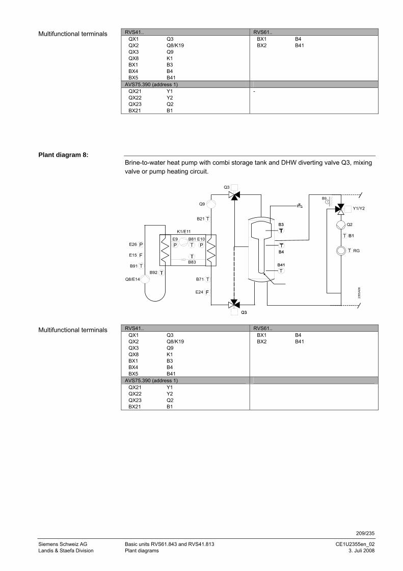
209/235
Siemens Schweiz AG Basic units RVS61.843 and RVS41.813 CE1U2355en_02 Landis & Staefa Division Plant diagrams 3. Juli 2008
RVS41.. RVS61.. QX1 Q3 QX2 Q8/K19 QX3 Q9 QX8 K1 BX1 B3 BX4 B4 BX5 B41
BX1 B4 BX2 B41
AVS75.390 (address 1) QX21 Y1 QX22 Y2 QX23 Q2 BX21 B1
-
Brine-to-water heat pump with combi storage tank and DHW diverting valve Q3, mixing valve or pump heating circuit.
Q3
2355
A08
Y1/Y2
Q2
RG
B21
K1/E11
B71B92
Q8/E14
B91
E9PP
B81 E10
B83
Q9
E15
E26
E24
B9
RVS41.. RVS61..
QX1 Q3 QX2 Q8/K19 QX3 Q9 QX8 K1 BX1 B3 BX4 B4 BX5 B41
BX1 B4 BX2 B41
AVS75.390 (address 1) QX21 Y1 QX22 Y2 QX23 Q2 BX21 B1
Multifunctional terminals
Plant diagram 8:
Multifunctional terminals
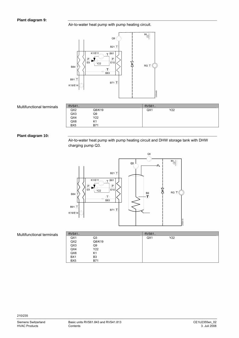
210/235
Siemens Switzerland Basic units RVS61.843 and RVS41.813 CE1U2355en_02 HVAC Products Contents 3. Juli 2008
Air-to-water heat pump with pump heating circuit.
RG
B21
B71
Q9
K1/E11
P
B81
E10
B83
B91
K19/E14
B84
PE9 Y22
2355
A09
B9
RVS41.. RVS61..
QX2 Q8/K19 QX3 Q9 QX4 Y22 QX8 K1 BX5 B71
QX1 Y22
Air-to-water heat pump with pump heating circuit and DHW storage tank with DHW charging pump Q3.
RG
Q9
B21
B71
K1/E11
P
B81
E10
B83
B91
K19/E14
B84
PE9 Y22
2355
A10
B9
RVS41.. RVS61..
QX1 Q3 QX2 Q8/K19 QX3 Q9 QX4 Y22 QX8 K1 BX1 B3 BX5 B71
QX1 Y22
Plant diagram 9:
Multifunctional terminals
Plant diagram 10:
Multifunctional terminals
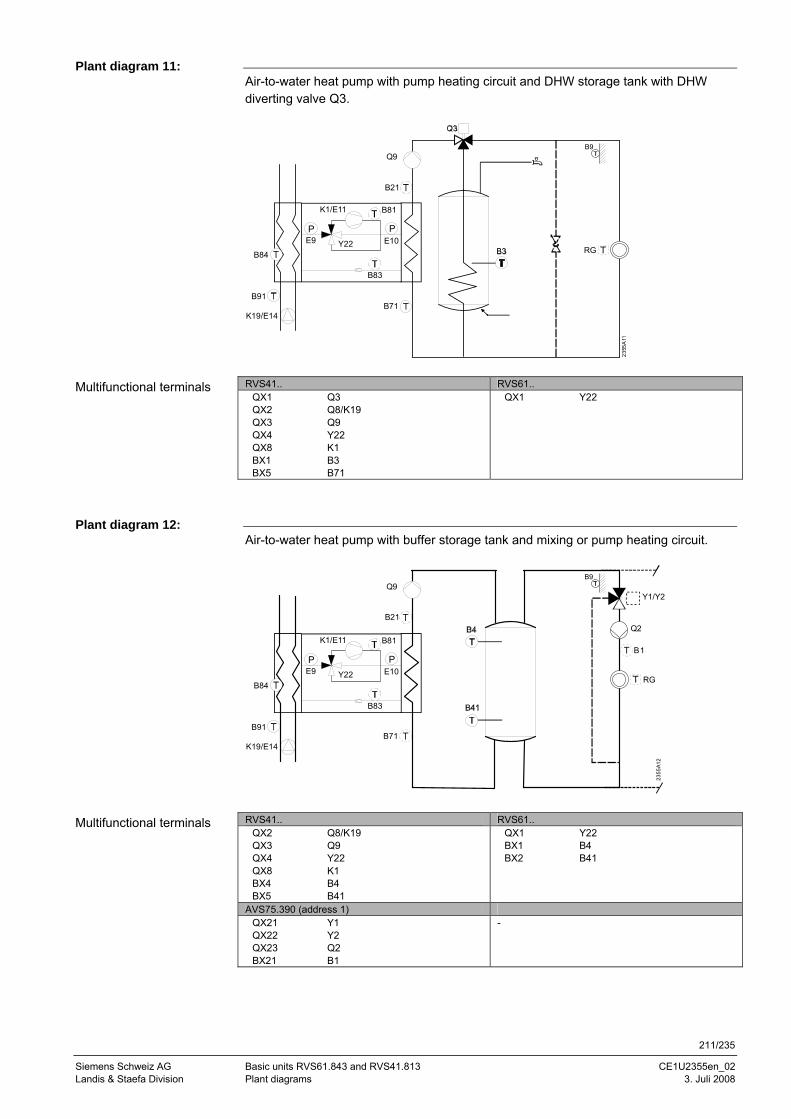
211/235
Siemens Schweiz AG Basic units RVS61.843 and RVS41.813 CE1U2355en_02 Landis & Staefa Division Plant diagrams 3. Juli 2008
Air-to-water heat pump with pump heating circuit and DHW storage tank with DHW diverting valve Q3.
RG
B21
B71
Q9
K1/E11
P
B81
E10
B83
B91
K19/E14
B84
PE9 Y22
2355
A11
B9
RVS41.. RVS61..
QX1 Q3 QX2 Q8/K19 QX3 Q9 QX4 Y22 QX8 K1 BX1 B3 BX5 B71
QX1 Y22
Air-to-water heat pump with buffer storage tank and mixing or pump heating circuit.
B21
B71
Q9Y1/Y2
Q2
B1
RG
K1/E11
P
B81
E10
B83
B91
K19/E14
B84
PE9 Y22
2355
A12
B9
RVS41.. RVS61..
QX2 Q8/K19 QX3 Q9 QX4 Y22 QX8 K1 BX4 B4 BX5 B41
QX1 Y22 BX1 B4 BX2 B41
AVS75.390 (address 1) QX21 Y1 QX22 Y2 QX23 Q2 BX21 B1
-
Plant diagram 11:
Multifunctional terminals
Plant diagram 12:
Multifunctional terminals
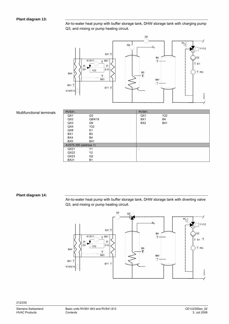
212/235
Siemens Switzerland Basic units RVS61.843 and RVS41.813 CE1U2355en_02 HVAC Products Contents 3. Juli 2008
Air-to-water heat pump with buffer storage tank, DHW storage tank with charging pump Q3, and mixing or pump heating circuit.
Q9
B21
B71
Y1/Y2
Q2
B1
RG
K1/E11
P
B81
E10
B83
B91
K19/E14
B84
PE9 Y22
2355
A13
B9
RVS41.. RVS61..
QX1 Q3 QX2 Q8/K19 QX3 Q9 QX4 Y22 QX8 K1 BX1 B3 BX4 B4 BX5 B41
QX1 Y22 BX1 B4 BX2 B41
AVS75.390 (address 1) QX21 Y1 QX22 Y2 QX23 Q2 BX21 B1
-
Air-to-water heat pump with buffer storage tank, DHW storage tank with diverting valve Q3, and mixing or pump heating circuit.
Q9
B21
B71
Y1/Y2
Q2
B1
RG
K1/E11
P
B81
E10
B83
B91
K19/E14
B84
PE9 Y22
2355
A14
B9
Plant diagram 13:
Multifunctional terminals
Plant diagram 14:
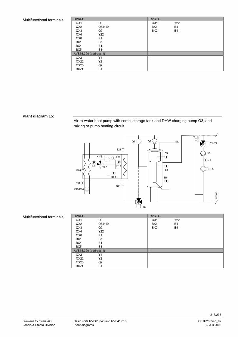
213/235
Siemens Schweiz AG Basic units RVS61.843 and RVS41.813 CE1U2355en_02 Landis & Staefa Division Plant diagrams 3. Juli 2008
RVS41.. RVS61.. QX1 Q3 QX2 Q8/K19 QX3 Q9 QX4 Y22 QX8 K1 BX1 B3 BX4 B4 BX5 B41
QX1 Y22 BX1 B4 BX2 B41
AVS75.390 (address 1) QX21 Y1 QX22 Y2 QX23 Q2 BX21 B1
-
Air-to-water heat pump with combi storage tank and DHW charging pump Q3, and mixing or pump heating circuit.
Y1/Y2
Q2
B1
RG
Q9
B21
B71
Q3
K1/E11
P
B81
E10
B83
B91
K19/E14
B84
PE9 Y22
2355
A15
B9
RVS41.. RVS61..
QX1 Q3 QX2 Q8/K19 QX3 Q9 QX4 Y22 QX8 K1 BX1 B3 BX4 B4 BX5 B41
QX1 Y22 BX1 B4 BX2 B41
AVS75.390 (address 1) QX21 Y1 QX22 Y2 QX23 Q2 BX21 B1
-
Multifunctional terminals
Plant diagram 15:
Multifunctional terminals
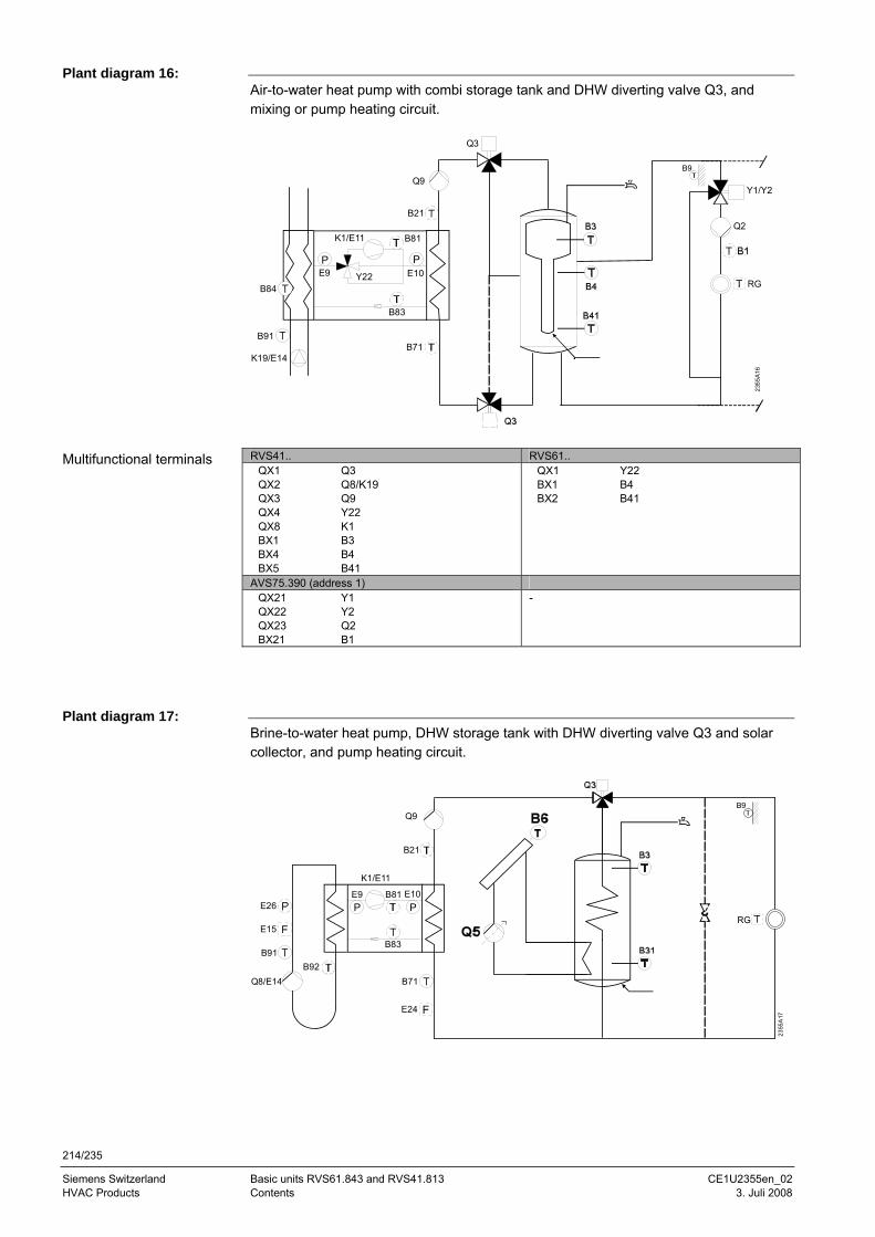
214/235
Siemens Switzerland Basic units RVS61.843 and RVS41.813 CE1U2355en_02 HVAC Products Contents 3. Juli 2008
Air-to-water heat pump with combi storage tank and DHW diverting valve Q3, and mixing or pump heating circuit.
Q3
Y1/Y2
Q2
RG
B21
B71
Q9
K1/E11
P
B81
E10
B83
B91
K19/E14
B84
PE9 Y22
2355
A16
B9
RVS41.. RVS61..
QX1 Q3 QX2 Q8/K19 QX3 Q9 QX4 Y22 QX8 K1 BX1 B3 BX4 B4 BX5 B41
QX1 Y22 BX1 B4 BX2 B41
AVS75.390 (address 1) QX21 Y1 QX22 Y2 QX23 Q2 BX21 B1
-
Brine-to-water heat pump, DHW storage tank with DHW diverting valve Q3 and solar collector, and pump heating circuit.
RG
B21
K1/E11
B71B92
Q8/E14
B91
E9PP
B81 E10
B83
Q9
2355
A17
B9
E15
E26
E24
Plant diagram 16:
Multifunctional terminals
Plant diagram 17:
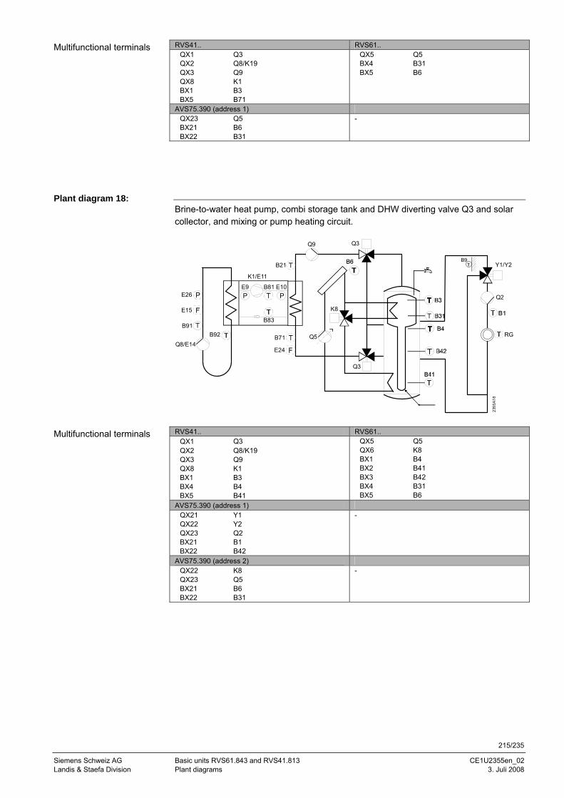
215/235
Siemens Schweiz AG Basic units RVS61.843 and RVS41.813 CE1U2355en_02 Landis & Staefa Division Plant diagrams 3. Juli 2008
RVS41.. RVS61.. QX1 Q3 QX2 Q8/K19 QX3 Q9 QX8 K1 BX1 B3 BX5 B71
QX5 Q5 BX4 B31 BX5 B6
AVS75.390 (address 1) QX23 Q5 BX21 B6 BX22 B31
-
Brine-to-water heat pump, combi storage tank and DHW diverting valve Q3 and solar collector, and mixing or pump heating circuit.
Y1/Y2
Q2
RG
B21
K1/E11
B71B92Q8/E14
B91
E9PP
B81 E10
B83
Q9
K8
Q3
Q5
Q3
2355
A18
E15
E26
E24
B9
RVS41.. RVS61..
QX1 Q3 QX2 Q8/K19 QX3 Q9 QX8 K1 BX1 B3 BX4 B4 BX5 B41
QX5 Q5 QX6 K8 BX1 B4 BX2 B41 BX3 B42 BX4 B31 BX5 B6
AVS75.390 (address 1) QX21 Y1 QX22 Y2 QX23 Q2 BX21 B1 BX22 B42
-
AVS75.390 (address 2) QX22 K8 QX23 Q5 BX21 B6 BX22 B31
-
Multifunctional terminals
Plant diagram 18:
Multifunctional terminals
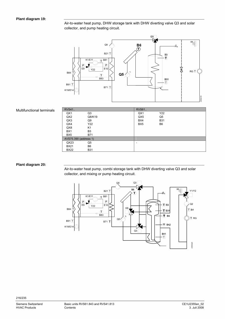
216/235
Siemens Switzerland Basic units RVS61.843 and RVS41.813 CE1U2355en_02 HVAC Products Contents 3. Juli 2008
Air-to-water heat pump, DHW storage tank with DHW diverting valve Q3 and solar collector, and pump heating circuit.
RG
B21
B71
Q9
K1/E11
P
B81
E10
B83
B91
K19/E14
B84
PE9 Y22
2355
A19
B9
RVS41.. RVS61..
QX1 Q3 QX2 Q8/K19 QX3 Q9 QX4 Y22 QX8 K1 BX1 B3 BX5 B71
QX1 Y22 QX5 Q5 BX4 B31 BX5 B6
AVS75.390 (address 1) QX23 Q5 BX21 B6 BX22 B31
-
Air-to-water heat pump, combi storage tank with DHW diverting valve Q3 and solar collector, and mixing or pump heating circuit.
Y1/Y2
Q2
RG
B21
B71
Q9
K8
Q3
Q5
Q3
K1/E11
P
B81
E10
B83
B91
K19/E14
B84
PE9 Y22
2355
A20
B9
Plant diagram 19:
Multifunctional terminals
Plant diagram 20:
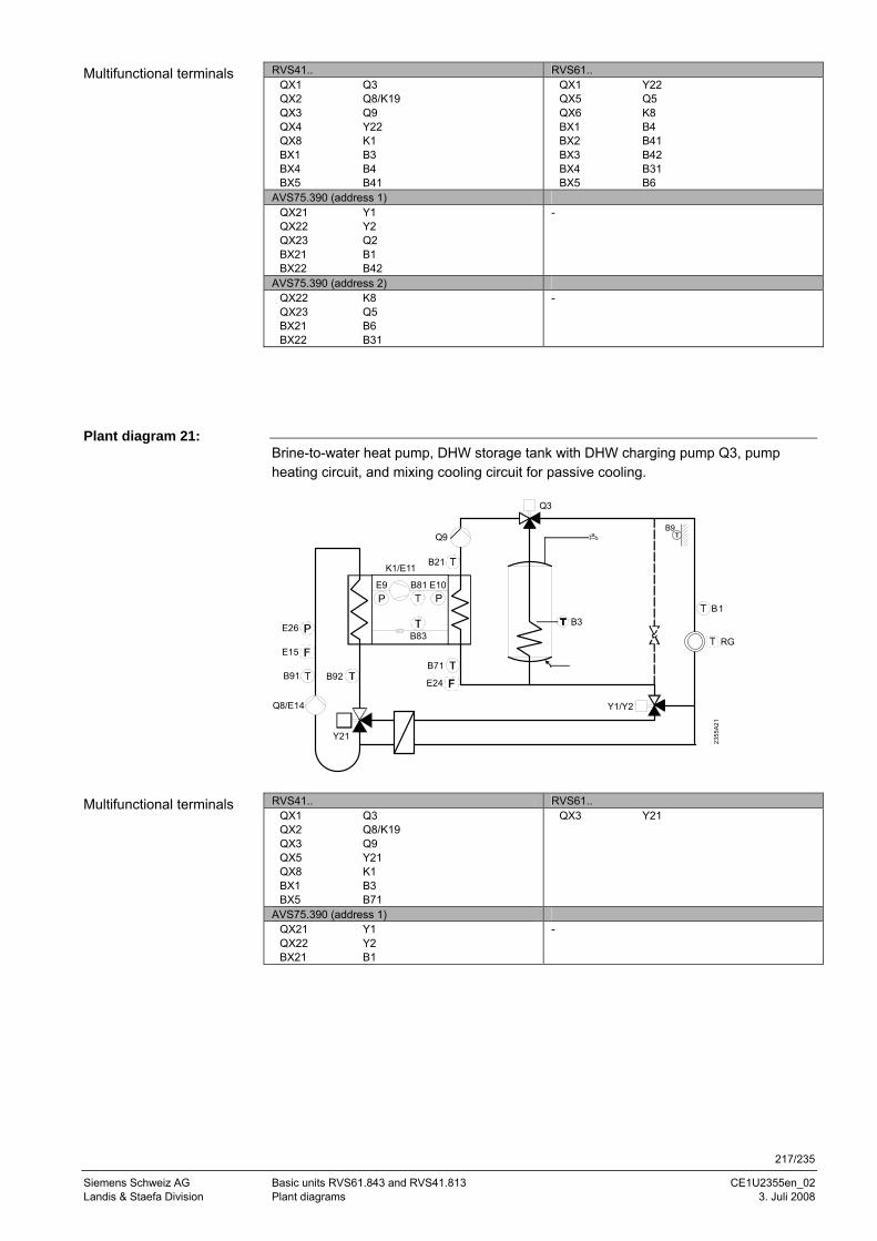
217/235
Siemens Schweiz AG Basic units RVS61.843 and RVS41.813 CE1U2355en_02 Landis & Staefa Division Plant diagrams 3. Juli 2008
RVS41.. RVS61.. QX1 Q3 QX2 Q8/K19 QX3 Q9 QX4 Y22 QX8 K1 BX1 B3 BX4 B4 BX5 B41
QX1 Y22 QX5 Q5 QX6 K8 BX1 B4 BX2 B41 BX3 B42 BX4 B31 BX5 B6
AVS75.390 (address 1) QX21 Y1 QX22 Y2 QX23 Q2 BX21 B1 BX22 B42
-
AVS75.390 (address 2) QX22 K8 QX23 Q5 BX21 B6 BX22 B31
-
Brine-to-water heat pump, DHW storage tank with DHW charging pump Q3, pump heating circuit, and mixing cooling circuit for passive cooling.
B3
B21
B71B92
Q8/E14
B91
K1/E11
E9PP
B81 E10
B83
Q9
B1
RG
Y1/Y2
Y21
Q3
2355
A21
E15
E26
E24
B9
RVS41.. RVS61..
QX1 Q3 QX2 Q8/K19 QX3 Q9 QX5 Y21 QX8 K1 BX1 B3 BX5 B71
QX3 Y21
AVS75.390 (address 1) QX21 Y1 QX22 Y2 BX21 B1
-
Multifunctional terminals
Plant diagram 21:
Multifunctional terminals
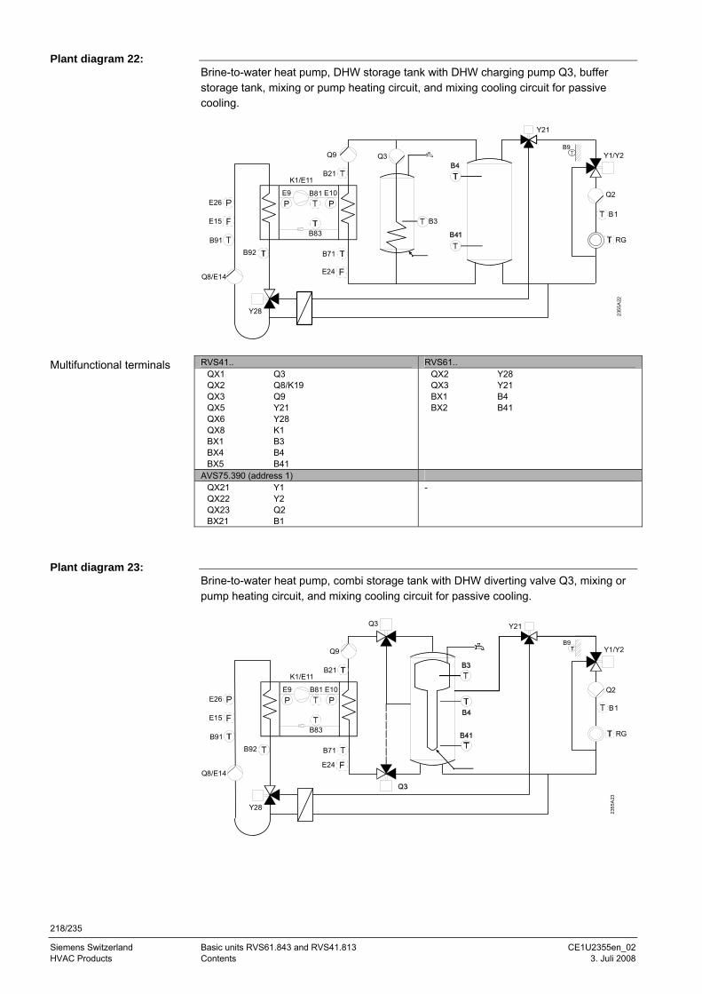
218/235
Siemens Switzerland Basic units RVS61.843 and RVS41.813 CE1U2355en_02 HVAC Products Contents 3. Juli 2008
Brine-to-water heat pump, DHW storage tank with DHW charging pump Q3, buffer storage tank, mixing or pump heating circuit, and mixing cooling circuit for passive cooling.
Y21
Y1/Y2
Q2
B1
RG
B21K1/E11
B71B92
Q8/E14
B91
E9PP
B81 E10
B83
Y28
Q9 Q3
B3
2355
A22
E15
E26
E24
B9
RVS41.. RVS61..
QX1 Q3 QX2 Q8/K19 QX3 Q9 QX5 Y21 QX6 Y28 QX8 K1 BX1 B3 BX4 B4 BX5 B41
QX2 Y28 QX3 Y21 BX1 B4 BX2 B41
AVS75.390 (address 1) QX21 Y1 QX22 Y2 QX23 Q2 BX21 B1
-
Brine-to-water heat pump, combi storage tank with DHW diverting valve Q3, mixing or pump heating circuit, and mixing cooling circuit for passive cooling.
B21K1/E11
B71B92
Q8/E14
B91
E9PP
B81 E10
B83
Y28
Y21Q3
Q9 Y1/Y2
Q2
B1
RG
2355
A23
E15
E26
E24
B9
Plant diagram 22:
Multifunctional terminals
Plant diagram 23:
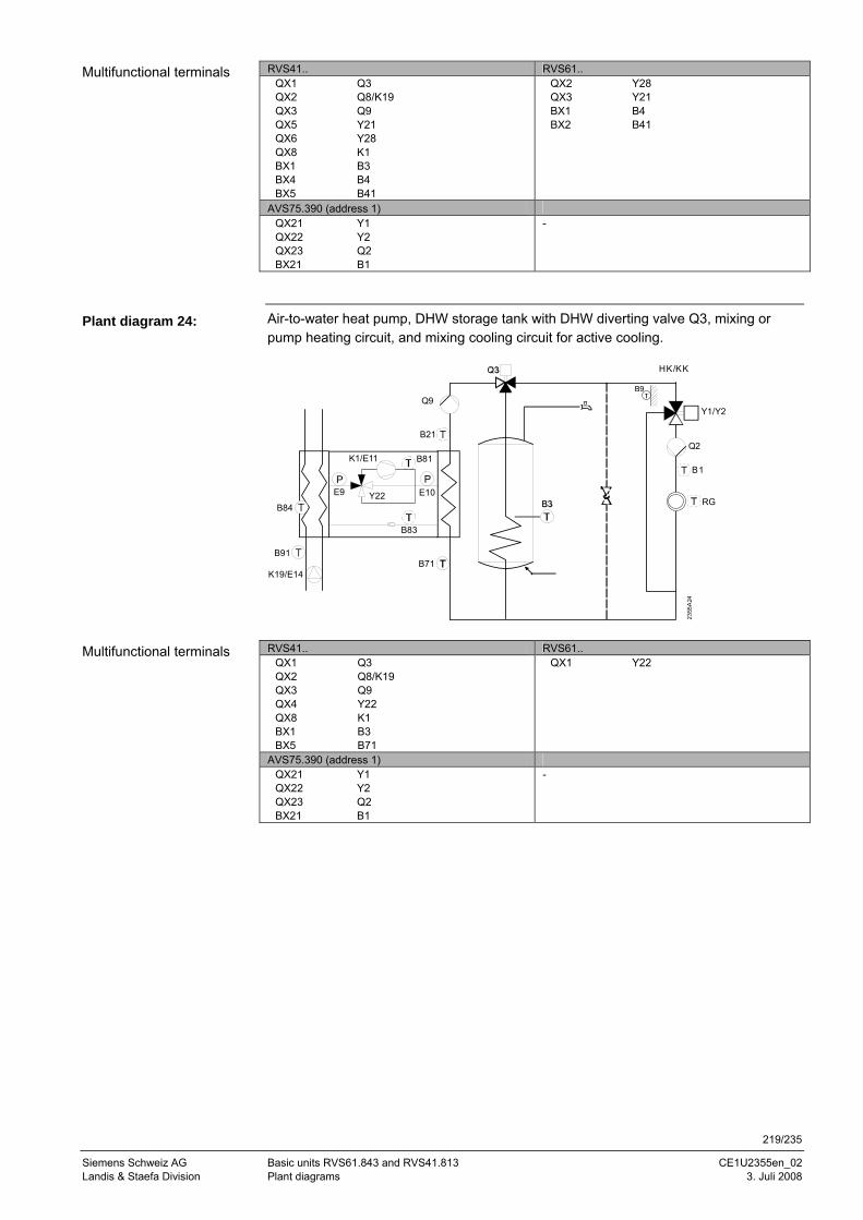
219/235
Siemens Schweiz AG Basic units RVS61.843 and RVS41.813 CE1U2355en_02 Landis & Staefa Division Plant diagrams 3. Juli 2008
RVS41.. RVS61.. QX1 Q3 QX2 Q8/K19 QX3 Q9 QX5 Y21 QX6 Y28 QX8 K1 BX1 B3 BX4 B4 BX5 B41
QX2 Y28 QX3 Y21 BX1 B4 BX2 B41
AVS75.390 (address 1) QX21 Y1 QX22 Y2 QX23 Q2 BX21 B1
-
Air-to-water heat pump, DHW storage tank with DHW diverting valve Q3, mixing or pump heating circuit, and mixing cooling circuit for active cooling.
B21
B71
Q9
K1/E11
P
B81
E10
B83
B91
K19/E14
B84
PE9 Y22
Y1/Y2
Q2
B1
RG
HK/KK
2355
A24
B9
RVS41.. RVS61..
QX1 Q3 QX2 Q8/K19 QX3 Q9 QX4 Y22 QX8 K1 BX1 B3 BX5 B71
QX1 Y22
AVS75.390 (address 1) QX21 Y1 QX22 Y2 QX23 Q2 BX21 B1
-
Multifunctional terminals
Plant diagram 24:
Multifunctional terminals
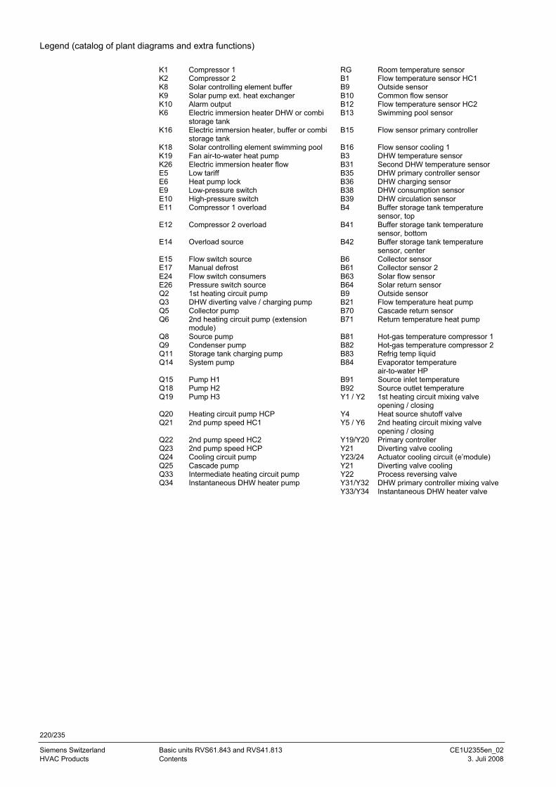
220/235
Siemens Switzerland Basic units RVS61.843 and RVS41.813 CE1U2355en_02 HVAC Products Contents 3. Juli 2008
Legend (catalog of plant diagrams and extra functions)
K1 Compressor 1 RG Room temperature sensor K2 Compressor 2 B1 Flow temperature sensor HC1 K8 Solar controlling element buffer B9 Outside sensor K9 Solar pump ext. heat exchanger B10 Common flow sensor K10 Alarm output B12 Flow temperature sensor HC2 K6 Electric immersion heater DHW or combi
storage tank B13 Swimming pool sensor
K16 Electric immersion heater, buffer or combi storage tank
B15 Flow sensor primary controller
K18 Solar controlling element swimming pool B16 Flow sensor cooling 1 K19 Fan air-to-water heat pump B3 DHW temperature sensor K26 Electric immersion heater flow B31 Second DHW temperature sensor E5 Low tariff B35 DHW primary controller sensor E6 Heat pump lock B36 DHW charging sensor E9 Low-pressure switch B38 DHW consumption sensor E10 High-pressure switch B39 DHW circulation sensor E11 Compressor 1 overload B4 Buffer storage tank temperature
sensor, top E12 Compressor 2 overload B41 Buffer storage tank temperature
sensor, bottom E14 Overload source B42 Buffer storage tank temperature
sensor, center E15 Flow switch source B6 Collector sensor E17 Manual defrost B61 Collector sensor 2 E24 Flow switch consumers B63 Solar flow sensor E26 Pressure switch source B64 Solar return sensor Q2 1st heating circuit pump B9 Outside sensor Q3 DHW diverting valve / charging pump B21 Flow temperature heat pump Q5 Collector pump B70 Cascade return sensor Q6 2nd heating circuit pump (extension
module) B71 Return temperature heat pump
Q8 Source pump B81 Hot-gas temperature compressor 1 Q9 Condenser pump B82 Hot-gas temperature compressor 2 Q11 Storage tank charging pump B83 Refrig temp liquid Q14 System pump B84 Evaporator temperature
air-to-water HP Q15 Pump H1 B91 Source inlet temperature Q18 Pump H2 B92 Source outlet temperature Q19 Pump H3 Y1 / Y2 1st heating circuit mixing valve
opening / closing Q20 Heating circuit pump HCP Y4 Heat source shutoff valve Q21 2nd pump speed HC1 Y5 / Y6 2nd heating circuit mixing valve
opening / closing Q22 2nd pump speed HC2 Y19/Y20 Primary controller Q23 2nd pump speed HCP Y21 Diverting valve cooling Q24 Cooling circuit pump Y23/24 Actuator cooling circuit (e’module) Q25 Cascade pump Y21 Diverting valve cooling Q33 Intermediate heating circuit pump Y22 Process reversing valve Q34 Instantaneous DHW heater pump Y31/Y32 DHW primary controller mixing valve Y33/Y34 Instantaneous DHW heater valve
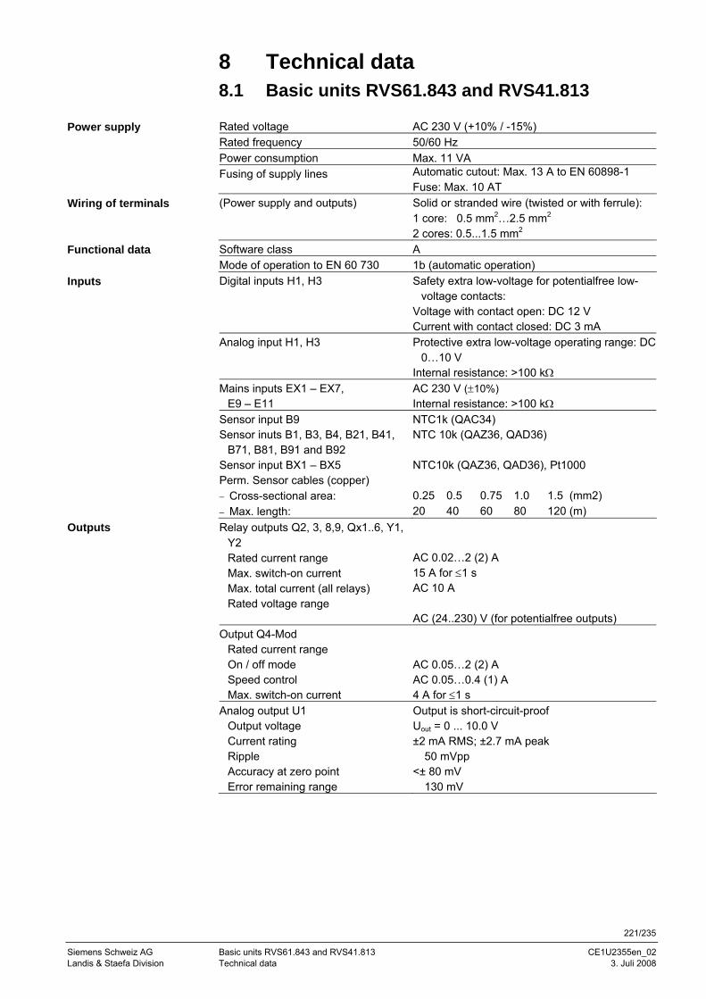
221/235
Siemens Schweiz AG Basic units RVS61.843 and RVS41.813 CE1U2355en_02 Landis & Staefa Division Technical data 3. Juli 2008
8 Technical data 8.1 Basic units RVS61.843 and RVS41.813 Rated voltage AC 230 V (+10% / -15%) Rated frequency 50/60 Hz Power consumption Max. 11 VA Fusing of supply lines Automatic cutout: Max. 13 A to EN 60898-1
Fuse: Max. 10 AT (Power supply and outputs) Solid or stranded wire (twisted or with ferrule):
1 core: 0.5 mm2…2.5 mm2
2 cores: 0.5...1.5 mm2 Software class A Mode of operation to EN 60 730 1b (automatic operation) Digital inputs H1, H3 Safety extra low-voltage for potentialfree low-
voltage contacts: Voltage with contact open: DC 12 V Current with contact closed: DC 3 mA
Analog input H1, H3 Protective extra low-voltage operating range: DC 0…10 V
Internal resistance: >100 kΩ Mains inputs EX1 – EX7,
E9 – E11 AC 230 V (±10%) Internal resistance: >100 kΩ
Sensor input B9 Sensor inuts B1, B3, B4, B21, B41,
B71, B81, B91 and B92
NTC1k (QAC34) NTC 10k (QAZ36, QAD36)
Sensor input BX1 – BX5 NTC10k (QAZ36, QAD36), Pt1000 Perm. Sensor cables (copper) − Cross-sectional area: 0.25 0.5 0.75 1.0 1.5 (mm2) − Max. length: 20 40 60 80 120 (m) Relay outputs Q2, 3, 8,9, Qx1..6, Y1,
Y2 Rated current range Max. switch-on current Max. total current (all relays) Rated voltage range
AC 0.02…2 (2) A 15 A for ≤1 s AC 10 A AC (24..230) V (for potentialfree outputs)
Output Q4-Mod Rated current range On / off mode Speed control Max. switch-on current
AC 0.05…2 (2) A AC 0.05…0.4 (1) A 4 A for ≤1 s
Analog output U1 Output voltage Current rating Ripple Accuracy at zero point Error remaining range
Output is short-circuit-proof Uout = 0 ... 10.0 V ±2 mA RMS; ±2.7 mA peak � 50 mVpp <± 80 mV � 130 mV
Power supply
Wiring of terminals
Functional data
Inputs
Outputs
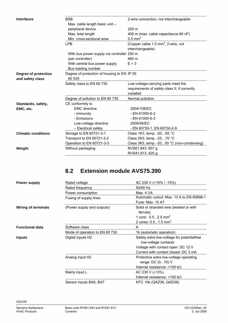
222/235
Siemens Switzerland Basic units RVS61.843 and RVS41.813 CE1U2355en_02 HVAC Products Contents 3. Juli 2008
BSB Max. cable length basic unit –
peripheral device Max. total length Min. cross-sectional area
2-wire connection, not interchangeable 200 m 400 m (max. cable capacitance 60 nF) 0.5 mm2
LPB With bus power supply via controller (per controller) With central bus power supply Bus loading number
(Copper cable 1.5 mm2, 2-wire, not interchangeable) 250 m 460 m E = 3
Degree of protection of housing to EN 60 529
IP 00
Safety class to EN 60 730 Low-voltage-carrying parts meet the requirements of safety class II, if correctly installed
Degree of pollution to EN 60 730 Normal pollution CE conformity to
EMC directive - Immunity - Emissions Low-voltage directive – Electrical safety
2004/108/EC - EN 61000-6-2 - EN 61000-6-3 2006/95/EC - EN 60730-1, EN 60730-2-9
Storage to EN 60721-3-1 Class 1K3, temp. -20…65 °C Transport to EN 60721-3-2 Class 2K3, temp. -25…70 °C Operation to EN 60721-3-3 Class 3K5, temp. -20...50 °C (non-condensing) Without packaging RVS61.843: 607 g
RVS41.813: 420 g
8.2 Extension module AVS75.390 Rated voltage AC 230 V (+10% / -15%) Rated frequency 50/60 Hz Power consumption Max. 4 VA Fusing of supply lines Automatic cutout: Max. 13 A to EN 60898-1
Fuse: Max. 10 AT (Power supply and outputs) Solid or stranded wire (twisted or with
ferrule): 1 core: 0.5...2.5 mm2 2 cores: 0.5...1.5 mm2
Software class A Mode of operation to EN 60 730 1b (automatic operation) Digital inputs H2 Safety extra low-voltage for potentialfree
low-voltage contacts: Voltage with contact open: DC 12 V Current with contact closed: DC 3 mA
Analog input H2 Protective extra low-voltage operating range: DC (0...10) V Internal resistance: >100 kΩ
Mains input L AC 230 V (±10%) Internal resistance: >100 kΩ
Sensor inputs BX6, BX7 NTC 10k (QAZ36, QAD36)
Interfaces
Degree of protection and safety class
Standards, safety, EMC, etc.
Climatic conditions
Weight
Power supply
Wiring of terminals
Functional data
Inputs
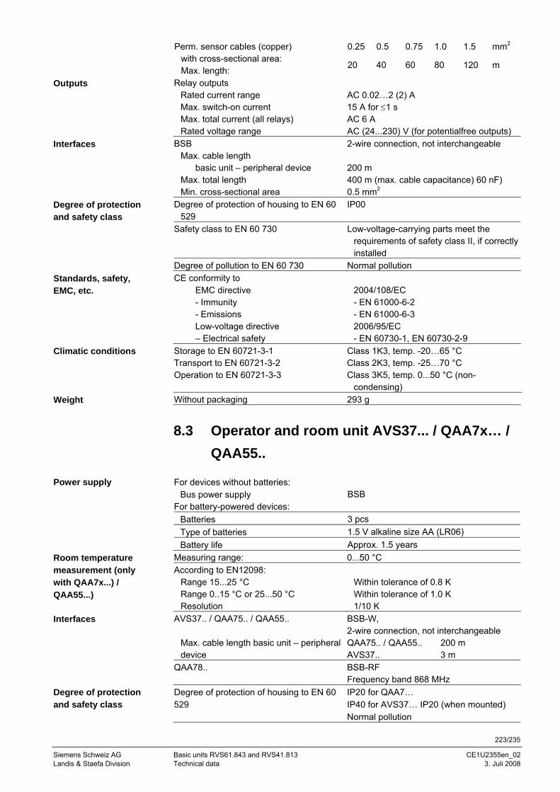
223/235
Siemens Schweiz AG Basic units RVS61.843 and RVS41.813 CE1U2355en_02 Landis & Staefa Division Technical data 3. Juli 2008
0.25 0.5 0.75 1.0 1.5 mm2 Perm. sensor cables (copper) with cross-sectional area: Max. length: 20 40 60 80 120 m
Relay outputs Rated current range Max. switch-on current Max. total current (all relays) Rated voltage range
AC 0.02…2 (2) A 15 A for ≤1 s AC 6 A AC (24...230) V (for potentialfree outputs)
BSB Max. cable length
basic unit – peripheral device Max. total length Min. cross-sectional area
2-wire connection, not interchangeable 200 m 400 m (max. cable capacitance) 60 nF) 0.5 mm2
Degree of protection of housing to EN 60 529
IP00
Safety class to EN 60 730 Low-voltage-carrying parts meet the requirements of safety class II, if correctly installed
Degree of pollution to EN 60 730 Normal pollution CE conformity to
EMC directive - Immunity - Emissions Low-voltage directive – Electrical safety
2004/108/EC - EN 61000-6-2 - EN 61000-6-3 2006/95/EC - EN 60730-1, EN 60730-2-9
Storage to EN 60721-3-1 Class 1K3, temp. -20…65 °C Transport to EN 60721-3-2 Class 2K3, temp. -25…70 °C Operation to EN 60721-3-3 Class 3K5, temp. 0...50 °C (non-
condensing) Without packaging 293 g
8.3 Operator and room unit AVS37... / QAA7x… / QAA55..
For devices without batteries:
Bus power supply BSB For battery-powered devices:
Batteries 3 pcs Type of batteries 1.5 V alkaline size AA (LR06) Battery life Approx. 1.5 years
Measuring range: 0...50 °C According to EN12098:
Range 15...25 °C Range 0..15 °C or 25...50 °C Resolution
Within tolerance of 0.8 K Within tolerance of 1.0 K 1/10 K
AVS37.. / QAA75.. / QAA55..
Max. cable length basic unit – peripheral device
BSB-W, 2-wire connection, not interchangeable QAA75.. / QAA55.. 200 m AVS37.. 3 m
QAA78.. BSB-RF Frequency band 868 MHz
Degree of protection of housing to EN 60 529
IP20 for QAA7… IP40 for AVS37… IP20 (when mounted) Normal pollution
Outputs
Interfaces
Degree of protection and safety class
Standards, safety, EMC, etc.
Climatic conditions
Weight
Power supply
Room temperature measurement (only with QAA7x...) / QAA55...)
Interfaces
Degree of protection and safety class
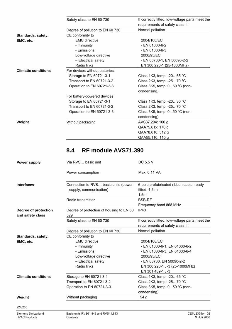
224/235
Siemens Switzerland Basic units RVS61.843 and RVS41.813 CE1U2355en_02 HVAC Products Contents 3. Juli 2008
Safety class to EN 60 730 If correctly fitted, low-voltage parts meet the requirements of safety class III
Degree of pollution to EN 60 730 Normal pollution CE conformity to
EMC directive - Immunity - Emissions Low-voltage directive – Electrical safety Radio links
2004/108/EC - EN 61000-6-2 - EN 61000-6-3 2006/95/EC - EN 60730-1, EN 50090-2-2 EN 300 220-1 (25-1000MHz)
For devices without batteries: Storage to EN 60721-3-1 Class 1K3, temp. -20…65 °C Transport to EN 60721-3-2 Class 2K3, temp. -25…70 °C Operation to EN 60721-3-3 Class 3K5, temp. 0...50 °C (non-
condensing) For battery-powered devices:
Storage to EN 60721-3-1 Class 1K3, temp. -20…30 °C Transport to EN 60721-3-2 Class 2K3, temp. -25…70 °C Operation to EN 60721-3-3 Class 3K5, temp. 0...50 °C (non-
condensing) Without packaging AVS37.294: 160 g
QAA75.61x: 170 g QAA78.610: 312 g QAA55.110: 115 g
8.4 RF module AVS71.390 Via RVS… basic unit
DC 5.5 V
Power consumption Max. 0.11 VA
Connection to RVS… basic units (power supply, communication)
6-pole prefabricated ribbon cable, ready fitted, 1.5 m 1.5m
Radio transmitter BSB-RF Frequency band 868 MHz
Degree of protection of housing to EN 60 529
IP40
Safety class to EN 60 730 If correctly fitted, low-voltage parts meet the requirements of safety class III
Degree of pollution to EN 60 730 Normal pollution CE conformity to
EMC directive - Immunity - Emissions Low-voltage directive – Electrical safety Radio links
2004/108/EC - EN 61000-6-1, EN 61000-6-2 - EN 61000-6-3, EN 61000-6-4 2006/95/EC - EN 60730, EN 50090-2-2 EN 300 220-1 , -3 (25-1000MHz) EN 301 489-1 , -3
Storage to EN 60721-3-1 Class 1K3, temp. -20…65 °C Transport to EN 60721-3-2 Class 2K3, temp. -25…70 °C Operation to EN 60721-3-3 Class 3K5, temp. 0...50 °C (non-
condensing) Without packaging 54 g
Standards, safety, EMC, etc.
Climatic conditions
Weight
Power supply
Interfaces
Degree of protection and safety class
Standards, safety, EMC, etc.
Climatic conditions
Weight

225/235
Siemens Schweiz AG Basic units RVS61.843 and RVS41.813 CE1U2355en_02 Landis & Staefa Division Technical data 3. Juli 2008
8.5 Wireless outside sensor AVS13.399 Batteries 2 pcs Type of batteries 1.5 V alkaline size AAA (LR03) Battery life Approx. 2 years Radio transmitter BSB-RF
Frequency band 868 MHz Degree of protection of housing to EN 60 529
IP20
Safety class to EN 60 730 If correctly fitted, low-voltage parts meet the requirements of safety class III
Degree of pollution to EN 60 730 Normal pollution CE conformity to
EMC directive - Immunity - Emissions Low-voltage directive – Electrical safety Radio links
2004/108/EC - EN 61000-6-2 - EN 61000-6-3 2006/95/EC - EN 60730-1, EN 50090-2-2 EN 300 220-1 (25-1000 MHz)
For devices without batteries: Storage to EN 60721-3-1 Class 1K3, temp. -20…65 °C Transport to EN 60721-3-2 Class 2K3, temp. -25…70 °C Operation to EN 60721-3-3 Class 3K5, temp. 0...50 °C (non-
condensing) For battery-powered devices:
Storage to EN 60721-3-1 Class 1K3, temp. -20…30 °C Transport to EN 60721-3-2 Class 2K3, temp. -25…70 °C Operation to EN 60721-3-3 Class 3K5, temp. 0...50 °C (non-
condensing) Outside sensor QAC34/101
Measuring range -50…50 °C
Cable length Max. 5 m
Without packaging Radio transmitter: 160 g Outside sensor QAC34: 73 g Cable: 70 g
Power supply
Interfaces
Degree of protection and safety class
Standards, safety, EMC, etc.
Climatic conditions
Outside temperature acquisition
Weight
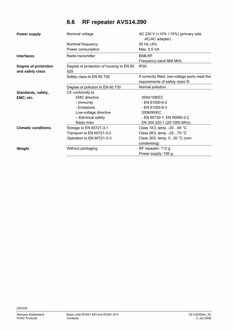
226/235
Siemens Switzerland Basic units RVS61.843 and RVS41.813 CE1U2355en_02 HVAC Products Contents 3. Juli 2008
8.6 RF repeater AVS14.390 Nominal voltage AC 230 V (+10% /-15%) (primary side
AC/AC adapter) Nominal frequency 50 Hz ±6% Power consumption Max. 0.5 VA
Radio transmitter BSB-RF Frequency band 868 MHz
Degree of protection of housing to EN 60 529
IP20
Safety class to EN 60 730 If correctly fitted, low-voltage parts meet the requirements of safety class III
Degree of pollution to EN 60 730 Normal pollution CE conformity to
EMC directive - Immunity - Emissions Low-voltage directive – Electrical safety Radio links
2004/108/EC - EN 61000-6-2 - EN 61000-6-3 2006/95/EC - EN 60730-1, EN 50090-2-2 EN 300 220-1 (25-1000 MHz)
Storage to EN 60721-3-1 Class 1K3, temp. -20…65 °C Transport to EN 60721-3-2 Class 2K3, temp. -25…70 °C Operation to EN 60721-3-3 Class 3K5, temp. 0...50 °C (non-
condensing) Without packaging RF repeater: 112 g
Power supply: 195 g
Power supply
Interfaces
Degree of protection and safety class
Standards, safety, EMC, etc.
Climatic conditions
Weight
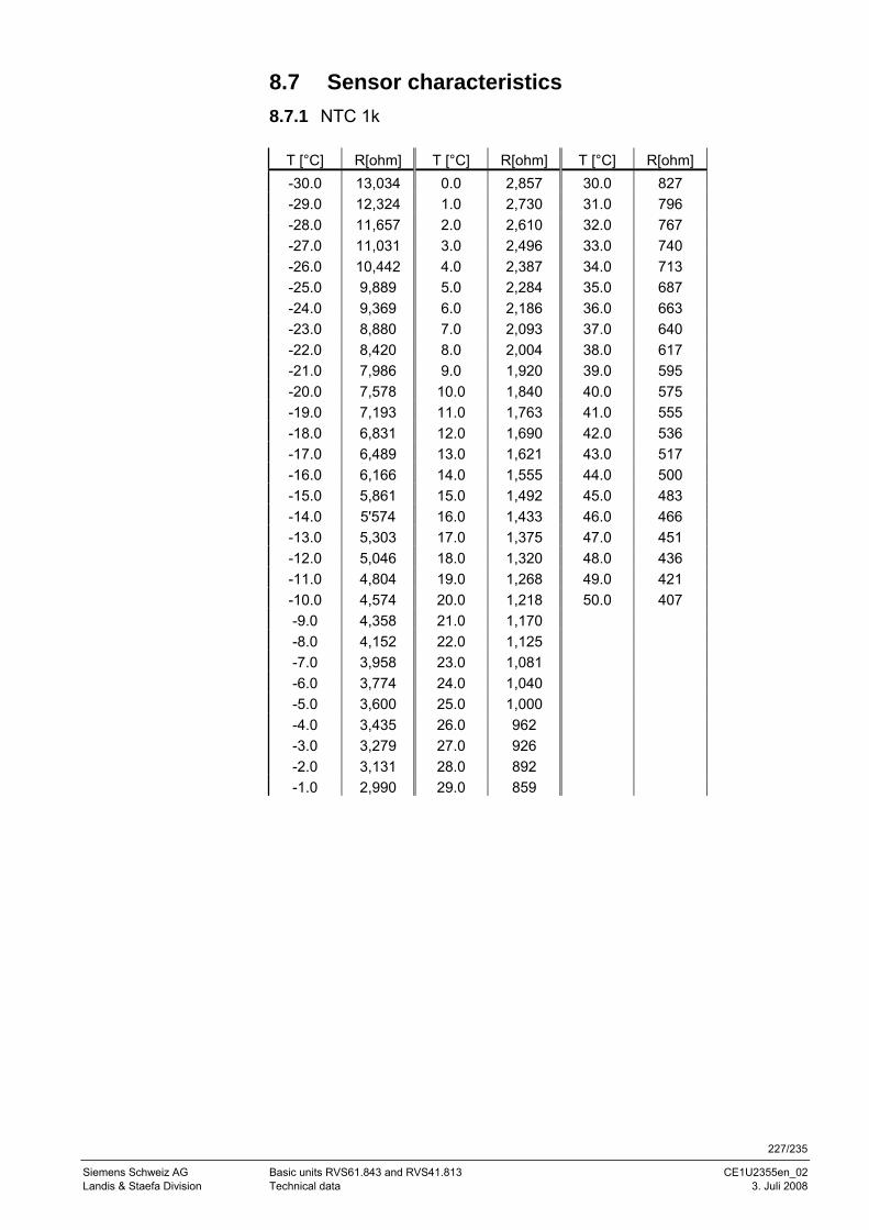
227/235
Siemens Schweiz AG Basic units RVS61.843 and RVS41.813 CE1U2355en_02 Landis & Staefa Division Technical data 3. Juli 2008
8.7 Sensor characteristics 8.7.1 NTC 1k
T [°C] R[ohm] T [°C] R[ohm] T [°C] R[ohm] -30.0 13,034 0.0 2,857 30.0 827 -29.0 12,324 1.0 2,730 31.0 796 -28.0 11,657 2.0 2,610 32.0 767 -27.0 11,031 3.0 2,496 33.0 740 -26.0 10,442 4.0 2,387 34.0 713 -25.0 9,889 5.0 2,284 35.0 687 -24.0 9,369 6.0 2,186 36.0 663 -23.0 8,880 7.0 2,093 37.0 640 -22.0 8,420 8.0 2,004 38.0 617 -21.0 7,986 9.0 1,920 39.0 595 -20.0 7,578 10.0 1,840 40.0 575 -19.0 7,193 11.0 1,763 41.0 555 -18.0 6,831 12.0 1,690 42.0 536 -17.0 6,489 13.0 1,621 43.0 517 -16.0 6,166 14.0 1,555 44.0 500 -15.0 5,861 15.0 1,492 45.0 483 -14.0 5'574 16.0 1,433 46.0 466 -13.0 5,303 17.0 1,375 47.0 451 -12.0 5,046 18.0 1,320 48.0 436 -11.0 4,804 19.0 1,268 49.0 421 -10.0 4,574 20.0 1,218 50.0 407 -9.0 4,358 21.0 1,170 -8.0 4,152 22.0 1,125 -7.0 3,958 23.0 1,081 -6.0 3,774 24.0 1,040 -5.0 3,600 25.0 1,000 -4.0 3,435 26.0 962 -3.0 3,279 27.0 926 -2.0 3,131 28.0 892 -1.0 2,990 29.0 859
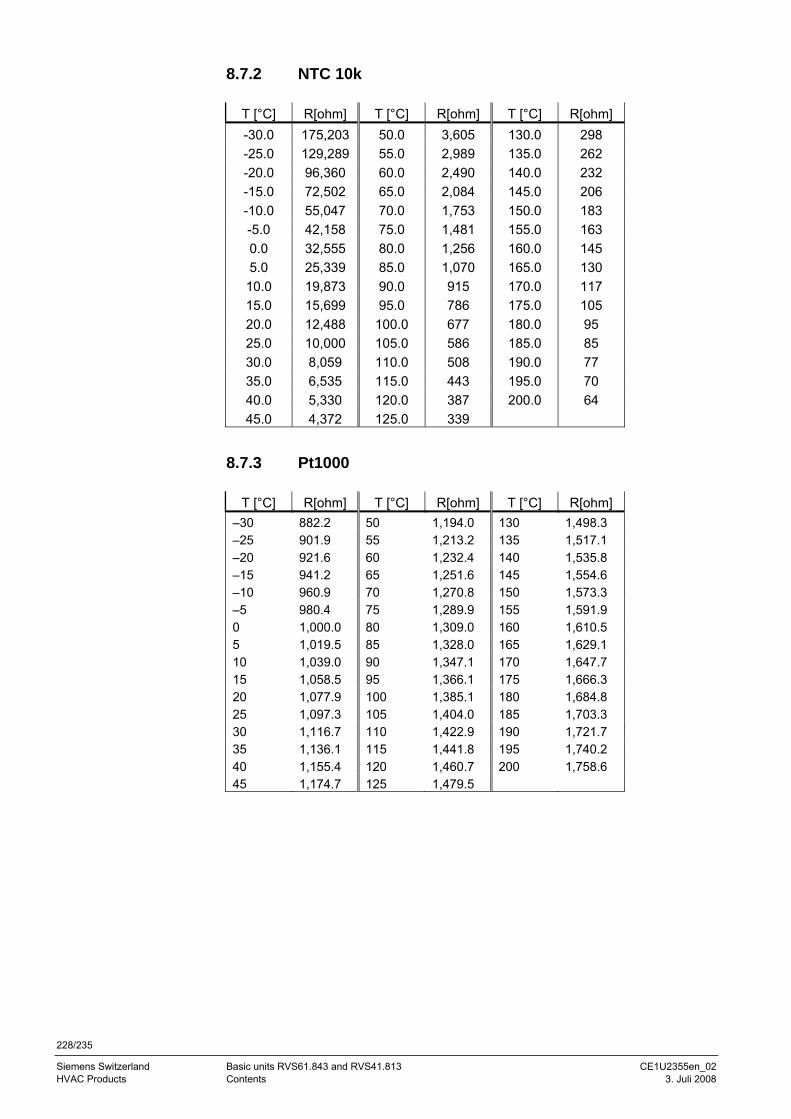
228/235
Siemens Switzerland Basic units RVS61.843 and RVS41.813 CE1U2355en_02 HVAC Products Contents 3. Juli 2008
8.7.2 NTC 10k
T [°C] R[ohm] T [°C] R[ohm] T [°C] R[ohm] -30.0 175,203 50.0 3,605 130.0 298 -25.0 129,289 55.0 2,989 135.0 262 -20.0 96,360 60.0 2,490 140.0 232 -15.0 72,502 65.0 2,084 145.0 206 -10.0 55,047 70.0 1,753 150.0 183 -5.0 42,158 75.0 1,481 155.0 163 0.0 32,555 80.0 1,256 160.0 145 5.0 25,339 85.0 1,070 165.0 130 10.0 19,873 90.0 915 170.0 117 15.0 15,699 95.0 786 175.0 105 20.0 12,488 100.0 677 180.0 95 25.0 10,000 105.0 586 185.0 85 30.0 8,059 110.0 508 190.0 77 35.0 6,535 115.0 443 195.0 70 40.0 5,330 120.0 387 200.0 64 45.0 4,372 125.0 339
8.7.3 Pt1000
T [°C] R[ohm] T [°C] R[ohm] T [°C] R[ohm] –30 882.2 50 1,194.0 130 1,498.3 –25 901.9 55 1,213.2 135 1,517.1 –20 921.6 60 1,232.4 140 1,535.8 –15 941.2 65 1,251.6 145 1,554.6 –10 960.9 70 1,270.8 150 1,573.3 –5 980.4 75 1,289.9 155 1,591.9 0 1,000.0 80 1,309.0 160 1,610.5 5 1,019.5 85 1,328.0 165 1,629.1 10 1,039.0 90 1,347.1 170 1,647.7 15 1,058.5 95 1,366.1 175 1,666.3 20 1,077.9 100 1,385.1 180 1,684.8 25 1,097.3 105 1,404.0 185 1,703.3 30 1,116.7 110 1,422.9 190 1,721.7 35 1,136.1 115 1,441.8 195 1,740.2 40 1,155.4 120 1,460.7 200 1,758.6 45 1,174.7 125 1,479.5
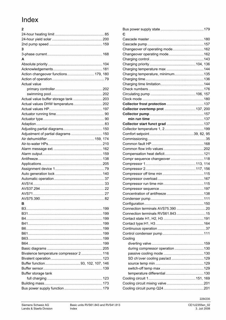
229/235
Siemens Schweiz AG Basic units RVS61.843 and RVS41.813 CE1U2355en_02 Landis & Staefa Division Index 3. Juli 2008
Index 2 24-hour heating limit .................................................85 24-hour yield solar ..................................................200 2nd pump speed .....................................................159 3 3-phase current.......................................................168 A Absolute priority ......................................................104 Acknowledgements.................................................181 Action changeover functions...........................179, 180 Action of operation ....................................................79 Actual value
primary controller...............................................202 swimming pool...................................................202
Actual value buffer storage tank .............................203 Actual values DHW temperature.............................202 Actual values HP.....................................................197 Actuator running time................................................90 Actuator type.............................................................90 Adaption....................................................................83 Adjusting partial diagrams.......................................150 Adjustment of partial diagrams ...............................150 Air dehumidifier ...............................................159, 174 Air-to-water HPs......................................................210 Alarm message ext. ................................................162 Alarm output............................................................159 Antifreeze................................................................138 Applications.............................................................205 Assignment device 1.................................................79 Auto generation lock ...............................................140 Automatic operation ..................................................37 AVS14.......................................................................33 AVS37.294................................................................22 AVS71.......................................................................27 AVS75.390................................................................82 B B3............................................................................199 B31..........................................................................199 B4............................................................................199 B41..........................................................................199 B6............................................................................199 B61..........................................................................199 B63..........................................................................199 B64..........................................................................199 Basic diagrams .......................................................205 Bivalence temperature compressor 2 .....................116 Bivalent operation ...................................................123 Buffer function...................................93, 102, 107, 146 Buffer sensor...........................................................139 Buffer storage tank
full charging .......................................................123 Building mass..........................................................173 Bus power supply function ......................................179
Bus power supply state ...........................................179 C Cascade master ......................................................180 Cascade pump ........................................................157 Changeover of operating mode...............................162 Changeover operating mode...................................162 Charging control ......................................................143 Charging priority..............................................104, 136 Charging temperature max .....................................144 Charging temperature, minimum.............................135 Charging time..........................................................136 Charging time limitation...........................................144 Check numbers .......................................................176 Circulating pump .............................................106, 157 Clock mode .............................................................180 Collector frost protection .....................................137 Collector overtemp prot ...............................137, 200 Collector pump ......................................................157
min run time .....................................................137 Collector start funct grad .....................................137 Collector temperature 1, 2.......................................199 Comfort setpoint ............................................39, 82, 95 Commissioning..........................................................35 Common fault HP....................................................168 Common flow info values ........................................202 Compensation heat deficit.......................................121 Compr sequence changeover .................................118 Compressor 1..................................................113, 114 Compressor 2..................................................117, 156 Compressor off time min .........................................115 Compressor overload..............................................167 Compressor run time min........................................115 Compressor sequence ............................................197 Concentration of antifreeze .....................................138 Condenser pump.....................................................111 Configuration...........................................................150 Connection terminals AVS75.390 .............................20 Connection terminals RVS61.843 .............................15 Contact state H1, H2, H3 ........................................191 Contact type:H1, H3................................................164 Continuous operation ................................................37 Control condenser pump.........................................111 Cooling
diverting valve....................................................159 during compressor operation .............................130 passive cooling mode ........................................130 SD ch’over cooling pas/act ................................129 source temp min ................................................129 switch-off temp max...........................................129 temperature differential ......................................130
Cooling circuit 1...............................................151, 169 Cooling circuit mixing valve.....................................201 Cooling circuit pump Q24........................................201
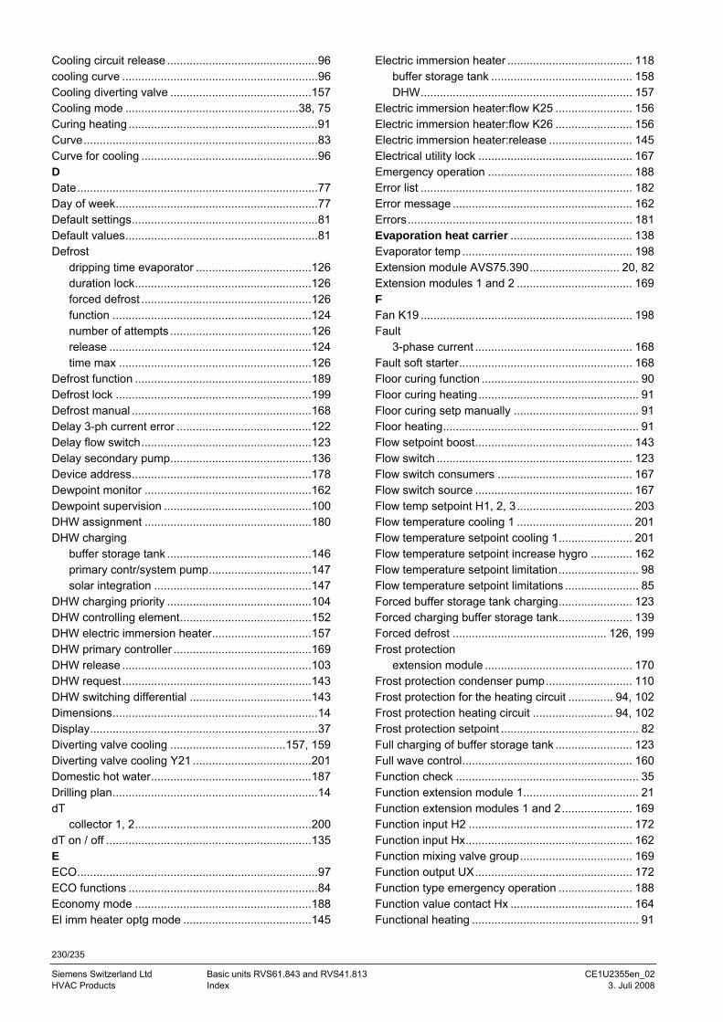
230/235
Siemens Switzerland Ltd Basic units RVS61.843 and RVS41.813 CE1U2355en_02 HVAC Products Index 3. Juli 2008
Cooling circuit release ...............................................96 cooling curve .............................................................96 Cooling diverting valve ............................................157 Cooling mode ......................................................38, 75 Curing heating ...........................................................91 Curve.........................................................................83 Curve for cooling .......................................................96 D Date...........................................................................77 Day of week...............................................................77 Default settings..........................................................81 Default values............................................................81 Defrost
dripping time evaporator ....................................126 duration lock.......................................................126 forced defrost .....................................................126 function ..............................................................124 number of attempts ............................................126 release ...............................................................124 time max ............................................................126
Defrost function .......................................................189 Defrost lock .............................................................199 Defrost manual ........................................................168 Delay 3-ph current error ..........................................122 Delay flow switch.....................................................123 Delay secondary pump............................................136 Device address........................................................178 Dewpoint monitor ....................................................162 Dewpoint supervision ..............................................100 DHW assignment ....................................................180 DHW charging
buffer storage tank .............................................146 primary contr/system pump................................147 solar integration .................................................147
DHW charging priority .............................................104 DHW controlling element.........................................152 DHW electric immersion heater...............................157 DHW primary controller ...........................................169 DHW release ...........................................................103 DHW request...........................................................143 DHW switching differential ......................................143 Dimensions................................................................14 Display.......................................................................37 Diverting valve cooling ....................................157, 159 Diverting valve cooling Y21 .....................................201 Domestic hot water..................................................187 Drilling plan................................................................14 dT
collector 1, 2.......................................................200 dT on / off ................................................................135 E ECO...........................................................................97 ECO functions ...........................................................84 Economy mode .......................................................188 El imm heater optg mode ........................................145
Electric immersion heater ....................................... 118 buffer storage tank ............................................ 158 DHW.................................................................. 157
Electric immersion heater:flow K25 ........................ 156 Electric immersion heater:flow K26 ........................ 156 Electric immersion heater:release .......................... 145 Electrical utility lock ................................................ 167 Emergency operation ............................................. 188 Error list .................................................................. 182 Error message ........................................................ 162 Errors...................................................................... 181 Evaporation heat carrier ...................................... 138 Evaporator temp ..................................................... 198 Extension module AVS75.390............................ 20, 82 Extension modules 1 and 2 .................................... 169 F Fan K19 .................................................................. 198 Fault
3-phase current ................................................. 168 Fault soft starter...................................................... 168 Floor curing function ................................................. 90 Floor curing heating.................................................. 91 Floor curing setp manually ....................................... 91 Floor heating............................................................. 91 Flow setpoint boost................................................. 143 Flow switch ............................................................. 123 Flow switch consumers .......................................... 167 Flow switch source ................................................. 167 Flow temp setpoint H1, 2, 3.................................... 203 Flow temperature cooling 1 .................................... 201 Flow temperature setpoint cooling 1....................... 201 Flow temperature setpoint increase hygro ............. 162 Flow temperature setpoint limitation......................... 98 Flow temperature setpoint limitations ....................... 85 Forced buffer storage tank charging....................... 123 Forced charging buffer storage tank....................... 139 Forced defrost ................................................ 126, 199 Frost protection
extension module .............................................. 170 Frost protection condenser pump........................... 110 Frost protection for the heating circuit .............. 94, 102 Frost protection heating circuit ......................... 94, 102 Frost protection setpoint ........................................... 82 Full charging of buffer storage tank ........................ 123 Full wave control..................................................... 160 Function check ......................................................... 35 Function extension module 1.................................... 21 Function extension modules 1 and 2...................... 169 Function input H2 ................................................... 172 Function input Hx.................................................... 162 Function mixing valve group................................... 169 Function output UX................................................. 172 Function type emergency operation ....................... 188 Function value contact Hx ...................................... 164 Functional heating .................................................... 91
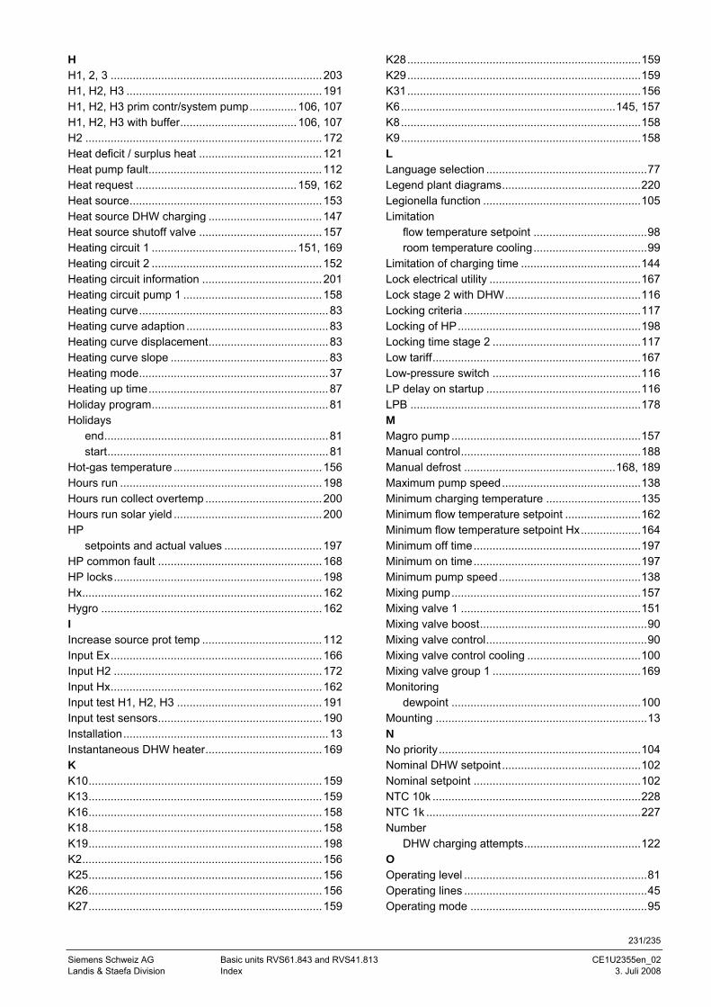
231/235
Siemens Schweiz AG Basic units RVS61.843 and RVS41.813 CE1U2355en_02 Landis & Staefa Division Index 3. Juli 2008
H H1, 2, 3 ...................................................................203 H1, H2, H3 ..............................................................191 H1, H2, H3 prim contr/system pump...............106, 107 H1, H2, H3 with buffer.....................................106, 107 H2 ...........................................................................172 Heat deficit / surplus heat .......................................121 Heat pump fault.......................................................112 Heat request ...................................................159, 162 Heat source.............................................................153 Heat source DHW charging ....................................147 Heat source shutoff valve .......................................157 Heating circuit 1 ..............................................151, 169 Heating circuit 2 ......................................................152 Heating circuit information ......................................201 Heating circuit pump 1 ............................................158 Heating curve............................................................83 Heating curve adaption .............................................83 Heating curve displacement......................................83 Heating curve slope ..................................................83 Heating mode............................................................37 Heating up time.........................................................87 Holiday program........................................................81 Holidays
end.......................................................................81 start......................................................................81
Hot-gas temperature ...............................................156 Hours run ................................................................198 Hours run collect overtemp .....................................200 Hours run solar yield ...............................................200 HP
setpoints and actual values ...............................197 HP common fault ....................................................168 HP locks..................................................................198 Hx............................................................................162 Hygro ......................................................................162 I Increase source prot temp ......................................112 Input Ex...................................................................166 Input H2 ..................................................................172 Input Hx...................................................................162 Input test H1, H2, H3 ..............................................191 Input test sensors....................................................190 Installation.................................................................13 Instantaneous DHW heater.....................................169 K K10..........................................................................159 K13..........................................................................159 K16..........................................................................158 K18..........................................................................158 K19..........................................................................198 K2............................................................................156 K25..........................................................................156 K26..........................................................................156 K27..........................................................................159
K28..........................................................................159 K29..........................................................................159 K31..........................................................................156 K6....................................................................145, 157 K8............................................................................158 K9............................................................................158 L Language selection ...................................................77 Legend plant diagrams............................................220 Legionella function ..................................................105 Limitation
flow temperature setpoint ....................................98 room temperature cooling....................................99
Limitation of charging time ......................................144 Lock electrical utility ................................................167 Lock stage 2 with DHW...........................................116 Locking criteria ........................................................117 Locking of HP..........................................................198 Locking time stage 2 ...............................................117 Low tariff..................................................................167 Low-pressure switch ...............................................116 LP delay on startup .................................................116 LPB .........................................................................178 M Magro pump ............................................................157 Manual control.........................................................188 Manual defrost ................................................168, 189 Maximum pump speed............................................138 Minimum charging temperature ..............................135 Minimum flow temperature setpoint ........................162 Minimum flow temperature setpoint Hx...................164 Minimum off time.....................................................197 Minimum on time.....................................................197 Minimum pump speed.............................................138 Mixing pump............................................................157 Mixing valve 1 .........................................................151 Mixing valve boost.....................................................90 Mixing valve control...................................................90 Mixing valve control cooling ....................................100 Mixing valve group 1 ...............................................169 Monitoring
dewpoint ............................................................100 Mounting ...................................................................13 N No priority................................................................104 Nominal DHW setpoint ............................................102 Nominal setpoint .....................................................102 NTC 10k ..................................................................228 NTC 1k ....................................................................227 Number
DHW charging attempts.....................................122 O Operating level ..........................................................81 Operating lines ..........................................................45 Operating mode ........................................................95
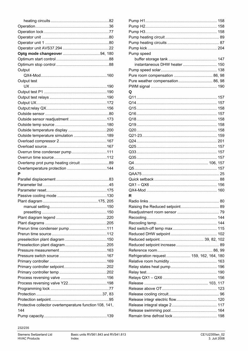
232/235
Siemens Switzerland Ltd Basic units RVS61.843 and RVS41.813 CE1U2355en_02 HVAC Products Index 3. Juli 2008
heating circuits .....................................................82 Operation...................................................................36 Operation lock ...........................................................77 Operator unit .............................................................80 Operator unit 1 ..........................................................80 Operator unit AVS37.294 ..........................................22 Optg mode changeover ..................................94, 180 Optimum start control ................................................88 Optimum stop control ................................................88 Output
QX4-Mod............................................................160 Output test
UX ......................................................................190 Output test P1 .........................................................190 Output test relays ....................................................190 Output UX................................................................172 Output:relay QX.......................................................156 Outside sensor ..........................................................80 Outside sensor readjustment ..................................173 Outside temp source ...............................................180 Outside temperature display ...................................200 Outside temperature simulation ..............................189 Overload compressor 2 ...........................................167 Overload source ......................................................167 Overrun time condenser pump................................111 Overrun time source................................................112 Overtemp prot pump heating circuit ..........................89 Overtemperature protection ....................................144 P Parallel displacement ................................................83 Parameter list ............................................................45 Parameter reset.......................................................175 Passive cooling mode .............................................130 Plant diagram ..................................................175, 205
manual setting....................................................150 presetting ...........................................................150
Plant diagram legend ..............................................220 Plant diagrams ........................................................205 Prerun time condenser pump ..................................111 Prerun time source ..................................................112 preselection plant diagram ......................................150 Preselection plant diagram......................................205 Pressure measurement ...........................................163 Pressure switch source ...........................................167 Primary controller ....................................................169 Primary controller setpoint.......................................202 Primary controller temp ...........................................202 Process reversing valve ..........................................156 Process reversing valve Y22...................................198 Programming lock .....................................................77 Protection ............................................................37, 83 Protection setpoint.....................................................95 Protective collector overtemperature function 108, 141, 144 Pump capacity.........................................................139
Pump H1................................................................. 158 Pump H2................................................................. 158 Pump H3................................................................. 158 Pump heating circuit ................................................. 89 Pump heating circuits ............................................... 87 Pump kick ............................................................... 204 Pump speed
buffer storage tank ............................................ 147 instantaneous DHW heater ............................... 150
Pump speed solar................................................... 138 Pure room compensation ................................... 86, 98 Pure weather compensation............................... 86, 98 PWM signal ............................................................ 190 Q Q11......................................................................... 157 Q14......................................................................... 157 Q15......................................................................... 158 Q16......................................................................... 157 Q18......................................................................... 158 Q19......................................................................... 158 Q20......................................................................... 158 Q21-23.................................................................... 159 Q24......................................................................... 201 Q25......................................................................... 157 Q33......................................................................... 157 Q35......................................................................... 157 Q4................................................................... 106, 157 Q5........................................................................... 157 QAA75 ...................................................................... 25 Quick setback ........................................................... 88 QX1 – QX6 ............................................................. 156 QX4-Mod ................................................................ 160 R Radio links ................................................................ 80 Raising the Reduced setpoint................................... 89 Readjustment room sensor ...................................... 79 Recooling................................................................ 144 Recooling temp....................................................... 144 Red switch-off temp max ........................................ 115 Reduced DHW setpoint .......................................... 102 Reduced setpoint........................................ 39, 82, 102 Reduced setpoint increase ....................................... 89 Reference room.................................................. 86, 99 Refrigeration request ...................... 159, 162, 164, 180 Relative room humidity ........................................... 163 Relay states heat pump.......................................... 196 Relay test................................................................ 190 Relays QX1 – QX6 ................................................. 156 Release .......................................................... 103, 117 Release above OT.................................................. 123 Release cooling circuit.............................................. 96 Release integr electric flow..................................... 120 Release integral stage 2......................................... 117 Release swimming pool.......................................... 164 Remain time defrost lock ........................................ 198
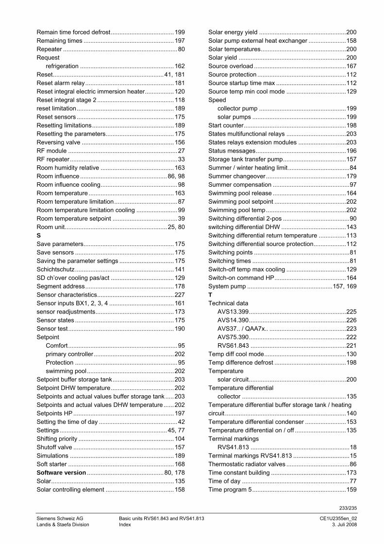
233/235
Siemens Schweiz AG Basic units RVS61.843 and RVS41.813 CE1U2355en_02 Landis & Staefa Division Index 3. Juli 2008
Remain time forced defrost.....................................199 Remaining times .....................................................197 Repeater ...................................................................80 Request
refrigeration .......................................................162 Reset.................................................................41, 181 Reset alarm relay....................................................181 Reset integral electric immersion heater.................120 Reset integral stage 2 .............................................118 reset limitation.........................................................189 Reset sensors .........................................................175 Resetting limitations................................................189 Resetting the parameters........................................175 Reversing valve ......................................................156 RF module ................................................................27 RF repeater...............................................................33 Room humidity relative ...........................................163 Room influence ...................................................86, 98 Room influence cooling.............................................98 Room temperature ..................................................163 Room temperature limitation.....................................87 Room temperature limitation cooling ........................99 Room temperature setpoint ......................................39 Room unit............................................................25, 80 S Save parameters.....................................................175 Save sensors ..........................................................175 Saving the parameter settings ................................175 Schichtschutz..........................................................141 SD ch’over cooling pas/act .....................................129 Segment address....................................................178 Sensor characteristics.............................................227 Sensor inputs BX1, 2, 3, 4 ......................................161 sensor readjustments..............................................173 Sensor states ..........................................................175 Sensor test..............................................................190 Setpoint
Comfort................................................................95 primary controller...............................................202 Protection ............................................................95 swimming pool...................................................202
Setpoint buffer storage tank....................................203 Setpoint DHW temperature.....................................202 Setpoints and actual values buffer storage tank .....203 Setpoints and actual values DHW temperature ......202 Setpoints HP ...........................................................197 Setting the time of day ..............................................42 Settings ...............................................................45, 77 Shifting priority ........................................................104 Shutoff valve ...........................................................157 Simulations .............................................................189 Soft starter ..............................................................168 Software version .............................................80, 178 Solar........................................................................135 Solar controlling element ........................................158
Solar energy yield ...................................................200 Solar pump external heat exchanger ......................158 Solar temperatures..................................................200 Solar yield ...............................................................200 Source overload ......................................................167 Source protection ....................................................112 Source startup time max .........................................112 Source temp min cool mode ...................................129 Speed
collector pump ...................................................199 solar pumps .......................................................199
Start counter............................................................198 States multifunctional relays ...................................203 States relays extension modules ............................203 Status messages.....................................................196 Storage tank transfer pump.....................................157 Summer / winter heating limit ....................................84 Summer changeover...............................................179 Summer compensation .............................................97 Swimming pool release ...........................................164 Swimming pool setpoint ..........................................202 Swimming pool temp...............................................202 Switching differential 2-pos .......................................90 switching differential DHW ......................................143 Switching differential return temperature ................113 Switching differential source protection...................112 Switching points ........................................................81 Switching times .........................................................81 Switch-off temp max cooling ...................................129 Switch-on command HP..........................................164 System pump ..................................................157, 169 T Technical data
AVS13.399.........................................................225 AVS14.390.........................................................226 AVS37.. / QAA7x.. .............................................223 AVS75.390.........................................................222 RVS61.843 ........................................................221
Temp diff cool mode................................................130 Temp difference defrost ..........................................198 Temperature
solar circuit.........................................................200 Temperature differential
collector .............................................................135 Temperature differential buffer storage tank / heating circuit .......................................................................140 Temperature differential condenser ........................153 Temperature differential on / off ..............................135 Terminal markings
RVS41.813 ..........................................................18 Terminal markings RVS41.813 .................................15 Thermostatic radiator valves .....................................86 Time constant building ............................................173 Time of day ...............................................................77 Time program 5.......................................................159
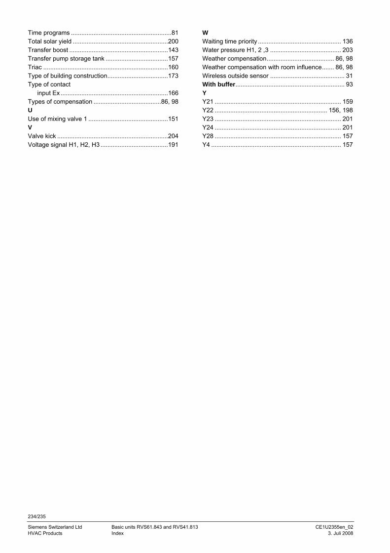
234/235
Siemens Switzerland Ltd Basic units RVS61.843 and RVS41.813 CE1U2355en_02 HVAC Products Index 3. Juli 2008
Time programs ..........................................................81 Total solar yield .......................................................200 Transfer boost .........................................................143 Transfer pump storage tank ....................................157 Triac ........................................................................160 Type of building construction...................................173 Type of contact
input Ex ..............................................................166 Types of compensation .......................................86, 98 U Use of mixing valve 1 ..............................................151 V Valve kick ................................................................204 Voltage signal H1, H2, H3 .......................................191
W Waiting time priority ................................................ 136 Water pressure H1, 2 ,3 ......................................... 203 Weather compensation....................................... 86, 98 Weather compensation with room influence....... 86, 98 Wireless outside sensor ........................................... 31 With buffer............................................................... 93 Y Y21 ......................................................................... 159 Y22 ................................................................. 156, 198 Y23 ......................................................................... 201 Y24 ......................................................................... 201 Y28 ......................................................................... 157 Y4 ........................................................................... 157

235/235
Siemens Schweiz AG Basic units RVS61.843 and RVS41.813 CE1U2355de_02 Landis & Staefa Division 3. Juli 2008
Siemens Switzerland Ltd Building Technologies Group / HVAC Products Gubelstrasse 22 CH -6301 Zug Tel. +41 41-724 24 24 Fax +41 41-724 35 22 www.sbt.siemens.com
© 2006 Siemens Building Technologies AGSubject to alteration