Embed Size (px)
Citation preview

1

03 1. PRODUCT INFO 05 2. REMOVING THE STOCK COMPONENTS16 3. PARTS/SYSTEM LAYOUT19 4. INSTALLING THE TURBOCHARGER KIT, TURBO EXHAUST MANIFOLD AND TURBO OUTLET/ELBOW
4.1. PARTS AND COMPONENTS4.1.1. TURBOCHARGER KIT
27 4.1.2. TURBO EXHAUST MANIFOLD29 4.2. MODIFICATIONS
4.2.1. ENGINE MOUNT BRACKET (LH) 30 4.2.2. OIL PAN31 4.3. PREPARING AND REINSTALLING THE OIL PAN32 4.4. REINSTALLING THE STOCK COMPONENTS33 4.5. INSTALLING THE TURBO EXHAUST MANIFOLD AND TURBO OUTLET/ELBOW
4.5.1. PREPARING THE TURBOCHARGER4.5.2. PREPARING THE EXHAUST MANIFOLD
34 4.5.3. ASSEMBLING THE TURBOCHARGER, TURBO EXHAUST MANIFOLD AND TURBO OUTLET/ELBOW35 4.6. INSTALLING THE TURBOCHARGER HOSES, TUBES AND PIPES
4.6.1. WATER OUT HOSE36 4.6.2. WATER IN HOSE37 4.6.3.OIL IN HOSE38 4.6.4. OIL DRAIN PIPE
4.6.5. HEAT RESISTANT HOSING39 4.6.6. WATER IN HOSE ADAPTER (to cylinder block)
4.6.7. COMPRESSOR INLET ELBOW PIPE40 4.6.8. COMPRESSOR OUTLET ELBOW PIPE41 4.7. INSTALLING THE COMPONENTS ONTO THE ENGINE
4.7.1. OIL IN FROM PRESSURE SENSOR42 4.7.2. WATER IN FROM CYLINDER BLOCK43 4.7.3. WATER OUT TO UPPER RADIATOR HOSE44 4.7.4. TURBOCHARGER ASSY45 4.7.5. HOSES49 4.8. OTHER
4.8.1. REATTACHING THE STEERING SHAFT4.8.2. (RE)INSTALLING EXHAUST COMPONENTS4.8.3. EGR BLIND PLUG
50 4.8.4. INSTALLING AN AIR INTAKE51 5. INSTALLING THE INTERCOOLER PIPING KIT
5.1. PARTS AND COMPONENTS53 5.2. INSTALLING THE GREDDY INTERCOOLER KIT54 5.3. INSTALLING THE INTERCOOLER PIPING KIT
5.3.1. INTAKE PIPE A55 5.3.2.INTAKE PIPE B56 5.3.3 BLOW-BY HOSE
5.3.4. INTERCOOLER57 6. POST INSTALLATION
6.1. FILL ENGINE OIL6.2. (RE)CONNECT BATTERY6.3. REFILL COOLANT AND 'BLEED' SYSTEM
58 7. CHECKS AND PRECAUTIONS59 8. SETUP AND SETTINGS
8.1. TURBOCHARGER SPECIFICATIONS60 8.2.ACTUATOR SPRINGS62 8.3. ADDITIONAL/RECOMMENDED PARTS
8.3.1. TOMEI PARTS64 8.3.2. OTHER PARTS
8.3.3. OPTIONAL PARTS DEPENDING ON SETUP65 9. TOMEI 240SX KA24DET SPECIFICATIONS
2

1. PRODUCT INFO
TURBOCHARGER KIT MX7960 / MX8270 KA24DE
MX7960 PART No. TB401A-NS16CMX8270 PART No. TB401A-NS16D
APPLICATION: NISSAN 240SX S14 KA24DE※ This kit is comprised of the TURBOCHARGERand KA24DE HARDWARE PACK.
TURBOCHARGER KIT KA24DE HARDWARE PACK
PART No. TB401A-NS16PK
APPLICATION: NISSAN 240SX S14 KA24DE
※ KA24DE HARDWARE PACK ONLY.
EXHAUST MANIFOLD KITKA24DE S13/S14 TURBO TYPE
PART No. TB601A-NS16A
APPLICATION: NISSAN 240SX S14 KA24DE
INTERCOOLERPIPING KIT KA24DE
PART No. TB403A-NS16A
APPLICATION: NISSAN 240SX S14 KA24DE
3

WARNING■ Make sure the engine is cold be fore conducting any work on the vehicle. This is to avoid burn potential burn hazards and failing to adhere to this can be extremely dangerous.
■ Ensure you use the appropriate tools and safety equipment to avoid injury during installation.
■ Ensure that all parts are fitted correctly during installation. This is to avoid potential fire hazards and/or damage to not only your vehicle but also the vehicles around you.
CAUTION■ This document contains instructions on how to install the TURBOCHARGER, TURBO EXHAUST MANIFOLD and INTERCOOLER PIPING KIT. For details on the removal/installation of factory components as well as general maintenance information, please consult the manufacturer's official servicing manual.
■ These products are designed specifically for motorsport use. As such, it should only be used off-road and/or on race tracks/circuits closed off from public roads.
■ The engine's output will increase after installing the above products. Accordingly, the brakes, suspension, ECU as well as other surrounding components will also need to be upgraded and/or adjusted. These upgrades will need to be purchased separately and will depend on your particular setup.
■ These products can/should only be used on the specified vehicle(s) or engine(s). Attempting to install these on any other vehicle will likely result in damage to the product and/or the engine/vehicle.
■ To install the TURBO ASSY, TURBO EXHAUST MANIFOLD and INTERCOOLER PIPING KIT, you will need to makesome modifications to the surrounding components. Ensure you familiarize yourself with the process and have the appropriate tools to hand before commencing any work.
■ These products should be installed by a trained professional in a well equipped workshop.
■ Take extra care when removing components as using excessive force can damage the part(s).
■ Each bolt should be tightened down to using the specified amount of torque. Failing to do so could cause the bolt to warp and/or break.
■ After installation, ensure that the engine has sufficient coolant and conduct a thorough check for leaks before driving the vehicle. Do not attempt to drive the vehicle when there is a leak or insufficient coolant. This can cause the engine/water temperature to rise, leading to engine damage.
■ Be sure to install a boost gauge to monitor the turbo's performance.
REQUIRED TOOLS The following tools are required for installation.
・General engine maintenance tools ・Official Servicing Manual ・Liquid gasket・Torque wrench ・Safety equipment ・Thread seal tape・Drill or drill press ・Grinder ・Coolant・Center drill ・Paint ・Engine oil・10mm & 16.5mm drill bit ・Engine crane ・Silicone hose (Φ8mm)*
* The Silicone hose may or may not be required depending on the setup. In this guide, the hose is used in step 5.3.1. to connect a boost controller.
4

2. REMOVING THE STOCK COMPONENTS
CAUTIONThis manual provides only the basic instructions. For details, please refer to the vehicle's official servicing manual.
1. Disconnect and remove the battery.※ a modified 240SX may look slightly different but fundamentally the same components components will need to be removed.
2. Remove the engine under cover.
3. Remove the hood.
4. Remove the air intake ASSY (pre-throttle body).
5. Remove the exhaust (front, center and rear sections).
5
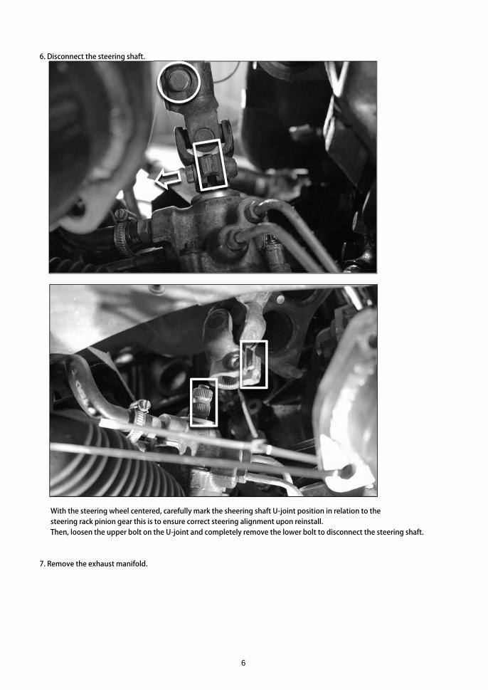
6. Disconnect the steering shaft.
With the steering wheel centered, carefully mark the sheering shaft U-joint position in relation to the steering rack pinion gear this is to ensure correct steering alignment upon reinstall. Then, loosen the upper bolt on the U-joint and completely remove the lower bolt to disconnect the steering shaft.
7. Remove the exhaust manifold.
6

8. Drain the engine oil and coolant.
Remove the drain plug on both the oil pan and radiator to drain the engine oil and coolant.
7

9. Remove the oil filter and oil pressure sensor.
The oil pressure sensor will be reused later. ※ Removing the oil filter makes access to the oil pressure sensor a lot easier.
8

10. Remove the coolant drain bolt on the cylinder block.
※ This hole will later be used for the turbocharger WATER IN FITTING.
9

11. Remove the radiator and radiator fan shroud.
Carefully remove the radiator and radiator fan shroud from the engine bay.Depending on your setup, you may need to remove these separately.※ A modified 240SX may look slightly different but fundamentally the same components will need to be removed.
10

12. Remove the front stabilizer bar.
Remove the 4 bolts/nuts for both the left and right side of the stabilizer bar. (Right side shown above) ※ Removing the stabilizer bar ensures sufficient clearance for the oil pan to be lowered and removed. ※ A modified 240SX may look slightly different but fundamentally the same components will need to be removed.
①②
③
④
11
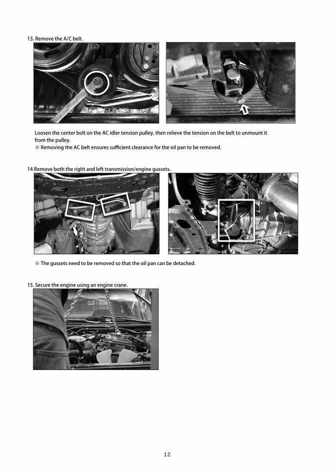
13. Remove the A/C belt.
Loosen the center bolt on the AC idler tension pulley, then relieve the tension on the belt to unmount itfrom the pulley. ※ Removing the AC belt ensures sufficient clearance for the oil pan to be removed.
14.Remove both the right and left transmission/engine gussets.
※ The gussets need to be removed so that the oil pan can be detached.
15. Secure the engine using an engine crane.
12

16. Remove the lower engine mount bolt/nut from the left and right engine mounts.
※ The lower bolt/nut needs to be removed so that the front crossmember can be lowered enough to remove the oil pan.
17. Loosen and lower the front crossmember.
Loosen the 4 bolts/nuts holding the front crossmember in place. (left side x2, right side x2) ※ Do not completely remove the bolts/nuts during this process.
13

18. Hoist the engine and remove the LH engine mount bracket.
Ensure you have appropriate engine slingers attached to the cylinder head then hoist the enginejust enough so that the LH engine mount bracket and bolts can be removed.
With the engine hoisted, carefully remove the LH engine mount bracket. ※ The LH engine mount bracket needs to be modified slightly to allow sufficient clearance for the turbocharger.
14

19. Carefully separate the oil pan from the cylinder block using an oil pan seal cutter.
20. Disconnect the oil strainer from the cylinder block.
※ The oil strainer gasket will be reused when reinstalling later.※ Detaching the oil strainer from the cylinder block makes removing the oil pan much easier.
21. Remove the oil pan and strainer from the vehicle.While lowering the front cross member, carefully remove both the oil pan and oil strainer from the vehicle.
22. Clean the oil pan thoroughly.
Ensure sure you also remove and/or modify any other necessary parts.
15

3. PARTS/SYSTEM LAYOUTThe below diagram shows the positioning/layout of the components included in this kit.You may wish to print and have this to hand for reference during the installation.
16

TURBOCHARGER KIT
TC1 TURBOCHARGERTC2 COMPRESSOR IN PIPE Compressor HousingTC12 COMPRESSOR IN GASKETTC5 COMPRESSOR IN ADAPTERTC4 COMPRESSOR OUT PIPE Compressor HousingTC13 COMPRESSOR OUT GASKETTC3 FLANGE BOLT M6TC10 TURBINE IN GASKET Turbocharger / Exhaust HousingTC8 HEX NUT M8×P=1.25TC6 STUD BOLT M8×P=1.25×L=35mm Turbocharger / Compressor HousingTC9 FLANGE NUT M8×P=1.25TC7 STUD BOLT M8×P=1.25×L=38mm Turbocharger / Exhaust HousingTC8 HEX NUT M8×P=1.25TC11 TURBINE OUT GASKETTC28 MESH HOSE 940mm Oil In / Turbo-Oil Pressure SensorTC29 3WAY ADAPTER Oil In / Oil Pressure SensorTC30 FITTING PT1/8-AN4TC31 FITTING 4AN M TO F 90°TC32 BANJO FITTING M12 4AN 50mm Oil In / Turbocharger
COPPER WASHER M12×D18×D12.2×T1.2BANJO BOLT M12×P1.25×H25.3 2.5
TC35 OIL DRAIN PIPE A Oil Out / TurbochargerTC37 OIL RETURN GASKETTC36 BOLT M6×P=1.0×L=16mmTC38 OIL DRAIN PIPE B Oil Out / Oil panTC39 HEX NUT M16TC40 WASHER M16TC41 SEAL WASHER M16TC42 HOSE BAND 18-32mmTC14 MESH HOSE 1350mm Water Out / Turbo - Radiator Upper HoseTC15 WATER PIPE ADAPTER Water Out / Radiator Upper HoseTC16 FITTING PT1/8-4ANTC17 FITTING 4AN M TO F 90°TC18 HOSE BAND 27-51MMTC19 BANJO FITTING M14 4AN 38.5mm Water Out / Turbocharger
COPPER WASHER M14×D21×D14×T1.0
TC21 WATER BOLT M14×P1.5×27mmTC22 MESH HOSE 200mm Water In / Turbo - Cylinder Block Coolant DrainTC23 FITTING PT1/4-AN4 Water In / Cylinder Block Coolant DrainTC24 FITTING 4AN M TO F 90°TC25 BANJO FITTING M14 4AN 38.5mm Water In / Turbocharger
COPPER WASHER M14×D21×D14×T1.0
TC27 WATER BOLT M14×P1.5×27mmTC44 HOSE BAND 18-32mm EGR BlindTC43 BLIND PLUG EGR BlindTC45 HEAT RESISTANT HOSING For TC28 OIL IN and TC14 WATER OUT HOSEsTC46 OIL PROOF HOSE For TC35 and TC38 OIL DRAIN PIPEs
1
1
1111
11111
21111
21111
41
2111
1
211
TC33 2
TC34 1
TC20 2
TC26 2
REF. PART LOCATION QTY.
3111211
12222
17

EXHAUST MANIFOLD KIT
EM1 EXHAUST MANIFOLDEM2 EXHAUST MANIFOLD GASKETEM3 TURBINE IN GASKETEM4 FLANGE NUTEM5 HEX NUTEM6 LOCK PLATEEM7 STUD BOLT M8 13-20 38mmEM8 FLANGE BOLT M6
INTERCOOLER PIPING KIT
IP1 INTAKE PIPE A Φ70 Throttle SideIP2 FITTING #8 STRAIGHT 1/8PTIP3 HOSE BAND 18-32mmIP4 INTAKE PIPE B Φ50 Intercooler Side
SILICONE HOSE Φ50×L=70 STRAIGHT
IP6 HOSE BAND 46-70mmIP7 SILICONE HOSE Φ50 ELBOWIP8 SILICONE HOSE Φ28-Φ22 Intake/Suction Kit SideIP9 HOSE BAND 18-32mmIP10 HOSE BAND 21-44mmIP11 OIL PROOF HOSE Throttle Side / Blow-by hose
REQUIRED PARTS The following parts are required for installation.
PART No. PARTTB601A-NS16A EXHAUST MANIFOLD KIT EXPREME KA24DE S13/S14 TURBO TYPE※ Please note that exhaust manifold kits from other makers might not include the manifold gasket.
PART No. PART12020480 INTERCOOLER KIT/SPEC-LS S14/S15 TYPE24E11920202 SUCTION KIT Φ80※ This kit is designed to be used in conjunction with the above intercooler.
111114
14262141
IP5 1
1211
REF. PART LOCATION QTY.
REF. PART LOCATION QTY.
18

4. INSTALLING THE TURBOCHARGER KIT, TURBO EXHAUST MANIFOLD AND TURBO OUTLET/ELBOW.4.1. PARTS & COMPONENTS
4.1.1.TURBOCHARGER KIT This kit is comprised of the below items.
The HARDWARE PACK(TB401A-NS16PK)does not include the TC1 TURBOCHARGER.
Bolts, nuts and gaskets for the pipes and inlet/outlet elbows.
PART TURBOCHARGERQTY. 1PART No. -
PART No.MX7960 TB401B-CRA13MX8270 TB401B-CRA14
TB401B-RBK01MX7960 TB401B-ACT09MX8270 TB401B-ACT09MX7960 TB401B-COH04MX8270 TB401B-COH05MX7960 TB401B-COW10MX8270 TB401B-COW11 MX7960 TB401B-TBH05MX8270 TB401B-TBH06 MX7960 TB401B-TBW02 MX8270 TB401B-TBW03
QTY. 1 QTY. 3PART No. TB401B-CIP04 PART No. TB401B-FBT01
QTY. 1 QTY. 1PART No. TB401B-COP04 PART No. TB401B-SPC04
ACTUATOR
TURBINE HOUSING
TURBINE WHEEL
TC2 TC3
TC4 TC5
PART
COMPRESSOR WHEEL
TC1
COMPONENT(S)
CHAR
REBUILT KIT
COMPRESSOR IN PIPE
PART
FLANGE BOLT M6
COMPRESSOR IN ADAPTER
COMPRESSOR HOUSING
COMPRESSOR OUT PIPE PART
PART
19

Bolts, nuts and gaskets for the pipes and inlet/outlet elbows.
STUD BOLT STUD BOLT M8×P1.25 35mm M8×P1.25 38mm
QTY. 2 QTY. 2PART No. TB401B-STB04 PART No. TB401B-STB05
HEX NUT FLANGE NUT M8×P=1.25mm M8×P=1.25mm
QTY. 6 QTY. 2PART No. TB401B-HNT03 PART No. TB401B-FNT01
QTY. 1 QTY. 1PART No. TB401B-TIG03 PART No. TB401B-TOG03
QTY. 2 QTY. 1PART No. TB401B-CIG01 PART No. TB401B-COG02
PART
COMPRESSOR OUT GASKET
TC8 TC9
TC11TC10
TC12 TC13
PART PART
PART
TURBINE OUT GASKET
PART
TC7TC6
COMPRESSOR IN GASKET PART
PART TURBINE IN GASKET PART
20

HOSES AND RELATED HARDWARE 1WATER OUT
QTY. 1 QTY. 1PART No. TB401B-OFP13 PART No. TB401B-ADP03
QTY. 1 QTY. 1PART No. TB401B-FIT26 PART No. TB401B-FIT01
BANJO FITTINGM14 4AN 38.5mm
QTY. 2 QTY. 1PART No. TB401B-HBD03 PART No. TB401B-FIT21
COPPER WASHER WATER BOLTM14 D21×D14×T1.0 M14×P1.5 27mm
QTY. 2 QTY. 1PART No. TB401B-WAS02 PART No. TB401B-WTB01
TC15TC14
TC17
TC20
PART
PART
TC18 TC19
WATER PIPE ADAPTER
FITTING 4AN M to F 90°
TC21
TC16
FITTING PT1/8 - 4AN
PARTMESH HOSE 1350mm
PART PART
PART HOSE BAND 27 - 51mm PART
PART
21
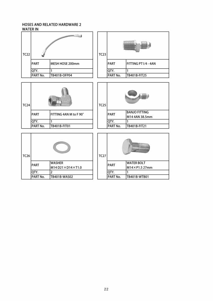
HOSES AND RELATED HARDWARE 2WATER IN
QTY. 1 QTY. 1PART No. TB401B-OFP04 PART No. TB401B-FIT25
BANJO FITTINGM14 4AN 38.5mm
QTY. 1 QTY. 1PART No. TB401B-FIT01 PART No. TB401B-FIT21
WASHER WATER BOLTM14 D21×D14×T1.0 M14×P1.5 27mm
QTY. 2 QTY. 1PART No. TB401B-WAS02 PART No. TB401B-WTB01
TC25
TC26 TC27
TC24
FITTING PT1/4 - 4AN
PART
TC22 TC23
PART
PART PART
PART FITTING 4AN M to F 90° PART
MESH HOSE 200mm
22

HOSES AND RELATED HARDWARE 3OIL IN
QTY. 1 QTY. 1PART No. TB401B-OFP14 PART No. TB401B-ADP02
QTY. 1 QTY. 2PART No. TB401B-FIT26 PART No. TB401B-FIT01
BANJO FITTING COPPER WASHER M12 4AN 50mm M12×D18×D12.2×T1.2
QTY. 1 QTY. 2PART No. TB401B-FIT04 PART No. TB401B-WAS04
BANJO BOLT M12×P1.25 H25.3 2.5
QTY. 1PART No. TB401B-BJB02
TC34
TC28
TC32 TC33
3WAY ADAPTER
FITTING 4AN M to F 90°PART FITTING PT1/8 - 4AN PART
PART MESH HOSE 940mm PART
PART
TC29
TC30 TC31
PART PART
23

HOSES AND RELATED HARDWARE 4OIL OUT
QTY. 1 QTY. 2PART No. TB401B-ODP06 PART No. TB401B-WBT01
QTY. 1PART No. TB401B-ORG01
QTY. 1PART No. TB401B-ODK02
COMPONENT(S)PART QTY.
TC38 OIL DRAIN PIPE B 1TC39 HEX NUT M16 1TC40 WASHER M16 1TC41 SEAL WASHER M16 1
QTY. 2PART No. TB401B-HBD04
TC37
TC42
PART
TC38|TC41
TC35
OIL DRAIN PIPE A PART BOLT M6 × P1.0 16mm
OIL RETURN GASKET
TC36
PART HOSE BAND 18 - 32mm
PART OIL DRAIN FITTING KIT
PART
TC38 TC39 TC40 TC41
24

QTY. 1 QTY. 1PART No. TB401B-CAP02 PART No. TB401B-HBD04
HEAT RESISTANT HOSING 400mm
QTY. 1 QTY. 1PART No. TB401B-TIT01 PART No. TB401B-OPH01
VACUUM HOSE 5☓11mm ACTUATOR SPRING BLACK
QTY. 1 QTY. 1PART No. TB401B-SLH03 PART No. TB401B-SPR07
ACTUATOR SPRING ACTUATOR SPRING RED PINK
QTY. 1 QTY. 1PART No. TB401B-SPR10 PART No. TB401B-SPR11
ACTUATOR SPRING ACTUATOR NIPPLEBLUE (STRAIGHT)
QTY. 1 QTY. 1PART No. TB401B-SPR11 PART No. TB401B-SAN01
TC46
TC43
TC45
HOSE BAND 18 - 32mm
TC44
TC47 TC48
PART
BLIND CAP PART
TC52
PART
OTHER
PART
TC49 TC50
PART PART
TC51
PART
PART PART OIL PROOF HOSE
PART
25

QTY. 2 QTY. 2PART No. TG202A-0000A PART No. TG205A-0000A
QTY. 1 QTY. 1PART No. TE501A-0000A PART No. PB6150-BSP01
ACTUATOR MANUALQTY. 1
QTY. 1 PART No.PART No.
QTY. 1 QTY. 1PART No. PART No.
QTY. 1 QTY. 1PART No. PART No.
WARRANTY REG. CARD
TC61
PART WARRANTY REG. NOTES
TC62
PART BOOST SETTING CAUTION
PART TOMEI STICKER
TC58
PART
TC59
PART SPEC. SHEET
TC60
PART
TC53 TC54
TC55 TC56
OTHER
PART
PART PART
ARMS STICKER
TOMEI EMBLEM BOLT SMOOTH PASTE
PART TURBO MANUAL
TC57
26
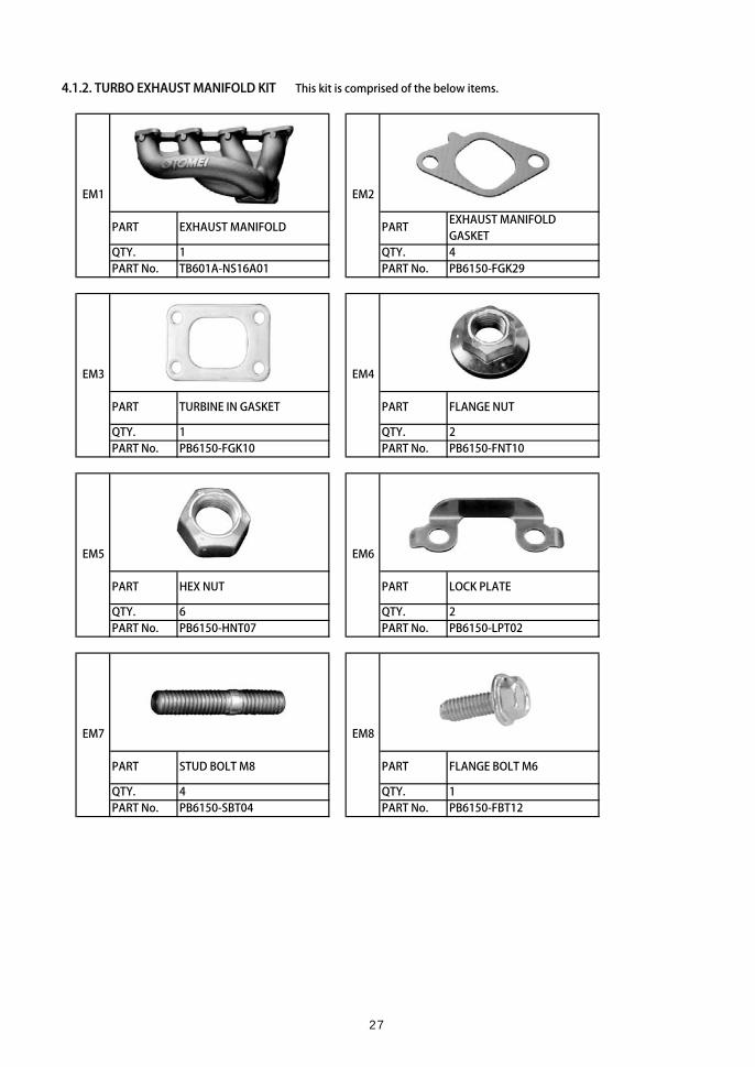
4.1.2. TURBO EXHAUST MANIFOLD KIT This kit is comprised of the below items.
EXHAUST MANIFOLD GASKET
QTY. 1 QTY. 4PART No. TB601A-NS16A01 PART No. PB6150-FGK29
QTY. 1 QTY. 2PART No. PB6150-FGK10 PART No. PB6150-FNT10
QTY. 6 QTY. 2PART No. PB6150-HNT07 PART No. PB6150-LPT02
QTY. 4 QTY. 1PART No. PB6150-SBT04 PART No. PB6150-FBT12
PART EXHAUST MANIFOLD PART
PART TURBINE IN GASKET
EM1 EM2
PART PART
PART FLANGE NUT
PART
EM3 EM4
EM5
HEX NUT PART
EM6
EM7 EM8
STUD BOLT M8 FLANGE BOLT M6
LOCK PLATE
27

QTY. 1 QTY. 2PART No. PB6150-BSP01 PART No. TG204A-0000A
QTY. 2PART No. TG202A-0000A
TOMEI STICKER
EM9 EM10
PART BOLT SMOOTH PASTE PART EXTREME STICKER
PART
EM11
28

4.2. MODIFICATIONS
4.2.1. ENGINE MOUNT BRACKET (LH)
Modify the LH engine mount bracket as shown below.
WARNINGEnsure you wear appropriate safety goggles, gloves and dust mask.
CAUTIONOnce the modification is complete, apply some paint to prevent rust.
25mm35mm
40mm50mm
DISTANCE FROM TOP RIB HEIGHT10mm20mm30mm
5mm10mm15mm
RIB HEIGHT
DISTANCEFROM TOP
29

4.2.2. OIL PAN
1. Clean the oil pan thoroughly and remove all gasket residue using a scraper.
2. Use a drill press or handheld drill to make a 16.5mm diameter hole in the oil pan as shown below.
Start with a smaller drill size first (10mm),then expand the hole to 16.5mm.
※This helps to ensure that the final hole is positioned/centered correctly.
Vertically, the hole center should be 18mm from the oil pan flange.
Horizontally, the hole center should be 33mmfrom the bolt hole center pictured left.
30

4.3. PREPARING & REINSTALLING THE OIL PAN
1. Clean the modified oil pan thoroughly.
2. Attach the OIL DRAIN PIPE B to the oil pan as shown below.
The OIL DRAIN PIPE B should be installedparallel to the oil pan flange.
OIL DRAIN PIPE B T=89.2N・m (9.1kgf・m)HEX NUT M16WASHER M16SEAL WASHER M16
CAUTIONAfter installing the above hardware, ensure you test for leaks using water.Once the checks are complete, allow the oil pan to dry completely.
REF. PART QTY. TORQUE SPEC.
111
TC40
TC38TC39
<1>
TC41
1
TC38
TC41
TC39TC40 <1>
31

3. Apply liquid (silicon) gasket to the oil pan flange.
4 .Carefully pass the oil pan together with the oil strainer over the front cross member making sure that the liquid (silicon) gasket doesn't come into contact with the surrounding components.
5. Attach the oil strainer to the cylinder block.
6. Attach the oil pan to the cylinder block.
TORQUE SPEC. T=9.0N・m (0.9kgf・m)
4.4. REINSTALLING THE STOCK COMPONENTS
Reinstall the front stabilizer, crossmember, AC belt, gussets, modified LH engine mount bracket,radiator and radiator fan shroud.
32

4.5. INSTALLING THE TURBO EXHAUST MANIFOLD AND TURBO OUTLET/ELBOW4.5.1. PREPARING THE TURBOCHARGER
Attach the included stud bolts to the turbocharger.
※ Attach using the 'double nut' method.※ Note the long and short ends of the bolt(s).※ Apply the included Bolt Smooth Paste to prevent the parts from becoming seized.
TURBOCHARGERSTUD BOLT M8*P1.25 35mmSTUD BOLT M8*P1.25 38mm
4.5.2. PREPARING THE EXHAUST MANIFOLD
Attach the included stud bolts to the exhaust manifold
※ Attach using the 'double nut' method.※ Note the long and short ends of the bolt(s).※ Apply the included Bolt Smooth Paste to prevent the parts from becoming seized.
EXHAUST MANIFOLDSTUD BOLT M8
QTY.TC1TC6TC7
122
REF.EM1EM7
PART QTY.1
REF. PART
T=19.6~21.6N・m (2.0~2.2kgf・m)SPEC.4
TORQUESPEC.
TORQUE
T=19.6~21.6N・m (2.0~2.2kgf・m)
TC1
TC6TC7
EM1
EM7
※The short end is the turbine side.
※Attach using the 'double nut'
method (nuts included)
※Ensure the stud bolt does not
move when removing the nuts.
Should the bolts move when
removing the nuts, you will need
to repeat the process.
ATTENTION
Short Long
※The short end is the turbine side.
※Attach using the 'double nut'
method (nuts included).
※Ensure the stud bolt does not
move when removing the nuts.
Should the bolts move when
removing the nuts, you will need
to repeat the process.
Short Long
ATTENTION
33

4.5.3. ASSEMBLING THE TURBOCHARGER, TURBO EXHAUST MANIFOLD AND TURBO OUTLET/ELBOW
※Refer to the manual included with your preferred choice of TURBO OUTLET/ELBOW for details.TOMEI TURBO OUTLET/ELBOW RECOMMENDED
TURBINE OUTLET PIPE KIT EXPREME SR20DET (R)PS13/S14/S15)
HEX NUT M8×P=1.25 T=21.0N・m(2.1kgf・m)TURBINE IN GASKETTURBINE OUT GASKETLOCK PLATE
CAUTION
※Ensure orientation is correct. ※ After tightening down the lock plates, bend the tabs to secure into position.
※Apply the included Bolt Smooth Paste to prevent the parts from becoming seized.
TC11EM6
6112
TORQUE SPEC.<1>
PART No.423002
PART
REF. PART QTY.TC8
TC10 / EM3
TABS
EXHAUST MANIFOLD
TURBOCHARGER
TC8TC8
TC8TC8TC8
TC8
TC10/EM3TC11
EM6EM6
<1>
<1>
34

4.6. ATTACHING THE TURBOCHARGER HOSES, TUBES AND PIPES
CAUTIONEnsure each part is positioned and orientated as shown below. Failing to do so will not only result in damageto the turbo from insufficient lubrication/cooling, but will also prevent the TURBO ASSY from being installed.
4.6.1. WATER OUT HOSE
1. Attach the MESH HOSE to the BANJO FITTING.
2. Using the included WATER BOLT and WASHERs, attach the BANJO FITTING and MESH HOSE to the turbocharger.
MESH HOSE 1350mmBANJO FITTING M14 4AN 38.5mmWASHER M14 D21×D14×T1.0WATER BOLT M14×P1.5 27mm
TORQUE SPEC.T=31.4N・m(3.2kgf・m)
QTY.
12
TC21 1
REF. PART
TC20
TC14TC19
1
<1>
TC14
TC20/TC19/TC20/TC21<1>
35

4.6.2. WATER IN HOSE
1. Attach the MESH HOSE to the BANJO FITTING.
2. Using the included WATER BOLT and WASHERs, attach the BANJO FITTING and MESH HOSE to the turbocharger.
MESH HOSE 200mmBANJO FITTING M14 4AN 38.5mmWASHER M14 D21×D14×T1.0WATER BOLT M14×P1.5 27mm
T=31.4N・m(3.2kgm)
REF. PART QTY.
TORQUE SPEC.<1>
TC22
TC27 1
TC25 1TC26 2
1
TC22
TC26/TC25/TC26/TC27<1>
36
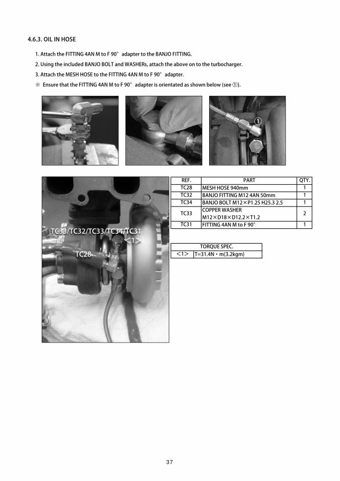
4.6.3. OIL IN HOSE
1. Attach the FITTING 4AN M to F 90°adapter to the BANJO FITTING.
2. Using the included BANJO BOLT and WASHERs, attach the above on to the turbocharger.
3. Attach the MESH HOSE to the FITTING 4AN M to F 90°adapter.
※ Ensure that the FITTING 4AN M to F 90°adapter is orientated as shown below (see ①).
MESH HOSE 940mmBANJO FITTING M12 4AN 50mmBANJO BOLT M12×P1.25 H25.3 2.5COPPER WASHER M12×D18×D12.2×T1.2FITTING 4AN M to F 90°
T=31.4N・m(3.2kgm) TORQUE SPEC.
1
2
TC34
REF. PART QTY.
TC31 1
<1>
TC28 1TC32 1
TC33
①
TC28
TC33/TC32/TC33/TC34/TC31<1>
37

4.6.4. OIL DRAIN PIPE
Attach the OIL DRAIN PIPE A as shown below.
OIL DRAIN PIPE A T=9N・m(0.9kgm)BOLT M6*P1.0 16mmOIL RETURN GASKET
4.6.5. HEAT RESISTANT HOSING
Cover the WATER OUT HOSE (from step 4.6.1.) and the OIL IN HOSE (from step 4.6.3.) using the includedHEAT RESISTANT HOSING.
CAUTIONCut the HEAT RESISTANT HOSING to length and use it to prevent heat damage from the turbo.
※ Use zip ties where necessary to secure the hosing in place.
HEAT RESISTANT HOSINGREF.TC45
PART QTY.1
REF. PART QTY.121
TORQUE SPEC.<1>TC35
TC36TC37
TC35
TC36
TC37
<1>
TC45
TC45
38

4.6.6. WATER IN FITTING ADAPTER (to cylinder block)
Attach the FITTING 4AN M to F 90°adapter to the WATER IN HOSE (from step 4.6.2.) as shown below.
4.6.7. COMPRESSOR INLET ELBOW PIPE
Install the COMPRESSOR IN PIPE onto the turbocharger compressor housing.
COMPRESSOR IN PIPE T=31.4N・m(3.2kgm) COMPRESSOR IN ADAPTERCOMPRESSOR IN GASKETFLANGE NUT M8*P=1.25mm
CAUTIONDo not modify the COMPRESSOR IN ADAPTER. It is specifically designed to prevent over boosting.
REF. PART QTY.<1>
TC9TC12TC5TC2
REF.TC24
PARTFITTING 4AN M to F 90°
QTY.1
2211
TORQUE SPEC.
TC24
TC4/TC12/TC5/TC12
TC9 <1>
39
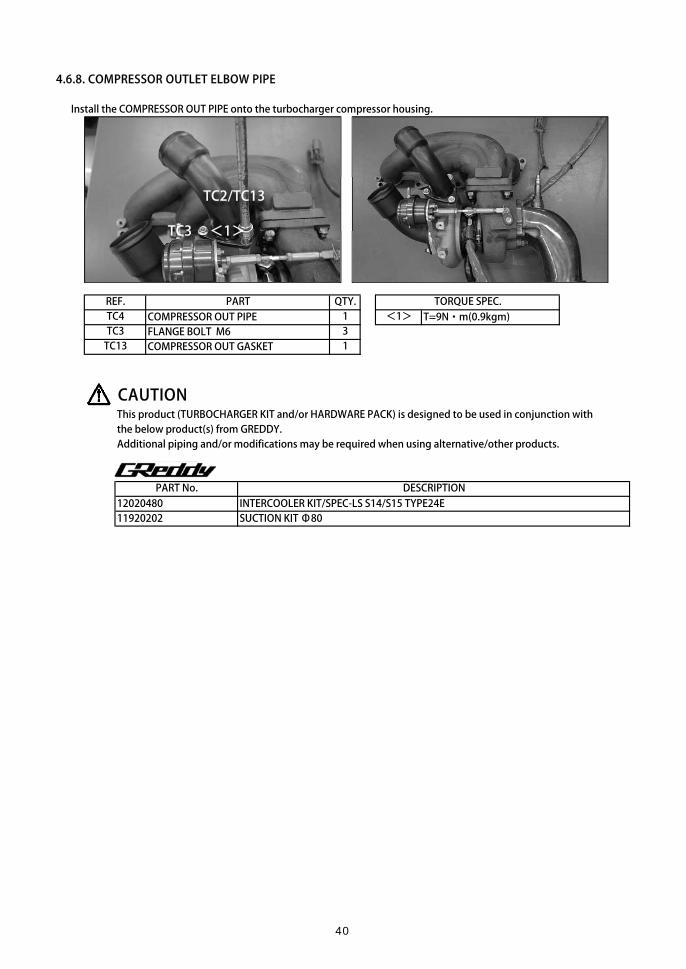
4.6.8. COMPRESSOR OUTLET ELBOW PIPE
Install the COMPRESSOR OUT PIPE onto the turbocharger compressor housing.
COMPRESSOR OUT PIPE T=9N・m(0.9kgm) FLANGE BOLT M6COMPRESSOR OUT GASKET
CAUTIONThis product (TURBOCHARGER KIT and/or HARDWARE PACK) is designed to be used in conjunction withthe below product(s) from GREDDY.Additional piping and/or modifications may be required when using alternative/other products.
12020480 INTERCOOLER KIT/SPEC-LS S14/S15 TYPE24E11920202 SUCTION KIT Φ80
PART No. DESCRIPTION
PART QTY. TORQUE SPEC.
1
1 <1>REF.
3TC13TC3TC4
TC2/TC13
TC3 <1>
40

4.7. INSTALLING THE COMPONENTS ONTO THE ENGINE
CAUTIONUsing excessive force to tighten the banjo/adapter fittings can damage the parts and/or the engine. In someinstances, you may need to remove the engine from the vehicle to repair the damage caused by this.
4.7.1. OIL PRESSURE SENSOR
1. Apply thread sealing tape to the included PT 1/8 4AN and 3 WAY adapter fittings
2. Install the 3 WAY ADAPTER as shown below.
3. Combine the PT 1/8 4AN and 90°fitting adapters and install onto the 3 WAY ADAPTER as shown below.
TC29
TC30
TC31
41

4. Install the oil pressure sensor onto the 3 WAY ADAPTER and reconnect the sensor coupler. The oil filter should also be reinstalled.
REF. PART QTY.3WAY ADAPTERFITTING PT1/8 - 4ANFITTING 4AN M to F 90°
4.7.2. WATER IN FROM CYLINDER BLOCK
Apply thread sealing tape to the FITTING PT1/4 - 4AN adapter and install onto the cylinder block.
REF. PART QTY.FITTING PT1/4 - 4AN
11
TC23
TC31TC30TC29
1
1
TC23
42

4.7.3. WATER OUT TO UPPER RADIATOR HOSE
1. Temporarily reattach the upper radiator hose.
2. Starting at 35mm from the bend, carefully cut out a 20mm section of the upper radiator hose as shown below.
3. Install the WATER PIPE ADAPTER using the included HOSE BANDs.
4. Apply thread sealing tape to the FITTING PT1/8 - 4AN adapter. Then, combine with the FITTING 4AN M to F 90° adapter and install onto the WATER PIPE ADAPTER.
REF. PART QTY.TC15 WATER PIPE ADAPTER 1TC16 FITTING PT1/8 - 4AN 1TC17 FITTING 4AN M to F 90° 1TC18 HOSE BAND 27 - 51mm 2
35mm
20mm
TC15
TC18
TC18
TC16
TC17
43

4.7.4. TURBOCHARGER ASSY
1. Test fit the TURBOCHARGER ASSY onto the engine together with the included EXHAUST MANIFOLD GASKETs. Use the stock nuts to temporarily secure in place.
2. Check there is sufficient clearance between the modified LH engine mount bracket and the turbocharger unit.※ Should there be insufficient clearance, modify the LH engine mount bracket accordingly.
3. Once sufficient clearance have been confirmed/achieved, tighten down the LH engine mount bracket.
4. Replace the stock nuts used in step 1. with those included in the kit and secure the EXHAUST MANIFOLD in place.
EXHAUST MANIFOLD GASKETFLANGE NUT [37.3~48.1N・m (3.8~4.9kgf-m)]HEX NUT [37.3~48.1N・m (3.8~4.9kgf-m)]FLANGE BOLT M6 [13.6N・m (1.4kgf-m)]
4. Secure the oil dip stick to the exhaust manifold using the included FLANGE BOLT.
QTY.REF.
EM8EM5
TORQUE SPEC.
1624
EM4EM2
PART
※Apply the included Bolt Smooth Paste to prevent the parts from becoming seized.
EM2EM2EM2EM2
EM4
EM4
EM5
EM5EM5
EM5
EM8
Reuse the washers from the
the stock exhaust manifold.
44
CAUTION・Ensure sufficient clearance and correct fitment has been achieved before completely tightening down the fastenings. In some cases, there may be insufficient clearance due to minor differences between individual vehicles. In such a case, loosen the fastenings on each component and adjust the positioning until sufficient clearance is achieved before retightening the fastenings again.
・Ensure you clean the EXHAUST MANIFOLD after installation. Using the EXHAUST MANIFOLD with oil or other debris on it can cause blemishes and/or burn marks.
・ Depending on the setup and/or use, heat from the Exhaust manifold can damage the surrounding components. Thermal insulation should be used where necessary to prevent this.
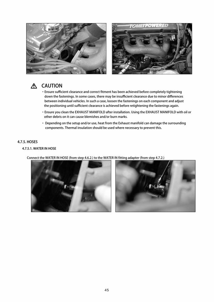
4.7.5. HOSES
4.7.5.1. WATER IN HOSE
Connect the WATER IN HOSE (from step 4.6.2.) to the WATER IN fitting adapter (from step 4.7.2.)
45

4.7.5.2. OIL IN HOSE
1. Carefully route the OIL IN HOSE (from step 4.6.3.) over the bell housing, between the engine and firewall.
2. From there, route the hose alongside the stock wiring/harness and connect to the 3 WAY ADAPTER (from step 4.7.1.) Use zip ties where necessary to anchor the hose in place as circled below.
46

4.7.5.3. WATER OUT HOSE
1. Carefully route the WATER OUT HOSE (from step 4.6.1.) between the engine and firewall.
Ensure that the hose does not make contact with the turbocharger/exhaust components.
2. From there, route the hose under the intake manifold and (loosely) anchor in place where necessary.※ Depending on your setup, you may need to route the hose around the intake manifold instead.
3. Connect the hose to the WATER PIPE ADAPTER (from step 4.7.3.).
47

4.7.5.4. OIL DRAIN
1. Attach the OIL PROOF HOSE to OIL DRAIN PIPE A (from step 4.6.4.) using the included HOSE BAND.
2. Cut the OIL PROOF HOSE to the appropriate length and connect onto OIL DRAIN PIPE B (from step 4.3.) and secure using the included HOSE BAND.
PART QTY.HOSE BAND 18 - 32mmOIL PROOF HOSE
CAUTIONEnsure the hoses are routed tension-free and away from the TURBOCHARGER and/or EXHAUST MANIFOLDto avoid heat damage.
TC42TC46
21
REF.
TC46TC42
48

4.8. OTHER4.8.1. REATTACHING THE STEERING SHAFT
Check that everything is fitted correctly and that sufficient clearance has been achieved. Then proceed to reconnect the steering shaft, making sure the U-Joint and steering rack pinion gear align correctly.
4.8.2. (RE)INSTALLING EXHAUST COMPONENTS
(Re)install the exhaust (front, center and rear sections).※
4.8.3.EGR BLIND PLUG
Cover the EGR valve with the BLIND CAP and secure using the included HOSE BAND.
BLIND CAPHOSE BAND 18 - 32mm
TC43 1TC44 1
PART QTY.REF.
TC43TC44
49

4.8.4. INSTALLING AN AIR INTAKE
Please refer to the installation manual included with you preferred choice of turbo intake.
CAUTIONThis product (TURBOCHARGER KIT and/or HARDWARE PACK) is designed to be used in conjunction with the below product(s) from GREDDY.Additional piping and/or modifications may be required when using alternative/other products.
PART No. DESCRIPTION12020480 INTERCOOLER KIT/SPEC-LS S14/S15 TYPE24E11920202 SUCTION KIT Φ80
50

5. INSTALLING THE INTERCOOLER PIPING KIT5.1. PARTS AND COMPONENTS
FITTING #8 STRAIGHT 1/8PT
QTY. 1 QTY. 1PART No. TB403B-ITP01 PART No. TB403B-FIT01
QTY. 2 QTY. 1PART No. TB401B-HBD04 PART No. TB403B-ITP02
SILICONE HOSE Φ50 × L=70 STRAIGHT
QTY. 1 QTY. 4PART No. TB403B-SLH01 PART No. TB403B-HBD01
SILICONE HOSE SILICONE HOSE Φ50 ELBOW Φ28 - Φ22
QTY. 1 QTY. 1PART No. TB403B-ELH01 PART No. TB403B-RDH01
INTAKE PIPE A Φ70 PART
HOSE BAND 18 -32mm PART INTAKE PIPE B Φ50
PART HOSE BAND 46 -70mm
PART
IP1
IP5 IP6
IP7
IP3
IP8
PART
PART
PART
PART
IP2
IP4
51

QTY. 1 QTY. 1PART No. TB401B-HBD04 PART No. TB403B-HBD02
QTY. 1 QTY. 2PART No. TB401B-OPH01 PART No. TG202A-0000A
REQUIRED PARTS The following parts are required for installation.
PART No. DESCRIPTIONTB401A-NS16C TURBOCHARGER KIT ARMS MX7960 KA24DETB401A-NS16D TURBOCHARGER KIT ARMS MX8270 KA24DE
for installing other turbochargers
TB601A-NS16A EXHAUST MANIFOLD KIT EXPREME KA24DE S13/S14 TURBO TYPE※ Please note that exhaust manifold kits from other makers might not include the manifold gasket.
PART No. DESCRIPTION12020480 INTERCOOLER KIT/SPEC-LS S14/S15 TYPE24E11920202 SUCTION KIT Φ80
CAUTIONThis product has been designed to work in conjunction with the above products.Alternative products can also be installed but may require some modification and/or additional parts.
IP9
EITHER ONE
TURBOCHARGER KIT ARMS KA24DE HARDWARE PACK
HOSE BAND 18 -32mm PART HOSE BAND 21 -44mm
OIL PROOF HOSE PART TOMEI STICKER
TB401A-NS16PK
IP11
IP10
IP12
PART
PART
52
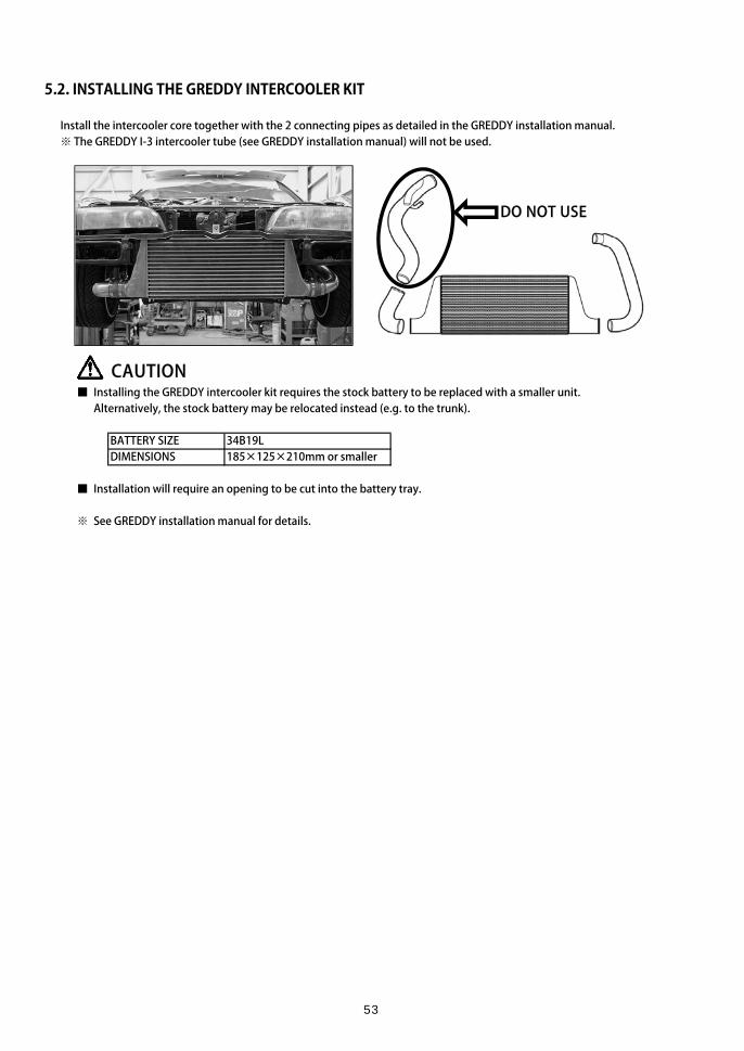
5.2. INSTALLING THE GREDDY INTERCOOLER KIT
Install the intercooler core together with the 2 connecting pipes as detailed in the GREDDY installation manual.※ The GREDDY I-3 intercooler tube (see GREDDY installation manual) will not be used.
CAUTION■ Installing the GREDDY intercooler kit requires the stock battery to be replaced with a smaller unit.Alternatively, the stock battery may be relocated instead (e.g. to the trunk).
BATTERY SIZE 34B19LDIMENSIONS 185×125×210mm or smaller
■ Installation will require an opening to be cut into the battery tray.
※ See GREDDY installation manual for details.
DO NOT USE
53

5.3. INSTALLING THE INTERCOOLER PIPING KIT5.3.1. INTAKE PIPE A
1. Apply thread sealing tape to the FITTING #8 STRAIGHT 1/8PT adapter and install onto INTAKE PIPE A. Ensure you also remove the rubber cap from the AACV (IACV) connecting tube.
2. Install INTAKE PIPE A onto the throttle body and pass the opposite end through the opening in the battery tray. Then, cut the included OIL PROOF HOSE to length and use the provided hose bands to connect the AACV (IACV) to INTAKE PIPE A. The FITTING #8 STRAIGHT 1/8PT adapter can be used to connect devices such as a boost controller.
※ The silicone hose for connecting devices such as a boost controller will need to be purchased separately.
CAUTIONThe OIL PROOF HOSE should be cut to length so that there are no kinks once the hose is installed.
PARTINTAKE PIPE A Φ70FITTING #8 STRAIGHT 1/8PTHOSE BAND 18 - 32mmOIL PROOF HOSE
REF. QTY.112
IP1IP2IP3IP11 1
IP1IP2
IP3
IP11
To boost controller etc.
To AAC
54

5.3.2. INTAKE PIPE B
1. Using the included HOSE BANDs, install the SILICONE Φ50 X L=70 STRAIGHT HOSE onto the COMPRESSOR OUTLET PIPE and the SILICONE Φ50 ELBOW HOSE onto the GREDDY intercooler pipe as shown below. Then, install INTAKE PIPE B and secure in place with the provided HOSE BANDs.
PARTINTAKE PIPE B Φ50SILICONE HOSE Φ50× L=70 STRAIGHTHOSE BAND 46 - 70mmSILICONE HOSE Φ50 ELBOW
CAUTIONINTAKE PIPE B can be installed either way round.Ensure there is also sufficient clearance with the hood, turbo air intake and other surrounding components.
IP4 1IP5 1IP6 4IP7 1
REF. QTY.
IP4
IP5IP7
IP6IP6
IP6
IP6
55

5.3.3 BLOW-BY HOSE
1. Connect the blow-by hose from the cylinder head to the turbo air intake using the provided OIL PROOF HOSE and SILICONE HOSE Φ28 - Φ22 as shown below.
CAUTIONThe OIL PROOF HOSE should be cut to length so that there are no kinks once the hose is installed.
PARTSILICONE HOSE Φ28 - Φ22HOSE BAND 18 -32mmHOSE BAND 21 -44mmOIL PROOF HOSEReuse stock item
5.3.4. INTERCOOLER
Ensuring that sufficient clearance has been achieved, connect the bottom end of INTAKE PIPE A to the intercooler piping and tighten down all hose bands to complete the installation.
QTY.IP8 1IP9 1IP10 1IP11 1※ 1
※
IP11
IP8
IP9IP10
56

6. POST INSTALLATION
6.1. REFILL ENGINE OIL
6.2. (RE)CONNECT BATTERY
CAUTIONSee GREDDY intercooler installation manual for details.
6.3. REFILL COOLANT AND 'BLEED' SYSTEM
CAUTION■ Ensure you use the appropriate coolant. Using only water can cause the aluminum components to corrode.
■ Ensure you properly 'bleed' the cooling system. Air in the cooling system can lead to overheating.
WARNING■ To avoid scalding, do not open the radiator cap when coolant temperatures are high.
1. Check to make sure that the hose bands on the radiator and heater hoses are tightened down.Ensure that the drain bolt is also tightened down.
2. Set the heater temperature control lever to 'HOT'.
3. Remove the radiator cap and air relief plug.
4. Slowly fill the radiator with coolant until full to the brim.Once coolant beings to over flow from the air relief, reinstall the plug, then proceed to fill the radiator to the brim.
5. Close the radiator cap and start the engine. Maintain the idle until the thermostat opens.
6. Consult the water temperature gauge. Once the temperature has risen beyond the midpoint, check to see whetherthe thermostat has opened by feeling the lower radiator hose to check that warm coolant is flowing.
7. Once you have confirmed that the thermostat has opened, rev the engine to 2000-3000rpm and hold for around10 seconds, making sure water temperatures stay within acceptable limits. Repeat this step several times.
8. Stop the engine.
9. After the engine has cooled, open the radiator cap and check the coolant level. If the level has dropped, repeat theabove steps.
10. When the coolant level no longer drops, fill the coolant reservoir to 'MAX'.
57

7. CHECKS AND PRECAUTIONS
① Ensure the vehicle is in neutral gear and check that the parking brake is engaged.
② Crank the engine for around 15 seconds but ensure you do not start the engine.
③ Start the engine and check for any signs of oil or coolant leaks during idle.
④ Stop the engine. Check to make sure that the oil and coolant are at acceptable levels.Be sure to also check the coolant reservoir level.
⑤ Start the engine again and rev to 3000rpm. Thoroughly check for any exhaust leaks and/or abnormal sounds.
⑥ Test drive the vehicle and check to make sure that the turbo is generating pressure/boost.
■ By default, the actuator (standalone) is configured to give 1.0kg spring pressure with 2mm of preload applied.
■ The actual boost pressure will vary depending on pre-turbo back pressure as well asthe surrounding components installed. A boost controller should be used in conjunctionto make precise adjustments to boost pressure.
■ For details on changing actuator springs, please refer to the included actuator manual.
■ Ensure you monitor boost levels using a boost gauge.
⑦ Check to ensure all parts are fitted correctly and that there are no oil/coolant leaks.
■ Do not turn the engine off immediately after hard driving.
■ Ensure you periodically change the engine oil.
WARNING■ Ensure checks are conducted thoroughly as incorrect fitment and/or loose parts can damage other components.
■ Exhaust leaks are not only a health hazard but can also lead to reduced performance.
■ Should you notice anything abnormal whilst driving, stop the vehicle immediately and check for faults.
■ Make sure all parts have completely cooled before commencing any repair work.
■ Should you notice any missing and/or broken parts, do not attempt to restart the engine. Instead, consult atrained professional and follow their instructions.
CAUTION■ The ECU as well as other parts of the vehicle will need to be adjusted/upgraded accordingly.
■ Engine parts, fluids and any other related components should be selected carefully.
58

8. SETUP AND SETTINGS
8.1. TURBOCHARGER SPECIFICATIONS
MX7960
TURBINE HOUSING
MX8270
TURBINE HOUSING
TRIMOUTER DIA. (mm)
0.57A/R
SR20DETEXIT
T25INLET
0.6238.560.0A/R
INLET DIA. (mm)COMPRESSOR WHEEL
CONSTRUCTIONMATERIALBLADESTRIMOUTER DIA. (mm)CNC BILLETA261866068.052.6
MATERIALBLADESTRIMOUTER DIA. (mm)EXIT DIA. (mm)TURBINE WHEEL
EXIT DIA. (mm)INLET DIA. (mm)COMPRESSOR HOUSING
CNC BILLETA261866076.259.0CONSTRUCTIONMATERIALBLADESTRIMOUTER DIA. (mm)
COMPRESSOR WHEELINLET DIA. (mm)
FORGEDK418117961.054.0CONSTRUCTION
EXIT DIA. (mm)TURBINE WHEEL
0.57A/R
SR20DETEXIT
T25INLET
0.62A/R
38.8EXIT DIA. (mm)
53.5INLET DIA. (mm)
COMPRESSOR HOUSING
FORGEDK418117767.058.8CONSTRUCTIONMATERIALBLADES
59

8.2. ACTUATOR SPRINGS
This product features interchangeable actuator springs, allowing you to set different boost pressures.Use the following information as reference to choose the appropriate spring(s) for your setup.
CHOOSING ACTUATOR SPRINGS
The table on the next page shows the standalone pressure/spring rate of each spring. All pressure/spring rates were measured just as the internal wastegate begins to open.Always ensure you measure and choose the appropriate spring(s) for your particular setup.For details on how to change actuator springs, please refer to the separate actuator manual.
※ The table on the next page shows the standalone pressure/spring rate of each spring with 2mm of preload applied.
※ The included actuator ships preconfigured with 1.0kgf/cm2 springs as shown in thetable on the next page.
※ The table on the next page should be used for reference only as actual boost pressurewill vary depending on the setup.
※ A boost controller should be used in conjunction to accurately adjust boost settings.For best results, the boost controller should be used as the main boost control device,with the actuator springs providing a secondary level of adjustment.
HOW TO CHOOSE ACTUATOR SPRINGS (EXAMPLE)
■ Clamp/secure the actuator on a stable surface so that it doesn't move.■ Next, set up a dial indicator or similar tool so that you can accurately measureactuator rod travel.
■ Using an air compressor and pressure gauge, apply air pressure to the actuator. ■ Note the pressure at which the actuator rod begins to move.■ Then, use the following table to choose the appropriate spring(s) for your setup.
60

STANDALONE kgf/cm2
SPRING KpaPRESSURE PSIPOSITIONINGP/N
COLORSIZE O.D (mm)
LENGTH (mm)
0.20 0.4 0.6 0.9 0.65 0.7519.61 39.23 58.84 88.26 63.74 73.552.84 5.69 8.53 12.80 9.25 10.67INNER INNER MIDDLE MIDDLE OUTER OUTERTB401B TB401B TB401B TB401B TB401B TB401B-SPR07 -SPR08 -SPR09 -SPR10 -SPR11 -SPR12BLACK SILVER PURPLE RED PINK BLUE29 29 36.5 36.5 44 4432 36 43 52 57 68
CONFIGURED PRESSURE
kgf/cm2 Kpa PSI0.20 19.61 2.84 0.200.40 39.23 5.69 0.400.60 58.84 8.53 0.600.65 63.74 9.25 0.650.75 73.55 10.67 0.750.80 78.45 11.38 0.20 0.600.85 83.36 12.09 0.20 0.650.90 88.26 12.80 0.900.95 93.16 13.51 0.20 0.75
1.00 98.07 14.22 0.40 0.60
1.05 102.97 14.93 0.40 0.651.10 107.87 15.65 0.20 0.901.15 112.78 16.36 0.40 0.751.25 122.58 17.78 0.60 0.651.30 127.49 18.49 0.40 0.901.35 132.39 19.20 0.60 0.751.45 142.20 20.62 0.20 0.60 0.651.55 152.00 22.05 0.20 0.60 0.751.55 152.00 22.05 0.90 0.651.65 161.81 23.47 0.40 0.60 0.651.65 161.81 23.47 0.90 0.751.75 171.62 24.89 0.20 0.90 0.651.75 171.62 24.89 0.40 0.60 0.751.85 181.42 26.31 0.20 0.90 0.751.95 191.23 27.74 0.40 0.90 0.652.05 201.04 29.16 0.40 0.90 0.75
61

8.3. ADDITIONAL/RECOMMENDED PARTS
8.3.1. TOMEI PARTS
HEAD GASKETHEAD GASKET KA24DE 90.0-0.6mm TA4070-NS16AHEAD GASKET KA24DE 90.0-1.0mm TA4070-NS16B
HEAD GASKET KA24DE 90.0-1.2mm TA4070-NS16CHEAD GASKET KA24DE 90.0-1.5mm TA4070-NS16DForced induction greatly increases the combustion pressure,which often causes stock head gaskets to 'blow'. To avoid
this, choose a head gasket to suit your setup/desired CR.
CAMSHAFTSPONCAM KA24DE IN 270-9.8mm TA301C-NS16APONCAM KA24DE EX 270-9.8mm TA301E-NS16AInstalling longer duration camshafts helps increase exhaustpressure. This allows the turbo to spool faster, improvingboth response as well as peak power output.
VALVE SPRINGSVALVE SPRING KA24DE TA301C-NS16ATo take full advantage of using high lift, longer durationcamshafts, the valve springs should also be upgraded. Thesesprings help ensure the precise actuation of the valve springsin relation to the camshaft profile.
FUEL PUMPFUEL PUMP 255L/H 183020Injector capacity × No. of cylinders × 0.06 = Flow rate req.With longevity in mind, ensure you choose a fuel pump that will be operating at around 80~90% capacity.
62

FUEL PRESSURE REGULATORFUEL PRESSURE REGULATOR TYPE-S 185001The fuel pressure will also need to be adjusted to matchthe fuel pump.
The initial pressure is set at 3kg/cm2.
FUEL PRESSURE GAUGEFUEL PRESSURE GAUGE 185111This is needed to measure fuel pressure.
TURBINE OUTLET PIPETURBINE OUTLET PIPE KIT EXPREME SR20DET (R)PS13/S14/S15)Turbocharging or converting to a SR20DET turbo layout willrequire a turbo outlet/elbow to be installed. Installing a large, high flow unit improves turbo spool and responseas well as helping to deliver stable boost.
CAT STRAIGHT PIPECAT STRAIGHT PIPE KIT EXPREME Ti FULL TITANIUM NISSAN TYPE-ATurbocharging or converting to a SR20DET turbo layout willrequire the stock catalytic converter to be replaced.Installing this item will remove the restrictive catalyticconverter, allowing for even more power to be made.※Competition use only
EXHAUSTMUFFLER KIT EXPREME Ti FULL TITANIUM S14 SR20DETTurbocharging or converting to a SR20DET turbo layout willrequire the exhaust to be replaced. Like the outlet/elbow,installing a large, high flow exhaust improves turbo spooland response as well as top end power.
TB6100-NS00A
TB6090-NS08B
TB6020-NS08B
63

8.3.2. OTHER PARTS
DOWN PIPETurbocharging or converting to a SR20DET turbo layout will require a down pipe to be installed.Choose one that best suits the vehicle's setup and/or intended use.
INJECTORSTarget BHP ×5.9÷No. of cylinders = Required injector flow rate (per cylinder)To ensure consistent fuel atomization, injectors ideally need to operate at around 80~90% capacity.
FUEL RAIL
ECU Must be usable without MAF.
(ENGINE) WIRING HARNESSAn aftermarket harness may need to be installed to suite the new setup.
The TOMEI USA 240SX uses a Wiring Specialties S14 KA24DE OEM replacement harness, compatible with:
1995-1996 240sx USDM Manual1995-1996 240sx USDM Automatic1995-1996 240sx USDM Automatic, converted to Manual
Link: http://www.wiringspecialties.com/s14-ka24de-parts/
BOOST CONTROLLER
BOOST GAUGE
A/F METER
DATA LOGGER
8.3.3. OPTIONAL PARTS DEPENDING ON SETUP
■ FORGED PISTONS These parts may need upgrading/replacing depending on the ■ PERFORMANCE CONNECTING RODS engine power, boost levels and/or intended vehicle use.■ SPARK PLUGS Always use, high performance upgrades/replacements■ RADIATOR where possible.■ OIL COOLER
The fuel rail may need to be replaced/upgraded depending on injector type and/or size.
An ECU will need to be installed and mapped to suit the setup.
A boost controller is needed to adjust boost settings.
A boost gauge is required in order to monitor boost levels.
An A/F meter will allow you to monitor the A/F ratio.
A data logger collects various engine data which can then be used for optimizing the setup.
64

9. TOMEI 240SX KA24DET SPECIFICATIONS
BORE × STROKE 89.5mm×96.0mmDISPLACEMENT 2414.8ccCOMPRESSION RATIO 9.0:1BOOST 1.0kg/cm2
PISTONS TOMEI PROTOTYPE 89.5mmCONNECTING RODS TOMEI PROTOTYPECRANKSHAFT NISSAN STDMAIN BEARINGS NISSAN STDCONNECTING ROD BEARINGS NISSAN STDHEAD GASKET TOMEI 90.0-1.0mmIN CAMSHAFT TOMEI 270-9.8mmEX CAMSHAFT TOMEI 270-9.8mmCAM SPROCKETS NISSAN STDVALVES NISSAN STDVALVE SPRINGS TOMEIVALVE SPRING RETAINERS NISSAN STDHEAD STUDS ARP 202-4304TURBOCHARGER TOMEI ARMS M8270INJECTORS INJECTOR DYNAMICS 725-48-14FUEL RAIL RADIUM 20-0157FUEL PUMP TOMEI UNIVERSAL 255L/hFUEL PRESSURE REGULATOR TOMEI TYPE-SFUEL PRESSURE GAUGE TOMEISPARK PLUGS DENSO IK24SPARK PLUG WIRES CUSTOM MADE ULTRA BLUE POINT POWER PLUG WIRESECU HALTECH PLATINUM SPORTS 1000ENGINE/WIRING HARNESS WIRING SPECIALTIESDATA LOGGER/DASH DISPLAY RACEPAK IQ3
65

A/F METER PLX DM-6INTERCOOLER GREDDY SPEC-LS TYPE-24EINTERCOOLER PIPING TOMEITHROTTLE BODY NISSAN STDINTAKE MANIFOLD NISSAN STDRADIATOR KOYO 1751RADIATOR HOSE CIRCUIT SPORTS / MEGAN RACINGTHERMOSTAT NISSAN STDAIR INTAKE GREDDY SUCTION KIT Φ80 (w/o MAF)EXHAUST MANIFOLD TOMEI EXPREMETURBO OUTLET/ELBOW TOMEI EXPREME TURBO OUTLET for SR20DET DOWN PIPE TOMEI PROTOTYPECATALYTIC CONVERTER TOMEI EXPREME TI STRAIGHT NISSAN TYPE-AEXHAUST TOMEI EXPREME TI for SR20DET S14ENGINE OIL WAKO'S 4CRFUEL 100 OCTANE
(ref.)
66

67

02
13 Orchard Suite 107Lake Forest, CA 92630 USA
TEL : +1-949-855-6577FAX : +1-949-855-6525
OPEN: Monday - Friday (National holidays and public holidays excluded). 10:00 - 19:00 PST
http://www.tomeiusa.com
TOMEI POWERED USA INC.
68