Embed Size (px)
DESCRIPTION
doc
Citation preview
IEEE TRANSACTIONS ON INDUSTRY APPLICATIONS, VOL. 45, NO. 3, MAY/JUNE 2009 1095
Control of IPM Synchronous Generator forMaximum Wind Power GenerationConsidering Magnetic Saturation
Wei Qiao, Member, IEEE, Liyan Qu, Member, IEEE, and Ronald G. Harley, Fellow, IEEE
Abstract—Permanent-magnet synchronous generators(PMSGs) are commonly used for small variable-speed windturbines to produce high-efficiency, high-reliability, and low-costwind power generation. This paper proposes a novel controlscheme for an interior PMSG (IPMSG) driven by a wind turbine,in which the d-axis and q-axis stator-current components areoptimally controlled to achieve the maximum wind powergeneration and loss minimization of the IPMSG. The effectof magnetic saturation, which causes the highly nonlinearcharacteristics of the IPMSG, is considered in the control-schemedesign. The optimal d-axis stator-current command is obtainedas a function of the IPMSG rotor speed by solving a constrainednonlinear-optimization problem that minimizes the copperand core losses of the IPMSG. At any wind speed within theoperating range, the IPMSG rotor speed is optimally controlled toextract maximum wind power. The optimal q-axis stator-currentcommand is then obtained from the optimal IPMSG rotor speedand d-axis current. To eliminate the effects of nonlinearity causedby magnetic saturation, an input–output feedback linearizationtechnique is applied to design the high-performance nonlinearcurrent controllers. The proposed control scheme provides thewind generation system with the maximum efficiency and highdynamic performance.
Index Terms—Input–ouput feedback linearization (IOL), lossminimization, magnetic saturation, maximum wind power gener-ation, permanent-magnet synchronous generator (PMSG).
I. INTRODUCTION
THE USE OF permanent-magnet synchronous machines(PMSMs) for wind power generation has received in-
creasing attention in recent years [1]–[6]. The PMSMs canprovide high-efficiency and high-reliability power generation,since there is no need for external excitation and no copper
Paper MSDAD-08-25, presented at the 2007 Industry ApplicationsSociety Annual Meeting, New Orleans, LA, September 23–27, and approvedfor publication in the IEEE TRANSACTIONS ON INDUSTRY APPLICATIONS
by the Industrial Automation and Control Committee of the IEEE IndustryApplications Society. Manuscript submitted for review November 30, 2007 andreleased for publication October 20, 2008. Current version published May 20,2009. This work was supported in part by the National Science Foundationunder Grant ECS 0524183 and in part by the University of Nebraska-Lincoln.
W. Qiao is with the Department of Electrical Engineering, University ofNebraska-Lincoln, NE 68588-0511 USA (e-mail: [email protected]).
L. Qu is with Ansoft LLC, Irvine, CA 92602 USA (e-mail: [email protected]).
R. G. Harley is with the Intelligent Power Infrastructure Consortium, Schoolof Electrical and Computer Engineering, Georgia Institute of Technology,Atlanta, GA 30332-0250 USA (e-mail: [email protected]).
Color versions of one or more of the figures in this paper are available onlineat http://ieeexplore.ieee.org.
Digital Object Identifier 10.1109/TIA.2009.2018914
losses in the rotor circuits. In addition, the high-power-densityPMSMs are small in size, which reduces the cost and weightof wind turbines. Furthermore, in the wind generation systemequipped with a PMSM and power-electronic converters, thewind turbine can be operated to extract the maximum powerfrom the wind at various wind speeds by adjusting the shaftspeed optimally. Therefore, the PMSMs are commonly used forsmall variable-speed wind turbines to produce high-efficiency,high-reliability, and low-cost wind power generation.
Among various PMSMs, the interior PMSM (IPMSM) canoffer high-efficiency and high-controllability generation byutilizing the reluctance torque, in addition to the magnet torque[7], and achieve a constant power in a wide speed range byutilizing flux weakening along the d-axis [8]–[10]. However,due to the effect of magnetic saturation, the q-axis inductanceof the IPMSM varies depending on the q-axis stator current [6],[10]–[12]. Consequently, the generated electrical torqueand EMF of the IPMSM are nonlinear functions of the statorcurrents. In addition, in an IPMSM, both d-axis and q-axis com-ponents of the stator currents contribute to the developedtorque. As a result, the system nonlinearity becomes severe ifthe IPMSM operates in the flux-weakening region where thed-axis stator-current component id �= 0. This nonlinearitycomplicates direct application of well-developed linear-systemtheory. To solve this problem, nonlinear control schemes havebeen developed to improve the performance of the IPMSMs[12], [13].
Moreover, in energy production and utilization, efficiencyis always an important issue, but this was not addressed in[1]–[4], [8]–[13]. In [14], the authors investigated the mini-mization of the core losses of a PMSM through a suitable designof magnets and slots and the choice of the number of poles.In fact, the efficiency of an IPMSM can be improved not onlyduring the machine-design stage but also during the operationstage. By optimally controlling the d-axis component of the sta-tor currents, the stator copper and core losses of an IPMSM canbe minimized. In [15], the control-system design of the IPMSMtook into account the minimization of the copper, core, andstray-load losses. However, the authors did not consider the op-erating limits of and the saturation effect within the IPMSM. In[16], the stator copper and core losses of the IPMSM were min-imized via an online iterative search algorithm, but once again,the operating limits and saturation effect were not considered.In addition, the online search for the optimal value of idresults in a time-consuming calculation and, therefore, reduces
0093-9994/$25.00 © 2009 IEEE
1096 IEEE TRANSACTIONS ON INDUSTRY APPLICATIONS, VOL. 45, NO. 3, MAY/JUNE 2009
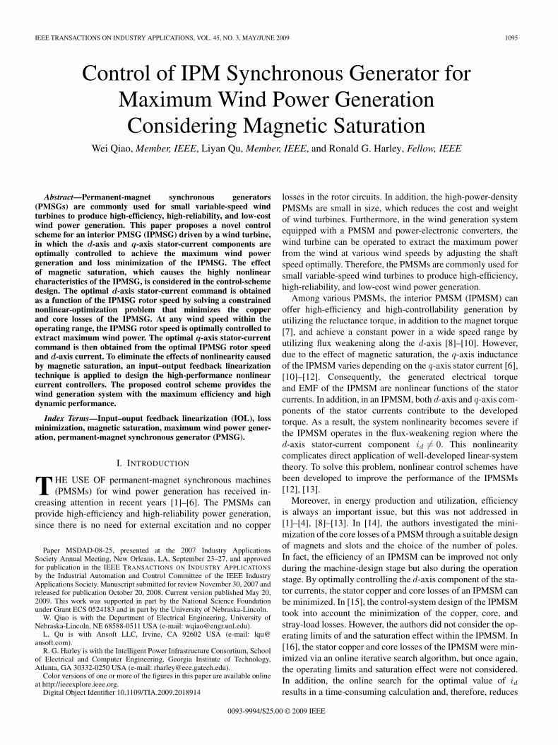
Fig. 1. Basic configuration of an IPMSG driven by a wind turbine.
the overall control-system performance. In [17], an onlineminimum-copper-loss control was proposed for an IPMSM, butthe core loss was not minimized.
In [6], the authors proposed an output maximization controlfor a variable-speed wind generation system using an IPMSMbut without closed-loop speed control. Both the optimal d-axisand q-axis stator-current commands were obtained as functionsof the generator speed to achieve loss minimization and maxi-mum wind power tracking. However, since there was no close-loop speed control, the maximum power point may not be ableto be accurately tracked due to parameter variations in the realsystem operation. In addition, the effect of magnetic saturationon the dynamic performance and control of the IPMSM wasnot addressed. To achieve optimal power efficiency and dy-namic performance of the IPMSM, magnetic saturation mustbe considered in designing the IPMSM controllers for torqueand current control.
This paper proposes a novel control scheme for an interiorPM synchronous generator (IPMSG) to achieve the maximumwind power generation in a variable-speed wind-power-generation system. The d-axis and q-axis stator-currentcomponents of the IPMSG are suitably controlled accordingto the IPMSG rotor speed in order to extract the maximumwind power at various wind speeds as well as to minimize thestator copper and core losses in the IPMSG. The optimal d-axisstator-current command is obtained as a function of the IPMSGrotor speed by solving a constrained nonlinear-optimizationproblem, which maximizes the efficiency while consideringmagnetic saturation as well as the voltage and current limitsof the IPMSG. A speed controller is designed to generatethe optimal torque commands for the IPMSG in order toextract maximum wind power at various wind speeds. Theoptimal q-axis stator-current commands are then obtainedfrom the optimal torque and d-axis current commands. Byadjusting the shaft speed optimally, using the close-loopspeed control, the maximum power point can be accuratelytracked at various wind speeds. To eliminate the effects of non-linearity caused by magnetic saturation, an input–outputfeedback linearization (IOL) technique [18] is applied to designthe high-performance nonlinear current controllers. Theproposed control scheme improves the efficiency and dynamicperformance of the wind generation system.
II. WIND TURBINE GENERATOR (WTG) SYSTEM
Fig. 1 shows the basic configuration of an IPMSG driven by awind turbine. The IPMSG converts the mechanical power fromthe wind turbine to ac electrical power, which is then converted
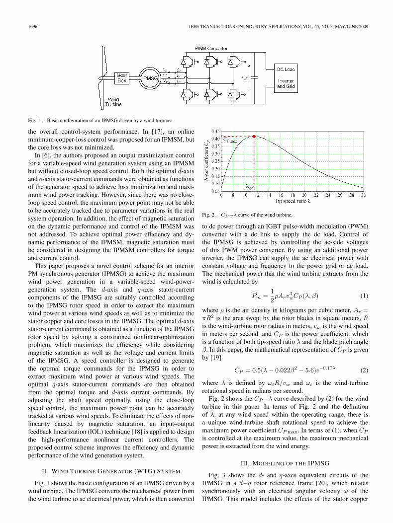
Fig. 2. CP−λ curve of the wind turbine.
to dc power through an IGBT pulse-width modulation (PWM)converter with a dc link to supply the dc load. Control ofthe IPMSG is achieved by controlling the ac-side voltagesof this PWM power converter. By using an additional powerinverter, the IPMSG can supply the ac electrical power withconstant voltage and frequency to the power grid or ac load.The mechanical power that the wind turbine extracts from thewind is calculated by
Pm =12ρArv
3wCP (λ, β) (1)
where ρ is the air density in kilograms per cubic meter, Ar =πR2 is the area swept by the rotor blades in square meters, Ris the wind-turbine rotor radius in meters, vw is the wind speedin meters per second, and CP is the power coefficient, whichis a function of both tip-speed ratio λ and the blade pitch angleβ. In this paper, the mathematical representation of CP is givenby [19]
CP = 0.5(λ− 0.022β2 − 5.6)e−0.17λ (2)
where λ is defined by ωtR/vw and ωt is the wind-turbinerotational speed in radians per second.
Fig. 2 shows the CP−λ curve described by (2) for the windturbine in this paper. In terms of Fig. 2 and the definitionof λ, at any wind speed within the operating range, there isa unique wind-turbine shaft rotational speed to achieve themaximum power coefficient CP max. In terms of (1), when CP
is controlled at the maximum value, the maximum mechanicalpower is extracted from the wind energy.
III. MODELING OF THE IPMSG
Fig. 3 shows the d- and q-axes equivalent circuits of theIPMSG in a d−q rotor reference frame [20], which rotatessynchronously with an electrical angular velocity ω of theIPMSG. This model includes the effects of the stator copper
QIAO et al.: CONTROL OF IPMSG FOR WIND POWER GENERATION CONSIDERING MAGNETIC SATURATION 1097
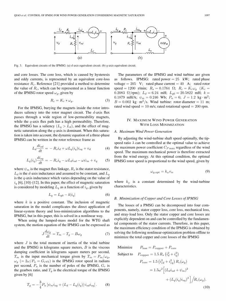
Fig. 3. Equivalent circuits of the IPMSG. (a) d-axis equivalent circuit. (b) q-axis equivalent circuit.
and core losses. The core loss, which is caused by hysteresisand eddy currents, is represented by an equivalent core-lossresistance Rc. Reference [21] provided a method to determinethe value of Rc, which can be represented as a linear functionof the IPMSG rotor speed ωg , given by
Rc = Kr ∗ ωg. (3)
For the IPMSG, burying the magnets inside the rotor intro-duces saliency into the rotor magnet circuit. The d-axis fluxpasses through a wide region of low-permeability magnets,while the q-axis flux path has a high permeability. Therefore,the IPMSG has a saliency (Lq > Ld), and the effect of mag-netic saturation along the q-axis is dominant. When this satura-tion is taken into account, the dynamic equation of a three-phaseIPMSG can be written in the rotor reference frame as
Lddiod
dt= −Rsid + ωLq(iq)ioq + vd (4)
Lq(iq)dioq
dt= −Rsiq − ωLdiod − ωψm + vq (5)
where ψm is the magnet flux linkage,Rs is the stator resistance,Ld is the d-axis inductance and assumed to be constant, and Lq
is the q-axis inductance which varies depending on the value ofiq [6], [10]–[12]. In this paper, the effect of magnetic saturationis considered by modeling Lq as a function of iq , given by
Lq = Lq0 − k|iq| (6)
where k is a positive constant. The inclusion of magneticsaturation in the model complicates the direct application oflinear-system theory and loss-minimization algorithms to theIPMSG, but in this paper, this is solved in a nonlinear way.
When using the lumped-mass model for the WTG shaftsystem, the motion equation of the IPMSG can be expressed as
Jdωg
dt= Tm − Tg −Bωg (7)
where J is the total moment of inertia of the wind turbineand the IPMSG in kilograms square meters, B is the viscousdamping coefficient in kilograms square meters per second,Tm is the input mechanical torque given by Tm = Pm/ωg ,ωg (= 2ω/Pn = Grωt) is the IPMSG rotor speed in radiansper second, Pn is the number of poles of the IPMSG, Gr isthe gearbox ratio, and Tg is the electrical torque of the IPMSGgiven by [6]
Tg = −34Pn [ψmioq + (Ld − Lq(iq)) iodioq] . (8)
The parameters of the IPMSG and wind turbine are givenas follows. IPMSG: rated power = 25 kW; rated phasevoltage = 205 V; rated phase current = 40 A; rated rotorspeed = 1200 r/min; Rs = 0.1764 Ω; Rc = Krωg (Kr =0.2083 Ω/rpm); Ld = 6.24 mH; Lq0 = 20.5822 mH; k =0.1879 mH/A; ψm = 0.246 Wb; Pn = 6; J = 1.2 kg · m2;B = 0.002 kg · m2/s. Wind turbine: rotor diameter = 11 m;rated wind speed = 10 m/s; rated rotational speed = 200 rpm.
IV. MAXIMUM WIND POWER GENERATION
WITH LOSS MINIMIZATION
A. Maximum Wind Power Generation
By adjusting the wind-turbine shaft speed optimally, the tip-speed ratio λ can be controlled at the optimal value to achievethe maximum power coefficient CP max regardless of the windspeed. The maximum mechanical power is therefore extractedfrom the wind energy. At this optimal condition, the optimalIPMSG rotor speed is proportional to the wind speed, given by
ωg,opt = kωvw (9)
where kω is a constant determined by the wind-turbinecharacteristics.
B. Minimization of Copper and Core Losses of IPMSG
The losses of a PMSG can be decomposed into four com-ponents, namely, stator copper loss, core loss, mechanical loss,and stray-load loss. Only the stator copper and core losses areexplicitly dependent on and can be controlled by the fundamen-tal components of the stator currents. Therefore, in this paper,the maximum efficiency condition of the IPMSG is obtained bysolving the following nonlinear-optimization problem offline tominimize the total copper and core losses of the IPMSG
Minimize Ploss = Pcopper + Pcore
Subject to Pcopper = 1.5Rs
(i2d + i2q
)Pcore = 1.5
(i2cd + i2cq
)Rc(ωg)
= 1.5ω2[(Ldiod + ψm)2
+ (Lq(iq)ioq)2]/Rc(ωg).
(10)
1098 IEEE TRANSACTIONS ON INDUSTRY APPLICATIONS, VOL. 45, NO. 3, MAY/JUNE 2009
Equations (1)–(3), (6), and (8)
vd = Rsid − ωLq(iq)ioq
vq = Rsiq + ωLdiod + ωψm
iod = id − (vd −Rsid)/Rc(ωg)
ioq = iq − (vq −Rsiq)/Rc(ωg)
Tm − Tg −Bωg = 0
Tm = Pm/ωg
ω = Pnωg/2
i2d + i2q ≤ I2M
v2d + v2
q ≤ V 2M
where Pcopper is the copper loss, Pcore is the core loss [6], andIM and VM are the maximum current and voltage, respectively,of the IPMSG.
Given an optimal IPMSG rotor speed [calculated by (9)], thesolutions of the nonlinear-optimization problem (10) yield theoptimal values of id and iq , which minimize the total copperand core losses of the IPMSG. Therefore, at any wind speed,the solutions of (9) and (10) provide the desired optimal IPMSGrotor speed, optimal currents id and iq to achieve the maximumwind power extraction, and loss minimization of the IPMSG.Without considering the effect of magnetic saturation (i.e., Lq
is constant) and the variation ofRc, (10) would be a constrainednonlinear quadric optimization problem that can be solvedby conventional nonlinear-optimization methods. However, theinclusion of magnetic saturation and variation of Rc resultsin a complex nonlinear-optimization problem that requires ex-tensive computation effort when using conventional nonlinear-optimization methods. In this paper, a stochastic optimizationtechnique—particle swarm optimization (PSO) [22], [23]—isemployed to obtain the optimal solution of (10).
C. PSO
PSO is a population-based stochastic optimization technique.It searches for the optimal solution from a population of movingparticles. Each particle represents a potential solution and hasa position (vector xi) and a velocity (vector vi) in the problemspace. Each particle keeps track of its individual best positionxi,pbest, which is associated with the best fitness it has achievedso far, at any step in the solution. Moreover, the best positionamong all the particles obtained so far in the swarm is kepttrack of as xgbest. This information is shared by all particles.The PSO algorithm is implemented in the following iterativeprocedure to search for the optimal solution.
1) Initialize a population of particles with random positionsand velocities of M dimensions in the problem space.
2) Define a fitness-measure function to evaluate the perfor-mance of each particle.
3) Compare each particle’s present position xi with itsxi,pbest based on the fitness evaluation. If the currentposition xi is better than xi,pbest, then set xi,pbest = xi.
4) If xi,pbest is updated, then compare each particle’sxi,pbest with the swarm best position xgbest based on the
fitness evaluation. If xi,pbest is better than xgbest, then setxgbest = xi,pbest.
5) At iteration k, the velocity of each particle is updated by
vi(k + 1) = w · vi(k) + c1φ1 (xi,pbest(k) − xi(k))
+c2φ2 (xgbest(k) − xi(k)) , i = 1, 2, . . . , N.
(11)
6) Based on the updated velocity, each particle then changesits position by
xi(k + 1) = xi(k) + vi(k + 1), i = 1, 2, . . . , N. (12)
7) Repeat steps 3)–6) until a criterion, usually a sufficientlygood fitness or a maximum number of iterations, isachieved. The final value of xgbest is regarded as theoptimal solution of the problem.
In (11), c1 and c2 are positive constants representing theweighting of the acceleration terms that guide each particletoward the individual best and the swarm best positions, xi,pbest
and xgbest, respectively; φ1 and φ2 are uniformly distributedrandom numbers in [0, 1]; w is a positive inertia weightdeveloped to provide better control between exploration andexploitation; N is the number of particles in the swarm. Thelast two terms in (11) enable each particle to perform a localsearch around its individual best position xi,pbest and theswarm best position xgbest. The first term in (11) enables eachparticle to perform a global search by exploring a new searchspace.
Because of many attractive features, e.g., multiagent search,simple implementation, small computational load, and fastconvergence, the PSO algorithm can provide a fast and efficientsearch for the optimal solution. These features provide PSOwith superior performance over other evolutionary computationalgorithms (e.g., genetic algorithms) in many applications. Inaddition, for many complex optimization problems that aredifficult to formulate mathematically or to solve by traditionaloptimization methods, PSO is efficient to find the optimalsolution.
D. Optimal d-axis and q-axis Stator Currents of IPMSG
In this paper, the values of the PSO parameters are chosenas follows: c1 = c2 = 2, N = 20, and w = 1.4 − (1.4 − 0.4) ·k/K, where k is the iteration number and K is the maximumnumber of iterations. The PSO algorithm only performs a 1-Dsearch for the optimal value of iq. The optimal value of id isdetermined by the torque equation (8) and the correspondingoptimal value of iq , where the electrical torque Tg in (8) isdetermined by (9) and the constraint equations of (10). Thefitness-measure function is simply the total copper and corelosses Ploss of the IPMSG. It is calculated by the first twoconstraint equations of (10).
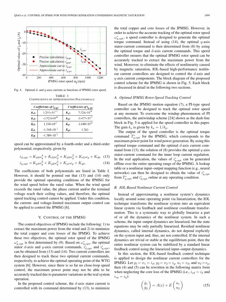
By solving the nonlinear-optimization problem (10) at var-ious IPMSG rotor speeds, the optimal values of id and iq areobtained and shown as functions of the IPMSG rotor speedωg in Fig. 4. The relationship between the optimal d-axisand q-axis stator-current components and the IPMSG rotor
QIAO et al.: CONTROL OF IPMSG FOR WIND POWER GENERATION CONSIDERING MAGNETIC SATURATION 1099
Fig. 4. Optimal d- and q-axes currents as functions of IPMSG rotor speed.
TABLE ICOEFFICIENTS OF APPROXIMATING POLYNOMIALS
speed can be approximated by a fourth-order and a third-orderpolynomial, respectively, given by
id,opt =Kd4ω4g +Kd3ω
3g +Kd2ω
2g +Kd1ωg +Kd0 (13)
iq,opt =Kq3ω3g +Kq2ω
2g +Kq1ωg +Kq0. (14)
The coefficients of both polynomials are listed in Table I.However, it should be pointed out that (13) and (14) onlyprovide the optimal operating conditions of the IPMSG forthe wind speed below the rated value. When the wind speedexceeds the rated value, the phase current and/or the terminalvoltage reach their ceiling values, and therefore, the optimalspeed tracking control cannot be applied. Under this condition,the current- and voltage-limited maximum output control canbe applied to control the IPMSG [6].
V. CONTROL OF THE IPMSG
The control objectives of IPMSG include the following: 1) toextract the maximum power from the wind and 2) to minimizethe total copper and core losses of the IPMSG. To achievethese two objectives, the optimal rotor speed of the IPMSGω∗
g,opt is first determined by (9). Based on ω∗g,opt, the optimal
stator d-axis and q-axis current commands, i∗d,opt and i∗q,opt,can be obtained from (13) and (14). Two current controllers arethen designed to track these two optimal current commands,respectively, to achieve the optimal operating point of the WTGsystem [6]. However, since there is so far no close-loop speedcontrol, the maximum power point may not be able to beaccurately tracked due to parameter variations in the real systemoperation.
In the proposed control scheme, the d-axis stator current iscontrolled with its command determined by (13), to minimize
the total copper and core losses of the IPMSG. However, inorder to achieve the accurate tracking of the optimal rotor speedω∗
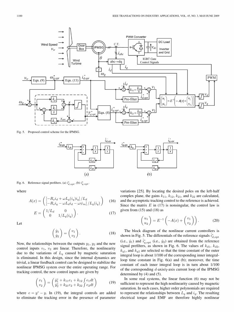
g,opt, a speed controller is designed to generate the optimaltorque command. Instead of using (14), the optimal q-axisstator-current command is then determined from (8) by usingthe optimal torque and d-axis current commands. This speedcontroller ensures that the optimal IPMSG rotor speed can beaccurately tracked to extract the maximum power from thewind. Moreover, to eliminate the effects of nonlinearity causedby magnetic saturation, IOL-based high-performance nonlin-ear current controllers are designed to control the d-axis andq-axis current components. The block diagram of the proposedcontrol scheme for the IPMSG is shown in Fig. 5. Each blockis discussed in detail in the following two sections.
A. Optimal IPMSG Rotor-Speed Tracking Control
Based on the IPMSG motion equation (7), a PI-type speedcontroller can be designed to track the optimal rotor speedat any moment. To overcome the windup phenomenon of PIcontrollers, the antiwindup scheme [24] shown as the dash-lineblock in Fig. 5 is applied for the speed controller in this paper.The gain ka is given by ka = 1/kp.
The output of the speed controller is the optimal torquecommand T ∗
g,opt for the IPMSG, which corresponds to themaximum power point for wind power generation. By using thisoptimal torque command and the optimal d-axis current com-mand from (13), the solution of (8) provides the optimal q-axisstator-current command for the inner loop current regulation.In the real application, the values of i∗q,opt can be generatedoffline over the entire operating range of the IPMSG. A lookuptable or a nonlinear input–output mapping function (e.g., neuralnetworks) can then be designed to obtain the value of i∗q,opt
from T ∗g,opt and i∗d,opt online at any operating condition.
B. IOL-Based Nonlinear Current Control
Instead of approximating a nonlinear system’s dynamicslocally around some operating point via linearization, the IOLtechnique transforms the nonlinear system into an equivalentlinear system via feedback and nonlinear coordinate transfor-mation. This is a systematic way to globally linearize a partof or all the dynamics of the nonlinear system. In such ascheme, the input–output dynamics are linearized, but the stateequations may be only partially linearized. Residual nonlineardynamics, called internal dynamics, do not depend explicitlyon the system input and, thus, are not controlled. If the internaldynamics are trivial or stable at the equilibrium point, then theentire nonlinear system can be stabilized by a standard linearfeedback control using the linearized input–output dynamics.
In this section, the IOL-based feedback control techniqueis applied to design the nonlinear current controllers for theIPMSG. Let y1 = x1 = id, y2 = x2 = iq, u1 = vd, and u2 =vq,then (4) and (5) can be rewritten in the following matrix formwhen neglecting the core loss of the IPMSG (i.e., iod = id andioq = iq): (
y1y2
)= A(x) + E
(u1
u2
)(15)
1100 IEEE TRANSACTIONS ON INDUSTRY APPLICATIONS, VOL. 45, NO. 3, MAY/JUNE 2009
Fig. 5. Proposed control scheme for the IPMSG.
Fig. 6. Reference signal prefilters. (a) i∗d,opt. (b) i∗q,opt.
where
A(x) =(
[−Rsid + ωLq(iq)iq] /Ld
[−Rsiq − ωLdid − ωψm] /Lq(iq)
)(16)
E =(
1/Ld 00 1/Lq(iq)
). (17)
Let (y1y2
)=
(v1v2
). (18)
Now, the relationships between the outputs y1, y2 and the newcontrol inputs v1, v2 are linear. Therefore, the nonlinearitydue to the variations of Lq caused by magnetic saturationis eliminated. In this design, since the internal dynamics aretrivial, a linear feedback control can be designed to stabilize thenonlinear IPMSG system over the entire operating range. Fortracking control, the new control inputs are given by
(v1v2
)=
(y∗1 + k11e1 + k12
∫e1dt
y∗2 + k21e2 + k22
∫e2dt
)(19)
where e = y∗ − y. In (19), the integral controls are addedto eliminate the tracking error in the presence of parameter
variations [25]. By locating the desired poles on the left-halfcomplex plane, the gains k11, k12, k21, and k22 are calculated,and the asymptotic tracking control to the reference is achieved.Since the matrix E in (17) is nonsingular, the control law isgiven from (15) and (18) as
(u1
u2
)= E−1
(−A(x) +
(v1v2
)). (20)
The block diagram of the nonlinear current controllers isshown in Fig. 5. The differentials of the reference signals i∗d,opt
(i.e., y1) and i∗q,opt (i.e., y2) are obtained from the referencesignal prefilters, as shown in Fig. 6. The values of kd1, kd2,kq1, and kq2 are selected so that the time constant of the outerintegral loop is about 1/100 of the corresponding inner integral-loop time constant in Fig. 6(a) and (b); moreover, the timeconstant of each inner integral loop is in turn about 1/100of the corresponding d-axis/q-axis current loop of the IPMSGdetermined by (4) and (5).
In some real systems, the linear function (6) may not besufficient to represent the high nonlinearity caused by magneticsaturation. In such cases, higher order polynomials are requiredto represent the relationships between Lq and iq. The resultingelectrical torque and EMF are therefore highly nonlinear
QIAO et al.: CONTROL OF IPMSG FOR WIND POWER GENERATION CONSIDERING MAGNETIC SATURATION 1101
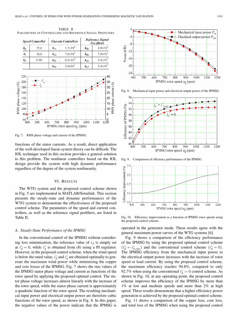
TABLE IIPARAMETERS OF CONTROLLERS AND REFERENCE SIGNAL PREFILTERS
Fig. 7. RMS phase voltage and current of the IPMSG.
functions of the stator currents. As a result, direct applicationof the well-developed linear-system theory can be difficult. TheIOL technique used in this section provides a general solutionto this problem. The nonlinear controllers based on the IOLdesign provide the system with high dynamic performanceregardless of the degree of the system nonlinearity.
VI. RESULTS
The WTG system and the proposed control scheme shownin Fig. 5 are implemented in MATLAB/Simulink. This sectionpresents the steady-state and dynamic performances of theWTG system to demonstrate the effectiveness of the proposedcontrol scheme. The parameters of the speed and current con-trollers, as well as the reference signal prefilters, are listed inTable II.
A. Steady-State Performance of the IPMSG
In the conventional control of the IPMSG without consider-ing loss minimization, the reference value of id is simply setat i∗d = 0, while i∗q is obtained from (8) using a PI regulator.However, in the proposed control scheme, when the wind speedis below the rated value, i∗d and i∗q are obtained optimally to gen-erate the maximum wind power while minimizing the copperand core losses of the IPMSG. Fig. 7 shows the rms values ofthe IPMSG stator phase voltage and current as functions of therotor speed by applying the proposed optimal control. The sta-tor phase voltage increases almost linearly with the increase ofthe rotor speed, while the stator phase current is approximatelya quadratic function of the rotor speed. The resulting mechani-cal input power and electrical output power are therefore cubicfunctions of the rotor speed, as shown in Fig. 8. In this paper,the negative values of the power indicate that the IPMSG is
Fig. 8. Mechanical input power and electrical output power of the IPMSG.
Fig. 9. Comparison of efficiency performance of the IPMSG.
Fig. 10. Efficiency improvement as a function of IPMSG rotor speeds usingthe proposed control scheme.
operated in the generator mode. These results agree with thegeneral maximum power curves of the WTG systems [6].
Fig. 9 shows a comparison of the efficiency performanceof the IPMSG by using the proposed optimal control scheme(i∗d = i∗d,opt) and the conventional control scheme (i∗d = 0).The IPMSG efficiency from the mechanical input power tothe electrical output power increases with the increase of rotorspeed or load current. By using the proposed control scheme,the maximum efficiency reaches 94.8%, compared to only92.7% when using the conventional i∗d = 0 control scheme. Asshown in Fig. 10, at any operating point, the proposed controlscheme improves the efficiency of the IPMSG by more than1% at low and medium speeds and more than 2% at highspeed. These results demonstrate that a higher efficiency powergeneration is achieved by the proposed optimal control scheme.
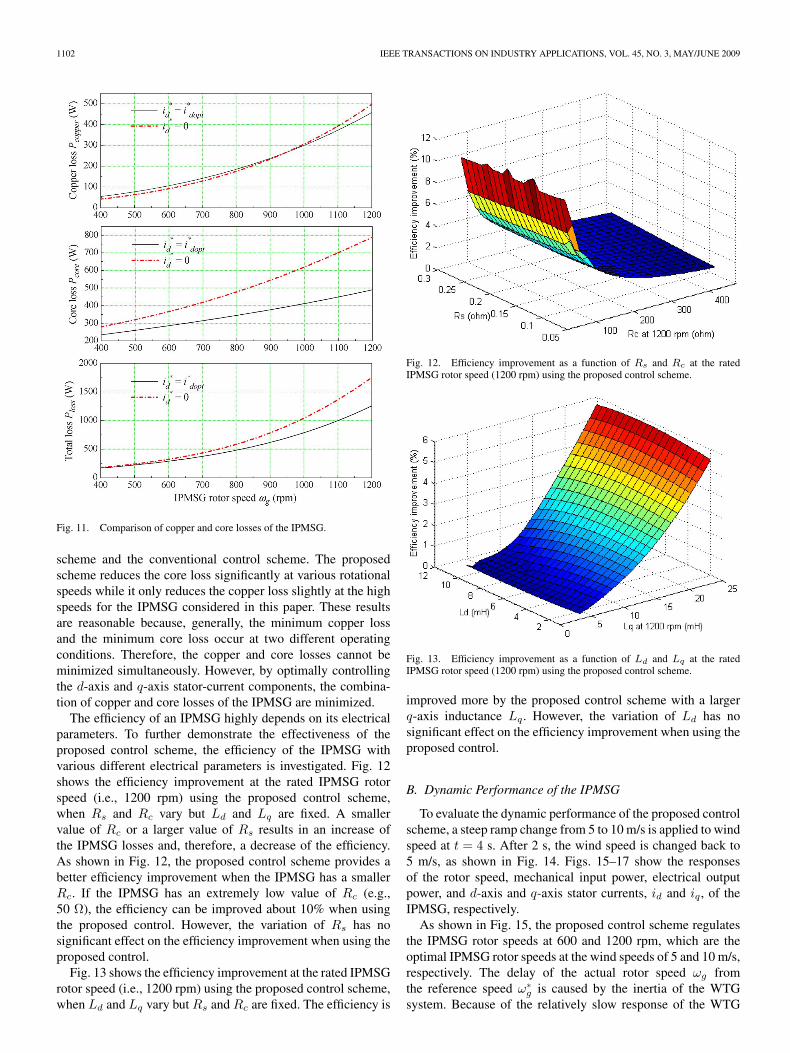
Fig. 11 shows a comparison of the copper loss, core loss,and total loss of the IPMSG when using the proposed control
1102 IEEE TRANSACTIONS ON INDUSTRY APPLICATIONS, VOL. 45, NO. 3, MAY/JUNE 2009
Fig. 11. Comparison of copper and core losses of the IPMSG.
scheme and the conventional control scheme. The proposedscheme reduces the core loss significantly at various rotationalspeeds while it only reduces the copper loss slightly at the highspeeds for the IPMSG considered in this paper. These resultsare reasonable because, generally, the minimum copper lossand the minimum core loss occur at two different operatingconditions. Therefore, the copper and core losses cannot beminimized simultaneously. However, by optimally controllingthe d-axis and q-axis stator-current components, the combina-tion of copper and core losses of the IPMSG are minimized.
The efficiency of an IPMSG highly depends on its electricalparameters. To further demonstrate the effectiveness of theproposed control scheme, the efficiency of the IPMSG withvarious different electrical parameters is investigated. Fig. 12shows the efficiency improvement at the rated IPMSG rotorspeed (i.e., 1200 rpm) using the proposed control scheme,when Rs and Rc vary but Ld and Lq are fixed. A smallervalue of Rc or a larger value of Rs results in an increase ofthe IPMSG losses and, therefore, a decrease of the efficiency.As shown in Fig. 12, the proposed control scheme provides abetter efficiency improvement when the IPMSG has a smallerRc. If the IPMSG has an extremely low value of Rc (e.g.,50 Ω), the efficiency can be improved about 10% when usingthe proposed control. However, the variation of Rs has nosignificant effect on the efficiency improvement when using theproposed control.
Fig. 13 shows the efficiency improvement at the rated IPMSGrotor speed (i.e., 1200 rpm) using the proposed control scheme,when Ld and Lq vary but Rs and Rc are fixed. The efficiency is
Fig. 12. Efficiency improvement as a function of Rs and Rc at the ratedIPMSG rotor speed (1200 rpm) using the proposed control scheme.
Fig. 13. Efficiency improvement as a function of Ld and Lq at the ratedIPMSG rotor speed (1200 rpm) using the proposed control scheme.
improved more by the proposed control scheme with a largerq-axis inductance Lq. However, the variation of Ld has nosignificant effect on the efficiency improvement when using theproposed control.
B. Dynamic Performance of the IPMSG
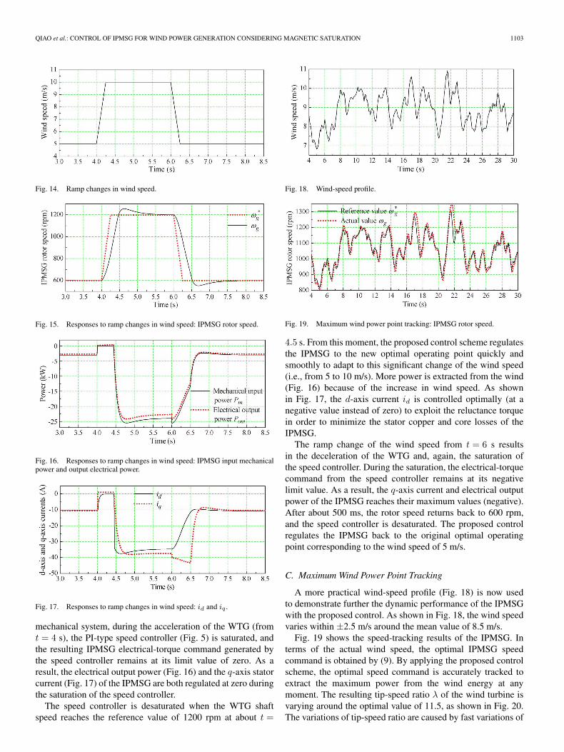
To evaluate the dynamic performance of the proposed controlscheme, a steep ramp change from 5 to 10 m/s is applied to windspeed at t = 4 s. After 2 s, the wind speed is changed back to5 m/s, as shown in Fig. 14. Figs. 15–17 show the responsesof the rotor speed, mechanical input power, electrical outputpower, and d-axis and q-axis stator currents, id and iq , of theIPMSG, respectively.
As shown in Fig. 15, the proposed control scheme regulatesthe IPMSG rotor speeds at 600 and 1200 rpm, which are theoptimal IPMSG rotor speeds at the wind speeds of 5 and 10 m/s,respectively. The delay of the actual rotor speed ωg fromthe reference speed ω∗
g is caused by the inertia of the WTGsystem. Because of the relatively slow response of the WTG
QIAO et al.: CONTROL OF IPMSG FOR WIND POWER GENERATION CONSIDERING MAGNETIC SATURATION 1103
Fig. 14. Ramp changes in wind speed.
Fig. 15. Responses to ramp changes in wind speed: IPMSG rotor speed.
Fig. 16. Responses to ramp changes in wind speed: IPMSG input mechanicalpower and output electrical power.
Fig. 17. Responses to ramp changes in wind speed: id and iq .
mechanical system, during the acceleration of the WTG (fromt = 4 s), the PI-type speed controller (Fig. 5) is saturated, andthe resulting IPMSG electrical-torque command generated bythe speed controller remains at its limit value of zero. As aresult, the electrical output power (Fig. 16) and the q-axis statorcurrent (Fig. 17) of the IPMSG are both regulated at zero duringthe saturation of the speed controller.
The speed controller is desaturated when the WTG shaftspeed reaches the reference value of 1200 rpm at about t =
Fig. 18. Wind-speed profile.
Fig. 19. Maximum wind power point tracking: IPMSG rotor speed.
4.5 s. From this moment, the proposed control scheme regulatesthe IPMSG to the new optimal operating point quickly andsmoothly to adapt to this significant change of the wind speed(i.e., from 5 to 10 m/s). More power is extracted from the wind(Fig. 16) because of the increase in wind speed. As shownin Fig. 17, the d-axis current id is controlled optimally (at anegative value instead of zero) to exploit the reluctance torquein order to minimize the stator copper and core losses of theIPMSG.
The ramp change of the wind speed from t = 6 s resultsin the deceleration of the WTG and, again, the saturation ofthe speed controller. During the saturation, the electrical-torquecommand from the speed controller remains at its negativelimit value. As a result, the q-axis current and electrical outputpower of the IPMSG reaches their maximum values (negative).After about 500 ms, the rotor speed returns back to 600 rpm,and the speed controller is desaturated. The proposed controlregulates the IPMSG back to the original optimal operatingpoint corresponding to the wind speed of 5 m/s.
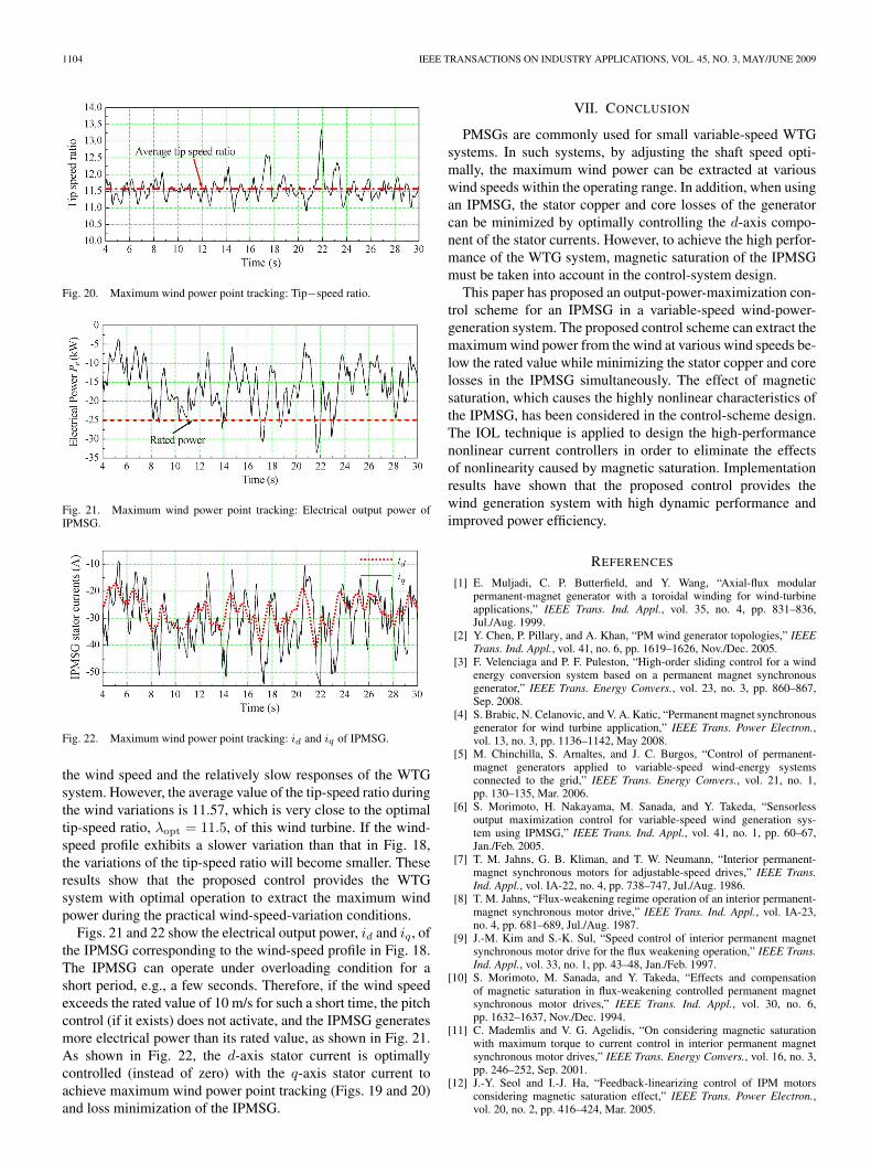
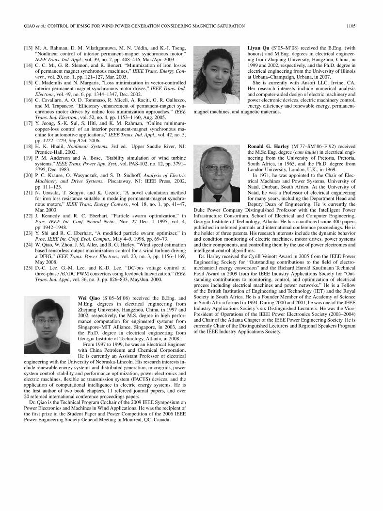
C. Maximum Wind Power Point Tracking
A more practical wind-speed profile (Fig. 18) is now usedto demonstrate further the dynamic performance of the IPMSGwith the proposed control. As shown in Fig. 18, the wind speedvaries within ±2.5 m/s around the mean value of 8.5 m/s.
Fig. 19 shows the speed-tracking results of the IPMSG. Interms of the actual wind speed, the optimal IPMSG speedcommand is obtained by (9). By applying the proposed controlscheme, the optimal speed command is accurately tracked toextract the maximum power from the wind energy at anymoment. The resulting tip-speed ratio λ of the wind turbine isvarying around the optimal value of 11.5, as shown in Fig. 20.The variations of tip-speed ratio are caused by fast variations of
1104 IEEE TRANSACTIONS ON INDUSTRY APPLICATIONS, VOL. 45, NO. 3, MAY/JUNE 2009
Fig. 20. Maximum wind power point tracking: Tip−speed ratio.
Fig. 21. Maximum wind power point tracking: Electrical output power ofIPMSG.
Fig. 22. Maximum wind power point tracking: id and iq of IPMSG.
the wind speed and the relatively slow responses of the WTGsystem. However, the average value of the tip-speed ratio duringthe wind variations is 11.57, which is very close to the optimaltip-speed ratio, λopt = 11.5, of this wind turbine. If the wind-speed profile exhibits a slower variation than that in Fig. 18,the variations of the tip-speed ratio will become smaller. Theseresults show that the proposed control provides the WTGsystem with optimal operation to extract the maximum windpower during the practical wind-speed-variation conditions.
Figs. 21 and 22 show the electrical output power, id and iq, ofthe IPMSG corresponding to the wind-speed profile in Fig. 18.The IPMSG can operate under overloading condition for ashort period, e.g., a few seconds. Therefore, if the wind speedexceeds the rated value of 10 m/s for such a short time, the pitchcontrol (if it exists) does not activate, and the IPMSG generatesmore electrical power than its rated value, as shown in Fig. 21.As shown in Fig. 22, the d-axis stator current is optimallycontrolled (instead of zero) with the q-axis stator current toachieve maximum wind power point tracking (Figs. 19 and 20)and loss minimization of the IPMSG.
VII. CONCLUSION
PMSGs are commonly used for small variable-speed WTGsystems. In such systems, by adjusting the shaft speed opti-mally, the maximum wind power can be extracted at variouswind speeds within the operating range. In addition, when usingan IPMSG, the stator copper and core losses of the generatorcan be minimized by optimally controlling the d-axis compo-nent of the stator currents. However, to achieve the high perfor-mance of the WTG system, magnetic saturation of the IPMSGmust be taken into account in the control-system design.
This paper has proposed an output-power-maximization con-trol scheme for an IPMSG in a variable-speed wind-power-generation system. The proposed control scheme can extract themaximum wind power from the wind at various wind speeds be-low the rated value while minimizing the stator copper and corelosses in the IPMSG simultaneously. The effect of magneticsaturation, which causes the highly nonlinear characteristics ofthe IPMSG, has been considered in the control-scheme design.The IOL technique is applied to design the high-performancenonlinear current controllers in order to eliminate the effectsof nonlinearity caused by magnetic saturation. Implementationresults have shown that the proposed control provides thewind generation system with high dynamic performance andimproved power efficiency.
REFERENCES
[1] E. Muljadi, C. P. Butterfield, and Y. Wang, “Axial-flux modularpermanent-magnet generator with a toroidal winding for wind-turbineapplications,” IEEE Trans. Ind. Appl., vol. 35, no. 4, pp. 831–836,Jul./Aug. 1999.
[2] Y. Chen, P. Pillary, and A. Khan, “PM wind generator topologies,” IEEETrans. Ind. Appl., vol. 41, no. 6, pp. 1619–1626, Nov./Dec. 2005.
[3] F. Velenciaga and P. F. Puleston, “High-order sliding control for a windenergy conversion system based on a permanent magnet synchronousgenerator,” IEEE Trans. Energy Convers., vol. 23, no. 3, pp. 860–867,Sep. 2008.
[4] S. Brabic, N. Celanovic, and V. A. Katic, “Permanent magnet synchronousgenerator for wind turbine application,” IEEE Trans. Power Electron.,vol. 13, no. 3, pp. 1136–1142, May 2008.
[5] M. Chinchilla, S. Arnaltes, and J. C. Burgos, “Control of permanent-magnet generators applied to variable-speed wind-energy systemsconnected to the grid,” IEEE Trans. Energy Convers., vol. 21, no. 1,pp. 130–135, Mar. 2006.
[6] S. Morimoto, H. Nakayama, M. Sanada, and Y. Takeda, “Sensorlessoutput maximization control for variable-speed wind generation sys-tem using IPMSG,” IEEE Trans. Ind. Appl., vol. 41, no. 1, pp. 60–67,Jan./Feb. 2005.
[7] T. M. Jahns, G. B. Kliman, and T. W. Neumann, “Interior permanent-magnet synchronous motors for adjustable-speed drives,” IEEE Trans.Ind. Appl., vol. IA-22, no. 4, pp. 738–747, Jul./Aug. 1986.
[8] T. M. Jahns, “Flux-weakening regime operation of an interior permanent-magnet synchronous motor drive,” IEEE Trans. Ind. Appl., vol. IA-23,no. 4, pp. 681–689, Jul./Aug. 1987.
[9] J.-M. Kim and S.-K. Sul, “Speed control of interior permanent magnetsynchronous motor drive for the flux weakening operation,” IEEE Trans.Ind. Appl., vol. 33, no. 1, pp. 43–48, Jan./Feb. 1997.
[10] S. Morimoto, M. Sanada, and Y. Takeda, “Effects and compensationof magnetic saturation in flux-weakening controlled permanent magnetsynchronous motor drives,” IEEE Trans. Ind. Appl., vol. 30, no. 6,pp. 1632–1637, Nov./Dec. 1994.
[11] C. Mademlis and V. G. Agelidis, “On considering magnetic saturationwith maximum torque to current control in interior permanent magnetsynchronous motor drives,” IEEE Trans. Energy Convers., vol. 16, no. 3,pp. 246–252, Sep. 2001.
[12] J.-Y. Seol and I.-J. Ha, “Feedback-linearizing control of IPM motorsconsidering magnetic saturation effect,” IEEE Trans. Power Electron.,vol. 20, no. 2, pp. 416–424, Mar. 2005.
QIAO et al.: CONTROL OF IPMSG FOR WIND POWER GENERATION CONSIDERING MAGNETIC SATURATION 1105
[13] M. A. Rahman, D. M. Vilathgamuwa, M. N. Uddin, and K.-J. Tseng,“Nonlinear control of interior permanent-magnet synchronous motor,”IEEE Trans. Ind. Appl., vol. 39, no. 2, pp. 408–416, Mar./Apr. 2003.
[14] C. C. Mi, G. R. Slemon, and R. Bonert, “Minimization of iron lossesof permanent magnet synchronous machines,” IEEE Trans. Energy Con-vers., vol. 20, no. 1, pp. 121–127, Mar. 2005.
[15] C. Mademlis and N. Margaris, “Loss minimization in vector-controlledinterior permanent-magnet synchronous motor drives,” IEEE Trans. Ind.Electron., vol. 49, no. 6, pp. 1344–1347, Dec. 2002.
[16] C. Cavallaro, A. O. D. Tommaso, R. Miceli, A. Raciti, G. R. Galluzzo,and M. Trapanese, “Efficiency enhancement of permanent-magnet syn-chronous motor drives by online loss minimization approaches,” IEEETrans. Ind. Electron., vol. 52, no. 4, pp. 1153–1160, Aug. 2005.
[17] Y. Jeong, S.-K. Sul, S. Hiti, and K. M. Rahman, “Online minimum-copper-loss control of an interior permanent-magnet synchronous ma-chine for automotive applications,” IEEE Trans. Ind. Appl., vol. 42, no. 5,pp. 1222–1229, Sep./Oct. 2006.
[18] H. K. Hhalil, Nonlinear Systems, 3rd ed. Upper Saddle River, NJ:Prentice-Hall, 2002.
[19] P. M. Anderson and A. Bose, “Stability simulation of wind turbinesystems,” IEEE Trans. Power App. Syst., vol. PAS-102, no. 12, pp. 3791–3795, Dec. 1983.
[20] P. C. Krause, O. Wasynczuk, and S. D. Sudhoff, Analysis of ElectricMachinery and Drive Systems. Piscataway, NJ: IEEE Press, 2002,pp. 111–125.
[21] N. Urasaki, T. Senjyu, and K. Uezato, “A novel calculation methodfor iron loss resistance suitable in modeling permanent-magnet synchro-nous motors,” IEEE Trans. Energy Convers., vol. 18, no. 1, pp. 41–47,Mar. 2003.
[22] J. Kennedy and R. C. Eberhart, “Particle swarm optimization,” inProc. IEEE Int. Conf. Neural Netw., Nov. 27–Dec. 1 1995, vol. 4,pp. 1942–1948.
[23] Y. Shi and R. C. Eberhart, “A modified particle swarm optimizer,” inProc. IEEE Int. Conf. Evol. Comput., May 4–9, 1998, pp. 69–73.
[24] W. Qiao, W. Zhou, J. M. Aller, and R. G. Harley, “Wind speed estimationbased sensorless output maximization control for a wind turbine drivinga DFIG,” IEEE Trans. Power Electron., vol. 23, no. 3, pp. 1156–1169,May 2008.
[25] D.-C. Lee, G.-M. Lee, and K.-D. Lee, “DC-bus voltage control ofthree-phase AC/DC PWM converters using feedback linearization,” IEEETrans. Ind. Appl., vol. 36, no. 3, pp. 826–833, May/Jun. 2000.
Wei Qiao (S’05–M’08) received the B.Eng. andM.Eng. degrees in electrical engineering fromZhejiang University, Hangzhou, China, in 1997 and2002, respectively, the M.S. degree in high perfor-mance computation for engineered systems fromSingapore–MIT Alliance, Singapore, in 2003, andthe Ph.D. degree in electrical engineering fromGeorgia Institute of Technology, Atlanta, in 2008.
From 1997 to 1999, he was an Electrical Engineerwith China Petroleum and Chemical Corporation.He is currently an Assistant Professor of electrical
engineering with the University of Nebraska-Lincoln. His research interests in-clude renewable energy systems and distributed generation, microgrids, powersystem control, stability and performance optimization, power electronics andelectric machines, flexible ac transmission system (FACTS) devices, and theapplication of computational intelligence in electric energy systems. He isthe first author of two book chapters, 11 refereed journal papers, and over20 refereed international conference proceedings papers.
Dr. Qiao is the Technical Program Cochair of the 2009 IEEE Symposium onPower Electronics and Machines in Wind Applications. He was the recipient ofthe first prize in the Student Paper and Poster Competition of the 2006 IEEEPower Engineering Society General Meeting in Montreal, QC, Canada.
Liyan Qu (S’05–M’08) received the B.Eng. (withhonors) and M.Eng. degrees in electrical engineer-ing from Zhejiang University, Hangzhou, China, in1999 and 2002, respectively, and the Ph.D. degree inelectrical engineering from the University of Illinoisat Urbana–Champaign, Urbana, in 2007.
She is currently with Ansoft LLC, Irvine, CA.Her research interests include numerical analysisand computer-aided design of electric machinery andpower electronic devices, electric machinery control,energy efficiency and renewable energy, permanent-
magnet machines, and magnetic materials.
Ronald G. Harley (M’77–SM’86–F’92) receivedthe M.Sc.Eng. degree (cum laude) in electrical engi-neering from the University of Pretoria, Pretoria,South Africa, in 1965, and the Ph.D. degree fromLondon University, London, U.K., in 1969.
In 1971, he was appointed to the Chair of Elec-trical Machines and Power Systems, University ofNatal, Durban, South Africa. At the University ofNatal, he was a Professor of electrical engineeringfor many years, including the Department Head andDeputy Dean of Engineering. He is currently the
Duke Power Company Distinguished Professor with the Intelligent PowerInfrastructure Consortium, School of Electrical and Computer Engineering,Georgia Institute of Technology, Atlanta. He has coauthored some 400 paperspublished in refereed journals and international conference proceedings. He isthe holder of three patents. His research interests include the dynamic behaviorand condition monitoring of electric machines, motor drives, power systemsand their components, and controlling them by the use of power electronics andintelligent control algorithms.
Dr. Harley received the Cyrill Veinott Award in 2005 from the IEEE PowerEngineering Society for “Outstanding contributions to the field of electro-mechanical energy conversion” and the Richard Harold Kaufmann TechnicalField Award in 2009 from the IEEE Industry Applications Society for “Out-standing contributions to monitoring, control, and optimization of electricalprocess including electrical machines and power networks.” He is a Fellowof the British Institution of Engineering and Technology (IET) and the RoyalSociety in South Africa. He is a Founder Member of the Academy of Sciencein South Africa formed in 1994. During 2000 and 2001, he was one of the IEEEIndustry Applications Society’s six Distinguished Lecturers. He was the Vice-President of Operations of the IEEE Power Electronics Society (2003–2004)and Chair of the Atlanta Chapter of the IEEE Power Engineering Society. He iscurrently Chair of the Distinguished Lecturers and Regional Speakers Programof the IEEE Industry Applications Society.


