Embed Size (px)
Citation preview

Comfort Shift, CS
Work description
1 710 447
05:05-56Issue 1 en
© Scania AB 1997, Sweden


Work description
05:05-56 en © Scania AB 1997, Sweden 3
Contents
CS system components ........................................................................ 4
Fault codes ........................................................................ 5
Emergency gear changing .............................. 6
Electrical system Test programme ........................................... 35
Control unit connections .............................. 41
Circuit diagram ............................................ 43
Trouble shooting Gear control ................................................. 47
Position sensors ........................................... 48
Engine operating mode ................................ 48
Road speed sensor ........................................ 48
Solenoid valves ............................................ 49
Clutch pedal switches .................................. 49
Mechanical work Gear control ................................................. 51
Solenoid valve ............................................. 60
Checking wear ............................................. 61
Checks and settings ...................................... 61
Gear-changing pattern ................................. 63
Location of gearbox components ................. 65
Specifications ...................................................................... 67

CS system components
4 © Scania AB 1997, Sweden 05:05-56 en
CS system components
1 Manual gearbox2 Longitudinal stroke cylinder3 Lateral stroke cylinder4 Control cylinders for range part5 Position sensors6 Speed sensing7 Solenoid valves
8 Clutch pedal switches9 Gear lever carrier10 Gear indicator with buzzer11 Control unit with code plug12 Diagnostics switch for test programme13 Diagnostics socket14 Delay relay
103
574
12
1113
14 8 10 910
3 70
2
7 1 55
2 3 6 4
05:05-56 en © Scania AB 1997, Sweden 5
Fault codes
Fault codes
Fault codes are generated in the control unitwhen disturbances in the operation of the CSsystem are detected.
Experience has shown that the cause is nearlyalways to be found in a component other thanthe control unit, such as a sensor, solenoidvalve, the wiring or a connector. For this rea-son, first look for the cause of the fault in someother component before checking the controlunit.
The list of fault codes contains a description ofthe conditions necessary for a fault code to begenerated and suggested suitable remedialmeasures. The way in which the fault affectsthe control unit’s gear-changing function isdescribed in the comments.
When a fault code has been generated it may incertain circumstances affect the regular gear-changing or gear-selection function. If the con-trol unit’s power supply is switched off and onagain, the function will be restored in spite ofthe fault code, provided that the fault does notrecur.
There are three different categories of faultcode:
A, B and C.
A: Generated when an electrical fault is detec-ted in electrical components (including con-nectors and wiring).
B: May be generated as for A or if mechanicalbinding occurs. Try to determine primarilywhether the code is generated because ofmechanical binding or faulty adjustment.
C: May be generated as for A or if incorrectoperation is detected. If no electrical faulthas been detected, try to establish in conver-sation with the driver whether incorrect ope-ration is the cause.
Category A faults can be rectified withoutfurther trouble shooting.
Category B and C faults require the cause to bechecked more thoroughly.

Fault codes
6 © Scania AB 1997, Sweden 05:05-56 en
Emergency gear changingIf the vehicle has been driven to a workshopwith the emergency gear-changing function inoperation, turn the knob back to position Dbefore starting repair work.

05:05-56 en © Scania AB 1997, Sweden 7
Fault codes
Fault code 01
Category A
Fault code 03
Category A
Fault: Internal fault in the control unit.
Comment: The gear indicator may display ”BLACKBOX”.
Action: If the fault has occurred several times, change thecontrol unit.
Fault: No signal from the road speed sensor.
Cause: No road speed signal input on pins 16 and 34 of thecontrol unit even though the following conditions are met:
- Clutch pedal released. The voltage on pins 2, 3 and 50 islower than 9 V.
- Engine running. The voltage on pin 51 is higher than 10 V.
- A gear with a ratio higher than 8:1 is engaged.(Gears 2-7 on GR801.)
The fault code is generated after 5 seconds.
Comment: The buzzer sounds repeatedly. Only selection of ahigher gear and neutral is permitted.
If the fault disappears, the control unit will return to normaloperation.
The fault code may be generated if the fault concerns only oneof the conditions, but in that case more fault codes ought tohave been generated.
Action: Check the road speed sensor, connectors and wiring.
Check whether the clutch is slipping.
Check whether the engine is sending signals even when it isnot running. This could be due to a fault in the alternator’sdiode bridge.
Circuit: 46, 53, 72, 75

Fault codes
8 © Scania AB 1997, Sweden 05:05-56 en
Fault code 04
Category A
Fault code 06
Category A
Fault: Defective contact in the code plug connector.
Cause: When power is turned on the control unit checks andapproves the code plug. After this the code plug has beenchanged.
Comment: The driver receives no information when the faultoccurs. Operation of the control unit is unaffected. The codeplug that was valid when the control unit’s power supply wasturned on remains valid as long as the control unit continuesto be supplied with power.
The fault may be caused by a bad contact or corrosion in thecontrol unit’s code plug connector.
Action: Unplug the code plug and plug it back in again.Check by means of the test programme whether the controlunit senses the code plug’s correct part number.
Note: If the fault is not rectified, it could in the worst casecause the control unit to use the wrong gear-changingsequences.
Fault: Unidentified code plug.
Cause: The control unit can select neither gear-changingpattern nor engine type via the code plug.
The fault code is generated in the following cases:
1. Faulty code plug.
2. Fault in the control unit’s code plug connector.
3. The control unit is of earlier design and not programmedfor this code plug.
Comment: The gear indicator displays ”CODEPLUG”.
Action: Unplug the code plug and plug it back in again.
Case 1: Change the code plug.
Case 2: Change the control unit.
Case 3: Change the control unit.

05:05-56 en © Scania AB 1997, Sweden 9
Fault codes
Fault code 08
Category A
Fault code 09
Category C
Fault: No engine signal.
Cause: No input signal from the alternator. The signal indica-tes that the alternator is charging and that the engine isrunning.
The engine signal input on pin 51 is lower than 10 V, eventhough the following conditions are met:
- Clutch pedal released. The voltage on pins 2, 3 and 50 islower than 9 V.
- A gear is engaged.
- Vehicle speed is above 50 km/h.
The fault code is generated after 10 seconds.
Comment: The buzzer sounds repeatedly.
Action: Check the alternator, connectors and wiring.
Circuit: 46, 53, 75
Note: After 5 gear changes the buzzer will stop.
Fault: Overrevving when changing gear.
Cause: Vehicle speed increase (acceleration) during gear-changing so that the selected gear causes the engine to over-rev. Gear-changing is interrupted.
Comment: Selection of a gear leading to high engine rpm,close to 3000 rpm, may cause a fault code to be generated.

Fault codes
10 © Scania AB 1997, Sweden 05:05-56 en
Fault code 11
Category B
Fault: Gear-changing movement forward ordered but notconfirmed.
Cause:Forward longitudinal stroke ordered from pin 41. Noconfirmation of this within 2 seconds, i.e. the input voltage onpin 45 is still lower than 10 V.
Comment: When gear-changing time exceeds 2.5 seconds,gear-changing is cancelled. The neutral and high-range sole-noid valves are supplied with current for 0.5 seconds to returnto the disengaged position. A fresh attempt to change gear canthen be made with the clutch pedal depressed.
The fault code can also be generated if the gearbox seizes.
Fault code 61 can be generated for the same reason.
The fault code is not generated at speeds below 5 km/h.
Action: Check the control cylinders, the solenoid valve forforward stroke, compressed air lines, hall sensor with hous-ing, connectors and wiring.
Circuit: 87, 105.
Fault code 12
Category B
Fault: Gear-changing movement rearward ordered but notconfirmed.
Cause:Rearward longitudinal stroke ordered from pin 4. Noconfirmation of this within 2 seconds, i.e. the input voltage onpin 8 is still lower than 10 V.
Comment: When gear-changing time exceeds 2.5 seconds,gear-changing is cancelled. The neutral and high-range sole-noid valves are supplied with current for 0.5 seconds to returnto the disengaged position. A fresh attempt to change gear canthen be made with the clutch pedal depressed.

05:05-56 en © Scania AB 1997, Sweden 11
Fault codes
The fault code can also be generated if the gearbox seizes.
Fault code 61 can be generated for the same reason.
The fault code is not generated at speeds below 5 km/h.
Action: Check the control cylinders, the solenoid valve forrearward stroke, compressed air lines, hall sensor with hous-ing, connectors and wiring.
Circuit: 96, 112.
Fault code 13
Category B
Fault: Gear-changing movement right ordered but notconfirmed.
Cause: Right lateral stroke ordered from pin 5. No confirma-tion of this within 0.5 seconds, i.e. the input voltage on pin 9is still lower than 10 V.
Comment: When gear-changing time exceeds 2.5 seconds,gear-changing is cancelled. The neutral and high-range sole-noid valves are supplied with current for 0.5 seconds. A freshattempt to change gear can then be made with the clutch pedaldepressed.
The fault code can also be generated if the gearbox seizes.
Fault code 53 can be generated for the same reason.
Action: Check the control cylinders, the solenoid valve forright lateral stroke, compressed air lines, hall sensor withhousing, connectors and wiring.
Circuit : 95, 110.

Fault codes
12 © Scania AB 1997, Sweden 05:05-56 en
Fault code 14
Category B
Fault: Gear-changing movement left ordered but notconfirmed.
Cause: Left lateral stroke ordered from pin 23. No confirma-tion of this within 0.5 seconds, i.e. the input voltage on pin 27is still lower than 10 V.
Comment: When gear-changing time exceeds 2.5 seconds,gear-changing is cancelled. The neutral and high-range sole-noid valves are supplied with current for 0.5 seconds. A freshattempt to change gear can then be made with the clutch pedaldepressed.
The fault code can also be generated if the gearbox seizes.
Fault code 52 can be generated for the same reason.
Action: Check the control cylinders, the solenoid valve forleft lateral stroke, compressed air lines, hall sensor withhousing, connectors and wiring.
Circuit : 93, 103.
Fault code 15
Category B
Fault: Gear-changing movement from high to low rangeordered but not confirmed.
Cause: Low range ordered from pin 24. No confirmation ofthis within 2 seconds, i.e. the input voltage on pin 29 is stilllower than 10 V.
Comment: When gear-changing time exceeds 2.5 seconds,gear-changing is cancelled. The neutral and high-range sole-noid valves are supplied with current for 0.5 seconds to returnto the disengaged position. A fresh attempt to change gear canthen be made with the clutch pedal depressed.

05:05-56 en © Scania AB 1997, Sweden 13
Fault codes
The fault code can also be generated if the gearbox seizes.
Fault code 58 can be generated for the same reason.
The fault code is not generated at speeds below 5 km/h.
Action: Check the control cylinders, the solenoid valve forlow range, compressed air lines, hall sensor with housing,connectors and wiring.
Circuit : 84, 114.
Fault code 16
Category B
Fault: Gear-changing movement from low to high rangeordered but not confirmed.
Cause: High range ordered from pin 6. No confirmation ofthis within 2 seconds, i.e. the input voltage on pin 28 is stilllower than 10 V.
Comment: When gear-changing time exceeds 2.5 seconds,gear-changing is cancelled. The neutral and high-range sole-noid valves are supplied with current for 0.5 seconds to returnto the disengaged position. A fresh attempt to change gear canthen be made with the clutch pedal depressed.
The fault code can also be generated if the gearbox seizes.
Fault code 57 can be generated for the same reason.
The fault code is not generated at speeds below 5 km/h.
Action: Check the control cylinders, the solenoid valve forhigh range, compressed air lines, hall sensor with housing,connectors and wiring.
Circuit : 81, 116.

Fault codes
14 © Scania AB 1997, Sweden 05:05-56 en
Fault code 19
Category B
Fault: Gear-changing movement neutral ordered but notconfirmed.
Cause: Neutral ordered from pin 42. No confirmation of thiswithin 1 second, i.e. the input voltage on pin 46 is still lowerthan 10 V.
Comment: When gear-changing time exceeds 2.5 seconds,gear-changing is cancelled. The neutral and high-range sole-noid valves are supplied with current for 0.5 seconds. A freshattempt to change gear can then be made with the clutch pedaldepressed.
The fault code can also be generated if the gearbox seizes.
Fault codes 55 and 56 can be generated for the same reason.
The fault code is not generated at speeds below 5 km/h.
Action: Check the control cylinders, the solenoid valve forneutral, compressed air lines, hall sensor with housing, con-nectors and wiring.
Circuit : 89, 107.
Fault code 20
Category A
Fault: Break or short-circuit in the leads to the solenoid valvefor forward longitudinal stroke.
Cause: Power consumption too low or too high from controlunit pin 41.
Comment: When the solenoid valve for forward longitudinalstroke is activated, the control unit can sense the followingcases. Break: circuit not consuming any current. Short-circuit:current in circuit too high.
For the fault code to be generated afresh, power consumptionmust undergo a sudden change as might be caused by a loosecontact. In the case of a persistent fault, the fault code will begenerated afresh the first time the control unit attempts to acti-vate the solenoid valve after the power has been switched on.

05:05-56 en © Scania AB 1997, Sweden 15
Fault codes
Fault code 21
Category A
A high current could be caused by shorted windings in thesolenoid valve coil, for instance.
Gear-changing is cancelled. A fresh attempt to change gearcan then be made after 2.5 seconds with the clutch pedaldepressed.
Action: Check the solenoid valve for forward longitudinalstroke, the connectors and wiring.
Circuit : 105.
Fault: Break or short-circuit in the leads to the solenoid valvefor rearward longitudinal stroke.
Cause: Power consumption too low or too high from controlunit pin 4.
Comment: When the solenoid valve for rearward longitudinalstroke is activated, the control unit can sense the followingcases. Break: circuit not consuming any current. Short-circuit:current in circuit too high.
For the fault code to be generated afresh, power consumptionmust undergo a sudden change as might be caused by a loosecontact. In the case of a persistent fault, the fault code will begenerated afresh the first time the control unit attempts to acti-vate the solenoid valve after the power has been switched on.
A high current could be caused by shorted windings in thesolenoid valve coil, for instance.
Gear-changing is cancelled. A fresh attempt to change gearcan then be made after 2.5 seconds with the clutch pedaldepressed.
Action: Check the solenoid valve for forward longitudinalstroke, the connectors and wiring.
Circuit : 112.

Fault codes
16 © Scania AB 1997, Sweden 05:05-56 en
Fault code 22
Category A
Fault: Break or short-circuit in the leads to the solenoid valvefor right-hand lateral stroke.
Cause: Power consumption too low or too high from controlunit pin 5.
Comment: When the solenoid valve for right-hand lateralstroke is activated, the control unit can sense the followingcases. Break: circuit not consuming any current. Short-circuit:current in circuit too high.
For the fault code to be generated afresh, power consumptionmust undergo a sudden change as might be caused by a loosecontact. In the case of a persistent fault, the fault code will begenerated afresh the first time the control unit attempts to acti-vate the solenoid valve after the power has been switched on.
A high current could be caused by shorted windings in thesolenoid valve coil, for instance.
Gear-changing is cancelled. A fresh attempt to change gearcan then be made after 2.5 seconds with the clutch pedaldepressed.
Action: Check the solenoid valve for right-hand lateral stroke,the connectors and wiring.
Circuit : 110.
Fault code 23
Category A
Fault: Break or short-circuit in the leads to the solenoid valvefor left-hand lateral stroke.
Cause: Power consumption too low or too high from controlunit pin 23.
Comment: When the solenoid valve for left-hand lateralstroke is activated, the control unit can sense the followingcases. Break: circuit not consuming any current. Short-circuit:current in circuit too high.
For the fault code to be generated afresh, power consumptionmust undergo a sudden change as might be caused by a loosecontact. In the case of a persistent fault, the fault code will begenerated afresh the first time the control unit attempts to acti-vate the solenoid valve after the power has been switched on.

05:05-56 en © Scania AB 1997, Sweden 17
Fault codes
Fault code 24
Category A
A high current could be caused by shorted windings in thesolenoid valve coil, for instance.
Gear-changing is cancelled. A fresh attempt to change gearcan then be made after 2.5 seconds with the clutch pedaldepressed.
Action: Check the solenoid valve for left-hand lateral stroke,the connectors and wiring.
Circuit : 103.
Fault: Break or short-circuit in the leads to the solenoid valvefor low range.
Cause: Power consumption too low or too high from controlunit pin 24.
Comment: When the solenoid valve for low range is acti-vated, the control unit can sense the following cases. Break:circuit not consuming any current. Short-circuit: current incircuit too high.
For the fault code to be generated afresh, power consumptionmust undergo a sudden change as might be caused by a loosecontact. In the case of a persistent fault, the fault code will begenerated afresh the first time the control unit attempts to acti-vate the solenoid valve after the power has been switched on.
A high current could be caused by shorted windings in thesolenoid valve coil, for instance.
Gear-changing is cancelled. A fresh attempt to change gearcan then be made after 2.5 seconds with the clutch pedaldepressed.
Action: Check the solenoid valve for low range, the connec-tors and wiring.
Circuit : 114.

Fault codes
18 © Scania AB 1997, Sweden 05:05-56 en
Fault code 25
Category A
Fault: Break or short-circuit in the leads to the solenoid valvefor high range.
Cause: Power consumption too low or too high from controlunit pin 6.
Comment: When the solenoid valve for high range is acti-vated, the control unit can sense the following cases. Break:circuit not consuming any current. Short-circuit: current incircuit too high.
For the fault code to be generated afresh, power consumptionmust undergo a sudden change as might be caused by a loosecontact. In the case of a persistent fault, the fault code will begenerated afresh the first time the control unit attempts to acti-vate the solenoid valve after the power has been switched on.
A high current could be caused by shorted windings in thesolenoid valve coil, for instance.
Gear-changing is cancelled. A fresh attempt to change gearcan then be made after 2.5 seconds with the clutch pedaldepressed.
Action: Check the solenoid valve for high range, the connec-tors and wiring.
Circuit : 117.
Fault code 28
Category A
Fault: Break or short-circuit in the leads to the solenoid valvefor neutral position.
Cause: Power consumption too low or too high from controlunit pin 42.
Comment: When the solenoid valve for neutral position isactivated, the control unit can sense the following cases.Break: circuit not consuming any current. Short-circuit: cur-rent in circuit too high.
For the fault code to be generated afresh, power consumptionmust undergo a sudden change as might be caused by a loosecontact. In the case of a persistent fault, the fault code will begenerated afresh the first time the control unit attempts to acti-vate the solenoid valve after the power has been switched on.
A high current could be caused by shorted windings in thesolenoid valve coil, for instance.

05:05-56 en © Scania AB 1997, Sweden 19
Fault codes
Fault code 29
Category A
Gear-changing is cancelled. A fresh attempt to change gearcan then be made after 2.5 seconds with the clutch pedaldepressed.
Action: Check the solenoid valve for neutral position, theconnectors and wiring.
Circuit : 107.
Fault: Break or short-circuit in the leads to the solenoid valvefor gear-changing confirmation.
Cause: Power consumption too low or too high from controlunit pin 21.
Comment: When the solenoid valve for gear-changing con-firmation is activated, the control unit can sense the followingcases. Break: circuit not consuming any current. Short-circuit:current in circuit too high.
For the fault code to be generated afresh, power consumptionmust undergo a sudden change as might be caused by a loosecontact. In the case of a persistent fault, the fault code will begenerated afresh the first time the control unit attempts to acti-vate the solenoid valve after the power has been switched on.
A high current could be caused by shorted windings in thesolenoid valve coil, for instance.
If the solenoid valve is faulty, no gear-changing confirmationwill be obtained in the CS lever.
Action: Check the solenoid valve for gear-changing confir-mation, the connectors and wiring.
Circuit : 29.

Fault codes
20 © Scania AB 1997, Sweden 05:05-56 en
Fault code 30
Category A
Fault: The safety relay in the control unit is defective.
Cause: The first time the clutch pedal is depressed afterpower is switched on, the control unit checks its safety relayby attempting to activate the driver stage for the neutral posi-tion solenoid valve. If this is successful, the fault code mayhave been generated as a result of the following:
1 One of the 7 driver stages for the solenoid valves has beensupplied with current through a short-circuit to +24 V,such as may have occurred in the wiring.
2 The safety relay is defective.
Comment: The buzzer sounds repeatedly and no gear-changing is allowed.
Action: Case 1. Check that no solenoid valve is activatedwhen the clutch pedal is released.
Case 2. Change the control unit.
Circuit: 103-116.
Fault code 33
Category C
Fault: Continuous signal from the upper clutch pedal switch.
Cause: The input power on pin 50 has been higher than 10 Vfor 10 minutes. At the same time, the input power on pins 2and 3 has been lower than 10 V.
Comment: The clutch pedal switch cannot normally remainclosed for such a long time unless the driver rests his foot onthe clutch pedal while driving.
When the switch is activated, it activates a relay which supp-lies pin 50 with system voltage (24 V).
The buzzer sounds repeatedly. Only selection of a higher gearor neutral is allowed.

05:05-56 en © Scania AB 1997, Sweden 21
Fault codes
Action: Check the upper clutch pedal switch, relay R515, theconnectors and wiring.
Circuit : 46-53.
Fault code 34
Category A
Fault: Implausible signals from the clutch pedal switches.
Cause: The input power on pins 2 and 3 has been higher than10 V. At the same time, the input power on pin 50 has beenlower than 9 V.
Comment: The lower clutch pedal switch has been closedalthough the upper clutch pedal switch was not closed. Thisshould not be possible during normal driving.
When the lower switch is activated, it closes and supplies pins2 and 3 with +24 V.
When the upper switch is activated, it activates a relay whichsupplies pin 50 with system voltage (24 V).
No gear-changing is allowed.
Action: Check the clutch pedal switches, relay R515, theconnectors and wiring.
Circuit : 46-53.

Fault codes
22 © Scania AB 1997, Sweden 05:05-56 en
Fault code 35
Category C
Fault: Continuous signal from the diagnostics switch.
Cause: The input power on pin 44 has been lower than 9 Vfor 60 seconds.
Comment: The diagnostics switch cannot remain depressedfor such a long time during normal driving. Activating thisswitch connects it to system earth (0 V).
If this fault occurs as soon as the driver turns on the power, allfault codes will be erased and the gear indicator will display“ERASE”.
The test programme cannot be started and the test lamp comeson.
Action: Check the diagnostics switch, the connectors andwiring.
Circuit : 146.
Fault code 37
Category B
Fault: Loss of confirmation signal for forward stroke.
Cause: The control unit has sensed that the voltage level ofthe confirmation signal on pin 45 has suddenly changed.
Comment: For the control unit to check for loss of the confir-mation signal, a complete gear-changing sequence must firstbe performed. When the clutch pedal has subsequently beenreleased for more than 5 seconds, the control unit can checkthat the confirmation signal has not changed. The fault codecould be generated if the gear ”jumps out” due to a mechani-cal fault, for instance.
If the gear indicator shows ”--” it is because the control unitdoes not recognize the combination of signals.
Action: Check the hall effect sensor, connectors and wiring.
Circuit : 87.

05:05-56 en © Scania AB 1997, Sweden 23
Fault codes
Fault code 38
Category B
Fault: Loss of confirmation signal for rearward stroke.
Cause: The control unit has sensed that the voltage level ofthe confirmation signal on pin 8 has suddenly changed.
Comment: For the control unit to check for loss of the confir-mation signal, a complete gear-changing sequence must firstbe performed. When the clutch pedal has subsequently beenreleased for more than 5 seconds, the control unit can checkthat the confirmation signal has not changed. The fault codecould be generated if the gear ”jumps out” due to a mechani-cal fault, for instance.
If the gear indicator shows ”--” it is because the control unitdoes not recognize the combination of signals.
Action: Check the hall effect sensor, connectors and wiring.
Circuit : 96.
Fault code 39
Category B
Fault: Loss of confirmation signal for right lateral stroke.
Cause: The control unit has sensed that the voltage level ofthe confirmation signal on pin 9 has suddenly changed.
Comment: For the control unit to check for loss of the confir-mation signal, a complete gear-changing sequence must firstbe performed. When the clutch pedal has subsequently beenreleased for more than 5 seconds, the control unit can checkthat the confirmation signal has not changed. The fault codecould be generated if the gear ”jumps out” due to a mechani-cal fault, for instance.
If the gear indicator shows ”--” it is because the control unitdoes not recognize the combination of signals.
Action: Check the hall effect sensor, connectors and wiring.
Circuit : 95.

Fault codes
24 © Scania AB 1997, Sweden 05:05-56 en
Fault code 40
Category B
Fault: Loss of confirmation signal for left lateral stroke.
Cause: The control unit has sensed that the voltage level ofthe confirmation signal on pin 27 has suddenly changed.
Comment: For the control unit to check for loss of the confir-mation signal, a complete gear-changing sequence must firstbe performed. When the clutch pedal has subsequently beenreleased for more than 5 seconds, the control unit can checkthat the confirmation signal has not changed. The fault codecould be generated if the gear ”jumps out” due to a mechani-cal fault, for instance.
If the gear indicator shows ”--” it is because the control unitdoes not recognize the combination of signals.
Action: Check the hall effect sensor, connectors and wiring.
Circuit : 93.
Fault code 41
Category B
Fault: Loss of confirmation signal for low range.
Cause: The control unit has sensed that the voltage level ofthe confirmation signal on pin 29 has suddenly changed.
Comment: For the control unit to check for loss of the confir-mation signal, a complete gear-changing sequence must firstbe performed. When the clutch pedal has subsequently beenreleased for more than 5 seconds, the control unit can checkthat the confirmation signal has not changed. The fault codecould be generated if the gear ”jumps out” due to a mechani-cal fault, for instance.

05:05-56 en © Scania AB 1997, Sweden 25
Fault codes
Fault code 42
Category B
Fault: Loss of confirmation signal for high range.
Cause: The control unit has sensed that the voltage level ofthe confirmation signal on pin 28 has suddenly changed.
Comment: For the control unit to check for loss of the confir-mation signal, a complete gear-changing sequence must firstbe performed. When the clutch pedal has subsequently beenreleased for more than 5 seconds, the control unit can checkthat the confirmation signal has not changed. The fault codecould be generated if the gear ”jumps out” due to a mechani-cal fault, for instance.
If the gear indicator shows ”--” it is because the control unitdoes not recognize the combination of signals.
Action: Check the hall effect sensor, connectors and wiring.
Circuit : 81.
If the gear indicator shows ”--” it is because the control unitdoes not recognize the combination of signals.
Action: Check the hall effect sensor, connectors and wiring.
Circuit : 83.
Fault codes
26 © Scania AB 1997, Sweden 05:05-56 en
Fault code 45
Category B
Fault: Loss of confirmation signal for neutral position.
Cause: The control unit has sensed that the voltage level ofthe confirmation signal on pin 46 has suddenly changed.
Comment: For the control unit to check for loss of the confir-mation signal, a complete gear-changing sequence must firstbe performed. When the clutch pedal has subsequently beenreleased for more than 5 seconds, the control unit can checkthat the confirmation signal has not changed. The fault codecould be generated if the gear ”jumps out” due to a mechani-cal fault, for instance.
If the gear indicator shows ”--” it is because the control unitdoes not recognize the combination of signals.
Action: Check the hall effect sensor, connectors and wiring.
Circuit : 88.
Fault code 46
Category A
Fault: Erroneous activation of the solenoid valve for lowrange.
Cause: Power has been supplied to control unit pin 24without gear-changing having been ordered.
Comment: The fault code is generated if the control unit’s pinhas been supplied with power erroneously, such as shorting to+24 V.
The fault code can also be generated by an internal controlunit fault.
The buzzer sounds repeatedly and no gear-changing isallowed.
Action: Disconnect the lead from pin 24 and take a readingwith a multimeter. Check the connectors and wiring.
Change the control unit.
Circuit : 114.

05:05-56 en © Scania AB 1997, Sweden 27
Fault codes
Fault code 47
Category A
Fault: Erroneous activation of the solenoid valve for forwardstroke.
Cause: Power has been supplied to control unit pin 41 with-out gear-changing having been ordered.
Comment: The fault code is generated if the control unit’s pinhas been supplied with power erroneously, such as shorting to+24 V.
The fault code can also be generated by an internal controlunit fault.
The buzzer sounds repeatedly and no gear-changing isallowed.
Action: Disconnect the lead from pin 41 and take a readingwith a multimeter. Check the connectors and wiring.
Change the control unit.
Circuit : 105.
Fault code 48
Category A
Fault: Erroneous activation of the solenoid valve for rearwardstroke.
Cause: Power has been supplied to control unit pin 4 withoutgear-changing having been ordered.
Comment: The fault code is generated if the control unit’s pinhas been supplied with power erroneously, such as shorting to+24 V.
The fault code can also be generated by an internal controlunit fault.
The buzzer sounds repeatedly and no gear-changing isallowed.
Action: Disconnect the lead from pin 4 and take a readingwith a multimeter. Check the connectors and wiring.
Change the control unit.
Circuit : 112.

Fault codes
28 © Scania AB 1997, Sweden 05:05-56 en
Fault code 52
Category B
Fault: Continuous confirmation signal for right lateral stroke.
Cause: Power (over 9 V) has remained on pin 9 for longerthan 1 second after pin 46 has been supplied with power(over 10 V).
Comment: The confirmation signal must not be applied forlonger than 1 second after neutral position confirmation inconnection with right lateral stroke.
When gear-changing time exceeds 2.5 seconds, gear-changingis cancelled. The neutral and high-range solenoid valves aresupplied with current for 0.5 seconds. A fresh attempt tochange gear can then be made with the clutch pedaldepressed.
The fault code can also be generated if the gearbox seizes.
Fault code 14 can be generated for the same reason.
Action: Check the control cylinders, the solenoid valve forright lateral stroke, the compressed air lines, hall sensor, con-nectors and wiring.
Circuit : 88, 95.
Fault code 50
Category C
Fault: Gear-changing cancelled.
Cause: Gear-changing cancelled because the clutch pedal wasreleased too soon.
Comment: The driver released the clutch pedal before gear-changing was completed. The fault code is generated after10 cancelled gear changes. The driver will notice the faultbecause neutral is often obtained instead of the gear selected.
The fault code can also be generated by a loose contact on thelower clutch pedal switch.

05:05-56 en © Scania AB 1997, Sweden 29
Fault codes
Fault code 54
Category A
Fault: Loss of signal from road speed sensor.
Cause: The control unit has in two consecutive measure-ment periods detected on pins 16 and 34 a speed higher than10 km/h and a speed of 0 km/h.
Comment: The buzzer sounds repeatedly. Only selection of ahigher gear and neutral is permitted.
If the fault disappears, the control unit will return to normaloperation.
Action: Check the road speed sensor, connectors and wiring.
Circuit: 71-72.
Fault code 53
Category B
Fault: Continuous confirmation signal for left lateral stroke.
Cause: Power (over 9 V) has remained on pin 27 for longerthan 1 second after pin 46 has been supplied with power(over 10 V).
Comment: The confirmation signal must not be applied forlonger than 1 second after neutral position confirmation inconnection with left lateral stroke.
When gear-changing time exceeds 2.5 seconds, gear-changingis cancelled. The neutral and high-range solenoid valves aresupplied with current for 0.5 seconds. A fresh attempt tochange gear can then be made with the clutch pedaldepressed.
The fault code can also be generated if the gearbox seizes.
Fault code 13 can be generated for the same reason.
Action: Check the control cylinders, the solenoid valve forleft lateral stroke, the compressed air lines, hall sensor, con-nectors and wiring.
Circuit : 88, 93.

Fault codes
30 © Scania AB 1997, Sweden 05:05-56 en
Fault code 55
Category B
Fault: Continuous confirmation signal for forward longitudi-nal stroke.
Cause: Power (over 9 V) has remained on pin 45 for longerthan 1 second after pin 42 has supplied the solenoid valvewith power.
Comment: The confirmation signal must not be applied forlonger than 1 second after activation of the solenoid valve forforward longitudinal stroke.
When gear-changing time exceeds 2.5 seconds, gear-changingis cancelled. The neutral and high-range solenoid valves aresupplied with current for 0.5 seconds. A fresh attempt tochange gear can then be made with the clutch pedaldepressed.
The fault code can also be generated if the gearbox seizes.
Fault code 19 can be generated for the same reason.
The fault code is not generated at speeds below 5 km/h.
Action: Check the control cylinders, the solenoid valve forneutral position, the compressed air lines, hall sensor, connec-tors and wiring.
Circuit : 87, 107.
Fault: Continuous confirmation signal for rearward longitudi-nal stroke.
Cause: Power (over 9 V) has remained on pin 8 for longerthan 1 second after pin 42 has supplied the solenoid valvewith power.
Comment: The confirmation signal must not be applied forlonger than 1 second after activation of the solenoid valve forrearward longitudinal stroke.
When gear-changing time exceeds 2.5 seconds, gear-changingis cancelled. The neutral and high-range solenoid valves aresupplied with current for 0.5 seconds. A fresh attempt tochange gear can then be made with the clutch pedaldepressed.
The fault code can also be generated if the gearbox seizes.
Fault code 56
Category B

05:05-56 en © Scania AB 1997, Sweden 31
Fault codes
Fault code 19 can be generated for the same reason.
The fault code is not generated at speeds below 5 km/h.
Action: Check the control cylinders, the solenoid valve forneutral position, the compressed air lines, hall sensor, connec-tors and wiring.
Circuit : 96, 107.
Fault code 57
Category B
Fault: Continuous confirmation signal for low range.
Cause: Power (over 9 V) has remained on pin 29 for longerthan 2 seconds after pin 6 has supplied the solenoid valve withpower.
Comment: The confirmation signal for low range must not beapplied for longer than 2 seconds after high range has beenordered. When gear-changing time exceeds 2.5 seconds, gear-changing is cancelled. The neutral and high-range solenoidvalves are supplied with current for 0.5 seconds. A freshattempt to change gear can then be made with the clutch pedaldepressed.
The fault code can also be generated if the gearbox seizes.
Fault code 16 can be generated for the same reason.
The fault code is not generated at speeds below 5 km/h.
Action: Check the control cylinders, the solenoid valve forhigh range, the compressed air lines, hall sensor, connectorsand wiring.
Circuit : 84, 116.

Fault codes
32 © Scania AB 1997, Sweden 05:05-56 en
Fault code 58
Category B
Fault: Continuous confirmation signal for high range.
Cause: Power (over 9 V) has remained on pin 28 for longerthan 2 seconds after pin 24 has supplied the solenoid valvewith power.
Comment: The confirmation signal for high range must notbe applied for longer than 2 seconds after low range has beenordered. When gear-changing time exceeds 2.5 seconds, gear-changing is cancelled. The neutral and high-range solenoidvalves are supplied with current for 0.5 seconds. A freshattempt to change gear can then be made with the clutch pedaldepressed.
The fault code can also be generated if the gearbox seizes.
Fault code 15 can be generated for the same reason.
The fault code is not generated at speeds below 5 km/h.
Action: Check the control cylinders, the solenoid valve forhigh range, the compressed air lines, hall sensor, connectorsand wiring.
Circuit : 81, 114.

05:05-56 en © Scania AB 1997, Sweden 33
Fault codes
Fault: Continuous confirmation signal for neutral position.
Cause: Power (over 9 V) has remained on pin 46 for longerthan 2 seconds after pin 41 or pin 4 has supplied the relevantsolenoid valve with power.
Comment: The confirmation signal for neutral position mustnot be applied for longer than 2 seconds after the solenoidvalve for forward or rearward stroke is activated from neutral.When gear-changing time exceeds 2.5 seconds, gear-changingis cancelled. The neutral and high-range solenoid valves aresupplied with current for 0.5 seconds. A fresh attempt tochange gear can then be made with the clutch pedaldepressed.
The fault code can also be generated if the gearbox seizes.
Fault codes 11 and 12 can be generated for the same reason.
The fault code is not generated at speeds below 5 km/h.
Action: Check the control cylinders, the solenoid valves forforward and rearward stroke, the compressed air lines, hallsensor, connectors and wiring.
Circuit : 88, 105, 112.
Fault code 61
Category B

Fault codes
34 © Scania AB 1997, Sweden 05:05-56 en
Fault code 63
Category B
Fault code 64
Category B
Fault: Implausible signals from the CS lever longitudinally.
Cause: The control unit senses the ordering of several gears atthe same time.
Comment: The fault code is generated in the following cases:
- the voltage on pin 12 is higher than 10 V at the same timeas the voltage on pins 31 and 13 is lower than 9 V.
- the voltage on pin 31 is higher than 10 V at the same timeas the voltage on pin 13 is higher than 10 V.
The fault code is generated after 2 seconds. No gear isengaged.
Action: Check the CS lever, the connectors and wiring.
Fault: Implausible signals from the CS lever laterally.
Cause: The control unit senses the ordering of several gears atthe same time.
Comment: The fault code is generated in the following case:
- the voltage on pin 31 or pin 13 is higher than 10 V at thesame time as the voltage on pins 30, 11, 36 and 49 is lowerthan 9 V.
The fault code is generated after 2 seconds. No gear isengaged.
Action: Check the CS lever, the connectors and wiring.

05:05-56 en © Scania AB 1997, Sweden 35
Electrical system
Electrical system
Test programmeThe CS system is equipped with a test pro-gramme with which circuits and gear-changingmovements can be checked and any faults canquickly be traced.
The test programme consists of four stages.Each stage is reached by pressing the diagnos-tics switch for about 1/2 second and then relea-sing it. The gearbox should be in neutral. Thevehicle must be stationary so that the test pro-gramme will not be interrupted.
Test all stages one by one, even if only one sys-tem is to be checked. When the switch has beenpressed for the fifth time the programme willend.
The test programme can also be stopped by tur-ning off the power with the starter key.
Preparation
Proceed as follows before starting the testprogramme:
1 Change up and down using all the gears,including reverse. Note whether any gearcannot be engaged.
2 Listen for acoustic signals, see below.
Note: The warning for engaged gear and eng-ine switched off is removed after 5 gearchanges.

Test programme
36 © Scania AB 1997, Sweden 05:05-56 en
Signals from the buzzer
Buzzer signals warn the driver of operatingfaults or faults arising in the CS system.
2 signals / second
Warns the driver against leaving the vehiclewith a gear engaged and the engine switchedoff. Since the clutch is operated by means ofcompressed air it will be heavy going if thevehicle is left in this state long enough for thecompressed air system to lose all pressure. Thesignal continues for about 10 seconds.
3 signals / second
Warns that the speedometer is unreliable.
10 signals / second
Advises that overrevving protection has beenengaged.

Test programme
05:05-56 en © Scania AB 1997, Sweden 37
Starting the test program
Switch on the power using the starter key.
First depression
- All the gear indicator character positionslight up one by one for 1 second and go outfor 1 second and the buzzer sounds for2 seconds.
- The code plug part number is displayed for2 seconds.
- The part number of the control unit is dis-played for 2 seconds.
- Fault codes are displayed at 2 second inter-vals. When all the fault codes stored in thecontrol unit have been displayed, the buzzersounds twice and the fault codes are dis-played again from the beginning.
Example:The gear indicator shows
E035 = Fault code 35003 = Has occurred 3 times
Second depression
- Test of clutch pedal switches and enginesignal.
The gear indicator shows:No indication when the clutch pedal is fullyreleased.R: The clutch pedal is partially depressed.RD: The clutch pedal is fully depressed. *: 0-7 may occur. Used when testing the
connection for Scania Diagnos.E: Engine running.
1039
7010
3 97
1
)
1039
72

Test programme
38 © Scania AB 1997, Sweden 05:05-56 en
Third depression
- Test of microswitch (ST1-7) in gear lever.
The gear indicator shows how the microswit-ches work in different gears.
The upper figure shows where the micros-witch starts to have an effect in the differentgears.
Move the lever to the gear positions andcheck that the symbols for the differentmicroswitches light up in the gear indicator.
Microswitch 6 is reached when the clutchpedal is depressed so that the interlock valvereleases.
Fourth depression
- Test of the gearbox.
The gear indicator displays:
*): Confirmation from rangeL = LowH = HighX = signal from both high and low rangeswitches, which is wrong
Confirmation from left lateral stroke
B: Confirmation from rearward stroke
NN: Confirmation from neutral
F: Confirmation from forward stroke
R: Confirmation from right lateral stroke
ST5
ST7
ST6
ST6
1 2 3 4
103
975
ST
R 2 4 6
1 3 5 7
Symbols for the microswitches
103
974
(
103
973
1 2 3 4
5
6
7

Test programme
05:05-56 en © Scania AB 1997, Sweden 39
- Control of solenoid valves.Disengage and engage the gears as follows:
R - (High range)
N - (Neutral)
1 - (Low range)
2 - (Left/Forward)
3 - (Left/Rearward)
4 - (Forward)
5 - (Rearward)
6 - (Right/Forward)
7 - (Right/Rearward) 1)
1) The gearbox does not have this position. Thegear indicator will show confirmation for Right -Neutral instead.
)
)
)
)
)
) 103
976

Test programme
40 © Scania AB 1997, Sweden 05:05-56 en
Fifth depression
- Return to normal operation.
- Return to normal operation takes place if thevehicle moves, regardless of where in theprogramme you are.
Erasing fault codes
1 Switch off the power using the starter key.
2 Press and hold the diagnostics switch in thedepressed position.
3 Turn the starter key to the drive position.The gear indicator displays ”ERASE” as asign that the fault codes have been erased.
103
977

Control unit connections
05:05-56 en © Scania AB 1997, Sweden 41
Control unit connections
Input signals
Use Source Signal type Pin
Gives clutch pedal position Lower pedal switch +24 V 2
Gives clutch pedal position Lower pedal switch +24 V 3
Engine speed = 0 Delay relay +24 V 7
Confirms rearward longitudinalstroke
Hall effect sensor +18 V 8
Confirms right lateral stroke Hall effect sensor +18 V 9
Gives CS lever’s lateral position Microswitch ST2 +24 V 11
Gives CS lever’s end position for-ward/rearward
Microswitch ST6 +24 V 12
Gives CS lever’s position rearward Microswitch ST7 +24 V 13
Gives vehicle speed Sensor on output shaft Frequency 16
Confirms left lateral stroke Hall effect sensor +18 V 27
Confirms high range Confirmation switch, high range +24 V 28
Confirms low range Confirmation switch, low range +24 V 29
Gives CS lever’s lateral position Microswitch ST1 +24 V 30
Gives CS lever’s position forward Microswitch ST5 +24 V 31
Gives vehicle speed Sensor on output shaft Frequency 34
Gives CS lever’s lateral position Microswitch ST3 +24 V 36
Activates the test programme Diagnostics switch Earthing (0 V) 44
Confirms forward longitudinalstroke
Hall effect sensor +18 V 45
Confirms neutral position Hall effect sensor +18 V 46
Ordering of emergencygearchanging position
Switch in gear lever carrier +24 V 48
Gives CS lever’s lateral position Microswitch ST4 +24 V 49
Gives clutch pedal position Upper pedal switch via R515 +24 V 50
Informs whether engine is running Alternator connection D+, viafuse 22
+24 V 51

Control unit connections
42 © Scania AB 1997, Sweden 05:05-56 en
Output signals
Other signals
Use Destination Signal type Pin
Orders rearward longitudinalstroke
Solenoid valve, rearwardlongitudinal stroke
+24 V 4
Orders right lateral stroke Solenoid valve, right lateral stroke +24 V 5
Orders high range Solenoid valve, high range +24 V 6
Allows engagement of neutralposition
Interlock valve in gear selectorhousing
+24 V 21
Controls the gear indicator Gear indicator (in instrumentcluster)
Data 22
Orders left lateral stroke Solenoid valve, left lateral stroke +24 V 23
Orders low range Solenoid valve, low range +24 V 24
Road speed sensor output PWM 26
Activates the buzzer Gear indicator (buzzer) +24 V 40
Orders forward longitudinal stroke Solenoid valve, forwardlongitudinal stroke
+24 V 41
Orders neutral position Solenoid valve, neutral +24 V 42
Use Source Signal type Pin
Earth for control unit G505 Earth 1
Diagnostics communication Diagnostics socket, K lead Data 15
Earth for control unit G505 Earth 18
Earth for control unit G505 Earth 19
Power supply for control unit From delay relay R514 +24 V (U30) 20
Diagnostics communication Diagnostics socket, L lead Data 33
Earth for control unit G505 Earth 37

Circuit diagram
05:05-56 en © Scania AB 1997, Sweden 43
Circuit diagram
Delay relay, gear indicator
Gear control
Circuit diagram
44 © Scania AB 1997, Sweden 05:05-56 en
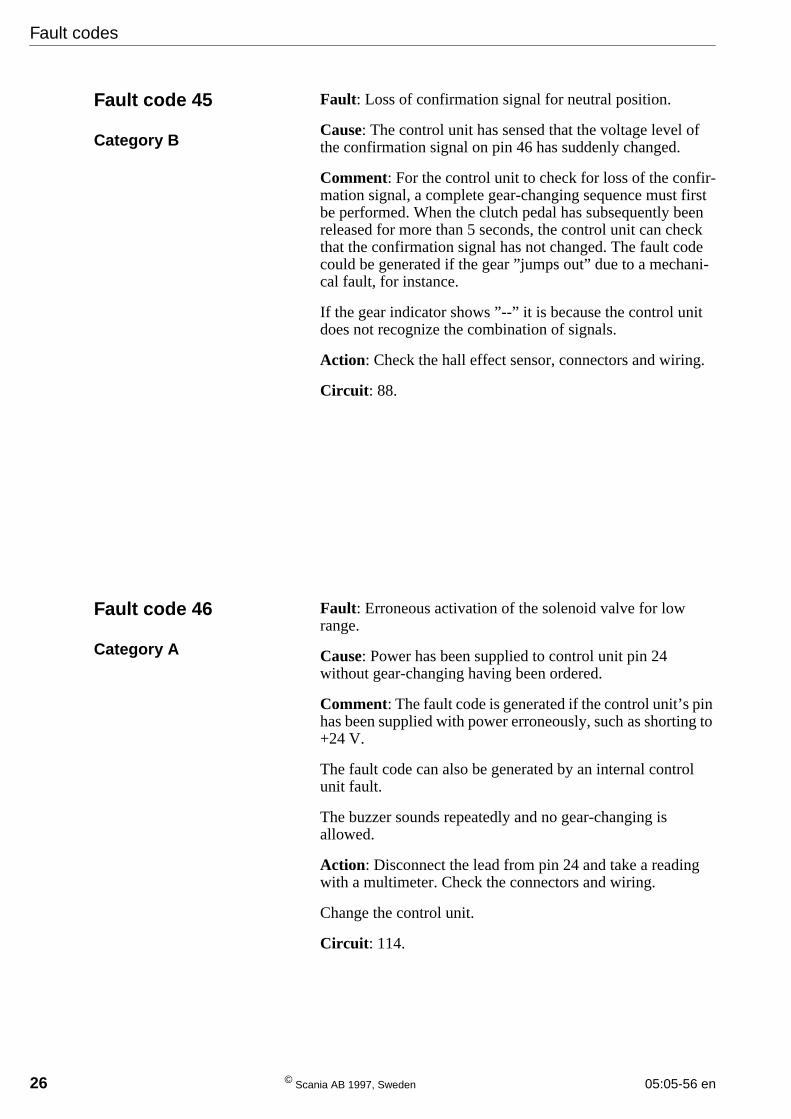
Clutch pedal, emergency gear-changing, road speed sensor
Range switches, hall sensor

Circuit diagram
05:05-56 en © Scania AB 1997, Sweden 45
Neutral switch, reversing light switch, diagnostics socket, diagnostic-switch
Solenoid valves

46 © Scania AB 1997, Sweden 05:05-56 en

05:05-56 en © Scania AB 1997, Sweden 47
Trouble shooting
Trouble shooting
Gear controlFaults in the gear control’s microswitches, wiring or connectors can lead to malfunctioning of vari-ous kinds.
Symptoms Open circuit on microswitch(ST)
Selection of 1st gear and R is not allowed. 1
Selection of 2nd and 3rd gears is not allowed. 2
Selection of 4th and 5th gears and N is not allowed. 3
Selection of 6th and 7th gears is not allowed. 4
Selection of 2nd, 4th and 6th gears and R is not allowed. 5
The CS lever is not blocked when the engine has been switchedoff with a gear engaged.
6
Selection of 1st, 3rd, 5th and 7th gears is not allowed. 7
Symptoms Short-circuit on micro-switch (ST)
Only 1st gear and R can be selected. 1
Only 2nd and 3rd gears can be selected. 2
Only 4th and 5th gears and N can be selected. 3
Only 6th and 7th gears can be selected. 4
Only 2nd, 4th and 6th gears and R can be selected. 5
No confirmation from the CS lever. The interlock valve iswithdrawn and the CS lever enters the drive position before thegearbox has had time to change gear.
6
Only 1st, 3rd, 5th and 7th gears can be selected. 7

Trouble shooting
48 © Scania AB 1997, Sweden 05:05-56 en
Position sensorsFaults such as
- transposed electrical connections,
- interchanged confirmation switches,
- loose contacts
on position switches (confirmation swiches/hallsensors) or in their wiring or connectors canresult in:
1 the control unit failing to recognize anengaged gear. Two dashes will then be dis-played in the middle of the gear indicator.
2 the control unit recognizing a differentgear to the one engaged.
3 the control unit being unable to carry out agear change because of incorrect or absentconfirmation.
4 clashing of the gears.
In cases 1 and 2 it is common for the controlunit, as a consequence of the selected andengaged gear, to perceive these signals diffe-rently. The selected gear will then be engagedand disengaged repeatedly as long as the clutchpedal remains depressed.
Incorrectly selected gear-change points cannotbe caused by the above faults.
Engine operating modeThe control unit senses through alternator char-ging whether or not the engine is running.
1 Continuous input power results in absenceof the warning for engaged gear and swit-ched-off engine.
2 An open circuit causes the buzzer to soundcontinuously when a gear is engaged. Thebuzzer stops sounding after 5 gearchanges.
Road speed sensorThe road speed sensor signal is one of the sys-tem’s most important input signals and is the-refore monitored by two safety functions.Faults in the road speed sensor or its wiringand/or connectors can lead to malfunctioningof various kinds.
1 If a short-circuit or open circuit occurs inthe sensor or its wiring at high speed, thecontrol unit reacts to what it assumes isexcessively rapid deceleration and freezesthe engaged gear. Only selection of neutralor a higher gear is then allowed.
2 If the above fault already exists when thevehicle is driven off from a standstill,another safety function prevents the driverfrom selecting a lower gear than the oneengaged. The buzzer also sounds awarning.
Faulty road speed information can only affectgear selection, not the gear-changing sequence.

05:05-56 en © Scania AB 1997, Sweden 49
Trouble shooting
Solenoid valvesIf there is a fault in the solenoid valves, wiring,compressed air system or gearbox mechanism,it will only affect the gear-changing sequence.Gears can be selected as usual without trouble.
A fault in the electrical part of the solenoidvalve cannot affect an engaged gear until thelower clutch pedal switch is closed (clutchpedal depressed).
Clutch pedal switchesThe upper clutch pedal switch connects toearth and activates relay R515 which suppliescurrent to control unit pin 50.
The lower clutch pedal switch applies currentdirectly to control unit pins 2 and 3.
The clutch pedal switches only affect gearselection, not the gear-changing sequence.
A fault in the clutch pedal switches or theirwiring and/or connectors could have the follo-wing consequences:
1 A continuous supply of current from boththe lower switch and R515 causes the con-trol unit to believe that the clutch pedal isdepressed. It then attempts to change gearas soon as the selected and engaged gearsare different.The driver often discovers the faultbecause the audible signal, which soundsat the start of a gear-changing sequence,sounds when he preselects the next gear.Sometimes the control unit succeeds indisengaging the engaged gear but as a rulethe gear-changing force required is insuffi-cient for engaging the selected gear as theclutch pedal is in the released position(clutch engaged).
2 Gear-changing never takes place if there isan open circuit in one of the switches.
3 Current from R515 but not on the lowerswitch for more than ten minutes causesthe buzzer to sound and enables the driverto change up and engage neutral.
4 Current on the lower switch but not fromR515 causes the buzzer to sound after onesecond and enables the driver to change upand engage neutral.

50 © Scania AB 1997, Sweden 05:05-56 en
1 Frame2 Slide3 Steel ball4 Steel balls5 Spring6 Key7 Detent8 Catch9 Steel balls10 Coulisse11 Steel washer12 O-ring13 Cover14 O-ring
15 Piston16 Guide17 Disc spring18 Microswitch19 Holder20 Pin21 Pin22 Solenoid valve23 Silencer24 Elbow union25 Bolt26 Bolt27 Cylinder housing28 Bolt
Gear control

Gear control
05:05-56 en © Scania AB 1997, Sweden 51
Mechanical work
Gear control
Detaching the CS lever
1 Remove the bolts and remove the boot andcover from the mode selector housing.
2 Remove the clamps and air lines 1 and 2.
3 Unplug all electrical connectors from theCS lever housing.
4 Unscrew the four bolts 3 and remove thegear control from the bracket.
Fitting
5 Connect the lines and connectors to the newgear control.
6 Screw the gear control in place with the fourbolts. Fit a washer between each bolt andthe bracket,
7 Bolt the outer casing and cover in place.

Gear control
52 © Scania AB 1997, Sweden 05:05-56 en
Operational test
Check that the lever moves easily sideways, thatthe latch for position R/1 works and that thelever automatically assumes position N (4/5)when it is not actuated.
Check all gear positions as follows:
1 Connect 24 V via a switch to the twoparal-lel pins on the solenoid valve and connectcompressed air.
2 When the valve is not supplied with currentit should be easy (max. 30 N) to move thelever to each gear position.
3 When the valve is supplied with current itshould be possible to move the lever to thedrive position.
4 Cut off the current supplied to the valve.The lever should now be locked in place andimmovable against a force of 200 N.
Equipment: Compressed air at least 6 bar 24 V via a switch
Leakage: With the compressed airsupply connected and the valveclosed, no sound of leakageshould be heard.

Gear control
05:05-56 en © Scania AB 1997, Sweden 53
Figures and designations refer to the explodedview drawing of the gear control.
Dismantling
1 Take the gear control out of the lever hous-ing and clamp it in a vice.
2 Unscrew the six socket cap screws andremove the CS lever.
3 Remove ball 3 and slide 2.
4 Remove key 6 and spring 5.
5 Remove detent 7.
6 Remove steel balls 4, 3+3 pieces, fromunder microswitches ST 5, 6 and 7.
Note: Be careful and make sure that the steelballs do not disappear.

Gear control
54 © Scania AB 1997, Sweden 05:05-56 en
7 Invert the frame so that the microswitch sec-tions and cylinder are uppermost.
8 Unbolt and lift out the two microswitchsections.
The sections can be dismantled so that indi-vidual microswitches can be changed.
9 Remove the eight (4+4) steel balls 9 undermicroswitches ST 1, 2, 3 and 4.
10 Remove coulisse 10 and catch 8.
11 Make a mark on cylinder housing 27 with apen to indicate the way it is mounted. It is tobe refitted later in the same way.
12 Undo the four cylinder housing bolts 28.
Note: Remove the cylinder housing, keeping itstraight so that it does not tilt against the pistoninside it.
Gear control
05:05-56 en © Scania AB 1997, Sweden 55
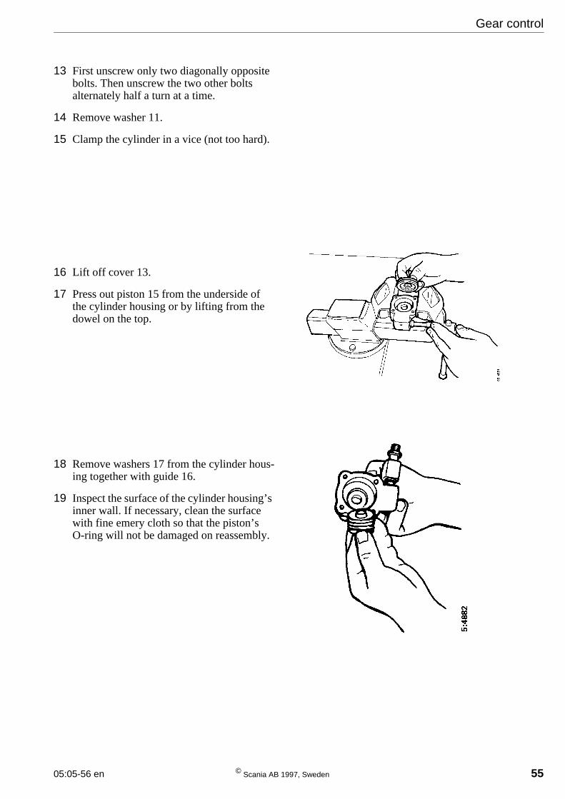
13 First unscrew only two diagonally oppositebolts. Then unscrew the two other boltsalternately half a turn at a time.
14 Remove washer 11.
15 Clamp the cylinder in a vice (not too hard).
16 Lift off cover 13.
17 Press out piston 15 from the underside ofthe cylinder housing or by lifting from thedowel on the top.
18 Remove washers 17 from the cylinder hous-ing together with guide 16.
19 Inspect the surface of the cylinder housing’sinner wall. If necessary, clean the surfacewith fine emery cloth so that the piston’sO-ring will not be damaged on reassembly.
Gear control
56 © Scania AB 1997, Sweden 05:05-56 en
Assembly
When greasing: Use air grease, part No. 319 308, round O-rings14 and 12 and Universal grease for other parts.
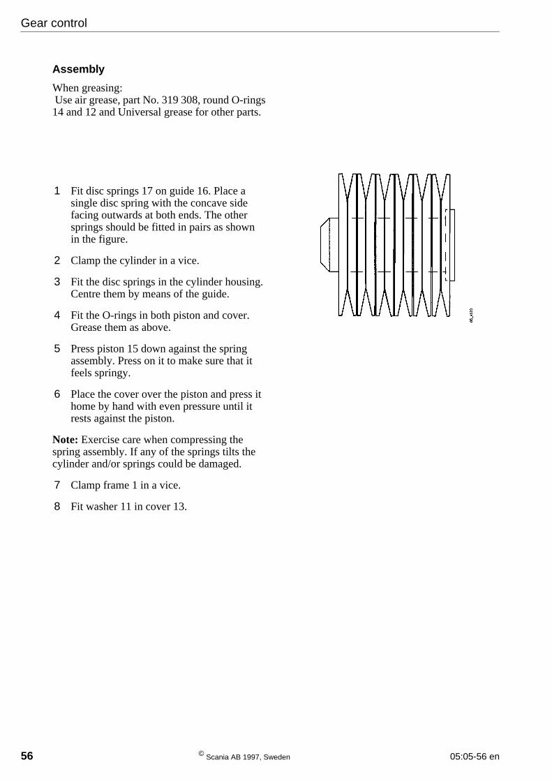
1 Fit disc springs 17 on guide 16. Place asingle disc spring with the concave sidefacing outwards at both ends. The othersprings should be fitted in pairs as shownin the figure.
2 Clamp the cylinder in a vice.
3 Fit the disc springs in the cylinder housing.Centre them by means of the guide.
4 Fit the O-rings in both piston and cover.Grease them as above.
5 Press piston 15 down against the springassembly. Press on it to make sure that itfeels springy.
6 Place the cover over the piston and press ithome by hand with even pressure until itrests against the piston.
Note: Exercise care when compressing thespring assembly. If any of the springs tilts thecylinder and/or springs could be damaged.
7 Clamp frame 1 in a vice.
8 Fit washer 11 in cover 13.

Gear control
05:05-56 en © Scania AB 1997, Sweden 57
9 Fit the cylinder, making sure that it is cor-rectly positioned. Secure it with only twodiagonally opposite bolts so that it lies flatagainst the frame. Tighten the bolts alterna-tely only half a turn at a time, checking fromtime to time that the cylinder is centred andbolted down evenly.
Tighten these two bolts.
10 Check that the piston can move.
Connect compressed air to the elbow unionon the cylinder and 24 V via a switch to thesolenoid valve’s parallel pins.
Switch the current on and off again andcheck that the piston’s stroke is2.8 +/- 0.1 mm.
11 Tighten the two remaining bolts on thecylinder housing.
12 Grease the catch, coulisse and support lugs.Place catch 8 in coulisse 10. Make sure thatthe grooves in the catch and the coulisse arein alignment to accommodate the CS lever’sguide.
13 Turn the coulisse with catch upside downand place them on the frame.
Gear control
58 © Scania AB 1997, Sweden 05:05-56 en
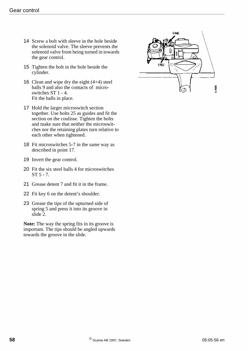
14 Screw a bolt with sleeve in the hole besidethe solenoid valve. The sleeve prevents thesolenoid valve from being turned in towardsthe gear control.
15 Tighten the bolt in the hole beside thecylinder.
16 Clean and wipe dry the eight (4+4) steelballs 9 and also the contacts of micro-switches ST 1 - 4.Fit the balls in place.
17 Hold the larger microswitch sectiontogether. Use bolts 25 as guides and fit thesection on the coulisse. Tighten the boltsand make sure that neither the microswit-ches nor the retaining plates turn relative toeach other when tightened.
18 Fit microswitches 5-7 in the same way asdescribed in point 17.
19 Invert the gear control.
20 Fit the six steel balls 4 for microswitchesST 5 - 7.
21 Grease detent 7 and fit it in the frame.
22 Fit key 6 on the detent’s shoulder.
23 Grease the tips of the upturned side ofspring 5 and press it into its groove inslide 2.
Note: The way the spring fits in its groove isimportant. The tips should be angled upwardstowards the groove in the slide.

Gear control
05:05-56 en © Scania AB 1997, Sweden 59
24 Place the slide on the frame.Take care to position the slide’s groove overthe key.
25 Place ball 3 in position and grease it.
26 Fit the lever part and secure it with fiveretaining bolts.

Solenoid valve
60 © Scania AB 1997, Sweden 05:05-56 en
Solenoid valveFigures and designations refer to the explodedview drawing of the gear control.
Dismantling
1 Undo union 23 and remove the coil. Checkthe valve part’s protective sleeve to makesure that it is not bent or cracked.
2 Unscrew the valve part at the bottom plate(bolts) or at the nut.
Assembly
1 Bolt the valve part to the cylinder housing.
2 Fit the solenoid coil on the valve part.
3 It is important to fit the spring washer in therecess on the outside of the coil before fit-ting the flat washer.
4 Screw the union into the solenoid valve. Becareful with the guide for the washers.Tighten the union carefully until the wash-ers have been guided into place correctly.
Note: Tighten only so hard that the solenoidvalve cannot be turned round with moderatefinger strength.

Checking wear
05:05-56 en © Scania AB 1997, Sweden 61
Checking wearFigures and designations refer to the explodedview drawing of the gear control.
1 Check catch 8 if the groove in its edges isdamaged. Change the catch if necessary.
2 Check the shoulders of coulisse 10 for wear.Change the coulisse if necessary.
3 Check spring 5 for damage. Change thespring if necessary.
4 Check whether detent 7 has been seatedaskew and sustained damage. Change thedetent if necessary.
5 Check whether any of microswitches 18 aredamaged. Change as necessary.
6 Check whether the edges of the end of theCD lever towards coulisse 10 are sharp.Clean the edges if necessary.
7 Change the O-rings on cover 13 andpiston 15.

Checks and settings
62 © Scania AB 1997, Sweden 05:05-56 en
Checks and settings
Position sensors
The integral test programme is used to check theoperation of the position sensors.
Hall effect sensor
The position of the hall sensor is checked withthe gear shift housing removed from the gear-box. For checking and setting, see gear shifthousing, Opticruise and CS.
Confirmation switches
The confirmation switches should not be set.Simply check that they are working.
Designation Function
B41
B42
High range
Low range
A = High range switch (B41)B = Low range switch (B42), gearbox withoutScania retarderC = Low range switch (B42), gearbox withScania retarder
Confirmation switches on range part.

Checks and settings
05:05-56 en © Scania AB 1997, Sweden 63
Solenoid valves
Change gear with the engine switched off, thestarter key in the drive position and operatingpressure in the compressed air system.
Check all gear positions with the gear indicatorby preselecting and then depressing the clutchpedal.
If no gear can be engaged, it may be because thegear teeth are not in mesh. In such case, try rele-asing the parking brake and depressing theclutch pedal again.
If this does not help, select neutral and start andstop the engine. Then engage the gear that couldnot be engaged earlier.
If two or more gears cannot be engaged, checkthe solenoid valves according to the table underspecifications. Their location in the vehicle isgiven under the heading ”Location of gearboxcomponents” and shown in the position illustra-tions in this booklet.
Note: The solenoid valves are supplied withcurrent only as long as the clutch pedal isdepressed.
If no gear-changing takes place, check theclutch pedal switches.

Gear-changing pattern
64 © Scania AB 1997, Sweden 05:05-56 en
Gear-changing movements andconfirmations
The following table shows:
- gear-changing movements from the neutralposition
- the solenoid valves which are activated whena gear is engaged.
Selectedgear
Gear ingearbox
Gear-changing move-ments
Gear-changing Working solenoid valves and position sensors
Lateral-stroke
Longitudi-nal stroke
Main boxRange
High/Low gear
N N Centre Centre V22-N V78-B41/V63-B42
R RL R F V20-NR V24-FR V63-B42
1 1L Centre F V22-N V24-F V63-B42
2 2L Centre B V22-N V23-B V63-B42
3 4L L B V22-N V21-NL V23-BL V63-B42
4 1H Centre F V22-N V24-F V78-B41
5 2H Centre B V22-N V23-B V78-B41
6 3H L F V22-N V21-NL V24-FL V78-B41
7 4H L B V22-N V21-NL V23-BL V78-B41
L = LeftR = RightF = ForwardsB = Backwards
Gear selector movement pattern, GR801
Gear-changing patternSince a vehicle with Comfort Shift is equippedwith a manual gearbox, the gears have the samepattern of movement as the gear selector.

Location of gearbox components
05:05-56 en © Scania AB 1997, Sweden 65
Location of gearbox components
Solenoid valves
Designation Function Connection
V20 Lateral stroke, right A5
V21 Lateral stroke, left A4
V22 Lateral stroke, neutral A2
V23 Lateral stroke, back A1
V24 Lateral stroke, forward A3
V63 Range, low A6
V78 Range, high A7

Location of gearbox components
66 © Scania AB 1997, Sweden 05:05-56 en
Switches
Connectors
Position sensors
Speed sensing
Designation Function
B16 Reversing lights
B500 Neutral position -gearbox
Designation Function
C97 7-pin
C99 10-pin
C142 7-pin
C202 2-pin
C203 2-pin
Designation Function
E6
Right
Left
Rearward
Neutral
Forward
B41 Range, high
B42 Range, low
Designation Function
T17 Speed sensor

05:05-56 en © Scania AB 1997, Sweden 67
Specifications
Specifications
Settings
Page
Piston in gear control ................................................................. 2.8± 0.1 mm 51
Fluids and lubricants
Universal grease............................................................................ See group 0
Code plugs for control unit
Part No. Engine Engages low range in reverse gear
1 303 044 All X