Embed Size (px)
Citation preview
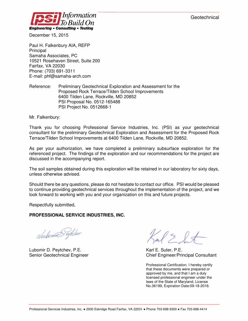
Geotechnical
Professional Services Industries, Inc. ● 2930 Eskridge Road Fairfax, VA 22031 ● Phone 703-698-9300 ● Fax 703-698-4414
December 15, 2015 Paul H. Falkenbury AIA, REFP Principal Samaha Associates, PC 10521 Rosehaven Street, Suite 200 Fairfax, VA 22030 Phone: (703) 691-3311 E-mail: [email protected] Reference: Preliminary Geotechnical Exploration and Assessment for the
Proposed Rock Terrace/Tilden School Improvements 6400 Tilden Lane, Rockville, MD 20852
PSI Proposal No. 0512-165488 PSI Project No. 0512668-1
Mr. Falkenbury: Thank you for choosing Professional Service Industries, Inc. (PSI) as your geotechnical consultant for the preliminary Geotechnical Exploration and Assessment for the Proposed Rock
Terrace/Tilden School Improvements at 6400 Tilden Lane, Rockville, MD 20852. As per your authorization, we have completed a preliminary subsurface exploration for the referenced project. The findings of the exploration and our recommendations for the project are discussed in the accompanying report. The soil samples obtained during this exploration will be retained in our laboratory for sixty days, unless otherwise advised. Should there be any questions, please do not hesitate to contact our office. PSI would be pleased to continue providing geotechnical services throughout the implementation of the project, and we look forward to working with you and your organization on this and future projects. Respectfully submitted, PROFESSIONAL SERVICE INDUSTRIES, INC.
Lubomir D. Peytchev, P.E. Karl E. Suter, P.E. Senior Geotechnical Engineer Chief Engineer/Principal Consultant
Professional Certification. I hereby certify that these documents were prepared or approved by me, and that I am a duly licensed professional engineer under the laws of the State of Maryland, License No.36199, Expiration Date:09-18-2016.
Proposed Rock Terrace/Tilden School Improvements December 15, 2015 6400 Tilden Lane, Rockville, Maryland PSI Project 0512668-1
i
TABLE OF CONTENTS
1 PROJECT INFORMATION ..................................................................................... 1
1.1 PROPOSAL AND PROJECT AUTHORIZATION ............................................ 1
1.2 PROJECT DESCRIPTION .............................................................................. 1
1.3 PURPOSE AND SCOPE OF WORK .............................................................. 1
FIELD EXPLORATION............................................................................................ 2
REPORT PREPARATION ....................................................................................... 2
1.4 SUBSURFACE EXPLORATION ..................................................................... 2
1.5 LABORATORY TESTING ............................................................................... 3
2 SITE AND SUBSURFACE CONDITIONS .............................................................. 4
2.1 SITE LOCATION AND DESCRIPTION ........................................................... 4
2.2 AREA GEOLOGY ........................................................................................... 4
2.3 SUBSURFACE CONDITIONS ........................................................................ 4
2.4 GROUNDWATER CONDITIONS .................................................................... 6
3 PRELIMINARY GEOTECHNICAL CONSIDERATIONS ......................................... 7
3.1 EXISTING FILL SOILS .................................................................................... 8
3.2 EXCAVATION CHARACTERISTICS .............................................................. 8
3.3 SEISMIC CONSIDERATIONS ...................................................................... 10
3.4 FOUNDATION DISCUSSIONS ..................................................................... 10
3.5 FLOOR SLAB ................................................................................................ 11
3.6 INFILTRATION FACILITY ............................................................................. 12
3.7 GENERAL PAVEMENT RECOMMENDATIONS .......................................... 12 3.8 SLOPE STABILITY……………..…………………………………………………………14
4 SITE PREPARATION AND EARTH WORK ......................................................... 13
4.1 SITE PREPARATION ................................................................................... 13
4.2 FILL SOIL SELECTION, PLACEMENT AND COMPACTION ....................... 14
5 CONSTRUCTION CONSIDERATIONS ................................................................ 16
5.1 CONSTRUCTION DEWATERING ................................................................ 16
5.2 EXCAVATION AND SAFETY ........................................................................ 16
6 ADDITIONAL STUDIES ........................................................................................ 17
7 REPORT LIMITATIONS ....................................................................................... 18
APPENDICES
Important Information about Your Geotechnical Report…………................................. Appendix A Vicinity Map and Test Boring Location Plan ..................................................................... Appendix B Boring Logs and Profiles .................................................................................................. Appendix C Laboratory Test Results ................................................................................................... Appendix D
Proposed Rock Terrace/Tilden School Improvements December 15, 2015 6400 Tilden Lane, Rockville, Maryland PSI Project 0512668-1
1
1 PROJECT INFORMATION
1.1 PROPOSAL AND PROJECT AUTHORIZATION
This report presents the findings and recommendations of a preliminary subsurface exploration and geotechnical evaluation performed by Professional Service Industries, Inc. (PSI) for the proposed Rock Terrace/Tilden School at 6400 Tilden Lane, Rockville, Maryland. These services were performed in general accordance with PSI’s PSI Proposal No. 0512-165488, dated October 27, 2015. The work for this project was authorized by Mr. Paul H. Falkenbury.
1.2 PROJECT DESCRIPTION
We understand that Montgomery County Public Schools intends to develop the property located at 6400 Tilden Lane, Rockville, MD 20852. The intention is to build a new school in place of the existing school located at the site currently. The footprint, layout, structural loads, or finished grades have not been developed for the project and it is our understanding that this project is in the feasibility stage.
This preliminary report is based on minimal site grading with maximum anticipated cuts
and/or fills of 3 feet or less. Utility layout and information regarding stormwater management facilities were also not available and therefore were not considered as part of this study.
The L-shaped property is currently a developed with an existing school with playing fields located on the southern portion of the site. The existing building is located in the central portion of the site. Existing survey data is not available, however, based on aerial topographic maps, site grades generally slope downwards from the north to south, approximately El. 355 feet to El. 321 feet respectively.
1.3 PURPOSE AND SCOPE OF WORK
The intent of this preliminary geotechnical study is to explore and analyze the subsurface conditions and provide general land development considerations for the proposed development. No specific engineering calculations or analysis were conducted as part of our scope of work. This report is considered preliminary and once the future development plans and foundation loads are determined additional field exploration will likely be required and a final geotechnical report will need to be prepared. The locations and depths of borings performed for this preliminary study were selected to facilitate re-use of the information during the final study.
The scope of services for this study included a site reconnaissance, the preliminary assessment of subsurface conditions through field exploration and laboratory testing, and the preparation of preliminary engineering recommendations for the planned improvements. The subsurface exploration included the following:
Proposed Rock Terrace/Tilden School Improvements December 15, 2015 6400 Tilden Lane, Rockville, Maryland PSI Project 0512668-1
2
FIELD EXPLORATION
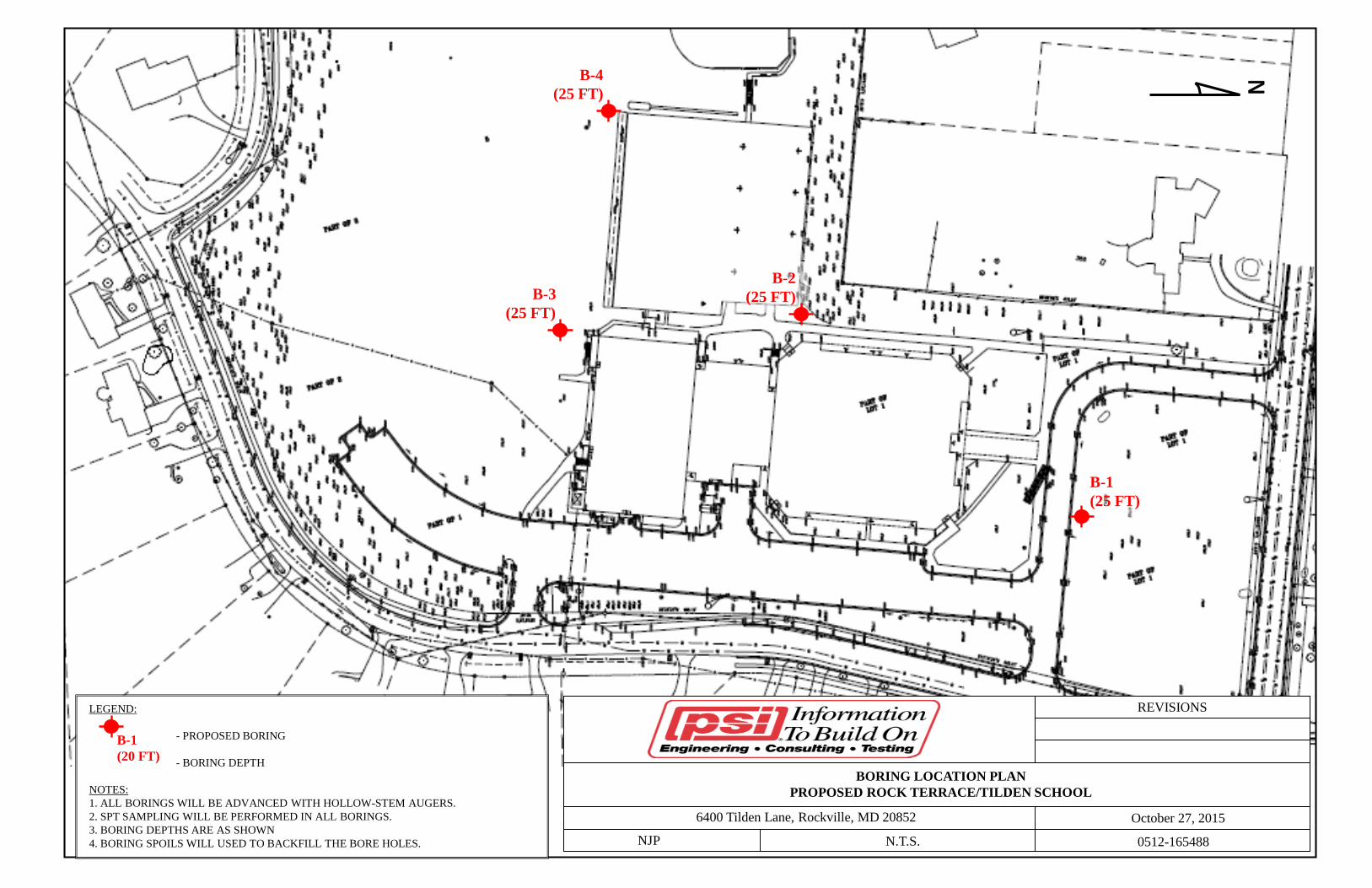
We performed a total of four borings amounting to approximately 100 total feet of drilling in order to characterize the subsurface conditions for the planned development. Based on the site plan provided and the existing site grades, we advanced the borings within the planned development areas to depths of 25 feet below existing grades. Auger refusal was encountered in two of the borings.
The borings for this preliminary study were widely spaced in order to capture the variation of the subsurface conditions and were located to avoid existing utilities and structures. Soil was sampled four times in the top 10 feet of the borings and at 5-foot intervals for the remaining planned boring depth or until auger refusal was encountered; whichever occurred first. Soil samples were classified in the field by our geotechnical engineer and recorded on our boring logs along with groundwater observations, penetration resistances, action of the drill rig, and other observations during the work.
LABORATORY TESTING
Representative soil samples obtained during the field exploration program were returned to the laboratory for classification and a limited number of engineering properties tests. The nature and extent of the laboratory testing were dependent upon the subsurface conditions encountered in the borings.
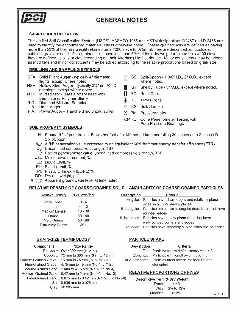
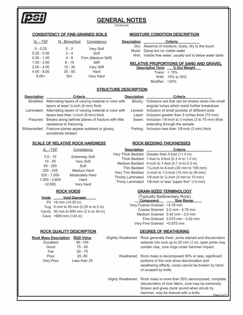
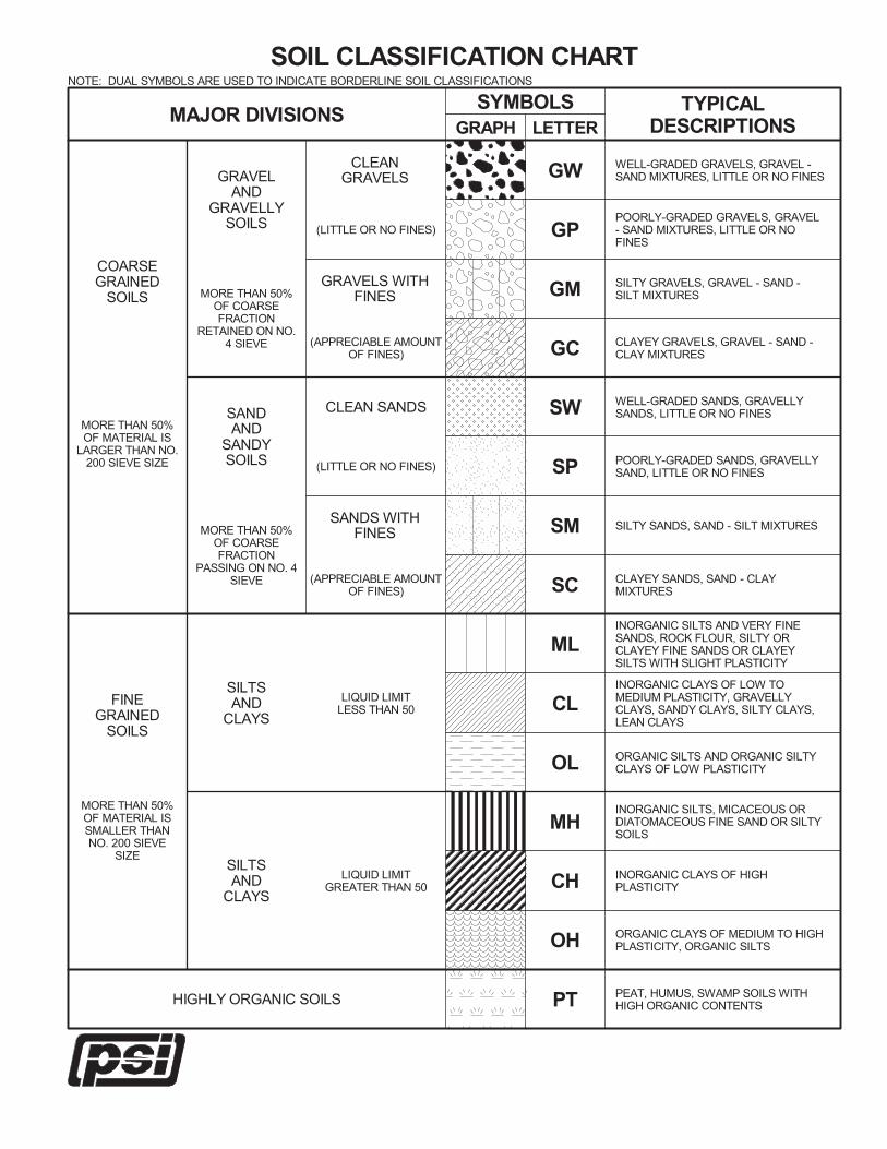
The recovered split-spoon samples were visually-manually classified and lab tests consisted of moisture contents, sieve analysis, and atterberg limits in general accordance with the Unified Soil Classification System (USCS) [ASTM D2487 and D2488].
REPORT PREPARATION
The results of the field exploration and laboratory work were reviewed by a geotechnical engineer and a discussion summarizing our findings and providing preliminary land development considerations was prepared.
Given the preliminary stage of this project, no specific engineering calculations and analysis were performed at this time. Geotechnical considerations, such as foundation type selection, bearing elevation, soil re-use, soil stabilization, and storm water infiltration were considered and are presented in this report.
1.4 SUBSURFACE EXPLORATION
Four soil borings were drilled on the site with a Diedrich D-50 drill rig utilizing 3 ¼” hollow stem augers. Refer to the Boring Location Plan in the Appendix B. Borings were terminated at approximately 25 feet below existing grades in the area of the proposed development.
Proposed Rock Terrace/Tilden School Improvements December 15, 2015 6400 Tilden Lane, Rockville, Maryland PSI Project 0512668-1
3
Drilling and soil sampling were conducted in accordance with the procedures generally recognized and accepted as standard methods of exploration of subsurface conditions related to earthwork and foundation engineering projects. Representative soil samples were obtained by employing split-spoon sampling procedures in general accordance with ASTM D1586 test method. Soil samples obtained from the borings were identified according to boring number and depths, and a representative portion of each sample was placed in a moisture-tight glass container to protect against moisture loss. The soil samples from the borings were subsequently transported to PSI’s soil laboratory for visual classification and further evaluation. The location of the site is shown on the Vicinity Map and the test boring locations are shown on the Boring Location Plan, both in Appendix B. The findings of the PSI borings are presented on the Boring Logs in Appendix C.
1.5 LABORATORY TESTING
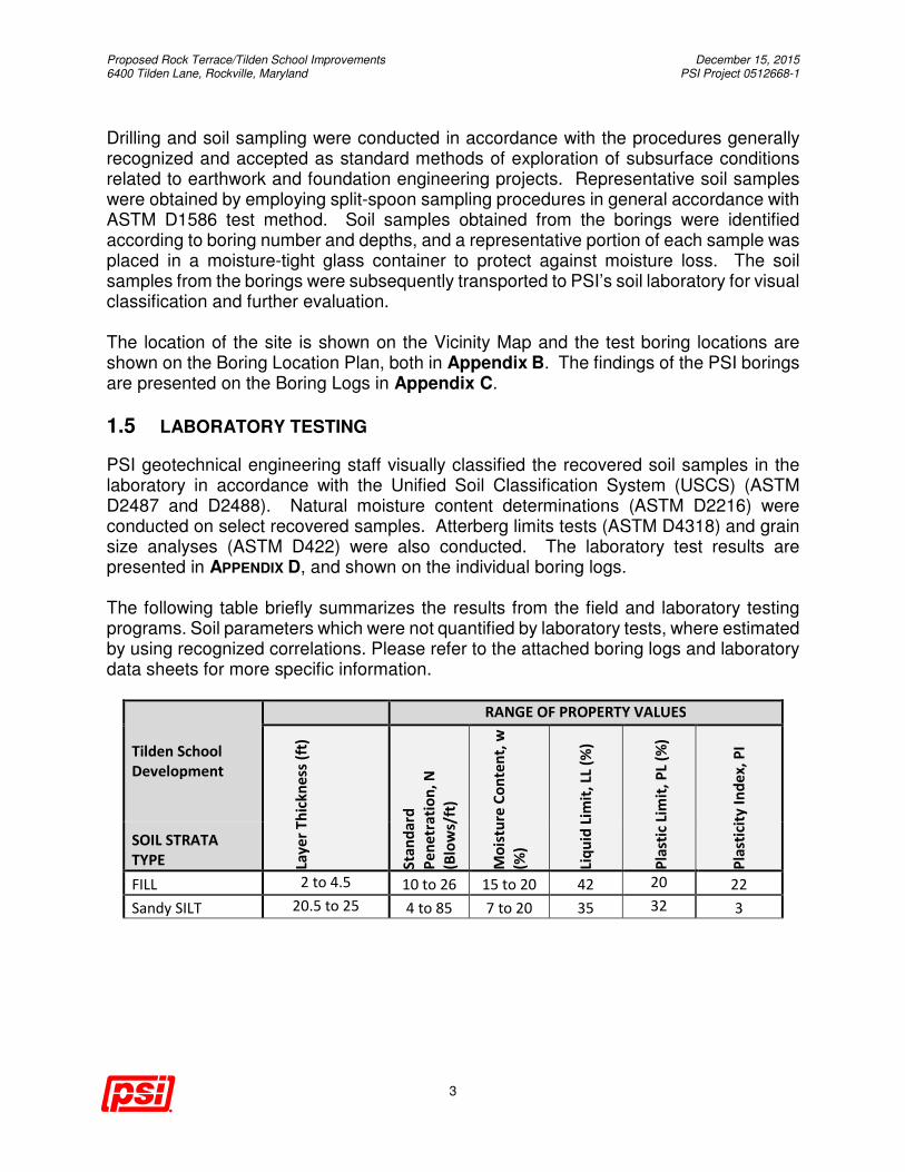
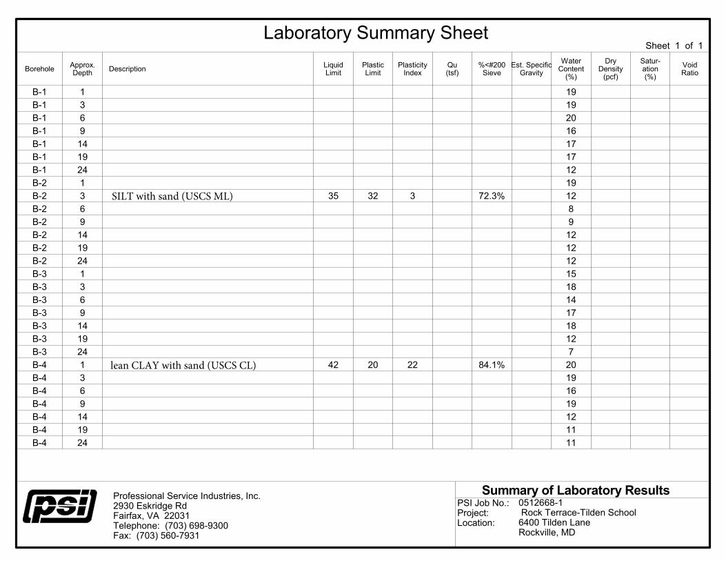
PSI geotechnical engineering staff visually classified the recovered soil samples in the laboratory in accordance with the Unified Soil Classification System (USCS) (ASTM D2487 and D2488). Natural moisture content determinations (ASTM D2216) were conducted on select recovered samples. Atterberg limits tests (ASTM D4318) and grain size analyses (ASTM D422) were also conducted. The laboratory test results are presented in APPENDIX D, and shown on the individual boring logs. The following table briefly summarizes the results from the field and laboratory testing programs. Soil parameters which were not quantified by laboratory tests, where estimated by using recognized correlations. Please refer to the attached boring logs and laboratory data sheets for more specific information.
Tilden School
Development
RANGE OF PROPERTY VALUES
Lay
er
Th
ick
ne
ss (
ft)
Sta
nd
ard
Pe
ne
tra
tio
n,
N
(Blo
ws/
ft)
Mo
istu
re C
on
ten
t, w
(%)
Liq
uid
Lim
it,
LL (
%)
Pla
stic
Lim
it,
PL
(%)
Pla
stic
ity
In
de
x,
PI
SOIL STRATA
TYPE
FILL 2 to 4.5 10 to 26 15 to 20 42 20 22
Sandy SILT 20.5 to 25 4 to 85 7 to 20 35 32 3
Proposed Rock Terrace/Tilden School Improvements December 15, 2015 6400 Tilden Lane, Rockville, Maryland PSI Project 0512668-1
4
2 SITE AND SUBSURFACE CONDITIONS
2.1 SITE LOCATION AND DESCRIPTION
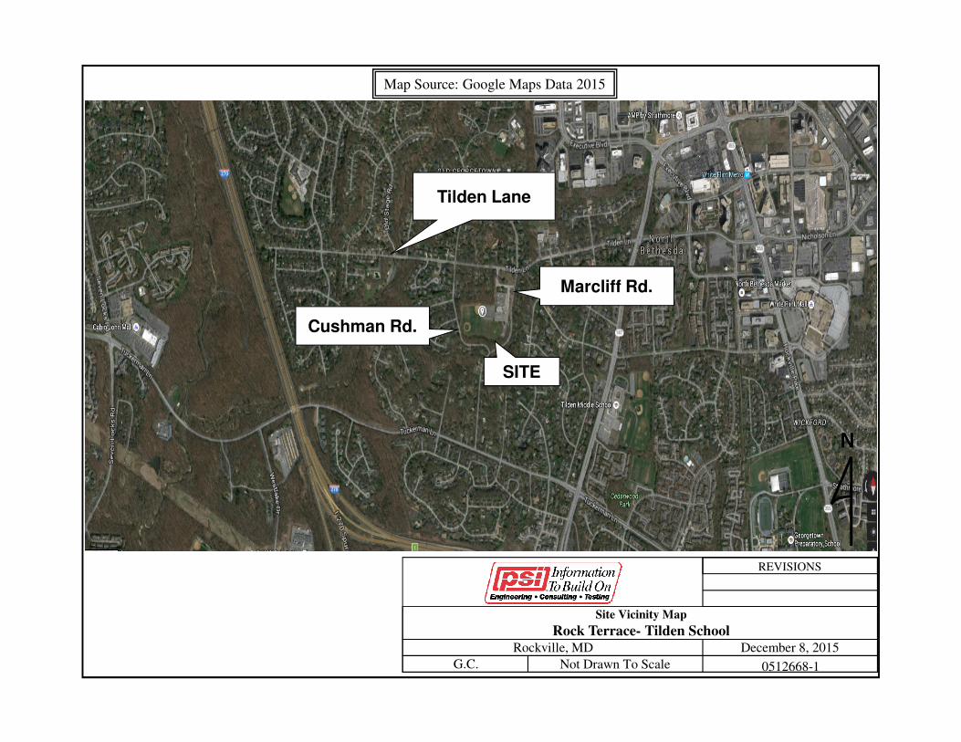
The site is located in the southwest quadrant of the intersection of Tilden Lane and Marcliff Road in Rockvile, MD. The site has an approximately 34 feet of relief with the high point near the service road located off Tilden Lane on the north side of the site to the low point of the site located on the southwestern portion of the site immediately adjacent to Cushman Road. The site slopes down from the north to the south and the west. The property is currently developed with school structures, paved walkways, drives with parking and landscaping.
2.2 AREA GEOLOGY
The site is geologically located in the Piedmont Physiographic Province. The Piedmont is a complex assemblage of igneous (volcanic and plutonic) and sedimentary rocks that were generally formed during the Late Proterozoic Era and the Early Cambrian Period (approximately 550 to 900 million years ago). During and subsequent to formation these rocks were subjected to several major tectonic events, including plate collisions, folding, faulting, and igneous intrusions, that resulted in the uplift and metamorphism of the preexisting rocks. The tectonic activity generally stopped about 200 to 250 million years ago and erosional forces have formed the current ground surface. A study of the area geology from the available literature1 and field observation indicates that the site is underlain by Wissahickon Formation of late Precambrian. The Wissahickon Formation (wlps) is described as “Medium- to coarse-grained biotite-oligoclase-muscovite-quartz schist with garnet, staurolite, and kyanite; fine- to medium-grained semipelitic schist; and fine-grained granular to weakly schistose psammitic granulite; psammitic beds increase upward; apparent thickness 5,500 feet or more”. The residual soils of Wissahickon formation typically consist of low plasticity to non-plastic micaceous silt and sand that weathered from parent bedrock, which consists of schist. The geologic conditions at the site have been modified by the placement of existing fill materials. It is not uncommon to encounter buried materials, such as unsuitable soils, buried foundations, burn pits and other undesirable materials on previously developed sites. These materials, may be encountered during site work and construction.
2.3 SUBSURFACE CONDITIONS
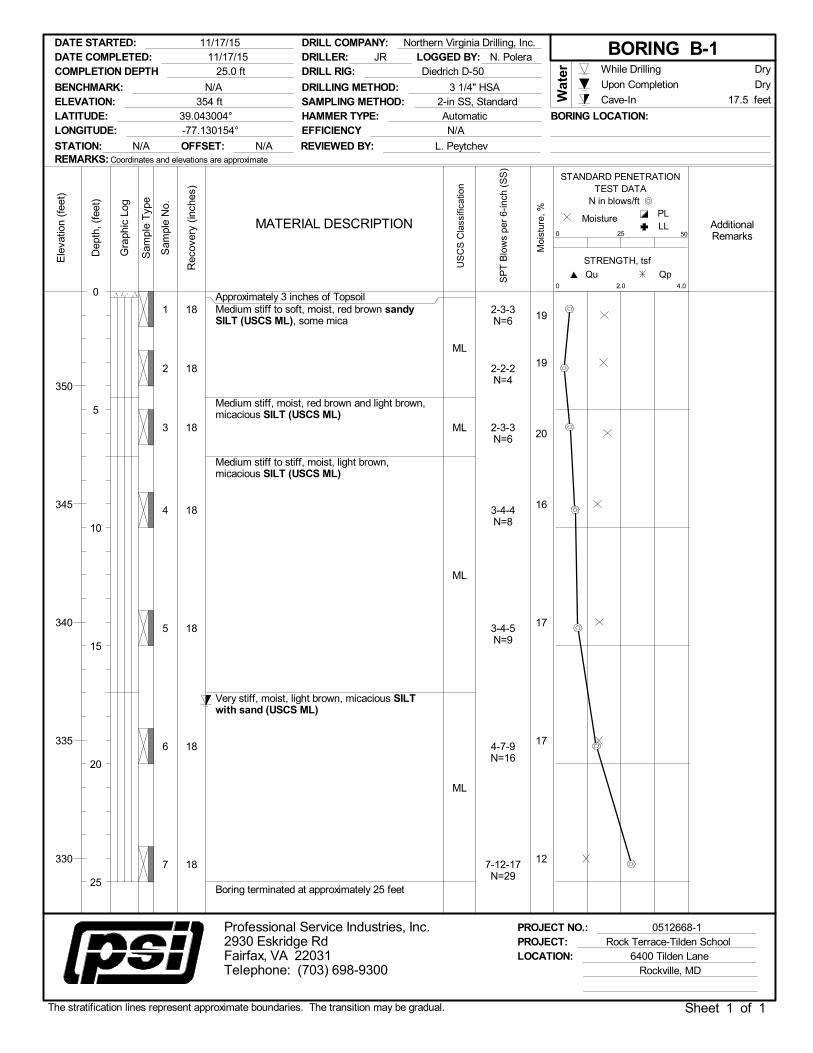
A thin layer (approximately 3 inches) of organic topsoil soil was encountered in all borings.
1 Cleaves, E.T., Edwards, J., Jr., Glaser, J.D. (1968). Geologic Map of Maryland: Maryland Geological Survey, Baltimore, Maryland, scale 1:250,000.
Proposed Rock Terrace/Tilden School Improvements December 15, 2015 6400 Tilden Lane, Rockville, Maryland PSI Project 0512668-1
5
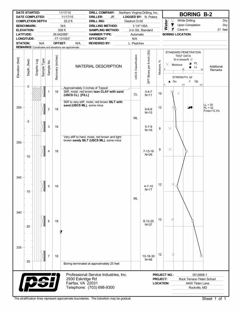
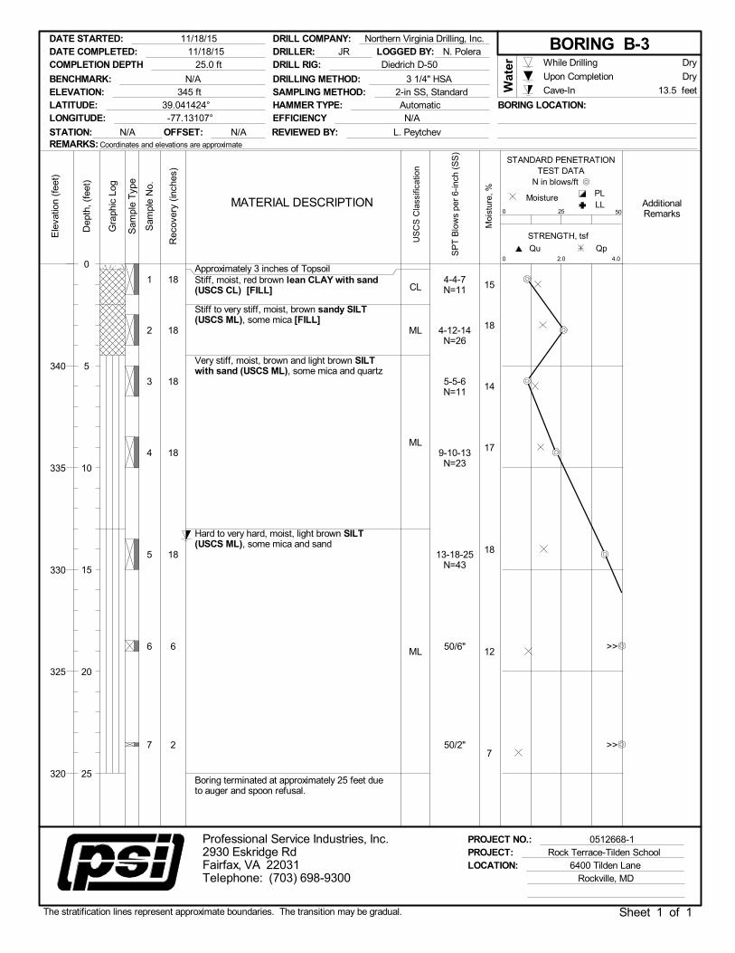
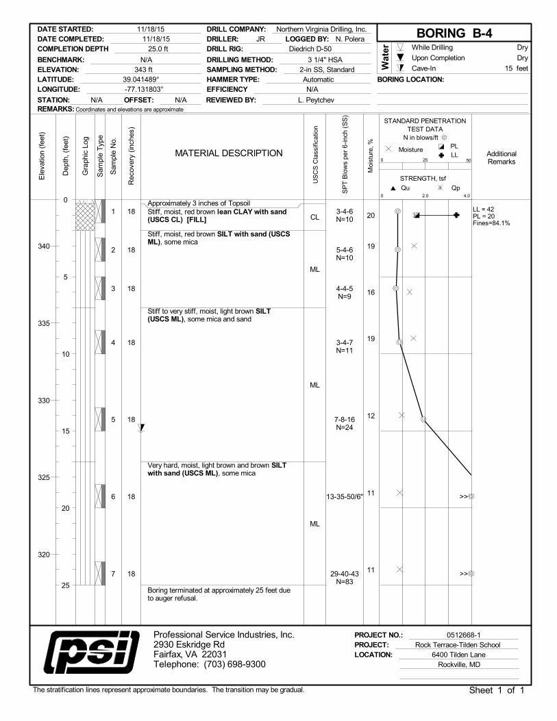
Underlying the surficial topsoil materials, three of the four borings encountered 2 to 4.5 feet of stiff to very stiff lean clay and sandy silt materials interpreted to be previously placed fill with varying amounts of sand. Underlying the topsoil and/or fill materials, a stratum of soft to very hard sandy Silt was encountered across the site. This stratum expanded to the depth of drilled borings to approximately 20.5 to 25 feet thick. Split spoon refusal was reached within two of four borings into this stratum. The following is a more detailed description of each stratum encountered: Surface: Topsoil was encountered in all four borings. The measured thickness of the topsoil was approximately 3 inches. The term topsoil, as used in this report, is a general designation given to the surface horizon of soil which appears to have an elevated organic content. No laboratory testing was performed on the topsoil to determine its suitability for supporting plant life, or ability to satisfy a particular specification. Fill: Fill soils were encountered in Borings B-2, B-3 and B-4 beneath the topsoil layer to depths from 2 to 4.5 feet. The fill consisted of lean CLAY (CL) and sandy SILT (ML). Standard Penetration Test resistance (N-values) ranged from 10 to 26 blows per foot (bpf) with a typical average of 14.5 bpf were recorded in the fill. The moisture contents of the fill soils were found to range from approximately 15 to 20 percent with an approximate average of 18 percent. One of the samples was found to be with low-plasticity with a Liquid Limit of 42, a Plastic Limit of 20 and a Plasticity Index of 22. The fines content of the fill soils was found to be an approximately 84.1 percent. The samples were classified as a lean CLAY and a low plasticity, sandy SILT (ML) in accordance with the Unified Soil Classification System (USCS). Sandy SILT: Undisturbed natural materials encountered at this site generally consisted of soft to very hard, red-brown, light brown and brown, Sandy SILT (ML). Standard Penetration Test (SPT) “N” values ranged from 4 to 85 and 50+ blows per foot with a typical average of 27 bpf. The moisture content of the sandy SILT was found to range from approximately 7 to 20 percent with an approximate average of 14.2 percent. One of the samples was found to be with low-plasticity with a Liquid Limit of 35, a Plastic Limit of 32 and a Plasticity Index of 3. The fines content of the sandy silt soils was found to be an approximately 72.3 percent. The samples were classified as a low plasticity, sandy SILT (ML) in accordance with the USCS. Refusal Material: Auger refusal was encountered in Borings B-3 and B-4 at El. 327 to 324 feet. Auger refusal is a term that describes subsurface materials sufficiently competent to prevent auger penetration with geotechnical soil drilling equipment. Auger refusal likely occurred on the surface of continuous weathered schist bedrock or suspended boulders. The refusal generally occurred abruptly on hard material. Core sampling of the refusal materials to determine their consistency and composition was beyond the scope of services for this project.
Proposed Rock Terrace/Tilden School Improvements December 15, 2015 6400 Tilden Lane, Rockville, Maryland PSI Project 0512668-1
6
Soil test results are indicated on the boring logs included as APPENDIX C, and the laboratory test results located in APPENDIX D. The above subsurface description is of a generalized nature provided to highlight the major soil strata encountered. The boring logs included in the appendices should be reviewed for specific information as to individual test boring locations. The stratification lines shown on the test boring logs represent the conditions only at the actual test boring locations. The stratification lines represent the approximate boundaries between subsurface materials and the actual transition may be gradual.
2.4 GROUNDWATER CONDITIONS
Groundwater was not observed at the time of drilling. The cave-in depths within the borings were measured to occur between 13.5 and 21 feet of the ground surface. Boreholes often collapse within a few feet of the groundwater level, but this depth may not be indicative of the stabilized groundwater level. The groundwater conditions observed in this report are the levels that were measured at the time of our field activities. Fluctuation in groundwater levels should be anticipated. We recommend that the Contractor determine the actual groundwater levels at the time of construction to determine groundwater impact on the proposed construction procedure.
Proposed Rock Terrace/Tilden School Improvements December 15, 2015 6400 Tilden Lane, Rockville, Maryland PSI Project 0512668-1
7
3 PRELIMINARY GEOTECHNICAL CONSIDERATIONS
The following preliminary geotechnical recommendations have been developed on the basis of the previously described characteristics, the subsurface conditions disclosed by the borings, and our understanding that this project is in the feasibility stage. Once project plans are more complete, a final subsurface exploration will need to be conducted and should include additional field and laboratory testing and development of design-level recommendations for foundation bearing, grade slab and pavement support, earthwork, retaining structures and stormwater management facilities. This preliminary report should not be used in lieu of the final geotechnical report for the project. Section 7 of this report provides general recommendations for additional exploration based on the findings of this study and our limited understanding of the proposed construction. One important recommendation is for the use of in-situ testing which, in our experience, allows for the design of much more economical foundations when used to supplement conventional soil test borings. In-situ testing, such as Flat Dilatometer (DMT) testing, may be used at this site to refine and optimize the foundation design for this project. Based on the results of the preliminary fieldwork and laboratory evaluation, the following should be considered during future planning and design for the proposed development:
1. Existing surface fill and native soils with relatively low SPT N-values. 2. Dense materials that may require rock excavation techniques.
We believe with proper planning and execution, the site can be adapted for the proposed development. The following preliminary geotechnical recommendations have been developed on the basis of the previously described development plans and the subsurface conditions encountered during our exploration. The preliminary development plans, including building locations, assumed loads, elevations and site grades, a review should be made by PSI to determine if modifications to this preliminary report are warranted. Once project plans are more complete, a final subsurface exploration will need to be conducted and should include additional field and laboratory testing and development of design-level recommendations for foundation bearing, grade slab and pavement support, earthwork, retaining structures and stormwater management facilities. This preliminary report should not be used in lieu of the final geotechnical report for the project.
Proposed Rock Terrace/Tilden School Improvements December 15, 2015 6400 Tilden Lane, Rockville, Maryland PSI Project 0512668-1
8
3.1 EXISTING FILL SOILS
Previously placed fill material was encountered in three of four borings to a depth of approximately 4.5 feet. The sampled fill consisted of Lean CLAY (CL) and Sandy SILT (ML). PSI has not been provided any documentation of prior site grading and fill placement activities. The quality of man-made fills can vary significantly over short distances (i.e. between test boring locations) and with depth which makes it difficult, if not impossible, to accurately assess the engineering properties of existing fills. Furthermore, there is no specific correlation between N-values from Standard Penetration Tests (SPT) performed in soil borings and the degree of compaction of existing fill soils. As such, there is some risk in any building over unmonitored and undocumented fill. We recommend an evaluation of the existing fill soils by use of test pits and possibly density testing during the final exploration to check for the degree of compaction.
3.2 EXCAVATION CHARACTERISTICS
Based on the boring data and our grading assumptions, it appears that very hard or very dense soils, and highly weathered rock may be encountered during general site grading. In addition, these materials may be encountered in excavations for foundations, underground utilities, and other below grade structures depending on final site grades. This material is likely to be very difficult and expensive to excavate for construction. We recommend that test pits be performed with a large track excavator to further evaluate rock conditions once grading plans are finalized. Rock excavation techniques including the use of rippers, pneumatic tools, and blasting may be required. Deeper excavations such as utility line construction may encounter weathered rock, boulders, or intact rock. Contingency funds for difficult excavation should be set aside for the construction of utility lines. Actual conditions during excavation may be different as some variation is expected within the proposed building footprints. Based on our field exploration, most soils should generally be excavatable using conventional excavation equipment, such as scrapers, front end loaders, bulldozers, etc. The results of the soil test borings indicate SPT N-values within the soil profile as high as 50 blows per 2 inches of penetration (50/2”). Based on our experience, weathered rock with N-values of 50/3” (or less penetration) and rock will likely require blasting, splitting, or jack hammering to facilitate removal. Disagreements often arise relative to excavatability of materials in the transition zone between soil and rock, and below. In addition, “floaters” or boulders also cause disagreements.
Proposed Rock Terrace/Tilden School Improvements December 15, 2015 6400 Tilden Lane, Rockville, Maryland PSI Project 0512668-1
9
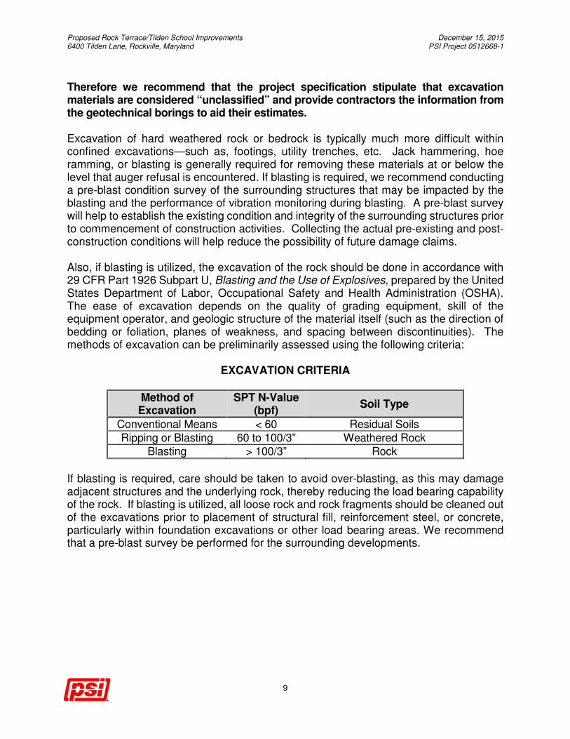
Therefore we recommend that the project specification stipulate that excavation materials are considered “unclassified” and provide contractors the information from the geotechnical borings to aid their estimates. Excavation of hard weathered rock or bedrock is typically much more difficult within confined excavations—such as, footings, utility trenches, etc. Jack hammering, hoe ramming, or blasting is generally required for removing these materials at or below the level that auger refusal is encountered. If blasting is required, we recommend conducting a pre-blast condition survey of the surrounding structures that may be impacted by the blasting and the performance of vibration monitoring during blasting. A pre-blast survey will help to establish the existing condition and integrity of the surrounding structures prior to commencement of construction activities. Collecting the actual pre-existing and post-construction conditions will help reduce the possibility of future damage claims. Also, if blasting is utilized, the excavation of the rock should be done in accordance with 29 CFR Part 1926 Subpart U, Blasting and the Use of Explosives, prepared by the United States Department of Labor, Occupational Safety and Health Administration (OSHA). The ease of excavation depends on the quality of grading equipment, skill of the equipment operator, and geologic structure of the material itself (such as the direction of bedding or foliation, planes of weakness, and spacing between discontinuities). The methods of excavation can be preliminarily assessed using the following criteria:
EXCAVATION CRITERIA
Method of Excavation
SPT N-Value (bpf)
Soil Type
Conventional Means < 60 Residual Soils
Ripping or Blasting 60 to 100/3” Weathered Rock
Blasting > 100/3” Rock
If blasting is required, care should be taken to avoid over-blasting, as this may damage adjacent structures and the underlying rock, thereby reducing the load bearing capability of the rock. If blasting is utilized, all loose rock and rock fragments should be cleaned out of the excavations prior to placement of structural fill, reinforcement steel, or concrete, particularly within foundation excavations or other load bearing areas. We recommend that a pre-blast survey be performed for the surrounding developments.
Proposed Rock Terrace/Tilden School Improvements December 15, 2015 6400 Tilden Lane, Rockville, Maryland PSI Project 0512668-1
10
3.3 SEISMIC CONSIDERATIONS
The project site is located within a municipality that employs the International Building Code (IBC), 2012 edition. As part of this code, the design of structures must consider dynamic forces resulting from seismic events. These forces are dependent upon the magnitude of the earthquake event as well as the properties of the soils that underlie the site. Part of the IBC code procedure to evaluate seismic forces requires the evaluation of the Seismic Site Class, which categorizes the site based upon the characteristics of the subsurface profile within the upper 100 feet of the ground surface. To define the Seismic Site Class for this project, and in accordance with your requested level of assessment, we have interpreted the results of our soil test borings drilled within the project site per Section 1613 of the code. The estimated soil properties are based upon data available in published geologic reports and our experience with subsurface conditions in the general site area. It is our opinion that the subsurface conditions within the areas of the site planned for building construction are consistent with the characteristics of Site Class C as defined in Table 20.3-1 of 2010 ASCE-7 Standard. As per Section 1613.3.2 of the building code, this classification was used for this assessment. This site class designation should be revisited when actual foundation elevations for specific structures are established. The dense soils present at the site may provide more favorable site classes for some structures with foundations bearing in or near these materials. For buildings with a Seismic Design Category of C, D, E, or F the code requires an assessment of slope stability, liquefaction potential, and surface rupture due to faulting or lateral spreading. Detailed assessments of these factors were beyond the scope of this study. However, the material types and consistencies observed in the borings indicate a relatively low probability that these factors will adversely impact development.
3.4 FOUNDATION DISCUSSIONS
Further exploration will be needed when the foundation scheme of the design is finalized. The further exploration will allow us to provide our final geotechnical recommendations; however the following is a general summary of the foundations that are anticipated for the proposed development. Shallow Foundations on Native Soils/PWR: Shallow foundations bearing on the native soils and/or PWR appear to be the likely foundation system.
Proposed Rock Terrace/Tilden School Improvements December 15, 2015 6400 Tilden Lane, Rockville, Maryland PSI Project 0512668-1
11
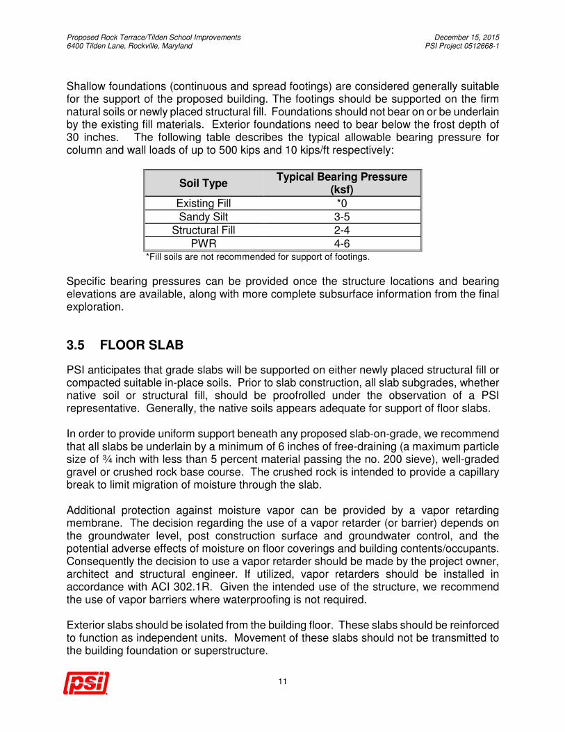
Shallow foundations (continuous and spread footings) are considered generally suitable for the support of the proposed building. The footings should be supported on the firm natural soils or newly placed structural fill. Foundations should not bear on or be underlain by the existing fill materials. Exterior foundations need to bear below the frost depth of 30 inches. The following table describes the typical allowable bearing pressure for column and wall loads of up to 500 kips and 10 kips/ft respectively:
Soil Type Typical Bearing Pressure
(ksf)
Existing Fill *0
Sandy Silt 3-5
Structural Fill 2-4
PWR 4-6 *Fill soils are not recommended for support of footings.
Specific bearing pressures can be provided once the structure locations and bearing elevations are available, along with more complete subsurface information from the final exploration.
3.5 FLOOR SLAB
PSI anticipates that grade slabs will be supported on either newly placed structural fill or compacted suitable in-place soils. Prior to slab construction, all slab subgrades, whether native soil or structural fill, should be proofrolled under the observation of a PSI representative. Generally, the native soils appears adequate for support of floor slabs. In order to provide uniform support beneath any proposed slab-on-grade, we recommend that all slabs be underlain by a minimum of 6 inches of free-draining (a maximum particle size of ¾ inch with less than 5 percent material passing the no. 200 sieve), well-graded gravel or crushed rock base course. The crushed rock is intended to provide a capillary break to limit migration of moisture through the slab. Additional protection against moisture vapor can be provided by a vapor retarding membrane. The decision regarding the use of a vapor retarder (or barrier) depends on the groundwater level, post construction surface and groundwater control, and the potential adverse effects of moisture on floor coverings and building contents/occupants. Consequently the decision to use a vapor retarder should be made by the project owner, architect and structural engineer. If utilized, vapor retarders should be installed in accordance with ACI 302.1R. Given the intended use of the structure, we recommend the use of vapor barriers where waterproofing is not required. Exterior slabs should be isolated from the building floor. These slabs should be reinforced to function as independent units. Movement of these slabs should not be transmitted to the building foundation or superstructure.
Proposed Rock Terrace/Tilden School Improvements December 15, 2015 6400 Tilden Lane, Rockville, Maryland PSI Project 0512668-1
12
3.6 INFILTRATION FACILITY
Infiltration facilities discharge stormwater runoff by allowing the water to infiltrate into the surrounding soils rather than through storm sewer utilities. These facilities are generally used for water quality enhancement and to recharge the local aquifer. These facilities can include bio-retention basins, infiltration trenches and larger volume subgrade structures that collect and hold stormwater runoff to allow the gradual infiltration into the soil.
Some fill soils found on site are not suitable for infiltration and should be removed and replaced with suitable fill before constructing stormwater facilities. Based on the available borings, the shallow site soils are fine grained and are not expected to have suitable infiltration rates. In-situ field testing will be needed to determine the rate of infiltration at each proposed stormwater facility.
Infiltration will not be permitted within 5 feet of the high groundwater table or rock. Site grading and placement of infiltration facilities should be done with consideration to the elevation of groundwater and partially weathered rock encountered in this and future explorations. Special care should be given to the location of infiltration facilities with respect to any planned retaining walls to avoid saturating the soils retained by the walls.
3.7 GENERAL PAVEMENT RECOMMENDATIONS
The on-site fill and native soils consist of fine grained silt and clay. Once compacted, these materials are expected to have CBR values between 3 and 4. California Bearing Ratio (CBR) tests will need to be performed for the Final Report and further information can be provided upon request. Pavement subgrade soils should have compaction levels of approximately 98 percent of the standard Proctor maximum dry density within approximately 3 percent of optimum moisture content. Prevention of infiltration of water into the subgrade is essential for the successful long-term performance of any pavement. Both the subgrade and the pavement surface should be sloped to promote surface drainage away from the pavement structure. Recommended pavement sections can be provide as part of the final subsurface exploration for the project.
3.8 SLOPE STABILITY Special consideration must be given to the stability of the existing ground when supporting fills, to structural fills themselves, and to cut slopes in natural soil and rock excavations. The evaluation of slope stability aspects of this site and the proposed development is beyond the scope of this exploration. Relatively detailed grading plans will have to be developed before meaningful evaluation of slope stability can be accomplished. All slope stability evaluations should be performed by qualified geotechnical engineering personnel prior to the initiation of any significant grading activities at this site.
Proposed Rock Terrace/Tilden School Improvements December 15, 2015 6400 Tilden Lane, Rockville, Maryland PSI Project 0512668-1
13
The following general guidelines have been applied successfully in the general site vicinity. These guidelines are provided for preliminary feasibility planning and may need to be adjusted based on the findings of the final subsurface exploration. Unless specifically designed, temporary slopes should not be steeper than a ratio of 2:1 Horizontal:Vertical. Temporary slopes exceeding 10 feet in vertical height should have a slope stability analysis. Permanent cut and engineered fill slopes should not be steeper than a ratio of 3:1 Horizontal:Vertical without a specific slope stability analysis. Fill placed on existing slopes of 3:1 or steeper should be benched into the existing slope to provide a good bond between the existing and new materials and to avoid creation of a preferential failure surface and to allow compaction of fill on a horizontal surface. The base of the bench should be nearly level and the width should be equal to or greater than the width of the excavation and compaction equipment being used to form the bench and compact the fill material. The height of each bench should typically be between 2 and 4 feet. In rock, or materials that have potential for seepage, drains should be constructed along
the back of each bench and sloped approximately 1 percent in a direction parallel to the
slope crest so that the collected water drains by gravity outlets away from the slope
face. The drains should consist of a perforated pipe surrounded by open-graded gravel,
such as No. 57 stone, wrapped in a nonwoven geotextile made for drainage purposes.
4 SITE PREPARATION AND EARTH WORK
4.1 SITE PREPARATION
Initially, remnants of the existing on-site conditions including foundations, pavements, and utilities, as well as trees, wet soils, topsoil, organics, and other unsuitable materials, should be stripped from an area extending at least 10 feet beyond the outline of the proposed construction. Depressions or low areas resulting from stripping and grubbing or removal of foundations, utility lines, and other subsurface appurtenances should be backfilled with compacted structural fill in accordance with the recommendations presented in this report. We anticipate that some of existing fill at the project site will be suitable for reuse as structural fill. In addition, the native soils should be suitable for use as fill material. However, all of the site soils are fine grained and will be very sensitive to their moisture condition. Consequently, substantial manipulation of the moisture content will likely be required to make use of the site soils.
Proposed Rock Terrace/Tilden School Improvements December 15, 2015 6400 Tilden Lane, Rockville, Maryland PSI Project 0512668-1
14
Fill soils which are suitable for use as structural fill should be stockpiled separate from other soils and materials on site. Soils which are identified as unsuitable are not to be used as structural fill; however, these unsuitable soils may be carefully reused as backfill in specific approved areas which are to remain undeveloped or landscaped areas. Unsuitable fill shall never be used below building pads, pavements, retaining walls, areas of the site that contain existing or proposed utilities or engineered slopes. After stripping, removal of unsuitable surface soils, and rough excavation grading, we recommend that areas to provide support for the floor slabs and/or structural fill be evaluated for the presence of soft, surficial soils and/or plastic soils, by proof-rolling and inspection by the geotechnical engineer. Depending on final grades, we anticipate that undercutting of fill soils will be required over portions of the site based on the relatively low single digit N-values obtained in boring B-1. We recommend that the project includes a budget contingency for undercutting and replacement of weak soils with structural fill. Actual extents and depths of required undercut will be dependent upon final site grades and will be determined during the final subsurface exploration and in the field by PSI personnel during grading operations. Proofrolling with a loaded tandem-axle dump truck or similar pneumatic-tired equipment weighing between 15 and 20 tons can be used to evaluate natural subgrades, as is common in local earthwork projects. In general, correction of unstable areas within proposed structural areas will require undercutting until stable soils are exposed under the observation of the Geotechnical Engineer. Some remedial repair of weak areas should be anticipated during earthwork operations. Budget contingencies should be increased if earthwork is scheduled to be performed during seasonally wetter periods of the year.
4.2 FILL SOIL SELECTION, PLACEMENT AND COMPACTION
Material utilized as structural fill should not contain rocks greater than 3 inches in diameter or less than 30 percent passing the ¾-inch sieve unless otherwise approved. Fill material should not contain more than 3 percent (by weight) of organic matter or other deleterious material. Typically, the Plasticity Index (PI) for the material should not exceed 20, and the Liquid Limit (LL) for the material should not exceed 40 (Unified Soil Classifications of GW, GM, GC, SW, SM, ML and some SC and CL). Typically, structural fill should possess a maximum dry density (MDD) of at least 95 pounds per cubic foot (pcf).
Proposed Rock Terrace/Tilden School Improvements December 15, 2015 6400 Tilden Lane, Rockville, Maryland PSI Project 0512668-1
15
The lean CLAY (CL) and Sandy SILTS (ML) encountered in the borings are typically considered suitable for use as structural fill if free of organic material/debris. Please note that suitable soils with high fines contents such as ML and CL tend to be sensitive to even slight changes in moisture content and can become difficult to place and properly compact when they become wet. High plasticity soils and organic soils such as MH, CH, OH, OL, and PT are generally considered unsuitable for fills supporting foundations, grade slabs, pavements and other features that may be damaged by shrinking and swelling that these soils are prone to. Structural fill required to achieve subgrade elevations should be placed in loose lifts of 8 inches or less in thickness. Fill soils within the upper 12 inches of finished grade should be compacted to at least 98% of the material’s maximum dry density as determined by the Standard Proctor Compaction Test (ASTM D 698). Below 12 inches structural fill should be densified to at least 95% of the MDD. Earth fills deeper than 10 feet in thickness should be compacted to 98% of the ASTM D-698 MMD. Structural fill required for utility trench backfills should be placed in loose lifts of 6 inches or less in thickness and compacted as stated above. The moisture content of the controlled fill should be maintained within 3% of the optimum moisture content as determined by the Standard Proctor Compaction Test. Placement and compaction of any fill should be monitored by a Soil Technician, working under the direction of the Geotechnical Engineer, to document that the specified degree of compaction is being obtained. We recommend compaction testing be performed at a rate of 1 test per lift per 2,500 square feet of fill placed within the building pads and 1 test per 10,000 square feet in other structural areas such as pavements, with a minimum of three tests per lift.
Proposed Rock Terrace/Tilden School Improvements December 15, 2015 6400 Tilden Lane, Rockville, Maryland PSI Project 0512668-1
16
5 CONSTRUCTION CONSIDERATIONS
5.1 CONSTRUCTION DEWATERING
Based on our preliminary subsurface investigation, it does not appear that groundwater will significantly impact the proposed construction. If encountered, we recommend that the groundwater table be lowered and maintained at a depth of at least 2 feet below bearing levels and excavation bottoms during construction. Adequate control of groundwater could likely be accomplished by means of pumping from gravel-lined, cased sumps. However, the contractor should be responsible for selecting the most optimal dewatering method. Furthermore, we recommend that the Contractor determine the actual groundwater levels at the time of construction to determine the groundwater impact on the construction procedures.
5.2 EXCAVATION AND SAFETY
In Federal Register, Volume 54, No. 209 (October 1989), the United States Department of Labor, Occupational Safety and Health Administration (OSHA) amended its “Construction Standards for Excavations, 29 CFR, Part 1926, Subpart P”. This document was issued to better allow for the safety of workers entering trenches or excavations. It is mandated by this federal regulation that excavations, whether these excavations consist of utility trenches, basement excavations or footing excavations, be constructed in accordance with the new OSHA guidelines. It is our understanding that these regulations are being strictly enforced and if they are not closely followed, the owner and the Contractor could be liable for substantial penalties. The Contractor is solely responsible for designing and constructing stable, temporary excavations and should shore, slope, or bench the sides of the excavations as required to maintain stability of both the excavation sides and bottom. The Contractor's “responsible person”, as defined in 29 CFR Part 1926, should evaluate the soil exposed in the excavations as part of the Contractor’s safety procedures. In no case should slope height, slope inclination, or excavation depth, including utility trench excavation depth, exceed those specified in all local, state, and federal safety regulations. We are providing this information solely as a service to our client. PSI does not assume responsibility for construction site safety or the Contractor’s or other parties' compliance with local, state, and federal safety or other regulations.
Proposed Rock Terrace/Tilden School Improvements December 15, 2015 6400 Tilden Lane, Rockville, Maryland PSI Project 0512668-1
17
6 ADDITIONAL STUDIES
Please note that this exploration program was preliminary in nature, and is intended to provide information on the general subsurface conditions at this site and identify potential subsurface constraints that may affect the cost of development and construction. The information obtained from this exploration program is not sufficient for final design of foundation systems, IBC Site Class, cut/fill slopes, earth retaining structures, pavements, and site grades. We strongly recommended that information obtained from this preliminary exploration be supplemented with a more comprehensive subsurface exploration once the site layout and grading plans have been finalized. At such time, an additional geotechnical exploration consisting of soil test borings, test pits, and rock coring will be necessary prior to development of final design recommendations for foundation systems, cut/fill slopes, earth retaining structures, pavements, and site construction. Where soil conditions allow, Flat Dilatometer Testing (DMT) is also highly recommended. DMT blades are pushed through the soils by an equipped truck to determine soil stiffness. The soil stiffness is the key parameter needed to calculate and estimate the expected settlement of the soil due to the applied loads from the proposed structures. If soils in the areas of interest are found to be too dense, Pressure Meter Tests (PMT) can be performed to provide valuable information at the bearing elevations of heavily loaded structures to be supported by either shallow or mat foundations. The results of in-situ testing can provide less conservative soil data that will allow us to refine our recommendations and likely save significant construction costs. Undocumented fill materials may contain debris and deleterious materials which cannot be reused on site. Test pits should be performed at various locations throughout the site to provide more information regarding fill soils. Additional laboratory testing will likely be needed as well. This may consist of moisture contents, sieve analysis, atterberg limits, and advanced testing such as triaxial tests, consolidation tests, and California Bearing Ratio (CBR) tests. We recommend that piezometers be installed as part of the final exploration, particularly where planned sub-grade parking or basements reach below the groundwater elevation. With periodic monitoring, these piezometers can help establish the seasonally-high groundwater table which will be important for confirming which structures require groundwater control and also determine uplift forces on any waterproofed subgrade structures. These piezometers can also be used for pump testing to help determine groundwater flow for construction and permanent dewatering rates.
Proposed Rock Terrace/Tilden School Improvements December 15, 2015 6400 Tilden Lane, Rockville, Maryland PSI Project 0512668-1
18
7 REPORT LIMITATIONS
The recommendations submitted are based on the available subsurface information obtained by PSI and design details furnished by Samaha Associates, PC and their consultants for the proposed project. If there are revisions to the plans for this project or if deviations from the subsurface conditions noted in this report are encountered during construction, PSI should be notified immediately to determine if changes in the foundation recommendations are required. If PSI is not retained to perform these functions, we will not be responsible for the impact of those conditions on the geotechnical recommendations for the project. PSI warrants that the findings, recommendations, specifications, or professional advice contained herein have been made in accordance with generally accepted professional geotechnical engineering practices in the local area at the date of this report. No other warranties are implied or expressed. After the plans and specifications are more complete, PSI should be retained and provided the opportunity to review the final design plans and specifications to check that our engineering recommendations have been properly incorporated into the design documents. At that time, a proposal can be prepared for the final subsurface exploration for the project. This report has been prepared for the exclusive use of Samaha Associates, PC and its consultants for the specific application to the Proposed Rock Terrace/Tilden School Improvements at 6400 Tilden Lane, Rockville, Maryland.

APPENDIX A: IMPORTANT INFORMATION ABOUT YOUR GEOTECHNICAL
REPORT

APPENDIX B – VICINITY MAP AND BORING LOCATION PLAN
REVISIONS
Site Vicinity Map
Rock Terrace- Tilden School
Rockville, MD December 8, 2015
0512668-1Not Drawn To Scale
Map Source: Google Maps Data 2015
G.C.
NNNN
SITE
Tilden Lane
Cushman Rd.
Marcliff Rd.
REVISIONS
BORING LOCATION PLANPROPOSED ROCK TERRACE/TILDEN SCHOOL
6400 Tilden Lane, Rockville, MD 20852 October 27, 2015
NJP 0512-165488N.T.S.
LEGEND:
- PROPOSED BORING
- BORING DEPTH
NOTES:1. ALL BORINGS WILL BE ADVANCED WITH HOLLOW-STEM AUGERS.2. SPT SAMPLING WILL BE PERFORMED IN ALL BORINGS.3. BORING DEPTHS ARE AS SHOWN 4. BORING SPOILS WILL USED TO BACKFILL THE BORE HOLES.
B-1 (20 FT)
N
B-1(25 FT)
B-2(25 FT)B-3
(25 FT)
B-4(25 FT)

APPENDIX C: BORING LOGS
1
2
3
4
5
6
7
18
18
18
18
18
18
18
2-3-3N=6
2-2-2N=4
2-3-3N=6
3-4-4N=8
3-4-5N=9
4-7-9N=16
7-12-17N=29
Approximately 3 inches of TopsoilMedium stiff to soft, moist, red brown sandySILT (USCS ML), some mica
Medium stiff, moist, red brown and light brown,micacious SILT (USCS ML)
Medium stiff to stiff, moist, light brown,micacious SILT (USCS ML)
Very stiff, moist, light brown, micacious SILTwith sand (USCS ML)
Boring terminated at approximately 25 feet
ML
ML
ML
ML
19
19
20
16
17
17
12
PROJECT NO.: 0512668-1PROJECT: Rock Terrace-Tilden School
Dep
th, (
feet
)
STRENGTH, tsf
AdditionalRemarks
US
CS
Cla
ssifi
catio
n
0
Qp
Sam
ple
Typ
e
2.0
0
Moi
stur
e, %
MoistureMATERIAL DESCRIPTION
STANDARD PENETRATIONTEST DATA
N in blows/ft
Qu
Sam
ple
No.
Gra
phic
Log
50
PL
Ele
vatio
n (f
eet)
LL
4.0
25
Rec
over
y (in
ches
)
17.5 feet
While Drilling
Upon Completion
Cave-In
350
345
340
335
330
LATITUDE: 39.043004°LONGITUDE: -77.130154°
LOCATION: 6400 Tilden Lane
Dry
Dry
Wat
er
REMARKS: Coordinates and elevations are approximate
DRILLER: JR
Professional Service Industries, Inc.2930 Eskridge RdFairfax, VA 22031Telephone: (703) 698-9300 Rockville, MD
SP
T B
low
s pe
r 6-
inch
(S
S)
SAMPLING METHOD: 2-in SS, Standard
DATE STARTED: 11/17/15
BENCHMARK: N/A
The stratification lines represent approximate boundaries. The transition may be gradual. Sheet 1 of 1
DRILL COMPANY: Northern Virginia Drilling, Inc.
STATION: N/A OFFSET: N/A
LOGGED BY: N. PoleraCOMPLETION DEPTH 25.0 ft DRILL RIG: Diedrich D-50
DRILLING METHOD: 3 1/4" HSAELEVATION: 354 ft
REVIEWED BY: L. Peytchev
EFFICIENCY N/AHAMMER TYPE: Automatic BORING LOCATION:
0
5
10
15
20
25
DATE COMPLETED: 11/17/15 BORING B-1
1
2
3
4
5
6
7
18
18
18
18
18
18
18
3-4-7N=11
6-6-9N=15
5-7-9N=16
7-13-16N=29
4-7-10N=17
8-12-25N=37
10-18-30N=48
Approximately 3 inches of TopsoilStiff, moist, red brown lean CLAY with sand(USCS CL) [FILL]
Stiff to very stiff, moist, red brown SILT withsand (USCS ML), some mica
Very stiff to hard, moist, red brown and lightbrown sandy SILT (USCS ML), some mica
Boring terminated at approximately 25 feet
CL
ML
ML
19
12
8
9
12
12
12
LL = 35PL = 32Fines=72.3%
PROJECT NO.: 0512668-1PROJECT: Rock Terrace-Tilden School
Dep
th, (
feet
)
STRENGTH, tsf
AdditionalRemarks
US
CS
Cla
ssifi
catio
n
0
Qp
Sam
ple
Typ
e
2.0
0
Moi
stur
e, %
MoistureMATERIAL DESCRIPTION
STANDARD PENETRATIONTEST DATA
N in blows/ft
Qu
Sam
ple
No.
Gra
phic
Log
50
PL
Ele
vatio
n (f
eet)
LL
4.0
25
Rec
over
y (in
ches
)
21 feet
While Drilling
Upon Completion
Cave-In
355
350
345
340
335
LATITUDE: 39.042085°LONGITUDE: -77.131053°
LOCATION: 6400 Tilden Lane
Dry
Dry
Wat
er
REMARKS: Coordinates and elevations are approximate
DRILLER: JR
Professional Service Industries, Inc.2930 Eskridge RdFairfax, VA 22031Telephone: (703) 698-9300 Rockville, MD
SP
T B
low
s pe
r 6-
inch
(S
S)
SAMPLING METHOD: 2-in SS, Standard
DATE STARTED: 11/17/15
BENCHMARK: N/A
The stratification lines represent approximate boundaries. The transition may be gradual. Sheet 1 of 1
DRILL COMPANY: Northern Virginia Drilling, Inc.
STATION: N/A OFFSET: N/A
LOGGED BY: N. PoleraCOMPLETION DEPTH 25.0 ft DRILL RIG: Diedrich D-50
DRILLING METHOD: 3 1/4" HSAELEVATION: 358 ft
REVIEWED BY: L. Peytchev
EFFICIENCY N/AHAMMER TYPE: Automatic BORING LOCATION:
0
5
10
15
20
25
DATE COMPLETED: 11/17/15 BORING B-2
1
2
3
4
5
6
7
18
18
18
18
18
6
2
4-4-7N=11
4-12-14N=26
5-5-6N=11
9-10-13N=23
13-18-25N=43
50/6"
50/2"
Approximately 3 inches of TopsoilStiff, moist, red brown lean CLAY with sand(USCS CL) [FILL]
Stiff to very stiff, moist, brown sandy SILT(USCS ML), some mica [FILL]
Very stiff, moist, brown and light brown SILTwith sand (USCS ML), some mica and quartz
Hard to very hard, moist, light brown SILT(USCS ML), some mica and sand
Boring terminated at approximately 25 feet dueto auger and spoon refusal.
CL
ML
ML
ML
15
18
14
17
18
12
7
PROJECT NO.: 0512668-1PROJECT: Rock Terrace-Tilden School
Dep
th, (
feet
)
STRENGTH, tsf
AdditionalRemarks
US
CS
Cla
ssifi
catio
n
0
Qp
Sam
ple
Typ
e
2.0
0
Moi
stur
e, %
MoistureMATERIAL DESCRIPTION
STANDARD PENETRATIONTEST DATA
N in blows/ft
Qu
Sam
ple
No.
Gra
phic
Log
50
PL
Ele
vatio
n (f
eet)
LL
4.0
25
Rec
over
y (in
ches
)
13.5 feet
While Drilling
Upon Completion
Cave-In
340
335
330
325
320
LATITUDE: 39.041424°LONGITUDE: -77.13107°
LOCATION: 6400 Tilden Lane
Dry
Dry
Wat
er
REMARKS: Coordinates and elevations are approximate
DRILLER: JR
Professional Service Industries, Inc.2930 Eskridge RdFairfax, VA 22031Telephone: (703) 698-9300 Rockville, MD
SP
T B
low
s pe
r 6-
inch
(S
S)
SAMPLING METHOD: 2-in SS, Standard
DATE STARTED: 11/18/15
BENCHMARK: N/A
The stratification lines represent approximate boundaries. The transition may be gradual. Sheet 1 of 1
DRILL COMPANY: Northern Virginia Drilling, Inc.
STATION: N/A OFFSET: N/A
LOGGED BY: N. PoleraCOMPLETION DEPTH 25.0 ft DRILL RIG: Diedrich D-50
DRILLING METHOD: 3 1/4" HSAELEVATION: 345 ft
REVIEWED BY: L. Peytchev
EFFICIENCY N/AHAMMER TYPE: Automatic BORING LOCATION:
0
5
10
15
20
25
DATE COMPLETED: 11/18/15 BORING B-3
>>
>>
1
2
3
4
5
6
7
18
18
18
18
18
18
18
3-4-6N=10
5-4-6N=10
4-4-5N=9
3-4-7N=11
7-8-16N=24
13-35-50/6"
29-40-43N=83
Approximately 3 inches of TopsoilStiff, moist, red brown lean CLAY with sand(USCS CL) [FILL]
Stiff, moist, red brown SILT with sand (USCSML), some mica
Stiff to very stiff, moist, light brown SILT(USCS ML), some mica and sand
Very hard, moist, light brown and brown SILTwith sand (USCS ML), some mica
Boring terminated at approximately 25 feet dueto auger refusal.
CL
ML
ML
ML
20
19
16
19
12
11
11
LL = 42PL = 20Fines=84.1%
PROJECT NO.: 0512668-1PROJECT: Rock Terrace-Tilden School
Dep
th, (
feet
)
STRENGTH, tsf
AdditionalRemarks
US
CS
Cla
ssifi
catio
n
0
Qp
Sam
ple
Typ
e
2.0
0
Moi
stur
e, %
MoistureMATERIAL DESCRIPTION
STANDARD PENETRATIONTEST DATA
N in blows/ft
Qu
Sam
ple
No.
Gra
phic
Log
50
PL
Ele
vatio
n (f
eet)
LL
4.0
25
Rec
over
y (in
ches
)
15 feet
While Drilling
Upon Completion
Cave-In
340
335
330
325
320
LATITUDE: 39.041489°LONGITUDE: -77.131803°
LOCATION: 6400 Tilden Lane
Dry
Dry
Wat
er
REMARKS: Coordinates and elevations are approximate
DRILLER: JR
Professional Service Industries, Inc.2930 Eskridge RdFairfax, VA 22031Telephone: (703) 698-9300 Rockville, MD
SP
T B
low
s pe
r 6-
inch
(S
S)
SAMPLING METHOD: 2-in SS, Standard
DATE STARTED: 11/18/15
BENCHMARK: N/A
The stratification lines represent approximate boundaries. The transition may be gradual. Sheet 1 of 1
DRILL COMPANY: Northern Virginia Drilling, Inc.
STATION: N/A OFFSET: N/A
LOGGED BY: N. PoleraCOMPLETION DEPTH 25.0 ft DRILL RIG: Diedrich D-50
DRILLING METHOD: 3 1/4" HSAELEVATION: 343 ft
REVIEWED BY: L. Peytchev
EFFICIENCY N/AHAMMER TYPE: Automatic BORING LOCATION:
0
5
10
15
20
25
DATE COMPLETED: 11/18/15 BORING B-4
>>
>>
� � � � � � � � � � � � � � � � �
� � � � � � �
� � � � � � � � � � � � � � � ! " " � � � # ! $ � � � � % " $ � & ' � � � ( ) * * � + � , - . / / ! � � * � � 0 � � " � 1 � ! $ � � � " 2 3 4 / 5 ! � � 2 6 3 4 / / ! 7 �8 " � � $ � � � � � $ � � % $ � � � � # � 8 � $ � 7 � � & ! $ � 7 � ! � " 8 � � � " " � $ � � 7 9 � " � � � $ � � : � ! 7 " � 6 1 7 ! � � � � " � � � " ! 7 � � � � � � � � ! " � ! ; � � 1& � 7 � $ � ! � < = > � � $ � � � 7 � 7 % 9 � � 1 � $ 7 � $ ! � � � � � � ! ? 3 = = " � � ; � ' = : = 5 < & & ( @ $ � � % ! 7 � � � " # 7 � A � � ! " B A � 8 � � � 7 " )# � A A � � " ) 1 7 ! ; � � � 7 " ! � � : C � � � 6 1 7 ! � � � � " � � � " � ! ; � � � " " $ � ! � < = > � � $ � � � 7 � 7 % 9 � � 1 � $ 7 � $ ! � � � � � � ! ? 3 = = " � � ; � @$ � � % ! 7 � � � � � � � � ! " " � � $ " � 7 # � ! % � � D � � � � � 1 � � $ � � � 7 * $ $ � 7 A � 7 1 E � & � $ ! $ $ 7 � A 8 $ � " : 0 ! F � 7 # � � " $ � $ 8 � � $ " & ! % A � ! � � � �! " & � � � � � � 7 " ! � � & � � � 7 # � � " $ � $ 8 � � $ " & ! % A � ! � � � � ! # # � 7 � � � 1 $ � $ � � 7 � � ! $ � ; � D 7 � D � 7 $ � � � " A ! " � � � � 1 7 ! � � " � G � :
H I J K L M N O M P QR S T U VW S X Y Z T U [ \ VR S T U ] W S X Y Z T U [ \ V
^ _ ` a b c d e c f gh Y Z i S T j Vk i l T Y Z i S T j Vk i l j X i Y \ [ \ Vm X i Y \ [ \ V n b c e _ b c op T j U q r S [ s t q U u t q \ U u v U u q r w Y [ s s j T U q X x yp T j U q r S [ s t q U u S [ Y Z U u v t q \ U u j T U q X x yp T j U q r S [ s z [ [ U r j q U [ j q T { X j l X U u { S T U T Y \[ S X Y Z T U [ \^ _ ` a b c d e c | _ } _ b ~� j T r [ V� q U u V� X \ q { q [ j V� c � _ � o g � _� � [ j y � � z z � x � � q Y � �� � z z U X y � � z z � y q Y � U X � � q Y � �� � z z U X � � z z � � q Y � U X y q Y � �� � � � z z U X � � z z � � X � � U X � q Y � �� z z U X � � � � z z � � X � � � U X � X � � �� � � � z z U X � z z � � X � � � U X � X � � � �� � � � � z z U X � � � � z z � � X � � � � U X � X � � � �� � � � � z z U X � � � � � z z� � � � � � z z
n f ~ d f g _ g e� X i S \ [ j s V� X l l S [ s V� X T j s [ � � j T q Y [ \ � j T � [ S VR q Y [ � � j T q Y [ \ � j T � [ S V� X T j s [ � � j T q Y [ \ k T Y \ V� [ \ q i z � � j T q Y [ \ k T Y \ VR q Y [ � � j T q Y [ \ k T Y \ Vk q S U V� S T � V
� � � � � � � ¡ ¢ £ ¤ ¥ £ � � ¦ § ¨ � � � � § © ª � � ¡ ¥ � § ¦� § � � ¡ « § © § � ¦ ¡ ¢ £ ¤ ¥ £ � � ¦ § ¨ � � � � § © ¦ £ � ¦� � � S X t s v { X X U� � �� � � �� � � y �y � � � �� � � ¬ �¬ � m [ S T U q � [ ® [ Y s q U �¯ [ j � ° X X s [° X X s [� [ \ q i z ® [ Y s [® [ Y s [¯ [ j � ® [ Y s [W ± U j [ z [ S � ® [ Y s [
� § � � ¡ « § ª � £ ª £ � ¡ £ � ¦ £ ¤ ¤ � § ¦² ^ b ³ ´ _ c � µ e� � ¶� ¶ U X � � ¶x � � ¶
· ¸ ¹ º » ¹ ¼ » ½ ¾ ½ ¿ À º À ¸ ¼ ¹ ¸ Á  º Ã Ä Å Â Æ Ç ¿ À ¼ È Â Â ¸ Â È ¹ É Ê Ë ¿ Â Ì º » Í ¹ Î Î À ¼ È ¹ Å Å Á º Ï Ð Ë Á º Ñ Í À Ç Â º ¹ Ò Ó Á º Ñ Í Ô Õ Ö Õ· ¿ Å Á ¸ Ó · ¿   º Õ× ½ ¾ ½ ¿ À º À ¸ ¼ ¹ ¸ Á  º Ø ¹ Å Ì À Ñ Â ¼ ¼ À Ñ ¸ À » ¸  ¹ º À Ù Ì Á Ø ¹ Å À º ¸ Ú Ë Û Í ¹ Î Î À ¼ À º À ¼ Ï Ü ¸ ¼ ¹ º Ç È À ¼ À È È Á Ñ Á À º Ñ Ü Ý Þ ß à áâ º Ñ Â º È Á º À » Ñ Â Î ¿ ¼ À Ç Ç Á Ø À Ç ¸ ¼ À º Ï ¸ Í ã ß · äå Â Ñ æ À ¸ ¿ À º À ¸ ¼  ΠÀ ¸ À ¼ Ø ¹ Å Ì À ã Ì º Ñ Â º È Á º À » Ñ Â Î ¿ ¼ À Ç Ç Á Ø À Ç ¸ ¼ À º Ï ¸ Í ã ß · äç  Á Ç ¸ Ì ¼ À è Æ ¹ ¸ À ¼ Ñ Â º ¸ À º ¸ ã Ûé Á Ù Ì Á » é Á Î Á ¸ ã Ûå Å ¹ Ç ¸ Á Ñ é Á Î Á ¸ ã Ûå Å ¹ Ç ¸ Á Ñ Á ¸ Ü ê º » À ë ì Ý é é Ó å é á ã ÛÖ ¼ Ü Ì º Á ¸ Æ À Á Ï Í ¸ ã ¿ Ñ È× ¿ ¿ ¹ ¼ À º ¸ Ï ¼ Â Ì º » Æ ¹ ¸ À ¼ Å À Ø À Å ¹ ¸ ¸ Á Î À º  ¸ À » n b c e _ b c op T j U q r S [ s u T � [ s u T j í [ \ Z [ s T Y \ j [ S T U q � [ S � í S T Y [s q \ [ s t q U u i Y í X S q s u [ \ s i j { T r [ sp T j U q r S [ s T j [ s q z q S T j U X T Y Z i S T j \ [ s r j q í U q X Y î l i U u T � [j X i Y \ [ \ [ \ Z [ sp T j U q r S [ s u T � [ Y [ T j S � í S T Y [ s q \ [ s î l i U u T � [t [ S S � j X i Y \ [ \ r X j Y [ j s T Y \ [ \ Z [ sp T j U q r S [ s u T � [ s z X X U u S � r i j � [ \ s q \ [ s T Y \ Y X [ \ Z [ s
¾ þ ï ð Ãñ ò Ãñ ó ÃÆ Û Ãé é Ãå é Ãå ê ÃÖ Ö Ãã ã� � � � ¨ ¦ ô § ¡ § � õ � £ � £ � ¢ ª � � ¡ ¥ � § ¦ ö � ª §
¦ £ � ª � £ ª § � ¡ ¢ ¦ ¢ õ ÷ £ � ¦· Í À Å ø Ü ß Ì ø À Ó Ð ½ Ô Õ Ö Õ ã À ë Ñ À ¿ ¸ Æ Í À ¼ À º Â ¸ À » Õà Â Ñ æ ù Â ¼ Àß À ë ¹ Ç ù Â º ÀÄ Ì Å æ · ¹ Î ¿ Å Àå ¼ À Ç Ç Ì ¼ À Î À ¸ À ¼ù Â º À å À º À ¸ ¼ Â Î À ¸ À ¼ ß À Ç ¸ Á º Ï Æ Á ¸ Íå Â ¼ À Ó å ¼ À Ç Ç Ì ¼ À à À ¹ » Á º Ï Ç
© � � � � � � � © ¦ � õ ª � � � ¦ ¢ õ ÷ £ � ¦·  ŠÁ » ä Å Á Ï Í ¸ × Ì Ï À ¼ Ó ¸ Ü ¿ Á Ñ ¹ Å Å Ü Ê ½ » Á ¹ Î À ¸ À ¼È Å Á Ï Í ¸ Ç ã À ë Ñ À ¿ ¸ Æ Í À ¼ À º  ¸ À » Õú Â Å Å Â Æ · ¸ À Î × Ì Ï À ¼ Ó ¸ Ü ¿ Á Ñ ¹ Å Å Ü Ð û ½  ¼ Ê û ê Õ Ö Õ ¿ À º Á º Ï Ç ã À ë Ñ À ¿ ¸ Æ Í À ¼ À º  ¸ À » Õç Ì » à  ¸ ¹ ¼ Ü Ó â Ç À Ç ¹ ¼  ¸ ¹ ¼ Ü Í À ¹ » Æ Á ¸ ÍÄ À º ¸  º Á ¸ À  ¼ å Â Å Ü Î À ¼ · Å Ì ¼ ¼ ÜÖ Á ¹ Î Â º » Ä Á ¸ ù  ¼ À · ¹ Î ¿ Å À ¼ú ¹ º » × Ì Ï À ¼å Â Æ À ¼ × Ì Ï À ¼ Ó ú ¹ º » Í À Å » Î Â ¸  ¼ Á ü À » ¹ Ì Ï À ¼· ¿ Å Á ¸ Ó · ¿   º Ó É Ð è ý ½ ê Õ Ö Õ ã Ò ½ Ô Õ Ö Õ ã À ë Ñ À ¿ ¸Æ Í À ¼ À º  ¸ À » Õ· ä × Ãú · × Ãç Õ à Õ Ãà Õ ù Õ Ãú Õ × Õ Ãå Õ × Õ Ã
· · ÷ ß Ãà ù Ãß ù ÃÄ · Ãå ç Ãù å ß Ó â Ã

APPENDIX D: LABORATORY TESTING RESULTS
B-1 1 19
B-1 3 19
B-1 6 20
B-1 9 16
B-1 14 17
B-1 19 17
B-1 24 12
B-2 1 19
B-2 3 35 32 3 72.3% 12
B-2 6 8
B-2 9 9
B-2 14 12
B-2 19 12
B-2 24 12
B-3 1 15
B-3 3 18
B-3 6 14
B-3 9 17
B-3 14 18
B-3 19 12
B-3 24 7
B-4 1 42 20 22 84.1% 20
B-4 3 19
B-4 6 16
B-4 9 19
B-4 14 12
B-4 19 11
B-4 24 11
LiquidLimit
Sheet 1 of 1
VoidRatio
Satur-ation(%)
DryDensity
(pcf)
WaterContent
(%)
Est. SpecificGravity
%<#200Sieve
Qu(tsf)
PlasticityIndex
PlasticLimit
0512668-1 Rock Terrace-Tilden School6400 Tilden LaneRockville, MD
Borehole Approx.Depth Description
Laboratory Summary Sheet
Summary of Laboratory ResultsPSI Job No.:Project:Location:
Professional Service Industries, Inc.2930 Eskridge RdFairfax, VA 22031Telephone: (703) 698-9300Fax: (703) 560-7931
SILT with sand (USCS ML)
lean CLAY with sand (USCS CL)
0
5
10
15
20
25
30
35
40
45
50
55
60
65
70
75
80
85
90
95
100
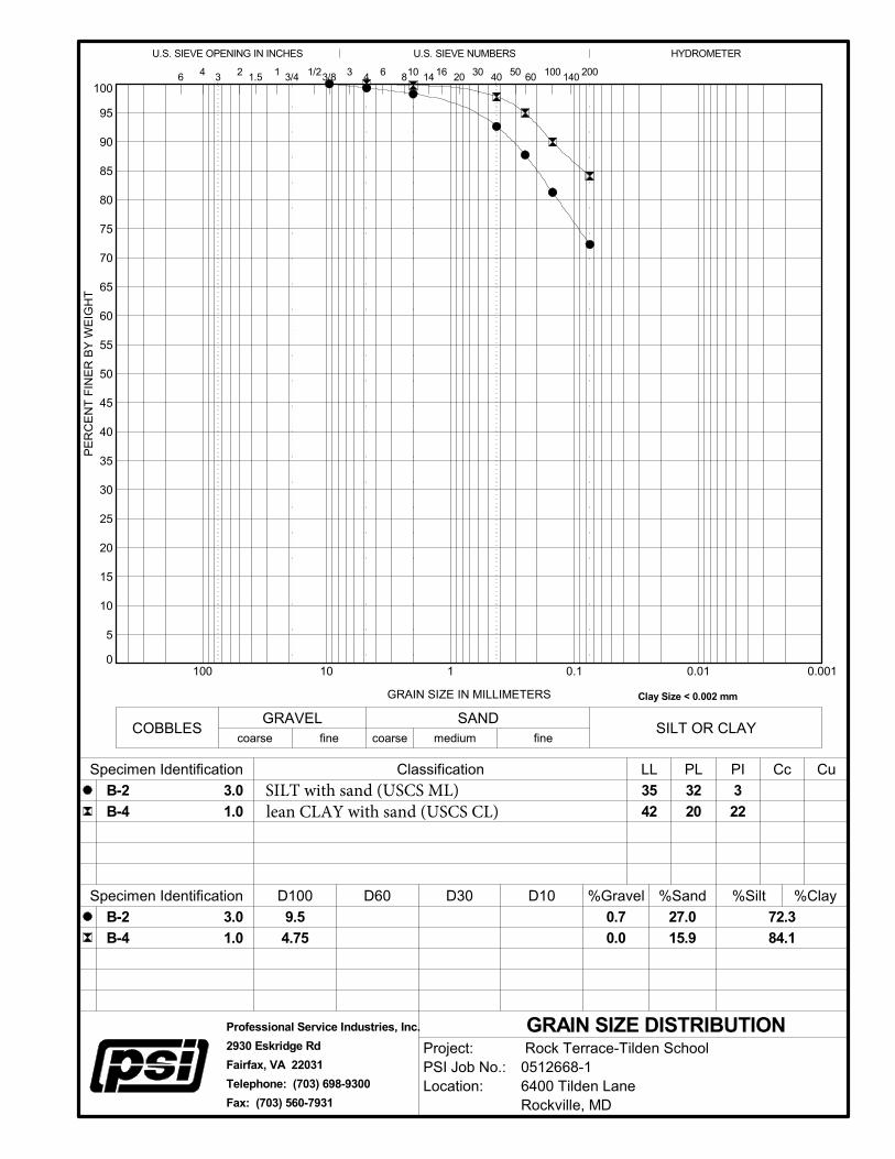
0.0010.010.1110100
2
Clay Size < 0.002 mm
COBBLES
14
Specimen Identification
Specimen Identification
PI Cc
D10
41 3/4 100 140
U.S. SIEVE OPENING IN INCHES
3
D60
9.5
4.75
200
fine
GRAIN SIZE DISTRIBUTION
20 301.5
coarse medium
3.0
1.0
Classification
D100
50
72.3
84.1
32
20
3
22
6
Cu
fine
SANDSILT OR CLAY
GRAVEL
1/23/8
HYDROMETER
3
GRAIN SIZE IN MILLIMETERS
PE
RC
EN
T F
INE
R B
Y W
EIG
HT
40
U.S. SIEVE NUMBERS
4
B-2
B-4
LL PL
6 810
%Gravel %Sand %Silt %Clay
B-2
B-4
60
coarse
D30
3.0
1.0
16
35
42
27.0
15.9
0.7
0.0
Project:PSI Job No.:Location:
Rock Terrace-Tilden School0512668-16400 Tilden LaneRockville, MD
Professional Service Industries, Inc.
2930 Eskridge Rd
Fairfax, VA 22031
Telephone: (703) 698-9300
Fax: (703) 560-7931
SILT with sand (USCS ML)lean CLAY with sand (USCS CL)
0
10
20
30
40
50
60
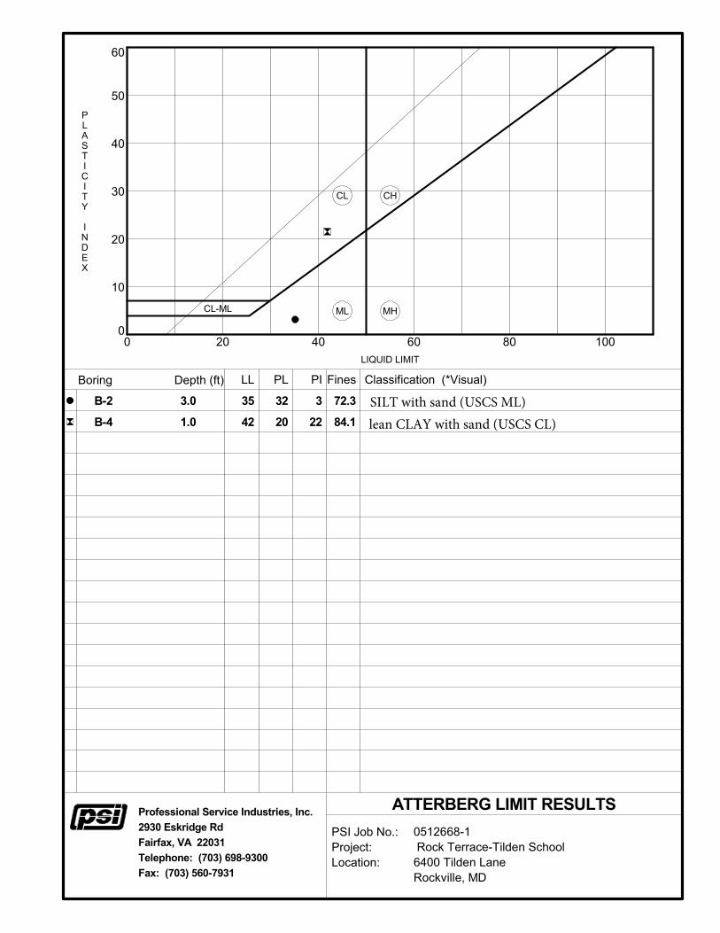
0 20 40 60 80 100
LL
PSI Job No.:Project:Location:
0512668-1 Rock Terrace-Tilden School6400 Tilden LaneRockville, MD
Fines
PLASTICITY
INDEX
CL
3.0
1.0
3
22
35
42
PI
CH
CL-ML
Classification (*Visual)
ML
Boring Depth (ft) PL
LIQUID LIMIT
MH
72.3
84.1
B-2
B-4
Professional Service Industries, Inc.
2930 Eskridge Rd
Fairfax, VA 22031
Telephone: (703) 698-9300
Fax: (703) 560-7931
ATTERBERG LIMIT RESULTS
32
20
SILT with sand (USCS ML)lean CLAY with sand (USCS CL)