Embed Size (px)
Citation preview
180
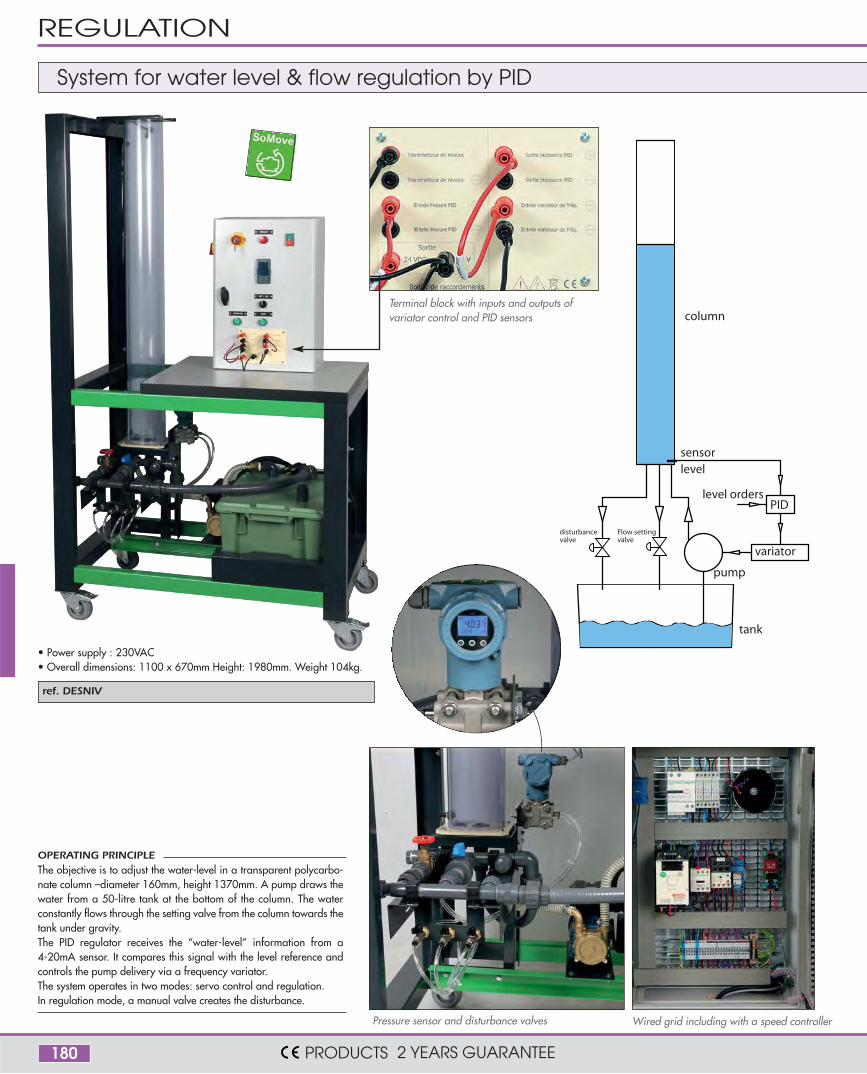
ref. DESNIV
variator
pump
sensorlevel
PIDlevel orders
column
tank
Flow settingvalve
disturbancevalve
OPERATING PRINCIPLE The objective is to adjust the water-level in a transparent polycarbo-nate column –diameter 160mm, height 1370mm. A pump draws thewater from a 50-litre tank at the bottom of the column. The waterconstantly flows through the setting valve from the column towards thetank under gravity.The PID regulator receives the “water-level” information from a4-20mA sensor. It compares this signal with the level reference andcontrols the pump delivery via a frequency variator.The system operates in two modes: servo control and regulation.In regulation mode, a manual valve creates the disturbance.
Wired grid including with a speed controllerPressure sensor and disturbance valves
Terminal block with inputs and outputs ofvariator control and PID sensors
System for water level & flow regulation by PID
• Power supply : 230VAC• Overall dimensions: 1100 x 670mm Height: 1980mm. Weight 104kg.
REGULATION
PRODUCTS 2 YEARS GUARANTEE
181
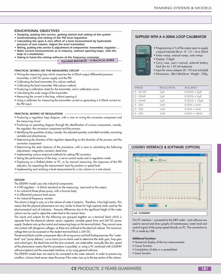
ref. LOGINIV
DESIGNThe DESNIV model uses only industrial components. • A PID regulator – 4-20mA standard on the measuring input and on the output.• An industrial three-phase pump, with a bronze body• A differential pressure level sensor• An industrial frequency variatorThe column is large in size, as is the volume of water it contains. Therefore, it has high inertia. Thismeans that the physical phenomena are very similar to those for high-capacity tanks used by thepharmaceutical and oil industries. Pressure differences due to the significant height of the watercolumn can be used to adjust the water-level to the nearest 5mm.The inputs and outputs for the following are grouped together on a terminal block which isseparate from the electrical cabinet: sensor, regulator, variable speed drive and 24V DC powersupply. Students wire up the control and measuring loops on this terminal block. They cannot comeinto contact with dangerous voltages, as these are confined to the electrical cabinet. The maximumvoltage that can be accessed on the student terminal block is 24V DC.The terminal block and the components allow all wiring errors and fault finding exercises.The “water-level” and “pump delivery” curve charts (curve charts used to determine the static gain, loop gainand critical gain, the dead time and the time constant) are noted either manually (the slow speedof the phenomena means that this procedure is possible), or using a PC combined with LOGINIVsoftware (option) and the associated interface, or by using general software.The DESNIV model does not need to be connected to the water network. In order to prevent anyoverflow, a binary level sensor stops the pump if the water rises up to the top section of the column.
PRACTICAL WORKS ON THE MEASURING CIRCUIT• Wiring the measuring loop which comprises the 4-20mA output differential pressure
transmitter, a 24V DC power supply and the PID.• Calibrating the level transmitter Dry column method.• Calibrating the level transmitter Wet column method.• Producing a calibration sheet for the transmitter, and a calibration curve.• Calculating the scale range of the transmitter.• Measuring the current in the loop, without opening it.• Using a calibrator for measuring the transmitter current or generating a 4-20mA current on
the PID input.
• Studying, putting into service, getting started and setting of the system• Understanding and setting of the PID level regulation• Calculating the span & zero offset of a level measurement by hydrostatic
pressure of wet column. Adjust the level transmitter• Wiring, putting into service & adjustment of components: transmitter, regulator …• Make current measurements as in industry, without opening loops, with the
help of a multimeter.• Taking in hand the setting software of the frequency converter.
PRACTICAL WORKS OF REGULATION• Producing a regulation loop diagram, with a view to wiring the correction component and
the measuring circuit• Producing an operating diagram through the identification of various components, namely:
the regulator, the correction component and the process.• Identifying the quantities at play, namely: the adjusted quantity, controlled variable, correcting
variable and disturbances• Determining the direction of the regulator depending on the direction of the process and the
correction component• Determining the static features of the procedure, with a view to calculating the following
adjustments: integration constant, dead time• Implementing various empirical methods for setting PID correctors• Testing the performance of the loop, in servo-control mode and in regulation mode• Displaying on a flatbed plotter or PC, or by manual measuring, the responses of the PID
adjusters, by requesting the measurement input by position or speed level• Implementing and verifying a level measurement for a dry column or a wet column
EDUCATIONAL OBJECTIVES
TEACHING RESOURCES – 19 PRACTICAL WORKS
LOGINIV INTERFACE & SOFTWARE (OPTION)
This PC interface – connected to the DB9 outlet – and software areused to record and draw graphs of instantaneous water level andcontrol signal of the pump speed directly on PC. The connection toPC is made by USB.
Additional functions• Numerical display of the two measurements• Cursor function• Compilation of data in a spreadsheet• Zoom function
SUPPLIED WITH A 4-20MA LOOP CALIBRATOR
• Programming in % of the output span to supplya typical intensity like 4 – 8 – 12 – 16 or 20mA
• linear ramps, manual ramps, auto ramps• Display: 5 digits• Carry case, user’s manual, external battery
Pack (for 6x 1.5V AA batteries)• Input for mains adapter DC 12V (not included) • Dimensions : 88x168x26mm Weight : 330g
RANGE RESOLUTION ACCURACY
4 - 20 mA 1µA 0.025% + 5µA
0 - 20mA 1µA 0.025% + 5µA
0 - 24mA 1µA 0.025% + 10µA
4 - 20V 1mV 0.05% + 5mV
0 - 20V 1mV 0.05% + 5mV
0 - 24V 1mV 0.05% + 10mV
TRAINING SYSTEMS & MODELS
PRODUCTS 2 YEARS GUARANTEE
182
Example of monitoring on the touchsreen
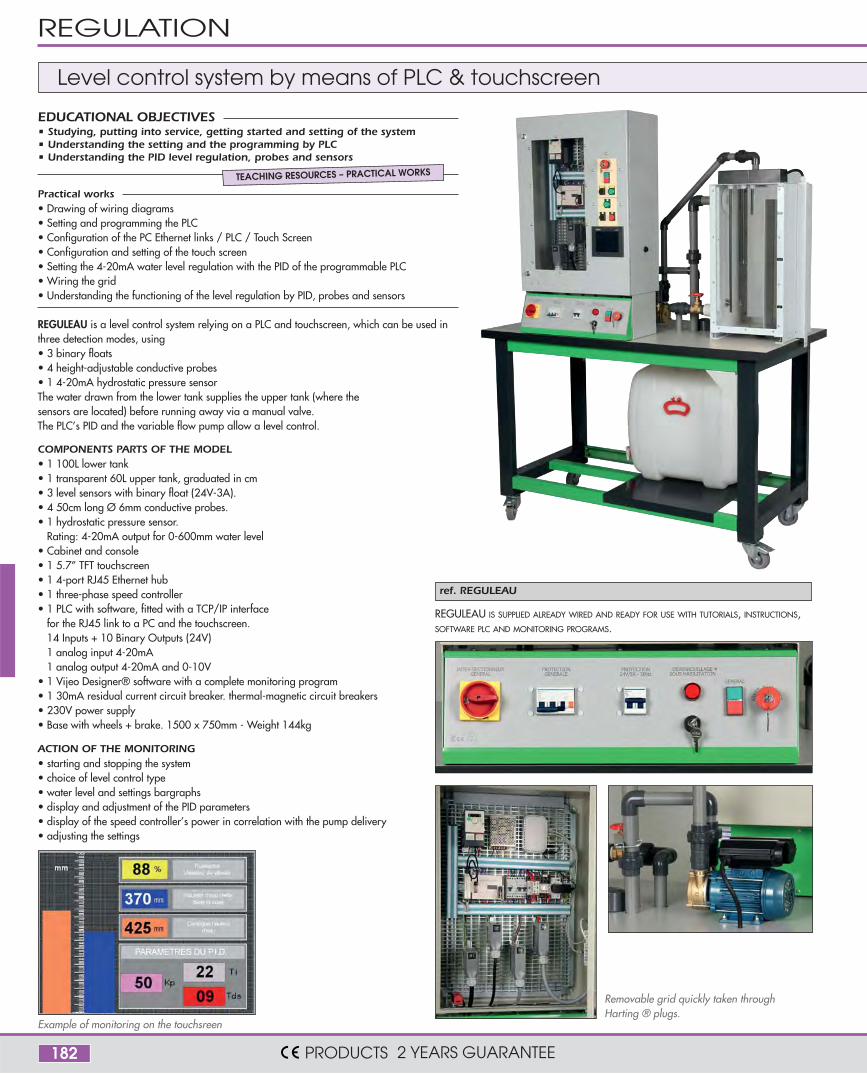
ref. REGULEAU
REGULEAU is a level control system relying on a PLC and touchscreen, which can be used inthree detection modes, using • 3 binary floats• 4 height-adjustable conductive probes• 1 4-20mA hydrostatic pressure sensor The water drawn from the lower tank supplies the upper tank (where thesensors are located) before running away via a manual valve.The PLC’s PID and the variable flow pump allow a level control.
COMPONENTS PARTS OF THE MODEL• 1 100L lower tank • 1 transparent 60L upper tank, graduated in cm• 3 level sensors with binary float (24V-3A).• 4 50cm long Ø 6mm conductive probes.• 1 hydrostatic pressure sensor.
Rating: 4-20mA output for 0-600mm water level • Cabinet and console • 1 5.7” TFT touchscreen• 1 4-port RJ45 Ethernet hub• 1 three-phase speed controller• 1 PLC with software, fitted with a TCP/IP interface
for the RJ45 link to a PC and the touchscreen. 14 Inputs + 10 Binary Outputs (24V)1 analog input 4-20mA1 analog output 4-20mA and 0-10V
• 1 Vijeo Designer® software with a complete monitoring program• 1 30mA residual current circuit breaker. thermal-magnetic circuit breakers• 230V power supply• Base with wheels + brake. 1500 x 750mm - Weight 144kg
ACTION OF THE MONITORING• starting and stopping the system• choice of level control type• water level and settings bargraphs • display and adjustment of the PID parameters • display of the speed controller’s power in correlation with the pump delivery• adjusting the settings
REGULEAU IS SUPPLIED ALREADY WIRED AND READY FOR USE WITH TUTORIALS, INSTRUCTIONS,SOFTWARE PLC AND MONITORING PROGRAMS.
Removable grid quickly taken throughHarting ® plugs.
Level control system by means of PLC & touchscreen
Practical works• Drawing of wiring diagrams• Setting and programming the PLC• Configuration of the PC Ethernet links / PLC / Touch Screen• Configuration and setting of the touch screen• Setting the 4-20mA water level regulation with the PID of the programmable PLC• Wiring the grid• Understanding the functioning of the level regulation by PID, probes and sensors
• Studying, putting into service, getting started and setting of the system• Understanding the setting and the programming by PLC• Understanding the PID level regulation, probes and sensors
EDUCATIONAL OBJECTIVES
TEACHING RESOURCES – PRACTICAL WORKS
REGULATION
PRODUCTS 2 YEARS GUARANTEE
183
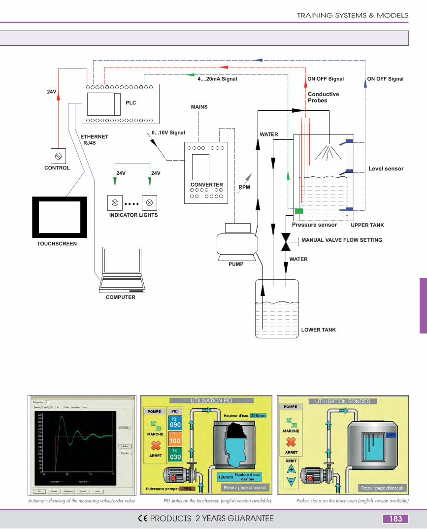
PLC
COMPUTER
4....20mA Signal
PUMP
CONVERTER
ON OFF Signal ON OFF Signal
0...10V Signal
MANUAL VALVE FLOW SETTING
INDICATOR LIGHTS
24V
LOWER TANK
UPPER TANK
24V
.. ..
CONTROL
24V
MAINS
TOUCHSCREEN
ETHERNETRJ45
RPM
WATER
WATER
ConductiveProbes
Level sensor
Pressure sensor
PID status on the touchscreen (english version available) Probes status on the touchsreen (english version available)Automatic drawing of the measuring value/order value
TRAINING SYSTEMS & MODELS
PRODUCTS 2 YEARS GUARANTEE
184
COMPONENTS COMMON TO THE BOTH REFERENCES
MAIN COMPONENT - STANDARD VERSION MAIN COMPONENT - COMMUNICATING VERSION
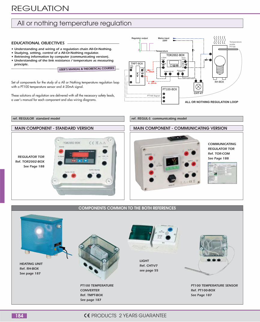
All or nothing temperature regulation
CHT-V7
4-20mAInput
4-20mA
PT100 Signal
4...20mA
Pt100
zero
Gain
-
Output
4-20mA
+
TMPT-BOXInput
4...20mA
PT100-BOX
Alarm outputOutput 24V DC
TOR2002-BOX
OR5A/240V
MAX
PowerOutput
Mains input
0
1
Regulator output
Temperature
220V
I
I
Temperatureprobe PT100
ALL OR NOTHING REGULATION LOOP
RH-BOX
ref. REGULOR standard model ref. REGUL-S communicating model
Set of components for the study of a All or Nothing temperature regulation loopwith a PT100 temperature sensor and 4-20mA signal.
These solutions of regulation are delivered with all the necessary safety leads,a user’s manual for each component and also wiring diagrams.
• Understanding and wiring of a regulation chain All-Or-Nothing.• Studying, setting, control of a All-Or-Nothing regulator.• Retrieving information by computer (communicating version).• Understanding of the link resistance / temperature as measuring
principle.
EDUCATIONAL OBJECTIVES
USER’S MANUAL & THEORETICAL COURSES
REGULATOR TOR
Ref. TOR2002-BOX
See Page 188
COMMUNICATING
REGULATOR TOR
Ref. TOR-COM
See Page 188
PT100 TEMPERATURE
CONVERTER
Ref. TMPT-BOX
See page 187
PT100 TEMPERATURE SENSOR
Ref. PT100-BOX
See Page 187
HEATING UNIT
Ref. RH-BOX
See page 187
LIGHT
Ref. CHT-V7
see page 55
REGULATION
PRODUCTS 2 YEARS GUARANTEE
185
COMPONENTS COMMON TO THE BOTH REFERENCES
4-20mA
4-20mA
PT100 Signal
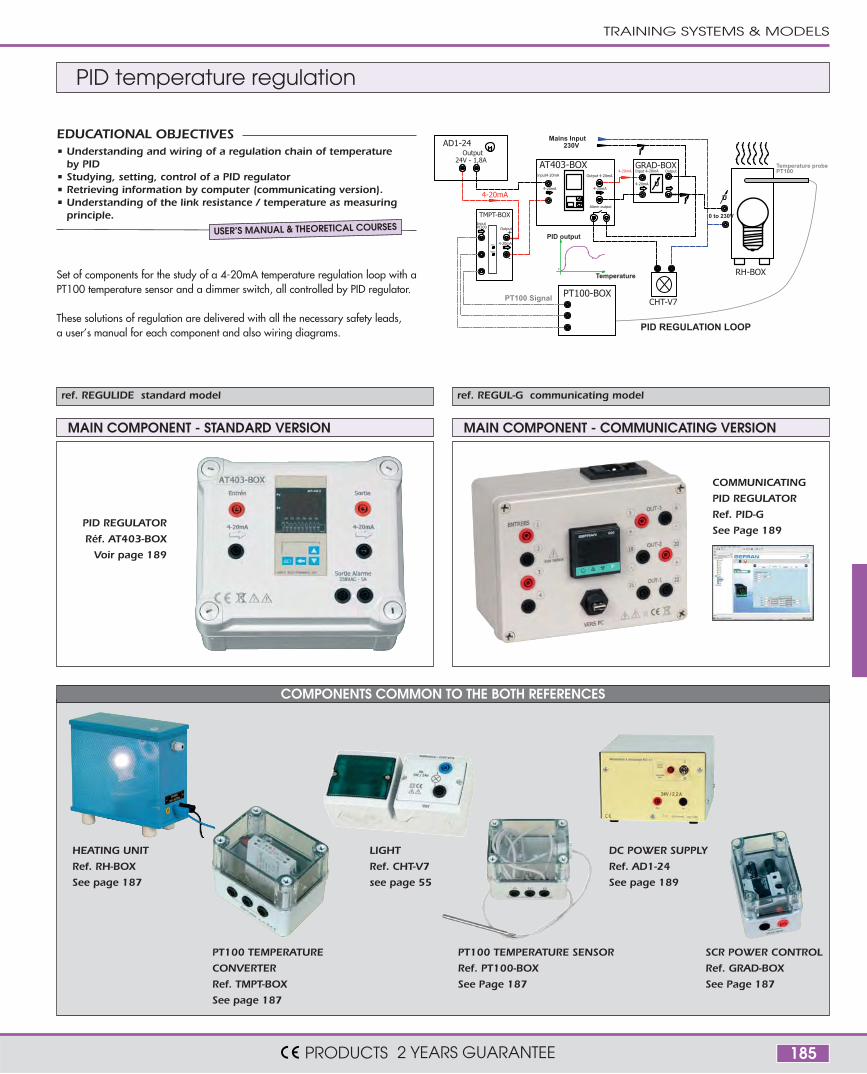
PID REGULATION LOOP
PID output
TMPT-BOXInput
Gain
Pt100
zéro
-
4-20mA
Output+
Mains Input
0
Temperature
230V
Alarm output
4-20mA 4-20mA
AT403-BOXinput4-20mA Output 4-20mA
CHT-V7
RH-BOX
Temperature probePT100
I
Input 4-20mA
4-20mA
Output
U
GRAD-BOX
AD1-24
24V - 1,8A
U
0 to 230V
I
Output
PT100-BOX
MAIN COMPONENT - STANDARD VERSION MAIN COMPONENT - COMMUNICATING VERSION
PID temperature regulation
ref. REGULIDE standard model ref. REGUL-G communicating model
Set of components for the study of a 4-20mA temperature regulation loop with aPT100 temperature sensor and a dimmer switch, all controlled by PID regulator.
These solutions of regulation are delivered with all the necessary safety leads,a user’s manual for each component and also wiring diagrams.
• Understanding and wiring of a regulation chain of temperatureby PID
• Studying, setting, control of a PID regulator• Retrieving information by computer (communicating version).• Understanding of the link resistance / temperature as measuring
principle.
EDUCATIONAL OBJECTIVES
PID REGULATOR
Réf. AT403-BOX
Voir page 189
COMMUNICATING
PID REGULATOR
Ref. PID-G
See Page 189
PT100 TEMPERATURE
CONVERTER
Ref. TMPT-BOX
See page 187
PT100 TEMPERATURE SENSOR
Ref. PT100-BOX
See Page 187
HEATING UNIT
Ref. RH-BOX
See page 187
LIGHT
Ref. CHT-V7
see page 55
SCR POWER CONTROL
Ref. GRAD-BOX
See Page 187
DC POWER SUPPLY
Ref. AD1-24
See page 189
TRAINING SYSTEMS & MODELS
PRODUCTS 2 YEARS GUARANTEE
USER’S MANUAL & THEORETICAL COURSES
186
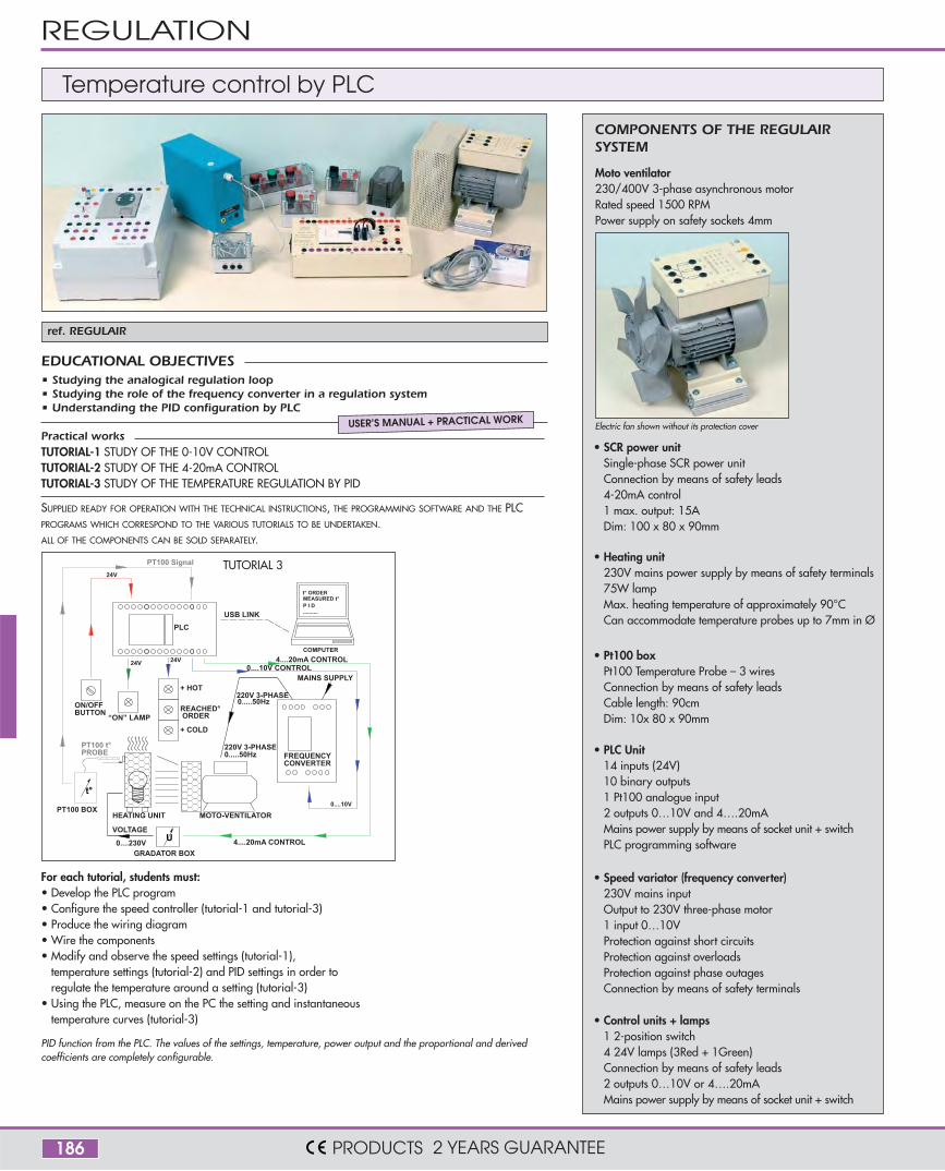
ref. REGULAIR
Electric fan shown without its protection cover
COMPONENTS OF THE REGULAIRSYSTEM
Moto ventilator230/400V 3-phase asynchronous motorRated speed 1500 RPMPower supply on safety sockets 4mm
SUPPLIED READY FOR OPERATION WITH THE TECHNICAL INSTRUCTIONS, THE PROGRAMMING SOFTWARE AND THE PLCPROGRAMS WHICH CORRESPOND TO THE VARIOUS TUTORIALS TO BE UNDERTAKEN.ALL OF THE COMPONENTS CAN BE SOLD SEPARATELY.
COMPUTER
0....10V CONTROL
0....10V
PLC
MOTO-VENTILATOR
FREQUENCYCONVERTER
220V 3-PHASE
220V 3-PHASE
MAINS SUPPLY
0.....50Hz
0.....50HzON/OFFBUTTON
“ON” LAMP
24V
24V
USB LINK
24V
+ HOT
+ COLD
REACHED°
HEATING UNITPT100 BOX
PT100 Signal
PT100 t°PROBE
GRADATOR BOX
4....20mA CONTROL
4....20mA CONTROL
VOLTAGE
t°
U
..........
MEASURED t°t° ORDER
P I D
ORDER
0....230V
TUTORIAL 3
For each tutorial, students must:• Develop the PLC program• Configure the speed controller (tutorial-1 and tutorial-3)• Produce the wiring diagram• Wire the components• Modify and observe the speed settings (tutorial-1),
temperature settings (tutorial-2) and PID settings in order toregulate the temperature around a setting (tutorial-3)
• Using the PLC, measure on the PC the setting and instantaneoustemperature curves (tutorial-3)
PID function from the PLC. The values of the settings, temperature, power output and the proportional and derivedcoefficients are completely configurable.
Temperature control by PLC
Practical worksTUTORIAL-1 STUDY OF THE 0-10V CONTROL TUTORIAL-2 STUDY OF THE 4-20mA CONTROL TUTORIAL-3 STUDY OF THE TEMPERATURE REGULATION BY PID
• Studying the analogical regulation loop• Studying the role of the frequency converter in a regulation system• Understanding the PID configuration by PLC
EDUCATIONAL OBJECTIVES
USER’S MANUAL + PRACTICAL WORK
REGULATION
PRODUCTS 2 YEARS GUARANTEE
• Control units + lamps1 2-position switch 4 24V lamps (3Red + 1Green)Connection by means of safety leads2 outputs 0…10V or 4….20mAMains power supply by means of socket unit + switch
• SCR power unitSingle-phase SCR power unitConnection by means of safety leads4-20mA control 1 max. output: 15ADim: 100 x 80 x 90mm
• Heating unit230V mains power supply by means of safety terminals75W lampMax. heating temperature of approximately 90°CCan accommodate temperature probes up to 7mm in Ø
• Speed variator (frequency converter)230V mains input Output to 230V three-phase motor1 input 0…10VProtection against short circuits Protection against overloads Protection against phase outagesConnection by means of safety terminals
• PLC Unit14 inputs (24V)10 binary outputs 1 Pt100 analogue input2 outputs 0…10V and 4….20mAMains power supply by means of socket unit + switchPLC programming software
• Pt100 boxPt100 Temperature Probe – 3 wiresConnection by means of safety leads Cable length: 90cmDim: 10x 80 x 90mm

187
ref. TMPT-BOX
ref. RH-BOX
ref. GRAD-BOX
ref. PT100-BOX
TMPT-BOX
Output
Example of use TMPT-BOX unit
4-20mA
Pt100Input
zero
Gain 4-20mA
+
-
PID
Temperature probe
HEATING UNIT
PT100 TEMPERATURE SENSOR
SINGLE-PHASE SCR POWER CONTROL
SCR POWER CONTROLS
PT100 - 4-20mA TEMPERATURE CONVERTER
• This unit allows the connection of a temperature probe to the 4-20mA inputof the PID.
• Adjustment of the signal gain & zero thanks 2 potentiometers• Compatibility with the 2 or 3 wires temperature probes (see PT100-BOX)• Input/output connection on safety sockets 4mm• Works without any external supply• DIMS: 77 x 106 x 92 mm
230V power supply heating unit fitted with a 75W lamp. Completely safe thanksto two 4mm double channel terminals. The Pt100 temperature probe, with a maxi-mum diameter of 7mm, can be inserted sideways (e.g. PT100-BOX).Powered via 230V mains supply or SCR power unit (e.g. GRAD-BOX), whichregulates the light intensity and therefore the temperature in the unit.This temperature can be measured by a temperature probe (e.g. PT100-BOX)
Features• 75W incandescent lamp – E27• Mains power supply via 2 safety terminals • Inlet port can accommodate temperature probe up to 7mm in Ø maximum• Dim: 250 x 250 x 110mm
FEATURES• Connection by means of safety leads.• Max. current output: 15A• Dim: 100 x 80 x 90mm
Controls the power in the charge by varying theconduction angle of the thyristors according tothe control current of 4-20mA.Can be connected directly to the built-in PLCunit ref. AUTO-BOX-A.
These SCR power units controlthe power in the charge byvarying the conduction time ofthe thyristors according to thecontrol current 4 – 20mA
The power, the output power,the control input 4-20mA andthe potentiometer can be usedon 4mm safety terminals.
A potentiometer front allows tovary the conduction time.
Compatible with resistive loadsonly.
Ref. CIA-GRA30M CIA-GRA30T
Supply type Single-phase 3-phase
Main supply 230VAC 3 x 400VAC
Auxiliary supply -220VAC from mains
(for the cooling fan)
Output voltage 230VAC 3 x 400VAC
Max. output current 30A 30A
Control4-20mA
and/or potentiometer
4-20mA
and/or potentiometer
Dimensions 290 x 190mm x 135mm 390 x 280mm x 185mm
FEATURES• Connection by means
of safety leads.• Dim: 100 x 80 x 90mm• Cable length: 90cm
SRC power control and loads for regulation
TRAINING SYSTEMS & MODELS
PRODUCTS 2 YEARS GUARANTEE
188
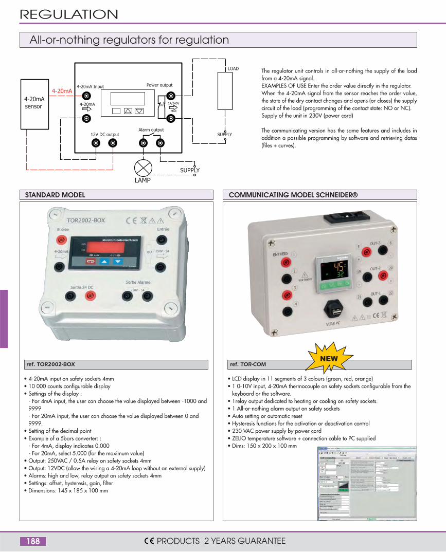
ref. TOR2002-BOX ref. TOR-COM
• 4-20mA input on safety sockets 4mm• 10 000 counts configurable display• Settings of the display :
- For 4mA input, the user can choose the value displayed between -1000 and9999- For 20mA input, the user can choose the value displayed between 0 and9999.
• Setting of the decimal point• Example of a 5bars converter: :
- For 4mA, display indicates 0.000- For 20mA, select 5.000 (for the maximum value)
• Output: 250VAC / 0.5A relay on safety sockets 4mm• Output: 12VDC (allow the wiring a 4-20mA loop without an external supply)• Alarms: high and low, relay output on safety sockets 4mm• Settings: offset, hysteresis, gain, filter• Dimensions: 145 x 185 x 100 mm
• LCD display in 11 segments of 3 colours (green, red, orange)• 1 0-10V input, 4-20mA thermocouple on safety sockets configurable from the
keyboard or the software.• 1relay output dedicated to heating or cooling on safety sockets.• 1 All-or-nothing alarm output on safety sockets• Auto setting or automatic reset• Hysteresis functions for the activation or deactivation control• 230 VAC power supply by power cord• ZELIO temperature software + connection cable to PC supplied• Dims: 150 x 200 x 100 mm
4-20mA
4-20mA OU
4-20mA Input Power output
5A/240V
MAX
12V DC outputAlarm output
4-20mAsensor
SUPPLY
LAMP
SUPPLY
LOAD The regulator unit controls in all-or-nothing the supply of the loadfrom a 4-20mA signal.EXAMPLES OF USE Enter the order value directly in the regulator.When the 4-20mA signal from the sensor reaches the order value,the state of the dry contact changes and opens (or closes) the supplycircuit of the load (programming of the contact state: NO or NC).Supply of the unit in 230V (power cord)
The communicating version has the same features and includes inaddition a possible programming by software and retrieving datas(files + curves).
STANDARD MODEL
All-or-nothing regulators for regulation
COMMUNICATING MODEL SCHNEIDER®
REGULATION
PRODUCTS 2 YEARS GUARANTEE
189
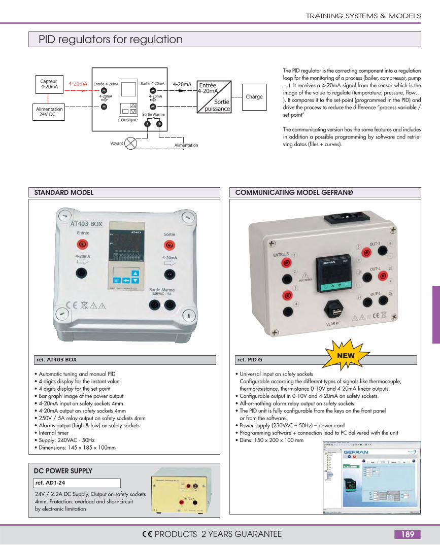
ref. AT403-BOX
ref. AD1-24
ref. PID-G
DC POWER SUPPLY
• Automatic tuning and manual PID• 4 digits display for the instant value• 4 digits display for the set-point• Bar graph image of the power output• 4-20mA input on safety sockets 4mm• 4-20mA output on safety sockets 4mm• 250V / 5A relay output on safety sockets 4mm• Alarms output (high & low) on safety sockets• Internal timer• Supply: 240VAC - 50Hz• Dimensions: 145 x 185 x 100mm
• Universal input on safety socketsConfigurable according the different types of signals like thermocouple,thermoresistance, thermistance 0-10V and 4-20mA linear outputs.
• Configurable output in 0-10V and 4-20mA on safety sockets.• All-or-nothing alarm relay output on safety sockets.• The PID unit is fully configurable from the keys on the front panel
or from the software.• Power supply (230VAC – 50Hz) – power cord• Programming software + connection lead to PC delivered with the unit• Dims: 150 x 200 x 100 mm
4-20mA
4-20mA
Entrée 4-20mA Sortie 4-20mA
Sortie Alarme
Capteur4-20mA
AlimentationVoyant
4-20mA
Entrée 4-20mA
Sortiepuissance
Charge
Alimentation24V DC
4-20mA
Consigne
24V / 2.2A DC Supply. Output on safety sockets4mm. Protection: overload and short-circuitby electronic limitation
The PID regulator is the correcting component into a regulationloop for the monitoring of a process (boiler, compressor, pump…). It receives a 4-20mA signal from the sensor which is theimage of the value to regulate (temperature, pressure, flow…). It compares it to the set-point (programmed in the PID) anddrive the process to reduce the difference “process variable /set-point”
The communicating version has the same features and includesin addition a possible programming by software and retrie-ving datas (files + curves).
STANDARD MODEL COMMUNICATING MODEL GEFRAN®
PID regulators for regulation
TRAINING SYSTEMS & MODELS
PRODUCTS 2 YEARS GUARANTEE
190
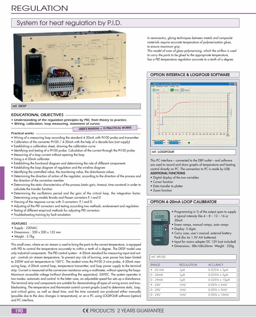
ref. DESP
ref. LOGIFOUR
FEATURES• Supply : 230VAC• Dimensions : 350 x 200 x 122 mm• Weight : 3.7kg
This small oven, where an air stream is used to bring the parts to the correct temperature, is equippedwith PID to control the temperature accurately to within a tenth of a degree. The DESP model usesonly industrial components. The PID control system - 4-20mA standard for measuring input and out-put - controls air stream temperature. To prevent any risk of burning, oven power has been limitedto 250W and air temperature to 100°C. The student wires the Pt100 3-wire probe, 4-20mA mea-suring loop, 4-20mA control loop, temperature transmitter, and loop power supply to the terminalstrip. Current is measured at the conversion resistance using a multimeter, without opening the loops.Maximum accessible voltage (without dismantling the apparatus): 24VDC. The system operates intwo modes: automatic and control. In the latter case, an adjustable-speed fan sets up a disturbance.The terminal strip and components are suitable for demonstrating all types of wiring errors and trou-bleshooting. The temperature and thermostat control current graphs (used to determine static, loop,and critical gains, as well as dead time, and the time constant) are produced either manually(possible due to the slow changes in temperature), or on a PC using LOGIFOUR software (option)and PC interface.
This PC interface – connected to the DB9 outlet – and softwareare used to record and draw graphs of temperature and heatingcontrol directly on PC. The connection to PC is made by USB.ADDITIONAL FUNCTIONS• Digital display of the two variables• Cursor function• Data transfer to plotter• Zoom function
System for heat regulation by P.I.D.
Practical works• Wiring of a measuring loop according the standard 4-20mA with Pt100 probe and transmitter• Calibration of the converter Pt100 / 4-20mA with the help of a decade box (not supply)• Establishing a calibration sheet, drawing the calibration curve• Identifying and testing of a Pt100 probe. Calculation of the current through the Pt100 probe.• Measuring of a loop current without opening the loop• Using a 4-20mA calibrator• Establishing the functional diagram and determining the role of different components• Establishing the loop diagram of regulation and the wireline diagram• Identifying the controlled value, the monitoring value, the disturbance values.• Determining the direction of action of the regulator, according to the direction of the process and
the direction of the correction member• Determining the static characteristics of the process (static gain, timeout, time constant) in order to
calculate the transfer function• Determining the oscillations period and the gain of the critical loop, the integration factor.
Determining using models Broida and Pessen correctors P, I and D• Viewing of the response curves with 3 correctors: P, I and D• Adjusting of the PID correctors and testing according two methods: enslavement and regulation• Testing of different empirical methods for adjusting PID correctors• Troubleshooting training by fault simulation
• Understanding of the regulation principles by PID, from theory to practice.• Wiring, calibration, loop measuring, statement of curves.
EDUCATIONAL OBJECTIVES
USER’S MANUAL + 15 PRACTICAL WORKS
OPTION INTERFACE & LOGIFOUR SOFTWARE
OPTION 4-20mA LOOP CALIBRATOR
ref. VA100
• Programming in % of the output span to supplya typical intensity like 4 – 8 – 12 – 16 or20mA
• linear ramps, manual ramps, auto ramps• Display: 5 digits• Carry case, user’s manual, external battery
Pack (for 6x 1.5V AA batteries)• Input for mains adapter DC 12V (not included) • Dimensions : 88x168x26mm Weight : 330g
RANGE RESOLUTION ACCURACY
4 - 20 mA 1µA 0.025% + 5µA
0 - 20mA 1µA 0.025% + 5µA
0 - 24mA 1µA 0.025% + 10µA
4 - 20V 1mV 0.05% + 5mV
0 - 20V 1mV 0.05% + 5mV
0 - 24V 1mV 0.05% + 10mV
REGULATION
PRODUCTS 2 YEARS GUARANTEE
In aeronautics, gluing techniques between metals and compositematerials require accurate temperature of polymerization glues,to ensure maximum grip.This model of oven of glues polymerizing, which the airflow is usedto carry the parts to be glued to the appropriate temperature,has a PID temperature regulation accurate to a tenth of a degree.

191
ref. CLIMABOX
ref. MAQCOS
ref. PSYJR
Air conditionning system Power factor correction system
MAIN COMPONENTS• A complete air conditioning system• An extractor fan• Many heating resistors• Two counters : start and time• Four digital thermometers• One alarm buzzer
TECHNICAL SPECIFICATIONS• 13 displays: 3 x A , 3 x W , 3 x power factor , 3 x VAR , 1 x V• 10 condensers: 0.1µF - 41µF• Fuse protection• Dimensions: 510 x 400 x 150 mm - Weight 8.2kg
FEATURES OF THE BOARD• 230V/50Hz single-phase power supply• Dim : (L x W x H) 550 x 450 x 650 mm - Weight: 45kg
The MAQCOS model is designed for studying and rectifying power factors.It consists of three branches:• source branch, S, representing the energy supplied by the electricity mains (Network)• plant branch, L , symbolizing a plant's energy consumption• plant branch, C, including the padding condensers (integrated in the model and
connected using jumper wires)Each branch is equipped with the same measuring instruments:• ammeter• wattmeter, measuring active energy• Power factor meter, measuring the power factor• varmeter, measuring reactive energyStudents are thus able to compare four electrical variables in the three branches at thesame time. They will observe (surprisingly?) that the source current value in the mainsnetwork branch may be much lower than the value in the plant branches. That sourcereactive energy is close to zero when power factor is around 1, whereas plant reactiveenergy is at maximum value. The model shows the impact of a power factor regulatoron the cost per kWh transmitted and the resulting electricity bill. MAQCOS is supplied with a fluorescent tube and IPXX connection.CLIMABOX is an air conditioned industrial electric board, often used in industry
whenelectronic components need a steady temperature.Delivered with wiring diagrams and practical works.
VARIABLE INDUCTANCE OPTION
Students have to find out the pure resistancesand inductances of an installation, withoutinterrupting its operation and with a view todeciding on the compensation condenserbattery to activate, via a power factor regu-lator.
Proposed Practical Works• Temperature stabilization by simple fan, air conditioner alone, by ventilation
and air conditioner.• Sudden internal heat• External temperature too low (winter)• Condensation problems• Incorrect design of the air conditioner preventing temperature stabilization• Adjustment of the temperature set point
• Understanding of the functioning of an air conditioning system• Performing maintenance operations
EDUCATIONAL OBJECTIVES
USER’S MANUAL + 6 PRACTICAL WORKS
Proposed Practical Works• studying of an industrial lighting installation from fluorescent tubes:
Current of branches – power of the transport line with and without power factorcorrection – Active and reactive power in the branches – Fresnel diagrams
• Study of the pure inductance of a plant in working in order to determine thecapacitor bank necessaryRole of automatic compensation
• Study of resonance, max / min current
• Studying the power factor & Demonstrating the interest of powerfactor corrector for the cost of the power (kWh)
EDUCATIONAL OBJECTIVES
USER’S MANUAL + 3 PRACTICAL WORKS
TRAINING SYSTEMS & MODELS
PRODUCTS 2 YEARS GUARANTEE
192
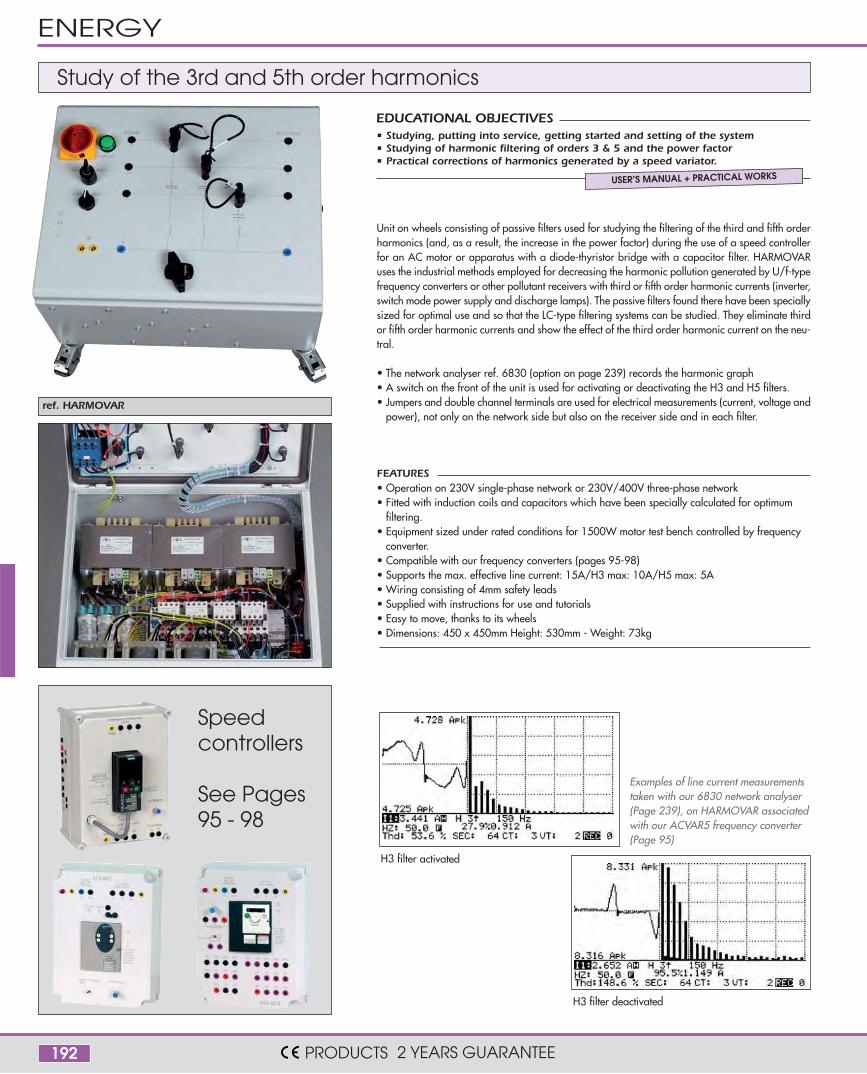
ref. HARMOVAR
Speedcontrollers
See Pages95 - 98
FEATURES• Operation on 230V single-phase network or 230V/400V three-phase network• Fitted with induction coils and capacitors which have been specially calculated for optimum
filtering. • Equipment sized under rated conditions for 1500W motor test bench controlled by frequency
converter.• Compatible with our frequency converters (pages 95-98)• Supports the max. effective line current: 15A/H3 max: 10A/H5 max: 5A• Wiring consisting of 4mm safety leads• Supplied with instructions for use and tutorials • Easy to move, thanks to its wheels• Dimensions: 450 x 450mm Height: 530mm - Weight: 73kg
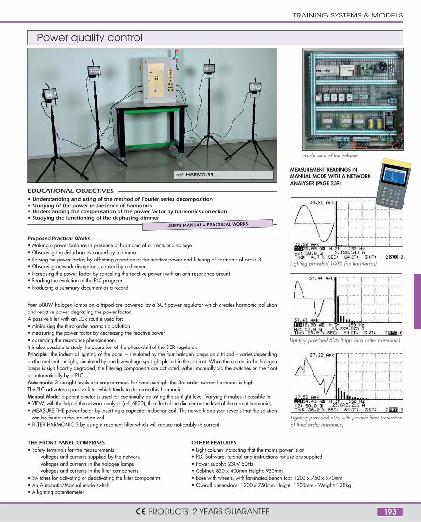
H3 filter deactivated
H3 filter activated
Unit on wheels consisting of passive filters used for studying the filtering of the third and fifth orderharmonics (and, as a result, the increase in the power factor) during the use of a speed controllerfor an AC motor or apparatus with a diode-thyristor bridge with a capacitor filter. HARMOVARuses the industrial methods employed for decreasing the harmonic pollution generated by U/f-typefrequency converters or other pollutant receivers with third or fifth order harmonic currents (inverter,switch mode power supply and discharge lamps). The passive filters found there have been speciallysized for optimal use and so that the LC-type filtering systems can be studied. They eliminate thirdor fifth order harmonic currents and show the effect of the third order harmonic current on the neu-tral.
• The network analyser ref. 6830 (option on page 239) records the harmonic graph• A switch on the front of the unit is used for activating or deactivating the H3 and H5 filters.• Jumpers and double channel terminals are used for electrical measurements (current, voltage and
power), not only on the network side but also on the receiver side and in each filter.
Study of the 3rd and 5th order harmonics
• Studying, putting into service, getting started and setting of the system• Studying of harmonic filtering of orders 3 & 5 and the power factor• Practical corrections of harmonics generated by a speed variator.
EDUCATIONAL OBJECTIVES
USER’S MANUAL + PRACTICAL WORKS
Examples of line current measurementstaken with our 6830 network analyser(Page 239), on HARMOVAR associatedwith our ACVAR5 frequency converter(Page 95)
ENERGY
PRODUCTS 2 YEARS GUARANTEE
193
ref. HARMO-35
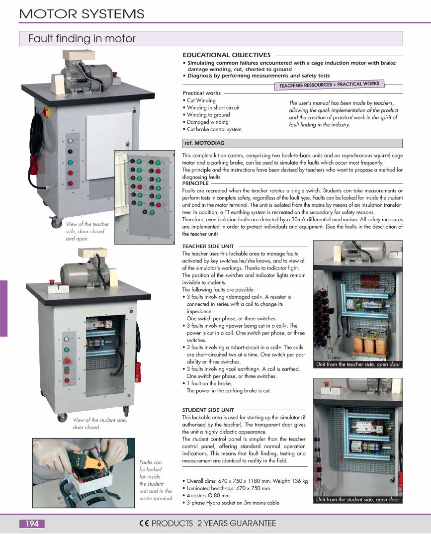
Lighting provided 50% (high third order harmonic)
Four 500W halogen lamps on a tripod are powered by a SCR power regulator which creates harmonic pollutionand reactive power degrading the power factor.A passive filter with an LC circuit is used for:• minimising the third order harmonic pollution• measuring the power factor by decreasing the reactive power • observing the resonance phenomenon.It is also possible to study the operation of the phase-shift of the SCR regulator.Principle : the industrial lighting of the panel – simulated by the four halogen lamps on a tripod – varies dependingon the ambient sunlight, simulated by one low-voltage spotlight placed in the cabinet. When the current in the halogenlamps is significantly degraded, the filtering components are activated, either manually via the switches on the frontor automatically by a PLC. Auto mode: 3 sunlight levels are programmed. For weak sunlight the 3rd order current harmonic is high.The PLC activates a passive filter which tends to decrease this harmonic. Manual Mode: a potentiometer is used for continually adjusting the sunlight level. Varying it makes it possible to:• VIEW, with the help of the network analyser (ref. 6830), the effect of the dimmer on the level of the current harmonics;• MEASURE THE power factor by inserting a capacitor induction coil. The network analyser reveals that the solution
can be found in the induction coil. • FILTER HARMONIC 3 by using a resonant filter which will reduce noticeably its current
MEASUREMENT READINGS INMANUAL MODE WITH A NETWORKANALYSER (PAGE 239)
Lighting provided 100% (no harmonics)
Lighting provided 50% with passive filter (reductionof third order harmonic)
THE FRONT PANEL COMPRISES• Safety terminals for the measurements
- voltages and currents supplied by the network- voltages and currents in the halogen lamps- voltages and currents in the filter components
• Switches for activating or deactivating the filter components • An Automatic/Manual mode switch• A lighting potentiometer
OTHER FEATURES• Light column indicating that the mains power is on• PLC Software, tutorial and instructions for use are supplied.• Power supply: 230V 50Hz• Cabinet: 820 x 400mm Height: 930mm• Base with wheels, with laminated bench-top: 1200 x 750 x 970mm• Overall dimensions: 1200 x 750mm Height: 1900mm - Weight: 128kg
Inside view of the cabinet
Power quality control
Proposed Practical Works• Making a power balance in presence of harmonic of currents and voltage• Observing the disturbances caused by a dimmer• Raising the power factor, by offsetting a portion of the reactive power and filtering of harmonic of order 3• Observing network disruptions, caused by a dimmer• Increasing the power factor by canceling the reactive power (with an anti-resonance circuit)• Reading the evolution of the PLC program• Producing a summary document as a record
• Understanding and using of the method of Fourier series decomposition• Studying of the power in presence of harmonics• Understanding the compensation of the power factor by harmonics correction• Studying the functioning of the dephasing dimmer
EDUCATIONAL OBJECTIVES
USER’S MANUAL + PRACTICAL WORKS
TRAINING SYSTEMS & MODELS
PRODUCTS 2 YEARS GUARANTEE
194
ref. MOTODIAG
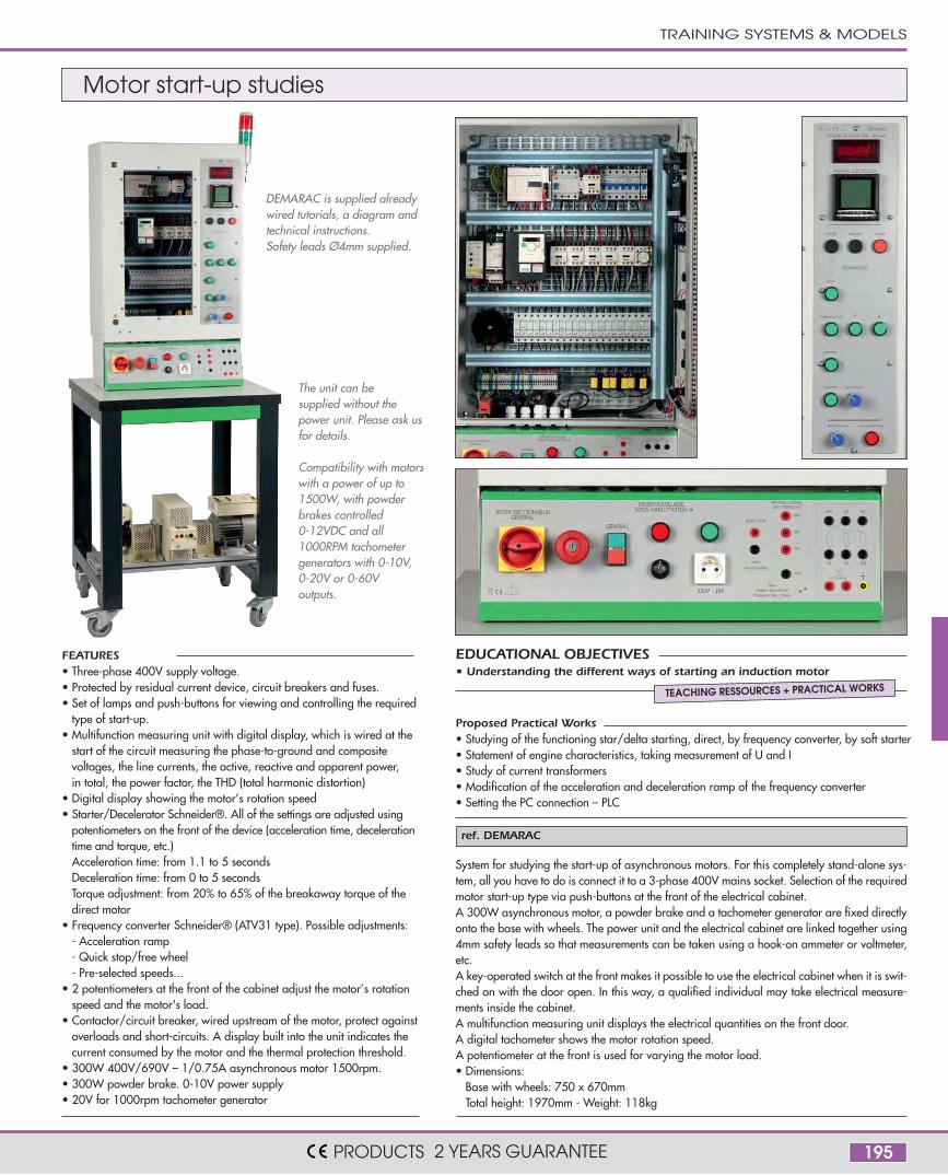
Unit from the teacher side, open door
Unit from the student side, open door.
STUDENT SIDE UNITThis lockable area is used for starting up the simulator (ifauthorised by the teacher). The transparent door givesthe unit a highly didactic appearance.The student control panel is simpler than the teachercontrol panel, offering standard normal operationindications. This means that fault finding, testing andmeasurement are identical to reality in the field.
This complete kit on casters, comprising two back-to-back units and an asynchronous squirrel cagemotor and a parking brake, can be used to simulate the faults which occur most frequently.The principle and the instructions have been devised by teachers who want to propose a method fordiagnosing faults.PRINCIPLEFaults are recreated when the teacher rotates a single switch. Students can take measurements orperform tests in complete safety, regardless of the fault type. Faults can be looked for inside the studentunit and in the motor terminal. The unit is isolated from the mains by means of an insulation transfor-mer. In addition, a TT earthing system is recreated on the secondary for safety reasons.Therefore, even isolation faults are detected by a 30mA differential mechanism. All safety measuresare implemented in order to protect individuals and equipment. (See the faults in the description ofthe teacher unit)
TEACHER SIDE UNITThe teacher uses this lockable area to manage faultsactivated by key switches he/she knows, and to view allof the simulator's workings. Thanks to indicator light.The position of the switches and indicator lights remaininvisible to students.The following faults are possible:• 3 faults involving «damaged coil». A resistor is
connected in series with a coil to change itsimpedance.One switch per phase, or three switches.
• 3 faults involving «power being cut in a coil». Thepower is cut in a coil. One switch per phase, or threeswitches.
• 3 faults involving a «short-circuit in a coil». The coilsare short-circuited two at a time. One switch per pos-sibility or three switches.
• 3 faults involving «coil earthing». A coil is earthed.One switch per phase, or three switches.
• 1 fault on the brake.The power in the parking brake is cut.
The user’s manual has been made by teachers,allowing the quick implementation of the productand the creation of practical work in the spirit offault finding in the industry.
Faults canbe lookedfor insidethe studentunit and in themotor terminal.
View of the student side,door closed
View of the teacherside, door closedand open.
• Overall dims: 670 x 750 x 1180 mm. Weight: 136 kg• Laminated bench-top: 670 x 750 mm• 4 casters Ø 80 mm• 3-phase Hypra socket on 5m mains cable
Fault finding in motor
Practical works• Cut Winding• Winding in short circuit• Winding to ground• Damaged winding• Cut brake control system
• Simulating common failures encountered with a cage induction motor with brake:damage winding, cut, shorted to ground
• Diagnosis by performing measurements and safety tests
EDUCATIONAL OBJECTIVES
TEACHING RESSOURCES + PRACTICAL WORKS
MOTOR SYSTEMS
PRODUCTS 2 YEARS GUARANTEE
195
ref. DEMARAC
Motor start-up studies
The unit can besupplied without thepower unit. Please ask usfor details.
Compatibility with motorswith a power of up to1500W, with powderbrakes controlled0-12VDC and all1000RPM tachometergenerators with 0-10V,0-20V or 0-60Voutputs.
System for studying the start-up of asynchronous motors. For this completely stand-alone sys-tem, all you have to do is connect it to a 3-phase 400V mains socket. Selection of the requiredmotor start-up type via push-buttons at the front of the electrical cabinet.A 300W asynchronous motor, a powder brake and a tachometer generator are fixed directlyonto the base with wheels. The power unit and the electrical cabinet are linked together using4mm safety leads so that measurements can be taken using a hook-on ammeter or voltmeter,etc.A key-operated switch at the front makes it possible to use the electrical cabinet when it is swit-ched on with the door open. In this way, a qualified individual may take electrical measure-ments inside the cabinet.A multifunction measuring unit displays the electrical quantities on the front door.A digital tachometer shows the motor rotation speed.A potentiometer at the front is used for varying the motor load.• Dimensions:
Base with wheels: 750 x 670mmTotal height: 1970mm - Weight: 118kg
DEMARAC is supplied alreadywired tutorials, a diagram andtechnical instructions.Safety leads Ø4mm supplied.
FEATURES• Three-phase 400V supply voltage.• Protected by residual current device, circuit breakers and fuses.• Set of lamps and push-buttons for viewing and controlling the required
type of start-up.• Multifunction measuring unit with digital display, which is wired at the
start of the circuit measuring the phase-to-ground and compositevoltages, the line currents, the active, reactive and apparent power,in total, the power factor, the THD (total harmonic distortion)
• Digital display showing the motor’s rotation speed• Starter/Decelerator Schneider®. All of the settings are adjusted using
potentiometers on the front of the device (acceleration time, decelerationtime and torque, etc.)Acceleration time: from 1.1 to 5 secondsDeceleration time: from 0 to 5 secondsTorque adjustment: from 20% to 65% of the breakaway torque of thedirect motor
• Frequency converter Schneider® (ATV31 type). Possible adjustments:- Acceleration ramp- Quick stop/free wheel- Pre-selected speeds...
• 2 potentiometers at the front of the cabinet adjust the motor’s rotationspeed and the motor's load.
• Contactor/circuit breaker, wired upstream of the motor, protect againstoverloads and short-circuits. A display built into the unit indicates thecurrent consumed by the motor and the thermal protection threshold.
• 300W 400V/690V – 1/0.75A asynchronous motor 1500rpm.• 300W powder brake. 0-10V power supply• 20V for 1000rpm tachometer generator
Proposed Practical Works• Studying of the functioning star/delta starting, direct, by frequency converter, by soft starter• Statement of engine characteristics, taking measurement of U and I• Study of current transformers• Modification of the acceleration and deceleration ramp of the frequency converter• Setting the PC connection – PLC
• Understanding the different ways of starting an induction motorEDUCATIONAL OBJECTIVES
TEACHING RESSOURCES + PRACTICAL WORKS
TRAINING SYSTEMS & MODELS
PRODUCTS 2 YEARS GUARANTEE
196
ref. MICROMAG
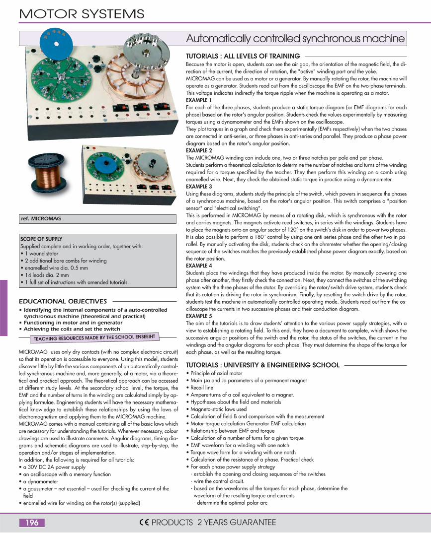
TUTORIALS : ALL LEVELS OF TRAININGBecause the motor is open, students can see the air gap, the orientation of the magnetic field, the di-rection of the current, the direction of rotation, the "active" winding part and the yoke.MICROMAG can be used as a motor or a generator. By manually rotating the rotor, the machine willoperate as a generator. Students read out from the oscilloscope the EMF on the two-phase terminals.This voltage indicates indirectly the torque ripple when the machine is operating as a motor. EXAMPLE 1For each of the three phases, students produce a static torque diagram (or EMF diagrams for eachphase) based on the rotor's angular position. Students check the values experimentally by measuringtorques using a dynamometer and the EMFs shown on the oscilloscope.They plot torques in a graph and check them experimentally (EMFs respectively) when the two phasesare connected in anti-series, or three phases in anti-series and parallel. They produce a phase powerdiagram based on the rotor's angular position.EXAMPLE 2The MICROMAG winding can include one, two or three notches per pole and per phase.Students perform a theoretical calculation to determine the number of notches and turns of the windingrequired for a torque specified by the teacher. They then perform this winding on a comb usingenamelled wire. Next, they check the obtained static torque in practice using a dynamometer.EXAMPLE 3Using these diagrams, students study the principle of the switch, which powers in sequence the phasesof a synchronous machine, based on the rotor's angular position. This switch comprises a "positionsensor" and "electrical switching".This is performed in MICROMAG by means of a rotating disk, which is synchronous with the rotorand carries magnets. The magnets activate reed switches, in series with the windings. Students haveto place the magnets onto an angular sector of 120° on the switch’s disk in order to power two phases.It is also possible to perform a 180° control by using one anti-series phase and the other two in pa-rallel. By manually activating the disk, students check on the ohmmeter whether the opening/closingsequence of the switches matches the previously established phase power diagram exactly, based onthe rotor position.EXAMPLE 4Students place the windings that they have produced inside the motor. By manually powering onephase after another, they firstly check the connection. Next, they connect the switches of the switchingsystem with the three phases of the stator. By overriding the rotor/switch drive system, students checkthat its rotation is driving the rotor in synchronism. Finally, by resetting the switch drive by the rotor,students test the machine in automatically controlled operating mode. Students read out from the os-cilloscope the currents in two successive phases and their conduction diagram.EXAMPLE 5The aim of the tutorials is to draw students’ attention to the various power supply strategies, with aview to establishing a rotating field. To this end, they have a document to complete, which shows thesuccessive angular positions of the switch and the rotor, the status of the switches, the current in thewindings and the angular diagrams for each phase. They must determine the shape of the torque foreach phase, as well as the resulting torque.
TUTORIALS : UNIVERSITY & ENGINEERING SCHOOL• Principle of axial motor• Main µa and Ja parameters of a permanent magnet• Recoil line• Ampere-turns of a coil equivalent to a magnet.• Hypotheses about the field and materials• Magneto-static laws used• Calculation of field B and comparison with the measurement• Motor torque calculation Generator EMF calculation• Relationship between EMF and torque• Calculation of a number of turns for a given torque• EMF waveform for a winding with one notch• Torque wave form for a winding with one notch• Calculation of the resistance of a phase. Practical check• For each phase power supply strategy
- establish the opening and closing sequences of the switches- wire the control circuit.- based on the waveforms of the torques for each phase, determine the
waveform of the resulting torque and currents- determine the optimal polar arc
SCOPE OF SUPPLYSupplied complete and in working order, together with:• 1 wound stator• 2 additional bare combs for winding• enamelled wire dia. 0.5 mm• 14 leads dia. 2 mm• 1 full set of instructions with amended tutorials.
MICROMAG uses only dry contacts (with no complex electronic circuit)so that its operation is accessible to everyone. Using this model, studentsdiscover little by little the various components of an automatically control-led synchronous machine and, more generally, of a motor, via a theore-tical and practical approach. The theoretical approach can be accessedat different study levels. At the secondary school level, the torque, theEMF and the number of turns in the winding are calculated simply by ap-plying formulae. Engineering students will have the necessary mathema-tical knowledge to establish these relationships by using the laws ofelectromagnetism and applying them to the MICROMAG machine.MICROMAG comes with a manual containing all of the basic laws whichare necessary for understanding the tutorials. Wherever necessary, colourdrawings are used to illustrate comments. Angular diagrams, timing dia-grams and schematic diagrams are used to illustrate, step-by-step, theoperation and/or stages of implementation.In addition, the following is required for all tutorials:• a 30V DC 2A power supply• an oscilloscope with a memory function• a dynamometer• a gaussmeter – not essential – used for checking the current of the
field• enamelled wire for winding on the rotor(s) (supplied)
Automatically controlled synchronous machine
• Identifying the internal components of a auto-controlledsynchronous machine (theoretical and practical)
• Functioning in motor and in generator• Achieving the coils and set the switch
EDUCATIONAL OBJECTIVES
TEACHING RESOURCES MADE BY THE SCHOOL ENSEEIHT
MOTOR SYSTEMS
PRODUCTS 2 YEARS GUARANTEE
197
ref. PSY2101
ref. ELEC3
ref. ELEC5
ref. ELEC9
ref. ELEC10
ref. ELEC11
ref. ELEC6
ref. ELEC7
ref. ELEC8
ref. ELEC4
ref. ELEC2
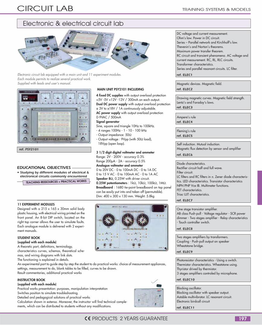
ref. ELEC1 Electronic circuit lab equipped with a main unit and 11 experiment modules.Each module permits to realize several practical work.Supplied with leads and user’s manual.
4 fixed DC supplies with output overload protection+5V -5V +12V -12V / 300mA on each output.Dual DC power supply with output overload protection± 3V to ±18V / 1A continuously adjustable.AC power supply with output overload protection0-9VAC / 500mASignal generatorSine, square and triangle 10Hz to 100kHz.- 4 ranges 100Hz - 1 - 10 - 100 kHz- Output impedance: 50Ω- Output voltage : 9Vpp (with 50Ω load),
18Vpp (open loop).
3 1/2 digit digital voltmeter and ammeterRange: 2V - 200V - accuracy 0.3%Range 200µA - 2A - accuracy 0.5%Analogue voltmeter and ammeter0 to 20V DC - 0 to 100mA DC - 0 to 1A DC0 to 15 V AC - 0 to 100mA AC - 0 to 1A ACSpeaker 8Ω, 0.25W with driver circuit.0.25W potentiometers : 1kΩ, 10kΩ, 100kΩ, 1MΩ.Breadboard : 1680 tie-point breadboard on top panelcan be easily put into and taken off (permutable).Dim: 400 x 300 x 130 mm. Weight: 5.8kg
11 EXPERIMENT MODULESDesigned with a 215 x 165 x 30mm solid bodyplastic housing, with electrical wiring printed on thefront panel. An 8-bit DIP switch, located on theright top corner allows the user to simulate faults.Each analogue module is delivered with 2 experi-ment manuals.
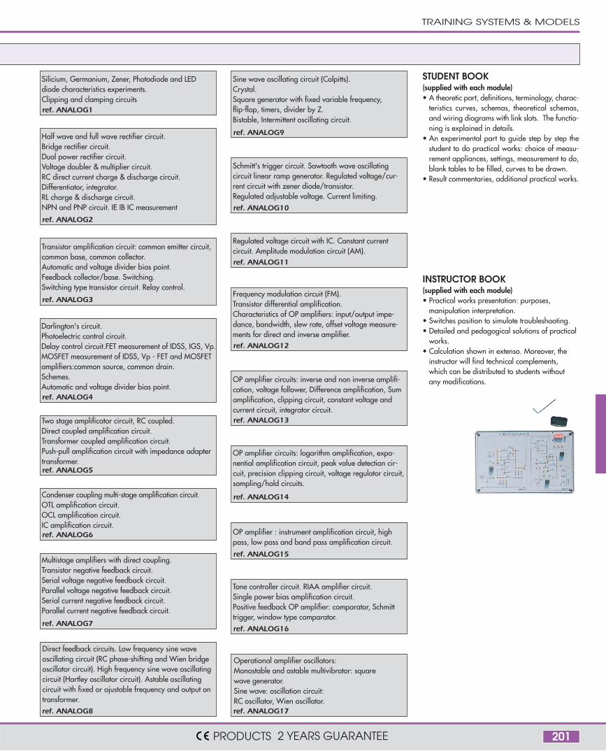
STUDENT BOOK(supplied with each module)A theoretic part, definitions, terminology,characteristics curves, schemas, theoretical sche-mas, and wiring diagrams with link slots.The functioning is explained in details.An experimental part to guide step by step the student to do practical works: choice of measurement appliances,settings, measurement to do, blank tables to be filled, curves to be drawn.Result commentaries, additional practical works
INSTRUCTOR BOOK(supplied with each module)Practical works presentation: purposes, manipulation interpretationSwitches position to simulate troubleshooting.Detailed and pedagogical solutions of practical worksCalculation shown in extenso. Moreover, the instructor will find technical comple-ments, which can be distributed to students without any modifications.
DC voltage and current measurement.Ohm’s law. Power in DC circuit.Series – Parallel network and Kirchhoff’s law.Thevenin’s and Norton’s theorems.Maximum power transfer theorem.RC circuit and transient phenomena. AC voltage andcurrent measurement. RC, RL, RLC circuits.Transformer characteristics.Series and parallel resonant circuits. LC filter.
Fleming’s rule
Two stages amplifiers by transformers.Coupling - Push-pull output on speakerWheatstone bridge.
Photoresistor characteristics - Using a switch.Thermistor characteristics. Wheatstone using.Thyristor drived by thermistor.3 stages amplifiers controled by microphone.
Blocking oscillator.Blocking oscillator with speaker output.Astable multivibrator. LC resonant circuit.Electronic birdcall circuit
Self induction. Mutual induction.Magnetic flux detection by sensor and amplifier
Diode characteristics.Rectifier circuit half and full wave.Filter circuit.LC filters and RC filters in π. Zener diode characteris-tics. LED characteristics. Transistor characteristicsNPN PNP Vce IB. Multimeter functions.FET characteristics.Triac UJT characteristics.
One stage transistor amplifier.AB class Push-pull - Voltage regulator - SCR powerdimmer - Two stages amplifier - Relay characteristics- Touch controller switch.
Magnetic devices. Magnetic field.
Drawing magnetic curves. Magnetic field strength.Lentz’s and Faraday’s laws.
Ampere’s rule
MAIN UNIT PSY2101 INCLUDING
Electronic & electrical circuit lab
• Studying by different modules of electrical &electronical circuits commonly encountered
EDUCATIONAL OBJECTIVES
TEACHING RESSOURCES + PRACTICAL WORKS
CIRCUIT LAB TRAINING SYSTEMS & MODELS
PRODUCTS 2 YEARS GUARANTEE
198
ref. PSY3101
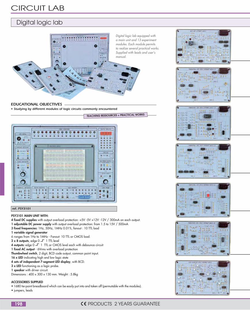
Digital logic lab equipped witha main unit and 13 experimentmodules. Each module permitsto realize several practical works.Supplied with leads and user’smanual.
PSY3101 MAIN UNIT WITH:4 fixed DC supplies with output overload protection: +5V -5V +12V -12V / 300mA on each output.1 adjustable DC power supply with output overload protection: from 1.5 to 15V / 500mA3 fixed frequencies: 1Hz, 50Hz, 1MHz 0.01%, fanout : 10 TTL load1 variable signal generator6 ranges from 1Hz to 1MHz - Fanout: 10 TTL or CMOS load.2 x 8 outputs, edge 0 1 TTL level4 outputs: edge 0 1 TTL or CMOS level each with debounce circuit1 fixed AC output - 6Vrms with overload protectionThumbwheel switch, 2 digit, BCD code output, common point input.16 x LED indicating high and low logic state4 sets of independent 7-segment LED display, with BCD.3 x LED functioning as a logic probe.1 speaker with driver circuit.Dimensions : 400 x 300 x 130 mm. Weight : 5.8kg
ACCESSORIES SUPPLIED• 1680 tie-point breadboard which can be easily put into and taken off (permutable with the modules).• jumpers, leads
Digital logic lab
• Studying by different modules of logic circuits commonly encounteredEDUCATIONAL OBJECTIVES
TEACHING RESSOURCES + PRACTICAL WORKS
CIRCUIT LAB
PRODUCTS 2 YEARS GUARANTEE

199
ref. DIGITAL1
ref. DIGITAL2
ref. DIGITAL8
ref. DIGITAL9
ref. DIGITAL10
ref. DIGITAL11
ref. DIGITAL12
ref. DIGITAL13
ref. DIGITAL3
ref. DIGITAL4
ref. DIGITAL5
ref. DIGITAL6
ref. DIGITAL7
13 EXPERIMENT MODULES.Designed with a 215 x 165 x 30mm solid body plastic housing, with electrical wiring printed on thefront panel. An 8-bit DIP switch, located on the right top corner allows the user to simulate faults. Solutionfor faults are listed in the experiment manual for user's reference. Comprehensive experiment andinstructor's manual are supplied with modules and contains theoretical drawings, wiring drawings.The experiment part has input signals, location of test points, tables to be filled up, comments andexercises.
TRAINING SYSTEMS & MODELS
PRODUCTS 2 YEARS GUARANTEE
Logic gates circuits, transistors, TTL and CMOS logic cir-cuits. TTL/CMOS I/O voltage and current measurementexperiments. Basic logic gate transmission delay mea-surement. AND, OR, NAND, NOR, XOR gate charac-teristics. Interface between TTL/CMOS and CMOS/TTL.
NOR NAND XOR gate circuits, reverser,comparator circuit experiments, Schmitt trigger,open collector gate circuits.
Three-state gate circuit. Adder.Arithmetic logic unit.Bit parity generator.
Adder. Subtractor. 2 and 3 inputs reverser.BCD code adder circuit.Bit parity generator with XOR gate.10 to 4 bit decoder with TTL IC.
4 to 2 bit encoder. 4 to 2 bit decoder.Decoder circuit experiments(decoding 7-segment display with BCD code).
10 to 4 bit encoder.Multiplexer circuit experiments.Digitally controlled analogMultiplexer/demultiplexer circuits.Bi-directional transmission with CMOS IC.
Oscillator circuit with basic logic gates, with Schmitttrigger. Voltage controlled oscillator circuit, with 555trigger. Monostable multivibrator and synchronousastable multivibrator.
Variable duty ratio oscillator. RS, T, D, JK flip flop. Presetleft/right shift register circuit.Noise elimination circuit.
JK flip flop: asynchronous/synchronous, binaries up/down bi-directional counters.Ring counter circuit, Johnson's counter circuit.
JK flip flop: asynchronous counter:decimal, divide by N, preset synchronous binary/decimal.Constructing ROM memories with diodes,RAM memories with D flip flop. Constructing EPROM
Constructing 64 bits RAM circuit.Constructing Electronic EPROM circuit
Construction dynamic scanning counter with single chipmicroprocessor. 8- bit analog/digital converter circuit.
Digital/analog converter circuit, unipolar and bipolar.3 digits analog/digital converter circuit.
200
REF. ANALOG 1
REF. ANALOG 2
REF. ANALOG 3
REF. ANALOG 4
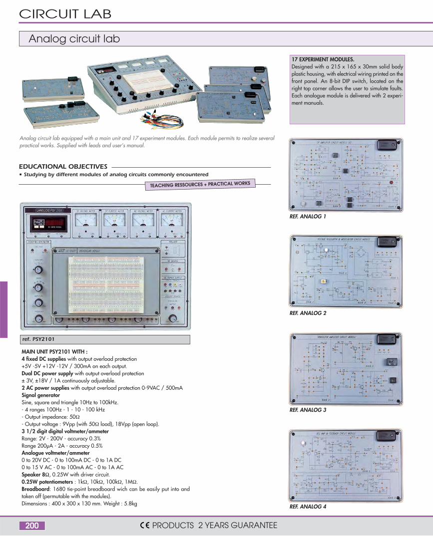
ref. PSY2101
• Studying by different modules of analog circuits commonly encounteredEDUCATIONAL OBJECTIVES
TEACHING RESSOURCES + PRACTICAL WORKS
Analog circuit lab equipped with a main unit and 17 experiment modules. Each module permits to realize severalpractical works. Supplied with leads and user’s manual.
MAIN UNIT PSY2101 WITH :4 fixed DC supplies with output overload protection+5V -5V +12V -12V / 300mA on each output.Dual DC power supply with output overload protection± 3V, ±18V / 1A continuously adjustable.2 AC power supplies with output overload protection 0-9VAC / 500mASignal generatorSine, square and triangle 10Hz to 100kHz.- 4 ranges 100Hz - 1 - 10 - 100 kHz- Output impedance: 50Ω- Output voltage : 9Vpp (with 50Ω load), 18Vpp (open loop).3 1/2 digit digital voltmeter/ammeterRange: 2V - 200V - accuracy 0.3%Range 200µA - 2A - accuracy 0.5%Analogue voltmeter/ammeter0 to 20V DC - 0 to 100mA DC - 0 to 1A DC0 to 15 V AC - 0 to 100mA AC - 0 to 1A ACSpeaker 8Ω, 0.25W with driver circuit.0.25W potentiometers : 1kΩ, 10kΩ, 100kΩ, 1MΩ.Breadboard: 1680 tie-point breadboard wich can be easily put into andtaken off (permutable with the modules).Dimensions : 400 x 300 x 130 mm. Weight : 5.8kg
17 EXPERIMENT MODULES.Designed with a 215 x 165 x 30mm solid bodyplastic housing, with electrical wiring printed on thefront panel. An 8-bit DIP switch, located on theright top corner allows the user to simulate faults.Each analogue module is delivered with 2 experi-ment manuals.
Analog circuit lab
CIRCUIT LAB
PRODUCTS 2 YEARS GUARANTEE
201
ref. ANALOG5
ref. ANALOG6
ref. ANALOG7
ref. ANALOG8
ref. ANALOG14
ref. ANALOG15
ref. ANALOG16
ref. ANALOG17
INSTRUCTOR BOOK(supplied with each module)• Practical works presentation: purposes,
manipulation interpretation.• Switches position to simulate troubleshooting.• Detailed and pedagogical solutions of practical
works.• Calculation shown in extenso. Moreover, the
instructor will find technical complements,which can be distributed to students withoutany modifications.
STUDENT BOOK(supplied with each module)• A theoretic part, definitions, terminology, charac-
teristics curves, schemas, theoretical schemas,and wiring diagrams with link slots. The functio-ning is explained in details.
• An experimental part to guide step by step thestudent to do practical works: choice of measu-rement appliances, settings, measurement to do,blank tables to be filled, curves to be drawn.
• Result commentaries, additional practical works.
ref. ANALOG1
ref. ANALOG2
ref. ANALOG3
ref. ANALOG4
ref. ANALOG9
ref. ANALOG10
ref. ANALOG11
ref. ANALOG12
ref. ANALOG13
TRAINING SYSTEMS & MODELS
PRODUCTS 2 YEARS GUARANTEE
Direct feedback circuits. Low frequency sine waveoscillating circuit (RC phase-shifting and Wien bridgeoscillator circuit). High frequency sine wave oscillatingcircuit (Hartley oscillator circuit). Astable oscillatingcircuit with fixed or ajustable frequency and output ontransformer.
Operational amplifier oscillators:Monostable and astable multivibrator: squarewave generator.Sine wave: oscillation circuit:RC oscillator, Wien oscillator.
Silicium, Germanium, Zener, Photodiode and LEDdiode characteristics experiments.Clipping and clamping circuits
Sine wave oscillating circuit (Colpitts).Crystal.Square generator with fixed variable frequency,flip-flop, timers, divider by Z.Bistable, Intermittent oscillating circuit.
Schmitt's trigger circuit. Sawtooth wave oscillatingcircuit linear ramp generator. Regulated voltage/cur-rent circuit with zener diode/transistor.Regulated adjustable voltage. Current limiting.
Regulated voltage circuit with IC. Constant currentcircuit. Amplitude modulation circuit (AM).
Frequency modulation circuit (FM).Transistor differential amplification.Characteristics of OP amplifiers: input/output impe-dance, bandwidth, slew rate, offset voltage measure-ments for direct and inverse amplifier.
OP amplifier circuits: inverse and non inverse amplifi-cation, voltage follower, Difference amplification, Sumamplification, clipping circuit, constant voltage andcurrent circuit, integrator circuit.
OP amplifier circuits: logarithm amplification, expo-nential amplification circuit, peak value detection cir-cuit, precision clipping circuit, voltage regulator circuit,sampling/hold circuits.
OP amplifier : instrument amplification circuit, highpass, low pass and band pass amplification circuit.
Tone controller circuit. RIAA amplifier circuit.Single power bias amplification circuit.Positive feedback OP amplifier: comparator, Schmitttrigger, window type comparator.
Half wave and full wave rectifier circuit.Bridge rectifier circuit.Dual power rectifier circuit.Voltage doubler & multiplier circuit.RC direct current charge & discharge circuit.Differentiator, integrator.RL charge & discharge circuit.NPN and PNP circuit. IE IB IC measurement
Transistor amplification circuit: common emitter circuit,common base, common collector.Automatic and voltage divider bias point.Feedback collector/base. Switching.Switching type transistor circuit. Relay control.
Darlington's circuit.Photoelectric control circuit.Delay control circuit.FET measurement of IDSS, IGS, Vp.MOSFET measurement of IDSS, Vp - FET and MOSFETamplifiers:common source, common drain.Schemes.Automatic and voltage divider bias point.
Two stage amplificator circuit, RC coupled.Direct coupled amplification circuit.Transformer coupled amplification circuit.Push-pull amplification circuit with impedance adaptertransformer.
Condenser coupling multi-stage amplification circuit.OTL amplification circuit.OCL amplification circuit.IC amplification circuit.
Multistage amplifiers with direct coupling.Transistor negative feedback circuit.Serial voltage negative feedback circuit.Parallel voltage negative feedback circuit.Serial current negative feedback circuit.Parallel current negative feedback circuit.
202
CEI1010 CATIII pol2 300V CL1
~
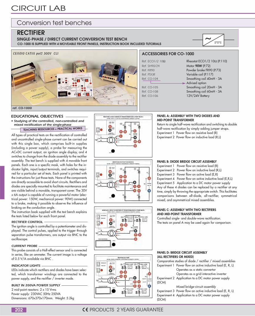
ref. CO-1000
RECTIFIER CONTROLThe ignition angle is controlled by a potentiometer and dis-played. The control pulses, applied to the trigger throughseparation pulse transformers, are output via BNC to theoscilloscope.
CURRENT PROBEThis probe consists of a Hall-effect sensor and is connectedin series, like an ammeter. The current image is a voltageof 0.5 V/A available via BNC .
INDICATOR LIGHTSLEDs indicate which rectifiers and diodes have been selec-ted, which transformer windings are connected to thepower supply, and the rectifier / inverter mode.
BUILT IN 200VA POWER SUPPLY2 mid-point reactors: 2 x 15 VrmsPower supply: 230VAC 50Hz 250VADimensions: 670x370x170mm. Weight: 5.2kg
All types of practical tests on the rectification of controlledand uncontrolled single-phase current can be carried outwith this single box, which comprises built-in supplies(including a power supply), a probe for measuring theAC+DC current output, an ignition angle display, and 4switches to change from the diode assembly to the rectifierassembly. The test bench is supplied with 4 movable frontpanels. Each one is a specific mask, with holes for the in-dicator lights, input/output terminals, and switches requi-red for a particular set of tests. Each panel is printed withthe instructions for just those tests. None of the componentsare directly accessible to avoid short circuits. Rectifiers anddiodes are specially mounted to facilitate maintenance andare visible behind a movable, transparent cover. The 30Vx 6A output is capable of running a powerful motor (elec-trical power: 150W, mechanical power: 90W) connectedto a brake, making it possible to observe the influence ofbraking on the conduction angle.The instruction book supplied with the test bench explainsthe tests listed below for each front panel.
• Studying of the controlled, non-controlled andmixed rectification of the single-phase
EDUCATIONAL OBJECTIVES
TEACHING RESSOURCES + PRACTICAL WORKS
CO-1000 IS SUPPLIED WITH 4 MOVEABLE FRONT PANELS, INSTRUCTION BOOK INCLUDED TUTORIALS
PANEL A: ASSEMBLY WITH TWO DIODES ANDMID-POINT TRANSFORMERReturn to single half-wave rectification and switching to doublehalf-wave rectification by simply adding jumper straps.Experiment 1 Power flow on resistive load (R)Experiment 2 Power flow on inductive load (R,L)
PANEL B: DIODE BRIDGE CIRCUIT ASSEMBLY Experiment 1 Power flow on resistive load (R)Experiment 2 Power flow on inductive load (R,L)Experiment 3 Power flow on active load (E,R)Experiment 4 Power flow on active inductive load (E,R,L)Experiment 5 Application to a DC motor power supplyAny of these 4 diodes can be replaced by a rectifier at anytime, simply by throwing the appropriate switch. This facilitatescomparisons between all-diode, all-rectifier, symmetricalmixed, and asymmetrical mixed assemblies.
PANEL C: ASSEMBLY WITH TWO RECTIFIERSAND MID-POINT TRANSFORMERControlled single- and double-wave rectification.The tests on panel A may be used again for comparison.
PANEL D: BRIDGE CIRCUIT ASSEMBLY(ALL RECTIFIERS OR MIXED)Comparative studies of diode / rectifier / mixed assembliesExperiment 1 Power flow on active inductive load (E, R, L) Operates as a static convertor Operates as a grid-interactive inverterExperiment 2 Application to a DC motor power supply(DCM) Mixed bridge-circuit assemblyExperiment 3 Power flow on active inductive load (E, R, L)Experiment 4 Application to a DC motor power supply(DCM)
SINGLE-PHASE / DIRECT CURRENT CONVERSION TEST BENCHRECTIFIERConversion test benches
ACCESSORIES FOR CO-1000
Ref. ECO1/2 10Ω Rheostat ECO1/2 10Ω (P.110)Ref. SH90/24 Motor 90W (P.72)Ref. FR90 Powder brake FR90 (P.73)Ref. PSYJR Variable coil (P.117)Ref. CO-104 Smoothing coil 40mH - 3A Advised optionRef. CO-105 Smoothing coil 20mH - 3ARef. CO-108 Smoothing coil 60mH - 3ARef. CO-106 12V/24V Battery
CIRCUIT LAB
PRODUCTS 2 YEARS GUARANTEE
203
~
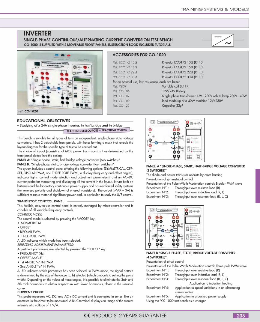
ref. CO-1020
This bench is suitable for all types of tests on independent, single-phase static voltageconverters. It has 2 detachable front panels, with holes forming a mask that reveals thelayout diagram for the specific type of test to be carried out.The choice of layout (consisting of MOS power transistors) is thus determined by thefront panel slotted into the casing:PANEL A: "Single-phase, static, half-bridge voltage converter (two switches)"PANEL B: "Single-phase, static, bridge voltage converter (four switches)"The system includes a control panel offering the following options: (SYMMETRICAL, OFF-SET, BIPOLAR PWM, and THREE-POLE PWM), a display (frequency and offset angles),indicator lights (control mode selection and adjustment parameters), and an AC+DCcurrent probe for measuring and displaying all the current in the layout. It runs both onbatteries and the laboratory continuous power supply and has reinforced safety systems(for reversed polarity and shutdown of unused transistors). The output (IMAX = 3A) issufficient to run a motor of significant power and, in particular, to study the U/F control.
TRANSISTOR CONTROL PANELThis flexible, easy-to-use control panel is entirely managed by micro-controller and iscapable of all variable frequency controls.CONTROL MODEThe control mode is selected by pressing the "MODE" key: • SYMMETRICAL• OFFSET• BIPOLAR PWM• THREE-POLE PWMA LED indicates which mode has been selected.SELECTING ADJUSTMENT PARAMETERS: Adjustment parameters are selected by pressing the "SELECT" key: • FREQUENCY (Hz)• OFFSET ANGLE• 1st ANGLE "a" IN PWM• 2nd ANGLE "b" IN PWMA LED indicates which parameter has been selected. In PWM mode, the signal patternis determined by the size of the angle (a, b) selected (which amounts to setting the pulsewidth). Depending on the values of these angles, it is possible to eliminate the 3rd- and5th-rank harmonics to obtain a spectrum with fewer harmonics, closer to the sinusoidcurve.CURRENT PROBEThis probe measures AC, DC, and AC + DC current and is connected in series, like anammeter, in the circuit to be measured. A BNC terminal displays an image of the currentintensity at a voltage of 1 V/A.
• Studying of a 24V single-phase inverter, in half bridge and in bridgeEDUCATIONAL OBJECTIVES
TEACHING RESSOURCES + PRACTICAL WORKS
PANEL: A "SINGLE-PHASE, STATIC, HALF-BRIDGE VOLTAGE CONVERTER(2 SWITCHES)"The diode and power transistor operate by cross-barring Presentation of symmetrical control Presentation of the Pulse-Width Modulation control: Bipolar PWM wave Experiment N°1: Throughput over resistive load (R)Experiment N°2: Throughput over inductive load (R, L)Experiment N°3: Throughput over resonant load (R, L, C)
PANEL B "SINGLE-PHASE, STATIC, BRIDGE VOLTAGE CONVERTER(4 SWITCHES)"Presentation of offset controlPresentation of the Pulse-Width Modulation control: Three-pole PWM wave Experiment N°1: Throughput over resistive load (R)Experiment N°2: Throughput over inductive load (R, L)Experiment N°3: Throughput over resonant load (R, L, C)
Application to induction heatingExperiment N°4: Application to speed variations in an alternating current motorExperiment N°5: Application to a backup power supplyUsing the "C0-1000 test bench as a charger.
CO-1000 IS SUPPLIED WITH 2 MOVEABLE FRONT PANELS, INSTRUCTION BOOK INCLUDED TUTORIALSSINGLE-PHASE CONTINUOUS/ALTERNATING CURRENT CONVERSION TEST BENCHINVERTER
ACCESSORIES FOR CO-1020
Ref. ECO1/2 10Ω Rheostat ECO1/2 10Ω (P.110)Ref. ECO1/2 15Ω Rheostat ECO1/2 15Ω (P.110)Ref. ECO1/2 22Ω Rheostat ECO1/2 22Ω (P.110)Ref. ECO1/2 33Ω Rheostat ECO1/2 33Ω (P.110)for an optimal use, low resistance loads are betterRef. PSYJR Variable coil (P.117)Ref. CO-106 12V/24V BatteryRef. CO-107 Single-phase transformer 12V - 230V wth its lamp 230V - 40WRef. CO-109 load made up of a 40W machine 12V/230VRef. CO-122 Capacitor 22µF
TRAINING SYSTEMS & MODELS
PRODUCTS 2 YEARS GUARANTEE

204
ref. AT104
ref. AT106
MICRO-LEADSNOT SUPPLIED SEE PAGE 206
MICRO-LEADSNOT SUPPLIED SEE PAGE 206
AT104 is a test bed intended for learning about logic circuits. Several of the commonest circuits areintegrated into the test bed. They are fed and their inputs/outputs are clearly indicated on short sum-maries. There are: 3 inverters - 3 exclusive OR - 6 AND - 6 OR - 6 NAND - 6 NOR.A manual supplied with the test bed shows how to make: an RS, D bistable,a comparison unit, a trigger, a counter etc.Maintenance: the cover is removable, the standard circuits are easily replaced.Dimensions: 340 x 265 x 130mm Weight 4.7kg. Mains 230V.
AT106 is a test bed for analog circuits.Easy maintenance: common circuits and diagrams provided.Dimensions: 340 x 265 x 130mm Weight 3.7kg. Mains 230V.
SUPPLY +5V/1A 0 to +15V/0,5A 0 to -15V/0,5A -5V/0,5A
REGULATION <100mV<50mV
<150mV<150mV
<150mV<150mV
<30mV<25mV
Load variation 100%Mains variation 15%
1 INTERCONNECTION BREADBOARD with 1580 contacts, 2 fields of 640 contacts bearing thecomponents, 3 fields of 100 feed distribution contacts4 SUPPLIES immediately next to the board, short circuit protected.
3 CLOCKS at fixed frequencies of 1Hz - 10Hz - 100Hz square signal 0 to 5VShort circuit protected.
1 SHORT CIRCUIT INDICATOR lights up when a supply or clock has short circuited.
4 SWITCHES delivering between 0 and +5V.
8 LED DISPLAYS marked 0 to 7
SUPPLY +5V/1A 0 to +15V/0,3A 0 to -15V/0,3A -5V/100mA
REGULATION <100mV<50mV
<0,05% of V<30mV
<0,05% of V<30mV
Load variation 100%Mains variation 15%
<100mV
<50mV
1 BOARD 1896 contacts with spacing 2.54, 1,280 bearing the components,400 for supply distribution.
4 SUPPLIES short circuit protected.
1 FUNCTION GENERATOR Sinusoidal, Square, Triangular, Ranges 0.1Hz à 200 kHz, fine adjust-ment vernier, Sinusoidal adjustable between 0 and 5Vcc, Triangular 5Vcc, Square 5Vcc, TTL 5V
1 VOLTMETER 0 to 30V analogue, impedance 320 kΩ
1 UNIVERSAL COUNTER 8 DIGITSFrequencymeter 1Hz to 100MHz. Periodmètre 0,01µs to 99 999 999µs.TTL and CMOS Internal / External Input
1 MICRO-AMMETER 0 to 100 µA analogue, impedance 1kΩ
1 LOUDSPEAKER
4 ADAPTERSThese adapters allow the unit to be connected to an external electronic unit.- 2 banana inputs of 4mm diameter- 2 inputs of female BNC connectors
3 SWITCHES2 to 2 positions and 1 to 3 positions
6 positions rotary switche
2 POTENTIOMETERS 0 to 1kΩ - 0 to 100kΩ
Analog test unit
Logic test unit
TEST UNITS
PRODUCTS 2 YEARS GUARANTEE

205
ref. AT102
ref. PR6
Electronic test unit
MICRO-LEADSNOT SUPPLIED SEE PAGE 206
The central board.Identical for the 3 benches (AT102 - AT104 - AT106).For receptacle 173 x 120mm.
ELEMENT OF REPLACEMENT
TRAINING SYSTEMS & MODELS
PRODUCTS 2 YEARS GUARANTEE
Designed for installation and rapid testing of prototypes and for practical experiments withanalog and digital circuits. The contact board, which is hardwearing, is removable.Dimensions: 340 x 265 x 130mm. Weight: 4.8kg.
The components are inserted on the contact board with the normal pitch spacing of 2.54mm.There are 1896 contact points divided into:12 contact points of supply lines256 separate sets of 5 contact points receiving components and interconnetions.
4 SUPPLIESPositioned in view immediately on the face, they are protected against short circuits- Variable DC from 0 to +15V 300mA (ripple 30mV)- Variable DC from 0 to -15V 300mA (ripple 30mV)- Fixed DC +5V, 1A (100mV ripple)- Fixed DC -5V, 100mA (30mV ripple)
1 FUNCTION GENERATORFrom 0.1Hz to 200kHz in 6 ranges varied with a control dial. The output is protected againstshort circuits. - Sinewave, level variable from 0 to 10V peak-to-peak - Triangular wave, levelvariable from 0 to 5V peak-to-peak - Square wave, level variable from 0 to 15V peak-to-peak
2 DIGITAL DISPLAYS 7 segments and decimal point display. Switched by the inputs of D1 & D2.- Direct control of each segment, a b c d e f - Access to the input of the ABCD decoder IC
1 DC DIGITAL VOLTMETER3 1/2 digits with a maximum reading of 2,000.Ranges 200mV-2-20-200VDC. Input impedance 10MΩ
1 UNIVERSAL COUNTER 8 DIGITSFrequencymeter 1 Hz to 100MHz. Periodmeter 99,999 999µs.TTL & CMOS Internal/External Input
8 DIODE DISPLAYStatus from 0 to 7 with lamps to view logic levels.
10 LOGIC SWITCHES- 8 with 2 positions giving a voltage a either 0 or 5V - 2 with 3 positions giving voltages of -5V 0V +5V
2 LOGIC PUSHBUTTONS2 anti-bounce outputs A and A (respectively B and B) supplying a level between 0 and 5Von the side of the unit.
4 ADAPTERSThese adapters allow the unit to be connected to an external electronic unit.- 2 banana inputs of 4mm diameter- 2 inputs of female BNC connectors

206
REF. PAL2420 REF. GL12 REF. GL48 REF. GL24
ref. MICRO-B
Micro-leads
Contact boards for the design and rapid testing of circuits. The double reed contacts of these boards are in nickel platedbronze. They are pitched 1 inch/2.54 mm apart in an insulating ABS base. Contacts grouped in strips of 5 or 10, can befully dismantled from the rear. Use components or leads with maximum diameter 0.6mm.
Model with integrated power supply protected from short-circuits (PAL2420): 0 to +15V/500mA continuously variable ; 0 to -15V/500mA continuously variable ; +5V/1A fixed
* With safety sockets
Ref. PAL2420 PAL2420S* GL12 GL12S* GL24 GL24S* GL48 GL48S*
Nb of contacts 2420 2420 840 840 1680 1680 3260 3260
Dimensions mm 245 x 195 245 x 195 200 x 75 200 x 75 225 x 150 2250 x 150 260 x 240 260 x 240
The flexible wire used for these leads is terminated at each end by a 0.6mm diameter nickel-plated plug. The electrical contact is excellent.
8 racks. Transparent plastic cover.Total capacity of the box:
160 micro-leads.Dimensions : 230 x 160 x 30mm.
Weight : 180g
Storage box formicro-leads
Ref. M5 G7 O1 R10 N10 V1 B2
Length 50 mm 70 mm 100 mm 100 mm 100 mm 150 mm 200 mm
Colorobligatory
BROWN GREY ORANGE RED BLACK PURPLE BLUE
Special lead to connect thetesting boards and any systemin diameter 2mm. Max current 500mA.
ref. INTER-2R
25cm Red color
ref. INTER-2N 25cm Black color
supplied without
leads
Electronic test boards
Interfacelead
TEST UNITS
PRODUCTS 2 YEARS GUARANTEE
207
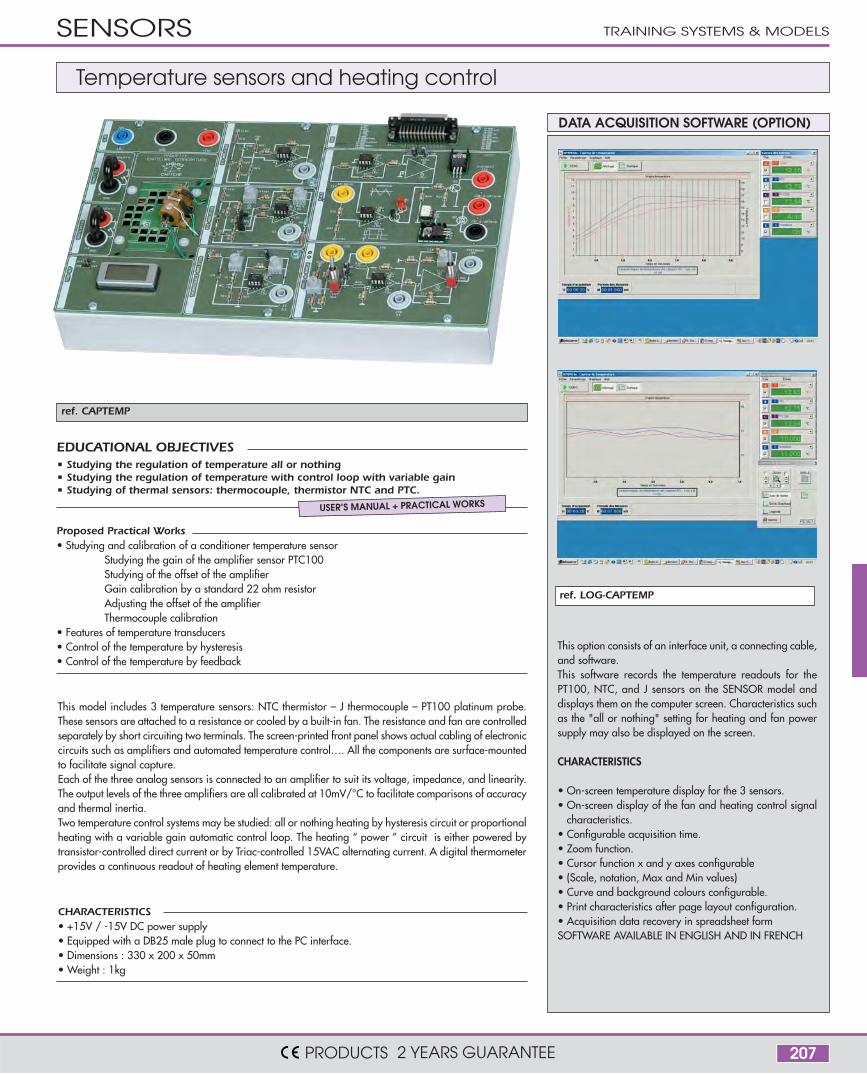
ref. CAPTEMP
ref. LOG-CAPTEMP
Temperature sensors and heating control
This option consists of an interface unit, a connecting cable,and software.This software records the temperature readouts for thePT100, NTC, and J sensors on the SENSOR model anddisplays them on the computer screen. Characteristics suchas the "all or nothing" setting for heating and fan powersupply may also be displayed on the screen.
CHARACTERISTICS
• On-screen temperature display for the 3 sensors.• On-screen display of the fan and heating control signal
characteristics.• Configurable acquisition time.• Zoom function.• Cursor function x and y axes configurable• (Scale, notation, Max and Min values)• Curve and background colours configurable.• Print characteristics after page layout configuration.• Acquisition data recovery in spreadsheet formSOFTWARE AVAILABLE IN ENGLISH AND IN FRENCH
DATA ACQUISITION SOFTWARE (OPTION)
This model includes 3 temperature sensors: NTC thermistor – J thermocouple – PT100 platinum probe.These sensors are attached to a resistance or cooled by a built-in fan. The resistance and fan are controlledseparately by short circuiting two terminals. The screen-printed front panel shows actual cabling of electroniccircuits such as amplifiers and automated temperature control…. All the components are surface-mountedto facilitate signal capture.Each of the three analog sensors is connected to an amplifier to suit its voltage, impedance, and linearity.The output levels of the three amplifiers are all calibrated at 10mV/°C to facilitate comparisons of accuracyand thermal inertia.Two temperature control systems may be studied: all or nothing heating by hysteresis circuit or proportionalheating with a variable gain automatic control loop. The heating “ power ” circuit is either powered bytransistor-controlled direct current or by Triac-controlled 15VAC alternating current. A digital thermometerprovides a continuous readout of heating element temperature.
CHARACTERISTICS• +15V / -15V DC power supply• Equipped with a DB25 male plug to connect to the PC interface.• Dimensions : 330 x 200 x 50mm• Weight : 1kg
Proposed Practical Works• Studying and calibration of a conditioner temperature sensor
Studying the gain of the amplifier sensor PTC100Studying of the offset of the amplifierGain calibration by a standard 22 ohm resistorAdjusting the offset of the amplifierThermocouple calibration
• Features of temperature transducers• Control of the temperature by hysteresis• Control of the temperature by feedback
• Studying the regulation of temperature all or nothing• Studying the regulation of temperature with control loop with variable gain• Studying of thermal sensors: thermocouple, thermistor NTC and PTC.
EDUCATIONAL OBJECTIVES
USER’S MANUAL + PRACTICAL WORKS
SENSORS TRAINING SYSTEMS & MODELS
PRODUCTS 2 YEARS GUARANTEE
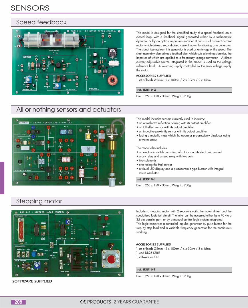
208
ref. B3510-G
ref. B3510-L
ref. B3510-T
SOFTWARE SUPPLIED
This model is designed for the simplified study of a speed feedback on aclosed loop, with a feedback signal generated either by a tachometricdynamo, or by an optical impulsion encoder. It consists of a direct currentmotor which drives a second direct current motor, functioning as a generator.The signal issuing from this generator is used as an image of the speed. Theshaft assembly also drives a toothed disc, which cuts a luminous barrier, theimpulses of which are applied to a frequency voltage converter. A directcurrent adjustable source integrated in the model is used as the voltagereference level. A switching supply controlled by the error voltage supplythe motor.
Dim. : 250 x 150 x 30mm. Weight : 900g.
Dim. : 250 x 150 x 30mm. Weight : 900g.
Dim. : 250 x 150 x 30mm. Weight : 900g.
This model includes sensors currently used in industry:• an optoelectro-reflection barrier, with its output amplifier• a Hall effect sensor with its output amplifier• an inductive proximity sensor with its output amplifier• facing a metallic mass which the operator progressively displaces using
a worm screw.
The model also includes:• an electronic switch consisting of a triac and its electronic control• a dry relay and a reed relay with two coils• two solenoids• one facing the Hall sensor• a visual LED display and a piezoceramic type buzzer with integral
micro-oscillator.
Includes a stepping motor with 2 separate coils, the motor driver and thespecialised logic test circuit. The latter can be accessed either by a PC via a25 pin parallel port, or by a manual control logic system integrated.This logic comprises a controled impulse generator by push button for thestep by step lead and a variable frequency generator for the continuousworking.
ACCESSORIES SUPPLIED1 set of leads Ø2mm : 2 x 100cm / 2 x 30cm / 2 x 15cm
ACCESSORIES SUPPLIED1 set of leads Ø2mm : 2 x 100cm / 4 x 30cm / 3 x 15cm1 lead DB25 SERIE1 software on CD
Speed feedback
All or nothing sensors and actuators
Stepping motor
SENSORS
PRODUCTS 2 YEARS GUARANTEE
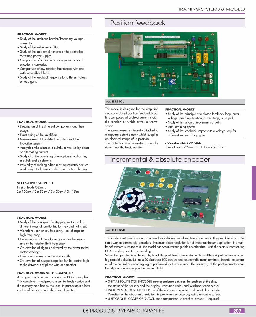
209
ref. B3510-J
ref. B3510-R
PRACTICAL WORKS• Description of the different components and their
usage.• Functioning of the amplifiers.• Measurement of the detection distance of the
inductive sensor.• Analysis of the electronic switch, controlled by direct
or alternating current.• Study of a line consisting of an optoelectro-barrier,
a switch and a solenoid.• Possibility of making other lines: optoelectro-barrier -
reed relay - Hall sensor - electronic switch - buzzer
PRACTICAL WORKS• Study of the luminous barrier/frequency voltage
converter.• Study of the tachometric filter.• Study of the loop amplifier and of the controlled
switching power supply.• Comparison of tachometric voltages and optical
encoder + converter.• Comparison of low rotation frequencies with and
without feedback loop.• Study of the feedback response for different values
of loop gain.
PRACTICAL WORKS • Study of the principle of a stepping motor and its
different ways of functioning by step and half-step.• Vibrations seen at low frequency, loss of steps at
high frequency.• Determination of the take-in resonance frequency
and of the rotation limit frequency• Observation of signals delivered by the driver to the
motor windings.• Inversion of currents in the motor coils.• Observation of 4 signals applied by the control logic
to the driver out of phase with one another.
PRACTICAL WORK WITH COMPUTERA program in basic and working in DOS is supplied.This completely listed program can be freely copied andif necessary modified by the user. In particular, it allowscontrol of the speed and direction of rotation.
This model is designed for the simplifiedstudy of a closed position feedback loop.It is composed of a direct current motor,the rotation of which drives a worm-screw.The screw cursor is integrally attached toa copying potentiometer which suppliesan electrical image of its position.The potentiometer operated manuallydetermines the basic position.
PRACTICAL WORKS • Study of the principle of a closed feedback loop: error
voltage, pre-amplification, driver stage, push-pull.• Study of limitation of movements circuits.• Anti-jamming system.• Study of the feedback response to a voltage step for
different values of loop gain.
This model illustrates how an incremental encoder and an absolute encoder work. They work in exactly thesame way as commercial encoders. However, since resolution is not important in our application, the num-ber of sensors is limited to 5. The model has two interchangeable encoder discs, with the sectors representingDCB encoding and Gray encoding.When the operator turns the disc by hand, the phototransistors underneath send their signals to the decodinglogic and the display (4 line x 20 character LCD screen) and to 4mm-diameter terminals, in order to controlall of the control or decoding logics performed by the operator. The sensitivity of the phototransistors canbe adjusted depending on the ambient light.
PRACTICAL WORKS • 3-BIT ABSOLUTE DCB ENCODER correspondence between the position of the disc,
the status of the sensors and the display. Transition codes and synchronisation sensor.• INCREMENTAL DCB ENCODER use of the encoder in counter and count-down mode.
Detection of the direction of rotation, improvement of accuracy using an angle sensor.• 4 BIT GRAY ENCODER GRAY/DCB code comparison. A synchro. sensor is required.
ACCESSORIES SUPPLIED1 set of leads Ø2mm :2 x 100cm / 2 x 50cm / 3 x 30cm / 3 x 15cm
ACCESSORIES SUPPLIED1 set of leads Ø2mm : 3 x 100cm / 2 x 30cm
Position feedback
Incremental & absolute encoder
TRAINING SYSTEMS & MODELS
PRODUCTS 2 YEARS GUARANTEE


![Vijeo-Designer Tutorial - infoPLC · Vijeo Ejercicio_1 - Vijeo-Frame - [Destino1 - Configuración] Designe Vijeo Destino1 - Configuración 123 Nivel del agua configuración Alarma](https://img.pdfslide.net/doc/110x75/5bde874109d3f2545f8cf49c/vijeo-designer-tutorial-vijeo-ejercicio1-vijeo-frame-destino1-configuracion.jpg)