Embed Size (px)
Citation preview
Abstract- It is well-known that the exploration of
hydrocarbons (oil and gas) has been playing a major role in the
world economy. Excessive exploration activities have pushed the
reservoirs of oil and gas either into hard terrains such as thrush,
folds, basalts and sub-basalts or several kilometers deep into the
surface of the earth. Traditional seismic methods and equipment
are not sufficient to ensure the exploration of hydrocarbons
around the world due to their low sensitivity in low frequency
bands and low signal to noise ratio (SNR). Features of Micro-
Electro-Mechanical System (MEMS) accelerometers show the
capabilities of replacing traditional equipment. In addition,
exploration of hydrocarbon can be more significant by using
passive seismic acquisition. This paper proposes a MEMS
accelerometer utilizing capacitive sensing designed in standard
SOI MUMPs technology. The proposed accelerometer will be
used for exploration of oil and gas using passive seismic
acquisitions.
Keywords: MEMS accelerometer, passive seismic, geophone,
sensitivity.
I. INTRODUCTION
Energy needs across the world are growing
continuously and an increase of upto 60% in its demand is
estimated over the next coming 25 years. Technological and
industrial advancement in the developed countries is also
seriously dependant on readily available energy. Fossil fuels
have been gaining attention since the early 1970s as a source
of energy production. It is well known that domestic oil and
gas, a fossil fuel energy source recovery can play a vital role
in this regard. Hence, it is suggested that the production rate of
domestic hydrocarbon could be increased by employing state-
of-the-art technology. Since the introduction of the systematic
exploration for oil in 1912 [1], modern technology and
engineering has been incorporated with the fundamental
process of exploration of oil to improve performance and
production. Drilling a wildcat exploration well or a well
within a known oil field are risky and tentative [2]; however
advances in seismic surveying techniques have reduced the
drilling risk by indicating direct hydrocarbons.
Active seismic imaging is the most commonly used
exploration technology to image reservoirs of oil and gas,
where explosives or vibroseis trucks are used to generate
seismic energy. The generated energy, which contains
information about existing potential oil and gas traps, is
received by a network of several seismic sensors spread over
the ground. The sensor data is then used to construct a 3D map
of the underlying strata to identify the location of hydrocarbon
deposits. Moreover, the increased demand for the supply of oil
and gas has compelled the industry to setup the exploration
activities in geologically complex areas as well, such as thrust
belts, folds and even seeking for good seismic images in high
impedance areas such as basalts [3]. Exploration in such areas
is very demanding and challenging as well as expensive. The
rock pores, containing oil and gas affect the physical
properties of the rock and the energy received from it; using
the conventional technique cannot provide reliable
information. Passive seismic is a new revolutionary technique
that utilizes naturally occurring seismic signals such as earth-
quakes, microtremors and ocean waves to image subsurface
structures. It monitors lower frequency waves that can travel
long s crust without attenuation
whereas the conventional technique utilizes the frequency
range from 10 to 300Hz. Passive seismic has applications in
the areas of reservoir monitoring (permanent/temporary) [4],
CO2
appropriation, mining, geothermal and geotechnical,
hazard safety monitoring [5], and microseismic recording
using a natural frequency for the exploration of oil and gas.
Passive seismic is developing attention after recognition that
the very low end of the seismic spectrum, i.e. less than 10 Hz,
contains more valuable information about the location of
hydrocarbon reservoirs [6], [7]. Different types of sensors are
required for passive seismic sensing as the existing devices are
not facilitated to record a frequency spectrum below 10 Hz.
Excessive exploration activities have pushed the reservoirs of
oil and gas either into hard terrains such as thrush, folds,
basalts and sub-basalts or several kilometers deep into the
surface of the earth. Traditional seismic methods and
equipment are not sufficient to ensure the exploration of
hydrocarbons around the world due to their low sensitivity in
low frequency bands and low signal to noise ratio (SNR).
Features of Micro-Electro-Mechanical System (MEMS)
accelerometers show the capabilities of replacing traditional
equipment. Table I shows the sensitivity of MEMS
accelerometers used in the field of everyday life [8]. Keeping
these views in mind, an analog MEMS accelerometer is
proposed that is based on capacitive-sensing. The proposed
accelerometer can be applied for enhanced oil recovery (EOR)
using passive seismic acquisitions.
The oil and gas industry has been supercharged in the
21st century via innovations and utilization of new
technologies [9]. Progression in technology has significantly
changed the exploration, development and production of oil
and gas reservoirs. Land Seismic is the classical geophysical
method used for the exploration of oil and gas based on the
principle of reflection. In this process acoustic waves are made
incident to enter into the sub-surface of earth with the help of
energy sources such as an air gun, dynamite and vibroseis;
some of these incident acoustic waves when struck with the
subsurface of the earth or rocks, reflect back to the surface of
An Unconventional Method for Exploration of Oil and Gas
M.T. Jan1, Abid Iqbal
2, M. Shoaib
3
1Department of Physics, Kohat University of Science & Technology, KPK, Kohat, 26000. Pakistan
2Department of Electrical Engineering, C.I.I.T Abbottattabad, Pakistan
3MERC, University of the Punjab, Pakistan
[email protected], [email protected], [email protected]
978-1-4673-4451-7/12/$31.00 ©2012 IEEE
the earth.. These reflected waves are detected by a number of
sensors, mainly Geophones. Geophysicists then interface the
travel time of the seismic waves and the reflected waves and
buildup images of the sub-surface of the earth; these images
can be simple or multi dimensional [10]. When seismic
technology comes under discussion, the significance of the
Geophone cannot be underestimated. It has been the main
pillar in the exploration of oil and gas on the surface of earth
or under the water and for the detection of ground motion in
the form of earth quakes and landslides. To determine
microearthquake location patterns, a borehole geophone can
provide high quality data but this can be expensive as special
observation wells should be drilled for microseismic studies.
Due to the day to day increase in the consumption of oil and
gas, conventional geophones are insufficient to get the desired
outcomes due to their low bandwidth and low sensitivity. New
technologies such as Microelectromechanical System
(MEMS), optical sensors and gyroscopes are step-in to
overcome these limitations, are stepped-in to overcome these
limitations. Natural earthquake phenomena have opened the
gateways of obtaining sufficient knowledge about the structure
of the earth and its crust [11]. Passive seismic techniques have
been adopted for the characterization of reservoirs in terms of
fault and fracture location and orientation. Researchers have
also diverted their attention towards passive seismic as a new
tool for oil and gas exploration. Passive seismic is a promising
technique which can be a major contributor in exploration
industries. Recovery of oil and gas without any harm to
Mother Nature has been the main advantage of passive seismic
over the land seismic methods. It is performed for the
detection of movements of the earth (both P and S wave
velocities) at natural frequencies (0 to 10 Hz) and for the
location detection of oil and gas reservoirs under the ground.
Such topographic imaging methods are particularly attractive
since they provide both the structural information as
conventional 3-D reflection surveys and lithological (rock
formation) [12]. Furthermore the information collected during
the passive surveys for the exploration of hydrocarbons
around the world can be applied to a specific area with minor
modifications depending upon the location and geology of the
area [13]. Mapping complex regions (subbasalts, shallow
carbonates, over thrust belts) are relatively easy in passive
seismic as the energy source (microearthquake) comes from
below the target [14].
The passive seismic has the main advantage that it does not
require application of an active source and thus can be
performed without mobilizing a synthetic source or waiting
for major earthquake events. Observations regarding data
collection can be carried out in several hours or can be
extended to several days depending on the location of the site
[13].
In the past passive equipments were specifically designed
for particular tasks which were costly and were not considered
compatible for other seismic operations. Recently universal
equipments are available in the electronics industry and can be
utilized for almost all passive and active seismic operations
[15].
TABLE I
APPLICATIONS OF MEMS ACCELEROMETERS USED IN EVERY DAY LIFE.
II. PROPOSED MEMS ACCELEROMETER
The main objective of this present research is to model a new
MEMS accelerometer using standard SOI MUMPs
technology, which is sensitive enough to detect minuscule
moments so that it can be used in geologically complex areas
for exploration of oil and gas. The MEMS accelerometer
presented in [16] relate to this proposed research work in
terms of its applications in seismology. Unfortunately, it
carries a higher value of 2g and cannot be employed for the
detection of oil and gas using passive seismic techniques due
to its lower sensitivity and high noise level. The authors in
[12] presented a comparison between the modern geophones
and MEMS accelerometers for improved reflected seismic
images and rays for detection of oil and gas. The sensitivity
and frequency range of the accelerometer used are much
higher than the proposed accelerometer. In addition, the
method used for detection of oil and gas was land seismic,
whereas, the proposed research focuses on passive seismic.
III. MODELING OF THE ACCELEROMETER
The analytical modeling of the proposed MEMS
accelerometer is given below, based on the specification yield
from this will be use to model the Novel MEMS
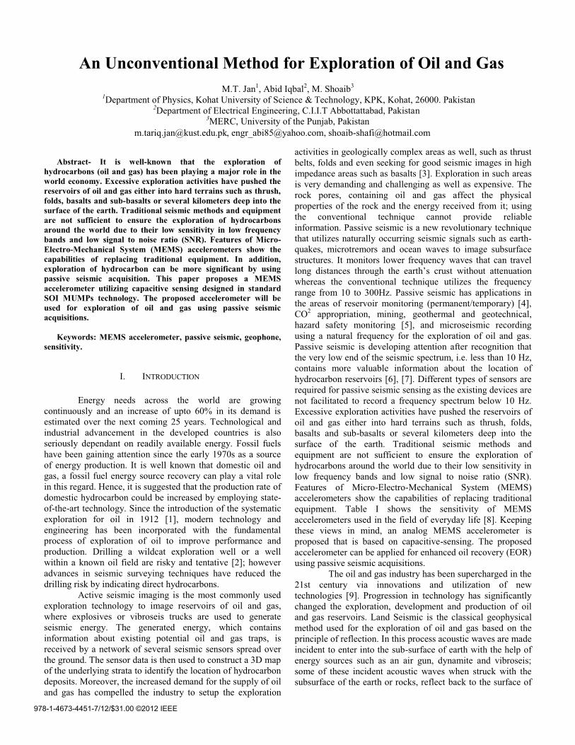
accelerometer. The differential equation for the mass-spring-
damper accelerometer shown in Fig 1 can be given as equation
1. Where the displacement x is a function of external
acceleration:
extext maFkxt
xB
t
xm 2
(1)
Where k is the spring stiffness, B is the damping coefficient,
m is the effective mass, extF is the external force and exta is
the external acceleration.
Field Sensitivity Power
Consumption
Frequency
Range
Medical ± 16 g >= 19 mA 2.4 MHz IEEE standard
Implantable ±2g, ±4g, ±8g,
±16g
25 uA 2.4 MHz
IEEE standard
Automobile ±35g, ±50g, ±70g.
>= 1.3 mA 2.50 GHz
Defense Up ±70 g 2.0 A, 20 V 650 KHz to
1.5 MHz
Communication ±20 to ±70g Varies with applications
2.7 to 10 GHz
Seismology >= ±2g Varies with
applications
>= 1 KHz
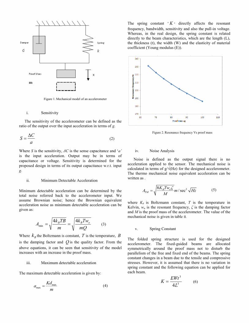
Figure 1. Mechanical model of an accelerometer
i. Sensitivity
The sensitivity of the accelerometer can be defined as the
ratio of the output over the input acceleration in terms of g.
CS
a(2)
Where S is the sensitivity, is the sense capacitance and a
is the input acceleration. Output may be in terms of
capacitance or voltage. Sensitivity is determined for the
proposed design in terms of its output capacitance w.r.t. input
g.
ii. Minimum Detectable Acceleration
Minimum detectable acceleration can be determined by the
total noise referred back to the accelerometer input. We
assume Brownian noise; hence the Brownian equivalent
acceleration noise as minimum detectable acceleration can be
given as:
mQ
Twk
m
TBkA oBB 44
min (3)
Where Bk the Boltzmann is constant, T is the temperature, B
is the damping factor and Q is the quality factor. From the
above equations, it can be seen that sensitivity of the model
increases with an increase in the proof mass.
iii. Maximum detectable acceleration
The maximum detectable acceleration is given by:
maxmax
Kda
m (4)
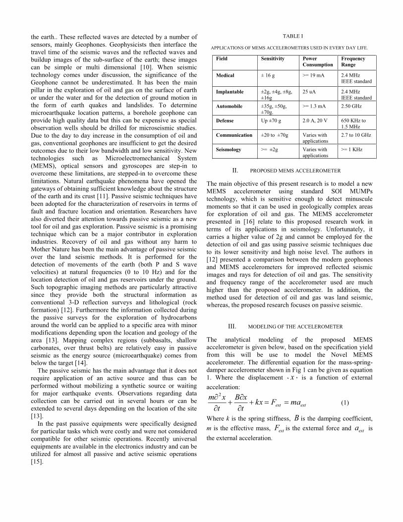
The spring constant K directly affects the resonant
frequency, bandwidth, sensitivity and also the pull-in voltage.
Whereas, in the real design, the spring constant is related
directly to the beam characteristics, which are the length (L),
the thickness (t), the width (W) and the elasticity of material
coefficient (Young modulus (E)).
Figure 2. Resonance frequency Vs proof mass
iv. Noise Analysis
Noise is defined as the output signal there is no
acceleration applied to the sensor. The mechanical noise is
calculated in terms of for the designed accelerometer.
The thermo mechanical noise equivalent acceleration can be
written as .
28/ secB n
TM
K TwA m Hz
M (5)
where KB is Boltzmann constant, T is the temperature in
Kelvin, wn is the resonant frequency, is the damping factor
and M is the proof mass of the accelerometer. The value of the
mechanical noise is given in table II.
v. Spring Constant
The folded spring structure is used for the designed
accelerometer. The fixed-guided beams are allocated
symmetrically around the proof mass not to disturb the
parallelism of the free and fixed end of the beams. The spring
constant changes in a beam due to the tensile and compressive
stresses. However, it is assumed that there is no variation in
spring constant and the following equation can be applied for
each beam.
3
3
4L
EWtK (6)
vi. Sense Capacitance
The lateral differential capacitance scheme is used for
sensing the capacitance. The analytical calculation for the
capacitance is given below :
1 '
[ ( )]. ot l d
C N nd
(7)
2 '
[ ( )]. ot l d
C N nd
(8)
1 2C C C (9)
The external acceleration causes the seismic mass to
move from its rest position, which results in the change in
overlap length of the sensing fingers. The change in
capacitance with change in overlap length of the sensing
fingers can be found by using Equations (7) and (8), showing
a linear change in capacitance with respect to the change in
acceleration. Where N is the number of comb drives, n is the
number of fingers in each comb drive, t is the thickness of the
electrode finger in a comb; l is the initial overlapping length
of the fingers and do is the change in overlapping distance
between two fingers. The total change in differential
capacitance is equal to the sum of the capacitances in the two
combs, as given in Equations (9).
IV. ACCELEROMETER LAYOUT
The proposed accelerometer is designed in standard
SOIMUMPs process. The layout of the proposed design is
shown in Fig 3. The lateral capacitive differential scheme is
used for sensing the magnitude of acceleration. Two comb
drives are attached with the proof mass to support the
differential capacitive sensing. The external acceleration
causes the proof mass to displace from its mean position. This
displacement is directly proportional to the magnitude of
displacement which results in the change in overlap length of
the sensing fingers. The change in capacitance with change in
overlap length of the sensing fingers can be found by using
Equations (7) and (8), showing a linear change in capacitance
with respect to the change in acceleration. The total change in
differential capacitance is equal to the sum of the capacitances
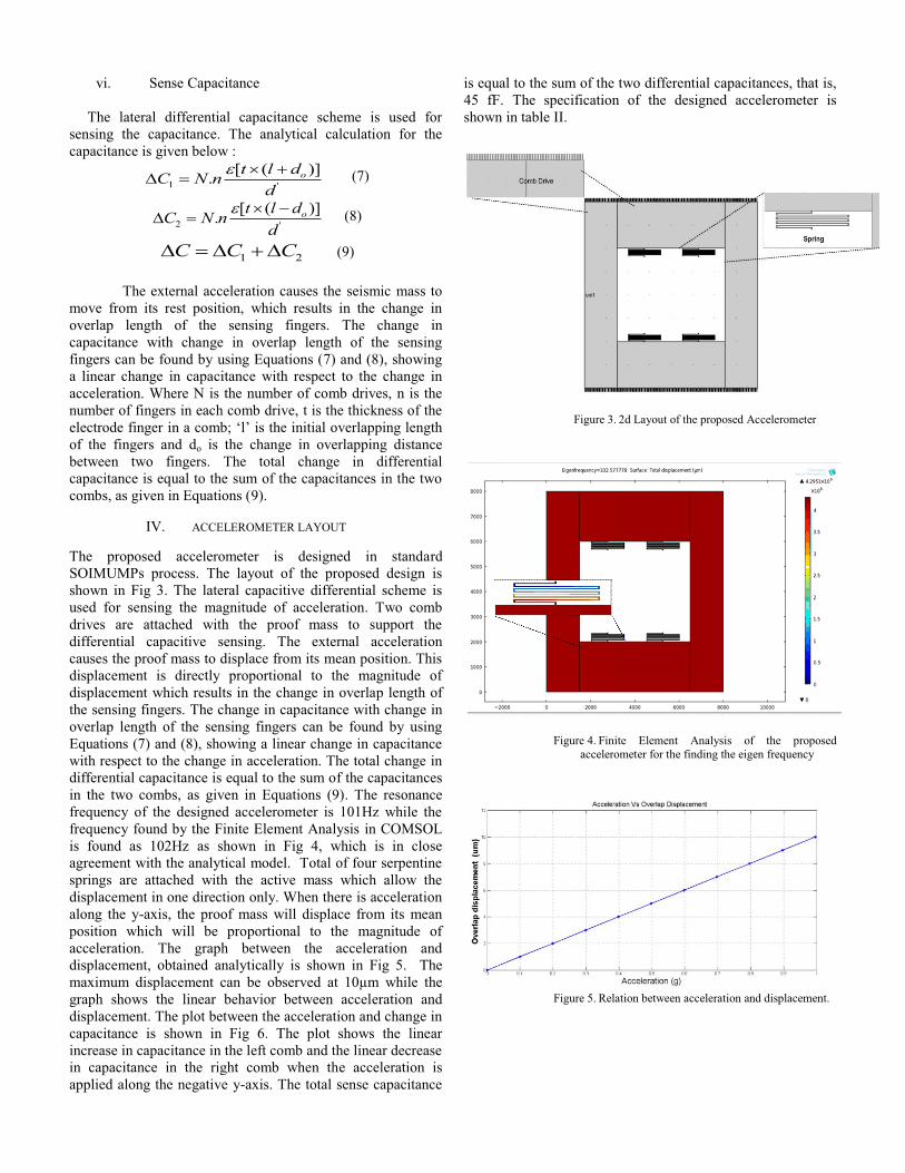
in the two combs, as given in Equations (9). The resonance
frequency of the designed accelerometer is 101Hz while the
frequency found by the Finite Element Analysis in COMSOL
is found as 102Hz as shown in Fig 4, which is in close
agreement with the analytical model. Total of four serpentine
springs are attached with the active mass which allow the
displacement in one direction only. When there is acceleration
along the y-axis, the proof mass will displace from its mean
position which will be proportional to the magnitude of
acceleration. The graph between the acceleration and
displacement, obtained analytically is shown in Fig 5. The
maximum displacement can be observed at 10µm while the
graph shows the linear behavior between acceleration and
displacement. The plot between the acceleration and change in
capacitance is shown in Fig 6. The plot shows the linear
increase in capacitance in the left comb and the linear decrease
in capacitance in the right comb when the acceleration is
applied along the negative y-axis. The total sense capacitance
is equal to the sum of the two differential capacitances, that is,
45 fF. The specification of the designed accelerometer is
shown in table II.
Figure 3. 2d Layout of the proposed Accelerometer
Figure 4. Finite Element Analysis of the proposed
accelerometer for the finding the eigen frequency
Figure 5. Relation between acceleration and displacement.
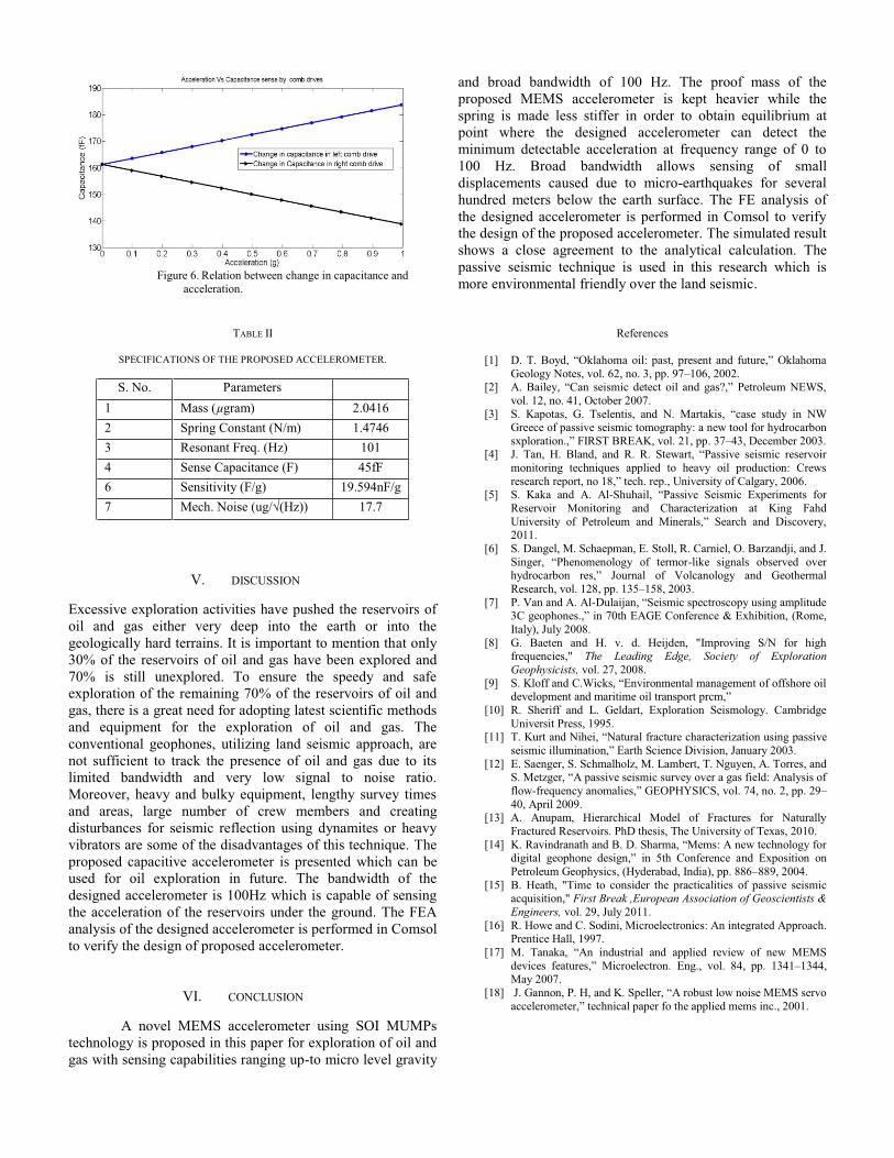
Figure 6. Relation between change in capacitance and
acceleration.
TABLE II
SPECIFICATIONS OF THE PROPOSED ACCELEROMETER.
S. No. Parameters
1 Mass (µgram) 2.0416
2 Spring Constant (N/m) 1.4746
3 Resonant Freq. (Hz) 101
4 Sense Capacitance (F) 45fF
6 Sensitivity (F/g) 19.594nF/g
7 17.7
V. DISCUSSION
Excessive exploration activities have pushed the reservoirs of
oil and gas either very deep into the earth or into the
geologically hard terrains. It is important to mention that only
30% of the reservoirs of oil and gas have been explored and
70% is still unexplored. To ensure the speedy and safe
exploration of the remaining 70% of the reservoirs of oil and
gas, there is a great need for adopting latest scientific methods
and equipment for the exploration of oil and gas. The
conventional geophones, utilizing land seismic approach, are
not sufficient to track the presence of oil and gas due to its
limited bandwidth and very low signal to noise ratio.
Moreover, heavy and bulky equipment, lengthy survey times
and areas, large number of crew members and creating
disturbances for seismic reflection using dynamites or heavy
vibrators are some of the disadvantages of this technique. The
proposed capacitive accelerometer is presented which can be
used for oil exploration in future. The bandwidth of the
designed accelerometer is 100Hz which is capable of sensing
the acceleration of the reservoirs under the ground. The FEA
analysis of the designed accelerometer is performed in Comsol
to verify the design of proposed accelerometer.
VI. CONCLUSION
A novel MEMS accelerometer using SOI MUMPs
technology is proposed in this paper for exploration of oil and
gas with sensing capabilities ranging up-to micro level gravity
and broad bandwidth of 100 Hz. The proof mass of the
proposed MEMS accelerometer is kept heavier while the
spring is made less stiffer in order to obtain equilibrium at
point where the designed accelerometer can detect the
minimum detectable acceleration at frequency range of 0 to
100 Hz. Broad bandwidth allows sensing of small
displacements caused due to micro-earthquakes for several
hundred meters below the earth surface. The FE analysis of
the designed accelerometer is performed in Comsol to verify
the design of the proposed accelerometer. The simulated result
shows a close agreement to the analytical calculation. The
passive seismic technique is used in this research which is
more environmental friendly over the land seismic.
References
[1]
Geology Notes, vol. 62, no. 3, pp. 97 106, 2002.[2] A.
vol. 12, no. 41, October 2007.
[3]Greece of passive seismic tomography: a new tool for hydrocarbon
. 37 43, December 2003.[4]
monitoring techniques applied to heavy oil production: Crews
[5] S. Kaka and A. Al- ic Experiments for
Reservoir Monitoring and Characterization at King Fahd
2011.
[6] S. Dangel, M. Schaepman, E. Stoll, R. Carniel, O. Barzandji, and J.
-like signals observed over
Research, vol. 128, pp. 135 158, 2003.
[7] P. Van and A. Al-
Italy), July 2008.
[8] G. Baeten and H. v. d. Heijden, "Improving S/N for high frequencies," The Leading Edge, Society of Exploration
Geophysicists, vol. 27, 2008.
[9] S.
[10] R. Sheriff and L. Geldart, Exploration Seismology. Cambridge
Universit Press, 1995. [11] ssive
[12] E. Saenger, S. Schmalholz, M. Lambert, T. Nguyen, A. Torres, and
flow- 2, pp. 29
40, April 2009.[13] A. Anupam, Hierarchical Model of Fractures for Naturally
Fractured Reservoirs. PhD thesis, The University of Texas, 2010.
[14]nd Exposition on
Petroleum Geophysics, (Hyderabad, India), pp. 886 889, 2004.
[15] B. Heath, "Time to consider the practicalities of passive seismic acquisition," First Break ,European Association of Geoscientists &
Engineers, vol. 29, July 2011.
[16] R. Howe and C. Sodini, Microelectronics: An integrated Approach. Prentice Hall, 1997.
[17]
Eng., vol. 84, pp. 1341 1344, May 2007.
[18]


