Embed Size (px)
Citation preview
Instruction ManualR 5 ATEXOil-Lubricated Rotary Vane Vacuum PumpsRA 0400 C, RA 0502 C, RA 0630 CRC 0400 C, RC 0502 C, RC 0630 C
0870572240/-0008_en / Original instructions / Modifications reserved 10/04/2018
Ateliers Busch S.A.Zone industrielle, 2906 ChevenezSwitzerland

Table of Contents
2 / 40 0870572240_RA0400-0630C_Ex_-0008_IM_en
Table of Contents1 Safety........................................................................................................................... 4
2 Product Description ..................................................................................................... 5
2.1 Operating Principle...............................................................................................6
2.2 Application ...........................................................................................................6
2.3 Start Controls .......................................................................................................7
2.4 Accessories ...........................................................................................................72.4.1 Gas Ballast Valve........................................................................................72.4.2 Inlet Filter ..................................................................................................72.4.3 Water-oil Heat Exchanger..........................................................................72.4.4 Temperature Switch...................................................................................72.4.5 Resistance Thermometer............................................................................72.4.6 Level and Temperature Switch ...................................................................72.4.7 Pressure Switch..........................................................................................82.4.8 Pressure Transmitter ..................................................................................8
2.5 Explanation of ATEX Classification........................................................................9
2.6 Safety concept......................................................................................................92.6.1 ATEX Classifications and Associated Accessories ........................................92.6.2 P&ID "Piping and Instrumentation Diagram" ............................................10
3 Transport ..................................................................................................................... 11
4 Storage......................................................................................................................... 12
5 Installation................................................................................................................... 12
5.1 Installation Conditions ..........................................................................................12
5.2 Connecting Lines / Pipes ......................................................................................135.2.1 Suction Connection....................................................................................145.2.2 Discharge Connection................................................................................145.2.3 Cooling Water Connection (Optional) .......................................................15
5.3 Earth Connection..................................................................................................16
5.4 Filling Oil ..............................................................................................................17
5.5 Fitting the Coupling..............................................................................................17
5.6 Electrical Connection ............................................................................................185.6.1 Wiring Diagram Three-Phase Motor ..........................................................19
5.7 Electrical Connection of the Monitoring Devices ...................................................205.7.1 Wiring Diagram Temperature Switch .........................................................205.7.2 Wiring Diagram Resistance Thermometer ..................................................205.7.3 Wiring Diagram Pressure Switch ................................................................215.7.4 Wiring Diagram Pressure Transmitter.........................................................215.7.5 Wiring Diagram Level and Temperature Switch .........................................215.7.6 Wiring Diagram Level Switch .....................................................................225.7.7 Wiring Diagram Pressure Switch of Water-oil Heat Exchanger (Optional) ..22
5.8 Flowchart .............................................................................................................23
6 Commissioning............................................................................................................ 24
6.1 Conveying Condensable Vapours .........................................................................25
7 Maintenance ................................................................................................................ 25
7.1 Maintenance Schedule..........................................................................................26
7.2 Oil Level Inspection ..............................................................................................27
7.3 Oil and Oil Filter Change......................................................................................27
7.4 Exhaust Filter Change...........................................................................................29
7.5 Coupling Maintenance .........................................................................................30

Table of Contents
0870572240_RA0400-0630C_Ex_-0008_IM_en 3
8 Overhaul...................................................................................................................... 30
9 Decommissioning ........................................................................................................ 30
9.1 Dismantling and Disposal......................................................................................31
10 Spare Parts ................................................................................................................... 31
11 Troubleshooting........................................................................................................... 32
12 Technical Data ............................................................................................................. 34
13 Oil ............................................................................................................................... 34
14 EU Declaration of Conformity ...................................................................................... 36
1 | Safety
4 / 40 0870572240_RA0400-0630C_Ex_-0008_IM_en
1 SafetyPrior to handling the machine, this instruction manual should be read and understood. Ifanything needs to be clarified, please contact your Busch representative.
Read this manual carefully before use and keep for future reference.
This instruction manual remains valid as long as the customer does not change anythingon the product.
The machine is intended for industrial use. It must be handled only by technically trainedpersonnel.
Always wear appropriate personal protective equipment in accordance with the localregulations.
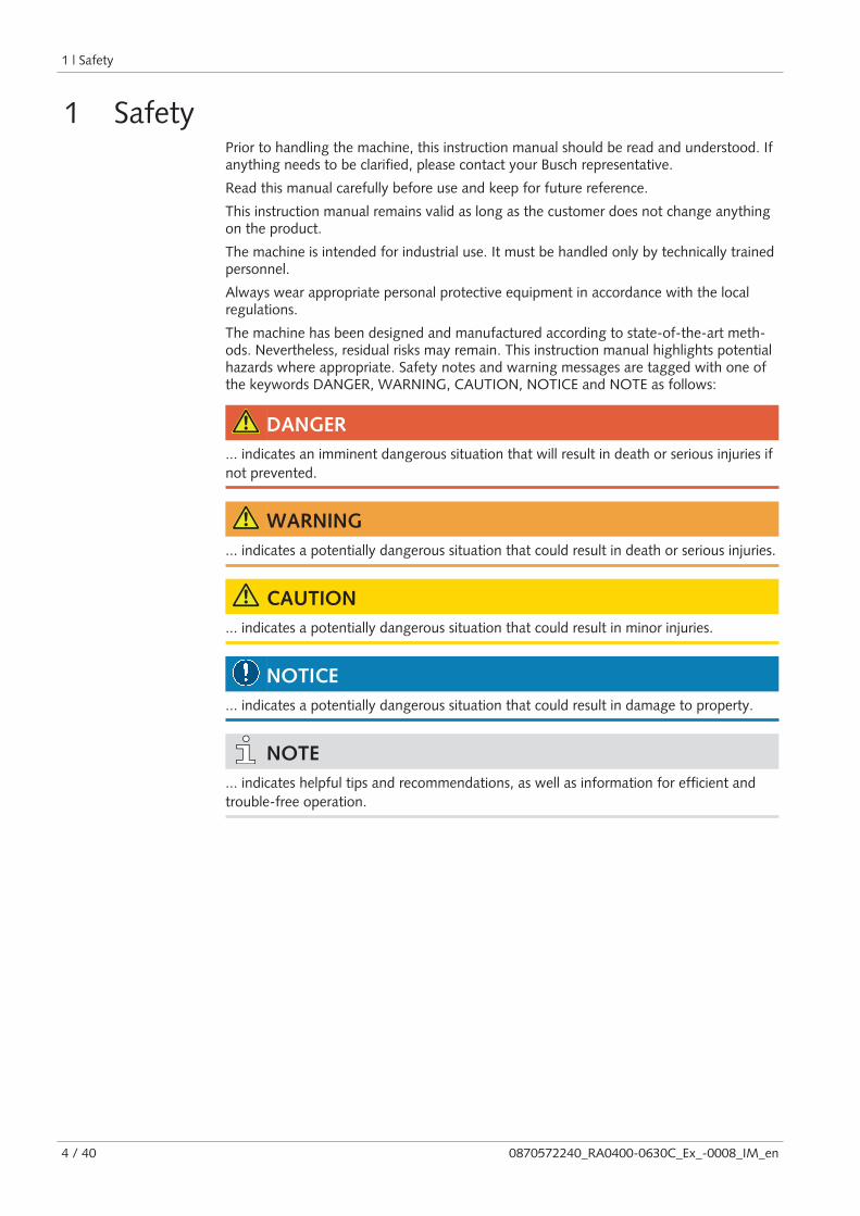
The machine has been designed and manufactured according to state-of-the-art meth-ods. Nevertheless, residual risks may remain. This instruction manual highlights potentialhazards where appropriate. Safety notes and warning messages are tagged with one ofthe keywords DANGER, WARNING, CAUTION, NOTICE and NOTE as follows:
DANGER... indicates an imminent dangerous situation that will result in death or serious injuries ifnot prevented.
WARNING... indicates a potentially dangerous situation that could result in death or serious injuries.
CAUTION... indicates a potentially dangerous situation that could result in minor injuries.
NOTICE... indicates a potentially dangerous situation that could result in damage to property.
NOTE... indicates helpful tips and recommendations, as well as information for efficient andtrouble-free operation.

Product Description | 2
0870572240_RA0400-0630C_Ex_-0008_IM_en 5 / 40
2 Product DescriptionNP OS EB
IN
OUT
OF
ODP OSG
MTB
GB
LS-0201 &TS+0104
TSA orTS+0101
PSA orPS+0301
TSA+0104
OFP
IF ECI
AF
AHE
DA
FV
FV
MTB DAAHE
TSA orTS+0102
RA 0400 C /RA 0502 C
RA 0400 C (60 Hz) / RA 0502 C
RA 0630 C
RA 0400 C - RA 0630 C
ECP
EF FM
two positions are possible
two positions are possible
IN Suction connection MTB Motor terminal box
OUT Discharge connection DA Directional arrow
OFP Oil fill plug EF Exhaust filter
OSG Oil sight glass NP Nameplate
ODP Oil drain plug OF Oil filter
EB Eye bolt AF Axial fan
GB Gas ballast valve OS Oil separator
AHE Air-oil heat exchanger FM Filter material
FV Float valve (on RA version only) TS Temperature switch
TSA Resistance thermometer PS Pressure switch
PSA Pressure transmitter LS Level switch
IF Inlet filter ECP Pump earth connection
ECI Inlet filter earth connection
2 | Product Description
6 / 40 0870572240_RA0400-0630C_Ex_-0008_IM_en
NOTETechnical term.
In this instruction manual, we consider that the term ‘machine’ refers to the ‘vacuumpump’.
2.1 Operating Principle
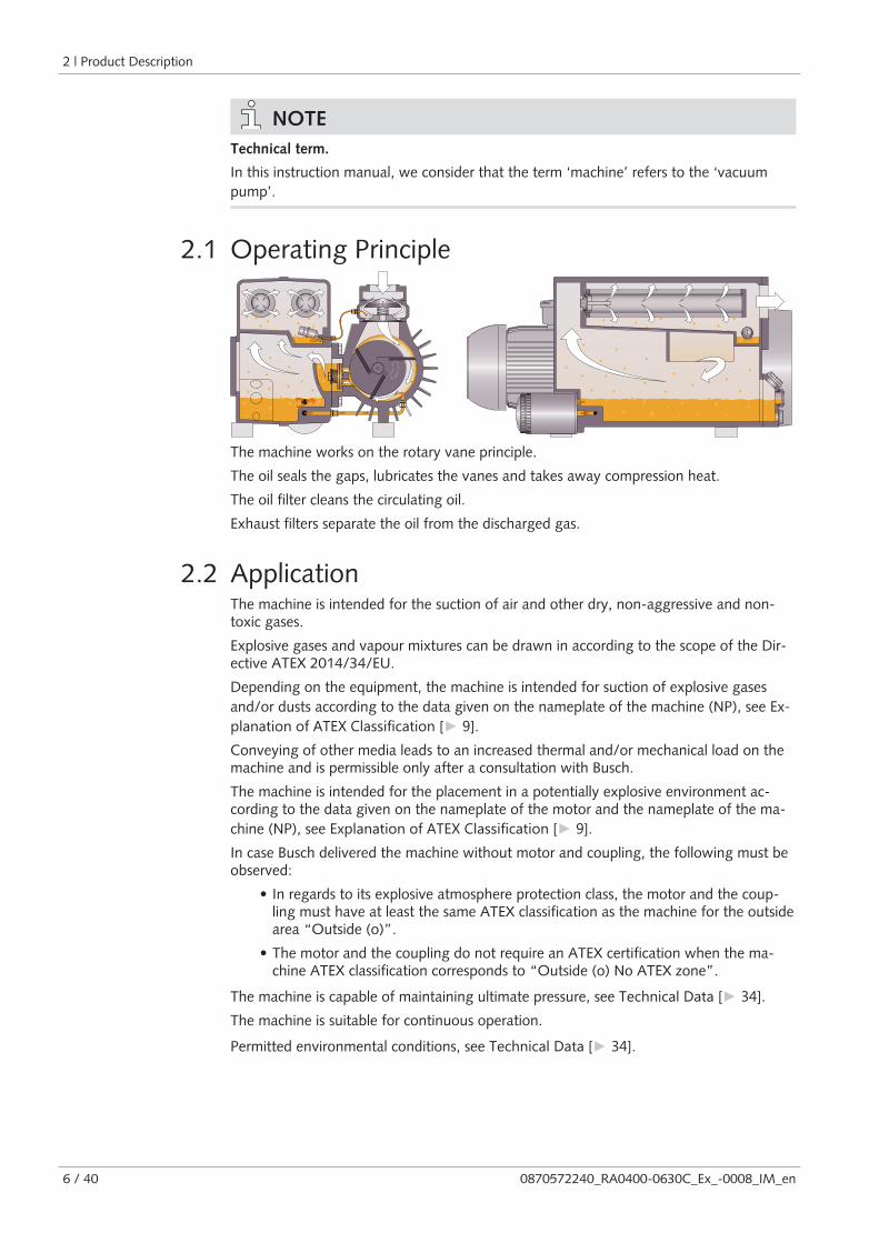
The machine works on the rotary vane principle.
The oil seals the gaps, lubricates the vanes and takes away compression heat.
The oil filter cleans the circulating oil.
Exhaust filters separate the oil from the discharged gas.
2.2 ApplicationThe machine is intended for the suction of air and other dry, non-aggressive and non-toxic gases.
Explosive gases and vapour mixtures can be drawn in according to the scope of the Dir-ective ATEX 2014/34/EU.
Depending on the equipment, the machine is intended for suction of explosive gasesand/or dusts according to the data given on the nameplate of the machine (NP), see Ex-planation of ATEX Classification [► 9].Conveying of other media leads to an increased thermal and/or mechanical load on themachine and is permissible only after a consultation with Busch.
The machine is intended for the placement in a potentially explosive environment ac-cording to the data given on the nameplate of the motor and the nameplate of the ma-chine (NP), see Explanation of ATEX Classification [► 9].In case Busch delivered the machine without motor and coupling, the following must beobserved:
• In regards to its explosive atmosphere protection class, the motor and the coup-ling must have at least the same ATEX classification as the machine for the outsidearea “Outside (o)”.
• The motor and the coupling do not require an ATEX certification when the ma-chine ATEX classification corresponds to “Outside (o) No ATEX zone”.
The machine is capable of maintaining ultimate pressure, see Technical Data [► 34].The machine is suitable for continuous operation.
Permitted environmental conditions, see Technical Data [► 34].

Product Description | 2
0870572240_RA0400-0630C_Ex_-0008_IM_en 7 / 40
2.3 Start ControlsThe machine comes without start controls. The control of the machine is to be providedin the course of installation.
The machine can be optionally equipped with a starter unit or a variable-frequency drive.
2.4 Accessories
NOTEDepending on the ATEX classification of the machine, some of the following accessoriesmay be mandatory, see ATEX Classifications and Associated Accessories [► 9].
2.4.1 Gas Ballast ValveThe gas ballast valve mixes the process gas with a limited quantity of ambient air tocounteract the condensation of vapour inside the machine.
The gas ballast valve has an influence on the ultimate pressure of the machine, see Tech-nical Data [► 34].
2.4.2 Inlet FilterThe inlet filter protects the machine against dust and other solids in the process gas. Theinlet filter is available with a polyester (antistatic) cartridge.
2.4.3 Water-oil Heat ExchangerIn case of unfavourable ambient conditions a water-oil heat exchanger can be provided.
See Cooling Water Connection (Optional) [► 15].
2.4.4 Temperature SwitchThe temperature switch monitors the gas temperature of the machine.
The machine must be stopped when the gas reaches a certain temperature, see WiringDiagram Temperature Switch [► 20].
2.4.5 Resistance ThermometerThe resistance thermometer monitors the gas temperature of the machine and optionallythe oil temperature.
A warning and a trip signals must be set, see Wiring Diagram Resistance Thermometer[► 20].
2.4.6 Level and Temperature SwitchThe level switch with integrated temperature switch monitors the oil level and the oiltemperature. It has one level switch point and two temperature switch points.
The machine must be stopped when the oil level is too low or, depending on the oiltype, when the oil reaches a certain temperature, see Oil [► 34].
2 | Product Description
8 / 40 0870572240_RA0400-0630C_Ex_-0008_IM_en
2.4.7 Pressure SwitchThe pressure switch monitors the pressure in the oil separator.
The machine must be stopped when the gas reaches a certain pressure, see Wiring Dia-gram Pressure Switch [► 21].
2.4.8 Pressure TransmitterThe pressure transmitter monitors the pressure in the oil separator.
A warning and a trip signals must be set, see Wiring Diagram Pressure Transmitter[► 21].
Product Description | 2
0870572240_RA0400-0630C_Ex_-0008_IM_en 9 / 40
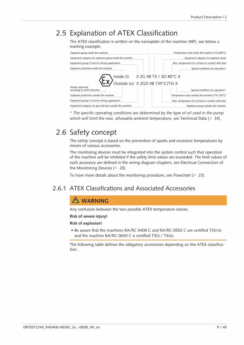
2.5 Explanation of ATEX ClassificationThe ATEX classification is written on the nameplate of the machine (NP), see below amarking example:
Inside (i)
Outside (o)
II 2G IIB T3 / 3D 80°C X
II 2GD IIB 135°C(T4) X
Explosion group inside the machine
Equipment category for explosive gases inside the machine
Equipment category for gas and dust outside the machine
Equipment group II (not for mining application)
Explosion protection inside the machine
Explosion protection outside the machine
Design approvedaccording to ATEX Directive
Equipment group II (not for mining application)
Temperature class inside the machine (T3=200°C)
Equipment category for explosive dusts
Max. temperature for surfaces in contact with dust
Special conditions for operation*
Special conditions for operation*
Temperature class outside the machine (T4=135°C)
Max. temperature for surfaces in contact with dust
Explosion group outside the machine
* The specific operating conditions are determined by the type of oil used in the pumpwhich will limit the max. allowable ambient temperature, see Technical Data [► 34].
2.6 Safety conceptThe safety concept is based on the prevention of sparks and excessive temperatures bymeans of various accessories.
The monitoring devices must be integrated into the system control such that operationof the machine will be inhibited if the safety limit values are exceeded. The limit values ofeach accessory are defined in the wiring diagram chapters, see Electrical Connection ofthe Monitoring Devices [► 20].
To have more details about the monitoring procedure, see Flowchart [► 23].
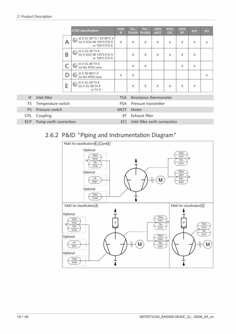
2.6.1 ATEX Classifications and Associated Accessories
WARNINGAny confusion between the two possible ATEX temperature classes.
Risk of severe injury!
Risk of explosion!
• Be aware that the machines RA/RC 0400 C and RA/RC 0502 C are certified T3(i/o)and the machine RA/RC 0630 C is certified T3(i) / T4(o).
The following table defines the obligatory accessories depending on the ATEX classifica-tion.
2 | Product Description
10 / 40 0870572240_RA0400-0630C_Ex_-0008_IM_en
(i) II 2G IIB T3 X
(o) II 2G IIB T4 X
or T3 X
(i) II 2G IIB T3 / 3D 80°C X
(o) II 2GD IIB 135°C(T4) X
or 150°C(T3) X
(i) II 2G IIB T3 X
(o) II 2GD IIB 135°C(T4) X
or 150°C(T3) X
(i) II 3D 80°C X
(o) No ATEX zone
(i) II 2G IIB T3 X
(o) No ATEX zone
ATEX
IF
TSA /
TS+0101
PSA /
PS+0301
ATEX
MOT
ATEX
CPL
ATEX
EFECP ECI
X X
X
X
X
X
X
X
X
X
X
X
X
X
X
X
X
X
X
X
X X X X
X X
E
A
B
C
D X
ATEX classification
IF Inlet filter TSA Resistance thermometer
TS Temperature switch PSA Pressure transmitter
PS Pressure switch MOT Motor
CPL Coupling EF Exhaust filter
ECP Pump earth connection ECI Inlet filter earth connection
2.6.2 P&ID "Piping and Instrumentation Diagram"
M
PSA+
0301
0201
LS- PS+
0301
TSA+
0104
TSA+
0101
TS+
0101
M
PSA+
0301
0201
LS- PS+
0301
TSA+
0104
TSA+
0101
TS+
0101
IF
M
IF
TSA+
0102
TS+
0102
TSA+
0102
TS+
0102
TSA+
0101
TS+
0101
Optional
Optional
or
or
P&ID for classification B , C and E
P&ID for classification A P&ID for classification D
Optional
Optional
or
or
Optional
Optional
or
or
Transport | 3
0870572240_RA0400-0630C_Ex_-0008_IM_en 11 / 40
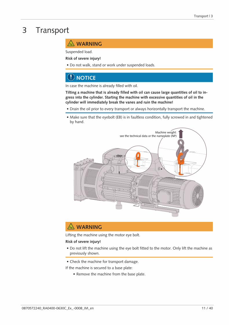
3 Transport
WARNINGSuspended load.
Risk of severe injury!
• Do not walk, stand or work under suspended loads.
NOTICEIn case the machine is already filled with oil.
Tilting a machine that is already filled with oil can cause large quantities of oil to in-gress into the cylinder. Starting the machine with excessive quantities of oil in thecylinder will immediately break the vanes and ruin the machine!
• Drain the oil prior to every transport or always horizontally transport the machine.
• Make sure that the eyebolt (EB) is in faultless condition, fully screwed in and tightenedby hand.
Machine weight:see the technical data or the nameplate (NP)
WARNINGLifting the machine using the motor eye bolt.
Risk of severe injury!
• Do not lift the machine using the eye bolt fitted to the motor. Only lift the machine aspreviously shown.
• Check the machine for transport damage.
If the machine is secured to a base plate:
• Remove the machine from the base plate.

4 | Storage
12 / 40 0870572240_RA0400-0630C_Ex_-0008_IM_en
4 Storage• Seal all apertures with adhesive tape or reuse provided caps.
If the machine is to be stored for more than 3 months:
• Wrap the machine in a corrosion inhibiting film.
• Store the machine indoors, dry, dust free and if possible in original packagingpreferably at temperatures between 0 ... 40 °C.
5 Installation
5.1 Installation Conditions
WARNINGThe installation conditions are not respected in an ATEX environment.
Risk of severe injury!
Risk of explosion!
• Take care that the installation conditions are fully complied with.
NOTICEUse of the machine outside of the permitted installation conditions.
Risk of premature failure!
Loss of efficiency!
• Take care that the installation conditions are fully complied with.
~50 cm
~50 cm
~100 cm
~100 cm
• Make sure that the environment of the machine complies with the ATEX classificationof the machine according to the data given on the nameplate of the motor and thenameplate of the machine (NP).
• Make sure that the ambient conditions comply with the Technical Data [► 34].• Make sure that the environmental conditions comply with the protection class of the
motor.
• Make sure that the installation space or location is vented such that sufficient coolingof the machine is provided.
• Make sure that cooling air inlets and outlets are not covered or obstructed and thatthe cooling air flow is not affected adversely in any other way.
Installation | 5
0870572240_RA0400-0630C_Ex_-0008_IM_en 13 / 40
• Make sure that the oil sight glass (OSG) remains easily visible.
• Make sure that enough space remains for maintenance work.
• Make sure that the machine is placed or mounted horizontally, a maximum of 1° inany direction.
• Check the oil level, see Oil Level Inspection [► 27].• Make sure that all provided covers, guards, hoods, etc. are mounted.
Version with water-oil heat exchanger:
• Make sure that the cooling water complies with the requirements, see CoolingWater Connection (Optional) [► 15].
If the machine is installed at an altitude greater than 1000 meters above sea level:
• Contact your Busch representative, the motor should be derated or the ambienttemperature limited.
Make sure that the monitoring devices are correctly connected and integrated into acontrol system such that operation of the machine will be inhibited if the safety limit val-ues are exceeded, see Electrical Connection of the Monitoring Devices [► 20].If additional electrical components not included in scope of delivery should be added:
• Make sure that they have a better or equal ATEX classification than that of themachine, see the ATEX marking on the nameplate (NP).
For classification type “C” and “D” (see ATEX Classifications and Associated Accessor-ies [► 9]):
• Make sure that the installation space or location is ventilated enough in order toprevent the formation of an explosive area.
• Make sure that the cooling liquid complies with the requirements, see Cooling LiquidConnection.
5.2 Connecting Lines / Pipes• Remove all protective caps before installation.
• Make sure that the connection lines cause no stress on the machine‘s connection; ifnecessary use flexible joints.
• Make sure that the line size of the connection lines over the entire length is at least aslarge as the connections of the machine.
In case of very long connection lines it is advisable to use larger line sizes in order toavoid a loss of efficiency. Seek advice from your Busch representative.
WARNINGThe connection lines can be built up by electrostatic charge.
Risk of severe injury!
Risk of explosion!
• The connection lines must be made out of conductive material or provisions must bemade against creating an electrostatic charge.
5 | Installation
14 / 40 0870572240_RA0400-0630C_Ex_-0008_IM_en
5.2.1 Suction Connection
WARNINGUnprotected suction connection.
Risk of severe injury!
• Do not put hand or fingers in the suction connection.
NOTICEIngress of foreign objects or liquids.
Risk of damage to the machine!
If the inlet gas contains dust or other foreign solid particles:
• Install a suitable filter (5 micron or less) upstream from the machine.
Connection size:
– G3
Depending on the specific order, other connection dimensions may apply.
If the machine is used as part of a vacuum system:
• Busch recommends the installation of an isolation valve in order to prevent the oilfrom flowing back to the vacuum system.
5.2.2 Discharge Connection
CAUTIONThe discharge gas contains small quantities of oil.
Risk to health!
If air is discharged into rooms where persons are present:
• Make sure that sufficient ventilation is provided.
Connection size:
– G3
Depending on the specific order, other connection dimensions may apply.
• Make sure that the discharged gas will flow without obstruction. Do not shut off orthrottle the discharge line or use it as a pressurised air source.
Unless the aspirated air is discharged to the environment right at the machine:
• Make sure that the discharge line either slopes away from the machine or provide a li-quid separator or a siphon with a drain cock, so that no liquids can flow back into themachine.

Installation | 5
0870572240_RA0400-0630C_Ex_-0008_IM_en 15 / 40
5.2.3 Cooling Water Connection (Optional)
Water-oil heat exchanger without inlet accessories
Water-oil heat exchanger with inlet accessories
(Available for all ATEX classifications)
(Only available for ATEX classifications C and D )
WHE CWO CWI
CWO TV PS
MV WF CWIWHE
WBV
CWI Cooling water inlet PS Pressure switch
CWO Cooling water outlet WBV Water bypass valve
WHE Water-oil heat exchanger WF Water filter
TV Thermostatic valve MV Solenoid valve
The thermostatic valve (TV) is used to control the water flow in order to keep a stablemachine temperature.
The factory default adjustment of the thermostatic valve (TV) is set in position 2 (approx.75°C oil temperature).
The pressure switch (PS) is used to monitor the presence of water at the cooling systemof the machine.
When the pressure switch detects a pressure lower than 2 bar, the machine must bestopped.
The water bypass valve (WBV) is used at the first machine start-up. At that moment itshould be open (approx. 90 seconds) to prime the water heat exchanger, afterwards itshould be closed.
The solenoid valve (MV) is used to stop the cooling water circulation when the machineis not running.
• Connect the cooling water connections (CWI / CWO) to the water supply.
Connection size:
– 19 mm hose (CWI / CWO)
• If necessary, electrically connect the pressure switch (PS), see Wiring Diagram Pres-sure Switch of Water-oil Heat Exchanger (Optional) [► 22].
• If necessary, electrically connect the solenoid valve (MV).
• Make sure that the cooling water complies with the following requirements:Min. supply capacity l/min 5
Water pressure bar 2 ... 6
Supply temperature °C +5 ... +35
Required pressure differential across supplyand return
bar ≥ 1

5 | Installation
16 / 40 0870572240_RA0400-0630C_Ex_-0008_IM_en
• To reduce the maintenance effort and ensure a long product lifetime we recommendthe following cooling water quality:
Hardness mg/l (ppm) < 90
Properties Clean & clear
PH value 7 … 8
Particle size µm < 200
Chloride mg/l < 100
Electrical conductivity µS/cm ≤ 100
Free chloride mg/l < 0.3
Materials in contact with the cooling water Stainless steel, copper and cast iron
NOTEWater hardness unit conversion.
1 mg/l (ppm) = 0.056 °dh (german degree) = 0.07 °e (english degree) = 0.1 °fH (frenchdegree)
5.3 Earth ConnectionIn order to prevent the machine from creating an electrostatic charge:
• Connect the earth connection of the machine (ECP)
If an inlet filter (IF) being installed:
• Connect the earth connection of the inlet filter (ECI) in addition to the earth con-nection of the machine.
Earth connection ofthe machine (ECP)
Earth connection ofthe inlet filter (ECI)
Installation | 5
0870572240_RA0400-0630C_Ex_-0008_IM_en 17 / 40
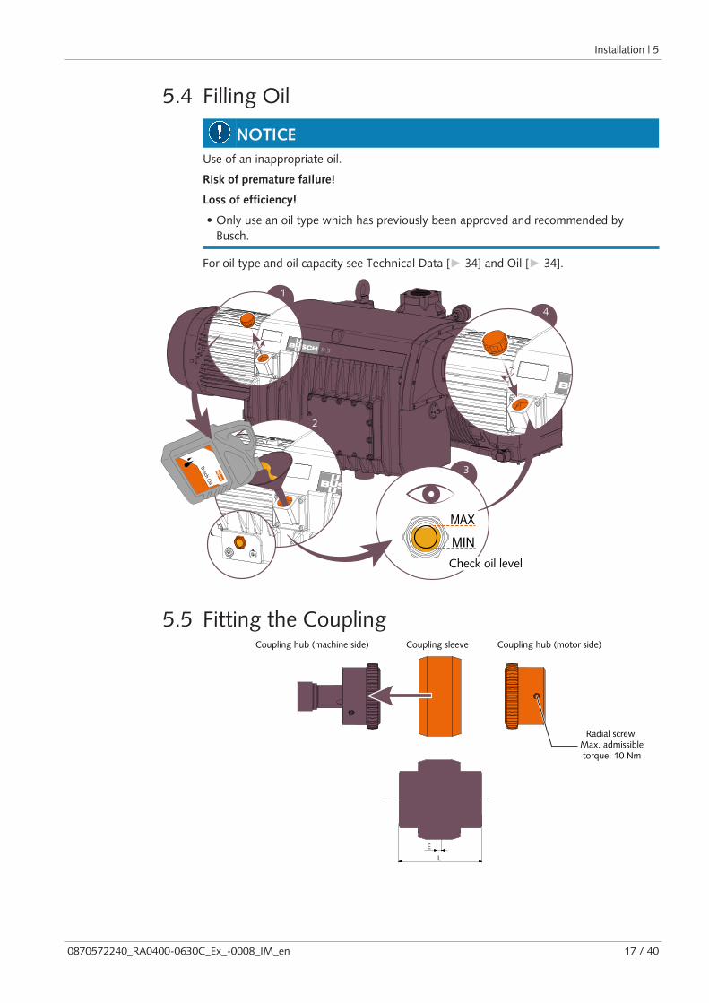
5.4 Filling Oil
NOTICEUse of an inappropriate oil.
Risk of premature failure!
Loss of efficiency!
• Only use an oil type which has previously been approved and recommended byBusch.
For oil type and oil capacity see Technical Data [► 34] and Oil [► 34].
1
4
MAX
MIN
3Busch Oil
2
Check oil level
5.5 Fitting the Coupling
E
L
Coupling hub (machine side) Coupling hub (motor side)Coupling sleeve
Radial screw Max. admissibletorque: 10 Nm
5 | Installation
18 / 40 0870572240_RA0400-0630C_Ex_-0008_IM_en
Machine type Coupling size Value “E” (mm) Value “L” (mm)
RA/RC 0400 C BoWex® M-65 4 114
RA/RC 0502 C
RA/RC 0630 C
In case of a machine delivery without motor:
• Fit the second coupling hub on the motor shaft (separately delivered).
• Axially adjust the sleeve in such a way until value "E" (or “L”) is reached.
• When the coupling adjustment is done, lock the coupling hub by tightening theradial screw.
• Mount the motor on the machine by including the coupling sleeve.
For further coupling information, go to www.ktr.com and download the instructionmanual of the BoWex® coupling.
5.6 Electrical Connection
DANGERLive wires.
Risk of electrical shock.
• Electrical installation work must only be executed by qualified personnel.
NOTEThe operation with variable speed, i.e. with a variable frequency drive or a soft starter, isallowed as long as the motor is admitted and the permitted motor speed range is neitherunderrun nor exceeded (see Technical Data [► 34]).
Seek advice from your Busch representative.
• Make sure that the power supply for the motor is compatible with the data on thenameplate of the motor.
• Provide overload protection according to EN 60204-1 for the motor.
• Busch recommends installing a D-curve circuit breaker.
• Make sure that the motor of the machine will not be affected by electric or electro-magnetic disturbance from the mains; if necessary seek advice from Busch.
• Connect the protective earth conductor.
• Electrically connect the motor.
NOTICEIncorrect connection.
Risk of damage to the motor!
• The wiring diagrams given below are typical. Check the inside of the terminal box formotor connection instructions/diagrams.

Installation | 5
0870572240_RA0400-0630C_Ex_-0008_IM_en 19 / 40
5.6.1 Wiring Diagram Three-Phase Motor
Delta connection (low voltage): Star connection (high voltage):
Double star connection, multi-voltagemotor with 12 pins (low voltage):
4
4
4
Star connection, multi-voltage motorwith 12 pins (high voltage):
4
4
4
Delta connection, multi-voltage motorwith 12 pins (middle voltage):
4
4
4
NOTICEIncorrect direction of rotation.
Risk of damage to the machine!
• Operation in the wrong direction of rotation can destroy the machine in a short time!Prior to start-up, ensure that the machine is operated in the right direction.
• Determine the intended direction of rotation with the arrow (stuck on or cast).
• Jog the motor briefly.
• Watch the fan wheel of the motor and determine the direction of rotation just beforethe fan wheel stops.
If the rotation of the motor must be changed:
• Switch any two of the motor phase wires.

5 | Installation
20 / 40 0870572240_RA0400-0630C_Ex_-0008_IM_en
5.7 Electrical Connection of the Monitoring Devices
NOTEIn order to prevent potential nuisance alarms, Busch allows that the control system isconfigured with a time delay of 2 seconds.
NOTEThe accessories below are considered as standard.
If other specific components should be used, refer to the instruction manual of the ac-cessory in question.
5.7.1 Wiring Diagram Temperature SwitchPart no.: 0651 538 812
Supplier reference: Trafag 414
P&ID position:TS+/0101 “gas temp.”TS+/0102 “gas temp.” (optional)
2
1
T
1 = Brown ; 2 = White
Electrical data:Ui = 24 VDC ; Ii = 100 mA ; Pi = 0.6 W ; Li = 0 µH ; Ci = 0 pF
Contact: Normally closed
Switch point: (factory default adjustment)Ttrip (TS+/0101) = 140°C (for RA/RC 0400 and 0502 C)Ttrip (TS+/0101) = 130°C (for RA/RC 0630 C)Ttrip (TS+/0102) = 80°C (for RA/RC 0400-0630 C)
5.7.2 Wiring Diagram Resistance ThermometerPart no.: 0651 563 753 (with transmitter)
Supplier reference: Wika TR31
Connector: M12x1, 4-pin
P&ID position:TSA+/0101 “gas temp.”TSA+/0102 “gas temp.” (optional)TSA+/0104 “oil temp.” (optional)
1 2
4 3
3
1
+
-
1 = Brown ; 3 = Blue
Electrical data:Ui = 30 VDC ; Ii = 120 mA ; Pi = 750 mW ; Li = 0 µH ; Ci = 29.7 nF4 ... 20 mA ► 0 ... 150 °C
Warning signal:Twarning (TSA+/0101) = 145°C ► 19.46 mA (for RA/RC 0400 and 0502 C)Twarning (TSA+/0101) = 135°C ► 18.4 mA (for RA/RC 0630 C)Twarning (TSA+/0102) = 75°C ► 12 mA (for RA/RC 0400-0630 C)Twarning (TSA+/0104) = see Oil [► 34] (for RA/RC 0400-0630 C)
Trip signal:Ttrip (TSA+/0101) = 150°C ► 20 mA (for RA/RC 0400 and 0502 C)Ttrip (TSA+/0101) = 140°C ► 18.93 mA (for RA/RC 0630 C)Ttrip (TSA+/0102) = 80°C ► 12.53 mA (for RA/RC 0400-0630 C)Ttrip (TSA+/0104) = see Oil [► 34] (for RA/RC 0400-0630 C)
Installation | 5
0870572240_RA0400-0630C_Ex_-0008_IM_en 21 / 40
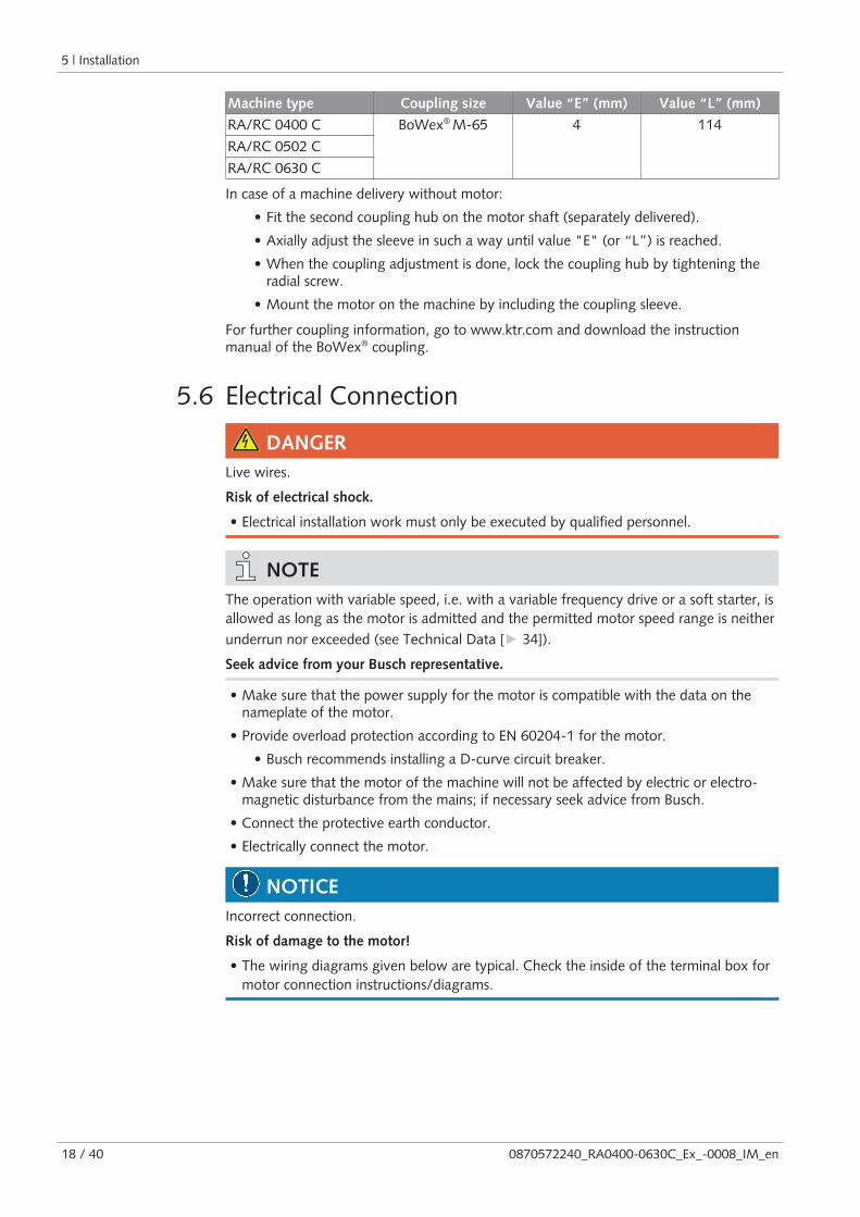
5.7.3 Wiring Diagram Pressure SwitchPart no.: 0653 539 030
Supplier reference: United Electric ControlsH100 (100 Series)
Maintenance procedure:Procedure B
P&ID position: PS+/0301
Electrical data:Ui = 49 VDC ; Ii = 3 A ; Li = 0 µH ; Ci = 0 pF
Contact: Normally closed
2
1
P
Switch point: P (PS+/0301) = 1500 hPa (mbar) abs. (factory default adjustment)
5.7.4 Wiring Diagram Pressure TransmitterPart no.: 0653 204 444
Supplier reference: Wika IS-3
Connector: M12x1, 4-pin
P&ID position: PSA+/0301
1 2
4 3
3
1
+
-
1 = Brown ; 3 = Blue
Electrical data:Ui = 30 VDC ; Ii = 100 mA ; Pi = 800 mW ; Li = 0 µH ; Ci = 16.5 nF4 ... 20 mA ► 0 ... 1.6 bar (abs.)
Warning signal:Pwarning (PSA+/0301) = 1.4* bar ► 18 mA*1400 hPa (mbar) abs.
Trip signal:Ptrip (PSA+/0301) = 1.5* bar ► 19 mA*1500 hPa (mbar) abs.
5.7.5 Wiring Diagram Level and Temperature SwitchPart no.: 0652 563 749
Supplier reference: Wika HLS-T-Exi
Connector: M12x1, 4-pin
P&ID position: LS-/0201 and TS+/0104
Electrical data:Ui = 36 VDC ; Ii = 100 mA ; Pi = 2.5 W ;Li = 0 µH ; Ci = 0 pF
Contact:Oil level is OK ► Normally closedTemperature is OK ► Normally closed
Switch points:L (LS-/0201) pin 1 + 4 = low levelT1 (TS+/0104) pin 1 + 2 = 110 °C*T2 (TS+/0104) pin 1 + 3 = 130 °C*
1 2
4 3
4
1
L2
1
T1
3
1
T2
1 = Brown ; 2 = White ;3 = Blue ; 4 = Black
* The switch point value depends on theoil type, see Oil [► 34].

5 | Installation
22 / 40 0870572240_RA0400-0630C_Ex_-0008_IM_en
5.7.6 Wiring Diagram Level SwitchPart no.: 0652 000 009
Supplier reference: Kobold NV-1103R4
P&ID position: LS-/0201
Electrical data:Ui = 30 VDC ; Ii = 100 mA ; Pi = 1.2 W ;Li = 0 µH ; Ci = 0 pF
Contact:Oil level is OK ► Normally closedSwitch points: L (LS-/0201) = low level
2
1
L
1 = Blue; 2 = Brown
5.7.7 Wiring Diagram Pressure Switch of Water-oil HeatExchanger (Optional)Part no.: 0653 000 002
Electrical data:U = 230 VAC ; I = 1 AU = 24 … 100 VDC ; I = 0.5 … 2 A
Contact: Normally open
Switch point:Ptrip = 2 bar (relative) ► min. admissiblepressure
2 4
P >
1PE
Installation | 5
0870572240_RA0400-0630C_Ex_-0008_IM_en 23 / 40
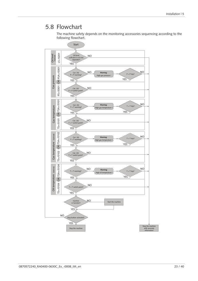
5.8 FlowchartThe machine safety depends on the monitoring accessories sequencing according to thefollowing flowchart.
Gas
pre
ssur
eG
as t
empe
ratu
re
Start
Cat. 2(i)P < P warning?
Oil levelsufficient in oil mist
separator?
High gas pressure !
Warning:P < P trip?
Cat. 2(i)P < P switch point?
YES
NOO
R YES
NO NO
YES
YES
NO
NO
YES
Cat. 2(i)T < T warning? High gas temperature !
Warning:T < T trip?
NO
YES
YES
NO
Cat. 2(i)T < T switch point?
PSA
+/0
301
PS+
/030
1
Oil
leve
l
TSA
+/0
101
TS+
/010
1TS
A+
/010
4TS
+/0
104
Oil
tem
pera
ture
T < T switch point?
T < T warning?High oil temperature !
Warning:T < T trip?
YES YES
NO
NO
machinein function? Start the machineNO
YES
YES
Stop button activated?
YES
NO
Stop the machineStop the machine
with anomalyinformation
OR
OR
LS-/
0201
(Optional)
(Optional)
YES
Cat. 2(i)T < T switch point?
NO
YES
Cat. 2(i)T < T warning? High gas temperature !
Warning:
YES
T < T trip?NO
TS+
/010
2O
RTS
A+
/010
2
Gas
tem
pera
ture
(Optional)

6 | Commissioning
24 / 40 0870572240_RA0400-0630C_Ex_-0008_IM_en
6 Commissioning
NOTICEThe machine is shipped without oil.
Operation without oil will ruin the machine in short time!
• Prior to commissioning, the machine must be filled with oil, see Filling Oil [► 17].
CAUTIONDuring operation the surface of the machine may reach temperatures of more than70°C.
Risk of burns!
• Avoid contact with the machine during and directly after operation.
CAUTIONNoise of running machine.
Risk of damage to hearing!
If persons are present in the vicinity of a non noise insulated machine over extendedperiods:
• Make sure that ear protection is being used.
• Make sure that the installation conditions (see Installation Conditions [► 12]) arecomplied with.
Version with water-oil heat exchanger:
• Open the water supply.
• If the cooling water inlet is equipped with a water bypass valve (WBV), open it forapprox. 90 seconds before the first machine start-up.
• Make sure that cooling water requirements are fully complied with, see CoolingWater Connection (Optional) [► 15].
• Switch on the machine.
• Make sure that the maximum permissible number of starts does not exceed 6 startsper hour.
• Make sure that the operating conditions are complied with, see Technical Data[► 34].
• After a few minutes of operation, check the oil level and top up if necessary.
As soon as the machine is operated under normal operating conditions:
• Measure the motor current and record it as reference for future maintenance andtroubleshooting work.

Maintenance | 7
0870572240_RA0400-0630C_Ex_-0008_IM_en 25 / 40
6.1 Conveying Condensable VapoursWater vapour within the gas flow is tolerated within certain limits. The conveyance ofother vapours shall be agreed upon with Busch.
If condensable vapours are to be conveyed:
START
Open the gas ballastvalve* (GB)
Warm up themachine
30 minutes 30 minutes• Open the inlet valve• Perform the process• Close the inlet valve
Close the gas ballastvalve*
END
* may be considered as optional on certain products
7 Maintenance
WARNINGMachines contaminated with hazardous material.
Risk of poisoning!
Risk of infection!
If the machine is contaminated with hazardous material:
• Wear appropriate personal protective equipment.
CAUTIONHot surface.
Risk of burns!
• Prior to any action requiring touching the machine, let the machine cool down first.
WARNINGThe paint thickness can be built up by electrostatic charge.
Risk of severe injury!
Risk of explosion!
• Wipe the machine surface with a damp cloth only!
NOTICEUsing inappropriate cleaners.
Risk of removing safety stickers and protective paint!
• Do not use incompatible solvents to clean the machine out.

7 | Maintenance
26 / 40 0870572240_RA0400-0630C_Ex_-0008_IM_en
NOTICEFailing to properly maintain the machine.
Risk of premature failure!
Loss of efficiency!
• Respect the maintenance intervals or ask your Busch representative for service.
• Shut down the machine and lock against inadvertent start up.
• Vent the connected lines to atmospheric pressure.
Version with water-oil heat exchanger:
• Turn off the water supply.
If necessary:
• Disconnect all connections.
7.1 Maintenance ScheduleThe maintenance intervals depend very much on the individual operating conditions. Theintervals given below are desired to be considered as starting values which should beshortened or extended as appropriate. Particularly harsh applications or heavy duty oper-ation, such as high dust loads in the environment or in the process gas, other contamina-tion or ingress of process material, can make it necessary to shorten the maintenance in-tervals significantly.
Maintenance work Interval
Normal application Harsh application
• Check the oil level, see Oil Level Inspec-tion [► 27].
Daily
• Check the machine for oil leaks - in case ofleaks have the machine repaired (contactBusch).
In case of an inlet filter being installed:
• Check the inlet filter cartridge, replace ifnecessary.
Monthly
• Change the oil*, the oil filter* (OF) andthe exhaust filters (EF).
Max. after 4000hours, at the latest
after 1 year
Max. after 2000hours, at the latest
after 6 months
• Clean the machine from dust and dirt.
In case of a gas ballast valve (GB) being in-stalled:
• Clean the gas ballast valve.
If the machine is equipped with an air-oilheat exchanger (AHE):
• Check and/or clean the air-oil heat ex-changer.
If the machine is equipped with an water-oilheat exchanger (WHE):
• Check and/or clean the water cooling sys-tem.
Every 6 months
• Contact Busch for an inspection.If required, overhaul the machine.
Every 5 years

Maintenance | 7
0870572240_RA0400-0630C_Ex_-0008_IM_en 27 / 40
* Service interval for synthetic oil, shorten the interval when using mineral oil, contactBusch Service
7.2 Oil Level Inspection• Shut down the machine.
• When the machine is stopped, wait 1 minute before checking the oil level.
MAX
MIN
MAX
MIN
MAX
MIN
• Fill up if necessary, see Oil Filling [► 17].
7.3 Oil and Oil Filter Change
NOTICEUse of an inappropriate oil.
Risk of premature failure!
Loss of efficiency!
• Only use an oil type which has previously been approved and recommended byBusch.
1
2
Drain pan
1x o-ring, part no.:0486 000 505

7 | Maintenance
28 / 40 0870572240_RA0400-0630C_Ex_-0008_IM_en
USED
1USED
2
NEW
0531 000 005
3
Busch genuine spare parts1x oil filter (OF), part no.: 0531 000 005
Oil filter wrench
For oil type and oil capacity see Technical Data [► 34] and Oil [► 34].
1
4
MAX
MIN
3Busch Oil
2
Check oil level

Maintenance | 7
0870572240_RA0400-0630C_Ex_-0008_IM_en 29 / 40
7.4 Exhaust Filter Change
12x
1
2
4x
3
4 6 mm hex key
extract filter material (FM)
8x exhaust filter (EF)
1
O-ring
12x
4
4x
2
3
6 mm hex keyMax. admissible torque: 21 Nm
1x filter material (FM)part no.: 0537 000 042
1x flat gasketpart no.: 0480 000 131
Busch genuine spare parts,8x exhaust filter (EF) , part no.: 0532 141 269
8 | Overhaul
30 / 40 0870572240_RA0400-0630C_Ex_-0008_IM_en
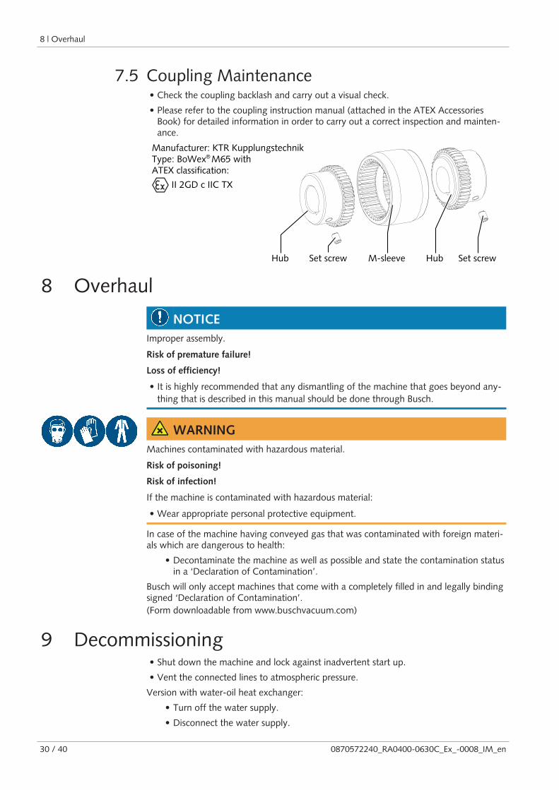
7.5 Coupling Maintenance• Check the coupling backlash and carry out a visual check.
• Please refer to the coupling instruction manual (attached in the ATEX AccessoriesBook) for detailed information in order to carry out a correct inspection and mainten-ance.
Manufacturer: KTR KupplungstechnikType: BoWex M65 withATEX classification:
II 2GD c IIC TX
Hub HubM-sleeveSet screw Set screw
®
8 Overhaul
NOTICEImproper assembly.
Risk of premature failure!
Loss of efficiency!
• It is highly recommended that any dismantling of the machine that goes beyond any-thing that is described in this manual should be done through Busch.
WARNINGMachines contaminated with hazardous material.
Risk of poisoning!
Risk of infection!
If the machine is contaminated with hazardous material:
• Wear appropriate personal protective equipment.
In case of the machine having conveyed gas that was contaminated with foreign materi-als which are dangerous to health:
• Decontaminate the machine as well as possible and state the contamination statusin a ‘Declaration of Contamination’.
Busch will only accept machines that come with a completely filled in and legally bindingsigned ‘Declaration of Contamination’.(Form downloadable from www.buschvacuum.com)
9 Decommissioning• Shut down the machine and lock against inadvertent start up.
• Vent the connected lines to atmospheric pressure.
Version with water-oil heat exchanger:
• Turn off the water supply.
• Disconnect the water supply.
Spare Parts | 10
0870572240_RA0400-0630C_Ex_-0008_IM_en 31 / 40
• Open the water bypass valve (WBV).
• Blow through the water cooling inlet with compressed air.
• Disconnect all connections.
If the machine is going to be stored:
• See Storage [► 12].
9.1 Dismantling and Disposal• Drain the oil.
• Remove the exhaust filters.
• Remove the oil filter.
• Separate special waste from the machine.
• Dispose of special waste in compliance with applicable regulations.
• Dispose of the machine as scrap metal.
10 Spare Parts
NOTICEUse of non-Busch genuine spare parts.
Risk of premature failure!
Loss of efficiency and ATEX compliance!
• The exclusive use of Busch genuine spare parts and consumables is recommended forthe proper function of the machine and for granting of warranty.
Spare parts kit Description Part no.
Service kit(RA/RC 0400 / 0502 /0630 C)
Includes all the necessary parts for mainten-ance.for ATEX classification type “A”
0992 543 533 +0532 541 197
Service kit(RA/RC 0400 / 0502 /0630 C)
Includes all the necessary parts for mainten-ance.for ATEX classification type “B”, “C” or“E”
0992 543 533
Service kit(RA/RC 0400 / 0502 /0630 C)
Includes all the necessary parts for mainten-ance.for ATEX classification type “D”
0992 568 271 +0532 541 197
See ATEX Classifications and Associated Accessories [► 9] to know the ATEX classifica-tion of the machine.
If other parts are required:
• Contact your Busch representative for the detailed spare parts list.
11 | Troubleshooting
32 / 40 0870572240_RA0400-0630C_Ex_-0008_IM_en
11 Troubleshooting
DANGERLive wires.
Risk of electrical shock.
• Electrical installation work must only be executed by qualified personnel.
CAUTIONHot surface.
Risk of burns!
• Prior to any action requiring touching the machine, let the machine cool down first.
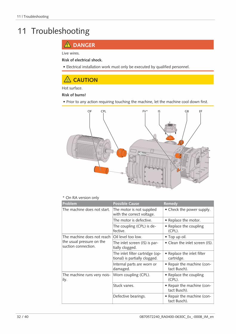
OF CPL GBFV* IS EF
* On RA version only
Problem Possible Cause Remedy
The machine does not start. The motor is not suppliedwith the correct voltage.
• Check the power supply.
The motor is defective. • Replace the motor.
The coupling (CPL) is de-fective.
• Replace the coupling(CPL).
The machine does not reachthe usual pressure on thesuction connection.
Oil level too low. • Top up oil.
The inlet screen (IS) is par-tially clogged.
• Clean the inlet screen (IS).
The inlet filter cartridge (op-tional) is partially clogged.
• Replace the inlet filtercartridge.
Internal parts are worn ordamaged.
• Repair the machine (con-tact Busch).
The machine runs very nois-ily.
Worn coupling (CPL). • Replace the coupling(CPL).
Stuck vanes. • Repair the machine (con-tact Busch).
Defective bearings. • Repair the machine (con-tact Busch).

Troubleshooting | 11
0870572240_RA0400-0630C_Ex_-0008_IM_en 33 / 40
The machine runs too hot. Insufficient cooling. • Remove dust and dirtfrom the machine.
• Check the cooling fan.
Ambient temperature toohigh.
• Observe the permittedambient temperature.
Oil level too low. • Top up oil.
The exhaust filters (EF) arepartially clogged.
• Replace the exhaust filters(EF).
The machine fumes or ex-pels oil droplets through thegas discharge.
The exhaust filters (EF) arepartially clogged.
• Replace the exhaust filters(EF).
An exhaust filter (EF) with o-ring is not fitted properly.
• Ensure the correct posi-tion of the exhaust filters(EF) and the o-rings.
The float valve (FV) doesnot work properly.
• Check the float valve andthe oil pipe for clogging.Remove the clogging.
The oil is black. Oil change intervals are toolong.
• Flush the machine (con-tact Busch).
The inlet filter (optional) isdefective.
• Replace the inlet filter.
The machine runs too hot. • See problem "The ma-chine runs too hot".
The oil is emulsified. The machine sucked in li-quids or significant amountsof vapour.
• Flush the machine (con-tact Busch).
• Clean the filter of the gasballast valve (GB).
• Modify the operationalmode (see ConveyingCondensable Vapours[► 25]).
For the solution of problems not mentioned in the troubleshooting chart contact yourBusch representative.

12 | Technical Data
34 / 40 0870572240_RA0400-0630C_Ex_-0008_IM_en
12 Technical DataRA 0400 CRC 0400 C
RA 0502 CRC 0502 C
RA 0630 CRC 0630 C
Nominal pumping speed(50Hz / 60Hz)
m³/h 410 / 480 510 / 590 630 / 760
Ultimate pressure(without gas ballast valve)
hPa (mbar) abs. For RA version: 0.1 ... 0.5 ► see nameplate (NP)For RC version: 20.0
Ultimate pressure(with gas ballast valve)
hPa (mbar) abs. For RA version: 0.5 ... 1.0For RC version: 20.0
Nominal motor speed(50Hz / 60Hz)
min-1 1000 / 1200
Permitted motor speed range min-1 800 … 1200
Nominal motor rating(50Hz / 60Hz)
kW 11.0 / 15.0 11.0 / 15.0 15.0 / 18.5
Power consumption at 100mbar (50Hz / 60Hz)
kWh 8.2 / 10.0 9.9 / 12.0 11.6 / 14.4
Power consumption at ulti-mate pressure (50Hz / 60Hz)
kWh 4.7 / 5.6 5.8 / 6.4 6.5 / 8.0
Noise level (EN ISO 2151)(50Hz / 60Hz)
dB(A) 77 / 79 77 / 79 77 / 79
Water vapour tolerance max.(with gas ballast valve)
hPa (mbar) 40
Water vapour capacity (withgas ballast valve)(50Hz / 60Hz)
kg / h 9 / 11 11 / 13 18 / 22
Operating temperature(50Hz / 60Hz)
°C 80 / 80 80 / 85 80 / 80
Max. allowable pressure inthe oil mist separator
hPa (mbar) abs. 1600
Max. allowable gas inlet tem-perature
°C 80
Ambient temperature range °C See Oil [► 34]Ambient pressure Atmospheric pressure
Oil capacity l 12.0 12.0 15.0
Weight approx. kg 435 530 550
13 OilVM 100 VE 101 VSL 100
ISO-VG 100 100 100
Oil type Mineral oil Synthetic oil Synthetic oil
Ambient temperature range [°C] 0 ... 30 0 ... 40 0 ... 40
Part number 1 L packaging 0831 000 060 0831 000 099 0831 122 573
Part number 5 L packaging 0831 000 059 0831 000 100 0831 122 572
Warning signalOil temperature [°C]
90 110 110
Switch point / Trip signalOil temperature [°C]
110 130 130
To know which oil has been filled in the machine, please refer to the nameplate (NP).
Oil | 13
0870572240_RA0400-0630C_Ex_-0008_IM_en 35 / 40
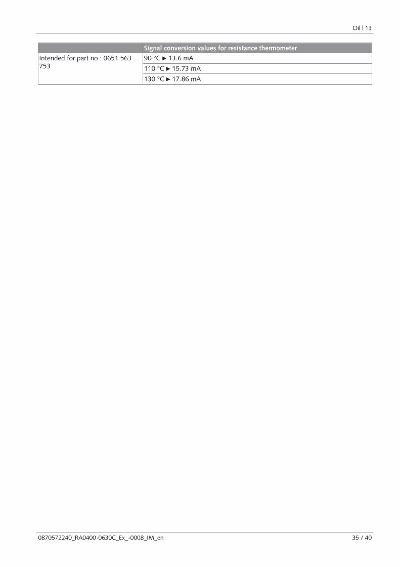
Signal conversion values for resistance thermometer
Intended for part no.: 0651 563753
90 °C ► 13.6 mA
110 °C ► 15.73 mA
130 °C ► 17.86 mA
14 | EU Declaration of Conformity
36 / 40 0870572240_RA0400-0630C_Ex_-0008_IM_en
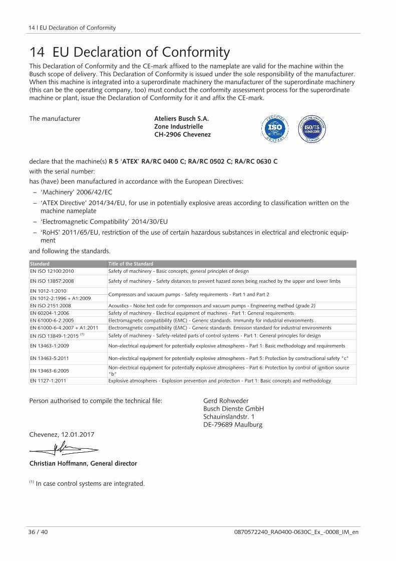
14 EU Declaration of ConformityThis Declaration of Conformity and the CE-mark affixed to the nameplate are valid for the machine within theBusch scope of delivery. This Declaration of Conformity is issued under the sole responsibility of the manufacturer.When this machine is integrated into a superordinate machinery the manufacturer of the superordinate machinery(this can be the operating company, too) must conduct the conformity assessment process for the superordinatemachine or plant, issue the Declaration of Conformity for it and affix the CE-mark.
The manufacturer Ateliers Busch S.A.Zone IndustrielleCH-2906 Chevenez
declare that the machine(s) R 5 ‘ATEX’ RA/RC 0400 C; RA/RC 0502 C; RA/RC 0630 C
with the serial number:
has (have) been manufactured in accordance with the European Directives:
– ‘Machinery’ 2006/42/EC
– ‘ATEX Directive’ 2014/34/EU, for use in potentially explosive areas according to classification written on themachine nameplate
– ‘Electromagnetic Compatibility’ 2014/30/EU
– ‘RoHS’ 2011/65/EU, restriction of the use of certain hazardous substances in electrical and electronic equip-ment
and following the standards.
Standard Title of the Standard
EN ISO 12100:2010 Safety of machinery - Basic concepts, general principles of design
EN ISO 13857:2008 Safety of machinery - Safety distances to prevent hazard zones being reached by the upper and lower limbs
EN 1012-1:2010
EN 1012-2:1996 + A1:2009
EN ISO 2151:2008 Acoustics - Noise test code for compressors and vacuum pumps - Engineering method (grade 2)
EN 60204-1:2006 Safety of machinery - Electrical equipment of machines - Part 1: General requirements
EN 61000-6-2:2005 Electromagnetic compatibility (EMC) - Generic standards. Immunity for industrial environments
EN 61000-6-4:2007 + A1:2011 Electromagnetic compatibility (EMC) - Generic standards. Emission standard for industrial environments
EN ISO 13849-1:2015 Safety of machinery - Safety-related parts of control systems - Part 1: General principles for design
EN 13463-1:2009 Non-electrical equipment for potentially explosive atmospheres - Part 1: Basic methodology and requirements
EN 13463-5:2011 Non-electrical equipment for potentially explosive atmospheres - Part 5: Protection by constructional safety "c"
EN 13463-6:2005Non-electrical equipment for potentially explosive atmospheres - Part 6: Protection by control of ignition source
"b"
EN 1127-1:2011 Explosive atmospheres - Explosion prevention and protection - Part 1: Basic concepts and methodology
Compressors and vacuum pumps - Safety requirements - Part 1 and Part 2
Person authorised to compile the technical file: Gerd RohwederBusch Dienste GmbHSchauinslandstr. 1DE-79689 Maulburg
Chevenez, 12.01.2017
Christian Hoffmann, General director
(1) In case control systems are integrated.

Note

Note

Note

Argentinawww.busch-vacuum.com.ar
Australiawww.busch.com.au
Austriawww.busch.at
Belgiumwww.busch.be
Brazilwww.buschdobrasil.com.br
Canadawww.busch.ca
Chilewww.busch.cl
Chinawww.busch-china.com
Colombiawww.buschvacuum.co
Czech Republicwww.buschvacuum.cz
Denmarkwww.busch.dk
Finlandwww.busch.fi
Francewww.busch.fr
Germanywww.busch.de
Hungarywww.buschvacuum.hu
Indiawww.buschindia.com
Irelandwww.busch.ie
Israelwww.busch.co.il
Italywww.busch.it
Japanwww.busch.co.jp
Koreawww.busch.co.kr
Malaysiawww.busch.com.my
Mexicowww.busch.com.mx
Netherlandswww.busch.nl
New Zealandwww.busch.com.au
Norwaywww.busch.no
Peruwww.busch.com.pe
Polandwww.busch.com.pl
Portugalwww.busch.pt
Russiawww.busch.ru
Singaporewww.busch.com.sg
South Africawww.busch.co.za
Spainwww.buschiberica.es
Swedenwww.busch.se
Switzerlandwww.busch.ch
Taiwanwww.busch.com.tw
Thailandwww.busch.co.th
Turkeywww.buschvacuum.com
United Arab Emirateswww.busch.ae
United Kingdomwww.busch.co.uk
USAwww.buschusa.com
www.buschvacuum.com
Busch Vacuum Pumpsand SystemsAll over the World in Industry
0870572240/-0008_en / © Ateliers Busch S.A.


![R5 0400-0630 B[1]](https://img.pdfslide.net/doc/110x75/54325720219acdd64e8b59a5/r5-0400-0630-b1.jpg)