Embed Size (px)
Citation preview
TM -576
090977
Revised 052578 Revised 050586
OPERATION AND MAINTENANCE MANUAL
with
ILLUSTRATED PARTS LIST
for
GATE BOX
4160 Volt AC Input
Single-Output, 115/200 Volt AC, 400 Hz, 3 Phase
PART NUMBER 483182
1 .I
HOBART BROTHERS COMPAN’Y , ;!
POWER. SYSTEMS DIVISION ’ 1
TRQY, OHIO 45373
1 U.S.A. i
;2 .., * - i ? : ./ !,


SAFETY INSTRUCTIONS AND WARNINGS FOR ELECTRICAL POWER EQUIPMENT
ELECTRIC SHOCK can kill. Do not touch live elect’rical parts.
FUMES AND GASES can be fire an d .health hazards. Ventilate all fumes and exhaust gases to the outside.
ELECTRIC ARC FLASH can injure eyes, burn skin, cause equipment damage, and ignite combustible material. Do not use power cables to break load and be sure tools don’t cause short circuits.
IMPROPER PHASE CONNECTION, PARALLELING, OR USE can damage this and attached equipment.
MOVING PARTS can cause serious injury. Keep clear of moving parts.
IMPORTANT - Protect yourself and others. Read ,and understand all the instructions in this Operating/Instruction
Manual before installing, operating, or servicing this equipment. Keep this manual available for future use by all operators.
A. GENERAL Equipment that supplies electrical power can cause serious injury or death, or damage to other equipment or
property, if the operator does not strictly observe all safety rules and take precautionary actions. Safe practices
have developed from past experience in the use of power source equipment. Certain of the practices below apply to
engine driven equipment.
B. SHOCK PREVENTION Bare conductors, or terminals in the output circuit, or ungrounded, electrically-live equipment can fatally shock a person. Have a competent electrician verify that the equipment is adequately grounded and learn what terminals
and parts are electrically HOT. Use proper safety clothing, procedures, and,test equipment.
The electrical resistance of the body is decreased when wet, thus more easily permitting dangerous currents to flow
through it. When inspecting or servicing equipment, do not work in damp areas without being extremely careful.
Stand on dry rubber mat or dry wood, use insulating gloves that are effective when dampness or sweat cannot be
avoided. Keep your clothing dry and never work alone.
1. Installation and Grounding of Electrically Powered Equipment - Electrical equipment must be installed and maintained in accordance with the National Electrical Code, ANSI/NFPA 70, and other applicable codes. A power disconnect switch or circuit breaker must be located at the equipment. Check the nameplate for voltage,
a frequency, and phase requirements. If only 3-phase power is available, connect any single-phase rated equipment to
oniy two wires of the 3-phase line. DO NOT CONNECT the equipment grounding conductor (lead) to the third live
wire of the 3-phase line, as this makes the equipment frame electrically ---- HOT, which can cause a fatal shock. ---_--
Be sure to connect the grounding lead, if supplied in a power line cable, to the grounded switch box or building
ground. If not provided, use a separate grounding lead. Be certain that the current (amperage) capacity of the ’ grounding lead will be adequate for the worst fault current situation. Refer to the National Electrical Code ANSI/
NFPA 70 for details. Do not remove plug ground prongs. Use correct mating receptacles.
.I 2. Output Cables and Terminals - Inspect cables often for damage to the! insulation and the connectors. Replace
or repair cracked or worn cables immediately. Do not overload cables: Do not touch output terminal while equip- ment is energized. ) ‘!
/ 1
1 Instruction 910082 Page 1
Nov 16182 Revised

C.
D.
E.
F.
G. .I
3. Service and Maintenance - This equipment must be maintained in good electrical and mechanical condition
to avoid hazards stemming from disrepair. Report any equipment defect or safety hazard to your supervisor and discontinue use of the equipment until its safety has been assured. Repairs should be made by qualified personnel
only. Shut OFF all power at the disconnecting switch or line breaker before inspecting or servicing the equipment. Lock switch OPEN (or remove line fuses) so that power cannot be turned ON accidentally. Disconnect power to equipment if i”t is out of service. If troubleshooting must be done with the unit energized, have present another per-
son trainfld’inturning off the equipment land providing or calling for first aid. I(
FIRE AND EXPLOSION PREVENTION 1
Fire and explosion are caused by electrical short circuits, combustible material near engine exhaust piping, misuse
of batteries and fuel, or unsafe operating or fueling conditions.
1. Electrical Short Circuits and Overloads - ‘Overloaded or shorted equipment can become hot enough to cause
fires either by self destruction or causing nearby combustibles to ignite. Provide primary input protection to re-
move short circuited or heavily overloaded equipment from the line.
2. Battery - Batteries may explode and/or give off flammable hydrogen gas. The acid and arcing from a ruptured
battery can cause fires and additional failures. When servicing, do not smoke, causing sparking, or use open flame
near the battery.
3. Ensine Fuel - Use only approved fuel container or fueling system. Fires and explosions can occur if the fuel
tank is not grounded prior to and during fuel transfer. Shut unit DOWN before removing fuel tank cap. Do not
completely fill tank. Heat from the equipment may cause fuel expansion overflow. Remove all spilled fuel im- mediately including any that penetrates the unit. After cleanup, open equipment doors and blow fumes away with compressed air.
TOXIC FUME PREVENTION Carbon Monoxide - Engine exhaust fumes can kill and cause health problems. Pipe or vent the exhaust fumes to a
suitable exhaust duct or outdoors. Never locate engine exhausts near intake ducts or air conditioners.
BODILY INJURY PREVENTION Serious injury can result from contact with fans, belts, and pulleys inside the equip’ment. Shut DOWN equipment for inspection and routine maintenance. When equipment is in operation use extreme care in doing necessary
troubleshooting and adjustment.
MEDICAL AND FIRST AID TREATMFNT
First aid facilities and a qualified first aid person should be available for each shift for immediate treatment of all
injury victims. Electric shock victims should be checked by a physician and taken to a hospital immediately if any
abnormal signs are observed.
EMERGENCY FIRST AID
Call physician immediately. Seek additional assistance and use First Aid techniques recommended
by American Red Cross until medical help arrives.
IF BREATHING IS DIFFICULT, give oxygen, if available, and have victim lie down. FOR ELEC-
TR,lCAL SHOCK, turn off power. Remove victim; if not breathing, begin artificial respiration, preferably mouth-to-mouth. If no detectable pulse, begin external heart massage. Call Emergency
Rescue Squad immediately. L A
EQUIPMENT PRECAUTIONARY LABELS
Inspect all precautionary labels on the equipment monthly. Order and replace all lap$s that cannot be easily read. / ’
P(w 2 Instruction 910082 Revised Nov 16182

TM-576
INTRODUCTION
This manual containsmoperation and maintenance information for a 4160 Volt AC Gate Box manufactured by Hobart
Brothers Company,,Power Systems Division, Troy, Ohio 45373.
The manual is not intended to be a text boo,k on electricity or electronics. Its primary purpose is to provide informa-
tion apd ipstructions to experienced operators, electricians, and mechanics who have never seen or operated these gen-
erator sets. It is the intent of the manual to guide and assist operators and maintenance people in the proper use and care of the equipment.
Use of the manual should not be put off until a trouble or need for help develops. Read the instructions before start-
ing the unit. Learn to use the manual and to locate’information contained in it. Its style and arrangement are very simi-
lar to commercial aircraft manuals. Each new section starts with page 1. Each page is identified by chapter, section, and page number in the lower, outside corner. When information located in another portion of the manual is referred to, its location is identified by chapter, section, and paragraph, or figure number. For example, (See 2-3, Para. 4) refers to
information located in Chapter 2, Section 3, paragraph 4. If a Chapter and Section are not indicated in a reference, the
referenced material is located in the same section as the reference, Example, (See Para. 3).
In addition to operation and maintenance instructions, the manual contains an illustrated parts list in Chapter 4. Con-
nection and schematic diagrams, and a collection of manufacturer’s literature are included in Chapter 6.
Content of the manual is arranged as follows:
Chapter I. Description/Operation Chapter 2. Servicing
Chapter 3. Troubleshooting
Chapter 4. Illustrated Parts List
Chapter 5. Optional Equipment
Chapter 6. Manufacturer’s Literature
If you have any questions concerning your Hobart Power Systems Division equipment, you are invited to contact our
Service Department by mail, telephone or TWX at:
Hobart Brothers Company
Power Systems Division
Service Department
Troy, Ohio 45373 U.S.A.
Telephone: Area Code (513) 339-6011 Extension 4276
TWX : 81 O-456-2907
1 .I ) ‘!
/ 1
Sept 9177 Introduction
1 / Page 1
I>


EEI m r I
TABLE OF CONTENTS
SUBJECT
Description/Operation 1
Descr\ption
CHAPTER/SECTION
1-o , ,’
I I-1
1. General
1 2. Identification
3. Orientation
4. Detailed Description
A. High Voltage Switchgear (Disconnect Switch)
B. Stepdown Transformer
C. Control Bay
(1) Line drop compensator
(a) Transformers
(b) Capacitors
(c) Overload protection
(2) Control module
(a) Power supply circuit
(b) Memory and time delay module
(c) Overvoltage and undervoltage module
(d) Overload module
(e) Rectifier
(f) Overload current transformers
(g) Load contactor
(h) Contactor monitor board
(j) Plug-interlock relay
(k) Test bank switch
(I) Contactor control circuit resistor
1 Sept 9177
TM-576
PAGE
1
1
1
1
1
1
1
4
7
7
7
7
7
10
10
11
11
!
I ‘!,
11
14
14
14
14
14
,I5
'15
Contents
Page 1

TABLE OF CONTENTS (CONTINUED)
SUBJECT
(m) Fuse-interlock relay
, , (r-j, Connector
4 , ’
I 15
(p) Safety switch 16
I
(q)’ Fault lights test switch
(r) Reset switch
(s) Fuses
(t1 Test receptacle
(3) Controls and indicators
(a) Contactor control switches and monitor
(b) Power available lights
(c) Fault lights
(4) Output receptacle
D. Spare Lamps and Fuses
E. Enclosure
(I 1 Switching bay cabinet
(2) voltage reduction bay and control bay cabinet
(3) Base
F. Test Box
Preparation for Use
1. Installation
A. Receipt of Equipment
B. Mounting
C. Input Power ‘Connections
D. Output Cable Recommendations
.I
E. Grounding
Contents
Pa()e 2
CHAPTER/SECTION PAGE
1-I
I-2
) ‘! I
TM-576
15
16
16
16
16
16
16
17
17
17
17
17
17
20
20
20
1
1’
1
1
i
1
’ I
Sept 9177

I I
TABLE OF CONTENTS (CONTINUED)
SUBJECT CHAPTER/SECTION
Operation I-3
1. General
2! ’ &connect Switch
, ,
3. Power Delivery I
1 4. Discontinue Power Delivery
Service
Maintenance
1. General
2. Lubrication
3. Parts Replacement
4. Line Fuse Replacement
Inspection/Check
1. General
Adjustment/Test
1. Adjustment
2. Tests Using 4160 Volts Input
A. General Tests
(1) Preparation for tests
(2) ,Test procedures
B. Line Drop Compensator
(I) Preparation for tests
(2) Test procedures
C. Overload Protection Circuits
(I) Preparation for tests
(2) Test procedures
3. Testing Protective System Circuits Using Test Box
A. Preparation For Tests
B. Test Procedures
Sept 9177 May 25178 Revised
2-o
2-I
2-2
2-3
TM-576
PAGE
5
6
‘6
Contents Page 3

rzl m I I I I
TABLE OF CONTENTS (CONTINUED)
SUBJECT CHAPTER/SECTION PAGE
Repair 2-4
1. General ’ ( ’ i”, I ’
Troubleshooting 3-o
3-1
1
1
1
1
1
1
1
1
1
2
2
1
1
1
1
1
1
Procedures I.
1. General
2. Troubleshooting Chart
% A. Description
B. Use
3. Equipment
4. Safety
5. Test Values
Illustrated Parts List
Introduction
1. General
2. Purpose
3. Arrangement
4. Explanation of Parts List
4-o
4-l
TM-576
A. Contents
B. Form
a (1) Figure-Item No. column
(2) Hobart Part No. column
(3) Nomenclature column
(4) Eff (Effective) column
(5) Units Per Assembly column
.I
Contents
Pabe 4
!
) ‘! I
i;
1’
Sept 9/77

TM-576
TABLE OF CONTENTS (CONTINUED)
SUBJECT
Manufacturer’s Codes ( 1./l )
1. Explanatibn
Parts List
CHAPTER/SECTION
4-2
PAGE
1
1
4-3 1
1
1
4-4 1
1
5-o 1
6-O 1
1. Explanation of Arrangement
2. Symbols and Abbreviations
Numerical Index
1. Explanation
Optional Equipment
Manufacturer’s Literature
LIST OF ILLUSTRATIONS
PAGE
NO.
CHAPTER/ FIGURE
SECTION NUMBER TITLE
l-l 1 Gate Box Assembly 2 l-l 2 Specifications and Characteristics 3 l-l 3 Switchgear Assembly 4 l-l 4 Fuseholder and Switch Arm 5 l-l 5 Voltage Reduction Bay . 6 l-l 6 Control Bay 8 l-l 7 Line Drop Compensator 9 l-l 8 Overload Module 10 l-l 9 Control Module 12 l-l 10 Transformer-Rectifier Assembly 13 l-l 11 Contactor Monitor Board 15
5 l-l 12 Controls and Indicators 18 l-l 13 Spare Lamp and Fuse Board 19 l-l 14 Test Box 21
i Sept 9177 Contents
Page 5

CHAPTER/ FIGURE
SECTION NUMBER
1-2 1-2
l-3
2-l I 1 Changing Line Fuse 2
2-l 2 Fuseholder Assembly 3
2-2 1 Fuse Identification Chart 1
2-2 2 Lamp and LED Identification Chart 2
2-3
2-3 2-3
I 2-3
23
I 2-3
3-1
3-1
3-1
3-1
3-1
3-1
Line Drop Compensator Overload Adjustment
Gate Box Assembly
Control Module Controls and Indicators
Test Box
Line Drop Compensator
i Control Module Assembly- ~~ .___ __-..--.---
1
3 4 7
8 9 ~-~~
Line Drop Compensator Schematic and Connection Diagram
Gate Box Schematic Diagram
Controls and Indicators
Control Module
Line Drop Compensator Troubleshooting Chart (4 Sheets)
3
4
5
6 7
8thru 11
4-3
4-3 4-3
4-3
4-3
1
~- 1 2
3
4
5
I E
1
LIST OF ILLUSTRATIONS (CONTINUED)
TITLE
Gate Box Mounting Dimensions
Input Cable Connections
Operating Controls and Indicators
Gate Box Assembly Disconnect Switch Group _---.------- Gate Box Interior
Line Drop Compensator Assembly
TM-576
PAGE
NO A
2
3
2
2 4
6
8
10
.t
Contents
Pabe 6
,
) ‘! / 1
Sept 9/77 Revised May 25/78

TM-576
CHAPTER 1. DESCRIPTION/OPERATION
SECTION 1. DESCRIPTION
The gate box covered by this manual is manufactured by Hobart Brothers Company, Power Systems Division,
Troy, Ohio 45373 U.S.A. I
’ The purpose of this unit is to provide 115 Volt AC, 3 phase, 400 Hz power for aircraft servicing and to power the aircraft’s electrical equipment when the on-board generator is not running.
Refer to Figure 1. The gate box assembly is housed in two cabinets; one contains the high voltage switchgear (disconnect switch) for the 4160 Volt AC input power and the other cabinet houses the’stepdown transformer,
line drop compensator assembly, voltage sensing protection circuits, output receptacle and controls and indica-
tors. Both cabinets are mounted on a welded steel base which has openings to accommodate the forks of a lift truck. Specifications and capabilities are listed in Figure 2.
2. Identification
The gate box is identified by Hobart part number 483182. The unit’s nameplate is attached to the cabinet door
and displays the power ratings, serial number, model number and other pertinent information, including the part number.
3. Orientation
Throughout the manual, references to right and left, front and rear assume that the viewer is facing the front
doors of the cabinets. This puts the control panel at the FRONT and the output connector on the RIGHT side
of the unit.
4. Detailed Description
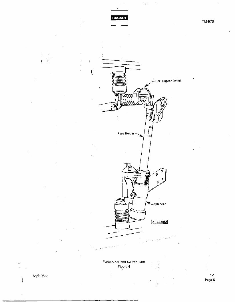
A. High Voltage Switchgear (Disconnect Switch)
The special high voltage, hookstick operated line switch is housed in its own cabinet, separate from the rest
of the gate box components (see Figure 3). It consists of three separate switches; one for each phase of the
three phase input line. Each phase has its own fuse, located in the switch actuating arm. A special switch operating tool, attached to a six-foot long fibreglass pole, provides a safe method of opening and closing the switches. The combination fuseholder and switch actuating arm is hinged at the bottom by means of two
lugs, one on each side of the assembly, which ride in slots in a support bracket. The fuseholder may be re- moved by disengaging the lugs from the slots. Positive electrical contact is assured by heavy leaf-spring clips
which secure the fuseholder assembly at the top and bottom when the switch is closed (see Figure 4). The
actual switching action takes place within the totally enclosed shielding of the Uni-Rupter assembly. (Uni- Rupter is the registered trade mark of S & C Electric Company.) This shielding prevents external flame and
arcing when switching takes place.
.I !
\ ‘! I 1
Sept 9177 l-l
1 Page 1

TM-576
Voltage Reduction Bay /
Gate Box Assembly Figure 1
!
I I!( I
,Sept 9177

TM-576
PHYSICAL 9
1 ’ “Weight (approximately) 1 ’
Height
Width I Depth (overall including handles)
2310 pounds (1048 kg)
65.5 inches (1664 mm)
82.5 inches (2096 mm)
40 inches (1016 mm)
ELECTRICAL
INPUT
Volts 4160 V AC
Frequency 400-Hz
Phase 3
TRANSFORMER
INPUT -
OUTPUT -
CONNECTION -
4160 V AC, 13.0112.5 Amps, 3-phase, 400-Hz,
93.7 kVA continuous duty
115/200-V AC, 260 Amps, 3-phase, 400-Hz,
Full wave, 93.7 kVA
Primary - delta Secondary - 4-wire wye
LINE DROP COMPENSATOR
REACTIVE COMPENSATION - 24 Volts + 10% (each phase)
OUTPUT
Number of output cable assemblies accommodated 1
Volts 115/200-V AC
Phase 3
Frequency 400 Hz
Capacity 72-kW, 90-kVA. 260-Amps at 0.8 Power Factor
Overload 125% for 5 minutes
Specifications and Characteristics Figure 2
I
t
Sept 9177 l-l
Page 3

B. Stepdown Transformer
The 4160 Volt AC transformer is mounted in the voltage reduction bay (see Fig. 5). The delta-connected
primary windings receive 4160 Volts AC from the power source at terminals HI, H2 and H3. The input
to the transformer is equipped with taps to raise the secondary voltage to 208 Volts when highter voltages are required. The four-wire, wyelconnected qecbndary windings deliver 115/200 Volts AC at terminals X0 (Neutrgll),‘&j (A), X2 (B) and X3 (C) [see Fig. 2 for transfoimer ratings).
rlnsulator //-Uni-Rupter Switch
Door lnte (front 1
~IOCK swmn - \
-
&rear) Fuse Interphase Barriers .-- --
\ 1%4831821
.I
LFuse Holder
Switchgear Assembly.
Figure 3
!
I ‘1,
Sept 9177 l-l Pabe 4
TM-576
Switch
Fuseholder and Switch Arm 1
Figure 4 I ‘1,
l-l
Page 5 ;:

.I
l-l Pdge f3
,
Switching Bay
l- r
Voltage Reduction Bay7
I
Stepdown Transformer J
Voltage Reduction Bay
Figure 5
TM-576
-Control Bay
Sept 9177

TM-576
C. Control Bay’
The.control bay (Figure 6) houses the line drop compensator, the control module (which includes overvoltage, undervoltage and overload protecti;ve.‘devices), the load contactor, output receptacle, controls and indicators.
( ’ ill) (I) Line drop compensator
,
The purpose of the line dkop compensator (Figure 7) is to eliminate reactive voltage losses (line drop) in long runs of 400 Hz transmission cables. This is accomplished by introducing a capacitive reactance
into the circuit which counteracts the inductive loss and maintains a voltage value at the output end of the cable which is very near the input value. There will be a resistive loss in any cable which can never be compensated for.
The compensator consists of a series of reactive components and sensing devices closely grouped and
mounted in the right-hand bay of the gate box assembly.
All internal components are cooled by the air convection method.
(a) Transformers
The largest components in the compensator are three current transformers (I) one for each phase
(A, B, C). Maximum rating for each transformer is 260 Amperes. The purpose of the transformers
is to reduce the current to an operating level in the secondary winding and develop a voltage across
the capacitors.
(b) Capacitors
A total of six, 34-UF, 220-Volt capacitors (2) are used in the compensator. Two capacitors are con-
nected in parallel across the secondary windings of each transformer. The purpose of these power factor capacitors is to reflect capacitive reactance in the transmission cables and cancel inductive
reactance.
(c) Overload protection
A current transformer (3) is mounted on each of the three (A, B, C) line cables in the compensator. A reduced current signal from each transformer is sent to the overload module (4) where it is con- verted to direct current. This DC is fed through an overload adjusting resistor (5) to the coil of an
overload relay (Fig. 8). An overload condition in any one of the output lines will increase DC power in the relay coil to a point which will close the relay contacts. When the overload relay closes, it con-
nects DC power to a three-pole contactor (7, Fig. 7) which then functions to close contacts which
are electrically connected in parallel to each set of capacitors across the secondary transformer coils.
This action allows secondary transformer current to by-pass the condensers and thus nullifies their voltage boost action. As voltage is reduced, the overload relay and contactor return to their normal
OPEN condition and the compensator becomes functional again.
t Sept 9177 l-l
Page 7

TM-576
Control Module Assembly7
-Output Receptacle
Control Bay
Figure 6
l-l
J P ge8
1
kept 9177

TM-576
1. Transformer
2. Capacitor 3. Sensing transformer (one of three)
4. Overload module
5. Overload adjusting resistor
(1000 ohm, 100 watt) 6. Overload relay
7. Contactor 8. Terminal boards
Line Drop Compensator Components
Figure 7
Sept 9177
I
l-l
Page 9

Overload Adjusting Resistor
/-Overload Relay
TM-576
LOverload Board
Overload Module
Figure 8
(2) Control module
The control module (Fig. 9) contains electrical and electronic safety devices designed to protect the air-
craft’s electrical system against damage which could result from overvoltage, undervoltage and overload. It also contains devices for the protection and control of the gate box output’circuits.
(a) ,Power supply circuit
The 12 Volt DC power required for operation of the protective system originates at the 115 Volt
AC, 400’Hz, C phase output of the line drop compensator. Refer to Figure 9. The power supply
system consists of a transformer-rectifier assembly (6), zener diode (3) and resistor (5). The zener
diode is mounted in a heatsink (4) for cooling.
The transformer (3, Fig. 10) steps down 115 Volts AC to approximately 24 Volts AC. The diode
bridge rectifier (2) then converts 24 Volts AC to a pulsating 24 Volts DC. A 3 UF, 50 Volt capacitor (1) prevents pulses from reaching zero. Rectifier output is further smoothed and reduced to 12 Volts DC by a zener diode (3, Fig. 9) and resistor (5). A terminal board (4, Fig. 10) provides connections
for transformer input and rectifier output leads. A connection diagram of the transformer-rectifier assembly is provided in Fig. 10. See complete diagrams in Chapter 6.
The 115 Volt AC side of the power supply circuit is protected by a 1 Ampere fuse (24, Fig. 9).
.I
I
l-l
Page IO
t
I '1,
i,
1
Sept 9177

TM-576
(b) Memory and time delay module
Refer to Figure 9. The memory and time delay module (13) is a solid-state protective monitor with a I
, ‘I.i,) hermetically-sealed, reed-type relay. The printed circuit board includes five memory circuits (three used in this applicatjon) and a time delay circuit. Each circuit used is connected to a corresponding
sensing circuit in the sensing modules (14 and 15). All memory circuits are connected to the module’s
relay coil, and any o 1
e of the circuits can energize the coil to open the relay contacts. When any
sensing device energizes one of the module circuits, the module relay is also energized to break the
load contactor holding circuit and open the load contactor. All circuits, except the undervoltage cir-
cuit, function immediately to open the load contactor. A time delay system is designed into the
undervoltage circuit to prevent nuisance opening of the contactor under conditions of momentary
undervoltage in the line drop compensator output. An under-voltage condition which continues un-
interrupted for a period of 5 seconds will cause the time delay circuit to open the load contactor.
Each of the circuits used is connected to a fault indicating light (6,7,8, Fig. 12) which is turned on
when a fault occurs. The module relay will remain energized (OPEN) and the light will remain ON
until reset switch (20, Fig. 9) is pushed to break the module’s 12 Volt DC circuit and allow the relay
to return to normal CLOSED position (after the fault is cleared).
(cl Overvoltage and undervoltage module
This voltage sensing module (14, Fig. 9) is connected to the output line between the line drop com- pensator and load contactor. The solid-state circuitry senses any abnormal condition of voltage and
signals the networks of the memory and time delay module (13) to open the load contactor and dis-
continue power delivery to the aircraft.
Trip values are factory set as follows:
Overvoltage trips at 130-134 Volts, and resets at 123 Volts Undervoltage trips at 102-98 Volts, and resets at 112 Volts Undervoltage time delay is 5 seconds
(d) Overload module
The overload module (15, Fig. 9) is a solid-state device designed to interpret a signal from transform-
.ers (2) and to send a signal to the memory and time delay module (13) when an overload condition
exists in any output phase. A pull-apart electrical connector is mounted on the overload module to
provide quick-disconnect facilities for all wiring to the module. The overload module is equipped with
a hermetically-sealed, reed-type relay. Relay contacts are normally open. The solid-state circuitry is
designed to close relay contacts when output current in ANY phase reaches 125% of normal rated output capacity. The closed relay sends a signal to the memory and time delay module. This signal
gates the overload SCR (silicone-controlled rectifier) in the module and interrupts the load contactor
holding circuit, allowing the load contactor to open.
The following is a list of overload module characteristics:
NOTE: The overload protective system will function when any phase carries 123% to 127% of
rated load.
.I 1
/ I ‘!, 1
Sept 9177 l-l
i Page 11

TM-576
1.7,
16’
26.
Control Module
Figure 9
j 1. Burden Resistor, 16.6 Ohm, 25 Watts 2. Current Transformer
3. Zener Diode, 50 Watts
4. Heatsink
5. Resistor, 10 Ohm, 25 Watts
6. Transformer Rectifier Assembly
7. Load Contactor 8. Plug Interlock Relay
9. Fuse Interlock Relay
10. Terminal Board
11. Silicon Diode
12. Receptacle Connector 13. Memory and Time Delay Module
14. Over-Undervoltage Module 15. Overload Module 16. Resistor, 20 Ohm, 25 Watts 17. Rectifier
18. Contactor Monitor Board 19. Test Switch
20. Reset Switch
21. Test Receptacle
22. Fuse, 2 Ampere
23. Test Bank Switch
24. Fuse, 1 Ampere 25. Safety Pin
26. Contactor Disable Switch
1
I ‘!, I
1-I
Pgge 12 8ept 9177
i,

I I
L
TM-576
1. Capacitor’ 3. Transformer 2. Rectifier 4. Terminal Board
,
NOTE: RECTIFIER ASSEMBLED AT THIS END.
+
ll5V. AC INPUT
Connection Diagram
NOTE: See diagram 483158 in Chapter 6 for connection of zener diode, resistor and transformer-rectifier in DC power supply circuit.
Transformer-Rectifier Assembly
Figure 10 I
Sept 9177 l-l
Page 13

TM-576
At 125% load the module will function in 5 minutes.
At 150% load the module will function in 16 seconds.
At 200% load the module will function in 4 seconds.
NQTE: All times are plus or minus 25% and are nonadjustable.
(et) Riectifier
/ ‘.
~
A diode-bridge rectifier (17, Ffg. 9) receives 400-Hz AC from phase C of the line drop compensator
output and converts it to a pulsating, direct current for energization of load contactor holding coil /
only. This DC coil-holding circuit is controlled indirectly by controlling 400-Hz AC to rectifier. Any
time a protective device functions to open the memory and time delay relay, the rectifier’s AC
circuit is opened. No DC is then available for the load contactor holding coil and the load contactor opens.
(f) Overload current transformers
Three overload current transformers (2, Fig. 9), in conjunction with burden resistors (I), monitor the
output load current in each of the three output phases and supply a reduced value current signal to
the overload module (15).
(g) Load contactor
The load contactor (7, Fig. 9) is a sealed unit which contains a magnetic operating coil and four sets
of contacts. The three larger contacts conduct three-phase AC output. A smaller contact set is con- nected in the protective monitor circuit and supplies 12-V DC power used by sensing relays to signal
the protective monitor when a fault occurs. Three-phase, 400-Hz output power is conducted to the
load contactor by l/O cables which pass through 3 current transformers (2).
(h) Contactor monitor board
The contactor monitor board (18, Fig. 9) provides mounting for three light emitting diodes (LEDs)
(2, Fig. 11). Each diode is connected to a single output phase and emits a red light when that phase is
energized. If all three phase lights are off, it indicates that the load contactor is open. These lights
‘are helpful in troubleshooting. For example, if only two lights are on when the contactor is supposed
to be closed, it indicates that one set of contacts is defective and the load contactor should be re-
placed. I’f one of the lights is on when the contactor is supposed to be open, it indicates that one set
of contacts is stuck, or fused together, and the load contactor should be replaced. A IOK Ohm, 10
Watt resistor (4) is connected in series with each LED to reduce voltage to a value (approximately 1 Volt) which will not destroy the diode. A 400 PRV, 1.5 Ampere silicon diode (3) is connected in
parallel with each LED. This protection is necessary because the LED has a peak reverse voltage capacity near zero.
(j) Plug-interlock relay
The function of the plug-interlock relay (8, Fig. 9) is to open the load contactor if the output cable
connector is disconnected accidentally from the aircraft during power delivery, or if an attempt is made to deliver power when the cable is not connected to the aircraft. Twenty-eight Volt DC for
operation of the relay is supplied from the aircraft either through an on-board transformer-rectifier, or from a 28 Volt electrical system. Connection from aircraft to interlock-relay is made through
.I terminal E or F on the output cable plug connector. t
, /
) ‘! /
l-l :Sept 9177
Pdge 14 i,

0
0 CONTACTOR MONITOR BOARD AY 40,2935 0
1. Connector 3. Silicon diode, 400 PRV, 1.5 Amp 2. Light emitting diode 4. Resistor, IOK Ohm, IO Watts
Contactor Monitor Board Figure 11
(k) Test bank switch
A sp st toggle switch (23, Fig. 9) provides a means of bypassing lthe plug-interlock relay (8) when
supplying power to a load bank or to an aircraft not equipped with a plug-interlock system. To
bypass the relay, switch must be in TEST BANK position. For power delivery to an aircraft equipped
with a plug-interlock system, switch must be in AIRCRAFT position.
(I) Contactor control circuit resistor
A 20 Ohm, 25 Watt resistor (16, Fig. 9) is connected in series with components of the load con-
tactor operating circuit. It protects relays, etc., in the event that phase C contacts in the load con-
tactor should fail to close when the contactor CLOSE switch (1, Fig. 12) is pushed.
(m) Fuse-interlock relay
The function of the fuse-interlock relay (9, Fig. 9) is to interrupt the load contactor holding coil
circuit and remove load in case of a blown fuse (24) in the protective monitor power supply circuit.
(n) Connector
.I
A 20-contact connector (12, Fig. 9) provides a quick-disconnect facility for all wiring to electrical
components so that the complete control module assembly may be removed quickly and easily.
I ) ‘!
I 1
t
Sept 9177 l-l
Page 15

(p) Safety switch
A safety toggle switch (26, Fig. 9) is provided for the output circuit. This switch is used to open the 1,&d contactor operating circuit and disable the load contactor. This feature allows an electrician to
( d,&able the output circuit and work with output cable in relative safety. A safety lock pin (25), with ball detent and pull ring, is mounted in a guard bracket beside the switch to prevent inadvertent
actuation of the switch. I
I (q) Fault lights test switch
The TEST switch (19, Fig. 9) is a snap-action pushbutton type. It connects 12 Volts DC power directly to the memory and time delay module (13) for testing the fault lights (6,7 and 8, Fig. 12).
A blocking diode (11, Fig. 9) in the light testing circuit is mounted with quick-connect terminals on the terminal board (10). This diode prevents an overload signal from following the test circuit and
turning on the overvoltage and under-voltage fault lights when no voltage fault exists.
NOTE: Similar blocking diodes for undervoltage and overvoltage lights are included in the
over-undervoltage module (14).
(r) Reset switch
A pushbutton switch (20, Fig. 9), identical to the fault light switch, resets the protective monitor
system and turns off the fault lights after a fault has activated the protective monitor system.
is) Fuses
A 1 Ampere cartridge type fuse (24, Fig. 9) protects the 12 Volt power supply circuit. A similar
2 Ampere fuse (22) protects the load contactor operating circuits.
(t) Test receptacle
The contacts in this connector (21, Fig. 9) are connected to the output line between the line drop
compensator and load contactor. Contacts A, B and C are connected to the corresponding line phases
and contact D is connected to neutral (N). This receptacle provides a connection point for the test
box, Hobart part number 483347-2 (see para. 4, E).
(3) Controls and indicators
The output controls and indicators for the gate box assembly are located on the front cabinet door of the
) control bay (see Fig. 12).
(a) Contactor control switches and monitor
Two pushbutton switches (1 and 2) close and open the load contactor as labeled. A green indicator
light (3) glows when the contactor is closed and goes out when the contactor is opened.
!
I ‘!,
l-l
Pa $ e 16
‘Sept 9177
TM-576
(b) Power available lights
Three amber indicator lights’(4,5 and 91, each one monitoring one phase of the three-phase line,
glow when power is available from the line drop compensator. When these three lights are on, the
only remaining operation to be performed for power delivery to the aircraft is pressing the con-
I’ tactor CLOSE switch (1). 1 ’
( 1.0
(cl Fault lights
Three red indicator lights (6,7 and 8) glow to indicate the abnormal condition of overvoltage,
undervoltage or overload which caused the protective monitor system to open the load contactor.
Each of these lights is connected to an actuating circuit in the memory and time delay module. When one of those circuits is activated, it turns on the applicable indicator light. The light will
remain on until the reset switch (20, Fig. 9) is pushed. All three lamps may be tested by pressing
the test switch (19).
(4) Output receptacle
The output receptacle (Fig. 6) is the connection point for power output cable to the aircraft. The mating
connector is AN3430.
D. Spare Lamps and Fuses
Spare lamps and fuses are provided on a board which is mounted inside the control bay (see Fig. 13). Three
each of the 12 and 120 Volt indicator lamps are mounted in the top edge of the board. Three each of the
1 and 2 Ampere fuses are mounted in holders on the front of the board. Labels identify the lamps and fuses.
E. Enclosure
The gate box components are protected from the elements by two heavy-gauge steel cabinets which are securely bolted to a welded steel base.
(I 1 Switching bay cabinet
The disconnect switch is housed in its own cabinet, separate from the rest of the gate box components.
This cabinet is a welded steel, free-standing enclosure equipped with heavy-gauge steel doors, front and
rear: The front door has a storage compartment inside where spare fuse refill units may be kept dry and
available for immediate restoration of service. Both doors have braces to retain them in the open posi-
tion for switching and service. When the doors are closed, these braces rest on outward-projecting flanges of the door openings and cannot swing into the inside of the enclosure. Each door has a recessed
operating handle which controls the latching mechanism inside. This handle is also a hood which shields
a padlock shackle. With the door padlocked, the interior is secure from tampering. The handle may be
secured in the closed position by a recessed pentahead bolt which requires a special socket head wrench
(furnished) to secure and release it.
Ventilating louvers with deflectors behind them are provided on the sides to allow the free flow of air.
The bottom is open for the entrance of input cables. Lifting eyes are provided for handling the switching
bay assembly with a crane or hoist. These lifting eyes are shipped attached to one of the boltswhich se-
cures the gate box base to the shipping pallet and they should be retained for future use. Their attach- ing hardware is in place on the cabinet sides.
.I 1
/ I ‘1,
1
1 Sept 9177 l-l
I; Page 17

‘I m I 1 I I
TM-576
8 J
4
3
.I
/
Controls and Indicators
Figure 12
t
) ‘! / 1
l-l i Page 18
‘Sept 9177

TM-576
\ Sept 9177
SPARE FUSES 8 INDICATOR LAMPS
Spare Lamp and Fuse Board !:
Figurk 13 I ‘!, 1
l-l
i; Page 19

(2) Voltage reduction bay and control bay cabinet
The stepdown transformer, line drop compensator and control module are housed in a free-standing,
welded steel cabinet with two doors on the front. A weatherproof top overlaps the side panels to pre- vent the entry of blowing rain, but permits the free flow of cooling air for the convection cooling of the
components. Both doors are equipped with lever-type handles which may be padlocked in the closed
positioh. Each handle operates a latching mechanism inside which secures the doors top and bottom. TheI ri&t-hand door provides a mounting facility for output controls and indicator lights, with control
cabling inside. An AN-type connector, mounted inside the cabinet, provides connection facilities for this
cabling. Also mounted inside the c ‘f
binet, on the right side, is a block containing spare fuses and light
bulbs fo.r use in servicing the control bay.
The bottom of the cabinet is open to allow the’entry of cooling air. Steel straps with lifting eyes are
bolted in position on the cabinet sides for handling with a crane or hoist.
(3) Base
A welded steel base, open at the top and bottom, provides a mounting pedestal for the two cabinets
described above. The base has two lateral channels which provide support for handling the complete
gate box assembly with a fork lift. Screened openings with snow deflectors behind them provide
entry for cooling air.
A 3/B inch diameter grounding stud is provided at the center rear of the base. Brackets for mounting
the switching bay door interlock switches are bolted to the top flange, front and rear. A support bracket for the output receptacle is bolted to the top flange on the right side. A tube for storing the in- sulated fuse handling tool is welded across the front of the base. Mounting holes are provided in the bottom flange to secure the base to a concrete pad.
F. Test Box (Option) - .._. .--. .~r-. ~--- - -.---. ~. ..-.-~---- ..-- -..-
An optional test box (Fig; 14)-Ts-avaiiable for testing the internal circuitry of the gate box. The test box,
Hobart part number 483347-1, is covered by Operation and Maintenance Manual TM-575. ______ __._ ---____. .__ __. ~.----~
.I
I
l- B Pa e 20
I ‘!, 1
Sept 9177

m I I TM-576
i Sept 9177
Output Circuit Breaker input Circuit Breaker
Voltmeter
4. 115-Volt Input Connector 5. Variable Power Transformer Knob
Test Box
Figure 14
1
I '!, 1
l-l
I, Page 21

TM-576
SECTION 2. PREPARATION FOR USE
1. Installation
A. Receipt of Equipment I
, ,C$eck the equipment received against ihe shipping papers to make certain the shipment is complete. Check
the equipment for shipping damage. If the equipment has been damaged in transit, notify the carrier at once
and file a claim for damages. If you require assistance with a damage claim or if the shipment is in error,
furnish full information to Hobart Brothers Company at the address given in the introduction of this manual.
Use care in uncrating to avoid damaging the equipment with tools.
It is recommended that the unit be uncrated-as close to the installation site as possible. Two openings in the mounting base are provided to accommodate the forks of a lift truck.
B. Mounting
Refer to Figure 1. It is recommended that the gate box be mounted on a concrete pad with l/2 inch diameter
threaded studs or lag bolts located to the dimensions shown.
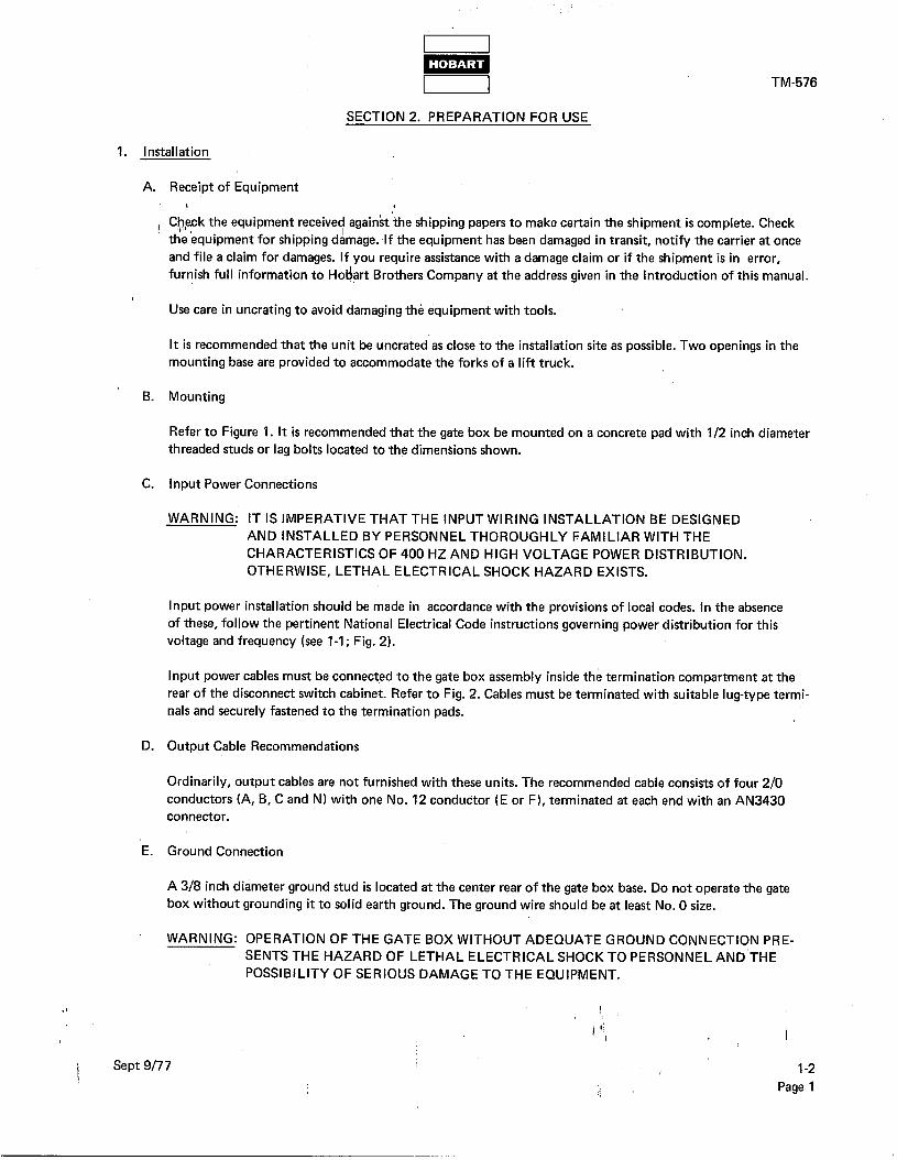
C. input Power Connections
WARNING: IT IS IMPERATIVE THAT THE INPUT WIRING INSTALLATION BE DESIGNED AND INSTALLED BY PERSONNEL THOROUGHLY FAMILIAR WITH THE
CHARACTERISTICS OF 400 HZ AND HIGH VOLTAGE POWER DISTRIBUTION.
OTHERWISE, LETHAL ELECTRICAL SHOCK HAZARD EXISTS.
Input power installation should be made in accordance with the provisions of local codes. In the absence
of these, follow the pertinent National Electrical Code instructions governing power distribution for this
voltage and frequency (see l-l; Fig. 2).
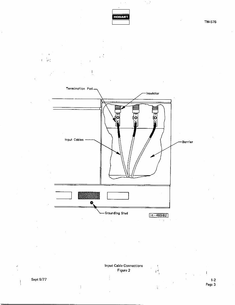
Input power cables must be connected to the gate box assembly inside the termination compartment at the
rear of the disconnect switch cabinet. Refer to Fig. 2. Cables must be terminated with suitable lug-type termi-
nals and securely fastened to the termination pads.
D. Output Cable Recommendations
Ordinarily, output cables are not furnished with these units. The recommended cable consists of four 2/O
conductors (A, B, C and NJ with one No. 12 conductor (E or F), terminated at each end with an AN3430
connector.
E. Ground Connection
A 318 inch diameter ground stud is located at the center rear of the gate box base. Do not operate the gate
box without grounding it to solid earth ground. The ground wire should be at least No. 0 size.
WARNING: OPERATION OF THE GATE BOX WITHOUT ADEQUATE GROUND CONNECTION PRE- SENTS THE HAZARD OF LETHAL ELECTRICAL SHOCK TO PERSONNEL AND’THE
POSSIBILITY OF SERIOUS DAMAGE TO THE EQUIPMENT.
.I ,
) ‘! I 1
i Sept 9177 1-2
I, Page 1

TM-576
Gate Box Mounting Dimensions
Figure 1
l-
t Pa e2
I ‘1, 1
kept 9177
Termination
Input Cables 7
Insulator
i Sept 9177
I
Grounding Stud
TM-576
rBarrier
Input Cable Connections !: Figure 2 I ‘!,
1
1-2 Page 3

( 1’1, I ’
!
) ‘! /

TM-576
SECTION 3. OPERATION
1. General
Operafion of the gate box assembly is limited to closing the three disconnect switches and operating the load con- tactor controls. , ’
( $./I )
CAUTION: MAKE SURE OUTPUT CABLE IS SECURELY ATTACHED TO GATE BOX OUTPUT CONNECTOR AND \TO AIRCRAFT.
2: Disconnect Switch
WARNING: OPERATOR MUST WEAR HEAVY RUBBER GLOVES AND OPERATE SWITCHES ONLY WITH INSULATED OPERATING TOOL PROVIDED. OTHERWISE, LETHAL
ELECTRICAL SHOCK HAZARD EXISTS.
A. Refer to Fig. 1. Close all three switches in the switching bay using the insulated tool provided. Three amber
POWER AVAILABLE lights on control panel will glow to indicate that the high voltage fuses are intact and
that gate box will deliver power when load contactor is closed.
B. Make sure that the switching bay doors are closed securely. A microswitch interlock is located just inside
each door, front and rear, which will prevent the load contactor from closing if the doors are not closed com- pletely.
3. Power Delivery
A. Open the door of the control bay and check position of test bank switch. For power delivery to an aircraft
with a 28 Volt plug-interlock system, switch must be in AIRCRAFT position. For power delivery to a load
bank or to an aircraft without plug-interlock circuit, switch must be in TEST BANK position.
B. Check position of contactor disable switch. It must be positioned away from DISABLE position. Close cabinet door.
C. Press contactor CLOSE switch. Green light will glow indicating that the load contactor is closed and 115 Volt,
‘400 Hz power is being delivered to the aircraft. Three red LEDs on contactor monitor board will glow indicat-
ing that the load contactor is closed.
4. Discontinue Power Delivery
A. Press contactor OPEN switch. Green light will go out indicating that power to aircraft is no longer being delivered.
B. Open door of control bay. Remove locking pin and position contactor disable switch to DISABLE. Reinsert
locking pin. Close the cabinet door.
C. Open three disconnect switches observing the WARNING in para. 2 above. Three amber POWER AVAIL- ABLE lights will go out indicating that 4160 Volts AC input power is no longer energizing the gate box.
Close the cabinet door.
.t !
) ‘! I 1
Sept 9177 1-3
1 i
Page 1 ‘.

TM-576
Disconnect Switches-
Contactor Monitor Board
Contactor Open
Contactor Close
7-Y @ B a\
Amber Power Available Lights
Green Contactor On Light
Operating Controls and Indicators
Figure 1
!
I ‘1, 1
l-
f P ge2
‘Sept 9177

CHAPTER 2. SERVICE
TM-576
SECTION 1. MAINTENANCE
1. General
The g’te box requires no maintenance,‘as”such, and should operate for long periods of time without attention. 81
lh thg event of a malfunction, maintenance is limited to the replacement of parts.
2. Lubrication I
’ No lubrication is required.
3. Parts Replacement
There are no high mortality parts which require periodic replacement, repair or special attention.
4. Line Fuse Replacement
WARNING: OPERATOR MUST WEAR HEAVY RUBBER GLOVES AND OPERATE SWITCHES ONLY WITH INSULATED OPERATING TOOL PROVIDED. OTHERWISE, LETHAL ELECTRIC’AL
SHOCK HAZARD EXISTS.
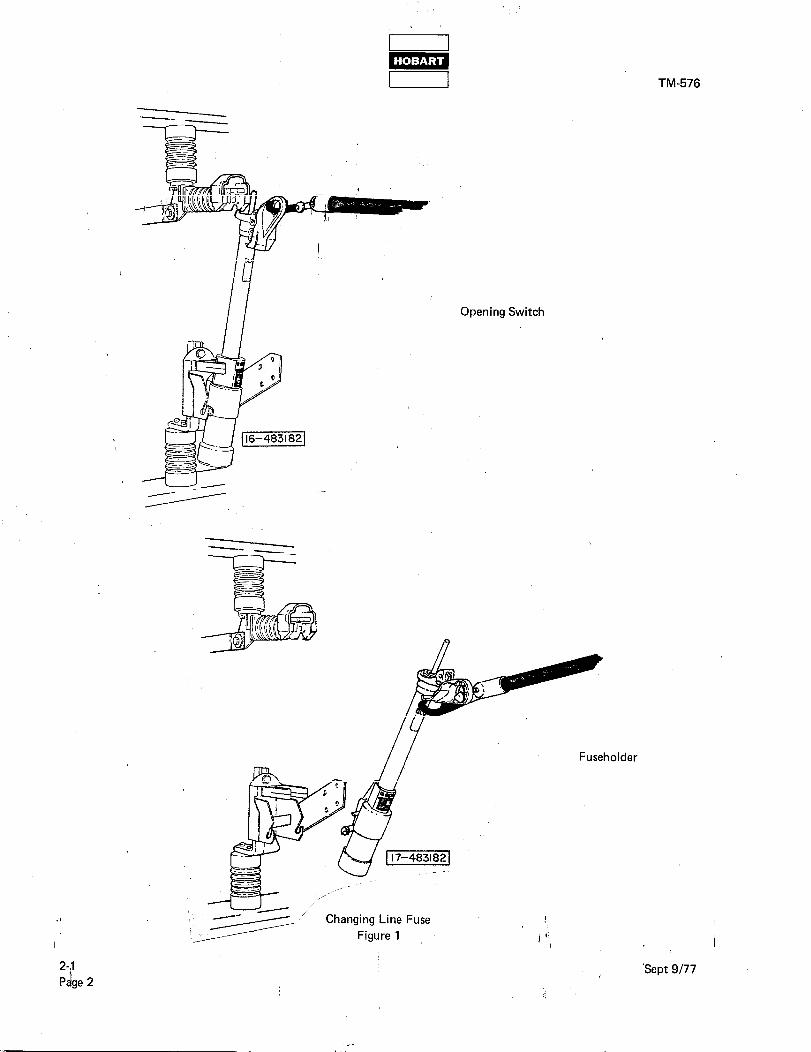
Refer to Fig. 1. When a fuse in one of the disconnect switches requires replacement, as indicated by the presence of the red indicator in the fuseholder’s BLOWN area, proceed as follows:
A. Use the special switch operating tool to disconnect all three switches by pulling straight out toward operator.
B. Use the same tool to remove the fuseholder with the blown fuse by pulling up and out, away from its support bracket.
C. Refer to Fig. 2. Loosen the holder cap with a wrench and remove it from the glass-epoxy tube of the fuse- holder. The spring and cable assembly is attached to this cap, and the arc’ing terminal of the blown fuse refill
unit is screwed into the bottom of the spring and cable assembly. Unscrew and discard the arcing terminal of the blown refill unit.
D. Unscrew and remove the silencer from the bottom of the fuseholder. Remove and discard the blown refill
unit.
E. After a heavy fault, the interior of the glass-epoxy tube should be wiped clean to remove any dust or metal particles that may be present.
‘F. After a heavy fault, inspect the spring and cable assembly and the silencer for damage. Replace as required.
NOTE: Spring and cable assembly, silencer and fuse refill unit are available from the manufacturer:
S & C Electric Company 3645 Warrensville Center Road
Shaker Heights, Ohio 44122
Spring and Cable Assembly - Catalog No. FA-973
Silencer - Catalog No. FA-104572 !
Fuse Refill Unit - Catalog No. 122030R4
i Sept 9177 2-1
Page 1
TM-576
2-1
Page 2
_2_- - --a-- _
Opening Switch
Fuseholder
1
I ‘!, 1
‘Sept 9177

, ,,i:: II /-Cap
/-Spring and Cable
Threaded Stud
/Fuse Refill Unit
H -Knurled Collar
-Pull-cord
IF, Fuseholder
i Sept 9177
Fuseholder Assembly , Figure 2
I’! I
TM-576
i,
2-1
Page 3
TM-576
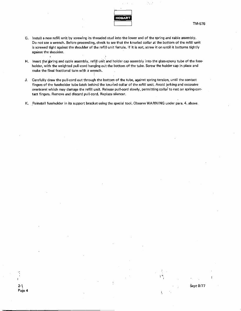
G. Install a new refill unit by screwing its threaded stud into the lower end of the spring and cable assembly. Do not use a wrench. Before proceeding, check to see that the knurled collar at the bottom of the refill unit
is screwed tight against the shoulder of the refijl unit ferrule. If it is not, screw it on until it bottoms tightly
against the shoulder. 1 1
H. Insert th,e’hring and cable assembly, refi and holder cap assembly into the glass-epoxy tube of the fuse- holder, with’the weighted pull-cord the bottom of the tube. Screw the holder cap in place and make the final fractional turn with a wrench.
J. Carefully draw the pull-cord out through the bottom of the tube, against spring tension, until the contact
fingers of the fuseholder tube latch behind the knurled collar of the refill unit. Avoid jerking and excessive
over-travel which may damage the refill unit. (Release pull-cord slowly, permitting colla; to rest on spring-con-
tact fingers. Remove and discard pull-cord. Replace silencer.
K. ,Reinstall fuseholder in its support bracket using the special tool. Observe WARNING under para. 4. above.
2-1
Pase 4 Sept 9177

TM-576
SECTION 2. INSPECTION/CHECK
1. General
The gate box requires a minimum of scheduled inspection and checking. Scheduled inspection periods of less than
one &ar are not required; however{avisual inspection of the components is recommended each time the doors are
opened. /I
WARNING: BE SURE DISCONN’ECT SWITCHES ARE OPEN. OTHERWISE, LETHAL ELECTRICAL
/ SHOCK HAZARD EXISTS.
A. Inspect ALL lead connections and terminals for security.
B. Inspect all components and connections for discoloration and evidence of overheating.
C. Inspect and check all attaching hardware for security.
D. Check transformer hardware for security to avoid rattle from magnetic force.
E. Inspect all fuses and indicators (lamp bulbs and LEDs). Refer to Figures 1 and 2 for replacements.
Item Protected Location Illustration Size and Type
I
I Power Reduction
I
Disconnect Switch
I
2-1; Fig. 2
I
20 Amp
Transformer SM-4 I
12 Volt Power
SUPPlY
Control Module l-l; 24, Fig. 9 1 Amp
AGC
Load Contactor Control Module l-l ; 22, Fig. 9 2 Amp
AGC
Fuse Identification Chart
Figure 1
, .I
I I ‘1,
1
Sept 9177 2-2
t Page 1
i ‘,

TM-576
Light Identification
l ‘,.I:!
Contactor Closed
Power Available ,
Phase A
Power Available Phase 6
’ Power Available
Phase C
Overvoltage Fault
Under-voltage Fault
Overload Fault
Location, Manufacturer
, Jncandescent Lamps , cll ,
Control Panel Sylvania I I
Control Panel Sylvania
Control Panel Sylvania
Control Panel Sylvania
Control Panel Sylvania
Control Panel Sylvania
Control Panel Sylvania
Part Number
120PSB5
120PSB5
120PSB5
120PSB5
12PSB5
12PSB5
12PSB5
Light Emitting Diodes
Contactor Monitor Phase A
Contactor Monitor Phase B
Contactor Monitor
Ptiase C
Control Module Hewlett-Packard 5082-4655
Control Module Hewlett-Packard 5082-4655
Control Module Hewlett-Packard 5082-4655
Lamp and LED Identification Chart Figure 2
1 .I
I ! ‘!, 1
2-2 Sept 9177 Page 2
1.
TM-576
SECTION 3. ADJUSTMENT/TEST
1. Adjustment
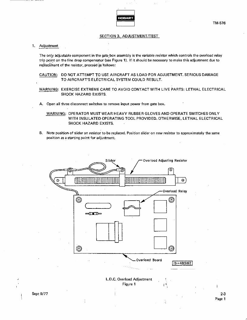
The only adjustable component in the gate,box assembly is the variable resistor which controls the overload relay trip po’nt on the line drop compensator (sbe Figure 1). If it should be necessary to make this adjustment due to
It re&&nent of the resistor, procedd ~s’follows:
CAUTION: DO NOT ATTEMPT TO USE AIRCRAFT AS LOAD FOR ADJUSTMENT. SERIOUS DAMAGE
TO AIRCRAFT’S ELECTRICAL SYSTEM COULD RESULT.
WARNING: EXERCISE EXTREME CARE TO AVOID CONTACT WITH LIVE PARTS: LETHAL ELECTRICAL SHOCK HAZARD EXISTS’.
A. Open all three disconnect switches to remove input power from gate box.
WARNING: OPERATOR MUST WEAR HEAVY RUBBER GLOVES AND OPERATE SWITCHES ONLY WITH INSULATED OPERATING TOOL PROVIDED. OTHERWISE, LETHAL ELECTRICAL
SHOCK HAZARD EXISTS.
B. Note position of slider on resistor to be replaced. Position slider on new resistor to approximately the same
position as a starting point for adjustment.
Overload Adjusting Resistor
i Sept 9177
\-Overload Board 119-4831821
L.D.C. Overload Adjustment !:
Figure 1 I ‘!, 1
23
i; Page 1
1 I w
TM-576
C. Disconnect cables from output terminals of the line drop compensator. Cables should be tagged to insure
proper connection when they are reconnected later.
D. Connect a load bank capable of applying a 335 Ampere load to the output terminals of the line drop compen-
sator.
E. Close all three disconnect switches to apply,power to the gate box. Observe WARNING under A. above.
F. Apply) do” “VA, 0.8 PF load with load b&&. Keep current at 260 Amperes, even if kVA varies slightly from 90. k
G. Remove load and increase load slowly until contactor trips. Note amperage at trip.
H. Adjust resistor for contactor trip at a point betwee,n 330 and 335 Amperes.
J. Repeat steps G. and H. as required.
K. Open all three disconnect switches. Observe WARNING under A. above. Remove load bank and reconnect cables removed in C. above.
2. Tests Using 4160 Volts Input
A. General Tests
The following tests may be made without the use of any test equipment.
(1) Preparation for tests
(a) Position contactor disable switch (26, Fig. 3) to DISABLE position. Secure with safety lock pin.
(b) Remove cable from output connector.
(c) Position contactor disable switch away from DISABLE position. Secure with safety lock pin.
(d) Position test bank switch (23) to TEST BANK position.
(2) Test procedures
(a) Close all three disconnect switches (Fig. 2).
WARNING: OPERATOR MUST WEAR HEAVY RUBBER GLOVES AND OPERATE
SWITCHES ONLY WITH INSULATED OPERATING TOOL PROVIDED. OTHERWISE, LETHAL ELECTRICAL SHOCK HAZARD EXISTS.
Three POWER AVAILABLE lights (4,5 and 9, Fig. 4) will glow. This procedure tests the lights and
power output from the line drop compensator.
(b) Press fault lights TEST switch (19, Fig. 3). Three fault lights (6, 7 and 8, Fig. 4) will glow. This tests
the fault light bulbs, 12 Volt power supply circuit and memory and time delay circuits. Press RESET switch (20, Fig. 3) to turn off fault lights.
(c) Press contactor CLOSE switch (1, Fig. 4). Green contactor CLOSE light (3) will glow and three LEDs
on contactor monitor board (18, Fig. 3) will glow red. This tests the contactor, LEDs, CLOSE light bulb and contactor control circuits.
, (d) Press contactor OPEN switch (2, Fig. 4). Green indicator light will go out and three red LEDS will go out to indicate that contactor is open.
(e) Open all three disconnect switches. Observe WARNING under (a) above.
2-3 ,Sept 9177
$ P ge2 ; Revised May 2517%

I TM-576
B. Line Drop Compensator
The following test requires the use of a load bank capable of applying 335 Amperes load.
(1) PrepaLtion for test 4 /
(g, ‘iefer to Figure 2. Open all th<ee”disconnect switches. Observe WARNING under para. 2. A. (2) (a)
above.
I , (b) Disconnect cables from line drop compensator output terminals.
Make sure cables are tagged to insure
proper connections after test.
(c) Connect load bank to line drop cbmpensator output terminals.
~ (2) Test procedures
(a) Close all three disconnect switches. Observe WARNING under para. 2. A. (2) (a) above. This energizes
the line drop compensator for test.
(b) Adjust load bank for 260 Ampere load. Measure boost voltage across line drop compensator for each
phase. Voltage will be 24 Volts k 10%.
(c) Increase load until overload relay (6, Fig. 6) trips contactor (7). Contactor will trip at 330 to 335
Amperes load. -,.
7 rnntrnl Bav Switching Bay
-i _-
-
.I A--
i
““...._. _-,
4 ,-Control Module
-output Terminals
‘Output Connector
Sept 9177
May 25176 Revised
Figure 2 2-3
Page 3

16’
26
Control Module
Figure 3
2-
5 Pa e4
TM-576
1. Burden Resistor, 16.6 Ohm, 25 Watts 2. Current Transformer
3. Zener Diode, 50 Watts
4. Heatsink
5. Resistor, 10 Ohm, 25 Watts
6. Transformer Rectifier Assembly
7. Load Contactor
8. Plug Interlock Relay
9. Fuse Interlock Relay
10. Terminal Board
11. Silicon Diode
12. Receptacle Connector
13. Memory and Time Delay Module 14. Over-Under-voltage Module
15. Overload Module 16. Resistor, 20 Ohm, 25 Watts
17. Rectifier
18. Contactor Monitor Board 19. Test Switch
20. Reset Switch
21. Test Receptacle
22. Fuse, 2 Ampere
23. Test Bank Switch
24. Fuse, 1 Ampere
25. Safety Pin
26. Contactor Disable Switch
) ‘! / 1
Sept 9177

I I m I I TM-576 I I
(d) Open all three disconnect switches. Observe WARNING under para. 2. A. (2) (a) above. Disconnect
load bank from line drop compensator output terminals and reconnect cables removed in para. (1)
(b) above.
C. ,q’verload Protection Circuits ( $./I )
, ,
~ The following tests require the’use of a load bank capable of applying 325 Amperes load.
(1) Preparation for tests ‘.
/ (a) Connect load bank to gate box output connector. Adjust for 260 Ampere load.
(b) Position contactor disable switch (26, Fig. 3) away from DISABLE position. Secure with safety lock pin.
(c) Position test bank switch (23) to TEST BANK position.
(2) Test procedures
(a) Refer to Figure 2. Close all three disconnect switches. Observe WARNING under para. 2. A. (2) (a) above.
(b) Press contactor CLOSE button (1, Fig. 4). Green contactor CLOSE light (3) will glow and three LEDs (18, Fig. 3) will glow red.
(c) Increase load to 112 kVA (325 Amperes). Overload module will open load contactor in 2 to 6
minutes. Green indicator light will go out, three red LEDs will go out and red OVERLOAD fault
light (6, Fig. 4) will glow. This indicates that the overload module and overload circuit on the memory and time delay board are functioning.
(d) Reduce load to 260 Amperes. Press RESET switch to turn off red OVERLOAD fault light and reset protective circuits.
(e) Open all three disconnect switches. Observe WARNING under para. 2. A. (2) (a) above.
(f) Disconnect load bank from gate box output connector, position contactor disable switch to DISABLE and position test bank switch to AIRCRAFT position.
3. Testing Protective System Circuits Using Test Box
, The following tests of the protective system circuits require the use of a 115 Volt AC, 400 Hz, 3 phase generator,
and a test box, Hobart part number 483347-l. These tests MUST be performed with the 4160 Volt input power
disconnected.
The gate box is energized by the generator, through the test box. The test box inserts a variable transformer into the input circuit. This transformer permits raising and lowering the voltage to test the overvoltage and undervoltage
’ protective circuits.
.I
I
t
I ‘1,
Sept 9177
t May 25178 Revised
2-3
i, Page 5

TM-576
A. Preparation For Tests
(1) Disconnect all ,three disconnect switches. Observe WARNING under 2. A. (2) (a) above.
(2) Position contactor disable switch (26, Fig. 3) away from DISABLE. /’
\ (3) Posit&n test bank switch (23) to TEST BANK.
(4) Connect optional test box output (cable part number 483584 to receptacle on rear panel of test box and to’test receptacle (21, Fig. 3),‘with test box circuit breakers (1 and 2, Fig. 5) OFF.
(5) Connect generator output cable to test box at connector (4).
(6) Set transformer knob (5) to 115 Volts.
WARNING: MAKE SURE GENERATOR LOAD CONTACTOR IS OPEN. OTHERWISE,
LETHAL ELECTRICAL SHOCK HAZARD EXISTS.
B. Test Procedures
(1) Position test box input circuit breaker (2, Fig. 5) to ON.
(2) Start generator and adjust for 115 Volts AC output. Close generator load contactor. Test box panel lights will glow, and voltmeter (3) will indicate 115 Volts.
(3) Set output circuit breaker (1) to ON position. Gate box power available lights will glow.
(4) Press contactor CLOSE switch (1, Fig. 4). Green contactor CLOSE light (3) will glow and three LEDs
on contactor monitor board (18, Fig. 3) will glow red. This indicates that the contactor is closed and
that the rectifier, fuse interlock relay and contactor holding coil circuit are operable.
2-3
(5) Turn voltage control on test box (5, Fig. 5) slowly clockwise to increase voltage. Observe voltmeter
(3). At some point between 130 and 134 Volts the load contactor will open. The green indicator light
will go out, the three red LEDs will go out and the red OVERVOLTAGE light (8, Fig. 4) will glow.
This indicates that the overvoltage circuits on the over-undervoltage board and the memory and time
delay board are operable.
(6) Turn voltage control knob on test box counterclockwise until voltmeter indicates 115 Volts.
(7) Press RESET button (20, Fig. 3). Red OVERVOLTAGE fault light will go out and the protective
circuits will be reset.
(8) Press contactor CLOSE switch. Green indicator light will glow and three LEDs will glow red.
(9) With voltage control knob on test box, reduce voltage 1 Volt at a time with at least a five-second delay
each time voltage is reduced. At some point between 102 and 98 Volts, and approximately five seconds , after the last adjustment, the load contactor will open. The green indicator light will go out, the three
red LEDs will go out and red UNDERVOLTAGE light will glow. This indicates that the undervoltage
circuits on the over-undervoltage board and the memory and time delay board are operable.
1
I ‘1,
‘Sept 9177
Page 6 Revised May 2517%

TM-576
Controls and Indicators
Figure 4
1
) ‘! /
Sept 9177
May 2517% Revised
2-3
Page 7

w
I I I I TM-576
1. Output Circuit Breaker 4. 1 l&Volt Input Connector 2. Input Circuit Breaker 5. Variable PowerTransformer Knob 3. Voltmeter
Test Box
Figure 5
(IO) With voltage control knob on test box, increase voltage to 115 Volts.
(I I.) Press RESET button. Red UNDERVOLTAGE light will go out and protective circuits will be reset.
(12) Position contactor disable switch (26, Fig. 3) to DISABLE and secure with safety locking pin.
(13) Open generator load contactor. Disconnect generator output cable from test box. Disconnect test box
output cable from gate box test receptacle.
2-3
t Page 8
Sept 9177
Revised May 2517%

TM-576
‘2
1. Transformer 5. Overload adjusting resistor
2. Capacitor (1000 ohm, 100 watt)
3. Sensing transformer 6. Overload relay
(one of three) 7. Contactor 4. Overload module 8. Terminal boards
Line Drop Compensator 1 Figure 6
I ‘1, 1
Sept 9/77 2-3
May 25178 Revised Page 9 _~ ~~- -- _~~


SECTION 4. REPAIR
1. General
Repaif will consist primarily of parts replacement. ( 11’ )
,
1 Protective circuits are designed as easily replaced, solid-state modules. Each one is connected with a quick-
disconnect connector and should be replaced as a complete assembly.
( WARNING: BEFORE WORKING ON ANY COMPONENT, MAKE CERTAIN THAT POWER
IS OFF AND CANNOT BE TURNED ON ACCIDENTALLY. OTHERWISE, LETHAL ELECTRICAL SHOCK HAZARD EXISTS.
TM-576
.I 1
I I ‘!, 1
Sept 9177
1
2-4
Page 1 i.

!
) ‘! I

TM-576
CHAPTER 3. TROUBLESHOOTING
SECTION I. PROCEDURES t 4
1. Gpej$~ ,I ’
I
A. Troubleshooting is an orderly process of checking and eliminating possible causes of trouble until the exact
cause is found. The best placelto start looking for the cause of trouble in a circuit is at the source of power.
/ Continue testing and checking the circuit, step-by-step, in an orderly manner, until the cause of trouble is located. See applicable connection diagrams and schematic diagrams.
B. This section provides information useful in diagnosing and correcting certain troubles which cause unsatis-
factory operation or failure of the equipment.
C. Minor troubles may be remedied by the operator; however, major repairs must be undertaken by experienced
mechanics and electricians only.
2. Troubleshooting Chart
A. Description
The troubleshooting chart (Figure 6) lists information under three headings:
(I) Trouble, symptom and condition
(2) Probable cause
(3) Test, check and remedy
B. Use
(1) The troubleshooting chart is designed to provide maintenance and repair personnel with a time-saving
guide for locating the source of trouble.
(2) A schematic diagram (Fig. 2) is included in this Chapter to assist in troubleshooting. Connection diagrams are provided in Chapter 6.
(3) Reference designators used on schematic diagrams are also used in the troubleshooting chart (in
parentheses after the item name) to help maintenance personnel identify parts on the schematic diagrams.
(4) ALWAYS check circuit fuses and the position of switches first in troubleshooting. The incorrect
positioning of a switch may cause a condition which could be misinterpreted as a fault.
3. Equipment
A good quality multi-scale voltohmmeter and a test box are important tools for good troubleshooting.
i Sept 9177
i,
3-1
Page 1

4. Safety
TM-576
WARNING: EXERCISE EXTREME CARE TO AVOID CONTACT WITH HIGH VOLTAGE LEADS AND
COMPONENTS. THEY COULD CAUSE SERIOUS SHOCK AND INJURY IF TOUCHED. I ,
5. Test Valueg ‘l,i’ ) ;I ’
Overload relay trips at any value above 125y rated load (I 12 kVA, 90 kW, or 325-A) in 5 minutes or less.
Overvoltage circuit functions at 130 to 134-V AC, resets at 125-V AC.
Undervoltage circuit functions at 102 to 93-V AC, resets at 1 IO-V AC.
Undervoltage time delay circuit functions in approximately 5 seconds.
3-f
Pa$e 2
) ‘i I I
Sept 9177

LEGEND
A70
1 C
OM
PE
NS
AT
OR
, LI
NE
D
RO
P
c707
C
AP
AC
ITO
R.
24”.
T
-R,
3 M
FD
.. S
W
Oc
CR
701
RE
CT
IFIE
R.
LOA
D
CO
NT
AC
TO
R
CR
RX
-CR
708
DIO
DE
. LI
GH
T
E”,
TT
,NG
yi
i3lp
723
;:y--
e.
., .̂̂
.I --
‘Y
S,
rLr-
wK
.n,
LC”
CR
737
:T,F
IER
. 24
,‘.
T-R
D
IG
CR
739
l!E.O
”ER
LOA
o F
AU
LT
LlG
HT
D
IOD
E,Z
EN
ER
.,5”,
;~~
;osm
3 IN
otcA
mR
, P
owR
A
VA
ILA
BLE
. A
M.S
E~
DS
72,
IND
ICA
TO
R.
OV
ER
LOA
D
FA
ULT
, R
ED
OS
726
INO
ICA
TO
A.
CO
NT
AC
TO
R
C‘O
SE
D,G
RE
EN
WI2
7 lN
DIC
AT
OR
,OV
ER
VC
~--
--
--
.-
---
IND
ICA
TO
R,
UN
DE
R, LrAGE
FAULT. RED
IOLT
AG
E
FA
ULT
, R
ED
t
i
II
II
p,
F701
F70
2 F
703-
F70
5
FU
SE
,IZV
P
OW
ER
S
UP
PLY
,A
. F
US
E,
LOA
O
CO
NT
AC
TO
R,
iA.
FU
SE
, D
ISC
ON
NE
CT
S
WIT
CH
, Z
OA
.
-!%
?I
RE
CE
PT
AC
LE.
OV
ER
LOA
D
GO
AR
D
^r^r
^-.-.
-
^_..
-._-
- .._
.. -_
- __
._.
K70
,
11%
K
721
K72
7 K
72G
R70
4 R
705
RE
SIS
TO
R.
12”.
T
-R.
10 O
HM
. 25
W
R71
2-R
714
RE
SIS
TO
R,
HO
LD
CIR
CU
IT.2
0 O
HM
, 25
W.
R72
7-R
72S
R
ES
IST
OR
. Y
OLT
AG
E
DR
OP
PIN
G,
,O,O
oO O
HM
, ,O
W
RE
SIS
TO
R,
OV
ER
LOA
D,
BU
RD
EN
. 16
.6
OH
M,
25L
5701
57
10
s711
57
11
S72
l
g;!
572;
; B,S723
:ETm”
T72
,
“CbCb-llL.LL.S”RI&C\I”” MONITOR
U”A”U
RE
CE
PT
AC
LE,
ME
MO
RY
B
T
,ME
D
ELA
Y
RE
LAY
R
EC
EP
TA
CLE
. S
YS
TE
MS
T
ES
T
AE
CE
PT
AC
LT,
OV
ER
-UN
DE
RV
OLT
AG
E
GO
AR
O
RE
CE
PT
AC
LE.
CO
NT
RO
L M
OD
ULE
R
EC
EP
TA
CLE
, LI
GH
TS
M
ON
ITO
RIN
G
RE
CE
PT
AC
LE,
OU
TP
UT
LOA
D
CO
NT
AC
TO
R
RE
LAY
, P
LUG
IN
TE
RW
CK
R
ELA
Y,
FU
SE
IN
TE
RLO
CK
R
ELA
Y,
OV
ER
LOA
D
S.
S
RE
LAY
, O
VE
R-U
N&
RV
OLT
AG
E.
s.S
. R
ELA
Y.
ME
MO
RY
B
T
IME
D
ELA
Y,
S S
PLU
G.
OV
ER
LOA
D
BO
AR
D
PLU
G.
CO
NT
AC
TO
R
MO
NIT
OR
B
OA
RD
F
iUG
, M
EM
OR
Y
G
TIM
E
DE
LAY
B
OA
RD
P
‘UG
.OV
ER
-UN
DE
RV
OLT
AG
E
GO
AR
O
PLU
G.
CO
NT
RO
L M
OD
ULE
F
i.UG
, LI
GH
TS
M
ON
lTO
RlN
G
SW
, S
W,
SW
,
TR
AN
SF
OR
ME
R.
CU
RR
EN
T,
OV
ER
LOA
D
TR
AN
SF
OR
ME
R.
24V
T
-R
TR
AN
SF
OR
ME
R.
3 P
HA
SE
: S
YS
TE
M
SY
ST
EM
K72
0
572,
I

i

I I’. I ’
i Sept 9177
I m t 1
I/,,“,
481553
TM-576
Line Drop Compensator Schematic and Connection qiagrams
Figure 1 ) ‘! I 1
3-1
Page 3

TM-576
483158
Gate Box Schematic Diagram
Figure 2
3-1
Pi+e 4
) ‘! I I
Sept 9177
I;

NI Ui’MOd
il
m
POWER OUT
: POWER WT POWER OUT

I II’!

TM-576
8 7
J J
4
Controls and Indicators
Figure 3
i Sept 9177
!
) ‘! /
I,
3-1 Page 5

TM-576
16’
18 19 20
23 [piEZ?J
.I
/
Control Module
Figure 4
3-J
P&e 6
1. Burden Resistor, 16.6 Ohm, 25 Watts 2. Current Transformer
3. Zener Diode, 50 Watts
4. Heatsink
5. Resistor, 10 Ohm, 25 Watts
6. Transformer Rectifier Assembly
7. Load Contactor
8. Plug Interlock Relay
9. Fuse Interlock Relay
10. Terminal Board
11. Silicon Diode
12. Receptacle Connector
13. Memory and Time Delay Module : 14. Over-Undervoltage Module
15. Overload Module 16. Resistor, 20 Ohm, 25 Watts 17. Rectifier 18. Contactor Monitor Board 19. Test Switch 20. Reset Switch
21. Test Receptacle
22. Fuse, 2 Ampere
23. Test Bank Switch
24. Fuse, 1 Ampere
25. Safety Pin
26. Contactor Disable Switch
) ‘! / 1
‘Sept 9177
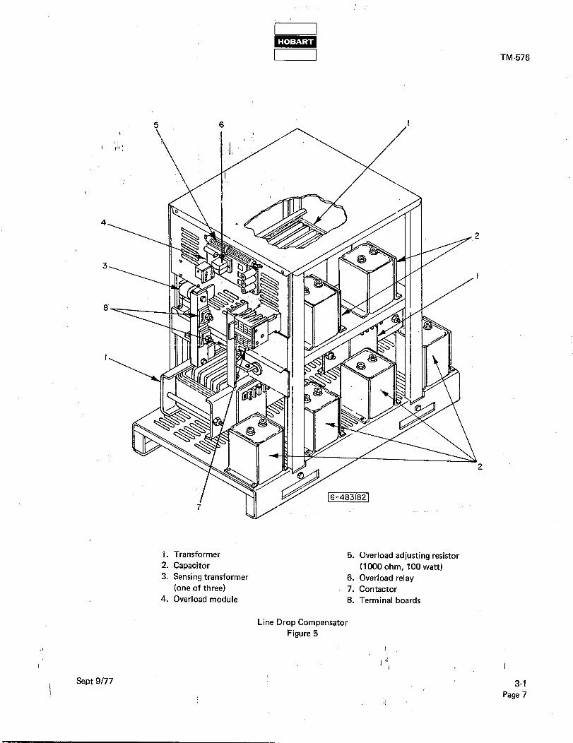
TM-576
1. Transformer 5. Overload adjusting resistor
2. Capacitor (I 000 watt) ohm, 100
3. Sensing transformer 6. Overload relay (one of three) 7. Contactor
4. Overload module 8. Terminal boards
Line Drop Compensator
Figure 5
1 Sept 9177
i ‘,
3-1 Page 7

TROUBLE, SYMPTOM, AND CONDITION
INPUT CIRCUIT
PROBABLE CAUSE TEST, CHECK, REMEDY
1. Amber indicatjhg light on gate bok ‘d&or does not glow when it is
known that power is
available at input line. ,
A. LaziCX$O/,, DSfO2 or DS703)
B. Line fuse (R703, F704 or F705)
blown ”
A. Check lamps (4,5 and 9, Fig. 3). Replace
as required.
B. Check fuses (2-l; Fig. 2) and replace per
2-1; para. 4.
C. Disconnect switch (S726) open
or defective
D. Transformer (T721) defective
C. Check switch (l-l ; Fig. 3). Replace if
defective.
D. Check windings on transformer (l-l ;
Fig. 5). Replace if defective.
LINE DROP COMPENSATOR
1. No voltage boost in one
phase
A. Defective transformer (T701, T702 A. Check transformers and capacitors (1 and
or T703) or capacitor (C701 thru 2, Fig. 5). Replace defective part.
C706)
2. No voltage boost in any
phase
A. Defective overload relay (K712) A. Check overload relay (6, Fig. 5). It may
be defective and causing contactor to
close. Replace as required.
8. Defective contactor (K706) B. Check contactor (7, Fig. 5). It may be remaining closed and bypassing capacitors.
Replace as required.
LOAD CONTACTOR CONTROL CIRCUIT
1. Amber indicating light A. Door interlock switch (S728) is A. Check as follows:
on gate box door does open due to open cabinet door or
not light when it is known switch is defective (I) Check doors (front and rear) on
that power IN is available switching bay cabinet (l-l ; Fig. 3).
and lamps are good. Load Close and secure as required.
contactor will not close. (2) Check switch. Replace if defective.
B. Defective resistor (R7051 B. Check resistor (16, Fig. 4) for open condi-
tion. Replace if defective.
C. Relay in memory and time delay module (K728) open
C. Check as follows:
(1) Relay may have opened due to a fault condition. Press reset switch (20, Fig.
4) to correct.
!
q-1 qage f3
Troubleshooting Chart (Sheet 1 of 4) Figure 6
i ‘,
Sept 9l77

TM-576
TROUBLE, SYMPTOM,
AND CONDITION PROBABLE CAUSE TEST, CHECK, REMEDY
:. (Contir(ued) y
LOAD CONTACTOR CONTROL CIRCUIT’(Continued)
1. (Cont&ued)
1. Fuse (F702) in load contactor
circuit blo\;vn
i. Contactor disable switch (S721) in E. Check switch (26: Fig. 4). Position DISABLE position or defective properly, or replace if defective.
2. Load contactor will 4. Fuse (701) blown, preventing A. Check fuse (24, Fig. 4). Replace if required.
not close when CLOSE fuse-interlock relay from closing
button is pushed.
Power available I. Defective fuse-interlock relay B. Check as follows:
lights are on. (K720) (1) Be sure power is available to operate
relay. Press test switch (19, Fig. 4)
(S727). If fault lights (DS706, DS726 ,
and DS727) (6,7 and 8, Fig. 3) do
NOT glow, look for trouble in 12 Volt
power supply circuit (see Trouble 2. C.
below). If fault lights glow, proceed
to step (2).
:. A component of the 12 Volt
power supply circuit is defective:
(1) Defective transformer (T719)
(2) Defective rectifier (CR7361
(3) Defective capacitor (C707)
C. (2) Check resistance across terminals 10 and 11 on memory and time delay module (13, Fig. 4) at connector
(J711). If resistance is infinite, replace
module.
D. Check and replace fuse (22, Fig. 4).
(2) Ctieck fuse-interlock relay coil and
contacts (9, Fig. 4). Replace relay
if defective.
C. If fault lights do NOT glow when test switch is pushed, check 12 Volt power
supply:
(1) Check windings on transformer (6, Fig. 4). If defective, replace transformer.
(2) Output of rectifier (I-l; 2, Fig. IO) should be a pulsating 24 Volts DC.
Replace if defective.
(3) A defective capacitor will allow power
supply output to reach zero’volts. Check
capacitor (I-l; 1, Fig. IO). Replace if
defective.
!
) ‘i
Sept 9177 Troubleshooting Chart (Sheet 2 of 4) 3-l Figure 6 Page 9
i,

0 m [ I
TM-576
TROUBLE, SYMPTOM,
AND CONDITION PROBABLE.CAUSE
LOAD CONTACTOR CONTROL CIRCUIT (Continued)
TEST, CHECK, REMEDY
2. (Continued) I 1’ ( $0
C. (Continue 4
) 1 ’ ’ ~ ;
(4) Open resistor (R704)
I
(4) Check resistor (5, Fig. 4). Replace if defective.
, (5) Defective Zener diode
(CR739) ,
D. Defective silicon rectifier
(CR7011
(5) Check diode (3, Fig. 4). Replace if defective.
D. Check output of rectifier (17, Fig. 4).
Should be a pulsating 1’15 Volts DC.
Replace rectifier if defective.
E. Defective coil in load contactor (K701)
E. Check resistance across terminals X and-
Y on load contactor (7, Fig. 4). Re-
sistance should be approximately 600
Ohms. If coil is defective, replace com- plete load contactor.
3. Load contactor will close, A. A component in the load con- A. Check as follows:
but OPENS when CLOSE tactor hold circuit is defective: button is released
(I) Output cable not properly (I) Connect output cable plug to aircraft
plugged into aircraft receptacle securely so that com- ponents are fully mated.
(2) Defective E and F terminals in cable plug connector or
receptacle
(2) Inspect plug and receptacle thor- oughly. ‘Repair or replace as required.
(3) Aircraft not supplying 28.5
Volts DC to plug-interlock
relay
(3) Check aircraft on-board equipment
to make certain that aircraft will
accept power and return 28.5 Volts
DC to terminals E and F.
(4) Defective plug-interlock relay (K707)
(4) If load contactor will remain closed
when test bank switch (S701) (23, Fig. 4) is in TEST BANK position,
replace plug-interlock relay (8, Fig.
4).
(5) Small contacts in load con- tactor (K701) not functioning
to connect power to fuse-
interlock relay (K720)
(5) Connect a jumper lead between terminals 1 and 2 on load con-
tactor (7, Fig. 4). If load contactor
will now remain closed, replace complete load contactor.
CAUTION: DO NOT OPERATE UNIT WITH ANY COMPONENTS JUMPERED, EXC$T FOR TEST. /
3-l Troubleshooting Chart (Sheet 3 of 4)
kage 10
Sept 9177 Figure 6
I>

TM-576
TROUBLE, SYMPTOM, AND CONDITIONS PROBABLE CAUSE TEST, CHECK, REMEDY
LOAD CONTACTOR CONTROL CIRCUIT‘(Continued)
4. Load ic\ontaCtor opens dbrirl’g ‘power delivery.
A. Outp P
t cable accidentally dis- A. Reconnect cable plug securely and proceed
cohn cted from aircraft with power delivery.
No fault lights on.
B. If ldad contactor cannot be B. Check load contactor operating circuit in
closed for operation accordance with Troubles 1 thru 4 above.
PROTECTIVE SYSTEM CIRCUITS
1. Load contactor opens A. An overload condition caused A. Press reset switch, (20, Fig. 4). Correct con-
during power delivery. load contactor to open. dition that caused overload.
Overload light (DS706)
is ON. B. One of the resistors (R727, R728 B. An open resistor will cause a higher than
or R729) is open circuited normal voltage signal to the memory and
time delay module. Check resistors (1, Fig.
4). Replace as required.
C. Defective overload module (K721) C. A load bank is required to check overload module. Refer to 2-3; para. 2. C. for test
procedure. Replace overload module (15,
Fig. 4) if defective.
2. Load contactor opens A. An overvoltage condition signaled A. Press reset switch (20, Fig. 4). With dis- during power delivery. over-undervoltage module (K727) connect switch on, check voltage in each
Overvoltage light to open contactor phase at test receptacle (21, Fig. 4). If (DS726) is ON. voltage is abnormally high, correct con-
dition before operating gate box.
B. Defective over-undervoltage
module (K727)
B. Use test box to test overvoltage protective
circuitry. Refer to 2-3; para. 2. C. Replace
module (14, Fig. 4) if defective.
3. Load contactor opens A. An under-voltage condition (last- A. Press reset switch (20, Fig. 4) . With dis-
during power delivery. ing more than 5 seconds) signaled connect switch on, check voltage in each
Under-voltage light the over-undervoltage module phase at test receptacle (21, Fig. 4). If
(DS727) is ON. (K727) to open the load con- voltage is abnormally low, correct con-
tactor. dition before operating gate box.
B. Defective over-undervoltage B. Use test box to test undervoltage protective module (K727) circuitry. Refer to 2-3; para. 2. C. Replace
module (14, Fig. 4) if defective.
!
) ‘!
Sept 9177 Troubleshooting Chart (Sheet 4 of 4) 3-1
Figure 6 Page 11 I>

!
) ‘! /

bid P-l I I TM-576
CHAPTER 4. ILLUSTRATED PARTS LIST
SECTION 1. INTRODUCTION
1. General
The.lilustrated Parts List identifies, describes, and illustrates main assemblies, subassemblies, and detail parts of
the 4./160 Volt AC Gate Box manu fh ctured by Hobart Brothers Company, Power Systems Division, Troy, Ohio
45373. The unit is identified by Part Number 483182.
2. Purpose
The purpose of this list is to provide parts identification and descriptive information to maintenance and provision-
ing personnel for use in provisioning, requisitioning, purchasing, storing, and issuing of spare parts.
3. Arrangement
Chapter 4 is arranged as follows:
Section 1 - Introduction
Section 2 - Manufacturer’s Codes
Section 3 - Parts List Section 4 - Numerical Index
4. Explanation of Parts List
A. Contents /
The parts list contains a breakdown of the equipment into assemblies, subassemblies, and detail parts. All parts of the equipment are listed except:
(1) Standard hardware items (attaching parts) such as nuts, screws, washers, etc., which are available com-
mercially.
(2) Bulk items such as wire, cable, sleeving, tubing, etc., which are also commercially available.
(3) Permanently attached parts which lose their identity by being welded, soldered, riveted, etc., to other
parts, weldments, or assemblies.
B. Form
This form is divided into five columns. Beginning at the left side of the form and proceeding to the right,
columns are identified as follows:
(1) FIGURE-ITEM NO. Column
This column lists the figure number of the illustration applicable to a particular parts list and also identifies each part in the list by an item number. These item numbers also appear on the illustration.
Each item number on an illustration is connected to the part to which it pertains by a leader line. Thus
the figure and item numbering system ties the parts lists to the illustrations and vice versa. The figure and index numbers are also used in the numerical index to assist the user in finding the illustration of a part
when the part number is known. !
) ‘i I I
Nov 4177 4-1
Page 1

1 TM-576
(2) HOBART PART NUMBER Column
ALL part num,bers appearing in this column are Hobart numbers. In all instances where the part is a
purchased item, the vendor’s identifying five-digit code and his part number will appear in the NOMEN- CLATURE column. Vendor parts which are modified by Hobart will be identified as such in the NO-
MEN F
LATURE column. In case obart does not have an identifying part number for a purchased parti’the HOBART PART NUMBE, I3 column will reflect “No Number” and the vendor’s number will
be shown in the NOMENCLATURE column. Parts manufactured by Hobart reflect no vendor code
or part number in the NOMENCLATURE column.
(3) NOMENCLATURE Column
The item identifying name appears in this column. The indenture method is used to indicate item re-
lationship. Thus, components of an assembly are listed directly below the assembly and indented one
space. Vendor codes and part numbers for purchased parts are shown in this column. ’
(4) EFF (Effective) Column
This column is used to indicate the applicability of’parts to different models of equipment. When more
than one model of equipment is covered by a parts list, there are some parts which are used on only one
model. This column is used for insertion of a code letter A, B, etc., to indicate these parts and to identify
the particular model they are used on. No coding is required for this manual.
(5) UNITS PER ASSEMBLY Column
This column indicates the quantity of parts required for an assembly or subassembly in which the part
appears. This column does not necessarily reflect the total used in the complete end item.
4:l
$ge 2
Nov 4177
s

TM-576
SECTION 2. MANUFACTURER’S CODES
1. Explanation
The following list is a compilation of vendor codes with names and addresses for suppliers of purchased parts
listed Lit-r this publication. The codes are in accordance with the Federal Supply Codes for Manufacturer’s Catalog- ivg Hbndbook H4-1, and are arrang d.‘in numerical order. Vendor codes are inserted in the nomenclature column
of the parts list directly following t ‘e item name and description. In case a manufacturer does not have a vendor 6
code, the full name of the manufacturer will be listed in the nomenclature column.
/ CODE VENDOR’S NAME AND ADDRESS
00779 AMP Inc. P. 0. Box 3608
Harrisburg, Pennsylvania 17105
02231 Anchor Rubber Company 840 S. Patterson Blvd.
Dayton, Ohio 45402
02660 Amphenol Corporation
2801 S. 25th Avenue
Broadview, Illinois 60153
04713 Motorola Semiconductor Products Inc.
5005 East McDowell Road Phoenix, Arizona 85008
05277 Westinghouse Electric Company
Semi & Conductor Dept.
Youngwood, Pennsylvania 15697
07497
08108
09332
10087
107853
.I
Amphenol Corporation
Amphenol Cable Division
6235 S. Harlem Avenue
Chicago, Illinois
Lamp Industry Designations
And Abbreviations For Lamps
Aerofast Inc.
P. 0. Box 324 Wheaton, Illinois 60187
Akron Hardware Consultants 2579 South Arlington Road Akron, Ohio 44139
Cornell Dubilier Electronics
P. 0. Box 9858
Chicago, Illinois 60690 !
Nov 4177 4-2
t Page 1
TM-576
CODE VENDOR’S NAME AND ADDRESS
120992 Hewlett Packard
P. 0. Box 38289 San Francisco, California 94138
L
13103 , *$
/ 13974
14280
14831
17411
23826
27191
44655
71400 >
73559
74063
4-2
Pbge 2
I ’
~ 1; Thermal’loy Company Inc.
P. 0. Box 34829
I’ 2021 W. Valley View Lane
Dallas, Texas 75234
Southco Division
South Chester Corporation
Concordville, Pennsylvania 19331
Square D Company
Distribution Equipment Div.
1601 Mercer Road
Lexington, Kentucky 40505
Magnetic Components Inc.
290 Fischer Street
Costa Mesa, California 92627
S & C Electric Company
3645.Warrensville Center Rd. Shaker Heights, Ohio 44122
Furnas Electric Company 1004 McKee Street Batavia, Illinois 60510
Cutler-Hammer Inc.
Power Distribution & Control Div.
4201 N. 27th Street
Milwaukee, Wisconsin 53216
Ohmite Manufacturing Company
3601 W. Howard Street
Skokie, Illinois 60076
Bussmann Manufacturing Division of
McGraw-Edison Company
2536 W. University Street
St. Louis, Missouri 63017
Carling Electric Inc. 505 New Park Avenue
West Hartford, Connecticut 06110
Hartman Electrical Manufacturing Company
P. 0. Box 8 !
Mansfield, Ohio 44901 ) ‘i I 1
Nov 4177

CODE VENDOR’S NAME AND ADDRESS
77342 American Machine 81 Foundry Company
Potter & Brumfield Division
1200 E. Broadway , P. 0. Box 522
Princeton, Indiana 47570
80368 I Sylvania Electric Products Inc.
730 Third Avenue / New York, New York 10017
81861
89110
89373 United States Rubber Company
Detroit, Michigan
89616 Uniroyal Inc.
91637
91929
97520
> 98410
Nov 4177
Burton Electrical Engineering Company Maryland & El Segundo Boulevard El Segundo, California 90246 ’
AMP Inc.
155 Park Street Elizabethtown, Pennsylvania 17022
Consumer Industrial & Plastic Products
312 N. Hill Street
Mishawaka, Indiana 46544
Dale Electronics Inc.
P. 0. Box 609
Columbus, Nebraska 68601
Honeywell, Inc.
Building Controls & Components Group
Micro Switch Division
Freeport, Illinois 61032
Basler Electric Company P. 0. Box Rt. 143 Highland, Illinois 62249
E.T.C. Inc.
990 E. 67th Street Cleveland, Ohio 44103
TM-576
) ‘! I ’
4-2
Page 3

!
) ‘! I

I m I 1 TM-576
”
SECTION 3. PARTS LIST
Tie parts list is arranged so that the idustration will appear on a left-hand page and the applicable parts list will I appear on the opposite right-hahd page. Unless the list is unusually long, the user will be able to look at the illustra-
tion and read the parts list without turning a page.
2. Symbols and Abbreviations ”
The following is a list of symbols and abbreviations used in the parts list.
+
A, or AMP -
AC - AR -
DC -
Fig. - hd. -
hex - Hz -
I.D. - IN -
kVA -
NHA -
PRV -
PSI -
Ref -
TM - T-R -
v- _ .~~ ~_.
Item not illustrated
ampere alternating current
as required
direct current
Figure head
hexagon Hertz (cycles-per-second)
inside diameter inch
kilovolt-ampere microfarad
number
next higher assembly peak reverse voltage
-
pounds per square inch reference (the item has been listed previously)
Technical Manual
transformer-rectifier volt (when used as a prefix to a five-digit number, indicates vendor code)
NOTE: An item which does not reflect an index number is an assembly which is not illustrated in its assembled
state, or it is similar (right-hand, left-hand, top, etc.) to an item which is illustrated.
I
4-3
i Nov 4177
Page 1

TM-576
1
, ‘,,i,! I 1;” :
Gate Box Assembly Figure 1
Nov 4177

FIGURE HOBART ITEM NO. PART NO.
l-
1 1
( 1". I ' 2
3 4
/ 5 6
7 8
9 d
10 11
12
13 14
15
16
17 77A-1036-2 . PUSHBUTTON, CONTACTOR OPEN V14280,
18 77A-1167
19 20
21
22
23
24
25
> 26 27
28 *
* *
I
NOMENCLATURE
12345.67
483182
No Number
483090
483335
483092
77A-1040
GATE, BOX, ASSEMBLY
. DlSC?i)JNECT SWITCH GROUP (For Details See Fig. 2)
.,B
‘8
x’, GATE, ASSEMBLY
. . hER, TOP BOX, ASSEMBLY
. . DOOR, LEFT ASSEMBLY
. .!LATCH, DOOR, RIGHT ASSEMBLY V10087,
No. 5648-82X LOCK, No. 5655 HANDLE
483093
483094
480695 77A-1048
. . BOX, GATC, ASSEMBLY
. . DOQR, RIGHT ASSEMBLY
. . DOOR, ACCESS RECEPTACLE
. . LATCH, DOOR, LEFT ASSEMBLY V10087, ,
No. 5648-82X LOCK, No. 5655 HANDLE 403127 . . CATCH, MAGNETIC V13974, No. 02-10-201-10 483171 . FRAME, MOUNTING, ASSEMBLY
No Number . GATE BOX INTERIOR (For Details See Fig. 3) 77B-1025-6 . NAMEPLATE, CLOSE 77B-1025-7 . NAMEPLATE, OPEN 778-l 025-5 . NAMEPLATE, POWER AVAILABLE 77B-1025-3 . NAMEPLATE, OVERVOLTAGE 77B-1025-4 . NAMEPLATE, UNDERVOLTAGE 77B-1025-I . NAMEPLATE, OVERLOAD 77A-1036-I . PUSHBUTTON, CONTACTOR CLOSE V14280,
No. KR-2B-H 1 1
No. KR-2R-H 1 1
483028-I 77A-1026-1
77A-1028-I
No Number
483028-2
77A-1026-2
77A-1028-2
No Number 483028-3
77A-1026-3
77A-1028-2
No Number
77A-1027
387205 402927
50GH-823
. CAP, PROTECTIVE, PUSHBUTTON V14280, CLASS 9001, TYPE KU7
. LIGHT, PILOT, FAULT, ASSEMBLY
. . LENS (RED) V14280, No. R-9
. . BASE, 17 AMPS., 12 V. V14280, No. KP-32
. . LAMP, 12 PSB. VO8108
. LIGHT, PILOT, POWER AVAILABLE, ASSEMBLY
. . LENS (AMBER) V14280, No. A-9
. . BASE, .025 AMPS., 120 V. V14280, No. KP-38
. . LAMP, 120 PSB VO8108
. LIGHT, CONTACTOR, CLOSED, ASSEMBLY
. . LENS (GREEN) V14280, No. G-9
. . BASE, .025 AMPS., 120 V. V14280, No. KP-38
. . LAMP, 120 PSB VO8108
. . CAP V14280, CLASS 9001, TYPE KU-27
. STRAP, GROUND
. NAMEPLATE, HOBART
. NAMEPLATE, RATING
TM-576
UNITS
per EFF ASSY
REF
REF
1
1
1
1
REF
2
1
3
1
1
2
3 3
3
3
3
3
3
3 1
1
1
1
7
1 2
Nov 4177 4-3 Page 3

TM-576
( I/lb
B 3
\
I 1;” :
8 /
3
% P ge4
Disconnect Switch Group
Figure 2
t
) ‘! / I
Nov 4177

NOMENCLATURE
FIGURE. HOBART
ITEM NO. PART NO.
2- No Number
1 1 401539 *
I ’
483 192 I 1”.
77A-1042
2 77A-1127
3 77A-1128
4 77A-1129
5 77A-1131
6 77A-1130
7 77A-1132
8 77A-1133
9 77A-1134
10 77A-1135 . . CABINET ASSEMBLY V17411, No. 198262
11 77A-1136 . . TOOL, FUSE, HANDLING VI741 1, No. 4423
12 77A-1137 . . POLE, UNIVERSAL VI741 1, No. 4402R2-E 13 77A-1138 . TOOL, DOOR LOCK V17411, No. B2191
Nov 4177
1234567
DISCONNECT SWITCH GROUP (For NHA See Fig. 1)
. MICRO,,SWITCH, INTERLOCK V91929, No. BZ-2R
*I B ACKkT, MOUNTING MICRO SWITCH, ASSEMBLY
. S a ITCH, DISCONNECT, ASSEMBLY V17411, No. 198262-Slob
. .IFUSEHOLDER, ASSEMBLY V17411, No. 92352 ” SPRING AND CABLE ASSEMBLY V17411, . . *
No. FA-973 . . . SILFNCER V17411, No. FA-104572 . . . FUSEHOLDER ‘VI741 1 . . FUSE, REFILL UNIT V17411, No. 122030R4 . . INSULATOR V17411, No. PA-7089 . . SWITCH ASSEMBLY V17411, No. SA-39139 . . SWITCH, BOTTOM, ASSEMBLY VI741 1,
No. SA-38950-I
TM-576
UN ITS
per EFF ASSY
REF 2
2
1
3
4-3
Page 5

TM-576
Gate Box Interior
Figure 3 1
I ‘1, I
Nov 4177
I,
43. I P ge6

FIGURE HOBART
ITEM NO. PA@T NO.
3- 1
: ,,I::
3
4 5
’ 6
No Number 483183 A.
402378
402379
402382
384918
483047
7 8
9
10 11
12
13
14
15
16 17
18
19 20
*
* * * * *
*
400162 483191
77c-1043
483282
483283
483303
483232
483234
400613-I 1 4006 13-I 2
483235 483236
W-l 1434
W-l 1166-I
W-l 1166-9
483342-l 483342-2 483342-3 W-9360-2 16 W-9360-287
W-9360-286
W-9360-288
W-9360-289
W-9360-290
W-9360-291
W-9360-204
W-9360-21 2
I I
NOMENCLATURE
1234567 EFF
GATE BOX INTERIOR (For NHA See Fig. I) . MODULE, CONTROL, ASSEMBLY (For Details See Fig. 5)
. R ~ N i
CEPtACLE, 20 CONTACTS V07497, .‘MS3102A-28-16P
PLUG, STRAIGHT V07497, No. MS-3106A-28-16s
: CLAMP, PLUG V07497, No. AN-3057-16
. BRACKET, MOUNTING RECEPTACLE
. COMPENSATOR, LINE DROP ASSEMBLY (For Details
See Fig. 4) . RECEPTACLE; OUTPUT V81861, No. AN-31 14-IB
. BRACKET, MOUNTING, RECEPTACLE
. TRANSFORMER, 90 KVA V97520, No. BE161 1 l-061
. COVER, PLEXIGLASS
. BRACKET, MOUNTING PLEXIGLASS
. BRACKET, MOUNTING PLEXIGLASS, ASSEMBLY
. BRACKET, MOUNTING CONTROL MODULE
. BOARD, MOUNTING FUSES AND LAMPS ASSEMBLY
. . LAMP, PILOT LIGHT, 12 PSB, V80368
. . LAMP, PILOT LIGHT, 120 PSB, V80368
. . LABEL, SPARE FUSES AND LAMPS
. . BOARD, MOUNTING, FUSES AND LAMPS
. . FUSE, HOLDER V71400, No. 4407
. . FUSE, AGC 2A, FAST BLOW FUSE, AGC IA, FAST BLOW
1 GABLE ASSEMBLY, POWER ELECTRICAL (NO. 101)
. CABLE ASSEMBLY, POWER ELECTRICAL (No. 102) CABLE ASSEMBLY, POWER ELECTRICAL (No. 103)
: CABLE ASSEMBLY, POWER ELECTRICAL (No. 104) CABLE ASSEMBLY, POWER ELECTRICAL (No. 105)
: CABLE ASSEMBLY, POWER ELECTRICAL (No. 106)
. CABLE ASSEMBLY, POWER ELECTRICAL (No. 107,
No. 109)
. CABLE ASSEMBLY, POWER ELECTRICAL (No. 108,
No. 110)
. CABLE ASSEMBLY, POWER ELECTRICAL (No. 111)
. CABLE ASSEMBLY, POWER ELECTRICAL (No. 112)
. CABLE ASSEMBLY, POWER ELECTRICAL (No. 113)
. CABLE ASSEMBLY, POWER ELECTRICAL (No. 114,
No. 115)
TM-576
UNITS
per ASSY
REF 1
1
1 1
1
1
1
1
4
1
3 3 1
1
6 3
3 1 1 1 1 1 I
1 .I
I I ‘!, I
1 May 5/86 Revised 4-3
Page 7

TM-576
4-3
Page 8
?r 3
-23
D
Line Drop Compensator Assembly
Figure 4
1
’ I ‘1,
Nov 4177

FIGURE HOBART
ITEM NO. PART NO.
4- 483047
2
3
4
1 5 6 7
8 9
10 11
12
13 14
15 16 17
18
19
20 21
22
23
24 * *
483247
1 cz-74
W-9746-l
ICZ-129
481552
402818 402817
401564-4
401566-I 1 481528
481548 481549
481550
481551 430278 400078
W-2974-H
481494A
404877 ICZ-148
481542
404131-3
481510
401556 403763-I
481495
i Nov 4177
NOMENCLATURE UNITS
12345,67 EFF ASSY
COMPENSATOR, LINE DROP ASSEMBLY (For NHA See Fig. 3)) I
.,T@P, LI,FT, COMPEN’SATOR
. INSULATOR, RESISTOR
RESISTOR, 50 OHM, 25 WATT V44655, No. 02000
: IbSULATOR, RESISTOR
. BOARD ASSEMBLY, OVERLOAD
. . SOCKET, RELAY V77342, No. 27E-636
. . RELAY V77342, No. RIO-El-Z2-V700
. . HOUSING, SOCKET V89110, No. l-480287-0
. TERMINAL, SOCKET V89110, No. 60619-I 3
. YOKE ASSEMBLY, LIFT
TERMINAL ASSEMBLY, LEFT, POWER IN : TERMINAL ASSEMBLY, RIGHT, POWER IN
. TERMINAL ASSEMBLY, LEFT, POWER OUT
. TERMINAL ASSEMBLY, RIGHT, POWER OUT
. GROMMET, RUBBER V89616, No. TPR No. 1812
. BRACKET, MOUNTING, RESISTOR
. RESISTOR, 1000 OHM, 100 WATT V44655, No. 0962
. TRANSFORMER ASSEMBLY
. CAPACITOR 34 pF, 400 CYC., 220 V. VI07853
. TRANSFORMER, CURRENT V14831, No. E-6170
. SUPPORT, TRANSFORMER
. CONTACTOR V23826, No. 42DE35AV-182
. BASE ASSEMBLY, COMPENSATOR
. MOUNT RUBBER V89616, No. B-323
. WASHER, SHOULDER, FIBER
. NAMEPLATE, IDENTIFICATION
TM-576
1
1
3 3
1
1
1
1 1
12
2
1 1
1
1 4
2 1
3
6 3
1 1
1
4
4 1
t
I ‘1, I
4-3
Page 9

TM-576
,,A,” [W} /’
Control Module Assemtily
Figure 5
) ‘! / I
Nov 4177
i,

FIGURE HOBART
ITEM NO. _ PAqT NO.
4
5 6
t 7
8 9 IO
11 16DA-4253-1
12 16DA-4004A-10
13 *
14 15
16 *
17
18
*
19
20 77A-1011
21 402662 22 76A-1118
23
24 25
*
26 27 28
’ 29 30 31
32
33
I 34 35
36 401564-5
,I * 401566-I 1
! May 5/8t
483183 404518 404065-I
483026 ICZ-271-9
1 cz-74
W-454 1 B
430476
401556
488887A 16DA-4004A-3
16DA-4052-0 363770-I
387725
401937-2
1 CZ-93B 400480-2
384918
402378
363771-5 77A-1010
403336
402658 W-l 1166-I
W-l 1166-9
76A-1123 482257 402037-g
482935 401564-I
483184
387736B 482038
387738A 401564-4
Revised
I m i TM-576
NOMENCLATURE
1234567
MODULE, CONTROL, ASSEMBLY
. CONTAFTOR, LOAD V74063, No. HB200B
. R
.‘H i
CT’IF’IER, SILICON V04713, No. SDA10270-1
AT, SINK, DIODE, ZENER V13103, No. 6423
. DIODE, ZENER; 50 WATTS V04713, No. IN3314A
. l(VSULATOR, RESISTOR, TOP
. F~‘ESISTOR, 10 OHM, 25 w V44655, NO. 0363
. INSULATOR, RESISTOR, BOTTOM
. MOlJ[)IT, SHOCK, RUBBER V89373, No. B-323
. TRANSFORMER, SUPPLY, POWER, ASSEMBLY
. RELAY, PLUG INTERLOCK, ASSEMBLY V77342, No. KAP-14DG
. RETAINER, SPRING, RELAY V77342, No. 2OC206
. RELAY, FUSE INTERLOCK, ASSEMBLY V77342,
No. KAP-14DY
. SOCKET, RELAY VO2660, No. 77-MIP-I I
. SLEEVING, PLASTIC, 3/16 I.D.
. BRACKET, MOUNTING, SOCKET, RELAY
. STRIP, TERMINAL V98410, No. 35008-3526
. DIODE, SILICON V05277, No. IN4820
. TERMINAL, QUICK CONNECT VO0779, No. 41274
. BRACKET, MOUNTING, RECEPTACLE
. RECEPTACLE, 20 CONTACTS V07497,
No. MS-3102A-28-I 6P . SLEEVING, PLASTIC, l/8 I.D. . RECEPTACLE, MODULE CONTROL VO2660,
No. MS3102A-18-20P . CAP AND CHAIN ASSEMBLY VO2660, No. 9760-18
. SWITCH, TOGGLE V73559, No. 2GK71-73
. SWITCH, SNAP, PUSHBUTTON V27191,
No. SA35BCB34-9
. RING, LOCKING, SWITCH V91929, No. TS10020
. HOLDER, FUSE V71400, No. HKP-HH
. FUSE, AGC, 2 A
. FUSE, AGC, 1 A
. PIN, SWITCH, DISABLE V09332, No. C5-1.3R
. GUARD, SWITCH, TOGGLE
. GROMMET, RUBBER V02231, No. AGW-4211
. BOARD, MONITOR, CONTACTOR, ASSEMBLY
. HOUSING, SOCKET, CONNECTOR
. MODULE, CONTROL, ASSEMBLY
. BOARD, MEMORY AND TIME DELAY ASSEMBLY
. BOARD, OVER-UNDERVOLTAGE, ASSEMBLY
. BOARD, OVERLOAD, 12 V ASSEMBLY
. HOUSING, SOCKET, CONNECTOR V89110, No. l-480287-0
. HOUSING, SOCKET, CONNECTOR V89110,
No. l-480438-0
. TERMINAL, SOCKET .V89110, No. 6081$, ‘I
UNITS
per EFF ASSY
1
1 1
1
1
2
1
2
18 1
1 2
1
38
1 1 2
2
2
2 1
1
1 1
3 1 1
1
1 1 1
2
4-3
Page 11

L m 1 I
NOMENCLATURE FIGURE HOBART
ITEM NO. PART NO. 1234567
5- 37 404402-I . RESISTOR, OVERLOAD BURDEN 16.6 OHM, 25 W I
38 ( ividi4541C V91637, No. qH125
. RESlSTqfj, -iO OHM, 25 W V44655, No. 0364B 39 ICZ-148 . TRANSFORMER, CURRENT, OVERLOAD V14831,
No. E-6170 40 404424 . DIODE, L!IGHT EMITTING, RED ~120992,
No. 5082-4655 41 483355 . SHIELD, MODULE CbNTROL
TM-576
UNITS
per EFF ASSY
3 1
3
3
1
4-3
Pbge 12 Nov 4177

‘I m
1 TM-576
1. Explanation
The purpose of this index is to assist the user in finding the illustration and description of a part when the part
numb& is known. Part numbers are arranged in alpha-numerical sequence. Thus, any part number beginning with
the letter A would be located at ornear the top of the index list. Likewise a part number 9 would be listed near I the end of the list and far below a part number 1900. The figure number and item number location of the part
is directly opposite the part. If thy part is used in more than one place, each location is listed commencing with
the first location the part is listed:
NUMERICAL INDEX
PART NUMBER
DISCONNECT SWITCH GROUP
GATE BOX INTERIOR
LAMP
W-l 1166-I
W-l 1166-9
W-l 1434 W-2974-H W-4541 B
w-4541c W-9360-204
W-9360-21 2
W-9360-2 16
W-9360-286
W-9360-287
W-9360-288’
W-9360-289 W-9360-290
W-9360-291 W-9746-l
2 ICZ-129
ICZ-148
ICZ-271-9 1 cz-74
’ ICZ-93B
16DA-4004A-3 16DA-4004A-IO
16DA-4052-0 16DA-4253-1
FIGURE AND ITEM NUMBER ’
I-l 2-o
1-o 3-o
1-21 I-24 I-27
5-25
3-19
5-o 3-20
3-18 4-I 7
5-6
5-38 3-o
3-o
3-o
3-o
3-o
3-o 3-o
3-o
3-o
4-3 4-4
539 4-20
5-4 5-5 4-2 5-16
5-10 5-12
5-13
“;!;I ‘/
I
Nov 4177
i,
1 Numerical Index
4-4
Page 1

PART NUMBER
363770-I 36377 1-5 ,' 384918 1 ed':
386781
387205
387725
3877368
387738A 400078
400 162 400480-2
400613-I 1
400613-12 401539
401556
401564-I
401564-4
401564-5
401566-I 1
40 1937-2 402037-g
402378
402379
402382
402658
402662
402817
402818
402927
403127
403336 404065- 1
404131'-3
404402-I
404424
404518 404877 430278
430476 480695
481494A
.I 481510
' 'Numerical Index 4-4
Pdge 2
NUMERICAL INDEX (CONTINUED)
FIGURE AND
ITEM NUMBER
I’,.“, 5-o 5-o
5-17
3-5
5-9
1-o
5-14
5-32 5-34
4-16 3-7
5-o 3-14
3-l 5
2-l
4-24
5-8
530 5-35 4-8
5-36
5-o 4-9
5-15
5-28 5-18 3-2
3-3 3-4
5-24
5-21
4-7
4-6
1-o
1-o
5-23
5-2
4-22
5-37
5-40
5-I
4-19 4-15
5-7 I-7
4-18
4-23
) ‘! /
TM-576
' Nov 4177 I

TM-576
PARTNUMBER
481528 -
481542
48~li&B 481549
481550
481551
/ 481552
482038 482257
482935 483026
483028-I 483028-2
483028-3
483047
483090 483092 483093
483094 483171
483182
483183
483184
483191 483192
483232
483234
483235
483236
483247
483282
483283 483303
483335 483342-l
a 483342-2
483342-3
483355 50GH-823 76A-1118 76A-1123
' 77A-1010
77A-1011. 77A-1026-I
77A-1026-2 .I
I Nov4177
1
NUMERICAL ~NDEXKONTINUED)
FIGUREAND
ITEMNUMBER
4-10 4-21
4-11
4-12
4-13
4-14
4-5
5-33 5-27 5-29
5-3 *
1-o
1-o
1-o
4-o 3-6
1-o
I-3 1-5 I-6
I-9
1-o
5-o
3-l
5-31
3-8 2-o
3-13
3-o
3-16
3-17
4-1
3-10
3-11 3-12
1-2
3-o
3-o
3-o
5-41 1-o 5-22 5-26 5-19
5-20 1-19
l-T2
I ‘1,
\,
, Numericalllndex 4-4
Page 3
PART NUMBER
77A-1026-3 ’ 77A-1027 I ‘$.i’ :
77A-1028-I 77A-1028-2
77A-1,036-I
77A-1036-2 77A-1040
77A-1042 77A-1048 77A-1127
77A-1128
77A-1129
77A-1130
77A-1131
77A-1132
77A-1133
77A-1134
77A-1135
77A-1136
77A-1137 77A-1138
77A-1167
77B-1025-1
77B-1025-3 77B- 1025-4 77B-1025-5 77B-1025-6
778-1025-7
77c-1043
’ Numerical Index
NUMERICAL INDEX (CONTINUED)
FIGURE AND
ITEM NUMBER
I’,.“, ’ I-25 1-28
I-20 I-26
I-23 I-16
1-17
I-4
2-o I-8 2-2
2-3
2-4
2-6
2-5
2-7
2-8
2-9
2-10 2-11
2-12 2-13
I-18
I-15
1-13 I-14 I-12
I-IO l-11
3-9
TM-576
’ Nov 4177 I

NAME - ( ‘1./l )
Test Box
CHAPTER 5. OPTIONAL EQUIPMENT
PART NUMBER
Ii,.“, 483347-l
MANUAL NUMBER
TM-575
Test Box Harness
(115-Volt Output Cable)
I
483584
TM-576
i Sept 9177
I
5-o
Page 1


,..i .._ .; A..: ,._ .., _. _. _-.._ ..-. :. _ . . . .- -. . ._, H
1 TM-576
CHAPTER 6. MANUFACTURER’S LITERATURE
Hobart Diairamr I I’! l/,.11:1.
481553 - Schematic and Connection, Line Drop Cdmpensator
I 483158 -: Schematic, Gate Box ”
483181 - Connection, Control Module
483200 - Connection, Gate Box
i Sept 9177 6-O
Page 1


CHAPTER 6. MANUFACTURER’S LITERATURE
Hobart Didgrams ,
I 1’. I ’ I 1;” 481553 - Schematic and Connection, Line Drop Compensator
483158 - Schematic, Gate Box !.
483181 - Connection, Control Module
483200 - Connection, Gate Box
1
Sept 9177
TM-576
6-O Page 1
i