Embed Size (px)
Citation preview
OUSEPIUEHT OF CMERCN WN eRT6edmkllftWme~bn#aM
AD-A036 095
AGARD FLIGHT TEST INSTRUMENTATION SERIESVOLUME 8. LINEAR AND ANGULAR POSITION
MEASUREMENT OF AIRCRAFT COMPONENTS
ADVISORY GROUP FOR AEROSPACE RESEARCH AND
DEVELOPMENT, PARIS, FRANCE
JANUARY 1977
41 I(16) - Design end iApplication of Resolvers, Wletin INle-9 American mectronics
Inc., Fullerton$ Cali ioaxi'i. A
(17) - Two-Speed Autoayn Synchroa, Publication W 26, Elliott Brothers Ltd.,
London SE 13.
(15) - Koarfott Drushlesa Synchrou, Koearfatt Products Division, Little Falls,
lhj., 1968.
(19) Kollawan Synchrotela, Publ. M.90-500-2-61, Ks0llaman Inutr. Corp., New York,1961. ,
(2o) -Arinc Reports 407 and 407-1, Synchro System Manual, Aeroiautical Radio,
Inc., 1700 LaSt., N.W. Waahineton 6 DC, 19641.1
(21) - Synchro Conversion Handbook, ILC Data Device Corporation, Airport
International Plaza, Bohemia, Long Island, New Yo•k, 1974.
(22) aL. Herceg Handbook of Me eme• t 9md Control, Lt-dSchaevitz Erigineerine, Pennsauken, N.J., July 1972. ;
(23) A C Inductive Pick-offal Pulbl. No- 753/3, Sperry Gyroscope ComJp. Ltd.,
M~ddlese-, England,*
(24) - DC/DC LVDT Displacement Seneor, Product Information Sheet Nc. 1304, A
Penny and Giles Ltd., Mudeford, Christchurch, Hants, England, 1971.
(25) A. Pool Basic Principles of Flight Test Instrumentation Tigineerine,D. Bosman
(editors') AlA.Dograph Wo.160, Vol.1.
-i
.I
WN1; 1W
AGARDpgnph No.1601
AGARD Rlight Test Instrumenta tion SeriesVolumne 8
aW-ngviar PoitoMesuemntof Airrf Copoens
Abyi~iid.imoc
j.C~vn de J~nen aWH.A.ensU
REPRODU( BY
/ AGARD-AG-160Volume 8
NORTH ATLANTIC TREATY ORGANIZATION
ADVISORY GROUP FOR AEROSPACE RESEARCH AND DEVELOPMENT i!(ORGANISATION DU TRAITE DE L'ATLANTIQUE NORD)
L
AGARDograph No. 160 Vol.8
LINEAR AND ANGULAR POSITION MEASUREMENT
OF AIRCRAFT COMPONENTS
by
J.C.van der Linden and l.A.Mensink
Volume 8
of the
AGARD FLIGHT TEST INSTRUMENTATION SERIES
Edited by
K.C.Sanderson and A.Pool J
"D-D C"
This 2A5 hq7 7
DISTRIBIl~ TPrApi' -- AA
This AGARDograph has been sponsored by the Flight Mechanics Panel of AGARD.
I= MISUSON OF AGARD
The minion of AGARD a to bring together the leading personalities of the NATO nations in the fields ofscience and technolog relating to aerospace for the following purposes:
- Exchanlinft of scientific and technical information;
- Continuously stimulating advances in the aerospace sciences relevant to strengthening the common defencepastureI
- Improving the cooperation among member nations in aerospace research and development:
- Providing scientific and techudcal advice and assistance to thl North Atlantic Military Committee in thefield of aerospace research and development;
- Rendering scientific and technical assistance. as requested, to other NATO bodies and to member nationsin connection with research and development problems in the aerospace field:
- Providing assistance to member nations for the purpose of increasing their scientific and technical potential:
- Recommending effective ways for the member nations to use their research and development capabilitiesfor the common benefit of the NATO community.
Th highest authority within AGARD is the National Delegates Board consisting of officially appointed seniorrepresentatives from each member nation. The mission of AGARD is carried out through the Panels which are
composed of experts appointed by the National Delegates, the Consultant and Exchange Program and the Aerospac:Applications Studies Progam. The results of AGARD work are reported to the member nations and the NATOAuthorities throagh the AGARD series of publications of which this is one.
Participation in AGARD activities is by invitation only and is normally limited to citizens of the NATO nations.
The content of this publication has been reproduceddirectly from material supplied by A(;ARD or thei authors.
sainlssi"ftinh0inW~jpqdwroll bIhlllm Ih~ll uiulIIM
Published January 1977
Copyright Q AGARD 1977All Rights Reserved
ISBN 92-835-1236-8
Printed by Technical E'dting and Reproduction LtdHarford House, 7 9 (harlotte St, London. WIP 1HD
REPORT DOCUMENTATION PAGEI.Redpkts Rreau 2. ESWMoxs 3.1•m eme 4.S amtI l
AGARD-AG-160Volume 8 ., ISBN 92-3512364 UNCLASSIFIED
5.0 l~s Advisory Group for Aerospace atesearch and DevelopmentNorth At!antic Treaty Organization7 rue Ancelle, 92200 Neudly sur Seine. France6.1nk...LINEAR AND ANGULAR POSITION MEASUREMENTOF AIRCRAFT COMPONENTS
7.Fftmed at
& Auih(s) 9, Deve
J.C.van der Linden and H.A.Mensink January 1977
10.Antor's Address National Aerospace Laboratory (NLR) I l.P*et
Amsterdam, Vhe Netherlands 46
12.D1NtlWti Statemeot This document is distributed in accordance with AGARDpolicies and regulations, which are outlined on theOutside Back Covers of all AGARD publications.
13.KeywaonhDescriptonFlight tests Control surfaces SensitivityPosition indicators Measuring instruments Indicating instrumentsAircraft equipment Frequency response
14.Abstact
This AGARDograph is the 8th of the AGARD Flight Test Instrumentation Series andconcentrates on the flight test instrumentation for determining the position of movableaircraft components such as:.
- rudder, elevator and aileron surfaces.- wing flaps, trim tabs, speed brakes, spoilers,- power-control levers,- elements of nosewheel-steering systems and of landing gear mechanisms, etc.
The sensitivity and frequency responses of the various system! -ed for making these measure-ments are discussed in the following groups with examples: -
- potentiometers,- synchros,- inductive systems,- digital systems.
This AGARDograph has been sponsored by the Flight Mechanics Panel of AGARD.
|I
PRI-FACE
Soon after its foundation in 1952. the .4dvisory Group for Aeronautical Research andIkvelopment recognlied the need for a comprmhensive puhlication on flight test techniquesand the aw so.iated instrumentation. Under the direction of the AGARD Flight Test Paneltnow the Flight Mechanics Panel). a Flight Test Manual was published in the years 1954 to1956;. The Manual was divided into four volumes: I. Perfo-,nanuv. II. Stability and Control.Ili. Instrumentation Catalog, and IV. Instrumentat;on Systems.
Since then flight test instrumentation has developed rapidly in a broad field of sophisti-cated techniques. In view of this development the Flight Test Instrumentation Committeeof the Flight Mechanics Panel was asked in 1968 to update Volumes III and IV of the FlightTest Manual. Upoii the advice of the Committee, the Panel decided that Volume III wouldnot be continued and that Volume IV would be replaced by a series of separately publishedmonographs on selected subjects of flight test instrumentation: the AGARD Flight TestInstrumentation Series. The first volume of the Series gives a general introduction to thebasic principles of flight test instrumentation engint ing and is composed from contribu-tions by several specialized authors. Each of the oth,, volumes provides a more detailedtreatise by a specialist on a selected instrumentation subject. Mr W.D.Mace and Mr A.Poolwere willing to accept the responsibility of editing the Series, and Prof." D.Bosm.n assistedthem in editing the introductory volume. In 1975 Mr K.C.Sanderson succeeded Mr Mace asan editor. AGARD was fortunate in finding competent editors and authors willing to con-tribute their knowledge and to spend considerable time in the preparation of this Series.
It is hoped that this Series will satisfy the existing need for speci•lized documentationin the field of flight test instrumentation and as such may promote a better understandingbetween the flight test engineer and the instrumentation and data processing specialists.Such understanding is essential for the efficient design and execution of flight test programs.
The efforts of the Flight Test Instrumentation Committee members and the assistanceof the Flight Mechanics Panel in the preparation of this Series are greatly appreciated. Inparticular, thanks are due to Professor T. Van Oosterom who until 1976 was Chairman ofthe Flight Test Instrumentation Committee and hield this position dtnring the preparationof this Volume.
N.O.MATITHEWSMember of :he Flight Mechanics PanelChairmar of the Flight TestInstrumentation Committee.
~J
F - Page
I so 1"Cr1111.0 I]RUJ~gXR' 1I
2.0 OnmYXT'M APYIl5 'U CMIY OP A 2
3.0 POM in 3
3.1 Principle of potentiometer. 33.2 Types of potentiometers 3
3.2.1 Wire potentiaoetera 43.2.2 Fila potentiozeters 43.2.3 Characteristioe of potentiometer. 5
4.0 - 104.1 Prinoiple of qnohro. 104.2 ItFpe of aWnamre 10
4.2.1 Definitions of sqnchro elments 114.2.2 Torque synohos 124.2.3 Control munnohroa 134.2-4 lFesolvers 144.2.5 Special types and fores of synchro elements 154.2.6 fteoial AC Wohranous mystem 174.2-7 Special DC: owmchronou ssteOem 184.3 Chaursteristioe of synbros 18
4.4 gync, o coding 20
5.0 MMoTI1ZT nroe 215.1 Principle of indurtive systma 215.2 Types of induoie systems 215.2.1 i~nearvariab~le differetnial trimsformer (LVVP) 21
5.2.2 Rotryx variable differential transformer (IR•I) 2,35.2-3 Induative syst~ems with one coil 235.2.4 Inductance bridges 235.2.5 "ems-. with Sl-shaped cores 245.2.6 Niaro•sy 24
5-3 Chr..acteristics of inductive systess 24
600 D•IGIL srMmW 25
7,0 IWAIAI•JCKJ OF KAMCKl( THIMCM27-1 Introduct ion 267.2 Trnwduosr ruggedisin 277.3 ?be coupling of tho transducer to the moving pa-rt 29
7.3.1 General especrt 297.3.2 Direct oovpling 307.3.3 Laewr oovplirg• 307-3.4 Cable oo~ling 327.3.5 Chai~n oovvlinc 347.3.6 Cam follower coupling 34
8.0 TI MBlOI0N OF1 &, ?IMNEUCU 34
9.0 CAUrBRATIN O oPOITO MOLL" RIM IQ, M N•"Rm 38
10,10 RERS 40
iv

or AITICUMJ COMPOIN
,.C. von der Linden and N.A. 1esmink
National Aerosopo Laboratory (NLR)Aunt art=m
The Netherlands
1.0 ] I
This volwme concentrates on flight teat instrumentation for determining the position of movable air-craft components such an&
rwuder, elevator and ailerui surfaoes,
wing flsps, trim tabs, speed brake., spoilers,
power-oont rl leovos,
elements of hydraulic systems and aircoditiotoing system,
elements of nosewheel-steerng systems and of landing gear mechanims,
etc.
The application of position measuring devices in transduoers, where the integration of the position
measuring device with the other parts of the tranasdcer is usually done by the instrvment manuftcturer, ir
not a primary subject of this volume. NMan of the detail@ about the position measuring devices discussed
here apply, however, to cases where they form an integral part of a transducer.
The discussion in this volume has been limited to measurements of the relative positions of two air-
crft components. Measurements of deformations inside the construction of a component, such as strain
meosuramos, are not included. They have been dincussed in Volume 7 of the OAR)RD Flight Test Insmruaente-
tion Series (Rof.(l)). Also excluded ai* measurements of displaoemerts with respect to space, such as din-
placements obtained by integrating velocity or double-ioztegrating acceleration as for instance in per-
formed by inertial navigation systems.
The meaauring ranges of the instruments discupsed in this volume vary from leas than 1 mm to several
hwireds of m for linear displacements and from lose than 1 degree to several times 360 degrees for
angular displaoeL'nts. The requircl frequenc response in generally from zero to a few Rzs frequencies ofup to 30 Ur can occasionally occur. Kany systems exist for the measurement of such displacements. In thisvolume only those regularly used during flight tooting are discussed. Theme can be classified in the fol-
lowing groupoi
- potentiometers,
- .ynchros,
- inductive systems,
- digital systems.
A uniform classification system for position-measuring systems does not exist and there is a large
moasure of confusion onoerting terminology. In the literature a subdivision of potentiometers into
resistive, capacitive and inductive potentiometers is often used. This is not common usage, and in this
volume the term *potentiometer" is reserved for resistive devices. Another example to illustrate how
methods of classification differ rpp~ies to AC synohro systems, whic'A are often considered to be special
inductive system.. In this paper they are treated separately, because there are some aspects that apply
only to the special characteristics inherent to these aystems. Inductive mrstems are not always regarded
as a main group, but often as a subgroup of reluctive systems. Sometimes inductive and reluctive systems
are considered as separate groups. As the number of inductive and reluctive systems available for the
measurements discussed in this volume in very limited, and the principles and characteristics differ only
slightly, they are treated in this paper as one group.
In some cases it was difficult to determine in what group a specific system could best be classified.
In such cases rather arbitrary decisions were made. The "induction potentiometer" is dexcribod neither in
Chapter 3.0, potentiometere, nor in Chapter 5.0, inductive systems, bu% in Chapter 4.0, synchros, because
it in a device that is similar to most member. of that group in appearance and characteristics. The device
is treated under its second, lesi used, name "linear synbro".
2
It aunt be stressed that only those easuri•g systems are discussed that aft frequently used for
position measurement during flight ".eto and that have proven their usefulness in practice. Some sytems
that were frequently used in the past but have currently lost their importance, am briefly mentioned,
eupecia'ly when an interesting principle formed the basis for such systems. btamples are the synchrotel
system and the magne..n system. Systems frequently used for displacement measurements and treated as such
in many handbooks on this subject can have certain disadvant ages when used as position tranuducers for
flight test work. Such systems, that are only very rarely used for the types of measurements di• cussed in
this vnluse, have not been treated here. Bramples of much systemu are capacitive syotems, optical systems,photo-eloctrical systems, and pieso-electric systems.
General considerations concerning the above-mentioned types of transducers are given in Refs (Bi) to
(B6) and (2).
3tgnal conditioning equ.poent, used in coohnation with transducors for flight tests will be exter-
sively treated in a iater volume of the Flight Test Instrumentation Series. Only some aspects on signai
conditioning for transducers, used for position measurement am briefly considered in this volume.
2.0 00I4MiTION3S AMMMO THU CHOICE OF A SYST
The choice of a transducer and the associated linkage and signal conditioning sywtems for each par-
ticular application depends or, many things, the most important of which will be briefly discussed in this
cha•pter.
Availability. On-the-ehelf availability can be a major consideration for choosing a specific type of
transducer, especially (but not exclusively) for measurements with a short lead time. In addition to the
availability of a transducer with suitable characteristics and dimensions, the availability of suitable
linkages or signal conditioning equipment mumt be considered. Several types of transducers are manufac.-
tured with suitable linkages attached, which reduces the in-house development and installation time. For
many nf the applications considered here, several types of transducers could be used with equal success. In
such cases the availability may be the decisive factor.
Mmer ce. In newly developed systems there is always a chance of unexpected trouble. The experience
of the teem which designs, installs and maintains the system with a particular type of installation may be
one of the main factors contributing to success. On the other hand, a uatchful eye muet be kept upon new
developuents, and for every application it must be considered whether or not other (newer) systems will
better seet the requirements. Conservatism can result in failure to use more suitable syftams. It is the
authorst opinion that conservatism is one of the main reasons that variable differential tranmformeers are
not used more extensively nowadays.
Accracy. The static accuracy required for the type of measurements discussed here is in general not
very high, i.e. in the range of 1 % of full scale. In exceptional cases, however, higher accuracies may be
required. An example is the very accurate measurement of control surface deflections (0.3 % of full
deflection) required for the method described in Ref.(3).
M J[EL&LrLir . The measuring range can vary considerably for different applications, from leas than
1 mm to several hundreds of = for linear displacements and from less than 1 degree to several times 30
for arigular displacements. For measuring very small And very large displacements there are in principle
two possibilities: either a linkage is inserted to increase or reduce the original displacement to a value
which is measurab)e with the required accuracy by normal transducers, or a special transducer is used
which can measure the origiial displacement directly.
Linearity or conformlit. In most applications, transducers with a linear relationshiap between the
position of the sensing shaft and the output can be chosen and a noD-linear relationship is necehsary only
for special purposes. For non-linear t.-aneduoere, the notion of conformity is generally used. The term
conformity is principally used for potentiometers, because potentiometers are best suited for realising
non-linear functions. Therefore, terms like linearity, conformity, etc. are described in detail in
ChaPter 3.0 am ptentiametere.
k. For moat of the measurements oonsidered here the dynsmic response requirvd will beonly a few HR. Only in those oases where the dynamic oharacteristice of systems muet be investigated will
a higher t*rwmc range be required, in general not higher than abort 30 Hs.
The effects of teerature, pressure, humidity, electro-magnetic fields,vibration and shook on the transducers will in man cases be im:,-rtani cn:n-iterit ,r••'•n -•h:in• a
tranmduer. In special oases other effects can be important, such as radiation, corrosive environments,
eta. Several mauree oam be taken by the manufacturer of position transducers to make his product better
resistant to the above mentioned conditions.
In several Military Specifications about potentiometers And synchrow, detailed requirements aboutenvironmental conditions are given (Ref. (4), (5) and (6)). It must not be thought, however, that a trans-
ducer meeting all requirements of a Military Specification will provide an optimum solution under all ciii-
ocistanoes. It is, for instance, almost impossible to meet ia an optimal way requirements for extremehumidity and simultaneously for extremely low torque; high humidity resistance is usually obtained by very
good eealing of the shaft, which cannot be realised in a low torque transducer. A similar conflict afinev
when the requirements for a potentiometer include long life and high vibration resistance. The first
requirment can only be met by choosing the wiper pressure as low as possible, whereas the second require-
ment demands a high wiper pressure.
=e of cutout reL irad. The choice of the transducer may tc some extent depend on whether the in-
formation must be diaplayed on a pointer instrument or recorded on film or magnetic tape and, in the
latter uae, whether digital or analog recording is required. The ready availability of many accurate
types of signal conditioning equipment has in recent years reduced the importance of this aspect for the
choice of transducers.
RaliabilitY. Reliability is a very important consideration in the choice of the transd'ucer and tneassociated measuring equipment. There are two aspectesa the measuring system must under no circumstances (in norm-l operaton or after break-down) reduce the
reliability of the norml operation of the aircraft.
bthe reliability of the measuring equipment itself must be such that loss or deterioration of informa-
tion is very improbable. This means that transducers with a relatively short service life (such as some
types of potentiometers when used under adverse conditions) should only be used when the measurements
are of short duration or when suitable maintenance and replacement is an integral part of the test
procedure.
Coot. All aspects mention-d above affect the cost of the installation in some way or other. Though
in some oases cost may not be the primar7 factor, it will play an important part in the choice of the
F system.
3.0 POT12TIONST3.1 Prinoiple of notentiometars
In the potentiometer, a sliding contact (wiper) moves over a resistance element, the 'Loinning and
end of which are usually connected to a voltage source, which can be either DC or AC. The wiper is mecha-
nically attached to the input shaft or rod and is usually electrically insulated f.-om it. The output of
the potentiometer depends on the position of the input shaft or rod.
3.2 Type of potentiometers
Concerning the movement of the wiper in -aivlar position potentiometers, two types can be distin-gu ished, viz.&
fthe sinle turn potentiometer, in which the wiper movement is a rotation. Shaft rotatiZn ranges up
to 355 0 can be realized with this type.
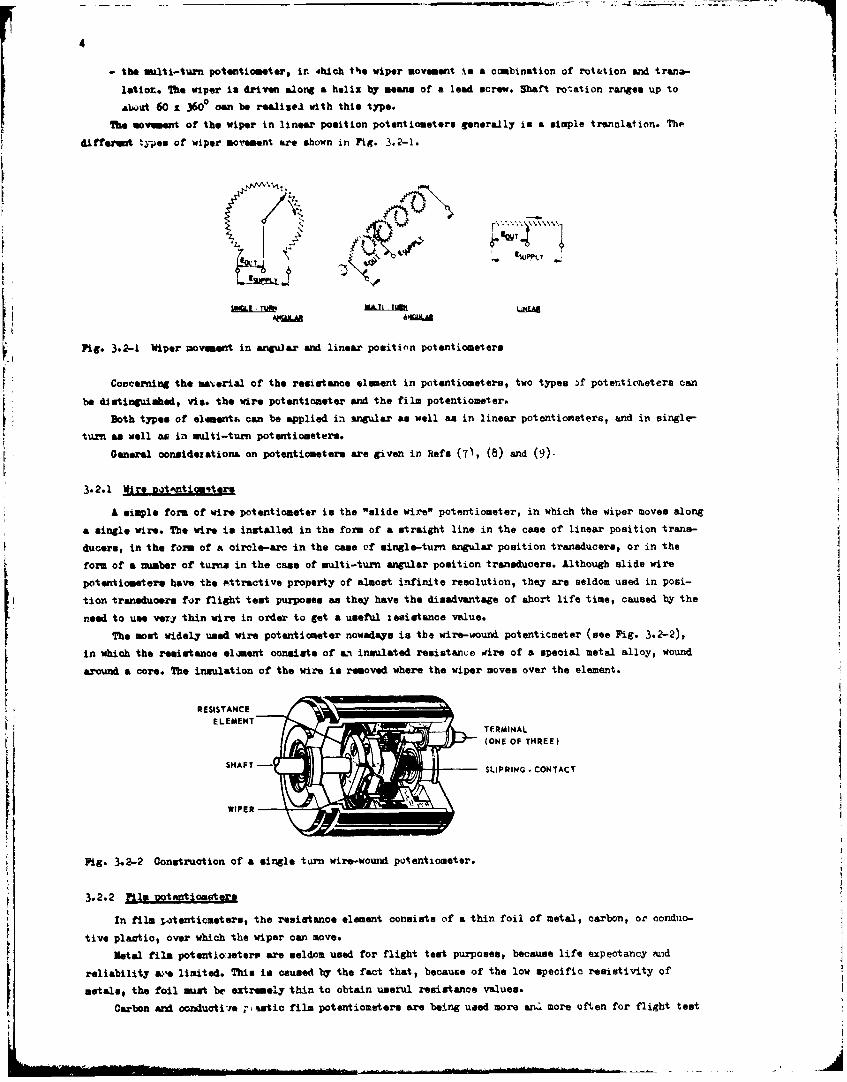
4
- the multi-turn potentiometer, I. 4hich the wiper movement is a combination of roittion and tranas-
letiot. The wiper is driven along a helix by means of a lead screw. Shaft rotation ranges up to
about 60 £ 3600 oem be realiseS with this type.
The movement of the wiper in linear position potentiometers generally is a simple trenolation. The
different types of wiper movement are shown in Pig. 3.2-1.
tI
Fig. 3.2-1 Wiper movmen in angu~ar and linear position potentiometers
Concerning the material of the resistance element in potentiometerst wo types 3f potentiometers can
be distinguished, viz. the wire potentiom=eter and the film potentiometer.
Both types of element|, can be applied in angu~lar as well an in linear potentiometers, and in single--
turn as. well as in nulti-ttum potentiometers.L Ge0neral oonaidexationL on potentiometers are given in Refs (7), (8) and (9)-
3.2.1 _Wire Dotmntiterst
A simple form of wire potentiometer is the "slide wire" potentiometer, in which the wiper moves along
a single wire. The wire in installed in the form of a straight line in the case of linear position trans-
ducersl, in the form of a circle-arc in the came of single-turn angular position transducers, or in the
form of a number of tu-a in the came of multi-turn angular position transducers. Although slide wire
potentioeetere hove the rkttrac'tive property, of almost infinite resolution, 'they are seldom used in posi-
tion transducers for flight test purposes an they have the disadvantage of short life time, caused by the
need to use very thin wire in order to got a useful ,esitance value.The mo-t widely used wire potentioaeter nowadays is tie wire-wound potenticmeter (see Fie. 3.2-2),
in which the res ea ri o the resistncs of e inulated retiwtano wire of a special fetet alloe, wound
a sounm a core. The insulation of the wire is removed whire the wiper moves over the element.
RESISTANCE
(ONE OF THREE)
SHAFTStLIPRING o CONTACT
WIPER -
ig. 3.2-2 Conwire. ction of h single turn wire-wormM pof entiometer.
3.2.2 Film iotenttoooers
d n film in tenfor metors, the resistante element consists of a nhln foil of metal, carbon, or conduo-
rive plofia , over which t the wiper can move.Mpotentioeter have ten e are seldom used for flight test purposes, becausrfese expectancy pead
reliaoilitr a %ue lirrligte Tes ip raused by the fact that, becauve of the low specific reaistivite of
metals, the foil tist be extremer thin o obtain useful resistanc e values.
Carbon tend ore duiti-e piantic film potentiometerd are being uwid more anf more oft en for flight test

purposes. Dues to the high resistivity, the resistance material of these potentiometers oem be much thickerthani in metal fila potentiometers, resulting in longer life ezp~ctancy and better reliability.
3.2.3 ~trsiso omintr
In prino~.pls, a potentiometer for position measurement ca be used as a vAriae resistor or as a~l (see Fig. 3.2-3). Applioation as a voltage divider must be preferred for the following
reasons&
0~~iA V/ OUTPUT IiJPPLT OUTPUTSUPPLY 0 -
Fig. 3.2-3 Potentiometer, used as a variable resistor (a) and ws a voltage divider (b).
- In mmzW' casm the viper--to-elament resist weec met be neglected with respect to the potentiometerrepiutance and wili, moreover, often very considerably. Neswuring the resistance between the viperand one of the end terminal@ will not provide a good measure for the shaft position, as the unknown
resistance affects the result. If the potentiometer in used as a voltage divider in properlydesigned (high impodance) measnuftog circuits, this generally uzknow resistance has a negligible
effect on the accuracy of the measurement. j
- In mmz' oases only very small currents can be drmn over the wiper, especially with film potentio-meters. This requireent can sore easily be met uwhen the poteatiometer is used an a voltage dividerinstead of a variable resistor.
- In non-linear film potentiometers the resitatene output curve can Jifrer seriously fromt the voltageoutput curve because of the 'two-dimensional oonf euration of the element (Bef. (8)). Manufacturers,
specifications always aseime application as voltage dividers in such cases.- The resistance of a potentiometer can 'vary seriously with v&Waryg tauperuture or humidity. When the
potentiometer is used as a variable resistor, this temerature vffeat will directly influence the
measurement. When the potentiometer is wsed aw a voltage &-vider, (with a sufficiently high loadresistance) the temperature effec, on the outp-,t -voliage will. be regligible.
P ou+ an with respect to potent ionmler trwanduoes c~ei be defined so *~he mmallest displacement of
the input ahaft that still produces a change in output.When the wiper of a wire-wound potentiometer is moved cortinun..sly, the resistance between the -Aper
and one of the eads of the potent icaster cbangw in steps (Pig. 3.2-4~ " - The voltage at the output of apo-ýentiometer will also abange in steps, which are, however, not completely equrll. Their exact shapedepends on the type of power source -ad on the geometry of the u~per. The resolution of such a potentio-
meter is, therefore, limited. It usn be shown that the resolution of an ideaZ pozentiometer in better than
that given b~ the following formulass
Resolution ('.n %) - 0.5 x voltage nor turn-%E = 100) % orsupply V011tage
Resoutin (n %)- 05 x100Resoutin (n 1)= 05 znumber of turna of wire
¶RESIS'YANCE
WIPERt . DSPLACEmENT
Fig. 3.2-4 Resistance as function of wiper displacement in hire-wound potentiometers

6
Due to irregularities in the windings and in the wipei'-to-wire contact, the accuracy of the masure-ment, with wire-wound potentiometer. will often be slightly worse than this resolution.
To obtain a high resolution in a given case size, very fine wire has to be chosen. The wire dianeteris, however, limited by a number of factors, so that in practice it is not possible to wind more thenabout 40 turns per -m without sacrificing reliability and life expectancy. Very high resolutions in wire-wound potentiometers can be obtained with large diameter oases and high element resistances. The maxnimiachievable resolution for wire-wound position transducers as a function of the case diameter is approxi-mately as follows:
resolution n 10o D degrees (D in sm).100 D
The maximum achievable resolution for wire-wound linear position transducers in about 0.02 m.Film potentiometers have an almost infinite resolution, depending only on the granularity of the
material used. A resolution of about 4 x 10⁻³ Rs of wiper displacement can be obtained with them devices.Linearity and oforoit-t are important factors in connection with the accursay of potenti moters.
Then: terms can be defined as follows:
Linearity is the maxiamInm deviation of a calibration curve from a specified straight line, generallyexpressed in percent of the full measuring rsage.Conformity is the maximum deviation of a calibration curve from a specified non-linear curve, generallyexpressed in percent of the full measuring range.
Several different types of linearity are used, especially for potentiometers. These will be discussedbelow. In an ideal potentiometer with perfect linearity, the curve of voltage output (or resistance out-put) plotted against shaft position would be a straight line, which, as is indicated in Fig. 3.2-5, passesthrough the points:
0 % voltage (or resistance) - 0 % position (A)
and 100 % voltage (or resistance) - 100 % position (B).The so defined straight line in called the "line of absolute linearity4. In ;ractice, however, perfectlinearity does not exist, and there will always be deviations from the ideal straight line. The maximrndeviation of voltage-output (or resistance output) from the absolute linearity line is the 'absolutelinearity", generally expressed in percent of the total applied voltage and sometimes in percent of thetotal resistance.
In a non-linear potentiometer, the curve of voltage output (or resistance output) plotted againstshaft position would be a curved line, ideally passing through the points:
0 % voltage (or resistance) - 0 % position (a)and 100 % voltage (or resistance) - 100 % position (B).
The so defined curve (me Fig-. 3.2-6) is called the 'line of absolute conformityO. In practice, perfectconformity doeo not exist, and there will always be deviations from the ideal curve. 7he maximum deviationof voltage output (or resistance output) from the absolute conformity line is the 'absolute conformity',generally expressed as percent of the applied total voltage and sometimes as percent of total resistance.
Nost potentiometers have sone 'end resistance', that is, resistance between the wiper and an end ter-minal or tap, when the wiper is positioned at the corresponding terminal or tap. This resistance is notonly caused by the cont.act resistance between wiper and element but also by the resistance between ter-
ainals and element. Especially for film potentio-5 moters,thia resistance can have an appreciable
value."TPIT - ACTUAL OUTPUT The "end resistance' in potentiometers in one
I -LINE OF ASSOLUTE of the reasons why the actual output line often
"IMAX. DEVIATION LINEARITY") does not pass through the points:
0%voltage (or resistance) - 0 % positionand 100 % voltage (or resistance) - 100 % position.
I POSITION
O% 100%
Fig. 3.2-5 Absolute linearity in a linearpotentiometer
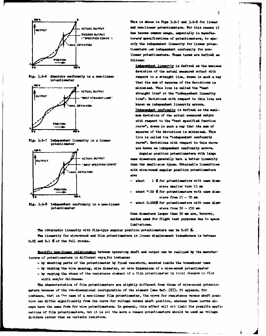
______________?Me to shg1 hown in Pigs 3.2-7 and 3.2-8 for linear
,OTPuT ACTUAL OUTPUT ald non-linear potentiometers. For this reamon it
S*PECIFIED CURVE-) turerdseiVosin of potentiometers, to upe-
tiometere .ud inioepadent cocfornity for non-* -PU linear potentiometers. Thean terms are derine& as
- POSITION follows:
A L id101%es liertoi definad as the maximum
deviation of the actual sommured o'atput with
Pig. 3.2-6 Absolute oonfoxuity in a non-linear respect to a straight line, dram in such a way
that thke via of squares of the deviations is
ACTUAL OUTPUT straight line' or the 'indeppeaimt linearity-f. "MST STRAIGHT LINE* line. Deviations with respect to ishia line are
jkCAJTUT - SEVIknown~ am independent linearity errors.
m~m deviat ion of the actual measured output04Idpnetcno.9 ndfnda h ai
P~emswith respect to the 'best specified funotion
A __________curve', drawn in sich a way that the am ofW SW' squares of the deviations is minimised. This
Pig.3.27 I idet ilearty ~ a i~rlire is called the 'indqepwdent oonformitypotentiometer curve'. Deviations with respect to this curve
are known as ineedn conformity error*..
Anzgular position potentiometers with lange
UPT-ACTUAL OUTPUT case diameter* generally havs- a better linearity
10 - -ST SPECIFIED CURVE*. than the amall-msie types. Obtainatle linearitiesK. DVIATONwit wire-wound angular position potentiometers
are$
-- -about 1 % for potentiometeirs with case dism-01 ~sters smaller then 15 a
S eters from 15 - 50 -m
Pig. 3.2-8 Indepenent conformityT in a non-linear - about 0.002% for potentiometer. with case diap-
potentiometer stars from 50 -250 nCase diameters larger than 50ma are, however,
seldom used for flight test purposes due to spacelimitations.
The obtainable linearity with film-type angular position potentiometer. can be 0.07 %.The linearity for wire-wound and film potentiometer. in linear displacement transducers is between
0.05 sand 0.1 % of the full stroke.
becficnonlinar elaionbinbetween operating shaft and output can be r~ealined by the manufac-
ture". of potentiometers in different wayn~, for instancet
- byr shnating parts of the potentiometer byr fixed resistor., mounted inside the transducer case
- by' varying the wire spacing, wire diamerter, or core dimensions of a wire-wound potentiometer
- by vezing the shape of the resistance element of a film potentiometer by local changes in film
width and/or thickness.
The characteristics of film potentiometersx are slightl~y different from those of wire-wound potentio-
meters because of the two-dimensionsl. configuration of the element (see Hef. (8)). It appears, forinstance, that. in t%". came of a non-linear film potentiometer, the curve for resistance versus shaft posi-
tion can differ significantly from the curve for voltage versus shaft position, whereas these curves al-
ways have the esie form for wire potentiometers. In general, this effect will net limit the possible appli-
cations of film potentiometers, but it is all the more a reason potentiometers should be used as voltage
dividers rather than an variable resistors.
ko-lizeer relatiosidpe between displacemet end transducer out.put cam almo be realised br operatinga llamas tzmesduoes via a zsam-limee linkage or ?V shwrting parts of the potentiomeater tv fixed resistorsoutside te Cme.
Nom-liness poteaticeetere awe seldcm used for the position measurment coansidered in this volume. Ina few cases, how~*ar the application or mno-linear potentiometers can be used as a smean -tecancel outno- linearities caussed btr mechanical linkages, eta.
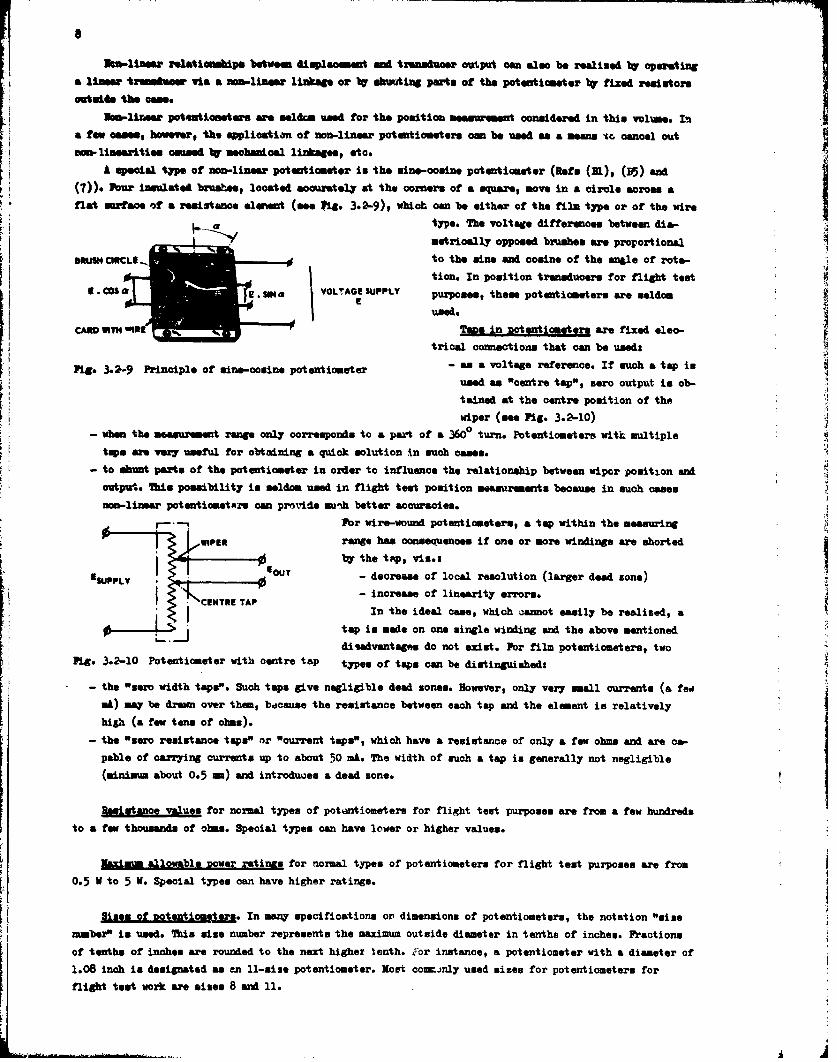
F ())A speciul type of nanp-linear potenticnater is the mine-acuine potentiometer (Refs (111), (B5) and
(M our insulated bruase", located aocuarately at the corners of a square, move in a circle across aIfiat susface of a resistance elment (see fig. 3.2-9), which can be either of the film type or of the wire
a. type. The voltage differences between dis-metrically opposed brushes are proportional
OWLISH CIECLI 7r to the mine and cosine of the angle of rota-tion. In position transducers for flight teat
VLAE SUPY purposes, the"e potentiometers are seldom
used.
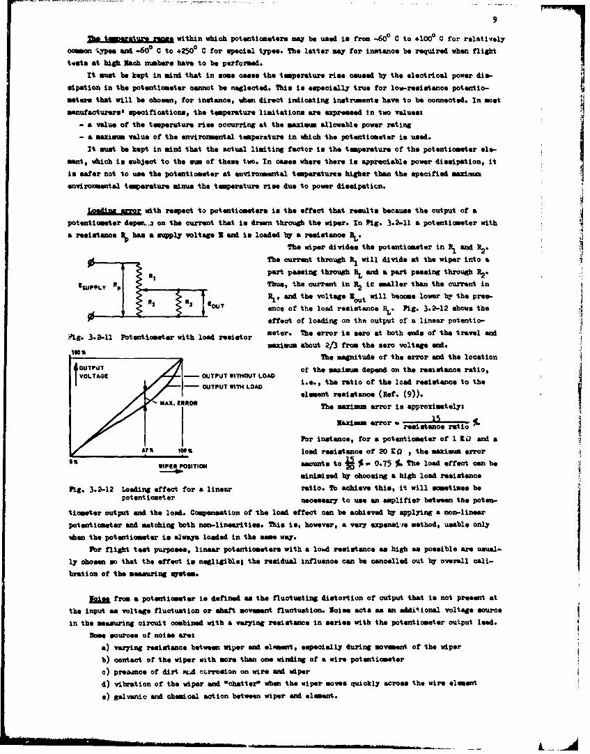
CARD WTHWOWTape in -potentiometers are fixed eleo-triosi connections that, can be usedt
Fig. 3.2-9 Principle of mine-cosine potentiometer -a otg eeec.I uhatpiused an "centre tap", zero output in ob-
H tained at the oentre position of the~wiper (see Fig. 3.2-10)
-when the meagurament range only corremponds to a part of a 3660 turn. Potentiometers with multipletape are very useful for obtaining a quick solution in such oases.
-to shun parts of the potentiometer in order to influence the relationship between wiper position sandoutput. This possibility in seldom, used in flight test position measurenenta because in such oases
non-linear potentiometarm can provile au-&h better accuracies.For wire-wound potentiometer., a tap within the measuring
WIPERrange has consequences if one or more windings are shortedA ythe tUp, viz.:
ESPL OUT - decrease of local resolution (larger deed zone)-,CETRE APý- increase of linearity errors.
In the ideal case, which ýamurot easily be realized, a
tap is mode on one single winding sand the above mentioneddisadvantagvo do not exist. Fbr film potentiometers, two
Pig. 3.2-10 Potentiomester with centre tap types of taps can be distinguished:
- the "sero width taps". Such taps give negligible dead zones. However, only very ismll currents (a fednA) may be drawmn over them, because the resistance between each tsp and the element is relativelyhig~h (a few tens of ohms).
- the "zero resistance taps" or "current taps", which have a resistance of only a few ohms and are ca-pable of carrying currents up to about 50 mi. The width of such a tap is generally not negligible(minimu, about 0.5 M) sand introduces a dead zone.
Resistance values for normal types of potiartiometers for flight test purposes are from a few hundreds
to a few thousands of obos. Special types can have lower or higher values.
Ulximui allowable Dower retinas for normal types of potentiometers for flight teat purposes are from
0.5 V to 5 V. Special types can have higher ratings..
Sizes ML_ of_&etom~g. In many specifioations or' dimensions of potentiometers, the notation "sizenumber" Is used. This size number represents the maximum outside diameter irn tenths of inches. Fractions
of tenths of inches are rounded to the next higher tenth. icor instance, a potentiometer with a diameter of1.08 inch is designated as en 11-size potentiometer. Most comminly used sizes for potentiometers for
flight -test work are mimes 8 and 11.
The tinerature rant. within which potentiometer. mW be used in from -60° C to +1000 C for relatively
cmo typospe and -60° C to +250P C for special typeo. The latter may for instance be required when flight
tests at high Mach mnbers have to be performed.
It must be kept in mind that in @om* cuses the temperature rise caused by the electrical power dio-
uipation in the potentiometer oannot be neglected. This in especially true for low-remistanoe potentio-
meters that will be ohomen, for inetanoe, when direct indicating instriments have to be connected. In most
manufsaturer.' specifications, the temperature limitations are expressed in two values$
- a value of the temperature rime occurring at the maximin allowable power rating
- a maxima value of the environmental temperature in which the potentiometer is used.
It must be kept in mind that the actual limiting factor is the temperature of the potentiometer ele-
ment, which is subject to the smn of these two. In oases where there is appreciable power dissipation, it
is safer not to use the potentiometer at environmental temperatures higher than the specified meximun
environmental temperature ainun the temperature rise due to power dissipation.
ZiMgu.%= with respect to potentiometers in the effect that results because the output of a
potentiometer depe&.3 on the current that is drawn through the wiper. In Pig. 3.-2-11 a potentiometer with
a resistance has a s•pply voltage Z sad is loaded by a resistance RL.
The wiper divides the potentiometer in R, and R2.
A • The current through R1 will divide at the wiper into a
pert pasaing through HL and a part passing through B2*eSUPPLy R Thu., the current in B2 ic maller than the current in
R , and the voltage out will become lower bv the pres-*2 IOUT once of the load resistance RL. Pig. 3.2-12 shows the
effect of loading on the output of a linear potentio-
ig. 3.2-11 Potentiometer with load resistor meter. The error is sero at both ends of the travel and
maimaum about 2/3 from the sero voltage end.
The magnitude of the error and the locationOUTPUT of the maximum depend on the resistance ratio,VOLTAGE - OUTPUT WITHOUT LOAD
-OUTPUT WITH LOAD ice, the ratio of the load reoietance to theelament resistence (Ref. (9)).
MAX. ERROC The maximuim error is approximatelys
Ea~XI. error - reietance ratio
Por instance, for a potentiometer of 1 It and a
675 1,00% load resistance of 20 Ka , the maximia error
WIPER POSITION amounts to % - 0.75 1. The load effect can be
minimised by choosing a high load resistance
Pig. 3.2-12 Loading effect for a linear ratio. To achieve this, it will sometimes bepotentiometer necessary to use an amplifier between the poten-
tiometer output and the load. Compensation of the load effect can be achieved bC applying a non-linear
potentiometer and matching both non-linearities. This is, however, a very expenai.e method, usable only
when the potentiometer is a nways loaded in the some way.
For flight test purposes, linear potentiometers with a lomd resistance an high as possible are usual-
ly chooen so that the effect in negligible; the residual influence can be cancelled out by overall cali-
bration of the measuring qatem.
&Jo• from a potentiometer is defined a. the fluctuating distortion of output that is not present at
the input am voltage fluctuation or shaft movement fluctuation. loie acts as an additional voltage source
in the measuring circuit combined with a vazring resistamne in series with the potentiometer output lead. 4
Some sources of noise ares
a) varing resistance between wiper and eloeent, especially during movement of the wiper
b) contact of the wiper with more than one winding of a wire potentiameter
c) preaoe of dirt ftA corrosion on wire and wiper
d) vibration of the wiper end "chatter* when the wiper moves quickly across the wire element
e) galvanic and chemical action between wiper and element.
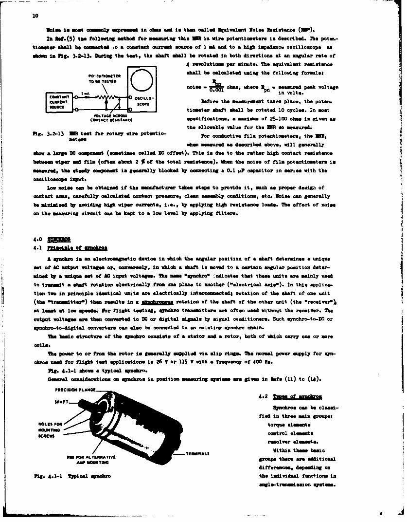
liontarshol b coneced o acontantcurentsouce f 1mA nd o &high impodanow oscilloscopepoam.
abdm i Fi. 32-1. Drin th tetthe shaft Whall be rotated In both directions at an angular rate of
4 revolutions per minute. The equivalent resistanoe
~ uhall be calculated using the following formulas
niea-- ohms, where - measured peak voltage
COMYNI S~gLO-Before the measurement takes place, the poten-.
E f t , 1"'Notiometer shaft ohall be rotated 10 cycles. In moatCONTACT .IMsAsmCE specifications, a mazimim of 25-100 ohma is given as
the allowable value for the MRI so meeasured.Fi.3.2-13 MR teat for rotary wire potentlo- Plrcnutv impotentiometera, th M,
when measured &a deacribed above, will generally
show a large M0 component (asometimee called D0 offeet). This in due to the rather high oontact reaiatanco
between wiper? am film (often about 2 % of the total resistance). When the noise of film potentiometers is
measured, the steely component is generally blooked by connecting a 0.1 $aP capacitor in aeriea with the
oscilloscope iznpu.
Low noise can be obtained if the manufacturer takes steps to provide it, much as proper desiffa of
contact arms, carefully calculated contact pressure, clean assembly ooaditiona, etc. Noise can generally
be minimised by avoiding high wiper currento, i.e., by applying high resistance load@. The effect of noise
on the measuring circuit can be kept to a low level by appiying filters..
4.1 Prnd al of inho
A anachro in an electromagnetic device in which the angular position of a ahaft detemuinea a unique
mat of AG output voltagee or, conversely, in which a ahaft in moved to~ a certain an~gular position doter-Imined 1W a unique eat of AC input voltageem. The nome mmynchro* ý*Mioate that theme units are mainly usedto treammit a shaft rotation electrically fro one place to another ("electrical azia"). In this applica-
tion two in principle identical units are electrically intercoumeated; rotation of the ahaft of one unit
(the Otranenitterw) the results in a gggZ rotation of the shaft of the other unit (the "receiver"I
at leant at low speeds. ]lbr flight tenting, mquobro transmittera are often used without the receiver. The
output voltages are then converted to 30 or digital signals by signal conditionera. Such synchro-to-30 or4
synobro-to-digital oonvertes" can also be connected to an exiating aynchro chain.
Mwe basic structure of the synobro consists of a stator and a rotor, both of which carry one or more
calls.the power to or free the rotor In generally mpplied via slip rings. the normal power supply for syn-
ohmos used for flight tent applications In 26 T or 115 T with a frequency of 400 No-
Mig. 4.1-1 above a typical synabro.
General oneidderations on synchrue in position measuring systems are given in 3sf.i (11) to (14).
PRECISION FLANGE
4.2 Xines ofinnabro
ftnahroo can be clasei-
fied in three main groups#HOLE FORtorque elements
OUMNGSS control elementsSCREWS
resolver 0lemInt.Within theme basic
Tort group. there are aditional
differences, depending on
Pi.4.1-1 Typica Much"r the individual functilone in
amgloetmnni salon syoess.
Ultments in the above mentioned groams aret
transmitters
gives definition.; of the ms motn lmns hr r pca ye n om fenho lmnstmeet particular requirements. These will be treated in Section 4.2.5. In Section 4.2.6 sme attention isgiven to a mother of special synchronous remote indicating systems. These systems are, however, bae*" onprinciples differing somewhat from the normal aynobro prinoiple. In Section 4.2.7 a short description isgiven of a special DO mynchironous system that wasn originally developed for direot-indioating purposes Man
in still occasionally us"e for flight te~at purposes..
4.2.1 Definition. of synchoh elements
A torgue treynmitter is a synohro which transmits electrical information corresponding to the pooi-tion of the rotor relative to the stator. This synohro in designed primarily for operation with receivers
and torque differential trousmitters. The unit can also~ be usned with signal-conditioning circuits withrelatively low input impedance. '
A in a mynobro which con~verts the electrical information received from a torque trans-
sitter into a torque applied to the rotor, thereby turning the rotor to a r~osition relative to the stator
corresponding to that of the torque transmitter rotor. This synchro in designed primarily for operation
with torque transmitters and torque differential transmittere.
A trmdifrtial transmitter is a synchro which when oonn%..ctoa to an energized torque transmit-
ter, transmits electrical information corresponding to the -ti or difference (depending on the interoon-
necting wiring system) of the angular position. of the rotors of these two units relative to their respect-
ive stators. This aynobro is designed primarily for operation. between a torque transmitter and a torque
A trudifenalreceiver is a synobro in which the rotor is forced to astmme a position with
respect to the stator equal to the ma or difference (depending on the intercooiecting wiring system) ofthe electrical angular information received ib7 its stator from one transmitter and bW its rotor from asecond trenemitter. This gynabro in primarily designed for operation with two synchro torque, tronemittere.
A sconrol. tranwitte is a synobro which transmits electrical information corresponding to the posi-
tion of the rotor relative to the stator. This synobro is designed primarily for operation with control
transformaer and high input impedance signal-conditioning circuits.
A otrltnfomris a syncbro whiah, when connected to an energised control transmitter, elves
an output signal proportional to the sine of the difference of the angular positions of the rotors of theoonnected units relative to their respective stators (error voltag). This synoro is designed primarily
for operation with control trenmaitters and control differential transmitters. The rotor output in general-
ly coneceted to a servo system which turns the rotor until the rotor output ios ero.
A qgto ifrailte~tris a synobro which, when connected to an energised control trans.-
mitter, transmits electrical information corresponding to the sta or difference (depending on the inter-
connecting wiring system) of the angular positions of the rotors of theme two units relative to their re-
ipective ststors. This oynobro is designed primarily for operation between a control transmitter end acontrol transformer.
A r~le rn itris a synobro which has two perpendicular windings on the stator and generally
two winidings on the rotor. The resolver ha. its rotor mechanically positioned for transmitting electrical
information, corresponding to the angular position of the rotor with respect to the stator. This synobrois designed primarily for use with rseslver c-)ntrol tranaformiers and resolver differential transmitters.
12
A ra i nrlto urIs a syncbro, which b"r two perpedicular winding. an the stator and
genereally two windings on the rotor. ftis resolver trensform. electrical angular Innformation from the ste.-
cUr to a voltage proportional 'to the ains of the difference between the electrical input angle and the ren-
solver control rotor Singl. M~e sacharo is designed primarily for use with resolver ttammitters and re.-solver differential transformesr.
A resolver jd~ difrnilo a syrnchro which has two perpendicular winding. an both the rotor and the
stator. Thide xesolr baa its rotor mechanioaflly positioned for modifying electrical Singular Information
received from a transmtter and re-trensmitting the electrical information, oorrespcnding to the NO or
difference (depending on the Interconnecting wiring system) of the electrical input angle and its rotor
position aftle. This Gynchro is designsA primarily for use with resolver transmitters and resolver control
transformers.
A I1LuaL is a oqnchro wich has a three-phase winding and two single-phase windings, either ofUkiah may be the rotor oir the stator. It oam be regarded as a combination of a synohro cootrol transformer
ad a resolver. the unilt cm be used for a. wide variety of spplioation.. Trsmmolvers form the bridge be-
tween the three-phase devices on oae aide and tbe resolvere on the other side.
More definitions on gynchrom aregieinf.(1)
K ~~4.2.2 in.Torque .3nchron are used for the transmission of angular position information and for the reproduo-
tioti of this information by the position or the ahaft of the receiver, Ukich oam, for instance, drive apointer or a set of pointers in a direct-indicatiag instrument. Misalignment between the shafts of the
tranemitter and receiver aynabros increases with the mechanical land on the receiver shaft, and for thide
reason these synobros give the highest accuracy when the receiver systems have Small inertia and are well
balanced. The system is not powsr'-amlifying, and hence any mechanical load acting upon the receiver is
fed bah as a load for the transmitter. b1th the transmitter and thle receiver have a three-phase statorand a single-phase rotor winding.
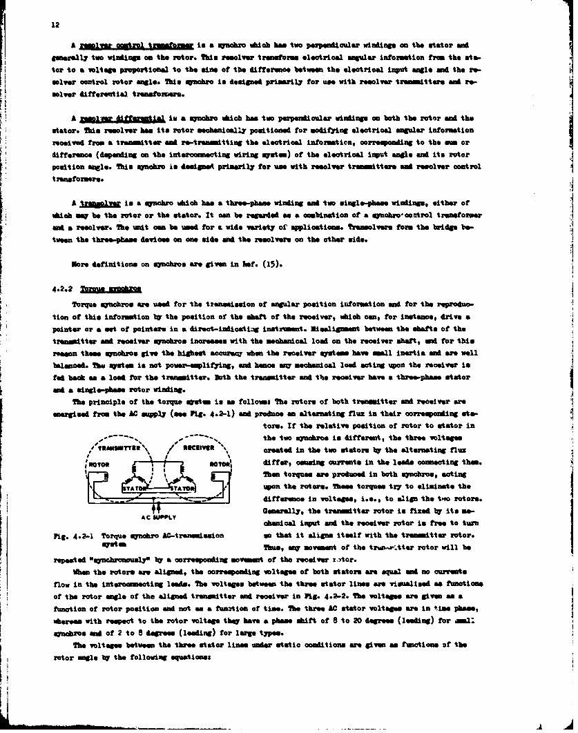
The principle of the torque system is ase followss The rotors of both transmitter and receiver are
energised from the AC supply7 (see Fig. 4.2-1) and produce an alternating flux in their corresponding step-tore. If the relative position of rotor to stator in
- the two synabxos in different, the three voltages_ _ _ _ __T~a 2nth .ThIrq est toeiiat\h
%created in the two stators by 'the alternating fluxj RTORdifercauingcurent in+A*lead@sonetn them.
Then torques are produced in both synchros, acting
difrnei olaegKe9t align tenorotors.
A C SUPPLY
abaica inut nd he eceverrotorisfetourFig. 4.2-1 Torque synchr AC-tranamisaion so that it aligns Itself with the transmitter rotor.
qstenThus, sny movement of the tran.r-.A~ter rotor will be
of the rotor angle of the aligned transmitter and receiver in Fig- 4.2-2. The voltages are given as afunction of rotor position and not as a function of times. The three he staor voltages are in time phase,
whereas with respect to the rotor voltage they have a phase shift of 8 to 20 degrees (leading) for amal:
apachis man of 2 to 8 degrees (leading) for large types.
The voltages between the three stator lines under static conditions are given as functions of the
rotor anle the following equations
13
u win ae-la'
23 a3 min (ae- 24?*)
Usm a om. irkaoed r~als. lime voltage
No 2 amo 33 a ra.m*. oltages between the three stator limesa rotor poseition in dogeeg.
Reg. 4.2-2 and the above
STATO16 tgive famalas also bold foraVOTA"OS minle rMynhr trmwmiltterý mot
Pro, the above equations
--- the following relations owi be
so6POTO deriveds
.4 13A
PLC. 4.2-2 Stator valtagme an a fmantic. ofr rotor position vr3 \ l
Theme @how that+ the angle a isindependent of Ithe wooly voltage 16and io fully defined (within ± 360 degrees) by the ratios between the
Gtator voltages. CIObanging teaOita~tion voltage will influence the Picture in Fig. 4.2-2 only with re-spect to the voltage amIi'tum. and met with respect to the ratio of the three voltages to each Lther.
lrar flgh test purposees it in possible to connect two (or mere) receivers In parallel to one transo..nitter but, in genernl, stob edlitiomal receivers awe liable to impair the accureaq of the eyoten if aosecial precautions awe token. Nimalignmeat due to excessive mechanical load on one receiver shaft is rim-
flected beak into tba qwtn and affects tbe &ownmM of all other receivers. This mutua interference canbe reduced %W using receiverm with higher stater ieiadmoos. The member of receivers that cam be operated
depends on the power rating of the troanmi~teto.4
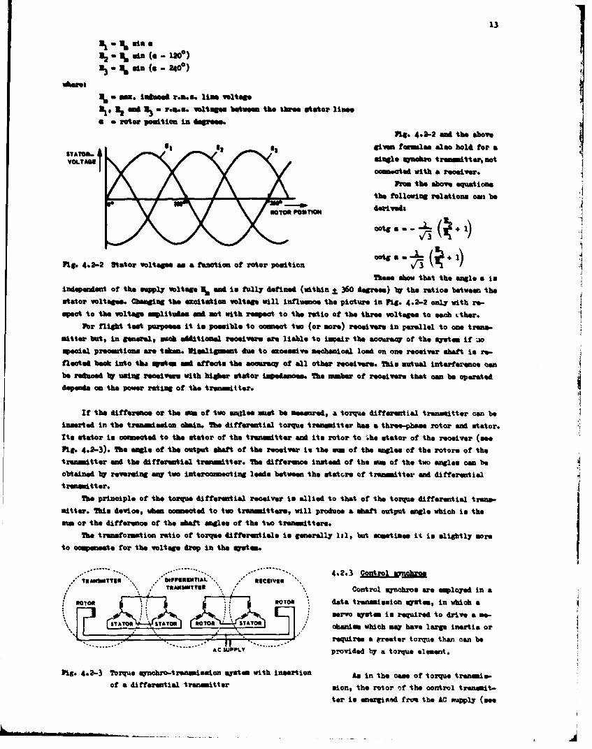
If the difference or the am of two ang~les most be eassoured, a torque differential transmitter can beinsarted in the trommaaion chain. The differential torque transmitter has a three-phase rotor and skateor.Its stator is cooessoted to the stator of the transmitter and its rotor to Ane stator of the receiver (seeFig. 4.2-3). The angle of the output ahaft of the receiver in the mm of the angles of the rotors of the'tranomitter and the diffsrential transmitter. The difference instead of the am of the two angles can beobtained I reversing mW two interonnecting lead@ between the statcre of trommitter mad differentialtransmitter.
The principle of the torque differential receiver is allied to that of the torque differential trans.-sitter. This device, when ca-mkotd to two trammmittrat will produce &oan safoutput manle which is theam or the difference of the abaft mogles of the tue tronmittera.
The transformation ratio of torque differentials is generally 1:1, but smontinse it ins.lightly moreto camennatt for the voltage drop in the mstest.
*TRANeSINTT**I MFPG ME" . AL \ asv.4.2.3 Coto U* R MaSMITTNu Control synchrom are employed in a
ROORRTOR data transmission gyaten, in which a
IT]servo system is required to drive a me-
% ~ l Tor T IIf hc a hv ag nAeoS-. * -. requires a rrester torque than can be
----- -- ..... .... ffA C SUPPLY provided b7 a torque element.
Pig. 4.2-3 Torque mynchro-tromsmisuion system with insertion An in the cawe of torque tranamis-of a differential transmitter sion, the rotor oif the control transmit-
tor is energive~d from the AC muply (ms
14
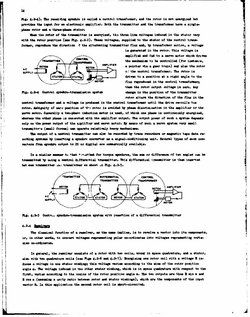
Pigs 4.2.4). ¶'he receiving synobro, is called a control transformer, and the rotor is not energised but
provides the input for an electronic amlifiers Doth the transmitter sad the transformer have a single-
phase rotor and a three-phase Utstaor.
When the rotor of the transmitter is enereivedg th3 three line voltages Induced in the stator vary
with the rotor position (eee Pigs 4.2-2). Theme voltages, supplied to the stator of the control trens-
former, reproduce the direction f the alternating transmitter flux and, by transeformer action, a voltage
is generated In the rotor. This voltage is
Samplilfied and red to a servo motor which drives/?UAWneYI \ RMPW the mechanism to be controlled (for inatanoo,
ACT ROTR APLIIE a pointer via a gear train) and also the rotorSUPPLYo,~the control transformers The rotor is
STATOR STAY% driven to a position at. a right anal* to the
~~ then the rotc?, output roltWg in seon. ArW
F1- -24 otrl rmo-trenmsicn Metein change in the position of the transmmitterPig 2-~rotor alters the direction of the flux in theI
control transformer and a voltage is produced in the control transformer until the drive rin-nu1l's tue
rotor. Ambiguit.y of sera3 position of 0o~ rotor is avoided by phase discrimCination in the amplifier or the
servo motor. Generally a two-pba".i induction motor in used, of which one phase is continuously energised,mhereas the other phase in cowapated with the amplifier output. The oftput power of such ot syatom depends
troanmitte-a (small forces) cen operate relatively heavy Mechanisms.The output of a control treanmitter can alse be recrded 1W' trace recorders or magnetic top* data& re-I
cording systems bly Inserting a mynohro converter as a signal-condiltioning unit. Several types of ouch oca.-
verters from synabro output to LC or digital are ocin~erially available.4
In a simdlar manner, tha*t b- -xr~4 bsd for torque synobros, the -m or difference of two angles tum be
tranmitted IV uwing a control differential transmitter. This differential treanmitter Is then inue~rted
btnntranowtter au trnsomr so sho Ln Pis-
VRAPSWIT'I CONTROL
*,.-' ~Uw~sam"\\, **/ TsAMSPONMEN' \1APUFl
ROCO STATORSUPPLY'
FIg. 4.2-5 Oontyi.., synchro-treanmission systom with insertion of a differential transmitter
4.2.4 Relyr
The classical function of a resolver, as the eam isplise, is to reviolve a vector into its components,
or, in other words, to oonvert voltagee representing polar co-ordinate, into voltages representing orite-:: mdiat cis(a is42- M427.briin n oo olwihavlaeUi.
In gor~erel, the resolver consists of a rotor with two coil., wound in space quadrature, and a stator,
duos. a voltage in ons stator winding; this voltage varies according to the sine of the rotor position
angle a. Mbs voltage induced in tho other stator winding, which in in space quadrature with respect to the
first, varies according to the cosine of the rotor position angle a. The two outputs are thus I sin a and
2 coo a (assiming a unity ratio between rotor and stator windings), which are the components of the inputy vector It In this application the second rotor coil is short-circuited.
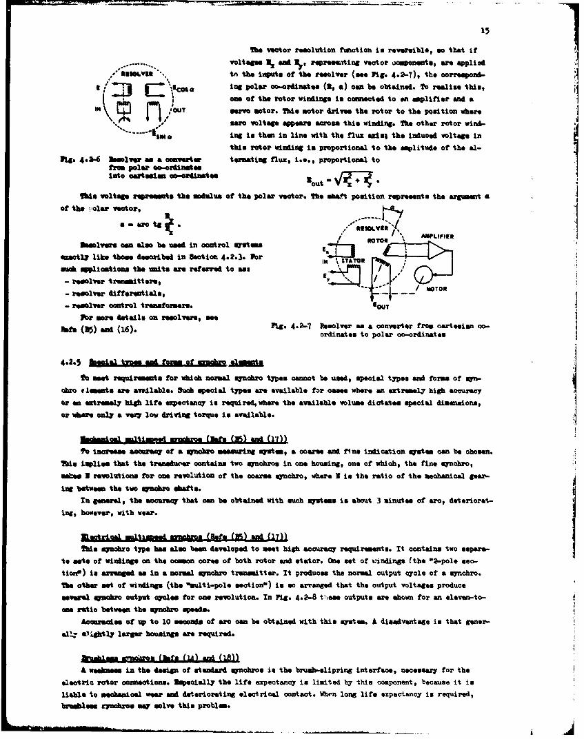
The vector resolution function is reversible, so that if
voltages NX and Us,, repressmiing vect or ocuponents, ane applied
ttn the inutS Of the reeolve? (see Pig- 4.2-7), the correspond-
s g/O In ~ 'lg polar co-ordinates (2, a) amn be obtained. To realize this,-m of the rotor windinga s Inoaimected to on aplifier rand a
"OUTsero motor. Mhi motor drives the rotor to the position where
sero voltage appears across this winding. The other rotor wind-
ISM aIng to then in line with the fluz wasia the induced voltage inthis rotor winding in proportional to the amplitude of the &I-
Fig. 4.5- Mosslver se a oenverter ternating flux, i.e., proportional tofrom polar so-ordinatesInto cafrtesian oao-ordiumtes
"outtise voltage represents the modulus of the polar vector. The .hatt position represent@ the argimnut a
of the polor veotor
am an tg .IS AMLIFIER
Sasolvers can also be used in control mystes/exactly like thoem described In Section 4.2.STATORsuch aplioatiomm the units are referred to ans s
- resolver transmitters, ± T- resolver differsatiala, ___ morom
- resolver control transformers. IOUTFor more details on resolvers, see
Pats (315) and (16). Fig. 4.2-7 Resolver as a converter from cartemian co-ordinate, to polar co-ordinates
4.2.5 baa ie n om fwcr
TO meet requiraments for which normal synchro types. cannot be need, special types. and forms of myn-d
Ohre closents wre avvilable. Such special types are available for oases where an eztremel7 high accuracy
or an extremely high life ~ecptenoy is requiredwhere the available volume dictates special dimensions,
or wherve only a vmsy low driving torque in available.
Nachnica instim~d inchr a (fa (in) and (17))
Toe incesase aooursq of a synchro measuring system, a coarse and fine indication system can be chosen.
This Implies that the traneduxer contains two mynchros in one housing, one of which, the fine qynobro,
inchesp I revolutions for one revolution of the comars synchro, where N in the ratio of the mechanical gear-
Ing between the two qucbro dufts.
In general, the accar'aq that cam be obtained with such qsrtm is about 3 minutes of arc, deteriorat-
in g , h o w e v e r , w it h w e a r . ( l e ( 5 A 1 1
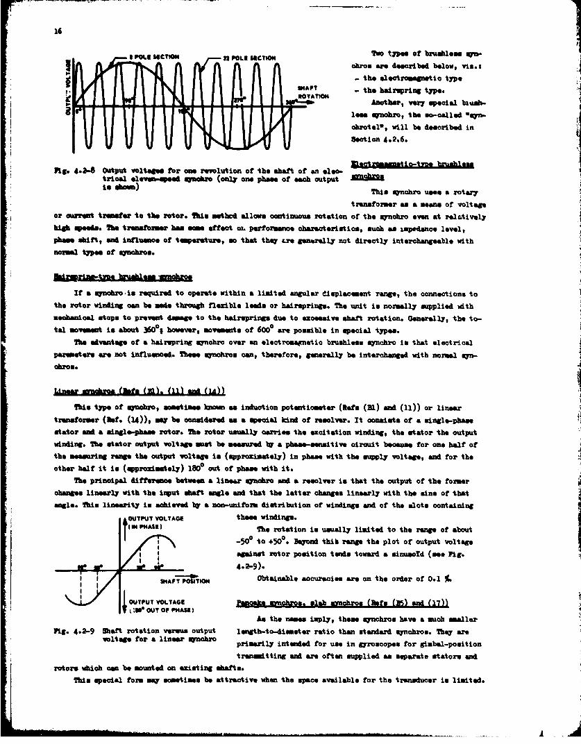
This syfchro type has also been developed to meet high accuracy requirements. It contains two setparv-
tion') is arrmngad, as In a normal mynohr trenmitter. It produces the normal output cycle of a synchro.
The other set of windings (the "multi-pole section") is so arranged that the output voltages produce
everal symchro output cycoles for one revolution. In Fig- 4.2-8 Viaee outputs are shown for an eleven-to-
oae ratio between the syncbrospe.
Aeosalroes of up to 10 seconds of arc can be obtained with this system. A disadvantage is that goner-
all.;' A32gh3 larger housings we required.
hushM a02iro (Ber. (M) and (18))
A we~akes in the design of standard synchrom is the bruah-slipring interface, necessary for the
electric rotor connections. Upecially the life expectanicy is limited by this component, because it is
liable to mecabnical vee and deteriorating electrical contact. When long life expectancy is required,bramblees cynoros may solve this problem.
TWO type. of brumbless a~
ohms. are described below, via.:
- the electromagnetic typeSHAFT- the hairuprIng type.
a.nothebr, "er special i-
less synohic, the so-called Osqn-
ohrotelt will be described in
Section 4.2.6.
Mg- 4.-" Output voltages for cae revolution of the shaft of an eleo-trical eleymb-speed qanchic (only one pha&e of each output 0ho
is ~m)This iunohro uses a rotary
transformer as a means of voltage*or iarreat tramfer to the rotor. ?Mes msthe allows continuous rotation of the synohro evan at relatively
high apees". The transformer has soeeffect or. performance characteristics, such am impedance level,phase shift, sand influence of temperature, so that they Lre generally not directly interchangeable with
* normal types of synohros.
* M mCWmj@If a synchzo is required to operate within a limited angular displacement range, the connections to
the rotor winding can be made through flexible leads or hairsprings. The unit is normally supplied withmechanical stop@ to preveift damage to the haireprings due to excessive shaft rotation. Generally, the to-tal Movemnut is shout 3601s however, movemeuats of 6000 are possible in special types.
The advantage of a hairspring synobro over en electromagnetic bruahless synchro is that electrical* par~mesterg are not Influenced. Theae awnobros can, thereforea, generally be interchanged with normal syn-
Liner nszoa Usf (M). (11) sand (IA))
Thi type of syuobro, sometimes kenow as induction potentiometer (Refs (33l) sand (11)) or linear
transformer (Hof. (14)), say be considered as a special kind of resolver. It consists of a single-phasestator sand a aingle-phass rotor. The rotor usually carries the excitation winding, the stator the outputwinding. The stator output voltage muet be measured by a phasee-esositive oircuit because for one half ofthe measuring range the output voltage is (approximately) in phase with the supply voltage, and for theother half it is (approximately) 1800 out of phase with it.
The principal difference between a linear aynobro and a resolver is that the output of the formerchanges linearly with the input shaft angle and that the latter changes linearly with the sine of thatangle. This linearity is achieved by a non-uniform distribution of windings sand of the slots containing
OUTPT VOTAGEthese windings.I IN HASE)The rotation is usually limited to the range of about
-50c to +5e. BeUyond thib range the plot of output voltage
against rotor position tends toward a sinusold (see Fig.
4.2-,).
SHAT PSITONObtainable accuracies are on the order of 0.1 %
OUTPUT VOLTAGE an akeEnchros. slab mmobros (sfsr (25) and (17))
An the names imply, themse ynchron have a much smaller
Fig- 4.2-9 Shaft rotation vesusw Output lwngtb-to-dismeter ratio than standard synobrs. They arevoltge fr aliner ~nhro primarily intended for use in Myroacopes for gimbal-position
transmtting and a"e often supplied an separate stators and
rotorst which can be mounted on existing shafts.This special form may sometimes be attractive when the space available for the trensducer is limited.
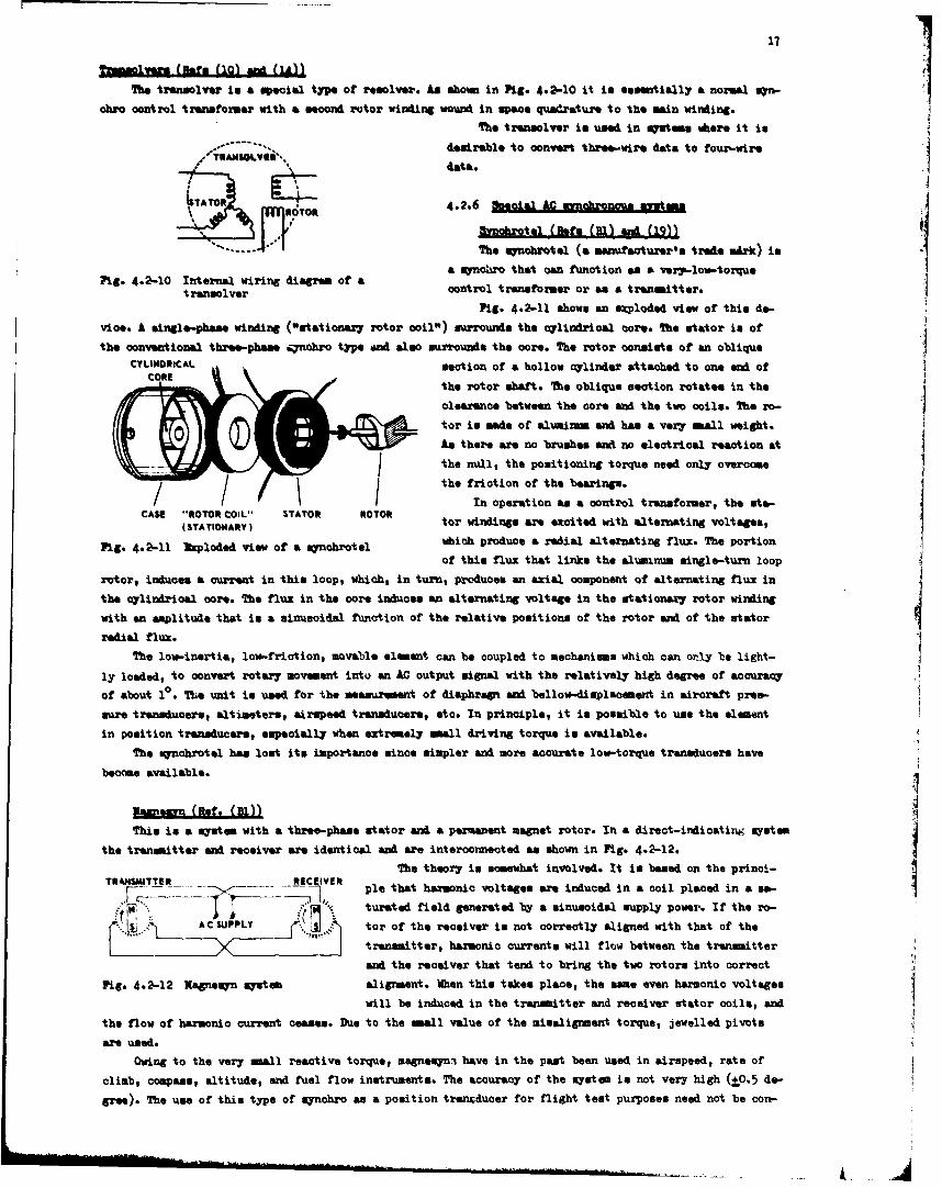
171Yzmaawms flt.(101 aM(IAfl
The translVer iu & SPecial type Of resolver. As shown in Fig- 4.2-10 it is essentially a normal sym-
okra control transformer with a second rutor wind~ing wound in *pWe quadrature to the main winking.The trunsolver in used in systems where it is
...... *.,desirable to convert three-wire data to four-.wireTRNS/ data.
ism ROTOR 4.2.6 eilA ubouartm
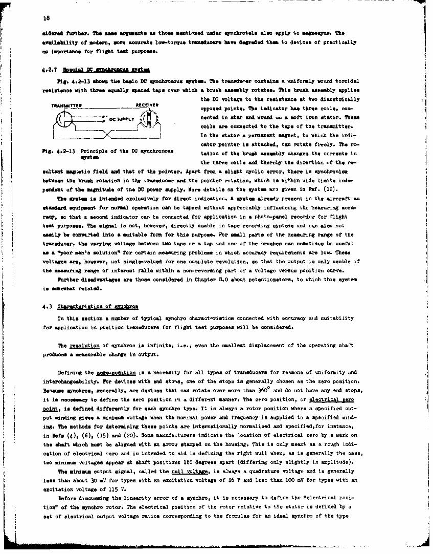
Mbaobrotl (taes (Rib ad tl9g))The synabrotel. (a mamiftaturer'm trade mirkc) is
Fig. 4.2-10 Internal wiring diagram of aa orthtcnfcinasav3-l-oqutrarisolver control transformer or as a transmitter.
Fig- 4.2-11 shows an exploded view of this do-
vice. A single-phase winding ("sntationary rotor coil") surrounds the cylindrical core. The stator in of
the convent ional three-phase 6ynohro type awl also surwoundis the core. The rotor consists of an obliqueCYLINRICALsection of a hollow cylinder attached to one end of
the rotor shaft. The oblique section rotates in the
clearance between the core and the two coils. The ro-
tar is *Ade of aluminum and has a very small weight.
An there are no brushes a&M no electrical reaction At
the null, the positioning torque need only overcomethe friction of the bearings.
ROTO COI STAOR /In operation as a control transformer, the ata-
(ASTATIONARY tor windings are excited with alternating voltages,
Pig. .2-1 kplded iew f a ynohotwhiciih produce a radia~l alternating flux. The portion
of this flux that links the alimmnm single-turn loop
rotor, induces a current in this loop, which, in turn, produces an axial component of alternating flux in
the cylindrical core. The flux in the core induces en alternating voltage in the stationax7 rotor winding
with an amplitude that is a sinusoidal function of the relative positions of the rotor andi of the stator
radial flux.
The low-inertia, low-friction, movable element can be coupled to mechanisms which can oraly be light-
ly loaded, to oonvert rotary movement into an AC output signal with the relatively high degree of accuracy
of about 10 * The unit is used for the measurement of diaphraw and bellow-displacement in aircraft pro&-
sure transducers, altimeters, airspeed transducers, etc. In principle, it in possible to use the element
in position transducers, especially when extremely mall driving torque in available.
The qynchrotel has lost its importanc, mince simpler and more accurate low-torque transducers have
become available.
iam'eexn (Ref. (111))This is a system with a three-phase stator and a permanent magnet rotor. In a direct-irdicating system
the transmitter and receiver afe identical and are interconnected as shown in Fig. 4.2-12.
The theory is somewhat involved. It is based on the princi-TRAIMITURREC-,E ple that harmonic voltages are induced in a coil placed in a se-
K- t&2rsted field generated by a sinusoidal supply power. If the ro-
A C SUPPLY tar of the receiver is not correctly aligned with that of the
________transmitter, harmonic currents will flow between the transmitterand the receiver that tend to bring the two rotors into correct
Fig. 4.2-12 Kagnesyn system alignment. When this takes place, the wsam even harmonic voltages
will be induced in the transmitter and receiver stator coils, andthe flow of harmonic current ceases. Due to the small value of the misalignment torque, jewelled pivots
are used.
Owing to the very small reactive torque, magnosyn~i have in the past been used in airspeed, rate of
climb, compass, altitude, wAd fuel flow instruments. The accuracy of the system is not very high (±0.-5 de-
gree). The use of this type of uynchro as a position txancducer for flight test purposes need not be con-
18F .idered further. The saea arcuments as thorse mentio'ned undler synobrotele also apply to megnemyne. Theavailability of modem, more accurate low-torque transducers have degraded them. to devices of practically
no importance for flight test purposes..
Fig- 4.2-13 shows thie basic DC synchronous, system. The trsnAdueer contains a uniformly wound toroidalresistance with three equally spaced tops over which a brusth asamebl~y rotate.. This brush assembly appliesn
the DO voltae -to the resistance at two dieaetvio&.llyTRANMITR - ECE.Vopposed points. The indicator has three coils, con-
DC SUPPLY noted in star and wound u., a soft iron stator. These
coils are connected to the taps of the transmitter.________ -In the stator a permanent magnet, to which the indi-
Fig-4.213 Pincple f te DCsynhronusoater pointer im attached, can rotate freely. The ro-
Pig 42-3sPisipem o h Csycrnu tation of the brush assembly obangea the ovrrentm in
the three ooils and thereby the direr~tion of the re-sultaut .sgnotio field and that of the pointer. Apart from a alight oyalic error, theme is synchronism
betwen te bwsh otaion n tp -ýansdoorand he ointr rtatin, wichis wtlimits liit ndndependent of the mazgnitude of theo DO power supply. More details on the syatem ar3 given in Ref. (12).
brosstm sh intetinded raxe ied for drc niao. A sytmaraypeeti h airc:afttasstnadequi'p.ent for normal operation can be tamped without appreciably influencing the measuring acou-ray othat a second indioutor can' be connected for application in a photo-panel recordeir for flight
tetpurposnes. The signal is not, however, directly usable in tape recording systems and can a.lso notIeasily be oonvts.Aed into a suitable form for this purpose. Pbr sml at ftemeasuring rneo h
trensducer, the varying voltage between two taps or a tap ýnd one of the brushes can sometimus be useful4as a "poor man's solution" for certain measuring problems in which accuracy requirements are low. Themevoltages are, however, iiot single-valued. for one complete revolution, so that the output is only usable if
the measuring range of interest falls within a non-reversing part of a voltage versus position curve.Purther disadvantages are those considered in Chapter .8.0 about potentiometers, to whicth thin system
insoumewhat related.
4.3 Oharacterintics of sonchros
Inthis section a number of typical synchro charact-riatice connected with accuracy anid suitabiiityfrapictio in position transducers for flight test pur'poses will be considered.
for rsouto of synchros is infinite, i.e., even the smallest displacement of the operating sha-r't
prdcsameasurable change in output.
rDefnn th eomoiini a necessit for al types of transducers for re~son ohe unefromoity and
intrcaneabliy.Flor dvcswith en tnone oftestops isgenerally coe stezr oiin
Becausne synchron, generally, are devices that can rotate over more týhan 3600 and do not ha~ve any end stops,it is necessary to define the zero position in a differtnt manner. The zero position, or ejlectrical zero
Doint, is defined differently for each synchro type. I'. in always a rotor position where a specified out-put winding gives a minim=m voltage when the nondnal power and frequtency is supplied to a specified wind-
ing. The methods for determining theme points are internationally normalized and specified,for iiistance,
in Refs (4), (6), (15) and (20). Some manufatuturers indicate the '.ocation of electrical zero by a rwark on
the saf which must be aligned with an arrow stamped on the housing. This is only meant as a rough indi-
cation of electrical -.ero and ic intended to aid in defining the right null when, as is generally the case,two minimum voltages appear at shaft positions le.0 degrees apart (differing only slightly in amplitude).
The minimum output signal, called the null voltsae, is always a quadrature voltage and is generally
loes than about 30 mV for types with an excitation voltage of 26 V and lesc than 100 mV for types with an
excitation voltage of 115 V.Bfore discussing the linearity error of a synobro, it is necessary to define the "electrical posi-
tionr of the synohro rotor. The electrical position of the rotor relative to the stator is defined by a
set of electrical output voltage ratios corresponding to the fc~lulae for an ideal synchro of the type
- .- ~--'-19
considgred.
For normal synchros these foriuls.e are given in Bectiol 4.2.2, and for resolvers they are given in
Section 4.2.4i
Synohro linvarit is defined as the difference between the electrical position angle corresponding to
the output voltage ratios and the actual rotor position angle. It is determined in a calibration process
that starts at the electrical zero point and continues with steps of generally 5 degrees until a completerevolution is accomplished.
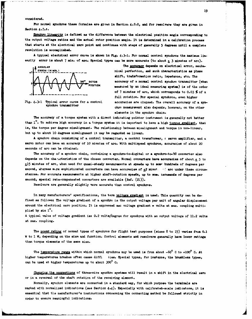
A typical electrical error ctuve is shown in Fig. 4.3-1. For normal control synchros the maximum lin-
earity error is about 7 min. of arc. Special types can be more accurate (to about 3 3 minutes of arc).
ANGULAR The acounrc depends on electrical error, meoha-+iT RROR (IN MIN.I nlical perfection, and such characteristics as phase
shift, trafsformation ratio, impedance, eto. The
AA ROTOR accuracy of a normal control synohro transmitter (whenPOSITION measured by an ideal measuring system) is of the order
of 7 minutes of arc, which corresponds to 0.03 % of a---- rotation. F-r special synchros, even higher
rig. 4.3-1 Typical error curce for a control accuracies are claimed. The overall accuracy of a syn-ful rtatonrFo secalaynhroivenhihe
synchro transmitter chro measurement also depends, however, on the other
elements in the synchro chain.The accuracy of a torque system with a direct indicating pointer instrument is generally not better
than 1". To achieve high accuracy in a torque system it is important to have a high torgue gradient, thatis, the torque per degree misalignment. The relationship between misalignment and torque ia non-linear, Ibut up to about 10 degrees misalignment it may be regarded as linear.
A synchro chain consisting of a control transmitter, a control transformer, E servo amplifier, and aservo motor can have an accuracy of 10 minutes of arc. With multispeed synchros, accuracies of about 20seconds of arc can be obtained.
The accuracy of a synchro chain, containing a eynchro-to-digital or a eynchro-to-WC converter also
depends on the cha:acteristios of the chosen converter. Normal converters have accuracies of about. 1 5 to
±15 minutes of arc, when used for quasi-steady measurements at speeds up to mosp hundreds of degrees per
second, whereas m.re sophisticated converters can have accuracies of +2 minut., - arc under these circum-
stances. For anrcurate measurements at higher shaft-rotation speeds, up to som. tnousands of degrees per
second, special rate-compensated converters are available (Ref. (21)).
Resolvers are generally slightly more accurate than control synchros.
In many manufacturers' specifications, the term voltage gradient is used. This quantity can be de-fined as follows: The voltage gradient of a synohro is the output voltage per unit of angular displacement
around the electrical zero position. It is expressed as: voltage gradient - volts at max. coupling multi-
plied by sin 10.
A typical value of voltage gradient is: 0.2 volts/degree for uynchros with an output voltage of 11.2 volts
at max. coupling.
The Dower rating of normal types of synohros for flight test purposes (sizes 8 to 15) varies from 0.1W to 1 W, depending on the size and function. Control elements and resolvers generally have lower ratings
than torque elements of the same size.
The temperature ranxe within which normal synchros may be used is from about -600 C to +100P C. At
higher temperatures brushes often cause diffi ties. Special types, for instance, the brushless types,can be used at higher temperatures up to about 3000 C.
Chaning the connections of three-wire synchro systems will result in a shift in the electrical zeroor in a reversal of the shaft rotation of the receiving element.
Normally, synchro elements are connected in a standard way, for which purpose the terminals aremarked with normalized indications (see Section 4.4). Especially with calibrated-scale indicators, it is
essential that the manufacturer's instructions concerning the connecting method be followed strictly in
order to ensure meaningful indications.
j
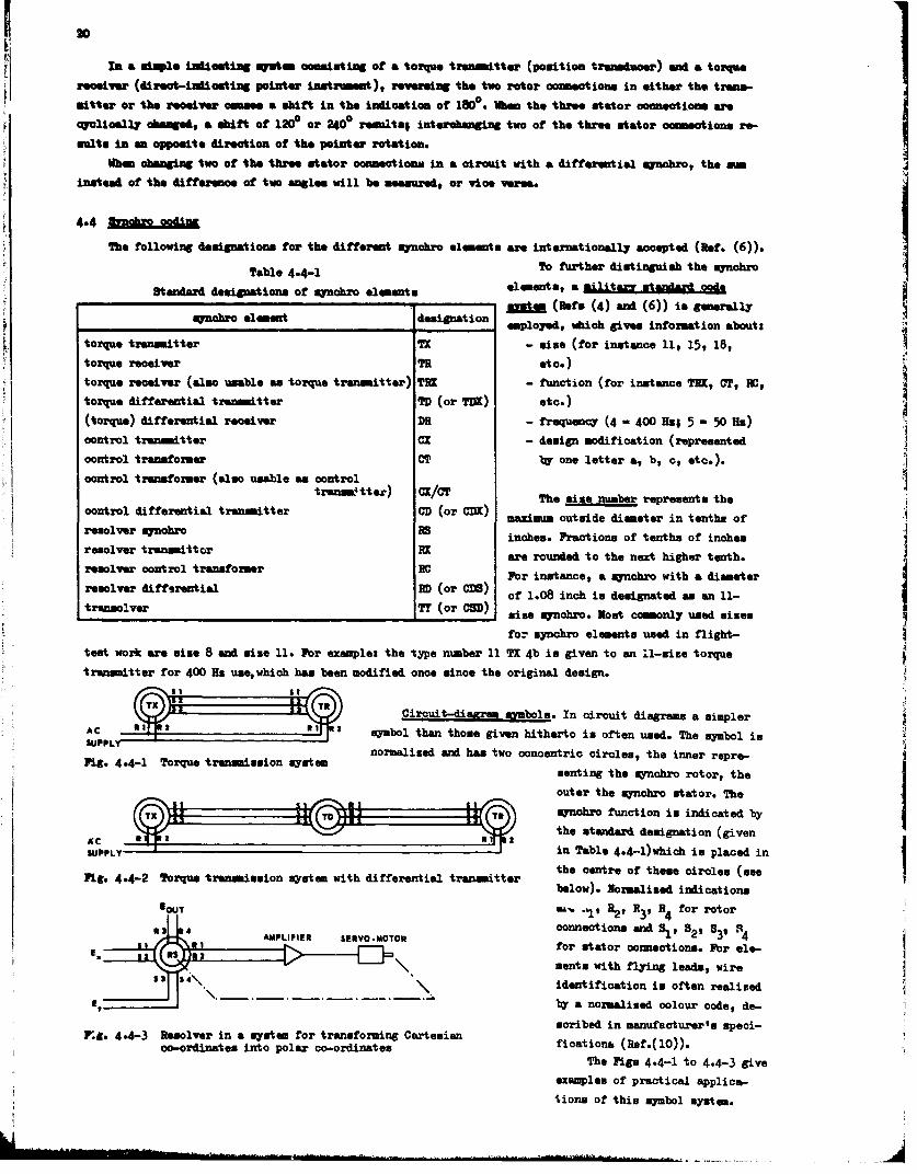
In asimpe inicatng aaitm cninstheing ita of 18a torqthe tranmete (pstintratoucr) acind a trqereceive dreat-iniliotivg pone - xrmet) ervftghe two rtor onectionsineither thetrans-
Whandhagin tw ofthe three stator connections in a circuit with a differential synobro, the aminstead of the difference of two angles will be meamured, or vice Verna.
4.4 131410Ioi~Th. following designations for the different qunohro almemarta are internationally accepted (Ref. (6)).
Table4.4-1To further distinguish the mynohro
Standard designat ions of mjrnobro elements eeetamltz tnadcd___________________________________________________ ________ bRf. (4) and (6)) is generally
mynoro lemnt eminatIo employed, which give. informat ion about:
torque transmitter TX - mine (for instance 11, 15, 18,torque receiver TR etc.)torque receiver (also unable as torque transmitter) TRI - function (for instance TEX, CT, NO,
torque differential transmtter TD (or TDX) etc.)(torque) differential receiver DR - frequency (4 - 400 Hz; 5 -50 HIS)
control transmitter CX - design modification (wrereented
control transformer CT by one letter a, b, c, etc.).
control transformer (also unable as controlcotrl iferntaltrnmttr tranem&tter) CX/T Th size nube represents the
contol iffrenialtrasmiterCD (or c1)X) maximunu outside diameter in tenths of
reaover 21OhO 15inches. Fraction. of tenths of inches
**J6W .C....J.are rounded to the next higher tenth.resolver control transformer BCFor instance, a synchro with a diameterresolver differential RD (or CD) of 1.08 inch ia designated as an 11-
tranolvr T (o ~) sise synchro. Most commonly used aizse
for mynoro elements used in flight-
test work are mize 8 and mize 11. For examplet the type number 11 TX 4b is given to an U.-mise torque
transmitter for 400 He usewhich has been modified once mince the original design.
AC .1as11R Circuit-diafra mynbl. In circuit diagrams a simpler
__________________ symbol than those given hitherto is often used. The symbol isSUPP~ynormalised and has two concentric ciroles, the inner repre-
Fig- 4.4-1 Torque transmission syatem anigtesnbortr h
outer the mynchrc stator. TheIsynchic function in indicated by
the standard designation (givensc 3 in Table 4.4-1)which is placed in
Fig.4.42 Trqu treemimio mytem ithdiferetialtruemiter the centre Of theme circles (mee1111- 44-2Torue ranmisionsystm wth iffrenialtrasmiter below). Normalized indications
BOUT 4-. -1 R2 R H3, R4 for rotor
43 4AMPLIFIER SERVO-MOTOR connections and I'll B22 539 N4for tstaor connections. For ele-Mentz with flying leads, wire
S S' S4\identification in often realized
E~byr a normalized colour code, de-
scribed in manufacturer's apeci-Pg.9 4.4-3 Resolver in a system for transforning Cartemian ficationag (Ref.( 10)).
co-ordinate, into polar co-ordinatesThe Pigs 4.4-1 to 4.4-3 give
examples of practical applical-
Lions of thim smnbol mystem.
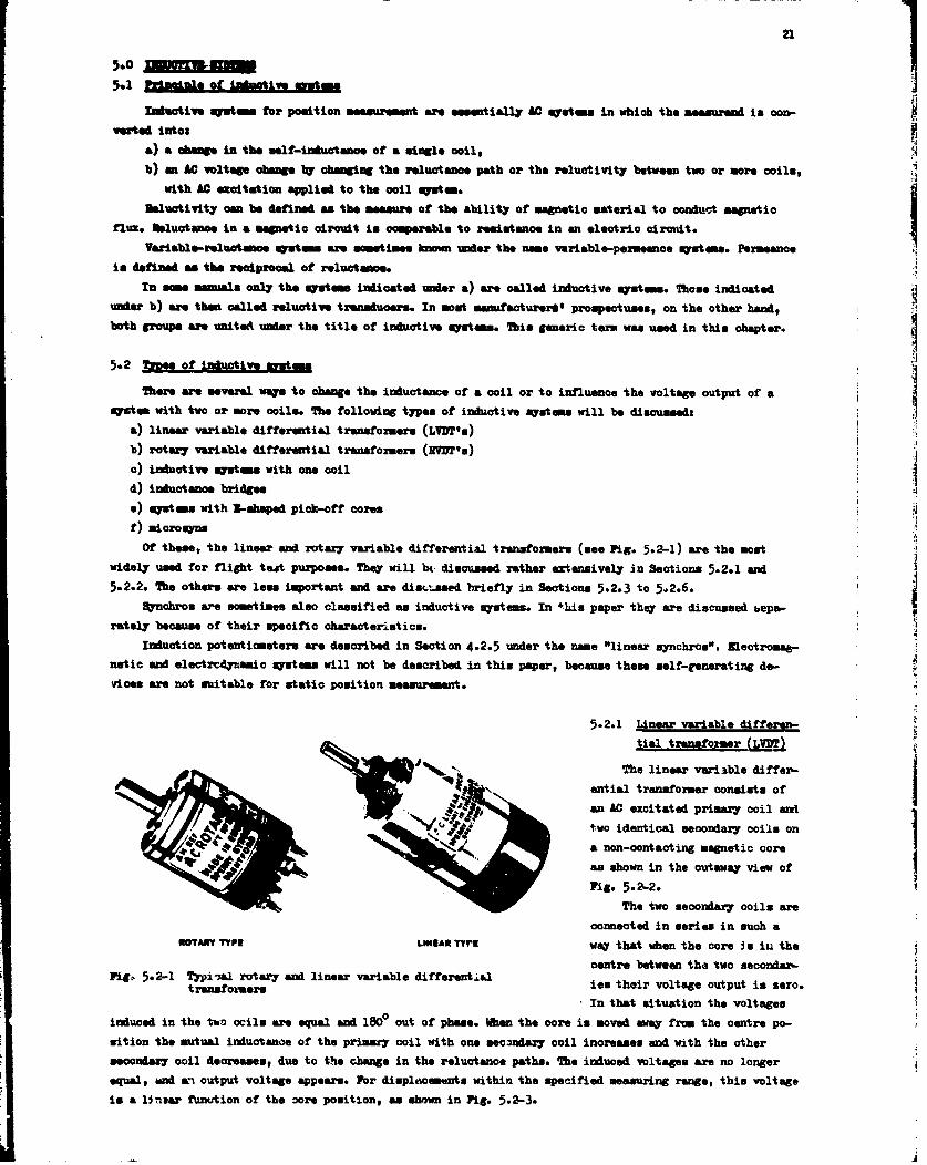
21
bsfoiesytm o osto esuhetw sen.UP tiall AC Systems in which the measuend in con-
5.1 a cuangi e of the motlrimmuatenceo inlgol
with AC excitation applied to the coil system.
UMluotivity cam be defined sa the measure of the ability of magnetic material to conduct magnetic
flux. Msluctance in a magnetic circuit is compaerable to resistance in an electrio circutit.
Variable-reluatance systes ame sometimes monunder the name variable-perseance systems. Permeano.is defined me the reciprocal of reluctance.
In smamnsnals only the systems indicated under a) are called inductive systems. Theme indicateduner b) are then called reductive transducers. In most manufacturer'l prospectuses, on the other hand,both group. are united under the title of inductive systems. This generic teria was used in this chapter.
5.2 Yzwee of imductive systems
system with two or more coils. The following types of inductive systems will be discussedta)lieare vareiaeledifwarsntoicang traesioructance of t o ilo)oifunete otg uptob) linary variable differential transformers (L'VDT'u)
b) roduta ve variabem diff oerential tasomr H
d)inductance bridges
e) systems with UB-saped pick-off cores
f) nicro@yns
Of these, the linear and rotary variable differential transformers (usee Fig- 5.2-1) are the mostwidely used for flight teat purposes. They will hi. discussed rather ertensively in Sections 5.2.1 and
5.2.2. The others are less important and are dincL'aaed briefly in Sections 5.2.3 to 5.2.6.Synchros are sometimes also classified as inductive systems. In +his paper they are discussed bepso-
rately because of their specific characteristics.Induction potentiometers are described in Section 4.2.5 under the name "linear sna~chros". Electromft-
netic and electredynsatic syst ems will not be described in this paper, because these self-generating de-.vices are not suitable for static position measurement.
5.2.1 Linear variable, differen-tial transformer (jjDT)
The linear variable differ-
ential transformer consist, of
two identical secondary coils on
a non-contacting magnetic coreIas shown in the cutaway view of
The. two.2 secondary coilsare
fOTARr TYPE LINEAR TYVE way that when the core in in thecentre between the two seconder-
PL.,52- ypial rotary and linear variable differentialisthrvoagoupti e.ftg~5.2- trssfo~ersIn that situation the voltages
induced in the two ocils are equal and 1800 out of phase. WIhen the core is moved away from the centre po-sition the mutual inductance of the primary coil with one secondary coil increases and with the othersecondary coil decreases, due to the change in the reluctance paths. The induced voltages Are no longerequal, and ain output voltage appears. For displacements within the specified measuring range, this voltage
is a linsar fuanution of the oore position, as shown in Pig- 5.2-3.
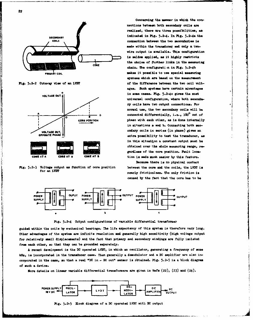
22
Concerning the manawr in which the con-nections between both secondary co1s are
realised, there are three possibilitise, an
SECONDARY indicated in Pig. 5.2-4. In Pig. 5.2•-4a the
connection between the two secondaries is
made within 'the trwnsduoer and only a two-r wire output in available. This oonfiguration
is seldom applied, as it highly restricts0- the choice of further links in the measuring
ohain. The coofiguratimen in Fig. 5.2-4bPRIARY COIL makes it possible to tie speoial measuring
Osystem which are based on the measurement
Pig. 5.2-2 Cutaway view of an LUI of the lifferen•oe between the two coil volt-ages. Such systems have certain advantages
+ in some oases. Pig. 5.2-40 given the mostVOLTAGE OUT 1
universal oonfigurationg where both socondab-
17 coils have two output connections. For,
normal use, the two acoondary coils will beA IA 4t oonnected differentially, i.e., 180° out of
CORE POSITION phase with each other, as is done internally
in situations a and b. Connqcting both seo-
VOLTAGE OUT. ondary coils in series (in phase) gives anOPPOSITE PHASE extra possibility to test the transducer, as
in this situat%on a constant output must beobtained over the whole measuring range, re-
gardless of the core position. lault loom-CORE ATT 9 tion is mad* much easier V this feature.
Because there is no physical oontact
Pi-.2-3 Voltage output as function of core position between the core and the coils, the LVDT isfor an LVBT nearly frictionless. The only friction is
caused by the fact that the core has to be
POtWER • h T POWER OUTPUT POWER OUTPUT
SUPPLY ~~~~SUPPLY __f SPL __
eI
Pig. 5.2-4 Output configurations of variable differential treusformer
guided within the coils by eohanioal bearings. T'he life expectancy of this system is therefore very long.Other advantages of the system are infinite resolution and generally high sensitivity (high voltage outputfor relatively mall displacements) and the fact that primajy and secondary windings are fully isolated
from each other, so that they can be grounded separately.
A recent development is the DC operated LVDT, in which an oscillator, generating a frequency of some
kHs, in incorporated in the transducer came. Then generally a demodulator and a DC amplifier are also in-
corporuted in the case, ao that a real "DC in - DC out" sensor is obtained. Pig. 5.2-5 is a block diagram
of such a device.
More details on linear variable differential transformers are given in Refs (22), (23) and (24).
POWER uPPLY DCnDOC S 1LATOR L V DTI MLOD - AMPL FLE -UPUT
Fig. 5.2-5 lock diagram of a DC operated LVDT with DC output
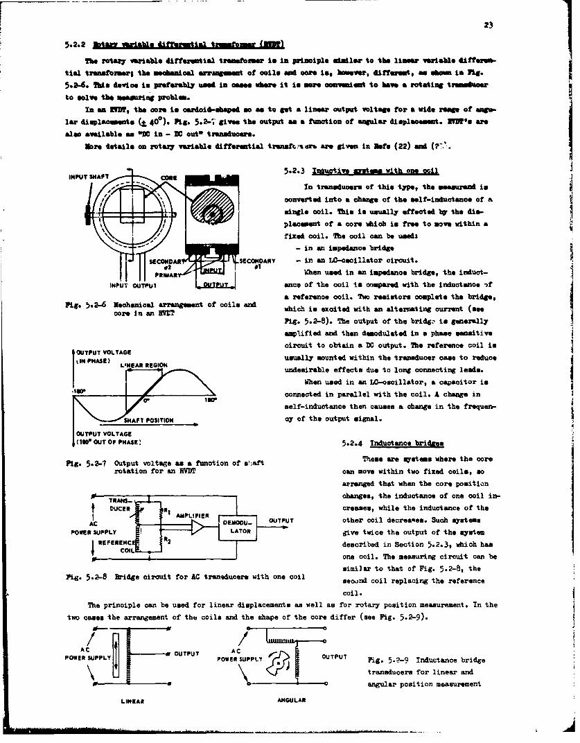
23
The rotary variable differential transformer In in principle similar to the linear variable dtftszuin-
tial trensformsrg the mechanical arrammngt of coils mad core is$ however, different, as mm in Pig.
5.2-6. this device io preferably used In ceane where It to mwor oosveiint to have a rotating tremeshoer
to solve the measuring problem.
In an RVIM, the core to oerdoi~-sbaped so as to get a linear output voltage for a wide rompe of umgo-
lar dinplaommets (t 400). Pig. 5.26-,, gives the output an a function of angular displacement. IWN'm ar*
also available a.s ON in - IDC out3 transducers.
More details on rotaq variable differential trsnsft.-%r& are given in Rafe (22) and (77.%
IPTSATE5.2.3 Inductiv sm ihoeci
In transduoers of this type, the meesurend in
converted into a change or the solf-inductance of a
mingle coil. This is usually effscted by the din-
placement of a oore whioh is free to move within a
fixed coil. The ooil can be useds
- in an impedance bridge
SECNDR SECONDARY - in an LO-osoillator circuit.
PRIMAR hen used in an impedance bridge, the induct-
INPU. UTPUIance of the coil is compared with the inductance -)f
a reference coil. Two resistors complete the bridge,Pig. 5.2-6 Nechanical arrangement of coils an which in excited with an alternating current (seeI
core inan RM ig. 5.2-8). The output of the bridgze is generally
amplified and then demodulated in a phase sensitive
OUTPT VOTAGEcircuit to obtain a DO output. The reference coil isIN PASE)L ER REI Nusually mounted within the transducer case to reduce
LINEARREGIONundesirable effects due to long connecting leads.IWIhen used in an LC-oscillator, a capacitor is
connected in parallel with the coil. A change in
self-inductance then causes a change in the frequen-
ýSHAFT POSITION cy of the output signal.
(WN OUTr OF PHASE' 5.2.4 Inductance bridges
Fig. 5.2-7 Output 'voltage as a function of s'af Those are systems where the corerotation for an RV~D can move within two fixed ccile, so
arranged that when the core position
TRANS-changes, the inductance of one coil in-
DUCERcreases, while the inductance of the
ACbEOoU. OUTPUT other coil decrea'tes. Such systemsPOWER SUPPLY *t give twice the output of the system
RZFERENCdescribed in Section 5.2.3, which hasCOIL one coil. The measuring circuit can be
similar to that of Fig. 5.2-8, theFig. 5.2-8 Bridge circuit for AC traneducers with one coil seoujnd coil replacing the reference
coil.
The principle can be used for linear displacements as well as for rotary position measurement. In the
two cases the arrangement of thee coils and the shape of the core differ (see Pig- 5.2-9).
POWE SUPLYOUTPUT ACPOE UPYPOWER SUPPLY OUPT Fig- 5.ý-9 Inductance bridge
OUPU transducers for linear and0 - - .angular position measurement
LINEAR ANGULAR
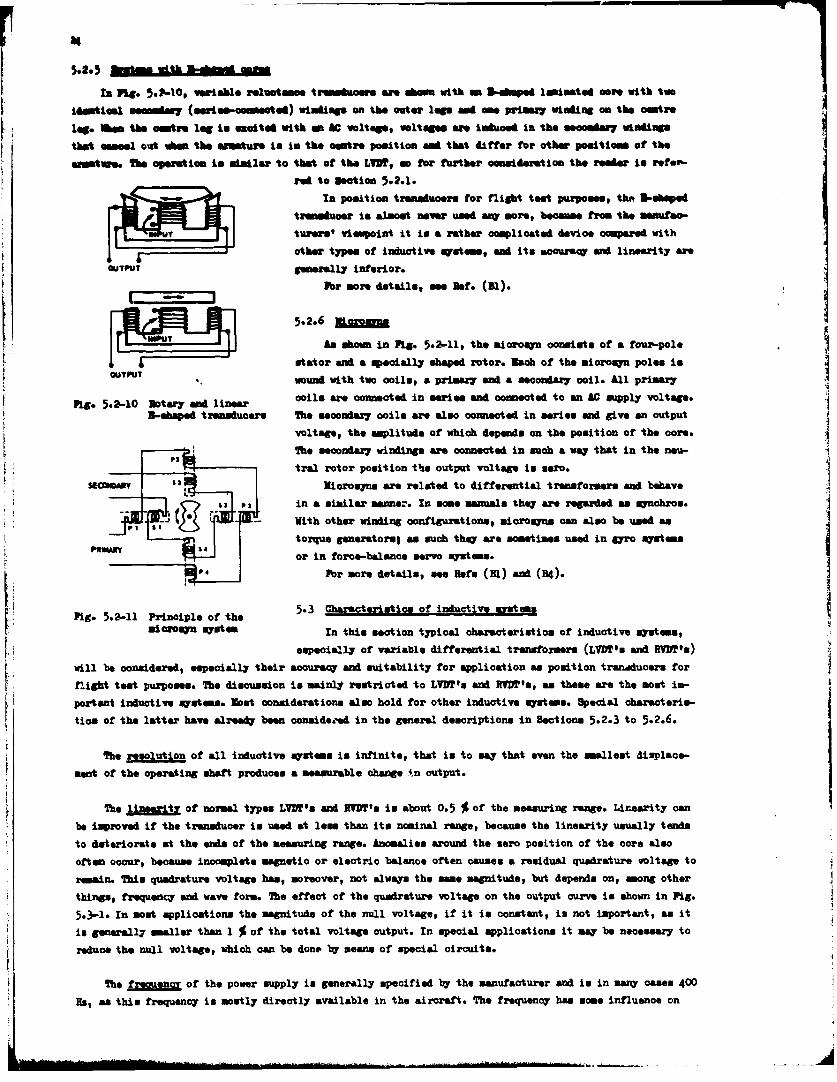
InPL. .6-0'Vaibl umetme iasiihr are .,'.. wit mSan ped laminated *or* with two
msatute. Soe operation in similar to stoth Vsfofutecnidrinteraerortr-
red to section 5.2.1.
In position transducers for flight teot purposes, thet 3I-oshpedI w U 1 turers' viewpoint it is a rather complicated device compared with
F ~other types of inucutiv. mystoms, and its somocura and linearity ameOUTPUT generally interior.
For more details, ne nsf. (31).
5.2.6 XL2inI [ ~1 An shown in Fig. 5.2-11, the microsy consists of a tour-polestator and a specially shaped rotor. loch of the miorosyn poles in
OUTPUT wound with two coils, a primary and a secondary coil. All primary'
Pig. 5.2-10 Rotary and linear coils are connected in serine and connected to an AC supply voltage.3-shaped transducers The secondary coils are also connected in sefien and give an cutput
voltage, the amplitude of which depends on the position at the cors.
tral rotor position thte output voltage is seo".ss~se~arNicrosyra are related to differential transformers and behave
63 P3 in a similar sanner. In some manuals wthey are regarded as synohyos.-- With other winding configurations, miorosynm can also be used as
J-11 torque generators; as such they are sometimes used in gyro sysutems
For more details, se Rafe (3l) and (B4).
L Pi 5211 rinopleof5he3 Characteristics of inductive mystman
especisally of variable differential transformers (L'VDT's and tVIM's)
will be considered, especially their accuracy and suitability for application an position transducers for
flight test purposes. The discussion is mainly restricted to LVDT's and UVPP's, as these are the most im-portant inductive systems. Most considerations also hold for other inductive systems. Special oharsaterim-
tios of the latter have already been conside.'sd in the general descriptions in Sections 5.2.3 to 5.2.6.
The resolution of all inductive zystems is infinite, that is to may that even the mallest displace-
sent of the operating shaft produces a measurable change 4n output.
The "MnAE"ti of normal types LVlN's and RIM's in about 0.5 % of the measuring range. Linearity can
be improved if the transducer is used at less than its nominal range, because the linearity usually tends
to deteriorate at the ends of the measuring range. Anomalies around the smer position of the core also
often occur# because incomplete magnetic or electric balance often causes a residual quadrature voltage to
remain. This quadrature voltage has, moreover, not always the same magnitude, but depends on, among other
* things, frequency and wave form. The effeect of the quakdrature voltage on the output curve is shown in Fig.
* 5.3-1. In most applications the magnitude of the null voltage, if it is constant, is not important, as it
isgneal COOM1 maller than 1 % of the total voltage output. In special applications it may be necessary to
reduce the null voltage, which can be don, by' seans of special circuits.
The frgena of the power supply is generally specified by the manufacturer and is in many cases 400
Hs, an this frequency is mostly directly available in the aircraft. The frequency has some influence on

AC VOLTAGE
R&. 5.3-1 eltw omtwt as a truetiea of dtafl positio ra or a variable &iffeee4tial tmr~oumw
"th smitiwity of t"e Output sdPLI, bet this can gaenwally be meglected fir the varia-tion of % thatOWN be asecs&ein the ftegmw of the AC power munly of mest aircraft. Sensitivity and efficiency0000101.y laImsrfff at cosmidaebin h~ghe frequencies, end for that rea~so the use at frequmacies in theare or 1 to 5 ktis semetime preferred, although the appliostion of a special oscillator io required
The JM3 to In principle directly proportional to the voltage amplitude of the power supply.The output In tbetore generally specified In terum of vnlt. per ow displaosmet per volt input androom frpm a raw mi/rn/v to a few V/cm/F. IMe mmximn allowable value for the voltage amplitude of thepower supply is datumined 1W the maxiými allowable power dissipation in the coils, Magnetic saturation ofthe core, an insulation breekdon of the windings. The effect of the input voltage on the sensitivity canbe canclled in measuring circuits, based on the determination of the ratio between output voltage and in-put voltage. Sy~stes based on the measurement of absolute voltages require a .tabilised voltage supply ifhigh aoouraq' in required. The excitation voltage in generally between a few volt* and a few tens of [email protected] otit that can directly be supplied from the 400 Ns main power supply (26 v or 115 v) which inavailable in most aircraft.
The elcrclla (iqput impedance) of the measuring circuit can affect the sennitivity. When high-impedance signal conditioning equipment is used, this effect lull generally be negligible. Measuring amy-tems with low input impedance, such ansimiple direct indicating instrments, can seriously decrease thesensitivity.
The &MRAVW of the output voltage with respect to the supply voltage can have appreciable values(some tens of degree"). This aspect must be seriously considered when choosing the measuring equipment. in
applications where the core pawnes the centre position, complications can be expected because the sign ofthe phase angle change.. It in therefore often nooesosar to reduce the phase shift to less than a few de-Crees t men of a compensation circruit, that can generally be a simple capacitor across, or in serieswith, the output signal. The phase angle depends somewhat on the frequency of the excitation voltage, butthis effect cam generally be neglect el for variations of the crier of t 5 %- The Phase angle fUrtheZW1oredepends on the load impedance. This effect must be taken into accunt when dimensioning phase ocapersat ioncircuits.
The o within which normal types of variable differential transformers cam be used istram -60o C to +1000 C. Yo~erature has acme effect on the sensitivity that cannot always be neglected.Special types cam withstand temperatures up to +600P C without being damaged, although the aoaurac7 camdecrease to a few per cont of the measuring range. The so-called wC in - DO out" types cannt withstandtemperatures higher than about .1000 C.
6.o Wa= 7
The following digital systems will be considereds
- shaft position encoders
- on/off suitohes..
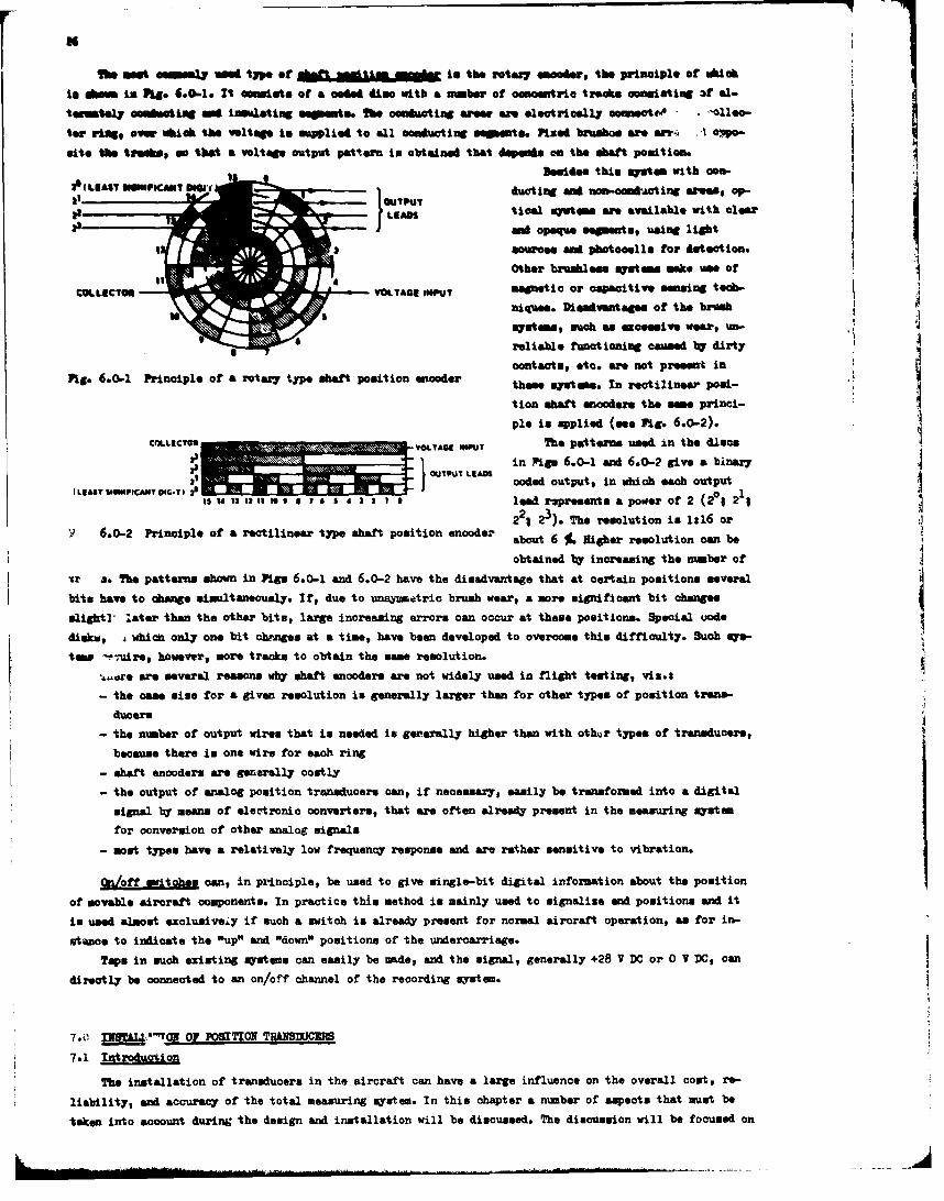
tor riq ever which the voltange is&ple15alcnutn gmns ie rsow r. vo
alt* the tvam, s0 that aVoltage Output Pattern is obtained that depends an the abaft position.
Besides this oslats with cow-
atOTPTduct ing and cnSoanduacting areas, op.-
32VLEADS ticl systems aft available with clearI33- en opaque segments, uasing light
sourcs and photocells for detection.
Other brushles syutema make use of
COLLIC OR .eOTAE"$Ulmgetic or capacitive sensing tech.
14 5 niquse. Disadvantages of the brushsystems, such as excessive wear, urp-
reliable functioning canised 1br dirtycontact@, eto. are not present in
Fig. 6.0-1 Principle of a rotary typo shaft position encoder thssyts.n cileap0-
tion sbaft encoders the swas princi-Iple in applied (see Fig. 6.0-2).
Cn.LICTý TA "U The patterns Used i.n the discs
~ } TPUT in Pigs 6.0-1 and 6.0-2 give a binaq7E ~31 OUTPUTC*N LEAN coded outputs in which each output
13 14 13 1211 Of I a 7 6 4 3 2 1 0 lead represents a power of 2 (20§ 212; 2 12). The resolution is 1W6 or
Y.6.0-2 Principle of & rectilinear typo shaft position e bot6 . ihe rsluio
obtained byr increasing the number of :Ir s. The patterns shown in Pigs 6.0-1 and 6.0-2 have the disadvantage that at certain positions several
bits have to dhange simultaneously. If, due to unasunetric brush wear, a more significant bit changesslight- later than the other bits, large increasing errors can occur at these positions. Special oode
disku, t which only one bit changes at a time, have been developed to overcome this difficulty. Such my*-
towg -Puire, however, more tracks to obtain the eae resolution.
-L-re are several reasons why shaft encoders are not widel.y used in flight testing, viz.$
- the case miss for a given resolution is generally larger than for other types of position trans-
ducers
- the number of output wires that is needed is generally higher than with othlar types of transducers,
because there is one wire for each ring
- shaft encoders are generally costly
- the output of analog position transducers can, if necessary, easily be transformed into a digital
signal by means of electronic converters, that are often already present in the measuring system
for conversion of other analog signals
- most types have a relatively low frequency response and are rather sensitive to vibration.
On/of swtdwscan, in principle, be used to give single-bit digital information about tha position
of movable aircraft components. In practice this method is mainly used to signalize and positions and it
is used almost exclusive4~ if such a switch is already present for normtal aircraft operation, as for in-
stance to indicate the *up" and "down" positions of the undercarriage.Taps in such existing systems can easily be made, and the signal, generally +28 V DC or 0 V DC, can
directly be connected to an on/off channel of the recording syst em.
7.0 EW ,-S OFPOSITION TR*EUMCERS
7.1 Inr~mto
The installation of transducers in the aircraft can have a large influence on the overall cost, re-
liability, and accuracy of the total measuring system. In this chapter a number of aspects that must be
taken into account during the design and installation will be discussed. The discussion will be focused on
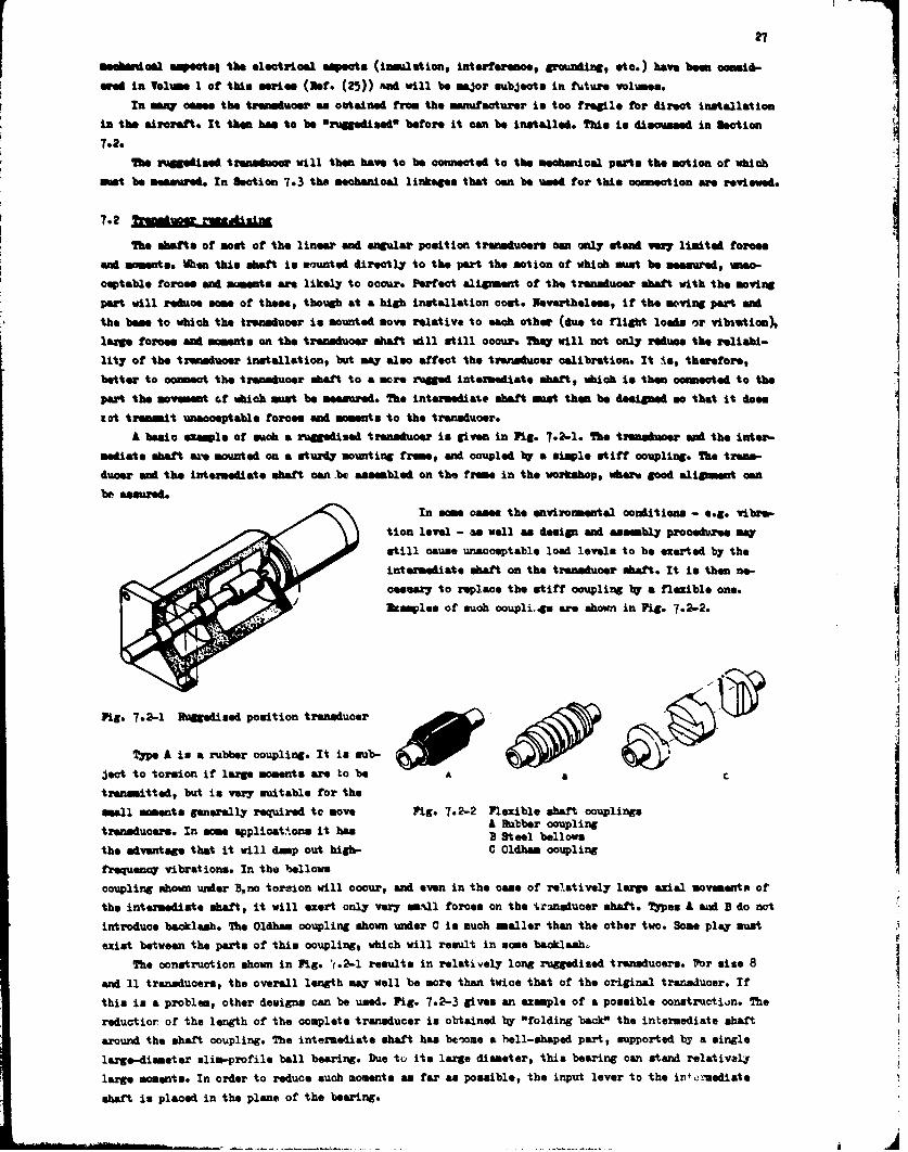
27
aemee aseetsq the electricel a"eate (insulation, interference, grounding, etc.) have bee onscmid-
ared In Valme 1 or this series (Psf. (25)) &M will be major subjects in future volumes.
In many cames the transducer ws ottained from the manufacturer in too fregile for direct installation
in the aircraft. It then has to be Oruggedisedw before it can be installed. This in disouseed in Section
7.2.
The ruggedised transducer wili then have to be connected to the mechanical parts the motion or which
must be measured. In Section 7.3 the mechanical linkages that oan be used for this connection ant reviewed.
7.2he shafts of most of the linear and angular position transducers can only stand very limited forces
and moments. When %his shaft in mounted directlyr to the pert the motion of which must be measured, un..-
ceptable forces end moments awe likely to occur. Perfect alignment of the transducer shaft with the moving
part will reduce msoe of these, though at a high installation cost. Neverthel"ess if the moving pert eamthe baes to which the trensducer in mounted move relative to each other (due to flight loads or vibratian),lange forces and moments on the trensduoer shaft will still occur. They will not only reduce the reliabi-
lity of the transducer installation, but may also affect the trarmsducer calibration. It is, therefore,
better to connect the transduoer shaft to a more rugged intermediate shaft, which is them connected to the
part the movement of which must be measured. The intermediate shaft must them be designed so that it does"
&ot transmit unacceptable forces and m omet to the tranaducer.
A basic example of much a ruggedised transducer is given in Fig. 7.2-1. The transducer and the inter'-
mediate shaft are mounted on a sturidy mounting truea and coupled by a simple stiff coupling. The trane-
ducer and the intermediate shaft cam ýb assembled on the frime in the workshop# where good alignment can
be assured.In acme canes the environmental conditions - e.g. vibrep-
tion level - as well as designl and assembly procedures may
still oause unacoeptable load levels to be exerted by theintermediate shaft on the transducer abaft. It is then n*- .
oessary' to replace the stiff coupling 1b' a flexible one.3kamples of such ooupligsj awe shown in Pig. 7.2-2.
Fig. 7.2-1 Ragedised position transducer
Type A is a rubber coupling. It is sub-7.2
ject to torsion if large moments are to be A c
transmitted, but in very suitable for thesmall moments generally required to move Fig .2- Flexible shaft couplings
tranduces. n soe aplict~kos ithasA Ruibber couplingtranducrs.In ame pploat~onsit .5 B Steel bellows
the advantage that it will damp out high- C Oldham coupling
frequency vibrations. In the bellows
coupling ahown unzder B,no toreion will occur, and even in the came of relatively large axial movementos of
the intermediate shaft, it will exert only vary smL~l forces on the %.r~naduoer shaft. Types A and a do not
introduce backlash. The Oldham coupling shown under C is much smaller than the other two. Somes play mustJ
exist between the parts of this coupling, which will result in acme backlash.
The construction shown in Fig. *1.2-1 results in relatively long ruggedised transducers. Pbr sise 8
and 11 transducers, the overall length may well be more than twioe that of the original transluoer. If
this is a problem, other devigna can be used. Fig- 7.2-3 gives an example of a possible construction. The
reduotior of the length of the complete transducer is obtained by "folding back" the intermediate shaft
around the shaft coupling. The intermediate shaft has bev)ome a bell-shaped part, supported by a single
large-diameter slim-profile ball bearing. Due tu it. large diameter, this bearing can stand relatively
large moments. In order to reduce such moments as far as possible, the input lever to the in0 rmediate
shaft in placed in the plane of the bearing.
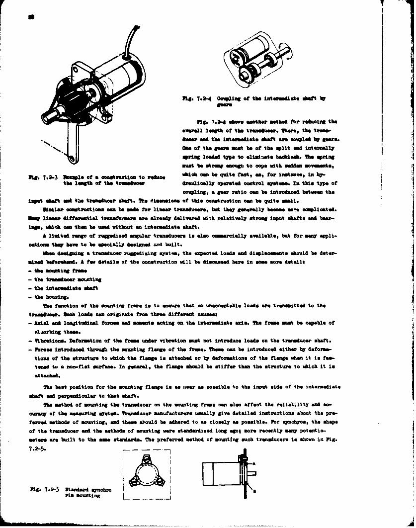
NN
Re-. 7.2-4 covoing or the intermediate oaf i
Pig. 7.2-4 dhow smothe method for reducing theoverall length of the trensmlower 2%*st, the trams-Inset ad the intezudiatet shaft a&M cOWpled bW gSeas.
am of the gSows must be of the split and internally
sping loaded typs to eliminate bacdaklah.e Us pringmust be strong inu~gh to cope with sudden movemmnt o
FRg. 7.2-3 Wkwile of a construction to reduce 05b ut at s o ntne nb-the length of the trwnluce dsualioslly operated control systems. In this type of
onpling, a gust ratio oem be introduced between the
iflt shaft aid *toe tmasuost shaft. The dismsinsios of this coantraction can be quite small.&Malar constructions oem be mad* for linsetr transducers, buit May generall~y became mo-e oomplioatedo
MW uis.. iffergatiga trtmsfonrmamr elraelfte delivered with relatively strong input shaft@ Nac beer-
ings, which can than be used without en intermediate shaft.
A limiteil rangoe of ruggedised angular transducers in also commerciell~y available, buit for many appli-
cations thqW haew to be speciall~y designed ard built.When designing a transducer ruggedizing systan, the expected loads and diqpalosments should be deter-
amied beforehand. A tow, details of the construction will be discussed here in same moare detaila
- the tratnsdce tmoutn
- the intermediate shaft
The fimation oftemutn rei omn htno unaccept able loads aer transmitted to the :transluce. koh loads can originate from three different onmease- naZL& and lonjitudinsi forces and moment* acting on the intermediate axisi. The frame must be capable of
e*.jorbing theae.
- Vibrations. Deformation of the frame under vibration mut not introduce loads on the transducer Shant.
- Forces introduced through the mounting flange of the fraee. ftese can be introduced either by deformaf-
tions of the structure to which the flange is attached or 1W deformations of' the flange when it is fas-tuned to a non.-flat surface. In general, the flange should be stiffer than the structure to which it is
attached.
The best position for the mounting flange is " tiea" as possible to the input side of the intermediate
shaft and perpendicular to that sbaft*
The method of mounting the transduoer on the mounting frame cani also effect the reliability act ao-
ouzen of the measuring system. Transudcaer manufacturers usually give detailed instructions about the pre-
ferred muthodiw of mounting, and theme should be adhered to as closely as possible. For syuobzos, the shape
of the transducer and the methods of mounting were standardized long agfo$ more recently many potentio-
meters are built to the man standards. The preferred method of mounting such transiucers is shown in Fig.
7-2-5-
Fig. 7.2-5 Standard .ynobz, ri ontn4i~ii~rim moutin
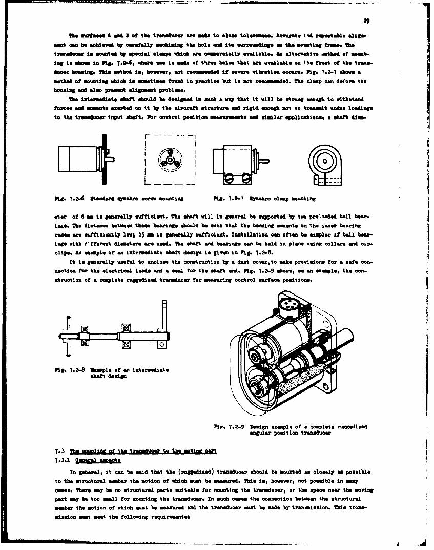
29
The surfaces A aid I of the trinseuoer awe am"d 'to close toleranees. ALocurate t, zd r &Msae elign- *mowt can be aohteved by carefull~y machining the bole and its surroundings an the WMoeing frame. The
tuinvaknoet in mounted %W special clamps which we cameroially available. An alternative iethod of moimt-
ing in sham in Ptg. 7.2-6, where use io made of three holes that ame Qvailable on fhe front of the tras.-
4dwer housing. this method is, however, not recommneded if severe vibration coca"-. Pig. 7.2-7 shows a
method of mowatilug which Is somet lass found in practice but in not recommendd the clImp can deform the
housing and also present alignment problems.
The intermediate shaft should be designed in such a way that it will be strong enough to withstand
forces almd momenit. exerted on ki 1W the aircraft structure and rigid enough no-t to transmit unde loadings
to the transducer irmput shaft. For control position measusmawls~t and similar applications, a shaft diam-
Pig. 7.-" 9seadard snobrc screw mounting Fig. 7.2-7 Synobro clamp mounting
ster of 6 sm is generall~y sufficient. The shaft will in general be supported t' two preloaded ball bear-
inos. The distance between these bearings should be such that the beanding moments on the inner bearingraces are sufficiently lomp 25 ma is generally sufficient. Installation can often be simpler if ball bear-in"e with eiffereat dismeter. are used. The shaft and bearingse can be held in place using collars wan cix'-
clips. An ezinple of an intermediate shaft design is given in PIC- 7.2-8.It is genorally useful to anclose the oonatruction 1b' a dust cover, to make provisions for a safe con-
neotion for the electrical leads and a seal for the shaft andi. Fig- 7.2-9 shows, as an example, the con-
srtruct ion of a complete ruggedised transducer for measuring control surface positions.
Fig- 7.2-8 2tamle of an intermediateshaft design
Pite. 7.2-9 Design example of a complete ruggedisedangular position transducer
7.3Th ommoftetaduortthmoim at
7.3.1 23In general, it can be said that the (ruggedised) transducer should be mounted an closely as possible
to the structural mamber the motion of which must be measured. This is, however, not possible in sanw
oases. There may be no structural parts suitable for nounting the transducer, or the spae. near the moving
part mWp be too small for mounting the transducer. In such cases the connect ion between the structural
member the motion of which must be measured sand the transducer must be made t7 transmission. This trw~a.-
mission munt meet the following requirementss
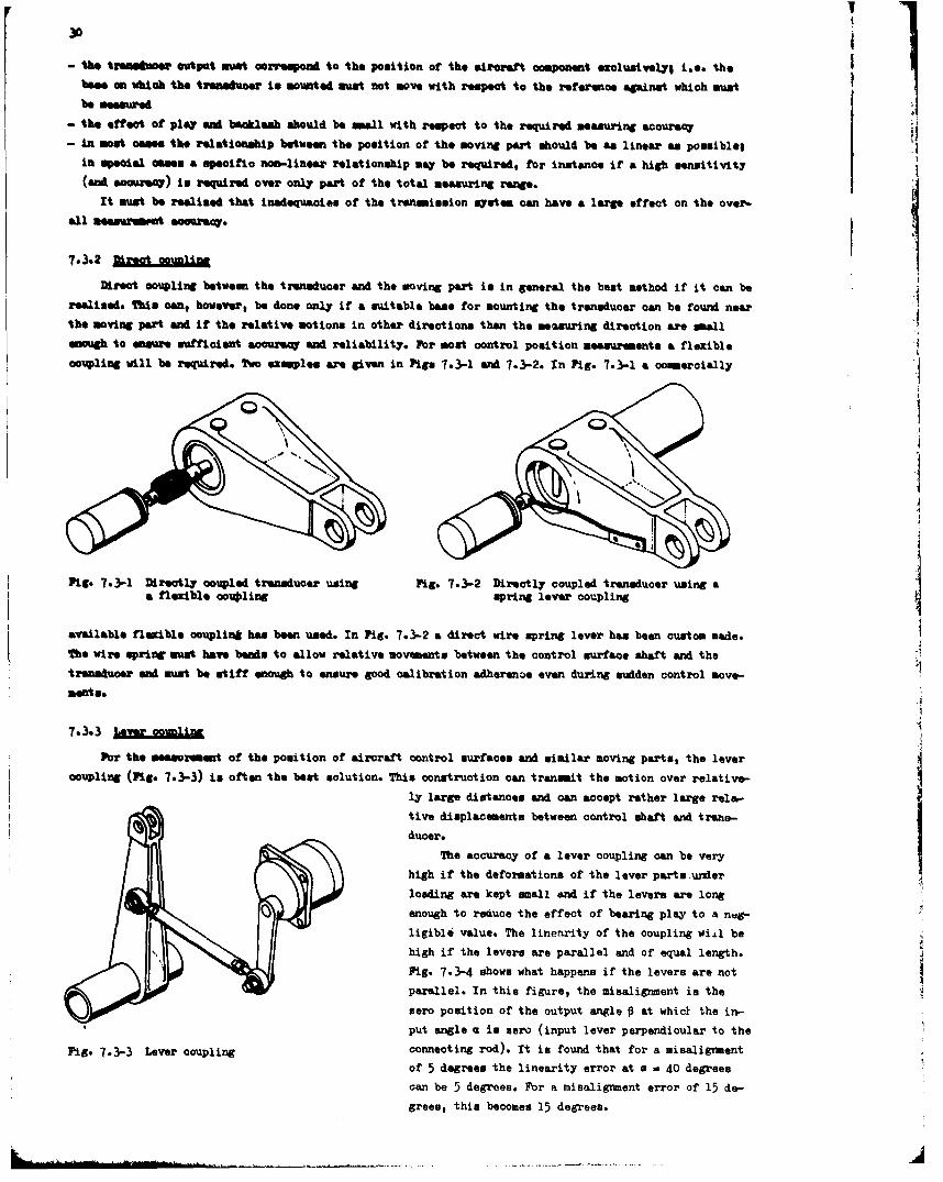
- the tr*=*wtnoutpu~t win• oozrftopwd to the position of the aircraft omnponent exclusivelyl i.e. thebee an which the trend•meor in mounted must not move with respect to the referenos against which mest
be meesured
- the effect of play and backlash should be mall with respect to the required measuring accuracy
- in most oages the relationship between the position of the moving part should be an linear as posmible;
in special case. a specific non-linear relationship way be required, for instance i' a high sensitivity
(snd acauzW) is required over only part of the total measuring range.
It must be reelised that inadequacies of the tranmsimion system can have a large effect on the over-
all measareut acouracy.
7.3.2 Direat o ,u,,inn
Direct ocupling between the transducer and the moving part is in general the best method if it can be
realised. This oan, however, be done only if a suitable base for mounting the transducer oan be found near
the moving part and if the relative motions in other directions than the mesuring direction are small
enoagh to enoure sunficient accuracy and reliability. For most control position measurements a flexible
coupling will be required. Two examples are given in Pigs 7.3-1 and 7.3-2. In Fig. 7.3-1 a omemercially
-I
Fig. 7.3-1 Directly coupled transducer using Fig. 7.3-2 Directly coupled transducer using aa flexble coupling spring lever coupling
available flexible oouplint has been used. In Fig. 7.3-2 a direct wire spring lever has been custom made.
The wire spring muet have bands to allow relative movements between the control surface shaft and the 2transducer and must be stiff enough to ensure good calibration adherenae even during sudden control move-
meats.
Pbr the messurement of the position of aircraft control surfaces and similar moving parts, the levercoupling (Fig. 7.3-3) is often the best solution. This construotion can tranmit the motion over relative-
ly large distances and can sacept rather large rele-
tive displacements between control shaft and trans-
ducer.
The accuracy of a lever coupling can be very
high if the deformations of the lever parts.under
loading are kept small and if the levers are long
enough to reduce the effect of bearing play to a ngligible value. The linearity of the coupling wid be
high if the levers are parallel and of equal length.
Fig. 7.3-4 shows what happens if the levers are not
parallel. In this figure, the misalignment is the
sero position of the output angle 0 at whict the in-
put angle a is zero (input lever perpendioular to the
Fig. 7.3-3 Lever coupling connecting rod). It in found that for a misalignment
of 5 degrees the linearity error at a a 40 degrees
can be 5 degrees. For a misalignment error of 15 de-grees, this becomes 15 degrees.
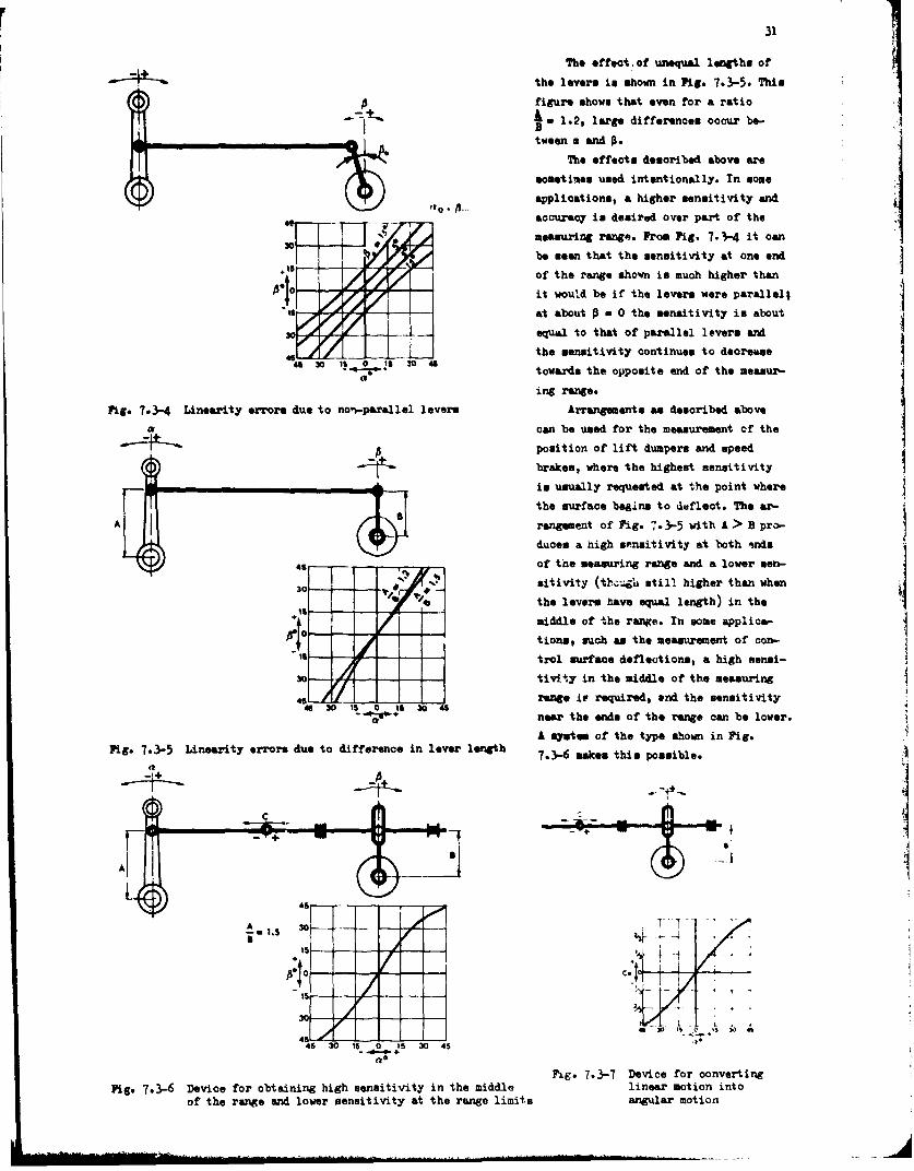
31
The effect, of unequal lengths of
•Ik."-b the levera in shown in Pig. 7.3-5. This
figure shows that even for a ratio
A - 1.2, large differences occur be-
tween a and 3.
7 V The effects described above are
sometimes used intentionally. In some
applications, a higher sensitivity and
4F accuracy in desired over part of the
Io measuring range. From Pig. 7.•-4 it can
be sean that the sensitivity at one end
"4f - -/ - of the range sho.wn is much higher than.10 /it would be if the levers were parallel;
""-4.-- * - at about • - 0 the senaitivity is about
30 equal to that of para~llel lover@ van
the sensitivity continues to dacreasaeI_ 0 1. 30 46 towards the opposite end of the measur-
ing range.
Fig. 7.-3-4 Linearity errore due to non-parallel levers Arrangements as described above
a can be used for the measurement cf the
p position of lift dumpers and speed
brakes, where the highest sensitivity
__....__ _ tis usually requested at the point where
the surface begina to deflect. The ar-
A rsngement of Fig-. 73-5 with A > B pro-
duces a high sensitivity at both inds
-s of the measuring range and a lower sen-
30 sitivity (ttI-4h still higher than when
"" the levers rave equal length) in the+1s middle of the range. In some applica-
;, tion., such an the measurement of con-Is t - ro l sur facn e defle ction s, a high sen ni-
tivity in the middle of the measuring
t // range it required, and the sensitivity46 It 0 IS 30 45 "near the ends of the range can be lower.
A sy•mte of the type shown in Fig.Fig- 7-3-5 Linearity errors due to difference in lever length 7.3-6 makes this possible.
44
4630 10 304
Fig. 7.3-7 Device for convertingFig- 7.3-6 Device for obtaining high sensitivity in the middle linear motion into
of the range and lower sensitivity at the range limits angular motion
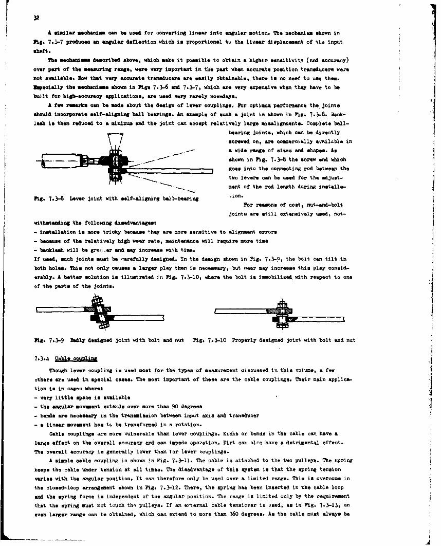
A similar meohanism can be used for oonverting linear into angular notion. The mechanism shown inFig. 7.3-7 produoec an angular deflection which in proportional tv the linear di splacement of the input
shaft.
The meohamems described above, which make it possible to obtain a hightr sensitivity (nd accuracy)over part of the meauring range, were very important in the pat when accurate position transducers were
not available. Now that very accurate transducer@ art easily obtainable, there is no neee to use them.
feoially the meobanims shown in Figs 7.3-6 and 7.3-7, which are very expensive when they have to be
built for high-accuracy applications, are used very rarely nowadays.
A few rmuarks can be made about the design of lever oouplings. For optimum performance the joints
should incorporate salf-aligning ball bearings. An example of such a joint is shown in Fig. 7.3-8. Baok-
lash is then reduced to a minimum and the joint can accept relatively large misalignment@. Complete ball-
bearing joints, which can be directly
screwed on, are oommercially available ina wide range of sises and shapes. An
shown in Fig. 7.3-8 the screw end which
goes into the connecting rod between thetwo levers can be used for the adjust-
ment of the rod length during installs-
PLg. 7.3-8 Lever joint with self-aligning baal-bearing 'ion.
For reasons of cost, nut-and-bolt
joints are still extensively used, not-
withstanding the following disadvantages:
- installation is more triok.7 because they are more sensitive to alignment errors
- because of the relatively high wear rate, maintenance will require more time
- backlash will be grea er and may increase with time.
If used, such joints must be rarefully designed. In the design shown in Fig. 7.3-9, the bolt can tilt in
both holes. This not only causes a larger play than in necessary, but wear may increase this play oonsid-
erably. A better solution is illustrated in Fig. 7.3-10, where the bolt is immobilieed with respect to one
of the parts of the joints.
Fig. 7.3-9 Badly designed joint with bolt and nut Fig. 7.3-10 Properly designed joint with bolt and nut
7.3-4 Cable o~upling i
Though lever coupling is used most for the types of measurement aisoussed in this volume, a few
others are used in special cases. The most important of these are the cable couplings. Their main applicA-
tion is in caset wherew
- very little space is available
- the angular movement extweIs over more than 90 degrees
- bends are necessary in the transmission between input axis and transducer
- a linear movement has tP. be transformed in a rotation.
Cable couplings Lre more vulnerable than lever couplings. Kinks or bends in the cable can have a
large effect on the overall accuracy exd can impede opezation. Dirt car alto have a detrimental effect.
The overall accuracy is generally lower than tor lever couplings.
A simple cable coupling is shown .n Fig. 7.3-11. The cable is attached to the two ptulleys. The spring
keeps the cable under tension at all times. The disadvantage of this system is that the spring tension
varies with the argular position. It c&n- therefore only be used over a limited range. This is overcome in
the closed-loop arrangement shown in Fig. 7.3-12. There, the spring has been inserted in -he cable loop
and the spring force is independent of tee angular position. The range is limited only by the requirement
that the spring must not touch thn pulleys. If an eoternal cable tensioner is used, as in Fig. 7.3-13, an
even larger range can be obtained, which can extend to more than 360 degrees. As the cable must always be
-~ -.- ~---
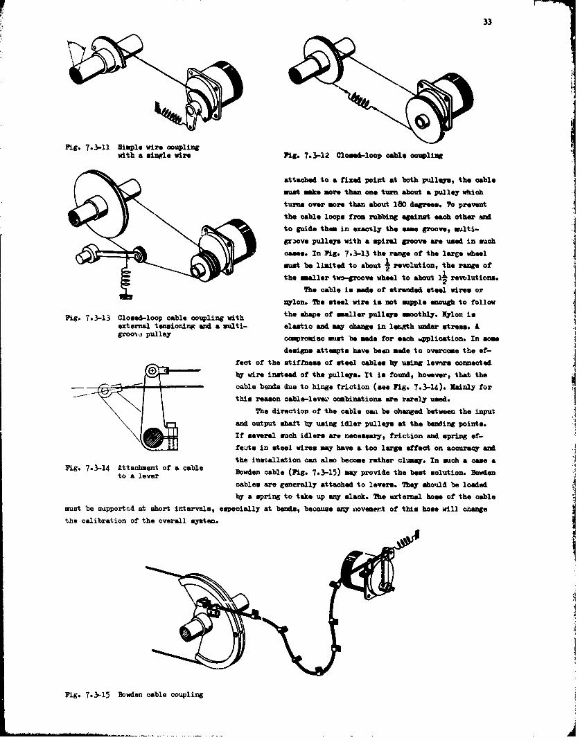
33
Fig. 7o3-11 Simple wire couplingwith a single wire Fig. 7.3-12 Closed-loop cable eoupling
attached to a fixed point at both pulleys, the cablemust make more than one turn about a pulley whichturns over more than about 180 degrees. To prevent
the cable loops from rubbing against each other and
to guide them in exacrly the some groove, multi-
grove pulleys with a spiral groove are used in muchcases. In Fig. 7.3-13 the range of the larCe wheel
munt be limited to about I revolution, the range ofthe maller two-groove wheel to about 1i revolutions.
The cable is made of stranded steel wires or
nlon. The steel wire is not supple enough to followthe shape of smaller pulleys smoothlyr. Nyrlon is
Fig. 7.3-13 Closed-loop cable coupling withexternal tensioning and a multi- elastic and may change in lektth under stress. Aroo0a pulley compromise must be made for each mpplication. In some
designs attempts have beon made to overcome the ef-fect of the stiffness of steel cables bl usin lev-rs connected
by wire instead of the pulleys. It is found, however, that the
cable bends due tc hinge friction (see Fig. 7.3-14). Zainly for
this reason cable-lveam combinations are rarely used.The direction of the cable c"i be changed between the input
and output shalt by using idler pulleys at the beWing points.If several such idlers are necessazr, friction and spring ef-fe'uts in steel wires may have a too large effect on accuracy and
the inasallation can also become rather clumsy. In such a case aFig- 7-3-14 Attachment of a cableto a lever Bowden cable (Fig. 7.3-15) may provide the best solution. Bowden
cables are generally attached to levers. They should be loadedby a spring to take up any slack. The urternal hose of the cable
must be sunpported at short intervals, especially at bends, because any movemert of this hose will change
the calibration of the overall system.
Fe
Fig. 7.3-15 Bowden cable coupling
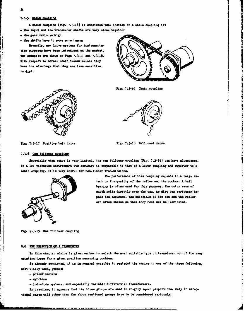
34
7.3.5 cain l1nA chain coupling (Pig. 7.3-16) in sometines used instead of a oable coupling ift
- the input ad the transduoer shafts are very close together
- the gear ratio is high
- the shats have to make more turns.boently, now drive iutean for instruments-
tion purpom have been introduced on the market.
Two examples are shown in Pigs 7.3-17 and 7.3-18.
With respect to normal chain trnissions they
have the advantage that they are less sensitive
to dirt.
Fig-. 7.3-16 Chain coupling
Pig-. 7.3-17 Positive belt drive Fig. 7.3-18 Ball cord drive
7.3.6 Cam follower oo=Ulina
ftpecially when space is very limited, the cam follower coupling (Pig. 7.3-19) can have advantages.
In a low vibration environment its accuracy is comparable to that of a lever coupling and superior to a
cable coupling. It is very useful for non-linear trani•desions.
The performance of this coupling depends to a large ox-
tent on the quality of the roller and the rocker. A ball
bearing is often used for this purpose, the outer race of
which rolls directly over the cam. An dirt can seriously in-
pair the accuracy, the materials of the cam and the roller
are often chosen so that they need not be lubricated.
Pig-. 7-3-19 Cam follower coupling
8.o T , LETON OF A TR*NMC
In this chapter advice in given on how to select the most suitable type of transducer out of the many
existing types for a given position measuring problem.
As already mentioned, it in in general possible to restrict the choice to one of the three following,
most widely usedt groups:
- potentiometers
- synchros
- inductive sy•tems, and especially variable differential transformers.
In practice, it appears that the three groups are used in roughly equaL.. proportions. Only in exoep-
tional cases will other than the above mentioned groups have to be considered seriously.
•-•J -• IP • o, ,.b- • • :- t • rr-. • : _÷. . ._ . . : -- ... r-- JZ• i.... - " ' • • - -• •
35
Yb. choice of the transducer in not only dependent on the special ohasoteristi of each group, but
is also closely determined by the characteristics of further links in the measuring chain, empeoially thorn
of the interface between the transducer and the indiotion or recording equipment. biviromintal conditions
often also play an important part in determining the optima choice.
In the following, for each of the three transducer groups attention will be paid tot
- aspects concerning pbysical environmental conditions
- aspects concerning interface equipment
- aspet. concerning speoial characteristics of that group of transducers
- advantages and disadvantages, when comparing the transducers with transducers of both other groups.
Potentiometers Of all transducers discussed in this volume, the potentiometer can most easily be adapted
to ma measuring systems without the need of complicated interface equipent for signal conditioning, as
often required for mynchros and variable differential transformers.
Concerning the interface equipment, the potentiometer should always be used in circuits that measure
the resistance ratio rather than the absolute value of resistance, as only in the first-mentioned circuits
the often highly fluctuating resistance between wiper and element can be cancelled out. This is especially
important when film potentiometers are chosen, as these generally have a relatively high resistance be-tween wiper and element.
Potenatiometer can be applied in DO circuits &a well an in AC circuits. High voltage outputs aim
easily be obtained. In applications where a relatively high output current is desired, as for instance in
direct measuring instruments in photo-panels, potentiometers and especially the low-resistance wire poten-tionetesare a• good choice.
Potentiometers can easily be integrated with other elements of computer" and electromechanical con-
trol Mystems.
It is generally possible to connect more than one measuring system to one potentiometer. The effect
of extra loading cannot always be neglected then, but can often be determined from a special calibration.
When a second load in connected to an operational circuit in the aircraft, it is essential, however, that
the performance of that circuit is not impaired. Furthermore, the possibility of introducing errors by
feed back from additional measuring system and errors from extra ground loops has to be scrutinised.
For low-aouraq applications (down to + 1 % of flull range), low-cost wire-wound potentiometers are
available. In thes cases the best choice with respect to life expectancy will be low-resistance types
with large wire diemeters. For higher accuracies more sophisticated potentiometers are available. Rel&-
tively oomon types have accursoies up to + 0.1 %, whereas still higher accuracies (4 0.01 %) can be
achieved lr using potentiometers with large diameters or multi-turn potentiometers.
Vire-wound potentiometers have a finite resolution, depending on the number of windings. When a ver7
high resolution is wanted, application of film-type potentiometers with practically infinite resolution
must be considered.
High linearities can be achieved with both film-type sad wire-wound resirtances (± 0.02 , resp.
± 0.07 %). If a non-linear relationship between position and output signal is required, this can more
easily be achieved with film-type potentiometers than with wire-wound types. Conformities to + 0.1 % can
be obtained with both types.
DTs to the wiper-to-element configuration, potentiometers are more subject to wear than synchros and
variable differential transformers. For the same reason potentiometers have a lower signal-to-noise ratio
than both othfr systems.
The life expectancy is proportional to the number of wiper operations and depends furthermore on
wiper pressure, wive thiloknes, choice of material, and construction. High-precision single-turn potentio-
meter. of both types (wire-wound or film) can have a life expectancy up to about 5 x l07 operations. Life
expectancy of multi-turn potentiometer. is lower. This is one of the reasons why these types are seldom
used for position measurements during flight tests.
For quasi-static measurements the above-mentioned figure of 5 x l07 operations means an appreciable
life expectancy. For dynamic measurements with high frequencies, however, it results in a short life, and
for this reason the potentiometer is less attractive than mynchros and variable differential transformers
for those applications. It is true that dynamic position measurements above frequencies of a few Hz seldom
occur, but often control surfaces, wing flaps, trim tabs, etc. are continuously subject to spurious high
F36freqay vibratioms, often arouM certain fixed positions. At the equivalent positions on the potentio-
meter, excessive wear oen occur.
For measurements within temperature reags up to about 100° C, relatively common types of potentio-
meters an be chosen. lbr temperatures to abowt 250c C, special type. are available. then extromely high
teoprasturem can be expeoted, as for instance when flight test. have to be executed at high Mach numbers,
potentiometere can ca-ue difficulties. For those applications, LVM'o ae a better choice.
An a disadvantage, single-turn potenticuetere can only be used for rotations of less thAn 3600 (max.
approximately 3550).
Mmo-Mo. The 'nchro system was originally intended for direct-indicating purposes. For this application
simple indicators are available and as such -he system has outstanding advantages over other systems. They
ar therefore extensively used in the circuits of the cockpit instnmemts in many aircraft types. For
flight test application., uynohros have the disadvantage that rather complicated signal conditioning
equipment has to be applied for the conversion of the electrical output into the DC or digital signals
required b0 moat flight test recording syst me. That synchros are nevertheless extensively used in flight
testin st ems from two reasons i
- many of the signal conditioning circuits can be connected in parallel with a synohro indicator without
degradig the normal operation of the original synchro chain. If the flight test sytes can be connectedto an existing aircrat circuit in this way, it will not be necessary to install a separaste transducer. "
- especially when the signal conditioning system is already available for other purposes, synchro trasn-
sitters are also often preferred for specific flight test applications. Besides th& technical character-
istios, previous experienoe and the relatively low cost may contribute to this choice.
Important features of mynchrou are their high accuracy and reliability, infinite resolution and the
absence of stops. The overall measurement accuracy is not only determined by the very high accuracy of the
transmitter, but is also affected by the other circuit elements. A torque synchro chain has an accuracy
of about 1 degree. A servo chain including a synchro control transmitter and a synchro control transformer
can attain an accuracy of 10 minutes of arc or even better. 3ynchro-to-DC and synchro-to-digital oonver-
tero ae available with different accuracies.
Normal converters have aocuracies in the order of 1 5 to _+ 15 minutes of arc ehen used for quasi-
steady measurements at speeds up to some hundreds of degrees per second, whereas more sophisticated con- %!
varters can have accuracies of + 2 minutes of arc under these circumstances. For accurate measurements at
higher shaft-rotation speeds up to some thousands of degrees per second, special rate-compensated conver-
ter are available.
Normal power supply for synchros is 26 V or 115 V; 400 Hz, that can generally be obtained from the
aircraft 115 V AC bus. Types working at higher fruquencies (for instance 3000 Hz) are available and have
certain advant&ges, especially with respect to the dimensions of transducers and the signal-oonditioning
components. For these types special power supply units are required.
Reliability and life expectancy of synohros are higher than can be obtained with potentiometers. A
life expectanc% of 5 x 10⁸ operationc can easily be obtained with normal types. For the highest reliabili-
ty 2nd life expectancy, tho brushless types are recommended. Bimshless synchros have almost the same re-
liability and life expectancy as variable diffe-ential transformers.Linearity of normal snnohchr in generally better than 4 0.02 % of a full rotation; linerrities better
than L 0.01 % are poseible. 3mn-linear functions cannot simply be realized with synchros. In this respect
potentiometers are more suitable. Of couret, non-linearities can always be introduced by special mechani-
cal linkages.
For measurements at temperatures up to about 1000 C, relatively ommon types of synchros can be
chosen. Brushes are a weak point in the synohro construction and especially at higher temperatures they
cause many difficulties. Although with special types, for instance brushless synchron, measurements at
higher temperatures (up to 3000 C) can be executed, they are not recommended for use in this field. For
measurements at high temperatures, variable differential transformers must be preferred to synohros.
Direct reading synchro indicattors and oynchro servo indicators generally have a low frequency response
and oannot be used for accurate dynamic measurements above frequencies of a few Hz. The combination of
.ynohro transducers and converters for resording purposes behaves better in this respect; however, in
practice here also many difficulties are met whei measurements above approximately 5 He have to be exe-
cuted. There is not much literature available about this subject and manufacturers' specifications
37
generally also give extremely brief information or none at all. In fact, accurate position messuremesat
above a few Ha ae seldom required, and the only quirrement in this reepect is that high frequiwc shaft
vibration will not damage the traneducer or degade the meassurment. Mynchroe can withstand vibration such
better than potentiometers.
Variable differential transformers. Of all existing inductive systems for position measurement, only the
linear variable differential transformer (LVM) and the rotuzy variable difierential transformer ("MD?)
need to be considered merioualy for flight test purposes, as these devices rise high above all other
transducers of this group in meeting all kinds of general and specific requirements. ha they require
neither brushes nor wipers, their meohanioal construction osn be very simple. In general they are extreme-
ly rugged, are resistant to vibration and shock, and have a long life expeatany. In the" respects they
exoall above potentiometer. and can compete with brushless aynohros.
Variable differential transformers have, like qmohros and film-type potentiometers, the advantage
above wire-wound potentioameters of having infinite resolution.
Variable differential transformers are esmential)l AC devlcee, AsiC modulation frequencies froe 50
Hs to a few kEs. The 400 R types have the advantage that the neoessary power supply can be obtained from
the aircraft AC main bus. Application at higher frequencies has certain advantages but requires a special
oscillator.
Normally, the transducer contains a half bridge, and the other two arme necessary to complete the
bridge are added externally. Cabling sometimes intrncupes qacitive unbalance which must be compensated
for. This tend&. to make the signal conditioning more complicated and eApensive.
Some of the above-mentioned difficulties with the signal conditioning equipment have been overcome in
the fDC in - DC out" variable differential transformar, in whioh the modulator and demodulator circuits
are fully integrated in the transducer came. In this type, most advantages of potentiometers are combined
with the advantages of high reliability, resolution, and life expeotancy.
For measurements at temperatures up to about 1000 C, relatively normal types of variable differential
transformers can be chosen, but special types are available for higher temperatures up to 600° C. In prao-
tices, the variable differential transformer is the only device that can successfully be used for position
measurements where the transducer must withstand temperatures that occur during flights at high Mach nub-
berm. Use of the "DC in - DC out" variable differential transformers is restricted to the teperature
range of 1000 C due to the limits prescribed by the built-in electronic components.
Concerning the dynamic response of variable differential transformers, there are no limitation eax-
cept those due to the demodulation process. In generl&, frequencies up to about 1/10 of the carrier frw-
quency can be measured. High-frequency transducer shaft vibrations will not seriously reduce the life ex-
pectancy or influence the measuring result if properly designed signal-oonditioning in used.
For direct-indicating purposes, the variable differential transformers have the disadvantage that
the relatively complicated signal conditioning remains necessary. For sqnchros and potentiometers simple
indicators are available without the need of interface equipment for those applications.
Variable differential transformers cannot easily be integrated with other computer elements, etc. In
this respect potentiometers and .yuchros must be preferred.
Advantages of variable differential transformers compared with potentiometers are finallys
- the low noise level
- the negligible actuation force
- the electrical separation between output signal and power suppljy.
. The specific charaoteristios of the three main groups of position transducers for flight test
purposee can be described as follows$
The p can be regarded am the device that is best suited for quasi-static applications. It
has the advantages of low cost, high output signal, and of being the simplest to use. Disadvantages are
the relatively low life expectancy, low reliability, and low resistance to shock and vibration and the
relatively high noise level. Wire-wound potentiometers have the disadvantage of finite resolution.
T1he aohro is a device with excellent resolution, high accuracy (even for normal types), high relia-
bility, anid, especially in the case of brushless types, a long life expectancy. A disadvantage is the noe-
cessity for complicated and expensive signal conditioning for recording purposes.
36
he variable -azntial trnsfomar it a device with excellent resolution, medium aoonracy, and
long life .exptanqr. hooms. of Its robustness it can be used under extreme environmetal onditeions. A
d4iadveta"e In the necemsity for relatively complicated signal oonditioning, except for "DC in - DC out"
types.In special oases, systms other than the three mentioned above must be considered. This is for in-
stance the osat for applioationf in telemetry circuits, because variable self-inductanoe transducers can
be easier adapted to an H tranmissioan sytem.
Another exaple is the appltoation of the DC aynchronous qstem for direct reading instruments.
9.o0 CQALTIE F P081C7 NUME MeJIMOi
General considerations concerning the calibration of flight test measuring instruments or measuring
chain* ae given in volme 1 (Ref. (25)) of the AGAE Plight Test Instrumentation ezries. Frio this it ap-
pear. to be preferable to first calibrate e*ah component of a measuring channel separately and then to
combine the different component calibrations into an overall (end-to-end) calibration of the measuringchannel. To be surn that all possible effects have been taken into account in such casest the overall ca-libration in finally checked at a few points or a complete overall calibration in executed.
For position measuring channels it sometimes is not so easy to obtain an overall calibration by com-
bining componert calibrations. It maW, for example, be difficult to separately calibrate the mechanical
linkage between an aircraft control surface and the position transducer with sufficient accuracy. The oom-
bination of the control surface to be measured, the mechanical linkage, and the transducer can then be re-
garded as one component. The overall calibration can then be obtained by combining this calibration with
the component oalibration. of the signal conditioner, the recording channel, etc. If the mechanical link-
age introduce@ a non-linearity, it may be neoesar-y to take a relatively large number of calibration
points. hpecially in that case it mW be better to execute an overall calibration of the total channel
than to combine the component calibrations. Ivan when an overall calibration of the total channel is pre-
forred, however, it is helpful to have component calibrations available for locating error sources if the Itotal channel acouracy deteriorates after some time. Component calibrations can also be useful to check
the accuracy', linearity, and play of mechanical linkages. This can be done by comparing the overall cali-
bration of the conbination of transducer and mechanical linkage with the calibration of the transducer
alone. For this purpose both calibrations must preferably be executed in the laboratory.
In the following, consideration will be given tot
- calibration of position transducers with and without coupled mechanical linkages
- calibration of signal conditioning equipment for position meaviring channel.
- overall calibration of a complete position measuring channel.
The calibration of Dosition transducers, which will generally be executed in the laboratory, is done
by positioning the transducer shaft in a number of accurately known pomitions and measuring the electrical
ovtput at each position. The shaft position can be measured by means of an angular setting table, a linear
displacement gauge of the dial-and-pointer type, a bubble inclinometer, a precision rulert or a similar
device that will mostly already be available for other purposes, for instance as a tool in the fine mecha-
nical workshop. The electrical output measurement can be performed by standard laboratory instruments such
am resistance rationeters, precision voltmeters, precision .ynchro indicators, etc. Values for power sup-
ply, frequency, load impedance, etc. during the laboratory calibration must preferably be chosen in as-
cordance with the values to be expected during the flight tests. Monitoring and recording of the excite-tion voltage during the calibration of position transducers is, in general, very useful.
In most cases the calibrations can be done under norial laboratory conditions. When extreme envirou-
mental conditions are expected, the calibrations will have to be done under simulated circumstances, for
instance, in a high-temperature chamber.
Calibrations of the combination of the transducer, the mechanical linkage, and the control surface
can be executed in a similar way. Such measurements must often be made on the aircraft itself. This should
then be placed in a hangar so that the calibration is least influenced by other factors.
The calibration of .sigal conditioning eguiiuent for position measurement is generally performed in
the laboratory, but can in principle also be done after installation in the aircraft. The calibration is
usually done by supplying a number of known input values (resistance ratio, voltage, synchro signal, etc.)
ad measuring the output for each setting. To facilitate thin work, often transduoer simulators are used.
b.e. can vax from simple homemade devioes to sophistlcated special-purpo.e simulating equipment. Pbr the
calibration of synchro-signal oonditioning equipment or fnohro-input channels of recorders, computers,
eta., apeoi7 synohro simulators are available, containing high-aecuracy precision nmohrom or malti-tap
treneforoer circuits to meet very high accuracy requirements. Nonitoring and recording of the excitation
voltage during the calibration of signal conditioning equipment is, in general, very useful.
?be overall calibration of i nlete nosition m chal is executed after the installation
of all components in the aircraft. It is performed by positioning the aircraft component in a number of
knoem positions and reoording or noting the output at the end of the measuring channel. GOnerml,1l, the
choice of the positions at which calibration points must be tak~en is self-evident, especially when there
are special points such as end stops, centre positions, etc. in the movement range. The number c," celi-bration points depends amongst other things on the desired accuracy and on the linearity of the measuringchain. The required number of calibration points in a non-linear channel, generally, is much larger than
in a linear channel.
Devices that can serve as calibration standards are, for instance, inclinometers (especially bubble-
inclinometer.), precision rulers, displacement gauges of the "dial-and-pointer" type, etc. Often a certain
measure of ingenuity and improvisation talent will be necessary to find the best solution for problems in
this field.
For calibrations that oannot be realised with simple auxiliary devices and (or) that have to be per-
formed frequently, it is often justified to develop special calibration tools. Obviously no general direo-
tives can be given for the manufacturing of such devices. They generally are homemade devices specially
adapted to a certain measuring situation. An example of such a special calibration tool is an angular
measuring mechanim used for the calibration of rudder control surfaoes (see Fig. 9.0-1). It consists of
two pair. of parallel armsl one pair is (by means of bell bearings) coupled at one and to a footplate and
at the other end with a graduated dial plate; the other pair is coupled at one end to a footplate and at
the other end to an adjustable, transparent, reference plate. Coupling and dimensions are such that two
parallelograms are formed by which any angular rotation of the footplates with respect to each other is
directly tranmitted to the dial and reference plates. The indication is only dependent on the angle be-
tween the footplates and not on the distance between them. The footplates are provided with rubber auction
cups by which one pair of arms can be attached to a convenient point on the rudder surface and the other
pair of arms to the vertical stabiliser. With the aid of this tool, the position of the rudder with re--
spect to the stabiliver can be read directly from
SUCTION CUP the dial. The indication can be adjusted to sero
PARALLEL •for the centre position of the rudder. The dater-
sination of the rudder centre position must be
done by other means that will not be described
4'. here. The tool can in principle also be applied
4ANGLE BETWEEN for the calibration of elevator and aileronII• FOOTPLATES
POO"PANGEDTWES ambles, but these calibrations can generally be
GR E executed better by using bubble-inclinometers.GRADUATED
DIAL PLATE REFERENCEPLATE C
PARATLLLARMS
\SUCTIONCU
CALIBRATION
AIRCRAFT
STABILIZER
Fig. 9.0--1 Special tool for rudder calibration
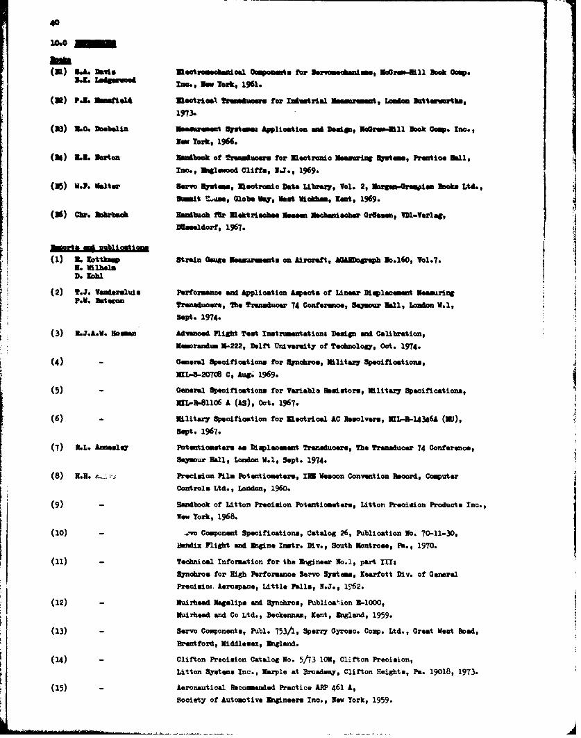
40
M0
(a) 34.a hDais eotrowdaoail Componmet for 3Seweacbmame, Ira41111 Book Omp..K eRoe In., New York$ 1961.
(O) Polo I1. t14 Uaotwioal eneuwn for Iodustral meal smurmemt, Iafon wttmvoths,
1973.
(23) L0. Doebelin IMasss t 1 t"mes Application and Dmiwas, w•wu-lll Book Camp. InO.
NO Tozkr 1966.
(24) L3. Norton m•• tbook of Yreduoere for mectronio •Nesuring 3"at , Pron tooe Malls
Ino.a waineood Cliffs, NTJ., 1969.
(25) V.P. Walter Servo Suetm, Usotrni• Dta Library, Vol. 2, N3wguiotrman s•oko Ltd.,
Smmit letaae Globe Va, NVet icham, Kent, 1969.
(36) 0Ch. Mobrbach Han•aoh fir Nlektrioinbee Neemm Ncaniieher OrBaon DI-Verlag,
eaeldorf, 1967.
• wot .a m nuliastion
(1) .L lottksm Strain Oage Nosaremets on Aircaftt, Ahf liph No.160, Vol.7.No Wilhelm3. Kohl
(2) T.J. Vederelvis Peromaoznce and Applioation Aspeots of Linger Dimploemuot NeoauringP. Y W.oee, The Transduoer 74 Confere.e, Belmoar Nll, London W.1,
Sept. 1974.
(3) L*J.A.V. omwn dancoed Flight Teat Instnmntations Design and Calibration,
Nmoradum 3-222, Delft Univermity of Technolog, Oct. 1974.
(4) - Genel Speoifiotions for Sluohro., Nilitar7 Specificotions,
MX-8-20708 C, Aug. 1969.
(5) - General Specifications for Va-iabla He:lutormt Militar7 Specifications,
KnL-R-81106 A (AS), oot. 1967.
(6) - Military Speoifioation for Ilevtrioal AC Hesolves, UIL-R-14346A (RU),
Sept. 1967.
(7) LL. moulay Pot entionetere an Displacment Transducers, The Transduoer 74 Conferenoe,Seamour Hall, London W.1, Sept. 1974.
(8) N.H. i " Precision Film Potentioseteze, IRS Veoon Convention Reoord, ComputerControls Ltd., London, 1960.
(9) - Habook of Litton Precision Potentiometer., Litton Preoision Produots Inc.,Now Yorok, 1968.
(10) - .. vo Component Specifioations, Catalog 26, Publioation No. 70-11-30,
Berni Flight and bigine Inutr. Div., South Montrose, Pa., 1970.
(11) - Technical Information for the •Igineer No.1, part III:
Synobros for High Perfozmanoe Servo Systems, Kearfott Div. of GeneralPrecisio-. Aerospace, Little Falls, N.J., 1762.
(12) - Nuirhead Usgalips and Synohros, Publioanion 2,1000,
Nuirhead and Co Ltd., Beckenham, Kent, higland, 1959.
(13) - Servo Conponents, Pibl. 753/1, Sperry Gyrosco. Cop. Ltd., Great West Road,
Brantford, Middlesex, Ioland.
(14) - Clifton Preoision Catalog No. 5/13 10o, Clifton Precision,
Litton System. Inc., Marple at Broadwmy, Clifton Heights, Pa. 19018, 1973.
(15) - Aeronautical Recommended Practice ARP 461 A,Society of Automotive Amgineerm Inc., Nw YTork, 1959.