Embed Size (px)
Citation preview

Service ManualQST30 Engine with PowerCommand 3.1Control
DFHA (Spec A−J)DFHB (Spec A−J)DFHC (Spec A−J)DFHD (Spec A−J)
EnglishOriginal Instructions 10-2017 0960−0509 (Issue 9)


Page −3Copyright 2017 Cummins Inc.
Table of Contents
SECTION TITLE PAGEIMPORTANT SAFETY INSTRUCTIONS 3 . . . . . . . . . . . . . . . . . . . . . . . . . . . . . . . . . . . . . . . . . . . . . . 1. Introduction 1−1 . . . . . . . . . . . . . . . . . . . . . . . . . . . . . . . . . . . . . . . . . . . . . . . . . . . . . . . . . . . . . . . . . .
ABOUT THIS MANUAL 1−1 . . . . . . . . . . . . . . . . . . . . . . . . . . . . . . . . . . . . . . . . . . . . . . . TEST EQUIPMENT 1−1 . . . . . . . . . . . . . . . . . . . . . . . . . . . . . . . . . . . . . . . . . . . . . . . . . . HOW TO OBTAIN SERVICE 1−1 . . . . . . . . . . . . . . . . . . . . . . . . . . . . . . . . . . . . . . . . . . . SYSTEM OVERVIEW 1−2 . . . . . . . . . . . . . . . . . . . . . . . . . . . . . . . . . . . . . . . . . . . . . . . . . GENERATOR SET CONTROL FUNCTION 1−2 . . . . . . . . . . . . . . . . . . . . . . . . . . . . . .
2. Control Operation 2−1 . . . . . . . . . . . . . . . . . . . . . . . . . . . . . . . . . . . . . . . . . . . . . . . . . . . . . . . . . . . . . GENERAL 2−1 . . . . . . . . . . . . . . . . . . . . . . . . . . . . . . . . . . . . . . . . . . . . . . . . . . . . . . . . . . . SAFETY CONSIDERATIONS 2−1 . . . . . . . . . . . . . . . . . . . . . . . . . . . . . . . . . . . . . . . . . . PCC POWER ON/STANDBY MODE 2−1 . . . . . . . . . . . . . . . . . . . . . . . . . . . . . . . . . . . .
Standby Mode 2−1 . . . . . . . . . . . . . . . . . . . . . . . . . . . . . . . . . . . . . . . . . . . . . . . . . . . . . Power On Mode 2−1 . . . . . . . . . . . . . . . . . . . . . . . . . . . . . . . . . . . . . . . . . . . . . . . . . . . .
FRONT PANEL 2−4 . . . . . . . . . . . . . . . . . . . . . . . . . . . . . . . . . . . . . . . . . . . . . . . . . . . . . . MENU DISPLAY AND SWITCHES 2−5 . . . . . . . . . . . . . . . . . . . . . . . . . . . . . . . . . . . . . . MAIN MENU 2−5 . . . . . . . . . . . . . . . . . . . . . . . . . . . . . . . . . . . . . . . . . . . . . . . . . . . . . . . . . ENGINE MENU 2−8 . . . . . . . . . . . . . . . . . . . . . . . . . . . . . . . . . . . . . . . . . . . . . . . . . . . . . . GEN MENU 2−11 . . . . . . . . . . . . . . . . . . . . . . . . . . . . . . . . . . . . . . . . . . . . . . . . . . . . . . . . .
3. Circuit Boards and Modules 3−1 . . . . . . . . . . . . . . . . . . . . . . . . . . . . . . . . . . . . . . . . . . . . . . . . . . . GENERAL 3−1 . . . . . . . . . . . . . . . . . . . . . . . . . . . . . . . . . . . . . . . . . . . . . . . . . . . . . . . . . . . DIGITAL BOARD (A32) 3−4 . . . . . . . . . . . . . . . . . . . . . . . . . . . . . . . . . . . . . . . . . . . . . . . .
Switch 3−4 . . . . . . . . . . . . . . . . . . . . . . . . . . . . . . . . . . . . . . . . . . . . . . . . . . . . . . . . . . . . . Connectors 3−4 . . . . . . . . . . . . . . . . . . . . . . . . . . . . . . . . . . . . . . . . . . . . . . . . . . . . . . . . LEDs 3−4 . . . . . . . . . . . . . . . . . . . . . . . . . . . . . . . . . . . . . . . . . . . . . . . . . . . . . . . . . . . . . . Resistors 3−4 . . . . . . . . . . . . . . . . . . . . . . . . . . . . . . . . . . . . . . . . . . . . . . . . . . . . . . . . . .
ENGINE INTERFACE BOARD (A31) 3−6 . . . . . . . . . . . . . . . . . . . . . . . . . . . . . . . . . . . . Connectors 3−6 . . . . . . . . . . . . . . . . . . . . . . . . . . . . . . . . . . . . . . . . . . . . . . . . . . . . . . . . Fuses 3−6 . . . . . . . . . . . . . . . . . . . . . . . . . . . . . . . . . . . . . . . . . . . . . . . . . . . . . . . . . . . . . LEDs 3−6 . . . . . . . . . . . . . . . . . . . . . . . . . . . . . . . . . . . . . . . . . . . . . . . . . . . . . . . . . . . . . .
ANALOG BOARD (A33) 3−9 . . . . . . . . . . . . . . . . . . . . . . . . . . . . . . . . . . . . . . . . . . . . . . . Connectors 3−9 . . . . . . . . . . . . . . . . . . . . . . . . . . . . . . . . . . . . . . . . . . . . . . . . . . . . . . . .
DIGITAL DISPLAY BOARD (A35) 3−10 . . . . . . . . . . . . . . . . . . . . . . . . . . . . . . . . . . . . . . Connectors 3−10 . . . . . . . . . . . . . . . . . . . . . . . . . . . . . . . . . . . . . . . . . . . . . . . . . . . . . . . LEDs 3−10 . . . . . . . . . . . . . . . . . . . . . . . . . . . . . . . . . . . . . . . . . . . . . . . . . . . . . . . . . . . . .
CUSTOMER INTERFACE BOARD (A34) 3−12 . . . . . . . . . . . . . . . . . . . . . . . . . . . . . . . Connectors 3−12 . . . . . . . . . . . . . . . . . . . . . . . . . . . . . . . . . . . . . . . . . . . . . . . . . . . . . . . LEDs 3−12 . . . . . . . . . . . . . . . . . . . . . . . . . . . . . . . . . . . . . . . . . . . . . . . . . . . . . . . . . . . . .
PT/CT BOARD (A36) 3−16 . . . . . . . . . . . . . . . . . . . . . . . . . . . . . . . . . . . . . . . . . . . . . . . . Connectors 3−16 . . . . . . . . . . . . . . . . . . . . . . . . . . . . . . . . . . . . . . . . . . . . . . . . . . . . . . .
VOLTAGE REGULATOR OUTPUT MODULE (A37) 3−18 . . . . . . . . . . . . . . . . . . . . . . Connectors 3−18 . . . . . . . . . . . . . . . . . . . . . . . . . . . . . . . . . . . . . . . . . . . . . . . . . . . . . . . LEDs 3−18 . . . . . . . . . . . . . . . . . . . . . . . . . . . . . . . . . . . . . . . . . . . . . . . . . . . . . . . . . . . . .
GOVERNOR OUTPUT MODULE (A38) 3−20 . . . . . . . . . . . . . . . . . . . . . . . . . . . . . . . .

Page −4 Copyright 2017 Cummins Inc.
Table of Contents (continued)
SECTION TITLE PAGEConnectors 3−20 . . . . . . . . . . . . . . . . . . . . . . . . . . . . . . . . . . . . . . . . . . . . . . . . . . . . . . . Fuses 3−20 . . . . . . . . . . . . . . . . . . . . . . . . . . . . . . . . . . . . . . . . . . . . . . . . . . . . . . . . . . . .
4. Troubleshooting 4−1 . . . . . . . . . . . . . . . . . . . . . . . . . . . . . . . . . . . . . . . . . . . . . . . . . . . . . . . . . . . . . . . . . . . GENERAL 4−1 . . . . . . . . . . . . . . . . . . . . . . . . . . . . . . . . . . . . . . . . . . . . . . . . . . . . . . . . . . . SAFETY CONSIDERATIONS 4−1 . . . . . . . . . . . . . . . . . . . . . . . . . . . . . . . . . . . . . . . . . . STATUS INDICATORS 4−2 . . . . . . . . . . . . . . . . . . . . . . . . . . . . . . . . . . . . . . . . . . . . . . . . RESETTING THE CONTROL 4−2 . . . . . . . . . . . . . . . . . . . . . . . . . . . . . . . . . . . . . . . . . . TROUBLESHOOTING PROCEDURE 4−15 . . . . . . . . . . . . . . . . . . . . . . . . . . . . . . . . . . RACK POSITION FAULT/TEST PROCEDURE 4−83 . . . . . . . . . . . . . . . . . . . . . . . . . .
5. Control Service and Calibration 5−1 . . . . . . . . . . . . . . . . . . . . . . . . . . . . . . . . . . . . . . . . . . . . . . . . . . . . GENERAL 5−1 . . . . . . . . . . . . . . . . . . . . . . . . . . . . . . . . . . . . . . . . . . . . . . . . . . . . . . . . . . . CIRCUIT BOARD REMOVAL/REPLACEMENT 5−1 . . . . . . . . . . . . . . . . . . . . . . . . . . .
Circuit Board Removal Safety Precautions 5−3 . . . . . . . . . . . . . . . . . . . . . . . . . . . . . INITIAL START SETUP MENU 5−5 . . . . . . . . . . . . . . . . . . . . . . . . . . . . . . . . . . . . . . . . . ADJUST MENU 5−7 . . . . . . . . . . . . . . . . . . . . . . . . . . . . . . . . . . . . . . . . . . . . . . . . . . . . . . SETUP AND CALIBRATION MENUS 5−9 . . . . . . . . . . . . . . . . . . . . . . . . . . . . . . . . . . .
Version and Displays Menus 5−9 . . . . . . . . . . . . . . . . . . . . . . . . . . . . . . . . . . . . . . . . . Meters Menu 5−14 . . . . . . . . . . . . . . . . . . . . . . . . . . . . . . . . . . . . . . . . . . . . . . . . . . . . . . Governor/Regulator Menu 5−16 . . . . . . . . . . . . . . . . . . . . . . . . . . . . . . . . . . . . . . . . . . Setup Menu 5−18 . . . . . . . . . . . . . . . . . . . . . . . . . . . . . . . . . . . . . . . . . . . . . . . . . . . . . . .
CALIBRATION PROCEDURE 5−23 . . . . . . . . . . . . . . . . . . . . . . . . . . . . . . . . . . . . . . . . . Initial Start Setup 5−23 . . . . . . . . . . . . . . . . . . . . . . . . . . . . . . . . . . . . . . . . . . . . . . . . . . Voltage and Frequency Adjustment 5−23 . . . . . . . . . . . . . . . . . . . . . . . . . . . . . . . . . . Digital Voltage Display Calibration 5−23 . . . . . . . . . . . . . . . . . . . . . . . . . . . . . . . . . . . Digital Ammeter Display Calibration 5−24 . . . . . . . . . . . . . . . . . . . . . . . . . . . . . . . . . . Digital Power Factor Display Calibration 5−24 . . . . . . . . . . . . . . . . . . . . . . . . . . . . . . Digital Coolant Temperature Display Calibration 5−24 . . . . . . . . . . . . . . . . . . . . . . . Analog Meter Calibration 5−24 . . . . . . . . . . . . . . . . . . . . . . . . . . . . . . . . . . . . . . . . . . .
ENGINE TORQUE ADJUSTMENT 5−25 . . . . . . . . . . . . . . . . . . . . . . . . . . . . . . . . . . . . . ACCESSORY BOX CONTROL COMPONENTS 5−26 . . . . . . . . . . . . . . . . . . . . . . . . .
+TB1 Customer Inputs 5−27 . . . . . . . . . . . . . . . . . . . . . . . . . . . . . . . . . . . . . . . . . . . . . TB1 Customer Outputs 5−27 . . . . . . . . . . . . . . . . . . . . . . . . . . . . . . . . . . . . . . . . . . . . . Run Relays (K11, K12, K13) 5−29 . . . . . . . . . . . . . . . . . . . . . . . . . . . . . . . . . . . . . . . . Alarm Relay (K14) 5−31 . . . . . . . . . . . . . . . . . . . . . . . . . . . . . . . . . . . . . . . . . . . . . . . . . RTD Relay (Optional) 5−32 . . . . . . . . . . . . . . . . . . . . . . . . . . . . . . . . . . . . . . . . . . . . . . Thermistor Relay (Optional) 5−33 . . . . . . . . . . . . . . . . . . . . . . . . . . . . . . . . . . . . . . . . .
ENGINE SENSORS 5−34 . . . . . . . . . . . . . . . . . . . . . . . . . . . . . . . . . . . . . . . . . . . . . . . . . MAGNETIC SPEED PICKUP UNIT (MPU) INSTALLATION 5−36 . . . . . . . . . . . . . . . CURRENT TRANSFORMER (CT) INSTALLATION 5−37 . . . . . . . . . . . . . . . . . . . . . . .
CT Installation Requirements 5−37 . . . . . . . . . . . . . . . . . . . . . . . . . . . . . . . . . . . . . . . DIGITAL BOARD (A32) CALIBRATION 5−38 . . . . . . . . . . . . . . . . . . . . . . . . . . . . . . . . .
6. Servicing the Alternator 6−1 . . . . . . . . . . . . . . . . . . . . . . . . . . . . . . . . . . . . . . . . . . . . . . . . . . . . . . . . . . . . GENERAL 6−1 . . . . . . . . . . . . . . . . . . . . . . . . . . . . . . . . . . . . . . . . . . . . . . . . . . . . . . . . . . . ALTERNATOR/PCC CONTROL ISOLATION PROCEDURE 6−2 . . . . . . . . . . . . . . . .

Page −5Copyright 2017 Cummins Inc.
Table of Contents (continued)
TESTING THE ALTERNATOR 6−3 . . . . . . . . . . . . . . . . . . . . . . . . . . . . . . . . . . . . . . . . .
SECTION TITLE PAGE
Insulation Resistance Testing 6−3 . . . . . . . . . . . . . . . . . . . . . . . . . . . . . . . . . . . . . . . . Drying the Windings 6−4 . . . . . . . . . . . . . . . . . . . . . . . . . . . . . . . . . . . . . . . . . . . . . . . .
EXCITER STATOR 6−5 . . . . . . . . . . . . . . . . . . . . . . . . . . . . . . . . . . . . . . . . . . . . . . . . . . . EXCITER RECTIFIER BRIDGE (ROTATING RECTIFIER ASSEMBLY) 6−6 . . . . . . EXCITER ROTOR 6−8 . . . . . . . . . . . . . . . . . . . . . . . . . . . . . . . . . . . . . . . . . . . . . . . . . . . . MAIN ROTOR (ALTERNATOR FIELD) 6−10 . . . . . . . . . . . . . . . . . . . . . . . . . . . . . . . . . MAIN STATOR 6−11 . . . . . . . . . . . . . . . . . . . . . . . . . . . . . . . . . . . . . . . . . . . . . . . . . . . . . . TESTING THE PMG 6−12 . . . . . . . . . . . . . . . . . . . . . . . . . . . . . . . . . . . . . . . . . . . . . . . . . BEARING INSPECTION/REMOVAL/REPLACEMENT 6−13 . . . . . . . . . . . . . . . . . . . .
P7 Bearing Removal 6−13 . . . . . . . . . . . . . . . . . . . . . . . . . . . . . . . . . . . . . . . . . . . . . . . P7 Bearing Replacement 6−13 . . . . . . . . . . . . . . . . . . . . . . . . . . . . . . . . . . . . . . . . . . . P7 Bearing Lubrication 6−13 . . . . . . . . . . . . . . . . . . . . . . . . . . . . . . . . . . . . . . . . . . . . . HC6 Bearing Removal 6−14 . . . . . . . . . . . . . . . . . . . . . . . . . . . . . . . . . . . . . . . . . . . . . HC6 Bearing Replacement 6−14 . . . . . . . . . . . . . . . . . . . . . . . . . . . . . . . . . . . . . . . . . HC6 Bearing Lubrication 6−14 . . . . . . . . . . . . . . . . . . . . . . . . . . . . . . . . . . . . . . . . . . .
ALTERNATOR DISASSEMBLY 6−15 . . . . . . . . . . . . . . . . . . . . . . . . . . . . . . . . . . . . . . . . Permanent Magnet (PMG) Removal 6−15 . . . . . . . . . . . . . . . . . . . . . . . . . . . . . . . . . Permanent Magnet (PMG) Installation 6−15 . . . . . . . . . . . . . . . . . . . . . . . . . . . . . . . . Main Stator and Rotor Removal 6−18 . . . . . . . . . . . . . . . . . . . . . . . . . . . . . . . . . . . . . Alternator Assembly Removal 6−27 . . . . . . . . . . . . . . . . . . . . . . . . . . . . . . . . . . . . . . .
ALTERNATOR REASSEMBLY 6−28 . . . . . . . . . . . . . . . . . . . . . . . . . . . . . . . . . . . . . . . . ALIGNING ALTERNATOR WITH ENGINE 6−31 . . . . . . . . . . . . . . . . . . . . . . . . . . . . . .
Angular Alignment Procedure 6−32 . . . . . . . . . . . . . . . . . . . . . . . . . . . . . . . . . . . . . . . Sample Alternator Runout Readings 6−33 . . . . . . . . . . . . . . . . . . . . . . . . . . . . . . . . . HC6 Axial Alignment Procedure 6−34 . . . . . . . . . . . . . . . . . . . . . . . . . . . . . . . . . . . . . P7 Axial Alignment Procedure 6−35 . . . . . . . . . . . . . . . . . . . . . . . . . . . . . . . . . . . . . . .
7. Optional Enclosure Fuel Tank System 7−1 . . . . . . . . . . . . . . . . . . . . . . . . . . . . . . . . . . . . . . . . . . . . . GENERAL 7−1 . . . . . . . . . . . . . . . . . . . . . . . . . . . . . . . . . . . . . . . . . . . . . . . . . . . . . . . . . . . WIRING CONNECTIONS 7−1 . . . . . . . . . . . . . . . . . . . . . . . . . . . . . . . . . . . . . . . . . . . . . .
PCC Customer Inputs 7−1 . . . . . . . . . . . . . . . . . . . . . . . . . . . . . . . . . . . . . . . . . . . . . . . FUEL TRANSFER PUMP 7−3 . . . . . . . . . . . . . . . . . . . . . . . . . . . . . . . . . . . . . . . . . . . . . .
Control Panel Switches and Indicators 7−3 . . . . . . . . . . . . . . . . . . . . . . . . . . . . . . . . Operation 7−3 . . . . . . . . . . . . . . . . . . . . . . . . . . . . . . . . . . . . . . . . . . . . . . . . . . . . . . . . . .
EXTERNAL/INTERNAL ALARM PANELS 7−5 . . . . . . . . . . . . . . . . . . . . . . . . . . . . . . . Overfill Indicator/Horn/Silence Button 7−5 . . . . . . . . . . . . . . . . . . . . . . . . . . . . . . . . . Fuel Gauge 7−5 . . . . . . . . . . . . . . . . . . . . . . . . . . . . . . . . . . . . . . . . . . . . . . . . . . . . . . . . Test Button 7−5 . . . . . . . . . . . . . . . . . . . . . . . . . . . . . . . . . . . . . . . . . . . . . . . . . . . . . . . .
RUPTURE BASIN LEAK DETECT SWITCH TEST 7−6 . . . . . . . . . . . . . . . . . . . . . . . . 8. Wiring Diagrams 8−1 . . . . . . . . . . . . . . . . . . . . . . . . . . . . . . . . . . . . . . . . . . . . . . . . . . . . . . . . . . . . . . . . . . .
GENERAL 8−1 . . . . . . . . . . . . . . . . . . . . . . . . . . . . . . . . . . . . . . . . . . . . . . . . . . . . . . . . . . .

Page −6 Copyright 2017 Cummins Inc.
THIS PAGE LEFT INTENTIONALLY BLANK

-3 Copyright 2017 Cummins Inc.
IMPORTANT SAFETY INSTRUCTIONS
SAVE THESE INSTRUCTIONS − This manual con-tains important instructions that should be followedduring installation and maintenance of the genera-tor and batteries.
Before operating the generator set, read the Op-erator’s Manual and become familiar with it and theequipment. Safe and efficient operation can beachieved only if the equipment is properly oper-ated and maintained. Many accidents are causedby failure to follow fundamental rules and precau-tions.
The following symbols, found throughout thismanual, alert you to potentially dangerous condi-tions to the operator, service personnel, or theequipment.
This symbol warns of immediatehazards which will result in severe personal in-jury or death.
WARNING This symbol refers to a hazard or un-safe practice which can result in severe person-al injury or death.
CAUTION This symbol refers to a hazard or un-safe practice which can result in personal injuryor product or property damage.
FUEL AND FUMES ARE FLAMMABLE
Fire, explosion, and personal injury or death can re-sult from improper practices.
DO NOT fill fuel tanks while engine is running,unless tanks are outside the engine compart-ment. Fuel contact with hot engine or exhaustis a potential fire hazard.
DO NOT permit any flame, cigarette, pilot light,spark, arcing equipment, or other ignitionsource near the generator set or fuel tank.
Fuel lines must be adequately secured andfree of leaks. Fuel connection at the engineshould be made with an approved flexible line.Do not use zinc coated or copper fuel lines withdiesel fuel.
Be sure all fuel supplies have a positive shutoffvalve.
Be sure battery area has been well-ventilatedprior to servicing near it. Lead-acid batteriesemit a highly explosive hydrogen gas that canbe ignited by arcing, sparking, smoking, etc.
EXHAUST GASES ARE DEADLY
Provide an adequate exhaust system to prop-erly expel discharged gases away from en-closed or sheltered areas and areas where in-dividuals are likely to congregate. Visually andaudibly inspect the exhaust daily for leaks perthe maintenance schedule. Make sure that ex-haust manifolds are secured and not warped.Do not use exhaust gases to heat a compart-ment.
Be sure the unit is well ventilated.
Engine exhaust and some of its constituentsare known to the state of California to causecancer, birth defects, and other reproductiveharm.
MOVING PARTS CAN CAUSE SEVEREPERSONAL INJURY OR DEATH
Keep your hands, clothing, and jewelry awayfrom moving parts.
Before starting work on the generator set, dis-connect battery charger from its AC source,then disconnect starting batteries, negative (−)cable first. This will prevent accidental starting.
Make sure that fasteners on the generator setare secure. Tighten supports and clamps,keep guards in position over fans, drive belts,etc.
Do not wear loose clothing or jewelry in the vi-cinity of moving parts, or while working on elec-trical equipment. Loose clothing and jewelrycan become caught in moving parts.
If adjustment must be made while the unit isrunning, use extreme caution around hot man-ifolds, moving parts, etc.
DO NOT OPERATE IN FLAMMABLE ANDEXPLOSIVE ENVIRONMENTS
Flammable vapor can cause an engine to over-speed and become difficult to stop, resulting in pos-sible fire, explosion, severe personal injury anddeath. Do not operate a generator set where a flam-

-4Copyright 2017 Cummins Inc.
mable vapor environment can be created by fuelspill, leak, etc., unless the generator set is equippedwith an automatic safety device to block the air in-take and stop the engine. The owners and opera-tors of the generator set are solely responsible foroperating the generator set safely. Contact your au-thorized Cummins distributor for more information.
ELECTRICAL SHOCK CAN CAUSESEVERE PERSONAL INJURY OR DEATH
Remove electric power before removing pro-tective shields or touching electrical equip-ment. Use rubber insulative mats placed ondry wood platforms over floors that are metal orconcrete when around electrical equipment.Do not wear damp clothing (particularly wetshoes) or allow skin surface to be damp whenhandling electrical equipment. Do not wearjewelry. Jewelry can short out electrical con-tacts and cause shock or burning.
Use extreme caution when working on electri-cal components. High voltages can cause inju-ry or death. DO NOT tamper with interlocks.
Follow all applicable state and local electricalcodes. Have all electrical installations per-formed by a qualified licensed electrician. Tagand lock open switches to avoid accidental clo-sure.
DO NOT CONNECT GENERATOR SET DI-RECTLY TO ANY BUILDING ELECTRICALSYSTEM. Hazardous voltages can flow fromthe generator set into the utility line. Thiscreates a potential for electrocution or propertydamage. Connect only through an approvedisolation switch or an approved paralleling de-vice.
GENERAL SAFETY PRECAUTIONS
Coolants under pressure have a higher boilingpoint than water. DO NOT open a radiator orheat exchanger pressure cap while the engineis running. To prevent severe scalding, let en-gine cool down before removing coolant pres-sure cap. Turn cap slowly, and do not open itfully until the pressure has been relieved.
Used engine oils have been identified by somestate or federal agencies as causing cancer orreproductive toxicity. When checking orchanging engine oil, take care not to ingest,breathe the fumes, or contact used oil.
Keep multi-class ABC fire extinguishers handy.Class A fires involve ordinary combustible ma-terials such as wood and cloth; Class B fires,combustible and flammable liquid fuels andgaseous fuels; Class C fires, live electricalequipment. (ref. NFPA No. 10).
Make sure that rags are not left on or near thegenerator set.
Make sure generator set is mounted in a man-ner to prevent combustible materials from ac-cumulating under or near the unit.
Remove all unnecessary grease and oil fromthe unit. Accumulated grease and oil cancause overheating and engine damage whichpresent a potential fire hazard.
Keep the generator set and the surroundingarea clean and free from obstructions. Re-move any debris from the set and keep the floorclean and dry.
Do not work on this equipment when mentallyor physically fatigued, or after consuming anyalcohol or drug that makes the operation ofequipment unsafe.
Substances in exhaust gases have been iden-tified by some state or federal agencies ascausing cancer or reproductive toxicity. Takecare not to breath or ingest or come into contactwith exhaust gases.
Do not store any flammable liquids, such asfuel, cleaners, oil, etc., near the generator set.A fire or explosion could result.
Wear hearing protection when going near anoperating generator set.
To prevent serious burns, avoid contact withhot metal parts such as radiator system, turbocharger system and exhaust system.
CONTAINERIZED RENTAL UNITSPOTENTIAL TIPPING PROBLEM
On all containerized rental equipment, there is a po-tential problem of having the container tip forwardover the landing legs, pulling the axles off theground when the container is fully fueled without asemi-tractor under the king pin. Jack stands for thefront of the container are required to mitigate thispotential problem.
Note: The figure below shows the jack stands and theirplacement at the nose of the container.

-5 Copyright 2017 Cummins Inc.
Jack Stands at Nose of Container
KEEP THIS MANUAL NEAR THE GENERATOR SET FOR EASY REFERENCE

-6Copyright 2017 Cummins Inc.
THIS PAGE LEFT INTENTIONALLY BLANK

1-1 Copyright 2017 Cummins Inc.
1. Introduction
ABOUT THIS MANUAL
This manual provides troubleshooting and repair in-formation regarding the PowerCommand Control3100 (PCC) and alternators for the generator setslisted on the front cover. Engine service instructionsare in the applicable engine service manual. Oper-ating and maintenance instructions are in the appli-cableOperator’s Manual.
This manual does not have instructions for servic-ing printed circuit board assemblies. After determin-ing that a printed circuit board assembly is faulty, re-place it. Do not repair it. Attempts to repair a printedcircuit board can lead to costly damage to the equip-ment.
This manual contains basic (generic) wiring dia-grams and schematics that are included to help introubleshooting. Service personnel must use theactual wiring diagram and schematic shipped witheach unit. The wiring diagrams and schematics thatare maintained with the unit should be updatedwhen modifications are made to the unit.
Read Important Safety Instructions and carefullyobserve all instructions and precautions in thismanual.
TEST EQUIPMENTTo perform the test procedures in this manual, thefollowing test equipment must be available True RMS meter for accurate measurement of
small AC and DC voltages. Fluke models 87 or8060A are good choices.
Grounding wrist strap to prevent circuit boarddamage due to electrostatic discharge (ESD).
Battery Hydrometer Jumper Leads Tachometer or Frequency Meter Wheatstone Bridge or Digital Ohmmeter Variac Load Test Panel Megger or Insulation Resistance Meter PCC Service Tool Kit (Harness Tool and Sen-
sor Tool)
HOW TO OBTAIN SERVICEAlways give the complete Model, Specification andSerial number of the generator set as shown on thenameplate when seeking additional service infor-mation or replacement parts. The nameplate is lo-cated on the side of the alternator output box.
WARNING Incorrect service or replacement ofparts can result in severe personal injury ordeath, and/or equipment damage. Service per-sonnel must be trained and experienced to per-form electrical and mechanical service. Readand follow Important Safety Instructions, onpages iii and iv.

1-2Copyright 2017 Cummins Inc.
SYSTEM OVERVIEWThe PCC is a microprocessor-based control forCummins generator sets. It provides fuel controland engine speed governing, main alternator volt-age output regulation, and complete generator setcontrol and monitoring.The operating software provides control of the gen-erator set and its performance characteristics, anddisplays performance information on a digital dis-play panel. It accepts menu-driven control and set-up input from the push button switches on the frontpanel.
GENERATOR SET CONTROL FUNCTIONFigure 1-1 shows some of the control functions. Amore complete block diagram is provided in Section3. A system schematic is provided in Section 8.
The PCC monitors frequency from both the mag-netic pick-up (MPU) and the main stator inputs. Thecontrol sends a low power pulse-width modulated(PWM) signal to the governor output module, whichthen sends an amplified signal to the engine fuelcontrol.
The external PT/CT module reduces alternator volt-age to approximately 18 VAC, and produces a rep-resentative AC voltage from CT output current. Thevoltage regulation function sends a low power PWMsignal to the voltage regulator output module, whichthen sends an amplified signal to the exciter stator.
Oil, coolant, and exhaust temperatures are sensedby variable resistance element sensors. Oil pres-sure is sensed by a capacitive element active sen-sor.
Sensors
GovernorOutput
Output
MPU
NS
PMG
BatteryBT1
FuelControl
Regulator
FIGURE 1-1. GENERATOR SET CONTROL FUNCTIONS

2-1 Copyright 2017 Cummins Inc.
2. Control Operation
GENERAL
The following describes the function and operationof the PowerCommand generator set control. All in-dicators, displays, meters and control switches arelocated on the face of the control panel as illustratedin Figure 2-1.
Normally, generator set configuration options areset at the factory. When a new control is installed ona generator set or when parts are replaced, the con-trol must be configured for that generator set withthe use of the “Initial Start Setup” portion of the inter-nal software. Setup and calibration procedures aredescribed in Section 5.
The automatic voltage regulator (AVR) and gover-nor operation characteristic adjustments are alsodescribed in Section 5.
SAFETY CONSIDERATIONS
AC power is present when the set is running. Do notopen the alternator output box while the set is run-ning.
WARNING Contacting high voltage compo-nents can cause electrocution, resulting in se-vere personal injury or death. Do not open thealternator output box while the set is running.Read and observe all WARNINGS and CAU-TIONS in your generator set manuals.
The PCC control cabinet must be opened only bytechnically qualified personnel.
CAUTION The PCC control cabinet must beopened only by technically qualified personnel.Lower level voltages (18 VAC to 24 VDC) arepresent in PCC control cabinet. These voltagescan cause electrical shock, resulting in person-al injury.
Even with power removed, improper handlingof components can cause electrostatic dis-charge and damage to circuit components.
PCC POWER ON/STANDBY MODE
Standby ModeIn the Standby (sleep) mode (selector switch S5 onthe Digital Board is set to the right and the generatorset is not running), the control’s operating softwareis inactive and the LEDs and displays on front panelare all off.The operating software is initialized and the frontpanel is turned on in response to a run signal or anyone of eight “wake up” inputs from remote sensingswitches.The wake up signals are: Emergency Stop
Low Coolant Level
Low Coolant Temperature
Low Fuel
Customer Fault Inputs 2 and 3
Run Selected on Run/Off/Auto Switch
Remote Start Signal in Auto Mode
Self Test switchTo activate and view the menu displays, press andrelease the Self Test switch. The PCC will initializethe operating software and permit operation of themenu display panel. If no menu selections aremade, the power to the control panel will shut downafter 30 seconds.
Power On ModeIn the Power On (awake) mode (selector switch S5on the Digital Board is set to the left), the PCC willinitialize the operating software and permit opera-tion of the menu display panel. (Refer to Figure 3-1for S5 location.) Power will stay on until switch (S5)is set to the Standby mode. It is recommended thatswitch S5 be left in the Power On mode in all ap-plication, except those where auxiliary batterycharging is not available.
CAUTION Electrostatic discharge will damagecircuit boards. Always wear a grounding wriststrap when touching or handling circuit boardsor socket-mounted ICs and when disconnect-ing or connecting harness connectors.

2-2Copyright 2017 Cummins Inc.
ACTIVE SWITCHINDICATOR
(1 of 6)
UPPER ANDLOWER SCALE
INDICATOR
FREQUENCYMETER
KILOWATT METER(PERCENT LOAD)
PHASE SELECTORSWITCH ANDINDICATORS
RUN/OFF/AUTOSWITCH
RESETSWITCH
NON-AUTOMATICWARNING
SHUTDOWNSTATUS INDICATORS
EMERGENCY STOPPUSH BUTTON
(Turn CW to reset)
PANEL LAMPSWITCH
SELF TESTSWITCH
MENUSWITCH
ACVOLTMETER
(DUAL SCALE)
AC AMMETER(PERCENT AMPS)
ALPHANUMERICDISPLAY
MENUSELECTION
SWITCH (1 of 4)
FIGURE 2-1. FRONT PANEL

2-3 Copyright 2017 Cummins Inc.
FRONT PANEL
Figure 2-1 shows the features of the front panel.
AC Voltmeter: Dual scale instrument indicates ACvoltage. Measurement scale in use is shown onscale indicator lamp.
AC Ammeter: Indicates current output in percent ofmaximum rated current. (Percent current is basedon .8 PF.)
Kilowatt Meter: Indicates 3-phase AC power out-put as percent of rated load.
Frequency Meter: Indicates alternator output fre-quency in hertz.
Upper and Lower Scale Indicator Lamps: Indi-cate AC voltmeter scale.
Digital Display: This two-line, 16-character per linealphanumeric display is used in the menu-drivenoperating system, in conjunction with the displaymenu selection switches and the Menu switch. Re-fer to the menu trees later in this section. The dis-play is also used to show warning and shutdownmessages.
Display Menu Selection Switches: Four momen-tary switches—two on each side of the digital dis-play window—are used to step through the variousmenu options and to adjust generator set parame-ters. The green arrow adjacent to the switch is litwhen the switch can be used (switch is “active”).
Menu Switch: Press this switch to return the digitaldisplay to the MAIN MENU. Refer to the menu treeslater in this section.
Reset Switch: Press this switch to reset warningand shutdown messages after the condition hasbeen corrected. To reset a shutdown message withthe Reset switch, the Run/Off/Auto switch must bein the Off position.
With the Run/Off/Auto switch in the Auto mode,shutdown faults can be reset by removing the re-mote start input and then cycling the remote resetinput.
Self Test Switch: Press and hold this switch to lightall front panel LEDs and cycle through all shutdownand warning messages.
In the Standby (sleep) mode, with the generator setnot running, the control’s operating software is inac-tive and the LEDs and displays on front panel are alloff.
To activate and view the menu displays withoutstarting the generator set, press and hold the Self
Test switch until the front panel LEDs light. ThePCC will initialize the operating software and permitoperation of the menu display panel. If no menuselections are made, a software timer will shutdown the power after 30 seconds.
Panel Lights Switch: Press this switch to turn con-trol panel illumination on and off. The illuminationwill shut off after about eight minutes.
Phase Selector Switch and Indicators: Press thismomentary switch to select phases of alternatoroutput to be measured by the analog AC voltmeterand ammeter. LEDs indicate the selected phase.
Run/Off/Auto Switch: This switch starts and stopsthe set locally, or enables start/stop control of theengine from a remote location. (Ground to start.)
Emergency Stop Button: Push the switch in foremergency shutdown of the engine.
Remote Reset switch will not reset emergency stop.Can only be reset at the PCC front panel.
To reset:
1. Turn the switch clockwise and allow it to popout.
2. Move the Run/Off/Auto switch to Off.
3. Press the front panel Reset switch.
4. Select Run or Auto, as required.
Non-Automatic Status Indicator: This red lampflashes continuously when the Run/Off/Auto switchis not in the Auto position.
Warning Status Indicator: This yellow lamp is litwhenever the control detects a warning condition.After the condition is corrected, warning indicatorscan be reset by pressing the Reset switch. (It is notnecessary to stop the generator set.)
With the Run/Off/Auto switch in the Auto mode,warnings can also be reset by cycling the remote re-set input after the condition is corrected.
Shutdown Status Indicator: This red lamp is litwhenever the control detects a shutdown condition.After the condition is corrected, shutdown indica-tors can be reset by turning the Run/Off/Auto switchto the Off position, and pressing the Reset switch.In Auto mode, shutdowns can be reset by removingthe remote start input and then cycling the remotereset input.Emergency Stop shutdown status (Code 102) can bereset only at the PCC front panel.

2-4Copyright 2017 Cummins Inc.
FIGURE 2-2. DIGITAL DISPLAY AND MENU SELECTION SWITCHES
MENU DISPLAY AND SWITCHES
Figure 2-2 shows the digital display and the menuselection switches. Refer to heading “Front Panel”which describes the menu display and switches.
In the Standby Mode, to activate and view the menudisplays without starting the generator set, pressand release the Self Test switch. This will initializethe PCC operating software and permit operation ofthe menu display panel. If no menu selections aremade, a software timer will shut down the power af-ter 30 seconds. In the Power On Mode, power iscontinuously supplied to the control panel. Displaywill always remain on.
In the digital display, the “>>” symbol indicates thatselecting the adjacent button causes the operatingprogram to branch to the next menu display—asshown in the menu diagrams.
In the digital display, the “<<” symbol indicates thatselecting the adjacent button causes the operatingprogram to go back to the previous menu display.
MAIN MENU
The facing page shows the main menu and a blockrepresentation of the available submenus.As shown in the diagram, the main menu canbranch into one of four directions.To display engine parameters, such as oil pressureand temperature, water temperature, engine speed(RPM), and exhaust temperature, press the buttonnext to the word “ENGINE” in the display. Refer toENGINE MENU in this section.To display alternator parameters, such as volts,amps, power (kW), and frequency, press the buttonnext to the word “GEN” in the display. Turn to theGEN MENU in this section.To adjust output voltage and frequency, or start andstop delays, press the button next to the word “AD-JUST” in the display. Refer to ADJUST MENU inSection 5.
To display the selected generator set model and theresident version software, press the button next tothe “>>” in the display. Refer to VERSION & DIS-PLAYS MENUS in Section 5.

2-5 Copyright 2017 Cummins Inc.
DISPLAYS <<METERS >>
VOLTAGE _______ >>
< >
< >
ENGINE GEN
ADJUST >>
< ACTIVE BUTTON
< ACTIVE BUTTONSELECTED
INACTIVE BUTTON
RESET MENU >
RETURN TO MAIN MENU
CLEAR WARNING ANDSHUTDOWN MESSAGES
PAGES 2-6 & 2-7
MAIN MENU
(ACCESS CODE)
PAGES 2-8 & 2-9
OIL <<COOLANT >>
BATTERY <<HOURS >>
RPM <<EXHAUST
FREQUENCY _______ >>
START DELAY _______ SEC >>
STOP DELAY _______SEC >>
VOLTS <<AMPS >>
POWER <<KW HRS >>
%GOV / REG <<FREQUENCY
GOV / REG <<SETUP >>
SECTION 5
SECTION 5
SECTION 5SECTION 5
RACKTEST <<SECTION 5
IDLE SPEED _______RPM >>
VERSIONSETUP / CALHISTORY
2-6Copyright 2017 Cummins Inc.
ENGINE MENU
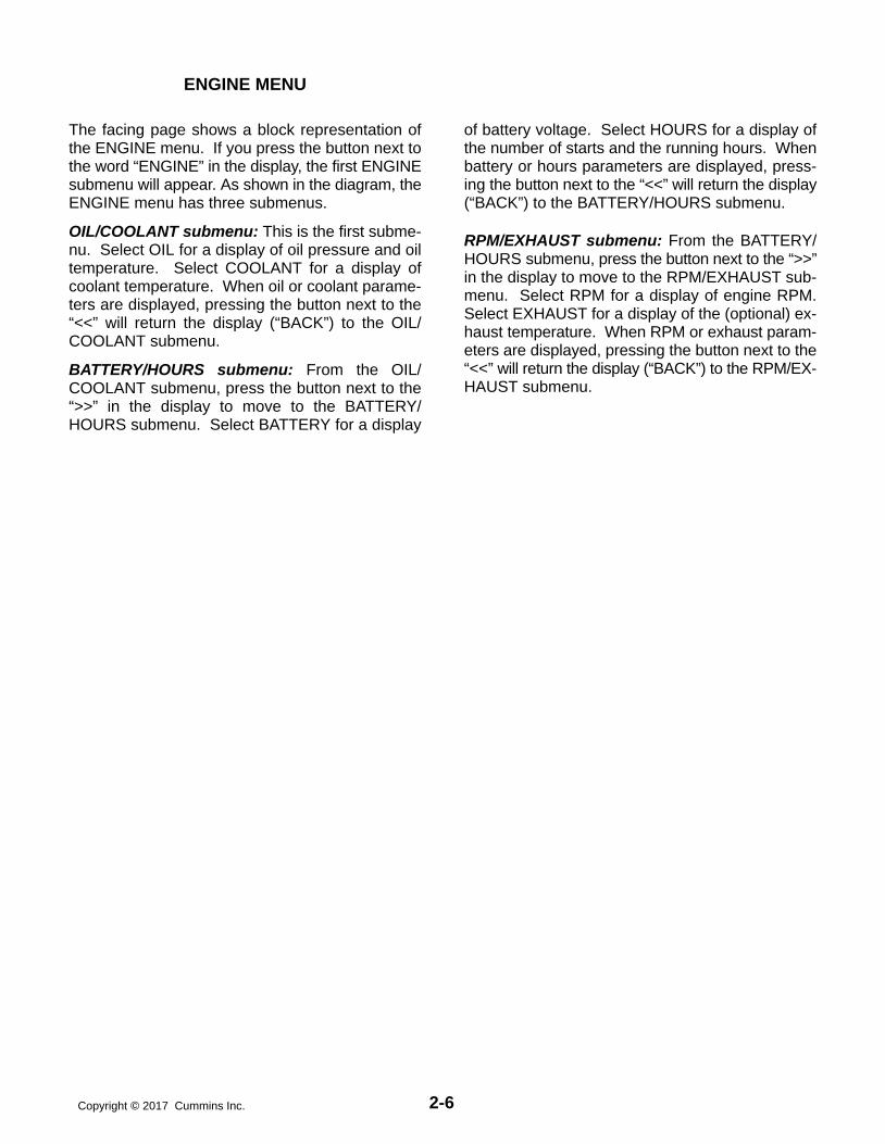
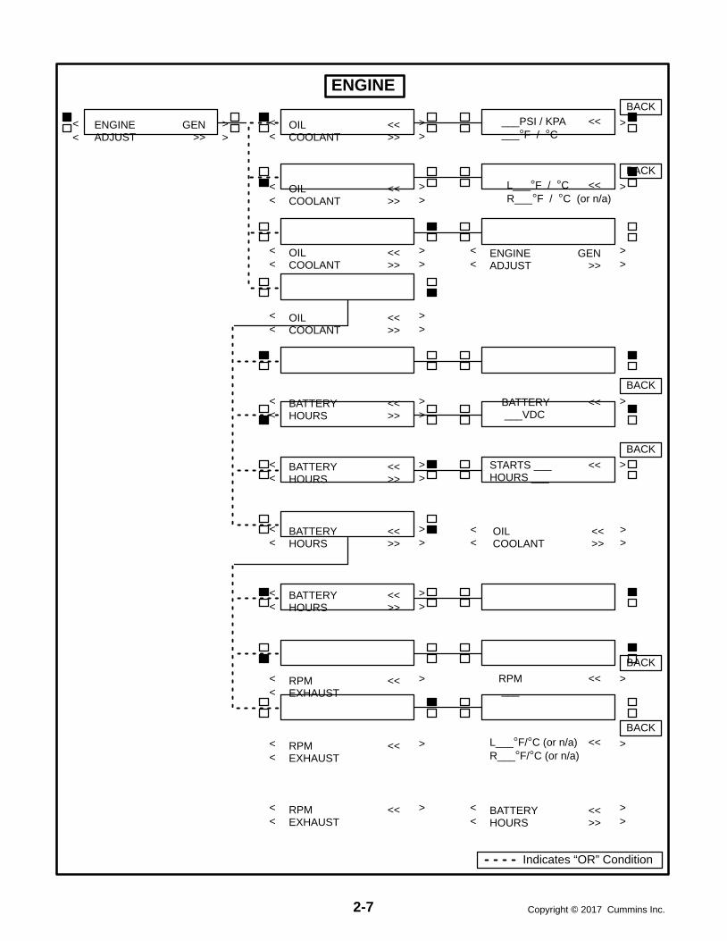
The facing page shows a block representation ofthe ENGINE menu. If you press the button next tothe word “ENGINE” in the display, the first ENGINEsubmenu will appear. As shown in the diagram, theENGINE menu has three submenus.
OIL/COOLANT submenu: This is the first subme-nu. Select OIL for a display of oil pressure and oiltemperature. Select COOLANT for a display ofcoolant temperature. When oil or coolant parame-ters are displayed, pressing the button next to the“<<” will return the display (“BACK”) to the OIL/COOLANT submenu.
BATTERY/HOURS submenu: From the OIL/COOLANT submenu, press the button next to the“>>” in the display to move to the BATTERY/HOURS submenu. Select BATTERY for a display
of battery voltage. Select HOURS for a display ofthe number of starts and the running hours. Whenbattery or hours parameters are displayed, press-ing the button next to the “<<” will return the display(“BACK”) to the BATTERY/HOURS submenu.
RPM/EXHAUST submenu: From the BATTERY/HOURS submenu, press the button next to the “>>”in the display to move to the RPM/EXHAUST sub-menu. Select RPM for a display of engine RPM.Select EXHAUST for a display of the (optional) ex-haust temperature. When RPM or exhaust param-eters are displayed, pressing the button next to the“<<” will return the display (“BACK”) to the RPM/EX-HAUST submenu.
2-7 Copyright 2017 Cummins Inc.
BATTERY << ___VDC
< >
< >
< >
< >
>L___F / C <<R___F / C (or n/a)
>
>
>
< >
< >
< >< >
BATTERY <<HOURS >>
>
< >
< >
< >ENGINE GENADJUST >>
< >< >
OIL <<COOLANT >>
< > ___PSI / KPA << ___F / C
ENGINE GENADJUST >>
< >< >
< >OIL <<COOLANT >>
< >
< >OIL <<COOLANT >>
OIL <<COOLANT >>
< >
>
< >BATTERY <<HOURS >>
STARTS ___ <<HOURS ___
< >
< >BATTERY <<HOURS >>
< >BATTERY <<HOURS >>
L___F/C (or n/a) <<R___F/C (or n/a)
<RPM <<EXHAUST
< >
<RPM <<EXHAUST
< >
<RPM <<EXHAUST
RPM << ___
BATTERY <<HOURS >>< >
BACK
BACK
BACK
BACK
BACK
BACK
ENGINE
OIL <<COOLANT >>
Indicates “OR” Condition

2-8Copyright 2017 Cummins Inc.
GEN MENU
The facing page shows a block representation ofthe GEN menu. If you press the button next to theword “GEN” in the display, the first GEN submenuwill appear.
As shown in the diagram, the GEN menu has threesubmenus.
VOLTS/AMPS submenu: This is the first subme-nu. Select VOLTS for a display of a line-line or line-neutral selection. Select line-line or line-neutral forthe desired voltage display. Select AMPS for a dis-play of L1, L2, and L3 current in amps. When volt-age or current parameters are displayed, pressingthe button next to the “<<” will return the display(“BACK”) to the L-L/L-N submenu.
If DELTA is selected in the Initial Start Setup subme-nu, when selecting VOLTS, the “line-line” or “line-neutral” submenus will not be displayed, only theL1-2, L2-3, L3-1 submenu will be displayed.
POWER / KW HOURS submenu: From the VOLTS/AMPS submenu, press the button next to the “>>” inthe display to move to the POWER/KW HOURS sub-
menu. Select POWER for a display of power outputin kilowatts and a power factor value. Select KWHOURS for a display of kilowatt hours. When poweror kW hours parameters are displayed, pressing thebutton next to the “<<” will return the display(“BACK”) to the POWER/KW HOURS submenu.
The PF reading will contain an asterisk if the powerfactor is leading (for example, *.3PF).
N/A is displayed in the PF field when the generatorset is not running.
%GOV/REG/FREQUENCY submenu: From thePOWER/KW HOURS submenu, press the buttonnext to the “>>” in the display to move to the %GOV/REG/FREQUENCY submenu. Select %GOV/REGfor a display of voltage regulator and governor dutycycle (drive) levels in percentage of maximum. Se-lect FREQUENCY for a display of the alternator out-put frequency. When voltage regulator and gover-nor or frequency parameters are displayed, press-ing the button next to the “<<” will return the display(“BACK”) to the %GOV/REG/FREQUENCY sub-menu.

2-9 Copyright 2017 Cummins Inc.
<
< >
< >< > < >
< >
< >< >
< >
< >
< > < >
< >
< >
< >
<< >
>< ><< >
ENGINE GENADJUST >>< >
VOLTS <<AMPS >>
L − L <<L − N
>
L12 L23 L31 <<___ ___ ___
L1N L2N L3N <<___ ___ ___
BACK
BACK
<
BACK
< >< >
VOLTS <<AMPS >>
>L1 L2 L3 <<___ ___ ___
BACK
VOLTS <<AMPS >>
ENGINE GENADJUST >>< >
VOLTS <<AMPS >>
POWER <<KW HRS >>
> ___ KW << ___ PF
BACK
< >< >POWER <<
KW HRS >>> KW HRS <<
____________
BACK
< >POWER <<KW HRS >>
POWER <<KW HRS >>
%GOV / REG <<FREQUENCY
BACK
< ><
%GOV / REG <<FREQUENCY
< ><
%GOV / REG <<FREQUENCY
> GOVERNOR_ % << REGULATOR_ %
> FREQUENCY << ___ HZ
BACK
BACK
BACK
GEN
L − L <<L − N
L − L <<L − N
Indicates “OR” Condition

2-10Copyright 2017 Cummins Inc.
THIS PAGE LEFT INTENTIONALLY BLANK

3-1 Copyright 2017 Cummins Inc.
3. Circuit Boards and Modules
GENERAL
This section describes the function of the PCC cir-cuit boards and modules that are contained in thecontrol panel (Figure 3-1) and the accessory box.The block diagram in Figure 3-2, shows both inter-nal and external components of the PCC system.
The system schematics are provided in Section 7 ofthis manual.
CAUTION Electrostatic discharge will damagecircuit boards. Always wear a grounding wriststrap when touching or handling circuit boardsor socket-mounted ICs.
CUSTOMER INTERFACEA34
ENGINE INTERFACEA31
ANALOG BOARDA33
DIGITAL BOARDA32
DISPLAY BOARDA35
RUN/OFF/AUTOSWITCH S12
S5 POWER ON/STANDBY SWITCH
GOVERNOROUTPUT MODULE
A38
PT/CTBOARD A36
VOLTAGEREGULATOR
OUTPUT MODULEA37
FIGURE 3-1. CIRCUIT BOARD LOCATIONS

3-2Copyright 2017 Cummins Inc.
FIGURE 3-2. BLOCK DIAGRAM

3-3 Copyright 2017 Cummins Inc.
DIGITAL BOARD (A32)
The digital circuit board (Figure 3-3) contains themicroprocessor and the operational software for thecontrol. It connects to all other boards inside thecontrol. This board also provides the analog-to-digi-tal conversions for the PCC.
SwitchS5 Slide the switch to the left to select the Power
On (awake) mode. Control panel power/oper-ating software will remain on until the switch isreset to the Standby mode. It is recom-mended that switch S5 be left in the Power Onmode in all applications, except those whereauxiliary battery charging is not available.
Slide right to put the PCC in the Standby(“sleep”) mode. In this mode, the PCC oper-ating software will be initiated by selection ofRun on the front panel, by pressing the SelfTest switch, by a remote start input (in Automode), or by any one of several “wake-up”signals from external switches.
Connectors
The digital board has five connectors. They are:
J1 Serial Interface RS232
J2 Connects to J4 on A34 Customer Interfaceboard
J3 Connects to J2 on A33 Analog boardJ4 Connects to J1 on A31 Engine Interface
boardJ5 Connects to J5 on A35 Digital Display assem-
bly
LEDsThe digital board has seven LED’s that indicate thefollowing conditions:
DS1 Spare (Green)DS2 Spare (Green)DS3 +18 VDC supply OK (Green)DS4 +5 VDC supply OK (Green)DS5 Run (Flashes once per second if software
is running) (Green)DS6 +24 VDC B+ supply OK (Green)DS7 +12 VDC supply OK (Green)
ResistorsThe three resistors (R36, R37 and R38) are used toconfigure the digital board to the generator set mod-el number. Refer to Digital Board (A32) Calibrationin Section 5, which provides a detailed descriptionof how to configure this board.
DS1DS2DS3DS4
DS7DS6DS5
R36R37R38
FIGURE 3-3. DIGITAL BOARD (A32)

3-4Copyright 2017 Cummins Inc.
ENGINE INTERFACE BOARD (A31)The engine interface board (Figure 3-4) reads usercontrol inputs, monitors engine, alternator and sys-tem status, and initiates the appropriate action fornormal operating and fault conditions (warning orshutdown).
This board is connected to the engine sensors, bat-tery, starter, governor output module, voltage regu-lator output module, and the magnetic pick-up(MPU).
The engine interface board can also be connectedto an optional network interface module for networkaccess.
During a typical start sequence the LED’s light asfollows:
1. DS11 lights when a remote run signal is re-ceived and S12 is in the Auto position, or S12 ismoved to the Run position.
2. DS12 lights when the magnetic pick-up voltageis sensed (engine is cranking). (When the en-gine is cranking, the mag pickup output shouldbe a minimum of 1 volt.)
3. DS11 extinguishes, DS9 lights and DS10 isdimly lit when the alternator is running.
Connectors
The engine interface board has seven connectorsand one terminal strip. They are:
J1 Connects to J4 on A32 Digital board.J2 Connects to J1 on A33 Analog board.J3 Connects to display board, front panel
switches and meters.
J4 Connects to customer connections and to en-gine harness which includes magnetic pick-up.
J5 Connects to engine sensors.J6 Connects to Genset Control module (GCM).J7 Connects to Genset Control module (GCM).
Fuses
The engine interface board has two replaceablefuses. They are:
F1 Control B+ (5 Amps)F3 Aux. B+ (5 Amps). (Panel lamps and run/start
contacts).
LEDs
The engine interface board has 10 LED’s that indi-cate the following conditions:
DS1 Low Fuel Alarm input (Red)DS2 Low Coolant Level Alarm input (Red)DS3 Low Engine Temperature Alarm input (Red)DS4 S12 in Run position (Green). S12 is the Run/
Off/Auto switch.DS5 S12 in Auto position (Green)DS6 Emergency Stop (Red)DS7 Not configured.DS8 Not configured.DS9 AVR duty cycle (Green). Brighter indicates
larger duty cycle.DS10 GOV duty cycle (Green). Brighter indicates
larger duty cycle.DS11 Start pilot relay output (Red)DS12 Run pilot relay output (Red)

3-5 Copyright 2017 Cummins Inc.
5A AUX B+
5A CNTRL B+
DS1 - LOW FUEL
DS2 - LO COOL
DS5 - AUTO
DS10 - GOV
DS11 - START
DS3 - LET
DS4 - RUN SW
DS6 - E-STOP
DS9 - REG
DS12 - RUN RLY
J4(WHITE)
J5(BLUE)
FIGURE 3-4. ENGINE INTERFACE BOARD

3-6Copyright 2017 Cummins Inc.
ANALOG BOARD (A33)
The analog board (Figure 3-5) is the only circuitboard inside the control that has no LED’s. Thereare two versions of the analog board that are usedfor paralleling and non-paralleling systems.
This board interprets all analog input signals andconverts the analog signals to 0−5 VDC for the digi-tal board.
Connectors
The analog board has four connectors with ribboncables permanently soldered to them. They are:
J1 Connects to J2 on A31 Engine Interfaceboard
J2 Connects to J3 on A32 Digital boardJ3 Spare analog inputsJ4 Connects to J1 on A34 Customer Interface
board
FIGURE 3-5. ANALOG BOARD

3-7 Copyright 2017 Cummins Inc.
DIGITAL DISPLAY BOARD (A35)The digital board (Figure 3-6) connects to all metersand the LED display.
Connectors
The digital board has three connectors. They are:
J1 Connects to front panel membrane switchesJ5 Connects to J2 on A32 Digital board. (With J5
disconnected, the display will be non-func-tional, but the PCC will continue to operate.)
J6 Connects to meters, Run/Off/Auto switch, J3on A31 Engine Interface board
LEDs
The digital board has 18 LED’s that are used to indi-cate operational status of the generator set andcontrol panel mode/switch selections.
DS9 Not In Auto (Red)DS10 Upper Scale (Green)DS11 Left Top Arrow (Green)DS12 Right Top Arrow (Green)
DS13 Warning (Amber)
DS14 Lower Scale (Green)
DS15 Shutdown (Red)
DS20 Left Bottom Arrow (Green)
DS21 Right Bottom Arrow (Green)
DS22 Automatic mains failure (AMF) for parallel-ing application only: Breaker Closed (Red)
DS23 Phase A (Green)
DS24 Reset Arrow (Green)
DS25 Menu Arrow (Green)
DS26 Automatic mains failure (AMF) for parallel-ing application only: Breaker Open (Green)
DS27 Phase B (Green)
DS29 Phase C (Green)
DS36 Automatic mains failure (AMF) for parallel-ing application only: Breaker Closed (Red) −or − paralleling application: Breaker Open(Green)
DS37 Automatic mains failure (AMF) for parallel-ing application only: Breaker Open (Green)
DS29DS27
DS23
DS15
DS13
DS9
DS24
DS11
DS20
DS25
DS12
DS21
DS14
DS10
DS26
DS22
DS37
DS36
FIGURE 3-6. DIGITAL DISPLAY BOARD

3-8Copyright 2017 Cummins Inc.
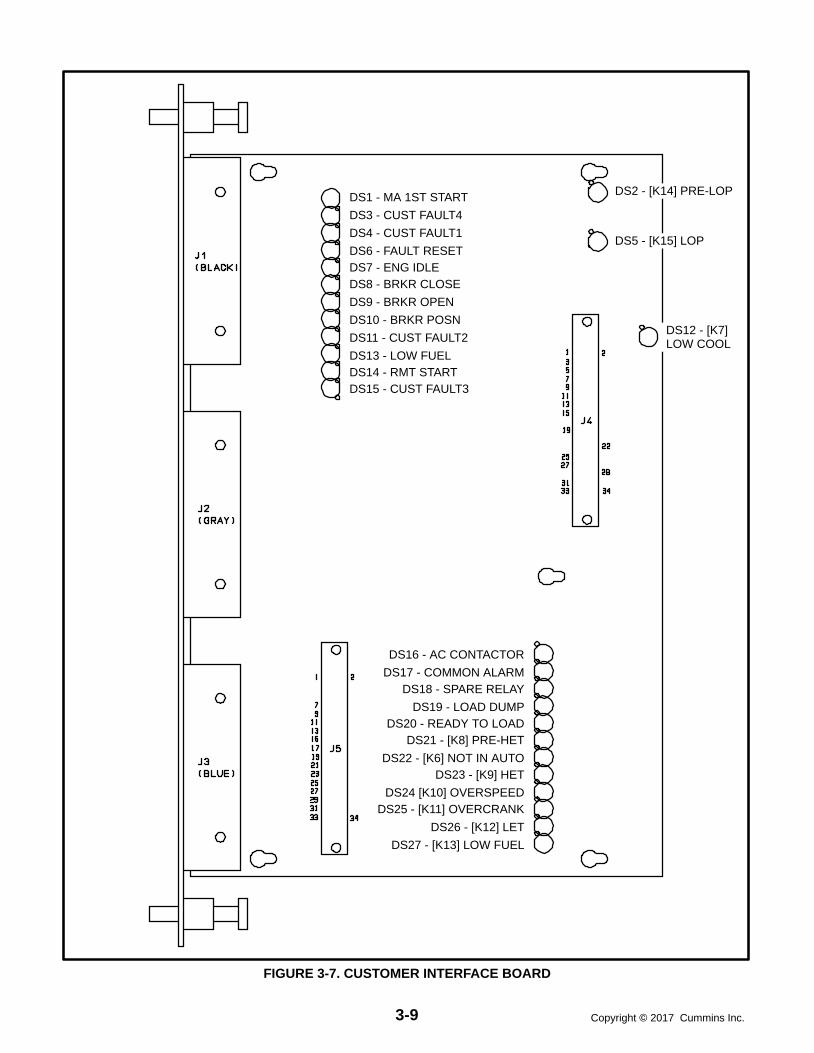
CUSTOMER INTERFACE BOARD (A34)The customer interface board (Figure 3-7) connectsto the PT/CT board to bring in voltage and current. Italso connects to customer inputs and outputs.
Connectors
The customer interface board has five connectors.They are:
J1 Customer connectionsJ2 Customer connectionsJ3 A36 PT/CT Board and customer connectionsJ4 Connects to J2 on A32 Digital boardJ5 Connects to J4 on A33 Analog board
LEDs
The customer interface board has 27 LED’s that in-dicate the following conditions:
DS1 Master First Start Input (Green) − parallelingapplication only
DS2 Pre low oil pressure output relay K14 (Red)DS3 Customer Fault #4 Input (Red)DS4 Customer Fault #1 Input (Red)DS5 Low oil pressure output relay K15 (Red)DS6 Fault Reset Input (Red)DS7 Engine Idle (Green)DS8 Load Demand (Green) − paralleling applica-
tion onlyDS9 Breaker Open/Inhibit Input (Green) − paral-
leling application onlyDS10 Genset Breaker Closed Position (Green) −
paralleling application onlyDS11 Customer Fault #2 input (Red)DS12 Low coolant output relay K17 (Red)DS13 Low Fuel Input (Red)
DS14 Remote Start input (Green)
DS15 Customer Fault #3 input (Red)
DS16 Breaker Control input relay energized fromDigital board (Green).In single set application, this output is acti-vated for a breaker trip when there is a shut-down fault.In paralleling application, this output is acti-vated to close a breaker
DS17 Common Alarm output relay energized fromDigital board (Green)This output is activated only on a shut-down condition.
DS18 Spare output relay energized from Digitalboard (Green)This output is activated only on a warn-ing condition.
DS19 Load Dump output relay energized fromDigital board (Red)If overload or underfrequency for 5 sec-onds, this output is activated (before shut-down).
DS20 Ready to Load output relay energized fromDigital board (Green) This output is activated when AC voltageand frequency exceed 90% of nominal.
DS21 Pre high engine temperature output relayK8 (Red)
DS22 Not in auto output relay K6 (Red)
DS23 High engine temperature output relay K9(Red)
DS24 Overspeed output relay K10 (Red)
DS25 Overcrank output relay K11 (Red)
DS26 Low engine temperature output relay K12(Red)
DS27 Low fuel output relay K13 (Red)
3-9 Copyright 2017 Cummins Inc.
DS1 - MA 1ST START
DS3 - CUST FAULT4
DS4 - CUST FAULT1
DS6 - FAULT RESETDS7 - ENG IDLEDS8 - BRKR CLOSE
DS9 - BRKR OPEN
DS10 - BRKR POSN
DS11 - CUST FAULT2
DS13 - LOW FUELDS14 - RMT STARTDS15 - CUST FAULT3
DS2 - [K14] PRE-LOP
DS5 - [K15] LOP
DS12 - [K7]LOW COOL
DS16 - AC CONTACTOR
DS17 - COMMON ALARMDS18 - SPARE RELAY
DS19 - LOAD DUMPDS20 - READY TO LOAD
DS21 - [K8] PRE-HET
DS22 - [K6] NOT IN AUTODS23 - [K9] HET
DS24 [K10] OVERSPEEDDS25 - [K11] OVERCRANK
DS26 - [K12] LET
DS27 - [K13] LOW FUEL
FIGURE 3-7. CUSTOMER INTERFACE BOARD

3-10Copyright 2017 Cummins Inc.
PT/CT BOARD (A36)
The PT/CT board (Figure 3-8) is mounted inside theaccessory box. This board converts alternator out-put voltage to approximately 18 VAC levels for theanalog board. It also converts CT .55 Amp (at fullload) output to approximately 1.65 VAC (at full load)input for the analog board.
There are three versions of this board. For properoperation, the PT/CT board must be correctlymatched to the generator set.
In addition, there is a specific set of CTs for eachgenerator set. For proper operation, the CTs mustalso be correctly matched to the generator set out-put current.
ConnectorsThe PT/CT board has two connectors. They are:J8 Connects to J3 on A34 Customer Interface
boardJ9 Connects to AC harness (alternator output
voltage and CTs)J9 wiring connections:
Yellow Gen. A InOrange Gen. B InRed Gen. C InBrown Gen. Common InWhite CT21 (+) InGray CT21 (common) InGrn/Ylw CT22 (+) InBlack CT22 (common) InPurple CT23 (+) InBlue CT23 (common) In
J8
J9
FIGURE 3-8. PT/CT BOARD

3-11 Copyright 2017 Cummins Inc.
VOLTAGE REGULATOR OUTPUT MODULE(A37)The voltage regulator output module (Figure 3-9) isa power Amplifier. This board is used to amplify thepulse-width modulated (PWM) signal from the PCCto drive the exciter windings. Power from the PMG isused by this board to amplify the PWM signal.
Connectors
The voltage regulator output module has two con-nectors. They are:
J7 Connects to engine harness (control)J7 wiring connections:
Gray Regulator Drive (+) InputWhite Regulator Drive (-) InputBlue B+ Input (RUN signal)Purple Ground InputGrn/Yel Start inBlack Start solenoid
J10 Connects to engine harness (power)J10 wiring connections:
Green Phase A PMG powerYellow Phase B PMG powerOrange Phase C PMG powerRed X (Field +) OutputBrown XX (Field −) Output
LEDs
The voltage regulator output module has 3 LED’sthat indicate the following conditions.
DS1 On when voltage regulator isolated supply isoperating (Green)
DS2 Output Duty Cycle − Brighter when load in-creases − larger duty cycle (Amber). The dutycycle range of the PWM signal is 0 - 60%. Be-cause the normal duty cycle is less than 10%,the output duty cycle LED, DS2 will normallybe very dimly lit.
DS3 Backup start disconnect − On when start dis-connect is true (Green). The backup start dis-connect is initiated at about 850 RPM, whensensed PMG voltage is greater than 105 voltsRMS.
J10J7
DS1 - ISOLATED SUPPLYDS2 - OUTPUT DUTY CYCLEDS3 - BACKUP START DISCONNECT
FIGURE 3-9. VOLTAGE REGULATOR OUTPUT MODULE (A37)

3-12Copyright 2017 Cummins Inc.
GOVERNOR OUTPUT MODULE (A38)
The governor output module (Figure 3-10) receivesa low power, 3 kHz pulse-width modulated (PWM)command from the engine interface board (A31).This module drives the two fuel actuators (right andleft) with a feed back-controlled, 200 Hz PWM pow-er output stage. The governor module also has bothright and left 0-5 volt actuator position voltageswhich are used for actuator diagnostics.
Connectors
The governor output module has two connectors.They are:
J6
Inputs: Run Signal, B+, Governor Command (fromengine interface board)
Outputs: B+ (fused), SwB+, actuator position volt-ages (R, L), and Rack Position Fault
J13
Inputs: (R, L) Actuator position sensing signals
Outputs: (R, L) Actuator drive
Fuses
The governor output module has four fuses to pro-tect it from overloads and groundfaults. They are:
F1 Left Actuator Drive (15 Amps)F2 Right Actuator Drive (15 Amps)
F3 Switched B+ (10 Amps)F4 B+ Fused (10 Amps)
LEDs
The governor output module has six LED’s that indi-cate the following conditions:
DS1 (Green) Run command signaling governormodule is active.
DS2 (Green) 5 volt power supply is active.DS3 (Green) Left actuator drive is active. The PCC
duty cycle range is 25 - 93%. When running,the maximum duty cycle is about 63%. Notethat the brighter the LED, the larger the dutycycle.
DS4 (Green) Right actuator drive is active. SeeDS3 description.
DS5 (Red) Left actuator fault indicator. If the actua-tor is more than 1.5 mm form its commandedposition, the fault indicator will be ON. Notethat the actuator has maximum range of 0 −21mm. During transients and starting se-quences, the fault indicator will become ac-tive for short (200 millisecond) periods.
DS6 (Red) Right actuator fault indicator. See DS5description.
RHLOOP
LHLOOP
DS3
DS4
DS5 DS6
F1 F2
R54
DS2
K1 K2 F3 F4
X1
R63 R68
DS1
BANK TOBANK
FIGURE 3-10. GOVERNOR OUTPUT MODULE (A38)

4-1 Copyright 2017 Cummins Inc.
4. Troubleshooting
GENERAL
The PowerCommand Control continuously moni-tors engine sensors for abnormal conditions, suchas low oil pressure and high coolant temperature. Ifany of these conditions occur, the PCC will light ayellow Warning lamp or a red Shutdown lamp anddisplay a message on the digital display panel.
In the event of a shutdown fault (red Shutdownlamp), the PCC will stop the engine and close a setof contacts that can be wired to trip a circuit breaker.If the generator set is stopped for this reason, theoperator can restart the generator set after makingadjustments or corrections.
This section contains the following information:
Table 4-1: Contains a list of all status codes, in-cluding the displayed message and status indi-cator. Also references the page number thatcontains a description of each code.
Table 4-2: Describes each warning and shut-down code, warning and shutdown limitswhere applicable, and basic corrective actions,such as, checking fluid levels, control resetfunctions, battery connections, etc.
Table 4-3: Lists the PCC oil pressure warningand shutdown limits.
Tables 4-4 through 4-30: Provide detailedtroubleshooting procedures.
Table 4-31: Describes the analog circuit boardinputs and outputs.
Table 4-32: Describes the location and func-tion of each fuse.
SAFETY CONSIDERATIONS
High voltages are present when the generator set isrunning. Do not open the alternator output boxwhile the generator set is running.
WARNING Contacting high voltage compo-nents can cause electrocution, resulting in se-vere personal injury or death. Keep the outputbox covers in place during troubleshooting.
When troubleshooting a generator set that is shutdown, make certain the generator set cannot be ac-cidentally restarted. Place the Run/Off/Auto switchin the Off position. Turn off or remove AC powerfrom the battery charger, MAKE CERTAIN EXPLO-SIVE BATTERY GASSES ARE DISPELLEDFROM BATTERY COMPARTMENT, and then re-move the negative (−) battery cable from the gener-ator set starting battery.
WARNING Accidental starting of the generatorset during troubleshooting can cause severepersonal injury or death. Disable the generatorset (see above) before troubleshooting.
4-2Copyright 2017 Cummins Inc.
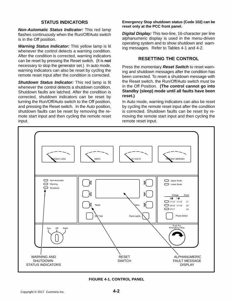
STATUS INDICATORS
Non-Automatic Status Indicator: This red lampflashes continuously when the Run/Off/Auto switchis in the Off position.
Warning Status Indicator: This yellow lamp is litwhenever the control detects a warning condition.After the condition is corrected, warning indicatorscan be reset by pressing the Reset switch. (It is notnecessary to stop the generator set.) In auto mode,warning indicators can also be reset by cycling theremote reset input after the condition is corrected.
Shutdown Status Indicator: This red lamp is litwhenever the control detects a shutdown condition.Shutdown faults are latched. After the condition iscorrected, shutdown indicators can be reset byturning the Run/Off/Auto switch to the Off position,and pressing the Reset switch. In the Auto position,shutdown faults can be reset by removing the re-mote start input and then cycling the remote resetinput.
Emergency Stop shutdown status (Code 102) can bereset only at the PCC front panel.
Digital Display: This two-line, 16-character per linealphanumeric display is used in the menu-drivenoperating system and to show shutdown and warn-ing messages. Refer to Tables 4-1 and 4-2.
RESETTING THE CONTROL
Press the momentary Reset Switch to reset warn-ing and shutdown messages after the condition hasbeen corrected. To reset a shutdown message withthe Reset switch, the Run/Off/Auto switch must bein the Off Position. (The control cannot go intoStandby (sleep) mode until all faults have beenreset.)In Auto mode, warning indicators can also be resetby cycling the remote reset input after the conditionis corrected. Shutdown faults can be reset by re-moving the remote start input and then cycling theremote reset input.
ALPHANUMERICFAULT MESSAGE
DISPLAY
RESETSWITCH
WARNING ANDSHUTDOWN
STATUS INDICATORS
FIGURE 4-1. CONTROL PANEL

4-3 Copyright 2017 Cummins Inc.
TABLE 4-1. WARNING AND SHUTDOWN CODES
BASIC TROUBLE-
CODE MESSAGE STATUS LED CHECKS SHOOTING. . . . . . . . . . . . . . . . . . . . . . . . . . . . . . . . .
101 IDLE MODE Warning 4-5. . . . . . . . . . . . . . . . . . . . . . . . . . . . . . . . . . . . .
102 EMERGENCY STOP Shutdown 4-5. . . . . . . . . . . . . . . . . . . . . . . . . . . . . .
200 LOW OIL PRESSURE Warning 4-5 4-23. . . . . . . . . . . . . . . . . . . . . . . . . . . . . . . . . . . . . .
201 LOW OIL PRESSURE Shutdown 4-5 4-23. . . . . . . . . . . . . . . . . . . . . . . . . . . . . . . . . . . . .
204 OIL PRES SENDER Warning 4-5 4-24. . . . . . . . . . . . . . . . . . . . . . . . . . . . . . . . . . . . . . .
210 LOW COOLANT TEMP Warning 4-6 4-25. . . . . . . . . . . . . . . . . . . . . . . . . . . . . . . . . . . . .
211 HIGH COOLANT TEMP Warning 4-6 4-26. . . . . . . . . . . . . . . . . . . . . . . . . . . . . . . . . . . .
212 HIGH COOLANT TEMP Shutdown 4-6 4-26. . . . . . . . . . . . . . . . . . . . . . . . . . . . . . . . . . .
213 COOLANT SENDER Warning 4-6 4-24. . . . . . . . . . . . . . . . . . . . . . . . . . . . . . . . . . . . . . .
214 LOW COOLANT LVL Warning 4-7 4-27. . . . . . . . . . . . . . . . . . . . . . . . . . . . . . . . . . . . . . .
215 LOW COOLANT LVL Shutdown 4-7 4-27. . . . . . . . . . . . . . . . . . . . . . . . . . . . . . . . . . . . . .
220 MAG PICKUP Shutdown 4-7 4-28. . . . . . . . . . . . . . . . . . . . . . . . . . . . . . . . . . . . . . . . . . . .
221 FAIL TO CRANK Shutdown 4-7 4-14, 4-22. . . . . . . . . . . . . . . . . . . . . . . . . . . . . . . . . . . . . . . . . .
222 OVERCRANK Shutdown 4-7 4-20. . . . . . . . . . . . . . . . . . . . . . . . . . . . . . . . . . . . . . . . . . . .
223 OVERSPEED Shutdown 4-7 4-29. . . . . . . . . . . . . . . . . . . . . . . . . . . . . . . . . . . . . . . . . . . .
230 LOW DC VOLTAGE Warning 4-8 4-30. . . . . . . . . . . . . . . . . . . . . . . . . . . . . . . . . . . . . . . .
231 HIGH DC VOLTAGE Warning 4-8 4-30. . . . . . . . . . . . . . . . . . . . . . . . . . . . . . . . . . . . . . .
232 WEAK BATTERY Warning 4-8 4-30. . . . . . . . . . . . . . . . . . . . . . . . . . . . . . . . . . . . . . . . . .
240 LOW FUEL − DAY Warning 4-8 4-31. . . . . . . . . . . . . . . . . . . . . . . . . . . . . . . . . . . . . . . . .
241 LOW FUEL Warning 4-8 4-32. . . . . . . . . . . . . . . . . . . . . . . . . . . . . . . . . . . . . . . . . . . . . . .
250 EEPROM ERROR Shutdown 4-8 4-33. . . . . . . . . . . . . . . . . . . . . . . . . . . . . . . . . . . . . . . .
251 EEPROM ERROR Warning 4-8 4-33. . . . . . . . . . . . . . . . . . . . . . . . . . . . . . . . . . . . . . . . .
252 EEPROM ERROR Warning 4-8 4-33. . . . . . . . . . . . . . . . . . . . . . . . . . . . . . . . . . . . . . . . .
260 RACK POSITION Warning 4-9 4-34. . . . . . . . . . . . . . . . . . . . . . . . . . . . . . . . . . . . . . . . . .
261 GROUND FAULT* Warning/Shutdown 4-9 4-35. . . . . . . . . . . . . . . . . . . . . . . . . . . . . . . .
262 RUPTURE BASIN* Warning/Shutdown 4-9 4-35. . . . . . . . . . . . . . . . . . . . . . . . . . . . . . . .
263 HIGH GEN TEMP* Warning/Shutdown 4-9 4-35. . . . . . . . . . . . . . . . . . . . . . . . . . . . . . . .
(Continued to next page)
* Default message. Editable for customer site requirements.

4-4Copyright 2017 Cummins Inc.
TABLE 4-1. WARNING AND SHUTDOWN CODES
BASIC TROUBLE-
CODE MESSAGE STATUS LED CHECKS SHOOTING. . . . . . . . . . . . . . . . . . . . . . . . . . . . . . . . .
301 HIGH AC VOLTAGE Shutdown 4-9 4-36. . . . . . . . . . . . . . . . . . . . . . . . . . . . . . . . . . . . . .
303 LOW AC VOLTAGE Shutdown 4-9 4-39. . . . . . . . . . . . . . . . . . . . . . . . . . . . . . . . . . . . . . .
313 UNDER FREQUENCY Shutdown 4-10 4-41. . . . . . . . . . . . . . . . . . . . . . . . . . . . . . . . . . .
320 OVERCURRENT Warning 4-10 4-42. . . . . . . . . . . . . . . . . . . . . . . . . . . . . . . . . . . . . . . . .
321 OVERCURRENT Shutdown 4-10 4-42. . . . . . . . . . . . . . . . . . . . . . . . . . . . . . . . . . . . . . . .
322 SHORT CIRCUIT Shutdown 4-10 4-42. . . . . . . . . . . . . . . . . . . . . . . . . . . . . . . . . . . . . . . .
330 OVERLOAD Warning 4-10 4-42. . . . . . . . . . . . . . . . . . . . . . . . . . . . . . . . . . . . . . . . . . . . .
335 REVERSE POWER Shutdown 4-10. . . . . . . . . . . . . . . . . . . . . . . . . . . . . . .
None INVALID SETUP None 4-10. . . . . . . . . . . . . . . . . . . . . . . . . . . . . . . . . . . .
None INVALID CAL None 4-10. . . . . . . . . . . . . . . . . . . . . . . . . . . . . . . . . . . . . .

4-5 Copyright 2017 Cummins Inc.
Indicates local or remote Emergency Stop.To reset the local/remote Emergency Stop button :
Turn the switch clockwise and allow it to pop out (local only).Move the Run/Off/Auto switch to Off. Press the Reset switch.Select Run or Auto, as required.
Shutdown lamp lights.
MESSAGE:LOW OIL PRESSURE 201 − SHUTDOWN
Indicates that the engine is operating in idle mode.When the generator set is operating in the RUNmode, grounding the engine idle input causes alter-nator build-up to be inhibited and the engine to begoverned at 800 RPM. When ground is removedfrom this input, the generator set returns to normalspeed and voltage.
When the engine idle function is enabled, the controlautomatically sets lower oil pressure warning andshutdown trip points to reflect the lower operatingspeed. When the engine idle function is removed andthe generator set reverts to normal operating speed,the control automatically resets oil pressure warningand shutdown trip points to the normal settings.
TABLE 4-2. WARNING AND SHUTDOWN CODES
Indicates engine oil pressure has dropped below theshutdown trip point. Check oil level, lines and filters. Ifoil system is OK but oil level is low, replenish. Resetcontrol and restart. Oil pressure limits are listed inTable 4-3.
SYMPTOM CORRECTIVE ACTION
Shutdown lamp lights.
MESSAGE:EMERGENCY STOP102 − SHUTDOWN
Warning lamp lights.
MESSAGE:LOW OIL PRESSURE200 − WARNING
Indicates engine oil pressure has dropped to an unac-ceptable level. If alternator is powering critical loadsand cannot be shut down, wait until next shutdown pe-riod and then follow 201-SHUTDOWN procedure.
To check oil pressure during a warning, access the oilpressure menu prior to clearing the fault.
Warning lamp lights.
MESSAGE:OIL PRES SENDER204 − WARNING
Indicates that the control has sensed that the engineoil pressure sender is out of its working range. Checkthat the engine oil pressure sender is properly con-nected.
Many troubleshooting procedures present hazards which can result in severe personalinjury or death. Only qualified service personnel with knowledge of fuels, electricity, and mechani-cal hazards should perform service procedures. Review Important Safety Instructions page.
WARNING
MESSAGE:IDLE MODE101 − WARNING

4-6Copyright 2017 Cummins Inc.
Warning lamp lights.
MESSAGE:LOW COOLANT TEMP210 − WARNING
Generator set is not operating. Warningoccurs when engine coolant tempera-ture is 70 F (21 C) or lower. NOTE: Inapplications where the ambient tem-perature falls below 40F (4C), LowCoolant Temp may be indicated eventhough the coolant heaters are oper-ating.
Warning lamp lights.
MESSAGE:COOLANT SENDER213 WARNING
SYMPTOM
TABLE 4-2. WARNING AND SHUTDOWN CODES(CONTINUED)
CORRECTIVE ACTIONIndicates engine coolant heater is not operating or isnot circulating coolant. Check for the following condi-tions:
a. Coolant heater not connected to power supply.Check for blown fuse or disconnected heatercord and correct as required.
b. Check for low coolant level and replenish if re-quired. Look for possible coolant leakage pointsand repair as required.
c. Open heater element. Check current draw ofheater.
Warning lamp lights.
MESSAGE:HIGH COOLANT TEMP211 − WARNING
Inticates the engine coolant temperature is gettingclose to the recommended maximum temperaturelimit: 215 F − standby / 207 F − primary).If alternator is powering non-critical and critical loadsand cannot be shut down, use the following:
a. Reduce load if possible by turning off non-criticalloads.
b. Check air inlets and outlets and remove any ob-structions to airflow.
If engine can be stopped, follow HIGH COOLANTTEMP 212 − SHUTDOWN procedure.
To check coolant temperature during a warning, ac-cess coolant temperature menu prior to clearing thefault.
Shutdown lamp lights.
MESSAGE:HIGH COOLANT TEMP212 − SHUTDOWN
Indicates engine has overheated (coolant tempera-ture has risen above the shutdown trip point:223 F − standby / 215 F − primary). Allow engineto cool down completely before proceeding with thefollowing checks:
a. Check for obstructions to cooling airflow andcorrect as necessary.
b. Check fan belt and repair or tighten if necessary.c. Reset control and restart after locating and cor-
recting problem.d. Check blower fan and circulation pumps on re-
mote radiator installations.
Indicates that the resistance of the coolant tempera-ture sender is out of range. Check the resistance ofthe sender. Resistance should be 500 to 2k ohms.
Many troubleshooting procedures present hazards which can result in severe personalinjury or death. Only qualified service personnel with knowledge of fuels, electricity, and mechani-cal hazards should perform service procedures. Review Important Safety Instructions page.
WARNING

4-7 Copyright 2017 Cummins Inc.
Shutdown lamp lights.
MESSAGE:LOW COOLANT LVL214 − WARNING
orLOW COOLANT LVL215 − SHUTDOWN
Engine runs and then shuts down,
Shutdown lamp lights.
MESSAGE:OVERSPEED 223 − SHUTDOWN
SYMPTOM
TABLE 4-2. WARNING AND SHUTDOWN CODES(CONTINUED)
CORRECTIVE ACTION
Shutdown lamp lights.
MESSAGE:MAG PICKUP220 − SHUTDOWN
Indicates engine coolant level has fallen below thetrip point. Allow engine to cool down completely be-fore proceeding.
a. Check coolant level and replenish if low. Look forpossible coolant leakage points and repair ifnecessary.
b. Reset control and restart after locating and cor-recting problem.LOW COOLANT LVL Shutdown will not occur ifgenerator set is in Idle mode (low coolant warningonly).
Indicates mag pickup speed indication is not beingsensed or does not match generator set output fre-quency.
a. Restart and check RPM on the digital display.
Engine will not crank.
Shutdown lamp lights.
MESSAGE:FAIL TO CRANK221 − SHUTDOWN
Indicates possible fuel system problem.a. Check for empty fuel tank, fuel leaks, or plugged
fuel lines and correct as required.b. Check for dirty fuel filter and replace if neces-
sary.c. Check for dirty or plugged air filter and replace if
necessary.d. Reset the control and restart after correcting the
problem.
Indicates possible fault with control or starting sys-tem. Check for the following conditions:
a. Check fuse F3 on the Engine Interface board.b. Poor battery cable connections. Clean the bat-
tery cable terminals and tighten all connections.c. Discharged or defective battery. Recharge or
replace the battery.
Shutdown lamp lights.
Engine stops cranking.
MESSAGE:OVERCRANK222 − SHUTDOWN
Indicates engine has exceeded normal operatingspeed. (115% 1% of nominal)
Many troubleshooting procedures present hazards which can result in severe personalinjury or death. Only qualified service personnel with knowledge of fuels, electricity, and mechani-cal hazards should perform service procedures. Review Important Safety Instructions page.
WARNING

4-8Copyright 2017 Cummins Inc.
Warning lamp lights.
MESSAGE:HIGH DC VOLTAGE231 − WARNING
SYMPTOM
TABLE 4-2. WARNING AND SHUTDOWN CODES (CONTINUED)
CORRECTIVE ACTION
Warning lamp lights.
MESSAGE:LOW DC VOLTAGE230 − WARNING
Warning lamp lights.
MESSAGE:WEAK BATTERY232 − WARNING
Indicates battery voltage exceeds 32 VDC.
Check float level on battery charger if applicable(lower float level).
Indicates battery voltage is below 24 VDC.a. Discharged or defective battery.
Check the battery charger fuse. Recharge or replace the battery.
b. Poor battery cable connections. Clean the bat-tery cable terminals and tighten all connections.
c. Check engine DC alternator. Replace engineDC alternator if normal batery charging voltage(12 to 14 VDC) is not obtained.
d. Check float level if applicable (raise float level).
Indicates battery voltage drops below 60% of nomi-nal for two seconds, during starting.
Discharged or defective battery. See Warning message 230 − LOW DC VOLTAGE.
Warning lamp lights.
MESSAGE:LOW FUEL−DAY240 − WARNING
Indicates day tank fuel supply is running low. Checkfuel supply and replenish as required.
Shutdown lamp lights.
MESSAGE:EEPROM ERROR250 − SHUTDOWN
Indicates PCC memory error. Data corruption of criti-cal operating parameters.
Indicates PCC memory error. Data corruption of non-critical operating parameters.
Warning lamp lights.
MESSAGE:EEPROM ERROR251 − WARNING or252 − WARNING
Many troubleshooting procedures present hazards which can result in severe personalinjury or death. Only qualified service personnel with knowledge of fuels, electricity, and mechani-cal hazards should perform service procedures. Review Important Safety Instructions page.
WARNING
Warning lamp lights.
MESSAGE:LOW FUEL241 − WARNING
Indicates fuel supply is running low. Check fuel sup-ply and replenish as required.

4-9 Copyright 2017 Cummins Inc.
Many troubleshooting procedures present hazards which can result in severe personalinjury or death. Only qualified service personnel with knowledge of fuels, electricity, and mechani-cal hazards should perform service procedures. Review Important Safety Instructions page.
Shutdown lamp lights.
MESSAGE:GROUND FAULT261 − SHUTDOWNorDAY TANK262 − SHUTDOWNorHIGH GEN TEMP263 − SHUTDOWN
TABLE 4-2. WARNING AND SHUTDOWN CODES (CONTINUED)
SYMPTOM
When any one of these customer defined inputs isclosed to ground, the corresponding fault message isdisplayed. The nature of the fault is an optional cus-tomer selection. These fault functions can be pro-grammed to initiate a shutdown or a warning.
As indicated by the Shutdown lamp, a shutdown re-sponse has been preselected.
Note: Customer fault messages are editable. Themessage displayed for the code shown (261 thru263) may have been edited and may not appear asshown in this table.
CORRECTIVE ACTION
WARNING
When any one of these customer defined inputs isclosed to ground, the corresponding fault message isdisplayed. The nature of the fault is an optional cus-tomer selection. These fault functions can be pro-grammed to initiate a shutdown or a warning.
As indicated by the Warning lamp, a warning re-sponse has been preselected.
Note: Customer fault messages are editable. Themessage displayed for the code shown (261 thru263) may have been edited and may not appear asshown in this table.
Shutdown lamp lights.
MESSAGE:HIGH AC VOLTAGE301 − SHUTDOWN
Indicates that one or more of the phase voltages hasexceeded 130% of nominal, or has exceeded 110%of nominal for 10 seconds.
Shutdown lamp lights.
MESSAGE:LOW AC VOLTAGE303 − SHUTDOWN
Indicates that one or more of the phase voltages hasdropped below 85% of nominal for 10 seconds.
Warning lamp lights.
MESSAGE:GROUND FAULT261 − WARNINGorRUPTURE BASIN262 − WARNINGorHIGH GEN TEMP263 − WARNING
Warning lamp lights.
MESSAGE:RACK POSITION260 − WARNING
Indicates that one or both of the fuel racks is not at thecommanded position.
a. Check fuel pump connections.b. Check left and right actuator fuses (A38-F1 &F2)
on the governor output module.

4-10Copyright 2017 Cummins Inc.
TABLE 4-2.WARNING AND SHUTDOWN CODES(CONTINUED)
SYMPTOM CORRECTIVE ACTION
Warning lamp lights.
MESSAGE:OVERCURRENT320 − WARNING
Indicates that alternator output current has exceeded110% of rated for 60 seconds.Check load and load lead connections.
Shutdown lamp lights.
MESSAGE:OVERCURRENT321 − SHUTDOWN
Indicates that alternator output current has exceeded110% of rated, and that a PCC time/current calcula-tion has initiated an overcurrent shutdown.Check load and load lead connections.
Shutdown lamp lights.
MESSAGE:SHORT CIRCUIT322 − SHUTDOWN
Indicates that alternator output current has exceeded175% of rated.Check load and load lead connections.
Warning lamp lights.
MESSAGE:OVERLOAD330 − WARNING
Indicates that three-phase power output exceeds105% of standby (or 115% of prime) rating. After fiveseconds, the Load Dump output is activated. After 60seconds, the OVERLOAD warning is activated.Check load and load lead connections.
Many troubleshooting procedures present hazards which can result in severe personalinjury or death. Only qualified service personnel with knowledge of fuels, electricity, and mechani-cal hazards should perform service procedures. Review Important Safety Instructions page.
WARNING
Indicates that engine speed has dropped below 90%of nominal for 10 seconds.NOTE: Five seconds before shutdown, a Load Dumpsignal is initiated.Check fuel supply, intake air supply and load.
Shutdown lamp lights.
MESSAGE:UNDER FREQUENCY313 − SHUTDOWN
Shutdown lamp lights.
MESSAGE:REVERSE POWER335 − SHUTDOWN
Indicates improper CT or PT phasing. (Non-parallelunits only.)Check CT / PT wiring. Refer to CT Installation in Sec-tion 5.
MESSAGE:INVALID SETUP
Indicates that the digital board is not properly cali-brated for the generator set model. Refer to DigitalBoard (A32) Calibration in Section 5.
MESSAGE:INVALID CAL
Indicates that the digital board is not properly cali-brated for the generator set model. Refer to DigitalBoard (A32) Calibration in Section 5.

4-11 Copyright 2017 Cummins Inc.
TABLE 4-3. PCC OIL PRESSURE WARNING & SHUTDOWN LIMITS
QST30 Engine: NORM 45-65 psi (310-448 kPa), IDLE 20 psi (138 kPa)
35 psi (241 kPa) shutdown limit - run mode value40 psi (276 kPa) warning limit - run mode value10 psi (69 kPa) shutdown limit - idle mode value15 psi (103 kPa) warning limit- idle mode value
To check oil pressure or engine temperature during a warning, access the oil pressure orcoolant temperature menu prior to clearing the fault.

4-12Copyright 2017 Cummins Inc.
TROUBLESHOOTING PROCEDURE
The following tables are a guide to help you evalu-ate problems with the generator set. You can savetime if you read through the manual ahead of timeand understand the system.
To determine the appropriate troubleshootingprocedure for the specific problem at hand, besure to refer to the “Indicators” column pro-vided in each troubleshooting table.
Try to think through the problem. Go over what wasdone during the last service call. The problem couldbe as simple as a loose wire, an opened fuse or atripped circuit breaker. (Table 4-32 describes thelocation and function of each fuse.)
Figure 4-2 shows the location of the componentswithin the control panel that are referenced in thefollowing troubleshooting procedures. Connector,
LED and switch locations for each circuit board andmodule are provided in Section 3. The control wiringand circuit board connections are shown in Section7.
CAUTION Always set the Run/Off/Auto (S12)switch to the Off position and the Power On/Standby (S5) switch to the Standby position be-fore disconnecting or connecting harness con-nectors. Otherwise, disconnecting the harnessconnectors can result in voltage spikes highenough to damage the DC control circuits of thegenerator set.
CAUTION Electrostatic discharge will damagecircuit boards. Always wear a wrist strap whenhandling circuit boards or socket-mounted IC’sand when disconnecting or connecting harnessconnectors.

4-13 Copyright 2017 Cummins Inc.
CUSTOMERINTERFACE
A34
ENGINE INTERFACEA31
ANALOG BOARDA33
DIGITAL BOARDA32
DISPLAY BOARDA35
RUN/OFF/AUTOSWITCH S12
S5 POWER ON/STANDBY SWITCH
OPTIONAL RTDRELAY
OPTIONAL RUN RELAYSK11, K12 & K13
OPTIONALCOMMON ALARM
RELAY K14
OPTIONALTHERMISTOR
RELAY 160/140 C
TB1-1
TB1-40
GOVERNOROUTPUT MODULE
A38
PT/CT BOARD A36
VOLTAGEREGULATOR
OUTPUT MODULEA37
FIGURE 4-2. CIRCUIT BOARD LOCATIONS

4-14Copyright 2017 Cummins Inc.
TABLE 4-4. ENGINE DOES NOT CRANK—LOCAL OR REMOTE RUN
WARNING Many troubleshooting procedures present hazards that can result in severe personal inju-ry or death. Only qualified service personnel with knowledge of fuels, electricity, and machinery haz-ards should perform service procedures. Review Important Safety Instructions page.
Indicator(s) Possible Cause Corrective Action
“FAIL TO CRANK” (221) message
Reset andattempt tostart:
Start LEDDS11 on theengineinterface boardturns on.
NOTE:These twoindicationssuggest thatthe PCC hasreceived astart signaland has sent astart commandto the startoutput (J4-2)on the engineinterfaceboard.
2. Starter could be bad.
5. If there is continuity at A37 J7-5/J7-6,there may be an open between A37and A31, an open between A37 andK4, or A31 may be bad.
2. Reset the control. Attempt to start, and test forB+ at the starter. If there is B+ at the starter, thestarter could be bad. Test starter (see engineservice manual). Replace the starter.
3. Reset the control. Attempt to start, and test forB+ into and out of start solenoid contacts. Ifthere is B+ in, but not out, check for B+ at thestart solenoid coil. If there is B+ at the coil,check ground connection. If ground connectionis good, the start solenoid is bad. Replace thestart solenoid.
If there is B+ into and out of the start solenoidcontacts, check for an open between the startsolenoid contacts and the starter. If there is noB+, go to the next step.
3. If there is no B+ at the starter, start so-lenoid K4 could be bad.
4. If there is no B+ at the start solenoidcoil (K4), the backup start disconnectcontacts in the regulator output mod-ule (A37) could be open (indicatingthat A37 is bad).
*4. Disconnect J7/P7 at the regulator output mod-ule. Test for continuity at A37 J7-5/J7-6. If thereis no continuity, the regulator output module isbad. Replace A37.
*5. If there is continuity at A37 J7-5/J7-6, reset thecontrol, attempt to start, and check for B+ atA37 P7-5.
If there is B+ at P7-5, there may be an open be-tween start solenoid coil (K4) and A37. If thereis no B+ at P7-5, check for B+ at J4-2 on the en-gine interface board (A31) while attempting tostart.
If there is B+ at A31 J4-2, check for an open be-tween A37 and A31.
If there is no B+ at A31 J4-2, (and DS11 is on)the engine interface board is bad. Replace A31.
1a. Recharge or replace the battery. Specific gravi-ty for a fully charged battery is approximately1.260 at 80 F (27 C).
1b. Clean and tighten or replace the battery cableconnectors and cables at the battery and thegenerator set.
1c. Adjust charge rate of battery charging circuit.
1d. Replace engine DC alternator if normal batterycharging voltage (12 to 14 VDC) is not obtained.
1. Insufficient battery voltage. Check thefollowing conditions:
a. Batteries not charged.
b. Battery connections loose ordirty.
c. Insufficient battery charging volt-age.
d. Engine DC alternator could bebad.
*CAUTION: Wearing a wrist strap, set S12 to Off and A32 S5 to Standby before connecting/disconnecting harness plugs.
6. The mag pickup signal is not beingsensed.
6. Refer to the mag pickup shutdown message(220).

4-15 Copyright 2017 Cummins Inc.
TABLE 4-5. ENGINE DOES NOT CRANK—LOCAL OR REMOTE RUN
WARNING Many troubleshooting procedures present hazards that can result in severe personal inju-ry or death. Only qualified service personnel with knowledge of fuels, electricity, and machinery haz-ards should perform service procedures. Review Important Safety Instructions page.
*1. Install harness tool between A31 J4/P4. Resetthe control. Attempt to start and check for B+ atJ4-2. If no B+, remove F3 and check continuity.If open, replace the fuse with one of the sametype and Amp rating (5 Amps). If F3 is OK,check the B+ supply from the wiring harness.
1. Fuse F3 on the engine interface board(A31) may be open, or B+ may not begetting to F3.
Indicator(s) Possible Cause Corrective Action
“FAIL TO CRANK” (221)message
Reset andattempt tostart:
Start LEDDS11 on theengineinterface boarddoes NOT turn on.
NOTE:These twoindicationssuggest thatthe PCC hasreceived astart signaland has NOTsent a startcommand tothe start output(J4-2) on theengineinterfaceboard.
2. To isolate:
Check for B+ at S13-1 and S13-2.If there is B+ at S13-2, but not at S13-1(and S13 is NOT in the emergency stopposition), then S13 is bad. Replace S13.
If there is no B+ at S13-2, disconnectJ3/P3, and check for B+ at A31 J3-2. Ifthere is no B+, replace A31.
If there is B+ at A31 J3-2, check continuityfrom P3-2 to P3-6. If no continuity, repairor replace as necessary.
2. Emergency Stop switch S13 or thePCC door harness may be bad.
4. Engine interface board (A31) may bebad.
*4. If there is a ground output at A32 J4-3, and yetthere is no B+ output at A31 J4-2; then A31 isbad. Replace A31.
*3. Install harness tool between A32 J4/P4. Resetthe control. Attempt to start, and test for groundoutput at A32 J4-3. If there is no ground output,A32 is bad. Replace A32.
3. Digital board (A32) may be bad.
*CAUTION: Wearing a wrist strap, set S12 to Off and A32 S5 to Standby before connecting/disconnecting harness plugs.

4-16Copyright 2017 Cummins Inc.
TABLE 4-6. ENGINE DOES NOT CRANK—REMOTE RUN
WARNING Many troubleshooting procedures present hazards that can result in severe personal inju-ry or death. Only qualified service personnel with knowledge of fuels, electricity, and machinery haz-ards should perform service procedures. Review Important Safety Instructions page.
“FAIL TO CRANK” (221)messageDOES NOTappear ondigital display−and:Auto LED DS5on the engineinterface board(A31) is on − RMT StartLED DS14 onthe customerinterface board(A34) is on −
NOTE:This conditionsuggests thatthe PCCprocessor(digital board−A32) hasNOT receivedor recognizeda remote startstart signal.
*1. Install harness tool between A32 J4/P4. Checkfor ground output at A32 J4-18.
If there is no ground output (but A31 DS5 is on)engine interface board A31 is bad. ReplaceA31.
If there is a ground output at A31 J1-18, pro-ceed to the next step.
1. The Auto mode signal is not gettingfrom engine interface board A31 todigital board A32, indicating that A31 isbad.
Indicator(s) Possible Cause Corrective Action
2. The Remote run signal is not gettingfrom customer interface board A34 toA32, indicating that A34 is bad.
*2. Install harness tool between A32 J4/P4. Resetthe control. Attempt to remote start, and checkfor ground output at A32 J2-26. If no ground out-put (but A34 DS14 is on) customer interfaceboard A34 is bad. Replace A31.
If there is a ground output at A32 J2-26, pro-ceed to the next step.
*3. If, when attempting remote start, there is aground input at A32 J2-26, and a ground inputat A32 J4-18—and there is no “FAIL TOCRANK” message—and the generator setdoes not crank; A32 is bad. Replace, A32.
3. Digital board (A32) may be bad.
*CAUTION: Wearing a wrist strap, set S12 to Off and A32 S5 to Standby before connecting/disconnecting harness plugs.
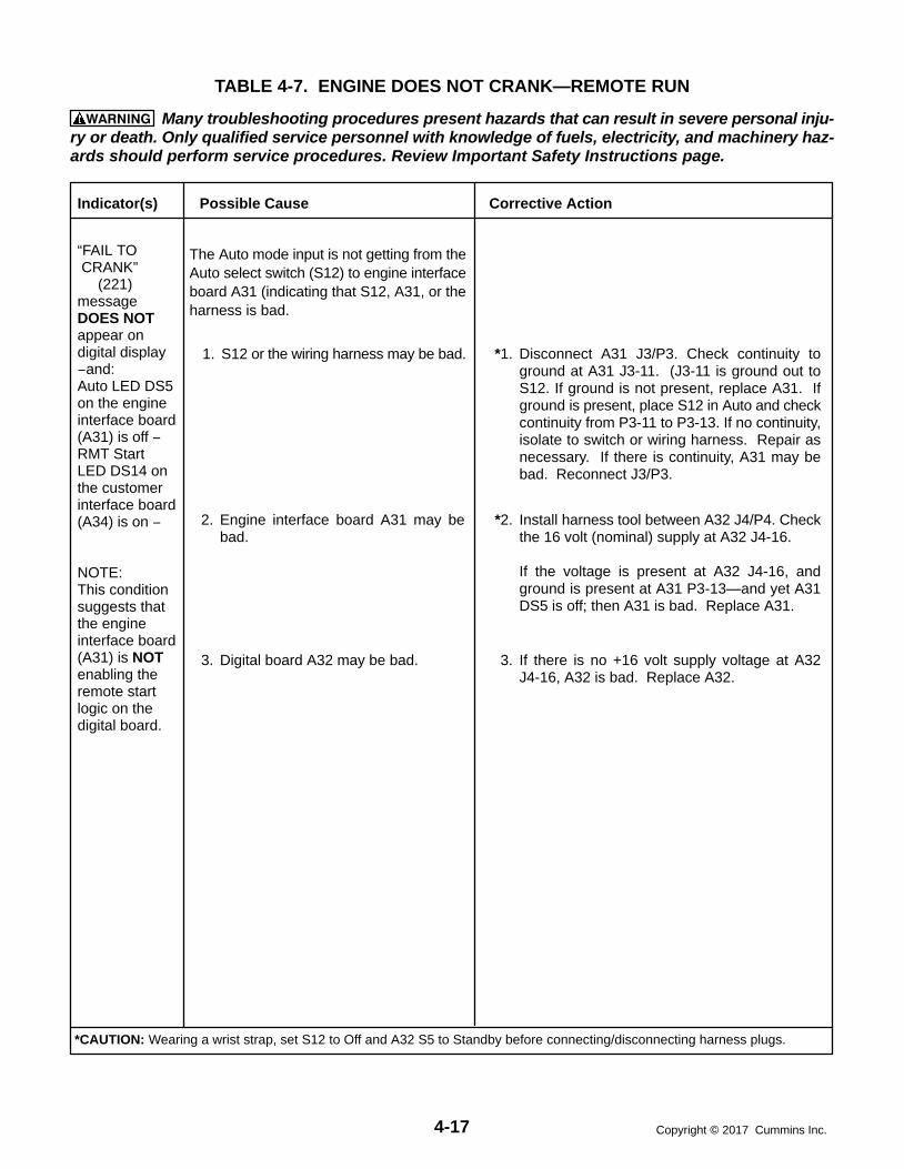
4-17 Copyright 2017 Cummins Inc.
TABLE 4-7. ENGINE DOES NOT CRANK—REMOTE RUN
WARNING Many troubleshooting procedures present hazards that can result in severe personal inju-ry or death. Only qualified service personnel with knowledge of fuels, electricity, and machinery haz-ards should perform service procedures. Review Important Safety Instructions page.
Indicator(s) Possible Cause Corrective Action
“FAIL TO CRANK” (221)messageDOES NOTappear ondigital display−and:Auto LED DS5on the engineinterface board(A31) is off − RMT StartLED DS14 onthe customerinterface board(A34) is on −
NOTE:This conditionsuggests thatthe engineinterface board(A31) is NOTenabling theremote startlogic on thedigital board.
*2. Install harness tool between A32 J4/P4. Checkthe 16 volt (nominal) supply at A32 J4-16.
If the voltage is present at A32 J4-16, andground is present at A31 P3-13—and yet A31DS5 is off; then A31 is bad. Replace A31.
The Auto mode input is not getting from theAuto select switch (S12) to engine interfaceboard A31 (indicating that S12, A31, or theharness is bad.
1. S12 or the wiring harness may be bad. *1. Disconnect A31 J3/P3. Check continuity toground at A31 J3-11. (J3-11 is ground out toS12. If ground is not present, replace A31. Ifground is present, place S12 in Auto and checkcontinuity from P3-11 to P3-13. If no continuity,isolate to switch or wiring harness. Repair asnecessary. If there is continuity, A31 may bebad. Reconnect J3/P3.
2. Engine interface board A31 may bebad.
3. If there is no +16 volt supply voltage at A32J4-16, A32 is bad. Replace A32.
3. Digital board A32 may be bad.
*CAUTION: Wearing a wrist strap, set S12 to Off and A32 S5 to Standby before connecting/disconnecting harness plugs.

4-18Copyright 2017 Cummins Inc.
TABLE 4-8. ENGINE DOES NOT CRANK—REMOTE RUN
WARNING Many troubleshooting procedures present hazards that can result in severe personal inju-ry or death. Only qualified service personnel with knowledge of fuels, electricity, and machinery haz-ards should perform service procedures. Review Important Safety Instructions page.
Indicator(s) Possible Cause Corrective Action
“FAIL TO CRANK” (221)messageDOES NOTappear ondigital display−and:Auto LED DS5on the engineinterface board(A31) is on − RMT StartLED DS14 onthe customerinterface board(A34) is off
NOTE:This conditionsuggests thatthe remotestart input isNOT passingthrough thecustomerinterface board(A34) toenable theremote startlogic on thedigital board.
2. If ground is present at A34 J1-13—and yet A34DS14 is off, replace A34.
The remote start input is not getting from theremote start switch to the output of the cus-tomer interface board (A34) (indicating thatthe switch, A34, or the harness is bad.
1. The remote start switch or the wiring harness may be bad.
*1. Install harness tool between A34 J1/P1. Resetthe control. Attempt remote start and check forground at A34 J1-13. If ground level is not pres-ent, isolate to the switch or the wiring harnessby checking for a start signal at TB1-5. Repairas necessary.
2. Customer interface board A34 may be bad.
*CAUTION: Wearing a wrist strap, set S12 to Off and A32 S5 to Standby before connecting/disconnecting harness plugs.

4-19 Copyright 2017 Cummins Inc.
TABLE 4-9. ENGINE DOES NOT CRANK—LOCAL RUN
WARNING Many troubleshooting procedures present hazards that can result in severe personal inju-ry or death. Only qualified service personnel with knowledge of fuels, electricity, and machinery haz-ards should perform service procedures. Review Important Safety Instructions page.
Indicator(s) Possible Cause Corrective Action
“FAIL TO CRANK” (221)messageDOES NOTappear ondigital display−and:Run LED DS4on the engineinterface board(A31) is off−
NOTE:This conditionsuggests thatthe start inputis NOT gettingfrom theRun/Off/ Autoswitch (S12) tothe engineinterface board(A31) toenable theremote startlogic on thedigital board.
The start input is not getting from the Run/Off/ Auto select switch (S12) to A31 (indi-cating that S12, A31, or the harness is bad.
1. Run/Off/ Auto select switch S12 or thewiring harness may be bad.
*1. Check continuity to ground at A31 J3-11. Ifground is not present, replace A31. If ground ispresent, place S12 in Run and check continuityfrom P3-11 to P3-12. If no continuity, isolate toswitch or wiring harness. Repair as necessary.If there is continuity, A31 may be bad.
2. Engine interface board A31 may be bad.
*2. Install harness tool between A32 J4/P4. Checkthe 16 volt (nominal) supply at A32 J4-16.
If the voltage is present at A32 J4-16, andground is present at A31 J3-12—and yet A31DS5 is off, replace A31.
3. If there is no +16 volt supply voltage at A32J4-16, replace A32.
3. Digital board A32 may be bad.
*CAUTION: Wearing a wrist strap, set S12 to Off and A32 S5 to Standby before connecting/disconnecting harness plugs.

4-20Copyright 2017 Cummins Inc.
TABLE 4-10. ENGINE CRANKS BUT DOES NOT START
WARNING Many troubleshooting procedures present hazards that can result in severe personal inju-ry or death. Only qualified service personnel with knowledge of fuels, electricity, and machinery haz-ards should perform service procedures. Review Important Safety Instructions page.
2. The fuel rack could be binding, loose,or damaged.
2. Perform the Rack Position Fault/Test Proce-dure at the end of this section.
1. Restricted fuel supply due to:
a. Fuel level below pickup tube intank.
b. Closed shutoff valve in supplyline.
c. Fuel injectors clogged.
d. Air in fuel system.
1a. Add fuel if low. Prime the fuel system.
1b. Open any closed shutoff valve in the fuel linesupplying the engine.
1c. Refer to engine service manual.
1d. Bleed air from fuel system. Refer to engine ser-vice manual.
Indicator(s) Possible Cause Corrective Action
“OVERCRANK” (222) message
−and
While cranking,Run LED DS12on theengine interfaceboard (A31)is on.
and
While cranking,Run LED DS2on thegovernor outputmodule (A38)is on.
NOTE:Theseindicationssuggest that thePCC has sent arun signal to thefuel solenoid.
3. Fuel solenoid (K1 and K4) on the injec-tion pump not energized due to:
a. Open in fuel solenoid circuit ordefective governor module.
b. Defective fuel solenoid.
3a. Reset the control. Attempt to start and check forB+ at the K1 and K4 fuel solenoid coil on the in-jection pump and at output of governor module.Check continuity from J6-20 and 21 to J6-19.
3b. Check wiring continuity of fuel solenoid circuit.Test fuel solenoid.
Repair or replace as necessary.
5. Engine fuel injection or other engineproblem.
4. Fuel tank solenoid not energized dueto:
a. Open in fuel tank solenoid circuit.
b. Defective fuel tank solenoid.
5. Refer to the engine service manual.
4a. Check wiring continuity of fuel tank solenoid cir-cuit.
4b. Test fuel tank solenoid.
Repair or replace as necessary.
Fuel supply or fuel delivery.
*CAUTION: Wearing a wrist strap, set S12 to Off and A32 S5 to Standby before connecting/disconnecting harness plugs.

4-21 Copyright 2017 Cummins Inc.
TABLE 4-11. ENGINE CRANKS BUT DOES NOT START
WARNING Many troubleshooting procedures present hazards that can result in severe personal inju-ry or death. Only qualified service personnel with knowledge of fuels, electricity, and machinery haz-ards should perform service procedures. Review Important Safety Instructions page.
1. The run signal is not getting out of theengine interface board (A31). A31may be bad.
*1. Install harness tool between A31 J4/P4. Resetthe control. Attempt to start and check for B+ atA31 J4-1. If there is no B+ at A31 J4-1, replaceA31.
Indicator(s) Possible Cause Corrective Action
“OVERCRANK” (222) message
−and
While cranking,Run LED DS12on theengine interfaceboard (A31)is on.
and
While cranking,Run LED DS1on thegovernor outputmodule (A38)is off.
NOTE:Theseindicationssuggest that thePCC has sent arun signal to thegovernormodule, but thesignal is notgetting throughthe governormodule to thefuel solenoid.
The run signal is not getting through thegovernor module to the fuel solenoid.
Reset the control. Attempt to start and check for B+at A31 J4-1.
2. There is an open between the engineinterface board (A31) and the gover-nor output module (A38).
3. The run signal is not getting throughthe governor output module (A38).A38 may be bad.
*2. If there is B+ at A31 J4-1, install harness tool be-tween A38 J6/P6. Check for B+ at A38 J6-19, while attempting to crank. If there isno B+ at A38 J6-19, isolate to connectors andwiring. Repair or replace as necessary.
3. If there is B+ at A31 J4-1, and there is B+ at A38J6-19, check continuity from A38 J6-15 to bat-tery ground, if not continuity replace harness, ifcontinuity, replace A38.
*CAUTION: Wearing a wrist strap, set S12 to Off and A32 S5 to Standby before connecting/disconnecting harness plugs.

4-22Copyright 2017 Cummins Inc.
TABLE 4-12. ENGINE CRANKS BUT DOES NOT START
WARNING Many troubleshooting procedures present hazards that can result in severe personal inju-ry or death. Only qualified service personnel with knowledge of fuels, electricity, and machinery haz-ards should perform service procedures. Review Important Safety Instructions page.
*Install harness tool between A32 J4/P4. Attempt tostart and check for ground signal at A32 J4−8.
1. The run signal is not getting out of thedigital board (A32). A32 may be bad.
1. If there is no ground signal at A32 J4−8, replaceA32.
Indicator(s) Possible Cause Corrective Action
“OVERCRANK” (222) message
−and
Run LED DS12on theengine interfaceboard (A31)is off.
NOTE:Theseindicationssuggest that thePCC has NOTsent a runsignal −(fuel solenoidenable signal)out to thegovernormodule and thefuel solenoid.
The run signal from the digital board (A32)is not being processed by the engine inter-face board (A31).
2. If there is a ground signal at A32 J4−8, replaceA31.
2. The run signal is not being processedby the engine interface board (A31).A31 may be bad.
“FAIL TO CRANK” (221)message
NOTE:The engine iscranking butshutting downon a 221 fault.
The mag pickup signal is not beingsensed.
Refer to the mag pickup shutdown message(220).
*CAUTION: Wearing a wrist strap, set S12 to Off and A32 S5 to Standby before connecting/disconnecting harness plugs.

4-23 Copyright 2017 Cummins Inc.
TABLE 4-13. LOW OIL PRESSURE WARNING (200) OR SHUTDOWN (201)
WARNING Many troubleshooting procedures present hazards that can result in severe personal inju-ry or death. Only qualified service personnel with knowledge of fuels, electricity, and machinery haz-ards should perform service procedures. Review Important Safety Instructions page.
Indicator(s) Possible Cause Corrective Action
“LOW OILPRESSURE”warning(200) orshutdown(201)message.
1. Low oil level. Clogged lines or filters.
2a. Sender or oil pump could be bad. Orthe generator set may be shuttingdown on another fault.
1. Check oil level, lines and filters. If oil system isOK but oil level is low, replenish. Oil pressurelimits are listed in Table 4-3.
2. Disconnect the oil pressure sender leads, andconnect an oil pressure sender simulator to theharness.
a. If the control responds to the simulator, recon-nect the sender, disconnect the run signal wireat the fuel solenoid, and crank the engine.Check the oil pressure reading on the digitaldisplay.
If the display shows an acceptable oil pres-sure, the problem may not be in the oil or oilsensing system. The generator set maybe shutting down on another fault (out offuel, blown governor fuse, intermittentconnector). Restart the generator set andmonitor the PCC display panel for otherfaults.
If the display does not show an acceptableoil pressure, replace the sender. If thePCC still doesn’t display an oil pressurewhile cranking, the oil pump may be faulty.Refer to the engine service manual.
*b. If the control does not respond to the simulator,the PCC or the harness is bad. Install harnesstool between A31 J2/P2.
Check for +5 VDC at the sender (lead markedE1-B). If there is no 5 VDC at the sender
Check for 5 VDC at A31 J5-18. If yes, harness is bad. If no, check for 5
VDC at A31 J2-24. If yes, A31 is bad. If no, A33 is bad.
If there is 5 VDC at the sender, use the sendersimulator to generate a signal to A31 J2-23. Ifthe pressure signal (0.5 to 4.5 VDC) does notget to A31 J2-23, isolate to the harness or A31.If the pressure signal does get to A31 J2-23, re-fer to the analog/digital troubleshooting proce-dure (Table 4-30a/b).
2b. Harness or PCC circuit board could bebad.
Isolate to the harness, engine inter-face board (A31), analog board (A33),or digital board (A32).
*CAUTION: Wearing a wrist strap, set S12 to Off and A32 S5 to Standby before connecting/disconnecting harness plugs.

4-24Copyright 2017 Cummins Inc.
TABLE 4-14. SENDER WARNINGS (204 OR 213)
WARNING Many troubleshooting procedures present hazards that can result in severe personal inju-ry or death. Only qualified service personnel with knowledge of fuels, electricity, and machinery haz-ards should perform service procedures. Review Important Safety Instructions page.
Indicator(s) Possible Cause Corrective Action
“OILPRESSURESENDER”warning(204)message.
1. The sender connections could be bad.
2. The sender, the harness, engine inter-face board (A31), digital board (A32),or analog board (A33) could be faulty.
1. Check the sender connections.
*2. Isolate to the sender, harness, engine interfaceboard (A31), analog board (A33), or digitalboard (A32).
Disconnect the oil pressure sender leads, andconnect an oil pressure sender simulator to theharness.“OIL PRES SENDER” warning is displayedafter the fault condition is sensed for 10 sec-onds.
a. If the control responds to the simulator, re-place the sender.
*b. If the control does not respond to the simulator,the PCC or the harness is bad. Install harnesstool between A31 J2/P2.
Check for +5 VDC at the sender (lead markedE1-B). If there is no 5 VDC at the sender
Check for 5 VDC at A31 J5-18. If yes, harness is bad. If no, check for 5
VDC at A31 J2-24. If yes, A31 is bad. If no, A33 is bad.
If there is 5 VDC at the sender, use the sendersimulator to generate a signal to A31 J2-23. Ifthe pressure signal (0.5 to 4.5 VDC) does notget to A31 J2-23, isolate to the harness or A31.If the pressure signal does get to A31 J2-23, re-fer to the analog/digital troubleshooting proce-dure (Table 4-30a/b).
“COOLANTSENDER”warning(213)message.
1. Check the sender connections.
*2. Isolate to the sender, harness, engine interfaceboard (A31), analog board (A33), or digitalboard (A32).
Disconnect the sender, and plug in a resistivesender simulator to isolate the fault.
a. If the control responds to the simulator, re-place the sender.
b. If the control does not respond to the simu-lator, refer to the high coolant temp trou-bleshooting procedure.
1. The sender connections could be bad.
2. The sender, the harness, engine inter-face board (A31), digital board (A32),or analog board (A33) could be faulty.
*CAUTION: Wearing a wrist strap, set S12 to Off and A32 S5 to Standby before connecting/disconnecting harness plugs.

4-25 Copyright 2017 Cummins Inc.
TABLE 4-15. LOW ENGINE TEMPERATURE WARNING (210)
WARNING Many troubleshooting procedures present hazards that can result in severe personal inju-ry or death. Only qualified service personnel with knowledge of fuels, electricity, and machinery haz-ards should perform service procedures. Review Important Safety Instructions page.
“LOWCOOLANTTEMP”warning(210)message.
Coolant levelis normal.
Heater is OK.
Coolant tempon front paneldisplay is OK.
DS3 on theengineinterfaceboard, A31, is on.
Indicator(s) Possible Cause Corrective Action
DS3 / A31 is on, indicating that engine in-terface board A31 is receiving a low cool-ant temp from the sender.The sender, the harness or A31 could bebad.
Isolate the source of the signal.Unplug the coolant temperature switch (S1) and re-set the control.
1. If the 210 warning message drops out and doesnot reappear, replace the sender.
*2. If the 210 warning message reappears and re-mains after control reset, disconnect A31 J4and check continuity from P4−13 to GND.
If there is continuity, replace the harness.
If there is no continuity, replace circuitboard A31.
DS3 / A31 is off, indicating that engine in-terface board A31 is not receiving a low en-gine temp signal from the sender—but the210 message indicates that A32, the digitalboard, is responding to a false low enginetemp signal.A31, the engine interface board, or A32,the digital board, could be bad.
Isolate the source of the signal.Check J4−6/P4−6 on A32.*1. Install harness tool between A32 J4/P4.
2. Open J4−6 and reset the control.
If fault drops out and does not return, re-place A31.
If fault returns after resetting the control,replace A32.
“LOWCOOLANTTEMP”warning(210)message.
Coolant levelis normal.
Heater is OK.
Coolant tempon front paneldisplay is OK.
DS3 on theengineinterfaceboard, A31, is off.
*CAUTION: Wearing a wrist strap, set S12 to Off and A32 S5 to Standby before connecting/disconnecting harness plugs.

4-26Copyright 2017 Cummins Inc.
TABLE 4-16. HIGH ENGINE TEMPERATURE WARNING (211) OR SHUTDOWN (212)
WARNING Many troubleshooting procedures present hazards that can result in severe personal inju-ry or death. Only qualified service personnel with knowledge of fuels, electricity, and machinery haz-ards should perform service procedures. Review Important Safety Instructions page.
Indicator(s) Possible Cause Corrective Action
“HIGHCOOLANTTEMP”warning(211) orshutdown(212)message.
Coolantmixture andlevel is normal.
No airflowobstructions.
Fan belt is OK.
1. Engine problem:
Coolant pump could be faulty.
Thermostat could be faulty.
There could be an obstruction inthe coolant flow.
External coolant pump (with re-mote radiator) could be faulty.
External radiator fan motor (withremote radiator) could be faulty.
2. The generator set may have beenoverloaded.
3. Sender, harness or PCC circuit boardcould be bad.
1. Refer to the engine service manual if there areany physical indications of overheating.
2. Correct any overload condition.
3. If there are no physical indications of overheat-ing, check to see if the PCC accurately displaysambient engine temperature.
If the PCC ambient coolant temperaturereading is accurate, the engine may beoverheating. Refer to the engine servicemanual.
If the PCC ambient coolant temperaturereading is not accurate, isolate to thesender, harness, engine interface board(A31), analog board, or digital board.
Disconnect the coolant temperature senderleads, and connect a coolant temperaturesender simulator to the harness.
a. If the control responds to the simulator, re-place the sender.
*b. If the control does not respond to the simu-lator, install harness tool between A31J5/P5. Connect the coolant temperaturesender simulator (and B+) to A31 J5.
If the control displays the correct simulatedtemperature, replace the harness.
If the control does not display the correctsimulated temperature, install harnesstool at A31 J2/P2, and open lines 18/19(and 14/15, if applicable). Check for conti-nuity between A31 J2-18 to 19 (for coolanttemp L), and A31 J2-14 to 15 (for coolanttemp R).
If no continuity, then A31 is bad. If continuity is OK, then send a simu-
lated temperature signal and mea-sure the voltage out of A31 (A31J2-18 to 19, and A31 J2-14 to 15).If voltage is not OK (refer to the ana-log board inputs and outputs, Table4-31), replace A33.If voltage is OK, refer to the analog/digital troubleshooting procedure(Table 4-30a/b).
*CAUTION: Wearing a wrist strap, set S12 to Off and A32 S5 to Standby before connecting/disconnecting harness plugs.

4-27 Copyright 2017 Cummins Inc.
TABLE 4-17. LOW COOLANT WARNING OR SHUTDOWN (214 / 215)
WARNING Many troubleshooting procedures present hazards that can result in severe personal inju-ry or death. Only qualified service personnel with knowledge of fuels, electricity, and machinery haz-ards should perform service procedures. Review Important Safety Instructions page.
Indicator(s) Possible Cause Corrective Action
“LOWCOOLANTLVL” warning(214) orshutdown(215) message
Coolant levelis normal.
DS2 on theengineinterfaceboard, A31, is on.
DS2 on A31 is on, indicating that A31 is re-ceiving a low coolant signal from the send-er.The sender, the harness or the A31 circuitboard could be bad.
If the coolant level is normal, isolate the source of thelow coolant signal. (This is a ground signal.)Disconnect the signal lead at the sender and resetthe control.
1. If the 215 shutdown message drops out anddoes not reappear, replace the sender.
*2. If the 215 shutdown message reappears andremains after control reset, disconnect J4/A31and check continuity from P4−7 to GND.
If there is continuity, replace the harness.
If there is no continuity, replace circuitboard A31.
“LOWCOOLANTLVL” warning(214) orshutdown(215) message
Coolant levelis normal.
DS2 on theengineinterfaceboard, A31, is off.
DS2 on A31 is off, indicating that A31 is notreceiving a low coolant signal from thesender—but the 215 message indicatesthat A32, the digital board, is responding toa false low coolant signal. A31, the engine interface board, or A32, thedigital board, could be bad.
If the coolant level is normal, isolate the source of thelow coolant signal.Check J4−4/P4−4 on A32.*1. Install harness tool between A32 J4/P4.
2. Open the J4-4 circuit and reset the control.
If the fault drops out and does not return,replace A31.
If the fault returns after resetting the con-trol, replace A32.
*CAUTION: Wearing a wrist strap, set S12 to Off and A32 S5 to Standby before connecting/disconnecting harness plugs.

4-28Copyright 2017 Cummins Inc.
TABLE 4-18. MAG PICKUP SHUTDOWN (220)
WARNING Many troubleshooting procedures present hazards that can result in severe personal inju-ry or death. Only qualified service personnel with knowledge of fuels, electricity, and machinery haz-ards should perform service procedures. Review Important Safety Instructions page.
Indicator(s) Possible Cause Corrective Action
“MAGPICKUP”shutdownmessage (220)
This indicates that the PCC is not sensingthe mag pickup signal, or the mag pickupfrequency does not correspond (in propor-tion) to the generator set output frequency.
1. Check and correct setting if necessary.
2. Inspect the wires, and repair or replace as nec-essary.
*3/4 To isolate the problem, reset the control and at-tempt to start the set in idle mode.
a. If the engine displays a “FAIL TO CRANK” shut-down message, or if the engine starts and idles,but then shuts down on a MAG PICKUP fault,the MPU sender could be bad. Remove theMPU connectors and check for 3.5 to 15 VAC atthe MPU while cranking.
If no output, check for damage or debris.Also check for improper adjustment of theMPU. (Refer to Section 5.) If there is stillno output, replace the MPU sender.
If the MPU output is OK, install harnesstool between A32 J4/P4. Check for MPUvoltage at A32 J4-10 to 11, while cranking.If OK, replace A32. If not OK, use continu-ity checks to isolate to A31 or harness.
b. If the engine starts and idles, and does not dis-play a fault, then there could be a frequencymismatch problem.
Measure alternator output frequency witha digital multimeter and compare to the fre-quency on the PCC display.
If they do match, multiply the frequency by30 and compare this number to the RPMon the PCC display. If these are not thesame, the MPU sender may be bad. Re-place the MPU sender
If the multimeter and PCC frequencies donot match, there is a frequency sensingproblem. Verify the accuracy of the PCCL1N voltage, and then refer to the analog/digital troubleshooting procedure (Table4-30a/b).
1. The PCC may not be set for the correctgenerator set.
2. Loose or damaged mag pickup wire.
3. Damaged mag pickup (MPU).
4. The harness, the engine interfaceboard (A31), the analog board (A33) orthe digital board (A32) could be bad.
*CAUTION: Wearing a wrist strap, set S12 to Off and A32 S5 to Standby before connecting/disconnecting harness plugs.
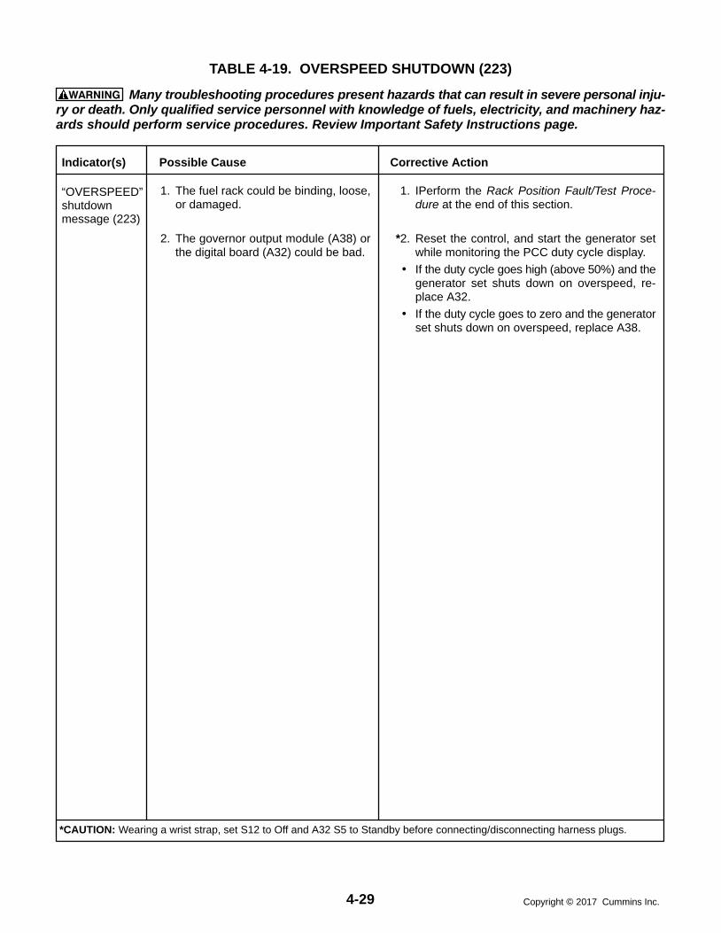
4-29 Copyright 2017 Cummins Inc.
TABLE 4-19. OVERSPEED SHUTDOWN (223)
WARNING Many troubleshooting procedures present hazards that can result in severe personal inju-ry or death. Only qualified service personnel with knowledge of fuels, electricity, and machinery haz-ards should perform service procedures. Review Important Safety Instructions page.
Indicator(s) Possible Cause Corrective Action
“OVERSPEED”shutdownmessage (223)
1. IPerform the Rack Position Fault/Test Proce-dure at the end of this section.
*2. Reset the control, and start the generator setwhile monitoring the PCC duty cycle display.
If the duty cycle goes high (above 50%) and thegenerator set shuts down on overspeed, re-place A32.
If the duty cycle goes to zero and the generatorset shuts down on overspeed, replace A38.
1. The fuel rack could be binding, loose,or damaged.
2. The governor output module (A38) orthe digital board (A32) could be bad.
*CAUTION: Wearing a wrist strap, set S12 to Off and A32 S5 to Standby before connecting/disconnecting harness plugs.

4-30Copyright 2017 Cummins Inc.
TABLE 4-20. DC (BATTERY) WARNINGS (230, 231, 232)
WARNING Many troubleshooting procedures present hazards that can result in severe personal inju-ry or death. Only qualified service personnel with knowledge of fuels, electricity, and machinery haz-ards should perform service procedures. Review Important Safety Instructions page.
Indicator(s) Possible Cause Corrective Action
5. If the batteries are OK, the problemmay be the harness, the engine inter-face board (A31), the digital board(A32), or the analog board (A33).
*5. If the battery voltage, electrolyte, and connec-tions are OK, check the battery voltage at A31J5-17. If the voltage is not OK (same as batteryvoltage), disconnect J5 and isolate to the har-ness or A31.
If the voltage is OK, check battery voltage atA33 J1-31. If the voltage is not OK, replaceA31. If the voltage at A33 J1-31 is OK, isolate toA33 or A32 using the analog input trouble-shooting procedure (Table 4-30a/b).
“LOW DCVOLTAGE”(230) or“WEAKBATTERY”(232), warningmessage.
“HIGH DCVOLTAGE”(231)warningmessage.
But batteryvoltage is OK.
1. Recharge or replace the battery. Specific gravi-ty for a fully charged battery is approximately1.260 at 80 F (27 C).
2. Replenish electrolyte and recharge battery.
3. Clean and tighten or replace the battery cableconnectors and cables at the battery and thegenerator set.
4. Adjust charge rate of battery charging circuit,according to manufacturers instructions.
1. Weak or discharged battery.
2. Low electrolyte level in battery.
3. Battery connections loose or dirty.
4. Insufficient battery charging voltage.
2. If the battery voltage is OK, the prob-lem may be the engine interface board(A31), the digital board (A32), or theanalog board (A33).
*2. Check the battery voltage at A31 J5-17. If thevoltage is not OK (same as battery voltage), dis-connect J5 and isolate to the harness or A31.
If the voltage is OK, check battery voltage atA33 J1-31. If the voltage is not OK, replaceA31. If the voltage at A33 J1-31 is OK, isolate toA33 or A32 using the analog input troubleshoot-ing procedure (Table 4-30a/b).
1. Adjust charge rate of battery charging circuit ac-cording to manufacturers instructions.
1. Excessive battery charging voltage.
*CAUTION: Wearing a wrist strap, set S12 to Off and A32 S5 to Standby before connecting/disconnecting harness plugs.
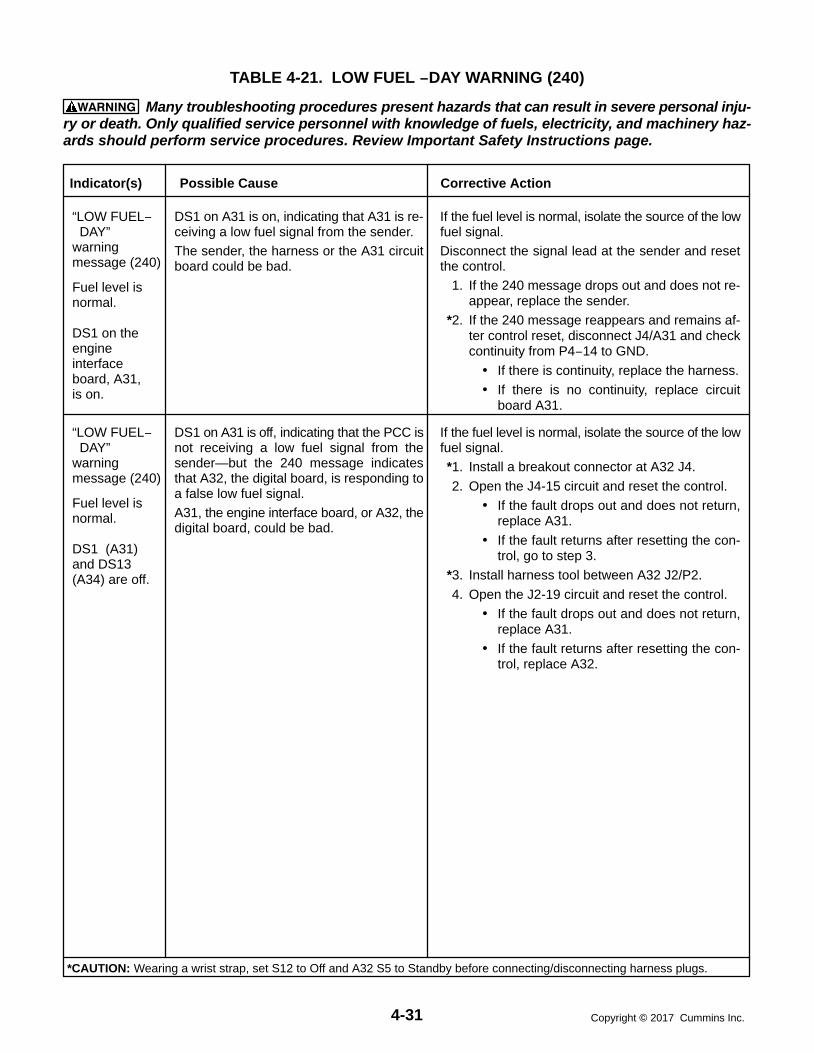
4-31 Copyright 2017 Cummins Inc.
TABLE 4-21. LOW FUEL −DAY WARNING (240)
WARNING Many troubleshooting procedures present hazards that can result in severe personal inju-ry or death. Only qualified service personnel with knowledge of fuels, electricity, and machinery haz-ards should perform service procedures. Review Important Safety Instructions page.
Indicator(s) Possible Cause Corrective Action
“LOW FUEL− DAY” warningmessage (240)
Fuel level isnormal.
DS1 on theengineinterfaceboard, A31, is on.
DS1 on A31 is on, indicating that A31 is re-ceiving a low fuel signal from the sender.The sender, the harness or the A31 circuitboard could be bad.
If the fuel level is normal, isolate the source of the lowfuel signal.Disconnect the signal lead at the sender and resetthe control.
1. If the 240 message drops out and does not re-appear, replace the sender.
*2. If the 240 message reappears and remains af-ter control reset, disconnect J4/A31 and checkcontinuity from P4−14 to GND.
If there is continuity, replace the harness.
If there is no continuity, replace circuitboard A31.
DS1 on A31 is off, indicating that the PCC isnot receiving a low fuel signal from thesender—but the 240 message indicatesthat A32, the digital board, is responding toa false low fuel signal.A31, the engine interface board, or A32, thedigital board, could be bad.
If the fuel level is normal, isolate the source of the lowfuel signal.*1. Install a breakout connector at A32 J4.
2. Open the J4-15 circuit and reset the control.
If the fault drops out and does not return,replace A31.
If the fault returns after resetting the con-trol, go to step 3.
*3. Install harness tool between A32 J2/P2.
4. Open the J2-19 circuit and reset the control.
If the fault drops out and does not return,replace A31.
If the fault returns after resetting the con-trol, replace A32.
“LOW FUEL− DAY” warningmessage (240)
Fuel level isnormal.
DS1 (A31)and DS13(A34) are off.
*CAUTION: Wearing a wrist strap, set S12 to Off and A32 S5 to Standby before connecting/disconnecting harness plugs.
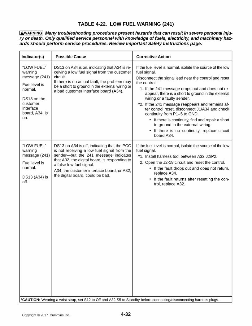
4-32Copyright 2017 Cummins Inc.
TABLE 4-22. LOW FUEL WARNING (241)
WARNING Many troubleshooting procedures present hazards that can result in severe personal inju-ry or death. Only qualified service personnel with knowledge of fuels, electricity, and machinery haz-ards should perform service procedures. Review Important Safety Instructions page.
DS13 on A34 is on, indicating that A34 is re-ceiving a low fuel signal from the customercircuit.If there is no actual fault, the problem maybe a short to ground in the external wiring ora bad customer interface board (A34).
Indicator(s) Possible Cause Corrective Action
DS13 on A34 is off, indicating that the PCCis not receiving a low fuel signal from thesender—but the 241 message indicatesthat A32, the digital board, is responding toa false low fuel signal.A34, the customer interface board, or A32,the digital board, could be bad.
If the fuel level is normal, isolate the source of the lowfuel signal.*1. Install harness tool between A32 J2/P2.
2. Open the J2-19 circuit and reset the control.
If the fault drops out and does not return,replace A34.
If the fault returns after resetting the con-trol, replace A32.
“LOW FUEL” warningmessage (241)
Fuel level isnormal.
DS13 (A34) isoff.
“LOW FUEL” warningmessage (241)
Fuel level isnormal.
DS13 on thecustomerinterfaceboard, A34, ison.
If the fuel level is normal, isolate the source of the lowfuel signal.Disconnect the signal lead near the control and resetthe control.
1. If the 241 message drops out and does not re-appear, there is a short to ground in the externalwiring or a faulty sender.
*2. If the 241 message reappears and remains af-ter control reset, disconnect J1/A34 and checkcontinuity from P1−5 to GND.
If there is continuity, find and repair a shortto ground in the external wiring.
If there is no continuity, replace circuitboard A34.
*CAUTION: Wearing a wrist strap, set S12 to Off and A32 S5 to Standby before connecting/disconnecting harness plugs.

4-33 Copyright 2017 Cummins Inc.
TABLE 4-23. EEPROM ERROR SHUTDOWN (250) OR WARNING (251, 252)
WARNING Many troubleshooting procedures present hazards that can result in severe personal inju-ry or death. Only qualified service personnel with knowledge of fuels, electricity, and machinery haz-ards should perform service procedures. Review Important Safety Instructions page.
Indicator(s) Possible Cause Corrective Action
“EEPROMERROR”shutdown(250)message.
The EE memory on the digital board (A32)may be bad.
1. Perform the initial start setup procedure (de-scribed in Section 5). Save the adjustments.
Reset the control. Shut off and restart the gen-erator set.
2. If the generator set shuts down on the same EE-PROM ERROR message, replace the digitalboard (A32).
“EEPROMERROR”warning (251)message.
The EE memory on the digital board (A32)may be bad.
1. Perform the initial start setup procedure (de-scribed in Section 5). Save the adjustments.
Reset the control. Shut off and restart the gen-erator set.
2. If the control generates the same EEPROM ERROR message, perform the calibration pro-cedures in Section 5.
Reset the control. Shut off and restart the gen-erator set.
3. If the control generates the same EEPROM ERROR message, replace the digital board(A32).
“EEPROMERROR”warning (252)message.
The EE memory on the digital board (A32)may be bad.
1. If this message occurred during an adjustment,option selection, or calibration of the PCC,verify the values or choices selected and repeatthe save operation.
Reset the control. Shut off and restart the gen-erator set.
2. If the control generates the same EEPROM ERROR message, replace the digital board(A32).
*CAUTION: Wearing a wrist strap, set S12 to Off and A32 S5 to Standby before connecting/disconnecting harness plugs.

4-34Copyright 2017 Cummins Inc.
TABLE 4-24. RACK POSITION WARNING (260)
WARNING Many troubleshooting procedures present hazards that can result in severe personal inju-ry or death. Only qualified service personnel with knowledge of fuels, electricity, and machinery haz-ards should perform service procedures. Review Important Safety Instructions page.
Indicator(s) Possible Cause Corrective Action
“RACK POSITION” warningmessage (260)
*CAUTION: Wearing a wrist strap, set S12 to Off and A32 S5 to Standby before connecting/disconnecting harness plugs.
PowerCommand control fault or defectivegovernor control circuitry.
Restart the generator set and monitor the fault LED’sof the governor output module (A38). Refer to Sec-tion 3 for LED descriptions.
1 LED’s (DS1 through DS4 are on and DS5 andDS6 are off) do not indicate a fault, refer to “Cus-tomer Fault 261, 262 & 263 for corrective ac-tion.
2 LED’s (DS5 or DS6 are on) one or moreindicatea fault and the generator set shuts down afterrestarting − perform the Rack Position Fault/Test Procedure at the end of this section.

4-35 Copyright 2017 Cummins Inc.
TABLE 4-25. CUSTOMER FAULTS (261, 262 OR 263)
WARNING Many troubleshooting procedures present hazards that can result in severe personal inju-ry or death. Only qualified service personnel with knowledge of fuels, electricity, and machinery haz-ards should perform service procedures. Review Important Safety Instructions page.
Indicator(s) Possible Cause Corrective Action
“CUSTOMERFAULT (261, 262 or263) message.
AndcorrespondingLED oncustomerinterface boardA34 is on.
If the corresponding LED on the customerinterface board (A34) is on, then A34 is re-ceiving a signal from the customer circuit.If there is no actual fault, the problem maybe a short to ground in the external wiring ora bad customer interface board (A34).
Isolate the source of the false signal.Disconnect the signal lead near the control and resetthe control.
1. If the message drops out, there is a short toground in the external wiring.
2. If the message remains, replace A34.
“CUSTOMERFAULT (261, 262 or263) message.
AndcorrespondingLED oncustomerinterface boardA34 is off.
Isolate the source of the false signal.Check J2/P2 on A32.*1. Install harness tool between A32 J2/P2.
2. Open the appropriate circuit J2-3, J2-24, J2-9,or J2-15 and reset the control.
If the fault does not return, replace A34.
If the fault reappears, replace A32.
If the corresponding LED on the customerinterface board (A34) is off, then A34 is notreceiving a signal from the customer circuit.The message indicates that A32, the digitalboard, is responding to a false signal. A34, the customer interface board, or A32,the digital board, could be bad.
A 34LED
A32CONNECTOR
CUSTOMERFAULT #
FAULTCODE
DS4DS11DS15DS3
J2-3J2-24J2-9J2-15
Rack Position234
260261262263
*CAUTION: Wearing a wrist strap, set S12 to Off and A32 S5 to Standby before connecting/disconnecting harness plugs.

4-36Copyright 2017 Cummins Inc.
TABLE 4-26A. HIGH AC VOLTAGE SHUTDOWN (301)
WARNING Many troubleshooting procedures present hazards that can result in severe personal inju-ry or death. Only qualified service personnel with knowledge of fuels, electricity, and machinery haz-ards should perform service procedures. Review Important Safety Instructions page.
Indicator(s) Possible Cause Corrective Action
“HIGH ACVOLTAGE ”shutdown(301)message.
1. The problem may be in the PCC, thealternator, or the interconnection be-tween them.
Note 1: The PCC may indicate eithera low AC Voltage or High AC Voltageshutdown due to the design of thelogic in the control.
You must first determine if the out-put voltage the control sees is lowor high.
Note 2: Residual voltage is normally5 to 10% of nominal output voltage.For example, a generator set with a480 volt output, will have a residualvoltage of 25 to 50 VAC at normaloperating speed.
1. Set the display on the PCC to GEN, VOLTS,L-N.
a. Start the generator set and observe the volt-age displayed on the digital display.
b. If all phases of voltage are balanced and notzero, but lower than normal, the alternatorand the input to the PCC are OK. The prob-lem is in the excitation circuit for the alterna-tor. Go to step 2.
c. If one or more phases of voltage are high orthe voltages are unbalanced, the PCC is notmeasuring all phases of voltage and is re-sponding to the low “average” of the threephases of voltage. Go to step 3.
2. The problem may be the regulatormodule (A37), the engine interfaceboard (A31), or the digital board (A32).
2. With DC power to the PCC and with the genera-tor set not running, check A31 DS9, the AVRduty cycle LED. this LED should be off. If it si on,go to step 2d.
Isolate the generator set output from the load.Disconnect A37 J10, and place the generatorset in Idle mode. In Idle mode the excitation cir-cuit is disabled. Start the generator set andmonitor the AC output voltage with a digitalmultimeter.
a. If output voltage is greater than residual (5%of normal output), go to step 3.
b. If output voltage stays at 0 (or residual), andDS2 on A37 is off, go to step 4.
c. If output voltage stays at 0 (or residual), andDS2 on A37 is on, look at DS9 on A31.
If DS9 on A31 is off, replace A37.
d. If DS9 on A31 is on, connect a breakout con-nector at A32 J4, and open J4-2.
If DS9 goes out, replace A32.
If DS9 stays on replace A31.
*CAUTION: Wearing a wrist strap, set S12 to Off and A32 S5 to Standby before connecting/disconnecting harness plugs.
(Continued)
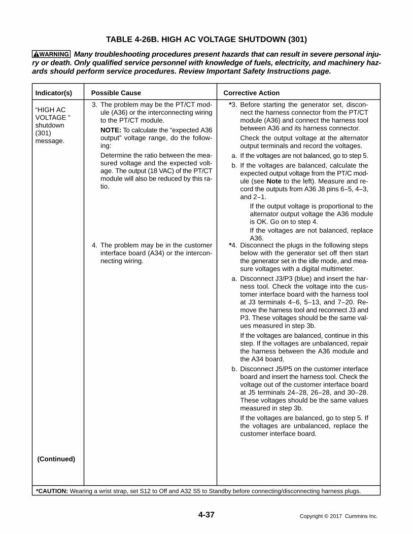
4-37 Copyright 2017 Cummins Inc.
TABLE 4-26B. HIGH AC VOLTAGE SHUTDOWN (301)
WARNING Many troubleshooting procedures present hazards that can result in severe personal inju-ry or death. Only qualified service personnel with knowledge of fuels, electricity, and machinery haz-ards should perform service procedures. Review Important Safety Instructions page.
Indicator(s) Possible Cause Corrective Action
“HIGH ACVOLTAGE ”shutdown(301)message.
3. The problem may be the PT/CT mod-ule (A36) or the interconnecting wiringto the PT/CT module.
NOTE: To calculate the “expected A36output” voltage range, do the follow-ing:Determine the ratio between the mea-sured voltage and the expected volt-age. The output (18 VAC) of the PT/CTmodule will also be reduced by this ra-tio.
*3. Before starting the generator set, discon-nect the harness connector from the PT/CTmodule (A36) and connect the harness toolbetween A36 and its harness connector.
Check the output voltage at the alternatoroutput terminals and record the voltages.
a. If the voltages are not balanced, go to step 5.
b. If the voltages are balanced, calculate theexpected output voltage from the PT/C mod-ule (see Note to the left). Measure and re-cord the outputs from A36 J8 pins 6−5, 4−3,and 2−1.
If the output voltage is proportional to thealternator output voltage the A36 moduleis OK. Go on to step 4.If the voltages are not balanced, replaceA36.
*CAUTION: Wearing a wrist strap, set S12 to Off and A32 S5 to Standby before connecting/disconnecting harness plugs.
4. The problem may be in the customerinterface board (A34) or the intercon-necting wiring.
*4. Disconnect the plugs in the following stepsbelow with the generator set off then startthe generator set in the idle mode, and mea-sure voltages with a digital multimeter.
a. Disconnect J3/P3 (blue) and insert the har-ness tool. Check the voltage into the cus-tomer interface board with the harness toolat J3 terminals 4−6, 5−13, and 7−20. Re-move the harness tool and reconnect J3 andP3. These voltages should be the same val-ues measured in step 3b.
If the voltages are balanced, continue in thisstep. If the voltages are unbalanced, repairthe harness between the A36 module andthe A34 board.
b. Disconnect J5/P5 on the customer interfaceboard and insert the harness tool. Check thevoltage out of the customer interface boardat J5 terminals 24−28, 26−28, and 30−28.These voltages should be the same valuesmeasured in step 3b.
If the voltages are balanced, go to step 5. Ifthe voltages are unbalanced, replace thecustomer interface board.
(Continued)

4-38Copyright 2017 Cummins Inc.
TABLE 4-26C. HIGH AC VOLTAGE SHUTDOWN (301)
WARNING Many troubleshooting procedures present hazards that can result in severe personal inju-ry or death. Only qualified service personnel with knowledge of fuels, electricity, and machinery haz-ards should perform service procedures. Review Important Safety Instructions page.
Indicator(s) Possible Cause Corrective Action
“HIGH ACVOLTAGE ”shutdown(301)message.
5. The problem may be the analog board(A33).
NOTE: To determine the “3-phaseave” signal voltage range for Step 3b,use the following formula:
Vout 3-phase ave = Vin (2.9PT) 5%
Vin = Actual alternator output voltage (phase-to-neutral)PT = PT primary (120, 240 or 346)
*5. Using the harness tool, check the “3-phaseave” signal at A33 J2-18.
If the voltage is within the expected range,replace A32. If the voltage is not within theexpected range, replace A33. See Note.
6. The problem may be in the generatorset itself.
6. Refer to the alternator servicing procedures inSection 6.
*CAUTION: Wearing a wrist strap, set S12 to Off and A32 S5 to Standby before connecting/disconnecting harness plugs.

4-39 Copyright 2017 Cummins Inc.
TABLE 4-27A. LOW AC VOLTAGE SHUTDOWN (303)
WARNING Many troubleshooting procedures present hazards that can result in severe personal inju-ry or death. Only qualified service personnel with knowledge of fuels, electricity, and machinery haz-ards should perform service procedures. Review Important Safety Instructions page.
Indicator(s) Possible Cause Corrective Action
“LOW ACVOLTAGE ”shutdown(303)message.
1. PMG or field wiring could be faulty.
2. The rotating rectifier assembly (diodesCR1 through CR6) is faulty.
3. Overload.
4. There may be a loose connector in thecontrol loop.
5a. The problem may be the analog board(A33) or the digital board (A32).
5b. The problem may be the regulatormodule (A37), the engine interfaceboard (A31), or the digital board (A32).
1. If output voltage is low and both A37/DS2 andA31/DS10 are on, check and repair the PMG orfield wiring.
2. Check each diode according to Servicing theAlternator in Section 6. Service as necessary.
3. Check the load and correct any overload.
4. Check connectors J8 and J9 on A36, J3 and J5on A34, and J7 on A37.
*5. Isolate the generator set output from the load.Reset the control, restart the generator set, andmeasure AC output voltage with a multimeter.
a. If output voltage is high, refer to the trouble-shooting section for High AC Voltage Shutdown(301).
If output voltage is normal, the problem must bein the voltage sensing circuitry (A32 or A33).
Isolate, using the analog input troubleshootingprocedure (Table 4-29a/b). Check the phasethat shows a low voltage on the PCC display.
*b. If output voltage is low, the control cannot drivethe output voltage high enough. The problemcould be A37, A31, or A32. Restart the genera-tor set and monitor isolated B+ supply LEDA37/DS1, output duty cycle LED A37/DS2, and AVR duty cycle LED A31/DS10.
If A37/DS1 is not on, disconnect A3 J7/P7and check for B+ at P7-1. (Control must be inRun mode for B+ reading.)
If B+ is OK to A37, replace A37.
If A37/DS1 is on, check A31/DS10 (with thegenerator set running).
If A31/DS10 is not on with generator set run-ning, check for continuity: A31 J1-2 to J4-10and A31 J1-1 to J4-11 (270 ohms). If no con-tinuity, replace A31.
If A31is OK, replace A32.
If A31/DS10 is on with generator set runningand A37/DS2 is not on, check the harness.
If the harness is OK, replace A37.
*CAUTION: Wearing a wrist strap, set S12 to Off and A32 S5 to Standby before connecting/disconnecting harness plugs.
(Continued)

4-40Copyright 2017 Cummins Inc.
TABLE 4-27B. LOW AC VOLTAGE SHUTDOWN (303)
WARNING Many troubleshooting procedures present hazards that can result in severe personal inju-ry or death. Only qualified service personnel with knowledge of fuels, electricity, and machinery haz-ards should perform service procedures. Review Important Safety Instructions page.
Indicator(s) Possible Cause Corrective Action
“LOW ACVOLTAGE ”shutdown(303)message.
5c. The problem may be the PT/CT mod-ule (A36), the analog board (A33), thecustomer interface board (A34), or thedigital board (A32).
c. If the measured AC voltage is high, the controlmust have lost AC sensing. Check PTs (primary1K−2.5K ohms; secondary 140−225 ohms),sensing harness wires, alternator output con-nections, and the customer interface board forcontinuity. If these are OK, then check the ana-log and digital boards, using the analog inputtroubleshooting procedure (Table 4-29a/b).
*CAUTION: Wearing a wrist strap, set S12 to Off and A32 S5 to Standby before connecting/disconnecting harness plugs.

4-41 Copyright 2017 Cummins Inc.
TABLE 4-28. UNDER FREQUENCY SHUTDOWN (313)
WARNING Many troubleshooting procedures present hazards that can result in severe personal inju-ry or death. Only qualified service personnel with knowledge of fuels, electricity, and machinery haz-ards should perform service procedures. Review Important Safety Instructions page.
Indicator(s) Possible Cause Corrective Action
“UNDERFREQUENCY”shutdown(313)message.
1. Improper setup.
2. Overload.
3. Fuel or air delivery problem.
4. The governor output module (A38),the digital board (A32), or the engineinterface board (A31) could be bad.
1. Check Initial Setup (set size) and correct, if nec-essary.
2. Check the load and correct any overload, if nec-essary.
Disconnect the load. Reset the control and at-tempt to restart the generator set.
3. If the engine starts and runs, refer to the enginefuel/air delivery service procedures.
*4. Disconnect the wire to the fuel solenoid, resetthe control, and crank the generator set. DS1and DS2 on the governor output module A38should light.
If the duty cycle LED’s (DS3 and DS4) on thegovernor output module (A38) become bright,the governor output module(A38), the digitalboard (A32), and the engine interface board(A31) are functioning properly.If DS3 and DS4 do not light, A31, A32 or A38may be bad.
A38 - Crank the generator set, and checkthe governor duty cycle on the PCC dis-play. If the duty cycle is OK (85% max), re-place governor output module (A38).If the duty cycle is not OK, the digital board(A32) or the engine interface board (A31)may be bad.
A31 - Check for continuity: A31 J1-13 toA31 J4-19 and A31 J1-14 to A31 J4-12. Ifno continuity, replace A31.
A32 - If A31 is OK, replace A32
*CAUTION: Wearing a wrist strap, set S12 to Off and A32 S5 to Standby before connecting/disconnecting harness plugs.

4-42Copyright 2017 Cummins Inc.
TABLE 4-29. OVERCURRENT WARNING (320) OR SHUTDOWN (321),SHORT CIRCUIT SHUTDOWN (322), OR OVERLOAD WARNING (330)
WARNING Many troubleshooting procedures present hazards that can result in severe personal inju-ry or death. Only qualified service personnel with knowledge of fuels, electricity, and machinery haz-ards should perform service procedures. Review Important Safety Instructions page.
Indicator(s) Possible Cause Corrective Action
“OVER-CURRENT”warning (320)or shutdown(321),or “SHORTCIRCUIT”shutdown(322), orOVERLOADwarning (330)message.
1. Short or Overload.
2. Incorrect CTs or CT connections.
3. The problem may be a bad PT/CTmodule (A36).
4. The problem may be the customer in-terface board (A34) or connections.
5. The problem may be the analog board(A33) or the digital board (A32).
1. Check the load and load cables. Repair if nec-essary.
2. Check CTs and CT connections. Correct if nec-essary. Refer to Current Transfer Installation inSection 5.
3. Disconnect the PT/CT module and check the3-ohm resistors (J8-15 to 14, J8-22 to 23, J8-7 to 8). Replace the module if necessary.
*4. Check continuity from A36—through A34—toA33. Repair the connection or replace A34 ifnecessary. Refer to Section 7 for pin reference.
5. Isolate, using the analog input troubleshootingprocedure (Table 4-30a/b). Check the badphase or phases.
*CAUTION: Wearing a wrist strap, set S12 to Off and A32 S5 to Standby before connecting/disconnecting harness plugs.

4-43 Copyright 2017 Cummins Inc.
TABLE 4-30A. TROUBLESHOOTING ANALOG SIGNALS BETWEEN ANALOG ANDDIGITAL BOARDS
WARNING Many troubleshooting procedures present hazards that can result in severe personal inju-ry or death. Only qualified service personnel with knowledge of fuels, electricity, and machinery haz-ards should perform service procedures. Review Important Safety Instructions page.
NOTE: Perform this procedure after you have isolated the problem to either the analog board(A33) or to the digital board (A32). You must have schematics and wiring diagrams toidentify the various inputs and outputs.
*1. Check that the input to the analog board is correct. There are a few signals (e.g.: 3PH Ave, Line Freq,Phase Angle 1 to 3, Lead Lag) that are derived from one or more input signals.
1a. To check the sensor input voltages into the analog board, connect the sender simulator and test thevoltage across the + and − inputs at A33 J1 using harness tool. (This assumes that you have verifiedthat the harness and the engine interface board is good.)
If the input voltage to the analog board is correct (refer to Table 4-30), go to step 2. If the input voltage to the analog board is incorrect, check for 12 VDC at A32 J3-20 and 5 VDC at
A32 J3-12. Do this with the analog board connected to the digital (A32).If the 12 VDC and 5 VDC voltages are OK, replace the analog board.If the 12 VDC and 5 VDC voltages are not OK, disconnect A32 J3 and recheck for 12 VDC atA32 J3-20 and 5 VDC at A32 J3-12.
If the 12 VDC and 5 VDC voltages are now OK, replace the analog board.If the 12 VDC and 5 VDC voltages are still not OK, replace the digital board.
1b. To check the AC inputs into the analog board, drive the PT/CT inputs (voltage or current) and verifythat the input is correct.
If the input to the analog board is correct, go to step 2. If the input to the analog board is incorrect, disconnect the ribbon cable at A34 J5 and check the volt-
age at A34 J5 again (Customer Interface).If the voltage is now correct, replace the analog board.If the voltage is still not correct, the problem is not on the analog or digital boards.
2. If the input to the analog board is correct, determine whether the signal is multiplexed (refer to Table4-30). If the signal is not multiplexed, go to step 2a. If the signal is multiplexed, go to step 2b.
2a. This step is for non-multiplexed AC signals. Drive the input to the analog board with an AC source,and test the signal level out of the analog board. You must calculate what the analog output voltageshould be (Table 4-30), assuming the analog board transfer function is linear.
If the signal level into the digital board is correct, the problem must be on the digital board. Replacethe digital board.
If the signal level into the digital board is incorrect, remove the ribbon cable connector at A32 J3, andcheck the front panel digital display of the bad analog value.
If the display reads 0, replace the analog board.If the display reads a value other than 0, replace the digital board.
*CAUTION: Wearing a wrist strap, set S12 to Off and A32 S5 to Standby before connecting/disconnecting harness plugs.

4-44Copyright 2017 Cummins Inc.
TABLE 4-30B. TROUBLESHOOTING ANALOG SIGNALS BETWEEN ANALOG ANDDIGITAL BOARDS
WARNING Many troubleshooting procedures present hazards that can result in severe personal inju-ry or death. Only qualified service personnel with knowledge of fuels, electricity, and machinery haz-ards should perform service procedures. Review Important Safety Instructions page.
NOTE: Perform this procedure after you have isolated the problem to either the analogboard (A33) or to the digital board (A32). You must have schematics and wiringdiagrams to identify the various inputs and outputs.
2b. This step is for multiplexed signals. Is more than one multiplexed signal reading bad? No. If the input to the analog board is correct and only one multiplexed signal is reading bad, replace
the analog board. Yes. If more than one multiplexed signal reading is bad, remove the ribbon cable connector at
A32 J3 and check the front panel digital display of the bad inputs. It should read 0 for all inputs ex-cept the temperature inputs (which should read less than 32 F or less than 0 C) and power factor(which should read “NA”).
If any values read incorrectly, replace the digital board.If they all read correctly, measure voltages on the multiplexer control lines (with A32-J3 discon-nected, measure from Digital board connector J3). Voltages should be:
A32-J3-23: 3.0 0.25 VDCA32-J3-24: 2.4 0.25 VDCA32-J3-27: 1.4 0.25 VDCA32-J3-33: 3.0 0.25 VDCA32-J3-34: 3.0 0.25 VDC
If these control (select) line voltages are not correct, replace the digital board.
If these control (select) line voltages are correct (and the input to the analog board is correct),reconnect the ribbon cable connector (through harness tool) at A32 J3 and check the 5 VDCreference at A32 J3-12 and the 12 VDC supply at A32 J3-20.
If the 5 VDC and the 12 VDC voltages are OK, replace the analog board.
If the 5 VDC and the 12 VDC voltages are not OK, disconnect A32 J3 and check the voltages again (measured from Digital board side).
If the 5 VDC and the 12 VDC voltages are OK with A32 J3 disconnected, replace theanalog board.
If the 5 VDC and the 12 VDC voltages are not OK with A32 J3 disconnected, replacethe digital board.
*CAUTION: Wearing a wrist strap, set S12 to Off and A32 S5 to Standby before connecting/disconnecting harness plugs.

4-45 Copyright 2017 Cummins Inc.
TABLE 4−31. ANALOG CIRCUIT BOARD (A33) INPUTS AND OUTPUTS
Input Name InputConnection
Input SignalRange
Output Name1 Output Connection2
OutputSignal Range
L1 (0 to nominal) J4-24 to J4-28 0 to 18 VAC L10 (ACH1) J2-4 0 to 3.0 VDC
L2 (0 to nominal) J4-26 to J4-28 0 to 18 VAC L20 (ACH2) J2-13 0 to 3.0 VDC
L3 (0 to nominal) J4-30 to J4-28 0 to 18 VAC L30 (ACH3) J2-1 0 to 3.0 VDC
3PH ave (ACH0) J2-18 0 to 2.9 VDC
Line freq. (HSI.1) J2-21 0-5V sq wave @ L1 Hz
CT21 (0 to full load) J4-33 to J4-34 0 to 1.65 VAC C1 fltrd (ACH4) J2-3 0 to 1.0 VDC
CT22 (0 to full load) J4-32 to J4-34 0 to 1.65 VAC C2 fltrd (ACH5) J2-9 0 to 1.0 VDC
CT23 (0 to full load) J4-31 to J4-34 0 to 1.65 VAC C3 fltrd (ACH6) J2-17 0 to 1.0 VDC
C1 (ACH7) J2-7 0 to 1.0 VDC
C2 (ACH7) J2-7 0 to 1.0 VDC
C3 (ACH7) J2-7 0 to 1.0 VDC
(1 to 0.8 pf) Phase angle 1 (ACH7)3 J2-7 0 to 1.0 VDC
(1 to 0.8 pf) Phase angle 2 (ACH7)3 J2-7 0 to 1.0 VDC
(1 to 0.8 pf) Phase angle 3 (ACH7)3 J2-7 0 to 1.0 VDC
(L1 vs CT21) Lead lag (P2A.1)) 3 J2-29 0 or 5 VDC (digital)
Bus L1 (0 to nominal) 6 J4-15 to J4-18 0 to 18 VAC Bus L1 (ACH7) J2-7 0 to 3.0 VDC
Bus L2 (0 to nominal) 6 J4-16 to J4-18 0 to 18 VAC Bus L2 (ACH7) J2-7 0 to 3.0 VDC
Bus L3 (0 to nominal) 6 J4-17 to J4-18 0 to 18 VAC Bus L3 (ACH7) J2-7 0 to 3.0 VDC
Bus freq (HS1.3) J2-22 0-5V sq wave @ Bus L1 Hz
Phase rot (P2A.0)5 J2-26 0 or 5 VDC (digital)
Bus/gen phase dif (ACH7)5 J2-7 0 to 5.0 VDC
Bus/gen phase (HS1.2)5 J2-19 0-5V 120 Hz 0 to 100% DC
Synch (ACH7)5 J2-7
Battery voltage J1-31 (+) to J1-30(−) 0 to 32 VDC Battery voltage (ACH7) J2-7 0 to 2.9 VDC
Oil press (0 to 100 psi) (See note 4 ) 0.5 to 4.5 VDC Oil press (ACH7) J2-7 0.5 to 4.5 VDC
H2O 1 (6 to 230 F) J1-19/20 to J1-17/18 700 to 1800 H2O 1 (ACH7) J2-7 1.4 to 3.7 VDC
H2O 2 (6 to 230 F) J1-15/16 to J1-14/15 700 to 1800 H2O 2 (ACH7) J2-7 1.4 to 3.7 VDC
Oil temp (6 to 230 F) J1-11/12 to J1-9/10 700 to 1800 Oil temp (ACH7) J2-7 1.4 to 3.7 VDC
Exh temp 1 (32 to 1471 F) J1-7/8 to J1-5/6 100 to 376 Exh temp 1 (ACH7) J2-7 0.8 to 3.0 VDC
Exh temp 2 (32 to 1471 F) J1-3/4 to J1-1/2 100 to 376 Exh temp 2 (ACH7) J2-7 0.8 to 3.0 VDC
Notes:
1. All output signals on ACH7 are multiplexed.
2. All output voltages on A33 J2 are referenced to ground (J2-15 and J2-16).
3. Must have L1, L2, L3, CT21, CT22, and CT23 for these phase angle outputs.
4. J1-24 (5VDC), J1-23 (signal), J1-18 (return).
5. Must have L1, L2, L3, Bus L1, Bus L2, and Bus L3 for these outputs.
6. L1, L2, and L3 can be 0 to 180 out of phase with Bus L1, Bus L2, and Bus L3, respectively.

4-46Copyright 2017 Cummins Inc.
TABLE 4-32. PCC FUSES
LOCATIONREFERENCE
DESIGNATION RATING FUNCTION
Engine Interface A31-F1 5 Amp PCC control B+
Engine Interface A31-F3 5 Amp Auxiliary B+ (for panel lights, run and start relays)
Governor OutputModule
A38-F4 10 Amp Network B+ (to TB1 customer terminal block)
Governor OutputModule
A38-F3 10 Amp Switched B+ (to TB1 customer terminal block)
Governor OutputModule
A38-F1 15 Amp Left actuator
TB-Bat (EngineHarness Assembly)
F1 20 Amp Customer B+ (to TB1 customer terminal block)
Governor OutputModule
A38-F2 15 Amp Right actuator

4-47 Copyright 2017 Cummins Inc.
RACK POSITION FAULT/TESTPROCEDURE
The rack position fault/test procedure is a trouble-shooting tool for the Rack Position (260) warningmessage. This test will isolate the fault to one ofthese components; fuel pump, governor outputmodule (A38), or the PowerCommand control.
Use a calibrated RMS multimeter for accurate mea-surements. Fluke models 87 or 8060A are goodchoices.
1. Move the Run/Off/Auto switch to the Off posi-tion.
2. At the engine interface board (A31), place ajumper wire from A31-TP1 to A31-TP2 (seeFigure 3-4 for test point location).
3. Select RACK TEST from the Setup Menu(page 5-17) to initiate the fuel rack test. This willapply power to the governor output module.
4. Are A38 DS1 (RUN) and A38 DS2 (VCC) LEDson?
Yes: Go to next step.
No: Possible control problem. Remove jum-ber wires (Step 2). Restart the generatorset and follow proper troubleshootingprocedure.
5. Are fuses A38 F1 and F2 blown?
Yes: Replace blown fuse and restart genera-tor set.
No: Go to next step.
6. Move both racks from 0mm to 19mm from the“POS MM” menu (see Setup Menu). Periodi-cally read the DC voltages from J11-B (leftposition voltage) to J11-A and J11-C (rightposition voltage) to J11-A. (The J11 engine har-ness connector is located at the bottom of theaccessory box.)
7. Do these voltages correspond to the voltage onthe display (0.25 VDC)?Yes: Test OK. Restart generator set and moni-
tor A38-DS5 (left position fault) andA38-DS6 (right position fault).
No: Go to next step.8. Are both left and right voltages out of toler-
ance?Yes: Possible control or governor output mod-
ule problem. Check PWM signal (refer toStep 4 of error Code 313 in Trouble-shooting section).
No: Go to next step.9. Move the racks to 0mm from the “POS MM”
menu. Monitor the position voltage of the sidethat has the incorrect voltage.
10. Disconnect the fuel pump connector at the fuelpump. Does the voltage rise up from approxi-mately 1.3 0.25 VDC to 4.5 0.25 VDC ?Yes: Replace defective fuel pump (refer to en-
gine service manual).No: Replace defective governor output mod-
ule.
Engine Torque Adjustment procedure must beperformed after replacement of fuel pump orgovernor output module. Refer to Section 5.

4-48Copyright 2017 Cummins Inc.
THIS PAGE LEFT INTENTIONALLY BLANK
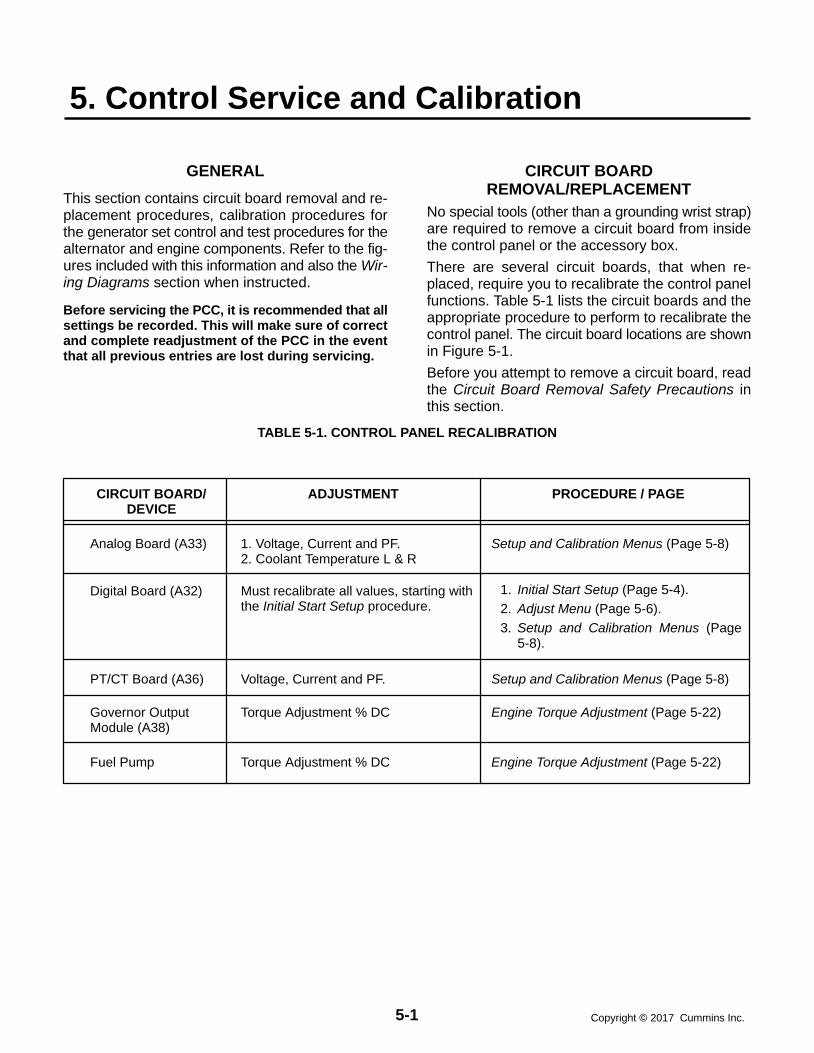
5-1 Copyright 2017 Cummins Inc.
5. Control Service and Calibration
GENERAL
This section contains circuit board removal and re-placement procedures, calibration procedures forthe generator set control and test procedures for thealternator and engine components. Refer to the fig-ures included with this information and also the Wir-ing Diagrams section when instructed.
Before servicing the PCC, it is recommended that allsettings be recorded. This will make sure of correctand complete readjustment of the PCC in the eventthat all previous entries are lost during servicing.
CIRCUIT BOARDREMOVAL/REPLACEMENT
No special tools (other than a grounding wrist strap)are required to remove a circuit board from insidethe control panel or the accessory box.
There are several circuit boards, that when re-placed, require you to recalibrate the control panelfunctions. Table 5-1 lists the circuit boards and theappropriate procedure to perform to recalibrate thecontrol panel. The circuit board locations are shownin Figure 5-1.
Before you attempt to remove a circuit board, readthe Circuit Board Removal Safety Precautions inthis section.
TABLE 5-1. CONTROL PANEL RECALIBRATION
CIRCUIT BOARD/DEVICE
Analog Board (A33)
ADJUSTMENT PROCEDURE / PAGE
1. Voltage, Current and PF.2. Coolant Temperature L & R
Digital Board (A32) Must recalibrate all values, starting withthe Initial Start Setup procedure.
1. Initial Start Setup (Page 5-4).2. Adjust Menu (Page 5-6).3. Setup and Calibration Menus (Page
5-8).
PT/CT Board (A36) Voltage, Current and PF.
Setup and Calibration Menus (Page 5-8)
Setup and Calibration Menus (Page 5-8)
Governor OutputModule (A38)
Torque Adjustment % DC Engine Torque Adjustment (Page 5-22)
Fuel Pump Torque Adjustment % DC Engine Torque Adjustment (Page 5-22)

5-2Copyright 2017 Cummins Inc.
CUSTOMERINTERFACE
A34
ENGINE INTERFACEA31
ANALOG BOARDA33
DIGITAL BOARDA32
DISPLAY BOARDA35
RUN/OFF/AUTOSWITCH S12
S5 POWER ON/STANDBY SWITCH
GOVERNOROUTPUT MODULE
A38
PT/CTBOARD A36
VOLTAGEREGULATOR
OUTPUT MODULEA37
FIGURE 5-1. CIRCUIT BOARD LOCATIONS
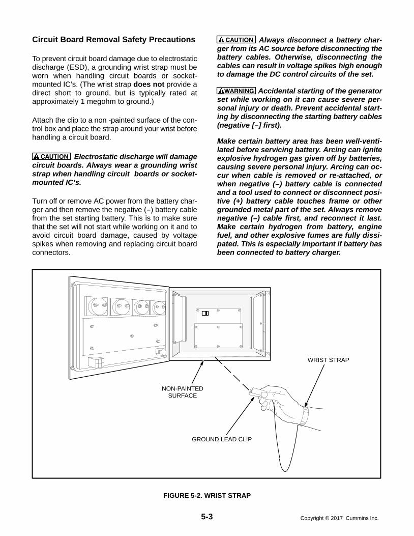
5-3 Copyright 2017 Cummins Inc.
Circuit Board Removal Safety Precautions
To prevent circuit board damage due to electrostaticdischarge (ESD), a grounding wrist strap must beworn when handling circuit boards or socket-mounted IC’s. (The wrist strap does not provide adirect short to ground, but is typically rated atapproximately 1 megohm to ground.)
Attach the clip to a non -painted surface of the con-trol box and place the strap around your wrist beforehandling a circuit board.
CAUTION Electrostatic discharge will damagecircuit boards. Always wear a grounding wriststrap when handling circuit boards or socket-mounted IC’s.
Turn off or remove AC power from the battery char-ger and then remove the negative (−) battery cablefrom the set starting battery. This is to make surethat the set will not start while working on it and toavoid circuit board damage, caused by voltagespikes when removing and replacing circuit boardconnectors.
CAUTION Always disconnect a battery char-ger from its AC source before disconnecting thebattery cables. Otherwise, disconnecting thecables can result in voltage spikes high enoughto damage the DC control circuits of the set.
WARNING Accidental starting of the generatorset while working on it can cause severe per-sonal injury or death. Prevent accidental start-ing by disconnecting the starting battery cables(negative [−] first).
Make certain battery area has been well-venti-lated before servicing battery. Arcing can igniteexplosive hydrogen gas given off by batteries,causing severe personal injury. Arcing can oc-cur when cable is removed or re-attached, orwhen negative (−) battery cable is connectedand a tool used to connect or disconnect posi-tive (+) battery cable touches frame or othergrounded metal part of the set. Always removenegative (−) cable first, and reconnect it last.Make certain hydrogen from battery, enginefuel, and other explosive fumes are fully dissi-pated. This is especially important if battery hasbeen connected to battery charger.
GROUND LEAD CLIP
WRIST STRAP
NON-PAINTEDSURFACE
FIGURE 5-2. WRIST STRAP

5-4Copyright 2017 Cummins Inc.
INITIAL START SETUP MENU
The facing page shows a block representation ofthe INITIAL START SETUP menu.
CAUTION Selecting this menu resets all oper-ating parameters to the default values for theselected set. All previously selected setup andadjustment settings will be lost. Therefore, thisprocedure must be performed by technicallyqualified personnel only.
This menu appears on the digital display when thePCC has not been set up for use with a generatorset during factory test, or the digital board was re-placed in the PCC.
When this display is showing, you must go throughthe Initial Start Setup menu to select the operatingparameters for the generator set. These includewhether the set will be used for Prime Power orStandby use, the Model Number of the generatorset, and its operating frequency and output voltage.These choices must be saved into the PCC’s read-only memory before the PCC will accept changesmade to other menus.
If the PCC is already set up to operate with a specificgenerator set, this menu will not appear when poweris applied. To reset the control and display the InitialStart Setup menu, you can press RESET, MENU, andPHASE SELECT buttons at the same time.
If you choose to do this, the governor/regulator ad-justments and the setup options will be reset to thedefault settings (including the editable customerfault messages). Display calibrations (volts, amps,PF and coolant temperature) are retained (not reset).To make sure correct and complete readjustment ofthe PCC, it is suggested that all settings be recordedbefore you perform the reset function.
CAUTION Improper setup, calibration, or ad-justments can cause equipment malfunction ordamage. Setup, calibration, and adjustmentmust be performed by technically qualified per-sonnel only.
STANDBY/PRIME submenu: Use the buttons nextto the “” symbols to toggle the standby/prime op-tion. Press the button next to the “>>” in the displayto move to the model select submenu.
MODEL select submenu: Use the buttons next tothe “” and “” symbols to select the correct genera-tor set model number, frequency and power rating.
VOLTAGE SELECT submenu: Use the buttonsnext to the “” and “” symbols to select the correctgenerator set nominal line-to-line output voltage.
DELTA / WYE submenu: Use the buttons next tothe “” and “” symbols to select the delta or wye op-tion.
SAVE submenu: From the model select submenu,press the button next to the “>>” in the display tomove to the SAVE submenu. Select SAVE to saveyour changes. The MAIN MENU will then be dis-played.
If “INVALID SETUP” or “INVALID CAL” is displayedafter saving your changes, refer to Digital Board(A32) Calibration at the end of this section.

5-5 Copyright 2017 Cummins Inc.
< >
< >
< >
< >
<
STANDBY/PRIME _______ >>
MODEL (kw mod# freq) >>
SAVE >> < >< >
INITIAL START SETUP(It can be invoked by simultaneously pressing
the Reset, Menu, and Phase Select keys.)
ENGINE GENADJUST >>
SAVE >> < > STANDBY/PRIME
_______ >>
TO LOOP BACK & CHECK:
< >< VOLTAGE SELECT
(vac) L-L VAC >>
< > DELTA / WYE
_______ >>
Indicates “OR” Condition

5-6Copyright 2017 Cummins Inc.
ADJUST MENU
The ADJUST submenus permit adjustment of theoutput voltage and frequency and the start and stopdelay times of the generator set.
The complete calibration procedure is described inthe Calibration Procedure in this section.
The facing page shows a block representation ofthe ADJUST menu. If you press the button next to
the word “ADJUST” in the Main menu, the VOLT-AGE ADJUST submenu will appear.
As shown in the diagram, the ADJUST menu hasfive submenus, including a save/exit procedure.
Voltage and frequency can be adjusted only whenthe generator set is running under normal operatingparameters (not in idle mode). For example, if volt-age adjustment is selected when the set is in Idlemode or not running, the digital display will be:
“ VOLTAGE ” “ N/A >>”
VOLTAGE submenu: This is the first submenu.Use the buttons next to the “” and “” symbols toadjust output voltage 5%.
FREQUENCY submenu: From the VOLTAGE sub-menu, press the button next to the “>>” in the dis-play to move to the FREQUENCY submenu. Usethe buttons next to the “” and “” symbols to adjustoutput frequency 5%.
START DELAY submenu: This delay applies onlyto remote starting in the Auto mode. From the FRE-QUENCY submenu, press the button next to the“>>” in the display to move to the START DELAYsubmenu. Use the buttons next to the “” and “”symbols to set the start delay. The start delay ad-justment range is 0 to 300 seconds.
STOP DELAY submenu: This delay applies onlyto remote stopping in the Auto mode. From theSTART DELAY submenu, press the button next tothe “>>” in the display to move to the STOP DELAYsubmenu. Use the buttons next to the “” and “”symbols to set the stop delay. The stop delay ad-
justment range is 0 to 600 seconds.
IDLE SPEED submenu: From the STOP DELAYsubmenu, press the button next to the “>>” in thedisplay to move to the IDLE SPEED submenu. Usethe buttons next to the “” and “” symbols to set theidle speed. The idle speed adjustment range is 800RPM 100 RPM. (Default value is 800 RPM.)
The idle speed can be adjusted only when the gener-ator set is running in the idle mode. When not in idlemode, N/A is displayed in RPM field.
SAVE/EXIT submenu: From the STOP DELAYsubmenu, press the button next to the “>>” in thedisplay to move to the SAVE/EXIT submenu. SelectSAVE to save your changes. At the CHANGESSAVED submenu, select EXIT to return to the mainmenu.
If you select SAVE, the adjustments will be retainedafter shutdown, and will be in effect when the set isrestarted. If you select EXIT without saving first, theadjustments will remain in effect until the generatorset is shut down, but will be reset (and will not be ineffect) when the set is restarted.

5-7 Copyright 2017 Cummins Inc.
< >< >
< >
< >
< >
< ><
<
< >
<
< >
ENGINE GENADJUST >>
< >< >
VOLTAGE _______ >>
<
FREQUENCY _______ >>
START DELAY _______ SEC >>
STOP DELAY _______SEC >>
< SAVEEXIT >>
< SAVEEXIT >>
< >< SAVE
EXIT >>
< >CHANGES SAVEDEXIT >>
CHANGES SAVEDEXIT >>
< VOLTAGE _______ >>
ENGINE GENADJUST >>
< >< >
< >< VOLTAGE
_______ >>
ENGINE GENADJUST >>
< >< >
ADJUST
< >< IDLE SPEED
_______RPM >>
Indicates “OR” Condition

5-8Copyright 2017 Cummins Inc.
SETUP AND CALIBRATION MENUS
The setup and calibration menus allow you to cali-brate the PCC with the reading from a calibratedmeter. There are four setup and calibration menusthat are selectable from the SETUP/CAL menu:
VERSION AND DISPLAYS
METERS
GOVERNOR/REGULATOR
SETUP
These four menus are intended for qualified servicepersonnel only. For this reason, a three-digit accesscode must be entered before you can proceed tothose menus.
ENTER CODE submenu:
The access code for your PCC is: 5 7 4.
To enter the code:1. Press the button next to the “” to increment the
first digit.
2. Press the button next to the “>>” to select thesecond digit.
3. Press the button next to the “” to increment thesecond digit.
4. Press the button next to the “>>” to select thethird digit.
5. Press the button next to the “” to increment thethird digit.
6. Press the button next to the “>>” to proceed tothe DISPLAYS/METERS submenu. (Pro-vided, of course, that you have correctly en-tered the access code.)
The following sub-sections describe how to selectand make changes to the setup and calibration me-nus and save the changes made to these menus.
Version and Displays Menus
The VERSION menu allows you to verify the modelnumber and frequency of the generator set, thedate and version of the operating software and gen-erator set configuration options. From the VER-SION menu you can also review a History file, thatcan contain up to 20 error messages.
The DISPLAYS submenus permit calibration of thedigital voltage, current, power factor (PF) and cool-ant temperature displays. Calibration is accom-plished by using this section of the menu software to
adjust the display so that it matches the reading tak-en on an accurate, recently calibrated meter.
The complete calibration procedure is described inthe Calibration Procedure in this section.
The facing page shows a block representation ofthe VERSION and DISPLAYS submenus, which isthe first of four SETUP/CAL menus. If you press thebutton next to the “>>” in the Main menu display, theVERSION/SETUP/CAL menu will appear.
CAUTION Improper calibration or adjustmentof the PowerCommand control can causeequipment malfunction or damage. Calibrationand adjustment must be performed by techni-cally qualified personnel only.
VERSION submenu: If you select VERSION, thedisplay will show the generator set model number,frequency, and kW rating, and the date and versionof the operating software.
To display the generator set configuration options,press the button next to the “>>” in the submenu thatdisplays the model number, frequency and etc. Thismenu provides the following information:
Generator set voltage
WYE or DELTA
Standby or Prime
Parallel or Single
HISTORY: From the VERSION, SETUP/CALmenu, press the button next to the “>>” in the dis-play to move to the HISTORY submenu. Press thebutton next to “HISTORY” to display the last (latest)recorded error message.
The software will record (save) up to 20 error mes-sages. The last error detected will always be dis-played first. As each new error is detected, the old-est error recorded after 20 will be deleted.
To view the generator set runtime at which the erroroccurred and to scroll through the remaining re-corded errors, press the button next to the “>>” inthe error message menu to display the RUNTIME,NEWER/OLDER menu.
The buttons next to NEWER and OLDER are usedto scroll up and down through the error messages.For example, pressing OLDER will display the nextoldest recorded error message. When pressingNEWER and the last (newest) error message is dis-played, or OLDER and oldest error is displayed, thedisplay will return to the HISTORY menu.

5-9 Copyright 2017 Cummins Inc.
< >
< >ENGINE GENADJUST >>
< >
< ENTER CODE __ __ __ >>
VERSION & DISPLAYS MENUS
< >< >VERSION <<
SETUP/CAL >>
< >
>>
(kW) (model) (hz) <<__ __ __ V:___.__ >>
BACK
ENGINE GENADJUST >>
< >< >< >VERSION <<
SETUP/CAL >>
< >< >VERSION <<
SETUP/CAL >>
>>
(kW) (model) (hz) <<__ __ __ V:___.__ >>
_______ V ______<<_______ ______
>
BACK
< >< >VERSION <<
SETUP/CAL >>
< >HISTORY <<
BACK
< >HISTORY <<>
__________________________________ >>
< > RUNTIME _________NEWER OLDER
CONTINUED
DISPLAYS ERRORMESSAGE AND CODE
DISPLAYS VOLTAGE &GENSET CONFIGURATION
Indicates “OR” Condition

5-10Copyright 2017 Cummins Inc.
Version and Displays Menus (Cont.)
DISPLAYS submenus: The DISPLAYS submenusare intended for qualified service personnel only.For this reason, a three-digit access code must beentered before you can proceed to those menus.
Select SETUP/CAL. The display will show the EN-TER CODE submenu. Enter access code (574) aspreviously described in this section.
Select DISPLAYS to proceed to the DISPLAYS sub-menus. Use the buttons next to the “” and “” sym-bols to calibrate the selected voltage, current, PF orcoolant temperature reading. Press the button nextto the “>>” in the display to move to the next adjust-ment.
“VOLTS L12,” “VOLTS L23,” and “VOLTS L31” referto voltages measured from L1 to L2, L2 to L3, andL3 to L1, respectively.
“PF1, PF2 and PF3” will display N/A when the gen-erator set is not running.
“COOLANT TEMP R” will display “N/A” if the gener-ator set has only one sensor. To calibrate coolanttemperature display, a precision resistor (providedin the engine sensor tool) must be temporally sub-stituted for the temperature sender. Refer to Cal-ibration Procedure in this section.
SAVE/EXIT submenu: From the AMPS L3 subme-nu, press the button next to the “>>” in the display tomove to the SAVE/EXIT submenu. Select SAVE tosave your changes. At the CHANGES SAVED sub-menu, select EXIT to return to the DISPLAYS/ME-TERS submenu.If you select SAVE, the adjustments will be retainedafter shutdown, and will be in effect when the set isrestarted. If you select EXIT without saving first, theadjustments will remain in effect until the generatorset is shut down, but will be reset (and will not be ineffect) when the set is restarted.
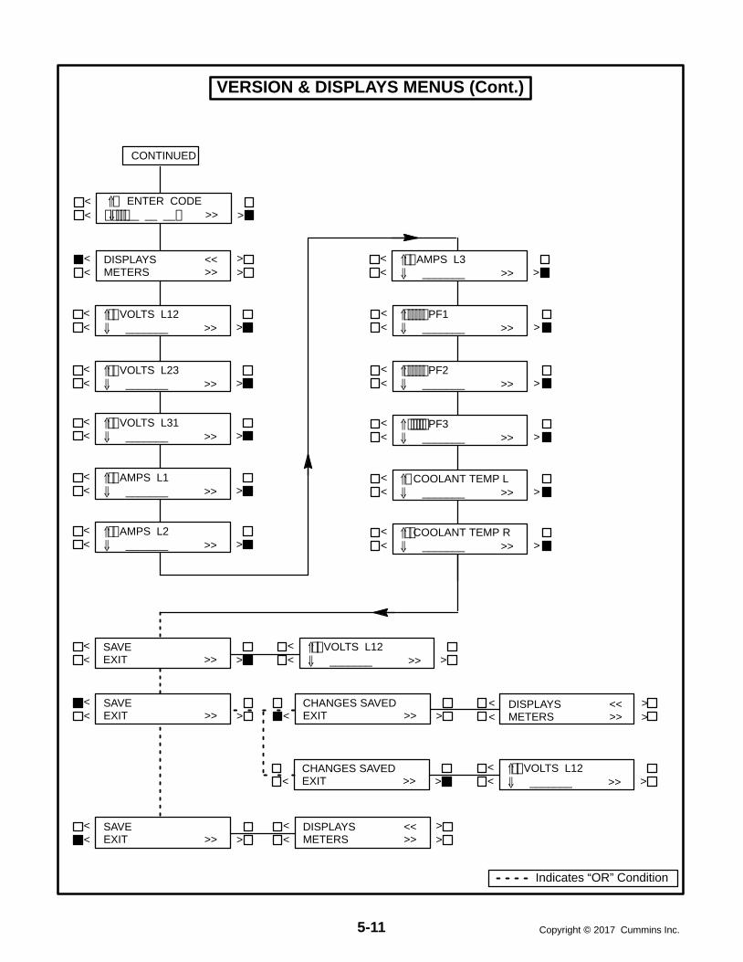
5-11 Copyright 2017 Cummins Inc.
VERSION & DISPLAYS MENUS (Cont.)
CONTINUED
<
<< >
<
<
<< >
< >
< >
< >
PF3 _______ >>
COOLANT TEMP R _______ >>
COOLANT TEMP L _______ >>
< >
< >
< >
< >DISPLAYS <<METERS >>
<< >
VOLTS L12 _______ >>
<< >
VOLTS L23 _______ >>
<< >
VOLTS L31 _______ >>
<< >
AMPS L1 _______ >>
<< >
AMPS L2 _______ >>
< >< SAVE
EXIT >> < >CHANGES SAVEDEXIT >>
< >< >CHANGES SAVEDEXIT >>
< VOLTS L12 _______ >>
< SAVEEXIT >> < >
< VOLTS L12 _______ >>
< SAVEEXIT >> < >
< >DISPLAYS <<METERS >>
< >< >DISPLAYS <<
METERS >>
PF1 _______ >>
PF2 _______ >>
<< >
AMPS L3 _______ >>
< >< ENTER CODE
__ __ __ >>
Indicates “OR” Condition
5-12Copyright 2017 Cummins Inc.
Meters Menu
The METERS submenus permit calibration of thecontrol’s analog meters to match the calibrated digi-tal values. (Calibrate the digital display before cali-brating the analog meters.) This calibration is ac-complished by using this section of the menu soft-ware to adjust the selected meter reading so that itmatches the reading provided on the digital display.
The complete calibration procedure is described inthe Calibration Procedure in this section.
The facing page shows a block representation ofthe METERS submenus, which is the second offour SETUP/CAL menus. If you press the buttonnext to the “>>” in the Main menu display, the VER-SION/SETUP/CAL submenu will appear.
CAUTION Improper calibration or adjustmentof the PowerCommand control can causeequipment malfunction or damage. Calibrationand adjustment must be performed by techni-cally qualified personnel only.
METERS submenu: The METERS submenus areintended for qualified service personnel only. Forthis reason, a three-digit access code must be en-tered before you can proceed to those menus.
Select SETUP/CAL. The display will show the EN-TER CODE submenu. Enter access code (574) aspreviously described in this section.
Select METERS to proceed to the METERS sub-menus. Use the buttons next to the “” and “” sym-bols to calibrate the selected meter to match the“CAL TO:” value provided on the digital display.Press the button next to the “>>” in the display tomove to the next calibration.
“VOLT METER” and “% AMPERES” calibration ref-erence the phase that is indicated on the phaseselection LED’s.
NOTE: The % AMPERES meter scale is based on a 0.8power factor. (100% of rated current is full load cur-rent at 0.8 PF.)
SAVE/EXIT submenu: From the HERTZ subme-nu, press the button next to the “>>” in the display tomove to the SAVE/EXIT submenu. Select SAVE tosave your changes. At the CHANGES SAVED sub-menu, select EXIT to return to the DISPLAYS/ME-TERS submenu.
If you select SAVE, the adjustments will be retainedafter shutdown, and will be in effect when the set isrestarted. If you select EXIT without saving first, theadjustments will remain in effect until the generatorset is shut down, but will be reset (and will not be ineffect) when the set is restarted.

5-13 Copyright 2017 Cummins Inc.
< >
< >
< >
< >
< >
<
< >DISPLAYS <<METERS >>
METERS MENU
< >< >VERSION <<
SETUP/CAL >>
<< >
A−C VOLTS CAL TO: ___ >>
<< >
% AMPERES CAL TO: ___ >>
<< >
% LOAD CAL TO: ___ >>
<< >
HERTZ CAL TO: ___ >>
< >< SAVE
EXIT >> < >CHANGES SAVEDEXIT >> < >
< >DISPLAYS <<METERS >>
< >< >CHANGES SAVEDEXIT >>
<
< SAVEEXIT >> < >
<
< SAVEEXIT >> < >
< >DISPLAYS <<METERS >>
< >DISPLAYS <<METERS >> < >
ENTER CODE __ __ __ >>
ENTER CODE __ __ __ >>
A−C VOLTS ADJ TO: ___ >>
A−C VOLTS ADJ TO: ___ >>
Indicates “OR” Condition

5-14Copyright 2017 Cummins Inc.
Governor/Regulator Menu
The GOV/REG submenus permit adjustment ofvoltage regulator and governor parameters.
All GOV/REG menu values, except for REG VHZ andGOV RAMP, will display “100%”. The expression“100%” represents the factory setting (default value)for the selected set. When increasing or decreasingthe value, you are increasing or decreasing from thefactory default value. (For example, entering “200%”will double the value; “50%” will decrease the valueby one half.)
Default values are preset by the factory. Due to sitevariables, the default values may need to be adjustedto attain peak performance.
The facing page shows a block representation ofthe GOV/REG submenus, which is the third of fourSETUP/CAL menus. If you press the button next tothe “>>” in the Main menu display, the VERSION/SETUP/CAL submenu will appear.
CAUTION Improper calibration or adjustmentof the PowerCommand control can causeequipment malfunction or damage. Calibrationand adjustment must be performed by techni-cally qualified personnel only.
GOV/REG submenu: The GOV/REG submenusare intended for qualified service personnel only.For this reason, a three-digit access code must beentered before you can proceed to those menus.
Select SETUP/CAL. The display will show the EN-TER CODE submenu. Enter the access code (574)as previously described in this section.
From the DISPLAYS/METERS submenu, press thebutton next to the “>>” in the display to move to theGOV/REG/SETUP submenu. Select GOV/REG toproceed to the GOV/REG submenus.
Use the buttons next to the “” and “” symbols toadjust the selected governor and regulator parame-ters. Press the button next to the “>>” in the displayto move to the next adjustment.
GOV GAIN: If the gain adjustment is set too high,engine speed will “hunt” or oscillate. If gain is set toolow, the engine will respond too slowly to changes inload—overspeed may result.
GOV INTEGRAL: If this adjustment is set too low,the engine will respond too slowly to changes inload. If it is set too high, engine response will be un-stable.
GOV RAMP: This adjustment sets the time for theengine to ramp to full operating speed. This adjust-ment applies only to set start up and does not affectthe transient response. (Adjustable range: 0through 10 seconds.)
REG GAIN: If the gain adjustment is set too high,output voltage will be unstable. If gain is set too low,the output voltage will respond sluggishly tochanges in load—overshoot may result.
REG INTEGRAL: If this adjustment is set too low,the output voltage will respond sluggishly tochanges in load, resulting in a droop-type responseIf it is set too high, output voltage will be unstable.
REG VHZ: This underfrequency roll-off adjustmentcontrols how much excitation is reduced in re-sponse to underfrequency. If the value is set toolow, excitation will be cut too fast, and the voltagewill drop too much. If set too high, the generator setmay not be able to pick up rated load in one step.(Adjustable range: 1 through 50; normal range 7through 21.)
SAVE/EXIT submenu: From the REG VHZ subme-nu, press the button next to the “>>” in the display tomove to the SAVE/EXIT submenu. Select SAVE tosave your changes. At the CHANGES SAVED sub-menu, select EXIT to return to the DISPLAYS/ME-TERS submenu.
If you select SAVE, the adjustments will be retainedafter shutdown, and will be in effect when the set isrestarted. If you select EXIT without saving first, theadjustments will remain in effect until the generatorset is shut down, but will be reset (and will not be ineffect) when the set is restarted.

5-15 Copyright 2017 Cummins Inc.
< >< >
< >
< >
< >
< >
< >DISPLAYS <<METERS >>
GOVERNOR/REGULATOR MENU
< >GOV / REG <<SETUP >>
<< >
GOV GAIN _______% >>
<< >
GOV INTEGRAL _______% >>
<< >
GOV RAMP _______ >>
< >< SAVE
EXIT >> < >CHANGES SAVEDEXIT >> < >
< >DISPLAYS <<METERS >>
< >< >CHANGES SAVEDEXIT >>
<
< SAVEEXIT >> < >
<
< SAVEEXIT >> < >
< >DISPLAYS <<METERS >>
<< >
REG GAIN _______% >>
<< >
REG INTEGRAL _______% >>
<< >
REG VHZ _______ >>
GOV GAIN _______% >>
GOV GAIN _______% >>
< >GOV / REG <<SETUP >>
< >DISPLAYS <<METERS >>
< ><
< >< >VERSION <<
SETUP/CAL >> ENTER CODE __ __ __ >>
Indicates “OR” Condition

5-16Copyright 2017 Cummins Inc.
Setup Menu
The SETUP submenus permit selection of severalconfiguration and operation options. Setup optiondefaults are listed in Table 5-2.
TABLE 5-2. SETUP DEFAULTS
SELECTION DEFAULT
CYCLE CRANK ONSYSTEM OF UNITS IMPERIAL*RACK POSITION (CF1) WARN*GRND FAULT (CF2) WARN*DAY TANK (CF3) WARN*HIGH GEN TEMP (CF4) WARNEGT L NOEGT R NOLOW COOLANT SHTDLANGUAGE ENGLISH
* Default display messages for customer faults (CF) 1through 4. To change the customer fault mes-sage(s) or select the desired fault condition (WARNor SHTD), refer to heading Edit Customer FaultMessages.
The facing page shows a block representation ofthe SETUP submenus, which is the fourth of fourSETUP/CAL menus. If you press the button next tothe “>>” in the Main menu display, the VERSION/SETUP/CAL submenu will appear.
CAUTION Improper calibration or adjustmentof the PowerCommand control can causeequipment malfunction or damage. Calibrationand adjustment must be performed by techni-cally qualified personnel only.
SETUP submenu: The SETUP submenus are in-tended for qualified service personnel only. For thisreason, a three-digit access code must be enteredbefore you can proceed to those menus.
Select SETUP/CAL. The display will show the EN-TER CODE submenu. Enter the access code (574)as previously described in this section.
From the DISPLAYS/METERS submenu, press thebutton next to the “>>” in the display to move to theGOV/REG/SETUP submenu. Select SETUP toproceed to the SETUP submenus or “>>” to pro-ceed to the RACK TEST submenus.
Use the buttons next to the “” symbols to togglethe setup options. Press the button next to the “>>”in the display to move to the next adjustment.
If the cycle cranking option is selected, the menu willprompt for the selection of cycle number (3, 4, or 5)and crank and rest times (7 to 20 seconds).
An in-line engine that has the EGT (exhaust gastemp.) option, select “YES” for EGT L and ’NO” forEGT R.
RACK TEST submenu: The RACK TEST subme-nu is used to initiate the rack position diagnostictest. This test is used to determine if the PCC isproperly controlling the rack position of the actua-tors. To initiate this test, the Run/Off/Auto switchmust be set to the Off position.
When exiting this test or if the Run/Off/Auto switchis moved to either the Run or Auto position, the PCCsoftware will re-initialize the governor duty cycle to 2(0%) and allow the engine starting sequence to pro-ceed as normal.
To perform the rack test, refer to the Rack PositionFault/Test Procedure in Section 4.
TORQUE ADJ %DC submenu: This submenu isused to adjust the engine torque through the digitaldisplay to compensate for engine/electronic varia-tions. If the generator set is not providing the nameplate kilowatt rating, the torque limit can be adjustedat this menu. Refer to Engine Torque Adjustment inthis section for a detailed description of how to per-form this adjustment.
Edit Customer Fault Message(s): The four cus-tomer fault messages shown in Table 5-2 are edit-able. Customer Fault 1 is reserved for the RACKPOSITION fault. Do not modify this fault name orchange the fault condition (WARN to SHTD).
To enter the desired customer fault message, pressthe button next to the “>>” in the display to display

5-17 Copyright 2017 Cummins Inc.
the customer fault message to be changed, Cus-tomer Fault 2, 3 or 4.Press the upper-left button bythe display to select the desired character.
Press the upper-right button to move the cursor tothe next character to be changed. (Holding this but-ton down will return the cursor to the first position.)The message can be up to 16 characters. The faultcode number will remain the same, this code cannotbe edited.
If these messages are changed, you should notethese changes in the Troubleshooting section of theOperator’s manual for this generator set.
SAVE/EXIT submenu: From the LANGUAGE sub-menu, press the button next to the “>>” in the dis-play to move to the SAVE/EXIT submenu. SelectSAVE to save your changes. At the CHANGESSAVED submenu, select EXIT to return to the DIS-PLAYS/METERS submenu.
If you select SAVE, the adjustments will be retainedafter shutdown, and will be in effect when the set isrestarted. If you select EXIT without saving first, theadjustments will remain in effect until the generatorset is shut down, but will be reset (and will not be ineffect) when the set is restarted.
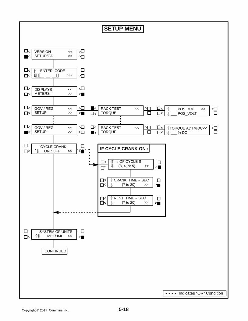
5-18Copyright 2017 Cummins Inc.
< >
< >< >
< >
<
< REST TIME − SEC (7 to 20) >>
<
DISPLAYS <<METERS >>
< ENTER CODE __ __ __ >>
< >
SETUP MENU
< > CYCLE CRANK ON / OFF >>
< > SYSTEM OF UNITS MET/ IMP >>
< >< >VERSION <<
SETUP/CAL >>
< > # OF CYCLE S (3, 4, or 5) >>
< > CYCLE CRANK ON / OFF >>< > CRANK TIME − SEC (7 to 20) >>
IF CYCLE CRANK ON :
< >< >GOV / REG <<
SETUP >>
< >< >GOV / REG <<
SETUP >>
< >RACK TEST <<TORQUE
CONTINUED
Indicates “OR” Condition
< < ___ POS_MM << ___ POS_VOLT
< >
< >RACK TEST <<TORQUE< <
TORQUE ADJ %DC<< ___ % DC
< >

5-19 Copyright 2017 Cummins Inc.
< >
< LANGUAGE _______________>>
< >
< >
SETUP MENU (Cont.)
< >< SAVE
EXIT >> < >CHANGES SAVEDEXIT >> < >
< >DISPLAYS <<METERS >>
< >< >CHANGES SAVEDEXIT >>
< SAVEEXIT >> < >
< SAVEEXIT >> < >
< >DISPLAYS <<METERS >>
< > LOW COOLANT SHTD / WARN >>
< > EGT L YES / NO >>
< > EGT R YES / NO >>
CYCLE CRANK ON / OFF >>
CYCLE CRANK ON / OFF >>
< >
< > HIGH GEN TEMP SHTD / WARN >>
CONTINUED
< >
< >
< > RACK POSITION SHTD / WARN >>
< >
< >
< > DAY TANK SHTD / WARN >>
GRND FAULT SHTD / WARN >>
Indicates “OR” Condition

5-20Copyright 2017 Cummins Inc.
CALIBRATION PROCEDURE
WARNING Contacting high voltage compo-nents can cause electrocution, resulting in se-vere personal injury or death. Calibration andadjustment must be performed by technicallyqualified personnel only. Read and observe allWARNINGS and CAUTIONS in your generatorset manuals.
CAUTION Improper calibration or adjustmentof the PowerCommand control can causeequipment malfunction or damage. Calibrationand adjustment must be performed by techni-cally qualified personnel only.
The calibration procedure is divided into 7 subsec-tions, with the subsections arranged in a specifiedorder. If two or more of the following subsections arerequired to calibrate the PCC, they must be com-pleted in the order shown.
When removing and replacing a defective circuitboard, you may have to perform one or more of thefollowing subsections. Table 5-1 (Control Panel Re-calibration) provides a list of the circuit boards thatrequire calibration when replaced and the calibra-tion procedure(s) that must be performed.
Use a calibrated RMS multimeter for accurate mea-surements. Fluke models 87 or 8060A are goodchoices.
Initial Start Setup
1. Refer to Page 5-4, which describes how andwhen you should perform this procedure.
To verify if the PCC is set to operate with a spe-cific generator set, refer to the VERSION menu(Page 5-9). This menu will show the generatorset model number, frequency, and kW rating. Ifany of these values are incorrect, you must per-form the Initial Start Setup procedure.
Voltage and Frequency Adjustment
2. With the generator set OFF, attach a calibratedfrequency/voltmeter to the AC output from L1to L2.
3. Select ADJUST from the Main Menu (page 5-7)to display the VOLTAGE adjust menu.
4. Start the generator set and allow the generatorset to reach normal operating speed.
5. Adjust VOLTAGE (generator set output volt-age) so that the calibrated voltmeter reads thedesired voltage. (Use a calibrated voltmeterbecause the value displayed on the PCC digitaldisplay may not be calibrated at this time;therefore, its accuracy is unknown.)
6 Select the Frequency adjust menu.
7. Verify that the frequency displayed on the cali-brated meter is the desired frequency. If not,adjust to the desired frequency. (Note: If thefrequency reading on the digital display is notthe same as frequency shown on calibratedmeter, there is an equipment malfunction.)
8. If no frequency or voltage adjustment wasmade, select EXIT. If an adjustment was made,SAVE, then EXIT.
Digital Voltage Display Calibration
9. Select “>>” from the Main Menu (Page 5-9).From this menu proceed to the VOLTS L12menu (Page 5-11).
10. With the generator set OFF, attach a calibratedfrequency/voltmeter to the AC output from L1to L2.
11. Start the generator set and allow it to reachnormal operating speed.
12. Calibrate voltage reading for VOLTS L12 sothat the reading on the digital display agreeswith the calibrated voltmeter.
13. Shut the generator set OFF.
14. Repeat steps 10 through 13 for L23 and L31.(In step 10 attach meter to the AC output fromL2 to L3 to calibrate VOLTS L23 and then L3 toL1 to calibrate VOLTS L31.)
15. If no calibration was made, select EXIT. If a cal-ibration was made, SAVE, then EXIT.

5-21 Copyright 2017 Cummins Inc.
Digital Ammeter Display Calibration
16. Select “>>” from the Main Menu (Page 5-9).From this menu proceed to the AMPS L1 menu(Page 5-11).
17. With the generator set OFF, attach a calibratedammeter to L1.
18. Start the generator set and allow it to reachnormal operating speed.
19. Load the generator set to maximum rated kVAat rated voltage.
20. Calibrate the reading for AMPS L1 so that thereading on the digital display agrees with cali-brated ammeter.
21. Repeat steps 17 through 20 for L2 and L3. (Instep 17, attach meter to L2 to calibrate AMPSL2 and then L3 to calibrate AMPS L3.)
22. If no calibration was made, select EXIT. If a cal-ibration was made, SAVE, then EXIT.
Digital Power Factor Display Calibration
Power factor calibration is not required except in ap-plications requiring a higher accuracy than 5%. Ifthe 5% accuracy is not acceptable, further calibra-tion will require reactive load sufficient to reach 0.8PF at rated load, and calibrated instruments with1% accuracy or better. Typical load rack instru-ments are not accurate enough to perform this pro-cedure.
23. Select “>>” from the Main Menu (Page 5-9).From this menu proceed to the PF1 menu(Page 5-11).
24. With the generator set OFF, attach the powerfactor meter to L1.
25. Start the generator set and allow it to reachnormal operating speed.
26. Load the generator set to maximum rated kVAat rated voltage.
27. Calibrate the reading for PF1 so that the read-ing on the digital display agrees with power fac-tor meter.
28. Repeat steps 24 through 27 for L2 and L3. (Instep 24, attach meter to L2 to calibrate PF2 andthen L3 to calibrate PF3.)
29. If no calibration was made, select EXIT. If a cal-ibration was made, SAVE, then EXIT.
Digital Coolant Temperature DisplayCalibration
An engine sensor calibration tool is required to per-form this procedure.
30. With the generator set OFF, replace the coolanttemperature sender with the precision resistorprovided in the calibration tool.
31. Select “>>” from the Main Menu (Page 5-9).From this menu proceed to the COOLANTTEMP L menu (5-11).
32. Calibrate the temperature reading to match thetemperature indicated on the calibration tool.
33. Repeat step 32 for COOLANT TEMP R if theengine uses two sensors.
34. If no calibration was made, select EXIT. If a cal-ibration was made, SAVE, then EXIT.
Analog Meter Calibration
35. Select “>>” from the Main Menu (Page 5-9).From this menu proceed to the A−C VOLTSADJ TO menu (Page 5-13).
36. Start the generator set and allow the generatorset to reach normal operating speed.
37. Calibrate the analog Voltmeter to the digitallydisplayed value.
38. Calibrate the analog % Amps meter to the digi-tally displayed value.
39. Calibrate the analog % Load meter to the digi-tally displayed value.
40. Calibrate the analog Frequency meter to thedigitally displayed value.
41. SAVE, then EXIT.

5-22Copyright 2017 Cummins Inc.
ENGINE TORQUE ADJUSTMENT
The engine torque fuel limit is set in the PowerCom-mand control. This limit is adjustable (0% to +1% ofduty cycle units, which corresponds approximatelyto 0% to +2% engine horsepower) through the digi-tal display to compensate for engine/electronic vari-ation. If the generator set is not providing the name-plate kilowatt rating, the torque limit can be adjustedwith the following procedure.
1. Select “>>” from the Main Menu (Page 5-9).From this menu proceed to the Torque Adjust%DC menu (Page 5-17).
2. Start the generator set and allow it to reach nor-mal operating speed.
3. Load the generator set to maximum rated kVAat rated voltage.
4. Adjust the torque limit up or down to achievethe proper generator set frequency, undermaximum load.
If you select SAVE, the adjustments will be retainedafter shutdown, and will be in effect when the set isrestarted. If you select EXIT without saving first, theadjustments will remain in effect until the generatorset is shut down, but will be reset (and will not be ineffect) when the set is restarted.
ACCESSORY BOX CONTROLCOMPONENTS
The generator set accessory box (Figure 5-3) whichis located on the backside of the control housing,contains components that provide connectionpoints for remote control and monitor options. Theset can be equipped with one or more of the follow-ing components (customer terminal block TB1 isstandard).

5-23 Copyright 2017 Cummins Inc.
OPTIONAL RTDRELAY
OPTIONAL RUN RELAYSK11, K12 & K13
OPTIONALCOMMON ALARM
RELAY K14
OPTIONALTHERMISTOR
RELAY 160/140 C
TB1-1
TB1-40
GOVERNOROUTPUT MODULE
A38
PT/CT BOARD A36
VOLTAGEREGULATOR
OUTPUT MODULEA37
FIGURE 5-3. ACCESSORY BOX COMPONENTS

5-24Copyright 2017 Cummins Inc.
+TB1 Customer Inputs
Refer to Page 7-7 for typical connections to TB1.
Remote Start: When the Run/Off/Auto switch is inthe Auto position, grounding this input initiates theengine cranking and start sequence. This circuitmust be opened to permit resetting a shutdown con-dition with the Reset input.
Low Fuel: Grounding this input actuates the LowFuel warning. This input can be connected to a localday tank or to a main fuel tank that is located on site.When the switch grounds this designated input, theinput will “wake up” the control, if it is not operating,and then initiate the fault.
Customer Fault Inputs 1 through 4: Groundingany one of these inputs activates the correspondingwarning or shutdown sequence. Warning or shut-down status is selected in the setup menu. Refer tothe Setup Menu description in this section.
External sensing equipment must be connected tothe designated digital input.
The four customer fault messages can be separate-ly edited in the setup menu to display any desiredmessage. This allows each customer “default” faultmessage to be customized to represent the type ofdevice that is attached the the fault input.
Customer Fault 1 is reserved for the RACK POSITIONfault. Do not modify this fault name or change thefault condition (Warning to Shutdown).
The “default” message that is displayed, whenground is applied to the input, is as follows:
Fault 1 = RACK POSITIONFault 2 = GRND FAULTFault 3 = DAY TANKFault 4 = HIGH GEN TEMP
If Fault 2 or 3 input is grounded, the control will“wake up” if it is not operating, and then initiate thefault.
Fault Reset: When the Run/Off/Auto switch is inthe Auto position and the remote start switch isopen, grounding this input resets any warning andlatched shutdown fault (except Emergency Stop,which must be reset at the front panel.)
Engine Idle: When the set is operating in the RUNmode, grounding this input causes alternator buildup to be inhibited and the engine to be governed at
800 RPM. When ground is removed from this input,the set returns to normal speed and voltage.
Engine idle operation is applicable only in the RUNmode. The PCC operating program does not permitengine idle operation when the set is operating inAUTO mode.
When the engine idle function is enabled, the con-trol automatically sets lower oil pressure warningand shutdown trip points to reflect the lower operat-ing speed. When the engine idle function is re-moved and the set reverts to normal operatingspeed, the control automatically resets oil pressurewarning and shutdown trip points to the normal set-tings.
Remote Emergency Stop: Grounding this inputcauses an immediate shutdown. Emergency stopmust be reset at the front panel.
TB1 Customer Outputs
Refer to Page 7-7 for typical connections to TB1.
Breaker Control: One set of normally open (NO)contacts, rated for 5 amps at 30 VDC. A shutdownfault will cause the relay to energize and operate ashunt trip circuit on a circuit breaker. The relay willstay energized until reset.
Common Alarm: One set of form-C contacts, ratedfor 2 amps at 30 VDC. Any warning or shutdowncauses the common alarm relay to be energized.This output is often used to energize an audiblealarm.
Load Dump: One set of normally open (NO) con-tacts, rated for 2 amps at 30 VDC. If an overload orunderfrequency condition exists for 5 seconds, theNO load dump contacts are closed. This relay is en-ergized before shutdown (for overload or underfre-quency) occurs.
Ready To Load: One set of normally open (NO)contacts, rated for 2 amps at 30 VDC. This output isactivated whenever AC voltage and frequency ex-ceed 90% of nominal.
Switched B+: This is a fused 10 amp, 24 voltswitched output. This output is activated by the runpilot signal, at the governor output module. (Fuse islocated on Governor Output Module.)
B+: This is a fused 20 amp, 24 volt output. (Fuse islocated on TB-BAT terminal block of the engine har-ness.)

5-25 Copyright 2017 Cummins Inc.
Run Relays (K11, K12, K13)
The optional run relays are rail mounted inside theaccessory box (Figure 5-3). The rail mount allowsyou to easily remove and replace the snap-on re-lays. The generator set can be equipped with one,two or three run relays.
The three-pole, double-throw run relays (Figure5-4) are used to control auxiliary equipment such as
fans, pumps and motorized air dampers. The runrelays are energized when the generator set reach-es operating speed.
The contacts are rated:
10 amps at 28 VDC or 120 VAC, 80%PF
6 amps at 240 VAC, 80%PF
3 amps at 480/600 VAC, 80%PF
CUSTOMERCONNECTIONS
A40-TB1-4(B-)
A40-TB1-2(SWITCHED B+)
NO
COIL
COM
NC
K11, K12, K13
K11RUN RELAY
K11, K12, K13
K11, K12, K13
K12RUN RELAY
K13RUN RELAY
NO
NC
NO
NC
FIGURE 5-4. OPTIONAL RUN RELAYS (K11, K12, K13)
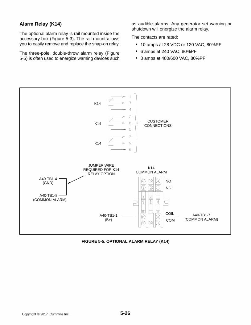
5-26Copyright 2017 Cummins Inc.
Alarm Relay (K14)
The optional alarm relay is rail mounted inside theaccessory box (Figure 5-3). The rail mount allowsyou to easily remove and replace the snap-on relay.
The three-pole, double-throw alarm relay (Figure5-5) is often used to energize warning devices such
as audible alarms. Any generator set warning orshutdown will energize the alarm relay.
The contacts are rated:
10 amps at 28 VDC or 120 VAC, 80%PF
6 amps at 240 VAC, 80%PF
3 amps at 480/600 VAC, 80%PF
CUSTOMERCONNECTIONS
A40-TB1-7(COMMON ALARM)
A40-TB1-1(B+)
NO
COIL
COM
NC
K14
K14
K14
K14COMMON ALARM
A40-TB1-4
A40-TB1-8
JUMPER WIREREQUIRED FOR K14
RELAY OPTION
(GND)
(COMMON ALARM)
FIGURE 5-5. OPTIONAL ALARM RELAY (K14)

5-27 Copyright 2017 Cummins Inc.
RTD Relay (Optional)
The optional RTD relay is rail mounted inside theaccessory box (Figure 5-3). This relay is used tomonitor six separate temperature zones in the alter-nator windings using resistive temperature detec-tors (RTDs). The relay determines the sensed tem-perature and acts to isolate, alarm, or initiate cor-rective action.
The RTD relay (Figure 5-6) compares the six inputsto the predetermined setpoint (temperature set-point is factory adjusted). If one or more of the inputsexceed the setpoint, the output relay is energized.LED’s indicate the state of the output relay (green
for normal, red for tripped). Additional red LED’s areused to indicate which inputs exceed the setpoint.
The relay terminals 11, 12 and 14 are for customerconnection. These terminals can be attached to anyone of the four Customer Fault inputs on TB1 to pro-vide a warning/shutdown condition or to other cus-tomer warning devices. (Refer to Setup Menu inSection 7, which describes how to modify the cus-tomer fault message and to select a warning orshutdown condition.)
The contacts are rated:
240 VAC, 5 amps non-inductive
24 VDC, 25 amps resistive
OUTPUT RELAY(CUSTOMER USE)
A40TB1-4(GROUND)
WHITEWHITE
TO RTD TERMINALBLOCK
TEMPERATURE RELAY CONNECTIONS
(+) PWR (−)
A40TB1-2(SWITCHED B+)
24 VDC
FIGURE 5-6. RTD RELAY (OPTIONAL)

5-28Copyright 2017 Cummins Inc.
Thermistor Relay (Optional)
The optional thermistor relays are rail mounted in-side the accessory box (Figure 5-3). Each relaymonitors three thermistors (one per phase) that areconnected in series inside the alternator. One se-ries or chain of thermistors are rated at 140 C andthe other at 160 C. The 140 C relay is commonlyused in a pre-alarm circuit and the 160 C relay in ashut-down circuit. The relay will energize (trip)
when the thermistor chain resistance reaches 3000500 ohms.
The relay terminals 1, 2 and 3 are for customer con-nection and are normally connected to a breakershunt trip or a load shed circuit (Figure 5-7).
The contacts are rated:
3 amps at 250 VAC
1 amp at 480 VAC
A40-TB1-4(GROUND)
WHITE/REDTHERMISTORSA B C
A40-TB1-2(SWITCHED B+)
BLUE
FAULT CHANNELS(CUSTOMER
CONNECTIONS)
RELAY CONTACTS
FIGURE 5-7. THERMISTOR RELAY (OPTIONAL)

5-29 Copyright 2017 Cummins Inc.
ENGINE SENSORS
Figures 5-8 shows the locations of the oil and cool-ant temperature and oil pressure senders to which
the PCC responds. The switches function by clos-ing the fault or warning circuit to the engine chassisground (battery negative [−]). The low coolant levelswitch has its own ground wire.

5-30Copyright 2017 Cummins Inc.
LOW COOLANTLEVEL SWITCH
LOW COOLANTTEMPERATURE
SWITCHCOOLANT TEMPERATURESENDER
OIL TEMPERATURESENDER (FAR SIDE)
OIL PRESSURESENDER (FAR SIDE)
FIGURE 5-8. ENGINE SENSOR LOCATIONS
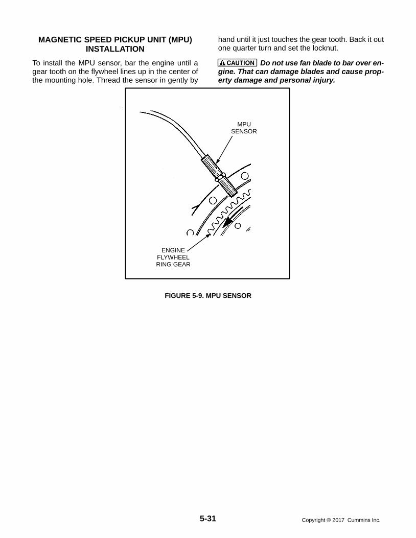
5-31 Copyright 2017 Cummins Inc.
MAGNETIC SPEED PICKUP UNIT (MPU)INSTALLATION
To install the MPU sensor, bar the engine until agear tooth on the flywheel lines up in the center ofthe mounting hole. Thread the sensor in gently by
hand until it just touches the gear tooth. Back it outone quarter turn and set the locknut.
CAUTION Do not use fan blade to bar over en-gine. That can damage blades and cause prop-erty damage and personal injury.
MPUSENSOR
ENGINEFLYWHEELRING GEAR
FIGURE 5-9. MPU SENSOR

5-32Copyright 2017 Cummins Inc.
CURRENT TRANSFORMER (CT)INSTALLATION
Current transformers (CT’s) are required on gener-ator sets that contain AC meters. The CT’s must beinstalled as noted in the following CT InstallationRequirements. Improper installation of CT’s willcause a “335 Reverse Power” shutdown error (non-parallel units only).
Refer to the Reconnection Diagram to identify theoutput leads/phase that must be routed througheach CT, and also appropriate transformer postselection for meter sensing leads. The transformersare labeled CT1, CT2 and CT3 on the reconnectionwiring diagram. (The Reconnection Diagram is lo-cated on the upper side cover of the control hous-ing.)
CT Installation Requirements
A. The CT has a dot on one side. This dot must befacing toward the alternator (conventional cur-rent flowing into the dot). A dot is also used toindicate pin 1 of the CT.
B. CT1 − U load leads (A phase)CT2 − V load leads (B phase)CT3 − W load leads (C phase)
C. Route the appropriate leads through each CT.
6 lead generator sets − alternator outputleads are routed through the CT’s.
12 lead generator sets − load wires arerouted through the CT’s.
D. Reconnectable generator sets (12 leads) havedual secondary CT’s (3 pins). The CT secon-dary wire marked 1 is connected to pin 1 of theCT. CT secondary wire marked 2/3 is con-nected to pin 2 for high voltage generator setsor to pin 3 for low voltage generator sets. (Referto Reconnection Diagram.)
Non-reconnectable generator sets (6 leads)have single secondary CT’s (2 pins).
The lead from CT terminal #1 connects tothe metering circuitry.
The lead from CT terminal #2/3 connectsto ground.

5-33 Copyright 2017 Cummins Inc.
DIGITAL BOARD (A32) CALIBRATION
The digital board (Figure 5-10) contains three resis-tors that are used to calibrate the digital board fordifferent generator set models. One of these resis-tors may need to be removed in order to calibrate/initialize the PowerCommand control to the genera-tor set model. Table 5-3 provides the necessary in-formation to determine which resistor that mayneed to be cut to select the desired generator setmodel.
After the appropriate resistor selection is made, thePowerCommand control must be re-initialized. Re-fer to Initial Start Setup Menu in this section to initial-ize the PowerCommand control. When the initialsetup save button is pushed, the PowerCommandcontrol will compare the calibration selection (cutresistor) to the initial setup and perform one of thefollowing:
1. If the model numbers corresponding to the cutresistor and the initial setup are compatible, ac-cording to Table 5-3, the calibration is vali-dated. The control will store the appropriate in-formation based on calibration and initial setupdata in EEProm. The initial setup is now com-plete and the control can start the engine.
2. If the model number corresponding to the cutresistor and the initial setup are not compatiblethe control will display the fault “INVALID SET-UP” (fault code 401). No initial setup data issaved and the control will not leave the initialsetup menu until this fault condition is cor-rected.
3. If the control senses that more than one resis-tor has been cut, the control will display thefault “INVALID CAL” (fault code 402). No initialsetup data is saved and the control will notleave the initial setup menu until this fault con-dition is corrected.
TABLE 5-3. DIGITAL BOARD (A32) CALIBRATION
Resistor Cut(1=cut, 0=uncut)
Model/Part Number
Torque R38 R37 R360326−6050,0326−6051
0326−6052,0326−6053
0326−6045,0326−6046
0326−0197,0326−0198
G1 0 0 0 DFHA −−− DFHA DFHC
G2 0 0 1 DFHB DFHA DFHB DFHA
G3 0 1 0 DFHC DFHB DFHC DFHB
G4 1 0 0 DFHD DFHC DFHD DFHC
G5 0 1 1 −−− −−−− −−−− −−−−
G6 1 1 0 DFHE −−−− −−−− CG6
G7 1 0 1 DFHF −−−− −−−− CG7
G8 1 0 1 DFHG −−−− −−−− CG8

5-34Copyright 2017 Cummins Inc.
See control rating calibration procedure.
FIGURE 5-10. DIGITAL BOX

6-1 Copyright 2017 Cummins Inc.
6. Servicing the Alternator
GENERAL
This section describes how to isolate a high AC volt-age fault to the PCC control circuitry or generator,and the procedures to test, disassemble and re-assemble the generator (Figure 6-1).
WARNING Incorrect service or replacement ofparts can result in severe personal injury ordeath, and/or equipment damage. Service per-sonnel must be trained and experienced to per-form electrical and mechanical service.
WARNING HAZARDOUS VOLTAGE. The PCC1301 control box must be opened only by tech-nically qualified personnel. Voltages of up to600 VAC are present in the PCC box. These volt-ages can cause electrical shock, resulting inpersonal injury.
RECONNECTIONTERMINALS
STATOR
BLOWER
COUPLING
DRIVEDISCS
ROTORSHAFT
AIR DISCHARGECOVERS
FRAME
ROTATINGRECTIFIERASSEMBLY
PMGSTATOR
EXCITERROTOR
END BRACKET
PMGROTOR
EXCITERSTATOR
END BRACKET/ENGINEADAPTOR
ROTOR
ENDBEARING
PRESSUREPLATE
FIGURE 6-1. TYPICAL ALTERNATOR

6-2Copyright 2017 Cummins Inc.
ALTERNATOR/PCC CONTROL ISOLATIONPROCEDURE
The following procedure is used to determine if thealternator or the PCC control circuitry is causing ahigh AC voltage shutdown fault.
1. Throw the line circuit breaker OFF and shutdown the set.
CAUTION This test involves unregulated ex-citation of the alternator. To prevent damage tothe alternator due to overcurrent, make surethat all loads have been disconnected and thatall faults have been cleared from the power out-put terminals of the alternator.
2. Remove the housing cover of the accessorybox and remove plug P10 from connector J10of the voltage regulator output module (A37).See Figure 3-9.
3. Prepare to measure output voltage across thealternator terminals while the set is running.
4. Bring two jumpers from a 12 volt battery forconnection to the X (Field +) and XX (Field −)pins of plug P10.
X = Red wire of P10-6XX = Brown wire of P10-3
Connect the jumper from the positive (+) postof the battery to the X pin (red wire) of P10-6.Be prepared to connect the jumper from thenegative (−) post of the battery to the XX pin(brown wire) of P10-3. If one of the 12 voltcranking batteries is used, bring the jumpersfrom the battery connected on the grounded
side of the system to avoid inadvertently im-posing 24 volts on the system.
5. Check polarity again. Polarity must be corrector this test will be inconclusive because the in-duced and residual magnetic polarities in theexciter stator will be opposed.
WARNING HAZARDOUS VOLTAGE. Touchinguninsulated high voltage parts inside the con-trol box can result in severe personal injury ordeath. Measurements and adjustments must bedone with care to avoid touching hazardousvoltage parts.
For your protection, stand on a clean dry wood-en platform or clean rubber insulating mat,make sure your clothing and shoes are dry, re-move jewelry and use tools with insulated han-dles.
6. Start the set and connect the jumper from thebattery negative (−) terminal to the XX lead.
7. The alternator circuitry is probably okay if ratedoutput voltage or higher is obtained and thevoltages for all phases are balanced when theexciter is powered by a 12 volt battery. Refer toSection 4 to troubleshoot the PCC control cir-cuitry. (Normal excitation voltage ranges fromapproximately 10 VDC at no-load to approxi-mately 40 VDC at full−load.)
8. If the voltages are unbalanced, troubleshootthe main stator first. If the voltages are uniform-ly low, troubleshoot the exciter and field circuitsfirst. Perform the Winding Resistance Test pro-cedure for the desired windings as noted in thissection.
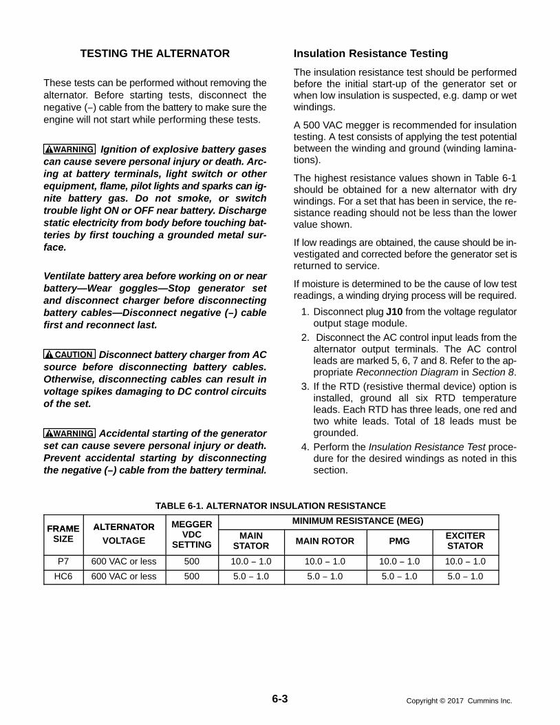
6-3 Copyright 2017 Cummins Inc.
TESTING THE ALTERNATOR
These tests can be performed without removing thealternator. Before starting tests, disconnect thenegative (−) cable from the battery to make sure theengine will not start while performing these tests.
WARNING Ignition of explosive battery gasescan cause severe personal injury or death. Arc-ing at battery terminals, light switch or otherequipment, flame, pilot lights and sparks can ig-nite battery gas. Do not smoke, or switchtrouble light ON or OFF near battery. Dischargestatic electricity from body before touching bat-teries by first touching a grounded metal sur-face.
Ventilate battery area before working on or nearbattery—Wear goggles—Stop generator setand disconnect charger before disconnectingbattery cables—Disconnect negative (−) cablefirst and reconnect last.
CAUTION Disconnect battery charger from ACsource before disconnecting battery cables.Otherwise, disconnecting cables can result involtage spikes damaging to DC control circuitsof the set.
WARNING Accidental starting of the generatorset can cause severe personal injury or death.Prevent accidental starting by disconnectingthe negative (−) cable from the battery terminal.
Insulation Resistance Testing
The insulation resistance test should be performedbefore the initial start-up of the generator set orwhen low insulation is suspected, e.g. damp or wetwindings.
A 500 VAC megger is recommended for insulationtesting. A test consists of applying the test potentialbetween the winding and ground (winding lamina-tions).
The highest resistance values shown in Table 6-1should be obtained for a new alternator with drywindings. For a set that has been in service, the re-sistance reading should not be less than the lowervalue shown.
If low readings are obtained, the cause should be in-vestigated and corrected before the generator set isreturned to service.
If moisture is determined to be the cause of low testreadings, a winding drying process will be required.
1. Disconnect plug J10 from the voltage regulatoroutput stage module.
2. Disconnect the AC control input leads from thealternator output terminals. The AC controlleads are marked 5, 6, 7 and 8. Refer to the ap-propriate Reconnection Diagram in Section 8.
3. If the RTD (resistive thermal device) option isinstalled, ground all six RTD temperatureleads. Each RTD has three leads, one red andtwo white leads. Total of 18 leads must begrounded.
4. Perform the Insulation Resistance Test proce-dure for the desired windings as noted in thissection.
TABLE 6-1. ALTERNATOR INSULATION RESISTANCE
FRAME ALTERNATOR MEGGER MINIMUM RESISTANCE (MEG)FRAME
SIZEALTERNATOR
VOLTAGE
MEGGERVDC
SETTINGMAIN
STATOR MAIN ROTOR PMG EXCITERSTATOR
P7 600 VAC or less 500 10.0 − 1.0 10.0 − 1.0 10.0 − 1.0 10.0 − 1.0
HC6 600 VAC or less 500 5.0 − 1.0 5.0 − 1.0 5.0 − 1.0 5.0 − 1.0

6-4Copyright 2017 Cummins Inc.
Drying the Windings
If low readings are obtained and moisture is deter-mined to be the problem, the windings should bedried out and the test repeated. Use the alternatorheaters or blow warm air through the alternator witha fan. A more effective way is to use a bolted3-phase short across the alternator terminals. Thisprocedure must be done as described or equipmentdamage can result. To do this:
1. Bolt the alternator three phase output terminalstogether. See the reconnection diagrams inSection 8.
2. Remove the housing cover of the accessorybox and remove plug P10 from connector J10of the voltage regulator output module (A37).See Figure 3-11.
3. Connect the positive and negative leads of avariable 12 VDC source to P10 as follows:Positive lead − Red wire of P10-6 (X)Negative lead − Brown wire of P10-3 (XX)
CAUTION Voltage must begin at zerovolts and be gradually increased or equip-ment damage will result. The current will in-crease rapidly and it must be monitored toprevent exceeding the alternator rating.
4. Attach a clamp-on ammeter to the alternatorleads to measure alternator current, adjust the12 VDC source for zero voltage, start the setand very slowly increase the excitation voltage.Obtain the highest current possible without ex-ceeding alternator rating.
5. Run the generator set for approximately onehour, then repeat the insulation resistancetests. If further drying time is indicated, contin-ue the drying process.
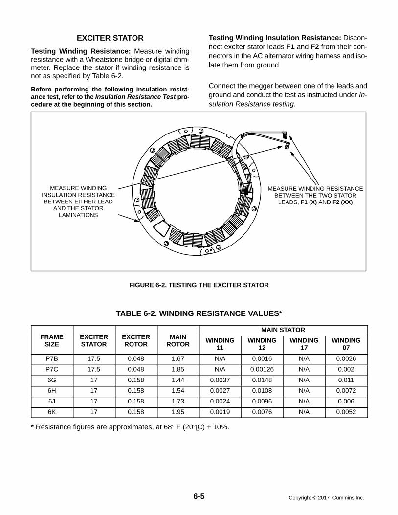
6-5 Copyright 2017 Cummins Inc.
EXCITER STATOR
Testing Winding Resistance: Measure windingresistance with a Wheatstone bridge or digital ohm-meter. Replace the stator if winding resistance isnot as specified by Table 6-2.
Before performing the following insulation resist-ance test, refer to the Insulation Resistance Test pro-cedure at the beginning of this section.
Testing Winding Insulation Resistance: Discon-nect exciter stator leads F1 and F2 from their con-nectors in the AC alternator wiring harness and iso-late them from ground.
Connect the megger between one of the leads andground and conduct the test as instructed under In-sulation Resistance testing.
MEASURE WINDINGINSULATION RESISTANCEBETWEEN EITHER LEAD
AND THE STATORLAMINATIONS
MEASURE WINDING RESISTANCEBETWEEN THE TWO STATOR
LEADS, F1 (X) AND F2 (XX)
FIGURE 6-2. TESTING THE EXCITER STATOR
TABLE 6-2. WINDING RESISTANCE VALUES*
FRAME EXCITER EXCITER MAINMAIN STATOR
FRAMESIZE
EXCITERSTATOR
EXCITERROTOR
MAINROTOR WINDING
11WINDING
12WINDING
17WINDING
07
P7B 17.5 0.048 1.67 N/A 0.0016 N/A 0.0026
P7C 17.5 0.048 1.85 N/A 0.00126 N/A 0.002
6G 17 0.158 1.44 0.0037 0.0148 N/A 0.011
6H 17 0.158 1.54 0.0027 0.0108 N/A 0.0072
6J 17 0.158 1.73 0.0024 0.0096 N/A 0.006
6K 17 0.158 1.95 0.0019 0.0076 N/A 0.0052
* Resistance figures are approximates, at 68 F (20 C) + 10%.

6-6Copyright 2017 Cummins Inc.
EXCITER RECTIFIER BRIDGE (ROTATINGRECTIFIER ASSEMBLY)
The exciter rectifier bridge is mounted on the exciterrotor, inboard, facing the main rotor. It consists of apositive plate and a negative plate, split diametrical-ly. Each carries three diodes, three terminal postsfor connecting exciter rotor leads to the diode pig-tails and a terminal for the main rotor (alternatorfield) lead. A surge suppresser is connected acrossthe two plates to prevent transient voltages thatcould damage the diodes.
Testing Diodes: Disconnect the diode pigtails fromthe terminal posts. Using an ohmmeter, measureelectrical resistance between each diode pigtail andthe plate on which the diode is mounted. Reversethe meter test probes and repeat the tests. Theelectrical resistance across each diode should behigh in one direction and low in the other. If the re-
sistance is high or low in both directions, replace thediode.
Replacing Diodes: Make sure the replacementdiode is of the correct polarity. Disconnect the pigtailfrom the terminal post and unscrew the old diode.Apply heat-sink compound under the head of thediode. Make sure the compound does not get on thethreads. Torque the diodes to 36 to 42 in-lb (4 to 4.8Nm) and the pigtail terminals to 24 in-lb (2.7 Nm)when reassembling.
Surge Suppresser Testing and Replacement:Remove the suppresser. Replace the suppresser ifit appears to have overheated or if ohmmeter read-ings indicate less than infinite resistance (end ofscale) in both directions. Torque the terminals to 24in-lb (2.7 Nm) when reassembling.
CAUTION Layers of dust can cause diodes tooverheat and fail. Brush dust off regularly.
TERMINAL(ONE OF SIX)
DIODE (ONE OF SIX)DISCONNECT THE DIODE
PIGTAIL FROM THE TERMINALAND MEASURE ELECTRICALRESISTANCE BETWEEN THE
PIGTAIL AND THE METALPLATE UNDER THE DIODE
SURGE SUPPRESSERREMOVE TO TEST
DIODE PLATES(TWO)
FIGURE 6-3. TESTING THE ROTATING RECTIFIER ASSEMBLY

6-7 Copyright 2017 Cummins Inc.
EXCITER ROTOR
Testing Winding Resistance: Disconnect the sixrotor winding leads from the terminal posts on therectifier assembly. With a Wheatstone bridge, mea-sure electrical resistance across each pair of rotorwindings: U (CR1 or CR4) and V (CR2 or CR5), V(CR2 or CR5) and W (CR3 or CR6), W (CR3 orCR6) and U (CR1 or CR4). See the winding sche-matic. Replace the whole rotor shaft assembly if theresistance of any winding is not as specified in Table6-2.
Before performing the following insulation resist-ance test, refer to the Insulation Resistance Test pro-cedure at the beginning of this section.
Testing Winding Insulation Resistance: Discon-nect all six exciter rotor leads from diode terminalsCR1 through CR6 and isolate them from ground.
Connect the megger between one of the leads andground and conduct the test as instructed under In-sulation Resistance testing.
WINDING SCHEMATIC
MEASURE WINDING INSULATIONRESISTANCE BETWEEN ANY LEADOR THE TERMINAL TO WHICH IT IS
CONNECTED AND THE ROTORLAMINATIONS
DISCONNECT THE SIX ROTOR WINDINGLEADS FROM THEIR TERMINALS ANDMEASURE ELECTRICAL RESISTANCE
ACROSS EACH PAIR OF WINDINGS: U-V,V-W, W-U
MAIN ROTORLEADS
FIGURE 6-4. TESTING THE EXCITER ROTOR

6-8Copyright 2017 Cummins Inc.
MAIN ROTOR (ALTERNATOR FIELD)Testing Winding Resistance: Disconnect the twoleads of the main rotor from the terminals on the ro-tating rectifier assembly. See Figure 6-5. Measureelectrical resistance between the two leads with aWheatstone bridge or digital ohmmeter. Replacethe rotor if the resistance is not as specified in Table6-2. Connect the rotor leads and torque the termi-nals to 23 in-lb (3.3 Nm) when reassembling.
Before performing the following insulation resist-ance test, refer to the Insulation Resistance Test pro-cedure at the beginning of this section.
Insulation Resistance and PI Test: Disconnectthe main rotor and voltage suppressor leads fromterminals F1+ and F2− on the rotating rectifier as-semblies and isolate them from ground. Tag andmark each lead with its terminal number (F1+ orF2−).
Connect the megger between one of the rotor leadsand ground and conduct the test as instructed un-der Insulation Resistance testing.
DISCONNECT THE MAIN ROTOR LEADSFROM THE ROTATING RECTIFIER ASSEMBLYAND MEASURE THE WINDING RESISTANCE
BETWEEN THEM
MEASURE WINDING INSULATIONRESISTANCE BETWEEN EITHER ROTOR
LEAD AND THE ROTOR LAMINATIONS
FIGURE 6-5. TESTING THE MAIN ROTOR

6-9 Copyright 2017 Cummins Inc.
MAIN STATOR
Testing Main Stator Winding Resistance: Dis-connect all stator leads from the terminals to whichthey are connected. Using a Wheatstone bridgehaving at least 0.001 ohm precision, measure elec-trical resistance across each pair of stator leads:U1-U2, V1-V2, W1-W2, U5-U6, V5-V6 and W5-W6.Replace the stator if the resistance of any winding isnot as specified in Table 6-2.
Before performing the following insulation resist-ance test, refer to the Insulation Resistance Test pro-cedure at the beginning of this section.
Insulation Resistance and PI Test: Remove andseparate all leads of the alternator from the alterna-tor load terminal block. Number of neutral leads(three or six) to remove will vary between low andmedium voltage alternators.
Connect the megger between one phase of the sta-tor and ground while grounding the other twophases and conduct the test as instructed under In-sulation Resistance testing.
Repeat this step in turn for the other two phases.
WHEATSTONEBRIDGE
FIGURE 6-6. TESTING THE ALTERNATOR STATOR

6-10Copyright 2017 Cummins Inc.
TESTING THE PMG
WARNING HAZARDOUS VOLTAGE. Touchinguninsulated high voltage parts inside the con-trol box can result in severe personal injury ordeath. Measurements and adjustments must bedone with care to avoid touching hazardousvoltage parts.
For your protection, stand on a clean dry wood-en platform or clean rubber insulating mat,make sure your clothing and shoes are dry, re-move jewelry and use tools with insulated han-dles.
1. Disconnect plug J10 from the voltage regulatoroutput stage module.
2. Start the engine at the set and let the speed sta-bilize.
3. Measure voltage across lead pairs J10-1 &J10-4, J10-4 & J10-5, and J10-5 & J10-1. Volt-age should be at least 150 VAC for 50 Hz setsand at least 180 VAC for 60 Hz sets, and shouldbe approximately the same for each set ofleads. If the voltages are low or uneven, checkall the leads and connections between the volt-age regulator output stage module and thePMG and repair as necessary before disas-sembling the PMG.
4. Stop the set and measure electrical resistanceacross lead pairs J10-1 & J10-4, J10-4 &J10-5, and J10-5 & J10-1 with a Wheatstonebridge or digital ohmmeter. The resistanceshould be 2.6 10% ohms for frame size P7and HC6.

6-11 Copyright 2017 Cummins Inc.
BEARINGINSPECTION/REMOVAL/REPLACEMENT
The end bearing is enclosed in a pre-packed ma-chined cartridge.
Bearing Inspection: If a situation occurs which al-lows an opportunity to visually inspect the end bear-ing with it installed, check the color of the grease.The color of the grease is the only indication thatcan be used to determine if the bearing is defective.
New grease is a whitish-beige color but some milddiscoloration will occur with use. If the greaseshows signs of gross discoloration, the bearingshould be replaced.
Bearing Removal: The bearing is press fitted ontothe shaft and can be removed with standard work-shop tools (i.e., two or three legged manual or hy-draulic bearing pullers). The bearing should only beremoved for replacement (bearing is destroyed dur-ing removal and must be replaced).
The end bearing is enclosed in a pre-packed car-tridge housing and must only be dismantled as nec-essary for relubrication, replacement, or when amajor overhaul is carried out on the generator set.
P7 Bearing Removal
1. Remove the endbracket (complete steps 1through 16 of the Main Stator and Rotor Re-moval (P7) procedure.
2. Remove the four screws holding bearing cap.
3. Remove cap.
4. Remove circlip.
5. Remove bearing cartridge housing completewith bearing.
P7 Bearing Replacement
The instruction sheet provided with the bearing kit isrequired to complete the following procedure.
P7 alternator component parts cannot be orderedfrom Cummins. Refer to the Newage nameplateand supply all available information. Contact yournearest Newage distributor for assistance in order-ing component parts.
1. Lift slightly on end of rotor shaft and installwooden shims to hold rotor on center with sta-tor.
2. Install bearing onto rotor shaft. Refer to bearingkit instruction sheet.
3. Install two threaded studs into end bearing car-tridge to aid subsequent procedures. Positionthe end bearing cartridge assembly close toproper position for hole alignment with end-bracket.
4. Install endbracket to the stator frame using theproper screws and lock washers, but do nottighten securely as yet.
5. Insert and start the threads of the bearing car-tridge fasteners, and remove threaded align-ment studs, through the endbracket into thecartridge housing.
6. Lift slightly on endbracket and remove woodenshims holding rotor on center with stator.
7. Securely tighten the endbracket fasteners.
8. Tighten the bearing cartridge fasteners to 4.5ft-lb (6 Nm) torque.
9. Install the PMG assembly. Refer to PermanentMagnet (PMG) Installation procedure.
P7 Bearing Lubrication
A grease fitting is provided to allow re-greasing ofthe bearing with a grease gun (see the Operatormanual for grease quantities/type, maintenance in-tervals, and procedure).

6-12Copyright 2017 Cummins Inc.
HC6 Bearing Removal
1. Remove the endbracket (complete steps 1through 16 of the Main Stator and Rotor Re-moval (P7) procedure.
2. Remove the four screws holding bearing cap3. Remove cap.4. Remove circlip.5. Remove bearing cartridge housing complete
with bearing.
HC6 Bearing ReplacementWhen replacing bearing onto rotor shaft, be sure toapply pressing force to the inner face of the bearingonly.
HC6 Bearing Lubrication
Bearing Lubrication: When re-lubricating or re-placing the bearing, review the following.
Recommended Lubricant: Lithium basedgrease, Mobilux No. 2 or Shell Alvania R3.
Temperature Range: -22F to +248F (-30C to+120C).
Quantity: 2.74 oz. (81 ml). The grease shouldbe equally divided between the bearing, thebearing cap cavity, and the bearing cartridgecavity.

6-13 Copyright 2017 Cummins Inc.
ALTERNATOR DISASSEMBLY
The following procedures provide information forremoval and reassembly of the alternator PMG ex-citer, control housing, and stator/rotor assemblies.Be sure to read through this section first, before per-forming procedures listed, to determine the stepsmost appropriate for the service attention required.
Two types of alternators (P7 or HC6) are used withthese generator set models. The major differencebetween these two alternators is the lifting eye loca-tions on the alternator and the type of control hous-ing. The control housing for the HC6 alternator isshown in Figure 6-7 and the control housing for theP7 alternator is shown in Figure 6-8. In the followingprocedures, if the step only applies to a particularcontrol housing or alternator, it will be noted at thebeginning of the step (e.g., HC6 control housing, P7alternator, etc.)
Permanent Magnet (PMG) Removal
WARNING Ignition of explosive battery gasescan cause severe personal injury or death. Arc-ing at battery terminals, light switch or otherequipment, flame, pilot lights and sparks can ig-nite battery gas. Do not smoke, or switchtrouble light ON or OFF near battery. Dischargestatic electricity from body before touching bat-teries by first touching a grounded metal sur-face.
Ventilate battery area before working on or nearbattery—Wear goggles—Stop generator setand disconnect charger before disconnectingbattery cables—Disconnect negative (−) cablefirst and reconnect last.
CAUTION Disconnect battery charger from ACsource before disconnecting battery cables.Otherwise, disconnecting cables can result involtage spikes damaging to DC control circuitsof the set.
WARNING Accidental starting of the generatorset can cause severe personal injury or death.Prevent accidental starting by disconnectingthe negative (−) cable from the battery terminal.
1. Disconnect the negative (-) battery cable toprevent accidental starting of the generator setwhile servicing.
2. HC6 Control Housing: Remove the controlhousing grille and access covers (see Figure6-7).
3. Remove the three M5X12mm capscrews andlockwashers from the PMG cover, and removecover.
4. Disconnect the PMG wiring harness connector.
5. Remove the four bolts and clamps retaining theexciter stator housing to the endbracket.
6. Tap the stator housing out of its spigot, andcarefully remove from alternator endbracket.
The highly magnetic rotor will attract the statorcore; care must be taken to avoid any contactwhich may damage the windings.
7. Remove the hex head through-bolt from the ro-tor shaft and firmly pull the complete rotor as-sembly from its location. Keep the rotor cleanby avoiding contact with metal dust or particles.
CAUTION The rotor assembly must not bedismantled, or the magnetic properties willbe destroyed.
Permanent Magnet (PMG) Installation1. Install the complete rotor assembly to the end
of the main rotor shaft using the hex headthrough-bolt. Keep the rotor clean by avoidingcontact with metal dust or particles.
2. Carefully locate the stator housing to positionon the alternator endbracket. Fasten in placeusing the 4 bolts and clamps, and tighten se-curely.
The highly magnetic rotor will attract the statorcore, care must be taken to avoid any contactwhich may damage the windings.
3. Connect the PMG wiring harness connector.
4. Install the PMG assembly cover using the threeM5x12mm capscrews and lockwashers, andtighten securely.
5. HC6 Control Housing: Install the control hous-ing grille and access covers (see Figure 6-7).
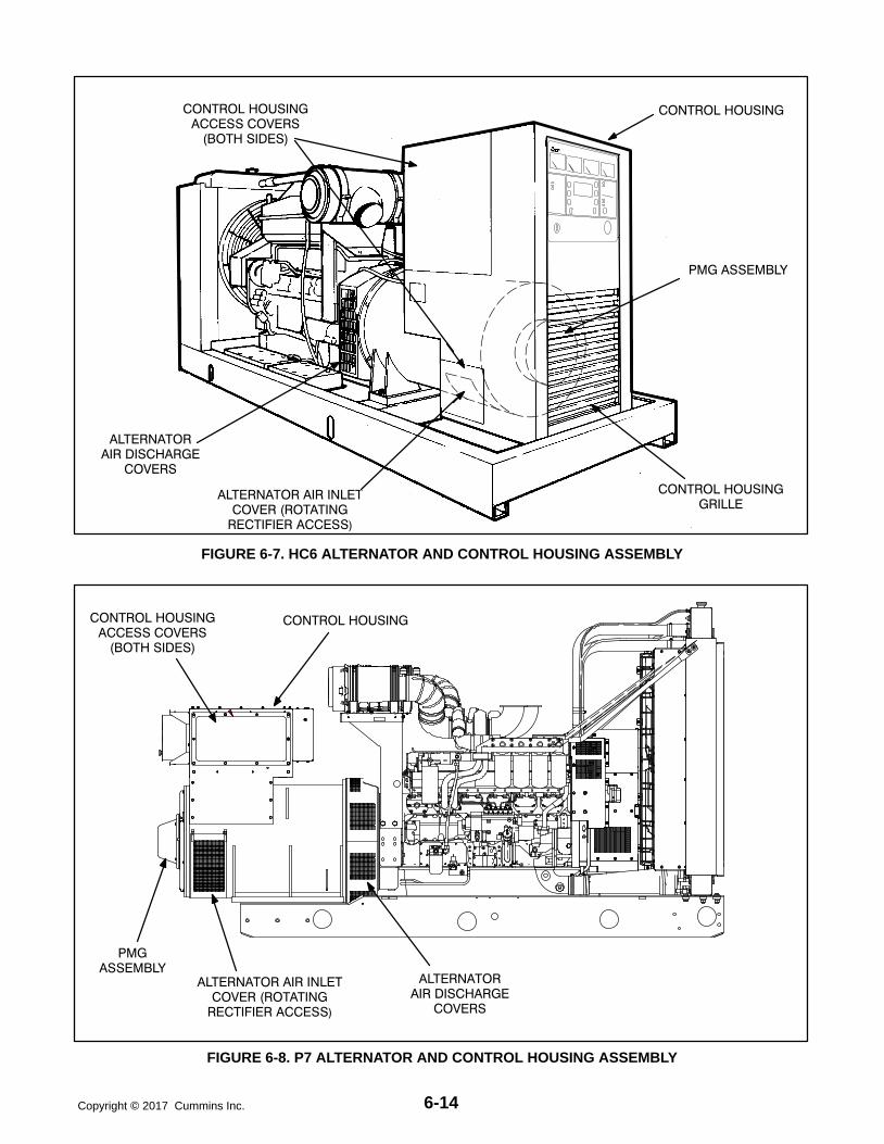
6-14Copyright 2017 Cummins Inc.
CONTROL HOUSINGACCESS COVERS
(BOTH SIDES)
ALTERNATORAIR DISCHARGE
COVERS
CONTROL HOUSING
PMG ASSEMBLY
CONTROL HOUSINGGRILLE
ALTERNATOR AIR INLETCOVER (ROTATING
RECTIFIER ACCESS)
FIGURE 6-7. HC6 ALTERNATOR AND CONTROL HOUSING ASSEMBLY
CONTROL HOUSINGACCESS COVERS
(BOTH SIDES)
ALTERNATORAIR DISCHARGE
COVERS
CONTROL HOUSING
PMGASSEMBLY
ALTERNATOR AIR INLETCOVER (ROTATING
RECTIFIER ACCESS)
FIGURE 6-8. P7 ALTERNATOR AND CONTROL HOUSING ASSEMBLY

6-15 Copyright 2017 Cummins Inc.
Main Stator and Rotor Removal1. Remove the PMG, refer to Permanent Magnet
PMG Removal, earlier this section.
2. Remove the air inlet and discharge panels andaccess covers from control housing and alter-nator (see Figure 6-7 or 6-8).
3. Disconnect all load wires from the reconnec-tion terminal block assembly. If equipped withthe circuit breaker option, disconnect loadwires from circuit breaker. Check that all leadsare labeled to ease reassembly.
4. Disconnect the remote control wiring and con-duit from the accessory box. For reconnectionslater, make sure each wire is clearly marked toindicate the correct terminal.
5. Disconnect the engine harness connectorsand remove harness assembly from the controlhousing:
P4 and P5 from the back side of the controlpanel box.
PMG2 through PMG4, F1 and F2 alterna-tor leads located inside the control hous-ing assembly.
P6 (Governor Output Module), P7 andP10 (Voltage Regulator OUtput Module)and J12 (from P12 of the rail assembly), lo-cated inside the accessory box.
6. Use a hoist or similar lifting device to supportthe control housing assembly (see Figure 6-9).
WARNING To prevent personal injury, useadequate lifting devices to support heavycomponents. Keep hands and feet clearwhile lifting.
7. HC6 Control Housing Removal:
a. Loosen the fasteners that secure the con-trol housing side and bottom panels to al-ternator. Make sure that hoisting device iscontrolling weight of control housing as-sembly.
b. Remove control housing fasteners, andremove the control housing assemblyfrom the alternator. Replace panel fasten-ers to their respectable positions for safekeeping, and tighten finger-tight.
c. Remove control housing mounting brack-ets from both sides of alternator, and as-semble lifting eyes to alternator.
8. P7 Control Housing Removal:
a. Loosen the fasteners that secure the con-trol housing side panels to alternator.Make sure that hoisting device is control-ling weight of control housing assembly.
b. Remove control housing fasteners, andremove the control housing assemblyfrom the alternator. Replace panel fasten-ers to their respectable positions for safekeeping, and tighten finger-tight.

6-16Copyright 2017 Cummins Inc.
PLACE SLING STRAPSTHROUGH HOUSING
(P7 OR HC6 HOUSING)
RECONNECTIONTERMINALS
ACCESSORYBOX
FIGURE 6-9. REMOVING CONTROL HOUSING

6-17 Copyright 2017 Cummins Inc.
9. Remove as necessary, air intake componentsto engine that may interfere with disassemblyand reassembly of alternator.
CAUTION Do not use fan blade to bar overengine. That can damage blades and causeproperty damage and personal injury.
10. Crank or bar the engine/alternator to positionthe rotor such that a full pole face is at the bot-tom of the main stator core. Proper positioningcan be viewed through the alternator accessopenings. Refer to engine service manual forproper cranking or barring procedure.
To remove the stator and rotor at the same time, referto step 28. To remove the stator and rotor individual-ly, continue with step 11.
11. Remove the four bolts retaining the bearingcartridge housing in the endbracket (outer fourbolts).
12. Remove the eight bolts holding the endbracketto the alternator housing.
13. Insert two bolts (M10) in the two holes providedfor “jacking” purposes, on the endbracket cen-
ter line. Screw bolts in until endbracket spigotis clear of locating recess.
14. Carefully tap the whole assembly off the bear-ing cartridge housing, ensuring the endbracketis supported to prevent the exciter stator fromdamaging the windings on the exciter rotor.
WARNING To prevent personal injury, useadequate lifting devices to support heavycomponents. Keep hands and feet clearwhile lifting.
15. The exciter stator is now accessible for inspec-tion and removal from endbracket/engineadaptor.
16. The end bearing can now be removed if re-quired. Refer to Bearing Inspection/Removal/Replacement in this section.
17. Remove the fasteners from the two alternatormounting feet brackets.
18. Attach cables of lifting device to alternator lift-ing points (Figures 6-10 or 6-11).
ALTERNATORLIFTING
POSITIONS
MOUNTING FEETBRACKETS
FIGURE 6-10. HC6 ALTERNATOR LIFTING POSITIONS

6-18Copyright 2017 Cummins Inc.
ALTERNATORLIFTING EYELOCATION
MOUNTING FEETBRACKET
FIGURE 6-11. P7 LIFTING POSITION
19. Using an adequate lifting device, lift the alter-nator (at lifting eyes provided, and main statorhousing) until the mounting feet brackets areclear of the frame member (see Figure 6-12 or6-13).
20. Disconnect the grounding strap from the fly-
wheel housing.
21. Using a forklift, position a lifting bar of the forklift(inside and inline with the alternator) under therotor shaft. Lift the rotor shaft slightly so that ro-tor is not resting on inside of stator assembly.See Figure 6-12 or 6-13.

6-19 Copyright 2017 Cummins Inc.
STATORASSEMBLY
LIFT
ROTORASSEMBLY
LIFT
STATORASSEMBLY
ROTORASSEMBLY
USE FORKLIFT OROTHER ADEQUATELIFTING DEVICE TO
SLIGHTLY LIFT ROTORSHAFT UNTIL ROTORCAN BE SUPPORTED
BY HOIST/SLING.
FIGURE 6-12. REMOVING HC6 STATOR ASSEMBLY

6-20Copyright 2017 Cummins Inc.
STATORASSEMBLY
LIFT
ROTORASSEMBLY
LIFT
STATORASSEMBLY
ROTORASSEMBLY
USE FORKLIFT OROTHER ADEQUATELIFTING DEVICE TO
SLIGHTLY LIFT ROTORSHAFT UNTIL ROTORCAN BE SUPPORTED
BY HOIST/SLING.
FIGURE 6-13. REMOVING P7 STATOR ASSEMBLY

6-21 Copyright 2017 Cummins Inc.
22. Verify that the stator is adequately supportedand then carefully remove the capscrews fromthe stator attachment ring.
WARNING To prevent personal injury, useadequate lifting devices to support heavycomponents. Keep hands and feet clearwhile lifting.
CAUTION Improper stator assembly rig-ging and handling can result in damage tostator and rotor assemblies. Lifting eyesmay not be at center-of-gravity position ofstator assembly. Therefore, lifting and mov-ing the stator assembly alone, by hoistingat lifting eyes only, presents the hazard ofload imbalance; allowing one end to dropand other end to rise. Make sure the statoris adequately hooked/strapped to maintainlevel control of stator assembly while liftingand moving.
23. Being careful not to drag the windings on therotor, move the stator assembly sufficientlyaway from engine to sling and support the rotorassembly. Do not allow rotor assembly to hangon engine flywheel.
CAUTION Drive disc damage can becaused by allowing the rotor assembly tohang on flywheel. Use adequate hoist andsling to support the rotor assembly.
24. Reposition or add hoist and sling support forthe main rotor, and remove the forklift. See Fig-ure 6-14, Rotor Lift detail.
WARNING To prevent personal injury, useadequate lifting devices to support heavycomponents. Keep hands and feet clearwhile lifting.
25. Remove the stator assembly, being careful notto drag the windings on the rotor. Place statorassembly away from the chassis in the horizon-tal position.
26. Using the hoist and sling to support the rotor,carefully remove the capscrews and flat wash-ers that secure the drive discs to the engine fly-wheel.
WARNING To prevent personal injury, useadequate lifting devices to support heavycomponents. Keep hands and feet clearwhile lifting.
27. Remove the rotor assembly and place it onwood blocks in the horizontal position. To avoidpossible distortion, do not allow the drive discsand fan to rest on anything.
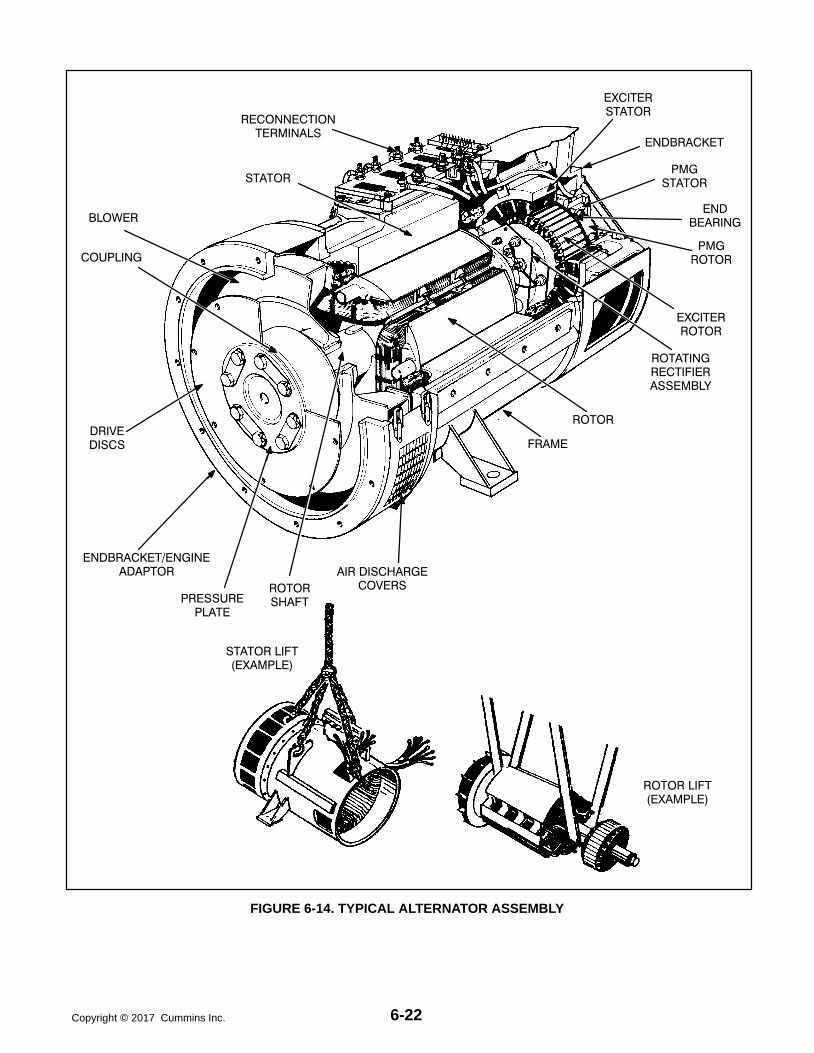
6-22Copyright 2017 Cummins Inc.
ROTOR LIFT(EXAMPLE)
STATOR LIFT(EXAMPLE)
RECONNECTIONTERMINALS
STATOR
BLOWER
COUPLING
DRIVEDISCS
ROTORSHAFT
AIR DISCHARGECOVERS
FRAME
ROTATINGRECTIFIERASSEMBLY
PMGSTATOR
EXCITERROTOR
ENDBRACKET
PMGROTOR
EXCITERSTATOR
ENDBRACKET/ENGINEADAPTOR
ROTOR
ENDBEARING
PRESSUREPLATE
FIGURE 6-14. TYPICAL ALTERNATOR ASSEMBLY

6-23 Copyright 2017 Cummins Inc.
Alternator Assembly Removal
28. Remove the fasteners from the two alternatormounting feet brackets.
29. Attach cables of lifting device to alternator lift-ing points (Figures 6-10 or 6-11).
30. Using an adequate lifting device, lift the alter-nator (at lifting eyes provided, and main statorhousing) until the mounting feet brackets areclear of the frame member.
31. Disconnect the grounding strap from the fly-wheel housing.
32. Carefully remove the capscrews and flat wash-ers that secure the drive discs to the engine fly-wheel.
33. Verify that the alternator assembly is adequate-ly supported. Carefully remove the capscrewssecuring the engine adaptor endbracket to theengine flywheel housing.
WARNING To prevent personal injury, useadequate lifting devices to support heavycomponents. Keep hands and feet clearwhile lifting.
CAUTION Improper alternator assemblyrigging and handling can result in damageto stator and rotor assemblies. Lifting eyesmay not be at center-of-gravity position ofstator assembly. Therefore, lifting and mov-ing the alternator by hoisting at lifting eyesonly, presents the hazard of load imbal-ance; allowing one end to drop and otherend to rise. Make sure the alternator is ade-quately hooked/strapped to maintain levelcontrol of assembly while lifting and mov-ing.
34. Remove the alternator assembly away fromengine. Place alternator assembly on floor witha piece of wood beneath the stator housing (to-ward PMG end) to allow for endbracket remov-al, if desired.

6-24Copyright 2017 Cummins Inc.
ALTERNATOR REASSEMBLY
Alternator reassembly is the reverse of disassem-bly procedure.
To assemble the stator and rotor at the same time,continue with step 1. To assemble the stator and ro-tor individually, skip to step 16.
1. Using an adequate lifting device, locate the al-ternator assembly into position near the engineflywheel housing. Align the holes of the rotordrive discs with the holes of the engine fly-wheel. Install the capscrews and flat washersthat secure the drive discs to the engine fly-wheel, hand tighten.
WARNING To prevent personal injury, useadequate lifting devices to support heavycomponents. Keep hands and feet clearwhile lifting.
CAUTION Improper alternator assemblyrigging and handling can result in damageto stator and rotor assemblies. Lifting eyesmay not be at center-of-gravity position ofstator assembly. Therefore, lifting and mov-ing the alternator by hoisting at lifting eyesonly, presents the hazard of load imbal-ance; allowing one end to drop and otherend to rise. Make sure the alternator is ade-quately hooked/strapped to maintain levelcontrol of assembly while lifting and mov-ing.
2. Align the holes of the engine adaptor endbrack-et with the holes in the flywheel housing andinstall the capscrews and lock washers. Tight-en fasteners to 95−105 ft-lb (129−142 Nm).
3. Secure the rotor assembly to the flywheel.Tighten fasteners to 150−180 ft-lb (204−245Nm).
4. Connect the grounding strap to the flywheelhousing using a capscrew and EIT lockingwasher; and tighten securely.
5. Install the mounting feet bracket fasteners; andtighten securely.
If endbracket has been removed, continue withstep 6, otherwise skip to step 15.
6. Lift slightly on end of rotor shaft and installwooden shims to hol rotor on center with stator.
7. If removed, install end bearing. Refer to Bear-ing Inspection/Removal/Replacement proce-dure in this section.
8. Install two threaded studs into end bearing car-tridge to aid subsequent procedures. Positionthe end bearing cartridge assembly close toproper position for hole alignment with end-bracket.
9. Assemble exciter stator, if removed, to inside ofendbracket. Tighten fasteners to 4.5 ft-lb (6Nm) torque.
10. Install endbracket to the stator frame using theproper capscrews and lock washers, but do nottighten securely as yet.
11. Insert and start the threads of the bearing car-tridge fasteners, and remove threaded align-ment studs, through the endbracket into thecartridge housing.
12. Lift slightly on endbracket and remove woodenshims holding rotor on center with stator.
13. Securely tighten the endbracket fasteners.
14. Tighten the bearing cartridge fasteners to 4.5ft-lb (6 Nm) torque.
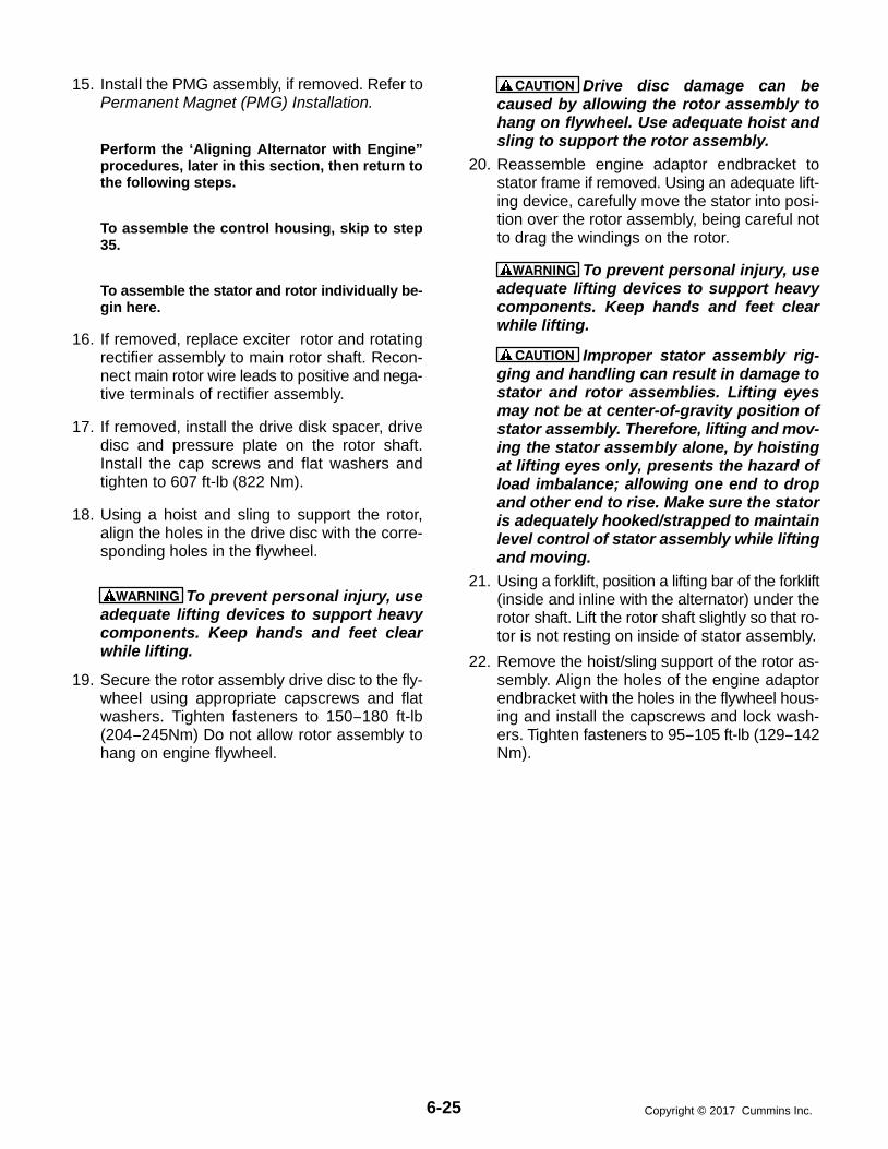
6-25 Copyright 2017 Cummins Inc.
15. Install the PMG assembly, if removed. Refer toPermanent Magnet (PMG) Installation.
Perform the ‘Aligning Alternator with Engine”procedures, later in this section, then return tothe following steps.
To assemble the control housing, skip to step35.
To assemble the stator and rotor individually be-gin here.
16. If removed, replace exciter rotor and rotatingrectifier assembly to main rotor shaft. Recon-nect main rotor wire leads to positive and nega-tive terminals of rectifier assembly.
17. If removed, install the drive disk spacer, drivedisc and pressure plate on the rotor shaft.Install the cap screws and flat washers andtighten to 607 ft-lb (822 Nm).
18. Using a hoist and sling to support the rotor,align the holes in the drive disc with the corre-sponding holes in the flywheel.
WARNING To prevent personal injury, useadequate lifting devices to support heavycomponents. Keep hands and feet clearwhile lifting.
19. Secure the rotor assembly drive disc to the fly-wheel using appropriate capscrews and flatwashers. Tighten fasteners to 150−180 ft-lb(204−245Nm) Do not allow rotor assembly tohang on engine flywheel.
CAUTION Drive disc damage can becaused by allowing the rotor assembly tohang on flywheel. Use adequate hoist andsling to support the rotor assembly.
20. Reassemble engine adaptor endbracket tostator frame if removed. Using an adequate lift-ing device, carefully move the stator into posi-tion over the rotor assembly, being careful notto drag the windings on the rotor.
WARNING To prevent personal injury, useadequate lifting devices to support heavycomponents. Keep hands and feet clearwhile lifting.
CAUTION Improper stator assembly rig-ging and handling can result in damage tostator and rotor assemblies. Lifting eyesmay not be at center-of-gravity position ofstator assembly. Therefore, lifting and mov-ing the stator assembly alone, by hoistingat lifting eyes only, presents the hazard ofload imbalance; allowing one end to dropand other end to rise. Make sure the statoris adequately hooked/strapped to maintainlevel control of stator assembly while liftingand moving.
21. Using a forklift, position a lifting bar of the forklift(inside and inline with the alternator) under therotor shaft. Lift the rotor shaft slightly so that ro-tor is not resting on inside of stator assembly.
22. Remove the hoist/sling support of the rotor as-sembly. Align the holes of the engine adaptorendbracket with the holes in the flywheel hous-ing and install the capscrews and lock wash-ers. Tighten fasteners to 95−105 ft-lb (129−142Nm).

6-26Copyright 2017 Cummins Inc.
23. Connect the grounding strap to the flywheelhousing using a capscrew and EIT lockingwasher; and tighten securely.
24. Install the mounting feet bracket fasteners; andtighten securely.
25. Lift slightly on end of rotor shaft and installwooden shims to hold rotor on center with sta-tor.
26. If removed, install end bearing. Refer to Bear-ing Inspection/Removal/Replacement proce-dure in this section.
27. Install two threaded studs into end bearing car-tridge to aid subsequent procedures. Positionthe end bearing cartridge assembly close toproper position for hole alignment with end-bracket.
28. Assemble exciter stator, if removed, to inside ofendbracket. Tighten fasteners to 4.5 ft-lb (6Nm) torque.
29. Install endbracket to the stator frame using theproper capscrews and lock washers, but do nottighten securely as yet.
30. Insert and start the threads of the bearing car-tridge fasteners, and remove threaded align-ment studs, through the endbracket into thecartridge housing.
31. Lift slightly on endbracket and remove woodenshims holding rotor on center with stator.
32. Securely tighten the endbracket fasteners.
33. Tighten the bearing cartridge fasteners to 4.5ft-lb (6 Nm) torque.
34. Install the PMG assembly, if removed. Refer toPermanent Magnet (PMG) Installation.
Perform the “Aligning Alternator with Engine”procedures later in this section, and then returnto step 35.
35. HC6 Control Housing: Remove alternator lift-ing eyes. Reassemble control housing mount-ing brackets to sides of alternator and fastensecurely.
WARNING To prevent personal injury, useadequate lifting devices to support heavycomponents. Keep hands and feet clearwhile lifting.
36. Use an adequate lifting device to lift the controlhousing in position for mounting to the statorframe. Replace the capscrews and lock wash-ers and tighten to 20 ft-lb (27 Nm) torque.
37. Connect all control wires and alternator leadsusing the proper generator set AC and DC wir-ing diagram/schematic.
38. Reassemble any engine air intake compo-nents removed during alternator disassembly.
39. Reassemble the covers over the alternator airdischarge openings and fasten securely.
40. Refer to Permanent Magnet (PMG) Installationprocedure in this section.
41. If equipped with the circuit breaker option, re-connect load wires to circuit breaker. Recon-nect all lead wires to the terminal block assem-bly using proper reconnection diagram in Sec-tion 9.
42. Verify that all connections are proper and se-cure and then install the air inlet panel and ac-cess covers to control housing.
43. Connect the negative (-) battery cable and testthe generator set for operation.

6-27 Copyright 2017 Cummins Inc.
ALIGNING ALTERNATOR WITH ENGINE
Proper alignment of the alternator and engine as-semblies is necessary to avoid premature wear andimproper operation of the generator set. Review thefollowing alignment conditions and procedures foraligning the alternator assembly to engine flywheelhousing.
Angular Misalignment: Is the result of the alterna-tor bearing center axis not aligning with axis of theengine crankshaft. This condition creates an anglebetween the alternator shaft axis and the crankshaftaxis. The cause of this type of misalignment is usu-ally shimming error.
Axial Misalignment: Is the result of the alternatorshaft axis not aligning with engine crankshaft axis.The tolerances in the bolted flywheel and drive discconnection may add up to displace the alternatoraxially relative to the crankshaft axis.
Misalignment Symptoms: If the assembly is al-lowed to run under these conditions, the discs must
flex in alternate directions twice for each engine rev-olution. It is important to minimize the amount ofdisc flexing since, if it is excessive, the drive disc willcrack. Although perfect bearing alignment is desir-able, it is more important to keep disc deflection tothe minimum possible. This procedure assumesthat the pilot bore of the drive discs are in the exactcenter and the flywheel counterbore (pilot) has nopractical runout. Under these conditions, perfectAngular alignment will be attained when no deflec-tion of the disks is measured.
Excessive Axial misalignment will cause more alter-nator vibration than Angular misalignment.
Axial misalignment needs to be checked only whenan objectionable vibration is present.
Either type of misalignment may be present in agenerator set assembly, with angular misalignmentbeing the most common problem. Angular align-ment may also be effected by set installation condi-tions and/or mishandling during shipping of the gen-erator set.

6-28Copyright 2017 Cummins Inc.
Angular Alignment Procedure
WARNING Accidental starting of the generatorset during this procedure presents the hazardof severe personal injury or death. Make sure todisconnect the negative (-) battery cable(s) be-fore beginning.
Fasten a dial indicator to either the alternator shaftor the cooling fan with the sensing point resting onthe capscrew head or the flat surface of the drive
disc at the bolt circle diameter, see Figure 6-15. Barthe engine over in a clockwise rotation as viewedfrom engine flywheel. Do not allow it to roll back oncompression at the end of the travel of each read-ing. It is unnecessary to zero the indicator since thetotal indicator reading (T.I.R.) of the deflection mea-surement to the bolt heads is what is required. T.I.R.will be the sum of the maximum positive and nega-tive dial indicator readings as the engine completesone revolution.
MOUNTING BOLTTO DISC
MEASUREMENT
SEE DETAIL A
CLAMP DIALINDICATOR
FLEXDISCS
AXIALALIGNMENT, SEE
FIGURE 6-17
ALTERNATORAND ENGINECRANKSHAFTCENTERLINE
SHIMSDETAIL A
FIGURE 6-15. ANGULAR ALIGNMENT MEASUREMENT

6-29 Copyright 2017 Cummins Inc.
Sample Alternator Runout Readings
When taking the deflection readings described,make a diagram similar to the example shown inFigure 6-16, where a total indicator reading of.025in. (The highest positive value of +.010 and thelargest negative value of -.015”.) The indicator iscloser to the top and further away at the bottom.This example indicates that the alternator bearing ishigh. Since the side readings are equal, the alterna-tor is centered side to side. To lower the alternator,remove equal shims from under both alternatormounting feet. To approximate the amount of shimsto remove or add:
1. Measure the distance between the center ofthe alternator shaft to the point the indicator ismeasuring at. (For example; a SAE 18 Disccoupling distance is 10.7in).
2. Measure the distance from the alternator sideof the flex discs to the center of the alternatormounting bolt, refer to Figure 6-15. (For exam-ple; a HC6 Frame’s distance is 28.4in.)
3. Compare the distance measured in steps 1 and2. (28.4in vs 10.7in or a 2.65 to 1 ratio.) Multiplythis ratio times one half the T.I.R. (In our exam-ple, .025in divided by 2 is .0125in. This, times2.65 equals .033in. Therefore, remove .033inof shims from under both mounting feet.)
In general, the T.I.R. should not be more than .001infor each inch of radius (center of shaft to indicatoraxis). If we use our example of 10.7in, then the max-imum T.I.R. would be .011in. This would only requirea correction of .014in from the T.I.R. of .025in. (Areading of +.002 at the top and -.009 at the bottomwould fall within the satisfactory range.)
+.010+.010
-.002
MEASURED ATBOLT CIRCLE
DIAMETER
-.010
10.7 IN.
-.015-.015
-.010
-.004
FIGURE 6-16. ANGULAR ALIGNMENT MEASUREMENT READINGS (Example)

6-30Copyright 2017 Cummins Inc.
HC6 Axial Alignment Procedure
Axial misalignment needs to be checked only whenan objectionable vibration is present.
If excessive vibration remains after the angularalignment, check for concentric alignment of the al-ternator shaft/engine crankshaft axes.
Fasten dial indicator holding device to skid base,engine block, or alternator shell with a magneticbase or clamp and position so the sensor point of in-dicator rests on the alternator shaft hub, see Figure6-15. Bar the engine over in a clockwise rotation asviewed from engine flywheel, through a couple ofrotations. Record indicator readings in eight equallyspaced points around the shaft diameter. This willprovide a T.I.R. for Axial shaft misalignment.
The maximum allowable T.I.R. runout is subjective,the optimal T.I.R. for runout would be .000in, how-ever, that may not be attainable. The recommenda-tion of this procedure will be to reduce the mea-sured T.I.R. runout by one half. Specific out-of-toler-ance runout levels are difficult to establish due to
the varying surface quality of the alternator shaft’sdrive disc mountain hub.
The goal of the Axial realignment is to reduce thevibration level of the generator set while it is operat-ing. A small improvement in the T.I.R. runout mayhave dramatic effects in the mechanically mea-sured or physically observed vibration levels.
To correct for an out of tolerance T.I.R. indication,remove the capscrews connecting drive discs andflywheel. Mark the drive discs and flywheel with re-spect to each other. Rotate either the engine or al-ternator so that drive discs holes are repositioned180 degrees from their original location. Put thedrive discs capscrews back in and retorque. Re-check shaft alignment as before. If shaft T.I.R. run-out remains unchanged then the discs should be ro-tated to either 30, 60, or 90 degrees from originallocation to correct the out of tolerance condition. Ifthe T.I.R. does not improve after repositioning, acloser inspection of the flywheel pilot and drive discrunouts is required. This will help determine thecause of the axial misalignment.
ALTERNATORAND ENGINECRANKSHAFTCENTERLINE
ANGULAR ALIGNMENT,SEE FIGURE 6-15
DETAIL A
SEE DETAIL A FAN HOUSING
CLAMP
ALTERNATORSHAFT HUB
DIALINDICATOR
FIGURE 6-17. HC6 AXIAL ALIGNMENT MEASUREMENT

6-31 Copyright 2017 Cummins Inc.
P7 Axial Alignment Procedure
Axial misalignment needs to be checked only whenan objectionable vibration is present.
If excessive vibration remains after the angularalignment, concentric alignment of the alternatorshaft/engine crankshaft axes may be at fault.
The goal of the axial realignment is to reduce thevibration level of the generator set while it is operat-ing. A small improvement in the axial alignment mayhave dramatic effects in the measured or physicallyobserved vibration levels.
To correct for possible axial misalignment, removethe capscrews connecting drive discs and flywheel.Mark the drive discs and flywheel with respect toeach other. Rotate either the engine or alternator sothat drive discs holes are repositioned two boltholes from their original location. Put the drive discscapscrews back in and retorque. Recheck/recordvibration levels as before. Repeat this test until thedrive discs holes are repositioned 180 degrees fromtheir original location.
Review vibration data and position drive disc in low-est recorded level location.

6-32Copyright 2017 Cummins Inc.
THIS PAGE LEFT INTENTIONALLY BLANK
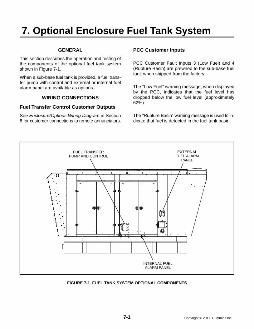
7-1 Copyright 2017 Cummins Inc.
7. Optional Enclosure Fuel Tank System
GENERAL
This section describes the operation and testing ofthe components of the optional fuel tank systemshown in Figure 7-1.
When a sub-base fuel tank is provided, a fuel trans-fer pump with control and external or internal fuelalarm panel are available as options.
WIRING CONNECTIONS
Fuel Transfer Control Customer Outputs
See Enclosure/Options Wiring Diagram in Section8 for customer connections to remote annunciators.
PCC Customer Inputs
PCC Customer Fault Inputs 3 (Low Fuel) and 4(Rupture Basin) are prewired to the sub-base fueltank when shipped from the factory.
The “Low Fuel” warning message, when displayedby the PCC, indicates that the fuel level hasdropped below the low fuel level (approximately62%).
The “Rupture Basin” warning message is used to in-dicate that fuel is detected in the fuel tank basin.
EXTERNALFUEL ALARM
PANEL
FUEL TRANSFERPUMP AND CONTROL
INTERNAL FUELALARM PANEL
FIGURE 7-1. FUEL TANK SYSTEM OPTIONAL COMPONENTS

7-2Copyright 2017 Cummins Inc.
FUEL TRANSFER PUMPThe fuel transfer pump and control are available asan option when a sub-base fuel tank is provided.The automatic control operates the fuel pump tomaintain a reservoir of fuel in the sub-base tank.
This section explains functions of the control panellamps, components and operation/testing of theday tank fuel control system.
Control Panel Switches and IndicatorsThe following paragraphs describe the operation ofthe control switches and indicators.
Indicators: POWER: indicates that AC power is available
to the control. PUMP: indicates that the fuel pump is running.
It will go on and off as fuel is pumped to main-tain the fuel tank level.
CRITICAL HIGH: indicates that the fuel hasreached an abnormally high level. It indicates apossible failure of the ”pump-off” float gauge inthe sub-base tank. The lamp will turn off whenthe fuel level drops to normal.
LOW FUEL SUPPLY TANK: indicates that thefuel level in the main fuel tank has dropped be-low the customer set low fuel level. This signalis used by the fuel system control to stop theoperation of the fuel transfer pump to preventpump damage. The control will enable the fueltransfer pump operation after tank fuel level isrestored.
RUPTURE BASIN: indicates that the fuel hasflooded the safety basin surrounding the fueltank. The basin float switch turns off the fuelpump. The pump cannot function again untilthe basin is drained of fuel. Possible cause,leak in fuel tank.
Switches: ON: This switch activates the control. OFF: This switch disables the control for rou-
tine maintenance to the tank system withoutdisrupting the control.
TEST: This switch will activate the pump for aslong as the switch is in the Test position. Allalarm functions will operate accordingly.Pump-on and pump-off float switches will re-main de-energized.
SYSTEM TEST: This switch will test all frontpanel lamps and activate pump/motor for aslong as the switch is in the System Test posi-tion. All alarm relays will not activate but willmaintain their original state.
RESET: This switch will reset the control sys-tem after a latched alarm event.
Operation
The following steps describe how to operate the daytank controller.
1. Activate the control ON switch for automaticoperation. The PUMP light will come on and thepump will fill the tank. The level of fuel in thetank will be automatically kept between a set ofpump-on and pump-off float gauge switches.
2. The PUMP light indicates when the pump isrunning. It will go on and off as fuel is pumped tomaintain the proper level in the tank.

7-3 Copyright 2017 Cummins Inc.
FIGURE 7-2. TRANSFER PUMP CONTROL FRONT PANEL
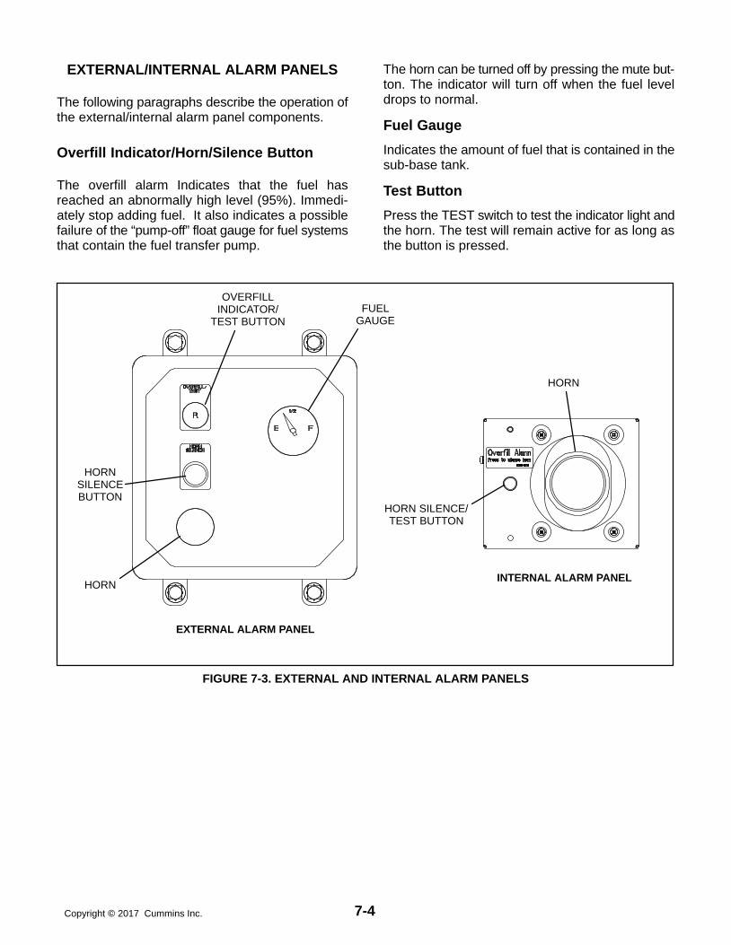
7-4Copyright 2017 Cummins Inc.
EXTERNAL/INTERNAL ALARM PANELS
The following paragraphs describe the operation ofthe external/internal alarm panel components.
Overfill Indicator/Horn/Silence Button
The overfill alarm Indicates that the fuel hasreached an abnormally high level (95%). Immedi-ately stop adding fuel. It also indicates a possiblefailure of the “pump-off” float gauge for fuel systemsthat contain the fuel transfer pump.
The horn can be turned off by pressing the mute but-ton. The indicator will turn off when the fuel leveldrops to normal.
Fuel Gauge
Indicates the amount of fuel that is contained in thesub-base tank.
Test Button
Press the TEST switch to test the indicator light andthe horn. The test will remain active for as long asthe button is pressed.
HORNSILENCEBUTTON
OVERFILLINDICATOR/
TEST BUTTON
HORN
FUELGAUGE
EXTERNAL ALARM PANEL
INTERNAL ALARM PANEL
HORN SILENCE/TEST BUTTON
HORN
FIGURE 7-3. EXTERNAL AND INTERNAL ALARM PANELS
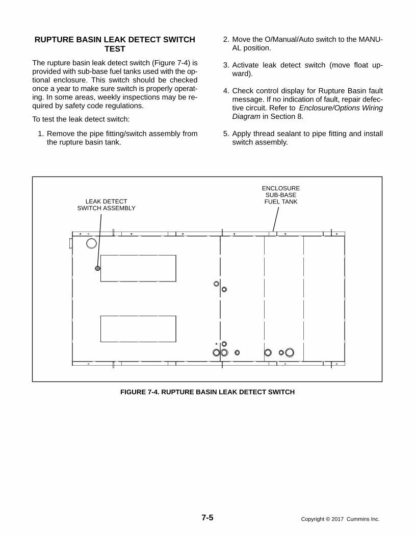
7-5 Copyright 2017 Cummins Inc.
RUPTURE BASIN LEAK DETECT SWITCHTEST
The rupture basin leak detect switch (Figure 7-4) isprovided with sub-base fuel tanks used with the op-tional enclosure. This switch should be checkedonce a year to make sure switch is properly operat-ing. In some areas, weekly inspections may be re-quired by safety code regulations.
To test the leak detect switch:
1. Remove the pipe fitting/switch assembly fromthe rupture basin tank.
2. Move the O/Manual/Auto switch to the MANU-AL position.
3. Activate leak detect switch (move float up-ward).
4. Check control display for Rupture Basin faultmessage. If no indication of fault, repair defec-tive circuit. Refer to Enclosure/Options WiringDiagram in Section 8.
5. Apply thread sealant to pipe fitting and installswitch assembly.
LEAK DETECTSWITCH ASSEMBLY
ENCLOSURESUB-BASEFUEL TANK
FIGURE 7-4. RUPTURE BASIN LEAK DETECT SWITCH

7-6Copyright 2017 Cummins Inc.
THIS PAGE LEFT INTENTIONALLY BLANK

8-1 Copyright 2017 Cummins Inc.
8. Wiring Diagrams
GENERAL
This section consists of the schematic and connec-tion wiring diagrams referenced in the text. The fol-lowing drawings are included.
Page 8-3 and 8-4, AC Reconnect Wiring Dia-gram
Page 8-5, Block Diagram (12 Lead)
Page 8-6, Block Diagram (6 Lead)
Page 8-7, Customer Connections
Page 8-8, Engine Interface Board (A31)
Page 8-9, Digital Board (A32)
Page 8-10, Analog Board (A33)
Page 8-11, Customer Interface Board (A34)
Page 8-12, Display Board (A35)
Page 8-13, PC/CT Board (A36)
Page 8-14,Voltage Regulator Output Module(A37)
Page 8-15, Governor Output Board (A38)
Page 8-16, PT/CT Wiring Harness
Page 8-17, Engine Wiring Harness
Page 8-18, Accessory Box InterconnectionHarness Diagram
Page 8-19, Day Tank Pump Control Wiring
Page 8-20 Accessory Interconnect Diagram
Page 8-21, Sequence of Operation (Local Startand Run)
Page 8-22, Sequence of Operation (LocalStop)
Page 8-23, Sequence of Operation (LocalEmergency Stop)
Page 8-24 through 8−28, Enclosure/OptionsWiring Diagrams

8-2Copyright 2017 Cummins Inc.

A-3Copyright 2017 Cummins Inc.
No. 625−3100 sh1of 2Rev. A Sys:CADAMModified 11/30/94
2. The dot on the side of the currenttransformer (CT) must face the gen-erator. A dot is also used to markterminal 1. CT terminal 1 connectsto the metering circuit. Terminal 2/3connects to ground.
THIS IS A REPRESENTATIVE (GENERIC) SCHEMATIC/WIRING DIAGRAM. FORTROUBLESHOOTING, REFER TO THEWIRING DIAGRAM PACKAGE THAT WASINCLUDED WITH YOUR GENSET.

A-4Copyright 2017 Cummins Inc.
No. 625−3100sh 2 of 2Rev. A Sys:CADAMModified 11/30/94
THIS IS A REPRESENTATIVE (GENERIC) SCHEMATIC/WIRING DIAGRAM. FORTROUBLESHOOTING, REFER TO THEWIRING DIAGRAM PACKAGE THAT WASINCLUDED WITH YOUR GENSET.

A-5Copyright 2017 Cummins Inc.
No. 612−6700 sh 1of 3Rev. A Sys: HPModified 11/20/95
THIS IS A REPRESENTATIVE (GENERIC) SCHEMATIC/WIRING DIAGRAM. FORTROUBLESHOOTING, REFER TO THEWIRING DIAGRAM PACKAGE THAT WASINCLUDED WITH YOUR GENSET.
A41GCM
(OPTION-AL)

A-6Copyright 2017 Cummins Inc.
No. 612−6700 sh 2of 3Rev. A Sys: HPModified 11/20/95
THIS IS A REPRESENTATIVE (GENERIC) SCHEMATIC/WIRING DIAGRAM. FORTROUBLESHOOTING, REFER TO THEWIRING DIAGRAM PACKAGE THAT WASINCLUDED WITH YOUR GENSET.
A41GCM
(OPTION-AL)

A-7Copyright 2017 Cummins Inc.
No. sh 3 of 3Rev. Sys: Modified
THIS IS A REPRESENTATIVE (GENERIC) SCHEMATIC/WIRING DIAGRAM. FORTROUBLESHOOTING, REFER TO THEWIRING DIAGRAM PACKAGE THAT WASINCLUDED WITH YOUR GENSET.
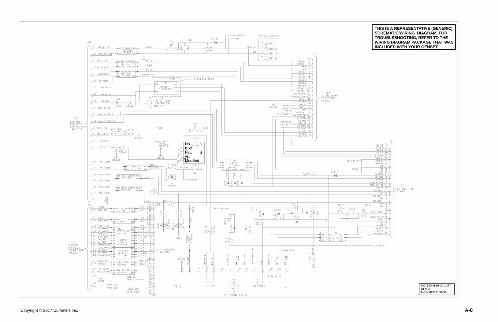
A-8Copyright 2017 Cummins Inc.
No. sh of Rev. Sys: Modified
NO. 300-4819 sht 1 of 4REV. AMODIFIED 11/29/95
THIS IS A REPRESENTATIVE (GENERIC) SCHEMATIC/WIRING DIAGRAM. FORTROUBLESHOOTING, REFER TO THEWIRING DIAGRAM PACKAGE THAT WASINCLUDED WITH YOUR GENSET.

A-9Copyright 2017 Cummins Inc.
NO. 300−4079REV. DMODIFIED 6/3/94
THIS IS A REPRESENTATIVE (GENERIC) SCHEMATIC/WIRING DIAGRAM. FORTROUBLESHOOTING, REFER TO THEWIRING DIAGRAM PACKAGE THAT WASINCLUDED WITH YOUR GENSET.
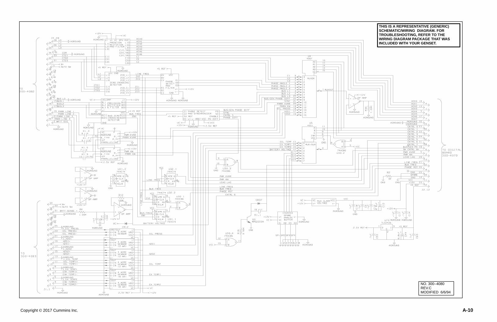
A-10Copyright 2017 Cummins Inc.
NO. 300−4080REV.CMODIFIED 6/6/94
THIS IS A REPRESENTATIVE (GENERIC) SCHEMATIC/WIRING DIAGRAM. FORTROUBLESHOOTING, REFER TO THEWIRING DIAGRAM PACKAGE THAT WASINCLUDED WITH YOUR GENSET.

A-11Copyright 2017 Cummins Inc.
NO. 300−4462 sh1REV. BMODIFIED 6/7/94
THIS IS A REPRESENTATIVE (GENERIC) SCHEMATIC/WIRING DIAGRAM. FORTROUBLESHOOTING, REFER TO THEWIRING DIAGRAM PACKAGE THAT WASINCLUDED WITH YOUR GENSET.
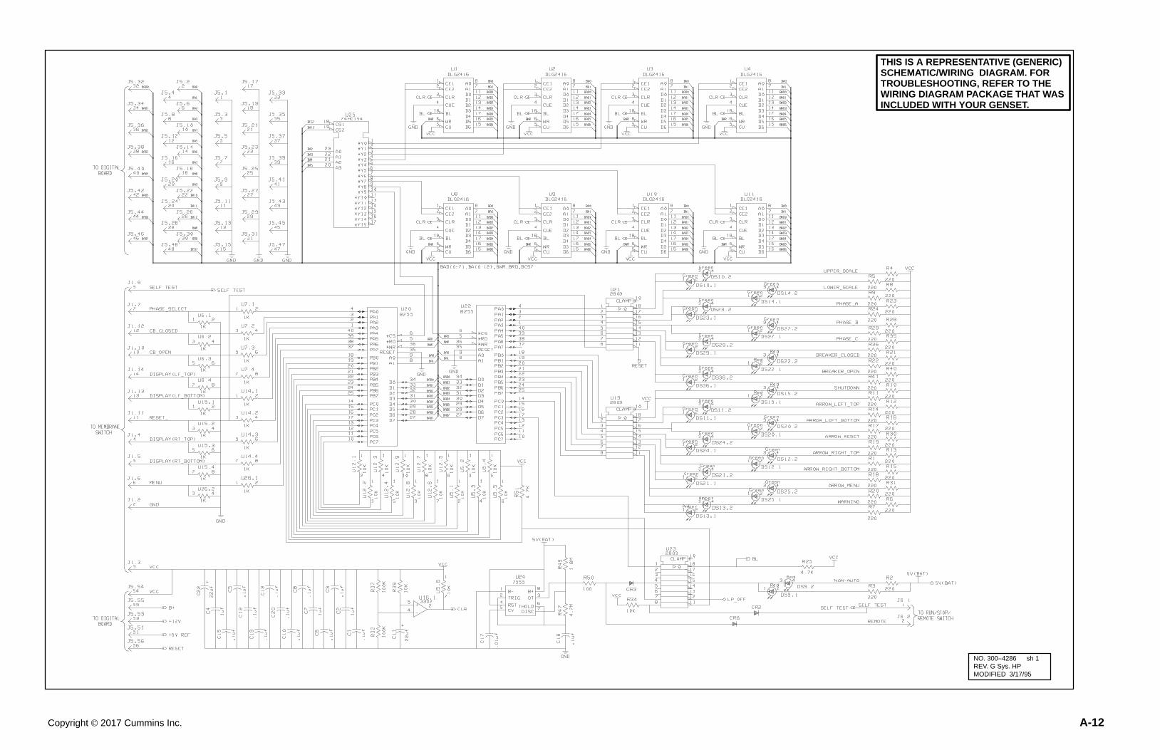
A-12Copyright 2017 Cummins Inc.
NO. 300−4286 sh 1REV. G Sys. HPMODIFIED 3/17/95
THIS IS A REPRESENTATIVE (GENERIC) SCHEMATIC/WIRING DIAGRAM. FORTROUBLESHOOTING, REFER TO THEWIRING DIAGRAM PACKAGE THAT WASINCLUDED WITH YOUR GENSET.

A-13Copyright 2017 Cummins Inc.
NO. 300−4250 sh1REV. C SYS. HPMODIFIED 1/24/95
THIS IS A REPRESENTATIVE (GENERIC) SCHEMATIC/WIRING DIAGRAM. FORTROUBLESHOOTING, REFER TO THEWIRING DIAGRAM PACKAGE THAT WASINCLUDED WITH YOUR GENSET.

A-14Copyright 2017 Cummins Inc.
NO. 300−4085sh1REV. FMODIFIED 6/7/94
THIS IS A REPRESENTATIVE (GENERIC) SCHEMATIC/WIRING DIAGRAM. FORTROUBLESHOOTING, REFER TO THEWIRING DIAGRAM PACKAGE THAT WASINCLUDED WITH YOUR GENSET.

A-15Copyright 2017 Cummins Inc.
NO.300-4724 sh1REV. DMODIFIED 4/1/96
THIS IS A REPRESENTATIVE (GENERIC) SCHEMATIC/WIRING DIAGRAM. FORTROUBLESHOOTING, REFER TO THEWIRING DIAGRAM PACKAGE THAT WASINCLUDED WITH YOUR GENSET.

A-16Copyright 2017 Cummins Inc.
NO. 338−3019 sh1REV. CMODIFIED 6/9/94
THIS IS A REPRESENTATIVE (GENERIC) SCHEMATIC/WIRING DIAGRAM. FORTROUBLESHOOTING, REFER TO THEWIRING DIAGRAM PACKAGE THAT WASINCLUDED WITH YOUR GENSET.

A-17Copyright 2017 Cummins Inc.
No. 338−3377 sh 2of 2Rev. C Sys: revisioModified 11/12/96

A-18Copyright 2017 Cummins Inc.
No. 338−3199 sh1Rev. C Sys:CADAMModified 11/30/94
THIS IS A REPRESENTATIVE (GENERIC) SCHEMATIC/WIRING DIAGRAM. FORTROUBLESHOOTING, REFER TO THEWIRING DIAGRAM PACKAGE THAT WASINCLUDED WITH YOUR GENSET.
TO PCC BACKPANEL
TO PT/CTMODULE
TO J12 OF ENGINEHARNESS
TO CONTROL BOX(PCC) HEATER

A-19Copyright 2017 Cummins Inc.
NO. 625-2141REV. HMODIFIED
See Note2
See Note1
NOTES:1. Item 23, transform-
er, is not included forkits where batteryconnections will bemade at TB1-19 andTB1-20.
2. Tag the control boxto indicate supplyvoltage.

A-20Copyright 2017 Cummins Inc.
NO.630−1345 sh1REV. EMODIFIED6/29/94
THIS IS A REPRESENTATIVE (GENERIC) SCHEMATIC/WIRING DIAGRAM. FORTROUBLESHOOTING, REFER TO THEWIRING DIAGRAM PACKAGE THAT WASINCLUDED WITH YOUR GENSET.

A-21Copyright 2017 Cummins Inc.
No. 612-6679 sh 1 of 2 Rev. B Sys: HPModified 11/21/95

A-22Copyright 2017 Cummins Inc.
No. 612-6679 sh 2 of 2 Rev. B Sys: HPModified 11/21/95

A-23Copyright 2017 Cummins Inc.
NO.612−6680sh10f1REV. AMODIFIED 8/25/94

A-24Copyright 2017 Cummins Inc.
No. 630-2672sh 1 of 4Rev. B
Modified 10-03
THIS IS A REPRESENTATIVE (GENERIC) SCHEMATIC/WIRING DIAGRAM. FORTROUBLESHOOTING, REFER TO THE
WIRING DIAGRAM PACKAGE THAT WASINCLUDED WITH YOUR GENSET.
ENCLOSURE/OPTIONS WIRING DIAGRAMS (SHEET 1 OF 5)

A-25Copyright 2017 Cummins Inc.
No. 630-2672sh 2 of 4Rev. B
Modified 10-03
THIS IS A REPRESENTATIVE (GENERIC) SCHEMATIC/WIRING DIAGRAM. FORTROUBLESHOOTING, REFER TO THE
WIRING DIAGRAM PACKAGE THAT WASINCLUDED WITH YOUR GENSET.
ENCLOSURE/OPTIONS WIRING DIAGRAMS (SHEET 2 OF 5)

A-26Copyright 2017 Cummins Inc.
No. 630-2672sh 3 of 4Rev. B
Modified 10-03
THIS IS A REPRESENTATIVE (GENERIC) SCHEMATIC/WIRING DIAGRAM. FORTROUBLESHOOTING, REFER TO THE
WIRING DIAGRAM PACKAGE THAT WASINCLUDED WITH YOUR GENSET.
ENCLOSURE/OPTIONS WIRING DIAGRAMS (SHEET 3 OF 5)

A-27Copyright 2017 Cummins Inc.
No. 630-2672sh 4 of 4Rev. B
Modified 10-03
THIS IS A REPRESENTATIVE (GENERIC) SCHEMATIC/WIRING DIAGRAM. FORTROUBLESHOOTING, REFER TO THE
WIRING DIAGRAM PACKAGE THAT WASINCLUDED WITH YOUR GENSET.
ENCLOSURE/OPTIONS WIRING DIAGRAMS (SHEET 4 OF 5)

A-28Copyright 2017 Cummins Inc.
No. 541-1066 sh 2/3 of 3Rev. B
Modified 12-03
THIS IS A REPRESENTATIVE (GENERIC) SCHEMATIC/WIRING DIAGRAM. FORTROUBLESHOOTING, REFER TO THE
WIRING DIAGRAM PACKAGE THAT WASINCLUDED WITH YOUR GENSET.
ALARM PANEL WIRING WITH TRANSFER PUMP CONTROL
ALARM PANEL WIRING WITHOUT TRANSFER PUMP CONTROL
CRITI-CALHIGH
FUELGAUAGE
FUELGAUAGE
HIGHFUEL
HIGHFUEL
OVERFILLVALVE (USEDWITH SPILLFILL BOX)
ENCLOSURE/OPTONS WIRING DIAGRAMS (SHEET 5 OF 5)

power.cummins.comCopyright � 2017 Cummins Inc. All rights reserved.
Cummins, the “C” logo, PowerCommand, AmpSentry, and InPower are trademarks of Cummins Inc.
Other company, product, or service names may be trademarks or service marks of others.
Specifications are subject to change without notice.