Embed Size (px)
Citation preview
T E C H N O L O G I E S
0E-13BF40 0E-21BF40 0E-31BF40 0E-13DF28 0E-21DF28 0E-31DF28 0E-21BVF2812 0E-31BVF2812 0E-13DVF2812 0E-21DVF2812 0E-31DVF2812
FOR TECHNICAL SUPPORT: 1-888-668-8808
April 2016 2
Contents Contents ..................................................................................................................................................................................... 2 Warranty .................................................................................................................................................................................... 3 Regulatory Information .............................................................................................................................................................. 8 Appearance Description ............................................................................................................................................................. 8 Installation ................................................................................................................................................................................ 10
1. Ceiling Mounting ............................................................................................................................................................ 11 2. MicroSD Card Installation ............................................................................................................................................... 13 3. Installation of Waterproof Jacket (supplied) .................................................................................................................. 16
Accessing via Web Browser ...................................................................................................................................................... 16 New Secure Activation Procedure ........................................................................................................................................... 19
Device Firmware with Secure Activation Chart ................................................................................................................... 19 Firmware Upgrade Strategy ................................................................................................................................................ 19 Upgraded Firmware Link ..................................................................................................................................................... 20 Post Firmware Upgrade Steps ............................................................................................................................................. 20
I. Perform a Factory Default Procedure (Mandatory) .................................................................................................. 20
II. Perform the New Secure Activation Procedure ........................................................................................................ 21
Plug-and-Play NVRs ............................................................................................................................................................. 28 Unlock Pattern (Select NVRs) ................................................................................................................................................... 32 Live View .................................................................................................................................................................................. 34 Specifications ........................................................................................................................................................................... 36
April 2016 3
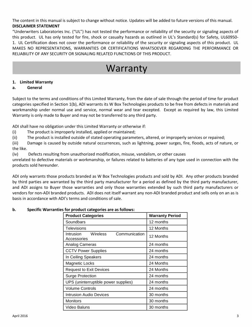
The content in this manual is subject to change without notice. Updates will be added to future versions of this manual. DISCLAIMER STATEMENT “Underwriters Laboratories Inc. (“UL”) has not tested the performance or reliability of the security or signaling aspects of this product. UL has only tested for fire, shock or casualty hazards as outlined in UL’s Standard(s) for Safety, UL60950-1. UL Certification does not cover the performance or reliability of the security or signaling aspects of this product. UL MAKES NO REPRESENTATIONS, WARRANTIES OR CERTIFICATIONS WHATSOEVER REGARDING THE PERFORMANCE OR RELIABILITY OF ANY SECURITY OR SIGNALING RELATED FUNCTIONS OF THIS PRODUCT.
Warranty 1. Limited Warranty a. General Subject to the terms and conditions of this Limited Warranty, from the date of sale through the period of time for product categories specified in Section 1(b), ADI warrants its W Box Technologies products to be free from defects in materials and workmanship under normal use and service, normal wear and tear excepted. Except as required by law, this Limited Warranty is only made to Buyer and may not be transferred to any third party. ADI shall have no obligation under this Limited Warranty or otherwise if: (i) The product is improperly installed, applied or maintained; (ii) The product is installed outside of stated operating parameters, altered, or improperly services or repaired; (iii) Damage is caused by outside natural occurrences, such as lightning, power surges, fire, floods, acts of nature, or the like. (iv) Defects resulting from unauthorized modification, misuse, vandalism, or other causes unrelated to defective materials or workmanship, or failures related to batteries of any type used in connection with the products sold hereunder. ADI only warrants those products branded as W Box Technologies products and sold by ADI. Any other products branded by third parties are warranted by the third party manufacturer for a period as defined by the third party manufacturer, and ADI assigns to Buyer those warranties and only those warranties extended by such third party manufacturers or vendors for non-ADI branded products. ADI does not itself warrant any non-ADI branded product and sells only on an as is basis in accordance with ADI’s terms and conditions of sale. b. Specific Warranties for product categories are as follows:
Product Categories Warranty Period Soundbars 12 months Televisions 12 Months Intrusion Wireless Communication Accessories 12 Months
Analog Cameras 24 months CCTV Power Supplies 24 months In Ceiling Speakers 24 months Magnetic Locks 24 Months Request to Exit Devices 24 Months Surge Protection 24 months UPS (uninterruptible power supplies) 24 months Volume Controls 24 months Intrusion Audio Devices 30 months Monitors 30 months Video Baluns 30 months
April 2016 4
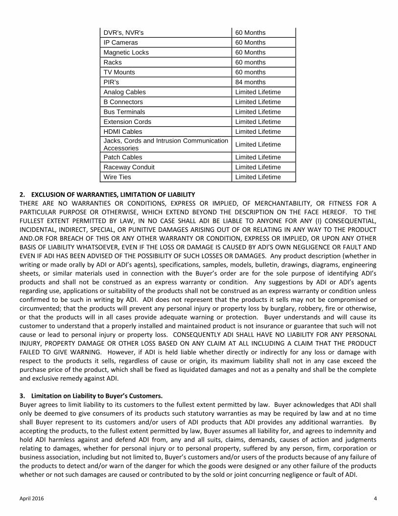
DVR's, NVR's 60 Months IP Cameras 60 Months Magnetic Locks 60 Months Racks 60 months TV Mounts 60 months PIR’s 84 months Analog Cables Limited Lifetime B Connectors Limited Lifetime Bus Terminals Limited Lifetime Extension Cords Limited Lifetime HDMI Cables Limited Lifetime Jacks, Cords and Intrusion Communication Accessories Limited Lifetime
Patch Cables Limited Lifetime Raceway Conduit Limited Lifetime Wire Ties Limited Lifetime
2. EXCLUSION OF WARRANTIES, LIMITATION OF LIABILITY THERE ARE NO WARRANTIES OR CONDITIONS, EXPRESS OR IMPLIED, OF MERCHANTABILITY, OR FITNESS FOR A PARTICULAR PURPOSE OR OTHERWISE, WHICH EXTEND BEYOND THE DESCRIPTION ON THE FACE HEREOF. TO THE FULLEST EXTENT PERMITTED BY LAW, IN NO CASE SHALL ADI BE LIABLE TO ANYONE FOR ANY (I) CONSEQUENTIAL, INCIDENTAL, INDIRECT, SPECIAL, OR PUNITIVE DAMAGES ARISING OUT OF OR RELATING IN ANY WAY TO THE PRODUCT AND.OR FOR BREACH OF THIS OR ANY OTHER WARRANTY OR CONDITION, EXPRESS OR IMPLIED, OR UPON ANY OTHER BASIS OF LIABILITY WHATSOEVER, EVEN IF THE LOSS OR DAMAGE IS CAUSED BY ADI’S OWN NEGLIGENCE OR FAULT AND EVEN IF ADI HAS BEEN ADVISED OF THE POSSIBILITY OF SUCH LOSSES OR DAMAGES. Any product description (whether in writing or made orally by ADI or ADI’s agents), specifications, samples, models, bulletin, drawings, diagrams, engineering sheets, or similar materials used in connection with the Buyer’s order are for the sole purpose of identifying ADI’s products and shall not be construed as an express warranty or condition. Any suggestions by ADI or ADI’s agents regarding use, applications or suitability of the products shall not be construed as an express warranty or condition unless confirmed to be such in writing by ADI. ADI does not represent that the products it sells may not be compromised or circumvented; that the products will prevent any personal injury or property loss by burglary, robbery, fire or otherwise, or that the products will in all cases provide adequate warning or protection. Buyer understands and will cause its customer to understand that a properly installed and maintained product is not insurance or guarantee that such will not cause or lead to personal injury or property loss. CONSEQUENTLY ADI SHALL HAVE NO LIABILITY FOR ANY PERSONAL INJURY, PROPERTY DAMAGE OR OTHER LOSS BASED ON ANY CLAIM AT ALL INCLUDING A CLAIM THAT THE PRODUCT FAILED TO GIVE WARNING. However, if ADI is held liable whether directly or indirectly for any loss or damage with respect to the products it sells, regardless of cause or origin, its maximum liability shall not in any case exceed the purchase price of the product, which shall be fixed as liquidated damages and not as a penalty and shall be the complete and exclusive remedy against ADI. 3. Limitation on Liability to Buyer’s Customers. Buyer agrees to limit liability to its customers to the fullest extent permitted by law. Buyer acknowledges that ADI shall only be deemed to give consumers of its products such statutory warranties as may be required by law and at no time shall Buyer represent to its customers and/or users of ADI products that ADI provides any additional warranties. By accepting the products, to the fullest extent permitted by law, Buyer assumes all liability for, and agrees to indemnity and hold ADI harmless against and defend ADI from, any and all suits, claims, demands, causes of action and judgments relating to damages, whether for personal injury or to personal property, suffered by any person, firm, corporation or business association, including but not limited to, Buyer’s customers and/or users of the products because of any failure of the products to detect and/or warn of the danger for which the goods were designed or any other failure of the products whether or not such damages are caused or contributed to by the sold or joint concurring negligence or fault of ADI.
April 2016 5
4. Returns Subject to the terms and conditions listed below, during the applicable warranty period, ADI will replace Product or provide a credit at purchase at its sole option free of charge any defective products returned prepaid. Any obligations of ADI to replace Limited Lifetime warranty products pursuant to this warranty which result from defect are limited to the availability of replacement product. ADI reserves the right to replace any such products with the then currently available products, or provide a credit in its sole discretion. In the event Buyer has a problem with any ADI product, please call your local ADI branch for return instructions: For US call 1-800-233-6261 For Canada call 877-234-7378 For Puerto Rico call 787-793-8830 Be sure to have the model number and the nature of the problem available. In the event of replacement, the return product will be credited to Buyer’s account and a new invoice issued for the replacement item. ADI reserves the right to issue a credit only in lieu of replacement. If any W Box Technologies product is found to be in good working order or such product’s inability to function properly is a result of user damage or abuse, the product will be returned to Buyer in the same condition as received and Buyer shall be responsible for any return freight changes. 5. Governing Law The laws of State of New York apply to this Limited Warranty. 6. Miscellaneous Where any term of this Limited Warranty is prohibited by such laws, it shall be null and void, but the remainder of the Limited Warranty shall remain in full force and effect. 1. Garantie limitée
a. Généralités Sous réserve des modalités de la présente garantie limitée, à compter de la date de vente et pendant la période de garantie applicable aux catégories de produits précisée au paragraphe 1b), ADI garantit que ses produits W Box Technologies sont libres de tout vice de matériaux et de fabrication dans des conditions d’utilisation et d’entretien normales, sauf l’usure normale. Sauf si les lois l’exigent, la présente garantie limitée est offerte uniquement à l’acheteur et ne peut être transférée à un tiers. ADI n’a aucune obligation aux termes de la présente garantie limitée ou autrement dans les circonstances suivantes : i) le produit est mal installé, appliqué ou entretenu; ii) le produit est installé de manière non conforme aux paramètres d’exploitation indiqués, modifié ou mal entretenu
ou réparé; iii) le produit est endommagé par des phénomènes naturels extérieurs comme la foudre, une surcharge, un incendie,
une inondation, une force majeure ou un phénomène similaire; iv) les défectuosités du produit résultent d’une modification non autorisée, d’une mauvaise utilisation, d’un acte de
vandalisme ou d’autres causes non liés aux vices de matériaux ou de fabrication, ou à une défaillance des piles de quelque type que ce soit utilisées avec les produits vendus aux termes des présentes.
ADI ne garantit que les produits portant la marque W Box Technologies qu’elle vend. Les autres produits portant une marque de tiers sont garantis par le fabricant tiers pendant une période définie par ce dernier, et ADI cède à l’acheteur ces garanties et uniquement les garanties offertes par ces fabricants tiers ou vendeurs à l’égard de produits ne portant pas ses marques. ADI ne garantit pas de produits ne portant pas ses marques et vend ces produits tels
April 2016 6
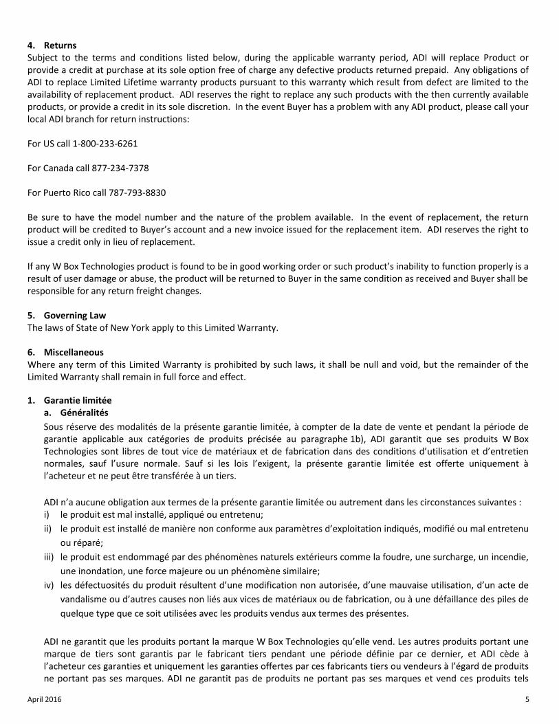
quels, conformément à ses modalités de vente. b. Les garanties particulières applicables aux catégories de produits sont les suivantes :
Catégories de produits Période de la garantie Téléviseurs 12 mois Accessoires de communication d’intrusion sans fil 12 mois Barres de son 12 mois UPS (systèmes d’alimentation sans coupure) 24 mois Caméras analogiques 24 mois Blocs d’alimentation CCTV 24 mois Contrôles du volume 24 mois Protection contre les surcharges 24 mois Haut-parleurs pour le plafond 24 mois Modules de requête de sortie 24 mois Mise à jour des serrures magnétiques 24 mois Écrans 30 mois Balluns vidéo 30 mois Système d’alarme anti-intrusion 30 mois Serrures magnétiques 36 mois Bâtis 60 mois Supports de télévision 60 mois Caméras IP 60 mois DVRs, NVR's 60 mois Détecteurs de mouvement infrarouge 84 mois Attaches pour câbles À vie limitée Câbles analogiques À vie limitée Câbles de raccordement À vie limitée Bornes de bus À vie limitée Connecteurs B À vie limitée Cordes d’extension À vie limitée Contacts magnétiques À vie limitée Bloc modulaire, câbles et accessoires de communication À vie limitée Conduits cache-fil À vie limitée Câbles HDMI À vie limitée
2. EXCLUSION DE GARANTIES ET LIMITATION DE RESPONSABILITÉ
IL N’EXISTE AUCUNE GARANTIE OU CONDITION, EXPRESSE OU IMPLICITE, DE QUALITÉ MARCHANDE, D’ADAPTATION À UNE FIN PARTICULIÈRE OU AUTRE QUI DÉPASSE LE CADRE DE LA DESCRIPTION FOURNIE AU RECTO DES PRÉSENTES. DANS LA PLEINE MESURE PERMISE PAR LA LOI, ADI NE SAURAIT EN AUCUN CAS ÊTRE TENUE RESPONSABLE ENVERS QUICONQUE DES DOMMAGES CONSÉCUTIFS, INDIRECTS, SPÉCIAUX OU PUNITIFS DÉCOULANT DU PRODUIT OU LIÉS À CELUI-CI DE QUELQUE FAÇON QUE CE SOIT ET/OU DU NON-RESPECT DE LA PRÉSENTE GARANTIE OU DE TOUTE AUTRE GARANTIE OU CONDITION, EXPRESSE OU IMPLICITE, OU DE TOUTE AUTRE RÉCLAMATION FONDÉE SUR LA RESPONSABILITÉ, MÊME SI LA PERTE OU LES DOMMAGES SONT CAUSÉS PAR LA NÉGLIGENCE OU LA FAUTE D’ADI ET MÊME SI CETTE DERNIÈRE A ÉTÉ AVISÉE DE LA POSSIBILITÉ QUE DE TELLES PERTES OU DE TELS DOMMAGES SURVIENNENT. Les descriptions de produits (fournies par écrit ou verbalement par ADI ou ses mandataires), caractéristiques techniques, échantillons, modèles, bulletins, dessins, diagrammes, esquisses techniques ou documents similaires utilisés par l’acheteur pour passer une commande visent uniquement à décrire les produits d’ADI et ne doivent pas être interprétés comme des garanties ou conditions expresses. Les suggestions faites par ADI
April 2016 7
ou ses mandataires au sujet de l’utilisation, de l’application ou du caractère approprié des produits ne doivent pas être interprétées comme des garanties ou conditions expresses, sauf si ADI confirme par écrit qu’il s’agit de garanties ou de conditions expresses. ADI ne garantit pas qu’il n’y aura aucune atteinte à l’intégrité des produits qu’elle vend ou que les produits qu’elle vend ne seront pas contournés, qu’ils préviendront les blessures ou les pertes matérielles en cas de cambriolage, de vol, d’incendie ou autrement ou qu’ils constitueront dans tous les cas une protection ou un avertissement approprié. L’acheteur comprend qu’un produit dûment installé et entretenu permet uniquement de réduire le risque de cambriolage, de vol ou d’incendie sans avertissement, mais qu’il ne constitue pas une assurance ou une garantie qu’un tel événement ne se produira pas ou qu’il n’entraînera pas des blessures ou des pertes matérielles. PAR CONSÉQUENT, ADI NE SAURAIT ÊTRE TENUE RESPONSABLE DES BLESSURES, DES DOMMAGES MATÉRIELS OU D’AUTRES PERTES FAISANT L’OBJET D’UNE RÉCLAMATION, Y COMPRIS UNE RÉCLAMATION SELON LAQUELLE LE PRODUIT N’AURAIT PAS DONNÉ DE SIGNAL D’AVERTISSEMENT. Toutefois, si ADI est tenue responsable, directement ou indirectement, de pertes ou de dommages à l’égard des produits qu’elle vend, quelle qu’en soit la cause ou l’origine, sa responsabilité n’excédera en aucun cas le prix d’achat du produit, dont le remboursement sera exigé à titre de dommages-intérêts extrajudiciaires et non d’amende, et il s’agira du recours exclusif et intégral pouvant être exercé contre ADI.
3. Limitation de la responsabilité envers les clients de l’acheteur. L’acheteur s’engage à limiter la responsabilité envers ses clients dans la pleine mesure permise par la loi. L’acheteur reconnaît qu’ADI ne sera réputée avoir fourni aux consommateurs de ses produits que les garanties qui sont exigées par la loi. L’acheteur ne doit en aucun cas déclarer à ses clients et/ou aux utilisateurs des produits d’ADI que cette dernière offre d’autres garanties. Par l’acceptation des produits, l’acheteur assume, dans la pleine mesure permise par la loi, la pleine responsabilité à l’égard de toutes les poursuites, réclamations, mises en demeure et causes d’action et à l’égard de tous les jugements se rapportant à des dommages-intérêts, que ce soit pour des préjudices personnels ou des dommages matériels, subis par une personne, une firme, une société ou une association commerciale, y compris les clients de l’acheteur et/ou les utilisateurs des produits, en raison de toute omission de la part des produits de déceler le danger pour la détection duquel ils sont conçus et/ou de donner l’alerte de ce danger ou un avertissement de toute autre défaillance des produits, que ces dommages aient été causés par la négligence dont ADI est l’auteur ou le coauteur, et il tiendra ADI à couvert à cet égard et prendra fait et cause pour lui.
4. Retours Sous réserve des modalités énumérées ci-après, durant la période de garantie applicable, ADI remplacera le produit ou donnera une note de crédit à l’achat, à son gré et sans frais, à l’égard de tout produit défectueux qui lui est retourné. L’obligation qui incombe à ADI de remplacer le produit visé par une garantie à vie limitée aux termes de la garantie en question si celui-ci est défectueux se limite à la disponibilité d’un produit de remplacement. ADI se réserve le droit de remplacer un produit défectueux par le produit qui est disponible à ce moment-là, ou de donner une note de crédit, à son gré. Si l’acheteur a un problème avec un produit d’ADI, il doit appeler sa succursale ADI locale pour connaître la marche à suivre pour retourner le produit. Aux États-Unis, composer le 1 800 233-6261 Au Canada, composer le 877 234-7378 À Porto Rico, composer le 787 793-8830 L’acheteur doit avoir en main le numéro du modèle et décrire la nature du problème. En cas de remplacement, le prix du produit retourné sera porté au crédit du compte de l’acheteur et une nouvelle facture sera établie pour le produit de remplacement. ADI se réserve le droit de donner une note de crédit plutôt que de remplacer le produit. Si l’on établit que le produit W Box Technologies n’est pas défectueux ou que son mauvais fonctionnement résulte d’une utilisation abusive ou de dommages causés par l’utilisateur, le produit sera retourné à l’acheteur dans le même état que celui dans lequel il a été reçu et l’acheteur devra acquitter les frais de transport.
April 2016 8
5. Lois applicables Les lois de l’État de New York s’appliquent à la présente garantie limitée.
6. Modalités diverses Si une modalité de la présente garantie limitée est interdite par ces lois, elle sera nulle, mais le reste de la présente garantie limitée demeurera pleinement en vigueur.
Regulatory Information FCC Information FCC compliance: This equipment has been tested and found to comply with the limits for a digital device, pursuant to part 15 of the FCC Rules. These limits are designed to provide reasonable protection against harmful interference when the equipment is operated in a commercial environment. This equipment generates, uses, and can radiate radio frequency energy and, if not installed and used in accordance with the instruction manual, may cause harmful interference to radio communications. Operation of this equipment in a residential area is likely to cause harmful interference in which case the users will be required to correct the interference at their own expense. FCC Conditions This device complies with part 15 of the FCC Rules. Operation is subject to the following two conditions: 1. This device may not cause harmful interference. 2. This device must accept any interference received, including interference that may cause undesired operation EU Conformity Statement
This product and - if applicable - the supplied accessories too are marked with "CE" and comply therefore with the applicable harmonized European standards listed under the Low Voltage Directive 2006/95/EC, the EMC
Directive 2004/108/EC, the RoHS Directive 2011/65/EU. Municipal waste in the European Union. For proper recycling, return this product to your local supplier upon the purchase of equivalent 2012/19/EU (WEEE directive): Products marked with this symbol cannot be disposed of as unsorted municipal waste in the European Union. For proper recycling, return this product to your local
supplier upon the purchase of equivalent new equipment, or dispose of it at designated collection points. For more information, see: www.recyclethis.info.
2006/66/EC (battery directive): This product contains a battery that cannot be disposed of as unsorted municipal waste in the European Union. See the product documentation for specific battery information. The battery is marked with this symbol, which may include lettering to indicate cadmium (Cd), lead (Pb), or mercury (Hg). For proper recycling, return the battery to your supplier or to a designated collection point. For more information,
see: www.recyclethis.info.
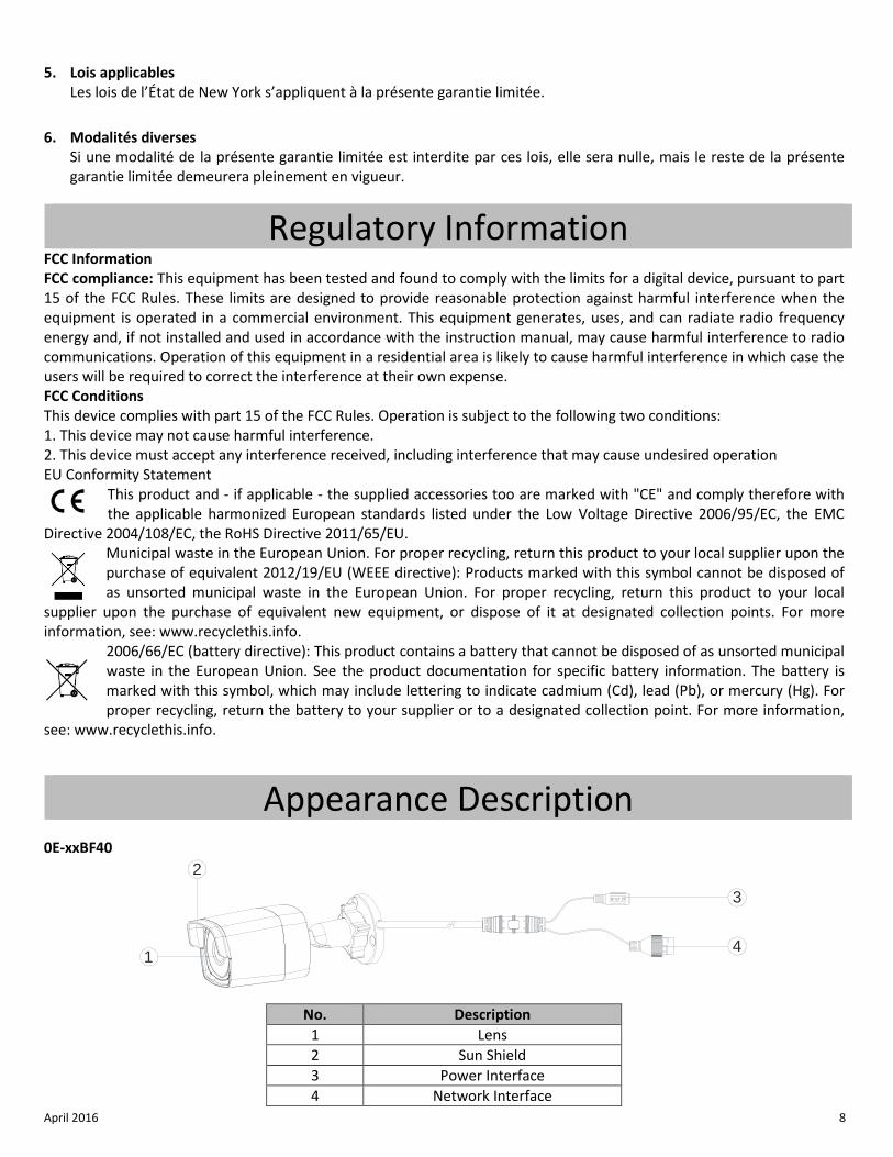
Appearance Description 0E-xxBF40
No. Description 1 Lens 2 Sun Shield 3 Power Interface 4 Network Interface
DC12V IN
1
2
3
4
April 2016 9
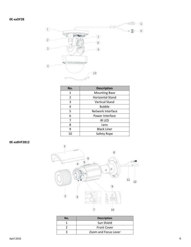
0E-xxDF28
No. Description 1 Mounting Base 2 Horizontal Stand 3 Vertical Stand 4 Bubble 5 Network Interface 6 Power Interface 7 IR LED 8 Lens 9 Black Liner
10 Safety Rope
0E-xxBVF2812
No. Description 1 Sun Shield 2 Front Cover 3 Zoom and Focus Lever
1
2
3
4
9
6
7
8
5
10
11
5
12
3
8
6
10
9
7
4
1
2
April 2016 10
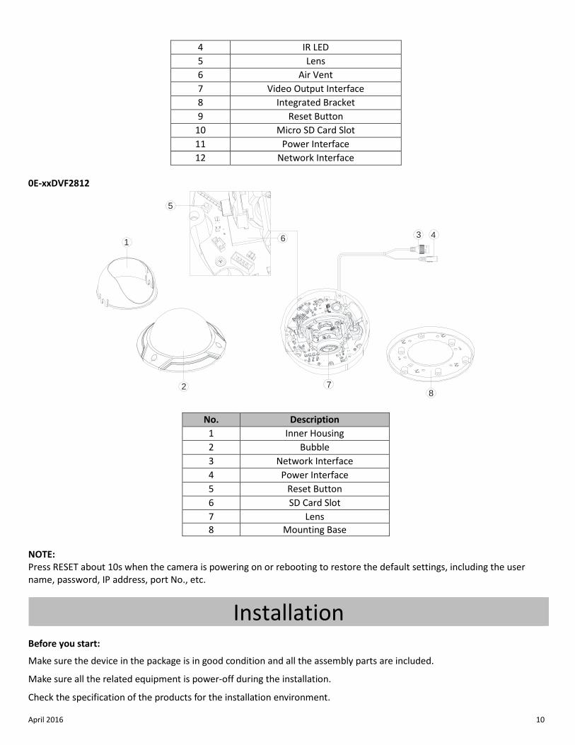
4 IR LED 5 Lens 6 Air Vent 7 Video Output Interface 8 Integrated Bracket 9 Reset Button
10 Micro SD Card Slot 11 Power Interface 12 Network Interface
0E-xxDVF2812
No. Description 1 Inner Housing 2 Bubble 3 Network Interface 4 Power Interface 5 Reset Button 6 SD Card Slot 7 Lens 8 Mounting Base
NOTE: Press RESET about 10s when the camera is powering on or rebooting to restore the default settings, including the user name, password, IP address, port No., etc.
Installation Before you start:
Make sure the device in the package is in good condition and all the assembly parts are included.
Make sure all the related equipment is power-off during the installation.
Check the specification of the products for the installation environment.
2
13 4
78
5
6
April 2016 11
Make sure the power supply is matched with your required voltage to avoid damage.
If the product does not function properly, please contact your dealer or the nearest service center. Do not disassemble the camera for repair or maintenance by yourself.
Make sure that the wall is strong enough to withstand three times the weight of the camera.
NOTE: For cameras that support IR, pay attention to the following precautions to prevent IR reflection:
Dust or grease on the dome cover will cause IR reflection. Please do not remove the dome cover film until the installation is finished. If there is dust or grease on the dome cover, clean the dome cover with clean soft cloth and isopropyl alcohol.
Make sure that there is no reflective surface too close to the camera lens. The IR light from the camera may reflect back into the lens causing reflection.
The foam ring around the lens must be seated flush against the inner surface of the bubble to isolate the lens from the IR LEDS. Fasten the dome cover to camera body so that the foam ring and the dome cover are attached seamlessly.
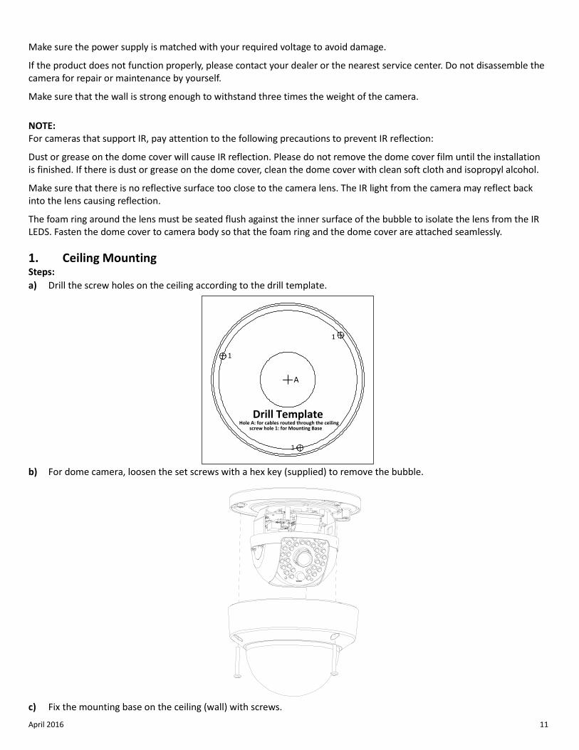
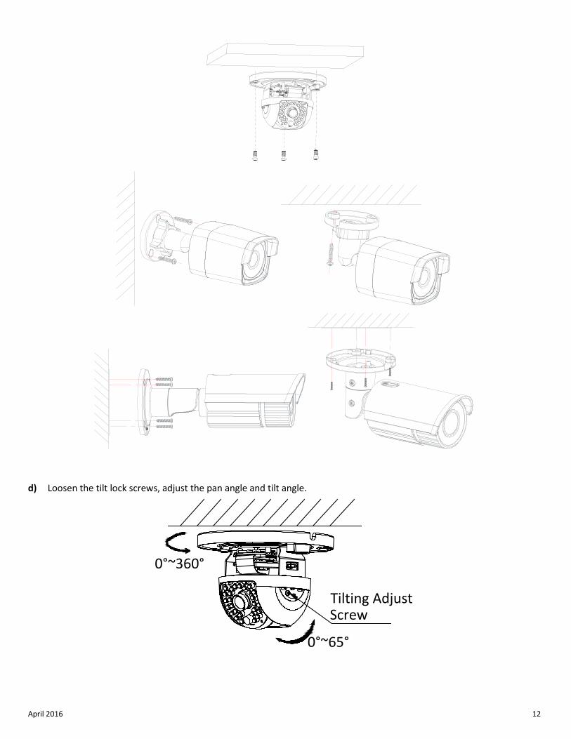
1. Ceiling Mounting Steps: a) Drill the screw holes on the ceiling according to the drill template.
b) For dome camera, loosen the set screws with a hex key (supplied) to remove the bubble.
c) Fix the mounting base on the ceiling (wall) with screws.
Drill TemplateHole A: for cables routed through the ceiling screw hole 1: for Mounting Base
1
1
1
A
April 2016 12
d) Loosen the tilt lock screws, adjust the pan angle and tilt angle.
0°~360°
0°~65°
Tilting AdjustScrew
April 2016 13
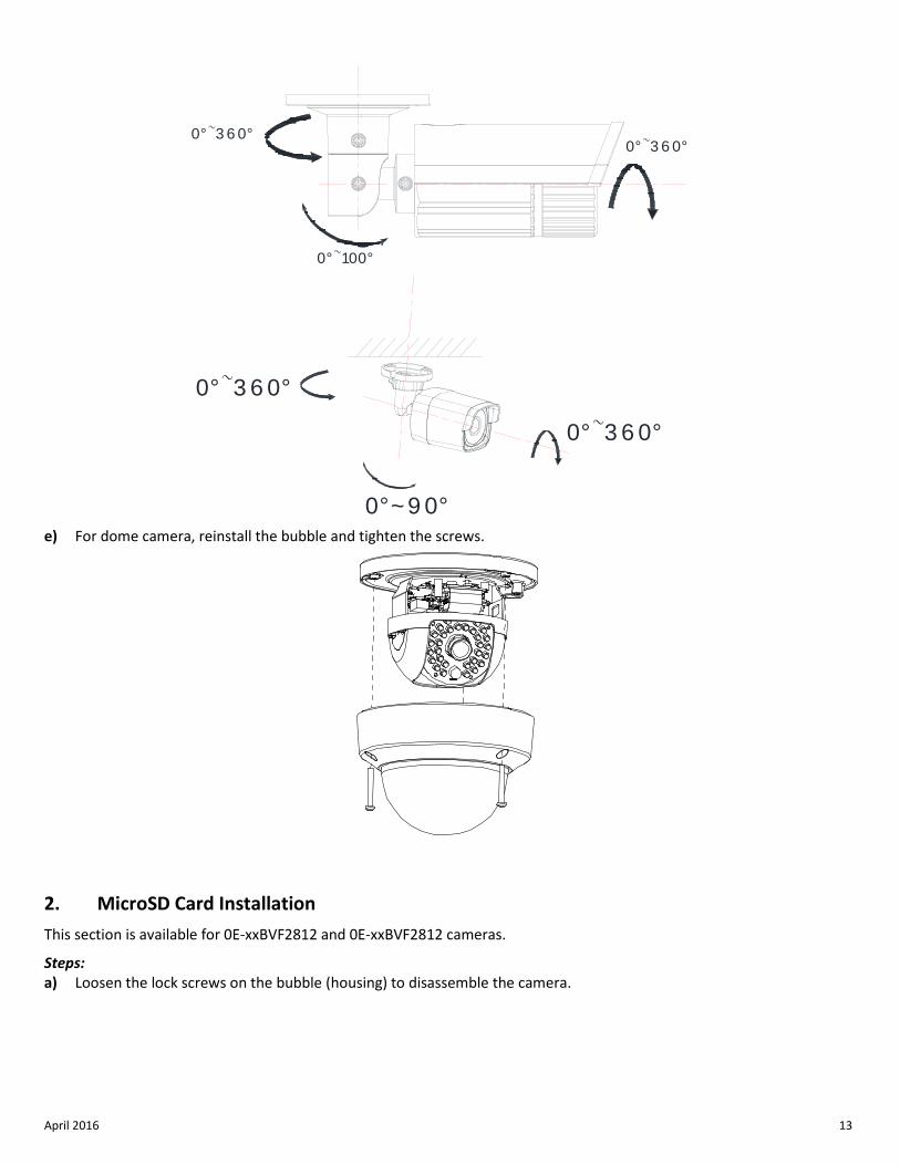
e) For dome camera, reinstall the bubble and tighten the screws.
2. MicroSD Card Installation This section is available for 0E-xxBVF2812 and 0E-xxBVF2812 cameras.
Steps: a) Loosen the lock screws on the bubble (housing) to disassemble the camera.
0°~100°
0°~3 6 0°0°~3 6 0°
0°~3 6 0°
0°~9 0°
0°~3 6 0°
April 2016 14
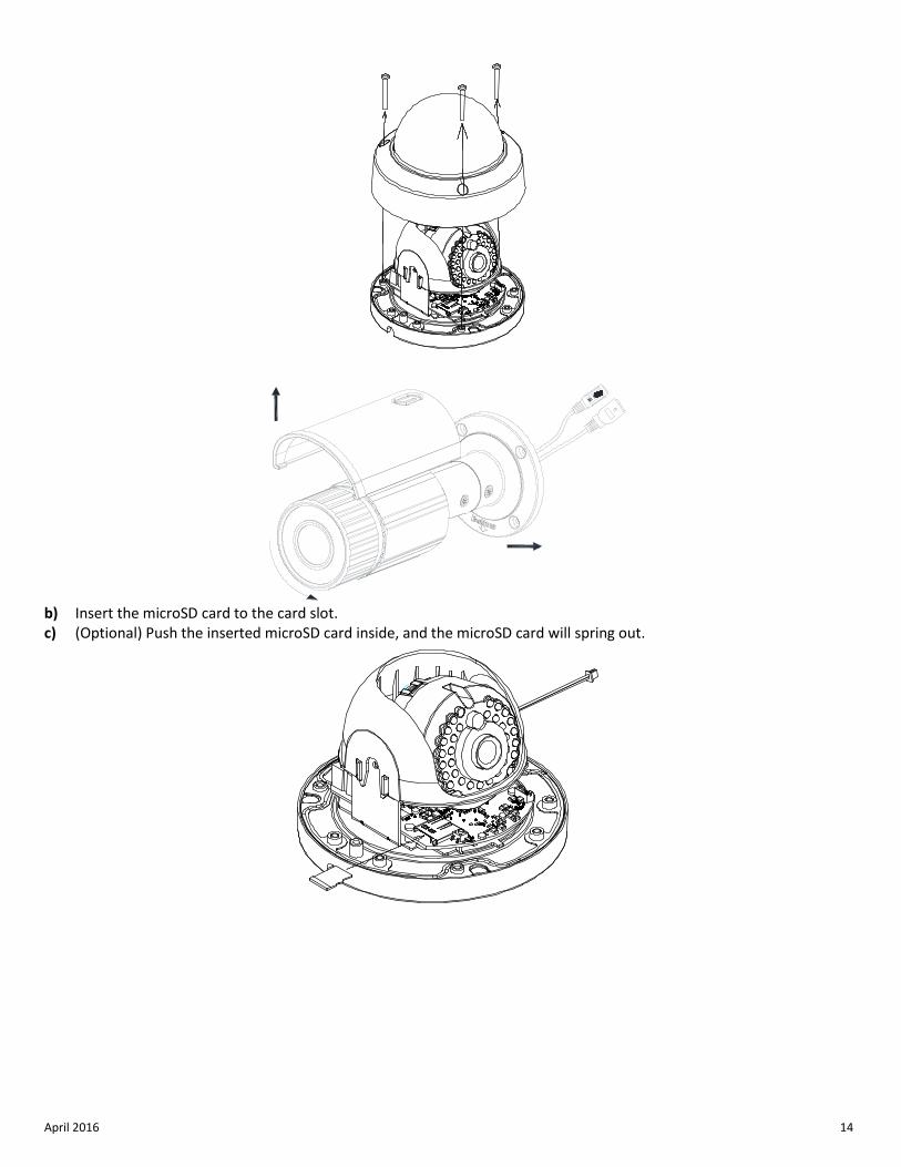
b) Insert the microSD card to the card slot. c) (Optional) Push the inserted microSD card inside, and the microSD card will spring out.
April 2016 15
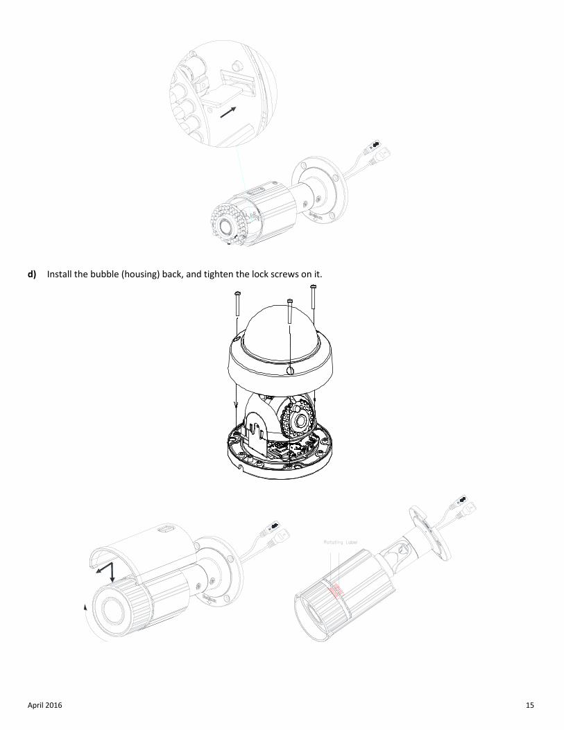
d) Install the bubble (housing) back, and tighten the lock screws on it.
April 2016 16
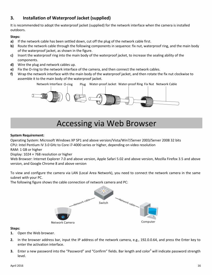
3. Installation of Waterproof Jacket (supplied) It is recommended to adopt the waterproof jacket (supplied) for the network interface when the camera is installed outdoors.
Steps: a) If the network cable has been settled down, cut off the plug of the network cable first. b) Route the network cable through the following components in sequence: fix nut, waterproof ring, and the main body
of the waterproof jacket, as shown in the figure. c) Insert the waterproof ring into the main body of the waterproof jacket, to increase the sealing ability of the
components. d) Wire the plug and network cables up. e) Fix the O-ring to the network interface of the camera, and then connect the network cables. f) Wrap the network interface with the main body of the waterproof jacket, and then rotate the fix nut clockwise to
assemble it to the main body of the waterproof jacket. Network Interface O-ring Plug Water-proof Jacket Water-proof Ring Fix Nut Network Cable
Accessing via Web Browser
System Requirement: Operating System: Microsoft Windows XP SP1 and above version/Vista/Win7/Server 2003/Server 2008 32 bits CPU: Intel Pentium IV 3.0 GHz to Core i7-4000 series or higher, depending on video resolution RAM: 1 GB or higher Display: 1024 × 768 resolution or higher Web Browser: Internet Explorer 7.0 and above version, Apple Safari 5.02 and above version, Mozilla Firefox 3.5 and above version, and Google Chrome 8 and above version To view and configure the camera via LAN (Local Area Network), you need to connect the network camera in the same subnet with your PC. The following figure shows the cable connection of network camera and PC:
Steps: 1. Open the Web browser.
2. In the browser address bar, input the IP address of the network camera, e.g., 192.0.0.64, and press the Enter key to enter the activation interface.
3. Enter a new password into the “Password” and “Confirm” fields. Bar length and color3 will indicate password strength level.
April 2016 17
NOTE: Activation will not be allowed unless password is of acceptable
strength. If the password is of unacceptable strength, a warning box will be displayed.
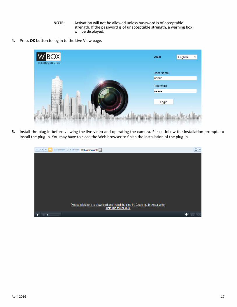
4. Press OK button to log in to the Live View page.
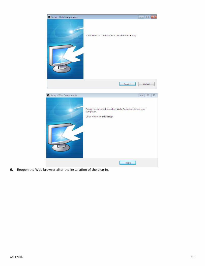
5. Install the plug-in before viewing the live video and operating the camera. Please follow the installation prompts to
install the plug-in. You may have to close the Web browser to finish the installation of the plug-in.
April 2016 18
6. Reopen the Web browser after the installation of the plug-in.
April 2016 19
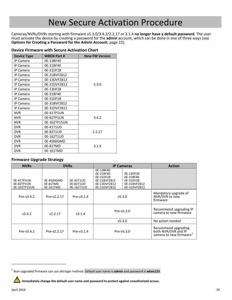
New Secure Activation Procedure Cameras/NVRs/DVRs starting with firmware v5.3.0/3.4.2/2.2.17 or 3.1.4 no longer have a default password. The user must activate the device by creating a password for the admin account, which can be done in one of three ways (see Options for Creating a Password for the Admin Account, page 22).
Device Firmware with Secure Activation Chart
Device Type WBOX Part # New FW Version IP Camera 0E-13BF40
5.3.0
IP Camera 0E-21BF40 IP Camera 0E-21DF28 IP Camera 0E-21BVF2812 IP Camera 0E-13DVF2812 IP Camera 0E-21DVF2812 IP Camera 0E-13DF28 IP Camera 0E-31BF40 IP Camera 0E-31DF28 IP Camera 0E-31BVF2812 IP Camera 0E-31DVF2812 NVR 0E-41TP1UN
3.4.2 NVR 0E-82TP1UN NVR 0E-162TP15UN DVR 0E-41T1UD
2.2.17 DVR 0E-82T1UD DVR 0E-162T1UD DVR 0E-4500GMD
3.1.4 DVR 0E-81TMD DVR 0E-161TMD
Firmware Upgrade Strategy
NVRs DVRs IP Cameras Action
0E-41TP1UN 0E-82TP1UN 0E-162TP15UN
0E-4500GMD 0E-81TMD 0E-161TMD
0E-41T1UD 0E-82T1UD 0E-162T1UD
0E-13BF40 0E-21BF40 0E-21DF28 0E-21BVF2812 0E-13DVF2812 0E-21DVF2812
0E-13DF28 0E-31BF40 0E-31DF28 0E-31BVF2812 0E-31DVF2812
Pre-v3.4.2 Pre-v2.2.17 Pre-v3.1.4 v5.3.0 Mandatory upgrade of NVR/DVR to new firmware
v3.4.2 v2.2.17 v3.1.4 Pre-v5.3.0 Recommend upgrading IP
camera to new firmware
v5.3.0 No action needed
Pre-v3.4.2 Pre-v2.2.17 Pre-v3.1.4 Pre-v5.3.0 Recommend upgrading both NVR/DVR and IP camera to new firmware1
1 Non-upgraded firmware can use old login method: Default user name is admin and password is wbox123.
Immediately change the default user name and password to protect against unauthorized access.
April 2016 20
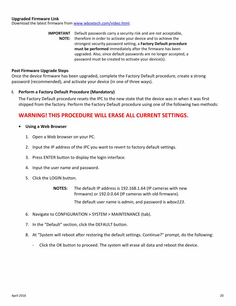
Upgraded Firmware Link Download the latest firmware from www.wboxtech.com/video.html.
IMPORTANT NOTE:
Default passwords carry a security risk and are not acceptable, therefore in order to activate your device and to achieve the strongest security password setting, a Factory Default procedure must be performed immediately after the firmware has been upgraded. Also, since default passwords are no longer accepted, a password must be created to activate your device(s).
Post Firmware Upgrade Steps Once the device firmware has been upgraded, complete the Factory Default procedure, create a strong password (recommended), and activate your device (in one of three ways).
I. Perform a Factory Default Procedure (Mandatory) The Factory Default procedure resets the IPC to the new state that the device was in when it was first shipped from the factory. Perform the Factory Default procedure using one of the following two methods:
WARNING! THIS PROCEDURE WILL ERASE ALL CURRENT SETTINGS.
• Using a Web Browser
1. Open a Web browser on your PC.
2. Input the IP address of the IPC you want to revert to factory default settings.
3. Press ENTER button to display the login interface.
4. Input the user name and password.
5. Click the LOGIN button.
NOTES: The default IP address is 192.168.1.64 (IP cameras with new firmware) or 192.0.0.64 (IP cameras with old firmware).
The default user name is admin, and password is wbox123.
6. Navigate to CONFIGURATION > SYSTEM > MAINTENANCE (tab).
7. In the “Default” section, click the DEFAULT button.
8. At “System will reboot after restoring the default settings. Continue?” prompt, do the following:
- Click the OK button to proceed. The system will erase all data and reboot the device.
April 2016 21
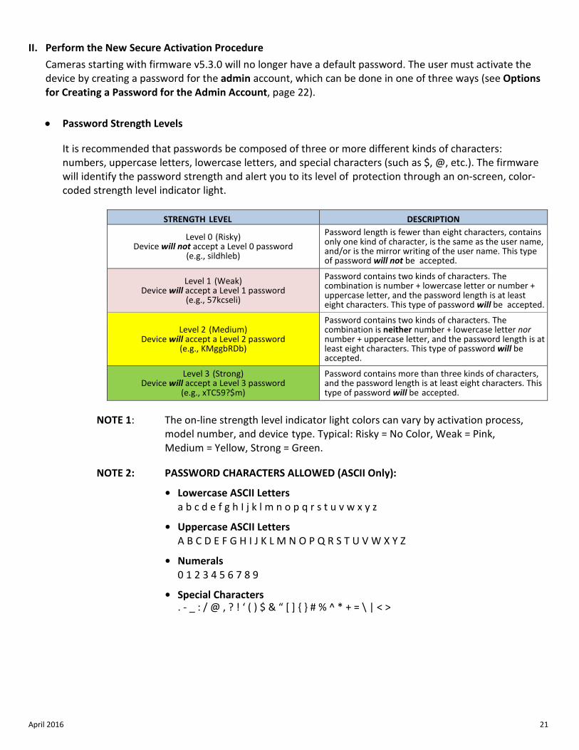
II. Perform the New Secure Activation Procedure Cameras starting with firmware v5.3.0 will no longer have a default password. The user must activate the device by creating a password for the admin account, which can be done in one of three ways (see Options for Creating a Password for the Admin Account, page 22).
• Password Strength Levels
It is recommended that passwords be composed of three or more different kinds of characters: numbers, uppercase letters, lowercase letters, and special characters (such as $, @, etc.). The firmware will identify the password strength and alert you to its level of protection through an on-screen, color-coded strength level indicator light.
STRENGTH LEVEL DESCRIPTION
Level 0 (Risky) Device will not accept a Level 0 password
(e.g., sildhleb)
Password length is fewer than eight characters, contains only one kind of character, is the same as the user name, and/or is the mirror writing of the user name. This type of password will not be accepted.
Level 1 (Weak) Device will accept a Level 1 password
(e.g., 57kcseli)
Password contains two kinds of characters. The combination is number + lowercase letter or number + uppercase letter, and the password length is at least eight characters. This type of password will be accepted.
Level 2 (Medium) Device will accept a Level 2 password
(e.g., KMggbRDb)
Password contains two kinds of characters. The combination is neither number + lowercase letter nor number + uppercase letter, and the password length is at least eight characters. This type of password will be accepted.
Level 3 (Strong) Device will accept a Level 3 password
(e.g., xTC59?$m)
Password contains more than three kinds of characters, and the password length is at least eight characters. This type of password will be accepted.
NOTE 1: The on-line strength level indicator light colors can vary by activation process,
model number, and device type. Typical: Risky = No Color, Weak = Pink, Medium = Yellow, Strong = Green.
NOTE 2: PASSWORD CHARACTERS ALLOWED (ASCII Only):
• Lowercase ASCII Letters a b c d e f g h I j k l m n o p q r s t u v w x y z
• Uppercase ASCII Letters A B C D E F G H I J K L M N O P Q R S T U V W X Y Z
• Numerals 0 1 2 3 4 5 6 7 8 9
• Special Characters . - _ : / @ , ? ! ‘ ( ) $ & “ [ ] { } # % ^ * + = \ | < >
April 2016 22
• Options for Creating a Password for the Admin Account
- Option 1: W Box Device Search Tool Activation on PC
1. Launch the latest version of the W Box Device Search Tool software (visit http://www.wboxtech.com/video/html).
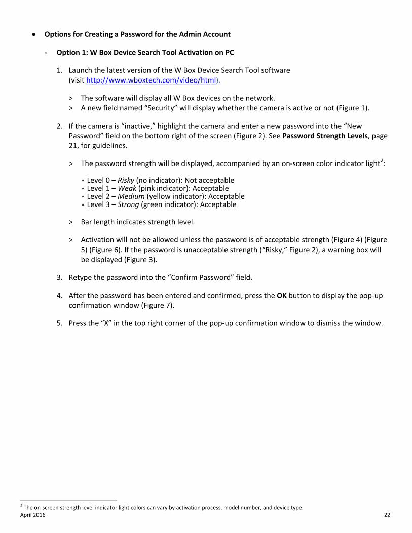
> The software will display all W Box devices on the network. > A new field named “Security” will display whether the camera is active or not (Figure 1).
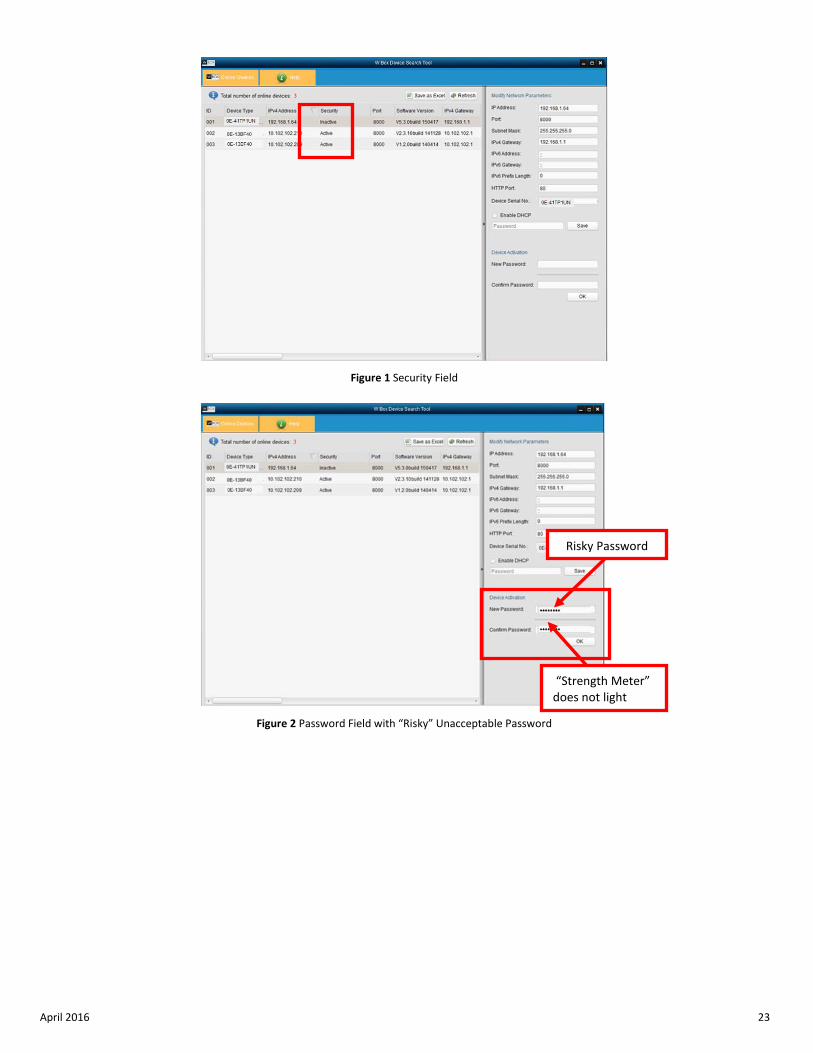
2. If the camera is “inactive,” highlight the camera and enter a new password into the “New Password” field on the bottom right of the screen (Figure 2). See Password Strength Levels, page 21, for guidelines.
> The password strength will be displayed, accompanied by an on-screen color indicator light2:
* Level 0 – Risky (no indicator): Not acceptable * Level 1 – Weak (pink indicator): Acceptable * Level 2 – Medium (yellow indicator): Acceptable * Level 3 – Strong (green indicator): Acceptable
> Bar length indicates strength level.
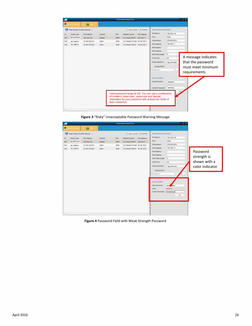
> Activation will not be allowed unless the password is of acceptable strength (Figure 4) (Figure 5) (Figure 6). If the password is unacceptable strength (“Risky,” Figure 2), a warning box will be displayed (Figure 3).
3. Retype the password into the “Confirm Password” field.
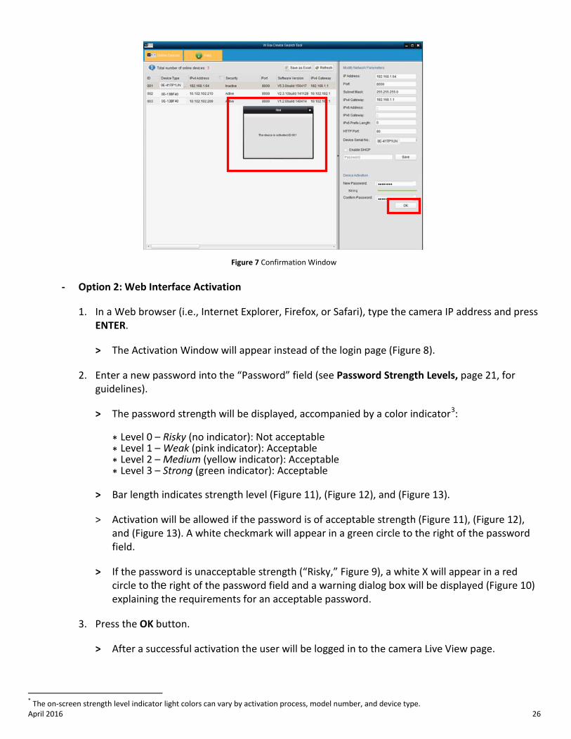
4. After the password has been entered and confirmed, press the OK button to display the pop-up confirmation window (Figure 7).
5. Press the “X” in the top right corner of the pop-up confirmation window to dismiss the window.
2 The on-screen strength level indicator light colors can vary by activation process, model number, and device type.
April 2016 23
Figure 1 Security Field
Figure 2 Password Field with “Risky” Unacceptable Password
Risky Password
“Strength Meter” does not light
April 2016 24
Figure 3 “Risky” Unacceptable Password Warning Message
Figure 4 Password Field with Weak Strength Password
Password strength is shown with a color indicator
A message indicates that the password must meet minimum requirements
Valid password range [8-16]. You can use a combination of numbers, lowercase, uppercase and special characters for your password with at least two kinds of them contained.
April 2016 25
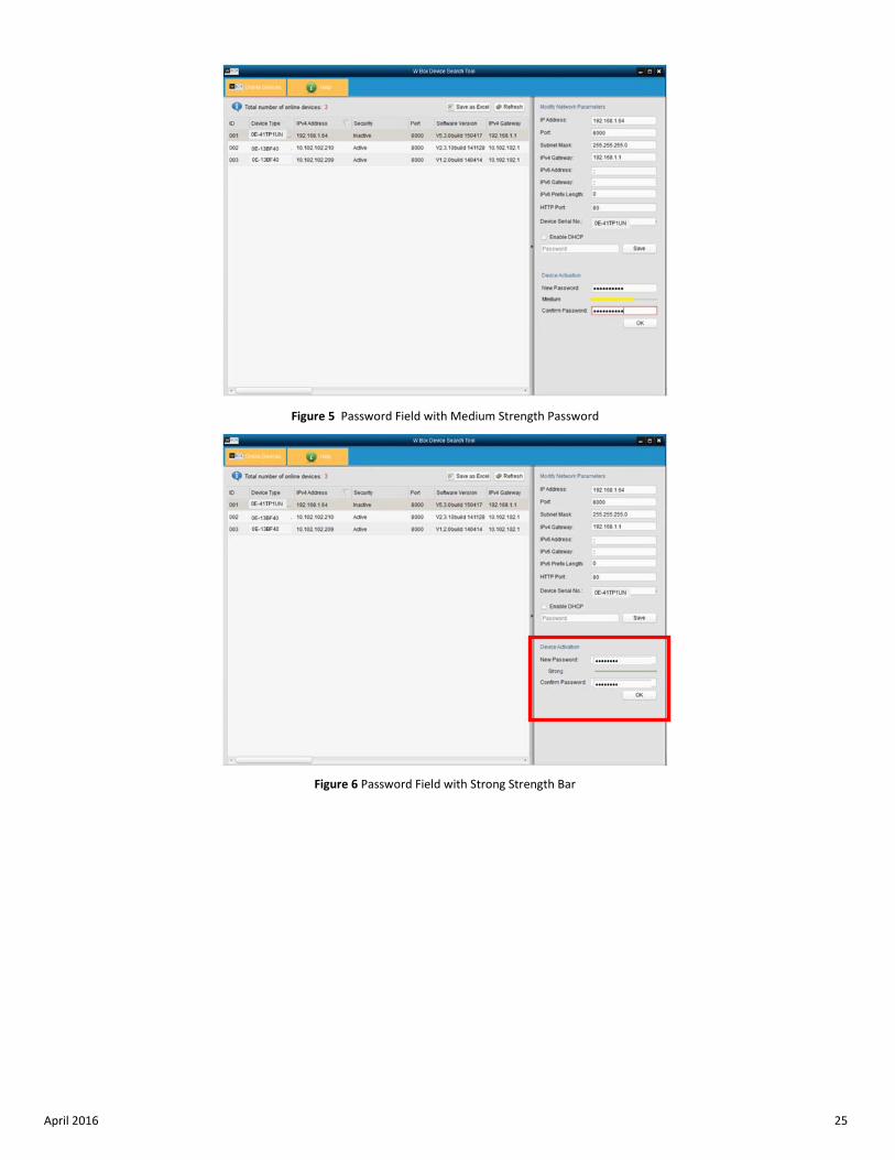
Figure 5 Password Field with Medium Strength Password
Figure 6 Password Field with Strong Strength Bar
April 2016 26
Figure 7 Confirmation Window
- Option 2: Web Interface Activation
1. In a Web browser (i.e., Internet Explorer, Firefox, or Safari), type the camera IP address and press ENTER.
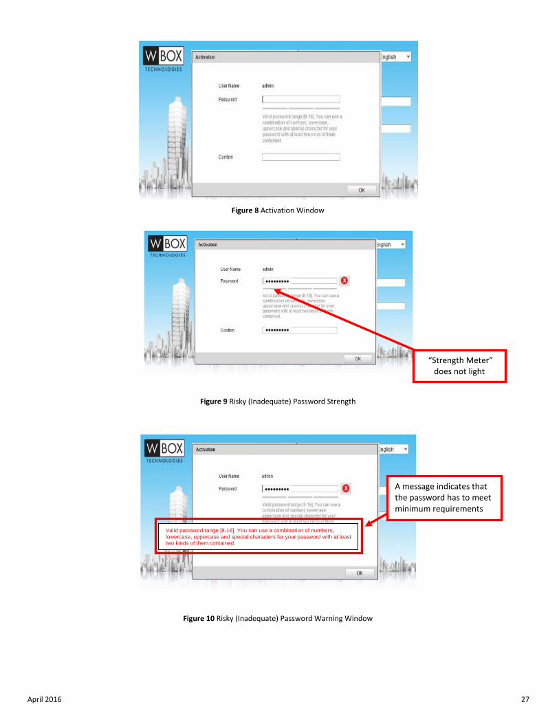
> The Activation Window will appear instead of the login page (Figure 8).
2. Enter a new password into the “Password” field (see Password Strength Levels, page 21, for guidelines).
> The password strength will be displayed, accompanied by a color indicator3:
* Level 0 – Risky (no indicator): Not acceptable * Level 1 – Weak (pink indicator): Acceptable * Level 2 – Medium (yellow indicator): Acceptable * Level 3 – Strong (green indicator): Acceptable
> Bar length indicates strength level (Figure 11), (Figure 12), and (Figure 13).
> Activation will be allowed if the password is of acceptable strength (Figure 11), (Figure 12), and (Figure 13). A white checkmark will appear in a green circle to the right of the password field.
> If the password is unacceptable strength (“Risky,” Figure 9), a white X will appear in a red circle to the right of the password field and a warning dialog box will be displayed (Figure 10) explaining the requirements for an acceptable password.
3. Press the OK button.
> After a successful activation the user will be logged in to the camera Live View page.
* The on-screen strength level indicator light colors can vary by activation process, model number, and device type.
April 2016 27
Figure 8 Activation Window
Figure 9 Risky (Inadequate) Password Strength
Figure 10 Risky (Inadequate) Password Warning Window
“Strength Meter” does not light
Valid password range [8-16]. You can use a combination of numbers, lowercase, uppercase and special characters for your password with at least two kinds of them contained.
A message indicates that the password has to meet minimum requirements
April 2016 28
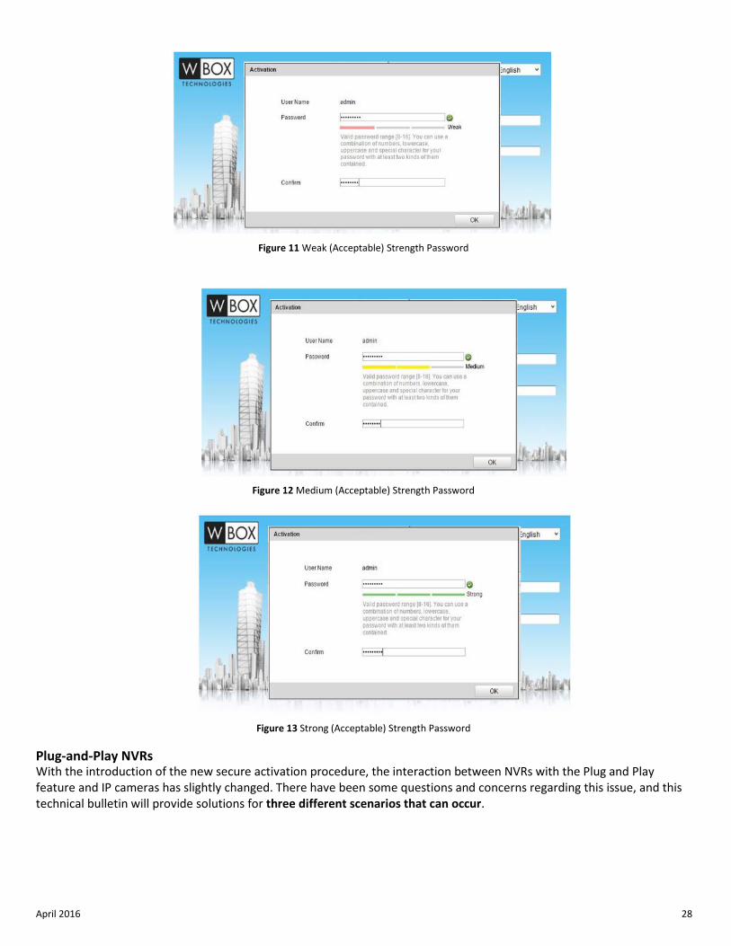
Figure 11 Weak (Acceptable) Strength Password
Figure 12 Medium (Acceptable) Strength Password
Figure 13 Strong (Acceptable) Strength Password
Plug-and-Play NVRs With the introduction of the new secure activation procedure, the interaction between NVRs with the Plug and Play feature and IP cameras has slightly changed. There have been some questions and concerns regarding this issue, and this technical bulletin will provide solutions for three different scenarios that can occur.
April 2016 29
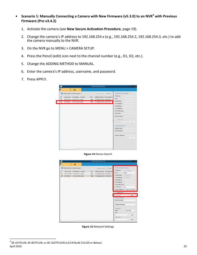
• Scenario 1: Manually Connecting a Camera with New Firmware (v5.3.0) to an NVR4 with Previous Firmware (Pre-v3.4.2)
1. Activate the camera (see New Secure Activation Procedure, page 19).
2. Change the camera’s IP address to 192.168.254.x (e.g., 192.168.254.2, 192.168.254.3, etc.) to add the camera manually to the NVR.
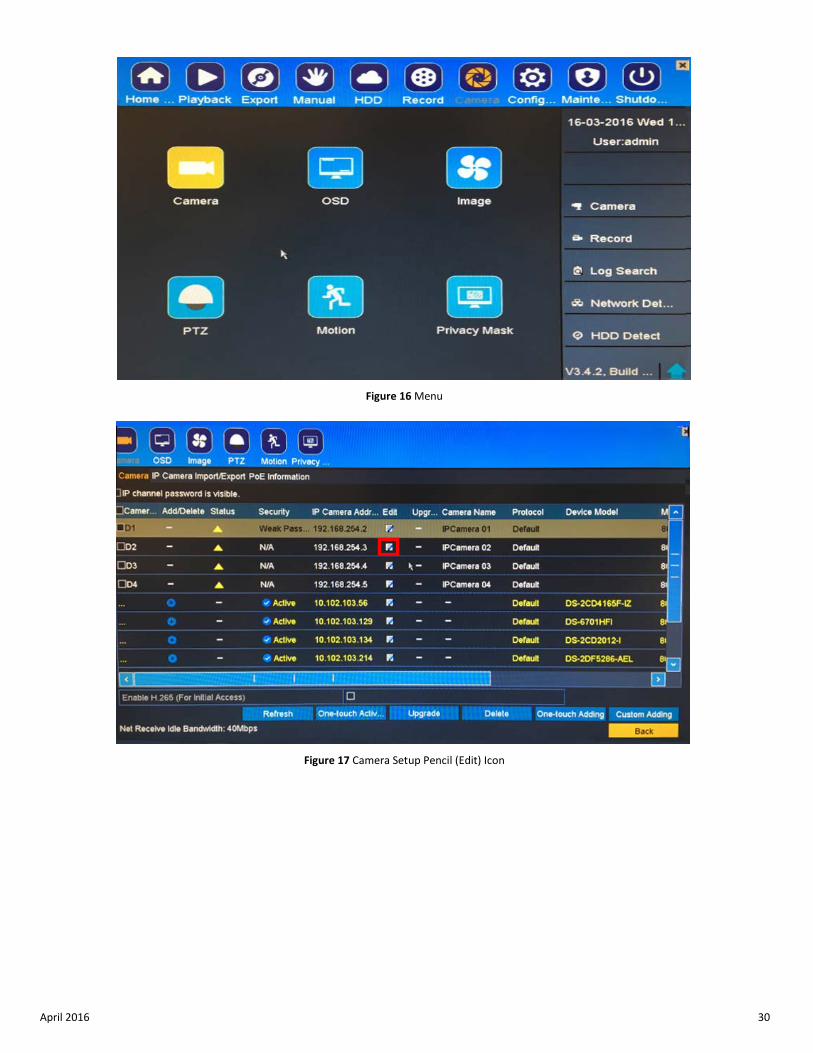
3. On the NVR go to MENU > CAMERA SETUP.
4. Press the Pencil (edit) icon next to the channel number (e.g., D1, D2, etc.).
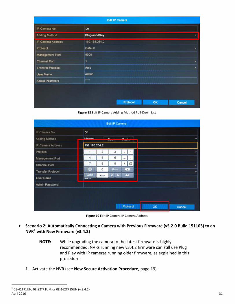
5. Change the ADDING METHOD to MANUAL.
6. Enter the camera’s IP address, username, and password.
7. Press APPLY.
Figure 14 Device Search
Figure 15 Network Settings
4 0E-41TP1UN, 0E-82TP1UN, or 0E-162TP15UN (v3.0.8 Build 151103 or Below)
April 2016 30
Figure 16 Menu
Figure 17 Camera Setup Pencil (Edit) Icon
April 2016 31
Figure 18 Edit IP Camera Adding Method Pull-Down List
Figure 19 Edit IP Camera IP Camera Address
• Scenario 2: Automatically Connecting a Camera with Previous Firmware (v5.2.0 Build 151105) to an
NVR5 with New Firmware (v3.4.2)
NOTE: While upgrading the camera to the latest firmware is highly recommended, NVRs running new v3.4.2 firmware can still use Plug and Play with IP cameras running older firmware, as explained in this procedure.
1. Activate the NVR (see New Secure Activation Procedure, page 19).
5 0E-41TP1UN, 0E-82TP1UN, or 0E-162TP15UN (v.3.4.2)
April 2016 32
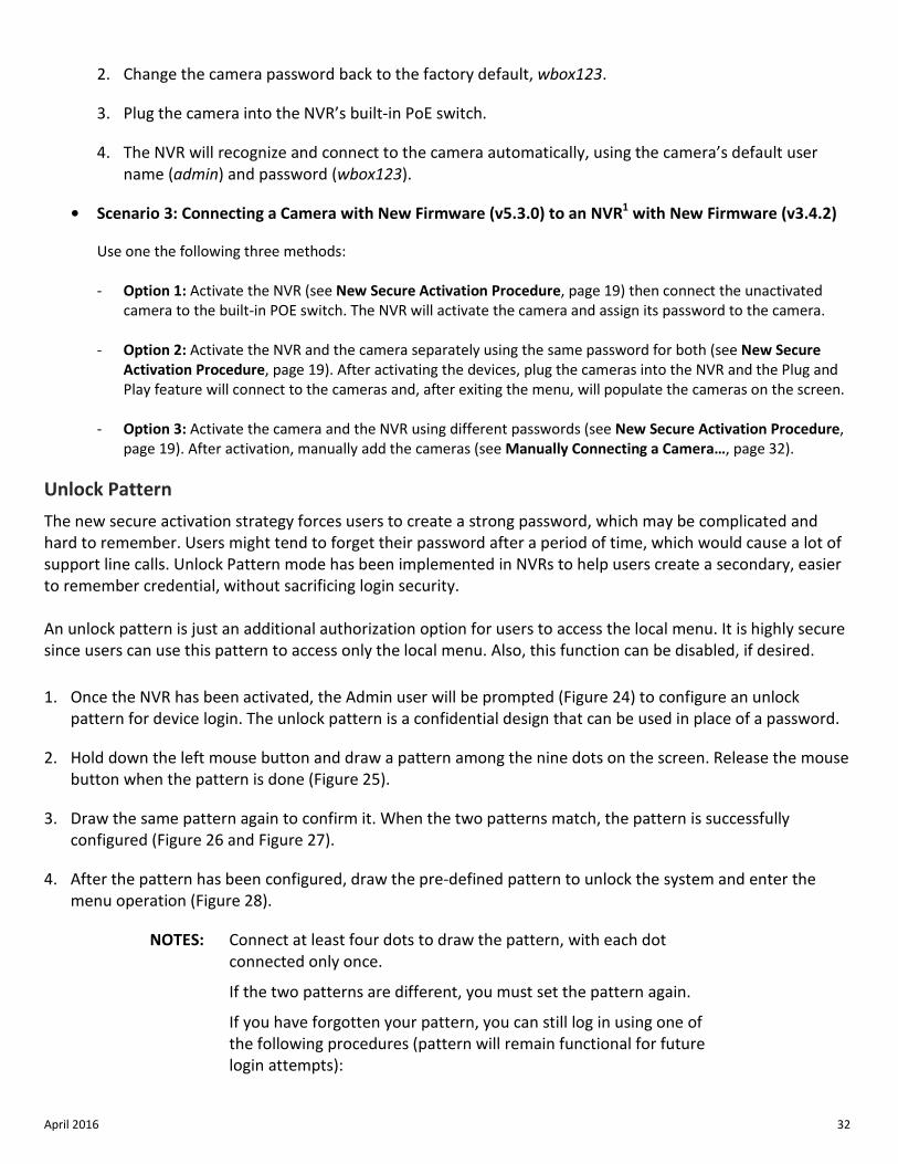
2. Change the camera password back to the factory default, wbox123.
3. Plug the camera into the NVR’s built-in PoE switch.
4. The NVR will recognize and connect to the camera automatically, using the camera’s default user name (admin) and password (wbox123).
• Scenario 3: Connecting a Camera with New Firmware (v5.3.0) to an NVR1 with New Firmware (v3.4.2)
Use one the following three methods: - Option 1: Activate the NVR (see New Secure Activation Procedure, page 19) then connect the unactivated
camera to the built-in POE switch. The NVR will activate the camera and assign its password to the camera.
- Option 2: Activate the NVR and the camera separately using the same password for both (see New Secure Activation Procedure, page 19). After activating the devices, plug the cameras into the NVR and the Plug and Play feature will connect to the cameras and, after exiting the menu, will populate the cameras on the screen.
- Option 3: Activate the camera and the NVR using different passwords (see New Secure Activation Procedure,
page 19). After activation, manually add the cameras (see Manually Connecting a Camera…, page 32).
Unlock Pattern The new secure activation strategy forces users to create a strong password, which may be complicated and hard to remember. Users might tend to forget their password after a period of time, which would cause a lot of support line calls. Unlock Pattern mode has been implemented in NVRs to help users create a secondary, easier to remember credential, without sacrificing login security.
An unlock pattern is just an additional authorization option for users to access the local menu. It is highly secure since users can use this pattern to access only the local menu. Also, this function can be disabled, if desired. 1. Once the NVR has been activated, the Admin user will be prompted (Figure 24) to configure an unlock
pattern for device login. The unlock pattern is a confidential design that can be used in place of a password.
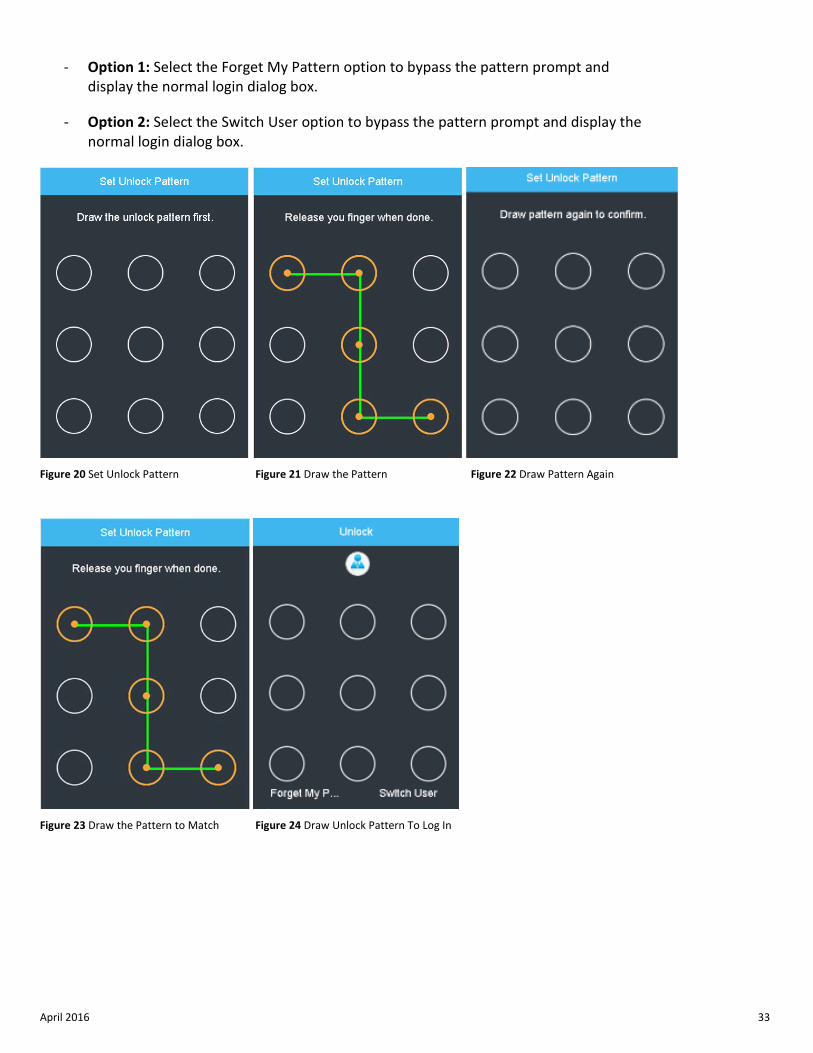
2. Hold down the left mouse button and draw a pattern among the nine dots on the screen. Release the mouse button when the pattern is done (Figure 25).
3. Draw the same pattern again to confirm it. When the two patterns match, the pattern is successfully configured (Figure 26 and Figure 27).
4. After the pattern has been configured, draw the pre-defined pattern to unlock the system and enter the menu operation (Figure 28).
NOTES: Connect at least four dots to draw the pattern, with each dot connected only once.
If the two patterns are different, you must set the pattern again.
If you have forgotten your pattern, you can still log in using one of the following procedures (pattern will remain functional for future login attempts):
April 2016 33
- Option 1: Select the Forget My Pattern option to bypass the pattern prompt and display the normal login dialog box.
- Option 2: Select the Switch User option to bypass the pattern prompt and display the normal login dialog box.
Figure 20 Set Unlock Pattern Figure 21 Draw the Pattern Figure 22 Draw Pattern Again
Figure 23 Draw the Pattern to Match Figure 24 Draw Unlock Pattern To Log In
April 2016 34
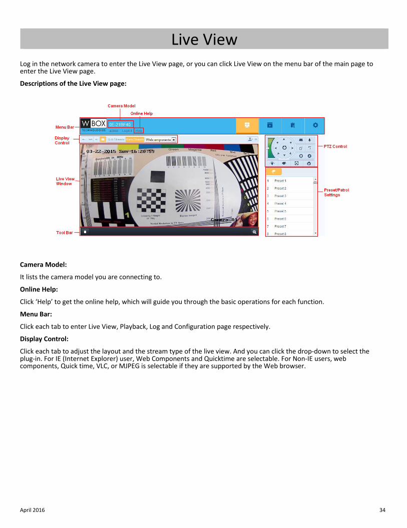
Live View Log in the network camera to enter the Live View page, or you can click Live View on the menu bar of the main page to enter the Live View page.
Descriptions of the Live View page:
Camera Model:
It lists the camera model you are connecting to.
Online Help:
Click ‘Help’ to get the online help, which will guide you through the basic operations for each function.
Menu Bar:
Click each tab to enter Live View, Playback, Log and Configuration page respectively.
Display Control:
Click each tab to adjust the layout and the stream type of the live view. And you can click the drop-down to select the plug-in. For IE (Internet Explorer) user, Web Components and Quicktime are selectable. For Non-IE users, web components, Quick time, VLC, or MJPEG is selectable if they are supported by the Web browser.
April 2016 35
Live View Window:
Display the live video.
Toolbar:
Operations on the Live View page, e.g., live view, capture, record, audio on/off, two-way audio, etc.
PTZ Control:
Panning, tilting, and zooming actions of the camera and the light and wiper control (only available for cameras supporting PTZ function)
Preset/Patrol Settings:
Set/call/delete the presets or patrols for PTZ cameras (available only for cameras supporting PTZ function)
April 2016 36
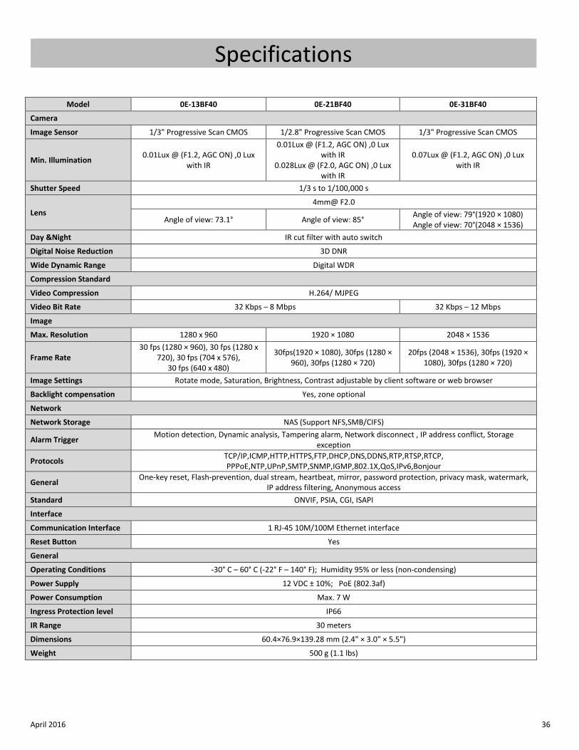
Specifications
Model 0E-13BF40 0E-21BF40 0E-31BF40
Camera
Image Sensor 1/3" Progressive Scan CMOS 1/2.8" Progressive Scan CMOS 1/3" Progressive Scan CMOS
Min. Illumination 0.01Lux @ (F1.2, AGC ON) ,0 Lux with IR
0.01Lux @ (F1.2, AGC ON) ,0 Lux with IR
0.028Lux @ (F2.0, AGC ON) ,0 Lux with IR
0.07Lux @ (F1.2, AGC ON) ,0 Lux with IR
Shutter Speed 1/3 s to 1/100,000 s
Lens 4mm@ F2.0
Angle of view: 73.1° Angle of view: 85° Angle of view: 79°(1920 × 1080) Angle of view: 70°(2048 × 1536)
Day &Night IR cut filter with auto switch
Digital Noise Reduction 3D DNR
Wide Dynamic Range Digital WDR
Compression Standard
Video Compression H.264/ MJPEG
Video Bit Rate 32 Kbps – 8 Mbps 32 Kbps – 12 Mbps
Image
Max. Resolution 1280 x 960 1920 × 1080 2048 × 1536
Frame Rate 30 fps (1280 × 960), 30 fps (1280 x
720), 30 fps (704 x 576), 30 fps (640 x 480)
30fps(1920 × 1080), 30fps (1280 × 960), 30fps (1280 × 720)
20fps (2048 × 1536), 30fps (1920 × 1080), 30fps (1280 × 720)
Image Settings Rotate mode, Saturation, Brightness, Contrast adjustable by client software or web browser
Backlight compensation Yes, zone optional
Network
Network Storage NAS (Support NFS,SMB/CIFS)
Alarm Trigger Motion detection, Dynamic analysis, Tampering alarm, Network disconnect , IP address conflict, Storage exception
Protocols TCP/IP,ICMP,HTTP,HTTPS,FTP,DHCP,DNS,DDNS,RTP,RTSP,RTCP, PPPoE,NTP,UPnP,SMTP,SNMP,IGMP,802.1X,QoS,IPv6,Bonjour
General One-key reset, Flash-prevention, dual stream, heartbeat, mirror, password protection, privacy mask, watermark, IP address filtering, Anonymous access
Standard ONVIF, PSIA, CGI, ISAPI
Interface
Communication Interface 1 RJ-45 10M/100M Ethernet interface
Reset Button Yes
General
Operating Conditions -30° C – 60° C (-22° F – 140° F); Humidity 95% or less (non-condensing)
Power Supply 12 VDC ± 10%; PoE (802.3af)
Power Consumption Max. 7 W
Ingress Protection level IP66
IR Range 30 meters
Dimensions 60.4×76.9×139.28 mm (2.4" × 3.0" × 5.5")
Weight 500 g (1.1 lbs)
April 2016 37
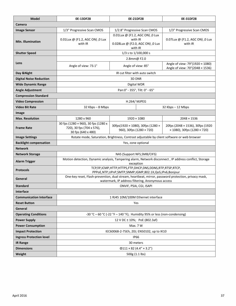
Model 0E-13DF28 0E-21DF28 0E-31DF28
Camera
Image Sensor 1/3" Progressive Scan CMOS 1/2.8" Progressive Scan CMOS 1/3" Progressive Scan CMOS
Min. Illumination 0.01Lux @ (F1.2, AGC ON) ,0 Lux with IR
0.01Lux @ (F1.2, AGC ON) ,0 Lux with IR
0.028Lux @ (F2.0, AGC ON) ,0 Lux with IR
0.07Lux @ (F1.2, AGC ON) ,0 Lux with IR
Shutter Speed 1/3 s to 1/100,000 s
Lens 2.8mm@ F2.0
Angle of view: 73.1° Angle of view: 85° Angle of view: 79°(1920 × 1080) Angle of view: 70°(2048 × 1536)
Day &Night IR cut filter with auto switch
Digital Noise Reduction 3D DNR
Wide Dynamic Range Digital WDR
Angle Adjustment Pan:0° - 355°, Tilt: 0° - 65°
Compression Standard
Video Compression H.264/ MJPEG
Video Bit Rate 32 Kbps – 8 Mbps 32 Kbps – 12 Mbps
Image
Max. Resolution 1280 x 960 1920 × 1080 2048 × 1536
Frame Rate 30 fps (1280 × 960), 30 fps (1280 x
720), 30 fps (704 x 576), 30 fps (640 x 480)
30fps(1920 × 1080), 30fps (1280 × 960), 30fps (1280 × 720)
20fps (2048 × 1536), 30fps (1920 × 1080), 30fps (1280 × 720)
Image Settings Rotate mode, Saturation, Brightness, Contrast adjustable by client software or web browser
Backlight compensation Yes, zone optional
Network
Network Storage NAS (Support NFS,SMB/CIFS)
Alarm Trigger Motion detection, Dynamic analysis, Tampering alarm, Network disconnect , IP address conflict, Storage exception
Protocols TCP/IP,ICMP,HTTP,HTTPS,FTP,DHCP,DNS,DDNS,RTP,RTSP,RTCP, PPPoE,NTP,UPnP,SMTP,SNMP,IGMP,802.1X,QoS,IPv6,Bonjour
General One-key reset, Flash-prevention, dual stream, heartbeat, mirror, password protection, privacy mask, watermark, IP address filtering, Anonymous access
Standard ONVIF, PSIA, CGI, ISAPI
Interface
Communication Interface 1 RJ45 10M/100M Ethernet interface
Reset Button Yes
General
Operating Conditions -30 °C – 60 °C (-22 °F – 140 °F); Humidity 95% or less (non-condensing)
Power Supply 12 V DC ± 10%; PoE (802.3af)
Power Consumption Max. 7 W
Impact Protection IEC60068-2-75Eh, 20J; EN50102, up to IK10
Ingress Protection level IP66
IR Range 30 meters
Dimensions Φ111 × 82 (4.4” × 3.2”)
Weight 500g (1.1 lbs)
April 2016 38
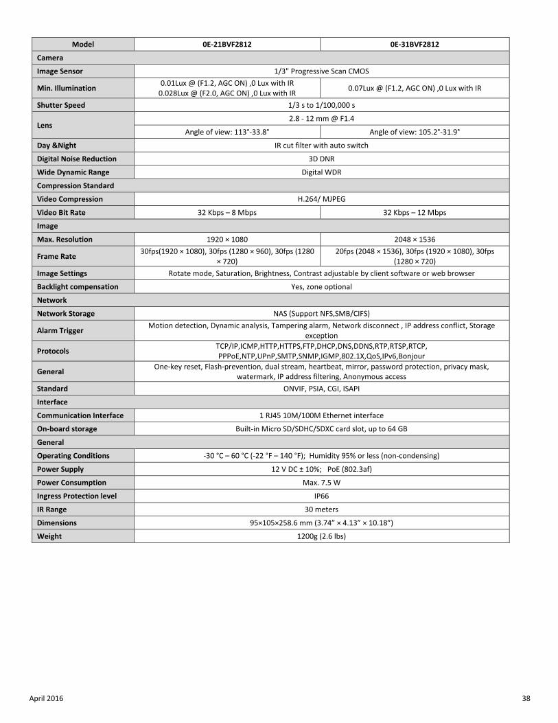
Model 0E-21BVF2812 0E-31BVF2812
Camera
Image Sensor 1/3" Progressive Scan CMOS
Min. Illumination 0.01Lux @ (F1.2, AGC ON) ,0 Lux with IR 0.028Lux @ (F2.0, AGC ON) ,0 Lux with IR 0.07Lux @ (F1.2, AGC ON) ,0 Lux with IR
Shutter Speed 1/3 s to 1/100,000 s
Lens 2.8 - 12 mm @ F1.4
Angle of view: 113°-33.8° Angle of view: 105.2°-31.9°
Day &Night IR cut filter with auto switch
Digital Noise Reduction 3D DNR
Wide Dynamic Range Digital WDR
Compression Standard
Video Compression H.264/ MJPEG
Video Bit Rate 32 Kbps – 8 Mbps 32 Kbps – 12 Mbps
Image
Max. Resolution 1920 × 1080 2048 × 1536
Frame Rate 30fps(1920 × 1080), 30fps (1280 × 960), 30fps (1280 × 720)
20fps (2048 × 1536), 30fps (1920 × 1080), 30fps (1280 × 720)
Image Settings Rotate mode, Saturation, Brightness, Contrast adjustable by client software or web browser
Backlight compensation Yes, zone optional
Network
Network Storage NAS (Support NFS,SMB/CIFS)
Alarm Trigger Motion detection, Dynamic analysis, Tampering alarm, Network disconnect , IP address conflict, Storage exception
Protocols TCP/IP,ICMP,HTTP,HTTPS,FTP,DHCP,DNS,DDNS,RTP,RTSP,RTCP, PPPoE,NTP,UPnP,SMTP,SNMP,IGMP,802.1X,QoS,IPv6,Bonjour
General One-key reset, Flash-prevention, dual stream, heartbeat, mirror, password protection, privacy mask, watermark, IP address filtering, Anonymous access
Standard ONVIF, PSIA, CGI, ISAPI
Interface
Communication Interface 1 RJ45 10M/100M Ethernet interface
On-board storage Built-in Micro SD/SDHC/SDXC card slot, up to 64 GB
General
Operating Conditions -30 °C – 60 °C (-22 °F – 140 °F); Humidity 95% or less (non-condensing)
Power Supply 12 V DC ± 10%; PoE (802.3af)
Power Consumption Max. 7.5 W
Ingress Protection level IP66
IR Range 30 meters
Dimensions 95×105×258.6 mm (3.74” × 4.13” × 10.18”)
Weight 1200g (2.6 lbs)
April 2016 39
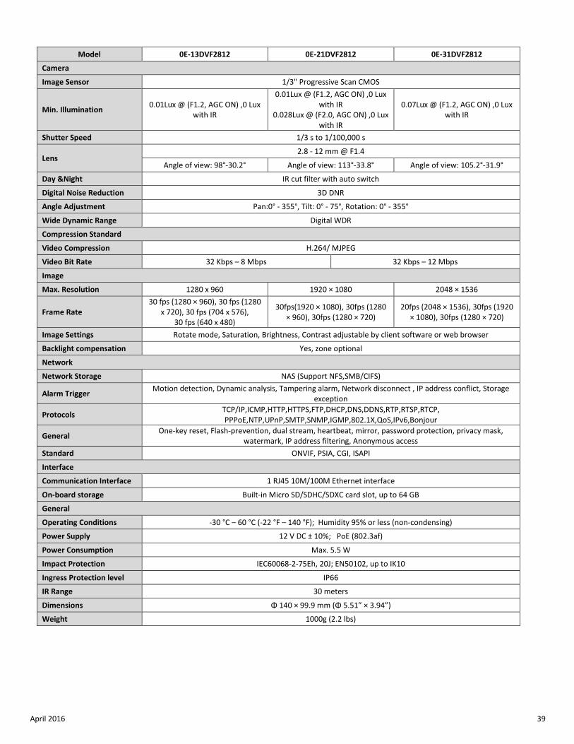
Model 0E-13DVF2812 0E-21DVF2812 0E-31DVF2812
Camera
Image Sensor 1/3" Progressive Scan CMOS
Min. Illumination 0.01Lux @ (F1.2, AGC ON) ,0 Lux with IR
0.01Lux @ (F1.2, AGC ON) ,0 Lux with IR
0.028Lux @ (F2.0, AGC ON) ,0 Lux with IR
0.07Lux @ (F1.2, AGC ON) ,0 Lux with IR
Shutter Speed 1/3 s to 1/100,000 s
Lens 2.8 - 12 mm @ F1.4
Angle of view: 98°-30.2° Angle of view: 113°-33.8° Angle of view: 105.2°-31.9°
Day &Night IR cut filter with auto switch
Digital Noise Reduction 3D DNR
Angle Adjustment Pan:0° - 355°, Tilt: 0° - 75°, Rotation: 0° - 355°
Wide Dynamic Range Digital WDR
Compression Standard
Video Compression H.264/ MJPEG
Video Bit Rate 32 Kbps – 8 Mbps 32 Kbps – 12 Mbps
Image
Max. Resolution 1280 x 960 1920 × 1080 2048 × 1536
Frame Rate 30 fps (1280 × 960), 30 fps (1280
x 720), 30 fps (704 x 576), 30 fps (640 x 480)
30fps(1920 × 1080), 30fps (1280 × 960), 30fps (1280 × 720)
20fps (2048 × 1536), 30fps (1920 × 1080), 30fps (1280 × 720)
Image Settings Rotate mode, Saturation, Brightness, Contrast adjustable by client software or web browser
Backlight compensation Yes, zone optional
Network
Network Storage NAS (Support NFS,SMB/CIFS)
Alarm Trigger Motion detection, Dynamic analysis, Tampering alarm, Network disconnect , IP address conflict, Storage exception
Protocols TCP/IP,ICMP,HTTP,HTTPS,FTP,DHCP,DNS,DDNS,RTP,RTSP,RTCP, PPPoE,NTP,UPnP,SMTP,SNMP,IGMP,802.1X,QoS,IPv6,Bonjour
General One-key reset, Flash-prevention, dual stream, heartbeat, mirror, password protection, privacy mask, watermark, IP address filtering, Anonymous access
Standard ONVIF, PSIA, CGI, ISAPI
Interface
Communication Interface 1 RJ45 10M/100M Ethernet interface
On-board storage Built-in Micro SD/SDHC/SDXC card slot, up to 64 GB
General
Operating Conditions -30 °C – 60 °C (-22 °F – 140 °F); Humidity 95% or less (non-condensing)
Power Supply 12 V DC ± 10%; PoE (802.3af)
Power Consumption Max. 5.5 W
Impact Protection IEC60068-2-75Eh, 20J; EN50102, up to IK10
Ingress Protection level IP66
IR Range 30 meters
Dimensions Φ 140 × 99.9 mm (Φ 5.51” × 3.94”)
Weight 1000g (2.2 lbs)
FOR TECHNICAL SUPPORT: 1-888-668-8808


![Travel Safety (2).ppt [Read-Only] - USDA · Travel Safety Hazards • Transportation Accidents • Assault/Robbery/Thief • Fire • Lifting/Ergonomics . Pre-Travel Preparations](https://img.pdfslide.net/doc/110x75/5ecf9832e806de0021054599/travel-safety-2ppt-read-only-usda-travel-safety-hazards-a-transportation.jpg)
![mediawebserver?mwsId=SSSSSu7zK1fslxtUn8 ... · FO_a‘"YW‘a 0E w"JaVVUX]Rd "NV]UZ_X"JYZV]Ud!""""" 0E w"9U!‘ "H‘hVcVU"9Zc"IVdaZcRe‘c!""""" 0E w"?cVdY*RZc "](https://img.pdfslide.net/doc/110x75/5be739ff09d3f2d66c8b9bdc/mediawebservermwsidsssssu7zk1fslxtun8-foaywa-0e-wjavvuxrd-nvuzxjyzvud.jpg)