Embed Size (px)
Citation preview
ISL
170.IU0.ISL.0B0 12-99
r USER MANUAL
ISL-0E.p65 15/12/99, 15.521
INDEX
ASSEMBLING ..................................................... 1WARNINGS ................................................. 1
PRELIMINARY HARWARE SETTING ................ 2NOTES ABOUT OPERATIVE MODES .............. 3GENERAL ASSEMBLING INFORMATION ........ 5
Wall mounting .............................................. 7Omega din rail mounting ............................. 7
CONNECTION DIAGRAMS ................................ 8General notes for wiring .............................. 8WARNINGS ................................................. 8Power ⇒ nominal current conversion ........ 10
CONNECTION .................................................. 12GENERAL SPECIFICATIONS .......................... 13CHARACTERISTICS OF ISL MODELS ........... 14MAINTENANCE ................................................ 15TROUBLESHOOTING ...................................... 16
How to replace the fuse ............................. 17WARNINGS ............................................... 17
APPENDIX ADimensions and panel cut out ..................A.1
GB
ISL-0E.p65 15/12/99, 15.522

ISL-0E.p65 15/12/99, 15.523
1GB
ASSEMBLING
WARNINGS:1) The correct functionality of these devices is
guaranteed only if transport, storage,installation, wiring, working condition andmaintenance are executed in compliance withthis manual.
2) The protection degree of these devices isequal to IP 20 (according to CEI EN 60529)and they are connected to dangerous powerlines, for these reasons:- installation, wiring and maintenance must be
executed by qualified personnel;- all warnings contained in this manual must
be complied.3) Do not execute any dielectric strength or
insulation resistance test on the powerterminals.These type of tests could damage the powersemiconductors.
4) Circuit-breaker:- a switch or circuit-breaker shall be included in
the building installation;- It shall be in close proximity to the equipment
and within easy reach of the operator;- it shall be marked as the disconnecting device
for the equipment.NOTE: a single switch or circuit-breaker candrive more than one device.
5) Before executing any operation on the load or itsconnections, disconnect the device from thepower line by the circuit breaker.
6) During continuous operation, the heat sink couldreach a temperature higher than 80 °C (176 °F)Before executing any operation to the device,you have to be sure that its temperature isdecreased to an acceptable value.
7) To place the device, choose a cleanedposition, easy to reach, and possibly withoutvibration.
8) The ambient temperature must be within 0 °Cand 50 °C (32 to 122 °F).
ISL-1-B0.p65 15/12/99, 15.521
2GB
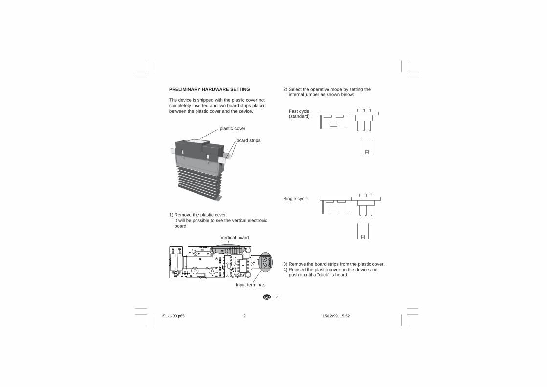
2) Select the operative mode by setting theinternal jumper as shown below:
Fast cycle(standard)
Single cycle
3) Remove the board strips from the plastic cover.4) Reinsert the plastic cover on the device and
push it until a "click" is heard.
PRELIMINARY HARDWARE SETTING
The device is shipped with the plastic cover notcompletely inserted and two board strips placedbetween the plastic cover and the device.
1) Remove the plastic cover.It will be possible to see the vertical electronicboard.
Vertical board
Input terminals
plastic cover
board strips
ISL-1-B0.p65 15/12/99, 15.522
3GB
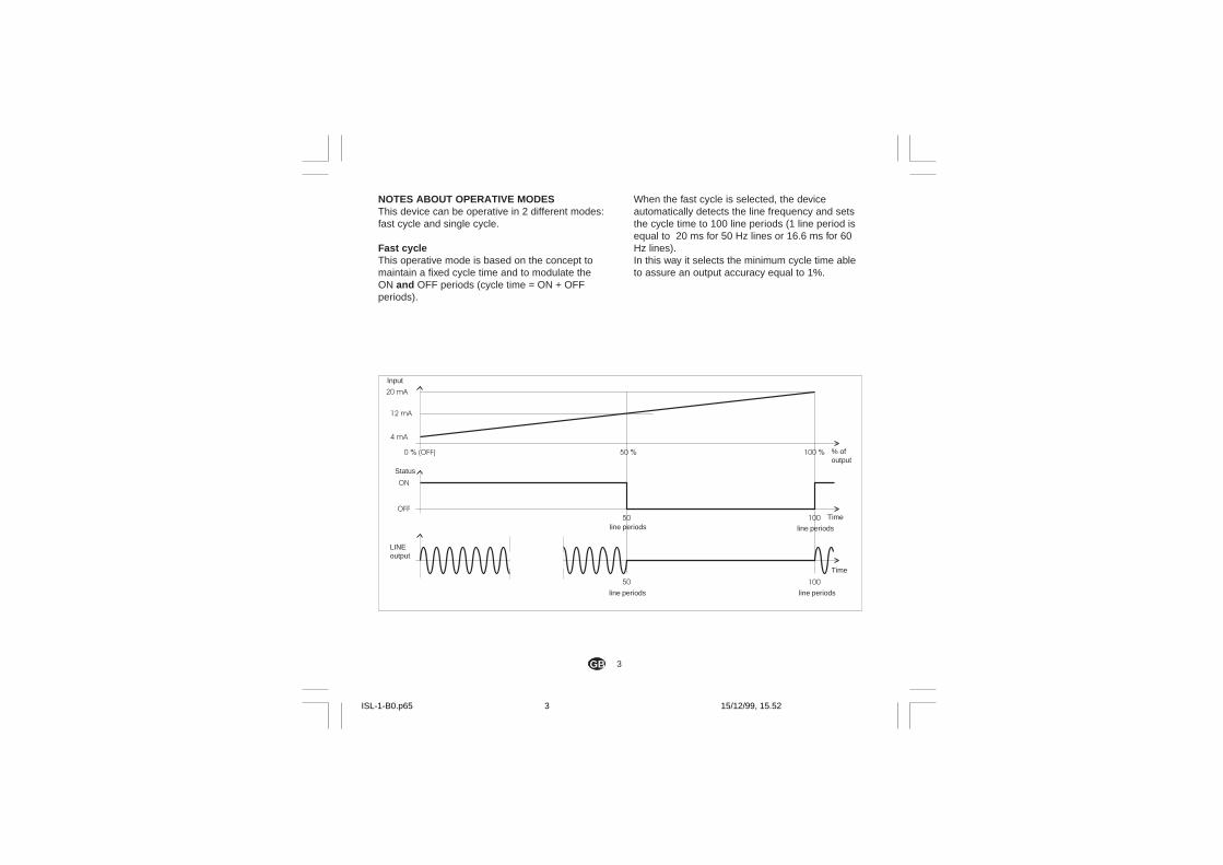
When the fast cycle is selected, the deviceautomatically detects the line frequency and setsthe cycle time to 100 line periods (1 line period isequal to 20 ms for 50 Hz lines or 16.6 ms for 60Hz lines).In this way it selects the minimum cycle time ableto assure an output accuracy equal to 1%.
NOTES ABOUT OPERATIVE MODESThis device can be operative in 2 different modes:fast cycle and single cycle.
Fast cycleThis operative mode is based on the concept tomaintain a fixed cycle time and to modulate theON and OFF periods (cycle time = ON + OFFperiods).
Input
Status
% ofoutput
Time
LINEoutput
line periods
Time
line periods
line periods
line periods
ISL-1-B0.p65 15/12/99, 15.523
4GB
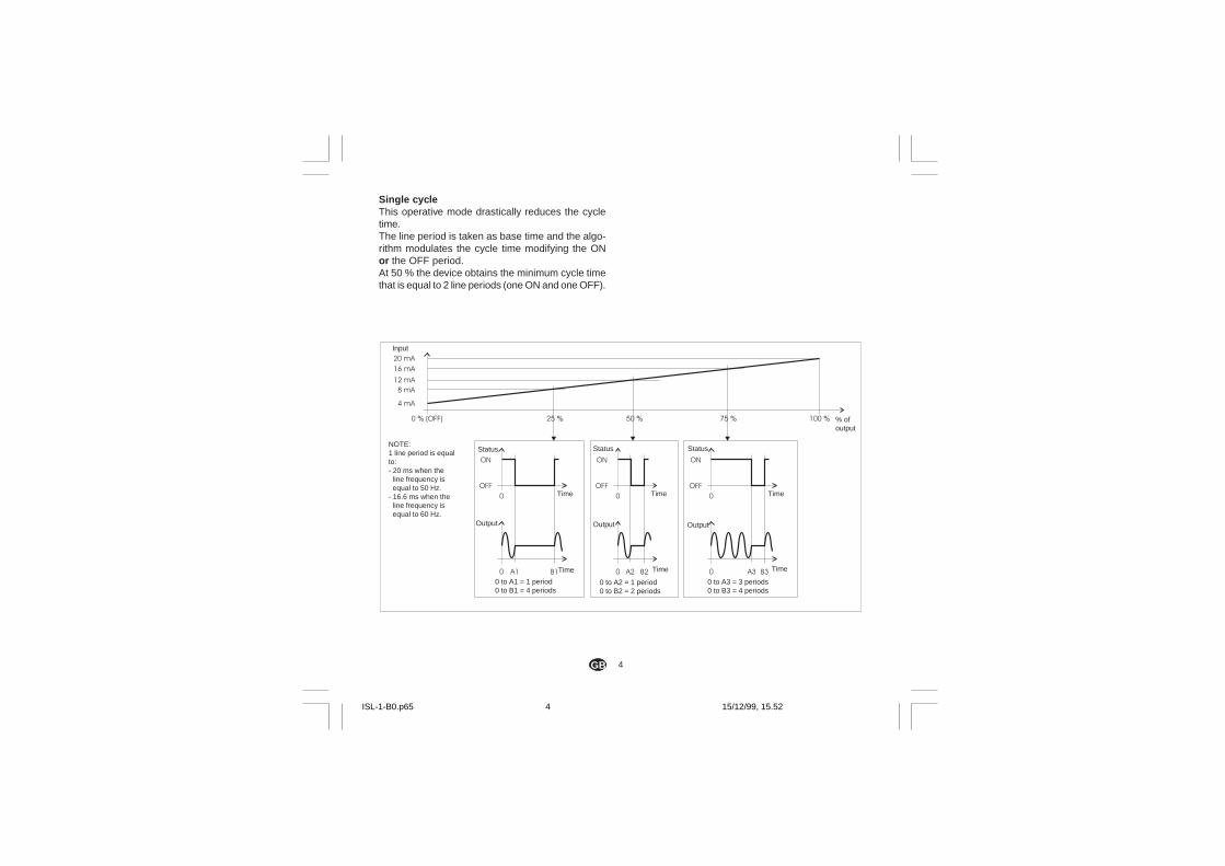
Single cycleThis operative mode drastically reduces the cycletime.The line period is taken as base time and the algo-rithm modulates the cycle time modifying the ONor the OFF period.At 50 % the device obtains the minimum cycle timethat is equal to 2 line periods (one ON and one OFF).
Input
% ofoutput
Status
Time
Output
Status Status
Output Output
Time Time
Time Time Time
0 to A1 = 1 period0 to B1 = 4 periods
0 to A2 = 1 period0 to B2 = 2 periods
0 to A3 = 3 periods0 to B3 = 4 periods
NOTE:1 line period is equalto:- 20 ms when the
line frequency isequal to 50 Hz.
- 16.6 ms when theline frequency isequal to 60 Hz.
ISL-1-B0.p65 15/12/99, 15.524
5GB
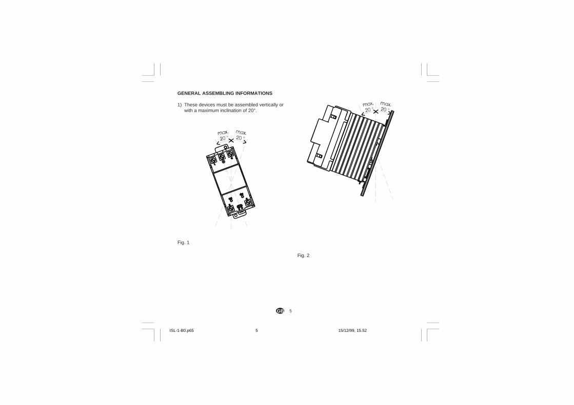
GENERAL ASSEMBLING INFORMATIONS
1) These devices must be assembled vertically orwith a maximum inclination of 20°.
Fig. 1
Fig. 2
ISL-1-B0.p65 15/12/99, 15.525
6GB
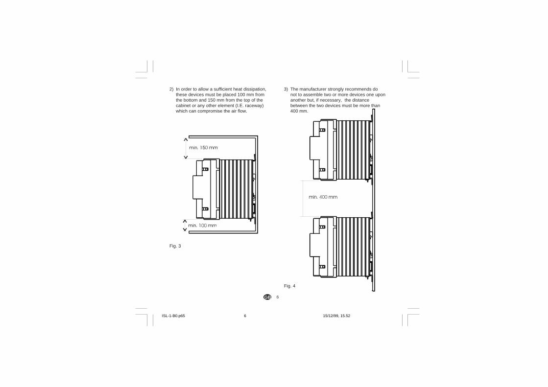
3) The manufacturer strongly recommends donot to assemble two or more devices one uponanother but, if necessary, the distancebetween the two devices must be more than400 mm.
Fig. 4
2) In order to allow a sufficient heat dissipation,these devices must be placed 100 mm fromthe bottom and 150 mm from the top of thecabinet or any other element (I.E. raceway)which can compromise the air flow.
Fig. 3
ISL-1-B0.p65 15/12/99, 15.526

7GB
The device can be mounted either on wall or on aOmega DIN rail.
WALL MOUNTINGFor wall mounting can be used the (A) holes.
In this case use two M4 screws (torque of 1Nmmax).
For the mounting template and the mechanicaldimensions of all models, please refer to theappropriate drawing, located in the "Mechanicaldimensions" paragraph.
OMEGA DIN RAIL MOUNTINGFor rail mounting use an Omega DIN rail inaccordance with EN 50 022 (35 x 7.5 mm or 35 x15 mm) regulations.
MOUNTING
Fig. 5
OmegaDIN rail
ISL-1-B0.p65 15/12/99, 15.527
8GB
CONNECTION DIAGRAMS
GENERAL NOTES FOR WIRING
WARNINGS:1) The wiring must be executed only after the device
has been correctly mounted.2) Before connecting the device, be sure that
power line voltage value is less or equal thenominal value reported on the device'sidentification label.
3) Before connecting the device, be sure that theload current (see Power ⇒⇒⇒⇒⇒ nominal currentconversion paragraph) is less or equal thedevice nominal current as a function of theambient temperature and the Duty cycle (seeTrend of the nominal current in relation withthe ambient temperature and duty cycleparagraph).
4) Before executing any operations, be absolutelysure that the device is disconnected from thepower line through the circuit breaker.
5) Use copper wires only.6) Pay attention to the input command polarity;
terminal 5 is the positive one while terminal 6 isthe negative one.
7) The neutral (if used) must be connected to the 2and 4 terminals.
8) The power input IS NOT fuse protected; placean external fuse selected among the typesshown in Table 1.NOTE:The Manufacturer decline any responsibility forinjury and/or property damage if NO fuse orfuse not included in Table 1 is used.The warranty validity also depends on it.
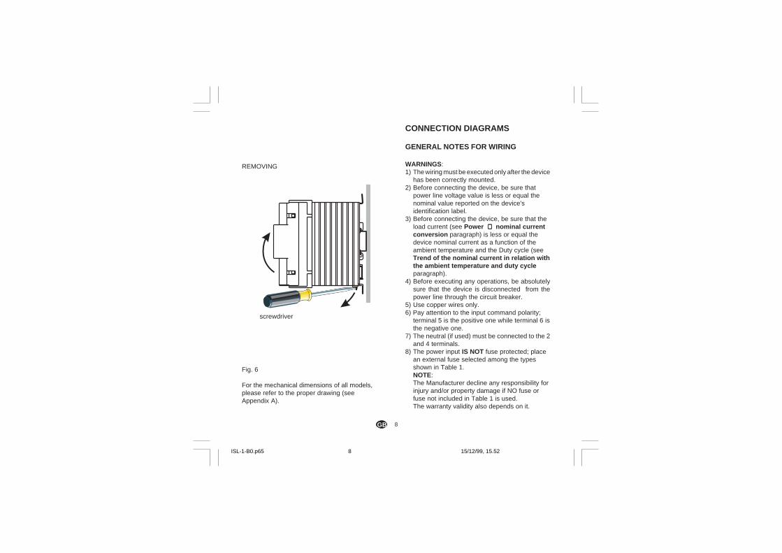
REMOVING
Fig. 6
For the mechanical dimensions of all models,please refer to the proper drawing (seeAppendix A).
screwdriver
ISL-1-B0.p65 15/12/99, 15.528
9GB
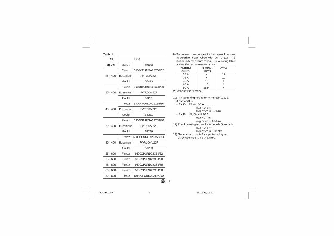
Table 1
ISL Fuse
Model Manuf. model
Ferraz 6600CPURGA22X58/32
25 - 400 Bussmann FWP.32A.22F
Gould 52443
Ferraz 6600CPURGA22X58/50
35 - 400 Bussmann FWP.50A.22F
Gould 53251
Ferraz 6600CPURGA22X58/50
45 - 400 Bussmann FWP.50A.22F
Gould 53251
Ferraz 6600CPURGA22X58/80
60 - 400 Bussmann FWP.80A.22F
Gould 53259
Ferraz 6600CPURGA22X58/100
80 - 400 Bussmann FWP.100A.22F
Gould 53263
25 - 600 Ferraz 6600CPURD22X58/32
35 - 600 Ferraz 6600CPURD22X58/50
45 - 600 Ferraz 6600CPURD22X58/50
60 - 600 Ferraz 6600CPURD22X58/80
80 - 600 Ferraz 6600CPURD22X58/100
9) To connect the devices to the power line, useappropriate sized wires with 75 °C (167 °F)minimum temperature rating. The following tableshows the recommended sizes:
Nominal φ wires AWGcurrent (mm2)25 A 4 1235 A 6 1045 A 10 860 A 16 680 A 25 (*) 4
(*) without wire terminal
10)The tightening torque for terminals 1, 2, 3,4 and earth is:- for ISL 25 and 35 A
max = 0.8 Nmsuggested = 0.7 Nm
- for ISL 45, 60 and 80 Amax = 2 Nmsuggested = 1.5 Nm
11) The tightening torque for terminals 5 and 6 is:max = 0.5 Nmsuggested = 0.33 Nm
12) The control input is fuse protected by anSMD fuse type F, 63 V 63 mA.
ISL-1-B0.p65 15/12/99, 15.529
10GB
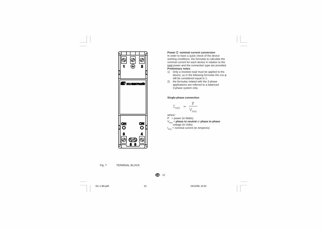
Power ⇒⇒⇒⇒⇒ nominal current conversionIn order to have a quick check of the deviceworking conditions, the formulas to calculate thenominal current for each device in relation to thetotal power and the connection type are provided.Preliminary notes :1) Only a resistive load must be applied to the
device, so in the following formulas the cos φwill be considered equal to 1.
2) the formulas related with the 3-phaseapplications are referred to a balanced3-phase system only.
Single-phase connection
IP
VRMSRMS
=
where:P = power (in Watts).V
RMS = phase to neutral or phase to phasevoltage (in Volts)
IRMS
= nominal current (in Amperes)
Fig. 7 TERMINAL BLOCK
ISL-1-B0.p65 15/12/99, 15.5210
11GB
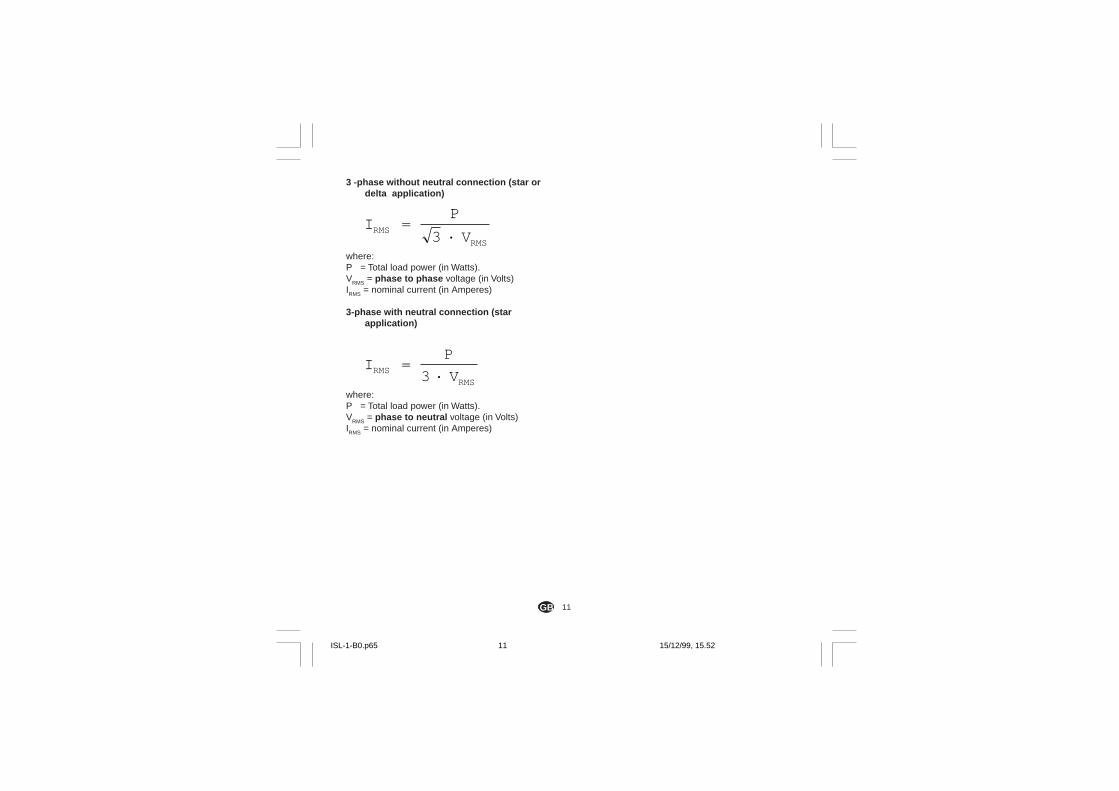
3 -phase without neutral connection (star ordelta application)
IP
VRMS
RMS
=·3
where:P = Total load power (in Watts).VRMS = phase to phase voltage (in Volts)IRMS = nominal current (in Amperes)
3-phase with neutral connection (starapplication)
IP
VRMSRMS
=·3
where:P = Total load power (in Watts).VRMS = phase to neutral voltage (in Volts)IRMS = nominal current (in Amperes)
ISL-1-B0.p65 15/12/99, 15.5211

12GB
Fig. 8
P (L1)
N (L2)
EARTH
POWERLINE
Signal
Single phase connection
Fus
e
CONNECTION
ISL-1-B0.p65 15/12/99, 15.5212
13GB
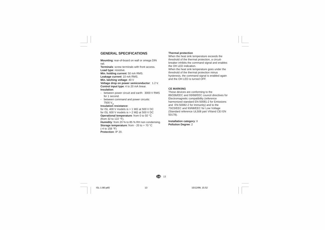
GENERAL SPECIFICATIONS
Mounting : rear-of-board on wall or omega DINrail.Terminals : screw terminals with front access.Load type : resistive.Min. holding current : 50 mA RMS.Leakage current : 10 mA RMS.Min. latching voltage : 40 VVoltage drop on power semiconductor : 1.2 V.Control input type : 4 to 20 mA linear.Insulation :- between power circuit and earth: 3000 V RMS
for 1 second.- between command and power circuits:
7500 Vpk
Insulation resistance :for ISL 400 V models is > 1 MΩ at 500 V DCfor ISL 600 V models is > 2 MΩ at 500 V DCOperational temperature : from 0 to 50 °C(from 32 to 122 °F).Humidity : from 20 % to 85 % RH non condensing.Storage temperature : from - 20 to + 70 °C(-4 to 158 °F)Protection : IP 20.
Thermal protectionWhen the heat sink temperature exceeds thethreshold of the thermal protection, a circuit-breaker inhibits the command signal and enablesthe OH LED indication.When the heat sink temperature goes under thethreshold of the thermal protection minushysteresis, the command signal is enabled againand the OH LED is turned OFF.
CE MARKINGThese devices are conforming to the89/336/EEC and 93/68/EEC council directives forElectromagnetic compatibility (referenceharmonized standard EN-50081-2 for Emissionsand EN-50082-2 for Immunity) and to the73/23/EEC and 93/68/EEC for Low Voltage(Standard reference UL508 part VIIIand CEI EN50178).
Installation category : IIPollution Degree : 2
ISL-1-B0.p65 15/12/99, 15.5213
14GB
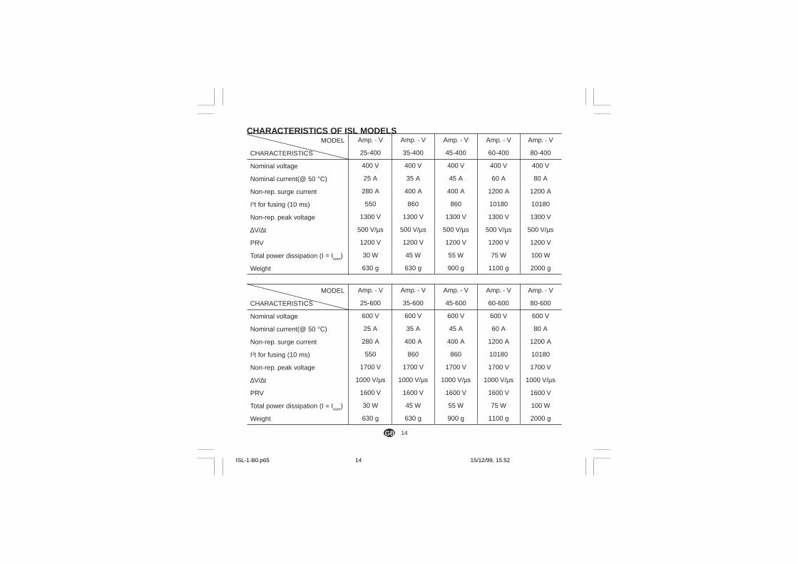
MODEL
CHARACTERISTICS
Nominal voltage
Nominal current(@ 50 °C)
Non-rep. surge current
I2t for fusing (10 ms)
Non-rep. peak voltage
∆V/∆t
PRV
Total power dissipation (I = Inom)
Weight
Amp. - V
25-400
400 V
25 A
280 A
550
1300 V
500 V/µs
1200 V
30 W
630 g
Amp. - V
35-400
400 V
35 A
400 A
860
1300 V
500 V/µs
1200 V
45 W
630 g
Amp. - V
45-400
400 V
45 A
400 A
860
1300 V
500 V/µs
1200 V
55 W
900 g
Amp. - V
60-400
400 V
60 A
1200 A
10180
1300 V
500 V/µs
1200 V
75 W
1100 g
Amp. - V
80-400
400 V
80 A
1200 A
10180
1300 V
500 V/µs
1200 V
100 W
2000 g
CHARACTERISTICS OF ISL MODELS
MODEL
CHARACTERISTICS
Nominal voltage
Nominal current(@ 50 °C)
Non-rep. surge current
I2t for fusing (10 ms)
Non-rep. peak voltage
∆V/∆t
PRV
Total power dissipation (I = Inom
)
Weight
Amp. - V
25-600
600 V
25 A
280 A
550
1700 V
1000 V/µs
1600 V
30 W
630 g
Amp. - V
35-600
600 V
35 A
400 A
860
1700 V
1000 V/µs
1600 V
45 W
630 g
Amp. - V
45-600
600 V
45 A
400 A
860
1700 V
1000 V/µs
1600 V
55 W
900 g
Amp. - V
60-600
600 V
60 A
1200 A
10180
1700 V
1000 V/µs
1600 V
75 W
1100 g
Amp. - V
80-600
600 V
80 A
1200 A
10180
1700 V
1000 V/µs
1600 V
100 W
2000 g
ISL-1-B0.p65 15/12/99, 15.5214
15GB
MAINTENANCE
WARNING:1) Before executing any maintenance operation
on the device, on the load or on theirconnections, disconnect it from the power lineby a mechanical circuit breaker.
2) The protection degree of these devices isequal to IP 20 (according to CEI EN 60529)and they are connected to dangerous powerlines, for these reasons:- installation, wiring and maintenance must be
executed by qualified personnel;- all warnings contained in this manual must
be complied.3) Do not execute any dielectric strength or
insulation resistance test on the powerterminals.These types of test could damage the powersemiconductors.
4) During continuous operation, the heat sink couldreach a temperature higher than 80 °C (176 °F)Before execute any operation on the device,be sure that its temperature has decreased toan acceptable value.
MAINTENANCE1) REMOVE POWER FROM THE DEVICE BY
USING A MECHANICAL CIRCUIT BREAKER2) Using a vacuum cleaner or a compressed air
jet (max. 5 kg/cm2) remove all deposit of dustand dirt which may be present on the heat sinkand on the terminals.
3) To clean external plastic or rubber parts useonly a cloth moistened with:- Ethyl Alcohol (pure or denatured) [C2H5OH] or- Isopropil Alcohol (pure or denatured)[(CH3)2CHOH] or- Water (H2O)
4) Verify that there are no loose terminals (seeparagraph GENERAL NOTES FOR WIRING) .
5) Before switching the power ON, be sure thatthe device is perfectly dry.
6) Turn the power ON.
ISL-1-B0.p65 15/12/99, 15.5215
16GB
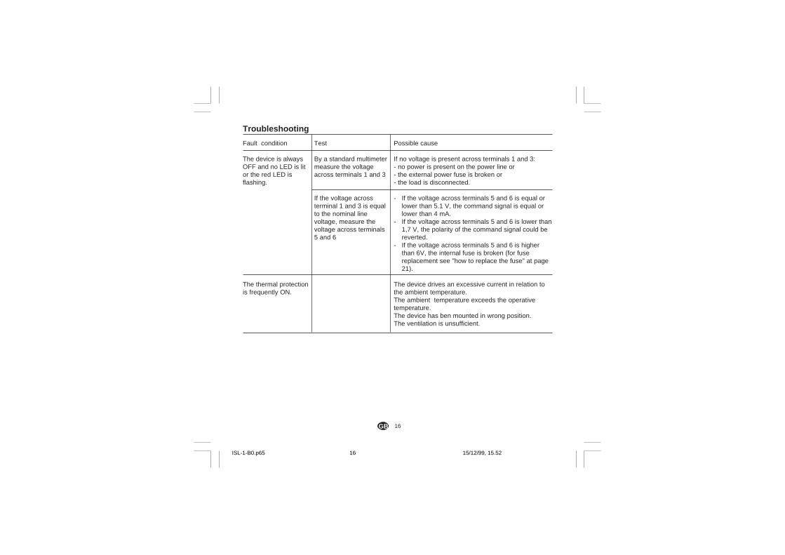
Troubleshooting
Fault condition
The device is alwaysOFF and no LED is litor the red LED isflashing.
The thermal protectionis frequently ON.
Possible cause
If no voltage is present across terminals 1 and 3:- no power is present on the power line or- the external power fuse is broken or- the load is disconnected.
- If the voltage across terminals 5 and 6 is equal orlower than 5.1 V, the command signal is equal orlower than 4 mA.
- If the voltage across terminals 5 and 6 is lower than1,7 V, the polarity of the command signal could bereverted.
- If the voltage across terminals 5 and 6 is higherthan 6V, the internal fuse is broken (for fusereplacement see "how to replace the fuse" at page21).
The device drives an excessive current in relation tothe ambient temperature.The ambient temperature exceeds the operativetemperature.The device has ben mounted in wrong position.The ventilation is unsufficient.
Test
By a standard multimetermeasure the voltageacross terminals 1 and 3
If the voltage acrossterminal 1 and 3 is equalto the nominal linevoltage, measure thevoltage across terminals5 and 6
ISL-1-B0.p65 15/12/99, 15.5216
17GB
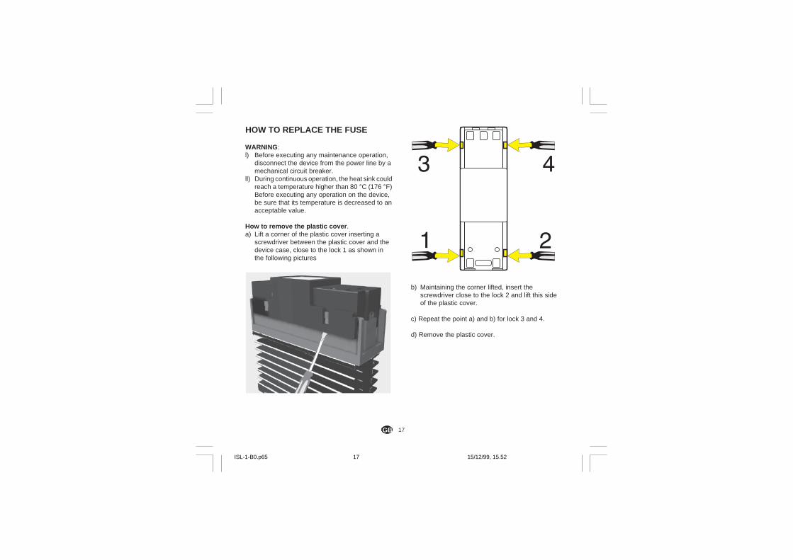
HOW TO REPLACE THE FUSE
WARNING:l) Before executing any maintenance operation,
disconnect the device from the power line by amechanical circuit breaker.
ll) During continuous operation, the heat sink couldreach a temperature higher than 80 °C (176 °F)Before executing any operation on the device,be sure that its temperature is decreased to anacceptable value.
How to remove the plastic cover .a) Lift a corner of the plastic cover inserting a
screwdriver between the plastic cover and thedevice case, close to the lock 1 as shown inthe following pictures
b) Maintaining the corner lifted, insert thescrewdriver close to the lock 2 and lift this sideof the plastic cover.
c) Repeat the point a) and b) for lock 3 and 4.
d) Remove the plastic cover.
ISL-1-B0.p65 15/12/99, 15.5217
18GB
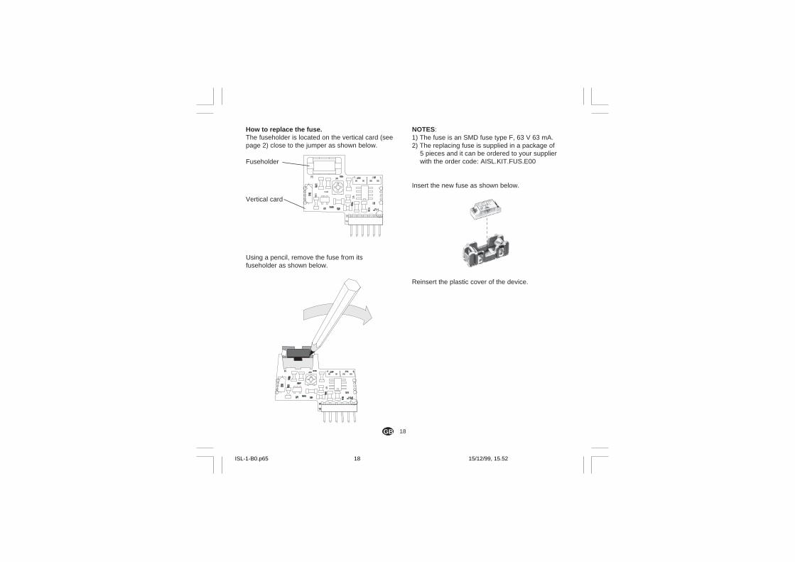
How to replace the fuse.The fuseholder is located on the vertical card (seepage 2) close to the jumper as shown below.
Using a pencil, remove the fuse from itsfuseholder as shown below.
NOTES:1) The fuse is an SMD fuse type F, 63 V 63 mA.2) The replacing fuse is supplied in a package of
5 pieces and it can be ordered to your supplierwith the order code: AISL.KIT.FUS.E00
Insert the new fuse as shown below.
Reinsert the plastic cover of the device.
Vertical card
Fuseholder
ISL-1-B0.p65 15/12/99, 15.5218
A. 1
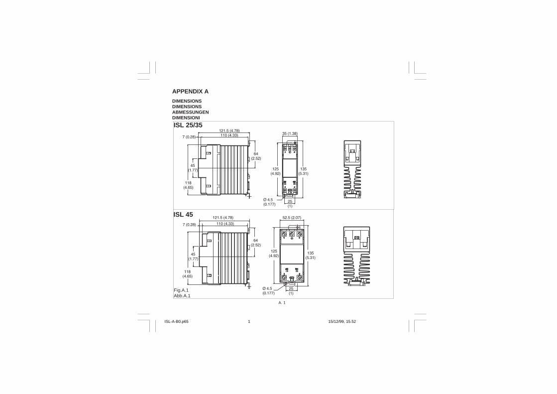
DIMENSIONSDIMENSIONSABMESSUNGENDIMENSIONI
APPENDIX A
ISL 25/35
ISL 45
Fig.A.1Abb.A.1
ISL-A-B0.p65 15/12/99, 15.521
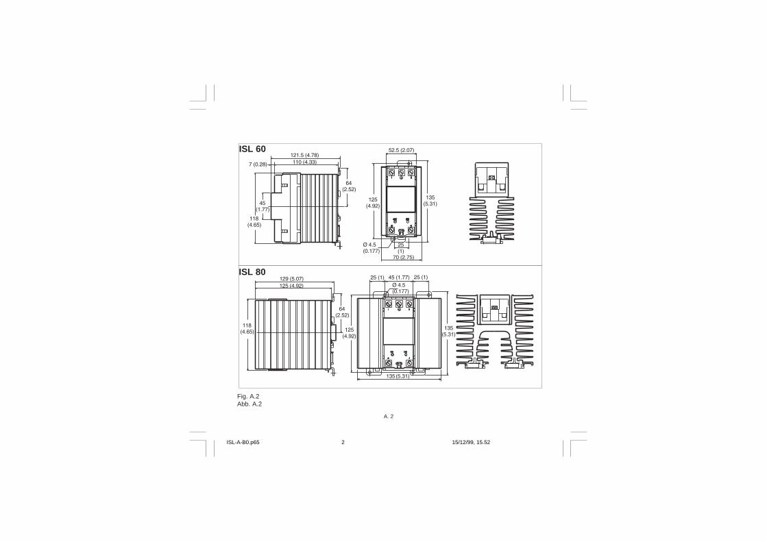
A. 2
Fig. A.2Abb. A.2
ISL 80
ISL 60
ISL-A-B0.p65 15/12/99, 15.522

A. 3
ISL-A-B0.p65 15/12/99, 15.523

ISL-A-B0.p65 15/12/99, 15.524

Ero Electronic S.r.l.Via E. Mattei, 2128100 NovaraItalyTel. +39 0321481111Fax +39 0321481112E-mail [email protected]://www.eroelectronic.com
AUSTRIAERO ELECTRONIC ÖSTERREICHGeiereckstrasse 18/11110 WienTel. 01-7987601Fax [email protected]
BENELUXERO ELECTRONIC BENELUX SA/NVRue Val Notre Dame 384MOHA 4520 (WANZE)Tel. 085-274080Fax [email protected]
BRASILERO ELECTRONIC DO BRASILINDUSTRIA E COMERCIO Ltda.Rua Garibaldi, 659 - Conj. 20290035-050 PORTO ALEGRETel. 051-2214888Fax [email protected]
CHINATIANJIN VEGA COMPANY Ltd(TAIF)Hebei District300232 TIANJINTel. 022-26273296Fax 022-26273297
FRANCEERO ELECTRONIC SARLZac du Chêne34, Rue du 35éme Régiment d’Aviation69673 BRON CEDEXTel. 0478267979Fax 0478267800
GERMANYERO ELECTRONIC GmbHOttostrasse 165549 LIMBURG A.D. LAHNTel. 06431-95680Fax 06431-57493
NETHERLANDERO ELECTRONIC NEDERLANDGanieelan 42404 CH Alphen a/d RijnTel. 0172-420400Fax. [email protected]
SOUTH AFRICAERO ELECTRONIC S.A. Pty LtdAirgro House1343, Spokeshave AvenueStormill Ext 2 ROODEPOORTTel. 011-4742278/9Fax 011-4749404P.O. Box 43112Industria [email protected]
SPAINERO ELECTRONIC IBERICACalle La granja, 74Pol. Ind. AlcobendasMADRIDTel. 091-6618194Fax. 091-6619093
U.K.ERO U.K.Unit 1, Cygnet Trading EstateFaraday CloseDurrington, WorthingWEST SUSSEX BN13 3RQTel. 01903-693322Fax. 01903-693377
U.S.A.AMERICAN ERO ELECTRONIC CorpBARRINGTON, ILL. 60010Tel. 0847-382-0881Fax 0847-382-0240
U.S.A.BARBER COLMANIndustrial Instruments Div.P.O. BOX 2940Loves Park, IL - 31132 - 2940Tel. 0815-637-3000Fax [email protected]
ISL-Z-A0.p65 15/12/99, 15.521